Embed Size (px)
Citation preview
1
GNSS Multi-Receiver Vector TrackingYuting Ng, Student Member, IEEE and Grace Xingxin Gao, Senior Member, IEEE
Abstract—Accurate, reliable and robust GPS localization isdesirable for many navigation applications. Unfortunately, it ischallenging for a single GPS receiver to always provide accuratepositioning solutions. In urban environments, intermittent signalavailability leads to degraded GPS signal tracking and positionestimation of the single GPS receiver. In addition, equipmentmalfunction of the single GPS receiver results in inaccuratenavigation solutions.
This paper presents a deeply-coupled Multi-Receiver VectorTracking (MRVT) architecture that improves the reliabilityand robustness of GPS signal tracking and position estimation.MRVT jointly tracks GPS signals received by multiple GPSreceivers, mitigating GPS signal tracking disruptions, improvingthe reliability of GPS localization in periods of intermittent signalavailability. In addition, the MRVT receiver is more robust toequipment malfunctions than the single GPS receiver.
We implemented a MRVT receiver using commercial radiofrequency front ends and our PyGNSS software. We experimen-tally validated the reliability of our MRVT receiver in periodsof intermittent GPS availability experienced in downtown SanFrancisco. Our MRVT receiver exhibited consistent GPS signaltracking and position estimation as compared to vector tracking.In addition, we experimentally validated the robustness of ourMRVT receiver to the failure of a single GPS receiver.
Index Terms—Global positioning system (GPS), global navi-gation satellite systems (GNSS), multiple GPS receivers, vectortracking
I. INTRODUCTION
GPS receivers, providing absolute position coordinates un-der all weather, platforms and visual conditions, are increas-ingly relied upon for urban navigation [1]. Unfortunately,a single GPS receiver suffers from intermittent GPS signalavailability in urban environments, leading to signal trackingdisruptions and position estimation challenges [2]. In addition,equipment malfunction of the single GPS receiver results ininaccurate position solutions. To improve the reliability androbustness of GPS localization, existing approaches includesensor fusion [3] with vision [4] and inertial measurements [5].Instead of augmenting the single GPS receiver with additionalsensors, there is inherent potential in leveraging multiple GPSreceivers [6].
A. Related Work
Existing approaches using multiple GPS receivers include“loosely-coupled” and “tightly-coupled” architectures. A well-known example with both loosely-coupled and tightly-coupledimplementations is Differential GPS (DGPS) [7]. The loosely-coupled implementation uses position differences while thetightly-coupled implementation uses pseudorange differences.
The authors are with the Department of Aerospace Engineering, Univer-sity of Illinois at Urbana-Champaign, Urbana, IL 61801, USA. E-mails:[email protected], [email protected].
Loosely-coupled/ tightly-coupled receiver architecture
GPS Receiver
GPS Receiver
Nav Filter
measurements/ coordinates
PVT
no feedback, no improvement to GPS signal tracking
(a)
PVT
precise calibration/significant additional processing
GPS Receiver
Antenna array processing of acontrolled radiation pattern antenna
(b)
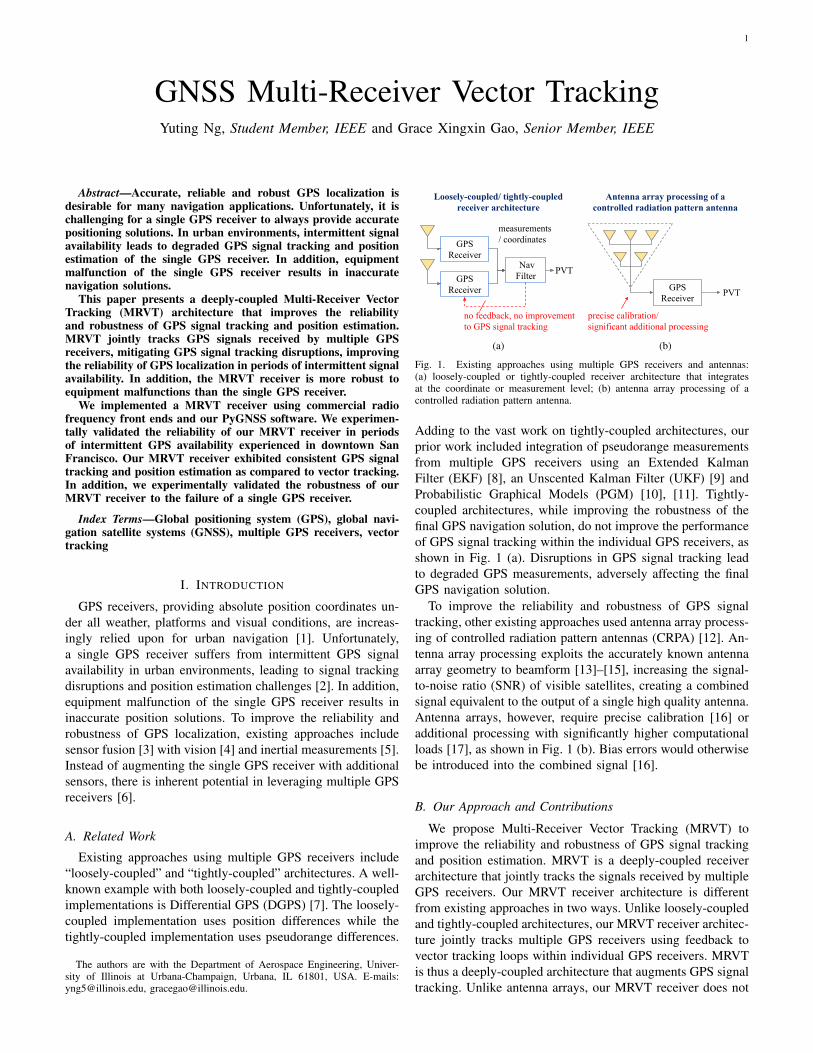
Fig. 1. Existing approaches using multiple GPS receivers and antennas:(a) loosely-coupled or tightly-coupled receiver architecture that integratesat the coordinate or measurement level; (b) antenna array processing of acontrolled radiation pattern antenna.
Adding to the vast work on tightly-coupled architectures, ourprior work included integration of pseudorange measurementsfrom multiple GPS receivers using an Extended KalmanFilter (EKF) [8], an Unscented Kalman Filter (UKF) [9] andProbabilistic Graphical Models (PGM) [10], [11]. Tightly-coupled architectures, while improving the robustness of thefinal GPS navigation solution, do not improve the performanceof GPS signal tracking within the individual GPS receivers, asshown in Fig. 1 (a). Disruptions in GPS signal tracking leadto degraded GPS measurements, adversely affecting the finalGPS navigation solution.
To improve the reliability and robustness of GPS signaltracking, other existing approaches used antenna array process-ing of controlled radiation pattern antennas (CRPA) [12]. An-tenna array processing exploits the accurately known antennaarray geometry to beamform [13]–[15], increasing the signal-to-noise ratio (SNR) of visible satellites, creating a combinedsignal equivalent to the output of a single high quality antenna.Antenna arrays, however, require precise calibration [16] oradditional processing with significantly higher computationalloads [17], as shown in Fig. 1 (b). Bias errors would otherwisebe introduced into the combined signal [16].
B. Our Approach and Contributions
We propose Multi-Receiver Vector Tracking (MRVT) toimprove the reliability and robustness of GPS signal trackingand position estimation. MRVT is a deeply-coupled receiverarchitecture that jointly tracks the signals received by multipleGPS receivers. Our MRVT receiver architecture is differentfrom existing approaches in two ways. Unlike loosely-coupledand tightly-coupled architectures, our MRVT receiver architec-ture jointly tracks multiple GPS receivers using feedback tovector tracking loops within individual GPS receivers. MRVTis thus a deeply-coupled architecture that augments GPS signaltracking. Unlike antenna arrays, our MRVT receiver does not
2
Multi-Receiver Vector Tracking (MRVT)deeply-coupled receiver architecture
GPS Receiver
GPS Receiver
fuse information from multiple GPS receivers
PVT
GPS Receiver
GPS Receiver feedback for
joint signal tracking
Nav Filter
Fig. 2. Our Multi-Receiver Vector Tracking (MRVT) architecture. Differentfrom loosely-coupled or tightly-coupled architectures, MRVT jointly trackssignals received by multiple GPS antennas. Unlike antenna arrays, MRVTdoes not require precise calibration nor significant additional processing.
require precise calibration nor significant additional process-ing. An illustration comparing MRVT to existing approachesis shown in Fig. 2.
Prior to this paper, our first iteration of MRVT [18] usedan average navigation solution from multiple GPS receiversas feedback. In addition, vector tracking within each GPSreceiver was implemented using an EKF with a constant ac-celeration motion model and a constant, heuristically specifiedprocess noise covariance. The coherent processing intervalwas 1 millisecond. Experiments were conducted in an open-sky environment, using 4 Universal Software Radio Periph-erals (USRPs), with timing signals split from 1 Chip ScaleAtomic Clock (CSAC).
Our second iteration of MRVT [19], [20] used a MinimumMean Square Error (MMSE) combination of navigation solu-tions as feedback. In addition, the EKF implementation withineach GPS receiver was improved with a time-varying processnoise covariance that addressed vehicle accelerations as pro-cess noise. The coherent processing interval was extended to20 milliseconds. Additional sub-sample time synchronizationwas implemented in our PyGNSS software receiver. Using theprevious experimental data, navigation solutions with reducednoise, increased reliability, and robustness was demonstrated.
In this paper, we improve upon previous iterations andcombine navigation solutions from multiple GPS receiversusing an EKF [21], [22]. Following navigation estimation inthe individual GPS receivers, we concatenate the states andstate error covariances from multiple GPS receivers into anoverall measurement input vector and an overall measurementnoise covariance input matrix for the overall EKF. We thenuse the state of the overall EKF as feedback to augmentvector tracking within the individual GPS receivers, closingthe overall MRVT loop.
We conducted further experiments using different equipmentconfigurations and different experiment scenarios to evaluateour MRVT receiver architecture. We defined reliability androbustness as key performance criteria:
• consistent and accurate GPS signal tracking and positionestimation in periods of intermittent signal availability,
GPS signals
TimeUpdate
EKF
PVT
GPS Receiver
Multi-Receiver Vector Tracking
TimeUpdate
Measurement Update
EKF
Measurement Update
Vector Tracking
Channel
Navigation Filter
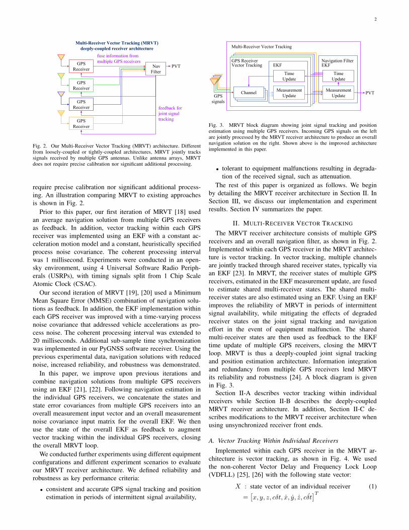
Fig. 3. MRVT block diagram showing joint signal tracking and positionestimation using multiple GPS receivers. Incoming GPS signals on the leftare jointly processed by the MRVT receiver architecture to produce an overallnavigation solution on the right. Shown above is the improved architectureimplemented in this paper.
• tolerant to equipment malfunctions resulting in degrada-tion of the received signal, such as attenuation.
The rest of this paper is organized as follows. We beginby detailing the MRVT receiver architecture in Section II. InSection III, we discuss our implementation and experimentresults. Section IV summarizes the paper.
II. MULTI-RECEIVER VECTOR TRACKING
The MRVT receiver architecture consists of multiple GPSreceivers and an overall navigation filter, as shown in Fig. 2.Implemented within each GPS receiver in the MRVT architec-ture is vector tracking. In vector tracking, multiple channelsare jointly tracked through shared receiver states, typically viaan EKF [23]. In MRVT, the receiver states of multiple GPSreceivers, estimated in the EKF measurement update, are fusedto estimate shared multi-receiver states. The shared multi-receiver states are also estimated using an EKF. Using an EKFimproves the reliability of MRVT in periods of intermittentsignal availability, while mitigating the effects of degradedreceiver states on the joint signal tracking and navigationeffort in the event of equipment malfunction. The sharedmulti-receiver states are then used as feedback to the EKFtime update of multiple GPS receivers, closing the MRVTloop. MRVT is thus a deeply-coupled joint signal trackingand position estimation architecture. Information integrationand redundancy from multiple GPS receivers lend MRVTits reliability and robustness [24]. A block diagram is givenin Fig. 3.
Section II-A describes vector tracking within individualreceivers while Section II-B describes the deeply-coupledMRVT receiver architecture. In addition, Section II-C de-scribes modifications to the MRVT receiver architecture whenusing unsynchronized receiver front ends.
A. Vector Tracking Within Individual ReceiversImplemented within each GPS receiver in the MRVT ar-
chitecture is vector tracking, as shown in Fig. 4. We usedthe non-coherent Vector Delay and Frequency Lock Loop(VDFLL) [25], [26] with the following state vector:
X : state vector of an individual receiver (1)
=[x, y, z, cδt, x, y, z, cδt
]T
3
Channel
GPS signal
TimeUpdate
LOS Projections
EKF
GPS Receiver
Measurement Update
Correlator
Code and Carrier Discriminators
Code and CarrierPhase Accumulations
PVT
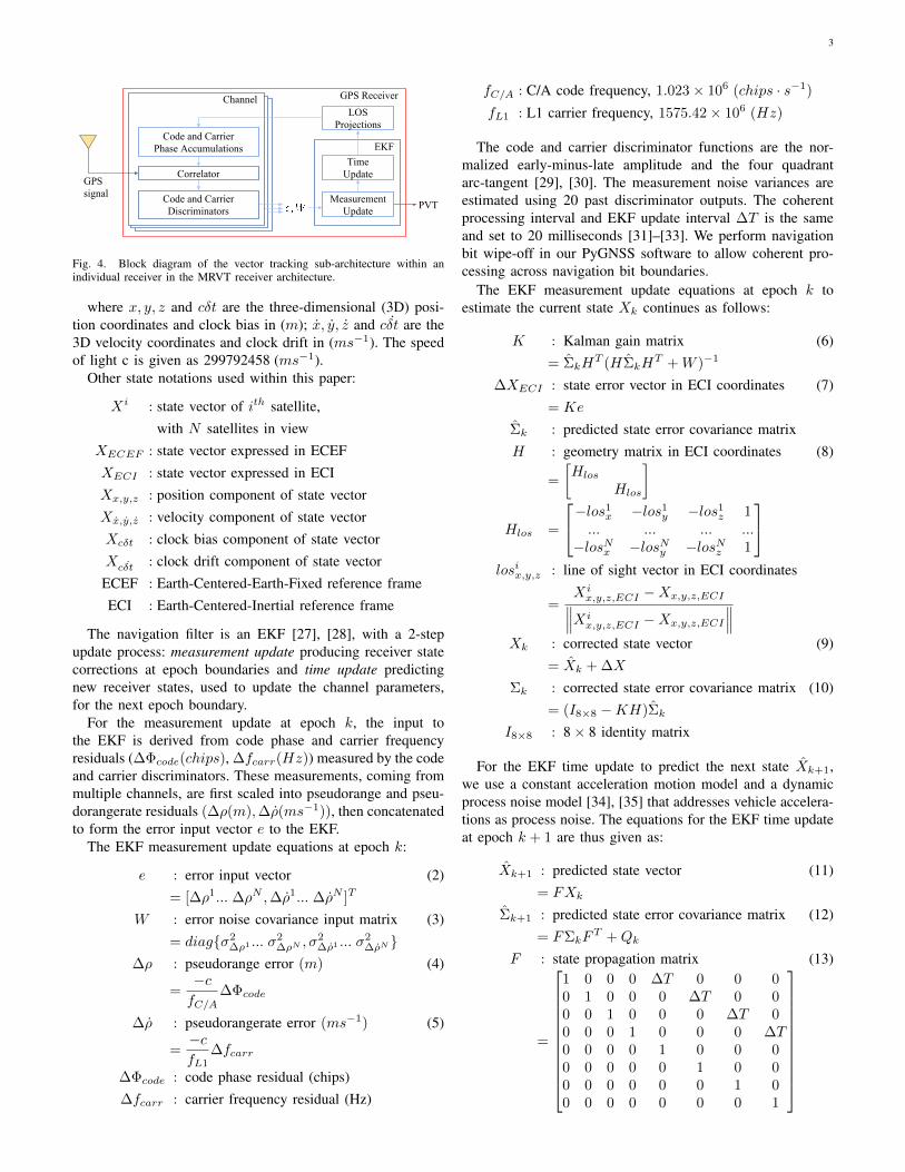
Fig. 4. Block diagram of the vector tracking sub-architecture within anindividual receiver in the MRVT receiver architecture.
where x, y, z and cδt are the three-dimensional (3D) posi-tion coordinates and clock bias in (m); x, y, z and cδt are the3D velocity coordinates and clock drift in (ms−1). The speedof light c is given as 299792458 (ms−1).
Other state notations used within this paper:
Xi : state vector of ith satellite,with N satellites in view
XECEF : state vector expressed in ECEFXECI : state vector expressed in ECIXx,y,z : position component of state vectorXx,y,z : velocity component of state vectorXcδt : clock bias component of state vectorXcδt : clock drift component of state vector
ECEF : Earth-Centered-Earth-Fixed reference frameECI : Earth-Centered-Inertial reference frame
The navigation filter is an EKF [27], [28], with a 2-stepupdate process: measurement update producing receiver statecorrections at epoch boundaries and time update predictingnew receiver states, used to update the channel parameters,for the next epoch boundary.
For the measurement update at epoch k, the input tothe EKF is derived from code phase and carrier frequencyresiduals (∆Φcode(chips), ∆fcarr(Hz)) measured by the codeand carrier discriminators. These measurements, coming frommultiple channels, are first scaled into pseudorange and pseu-dorangerate residuals (∆ρ(m),∆ρ(ms−1)), then concatenatedto form the error input vector e to the EKF.
The EKF measurement update equations at epoch k:
e : error input vector (2)= [∆ρ1... ∆ρN ,∆ρ1... ∆ρN ]T
W : error noise covariance input matrix (3)= diag{σ2
∆ρ1 ... σ2∆ρN , σ
2∆ρ1 ... σ
2∆ρN }
∆ρ : pseudorange error (m) (4)
=−cfC/A
∆Φcode
∆ρ : pseudorangerate error (ms−1) (5)
=−cfL1
∆fcarr
∆Φcode : code phase residual (chips)∆fcarr : carrier frequency residual (Hz)
fC/A : C/A code frequency, 1.023× 10⁶ (chips · s−1)
fL1 : L1 carrier frequency, 1575.42× 106 (Hz)
The code and carrier discriminator functions are the nor-malized early-minus-late amplitude and the four quadrantarc-tangent [29], [30]. The measurement noise variances areestimated using 20 past discriminator outputs. The coherentprocessing interval and EKF update interval ∆T is the sameand set to 20 milliseconds [31]–[33]. We perform navigationbit wipe-off in our PyGNSS software to allow coherent pro-cessing across navigation bit boundaries.
The EKF measurement update equations at epoch k toestimate the current state Xk continues as follows:
K : Kalman gain matrix (6)= ΣkH
T (HΣkHT +W )−1
∆XECI : state error vector in ECI coordinates (7)= Ke
Σk : predicted state error covariance matrixH : geometry matrix in ECI coordinates (8)
=
[Hlos
Hlos
]
Hlos =
−los1x −los1
y −los1z 1
... ... ... ...−losNx −losNy −losNz 1
losix,y,z : line of sight vector in ECI coordinates
=Xix,y,z,ECI −Xx,y,z,ECI∥∥∥Xix,y,z,ECI −Xx,y,z,ECI
∥∥∥Xk : corrected state vector (9)
= Xk + ∆X
Σk : corrected state error covariance matrix (10)= (I8×8 −KH)Σk
I8×8 : 8× 8 identity matrix
For the EKF time update to predict the next state Xk+1,we use a constant acceleration motion model and a dynamicprocess noise model [34], [35] that addresses vehicle accelera-tions as process noise. The equations for the EKF time updateat epoch k + 1 are thus given as:
Xk+1 : predicted state vector (11)= FXk
Σk+1 : predicted state error covariance matrix (12)= FΣkF
T +Qk
F : state propagation matrix (13)
=
1 0 0 0 ∆T 0 0 00 1 0 0 0 ∆T 0 00 0 1 0 0 0 ∆T 00 0 0 1 0 0 0 ∆T0 0 0 0 1 0 0 00 0 0 0 0 1 0 00 0 0 0 0 0 1 00 0 0 0 0 0 0 1
4
Qk : state process noise covariance matrix (14)
= F
0 0 0 0 0 0 0 00 0 0 0 0 0 0 00 0 0 0 0 0 0 00 0 0 0 0 0 0 00 0 0 0 σ2
xk0 0 0
0 0 0 0 0 σ2yk
0 00 0 0 0 0 0 σ2
zk0
0 0 0 0 0 0 0 σ2cδt
FT
where the process noise due to vehicle accelerations in thex, y and z directions are assumed to be the same and predictedusing a saturation function [36] as:
σ2xk
: process noise due to vehicle accelerations (15)in a constant acceleration motion model
= 1 + 250/(min(max(||Xx,y,z||2, 52), 252))
The above process noise function is small when thereceiver’s speed is large and large when the receiver’s speedis small, capturing the intuition that it is more difficult fora vehicle’s velocity to change when its speed is large ascompared to when its speed is small. The coefficients weredetermined from a least squares fit to acceleration time dataof a generic vehicle by [36].
The process noise of the front end oscillator is calculatedfrom the Allan deviation as:
σ2cδt
: process noise of front end oscillator
= (c · στ )2
στ : Allan deviation of front end oscillator
The Allan deviation στ of a front end oscillator is a measureof frequency stability [37], [38]. It can be estimated from pastnavigation solutions and also obtained from the manufacturer’sdatasheet, such as [39]. The predicted state error covariancematrix Σ is initialized using 20 past state vectors.
The equations for the frequency and phase updates, withinthe individual channels, after the EKF time update:
f icarr,k : corrected carrier frequency (16)
of the ith satellite= fIF + f idcarr,k
fIF : intermediate frequency (IF), (Hz)f idcarr,k : corrected carrier doppler frequency (17)
of the ith satellite
=−fL1
c(−losix,y,z · (Xx,y,z,ECI
−Xix,y,z,ECI) + (Xcδt −X
icδt
))
f icode,k : corrected code frequency of the ith satellite (18)
= fC/A +1
∆T(Φicode,k − Φicode,k)
+fC/A
fL1× f idcarr,k
Φicode,k : corrected code phase of the ith satellite (19)
=−fC/Ac
(∥∥Xx,y,z,ECI −Xi
x,y,z,ECI
∥∥+(Xcδt −Xi
cδt))
Φicode,k+1 : predicted code phase of the ith satellite (20)
= Φicode,k + f icode,k∆T
Φicarr,k+1 : predicted carrier phase of the ith satellite (21)
= Φicarr,k + f icarr,k∆T
B. Deeply-Coupled MRVT Architecture
In MRVT, the state vector X of multiple receivers are jointlytracked through the shared multi-receiver state vector Xm.
Xm : multi-receiver state vector (22)
=[x, y, z, cδt, x, y, z, cδt
]Twhere Xm contains the shared position and velocity refer-
enced to the geometric center of the multi-receiver configura-tion and the shared clock bias and clock drift referenced to asingle front end oscillator.
The MRVT update process is described as follows, withthe superscripts “−” and “+” differentiating between theindividual receiver states before and after the MRVT update.The individual receiver EKF measurement update is firstperformed to obtain the individual receiver corrections to thestate vectors and error noise covariance matrixes. X− areconcatenated to form the multi-receiver error input vector em;Σ− are concatenated to form the multi-receiver error noisecovariance input matrix Wm. We then perform the MRVTEKF measurement update. The updated joint multi-receiverstate vector Xm is used as feedback, replacing the individualreceiver state vectors with a more robust estimate X+. TheMRVT EKF time update is subsequently performed togetherwith the EKF time update of the individual receivers.
The MRVT EKF measurement update equations for Mreceivers are given as:
X−j,k : state vector of jth receiver
X+j,k : MRVT augmented (23)
state vector of jth receiver= Xm,k
em : multi-receiver error input vector (24)
=
X−
1,k − Xm,k
X−2,k − Xm,k
...
X−M,k − Xm,k
Wm : multi-receiver (25)
: error noise covariance input matrix= diag{Σ1,k,Σ2,k, ...,ΣM,k}
Km : multi-receiver Kalman gain matrix (26)= Σm,kH
Tm(HmΣm,kH
Tm +Wm)−1
Hm : multi-receiver geometry matrix (27)
=
H1
H2
...HM
5
Hj : geometry matrix element (28)= I8×8
∆Xm,k : multi-receiver state error vector (29)= Kmem
Xm,k : corrected multi-receiver state vector (30)
= Xm,k + ∆Xm,k
Σm,k : corrected multi-receiver (31): state error covariance matrix= (I8 −KmHm)Σm,k
The predicted multi-receiver state error covariance matrixΣm is initialized using past multi-receiver state vectors X−1,...
calculated using weighted least squares. The MRVT EKF timeupdate is performed together with the EKF time update of theindividual receivers. The equations are the same and given inEq. (11) to Eq. (15).
Through MRVT, shared multi-receiver states jointly trackthe states of multiple receivers which jointly track the statesof multiple channels, achieving deeply coupled multi-receiversignal tracking. Joint tracking increases signal availabilitywhile leveraging information redundancy for robustness. Thisis possible for multiple receivers installed in close proximity,on a rigid body and sharing the same front end oscillator [6],[24]. Section II-C describes modifications to the MRVT archi-tecture for unsynchronized front ends.
C. Modifications for Unsynchronized Front Ends
For the case of unsynchronized front ends, additional clockbias and clock drift states are appended to Xm.
Xm =[x, y, z, cδt1, x, y, z, cδt1, cδt2, cδt2,
]TThe rest of the MRVT equations are updated accordingly:
em =
[X−
1,k − Xm,x,y,z,cδt1,x,y,z,cδt1,k
X−2,k − Xm,x,y,z,cδt2,x,y,z,cδt2,k
]
Wm =
[Σ1,k
Σ2,k
]Hm =
[H1
H2
]
H1 =
1 0 0 0 0 0 0 0 0 00 1 0 0 0 0 0 0 0 00 0 1 0 0 0 0 0 0 00 0 0 1 0 0 0 0 0 00 0 0 0 1 0 0 0 0 00 0 0 0 0 1 0 0 0 00 0 0 0 0 0 1 0 0 00 0 0 0 0 0 0 1 0 0
H2 =
1 0 0 0 0 0 0 0 0 00 1 0 0 0 0 0 0 0 00 0 1 0 0 0 0 0 0 00 0 0 0 0 0 0 0 1 00 0 0 0 1 0 0 0 0 00 0 0 0 0 1 0 0 0 00 0 0 0 0 0 1 0 0 00 0 0 0 0 0 0 0 0 1
X+1,k = Xm,x,y,z,cδt1,x,y,z,cδt1,k
X+2,k = Xm,x,y,z,cδt2,x,y,z,cδt2,k
The MRVT EKF time update equations are also modified:
Xm,k+1 : predicted multi-receiver state vector= FmXm,k
Σm,k+1 : predicted multi-receiverstate error covariance matrix
= FmΣm,kFTm +Qm,k
Fm : multi-receiver state propagation matrix
=
1 0 0 0 ∆T 0 0 0 0 00 1 0 0 0 ∆T 0 0 0 00 0 1 0 0 0 ∆T 0 0 00 0 0 1 0 0 0 ∆T 0 00 0 0 0 1 0 0 0 0 00 0 0 0 0 1 0 0 0 00 0 0 0 0 0 1 0 0 00 0 0 0 0 0 0 1 0 00 0 0 0 0 0 0 0 1 ∆T0 0 0 0 0 0 0 0 0 1
Qm,k : multi-receiver
state process noise covariance matrix
Fm
0 0 0 0 0 0 0 0 0 00 0 0 0 0 0 0 0 0 00 0 0 0 0 0 0 0 0 00 0 0 0 0 0 0 0 0 00 0 0 0 σ2
xk0 0 0 0 0
0 0 0 0 0 σ2yk
0 0 0 00 0 0 0 0 0 σ2
zk0 0 0
0 0 0 0 0 0 0 σ2c ˙δt1
0 0
0 0 0 0 0 0 0 0 0 00 0 0 0 0 0 0 0 0 σ2
c ˙δt2
FTm
σ2c ˙δtj
: process noise of jth front end oscillator
III. IMPLEMENTATION AND EXPERIMENT RESULTS
We implemented 3 different MRVT receiver configurationsand conducted 3 different experiments to evaluate the perfor-mance of our MRVT receiver architecture.
Section III-A describes an experiment in downtown SanFrancisco using 2 unsynchronized radio frequency (RF) frontends with lower RF sensitivity and lower oscillator stability.This experiment validates the reliability of our MRVT receiverarchitecture in periods of intermittent signal availability whileusing only 2 GPS receivers. The total cost of this setuppurchased in the year 2015 is approximately $630.
Section III-B describes an experiment in our University ofIllinois at Urbana-Champaign campus using 4 synchronizedRF front ends with higher RF sensitivity and higher oscillatorstability. This experiment validates the reliability of our MRVTreceiver architecture in periods of limited signal availabilitywhile using more GPS receivers, and of higher quality. Thetotal cost of this setup purchased in the year 2014 is approx-imately $12000.
6
TABLE IEXPERIMENT SETUPS
Experiment A. Urban Environmentwith 2 Receivers
B. Suburban Environmentwith 4 Receivers
C. Equipment Malfunction(1 of 2 Receivers Malfunctioning)
Location Downtown San Francisco University of Illinoisat Urbana-Champaign
University of Illinoisat Urbana-Champaign
Number of receivers 2 4 2RF front end SiGe GN3S Sampler v3 USRP N210 USRP N210Sampling frequency 2.046 MHz 2 MHz 5 MHzSampling precision 2-bit 14-bit 14-bitBandwidth 2.2 MHz 8 MHz 8 MHzOscillator TCXO CSAC CSACOscillator frequency 16.368 MHz 10 MHz 10 MHzPhase noise − 80 dBc/Hz − 50 dBc/Hz − 50 dBc/HzFrequency bias ± 100 Hz ± 0.005 Hz ± 0.005 HzAllan deviation 1.0× 10⁻⁸s · s−1 2.5× 10⁻¹⁰s · s−1 2.5× 10⁻¹⁰s · s−1
Synchronized No Splitter MIMO cable
Remarks • validate reliability in periods ofintermittent signal availability
• lower RF sensitivity• lower oscillator stability• unsynchronized oscillators
• validate reliability• more receivers in architecture• higher RF sensitivity• higher oscillator stability• synchronized oscillators
• validate robustness toequipment malfunction
• higher RF sensitivity• higher oscillator stability• synchronized oscillators
Section III-C describes an experiment using 2 synchronizedGPS receivers where we physically loosened the antennaconnection of 1 GPS receiver, resulting in an SNR degradationof 15 dB per channel for that GPS receiver. This experimentvalidates the robustness of our MRVT receiver to equipmentmalfunctions of a single GPS receiver.
Table I provides an overview of the 3 experiment setups.
A. Experiment in Urban Environment With 2 GPS Receivers
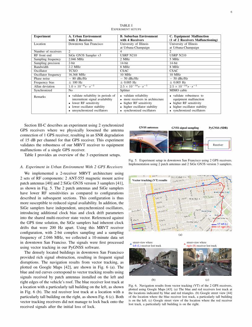
We implemented a 2-receiver MRVT architecture using2 sets of RF components: 2 ANT-555 magnetic mount activepatch antennas [40] and 2 SiGe GN3S version 3 samplers [41],as shown in Fig. 5. The 2 patch antennas and SiGe samplershave lower RF sensitivities as compared to configurationsdescribed in subsequent sections. This configuration is thusmore susceptible to reduced signal availability. In addition, theSiGe samplers have independent, unsynchronized oscillators,introducing additional clock bias and clock drift parametersinto the shared multi-receiver state vector. Referenced againstthe GPS time solution, the SiGe samplers had inherent clockdrifts that were 200 Hz apart. Using this MRVT receiverconfiguration, with 2-bit complex sampling and a samplingfrequency of 2.046 MHz, we collected a 10-minute data setin downtown San Franciso. The signals were first processedusing vector tracking in our PyGNSS software.
The densely located buildings in downtown San Franciscoprovided rich signal obstruction, resulting in frequent signaldisruptions. The navigation results from vector tracking, asplotted on Google Maps [42], are shown in Fig. 6 (a). Theblue and red curves correspond to vector tracking results usingsignals received by patch antennas installed on the left andright edges of the vehicle’s roof. The blue receiver lost track ata location with a particularly tall building on the left, as shownin Fig. 6 (b). The red receiver lost track at a location with aparticularly tall building on the right, as shown Fig. 6 (c). Bothvector tracking receivers did not manage to lock back onto thereceived signals after the initial loss of lock.
Fig. 5. Experiment setup in downtown San Francisco using 2 GPS receivers.Implementation using 2 patch antennas and 2 SiGe GN3S version 3 samplers.
Vector tracking (VT) results
VT left (L)VT right (R)
(a)
street-view where left (L) receiver lost track
(b)
street-view where right (R) receiver lost track
(c)
Fig. 6. Navigation results from vector tracking (VT) of the 2 GPS receivers,plotted using Google Maps [43]. (a) The blue and red receivers lost track atthe locations indicated by blue and red triangles. (b) Google street view [44]of the location where the blue receiver lost track, a particularly tall buildingis on the left. (c) Google street view of the location where the red receiverlost track, a particularly tall building is on the right.
7
(a)
(b)
(c)
(d)
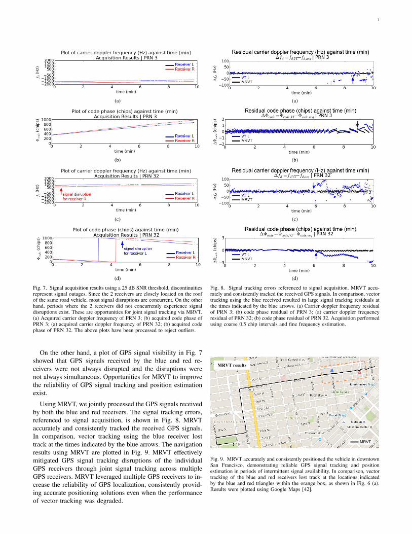
Fig. 7. Signal acquisition results using a 25 dB SNR threshold, discontinuitiesrepresent signal outages. Since the 2 receivers are closely located on the roofof the same road vehicle, most signal disruptions are concurrent. On the otherhand, periods where the 2 receivers did not concurrently experience signaldisruptions exist. These are opportunities for joint signal tracking via MRVT.(a) Acquired carrier doppler frequency of PRN 3; (b) acquired code phase ofPRN 3; (a) acquired carrier doppler frequency of PRN 32; (b) acquired codephase of PRN 32. The above plots have been processed to reject outliers.
On the other hand, a plot of GPS signal visibility in Fig. 7showed that GPS signals received by the blue and red re-ceivers were not always disrupted and the disruptions werenot always simultaneous. Opportunities for MRVT to improvethe reliability of GPS signal tracking and position estimationexist.
Using MRVT, we jointly processed the GPS signals receivedby both the blue and red receivers. The signal tracking errors,referenced to signal acquisition, is shown in Fig. 8. MRVTaccurately and consistently tracked the received GPS signals.In comparison, vector tracking using the blue receiver losttrack at the times indicated by the blue arrows. The navigationresults using MRVT are plotted in Fig. 9. MRVT effectivelymitigated GPS signal tracking disruptions of the individualGPS receivers through joint signal tracking across multipleGPS receivers. MRVT leveraged multiple GPS receivers to in-crease the reliability of GPS localization, consistently provid-ing accurate positioning solutions even when the performanceof vector tracking was degraded.
(a)
(b)
(c)
(d)
Fig. 8. Signal tracking errors referenced to signal acquisition. MRVT accu-rately and consistently tracked the received GPS signals. In comparison, vectortracking using the blue received resulted in large signal tracking residuals atthe times indicated by the blue arrows. (a) Carrier doppler frequency residualof PRN 3; (b) code phase residual of PRN 3; (a) carrier doppler frequencyresidual of PRN 32; (b) code phase residual of PRN 32. Acquisition performedusing coarse 0.5 chip intervals and fine frequency estimation.
MRVT
MRVT results
Fig. 9. MRVT accurately and consistently positioned the vehicle in downtownSan Francisco, demonstrating reliable GPS signal tracking and positionestimation in periods of intermittent signal availability. In comparison, vectortracking of the blue and red receivers lost track at the locations indicatedby the blue and red triangles within the orange box, as shown in Fig. 6 (a).Results were plotted using Google Maps [42].
8
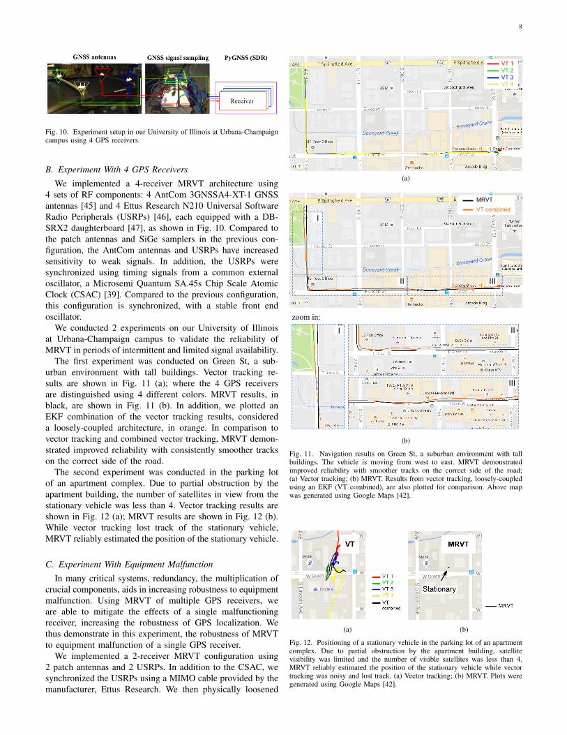
Fig. 10. Experiment setup in our University of Illinois at Urbana-Champaigncampus using 4 GPS receivers.
B. Experiment With 4 GPS Receivers
We implemented a 4-receiver MRVT architecture using4 sets of RF components: 4 AntCom 3GNSSA4-XT-1 GNSSantennas [45] and 4 Ettus Research N210 Universal SoftwareRadio Peripherals (USRPs) [46], each equipped with a DB-SRX2 daughterboard [47], as shown in Fig. 10. Compared tothe patch antennas and SiGe samplers in the previous con-figuration, the AntCom antennas and USRPs have increasedsensitivity to weak signals. In addition, the USRPs weresynchronized using timing signals from a common externaloscillator, a Microsemi Quantum SA.45s Chip Scale AtomicClock (CSAC) [39]. Compared to the previous configuration,this configuration is synchronized, with a stable front endoscillator.
We conducted 2 experiments on our University of Illinoisat Urbana-Champaign campus to validate the reliability ofMRVT in periods of intermittent and limited signal availability.
The first experiment was conducted on Green St, a sub-urban environment with tall buildings. Vector tracking re-sults are shown in Fig. 11 (a); where the 4 GPS receiversare distinguished using 4 different colors. MRVT results, inblack, are shown in Fig. 11 (b). In addition, we plotted anEKF combination of the vector tracking results, considereda loosely-coupled architecture, in orange. In comparison tovector tracking and combined vector tracking, MRVT demon-strated improved reliability with consistently smoother trackson the correct side of the road.
The second experiment was conducted in the parking lotof an apartment complex. Due to partial obstruction by theapartment building, the number of satellites in view from thestationary vehicle was less than 4. Vector tracking results areshown in Fig. 12 (a); MRVT results are shown in Fig. 12 (b).While vector tracking lost track of the stationary vehicle,MRVT reliably estimated the position of the stationary vehicle.
C. Experiment With Equipment Malfunction
In many critical systems, redundancy, the multiplication ofcrucial components, aids in increasing robustness to equipmentmalfunction. Using MRVT of multiple GPS receivers, weare able to mitigate the effects of a single malfunctioningreceiver, increasing the robustness of GPS localization. Wethus demonstrate in this experiment, the robustness of MRVTto equipment malfunction of a single GPS receiver.
We implemented a 2-receiver MRVT configuration using2 patch antennas and 2 USRPs. In addition to the CSAC, wesynchronized the USRPs using a MIMO cable provided by themanufacturer, Ettus Research. We then physically loosened
VT 1VT 2VT 3VT 4
(a)
I
II III
MRVT
VT combined
I II
III
zoom in:
(b)
Fig. 11. Navigation results on Green St, a suburban environment with tallbuildings. The vehicle is moving from west to east. MRVT demonstratedimproved reliability with smoother tracks on the correct side of the road;(a) Vector tracking; (b) MRVT. Results from vector tracking, loosely-coupledusing an EKF (VT combined), are also plotted for comparison. Above mapwas generated using Google Maps [42].
(a) (b)
Fig. 12. Positioning of a stationary vehicle in the parking lot of an apartmentcomplex. Due to partial obstruction by the apartment building, satellitevisibility was limited and the number of visible satellites was less than 4.MRVT reliably estimated the position of the stationary vehicle while vectortracking was noisy and lost track. (a) Vector tracking; (b) MRVT. Plots weregenerated using Google Maps [42].
9
(a)
(b) (c)
VT strong signalVT weak signal
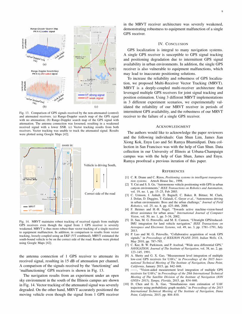
Fig. 13. Comparison of GPS signals received by the non-attenuated (control)and attenuated receivers. (a) Range-Doppler search map of the GPS signalwith no attenuation; (b) Range-Doppler search map of the GPS signal withattenuation. The antenna connection was loosened, resulting in a weakenedreceived signal with a lower SNR. (c) Vector tracking results from bothreceivers. Vector tracking was unable to track the attenuated signal. Resultswere plotted using Google Maps [42].
zoom in:
MRVT
VT combined
Vehicle is driving South,
Correct side of the road
Fig. 14. MRVT maintains robust tracking of received signals from multipleGPS receivers even though the signal from 1 GPS receiver is severelyweakened. MRVT is thus more robust than vector tracking of a single receiverto equipment malfunction. In addition, in comparison to results from vectortracking, loosely-coupled using an EKF (VT combined), MRVT estimated thesouth-bound vehicle to be on the correct side of the road. Results were plottedusing Google Maps [42].
the antenna connection of 1 GPS receiver to attenuate itsreceived signal, resulting in 15 dB of attenuation per channel.A comparison of the signals received by the ‘functioning’ and‘malfunctioning’ GPS receivers is shown in Fig. 13.
The navigation results from an experiment under an opensky environment in the south of the Illinois campus are shownin Fig. 14. Vector tracking of the attenuated signal was severelydegraded. On the other hand, MRVT accurately positioned themoving vehicle even though the signal from 1 GPS receiver
in the MRVT receiver architecture was severely weakened,demonstrating robustness to equipment malfunction of a singleGPS receiver.
IV. CONCLUSION
GPS localization is integral to many navigation systems.A single GPS receiver is susceptible to GPS signal trackingand positioning degradation due to intermittent GPS signalavailability in urban environments. In addition, the single GPSreceiver is also vulnerable to equipment malfunctions, whichmay lead to inaccurate positioning solutions.
To increase the reliability and robustness of GPS localiza-tion, we proposed Multi-Receiver Vector Tracking (MRVT).MRVT is a deeply-coupled multi-receiver architecture thatleveraged multiple GPS receivers for joint signal tracking andposition estimation. Using 3 different MRVT implementationsin 3 different experiment scenarios, we experimentally val-idated the reliability of our MRVT receiver in periods ofintermittent GPS availability, and the robustness of our MRVTreceiver to the failure of a single GPS receiver.
ACKNOWLEDGMENT
The authors would like to acknowledge the paper reviewersand the following individuals: Gan Shun Lim, James JianXiong Kok, Enyu Luo and Sri Ramya Bhamidipati. Data col-lection in San Francisco was with the help of Gan Shun. Datacollection in our University of Illinois at Urbana-Champaigncampus was with the help of Gan Shun, James and Enyu.Ramya proofread a previous iteration of this paper.
REFERENCES
[1] C. R. Drane and C. Rizos, Positioning systems in intelligent transporta-tion systems. Artech House Inc., 1998.
[2] Y. Cui and S. S. Ge, “Autonomous vehicle positioning with GPS in urbancanyon environments,” IEEE Transactions on Robotics and Automation,vol. 19, no. 1, pp. 15–25, Feb 2003.
[3] C. Urmson, J. Anhalt, D. Bagnell, C. Baker, R. Bittner, M. Clark,J. Dolan, D. Duggins, T. Galatali, C. Geyer et al., “Autonomous drivingin urban environments: Boss and the urban challenge,” Journal of FieldRobotics, vol. 25, no. 8, pp. 425–466, 2008.
[4] F. Heimes and H.-H. Nagel, “Towards active machine-vision-baseddriver assistance for urban areas,” International Journal of ComputerVision, vol. 50, no. 1, pp. 5–34, 2002.
[5] D. Sun, M. G. Petovello, and M. E. Cannon, “Ultratight GPS/reduced-IMU integration for land vehicle navigation,” IEEE Transactions onAerospace and Electronic Systems, vol. 49, no. 3, pp. 1781–1791, July2013.
[6] P. Luo and M. G. Petovello, “Collaborative acquisition of weak GPSsignals,” in Proceedings of IEEE/ION PLANS 2010, Indian Wells, CA,May 2010, pp. 787–795.
[7] C. Kee, B. W. Parkinson, and P. Axelrad, “Wide area differential GPS,”NAVIGATION, Journal of The Institute of Navigation, vol. 38, no. 2, pp.123–145, 1991.
[8] A. Shetty and G. X. Gao, “Measurement level integration of multiplelow-cost GPS receivers for UAVs,” in Proceedings of the 2015 Inter-national Technical Meeting of The Institute of Navigation, Dana Point,California, January 2015, pp. 842–848.
[9] ——, “Vision-aided measurement level integration of multiple GPSreceivers for UAVs,” in Proceedings of the 28th International TechnicalMeeting of The Satellite Division of the Institute of Navigation (IONGNSS+ 2015), Tampa, Florida, 2015, pp. 834–840.
[10] D. Chen and G. X. Gao, “Simultaneous state estimation of UAVtrajectory using probabilistic graph models,” in Proceedings of the 2015International Technical Meeting of The Institute of Navigation, DanaPoint, California, 2015, pp. 804–810.
10
[11] ——, “Robust MAV state estimation using an M-Estimator augmentedsensor fusion graphs,” in Proceedings of the 28th International TechnicalMeeting of The Satellite Division of the Institute of Navigation (IONGNSS+ 2015), Tampa, Florida, 2015, pp. 841–848.
[12] I. S. Reed, J. D. Mallett, and L. E. Brennan, “Rapid convergence ratein adaptive arrays,” IEEE Transactions on Aerospace and ElectronicSystems, vol. AES-10, no. 6, pp. 853–863, Nov 1974.
[13] J. K. Ray, M. E. Cannon, and P. Fenton, “GPS code and carriermultipath mitigation using a multiantenna system,” IEEE Transactionson Aerospace and Electronic Systems, vol. 37, no. 1, pp. 183–195, Jan2001.
[14] C. C. Counselman, “Multipath-rejecting GPS antennas,” Proceedings ofthe IEEE, vol. 87, no. 1, pp. 86–91, Jan 1999.
[15] A. Brown and N. Gerein, “Test results of a digital beamformingGPS receiver in a jamming environment,” in Proceedings of the 14thInternational Technical Meeting of the Satellite Division of The Instituteof Navigation (ION GPS 2001), Salt Lake City, UT. ION, 2001, pp.894–903.
[16] A. J. OBrien and I. J. Gupta, “Mitigation of adaptive antenna inducedbias errors in GNSS receivers,” IEEE Transactions on Aerospace andElectronic Systems, vol. 47, no. 1, pp. 524–538, January 2011.
[17] Y.-H. Chen, J.-C. Juang, J. Seo, S. Lo, D. M. Akos, D. S. De Lorenzo,and P. Enge, “Design and implementation of real-time software radiofor anti-interference GPS/WAAS sensors,” Sensors, vol. 12, no. 10, pp.13 417–13 440, 2012.
[18] Y. Ng and G. X. Gao, “Multi-receiver vector tracking based on a Pythonplatform,” in Proceedings of the 2015 International Technical Meeting ofThe Institute of Navigation, Dana Point, California, 2015, pp. 633–639.
[19] ——, “Advanced multi-receiver vector tracking for positioning a landvehicle,” in Proceedings of the 28th International Technical Meeting ofThe Satellite Division of the Institute of Navigation (ION GNSS+ 2015),Tampa, FL, 2015, pp. 3148–3155.
[20] ——, “Advanced multi-receiver position-information-aided vector track-ing for robust GPS time transfer to PMUs,” in Proceedings of the 28thInternational Technical Meeting of The Satellite Division of the Instituteof Navigation (ION GNSS+ 2015), Tampa, FL, 2015, pp. 3443–3448.
[21] Q. Gan and C. J. Harris, “Comparison of two measurement fusion meth-ods for Kalman-filter-based multisensor data fusion,” IEEE Transactionson Aerospace and Electronic Systems, vol. 37, no. 1, pp. 273–279, Jan2001.
[22] H. Qi and J. B. Moore, “Direct Kalman filtering approach for GPS/INSintegration,” IEEE Transactions on Aerospace and Electronic Systems,vol. 38, no. 2, pp. 687–693, Apr 2002.
[23] J. J. Spilker and B. W. Parkinson, Progress in Astronautics and Aero-nautics: Global Positioning System. American Institute of Aeronauticsand Astronautics, 1996, ch. Fundamentals of signal tracking theory, pp.245–328.
[24] I. Klein, I. Rusnak, and Y. Bar-Shalom, “A joint filter for formationtracking,” IEEE Transactions on Aerospace and Electronic Systems,vol. 51, no. 4, pp. 3456–3460, Oct 2015.
[25] S. Bhattacharyya, “Performance and integrity analysis of the vectortracking architecture of GNSS receivers,” Ph.D. dissertation, Universityof Minnesota, 2012.
[26] J. J. Brewer, “The differential vector phase-locked loop for globalnavigation satellite system signal tracking,” Ph.D. dissertation, Air ForceInstitute of Technology, 2014.
[27] R. E. Kalman et al., “Contributions to the theory of optimal control,”Bol. Soc. Mat. Mexicana, vol. 5, no. 2, pp. 102–119, 1960.
[28] R. E. Kalman, “A new approach to linear filtering and predictionproblems,” Journal of Basic Engineering, vol. 82, no. 1, pp. 35–45,1960.
[29] P. W. Ward, J. W. Betz, and C. J. Hegarty, Understanding GPS:Principles and Applications Second Edition. Artech House, Boston,2006, ch. Satellite signal acquisition, tracking, and data demodulation,pp. 153–240.
[30] P. Misra and P. Enge, Global Positioning System: Signals, Measurementsand Performance Second Edition. Lincoln, MA: Ganga-Jamuna Press,2006.
[31] P. W. Ward, “Performance comparisons between FLL, PLL and anovel FLL-assisted-PLL carrier tracking loop under RF interferenceconditions,” in Proceedings of the 11th International Technical Meetingof the Satellite Division of The Institute of Navigation (ION GPS 1998),Nashville, TN, 1998, pp. 783–795.
[32] P. W. Ward and T. D. Fuchser, “Stability criteria for GNSS receivertracking loops,” NAVIGATION, Journal of The Institute of Navigation,vol. 61, no. 4, pp. 293–309, 2014.
[33] C. O’Driscoll, M. G. Petovello, and G. Lachapelle, “Choosing thecoherent integration time for Kalman filter-based carrier-phase trackingof GNSS signals,” GPS solutions, vol. 15, no. 4, pp. 345–356, 2011.
[34] F. D. Busse, J. P. How, and J. Simpson, “Demonstration of adaptiveextended Kalman filter for low-earth-orbit formation estimation usingCDGPS,” NAVIGATION, Journal of The Institute of Navigation, vol. 50,no. 2, pp. 79–93, 2003.
[35] D. Simon and T. L. Chia, “Kalman filtering with state equality con-straints,” IEEE Transactions on Aerospace and Electronic Systems,vol. 38, no. 1, pp. 128–136, Jan 2002.
[36] Mathworks. (2015, jun) State estimation us-ing time-varying kalman filter. [Online]. Avail-able: http://www.mathworks.com/help/control/getstart/estimating-states-of-time-varying-systems-using-kalman-filters.html
[37] D. W. Allan, “Statistics of atomic frequency standards,” Proceedings ofthe IEEE, vol. 54, no. 2, pp. 221–230, Feb 1966.
[38] J. Rutman and F. L. Walls, “Characterization of frequency stability inprecision frequency sources,” Proceedings of the IEEE, vol. 79, no. 7,pp. 952–960, Jul 1991.
[39] Microsemi Corporation. (2012, jun) Quantum SA.45s chip scaleatomic clock (CSAC). [Online]. Available: http://www.microsemi.com/document-portal/doc download/133305-quantum-sa-45s-csac
[40] On Shine Enterprise Co. Ltd. (2012, jun) ON SHINE G.P.S.antenna ANT-555. [Online]. Available: http://www.onshine.com.tw//www/ANT555-2010.pdf
[41] K. Borre, D. M. Akos, N. Bertelsen, P. Rinder, and S. H. Jensen,A software-defined GPS and Galileo receiver: a single-frequency ap-proach. Springer Science & Business Media, 2007.
[42] Google Inc. (2016, jan) Google Maps. [Online]. Available: https://www.google.com/maps/
[43] Google Developers. (2016, jan) Google Maps Javascript API.[Online]. Available: https://developers.google.com/maps/documentation/javascript/
[44] ——. (2016, jan) Google Street View Image API. [Online]. Available:https://developers.google.com/maps/documentation/streetview/
[45] Antcom Corporation. (2014, jun) 3.5in dia. GNSS antenna for globalnavigation satellite systems (GNSS) applications P/N: 3GNSSA4-XT-1(front/back fixed mount). [Online]. Available: http://www.antcom.com/documents/catalogs/Page/3GNSSA4-XT-1 GNSSAntennas1.pdf
[46] Ettus Research. (2012, jun) USRP N200/N210 networked series.[Online]. Available: https://www.ettus.com/content/files/07495 EttusN200-210 DS Flyer HR 1.pdf
[47] ——. (2012, jun) DBSRX2 800-2300 MHz Rx. [Online]. Available:http://www.ettus.com/product/details/DBSRX2
Yuting Ng received her B.S. degree in electricalengineering and her M.S. degree in aerospace en-gineering from the University of Illinois at Urbana-Champaign, Illinois, USA in 2014 and 2016. Herresearch interests are in machine learning, radarsignal processing, GNSS signal tracking, navigationand time synchronization.
Grace Xingxin Gao received her B.S. degree inmechanical engineering and her M.S. degree in elec-trical engineering from Tsinghua University, Bei-jing, China in 2001 and 2003. She received herPhD degree in electrical engineering from StanfordUniversity in 2008. From 2008 to 2012, she wasa research associate at Stanford University. Since2012, she has been an assistant professor in theAerospace Engineering Department at University ofIllinois at Urbana-Champaign. Her research interestsare systems, signals, control, and robotics. She is a
senior member of IEEE and a member of ION.