Embed Size (px)
Citation preview
Page 1 of 82 Effective from 26.8.2015 Spec No.TI/SPC/OHE/8WDETC/0092
SPECIFICATION NO.TI/SPC/OHE/8WDETC/0092
GOVERNMENT OF INDIA MINISTRY OF RAILWAYS
TECHNICAL SPECIFICATION FOR
8-WHEELER DIESEL ELECTRIC INSPECTION &
MAINTENANCE OHE CAR UNDERSLUNG TYPE FOR
OPERATION ON BROAD GAUGE (1676 mm)
(August’ 2015)
Issued by
RESEARCH DESIGNS & STANDARDS ORGANISATION
MANAK NAGAR, LUCKNOW-226011
(For Official use only)
Page 2 of 82 Effective from 26.8.2015 Spec No.TI/SPC/OHE/8WDETC/0092
SPECIFICATION NO.TI/SPC/OHE/8WDETC/0092
Amendment
Number
Date of
Amendment
Total pages
including annexure
Amendment/Revision
0 NA First issue
Nil 02.05.2012 87 Revision-1
Nil 21.08.2015 82 Revision-2
PREPARED BY CHECKED BY APPROVED BY
SIGNATURE
DATE
DESIGNATION SSE/TW Dy. Director/TI EDTI
COPY NUMBER
ISSUED BY ……………. SIGNATURE…….. DATE……………
ISSUED TO ………………………………………………………………
………………………………………………………………
NOTE: This specification is property of RDSO. No reproduction shall be done without permission from DG (TI), RDSO. This specification is not for
general use.
Page 3 of 82 Effective from 26.8.2015 Spec No.TI/SPC/OHE/8WDETC/0092
Chapter - I
GENERAL CONDITIONS 1.1 Scope
1.1.1 This specification covers the design, manufacture, and supply, testing &
commissioning of self-propelled 8-Wheeler Inspection & Maintenance OHE car for operation on broad gauge (1676mm) electrified (25 kV
a.c.) routes of Indian Railways. The 8-Wheeler Inspection &
Maintenance OHE car is a self-propelled 4-axle vehicle and is used for periodical inspection, patrolling and maintenance of traction overhead
equipment (OHE). It shall also be used for attending to sites of break
down, restoration and damaged OHE etc. It is also required to erect small lengths of catenary and contact wire by way of repairs of
damaged OHE. The 8-Wheeler Inspection & Maintenance OHE car uses
the power generated by the Diesel Alternator set provided in the OHE
car for propulsion and not the power from live OHE.
1.1.2 In case of difference between the specification and / or exhibited
drawings, the tenderer shall get an immediate clarification from RDSO which shall be final authority for clarification.
1.2 CLIMATIC CONDITIONS
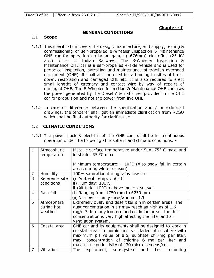
1.2.1 The power pack & electrics of the OHE car shall be in continuous
operation under the following atmospheric and climatic conditions: -
1 Atmospheric
temperature
Metallic surface temperature under Sun: 75° C max. and
in shade: 55 °C max.
Minimum temperature: - 10°C (Also snow fall in certain
areas during winter season).
2 Humidity 100% saturation during rainy season.
3 Reference site conditions
i) Ambient Temp. : 50° C ii) Humidity: 100%
iii) Altitude: 1000m above mean sea level.
4 Rain fall (i) Ranging from 1750 mm to 6250 mm.
(ii) Number of rainy days/annum 120
5 Atmosphere
during hot
weather
Extremely dusty and desert terrain in certain areas. The
dust concentration in air may reach as high as of 1.6
mg/m³. In many iron ore and coalmine areas, the dust
concentration is very high affecting the filter and air ventilation system.
6 Coastal area OHE car and its equipments shall be designed to work in
coastal areas in humid and salt laden atmosphere with maximum pH value of 8.5, sulphate of 7mg per liter,
max. concentration of chlorine 6 mg per liter and
maximum conductivity of 130 micro siemens/cm.
7 Vibration The equipment, sub-system and their mounting
Page 4 of 82 Effective from 26.8.2015 Spec No.TI/SPC/OHE/8WDETC/0092
arrangement shall be designed to withstand satisfactorily
the vibration and shocks encountered in service as specified in clause 1.2.2.
High level of 50 g vibration and shocks. Accelerations
over 500 m/s² have been recorded at axle box levels for long periods during run. Vibrations during wheel slips are
of even higher magnitude.
8 Wind speed High wind speed in certain areas, with wind pressure reaching 200kg/m²
1.2.2 The equipments and their arrangement shall withstand satisfactorily,
the vibration and shocks normally encountered in service which are as below:-
(a) Maximum Vertical Acceleration 3.0g (b) Maximum Longitudinal Acceleration 5.0g
(c) Maximum Train Acceleration 2.0g
[Where ‘g’ is acceleration due to gravity]
1.2.3 The OHE car shall be able to negotiate water logged tracks at 10 kmph,
with water level of 102 mm above the rail top, for which the Equipment
shall be suitably designed.
1.2.4 The OHE car and its principal assemblies shall be designed and
manufactured to give satisfactory performance in the tropical climate,
having very dry & dusty regions in arid zones of the country, to humid coastal areas and extreme cold climate of the northern region..
1.3 Examination of the Tender Offer:
1.3.1 The tenderer is required to furnish clause by clause comments to this
specification, either confirming acceptance of the clause or indicating deviation there from.
1.3.2 A comprehensive specification of the OHE car as offered shall be
submitted separately.
1.3.3 In the event a tenderer is unable to comply, either partially or fully, to
any of the stipulations made in this specification, it must be brought to the notice of purchaser with full particulars of the deviations, technical
details, cost implications and past service performance, etc.
1.4 Design Development:
1.4.1 The successful tenderer (hereafter called as contractor) shall develop
the design based on the details given in this specification and sound engineering practices. The entire design & technical data along with
Page 5 of 82 Effective from 26.8.2015 Spec No.TI/SPC/OHE/8WDETC/0092
calculations shall be submitted to RDSO for approval before
commencing construction of OHE car or placing orders on sub-contractors.
1.4.2 The design shall be based on S.I. Units.
1.4.3 From the information given in this specification and instructions of
RDSO, the contractor shall prepare a full set of engineering drawings
and submit the same to RDSO for approval.
1.4.4 When submitting drawings of a particular detail, other details
depending on it shall be shown in juxtaposition.
1.4.5 Material specifications, manufacturing tolerances and other details,
which are necessary for manufacture for each component shall be
indicated on the drawings.
1.5 Approval of Drawings:
1.5.1 “Approval” to the drawing means the approval to the general
adoptability of the design features. RDSO shall not be responsible for
the correctness of dimensions on the drawings, materials used, strength or performance of the components. The contractor shall be
wholly and completely responsible for all these variables. The
contractor, when submitting proposals or designs for approval of the
RDSO, shall draw attention to any deviation or departure from the specification involved in his proposals or drawings.
1.5.2 Drawing for approval shall be submitted in standard size (s) as per IS: 696 along with main calculation details in triplicate. List of
drawings/calculations to be submitted to RDSO for approval before
undertaking manufacture of prototype DETC are given in ANNEXURE-2. Any other drawings of which manufacturer desires to obtain approval of
RDSO shall also be submitted to RDSO.
1.6 Prints:
1.6.1 One set of tracing, two sets of their prints &two DVD of the RDSO
approved drawings/ calculations shall be supplied by the successful contractor with each tower wagon. The tracings shall be on RTF of
durable quality. Drawings shall be made on Auto CAD. Two sets of
tracing, two sets of prints and two copies of approved drawings &
calculations along with 3 DVDs shall be supplied to RDSO.
1.6.2 Each set of tracings shall form a complete set of working drawings, the
first sheet being the index and the following sheets being arranged properly to show the various assemblies, sub- assemblies and
components of complete works in the following sequence:-
Page 6 of 82 Effective from 26.8.2015 Spec No.TI/SPC/OHE/8WDETC/0092
(a) Diagram sheets show the overall dimensions of the equipment, weights and the relation of overall dimensions to the space in the
OHE car.
(b) Lists of all parts grouped in to major assembly with details of
numbers per set, weight, specification material and drawing reference against each item.
(c) General arrangement drawings of complete equipment sets.
Diagram of lubrication points indicating type of lubricant. Sub-assembly arrangement, drawing in proper and logical sequence.
(d) Detailed drawings:- On detailed drawing sheets, each part shall be
identified by an alphabetic letter and the list of all parts forming the sub-assembly shall be tabulated just above the title block on the
same sheet giving details against each alphabetic letter.
1.7 Contractor’s responsibility:
1.7.1 The contractor shall be entirely responsible for the execution of the
contract strictly in accordance with the terms of this specification and the conditions of contract, notwithstanding any approval which RDSO
or the Inspecting officer may have given:
(a) Of the detailed drawing prepared by the contractor.
(b) Of the sub-contractors for materials.
(c) Of other parts of the work involved by the contractor.
(d) Of the tests OHE carried out either by the contractor or by the RDSO or the Inspecting Officer.
1.8 Warrantee:
Warranty shall be as per IRS standard conditions of contract.
1.9 Exhibited Drawings and standard Specifications:
1.9.1 “Exhibited Drawings” means the drawings which are exhibited or
provided by RDSO for the guidance of the contractor.
1.9.2 The exhibited drawings, illustrative of a range of standardized
dimensions and fittings, are listed in Annexure -1. The design of the
OHE car must comply with the dimensions, and fittings included in the exhibited drawings as far as possible. Any deviation from there shall be
clearly mentioned in the form of a table on the drawing.
1.9.3 The exhibited drawings are not guaranteed to be free from discrepancies. The contractor while preparing the engineering drawings
shall ensure that these are free from discrepancies. He shall also
incorporate all modifications desired by the RDSO, subsequently,
Page 7 of 82 Effective from 26.8.2015 Spec No.TI/SPC/OHE/8WDETC/0092
without prejudice to the date of delivery or contracted price, except as
provided for under the conditions of contract.
1.9.4 To improve upon the performance, modifications and corrections are
made in the specification and drawings from time to time. The
contractor must, therefore, satisfy himself that the drawings being used by him are of the latest version. In case of any doubt, he must
get it clarified from RDSO.
1.9.5 The Contractor shall procure at his own expense all the drawings and
specifications required for the manufacture of the OHE car.
1.9.6 Copies of drawings referred to in this specification and given in
Annexure-1 may be obtained from RDSO/ICF on payment.
1.9.7 Indian Railways Standard (IRS) specifications and Schedules of
Maximum Moving Dimensions may be obtained on payment from the
Manager, Government of India Publications, Civil Lines, Delhi 110 006 (INDIA).
1.9.8 Indian Standard Specifications (ISS) are available from Bureau of
Indian Standards, 9-Bahadur Shah Zafar Marg, Delhi 110 002.
1.10 Materials:
1.10.1 Materials used in the construction of the OHE car shall comply with the
relevant IRS specifications or Indian Standard Specifications. Where
IRS or ISS do not exist for specific components, the contractor shall submit proposed material specification for approval of RDSO.
1.11 Service Engineering:
1.11.1 The Contractor shall arrange for the supervision of commissioning of
the OHE car immediately after their receipt at ultimate destination. He is also required carry out joint check of the receipt of components
regarding short shipment or transit damages.
1.11.2 The contractor shall ensure commissioning of the OHE car within 30 days from the date of intimation by the consignee.
1.11.3 The performance of OHE Car shall be demonstrated by the contractor after its successful commissioning at the consignee’s works.
1.11.4 The contractor shall provide and ensure servicing facilities in India
throughout the warranty period. After the warranty period is over, he shall, on call, give service support for troubleshooting and for
obtaining spare parts.
Page 8 of 82 Effective from 26.8.2015 Spec No.TI/SPC/OHE/8WDETC/0092
1.11.5 A well designed and informative electronic portal for lodging of
complains and action taken by supplier shall made operative before dispatch of first prototype vehicle.
1.12 Training:
1.12.1 The Contractor shall arrange to provide training in operation &
maintenance of the OHE car for two men for four days at their works
and user’s place respectively per tower wagon. The training material shall be supplied as per Annexure 8-D.The cost of training shall be
included in the price of tower car. The charges for travel, boarding
and lodging of trainees shall be borne by the Railways.
1.12.2 Technical experts of the manufacturer, during commissioning of OHE
car at consignee’s premises, shall also adequately train operators/
maintenance staff nominated by the consignee for minimum period of 3 days.
1.13 Service Manuals and Spare Parts Catalogues:
1.13.1 Detailed Maintenance & Service Manuals including the manual for
trouble shooting & operational requirement, spare parts catalogues for the driver and maintenance staff for the OHE car shall be
prepared and three copies supplied free of charge, per OHE car, to
the consignee. Before printing the final version of the manual, the
draft of the Manuals shall be got approved from RDSO.
1.13.2 Three copies per OHE cars of Spare Parts Catalogues& list of must
change items with periodicity & sources of supply shall also be supplied to the consignee.
1.13.3 In addition, three copies each of the Maintenance/Service and trouble shooting manual along with shall be supplied to RDSO.
1.14 Electric Arc Welding:
1.14.1 Indian Railways Standard Code of Practice for Electrical Arc Welding
shall be followed. If the contractor desires to follow any other code of
practice, it shall first be submitted for approval of RDSO.
1.14.2 Welding symbols shall be in accordance to IS:813. Drawings on which
such symbols appear, are to bear a note on the bottom left hand
corner, “WELDING SYMBOLS AS PER IS:813”.
1.14.3 Railway Initial Letters: Where parts are required to be marked
with Railway initial letters, they shall be ‘I.R’
Page 9 of 82 Effective from 26.8.2015 Spec No.TI/SPC/OHE/8WDETC/0092
1.15 Sublet Orders for Materials: Any subletting of orders for
materials/work shall have prior approval of RDSO.
1.16 Spare Parts:
1.16.1 Unit exchange spare parts shall be indicated. However, final decision to buy these will rest with the purchaser.
1.16.2 The prices for these spares shall be quoted separately. These spares shall be for every set of 10 OHE cars or part thereof. The complete
details such as part number and their quantity shall be clearly
indicated against following items with the offer.
i) Flexible coupling/ - 1 set
Engine connection (complete) ii) Traction Alternator alongwith - 1 set
Power Rectifier
iii) Air compressor (complete) - 1 unit iv) Motorised Bogie (complete with
Traction Motors and Break Gear) - 1 set
v) Battery charger for charging of - 1 unit
starter Batteries vi) Auxiliary Alternator - 1 set
1.16.1 The prices for these spares shall be quoted separately. These spares shall be for every set of 10 OHE cars or part thereof. The prices shall
not be used for tender evaluation purpose.
1.16.3 The tenderer shall be responsible to ensure subsequent availability of
the spare parts for the normal life of the respective equipment.
1.17 Tools:
List of tools & special tools for maintenance and overhaul of OHE
Cars shall be supplied as per Annexure-8-A, 8-B by the Tenderer in accordance with Clause 6.1 of this specification. The cost of tools shall
be included in the price of tower car. The successful Tenderer shall
submit the drawings and specification of tools required for the
maintenance of the OHE Car.
1.18 Testing Kit:
1.18.1 The tenderer shall supply testing equipment with each tower car required for ensuring optimum performance and trouble-free service
of the major equipments & accessories provided in the OHE car (e.g.
Diesel Engine, Traction Alternator, Traction Motor and other
Equipments with accessories). The testing Equipment shall be supplied as per annexure-8-C. The cost of testing equipment shall be
included in the price of tower car.
Page 10 of 82 Effective from 26.8.2015 Spec No.TI/SPC/OHE/8WDETC/0092
1.18.2 The Tenderer shall also offer separately special jigs, tools and
instruments, which shall essentially be required for maintenance of OHE Car body. Essential Equipments and facilities required for
attending local damage to Stainless Steel structures, OHE Car
interiors etc. in case of accidental damages should also be furnished.
1.18.3 The contractor shall demonstrate to the IR, the satisfactory
functioning of the tools, jigs & instruments supplied by him. The
Specification of testing equipments shall be provided by successful Tenderer.
1.19 OHE Maintenance equipments : The tenderer shall supply the following maintenance equipment along
with each tower car. The cost of maintenance equipment shall be
included in the price of tower car.
a) The technical specification No. TI/SPC/OHE/TIPS/1031 with latest amendment for infra-red imaging system suitable for monitoring
and measurement of hot spot temperature for different
applications. b) One Hydraulic Jack of 5 t capacity,
c) One tirfer 3t, Two tirfer 1.5 t, (As per RDSO’s Specification No.
TI/SPC/OHE/TOOLPL/0990). d) Three pull-lift 0.75 t, Two pull-lift 1.5 t , One pull-lift 3t (As per
RDSO’s Specification No. TI/SPC/OHE/TOOLPL/1990.
1.20 Quality Assurance Plan
1.20.1 The contractor should posses valid ISO-9001:2000 certificate for his
work’s address, covering the items for which he is participating in the contract. The contractor shall formulate Quality Assurance program
(QAP) detailing the methodology proposed to be followed to ensure a
quality product. QAP shall cover quality assurance procedures and procedures to be followed during all stages of design, manufacture,
testing and commissioning of the equipment. The Contractor shall
define the role of each functional group in the Organisation for
achieving the required quality of the product and submit a comprehensive document “ Quality assurance manual” in accordance
with IS 10201-1982 as the basic guideline. The preparation of
necessary charts and proforma shall be to IS: 7200 (Part- III)-82.
1.20.2 The Tenderer whose bid is accepted, shall be required to submit a
“Quality Assurance Manual” by giving details as to how the quality of
specific product is proposed to be assured. Supply of the equipment shall commence only after “Quality Assurance Plan” has been
approved by RDSO.
The above shall apply to the main contractor as well as sub-
contractors.
Page 11 of 82 Effective from 26.8.2015 Spec No.TI/SPC/OHE/8WDETC/0092
1.21 Annual Maintenance Contract (AMC)
1.21.1 The tenderer shall quote for AMC comprehensive of all equipments
including, traction motors, alternators, Diesel Engine complete with
transmission & cooling system, Air Brake system with compressor unit and Control System etc.
The Annual Maintenance shall be applicable for the period for 5 years beyond expiry of warantee. The tenderer shall quote year wise
rates of AMC detailing the various schedules to be undertaken by them
as well as submitting the requirement of material/spare parts, consumables and services to be rendered by him after regular
intervals. The AMC shall be comprehensive for all equipments for
preventing as well as break down maintenance. The tenderer shall keep
adequate spares in stock for regular schedule of AMC so that maintenance schedules are completed timely. AMC shall be all inclusive
of parts required to be replaced during each schedule, if required,
either due to brake down or wear. Average running of 8-Wheeler Tower Wagon shall be approx. 1200 Hrs per year.
The AMC cost shall be considered while evaluating the inter-se tender position. It shall be compulsory for the tenderer to quote for
AMC. However, the decision to enter into AMC shall vest with Railway
alone.
1.21.2 In case of failure of any of the equipment covered under maintenance contract, it shall be repaired or replaced within reasonable time not
exceeding 05 days from the day of reporting by the consignee. After
this period of 05 days, penalty at the rate of Rs.5000 per day (flat) shall be imposed on the Contractor for each day or its part thereof.
1.21.3 The AMC Agreement shall be entered with the Zonal Railways as per
the accepted rate in the Contract.

Page 12 of 82 Effective from 26.8.2015 Spec No.TI/SPC/OHE/8WDETC/0092
Chapter -II
DIMENSIONAL OPERATING AND OTHER REQUIREMENTS FOR OHE CAR
2.0 The OHE Car shall dimensionally conform to the following:
(i) Track gauge 1676 mm
(ii) Minimum radius
of curve
Normally 175 meters, sharper curves with radius less
than 175 meter are also available at isolated location. Regarding minimum radius of curvature for slip points,
turnouts or crossover roads, para 17 of chapter II of
Schedule-I of IRSOD (BG) Revised 2004 shall be
applicable which provides for minimum of 175 m radius curves in case of 1 in 8.5 scissors cross over.
(iii) Maximum super elevation
165 mm
(iv) Maximum Super
-elevation
deficiency
100mm
(v) Maximum wind
pressure
200 kg/m2
(vi) Maximum
moving Dimensions
Maximum moving dimensions shall conform to diagram
1D of Indian Railway Schedule of Dimension (SOD) 1676 mm gauge (BG) revised 2004 with the pantograph
and platform in lock down condition. Infringements, if
unavoidable and fully justified, may be considered, if within the limits shown in SOD 1676 mm gauge (BG)
revised 2004.
(vii) Maximum
permissible wheel base
length of the
OHE car, over hang beyond
bogie center,
buffer height
draw bar height
These shall conform to Indian railway, schedule of
dimension 1676 mm gauge (BG) Revised 2004. Adequate clearance shall be allowed so that no
component of the OHE car shall infringe a minimum of
102 mm above rail level with wheels in fully worn conditions, full deflection of springs and effect of
dynamics.
(viii) Maximum Axle
load
20.32 t
(ix) (a) Maximum
Speed when coupled to a
train
(b) Max operating speed under
its own power
110Km/h
110 km/h
(x) Brakes All wheels with clasp brakes.
Page 13 of 82 Effective from 26.8.2015 Spec No.TI/SPC/OHE/8WDETC/0092
(xi) Service Braking Pneumatic
(xii) Performance
capabilities:-
i) Pay load (excluding Power equipment
and hydraulic platform)
12tonnes (Approximately)
ii) Period of continuous running at 110
km/h on generally tangent track
followed by frequent to and fro
movement at walking pace for 1-1/2 h).
5-1/2h total
(4h+1-1/2h)
iii) Period of continuous running at 40
km/h up or down gradient of 1 in
60 to be followed by frequent to and
fro movement up to 5 km/h for 1-1/2 h on same gradient with speed
control.
5-1/2h total
(4h+1-1/2h)
iv) Performance in monsoon and squally conditions.
Un- restricted
v) OHE Car shall be capable of running at a speed of 75kmph with 2-loaded flat wagons weighing 120t at
tangent track.
vi) The OHE Car shall be capable of running at a speed
of 25 km/h on 1 in 33 up gradient.
vii) The OHE car shall be capable of starting and hauling Two wagons weighing 60t each in gross load
condition (Total 120 tonnes) on an up gradient of 1
in 33. Maximum operating speed of the OHE car for
level and 1 in 33 up gradients shall be indicated with the offer.
viii) With the hydraulic platform in raised condition the
OHE car shall run at a maximum speed of 10 km/h.
ix) The emergency braking distance (EBD) for fully loaded (20.32x4=81.28 t) OHE car from maximum
speed of 110km/h to zero shall not be more than
800m on flat section. The contractor shall also
submit calculation for EBD on 1 in 33 down gradient.
2.1 The purchaser may at his option revise the layout so as to provide for an arrangement for front opening on one side to load and unload
collapsible ladders from the trackside. Tenderer may offer alternative
proposals with full details of the advantages of his system.
2.2 The OHE car shall be an 8-wheeler vehicle. The disposition of
equipment storage space shall be such as to ensure equal axle loads.
Design shall be such as to afford easy inspection and maintenance.
Page 14 of 82 Effective from 26.8.2015 Spec No.TI/SPC/OHE/8WDETC/0092
2.3 Provision shall be made for the following in the OHE Car:
2.3.1 Driving Cabs:
i) Two driving cabs shall be provided, one at each end, with complete
operating & driving control with dash boards to facilitate operation from either cab. Driver’s seat shall be on the left side. Adequate leg space
shall be provided for the driver when he is seated. The general layout
and arrangement of equipment in Driver’s cab shall follow UIC CODEX 651 with respect to dimensions, safety features, furnishing, lighting,
ventilation, noise level, field of view, driver’s desk, seats etc. Spot
lights shall be provided at suitable locations. The cab shall be ergonomically designed for better view and comfort and also the
various panels /equipments meant for Driver shall be so laid that they
are easily readable and Driver is not required to move physically for
any operation during run.
ii) Foldable cushion sheet shall be provided in each of the driving cabs for
4 persons in addition to the Driver.
iii) All controls, brake handle, hand brake, Dead Man’s device for horn and
indication lamps/meters shall be within easy access and view of the Driver.
iv) The OHE car shall be equipped with inter-communication equipment
between cabs, Inspection compartment, working platform through hand free sets with their own battery.
v) Each driving cab shall be provided with one number 6 Inch TFT monitor connected with one number portable CCTV camera for viewing roof
activities during OHE maintenance.
vi) 2 numbers, 110 V sockets for hand signals in each cab.
vii) Head Light, Flasher lights search lights and marker lights at both ends
of the cab, refer para 4.5.
viii) Non-contact type OHE voltage sensing device in both the cabs.
ix) Full width single piece Stone proof lookout glass with Sun Screen shall
be provided at the end wall of each Driver’s compartment and these
shall be glazed, clear, colourless polycarbonate to ICF Specification
No.ICF/MD/SPEC-159 (latest revision).
x) Provision of wind screen Wiper arm and blade Assembly to be provided
as per RDSO Specification no.C-K306 (Rev 01).
Page 15 of 82 Effective from 26.8.2015 Spec No.TI/SPC/OHE/8WDETC/0092
2.3.2 It is proposed to keep one drum each of contact and catenary wire,
duly mounted on the stand, for erection during the restoration of breakdowns. Provision shall be made for rotating the contact wire drum
by 180 degree for matching contact wire groove in either direction is
possible so that it shall be possible to pay out the wire in either
direction. Stands shall be provided with hand brakes to control the tension in the wires during the laying out process. It shall be possible
to lay-out wires in either direction and therefore these drum shall
preferably be in the middle of the OHE car. The drums be loaded from a sliding door of adequate size on both sides. The laying out of the wire
shall be from two of the openings of suitable size in the roof vertically
above each of the drums. These openings shall normally be covered so as to prevent water falling into the OHE car.
2.3.3 Successful tenderer shall submit mounting drawings for conductor
drum as per principle details given below for approval of RDSO.
The principal details of the conductor drums are-
(a) Diameter 1900 mm (b) Width- 950 mm
(c) Bore for mounting on the stand- 105 mm x 105mm
(d) Facility shall be provided to rotate the conductor drums to enable pay out the conductor in either direction
2.3.4 The facilities to be provided in the OHE Car shall be as described briefly
in the following Clauses.
2.3.4.1 Material Cabin: A material cabin shall be provided adjoining one of
the driving cabs having adequate space and proper locking arrangement for the storage of costly equipments and fittings. A
reasonable number of cup-boards having sufficient number of pigeon
holes shall be provided inside the material cabin for storage of fittings, tools and tackles, lighting equipment and other fragile spares. Suitable
shelves/racks shall also be provided for storage of about 50 MS tubes
of upto 47 mm dia and upto 4m long, hangers for insulators, apart
from these two steel almirah (with five shelves) shall be provided for keeping costly items & essential records.
2.3.4.2 Workshop: A well-ventilated workshop shall be provided in the middle equipped with exhaust fans, ceiling fans and windows, with a room for
4 persons to stand and work. On one side a workbench of size 2500mm
x 900mm shall be provided. It shall be fitted with two vices to under
take minor repair work along with one drilling machine. On the side opposite the workbench, racks/cup board shall be provided for tools
and plant. Design/ drawings of these equipments shall be submitted to
RDSO for approval.
Page 16 of 82 Effective from 26.8.2015 Spec No.TI/SPC/OHE/8WDETC/0092
2.3.4.3 Storage space: Adequate space shall be provided for installation and
storage of equipment such as emergency lighting equipment and other items supplied with the OHE Car.
2.3.4.4 Staff Cabins: One cabin for Officers with four cushioned Berths and
one Cabin for staff (if possible) with two cushioned Berths shall be provided. The Cabins shall have separate entry and have windows on
both sides. The Cabins shall preferably be not over the wheels as far as
possible. An Indian style WC with separate over head Tank, Stainless Steel Sink and other accessory fitting and a folding cushioned seat
including shower with flexible Hose shall be provided. The WC shall be
provided with an exhaust Fan. Provision of two Mobile Charging points to be made in Officer and Staff’s Cabin as well as in both the driving
cab and working area. In addition two folding berths shall be provided
at suitable location without cabin.
2.3.4.5 Communicating doors: Each driving cab shall have independent
entry from both sides. The OHE car lobby shall have entry from both
the cab. Through communication inside the OHE car shall be provided. It shall be possible to isolate the cabins using sliding doors with locking
arrangements.
2.3.5 Facilities on roof:
i) The OHE car shall be provided with a pantograph similar to AM-12
type with foot insulators and its complete actuating mechanism on one bogie center. Pantograph shall be graduated to enable manual
measurement of stagger on either side of track center.
ii) For illumination of roof for night inspection four water proof industrial
plug points shall be provided for fixing portable lights.
iii) Two pneumatic points for connecting pneumatic operated/driven
tools and fasteners shall be provided.
iv) Observation dome: An observation dome shall be provided in the roof near the pantograph so as to observe interaction between the
contact wire of the OHE and the pantograph. Two to three persons
shall be able to sit comfortably in the observation dome. The upper
portion of the dome shall be of polycarbonate /FRP with reinforcement if required for adequate strength and shall also be
insulated for 25 KV. The arrangement shall be such that an
unobstructed view of the contact between contact wire and pantograph is obtained by the persons in the observation dome
without any strain. For this it is essential to have suitable
ergonomical design of sitting arrangement. The chair provided in the
observation dome shall have adjustable height, back rest with back and front adjustment just like in an automobile OHE car.
Page 17 of 82 Effective from 26.8.2015 Spec No.TI/SPC/OHE/8WDETC/0092
v) Lifting and swiveling platform: A lifting and swiveling platform
with hydraulically operated mechanized adjustment for height and rotation and capable of taking minimum 600 kg load with under-
noted features shall be provided over the fixed platform:-
(a) Length 5700 mm
(b) Width 1500 mm
(c) Platform floor 6150 mm
level above rail when elevated.
(d) Maxim lifting time to full height 45 s
(e) Rotation range of 900
Platform towards sides.
(f) Side shifting reach of platform 4200 mm
(g) Full height of collapsible 800 mm
railing above platform floor
(h) Maximum time of rotation from 45 s
00 position to 900
NOTE: (i) Control for lifting, lowering and swiveling shall be provided on the
platform. The raising and swiveling of the platform shall be
gradual and without jerks. In addition two emergency stop switches shall be provided on each side of the platform to bring
the OHE Car to an emergency halt.
(ii) Two search lights of 250 W metal halide lamps shall be provided on the platform for inspection of the overhead equipment while on
the run. Searchlights shall be capable of swiveling on universal
joints type support and swiveling control shall be from inside of
the either cab. (iii) Except space for pantograph and observation dome the remaining
roof shall be covered with a 2325mm wide fixed working platform
at maximum possible height but within the maximum moving dimensions. This fixed platform shall be provided with four
approach ladders, two on each side to climb on to the platform
from the ground.
2.3.6 Provision shall be made to OHE carry 3 OHE masts of 9.5 m and 1of 12
m lengths. The masts may either be rolled I beam of 150mm x 200mm
size or fabricated structure of 250mm x 300mm.
Page 18 of 82 Effective from 26.8.2015 Spec No.TI/SPC/OHE/8WDETC/0092
2.3.7 Suitable safety measures including interlocks between various
equipments, access doors and line equipment shall be provided to ensure.
(i) Safety of men and
(ii) Stability of the OHE Car while in operation.
The tenderer shall indicate the proposed interlocking and safety
aspects.
2.3.8 The entire OHE Car including bogies, superstructure alongwith
equipment is to be effectively earthed as per standard practice for
rolling stock. Schematic and other detailed drawings for earthing shall be got approved by RDSO.
2.3.9 The equipment fixed to the underframe shall be secured properly by
providing extra metallic chains of adequate strength to safeguard the equipment and to perform efficiently.
2.3.10 Fire prevention OHE Car shall suitably be provided as per RDSO’s Specification No.RDSO/PE/CP/EMU/0001 Rev.0 of Aug.’2003
(Amendment No.1 of July’2006) and with latest revision
Page 19 of 82 Effective from 26.8.2015 Spec No.TI/SPC/OHE/8WDETC/0092
Chapter - III
3.0 MECHANICAL DESIGN
3.1 Superstructure:
3.1.1 General: The OHE Car shall be of welded light weight construction, generally to maximum moving dimensions to diagram 1D of Indian
Railways Schedule of Dimension 1676 mm gauge (BG) revised 2004
(SOD) with pantograph and platform in lowered condition. Infringements, if unavoidable and fully justified, may be considered, if
within limits shown in the SOD. Weight of the OHE Car shall be kept as
low as possible, without compromising with the strength. The structure shall withstand end load of 200 t (divided equally between the two
buffers) applied in conjunction with full payload. Under such loading no
permanent deformation should occur and stresses should remain below
the yield point. The design shall be sufficiently rigid to withstand stresses imposed due to lifting with overhead or breakdown cranes or
by jacks applied to the headstocks. The super-structure shall be
designed as a tubular girder for the purpose of withstanding vertical loading, but the inner sheeting of the roof and walls shall not be stress-
bearing members.
3.1.2 The under frame shall be designed to meet the following loads:
i. A vertical load of 4 t/meter run uniformly distributed. The weight
of the various equipment mounted in the OHE car shall be
considered as concentrated load and shall be simulated as such during load/strain testing.
ii. A horizontal squeeze load of 100 t applied at each buffers.
iii. A combination of loads specified at (i) & (ii).
3.1.3 The stresses estimated by an approved method shall not exceed
139.3 MPa (14.2 kgf /sq.mm) for members made from Steel to IS:2062 Fe 410CuWC and 221.7 Mpa (22.6Kgf/ sq.mm) for members
made from corrosion resistant steel to IRS:M 41 for the uniformly
distributed vertical load. Also for the squeeze load referred to above,
the stress should not exceed 90% of the lower yield point or proportional limit of the material in the load OHE carrying member of
the shell and 95% of the lower yield point or proportional limit of the
material in the end construction. The estimated vertical deflection of the shell at the center of the OHE car shall also not exceed 10mm
under any loading condition detailed at (i) to (iii) above.
Completed shell of prototype OHE car shall be strain gauged for stress analysis under tare and loaded conditions with squeeze load. OHE Car
shall be tested for leakage through roof and body sides and ends at the
works of the manufacturer. To OHE carry out this test, the manufacturer shall provide a test rig to the satisfaction of the
inspecting authority.
Page 20 of 82 Effective from 26.8.2015 Spec No.TI/SPC/OHE/8WDETC/0092
3.1.4 Side and End Wall:
(i) Material: The frame work shall be of low alloy high tensile corrosion
resistant steel to IRS M-41 with latest revision/amendment.
(ii) Side wall and pillars: The material of body pillar shall be IRS M-41.
Pillars shall be continuous from sole bar to cant-rail, except below
window openings, and shall be braced by longitudinal members between adjacent pillars. Bracing being designed to act as integral part
of the exterior sheeting. Manufacturer can use better material than
IRS: M-41 for body pillar but without cost implication and supplier shall provide proof of better material.
(iii) The frame work shall be of low allow high tensile corrosion resistant
steel to IRS: M-41 with latest revision.
3.1.5 Body shell Structure: The body shell including sheathing shall be of IRS: M 41 steel.
3.1.6 Underframe: The underframe material shall be of corrosion resistant structural steel to IRS: M 41 or copper bearing quality steel to IS: 2062
Cu WC, of welded integral structure. The under frame design shall be
developed by the successful Tenderer keeping in mind the layout of DETC. The successful Tenderer shall submit under frame design to
RDSO for approval at the time of design approval stage. They shall be
assembled in jigs and fabricated by welding. Trough floor of 2.0 mm
thick of steel to IRS: M 41 steel shall be provided in covered area.
3.1.7 Headstocks: These shall be of robust design suitable for coupling and
buffing gear arrangements as detailed in this specification. Head stock material shall be IRS:M 41 steel.
3.1.8 Draw gear members: The members provided for OHE carrying the trimmer casting shall be of strong and rigid construction capable of
transmitting buffing forces specified in Clause - 3.1 under the most
adverse operating conditions. They shall be braced together to the
main sills in such a manner as to form, in conjunction with the flooring system between the transom and headstock a rigid assembly capable
of withstanding all cross-racking forces, which may occur in service.
The design shall, as far as possible, ensure that the load is applied symmetrically about the neutral axis of the longitudinal and is
concentric to them.
3.1.9 Draw & Buff Gear: The OHE Car shall be provided with high tensile centre buffer transition coupler conforming to RDSO Specification
No.56-BD-07 along with the side buffers arrangement to RDSO’s

Page 21 of 82 Effective from 26.8.2015 Spec No.TI/SPC/OHE/8WDETC/0092
Drawing No. SK-98145. The arrangement shall be such that OHE Car
shall be able to couple with existing BG rolling stock of Indian Railways.
3.1.10 Lifting Pads: The OHE Car body shall lend itself to repeated lifting in
workshop by overhead cranes or jacks without risk or damage. Suitable lifting pads shall be provided and marked in a readily distinguishable
manner on the OHE car body.
3.1.11 Solebar: These shall be continuous members from headstock to
headstock, adequately braced together to withstand the head on
loading and cross racking forces and shall be capable to withstand
jacking for the purpose of lifting the OHE Car. The sole bar shall be of corrosion resistant structural steel to IRS: M 41 Steel. The successful
Tenderer shall submit the design/drawing of Sole Bar to RDSO for
approval at the time of Design/Drawing approval stage.
3.1.12 Body bolster: These may be fabricated from pressed section and shall
have suitable pads on which lifting slings may be placed. Body bolster shall be of copper bearing quality steel to IS:2062 Cu WC of welded
integral structure.
3.1.13 Floor bearers: The design of floor bearers shall include robust main floor bearers placed transversely between the main sills and an
adequate numbers of racking panels between the main sills and
diagonal braces. The transverse floor bearers shall be so designed to OHE carry the maximum super-imposed load under maximum load
conditions as well as bracing between the main sills, and shall be
flushed with the top faces of the main sills, and a suitable surface for the floor covering. The design shall generally ensure adequate
drainage, so that corrosion is avoided, or is confined to parts, which
can be readily renewed without affecting the main flooring
members. Floor bearers shall be conforming to IRS: M 41 steel.
3.2 Roof:
3.2.1 The roof shall be designed to form a satisfactory chord to the superstructure considered as a girder, and to take a concentrated load
of 6 men standing (450 kg), close together at any point. The structure
shall consist generally of two main longitudinal members running from end to end of the OHE Car, braced at frequent intervals along their
lower flanges, and rigidly connected to the arch bars, and to the grab
pillars by rigid transverse members. At partition and semi bulkheads,
the sills shall be attached to vertical pillars within or forming part of the partitions or semi-bulk-heads The roof top at both ends i.e. back &
front ends shall be flat. Roof should be so designed that no water is
accumulated in cavities to avoid the damage/rusting. Proper channels to be provided for easy exit of rain water. The construction through out
shall be absolutely watertight and shall permit easy renewal of
Page 22 of 82 Effective from 26.8.2015 Spec No.TI/SPC/OHE/8WDETC/0092
corroded sheets. The material of the roof shall be of IRS: M 41 steel
sheet.
3.2.2 Two (02) openings shall be provided in the roof for erection of catenary
and contact wires in either direction. The openings shall be of suitable
size to permit paying out of the conductors in any direction, when the OHE car is moving slowly at 5-10 km/h speed, without any
obstruction, rubbing or scrapping.
3.2.3 Roof Ventilators: Roof ventilators shall be provided as per the ICF
Drawing No WL.RRM4-7-3-401 with latest alteration shall be used. The
ventilator shall not violate the schedule of dimensions & drawings to be got approved from RDSO.
3.2.4 Air Space: The air space between the outer and inner sheeting of the
roof shall be suitably ventilated as also the air space inside walls and end walls. Attachments may pass through the air space as required,
but must be designed, so that they do not cause sections to form
sealed chambers or lodgments for condensed moisture. The successful Tenderer shall submit the design/drawing to RDSO at the time of
design/drawing approval stage.
3.3 Windows:
Lift type window made of powder coated aluminum to ICF drawing No
EMU/4C/ASR-5-4-402 with latest alteration with fixed type poly
carbonate louver on top and movable glass window at the bottom.
3.3.1 All window and door glasses shall be of laminated plate glass set in sun
heat resistant synthetic rubber section.
3.3.2 All window openings shall be true to dimensions square and of uniform
width. The window opening shall not at any point exceed 2mm over or under the specified dimensions and shall not be out of square by more
than 2mm.
3.3.3 The windowsills of the body side windows shall have an outward slope of approximately 50.
3.3.4 The body side windows shall have two shutters, one louver on the outside and a glass on the inside.
3.3.5 The glass used for windows/shutters shall be of safety laminated quality to IS: 2553, weighing not less than 9.76 kg/m2. Gravity safety
latches of approved design shall be provided at two intermediate
positions to arrest the glass and louver shutters from falling down. The
shutters should be balanced by balancers of suitable Design.
Page 23 of 82 Effective from 26.8.2015 Spec No.TI/SPC/OHE/8WDETC/0092
3.3.6 The louver shutters shall be provided with shoot bolt type safety
latches to secure the shutters firmly in closed and open position.
3.4 Doors:
3.4.1 All door openings shall be true to specified dimensions and perfectly square. The openings shall be tested for size and squareness with
templates so that doors open and close freely and when closed shall be
reasonably weather proof and dust proof.
3.4.2 Hinged doors provided on the side walls for entry of drivers from
outside of the OHE Car shall be of inward opening type and will give an opening of 750 mm approx.
3.4.3 Single leaf inward opening hinged or sliding doors with locking
arrangement shall be provided in driver’s compartment for entry in the corridor and shall have a clear opening of 550 mm.
3.4.4 Other doors on sidewalls shall preferably be of sliding type with a clear opening of 1300 mm. The door leaves shall slide on roller bearing OHE
carriers suspended from top rail and shall work in retaining guides on
the doorsills. Each leaf shall have a window opening. Since the tenderer is expected to develop layout, location of doors may be
decided in the most suitable manner.
3.4.5 Latches shall be fitted on all doors so as to secure them from inside in the closed position.
3.4.6 Door locks: All doors shall be fitted with reliable locks to be operated from outside and inside. Hasps for external padlocking shall also be
provided on all doors opening out of the OHE car.
3.4.7 Door Footsteps: The door footsteps assembly shall be of mild steel
chequered plate of 6.0 mm thick edges shall be protected with metallic
treads. Any other suitable arrangement shall also be considered.
3.4.8 Door handholds: Door hand holds of chromium plated steel tube, with
malleable cast iron brackets shall be provided on either side of all body
side doors and shall be so fitted as to clear the side walls sufficiently to prevent injury to knuckles. Hand holds shall also be within the OHE car
profile.
3.5 Roof Water Tank: Roof water tank 4 mm thick of aluminum not less than 450 liters capacity shall be provided. The tank shall be mounted
so as to be readily removable for repairs. Side filling arrangement only
shall be provided for water filling. The water tank shall be tested to hydraulic pressure of 0.35 kg/cm2. The inside of all water tank shall be
painted with bituminous , black lead free, acid, alkali, water and
Page 24 of 82 Effective from 26.8.2015 Spec No.TI/SPC/OHE/8WDETC/0092
chlorine resisting paint to IS:9862-1981 and properly dried before
assembly in the car.
3.6 BOGIES:
3.6.1 General Design: OHE Car shall have two 4-Wheeled Bogies of
robust welded design suitable for taking brake gear, suspension
etc. and capable of withstanding the maximum static and
dynamic stresses under its full load condition. The weight of the Bogie shall be as low as possible, consistent with strength and
robustness. The bogie frame shall be of copper bearing steel
plates to IS: 2062 Fe 410 Cu WC and shall be fabricated by
welding.
3.6.2 Bogie suspension Design shall be coil steel suspension in primary and
air spring suspension in secondary stage. The Bogie Design shall be as
per ICF Drawing No AC/EMU/M/ASR-0-0-001 with latest Alteration. The manufacturer of diesel electric tower car shall purchase
bogie frame alongwith its accessories from the approved Vendors of
Indian Railways.
3.6.3 The design shall be capable of negotiating curves of 175 m radius,
turnout of 1 in 8 and1/2and gradients of 1 in 100.
3.7 WHEEL, AXLES AND AXLE BOXES
3.7.1 Wheel and axle dimensions shall meet the requirements of Indian Railways Schedule of Dimensions 1676 mm gauge-(BG) revised 2004.
3.7.2 Wheel assembly shall be 952 mm diameter and shall be provided with roller bearing no.22328 C/C3. The wheels of tower car shall be solid
forged wheels to RDSO drawing no.SK-K4004 with latest alteration. All
wheel sets shall be machined to take a speedometer drive.
3.7.3 Axles shall be to IRS-R43/92 stress calculations /FEM of wheel and
axles shall be submitted. The calculation shall be done as per ARR/UIC
Specification.
3.7.4 The wheel profile shall be to RDSO sketch No. 91146 with latest
alteration.
3.7.5 40% dynamic augmentation of the vertical journal in a load will be
used in calculating the axle stress in addition to vertical and horizontal
forces and movements.
Page 25 of 82 Effective from 26.8.2015 Spec No.TI/SPC/OHE/8WDETC/0092
3.7.6 All wheel and gear seats and traction motor suspension bearing
journals are required to be cold rolled together with stress relieving groves machined in the axle, between wheel seat and gear seat and
between the wheel and traction motor suspension bearing journal of
the axles.
3.7.7 Facilities for oil injection for removal of wheel shall necessarily be
provided.
3.7.8 Standard axle boxes shall be used. Roller bearings will be grease
lubricated and of type which have given satisfactory performance/
service on railway stock. Special attention shall be paid to sealing arrangement of the ends of axle, to prevent ingress of water, dirt and
loss of lubricants. This aspect requires special attention as the axle box
may remain submerged in flood water during heavy rains. The sealing
arrangement shall ensure that axle box will not need special maintenance even if it is submerged in water. The design of labyrinth
will be such as to prevent the ingress of dust in to or outflow of grease
from axle boxes.
3.7.9 One of the axle box and cover (not the leading one) shall house
speedometer generator with suitable adopter. OHE care shall be taken to provide special protection arrangement for the generator and cable
connection against flying ballast and any other extraneous objects. The
connection shall preferable be taken from the top of the axle box.
3.7.10 Complete working drawing of the axle box , guide arrangement with
bearing and its components shall be submitted for approval along with
maintenance instructions.
3.7.11 The axle box body shall preferably be of cast steel.
3.7.12 The contractor will be required to provide recommended lubricants
which should have been proven in similar railway service of the axle
bearings.
3.7.13 An alternative lubricant, manufactured in India shall also be identified
by the contractor in conjunction with the bearing manufacturer, and
the lubricants manufacturing industry.
3.7.14 Design calculation for the powered axle shall be submitted for approval
of RDSO.
3.8 Brake System:
3.8.1 The OHE Car shall be fitted with graduated release air brakes. The brake system shall be of UIC approved type and shall meet all UIC
requirements. It shall have the following distinct positions.
Page 26 of 82 Effective from 26.8.2015 Spec No.TI/SPC/OHE/8WDETC/0092
i) Release Position ii) Minimum reduction position.
iii) Full service position.
iv) Emergency position.
Note Panel mounted air brake system of approved make conforming to
Specification. No. MP-0.01.00.19 (Rev-01), June’2010 as approved by
RDSO should be provided in order to achieve high reliability, low weight, better sensitivity and easy maintainability.
3.8.2 Brake Blocks: The composition ‘K’ type non-asbestos brake blocks to RDSO Specification No. C-9508 with latest revision/amendment shall
be used. Brake rigging shall be as per ICF drawing No. EMU/M-3-2-064
with latest alteration shall be provided to prevent the brake blocks
riding down the wheel tapers.
3.8.3 The Emergency Braking Distance (EBD) for fully loaded
(20.32x4=81.28 t) OHE car from maximum speed of 110 km/h to zero shall not be more than 800 meter on flat section. The Tenderer shall
also submit calculation for EBD on 1 in 33 down gradient.
3.8.4 It is proposed to use the OHE Car for hauling two wagons weighing 60t
each in gross load condition [see Item-11 (vii & ix) of table at Clause 2.12(vii). The manufacturer shall indicate the Emergency Braking
Distance that can be obtained with above loaded wagons in the rear in
un-braked state.
3.8.5 The OHE car shall be provided with the following additional brake
requirements:
i) A D-1 Emergency Brake valve in both driving cab on extreme
right hand side for emergency brake application.
ii) Stand-by brakes, in case of failure of distributor valve or any component in the main brake system. This shall be decided at
the design approval stage.
iii) Parking brake to RDSO Specification No. CK 408 (latest revision)
capable of holding fully loaded OHE Carwith 120 t trailing load of
two loaded bogie Flat Wagons in un-Braked state on 1 in 33 down gradient under wet condition.
iv) Flexible Hose connection shall conform to SAE 100R1
3.8.6 Application of any type of brake provided on the OHE car shall result in
simultaneous cutting of the power to the driving axles. Interlock for
Page 27 of 82 Effective from 26.8.2015 Spec No.TI/SPC/OHE/8WDETC/0092
this arrangement may be included in governor system for safety
precaution.
3.8.7 The brake rigging arrangements shall be light and as simple as possible
with minimum number of levers and fulcrum points permitting easy access to brake blocks and other wearing parts. Composite brake block
shall only be used as per the standard approved drawing.
3.8.8 Brake system shall be provided with automatic slack adjuster built into
the brake cylinder.
3.8.9 Adequate safety straps shall be provided below the moving components
of the brake rigging and other components to prevent falling on the
track in the event of failure of any component.
3.8.10 The supplier shall submit details of brake system covering brake
schematic diagram, working principle, brake power diagram calculation
for EBD, number, dimension and type of brake blocks and literature on brake equipments proposed along with offer and get the brake system
approved from RDSO before manufacture of the prototype.
3.8.11 Air dryer of approved make conforming to Spec. No. MP-0.01.00.09
(Rev-05), March’2011 shall be provided. (In line with latest equipment
on EMU/DEMU)
3.8.12 Main air reservoirs of adequate capacity shall be provided. In addition,
a separate braking reservoir and a non-return valve be provided for
braking only. Suitable drain valves/cocks shall be provided to drain off the condensate in the reservoir (s).Cut off cock may be provided at
inlet of auto drain valve.
3.8.13 The tenderer shall be required to supply the detailed drawings,
specifications and testing procedure for rubber components/parts of all
the valves/cocks used in the brake system.
3.8.14 The supplier shall get the brake schematic approved by the RDSO.
3.8.15 Stand–alone VCD of approved make conforming to specification No. MP-0.34.00.04 (Rev.04) Dec 2008 shall be provided.
3.8.16 Brake system shall be such that in dead condition of 8WDETW can be hauled by another air brake stock.
3.9 Piping & Pipe fittings:
3.9.2 Seamless stainless steel pipe bright annealed to ASTM A 269 Gr.
304, which can be bent cold shall be used. The layout of piping
shall be designed to keep all pipes, especially the brake cylinder
Page 28 of 82 Effective from 26.8.2015 Spec No.TI/SPC/OHE/8WDETC/0092
pipes, as short and straight as possible Bends should be used
throughout, but where elbows have to be used; they shall be of
round type. Where the pipes itself are bent, their internal area shall be maintained uniformly.
3.9.3 Double ferule pipe fitting consisting of body, front ferrule, back ferrule
and nut shall be provided. The body and nut shall be of carbon steel of ASTM:A-108 Grade –II with electro cobalt zinc plating with chromic
passivation. The ferrule and back ferrule shall be made from stainless
steel to ASTM A276 TP 316 SS and conforming to ICF Specification No.
ICF/MD/SPEC-166 with latest revision/amendment.
3.9.4 All pipes shall be adequately clamped to the frame assembly. Compreg
to RDSO Specification No. C-9407- type II shall be used for clamp.
3.9.5 Pipes, ducts and conduits shall conform to an identification colour
scheme with polyurethane paint as per RDSO’s Specification, which
shall be approved by RDSO.
3.9.6 Chart showing the colours for identification of pipes shall be displayed
in cab at a prominent place where it is likely to be needed for reference.
3.10 Interior furnishing: The OHE Car shall be furnished with light weight fire retardant material. The material used for finishing and furnishing
shall be suitable for use under Indian climatic conditions and shall be as
for as possible fire proof, non-hygroscopic and vermin and rot proof.
The furnishing shall be as agreed between the contractor and RDSO. It may be noted that Indian Railways are presently using 3 mm
decorative/ resin bonded thermo-setting laminated plastic sheets of
approved shades, possessing resistance to spread of flame as indicated in para 5.16 of IS:2046. With a view to retarding the spread of fire, the
continuity of LP sheets shall be broken by the provision of suitable
metal barriers. The laminated plastic sheets conforming to STR No. C-K-514 (Latest Revision) may be used for thermosetting resin bonded
Laminated Sheet for OHE Car.
3.11 Ceiling and paneling: The ceiling in compartments shall be of minimum 2 mm thick NFTC to RDSO Specification No. C-K 511 (Latest
Revision). The ceiling material shall be IRS M-41, wherever required.
3.12 Flooring Construction: Floor of the vehicle shall be as per ICF drg.
No. EMU/MASR-41-001 with latest alteration. The opening in the
flooring for passage of pipes and cables through the floor shall be so constructed as to prevent any seepage of the oil. In addition to give
effective protection against the spread of fire originating beneath the
body.
Page 29 of 82 Effective from 26.8.2015 Spec No.TI/SPC/OHE/8WDETC/0092
3.13 Extra Fitting:
(i) Door steps shall be provided at all body side doors.
(ii) Continuous water wriggles from one end of the OHE Car to the other
shall be provided.
(iii) Tail lamp bracket to IRS Drawing No.C.BF-113 shall be fitted at each
end of the shell.
(iv) Rain water channels of suitable design over the doors & windows way shall be provided.
(v) Tenderers may note that the OHE Car may be washed mechanically. Tenderers may also note that the exterior of the OHE Car may be
washed in automatic OHE car washing plants. Exterior of the OHE Car
shall be designed keeping this in view.
3.14 Cattle Guard: Detachable type cattle guards shall be provided under
each buffer beam. The cattle guard shall be fitted with adjustable rail
guards so as to maintain the minimum free space above the rails under all conditions (see item 7 of clause 2.0).Cattle guard shall be as per
RCF Drawing No. EM26108 with Latest Revision.
3.15 Insulation: An insulation layer of suitable thickness of non-asbestos
material shall be provided inside the OHE car shell. End walls and
sidewalls shall be provided with suitable anti-drumming and anti-corrosive compound. Underside of the under frame over the engine
area shall be properly insulated to minimize heat transfer to the
compartment. The material used for insulation shall be non-inflammable type. All other parts shall be provided with anti-corrosive
compound.
3.16 Noise Suppression: The tenderers shall indicate noise suppression
features incorporated in the design. Maximum noise level should not
exceed 75 dB inside the cab.
3.17 Trap Doors: Suitable trap doors shall be provided on the flooring for
attention of underslungequipments, during service. The design of trap
door shall be such that it can be conveniently lifted when attention to equipment is required but strong enough to withstand normal
passenger loading. The trap door shall remain in level to the floor of
the OHE car.
3.18 Anti–pilferage measures: While securing compartment fittings, anti-
pilferage measures shall be incorporated.
Page 30 of 82 Effective from 26.8.2015 Spec No.TI/SPC/OHE/8WDETC/0092
3.19 Fire extinguishers and first aid equipment: Four fire extinguishers
CO2 type of 5 kg capacity shall be provided, one each in both the cabs and two in workmen’s lobby. Space shall be provided for keeping a first
aid box and one stretcher.
3.20 Corrosion protection:
i) Sheets and plates (other than Stainless Steel) used for OHE Car construction shall be suitably treated against corrosion before
fabrication.
ii) Sub- assemblies shall be treated against corrosion as per UIC Code
842-5 after they are manufactured. iii) OHE Car shall be treated after fabrication as per UIC Code 842-5.
iv) In addition to above, the OHE Car design shall be such as to minimize
the incidence of corrosion. Indian Railways experience is that most corrosion takes place due to seepage of water from the floor and
window openings.
v) The Tenderer may suggest any better corrosion protection system that he may have adopted with success in OHE Cars manufactured by him.
vi) The Tenderer shall note that OHE car floors are washed regularly at
certain time intervals. Hence the floor construction should be such that
it does not permit water to seep through the floor and cause corrosion to trough floor and under frame members.
vii) Tenderers may note that Indian Railway have noticed heavy corrosion
on OHE Car under the lavatories. As such, corrosion resistant steel shall be used for construction of floor and adjacent members under
lavatories and the neighboring bays.
3.21 Information to be submitted by the tenderer
(a) The following information shall be furnished by the tenderer alongwith
the offer:
(i) Transverse cross section of the proposed OHE Car along with principal
dimensions so as to illustrate the general construction of the shell. Also superimposed upon this should be the schedule of dimensions as
embodied in the Indian Railways Schedule of dimensions –1676 mm
gauge, revised 2004. Infringements, if any, should be accurately defined in the sketch.
(ii) A “Section” view of the plan of the OHE Car, showing the layout of the
major equipments along with principal dimensions.
(iii) Side elevation of the proposed OHE car.
(iv) A “Sectional” side elevation of the OHE Car underframe showing the
disposition of the major equipments on the underframe.
Page 31 of 82 Effective from 26.8.2015 Spec No.TI/SPC/OHE/8WDETC/0092
(v) To demonstrate his capability for designing OHE car body, the tenderer
shall submit a set of actual calculations pertaining to OHE car structure for any bogie vehicle, designed by him in the past. These shall be
submitted alongwith his tender offer.
(vi) The schematics of the brake pneumatic alongwith the internal
schematics of the valves proposed to be used shall be furnished alongwith the tender. The schematics shall be accompanied with a write
up on sequence of events during application, release and emergency.
(vii) Type of compressor and its capacity shall be indicated along with tender. This will be accompanied with a technical justification for the
compressor capacity selected.
(viii) Estimated weight of the OHE car structure shall be furnished alongwith the tender. Also weights of principal assemblies mounted on the OHE
car structure shall also be furnished.
(b) The other relevant information but not limited to following shall be furnished at design approval stage by the successful tenderer.
(i) A representative sectional view of the OHE car floor, illustrating the
floor construction. The specifications of the materials used in its
construction should be identified.
(ii) Furnishing material intended to be used by the tenderers-specifications should be identified.
(iii) Insulating material proposed by the manufacturer specifications should
be identified. (iv) Ceiling material proposed to be used by the manufacturer specifications
should be identified.
(v) Principal features of noise suppression shall be identified and submitted.
(vi) Principal features showing adequate fire redundancy shall be identified
and submitted.
(vii) Tentative brake rigging diagram alongwith details of brake cylinder and slack adjuster proposed to be used shall be submitted.
(viii) In case parking brakes are proposed the features of the proposed
parking brake actuator, its type and the schematics shall be furnished.
3.22 The guaranteed technical particulars of the inspection OHE car shall be
submitted as per Annexure-7.
Page 32 of 82 Effective from 26.8.2015 Spec No.TI/SPC/OHE/8WDETC/0092
Chapter - IV
ELECTRICAL EQUIPMENTS
4.0 Illumination: Driving Cabs, officers/Staff cabins, Workshop & Storage space shall be provided with level of Illumination of at least 30 Lux at
the working plane level (1m above the floor level).OHE Car lighting
shall be provided with 18 W, 600 mm x 26 mm double capped Fluorescent tube lights with wire mesh guard along with its fittings and
Electronic Lamp ballast as per RDSO Specification No. RDSO/PE/
SPEC/TL/0011-2000 (Rev.1) with the latest revision shall be used.
4.1 Driving cabs, officers/staff cabins and workshop shall be provided with
two, 110V, 300 mm sweep fans conforming to IS: 6680.
4.2 BATTERY: Lead Acid maintenance free storage battery of capacity as
mentioned at Clause no.5.3.2.20 of Chapter-V, conforming to IS: 6848–1972 shall be provided in under slung Battery boxes. The Battery
fuses shall be located close to the battery terminals.
4.2.1 Terminals for charging the batteries from external charging equipment
shall also be provided. The location of the batteries shall be such that
there is no danger of their getting damaged due to tools and equipment
inadvertently falling on them. If the cells are packed in two rows in the battery box, a hylam sheet shall separate the two rows.
4.3 Alternator for battery charger & DG sets:
4.3.1 An engine mounted alternator with rectifier and regulating equipment
of suitable capacity for charging of 24 V DC 290 Ah Battery shall be provided. The output of the generator shall cater for battery charging
for diesel engine starting (battery voltage 24V). The maximum power
demand will be required when the OHE car is stationary and with engine running at low idling speed.
4.3.2 An engine mounted alternator with Rectifier and regulating equipment of suitable capacity for charging of 24 V DC 290 Ah Battery shall be
provided. The output of the Alternator shall cater for battery charging
for diesel engine starting battery, 24V.
4.3.3 Battery charger for charging batteries of 110 V of 120 Ah capacity Lead
acid maintenance free storage battery of capacity as mentioned at
Clause No.5.3.2.20. The battery charger shall be from RDSO’s approved vendors complying to the RDSO’s Specification No. RDSO/
PE/SPEC/AC/0008 (Rev.2) with Latest alteration.
4.3.4 A 10 kVA, 3-phase, 415V, low noise Diesel Generating set for power
supply to lifting platform and machines in workshop shall be provided
Page 33 of 82 Effective from 26.8.2015 Spec No.TI/SPC/OHE/8WDETC/0092
with OHE Car. The Gen set shall be mounted on anti-vibration
mounting to reduce the vibrations.
4.3.5 A skid mounted portable Diesel Generator similar to Honda make
(petrol start kerosene run or petrol start petrol run) of 3kVA (minimum), 240V, 50 Hz along with transformer shall be provided to
meet 150 Amps light weight IGBT based welding machine load and
other auxiliary load of search lights (2x250 watts), emergency light and for other such purposes. Design of Transformer shall be decided at
design approval stage.
4.4 Circuitry
4.4.1 The load shall be suitably distributed based on standard practice. 4.4.2 Electrical equipment such as switches, lamp holders and other items
shall conform to the following latest Specifications:
IS:6965: Switches for use in Railway stock.
IS:1258: Bayonet lamp holders. IS:1293: Three pin plug and socket outlets.
IRS: EA-199: For ceiling light fittings like CFL within transparent
enclosure.
4.5 Power for head lights, tail lights
4.5.1 Following lights shall be worked on the alternator/ rectifier provided
with diesel engine. This is to ensure that failure in the other lighting
system does not affect the mobility of the OHE car.
4.5.2 Twin beam Head light: Twin Beam head lights shall be provided at
both ends. The head light shall confirm to RDSO’s Specification No. ELRS/SPEC/PR/0024 (Rev-1) Oct. 2004. The operating voltage of head
light shall be 24 V DC. 24 V DC, supply for twin beam head light shall
be taken from 110/24 DC-DC convertor. DC-DC Convertor shall be as per RDSO’s Specification No. ELRS/SPEC/DC-DC Convertor/0021 Rev.1.
4.5.3 Tail light: Tail lamp (Red aspect) of LED type 24 V 15 W as per RDSO’s Specification No. RDSO/PE/SPEC/TL/0119-2000 (with latest
revision) shall be provided at each end to comply with General &
Subsidiary Rules of Indian Railways.
4.5.4 Flasher light: One flasher light each of LED type as per RDSO’s
Specification No ELRS/ SPEC/LFL/0017 (Rev-1) Sept, 2004 shall be provided on the roof at either end of the OHE car.
4.5.5 Marker Light: Marker light of LED type(Red aspect) as per RDSO’s
Specification No ELRS/SPEC/PR/0022 (Rev-1) Oct. 2004 shall be
provided on either end of the OHE car.
Page 34 of 82 Effective from 26.8.2015 Spec No.TI/SPC/OHE/8WDETC/0092
4.5.6 Search Light: OHE car shall be provided with two 250 Watts
searchlights with Metal Halide lamps, one on each end, for inspection of the OHE while on the run. Searchlights shall provide a high intensity
illuminating beam and capable of swiveling on universal joint type
supports. Design details shall be finalized at the time of design
approval stage.
4.5.7 Wiring-All Electrical wiring in the tower wagon shall be done with e-beam cables conforming to RDSO’s Specification No ELRS/SPEC/
ELC/0019 Rev.-1 dated 06.07.2010 with latest amendment.
4.5.8 Horns: The OHE car shall be fitted with two horns at the roof with
different tones on both sides. Horns shall be operated on compressed
air. These shall be operated by a hand switch provided within the access of the Driver. Horn cover to RDSO Drawing No. CG-K5056.
4.5.9 SPEED INDICATOR / RECORDER: Speed Indicator and Recording
Equipment of 0 -160 km/h range shall conform to RDSO’s Specification No.MP-0.3700-07 (Rev.03) of April’2003. One cab of OHE Car shall
have one recorder-cum-indicator and the other cab shall have one
speed indicator only.
4.5.10 Mobile Charging: Four mobile charging points one each in Staff Cabin
and both the Driver’s Cab shall be provided as per RDSO approved source.
4.5.11 Cab Heaters: Both the cabs shall be provided with electrical heaters to
keep cab environment warm during winter season. The power supply to
heater shall be given from the auxiliary alternators as specified in clause 5.9.1
4.5.12 Flood lights: Four flood lights giving diffused light of 75 watts shall be provided with each OHE car. Detailed design of it shall be finalized at
the design approval stage.
4.5.13 Emergency push-buttons (Mushroom Type): Five emergency
push-buttons shall be fitted on the chassis sides and one on the roof.
When activated, they provoke:-
(i) Idling of the engine & removal of excitation of alternator.
(ii) Stop of elevating platform.
(iii) Braking of the vehicle.
4.5.14 Earthing Arrangement of Tower OHE Car:
All metallic parts of tower wagon including the working platform, shell structure & bogie shall be integrated electrically to ensure proper
earthing of tower OHE car through wheels to Rail. The body of the
Page 35 of 82 Effective from 26.8.2015 Spec No.TI/SPC/OHE/8WDETC/0092
lifting motor, control panels, swiveling motor at platform and other
electrical equipment shall be connected to the earth. Traction motor shall be provided with earth brush. The schematic diagram of earthing
arrangement to be provided for the tower OHE car& equipment in it
shall be submitted by the successful tenderer for approval of RDSO.
Page 36 of 82 Effective from 26.8.2015 Spec No.TI/SPC/OHE/8WDETC/0092
Chapter - V
5.0 POWER EQUIPMENT & CONTROL
5.1 The different speeds of the twin-power pack from idle to maximum
speed and the corresponding power developed should be so selected
that all the conditions mentioned in Clause - 2.0 of Chapter-II can be satisfactorily met. However the number of speeds and power levels
chosen should not be less than 8 (herein after referred to as notch
positions) in addition to the idle position. The performance of the power pack shall be optimum in each notch position in addition to being able
to meet the traction load and demand by the auxiliaries.
5.2 Detailed calculations shall be submitted along with tender indicating the
power demand by the traction motors for different conditions and the
demand on the power pack. These calculations shall indicate whether
adequate reserve power has been provided. Characteristic curves for the Traction Alternator& Rectifier indicating the performance for
different notch positions should be furnished. These curves, inter-alia,
should indicate speed, BHP, power consumption by auxiliaries, excitation voltage and a.c. and d.c. currents. These characteristics
should clearly indicate the extent of matching or mismatching of power.
5.3 DIESEL ENGINE AND TRANSMISSION SYSTEM
5.3.1 The OHE Car will have two independent diesel electric transmission systems, each comprising a diesel engine, an alternator along with its
power rectifier, two traction motors mounted on one bogie, auxiliary
alternators with their rectifier-cum regulator units, engine and traction controls, synchronised for operation from a common master controller
from the driving cab(s). In case of failure of one of the transmission
systems, provision shall be made so that the same can be isolated and
the OHE car can still be worked at reduced power from the healthy transmission.
5.3.2 Diesel Engine
5.3.2.1 Two independent under-slung naturally aspirated, turbo-charged and
after cooled Diesel Engines of proven design of Cummins make NTA-855R or similar other reputed make suitable for 8-Wheeler Diesel
Electric Tower Car, complete with all accessories, suitable for traction
service under the climatic and operating conditions obtained in India,
shall be provided.
The continuous traction rating of each engine shall be 340 hp
(approximately) or higher at 1800 rpm after due de-rating for environmental temperature of 550C. It shall be battery started.
Specific Fuel Consumption (SFC) shall be low. Robust construction, low
maintenance and satisfactory record of past performance are of

Page 37 of 82 Effective from 26.8.2015 Spec No.TI/SPC/OHE/8WDETC/0092
paramount importance. Tenderer shall furnish full particulars of the
engine with the offer. Adequate allowance shall be made in the power of the diesel engine for the de-rating under most adverse climatic
conditions stated in Clause-1.2 of Chapter-I of this specification.
Successful tender shall give detailed calculations for engine’s suitability
and its rating.
5.3.2.2 The supplier shall indicate the total horse power required for the
auxiliaries with the break up power for each of the auxiliary machines at rated output.
5.3.2.3 The tenderer shall indicate the net horse power available for input to traction under the conditions mentioned under para-1.2 of Chapter - I
of this specification.
5.3.2.4 The idling speed of the diesel engine shall be such so as to match the requirement of various auxiliary machines driven by the engine.
5.3.2.5 The Diesel Engine shall work satisfactorily with fuel oil to Indian Standard Specification No.1460-grade A, but shall also be able to
function in a trouble free manner even with Grade B fuel oil to the
same Specification.
5.3.2.6 Suitable hand priming pump shall be provided to avoid air lock in the
fuel system.
5.3.2.7 The engine shall be provided with suitable end on mounting
arrangement to SAE-O dimensions for coupling with and driving the traction alternator. The mounting and coupling arrangement shall be of
adequate capacity to withstand high deflection and torque (at starting,
stopping and due to misfiring of cylinders) so that no damage is caused
to the alternator and engine components in service.
5.3.2.8 The drive gear for driving compressor, auxiliary alternator and electric
fan drive for the radiator shall also be in the scope of supply of the tenderer.
5.3.2.9 Detailed torsional vibration analysis of the complete system under normal engine working as well as under conditions of one cylinder
misfiring for the complete operating range including 10% over speed
shall be furnished.
5.3.2.10 Air inlet to the engine shall be from inside the OHE car with proper
ducting arrangement from the filters.
5.3.2.11 Piping from the air cleaner to the turbo-driven air handling unit shall
be in the scope of supply.
Page 38 of 82 Effective from 26.8.2015 Spec No.TI/SPC/OHE/8WDETC/0092
5.3.2.12 The exhaust pipe shall not leave carbon soot on important assemblies
like traction motors, axle drive etc. The exhaust pipe shall be taken horizontally and located under floor avoiding the position near
footsteps of the vehicle with adequate insulation to with stand 7000C.
5.3.2.13 Filters shall be of adequate air flow capacity/filtering efficiency to ensure satisfactory performance under dusty environment.
5.3.2.14 The tenderer shall submit graphs showing the BMEP/engine output torque and SFC at all notch positions from idling speed to rated speed.
5.3.2.15 Lube oil consumption at rated output as a percentage of the fuel oil consumption should also be indicated.
5.3.2.16 The tenderer shall furnish a copy of the Type Test report of the
engine by a statutory body in support of their claim regarding performance, reliability and specific fuel consumption. In case the
engine offered is not type tested earlier, the testing shall be done in
the presence of RDSO’s representative. In case engine is already type tested and found satisfactory then routine test report is to be
submitted for all the engines by the firm to the purchaser. RDSO
may like to conduct acceptance test, if required.
5.3.2.17 Fuel tank of at least 700 liters capacity indicating tower wagon’s
operating time with 700 liter fuel oil to be given.
5.3.2.18 The noise level in the driver’s cabin with the doors and windows in
closed condition shall be less than 75 db (A) and in the inside of the
OHE car shall not exceed 80 db (A) at maximum output and speed of the engine.
5.3.2.19 The exhaust emission shall be below the limit laid down in UIC/ORE No. B13/RP22/E Clause-4 of the entire engine range of operation
from idle to full power and shall be measured as per
UIC/ORE/B13/RP21E. The exhaust opacity shall not exceed 20 as
measured by Hartridge smoke Meter or equivalent scale under all conditions including acceleration of the engine. A suitable catalytic
converter shall be connected in exhaust pipe to limit the emission.
5.3.2.20 The tenderer shall supply the complete system including engine
starter and battery chargers. Batteries shall be of following
ratings:-
(i) 24 V, 290 Ah batteries of RDSO’s approved make for
Engine cranking.
(ii) 110 V, 120Ah battery of RDSO’s approved make for Control and auxiliary circuits.
Page 39 of 82 Effective from 26.8.2015 Spec No.TI/SPC/OHE/8WDETC/0092
5.3.2.21 Suitable anti-vibration mountings for the engine, alternator,
auxiliary alternator, and compressor shall be used. The anti-vibration mountings (AVMs) shall be of approved make. The type
and number of AVMs offered shall be specified. To meet the
vibration limit, any increased numbers if required shall be to the
contractors account. The deflection characteristics of the AVMs shall be submitted.
5.3.2.22 Drawings for the suspension brackets shall be got approved by RDSO before manufacture/ supply.
5.3.2.23 All threaded fasteners shall be of RDSO approved make.
5.3.2.24 The engine manufacturer shall provide necessary safety devices to
protect the engine against hot engine, low lube oil pressure, engine
over speed and low water levels etc. two high water temperature
thermostats with 50C difference in setting shall be provided.
5.3.2.25 List of all accessories that are offered with the diesel engine, clearly
indicating those mounted on the engine and those supplied loose shall be furnished by the tenderers.
5.3.2.26 Electrically operated gauges for the various indication requirements
and fault indication lamps shall be provided in each driving cab.
5.3.2.27 The stopping of the engine shall be by de-energising a fuel solenoid
valve.
5.3.2.28 The initial fill of lube oil for the engine as recommended by the
engine manufacturer shall be in the tenderer’s scope of supply.
5.3.2.29 The tenderer shall submit along with the offer, complete engine
data as per Annexure - 3, as applicable to the Engine offered.
5.4 COOLING EQUIPMENT
5.4.1 The Cooling Equipment shall be guaranteed to work efficiently under the climatic conditions specified in para-1.2 of Chapter- I of the
specification. The radiator and fan shall be of adequate capacity with
30% choked condition of the radiator used. Air flow required for the radiator fan shall be at least 15% more than that actually required to
make up for any reduction in air flow due to train movement. The
limiting ambient capability of the cooling system shall be minimum 55 0 C with 30% chocked condition
5.4.2 The complete technical details of the radiator and its fan shall be
furnished.
Page 40 of 82 Effective from 26.8.2015 Spec No.TI/SPC/OHE/8WDETC/0092
5.4.3 Two independent sets of cooling equipment (i.e roof mounted
radiator, hydraulic tank, hydraulic oil cooler and water pipes) shall be provided. The individual radiator will take care of the cooling
requirements of respective engines and the hydraulic cooler.
5.4.4 The maximum operating water temperature shall normally not exceed 950C.There should be provision of alarm and shut off at higher
temperature.
5.4.5 The radiator shall be roof mounted either with proven electric fan
drive system or hydraulic fan drive arrangement which shall have
thermostatic control to regulate the fan speed depending upon the water temperature shall be provided. Complete technical details of
the radiator and its type of fan& drive shall be furnished to RDSO.
The most suitable and reliable design and type of fan & drive shall be
selected at the design approval stage. If there is any cost differential for electric driven radiator cooling fan and hydraulic driven radiator
cooling fan shall be clearly indicated by the tenderer.
5.4.6 Suitable water raising apparatus, using mono block pumps for topping
up the water in the radiator shall be in the scope of supply. A
stainless steel tank for the radiator of not less than 100 litres capacity shall also be provided.
5.4.7 The installation drawings of the radiator and fan with details of fan
drive shall be supplied by the tenderer.
5.4.8 Cooling Proving trials shall be carried out in a test bed at the firm’s
premises (OEM) to prove the adequacy of the cooling system comprising of radiator and hydraulic oil cooler for the prototype in the
presence of RDSO’s representative. The procedure for such testing
shall be submitted and got approved from RDSO.
5.4.9 The following calculations in support of offered cooling system shall
be submitted:
Cooling requirement for all sources of heat (with break up) Heat dissipation characteristics of the radiator and its resistance
characteristics.
Radiator fan characteristics showing the air flow Vs total heat at different speeds.
Cooling system-matching calculations.
Schematic cooling circuit diagram showing water, oil and air flow
through each equipment.
5.4.10 The tenderer shall submit drawing for mounting details of radiator
assembly, fan drive arrangement and ensure that these fit completely within the overall dimensions ofOHE car and shall be got
approved by RDSO.

Page 41 of 82 Effective from 26.8.2015 Spec No.TI/SPC/OHE/8WDETC/0092
5.4.11 Compressor
5.4.11.1 Two engine driven air-cooled compressors (one with each engine)
of adequate capacity and complete with all accessory suitable for continuous operation at a nominal maximum pressure of 8 kg/cm2
shall be offered. The capacity of the air compressor shall not be
less than 10 cfm at engine low idling speed. The essential accessories as under shall also be in the tenderer’s scope of
supply:
i) Suitable after cooler. ii) The compressor shall be provided with suitable governor to cut
in and cut out at 7 kg/cm2 and 8 kg/cm2 respectively and a
safety valve set at 8.5 kg/cm2.
Note: i) The compressor capacity and expected power consumption shall
be specified at low idle and max operating speed of the engine. ii) The compressor offered shall be of proven capability in Railway
Rolling stock application.
5.5 Engine Control
5.5.1 The engine shall be electronically controlled using suitable and
proven ECUs. 5.5.2 The engine control system should return the engine to idling (no
traction load) position in case of emergency brake application.
5.5.3 Electronic Governing system for engine control (LCC) as well as main traction alternator excitation control shall be provided.
5.5.4 Tenderers shall indicate notch wise speed and power of the engine
offered.
5.5 A Tests on Diesel Engine: i) Type, Routine and acceptance Tests on the Diesel Engine shall be
performed in accordance with International Union of Railway Code
No. UIC-623 OR with latest Edition. Para nos 4.3.2, 4.3.3, 4.3.5 of UIC-623-2 OR should be followed for test on Diesel Engine.
ii) The type tests shall comprise of 12 hours running of Engine
load cycle 100%, 110%, 75% and 50%. iii) At the end of run, the parameters like high idle rpm, low idle rpm
and lube oil pressure at high and low idle rpm shall be recorded.
iv) The Oil consumption test and Exhaust smoke shall be measured in
accordance with BS standards. v) All the performance parameters shall be recorded measured in
accordance with UIC-623-2 OR with latest edition.
vi) The type test/routine test schedule shall be submitted and got approved from RDSO. The tests shall be carried out in presence
of RDSO’s representative.

Page 42 of 82 Effective from 26.8.2015 Spec No.TI/SPC/OHE/8WDETC/0092
5.6 TRANSMISSION SYSTEM
Three phase a.c./d.c. transmission system shall be used. The tenderer
shall furnish full technical details as per Annexure-4 for the
transmission system offered. Tenderer shall submit block diagram of
power circuit for approval of RDSO.
5.7 Alternator
5.7.1 A three phase variable speed self-ventilated, self-excited, brushless
and under slung traction alternator shall be provided (two Alternators
per OHE Car). The Alternator shall either be end on mounted or connected to the engine through a flexible coupling. The alternator
shall have a load regulation system that shall ensure optimum
utilisation of the installed power of the diesel engine at all notch positions. Each Traction Alternator shall have power output of 230 KW
(approximately).
5.7.2 The Alternators offered shall be with Single Bearing, which will be self
locating type ball bearings.
5.7.3 The winding of the traction alternator for both stator and rotor shall be with Class H (180 oC). Insulation withstanding the dusty working
conditions without deterioration of electrical and other properties. The
tenderer shall give details of the insulation scheme, proposed to be used for approval by RDSO. Filters if felt necessary by the alternator
manufacturer shall be provided at the alternator intake. The filter shall
be of dry fire retardant type. Details shall be indicated in the tender. It
is, however, preferable not to use filters. One hour rating of Traction Alternator shall be 10 percent higher of continuous rating. Field proven
suitable to 8WDETC TA shall be offered by successful tenderer.
5.7.4 The alternator shall have minimum rating of 230 kW to meet the full
specified traction load under the prescribed site conditions, besides
capability to meet the higher starting load and sustained and momentary over loads.
NOTE: The tenderer shall clearly specify.
i) The VI characteristics of the Traction Alternator in d.c. at full load.
ii) The continuous rating near the top of the VI curve (higher voltage,
low current) and near the bottom of the VI curve (higher current, low voltage) at 1800 rpm and the corresponding one hour ratings.
iii) Overload capability as a percentage of the full load and deviations.
iv) Short circuit capability and deviations thereof.
Page 43 of 82 Effective from 26.8.2015 Spec No.TI/SPC/OHE/8WDETC/0092
5.7.5 External cables
5.7.5.1 For connecting the alternator with the rest of the associated traction
equipment, the thin walled e-beam cables as per RDSO approved
specification No ELRS/SPEC/ELC/0019(Rev.1) with latest amendment
shall be provided. However, the cable sizes and the voltage grade for the power and control cables shall be given by the manufacturer.
5.7.5.2 The Cables from traction alternator to power rectifier should be suitable for carrying out current of 800A (rms).
5.7.5.3 The location of terminal box shall be on the periphery of Traction Alternator. Suitable cutaway with a cover plate having cable entry
holes with suitable cable glands/ grommets to permit entry of insulated
cables as selected above, shall be provided. The internal and external
cable terminations shall be on a terminal board made of fiber glass SMC or better material, suitably mounted inside the alternator terminal
box. The galvanized/ cadmium coated MS terminal studs of adequate
size shall be located across each other without criss-crossing and they shall be suitable for crimped terminations connected palm to palm. The
head of the terminal studs (preferably hexagonal) shall be embedded
on the rear side of the terminal board and shall be further secured on top by a nut. For securing cable lugs, nuts, locknuts, flat and spring
washers shall be provided. Adequate number of crimping sockets
suitable for recommended size and number of output cables shall be
supplied along with the alternator. The Crimping sockets shall be of Dowell’s make only.
NOTE: The Terminal box location, internal and overall arrangement and dimensions shall have prior approval of RDSO.
5.7.5.4 The alternator housing shall be of fabricated steel construction designed to withstand high torsional stresses, shocks and vibrations.
The minimum ground clearance in half worn wheel wear condition
under tare weight shall not be less than 230 mm.
5.7.5.5 The provisions shall be made for driving the auxiliary alternator and Air
Compressor through a common shaft extension from Diesel Engine
through V-Belts and pulley on the extended shaft of the Diesel Engine. Pulley of C-section to IS: 3142 shall have a suitable PCD to be
approved during design approval stage. The material of pulley shall
steel forged conforming to IS: 2004 Gr.III. The pulley shall be push-fit
with suitable securing arrangement.
5.7.6 TESTS:
5.7.6.1 Type, routine and acceptance tests on the alternator if required, shall be performed in accordance with IEC 60-349.
Page 44 of 82 Effective from 26.8.2015 Spec No.TI/SPC/OHE/8WDETC/0092
5.7.6.2 The type test procedure for prototype power pack (engine plus
alternator) testing shall be submitted and got approved from RDSO. Type testing of prototype power pack shall be carried out in the
presence of RDSO’s representative. If already type testing is done for
the power pack, routine/acceptance tests shall be done in the
presence of RDSO’s representative after getting the procedure approved from RDSO by the contractor.
NOTE:-
(i) The temperature rise for the windings allowed by IEC:60-349 shall be reduced by 30 0C to allow for higher ambient
temperatures.
(ii) The characteristics curves as applicable to the traction alternator shall be submitted, duly indicating therein, the selected locations
corresponding to the different notch positions.
(iii) The successful Tenderer shall submit the bearing life and shaft
calculations and get them approved before offering the alternator for inspection.
(iv) The Tenderer shall clearly indicate the rating, weight, current,
voltage and power and also dimensional details. (v) The excitation system adopted shall be explained in detail giving
all relevant characteristics for different notch positions of the
engine and their matching with engine characteristics. (vi) The detailed calculations for arriving at the alternator rating to
meet the specified requirements shall be furnished.
(vii) Any special item (for e.g. Screened cables) required for any
signal/ control feed between engine, alternator and electronic governor shall be in the scope of supply.
5.7.6.3 Auxiliary Drive: An auxiliary drive of adequate capacity shall be provided to meet all the auxiliary loads of DETC. The drive shall be
suitable for minimum of 8 kW auxiliary alternator.
5.7.6.4 Power Rectifier: Each alternator power output shall be rectified by a
full wave 3 phase silicon diode bridge rectifier (two rectifiers per
Intelligent OHE recording car). The rectifiers shall be suitable for under
slung forced cooled and well protected. In case there is a space constraint in fitting under slung rectifier, the same shall be provided on
board and this aspect shall be decided at design approval stage. The
technical constructional requirements along with testing as given in Annexure-5 shall be complied with. The output of bridge shall be
connected to suitable filter chock if considered necessary. The design
should adequately to take care of the service conditions of the Traction
Motors.
Page 45 of 82 Effective from 26.8.2015 Spec No.TI/SPC/OHE/8WDETC/0092
5.7.6.5 Power Rectifier should have power loss not more than 400 Watt. It
should be able to work in N-1 condition. This indication “Rectifier fuse blown off” should be available on driver desk.
5.7.6.6 The OGA drawings shall be got approved prior to manufacture and
supply against each contract.
5.8 TRACTION MOTOR
5.8.1 Four axle hung, nose suspended and self-ventilated DC series Traction
Motors of proven design and approved by RDSO two on each Bogie,
shall be provided on the OHE car. The Armature coils shall be formed of polyimide (kapton) covered copper conductors and suitably
impregnated. TIG/MIG welding shall be used for the commutator. The
technical/ constructional requirements as given in Annexure – 6 shall
be complied with the traction motor of similar design and construction with proven performance in traction application on IR will be preferred.
Traction motors shall be 4601 BX type of M/s. BHEL or TM 2141 A of
M/s CGL type or similar proven design with taper roller suspension bearings. Class of insulation of TM shall be “H class” (180 0C Class).
Output of each Traction Motor shall be 115 KW (Approximately).
5.8.2 Motor rating: The one hour rating of traction motor shall be of 97%
excitation and continuous rating shall be adequate to give the required
performance. The motor will be provided with 3% permanent ohmic
field shunting.
5.8.3 The temperature rise for the windings allowed by IEC-60349 shall be
reduced by 300C to allow for higher ambient temperatures.
5.8.4 Motor Suspension & Axle Drive: The Traction Motor shall be nose
suspended with tapper roller bearing arrangement. Each traction motor
shall drive one axle of its motor bogie through a single reduction gear
drive enclosed in a rigid and water tight gear case firmly secured to prevent damage by movement and vibration under the most severe
operating condition but easily removable for attention to the gear.
5.8.5 The Traction Motor shall be designed to comply with the operating requirements stipulated in chapter-II without exceeding the
temperature rise limit.
5.8.6 The lubricants to be used for the suspension bearings and the gear case shall be specified by the manufacturer.
5.8.7 The gear wheels and pinion shall be as per RDSO’s Specification No. C-K-303 with latest revision.
5.8.8 The single reduction gear with gear ratio 20:91 shall be provided.
Page 46 of 82 Effective from 26.8.2015 Spec No.TI/SPC/OHE/8WDETC/0092
5.8.9 The traction motor should be a complete assembly including gears, pinions, gear case, nose suspension rubber sandwich, tapper roller
suspension bearings, dust guard and axle shield, earth brush etc.
Adequate length of the Traction Motor cables shall be brought out from
the motor for termination in the under frame mounted cable connection box with provision for connecting the cables from the coach. Provision
of a well covered terminal box on the traction motor such that the
connection between the traction motors and the junction box is made through separate cables shall be preferred. The design of suspension
shall ensure no leakage or ingress of gear case compound in the roller
bearing under any circumstances.
5.8.10 Motor Contactor
Motor contactor of BHEL make or similar proven make, duly type tested and approved by RDSO/ICF/CLW, one contactor for each motor,
suitable for operation in combination with overload relays, for opening
the traction motor circuit in overload and under fault conditions shall be provided. These contactors shall be located in dust-proof cubicle
mounted on the underframe in such a way as to prevent all risk and
damage to other apparatus from arcs formed by their operation.
5.8.11 Traction motor contactors, reversers, protective relays and other
control gears shall be as specified in Annexure-6 They shall be housed in box and dust proof enclosures to be mounted in the underframe,
however, alternate location may also be considered subject to
clearance of the offered layout by RDSO.
5.8.12 The Motor contactor shall open the circuit, they protect automatically
on overload and shall be capable of clearing the resultant arcs under all
conditions of overload.
5.8.13 Bearings: The Armature shall be mounted on anti-friction roller bearing
of RDSO approved make. The inner race shall have adequate interference for the duty.
5.8.14 All motor contactor on OHE car shall be suitable for remote operation from any driving cab through the traction motor overload ‘reset’ switch.
The motor contactors shall be of electro-pneumatic type of RDSO/
ICF/CLW approved make or similar proven make duly type tested and approved by RDSO/ICF/CLW shall be provided with blow out coils and
arcing horns, etc to brake the current without detriment to their
working parts or adjacent equipment. All contact trip, interlocks, pins
and plungers etc. shall be easily accessible for maintenance.
5.8.15 The Tenderer shall submit the following characteristic and performance
curves:
Page 47 of 82 Effective from 26.8.2015 Spec No.TI/SPC/OHE/8WDETC/0092
i) Speed Vs Tractive Effort
ii) Current Vs Speed iii) Tractive Effort Vs Current
5.8.16 Suspension Bearing: taper roller suspension Bearings from RDSO’s approved source shall be provided. Material composition and properties
of plain sleeve bearings shall be as laid down in RDSO’s Drawing No.
RDSO/PE/SK/EMU/0052-2003 Rev.0.
5.8.17 First four (04) Traction Motors of first prototype 8 wheeler DETC shall
be type tested by RDSO accordance with IEC-60349. Routine and
acceptance tests if required on the traction motors, shall also be performed in accordance with IEC-60349.
5.8.18 The Traction Motor’s thermal capability shall be adequate to meet the
operational requirement of lowest road speed (i.e. 5 kmph) for 90 minutes. A special test shall be carried out at the time of type test to
establish/confirm this aspect. For this purpose, at an output equal to
one fourth of the calculated power required for the lowest road speed and the corresponding cooling available, the temperature rise shall not
exceed the limit prescribed above.
5.9 AUXILIARY ALTERNATORWITH RECTIFIER-REGULATOR
Two auxiliary self-cooled, brushless pulley driven alternators of RDSO’s
approved make, one with each engine shall be provided in the inspection OHE Car with suitable regulating equipment and Battery
Charger to supply 122 V d.c.+ 5% regulated voltage from idle speed to
max. Speed of the engine for meeting the following loads:-
i. Battery charging (110 volts, 120 Ah batteries) provided on the
OHE car- 10 amps.
ii. Lights and fans load of the OHE Car-25 amps. iii. Flood Lights
iv. Search lights
v. Control system 10 amps.
vi. Twin beam head light of 250 watts, 110 V d.c. as specified in Chapter-IV of this specification.
vii. Power required for forced cooling motor for rectifier shall be of 1
kW approximately. viii. Cab Heater load one each of 1 kW in both the cab.
ix. The alternator shall have a rating of minimum 8 kW (Electrical
load requirement shall be got approved from RDSO)
5.9.1 The insulation of the alternator shall be class “F” or better and the
same shall not be affected by the Engine area environment, which may have traces of Diesel and Lube oil fumes.
Page 48 of 82 Effective from 26.8.2015 Spec No.TI/SPC/OHE/8WDETC/0092
5.9.2 Mounting: Suitable base frame and mounting arrangement shall be
supplied alongwith the auxiliary alternator. The base frame shall have suitable belt tensioning provision. The base frame drawing shall be
got approved by RDSO before manufacture. Driving and driven pulley
dimensions, pulley groove details, material specification, box
dimensions etc. Shall be furnished in a drawing and got approved.
NOTE: Alternatively, companion alternator made as an integral part of the
main alternator may also be offered.
5.10 Rectifier-Regulator:
5.10.1 The rectifier-regulating equipment will be under frame mounted. The
crimping sockets shall be of Dowell’s make only. The rectifier regulator
box shall have an openable front cover, which shall be capable of being closed and locked in position by suitable hinged bolts of M12 size and
wing nuts.
5.10.2 The Rectifier-Regulator box shall be of protection level IP: 65
(Completely protected against dust and jet of water from all
directions).
5.10.3 The Rectifier–Regulator box shall be Electro-galvanised and painted
gray.
5.10.4 The Regulator shall have provision of potentiometers for current and voltage setting for adjustment depending upon the service conditions.
5.10.5 The overall efficiency of the alternator alongwith its Rectifier-Regulator
shall not be less than 70%. 5.10.6 The Rectifier-Regulator shall conform to IEC: 60-571.
5.10.7 Details of the equipment shall be as per Annexure- 5.
5.11 TESTING: The following tests shall constitute type tests which are to be carried out
at the manufacturer’s works to ensure compliance of the specifications.
5.11.1 Type Test:
i. Verification of dimensions of assemblies of alternator, rectifier and
regulating equipment. ii. Temperature rise test at minimum speed for full output as well as
the maximum speed without Air over the auxiliary Alternator and
the rectifier regulator box.
iii. Insulation resistance test. iv. High voltage test
v. Load test
vi. Mechanical over speed and induced voltage test. vii. Drooping voltage characteristics test.
viii. Current limiting characteristics test.
ix. Surge protection test.
Page 49 of 82 Effective from 26.8.2015 Spec No.TI/SPC/OHE/8WDETC/0092
x. Measurement of stator and field resistance.
xi. Water tightness test for rectifier – regulator.
5.11.2 ROUTINE TESTS: All tests other than those indicated at serial nos.
ii, vii and ix of type tests mentioned above, shall be OHE carried out.
5.12 CONTROL AND INSTRUMENTATION: The basic control scheme
shall ensure matching of traction load with that of the diesel engine output preventing any overloading. The two power packs will
independently feed two motors each (the motors fed from one power
pack being on the same bogie). In case of failure of one power pack, it shall be possible to isolate the same, on line, by the driver, and the
OHE car shall continue to be worked with the healthy power pack, at
reduced power.
5.12.1 Motor speed will be controlled by varying the applied voltage. The two
Traction Motors fed from one power pack shall be connected in
parallel.
5.12.2 The tenderer shall furnish, along with schematic circuit diagrams, the
power, auxiliary and control scheme proposed to be followed.
5.13 Traction Control Gear: General Design Consideration: Control gear
for the motors and other switch gear shall comply with IEC:60-77 and shall be suitable for 110V D.C. supply.
5.13.1 The winding of all magnet coils shall be properly dried, impregnated, baked and moulded with epoxy resins.
5.13.2 All auxiliary machines operated on 110V D.C. supply shall be provided
with adequately rated dc contactors.
5.13.3 All the contactors used for breaking dc current of value 10 A and
above shall have properly designed arc chutes and blow out coils.
5.13.4 DC contactors shall be operated for one million operation during
endurance test for an electrical endurance capability of 1 million
operations at the rated voltage and current.
5.14 SCOPE OF CONTROL GEARS: Control gears which are in the scope of
supply of the contractor shall comprise of all apparatus and connections necessary for the safe and efficient operation of the equipment and
shall include the following.
5.14.1 The Control Gears shall include:
i) Driver Desk
ii) Control Cubicle-1
iii) Control Cubicle-2
Page 50 of 82 Effective from 26.8.2015 Spec No.TI/SPC/OHE/8WDETC/0092
iv) Motor Switch group cubicle
v) Resistor Panel 5.14.2 Energizing and controlling Traction Alternator and main motor circuits
and protecting these circuits from overload or short circuits.
5.14.3 Operating traction motor contactors, reversers, etc. By means of low voltage control circuits through any master controller and automatically
regulating the same as required for operation.
5.14.4 Providing means for annunciation of different healthy and fault
conditions, through necessary auxiliary contacts and LED indication
lamps, for traction and brake circuits at the driving cab.
5.14.5 Providing low tension supply of the main lighting circuits, ventilation
equipments, charging the 120 Ah, 110 V battery and driving of the
auxiliary machines.
5.14.6 Earthing in an approved manner, all equipment boxes and cases
supporting or containing live parts and of the main traction motor and auxiliary machine circuits.
5.14.7 Protecting and isolating all auxiliary circuits by means of circuit
breakers and by manually operated isolating switches or links and fuses.
5.15 CONTACTOR BOX(S)
5.15.1 All the power contactors of a power pack shall be housed and inter-
connected through bus bar in a separate cubicle called “CONTACTOR
BOX”, which shall preferably be under slung however, alternate location may also be considered subject to clearance of the offered
layout by RDSO and designed for IP-55 (hose proof) protection. For
each OHE car, two such boxes shall be supplied (one per power pack).
5.15.2 REVERSER: Electro pneumatically operated reverser of proven design
of reputed make duly tested and approved by RDSO/ICF/CLW for changing the direction of rotation shall be provided in each motor
circuit. These shall be mounted in cubicle on the underframe and shall
be of robust design, remote controlled and suitably interlocked to ensure that no movement can take place while they carry current.
Provision shall be made for hand operation, in emergency. The
reverser contact shall have self-wiping action.
5.15.3 Mounting arrangement shall be finalized at design approval stage.
5.15.4 Motor Cut out Switch: Two four position rotary switches, of RDSO/
ICF/CLW approved make one for motor 1&3 and other for motor 2 & 4 shall be provided. The first switch will have position marked as
‘normal’,’1 out’, ‘1 & 3 out’ and ‘3 out’. The second switch shall have
Page 51 of 82 Effective from 26.8.2015 Spec No.TI/SPC/OHE/8WDETC/0092
markings ‘normal’, ‘2 out’, ‘2 and 4 out’ and ‘4 out’. The switches shall
have sufficient contacts to provide various facilities for control as required including the following.
(i) To energise the shunt coils of the current limit Relay to reduce
the drop out power current value suitably, if any motor is cut out.
(ii) To prevent operation of ‘motor switches trip’ lights when motor
have been deliberately cut out. (iii) To permit operation of the unit while CABR is tripped provided
that a pair of motors has been cut out.
(iv) To control feeds to the individual motor contactors, to isolate the contactors and cut the motors out of the circuit.
(v) All pneumatic equipments used in the power circuit shall be
able to perform satisfactorily at minimum pressure of 5.0
kg/cm2.
5.15.5 RELAY PANEL: 5.15.6 Alternators:
Earth fault relay – for earth faults in the traction circuit.
5.15.7 Traction motor: (i) Overload relay/ over current protection-resetting type with reset in
the Driver’s cab -Contactor Box
(ii) Earth fault relay -Control Panel-1
(iii) Scheme for isolation of faulty motor: A scheme of isolation shall be provided individually for all the four traction motors to facilitate
their isolation by the driver quickly. –Control Panel-1
5.15.8 All the control relays required for the system shall be supplied duly mounted on a panel, name-tagged, wired and properly terminated.
5.15.9 INSTRUMENTS AND SAFETY DEVICES:
5.15.9.1 The following instruments & safety devices shall be part of supply for
safe and satisfactory operation of the OHE car. The equipment and controls shall be arranged in both the driving cabs of the OHE car so
that the OHE car can be worked from any one of the driving cabs.
Interlocks shall be provided such that OHE car can be operated from one cab only at a time. The driver should be able to start or shut
down the engine from his cab.
5.15.9.2 Instruments:
5.15.9.3 Diesel Engines.
5.15.9.4 Switches, meters and gauges (i) Engine starting switch/ push buttons
(ii) Lube oil pressure gauges
(iii) Lube oil temperature gauges (iv) Cooling water temperature gauges
Page 52 of 82 Effective from 26.8.2015 Spec No.TI/SPC/OHE/8WDETC/0092
(v) Battery charge/ discharge ammeter for 24 V battery.
(vi) Engine hour meter and engine speed indicators (vii) Engine stop switch/push buttons
(viii) Low cooling water level indicators
(ix) Over speed devices
(x) Emergency stop for engine by Borden wire
5.16 Safety Devices:
a) Water temperature too high- engine to idle. However, driver shall be able to raise the engine speed during the operation of the hot
water temperature switch.
b) Low lube oil pressure - engine to shut down c) Engine over speed - engine to shut down
d) Radiator water level low - engine to shut down
e) Low Hydraulic oil level - engine to shut down
A. Traction Alternator:
a) Control battery (110 V) Voltmeters. b) Control battery (110 V) Ammeter
c) For protecting the source, earth fault relay shall be provided.
d) Earth fault relay – for earth faults in the traction circuit
B. Rectifiers:
a) Traction Ammeter - To indicate the current drawn from rectifiers. b) Voltmeters reading phase to phase voltage
C. Traction motor:
(i) Overload relay/ over current protection-resetting type with reset
in the Driver’s cab. (ii) Earth fault relay.
(iii) Scheme for isolation of faulty motor: A scheme of isolation shall
be provided individually for all the four traction motors to
facilitate their isolation by the driver quickly.
NOTE: Recommended settings for all the aforementioned relays shall be
specified by the tenderer.
5.17 Control and Auxiliary Circuits: All circuits shall be protected by
MCBs of appropriate ratings and type. Ratings of the MCBs to be provided shall be furnished by the tenderer.
5.17.1 All coils of contactors and relays shall be provided with suitably rated freewheeling diodes.
Page 53 of 82 Effective from 26.8.2015 Spec No.TI/SPC/OHE/8WDETC/0092
5.18 DRIVER’S CONTROL DESK.
5.18.1 The Driver’s Desk complete in all respect with all the control gear
items duly fitted, wired and terminated on a terminal board shall form
the scope of supply of contractor.
5.18.2 DRIVER’S CONTROL SWITCH: The driver’s control circuit shall be
energized through the driver’s control key. The interchangeability
provided shall be such that the key can be removed from the lock only when the switch is turned to off position and when the key has
been removed, the switch cannot be turned to the ON position. The
key shall be common for both drivers’ key switches.
5.18.3 MASTER CONTROLLER :
i) The number and arrangement of step shall be marked on the
master controller.
ii) Contacts and operating mechanism shall be easily accessible and
of suitable design for railway service. All live portions and contacts, cables and terminal mountings within the master
controller shall be kept well clear of exhaust from all pipe unions
to, any pneumatic equipment.
iii) The reversing drum operating boss shall be fenced in such a
manner that the key can only be inserted and withdrawn when
the drum is in the neutral/off position and the drum shall be mechanically interlocked so that it can only be placed in this
position when the master controller handle is in the OFF position.
iv) The master controller shall be fitted with a Dead Man’s handle
(depression type) designed to switch OFF power and apply
brakes automatically whenever the driver releases his pressure on the handle, if it is in any but the OFF position and in the OFF
position if the reverser key is in FORWARD or REVERSE
positions. The Dead Man’s handle mechanism shall be suitably
enclosed to prevent interference with it or the insertion of any form of packing to wedge the handle down.
v) Spare contacts provided to be paralleled to prevent the tower wagon from not responding in case of any bad contacts on any of
the interlocks.
5.19 INDICATION LIGHTS :
5.19.1 The indications of LED type shall be provided in both driving cabs of
the OHE Car as given in Clause – 5.20. Built in redundancy (with spare LED) should be there so that in case of failure of one LED the
indication is available.
Page 54 of 82 Effective from 26.8.2015 Spec No.TI/SPC/OHE/8WDETC/0092
5.19.2 The “LED” indication provided in the OHE Car shall have illumination
level of minimum 30 mcd High intensity type LED, capable of being seen even against Direct Sunlight. The arrangement of LED indication
panel with LEDs connected with series resistor is NOT preferred.
5.19.3 The Driver’s desk shall be fabricated preferably in single unit, however two parts can be considered at the time design drawing approval for
ease of loading.
5.20 CONTROL PANEL
5.20.1 A suitably designed control panel shall be provided in the OHE car for
housing all the control accessories. The panel shall be so situated so as to provide easy access to all the components for their maintenance
/service.
5.20.2 Adequate Control Equipment including gauges, instruments and cab
safety devices shall be provided for safe and satisfactory operation of the DETC. The controls shall be so arranged in the driver’s cab that it
will be within easy reach of the driver from all drivers’ position. All
gauges shall be of proven, reliable design and of LED lit type. Gradations of all gauges shall be in metric unit. Following gauges
shall be provided in the cab:-
i) Diesel Engine lube oil pressure gauge.
ii) Cooling water temperature gauge (Electronic)
iii) Traction Motor load ammeter. iv) Air brake gauges.
v) Battery charge and discharge ammeter.
vi) Water level indicator (Electronic) vii) Speedo Meter.
The following audio-visual signals or reference panel lights shall be
provided in the cab for operation of the inspection OHE Car:
i) Low lubricating oil pressure
ii) Lube oil temperature too high iii) Radiator water temperature too high
iv) Engine 1 ON
v) Engine 2 ON vi) Engine shut-down
vii) Wheel slip indication
viii) Battery discharge indication
ix) Aux Gen failure indication x) Low idle rpm indication
xi) Power ground
xii) Cranking contactor welding indication xiii) Traction control supply ON
xiv) Alternator 1 Excitation ON
xv) Alternator 2 Excitation ON
Page 55 of 82 Effective from 26.8.2015 Spec No.TI/SPC/OHE/8WDETC/0092
xvi) Alternator overload
xvii) Alternator winding temp xviii) Alternator bearing temp
xix) Engine 1 Trip
xx) Engine 2 Trip
xxi) Rectifier 1 fuse failure xxii) Rectifier 2 fuse failure
xxiii) Rectifier 1 fan failure
xxiv) Rectifier 2 fan failure xxv) Aux . Alternator failure.
xxvi) Motor over load.
xxvii) Motor Earth fault. xxviii) Parking Brake applied.
xxix) Emergency Brake applied
xxx) Drive function released.
xxxi) Common annunciation.
The following safety devices, inter alia, shall be provided: i) Water temperature too high - Transmission cut off and engine returned to idle.
ii) Low water in radiator-Power to transmission cut-off and engine shut
down.
iii) Low lube oil pressure- Power to transmission cut-off and engine shut down.
iv) Engine speed too high (over speed trip)- Power to transmission cut-
off and engine shut down Adequate protection of an approved design shall be provided against
electrical over loads and grounding.
5.21 Surge suppression capacitors:
Capacitors of suitable rating shall be wired in the control circuits to
reduce the arcing at contacts of the relays to a minimum.
5.22 Operating Keys and Locks :
One set of operating keys of the approved design and dimensions having the following function shall be provided with each unit:-
(i) Door lock key.
(ii) Driver’s control Switch key.
(iii) Master controller locking key, (Reverser key) (iv) Any other control key offered as necessary.
(v) Brake controller key.

Page 56 of 82 Effective from 26.8.2015 Spec No.TI/SPC/OHE/8WDETC/0092
Chapter – VI
MISCELLANEOUS:
6.0 Tools
6.1 Each OHE Car shall be supplied with a complete kit of tools and testing equipment required by a driver in an emergency and for normal
working of the OHE Car. These will be arranged in a tool box provided
in a cab. These tools are listed in annexure 8-A & 8-B.
6.2 A list of tools to be provided for use in Maintenance Depot shall include
tools necessary for maintenance and repair of the entire OHE car
including specified equipment for auxiliary and ancillary equipment. The tenderer should list and quote for these tools. The rate shall however
not be used for tender evaluation purpose. It shall not be mandatory
for railways to buy these tools.
6.3 All special tools shall be listed and catalogued illustrating the method of
application.
6.4 Maker’s test certificate -Copies of maker’s test certificates guaranteeing
the performance of the equipment/accessories shall be supplied in
duplicate alongwith the delivery of each OHE Car.
6.5 Weighment:
6.5.1 Each completed OHE car shall be weighed 4 times successively and
vertical load exerted by each wheel on the track shall be measured,
with due regard as to the accuracy of the measuring equipment. The
pre-weighment run shall be over a section of track containing difference of levels. No alteration or adjustment shall be made to the
OHE car after passing or adjustment shall be made to the OHE car after
passing over this section of track and before weighment. The arithmetic mean of the values taken during 4 successive weighment shall be the
value of measurements.
6.5.2 After weighment, a check shall be made to ensure the following:
i) Total weight is within the nominal weight.
ii) Axle load is within +/- 2 % of the nominal axle load.
iii) The difference between the two wheel loads of any axle is not more than 4% of the axle load. First completed prototype OHE
car shall be subjected to squeeze test to ensure that it shall
withstand a maximum end load of 200 t without any signs or permanent distortion. The test conditions is specified in Clause-
3.1.1.
Page 57 of 82 Effective from 26.8.2015 Spec No.TI/SPC/OHE/8WDETC/0092
Chapter-VII
INSPECTION
7.1 The whole of the materials or fittings used for works covered by this
specification shall be subjected for inspection by the Inspecting officer to be nominated by the purchaser and shall be to his entire
satisfaction.
7.2 The Inspecting officer shall have the power to: -
a. Adopt any means he may think advisable to satisfy himself that the
materials for fittings specified are actually used throughout the construction.
b. Take samples for such tests as he may consider necessary by an
approved Metallurgist selected by him, whose report shall be final and binding on the contractors.
c. Visit at any reasonable time and without previous notice the
contractor’s works to inspect the progress and quality of the work and the contractor shall provide free of charge all equipment and
labour required by him for this purpose.
d. Reject any material or fittings that do not conform to the relevant
specification or good practice, which shall be marked in a distinguishable manner, and shall be disposed off in such a manner
as the Inspecting Officer directs. Such rejected parts shall be
replaced by the contractor without extra charge.
7.3 Tests of materials and fittings shall as far as possible be OHE carried
out at the works of the maker’s of the materials or fittings. The contractor shall provide such additional materials or fittings as may be
required or arrange for test pieces to be incorporated in forgings and
castings as required by the Inspecting Officer and for their removal in his presence for test purposes. All tests in the works of the contractors
and their sub-Contractors shall be at the cost of the contractors.
7.4 No material shall be dispatched or packed until it has been passed by
the Inspecting Officer. Such passing shall in no way exonerate the
contractor from their obligation in respect of quality and performance
of the OHE car.
7.5 In the event of dispute between the Inspecting Officer and the
Contractor, the decision of the purchaser shall be final and binding.
7.6 Radiographic testing of steel castings.
7.6.1 All steel castings wherever used and welding joints shall be subjected to radiographic testing after manufacture / repair, to a suitable
scheme/ standard suggested/approved by RDSO.
Page 58 of 82 Effective from 26.8.2015 Spec No.TI/SPC/OHE/8WDETC/0092
7.7 One of the power bogies shall be subjected to exhaustive stationary
tests at Contractor’s works in the presence or RDSO representative. The tests on bogies shall include dynamic fatigue testing and strain
measurement. The test shall be under simulated loading conditions to
represent the service load. The body shell shall also be subjected to
loads for validating the design calculations of shell. The contractor shall afford all facilities for conducting these tests at his cost.
7.8 Acceptance tests. Besides the checking and testing OHE carried out during manufacture
and before dispatch of the OHE car to India it shall be subjected to the
following tests before final acceptance.
7.8.1 Performance capability tests.
The OHE car shall be subjected to tests to establish its performance
based on the supply by the tenderer against the specification. The contractor shall at his own expense provide the services of competent
Engineers/Supervisors and supporting staff during the performance
capability tests of the prototype.
7.8.2 Riding quality tests.
The riding quality tests shall be based on detailed oscillation trial conducted at a speed 10% higher than the maximum specified
operating speed on a section of mainline track conforming to test
stretch as mentioned in 3rd criteria committee report to establish the
performance at the specified maximum operating speed.
7.8.3 Emergency Braking Distance (EBD) and haulage capability Test
shall be conducted.
7.8.4 The following shall be the track standards of the test section:
(i) Track structure:
The track shall be to a minimum standard of 90 R rail on sleepers with M+ 4 densities and minimum depth of ballast cushion below
sleeper of 200 mm, which may consists of at least of 75 mm
clean and the rest in caked up condition on compact and stable formation. However speed will depend on the axle load, Axle
spacing, dynamic augment value the rolling stock etc.
(ii) Permitted irregularities:
The track is maintained as per Indian Permanent Way Manual and
para 607 (i) gives details of track category for various parameters.
Third report of criteria committee shall be considered for number of peaks per kilometer, if specified any.
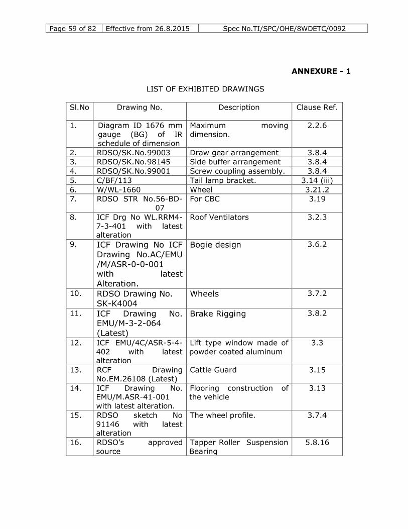
Page 59 of 82 Effective from 26.8.2015 Spec No.TI/SPC/OHE/8WDETC/0092
ANNEXURE - 1
LIST OF EXHIBITED DRAWINGS
Sl.No
.
Drawing No. Description Clause Ref.
1. Diagram ID 1676 mm
gauge (BG) of IR
schedule of dimension
Maximum moving
dimension.
2.2.6
2. RDSO/SK.No.99003 Draw gear arrangement 3.8.4
3. RDSO/SK.No.98145 Side buffer arrangement 3.8.4
4. RDSO/SK.No.99001 Screw coupling assembly. 3.8.4
5. C/BF/113 Tail lamp bracket. 3.14 (iii)
6. W/WL-1660 Wheel 3.21.2
7. RDSO STR No.56-BD-
07
For CBC 3.19
8. ICF Drg No WL.RRM4-
7-3-401 with latest alteration
Roof Ventilators 3.2.3
9. ICF Drawing No ICF
Drawing No.AC/EMU
/M/ASR-0-0-001 with latest
Alteration.
Bogie design 3.6.2
10. RDSO Drawing No.
SK-K4004
Wheels 3.7.2
11. ICF Drawing No. EMU/M-3-2-064
(Latest)
Brake Rigging 3.8.2
12. ICF EMU/4C/ASR-5-4-
402 with latest alteration
Lift type window made of
powder coated aluminum
3.3
13. RCF Drawing
No.EM.26108 (Latest)
Cattle Guard 3.15
14. ICF Drawing No. EMU/M.ASR-41-001
with latest alteration.
Flooring construction of the vehicle
3.13
15. RDSO sketch No
91146 with latest alteration
The wheel profile. 3.7.4
16. RDSO’s approved
source
Tapper Roller Suspension
Bearing
5.8.16
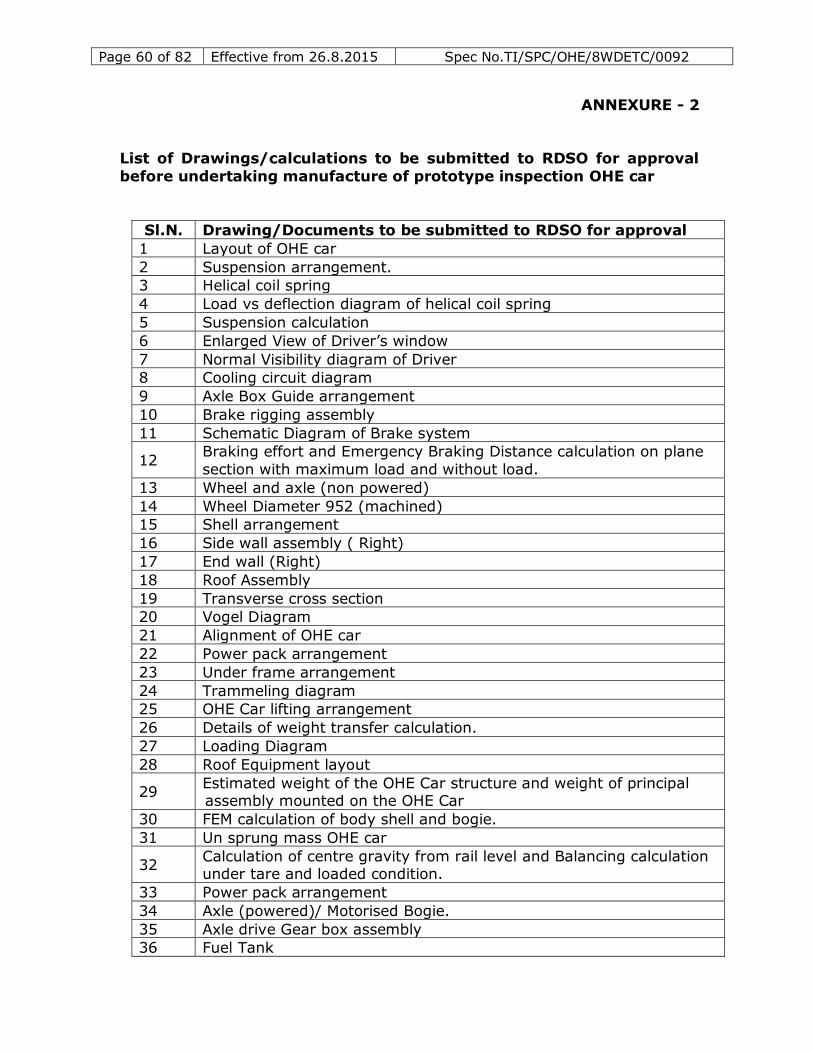
Page 60 of 82 Effective from 26.8.2015 Spec No.TI/SPC/OHE/8WDETC/0092
ANNEXURE - 2
List of Drawings/calculations to be submitted to RDSO for approval
before undertaking manufacture of prototype inspection OHE car
Sl.N. Drawing/Documents to be submitted to RDSO for approval
1 Layout of OHE car
2 Suspension arrangement.
3 Helical coil spring
4 Load vs deflection diagram of helical coil spring
5 Suspension calculation
6 Enlarged View of Driver’s window
7 Normal Visibility diagram of Driver
8 Cooling circuit diagram
9 Axle Box Guide arrangement
10 Brake rigging assembly
11 Schematic Diagram of Brake system
12 Braking effort and Emergency Braking Distance calculation on plane
section with maximum load and without load.
13 Wheel and axle (non powered)
14 Wheel Diameter 952 (machined)
15 Shell arrangement
16 Side wall assembly ( Right)
17 End wall (Right)
18 Roof Assembly
19 Transverse cross section
20 Vogel Diagram
21 Alignment of OHE car
22 Power pack arrangement
23 Under frame arrangement
24 Trammeling diagram
25 OHE Car lifting arrangement
26 Details of weight transfer calculation.
27 Loading Diagram
28 Roof Equipment layout
29 Estimated weight of the OHE Car structure and weight of principal assembly mounted on the OHE Car
30 FEM calculation of body shell and bogie.
31 Un sprung mass OHE car
32 Calculation of centre gravity from rail level and Balancing calculation under tare and loaded condition.
33 Power pack arrangement
34 Axle (powered)/ Motorised Bogie.
35 Axle drive Gear box assembly
36 Fuel Tank
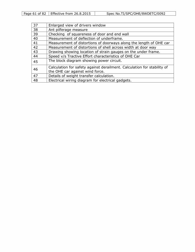
Page 61 of 82 Effective from 26.8.2015 Spec No.TI/SPC/OHE/8WDETC/0092
37 Enlarged view of drivers window
38 Ant pilferage measure
39 Checking of squareness of door and end wall
40 Measurement of deflection of underframe.
41 Measurement of distortions of doorways along the length of OHE car
42 Measurement of distortions of shell across width at door way
43 Drawing showing location of strain gauges on the under frame.
44 Speed v/s Tractive Effort characteristics of OHE Car
45 The block diagram showing power circuit.
46 Calculation for safety against derailment. Calculation for stability of the OHE car against wind force.
47 Details of weight transfer calculation.
48 Electrical wiring diagram for electrical gadgets.
Page 62 of 82 Effective from 26.8.2015 Spec No.TI/SPC/OHE/8WDETC/0092
ANNEXURE-3
The following details pertaining to electrical equipment shall be
submitted by the tenderer :
I. Diesel Engine
1. Exact description and model of the engine
2. Rated output under UIC site conditions
3. Site Conditions
- Ambient Temperature 55 oC - Altitude above mean sea level 1000 m
- Relative humidity above 40%
4. Rated speed at continuous rating
5. Type of cycle (two/four stroke)
6. Method of pressure charging - Pressure ratio of compressor at the rated output
- Single stage/two stage
- No. of turbochargers used
- Make and model of turbocharger
7 Type of exhaust system
Constant pressure/pulse type/multi pulse type 8 Method of cooling the charge air
9 Type of combustion chamber
10 Fuel injection equipment - Type of injection system
- Diameter of pump plunger
- Nozzle opening pressure
- Maximum duration of injection in degrees of crank 11. Number, arrangement and angle of cylinder.
12. Cylinder bore
13. Piston stroke 14. Cubic capacity/cylinder
15. Compression ratio
16. Firing order 17. Mean piston speed at rated speed
18. Brake mean effective pressure
19. Maximum combustion pressure at no load at minimum idling speed
20. Compression pressure at rated output 21. Minimum no-load idling speed – whether a low idle feature is provided
on the engine
22. Minimum no load speed under steady conditions 23. Speed ranges which should not be used continuously
24. Break away torque when the cooling water temperature is 5 oC
Page 63 of 82 Effective from 26.8.2015 Spec No.TI/SPC/OHE/8WDETC/0092
25. Minimum firing speed when the cooling water temperature is 50C or at
the lowest possible temperature of air intake air in rev/minute. 26. Torque resistance to the firing speed required to turn the engine when
the cooling water temperature is 5 0C at the lowest temperature of
intake air.
27. Piston i.Type of Piston used – whether single piece or composite
ii.No. of piston rings used.
iii.configuration of the rings iv.whether all the rings are located above the gudgeon pin
v.method of cooling required for the piston
vi.oil flow rate and temperature of oil at the piston oulet 28. Cooling system
i.Single/double cooling circuit
ii.Whether cooling system is pressurized
iii.Coolant temperature at outlet from the engine iv.Heat absorbed by the cooling water at the rated output
v.Rate of flow of water
vi.Inter cooler coolant temperature at entry to the cooler vii.Treatment recommended for water
29. Lube Oil System
i.Temperature of cooling oil with the indication of the point of measurement
ii.Maximum permissible temperature of cooling oil
iii.Heat absorbed by the cooling oil at rated output
iv.Swamp capacity v.Quantity required to commission
vi.Brand of oil recommended
30. Consumption of lubricating oil at the rated output in litres/hour and as
a percentage of fuel consumption.
31. Total capacity of lubricating oil pump (s) at the rated output speed in litres/min
32. Lubricating oil pressure at rated speed on entering the engine and at
the normal operating temperature
33. Maximum pressure of charge air in the intake manifold at the rated output.
34. Maximum pressure of gases at the turbo inlet at the rated output
35. Maximum speed of the turbocharger at rated output 36. Maximum permissible speed of the turbocharger.
37. Temperature of exhaust gases at turbo inlet at the rated output under
UIC and site conditions.
38. Maximum permissible temperature for which the turbocharger components have been designed
39. Heat balance of the engine
40. Weight of the engine complete with all items excluding water and lubricating oil.
41. Weight of water contained in the engine
Page 64 of 82 Effective from 26.8.2015 Spec No.TI/SPC/OHE/8WDETC/0092
42. Weight of oil contained in the engine
43. Weight of major components to be handled during maintenance i. Turbocharger
ii. Inlet cooler
iii. Crank case bare
iv. Crank shaft v. Piston and connecting rod
vi. Cylinder liner
vii. Cylinder head 44. Specific fuel consumption with the tolerance band under UIC and site
conditions – indicate the lower heating value of the fuel used in arriving
at the specific fuel consumption figures 45. Fuel oil consumption at idle in litres/hour
46. Requirement of fuel specification or any other restriction on the use of
duel with different sulphur contents
47. Number of such engines used in rail traction and the period since the engines have been in service and their performance
48. Safety devices provided on the engine
i. Over speed ii. low lube oil pressure
iii. overload
iv. high exhaust temperature v. high intake temperature
vi. any other
49. Specification of lube oil suitable for engine
50. Method of starting 51. Governor
i. Make and type
ii. Full load speed and drop characteristics iii. Torque required at the output shaft
52. Estimated period between top and major overhauls
53. periodicity of overhauling the following critical components i. Turbocharger
ii. Piston and piston rings
iii. Cylinder liner
iv. Air and exhaust valves v. Fuel pump
vi. Injector/Nozzle assembly
vii. Main bearings viii. Connecting rod bearings
54. Whether the diesel engine is suitable for satisfactory sustained
operation under :
i. Site conditions mentioned in para 2 ii. Dusty environment
iii. Frequent starting and stopping of diesel engine
iv. Average load factor 60% 55. Inlet and exhaust valve timings
Page 65 of 82 Effective from 26.8.2015 Spec No.TI/SPC/OHE/8WDETC/0092
56. Special design features of diesel engine highlighting the measures
which have been taken to achieve : i. Low specific fuel oil consumption
ii. Low lubricating oil consumption
iii. Low idling fuel oil consumption
iv. High reliability
- Maximum availability
- Reduced level of thermal and mechanical loading of critical components
57. General arrangement and dimensional details. 58. Characteristic curves of diesel engine under UIC and site conditions-
i) Curves for torque, output and specific fuel consumption expressed
and guaranteed without upper tolerance for different settings of the
injector pump, i.e. - Setting at which the engine develops the rated output at its rated
speed.
- Setting at which the engine develops ¾ of the rated output at its rated speed.
- Setting at which the engine develops ½ of the rated output at its
rated speed. - Setting at which the engine develops ¼ of the rated output at its
rated speed.
rated speed.
ii) The torque speed curve which the manufacturer considers to be
the maximum torque that should be used for rail traction. This
should cover the range from idling speed to the point corresponding to the international rated output at the rated speed.
iii) The curve of fuel consumption for no-load running, commencing from the minimum idling speed, expressed in litre/h
Page 66 of 82 Effective from 26.8.2015 Spec No.TI/SPC/OHE/8WDETC/0092
ANNEXURE -4
TRANSMISSION SYSTEM PARTICULAR
I Alternator
1. Description Make & type
2. Drive – Details of arrangement of bearings and coupling 3. Classification – No. poles, number of phases and phase
connections
4. Maximum permissible speed – Max. voltage a.c.
D.C. (i.e. rectified)
Max. current a.c.. 5. Rating -
i) One hour rating – Voltage, current, output & speed
ii) Continuous rating –
(a) High voltage (b) Low voltage
6. Class and type of insulation
a) Stator b) Rotor
7. Temperature rise
a) Rotor winding b) Stator winding
8. Resistance at 25 oC
a) Rotor winding
b) Stator winding 9. Synchronous impedance at max. frequency and load
10. Stator details
a) Overall dimensions b) No. and size of slots
c) Winding
i) Type ii) Conductor size and material
iii) Turns per coil
iv) Pitch
11. a) Rotor-type, No. of poles, length, bore, size and air gap b) Details of rotating armature exciter and rectifier assembly
12. Bearing:
a) Single or double b) Type-sealed or open
c) Grease-type, capacity and time interval for regreasing
d) Bearing life and shaft size calculations.
13. Mountings – Details of mounting arrangement. 14. Coupling-Type and details
15. Cooling
Calculations of cooling capacity
Page 67 of 82 Effective from 26.8.2015 Spec No.TI/SPC/OHE/8WDETC/0092
16. Weight
a) Complete unit with accessories b) Alternator only
c) Rotor (with fan if any)
17. Characteristic curves
a) Natural curves b) V-I curves (Notch wise)
c) Efficiency vs. current
18. Tests : Results of – a) Type test
i) Temp. rise test and its calculation
ii) Rating iii) Characteristic curves
b) Routine test
i) Temperature Rise Test
ii) Over speed Test iii) Dielectric Test
19. Tractive Efforts vs. Road Speed curve along with Alternator Rectifier
Current vs. Voltage curve showing method of calculations.
II Auxiliary Alternator with Rectifier – Regulator
1. Make
2. Model
3. Continuous & short time rating and details of voltage and current
regulation 4. Bearing life and shaft size calculations.
5. Weight
III Traction Motor
1.1 Type 1. V - volts
2. I - Amps
3. N – rpm
4. S – km/h 5. N max/N
6. N shaft
7. N max
1.2 Armature
1. Diameter. 2. Length
3. Air ducts – surface
- section 4. No. of slots.
5. Conductor size.
Page 68 of 82 Effective from 26.8.2015 Spec No.TI/SPC/OHE/8WDETC/0092
6. Conductor area.
7. A) Continuous........ for ........ amps 1 Hour .... .... for ....... amps
8. Continuous ............. A/sq.mm for ....... A
1 Hour............. A/sq. mm for ....... A
9. A) Continuous .......... 1 Hour ...........
10. ADNL 10-9 .......... at cont FF ...... at 1 hr rating
...... at S max.
11. B (B/A) ......... at cont FF
......... at 1 hr rating
........ at S max.
12. S max ....................km/h 13. N max ................... rpm
14. Wheel dia (half worn)
15. Gear Ratio (New) 16. Suspension
17. Armature bearing – commutator end
- pinion end 18. Turns/coil
19. Type of winding
20. Coil Throw
21. Length mean turn 22. Resistance at 110°C
23. Inductance at 30 cps.
24. Weight of copper (kg) 25. Tooth volume
26. Core volume
27. Arm. Turns/pole 28. Arm. At/pole - FF
29. Arm. Core int.dia
30. Net core depth
31. Arm. Steel tech. spec. 32. Banding material
33. No. of bands cc
34. Band width. 35. S (cont) .................. M/s ................. rpm ............ km/h
1.3 Main poles
1. Insulation
2. Number
3. External ................ D Internal ............ D
Page 69 of 82 Effective from 26.8.2015 Spec No.TI/SPC/OHE/8WDETC/0092
4. Number of turns per pole.
Frame end Arm end
5. Conductor dimension – Frame end
- Arm. end
6. Current density - Frame end - Armature end.
7. Length of mean turn - Frame end
- Armature End
8. Resistance at 110°C
9. Inductance at 50 cps 10. Radial gap length - Tip
Centre
Mean
Eff
11. Field At ------------- @ FF
Arm. AT
12. Pole Arc.
13. Total fringe 14. Eff. Pole arc
15. Eff gap area
16. Pole flux density. 17. Pole copper weight.
18. Pole steel tech spec.
19. Yoke steel tech. spec.
1.4 Commutation poles
1. Insulation 2. Number
3. External ............ D Internal ........... D
4. Number of turns per pole – Frame end - Arm end
5. Conductor dimensions - Frame end
- Arm end 6. Current density - Frame end
- Arm end
7. Length of mean turn - Frame end
- Arm end 8. Resistance at 110° c
9. Inductance a t 50 cps
10. Radial gap length - Tip - Centre
- Mean
- Eff
Page 70 of 82 Effective from 26.8.2015 Spec No.TI/SPC/OHE/8WDETC/0092
11. Int. Pole flux density
12. Copper weight 13. Pole steel tech. spec.
1.5 Equalisers (commutator end)
1. Total number 2. Copper weight
1.6 Ventilation 1. Number of fans
2. Flow ................. m3/min (at continuous speed)
3. N ............. rpm .............. 1.35 N max (overspeed)
1.7 Commutator and brushes
1. Useful diameter
2. Useful length
3. No. Of commutator bars. 4. Bar pitch
5. Average bar/brush
6. Voltage between segments 7. Reactance voltage
8. Insulation thickness between bars.
9. Number of brush arms
10. Brush/arm 11. Brush/size
12. Quality
13. Current density For ........ Amps (cont)
For ........ Amps (1Hr.)
For ........ Amps (start)
14. S (cont) .......... m/s ............ rpms
15. S (1hr) ........... m/s ............. rmps 16. S (max ) .......... m/s ........... km/h
17. Type of commutator construction
1.8 Weight
1. Motor without gearing ......... kg ............ N
2. Armature without pinion .......kg ............ N CONT 1 Hr
kg N kg N
3. Wt/kw 4. Wt/hp
5. Pinion (kg)
Page 71 of 82 Effective from 26.8.2015 Spec No.TI/SPC/OHE/8WDETC/0092
6. Gear wheel (kg)
7. Gear case (kg) 8. Frame (kg)
9. Total weight (kg)
1.9 Losses and Efficiency 1 Hour Continuos
1. I2 R (ARM) 2. I2 F (Series)
3. Core
4. Brush drop 5. Brush friction
6. Bearing F and W
1.10 Magnetic Circuit
1. 1 hr rating values
Magnetic FF Leakage
Area length B AT
Tooth Core
Pole
Yoke
Gap
Total AT
2.0 Gears and pinions
1. Type of gearing 2. Module
3. Grade of steel used for pinions and gears
4. Particulars of heat treatment
5. Kilometerage guarantee for bull gears 6. Kilometerage guarantee for pinions
7. Material and type of construction for gear case.
IV. Power Rectifier
1. Diode – Make & type
2. No. of parallel paths & no. Of diodes /path 3. Overall dimensions of rectifier unit
4. Ratings
a) Current Rating - max. Cont. (direct) forward current
b) Thermal Rating
Page 72 of 82 Effective from 26.8.2015 Spec No.TI/SPC/OHE/8WDETC/0092
- Max. & Min. Operating junction temp
- Max. & Min. Storage temperature 5. Resistance
a) Forward
b) Reverse
6. Details of damping circuit a) Resistance value & circuit
b) Capacitance value & connection
7. Bus bar arrangement 8. Weight
9. Mounting arrangement
10. Characteristic curves a) Voltage vs. Current
b) Power dissipation as a function of reference point
temperature
11. Semi-conductor fuses a) Make
b) Fusing characteristics
c) I2 t characteristic

Page 73 of 82 Effective from 26.8.2015 Spec No.TI/SPC/OHE/8WDETC/0092
ANNEXURE-5
POWER RECTIFIER SPECFICATION
1.0 Technical requirements including the design features.
1.1 The rectifier unit shall comprise of three phase full wave bridges using silicon diodes. It shall prefer-ably consist of three separate bridges
connected in parallel on the input and output side.
1.2 Device Rating
1.2.1 The current rating of the devices shall be such that even under one bridge (n-1) failure condition the rectifier, with two remaining effective
three phase bridges shall be capable of meeting the full Tractive
power duty/duty cycles and abnormal conditions including short
circuit.
1.2.2 An unbalance of 20% shall be considered in the sharing of the load
between the bridges, for design purposes, though, in actual testing the unbalance shall be limited to 10% only.
1.2.3 The diodes shall have a PIV rating of not less than 3000 V or not less than 2.8 times the maximum crest working voltage whichever is
higher.
1.2.4 Characteristics curves of the diodes indicating power loss, forward voltage drop, slope resistance, thermal resistance characteristics and
characteristics curves of the fuse shall be submitted in A4 size.
1.2.5 The permissible junction and case temperature for the device shall be
declared.
1.2.6 Diodes in the cubicle shall belong to one FVD group while they shall be
in three consecutive FVD groups for all the units to be supplied. FVD
shall have a band width of 50 milli-volts at the full rated diode
current.
1.2.7 The semiconductor device junction temperature shall be calculated for
(n-1) condition operation at rated permissible current for three duty cycles after temperature stabilisation in heat run test at a current
value equal to the one hour rating of the traction motors.
For this purpose, RMS value of the starting current over the notching up duration for 1 minute followed by RMS value of the steady state
one hour rating current for eight minutes, followed by zero current for
thirty seconds will form one cycle. At the end of three such successive cycles the junction temperature shall be computed. There shall be
enough margin.
Page 74 of 82 Effective from 26.8.2015 Spec No.TI/SPC/OHE/8WDETC/0092
1.2.8 The devices shall meet all the requirements as per IS:7788. 1.2.9 The use of capsule type diodes are acceptable.
1.3 Snubber and Damping Networks
1.3.1 Each diode shall be provided with RC network to overcome the hole
storage effect.
1.3.2 RC damping networks shall be provided to protect against switching
surges expected. Supporting calculations shall be furnished.
1.3.3 The resistors and capacitors for the RC network shall be respectively
of silicon coated, non-bursting type suitable for traction duty duly
approved by RDSO.
1.3.4 Resistances – Silicon coated, non-inductive, wire wound resistors and
stud mounting type with lug terminals shall be used. The wattage
ratings shall be three times the calculated maximum wattage in the circuit under worst loading and high ambient conditions.
1.3.4 Capacitors – shall be of non- bursting type. The clearance and creepage distance between the live terminals and also the body shall
comply with table 5 of IS-7788. The maximum working voltage across
any capacitor shall not exceed 50% of the rated repetitive voltage. In
the case of hole storage capacitors the voltage rating shall not to be less than PIV rating of the semiconductor device. The capacitors shall
be designed for operation at 85 oC. The capacitors will be of IOHE CAR
of GE make. Use of indigenous make shall have the prior approval of RDSO.
1.4 Fuses
1.4.1 The diodes shall be protected by semi-conductor fuses whose selection
shall be supported by the calculation to ensure their matching with the
diodes. I 2 t values for the diode shall be more than the I2 t for the fuse. Diode and fuse characteristics shall be furnished along with the
tender. The fuse selection shall withstand the short circuit current
expected.
Note: The expected short circuit current/impedance with duration
shall be specified.
1.4.2 The semiconductor fuses used for the diode protection shall be of
approved makes. Fuses of la Ferraz, Bussman or English Electric make
only are approved at present.
Page 75 of 82 Effective from 26.8.2015 Spec No.TI/SPC/OHE/8WDETC/0092
1.4.3 Since the rectifier unit consists of multi-bridges connected in parallel,
signaling fuses, associated suitable relays and micro switches shall be provided to given an indication in case of single bridge failure and to
trip the load on the alternator in case of double bridge failure.
1.5 Constructional Features
1.5.1 The tenderer shall submit details of the overall dimensions of the
rectifier along with the offer.
1.5.2 The cubicle as well as internal sub-assemblies shall be
interchangeable from one unit to the other.
1.5.2.1 The cubicle shall be of cold rolled steel metal sheet with strong
frame work suitable for underframe mounting to withstand shocks
and vibrations encountered in service run with a maximum speed of 105 kmph. This shall be protected against damages due to ballast
hitting. The minimum thickness of panels shall be 12.0mm and may
be increased as panel width increases as mentioned below.
Maximum Panel Widht Thickness
Upto 750 mm 2.0 mm > 750mm but < 1500 mm 2.5 mm
>1500 mm but < 2000 mm 3.2 mm
1.5.2.3 The cubicle shall be provided with two numbers of earthing bosses with M12x20 tapped hole on each side. The bosses shall have 5 mm
thick copper/brass plate brazed.
1.5.3 Easily interchangeable inspection doors with locking arrangement
shall be provided to facilitate easy access to vital parts like fuses,
diodes etc.
1.5.4 Withdrawable bridge racks consisting of diodes, fuses and associated
components shall be provided on rails for withdrawing during
maintenance.
1.5.5 The equipment layout shall provide easy accessibility for
maintenance.
1.5.6 Suitable ventilating louvers shall be provided for air outlet.
1.5.7 The devices with heat sink shall be mounted of FRP (SMC)/ Epoxy panels of adequate thickness (not less than 10mm) with hand holds
for easy removal and insertion in position.
1.5.7.1 Heat sinks shall be of extruded constructions. The sand casted or
gravity die casted are not acceptable. OHE care shall be taken to
Page 76 of 82 Effective from 26.8.2015 Spec No.TI/SPC/OHE/8WDETC/0092
have proper surface finish and surface flatness. Current collection
through heat sink shall be avoided. In case it is not possible, the heat sink device mounting surface and the current collection contact
area shall be treated to prevent electro corrosion and bimetallic
action.
1.5.7.2 Recommended optimum pressures for mounting the devices on the
heat sink shall be furnished. Suitable thermal compound having low
thermal resistance shall be used to fill up the void between the mating surfaces of heat sink and device. The same shall seal the
joint against moisture.
Note : Transient thermal impedance characteristics curves of the heat sink
at different cooling air rate shall be submitted for approval.
1.5.8 Blower shall be mounted as an independent unit connected suitably to the duct with adequate resistance to reduce vibrations. Blower
Motor shall be easily accessible for maintenance.
1.5.9 The unit shall be painted with two coats of red oxide followed by two
coats of white stove enamel on inside and aircraft grey on outside to
IS-5:1961.
1.5.10 Fasteners used in the cubicle shall be of minimum M6 and screws of
M10 and above shall be of high tensile strength.
1.5.10.1 Studs of the terminal board shall have adequate current rating with
minimum size not less than M6 and shall be coated with cadmium
plating. The method of connections shall be such that the current should not pass through the studs. Number of connections per stud
shall be limited to two. The insulating boards shall be fire retarding
FRP sheet moulding type. They shall pass the fire retardant test as per specification IS – 2046. Separate terminal board shall be
provided for different voltages. Positive and negative terminals shall
be separately located. All the terminal studs shall be legibly
identified with their circuit numbers.
1.5.11 The bus sizes on the a.c. & d.c. sides shall be such that the final
temperature when corrected to 47 oC ambient is not more than 100 oC copper bus bar must be tin plated after bending/drilling the
required holes, with thickness of plating not less than 8 microns.
1.5.11.1 The bus bars used shall be of high conductivity electrolytic copper as per IS:613 with current density not exceeding 4 A/mm2. The bus
bar shall have colour code with red, yellow and blue on the a.c. side
and brown and black respectively for positives and negatives on the d.c. side. Bus bars supports shall be made with insulators and be
Page 77 of 82 Effective from 26.8.2015 Spec No.TI/SPC/OHE/8WDETC/0092
identified by engraving the respective circuit numbers with contrast
colour paint applied on the engraved marking.
1.5.12 All the cable wire ends shall be terminated with suitable sockets
using proper dies and tools.
1.5.13 Cables – All the cables/wires shall be multi-strand flexible insulated
cables conforming to E/14-01/parts I,II and III. PTFE insulated
cables of adequate voltage rating and size shall be used for inter-connection snubber circuits and signaling fuses.
1.5.14 All the wires shall be numbered with cables ferrules of approved design on both ends of the cables.
1.5.15 Wiring layout- The quality of workmanship and layout of wiring shall
be of high standard to ensure long life. The following guidelines shall be kept in view.
a) Complete separation of low, medium and high voltages. b) Separation temporarily and permanently energised cables with
separate bunching.
c) Avoiding of sharp bends. d) Provision of grommets for cables entries.
e) Supporting of cable bunches with insulated supports using nylon
ties.
2.0 Tests :
2.1 Type tests on silicone diodes – At least ten diodes shall be subjected to type tests as per IS-7788 in the presence of RDSO Inspecting
Official sufficiently in advance to avoid delay of prototype testing of
the rectifier unit.
2.2 Routine tests on each diode shall be conducted as per IS-7788 and the
results recorded by the manufacturer. 10% of the lot offered selected
at random shall be subjected to routine tests in the presence of inspecting official of RDSO.
2.3 Type test on Rectifier assembly:
2.3.1 Temperature rise test – with normal ventilation, the rectifier shall be
subjected to the duty cycle expected on the traction motors with the
temperature maintained at 47oC and until steady temperature is obtained. The temperature stabilisation can be deemed when three
successive readings taken at 15 minutes intervals do not vary by more
than 0.5 oC. The maximum diode junction temperature arrived shall be less than the permissible junction temperature as declared by the
diode manufacturer after the duty cycles as described in clause1.2.7
Page 78 of 82 Effective from 26.8.2015 Spec No.TI/SPC/OHE/8WDETC/0092
of Annexure-5. The temperature rise test shall be conducted both for
n and (n-1) bridge conditions.
2.3.2 Heat run test with (n-1) parallel paths will be conducted on first
prototype and afterwards the test may be conducted corresponding to
normal duty cycle with all bridges in operation.
2.3.3 Fuse blade temperature and bus temperature shall not exceed 100
deg. C for (n-1) parallel paths.
2.3.4 Instruments used for type testing shall be of 0.5 clause accuracy and
shall have been calibrated within 6 months from the date of testing.
2.3.5 Power losses measured for the diodes shall not exceed 10% of the
declared value.
3. Guarantee:
The diodes of the main Rectifier shall be guaranteed for satisfactory working for a period of five years from the date of commissioning.

Page 79 of 82 Effective from 26.8.2015 Spec No.TI/SPC/OHE/8WDETC/0092
ANNEXURE - 6
DESIGN OF TRACTION MOTORS AND SWITCH GEARS
1.0 Number and arrangement of motors
1.1 Each OHE car shall be fitted with four numbers of DC series traction
motors, two on each bogie. The motors shall be axle hung nose
suspended type and shall be series wound, working on the pulsating current. The motors shall be designed to comply with the conditions
stipulated in IEC-60349. The temperature rise allowed by IEC shall be
reduced by 30 Deg. C, to allow for higher ambient temperatures. All motors shall be permanently connected in parallel.
1.2 The motor shall be designed to comply with the operating
requirements specified with exceeding the temperature-rise limits.
1.3 The motors shall be so designed that severe damage will be avoided in
case of transients such as fluctuations of the voltage, switching surges. The traction motor circuit shall comprise all the protective
devices which will prevent any damage to them due to transients. The
general design and maintenance of the motors shall be of the highest standard in accordance with the modern traction practices. The
particulars of the motors shall be furnished as per Annexure 4.
1.4 The motor contactor shall be of Electro-pneumatic type with blow out
coils and arcing horns etc. to break the current without detriment to their working parts or adjacent equipment. All contact tips, interlocks,
pins and plungers shall be easily assessable for maintenance. The
motor contactor shall be capable to open the circuit on overload and under fault condition.
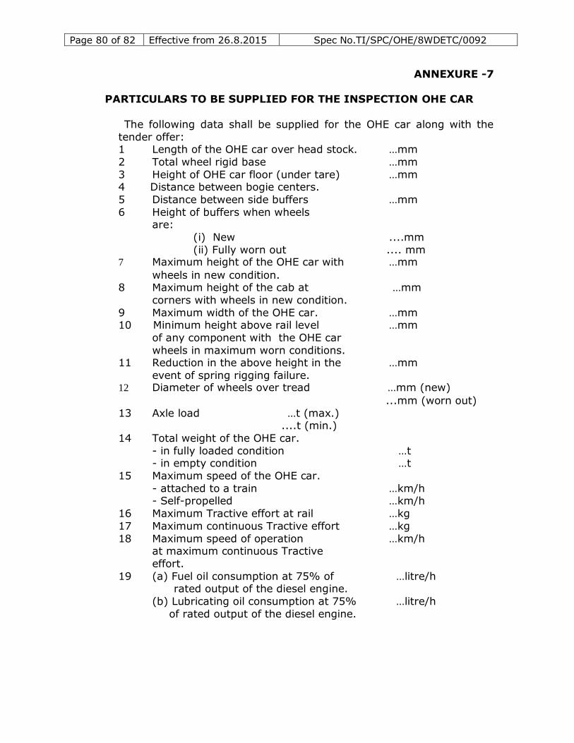
Page 80 of 82 Effective from 26.8.2015 Spec No.TI/SPC/OHE/8WDETC/0092
ANNEXURE -7
PARTICULARS TO BE SUPPLIED FOR THE INSPECTION OHE CAR
The following data shall be supplied for the OHE car along with the
tender offer: 1 Length of the OHE car over head stock. …mm
2 Total wheel rigid base …mm
3 Height of OHE car floor (under tare) …mm 4 Distance between bogie centers.
5 Distance between side buffers …mm
6 Height of buffers when wheels are:
(i) New ....mm
(ii) Fully worn out .... mm 7 Maximum height of the OHE car with …mm
wheels in new condition. 8 Maximum height of the cab at …mm
corners with wheels in new condition.
9 Maximum width of the OHE car. …mm 10 Minimum height above rail level …mm
of any component with the OHE car
wheels in maximum worn conditions. 11 Reduction in the above height in the …mm
event of spring rigging failure. 12 Diameter of wheels over tread …mm (new)
...mm (worn out)
13 Axle load …t (max.) ....t (min.)
14 Total weight of the OHE car.
- in fully loaded condition …t - in empty condition …t
15 Maximum speed of the OHE car.
- attached to a train …km/h - Self-propelled …km/h
16 Maximum Tractive effort at rail …kg
17 Maximum continuous Tractive effort …kg
18 Maximum speed of operation …km/h at maximum continuous Tractive
effort.
19 (a) Fuel oil consumption at 75% of …litre/h rated output of the diesel engine.
(b) Lubricating oil consumption at 75% …litre/h
of rated output of the diesel engine.
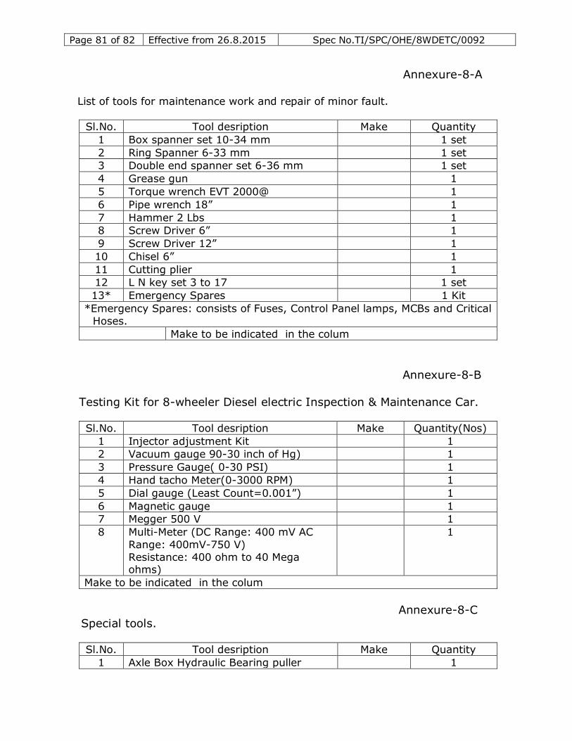
Page 81 of 82 Effective from 26.8.2015 Spec No.TI/SPC/OHE/8WDETC/0092
Annexure-8-A
List of tools for maintenance work and repair of minor fault.
Sl.No. Tool desription Make Quantity
1 Box spanner set 10-34 mm 1 set
2 Ring Spanner 6-33 mm 1 set
3 Double end spanner set 6-36 mm 1 set
4 Grease gun 1
5 Torque wrench EVT 2000@ 1
6 Pipe wrench 18” 1
7 Hammer 2 Lbs 1 8 Screw Driver 6” 1
9 Screw Driver 12” 1
10 Chisel 6” 1
11 Cutting plier 1 12 L N key set 3 to 17 1 set
13* Emergency Spares 1 Kit
*Emergency Spares: consists of Fuses, Control Panel lamps, MCBs and Critical
Hoses.
Make to be indicated in the colum
Annexure-8-B
Testing Kit for 8-wheeler Diesel electric Inspection & Maintenance Car.
Sl.No. Tool desription Make Quantity(Nos)
1 Injector adjustment Kit 1
2 Vacuum gauge 90-30 inch of Hg) 1
3 Pressure Gauge( 0-30 PSI) 1
4 Hand tacho Meter(0-3000 RPM) 1
5 Dial gauge (Least Count=0.001”) 1
6 Magnetic gauge 1 7 Megger 500 V 1
8 Multi-Meter (DC Range: 400 mV AC
Range: 400mV-750 V)
Resistance: 400 ohm to 40 Mega ohms)
1
Make to be indicated in the colum
Annexure-8-C Special tools.
Sl.No. Tool desription Make Quantity
1 Axle Box Hydraulic Bearing puller 1
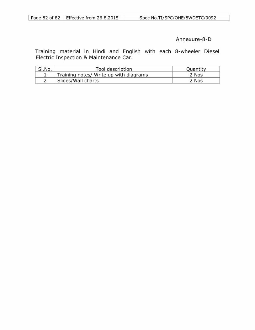
Page 82 of 82 Effective from 26.8.2015 Spec No.TI/SPC/OHE/8WDETC/0092
Annexure-8-D
Training material in Hindi and English with each 8-wheeler Diesel
Electric Inspection & Maintenance Car.
Sl.No. Tool description Quantity
1 Training notes/ Write up with diagrams 2 Nos
2 Slides/Wall charts 2 Nos