Embed Size (px)
Citation preview
Graphics Rendering Pipeline II
CS 211A
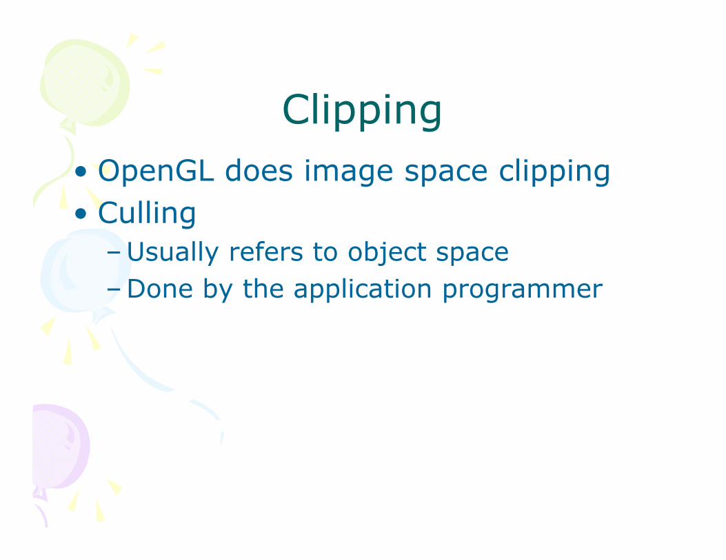
Clipping• OpenGL does image space clipping• Culling
–Usually refers to object space–Done by the application programmer
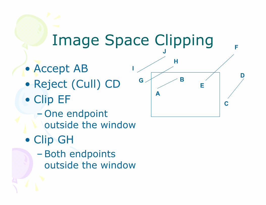
Image Space Clipping
• Accept AB• Reject (Cull) CD• Clip EF
–One endpoint outside the window
• Clip GH–Both endpoints
outside the window
G
H
A
BE
F
C
DI
J
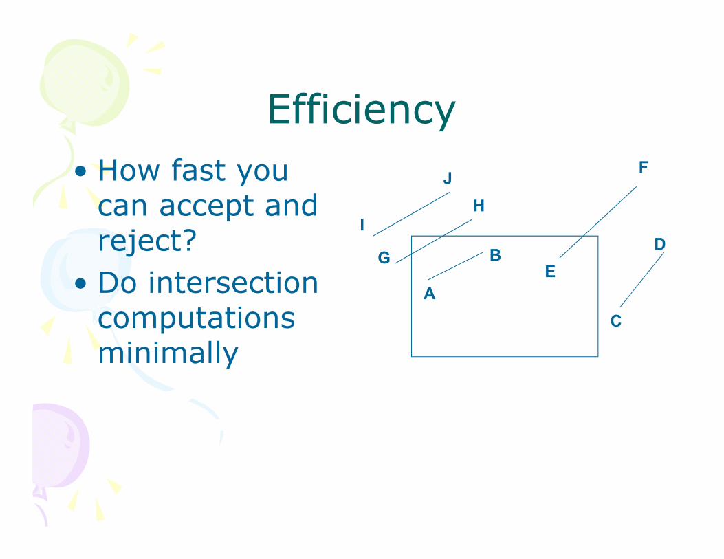
Efficiency • How fast you
can accept and reject?
• Do intersection computations minimally
G
H
A
BE
F
C
DI
J
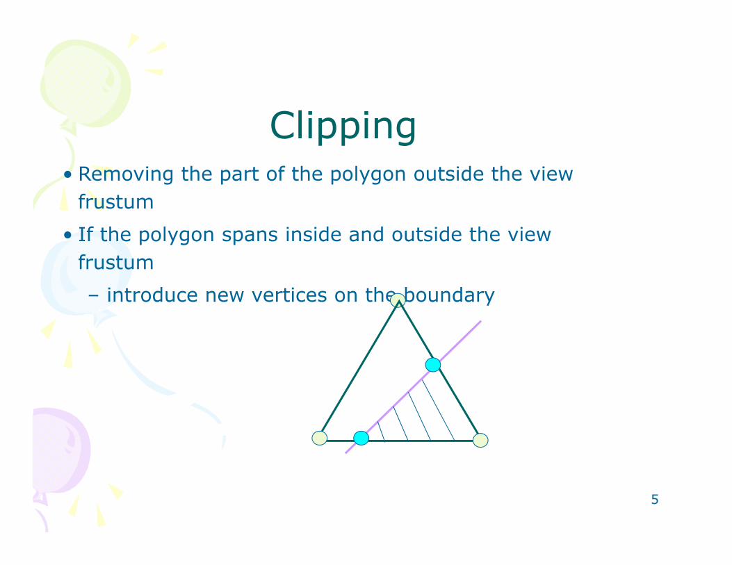
Clipping• Removing the part of the polygon outside the view
frustum• If the polygon spans inside and outside the view
frustum– introduce new vertices on the boundary
5
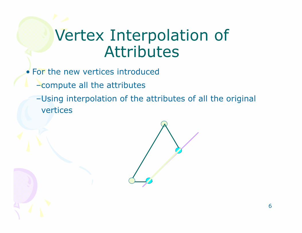
Vertex Interpolation of Attributes
• For the new vertices introduced–compute all the attributes –Using interpolation of the attributes of all the original vertices
6
Clipping• Every triangle needs to go through the process of
clipping• Fast acceptance or rejection test for primitives
completely inside or outside the window is critical• Such test achieved in multiple ways
– Using Bounding Boxes (Cohen Sutherland)– Using Logic Operations (Cohen Sutherland)– Using Integer Operations (Liang-Barsky)– Using Pipelining (Sutherland Hodgeman)
7
Spatial Subdivision• Can be used for both image space
and object space culling• Based on bounding boxes or volumes
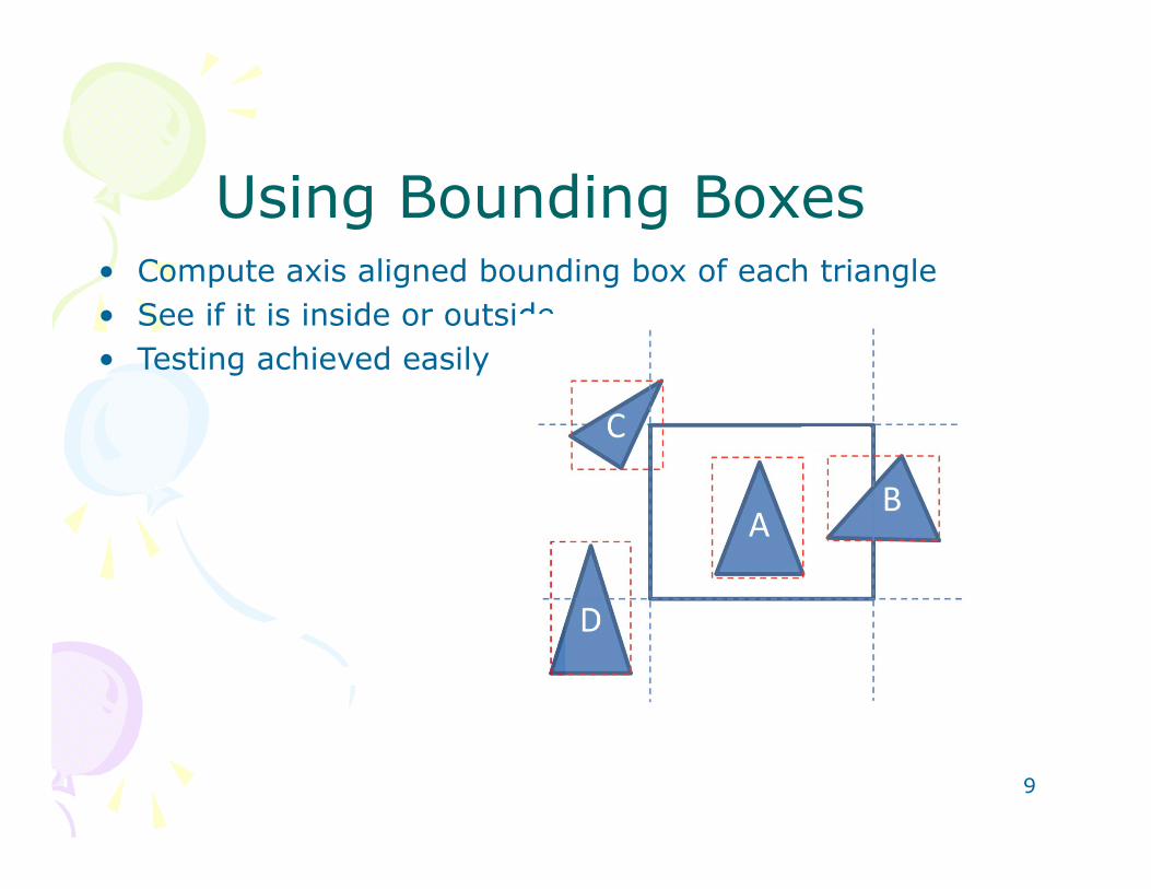
Using Bounding Boxes• Compute axis aligned bounding box of each triangle• See if it is inside or outside• Testing achieved easily
9
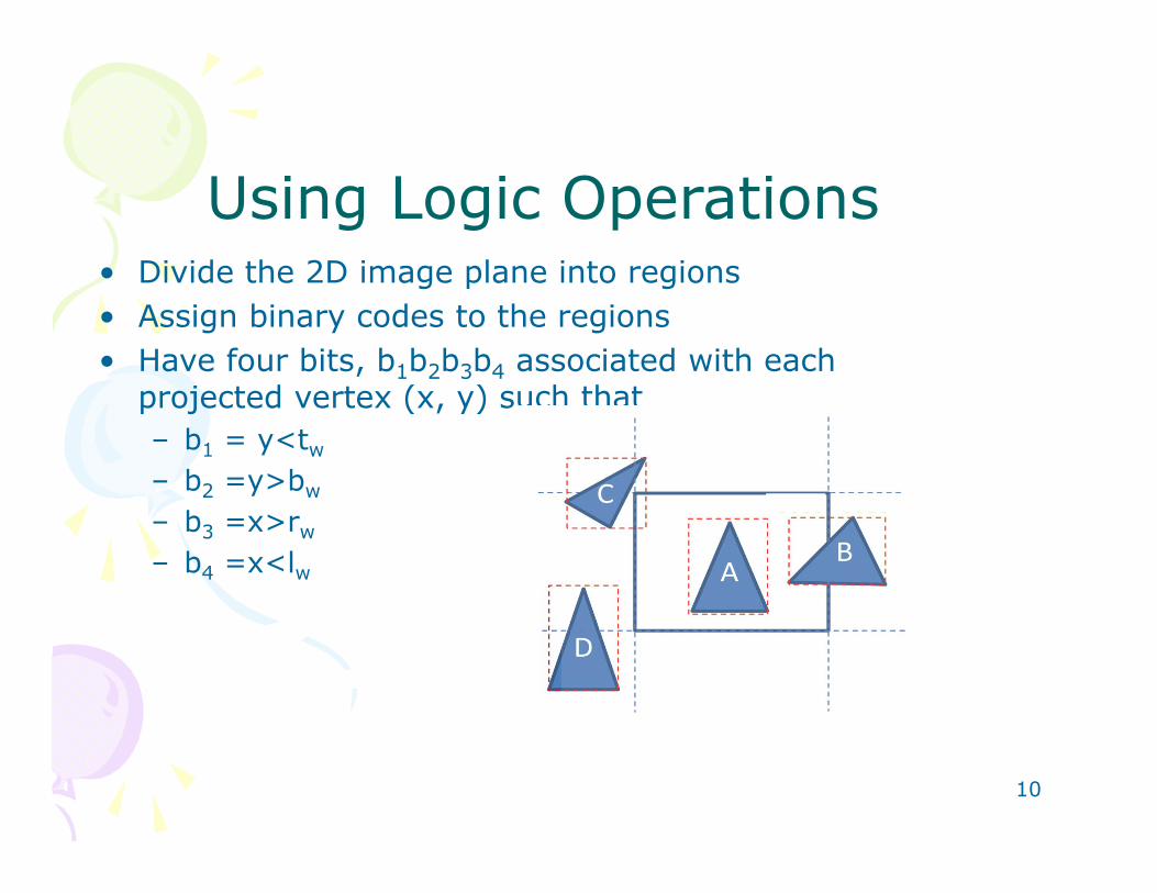
Using Logic Operations• Divide the 2D image plane into regions • Assign binary codes to the regions • Have four bits, b1b2b3b4 associated with each
projected vertex (x, y) such that– b1 = y<tw
– b2 =y>bw
– b3 =x>rw
– b4 =x<lw
10
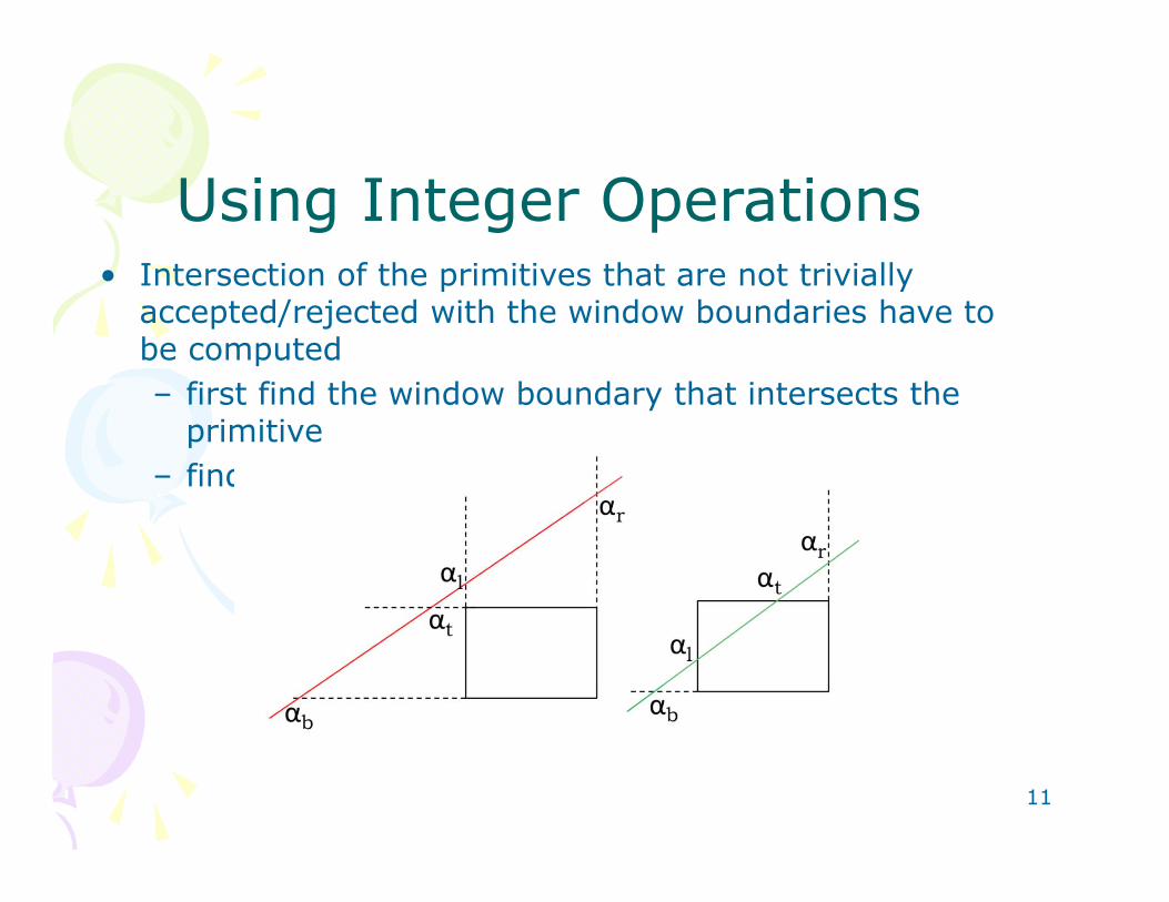
Using Integer Operations• Intersection of the primitives that are not trivially
accepted/rejected with the window boundaries have to be computed – first find the window boundary that intersects the
primitive – find the exact intersection
11
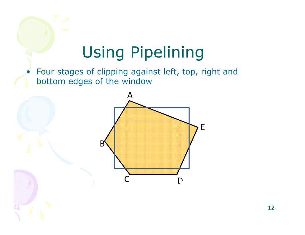
Using Pipelining• Four stages of clipping against left, top, right and
bottom edges of the window
12
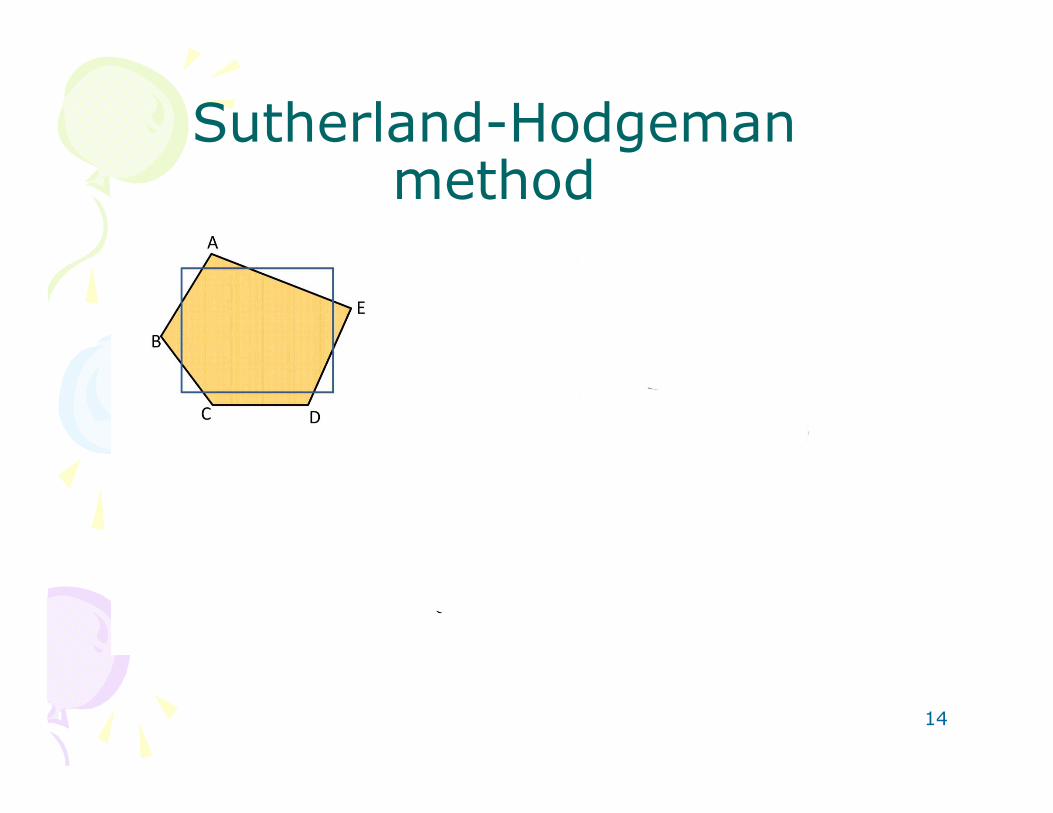
Using Pipelining• Sutherland-Hodgeman method • 1. If first vertex is IN output the same, or else nothing
2. Loop through the rest of the vertices testing transitions.
– (a) If IN-TO-OUT, output intersection with edge
– (b) If IN-TO-IN, output the vertex
– (c) If OUT-TO-IN, output intersection with edge and the
vertex
– (d) If OUT-TO-OUT, output nothing
13
Sutherland-Hodgeman method
14
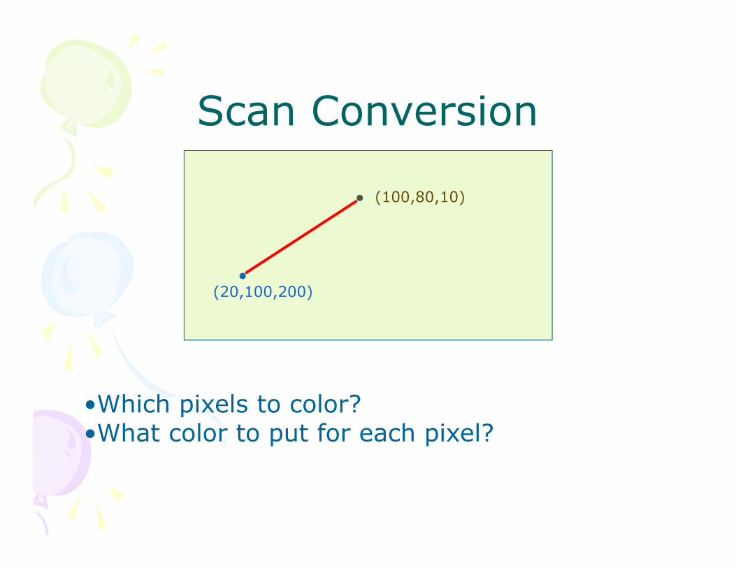
Scan Conversion
(20,100,200)
(100,80,10)
•Which pixels to color?•What color to put for each pixel?
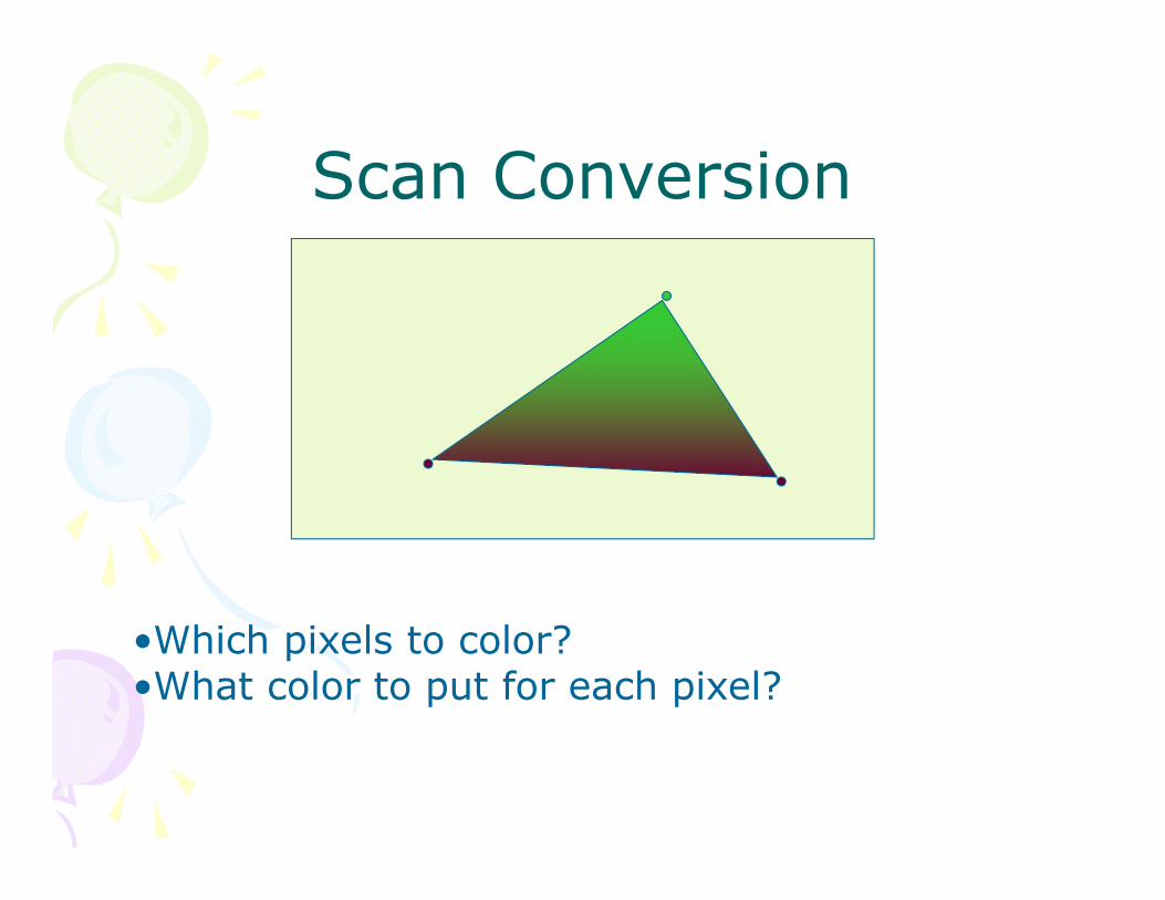
Scan Conversion
•Which pixels to color?•What color to put for each pixel?
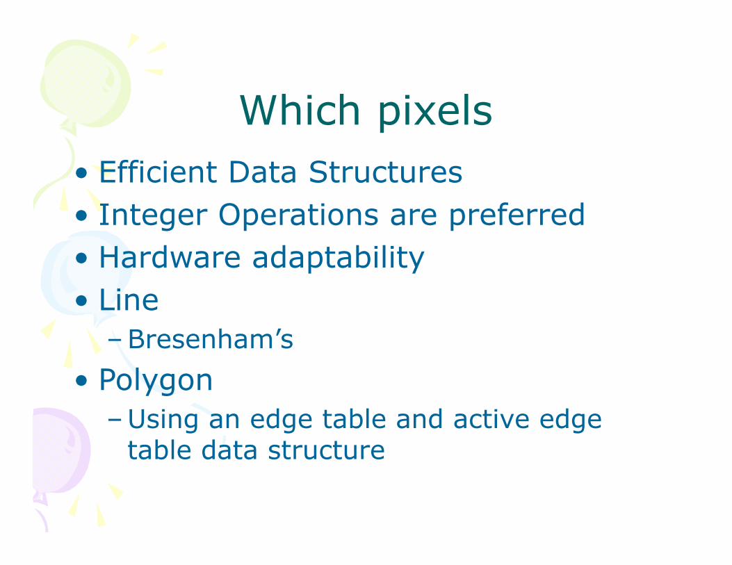
Which pixels• Efficient Data Structures• Integer Operations are preferred• Hardware adaptability• Line
–Bresenham’s• Polygon
–Using an edge table and active edge table data structure
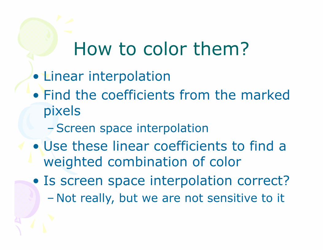
How to color them?• Linear interpolation• Find the coefficients from the marked
pixels–Screen space interpolation
• Use these linear coefficients to find a weighted combination of color
• Is screen space interpolation correct?–Not really, but we are not sensitive to it
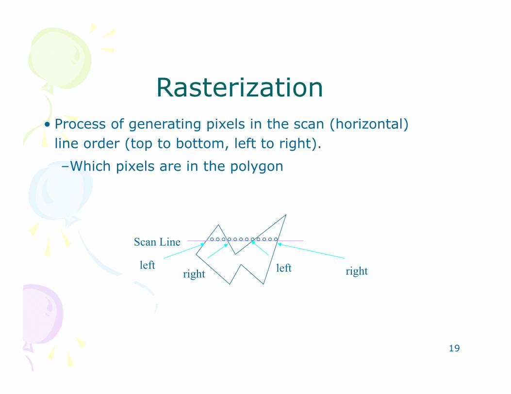
Rasterization• Process of generating pixels in the scan (horizontal)
line order (top to bottom, left to right). –Which pixels are in the polygon
19
left rightright left
Scan Line
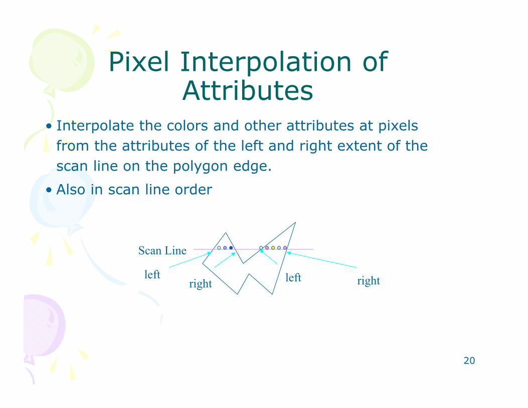
Pixel Interpolation of Attributes
• Interpolate the colors and other attributes at pixels from the attributes of the left and right extent of the scan line on the polygon edge.
• Also in scan line order
20
left rightright left
Scan Line
Hidden Surface Removal• Z buffer (size of the framebuffer)• Initialize• Store z when projecting vertices• During scan conversion
– Interpolate 1/z– If depth is smaller than existing value
• Set new depth• Color pixel
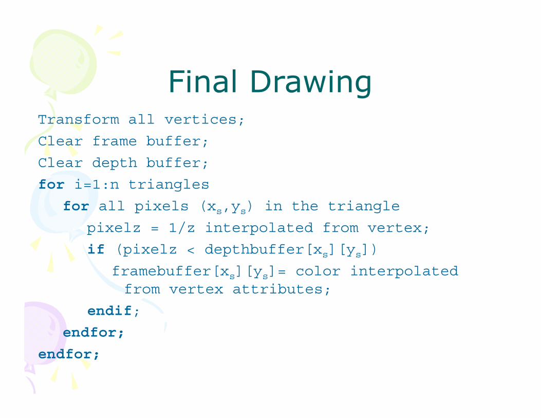
Final DrawingTransform all vertices;
Clear frame buffer;
Clear depth buffer;
for i=1:n triangles
for all pixels (xs,ys) in the triangle
pixelz = 1/z interpolated from vertex;
if (pixelz < depthbuffer[xs][ys])
framebuffer[xs][ys]= color interpolated from vertex attributes;
endif;
endfor;
endfor;
Two Efficiency Measures• Spatial Subdivision• Hidden Surface Removal
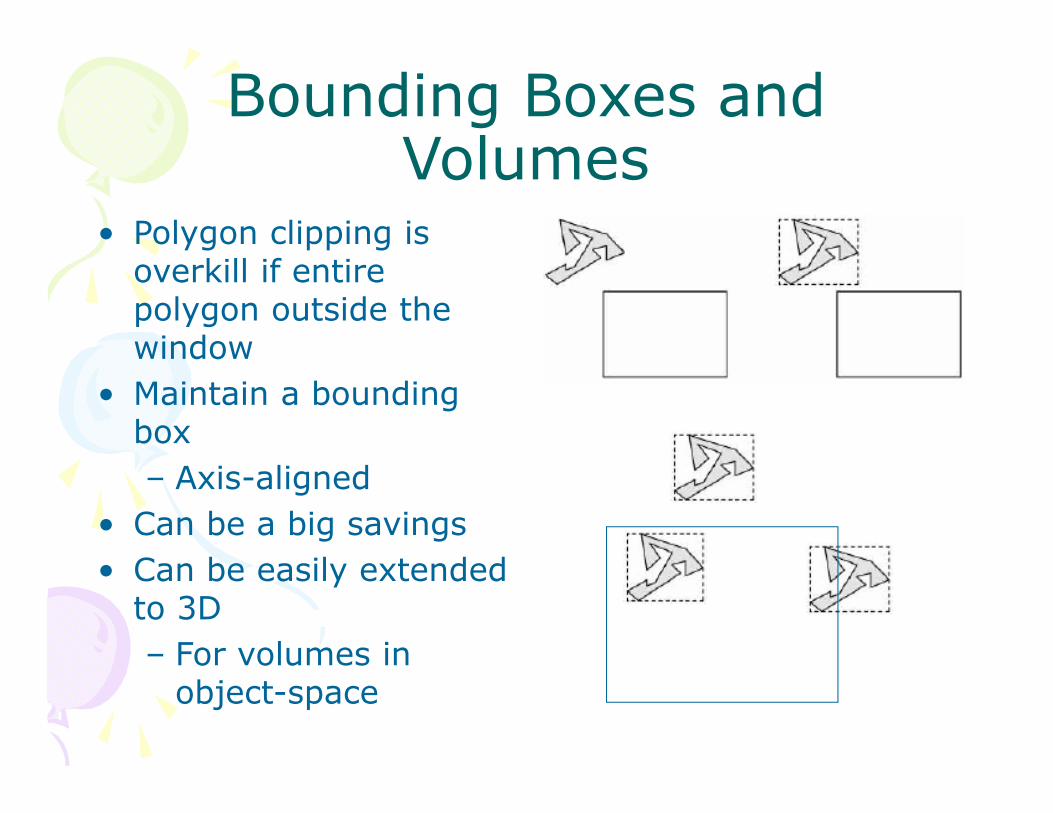
Bounding Boxes and Volumes
• Polygon clipping is overkill if entire polygon outside the window
• Maintain a bounding box– Axis-aligned
• Can be a big savings• Can be easily extended
to 3D– For volumes in
object-space
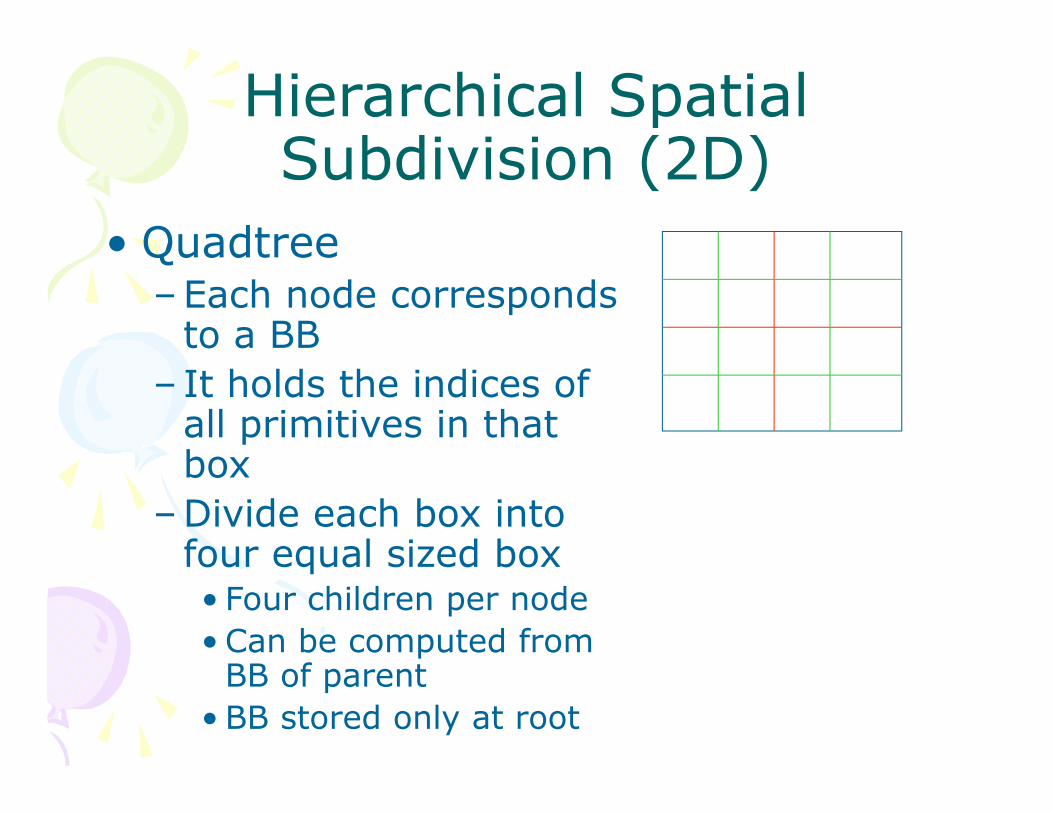
Hierarchical Spatial Subdivision (2D)
• Quadtree–Each node corresponds
to a BB– It holds the indices of
all primitives in that box
–Divide each box into four equal sized box• Four children per node• Can be computed from
BB of parent• BB stored only at root
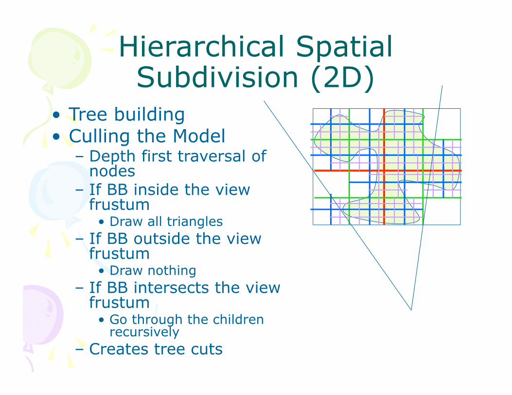
Hierarchical Spatial Subdivision (2D)
• Tree building• Culling the Model
– Depth first traversal of nodes
– If BB inside the view frustum• Draw all triangles
– If BB outside the view frustum• Draw nothing
– If BB intersects the view frustum• Go through the children
recursively– Creates tree cuts
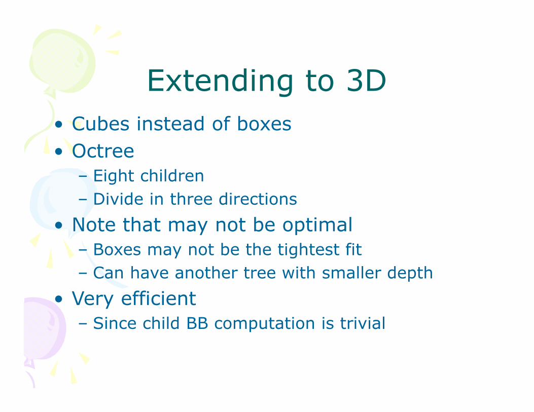
Extending to 3D• Cubes instead of boxes• Octree
– Eight children– Divide in three directions
• Note that may not be optimal– Boxes may not be the tightest fit– Can have another tree with smaller depth
• Very efficient– Since child BB computation is trivial
Back Face Culling
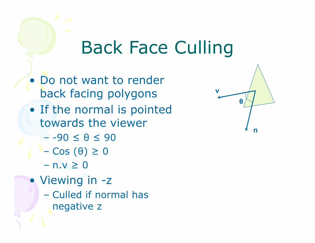
• Do not want to render back facing polygons
• If the normal is pointed towards the viewer– -90 ≤ θ ≤ 90– Cos (θ) ≥ 0– n.v ≥ 0
• Viewing in -z – Culled if normal has
negative z
v
n
θ