Embed Size (px)
Citation preview
35B-1
GROUP 35B
ANTI-LOCK BRAKING SYSTEM
(ABS)CONTENTS
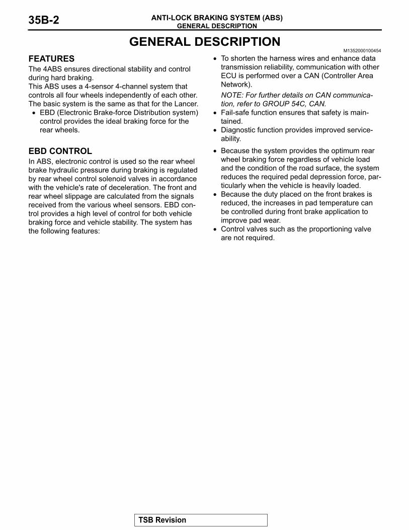
GENERAL DESCRIPTION. . . . . . . . . 35B-2
ABS DIAGNOSIS. . . . . . . . . . . . . . . . 35B-4INTRODUCTION TO ANTI-LOCK BRAKING SYSTEM DIAGNOSIS . . . . . . . . . . . . . . . . 35B-4ABS DIAGNOSTIC TROUBLESHOOTING STRATEGY. . . . . . . . . . . . . . . . . . . . . . . . . 35B-5DIAGNOSTIC FUNCTION . . . . . . . . . . . . . 35B-5DIAGNOSTIC TROUBLE CODE CHART. . 35B-9DIAGNOSTIC TROUBLE CODE PROCEDURES. . . . . . . . . . . . . . . . . . . . . . 35B-11SYMPTOM CHART. . . . . . . . . . . . . . . . . . . 35B-74SYMPTOM PROCEDURES . . . . . . . . . . . . 35B-75DATA LIST REFERENCE TABLE . . . . . . . 35B-95ACTUATOR TEST REFERENCE TABLE. . 35B-96CHECK AT ABS-ECU. . . . . . . . . . . . . . . . . 35B-97
SPECIAL TOOLS. . . . . . . . . . . . . . . . 35B-99
ON-VEHICLE SERVICE . . . . . . . . . . . 35B-100WHEEL SPEED SENSOR OUTPUT VOLTAGE MEASUREMENT. . . . . . . . . . . . 35B-100HYDRAULIC UNIT CHECK. . . . . . . . . . . . . 35B-103IN THE EVENT OF A DISCHARGED BATTERY . . . . . . . . . . . . . . . . . . . . . . . . . . 35B-105
HYDRAULIC UNIT . . . . . . . . . . . . . . . 35B-106REMOVAL AND INSTALLATION . . . . . . . . 35B-106
WHEEL SPEED SENSOR . . . . . . . . . 35B-108REMOVAL AND INSTALLATION . . . . . . . . 35B-108INSPECTION. . . . . . . . . . . . . . . . . . . . . . . . 35B-109
SPECIFICATIONS . . . . . . . . . . . . . . . 35B-110FASTENER TIGHTENING SPECIFICATION . . . . . . . . . . . . . . . . . . . . . 35B-110GENERAL SPECIFICATIONS . . . . . . . . . . 35B-110SERVICE SPECIFICATION . . . . . . . . . . . . 35B-110
GENERAL DESCRIPTIONANTI-LOCK BRAKING SYSTEM (ABS)35B-2
GENERAL DESCRIPTIONM1352000100454
FEATURESThe 4ABS ensures directional stability and control during hard braking.This ABS uses a 4-sensor 4-channel system that controls all four wheels independently of each other. The basic system is the same as that for the Lancer.
• EBD (Electronic Brake-force Distribution system) control provides the ideal braking force for the rear wheels.
• To shorten the harness wires and enhance data transmission reliability, communication with other ECU is performed over a CAN (Controller Area Network).NOTE: For further details on CAN communica-tion, refer to GROUP 54C, CAN.
• Fail-safe function ensures that safety is main-tained.
• Diagnostic function provides improved service-ability.
EBD CONTROLIn ABS, electronic control is used so the rear wheel brake hydraulic pressure during braking is regulated by rear wheel control solenoid valves in accordance with the vehicle's rate of deceleration. The front and rear wheel slippage are calculated from the signals received from the various wheel sensors. EBD con-trol provides a high level of control for both vehicle braking force and vehicle stability. The system has the following features:
• Because the system provides the optimum rear wheel braking force regardless of vehicle load and the condition of the road surface, the system reduces the required pedal depression force, par-ticularly when the vehicle is heavily loaded.
• Because the duty placed on the front brakes is reduced, the increases in pad temperature can be controlled during front brake application to improve pad wear.
• Control valves such as the proportioning valve are not required.
TSB Revision
GENERAL DESCRIPTIONANTI-LOCK BRAKING SYSTEM (ABS) 35B-3
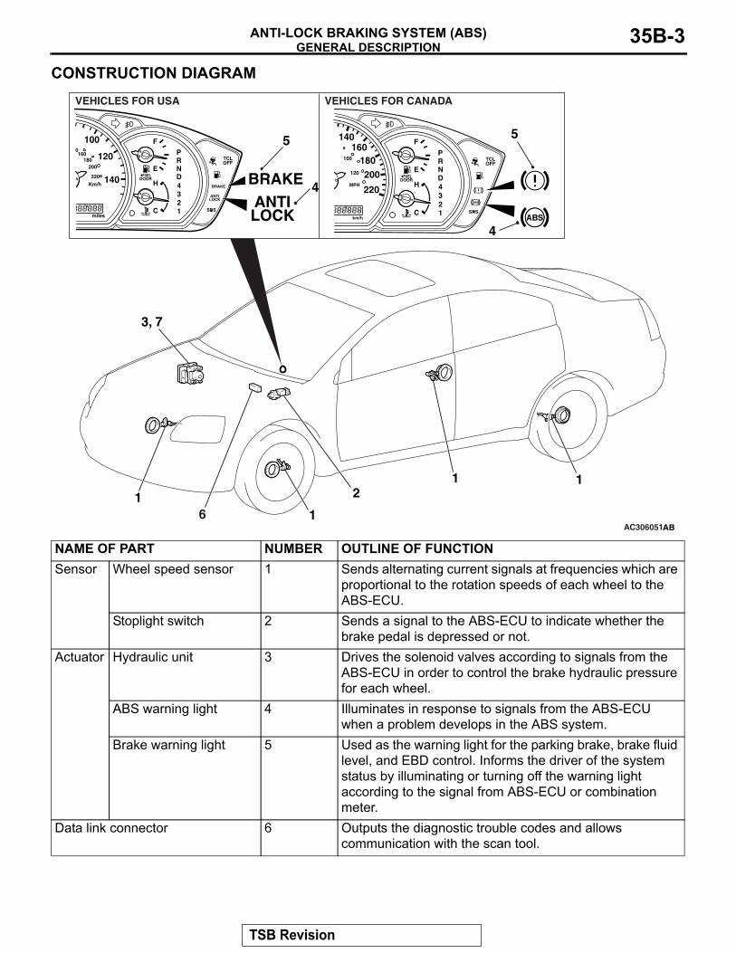
CONSTRUCTION DIAGRAM
AC306051AB
11
3, 7
5
2
4
11
6
5
4
VEHICLES FOR CANADAVEHICLES FOR USA
NAME OF PART NUMBER OUTLINE OF FUNCTIONSensor Wheel speed sensor 1 Sends alternating current signals at frequencies which are
proportional to the rotation speeds of each wheel to the ABS-ECU.
Stoplight switch 2 Sends a signal to the ABS-ECU to indicate whether the brake pedal is depressed or not.
Actuator Hydraulic unit 3 Drives the solenoid valves according to signals from the ABS-ECU in order to control the brake hydraulic pressure for each wheel.
ABS warning light 4 Illuminates in response to signals from the ABS-ECU when a problem develops in the ABS system.
Brake warning light 5 Used as the warning light for the parking brake, brake fluid level, and EBD control. Informs the driver of the system status by illuminating or turning off the warning light according to the signal from ABS-ECU or combination meter.
Data link connector 6 Outputs the diagnostic trouble codes and allows communication with the scan tool.
TSB Revision
ABS DIAGNOSISANTI-LOCK BRAKING SYSTEM (ABS)35B-4
SYSTEM CHECK SOUNDWhen the vehicle speed reaches 10 km/h after igni-tion switch ON, a thudding sound can sometimes be heard coming from the engine compartment. This is a normal sound during the ABS self-check.
ABS OPERATION SOUNDS AND SENSATIONSDuring normal operation, the ABS makes several sounds that may seem unusual at first:
• A whining sound is caused by the ABS hydraulic unit motor.
• When pressure is applied to the brake pedal, the pulsation of the pedal causes a scraping sound.
• When the brakes are applied firmly, the ABS operates, rapidly applying and releasing the brakes many times per second. This repeated application and release of braking forces can cause the suspension to make a thumping sound and the tires to squeak.
LONG STOPPING DISTANCES ON LOOSE ROAD SURFACESWhen braking on loose surfaces like snow-covered or gravel roads, the stopping distance can be longer for an ABS-equipped vehicle than the stopping dis-tance for a vehicle with a conventional brake system.
SHOCK AT STARTING CHECKShock may be felt when the brake pedal is lightly pressed while driving at a low speed. This is a nor-mal characteristic because the ABS system opera-tion check is carried out when vehicle speed is 8 km/h (5 mph) or less.
ABS DIAGNOSISINTRODUCTION TO ANTI-LOCK BRAKING SYSTEM DIAGNOSIS
M1352012500396The anti-lock braking system (ABS) operates differ-ently from conventional brake systems. These differ-ences include sounds, sensations, and vehicle performance that owners and service technicians who are not familiar with ABS may not be used to.Some operational characteristics may seem to be malfunctions, but they are simply signs of normal ABS operation. When diagnosing the ABS system, keep these operational characteristics in mind. Inform the owner of the kind of performance charac-teristics to expect from an ABS-equipped vehicle.
ABS Diagnostic Trouble Code Detection ConditionsABS diagnostic trouble codes (ABS DTCs) are set under different conditions, depending on the mal-function detected. Most ABS DTCs will only be set during vehicle operation. Some ABS DTCs will also be set during the ABS self-check immediately after the engine is started.When you check if an ABS DTC will be displayed again after the DTC has been erased, you should duplicate the ABS DTC set conditions. Depending on the detection timing and set conditions for the spe-cific ABS DTC, you must either drive the vehicle or turn the engine off and restart it. To set the proper conditions for that DTC again, refer to "ABS DTC SET CONDITIONS" for each ABS DTC that you are trying to reset.
ABS-ECU 7 Controls actuators (described above) based on the signals coming from each sensor.Controls the self-diagnosis and fail-safe functions.Controls the diagnostic function (scan tool compatible).
NAME OF PART NUMBER OUTLINE OF FUNCTION
TSB Revision
ABS DIAGNOSISANTI-LOCK BRAKING SYSTEM (ABS) 35B-5
ABS DIAGNOSTIC TROUBLESHOOTING STRATEGYM1352011100771
Use these steps to plan your diagnostic strategy. If you follow them carefully, you will be sure that you have exhausted most of the possible ways to find an ABS fault.1. Gather information about the problem from the
customer.2. Verify that the condition described by the
customer exists.3. Check the vehicle for any ABS DTC.4. If you cannot verify the condition and there are no
ABS DTCs, the malfunction is intermittent. Refer to GROUP 00, How to use Troubleshooting/Inspection Service Points − How to Cope with Intermittent Malfunctions P.00-14.
5. If you can verify the condition but there are no ABS DTCs, or the system cannot communicate with the scan tool, check that the basic brake system is operating properly.
• If the basic brake system is not operating prop-erly, refer to the GROUP 35A, Basic Brake Sys-tem Diagnosis P.35A-3.
• If the basic brake system is operating properly, refer to P.35B-74.
6. If there is an ABS DTC, record the number of the DTC, then erase the DTC from the memory using the scan tool.NOTE: Any DTCs stored in the ABS-ECU cannot be erased if there is a malfunction.
7. Duplicate the ABS DTC set conditions to see if the same ABS DTC will set again.
• If the same ABS DTC sets again or the ABS DTC cannot be erased, perform the diagnostic proce-dures for the DTC. Refer to P.35B-9.
• If you cannot get the same ABS DTC to set again, the malfunction is intermittent. Refer to GROUP 00, How to use Troubleshooting/Inspec-tion Service Points − How to Cope with Intermit-tent Malfunctions P.00-14.
DIAGNOSTIC FUNCTIONM1352011200596
ON-BOARD DIAGNOSTICSIf the ABS-ECU detects any problem in the CAN communication line or the ECUs, which the ABS-ECU is communicating with, it stores a diagnos-tic trouble code. The DTCs have 26 items. The DTCs can be confirmed by connecting scan tool MB991958
(M.U.T.-III sub assembly.) The stored DTCs are not erased even after the ignition switch has been turned to the LOCK (OFF) position, or the battery has been disconnected. The DTCs can be erased by operating scan tool MB991958 (M.U.T.-III sub assembly.)
HOW TO CONNECT THE SCAN TOOL (M.U.T.-III)Required Special Tools:
• MB991958: Scan Tool (M.U.T.-III Sub Assembly)• MB991824: Vehicle Communication Interface (V.C.I.)• MB991827: M.U.T.-III USB Cable• MB991910: M.U.T.-III Main Harness A
TSB Revision
ABS DIAGNOSISANTI-LOCK BRAKING SYSTEM (ABS)35B-6
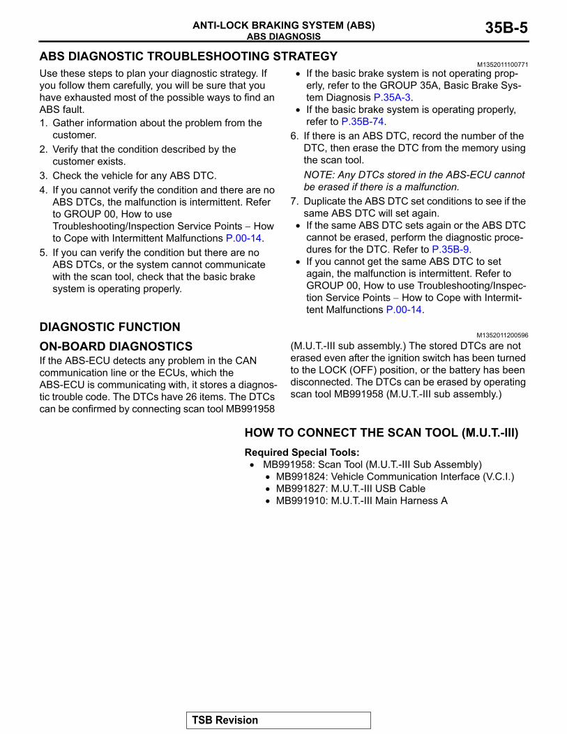
CAUTIONTo prevent damage to scan tool MB991958, always turn the ignition switch to the "LOCK" (OFF) position before con-necting or disconnecting scan tool MB991958.1. Ensure that the ignition switch is at the "LOCK" (OFF)
position.2. Start up the personal computer.3. Connect special tool MB991827 to special tool MB991824
and the personal computer.4. Connect special tool MB991910 to the special tool
MB991824.5. Connect special tool MB991910 to the data link connector.6. Turn the power switch special tool MB991824 to the "ON"
position.NOTE: When the special tool MB991824 is energized, the special tool MB991824 indicator light will be illuminated in a green color.
7. Start the M.U.T.-III system on the personal computer.NOTE: Disconnect the scan tool MB991958 in the reverse order of the connecting sequence, making sure that the ignition switch is at the "LOCK" (OFF) position.
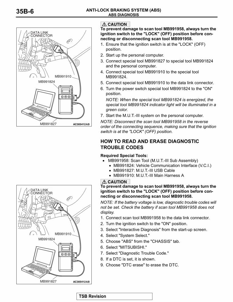
HOW TO READ AND ERASE DIAGNOSTIC TROUBLE CODESRequired Special Tools:
• MB991958: Scan Tool (M.U.T.-III Sub Assembly)• MB991824: Vehicle Communication Interface (V.C.I.)• MB991827: M.U.T.-III USB Cable• MB991910: M.U.T.-III Main Harness A
CAUTIONTo prevent damage to scan tool MB991958, always turn the ignition switch to the "LOCK" (OFF) position before con-necting or disconnecting scan tool MB991958.NOTE: If the battery voltage is low, diagnostic trouble codes will not be set. Check the battery if scan tool MB991958 does not display.1. Connect scan tool MB991958 to the data link connector.2. Turn the ignition switch to the "ON" position.3. Select "Interactive Diagnosis" from the start-up screen.4. Select "System Select."5. Choose "ABS" from the "CHASSIS" tab.6. Select "MITSUBISHI."7. Select "Diagnostic Trouble Code."8. If a DTC is set, it is shown.9. Choose "DTC erase" to erase the DTC.
AC305412AB
MB991910
DATA LINKCONNECTOR
MB991824
MB991827
AC305412AB
MB991910
DATA LINKCONNECTOR
MB991824
MB991827
TSB Revision
ABS DIAGNOSISANTI-LOCK BRAKING SYSTEM (ABS) 35B-7
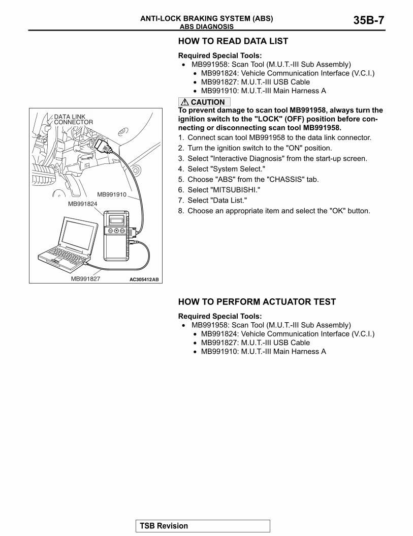
HOW TO READ DATA LISTRequired Special Tools:
• MB991958: Scan Tool (M.U.T.-III Sub Assembly)• MB991824: Vehicle Communication Interface (V.C.I.)• MB991827: M.U.T.-III USB Cable• MB991910: M.U.T.-III Main Harness A
CAUTIONTo prevent damage to scan tool MB991958, always turn the ignition switch to the "LOCK" (OFF) position before con-necting or disconnecting scan tool MB991958.1. Connect scan tool MB991958 to the data link connector.2. Turn the ignition switch to the "ON" position.3. Select "Interactive Diagnosis" from the start-up screen.4. Select "System Select."5. Choose "ABS" from the "CHASSIS" tab.6. Select "MITSUBISHI."7. Select "Data List."8. Choose an appropriate item and select the "OK" button.
HOW TO PERFORM ACTUATOR TESTRequired Special Tools:
• MB991958: Scan Tool (M.U.T.-III Sub Assembly)• MB991824: Vehicle Communication Interface (V.C.I.)• MB991827: M.U.T.-III USB Cable• MB991910: M.U.T.-III Main Harness A
AC305412AB
MB991910
DATA LINKCONNECTOR
MB991824
MB991827
TSB Revision
ABS DIAGNOSISANTI-LOCK BRAKING SYSTEM (ABS)35B-8
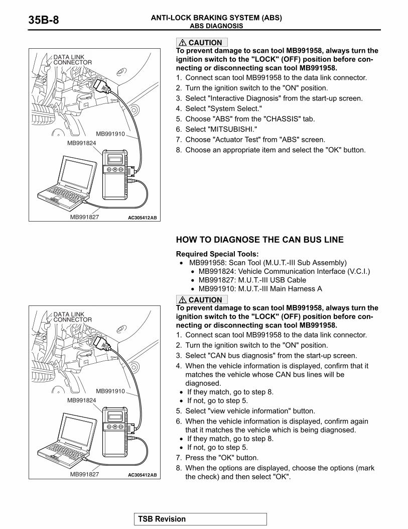
CAUTIONTo prevent damage to scan tool MB991958, always turn the ignition switch to the "LOCK" (OFF) position before con-necting or disconnecting scan tool MB991958.1. Connect scan tool MB991958 to the data link connector.2. Turn the ignition switch to the "ON" position.3. Select "Interactive Diagnosis" from the start-up screen.4. Select "System Select."5. Choose "ABS" from the "CHASSIS" tab.6. Select "MITSUBISHI."7. Choose "Actuator Test" from "ABS" screen.8. Choose an appropriate item and select the "OK" button.
HOW TO DIAGNOSE THE CAN BUS LINERequired Special Tools:
• MB991958: Scan Tool (M.U.T.-III Sub Assembly)• MB991824: Vehicle Communication Interface (V.C.I.)• MB991827: M.U.T.-III USB Cable• MB991910: M.U.T.-III Main Harness A
CAUTIONTo prevent damage to scan tool MB991958, always turn the ignition switch to the "LOCK" (OFF) position before con-necting or disconnecting scan tool MB991958.1. Connect scan tool MB991958 to the data link connector.2. Turn the ignition switch to the "ON" position.3. Select "CAN bus diagnosis" from the start-up screen.4. When the vehicle information is displayed, confirm that it
matches the vehicle whose CAN bus lines will be diagnosed.
• If they match, go to step 8.• If not, go to step 5.
5. Select "view vehicle information" button.6. When the vehicle information is displayed, confirm again
that it matches the vehicle which is being diagnosed.• If they match, go to step 8.• If not, go to step 5.
7. Press the "OK" button.8. When the options are displayed, choose the options (mark
the check) and then select "OK".
AC305412AB
MB991910
DATA LINKCONNECTOR
MB991824
MB991827
AC305412AB
MB991910
DATA LINKCONNECTOR
MB991824
MB991827
TSB Revision
ABS DIAGNOSISANTI-LOCK BRAKING SYSTEM (ABS) 35B-9
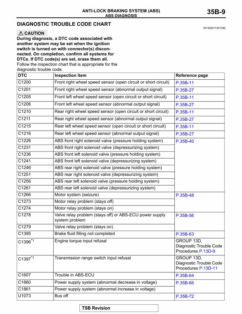
DIAGNOSTIC TROUBLE CODE CHARTM1352011301392
CAUTIONDuring diagnosis, a DTC code associated with another system may be set when the ignition switch is turned on with connector(s) discon-nected. On completion, confirm all systems for DTCs. If DTC code(s) are set, erase them all.Follow the inspection chart that is appropriate for the diagnostic trouble code.DTC Inspection item Reference pageC1200 Front right wheel speed sensor (open circuit or short circuit) P.35B-11C1201 Front right wheel speed sensor (abnormal output signal) P.35B-27C1205 Front left wheel speed sensor (open circuit or short circuit) P.35B-11C1206 Front left wheel speed sensor (abnormal output signal) P.35B-27C1210 Rear right wheel speed sensor (open circuit or short circuit) P.35B-11C1211 Rear right wheel speed sensor (abnormal output signal) P.35B-27C1215 Rear left wheel speed sensor (open circuit or short circuit) P.35B-11C1216 Rear left wheel speed sensor (abnormal output signal) P.35B-27C1226 ABS front right solenoid valve (pressure holding system) P.35B-40C1231 ABS front right solenoid valve (depressurizing system)C1236 ABS front left solenoid valve (pressure holding system)C1241 ABS front left solenoid valve (depressurizing system)C1246 ABS rear right solenoid valve (pressure holding system)C1251 ABS rear right solenoid valve (depressurizing system)C1256 ABS rear left solenoid valve (pressure holding system)C1261 ABS rear left solenoid valve (depressurizing system)C1266 Motor system (seizure) P.35B-48C1273 Motor relay problem (stays off)C1274 Motor relay problem (stays on)C1278 Valve relay problem (stays off) or ABS-ECU power supply
system problemP.35B-56
C1279 Valve relay problem (stays on)C1395 Brake fluid filling not completed P.35B-63
C1396*1 Engine torque input refusal GROUP 13D, Diagnostic Trouble Code Procedures P.13D-9
C1397*1 Transmission range switch input refusal GROUP 13D, Diagnostic Trouble Code Procedures P.13D-11
C1607 Trouble in ABS-ECU P.35B-64C1860 Power supply system (abnormal decrease in voltage) P.35B-66C1861 Power supply system (abnormal increase in voltage)U1073 Bus off P.35B-72
TSB Revision
ABS DIAGNOSISANTI-LOCK BRAKING SYSTEM (ABS)35B-10
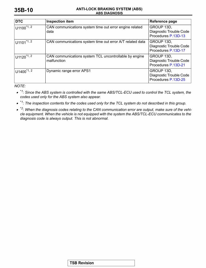
NOTE: .
• *1: Since the ABS system is controlled with the same ABS/TCL-ECU used to control the TCL system, the codes used only for the ABS system also appear.
• *1: The inspection contents for the codes used only for the TCL system do not described in this group.
• *2: When the diagnosis codes relating to the CAN communication error are output, make sure of the vehi-cle equipment. When the vehicle is not equipped with the system the ABS/TCL-ECU communicates to the diagnosis code is always output. This is not abnormal.
U1100*1, 2 CAN communications system time out error engine related data
GROUP 13D, Diagnostic Trouble Code Procedures P.13D-13
U1101*1, 2 CAN communications system time out error A/T related data GROUP 13D, Diagnostic Trouble Code Procedures P.13D-17
U1120*1, 2 CAN communications system TCL uncontrollable by engine malfunction
GROUP 13D, Diagnostic Trouble Code Procedures P.13D-21
U1400*1, 2 Dynamic range error APS1 GROUP 13D, Diagnostic Trouble Code Procedures P.13D-25
DTC Inspection item Reference page
TSB Revision
ABS DIAGNOSISANTI-LOCK BRAKING SYSTEM (ABS) 35B-11
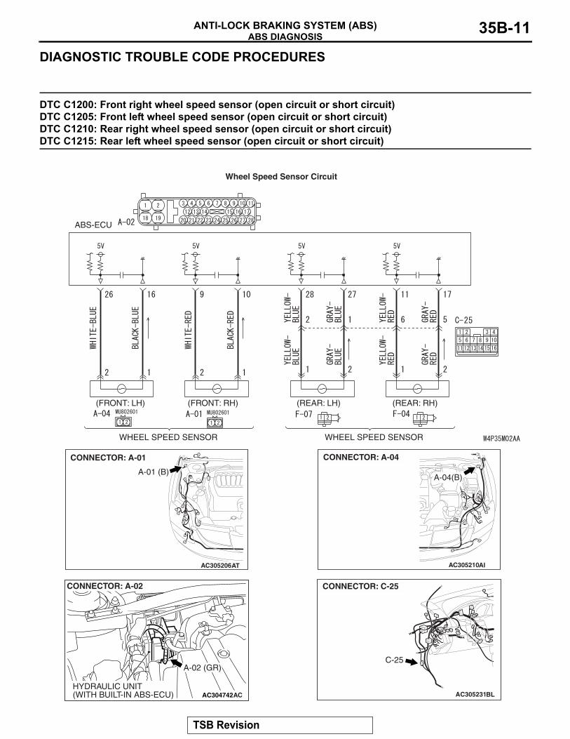
DIAGNOSTIC TROUBLE CODE PROCEDURES
DTC C1200: Front right wheel speed sensor (open circuit or short circuit) DTC C1205: Front left wheel speed sensor (open circuit or short circuit) DTC C1210: Rear right wheel speed sensor (open circuit or short circuit) DTC C1215: Rear left wheel speed sensor (open circuit or short circuit)
WHEEL SPEED SENSOR WHEEL SPEED SENSOR
(REAR: RH)(REAR: LH)(FRONT: RH)(FRONT: LH)
ABS-ECU
Wheel Speed Sensor Circuit
AC305206
A-01 (B)
CONNECTOR: A-01
AT
AC304742
A-02 (GR)
CONNECTOR: A-02
HYDRAULIC UNIT(WITH BUILT-IN ABS-ECU) AC
AC305210AI
A-04(B)
CONNECTOR: A-04
AC305231BL
CONNECTOR: C-25
C-25
TSB Revision
ABS DIAGNOSISANTI-LOCK BRAKING SYSTEM (ABS)35B-12
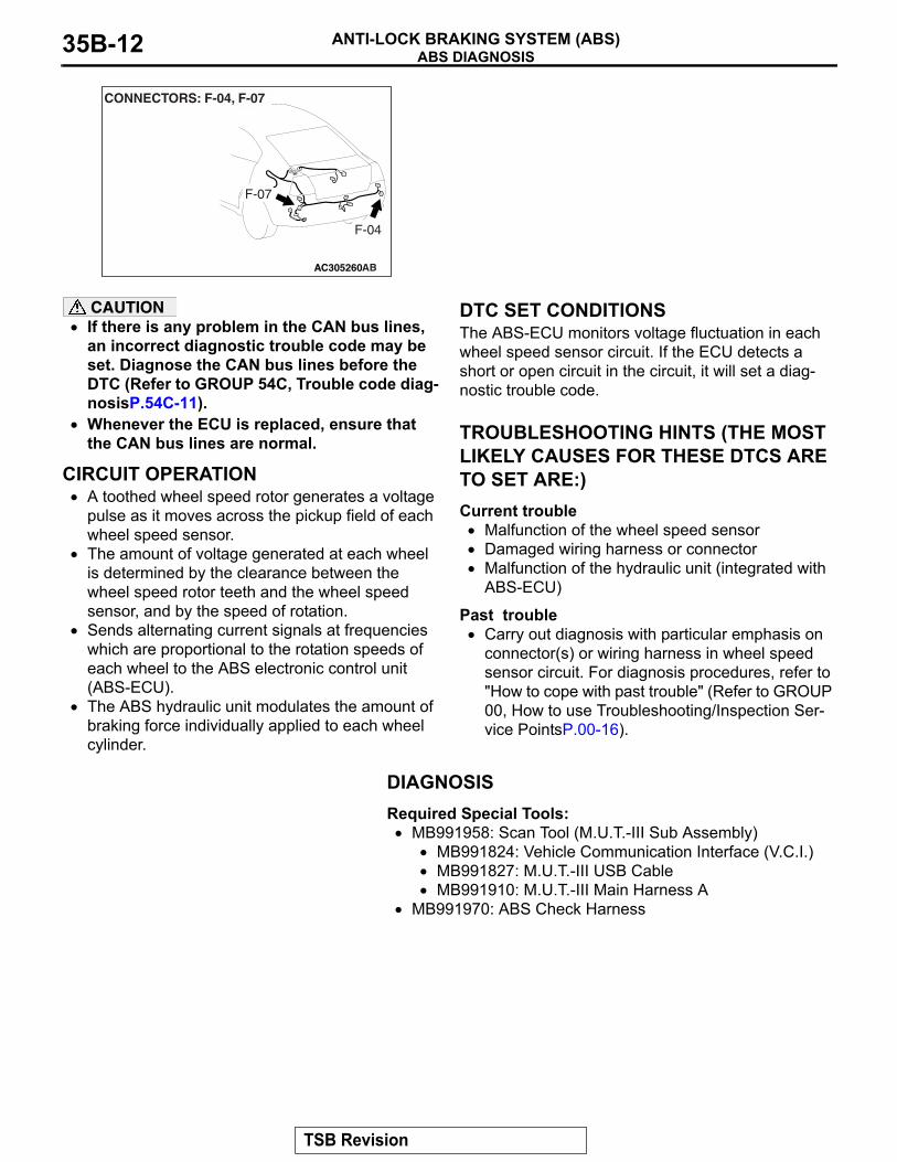
CAUTION• If there is any problem in the CAN bus lines,
an incorrect diagnostic trouble code may be set. Diagnose the CAN bus lines before the DTC (Refer to GROUP 54C, Trouble code diag-nosisP.54C-11).
• Whenever the ECU is replaced, ensure that the CAN bus lines are normal.
.
CIRCUIT OPERATION• A toothed wheel speed rotor generates a voltage
pulse as it moves across the pickup field of each wheel speed sensor.
• The amount of voltage generated at each wheel is determined by the clearance between the wheel speed rotor teeth and the wheel speed sensor, and by the speed of rotation.
• Sends alternating current signals at frequencies which are proportional to the rotation speeds of each wheel to the ABS electronic control unit (ABS-ECU).
• The ABS hydraulic unit modulates the amount of braking force individually applied to each wheel cylinder.
.
DTC SET CONDITIONSThe ABS-ECU monitors voltage fluctuation in each wheel speed sensor circuit. If the ECU detects a short or open circuit in the circuit, it will set a diag-nostic trouble code..
TROUBLESHOOTING HINTS (THE MOST LIKELY CAUSES FOR THESE DTCS ARE TO SET ARE:)Current trouble
• Malfunction of the wheel speed sensor• Damaged wiring harness or connector• Malfunction of the hydraulic unit (integrated with
ABS-ECU)
Past trouble• Carry out diagnosis with particular emphasis on
connector(s) or wiring harness in wheel speed sensor circuit. For diagnosis procedures, refer to "How to cope with past trouble" (Refer to GROUP 00, How to use Troubleshooting/Inspection Ser-vice PointsP.00-16).
DIAGNOSISRequired Special Tools:
• MB991958: Scan Tool (M.U.T.-III Sub Assembly)• MB991824: Vehicle Communication Interface (V.C.I.)• MB991827: M.U.T.-III USB Cable• MB991910: M.U.T.-III Main Harness A
• MB991970: ABS Check Harness
AC305260
F-04
F-07
CONNECTORS: F-04, F-07
AB
TSB Revision
ABS DIAGNOSISANTI-LOCK BRAKING SYSTEM (ABS) 35B-13
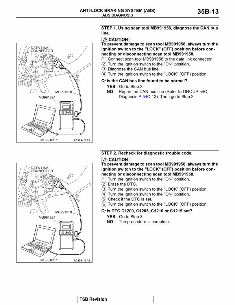
STEP 1. Using scan tool MB991958, diagnose the CAN bus line.
CAUTIONTo prevent damage to scan tool MB991958, always turn the ignition switch to the "LOCK" (OFF) position before con-necting or disconnecting scan tool MB991958.(1) Connect scan tool MB991958 to the data link connector.(2) Turn the ignition switch to the "ON" position.(3) Diagnose the CAN bus line.(4) Turn the ignition switch to the "LOCK" (OFF) position.Q: Is the CAN bus line found to be normal?
YES : Go to Step 3NO : Repair the CAN bus line (Refer to GROUP 54C,
Diagnosis P.54C-13). Then go to Step 2.
STEP 2. Recheck for diagnostic trouble code.CAUTION
To prevent damage to scan tool MB991958, always turn the ignition switch to the "LOCK" (OFF) position before con-necting or disconnecting scan tool MB991958.(1) Turn the ignition switch to the "ON" position.(2) Erase the DTC.(3) Turn the ignition switch to the "LOCK" (OFF) position.(4) Turn the ignition switch to the "ON" position.(5) Check if the DTC is set.(6) Turn the ignition switch to the "LOCK" (OFF) position.Q: Is DTC C1200, C1205, C1210 or C1215 set?
YES : Go to Step 3NO : The procedure is complete.
AC305412AB
MB991910
DATA LINKCONNECTOR
MB991824
MB991827
AC305412AB
MB991910
DATA LINKCONNECTOR
MB991824
MB991827
TSB Revision
ABS DIAGNOSISANTI-LOCK BRAKING SYSTEM (ABS)35B-14
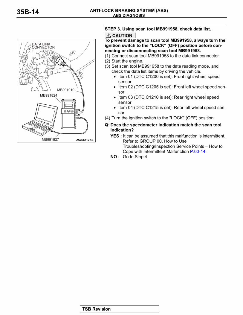
STEP 3. Using scan tool MB991958, check data list.CAUTION
To prevent damage to scan tool MB991958, always turn the ignition switch to the "LOCK" (OFF) position before con-necting or disconnecting scan tool MB991958.(1) Connect scan tool MB991958 to the data link connector.(2) Start the engine.(3) Set scan tool MB991958 to the data reading mode, and
check the data list items by driving the vehicle.• Item 01 (DTC C1200 is set): Front right wheel speed
sensor• Item 02 (DTC C1205 is set): Front left wheel speed sen-
sor• Item 03 (DTC C1210 is set): Rear right wheel speed
sensor• Item 04 (DTC C1215 is set): Rear left wheel speed sen-
sor(4) Turn the ignition switch to the "LOCK" (OFF) position.Q: Does the speedometer indication match the scan tool
indication?YES : It can be assumed that this malfunction is intermittent.
Refer to GROUP 00, How to Use Troubleshooting/Inspection Service Points − How to Cope with Intermittent Malfunction P.00-14.
NO : Go to Step 4.
AC305412AB
MB991910
DATA LINKCONNECTOR
MB991824
MB991827
TSB Revision
ABS DIAGNOSISANTI-LOCK BRAKING SYSTEM (ABS) 35B-15
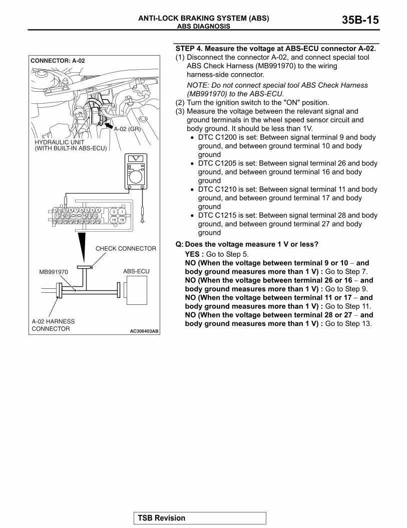
STEP 4. Measure the voltage at ABS-ECU connector A-02.(1) Disconnect the connector A-02, and connect special tool
ABS Check Harness (MB991970) to the wiring harness-side connector.NOTE: Do not connect special tool ABS Check Harness (MB991970) to the ABS-ECU.
(2) Turn the ignition switch to the "ON" position.(3) Measure the voltage between the relevant signal and
ground terminals in the wheel speed sensor circuit and body ground. It should be less than 1V.
• DTC C1200 is set: Between signal terminal 9 and body ground, and between ground terminal 10 and body ground
• DTC C1205 is set: Between signal terminal 26 and body ground, and between ground terminal 16 and body ground
• DTC C1210 is set: Between signal terminal 11 and body ground, and between ground terminal 17 and body ground
• DTC C1215 is set: Between signal terminal 28 and body ground, and between ground terminal 27 and body ground
Q: Does the voltage measure 1 V or less?YES : Go to Step 5.NO (When the voltage between terminal 9 or 10 − and body ground measures more than 1 V) : Go to Step 7.NO (When the voltage between terminal 26 or 16 − and body ground measures more than 1 V) : Go to Step 9.NO (When the voltage between terminal 11 or 17 − and body ground measures more than 1 V) : Go to Step 11.NO (When the voltage between terminal 28 or 27 − and body ground measures more than 1 V) : Go to Step 13.
AC306403
19
2
18
189 7 6 5 4 31011
25
151617
2728 26
121314
2324 22 21 20
AB
ABS-ECUMB991970
CHECK CONNECTOR
A-02 HARNESSCONNECTOR
A-02 (GR)
CONNECTOR: A-02
HYDRAULIC UNIT(WITH BUILT-IN ABS-ECU)
TSB Revision
ABS DIAGNOSISANTI-LOCK BRAKING SYSTEM (ABS)35B-16
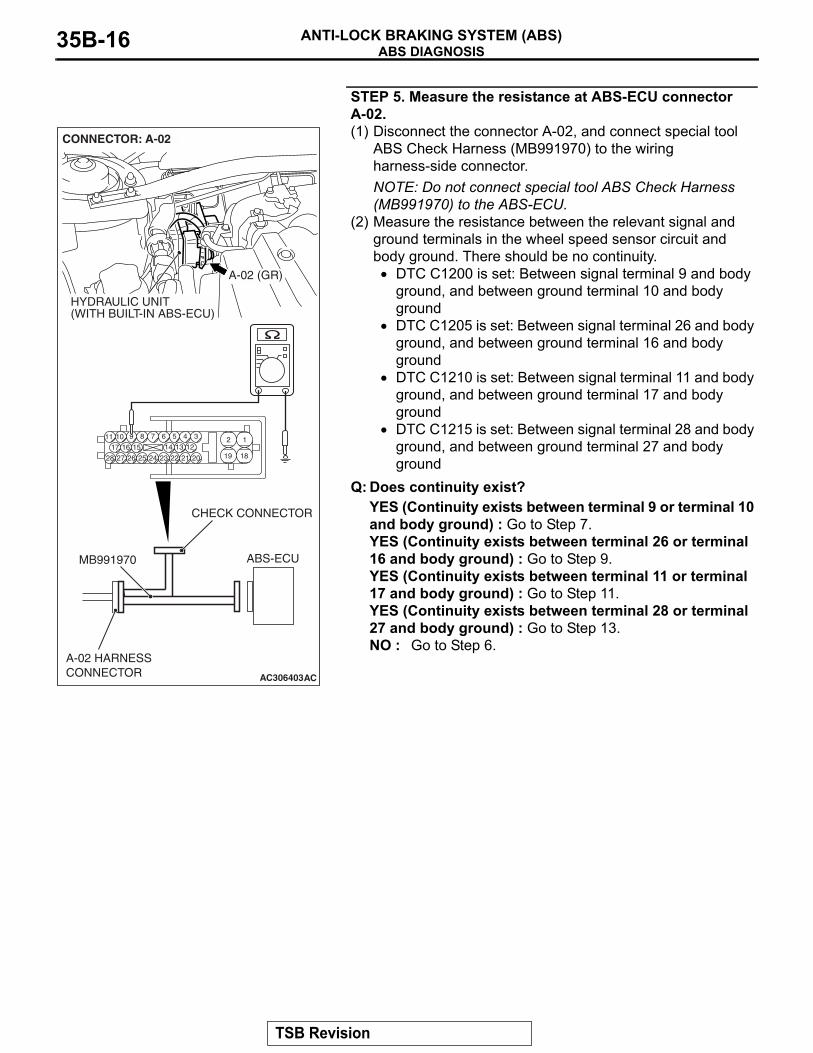
STEP 5. Measure the resistance at ABS-ECU connector A-02.(1) Disconnect the connector A-02, and connect special tool
ABS Check Harness (MB991970) to the wiring harness-side connector.NOTE: Do not connect special tool ABS Check Harness (MB991970) to the ABS-ECU.
(2) Measure the resistance between the relevant signal and ground terminals in the wheel speed sensor circuit and body ground. There should be no continuity.
• DTC C1200 is set: Between signal terminal 9 and body ground, and between ground terminal 10 and body ground
• DTC C1205 is set: Between signal terminal 26 and body ground, and between ground terminal 16 and body ground
• DTC C1210 is set: Between signal terminal 11 and body ground, and between ground terminal 17 and body ground
• DTC C1215 is set: Between signal terminal 28 and body ground, and between ground terminal 27 and body ground
Q: Does continuity exist?YES (Continuity exists between terminal 9 or terminal 10 and body ground) : Go to Step 7.YES (Continuity exists between terminal 26 or terminal 16 and body ground) : Go to Step 9.YES (Continuity exists between terminal 11 or terminal 17 and body ground) : Go to Step 11.YES (Continuity exists between terminal 28 or terminal 27 and body ground) : Go to Step 13.NO : Go to Step 6.
AC306403
19
2
18
189 7 6 5 4 31011
25
151617
2728 26
121314
2324 22 21 20
AC
ABS-ECUMB991970
CHECK CONNECTOR
A-02 HARNESSCONNECTOR
A-02 (GR)
CONNECTOR: A-02
HYDRAULIC UNIT(WITH BUILT-IN ABS-ECU)
TSB Revision
ABS DIAGNOSISANTI-LOCK BRAKING SYSTEM (ABS) 35B-17
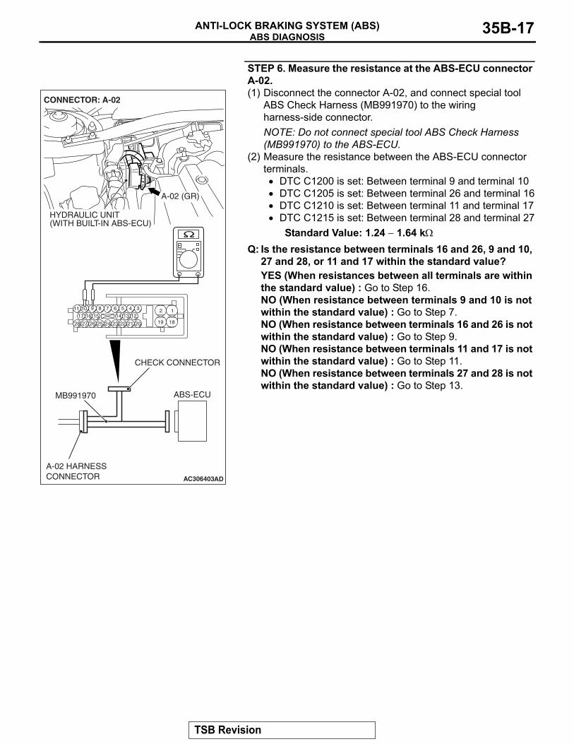
STEP 6. Measure the resistance at the ABS-ECU connector A-02.(1) Disconnect the connector A-02, and connect special tool
ABS Check Harness (MB991970) to the wiring harness-side connector.NOTE: Do not connect special tool ABS Check Harness (MB991970) to the ABS-ECU.
(2) Measure the resistance between the ABS-ECU connector terminals.
• DTC C1200 is set: Between terminal 9 and terminal 10• DTC C1205 is set: Between terminal 26 and terminal 16• DTC C1210 is set: Between terminal 11 and terminal 17• DTC C1215 is set: Between terminal 28 and terminal 27
Standard Value: 1.24 − 1.64 kΩ
Q: Is the resistance between terminals 16 and 26, 9 and 10, 27 and 28, or 11 and 17 within the standard value?YES (When resistances between all terminals are within the standard value) : Go to Step 16.NO (When resistance between terminals 9 and 10 is not within the standard value) : Go to Step 7.NO (When resistance between terminals 16 and 26 is not within the standard value) : Go to Step 9.NO (When resistance between terminals 11 and 17 is not within the standard value) : Go to Step 11.NO (When resistance between terminals 27 and 28 is not within the standard value) : Go to Step 13.
AC306403
19
2
18
189 7 6 5 4 31011
25
151617
2728 26
121314
2324 22 21 20
AD
ABS-ECUMB991970
CHECK CONNECTOR
A-02 HARNESSCONNECTOR
A-02 (GR)
CONNECTOR: A-02
HYDRAULIC UNIT(WITH BUILT-IN ABS-ECU)
TSB Revision
ABS DIAGNOSISANTI-LOCK BRAKING SYSTEM (ABS)35B-18
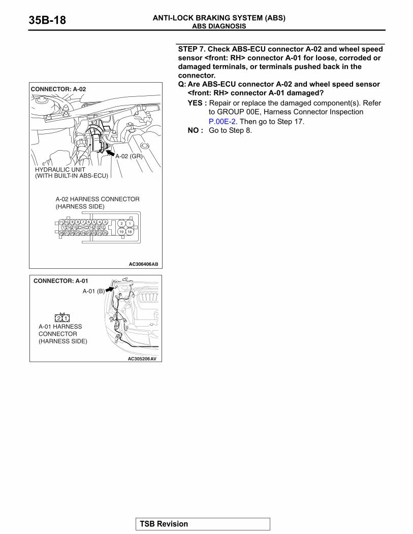
STEP 7. Check ABS-ECU connector A-02 and wheel speed sensor <front: RH> connector A-01 for loose, corroded or damaged terminals, or terminals pushed back in the connector.Q: Are ABS-ECU connector A-02 and wheel speed sensor
<front: RH> connector A-01 damaged?YES : Repair or replace the damaged component(s). Refer
to GROUP 00E, Harness Connector Inspection P.00E-2. Then go to Step 17.
NO : Go to Step 8.
AC306406
19
2
18
189 7 6 5 4 31011
25
151617
2728 26
121314
2324 22 21 20
A-02 HARNESS CONNECTOR(HARNESS SIDE)
AB
A-02 (GR)
CONNECTOR: A-02
HYDRAULIC UNIT(WITH BUILT-IN ABS-ECU)
AC305206
A-01 (B)
CONNECTOR: A-01
AV
A-01 HARNESSCONNECTOR(HARNESS SIDE)
2 1
TSB Revision
ABS DIAGNOSISANTI-LOCK BRAKING SYSTEM (ABS) 35B-19
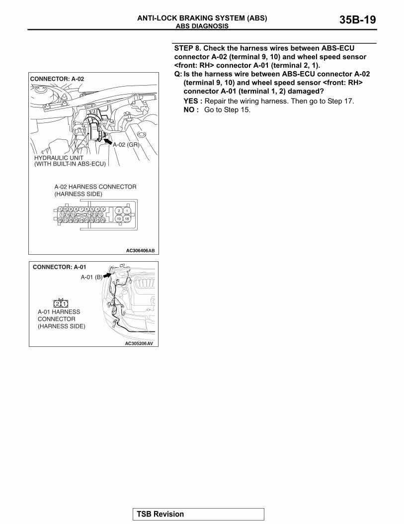
STEP 8. Check the harness wires between ABS-ECU connector A-02 (terminal 9, 10) and wheel speed sensor <front: RH> connector A-01 (terminal 2, 1).Q: Is the harness wire between ABS-ECU connector A-02
(terminal 9, 10) and wheel speed sensor <front: RH> connector A-01 (terminal 1, 2) damaged?YES : Repair the wiring harness. Then go to Step 17.NO : Go to Step 15.
AC306406
19
2
18
189 7 6 5 4 31011
25
151617
2728 26
121314
2324 22 21 20
A-02 HARNESS CONNECTOR(HARNESS SIDE)
AB
A-02 (GR)
CONNECTOR: A-02
HYDRAULIC UNIT(WITH BUILT-IN ABS-ECU)
AC305206
A-01 (B)
CONNECTOR: A-01
AV
A-01 HARNESSCONNECTOR(HARNESS SIDE)
2 1
TSB Revision
ABS DIAGNOSISANTI-LOCK BRAKING SYSTEM (ABS)35B-20
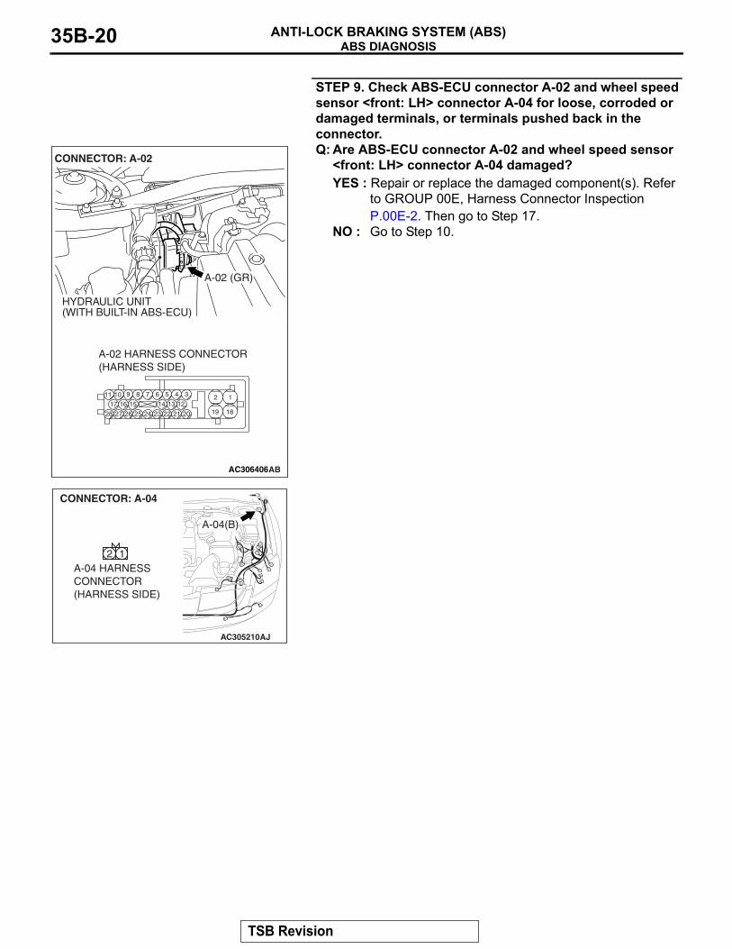
STEP 9. Check ABS-ECU connector A-02 and wheel speed sensor <front: LH> connector A-04 for loose, corroded or damaged terminals, or terminals pushed back in the connector.Q: Are ABS-ECU connector A-02 and wheel speed sensor
<front: LH> connector A-04 damaged?YES : Repair or replace the damaged component(s). Refer
to GROUP 00E, Harness Connector Inspection P.00E-2. Then go to Step 17.
NO : Go to Step 10.
AC306406
19
2
18
189 7 6 5 4 31011
25
151617
2728 26
121314
2324 22 21 20
A-02 HARNESS CONNECTOR(HARNESS SIDE)
AB
A-02 (GR)
CONNECTOR: A-02
HYDRAULIC UNIT(WITH BUILT-IN ABS-ECU)
AC305210AJ
A-04(B)
CONNECTOR: A-04
A-04 HARNESSCONNECTOR(HARNESS SIDE)
2 1
TSB Revision
ABS DIAGNOSISANTI-LOCK BRAKING SYSTEM (ABS) 35B-21
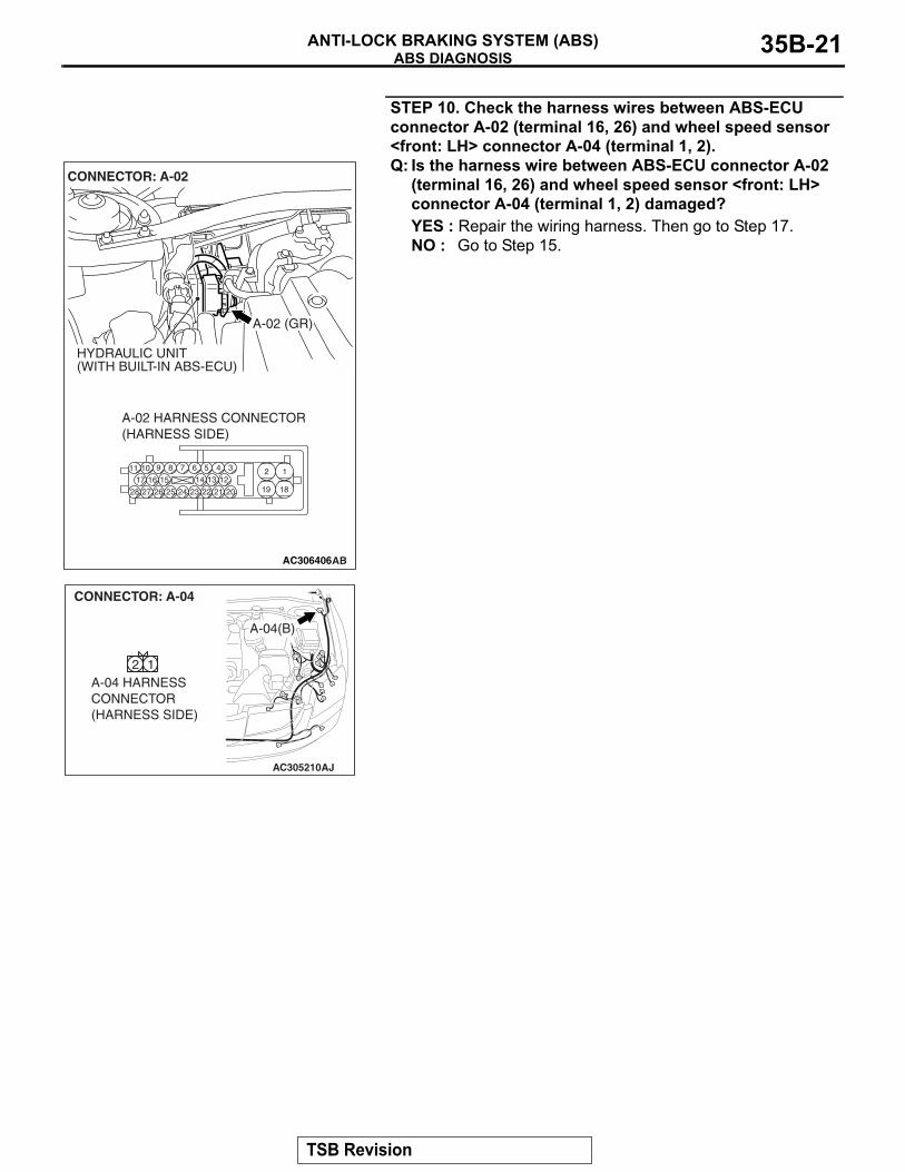
STEP 10. Check the harness wires between ABS-ECU connector A-02 (terminal 16, 26) and wheel speed sensor <front: LH> connector A-04 (terminal 1, 2).Q: Is the harness wire between ABS-ECU connector A-02
(terminal 16, 26) and wheel speed sensor <front: LH> connector A-04 (terminal 1, 2) damaged?YES : Repair the wiring harness. Then go to Step 17.NO : Go to Step 15.
AC306406
19
2
18
189 7 6 5 4 31011
25
151617
2728 26
121314
2324 22 21 20
A-02 HARNESS CONNECTOR(HARNESS SIDE)
AB
A-02 (GR)
CONNECTOR: A-02
HYDRAULIC UNIT(WITH BUILT-IN ABS-ECU)
AC305210AJ
A-04(B)
CONNECTOR: A-04
A-04 HARNESSCONNECTOR(HARNESS SIDE)
2 1
TSB Revision
ABS DIAGNOSISANTI-LOCK BRAKING SYSTEM (ABS)35B-22
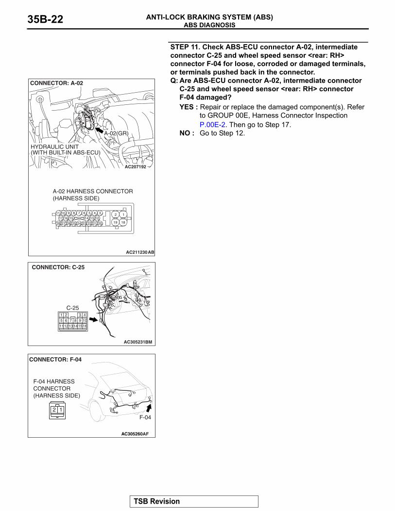
STEP 11. Check ABS-ECU connector A-02, intermediate connector C-25 and wheel speed sensor <rear: RH> connector F-04 for loose, corroded or damaged terminals, or terminals pushed back in the connector.Q: Are ABS-ECU connector A-02, intermediate connector
C-25 and wheel speed sensor <rear: RH> connector F-04 damaged?YES : Repair or replace the damaged component(s). Refer
to GROUP 00E, Harness Connector Inspection P.00E-2. Then go to Step 17.
NO : Go to Step 12.
AC207192
AC211230
19
2
18
189 7 6 5 4 31011
25
151617
2728 26
121314
2324 22 21 20
A-02(GR)
CONNECTOR: A-02
HYDRAULIC UNIT(WITH BUILT-IN ABS-ECU)
A-02 HARNESS CONNECTOR(HARNESS SIDE)
AB
AC305231BM
CONNECTOR: C-25
C-25
11
1 4310161312
5 62
148
1597
AC305260
F-04
CONNECTOR: F-04
AF
F-04 HARNESSCONNECTOR(HARNESS SIDE)
2 1
TSB Revision
ABS DIAGNOSISANTI-LOCK BRAKING SYSTEM (ABS) 35B-23
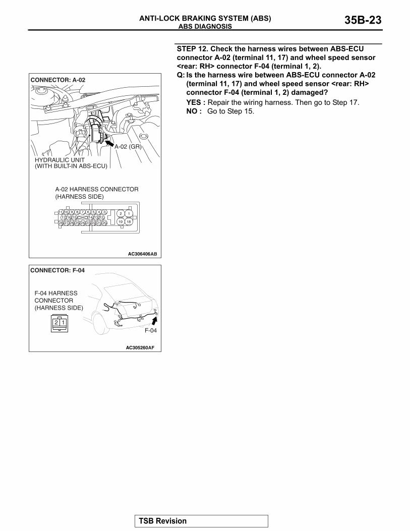
STEP 12. Check the harness wires between ABS-ECU connector A-02 (terminal 11, 17) and wheel speed sensor <rear: RH> connector F-04 (terminal 1, 2).Q: Is the harness wire between ABS-ECU connector A-02
(terminal 11, 17) and wheel speed sensor <rear: RH> connector F-04 (terminal 1, 2) damaged?YES : Repair the wiring harness. Then go to Step 17.NO : Go to Step 15.
AC306406
19
2
18
189 7 6 5 4 31011
25
151617
2728 26
121314
2324 22 21 20
A-02 HARNESS CONNECTOR(HARNESS SIDE)
AB
A-02 (GR)
CONNECTOR: A-02
HYDRAULIC UNIT(WITH BUILT-IN ABS-ECU)
AC305260
F-04
CONNECTOR: F-04
AF
F-04 HARNESSCONNECTOR(HARNESS SIDE)
2 1
TSB Revision
ABS DIAGNOSISANTI-LOCK BRAKING SYSTEM (ABS)35B-24
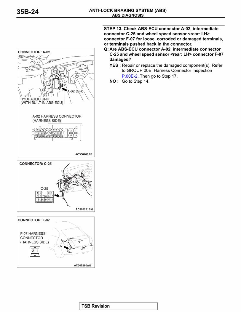
STEP 13. Check ABS-ECU connector A-02, intermediate connector C-25 and wheel speed sensor <rear: LH> connector F-07 for loose, corroded or damaged terminals, or terminals pushed back in the connector.Q: Are ABS-ECU connector A-02, intermediate connector
C-25 and wheel speed sensor <rear: LH> connector F-07 damaged?YES : Repair or replace the damaged component(s). Refer
to GROUP 00E, Harness Connector Inspection P.00E-2. Then go to Step 17.
NO : Go to Step 14.
AC306406
19
2
18
189 7 6 5 4 31011
25
151617
2728 26
121314
2324 22 21 20
A-02 HARNESS CONNECTOR(HARNESS SIDE)
AB
A-02 (GR)
CONNECTOR: A-02
HYDRAULIC UNIT(WITH BUILT-IN ABS-ECU)
AC305231BM
CONNECTOR: C-25
C-25
11
1 4310161312
5 62
148
1597
AC305260
CONNECTOR: F-07
AG
F-07 HARNESSCONNECTOR(HARNESS SIDE)
2 1F-07
TSB Revision
ABS DIAGNOSISANTI-LOCK BRAKING SYSTEM (ABS) 35B-25
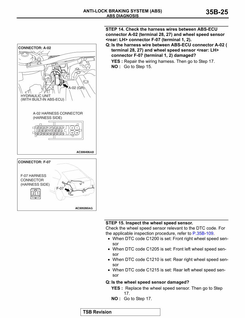
STEP 14. Check the harness wires between ABS-ECU connector A-02 (terminal 28, 27) and wheel speed sensor <rear: LH> connector F-07 (terminal 1, 2).Q: Is the harness wire between ABS-ECU connector A-02 (
terminal 28, 27) and wheel speed sensor <rear: LH> connector F-07 (terminal 1, 2) damaged?YES : Repair the wiring harness. Then go to Step 17.NO : Go to Step 15.
STEP 15. Inspect the wheel speed sensor.Check the wheel speed sensor relevant to the DTC code. For the applicable inspection procedure, refer to P.35B-109.
• When DTC code C1200 is set: Front right wheel speed sen-sor
• When DTC code C1205 is set: Front left wheel speed sen-sor
• When DTC code C1210 is set: Rear right wheel speed sen-sor
• When DTC code C1215 is set: Rear left wheel speed sen-sor
Q: Is the wheel speed sensor damaged?YES : Replace the wheel speed sensor. Then go to Step
17.NO : Go to Step 17.
AC306406
19
2
18
189 7 6 5 4 31011
25
151617
2728 26
121314
2324 22 21 20
A-02 HARNESS CONNECTOR(HARNESS SIDE)
AB
A-02 (GR)
CONNECTOR: A-02
HYDRAULIC UNIT(WITH BUILT-IN ABS-ECU)
AC305260
CONNECTOR: F-07
AG
F-07 HARNESSCONNECTOR(HARNESS SIDE)
2 1F-07
TSB Revision
ABS DIAGNOSISANTI-LOCK BRAKING SYSTEM (ABS)35B-26
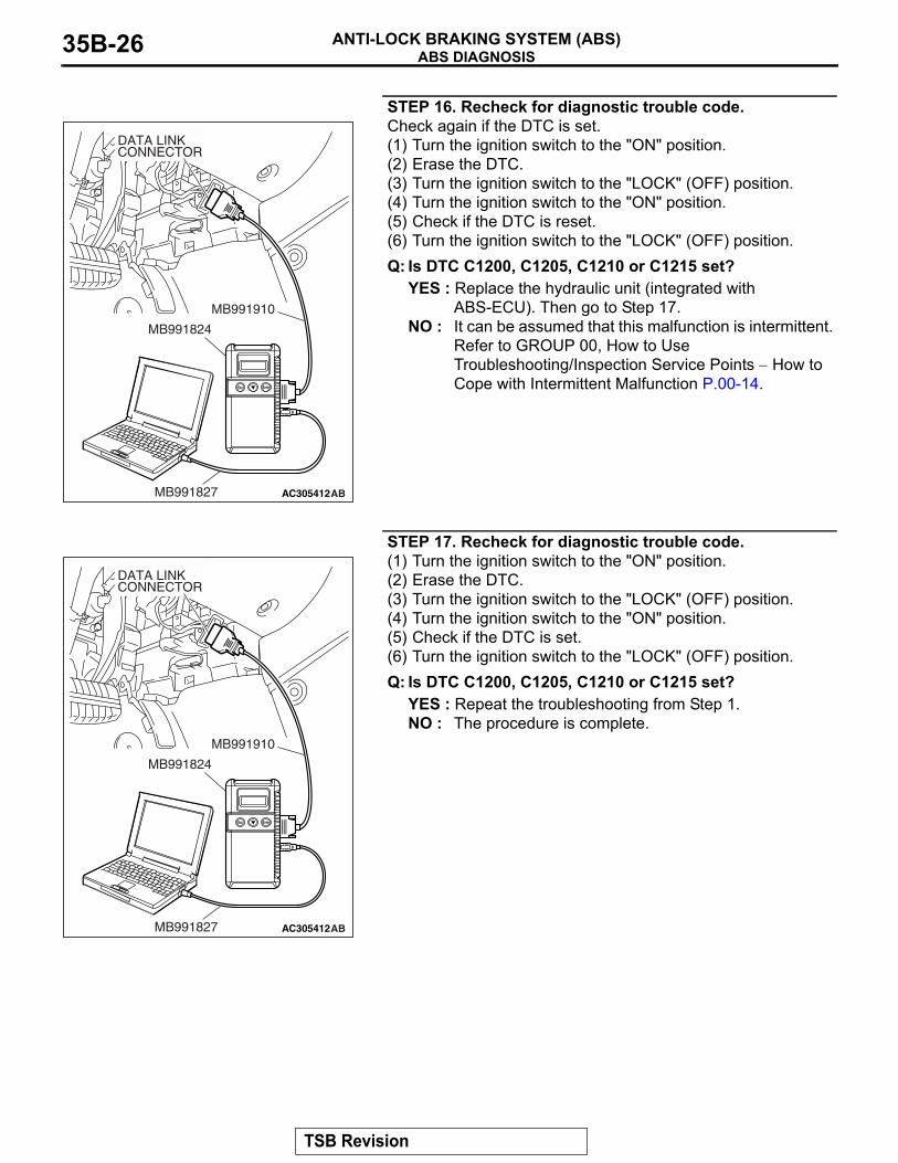
STEP 16. Recheck for diagnostic trouble code.Check again if the DTC is set.(1) Turn the ignition switch to the "ON" position.(2) Erase the DTC.(3) Turn the ignition switch to the "LOCK" (OFF) position.(4) Turn the ignition switch to the "ON" position.(5) Check if the DTC is reset.(6) Turn the ignition switch to the "LOCK" (OFF) position.Q: Is DTC C1200, C1205, C1210 or C1215 set?
YES : Replace the hydraulic unit (integrated with ABS-ECU). Then go to Step 17.
NO : It can be assumed that this malfunction is intermittent. Refer to GROUP 00, How to Use Troubleshooting/Inspection Service Points − How to Cope with Intermittent Malfunction P.00-14.
STEP 17. Recheck for diagnostic trouble code.(1) Turn the ignition switch to the "ON" position.(2) Erase the DTC.(3) Turn the ignition switch to the "LOCK" (OFF) position.(4) Turn the ignition switch to the "ON" position.(5) Check if the DTC is set.(6) Turn the ignition switch to the "LOCK" (OFF) position.Q: Is DTC C1200, C1205, C1210 or C1215 set?
YES : Repeat the troubleshooting from Step 1.NO : The procedure is complete.
AC305412AB
MB991910
DATA LINKCONNECTOR
MB991824
MB991827
AC305412AB
MB991910
DATA LINKCONNECTOR
MB991824
MB991827
TSB Revision
ABS DIAGNOSISANTI-LOCK BRAKING SYSTEM (ABS) 35B-27
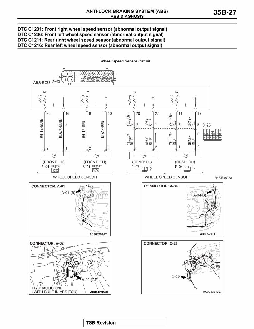
DTC C1201: Front right wheel speed sensor (abnormal output signal) DTC C1206: Front left wheel speed sensor (abnormal output signal) DTC C1211: Rear right wheel speed sensor (abnormal output signal) DTC C1216: Rear left wheel speed sensor (abnormal output signal)
WHEEL SPEED SENSOR WHEEL SPEED SENSOR
(REAR: RH)(REAR: LH)(FRONT: RH)(FRONT: LH)
ABS-ECU
Wheel Speed Sensor Circuit
AC305206
A-01 (B)
CONNECTOR: A-01
AT
AC304742
A-02 (GR)
CONNECTOR: A-02
HYDRAULIC UNIT(WITH BUILT-IN ABS-ECU) AC
AC305210AI
A-04(B)
CONNECTOR: A-04
AC305231BL
CONNECTOR: C-25
C-25
TSB Revision
ABS DIAGNOSISANTI-LOCK BRAKING SYSTEM (ABS)35B-28
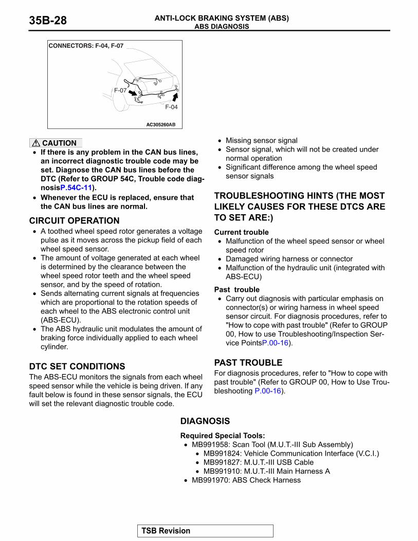
CAUTION• If there is any problem in the CAN bus lines,
an incorrect diagnostic trouble code may be set. Diagnose the CAN bus lines before the DTC (Refer to GROUP 54C, Trouble code diag-nosisP.54C-11).
• Whenever the ECU is replaced, ensure that the CAN bus lines are normal.
.
CIRCUIT OPERATION• A toothed wheel speed rotor generates a voltage
pulse as it moves across the pickup field of each wheel speed sensor.
• The amount of voltage generated at each wheel is determined by the clearance between the wheel speed rotor teeth and the wheel speed sensor, and by the speed of rotation.
• Sends alternating current signals at frequencies which are proportional to the rotation speeds of each wheel to the ABS electronic control unit (ABS-ECU).
• The ABS hydraulic unit modulates the amount of braking force individually applied to each wheel cylinder.
.
DTC SET CONDITIONSThe ABS-ECU monitors the signals from each wheel speed sensor while the vehicle is being driven. If any fault below is found in these sensor signals, the ECU will set the relevant diagnostic trouble code.
• Missing sensor signal• Sensor signal, which will not be created under
normal operation• Significant difference among the wheel speed
sensor signals.
TROUBLESHOOTING HINTS (THE MOST LIKELY CAUSES FOR THESE DTCS ARE TO SET ARE:)Current trouble
• Malfunction of the wheel speed sensor or wheel speed rotor
• Damaged wiring harness or connector• Malfunction of the hydraulic unit (integrated with
ABS-ECU)
Past trouble• Carry out diagnosis with particular emphasis on
connector(s) or wiring harness in wheel speed sensor circuit. For diagnosis procedures, refer to "How to cope with past trouble" (Refer to GROUP 00, How to use Troubleshooting/Inspection Ser-vice PointsP.00-16).
.
PAST TROUBLEFor diagnosis procedures, refer to "How to cope with past trouble" (Refer to GROUP 00, How to Use Trou-bleshooting P.00-16).
DIAGNOSISRequired Special Tools:
• MB991958: Scan Tool (M.U.T.-III Sub Assembly)• MB991824: Vehicle Communication Interface (V.C.I.)• MB991827: M.U.T.-III USB Cable• MB991910: M.U.T.-III Main Harness A
• MB991970: ABS Check Harness
AC305260
F-04
F-07
CONNECTORS: F-04, F-07
AB
TSB Revision
ABS DIAGNOSISANTI-LOCK BRAKING SYSTEM (ABS) 35B-29
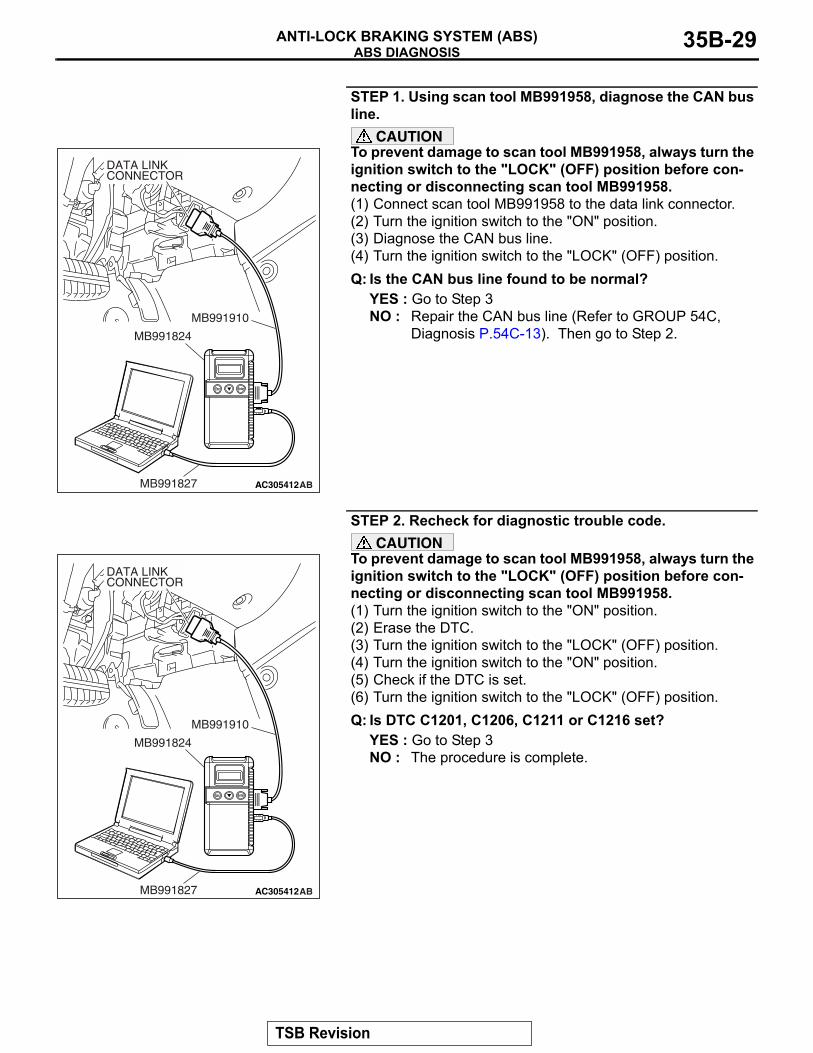
STEP 1. Using scan tool MB991958, diagnose the CAN bus line.
CAUTIONTo prevent damage to scan tool MB991958, always turn the ignition switch to the "LOCK" (OFF) position before con-necting or disconnecting scan tool MB991958.(1) Connect scan tool MB991958 to the data link connector.(2) Turn the ignition switch to the "ON" position.(3) Diagnose the CAN bus line.(4) Turn the ignition switch to the "LOCK" (OFF) position.Q: Is the CAN bus line found to be normal?
YES : Go to Step 3NO : Repair the CAN bus line (Refer to GROUP 54C,
Diagnosis P.54C-13). Then go to Step 2.
STEP 2. Recheck for diagnostic trouble code.CAUTION
To prevent damage to scan tool MB991958, always turn the ignition switch to the "LOCK" (OFF) position before con-necting or disconnecting scan tool MB991958.(1) Turn the ignition switch to the "ON" position.(2) Erase the DTC.(3) Turn the ignition switch to the "LOCK" (OFF) position.(4) Turn the ignition switch to the "ON" position.(5) Check if the DTC is set.(6) Turn the ignition switch to the "LOCK" (OFF) position.Q: Is DTC C1201, C1206, C1211 or C1216 set?
YES : Go to Step 3NO : The procedure is complete.
AC305412AB
MB991910
DATA LINKCONNECTOR
MB991824
MB991827
AC305412AB
MB991910
DATA LINKCONNECTOR
MB991824
MB991827
TSB Revision
ABS DIAGNOSISANTI-LOCK BRAKING SYSTEM (ABS)35B-30
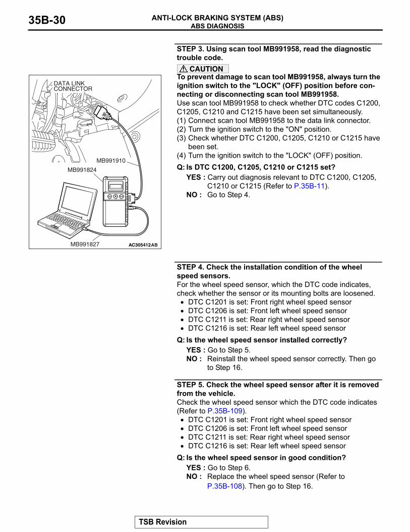
STEP 3. Using scan tool MB991958, read the diagnostic trouble code.
CAUTIONTo prevent damage to scan tool MB991958, always turn the ignition switch to the "LOCK" (OFF) position before con-necting or disconnecting scan tool MB991958.Use scan tool MB991958 to check whether DTC codes C1200, C1205, C1210 and C1215 have been set simultaneously.(1) Connect scan tool MB991958 to the data link connector.(2) Turn the ignition switch to the "ON" position.(3) Check whether DTC C1200, C1205, C1210 or C1215 have
been set.(4) Turn the ignition switch to the "LOCK" (OFF) position.Q: Is DTC C1200, C1205, C1210 or C1215 set?
YES : Carry out diagnosis relevant to DTC C1200, C1205, C1210 or C1215 (Refer to P.35B-11).
NO : Go to Step 4.
STEP 4. Check the installation condition of the wheel speed sensors.For the wheel speed sensor, which the DTC code indicates, check whether the sensor or its mounting bolts are loosened.
• DTC C1201 is set: Front right wheel speed sensor• DTC C1206 is set: Front left wheel speed sensor• DTC C1211 is set: Rear right wheel speed sensor• DTC C1216 is set: Rear left wheel speed sensor
Q: Is the wheel speed sensor installed correctly?YES : Go to Step 5.NO : Reinstall the wheel speed sensor correctly. Then go
to Step 16.
STEP 5. Check the wheel speed sensor after it is removed from the vehicle.Check the wheel speed sensor which the DTC code indicates (Refer to P.35B-109).
• DTC C1201 is set: Front right wheel speed sensor• DTC C1206 is set: Front left wheel speed sensor• DTC C1211 is set: Rear right wheel speed sensor• DTC C1216 is set: Rear left wheel speed sensor
Q: Is the wheel speed sensor in good condition?YES : Go to Step 6.NO : Replace the wheel speed sensor (Refer to
P.35B-108). Then go to Step 16.
AC305412AB
MB991910
DATA LINKCONNECTOR
MB991824
MB991827
TSB Revision
ABS DIAGNOSISANTI-LOCK BRAKING SYSTEM (ABS) 35B-31
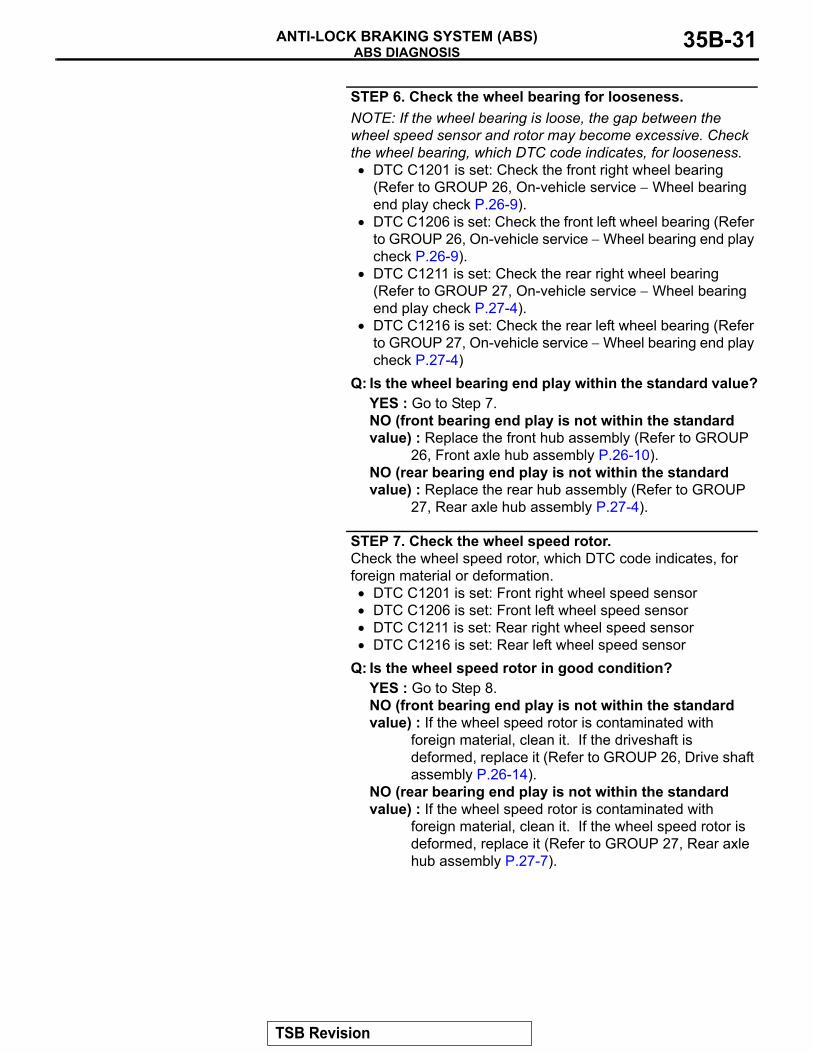
STEP 6. Check the wheel bearing for looseness.NOTE: If the wheel bearing is loose, the gap between the wheel speed sensor and rotor may become excessive. Check the wheel bearing, which DTC code indicates, for looseness.
• DTC C1201 is set: Check the front right wheel bearing (Refer to GROUP 26, On-vehicle service − Wheel bearing end play check P.26-9).
• DTC C1206 is set: Check the front left wheel bearing (Refer to GROUP 26, On-vehicle service − Wheel bearing end play check P.26-9).
• DTC C1211 is set: Check the rear right wheel bearing (Refer to GROUP 27, On-vehicle service − Wheel bearing end play check P.27-4).
• DTC C1216 is set: Check the rear left wheel bearing (Refer to GROUP 27, On-vehicle service − Wheel bearing end play check P.27-4)
Q: Is the wheel bearing end play within the standard value?YES : Go to Step 7.NO (front bearing end play is not within the standard value) : Replace the front hub assembly (Refer to GROUP
26, Front axle hub assembly P.26-10).NO (rear bearing end play is not within the standard value) : Replace the rear hub assembly (Refer to GROUP
27, Rear axle hub assembly P.27-4).
STEP 7. Check the wheel speed rotor.Check the wheel speed rotor, which DTC code indicates, for foreign material or deformation.
• DTC C1201 is set: Front right wheel speed sensor• DTC C1206 is set: Front left wheel speed sensor• DTC C1211 is set: Rear right wheel speed sensor• DTC C1216 is set: Rear left wheel speed sensor
Q: Is the wheel speed rotor in good condition?YES : Go to Step 8.NO (front bearing end play is not within the standard value) : If the wheel speed rotor is contaminated with
foreign material, clean it. If the driveshaft is deformed, replace it (Refer to GROUP 26, Drive shaft assembly P.26-14).
NO (rear bearing end play is not within the standard value) : If the wheel speed rotor is contaminated with
foreign material, clean it. If the wheel speed rotor is deformed, replace it (Refer to GROUP 27, Rear axle hub assembly P.27-7).
TSB Revision
ABS DIAGNOSISANTI-LOCK BRAKING SYSTEM (ABS)35B-32
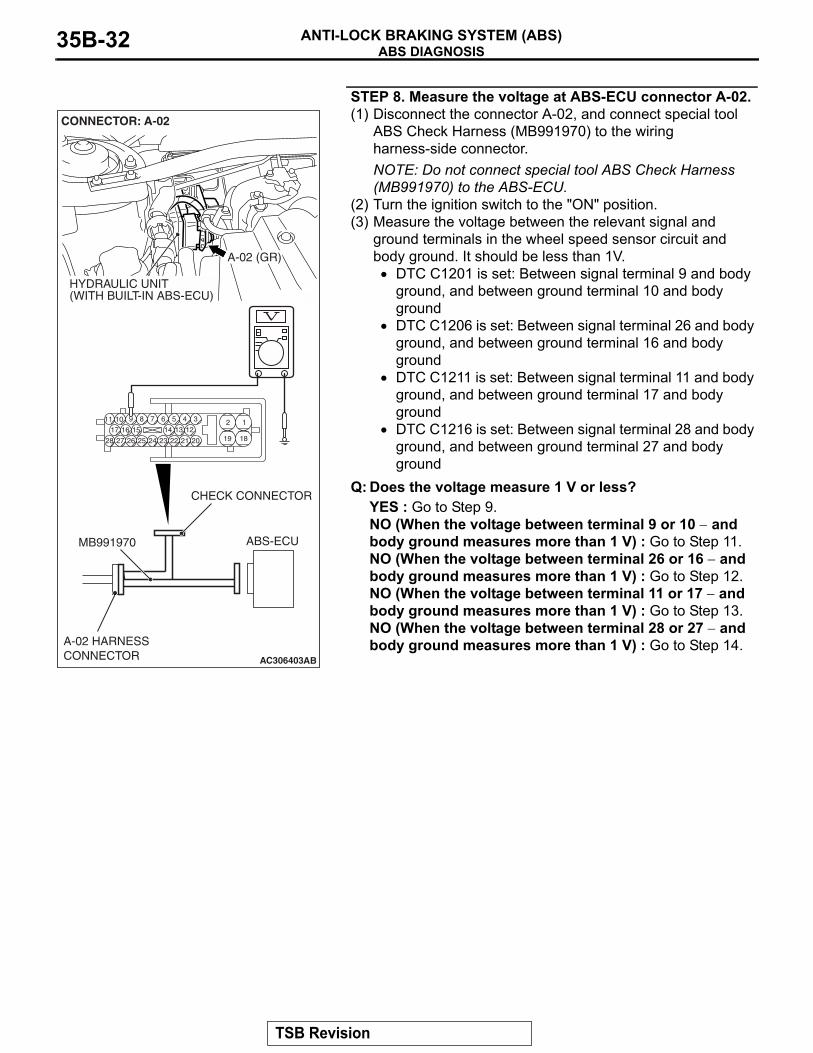
STEP 8. Measure the voltage at ABS-ECU connector A-02.(1) Disconnect the connector A-02, and connect special tool
ABS Check Harness (MB991970) to the wiring harness-side connector.NOTE: Do not connect special tool ABS Check Harness (MB991970) to the ABS-ECU.
(2) Turn the ignition switch to the "ON" position.(3) Measure the voltage between the relevant signal and
ground terminals in the wheel speed sensor circuit and body ground. It should be less than 1V.
• DTC C1201 is set: Between signal terminal 9 and body ground, and between ground terminal 10 and body ground
• DTC C1206 is set: Between signal terminal 26 and body ground, and between ground terminal 16 and body ground
• DTC C1211 is set: Between signal terminal 11 and body ground, and between ground terminal 17 and body ground
• DTC C1216 is set: Between signal terminal 28 and body ground, and between ground terminal 27 and body ground
Q: Does the voltage measure 1 V or less?YES : Go to Step 9.NO (When the voltage between terminal 9 or 10 − and body ground measures more than 1 V) : Go to Step 11.NO (When the voltage between terminal 26 or 16 − and body ground measures more than 1 V) : Go to Step 12.NO (When the voltage between terminal 11 or 17 − and body ground measures more than 1 V) : Go to Step 13.NO (When the voltage between terminal 28 or 27 − and body ground measures more than 1 V) : Go to Step 14.
AC306403
19
2
18
189 7 6 5 4 31011
25
151617
2728 26
121314
2324 22 21 20
AB
ABS-ECUMB991970
CHECK CONNECTOR
A-02 HARNESSCONNECTOR
A-02 (GR)
CONNECTOR: A-02
HYDRAULIC UNIT(WITH BUILT-IN ABS-ECU)
TSB Revision
ABS DIAGNOSISANTI-LOCK BRAKING SYSTEM (ABS) 35B-33
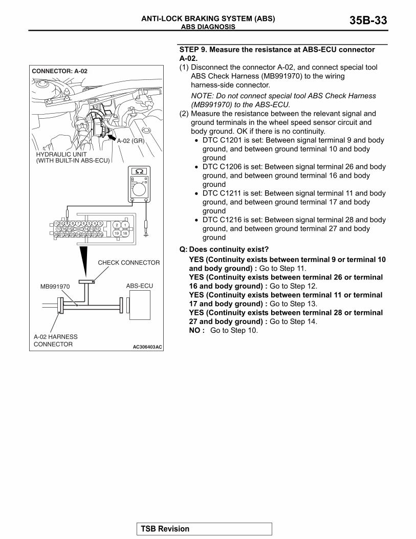
STEP 9. Measure the resistance at ABS-ECU connector A-02.(1) Disconnect the connector A-02, and connect special tool
ABS Check Harness (MB991970) to the wiring harness-side connector.NOTE: Do not connect special tool ABS Check Harness (MB991970) to the ABS-ECU.
(2) Measure the resistance between the relevant signal and ground terminals in the wheel speed sensor circuit and body ground. OK if there is no continuity.
• DTC C1201 is set: Between signal terminal 9 and body ground, and between ground terminal 10 and body ground
• DTC C1206 is set: Between signal terminal 26 and body ground, and between ground terminal 16 and body ground
• DTC C1211 is set: Between signal terminal 11 and body ground, and between ground terminal 17 and body ground
• DTC C1216 is set: Between signal terminal 28 and body ground, and between ground terminal 27 and body ground
Q: Does continuity exist?YES (Continuity exists between terminal 9 or terminal 10 and body ground) : Go to Step 11.YES (Continuity exists between terminal 26 or terminal 16 and body ground) : Go to Step 12.YES (Continuity exists between terminal 11 or terminal 17 and body ground) : Go to Step 13.YES (Continuity exists between terminal 28 or terminal 27 and body ground) : Go to Step 14.NO : Go to Step 10.
AC306403
19
2
18
189 7 6 5 4 31011
25
151617
2728 26
121314
2324 22 21 20
AC
ABS-ECUMB991970
CHECK CONNECTOR
A-02 HARNESSCONNECTOR
A-02 (GR)
CONNECTOR: A-02
HYDRAULIC UNIT(WITH BUILT-IN ABS-ECU)
TSB Revision
ABS DIAGNOSISANTI-LOCK BRAKING SYSTEM (ABS)35B-34
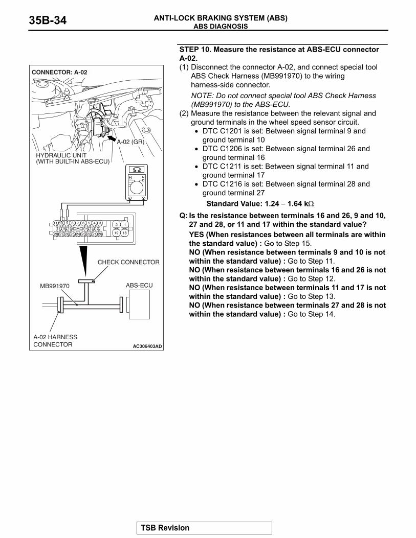
STEP 10. Measure the resistance at ABS-ECU connector A-02.(1) Disconnect the connector A-02, and connect special tool
ABS Check Harness (MB991970) to the wiring harness-side connector.NOTE: Do not connect special tool ABS Check Harness (MB991970) to the ABS-ECU.
(2) Measure the resistance between the relevant signal and ground terminals in the wheel speed sensor circuit.
• DTC C1201 is set: Between signal terminal 9 and ground terminal 10
• DTC C1206 is set: Between signal terminal 26 and ground terminal 16
• DTC C1211 is set: Between signal terminal 11 and ground terminal 17
• DTC C1216 is set: Between signal terminal 28 and ground terminal 27Standard Value: 1.24 − 1.64 kΩ
Q: Is the resistance between terminals 16 and 26, 9 and 10, 27 and 28, or 11 and 17 within the standard value?YES (When resistances between all terminals are within the standard value) : Go to Step 15.NO (When resistance between terminals 9 and 10 is not within the standard value) : Go to Step 11.NO (When resistance between terminals 16 and 26 is not within the standard value) : Go to Step 12.NO (When resistance between terminals 11 and 17 is not within the standard value) : Go to Step 13.NO (When resistance between terminals 27 and 28 is not within the standard value) : Go to Step 14.
AC306403
19
2
18
189 7 6 5 4 31011
25
151617
2728 26
121314
2324 22 21 20
AD
ABS-ECUMB991970
CHECK CONNECTOR
A-02 HARNESSCONNECTOR
A-02 (GR)
CONNECTOR: A-02
HYDRAULIC UNIT(WITH BUILT-IN ABS-ECU)
TSB Revision
ABS DIAGNOSISANTI-LOCK BRAKING SYSTEM (ABS) 35B-35
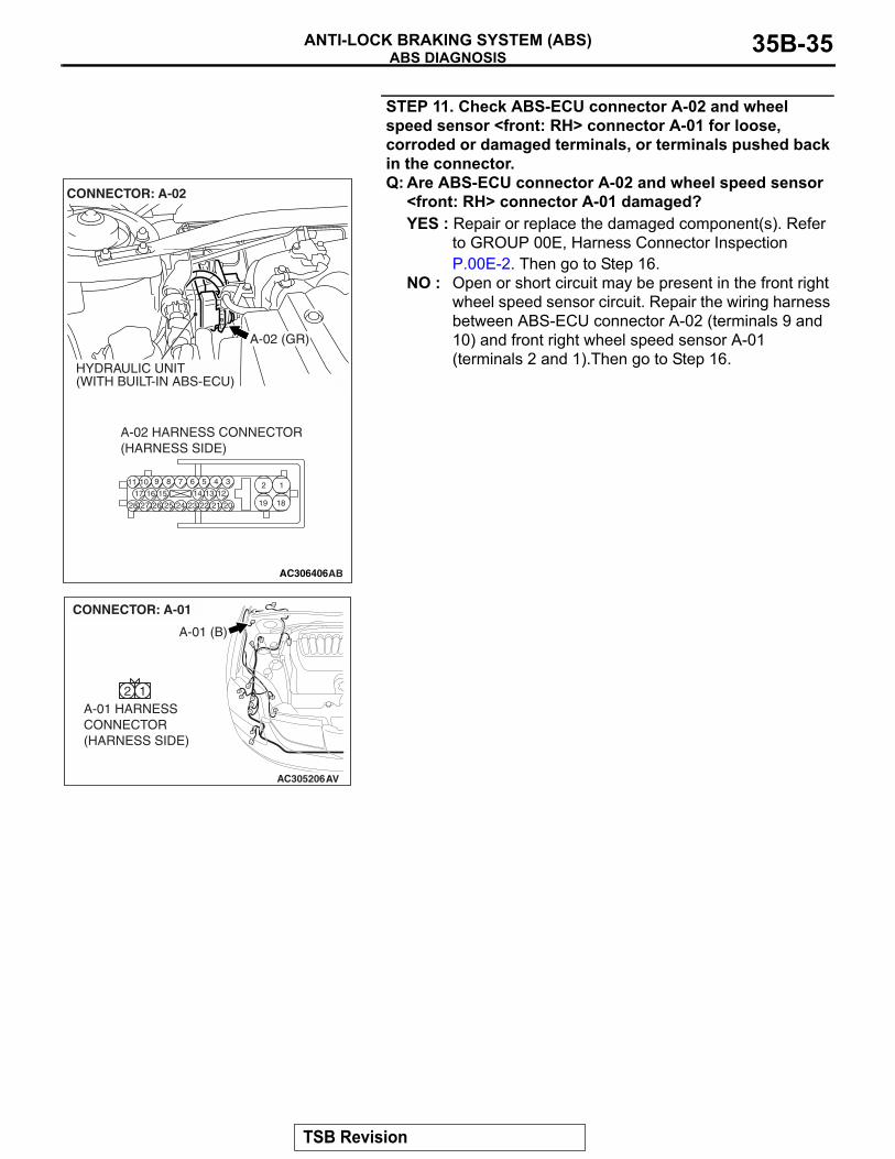
STEP 11. Check ABS-ECU connector A-02 and wheel speed sensor <front: RH> connector A-01 for loose, corroded or damaged terminals, or terminals pushed back in the connector.Q: Are ABS-ECU connector A-02 and wheel speed sensor
<front: RH> connector A-01 damaged?YES : Repair or replace the damaged component(s). Refer
to GROUP 00E, Harness Connector Inspection P.00E-2. Then go to Step 16.
NO : Open or short circuit may be present in the front right wheel speed sensor circuit. Repair the wiring harness between ABS-ECU connector A-02 (terminals 9 and 10) and front right wheel speed sensor A-01 (terminals 2 and 1).Then go to Step 16.
AC306406
19
2
18
189 7 6 5 4 31011
25
151617
2728 26
121314
2324 22 21 20
A-02 HARNESS CONNECTOR(HARNESS SIDE)
AB
A-02 (GR)
CONNECTOR: A-02
HYDRAULIC UNIT(WITH BUILT-IN ABS-ECU)
AC305206
A-01 (B)
CONNECTOR: A-01
AV
A-01 HARNESSCONNECTOR(HARNESS SIDE)
2 1
TSB Revision
ABS DIAGNOSISANTI-LOCK BRAKING SYSTEM (ABS)35B-36
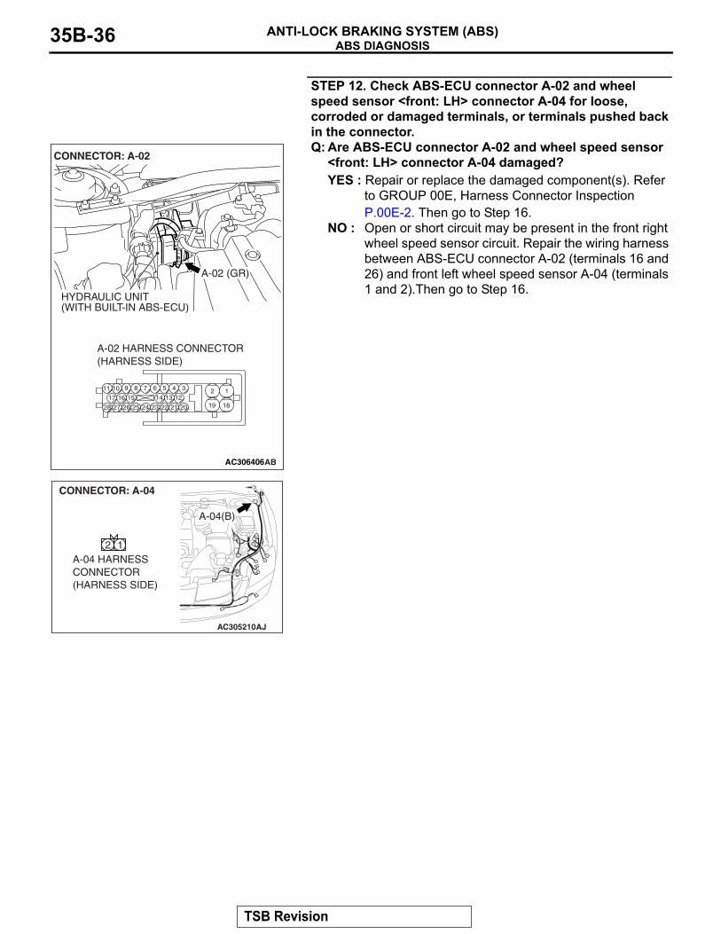
STEP 12. Check ABS-ECU connector A-02 and wheel speed sensor <front: LH> connector A-04 for loose, corroded or damaged terminals, or terminals pushed back in the connector.Q: Are ABS-ECU connector A-02 and wheel speed sensor
<front: LH> connector A-04 damaged?YES : Repair or replace the damaged component(s). Refer
to GROUP 00E, Harness Connector Inspection P.00E-2. Then go to Step 16.
NO : Open or short circuit may be present in the front right wheel speed sensor circuit. Repair the wiring harness between ABS-ECU connector A-02 (terminals 16 and 26) and front left wheel speed sensor A-04 (terminals 1 and 2).Then go to Step 16.
AC306406
19
2
18
189 7 6 5 4 31011
25
151617
2728 26
121314
2324 22 21 20
A-02 HARNESS CONNECTOR(HARNESS SIDE)
AB
A-02 (GR)
CONNECTOR: A-02
HYDRAULIC UNIT(WITH BUILT-IN ABS-ECU)
AC305210AJ
A-04(B)
CONNECTOR: A-04
A-04 HARNESSCONNECTOR(HARNESS SIDE)
2 1
TSB Revision
ABS DIAGNOSISANTI-LOCK BRAKING SYSTEM (ABS) 35B-37
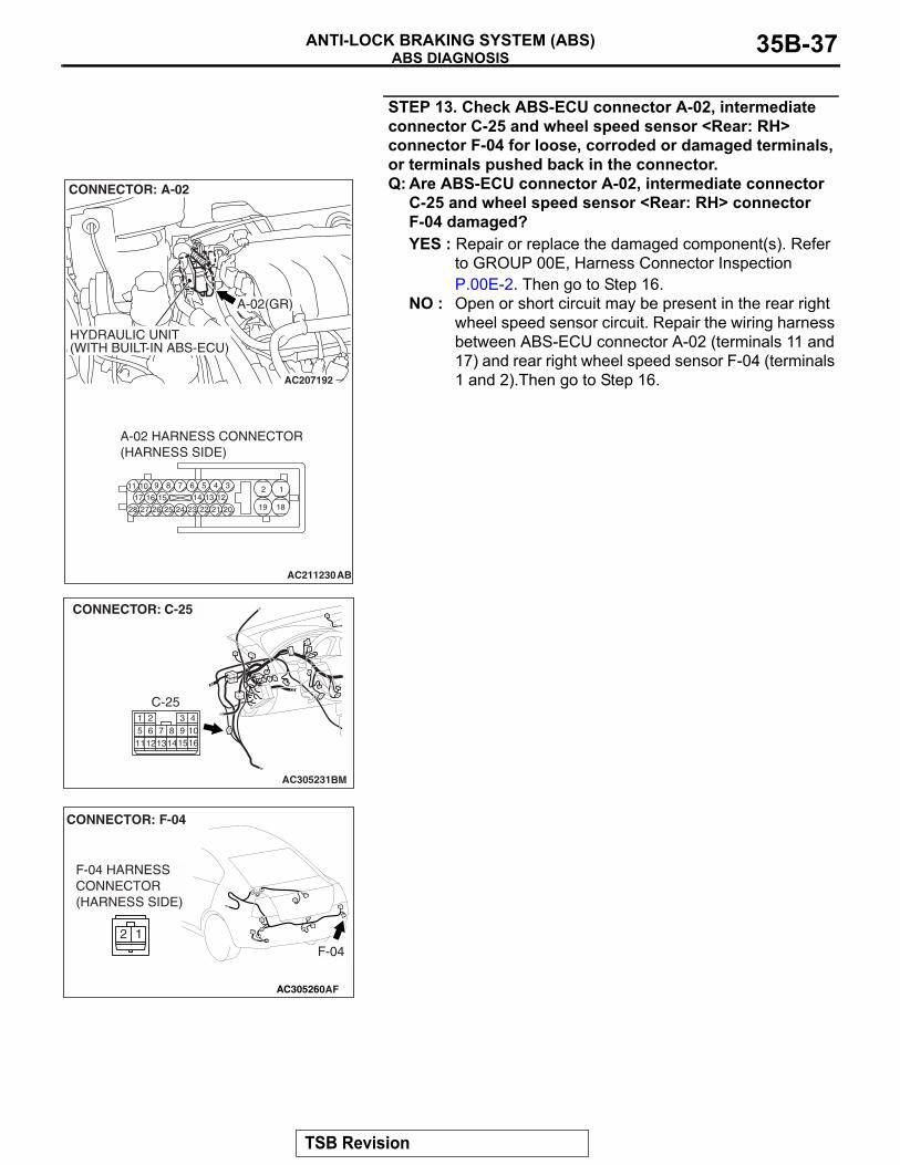
STEP 13. Check ABS-ECU connector A-02, intermediate connector C-25 and wheel speed sensor <Rear: RH> connector F-04 for loose, corroded or damaged terminals, or terminals pushed back in the connector.Q: Are ABS-ECU connector A-02, intermediate connector
C-25 and wheel speed sensor <Rear: RH> connector F-04 damaged?YES : Repair or replace the damaged component(s). Refer
to GROUP 00E, Harness Connector Inspection P.00E-2. Then go to Step 16.
NO : Open or short circuit may be present in the rear right wheel speed sensor circuit. Repair the wiring harness between ABS-ECU connector A-02 (terminals 11 and 17) and rear right wheel speed sensor F-04 (terminals 1 and 2).Then go to Step 16.AC207192
AC211230
19
2
18
189 7 6 5 4 31011
25
151617
2728 26
121314
2324 22 21 20
A-02(GR)
CONNECTOR: A-02
HYDRAULIC UNIT(WITH BUILT-IN ABS-ECU)
A-02 HARNESS CONNECTOR(HARNESS SIDE)
AB
AC305231BM
CONNECTOR: C-25
C-25
11
1 4310161312
5 62
148
1597
AC305260
F-04
CONNECTOR: F-04
AF
F-04 HARNESSCONNECTOR(HARNESS SIDE)
2 1
TSB Revision
ABS DIAGNOSISANTI-LOCK BRAKING SYSTEM (ABS)35B-38
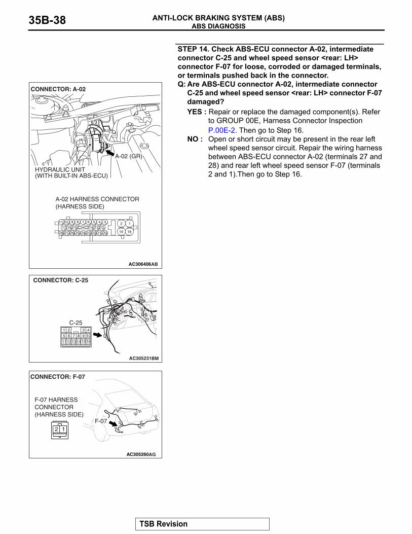
STEP 14. Check ABS-ECU connector A-02, intermediate connector C-25 and wheel speed sensor <rear: LH> connector F-07 for loose, corroded or damaged terminals, or terminals pushed back in the connector.Q: Are ABS-ECU connector A-02, intermediate connector
C-25 and wheel speed sensor <rear: LH> connector F-07 damaged?YES : Repair or replace the damaged component(s). Refer
to GROUP 00E, Harness Connector Inspection P.00E-2. Then go to Step 16.
NO : Open or short circuit may be present in the rear left wheel speed sensor circuit. Repair the wiring harness between ABS-ECU connector A-02 (terminals 27 and 28) and rear left wheel speed sensor F-07 (terminals 2 and 1).Then go to Step 16.
AC306406
19
2
18
189 7 6 5 4 31011
25
151617
2728 26
121314
2324 22 21 20
A-02 HARNESS CONNECTOR(HARNESS SIDE)
AB
A-02 (GR)
CONNECTOR: A-02
HYDRAULIC UNIT(WITH BUILT-IN ABS-ECU)
AC305231BM
CONNECTOR: C-25
C-25
11
1 4310161312
5 62
148
1597
AC305260
CONNECTOR: F-07
AG
F-07 HARNESSCONNECTOR(HARNESS SIDE)
2 1F-07
TSB Revision
ABS DIAGNOSISANTI-LOCK BRAKING SYSTEM (ABS) 35B-39
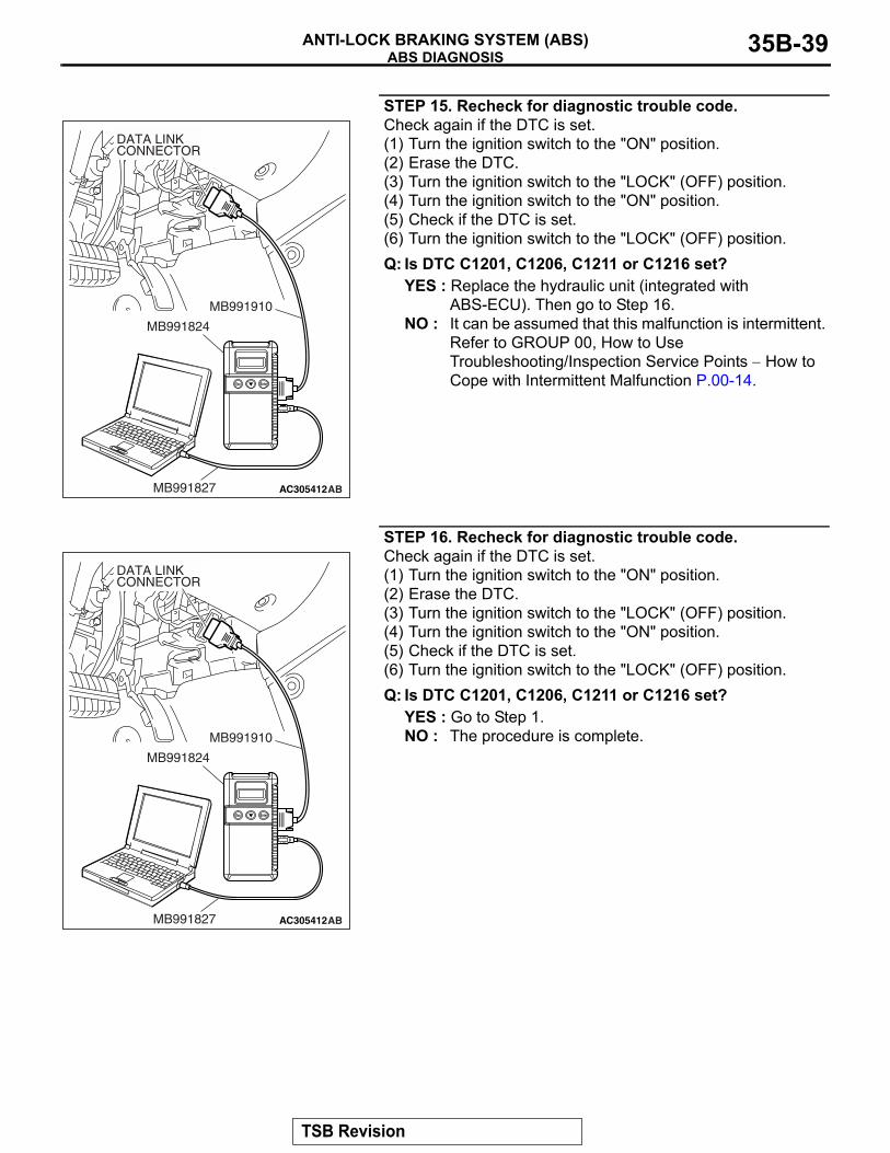
STEP 15. Recheck for diagnostic trouble code.Check again if the DTC is set.(1) Turn the ignition switch to the "ON" position.(2) Erase the DTC.(3) Turn the ignition switch to the "LOCK" (OFF) position.(4) Turn the ignition switch to the "ON" position.(5) Check if the DTC is set.(6) Turn the ignition switch to the "LOCK" (OFF) position.Q: Is DTC C1201, C1206, C1211 or C1216 set?
YES : Replace the hydraulic unit (integrated with ABS-ECU). Then go to Step 16.
NO : It can be assumed that this malfunction is intermittent. Refer to GROUP 00, How to Use Troubleshooting/Inspection Service Points − How to Cope with Intermittent Malfunction P.00-14.
STEP 16. Recheck for diagnostic trouble code.Check again if the DTC is set.(1) Turn the ignition switch to the "ON" position.(2) Erase the DTC.(3) Turn the ignition switch to the "LOCK" (OFF) position.(4) Turn the ignition switch to the "ON" position.(5) Check if the DTC is set.(6) Turn the ignition switch to the "LOCK" (OFF) position.Q: Is DTC C1201, C1206, C1211 or C1216 set?
YES : Go to Step 1.NO : The procedure is complete.
AC305412AB
MB991910
DATA LINKCONNECTOR
MB991824
MB991827
AC305412AB
MB991910
DATA LINKCONNECTOR
MB991824
MB991827
TSB Revision
ABS DIAGNOSISANTI-LOCK BRAKING SYSTEM (ABS)35B-40
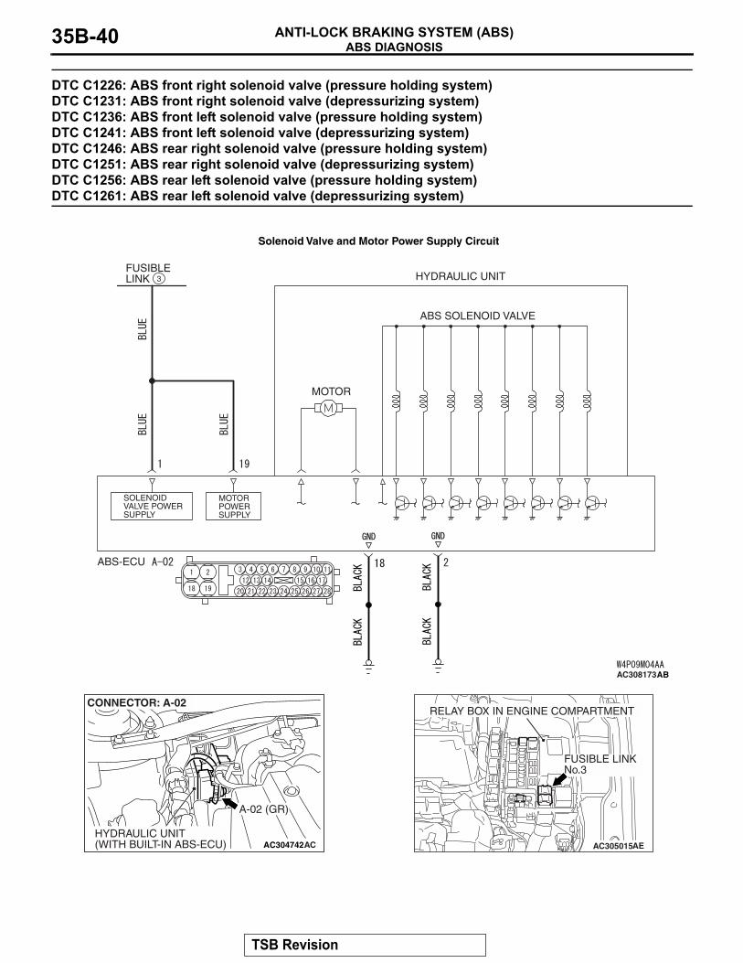
DTC C1226: ABS front right solenoid valve (pressure holding system) DTC C1231: ABS front right solenoid valve (depressurizing system) DTC C1236: ABS front left solenoid valve (pressure holding system) DTC C1241: ABS front left solenoid valve (depressurizing system) DTC C1246: ABS rear right solenoid valve (pressure holding system) DTC C1251: ABS rear right solenoid valve (depressurizing system) DTC C1256: ABS rear left solenoid valve (pressure holding system) DTC C1261: ABS rear left solenoid valve (depressurizing system)
ABS SOLENOID VALVE
HYDRAULIC UNIT
MOTOR
FUSIBLE LINK
MOTOR POWER SUPPLY
SOLENOID VALVE POWER SUPPLY
ABS-ECU
3
AC308173AB
Solenoid Valve and Motor Power Supply Circuit
AC304742
A-02 (GR)
CONNECTOR: A-02
HYDRAULIC UNIT(WITH BUILT-IN ABS-ECU) AC AC305015AE
FUSIBLE LINKNo.3
RELAY BOX IN ENGINE COMPARTMENT
TSB Revision
ABS DIAGNOSISANTI-LOCK BRAKING SYSTEM (ABS) 35B-41
CAUTION• If there is any problem in the CAN bus lines,
an incorrect diagnostic trouble code may be set. Diagnose the CAN bus lines before the DTC (Refer to GROUP 54C, Trouble code diag-nosisP.54C-11).
• Whenever the ECU is replaced, ensure that the CAN bus lines are normal.
.
CIRCUIT OPERATION• The ABS-ECU contains the power supply circuit
(terminal 1) for the solenoid valve. The solenoid valve is energized by the valve relay, which is integrated in the ABS-ECU.
• The valve relay, which is integrated in the ABS-ECU, is always energizing the solenoid valve unless the initial check is in progress when the ignition switch is turned on.
• The ABS-ECU activates the solenoid valve by turning on its driving transistor.
.
DTC SET CONDITIONSThese diagnostic trouble codes will be set under the cases below.
• The solenoid valve is not energized even after the ABS-ECU has turned on the driving transistor (Open circuit is present in the power supply cir-cuit to the ABS-ECU solenoid valve, or the valve relay has failed).
• The solenoid valve is not energized even after the ABS-ECU has turned on the driving transistor (Open circuit is present in the solenoid valve cir-cuit inside the ABS-ECU, or the valve relay has failed).
• After the ABS-ECU has turned off the driving transistor, the solenoid valve still remains ener-gized (short in the solenoid valve circuit).
• When a solenoid valve failure is detected.
TROUBLESHOOTING HINTS (THE MOST LIKELY CAUSES FOR THESE DTCS ARE TO SET ARE:)Current trouble
• Damaged wiring harness or connector• Malfunction of the hydraulic unit (integrated with
ABS-ECU).
PAST TROUBLE• Carry out diagnosis with particular emphasis on
connector(s) or wiring harness between the power supply circuit (terminal 1) to the ABS-ECU solenoid valve or ground circuit (terminal 2) . For diagnosis procedures, refer to "How to cope with past trouble" (Refer to GROUP 00, How to Use Troubleshooting/Inspection Service Points P.00-16).
DIAGNOSISRequired Special Tools:
• MB991958: Scan Tool (M.U.T.-III Sub Assembly)• MB991824: Vehicle Communication Interface (V.C.I.)• MB991827: M.U.T.-III USB Cable• MB991910: M.U.T.-III Main Harness A
• MB991970: ABS Check Harness
TSB Revision
ABS DIAGNOSISANTI-LOCK BRAKING SYSTEM (ABS)35B-42
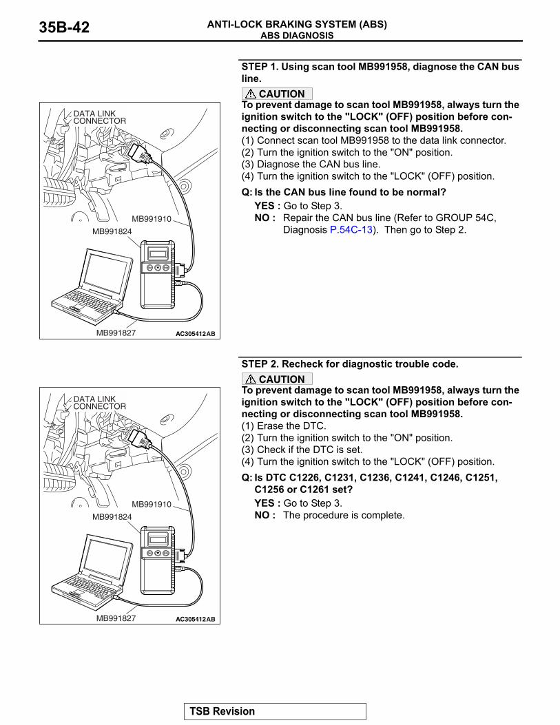
STEP 1. Using scan tool MB991958, diagnose the CAN bus line.
CAUTIONTo prevent damage to scan tool MB991958, always turn the ignition switch to the "LOCK" (OFF) position before con-necting or disconnecting scan tool MB991958.(1) Connect scan tool MB991958 to the data link connector.(2) Turn the ignition switch to the "ON" position.(3) Diagnose the CAN bus line.(4) Turn the ignition switch to the "LOCK" (OFF) position.Q: Is the CAN bus line found to be normal?
YES : Go to Step 3.NO : Repair the CAN bus line (Refer to GROUP 54C,
Diagnosis P.54C-13). Then go to Step 2.
STEP 2. Recheck for diagnostic trouble code.CAUTION
To prevent damage to scan tool MB991958, always turn the ignition switch to the "LOCK" (OFF) position before con-necting or disconnecting scan tool MB991958.(1) Erase the DTC.(2) Turn the ignition switch to the "ON" position.(3) Check if the DTC is set.(4) Turn the ignition switch to the "LOCK" (OFF) position.Q: Is DTC C1226, C1231, C1236, C1241, C1246, C1251,
C1256 or C1261 set?YES : Go to Step 3.NO : The procedure is complete.
AC305412AB
MB991910
DATA LINKCONNECTOR
MB991824
MB991827
AC305412AB
MB991910
DATA LINKCONNECTOR
MB991824
MB991827
TSB Revision
ABS DIAGNOSISANTI-LOCK BRAKING SYSTEM (ABS) 35B-43
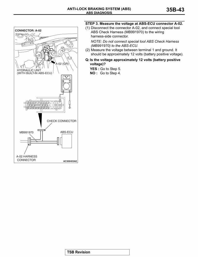
STEP 3. Measure the voltage at ABS-ECU connector A-02.(1) Disconnect the connector A-02, and connect special tool
ABS Check Harness (MB991970) to the wiring harness-side connector.NOTE: Do not connect special tool ABS Check Harness (MB991970) to the ABS-ECU.
(2) Measure the voltage between terminal 1 and ground. It should be approximately 12 volts (battery positive voltage).
Q: Is the voltage approximately 12 volts (battery positive voltage)?YES : Go to Step 5.NO : Go to Step 4.
AC306403
19
2
18
189 7 6 5 4 31011
25
151617
2728 26
121314
2324 22 21 20
AE
ABS-ECUMB991970
CHECK CONNECTOR
A-02 HARNESS CONNECTOR
A-02 (GR)
CONNECTOR: A-02
HYDRAULIC UNIT(WITH BUILT-IN ABS-ECU)
TSB Revision
ABS DIAGNOSISANTI-LOCK BRAKING SYSTEM (ABS)35B-44
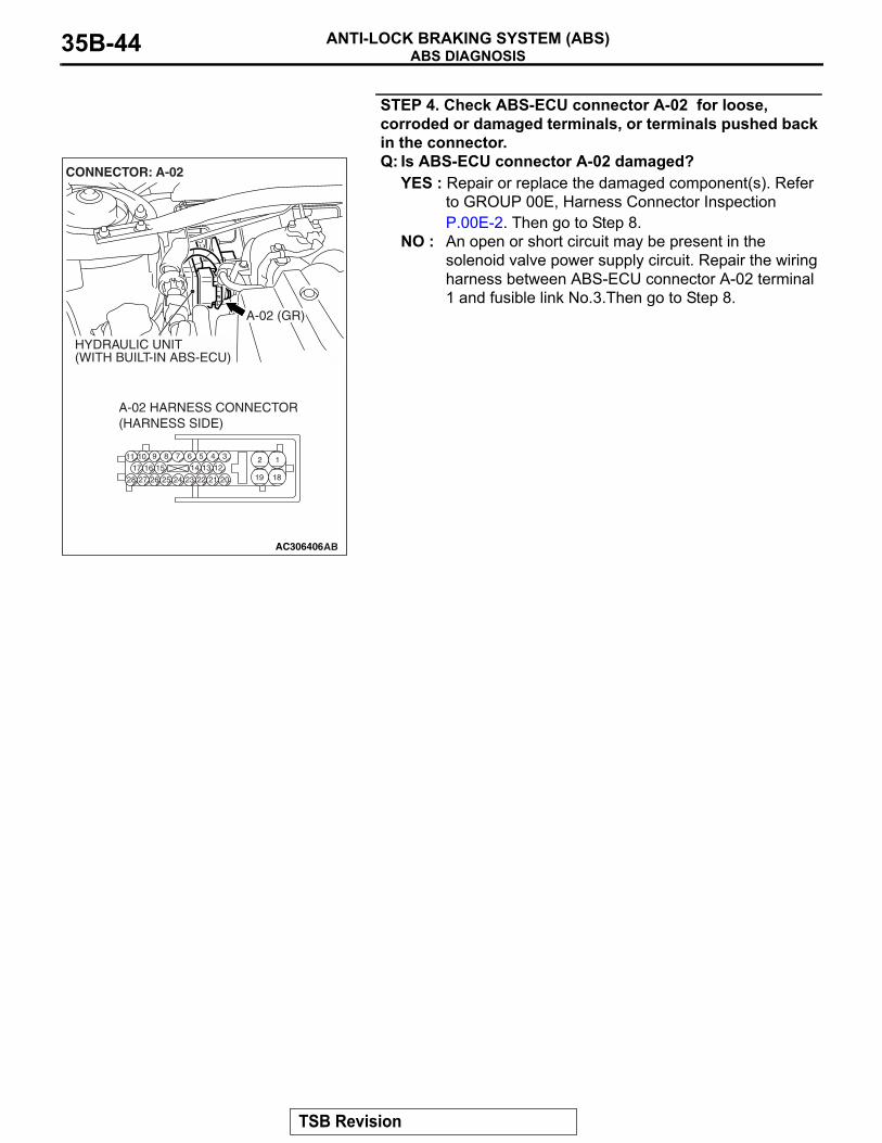
STEP 4. Check ABS-ECU connector A-02 for loose, corroded or damaged terminals, or terminals pushed back in the connector.Q: Is ABS-ECU connector A-02 damaged?
YES : Repair or replace the damaged component(s). Refer to GROUP 00E, Harness Connector Inspection P.00E-2. Then go to Step 8.
NO : An open or short circuit may be present in the solenoid valve power supply circuit. Repair the wiring harness between ABS-ECU connector A-02 terminal 1 and fusible link No.3.Then go to Step 8.
AC306406
19
2
18
189 7 6 5 4 31011
25
151617
2728 26
121314
2324 22 21 20
A-02 HARNESS CONNECTOR(HARNESS SIDE)
AB
A-02 (GR)
CONNECTOR: A-02
HYDRAULIC UNIT(WITH BUILT-IN ABS-ECU)
TSB Revision

ABS DIAGNOSISANTI-LOCK BRAKING SYSTEM (ABS) 35B-45
STEP 5. Measure the resistance at ABS-ECU connector A-02.(1) Disconnect the connector A-02, and connect special tool
ABS Check Harness (MB991970) to the wiring harness-side connector.NOTE: Do not connect special tool ABS Check Harness (MB991970) to the ABS-ECU.
(2) Measure the resistance between terminal 2 and ground. It should be 2 ohms or less.
Q: Is the measured resistance 2 ohms or less?YES : Go to Step 7.NO : Go to Step 6.
AC306403
19
2
18
189 7 6 5 4 31011
25
151617
2728 26
121314
2324 22 21 20
AF
ABS-ECUMB991970
ABS CHECKHARNESS
CHECK CONNECTOR
A-02 HARNESS CONNECTOR(HARNESS SIDE)
A-02 (GR)
CONNECTOR: A-02
HYDRAULIC UNIT(WITH BUILT-IN ABS-ECU)
TSB Revision
ABS DIAGNOSISANTI-LOCK BRAKING SYSTEM (ABS)35B-46
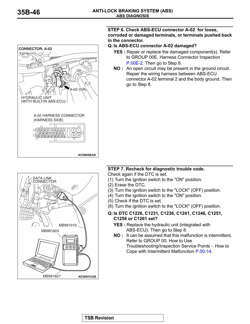
STEP 6. Check ABS-ECU connector A-02 for loose, corroded or damaged terminals, or terminals pushed back in the connector.Q: Is ABS-ECU connector A-02 damaged?
YES : Repair or replace the damaged component(s). Refer to GROUP 00E, Harness Connector Inspection P.00E-2. Then go to Step 8.
NO : An open circuit may be present in the ground circuit. Repair the wiring harness between ABS-ECU connector A-02 terminal 2 and the body ground. Then go to Step 8.
STEP 7. Recheck for diagnostic trouble code.Check again if the DTC is set.(1) Turn the ignition switch to the "ON" position.(2) Erase the DTC.(3) Turn the ignition switch to the "LOCK" (OFF) position.(4) Turn the ignition switch to the "ON" position.(5) Check if the DTC is set.(6) Turn the ignition switch to the "LOCK" (OFF) position.Q: Is DTC C1226, C1231, C1236, C1241, C1246, C1251,
C1256 or C1261 set?YES : Replace the hydraulic unit (integrated with
ABS-ECU). Then go to Step 8.NO : It can be assumed that this malfunction is intermittent.
Refer to GROUP 00, How to Use Troubleshooting/Inspection Service Points − How to Cope with Intermittent Malfunction P.00-14.
AC306406
19
2
18
189 7 6 5 4 31011
25
151617
2728 26
121314
2324 22 21 20
A-02 HARNESS CONNECTOR(HARNESS SIDE)
AB
A-02 (GR)
CONNECTOR: A-02
HYDRAULIC UNIT(WITH BUILT-IN ABS-ECU)
AC305412AB
MB991910
DATA LINKCONNECTOR
MB991824
MB991827
TSB Revision
ABS DIAGNOSISANTI-LOCK BRAKING SYSTEM (ABS) 35B-47
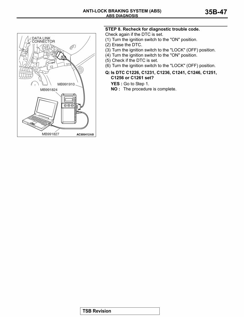
STEP 8. Recheck for diagnostic trouble code.Check again if the DTC is set.(1) Turn the ignition switch to the "ON" position.(2) Erase the DTC.(3) Turn the ignition switch to the "LOCK" (OFF) position.(4) Turn the ignition switch to the "ON" position.(5) Check if the DTC is set.(6) Turn the ignition switch to the "LOCK" (OFF) position.Q: Is DTC C1226, C1231, C1236, C1241, C1246, C1251,
C1256 or C1261 set?YES : Go to Step 1.NO : The procedure is complete.
AC305412AB
MB991910
DATA LINKCONNECTOR
MB991824
MB991827
TSB Revision
ABS DIAGNOSISANTI-LOCK BRAKING SYSTEM (ABS)35B-48
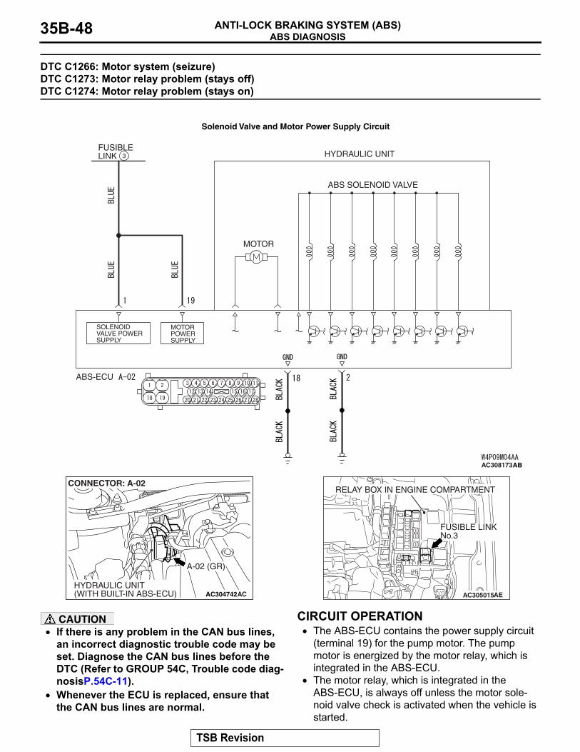
DTC C1266: Motor system (seizure) DTC C1273: Motor relay problem (stays off) DTC C1274: Motor relay problem (stays on)
CAUTION• If there is any problem in the CAN bus lines,
an incorrect diagnostic trouble code may be set. Diagnose the CAN bus lines before the DTC (Refer to GROUP 54C, Trouble code diag-nosisP.54C-11).
• Whenever the ECU is replaced, ensure that the CAN bus lines are normal.
.
CIRCUIT OPERATION• The ABS-ECU contains the power supply circuit
(terminal 19) for the pump motor. The pump motor is energized by the motor relay, which is integrated in the ABS-ECU.
• The motor relay, which is integrated in the ABS-ECU, is always off unless the motor sole-noid valve check is activated when the vehicle is started.
ABS SOLENOID VALVE
HYDRAULIC UNIT
MOTOR
FUSIBLE LINK
MOTOR POWER SUPPLY
SOLENOID VALVE POWER SUPPLY
ABS-ECU
3
AC308173AB
Solenoid Valve and Motor Power Supply Circuit
AC304742
A-02 (GR)
CONNECTOR: A-02
HYDRAULIC UNIT(WITH BUILT-IN ABS-ECU) AC AC305015AE
FUSIBLE LINKNo.3
RELAY BOX IN ENGINE COMPARTMENT
TSB Revision
ABS DIAGNOSISANTI-LOCK BRAKING SYSTEM (ABS) 35B-49
• The ABS-ECU activates the pump motor by turn-ing on the ECU built-in motor relay when the ABS is working.
.
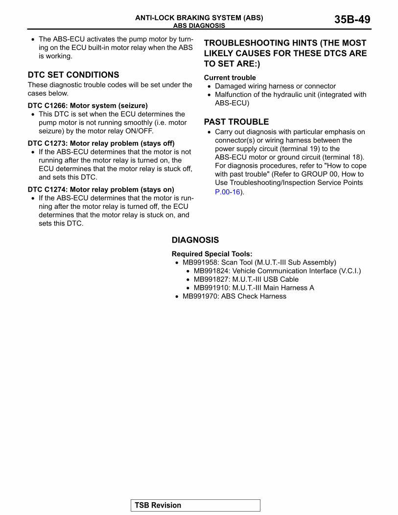
DTC SET CONDITIONSThese diagnostic trouble codes will be set under the cases below.
DTC C1266: Motor system (seizure)• This DTC is set when the ECU determines the
pump motor is not running smoothly (i.e. motor seizure) by the motor relay ON/OFF.
DTC C1273: Motor relay problem (stays off)• If the ABS-ECU determines that the motor is not
running after the motor relay is turned on, the ECU determines that the motor relay is stuck off, and sets this DTC.
DTC C1274: Motor relay problem (stays on)• If the ABS-ECU determines that the motor is run-
ning after the motor relay is turned off, the ECU determines that the motor relay is stuck on, and sets this DTC.
.
TROUBLESHOOTING HINTS (THE MOST LIKELY CAUSES FOR THESE DTCS ARE TO SET ARE:)Current trouble
• Damaged wiring harness or connector• Malfunction of the hydraulic unit (integrated with
ABS-ECU).
PAST TROUBLE• Carry out diagnosis with particular emphasis on
connector(s) or wiring harness between the power supply circuit (terminal 19) to the ABS-ECU motor or ground circuit (terminal 18). For diagnosis procedures, refer to "How to cope with past trouble" (Refer to GROUP 00, How to Use Troubleshooting/Inspection Service Points P.00-16).
DIAGNOSISRequired Special Tools:
• MB991958: Scan Tool (M.U.T.-III Sub Assembly)• MB991824: Vehicle Communication Interface (V.C.I.)• MB991827: M.U.T.-III USB Cable• MB991910: M.U.T.-III Main Harness A
• MB991970: ABS Check Harness
TSB Revision
ABS DIAGNOSISANTI-LOCK BRAKING SYSTEM (ABS)35B-50
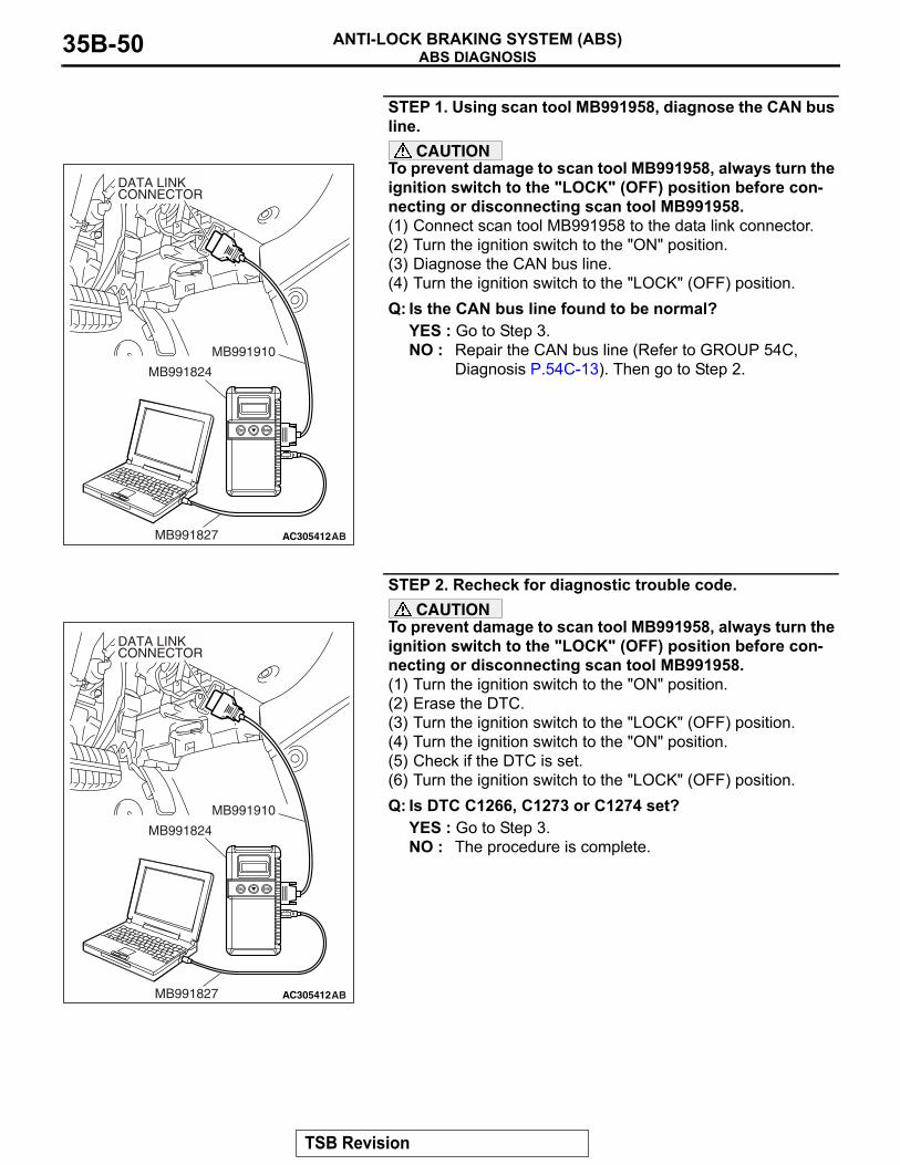
STEP 1. Using scan tool MB991958, diagnose the CAN bus line.
CAUTIONTo prevent damage to scan tool MB991958, always turn the ignition switch to the "LOCK" (OFF) position before con-necting or disconnecting scan tool MB991958.(1) Connect scan tool MB991958 to the data link connector.(2) Turn the ignition switch to the "ON" position.(3) Diagnose the CAN bus line.(4) Turn the ignition switch to the "LOCK" (OFF) position.Q: Is the CAN bus line found to be normal?
YES : Go to Step 3.NO : Repair the CAN bus line (Refer to GROUP 54C,
Diagnosis P.54C-13). Then go to Step 2.
STEP 2. Recheck for diagnostic trouble code.CAUTION
To prevent damage to scan tool MB991958, always turn the ignition switch to the "LOCK" (OFF) position before con-necting or disconnecting scan tool MB991958.(1) Turn the ignition switch to the "ON" position.(2) Erase the DTC.(3) Turn the ignition switch to the "LOCK" (OFF) position.(4) Turn the ignition switch to the "ON" position.(5) Check if the DTC is set.(6) Turn the ignition switch to the "LOCK" (OFF) position.Q: Is DTC C1266, C1273 or C1274 set?
YES : Go to Step 3.NO : The procedure is complete.
AC305412AB
MB991910
DATA LINKCONNECTOR
MB991824
MB991827
AC305412AB
MB991910
DATA LINKCONNECTOR
MB991824
MB991827
TSB Revision

ABS DIAGNOSISANTI-LOCK BRAKING SYSTEM (ABS) 35B-51
STEP 3. Measure the voltage at ABS-ECU connector A-02.(1) Disconnect the connector A-02, and connect special tool
ABS Check Harness (MB991970) to the wiring harness-side connector.NOTE: Do not connect special tool ABS Check Harness (MB991970) to the ABS-ECU.
(2) Measure the voltage between terminal 19 and ground. It should be approximately 12 volts (battery positive voltage).
Q: Is the voltage approximately 12 volts (battery positive voltage)?YES : Go to Step 5.NO : Go to Step 4.
AC306403
19
2
18
189 7 6 5 4 31011
25
151617
2728 26
121314
2324 22 21 20
A-02(GR)
CONNECTOR: A-02
HYDRAULIC UNIT(WITH BUILT-IN ABS-ECU)
AG
ABS-ECUMB991970
CHECK CONNECTOR
A-02 HARNESSCONNECTOR
TSB Revision

ABS DIAGNOSISANTI-LOCK BRAKING SYSTEM (ABS)35B-52
STEP 4. Check ABS-ECU connector A-02 for loose, corroded or damaged terminals, or terminals pushed back in the connector.Q: Is ABS-ECU connector A-02 damaged?
YES : Repair or replace the damaged component(s). Refer to GROUP 00E, Harness Connector Inspection P.00E-2. Then go to Step 8.
NO : An open or short circuit may be present in the solenoid valve power supply circuit. Repair the wiring harness between ABS-ECU connector A-02 terminal 19 and fusible link No.3.Then go to Step 8.
AC306406
19
2
18
189 7 6 5 4 31011
25
151617
2728 26
121314
2324 22 21 20
A-02 HARNESS CONNECTOR(HARNESS SIDE)
AB
A-02 (GR)
CONNECTOR: A-02
HYDRAULIC UNIT(WITH BUILT-IN ABS-ECU)
TSB Revision
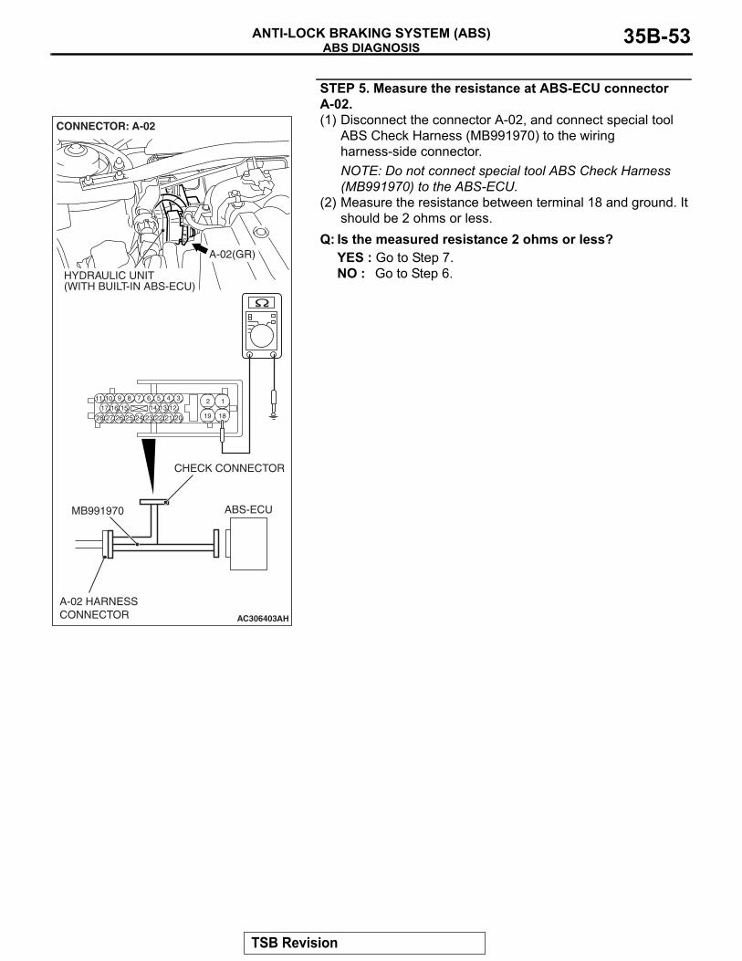
ABS DIAGNOSISANTI-LOCK BRAKING SYSTEM (ABS) 35B-53
STEP 5. Measure the resistance at ABS-ECU connector A-02.(1) Disconnect the connector A-02, and connect special tool
ABS Check Harness (MB991970) to the wiring harness-side connector.NOTE: Do not connect special tool ABS Check Harness (MB991970) to the ABS-ECU.
(2) Measure the resistance between terminal 18 and ground. It should be 2 ohms or less.
Q: Is the measured resistance 2 ohms or less?YES : Go to Step 7.NO : Go to Step 6.
AC306403
19
2
18
189 7 6 5 4 31011
25
151617
2728 26
121314
2324 22 21 20
A-02(GR)
CONNECTOR: A-02
HYDRAULIC UNIT(WITH BUILT-IN ABS-ECU)
AH
ABS-ECUMB991970
CHECK CONNECTOR
A-02 HARNESSCONNECTOR
TSB Revision
ABS DIAGNOSISANTI-LOCK BRAKING SYSTEM (ABS)35B-54
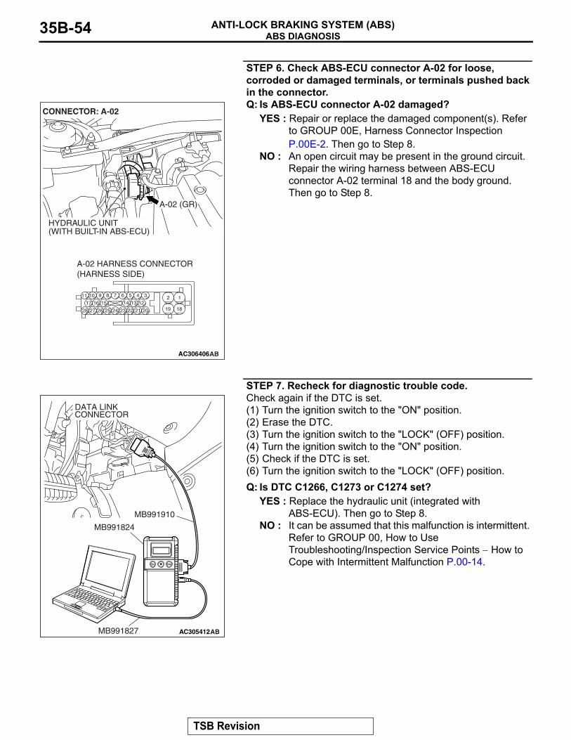
STEP 6. Check ABS-ECU connector A-02 for loose, corroded or damaged terminals, or terminals pushed back in the connector.Q: Is ABS-ECU connector A-02 damaged?
YES : Repair or replace the damaged component(s). Refer to GROUP 00E, Harness Connector Inspection P.00E-2. Then go to Step 8.
NO : An open circuit may be present in the ground circuit. Repair the wiring harness between ABS-ECU connector A-02 terminal 18 and the body ground. Then go to Step 8.
STEP 7. Recheck for diagnostic trouble code.Check again if the DTC is set.(1) Turn the ignition switch to the "ON" position.(2) Erase the DTC.(3) Turn the ignition switch to the "LOCK" (OFF) position.(4) Turn the ignition switch to the "ON" position.(5) Check if the DTC is set.(6) Turn the ignition switch to the "LOCK" (OFF) position.Q: Is DTC C1266, C1273 or C1274 set?
YES : Replace the hydraulic unit (integrated with ABS-ECU). Then go to Step 8.
NO : It can be assumed that this malfunction is intermittent. Refer to GROUP 00, How to Use Troubleshooting/Inspection Service Points − How to Cope with Intermittent Malfunction P.00-14.
AC306406
19
2
18
189 7 6 5 4 31011
25
151617
2728 26
121314
2324 22 21 20
A-02 HARNESS CONNECTOR(HARNESS SIDE)
AB
A-02 (GR)
CONNECTOR: A-02
HYDRAULIC UNIT(WITH BUILT-IN ABS-ECU)
AC305412AB
MB991910
DATA LINKCONNECTOR
MB991824
MB991827
TSB Revision
ABS DIAGNOSISANTI-LOCK BRAKING SYSTEM (ABS) 35B-55
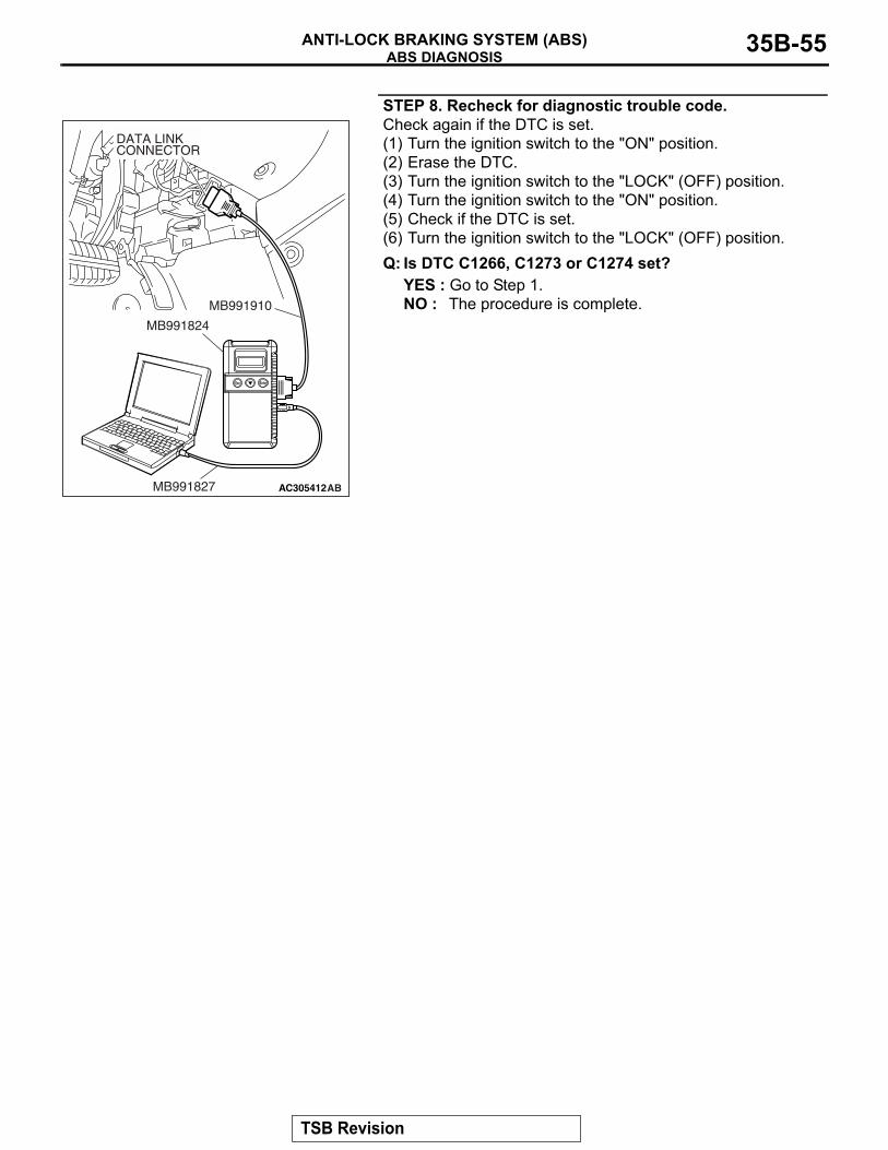
STEP 8. Recheck for diagnostic trouble code.Check again if the DTC is set.(1) Turn the ignition switch to the "ON" position.(2) Erase the DTC.(3) Turn the ignition switch to the "LOCK" (OFF) position.(4) Turn the ignition switch to the "ON" position.(5) Check if the DTC is set.(6) Turn the ignition switch to the "LOCK" (OFF) position.Q: Is DTC C1266, C1273 or C1274 set?
YES : Go to Step 1.NO : The procedure is complete.
AC305412AB
MB991910
DATA LINKCONNECTOR
MB991824
MB991827
TSB Revision
ABS DIAGNOSISANTI-LOCK BRAKING SYSTEM (ABS)35B-56
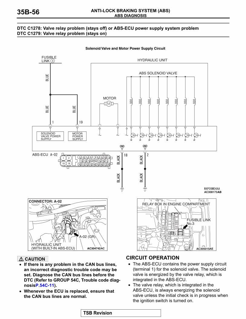
DTC C1278: Valve relay problem (stays off) or ABS-ECU power supply system problem DTC C1279: Valve relay problem (stays on)
CAUTION• If there is any problem in the CAN bus lines,
an incorrect diagnostic trouble code may be set. Diagnose the CAN bus lines before the DTC (Refer to GROUP 54C, Trouble code diag-nosisP.54C-11).
• Whenever the ECU is replaced, ensure that the CAN bus lines are normal.
.
CIRCUIT OPERATION• The ABS-ECU contains the power supply circuit
(terminal 1) for the solenoid valve. The solenoid valve is energized by the valve relay, which is integrated in the ABS-ECU.
• The valve relay, which is integrated in the ABS-ECU, is always energizing the solenoid valve unless the initial check is in progress when the ignition switch is turned on.
ABS SOLENOID VALVE
HYDRAULIC UNIT
MOTOR
FUSIBLE LINK
MOTOR POWER SUPPLY
SOLENOID VALVE POWER SUPPLY
ABS-ECU
3
AC308173AB
Solenoid Valve and Motor Power Supply Circuit
AC304742
A-02 (GR)
CONNECTOR: A-02
HYDRAULIC UNIT(WITH BUILT-IN ABS-ECU) AC AC305015AE
FUSIBLE LINKNo.3
RELAY BOX IN ENGINE COMPARTMENT
TSB Revision
ABS DIAGNOSISANTI-LOCK BRAKING SYSTEM (ABS) 35B-57
.
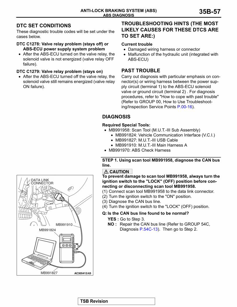
DTC SET CONDITIONSThese diagnostic trouble codes will be set under the cases below.
DTC C1278: Valve relay problem (stays off) or ABS-ECU power supply system problem
• After the ABS-ECU turned on the valve relay, the solenoid valve is not energized (valve relay OFF failure).
DTC C1279: Valve relay problem (stays on)• After the ABS-ECU turned off the valve relay, the
solenoid valve still remains energized (valve relay ON failure).
.
TROUBLESHOOTING HINTS (THE MOST LIKELY CAUSES FOR THESE DTCS ARE TO SET ARE:)Current trouble
• Damaged wiring harness or connector• Malfunction of the hydraulic unit (integrated with
ABS-ECU).
PAST TROUBLECarry out diagnosis with particular emphasis on con-nector(s) or wiring harness between the power sup-ply circuit (terminal 1) to the ABS-ECU solenoid valve or ground circuit (terminal 2) . For diagnosis procedures, refer to "How to cope with past trouble" (Refer to GROUP 00, How to Use Troubleshoot-ing/Inspection Service Points P.00-16).
DIAGNOSISRequired Special Tools:
• MB991958: Scan Tool (M.U.T.-III Sub Assembly)• MB991824: Vehicle Communication Interface (V.C.I.)• MB991827: M.U.T.-III USB Cable• MB991910: M.U.T.-III Main Harness A
• MB991970: ABS Check Harness
STEP 1. Using scan tool MB991958, diagnose the CAN bus line.
CAUTIONTo prevent damage to scan tool MB991958, always turn the ignition switch to the "LOCK" (OFF) position before con-necting or disconnecting scan tool MB991958.(1) Connect scan tool MB991958 to the data link connector.(2) Turn the ignition switch to the "ON" position.(3) Diagnose the CAN bus line.(4) Turn the ignition switch to the "LOCK" (OFF) position.Q: Is the CAN bus line found to be normal?
YES : Go to Step 3.NO : Repair the CAN bus line (Refer to GROUP 54C,
Diagnosis P.54C-13). Then go to Step 2.
AC305412AB
MB991910
DATA LINKCONNECTOR
MB991824
MB991827
TSB Revision
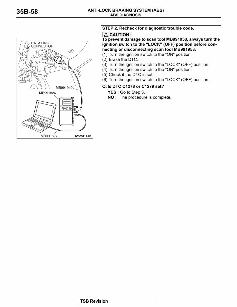
ABS DIAGNOSISANTI-LOCK BRAKING SYSTEM (ABS)35B-58
STEP 2. Recheck for diagnostic trouble code.CAUTION
To prevent damage to scan tool MB991958, always turn the ignition switch to the "LOCK" (OFF) position before con-necting or disconnecting scan tool MB991958.(1) Turn the ignition switch to the "ON" position.(2) Erase the DTC.(3) Turn the ignition switch to the "LOCK" (OFF) position.(4) Turn the ignition switch to the "ON" position.(5) Check if the DTC is set.(6) Turn the ignition switch to the "LOCK" (OFF) position.Q: Is DTC C1278 or C1279 set?
YES : Go to Step 3.NO : The procedure is complete.
AC305412AB
MB991910
DATA LINKCONNECTOR
MB991824
MB991827
TSB Revision

ABS DIAGNOSISANTI-LOCK BRAKING SYSTEM (ABS) 35B-59
STEP 3. Measure the voltage at ABS-ECU connector A-02.(1) Disconnect the connector A-02, and connect special tool
ABS Check Harness (MB991970) to the wiring harness-side connector.NOTE: Do not connect special tool ABS Check Harness (MB991970) to the ABS-ECU.
(2) Measure the voltage between terminal 1 and ground. It should be approximately 12 volts (battery positive voltage).
Q: Is the voltage approximately 12 volts (battery positive voltage)?YES : Go to Step 5.NO : Go to Step 4.
AC306403
19
2
18
189 7 6 5 4 31011
25
151617
2728 26
121314
2324 22 21 20
AE
ABS-ECUMB991970
CHECK CONNECTOR
A-02 HARNESS CONNECTOR
A-02 (GR)
CONNECTOR: A-02
HYDRAULIC UNIT(WITH BUILT-IN ABS-ECU)
TSB Revision

ABS DIAGNOSISANTI-LOCK BRAKING SYSTEM (ABS)35B-60
STEP 4. Check ABS-ECU connector A-02 for loose, corroded or damaged terminals, or terminals pushed back in the connector.Q: Is ABS-ECU connector A-02 damaged?
YES : Repair or replace the damaged component(s). Refer to GROUP 00E, Harness Connector Inspection P.00E-2. Then go to Step 8.
NO : An open or short circuit may be present in the solenoid valve power supply circuit. Repair the wiring harness between ABS-ECU connector A-02 terminal 1 and fusible link No.3. Then go to Step 8.
AC306406
19
2
18
189 7 6 5 4 31011
25
151617
2728 26
121314
2324 22 21 20
A-02 HARNESS CONNECTOR(HARNESS SIDE)
AB
A-02 (GR)
CONNECTOR: A-02
HYDRAULIC UNIT(WITH BUILT-IN ABS-ECU)
TSB Revision
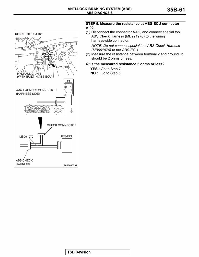
ABS DIAGNOSISANTI-LOCK BRAKING SYSTEM (ABS) 35B-61
STEP 5. Measure the resistance at ABS-ECU connector A-02.(1) Disconnect the connector A-02, and connect special tool
ABS Check Harness (MB991970) to the wiring harness-side connector.NOTE: Do not connect special tool ABS Check Harness (MB991970) to the ABS-ECU.
(2) Measure the resistance between terminal 2 and ground. It should be 2 ohms or less.
Q: Is the measured resistance 2 ohms or less?YES : Go to Step 7.NO : Go to Step 6.
AC306403
19
2
18
189 7 6 5 4 31011
25
151617
2728 26
121314
2324 22 21 20
AF
ABS-ECUMB991970
ABS CHECKHARNESS
CHECK CONNECTOR
A-02 HARNESS CONNECTOR(HARNESS SIDE)
A-02 (GR)
CONNECTOR: A-02
HYDRAULIC UNIT(WITH BUILT-IN ABS-ECU)
TSB Revision
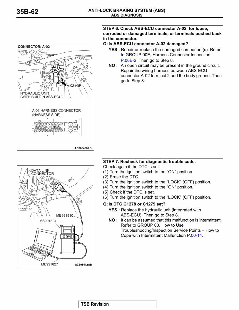
ABS DIAGNOSISANTI-LOCK BRAKING SYSTEM (ABS)35B-62
STEP 6. Check ABS-ECU connector A-02 for loose, corroded or damaged terminals, or terminals pushed back in the connector.Q: Is ABS-ECU connector A-02 damaged?
YES : Repair or replace the damaged component(s). Refer to GROUP 00E, Harness Connector Inspection P.00E-2. Then go to Step 8.
NO : An open circuit may be present in the ground circuit. Repair the wiring harness between ABS-ECU connector A-02 terminal 2 and the body ground. Then go to Step 8.
STEP 7. Recheck for diagnostic trouble code.Check again if the DTC is set.(1) Turn the ignition switch to the "ON" position.(2) Erase the DTC.(3) Turn the ignition switch to the "LOCK" (OFF) position.(4) Turn the ignition switch to the "ON" position.(5) Check if the DTC is set.(6) Turn the ignition switch to the "LOCK" (OFF) position.Q: Is DTC C1278 or C1279 set?
YES : Replace the hydraulic unit (integrated with ABS-ECU). Then go to Step 8.
NO : It can be assumed that this malfunction is intermittent. Refer to GROUP 00, How to Use Troubleshooting/Inspection Service Points − How to Cope with Intermittent Malfunction P.00-14.
AC306406
19
2
18
189 7 6 5 4 31011
25
151617
2728 26
121314
2324 22 21 20
A-02 HARNESS CONNECTOR(HARNESS SIDE)
AB
A-02 (GR)
CONNECTOR: A-02
HYDRAULIC UNIT(WITH BUILT-IN ABS-ECU)
AC305412AB
MB991910
DATA LINKCONNECTOR
MB991824
MB991827
TSB Revision
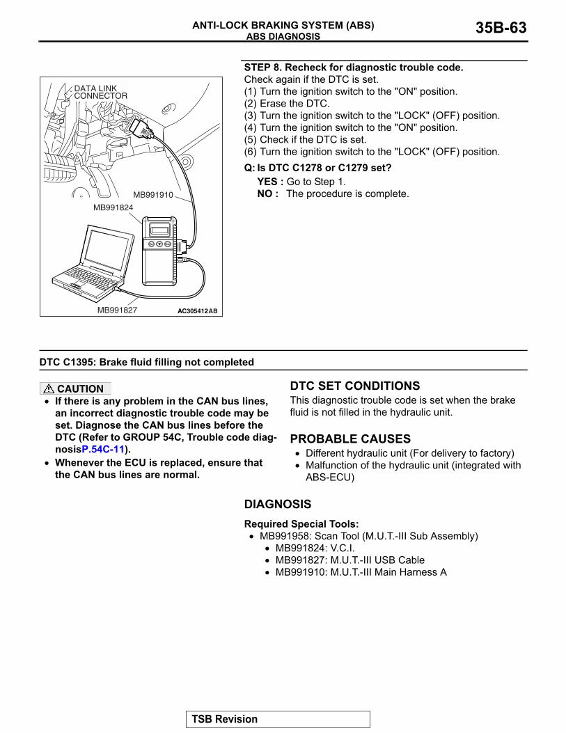
ABS DIAGNOSISANTI-LOCK BRAKING SYSTEM (ABS) 35B-63
STEP 8. Recheck for diagnostic trouble code.Check again if the DTC is set.(1) Turn the ignition switch to the "ON" position.(2) Erase the DTC.(3) Turn the ignition switch to the "LOCK" (OFF) position.(4) Turn the ignition switch to the "ON" position.(5) Check if the DTC is set.(6) Turn the ignition switch to the "LOCK" (OFF) position.Q: Is DTC C1278 or C1279 set?
YES : Go to Step 1.NO : The procedure is complete.
DTC C1395: Brake fluid filling not completed
CAUTION• If there is any problem in the CAN bus lines,
an incorrect diagnostic trouble code may be set. Diagnose the CAN bus lines before the DTC (Refer to GROUP 54C, Trouble code diag-nosisP.54C-11).
• Whenever the ECU is replaced, ensure that the CAN bus lines are normal.
.
DTC SET CONDITIONSThis diagnostic trouble code is set when the brake fluid is not filled in the hydraulic unit..
PROBABLE CAUSES• Different hydraulic unit (For delivery to factory)• Malfunction of the hydraulic unit (integrated with
ABS-ECU)
DIAGNOSISRequired Special Tools:
• MB991958: Scan Tool (M.U.T.-III Sub Assembly)• MB991824: V.C.I.• MB991827: M.U.T.-III USB Cable• MB991910: M.U.T.-III Main Harness A
AC305412AB
MB991910
DATA LINKCONNECTOR
MB991824
MB991827
TSB Revision
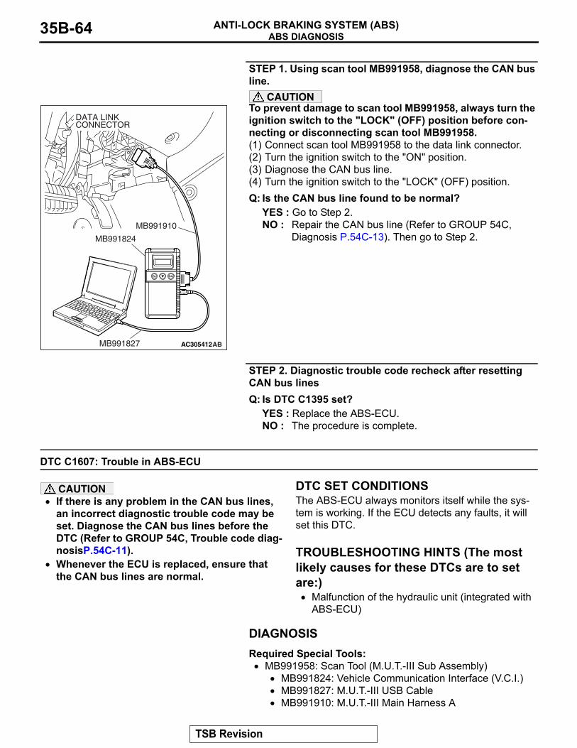
ABS DIAGNOSISANTI-LOCK BRAKING SYSTEM (ABS)35B-64
STEP 1. Using scan tool MB991958, diagnose the CAN bus line.
CAUTIONTo prevent damage to scan tool MB991958, always turn the ignition switch to the "LOCK" (OFF) position before con-necting or disconnecting scan tool MB991958.(1) Connect scan tool MB991958 to the data link connector.(2) Turn the ignition switch to the "ON" position.(3) Diagnose the CAN bus line.(4) Turn the ignition switch to the "LOCK" (OFF) position.Q: Is the CAN bus line found to be normal?
YES : Go to Step 2.NO : Repair the CAN bus line (Refer to GROUP 54C,
Diagnosis P.54C-13). Then go to Step 2.
STEP 2. Diagnostic trouble code recheck after resetting CAN bus linesQ: Is DTC C1395 set?
YES : Replace the ABS-ECU.NO : The procedure is complete.
DTC C1607: Trouble in ABS-ECU
CAUTION• If there is any problem in the CAN bus lines,
an incorrect diagnostic trouble code may be set. Diagnose the CAN bus lines before the DTC (Refer to GROUP 54C, Trouble code diag-nosisP.54C-11).
• Whenever the ECU is replaced, ensure that the CAN bus lines are normal.
.
DTC SET CONDITIONSThe ABS-ECU always monitors itself while the sys-tem is working. If the ECU detects any faults, it will set this DTC..
TROUBLESHOOTING HINTS (The most likely causes for these DTCs are to set are:)
• Malfunction of the hydraulic unit (integrated with ABS-ECU)
DIAGNOSISRequired Special Tools:
• MB991958: Scan Tool (M.U.T.-III Sub Assembly)• MB991824: Vehicle Communication Interface (V.C.I.)• MB991827: M.U.T.-III USB Cable• MB991910: M.U.T.-III Main Harness A
AC305412AB
MB991910
DATA LINKCONNECTOR
MB991824
MB991827
TSB Revision
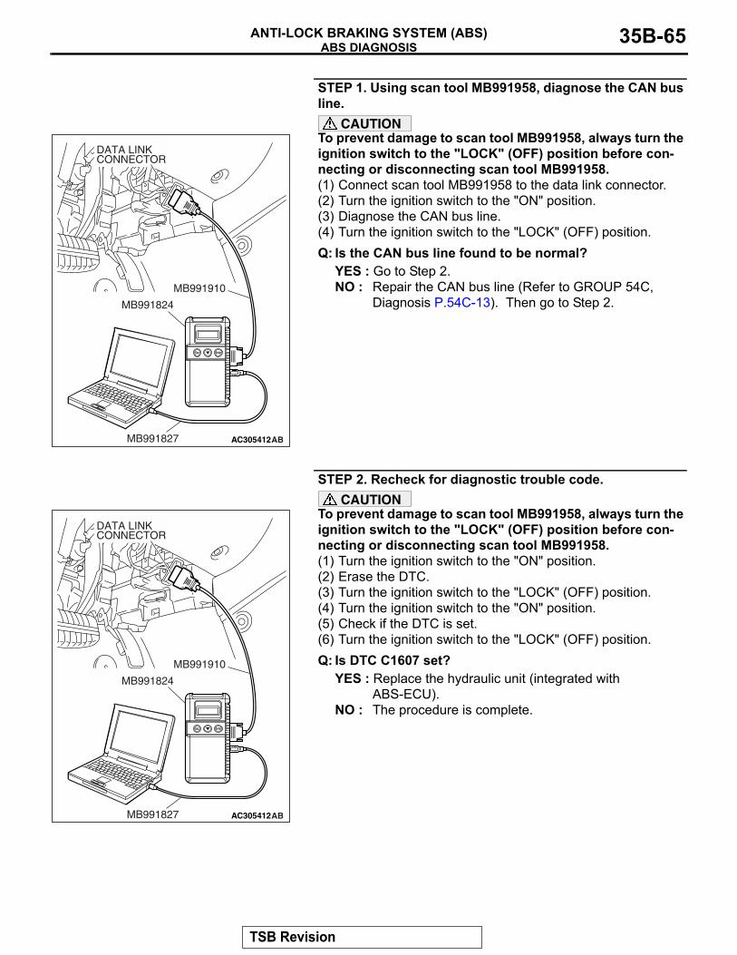
ABS DIAGNOSISANTI-LOCK BRAKING SYSTEM (ABS) 35B-65
STEP 1. Using scan tool MB991958, diagnose the CAN bus line.
CAUTIONTo prevent damage to scan tool MB991958, always turn the ignition switch to the "LOCK" (OFF) position before con-necting or disconnecting scan tool MB991958.(1) Connect scan tool MB991958 to the data link connector.(2) Turn the ignition switch to the "ON" position.(3) Diagnose the CAN bus line.(4) Turn the ignition switch to the "LOCK" (OFF) position.Q: Is the CAN bus line found to be normal?
YES : Go to Step 2.NO : Repair the CAN bus line (Refer to GROUP 54C,
Diagnosis P.54C-13). Then go to Step 2.
STEP 2. Recheck for diagnostic trouble code.CAUTION
To prevent damage to scan tool MB991958, always turn the ignition switch to the "LOCK" (OFF) position before con-necting or disconnecting scan tool MB991958.(1) Turn the ignition switch to the "ON" position.(2) Erase the DTC.(3) Turn the ignition switch to the "LOCK" (OFF) position.(4) Turn the ignition switch to the "ON" position.(5) Check if the DTC is set.(6) Turn the ignition switch to the "LOCK" (OFF) position.Q: Is DTC C1607 set?
YES : Replace the hydraulic unit (integrated with ABS-ECU).
NO : The procedure is complete.
AC305412AB
MB991910
DATA LINKCONNECTOR
MB991824
MB991827
AC305412AB
MB991910
DATA LINKCONNECTOR
MB991824
MB991827
TSB Revision
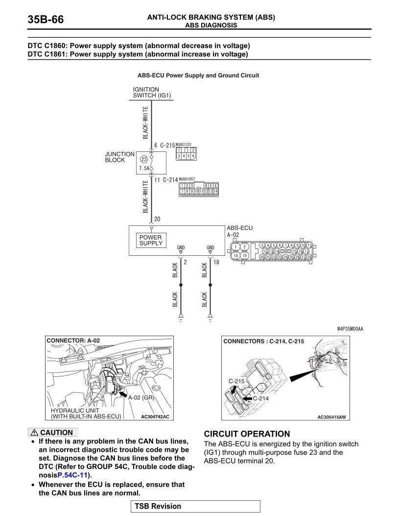
ABS DIAGNOSISANTI-LOCK BRAKING SYSTEM (ABS)35B-66
DTC C1860: Power supply system (abnormal decrease in voltage) DTC C1861: Power supply system (abnormal increase in voltage)
CAUTION• If there is any problem in the CAN bus lines,
an incorrect diagnostic trouble code may be set. Diagnose the CAN bus lines before the DTC (Refer to GROUP 54C, Trouble code diag-nosisP.54C-11).
• Whenever the ECU is replaced, ensure that the CAN bus lines are normal.
.
CIRCUIT OPERATIONThe ABS-ECU is energized by the ignition switch (IG1) through multi-purpose fuse 23 and the ABS-ECU terminal 20..
JUNCTION BLOCK
IGNITION SWITCH (IG1)
POWER SUPPLY
ABS-ECU
ABS-ECU Power Supply and Ground Circuit
AC304742
A-02 (GR)
CONNECTOR: A-02
HYDRAULIC UNIT(WITH BUILT-IN ABS-ECU) AC AC305415
CONNECTORS : C-214, C-215
C-214
C-215
AW
TSB Revision
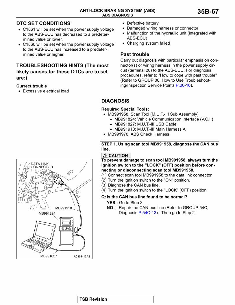
ABS DIAGNOSISANTI-LOCK BRAKING SYSTEM (ABS) 35B-67
DTC SET CONDITIONS• C1861 will be set when the power supply voltage
to the ABS-ECU has decreased to a predeter-mined value or lower.
• C1860 will be set when the power supply voltage to the ABS-ECU has increased to a predeter-mined value or higher.
.
TROUBLESHOOTING HINTS (The most likely causes for these DTCs are to set are:)Currect trouble
• Excessive electrical load
• Defective battery• Damaged wiring harness or connector• Malfunction of the hydraulic unit (integrated with
ABS-ECU)• Charging system failed
.
Past troubleCarry out diagnosis with particular emphasis on con-nector(s) or wiring harness in the power supply cir-cuit (terminal 20) to the ABS-ECU. For diagnosis procedures, refer to "How to cope with past trouble" (Refer to GROUP 00, How to Use Troubleshoot-ing/Inspection Service Points P.00-16).
DIAGNOSISRequired Special Tools:
• MB991958: Scan Tool (M.U.T.-III Sub Assembly)• MB991824: Vehicle Communication Interface (V.C.I.)• MB991827: M.U.T.-III USB Cable• MB991910: M.U.T.-III Main Harness A
• MB991970: ABS Check Harness
STEP 1. Using scan tool MB991958, diagnose the CAN bus line.
CAUTIONTo prevent damage to scan tool MB991958, always turn the ignition switch to the "LOCK" (OFF) position before con-necting or disconnecting scan tool MB991958.(1) Connect scan tool MB991958 to the data link connector.(2) Turn the ignition switch to the "ON" position.(3) Diagnose the CAN bus line.(4) Turn the ignition switch to the "LOCK" (OFF) position.Q: Is the CAN bus line found to be normal?
YES : Go to Step 3.NO : Repair the CAN bus line (Refer to GROUP 54C,
Diagnosis P.54C-13). Then go to Step 2.
AC305412AB
MB991910
DATA LINKCONNECTOR
MB991824
MB991827
TSB Revision
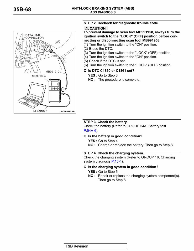
ABS DIAGNOSISANTI-LOCK BRAKING SYSTEM (ABS)35B-68
STEP 2. Recheck for diagnostic trouble code.CAUTION
To prevent damage to scan tool MB991958, always turn the ignition switch to the "LOCK" (OFF) position before con-necting or disconnecting scan tool MB991958.(1) Turn the ignition switch to the "ON" position.(2) Erase the DTC.(3) Turn the ignition switch to the "LOCK" (OFF) position.(4) Turn the ignition switch to the "ON" position.(5) Check if the DTC is set.(6) Turn the ignition switch to the "LOCK" (OFF) position.Q: Is DTC C1860 or C1861 set?
YES : Go to Step 3.NO : The procedure is complete.
STEP 3. Check the battery.Check the battery (Refer to GROUP 54A, Battery test P.54A-6).Q: Is the battery in good condition?
YES : Go to Step 4.NO : Charge or replace the battery. Then go to Step 8.
STEP 4. Check the charging system.Check the charging system (Refer to GROUP 16, Charging system diagnosis P.16-4).Q: Is the charging system in good condition?
YES : Go to Step 5.NO : Repair or replace the charging system component(s).
Then go to Step 8.
AC305412AB
MB991910
DATA LINKCONNECTOR
MB991824
MB991827
TSB Revision
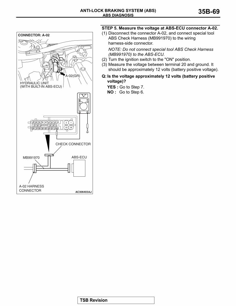
ABS DIAGNOSISANTI-LOCK BRAKING SYSTEM (ABS) 35B-69
STEP 5. Measure the voltage at ABS-ECU connector A-02.(1) Disconnect the connector A-02, and connect special tool
ABS Check Harness (MB991970) to the wiring harness-side connector.NOTE: Do not connect special tool ABS Check Harness (MB991970) to the ABS-ECU.
(2) Turn the ignition switch to the "ON" position.(3) Measure the voltage between terminal 20 and ground. It
should be approximately 12 volts (battery positive voltage).Q: Is the voltage approximately 12 volts (battery positive
voltage)?YES : Go to Step 7.NO : Go to Step 6.
AC306403
19
2
18
189 7 6 5 4 31011
25
151617
2728 26
121314
2324 22 21 20
A-02(GR)
CONNECTOR: A-02
HYDRAULIC UNIT(WITH BUILT-IN ABS-ECU)
AJ
ABS-ECUMB991970
CHECK CONNECTOR
A-02 HARNESSCONNECTOR
TSB Revision
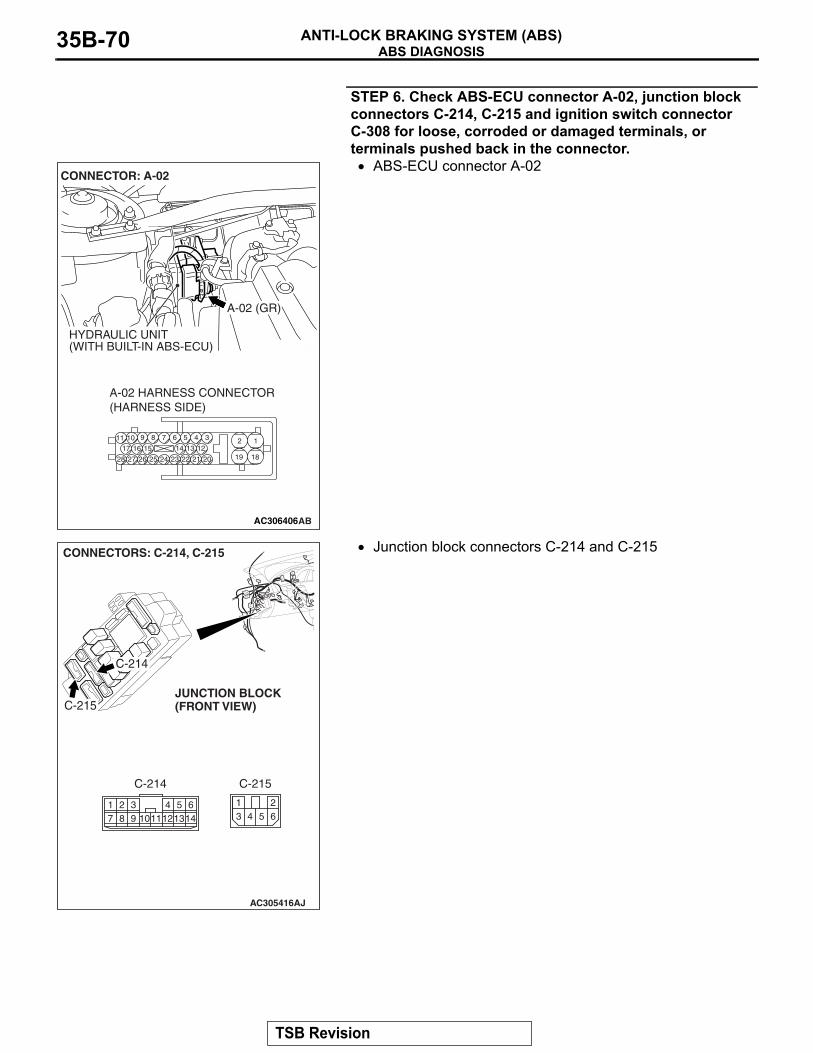
ABS DIAGNOSISANTI-LOCK BRAKING SYSTEM (ABS)35B-70
STEP 6. Check ABS-ECU connector A-02, junction block connectors C-214, C-215 and ignition switch connector C-308 for loose, corroded or damaged terminals, or terminals pushed back in the connector.
• ABS-ECU connector A-02
• Junction block connectors C-214 and C-215
AC306406
19
2
18
189 7 6 5 4 31011
25
151617
2728 26
121314
2324 22 21 20
A-02 HARNESS CONNECTOR(HARNESS SIDE)
AB
A-02 (GR)
CONNECTOR: A-02
HYDRAULIC UNIT(WITH BUILT-IN ABS-ECU)
AC305416AJ
C-214
CONNECTORS: C-214, C-215
C-215
13 4
265
C-214
617
298 103 5
12114
1314
C-215JUNCTION BLOCK(FRONT VIEW)
TSB Revision
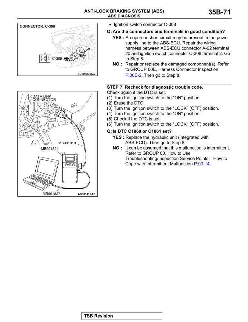
ABS DIAGNOSISANTI-LOCK BRAKING SYSTEM (ABS) 35B-71
• Ignition switch connector C-308Q: Are the connectors and terminals in good condition?
YES : An open or short circuit may be present in the power supply line to the ABS-ECU. Repair the wiring harness between ABS-ECU connector A-02 terminal 20 and ignition switch connector C-308 terminal 2. Go to Step 8.
NO : Repair or replace the damaged component(s). Refer to GROUP 00E, Harness Connector Inspection P.00E-2. Then go to Step 8.
STEP 7. Recheck for diagnostic trouble code.Check again if the DTC is set.(1) Turn the ignition switch to the "ON" position.(2) Erase the DTC.(3) Turn the ignition switch to the "LOCK" (OFF) position.(4) Turn the ignition switch to the "ON" position.(5) Check if the DTC is set.(6) Turn the ignition switch to the "LOCK" (OFF) position.Q: Is DTC C1860 or C1861 set?
YES : Replace the hydraulic unit (integrated with ABS-ECU). Then go to Step 8.
NO : It can be assumed that this malfunction is intermittent. Refer to GROUP 00, How to Use Troubleshooting/Inspection Service Points − How to Cope with Intermittent Malfunction P.00-14.
AC305235AG
CONNECTOR: C-308
C-308254
163
AC305412AB
MB991910
DATA LINKCONNECTOR
MB991824
MB991827
TSB Revision
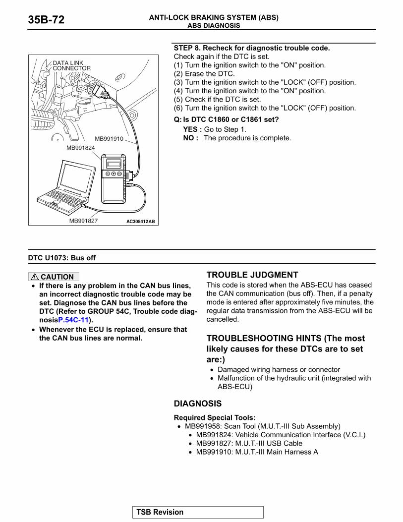
ABS DIAGNOSISANTI-LOCK BRAKING SYSTEM (ABS)35B-72
STEP 8. Recheck for diagnostic trouble code.Check again if the DTC is set.(1) Turn the ignition switch to the "ON" position.(2) Erase the DTC.(3) Turn the ignition switch to the "LOCK" (OFF) position.(4) Turn the ignition switch to the "ON" position.(5) Check if the DTC is set.(6) Turn the ignition switch to the "LOCK" (OFF) position.Q: Is DTC C1860 or C1861 set?
YES : Go to Step 1.NO : The procedure is complete.
DTC U1073: Bus off
CAUTION• If there is any problem in the CAN bus lines,
an incorrect diagnostic trouble code may be set. Diagnose the CAN bus lines before the DTC (Refer to GROUP 54C, Trouble code diag-nosisP.54C-11).
• Whenever the ECU is replaced, ensure that the CAN bus lines are normal.
.
TROUBLE JUDGMENTThis code is stored when the ABS-ECU has ceased the CAN communication (bus off). Then, if a penalty mode is entered after approximately five minutes, the regular data transmission from the ABS-ECU will be cancelled..
TROUBLESHOOTING HINTS (The most likely causes for these DTCs are to set are:)
• Damaged wiring harness or connector• Malfunction of the hydraulic unit (integrated with
ABS-ECU)
DIAGNOSISRequired Special Tools:
• MB991958: Scan Tool (M.U.T.-III Sub Assembly)• MB991824: Vehicle Communication Interface (V.C.I.)• MB991827: M.U.T.-III USB Cable• MB991910: M.U.T.-III Main Harness A
AC305412AB
MB991910
DATA LINKCONNECTOR
MB991824
MB991827
TSB Revision
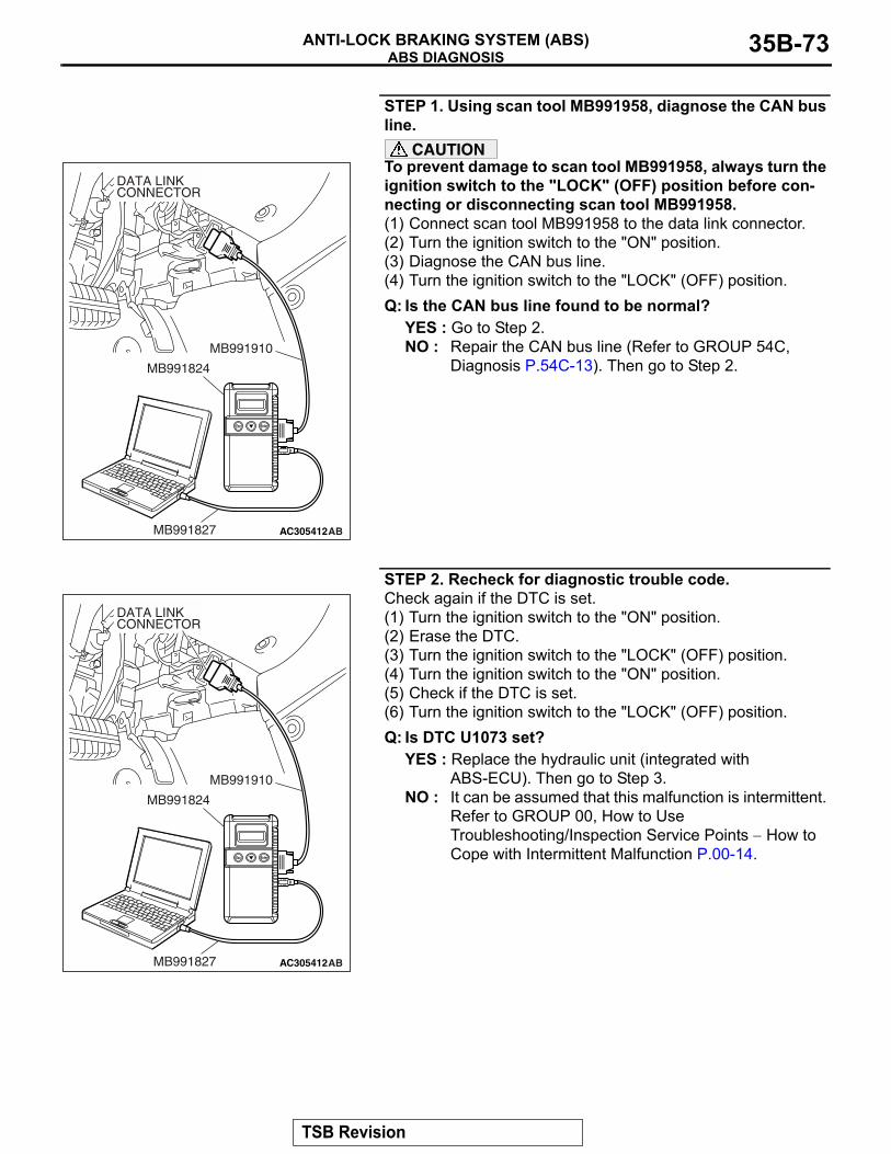
ABS DIAGNOSISANTI-LOCK BRAKING SYSTEM (ABS) 35B-73
STEP 1. Using scan tool MB991958, diagnose the CAN bus line.
CAUTIONTo prevent damage to scan tool MB991958, always turn the ignition switch to the "LOCK" (OFF) position before con-necting or disconnecting scan tool MB991958.(1) Connect scan tool MB991958 to the data link connector.(2) Turn the ignition switch to the "ON" position.(3) Diagnose the CAN bus line.(4) Turn the ignition switch to the "LOCK" (OFF) position.Q: Is the CAN bus line found to be normal?
YES : Go to Step 2.NO : Repair the CAN bus line (Refer to GROUP 54C,
Diagnosis P.54C-13). Then go to Step 2.
STEP 2. Recheck for diagnostic trouble code.Check again if the DTC is set.(1) Turn the ignition switch to the "ON" position.(2) Erase the DTC.(3) Turn the ignition switch to the "LOCK" (OFF) position.(4) Turn the ignition switch to the "ON" position.(5) Check if the DTC is set.(6) Turn the ignition switch to the "LOCK" (OFF) position.Q: Is DTC U1073 set?
YES : Replace the hydraulic unit (integrated with ABS-ECU). Then go to Step 3.
NO : It can be assumed that this malfunction is intermittent. Refer to GROUP 00, How to Use Troubleshooting/Inspection Service Points − How to Cope with Intermittent Malfunction P.00-14.
AC305412AB
MB991910
DATA LINKCONNECTOR
MB991824
MB991827
AC305412AB
MB991910
DATA LINKCONNECTOR
MB991824
MB991827
TSB Revision
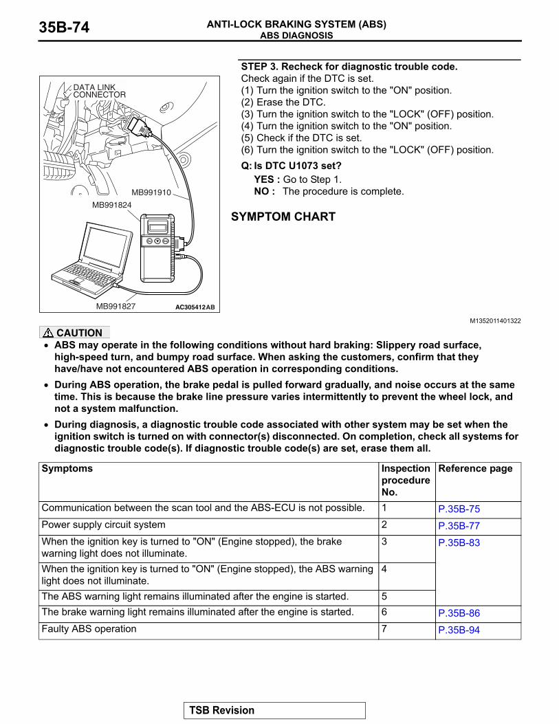
ABS DIAGNOSISANTI-LOCK BRAKING SYSTEM (ABS)35B-74
STEP 3. Recheck for diagnostic trouble code.Check again if the DTC is set.(1) Turn the ignition switch to the "ON" position.(2) Erase the DTC.(3) Turn the ignition switch to the "LOCK" (OFF) position.(4) Turn the ignition switch to the "ON" position.(5) Check if the DTC is set.(6) Turn the ignition switch to the "LOCK" (OFF) position.Q: Is DTC U1073 set?
YES : Go to Step 1.NO : The procedure is complete.
SYMPTOM CHART
M1352011401322
CAUTION• ABS may operate in the following conditions without hard braking: Slippery road surface,
high-speed turn, and bumpy road surface. When asking the customers, confirm that they have/have not encountered ABS operation in corresponding conditions.
• During ABS operation, the brake pedal is pulled forward gradually, and noise occurs at the same time. This is because the brake line pressure varies intermittently to prevent the wheel lock, and not a system malfunction.
• During diagnosis, a diagnostic trouble code associated with other system may be set when the ignition switch is turned on with connector(s) disconnected. On completion, check all systems for diagnostic trouble code(s). If diagnostic trouble code(s) are set, erase them all.
AC305412AB
MB991910
DATA LINKCONNECTOR
MB991824
MB991827
Symptoms Inspection procedure No.
Reference page
Communication between the scan tool and the ABS-ECU is not possible. 1 P.35B-75Power supply circuit system 2 P.35B-77When the ignition key is turned to "ON" (Engine stopped), the brake warning light does not illuminate.
3 P.35B-83
When the ignition key is turned to "ON" (Engine stopped), the ABS warning light does not illuminate.
4
The ABS warning light remains illuminated after the engine is started. 5The brake warning light remains illuminated after the engine is started. 6 P.35B-86Faulty ABS operation 7 P.35B-94
TSB Revision
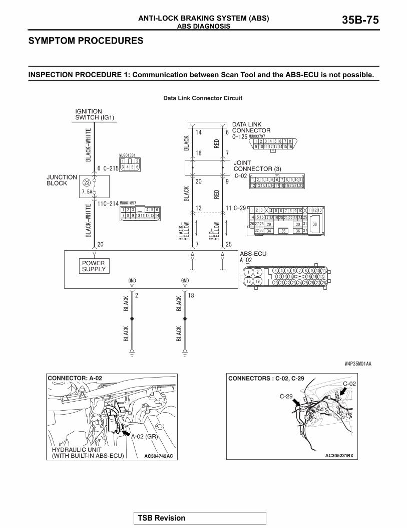
ABS DIAGNOSISANTI-LOCK BRAKING SYSTEM (ABS) 35B-75
SYMPTOM PROCEDURES
INSPECTION PROCEDURE 1: Communication between Scan Tool and the ABS-ECU is not possible.
ABS-ECU
IGNITION SWITCH (IG1)
DATA LINK CONNECTOR
JUNCTION BLOCK
JOINT CONNECTOR (3)
POWERSUPPLY
Data Link Connector Circuit
AC304742
A-02 (GR)
CONNECTOR: A-02
HYDRAULIC UNIT(WITH BUILT-IN ABS-ECU) AC AC305231
CONNECTORS : C-02, C-29
C-29
BX
C-02
TSB Revision
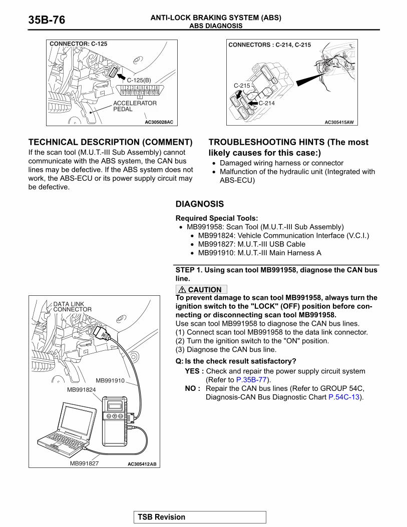
ABS DIAGNOSISANTI-LOCK BRAKING SYSTEM (ABS)35B-76
.
TECHNICAL DESCRIPTION (COMMENT)If the scan tool (M.U.T.-III Sub Assembly) cannot communicate with the ABS system, the CAN bus lines may be defective. If the ABS system does not work, the ABS-ECU or its power supply circuit may be defective.
.
TROUBLESHOOTING HINTS (The most likely causes for this case:)
• Damaged wiring harness or connector• Malfunction of the hydraulic unit (Integrated with
ABS-ECU)
DIAGNOSISRequired Special Tools:
• MB991958: Scan Tool (M.U.T.-III Sub Assembly)• MB991824: Vehicle Communication Interface (V.C.I.)• MB991827: M.U.T.-III USB Cable• MB991910: M.U.T.-III Main Harness A
STEP 1. Using scan tool MB991958, diagnose the CAN bus line.
CAUTIONTo prevent damage to scan tool MB991958, always turn the ignition switch to the "LOCK" (OFF) position before con-necting or disconnecting scan tool MB991958.Use scan tool MB991958 to diagnose the CAN bus lines.(1) Connect scan tool MB991958 to the data link connector.(2) Turn the ignition switch to the "ON" position.(3) Diagnose the CAN bus line.Q: Is the check result satisfactory?
YES : Check and repair the power supply circuit system (Refer to P.35B-77).
NO : Repair the CAN bus lines (Refer to GROUP 54C, Diagnosis-CAN Bus Diagnostic Chart P.54C-13).
AC305028
ACCELERATORPEDAL
AC
CONNECTOR: C-125
C-125(B)
AC305415
CONNECTORS : C-214, C-215
C-214
C-215
AW
AC305412AB
MB991910
DATA LINKCONNECTOR
MB991824
MB991827
TSB Revision
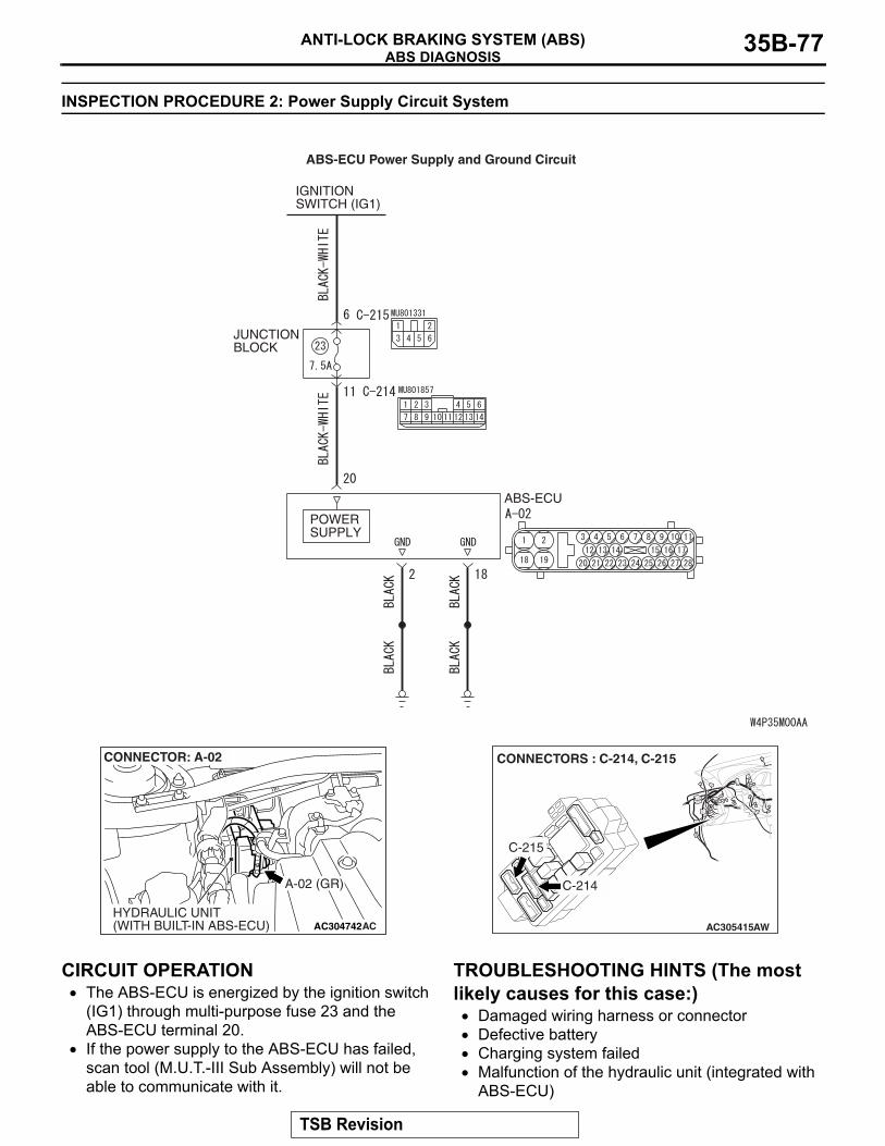
ABS DIAGNOSISANTI-LOCK BRAKING SYSTEM (ABS) 35B-77
INSPECTION PROCEDURE 2: Power Supply Circuit System
.
CIRCUIT OPERATION• The ABS-ECU is energized by the ignition switch
(IG1) through multi-purpose fuse 23 and the ABS-ECU terminal 20.
• If the power supply to the ABS-ECU has failed, scan tool (M.U.T.-III Sub Assembly) will not be able to communicate with it.
.
TROUBLESHOOTING HINTS (The most likely causes for this case:)
• Damaged wiring harness or connector• Defective battery• Charging system failed• Malfunction of the hydraulic unit (integrated with
ABS-ECU)
JUNCTION BLOCK
IGNITION SWITCH (IG1)
POWER SUPPLY
ABS-ECU
ABS-ECU Power Supply and Ground Circuit
AC304742
A-02 (GR)
CONNECTOR: A-02
HYDRAULIC UNIT(WITH BUILT-IN ABS-ECU) AC AC305415
CONNECTORS : C-214, C-215
C-214
C-215
AW
TSB Revision
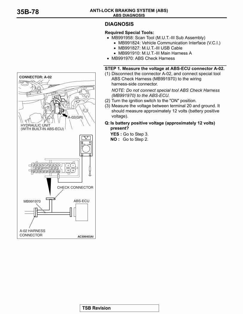
ABS DIAGNOSISANTI-LOCK BRAKING SYSTEM (ABS)35B-78
DIAGNOSISRequired Special Tools:
• MB991958: Scan Tool (M.U.T.-III Sub Assembly)• MB991824: Vehicle Communication Interface (V.C.I.)• MB991827: M.U.T.-III USB Cable• MB991910: M.U.T.-III Main Harness A
• MB991970: ABS Check Harness
STEP 1. Measure the voltage at ABS-ECU connector A-02.(1) Disconnect the connector A-02, and connect special tool
ABS Check Harness (MB991970) to the wiring harness-side connector.NOTE: Do not connect special tool ABS Check Harness (MB991970) to the ABS-ECU.
(2) Turn the ignition switch to the "ON" position.(3) Measure the voltage between terminal 20 and ground. It
should measure approximately 12 volts (battery positive voltage).
Q: Is battery positive voltage (approximately 12 volts) present?YES : Go to Step 3.NO : Go to Step 2.
AC306403
19
2
18
189 7 6 5 4 31011
25
151617
2728 26
121314
2324 22 21 20
A-02(GR)
CONNECTOR: A-02
HYDRAULIC UNIT(WITH BUILT-IN ABS-ECU)
AI
ABS-ECUMB991970
CHECK CONNECTOR
A-02 HARNESSCONNECTOR
TSB Revision
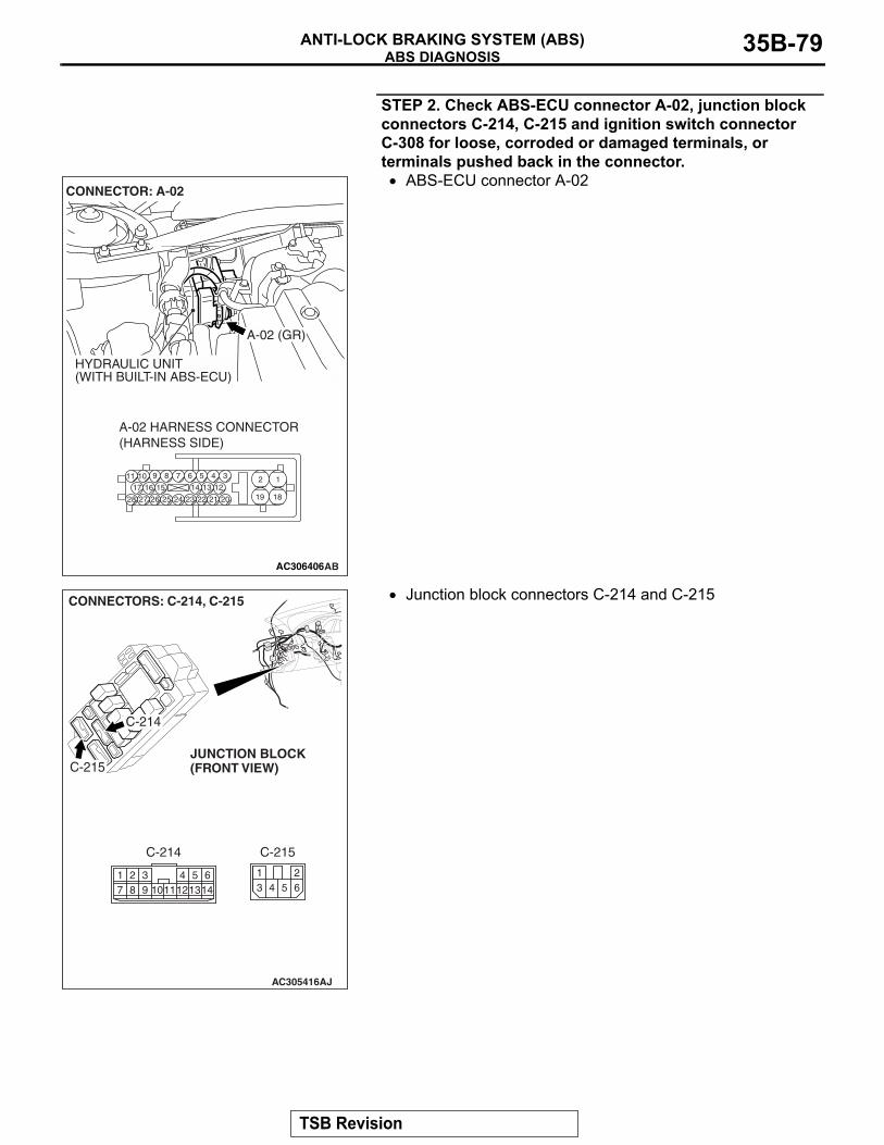
ABS DIAGNOSISANTI-LOCK BRAKING SYSTEM (ABS) 35B-79
STEP 2. Check ABS-ECU connector A-02, junction block connectors C-214, C-215 and ignition switch connector C-308 for loose, corroded or damaged terminals, or terminals pushed back in the connector.
• ABS-ECU connector A-02
• Junction block connectors C-214 and C-215
AC306406
19
2
18
189 7 6 5 4 31011
25
151617
2728 26
121314
2324 22 21 20
A-02 HARNESS CONNECTOR(HARNESS SIDE)
AB
A-02 (GR)
CONNECTOR: A-02
HYDRAULIC UNIT(WITH BUILT-IN ABS-ECU)
AC305416AJ
C-214
CONNECTORS: C-214, C-215
C-215
13 4
265
C-214
617
298 103 5
12114
1314
C-215JUNCTION BLOCK(FRONT VIEW)
TSB Revision
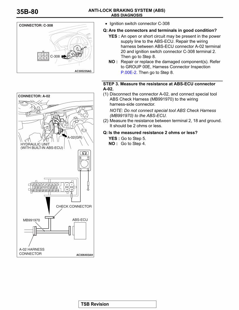
ABS DIAGNOSISANTI-LOCK BRAKING SYSTEM (ABS)35B-80
• Ignition switch connector C-308Q: Are the connectors and terminals in good condition?
YES : An open or short circuit may be present in the power supply line to the ABS-ECU. Repair the wiring harness between ABS-ECU connector A-02 terminal 20 and ignition switch connector C-308 terminal 2. Then go to Step 8.
NO : Repair or replace the damaged component(s). Refer to GROUP 00E, Harness Connector Inspection P.00E-2. Then go to Step 8.
STEP 3. Measure the resistance at ABS-ECU connector A-02.(1) Disconnect the connector A-02, and connect special tool
ABS Check Harness (MB991970) to the wiring harness-side connector.NOTE: Do not connect special tool ABS Check Harness (MB991970) to the ABS-ECU.
(2) Measure the resistance between terminal 2, 18 and ground. It should be 2 ohms or less.
Q: Is the measured resistance 2 ohms or less?YES : Go to Step 5.NO : Go to Step 4.
AC305235AG
CONNECTOR: C-308
C-308254
163
AC306403
19
2
18
189 7 6 5 4 31011
25
151617
2728 26
121314
2324 22 21 20
A-02(GR)
CONNECTOR: A-02
HYDRAULIC UNIT(WITH BUILT-IN ABS-ECU)
AH
ABS-ECUMB991970
CHECK CONNECTOR
A-02 HARNESSCONNECTOR
TSB Revision
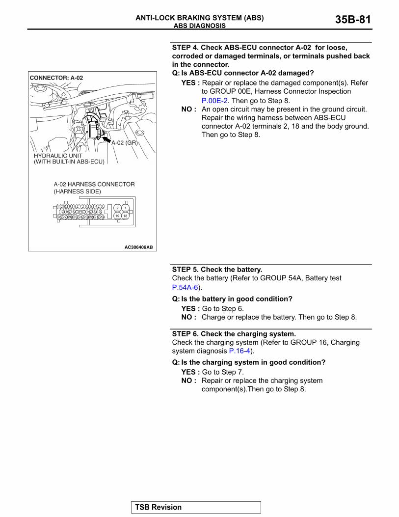
ABS DIAGNOSISANTI-LOCK BRAKING SYSTEM (ABS) 35B-81
STEP 4. Check ABS-ECU connector A-02 for loose, corroded or damaged terminals, or terminals pushed back in the connector.Q: Is ABS-ECU connector A-02 damaged?
YES : Repair or replace the damaged component(s). Refer to GROUP 00E, Harness Connector Inspection P.00E-2. Then go to Step 8.
NO : An open circuit may be present in the ground circuit. Repair the wiring harness between ABS-ECU connector A-02 terminals 2, 18 and the body ground. Then go to Step 8.
STEP 5. Check the battery.Check the battery (Refer to GROUP 54A, Battery test P.54A-6).Q: Is the battery in good condition?
YES : Go to Step 6.NO : Charge or replace the battery. Then go to Step 8.
STEP 6. Check the charging system.Check the charging system (Refer to GROUP 16, Charging system diagnosis P.16-4).Q: Is the charging system in good condition?
YES : Go to Step 7.NO : Repair or replace the charging system
component(s).Then go to Step 8.
AC306406
19
2
18
189 7 6 5 4 31011
25
151617
2728 26
121314
2324 22 21 20
A-02 HARNESS CONNECTOR(HARNESS SIDE)
AB
A-02 (GR)
CONNECTOR: A-02
HYDRAULIC UNIT(WITH BUILT-IN ABS-ECU)
TSB Revision
ABS DIAGNOSISANTI-LOCK BRAKING SYSTEM (ABS)35B-82
STEP 7. Retest the system.Q: Can the ABS-ECU communicate with the scan tool
(M.U.T.-III Sub Assembly)?YES : It can be assumed that this malfunction is intermittent.
Refer to GROUP 00, How to Use Troubleshooting/Inspection Service Points − How to Cope with Intermittent Malfunction P.00-14.
NO : Replace the ABS-ECU. Then go to Step 8.
STEP 8. Retest the system.Q: Can the ABS-ECU communicate with the scan tool
(M.U.T.-III Sub Assembly)?YES : The procedure is complete.NO : Go to Step 1.
TSB Revision
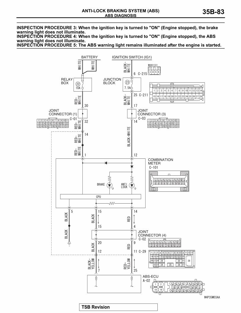
ABS DIAGNOSISANTI-LOCK BRAKING SYSTEM (ABS) 35B-83
INSPECTION PROCEDURE 3: When the ignition key is turned to "ON" (Engine stopped), the brake warning light does not illuminate. INSPECTION PROCEDURE 4: When the ignition key is turned to "ON" (Engine stopped), the ABS warning light does not illuminate. INSPECTION PROCEDURE 5: The ABS warning light remains illuminated after the engine is started.
BATTERY IGNITION SWITCH (IG1)
JOINTCONNECTOR (1)
JOINT CONNECTOR (3)
RELAYBOX
JUNCTIONBLOCK
COMBINATIONMETER
JOINTCONNECTOR (4)
ABS-ECU
TSB Revision
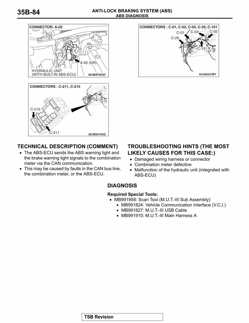
ABS DIAGNOSISANTI-LOCK BRAKING SYSTEM (ABS)35B-84
.
TECHNICAL DESCRIPTION (COMMENT)• The ABS-ECU sends the ABS warning light and
the brake warning light signals to the combination meter via the CAN communication.
• This may be caused by faults in the CAN bus line, the combination meter, or the ABS-ECU.
.
TROUBLESHOOTING HINTS (THE MOST LIKELY CAUSES FOR THIS CASE:)
• Damaged wiring harness or connector• Combination meter defective • Malfunction of the hydraulic unit (integrated with
ABS-ECU)
DIAGNOSISRequired Special Tools:
• MB991958: Scan Tool (M.U.T.-III Sub Assembly)• MB991824: Vehicle Communication Interface (V.C.I.)• MB991827: M.U.T.-III USB Cable• MB991910: M.U.T.-III Main Harness A
AC304742
A-02 (GR)
CONNECTOR: A-02
HYDRAULIC UNIT(WITH BUILT-IN ABS-ECU) AC AC305231
CONNECTORS : C-01, C-02, C-03, C-29, C-101
C-29
BY
C-02C-03C-01
C-101
AC305415
CONNECTORS : C-211, C-215
C-211
C-215
AZ
TSB Revision
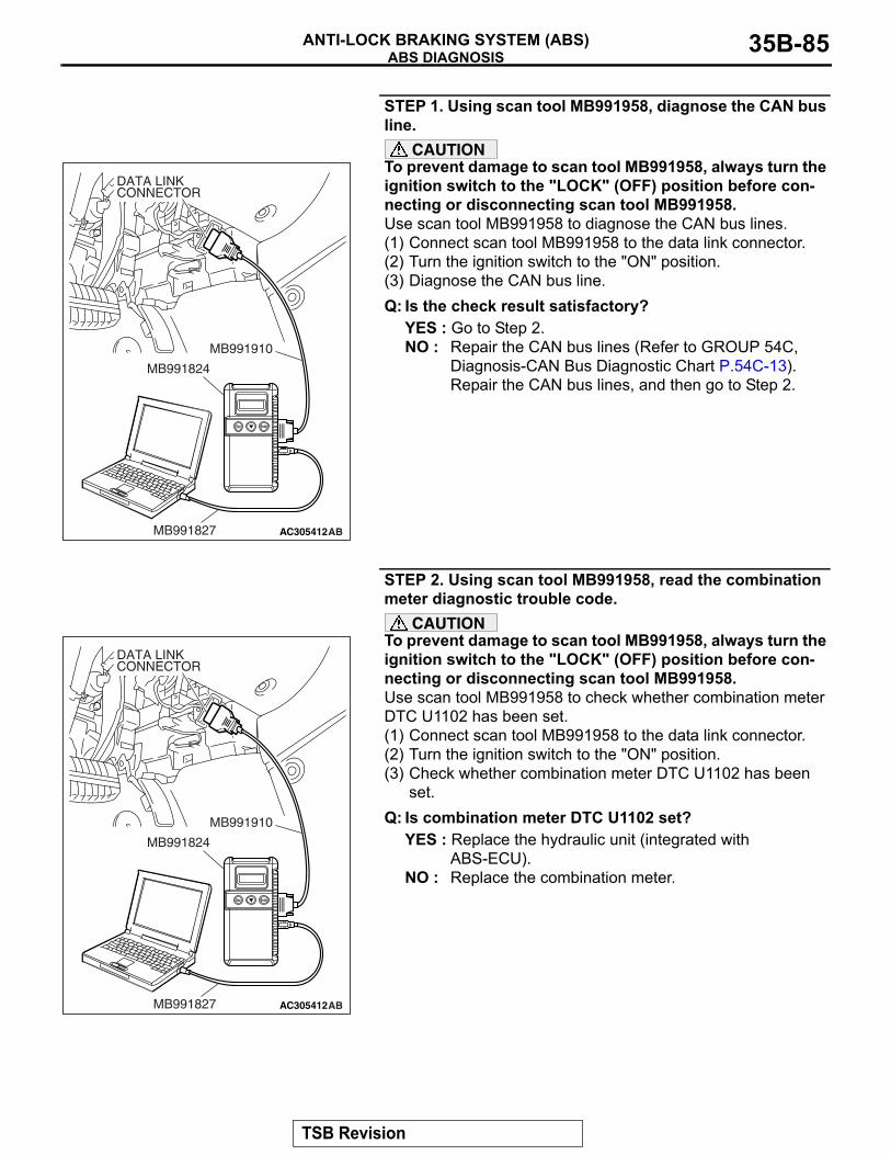
ABS DIAGNOSISANTI-LOCK BRAKING SYSTEM (ABS) 35B-85
STEP 1. Using scan tool MB991958, diagnose the CAN bus line.
CAUTIONTo prevent damage to scan tool MB991958, always turn the ignition switch to the "LOCK" (OFF) position before con-necting or disconnecting scan tool MB991958.Use scan tool MB991958 to diagnose the CAN bus lines.(1) Connect scan tool MB991958 to the data link connector.(2) Turn the ignition switch to the "ON" position.(3) Diagnose the CAN bus line.Q: Is the check result satisfactory?
YES : Go to Step 2.NO : Repair the CAN bus lines (Refer to GROUP 54C,
Diagnosis-CAN Bus Diagnostic Chart P.54C-13). Repair the CAN bus lines, and then go to Step 2.
STEP 2. Using scan tool MB991958, read the combination meter diagnostic trouble code.
CAUTIONTo prevent damage to scan tool MB991958, always turn the ignition switch to the "LOCK" (OFF) position before con-necting or disconnecting scan tool MB991958.Use scan tool MB991958 to check whether combination meter DTC U1102 has been set.(1) Connect scan tool MB991958 to the data link connector.(2) Turn the ignition switch to the "ON" position.(3) Check whether combination meter DTC U1102 has been
set.Q: Is combination meter DTC U1102 set?
YES : Replace the hydraulic unit (integrated with ABS-ECU).
NO : Replace the combination meter.
AC305412AB
MB991910
DATA LINKCONNECTOR
MB991824
MB991827
AC305412AB
MB991910
DATA LINKCONNECTOR
MB991824
MB991827
TSB Revision
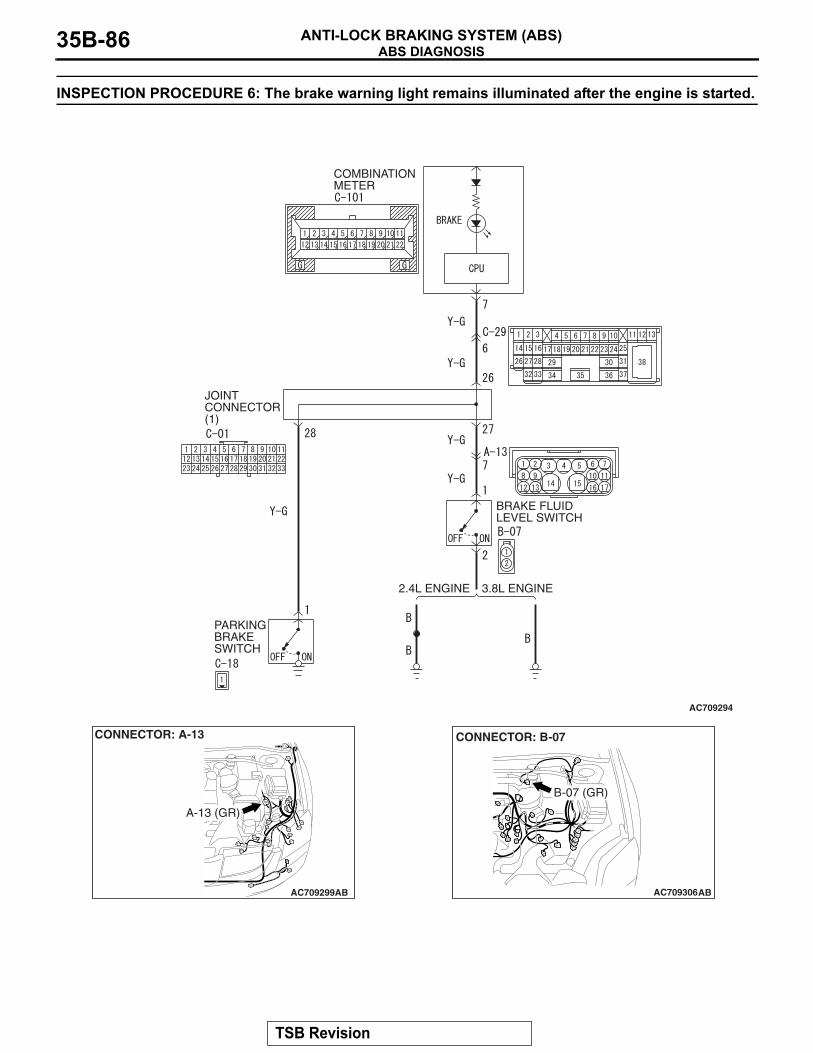
ABS DIAGNOSISANTI-LOCK BRAKING SYSTEM (ABS)35B-86
INSPECTION PROCEDURE 6: The brake warning light remains illuminated after the engine is started.
COMBINATIONMETER
JOINTCONNECTOR(1)
PARKINGBRAKESWITCH
BRAKE FLUIDLEVEL SWITCH
2.4L ENGINE 3.8L ENGINE
AC709294
AC709299
CONNECTOR: A-13
A-13 (GR)
AB AC709306
CONNECTOR: B-07
B-07 (GR)
AB
TSB Revision
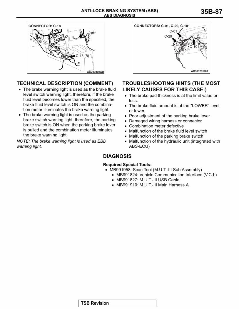
ABS DIAGNOSISANTI-LOCK BRAKING SYSTEM (ABS) 35B-87
.
TECHNICAL DESCRIPTION (COMMENT)• The brake warning light is used as the brake fluid
level switch warning light, therefore, if the brake fluid level becomes lower than the specified, the brake fluid level switch is ON and the combina-tion meter illuminates the brake warning light.
• The brake warning light is used as the parking brake switch warning light, therefore, the parking brake switch is ON when the parking brake lever is pulled and the combination meter illuminates the brake warning light.
NOTE: The brake warning light is used as EBD warning light.
.
TROUBLESHOOTING HINTS (THE MOST LIKELY CAUSES FOR THIS CASE:)
• The brake pad thickness is at the limit value or less.
• The brake fluid amount is at the "LOWER" level or lower.
• Poor adjustment of the parking brake lever• Damaged wiring harness or connector• Combination meter defective • Malfunction of the brake fluid level switch• Malfunction of the parking brake switch• Malfunction of the hydraulic unit (integrated with
ABS-ECU)
DIAGNOSISRequired Special Tools:
• MB991958: Scan Tool (M.U.T.-III Sub Assembly)• MB991824: Vehicle Communication Interface (V.C.I.)• MB991827: M.U.T.-III USB Cable• MB991910: M.U.T.-III Main Harness A
AC709302
CONNECTOR: C-18
C-18 (B)
AB AC305231
CONNECTORS: C-01, C-29, C-101
C-29
DU
C-01
C-101
TSB Revision
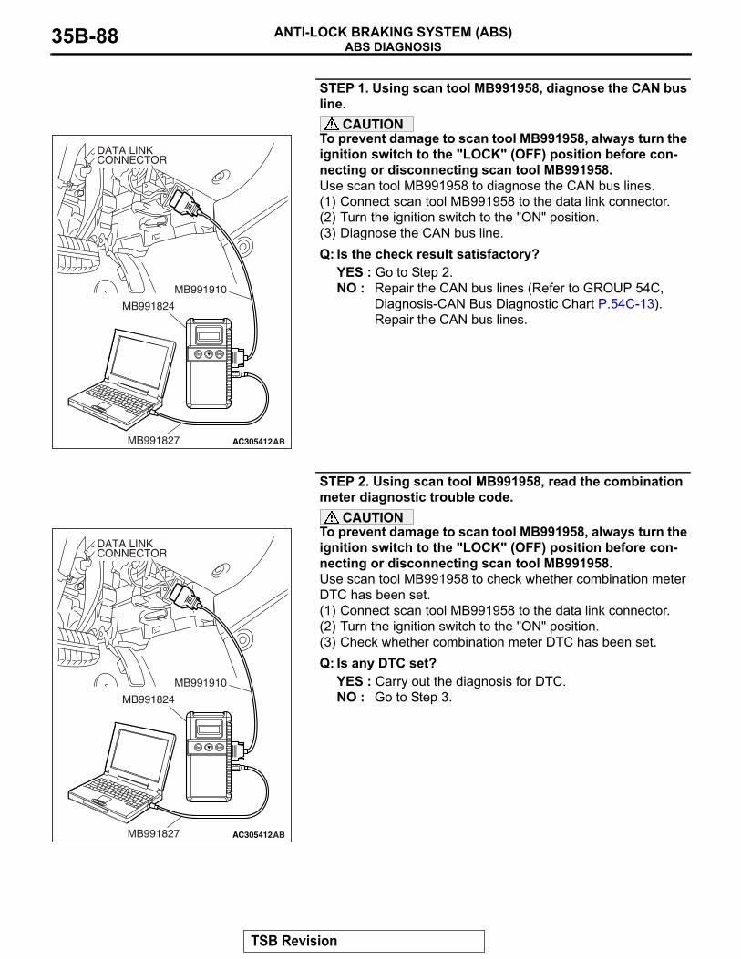
ABS DIAGNOSISANTI-LOCK BRAKING SYSTEM (ABS)35B-88
STEP 1. Using scan tool MB991958, diagnose the CAN bus line.
CAUTIONTo prevent damage to scan tool MB991958, always turn the ignition switch to the "LOCK" (OFF) position before con-necting or disconnecting scan tool MB991958.Use scan tool MB991958 to diagnose the CAN bus lines.(1) Connect scan tool MB991958 to the data link connector.(2) Turn the ignition switch to the "ON" position.(3) Diagnose the CAN bus line.Q: Is the check result satisfactory?
YES : Go to Step 2.NO : Repair the CAN bus lines (Refer to GROUP 54C,
Diagnosis-CAN Bus Diagnostic Chart P.54C-13). Repair the CAN bus lines.
STEP 2. Using scan tool MB991958, read the combination meter diagnostic trouble code.
CAUTIONTo prevent damage to scan tool MB991958, always turn the ignition switch to the "LOCK" (OFF) position before con-necting or disconnecting scan tool MB991958.Use scan tool MB991958 to check whether combination meter DTC has been set.(1) Connect scan tool MB991958 to the data link connector.(2) Turn the ignition switch to the "ON" position.(3) Check whether combination meter DTC has been set.Q: Is any DTC set?
YES : Carry out the diagnosis for DTC.NO : Go to Step 3.
AC305412AB
MB991910
DATA LINKCONNECTOR
MB991824
MB991827
AC305412AB
MB991910
DATA LINKCONNECTOR
MB991824
MB991827
TSB Revision
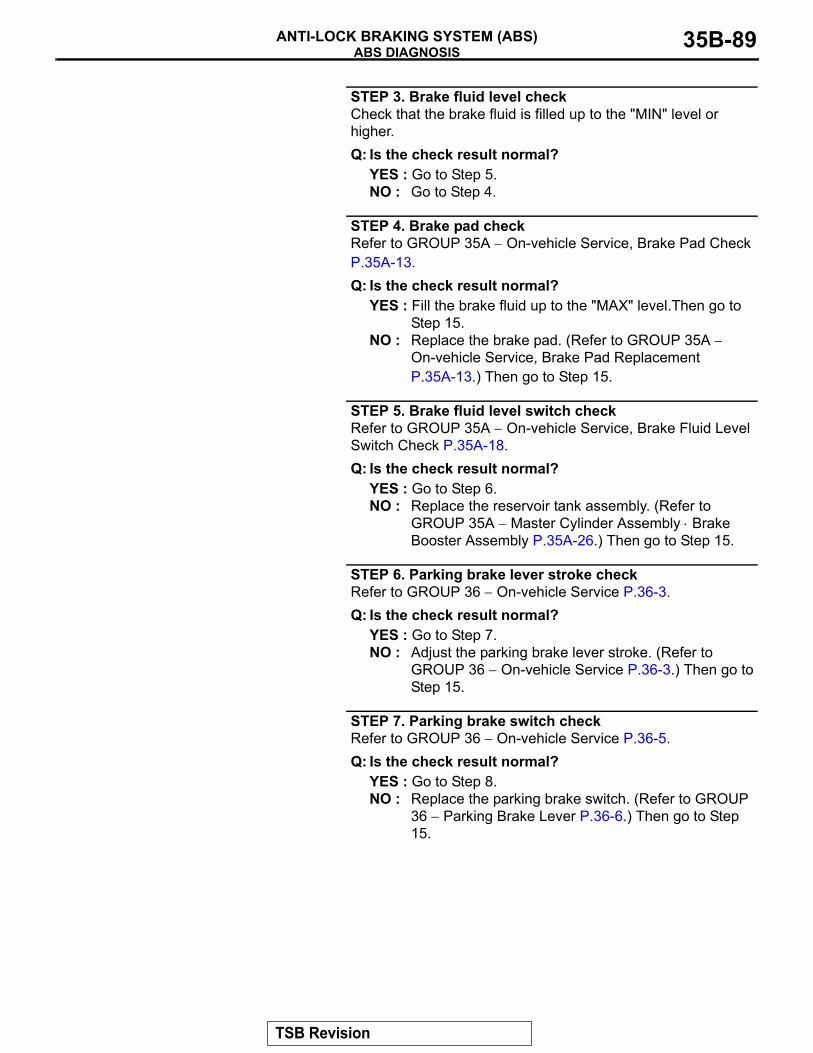
ABS DIAGNOSISANTI-LOCK BRAKING SYSTEM (ABS) 35B-89
STEP 3. Brake fluid level checkCheck that the brake fluid is filled up to the "MIN" level or higher.Q: Is the check result normal?
YES : Go to Step 5.NO : Go to Step 4.
STEP 4. Brake pad checkRefer to GROUP 35A − On-vehicle Service, Brake Pad Check P.35A-13.Q: Is the check result normal?
YES : Fill the brake fluid up to the "MAX" level.Then go to Step 15.
NO : Replace the brake pad. (Refer to GROUP 35A − On-vehicle Service, Brake Pad Replacement P.35A-13.) Then go to Step 15.
STEP 5. Brake fluid level switch checkRefer to GROUP 35A − On-vehicle Service, Brake Fluid Level Switch Check P.35A-18.Q: Is the check result normal?
YES : Go to Step 6.NO : Replace the reservoir tank assembly. (Refer to
GROUP 35A − Master Cylinder Assembly ⋅ Brake Booster Assembly P.35A-26.) Then go to Step 15.
STEP 6. Parking brake lever stroke checkRefer to GROUP 36 − On-vehicle Service P.36-3.Q: Is the check result normal?
YES : Go to Step 7.NO : Adjust the parking brake lever stroke. (Refer to
GROUP 36 − On-vehicle Service P.36-3.) Then go to Step 15.
STEP 7. Parking brake switch checkRefer to GROUP 36 − On-vehicle Service P.36-5.Q: Is the check result normal?
YES : Go to Step 8.NO : Replace the parking brake switch. (Refer to GROUP
36 − Parking Brake Lever P.36-6.) Then go to Step 15.
TSB Revision
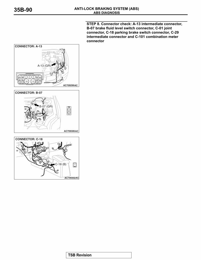
ABS DIAGNOSISANTI-LOCK BRAKING SYSTEM (ABS)35B-90
STEP 8. Connector check: A-13 intermediate connector, B-07 brake fluid level switch connector, C-01 joint connector, C-18 parking brake switch connector, C-29 intermediate connector and C-101 combination meter connector
AC709299
CONNECTOR: A-13
A-13 (GR)
AC
AC709306
CONNECTOR: B-07
B-07 (GR)
AC
AC709302
CONNECTOR: C-18
C-18 (B)
AC
TSB Revision
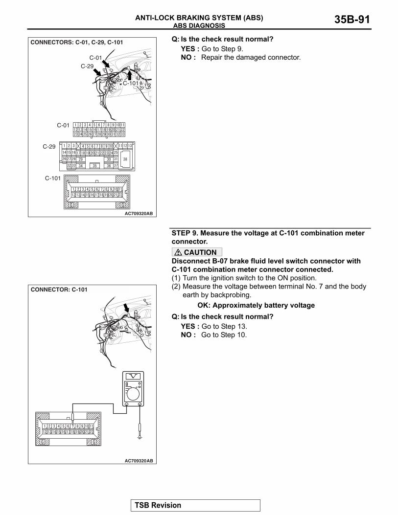
ABS DIAGNOSISANTI-LOCK BRAKING SYSTEM (ABS) 35B-91
Q: Is the check result normal?YES : Go to Step 9.NO : Repair the damaged connector.
STEP 9. Measure the voltage at C-101 combination meter connector.
CAUTIONDisconnect B-07 brake fluid level switch connector with C-101 combination meter connector connected.(1) Turn the ignition switch to the ON position.(2) Measure the voltage between terminal No. 7 and the body
earth by backprobing.OK: Approximately battery voltage
Q: Is the check result normal?YES : Go to Step 13.NO : Go to Step 10.
AC709320
CONNECTORS: C-01, C-29, C-101
C-29
AB
C-01
C-101
C-29
C-01
C-101
AC709320
CONNECTOR: C-101
AB
TSB Revision
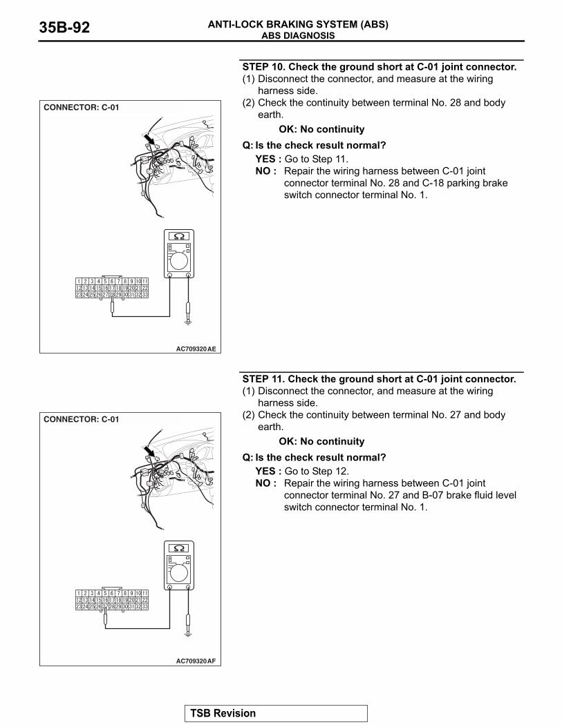
ABS DIAGNOSISANTI-LOCK BRAKING SYSTEM (ABS)35B-92
STEP 10. Check the ground short at C-01 joint connector.(1) Disconnect the connector, and measure at the wiring
harness side.(2) Check the continuity between terminal No. 28 and body
earth.OK: No continuity
Q: Is the check result normal?YES : Go to Step 11.NO : Repair the wiring harness between C-01 joint
connector terminal No. 28 and C-18 parking brake switch connector terminal No. 1.
STEP 11. Check the ground short at C-01 joint connector.(1) Disconnect the connector, and measure at the wiring
harness side.(2) Check the continuity between terminal No. 27 and body
earth.OK: No continuity
Q: Is the check result normal?YES : Go to Step 12.NO : Repair the wiring harness between C-01 joint
connector terminal No. 27 and B-07 brake fluid level switch connector terminal No. 1.
AC709320
CONNECTOR: C-01
AE
AC709320
CONNECTOR: C-01
AF
TSB Revision
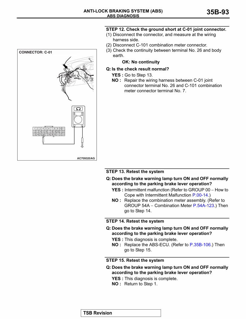
ABS DIAGNOSISANTI-LOCK BRAKING SYSTEM (ABS) 35B-93
STEP 12. Check the ground short at C-01 joint connector.(1) Disconnect the connector, and measure at the wiring
harness side.(2) Disconnect C-101 combination meter connector.(3) Check the continuity between terminal No. 26 and body
earth.OK: No continuity
Q: Is the check result normal?YES : Go to Step 13.NO : Repair the wiring harness between C-01 joint
connector terminal No. 26 and C-101 combination meter connector terminal No. 7.
STEP 13. Retest the systemQ: Does the brake warning lamp turn ON and OFF normally
according to the parking brake lever operation?YES : Intermittent malfunction (Refer to GROUP 00 − How to
Cope with Intermittent Malfunction P.00-14.)NO : Replace the combination meter assembly. (Refer to
GROUP 54A − Combination Meter P.54A-123.) Then go to Step 14.
STEP 14. Retest the systemQ: Does the brake warning lamp turn ON and OFF normally
according to the parking brake lever operation?YES : This diagnosis is complete.NO : Replace the ABS-ECU. (Refer to P.35B-106.) Then
go to Step 15.
STEP 15. Retest the systemQ: Does the brake warning lamp turn ON and OFF normally
according to the parking brake lever operation?YES : This diagnosis is complete.NO : Return to Step 1.
AC709320
CONNECTOR: C-01
AG
TSB Revision
ABS DIAGNOSISANTI-LOCK BRAKING SYSTEM (ABS)35B-94
INSPECTION PROCEDURE 7: Faulty ABS Operation
.
TECHNICAL DESCRIPTION (COMMENT)The cause depends on driving and road surface con-ditions, so diagnosis may be difficult. However, if no diagnostic trouble code is displayed, carry out the fol-lowing inspection.
.
TROUBLESHOOTING HINTS (The most likely causes for this case:)
• Malfunction of the hydraulic unit
DIAGNOSIS
STEP 1. Hydraulic unit check Refer to P.35B-103.Q: Is the hydraulic unit normal?
YES : Go to Step 2.NO : Connect the brake pipes correctly, repair the external
brake lines, or replace the hydraulic unit.
STEP 2. Verify that the condition described by the customer exists.Q: Can any faults be found with the brake operation?
YES : Check the brake system related components except the ABS system.
NO : The procedure is complete.
TSB Revision
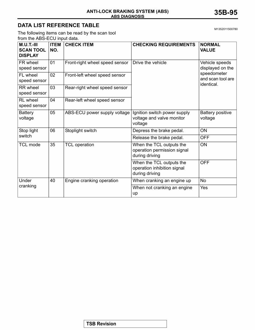
ABS DIAGNOSISANTI-LOCK BRAKING SYSTEM (ABS) 35B-95
DATA LIST REFERENCE TABLEM1352011500780
The following items can be read by the scan tool from the ABS-ECU input data.M.U.T.-III SCAN TOOL DISPLAY
ITEM NO.
CHECK ITEM CHECKING REQUIREMENTS NORMAL VALUE
FR wheel speed sensor
01 Front-right wheel speed sensor Drive the vehicle Vehicle speeds displayed on the speedometer and scan tool are identical.
FL wheel speed sensor
02 Front-left wheel speed sensor
RR wheel speed sensor
03 Rear-right wheel speed sensor
RL wheel speed sensor
04 Rear-left wheel speed sensor
Battery voltage
05 ABS-ECU power supply voltage Ignition switch power supply voltage and valve monitor voltage
Battery positive voltage
Stop light switch
06 Stoplight switch Depress the brake pedal. ONRelease the brake pedal. OFF
TCL mode 35 TCL operation When the TCL outputs the operation permission signal during driving
ON
When the TCL outputs the operation inhibition signal during driving
OFF
Under cranking
40 Engine cranking operation When cranking an engine up NoWhen not cranking an engine up
Yes
TSB Revision
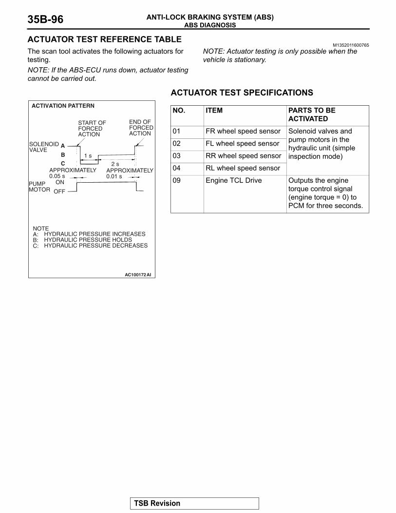
ABS DIAGNOSISANTI-LOCK BRAKING SYSTEM (ABS)35B-96
ACTUATOR TEST REFERENCE TABLEM1352011600765
The scan tool activates the following actuators for testing.NOTE: If the ABS-ECU runs down, actuator testing cannot be carried out.
NOTE: Actuator testing is only possible when the vehicle is stationary.
.
ACTUATOR TEST SPECIFICATIONS
NO. ITEM PARTS TO BE ACTIVATED
01 FR wheel speed sensor Solenoid valves and pump motors in the hydraulic unit (simple inspection mode)
02 FL wheel speed sensor
03 RR wheel speed sensor
04 RL wheel speed sensor
09 Engine TCL Drive Outputs the engine torque control signal (engine torque = 0) to PCM for three seconds.
AC100172AI
ACTIVATION PATTERN
A
B
C
SOLENOIDVALVE
END OFFORCEDACTION
START OFFORCEDACTION
1 s2 s
PUMPMOTOR
ON
OFF
NOTEA:B:C:
HYDRAULIC PRESSURE INCREASESHYDRAULIC PRESSURE HOLDSHYDRAULIC PRESSURE DECREASES
APPROXIMATELY0.05 s
APPROXIMATELY0.01 s
TSB Revision
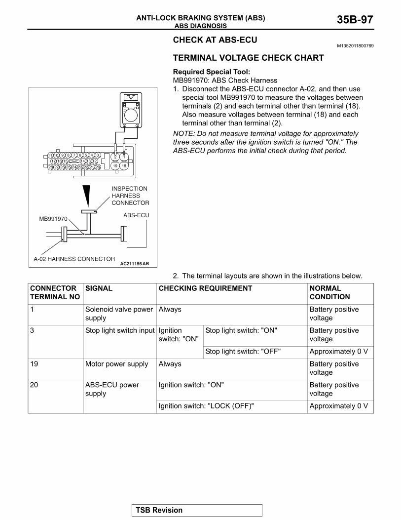
ABS DIAGNOSISANTI-LOCK BRAKING SYSTEM (ABS) 35B-97
CHECK AT ABS-ECUM1352011800769
.
TERMINAL VOLTAGE CHECK CHARTRequired Special Tool:MB991970: ABS Check Harness1. Disconnect the ABS-ECU connector A-02, and then use
special tool MB991970 to measure the voltages between terminals (2) and each terminal other than terminal (18). Also measure voltages between terminal (18) and each terminal other than terminal (2).
NOTE: Do not measure terminal voltage for approximately three seconds after the ignition switch is turned "ON." The ABS-ECU performs the initial check during that period.
2. The terminal layouts are shown in the illustrations below.
.
AC211156 AB
ABS-ECU
A-02 HARNESS CONNECTOR
MB991970
INSPECTIONHARNESSCONNECTOR
CONNECTOR TERMINAL NO
SIGNAL CHECKING REQUIREMENT NORMAL CONDITION
1 Solenoid valve power supply
Always Battery positive voltage
3 Stop light switch input Ignition switch: "ON"
Stop light switch: "ON" Battery positive voltage
Stop light switch: "OFF" Approximately 0 V
19 Motor power supply Always Battery positive voltage
20 ABS-ECU power supply
Ignition switch: "ON" Battery positive voltage
Ignition switch: "LOCK (OFF)" Approximately 0 V
TSB Revision
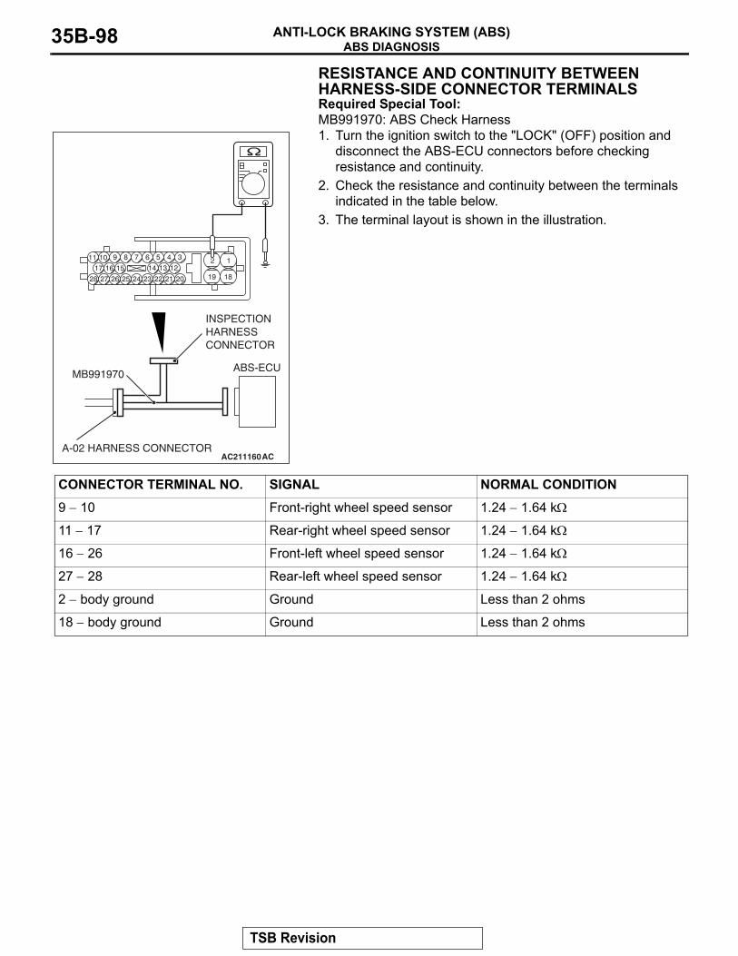
ABS DIAGNOSISANTI-LOCK BRAKING SYSTEM (ABS)35B-98
RESISTANCE AND CONTINUITY BETWEEN HARNESS-SIDE CONNECTOR TERMINALSRequired Special Tool:MB991970: ABS Check Harness1. Turn the ignition switch to the "LOCK" (OFF) position and
disconnect the ABS-ECU connectors before checking resistance and continuity.
2. Check the resistance and continuity between the terminals indicated in the table below.
3. The terminal layout is shown in the illustration.
AC211160AC
ABS-ECU
A-02 HARNESS CONNECTOR
MB991970
INSPECTIONHARNESSCONNECTOR
CONNECTOR TERMINAL NO. SIGNAL NORMAL CONDITION9 − 10 Front-right wheel speed sensor 1.24 − 1.64 kΩ
11 − 17 Rear-right wheel speed sensor 1.24 − 1.64 kΩ
16 − 26 Front-left wheel speed sensor 1.24 − 1.64 kΩ
27 − 28 Rear-left wheel speed sensor 1.24 − 1.64 kΩ
2 − body ground Ground Less than 2 ohms
18 − body ground Ground Less than 2 ohms
TSB Revision
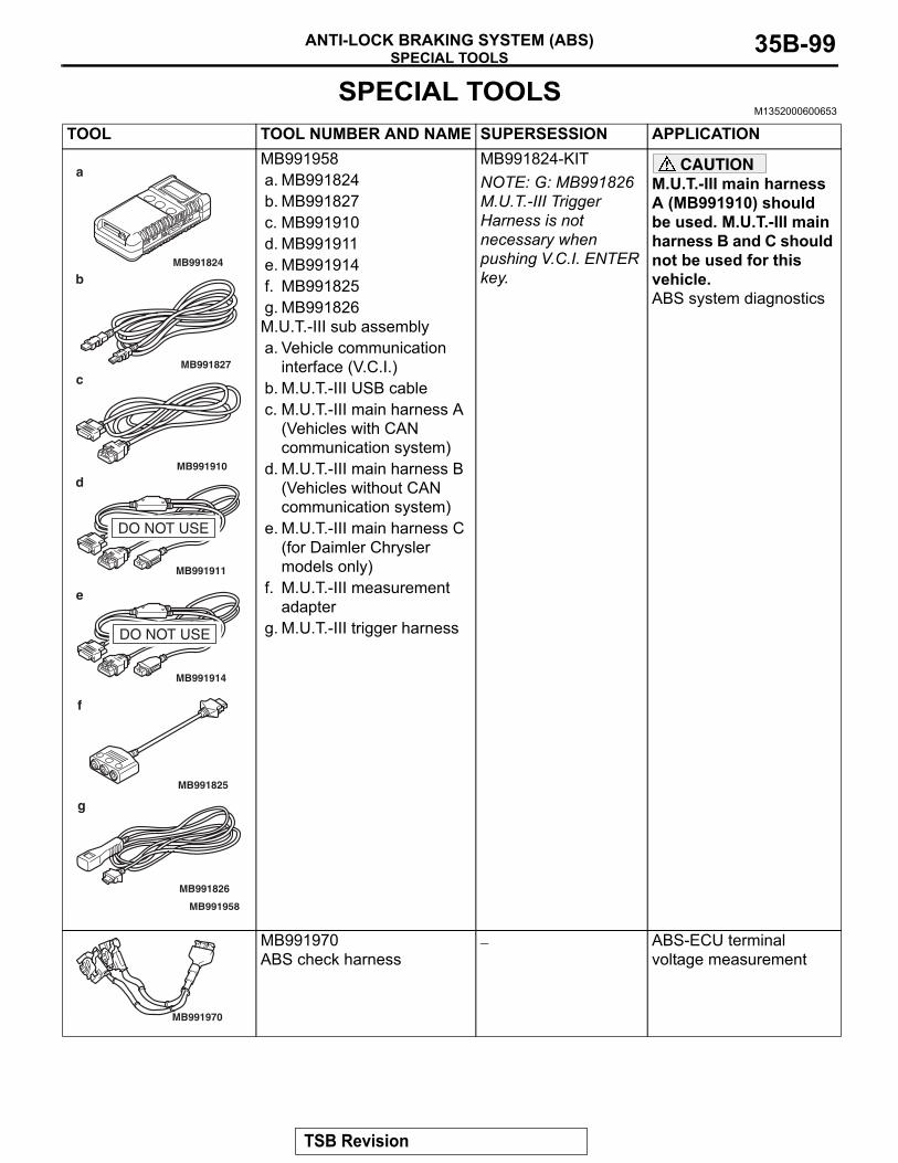
SPECIAL TOOLSANTI-LOCK BRAKING SYSTEM (ABS) 35B-99
SPECIAL TOOLSM1352000600653
TOOL TOOL NUMBER AND NAME SUPERSESSION APPLICATIONMB991958a. MB991824b. MB991827c. MB991910d. MB991911e. MB991914f. MB991825g. MB991826M.U.T.-III sub assemblya. Vehicle communication
interface (V.C.I.)b. M.U.T.-III USB cablec. M.U.T.-III main harness A
(Vehicles with CAN communication system)
d. M.U.T.-III main harness B (Vehicles without CAN communication system)
e. M.U.T.-III main harness C (for Daimler Chrysler models only)
f. M.U.T.-III measurement adapter
g. M.U.T.-III trigger harness
MB991824-KITNOTE: G: MB991826 M.U.T.-III Trigger Harness is not necessary when pushing V.C.I. ENTER key.
CAUTIONM.U.T.-III main harness A (MB991910) should be used. M.U.T.-III main harness B and C should not be used for this vehicle.ABS system diagnostics
MB991970 ABS check harness
− ABS-ECU terminal voltage measurement
MB991910
MB991826
MB991958
MB991911
MB991914
MB991824
MB991827
MB991825
DO NOT USE
a
b
c
d
e
f
g
DO NOT USE
MB991970
TSB Revision
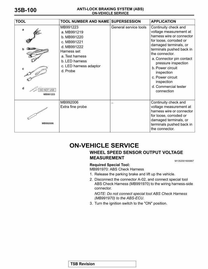
ON-VEHICLE SERVICEANTI-LOCK BRAKING SYSTEM (ABS)35B-100
ON-VEHICLE SERVICEWHEEL SPEED SENSOR OUTPUT VOLTAGE MEASUREMENT
M1352001600667
Required Special Tool:MB991970: ABS Check Harness1. Release the parking brake and lift up the vehicle.2. Disconnect the connector A-02, and connect special tool
ABS Check Harness (MB991970) to the wiring harness-side connector.NOTE: Do not connect special tool ABS Check Harness (MB991970) to the ABS-ECU.
3. Turn the ignition switch to the "ON" position.
MB991223a. MB991219b. MB991220c. MB991221d. MB991222Harness seta. Test harnessb. LED harnessc. LED harness adaptord. Probe
General service tools Continuity check and voltage measurement at harness wire or connector for loose, corroded or damaged terminals, or terminals pushed back in the connector.a. Connector pin contact
pressure inspectionb. Power circuit
inspectionc. Power circuit
inspectiond. Commercial tester
connection
MB992006Extra fine probe
− Continuity check and voltage measurement at harness wire or connector for loose, corroded or damaged terminals, or terminals pushed back in the connector.
TOOL TOOL NUMBER AND NAME SUPERSESSION APPLICATION
MB991223
a
d
c
b
DO NOT USE
BA
MB992006
TSB Revision
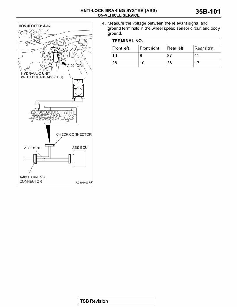
ON-VEHICLE SERVICEANTI-LOCK BRAKING SYSTEM (ABS) 35B-101
4. Measure the voltage between the relevant signal and ground terminals in the wheel speed sensor circuit and body ground.
TERMINAL NO.Front left Front right Rear left Rear right
16 9 27 11
26 10 28 17
AC306403
19
2
18
189 7 6 5 4 31011
25
151617
2728 26
121314
2324 22 21 20
AK
ABS-ECUMB991970
CHECK CONNECTOR
A-02 HARNESSCONNECTOR
A-02 (GR)
CONNECTOR: A-02
HYDRAULIC UNIT(WITH BUILT-IN ABS-ECU)
TSB Revision
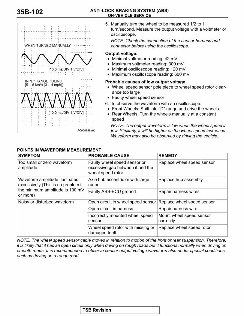
ON-VEHICLE SERVICEANTI-LOCK BRAKING SYSTEM (ABS)35B-102
5. Manually turn the wheel to be measured 1/2 to 1 turn/second. Measure the output voltage with a voltmeter or oscilloscope.NOTE: Check the connection of the sensor harness and connector before using the oscilloscope.
Output voltage:• Minimal voltmeter reading: 42 mV• Maximum voltmeter reading: 300 mV• Minimal oscilloscope reading: 120 mV• Maximum oscilloscope reading: 600 mV
Probable causes of low output voltage• Wheel speed sensor pole piece to wheel speed rotor clear-
ance too large• Faulty wheel speed sensor
6. To observe the waveform with an oscilloscope:• Front Wheels: Shift into "D" range and drive the wheels.• Rear Wheels: Turn the wheels manually at a constant
speedNOTE: The output waveform is low when the wheel speed is low. Similarly, it will be higher as the wheel speed increases. Waveform may also be observed by driving the vehicle.
.
POINTS IN WAVEFORM MEASUREMENT
NOTE: The wheel speed sensor cable moves in relation to motion of the front or rear suspension. Therefore, it is likely that it has an open circuit only when driving on rough roads but it functions normally when driving on smooth roads. It is recommended to observe sensor output voltage waveform also under special conditions, such as driving on a rough road.
AC000949 AC
WHEN TURNED MANUALLY
IN "D" RANGE, IDLING[5 − 6 km/h (3 − 4 mph)]
[10.0 ms/DIV 1 V/DIV]
[10.0 ms/DIV 1 V/DIV]
SYMPTOM PROBABLE CAUSE REMEDYToo small or zero waveform amplitude
Faulty wheel speed sensor or excessive gap between it and the wheel speed rotor
Replace wheel speed sensor
Waveform amplitude fluctuates excessively (This is no problem if the minimum amplitude is 100 mV or more)
Axle hub eccentric or with large runout
Replace hub assembly
Faulty ABS-ECU ground Repair harness wires
Noisy or disturbed waveform Open circuit in wheel speed sensor Replace wheel speed sensorOpen circuit in harness Repair harness wireIncorrectly mounted wheel speed sensor
Mount wheel speed sensor correctly
Wheel speed rotor with missing or damaged teeth
Replace wheel speed rotor
TSB Revision
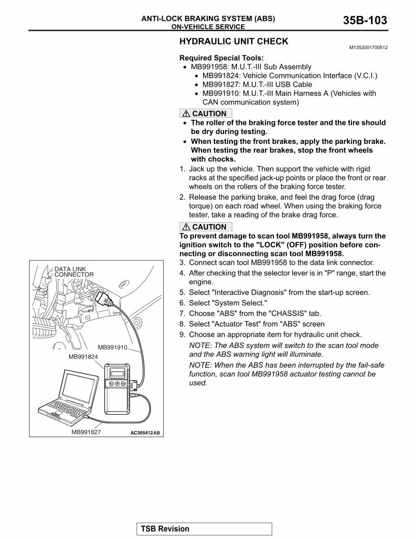
ON-VEHICLE SERVICEANTI-LOCK BRAKING SYSTEM (ABS) 35B-103
HYDRAULIC UNIT CHECKM1352001700512
Required Special Tools:• MB991958: M.U.T.-III Sub Assembly
• MB991824: Vehicle Communication Interface (V.C.I.)• MB991827: M.U.T.-III USB Cable• MB991910: M.U.T.-III Main Harness A (Vehicles with
CAN communication system)CAUTION
• The roller of the braking force tester and the tire should be dry during testing.
• When testing the front brakes, apply the parking brake. When testing the rear brakes, stop the front wheels with chocks.
1. Jack up the vehicle. Then support the vehicle with rigid racks at the specified jack-up points or place the front or rear wheels on the rollers of the braking force tester.
2. Release the parking brake, and feel the drag force (drag torque) on each road wheel. When using the braking force tester, take a reading of the brake drag force.CAUTION
To prevent damage to scan tool MB991958, always turn the ignition switch to the "LOCK" (OFF) position before con-necting or disconnecting scan tool MB991958.3. Connect scan tool MB991958 to the data link connector.4. After checking that the selector lever is in "P" range, start the
engine.5. Select "Interactive Diagnosis" from the start-up screen.6. Select "System Select."7. Choose "ABS" from the "CHASSIS" tab.8. Select "Actuator Test" from "ABS" screen9. Choose an appropriate item for hydraulic unit check.
NOTE: The ABS system will switch to the scan tool mode and the ABS warning light will illuminate.NOTE: When the ABS has been interrupted by the fail-safe function, scan tool MB991958 actuator testing cannot be used.
AC305412AB
MB991910
DATA LINKCONNECTOR
MB991824
MB991827
TSB Revision
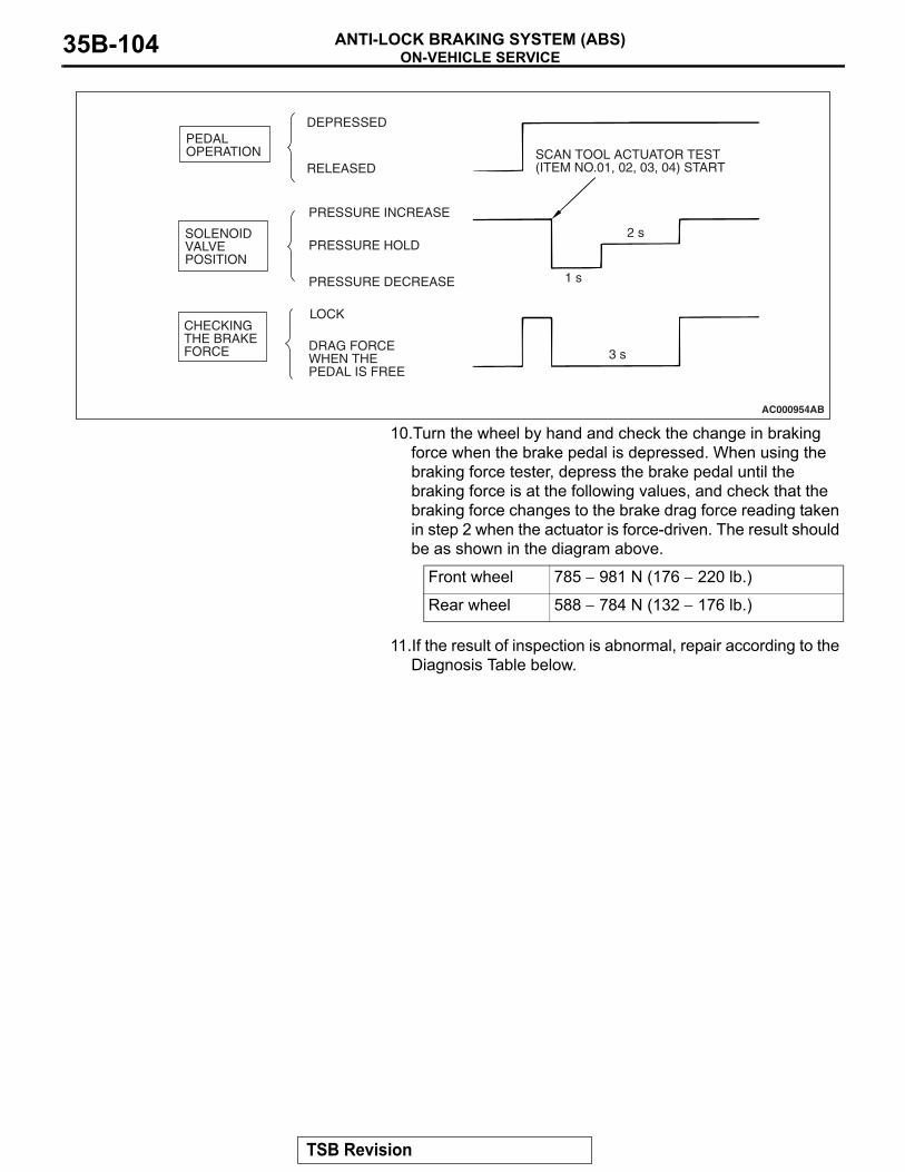
ON-VEHICLE SERVICEANTI-LOCK BRAKING SYSTEM (ABS)35B-104
10.Turn the wheel by hand and check the change in braking force when the brake pedal is depressed. When using the braking force tester, depress the brake pedal until the braking force is at the following values, and check that the braking force changes to the brake drag force reading taken in step 2 when the actuator is force-driven. The result should be as shown in the diagram above.
11.If the result of inspection is abnormal, repair according to the Diagnosis Table below.
Front wheel 785 − 981 N (176 − 220 lb.)
Rear wheel 588 − 784 N (132 − 176 lb.)
AC000954AB
SCAN TOOL ACTUATOR TEST(ITEM NO.01, 02, 03, 04) START
1 s
2 s
3 s
DEPRESSED
RELEASED
PRESSURE INCREASE
PRESSURE DECREASE
PRESSURE HOLD
LOCK
DRAG FORCEWHEN THEPEDAL IS FREE
PEDALOPERATION
SOLENOIDVALVEPOSITION
CHECKINGTHE BRAKEFORCE
TSB Revision
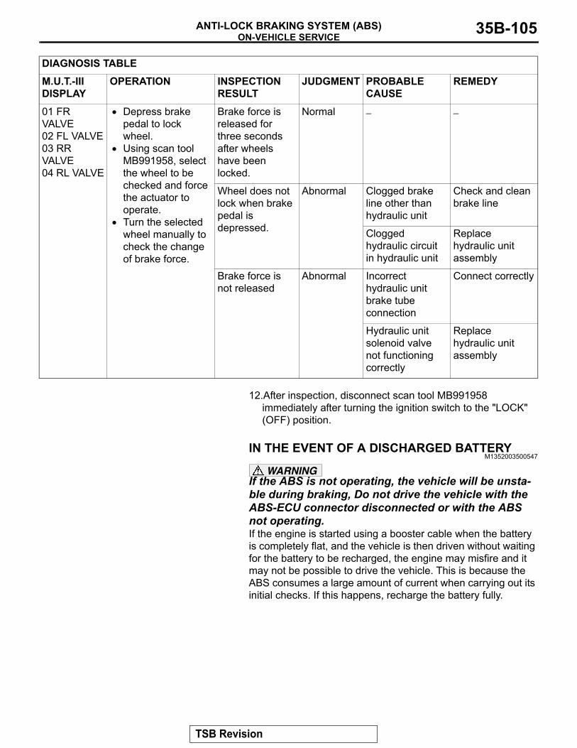
ON-VEHICLE SERVICEANTI-LOCK BRAKING SYSTEM (ABS) 35B-105
12.After inspection, disconnect scan tool MB991958 immediately after turning the ignition switch to the "LOCK" (OFF) position.
IN THE EVENT OF A DISCHARGED BATTERYM1352003500547
WARNINGIf the ABS is not operating, the vehicle will be unsta-ble during braking, Do not drive the vehicle with the ABS-ECU connector disconnected or with the ABS not operating.If the engine is started using a booster cable when the battery is completely flat, and the vehicle is then driven without waiting for the battery to be recharged, the engine may misfire and it may not be possible to drive the vehicle. This is because the ABS consumes a large amount of current when carrying out its initial checks. If this happens, recharge the battery fully.
DIAGNOSIS TABLEM.U.T.-III DISPLAY
OPERATION INSPECTION RESULT
JUDGMENT PROBABLE CAUSE
REMEDY
01 FR VALVE02 FL VALVE03 RR VALVE04 RL VALVE
• Depress brake pedal to lock wheel.
• Using scan tool MB991958, select the wheel to be checked and force the actuator to operate.
• Turn the selected wheel manually to check the change of brake force.
Brake force is released for three seconds after wheels have been locked.
Normal − −
Wheel does not lock when brake pedal is depressed.
Abnormal Clogged brake line other than hydraulic unit
Check and clean brake line
Clogged hydraulic circuit in hydraulic unit
Replace hydraulic unit assembly
Brake force is not released
Abnormal Incorrect hydraulic unit brake tube connection
Connect correctly
Hydraulic unit solenoid valve not functioning correctly
Replace hydraulic unit assembly
TSB Revision
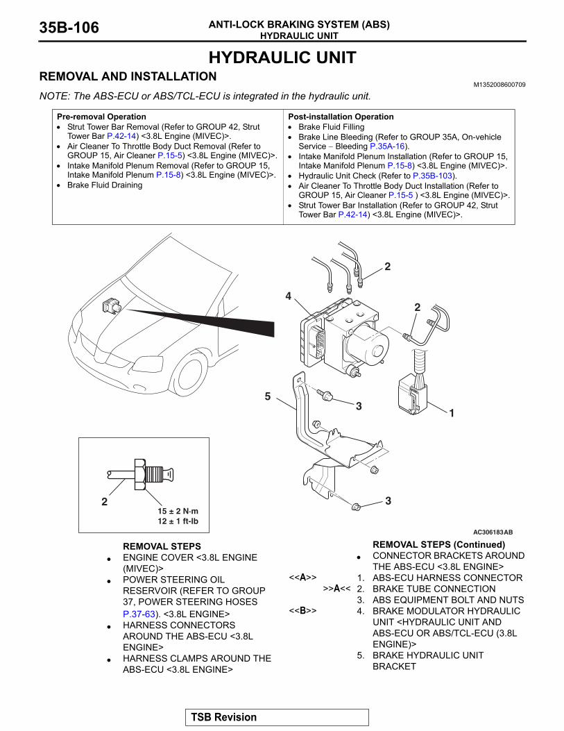
HYDRAULIC UNITANTI-LOCK BRAKING SYSTEM (ABS)35B-106
HYDRAULIC UNITREMOVAL AND INSTALLATION
M1352008600709
NOTE: The ABS-ECU or ABS/TCL-ECU is integrated in the hydraulic unit.
Pre-removal Operation• Strut Tower Bar Removal (Refer to GROUP 42, Strut
Tower Bar P.42-14) <3.8L Engine (MIVEC)>.• Air Cleaner To Throttle Body Duct Removal (Refer to
GROUP 15, Air Cleaner P.15-5) <3.8L Engine (MIVEC)>.• Intake Manifold Plenum Removal (Refer to GROUP 15,
Intake Manifold Plenum P.15-8) <3.8L Engine (MIVEC)>.• Brake Fluid Draining
Post-installation Operation• Brake Fluid Filling• Brake Line Bleeding (Refer to GROUP 35A, On-vehicle
Service − Bleeding P.35A-16).• Intake Manifold Plenum Installation (Refer to GROUP 15,
Intake Manifold Plenum P.15-8) <3.8L Engine (MIVEC)>.• Hydraulic Unit Check (Refer to P.35B-103).• Air Cleaner To Throttle Body Duct Installation (Refer to
GROUP 15, Air Cleaner P.15-5 ) <3.8L Engine (MIVEC)>.• Strut Tower Bar Installation (Refer to GROUP 42, Strut
Tower Bar P.42-14) <3.8L Engine (MIVEC)>.
AC306183AB
15 ± 2 N·m12 ± 1 ft-lb
4
5
2
31
2
32
REMOVAL STEPS • ENGINE COVER <3.8L ENGINE
(MIVEC)>• POWER STEERING OIL
RESERVOIR (REFER TO GROUP 37, POWER STEERING HOSES P.37-63). <3.8L ENGINE>
• HARNESS CONNECTORS AROUND THE ABS-ECU <3.8L ENGINE>
• HARNESS CLAMPS AROUND THE ABS-ECU <3.8L ENGINE>
• CONNECTOR BRACKETS AROUND THE ABS-ECU <3.8L ENGINE>
<<A>> 1. ABS-ECU HARNESS CONNECTOR>>A<< 2. BRAKE TUBE CONNECTION
3. ABS EQUIPMENT BOLT AND NUTS<<B>> 4. BRAKE MODULATOR HYDRAULIC
UNIT <HYDRAULIC UNIT AND ABS-ECU OR ABS/TCL-ECU (3.8L ENGINE)>
5. BRAKE HYDRAULIC UNIT BRACKET
REMOVAL STEPS (Continued)
TSB Revision
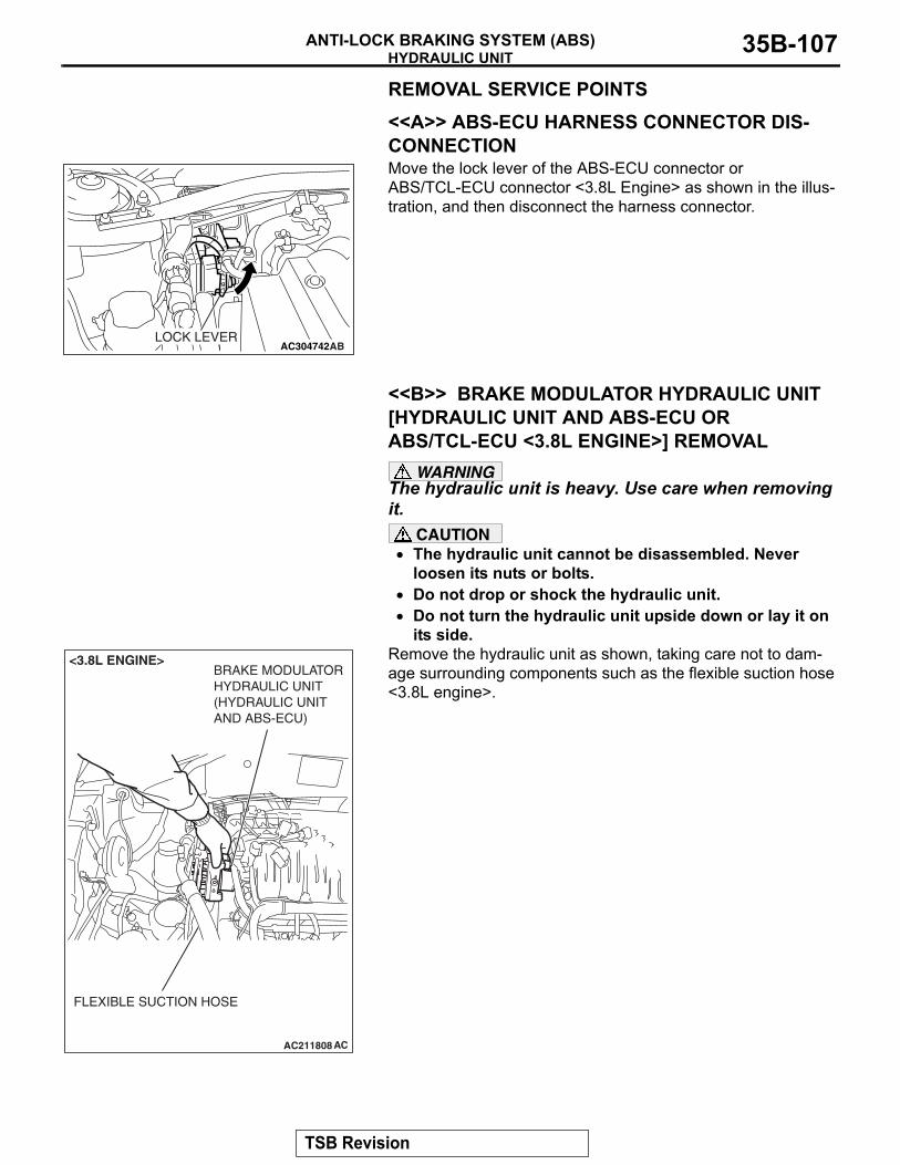
HYDRAULIC UNITANTI-LOCK BRAKING SYSTEM (ABS) 35B-107
REMOVAL SERVICE POINTS.
<<A>> ABS-ECU HARNESS CONNECTOR DIS-CONNECTIONMove the lock lever of the ABS-ECU connector or ABS/TCL-ECU connector <3.8L Engine> as shown in the illus-tration, and then disconnect the harness connector.
.
<<B>> BRAKE MODULATOR HYDRAULIC UNIT [HYDRAULIC UNIT AND ABS-ECU OR ABS/TCL-ECU <3.8L ENGINE>] REMOVAL
WARNINGThe hydraulic unit is heavy. Use care when removing it.
CAUTION• The hydraulic unit cannot be disassembled. Never
loosen its nuts or bolts.• Do not drop or shock the hydraulic unit.• Do not turn the hydraulic unit upside down or lay it on
its side.Remove the hydraulic unit as shown, taking care not to dam-age surrounding components such as the flexible suction hose <3.8L engine>.
AC304742ABLOCK LEVER
AC211808 AC
BRAKE MODULATORHYDRAULIC UNIT(HYDRAULIC UNITAND ABS-ECU)
FLEXIBLE SUCTION HOSE
<3.8L ENGINE>
TSB Revision
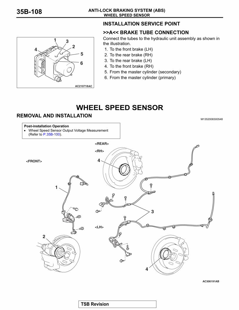
WHEEL SPEED SENSORANTI-LOCK BRAKING SYSTEM (ABS)35B-108
INSTALLATION SERVICE POINT.
>>A<< BRAKE TUBE CONNECTIONConnect the tubes to the hydraulic unit assembly as shown in the illustration.1. To the front brake (LH)2. To the rear brake (RH)3. To the rear brake (LH)4. To the front brake (RH)5. From the master cylinder (secondary)6. From the master cylinder (primary)
WHEEL SPEED SENSORREMOVAL AND INSTALLATION
M1352008300548
AC210718AC
6
5
231
4
Post-installation Operation• Wheel Speed Sensor Output Voltage Measurement
(Refer to P.35B-100).
AC306191AB
<FRONT>
<REAR>
1
2
4
3
4
<RH>
<LH>
TSB Revision
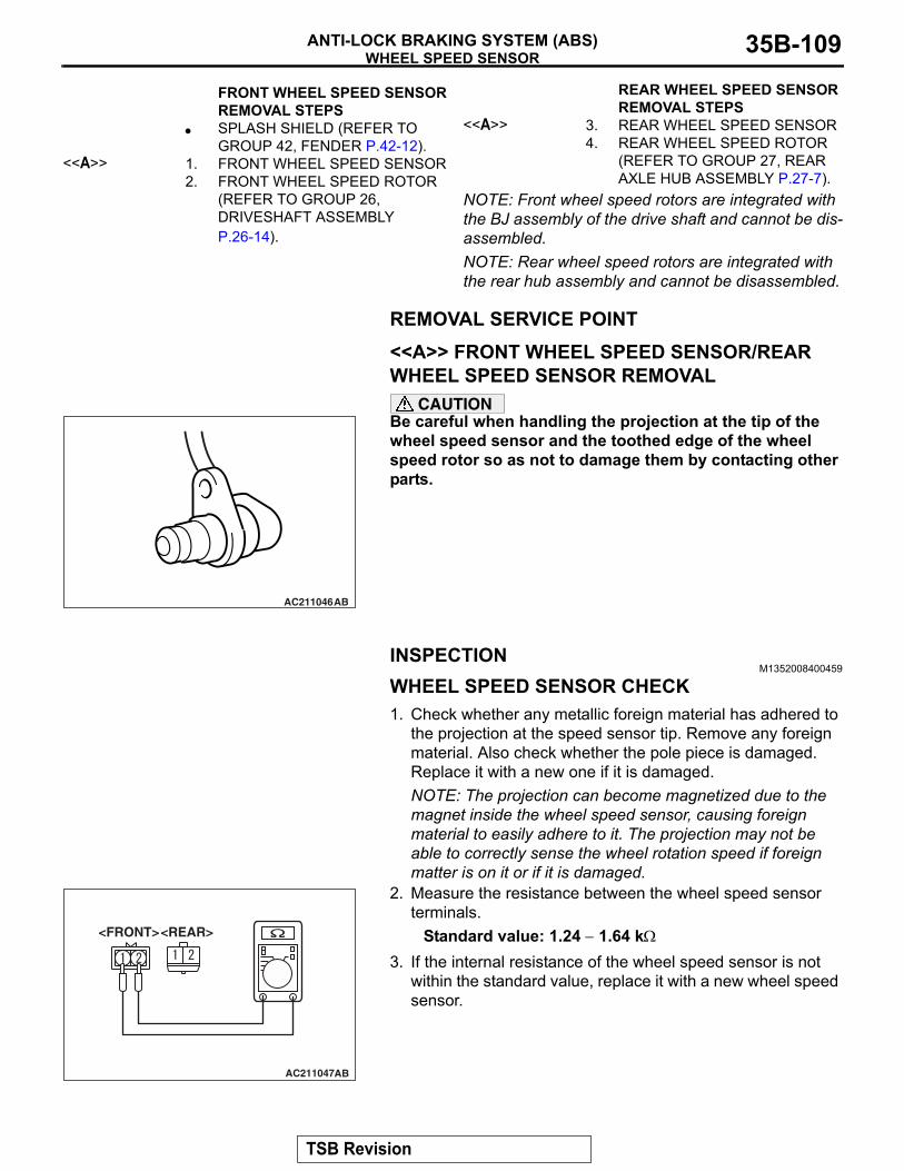
WHEEL SPEED SENSORANTI-LOCK BRAKING SYSTEM (ABS) 35B-109
NOTE: Front wheel speed rotors are integrated with the BJ assembly of the drive shaft and cannot be dis-assembled.NOTE: Rear wheel speed rotors are integrated with the rear hub assembly and cannot be disassembled.
REMOVAL SERVICE POINT.
<<A>> FRONT WHEEL SPEED SENSOR/REAR WHEEL SPEED SENSOR REMOVAL
CAUTIONBe careful when handling the projection at the tip of the wheel speed sensor and the toothed edge of the wheel speed rotor so as not to damage them by contacting other parts.
INSPECTIONM1352008400459
WHEEL SPEED SENSOR CHECK1. Check whether any metallic foreign material has adhered to
the projection at the speed sensor tip. Remove any foreign material. Also check whether the pole piece is damaged. Replace it with a new one if it is damaged.NOTE: The projection can become magnetized due to the magnet inside the wheel speed sensor, causing foreign material to easily adhere to it. The projection may not be able to correctly sense the wheel rotation speed if foreign matter is on it or if it is damaged.
2. Measure the resistance between the wheel speed sensor terminals.
Standard value: 1.24 − 1.64 kΩ
3. If the internal resistance of the wheel speed sensor is not within the standard value, replace it with a new wheel speed sensor.
FRONT WHEEL SPEED SENSOR REMOVAL STEPS
• SPLASH SHIELD (REFER TO GROUP 42, FENDER P.42-12).
<<A>> 1. FRONT WHEEL SPEED SENSOR2. FRONT WHEEL SPEED ROTOR
(REFER TO GROUP 26, DRIVESHAFT ASSEMBLY P.26-14).
REAR WHEEL SPEED SENSOR REMOVAL STEPS
<<A>> 3. REAR WHEEL SPEED SENSOR4. REAR WHEEL SPEED ROTOR
(REFER TO GROUP 27, REAR AXLE HUB ASSEMBLY P.27-7).
AC211046AB
AC211047AB
<REAR><FRONT>
TSB Revision
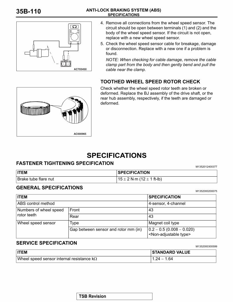
SPECIFICATIONSANTI-LOCK BRAKING SYSTEM (ABS)35B-110
4. Remove all connections from the wheel speed sensor. The circuit should be open between terminals (1) and (2) and the body of the wheel speed sensor. If the circuit is not open, replace with a new wheel speed sensor.
5. Check the wheel speed sensor cable for breakage, damage or disconnection. Replace with a new one if a problem is found.NOTE: When checking for cable damage, remove the cable clamp part from the body and then gently bend and pull the cable near the clamp.
TOOTHED WHEEL SPEED ROTOR CHECKCheck whether the wheel speed rotor teeth are broken or deformed. Replace the BJ assembly of the drive shaft, or the rear hub assembly, respectively, if the teeth are damaged or deformed.
SPECIFICATIONSFASTENER TIGHTENING SPECIFICATION
M1352012400377
GENERAL SPECIFICATIONSM1352000200075
SERVICE SPECIFICATIONM1352000300599
AC703450
1 2
AC000965
ITEM SPECIFICATIONBrake tube flare nut 15 ± 2 N⋅m (12 ± 1 ft-lb)
ITEM SPECIFICATIONABS control method 4-sensor, 4-channelNumbers of wheel speed rotor teeth
Front 43Rear 43
Wheel speed sensor Type Magnet coil typeGap between sensor and rotor mm (in) 0.2 − 0.5 (0.008 − 0.020)
<Non-adjustable type>
ITEM STANDARD VALUEWheel speed sensor internal resistance kΩ 1.24 − 1.64
TSB Revision