Embed Size (px)
Citation preview
HAMBAKER GROUP
Screw Pumps
www.hambakergroup.com
HAMBAKER GROUP
Established in the 19th Century, The Ham Baker Group is a market leading, global organisation dedicated to the design and manufacture of innovative products, for the water, waste water and process sectors.
Ham Baker’s name is synonymous with precision-engineered products and adding value to customer’s individual requirements. The group designs complete engineered solutions, with experts on hand across all sectors to cover customers individual process and flow needs.
The Ham Baker Group is unique amongst modern day suppliers in being able to offer product to all areas of water, waste water and process applications. The understanding of individual applications informs the design of complementary products and services resulting in the ability to be able to offer complete engineered solutions which deliver optimum performance.
A fully equipped, UK, in-house manufacturing facility complemented by state-of-the-art design facilities provides customers with bespoke engineered solutions, capable of operating to industry leading standards.
A dedicated research and development team, working in conjunction with world renowned universities delivers innovative solutions to process applications, providing significant infrastructure benefits to customers.
Significant investment in new processes, design facilities and CNC machinery complements the apprentice-trained workforce with skills in manufacture, procurement, project management, design and development and logistics to satisfy the most demanding customer requirements.
With manufacturing bases in the UK, China, Hong Kong, UAE and Australia we are able to offer engineered solutions worldwide.
02
03
04
Introduction 06
Transport, reception, handling and storage 07
Description of screw pump 09
Safety instructions 13
Installation 14
Start-up 17
Maintenance and control 18
Trouble shooting 19
Images from the existing plants 20
Services 22
05
Screw Pumps
06
IntroductionThe Ham Baker Group of companies has well over 125 years of experience supplying precision engineered products and services, by incorporating several SİSMAT products into our portfolio we are able to offer a complete water and wastewater treatment solution
It is obvious that using improperly chosen, poor-quality or unavailable equipment in a treatment plant will affect the efficiency of the plant directly and cause unnecessary power consumption, it may even cause the plant to be out of order. Most of its competitors are contracting companies whereas SISMAT (Ham Baker), particularly specialized in manufacturing equipment used in wastewater treatment plants, is the first company to have practiced wastewater treatment technologies as an industry with its manufacturing and environmental engineers who are experts at functions of equipment and proved their experience and knowledge with wastewater equipment plants working at their best at various locations in Turkey.
At its modern manufacturing plants in GOSB, SİSMAT (Ham Baker) provides direct service to the end-user as well as contracting companies, by manufacturing all the equipment used in each stage of the wastewater treatment process with its personnel consisting of over fifty people.
With 200 staff in the UK and over 70 experienced staff of 40 mechanical and environmental engineers, and 30 labours based in Turkey. With our wealth of experience and knowledge in our field, Ham Baker is fully capable to compete with well known foreign companies worldwide.
All equipment manufactured by SİSMAT (Ham Baker) has the Turkish Standart Insitute Quality Certificate. Furthermore, SİSMAT (Ham Baker) is the first to get TSE for prefabricated, ready to commission Package Treatment Units; thus, making it an obligation that every treatment equipment should have TSE certificate. Also, after a long time quality improvement effort, SİSMAT (Ham Baker) is the first Turkish company to have ISO9001 Quality Certificate for design, manufacturing and application of water and wastewater treatment plant equipment, package wastewater treatment units and dewatering equipment by the auditing on 2/06/1999 by a German originated international auditing company – RW TUW (Rheinisch Westfalischer TÜV).
Together with the wastewater treatment machines that are mostly manufactured and developed by our own engineering experience, surface aerators (GYROX) and special purpose mixers (RAPIMIX and RAPIFLOC) with LURGI license, beltfilterpresses and sludge conditioning units with KLEIN ex-license.
As it is observed in enclosed reference lists, Sismat (Ham Baker) has lots of equipment which has been working for more than 15 years in all big size wastewater treatment plants in Turkiye, like city wastewater treatment plants tendered by İller Bankası, plants of touristical region tendered by Ministry of Tourism and Kalkınma Bankası and some plants of industrial organized areas.
The number of countries where Ham Baker equipment is exported is continuously increasing. In many countries, other than the UK, such as Libya, Nigeria, Pakistan, Germany, Egypt, Abu Dhabi, Saudi Arabia, Slovenia, Romania, Singapore, Hong Kong, Australia Ham Baker equipment and package treatment units have been installed.
Duration of the manufacturing companies is very important for either contractors or end users.
From this point of view, supplying spare parts for all the equipment placed in our production range at any time with maintenance and repair service guarantee provided by Ham Baker after sale service department even years after delivery is a considerable advantage. We would like to remind you that for all plants, either smaller or bigger, guarantee periods are determined by agreements or by tender documents. After this limited period, maintenance obligation of the contractors is over. It should be considered that the wearable parts and parts required expert care are non-stop working machines. Therefore, the company you should keep your relation alive should be your equipment manufacturer and Ham Baker gives you this guarantee for lifetime.
07
Transport, reception, handling and storage
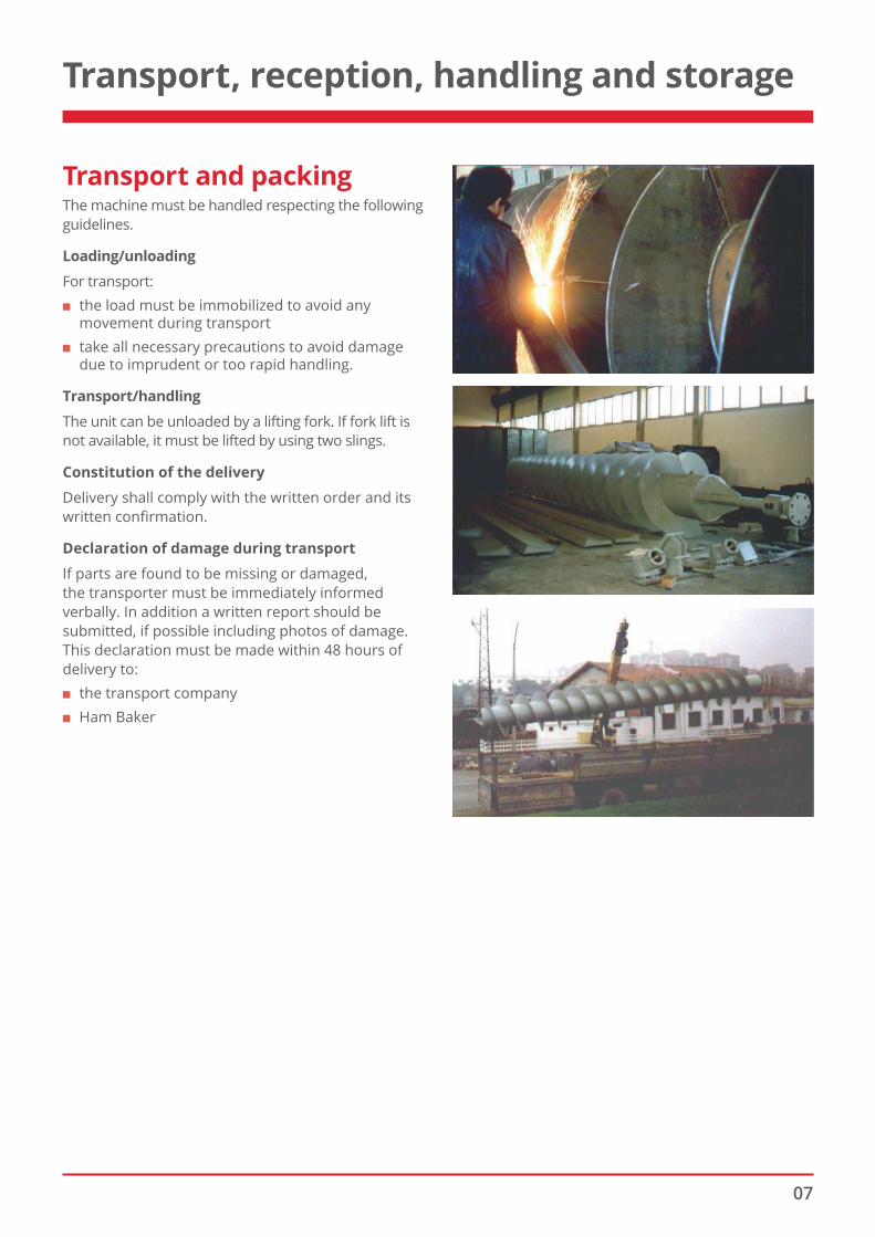
Transport and packingThe machine must be handled respecting the following guidelines.
Loading/unloading
For transport: ■ the load must be immobilized to avoid any
movement during transport ■ take all necessary precautions to avoid damage
due to imprudent or too rapid handling.
Transport/handling
The unit can be unloaded by a lifting fork. If fork lift is not available, it must be lifted by using two slings.
Constitution of the delivery
Delivery shall comply with the written order and its written confirmation.
Declaration of damage during transport
If parts are found to be missing or damaged, the transporter must be immediately informed verbally. In addition a written report should be submitted, if possible including photos of damage. This declaration must be made within 48 hours of delivery to:
■ the transport company ■ Ham Baker
08
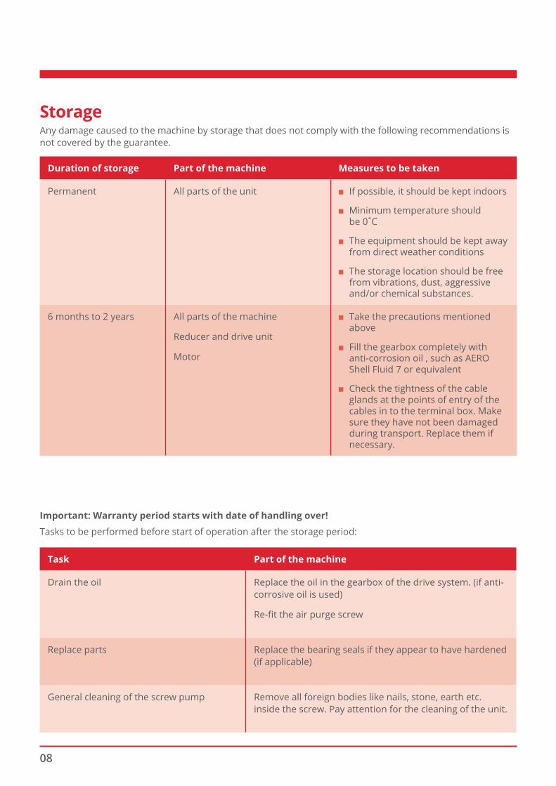
Duration of storage Part of the machine Measures to be taken
Permanent All parts of the unit ■ If possible, it should be kept indoors
■ Minimum temperature should be 0̊ C
■ The equipment should be kept away from direct weather conditions
■ The storage location should be free from vibrations, dust, aggressive and/or chemical substances.
6 months to 2 years All parts of the machine
Reducer and drive unit
Motor
■ Take the precautions mentioned above
■ Fill the gearbox completely with anti-corrosion oil , such as AERO Shell Fluid 7 or equivalent
■ Check the tightness of the cable glands at the points of entry of the cables in to the terminal box. Make sure they have not been damaged during transport. Replace them if necessary.
StorageAny damage caused to the machine by storage that does not comply with the following recommendations is not covered by the guarantee.
Important: Warranty period starts with date of handling over!
Tasks to be performed before start of operation after the storage period:
Task Part of the machine
Drain the oil Replace the oil in the gearbox of the drive system. (if anti-corrosive oil is used)
Re-fit the air purge screw
Replace parts Replace the bearing seals if they appear to have hardened (if applicable)
General cleaning of the screw pump Remove all foreign bodies like nails, stone, earth etc. inside the screw. Pay attention for the cleaning of the unit.
09
Description of the screw pump
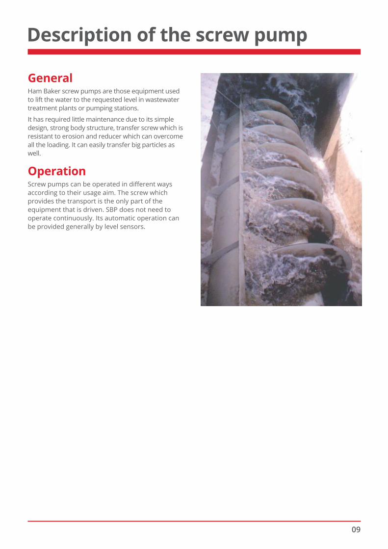
GeneralHam Baker screw pumps are those equipment used to lift the water to the requested level in wastewater treatment plants or pumping stations.
It has required little maintenance due to its simple design, strong body structure, transfer screw which is resistant to erosion and reducer which can overcome all the loading. It can easily transfer big particles as well.
OperationScrew pumps can be operated in different ways according to their usage aim. The screw which provides the transport is the only part of the equipment that is driven. SBP does not need to operate continuously. Its automatic operation can be provided generally by level sensors.
10
Detailed description
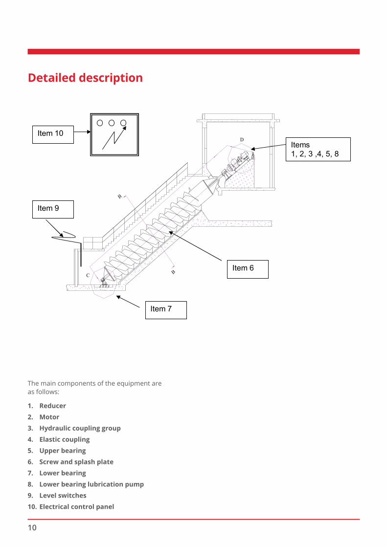
The main components of the equipment areas follows:
1. Reducer
2. Motor
3. Hydraulic coupling group
4. Elastic coupling
5. Upper bearing
6. Screw and splash plate
7. Lower bearing
8. Lower bearing lubrication pump
9. Level switches
10. Electrical control panel
Screw pumps can be operated in different ways according to their usage aim. The screw which
provides the transport is the only part of the equipment that is driven.
SBP does not need to operate continuously. Its automatic operation can be provided generally
by level sensors.
3.3. Detailed description
FIGURE-1
The main components of the equipment are as follows:
1. Reducer
2. Motor
3. Hydraulic coupling group
4. Elastic coupling
5. Upper bearing
Items 1, 2, 3 ,4, 5, 8
Item 9
Item 7
Item 6
Item 10
11
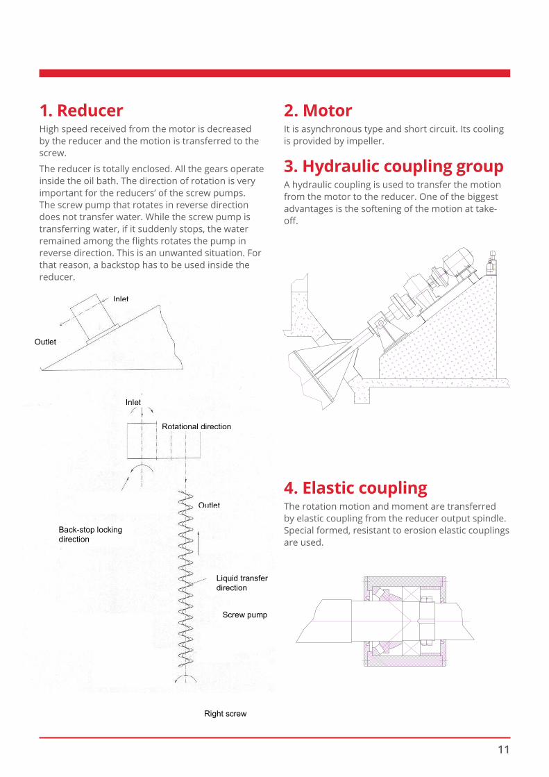
1. ReducerHigh speed received from the motor is decreased by the reducer and the motion is transferred to the screw.
The reducer is totally enclosed. All the gears operate inside the oil bath. The direction of rotation is very important for the reducers’ of the screw pumps. The screw pump that rotates in reverse direction does not transfer water. While the screw pump is transferring water, if it suddenly stops, the water remained among the fl ights rotates the pump in reverse direction. This is an unwanted situation. For that reason, a backstop has to be used inside the reducer.
2. MotorIt is asynchronous type and short circuit. Its cooling is provided by impeller.
3. Hydraulic coupling groupA hydraulic coupling is used to transfer the motion from the motor to the reducer. One of the biggest advantages is the softening of the motion at take-off .
4. Elastic couplingThe rotation motion and moment are transferred by elastic coupling from the reducer output spindle. Special formed, resistant to erosion elastic couplings are used.
FIGURE-2 (Backstop Direction)
Inlet
Outlet
Inlet
Rotational direction
Outlet
Back-stop locking direction
Liquid transfer direction
Screw pump
Right screw
2- Motor
it is asynchronous type and short circuit. Its cooling is provided by impeller.
3- Hydraulic coupling group
A hydraulic coupling is used to transfer the motion from the motor to the reducer. One of the
biggest advantages is the softening of the motion at take-off.
FIGURE-3
4- Elastic Coupling
The rotation motion and moment are transferred by elastic coupling from the reducer output
spindle. Special formed, resistant to erosion elastic couplings are used.
FIGURE-4
12
5. Upper bearingAll the axial loading occurred while the screw pump is transferring water is overcome by upper bearing. Meanwhile, some part of the radial loading shared with lower bearing are overcome by upper bearing.
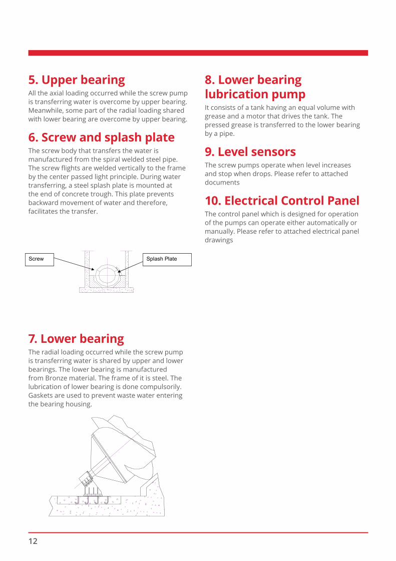
6. Screw and splash plateThe screw body that transfers the water is manufactured from the spiral welded steel pipe. The screw fl ights are welded vertically to the frame by the center passed light principle. During water transferring, a steel splash plate is mounted at the end of concrete trough. This plate prevents backward movement of water and therefore, facilitates the transfer.
7. Lower bearingThe radial loading occurred while the screw pump is transferring water is shared by upper and lower bearings. The lower bearing is manufactured from Bronze material. The frame of it is steel. The lubrication of lower bearing is done compulsorily. Gaskets are used to prevent waste water entering the bearing housing.
8. Lower bearinglubrication pumpIt consists of a tank having an equal volume with grease and a motor that drives the tank. The pressed grease is transferred to the lower bearing by a pipe.
9. Level sensorsThe screw pumps operate when level increases and stop when drops. Please refer to attached documents
10. Electrical Control PanelThe control panel which is designed for operation of the pumps can operate either automatically or manually. Please refer to attached electrical panel drawings
5- Upper Bearing
All the axial loading occurred while the screw pump is transferring water is overcome by upper
bearing. Meanwhile, some part of the radial loading shared with lower bearing are overcome by
upper bearing.
6- Screw and Splash Plate
FIGURE-5
The screw body that transfers the water is manufactured from the spiral welded steel pipe. The
screw flights are welded vertically to the frame by the center passed light principle. During water
transferring, a steel splash plate is mounted at the end of concrete trough. This plate prevents
backward movement of water and therefore, facilitates the transfer.
7- Lower Bearing
FIGURE-6
Splash Plate Screw
13
Safety instructions
Safety Recommendations ■ In order to use the machine without risk of injury
and to avoid unnecessary breakdowns, the basic safety instructions and recommendations must be understood.
■ The safety instructions and recommendations must be respected by all persons who work on the machine.
■ In addition, the general safety and accident prevention rules in force in the place of operation must also be respected.
Obligations of the owner of the machine
The owner of the machine must make sure that all persons who need to work on the machine:
■ are fully aware of the basic safety and accident prevention instructions and that they have been trained to use the machine,
■ in addition, he must also check at regular intervals that the safety rules are being properly respected.
Obligations of the personnel
Before working on the machine, all persons must commit themselves to;
■ respecting the basic safety and accident prevention instructions.
■ read the “safety” section and the warnings given in this manual.
Risks during work on the machine
The machine is designed to respect normal safety rules. Nevertheless, the machine presents a risk of death or injury for the operator. In addition, improper operation can lead to damage of the machine or connected systems. The machine must be used:
■ only for the purpose for which it was designed, ■ only when its operational safety is assured,
Any defect that might affect the machine’s safety must be repaired immediately.
Utilisation for the intended purpose
The machine is designed only for the transportation of wastewater indicated in the contract. It must not be used for any other application. Ham Baker declines all responsibility for damage resulting from inappropriate use of the machine.
Correct utilisation of the machine also implies: ■ respect of all the recommendations in this
manual, ■ regular execution of inspection and maintenance
tasks.
The choice of materials used in the construction of the machine was guided by our knowledge and experience and information provided by the customer.
Guarantee and responsibility
The manufacturer’s General Conditions of Sales are applicable.
Any claim under the terms of the guarantee concerning the responsibility for human injury or material damage will not be accepted if such injury or damage is due to one or more of the following:
■ the usage of the machine for a purpose other than that for which it was designed,
■ incorrect installation, commissioning, operation or maintenance of the machine,
■ operation of the machine when individual protection equipment is defective, or when any safety or protection equipment is not correctly installed or operational,
■ modification of the machine without the prior written consent of the manufacturer.
■ modification of the drive unit (power and speed) without the prior written consent of the manufacturer,
■ failure to monitor wearing parts of the machine, ■ repairs not carried out according to normal
professional standards, ■ in case the foreign particles enter the machine.
We kindly remind you that for the parts that we don’t manufacture, such as, drive unit, etc.., guarantee conditions of its manufacturer will be valid.
Organisational Measures ■ The necessary individual protection equipment
shall be provided by the customer. ■ All protection equipment must be inspected
regularly.
14
Safety equipment ■ All safety equipment must be correctly installed
and fully operational before the machine is started.
■ Safety equipment may be removed from the machine only after is has been stopped and locked out to prevent accidental starting.
■ After lifting individual parts, all safety equipment must be correctly re-installed before the machine is started.
Informal safety measures ■ This manual must remain permanently available
near the location of the machine. ■ In addition to the recommendations given
in this manual, all local accident prevention and environmental protection rules must be respected.
■ All posted information relating to the machine, hazards and safety must be perfectly legible.
Staff training ■ Only qualified, fully trained persons must be
allowed to operate the machine. ■ Clearly define the responsibilities of the personal
responsible for installation, commissioning, operation and maintenance of the machine.
■ Personnel being trained in the use of the machine must work under the supervision of a fully trained operator.
Operation of the machine ■ If the control panel is supplied by Ham Baker,
never modify its logic without the prior written consent of Ham Baker
■ Only persons who have been adequately trained may change the controls.
Safety measures during normal operation ■ The machine must not be started unless all safety
equipment is fully operational. ■ Before starting the machine, to avoid any risk of
injury check that no person is near it.
Dangers of electrical energy ■ All work on electrical equipment must be carried
out by a qualified electrician. ■ Check all the electrical equipment regularly, in
particular the connections. Replace any cable that is even slightly carbonised.
■ The control cabinet must be kept shut. An authorised person should open and operate it.
Particularly hazardous sections of the machine
■ Screw: Risk of crushing of hands between screw.
■ When working on the machine the motor power supply must be switched off and locked out to prevent any accident.
■ Remember that the risks are greater when safety equipment has been removed.
Maintenance and trouble-shooting
Before carrying out any inspection, maintenance or repairs make sure the machine and all others parts of the installation, such as the electricity, compressed air and water supplies, are disconnected upstream and downstream of the machine, and lock them out to avoid accidental connection:
• switch off and lock out the main electrical switch,
• cut off the water and compressed air supplies,
• put warning notices at all cut-off points to prevent accidental starting.
■ Carry out the adjustment, maintenance and inspection tasks at the recommended intervals.
■ Inform the operators before starting any maintenance work.
■ Systematically check the adjustment of bolts that become loose.
■ Once an intervention is finished, check the operation of safety systems.
■ Any part that is not in perfect condition must be replaced immediately.
■ Use only manufacturer’s original spare parts. The manufacturer cannot guarantee that partsmsupplied from other sources are designed and made to be sufficiently strong and able to assure an adequate level of safety.
15
Modifications of the machine
■ The machine must not be modified or transformed, and any part must not be added, without the prior written consent of the manufacturer.
■ It is particularly important to consult the manufacturer before carrying out any transformation.
Cleaning the machine ■ Avoid that pressured water is not directed to
electrical switches, motors, valves, bearings or control cabinets.
■ Remove all remaining of products and substances used, notably:
• after work on lubrication systems and equipment
• after cleaning operations using detergents
• after maintenance work
INDUSTRIAL PROPERTY RIGHTS
This manual remains the property of:
Ham Baker Renewables Ltd part of the Ham Baker Group of Companies Garner Street Business Park Garner Street Etruria, Stoke on Trent Staffordshire ST4 7BH United Kingdom
t: +44 (0) 1782 202300 e: [email protected]
This manual is intended for use by the personnel in charge of
■ installation, ■ maintenance, ■ surveillance and operation.
Its content must not be reproduced, divulged or otherwise distributed, even in part. Non-respect of this confidentiality clause may result in legal action being taken.
16
Installation
Ham Baker screw pumps were dispatched in a form that is ready for assembling after final controls at the factory.
Check the ground on which the screw pump will operate. It should be clean and leveled correctly. If it is not at balance, adjust and bring the ground to balance.
The following steps will be followed during the assembling of the equipment.
1. Check the suitability of all the civil construction to plans
2. Bring the lower bearing group to its place. The lower bearing parts have to be ready to pass inside the spindle or have already been passed to it.
3. Upper Bearing Group Assembly: this bearing is ready and has already passed to the spindle. So it is planned to deal only with the field assembly.
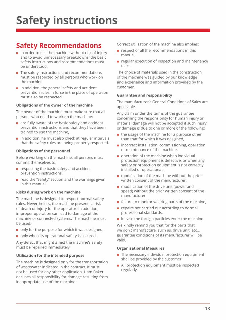
4. Screw assembly: A screw pump whose upper and lower bearings are ready is landed to the assembling field by a crane. The angle is measured. The empty space between raw concrete and pump has to be 5-10 cm for finish concrete. Side measurement controls are made inside the channel. The measures have to be equal.
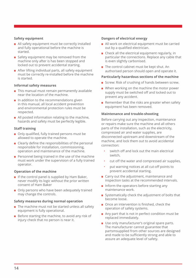
5. Drive unit assembly: all the adjustments are made carefully.
6. Welding of anchorage plates: after final assembly controls of the plates, that will be welded under the bearings and drive units, are finished they are welded.
7. Pouring the screw concrete: Flights have to be operated inside a concrete channel in order to transfer water. A 3 mm steel plate is wrapped around the flights and finish concrete is poured between this plate and concrete. This procedure is repeated sector by sector. The quality of the finish concrete has to be 300 doz.
8. Splash plate assembly: the splash plate is mounted after concrete processes.
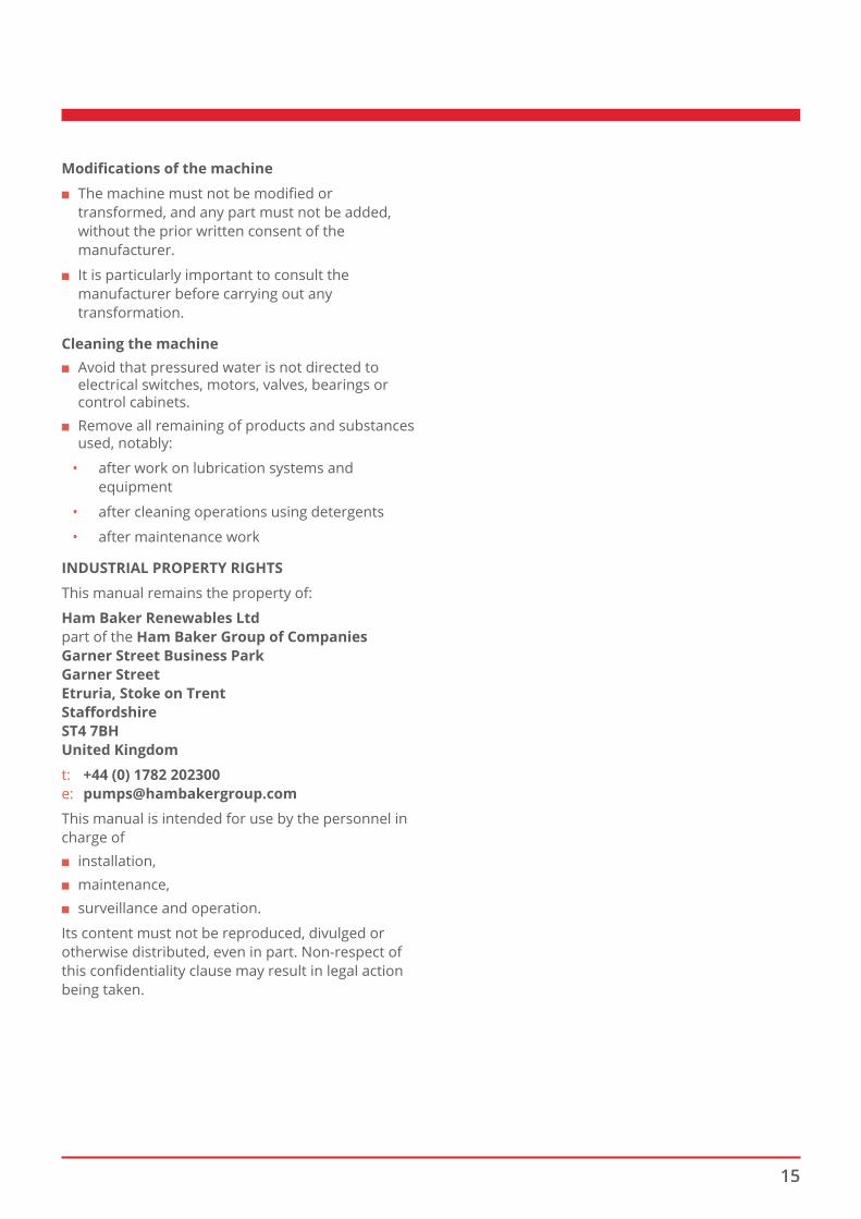
9. Lower bearing lubrication pump assembly: This pump will be inside the drive unit chamber.
10. The pressed grease will be transferred to the lower bearing by a steel pipe. This pipe will be covered by another pipe to prevent the damaging of the grease pipe.
11. Level sensor assembly
17
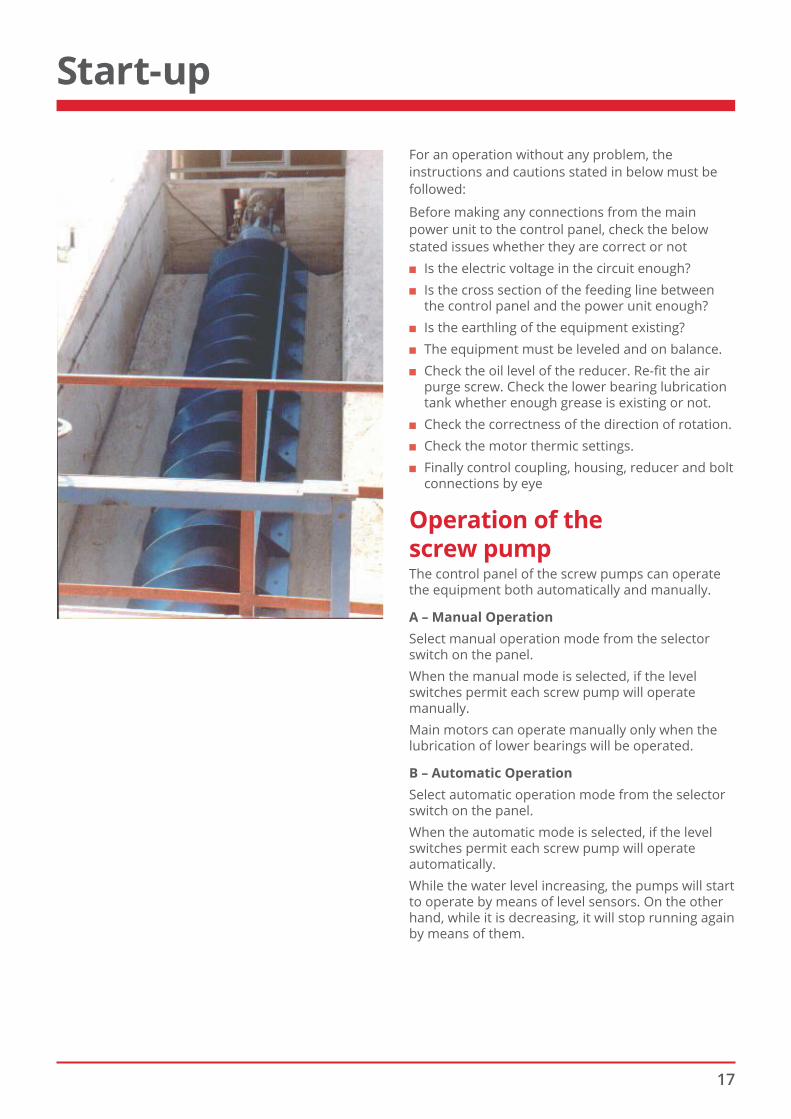
For an operation without any problem, the instructions and cautions stated in below must be followed:
Before making any connections from the main power unit to the control panel, check the below stated issues whether they are correct or not
■ Is the electric voltage in the circuit enough? ■ Is the cross section of the feeding line between
the control panel and the power unit enough? ■ Is the earthling of the equipment existing? ■ The equipment must be leveled and on balance. ■ Check the oil level of the reducer. Re-fit the air
purge screw. Check the lower bearing lubrication tank whether enough grease is existing or not.
■ Check the correctness of the direction of rotation. ■ Check the motor thermic settings. ■ Finally control coupling, housing, reducer and bolt
connections by eye
Operation of the screw pumpThe control panel of the screw pumps can operate the equipment both automatically and manually.
A – Manual OperationSelect manual operation mode from the selector switch on the panel.When the manual mode is selected, if the level switches permit each screw pump will operate manually.Main motors can operate manually only when the lubrication of lower bearings will be operated.
B – Automatic OperationSelect automatic operation mode from the selector switch on the panel.When the automatic mode is selected, if the level switches permit each screw pump will operate automatically.While the water level increasing, the pumps will start to operate by means of level sensors. On the other hand, while it is decreasing, it will stop running again by means of them.
Start-up
18
Maintenance and control
LubricationReducer
Lubrication of reducer will be controlled on the level stopper. After the first 500 working hours, oil will be changed. Then oil will be changed once in 5000 hours.
Lower Bearing Lubrication pump
This pump will never operate without grease. While the equipment is running, if the oil levels do not drop, make sure that there is a problem that prevents the pressing of oil. This pump lubricates the bronze housing that is mounted in the steel construction which is under water.
Upper bearing
This bearing has to be lubricated once every 750 hours by means of nipples on it.
Grease type
Lubricate lower and upper bearings by Lithium origin greases. These greases are suitable for temperature values between –40 and +120 degrees. Do not use different grease types and manufacturers.
Some grease names are given below for your information.
BP ESSO MOBIL OIL SHELL
Lithium origin
BP Energrease
Beacon3 Mobilux 2Shell
Alvania
GreaseLS2
Grease R2
LS3
Maintenance ■ Observe reducer inlet and outlet seals daily, take
care whether there is an oil escape or not. ■ If the electricity controls are made, check
correctness of the direction of rotation of reducer and lower bearing lubrication pumps.
■ Check all the bolts and nuts in each periodical control.
■ Check the rubbers of elastic coupling weekly by eyes. Change the wearing ones.
■ Control the motor bearings in every 20.000 hours. ■ Control paintings every year. ■ Prevent the interference of the people except the
operator.
ATTENTIONHam Baker has no responsibility for the problems that would arise due to the unapplication of the below issues.
■ Nobody except the operator can use the screw pumps.
■ If somebody will enter the chamber in which screw pumps is operating, all the electrical circuits must be closed from the main switch and fuses. A sentry must be placed at these points.
■ Reducer will never be operated without grease. ■ The lower bearing lubrication pump will never
be operated without grease. ■ Do not change the level switch settings. ■ Do not interfere to the selector switches while
motors are running. ■ In case that the alarm horn rings, find the
related failure lamp on the panel and eliminate the problem.
■ If the covers of the rotating parts are removed during maintenance, they must be refit to their places again.
Regular maintenance will assure a good performance and long life for the screw pump. For this reason, please pay attention the following instructions.
19
Operating troublesHam Baker screw pumps require little maintenance due to their structures. The failure risks of these equipment are very low. In case of any failure first of all the type of the failure must be defined. Those failure types are;
■ Electrical failures ■ Mechanical failures
Electrical failures: are those resulting from cable connections, fuses, thermic, contactor etc.
An electrical specialist has to examine those parts respectively.
Mechanical failures: In cases such as an unexpected material enters the screw, the system can fail. Other failures may be at motor and reducer group. Motor failure, bearing failure and gear failure may be defined as mechanical failures.
Below table would help you in finding failures
Trouble Causes Tasks
SBP does not operate
Electrical failure
Cable and connection control.
Control of equipment such as fuse, thermic, contactor, relay etc.
SBP does not operate
Compression
Bearing wrapping around
There may be big-sized particles inside the screw and feeding trough.
Cleaning has to be made.
Control lower and upper bearing.
Control lower bearing pumps and oil level
SBP does not operate
Motor failure Control the motor
SBP does not operate
Bearing failure
Gear failure
Change the bearing
Change the gear
Noise in reducer
Humming noise
Noise in shape of hammer
stroke
Bearing may be broken; change it
Gear may be broken; change it
Leaking at reducer
Seal failed Change the seal
Trouble shooting
20
Images from existing plants
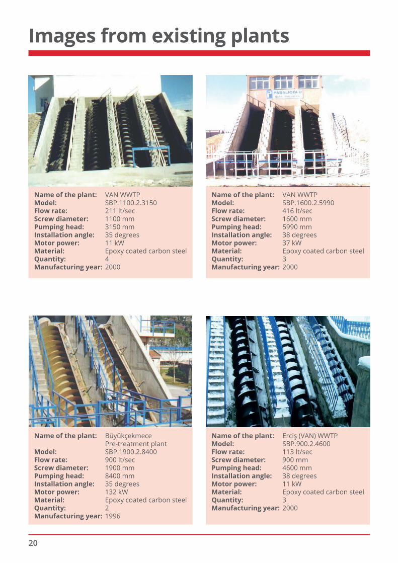
Name of the plant: VAN WWTP Model: SBP.1100.2.3150 Flow rate: 211 lt/sec Screw diameter: 1100 mm Pumping head: 3150 mm Installation angle: 35 degrees Motor power: 11 kW Material: Epoxy coated carbon steel Quantity: 4 Manufacturing year: 2000
Name of the plant: VAN WWTP Model: SBP.1600.2.5990 Flow rate: 416 lt/sec Screw diameter: 1600 mm Pumping head: 5990 mm Installation angle: 38 degrees Motor power: 37 kW Material: Epoxy coated carbon steel Quantity: 3 Manufacturing year: 2000
Name of the plant: Büyükçekmece Pre-treatment plant Model: SBP.1900.2.8400 Flow rate: 900 lt/sec Screw diameter: 1900 mm Pumping head: 8400 mm Installation angle: 35 degrees Motor power: 132 kW Material: Epoxy coated carbon steel Quantity: 2 Manufacturing year: 1996
Name of the plant: Erciş (VAN) WWTP Model: SBP.900.2.4600 Flow rate: 113 lt/sec Screw diameter: 900 mm Pumping head: 4600 mm Installation angle: 38 degrees Motor power: 11 kW Material: Epoxy coated carbon steel Quantity: 3 Manufacturing year: 2000
21
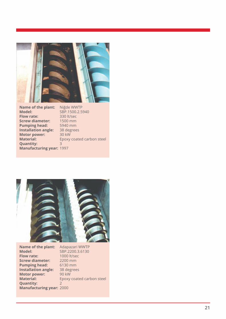
Name of the plant: Niğde WWTP Model: SBP.1500.2.5940 Flow rate: 330 lt/sec Screw diameter: 1500 mm Pumping head: 5940 mm Installation angle: 38 degrees Motor power: 30 kW Material: Epoxy coated carbon steel Quantity: 3 Manufacturing year: 1997
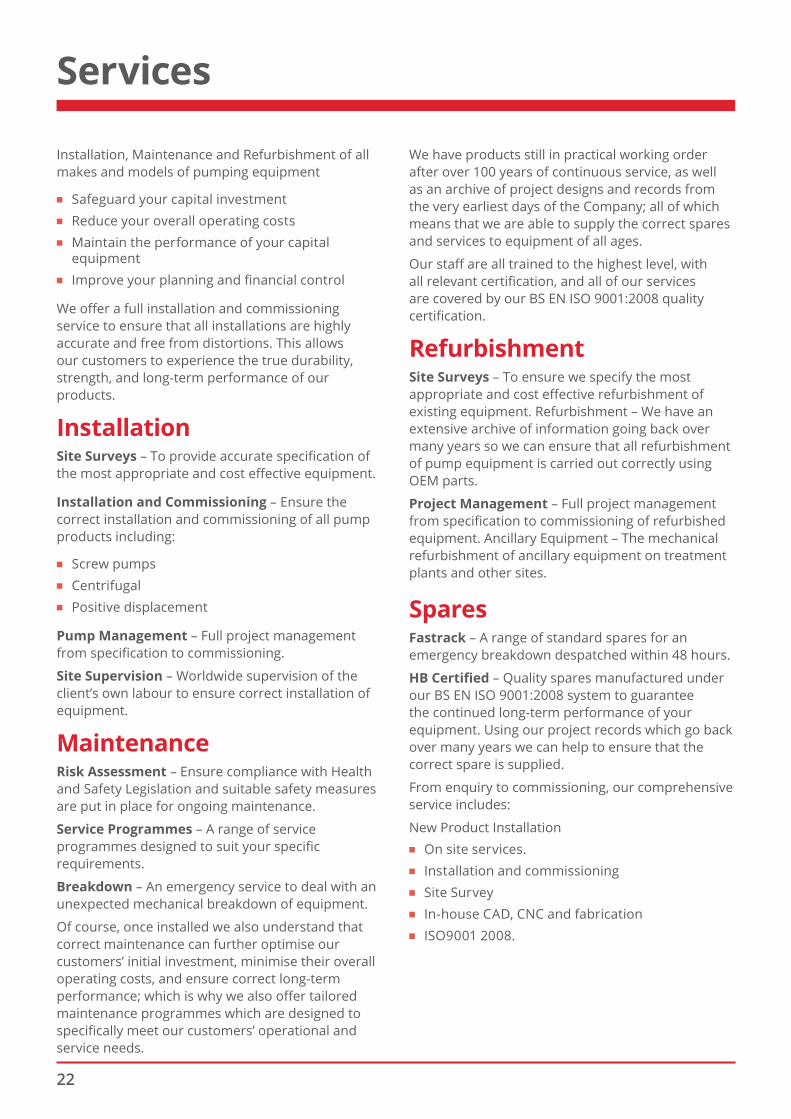
Name of the plant: Adapazari WWTP Model: SBP.2200.3.6130 Flow rate: 1000 lt/sec Screw diameter: 2200 mm Pumping head: 6130 mm Installation angle: 38 degrees Motor power: 90 kW Material: Epoxy coated carbon steel Quantity: 2 Manufacturing year: 2000
22
Installation, Maintenance and Refurbishment of all makes and models of pumping equipment
■ Safeguard your capital investment ■ Reduce your overall operating costs ■ Maintain the performance of your capital
equipment ■ Improve your planning and financial control
We offer a full installation and commissioning service to ensure that all installations are highly accurate and free from distortions. This allows our customers to experience the true durability, strength, and long-term performance of our products.
InstallationSite Surveys – To provide accurate specification of the most appropriate and cost effective equipment.
Installation and Commissioning – Ensure the correct installation and commissioning of all pump products including:
■ Screw pumps ■ Centrifugal ■ Positive displacement
Pump Management – Full project management from specification to commissioning.
Site Supervision – Worldwide supervision of the client’s own labour to ensure correct installation of equipment.
MaintenanceRisk Assessment – Ensure compliance with Health and Safety Legislation and suitable safety measures are put in place for ongoing maintenance.
Service Programmes – A range of service programmes designed to suit your specific requirements.
Breakdown – An emergency service to deal with an unexpected mechanical breakdown of equipment.
Of course, once installed we also understand that correct maintenance can further optimise our customers’ initial investment, minimise their overall operating costs, and ensure correct long-term performance; which is why we also offer tailored maintenance programmes which are designed to specifically meet our customers’ operational and service needs.
We have products still in practical working order after over 100 years of continuous service, as well as an archive of project designs and records from the very earliest days of the Company; all of which means that we are able to supply the correct spares and services to equipment of all ages.
Our staff are all trained to the highest level, with all relevant certification, and all of our services are covered by our BS EN ISO 9001:2008 quality certification.
RefurbishmentSite Surveys – To ensure we specify the most appropriate and cost effective refurbishment of existing equipment. Refurbishment – We have an extensive archive of information going back over many years so we can ensure that all refurbishment of pump equipment is carried out correctly using OEM parts.
Project Management – Full project management from specification to commissioning of refurbished equipment. Ancillary Equipment – The mechanical refurbishment of ancillary equipment on treatment plants and other sites.
SparesFastrack – A range of standard spares for an emergency breakdown despatched within 48 hours.
HB Certified – Quality spares manufactured under our BS EN ISO 9001:2008 system to guarantee the continued long-term performance of your equipment. Using our project records which go back over many years we can help to ensure that the correct spare is supplied.
From enquiry to commissioning, our comprehensive service includes:
New Product Installation ■ On site services. ■ Installation and commissioning ■ Site Survey ■ In-house CAD, CNC and fabrication ■ ISO9001 2008.
Services
HAMBAKER GROUP
ISO 14064-1
certifi edorganisation
A & J Water TreatmentAdams Hydraulics
AutodamCoes GRP
FSE InstallationsHam Baker Adams
Ham Baker Control SystemsHam Baker Pumps
Ham Baker RenewablesHi-Bar
Industrial PenstocksIndustrial Pipelines
Industrial ValvesIntovalve
IVL Flow ControlKempster Valves & Engineering
Three Star Environmental
The Ham Baker Group companies
Ham Baker Group is a trading name of F. J. Holdings LtdCompany Registration No. 4878424
Garner Street Business ParkGarner Street
Etruria Stoke-on-Trent
ST4 7BH
t: +44 (0) 1782 202300f: +44 (0) 1782 203649
www.hambakergroup.com