Embed Size (px)
Citation preview
GRUNDFOS ALLDOS DATA BOOKLET
DDI
DIGITAL DOSING™
2
Contents
Features and benefitsDDI 209 3DDI 222 4
Performance rangeDDI 5DDI 209 with Plus3 6
IdentificationType key 7
FunctionsControl variants 8Options 8Capacity control 9Control panel 9Menu 10Operating modes 12Other options 12
ConstructionGeneral description 15DDI 209 with manual deaeration valve 15DDI 222 16DDI 209 with Plus3 system 17Functional principle of the Plus3 system 18Spring-loaded valves 18DDI with diaphragm leak detection 19
Technical dataDimensions 20Performance data 24Suction lift 25Permissible viscosity 26Inlet and discharge pressures 27Permissible temperature range of thepumped medium 27Weights 28Electrical data 28Additional technical data 28Electronic functions 29Operating modes, additional data 30
Pump selectionDDI selection (0.4 to 150 l/h) 32
Pumped mediaList of pumped media 35
Further product documentationWebCAPS 36WinCAPS 37
DDIFeatures and benefits
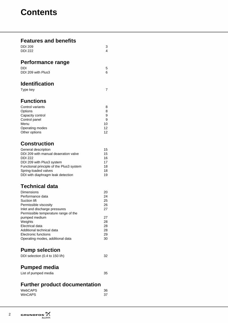
DDI 209DIGITAL DOSING
up to 20 l/h
Fig. 1 DDI 209
The difference is digitalThe Grundfos Alldos DDI range was created because accurate dosing demands precision. But it need not be hard work. These compact units combine perfect preci-sion with a user interface that lets you set the dosing rate you want directly on the unit – without spending time on complicated calculations beforehand. Available materials include PVC, PVDF, polypropylene and stain-less steel 1.4401.
The DDI AR: Taking diaphragm dosing pumps to the next levelThe DDI AR series is the backbone of the overall DDI range. Its innovative drive technology combines a pow-erful stepper motor with integrated contact signal con-trol to bring you smoother, more accurate dosing. The user interface gives you a full range of options for cus-tomising the dosing process.
Does the hard work for youThe DDI range eliminates the need for extensive calcu-lation work associated with other dosing equipment. You will not need to work out how many strokes per minute are necessary to give you the desired dosing rate – simply enter the figure you want in the user inter-face, and the DDI does the work for you.
Smooth dosing through variable speedThe Grundfos Alldos DDI never rushes things. It has an ingenious stepper motor that extends the discharge phase throughout the full period between suction phases. In other words, it automatically adjusts the dos-ing speed to provide the right amount of additive at all times. No jerky movements here – just smooth, even dosing.
Full stroke length at all timesThe Grundfos Alldos DDI uses a full stroke length every time, thereby eliminating potential disruptive factors such as gas build-up. Rather than adjusting the stroke length by shortening it to suit dosing demand, the Grundfos Alldos DDI carefully times each full stroke to ensure even concentrations of additive in your media.
Turndown ratio 1:100The DDI range is designed to give you superior flexibil-ity and accuracy with as few product variants as possi-ble. That is why you can adjust dosing rates within a 1:100 scale without any loss of dosing accuracy: the DDI series can dose additive in quantities down to 0.025 l/h with perfect precision – and evidence of this precision can be provided at any time while the pump is running.
Flow monitor checks for malfunctions - optionalThe unique flow monitor detects any dosing errors on both the suction and pressure sides and immediately emits an error message if anything is wrong. It can also check for excess pressure: Just enter the maximum counter pressure allowed (in bar) and leave everything to the DDI. If the pressure is exceeded, the pump stops.
Fieldbus communication availableThe DDI is also available with a PROFIBUS DP inter-face.
Switch-mode power supplyDDI pumps can be used worldwide within the range of 100-240 VAC, 50/60 Hz.
Reliable dosing of viscous mediaWhen you wish to dose viscous media, many conven-tional dosing pumps struggle to maintain reliability. By contrast, the DDI series has a special "slow mode" function which decelerates the suction stroke. This maintains reliable dosing.
Examples of applications• industrial and municipal water treatment• industrial cleaning• polymer feed• paper production/paper finishing• optical technology and chip production• chemical industry• Cleaning-In-Place (CIP) and disinfection • galvanic and surface treatment• air conditioning/water treatment in cooling towers• reverse-osmosis systems• semi-conductor industry.
GrA
3479
3
4
Features and benefits DDI
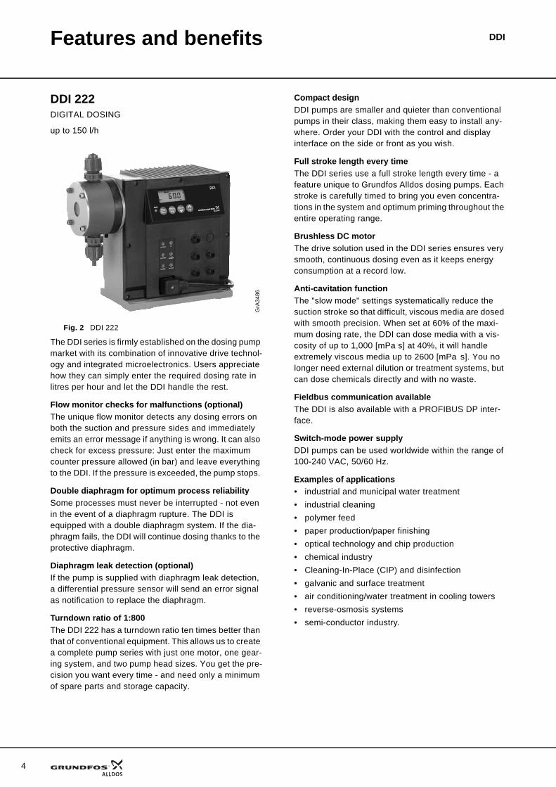
DDI 222DIGITAL DOSING
up to 150 l/h
Fig. 2 DDI 222
The DDI series is firmly established on the dosing pump market with its combination of innovative drive technol-ogy and integrated microelectronics. Users appreciate how they can simply enter the required dosing rate in litres per hour and let the DDI handle the rest.
Flow monitor checks for malfunctions (optional)The unique flow monitor detects any dosing errors on both the suction and pressure sides and immediately emits an error message if anything is wrong. It can also check for excess pressure: Just enter the maximum counter pressure allowed (in bar) and leave everything to the DDI. If the pressure is exceeded, the pump stops.
Double diaphragm for optimum process reliabilitySome processes must never be interrupted - not even in the event of a diaphragm rupture. The DDI is equipped with a double diaphragm system. If the dia-phragm fails, the DDI will continue dosing thanks to the protective diaphragm.
Diaphragm leak detection (optional)If the pump is supplied with diaphragm leak detection, a differential pressure sensor will send an error signal as notification to replace the diaphragm.
Turndown ratio of 1:800The DDI 222 has a turndown ratio ten times better than that of conventional equipment. This allows us to create a complete pump series with just one motor, one gear-ing system, and two pump head sizes. You get the pre-cision you want every time - and need only a minimum of spare parts and storage capacity.
Compact designDDI pumps are smaller and quieter than conventional pumps in their class, making them easy to install any-where. Order your DDI with the control and display interface on the side or front as you wish.
Full stroke length every timeThe DDI series use a full stroke length every time - a feature unique to Grundfos Alldos dosing pumps. Each stroke is carefully timed to bring you even concentra-tions in the system and optimum priming throughout the entire operating range.
Brushless DC motorThe drive solution used in the DDI series ensures very smooth, continuous dosing even as it keeps energy consumption at a record low.
Anti-cavitation functionThe "slow mode" settings systematically reduce the suction stroke so that difficult, viscous media are dosed with smooth precision. When set at 60% of the maxi-mum dosing rate, the DDI can dose media with a vis-cosity of up to 1,000 [mPa s] at 40%, it will handle extremely viscous media up to 2600 [mPa s]. You no longer need external dilution or treatment systems, but can dose chemicals directly and with no waste.
Fieldbus communication availableThe DDI is also available with a PROFIBUS DP inter-face.
Switch-mode power supplyDDI pumps can be used worldwide within the range of 100-240 VAC, 50/60 Hz.
Examples of applications• industrial and municipal water treatment• industrial cleaning• polymer feed• paper production/paper finishing• optical technology and chip production• chemical industry• Cleaning-In-Place (CIP) and disinfection • galvanic and surface treatment• air conditioning/water treatment in cooling towers• reverse-osmosis systems• semi-conductor industry.
GrA
3486
DDIPerformance range
DDI
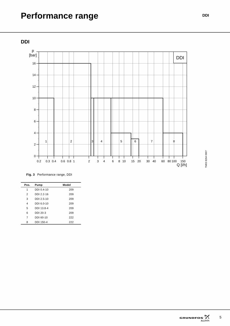
Fig. 3 Performance range, DDI
TM03
826
4 09
07
00.2 0.3 0.4 0.6 0.8 1 2 3 4 6 8 10 15 20 30 40 60 80 100 150Q [l/h]
0
2
4
6
8
10
12
14
16
p[bar]
DDI
1 2 543 6 7 8
Pos. Pump Model1 DDI 0.4-10 209
2 DDI 2.2-16 209
3 DDI 2.5-10 209
4 DDI 6.0-10 209
5 DDI 13.8-4 209
6 DDI 20-3 209
7 DDI 60-10 222
8 DDI 150-4 222
5
6
Performance range DDI
DDI 209 with Plus3
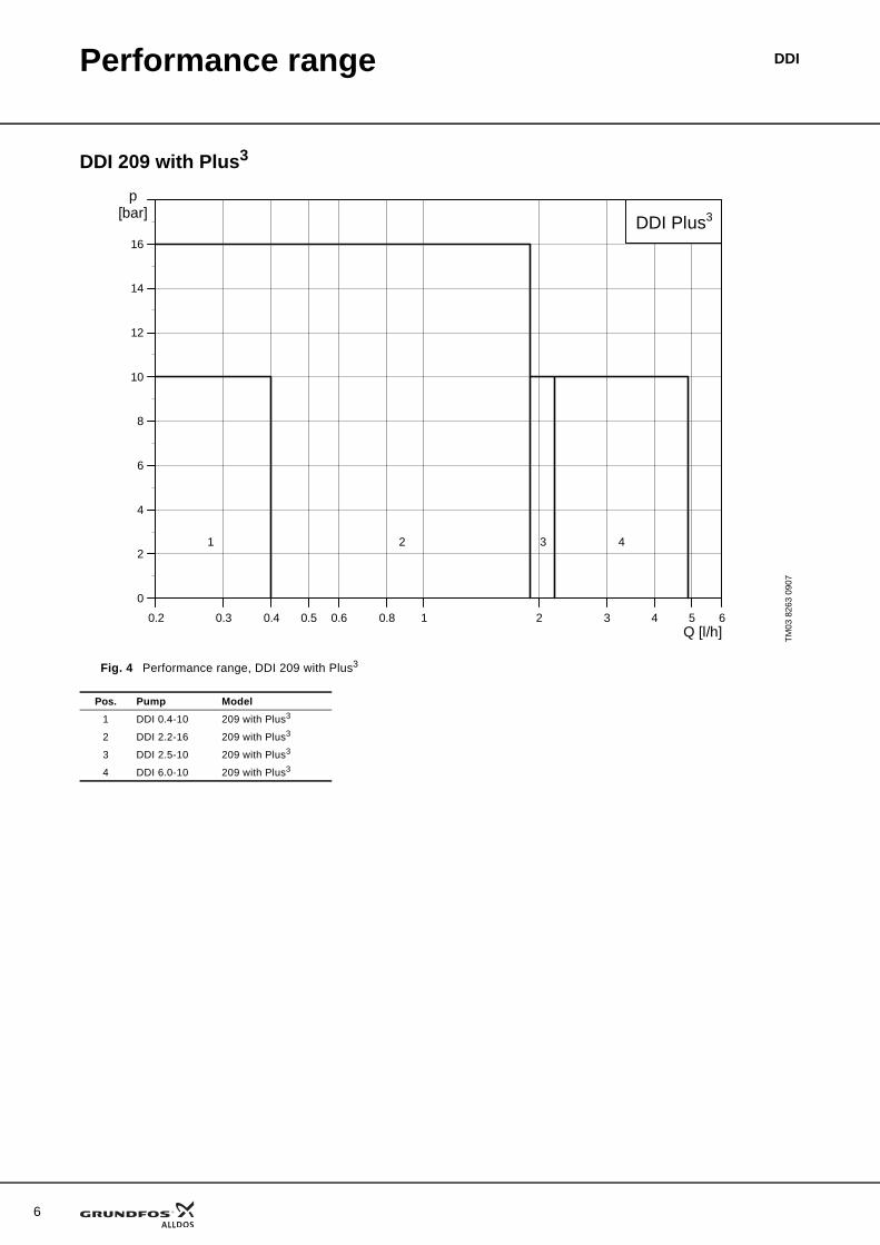
Fig. 4 Performance range, DDI 209 with Plus3
TM03
826
3 09
07
00.2 0.3 0.4 0.5 0.6 0.8 1 2 3 4 5 6Q [l/h]
0
2
4
6
8
10
12
14
16
p[bar]
DDI Plus3
1 2 43
Pos. Pump Model1 DDI 0.4-10 209 with Plus3
2 DDI 2.2-16 209 with Plus3
3 DDI 2.5-10 209 with Plus3
4 DDI 6.0-10 209 with Plus3
7
DDIIdentification
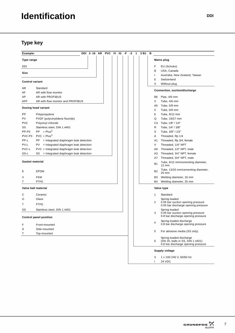
Type key
Example: DDI 2- 16 AR PVC /V /G -F -3 1 3 B1 B
Type range Mains plug
DDI F EU (Schuko)
SizeB USA, CanadaI Australia, New Zealand, Taiwan
Control variantE SwitzerlandX Without plug
AR StandardConnection, suction/discharge
AF AR with flow monitorAP AR with PROFIBUS B6 Pipe, 4/6 mmAPF AR with flow monitor and PROFIBUS 3 Tube, 4/6 mm
Dosing head variantA5 Tube, 5/8 mm4 Tube, 6/9 mm
PP Polypropylene 6 Tube, 9/12 mmPV PVDF (polyvinylidene fluoride) Q Tube, 19/27 mmPVC Polyvinyl chloride C4 Tube, 1/8" / 1/4"SS Stainless steel, DIN 1.4401 R Tube, 1/4" / 3/8"PP-P3 PP + Plus3 S Tube, 3/8" / 1/2"PVC-P3 PVC + Plus3 A Threaded, Rp 1/4PP-L PP + Integrated diaphragm leak detection A1 Threaded, Rp 3/4, femalePV-L PV + Integrated diaphragm leak detection V Threaded, 1/4" NPTPVC-L PVC + Integrated diaphragm leak detection A9 Threaded, 1/2" NPT, maleSS-L SS + Integrated diaphragm leak detection A3 Threaded, 3/4" NPT, female
Gasket materialA7 Threaded, 3/4" NPT, male
B1 Tube, 6/12 mm/cementing diameter, 12 mm
E EPDM B2 Tube, 13/20 mm/cementing diameter, 25 mm
V FKM B3 Welding diameter, 16 mmT PTFE B4 Welding diameter, 25 mm
Valve ball material Valve type
C Ceramic 1 StandardG Glass
2Spring-loaded0.05 bar suction opening pressure0.05 bar discharge opening pressureT PTFE
SS Stainless steel, DIN 1.44013
Spring-loaded0.05 bar suction opening pressure0.8 bar discharge opening pressure Control panel position
4 Spring-loaded discharge0.8 bar discharge opening pressure F Front-mounted
S Side-mounted5 For abrasive media (SS only)
T Top-mounted
6Spring-loaded discharge(DN 20, balls in SS, DIN 1.4401)0.8 bar discharge opening pressure
Supply voltage
3 1 x 100-240 V, 50/60 HzI 24 VDC
8
DDIFunctions
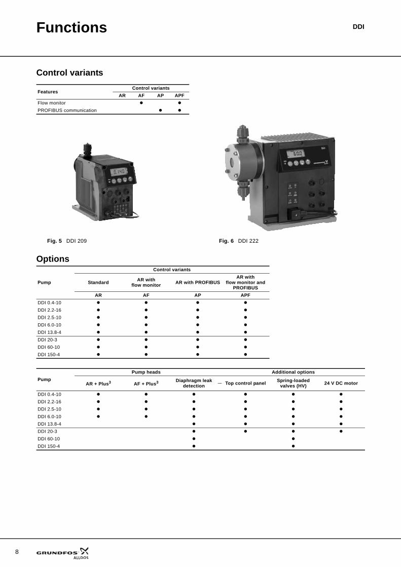
Control variants
Options
FeaturesControl variants
AR AF AP APFFlow monitorPROFIBUS communication
Fig. 5 DDI 209 Fig. 6 DDI 222
Pump
Control variants
Standard AR with flow monitor AR with PROFIBUS
AR with flow monitor and
PROFIBUSAR AF AP APF
DDI 0.4-10DDI 2.2-16DDI 2.5-10DDI 6.0-10DDI 13.8-4DDI 20-3DDI 60-10DDI 150-4
PumpPump heads Additional options
AR + Plus3 AF + Plus3 Diaphragm leak detection Top control panel Spring-loaded
valves (HV) 24 V DC motor
DDI 0.4-10DDI 2.2-16DDI 2.5-10DDI 6.0-10DDI 13.8-4DDI 20-3DDI 60-10DDI 150-4
Functions DDI
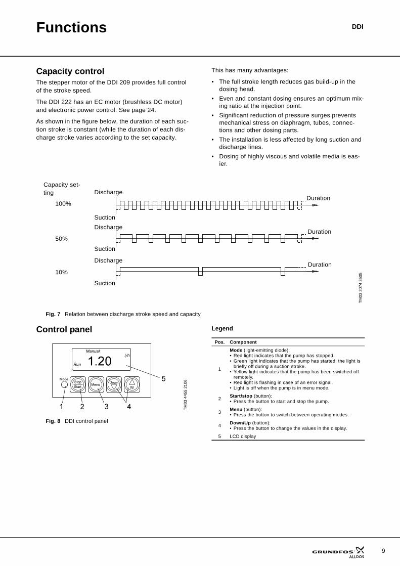
Capacity controlThe stepper motor of the DDI 209 provides full control of the stroke speed.
The DDI 222 has an EC motor (brushless DC motor) and electronic power control. See page 24.
As shown in the figure below, the duration of each suc-tion stroke is constant (while the duration of each dis-charge stroke varies according to the set capacity.
This has many advantages:
• The full stroke length reduces gas build-up in the dosing head.
• Even and constant dosing ensures an optimum mix-ing ratio at the injection point.
• Significant reduction of pressure surges prevents mechanical stress on diaphragm, tubes, connec-tions and other dosing parts.
• The installation is less affected by long suction and discharge lines.
• Dosing of highly viscous and volatile media is eas-ier.
Fig. 7 Relation between discharge stroke speed and capacity
Control panel
Fig. 8 DDI control panel
Legend
TM03
207
4 35
05
50%
10%Duration
Capacity set-ting
Duration
Duration100%
Discharge
Suction
Discharge
Suction
Discharge
Suction
TM03
445
5 21
06
Pos. Component
1
Mode (light-emitting diode):• Red light indicates that the pump has stopped.• Green light indicates that the pump has started; the light is
briefly off during a suction stroke.• Yellow light indicates that the pump has been switched off
remotely.• Red light is flashing in case of an error signal.• Light is off when the pump is in menu mode.
2 Start/stop (button):• Press the button to start and stop the pump.
3 Menu (button):• Press the button to switch between operating modes.
4 Down/Up (button):• Press the button to change the values in the display.
5 LCD display
9
10
Functions DDI
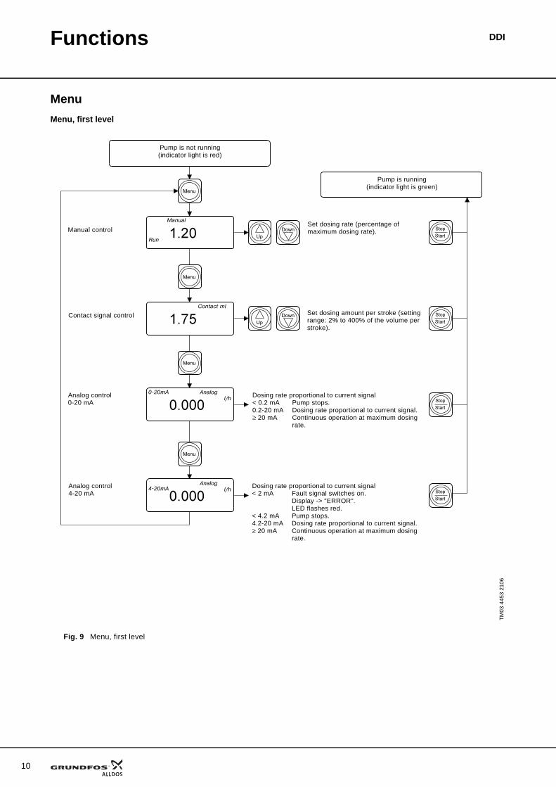
MenuMenu, first level
Fig. 9 Menu, first level
TM03
445
3 21
06
Manual control
Pump is not running (indicator light is red)
Contact signal control
Analog control0-20 mA
Analog control4-20 mA
Set dosing rate (percentage of maximum dosing rate).
Set dosing amount per stroke (setting range: 2% to 400% of the volume per stroke).
Dosing rate proportional to current signal< 0.2 mA Pump stops.0.2-20 mA Dosing rate proportional to current signal.≥ 20 mA Continuous operation at maximum dosing
rate.
Dosing rate proportional to current signal< 2 mA Fault signal switches on.
Display -> "ERROR".LED flashes red.
< 4.2 mA Pump stops.4.2-20 mA Dosing rate proportional to current signal.≥ 20 mA Continuous operation at maximum dosing
rate.
Pump is running (indicator light is green)
Functions DDI
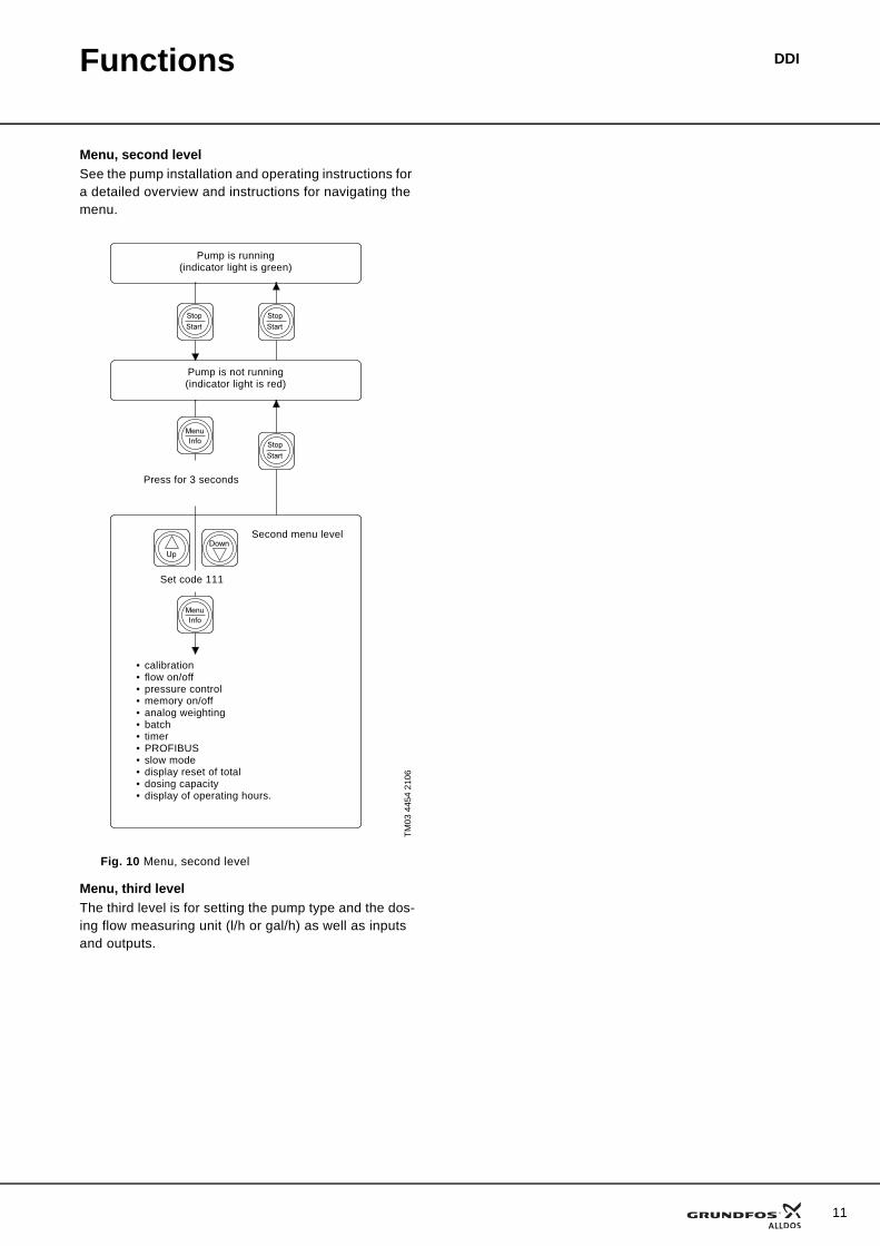
Menu, second levelSee the pump installation and operating instructions for a detailed overview and instructions for navigating the menu.
Fig. 10 Menu, second level
Menu, third levelThe third level is for setting the pump type and the dos-ing flow measuring unit (l/h or gal/h) as well as inputs and outputs.
TM03
445
4 21
06
Pump is running (indicator light is green)
Pump is not running (indicator light is red)
Press for 3 seconds
Set code 111
• calibration• flow on/off• pressure control• memory on/off• analog weighting• batch• timer• PROFIBUS• slow mode• display reset of total• dosing capacity• display of operating hours.
Second menu level
11
12
Functions DDI
Operating modesManual controlIn manual control mode, set the flow rate in the display.
Pulse controlFor each pulse received at the contact input of the pump (for example from a water meter with reed con-tact output), the pump doses the set quantity. The memory can store a maximum of 65,000 pulses for later processing.
Analog controlThe dosed quantity is proportional to the current input signal of 0-20 mA or 4-20 mA.
Batch modeIn batch mode, a defined batch quantity is dosed with a defined flow. The dosing of a batch can be triggered manually and by pulse.
Timer batchThe set batch quantity is dosed with a preset interval.
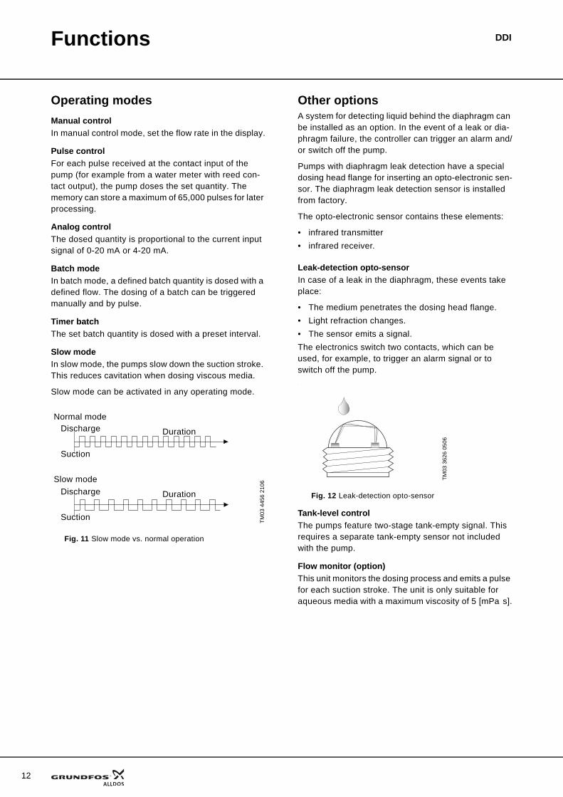
Slow modeIn slow mode, the pumps slow down the suction stroke. This reduces cavitation when dosing viscous media.
Slow mode can be activated in any operating mode.
Fig. 11 Slow mode vs. normal operation
Other optionsA system for detecting liquid behind the diaphragm can be installed as an option. In the event of a leak or dia-phragm failure, the controller can trigger an alarm and/or switch off the pump.
Pumps with diaphragm leak detection have a special dosing head flange for inserting an opto-electronic sen-sor. The diaphragm leak detection sensor is installed from factory.
The opto-electronic sensor contains these elements:
• infrared transmitter• infrared receiver.
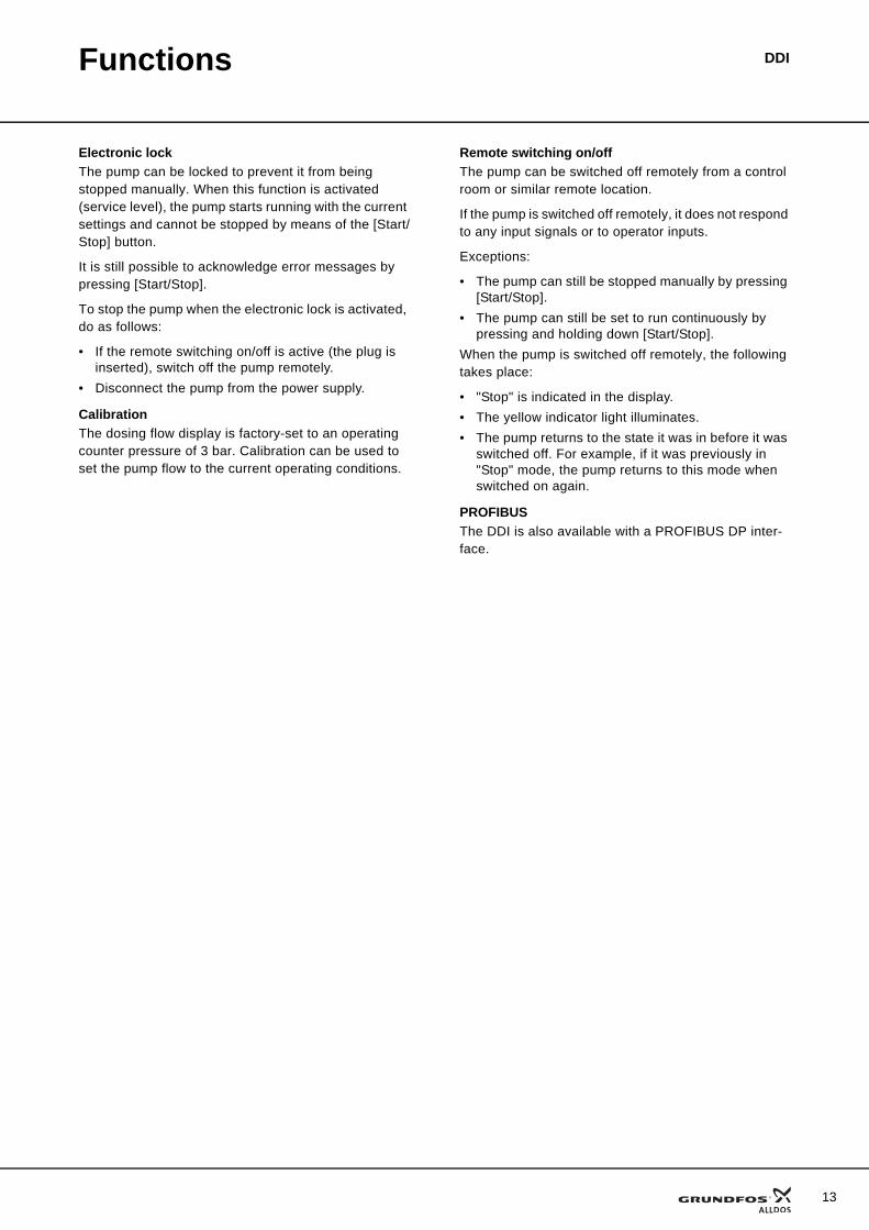
Leak-detection opto-sensorIn case of a leak in the diaphragm, these events take place:
• The medium penetrates the dosing head flange.• Light refraction changes.• The sensor emits a signal.The electronics switch two contacts, which can be used, for example, to trigger an alarm signal or to switch off the pump..
Fig. 12 Leak-detection opto-sensor
Tank-level controlThe pumps feature two-stage tank-empty signal. This requires a separate tank-empty sensor not included with the pump.
Flow monitor (option)This unit monitors the dosing process and emits a pulse for each suction stroke. The unit is only suitable for aqueous media with a maximum viscosity of 5 [mPa s].
TM03
445
6 21
06
Discharge
Suction
Duration
Duration
Normal mode
Slow mode
Discharge
SuctionTM
03 3
626
0506
Functions DDI
Electronic lockThe pump can be locked to prevent it from being stopped manually. When this function is activated (service level), the pump starts running with the current settings and cannot be stopped by means of the [Start/Stop] button.
It is still possible to acknowledge error messages by pressing [Start/Stop].
To stop the pump when the electronic lock is activated, do as follows:
• If the remote switching on/off is active (the plug is inserted), switch off the pump remotely.
• Disconnect the pump from the power supply.
CalibrationThe dosing flow display is factory-set to an operating counter pressure of 3 bar. Calibration can be used to set the pump flow to the current operating conditions.
Remote switching on/offThe pump can be switched off remotely from a control room or similar remote location.
If the pump is switched off remotely, it does not respond to any input signals or to operator inputs.
Exceptions:
• The pump can still be stopped manually by pressing [Start/Stop].
• The pump can still be set to run continuously by pressing and holding down [Start/Stop].
When the pump is switched off remotely, the following takes place:
• "Stop" is indicated in the display.• The yellow indicator light illuminates.• The pump returns to the state it was in before it was
switched off. For example, if it was previously in "Stop" mode, the pump returns to this mode when switched on again.
PROFIBUSThe DDI is also available with a PROFIBUS DP inter-face.
13
14
Functions DDI
Connectors
Legend
TM03
445
2 21
06
TM03
478
0 28
06
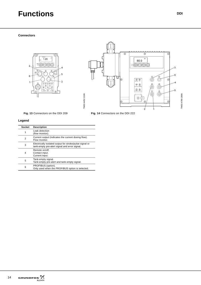
Fig. 13 Connectors on the DDI 209 Fig. 14 Connectors on the DDI 222
Socket Description
1 Leak detection(flow monitor).
2 Current output (indicates the current dosing flow).Flow monitor.
3 Electrically isolated output for stroke/pulse signal or tank-empty pre-alert signal and error signal.
4Remote on/off. Contact input.Current input.
5 Tank-empty signal.Tank-empty pre-alert and tank-empty signal.
6 PROFIBUS (option).Only used when the PROFIBUS option is selected.
DDIConstruction
General descriptionThe DDI range of pumps are digitally controlled dosing pumps.
DDI 209The DDI 209 are electronic stepper-motor-driven pumps. The rotation of the motor generates the dis-charge stroke via an eccentric. The suction stroke is performed by a spring.
The control panel can be top- or side-mounted.
The DDI 209 is available in a range of versions.
The various head types available have these features:
• manual deaeration valve• Plus3 system (P3)• diaphragm leak detection.The DDI 209 AR has these optional features:
• flow monitor• interface for PROFIBUS (AP).
DDI 222The DDI 222 is driven by a low-energy and brushless DC motor. The speed of the motor is reduced by means of belt drive (toothed belts). The DDI 222 suction and discharge strokes are generated by the motor.
The control panel can be front- or side-mounted.
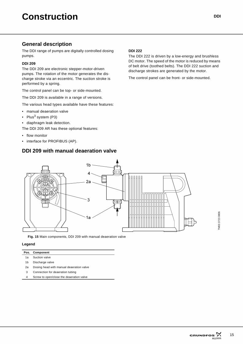
DDI 209 with manual deaeration valve
Fig. 15 Main components, DDI 209 with manual deaeration valve
Legend
TM03
372
3 08
06
Pos. Component1a Suction valve
1b Discharge valve
2a Dosing head with manual deaeration valve
3 Connection for deaeration tubing
4 Screw to open/close the deaeration valve
15
16
Construction DDI
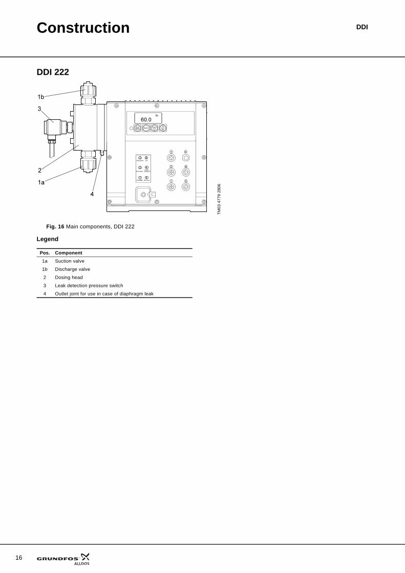
DDI 222
Fig. 16 Main components, DDI 222
Legend
TM03
477
9 28
06
Pos. Component
1a Suction valve
1b Discharge valve
2 Dosing head
3 Leak detection pressure switch
4 Outlet joint for use in case of diaphragm leak
Construction DDI
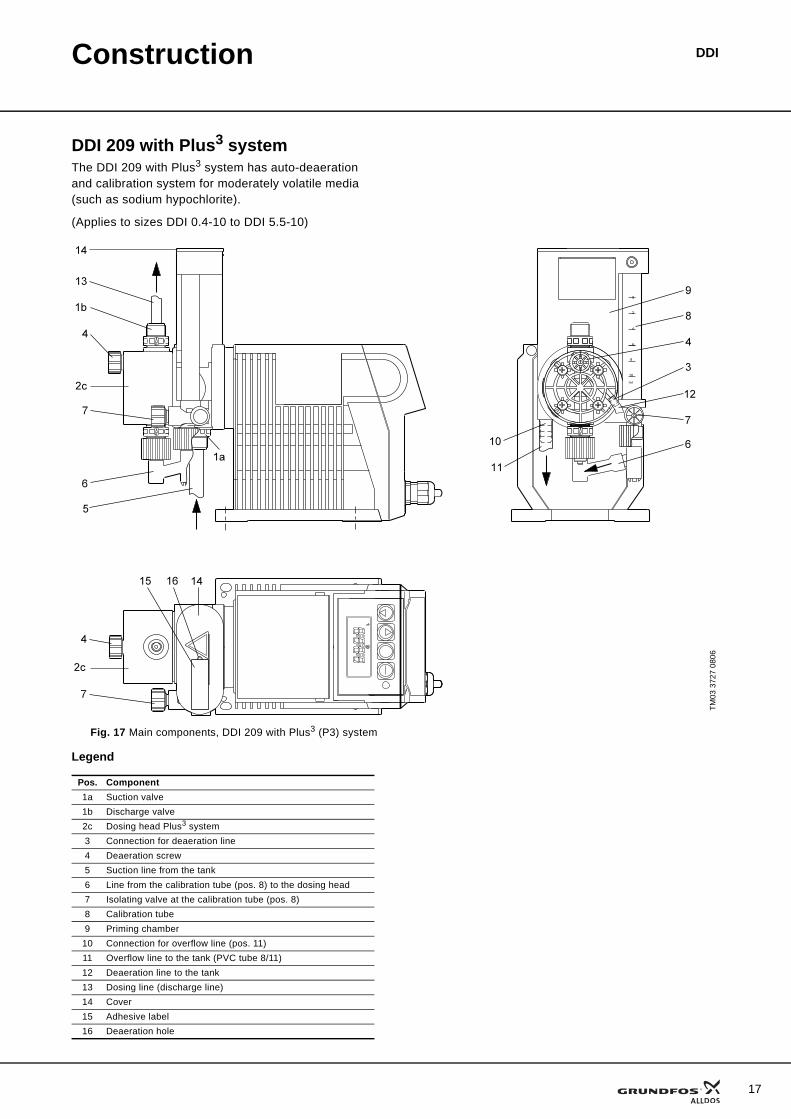
DDI 209 with Plus3 system The DDI 209 with Plus3 system has auto-deaeration and calibration system for moderately volatile media (such as sodium hypochlorite).
(Applies to sizes DDI 0.4-10 to DDI 5.5-10)
Fig. 17 Main components, DDI 209 with Plus3 (P3) system
Legend
TM03
372
7 08
06
Pos. Component1a Suction valve1b Discharge valve2c Dosing head Plus3 system3 Connection for deaeration line4 Deaeration screw5 Suction line from the tank6 Line from the calibration tube (pos. 8) to the dosing head7 Isolating valve at the calibration tube (pos. 8)8 Calibration tube9 Priming chamber
10 Connection for overflow line (pos. 11)11 Overflow line to the tank (PVC tube 8/11)12 Deaeration line to the tank13 Dosing line (discharge line)14 Cover15 Adhesive label16 Deaeration hole
17
18
Construction DDI
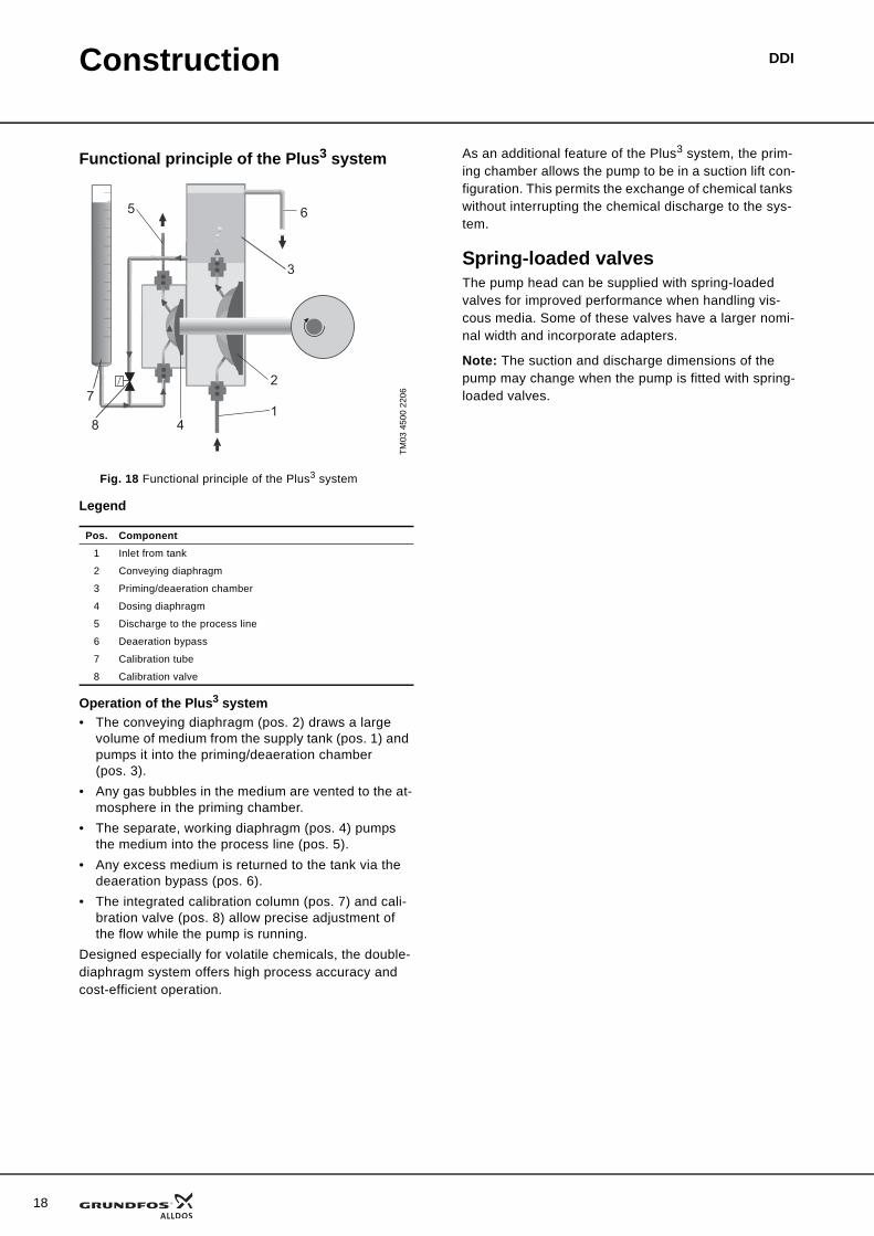
Functional principle of the Plus3 system
Fig. 18 Functional principle of the Plus3 system
Legend
Operation of the Plus3 system• The conveying diaphragm (pos. 2) draws a large
volume of medium from the supply tank (pos. 1) and pumps it into the priming/deaeration chamber (pos. 3).
• Any gas bubbles in the medium are vented to the at-mosphere in the priming chamber.
• The separate, working diaphragm (pos. 4) pumps the medium into the process line (pos. 5).
• Any excess medium is returned to the tank via the deaeration bypass (pos. 6).
• The integrated calibration column (pos. 7) and cali-bration valve (pos. 8) allow precise adjustment of the flow while the pump is running.
Designed especially for volatile chemicals, the double-diaphragm system offers high process accuracy and cost-efficient operation.
As an additional feature of the Plus3 system, the prim-ing chamber allows the pump to be in a suction lift con-figuration. This permits the exchange of chemical tanks without interrupting the chemical discharge to the sys-tem.
Spring-loaded valvesThe pump head can be supplied with spring-loaded valves for improved performance when handling vis-cous media. Some of these valves have a larger nomi-nal width and incorporate adapters.
Note: The suction and discharge dimensions of the pump may change when the pump is fitted with spring-loaded valves.
TM03
450
0 22
06
Pos. Component1 Inlet from tank
2 Conveying diaphragm
3 Priming/deaeration chamber
4 Dosing diaphragm
5 Discharge to the process line
6 Deaeration bypass
7 Calibration tube
8 Calibration valve
5 6
3
1
2
8 4
7
Construction DDI
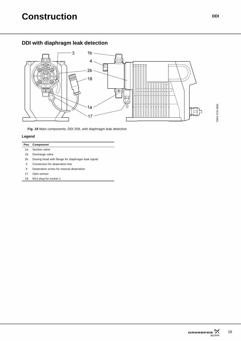
DDI with diaphragm leak detection
Fig. 19 Main components, DDI 209, with diaphragm leak detection
Legend
TM03
372
5 08
06
Pos. Component1a Suction valve
1b Discharge valve
2b Dosing head with flange for diaphragm leak signal
3 Connection for deaeration line
4 Deaeration screw for manual deaeration
17 Opto-sensor
18 M12 plug for socket 1
19
20
Technical data
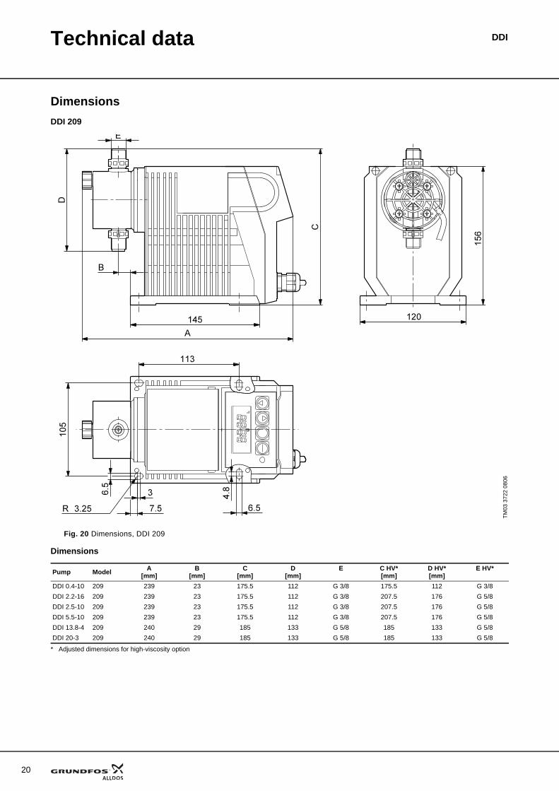
DimensionsDDI 209
Fig. 20 Dimensions, DDI 209
Dimensions
* Adjusted dimensions for high-viscosity option
TM03
372
2 08
06
Pump Model A[mm]
B[mm]
C[mm]
D[mm]
E C HV*[mm]
D HV*[mm]
E HV*
DDI 0.4-10 209 239 23 175.5 112 G 3/8 175.5 112 G 3/8DDI 2.2-16 209 239 23 175.5 112 G 3/8 207.5 176 G 5/8DDI 2.5-10 209 239 23 175.5 112 G 3/8 207.5 176 G 5/8DDI 5.5-10 209 239 23 175.5 112 G 3/8 207.5 176 G 5/8DDI 13.8-4 209 240 29 185 133 G 5/8 185 133 G 5/8DDI 20-3 209 240 29 185 133 G 5/8 185 133 G 5/8
DDI
Technical data DDI
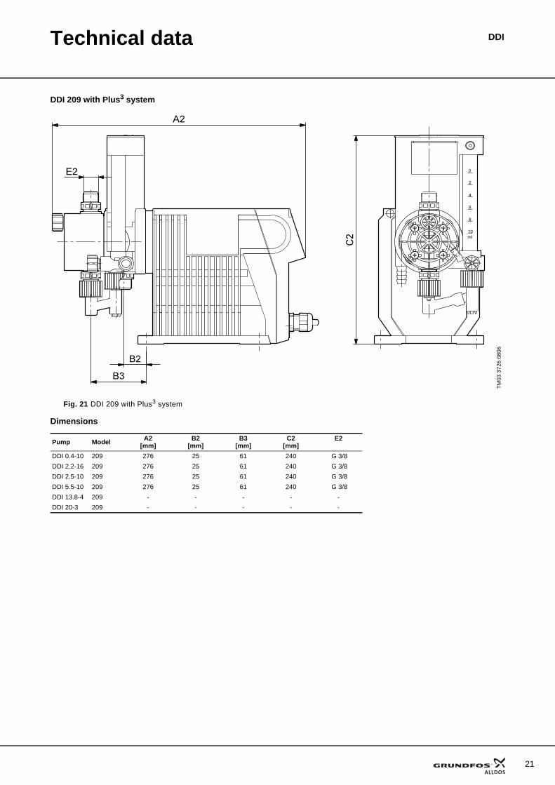
DDI 209 with Plus3 system
Fig. 21 DDI 209 with Plus3 system
Dimensions
TM03
372
6 08
06
Pump Model A2[mm]
B2[mm]
B3[mm]
C2[mm]
E2
DDI 0.4-10 209 276 25 61 240 G 3/8DDI 2.2-16 209 276 25 61 240 G 3/8DDI 2.5-10 209 276 25 61 240 G 3/8DDI 5.5-10 209 276 25 61 240 G 3/8DDI 13.8-4 209 - - - - -DDI 20-3 209 - - - - -
21
22
Technical data DDI
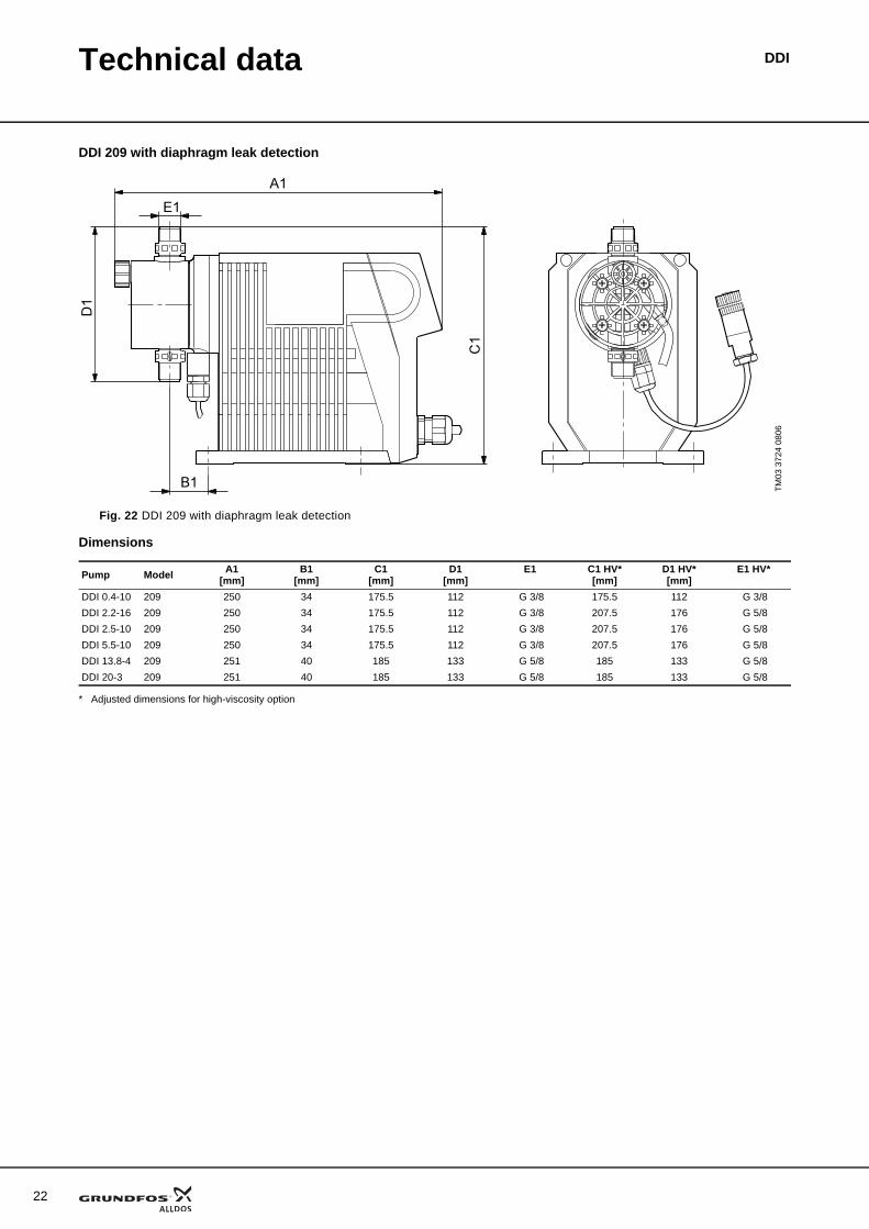
DDI 209 with diaphragm leak detection
Fig. 22 DDI 209 with diaphragm leak detection
Dimensions
* Adjusted dimensions for high-viscosity option
TM03
372
4 08
06
Pump Model A1[mm]
B1[mm]
C1[mm]
D1[mm]
E1 C1 HV*[mm]
D1 HV*[mm]
E1 HV*
DDI 0.4-10 209 250 34 175.5 112 G 3/8 175.5 112 G 3/8DDI 2.2-16 209 250 34 175.5 112 G 3/8 207.5 176 G 5/8DDI 2.5-10 209 250 34 175.5 112 G 3/8 207.5 176 G 5/8DDI 5.5-10 209 250 34 175.5 112 G 3/8 207.5 176 G 5/8DDI 13.8-4 209 251 40 185 133 G 5/8 185 133 G 5/8DDI 20-3 209 251 40 185 133 G 5/8 185 133 G 5/8
Technical data DDI
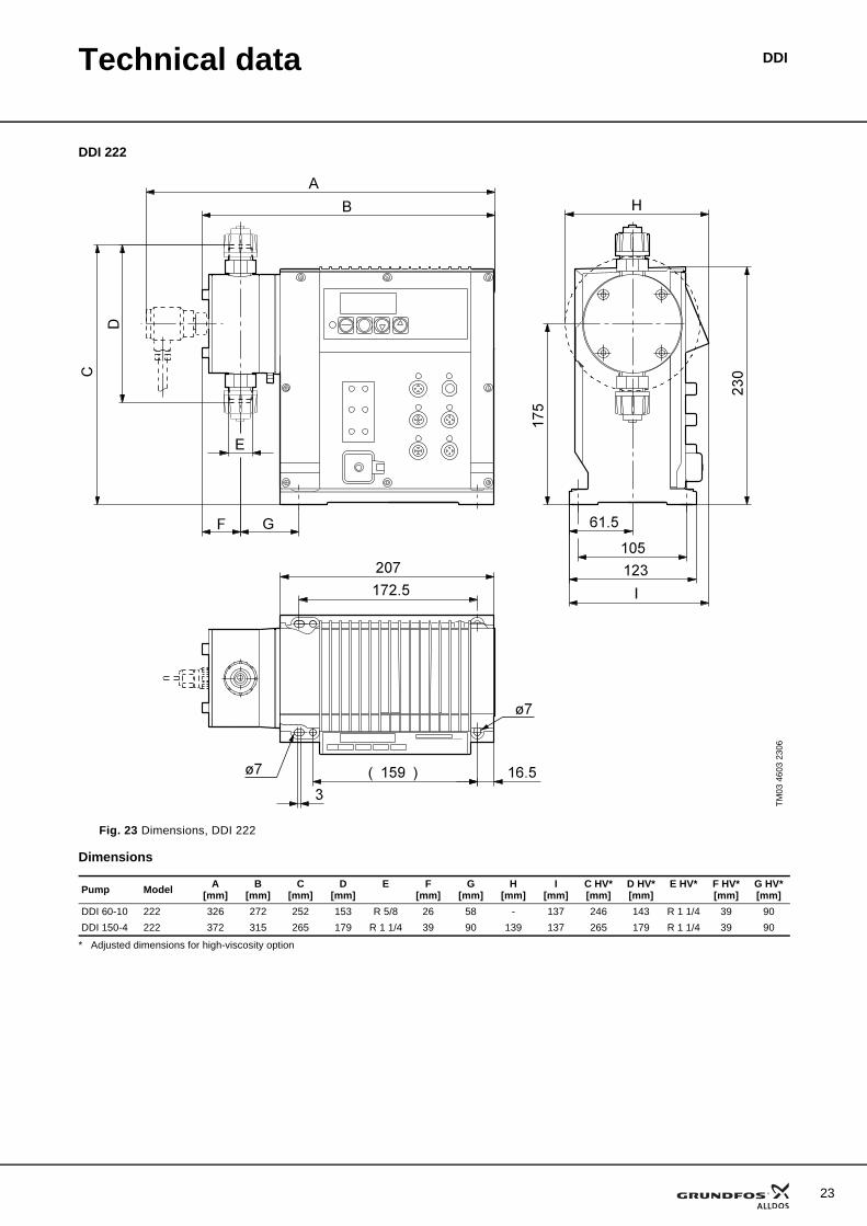
DDI 222
Fig. 23 Dimensions, DDI 222
Dimensions
* Adjusted dimensions for high-viscosity option
TM03
460
3 23
06
Pump Model A[mm]
B[mm]
C[mm]
D[mm]
E F[mm]
G[mm]
H[mm]
I[mm]
C HV*[mm]
D HV*[mm]
E HV* F HV*[mm]
G HV*[mm]
DDI 60-10 222 326 272 252 153 R 5/8 26 58 - 137 246 143 R 1 1/4 39 90DDI 150-4 222 372 315 265 179 R 1 1/4 39 90 139 137 265 179 R 1 1/4 39 90
23
24
Technical data DDI
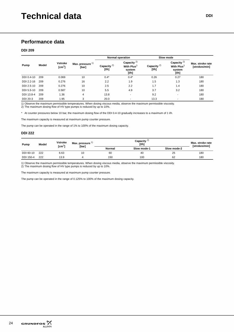
Performance dataDDI 209
1) Observe the maximum permissible temperatures. When dosing viscous media, observe the maximum permissible viscosity. 2) The maximum dosing flow of HV type pumps is reduced by up to 10%.
* At counter pressures below 10 bar, the maximum dosing flow of the DDI 0.4-10 gradually increases to a maximum of 1 l/h.
The maximum capacity is measured at maximum pump counter pressure.
The pump can be operated in the range of 1% to 100% of the maximum dosing capacity.
DDI 222
1) Observe the maximum permissible temperatures. When dosing viscous media, observe the maximum permissible viscosity. 2) The maximum dosing flow of HV type pumps is reduced by up to 10%.
The maximum capacity is measured at maximum pump counter pressure.
The pump can be operated in the range of 0.125% to 100% of the maximum dosing capacity.
Pump ModelVstroke[cm3]
Max. pressure 1) [bar]
Normal operation Slow mode
Max. stroke rate [strokes/min]Capacity 2)
[l/h]
Capacity 2) With Plus3
system[l/h]
Capacity 2)
[l/h]
Capacity 2) With Plus3
system[l/h]
DDI 0.4-10 209 0.069 10 0.4* 0.4* 0.26 0.27 180DDI 2.2-16 209 0.276 16 2.2 1.9 1.5 1.3 180DDI 2.5-10 209 0.276 10 2.5 2.2 1.7 1.4 180DDI 5.5-10 209 0.587 10 5.5 4.9 3.7 3.2 180DDI 13.8-4 209 1.36 4 13.8 - 9.2 - 180DDI 20-3 209 1.95 3 20.0 - 13.3 - 180
Pump ModelVstroke[cm3]
Max. pressure 1) [bar]
Capacity 2)
[l/h] Max. stroke rate [strokes/min]
Normal Slow mode-1 Slow mode-2DDI 60-10 222 6.63 10 60 40 25 180DDI 150-4 222 13.9 4 150 100 62 180
Technical data DDI
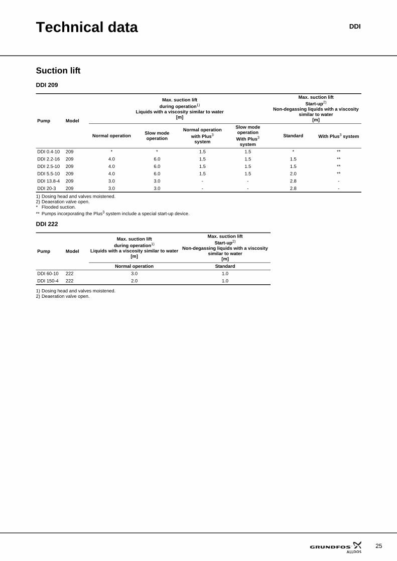
Suction liftDDI 209
1) Dosing head and valves moistened.2) Deaeration valve open.* Flooded suction.** Pumps incorporating the Plus3 system include a special start-up device.
DDI 222
1) Dosing head and valves moistened.2) Deaeration valve open.
Pump Model
Max. suction liftduring operation1)
Liquids with a viscosity similar to water[m]
Max. suction liftStart-up2)
Non-degassing liquids with a viscosity similar to water
[m]
Normal operation Slow mode operation
Normal operation with Plus3
system
Slow mode operation With Plus3
system
Standard With Plus3 system
DDI 0.4-10 209 * * 1.5 1.5 * **DDI 2.2-16 209 4.0 6.0 1.5 1.5 1.5 **DDI 2.5-10 209 4.0 6.0 1.5 1.5 1.5 **DDI 5.5-10 209 4.0 6.0 1.5 1.5 2.0 **DDI 13.8-4 209 3.0 3.0 - - 2.8 -DDI 20-3 209 3.0 3.0 - - 2.8 -
Pump Model
Max. suction liftduring operation1)
Liquids with a viscosity similar to water[m]
Max. suction liftStart-up2)
Non-degassing liquids with a viscosity similar to water
[m]Normal operation Standard
DDI 60-10 222 3.0 1.0DDI 150-4 222 2.0 1.0
25
26
Technical data DDI
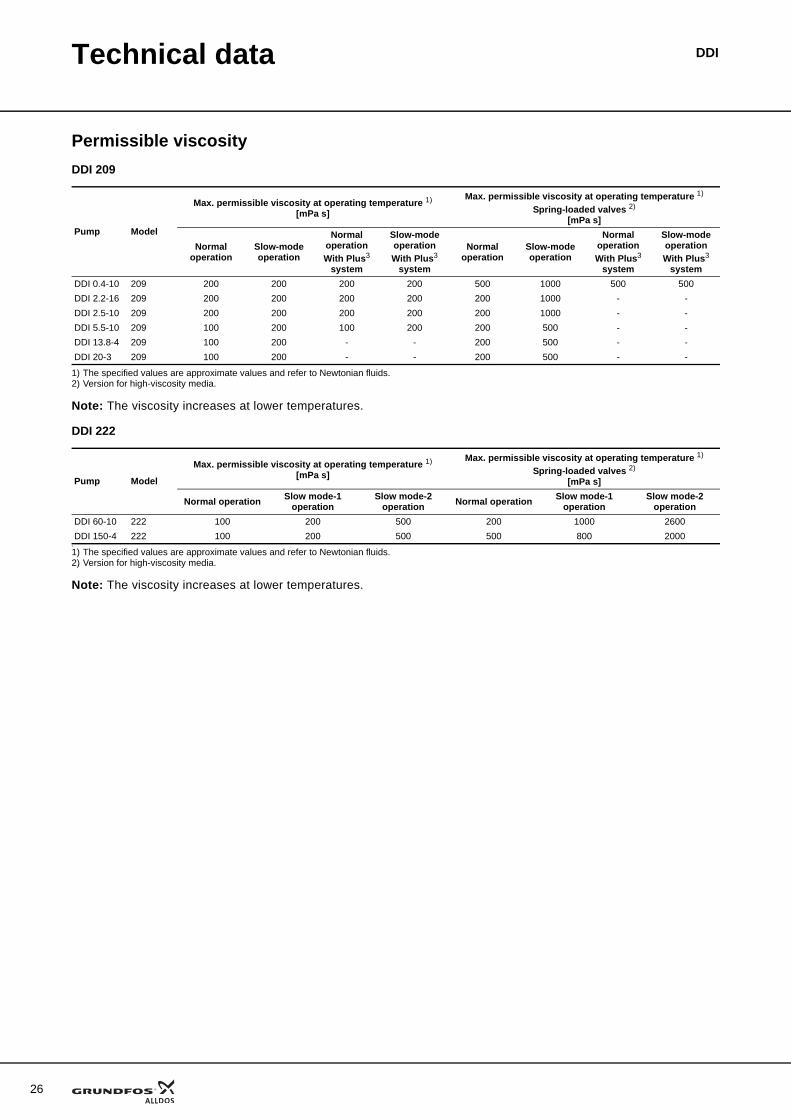
Permissible viscosityDDI 209
1) The specified values are approximate values and refer to Newtonian fluids.2) Version for high-viscosity media.
Note: The viscosity increases at lower temperatures.
DDI 222
1
1) The specified values are approximate values and refer to Newtonian fluids.2) Version for high-viscosity media.
Note: The viscosity increases at lower temperatures.
Pump Model
Max. permissible viscosity at operating temperature 1)
[mPa s]
Max. permissible viscosity at operating temperature 1) Spring-loaded valves 2)
[mPa s]
Normal operation
Slow-mode operation
Normal operation With Plus3
system
Slow-mode operation With Plus3
system
Normal operation
Slow-mode operation
Normal operation With Plus3
system
Slow-mode operation With Plus3
systemDDI 0.4-10 209 200 200 200 200 500 1000 500 500DDI 2.2-16 209 200 200 200 200 200 1000 - -DDI 2.5-10 209 200 200 200 200 200 1000 - -DDI 5.5-10 209 100 200 100 200 200 500 - -DDI 13.8-4 209 100 200 - - 200 500 - -DDI 20-3 209 100 200 - - 200 500 - -
Pump Model
Max. permissible viscosity at operating temperature 1) [mPa s]
Max. permissible viscosity at operating temperature 1) Spring-loaded valves 2)
[mPa s]
Normal operation Slow mode-1 operation
Slow mode-2 operation Normal operation Slow mode-1
operationSlow mode-2
operationDDI 60-10 222 100 200 500 200 1000 2600DDI 150-4 222 100 200 500 500 800 2000
Technical data DDI
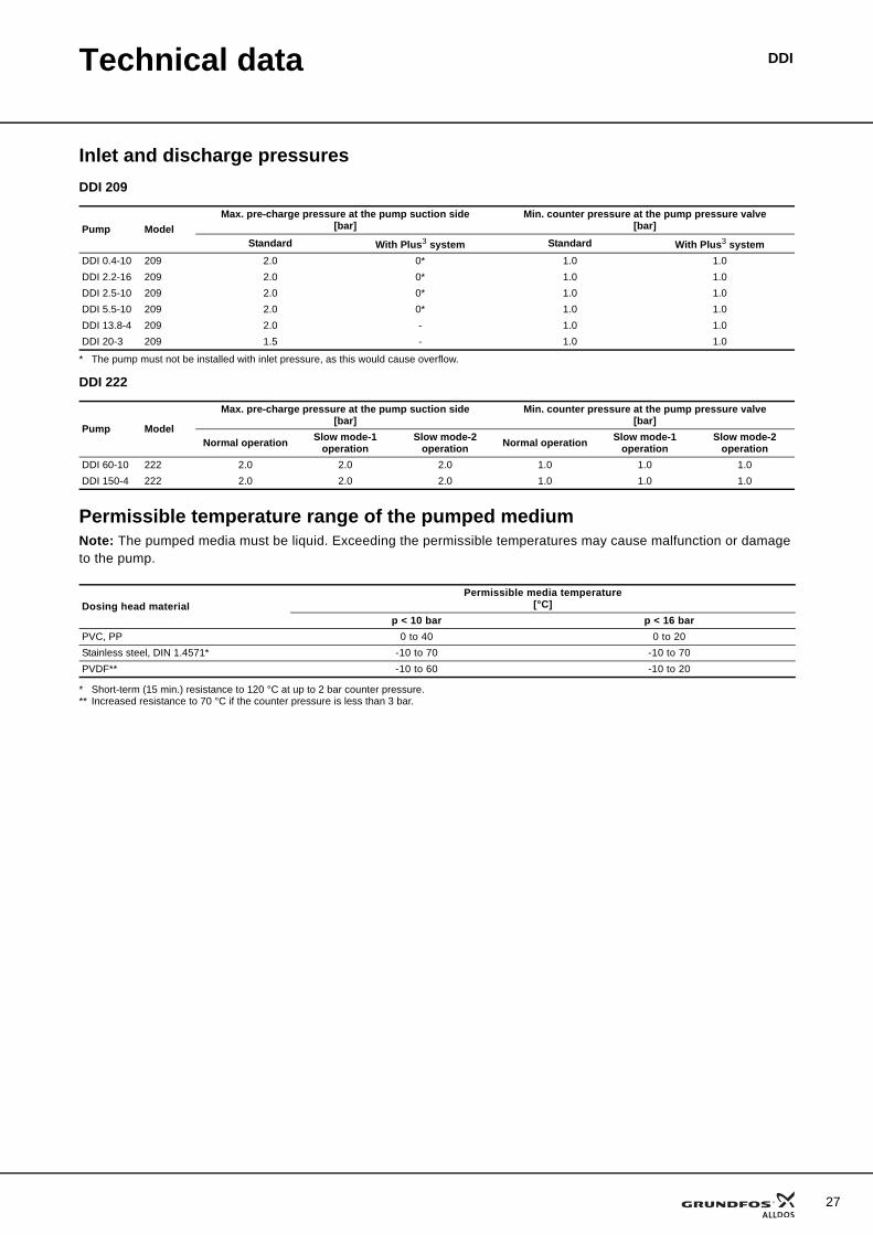
Inlet and discharge pressuresDDI 209
* The pump must not be installed with inlet pressure, as this would cause overflow.
DDI 222
Permissible temperature range of the pumped mediumNote: The pumped media must be liquid. Exceeding the permissible temperatures may cause malfunction or damage to the pump.
* Short-term (15 min.) resistance to 120 °C at up to 2 bar counter pressure.** Increased resistance to 70 °C if the counter pressure is less than 3 bar.
Pump ModelMax. pre-charge pressure at the pump suction side
[bar]Min. counter pressure at the pump pressure valve
[bar]Standard With Plus3 system Standard With Plus3 system
DDI 0.4-10 209 2.0 0* 1.0 1.0DDI 2.2-16 209 2.0 0* 1.0 1.0DDI 2.5-10 209 2.0 0* 1.0 1.0DDI 5.5-10 209 2.0 0* 1.0 1.0DDI 13.8-4 209 2.0 - 1.0 1.0DDI 20-3 209 1.5 - 1.0 1.0
Pump Model
Max. pre-charge pressure at the pump suction side [bar]
Min. counter pressure at the pump pressure valve[bar]
Normal operation Slow mode-1 operation
Slow mode-2 operation Normal operation Slow mode-1
operationSlow mode-2
operationDDI 60-10 222 2.0 2.0 2.0 1.0 1.0 1.0DDI 150-4 222 2.0 2.0 2.0 1.0 1.0 1.0
Dosing head materialPermissible media temperature
[°C]p < 10 bar p < 16 bar
PVC, PP 0 to 40 0 to 20Stainless steel, DIN 1.4571* -10 to 70 -10 to 70PVDF** -10 to 60 -10 to 20
27
28
Technical data DDI
Weights
Electrical data
Additional technical data
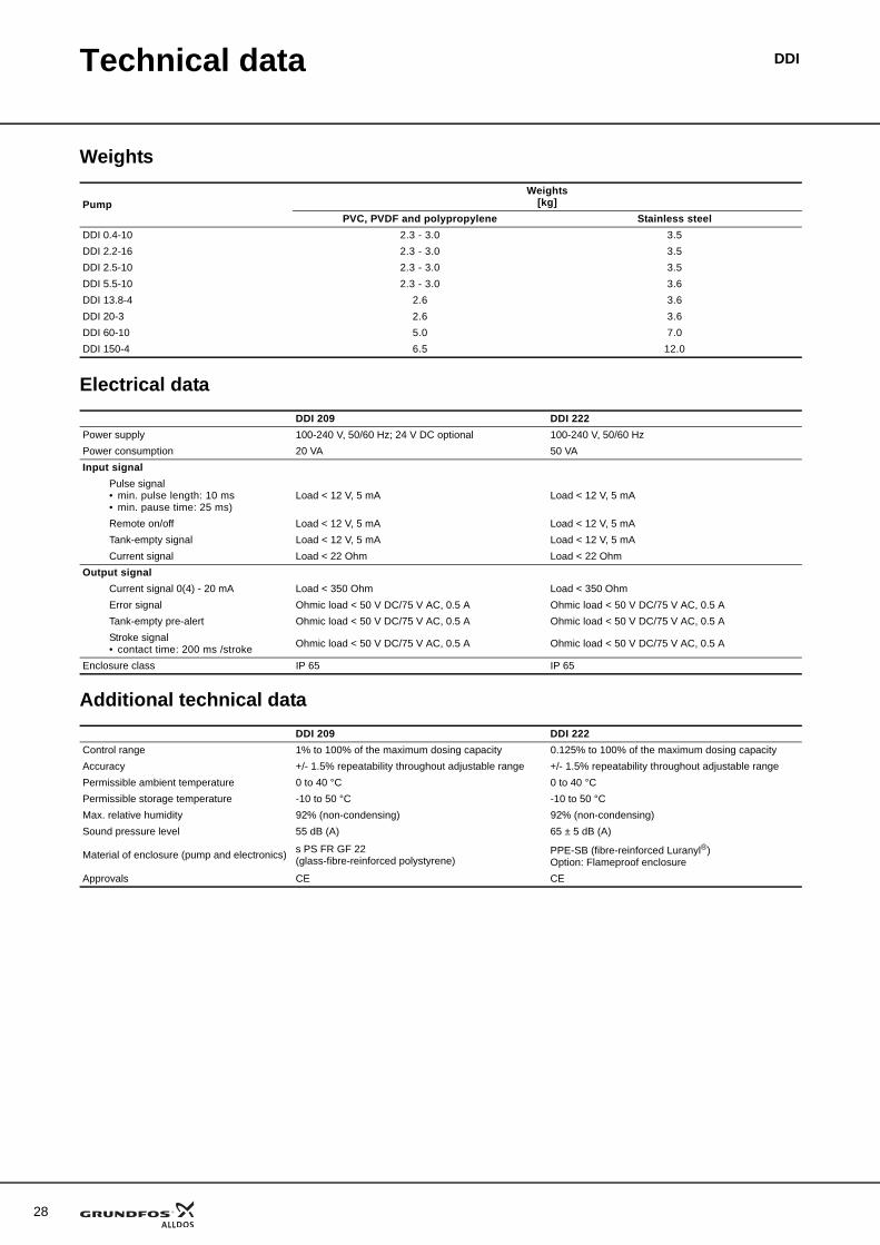
PumpWeights
[kg]PVC, PVDF and polypropylene Stainless steel
DDI 0.4-10 2.3 - 3.0 3.5DDI 2.2-16 2.3 - 3.0 3.5DDI 2.5-10 2.3 - 3.0 3.5DDI 5.5-10 2.3 - 3.0 3.6DDI 13.8-4 2.6 3.6DDI 20-3 2.6 3.6DDI 60-10 5.0 7.0DDI 150-4 6.5 12.0
DDI 209 DDI 222Power supply 100-240 V, 50/60 Hz; 24 V DC optional 100-240 V, 50/60 HzPower consumption 20 VA 50 VAInput signal
Pulse signal • min. pulse length: 10 ms• min. pause time: 25 ms)
Load < 12 V, 5 mA Load < 12 V, 5 mA
Remote on/off Load < 12 V, 5 mA Load < 12 V, 5 mATank-empty signal Load < 12 V, 5 mA Load < 12 V, 5 mACurrent signal Load < 22 Ohm Load < 22 Ohm
Output signalCurrent signal 0(4) - 20 mA Load < 350 Ohm Load < 350 OhmError signal Ohmic load < 50 V DC/75 V AC, 0.5 A Ohmic load < 50 V DC/75 V AC, 0.5 ATank-empty pre-alert Ohmic load < 50 V DC/75 V AC, 0.5 A Ohmic load < 50 V DC/75 V AC, 0.5 AStroke signal • contact time: 200 ms /stroke Ohmic load < 50 V DC/75 V AC, 0.5 A Ohmic load < 50 V DC/75 V AC, 0.5 A
Enclosure class IP 65 IP 65
DDI 209 DDI 222Control range 1% to 100% of the maximum dosing capacity 0.125% to 100% of the maximum dosing capacityAccuracy +/- 1.5% repeatability throughout adjustable range +/- 1.5% repeatability throughout adjustable rangePermissible ambient temperature 0 to 40 °C 0 to 40 °CPermissible storage temperature -10 to 50 °C -10 to 50 °CMax. relative humidity 92% (non-condensing) 92% (non-condensing)Sound pressure level 55 dB (A) 65 ± 5 dB (A)
Material of enclosure (pump and electronics) s PS FR GF 22(glass-fibre-reinforced polystyrene)
PPE-SB (fibre-reinforced Luranyl®)Option: Flameproof enclosure
Approvals CE CE
Technical data DDI
Electronic functions
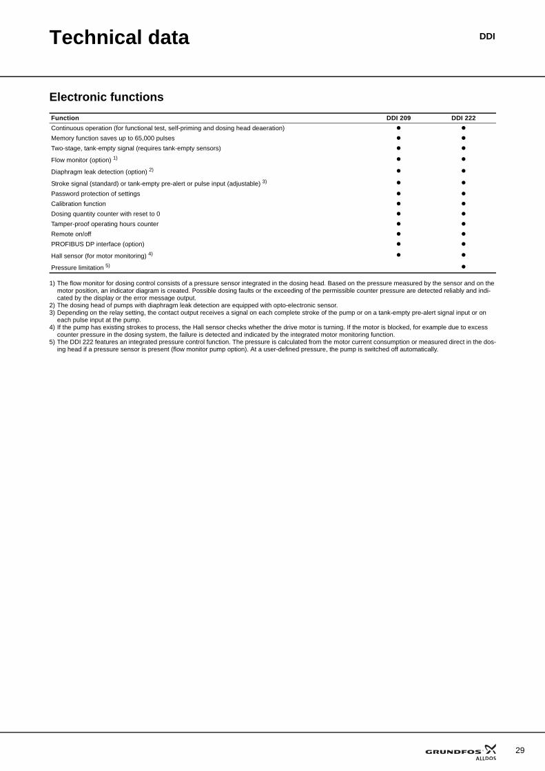
1) The flow monitor for dosing control consists of a pressure sensor integrated in the dosing head. Based on the pressure measured by the sensor and on the motor position, an indicator diagram is created. Possible dosing faults or the exceeding of the permissible counter pressure are detected reliably and indi-cated by the display or the error message output.
2) The dosing head of pumps with diaphragm leak detection are equipped with opto-electronic sensor.3) Depending on the relay setting, the contact output receives a signal on each complete stroke of the pump or on a tank-empty pre-alert signal input or on
each pulse input at the pump.4) If the pump has existing strokes to process, the Hall sensor checks whether the drive motor is turning. If the motor is blocked, for example due to excess
counter pressure in the dosing system, the failure is detected and indicated by the integrated motor monitoring function.5) The DDI 222 features an integrated pressure control function. The pressure is calculated from the motor current consumption or measured direct in the dos-
ing head if a pressure sensor is present (flow monitor pump option). At a user-defined pressure, the pump is switched off automatically.
Function DDI 209 DDI 222Continuous operation (for functional test, self-priming and dosing head deaeration)Memory function saves up to 65,000 pulsesTwo-stage, tank-empty signal (requires tank-empty sensors)
Flow monitor (option) 1)
Diaphragm leak detection (option) 2)
Stroke signal (standard) or tank-empty pre-alert or pulse input (adjustable) 3)
Password protection of settingsCalibration functionDosing quantity counter with reset to 0Tamper-proof operating hours counterRemote on/offPROFIBUS DP interface (option)
Hall sensor (for motor monitoring) 4)
Pressure limitation 5)
29
30
Technical data DDI
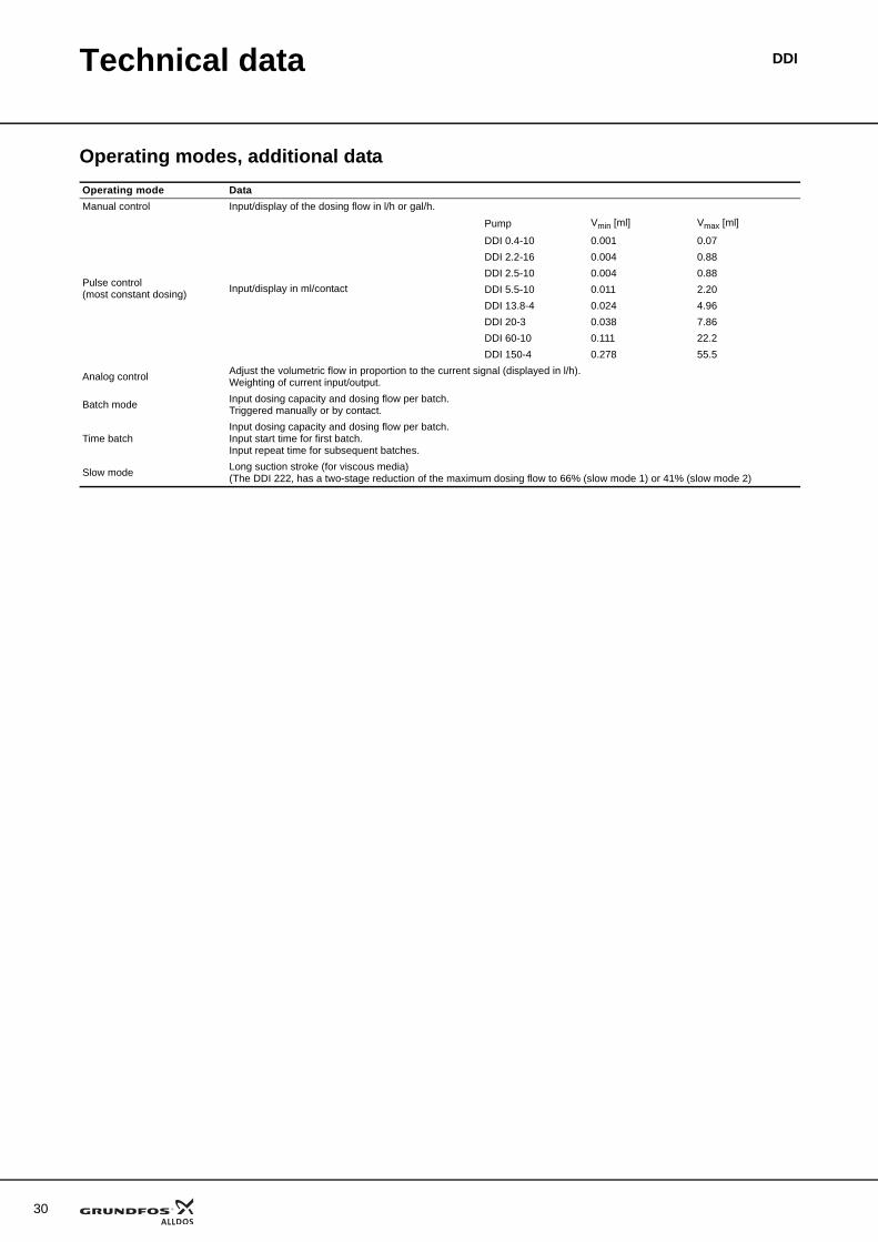
Operating modes, additional dataOperating mode DataManual control Input/display of the dosing flow in l/h or gal/h.
Pulse control (most constant dosing) Input/display in ml/contact
Pump Vmin [ml] Vmax [ml]
DDI 0.4-10 0.001 0.07DDI 2.2-16 0.004 0.88DDI 2.5-10 0.004 0.88DDI 5.5-10 0.011 2.20DDI 13.8-4 0.024 4.96DDI 20-3 0.038 7.86DDI 60-10 0.111 22.2DDI 150-4 0.278 55.5
Analog control Adjust the volumetric flow in proportion to the current signal (displayed in l/h).Weighting of current input/output.
Batch mode Input dosing capacity and dosing flow per batch.Triggered manually or by contact.
Time batchInput dosing capacity and dosing flow per batch.Input start time for first batch.Input repeat time for subsequent batches.
Slow mode Long suction stroke (for viscous media)(The DDI 222, has a two-stage reduction of the maximum dosing flow to 66% (slow mode 1) or 41% (slow mode 2)
Technical data DDI
31
32
DDIPump selection
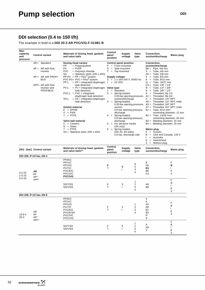
DDI selection (0.4 to 150 l/h)The example in bold is a DDI 20-3 AR PVC/V/G-F-313B1 B
Max. capacity and pressure
Control variant Materials of dosing head, gaskets and valve balls
Control panel position
Supply voltage
Valve type
Connection, suction/discharge Mains plug
AR = Standard
AF = AR with flow monitor
AP = AR with PROFI-BUS
APF= AR with flow monitor and PROFIBUS
Dosing head variantPP = PolypropylenePV = PVDFPVC = Polyvinyl chlorideSS = Stainless steel, DIN 1.4401PP-P3 = PP + Plus3 systemPVC-P3= PVC + Plus3 systemPP-L = PP + integrated diaphragm
leak detectionPV-L = PV + integrated diaphragm
leak detectionPVC-L = PVC + integrated
diaphragm leak detectionSS-L = SS + integrated diaphragm
leak detection
Gasket materialE = EPDMV = FKMT = PTFE
Valve ball materialC = CeramicG = GlassT = PTFESS = Stainless steel, DIN 1.4401
Control panel positionF = Front-mounted S = Side-mounted T = Top-mounted
Supply voltage3 = 1 x 100-240 V, 50/60 HzI = 24 VDC
Valve type1 = Standard2 = Spring-loaded,
0.05 bar opening pressure, suction/discharge
3 = Spring-loaded, 0.05 bar opening pressure, suction0.8 bar opening pressure, discharge
4 = Spring-loaded,0.8 bar opening pressure, discharge
5 = For abrasive media (SS only)
6 = Spring-loaded, (DN 20, SS balls) 0.8 bar, discharge side
Connection, suction/dischargeB6 = Pipe, 4/6 mm3 = Tube, 4/6 mmA5 = Tube, 5/8 mm4 = Tube, 6/9 mm6 = Tube, 9/12 mmQ = Tube, 19/27 mmC4 = Tube, 1/8" / 1/4"R = Tube, 1/4" / 3/8"S = Tube, 3/8" / 1/2"A = Threaded, Rp 1/4A1 = Threaded, Rp 3/4V = Threaded, 1/4" NPT A9 = Threaded, 1/2" NPT, maleA3 = Threaded, 3/4" NPTA7 = Threaded, 3/4" NPT, maleB1 = Tube, 6/12 mm/
cementing diameter, 12 mmB2 = Tube, 13/20 mm/
cementing diameter, 25 mmB3 = Welding diameter, 16 mmB4 = Welding diameter, 25 mm
Mains plugF = SchukoB = USA and Canada, 120 VI = AustraliaE = SwitzerlandX = Without plug
[l/h] - [bar] Control variant Materials of dosing head, gaskets and valve balls**
Control panel position
Supply voltage
Valve type
Connection, suction/discharge Mains plug
DDI 209, P<10 bar, DN 4
0.4-102.5-105.5-10
ARAFAP*APF*
PP/E/CPP/V/CPP/V/GPV/T/CPVC/E/CPVC/V/CPVC/V/G
FT 3
I
1234
3A5B1B6C4
FBIEX
SS/T/SSSS/V/SS
FT
3I
1234
A9B6
FBIEX
DDI 209, P<10 bar, DN 8
13.8-420-3
ARAFAP*APF*
PP/E/CPP/V/CPP/V/GPV/T/CPVC/E/CPVC/E/SSPVC/V/CPVC/V/G
FT
3I
1234
46A5A9B1B3RS
FBIEX
SS/T/SSSS/V/SS
FT
3I
1234
AA9V
FBIEX
Pump selection DDI
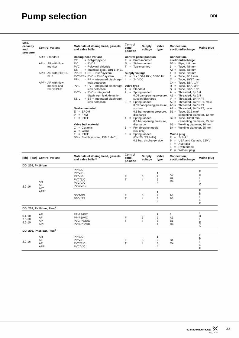
DDI 209, P<16 bar
2.2-16
ARAFAP*APF*
PP/E/CPP/V/CPP/V/GPVC/E/CPVC/V/CPVC/V/G
FT
3I
1234
A9B1C4
FBIEX
SS/T/SSSS/V/SS
FT
3I
1234
A9B6
FBIEX
DDI 209, P<10 bar, Plus3
0.4-102.5-105.5-10
ARAFAPAPF
PP-P3/E/CPP-P3/V/CPVC-P3/E/CPVC-P3/V/C
FT
3I
1234
3A5B1C4
FBIEX
DDI 209, P<16 bar, Plus3
2.2-16
ARAFAPAPF
PP/E/CPP/V/CPVC/E/CPVC/V/C
FT
3I
1234
B1C4
FBIEX
Max. capacity and pressure
Control variant Materials of dosing head, gaskets and valve balls
Control panel position
Supply voltage
Valve type
Connection, suction/discharge Mains plug
AR = Standard
AF = AR with flow monitor
AP = AR with PROFI-BUS
APF= AR with flow monitor and PROFIBUS
Dosing head variantPP = PolypropylenePV = PVDFPVC = Polyvinyl chlorideSS = Stainless steel, DIN 1.4401PP-P3 = PP + Plus3 systemPVC-P3= PVC + Plus3 systemPP-L = PP + integrated diaphragm
leak detectionPV-L = PV + integrated diaphragm
leak detectionPVC-L = PVC + integrated
diaphragm leak detectionSS-L = SS + integrated diaphragm
leak detection
Gasket materialE = EPDMV = FKMT = PTFE
Valve ball materialC = CeramicG = GlassT = PTFESS = Stainless steel, DIN 1.4401
Control panel positionF = Front-mounted S = Side-mounted T = Top-mounted
Supply voltage3 = 1 x 100-240 V, 50/60 HzI = 24 VDC
Valve type1 = Standard2 = Spring-loaded,
0.05 bar opening pressure, suction/discharge
3 = Spring-loaded, 0.05 bar opening pressure, suction0.8 bar opening pressure, discharge
4 = Spring-loaded,0.8 bar opening pressure, discharge
5 = For abrasive media (SS only)
6 = Spring-loaded, (DN 20, SS balls) 0.8 bar, discharge side
Connection, suction/dischargeB6 = Pipe, 4/6 mm3 = Tube, 4/6 mmA5 = Tube, 5/8 mm4 = Tube, 6/9 mm6 = Tube, 9/12 mmQ = Tube, 19/27 mmC4 = Tube, 1/8" / 1/4"R = Tube, 1/4" / 3/8"S = Tube, 3/8" / 1/2"A = Threaded, Rp 1/4A1 = Threaded, Rp 3/4V = Threaded, 1/4" NPT A9 = Threaded, 1/2" NPT, maleA3 = Threaded, 3/4" NPTA7 = Threaded, 3/4" NPT, maleB1 = Tube, 6/12 mm/
cementing diameter, 12 mmB2 = Tube, 13/20 mm/
cementing diameter, 25 mmB3 = Welding diameter, 16 mmB4 = Welding diameter, 25 mm
Mains plugF = SchukoB = USA and Canada, 120 VI = AustraliaE = SwitzerlandX = Without plug
[l/h] - [bar] Control variant Materials of dosing head, gaskets and valve balls**
Control panel position
Supply voltage
Valve type
Connection, suction/discharge Mains plug
33
34
Pump selection DDI
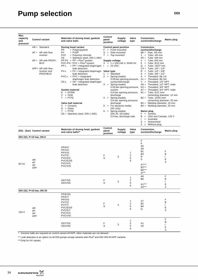
* Ceramic balls are required on control variant AF/APF, other materials are not allowed.
** Leak detection is an option on all DDI pumps except variants with Plus3 and DDI 209 AF/APF variants.***Only for HV variant.
DDI 222, P<10 bar, DN 8
60-10
ARAFAPAPF
PP/E/CPP/V/CPP/V/GPV/T/CPVC/E/CPVC/E/SSPVC/V/CPVC/V/G
FS 3
1256
46A5A9B1B3RS
A7***B2***B4***Q***
FBIEX
SS/T/SSSS/V/SS
FS 3
1256
A9B6
A1***A3***
FBIEX
DDI 222, P<10 bar, DN 20
150-4
ARAFAPAPF
PP/E/SSPP/E/TPP/V/GPV/T/CPV/T/TPVC/E/SSPVC/E/TPVC/V/CPVC/V/G
FS 3
1256
A7B2B4Q
FBIEX
SS/T/SSSS/V/SS
FS 3
1256
A1A3
FBIEX
Max. capacity and pressure
Control variant Materials of dosing head, gaskets and valve balls
Control panel position
Supply voltage
Valve type
Connection, suction/discharge Mains plug
AR = Standard
AF = AR with flow monitor
AP = AR with PROFI-BUS
APF= AR with flow monitor and PROFIBUS
Dosing head variantPP = PolypropylenePV = PVDFPVC = Polyvinyl chlorideSS = Stainless steel, DIN 1.4401PP-P3 = PP + Plus3 systemPVC-P3= PVC + Plus3 systemPP-L = PP + integrated diaphragm
leak detectionPV-L = PV + integrated diaphragm
leak detectionPVC-L = PVC + integrated
diaphragm leak detectionSS-L = SS + integrated diaphragm
leak detection
Gasket materialE = EPDMV = FKMT = PTFE
Valve ball materialC = CeramicG = GlassT = PTFESS = Stainless steel, DIN 1.4401
Control panel positionF = Front-mounted S = Side-mounted T = Top-mounted
Supply voltage3 = 1 x 100-240 V, 50/60 HzI = 24 VDC
Valve type1 = Standard2 = Spring-loaded,
0.05 bar opening pressure, suction/discharge
3 = Spring-loaded, 0.05 bar opening pressure, suction0.8 bar opening pressure, discharge
4 = Spring-loaded,0.8 bar opening pressure, discharge
5 = For abrasive media (SS only)
6 = Spring-loaded, (DN 20, SS balls) 0.8 bar, discharge side
Connection, suction/dischargeB6 = Pipe, 4/6 mm3 = Tube, 4/6 mmA5 = Tube, 5/8 mm4 = Tube, 6/9 mm6 = Tube, 9/12 mmQ = Tube, 19/27 mmC4 = Tube, 1/8" / 1/4"R = Tube, 1/4" / 3/8"S = Tube, 3/8" / 1/2"A = Threaded, Rp 1/4A1 = Threaded, Rp 3/4V = Threaded, 1/4" NPT A9 = Threaded, 1/2" NPT, maleA3 = Threaded, 3/4" NPTA7 = Threaded, 3/4" NPT, maleB1 = Tube, 6/12 mm/
cementing diameter, 12 mmB2 = Tube, 13/20 mm/
cementing diameter, 25 mmB3 = Welding diameter, 16 mmB4 = Welding diameter, 25 mm
Mains plugF = SchukoB = USA and Canada, 120 VI = AustraliaE = SwitzerlandX = Without plug
[l/h] - [bar] Control variant Materials of dosing head, gaskets and valve balls**
Control panel position
Supply voltage
Valve type
Connection, suction/discharge Mains plug
35
DDIPumped media
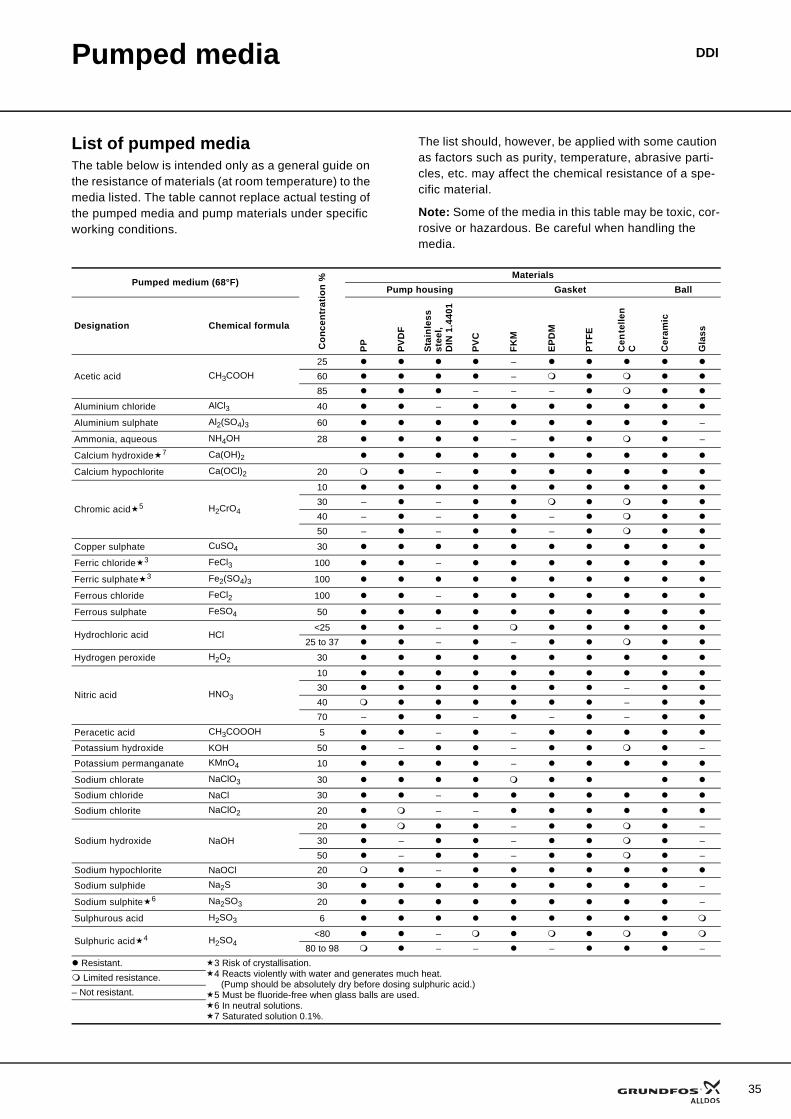
List of pumped mediaThe table below is intended only as a general guide on the resistance of materials (at room temperature) to the media listed. The table cannot replace actual testing of the pumped media and pump materials under specific working conditions.
The list should, however, be applied with some caution as factors such as purity, temperature, abrasive parti-cles, etc. may affect the chemical resistance of a spe-cific material.
Note: Some of the media in this table may be toxic, cor-rosive or hazardous. Be careful when handling the media.
Pumped medium (68°F)
Con
cent
ratio
n % Materials
Pump housing Gasket Ball
Designation Chemical formula
PP PVD
F
Stai
nles
s st
eel,
DIN
1.4
401
PVC
FKM
EPD
M
PTFE
Cen
telle
n C C
eram
ic
Gla
ss
Acetic acid CH3COOH25 –60 –85 – – –
Aluminium chloride AlCl3 40 –
Aluminium sulphate Al2(SO4)3 60 –
Ammonia, aqueous NH4OH 28 – –
Calcium hydroxide 7 Ca(OH)2Calcium hypochlorite Ca(OCl)2 20 –
Chromic acid 5 H2CrO4
1030 – –40 – – –50 – – –
Copper sulphate CuSO4 30
Ferric chloride 3 FeCl3 100 –
Ferric sulphate 3 Fe2(SO4)3 100
Ferrous chloride FeCl2 100 –
Ferrous sulphate FeSO4 50
Hydrochloric acid HCl<25 –
25 to 37 – –
Hydrogen peroxide H2O2 30
Nitric acid HNO3
1030 –40 –70 – – – –
Peracetic acid CH3COOOH 5 – –
Potassium hydroxide KOH 50 – – –
Potassium permanganate KMnO4 10 –
Sodium chlorate NaClO3 30
Sodium chloride NaCl 30 –
Sodium chlorite NaClO2 20 – –
Sodium hydroxide NaOH20 – –30 – – –50 – – –
Sodium hypochlorite NaOCl 20 –
Sodium sulphide Na2S 30 –
Sodium sulphite 6 Na2SO3 20 –
Sulphurous acid H2SO3 6
Sulphuric acid 4 H2SO4<80 –
80 to 98 – – – – Resistant. 3 Risk of crystallisation.
4 Reacts violently with water and generates much heat. (Pump should be absolutely dry before dosing sulphuric acid.)
5 Must be fluoride-free when glass balls are used.6 In neutral solutions.7 Saturated solution 0.1%.
Limited resistance.– Not resistant.
36
DDIFurther product documentation
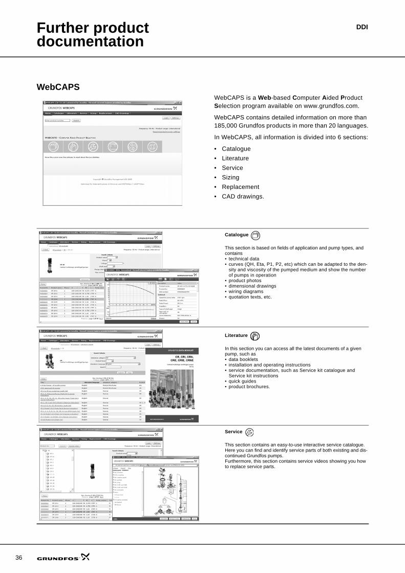
WebCAPSWebCAPS is a Web-based Computer Aided Product Selection program available on www.grundfos.com.
WebCAPS contains detailed information on more than 185,000 Grundfos products in more than 20 languages.
In WebCAPS, all information is divided into 6 sections:
• Catalogue• Literature• Service• Sizing• Replacement• CAD drawings.
Catalogue
This section is based on fields of application and pump types, and contains • technical data• curves (QH, Eta, P1, P2, etc) which can be adapted to the den-
sity and viscosity of the pumped medium and show the number of pumps in operation
• product photos• dimensional drawings• wiring diagrams• quotation texts, etc.
Literature
In this section you can access all the latest documents of a given pump, such as• data booklets• installation and operating instructions• service documentation, such as Service kit catalogue and
Service kit instructions• quick guides• product brochures.
Service
This section contains an easy-to-use interactive service catalogue. Here you can find and identify service parts of both existing and dis-continued Grundfos pumps.Furthermore, this section contains service videos showing you how to replace service parts.
Further product documentation
DDI
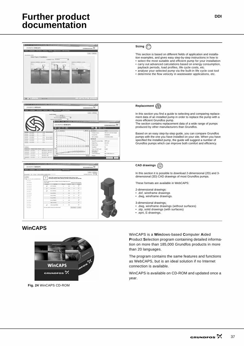
WinCAPS
Fig. 24 WinCAPS CD-ROM
WinCAPS is a Windows-based Computer Aided Product Selection program containing detailed informa-tion on more than 185,000 Grundfos products in more than 20 languages.
The program contains the same features and functions as WebCAPS, but is an ideal solution if no Internet connection is available.
WinCAPS is available on CD-ROM and updated once a year.
Sizing
This section is based on different fields of application and installa-tion examples, and gives easy step-by-step instructions in how to• select the most suitable and efficient pump for your installation• carry out advanced calculations based on energy consumption,
payback periods, load profiles, life cycle costs, etc.• analyse your selected pump via the built-in life cycle cost tool• determine the flow velocity in wastewater applications, etc.
Replacement
In this section you find a guide to selecting and comparing replace-ment data of an installed pump in order to replace the pump with a more efficient Grundfos pump. The section contains replacement data of a wide range of pumps produced by other manufacturers than Grundfos.
Based on an easy step-by-step guide, you can compare Grundfos pumps with the one you have installed on your site. When you have specified the installed pump, the guide will suggest a number of Grundfos pumps which can improve both comfort and efficiency.
CAD drawings
In this section it is possible to download 2-dimensional (2D) and 3-dimensional (3D) CAD drawings of most Grundfos pumps.
These formats are available in WebCAPS:
2-dimensional drawings:• .dxf, wireframe drawings• .dwg, wireframe drawings.
3-dimensional drawings:• .dwg, wireframe drawings (without surfaces)• .stp, solid drawings (with surfaces)• .eprt, E-drawings.
0 1
37
38
DDI

DDI
39

www.grundfosalldos.com
Grundfos Management A/SPoul Due Jensens Vej 7DK-8850 Bjerringbro
Telephone: +45 87 50 14 00
Grundfos Alldos Dosing & Disinfection Alldos Eichler GmbHReetzstrasse 85D-76327 Pfinztal (Söllingen)
Telephone: +49 72 40 61 0
Subject to alterations.
96699724 0307 GB
Being responsible is our foundationThinking ahead makes it possible
Innovation is the essence


![[XLS] · Web view28 209 70227595 29 209 70775496 30 209 70554395 31 209 70775195 32 209 70559596 33 209 70774296 34 209 70778999 35 209 70773995 36 209 70226095 37 209 70776596 38](https://img.pdfslide.net/doc/110x75/5b0cded17f8b9ab7658b981b/xls-view28-209-70227595-29-209-70775496-30-209-70554395-31-209-70775195-32-209.jpg)