Embed Size (px)
Citation preview
® SPECIF ICAT ION SUBMITTAL Page
Job Name:
Job Number:
Model Numbers:
Lutron GRX-TVI Power Interfaces
369247d 1 07.07.14
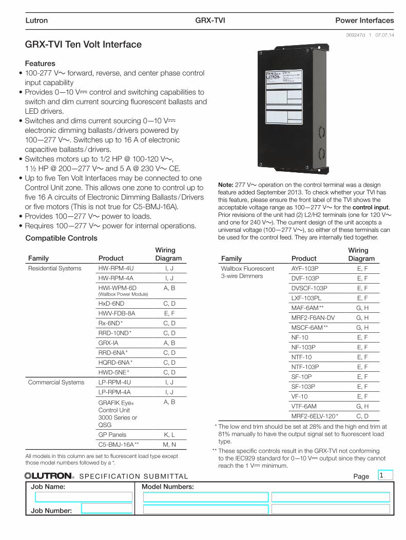
GRX-TVI Ten Volt Interface
Features• 100-277 V~ forward, reverse, and center phase control
input capability• Provides 0—10 V- control and switching capabilities to
switch and dim current sourcing fluorescent ballasts and LED drivers.
• Switches and dims current sourcing 0—10 V- electronic dimming ballasts / drivers powered by 100—277 V~. Switches up to 16 A of electronic capacitive ballasts / drivers.
• Switches motors up to 1/2 HP @ 100-120 V~, 1 ½ HP @ 200—277 V~ and 5 A @ 230 V~ CE.
• Up to five Ten Volt Interfaces may be connected to one Control Unit zone. This allows one zone to control up to five 16 A circuits of Electronic Dimming Ballasts / Drivers or five motors (This is not true for C5-BMJ-16A).
• Provides 100—277 V~ power to loads.• Requires 100—277 V~ power for internal operations.
Compatible Controls
Family ProductWiring Diagram
Residential Systems HW-RPM-4U I, J
HW-RPM-4A I, J
HWI-WPM-6D (Wallbox Power Module)
A, B
HxD-6ND C, D
HWV-FDB-8A E, F
Rx-6ND * C, D
RRD-10ND * C, D
GRX-IA A, B
RRD-6NA * C, D
HQRD-6NA * C, D
HWD-5NE * C, D
Commercial Systems LP-RPM-4U I, J
LP-RPM-4A I, J
GRAFIK EyeR Control Unit 3000 Series or QSG
A, B
GP Panels K, L
C5-BMJ-16A ** M, N
Family ProductWiring Diagram
Wallbox Fluorescent 3-wire Dimmers
AYF-103P E, F
DVF-103P E, F
DVSCF-103P E, F
LXF-103PL E, F
MAF-6AM ** G, H
MRF2-F6AN-DV G, H
MSCF-6AM ** G, H
NF-10 E, F
NF-103P E, F
NTF-10 E, F
NTF-103P E, F
SF-10P E, F
SF-103P E, F
VF-10 E, F
VTF-6AM G, H
MRF2-6ELV-120 * C, D
* The low end trim should be set at 28% and the high end trim at 81% manually to have the output signal set to fluorescent load type.
** These specific controls result in the GRX-TVI not conforming to the IEC929 standard for 0—10 V- output since they cannot reach the 1 V- minimum.
All models in this column are set to fluorescent load type except those model numbers followed by a *.
Note: 277 V~ operation on the control terminal was a design feature added September 2013. To check whether your TVI has this feature, please ensure the front label of the TVI shows the acceptable voltage range as 100—277 V~ for the control input. Prior revisions of the unit had (2) L2/H2 terminals (one for 120 V~ and one for 240 V~). The current design of the unit accepts a universal voltage (100—277 V~), so either of these terminals can be used for the control feed. They are internally tied together.
® SPECIF ICAT ION SUBMITTAL Page
Job Name:
Job Number:
Model Numbers:
Lutron GRX-TVI Power Interfaces
369247d 2 07.07.14
Specifications
Regulatory Approvals
• ULR Listed in US and Canada• CE• C-Tick
Power
• Control circuit: 100—277 V~. • Output/Load circuit: 100—277 V~.• Control and Load circuits are independent of each
other and can have unique phases.
0-10 V- Dimming Control
• Output rating: 10 µA—300 mA. Sinks current only (ballast / driver must source / provide 10 V- supply). <1 V- minimum, >10 V- maximum
Zone Capacity
• Up to five Ten Volt Interfaces per Control Unit zone. (This is not true for C5-BMJ-16A)
Key Design Features
• Complies with UL508 Standard.• Provides a Class 2 isolated 0—10 V- output signal
that conforms to EN60929 and IEC929.• Accepts a forward, reverse and center phase control
signal (100—277 V~ 50 / 60 Hz).
Terminals
• Each terminal accepts up to two 12 AWG (2.5 mm2) conductors.
Physical Design
• Wall-mounted. Indoor use only. Type 1 enclosure.• Weight: 4.25 lbs (2 kg).
Environment
• Temperature: 32 ºF to 104 ºF (0 ºC to 40 ºC)• 0 to 90% humidity, non-condensing.
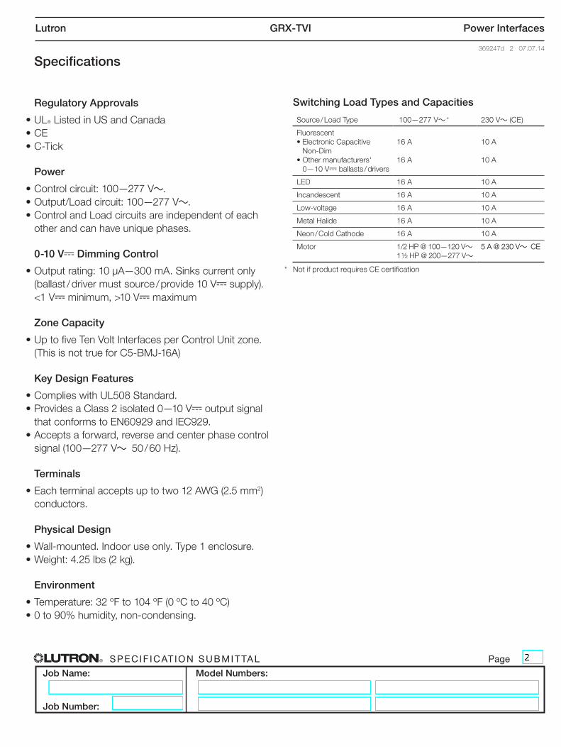
Switching Load Types and Capacities
Source / Load Type 100—277 V~ * 230 V~ (CE)
Fluorescent• Electronic Capacitive
Non-Dim• Other manufacturers'
0—10 V- ballasts / drivers
16 A
16 A
10 A
10 A
LED 16 A 10 A
Incandescent 16 A 10 A
Low-voltage 16 A 10 A
Metal Halide 16 A 10 A
Neon / Cold Cathode 16 A 10 A
Motor 1/2 HP @ 100—120 V~ 1 ½ HP @ 200—277 V~
5 A @ 230 V~ CE
* Not if product requires CE certification
® SPECIF ICAT ION SUBMITTAL Page
Job Name:
Job Number:
Model Numbers:
Lutron GRX-TVI Power Interfaces
369247d 3 07.07.14
COOPERSBURG, PA 18036 U.S.A.
0-10V INTERFACE CONTROLControl Input: 100-120V, 220-240V 50/60HzSwitches: 100-277VAC
GRX-TVI
Incandescent 16A
Fluorescent 5A
Magnetic Low-voltage 16A
Electronic Low-voltage 16A
Motor 1/4 HP@120VV772@PH 2/1
¨
GRX-TVI Input Rating
IH2 0.02AIDH2 0.1A
0-10V Output Rating
Max. 0.3A
Switched Rating
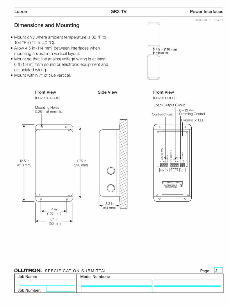
Dimensions and Mounting
• Mount only where ambient temperature is 32 °F to 104 °F (0 °C to 40 °C).
• Allow 4.5 in (114 mm) between Interfaces when mounting several in a vertical layout.
• Mount so that line (mains) voltage wiring is at least 6 ft (1.8 m) from sound or electronic equipment and associated wiring.
• Mount within 7° of true vertical.
Front View (cover closed)
Mounting Holes 0.25 in (6 mm) dia.
Load / Output Circuit
Control Circuit0—10 V- Dimming Control
Side View Front View (cover open)
12.5 in (318 mm)
4 in (102 mm)
3.3 in (84 mm)
6.1 in (155 mm)
11.75 in (298 mm)
COOPERSBURG, PA 18036 U.S.A.
0-10V INTERFACE CONTROLControl Input: 100-120V, 220-240V 50/60HzSwitches: 100-277VAC
GRX-TVI
Incandescent 16A
Fluorescent 5A
Magnetic Low-voltage 16A
Electronic Low-voltage 16A
Motor 1/4 HP@120VV772@PH 2/1
¨
GRX-TVI Input Rating
IH2 0.02AIDH2 0.1A
0-10V Output Rating
Max. 0.3A
Switched Rating
4.5 in (110 mm) minimum
Diagnostic LED
® SPECIF ICAT ION SUBMITTAL Page
Job Name:
Job Number:
Model Numbers:
Lutron GRX-TVI Power Interfaces
369247d 4 07.07.14
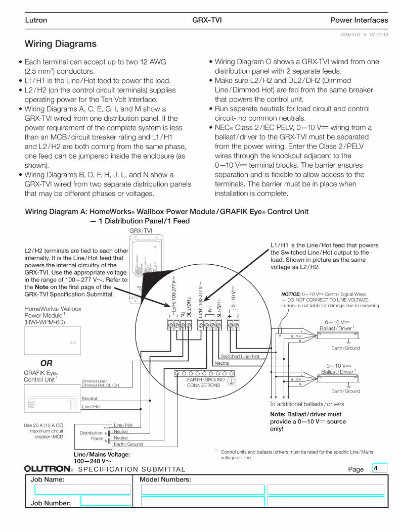
Wiring Diagrams
• Each terminal can accept up to two 12 AWG (2.5 mm2) conductors.• L1 / H1 is the Line / Hot feed to power the load.• L2 / H2 (on the control circuit terminals) supplies
operating power for the Ten Volt Interface.• Wiring Diagrams A, C, E, G, I, and M show a GRX-TVI wired from one distribution panel. If the
power requirement of the complete system is less than an MCB / circuit breaker rating and L1 / H1 and L2 / H2 are both coming from the same phase, one feed can be jumpered inside the enclosure (as shown).
• Wiring Diagrams B, D, F, H, J, L, and N show a GRX-TVI wired from two separate distribution panels
that may be different phases or voltages.
• Wiring Diagram O shows a GRX-TVI wired from one distribution panel with 2 separate feeds.
• Make sure L2 / H2 and DL2 / DH2 (Dimmed Line / Dimmed Hot) are fed from the same breaker that powers the control unit.
• Run separate neutrals for load circuit and control circuit- no common neutrals.
• NEC® Class 2 / IEC PELV, 0—10 V- wiring from a ballast / driver to the GRX-TVI must be separated from the power wiring. Enter the Class 2 / PELV wires through the knockout adjacent to the
0—10 V- terminal blocks. The barrier ensures separation and is flexible to allow access to the terminals. The barrier must be in place when installation is complete.
Wiring Diagram A: HomeWorks® Wallbox Power Module / GRAFIK Eye® Control Unit — 1 Distribution Panel / 1 Feed
V-
100-127 V~
220-240 V~
L 2/H
2 100
-277
V~
LUTRON
LUTRON
GRX-TVI
HomeWorksR Wallbox Power Module 1 (HWI-WPM-6D)
L2 / H2 terminals are tied to each other internally. It is the Line / Hot feed that powers the internal circuitry of the GRX-TVI. Use the appropriate voltage in the range of 100—277 V~. Refer to the Note on the first page of the GRX-TVI Specification Submittal.
To additional ballasts / drivers
EARTH / GROUND CONNECTIONS
OR
Dimmed Line / Dimmed Hot, DL / DH
Switched Line / Hot
Line / Hot
Line / Hot
0—10 V- Ballast / Driver 1
0—10 V- Ballast / Driver 1
Earth / Ground
Earth / Ground
NOTICE: 0—10 V- Control Signal Wires — DO NOT CONNECT TO LINE VOLTAGE. LutronR is not liable for damage due to miswiring.
Use 20 A (10 A CE) maximum circuit
breaker / MCB
Neutral
Neutral Distribution Panel
Neutral
Earth / Ground
Note: Ballast / driver must provide a 0—10 V- source only!
L1 / H1 is the Line / Hot feed that powers the Switched Line / Hot output to the load. Shown in picture as the same voltage as L2 / H2.
Neutral
Line / Mains Voltage: 100—240 V~
GRAFIK EyeR Control Unit 1
1 Control units and ballasts / drivers must be rated for the specific Line / Mains voltage utilized.
® SPECIF ICAT ION SUBMITTAL Page
Job Name:
Job Number:
Model Numbers:
Lutron GRX-TVI Power Interfaces
369247d 5 07.07.14
L2/H
2 100
-277
V~
LUTRON
LUTRON
GRX-TVI
To additional ballast / drivers
Note: Ballast / driver must provide a 0—10 V- source only!
EARTH / GROUND CONNECTIONS
GRAFIK EyeR Control Unit 1
OR
Dimmed Line / Dimmed Hot, DL / DH
Switched Line / Hot
Line / Hot
Line / Hot
Line / Hot
Earth / Ground
Earth / Ground
NOTICE: 0—10 V- Control Signal Wires — DO NOT CONNECT TO LINE VOLTAGE. LutronR is not liable for damage due to miswiring.
Use 20 A (10 A CE) maximum circuit
breaker / MCB
Neutral
Neutral
Neutral
Distribution Panel A
Distribution Panel B
Neutral
Earth / Ground
Earth / Ground
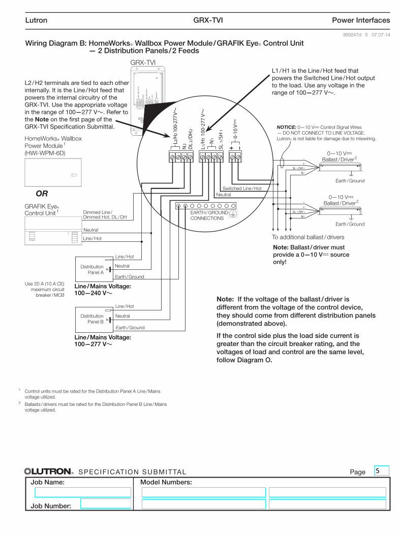
Wiring Diagram B: HomeWorksR Wallbox Power Module / GRAFIK EyeR Control Unit — 2 Distribution Panels / 2 Feeds
HomeWorksR Wallbox Power Module 1 (HWI-WPM-6D)
L2 / H2 terminals are tied to each other internally. It is the Line / Hot feed that powers the internal circuitry of the GRX-TVI. Use the appropriate voltage in the range of 100—277 V~. Refer to the Note on the first page of the GRX-TVI Specification Submittal.
L1 / H1 is the Line / Hot feed that powers the Switched Line / Hot output to the load. Use any voltage in the range of 100—277 V~.
Note: If the voltage of the ballast / driver is different from the voltage of the control device, they should come from different distribution panels (demonstrated above).
If the control side plus the load side current is greater than the circuit breaker rating, and the voltages of load and control are the same level, follow Diagram O.
Line / Mains Voltage: 100—277 V~
0—10 V- Ballast / Driver 2
0—10 V- Ballast / Driver 2
1 Control units must be rated for the Distribution Panel A Line / Mains voltage utilized.
2 Ballasts / drivers must be rated for the Distribution Panel B Line / Mains voltage utilized.
Line / Mains Voltage: 100—240 V~
® SPECIF ICAT ION SUBMITTAL Page
Job Name:
Job Number:
Model Numbers:
Lutron GRX-TVI Power Interfaces
369247d 6 07.07.14
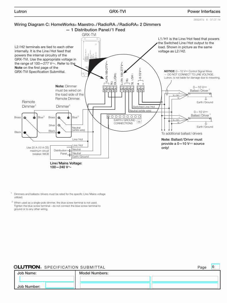
Wiring Diagram C: HomeWorks® MaestroR / RadioRAR / RadioRA® 2 Dimmers — 1 Distribution Panel / 1 Feed
L2/H
2 100
-277
V~
GRX-TVI
Remote Dimmer1 Dimmer1
To additional ballast / drivers
EARTH / GROUND CONNECTIONS
Blue 2Brass
Black
Blue 2Brass
Silver
Black
Switched Line / Hot
Line / Hot
Line / Hot
Earth / Ground
Earth / Ground
NOTICE: 0—10 V- Control Signal Wires — DO NOT CONNECT TO LINE VOLTAGE. LutronR is not liable for damage due to miswiring.
Use 20 A (10 A CE) maximum circuit
breaker / MCB Neutral
Neutral (white wire)
Distribution Panel
Neutral (white wire)
Earth / Ground
Note: Ballast / Driver must provide a 0—10 V- source only!
Note: Dimmer must be wired on the load side of the Remote Dimmer.
L2 / H2 terminals are tied to each other internally. It is the Line / Hot feed that powers the internal circuitry of the GRX-TVI. Use the appropriate voltage in the range of 100—277 V~. Refer to the Note on the first page of the GRX-TVI Specification Submittal.
L1 / H1 is the Line / Hot feed that powers the Switched Line / Hot output to the load. Shown in picture as the same voltage as L2 / H2.
Neutral
Line / Mains Voltage: 100—240 V~
2 When used as a single-pole dimmer, the blue screw terminal is not used. Tighten the blue screw terminal—do not connect the blue screw terminal to ground or to any other wiring.
0—10 V- Ballast / Driver 1
0—10 V- Ballast / Driver 1
1 Dimmers and ballasts / drivers must be rated for the specific Line / Mains voltage utilized.
® SPECIF ICAT ION SUBMITTAL Page
Job Name:
Job Number:
Model Numbers:
Lutron GRX-TVI Power Interfaces
369247d 7 07.07.14
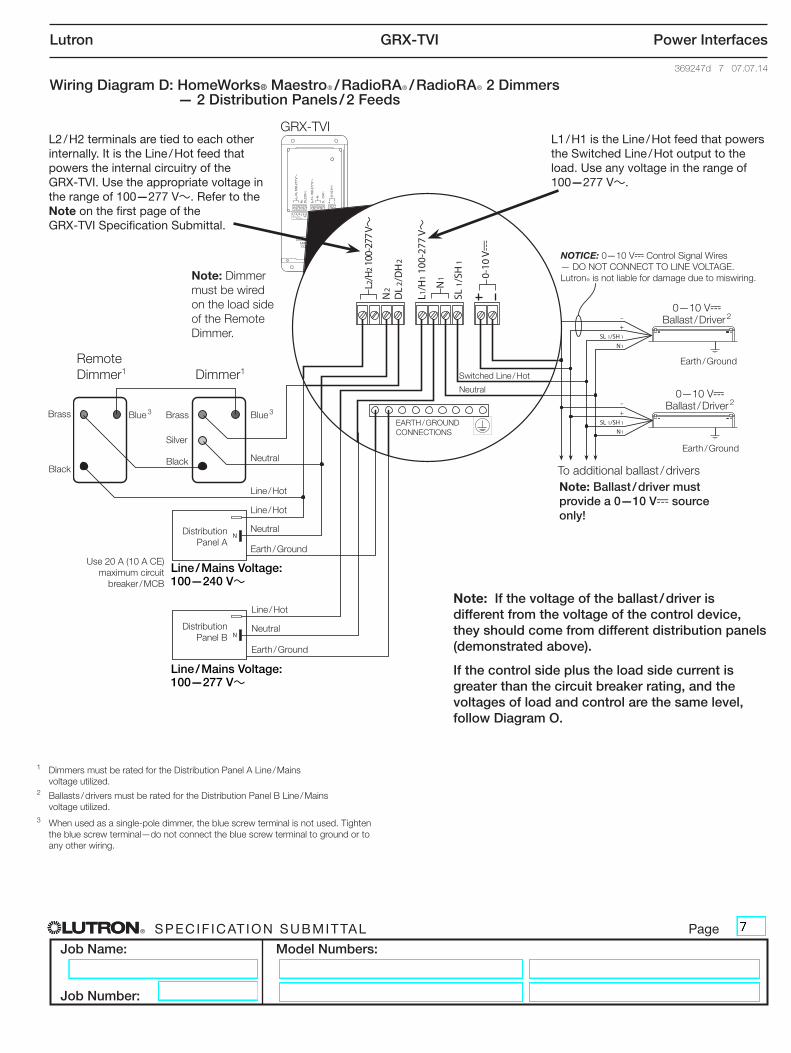
Wiring Diagram D: HomeWorks® MaestroR / RadioRAR / RadioRAR 2 Dimmers — 2 Distribution Panels / 2 Feeds
L2/H
2 100
-277
V~
GRX-TVI
To additional ballast / drivers
EARTH / GROUND CONNECTIONS
Blue 3Brass
Black
Blue 3Brass
Silver
Black
Switched Line / Hot
Line / Hot
Line / Hot
Earth / Ground
Earth / Ground
NOTICE: 0—10 V- Control Signal Wires — DO NOT CONNECT TO LINE VOLTAGE. LutronR is not liable for damage due to miswiring.
Use 20 A (10 A CE) maximum circuit
breaker / MCB
Neutral
Neutral
Neutral
Earth / Ground
Note: Ballast / driver must provide a 0—10 V- source only!
Line / Hot
Neutral
Distribution Panel A
Distribution Panel B
Earth / Ground
Note: Dimmer must be wired on the load side of the Remote Dimmer.
Note: If the voltage of the ballast / driver is different from the voltage of the control device, they should come from different distribution panels (demonstrated above).
If the control side plus the load side current is greater than the circuit breaker rating, and the voltages of load and control are the same level, follow Diagram O.
L2 / H2 terminals are tied to each other internally. It is the Line / Hot feed that powers the internal circuitry of the GRX-TVI. Use the appropriate voltage in the range of 100—277 V~. Refer to the Note on the first page of the GRX-TVI Specification Submittal.
L1 / H1 is the Line / Hot feed that powers the Switched Line / Hot output to the load. Use any voltage in the range of 100—277 V~.
Line / Mains Voltage: 100—277 V~
Remote Dimmer1 Dimmer1
0—10 V- Ballast / Driver 2
0—10 V- Ballast / Driver 2
1 Dimmers must be rated for the Distribution Panel A Line / Mains voltage utilized.
2 Ballasts / drivers must be rated for the Distribution Panel B Line / Mains voltage utilized.
3 When used as a single-pole dimmer, the blue screw terminal is not used. Tighten the blue screw terminal—do not connect the blue screw terminal to ground or to any other wiring.
Line / Mains Voltage: 100—240 V~
® SPECIF ICAT ION SUBMITTAL Page
Job Name:
Job Number:
Model Numbers:
Lutron GRX-TVI Power Interfaces
369247d 8 07.07.14
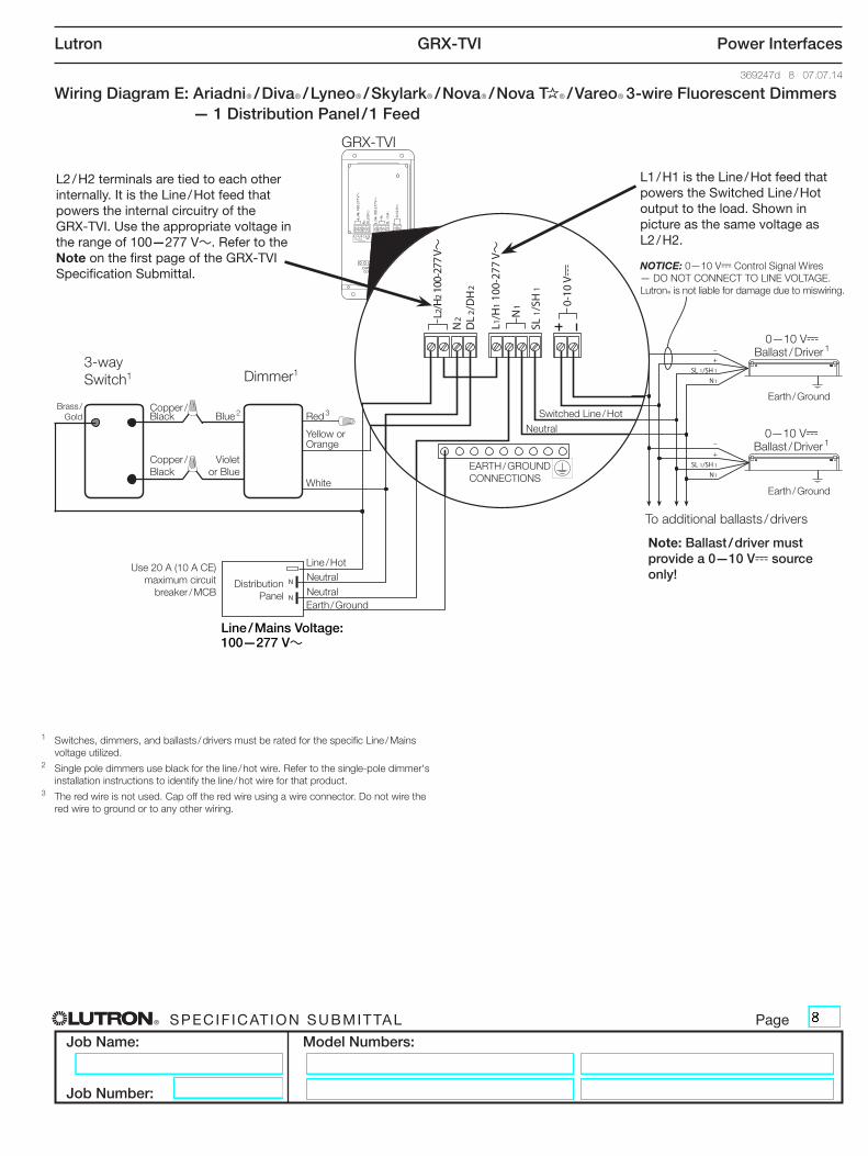
Wiring Diagram E: AriadniR / DivaR / LyneoR / SkylarkR / NovaR / Nova T R / VareoR 3-wire Fluorescent Dimmers — 1 Distribution Panel / 1 Feed
L2/H
2 100
-277
V~
GRX-TVI
Dimmer1
To additional ballasts / drivers
EARTH / GROUND CONNECTIONS
Red 3Blue 2Brass /
GoldCopper /Black
Copper /Black
Violet or Blue
Switched Line / Hot
Line / Hot
Earth / Ground
Earth / Ground
NOTICE: 0—10 V- Control Signal Wires — DO NOT CONNECT TO LINE VOLTAGE. LutronR is not liable for damage due to miswiring.
Use 20 A (10 A CE) maximum circuit
breaker / MCB Neutral
White
Yellow or Orange
Distribution Panel
Neutral
Earth / Ground
Note: Ballast / driver must provide a 0—10 V- source only!
L2 / H2 terminals are tied to each other internally. It is the Line / Hot feed that powers the internal circuitry of the GRX-TVI. Use the appropriate voltage in the range of 100—277 V~. Refer to the Note on the first page of the GRX-TVI Specification Submittal.
L1 / H1 is the Line / Hot feed that powers the Switched Line / Hot output to the load. Shown in picture as the same voltage as L2 / H2.
Neutral
Line / Mains Voltage: 100—277 V~
0—10 V- Ballast / Driver 1
0—10 V- Ballast / Driver 1
1 Switches, dimmers, and ballasts / drivers must be rated for the specific Line / Mains voltage utilized.
2 Single pole dimmers use black for the line / hot wire. Refer to the single-pole dimmer's installation instructions to identify the line / hot wire for that product.
3 The red wire is not used. Cap off the red wire using a wire connector. Do not wire the red wire to ground or to any other wiring.
3-way Switch1
® SPECIF ICAT ION SUBMITTAL Page
Job Name:
Job Number:
Model Numbers:
Lutron GRX-TVI Power Interfaces
369247d 9 07.07.14
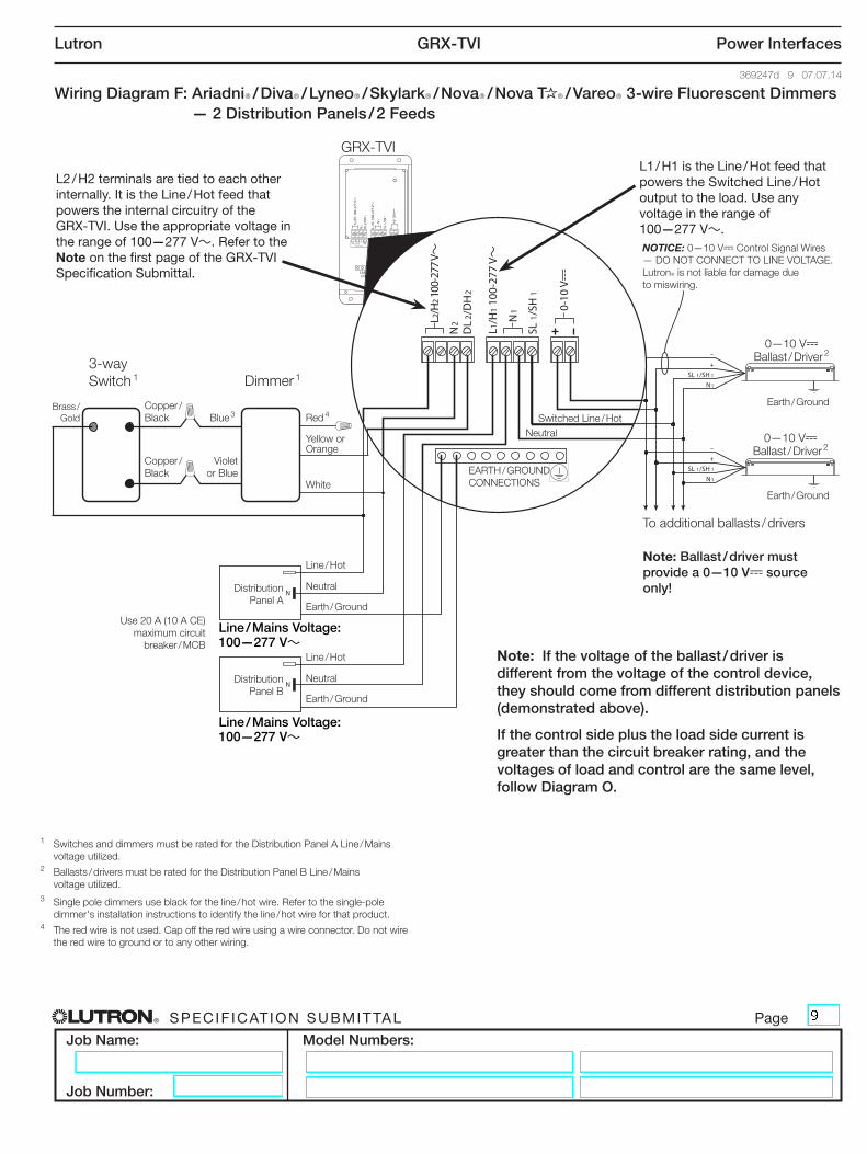
Wiring Diagram F: AriadniR / DivaR / LyneoR / SkylarkR / NovaR / Nova T R / VareoR 3-wire Fluorescent Dimmers — 2 Distribution Panels / 2 Feeds
L2/H
2 100
-277
V~
Line / Hot
Neutral
Earth / Ground
Distribution Panel B
GRX-TVI
3-way Switch 1
To additional ballasts / drivers
EARTH / GROUND CONNECTIONS
Red 4Blue 3Brass /
GoldCopper /Black
Copper /Black
Violet or Blue
Switched Line / Hot
Line / Hot
Earth / Ground
Earth / Ground
NOTICE: 0—10 V- Control Signal Wires — DO NOT CONNECT TO LINE VOLTAGE. LutronR is not liable for damage due to miswiring.
Use 20 A (10 A CE) maximum circuit
breaker / MCB
Neutral
White
Yellow or Orange
Distribution Panel A
Neutral
Earth / Ground
Note: Ballast / driver must provide a 0—10 V- source only!
L2 / H2 terminals are tied to each other internally. It is the Line / Hot feed that powers the internal circuitry of the GRX-TVI. Use the appropriate voltage in the range of 100—277 V~. Refer to the Note on the first page of the GRX-TVI Specification Submittal.
L1 / H1 is the Line / Hot feed that powers the Switched Line / Hot output to the load. Use any voltage in the range of 100—277 V~.
Note: If the voltage of the ballast / driver is different from the voltage of the control device, they should come from different distribution panels (demonstrated above).
If the control side plus the load side current is greater than the circuit breaker rating, and the voltages of load and control are the same level, follow Diagram O.
Line / Mains Voltage: 100—277 V~
0—10 V- Ballast / Driver 2
0—10 V- Ballast / Driver 2
1 Switches and dimmers must be rated for the Distribution Panel A Line / Mains voltage utilized.
2 Ballasts / drivers must be rated for the Distribution Panel B Line / Mains voltage utilized.
3 Single pole dimmers use black for the line / hot wire. Refer to the single-pole dimmer's installation instructions to identify the line / hot wire for that product.
4 The red wire is not used. Cap off the red wire using a wire connector. Do not wire the red wire to ground or to any other wiring.
Dimmer 1
Line / Mains Voltage: 100—277 V~
® SPECIF ICAT ION SUBMITTAL Page
Job Name:
Job Number:
Model Numbers:
Lutron GRX-TVI Power Interfaces
369247d 10 07.07.14
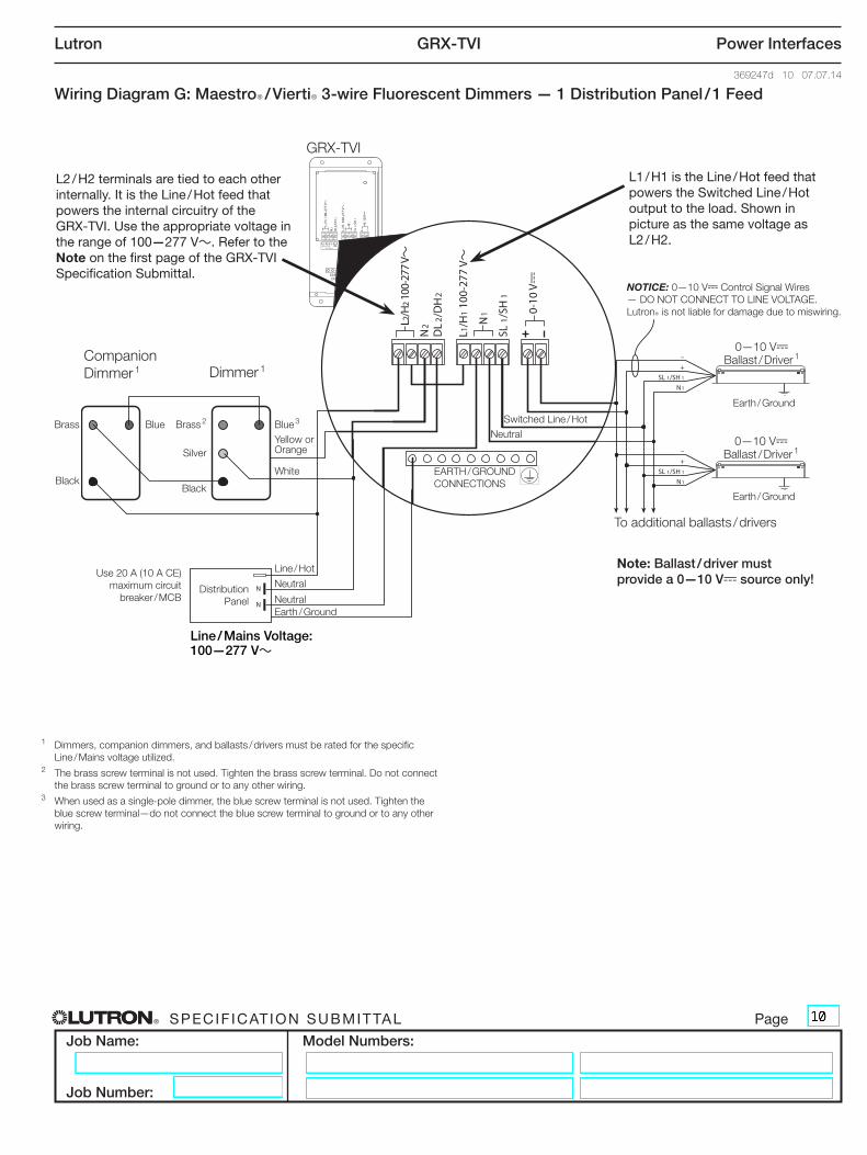
Wiring Diagram G: MaestroR / ViertiR 3-wire Fluorescent Dimmers — 1 Distribution Panel / 1 Feed
L2/H
2 100
-277
V~
GRX-TVI
Companion Dimmer 1
To additional ballasts / drivers
EARTH / GROUND CONNECTIONS
Blue 3Blue Brass 2Brass
Black
Silver
Black
Switched Line / Hot
Line / Hot
Earth / Ground
Earth / Ground
NOTICE: 0—10 V- Control Signal Wires — DO NOT CONNECT TO LINE VOLTAGE. LutronR is not liable for damage due to miswiring.
Use 20 A (10 A CE) maximum circuit
breaker / MCB Neutral
Yellow or Orange
Distribution Panel
Neutral
Earth / Ground
Note: Ballast / driver must provide a 0—10 V- source only!
L2 / H2 terminals are tied to each other internally. It is the Line / Hot feed that powers the internal circuitry of the GRX-TVI. Use the appropriate voltage in the range of 100—277 V~. Refer to the Note on the first page of the GRX-TVI Specification Submittal.
L1 / H1 is the Line / Hot feed that powers the Switched Line / Hot output to the load. Shown in picture as the same voltage as L2 / H2.
Neutral
White
Line / Mains Voltage: 100—277 V~
0—10 V- Ballast / Driver 1
0—10 V- Ballast / Driver 1
1 Dimmers, companion dimmers, and ballasts / drivers must be rated for the specific Line / Mains voltage utilized.
2 The brass screw terminal is not used. Tighten the brass screw terminal. Do not connect the brass screw terminal to ground or to any other wiring.
3 When used as a single-pole dimmer, the blue screw terminal is not used. Tighten the blue screw terminal—do not connect the blue screw terminal to ground or to any other wiring.
Dimmer 1
® SPECIF ICAT ION SUBMITTAL Page
Job Name:
Job Number:
Model Numbers:
Lutron GRX-TVI Power Interfaces
369247d 11 07.07.14
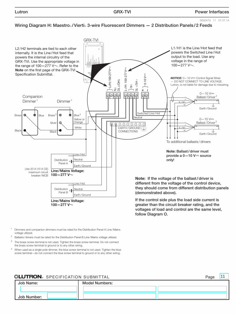
Wiring Diagram H: MaestroR / ViertiR 3-wire Fluorescent Dimmers — 2 Distribution Panels / 2 Feeds
L2/H
2 100
-277
V~
Line / Hot
Neutral
Earth / Ground
Distribution Panel B
GRX-TVI
To additional ballasts / drivers
EARTH / GROUND CONNECTIONS
Switched Line / Hot
Line / Hot
Earth / Ground
Earth / Ground
NOTICE: 0—10 V- Control Signal Wires — DO NOT CONNECT TO LINE VOLTAGE. LutronR is not liable for damage due to miswiring.
Use 20 A (10 A CE) maximum circuit
breaker / MCB
Neutral Distribution Panel A
Neutral
Earth / Ground
Note: Ballast / driver must provide a 0—10 V- source only!
Companion Dimmer 1
Blue 4Blue Brass 3Brass
Black
Silver
Black
Yellow or Orange
L2 / H2 terminals are tied to each other internally. It is the Line / Hot feed that powers the internal circuitry of the GRX-TVI. Use the appropriate voltage in the range of 100—277 V~. Refer to the Note on the first page of the GRX-TVI Specification Submittal.
L1 / H1 is the Line / Hot feed that powers the Switched Line / Hot output to the load. Use any voltage in the range of 100—277 V~.
Note: If the voltage of the ballast / driver is different from the voltage of the control device, they should come from different distribution panels (demonstrated above).
If the control side plus the load side current is greater than the circuit breaker rating, and the voltages of load and control are the same level, follow Diagram O.
White
Line / Mains Voltage: 100—277 V~
0—10 V- Ballast / Driver 2
0—10 V- Ballast / Driver 2
1 Dimmers and companion dimmers must be rated for the Distribution Panel A Line / Mains voltage utilized.
2 Ballasts / drivers must be rated for the Distribution Panel B Line / Mains voltage utilized.3 The brass screw terminal is not used. Tighten the brass screw terminal. Do not connect
the brass screw terminal to ground or to any other wiring.4 When used as a single-pole dimmer, the blue screw terminal is not used. Tighten the blue
screw terminal—do not connect the blue screw terminal to ground or to any other wiring.
Dimmer 1
Line / Mains Voltage: 100—277 V~
® SPECIF ICAT ION SUBMITTAL Page
Job Name:
Job Number:
Model Numbers:
Lutron GRX-TVI Power Interfaces
369247d 12 07.07.14
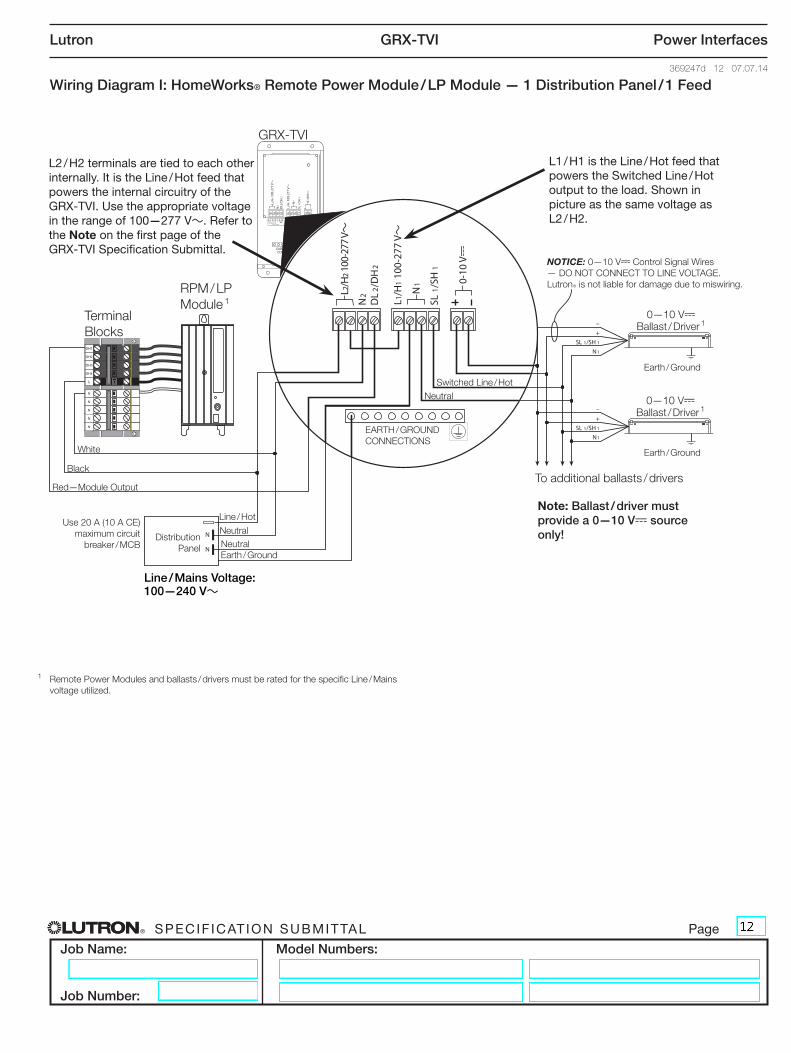
Wiring Diagram I: HomeWorks® Remote Power Module / LP Module — 1 Distribution Panel / 1 Feed
L2/H
2 100
-277
V~
GRX-TVI
To additional ballasts / drivers
EARTH / GROUND CONNECTIONS
Red—Module Output
Switched Line / Hot
Line / Hot
Earth / Ground
Earth / Ground
NOTICE: 0—10 V- Control Signal Wires — DO NOT CONNECT TO LINE VOLTAGE. LutronR is not liable for damage due to miswiring.
Use 20 A (10 A CE) maximum circuit
breaker / MCB
Neutral
White
Black
Distribution Panel
Neutral
Earth / Ground
Note: Ballast / driver must provide a 0—10 V- source only!
RPM / LP Module 1
Terminal Blocks
L2 / H2 terminals are tied to each other internally. It is the Line / Hot feed that powers the internal circuitry of the GRX-TVI. Use the appropriate voltage in the range of 100—277 V~. Refer to the Note on the first page of the GRX-TVI Specification Submittal.
L1 / H1 is the Line / Hot feed that powers the Switched Line / Hot output to the load. Shown in picture as the same voltage as L2 / H2.
Neutral
Line / Mains Voltage: 100—240 V~
0—10 V- Ballast / Driver 1
0—10 V- Ballast / Driver 1
1 Remote Power Modules and ballasts / drivers must be rated for the specific Line / Mains voltage utilized.
® SPECIF ICAT ION SUBMITTAL Page
Job Name:
Job Number:
Model Numbers:
Lutron GRX-TVI Power Interfaces
369247d 13 07.07.14
L2/H
2 100
-277
V~
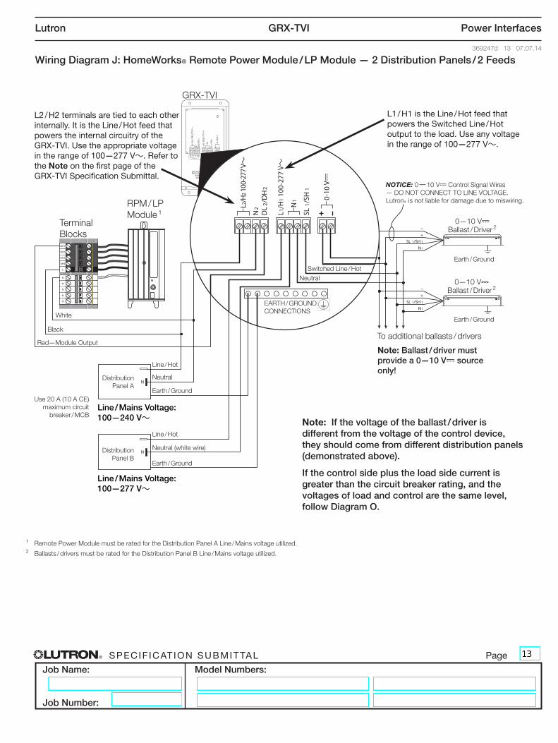
Wiring Diagram J: HomeWorks® Remote Power Module / LP Module — 2 Distribution Panels / 2 Feeds
Line / Hot
Neutral (white wire)
Earth / Ground
Distribution Panel B
Distribution Panel A
GRX-TVI
To additional ballasts / drivers
EARTH / GROUND CONNECTIONS
Red—Module Output
Switched Line / Hot
Line / Hot
Earth / Ground
Earth / Ground
NOTICE: 0—10 V- Control Signal Wires — DO NOT CONNECT TO LINE VOLTAGE. LutronR is not liable for damage due to miswiring.
Use 20 A (10 A CE) maximum circuit
breaker / MCB
Neutral
White
Black
Neutral
Earth / Ground
Note: Ballast / driver must provide a 0—10 V- source only!
RPM / LP Module 1
Terminal Blocks
L2 / H2 terminals are tied to each other internally. It is the Line / Hot feed that powers the internal circuitry of the GRX-TVI. Use the appropriate voltage in the range of 100—277 V~. Refer to the Note on the first page of the GRX-TVI Specification Submittal.
L1 / H1 is the Line / Hot feed that powers the Switched Line / Hot output to the load. Use any voltage in the range of 100—277 V~.
Note: If the voltage of the ballast / driver is different from the voltage of the control device, they should come from different distribution panels (demonstrated above).
If the control side plus the load side current is greater than the circuit breaker rating, and the voltages of load and control are the same level, follow Diagram O.
Line / Mains Voltage: 100—277 V~
0—10 V- Ballast / Driver 2
0—10 V- Ballast / Driver 2
1 Remote Power Module must be rated for the Distribution Panel A Line / Mains voltage utilized.2 Ballasts / drivers must be rated for the Distribution Panel B Line / Mains voltage utilized.
Line / Mains Voltage: 100—240 V~
® SPECIF ICAT ION SUBMITTAL Page
Job Name:
Job Number:
Model Numbers:
Lutron GRX-TVI Power Interfaces
369247d 14 07.07.14
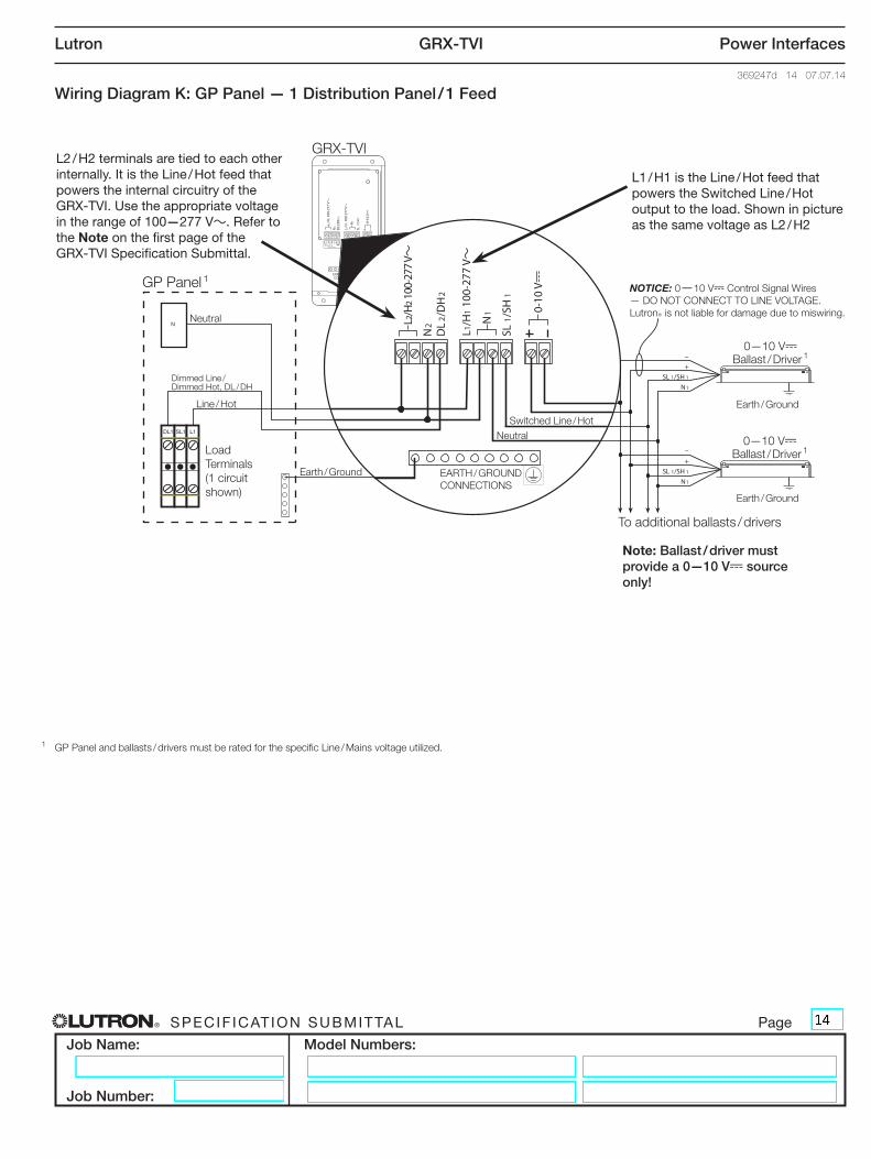
Wiring Diagram K: GP Panel — 1 Distribution Panel / 1 Feed
L2/H
2 100
-277
V~
GRX-TVI
To additional ballasts / drivers
EARTH / GROUND CONNECTIONS
Switched Line / Hot
Line / Hot
Dimmed Line / Dimmed Hot, DL / DH
Earth / Ground
Earth / Ground
NOTICE: 0—10 V- Control Signal Wires — DO NOT CONNECT TO LINE VOLTAGE. LutronR is not liable for damage due to miswiring.Neutral
Neutral
Earth / Ground
Note: Ballast / driver must provide a 0—10 V- source only!
GP Panel 1
Load Terminals (1 circuit shown)
L2 / H2 terminals are tied to each other internally. It is the Line / Hot feed that powers the internal circuitry of the GRX-TVI. Use the appropriate voltage in the range of 100—277 V~. Refer to the Note on the first page of the GRX-TVI Specification Submittal.
L1 / H1 is the Line / Hot feed that powers the Switched Line / Hot output to the load. Shown in picture as the same voltage as L2 / H2
0—10 V- Ballast / Driver 1
0—10 V- Ballast / Driver 1
1 GP Panel and ballasts / drivers must be rated for the specific Line / Mains voltage utilized.
® SPECIF ICAT ION SUBMITTAL Page
Job Name:
Job Number:
Model Numbers:
Lutron GRX-TVI Power Interfaces
369247d 15 07.07.14
L2/H
2 100
-277
V~
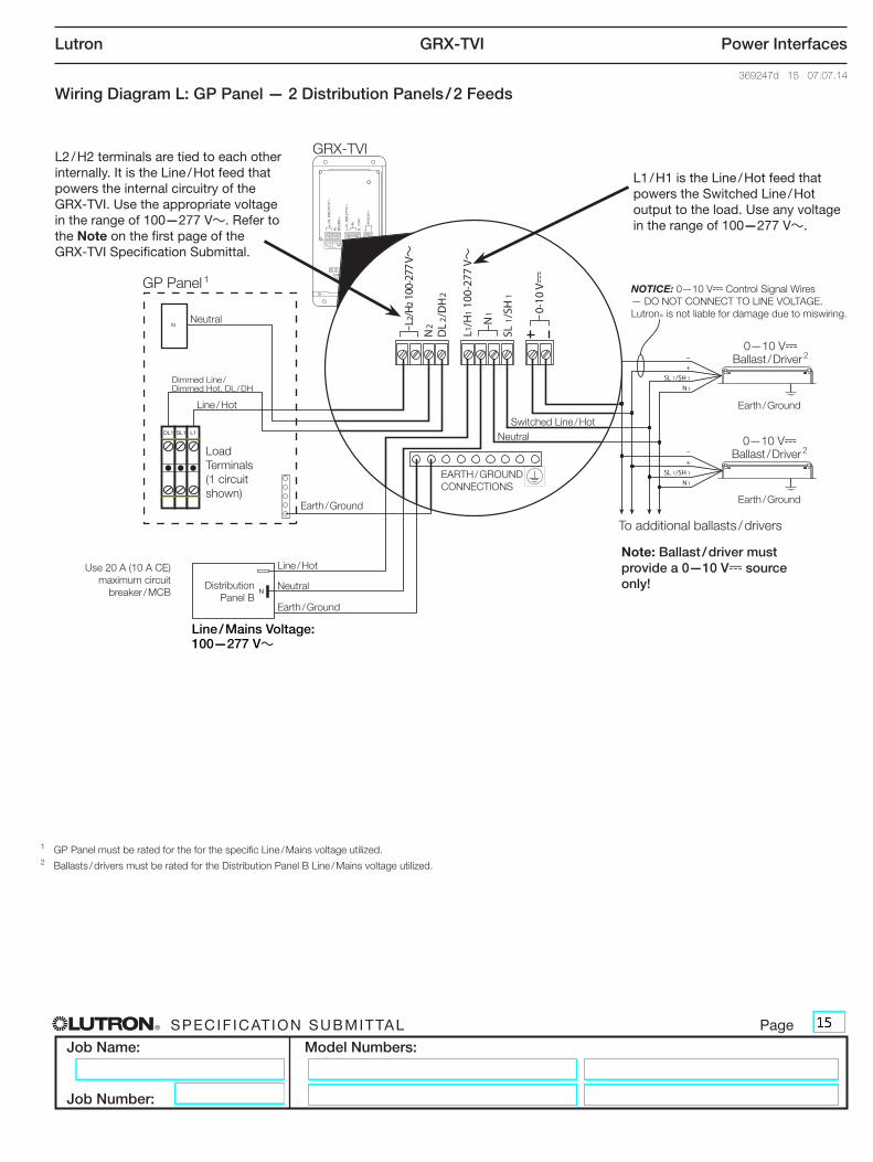
Wiring Diagram L: GP Panel — 2 Distribution Panels / 2 Feeds
Use 20 A (10 A CE) maximum circuit
breaker / MCBDistribution
Panel B
GRX-TVI
To additional ballasts / drivers
EARTH / GROUND CONNECTIONS
Switched Line / Hot
Line / Hot
Dimmed Line / Dimmed Hot, DL / DH
Earth / Ground
Earth / Ground
NOTICE: 0—10 V- Control Signal Wires — DO NOT CONNECT TO LINE VOLTAGE. LutronR is not liable for damage due to miswiring.Neutral
Neutral
Earth / Ground
Note: Ballast / driver must provide a 0—10 V- source only!
GP Panel 1
Load Terminals (1 circuit shown)
Line / Hot
Neutral
Earth / Ground
L2 / H2 terminals are tied to each other internally. It is the Line / Hot feed that powers the internal circuitry of the GRX-TVI. Use the appropriate voltage in the range of 100—277 V~. Refer to the Note on the first page of the GRX-TVI Specification Submittal.
L1 / H1 is the Line / Hot feed that powers the Switched Line / Hot output to the load. Use any voltage in the range of 100—277 V~.
Line / Mains Voltage: 100—277 V~
0—10 V- Ballast / Driver 2
0—10 V- Ballast / Driver 2
1 GP Panel must be rated for the for the specific Line / Mains voltage utilized.2 Ballasts / drivers must be rated for the Distribution Panel B Line / Mains voltage utilized.
® SPECIF ICAT ION SUBMITTAL Page
Job Name:
Job Number:
Model Numbers:
Lutron GRX-TVI Power Interfaces
369247d 16 07.07.14
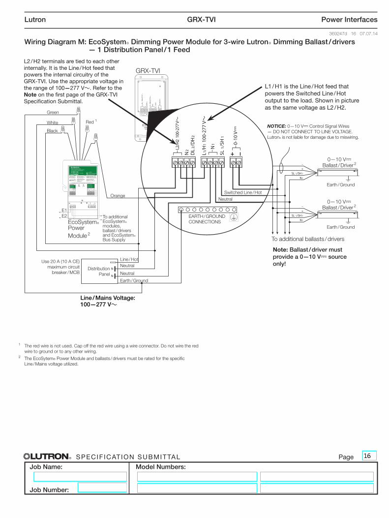
Wiring Diagram M: EcoSystemR Dimming Power Module for 3-wire LutronR Dimming Ballast / drivers — 1 Distribution Panel / 1 Feed
L2/H
2 1
00-2
77 V~
E1
E1
+20V
Common
IR OCC
Daylight
E2
E2
Class 2 Sensors
Capteurs Classe 2
Sensores Clase 2
Class 2 LinkLien Classe 2Enlace Clase 2
EcoSystem®
Multiple Fixture Dimming ControlContrôle de gradation de multiples luminairesControl atenuador de múltiples lámparas
PWR STAT
Indicateur de puissance (PWR)On: l’unité est alimentéeOff: l’unité n’est pas alimentée ou est dysfonctionnelle
Indicateur d’activité (STAT)Plein: Niveau de circuit Impulsion: Aucune communication
Power Indicator (PWR)On: Unit is poweredOff: Unit is not powered or is malfunctioning
Status Indicator (STAT)Solid: Circuit LevelPulse: No communication
Indicador de Alimentación (PWR)Encendido: unidad tiene corrienteApagado: unidad no tiene corriente o no está funcionando correctamente
Indicador de estado (STAT)Sólido: Nivel del CircuitoPulsante: No hay comunicación
C5-BMJ-16A
CO
M
DY
LT
P/N
500
-107
55
®
GRX-TVI
EcoSystemR Power Module 2 To additional ballasts / drivers
EARTH / GROUND CONNECTIONS
Red 1
Black
Switched Line / Hot
Line / Hot
Earth / Ground
Earth / Ground
NOTICE: 0—10 V- Control Signal Wires — DO NOT CONNECT TO LINE VOLTAGE. LutronR is not liable for damage due to miswiring.
Use 20 A (10 A CE) maximum circuit
breaker / MCB Neutral
White
Orange
Distribution Panel
Neutral
Earth / Ground
Note: Ballast / driver must provide a 0—10 V- source only!
L2 / H2 terminals are tied to each other internally. It is the Line / Hot feed that powers the internal circuitry of the GRX-TVI. Use the appropriate voltage in the range of 100—277 V~. Refer to the Note on the first page of the GRX-TVI Specification Submittal.
L1 / H1 is the Line / Hot feed that powers the Switched Line / Hot output to the load. Shown in picture as the same voltage as L2 / H2.
Neutral
Green
E1E2 To additional
EcoSystemR modules, ballast / drivers and EcoSystemR Bus Supply
Line / Mains Voltage: 100—277 V~
0—10 V- Ballast / Driver 2
0—10 V- Ballast / Driver 2
1 The red wire is not used. Cap off the red wire using a wire connector. Do not wire the red wire to ground or to any other wiring.
2 The EcoSytem® Power Module and ballasts / drivers must be rated for the specific Line / Mains voltage utilized.
® SPECIF ICAT ION SUBMITTAL Page
Job Name:
Job Number:
Model Numbers:
Lutron GRX-TVI Power Interfaces
369247d 17 07.07.14
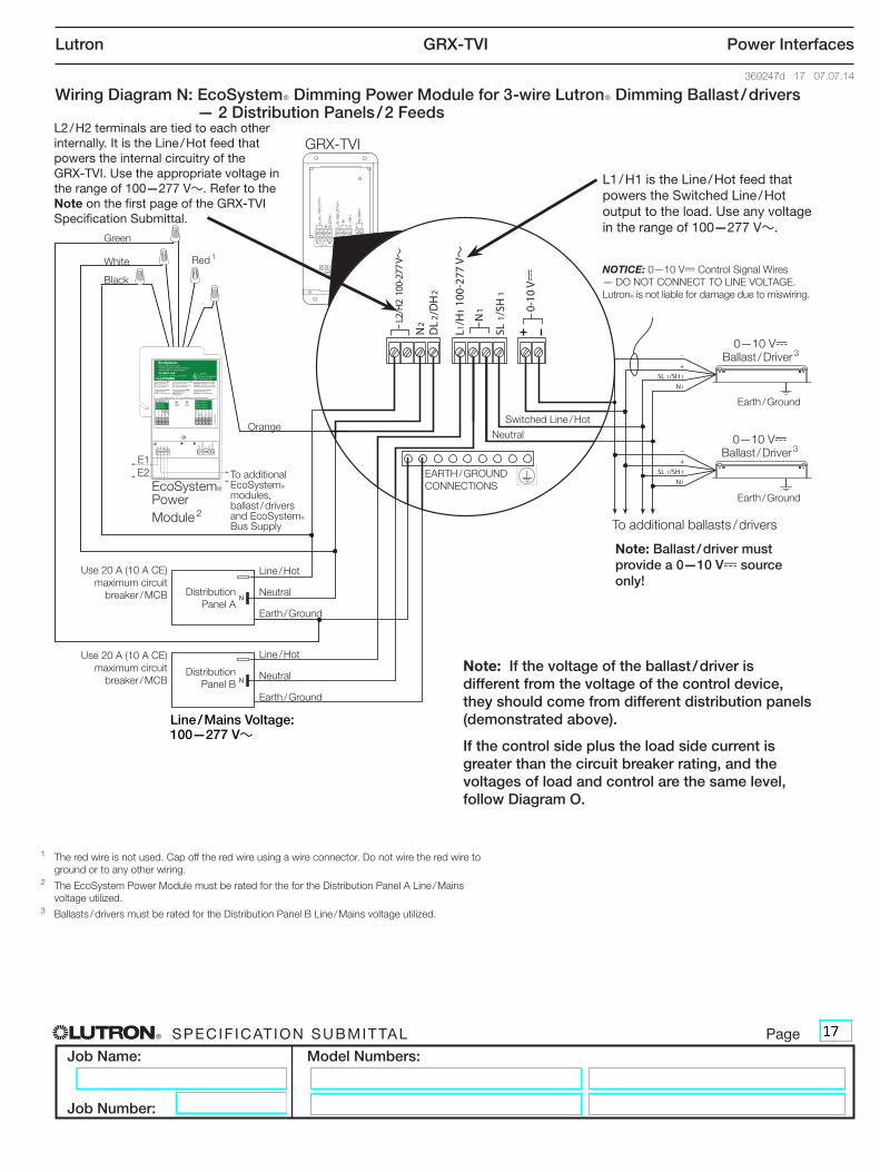
Wiring Diagram N: EcoSystemR Dimming Power Module for 3-wire LutronR Dimming Ballast / drivers — 2 Distribution Panels / 2 Feeds
L2/H
2 1
00-2
77 V~
E1
E1
+20V
Common
IR OCC
Daylight
E2
E2
Class 2 Sensors
Capteurs Classe 2
Sensores Clase 2
Class 2 LinkLien Classe 2Enlace Clase 2
EcoSystem®
Multiple Fixture Dimming ControlContrôle de gradation de multiples luminairesControl atenuador de múltiples lámparas
PWR STAT
Indicateur de puissance (PWR)On: l’unité est alimentéeOff: l’unité n’est pas alimentée ou est dysfonctionnelle
Indicateur d’activité (STAT)Plein: Niveau de circuit Impulsion: Aucune communication
Power Indicator (PWR)On: Unit is poweredOff: Unit is not powered or is malfunctioning
Status Indicator (STAT)Solid: Circuit LevelPulse: No communication
Indicador de Alimentación (PWR)Encendido: unidad tiene corrienteApagado: unidad no tiene corriente o no está funcionando correctamente
Indicador de estado (STAT)Sólido: Nivel del CircuitoPulsante: No hay comunicación
C5-BMJ-16A
CO
M
DY
LT
P/N
500
-107
55
®
GRX-TVI
EcoSystemR Power Module 2 To additional ballasts / drivers
EARTH / GROUND CONNECTIONS
Red 1
Black
Switched Line / Hot
Line / Hot
Earth / Ground
Earth / Ground
NOTICE: 0—10 V- Control Signal Wires — DO NOT CONNECT TO LINE VOLTAGE. LutronR is not liable for damage due to miswiring.
Use 20 A (10 A CE) maximum circuit
breaker / MCB
White
Orange
Distribution Panel A
Neutral
Earth / Ground
Note: Ballast / driver must provide a 0—10 V- source only!
L2 / H2 terminals are tied to each other internally. It is the Line / Hot feed that powers the internal circuitry of the GRX-TVI. Use the appropriate voltage in the range of 100—277 V~. Refer to the Note on the first page of the GRX-TVI Specification Submittal.
L1 / H1 is the Line / Hot feed that powers the Switched Line / Hot output to the load. Use any voltage in the range of 100—277 V~.
Neutral
Green
E1E2 To additional
EcoSystemR modules, ballast / drivers and EcoSystemR Bus Supply
Distribution Panel B
Line / Hot
Earth / Ground
Neutral Note: If the voltage of the ballast / driver is different from the voltage of the control device, they should come from different distribution panels (demonstrated above).
If the control side plus the load side current is greater than the circuit breaker rating, and the voltages of load and control are the same level, follow Diagram O.
Line / Mains Voltage: 100—277 V~
Use 20 A (10 A CE) maximum circuit
breaker / MCB
0—10 V- Ballast / Driver 3
0—10 V- Ballast / Driver 3
1 The red wire is not used. Cap off the red wire using a wire connector. Do not wire the red wire to ground or to any other wiring.
2 The EcoSystem Power Module must be rated for the for the Distribution Panel A Line / Mains voltage utilized.
3 Ballasts / drivers must be rated for the Distribution Panel B Line / Mains voltage utilized.
® SPECIF ICAT ION SUBMITTAL Page
Job Name:
Job Number:
Model Numbers:
Lutron GRX-TVI Power Interfaces
369247d 18 07.07.14
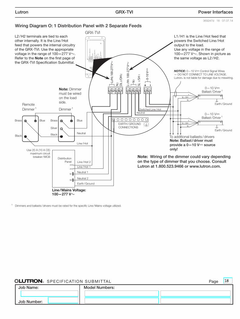
Wiring Diagram O: 1 Distribution Panel with 2 Separate Feeds
N2
N1
L2/H
2 100
-277
V~
GRX-TVI
Remote Dimmer 1 Dimmer 1
To additional ballasts / drivers
EARTH / GROUND CONNECTIONS
BlueBrass
Black
BlueBrass
Silver
Black
Switched Line / Hot
Line / Hot 1
Line / Hot 2
Earth / Ground
Earth / Ground
NOTICE: 0—10 V- Control Signal Wires — DO NOT CONNECT TO LINE VOLTAGE. LutronR is not liable for damage due to miswiring.
Use 20 A (10 A CE) maximum circuit
breaker / MCB
Neutral
Neutral
Note: Ballast / driver must provide a 0—10 V- source only!
Line / Hot
Neutral 1
Distribution Panel
Earth / Ground
Note: Dimmer must be wired on the load side.
L2 / H2 terminals are tied to each other internally. It is the Line / Hot feed that powers the internal circuitry of the GRX-TVI. Use the appropriate voltage in the range of 100—277 V~. Refer to the Note on the first page of the GRX-TVI Specification Submittal.
L1 / H1 is the Line / Hot feed that powers the Switched Line / Hot output to the load. Use any voltage in the range of 100—277 V~. Shown in picture as the same voltage as L2 / H2.
Neutral 2
Note: Wiring of the dimmer could vary depending on the type of dimmer that you choose. Consult Lutron at 1.800.523.9466 or www.lutron.com.
Line / Mains Voltage: 100—277 V~
0—10 V- Ballast / Driver 1
0—10 V- Ballast / Driver 1
1 Dimmers and ballasts / drivers must be rated for the specific Line / Mains voltage utilized.