Embed Size (px)
Citation preview
GS748T Smart Switch Hardware Installation Guide
202-10232-01 September 2007
NETGEAR, Inc.4500 Great America Parkway Santa Clara, CA 95054 USA

© 2007 by Netgear Inc. All Rights reserved
TrademarksNETGEAR, Netgear Inc., the NETGEAR logo, Auto Uplink, ProSafe, and Everybody’s connecting are trademarks or registered trademarks of Netgear, Inc. in the United States and/or other countries. Microsoft, Windows, and Windows NT are registered trademarks of Microsoft Corporation. Other brand and product names are trademarks of their respective holders. Information is subject to change without notice. All rights reserved.
Statement of ConditionsIn the interest of improving internal design, operational function, and/or reliability, NETGEAR reserves the right to make changes to the products described in this document without notice.NETGEAR does not assume any liability that may occur due to the use or application of the product(s) or circuit layout(s) described herein.
Certificate of the Manufacturer/ImporterIt is hereby certified that the GS748T Gigabit Smart Switch has been suppressed in accordance with the conditions set out in the BMPT-AmtsblVfg 243/1991 and Vfg 46/1992. The operation of some equipment (for example, test transmitters) in accordance with the regulations may, however, be subject to certain restrictions. Please refer to the notes in the operating instructions. The Federal Office for Telecommunications Approvals has been notified of the placing of this equipment on the market and has been granted the right to test the series for compliance with the regulations.
Voluntary Control Council for Interference (VCCI) StatementThis equipment is in the first category (information equipment to be used in commercial and/or industrial areas) and conforms to the standards set by the Voluntary Control Council for Interference by Data Processing Equipment and Electronic Office Machines that are aimed at preventing radio interference in commercial and/or industrial areas.Consequently, when this equipment is used in a residential area or in an adjacent area thereto, radio interference may be caused to equipment such as radios and TV receivers.
Federal Communications Commission (FCC) Compliance Notice: Radio Frequency NoticeThis device complies with part 15 of the FCC Rules. Operation is subject to the following two conditions:This device may not cause harmful interference.This device must accept any interference received, including interference that may cause undesired operation.
NOTE: This equipment has been tested and found to comply with the limits for a Class A digital device, pursuant to part 15 of the FCC Rules. These limits are designed to provide reasonable protection against harmful interference in a residential installation. This equipment generates, uses, and can radiate radio frequency energy and, if not installed and used in accordance with the instructions, may cause harmful interference to radio communications. However, there is no guarantee that interference will not occur in a particular installation. If this equipment does cause harmful interference to radio or television reception, which can be determined by turning the equipment off and on, the user is encouraged to try to correct the interference by one or more of the following measures:
• Reorient or relocate the receiving antenna.
ii
v1.1, September 2007
• Increase the separation between the equipment and receiver.• Connect the equipment into an outlet on a circuit different from that which the receiver is connected.• Consult the dealer or an experienced radio/TV technician for help.
EN 55 022 Declaration of ConformanceThis is to certify that the NETGEAR GS748T Gigabit Smart Switch is shielded against the generation of radio interference in accordance with the application of Council Directive 89/336/EEC, Article 4a. Conformity is de-clared by the application of EN 55024 Class A (CISPR 22).
EN 55 022 and EN 55 024 Statements
This is to certify that the NETGEAR GS748T Gigabit Smart Switch is shielded against the generation of radio interference in accordance with the application of Council Directive 89/336/EEC, Article 4a. Conformity is declared by the application of EN 55 022 Class A (CISPR 22) and EN 55 024.
Canadian Department of Communications Radio Interference RegulationsThis digital apparatus (NETGEAR GS748T Gigabit Smart Switch) does not exceed the Class A limits for radio-noise emissions from digital apparatus as set out in the Radio Interference Regulations of the Canadian Department of Communications.
Règlement sur le brouillage radioélectrique du ministère des CommunicationsCet appareil numérique (NETGEAR GS748T Gigabit Smart Switch) respecte les limites de bruits radioélectriques visant les appareils numériques de classe A prescrites dans le Règlement sur le brouillage radioélectrique du ministère des Communications du Canada.
Customer SupportFor assistance with installing and configuring your NETGEAR system or for questions or problems following installation:
• Check the NETGEAR Web page at http://www.NETGEAR.com/support• Call Technical Support in North America at 1-888-NETGEAR. If you are outside North America, please
refer to the phone numbers listed on the Support Information Card that was included with your switch.• Email Technical Support at [email protected].• Defective or damaged merchandise can be returned to your point-of-purchase representative.
Internet/World Wide WebNETGEAR maintains a World Wide Web home page that you can access at the uniform resource locator (URL) http://www.NETGEAR.com. A direct connection to the Internet and a Web browser such as Internet Explorer or Netscape are required.
Note: Warning: This is a Class A product. In a domestic environment, this product may cause radio interference, in which case the user may be required to take appropriate measures.
v1.1, September 2007
iii
FCC Requirements for Operation in the United StatesFCC Information to User This product does not contain any user-serviceable components and is to be used with approved antennas only. Any product changes or modifications will invalidate all applicable regulatory certifications and approvalsFCC Guidelines for Human Exposure This equipment complies with FCC radiation exposure limits set forth for an uncontrolled environment. This equipment should be installed and operated with a minimum distance of 20 cm between the radiator and your body. This transmitter must not be co-located or operating in conjunction with any other antenna or transmitter. FCC Declaration Of Conformity We, NETGEAR, Inc., 4500 Great America Parkway, Santa Clara, CA 95054, declare under our sole responsibility that the model FS728TP: ProSafe™ 24 Port 10/100 Smart Switch with 4 Gigabit Ports and 24 Port PoE complies with Part 15 of FCC Rules. Operation is subject to the following two conditions: a) This device may not cause harmful interference and b) This device must accept any interference received, including interference that may cause undesired operation."
Product and Publication Details
Model Number: GS748T
Publication Date: September 2007
Product Family: Smart Switch
Product Name: GS748T Gigabit Smart Switch
Home or Business Product: Business
Language: English
Publication Part Number: 202-10232-01
Publication Version Number: 1.1
v1.1, September 2007
iv
Contents
About This ManualConventions, Formats, and Scope ...................................................................................viiHow to Use This Manual .................................................................................................viiiHow to Print this Manual ..................................................................................................viiiRevision History ................................................................................................................ ix
Chapter 1 Introduction
Overview .........................................................................................................................1-1Features .........................................................................................................................1-2Package Contents ..........................................................................................................1-4
Chapter 2 Physical Description
Front and Back Panels .............................................................................................2-110/100/1000 Mbps RJ-45 Ports ...............................................................................2-2SFP GBIC Module ....................................................................................................2-2
LED Descriptions ............................................................................................................2-2Reset Button ............................................................................................................2-3Restore Factory Defaults Button ..............................................................................2-4
Chapter 3 Applications
Desktop Switching ....................................................................................................3-1Backbone Switching .................................................................................................3-2
Chapter 4 Installation
Step 2: Installing the Switch ............................................................................................4-2Installing the Switch on a Flat Surface .....................................................................4-2Installing the Switch in a Rack .................................................................................4-2
Step 3: Checking the Installation ....................................................................................4-3Step 4: Connecting Devices to the Switch ......................................................................4-3
v
v1.1, September 2007
Step 5: Installing a SFP GBIC Module ............................................................................4-4Step 6: Applying AC Power ............................................................................................4-5Step 7: Management through a Web Browser or Utility Program (Initial Configuration) .4-5
Appendix A Troubleshooting
Troubleshooting Chart ............................................................................................. A-1Additional Troubleshooting Suggestions ....................................................................... A-2
Network Adapter Cards ........................................................................................... A-2Configuration ........................................................................................................... A-2Switch Integrity ........................................................................................................ A-2
Appendix B Technical SpecificationsAppendix C Glossary
vi Contents
v1.1, September 2007
About This Manual
The NETGEAR® GS748T Smart Switch™ Hardware Installation Guide describes how to install, configure, and troubleshoot the GS748T Gigabit Smart Switch. The information in this manual is intended for readers with intermediate computer and Internet skills.
Conventions, Formats, and Scope
The conventions, formats, and scope of this manual are described in the following paragraphs:
• Typographical Conventions. This manual uses the following typographical conventions:
• Formats. This manual uses the following formats to highlight special messages:
Italics Emphasis, books, CDs, URL names
Bold User input
Fixed Screen text, file and server names, extensions, commands, IP addresses
Note: This format is used to highlight information of importance or special interest.
Tip: This format is used to highlight a procedure that will save time or resources.
Warning: This is a warning of possible malfunction or damage to the equipment.
Danger: This is a safety warning. Failure to take heed of this notice may result in personal injury or death.
vii
v1.1, September 2007
GS748T Smart Switch Hardware Installation Guide
• Scope. This manual is written for the GS748T Smart Switch according to these specifications:
.
How to Use This Manual
The HTML version of this manual includes the following:
• Buttons and for browsing forwards or backwards through the manual one page at a time.
• A button that displays the table of contents and a button. Double-click on a link in the table of contents or index to navigate directly to where the topic is described in the manual.
• A button to access the full NETGEAR, Inc. online knowledge base for the product model.
• Links to PDF versions of the full manual and individual chapters.
How to Print this Manual
To print this manual, choose one of the following options:
• Printing a Page from HTML. Each page in the HTML version of the manual is dedicated to a major topic. Select File > Print from the browser menu to print the page contents.
• Printing from PDF. Your computer must have the free Adobe Acrobat reader installed in order to view and print PDF files. The Acrobat reader is available on the Adobe Web site at http://www.adobe.com.– Printing a PDF Chapter.
Product Version GS748T Gigabit Smart Switch
Manual Publication Date September 2007
Note: Product updates are available on the NETGEAR, Inc. website athttp://kbserver.netgear.com/products/GS748T.asp.
viii About This Manual
v1.1, September 2007
GS748T Smart Switch Hardware Installation Guide
• Click the PDF of This Chapter link at the top left of any page in the chapter you want to print. The PDF version of the chapter you were viewing opens in a browser window.
• Click the print icon in the upper left of your browser window.
– Printing a PDF version of the Complete Manual.
• Click the Complete PDF Manual link at the top left of any page in the manual. The PDF version of the complete manual opens in a browser window.
• Click the print icon in the upper left of your browser window.
Revision History
Tip: If your printer supports printing two pages on a single sheet of paper, you can save paper and printer ink by selecting this feature.
Document Part Number
VersionNumber Description
202-10232-01 1.1 Document created
202-10232-01 1.1 Format modifications
About This Manual ix
v1.1, September 2007
GS748T Smart Switch Hardware Installation Guide
x About This Manual
v1.1, September 2007
Chapter 1 Introduction
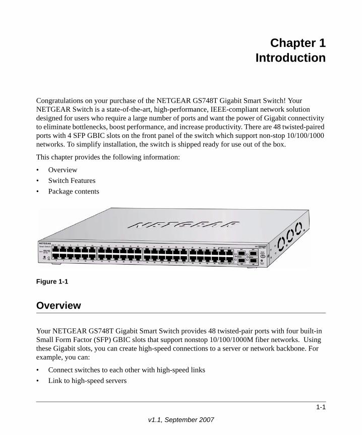
Congratulations on your purchase of the NETGEAR GS748T Gigabit Smart Switch! Your NETGEAR Switch is a state-of-the-art, high-performance, IEEE-compliant network solution designed for users who require a large number of ports and want the power of Gigabit connectivity to eliminate bottlenecks, boost performance, and increase productivity. There are 48 twisted-paired ports with 4 SFP GBIC slots on the front panel of the switch which support non-stop 10/100/1000 networks. To simplify installation, the switch is shipped ready for use out of the box.
This chapter provides the following information:
• Overview• Switch Features• Package contents
Overview
Your NETGEAR GS748T Gigabit Smart Switch provides 48 twisted-pair ports with four built-in Small Form Factor (SFP) GBIC slots that support nonstop 10/100/1000M fiber networks. Using these Gigabit slots, you can create high-speed connections to a server or network backbone. For example, you can:
• Connect switches to each other with high-speed links• Link to high-speed servers
Figure 1-1
1-1
v1.1, September 2007
GS748T Smart Switch Hardware Installation Guide
• Provide 10/100/1000 copper and fiber connectivity
Your GS748T Gigabit Smart Switch also provides the benefit of administrative management with a complete package of features for the observation, configuration, and control of your network. With a Web-based Graphical User Interface (GUI), the switch’s many capabilities can be viewed and used in a simple and intuitive manner. There is also an easy to use switch management utility that runs on a PC. The switch’s management features include configuration for port and switch information, VLAN for traffic control, port trunking for increased bandwidth, and Class of Service (CoS) for traffic prioritization. These features, and more, enable you better to understand and control your network.
Your NETGEAR GS748T Gigabit Smart Switch can be free-standing or rack-mounted in a wiring closet or equipment room. It is IEEE-compliant and offers low latency for high-speed networking. It includes 48 auto-sensing 10/100/1000 Ethernet ports with 4 SFP GBIC slots. All ports can automatically negotiate to the highest speed. This capability makes the switch ideal for environments that have a mix of Ethernet, Fast Ethernet, and Gigabit Ethernet devices. In addition, all 10/100/1000 Mbps ports operate in half- or full-duplex mode, increasing the maximum bandwidth of each connection to either 20 Mbps, 200 Mbps, or 2000 Mbps, respectively. The maximum segment length is 328 feet (100 meters) over Category 5 unshielded twisted-pair (UTP) cable.
Features
The following list identifies the key features of the NETGEAR GS748T Gigabit Smart Switch.
• Forty-eight 10/100/1000 Mbps auto-sensing Gigabit-Ethernet switching ports• Four SFP GBIC combo Gigabit Ethernet slots for optional fiber connectivity • Reset Button• Factory Defaults Button• Administrative switch management
• IEEE 802.1Q Tag VLAN with up to 48 VIDs ranging in 2 to 4K
• IEEE 802.1p QoS support, two priority queues per port • Port-based VLAN with up to 48 groups; any one port can belong to different VLAN
groups• IEEE 802.3ad Link Aggregation support • Embedded HTTP server for Web-based management• Supports port-setting function, enabling user to enable/disable each port, and set speed,
duplex mode and device flow control
1-2 Introduction
1.1, September 2007
GS748T Smart Switch Hardware Installation Guide
• Auto-Discovery support with application program for discovering and managing the smart switches on the network
• Flash upgrade, configuration backup/restore, and factory reset
• Full compatibility with IEEE standards:
• IEEE 802.3i (10BASE-T)
• IEEE 802.3u (100BASE-TX)• IEEE 802.3z/ab (1000BASE-X, 1000Base-T)• IEEE 802.3x (full-duplex flow control)
• Auto-sense and auto-negotiate for all ports• Auto Uplink on all ports for the right connection sense• Integrated address Look-Up Engine supports 8K absolute MAC addresses• Full- and half-duplex functions for all 10/100/1000 ports• Store-and-Forward transmission to remove bad packets from the network • Active flow control to minimize packet loss/frame drops:
• Half-duplex back-pressure control
• Full-duplex IEEE 802.3x pause frame flow control
• LED indicators for port status monitoring:
• Power LED indicates power on/off status
• Link/Act LED indicates link status and activity• SFP GBIC Link/Act LED indicates link status and activity
• Flexible installation:
• Standalone desktop installation
• 19-inch standard rack-mount
• Standard 1U case size
Introduction 1-3
v1.1, September 2007
GS748T Smart Switch Hardware Installation Guide
Package Contents
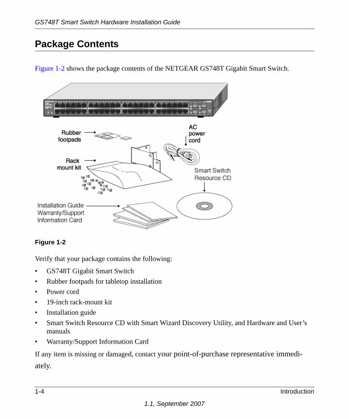
Figure 1-2 shows the package contents of the NETGEAR GS748T Gigabit Smart Switch.
Verify that your package contains the following:
• GS748T Gigabit Smart Switch• Rubber footpads for tabletop installation• Power cord• 19-inch rack-mount kit • Installation guide• Smart Switch Resource CD with Smart Wizard Discovery Utility, and Hardware and User’s
manuals• Warranty/Support Information Card
If any item is missing or damaged, contact your point-of-purchase representative immedi-ately.
Figure 1-2
1-4 Introduction
1.1, September 2007
Chapter 2Physical Description
This chapter describes the hardware features of the NETGEAR GS748T Gigabit Smart Switch. Topics include:
• Front and back panels• 10/100/1000 Mbps auto-sensing RJ-45 ports• SFP GBIC Module bay• LED descriptions• Reset button• Factory defaults button
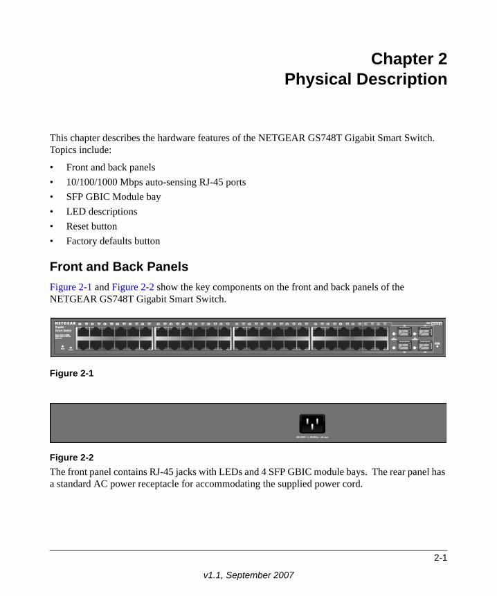
Front and Back PanelsFigure 2-1 and Figure 2-2 show the key components on the front and back panels of the NETGEAR GS748T Gigabit Smart Switch.
The front panel contains RJ-45 jacks with LEDs and 4 SFP GBIC module bays. The rear panel has a standard AC power receptacle for accommodating the supplied power cord.
Figure 2-1
Figure 2-2
2-1
v1.1, September 2007
GS748T Smart Switch Hardware Installation Guide
10/100/1000 Mbps RJ-45 PortsThe 48 10/100/1000 Mbps, auto-sensing RJ-45 ports of the GS748T Gigabit Smart Switch are seen in Figure 2-1. When you insert a cable into one of these ports, the switch automatically determines the maximum speed (10 or 100 or 1000 Mbps) and the mode (half- or full-duplex) of the attached device. All ports support only unshielded twisted-pair (UTP) cable with an 8-pin RJ-45 plug connection.
To simplify the procedure for attaching devices, all RJ-45 ports support Auto Uplink. This technology enables you to attach devices to the RJ-45 ports using either straight-through or crossover cables. When you insert a cable into one of these ports, the switch automatically:
• Detects whether the combination of attached device and network cable (normal or crossover) requires a normal connection (such as when connecting the port to a PC) or an uplink connection (such as when connecting the port to a router, switch, or hub).
• Configures the RJ-45 port to enable communications with the attached device without user intervention.
SFP GBIC ModuleTo enable you to have fiber connections on your network, there are four module bays which accommodate standard SFP GBIC modules, such as the AGM731F or AGM732F from NETGEAR. The module bays use combo ports which comprise respective shared connections with the last four RJ-45 ports, namely port 45T, 46T, 47T, and 48T. Only one type of connection of a combo port can be active at any time. For example, both port 45T and 45F cannot be used simultaneously. If both connectors of a combo port are made together, the fiber port (45F) is active.
The SFP GBIC bay accommodates a standard SFP GBIC module. This module has an LC connector that is compatible with the IEEE 802.3Z 1000 Base-SX Standard.
LED Descriptions
The front panel of the NETGEAR GS748T Gigabit Smart Switch comprises LEDs that provide a concise display of link, port speed, and activity. The following table summarizes the function of these LEDs.
2-2 Physical Description
v1.1, September 2007
GS748T Smart Switch Hardware Installation Guide
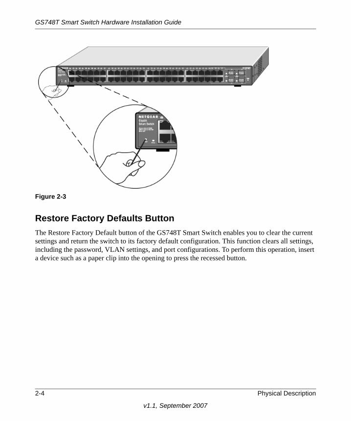
Reset ButtonThe Reset button of the GS748T triggers a hardware reset of the switch. Figure 2-3 shows its location on the front panel. This action is equivalent to switching the unit power off and back on. The last saved configuration is loaded into the switch as it resets. To operate the reset button, insert a device such as a paper clip into the opening to press the recessed button. The front-panel LEDs should extinguish and light again as the switch performs its Power On Self Test (POST).
Table 2-1. Front Panel LEDs
Label Color Activity Description
Power GreenOn Power is supplied to the switch
Off Power is disconnected
Speed/Link/ACT
Green
On A valid 1000Mbps link is established on the port
Blinking Data transmission is occurring at 1000Mbps on the port
Yellow On A valid 10/100Mbps link is established on the port
None Off No 10/100/1000Mbps link is established on the port
SFP (MiniGBIC) Link/Act GreenOn A valid 1000Mbps link is established on
the port
Off No valid link is established on the port
Physical Description 2-3
v1.1, September 2007
GS748T Smart Switch Hardware Installation Guide
Figure 2-3
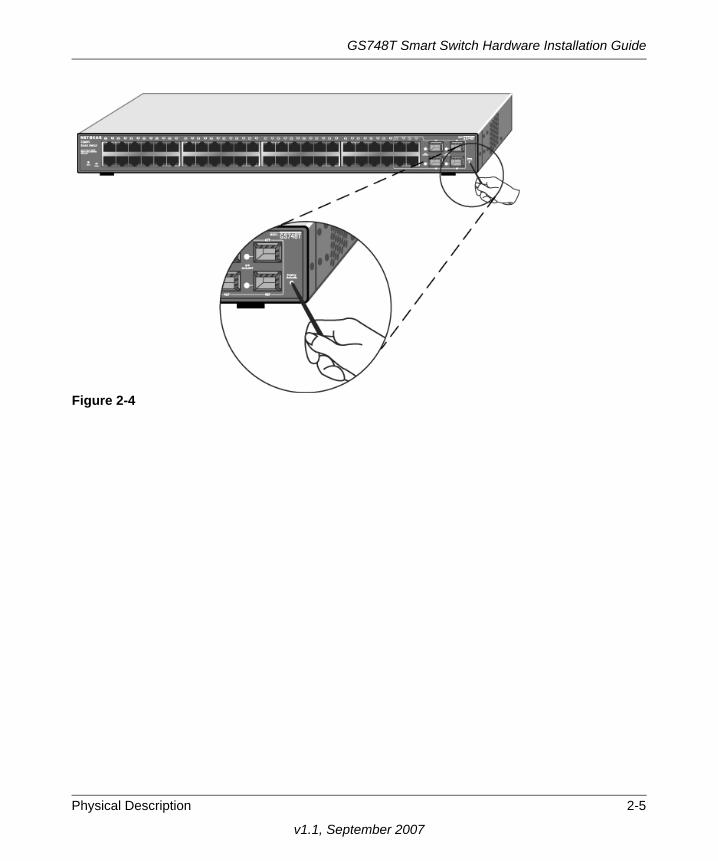
Restore Factory Defaults ButtonThe Restore Factory Default button of the GS748T Smart Switch enables you to clear the current settings and return the switch to its factory default configuration. This function clears all settings, including the password, VLAN settings, and port configurations. To perform this operation, insert a device such as a paper clip into the opening to press the recessed button.
2-4 Physical Description
v1.1, September 2007
GS748T Smart Switch Hardware Installation Guide
Figure 2-4
Physical Description 2-5
v1.1, September 2007
GS748T Smart Switch Hardware Installation Guide
2-6 Physical Description
v1.1, September 2007
Chapter 3Applications
Your NETGEAR GS748T Gigabit Smart Switch is designed to provide flexibility in configuring your network connections. It can be used as your only network traffic-distribution device or with added 10 Mbps, 100 Mbps, 10/100 Mbps, and 1000 Mbps hubs and switches. This chapter shows how the switch can be used in various network environments.
Topics include:
• Desktop switching• Backbone switching
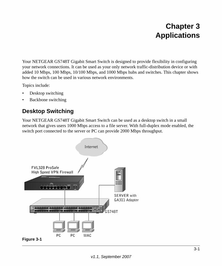
Desktop SwitchingYour NETGEAR GS748T Gigabit Smart Switch can be used as a desktop switch in a small network that gives users 1000 Mbps access to a file server. With full-duplex mode enabled, the switch port connected to the server or PC can provide 2000 Mbps throughput.
Figure 3-1
3-1
v1.1, September 2007
GS748T Smart Switch Hardware Installation Guide
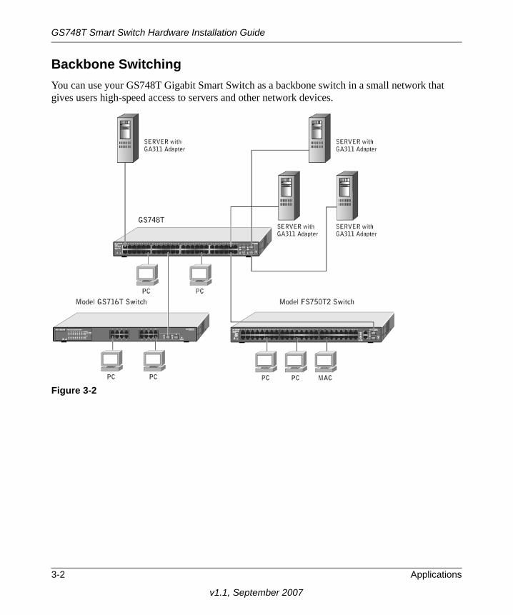
Backbone SwitchingYou can use your GS748T Gigabit Smart Switch as a backbone switch in a small network that gives users high-speed access to servers and other network devices.
Figure 3-2
3-2 Applications
v1.1, September 2007
.
Chapter 4Installation
This chapter describes the installation procedures for your NETGEAR GS748T Gigabit Smart Switch. Switch installation involves the following steps:
1. Preparing the site
2. Installing the switch
3. Checking the installation
4. Connecting devices to the switch
5. Installing an SFP GBIC module
6. Applying AC power
7. Switching management through a Web Browser or Utility Program (initial configuration)
Step 1: Preparing the SiteBefore you install your switch, ensure that your operating environment meets the environmental requirements in Table 4-1.
Table 4-1. Site Requirements
Characteristics Requirements
Mounting
Installations Desktop: provide a flat table or shelf surface
Rack-mount: use a 19-inch (48.3-centimeter) EIA standard equipment rack that is grounded and physically secure. You also need the rack-mount kit supplied with your switch.
Access Locate the switch in a position that lets you access the front panel RJ-45 ports, view the front panel LEDs, and access power connector.
Power source Provide a power sourcea within 6 feet (1.8 meters) of the installation locationEnsure that the AC outlet is not controlled by a wall switch, which can accidentally turn off power to the outlet and the switch.
4-1
v1.1, September 2007
GS748T Smart Switch Hardware Installation Guide
,
.
Step 2: Installing the Switch
Install the switch using one of the following methods:
Installing the Switch on a Flat SurfaceThe switch ships with four self-adhesive rubber footpads. Attach one rubber foot pad into each of the four concave depressions on the base of the switch.
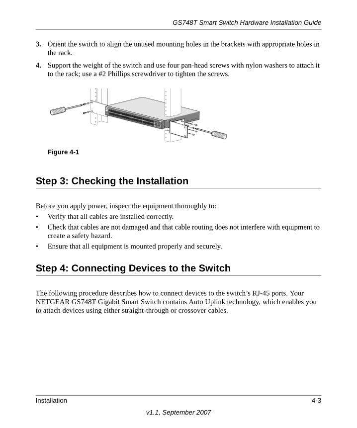
Installing the Switch in a RackTo install the switch in a rack, use the 19-inch rack-mount kit (supplied with your switch) with the following procedure (refer to Figure 4-1):
1. Attach the supplied mounting brackets to the side of the switch using the screws provided in the rack-mount kit.
2. Tighten the screws with a #1 Phillips screwdriver to secure each bracket.
Environmental
Temperature: Install the switch in a dry area, with ambient temperature in the range 0–55ºC(32–131ºF). Keep the switch away from heat sources such as direct sunlightwarm air exhausts, hot-air vents, and heaters.
Operating humidity: The installation location should have a maximum relative humidity of 90%, non-condensing.
Ventilation: Do not restrict airflow by covering or obstructing air inlets on the sides of theswitch. Keep at least 2 inches (5.08 centimeters) free on all sides for coolingBe sure there is adequate airflow in the room or wiring closet where you intend to install the switch.
Operating conditions: Keep the switch at least 6 ft. (1.83 m) away from any source of electromagnetic noise, for example, a photocopy machine.
a. Power specifications for the switch are shown in Appendix B, “Technical Specifications”
Note: These footpads cushion the switch against shock and vibration. They also provide for ventilation space between stacked switches.
Table 4-1. Site Requirements (continued)
4-2 Installation
v1.1, September 2007
GS748T Smart Switch Hardware Installation Guide
3. Orient the switch to align the unused mounting holes in the brackets with appropriate holes in the rack.
4. Support the weight of the switch and use four pan-head screws with nylon washers to attach it to the rack; use a #2 Phillips screwdriver to tighten the screws.
Step 3: Checking the Installation
Before you apply power, inspect the equipment thoroughly to:• Verify that all cables are installed correctly. • Check that cables are not damaged and that cable routing does not interfere with equipment to
create a safety hazard. • Ensure that all equipment is mounted properly and securely.
Step 4: Connecting Devices to the Switch
The following procedure describes how to connect devices to the switch’s RJ-45 ports. Your NETGEAR GS748T Gigabit Smart Switch contains Auto Uplink technology, which enables you to attach devices using either straight-through or crossover cables.
Figure 4-1
Installation 4-3
v1.1, September 2007

GS748T Smart Switch Hardware Installation Guide
Figure 4-2
Connect each device to an RJ-45 network port on the switch’s front panel (see Figure 4-2) using a Category 5 (Cat5) unshielded twisted-pair (UTP) cable with RJ-45 connectors.
Step 5: Installing a SFP GBIC Module
The following procedure describes how to install an optional SFP GBIC module into one of the SFP GBIC module bays of the switch.
To install a SFP GBIC module, insert the SFP module into the SFP GBIC module bay. Press firmly on the flange of the module to seat it securely into the connector. You can install up to three additional Gigabit Ethernet modules using this procedure.
Note: Ethernet specifications limit the cable length between the switch and the attached device to 100 m (328 ft.).
Note: Contact your NETGEAR sales office to buy these modules. If you do not want to install a SFP GBIC module, skip this procedure.
4-4 Installation
v1.1, September 2007
GS748T Smart Switch Hardware Installation Guide
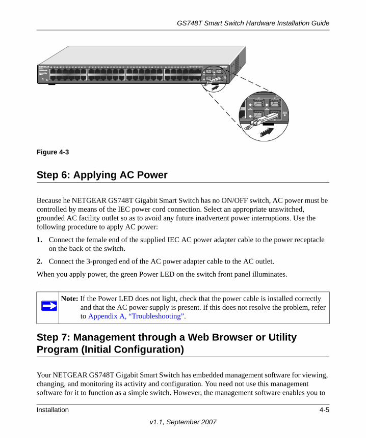
Figure 4-3
Step 6: Applying AC Power
Because he NETGEAR GS748T Gigabit Smart Switch has no ON/OFF switch, AC power must be controlled by means of the IEC power cord connection. Select an appropriate unswitched, grounded AC facility outlet so as to avoid any future inadvertent power interruptions. Use the following procedure to apply AC power:
1. Connect the female end of the supplied IEC AC power adapter cable to the power receptacle on the back of the switch.
2. Connect the 3-pronged end of the AC power adapter cable to the AC outlet.
When you apply power, the green Power LED on the switch front panel illuminates..
Step 7: Management through a Web Browser or Utility Program (Initial Configuration)
Your NETGEAR GS748T Gigabit Smart Switch has embedded management software for viewing, changing, and monitoring its activity and configuration. You need not use this management software for it to function as a simple switch. However, the management software enables you to
Note: If the Power LED does not light, check that the power cable is installed correctly and that the AC power supply is present. If this does not resolve the problem, refer to Appendix A, “Troubleshooting”.
Installation 4-5
v1.1, September 2007
GS748T Smart Switch Hardware Installation Guide
set up advanced features such as VLANs and Trunking and also enables you to configure the switch for improved efficiency and performance. As a result, you can improve the overall performance of your network.
After you power-up the switch for the first time, you can configure it using a Web browser or a utility program called Smartwizard Discovery. For more information about managing the switch, see the User Manual on the Smart Switch Resource CD.
4-6 Installation
v1.1, September 2007
Appendix ATroubleshooting
This chapter provides information about troubleshooting the NETGEAR GS748T Gigabit Smart Switch. Information is supplied as:
• A Troubleshooting chart• Additional troubleshooting suggestions
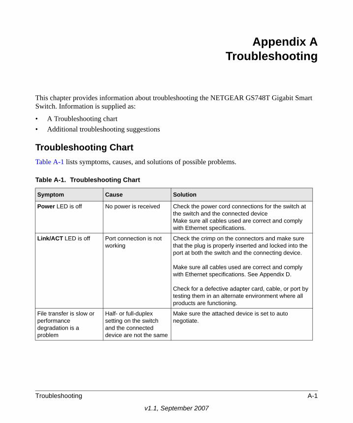
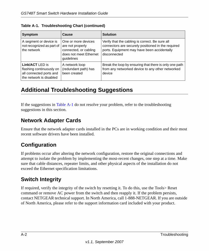
Troubleshooting ChartTable A-1 lists symptoms, causes, and solutions of possible problems.
Table A-1. Troubleshooting Chart
Symptom Cause Solution
Power LED is off No power is received Check the power cord connections for the switch at the switch and the connected deviceMake sure all cables used are correct and comply with Ethernet specifications.
Link/ACT LED is off Port connection is not working
Check the crimp on the connectors and make sure that the plug is properly inserted and locked into the port at both the switch and the connecting device.
Make sure all cables used are correct and comply with Ethernet specifications. See Appendix D.
Check for a defective adapter card, cable, or port by testing them in an alternate environment where all products are functioning.
File transfer is slow or performance degradation is a problem
Half- or full-duplex setting on the switch and the connected device are not the same
Make sure the attached device is set to auto negotiate.
Troubleshooting A-1
v1.1, September 2007
GS748T Smart Switch Hardware Installation Guide
Additional Troubleshooting Suggestions
If the suggestions in Table A-1 do not resolve your problem, refer to the troubleshooting suggestions in this section.
Network Adapter CardsEnsure that the network adapter cards installed in the PCs are in working condition and their most recent software drivers have been installed.
ConfigurationIf problems occur after altering the network configuration, restore the original connections and attempt to isolate the problem by implementing the most-recent changes, one step at a time. Make sure that cable distances, repeater limits, and other physical aspects of the installation do not exceed the Ethernet specification limitations.
Switch IntegrityIf required, verify the integrity of the switch by resetting it. To do this, use the Tools> Reset command or remove AC power from the switch and then reapply it. If the problem persists, contact NETGEAR technical support. In North America, call 1-888-NETGEAR. If you are outside of North America, please refer to the support information card included with your product.
A segment or device is not recognized as part of the network
One or more devices are not properly connected, or cabling does not meet Ethernet guidelines
Verify that the cabling is correct. Be sure all connectors are securely positioned in the required ports. Equipment may have been accidentally disconnected
Link/ACT LED is flashing continuously on all connected ports and the network is disabled
A network loop (redundant path) has been created
Break the loop by ensuring that there is only one path from any networked device to any other networked device
Table A-1. Troubleshooting Chart (continued)
Symptom Cause Solution
A-2 Troubleshooting
v1.1, September 2007
Appendix BTechnical Specifications
This appendix provides technical specifications for the NETGEAR GS748T Gigabit Smart Switch.
Network Protocol and Standards Compatibility
IEEE 802.3 10BASE-T
IEEE 802.3u 100BASE-TX
IEEE 802.3ab 1000BASE-T
IEEE 802.3z 1000Base-X
IEEE 802.3x flow control
Management
IEEE 802.1Q Static VLAN (Up to 256)
Port-based VLAN (Up to 48)
IEEE 802.1p Class of Service (CoS)
Port-based QoS (Port default priority; options: High/Normal/Low/Lowest)
Port Trunking - Manual as per IEEE802.3ad Link Aggregation
Port Monitoring
Interface
48 RJ-45 connectors for 10BASE-T, 100BASE-TX, and 1000BASE-T (Auto Uplink‘ on all ports) with 4 SFP GBIC module bays that share with 4 RJ-45 ports for fiber connectivity
LEDs
Per port (Gigabit): Speed/Link/Act
Per device: Power
Performance Specifications
Forwarding modes: Store-and-forward
Bandwidth: 96 Gbps
Network latency: Less than 20 microseconds for 64-byte frames in store-and-forward mode for 100 Mbps to 100 Mbps transmission
Buffer memory: 512 KB embedded memory per unit
Address database size: 8,000 media access control (MAC) addresses per system
Technical Specifications B-1
v1.1, September 2007

GS748T Smart Switch Hardware Installation Guide
Mean Time Between Failure (MTBF): 108,016 hours (~12 years)Power Supply
Power Consumption: 90 W maximum
100–240VAC/50–60 Hz universal input
Physical Specifications
Dimensions (H x W x D): 1.7 x 17.3 x 12.2 in (43.2 x 440 x 305 mm)
Weight: 10.89 lb. (4.95 kg)Environmental Specifications
Operating temperature: 0 to 55°C (32 to 131°F)
Storage temperature: -20 to 70°C (28 to 158°F)
Operating humidity: 90% maximum relative humidity, non-condensing
Storage humidity: 95% maximum relative humidity, non-condensing
Operating altitude: 3,000 m (10,000 ft.) maximum
Storage altitude: 3,000 m (10,000 ft.) maximum
Electromagnetic Emissions
CE mark, commercial
FCC Part 15 Class A
VCCI Class A
C-Tick
Electromagnetic Immunity
EN 55022 (CISPR 22), Class A
Safety
CE mark, commercial
CUL 60950 (Listed)/ EN60950 (Low Voltage Directive)page 2, see page 2, see
Modules
AGM731F 1000BASE-SX SFP GBIC for multimode fiber
AGM732F 1000BASE-LX SFP GBIC for single mode fiber
B-2 Technical Specifications
v1.1, September 2007
Appendix CGlossary
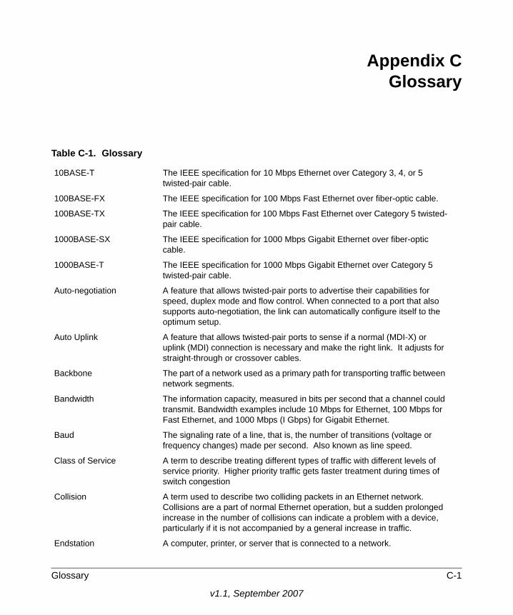
Table C-1. Glossary
10BASE-T The IEEE specification for 10 Mbps Ethernet over Category 3, 4, or 5 twisted-pair cable.
100BASE-FX The IEEE specification for 100 Mbps Fast Ethernet over fiber-optic cable.
100BASE-TX The IEEE specification for 100 Mbps Fast Ethernet over Category 5 twisted-pair cable.
1000BASE-SX The IEEE specification for 1000 Mbps Gigabit Ethernet over fiber-optic cable.
1000BASE-T The IEEE specification for 1000 Mbps Gigabit Ethernet over Category 5 twisted-pair cable.
Auto-negotiation A feature that allows twisted-pair ports to advertise their capabilities for speed, duplex mode and flow control. When connected to a port that also supports auto-negotiation, the link can automatically configure itself to the optimum setup.
Auto Uplink A feature that allows twisted-pair ports to sense if a normal (MDI-X) or uplink (MDI) connection is necessary and make the right link. It adjusts for straight-through or crossover cables.
Backbone The part of a network used as a primary path for transporting traffic between network segments.
Bandwidth The information capacity, measured in bits per second that a channel could transmit. Bandwidth examples include 10 Mbps for Ethernet, 100 Mbps for Fast Ethernet, and 1000 Mbps (I Gbps) for Gigabit Ethernet.
Baud The signaling rate of a line, that is, the number of transitions (voltage or frequency changes) made per second. Also known as line speed.
Class of Service A term to describe treating different types of traffic with different levels of service priority. Higher priority traffic gets faster treatment during times of switch congestion
Collision A term used to describe two colliding packets in an Ethernet network. Collisions are a part of normal Ethernet operation, but a sudden prolonged increase in the number of collisions can indicate a problem with a device, particularly if it is not accompanied by a general increase in traffic.
Endstation A computer, printer, or server that is connected to a network.
Glossary C-1
v1.1, September 2007
GS748T Smart Switch Hardware Installation Guide
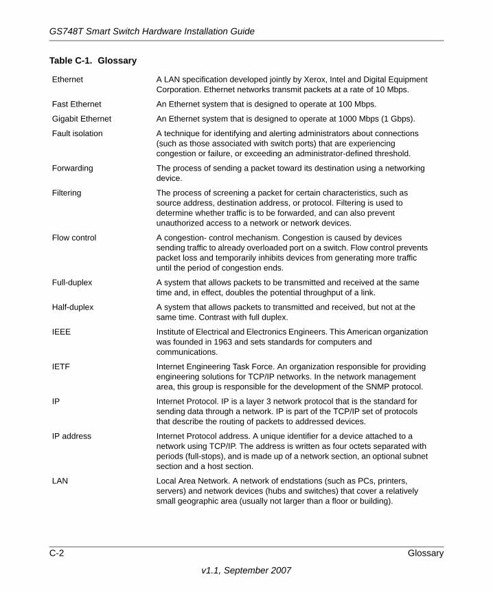
Ethernet A LAN specification developed jointly by Xerox, Intel and Digital Equipment Corporation. Ethernet networks transmit packets at a rate of 10 Mbps.
Fast Ethernet An Ethernet system that is designed to operate at 100 Mbps.
Gigabit Ethernet An Ethernet system that is designed to operate at 1000 Mbps (1 Gbps).
Fault isolation A technique for identifying and alerting administrators about connections (such as those associated with switch ports) that are experiencing congestion or failure, or exceeding an administrator-defined threshold.
Forwarding The process of sending a packet toward its destination using a networking device.
Filtering The process of screening a packet for certain characteristics, such as source address, destination address, or protocol. Filtering is used to determine whether traffic is to be forwarded, and can also prevent unauthorized access to a network or network devices.
Flow control A congestion- control mechanism. Congestion is caused by devices sending traffic to already overloaded port on a switch. Flow control prevents packet loss and temporarily inhibits devices from generating more traffic until the period of congestion ends.
Full-duplex A system that allows packets to be transmitted and received at the same time and, in effect, doubles the potential throughput of a link.
Half-duplex A system that allows packets to transmitted and received, but not at the same time. Contrast with full duplex.
IEEE Institute of Electrical and Electronics Engineers. This American organization was founded in 1963 and sets standards for computers and communications.
IETF Internet Engineering Task Force. An organization responsible for providing engineering solutions for TCP/IP networks. In the network management area, this group is responsible for the development of the SNMP protocol.
IP Internet Protocol. IP is a layer 3 network protocol that is the standard for sending data through a network. IP is part of the TCP/IP set of protocols that describe the routing of packets to addressed devices.
IP address Internet Protocol address. A unique identifier for a device attached to a network using TCP/IP. The address is written as four octets separated with periods (full-stops), and is made up of a network section, an optional subnet section and a host section.
LAN Local Area Network. A network of endstations (such as PCs, printers, servers) and network devices (hubs and switches) that cover a relatively small geographic area (usually not larger than a floor or building).
Table C-1. Glossary
C-2 Glossary
v1.1, September 2007
GS748T Smart Switch Hardware Installation Guide
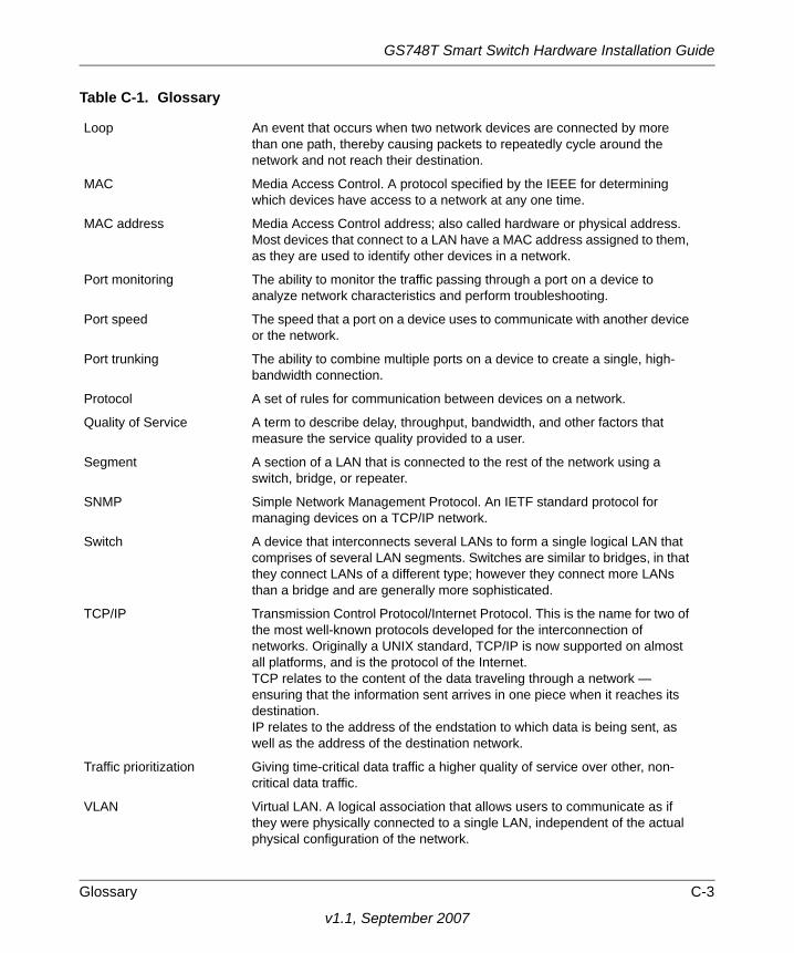
Loop An event that occurs when two network devices are connected by more than one path, thereby causing packets to repeatedly cycle around the network and not reach their destination.
MAC Media Access Control. A protocol specified by the IEEE for determining which devices have access to a network at any one time.
MAC address Media Access Control address; also called hardware or physical address. Most devices that connect to a LAN have a MAC address assigned to them, as they are used to identify other devices in a network.
Port monitoring The ability to monitor the traffic passing through a port on a device to analyze network characteristics and perform troubleshooting.
Port speed The speed that a port on a device uses to communicate with another device or the network.
Port trunking The ability to combine multiple ports on a device to create a single, high-bandwidth connection.
Protocol A set of rules for communication between devices on a network.
Quality of Service A term to describe delay, throughput, bandwidth, and other factors that measure the service quality provided to a user.
Segment A section of a LAN that is connected to the rest of the network using a switch, bridge, or repeater.
SNMP Simple Network Management Protocol. An IETF standard protocol for managing devices on a TCP/IP network.
Switch A device that interconnects several LANs to form a single logical LAN that comprises of several LAN segments. Switches are similar to bridges, in that they connect LANs of a different type; however they connect more LANs than a bridge and are generally more sophisticated.
TCP/IP Transmission Control Protocol/Internet Protocol. This is the name for two of the most well-known protocols developed for the interconnection of networks. Originally a UNIX standard, TCP/IP is now supported on almost all platforms, and is the protocol of the Internet.TCP relates to the content of the data traveling through a network — ensuring that the information sent arrives in one piece when it reaches its destination.IP relates to the address of the endstation to which data is being sent, as well as the address of the destination network.
Traffic prioritization Giving time-critical data traffic a higher quality of service over other, non-critical data traffic.
VLAN Virtual LAN. A logical association that allows users to communicate as if they were physically connected to a single LAN, independent of the actual physical configuration of the network.
Table C-1. Glossary
Glossary C-3
v1.1, September 2007

GS748T Smart Switch Hardware Installation Guide
C-4 Glossary
v1.1, September 2007