Embed Size (px)
Citation preview

Owner’s Manual
GTO-1001eZ/ GTO-751eZ/GTO-501eZsubwoofer amplifier
2
why yOu shOuld Pay aTTenTiOn TO This Owner’s Manual
The performance of your vehicle’s audio system depends as much on quality installation and setup as it does on quality gear. Of course, these new JBL® GTO subwoofer amplifiers are bulletproof performers that are built using the highest quality components, and will outperform any competing product on the test bench. To make sure you extract all the performance possible from your new amp, whether you install it yourself or have a professional install it for you, we’ve incorporated some new features that make setup simple and precise and ensure you get all the power and performance you’ve paid for.
What makes these amplifiers differentAll amplifiers include some signal processing functions, level setting controls and other switches and connectors that make it possible to hook the amp up to just about any existing system. However, with many amplifiers, considerable technical expertise is required to make the best use of those connectors, switches and controls to get powerful noise-free sound. JBL GTO subwoofer amplifiers include Simple Setup designed to make it easy for you to get all the noise-free power your amp is capable of delivering.
What makes input setup easyGTO Amplifiers include adapters for connecting almost any analog signal and feature built-in Gain Indicator LEDs and a setup CD that makes precision adjustment simple, no matter your level of experience. The setup of GTO amplifiers is a little different than amplifiers you may have installed in the past, so please read this owner’s manual before you begin. if you’re an experienced installer, skipping ahead is Ok, but please don’t skip Setup Procedure, on page 6.
So we can better serve you should you require warranty service, please retain your original sales receipt and register your GTO-1001EZ or GTO-751EZ or GTO-501EZ online at www.jbl.com.
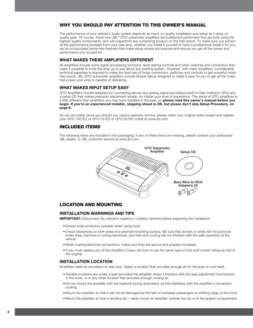
included iTeMs
The following items are included in the packaging. If any of these items are missing, please contact your authorized JBL dealer, or JBL customer service at www.jbl.com.
Setup CDGTO Subwoofer
Amplifier
Bare Wire-to-RCA Adapters (2)
lOcaTiOn and MOunTinG
installatiOn Warnings and tipsimpOrtant: Disconnect the vehicle’s negative (–) battery terminal before beginning the installation.
• Always wear protective eyewear when using tools.
• Check clearances on both sides of a planned mounting surface. Be sure that screws or wires will not puncture brake lines, fuel lines or wiring harnesses, and that wire routing will not interfere with the safe operation of the vehicle.
• When making electrical connections, make sure they are secure and properly insulated.
• If you must replace any of the amplifier’s fuses, be sure to use the same type of fuse and current rating as that of the original.
installatiOn lOcatiOnAmplifiers need air circulation to stay cool. Select a location that provides enough air for the amp to cool itself.
• Suitable locations are under a seat (provided the amplifier doesn’t interfere with the seat adjustment mechanism), in the trunk, or in any other location that provides enough cooling air.
• Do not mount the amplifier with the heatsink facing downward, as this interferes with the amplifier’s convection cooling.
• Mount the amplifier so that it will not be damaged by the feet of backseat passengers or shifting cargo in the trunk.
• Mount the amplifier so that it remains dry – never mount an amplifier outside the car or in the engine compartment.
3www.jbl.com
Eng
lish
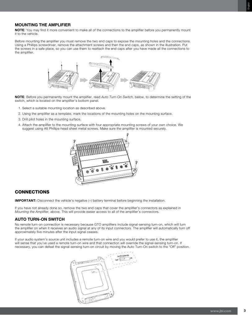
mOunting the amplifiernOte: You may find it more convenient to make all of the connections to the amplifier before you permanently mount it to the vehicle.
Before mounting the amplifier you must remove the two end caps to expose the mounting holes and the connections. Using a Phillips screwdriver, remove the attachment screws and then the end caps, as shown in the illustration. Put the screws in a safe place, so you can use them to reattach the end caps after you have made all the connections to the amplifier.
nOte: Before you permanently mount the amplifier, read Auto Turn-On Switch, below, to determine the setting of the switch, which is located on the amplifier’s bottom panel.
1. Select a suitable mounting location as described above.
2. Using the amplifier as a template, mark the locations of the mounting holes on the mounting surface.
3. Drill pilot holes in the mounting surface.
4. Attach the amplifier to the mounting surface with four appropriate mounting screws of your own choice. We suggest using #8 Phillips-head sheet metal screws. Make sure the amplifier is mounted securely.
cOnnecTiOns
impOrtant: Disconnect the vehicle’s negative (–) battery terminal before beginning the installation.
If you have not already done so, remove the two end caps that cover the amplifier’s connectors as explained in Mounting the Amplifier, above. This will provide easier access to all of the amplifier’s connectors.
autO turn-On sWitchNo remote turn-on connection is necessary because GTO amplifiers include signal-sensing turn-on, which will turn the amplifier on when it receives an audio signal at any of its input connectors. The amplifier will automatically turn off approximately five minutes after the input signal ceases.
If your audio system’s source unit includes a remote turn-on wire and you would prefer to use it, the amplifier will sense that you’ve used a remote turn-on wire and that connection will override the signal-sensing turn-on. If necessary, you can defeat the signal-sensing turn-on circuit by moving the Auto Turn-On switch to the “Off” position.
4
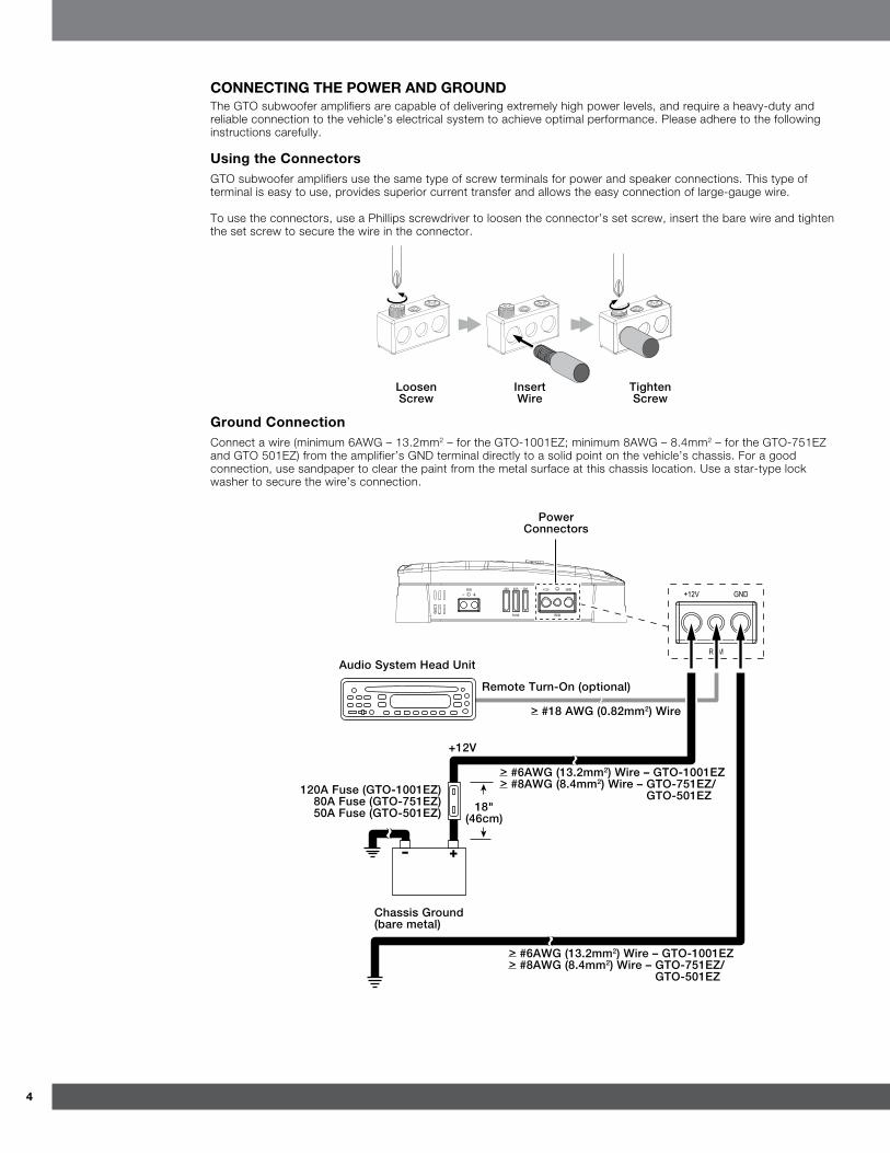
cOnnecting the pOWer and grOundThe GTO subwoofer amplifiers are capable of delivering extremely high power levels, and require a heavy-duty and reliable connection to the vehicle’s electrical system to achieve optimal performance. Please adhere to the following instructions carefully.
using the connectorsGTO subwoofer amplifiers use the same type of screw terminals for power and speaker connections. This type of terminal is easy to use, provides superior current transfer and allows the easy connection of large-gauge wire.
To use the connectors, use a Phillips screwdriver to loosen the connector’s set screw, insert the bare wire and tighten the set screw to secure the wire in the connector.
Loosen Screw
Insert Wire
Tighten Screw
ground connectionConnect a wire (minimum 6AWG – 13.2mm2 – for the GTO-1001EZ; minimum 8AWG – 8.4mm2 – for the GTO-751EZ and GTO 501EZ) from the amplifier’s GND terminal directly to a solid point on the vehicle’s chassis. For a good connection, use sandpaper to clear the paint from the metal surface at this chassis location. Use a star-type lock washer to secure the wire’s connection.
-
Power Connectors
Audio System Head Unit
Remote Turn-On (optional)
> #18 AWG (0.82mm2) Wire
> #6AWG (13.2mm2) Wire – GTO-1001EZ> #8AWG (8.4mm2) Wire – GTO-751EZ/
GTO-501EZ
+12V
18" (46cm)
> #6AWG (13.2mm2) Wire – GTO-1001EZ> #8AWG (8.4mm2) Wire – GTO-751EZ/
GTO-501EZ
120A Fuse (GTO-1001EZ) 80A Fuse (GTO-751EZ) 50A Fuse (GTO-501EZ)
Chassis Ground (bare metal)
5www.jbl.com
Eng
lish
power connection1. Connect a wire (minimum 6AWG – 13.2mm2 – for the GTO-1001EZ; minimum 8AWG – 8.4mm2 –for the
GTO-751EZ and GTO-501EZ) directly to the battery’s positive (+) terminal.
2. Install a fuse holder for a 120A fuse (GTO-1001EZ), 80A fuse (GTO-751EZ) or 50A Fuse (GTO-501EZ) on this wire within 18" (46cm) of the battery’s (+) terminal. Do not install the fuse in the holder at this time.
3. Route this wire to the amplifier’s location and connect it to the amplifier’s +12V terminal. Be sure to use appropriate grommets whenever routing wires through the firewall or other sheet metal. impOrtant: Failure to adequately protect the positive wire from potential damage may result in a vehicle fire.
4. When you are finished routing and connecting this wire, install the appropriate fuse in the holder you installed near the battery. (GTO-1001EZ = 120A fuse; GTO-751EZ = 80A fuse; GTO-501EZ = 50A fuse.)
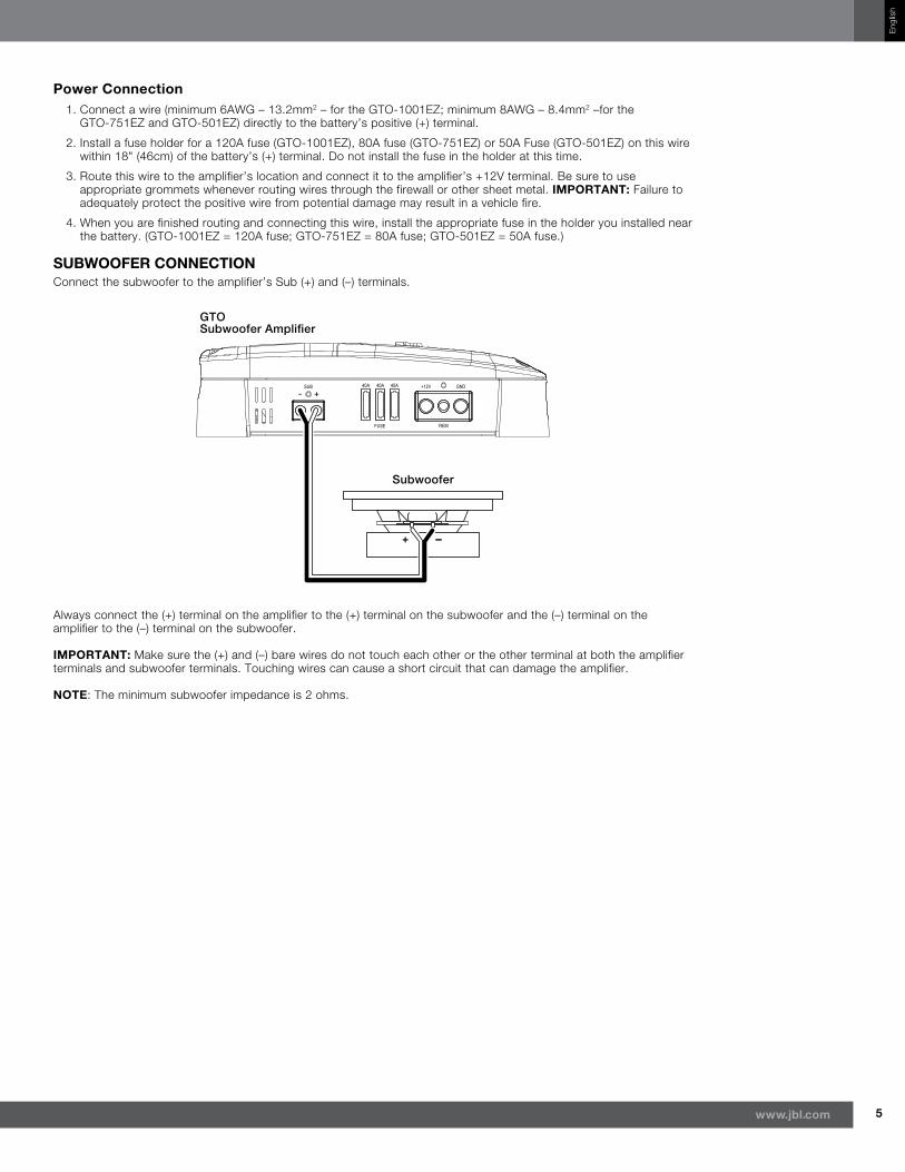
suBWOOfer cOnnectiOnConnect the subwoofer to the amplifier’s Sub (+) and (–) terminals.
-
Subwoofer
GTO Subwoofer Amplifier
Always connect the (+) terminal on the amplifier to the (+) terminal on the subwoofer and the (–) terminal on the amplifier to the (–) terminal on the subwoofer.
impOrtant: Make sure the (+) and (–) bare wires do not touch each other or the other terminal at both the amplifier terminals and subwoofer terminals. Touching wires can cause a short circuit that can damage the amplifier.
nOte: The minimum subwoofer impedance is 2 ohms.
6
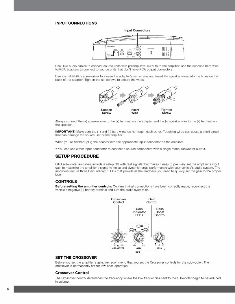
input cOnnectiOns
Input Connectors
Use RCA audio cables to connect source units with preamp-level outputs to the amplifier; use the supplied bare wire-to-RCA adapters to connect to source units that don’t have RCA output connectors.
Use a small Phillips screwdriver to loosen the adapter’s set screws and insert the speaker wires into the holes on the back of the adapter. Tighten the set screws to secure the wires.
Loosen Screw
Insert Wire
Tighten Screw
Always connect the (+) speaker wire to the (+) terminal on the adapter and the (–) speaker wire to the (–) terminal on the speaker.
impOrtant: Make sure the (+) and (–) bare wires do not touch each other. Touching wires can cause a short circuit that can damage the source unit or the amplifier.
When you’re finished, plug the adapter into the appropriate input connector on the amplifier.
• You can use either input connector to connect a source component with a single mono subwoofer output.
seTuP PrOcedure
GTO subwoofer amplifiers include a setup CD with test signals that makes it easy to precisely set the amplifier’s input gain to maximize the amplifier’s signal-to-noise and dynamic range performance with your vehicle’s audio system. The amplifiers feature three Gain Indicator LEDs that provide all the feedback you need to quickly set the gain to the proper level.
cOntrOlsBefore setting the amplifier controls: Confirm that all connections have been correctly made, reconnect the vehicle’s negative (–) battery terminal and turn the audio system on.
Crossover Control
Bass Boost
Control
Gain Indicator
LEDs
Gain Control
set the crOssOverBefore you set the amplifier’s gain, we recommend that you set the Crossover controls for the subwoofer. The crossover is permanently set for low-pass operation.
crossover controlThe Crossover control determines the frequency where the low frequencies sent to the subwoofer begin to be reduced in volume.
7www.jbl.com
Eng
lish
The low-pass Crossover control setting you use for your subwoofer will depend partly on the system’s high-pass channel settings, and partly on the type and location of your system’s subwoofer. Start by setting the Crossover control to a frequency somewhat lower than the lowest setting you used on any of the high-pass channels. After listening to music on the system for a time, fine-tune the low-pass Crossover control setting to achieve a smooth transition from the subwoofer to the rest of the system’s speakers while avoiding a “hole,” where the sounds that occur between the subwoofer and other speakers seem to drop out. The illustration below shows the acceptable low-pass Crossover control frequency range.
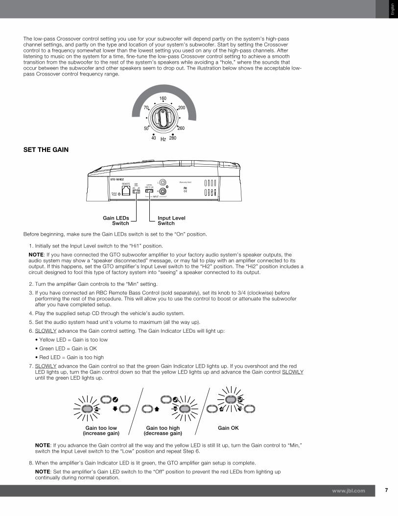
set the gain
Input Level Switch
Gain LEDs Switch
Before beginning, make sure the Gain LEDs switch is set to the “On” position.
1. Initially set the Input Level switch to the “Hi1” position.
nOte: If you have connected the GTO subwoofer amplifier to your factory audio system’s speaker outputs, the audio system may show a “speaker disconnected” message, or may fail to play with an amplifier connected to its output. If this happens, set the GTO amplifier’s Input Level switch to the “Hi2” position. The “Hi2” position includes a circuit designed to fool this type of factory system into “seeing” a speaker connected to its output.
2. Turn the amplifier Gain controls to the “Min” setting.
3. If you have connected an RBC Remote Bass Control (sold separately), set its knob to 3/4 (clockwise) before performing the rest of the procedure. This will allow you to use the control to boost or attenuate the subwoofer after you have completed setup.
4. Play the supplied setup CD through the vehicle’s audio system.
5. Set the audio system head unit’s volume to maximum (all the way up).
6. SLOWLY advance the Gain control setting. The Gain Indicator LEDs will light up:
• Yellow LED = Gain is too low
• Green LED = Gain is OK
• Red LED = Gain is too high
7. SLOWLY advance the Gain control so that the green Gain Indicator LED lights up. If you overshoot and the red LED lights up, turn the Gain control down so that the yellow LED lights up and advance the Gain control SLOWLY until the green LED lights up.
Gain too low (increase gain)
Gain OKGain too high (decrease gain)
nOte: If you advance the Gain control all the way and the yellow LED is still lit up, turn the Gain control to “Min,” switch the Input Level switch to the “Low” position and repeat Step 6.
8. When the amplifier’s Gain Indicator LED is lit green, the GTO amplifier gain setup is complete.
nOte: Set the amplifier’s Gain LED switch to the “Off” position to prevent the red LEDs from lighting up continually during normal operation.
8
Bass BOOstThe Bass Boost control provides up to 12dB of bass boost at 45Hz. Set this control according to your personal taste, but be careful not to set the control at a high enough level to cause audible distortion or bottoming of your subwoofer.
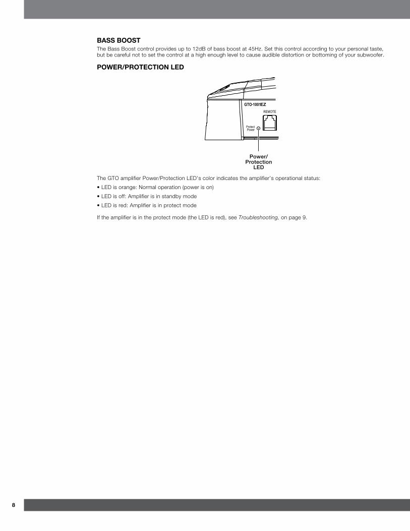
pOWer/prOtectiOn led
Power/ Protection
LED
The GTO amplifier Power/Protection LED’s color indicates the amplifier’s operational status:
• LED is orange: Normal operation (power is on)
• LED is off: Amplifier is in standby mode
• LED is red: Amplifier is in protect mode
If the amplifier is in the protect mode (the LED is red), see Troubleshooting, on page 9.
9www.jbl.com
Eng
lish
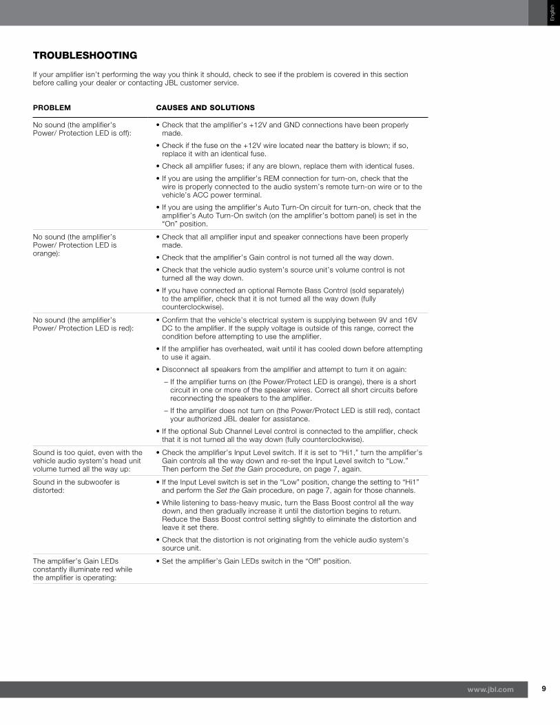
TrOubleshOOTinG
If your amplifier isn’t performing the way you think it should, check to see if the problem is covered in this section before calling your dealer or contacting JBL customer service.
prOBlem causes and sOluTiOns
No sound (the amplifier’s Power/ Protection LED is off):
• Check that the amplifier’s +12V and GND connections have been properly made.
• Check if the fuse on the +12V wire located near the battery is blown; if so, replace it with an identical fuse.
• Check all amplifier fuses; if any are blown, replace them with identical fuses.
• If you are using the amplifier’s REM connection for turn-on, check that the wire is properly connected to the audio system’s remote turn-on wire or to the vehicle’s ACC power terminal.
• If you are using the amplifier’s Auto Turn-On circuit for turn-on, check that the amplifier’s Auto Turn-On switch (on the amplifier’s bottom panel) is set in the “On” position.
No sound (the amplifier’s Power/ Protection LED is orange):
• Check that all amplifier input and speaker connections have been properly made.
• Check that the amplifier’s Gain control is not turned all the way down.
• Check that the vehicle audio system’s source unit’s volume control is not turned all the way down.
• If you have connected an optional Remote Bass Control (sold separately) to the amplifier, check that it is not turned all the way down (fully counterclockwise).
No sound (the amplifier’s Power/ Protection LED is red):
• Confirm that the vehicle’s electrical system is supplying between 9V and 16V DC to the amplifier. If the supply voltage is outside of this range, correct the condition before attempting to use the amplifier.
• If the amplifier has overheated, wait until it has cooled down before attempting to use it again.
• Disconnect all speakers from the amplifier and attempt to turn it on again:
– If the amplifier turns on (the Power/Protect LED is orange), there is a short circuit in one or more of the speaker wires. Correct all short circuits before reconnecting the speakers to the amplifier.
– If the amplifier does not turn on (the Power/Protect LED is still red), contact your authorized JBL dealer for assistance.
• If the optional Sub Channel Level control is connected to the amplifier, check that it is not turned all the way down (fully counterclockwise).
Sound is too quiet, even with the vehicle audio system’s head unit volume turned all the way up:
• Check the amplifier’s Input Level switch. If it is set to “Hi1,” turn the amplifier’s Gain controls all the way down and re-set the Input Level switch to “Low.” Then perform the Set the Gain procedure, on page 7, again.
Sound in the subwoofer is distorted:
• If the Input Level switch is set in the “Low” position, change the setting to “Hi1” and perform the Set the Gain procedure, on page 7, again for those channels.
• While listening to bass-heavy music, turn the Bass Boost control all the way down, and then gradually increase it until the distortion begins to return. Reduce the Bass Boost control setting slightly to eliminate the distortion and leave it set there.
• Check that the distortion is not originating from the vehicle audio system’s source unit.
The amplifier’s Gain LEDs constantly illuminate red while the amplifier is operating:
• Set the amplifier’s Gain LEDs switch in the “Off” position.
10
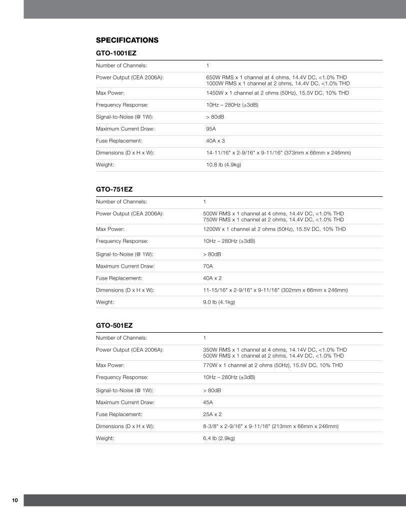
sPecificaTiOns
gtO-1001eZ
Number of Channels: 1
Power Output (CEA 2006A): 650W RMS x 1 channel at 4 ohms, 14.4V DC, <1.0% THD 1000W RMS x 1 channel at 2 ohms, 14.4V DC, <1.0% THD
Max Power: 1450W x 1 channel at 2 ohms (50Hz), 15.5V DC, 10% THD
Frequency Response: 10Hz – 280Hz (±3dB)
Signal-to-Noise (@ 1W): > 80dB
Maximum Current Draw: 95A
Fuse Replacement: 40A x 3
Dimensions (D x H x W): 14-11/16" x 2-9/16" x 9-11/16" (373mm x 66mm x 246mm)
Weight: 10.8 lb (4.9kg)
gtO-751eZ
Number of Channels: 1
Power Output (CEA 2006A): 500W RMS x 1 channel at 4 ohms, 14.4V DC, <1.0% THD 750W RMS x 1 channel at 2 ohms, 14.4V DC, <1.0% THD
Max Power: 1200W x 1 channel at 2 ohms (50Hz), 15.5V DC, 10% THD
Frequency Response: 10Hz – 280Hz (±3dB)
Signal-to-Noise (@ 1W): > 80dB
Maximum Current Draw: 70A
Fuse Replacement: 40A x 2
Dimensions (D x H x W): 11-15/16" x 2-9/16" x 9-11/16" (302mm x 66mm x 246mm)
Weight: 9.0 lb (4.1kg)
gtO-501eZ
Number of Channels: 1
Power Output (CEA 2006A): 350W RMS x 1 channel at 4 ohms, 14.14V DC, <1.0% THD 500W RMS x 1 channel at 2 ohms, 14.4V DC, <1.0% THD
Max Power: 770W x 1 channel at 2 ohms (50Hz), 15.5V DC, 10% THD
Frequency Response: 10Hz – 280Hz (±3dB)
Signal-to-Noise (@ 1W): > 80dB
Maximum Current Draw: 45A
Fuse Replacement: 25A x 2
Dimensions (D x H x W): 8-3/8" x 2-9/16" x 9-11/16" (213mm x 66mm x 246mm)
Weight: 6.4 lb (2.9kg)

11www.jbl.com
Eng
lish
© 2011 HARMAN International Industries, Incorporated. All rights reserved.
JBL is a trademark of HARMAN International Industries, Incorporated, registered in the United States and/or other countries.
Features, specifications and appearance are subject to change without notice.
HARMAN Consumer, Inc. 8500 Balboa Boulevard, Northridge, CA 91329 USA