Embed Size (px)
Citation preview
GTR-128/GTR-129 Development Document
V 0.4
Globalsat Technology Corporation
16F., No. 186, Jian-Yi Road, Chung-Ho City, Taipei Hsien 235, Taiwan
Tel: 886-2-8226-3799/ Fax: 886-2-8226-3899
E-mail: [email protected]
Website: www.globalsat.com.tw
1
CONTENT
1 Introduction ........................................................................................................................................... 3
2 Protocol Summary ................................................................................................................................. 4
2.1 General Format ........................................................................................................................... 4
2.2 Format of configuration message ............................................................................................... 5
2.2.1 Server -> Device ............................................................................................................. 5
2.2.2 Device -> Server ............................................................................................................. 5
2.3 Format of Geo-fence Message ................................................................................................... 6
2.3.1 Server -> Device ............................................................................................................. 6
2.3.2 Device -> Server ............................................................................................................. 6
2.3.3 Geo-fence area definition format .................................................................................... 6
2.4 Format of Command Message ................................................................................................... 7
2.5 Format of Report Message ......................................................................................................... 8
2.6 Parameters of Report Messages ................................................................................................. 9
2.6.1 Close the Cell ID information ....................................................................................... 13
2.7 Code word of Configuration Parameter ................................................................................... 14
2.8 Code word of Command .......................................................................................................... 28
2.9 Report Media ............................................................................................................................ 30
2.10 Action type ............................................................................................................................. 32
2.11 Checksum ............................................................................................................................... 33
3 Configuration ...................................................................................................................................... 34
3.1 Read parameters of configuration ............................................................................................ 34
3.2 Set parameters of configuration ............................................................................................... 35
4 GSM & GPRS ..................................................................................................................................... 36
4.1 GPRS Setting ........................................................................................................................... 36
4.2 Acknowledgement .................................................................................................................... 37
4.2.1 Receive Acknowledgement from Server ....................................................................... 38
4.2.2 Respond Acknowledgement to Server .......................................................................... 39
4.3 GPRS connection ..................................................................................................................... 40
5 GPS...................................................................................................................................................... 42
6 Tracking ............................................................................................................................................... 44
6.1 Ping Report ............................................................................................................................... 44
6.2 Motion Report .......................................................................................................................... 45
6.2.1 Angle Change Setting .................................................................................................... 48
6.2.2 Roaming allow/disallow ................................................................................................ 49
2
7. Alert .................................................................................................................................................... 50
7.1 Emergency ................................................................................................................................ 50
7.2 Speed Limits ............................................................................................................................. 51
7.2.1 Enable Speed Limit Alert .............................................................................................. 52
7.2.2 Disable Speed Limit Alert ............................................................................................. 53
7.3 Geo-fence ................................................................................................................................. 54
7.3.1 Setup Geo-fence ............................................................................................................ 54
7.3.2 Reading Geo-fence setting ............................................................................................ 58
7.3.3 Enable Geo-fence Alert ................................................................................................. 59
7.3.4 Dismiss Geo-fence Alarm ............................................................................................. 60
7.4 Autonomous Geo-fence ............................................................................................................ 61
7.5 ACC alert .................................................................................................................................. 62
7.6 Main battery alert ..................................................................................................................... 63
7.7 Parking Alert ............................................................................................................................ 65
7.8 Jammer Alert ............................................................................................................................ 66
8 Timer ................................................................................................................................................... 66
8.1 Timer 0 ..................................................................................................................................... 67
8.2 Timer 1~2 ................................................................................................................................. 67
9 Stopwatch ............................................................................................................................................ 69
10 Counter .............................................................................................................................................. 70
11 Odometer ........................................................................................................................................... 72
12 Report Messages ............................................................................................................................... 74
12.1 Format 0 of Report Messages................................................................................................. 74
12.2 Format 1 of Report Messages................................................................................................. 75
12.3 SMS Format Report ............................................................................................................... 77
13 Error Report....................................................................................................................................... 79
14 Buffer Storage ................................................................................................................................... 80
14.1 Bulk uploading of Buffered Report to Server ........................................................................ 81
15 I/O port .............................................................................................................................................. 82
15.1 Fuel sensor input .................................................................................................................... 83
15.2 Digital input............................................................................................................................ 84
15.3 Digital output.......................................................................................................................... 85
16 Simple command ............................................................................................................................... 86
17 OTA Function .................................................................................................................................... 89
17.1 OTA Firmware Upgrade ......................................................................................................... 89
17.2 OTA Setting Configuration .................................................................................................... 91
17.3 OTA Uploading Debug Message ............................................................................................ 92

3
1 Introduction
GTR-128/GTR-129 is designed as durable and multi-functional GPS/GSM/GPRS tracker. It
integrates highly sensitive GPS module and quad-band GSM communication module with a
powerful microcontroller that fits into a compact enclosure. The device is capable of
waterproof and ideal for use in motorcycle, golf cars and general car. It is small size and low
cost for covert and efficient tracking device. It provides real-time GPS positions anytime and
anywhere with an open view to the sky, and offers precise positioning, and reports vehicle
status to the server with necessary information shown on the map. Benefits such as enhanced
fleet management, improved vehicle safety, emergency response, are all accomplished
through the implementation of the GTR-128/GTR-129 system. The built-in GSM and GPS
antennas are for easy installation without hassle.
The key functions of GTR-128/GTR-129 are listed bel ow.
� Support communication protocols- SMS/TCP/UDP.
� Multiple I/Os support: 1 Digital Input for custom function, 1 Digital input for optional
Emergency button, 1 Analog Input for fuel sensor, 1 Digital Output for Relay, 1 Digital
Input for ACC detection.
� Over-The-Air Device Configuration and Firmware update
� Alert functions including Power low/ Over speed/ Movement alarms
� Tracking in preferred interval, scheduling and Geo-fence
� Embedded magnet and double clips for easy installation
� No any button and plug-in then power on for simple use
� Multiple power kits suit to diverse vehicles and motorcycles
This document describes the communication protocol between GTR-128/GTR-129
and application server, the built-in behavior modes of GTR-128/GTR-129, and the
function of each parameter.
4
2 Protocol Summary
2.1 General Format
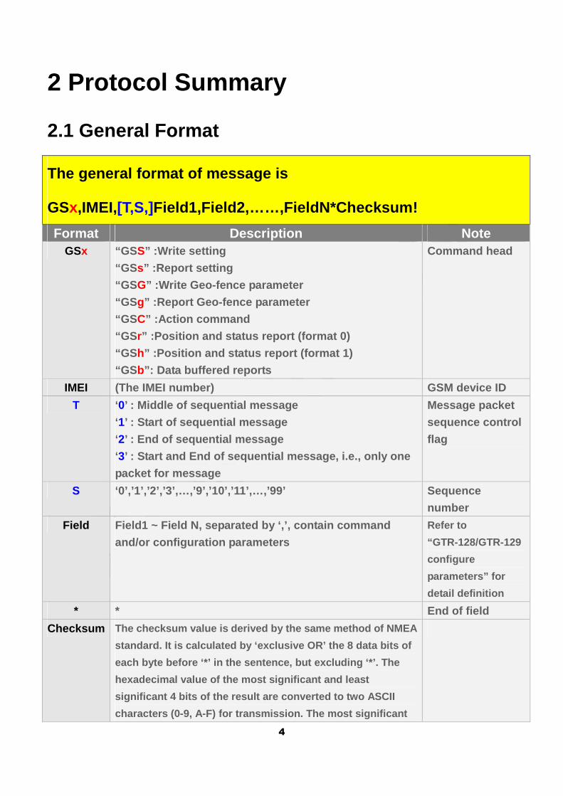
The general format of message is
GSx,IMEI,[T,S,]Field1,Field2,……,FieldN*Checksum!
Format Description Note GSx “GS S” :Write setting
“GS s” :Report setting
“GS G” :Write Geo-fence parameter
“GS g” :Report Geo-fence parameter
“GS C” :Action command
“GS r” :Position and status report (format 0)
“GS h” :Position and status report (format 1)
“GS b”: Data buffered reports
Command head
IMEI (The IMEI number) GSM device ID
T ‘0’ : Middle of sequential message
‘1’ : Start of sequential message
‘2’ : End of sequential message
‘3’ : Start and End of sequential message, i.e., only one
packet for message
Message packet
sequence control
flag
S ‘0’,’1’,’2’,’3’,…,’9’,’10’,’11’,…,’99’ Sequence
number
Field Field1 ~ Field N, separated by ‘,’, contain command
and/or configuration parameters
Refer to
“GTR-128/GTR-129
configure
parameters” for
detail definition
* * End of field
Checksum The checksum value is derived by the same method of NMEA
standard. It is calculated by ‘exclusive OR’ the 8 data bits of
each byte before ‘*’ in the sentence, but excluding ‘*’. The
hexadecimal value of the most significant and least
significant 4 bits of the result are converted to t wo ASCII
characters (0-9, A-F) for transmission. The most si gnificant
5
character is transmitted first.
! ! Message delimiter
2.2 Format of configuration message
2.2.1 Server -> Device
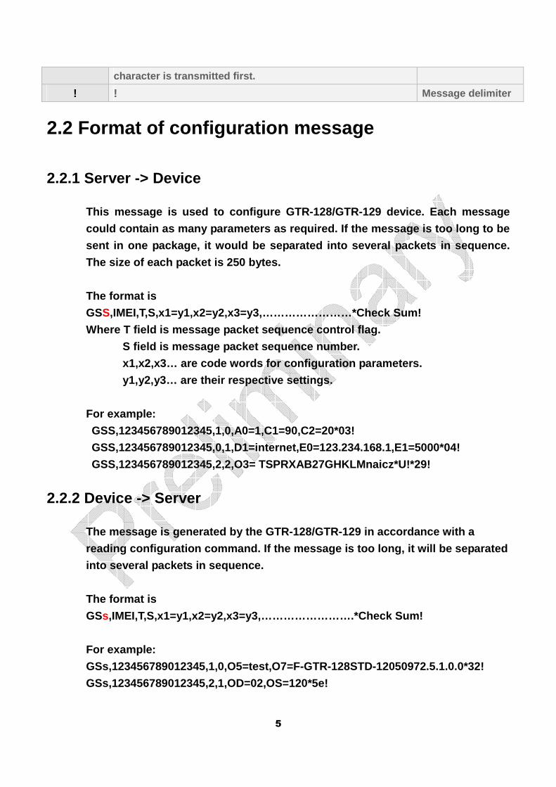
This message is used to configure GTR-128/GTR-129 d evice. Each message
could contain as many parameters as required. If th e message is too long to be
sent in one package, it would be separated into sev eral packets in sequence.
The size of each packet is 250 bytes.
The format is
GSS,IMEI,T,S,x1=y1,x2=y2,x3=y3,……………………*Check Sum!
Where T field is message packet sequence control fl ag.
S field is message packet sequence number.
x1,x2,x3… are code words for configuration paramete rs.
y1,y2,y3… are their respective settings.
For example:
GSS,123456789012345,1,0,A0=1,C1=90,C2=20*03!
GSS,123456789012345,0,1,D1=internet,E0=123.234.168 .1,E1=5000*04!
GSS,123456789012345,2,2,O3= TSPRXAB27GHKLMnaicz*U! *29!
2.2.2 Device -> Server
The message is generated by the GTR-128/GTR-129 in accordance with a
reading configuration command. If the message is to o long, it will be separated
into several packets in sequence.
The format is
GSs,IMEI,T,S,x1=y1,x2=y2,x3=y3,…………………….*Check Sum!
For example:
GSs,123456789012345,1,0,O5=test,O7=F-GTR-128STD-120 50972.5.1.0.0*32!
GSs,123456789012345,2,1,OD=02,OS=120*5e!
6
2.3 Format of Geo-fence Message
2.3.1 Server -> Device
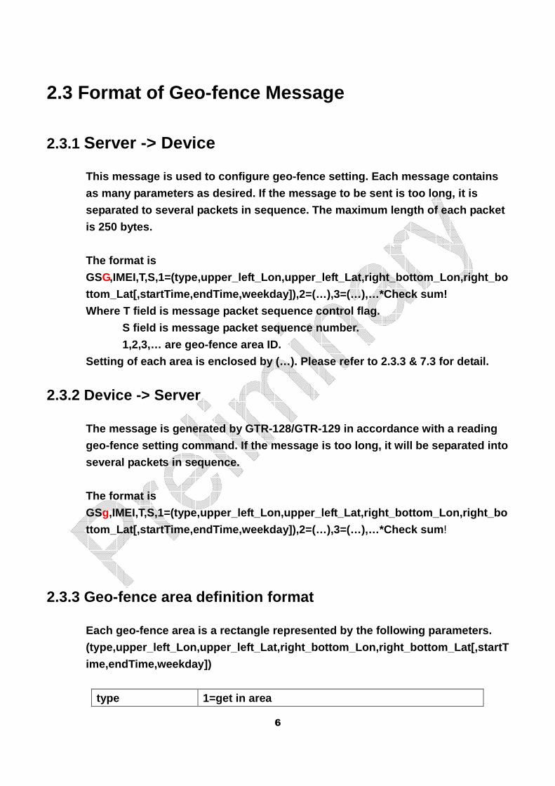
This message is used to configure geo-fence setting . Each message contains
as many parameters as desired. If the message to be sent is too long, it is
separated to several packets in sequence. The maxim um length of each packet
is 250 bytes.
The format is
GSG,IMEI,T,S,1=(type,upper_left_Lon,upper_left_Lat,rig ht_bottom_Lon,right_bo
ttom_Lat[,startTime,endTime,weekday]),2=(…),3=(…),… *Check sum!
Where T field is message packet sequence control fl ag.
S field is message packet sequence number.
1,2,3,… are geo-fence area ID.
Setting of each area is enclosed by (…). Please ref er to 2.3.3 & 7.3 for detail.
2.3.2 Device -> Server
The message is generated by GTR-128/GTR-129 in acco rdance with a reading
geo-fence setting command. If the message is too lo ng, it will be separated into
several packets in sequence.
The format is
GSg,IMEI,T,S,1=(type,upper_left_Lon,upper_left_Lat,rig ht_bottom_Lon,right_bo
ttom_Lat[,startTime,endTime,weekday]),2=(…),3=(…),… *Check sum !
2.3.3 Geo-fence area definition format
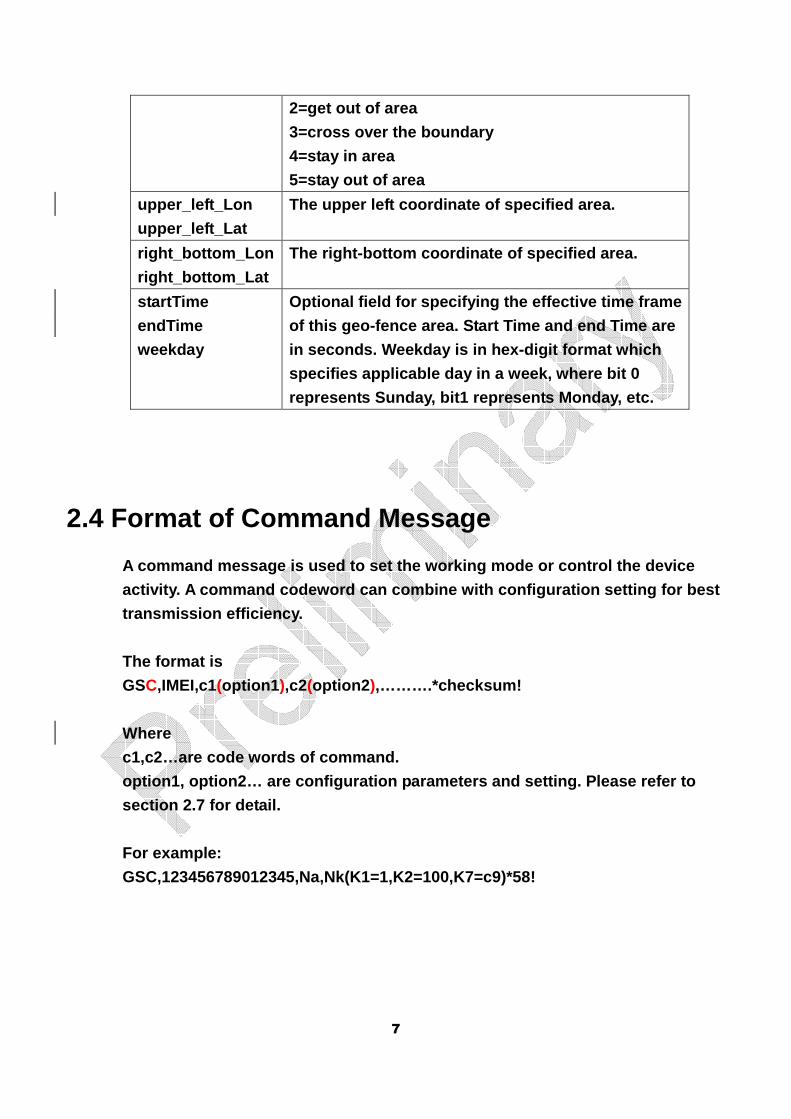
Each geo-fence area is a rectangle represented by the following parameters.
(type,upper_left_Lon,upper_left_Lat,right_bottom_Lon,right_bottom_Lat[,startT
ime,endTime,weekday])
type 1=get in area
7
2=get out of area
3=cross over the boundary
4=stay in area
5=stay out of area
upper_left_Lon
upper_left_Lat
The upper left coordinate of specified area.
right_bottom_Lon
right_bottom_Lat
The right-bottom coordinate of specified area.
startTime
endTime
weekday
Optional field for specifying the effective time fr ame
of this geo-fence area. Start Time and end Time are
in seconds. Weekday is in hex-digit format which
specifies applicable day in a week, where bit 0
represents Sunday, bit1 represents Monday, etc.
2.4 Format of Command Message
A command message is used to set the working mode o r control the device
activity. A command codeword can combine with confi guration setting for best
transmission efficiency.
The format is
GSC,IMEI,c1(option1 ),c2(option2 ),……….*checksum!
Where
c1,c2…are code words of command.
option1, option2… are configuration parameters and setting. Please refer to
section 2.7 for detail.
For example:
GSC,123456789012345,Na,Nk(K1=1,K2=100,K7=c9)*58!
8
2.5 Format of Report Message
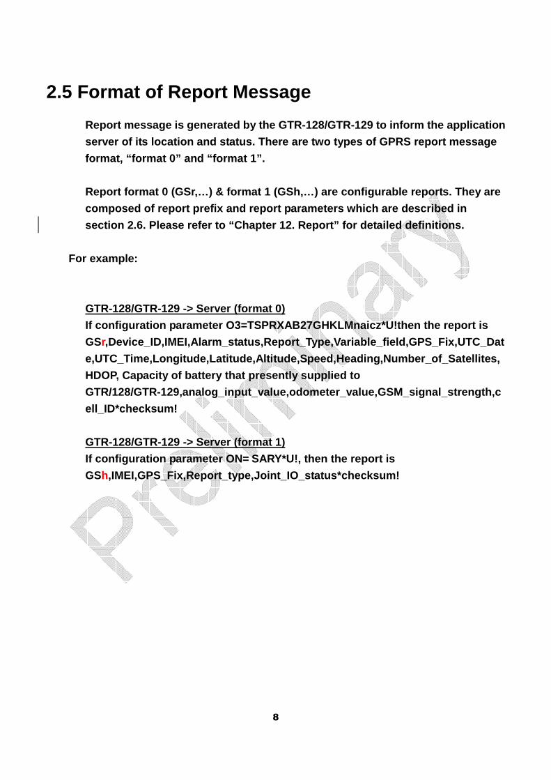
Report message is generated by the GTR-128/GTR-129 to inform the application
server of its location and status. There are two ty pes of GPRS report message
format, “format 0” and “format 1”.
Report format 0 (GSr,…) & format 1 (GSh,…) are conf igurable reports. They are
composed of report prefix and report parameters whi ch are described in
section 2.6. Please refer to “Chapter 12. Report” f or detailed definitions.
For example:
GTR-128/GTR-129 -> Server (format 0)
If configuration parameter O3=TSPRXAB27GHKLMnaicz*U !then the report is
GSr,Device_ID,IMEI,Alarm_status,Report_Type,Variable_f ield,GPS_Fix,UTC_Dat
e,UTC_Time,Longitude,Latitude,Altitude,Speed,Headin g,Number_of_Satellites,
HDOP, Capacity of battery that presently supplied to
GTR/128/GTR-129,analog_input_value,odometer_value,G SM_signal_strength,c
ell_ID*checksum!
GTR-128/GTR-129 -> Server (format 1)
If configuration parameter ON= SARY*U!, then the report is
GSh,IMEI,GPS_Fix,Report_type,Joint_IO_status*checksum!
9
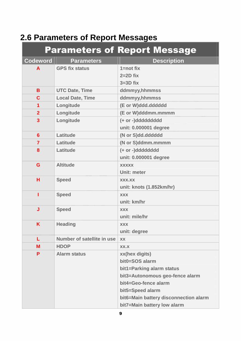
2.6 Parameters of Report Messages
Parameters of Report Message Codeword Parameters Description
A GPS fix status 1=not fix
2=2D fix
3=3D fix
B UTC Date, Time ddmmyy,hhmmss
C Local Date, Time ddmmyy,hhmmss
1 Longitude (E or W)ddd.dddddd
2 Longitude (E or W)dddmm.mmmm
3 Longitude (+ or -)ddddddddd
unit: 0.000001 degree
6 Latitude (N or S)dd.dddddd
7 Latitude (N or S)ddmm.mmmm
8 Latitude (+ or -)dddddddd
unit: 0.000001 degree
G Altitude xxxxx
Unit: meter
H Speed xxx.xx
unit: knots (1.852km/hr)
I Speed xxx
unit: km/hr
J Speed xxx
unit: mile/hr
K Heading xxx
unit: degree
L Number of satellite in use xx
M HDOP xx.x
P Alarm status xx(hex digits)
bit0=SOS alarm
bit1=Parking alarm status
bit3=Autonomous geo-fence alarm
bit4=Geo-fence alarm
bit5=Speed alarm
bit6=Main battery disconnection alarm
bit7=Main battery low alarm
10
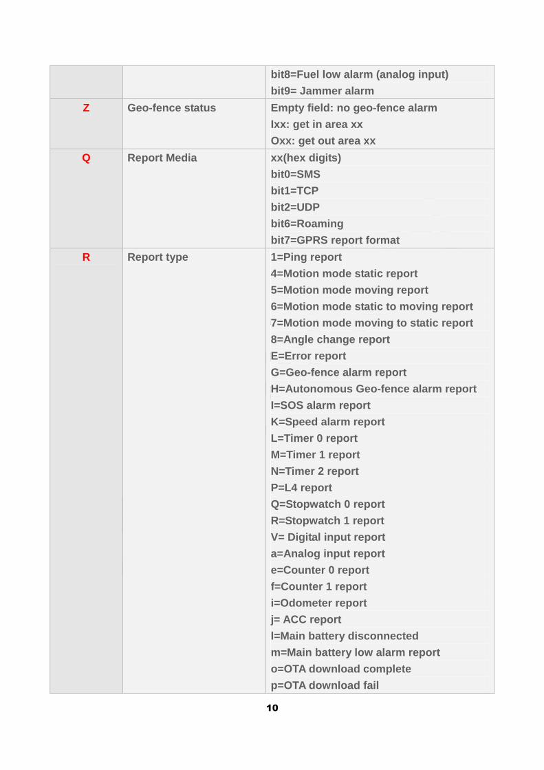
bit8=Fuel low alarm (analog input)
bit9= Jammer alarm
Z Geo-fence status Empty field: no geo-fence alarm
Ixx: get in area xx
Oxx: get out area xx
Q Report Media xx(hex digits)
bit0=SMS
bit1=TCP
bit2=UDP
bit6=Roaming
bit7=GPRS report format
R Report type 1=Ping report
4=Motion mode static report
5=Motion mode moving report
6=Motion mode static to moving report
7=Motion mode moving to static report
8=Angle change report
E=Error report
G=Geo-fence alarm report
H=Autonomous Geo-fence alarm report
I=SOS alarm report
K=Speed alarm report
L=Timer 0 report
M=Timer 1 report
N=Timer 2 report
P=L4 report
Q=Stopwatch 0 report
R=Stopwatch 1 report
V= Digital input report
a=Analog input report
e=Counter 0 report
f=Counter 1 report
i=Odometer report
j= ACC report
l=Main battery disconnected
m=Main battery low alarm report
o=OTA download complete
p=OTA download fail
11
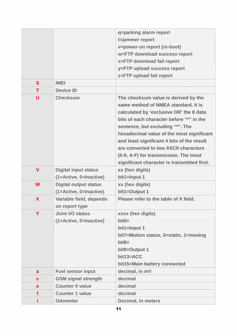
q=parking alarm report
t=jammer report
v=power-on report (re-boot)
w=FTP download success report
x=FTP download fail report
y=FTP upload success report
z=FTP upload fail report
S IMEI
T Device ID
U Checksum The checksum value is derived by the
same method of NMEA standard. It is
calculated by ‘exclusive OR’ the 8 data
bits of each character before “*” in the
sentence, but excluding “*”. The
hexadecimal value of the most significant
and least significant 4 bits of the result
are converted to two ASCII characters
(0-9, A-F) for transmission. The most
significant character is transmitted first.
V Digital input status
(1=Active, 0=Inactive)
xx (hex digits)
bit1=Input 1
W Digital output status
(1=Active, 0=Inactive)
xx (hex digits)
bit1=Output 1
X Variable field, depends
on report type
Please refer to the table of X field.
Y Joint I/O status
(1=Active, 0=Inactive)
xxxx (hex digits)
bit0=
bit1=Input 1
bit7=Motion status, 0=static, 1=moving
bit8=
bit9=Output 1
bit13=ACC
bit15=Main battery connected
a Fuel sensor input decimal, in mV
c GSM signal strength decimal
e Counter 0 value decimal
f Counter 1 value decimal
i Odometer Decimal, in meters
12
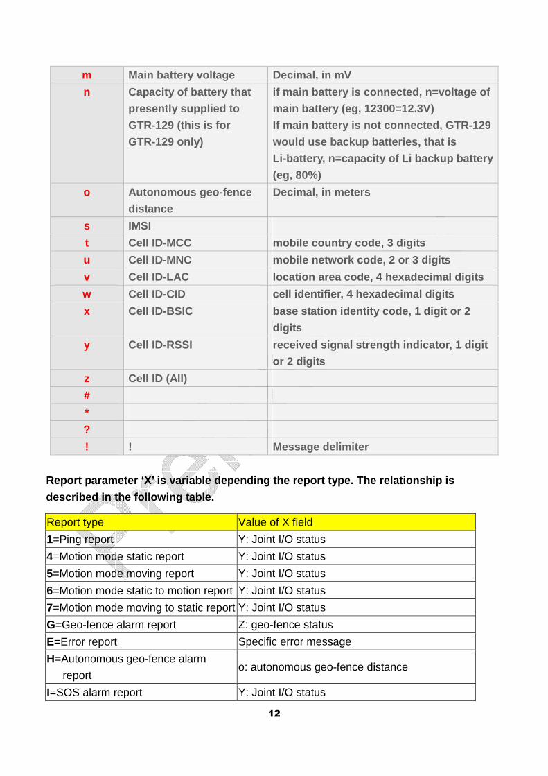
m Main battery voltage Decimal, in mV
n Capacity of battery that
presently supplied to
GTR-129 (this is for
GTR-129 only)
if main battery is connected, n=voltage of
main battery (eg, 12300=12.3V)
If main battery is not connected, GTR-129
would use backup batteries, that is
Li-battery, n=capacity of Li backup battery
(eg, 80%)
o Autonomous geo-fence
distance
Decimal, in meters
s IMSI
t Cell ID-MCC mobile country code, 3 digits
u Cell ID-MNC mobile network code, 2 or 3 digits
v Cell ID-LAC location area code, 4 hexadecimal digits
w Cell ID-CID cell identifier, 4 hexadecimal digits
x Cell ID-BSIC base station identity code, 1 digit or 2
digits
y Cell ID-RSSI received signal strength indicator, 1 digit
or 2 digits
z Cell ID (All)
#
*
?
! ! Message delimiter
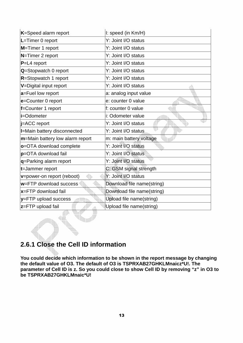
Report parameter ‘X’ is variable depending the repo rt type. The relationship is
described in the following table.
Report type Value of X field
1=Ping report Y: Joint I/O status
4=Motion mode static report Y: Joint I/O status
5=Motion mode moving report Y: Joint I/O status
6=Motion mode static to motion report Y: Joint I/O status
7=Motion mode moving to static report Y: Joint I/O status
G=Geo-fence alarm report Z: geo-fence status
E=Error report Specific error message
H=Autonomous geo-fence alarm
report o: autonomous geo-fence distance
I=SOS alarm report Y: Joint I/O status
13
K=Speed alarm report I: speed (in Km/H)
L=Timer 0 report Y: Joint I/O status
M=Timer 1 report Y: Joint I/O status
N=Timer 2 report Y: Joint I/O status
P=L4 report Y: Joint I/O status
Q=Stopwatch 0 report Y: Joint I/O status
R=Stopwatch 1 report Y: Joint I/O status
V=Digital input report Y: Joint I/O status
a=Fuel low report a: analog input value
e=Counter 0 report e: counter 0 value
f=Counter 1 report f: counter 0 value
i=Odometer i: Odometer value
j=ACC report Y: Joint I/O status
l=Main battery disconnected Y: Joint I/O status
m=Main battery low alarm report m: main battery voltage
o=OTA download complete Y: Joint I/O status
p=OTA download fail Y: Joint I/O status
q=Parking alarm report Y: Joint I/O status
t=Jammer report C: GSM signal strength
v=power-on report (reboot) Y: Joint I/O status
w=FTP download success Download file name(string)
x=FTP download fail Download file name(string)
y=FTP upload success Upload file name(string)
z=FTP upload fail Upload file name(string)
2.6.1 Close the Cell ID information
You could decide which information to be shown in t he report message by changing the default value of O3. The default of O3 is TSPRX AB27GHKLMnaicz*U!. The parameter of Cell ID is z. So you could close to sh ow Cell ID by removing “z” in O3 to be TSPRXAB27GHKLMnaic*U!
14
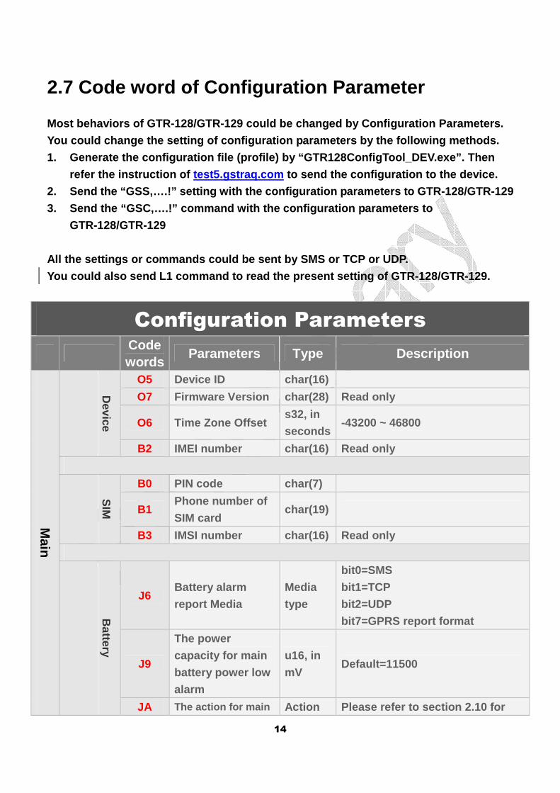
2.7 Code word of Configuration Parameter
Most behaviors of GTR-128/GTR-129 could be changed by Configuration Parameters.
You could change the setting of configuration param eters by the following methods.
1. Generate the configuration file (profile) by “GT R128ConfigTool_DEV.exe”. Then
refer the instruction of test5.gstraq.com to send the configuration to the device.
2. Send the “GSS,….!” setting with the configuratio n parameters to GTR-128/GTR-129
3. Send the “GSC,….!” command with the configuratio n parameters to
GTR-128/GTR-129
All the settings or commands could be sent by SMS o r TCP or UDP.
You could also send L1 command to read the present setting of GTR-128/GTR-129.
Configuration Parameters
Code words
Parameters Type Description
Main
Device
O5 Device ID char(16)
O7 Firmware Version char(28) Read only
O6 Time Zone Offset s32, in
seconds -43200 ~ 46800
B2 IMEI number char(16) Read only
S
IM
B0 PIN code char(7)
B1 Phone number of
SIM card char(19)
B3 IMSI number char(16) Read only
Battery
J6 Battery alarm
report Media
Media
type
bit0=SMS
bit1=TCP
bit2=UDP
bit7=GPRS report format
J9
The power
capacity for main
battery power low
alarm
u16, in
mV Default=11500
JA The action for main Action Please refer to section 2.10 for
15
battery
disconnection
alarm
type detail.
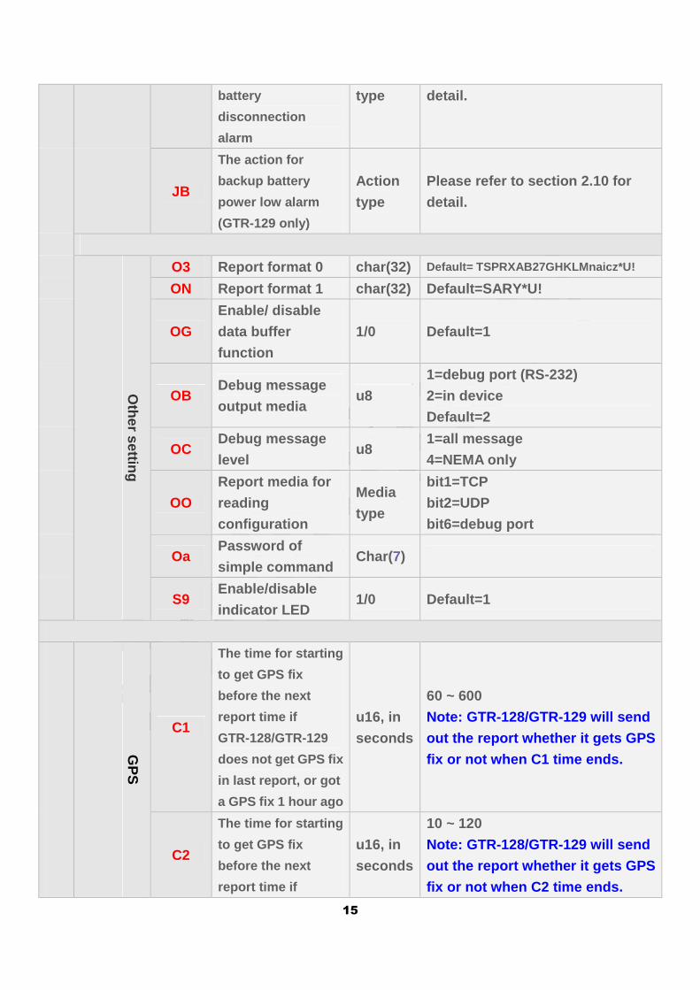
JB
The action for
backup battery
power low alarm
(GTR-129 only)
Action
type
Please refer to section 2.10 for
detail.
Other setting
O3 Report format 0 char(32) Default= TSPRXAB27GHKLMnaicz*U!
ON Report format 1 char(32) Default=SARY*U!
OG
Enable/ disable
data buffer
function
1/0 Default=1
OB Debug message
output media u8
1=debug port (RS-232)
2=in device
Default=2
OC Debug message
level u8
1=all message
4=NEMA only
OO
Report media for
reading
configuration
Media
type
bit1=TCP
bit2=UDP
bit6=debug port
Oa Password of
simple command Char(7)
S9 Enable/disable
indicator LED 1/0 Default=1
GP
S
C1
The time for starting
to get GPS fix
before the next
report time if
GTR-128/GTR-129
does not get GPS fix
in last report, or got
a GPS fix 1 hour ago
u16, in
seconds
60 ~ 600
Note: GTR-128/GTR-129 will send
out the report whether it gets GPS
fix or not when C1 time ends.
C2
The time for starting
to get GPS fix
before the next
report time if
u16, in
seconds
10 ~ 120
Note: GTR-128/GTR-129 will send
out the report whether it gets GPS
fix or not when C2 time ends.
16
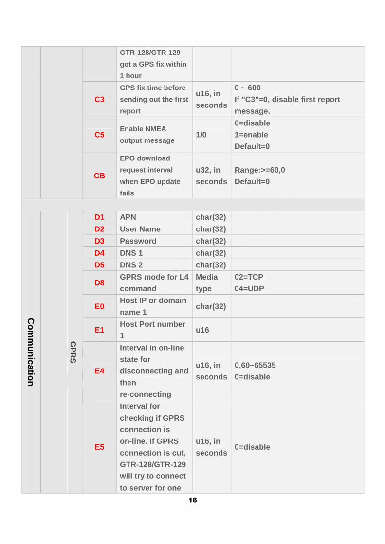
GTR-128/GTR-129
got a GPS fix within
1 hour
C3
GPS fix time before
sending out the first
report
u16, in
seconds
0 ~ 600
If "C3"=0, disable first report
message.
C5 Enable NMEA
output message 1/0
0=disable
1=enable
Default=0
CB
EPO download
request interval
when EPO update
fails
u32, in
seconds
Range:>=60,0
Default=0
Com
munication
GP
RS
D1 APN char(32)
D2 User Name char(32)
D3 Password char(32)
D4 DNS 1 char(32)
D5 DNS 2 char(32)
D8 GPRS mode for L4
command
Media
type
02=TCP
04=UDP
E0 Host IP or domain
name 1 char(32)
E1 Host Port number
1 u16
E4
Interval in on-line
state for
disconnecting and
then
re-connecting
u16, in
seconds
0,60~65535
0=disable
E5
Interval for
checking if GPRS
connection is
on-line. If GPRS
connection is cut,
GTR-128/GTR-129
will try to connect
to server for one
u16, in
seconds 0=disable
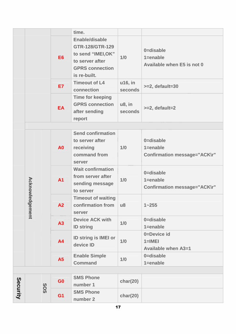
17
time.
E6
Enable/disable
GTR-128/GTR-129
to send “IMEI,OK”
to server after
GPRS connection
is re-built.
1/0
0=disable
1=enable
Available when E5 is not 0
E7 Timeout of L4
connection
u16, in
seconds >=2, default=30
EA
Time for keeping
GPRS connection
after sending
report
u8, in
seconds >=2, default=2
Acknow
ledgement
A0
Send confirmation
to server after
receiving
command from
server
1/0
0=disable
1=enable
Confirmation message="ACK\r"
A1
Wait confirmation
from server after
sending message
to server
1/0
0=disable
1=enable
Confirmation message="ACK\r"
A2
Timeout of waiting
confirmation from
server
u8 1~255
A3 Device ACK with
ID string 1/0
0=disable
1=enable
A4 ID string is IMEI or
device ID 1/0
0=Device id
1=IMEI
Available when A3=1
A5 Enable Simple
Command 1/0
0=disable
1=enable
Security
SO
S
G0 SMS Phone
number 1 char(20)
G1 SMS Phone
number 2 char(20)
18
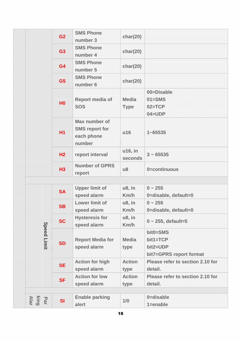
G2 SMS Phone
number 3 char(20)
G3 SMS Phone
number 4 char(20)
G4 SMS Phone
number 5 char(20)
G5 SMS Phone
number 6 char(20)
H0 Report media of
SOS
Media
Type
00=Disable
01=SMS
02=TCP
04=UDP
H1
Max number of
SMS report for
each phone
number
u16 1~65535
H2 report interval u16, in
seconds 3 ~ 65535
H3 Number of GPRS
report u8 0=continuous
Speed Lim
it
SA Upper limit of
speed alarm
u8, in
Km/h
0 ~ 255
0=disable, default=0
SB Lower limit of
speed alarm
u8, in
Km/h
0 ~ 255
0=disable, default=0
SC Hysteresis for
speed alarm
u8, in
Km/h 0 ~ 255, default=5
SD Report Media for
speed alarm
Media
type
bit0=SMS
bit1=TCP
bit2=UDP
bit7=GPRS report format
SE Action for high
speed alarm
Action
type
Please refer to section 2.10 for
detail.
SF Action for low
speed alarm
Action
type
Please refer to section 2.10 for
detail.
Par
king
Alar
m SI
Enable parking
alert 1/0
0=disable
1=enable
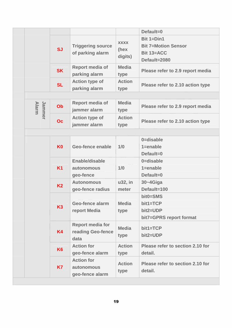
19
Default=0
SJ Triggering source
of parking alarm
xxxx
(hex
digits)
Bit 1=Din1
Bit 7=Motion Sensor
Bit 13=ACC
Default=2080
SK Report media of
parking alarm
Media
type Please refer to 2.9 report media
SL Action type of
parking alarm
Action
type Please refer to 2.10 action type
Jamm
er
Alarm
Ob Report media of
jammer alarm
Media
type Please refer to 2.9 report media
Oc Action type of
jammer alarm
Action
type Please refer to 2.10 action type
K0 Geo-fence enable 1/0
0=disable
1=enable
Default=0
K1
Enable/disable
autonomous
geo-fence
1/0
0=disable
1=enable
Default=0
K2 Autonomous
geo-fence radius
u32, in
meter
30~4Giga
Default=100
K3 Geo-fence alarm
report Media
Media
type
bit0=SMS
bit1=TCP
bit2=UDP
bit7=GPRS report format
K4
Report media for
reading Geo-fence
data
Media
type
bit1=TCP
bit2=UDP
K6 Action for
geo-fence alarm
Action
type
Please refer to section 2.10 for
detail.
K7
Action for
autonomous
geo-fence alarm
Action
type
Please refer to section 2.10 for
detail.
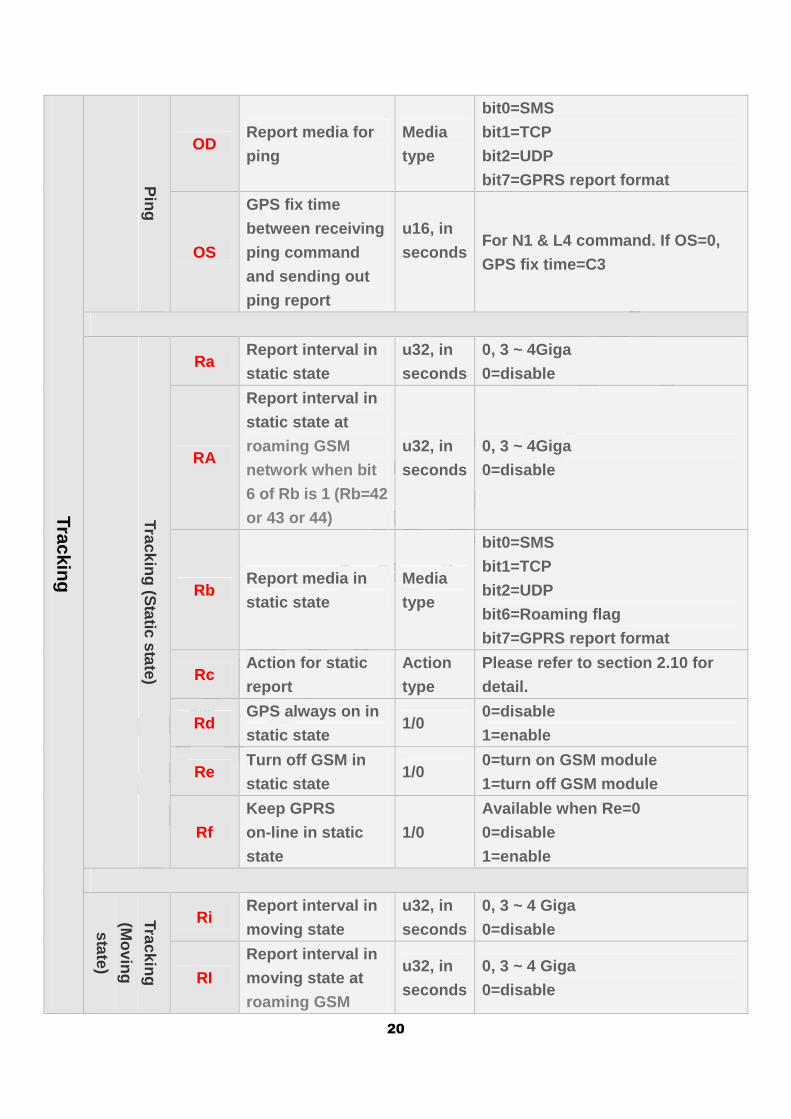
20
Tracking
Ping
OD Report media for
ping
Media
type
bit0=SMS
bit1=TCP
bit2=UDP
bit7=GPRS report format
OS
GPS fix time
between receiving
ping command
and sending out
ping report
u16, in
seconds
For N1 & L4 command. If OS=0,
GPS fix time=C3
Tracking (Static state)
Ra Report interval in
static state
u32, in
seconds
0, 3 ~ 4Giga
0=disable
RA
Report interval in
static state at
roaming GSM
network when bit
6 of Rb is 1 (Rb=42
or 43 or 44)
u32, in
seconds
0, 3 ~ 4Giga
0=disable
Rb Report media in
static state
Media
type
bit0=SMS
bit1=TCP
bit2=UDP
bit6=Roaming flag
bit7=GPRS report format
Rc Action for static
report
Action
type
Please refer to section 2.10 for
detail.
Rd GPS always on in
static state 1/0
0=disable
1=enable
Re Turn off GSM in
static state 1/0
0=turn on GSM module
1=turn off GSM module
Rf
Keep GPRS
on-line in static
state
1/0
Available when Re=0
0=disable
1=enable
Tracking
(Moving
state)
Ri Report interval in
moving state
u32, in
seconds
0, 3 ~ 4 Giga
0=disable
RI
Report interval in
moving state at
roaming GSM
u32, in
seconds
0, 3 ~ 4 Giga
0=disable
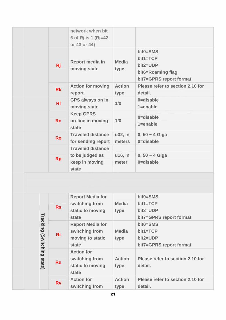
21
network when bit
6 of Rj is 1 (Rj=42
or 43 or 44)
Rj Report media in
moving state
Media
type
bit0=SMS
bit1=TCP
bit2=UDP
bit6=Roaming flag
bit7=GPRS report format
Rk Action for moving
report
Action
type
Please refer to section 2.10 for
detail.
Rl GPS always on in
moving state 1/0
0=disable
1=enable
Rn
Keep GPRS
on-line in moving
state
1/0 0=disable
1=enable
Ro Traveled distance
for sending report
u32, in
meters
0, 50 ~ 4 Giga
0=disable
Rp
Traveled distance
to be judged as
keep in moving
state
u16, in
meter
0, 50 ~ 4 Giga
0=disable
Tracking (S
witching state)
Rs
Report Media for
switching from
static to moving
state
Media
type
bit0=SMS
bit1=TCP
bit2=UDP
bit7=GPRS report format
Rt
Report Media for
switching from
moving to static
state
Media
type
bit0=SMS
bit1=TCP
bit2=UDP
bit7=GPRS report format
Ru
Action for
switching from
static to moving
state
Action
type
Please refer to section 2.10 for
detail.
Rv Action for
switching from
Action
type
Please refer to section 2.10 for
detail.
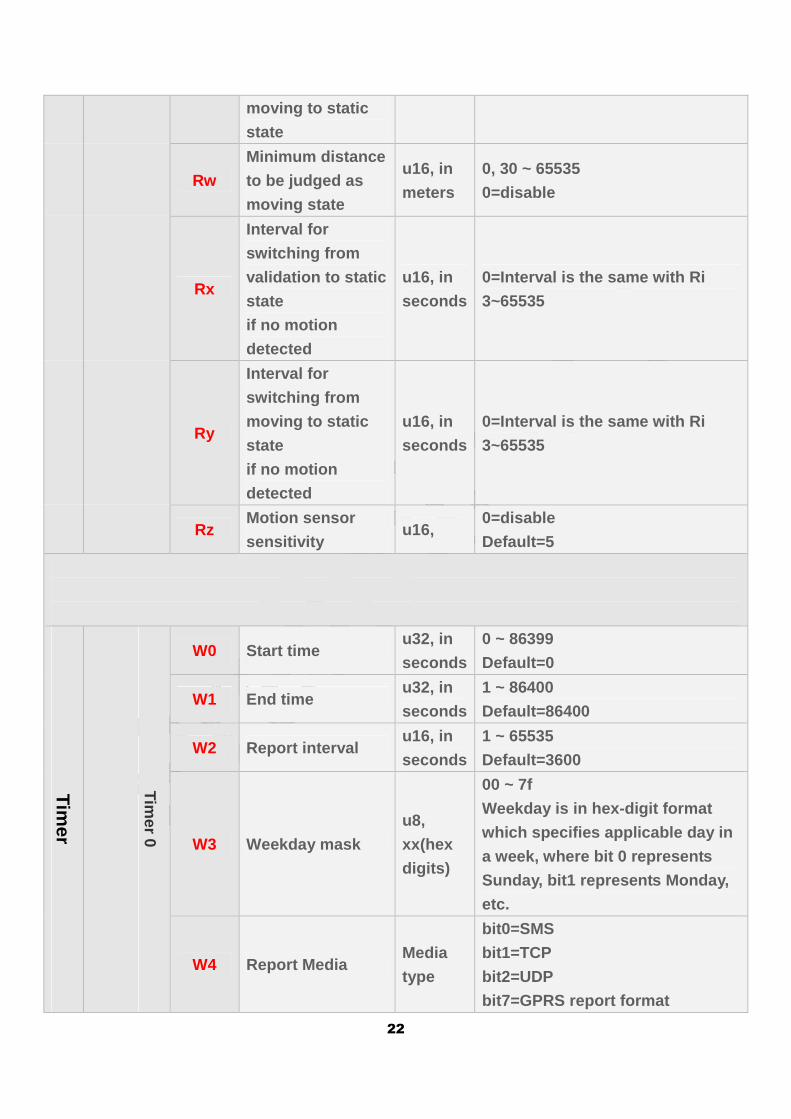
22
moving to static
state
Rw
Minimum distance
to be judged as
moving state
u16, in
meters
0, 30 ~ 65535
0=disable
Rx
Interval for
switching from
validation to static
state
if no motion
detected
u16, in
seconds
0=Interval is the same with Ri
3~65535
Ry
Interval for
switching from
moving to static
state
if no motion
detected
u16, in
seconds
0=Interval is the same with Ri
3~65535
Rz Motion sensor
sensitivity u16,
0=disable
Default=5
Timer
Timer 0
W0 Start time u32, in
seconds
0 ~ 86399
Default=0
W1 End time u32, in
seconds
1 ~ 86400
Default=86400
W2 Report interval u16, in
seconds
1 ~ 65535
Default=3600
W3 Weekday mask
u8,
xx(hex
digits)
00 ~ 7f
Weekday is in hex-digit format
which specifies applicable day in
a week, where bit 0 represents
Sunday, bit1 represents Monday,
etc.
W4 Report Media Media
type
bit0=SMS
bit1=TCP
bit2=UDP
bit7=GPRS report format
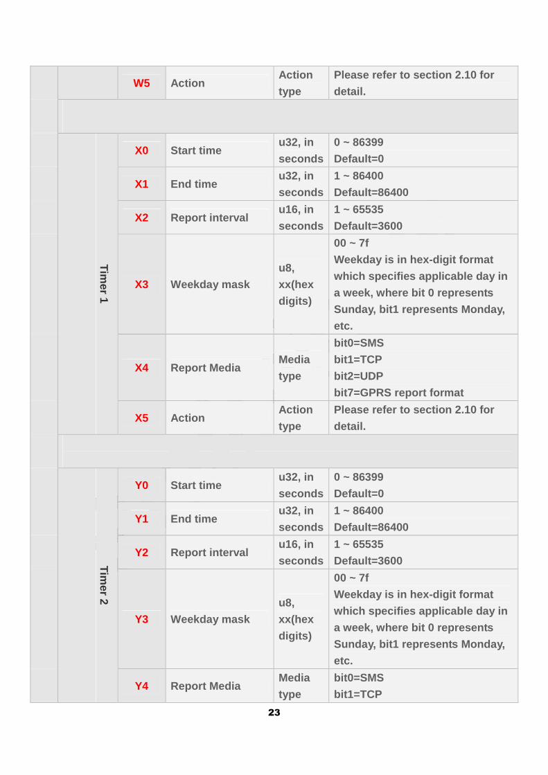
23
W5 Action Action
type
Please refer to section 2.10 for
detail.
Timer 1
X0 Start time u32, in
seconds
0 ~ 86399
Default=0
X1 End time u32, in
seconds
1 ~ 86400
Default=86400
X2 Report interval u16, in
seconds
1 ~ 65535
Default=3600
X3 Weekday mask
u8,
xx(hex
digits)
00 ~ 7f
Weekday is in hex-digit format
which specifies applicable day in
a week, where bit 0 represents
Sunday, bit1 represents Monday,
etc.
X4 Report Media Media
type
bit0=SMS
bit1=TCP
bit2=UDP
bit7=GPRS report format
X5 Action Action
type
Please refer to section 2.10 for
detail.
Tim
er 2
Y0 Start time u32, in
seconds
0 ~ 86399
Default=0
Y1 End time u32, in
seconds
1 ~ 86400
Default=86400
Y2 Report interval u16, in
seconds
1 ~ 65535
Default=3600
Y3 Weekday mask
u8,
xx(hex
digits)
00 ~ 7f
Weekday is in hex-digit format
which specifies applicable day in
a week, where bit 0 represents
Sunday, bit1 represents Monday,
etc.
Y4 Report Media Media
type
bit0=SMS
bit1=TCP
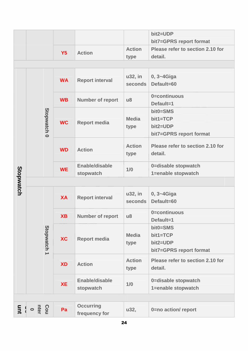
24
bit2=UDP
bit7=GPRS report format
Y5 Action Action
type
Please refer to section 2.10 for
detail.
Stopw
atch
Stopw
atch 0
WA Report interval u32, in
seconds
0, 3~4Giga
Default=60
WB Number of report u8 0=continuous
Default=1
WC Report media Media
type
bit0=SMS
bit1=TCP
bit2=UDP
bit7=GPRS report format
WD Action Action
type
Please refer to section 2.10 for
detail.
WE Enable/disable
stopwatch 1/0
0=disable stopwatch
1=enable stopwatch
Stopw
atch 1 XA Report interval
u32, in
seconds
0, 3~4Giga
Default=60
XB Number of report u8 0=continuous
Default=1
XC Report media Media
type
bit0=SMS
bit1=TCP
bit2=UDP
bit7=GPRS report format
XD Action Action
type
Please refer to section 2.10 for
detail.
XE Enable/disable
stopwatch 1/0
0=disable stopwatch
1=enable stopwatch
Co
unter
Cou
nter
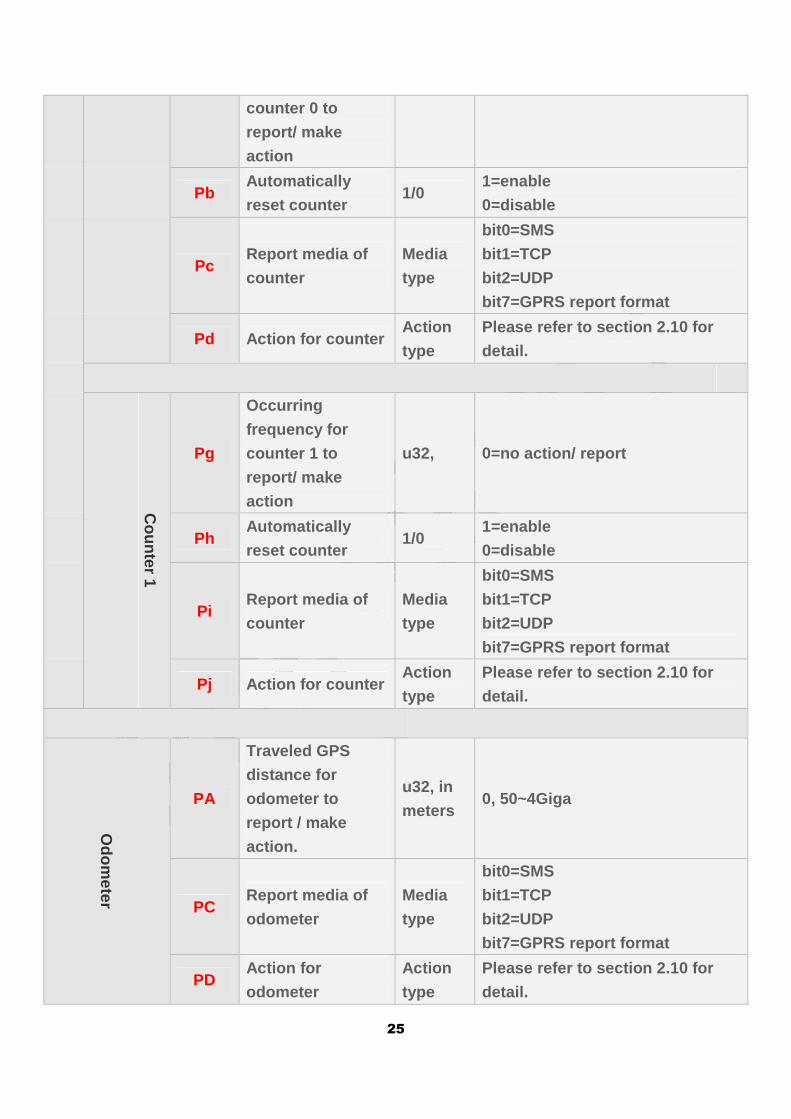
0 Pa Occurring
frequency for u32, 0=no action/ report
25
counter 0 to
report/ make
action
Pb Automatically
reset counter 1/0
1=enable
0=disable
Pc Report media of
counter
Media
type
bit0=SMS
bit1=TCP
bit2=UDP
bit7=GPRS report format
Pd Action for counter Action
type
Please refer to section 2.10 for
detail.
Counter 1
Pg
Occurring
frequency for
counter 1 to
report/ make
action
u32, 0=no action/ report
Ph Automatically
reset counter 1/0
1=enable
0=disable
Pi Report media of
counter
Media
type
bit0=SMS
bit1=TCP
bit2=UDP
bit7=GPRS report format
Pj Action for counter Action
type
Please refer to section 2.10 for
detail.
Odom
eter
PA
Traveled GPS
distance for
odometer to
report / make
action.
u32, in
meters 0, 50~4Giga
PC Report media of
odometer
Media
type
bit0=SMS
bit1=TCP
bit2=UDP
bit7=GPRS report format
PD Action for
odometer
Action
type
Please refer to section 2.10 for
detail.
26
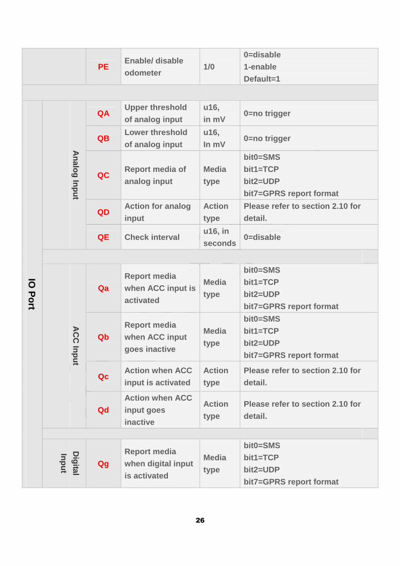
PE Enable/ disable
odometer 1/0
0=disable
1-enable
Default=1
IO P
ort
Analog Input
QA Upper threshold
of analog input
u16,
in mV 0=no trigger
QB Lower threshold
of analog input
u16,
In mV 0=no trigger
QC Report media of
analog input
Media
type
bit0=SMS
bit1=TCP
bit2=UDP
bit7=GPRS report format
QD Action for analog
input
Action
type
Please refer to section 2.10 for
detail.
QE Check interval u16, in
seconds 0=disable
AC
C Input
Qa
Report media
when ACC input is
activated
Media
type
bit0=SMS
bit1=TCP
bit2=UDP
bit7=GPRS report format
Qb
Report media
when ACC input
goes inactive
Media
type
bit0=SMS
bit1=TCP
bit2=UDP
bit7=GPRS report format
Qc Action when ACC
input is activated
Action
type
Please refer to section 2.10 for
detail.
Qd
Action when ACC
input goes
inactive
Action
type
Please refer to section 2.10 for
detail.
Digital
Input
Qg
Report media
when digital input
is activated
Media
type
bit0=SMS
bit1=TCP
bit2=UDP
bit7=GPRS report format
27
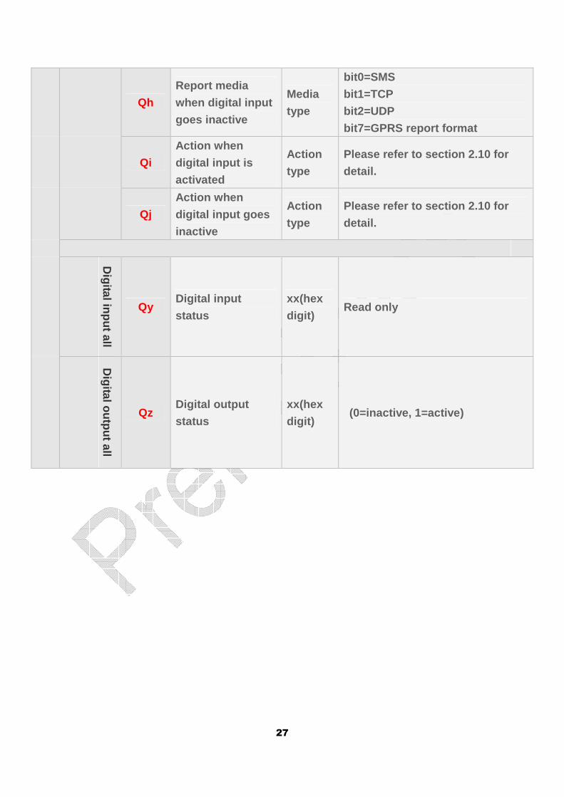
Qh
Report media
when digital input
goes inactive
Media
type
bit0=SMS
bit1=TCP
bit2=UDP
bit7=GPRS report format
Qi
Action when
digital input is
activated
Action
type
Please refer to section 2.10 for
detail.
Qj
Action when
digital input goes
inactive
Action
type
Please refer to section 2.10 for
detail.
Digital input all
Qy Digital input
status
xx(hex
digit) Read only
Digital output all
Qz Digital output
status
xx(hex
digit) (0=inactive, 1=active)
28
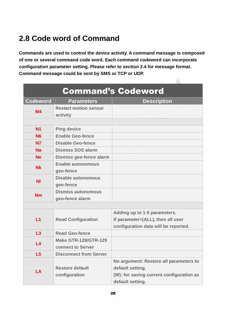
2.8 Code word of Command
Commands are used to control the device activity. A command message is composed
of one or several command code word. Each command c odeword can incorporate
configuration parameter setting. Please refer to se ction 2.4 for message format.
Command message could be sent by SMS or TCP or UDP.
Command’s Codeword Codeword Parameters Description
M4 Restart motion sensor
activity
N1 Ping device
N6 Enable Geo-fence
N7 Disable Geo-fence
Na Dismiss SOS alarm
Ne Dismiss geo-fence alarm
Nk Enable autonomous
geo-fence
Nl Disable autonomous
geo-fence
Nm Dismiss autonomous
geo-fence alarm
L1 Read Configuration
Adding up to 1-5 parameters.
If parameter=(ALL), then all user
configuration data will be reported.
L3 Read Geo-fence
L4 Make GTR-128/GTR-129
connect to Server
L5 Disconnect from Server
LA Restore default
configuration
No argument: Restore all parameters to
default setting.
(W): for saving current configuration as
default setting.
29
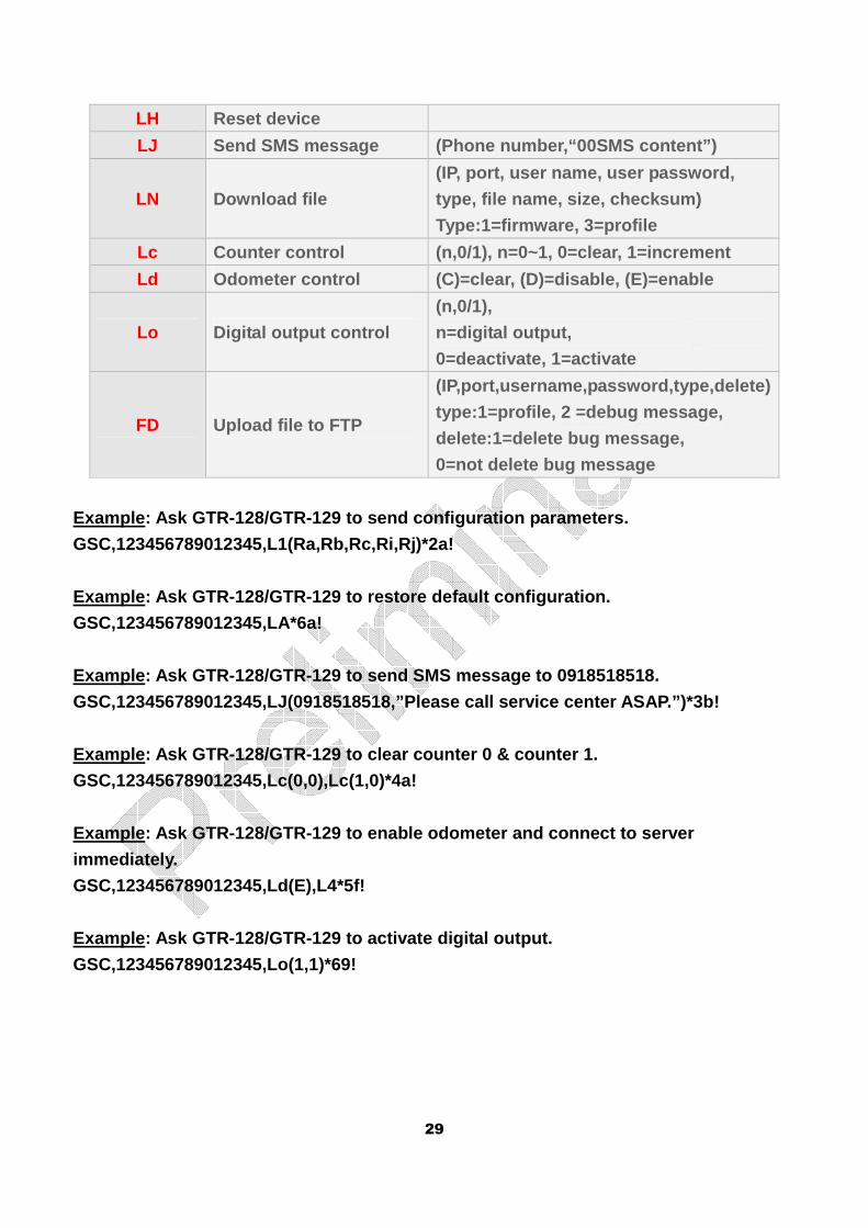
LH Reset device
LJ Send SMS message (Phone number,“00SMS content”)
LN Download file
(IP, port, user name, user password,
type, file name, size, checksum)
Type:1=firmware, 3=profile
Lc Counter control (n,0/1), n=0~1, 0=clear, 1=increment
Ld Odometer control (C)=clear, (D)=disable, (E)=enable
Lo Digital output control
(n,0/1),
n=digital output,
0=deactivate, 1=activate
FD Upload file to FTP
(IP,port,username,password,type,delete)
type:1=profile, 2 =debug message,
delete:1=delete bug message,
0=not delete bug message
Example: Ask GTR-128/GTR-129 to send configuration parameters.
GSC,123456789012345,L1(Ra,Rb,Rc,Ri,Rj)*2a!
Example: Ask GTR-128/GTR-129 to restore default con figuration.
GSC,123456789012345,LA*6a!
Example: Ask GTR-128/GTR-129 to send SMS message to 0918518518.
GSC,123456789012345,LJ(0918518518,”Please call serv ice center ASAP.”)*3b!
Example: Ask GTR-128/GTR-129 to clear counter 0 & c ounter 1.
GSC,123456789012345,Lc(0,0),Lc(1,0)*4a!
Example: Ask GTR-128/GTR-129 to enable odometer and connect to server
immediately.
GSC,123456789012345,Ld(E),L4*5f!
Example: Ask GTR-128/GTR-129 to activate digital ou tput.
GSC,123456789012345,Lo(1,1)*69!
30
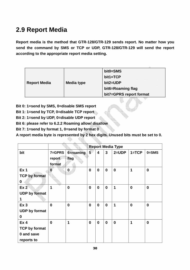
2.9 Report Media
Report media is the method that GTR-128/GTR-129 sen ds report. No matter how you
send the command by SMS or TCP or UDP, GTR-128/GTR- 129 will send the report
according to the appropriate report media setting.
Report Media Media type
bit0=SMS
bit1=TCP
bit2=UDP
bit6=Roaming flag
bit7=GPRS report format
Bit 0: 1=send by SMS, 0=disable SMS report
Bit 1: 1=send by TCP, 0=disable TCP report
Bit 2: 1=send by UDP, 0=disable UDP report
Bit 6: please refer to 6.2.2 Roaming allow/ disallo w
Bit 7: 1=send by format 1, 0=send by format 0
A report media byte is represented by 2 hex digits. Unused bits must be set to 0.
Report Media Type
bit 7=GPRS
report
format
6=roaming
flag 5 4 3 2=UDP 1=TCP 0=SMS
Ex 1
TCP by format
0
0 0 0 0 0 0 1 0
Ex 2
UDP by format
1
1 0 0 0 0 1 0 0
Ex 3
UDP by format
0
0 0 0 0 0 1 0 0
Ex 4
TCP by format
0 and save
reports to
0 1 0 0 0 0 1 0

31
buffer in
roaming GSM
network
Example 1: Ask GTR-128/GTR-129 to send motion repor t with report static interval of 5
minutes (Ra=300) and report format 0 to TCP server (Rb=02).
GSC,011412000010789,M4(Ra=300,Rb=02)*01!
Example 2: Ask GTR-128/GTR-129 to send static repor t with report interval of 7 minutes
(Ra=420) by format 1 (Rb=84) and moving report with interval of 20 seconds (Ri=20)
with format 0(Rj=04), to UDP server.
GSC,011412000010789,M4(Ra=420,Rb=84,Ri=20,Rj=04)*2f !
32
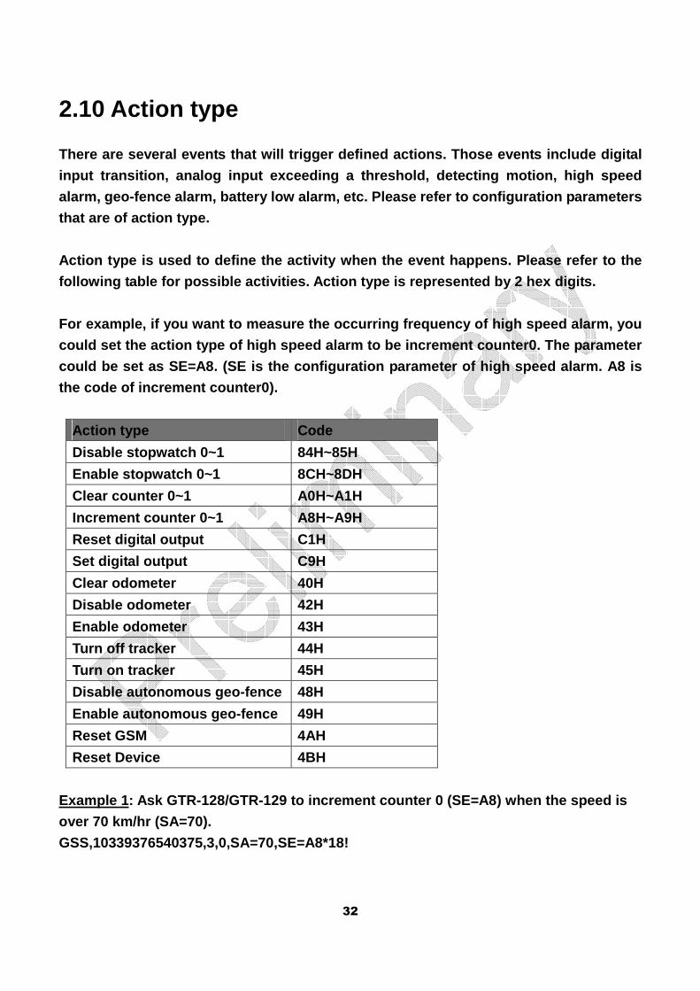
2.10 Action type
There are several events that will trigger defined actions. Those events include digital
input transition, analog input exceeding a threshol d, detecting motion, high speed
alarm, geo-fence alarm, battery low alarm, etc. Ple ase refer to configuration parameters
that are of action type.
Action type is used to define the activity when the event happens. Please refer to the
following table for possible activities. Action typ e is represented by 2 hex digits.
For example, if you want to measure the occurring f requency of high speed alarm, you
could set the action type of high speed alarm to be increment counter0. The parameter
could be set as SE=A8. (SE is the configuration par ameter of high speed alarm. A8 is
the code of increment counter0).
Action type Code
Disable stopwatch 0~1 84H~85H
Enable stopwatch 0~1 8CH~8DH
Clear counter 0~1 A0H~A1H
Increment counter 0~1 A8H~A9H
Reset digital output C1H
Set digital output C9H
Clear odometer 40H
Disable odometer 42H
Enable odometer 43H
Turn off tracker 44H
Turn on tracker 45H
Disable autonomous geo-fence 48H
Enable autonomous geo-fence 49H
Reset GSM 4AH
Reset Device 4BH
Example 1: Ask GTR-128/GTR-129 to increment counter 0 (SE=A8) when the speed is
over 70 km/hr (SA=70).
GSS,10339376540375,3,0,SA=70,SE=A8*18!
33
2.11 Checksum The checksum value is derived by the same method of NMEA standard. It is calculated
by ‘exclusive OR’ the 8 data bits of each character before “*” in the sentence, but
excluding “*”. The hexadecimal value of the most si gnificant and least significant 4 bits
of the result are converted to two ASCII characters (0-9, A-F) for transmission. The
most significant character is transmitted first.
Example1: set the device whose IMEI is 011412000011274, the APN is internet, the user
name and password are not necessary, the server type is TCP, the server IP is
220.128.207.75, the server port number 3000.
The setup command is
GSS,011412000011274,3,1,D1=internet,D2=,D3=,D8=02,E 0=220.128.207.75,E1=3000*5E!
The checksum is 5E.
Example2: Set GTR-128/GTR-129 periodic report and ask it to report based on traveled
distance (Ro) of 500 meters
The setup command is
GSC,011412000010789,M4(Ro=500)*2a!
The checksum is 2a.
34
3 Configuration GTR-128/GTR-129 has a very flexible platform. Its b ehavior is totally configurable.
Please refer to section 2.7 for the list of configu ration parameters.
3.1 Read parameters of configuration The PC tool “TR600ConfigTool_DEV.exe” is used to co nfigure the device by RS-232
interface. You could also send L1 command to remote ly read back the setting by
TCP or UDP protocol.
Please note GTR-128/GTR-129 could NOT send back the configuration parameter by SMS.
Command’s format:
GSC,IMEI,L1(x1,x2,x3,x4,x5)*Checksum! GSC,IMEI,L1(ALL)*Checksum! Add up to 1-5 parameters.
If parameter =(ALL), then all user configuration da ta will be generated.
Report format:
GSs,IMEI,T,S,x1=y1,x2=y2,x3=y3,……*Checksum!
x1,x2,x3… are code words for configuration paramete rs.
y1,y2,y3… are their respective settings.
Example 1:
Ask GTR-128/GTR-129 report parameters of speed limi ts(SA, SB, SC, SD, SE)
GSC,136489586301578,L1(SA,SB,SC,SD,SE)*0b!
Report parameters SA,SB,SC,SD,SE, from GTR-128/GTR- 129
GSs,136489586301578,3,0,SA=100,SB=40,SC=5,SD=02,SE= A8*3f!
35
3.2 Set parameters of configuration The setting of configuration parameters could be ch anged by the following methods.
� Generate the configuration file (profile) by “GTR12 8ConfigTool_DEV.exe”. Then
refer the instruction of test5.gstraq.com to send the configuration to the device.
� Send the “GSS,….!” setting with the configuration p arameters to GTR-128/GTR-129
� Send the “GSC,….!” command with the configuration p arameters to
GTR-128/GTR-129
All the settings or commands could be sent by SMS o r TCP or UDP.
Command format:
GSS,IMEI,T,S,x1=y1,x2=y2,x3=y3,……,*Checksum! x1,x2,x3… are code words for configuration paramete rs.
y1,y2,y3… are their respective settings.
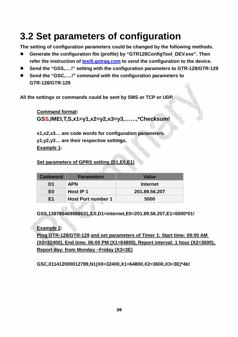
Example 1:
Set parameters of GPRS setting (D1,E0,E1)
Codeword Parameters Value
D1 APN Internet
E0 Host IP 1 201.89.56.207
E1 Host Port number 1 5000
GSS,138785469589531,3,0,D1=internet,E0=201.89.56.20 7,E1=5000*01!
Example 2:
Ping GTR-128/GTR-129 and set parameters of Timer 1: Start time: 09:00 AM
(X0=32400), End time: 06:00 PM (X1=64800), Report i nterval: 1 hour (X2=3600),
Report day: from Monday ~Friday (X3=3E)
GSC,011412000012789,N1(X0=32400,X1=64800,X2=3600,X3=3E)*4b!
36
4 GSM & GPRS
4.1 GPRS Setting
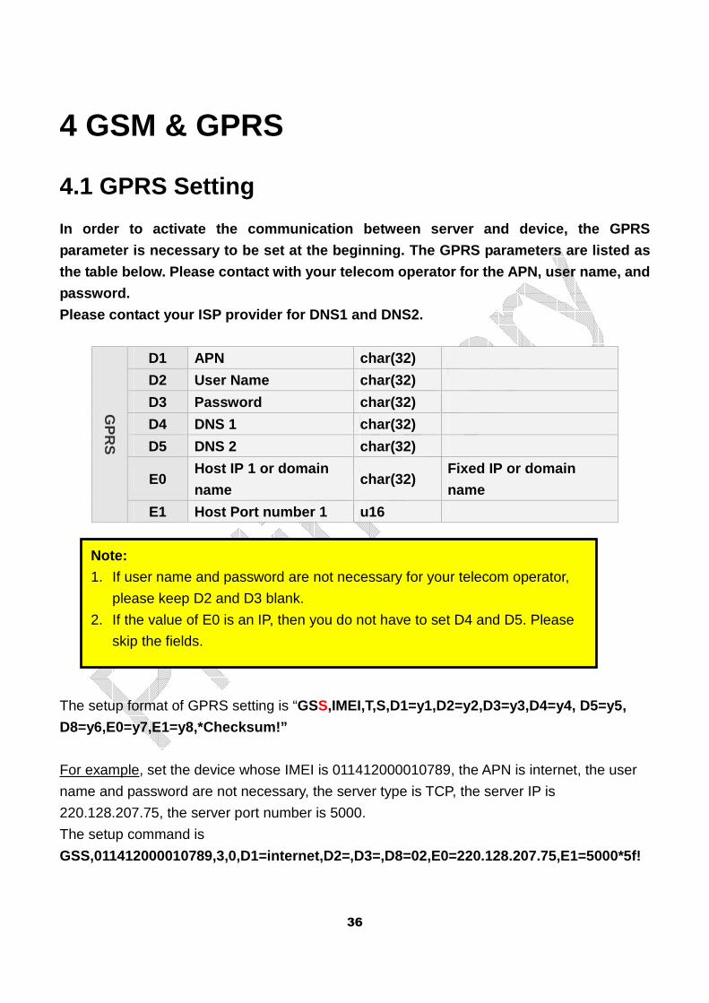
In order to activate the communication between serv er and device, the GPRS
parameter is necessary to be set at the beginning. The GPRS parameters are listed as
the table below. Please contact with your telecom o perator for the APN, user name, and
password.
Please contact your ISP provider for DNS1 and DNS2.
GP
RS
D1 APN char(32)
D2 User Name char(32)
D3 Password char(32)
D4 DNS 1 char(32)
D5 DNS 2 char(32)
E0 Host IP 1 or domain
name char(32)
Fixed IP or domain
name
E1 Host Port number 1 u16
The setup format of GPRS setting is “GSS,IMEI,T,S,D1=y1,D2=y2,D3=y3,D4=y4, D5=y5,
D8=y6,E0=y7,E1=y8,*Checksum!”
For example, set the device whose IMEI is 011412000010789, the APN is internet, the user
name and password are not necessary, the server type is TCP, the server IP is
220.128.207.75, the server port number is 5000.
The setup command is
GSS,011412000010789,3,0,D1=internet,D2=,D3=,D8=02,E 0=220.128.207.75,E1=5000*5f!
Note:
1. If user name and password are not necessary for your telecom operator,
please keep D2 and D3 blank.
2. If the value of E0 is an IP, then you do not have to set D4 and D5. Please
skip the fields.
37
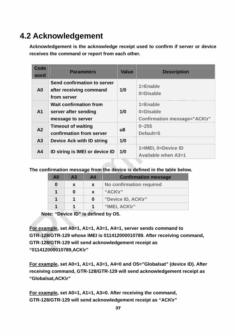
4.2 Acknowledgement Acknowledgement is the acknowledge receipt used to confirm if server or device
receives the command or report from each other.
Code
word Parameters Value Description
A0
Send confirmation to server
after receiving command
from server
1/0 1=Enable
0=Disable
A1
Wait confirmation from
server after sending
message to server
1/0
1=Enable
0=Disable
Confirmation message="ACK\r"
A2 Timeout of waiting
confirmation from server u8
0~255
Default=5
A3 Device Ack with ID string 1/0
A4 ID string is IMEI or device ID 1/0 1=IMEI, 0=Device ID
Available when A3=1
The confirmation message from the device is defined in the table below.
A0 A3 A4 Confirmation message
0 x x No confirmation required
1 0 x “ACK\r”
1 1 0 ”Device ID, ACK\r”
1 1 1 ”IMEI, ACK\r”
Note: “Device ID” is defined by O5.
For example, set A0=1, A1=1, A3=1, A4=1, server sen ds command to
GTR-128/GTR-129 whose IMEI is 011412000010789. Afte r receiving command,
GTR-128/GTR-129 will send acknowledgement receipt a s
“011412000010789,ACK\r”
For example, set A0=1, A1=1, A3=1, A4=0 and O5=”Glo balsat” (device ID). After
receiving command, GTR-128/GTR-129 will send acknow ledgement receipt as
“Globalsat,ACK\r”
For example, set A0=1, A1=1, A3=0. After receiving the command,
GTR-128/GTR-129 will send acknowledgement receipt a s “ACK\r”
38
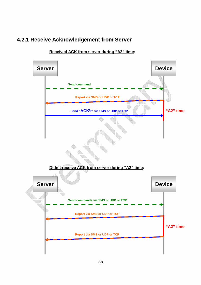
4.2.1 Receive Acknowledgement from Server
Received ACK from server during “A2” time:
Didn’t receive ACK from server during “A2” time:
Send command
Server
Send “ ACK\r” via SMS or UDP or TCP
Device
“A2” time
Send commands via SMS or UDP or TCP
Server Device
“A2” time
Report via SMS or UDP or TCP
Report via SMS or UDP or TCP
Report via SMS or UDP or TCP
39
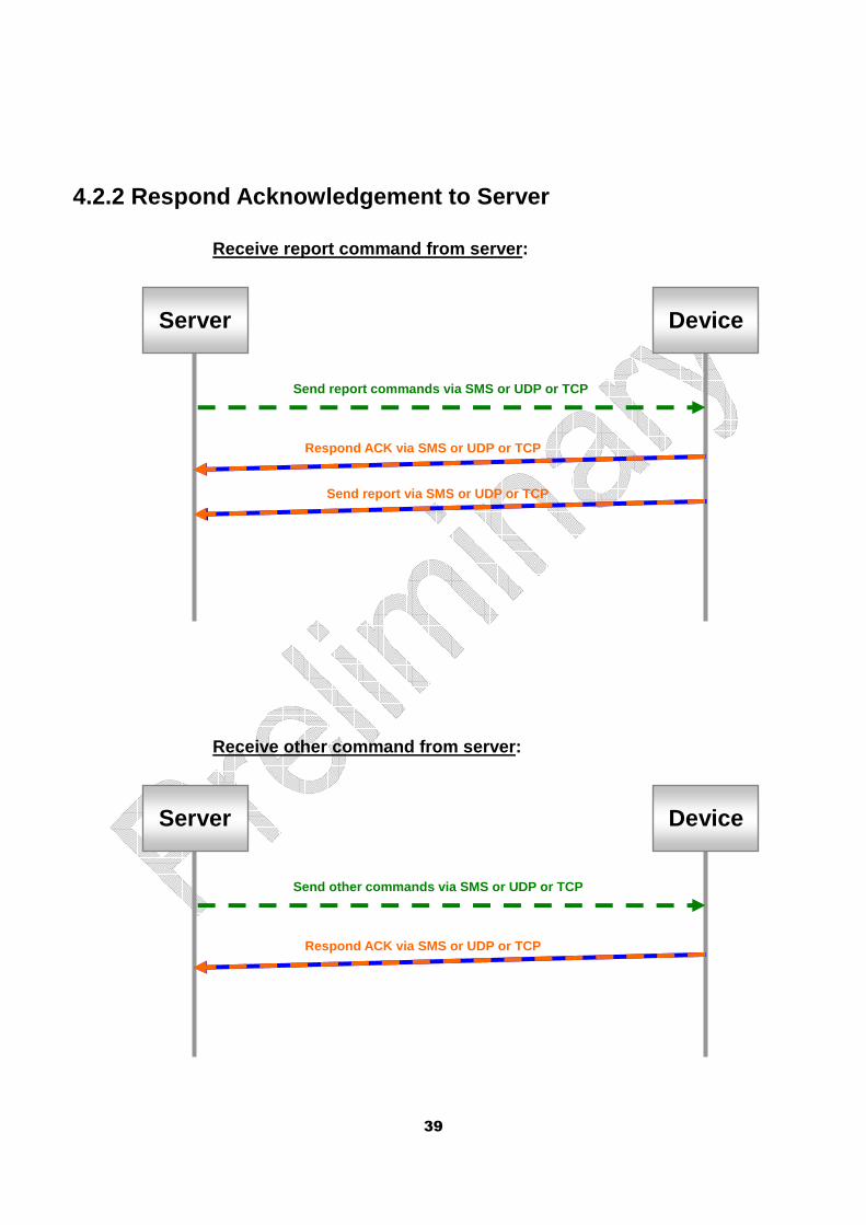
4.2.2 Respond Acknowledgement to Server
Receive report command from server:
Receive other command from server:
Send report commands via SMS or UDP or TCP
Server Device
Send report via SMS or UDP or TCP
Respond ACK via SMS or UDP or TCP
Send other commands via SMS or UDP or TCP
Server Device
Respond ACK via SMS or UDP or TCP
40
4.3 GPRS connection
If ‘Rn’ is set in moving state or ‘Rf’ is set in st atic state, then GTR-128/GTR-129 will try
to keep GPRS always on-line. The device will check the connection periodically. The
period is defined by ‘E5’. If the connection is los t, the device will try to connect again. If
‘E6’ is set, device will send “OK” message when con nection is recovered.
If the connection is kept for a long time without s ending any message, GSM carrier may
terminate the connection intentionally. In some wor st conditions, the carrier may even
reject further request for connection. Setting of ‘ E4’ is used to overcome this issue.
GTR-128/GTR-129 will disconnect and then re-connect after it has been on-line for the
time defined by ‘E4’.
If the “always on-line” setting is not set, GTR-128 /GTR-129 will establish GPRS
connection when it wants to send UDP or TCP reports . After the report has been sent
out, the device will keep GPRS connected for the in terval defined by ‘EA’. Server can
send message to device in the interval and the conn ection will be extended further for
‘EA’ time.
In certain circumstance the server may want the dev ice to setup GPRS connection for
receiving command or configuration messages. ‘L4’ c ommand is used to achieve the
purpose. GTR-128/GTR-129 will connect to server imm ediately when getting L4
command. After the connection is established, GTR-1 28/GTR-129 will keep on-line for
an interval defined by E7. Server can send commands or configure the device during
the interval. If there’s no message received during the interval, the connection will be
terminated. If there is a message received in the i nterval, the connection will be
extended for another E7 time. Server can send L5 co mmand to terminate the
connection immediately.
The related configuration parameters are listed in the table below.
Code
word Parameters Value Description
D8 Report Media for L4
command
02=TCP
04=UDP
Connection protocol for
always on-line and “L4”
command.
E4 Interval in on-line state for u16, in 0=disable
41
disconnecting and then
re-connecting
seconds
E5
Interval for checking if GPRS
connection is on-line. If GPRS
connection is cut,
GTR-128/GTR-129 will try to
connect to server for one
time.
u16, in
seconds 0=disable
E6
Enable/disable
GTR-128/GTR-129 to send
“IMEI,OK” to server after
GPRS connection is re-built.
1/0
0=disable
1=enable
Available when E5 is not 0
E7 Timeout of L4 connection u16, in
seconds >=2, default=30
EA
Time for keeping GPRS
connection after sending
report
u8, in
seconds >=2, default=2
Rf Keep GPRS on-line in static
state 0/1
0=disable
1=enable
Rn Keep GPRS on-line in moving
state 0/1
0=disable
1=enable
Command format:
GSC,IMEI,L4*Checksum!
Command Codeword Parameters
L4 Connect to server
Example: Ask GTR-128/GTR-129 to connect to server b y TCP. GSC,123456789012345,L4(D8=02)*5d!
42
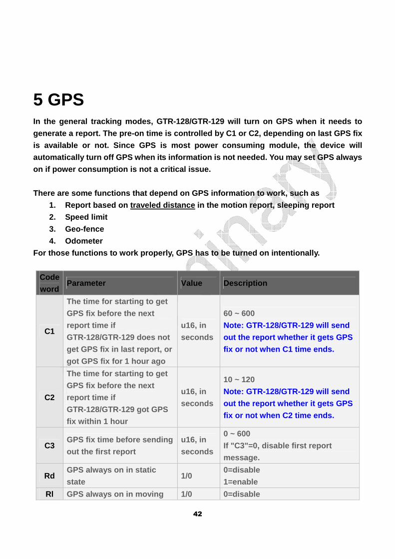
5 GPS In the general tracking modes, GTR-128/GTR-129 will turn on GPS when it needs to
generate a report. The pre-on time is controlled by C1 or C2, depending on last GPS fix
is available or not. Since GPS is most power consum ing module, the device will
automatically turn off GPS when its information is not needed. You may set GPS always
on if power consumption is not a critical issue.
There are some functions that depend on GPS informa tion to work, such as
1. Report based on traveled distance in the motion report, sleeping report
2. Speed limit
3. Geo-fence
4. Odometer
For those functions to work properly, GPS has to be turned on intentionally.
Code
word Parameter Value Description
C1
The time for starting to get
GPS fix before the next
report time if
GTR-128/GTR-129 does not
get GPS fix in last report, or
got GPS fix for 1 hour ago
u16, in
seconds
60 ~ 600
Note: GTR-128/GTR-129 will send
out the report whether it gets GPS
fix or not when C1 time ends.
C2
The time for starting to get
GPS fix before the next
report time if
GTR-128/GTR-129 got GPS
fix within 1 hour
u16, in
seconds
10 ~ 120
Note: GTR-128/GTR-129 will send
out the report whether it gets GPS
fix or not when C2 time ends.
C3 GPS fix time before sending
out the first report
u16, in
seconds
0 ~ 600
If "C3"=0, disable first report
message.
Rd GPS always on in static
state 1/0
0=disable
1=enable
Rl GPS always on in moving 1/0 0=disable
43
state 1=enable
C1 example, the next report time is 10:00:00 and GT R-128/GTR-129 does not get GPS
fix in last report, C1 is 180 seconds. GTR-128/GTR- 129 will start to get GPS fix at
9:57:00 and send out report at 10:00:00.
C2 example, the next report time is 10:00:00 and GT R-128/GTR-129 got GPS fix within 1
hour, C2 is 20 seconds. GTR-128/GTR-129 will start to get GPS fix at 9:59:40 and send
out report at 10:00:00.
C3 example, If C3=10 seconds and GTR-128/GTR-129 is in the static state. When
GTR-128/GTR-129 is moved, it will switch to moving state and try to get GPS fix for 10
seconds. Then it sends motion moving report to noti fy the motion event.
44
6 Tracking
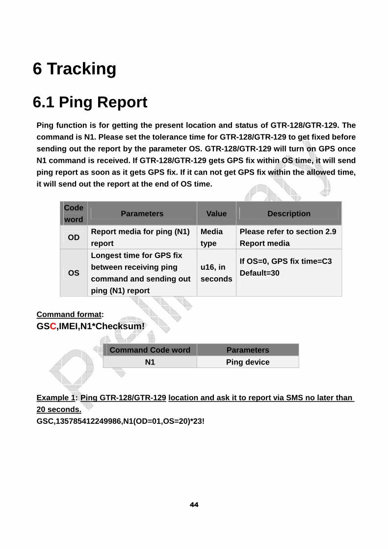
6.1 Ping Report Ping function is for getting the present location a nd status of GTR-128/GTR-129. The
command is N1. Please set the tolerance time for GT R-128/GTR-129 to get fixed before
sending out the report by the parameter OS. GTR-128 /GTR-129 will turn on GPS once
N1 command is received. If GTR-128/GTR-129 gets GPS fix within OS time, it will send
ping report as soon as it gets GPS fix. If it can n ot get GPS fix within the allowed time,
it will send out the report at the end of OS time.
Code
word Parameters Value Description
OD Report media for ping (N1)
report
Media
type
Please refer to section 2.9
Report media
OS
Longest time for GPS fix
between receiving ping
command and sending out
ping (N1) report
u16, in
seconds
If OS=0, GPS fix time=C3
Default=30
Command format:
GSC,IMEI,N1*Checksum!
Command Code word Parameters
N1 Ping device
Example 1: Ping GTR-128/GTR-129 location and ask it to report via SMS no later than
20 seconds.
GSC,135785412249986,N1(OD=01,OS=20)*23!
45
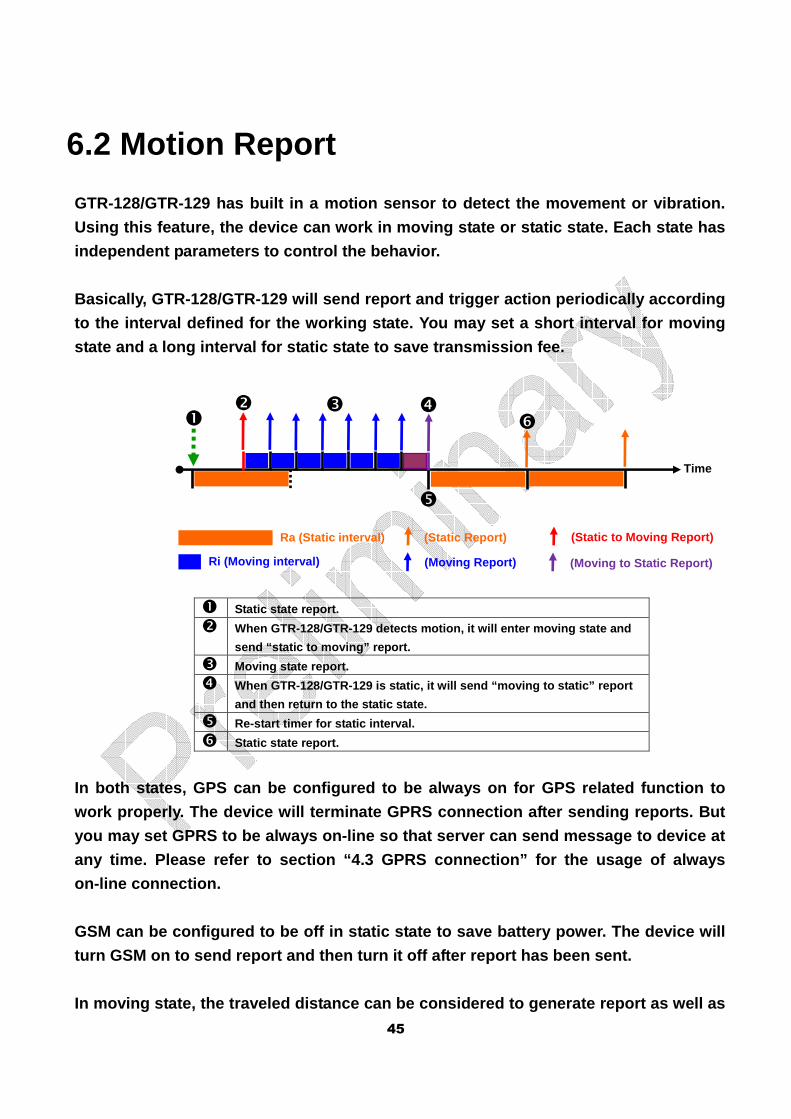
6.2 Motion Report
GTR-128/GTR-129 has built in a motion sensor to det ect the movement or vibration.
Using this feature, the device can work in moving s tate or static state. Each state has
independent parameters to control the behavior.
Basically, GTR-128/GTR-129 will send report and tri gger action periodically according
to the interval defined for the working state. You may set a short interval for moving
state and a long interval for static state to save transmission fee.
� Static state report.
� When GTR-128/GTR-129 detects motion, it will enter moving state and
send “static to moving” report.
� Moving state report.
� When GTR-128/GTR-129 is static, it will send “movin g to static” report
and then return to the static state.
� Re-start timer for static interval.
� Static state report.
In both states, GPS can be configured to be always on for GPS related function to
work properly. The device will terminate GPRS conne ction after sending reports. But
you may set GPRS to be always on-line so that serve r can send message to device at
any time. Please refer to section “4.3 GPRS connect ion” for the usage of always
on-line connection.
GSM can be configured to be off in static state to save battery power. The device will
turn GSM on to send report and then turn it off aft er report has been sent.
In moving state, the traveled distance can be consi dered to generate report as well as
� � � �
�
Time
Ra (Static interval)
Ri (Moving interval)
(Static Report)
(Moving Report)
(Static to Moving Report)
(Moving to Static Report)
�
46
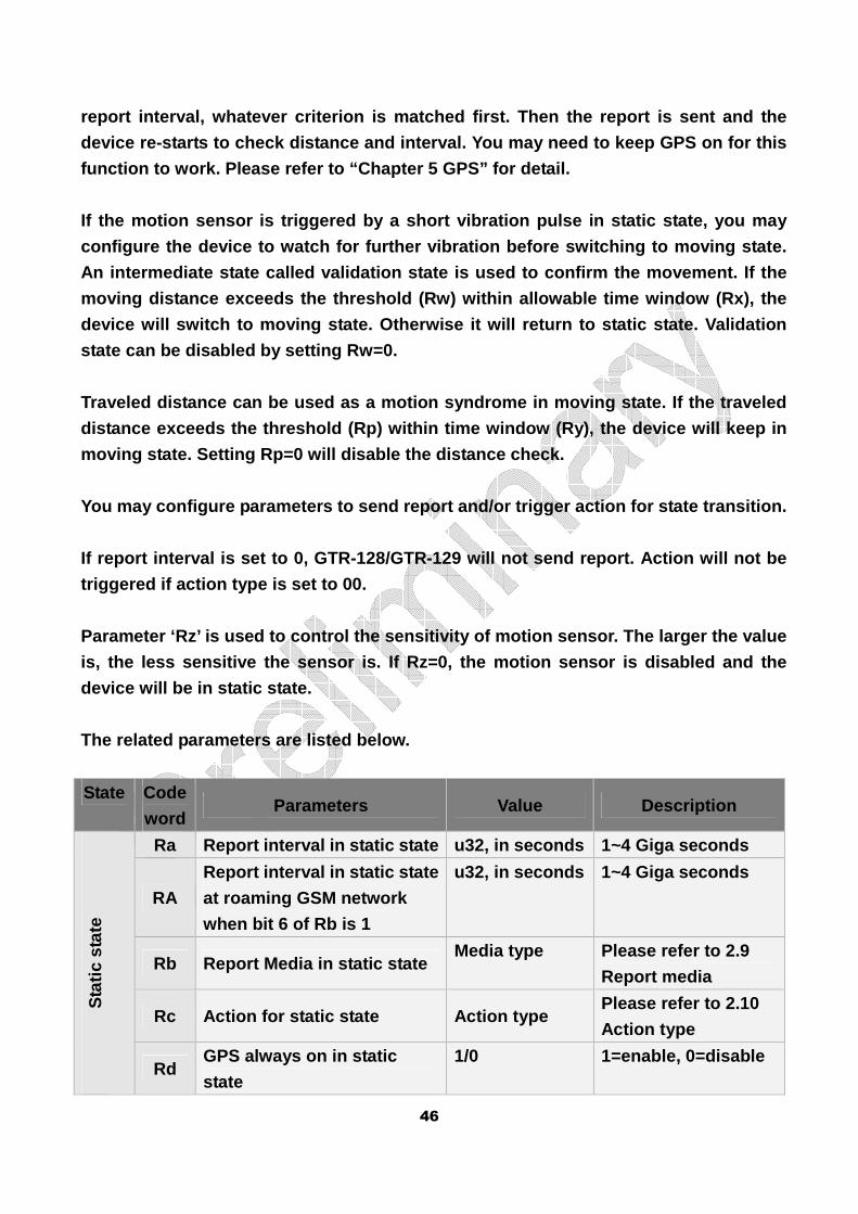
report interval, whatever criterion is matched firs t. Then the report is sent and the
device re-starts to check distance and interval. Yo u may need to keep GPS on for this
function to work. Please refer to “Chapter 5 GPS” f or detail.
If the motion sensor is triggered by a short vibrat ion pulse in static state, you may
configure the device to watch for further vibration before switching to moving state.
An intermediate state called validation state is us ed to confirm the movement. If the
moving distance exceeds the threshold (Rw) within a llowable time window (Rx), the
device will switch to moving state. Otherwise it wi ll return to static state. Validation
state can be disabled by setting Rw=0.
Traveled distance can be used as a motion syndrome in moving state. If the traveled
distance exceeds the threshold (Rp) within time win dow (Ry), the device will keep in
moving state. Setting Rp=0 will disable the distanc e check.
You may configure parameters to send report and/or trigger action for state transition.
If report interval is set to 0, GTR-128/GTR-129 wil l not send report. Action will not be
triggered if action type is set to 00.
Parameter ‘Rz’ is used to control the sensitivity o f motion sensor. The larger the value
is, the less sensitive the sensor is. If Rz=0, the motion sensor is disabled and the
device will be in static state.
The related parameters are listed below.
State Code
word Parameters Value Description
Sta
tic s
tate
Ra Report interval in static state u32, in seconds 1~4 Giga seconds
RA
Report interval in static state
at roaming GSM network
when bit 6 of Rb is 1
u32, in seconds 1~4 Giga seconds
Rb Report Media in static state Media type Please refer to 2.9
Report media
Rc Action for static state Action type Please refer to 2.10
Action type
Rd GPS always on in static
state
1/0 1=enable, 0=disable
47
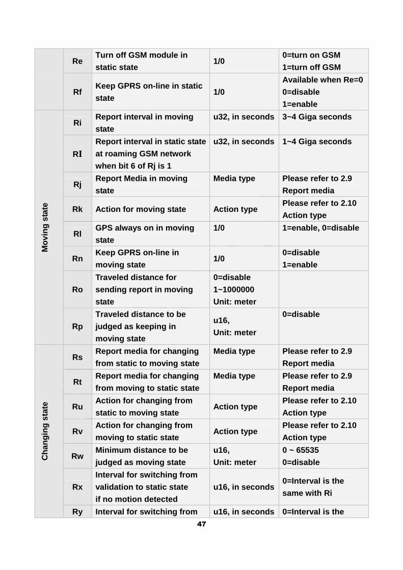
Re Turn off GSM module in
static state 1/0
0=turn on GSM
1=turn off GSM
Rf Keep GPRS on-line in static
state 1/0
Available when Re=0
0=disable
1=enable
Mov
ing
stat
e
Ri Report interval in moving
state
u32, in seconds 3~4 Giga seconds
RI
Report interval in static state
at roaming GSM network
when bit 6 of Rj is 1
u32, in seconds 1~4 Giga seconds
Rj Report Media in moving
state
Media type Please refer to 2.9
Report media
Rk Action for moving state Action type Please refer to 2.10
Action type
Rl GPS always on in moving
state
1/0 1=enable, 0=disable
Rn Keep GPRS on-line in
moving state 1/0
0=disable
1=enable
Ro
Traveled distance for
sending report in moving
state
0=disable
1~1000000
Unit: meter
Rp
Traveled distance to be
judged as keeping in
moving state
u16,
Unit: meter
0=disable
Cha
ngin
g st
ate
Rs Report media for changing
from static to moving state
Media type Please refer to 2.9
Report media
Rt Report media for changing
from moving to static state
Media type Please refer to 2.9
Report media
Ru Action for changing from
static to moving state Action type
Please refer to 2.10
Action type
Rv Action for changing from
moving to static state Action type
Please refer to 2.10
Action type
Rw Minimum distance to be
judged as moving state
u16,
Unit: meter
0 ~ 65535
0=disable
Rx
Interval for switching from
validation to static state
if no motion detected
u16, in seconds 0=Interval is the
same with Ri
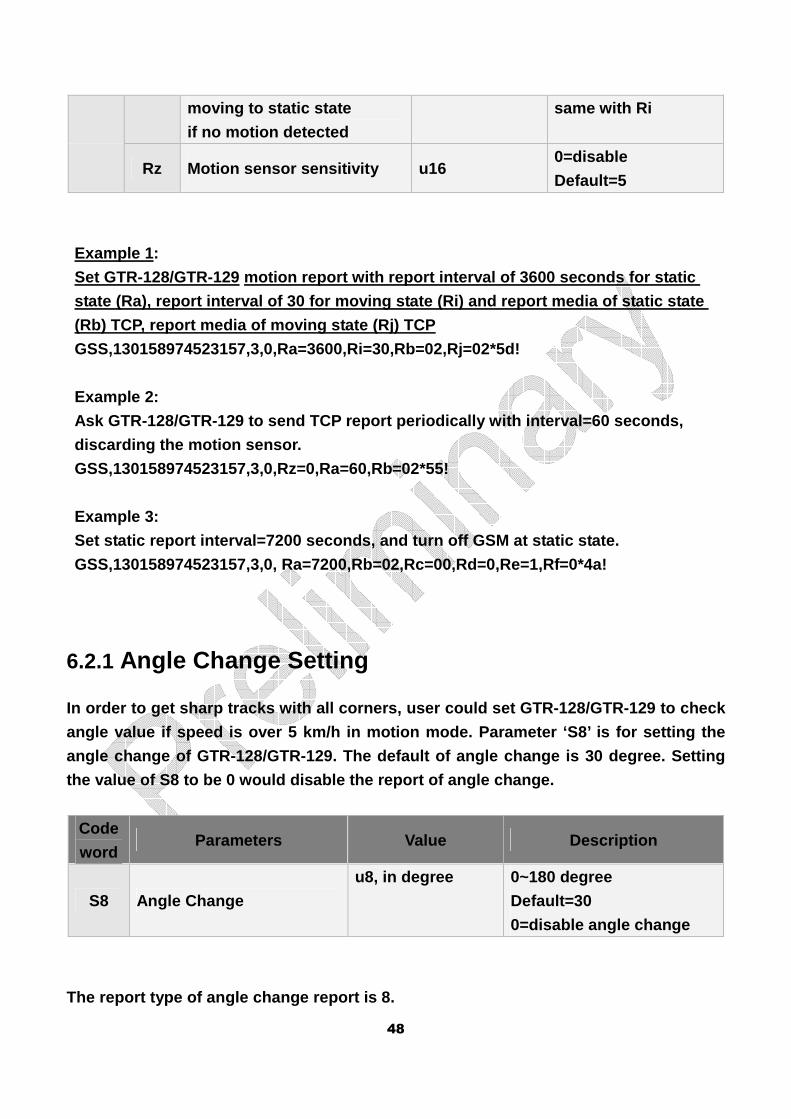
Ry Interval for switching from u16, in seconds 0=Interval is the
48
moving to static state
if no motion detected
same with Ri
Rz Motion sensor sensitivity u16 0=disable
Default=5
Example 1:
Set GTR-128/GTR-129 motion report with report inter val of 3600 seconds for static
state (Ra), report interval of 30 for moving state (Ri) and report media of static state
(Rb) TCP, report media of moving state (Rj) TCP
GSS,130158974523157,3,0,Ra=3600,Ri=30,Rb=02,Rj=02*5 d!
Example 2:
Ask GTR-128/GTR-129 to send TCP report periodically with interval=60 seconds,
discarding the motion sensor.
GSS,130158974523157,3,0,Rz=0,Ra=60,Rb=02*55!
Example 3:
Set static report interval=7200 seconds, and turn o ff GSM at static state.
GSS,130158974523157,3,0, Ra=7200,Rb=02,Rc=00,Rd=0,R e=1,Rf=0*4a!
6.2.1 Angle Change Setting
In order to get sharp tracks with all corners, user could set GTR-128/GTR-129 to check
angle value if speed is over 5 km/h in motion mode. Parameter ‘S8’ is for setting the
angle change of GTR-128/GTR-129. The default of ang le change is 30 degree. Setting
the value of S8 to be 0 would disable the report of angle change.
Code
word Parameters Value Description
S8 Angle Change
u8, in degree 0~180 degree
Default=30
0=disable angle change
The report type of angle change report is 8.
49
6.2.2 Roaming allow/disallow
While GTR-128/GTR-129 travelling to the area of the roaming GSM network, users could
choose GTR-128/GTR-129 to send reports as usual as the frequency in home GSM
network or to save the original frequency of report s in home GSM network to buffer
storage. If there is no problem of roaming GPRS con nection fee, users could set the
report media of moving state and static state to be ‘02’ or '04’ (parameters ‘Rb’ and ‘Rj’).
Considering to the high GPRS traffic cost in the ro aming network, users could set
GTR-128/GTR-129 to save the original frequency of m otion reports (parameters ‘Ra’ and
‘Ri’) to buffer storage in the area of roaming GSM network. And then send out those
buffered reports to server when it returns to the h ome GSM network. At the same time,
users could set a lower frequency for sending the r eports in roaming GSM network by
parameters ‘RA’ and ‘RI’. In that condition, please set the report media of moving state
and static state to be ‘42’ or ‘44’. (parameters ‘R b’ and ‘Rj’).
50
7. Alert
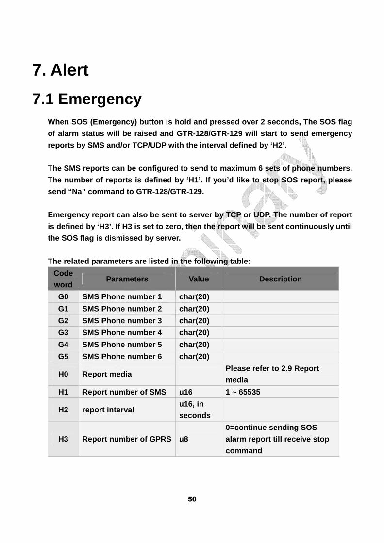
7.1 Emergency When SOS (Emergency) button is hold and pressed ove r 2 seconds, The SOS flag
of alarm status will be raised and GTR-128/GTR-129 will start to send emergency
reports by SMS and/or TCP/UDP with the interval def ined by ‘H2’.
The SMS reports can be configured to send to maximu m 6 sets of phone numbers.
The number of reports is defined by ‘H1’. If you’d like to stop SOS report, please
send “Na” command to GTR-128/GTR-129.
Emergency report can also be sent to server by TCP or UDP. The number of report
is defined by ‘H3’. If H3 is set to zero, then the report will be sent continuously until
the SOS flag is dismissed by server.
The related parameters are listed in the following table:
Code
word Parameters Value Description
G0 SMS Phone number 1 char(20)
G1 SMS Phone number 2 char(20)
G2 SMS Phone number 3 char(20)
G3 SMS Phone number 4 char(20)
G4 SMS Phone number 5 char(20)
G5 SMS Phone number 6 char(20)
H0 Report media Please refer to 2.9 Report
media
H1 Report number of SMS u16 1 ~ 65535
H2 report interval u16, in
seconds
H3 Report number of GPRS u8
0=continue sending SOS
alarm report till receive stop
command
51
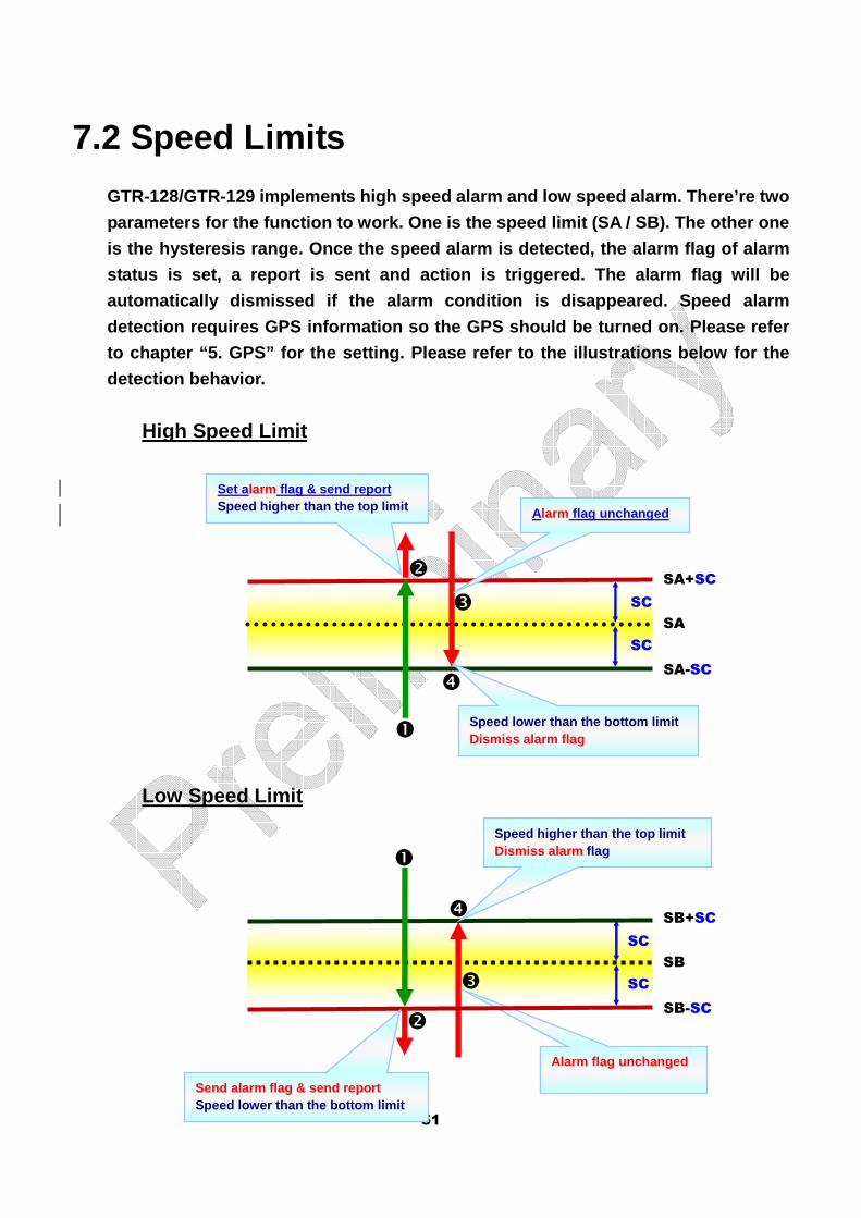
7.2 Speed Limits
GTR-128/GTR-129 implements high speed alarm and low speed alarm. There’re two
parameters for the function to work. One is the spe ed limit (SA / SB). The other one
is the hysteresis range. Once the speed alarm is de tected, the alarm flag of alarm
status is set, a report is sent and action is trigg ered. The alarm flag will be
automatically dismissed if the alarm condition is d isappeared. Speed alarm
detection requires GPS information so the GPS shoul d be turned on. Please refer
to chapter “5. GPS” for the setting. Please refer t o the illustrations below for the
detection behavior.
High Speed Limit
Low Speed Limit
SA
SC
SC
SA+SC
SA-SC
SB
SC
SC
SB+SC
SB-SC
Alarm flag unchanged
Send alarm flag & send report Speed lower than the bottom limit
Speed higher than the top limit Dismiss alarm flag
Set alarm flag & send report Speed higher than the top limit Alarm flag unchanged
Speed lower than the bottom limit Dismiss alarm flag
�
�
�
�
�
�
�
�
52
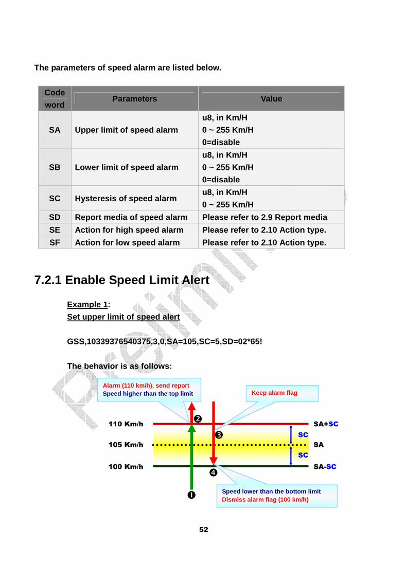
The parameters of speed alarm are listed below.
Code
word Parameters Value
SA Upper limit of speed alarm
u8, in Km/H
0 ~ 255 Km/H
0=disable
SB Lower limit of speed alarm
u8, in Km/H
0 ~ 255 Km/H
0=disable
SC Hysteresis of speed alarm u8, in Km/H
0 ~ 255 Km/H
SD Report media of speed alarm Please refer to 2.9 Report media
SE Action for high speed alarm Please refer to 2.10 Action type.
SF Action for low speed alarm Please refer to 2.10 Action type.
7.2.1 Enable Speed Limit Alert
Example 1:
Set upper limit of speed alert
GSS,10339376540375,3,0,SA=105,SC=5,SD=02*65!
The behavior is as follows:
SA
SC
SC
SA+SC
SA-SC 100 Km/h
105 Km/h
110 Km/h
Alarm (110 km/h), send report Speed higher than the top limit Keep alarm flag
Speed lower than the bottom limit Dismiss alarm flag (100 km/h)
�
�
�
�
53
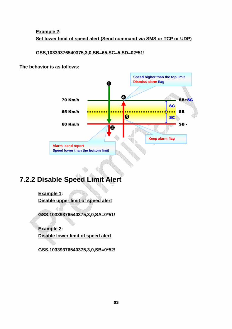
Example 2: Set lower limit of speed alert (Send command via SM S or TCP or UDP)
GSS,10339376540375,3,0,SB=65,SC=5,SD=02*51!
The behavior is as follows:
7.2.2 Disable Speed Limit Alert
Example 1:
Disable upper limit of speed alert
GSS,10339376540375,3,0,SA=0*51!
Example 2:
Disable lower limit of speed alert
GSS,10339376540375,3,0,SB=0*52!
SB SC
SC
SB+SC
SB - 60 Km/h
65 Km/h
70 Km/h
Keep alarm flag
Alarm, send report Speed lower than the bottom limit
Speed higher than the top limit Dismiss alarm flag �
�
�
�
54
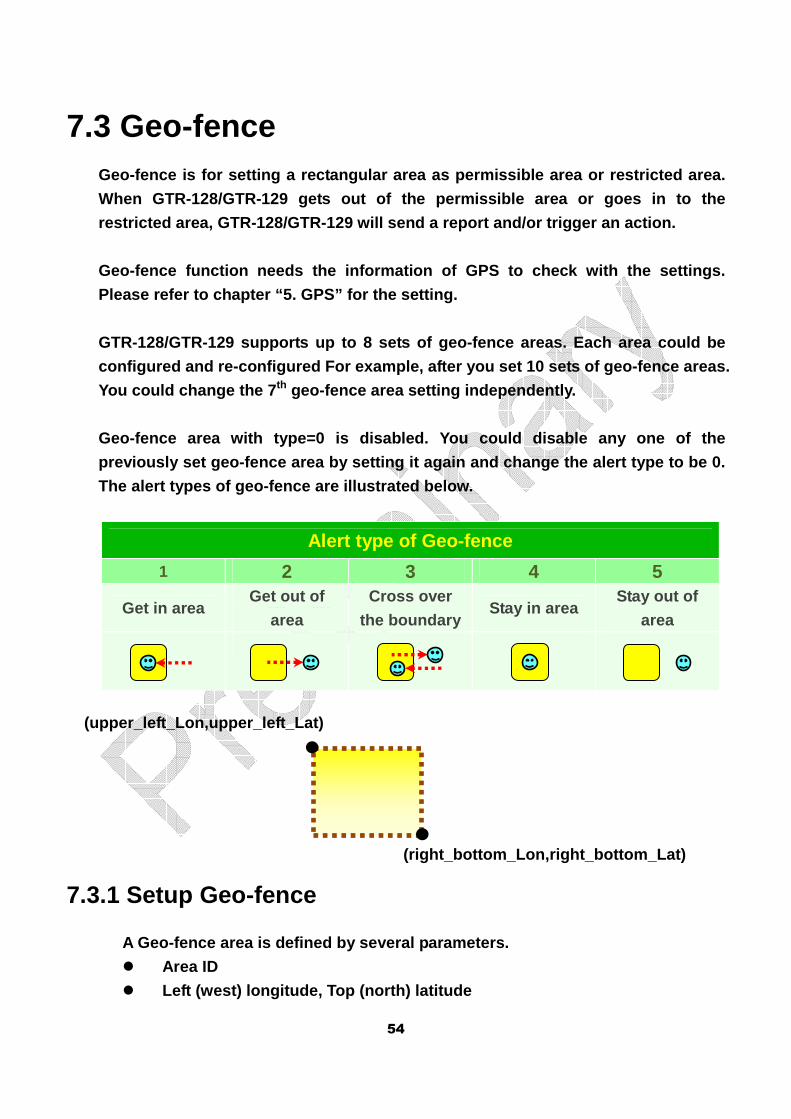
7.3 Geo-fence Geo-fence is for setting a rectangular area as perm issible area or restricted area.
When GTR-128/GTR-129 gets out of the permissible ar ea or goes in to the
restricted area, GTR-128/GTR-129 will send a report and/or trigger an action.
Geo-fence function needs the information of GPS to check with the settings.
Please refer to chapter “5. GPS” for the setting.
GTR-128/GTR-129 supports up to 8 sets of geo-fence areas. Each area could be
configured and re-configured For example, after you set 10 sets of geo-fence areas.
You could change the 7 th geo-fence area setting independently.
Geo-fence area with type=0 is disabled. You could d isable any one of the
previously set geo-fence area by setting it again a nd change the alert type to be 0.
The alert types of geo-fence are illustrated below.
Alert type of Geo-fence
1 2 3 4 5
Get in area Get out of
area Cross over
the boundary Stay in area
Stay out of
area
7.3.1 Setup Geo-fence
A Geo-fence area is defined by several parameters.
� Area ID
� Left (west) longitude, Top (north) latitude
(right_bottom_Lon,right_bottom_Lat)
(upper_left_Lon,upper_left_Lat)
55
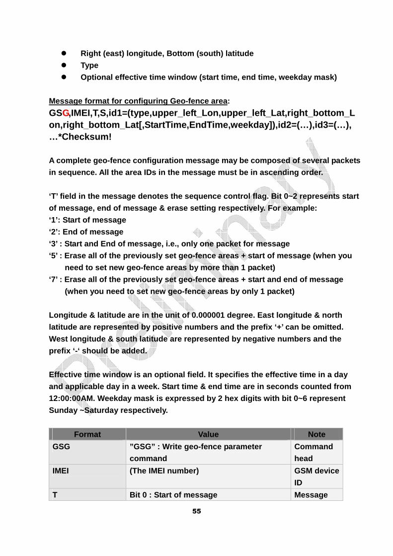
� Right (east) longitude, Bottom (south) latitude
� Type
� Optional effective time window (start time, end tim e, weekday mask)
Message format for configuring Geo-fence area:
GSG,IMEI,T,S,id1=(type,upper_left_Lon,upper_left_Lat,r ight_bottom_Lon,right_bottom_Lat[,StartTime,EndTime,weekday]),id 2=(…),id3=(…),…*Checksum!
A complete geo-fence configuration message may be c omposed of several packets
in sequence. All the area IDs in the message must b e in ascending order.
‘T’ field in the message denotes the sequence contr ol flag. Bit 0~2 represents start
of message, end of message & erase setting respecti vely. For example:
‘1’: Start of message
‘2’: End of message
‘3’ : Start and End of message, i.e., only one pack et for message
‘5’ : Erase all of the previously set geo-fence are as + start of message (when you
need to set new geo-fence areas by more than 1 pack et)
‘7’ : Erase all of the previously set geo-fence are as + start and end of message
(when you need to set new geo-fence areas by only 1 packet)
Longitude & latitude are in the unit of 0.000001 de gree. East longitude & north
latitude are represented by positive numbers and th e prefix ‘+’ can be omitted.
West longitude & south latitude are represented by negative numbers and the
prefix ‘-‘ should be added.
Effective time window is an optional field. It spec ifies the effective time in a day
and applicable day in a week. Start time & end time are in seconds counted from
12:00:00AM. Weekday mask is expressed by 2 hex digi ts with bit 0~6 represent
Sunday ~Saturday respectively.
Format Value Note
GSG ”GSG” : Write geo-fence parameter
command
Command
head
IMEI (The IMEI number) GSM device
ID
T Bit 0 : Start of message Message
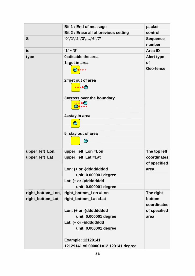
56
Bit 1 : End of message
Bit 2 : Erase all of previous setting
packet
control
S ‘0’,’1’,’2’,’3’,…,’6’,’7’ Sequence
number
id ‘1’ ~ ‘8’ Area ID
type 0=disable the area
1=get in area
2=get out of area
3=cross over the boundary
4=stay in area
5=stay out of area
Alert type
of
Geo-fence
upper_left_Lon,
upper_left_Lat
upper_left_Lon =Lon
upper_left_Lat =Lat
Lon: (+ or -)ddddddddd
unit: 0.000001 degree
Lat: (+ or -)dddddddd
unit: 0.000001 degree
The top left
coordinates
of specified
area
right_bottom_Lon,
right_bottom_Lat
right_bottom_Lon =Lon
right_bottom_Lat =Lat
Lon: (+ or -)ddddddddd
unit: 0.000001 degree
Lat: (+ or -)dddddddd
unit: 0.000001 degree
Example: 12129141
12129141 x0.000001=12.129141 degree
The right
bottom
coordinates
of specified
area
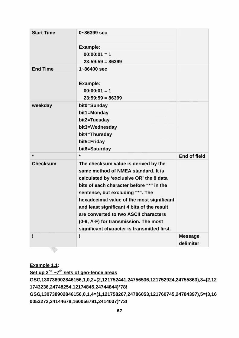
57
Start Time 0~86399 sec
Example:
00:00:01 = 1
23:59:59 = 86399
End Time 1~86400 sec
Example:
00:00:01 = 1
23:59:59 = 86399
weekday bit0=Sunday
bit1=Monday
bit2=Tuesday
bit3=Wednesday
bit4=Thursday
bit5=Friday
bit6=Saturday
* * End of field
Checksum The checksum value is derived by the
same method of NMEA standard. It is
calculated by ‘exclusive OR’ the 8 data
bits of each character before “*” in the
sentence, but excluding “*”. The
hexadecimal value of the most significant
and least significant 4 bits of the result
are converted to two ASCII characters
(0-9, A-F) for transmission. The most
significant character is transmitted first.
! ! Message
delimiter
Example 1.1:
Set up 2 nd ~7th sets of geo-fence areas
GSG,130738902846156,1,0,2=(2,121752441,24756536,121752924,24755863),3=(2,12
1743236,24748254,12174845,24744844)*78!
GSG,130738902846156,0,1,4=(1,121758267,24786053,121760745,24784397),5=(3,16
0053272,24144678,160056791,2414037)*73!
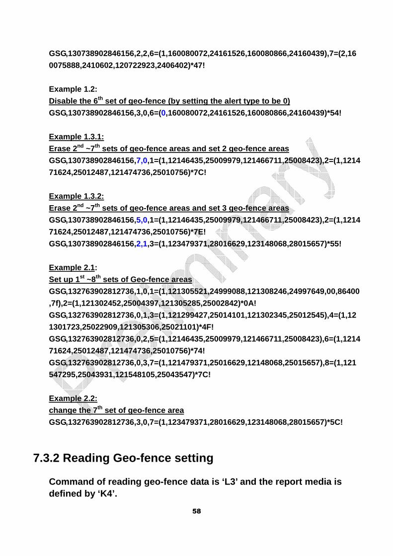
58
GSG,130738902846156,2,2,6=(1,160080072,24161526,160080866,24160439),7=(2,16
0075888,2410602,120722923,2406402)*47!
Example 1.2:
Disable the 6 th set of geo-fence (by setting the alert type to be 0)
GSG,130738902846156,3,0,6=(0,160080072,24161526,160080866,24160439)*54!
Example 1.3.1:
Erase 2 nd ~7th sets of geo-fence areas and set 2 geo-fence areas
GSG,130738902846156,7,0,1=(1,12146435,25009979,121466711,25008423),2=(1,1214
71624,25012487,121474736,25010756)*7C!
Example 1.3.2:
Erase 2 nd ~7th sets of geo-fence areas and set 3 geo-fence areas
GSG,130738902846156,5,0,1=(1,12146435,25009979,121466711,25008423),2=(1,1214
71624,25012487,121474736,25010756)*7E!
GSG,130738902846156,2,1,3=(1,123479371,28016629,123148068,28015657)*55!
Example 2.1:
Set up 1 st ~8th sets of Geo-fence areas
GSG,132763902812736,1,0,1=(1,121305521,24999088,121308246,24997649,00,86400
,7f),2=(1,121302452,25004397,121305285,25002842)*0A!
GSG,132763902812736,0,1,3=(1,121299427,25014101,121302345,25012545),4=(1,12
1301723,25022909,121305306,25021101)*4F!
GSG,132763902812736,0,2,5=(1,12146435,25009979,121466711,25008423),6=(1,1214
71624,25012487,121474736,25010756)*74!
GSG,132763902812736,0,3,7=(1,121479371,25016629,12148068,25015657),8=(1,121
547295,25043931,121548105,25043547)*7C!
Example 2.2:
change the 7 th set of geo-fence area
GSG,132763902812736,3,0,7=(1,123479371,28016629,123148068,28015657)*5C!
7.3.2 Reading Geo-fence setting
Command of reading geo-fence data is ‘L3’ and the r eport media is defined by ‘K4’.
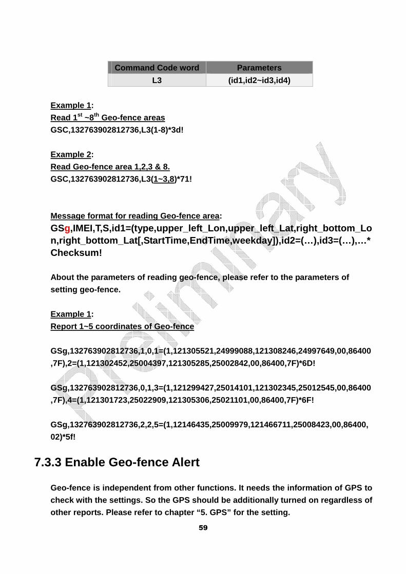
59
Command Code word Parameters
L3 (id1,id2~id3,id4)
Example 1:
Read 1st ~8th Geo-fence areas
GSC,132763902812736,L3(1-8)*3d!
Example 2:
Read Geo-fence area 1,2,3 & 8.
GSC,132763902812736,L3(1~3,8)*71!
Message format for reading Geo-fence area:
GSg,IMEI,T,S,id1=(type,upper_left_Lon,upper_left_Lat,r ight_bottom_Lon,right_bottom_Lat[,StartTime,EndTime,weekday]),id2 =(…),id3=(…),…*Checksum!
About the parameters of reading geo-fence, please r efer to the parameters of
setting geo-fence.
Example 1:
Report 1~5 coordinates of Geo-fence
GSg,132763902812736,1,0,1=(1,121305521,24999088,121308246,24997649,00,86400
,7F),2=(1,121302452,25004397,121305285,25002842,00,86400,7F)*6D!
GSg,132763902812736,0,1,3=(1,121299427,25014101,121302345,25012545,00,86400
,7F),4=(1,121301723,25022909,121305306,25021101,00,86400,7F)*6F!
GSg,132763902812736,2,2,5=(1,12146435,25009979,121466711,25008423,00,86400,
02)*5f!
7.3.3 Enable Geo-fence Alert
Geo-fence is independent from other functions. It n eeds the information of GPS to
check with the settings. So the GPS should be addit ionally turned on regardless of
other reports. Please refer to chapter “5. GPS” for the setting.
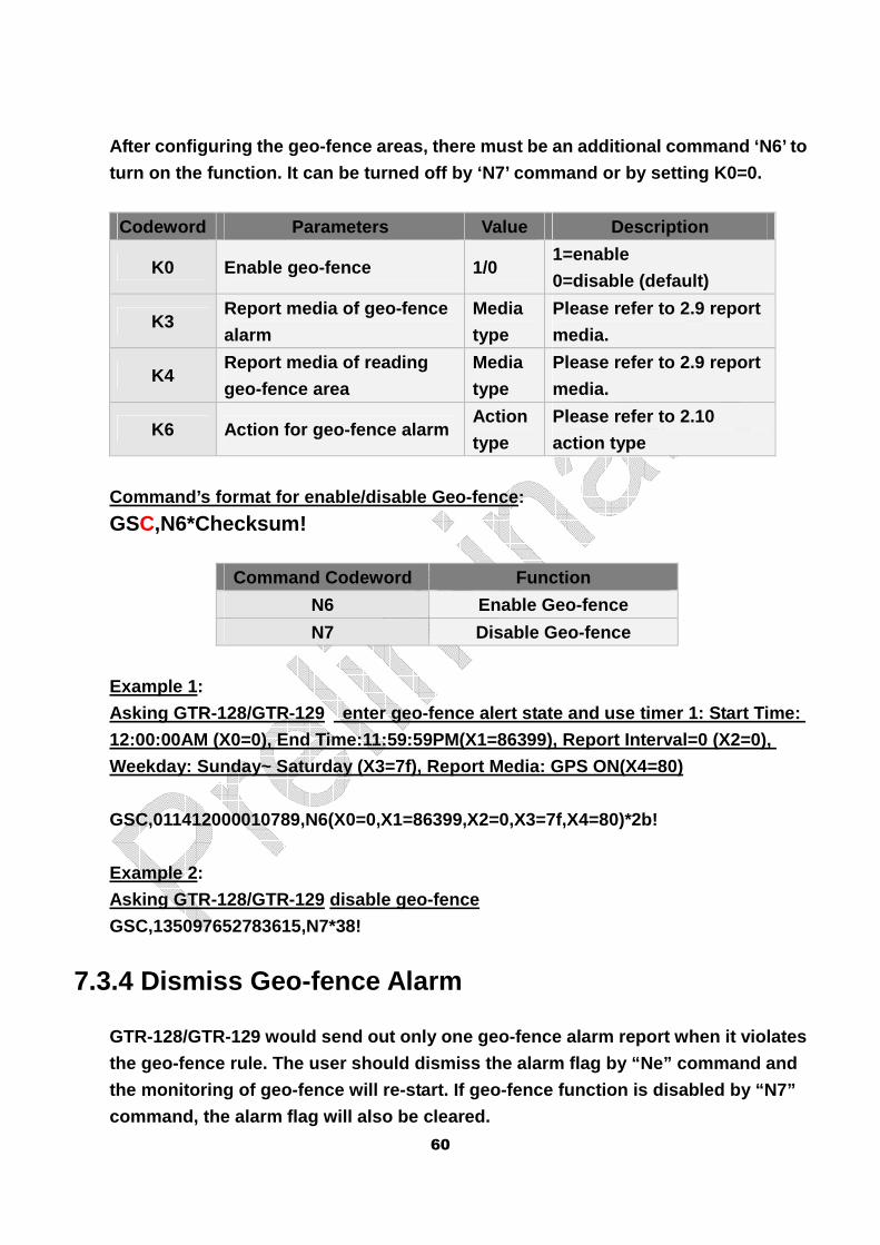
60
After configuring the geo-fence areas, there must b e an additional command ‘N6’ to
turn on the function. It can be turned off by ‘N7’ command or by setting K0=0.
Codeword Parameters Value Description
K0 Enable geo-fence 1/0 1=enable
0=disable (default)
K3 Report media of geo-fence
alarm
Media
type
Please refer to 2.9 report
media.
K4 Report media of reading
geo-fence area
Media
type
Please refer to 2.9 report
media.
K6 Action for geo-fence alarm Action
type
Please refer to 2.10
action type
Command’s format for enable/disable Geo-fence:
GSC,N6*Checksum!
Command Codeword Function
N6 Enable Geo-fence
N7 Disable Geo-fence
Example 1:
Asking GTR-128/GTR-129 enter geo-fence alert state and use timer 1: Start Time:
12:00:00AM (X0=0), End Time:11:59:59PM(X1=86399), R eport Interval=0 (X2=0),
Weekday: Sunday~ Saturday (X3=7f), Report Media: GP S ON(X4=80)
GSC,011412000010789,N6(X0=0,X1=86399,X2=0,X3=7f,X4=80)*2b!
Example 2:
Asking GTR-128/GTR-129 disable geo-fence
GSC,135097652783615,N7*38!
7.3.4 Dismiss Geo-fence Alarm
GTR-128/GTR-129 would send out only one geo-fence a larm report when it violates
the geo-fence rule. The user should dismiss the ala rm flag by “Ne” command and
the monitoring of geo-fence will re-start. If geo-f ence function is disabled by “N7”
command, the alarm flag will also be cleared.
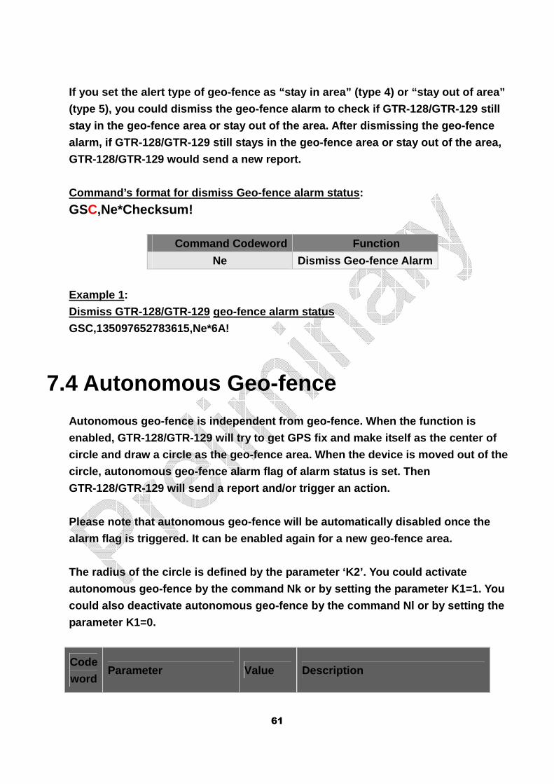
61
If you set the alert type of geo-fence as “stay in area” (type 4) or “stay out of area”
(type 5), you could dismiss the geo-fence alarm to check if GTR-128/GTR-129 still
stay in the geo-fence area or stay out of the area. After dismissing the geo-fence
alarm, if GTR-128/GTR-129 still stays in the geo-fe nce area or stay out of the area,
GTR-128/GTR-129 would send a new report.
Command’s format for dismiss Geo-fence alarm status :
GSC,Ne*Checksum!
Command Codeword Function
Ne Dismiss Geo-fence Alarm
Example 1:
Dismiss GTR-128/GTR-129 geo-fence alarm status
GSC,135097652783615,Ne*6A!
7.4 Autonomous Geo-fence
Autonomous geo-fence is independent from geo-fence. When the function is
enabled, GTR-128/GTR-129 will try to get GPS fix an d make itself as the center of
circle and draw a circle as the geo-fence area. Whe n the device is moved out of the
circle, autonomous geo-fence alarm flag of alarm st atus is set. Then
GTR-128/GTR-129 will send a report and/or trigger a n action.
Please note that autonomous geo-fence will be autom atically disabled once the
alarm flag is triggered. It can be enabled again fo r a new geo-fence area.
The radius of the circle is defined by the paramete r ‘K2’. You could activate
autonomous geo-fence by the command Nk or by settin g the parameter K1=1. You
could also deactivate autonomous geo-fence by the c ommand Nl or by setting the
parameter K1=0.
Code
word Parameter Value Description
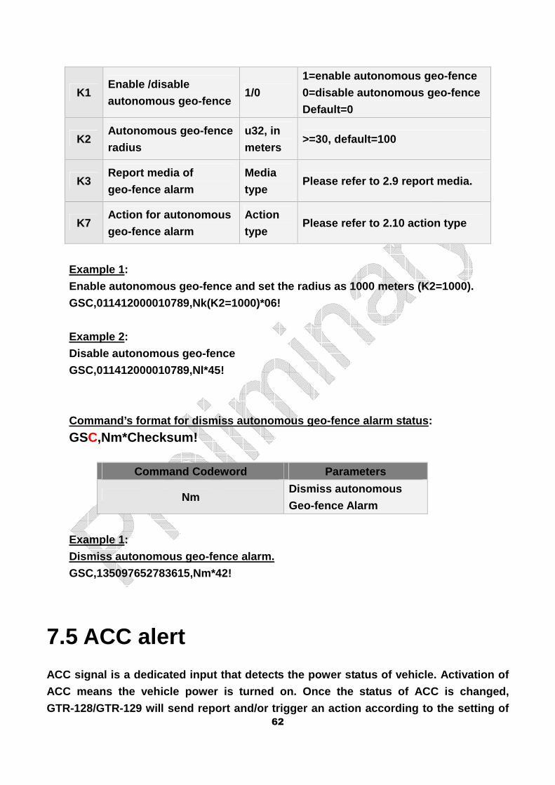
62
K1 Enable /disable
autonomous geo-fence 1/0
1=enable autonomous geo-fence
0=disable autonomous geo-fence
Default=0
K2 Autonomous geo-fence
radius
u32, in
meters >=30, default=100
K3 Report media of
geo-fence alarm
Media
type Please refer to 2.9 report media.
K7 Action for autonomous
geo-fence alarm
Action
type Please refer to 2.10 action type
Example 1:
Enable autonomous geo-fence and set the radius as 1 000 meters (K2=1000).
GSC,011412000010789,Nk(K2=1000)*06!
Example 2:
Disable autonomous geo-fence
GSC,011412000010789,Nl*45!
Command’s format for dismiss autonomous geo-fence a larm status:
GSC,Nm*Checksum!
Command Codeword Parameters
Nm Dismiss autonomous
Geo-fence Alarm
Example 1:
Dismiss autonomous geo-fence alarm.
GSC,135097652783615,Nm*42!
7.5 ACC alert
ACC signal is a dedicated input that detects the po wer status of vehicle. Activation of
ACC means the vehicle power is turned on. Once the status of ACC is changed,
GTR-128/GTR-129 will send report and/or trigger an action according to the setting of
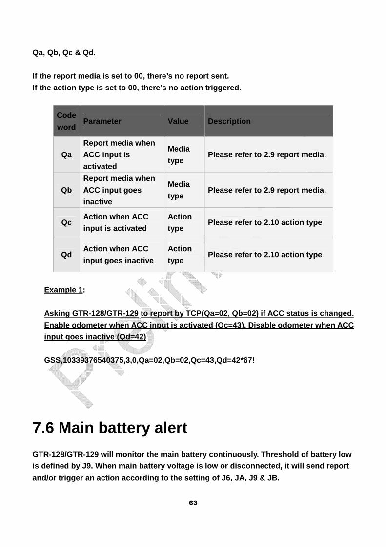
63
Qa, Qb, Qc & Qd.
If the report media is set to 00, there’s no report sent.
If the action type is set to 00, there’s no action triggered.
Code
word Parameter Value Description
Qa
Report media when
ACC input is
activated
Media
type Please refer to 2.9 report media.
Qb
Report media when
ACC input goes
inactive
Media
type Please refer to 2.9 report media.
Qc Action when ACC
input is activated
Action
type Please refer to 2.10 action type
Qd Action when ACC
input goes inactive
Action
type Please refer to 2.10 action type
Example 1:
Asking GTR-128/GTR-129 to report by TCP(Qa=02, Qb=0 2) if ACC status is changed.
Enable odometer when ACC input is activated (Qc=43) . Disable odometer when ACC
input goes inactive (Qd=42)
GSS,10339376540375,3,0,Qa=02,Qb=02,Qc=43,Qd=42*67!
7.6 Main battery alert
GTR-128/GTR-129 will monitor the main battery conti nuously. Threshold of battery low
is defined by J9. When main battery voltage is low or disconnected, it will send report
and/or trigger an action according to the setting o f J6, JA, J9 & JB.
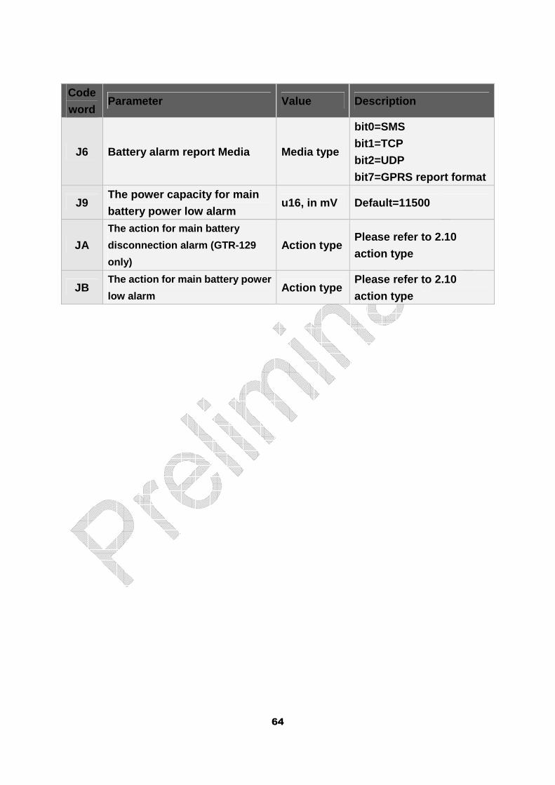
64
Code
word Parameter Value Description
J6 Battery alarm report Media Media type
bit0=SMS
bit1=TCP
bit2=UDP
bit7=GPRS report format
J9 The power capacity for main
battery power low alarm u16, in mV Default=11500
JA
The action for main battery
disconnection alarm (GTR-129
only)
Action type Please refer to 2.10
action type
JB The action for main battery power
low alarm Action type
Please refer to 2.10
action type
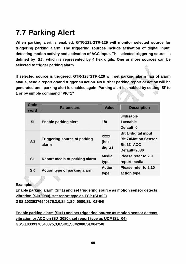
65
7.7 Parking Alert When parking alert is enabled, GTR-128/GTR-129 will monitor selected source for
triggering parking alarm. The triggering sources in clude activation of digital input,
detecting motion activity and activation of ACC inp ut. The selected triggering source is
defined by ‘SJ’, which is represented by 4 hex digi ts. One or more sources can be
selected to trigger parking alarm.
If selected source is triggered, GTR-128/GTR-129 wi ll set parking alarm flag of alarm
status, send a report or/and trigger an action. No further parking report or action will be
generated until parking alert is enabled again. Par king alert is enabled by setting ‘SI’ to
1 or by simple command “PK=1”
Code
word Parameters Value Description
SI Enable parking alert 1/0
0=disable
1=enable
Default=0
SJ Triggering source of parking
alarm
xxxx
(hex
digits)
Bit 1=digital input
Bit 7=Motion Sensor
Bit 13=ACC
Default=2080
SL Report media of parking alarm Media
type
Please refer to 2.9
report media
SK Action type of parking alarm Action
type
Please refer to 2.10
action type
Example:
Enable parking alarm (SI=1) and set triggering sour ce as motion sensor detects
vibration (SJ=0080), set report type as TCP (SL=02)
GSS,10339376540375,3,0,SI=1,SJ=0080,SL=02*54!
Enable parking alarm (SI=1) and set triggering sour ce as motion sensor detects
vibration or ACC on (SJ=2080), set report type as U DP (SL=04)
GSS,10339376540375,3,0,SI=1,SJ=2080,SL=04*50!
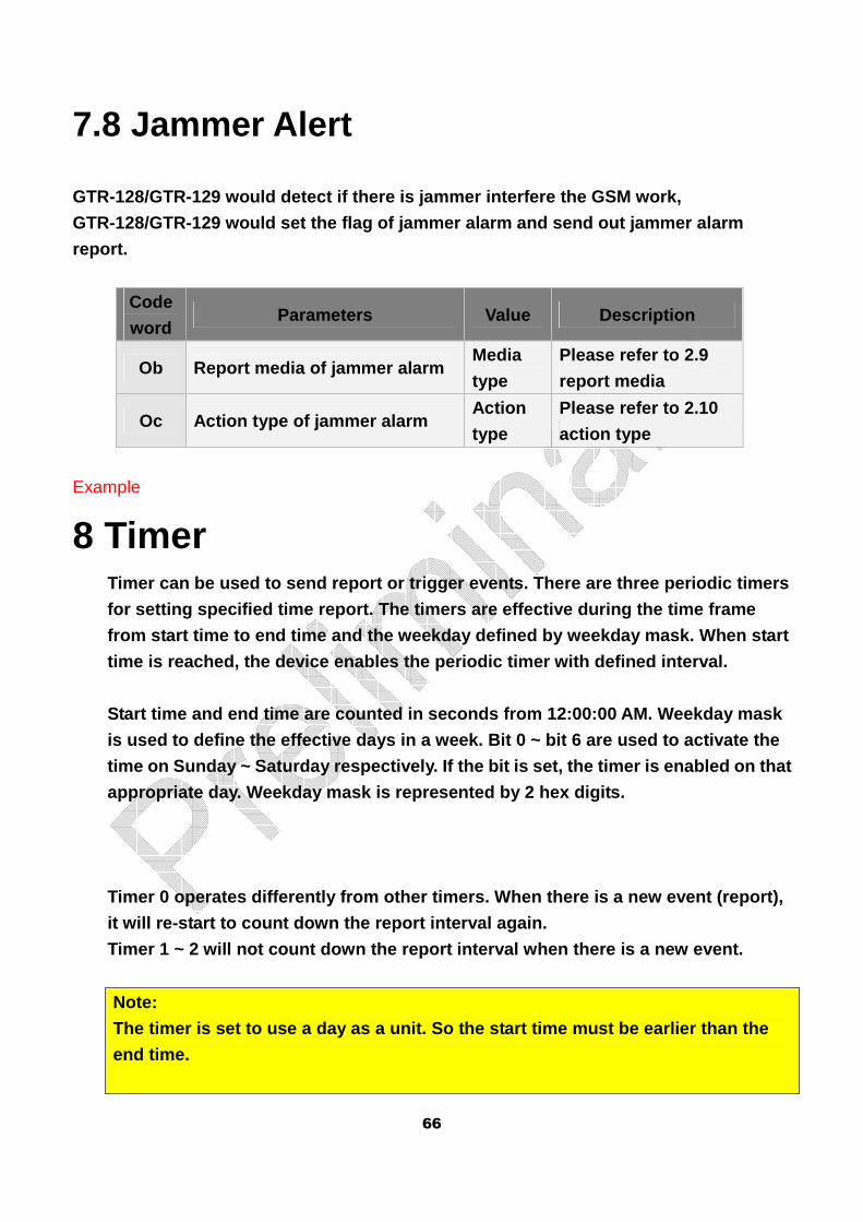
66
7.8 Jammer Alert
GTR-128/GTR-129 would detect if there is jammer int erfere the GSM work,
GTR-128/GTR-129 would set the flag of jammer alarm and send out jammer alarm
report.
Code
word Parameters Value Description
Ob Report media of jammer alarm Media
type
Please refer to 2.9
report media
Oc Action type of jammer alarm Action
type
Please refer to 2.10
action type
Example
8 Timer Timer can be used to send report or trigger events. There are three periodic timers
for setting specified time report. The timers are e ffective during the time frame
from start time to end time and the weekday defined by weekday mask. When start
time is reached, the device enables the periodic ti mer with defined interval.
Start time and end time are counted in seconds from 12:00:00 AM. Weekday mask
is used to define the effective days in a week. Bit 0 ~ bit 6 are used to activate the
time on Sunday ~ Saturday respectively. If the bit is set, the timer is enabled on that
appropriate day. Weekday mask is represented by 2 h ex digits.
Timer 0 operates differently from other timers. Whe n there is a new event (report),
it will re-start to count down the report interval again.
Timer 1 ~ 2 will not count down the report interval when there is a new event.
Note:
The timer is set to use a day as a unit. So the sta rt time must be earlier than the
end time.
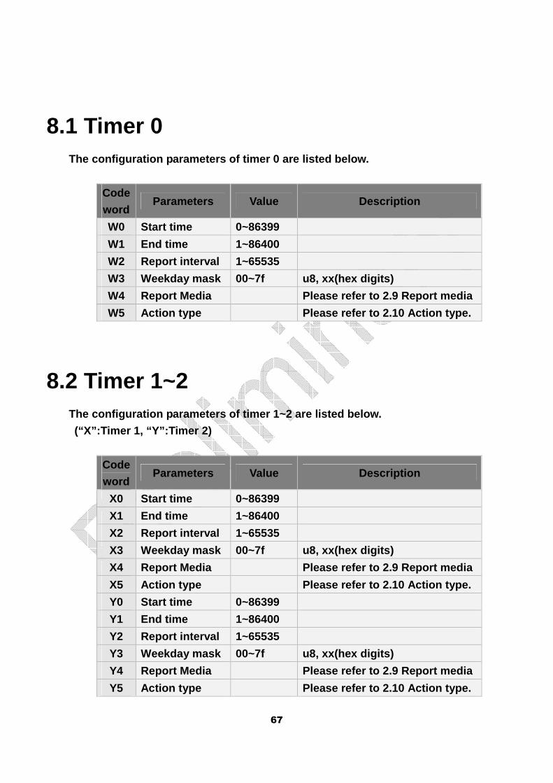
67
8.1 Timer 0 The configuration parameters of timer 0 are listed below.
Code
word Parameters Value Description
W0 Start time 0~86399
W1 End time 1~86400
W2 Report interval 1~65535
W3 Weekday mask 00~7f u8, xx(hex digits)
W4 Report Media Please refer to 2.9 Report media
W5 Action type Please refer to 2.10 Action type.
8.2 Timer 1~2 The configuration parameters of timer 1~2 are liste d below.
(“X”:Timer 1, “Y”:Timer 2)
Code
word Parameters Value Description
X0 Start time 0~86399
X1 End time 1~86400
X2 Report interval 1~65535
X3 Weekday mask 00~7f u8, xx(hex digits)
X4 Report Media Please refer to 2.9 Report media
X5 Action type Please refer to 2.10 Action type.
Y0 Start time 0~86399
Y1 End time 1~86400
Y2 Report interval 1~65535
Y3 Weekday mask 00~7f u8, xx(hex digits)
Y4 Report Media Please refer to 2.9 Report media
Y5 Action type Please refer to 2.10 Action type.
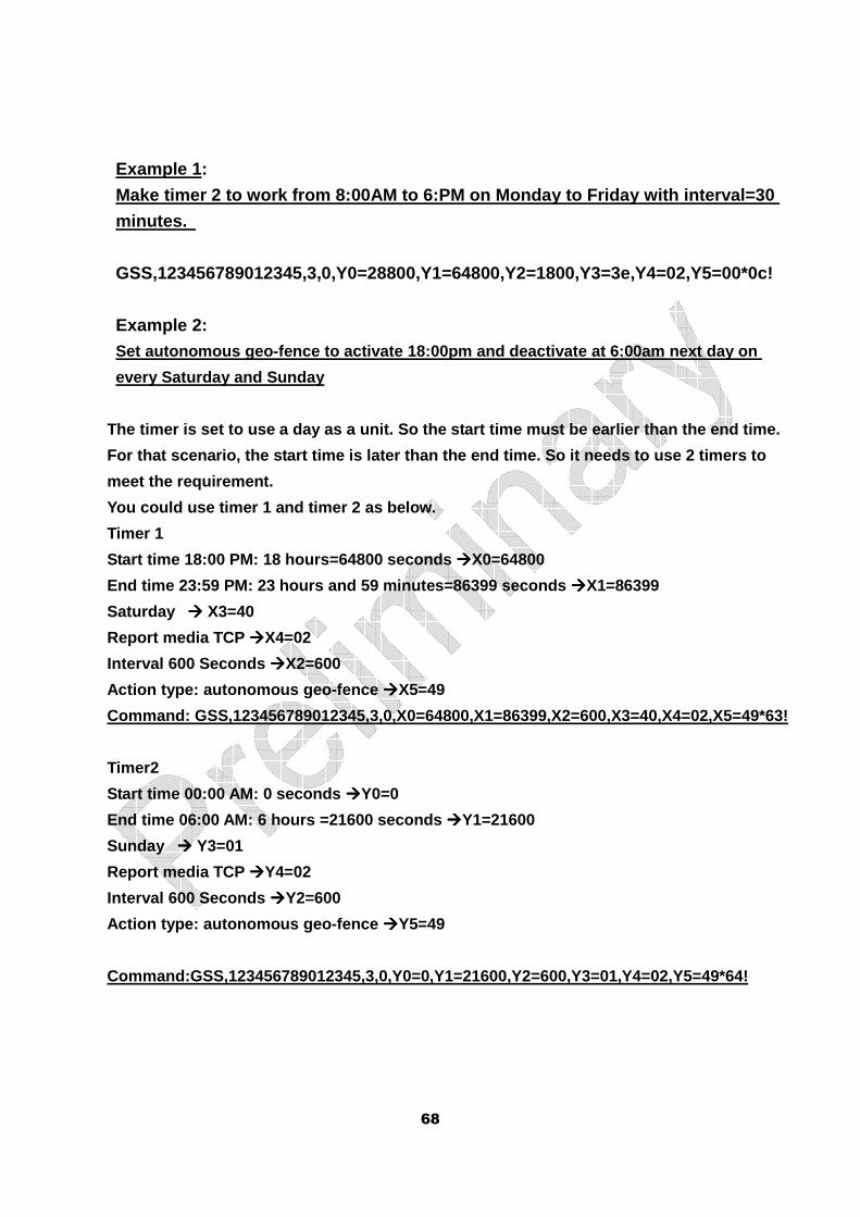
68
Example 1:
Make timer 2 to work from 8:00AM to 6:PM on Monday to Friday with interval=30
minutes.
GSS,123456789012345,3,0,Y0=28800,Y1=64800,Y2=1800,Y3=3e,Y4=02,Y5=00*0c!
Example 2: Set autonomous geo-fence to activate 18:00pm and de activate at 6:00am next day on
every Saturday and Sunday
The timer is set to use a day as a unit. So the sta rt time must be earlier than the end time.
For that scenario, the start time is later than the end time. So it needs to use 2 timers to
meet the requirement.
You could use timer 1 and timer 2 as below.
Timer 1
Start time 18:00 PM: 18 hours=64800 seconds ����X0=64800
End time 23:59 PM: 23 hours and 59 minutes=86399 se conds ����X1=86399
Saturday ���� X3=40
Report media TCP ����X4=02
Interval 600 Seconds ����X2=600
Action type: autonomous geo-fence ����X5=49
Command: GSS,123456789012345,3,0,X0=64800,X1=86399, X2=600,X3=40,X4=02,X5=49*63!
Timer2
Start time 00:00 AM: 0 seconds ����Y0=0
End time 06:00 AM: 6 hours =21600 seconds ����Y1=21600
Sunday ���� Y3=01
Report media TCP ����Y4=02
Interval 600 Seconds ����Y2=600
Action type: autonomous geo-fence ����Y5=49
Command:GSS,123456789012345,3,0,Y0=0,Y1=21600,Y2=60 0,Y3=01,Y4=02,Y5=49*64!
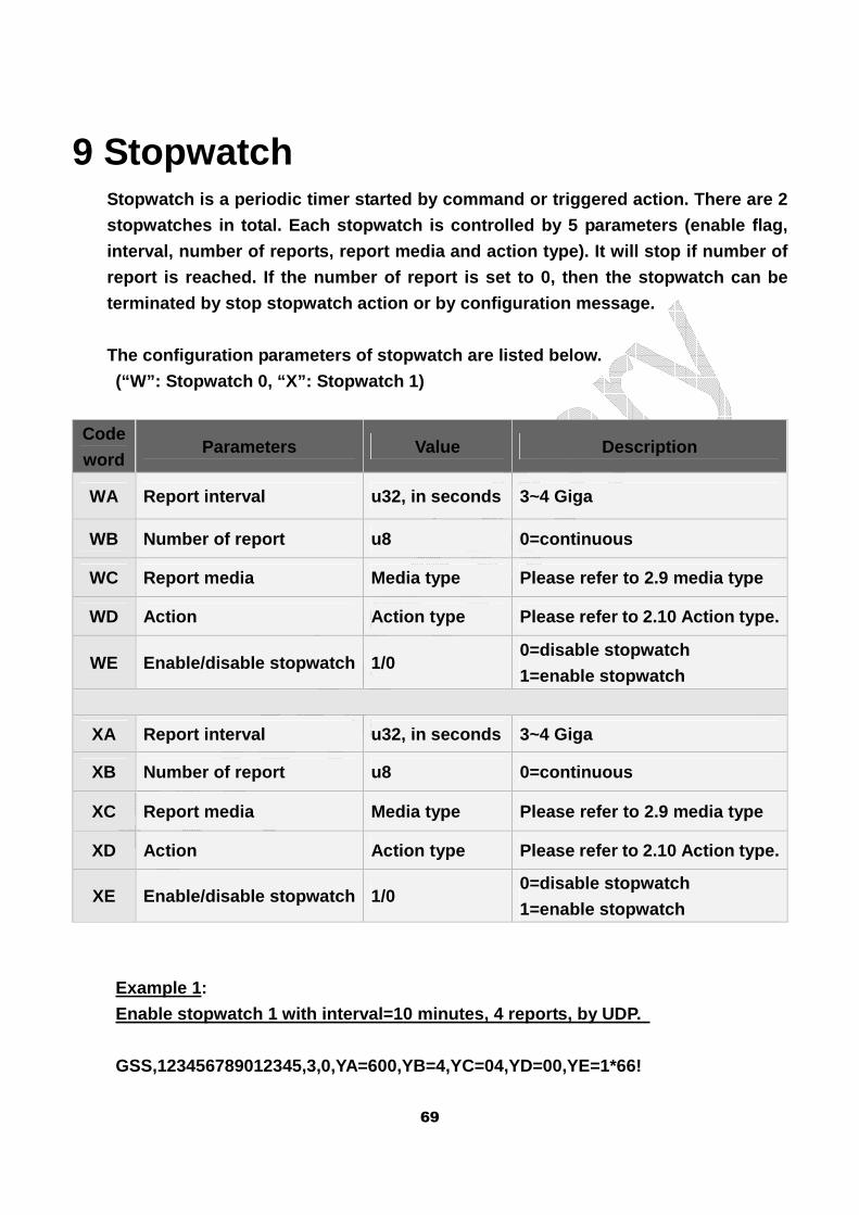
69
9 Stopwatch Stopwatch is a periodic timer started by command or triggered action. There are 2
stopwatches in total. Each stopwatch is controlled by 5 parameters (enable flag,
interval, number of reports, report media and actio n type). It will stop if number of
report is reached. If the number of report is set t o 0, then the stopwatch can be
terminated by stop stopwatch action or by configura tion message.
The configuration parameters of stopwatch are liste d below.
(“W”: Stopwatch 0, “X”: Stopwatch 1)
Code
word Parameters Value Description
WA Report interval u32, in seconds 3~4 Giga
WB Number of report u8 0=continuous
WC Report media Media type Please refer to 2.9 media type
WD Action Action type Please refer to 2.10 Action type.
WE Enable/disable stopwatch 1/0 0=disable stopwatch
1=enable stopwatch
XA Report interval u32, in seconds 3~4 Giga
XB Number of report u8 0=continuous
XC Report media Media type Please refer to 2.9 media type
XD Action Action type Please refer to 2.10 Action type.
XE Enable/disable stopwatch 1/0 0=disable stopwatch
1=enable stopwatch
Example 1:
Enable stopwatch 1 with interval=10 minutes, 4 repo rts, by UDP.
GSS,123456789012345,3,0,YA=600,YB=4,YC=04,YD=00,YE=1*66!
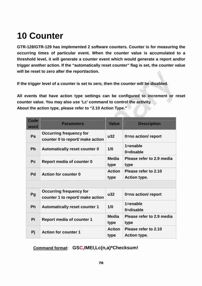
70
10 Counter GTR-128/GTR-129 has implemented 2 software counters . Counter is for measuring the
occurring times of particular event. When the count er value is accumulated to a
threshold level, it will generate a counter event w hich would generate a report and/or
trigger another action. If the “automatically reset counter” flag is set, the counter value
will be reset to zero after the report/action.
If the trigger level of a counter is set to zero, t hen the counter will be disabled.
All events that have action type settings can be co nfigured to increment or reset
counter value. You may also use ‘Lc’ command to con trol the activity.
About the action type, please refer to “2.10 Action Type.”
Code
word Parameters Value Description
Pa Occurring frequency for
counter 0 to report/ make action u32 0=no action/ report
Pb Automatically reset counter 0 1/0 1=enable
0=disable
Pc Report media of counter 0 Media
type
Please refer to 2.9 media
type
Pd Action for counter 0 Action
type
Please refer to 2.10
Action type.
Pg Occurring frequency for
counter 1 to report/ make action u32 0=no action/ report
Ph Automatically reset counter 1 1/0 1=enable
0=disable
Pi Report media of counter 1 Media
type
Please refer to 2.9 media
type
Pj Action for counter 1 Action
type
Please refer to 2.10
Action type.
Command format: GSC,IMEI,Lc(n,a)*Checksum!
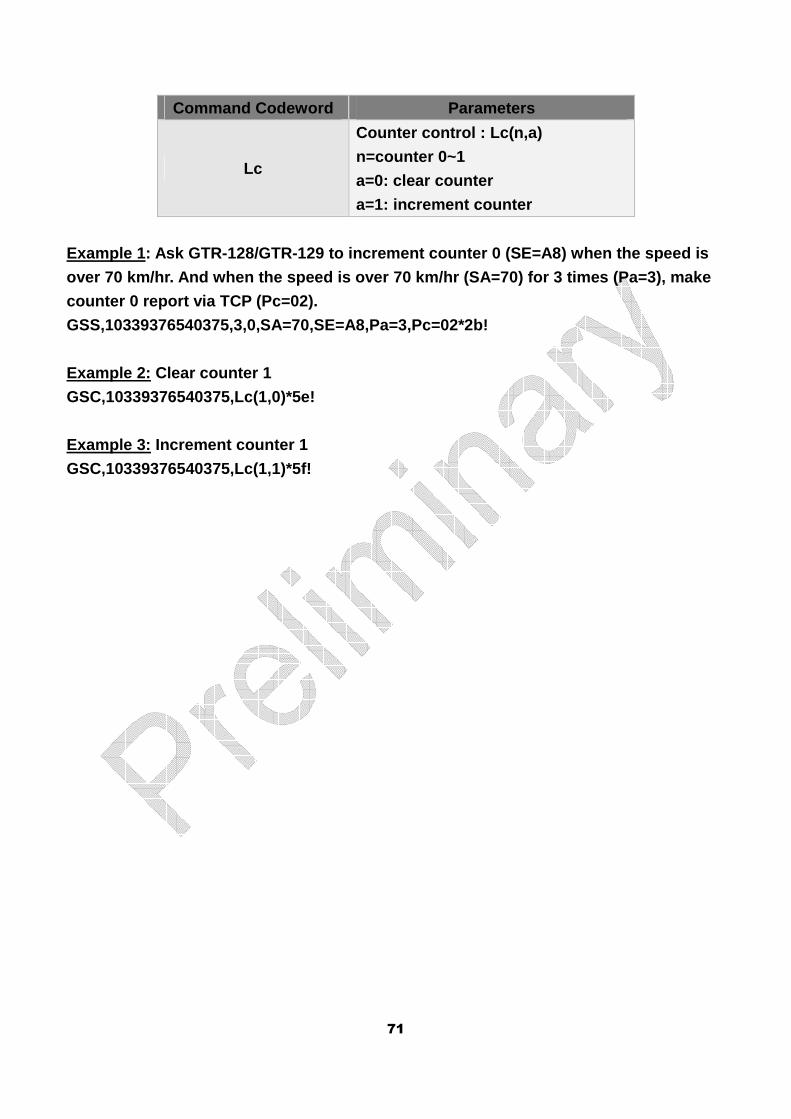
71
Command Codeword Parameters
Lc
Counter control : Lc(n,a)
n=counter 0~1
a=0: clear counter
a=1: increment counter
Example 1: Ask GTR-128/GTR-129 to increment counter 0 (SE=A8) when the speed is
over 70 km/hr. And when the speed is over 70 km/hr (SA=70) for 3 times (Pa=3), make
counter 0 report via TCP (Pc=02).
GSS,10339376540375,3,0,SA=70,SE=A8,Pa=3,Pc=02*2b!
Example 2: Clear counter 1
GSC,10339376540375,Lc(1,0)*5e!
Example 3: Increment counter 1
GSC,10339376540375,Lc(1,1)*5f!
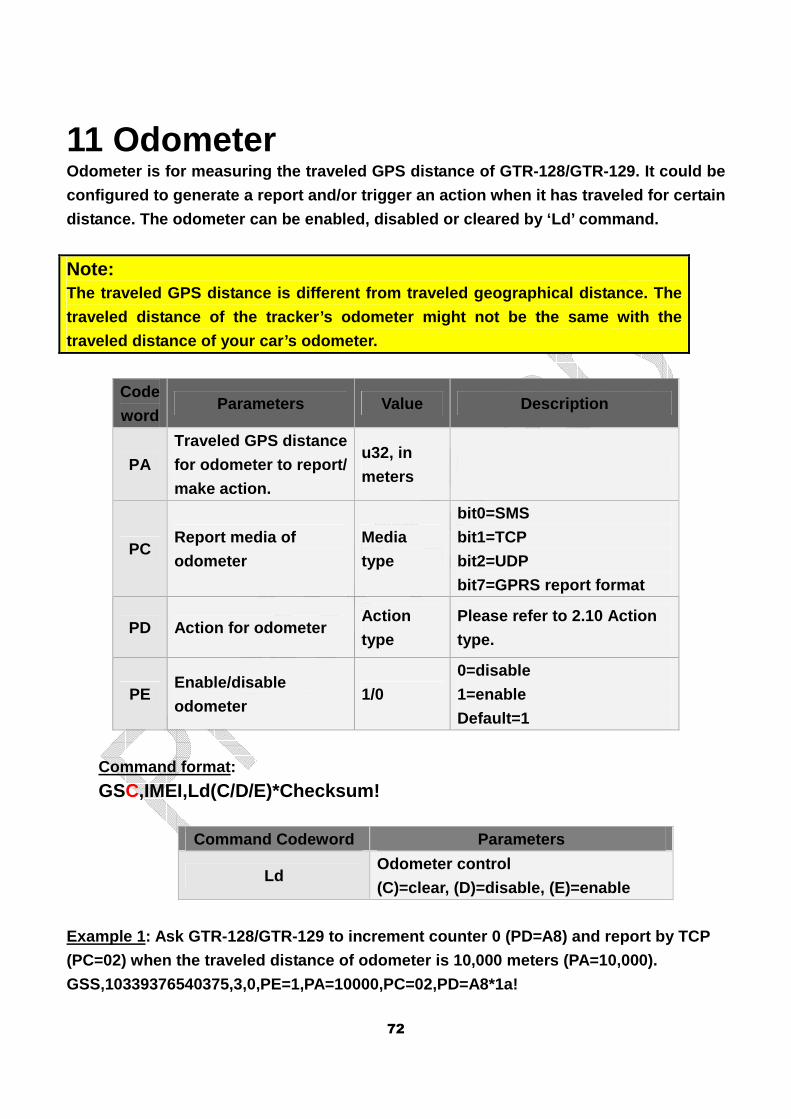
72
11 Odometer Odometer is for measuring the traveled GPS distance of GTR-128/GTR-129. It could be
configured to generate a report and/or trigger an a ction when it has traveled for certain
distance. The odometer can be enabled, disabled or cleared by ‘Ld’ command.
Note: The traveled GPS distance is different from travele d geographical distance. The
traveled distance of the tracker’s odometer might n ot be the same with the
traveled distance of your car’s odometer.
Code
word Parameters Value Description
PA
Traveled GPS distance
for odometer to report/
make action.
u32, in
meters
PC Report media of
odometer
Media
type
bit0=SMS
bit1=TCP
bit2=UDP
bit7=GPRS report format
PD Action for odometer Action
type
Please refer to 2.10 Action
type.
PE Enable/disable
odometer 1/0
0=disable
1=enable
Default=1
Command format:
GSC,IMEI,Ld(C/D/E)*Checksum!
Command Codeword Parameters
Ld Odometer control
(C)=clear, (D)=disable, (E)=enable
Example 1: Ask GTR-128/GTR-129 to increment counter 0 (PD=A8) and report by TCP
(PC=02) when the traveled distance of odometer is 1 0,000 meters (PA=10,000).
GSS,10339376540375,3,0,PE=1,PA=10000,PC=02,PD=A8*1a!

73
Example 2: Clear odometer
GSC,10339376540375,Ld(C)*37!
Example 3: Disable odometer
GSC,10339376540375,Ld(D)*30!
Example 4: Enable odometer
GSC,10339376540375,Ld(E)*31!
74
12 Report Messages
A report is generated by a specific event, such as ping, SOS alarm, digital input
activated, etc. Each event has a corresponding repo rt type and report media.
Please refer to section 2.6 for the mapping of repo rt type. The report media defines
the report channel (TCP/UDP/SMS) and report format.
There are two types of GPRS report format, “format 0” and “format 1”. Typically
format 0 is used for normal report which contains a s much information as possible,
and format 1 is used for heart beat report which co ntains necessary information to
notify the server that the device is working proper ly.
Selection of report format 0/1 is defined in the re port media setting for respective
report condition. Please refer to section “2.9 Repo rt media” for detail.
Format 0 and format 1 are configurable by setting O 3 & ON respectively.
There are three types of SMS messages. The first ty pe is the same as GPRS report
which is not friendly for reading. In order to over come this drawback, you could
choose Google map format or GeoSMS format for easy reading.
12.1 Format 0 of R eport Messages Format 0 report is prefixed by “GSr”. Its content i s configurable by setting
parameter “O3”. Please refer to section 2.6 for the available report parameter and
the respective codeword. Please collect the require d codeword and put them
together to form a string and set to “O3”. Then GTR -128/GTR-129 will generate
report according to the codeword sequence and trans late to corresponding
information.
Parameter’s Codeword Description
O3 Report format 0
(Refer to “2.6. Parameters of Report Messages” for details of parameters’
definition)
Example 1:
75
Set report format 0 by configuration message.
GSS,135785412249986,3,0,O3=TSPRXAB27GHKLMnaicz*U!*4 d!
Then format 0 report will be in the following forma t.
GSr,Device_ID,IMEI,Alarm_status,Report_Type,Variable_f ield,GPS_Fix,UTC_Date,U
TC_Time,Longitude,Latitude,Altitude,Speed,Heading,N umber_of_Satellites,HDOP,
Capacity of battery that presently supplied to
GTR/128/GTR-129,analog_input_value,odometer_value,G SM_signal_strength,cell_I
D*checksum!
For example:
GSr,135785412249986,01,I,EA02,,3,230410,153318,E12129.2839,N2459.8570,0,1.17,
212,8,1.0,12.3V*55!
Example 2:
Ask GTR-128/GTR-129 report “format of format 0” (Se nd command via SMS or TCP
or UDP)
GSC,136647890362718,3,0,L1(O3)*6D!
GTR-128/GTR-129 receives the command and reports th e following message.
GSs,136647890362718,3,0,O3=TSPRXAB27GHKLMnaicz*U!*4 6!
12.2 Format 1 of Report Messages Format 1 report is prefixed by “GSh”. Its content i s configurable by setting
parameter “ON”. Please refer to section 2.6 for the available report parameter and
the respective codeword. Please collect the require d codeword and put them
together to form a string and set to “ON”. Then GTR -128/GTR-129 will generate
report according to the codeword sequence and trans late to corresponding
information.
Parameter’s Codeword Description
ON Report format 1
(Refer to “2.6. Parameters of Report Messages” for details of parameters’
definition)
76
Example 1:
Set GTR-128/GTR-129 format 1 of report by configura tion message.
GSS,131826789036289,3,0,ON=SARY*U!*46!
Then format 1 report will be in the following forma t.
GSh,IMEI,GPS_Fix status,report type,joint I/O status*c hecksum!
For example:
GSh,131826789036289,3,M,ea04*3d!
Example 2:
Ask GTR-128/GTR-129 report “format of format 1” (Se nd command via SMS or TCP
or UDP)
GSC,131826789036289,3,0,L1(ON)*36!
GTR-128/GTR-129 receives the command and reports t he following message
GSs,131826789036289,3,0,ON=SARY*U!*20!
77
12.3 SMS Format Report If the SMS flag of the report media is enabled when GTR-128/GTR-129 is generating
report, a SMS report will be sent to the phone numb er defined by F0. There’re two
types of SMS message. The first one is the same as GPRS messages described in
the above sections. The second type is a configurab le text which is designed for
easy reading. Parameter ‘F2’ is used to control SMS message type.
Code
word Parameters Value Description
F0 SMS return phone number char(20)
F2 SMS format 1 1/0
0=Same as GPRS report
1=Google format
2=GEO SMS
Google Format:
Content Description
Report Type Refer to return text of report type tab le
Date & Time yymmdd hh:mm (24 hour format)
GPS status Not fix, 2D fix, 3D fix
X field Refer to X field table
GSM signal Range=1~30 (the bigger number indicates the
stronger GSM signal)
Speed Default unit: km/h
Battery voltage Unit=mV or percentage (GTR-129 only )
Latitude and Longitude in
Google format
Example:
Pingreport,11072702:48,3Dfix,16,23Km/h,12000mV,http ://maps.google.com/maps?f=q&
hl=en&q=22.540103,114.082329&ie=UTF8&z=16
78
GeoSMS Format:
Content Description
Open GeoSMS format
GeoSMS/ Version
Number;Latitue;Longitude
Report Type Refer to return text of report type tab le
Date & Time yymmdd hh:mm (24 hour format)
GPS status Not fix, 2D fix, 3D fix
X field Refer to X field table
GSM signal Range=1~30 (the bigger number indicates the
stronger GSM signal)
Speed Default unit: km/h
Battery voltage Unit=mV or percentage (GTR-129 only )
Latitude and Longitude in
Example:
GeoSMS/2;2504.8015,N;12133.9766,E;E;Ping report,110 727 02:48,3D fix,16,23,12000mV
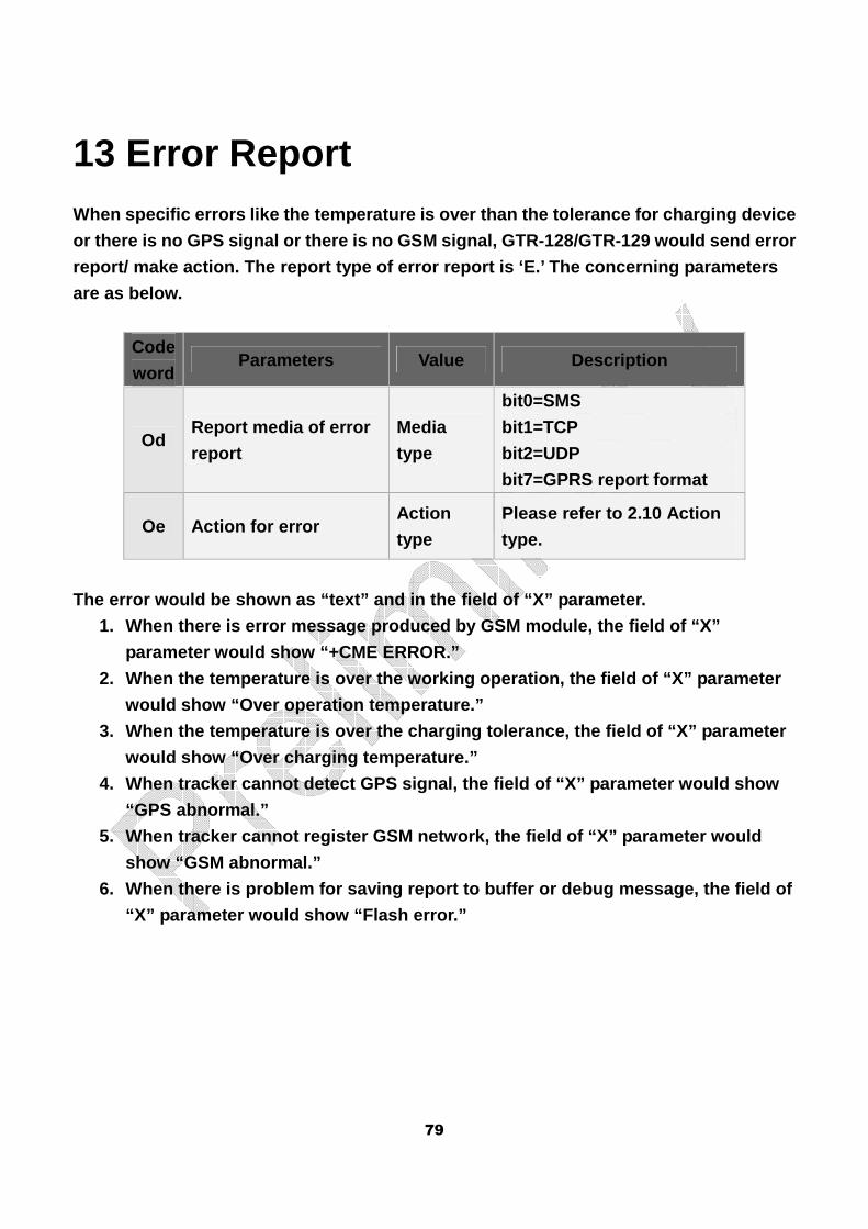
79
13 Error Report
When specific errors like the temperature is over t han the tolerance for charging device
or there is no GPS signal or there is no GSM signal , GTR-128/GTR-129 would send error
report/ make action. The report type of error repor t is ‘E.’ The concerning parameters
are as below.
Code
word Parameters Value Description
Od Report media of error
report
Media
type
bit0=SMS
bit1=TCP
bit2=UDP
bit7=GPRS report format
Oe Action for error Action
type
Please refer to 2.10 Action
type.
The error would be shown as “text” and in the field of “X” parameter.
1. When there is error message produced by GSM modu le, the field of “X”
parameter would show “+CME ERROR.”
2. When the temperature is over the working operati on, the field of “X” parameter
would show “Over operation temperature.”
3. When the temperature is over the charging tolera nce, the field of “X” parameter
would show “Over charging temperature.”
4. When tracker cannot detect GPS signal, the field of “X” parameter would show
“GPS abnormal.”
5. When tracker cannot register GSM network, the fi eld of “X” parameter would
show “GSM abnormal.”
6. When there is problem for saving report to buffe r or debug message, the field of
“X” parameter would show “Flash error.”
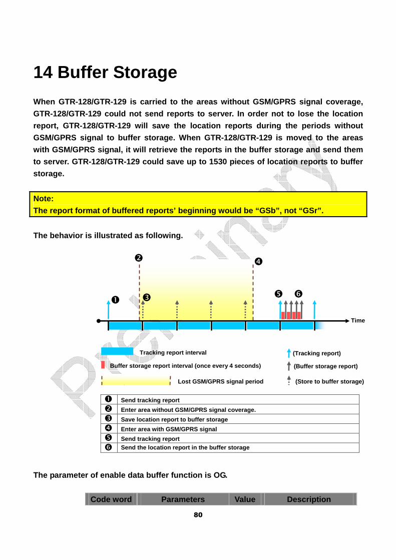
80
14 Buffer Storage
When GTR-128/GTR-129 is carried to the areas withou t GSM/GPRS signal coverage,
GTR-128/GTR-129 could not send reports to server. I n order not to lose the location
report, GTR-128/GTR-129 will save the location repo rts during the periods without
GSM/GPRS signal to buffer storage. When GTR-128/GTR -129 is moved to the areas
with GSM/GPRS signal, it will retrieve the reports in the buffer storage and send them
to server. GTR-128/GTR-129 could save up to 1530 pi eces of location reports to buffer
storage.
Note:
The report format of buffered reports’ beginning wo uld be “GSb”, not “GSr”.
The behavior is illustrated as following.
The parameter of enable data buffer function is OG.
Code word Parameters Value Description
� Send tracking report
� Enter area without GSM/GPRS signal coverage.
� Save location report to buffer storage
� Enter area with GSM/GPRS signal
� Send tracking report
� Send the location report in the buffer storage
Tracking report interval
Buffer storage report interval (once every 4 second s)
(Tracking report)
(Buffer storage report)
Lost GSM/GPRS signal period
Time
�
�
�
�
� �
(Store to buffer storage)
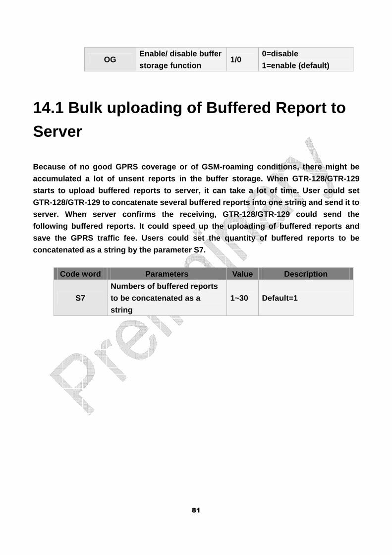
81
OG Enable/ disable buffer
storage function 1/0
0=disable
1=enable (default)
14.1 Bulk uploading of Buffered Report to
Server
Because of no good GPRS coverage or of GSM-roaming conditions, there might be
accumulated a lot of unsent reports in the buffer s torage. When GTR-128/GTR-129
starts to upload buffered reports to server, it can take a lot of time. User could set
GTR-128/GTR-129 to concatenate several buffered rep orts into one string and send it to
server. When server confirms the receiving, GTR-128 /GTR-129 could send the
following buffered reports. It could speed up the u ploading of buffered reports and
save the GPRS traffic fee. Users could set the quan tity of buffered reports to be
concatenated as a string by the parameter S7.
Code word Parameters Value Description
S7
Numbers of buffered reports
to be concatenated as a
string
1~30 Default=1
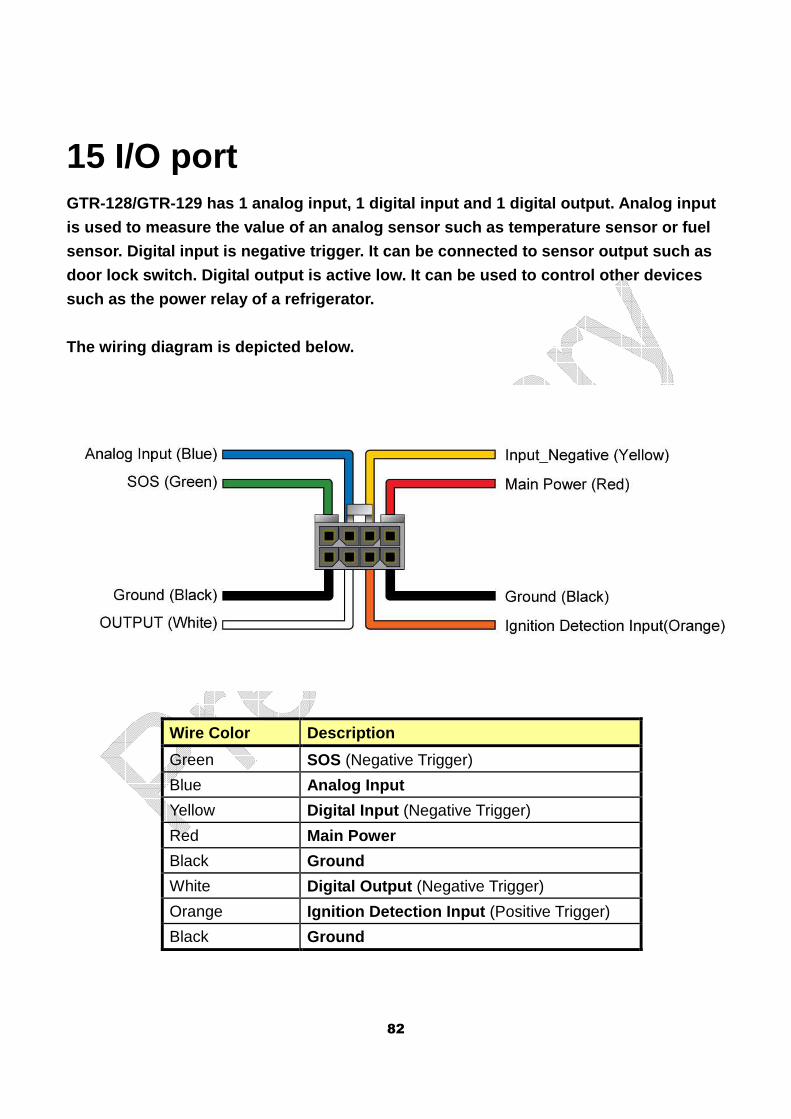
82
15 I/O port GTR-128/GTR-129 has 1 analog input, 1 digital input and 1 digital output. Analog input
is used to measure the value of an analog sensor su ch as temperature sensor or fuel
sensor. Digital input is negative trigger. It can b e connected to sensor output such as
door lock switch. Digital output is active low. It can be used to control other devices
such as the power relay of a refrigerator.
The wiring diagram is depicted below.
Wire Color Description
Green SOS (Negative Trigger)
Blue Analog Input
Yellow Digital Input (Negative Trigger)
Red Main Power
Black Ground
White Digital Output (Negative Trigger)
Orange Ignition Detection Input (Positive Trigger)
Black Ground
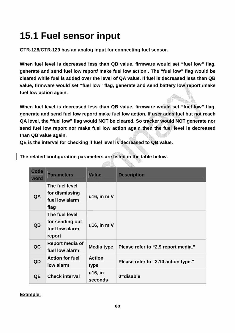
83
15.1 Fuel sensor input GTR-128/GTR-129 has an analog input for connecting fuel sensor.
When fuel level is decreased less than QB value, fi rmware would set “fuel low” flag,
generate and send fuel low report/ make fuel low ac tion . The “fuel low” flag would be
cleared while fuel is added over the level of QA va lue. If fuel is decreased less than QB
value, firmware would set “fuel low” flag, generate and send battery low report /make
fuel low action again.
When fuel level is decreased less than QB value, fi rmware would set “fuel low” flag,
generate and send fuel low report/ make fuel low ac tion. If user adds fuel but not reach
QA level, the “fuel low” flag would NOT be cleared. So tracker would NOT generate nor
send fuel low report nor make fuel low action again then the fuel level is decreased
than QB value again.
QE is the interval for checking if fuel level is de creased to QB value.
The related configuration parameters are listed in the table below.
Code
word Parameters Value Description
QA
The fuel level
for dismissing
fuel low alarm
flag
u16, in m V
QB
The fuel level
for sending out
fuel low alarm
report
u16, in m V
QC Report media of
fuel low alarm Media type Please refer to “2.9 report media.”
QD Action for fuel
low alarm
Action
type Please refer to “2.10 action type.”
QE Check interval u16, in
seconds 0=disable
Example:
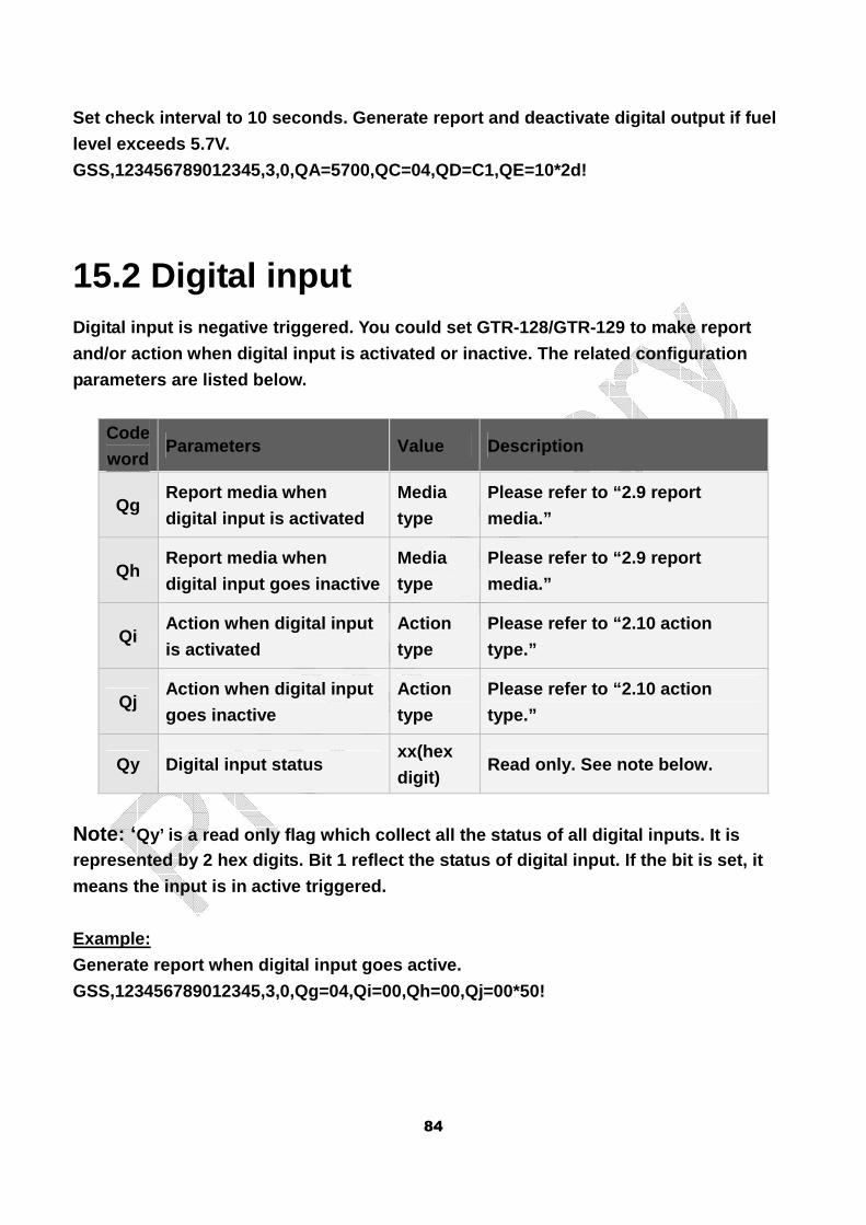
84
Set check interval to 10 seconds. Generate report a nd deactivate digital output if fuel
level exceeds 5.7V.
GSS,123456789012345,3,0,QA=5700,QC=04,QD=C1,QE=10*2d!
15.2 Digital input Digital input is negative triggered. You could set GTR-128/GTR-129 to make report
and/or action when digital input is activated or in active. The related configuration
parameters are listed below.
Code
word Parameters Value Description
Qg Report media when
digital input is activated
Media
type
Please refer to “2.9 report
media.”
Qh Report media when
digital input goes inactive
Media
type
Please refer to “2.9 report
media.”
Qi Action when digital input
is activated
Action
type
Please refer to “2.10 action
type.”
Qj Action when digital input
goes inactive
Action
type
Please refer to “2.10 action
type.”
Qy Digital input status xx(hex
digit) Read only. See note below.
Note: ‘ Qy’ is a read only flag which collect all the statu s of all digital inputs. It is represented by 2 hex digits. Bit 1 reflect the stat us of digital input. If the bit is set, it
means the input is in active triggered.
Example:
Generate report when digital input goes active.
GSS,123456789012345,3,0,Qg=04,Qi=00,Qh=00,Qj=00*50!
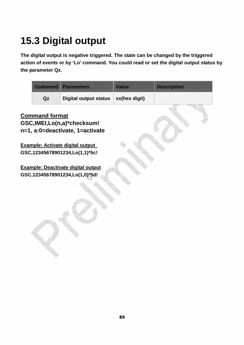
85
15.3 Digital output The digital output is negative triggered. The state can be changed by the triggered
action of events or by ‘Lo’ command. You could read or set the digital output status by
the parameter Qz.
Codeword Parameters Value Description
Qz Digital output status xx(hex digit)
Command format GSC,IMEI,Lo(n,a)*checksum! n=1, a:0=deactivate, 1=activate Example: Activate digital output
GSC,12345678901234,Lo(1,1)*5c!
Example: Deactivate digital output
GSC,12345678901234,Lo(1,0)*5d!
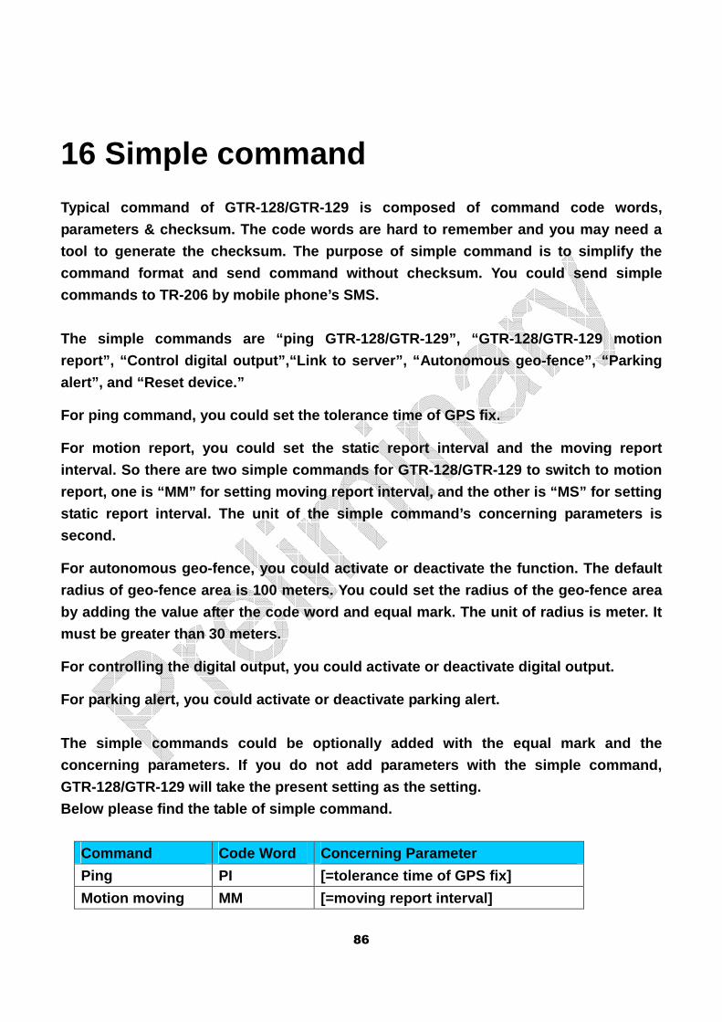
86
16 Simple command
Typical command of GTR-128/GTR-129 is composed of c ommand code words,
parameters & checksum. The code words are hard to r emember and you may need a
tool to generate the checksum. The purpose of simpl e command is to simplify the
command format and send command without checksum. Y ou could send simple
commands to TR-206 by mobile phone’s SMS.
The simple commands are “ping GTR-128/GTR-129”, “GT R-128/GTR-129 motion
report”, “Control digital output”,“Link to server”, “Autonomous geo-fence”, “Parking
alert”, and “Reset device.”
For ping command, you could set the tolerance time of GPS fix.
For motion report, you could set the static report interval and the moving report
interval. So there are two simple commands for GTR- 128/GTR-129 to switch to motion
report, one is “MM” for setting moving report inter val, and the other is “MS” for setting
static report interval. The unit of the simple comm and’s concerning parameters is
second.
For autonomous geo-fence, you could activate or dea ctivate the function. The default
radius of geo-fence area is 100 meters. You could s et the radius of the geo-fence area
by adding the value after the code word and equal m ark. The unit of radius is meter. It
must be greater than 30 meters.
For controlling the digital output, you could activ ate or deactivate digital output.
For parking alert, you could activate or deactivate parking alert.
The simple commands could be optionally added with the equal mark and the
concerning parameters. If you do not add parameters with the simple command,
GTR-128/GTR-129 will take the present setting as th e setting.
Below please find the table of simple command.
Command Code Word Concerning Parameter
Ping PI [=tolerance time of GPS fix]
Motion moving MM [=moving report interval]
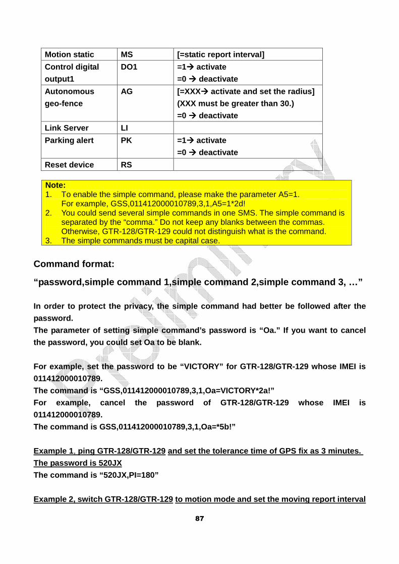
87
Note: 1. To enable the simple command, please make the parameter A5=1.
For example, GSS,011412000010789,3,1,A5=1*2d! 2. You could send several simple commands in one SMS. The simple command is
separated by the “comma.” Do not keep any blanks between the commas. Otherwise, GTR-128/GTR-129 could not distinguish what is the command.
3. The simple commands must be capital case.
Command format:
“password,simple command 1,simple command 2,simple command 3, …”
In order to protect the privacy, the simple command had better be followed after the
password.
The parameter of setting simple command’s password is “Oa.” If you want to cancel
the password, you could set Oa to be blank.
For example, set the password to be “VICTORY” for G TR-128/GTR-129 whose IMEI is
011412000010789.
The command is “GSS,011412000010789,3,1,Oa=VICTORY* 2a!”
For example, cancel the password of GTR-128/GTR-129 whose IMEI is
011412000010789.
The command is GSS,011412000010789,3,1,Oa=*5b!”
Example 1 , ping GTR-128/GTR-129 and set the tolerance time of GPS fix as 3 minutes.
The password is 520JX
The command is “520JX,PI=180”
Example 2, switch GTR-128/GTR-129 to motion mode an d set the moving report interval
Motion static MS [=static report interval]
Control digital
output1
DO1
=1���� activate
=0 ���� deactivate
Autonomous
geo-fence
AG [=XXX���� activate and set the radius]
(XXX must be greater than 30.)
=0 ���� deactivate
Link Server LI
Parking alert PK =1 ���� activate
=0 ���� deactivate
Reset device RS
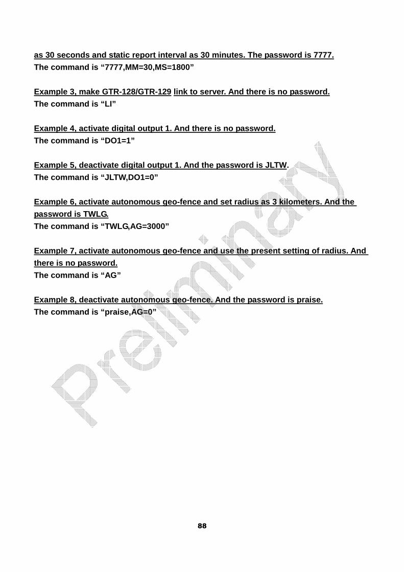
88
as 30 seconds and static report interval as 30 minu tes. The password is 7777.
The command is “7777,MM=30,MS=1800”
Example 3, make GTR-128/GTR-129 link to server. And there is no password.
The command is “LI”
Example 4, activate digital output 1. And there is no password.
The command is “DO1=1”
Example 5, deactivate digital output 1. And the pas sword is JLTW.
The command is “JLTW,DO1=0”
Example 6, activate autonomous geo-fence and set ra dius as 3 kilometers. And the
password is TWLG.
The command is “TWLG,AG=3000”
Example 7, activate autonomous geo-fence and use th e present setting of radius. And
there is no password.
The command is “AG”
Example 8, deactivate autonomous geo-fence. And the password is praise.
The command is “praise,AG=0”
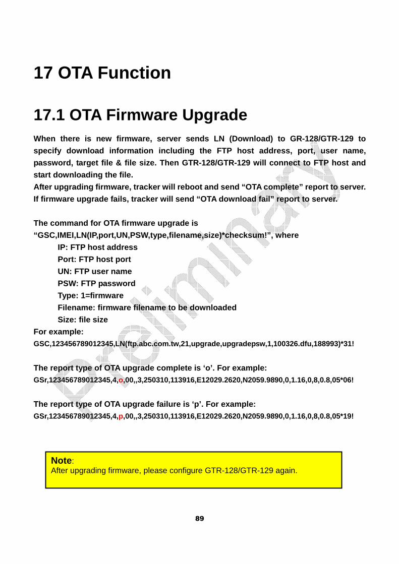
89
17 OTA Function
17.1 OTA Firmware Upgrade When there is new firmware, server sends LN (Downlo ad) to GR-128/GTR-129 to
specify download information including the FTP host address, port, user name,
password, target file & file size. Then GTR-128/GTR -129 will connect to FTP host and
start downloading the file.
After upgrading firmware, tracker will reboot and s end “OTA complete” report to server.
If firmware upgrade fails, tracker will send “OTA d ownload fail” report to server.
The command for OTA firmware upgrade is
“GSC,IMEI,LN(IP,port,UN,PSW,type,filename,size)*che cksum!”, where
IP: FTP host address
Port: FTP host port
UN: FTP user name
PSW: FTP password
Type: 1=firmware
Filename: firmware filename to be downloaded
Size: file size
For example: GSC,123456789012345,LN(ftp.abc.com.tw,21,upgrade,up gradepsw,1,100326.dfu,188993)*31!
The report type of OTA upgrade complete is ‘o’. For example: GSr,123456789012345,4,o,00,,3,250310,113916,E12029.2620,N2059.9890,0,1.16,0,8,0.8,05*06!
The report type of OTA upgrade failure is ‘p’. For example: GSr,123456789012345,4,p,00,,3,250310,113916,E12029.2620,N2059.9890,0,1.16,0,8,0.8,05*19!
Note : After upgrading firmware, please configure GTR-128/GTR-129 again.
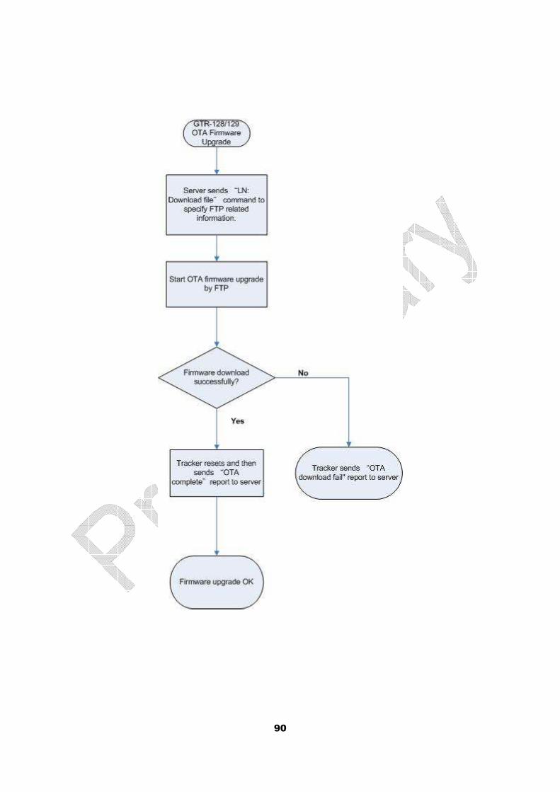
90
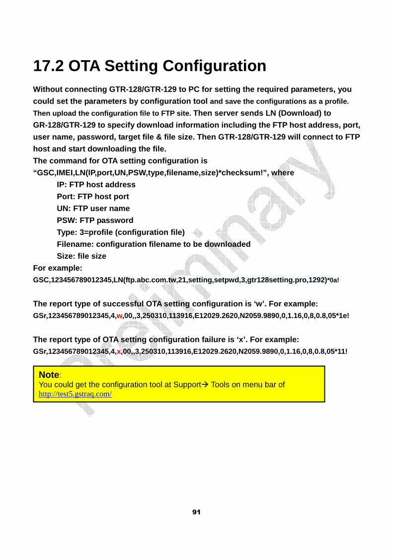
91
17.2 OTA Setting Configuration Without connecting GTR-128/GTR-129 to PC for settin g the required parameters, you
could set the parameters by configuration tool and save the configurations as a profile.
Then upload the configuration file to FTP site. Then server sends LN (Download) to
GR-128/GTR-129 to specify download information incl uding the FTP host address, port,
user name, password, target file & file size. Then GTR-128/GTR-129 will connect to FTP
host and start downloading the file.
The command for OTA setting configuration is
“GSC,IMEI,LN(IP,port,UN,PSW,type,filename,size)*che cksum!”, where
IP: FTP host address
Port: FTP host port
UN: FTP user name
PSW: FTP password
Type: 3=profile (configuration file)
Filename: configuration filename to be downloaded
Size: file size
For example: GSC,123456789012345,LN(ftp.abc.com.tw,21,setting,se tpwd,3,gtr128setting.pro,1292) *0a!
The report type of successful OTA setting configura tion is ‘w’. For example: GSr,123456789012345,4,w,00,,3,250310,113916,E12029.2620,N2059.9890,0,1.16,0,8,0.8,05*1e!
The report type of OTA setting configuration failur e is ‘x’. For example: GSr,123456789012345,4,x,00,,3,250310,113916,E12029.2620,N2059.9890,0,1.16,0,8,0.8,05*11!
Note : You could get the configuration tool at Support� Tools on menu bar of http://test5.gstraq.com/
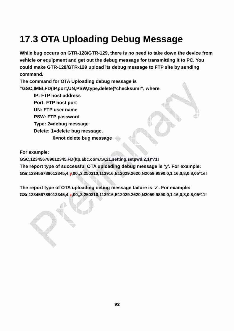
92
17.3 OTA Uploading Debug Message While bug occurs on GTR-128/GTR-129, there is no ne ed to take down the device from
vehicle or equipment and get out the debug message for transmitting it to PC. You
could make GTR-128/GTR-129 upload its debug message to FTP site by sending
command.
The command for OTA Uploading debug message is
“GSC,IMEI,FD(IP,port,UN,PSW,type,delete)*checksum!” , where
IP: FTP host address
Port: FTP host port
UN: FTP user name
PSW: FTP password
Type: 2=debug message
Delete: 1=delete bug message,
0=not delete bug message
For example: GSC,123456789012345,FD(ftp.abc.com.tw,21,setting,se tpwd,2,1)*71!
The report type of successful OTA uploading debug m essage is ‘y’. For example: GSr,123456789012345,4,y,00,,3,250310,113916,E12029.2620,N2059.9890,0,1.16,0,8,0.8,05*1e!
The report type of OTA uploading debug message fail ure is ‘z’. For example: GSr,123456789012345,4,z,00,,3,250310,113916,E12029.2620,N2059.9890,0,1.16,0,8,0.8,05*11!


![Chausseestraße 128/129 — 10115 Berlin — +49 /21 /22 /fax ... · neuer.berliner.kunstverein. e.V. Chausseestraße 128/129 — 10115 Berlin — +49 [0]30 280 70 20 /21 /22 /fax](https://img.pdfslide.net/doc/110x75/5fab6ace30e78868944c5d8e/chausseestrae-128129-a-10115-berlin-a-49-21-22-fax-neuerberlinerkunstverein.jpg)