Embed Size (px)
DESCRIPTION
article
Citation preview
G u i d e t o R e g u l a t o r s
2
T a b l e o f C o n t e n t s
S e c t i o n 1
R e g u l a t o r P r i m e r . . . . . . . . . . . . . . . . . . . 3
S e c t i o n 2
MAT H E S O N ’ s P r o d u c t L i n e . . . . . . . . . . . . . 7
S e c t i o n 3
R e g u l a t o r O p t i o n s a n d A c c e s s o r i e s . . . . . . 1 3
S e c t i o n 4
U s i n g Yo u r R e g u l a t o r . . . . . . . . . . . . . . . 1 5
S e c t i o n 5
P e r f o r m a n c e E v a l u a t i o n a n d
T r o u b l e S h o o t i n g . . . . . . . . . . . . . . . . . . 1 7
S e c t i o n 6
G l o s s a r y o f R e g u l a t o r Te r m s . . . . . . . . . . 1 9
3
I n t r o d u c t i o n
Choosing the right regulator for yourapplication is critical – and often difficult.Product application, gas service, and requireddelivery pressure all influence regulatorselection. At MATHESON, we understandgases, and we understand the importance ofusing the appropriate equipment for each gas.MATHESON’s Guide to Regulators is avaluable tool that will help you pick the rightproduct for your application, and get themost reliable results.
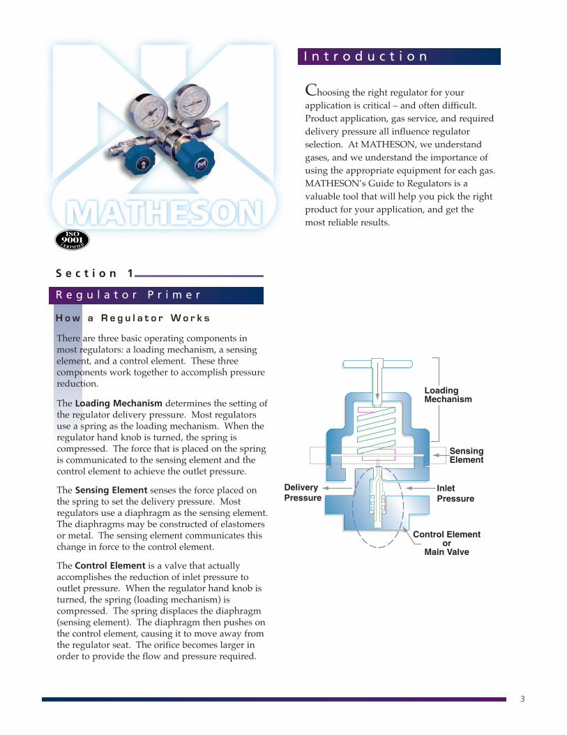
There are three basic operating components inmost regulators: a loading mechanism, a sensingelement, and a control element. These threecomponents work together to accomplish pressurereduction.
The Loading Mechanism determines the setting ofthe regulator delivery pressure. Most regulatorsuse a spring as the loading mechanism. When theregulator hand knob is turned, the spring iscompressed. The force that is placed on the springis communicated to the sensing element and thecontrol element to achieve the outlet pressure.
The Sensing Element senses the force placed onthe spring to set the delivery pressure. Mostregulators use a diaphragm as the sensing element.The diaphragms may be constructed of elastomersor metal. The sensing element communicates thischange in force to the control element.
The Control Element is a valve that actuallyaccomplishes the reduction of inlet pressure tooutlet pressure. When the regulator hand knob isturned, the spring (loading mechanism) iscompressed. The spring displaces the diaphragm(sensing element). The diaphragm then pushes onthe control element, causing it to move away fromthe regulator seat. The orifice becomes larger inorder to provide the flow and pressure required.
S e c t i o n 1
R e g u l a t o r P r i m e r
H o w a R e g u l a t o r Wo r k s
4
What makes a high purity regulatorhigh purity?
High purity applications requireequipment that will help maintain thepurity of the system. High purityapplications are sensitive tocontamination from elements such asmoisture, oxygen, and other gaseousvapors that may be present in ambientair. These contaminants enter the systemwhen the regulator is removed from thecylinder during cylinder changeout, orthey may enter through leaks or faultyseals.
The features of a regulator determine thetype of service for which it can be used.A regulator intended for a high purityapplication has different features than aunit designed for general purpose use.Three main features determine thesuitability of a regulator for high purityapplications.
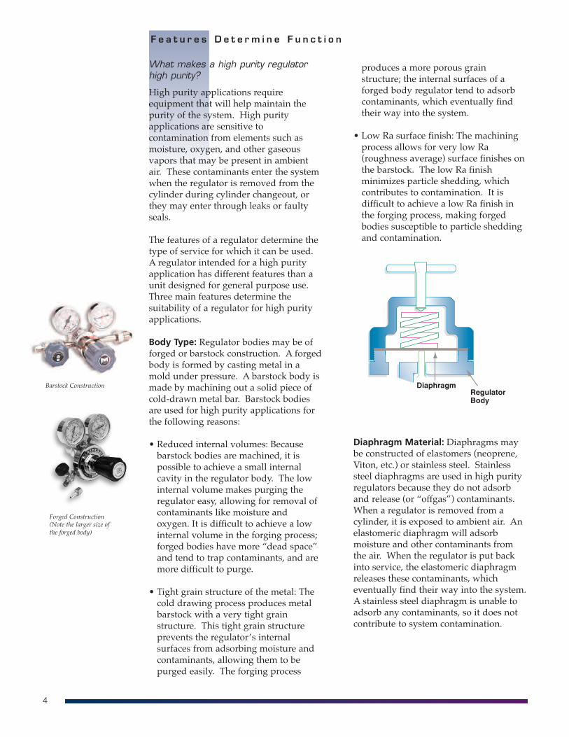
Body Type: Regulator bodies may be offorged or barstock construction. A forgedbody is formed by casting metal in amold under pressure. A barstock body ismade by machining out a solid piece ofcold-drawn metal bar. Barstock bodiesare used for high purity applications forthe following reasons:
• Reduced internal volumes: Becausebarstock bodies are machined, it ispossible to achieve a small internalcavity in the regulator body. The lowinternal volume makes purging theregulator easy, allowing for removal ofcontaminants like moisture andoxygen. It is difficult to achieve a lowinternal volume in the forging process;forged bodies have more “dead space”and tend to trap contaminants, and aremore difficult to purge.
• Tight grain structure of the metal: Thecold drawing process produces metalbarstock with a very tight grainstructure. This tight grain structureprevents the regulator’s internalsurfaces from adsorbing moisture andcontaminants, allowing them to bepurged easily. The forging process
F e a t u r e s D e t e r m i n e F u n c t i o n
Barstock Construction
Forged Construction(Note the larger size of the forged body)
produces a more porous grainstructure; the internal surfaces of aforged body regulator tend to adsorbcontaminants, which eventually findtheir way into the system.
• Low Ra surface finish: The machiningprocess allows for very low Ra(roughness average) surface finishes onthe barstock. The low Ra finishminimizes particle shedding, whichcontributes to contamination. It isdifficult to achieve a low Ra finish inthe forging process, making forgedbodies susceptible to particle sheddingand contamination.
Diaphragm Material: Diaphragms maybe constructed of elastomers (neoprene,Viton, etc.) or stainless steel. Stainlesssteel diaphragms are used in high purityregulators because they do not adsorband release (or “offgas”) contaminants.When a regulator is removed from acylinder, it is exposed to ambient air. Anelastomeric diaphragm will adsorbmoisture and other contaminants fromthe air. When the regulator is put backinto service, the elastomeric diaphragmreleases these contaminants, whicheventually find their way into the system.A stainless steel diaphragm is unable toadsorb any contaminants, so it does notcontribute to system contamination.
5
F e a t u r e s I n f l u e n c e C o s t
Type of Seals: The seal between the bodyof the regulator and the diaphragm isimportant in maintaining purity. A poorseal creates a leakage point throughwhich contaminants may enter thesystem. A metal to metal seal (metalregulator body sealing to a metaldiaphragm) is the most reliable, leak-freetype of seal. An elastomeric diaphragmcan degrade over time, compromising theintegrity of this seal. Some regulatordesigns incorporate a stainless steeldiaphragm that may be lined with anelastomer. Although the diaphragm isstainless steel, the seal is created betweenthe regulator body and the elastomericliner. Since the elastomeric liner maydegrade, this seal is not as reliable as ametal to metal seal. Like an elastomericdiaphragm, the elastomeric liner mayalso adsorb and release contaminantsinto the system.
A regulator designed for high purityapplications is more costly than aregulator intended for general purposeuse. Barstock bodies are more costly toproduce than forged bodies due to thehigh amount of machining involved.Stainless steel is a more expensivediaphragm material than elastomers. It isimportant to remember that not allregulators are created equal when itcomes to features.
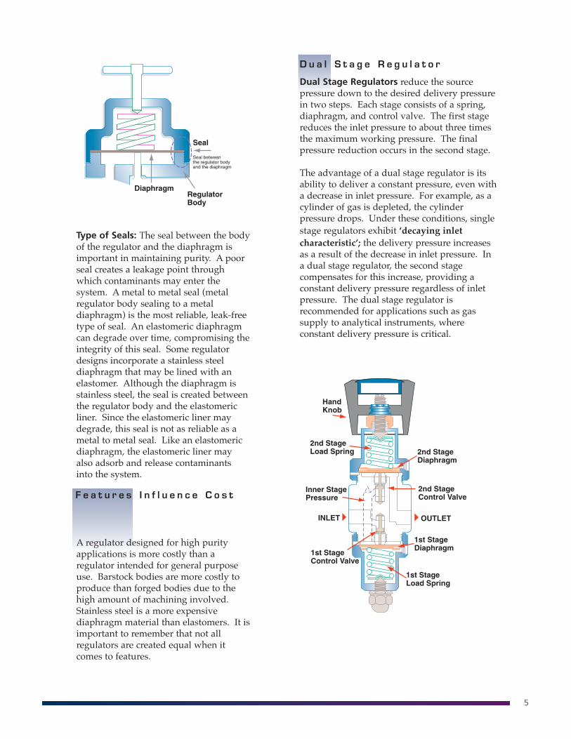
D u a l S t a g e R e g u l a t o r
Dual Stage Regulators reduce the sourcepressure down to the desired delivery pressurein two steps. Each stage consists of a spring,diaphragm, and control valve. The first stagereduces the inlet pressure to about three timesthe maximum working pressure. The finalpressure reduction occurs in the second stage.
The advantage of a dual stage regulator is itsability to deliver a constant pressure, even witha decrease in inlet pressure. For example, as acylinder of gas is depleted, the cylinderpressure drops. Under these conditions, singlestage regulators exhibit ‘decaying inletcharacteristic’; the delivery pressure increasesas a result of the decrease in inlet pressure. Ina dual stage regulator, the second stagecompensates for this increase, providing aconstant delivery pressure regardless of inletpressure. The dual stage regulator isrecommended for applications such as gassupply to analytical instruments, whereconstant delivery pressure is critical.
6
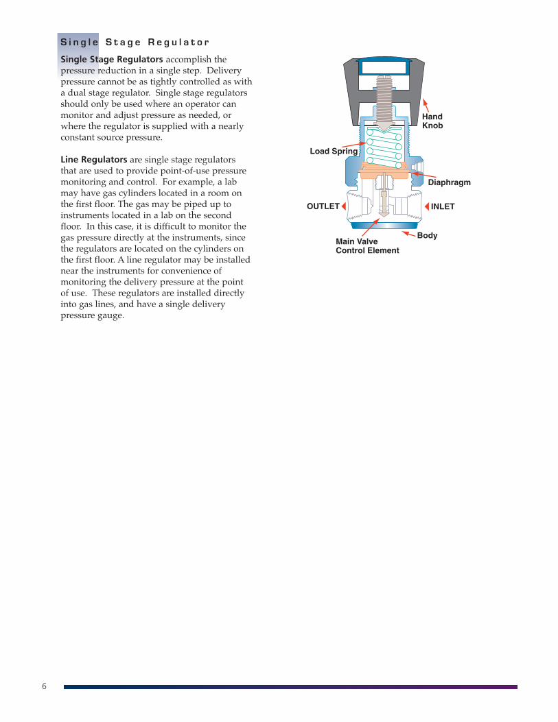
S i n g l e S t a g e R e g u l a t o r
Single Stage Regulators accomplish thepressure reduction in a single step. Deliverypressure cannot be as tightly controlled as witha dual stage regulator. Single stage regulatorsshould only be used where an operator canmonitor and adjust pressure as needed, orwhere the regulator is supplied with a nearlyconstant source pressure.
Line Regulators are single stage regulatorsthat are used to provide point-of-use pressuremonitoring and control. For example, a labmay have gas cylinders located in a room onthe first floor. The gas may be piped up toinstruments located in a lab on the secondfloor. In this case, it is difficult to monitor thegas pressure directly at the instruments, sincethe regulators are located on the cylinders onthe first floor. A line regulator may be installednear the instruments for convenience ofmonitoring the delivery pressure at the pointof use. These regulators are installed directlyinto gas lines, and have a single deliverypressure gauge.
7
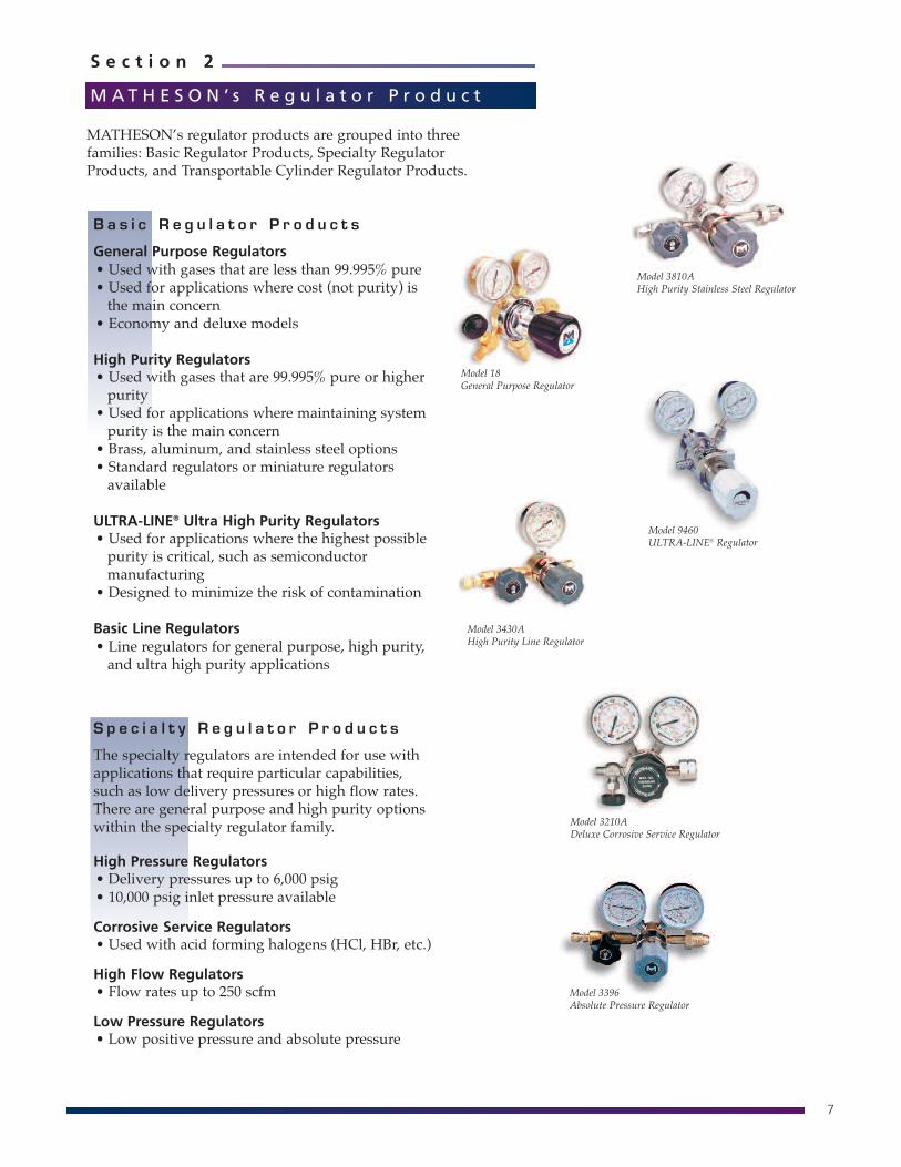
B a s i c R e g u l a t o r P r o d u c t s
General Purpose Regulators• Used with gases that are less than 99.995% pure• Used for applications where cost (not purity) isthe main concern
• Economy and deluxe models
High Purity Regulators• Used with gases that are 99.995% pure or higherpurity
• Used for applications where maintaining systempurity is the main concern
• Brass, aluminum, and stainless steel options• Standard regulators or miniature regulatorsavailable
ULTRA-LINE® Ultra High Purity Regulators• Used for applications where the highest possiblepurity is critical, such as semiconductormanufacturing
• Designed to minimize the risk of contamination
Basic Line Regulators• Line regulators for general purpose, high purity,and ultra high purity applications
S p e c i a l t y R e g u l a t o r P r o d u c t s
The specialty regulators are intended for use withapplications that require particular capabilities,such as low delivery pressures or high flow rates.There are general purpose and high purity optionswithin the specialty regulator family.
High Pressure Regulators• Delivery pressures up to 6,000 psig• 10,000 psig inlet pressure available
Corrosive Service Regulators• Used with acid forming halogens (HCl, HBr, etc.)
High Flow Regulators• Flow rates up to 250 scfm
Low Pressure Regulators• Low positive pressure and absolute pressure
S e c t i o n 2
M AT H E S O N ’ s R e g u l a t o r P r o d u c tL i n e
Model 18General Purpose Regulator
Model 3810AHigh Purity Stainless Steel Regulator
Model 9460ULTRA-LINE® Regulator
Model 3430AHigh Purity Line Regulator
MATHESON’s regulator products are grouped into threefamilies: Basic Regulator Products, Specialty RegulatorProducts, and Transportable Cylinder Regulator Products.
Model 3210ADeluxe Corrosive Service Regulator
Model 3396Absolute Pressure Regulator
8
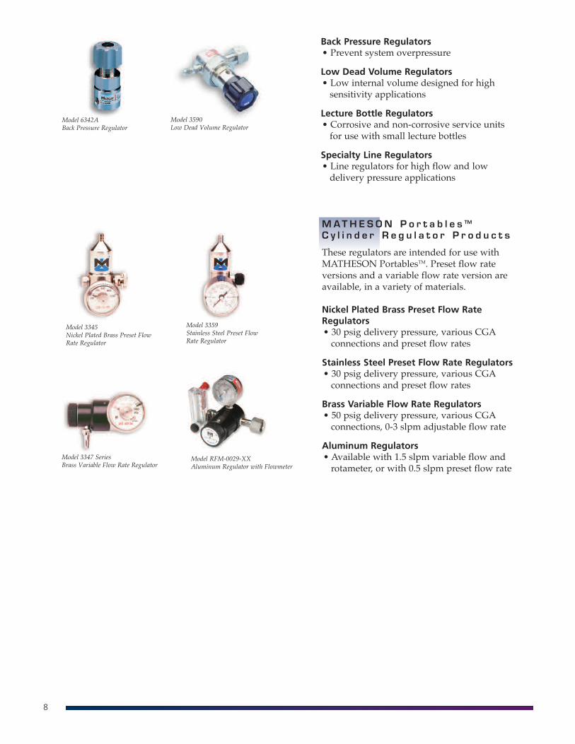
MAT H E S O N P o r t a b l e s TM
C y l i n d e r R e g u l a t o r P r o d u c t s
These regulators are intended for use withMATHESON PortablesTM. Preset flow rateversions and a variable flow rate version areavailable, in a variety of materials.
Nickel Plated Brass Preset Flow RateRegulators• 30 psig delivery pressure, various CGAconnections and preset flow rates
Stainless Steel Preset Flow Rate Regulators• 30 psig delivery pressure, various CGAconnections and preset flow rates
Brass Variable Flow Rate Regulators• 50 psig delivery pressure, various CGAconnections, 0-3 slpm adjustable flow rate
Aluminum Regulators• Available with 1.5 slpm variable flow androtameter, or with 0.5 slpm preset flow rate
Model 3345Nickel Plated Brass Preset FlowRate Regulator
Model 3359Stainless Steel Preset FlowRate Regulator
Model 3347 SeriesBrass Variable Flow Rate Regulator
Model RFM-0029-XXAluminum Regulator with Flowmeter
Back Pressure Regulators• Prevent system overpressure
Low Dead Volume Regulators• Low internal volume designed for highsensitivity applications
Lecture Bottle Regulators• Corrosive and non-corrosive service unitsfor use with small lecture bottles
Specialty Line Regulators• Line regulators for high flow and lowdelivery pressure applications
Model 3590Low Dead Volume Regulator
Model 6342ABack Pressure Regulator
9
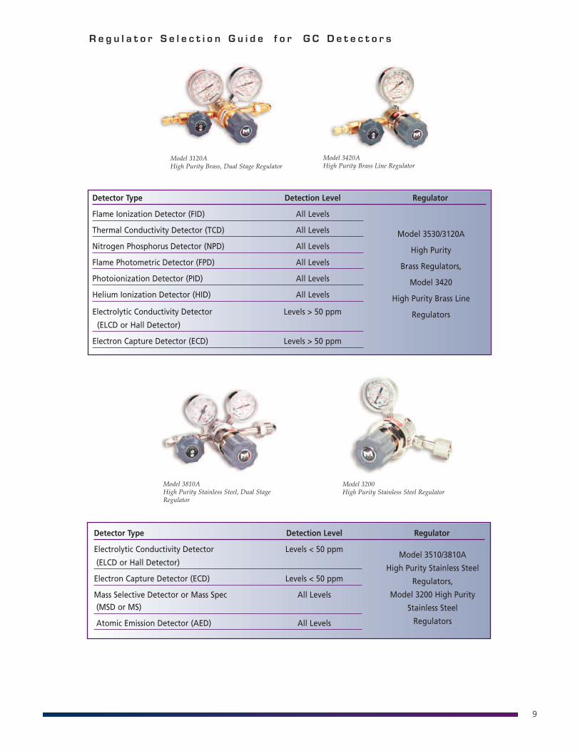
Detector Type Detection Level Regulator
Flame Ionization Detector (FID) All Levels
Thermal Conductivity Detector (TCD) All Levels
Nitrogen Phosphorus Detector (NPD) All Levels
Flame Photometric Detector (FPD) All Levels
Photoionization Detector (PID) All Levels
Helium Ionization Detector (HID) All Levels
Electrolytic Conductivity Detector Levels > 50 ppm
(ELCD or Hall Detector)
Electron Capture Detector (ECD) Levels > 50 ppm
R e g u l a t o r S e l e c t i o n G u i d e f o r G C D e t e c t o r s
Model 3530/3120A
High Purity
Brass Regulators,
Model 3420
High Purity Brass Line
Regulators
Detector Type Detection Level Regulator
Electrolytic Conductivity Detector Levels < 50 ppm
(ELCD or Hall Detector)
Electron Capture Detector (ECD) Levels < 50 ppm
Mass Selective Detector or Mass Spec All Levels(MSD or MS)
Atomic Emission Detector (AED) All Levels
Model 3510/3810A
High Purity Stainless Steel
Regulators,
Model 3200 High Purity
Stainless Steel
Regulators
Model 3120AHigh Purity Brass, Dual Stage Regulator
Model 3420AHigh Purity Brass Line Regulator
Model 3810AHigh Purity Stainless Steel, Dual StageRegulator
Model 3200High Purity Stainless Steel Regulator
10
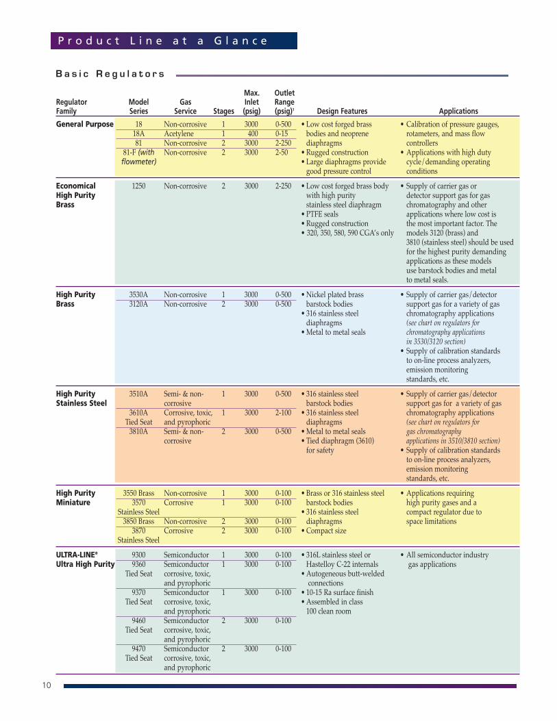
P r o d u c t L i n e a t a G l a n c e
B a s i c R e g u l a t o r s
Max. OutletRegulator Model Gas Inlet RangeFamily Series Service Stages (psig) (psig)1 Design Features Applications
General Purpose 18 Non-corrosive 1 3000 0-500 • Low cost forged brass • Calibration of pressure gauges, 18A Acetylene 1 400 0-15 bodies and neoprene rotameters, and mass flow 81 Non-corrosive 2 3000 2-250 diaphragms controllers
81-F (with Non-corrosive 2 3000 2-50 • Rugged construction • Applications with high duty flowmeter) • Large diaphragms provide cycle/demanding operating
good pressure control conditions
Economical 1250 Non-corrosive 2 3000 2-250 • Low cost forged brass body • Supply of carrier gas or High Purity with high purity detector support gas for gas Brass stainless steel diaphragm chromatography and other
• PTFE seals applications where low cost is• Rugged construction the most important factor. The• 320, 350, 580, 590 CGA’s only models 3120 (brass) and
3810 (stainless steel) should be usedfor the highest purity demandingapplications as these modelsuse barstock bodies and metalto metal seals.
High Purity 3530A Non-corrosive 1 3000 0-500 •Nickel plated brass • Supply of carrier gas/detectorBrass 3120A Non-corrosive 2 3000 0-500 barstock bodies support gas for a variety of gas
• 316 stainless steel chromatography applications diaphragms (see chart on regulators for
•Metal to metal seals chromatography applicationsin 3530/3120 section)
• Supply of calibration standardsto on-line process analyzers,emission monitoring standards, etc.
High Purity 3510A Semi- & non- 1 3000 0-500 • 316 stainless steel • Supply of carrier gas/detectorStainless Steel corrosive barstock bodies support gas for a variety of gas
3610A Corrosive, toxic, 1 3000 2-100 • 316 stainless steel chromatography applicationsTied Seat and pyrophoric diaphragms (see chart on regulators for3810A Semi- & non- 2 3000 0-500 •Metal to metal seals gas chromatography
corrosive • Tied diaphragm (3610) applications in 3510/3810 section)for safety • Supply of calibration standards
to on-line process analyzers,emission monitoring standards, etc.
High Purity 3550 Brass Non-corrosive 1 3000 0-100 • Brass or 316 stainless steel • Applications requiring Miniature 3570 Corrosive 1 3000 0-100 barstock bodies high purity gases and a
Stainless Steel • 316 stainless steel compact regulator due to3850 Brass Non-corrosive 2 3000 0-100 diaphragms space limitations3870 Corrosive 2 3000 0-100 • Compact size
Stainless Steel
ULTRA-LINE® 9300 Semiconductor 1 3000 0-100 • 316L stainless steel or • All semiconductor industryUltra High Purity 9360 Semiconductor 1 3000 0-100 Hastelloy C-22 internals gas applications
Tied Seat corrosive, toxic, • Autogeneous butt-weldedand pyrophoric connections
9370 Semiconductor 1 3000 0-100 • 10-15 Ra surface finishTied Seat corrosive, toxic, • Assembled in class
and pyrophoric 100 clean room9460 Semiconductor 2 3000 0-100
Tied Seat corrosive, toxic,and pyrophoric
9470 Semiconductor 2 3000 0-100Tied Seat corrosive, toxic,
and pyrophoric
11
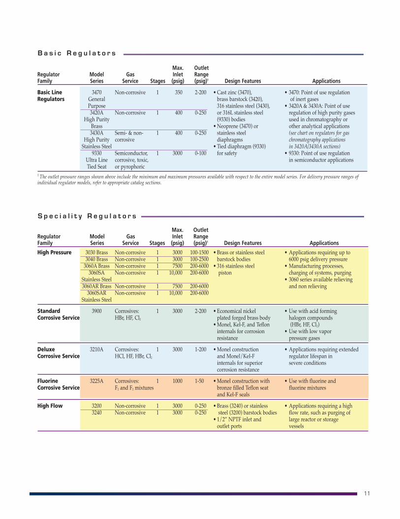
B a s i c R e g u l a t o r s
Max. OutletRegulator Model Gas Inlet RangeFamily Series Service Stages (psig) (psig)1 Design Features Applications
Basic Line 3470 Non-corrosive 1 350 2-200 • Cast zinc (3470), • 3470: Point of use regulationRegulators General brass barstock (3420), of inert gases
Purpose 316 stainless steel (3430), • 3420A & 3430A: Point of use 3420A Non-corrosive 1 400 0-250 or 316L stainless steel regulation of high purity gases
High Purity (9330) bodies used in chromatography orBrass •Neoprene (3470) or other analytical applications3430A Semi- & non- 1 400 0-250 stainless steel (see chart on regulators for gas
High Purity corrosive diaphragms chromatography applicationsStainless Steel • Tied diaphragm (9330) in 3420A/3430A sections)
9330 Semiconductor, 1 3000 0-100 for safety • 9330: Point of use regulationUltra Line corrosive, toxic, in semiconductor applicationsTied Seat or pyrophoric
1 The outlet pressure ranges shown above include the minimum and maximum pressures available with respect to the entire model series. For delivery pressure ranges ofindividual regulator models, refer to appropriate catalog sections.
S p e c i a l i t y R e g u l a t o r s
Max. OutletRegulator Model Gas Inlet RangeFamily Series Service Stages (psig) (psig)1 Design Features Applications
High Pressure 3030 Brass Non-corrosive 1 3000 100-1500 • Brass or stainless steel • Applications requiring up to3040 Brass Non-corrosive 1 3000 100-2500 barstock bodies 6000 psig delivery pressure3060A Brass Non-corrosive 1 7500 200-6000 • 316 stainless steel • Manufacturing processes, 3060SA Non-corrosive 1 10,000 200-6000 piston charging of systems, purging
Stainless Steel • 3060 series available relieving3060AR Brass Non-corrosive 1 7500 200-6000 and non relieving3060SAR Non-corrosive 1 10,000 200-6000
Stainless Steel
Standard 3900 Corrosives: 1 3000 2-200 • Economical nickel • Use with acid forming Corrosive Service HBr, HF, Cl2 plated forged brass body halogen compounds
•Monel, Kel-F, and Teflon (HBr, HF, Cl2)internals for corrosion • Use with low vapor resistance pressure gases
Deluxe 3210A Corrosives: 1 3000 1-200 •Monel construction • Applications requiring extendedCorrosive Service HCl, HF, HBr, Cl2 and Monel/Kel-F regulator lifespan in
internals for superior severe conditionscorrosion resistance
Fluorine 3225A Corrosives: 1 1000 1-50 •Monel construction with • Use with fluorine andCorrosive Service F2 and F2 mixtures bronze filled Teflon seat fluorine mixtures
and Kel-F seals
High Flow 3200 Non-corrosive 1 3000 0-250 • Brass (3240) or stainless • Applications requiring a high3240 Non-corrosive 1 3000 0-250 steel (3200) barstock bodies flow rate, such as purging of
• 1/2” NPTF inlet and large reactor or storageoutlet ports vessels
12
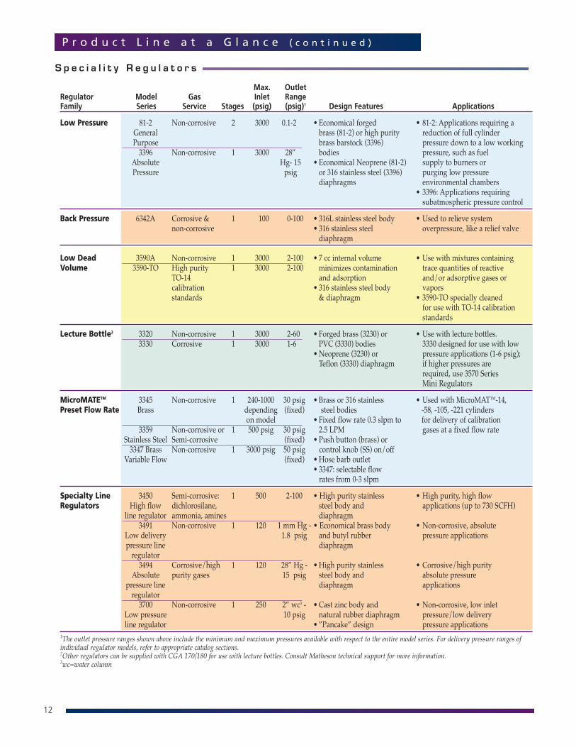
P r o d u c t L i n e a t a G l a n c e ( c o n t i n u e d )
S p e c i a l i t y R e g u l a t o r s
Max. OutletRegulator Model Gas Inlet RangeFamily Series Service Stages (psig) (psig)1 Design Features Applications
Low Pressure 81-2 Non-corrosive 2 3000 0.1-2 • Economical forged • 81-2: Applications requiring a General brass (81-2) or high purity reduction of full cylinderPurpose brass barstock (3396) pressure down to a low working3396 Non-corrosive 1 3000 28” bodies pressure, such as fuel
Absolute Hg- 15 • Economical Neoprene (81-2) supply to burners orPressure psig or 316 stainless steel (3396) purging low pressure
diaphragms environmental chambers • 3396: Applications requiring subatmospheric pressure control
Back Pressure 6342A Corrosive & 1 100 0-100 • 316L stainless steel body • Used to relieve system non-corrosive • 316 stainless steel overpressure, like a relief valve
diaphragm
Low Dead 3590A Non-corrosive 1 3000 2-100 • 7 cc internal volume • Use with mixtures containing Volume 3590-TO High purity 1 3000 2-100 minimizes contamination trace quantities of reactive
TO-14 and adsorption and/or adsorptive gases or calibration • 316 stainless steel body vaporsstandards & diaphragm • 3590-TO specially cleaned
for use with TO-14 calibrationstandards
Lecture Bottle2 3320 Non-corrosive 1 3000 2-60 • Forged brass (3230) or • Use with lecture bottles. 3330 Corrosive 1 3000 1-6 PVC (3330) bodies 3330 designed for use with low
•Neoprene (3230) or pressure applications (1-6 psig); Teflon (3330) diaphragm if higher pressures are
required, use 3570 Series Mini Regulators
MicroMATETM 3345 Non-corrosive 1 240-1000 30 psig • Brass or 316 stainless • Used with MicroMATTM-14,Preset Flow Rate Brass depending (fixed) steel bodies -58, -105, -221 cylinders
on model • Fixed flow rate 0.3 slpm to for delivery of calibration3359 Non-corrosive or 1 500 psig 30 psig 2.5 LPM gases at a fixed flow rate
Stainless Steel Semi-corrosive (fixed) • Push button (brass) or3347 Brass Non-corrosive 1 3000 psig 50 psig control knob (SS) on/off
Variable Flow (fixed) •Hose barb outlet• 3347: selectable flowrates from 0-3 slpm
Specialty Line 3450 Semi-corrosive: 1 500 2-100 • High purity stainless • High purity, high flow Regulators High flow dichlorosilane, steel body and applications (up to 730 SCFH)
line regulator ammonia, amines diaphragm3491 Non-corrosive 1 120 1 mm Hg - • Economical brass body • Non-corrosive, absolute
Low delivery 1.8 psig and butyl rubber pressure applicationspressure line diaphragmregulator 3494 Corrosive/high 1 120 28” Hg - •High purity stainless • Corrosive/high purity
Absolute purity gases 15 psig steel body and absolute pressure pressure line diaphragm applicationsregulator3700 Non-corrosive 1 250 2” wc3 - • Cast zinc body and • Non-corrosive, low inlet
Low pressure 10 psig natural rubber diaphragm pressure/low delivery line regulator • ”Pancake” design pressure applications
1The outlet pressure ranges shown above include the minimum and maximum pressures available with respect to the entire model series. For delivery pressure ranges ofindividual regulator models, refer to appropriate catalog sections.2Other regulators can be supplied with CGA 170/180 for use with lecture bottles. Consult Matheson technical support for more information.3wc=water column
13
H e l i u m L e a k Te s t i n g
A helium leak test is used to determine theleak rate across the diaphragm or fittings onthe regulator. The leak rate value should be aslow as possible to prevent contamination byambient air or escape of hazardous gases.
A complete helium leak test involvesmonitoring the inboard leakage and theoutboard leakage of a regulator. This testingis available for a fee. Inboard leak testinginvolves drawing an internal vacuum on theregulator, and surrounding it with helium.The helium leak rate from the outside of theregulator to the inside of the regulator is thenmonitored. Outboard leak testing isperformed by pressurizing the regulator withhelium and analyzing the surrounding spacefor the presence of helium. Upon completionof the tests, a certificate is written andforwarded with the item to the customer.
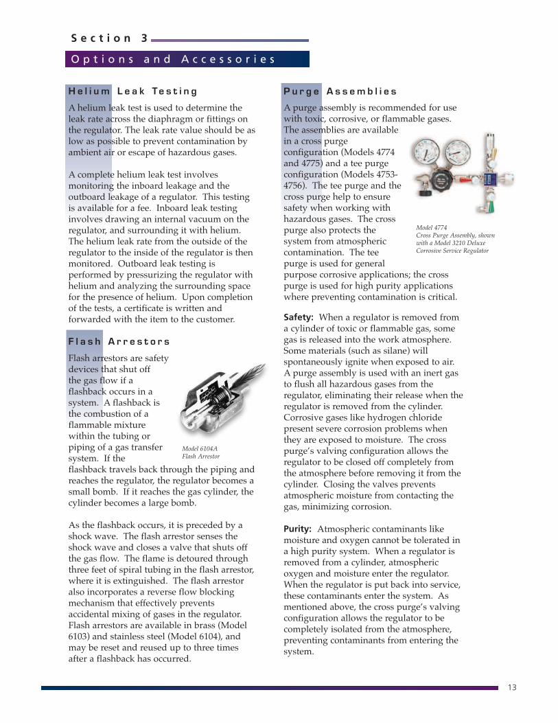
F l a s h A r r e s t o r s
Flash arrestors are safetydevices that shut offthe gas flow if aflashback occurs in asystem. A flashback isthe combustion of aflammable mixturewithin the tubing orpiping of a gas transfersystem. If theflashback travels back through the piping andreaches the regulator, the regulator becomes asmall bomb. If it reaches the gas cylinder, thecylinder becomes a large bomb.
As the flashback occurs, it is preceded by ashock wave. The flash arrestor senses theshock wave and closes a valve that shuts offthe gas flow. The flame is detoured throughthree feet of spiral tubing in the flash arrestor,where it is extinguished. The flash arrestoralso incorporates a reverse flow blockingmechanism that effectively preventsaccidental mixing of gases in the regulator.Flash arrestors are available in brass (Model6103) and stainless steel (Model 6104), andmay be reset and reused up to three timesafter a flashback has occurred.
S e c t i o n 3
O p t i o n s a n d A c c e s s o r i e s
P u r g e A s s e m b l i e s
A purge assembly is recommended for usewith toxic, corrosive, or flammable gases.The assemblies are availablein a cross purgeconfiguration (Models 4774and 4775) and a tee purgeconfiguration (Models 4753-4756). The tee purge and thecross purge help to ensuresafety when working withhazardous gases. The crosspurge also protects thesystem from atmosphericcontamination. The teepurge is used for generalpurpose corrosive applications; the crosspurge is used for high purity applicationswhere preventing contamination is critical.
Safety: When a regulator is removed froma cylinder of toxic or flammable gas, somegas is released into the work atmosphere.Some materials (such as silane) willspontaneously ignite when exposed to air.A purge assembly is used with an inert gasto flush all hazardous gases from theregulator, eliminating their release when theregulator is removed from the cylinder.Corrosive gases like hydrogen chloridepresent severe corrosion problems whenthey are exposed to moisture. The crosspurge’s valving configuration allows theregulator to be closed off completely fromthe atmosphere before removing it from thecylinder. Closing the valves preventsatmospheric moisture from contacting thegas, minimizing corrosion.
Purity: Atmospheric contaminants likemoisture and oxygen cannot be tolerated ina high purity system. When a regulator isremoved from a cylinder, atmosphericoxygen and moisture enter the regulator.When the regulator is put back into service,these contaminants enter the system. Asmentioned above, the cross purge’s valvingconfiguration allows the regulator to becompletely isolated from the atmosphere,preventing contaminants from entering thesystem.
Model 6104AFlash Arrestor
Model 4774Cross Purge Assembly, shownwith a Model 3210 DeluxeCorrosive Service Regulator
14
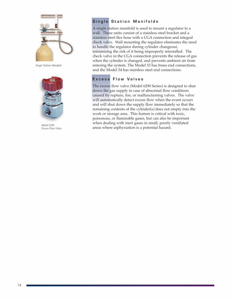
S i n g l e S t a t i o n M a n i f o l d s
A single station manifold is used to mount a regulator to awall. These units consist of a stainless steel bracket and astainless steel flex hose with a CGA connection and integralcheck valve. Wall mounting the regulator eliminates the needto handle the regulator during cylinder changeout,minimizing the risk of it being improperly reinstalled. Thecheck valve in the CGA connection prevents the release of gaswhen the cylinder is changed, and prevents ambient air fromentering the system. The Model 53 has brass end connections,and the Model 54 has stainless steel end connections.
E x c e s s F l o w V a l v e s
The excess flow valve (Model 6290 Series) is designed to shutdown the gas supply in case of abnormal flow conditionscaused by rupture, fire, or malfunctioning valves. The valvewill automatically detect excess flow when the event occursand will shut down the supply flow immediately so that theremaining contents of the cylinder(s) does not empty into thework or storage area. This feature is critical with toxic,poisonous, or flammable gases, but can also be importantwhen dealing with inert gases in small, poorly ventilatedareas where asphyxiation is a potential hazard.
Model 6290Excess Flow Valve
Single Station Manifold
15
S e c t i o n 4
U s i n g Y o u r R e g u l a t o r
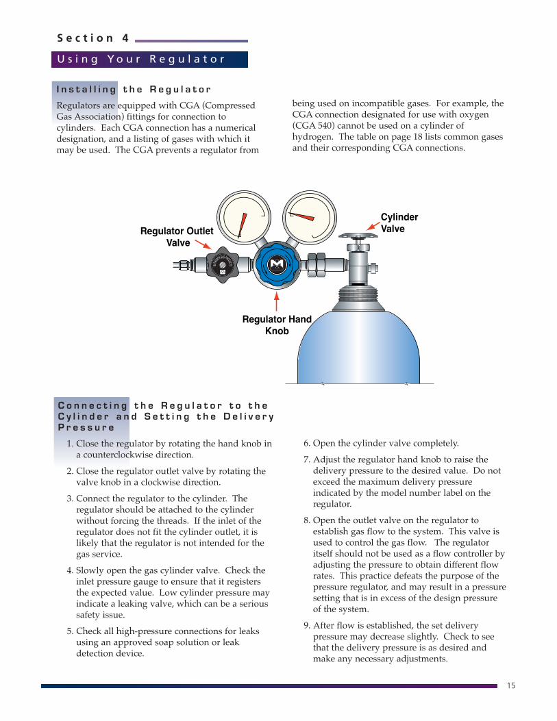
C o n n e c t i n g t h e R e g u l a t o r t o t h eC y l i n d e r a n d S e t t i n g t h e D e l i v e r yP r e s s u r e
1. Close the regulator by rotating the hand knob ina counterclockwise direction.
2. Close the regulator outlet valve by rotating thevalve knob in a clockwise direction.
3. Connect the regulator to the cylinder. Theregulator should be attached to the cylinderwithout forcing the threads. If the inlet of theregulator does not fit the cylinder outlet, it islikely that the regulator is not intended for thegas service.
4. Slowly open the gas cylinder valve. Check theinlet pressure gauge to ensure that it registersthe expected value. Low cylinder pressure mayindicate a leaking valve, which can be a serioussafety issue.
5. Check all high-pressure connections for leaksusing an approved soap solution or leakdetection device.
CylinderValveRegulator Outlet
Valve
Regulator HandKnob
6. Open the cylinder valve completely.
7. Adjust the regulator hand knob to raise thedelivery pressure to the desired value. Do notexceed the maximum delivery pressureindicated by the model number label on theregulator.
8. Open the outlet valve on the regulator toestablish gas flow to the system. This valve isused to control the gas flow. The regulatoritself should not be used as a flow controller byadjusting the pressure to obtain different flowrates. This practice defeats the purpose of thepressure regulator, and may result in a pressuresetting that is in excess of the design pressureof the system.
9. After flow is established, the set deliverypressure may decrease slightly. Check to seethat the delivery pressure is as desired andmake any necessary adjustments.
I n s t a l l i n g t h e R e g u l a t o r
Regulators are equipped with CGA (CompressedGas Association) fittings for connection tocylinders. Each CGA connection has a numericaldesignation, and a listing of gases with which itmay be used. The CGA prevents a regulator from
being used on incompatible gases. For example, theCGA connection designated for use with oxygen(CGA 540) cannot be used on a cylinder ofhydrogen. The table on page 18 lists common gasesand their corresponding CGA connections.
16
6. Disconnect the regulator from the system ordownstream equipment.
7. Disassemble the regulator from the cylinderby slowly loosening the cylinder connection.Listen for gas seepage. If leakage is evident,re-tighten the cylinder connectionimmediately, and check the cylinder valve forproper closure. If leakage occurs when thecylinder valve is closed, and the regulator hasbeen drained of all gases, contact the gassupplier immediately.
8. Replace the plug into the cylinder valve outlet(where applicable). Replace the cap on thecylinder over the valve. Remove the cylinderfrom the work place and put the cylinder intoa safe storage area. Replace the emptycylinder with a new one and re-install theregulator.
R em o v i n g t h e R e g u l a t o r f r o m t h eC y l i n d e r
For temporary shutdown (less than 30-minuteduration), simply close the regulator outlet valve.
For extended shutdown (beyond 30-minute duration)follow these steps:
1. Shut off the gas cylinder valve completely.
2. Shut down any additional gas supplies that maybe supplying gas to the system.
3. Open the regulator and the outlet valve to drainthe contents of the regulator through the system inuse. Both regulator gauges should descend tozero.
4. When using a toxic or other hazardous gas, purgethe regulator and system with an inert gas (seeinstructions on Purging the Regulator, below).
5. Close the regulator by rotating the hand knobcounterclockwise. Close the outlet valve byrotating the valve knob clockwise.
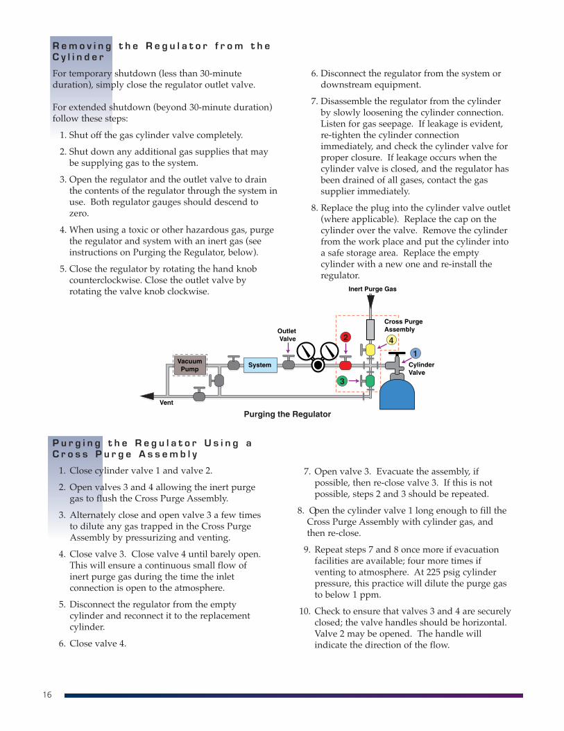
P u r g i n g t h e R e g u l a t o r U s i n g aC r o s s P u r g e A s s e m b l y
1. Close cylinder valve 1 and valve 2.
2. Open valves 3 and 4 allowing the inert purgegas to flush the Cross Purge Assembly.
3. Alternately close and open valve 3 a few timesto dilute any gas trapped in the Cross PurgeAssembly by pressurizing and venting.
4. Close valve 3. Close valve 4 until barely open.This will ensure a continuous small flow ofinert purge gas during the time the inletconnection is open to the atmosphere.
5. Disconnect the regulator from the emptycylinder and reconnect it to the replacementcylinder.
6. Close valve 4.
7. Open valve 3. Evacuate the assembly, ifpossible, then re-close valve 3. If this is notpossible, steps 2 and 3 should be repeated.
8. Open the cylinder valve 1 long enough to fill theCross Purge Assembly with cylinder gas, andthen re-close.
9. Repeat steps 7 and 8 once more if evacuationfacilities are available; four more times ifventing to atmosphere. At 225 psig cylinderpressure, this practice will dilute the purge gasto below 1 ppm.
10. Check to ensure that valves 3 and 4 are securelyclosed; the valve handles should be horizontal.Valve 2 may be opened. The handle willindicate the direction of the flow.
17
• Seat leakage of the regulator: Seat leakage isthe tendency of gas to leak across the regulatorseat, when the regulator outlet valve knob is fullyclosed (turned counterclockwise) and a highpressure source exists on the inlet side. A lowleakage value is preferred.
• Leakage rate across the diaphragm or fittingson the regulator: This leakage value is normallymeasured using helium gas and a massspectrometer or other type of helium leak detector.Regulators for specialty gas service may havepublished values of typical leakage rates eitherinboard (from the atmosphere into the regulator)or outboard (from the inside of the regulator to theatmosphere). For safety, it is important that thisleak rate value be as low as possible in order toprevent possible contamination by ambient air andmoisture or escape of hazardous gases.
0
20
40
60
80
100
S e c t i o n 5
P e r f o r m a n c e E v a l u a t i o n a n d T r o u b l e S h o o t i n g
Several things are evaluated to determine aregulator’s performance.
• Pressure regulation as a function of flow: Allregulators experience some delivery pressure dropwith increased flow rate. The smaller the drop asflow is increased, the better the performance.
• Pressure regulation as a function of inletpressure: As a cylinder’s contents are depletedand the inlet pressure drops, the regulator deliverypressure may either rise or fall depending on theregulator design. In both cases, this is known asregulator “droop.” Two stage regulators generallyprovide better regulation under thesecircumstances.
• “Lockup” of a regulator: Lockup is the differencein pressure between a flowing and a non-flowingcondition. If a regulator has its delivery pressureset while gas is flowing, and flow is suddenlystopped, a small rise in delivery pressure (lockup)will occur before the regulator’s valve closes fully.The lower the lockup, the better the performance.
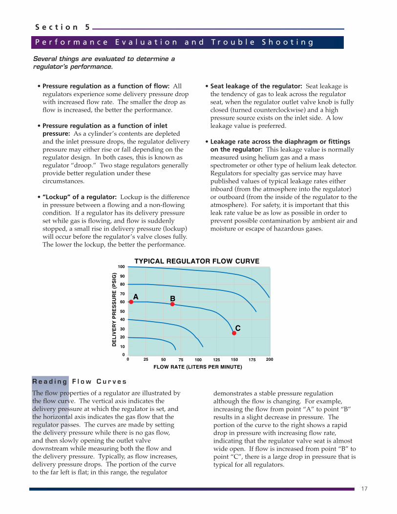
R e a d i n g F l o w C u r v e s
The flow properties of a regulator are illustrated bythe flow curve. The vertical axis indicates thedelivery pressure at which the regulator is set, andthe horizontal axis indicates the gas flow that theregulator passes. The curves are made by settingthe delivery pressure while there is no gas flow,and then slowly opening the outlet valvedownstream while measuring both the flow andthe delivery pressure. Typically, as flow increases,delivery pressure drops. The portion of the curveto the far left is flat; in this range, the regulator
demonstrates a stable pressure regulationalthough the flow is changing. For example,increasing the flow from point “A” to point “B”results in a slight decrease in pressure. Theportion of the curve to the right shows a rapiddrop in pressure with increasing flow rate,indicating that the regulator valve seat is almostwide open. If flow is increased from point “B” topoint “C”, there is a large drop in pressure that istypical for all regulators.
18
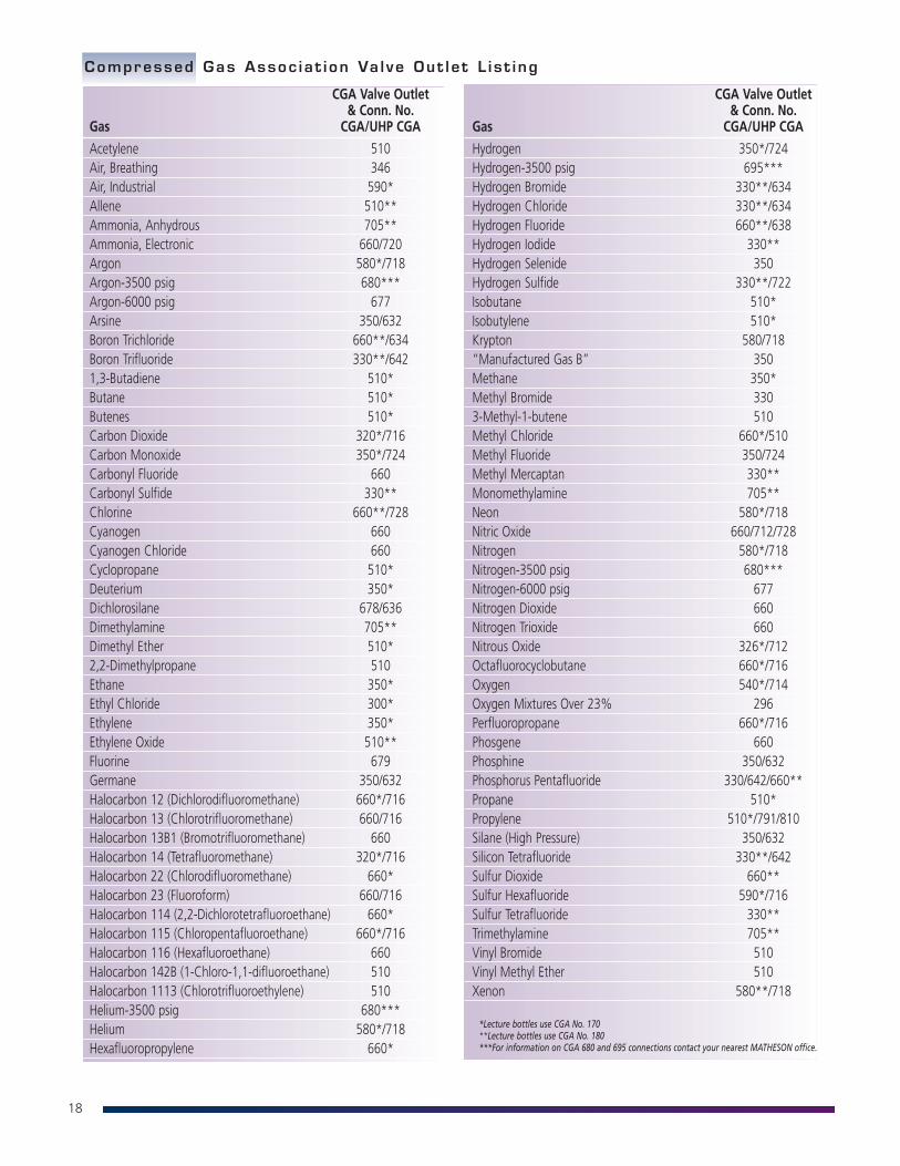
CGA Valve Outlet& Conn. No.
Gas CGA/UHP CGA
Acetylene 510Air, Breathing 346Air, Industrial 590*Allene 510**Ammonia, Anhydrous 705**Ammonia, Electronic 660/720Argon 580*/718Argon-3500 psig 680***Argon-6000 psig 677Arsine 350/632Boron Trichloride 660**/634Boron Trifluoride 330**/6421,3-Butadiene 510*Butane 510*Butenes 510*Carbon Dioxide 320*/716Carbon Monoxide 350*/724Carbonyl Fluoride 660Carbonyl Sulfide 330**Chlorine 660**/728Cyanogen 660Cyanogen Chloride 660Cyclopropane 510*Deuterium 350*Dichlorosilane 678/636Dimethylamine 705**Dimethyl Ether 510*2,2-Dimethylpropane 510Ethane 350*Ethyl Chloride 300*Ethylene 350*Ethylene Oxide 510**Fluorine 679Germane 350/632Halocarbon 12 (Dichlorodifluoromethane) 660*/716Halocarbon 13 (Chlorotrifluoromethane) 660/716Halocarbon 13B1 (Bromotrifluoromethane) 660Halocarbon 14 (Tetrafluoromethane) 320*/716Halocarbon 22 (Chlorodifluoromethane) 660*Halocarbon 23 (Fluoroform) 660/716Halocarbon 114 (2,2-Dichlorotetrafluoroethane) 660*Halocarbon 115 (Chloropentafluoroethane) 660*/716Halocarbon 116 (Hexafluoroethane) 660Halocarbon 142B (1-Chloro-1,1-difluoroethane) 510Halocarbon 1113 (Chlorotrifluoroethylene) 510Helium-3500 psig 680***Helium 580*/718Hexafluoropropylene 660*
Compressed Gas Assoc ia t i on Va l ve Out le t L i s t i ng
CGA Valve Outlet& Conn. No.
Gas CGA/UHP CGA
Hydrogen 350*/724Hydrogen-3500 psig 695***Hydrogen Bromide 330**/634Hydrogen Chloride 330**/634Hydrogen Fluoride 660**/638Hydrogen Iodide 330**Hydrogen Selenide 350Hydrogen Sulfide 330**/722Isobutane 510*Isobutylene 510*Krypton 580/718“Manufactured Gas B” 350Methane 350*Methyl Bromide 3303-Methyl-1-butene 510Methyl Chloride 660*/510Methyl Fluoride 350/724Methyl Mercaptan 330**Monomethylamine 705**Neon 580*/718Nitric Oxide 660/712/728Nitrogen 580*/718Nitrogen-3500 psig 680***Nitrogen-6000 psig 677Nitrogen Dioxide 660Nitrogen Trioxide 660Nitrous Oxide 326*/712Octafluorocyclobutane 660*/716Oxygen 540*/714Oxygen Mixtures Over 23% 296Perfluoropropane 660*/716Phosgene 660Phosphine 350/632Phosphorus Pentafluoride 330/642/660**Propane 510*Propylene 510*/791/810Silane (High Pressure) 350/632Silicon Tetrafluoride 330**/642Sulfur Dioxide 660**Sulfur Hexafluoride 590*/716Sulfur Tetrafluoride 330**Trimethylamine 705**Vinyl Bromide 510Vinyl Methyl Ether 510Xenon 580**/718
*Lecture bottles use CGA No. 170**Lecture bottles use CGA No. 180***For information on CGA 680 and 695 connections contact your nearest MATHESON office.
19
S e c t i o n 6
G l o s s a r y o f R e g u l a t o r T e r m s
The following terms may be encountered when dealing with regulators.
Burst Pressure – A design test pressure which determines the ultimate structural strength of aregulator or valve. Permanent deformation and leakage are permitted, but partsmust remain assembled (no sudden ruptures).
Captured Venting – A feature incorporated in a self-venting pressure reducing regulator whichprovides an additional port to permit the piping away of the expelled gas from theregulator’s vent valve.
Control Element – One of the three basic elements of a pressure regulator. It acts to reduce a highinlet pressure to a lower working or delivery pressure. The control element issometimes called a main valve, valve stem, or poppet.
Cv – See “Flow Capacity”
Decaying Inlet Characteristic – The effect of the set pressure of a regulator as a result of an inlet pressure change;normally an increase in outlet pressure due to a decrease in inlet pressure.
Diaphragm – A type of sensing element used in a regulator. Common diaphragm materials areBuna-N, Viton, Ethylene Propylene, 316 Stainless Steel, and Elgiloy.
Droop – The outlet pressure change (or offset) from the “set pressure” which occurs as flowrate increases.
Flow Capacity (Cv) – The maximum flow capability of a regulator or valve established at a specific setof conditions. The standard coefficient is the term ‘Cv’, which is defined as theflow of one GPM of water at one PSI pressure drop. The term Cv for gaseousservice is dependent on the ratio of inlet to outlet pressure and must bedetermined by the use of the appropriate formulae.
Inlet Pressure (P1) – The pressure of the gas at the supply connection of a regulator or valve. Typicalunits of measure are psig, bar, or pascal.
Leakage, Inboard – Leakage through an external joint or seal where the direction of flow is from theoutside into the regulator or valve. The leakage rate is measured in atm cc/secHe(lium).
Leakage, Outboard – Leakage through an external joint or seal where the direction of flow is from theinside of the regulator or valve to the outside. The leakage rate is measured inatm cc/sec He(lium), and the pressure inside the regulator should be stated.
Load Element – One of the three basic elements of a pressure reducing regulator (usually a spring).It provides the means by which the operator can set the force that determines theoutlet pressure of the regulator.
Lockup – The outlet pressure increase that occurs above the “set pressure” as the flow isdecreased to zero.
Outlet Pressure (P2) – The pressure of the gas from the discharge connection of a regulator or valve.
Sensing Element – One of the three basic elements of a pressure reducing regulator, typically adiaphragm. It senses the changes in the outlet pressure, permitting the regulatorto react in an attempt to return to the original “set pressure” by increasing ordecreasing pressure.
Set Pressure – The desired operational outlet pressure for a regulator, normally stated at NOFLOW conditions.
ULTRA-LINE® is a registered trademark of MATHESON Tri-GasAll other tradesmarks are property of their respective owners.

BR-71/R05-14 Printed in USA
www.mathesongas.com877-684-4427
National reach. Local values.
Copyright 2014 Matheson Tri-Gas, Inc. All Rights Reserved.All contents of this document are subject to change without notice and do not represent a commitment on the part of Matheson Tri-Gas, Inc. Every effort is made to ensurethe accuracy of this information. However, due to differences in actual and ongoing operational processes and product improvements and revisions, Matheson Tri-Gas, Inc.cannot guarantee the accuracy of this material, nor can it accept responsibility for errors or omissions. This document is intended to serve as a general orientation andcannot be relied upon for a specific operation. No warranties of any nature are extended by the information contained in these copyrighted materials.All names, products, and services mentioned herein are the trademarks or registered trademarks of their respective organizations and are the sole property of theirrespective owners. Matheson and the Matheson logo are registered trademarks of Matheson Tri-Gas, Inc.