Embed Size (px)
Citation preview
Guidelines for
Emergency Services
Rescue and Recovery
involving Audi Vehicles


3
Legal Disclaimer:
This manual has been created exclusively for rescuers who have been spe-
cially trained in the area of providing emergency rescue after automobile
accidents and who are therefore qualifi ed to use the activities described in
this manual.
Vehicle specifi cations and special options as well as Audi model availabil-
ity are constantly subject to change. Therefore, Audi reserves the right to
change the content of this manual at all times.
Please note: The information contained in this manual is not intended for
customers or for repair shops and dealers. Customers may gather detailed
information from their vehicle owner’s manual regarding vehicle functions
as well as any occupant safety features and system descriptions. Repair
shops and dealers obtain repair information through their normal channels.
(Status: November 2012)
Content
01 Foreword 07
02 Safety systems 09
2.1 Control module for safety systems 10
2.2 Airbags
2.2.1 Front airbags 12
2.2.2 Dual-stage front airbags 16
2.2.3 Knee airbags 16
2.2.4 Side airbags 17
2.2.5 Head airbags 18
2.2.6 Head/thorax airbags 19
2.3 Airbag gas generators 20
2.4 Safety belt pretensioners 22
2.5 Rollover protection system 25
2.6 Hints 26
A – Always keep your distance 26
I – Inspect the passenger compartment 27
R – Rescue personnel to be warned 28
B – Battery management 28
A – Assess removal of interior lining 29
G – Airbag components 30
2.7 Airbag safety systems 31
2.8 Pedestrian protection system 31
54
03 Vehicle electrics system 33
3.1 Vehicle batteries 33
3.2 Battery cut-off relays 34
3.3 User information regarding handling of the vehicle’s
electric system 35
1. Turn off the vehicle’s running engine 35
2. Activate the warning lights 35
3. Use of power comfort settings for the purpose
of rescue 35
4. Turn off the ignition 36
5. Locate the battery/batteries 36
6. Disconnect the battery/batteries 37
7. Test for electricity 37
04 Vehicle structure and material 41
4.1 A-pillars 42
4.2 B-pillars 43
4.3 Door sill 44
4.4 Side impact protection 44
4.5 Audi Space Frame (ASF®) aluminium vehicle body 45
4.6 Automotive glazing (heat absorbing glass) 46
Rescue data sheets
You will fi nd separate Audi vehicle overviews in a separate part,
entitled “Rescue data sheets”.
76
While the information in the technical part, in
particular, is meant for rescue personnel training,
the vehicle rescue data sheets are meant for the
work necessary at the accident scene.
The creation of this Emergency Rescue guide and
the rescue data sheets are supported by Moditech
Rescue Solutions (www.moditech.com).
The vehicle overviews in the rescue data sheets
are also included in interactive form in the data
base “Crash Recovery System”.
• Technical status: November 2012
01 Foreword
Driver, vehicle and environment – those are the
contributing factors which determine the degree
of traffi c safety.
The existence of a short, quick and eff ective res-
cue eff ort remains indispensible. These guidelines
should assist rescue personnel in accomplishing
their task because it provides all applicable tech-
nical Audi vehicle information. It includes a de-
tailed descriptive technical part. The rescue data
sheets are vehicle-specifi c and include detailed
information on various vehicles.
•
98
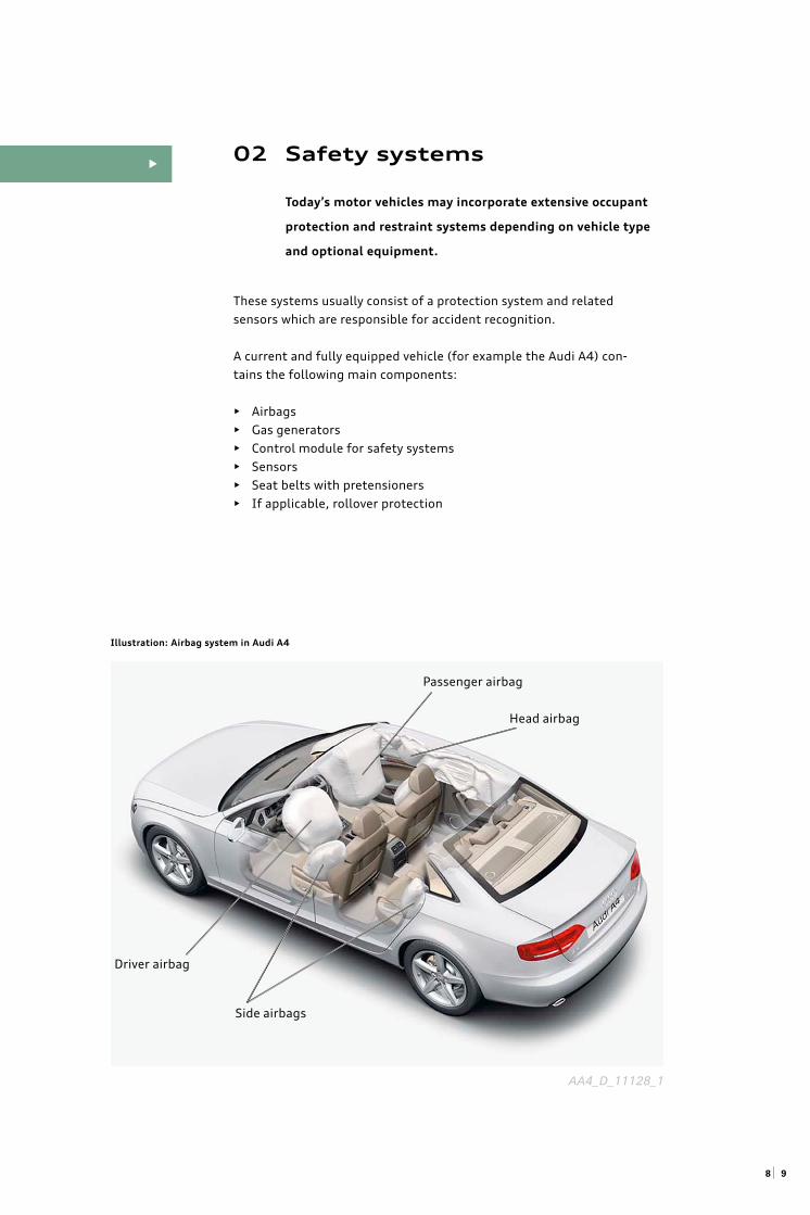
02 Safety systems
Today’s motor vehicles may incorporate extensive occupant
protection and restraint systems depending on vehicle type
and optional equipment.
These systems usually consist of a protection system and related
sensors which are responsible for accident recognition.
A current and fully equipped vehicle (for example the Audi A4) con-
tains the following main components:
• Airbags
• Gas generators
• Control module for safety systems
• Sensors
• Seat belts with pretensioners
• If applicable, rollover protection
•
Illustration: Airbag system in Audi A4
Driver airbag
Passenger airbag
Head airbag
Side airbags
AA4_D_11128_1
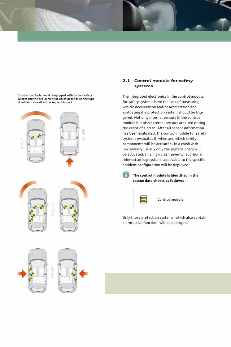
2.1 Control module for safety
systems
The integrated electronics in the control module
for safety systems have the task of measuring
vehicle deceleration and/or acceleration and
evaluating if a protection system should be trig-
gered. Not only internal sensors in the control
module but also external sensors are used during
the event of a crash. After all sensor information
has been evaluated, the control module for safety
systems evaluates if, when and which safety
components will be activated. In a crash with
low severity usually only the pretensioners will
be activated. In a high crash severity, additional
relevant airbag systems applicable to the specifi c
accident confi guration will be deployed.
Only those protection systems, which also contain
a protective function, will be deployed.
The control module is identifi ed in the
rescue data sheets as follows:
Control module
Illustration: Each model is equipped with its own safety
system and the deployment of which depends on the type
of collision as well as the angle of impact.
i
410_
069
410_
205
410_
071
410_
070
1110
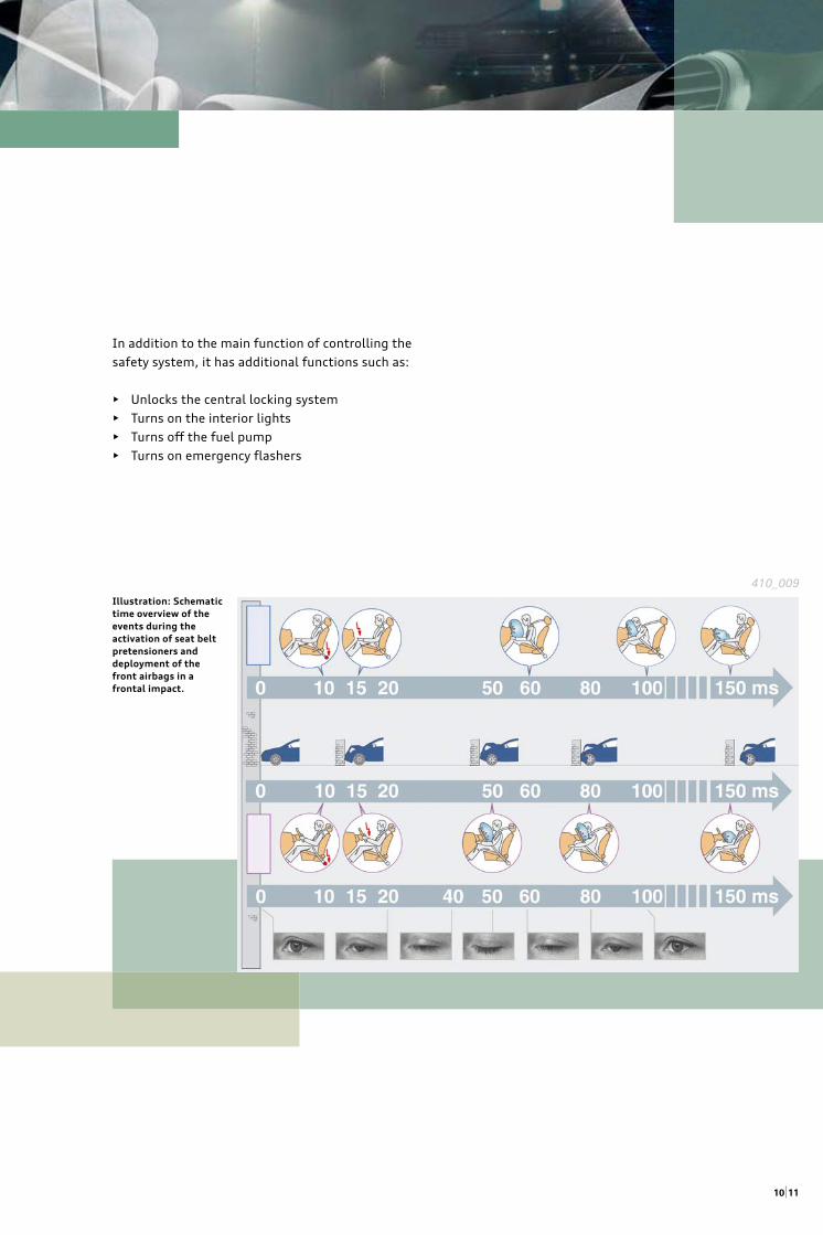
In addition to the main function of controlling the
safety system, it has additional functions such as:
• Unlocks the central locking system
• Turns on the interior lights
• Turns off the fuel pump
• Turns on emergency fl ashers
Illustration: Schematic
time overview of the
events during the
activation of seat belt
pretensioners and
deployment of the
front airbags in a
frontal impact.
410_009
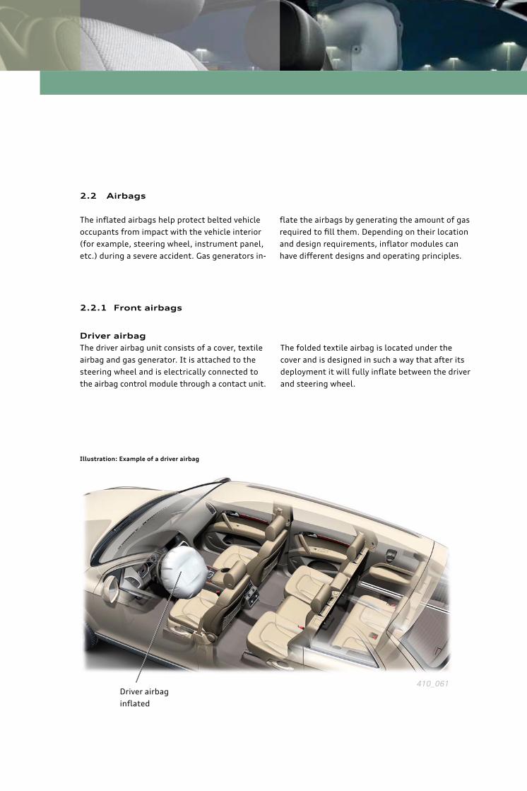
2.2 Airbags
The infl ated airbags help protect belted vehicle
occupants from impact with the vehicle interior
(for example, steering wheel, instrument panel,
etc.) during a severe accident. Gas generators in-
2.2.1 Front airbags
Driver airbag
The driver airbag unit consists of a cover, textile
airbag and gas generator. It is attached to the
steering wheel and is electrically connected to
the airbag control module through a contact unit.
fl ate the airbags by generating the amount of gas
required to fi ll them. Depending on their location
and design requirements, infl ator modules can
have diff erent designs and operating principles.
The folded textile airbag is located under the
cover and is designed in such a way that after its
deployment it will fully infl ate between the driver
and steering wheel.
Illustration: Example of a driver airbag
Driver airbag
infl ated
410_061
1312
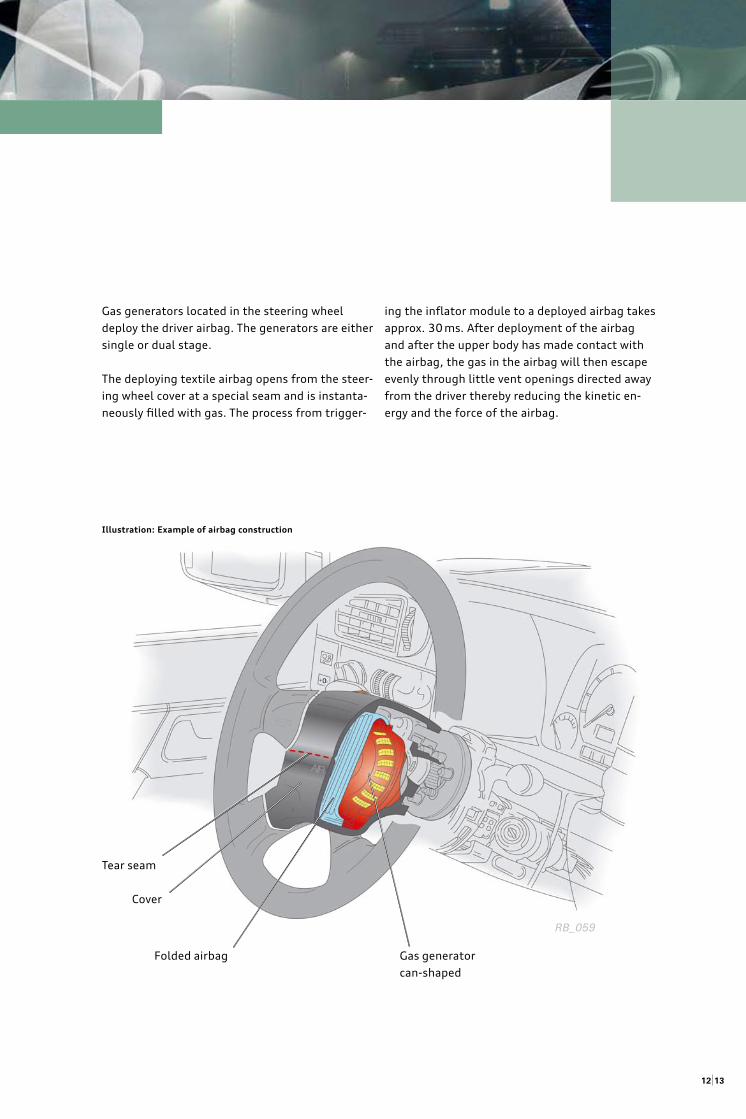
Gas generators located in the steering wheel
deploy the driver airbag. The generators are either
single or dual stage.
The deploying textile airbag opens from the steer-
ing wheel cover at a special seam and is instanta-
neously fi lled with gas. The process from trigger-
ing the infl ator module to a deployed airbag takes
approx. 30 ms. After deployment of the airbag
and after the upper body has made contact with
the airbag, the gas in the airbag will then escape
evenly through little vent openings directed away
from the driver thereby reducing the kinetic en-
ergy and the force of the airbag.
Illustration: Example of airbag construction
Tear seam
Cover
Folded airbag Gas generator
can-shaped
RB_059
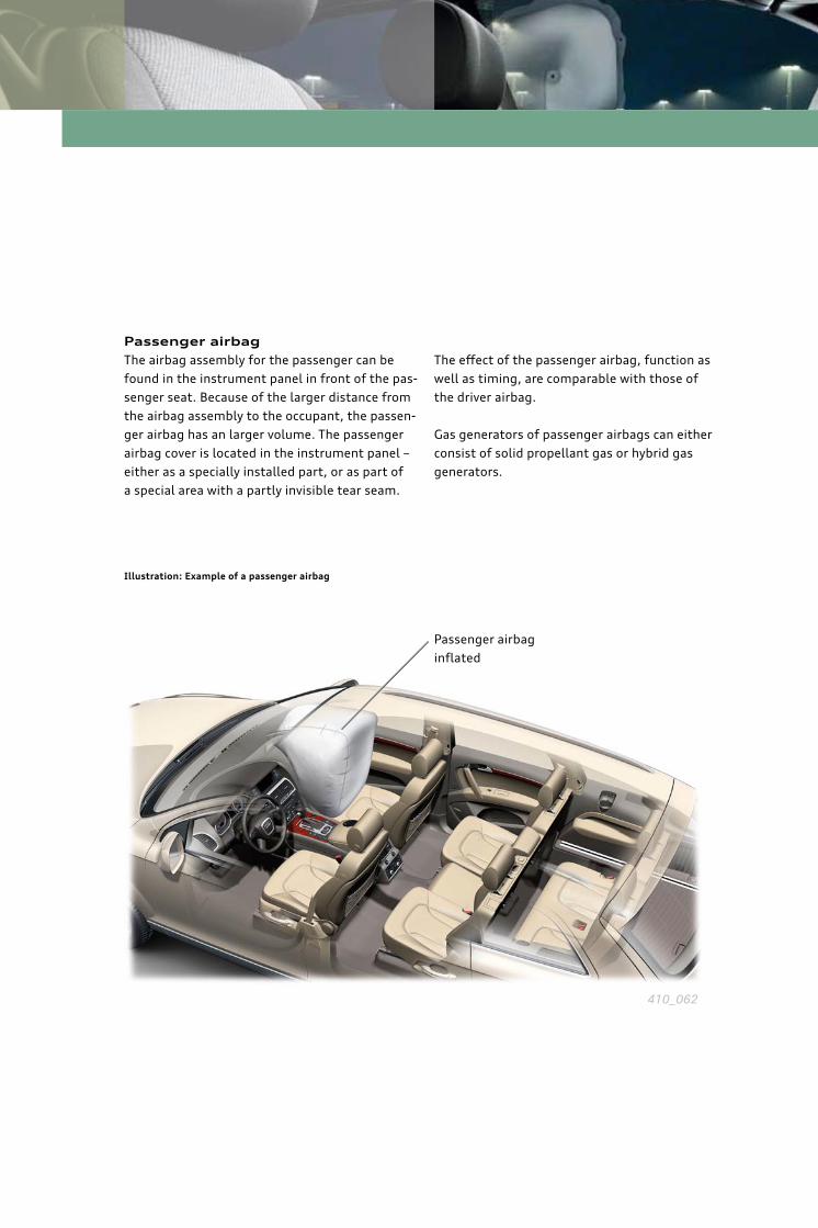
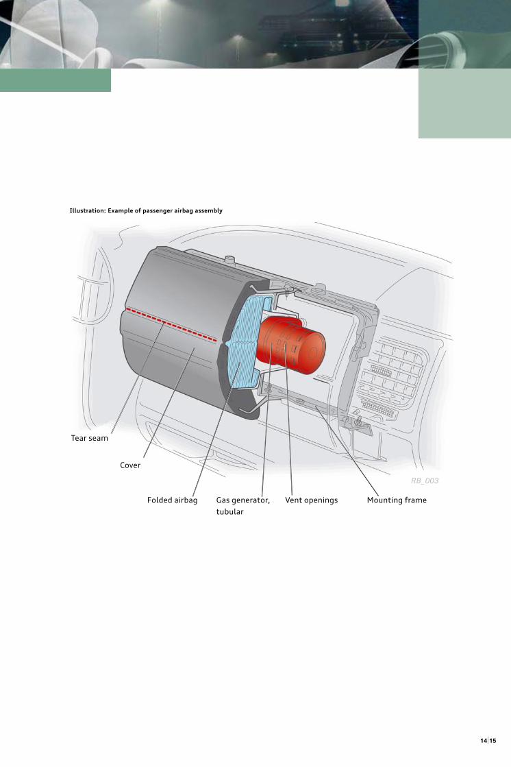
Illustration: Example of a passenger airbag
Passenger airbag
The airbag assembly for the passenger can be
found in the instrument panel in front of the pas-
senger seat. Because of the larger distance from
the airbag assembly to the occupant, the passen-
ger airbag has an larger volume. The passenger
airbag cover is located in the instrument panel –
either as a specially installed part, or as part of
a special area with a partly invisible tear seam.
The eff ect of the passenger airbag, function as
well as timing, are comparable with those of
the driver airbag.
Gas generators of passenger airbags can either
consist of solid propellant gas or hybrid gas
generators.
Passenger airbag
infl ated
410_062
15
Illustration: Example of passenger airbag assembly
Tear seam
Cover
Folded airbag Gas generator,
tubular
Vent openings Mounting frame
RB_003
14
ignition will have partially gone down, the airbag
will be infl ated with less pressure. If the ignitions
take place right after each other, then the airbag
pressure from the fi rst ignition will not yet have
gone down and the airbag will become stiff er.
In principle both stages will always ignite. This
will avoid a propelling charge remaining active
after the airbag deployment.
Adaptive front airbags
Some of the new Audi vehicles are equipped with
driver and passenger airbags which consist of the
so-called adaptive airbags. The cushioning eff ect
of these airbag systems can be infl uenced by the
activation of pyrotechnical units to the airbag gas
generator or airbag module housing. This enables
a diff erent degree of fi lling for the airbag.
2.2.2 Dual-stage front airbags
The ignition of the propellant takes place in one
stage with an airbag that has a single-stage gas
generator.
Some of the Audi vehicles are equiped with dual-
stage airbags. With this airbags, the gas genera-
tors work in two stages in which both propellants
are sequentially activated. The control module for
safety systems decides what the timing should
be between the two ignitions based on severity
and type of accident. The timing diff erence can,
depending on the vehicle, be anywhere between
5 and 200 ms.
The second stage ensures that the airbag is fi lled
with additional gas volume. The timing diff erence
between the ignitions determines the infl ation
stiff ness of the airbag: if the second ignition hap-
pens later, then the airbag pressure from the fi rst
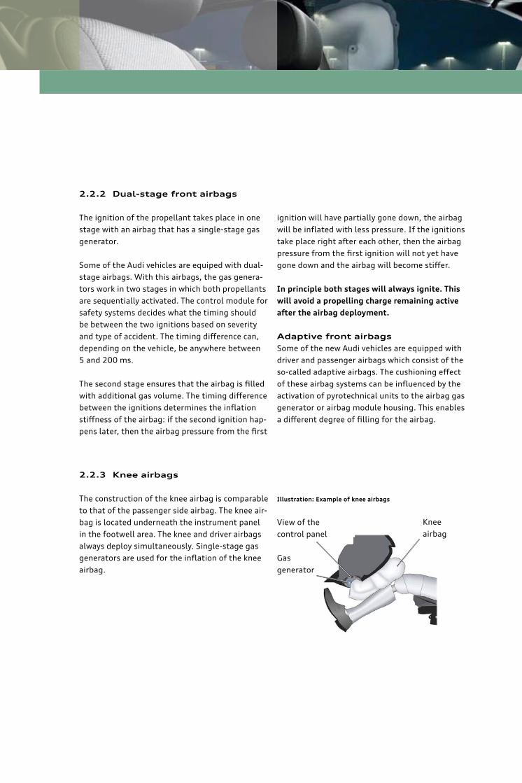
2.2.3 Knee airbags
The construction of the knee airbag is comparable
to that of the passenger side airbag. The knee air-
bag is located underneath the instrument panel
in the footwell area. The knee and driver airbags
always deploy simultaneously. Single-stage gas
generators are used for the infl ation of the knee
airbag.
Illustration: Example of knee airbags
Knee
airbag
View of the
control panel
Gas
generator
1716
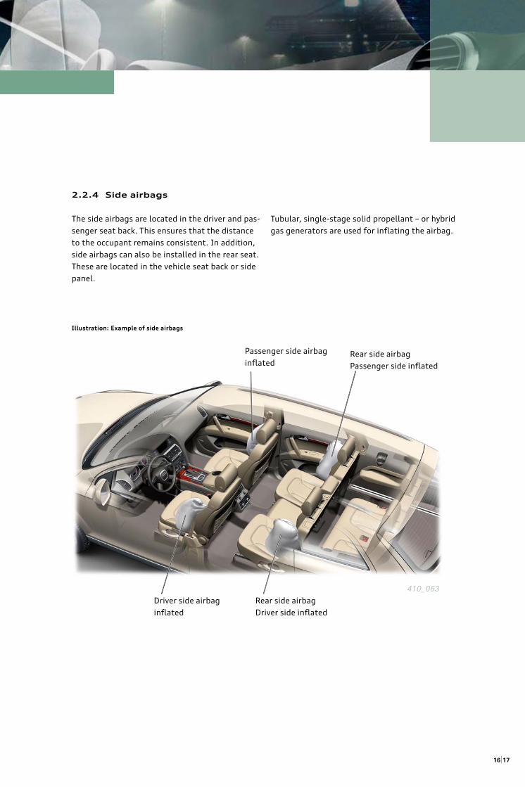
2.2.4 Side airbags
The side airbags are located in the driver and pas-
senger seat back. This ensures that the distance
to the occupant remains consistent. In addition,
side airbags can also be installed in the rear seat.
These are located in the vehicle seat back or side
panel.
Tubular, single-stage solid propellant – or hybrid
gas generators are used for infl ating the airbag.
Illustration: Example of side airbags
Passenger side airbag
infl ated
Driver side airbag
infl ated
Rear side airbag
Passenger side infl ated
Rear side airbag
Driver side infl ated
410_063
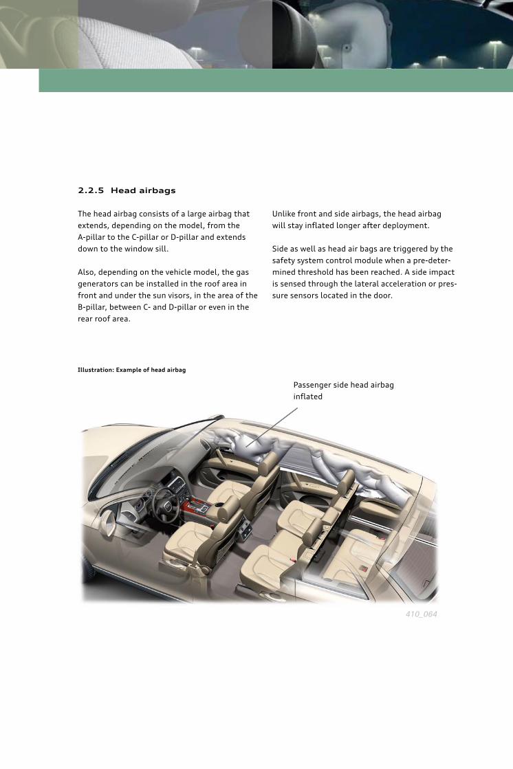
2.2.5 Head airbags
The head airbag consists of a large airbag that
extends, depending on the model, from the
A-pillar to the C-pillar or D-pillar and extends
down to the window sill.
Also, depending on the vehicle model, the gas
generators can be installed in the roof area in
front and under the sun visors, in the area of the
B-pillar, between C- and D-pillar or even in the
rear roof area.
Unlike front and side airbags, the head airbag
will stay infl ated longer after deployment.
Side as well as head air bags are triggered by the
safety system control module when a pre-deter-
mined threshold has been reached. A side impact
is sensed through the lateral acceleration or pres-
sure sensors located in the door.
Illustration: Example of head airbag
Passenger side head airbag
infl ated
410_064
1918
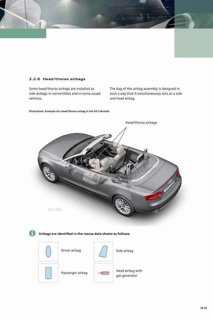
2.2.6 Head/thorax airbags
Some head/thorax airbags are installed as
side airbags in convertibles and in some coupé
vehicles.
The bag of the airbag assembly is designed in
such a way that it simultaneously acts as a side
and head airbag.
Illustration: Example of a head/thorax airbag in the A5 Cabriolet
Head/thorax airbags
Airbags are identifi ed in the rescue data sheets as follows:
Driver airbag
Passenger airbag
Side airbag
Head airbag with
gas generator
i
RLF_028
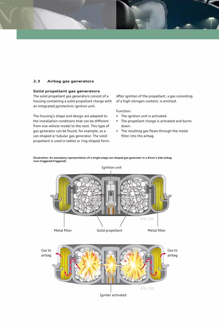
2.3 Airbag gas generators
Solid propellant gas generators
The solid propellant gas generators consist of a
housing containing a solid propellant charge with
an integrated pyrotechnic ignition unit.
The housing’s shape and design are adapted to
the installation conditions that can be diff erent
from one vehicle model to the next. This type of
gas generator can be found, for example, as a
can-shaped or tubular gas generator. The solid
propellant is used in tablet or ring-shaped form.
After ignition of the propellant, a gas consisting
of a high nitrogen content, is emitted.
Function:
• The ignition unit is activated.
• The propellant charge is activated and burns
down.
• The resulting gas fl ows through the metal
fi lter into the airbag.
Illustration: An exemplary representation of a single-stage can-shaped gas generator in a driver’s side airbag
(non-triggered/triggered)
Metal fi lter Metal fi lterSolid propellant
Igniter activated
410_103
Gas to
airbag
Gas to
airbag
Ignition unit
410_102
2120
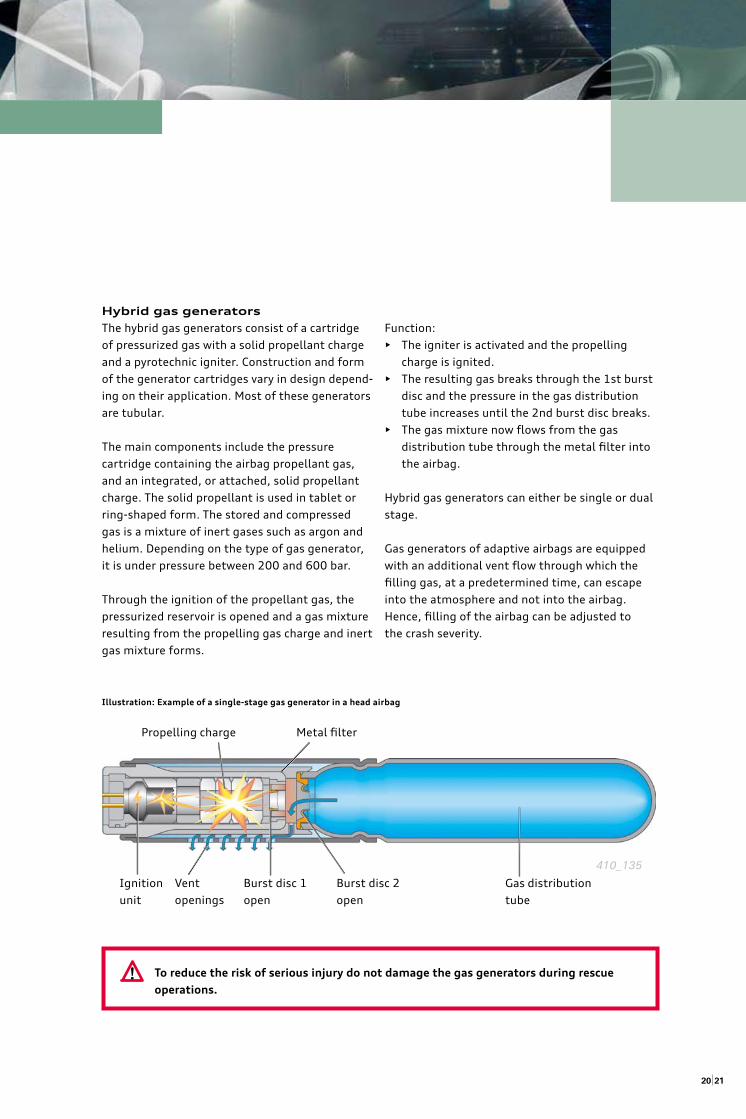
Hybrid gas generators
The hybrid gas generators consist of a cartridge
of pressurized gas with a solid propellant charge
and a pyrotechnic igniter. Construction and form
of the generator cartridges vary in design depend-
ing on their application. Most of these generators
are tubular.
The main components include the pressure
cartridge containing the airbag propellant gas,
and an integrated, or attached, solid propellant
charge. The solid propellant is used in tablet or
ring-shaped form. The stored and compressed
gas is a mixture of inert gases such as argon and
helium. Depending on the type of gas generator,
it is under pressure between 200 and 600 bar.
Through the ignition of the propellant gas, the
pressurized reservoir is opened and a gas mixture
resulting from the propelling gas charge and inert
gas mixture forms.
To reduce the risk of serious injury do not damage the gas generators during rescue
operations.
Function:
• The igniter is activated and the propelling
charge is ignited.
• The resulting gas breaks through the 1st burst
disc and the pressure in the gas distribution
tube increases until the 2nd burst disc breaks.
• The gas mixture now fl ows from the gas
distribution tube through the metal fi lter into
the airbag.
Hybrid gas generators can either be single or dual
stage.
Gas generators of adaptive airbags are equipped
with an additional vent fl ow through which the
fi lling gas, at a predetermined time, can escape
into the atmosphere and not into the airbag.
Hence, fi lling of the airbag can be adjusted to
the crash severity.
Illustration: Example of a single-stage gas generator in a head airbag
Ignition
unit
Metal fi lter Propelling charge
Burst disc 1
open
Burst disc 2
open
Vent
openings
Gas distribution
tube
!
410_135
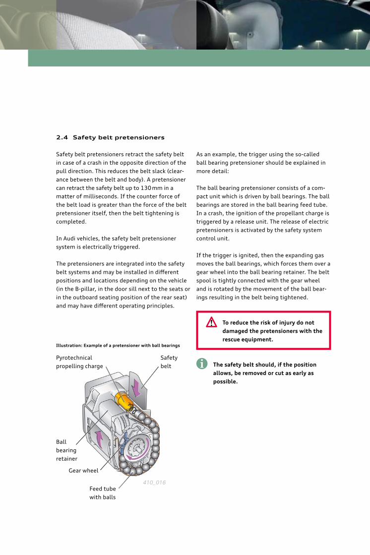
2.4 Safety belt pretensioners
Safety belt pretensioners retract the safety belt
in case of a crash in the opposite direction of the
pull direction. This reduces the belt slack (clear-
ance between the belt and body). A pretensioner
can retract the safety belt up to 130 mm in a
matter of milliseconds. If the counter force of
the belt load is greater than the force of the belt
pretensioner itself, then the belt tightening is
completed.
In Audi vehicles, the safety belt pretensioner
system is electrically triggered.
The pretensioners are integrated into the safety
belt systems and may be installed in diff erent
positions and locations depending on the vehicle
(in the B-pillar, in the door sill next to the seats or
in the outboard seating position of the rear seat)
and may have diff erent operating principles.
As an example, the trigger using the so-called
ball bearing pretensioner should be explained in
more detail:
The ball bearing pretensioner consists of a com-
pact unit which is driven by ball bearings. The ball
bearings are stored in the ball bearing feed tube.
In a crash, the ignition of the propellant charge is
triggered by a release unit. The release of electric
pretensioners is activated by the safety system
control unit.
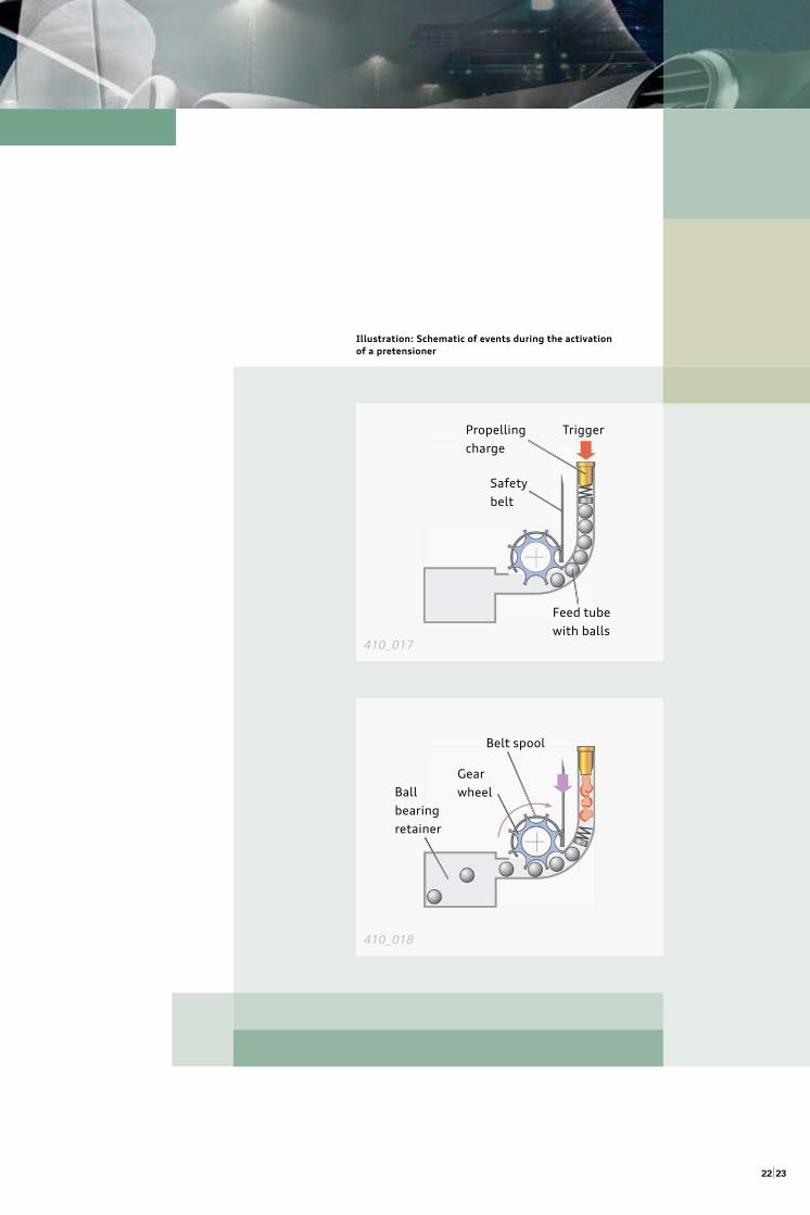
If the trigger is ignited, then the expanding gas
moves the ball bearings, which forces them over a
gear wheel into the ball bearing retainer. The belt
spool is tightly connected with the gear wheel
and is rotated by the movement of the ball bear-
ings resulting in the belt being tightened.
The safety belt should, if the position
allows, be removed or cut as early as
possible.
Illustration: Example of a pretensioner with ball bearings
Safety
belt
Gear wheel
Ball
bearing
retainer
Pyrotechnical
propelling charge
Feed tube
with balls
i
410_016
To reduce the risk of injury do not
damaged the pretensioners with the
rescue equipment.
!
2322
Illustration: Schematic of events during the activation
of a pretensioner
410_017
410_018
Safety
belt
TriggerPropelling
charge
Feed tube
with balls
Gear
wheel Ball
bearing
retainer
Belt spool
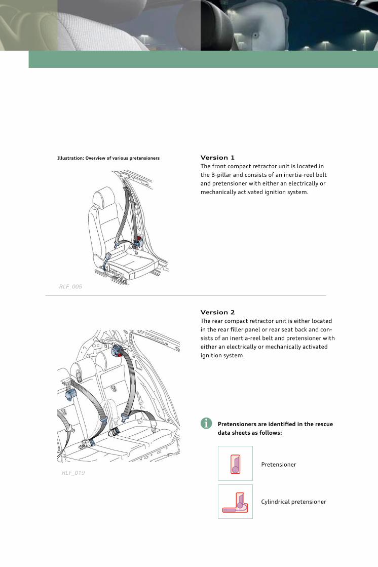
Version 1
The front compact retractor unit is located in
the B-pillar and consists of an inertia-reel belt
and pretensioner with either an electrically or
mechanically activated ignition system.
Version 2
The rear compact retractor unit is either located
in the rear fi ller panel or rear seat back and con-
sists of an inertia-reel belt and pretensioner with
either an electrically or mechanically activated
ignition system.
Pretensioners are identifi ed in the rescue
data sheets as follows:
i
Pretensioner
Cylindrical pretensioner
RLF_005
RLF_019
Illustration: Overview of various pretensioners
2524
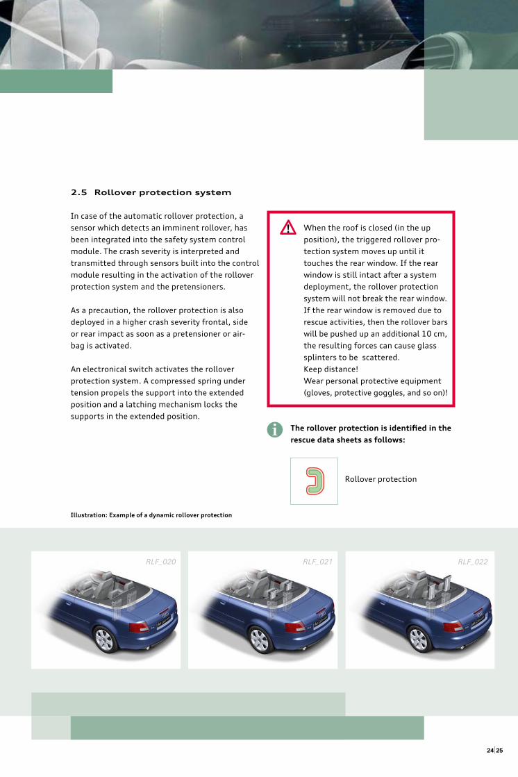
2.5 Rollover protection system
In case of the automatic rollover protection, a
sensor which detects an imminent rollover, has
been integrated into the safety system control
module. The crash severity is interpreted and
transmitted through sensors built into the control
module resulting in the activation of the rollover
protection system and the pretensioners.
As a precaution, the rollover protection is also
deployed in a higher crash severity frontal, side
or rear impact as soon as a pretensioner or air-
bag is activated.
An electronical switch activates the rollover
protection system. A compressed spring under
tension propels the support into the extended
position and a latching mechanism locks the
supports in the extended position.
Illustration: Example of a dynamic rollover protection
RLF_020 RLF_021 RLF_022
When the roof is closed (in the up
position), the triggered rollover pro-
tection system moves up until it
touches the rear window. If the rear
window is still intact after a system
deployment, the rollover protection
system will not break the rear window.
If the rear window is removed due to
rescue activities, then the rollover bars
will be pushed up an additional 10 cm,
the resulting forces can cause glass
splinters to be scattered.
Keep distance!
Wear personal protective equipment
(gloves, protective goggles, and so on)!
The rollover protection is identifi ed in the
rescue data sheets as follows:
!
i
Rollover protection
2.6 Hints
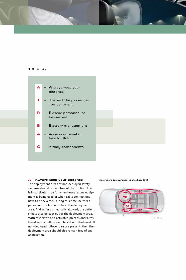
A – Always keep your distance
The deployment areas of non-deployed safety
systems should remain free of obstruction. This
is in particular true for when heavy rescue equip-
ment is being used or when cable connections
have to be severed. During this time, neither a
person nor tools should be in the deployment
area. And as far as medically allowed, the patient
should also be kept out of the deployment area.
With respect to non-activated pretensioners, fas-
tened safety belts should be cut or unfastened. If
non-deployed rollover bars are present, then their
deployment area should also remain free of any
obstruction.
Illustration: Deployment area of airbags (cm)
A – A lways keep your
distance
I – I nspect the passenger
compartment
R – R escue personnel to
be warned
B – B attery management
A – A ssess removal of
interior lining
G – Airbag components
90
6030
30
RLF_023
2726
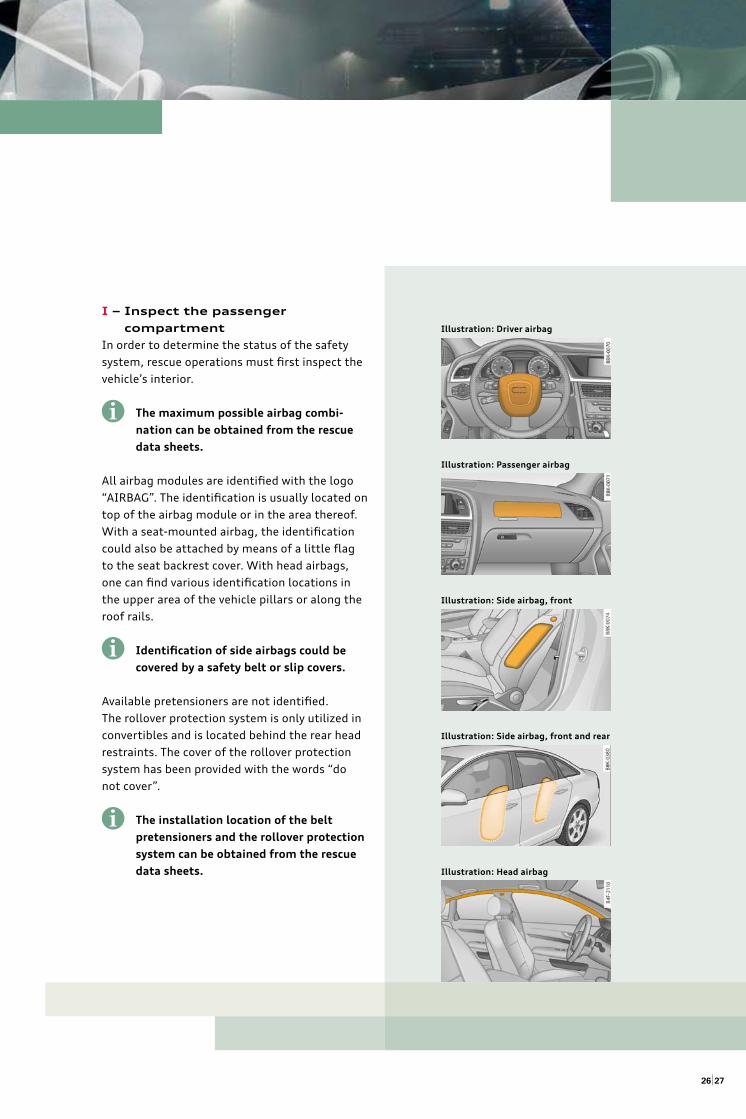
I – Inspect the passenger
compartment
In order to determine the status of the safety
system, rescue operations must fi rst inspect the
vehicle’s interior.
The maximum possible airbag combi-
na tion can be obtained from the rescue
data sheets.
All airbag modules are identifi ed with the logo
“AIRBAG”. The identifi cation is usually located on
top of the airbag module or in the area thereof.
With a seat-mounted airbag, the identifi cation
could also be attached by means of a little fl ag
to the seat backrest cover. With head airbags,
one can fi nd various identifi cation locations in
the upper area of the vehicle pillars or along the
roof rails.
Identifi cation of side airbags could be
covered by a safety belt or slip covers.
Available pretensioners are not identifi ed.
The rollover protection system is only utilized in
convertibles and is located behind the rear head
restraints. The cover of the rollover protection
system has been provided with the words “do
not cover”.
The installation location of the belt
pretensioners and the rollover protection
system can be obtained from the rescue
data sheets.
i
i
Illustration: Driver airbag
Illustration: Passenger airbag
Illustration: Side airbag, front
Illustration: Side airbag, front and rear
Illustration: Head airbag
i
B – Battery management
Audi vehicles are equipped with electrical igni-
tion systems for the airbag and mostly also for
the pretensioners. An electrical activation of the
airbags by the control module for safety systems
is not possible when power has been interrupted.
In order to disable the safety systems, the vehicle
must be disconnected from power.
The following systematic approach is off ered (see
“Vehicle electrics system”):
1. Turn off a running engine.
2. Turn on the warning lights.
3. Utilize the power comfort setting for the
benefi t of the rescue.
4. Turn off the ignition.
5. Locate the battery(ies)
6. Disconnect battery(ies)
7. Check for any voltage
If additional information is needed regarding the
vehicle electrics system, please see the chapter,
entitled “Vehicle electrics system”.
The location of the batteries can be found
in the rescue data sheets. Batteries are
identifi ed as follows:
R – Rescue personnel to be warned
All rescue personnel working on the accident
vehicle should be immediately informed about
the nature and status of the encountered safety
system. This is the only way to ensure that
during the rescue work, all required safety rules
are applied.
i
Battery
2928
A – Assess removal of interior lining
Regardless of installation, undeployed airbag gas
generators and undeployed pretensioners should
not be damaged. This is especially important
during roof removal, in particular during cutting
of the vehicle pillars or when cutting through the
bottom of the B-pillar.
In order to avoid damage to the pretensioner and
gas generators, the following options are recom-
mended:
Removal of interior trim panel
The interior trim panel should be removed from
the area at which point the vehicle pillar is intend-
ed to be cut. This ensures that one can detect the
presence of gas generators or pretensioners and
the direction of cutting can then be determined in
order to avoid damage.
Head airbag gas generators in Audi vehicles are
installed in mirror image of each other. If the
installation is known on one side of the vehicle,
then the gas generator will be located exactly
in the same location on the opposite side of the
vehicle.
Check the installation location with the help of
the rescue data sheets
The model overview in the rescue data sheets
shows the mount position of the gas generators
and pretensioners. The use of rescue equipment
can be planned in such a way so as not to damage
these components.
G – Airbag components
Deployed airbags, belt pretensioners and tripped
rollover protection
If a deployed airbag interferes, then it could be
pushed out of the way or, if necessary, it can be
cut off .
The airbag dust, which emerges during deploy-
ment and during compression of the airbags, can
cause slight irritation of the mucous membranes
and skin. The vehicle occupant compartment
should, when possible, be aired out. It is recom-
mended that protective gloves and eye wear is
worn. Out of precaution, unprotected skin should
be washed with water after the rescue.
Due to the fact that the area around the gas gen-
erators could remain hot for a while, one should
not lean on or against a deployed airbag module.
Undeployed airbags, belt pretensioners and non-
tripped rollover protection
• Do not damage the gas generators of non-
deployed airbags. Do not cut into the airbag
module.
• Avoid damage to the control unit of the safety
system during the rescue.
• The position of the control unit can be found
in the rescue data sheets.
• The control unit is usually found on the trans-
mission tunnel in the area of the shift lever.
• Do not put pressure on the non-deployed air-
bag modules nor untripped rollover protection.
• Avoid application of heat on the airbag module,
for example, avoid the use of torch/gas cutting
equipment. The airbag gas generator has a self-
igniting temperature of about 200 degrees.
Airbags will be triggered in a burning vehicle
due to the prolonged heat.
• Non-deployed belt pretensioners should, if
possible, not be damaged.
• Be careful when tilting or lifting the vehicle
with the engine ignition on and the battery
connected. An untripped rollover protection
could possibly be activated.
3130
2.7 Airbag safety systems
Safety devices, which should protect against
an airbag deployment after an accident, could
be displaced during an airbag deployment. We
therefore advise against the use of a safety device
which would puncture the airbag fabric in order
to prevent a pressure build-up since this would
result in hot burning gas escaping freely, possibly
leading to burns.
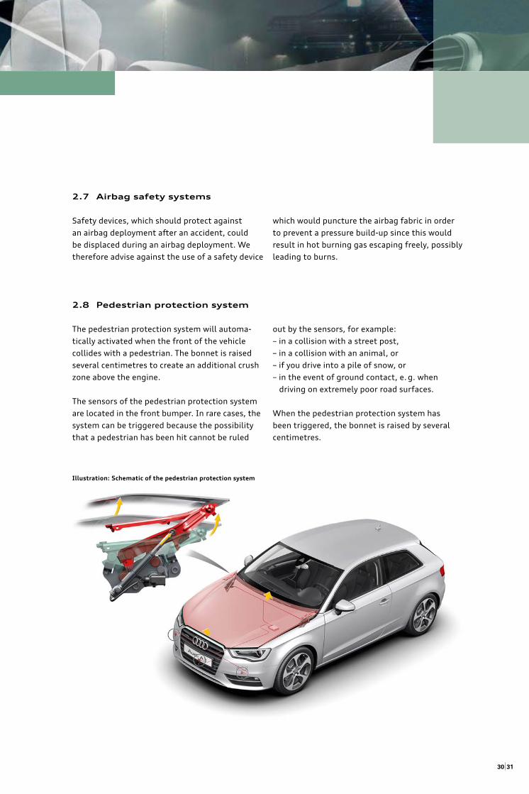
Illustration: Schematic of the pedestrian protection system
out by the sensors, for example:
– in a collision with a street post,
– in a collision with an animal, or
– if you drive into a pile of snow, or
– in the event of ground contact, e. g. when
driving on extremely poor road surfaces.
When the pedestrian protection system has
been triggered, the bonnet is raised by several
centimetres.
2.8 Pedestrian protection system
The pedestrian protection system will automa-
tically activated when the front of the vehicle
collides with a pedestrian. The bonnet is raised
several centimetres to create an additional crush
zone above the engine.
The sensors of the pedestrian protection system
are located in the front bumper. In rare cases, the
system can be triggered because the possibility
that a pedestrian has been hit cannot be ruled
3332
03 Vehicle electrics system
With the increasing types of equipment in vehi-
cles, energy consumption increases and therefore
the demand for larger or more energy storage.
This also has consequences for the rescue eff ort.
Particularly with the deactivation of the vehicle
electrics system (turn off the ignition, disconnect
battery), additional points must be observed.
Deactivation of the vehicle electrics system re-
duces the risk of fi re caused by electrical shorts,
and also the risk of delayed activation of airbags,
belt pretensioners or rollover protection.
When deactivating the vehicle’s electrics system,
one must ensure that the power for any existing
trailer is disconnected and that any existing solar
panels located in the sunroof are covered.
3.1 Vehicle batteries
Audi vehicles are usually equipped with one bat-
tery. However, in some special vehicles, there may
be additional vehicle batteries.
•
Risk of electrical shot, activation
of restraint systems, rollover pro-
tection and so on.
Turn ignition off !
Disconnect 12V Batteries!
The location and numbers of the
battery depends on the vehicles.
After crashes, all batteries should,
if possible, always be disconnected!
!
!
The automatically battery cut-off
relay only disconnects the battery-
plus-line from the starter or the
starter battery. Additional vehicle
functions such as hazard warning
fl ashing lights, interior lighting and
safety systems will remain functio-
nal. This means, however, that the
battery must still be disconnected.
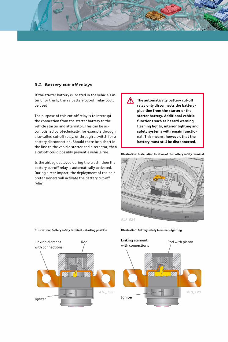
3.2 Battery cut-off relays
If the starter battery is located in the vehicle’s in-
terior or trunk, then a battery cut-off relay could
be used.
The purpose of this cut-off relay is to interrupt
the connection from the starter battery to the
vehicle starter and alternator. This can be ac-
complished pyrotechnically, for example through
a so-called cut-off relay, or through a switch for a
battery disconnection. Should there be a short in
the line to the vehicle starter and alternator, then
a cut-off could possibly prevent a vehicle fi re.
Is the airbag deployed during the crash, then the
battery cut-off relay is automatically activated.
During a rear impact, the deployment of the belt
pretensioners will activate the battery cut-off
relay.
!
Illustration: Installation location of the battery safety terminal
Linking element
with connections
Illustration: Battery safety terminal – starting position
Igniter
Rod
Illustration: Battery safety terminal – igniting
Linking element
with connectionsRod with piston
Igniter
RLF_024
410_122 410_123
3534
3.3 User information regarding
handling of the vehicle’s electric
system
Turning off the power supply to the vehicle can
be accomplished by following the following sys-
tematic approach:
1. Turn off the vehicle’s running engine
There could be situations in which it is necessary
for rescue personnel to turn off the vehicle’s
engine.
Normally this is accomplished by using the vehicle
ignition key. However, some models could be
equipped with a keyless entry and start ignition
system. In this case, the running engine can be
turned off by pushing the start/stop button.
Depending on vehicle type and model
year, the fuel pump is turned off by the
control module for the safety system.
This will most likely prevent the engine
from continuing to run.
2. Activate the warning lights
Any rescue personnel can use the activated warn-
ing lights as a visible sign of an active vehicle
power supply.
Depending on vehicle type and model
year, the warning lights are automatically
activated by the control module for the
safety system.
3. Use of power comfort settings for the
purpose of rescue
Depending on the model line and vehicle equip-
ment, Audi vehicles have a whole range of power
operated comfort features, for example:
• Power windows
• Power sunroof
• Power seats
• Power adjustable steering column
• Power assisted trunk opening
These can no longer be utilized after the battery
has been disconnected!
If possible, the power comfort features
should be used for optimizing the rescue
eff ort before the battery is disconnected!
i
i
i
4. Turn off the ignition
The voltage supply to the control unit for the
airbag is interrupted by turning off the ignition.
An electric ignition of the airbags, belt tensioners
and the rollover protection by the control unit
is no longer possible after a maximum of
30 seconds.
The shift lever must be positioned in
the “P” position for automatic trans-
mission equipped vehicles.
For vehicles with keyless entry and start ignition
systems, the ignition is turned off by one push on
the start/stop button or by complete removal of
the keys out of the switch for start authorization.
Make sure that the brake pedal is not
depressed, before pressing the START
ENGINE STOP button! By pressing
the START ENINGE STOP button with
depressing brake pedal, the engine
starts!
5. Locate the battery/batteries
Parallel to the aforementioned measures, the
battery/batteries should be located.
The vehicle batteries for Audi vehicles are located,
depending on vehicle model and engine:
• In the engine compartment
• In the trunk (in the side pocket or in the
area of the spare tyre)
• Under the driver seat (only in the Audi Q7)
• Under the rear seat (with older models)
The battery location can be found in the
rescue data sheets.
In order to successfully access the
engine and luggage compartment, con-
ventional methods of opening are possible
such as a hood release, ignition key, etc.
In case these do not work, then the engine
and trunk lids could be forced to open
with a crowbar or hydraulic spreader.
!
i
i
i
3736
6. Disconnect the battery/batteries
After access to the battery is accomplished and
then after the use of the power comfort features,
both battery terminals on all batteries are discon-
nected. A 10/13 mm wrench is needed for this.
The battery must also be disconnected
when a battery separator is attached.
Instruction how to disconnect the battery in
certain vehicle models …
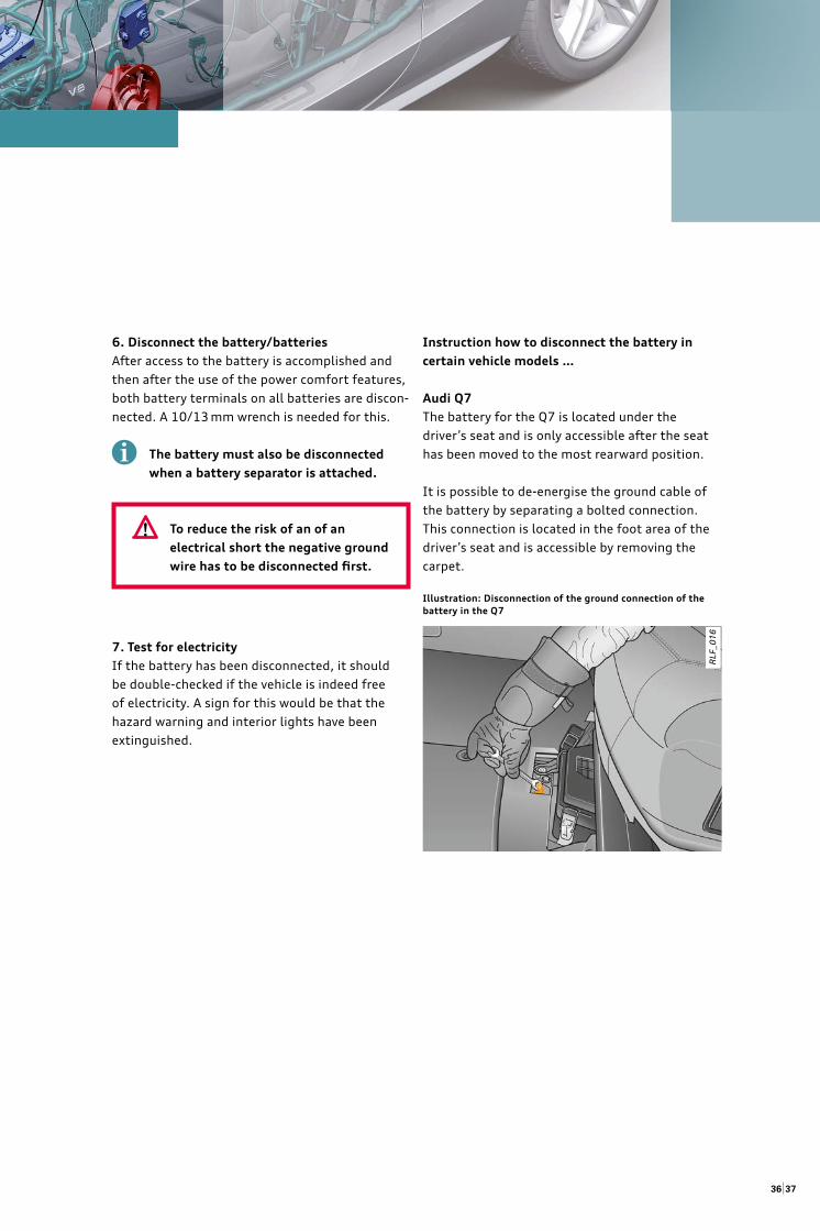
Audi Q7
The battery for the Q7 is located under the
driver’s seat and is only accessible after the seat
has been moved to the most rearward position.
It is possible to de-energise the ground cable of
the battery by separating a bolted connection.
This connection is located in the foot area of the
driver’s seat and is accessible by removing the
carpet.
Illustration: Disconnection of the ground connection of the
battery in the Q7
i
RLF
_016
7. Test for electricity
If the battery has been disconnected, it should
be double-checked if the vehicle is indeed free
of electricity. A sign for this would be that the
hazard warning and interior lights have been
extinguished.
To reduce the risk of an of an
electrical short the negative ground
wire has to be disconnected fi rst.
!
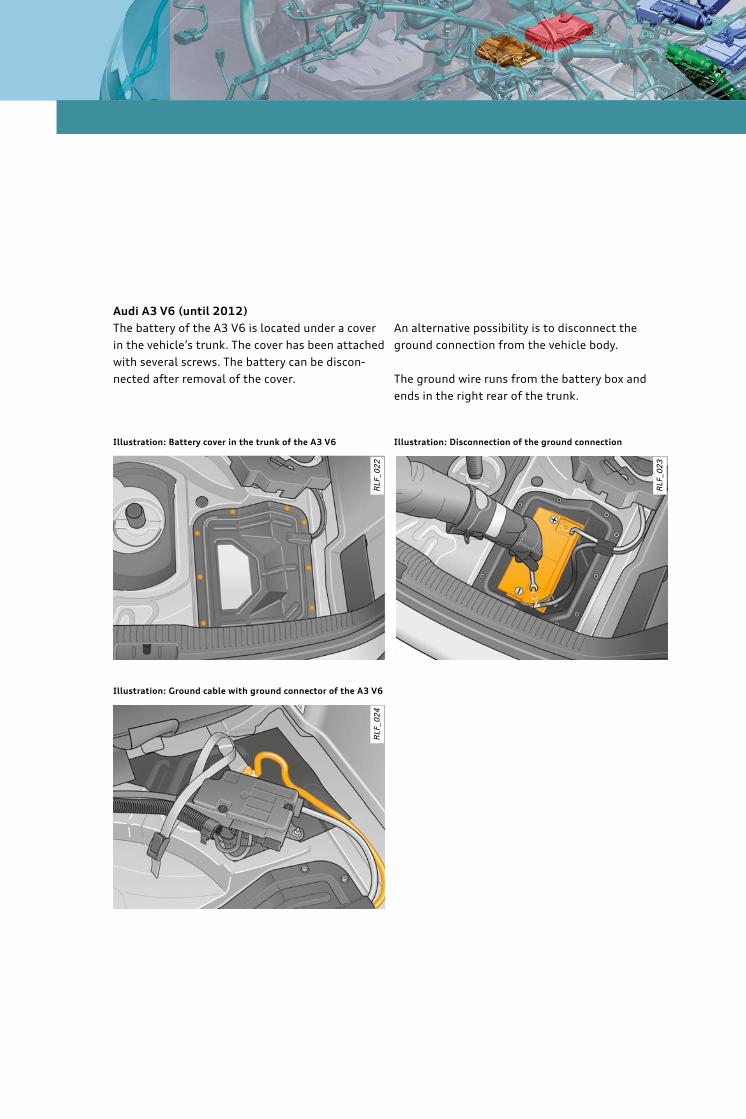
Audi A3 V6 (until 2012)
The battery of the A3 V6 is located under a cover
in the vehicle’s trunk. The cover has been attached
with several screws. The battery can be discon-
nected after removal of the cover.
Illustration: Battery cover in the trunk of the A3 V6
Illustration: Ground cable with ground connector of the A3 V6
An alternative possibility is to disconnect the
ground connection from the vehicle body.
The ground wire runs from the battery box and
ends in the right rear of the trunk.
Illustration: Disconnection of the ground connection
RLF
_022
RLF
_023
RLF
_024
39
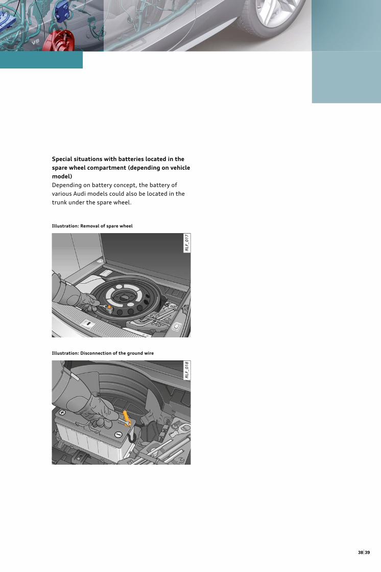
Special situations with batteries located in the
spare wheel compartment (depending on vehicle
model)
Depending on battery concept, the battery of
various Audi models could also be located in the
trunk under the spare wheel.
Illustration: Removal of spare wheel
Illustration: Disconnection of the ground wire
38
RLF
_017
R
LF_0
18
4140
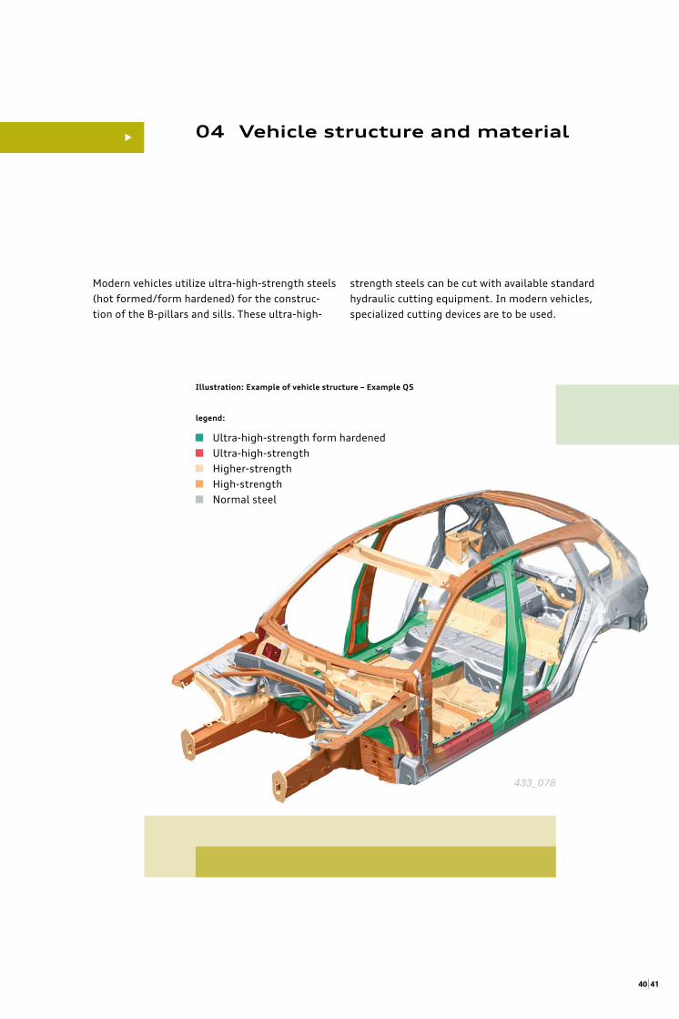
04 Vehicle structure and material
A high level of safety for vehicle occupants can be reached by designing a rigid passenger compart-
ment in order to minimize intrusion. This is achieved by using higher-strength steels, greater wall
thickness and a multi-shell construction.
•
Illustration: Example of vehicle structure – Example Q5
legend:
Ultra-high-strength form hardened
Ultra-high-strength
Higher-strength
High-strength
Normal steel
433_078
Modern vehicles utilize ultra-high-strength steels
(hot formed/form hardened) for the construc-
tion of the B-pillars and sills. These ultra-high-
strength steels can be cut with available standard
hydraulic cutting equipment. In modern vehicles,
specialized cutting devices are to be used.
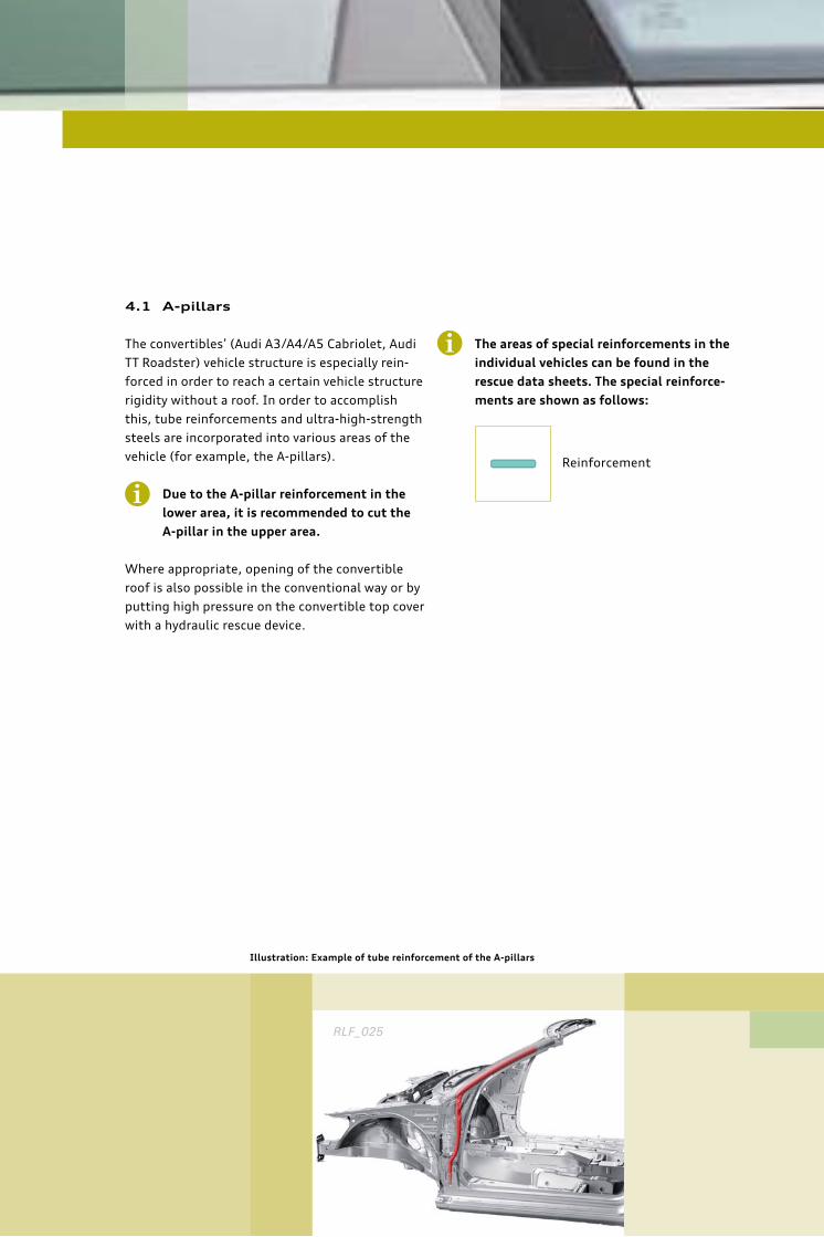
4.1 A-pillars
The convertibles’ (Audi A3/A4/A5 Cabriolet, Audi
TT Roadster) vehicle structure is especially rein-
forced in order to reach a certain vehicle structure
rigidity without a roof. In order to accomplish
this, tube reinforcements and ultra-high-strength
steels are incorporated into various areas of the
vehicle (for example, the A-pillars).
Due to the A-pillar reinforcement in the
lower area, it is recommended to cut the
A-pillar in the upper area.
Where appropriate, opening of the convertible
roof is also possible in the conventional way or by
putting high pressure on the convertible top cover
with a hydraulic rescue device.
The areas of special reinforcements in the
individual vehicles can be found in the
rescue data sheets. The special reinforce-
ments are shown as follows:
i
Illustration: Example of tube reinforcement of the A-pillars
Reinforcement
RLF_025
i
4342
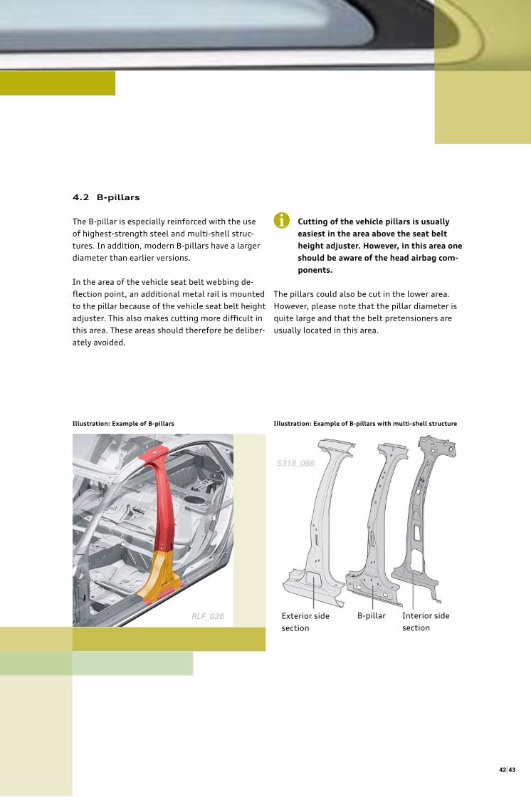
Illustration: Example of B-pillars Illustration: Example of B-pillars with multi-shell structure
4.2 B-pillars
The B-pillar is especially reinforced with the use
of highest-strength steel and multi-shell struc-
tures. In addition, modern B-pillars have a larger
diameter than earlier versions.
In the area of the vehicle seat belt webbing de-
fl ection point, an additional metal rail is mounted
to the pillar because of the vehicle seat belt height
adjuster. This also makes cutting more diffi cult in
this area. These areas should therefore be deliber-
ately avoided.
Cutting of the vehicle pillars is usually
easiest in the area above the seat belt
height adjuster. However, in this area one
should be aware of the head airbag com-
ponents.
The pillars could also be cut in the lower area.
However, please note that the pillar diameter is
quite large and that the belt pretensioners are
usually located in this area.
i
Interior side
section
Exterior side
section
B-pillarRLF_026
S318_066
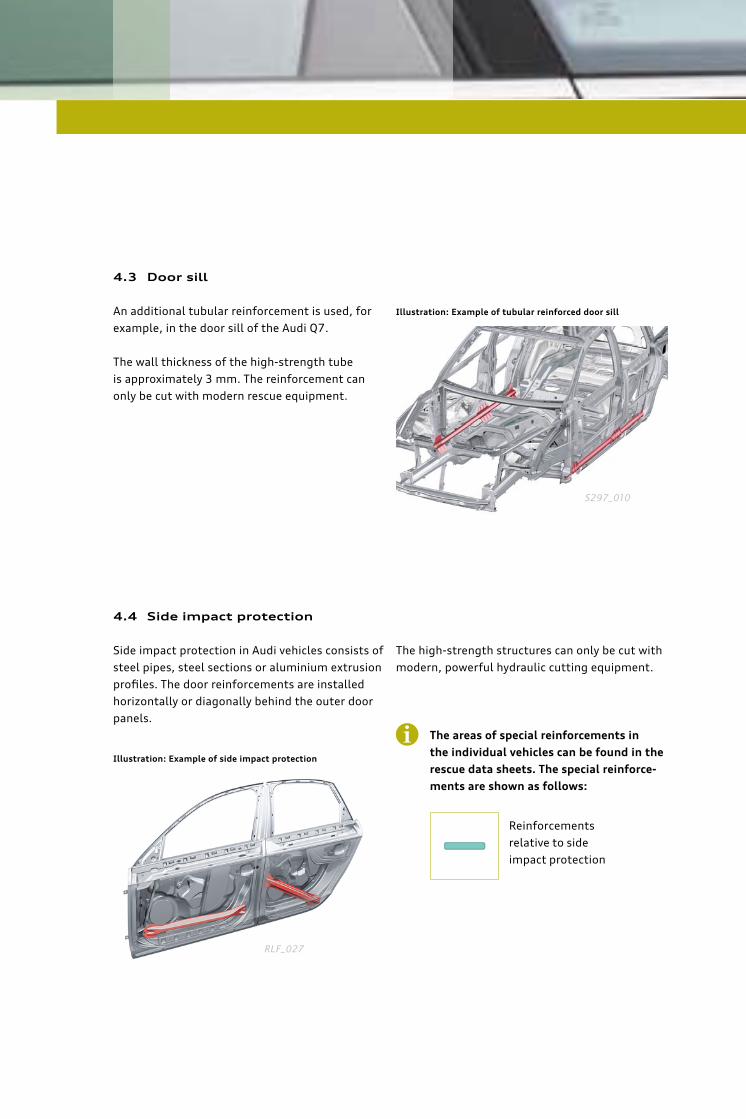
4.3 Door sill
An additional tubular reinforcement is used, for
example, in the door sill of the Audi Q7.
The wall thickness of the high-strength tube
is approximately 3 mm. The reinforcement can
only be cut with modern rescue equipment.
4.4 Side impact protection
Side impact protection in Audi vehicles consists of
steel pipes, steel sections or aluminium extrusion
profi les. The door reinforcements are installed
horizontally or diagonally behind the outer door
panels.
The high-strength structures can only be cut with
modern, powerful hydraulic cutting equipment.
The areas of special reinforcements in
the individual vehicles can be found in the
rescue data sheets. The special reinforce-
ments are shown as follows:
i
Illustration: Example of tubular reinforced door sill
Illustration: Example of side impact protection
Reinforcements
relative to side
impact protection
S297_010
RLF_027
4544
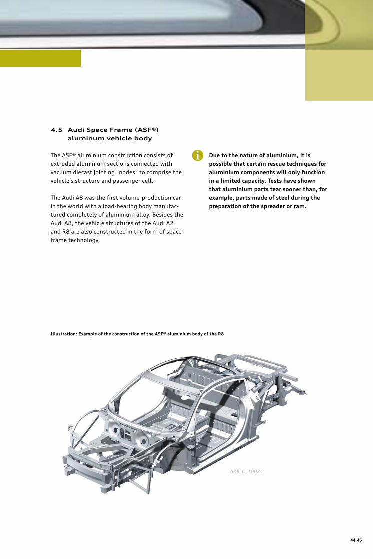
Illustration: Example of the construction of the ASF® aluminium body of the R8
4.5 Audi Space Frame (ASF®)
aluminum vehicle body
The ASF® aluminium construction consists of
extruded aluminium sections connected with
vacuum diecast jointing “nodes” to comprise the
vehicle’s structure and passenger cell.
The Audi A8 was the fi rst volume-production car
in the world with a load-bearing body manufac-
tured completely of aluminium alloy. Besides the
Audi A8, the vehicle structures of the Audi A2
and R8 are also constructed in the form of space
frame technology.
Due to the nature of aluminium, it is
possible that certain rescue techniques for
aluminium components will only function
in a limited capacity. Tests have shown
that aluminium parts tear sooner than, for
example, parts made of steel during the
preparation of the spreader or ram.
i
AR8_D_10084
4.6 Automotive glazing
(heat absorbing glass)
Audi vehicles are equipped with two diff erent
types of glazing:
Tempered glass is used for the side windows, the
rear windows and the sunroofs. It consists of
thermally pre-treated glass which can withstand
high loads. Should the load be too high, then the
glass will shatter in many, but not particularly
sharp, small pieces.
It is possible that tempered glass could
suddenly burst during use of rescue equip-
ment. Depending on the accident situa-
tion and extent of rescue work necessary,
the tempered glass window should fi rst
be removed.
Laminated safety glass is used in front windows
as well as in side windows of the A6 and A8. This
type of glass consists of two glass plates which
are held together by a fi lm. The windows will stay
intact even after it is damaged.
All vehicle windshields consist of laminated
safety glass and are glued to the vehicle struc-
ture. Side windows and sunroofs usually consist
of tempered glass and are either movable, hinged
or glued.
There are special glass saws and metal cutters
which are suitable for the removal of laminated
safety glass.
Since laminated safety glass does not
burst during rescue work with hydraulic
equipment, these types of windows
should only be removed if it is deemed
necessary under the circumstances.
Tempered glass can be removed by breaking with
a pointed load, for example with a spring centre
punch or emergency hammer. The window should
therefore be protected before removal.
Before removal of the windows, the
vehicle occupants should be protected
from dust and splinters.
i i
i


Vorsprung durch Technik www.audi.de
© AUDI AGVehicle SafetyI/EK-5585045 Ingolstadt
Status: November 2012