Embed Size (px)
DESCRIPTION
como fazer traffic calming Urbanismo
Citation preview

Traffic Calming Guidelines
GUIDELINES ON TRAFFIC CALMING
FOR TOWNS AND VILLAGES ON NATIONAL ROUTES
Rev B, February 2005
National Roads Authority
St Martin’s House, Waterloo Road, Dublin 4.
Telephone 01 660 2511 Fax 01 668 0009
e-mail: [email protected]
Web site: www.nra.ie

Traffic Calming Guidelines
Traffic Calming Guidelines
i
FOREWORD TO GUIDELINES ON TRAFFIC CALMING
In July 1998 the Government published “The Road to Safety”, its Strategy for road safety over the period 1998 – 2002. The primary target of the strategy is to reduce road fatalities by 2002 by a minimum of 20% on their 1997 level (472) and to achieve a similar reduction (at least 20%) in the number of serious injuries from road accidents (2,182 in 1997). Under the terms of the Strategy, the Authority will be required to undertake a number of specific tasks including the finalisation of a five year programme for traffic calming on the network of national roads. Traffic calming is one important application in the road safety management of national routes which pass through towns and villages. In the first instance, speed is reduced by altering the appearance of the road on the approach to the town/village through the use of “gateways” and by further traffic management measures within the town itself. Over the past 10 years a number of pilot traffic calming schemes, based on different concepts, were introduced and monitored for effectiveness. The preparation of this publication is based on the results of the monitoring of the pilot schemes and also best ideas from abroad. The guidelines will lead to a national uniformity of design for traffic calming. I wish to record my thanks to the Traffic Calming Working Group for all of the effort they put into the preparation of this publication. The members of the group were:
Finbarr Crowley N.R.A. (Chairman) Harry Cullen N.R.A. Ray Butler Tramore House R.D.O. Paul Crowe Limerick County Council Ciaran Jordan Westmeath County Council Jack Keyes Offaly County Council Eamonn McMahon Dundalk Institute of Technology Eimhin O’Murchu Colas Teoranta
Landscape Consultants to working group Murray and Associates, Dublin Eugene O’Connor, Head of Project Management and Engineering
October 1999

Traffic Calming Guidelines
ii
Traffic Calming Guidelines
iii
FOREWORD TO GUIDELINES ON TRAFFIC CALMING.................................. i
Introduction ...................................................................................................................1
Chapter 1 Preplanning, Selection and Evaluation...................................................3
1.1 Preplanning.................................................................................................................3 1.1.1 AADT 3 1.1.2 Accident Details 4 1.1.3 Speed Measurements 4 1.1.4 Geometry 5 1.1.5 Future Infrastructural Development 5
1.2. General Principles for the Selection of Traffic Calming Schemes...........................6 1.2.1 Selection based on Accidents 6 1.2.2 Other Considerations 6
1.3 Monitoring and Evaluation........................................................................................7
Chapter 2 Traffic Calming Techniques Appropriate to the Transition Zone ......9
2.1 Statement of Problem .................................................................................................9
2.2 Design Elements for Transition Zones ....................................................................10
2.3 General Design Guidelines for Gateways................................................................11
2.4 Detailed Design Guidelines for Gateways and Transition Zones...........................12
2.5 Guidelines for Landscape Design ............................................................................15 2.5.1 Transition Zone Landscape Design 16 2.5.2 Gateway Landscape Design 17
2.6 Guidelines for the Provision of Rumble Strips or Rumble Areas...........................17
Chapter 3 Ancillary Traffic Calming Techniques Appropriate to Urban
Sections of the Route ..............................................................................19
3.1 Statement of Problem ...............................................................................................19
3.2 Design Elements for Urban Sections.......................................................................19
3.3 General Design Guidelines.......................................................................................20 3.3.1 The Maintenance of an Appropriate Carriageway Width 20
Traffic Calming Guidelines
iv
3.3.2 The Provision of Pedestrian Facilities (9)(10)(11) 22 3.3.3 The Provision of Pedal Cycle Facilities (12) 23 3.3.4 The Use of Kerbing 25 3.3.5 The Use of Road Markings 27 3.3.6 Urban and Landscape Design 28
Chapter 4 Consultation Process and Legal Considerations .................................29
4.1 Legal Power to provide or remove Traffic Calming Measures .............................. 29
4.2 Consultation Process................................................................................................ 29 4.2.1 Legal Obligation 29 4.2.2 Limit to Legal Obligation 29 4.2.3 Recommendations on Consultation 31
4.3 Consent of the National Roads Authority ............................................................... 31
4.4 Other Legal Considerations..................................................................................... 31 4.4.1 Speed Limit Signs 32 4.4.2 Road Signs and Markings 32
Chapter 5 Planting Specification ...............................................................................35
5.1 Introduction.............................................................................................................. 35 5.1.1 The landscape proposals 35 5.1.2 Scoping assessment 35
5.2 Nursery Stock Selections ......................................................................................... 35 5.2.1 Nursery stock for cold, exposed inland areas 36 5.2.2 Nursery stock for sites consolidated by machines and re-soiled 36 5.2.3 Nursery stock for heavy soils 36 5.2.4 Nursery stock to withstand noxious fumes/polluted areas 36 5.2.5 Nursery stock for dry sites in full sun 36 5.2.6 Nursery stock for low maintenance 37 5.2.7 Selected specimen trees 37 5.2.8 Amenity value, plant associative table 37
Chapter 6 Technical Specification ..........................................................................55
6.1 Introduction.............................................................................................................. 55
6.2 Design/Construction Specification and Layout Guidelines ................................... 56 6.2.1 Signage 56 6.2.2 Road Markings 58 6.2.3 Road Studs 59
Traffic Calming Guidelines
v
6.2.4 Lighting 59 6.2.5 Bollards 60 6.2.6 Flexible Surfacing 61 6.2.7 Refuge Islands 61 6.2.8 Kerbing 62 6.2.9 Rumble Strips 62 6.2.10 Cycle/Pedestrian Facilities 63 6.2.11 Cycle Facilities 63
References 65
Appendix 1 Traffic Calming Data Summary Sheet ................................................67
Traffic Calming Data Sheet Guidance Notes .....................................................................67
Traffic Calming Data Summary Sheet ...............................................................................69
Appendix 2 Sign, Post and Foundation Details .......................................................71

Traffic Calming Guidelines
vi
Traffic Calming Guidelines
1
Introduction
High speed relative to the environment has long been recognised as a road safety problem.
The concepts of speed management and traffic calming were developed in response to this
problem.
Traffic calming is essentially a way of reducing vehicle speeds by self-enforcing traffic
engineering methods. Traffic calming is commonly applied in urban and residential road
safety management and in the road safety management of through routes in towns and
villages. The latter application is the subject of this guideline.
Chapter 1 deals with preplanning, selection and evaluation.
Chapter 2 deals with traffic calming techniques appropriate to the transition zone on
routes between the rural and urban area.
Chapter 3 deals with ancillary traffic calming techniques appropriate to the urban section
of the route.
Chapter 4 deals with the consultation process and legal considerations.
Chapter 5 presents a planting specification.
Chapter 6 presents a technical specification.
The contents of the above chapters are complementary and should not be considered in
isolation. In preparing a scheme the designer should have regard to the entire document so
that an integrated scheme may be achieved.

Traffic Calming Guidelines
2
Traffic Calming Guidelines
3
Chapter 1 Preplanning, Selection and Evaluation
Traffic calming schemes have been in place on the approaches to some of the towns and
villages on the National Route network since 1993 and the overall general public reaction has
been positive. As a natural consequence, Local Authorities are now facing an increased
demand for further traffic calming schemes. Given the limited resources available, it is
essential that a structured assessment framework be developed which will assist in identifying
priorities. This chapter sets out the major considerations for such an approach.
1.1 Preplanning
The following data should be collected and compiled:
• AADT (Annual Average Daily Traffic)
• accident details
• speed measurements
• geometry
• details of future infrastructural development.
Appendix 1 contains a data summary sheet that may be used to record the collected data. This
summary sheet may also be used for post-construction evaluation of the scheme.
1.1.1 AADT
AADT figures are obtained by a combination of manual and automatic counts. Classification
of vehicles, including cyclists, should be carried out manually while the overall volume can
be determined by automatic counting methods. The automatic count should be of one
month’s duration, if possible. This figure can be expanded to an AADT value by reference to
NRA (National Roads Authority) permanent traffic counters on the route in question.
Traffic Calming Guidelines
4
Specific manual counts may be necessary to determine cycle and pedestrian numbers.
Pedestrian numbers, in particular, will be site specific, and this fact should be borne in mind
when making an assessment.
1.1.2 Accident Details
The location and type of all fatal and personal injury accidents which have been recorded over
the previous five-year period should be abstracted and plotted.
A detailed examination of the circumstances of each accident should be carried out. This will
provide valuable information as to countermeasures. The circumstances of pedestrian
accidents in conjunction with observation of pedestrian movements will help to fix the
optimum positions of pedestrian crossing places. The Fermoy and Mitchelstown Traffic
Accident Studies(1,2) provide guidelines for this approach.
1.1.3 Speed Measurements
As a minimum, speed measurements should be taken:
• on the approaches
• at existing speed limit locations
• at suitable locations within the speed limits.
For the purposes of evaluation, the 85 percentile dry weather spot speed of vehicles should be
used(3). The method of measurement should be uniform in all respects to permit useful
comparison. Measurements using radar guns can be difficult to replicate and it is
recommended that inductive loops or magnetic imaging counters be used to achieve reliable
results.
Traffic Calming Guidelines
5
1.1.4 Geometry
A detailed survey of the route should be carried out, locating:
• junctions
• existing pedestrian crossing points
• accesses
• street furniture
• services
• landscape features
• future/proposed developments
• bus bays.
The approach geometry, which will have an effect on speeds, should also be recorded. A
straight horizontal alignment will have higher speeds than a curving alignment, as will a
vertical down grade.
The right-of-way width (face of fence to face of fence) should be determined as this will
determine the choice of gateway design type. The paved width (including hard shoulders) and
carriageway width should also be recorded.
It is often helpful to use these data to divide the through route into reasonably homogenous
sections at initial design stage.
1.1.5 Future Infrastructural Development
Consideration should be given to likely future developments in the area which might impact
on traffic calming proposals. These could include:
• future road developments
• future utilities requirements e.g. water, sewerage, gas, E.S.B., Telecom etc.
• planning permissions, altered land use etc.
Traffic Calming Guidelines
6
1.2. General Principles for the Selection of Traffic Calming Schemes
The engineer dealing with traffic calming may be faced with the problem of carrying out a
comparative assessment of a number of competing locations.
1.2.1 Selection based on Accidents
It is recommended that selection based on accidents should take account of both risk per unit
of travel and risk per head of population in the town or village under consideration.
Accident rates per unit of travel within speed limit zones on the national routes vary between
0.1 and 25.0 PIA/106 vkm (personal injury accidents per million kilometres of travel).
Accident rates per thousand head of population per annum vary between 0.1 and 9.35
PIA/1000 pop/annum (personal injury accidents per thousand population per year). For
selection purposes rates in excess of 5 PIA/106 vkm and 2 PIA/1000 pop/annum are deemed
significant.
The cost of the scheme relative to accident risk should also be taken into account to ensure
that schemes providing best value for money are assigned a higher priority.
1.2.2 Other Considerations
• Quality Pavement Projects. Experience shows that where quality pavement
improvement projects are undertaken, operating speeds and accident risk may increase
in towns and villages on the resurfaced section. It is recommended that traffic calming
measures should be considered in tandem with such projects.
• Bypasses. Where a town is being bypassed, the need for traffic calming measures on
the original route should be assessed and, if warranted, included as part of the overall
scheme.
• Planning Considerations. Major new developments in an area may give rise to
increased traffic volumes or changes in traffic make-up and type. Traffic calming may
be appropriate in addressing such issues, and could be considered as part of the
planning process.
Traffic Calming Guidelines
7
1.3 Monitoring and Evaluation
In order to assess the effectiveness of a traffic calming scheme, the impact of the scheme must
be systematically monitored after installation.
The importance of evaluation and monitoring can not be overstated and the accumulation of
this valuable information will assist in future assessment and prioritising of traffic calming
schemes.
The primary purpose of traffic calming is to reduce the number of accidents by reducing
vehicle speed. It is essential that the extent of the speed reduction and the impact of this
reduction on accidents be systematically evaluated for each installation.
Each scheme is likely to have some drawbacks as well as the acknowledged benefits
associated with the installation. It is important that any assessment has regard to both prior
expectations and reaction afterwards of all road users, especially those of the vulnerable
groups.
The Traffic Calming Data Summary Sheet in Appendix 1 should be completed for each
scheme. A separate sheet should be completed for each route within the scheme.

Traffic Calming Guidelines
8
Traffic Calming Guidelines
9
Chapter 2 Traffic Calming Techniques Appropriate to the Transition Zone
2.1 Statement of Problem
The transition zone between a high speed and a low speed road represents a difficult safety
management problem. Typically, these transition zones are located on the approaches to
towns and villages.
In Ireland the problem first became apparent over twenty years ago with the proliferation of
improved road sections with hard shoulders on the National Roads. Where these improved
sections adjoined towns and villages, approach speeds increased and the sections showed
higher accident rates than rural sections.
For many years it was thought that speed could be reduced in transition zones by the posting
of area speed limits. A large-scale Swedish experiment showed that the posting of a speed
limit alone without any physical speed reducing measure did not result in any significant
reduction in speed. The same result was experienced in Norway. Because the construction of
a by-pass was very costly in the Norwegian mountains, they developed the concept of through
roads with speed reducing measures (4). The idea was quickly assimilated and put to work
under the designation ‘Environmentally Adapted Through Roads’. All studies of the effects
of such speed reducing measures in European countries indicate a significant decline in the
number of traffic accidents (5).
The design problem is that one end of the transition zone looks very similar to the adjoining
rural sections while at the other end there is generally an abrupt change to the streetscape of
the town or village. This is particularly true where hard shoulders are present.
The difference in appearance between rural and urban sections is largely explained in terms of
the concept of ‘optical width’ (6). In a rural situation the width between fences is generally
many times greater than the height of the vertical elements which bound the field of view. In
a very narrow urban street, the height of the vertical elements is much greater than the width.
A driver’s perception of the appropriate driving speed is influenced by the relationship
Traffic Calming Guidelines
10
between the width of the road and the height of the vertical elements. It can be shown that
speeds are lower where the height of vertical elements is greater than the width of the road. A
combination of carriageway narrowing, appropriate landscape treatment and the introduction
of vertical elements can create this effect.
The ‘optical width’ concept should be used progressively throughout the length of the
transition zone to achieve the dominance of the vertical elements culminating in a ‘Gateway’.
A ‘Gateway’ is simply a concentration of vertical elements, which simulates an entrance to a
town or village.
2.2 Design Elements for Transition Zones
There should be a gradual change from rural to urban character in the transition zone.
A typical rural environment has informal character:
• grass verge not mown
• hedgerow composed of native species
• trees planted in clumps
• footpaths usually absent.
A typical urban environment has formal character:
• mown grass verge
• shrubs usually evergreen ground covers
• trees planted as standards in single or double rows
• footpaths usually present.
Traffic Calming Guidelines
11
The design elements, which may be considered, include:
• the prohibition of overtaking in the zone, using signs, solid centre lines and gateway
islands as appropriate
• the phasing out of the hard shoulder, using crosshatching inside the edge line to
increase the visual effect
• the narrowing of the carriageway
• the provision of rumble strips or rumble areas if speeds are not sufficiently reduced by
other measures
• the use of signs with a vertical emphasis
• the use of appropriate soft landscape elements such as trees, shrubs, and grass verge
treatment, which change in composition and degree of formality along the transition
zone into the town
• the provision of cyclist and pedestrian facilities
• the use of the town sign in conjunction with the area speed limit sign in the design of
the Gateway itself.
2.3 General Design Guidelines for Gateways
The Gateway should mark a definite change in the character of the surrounding area from
rural to urban. In addition:
• the Gateway should be conspicuous and should be the most prominent element in the
transition zone and located at the end of that zone
• the Gateway should be visible over the stopping distance for the 85 percentile of the
approach speed
• the Gateway should not interfere with sightlines at junctions etc.
• the Gateway location should take due cognisance of likely future developments
• when the Gateway location has been fixed, the existing speed limit zones should be
reviewed and changed, if necessary, so that the location of the 50kph or 60kph speed
limit sign corresponds with the Gateway
• public lighting, where provided, should extend at least two poles beyond the Gateway
Traffic Calming Guidelines
12
• traffic calming gateway lantern kit should be used on gateway centre islands
• kerbs on Gateway islands and build-outs should be painted (yellow and black)
• direct lighting of gateway signs at gateways without a centre island is optional, but has
been found to be very effective, particularly on long approaches
• the road surface should be of a reasonable standard before lining is undertaken (a
reasonable surface could be defined as one that is likely to be sufficient for the next
five years)
• the road surface may be colour or texture coded for the length of the Gateway
• a minimum width of 5.10m should be provided for between the edges of signs at the
entry side of the Gateway and this will accommodate the majority of loads. Wide loads
can use the exit side of the Gateway by prior arrangement
• gateway signs and lighting column in gateway centre islands must be demountable and
frangible
• fixtures on all central islands must be demountable as dismantling may be required
• signage clutter should be avoided
• all road signing and marking, other than where specifically mentioned in the text,
should be carried out in accordance with the Traffic Signs Manual(7)
• hardshoulders should, in general, be replaced with parking bays within the Gateway
• solid white lines may be used to mark parking bays within towns and villages
• a 2mm high narrow rib may be overlaid on crosshatching lines.
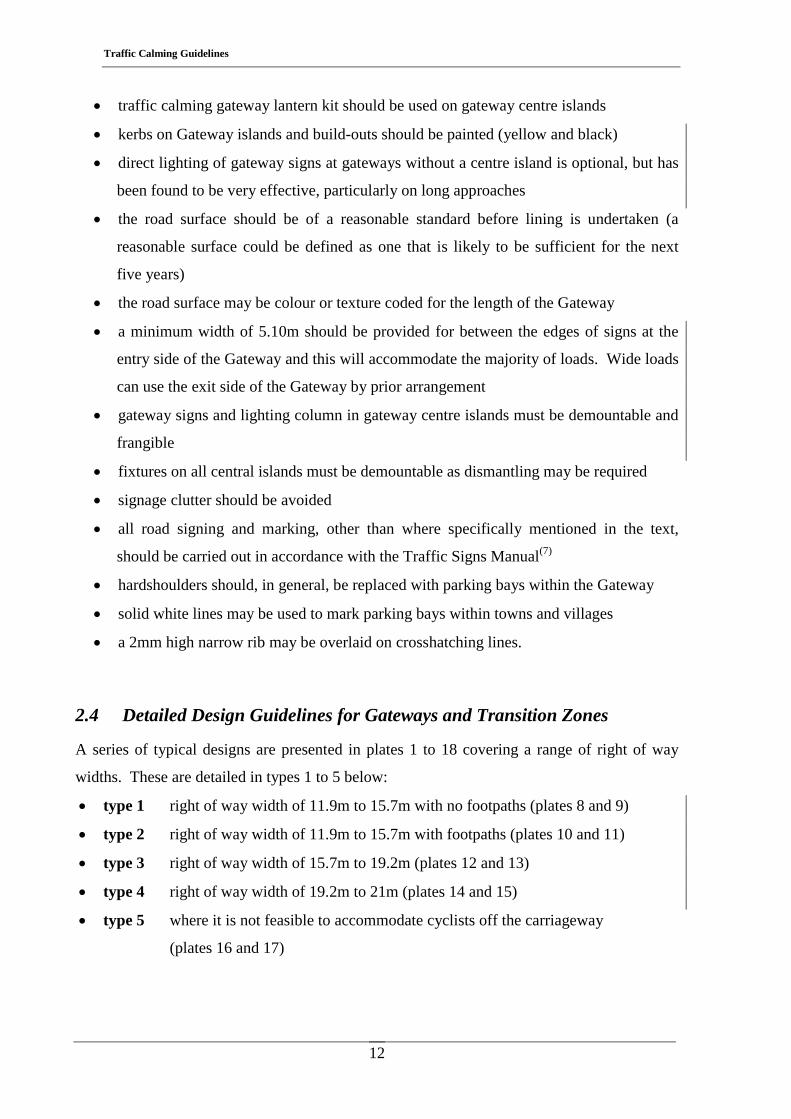
2.4 Detailed Design Guidelines for Gateways and Transition Zones
A series of typical designs are presented in plates 1 to 18 covering a range of right of way
widths. These are detailed in types 1 to 5 below:
• type 1 right of way width of 11.9m to 15.7m with no footpaths (plates 8 and 9)
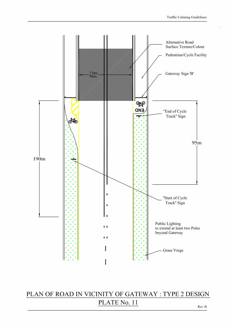
• type 2 right of way width of 11.9m to 15.7m with footpaths (plates 10 and 11)
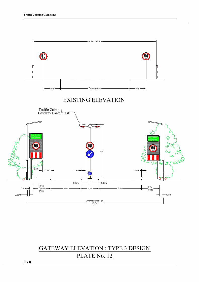
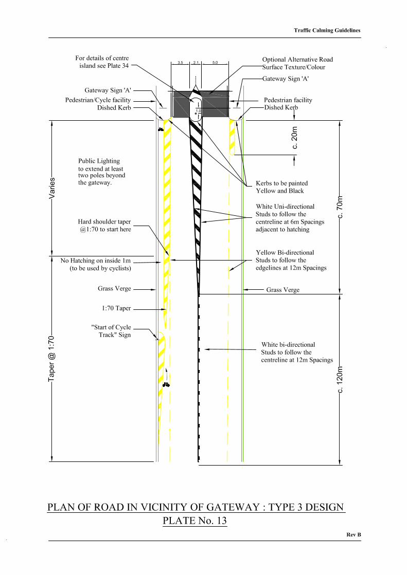
• type 3 right of way width of 15.7m to 19.2m (plates 12 and 13)
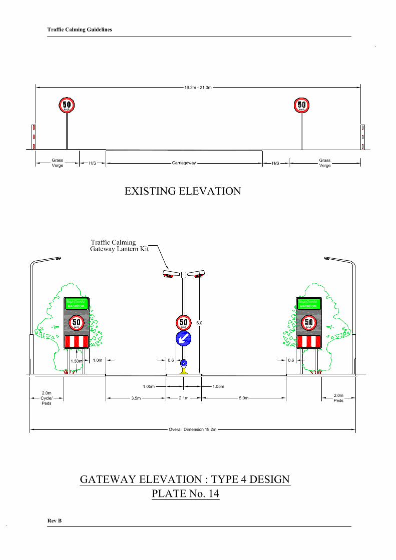
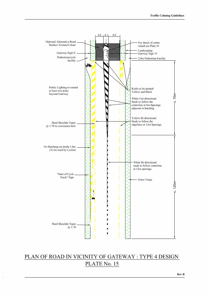
• type 4 right of way width of 19.2m to 21m (plates 14 and 15)
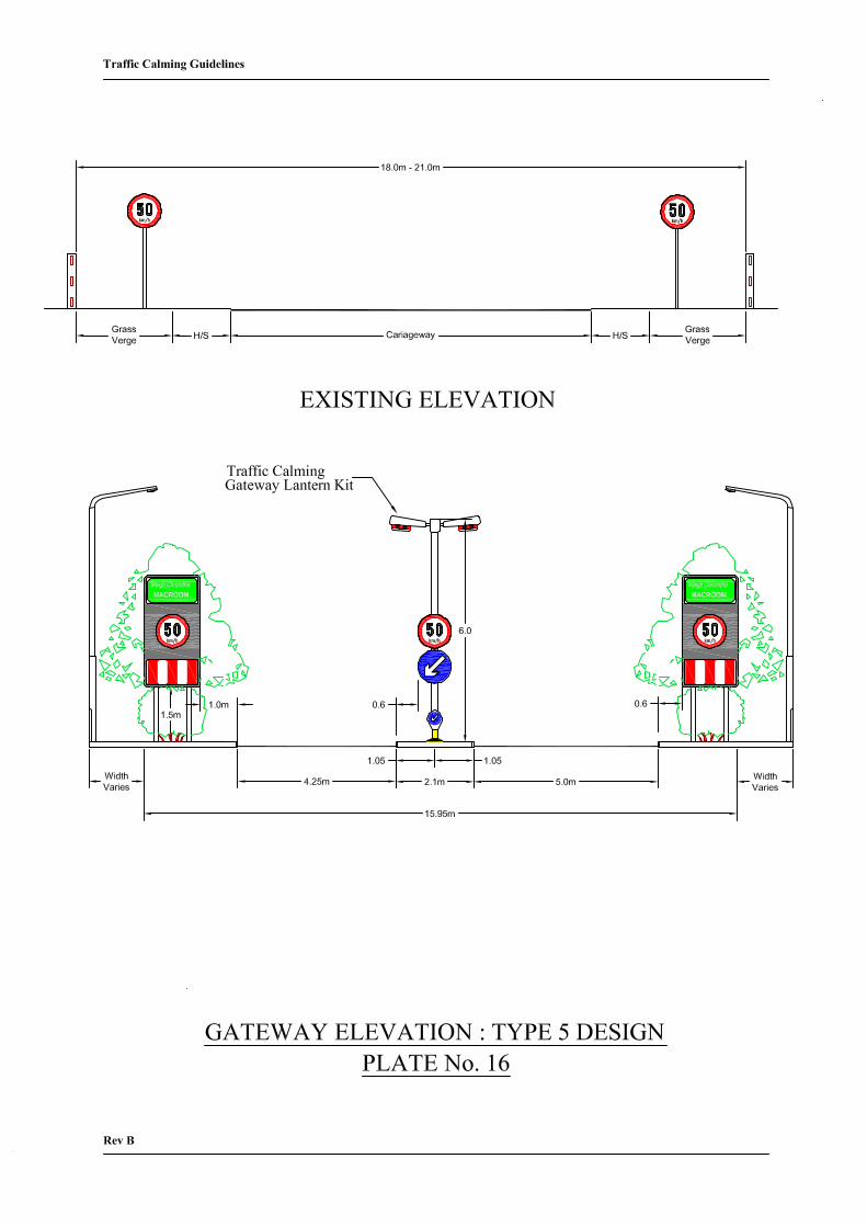
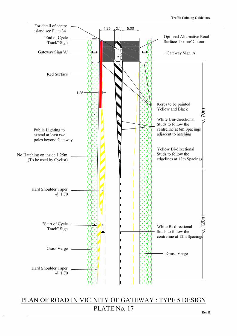
• type 5 where it is not feasible to accommodate cyclists off the carriageway
(plates 16 and 17)
Traffic Calming Guidelines
13
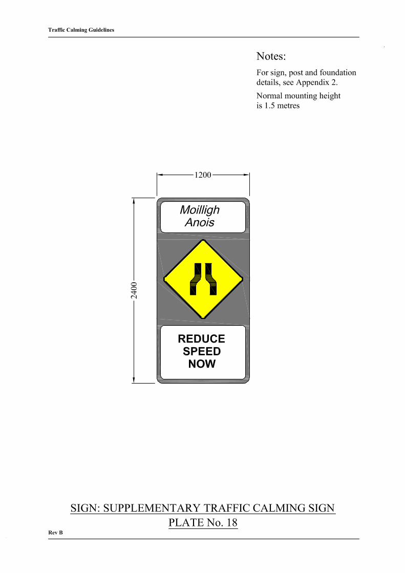
All signs shown in Plates 1 – 18, with the exception only of the gateway signs in Plates 10
and 12, and signs located on footpaths, should be mounted with a clearance of 1.5m.
Landscaping elements may be used to discourage pedestrians from passing underneath,
subject to sightline requirements. Careful consideration should be given to the provision of
frangible mountings to all traffic calming signs.
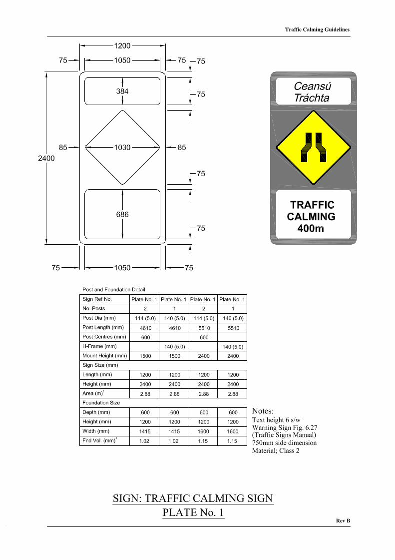
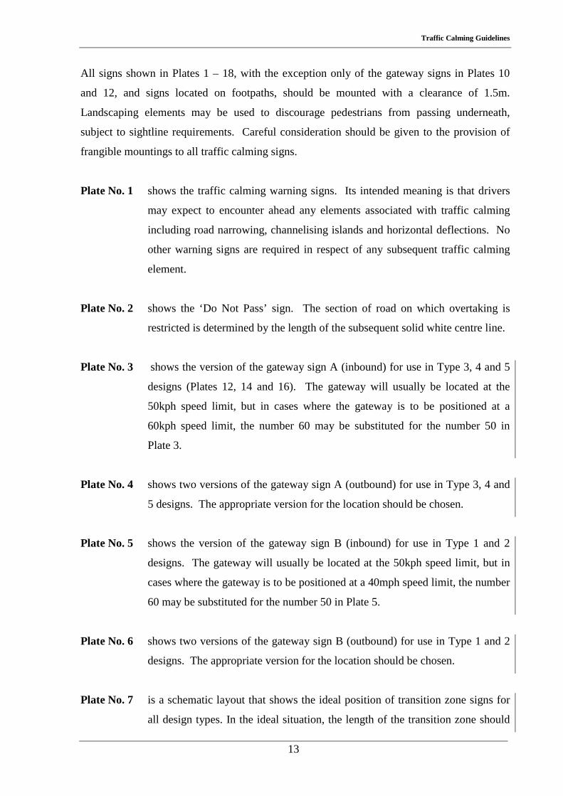
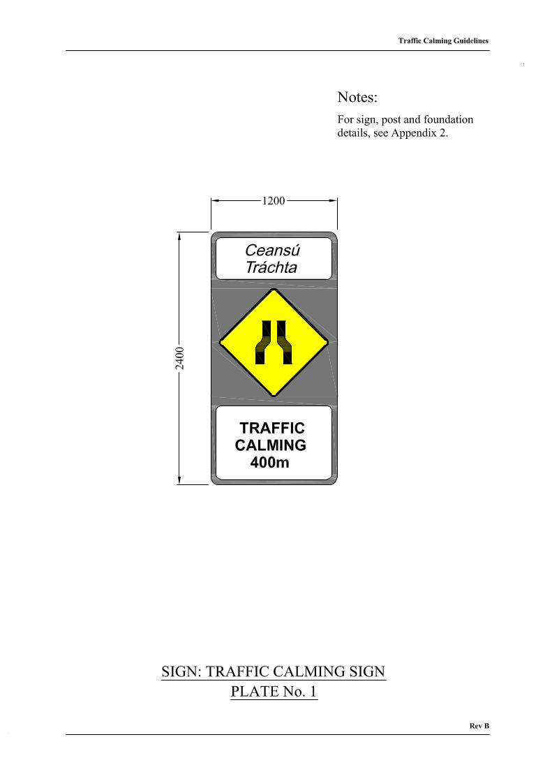
Plate No. 1 shows the traffic calming warning signs. Its intended meaning is that drivers
may expect to encounter ahead any elements associated with traffic calming
including road narrowing, channelising islands and horizontal deflections. No
other warning signs are required in respect of any subsequent traffic calming
element.
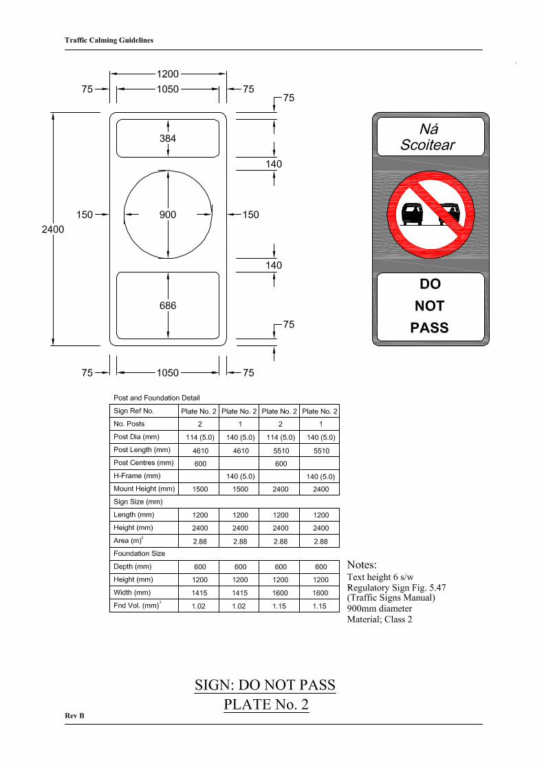
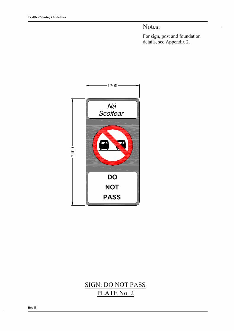
Plate No. 2 shows the ‘Do Not Pass’ sign. The section of road on which overtaking is
restricted is determined by the length of the subsequent solid white centre line.
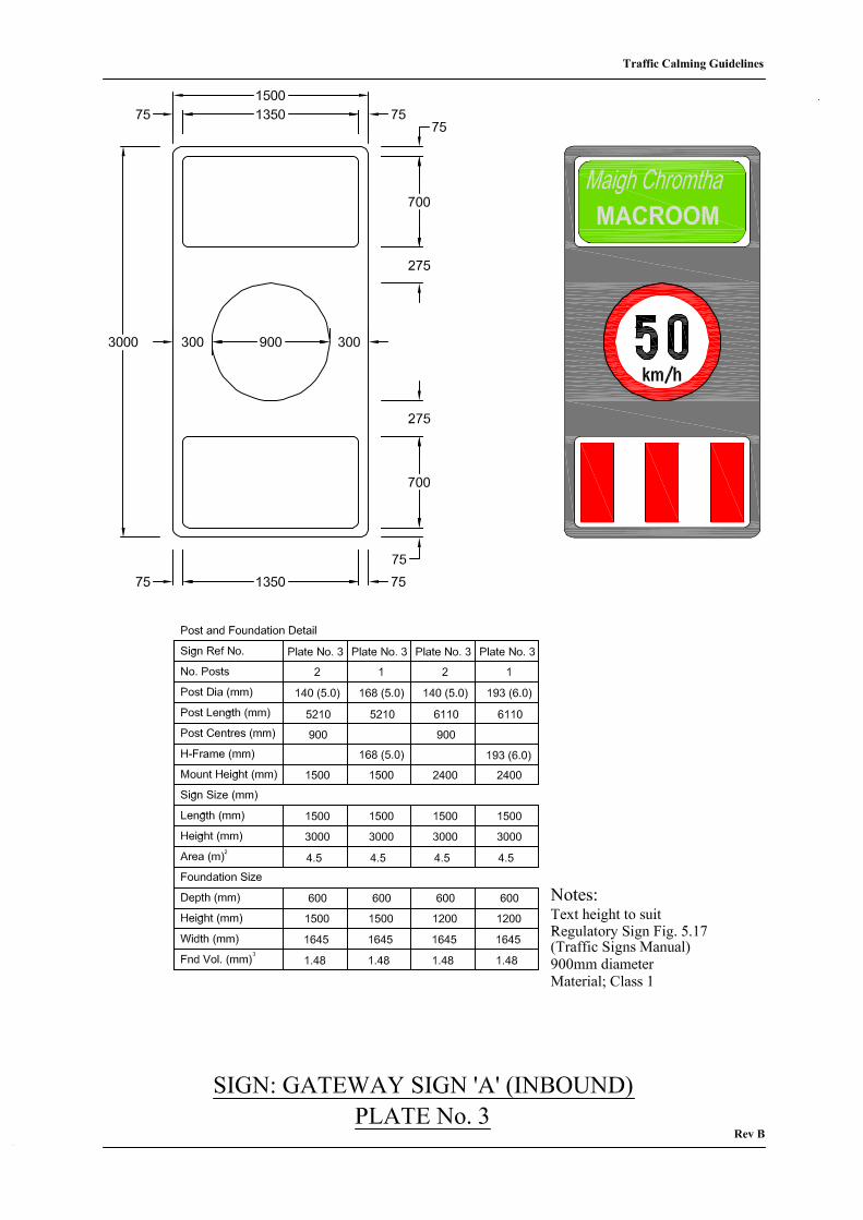
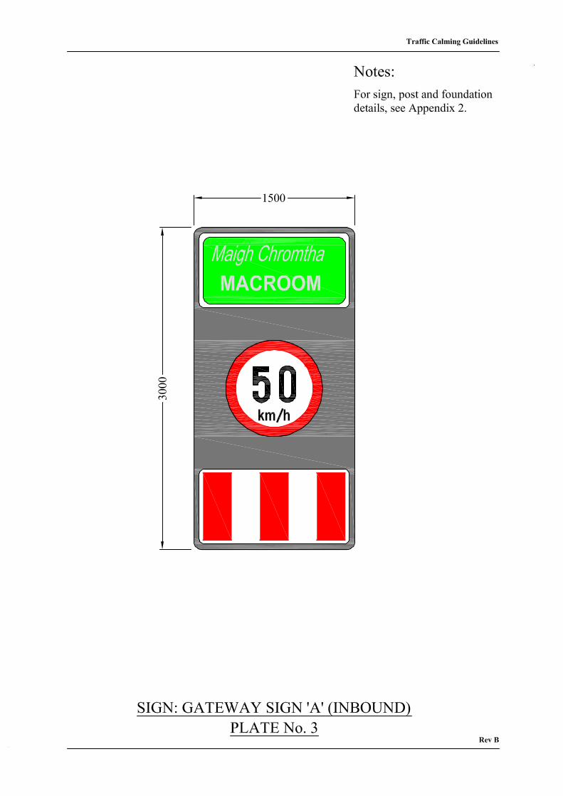
Plate No. 3 shows the version of the gateway sign A (inbound) for use in Type 3, 4 and 5
designs (Plates 12, 14 and 16). The gateway will usually be located at the
50kph speed limit, but in cases where the gateway is to be positioned at a
60kph speed limit, the number 60 may be substituted for the number 50 in
Plate 3.
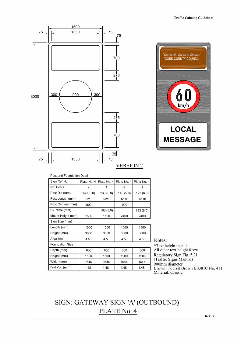
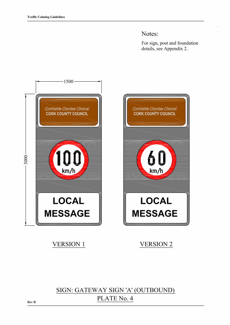
Plate No. 4 shows two versions of the gateway sign A (outbound) for use in Type 3, 4 and
5 designs. The appropriate version for the location should be chosen.
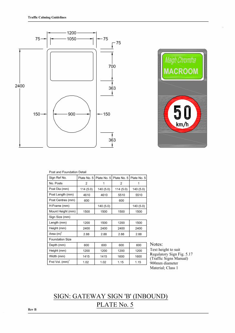
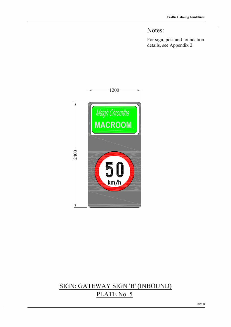
Plate No. 5 shows the version of the gateway sign B (inbound) for use in Type 1 and 2
designs. The gateway will usually be located at the 50kph speed limit, but in
cases where the gateway is to be positioned at a 40mph speed limit, the number
60 may be substituted for the number 50 in Plate 5.
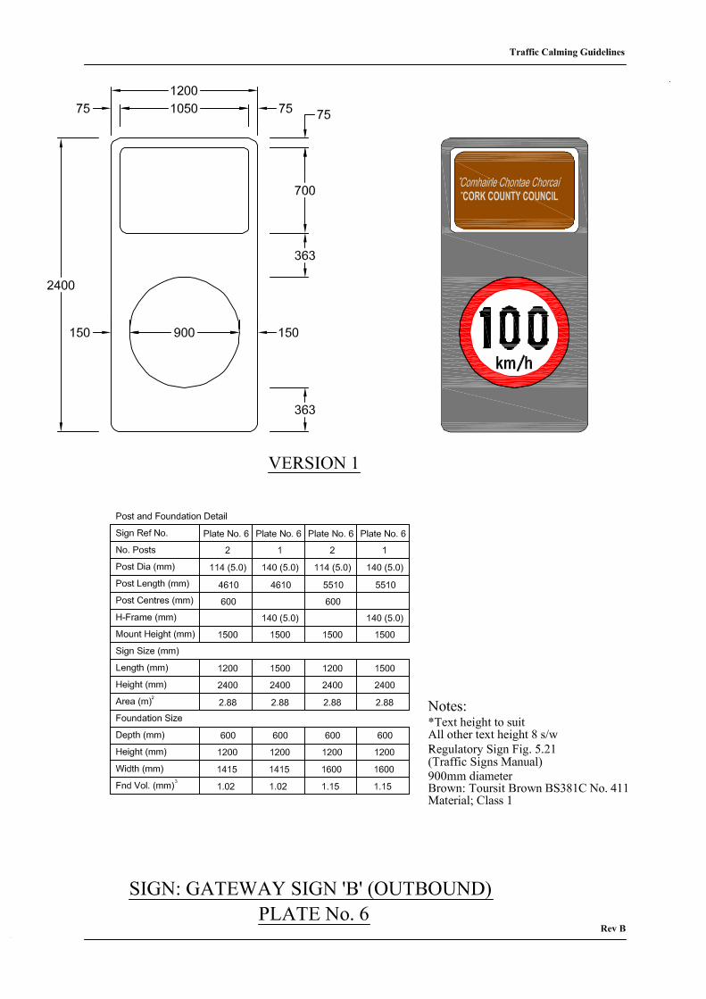
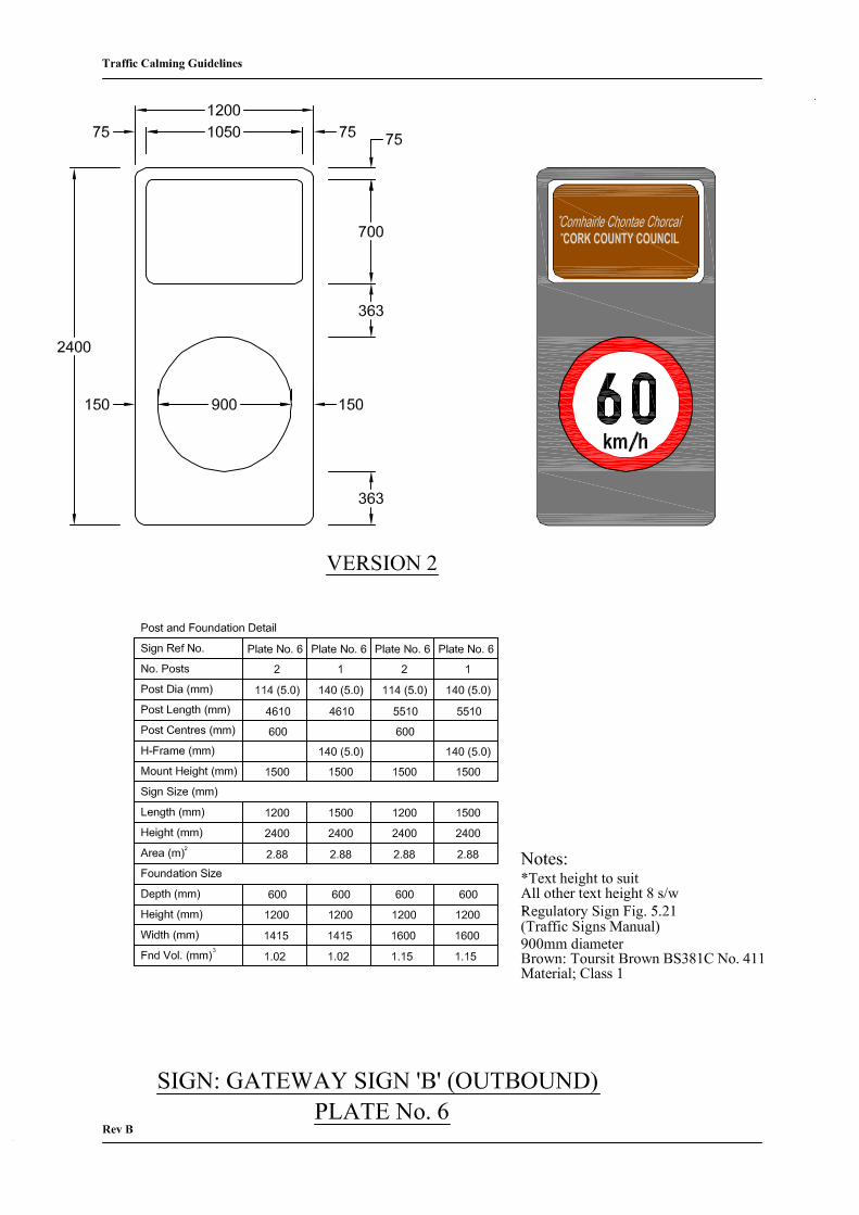
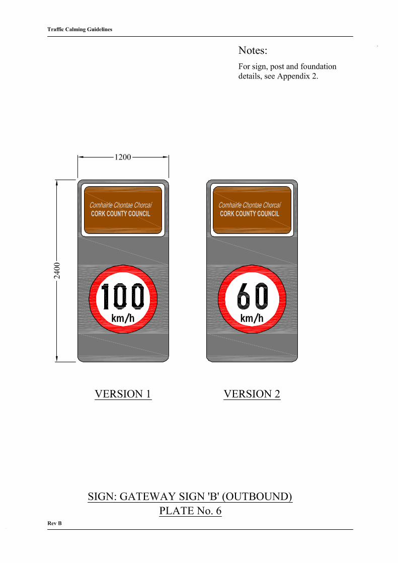
Plate No. 6 shows two versions of the gateway sign B (outbound) for use in Type 1 and 2
designs. The appropriate version for the location should be chosen.
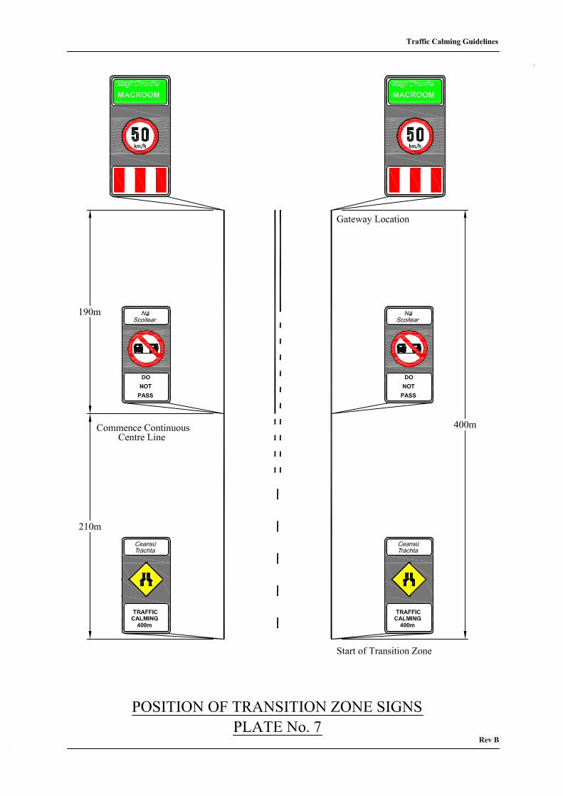
Plate No. 7 is a schematic layout that shows the ideal position of transition zone signs for
all design types. In the ideal situation, the length of the transition zone should
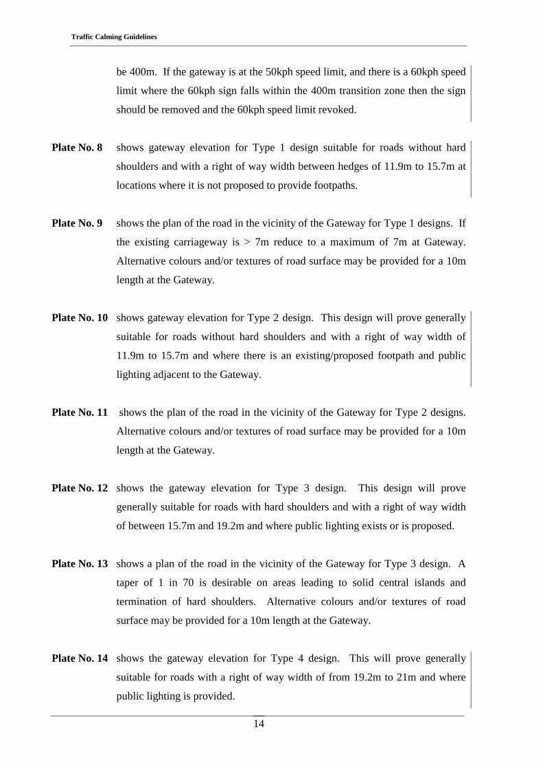
Traffic Calming Guidelines
14
be 400m. If the gateway is at the 50kph speed limit, and there is a 60kph speed
limit where the 60kph sign falls within the 400m transition zone then the sign
should be removed and the 60kph speed limit revoked.
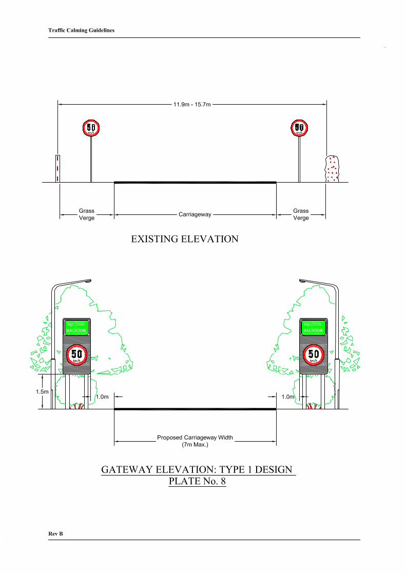
Plate No. 8 shows gateway elevation for Type 1 design suitable for roads without hard
shoulders and with a right of way width between hedges of 11.9m to 15.7m at
locations where it is not proposed to provide footpaths.
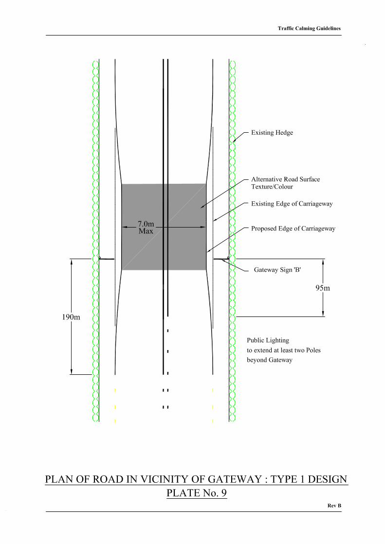
Plate No. 9 shows the plan of the road in the vicinity of the Gateway for Type 1 designs. If
the existing carriageway is > 7m reduce to a maximum of 7m at Gateway.
Alternative colours and/or textures of road surface may be provided for a 10m
length at the Gateway.
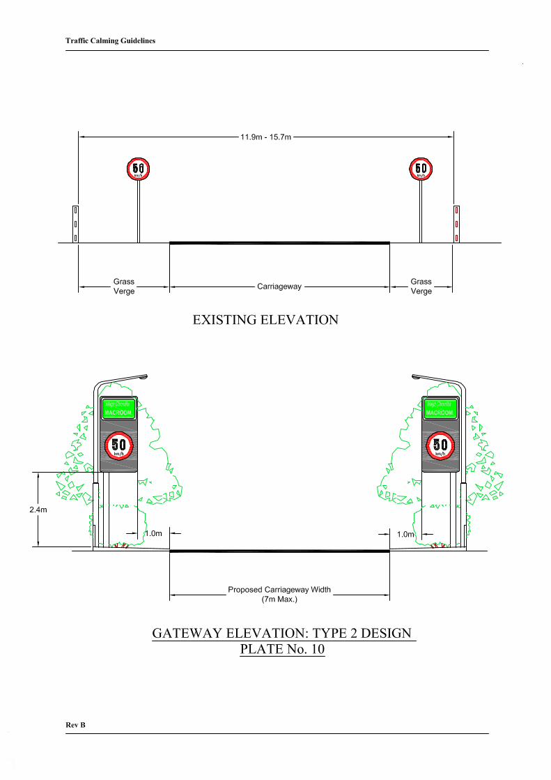
Plate No. 10 shows gateway elevation for Type 2 design. This design will prove generally
suitable for roads without hard shoulders and with a right of way width of
11.9m to 15.7m and where there is an existing/proposed footpath and public
lighting adjacent to the Gateway.
Plate No. 11 shows the plan of the road in the vicinity of the Gateway for Type 2 designs.
Alternative colours and/or textures of road surface may be provided for a 10m
length at the Gateway.
Plate No. 12 shows the gateway elevation for Type 3 design. This design will prove
generally suitable for roads with hard shoulders and with a right of way width
of between 15.7m and 19.2m and where public lighting exists or is proposed.
Plate No. 13 shows a plan of the road in the vicinity of the Gateway for Type 3 design. A
taper of 1 in 70 is desirable on areas leading to solid central islands and
termination of hard shoulders. Alternative colours and/or textures of road
surface may be provided for a 10m length at the Gateway.
Plate No. 14 shows the gateway elevation for Type 4 design. This will prove generally
suitable for roads with a right of way width of from 19.2m to 21m and where
public lighting is provided.
Traffic Calming Guidelines
15
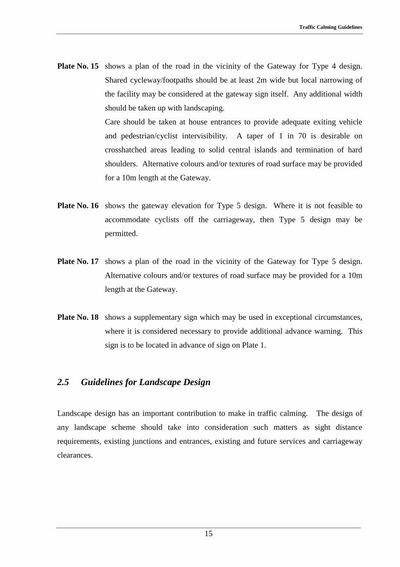
Plate No. 15 shows a plan of the road in the vicinity of the Gateway for Type 4 design.
Shared cycleway/footpaths should be at least 2m wide but local narrowing of
the facility may be considered at the gateway sign itself. Any additional width
should be taken up with landscaping.
Care should be taken at house entrances to provide adequate exiting vehicle
and pedestrian/cyclist intervisibility. A taper of 1 in 70 is desirable on
crosshatched areas leading to solid central islands and termination of hard
shoulders. Alternative colours and/or textures of road surface may be provided
for a 10m length at the Gateway.
Plate No. 16 shows the gateway elevation for Type 5 design. Where it is not feasible to
accommodate cyclists off the carriageway, then Type 5 design may be
permitted.
Plate No. 17 shows a plan of the road in the vicinity of the Gateway for Type 5 design.
Alternative colours and/or textures of road surface may be provided for a 10m
length at the Gateway.
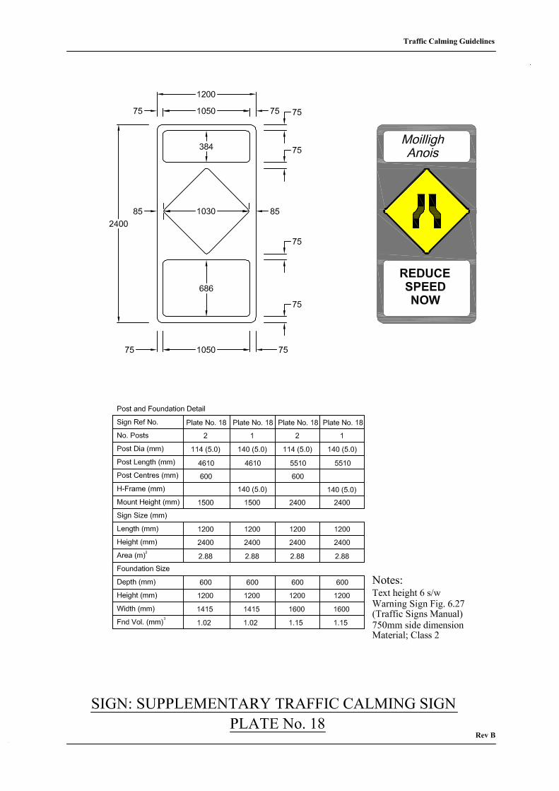
Plate No. 18 shows a supplementary sign which may be used in exceptional circumstances,
where it is considered necessary to provide additional advance warning. This
sign is to be located in advance of sign on Plate 1.
2.5 Guidelines for Landscape Design
Landscape design has an important contribution to make in traffic calming. The design of
any landscape scheme should take into consideration such matters as sight distance
requirements, existing junctions and entrances, existing and future services and carriageway
clearances.
Traffic Calming Guidelines
16
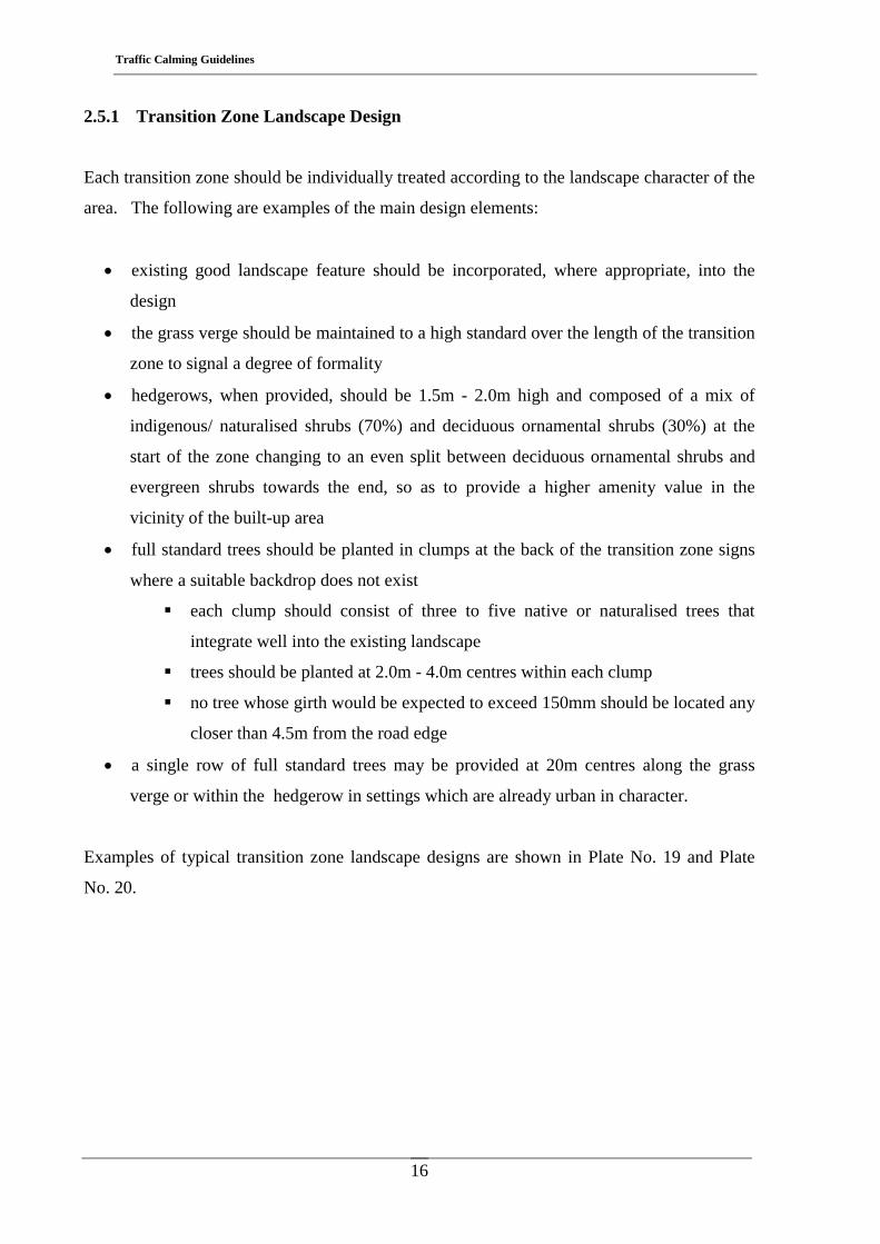
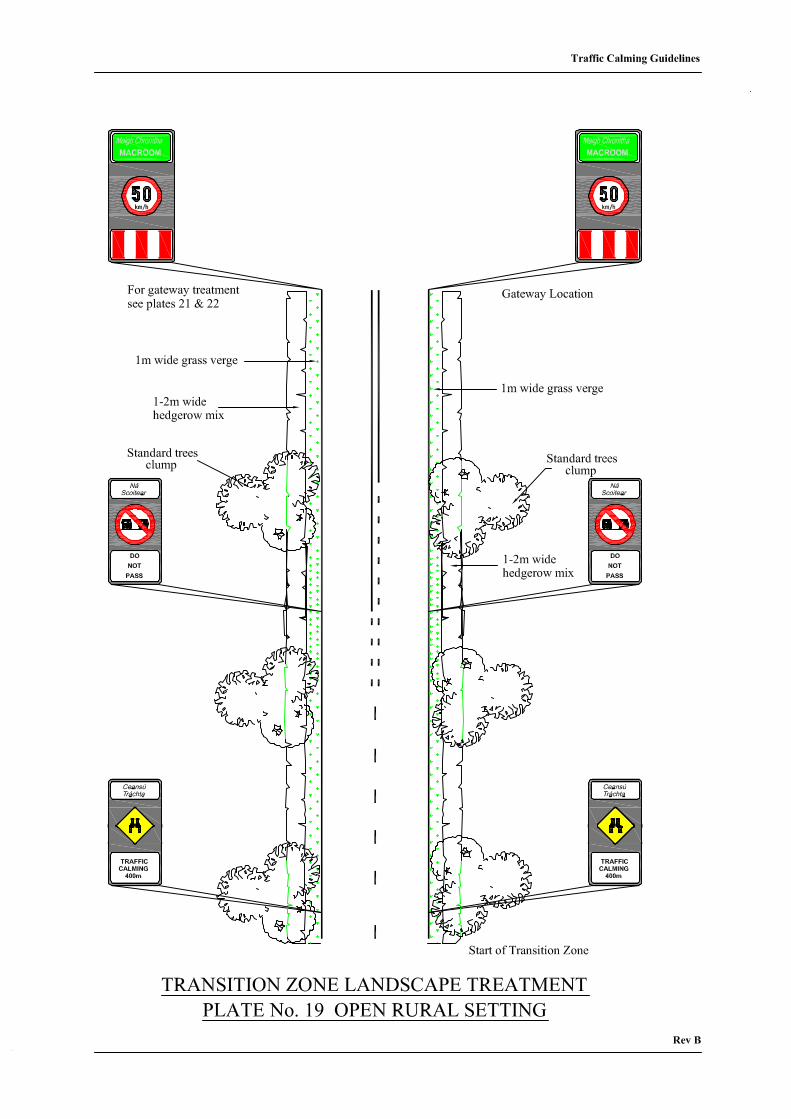
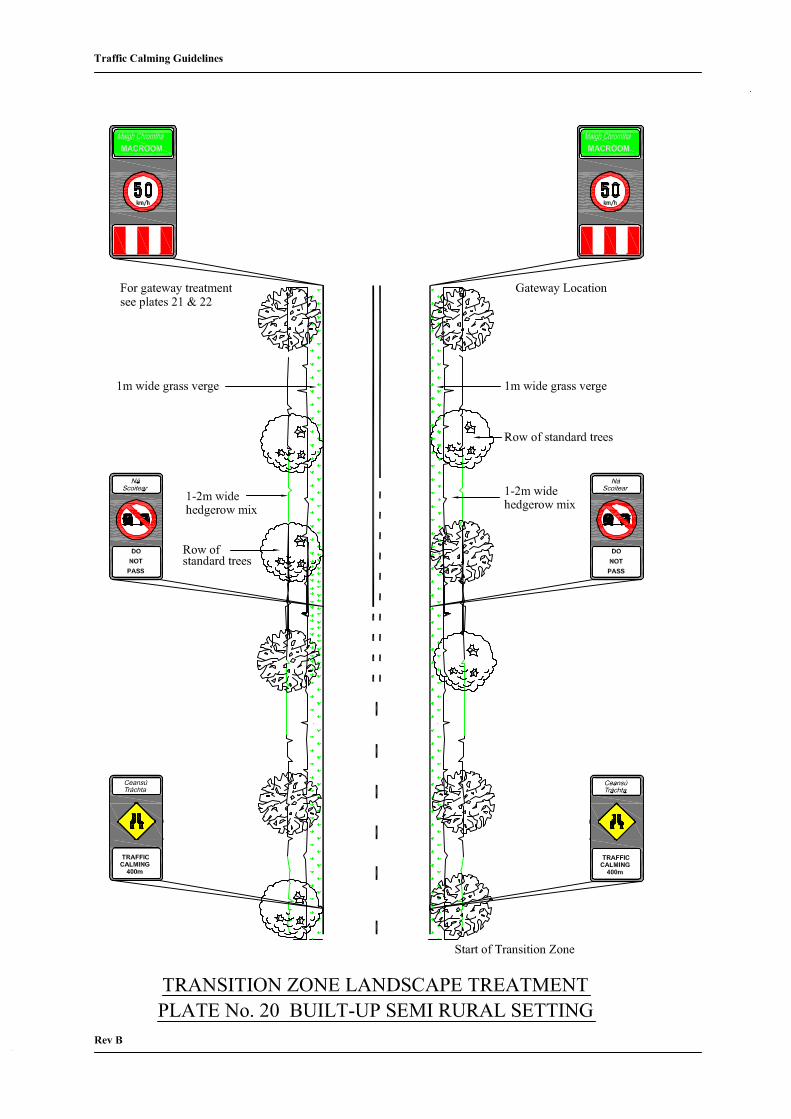
2.5.1 Transition Zone Landscape Design
Each transition zone should be individually treated according to the landscape character of the
area. The following are examples of the main design elements:
• existing good landscape feature should be incorporated, where appropriate, into the
design
• the grass verge should be maintained to a high standard over the length of the transition
zone to signal a degree of formality
• hedgerows, when provided, should be 1.5m - 2.0m high and composed of a mix of
indigenous/ naturalised shrubs (70%) and deciduous ornamental shrubs (30%) at the
start of the zone changing to an even split between deciduous ornamental shrubs and
evergreen shrubs towards the end, so as to provide a higher amenity value in the
vicinity of the built-up area
• full standard trees should be planted in clumps at the back of the transition zone signs
where a suitable backdrop does not exist
each clump should consist of three to five native or naturalised trees that
integrate well into the existing landscape
trees should be planted at 2.0m - 4.0m centres within each clump
no tree whose girth would be expected to exceed 150mm should be located any
closer than 4.5m from the road edge
• a single row of full standard trees may be provided at 20m centres along the grass
verge or within the hedgerow in settings which are already urban in character.
Examples of typical transition zone landscape designs are shown in Plate No. 19 and Plate
No. 20.
Traffic Calming Guidelines
17
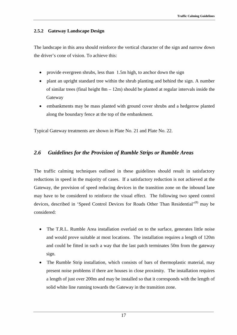
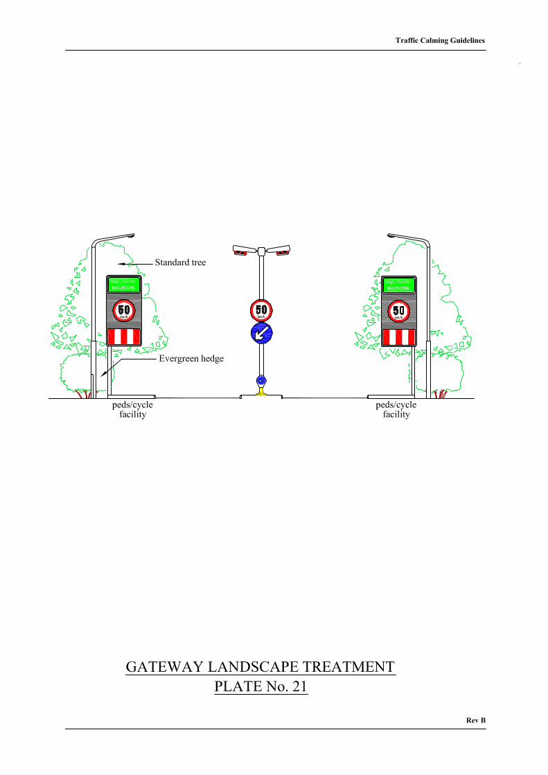
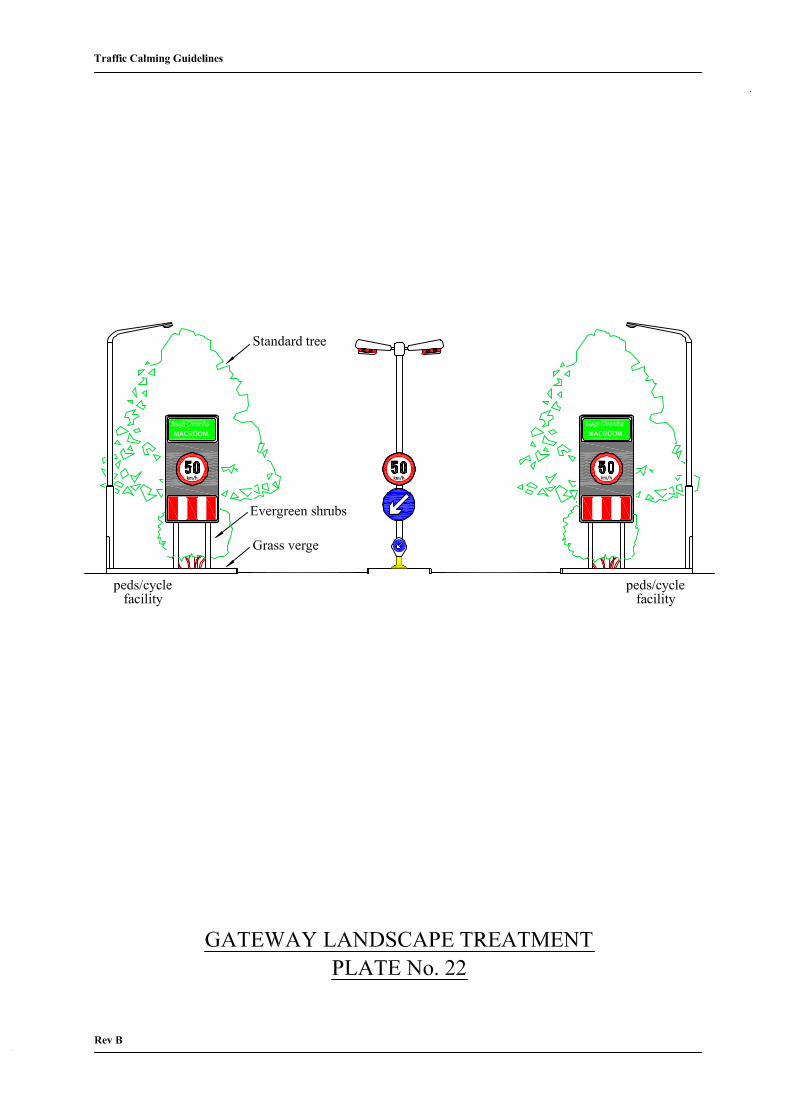
2.5.2 Gateway Landscape Design
The landscape in this area should reinforce the vertical character of the sign and narrow down
the driver’s cone of vision. To achieve this:
• provide evergreen shrubs, less than 1.5m high, to anchor down the sign
• plant an upright standard tree within the shrub planting and behind the sign. A number
of similar trees (final height 8m – 12m) should be planted at regular intervals inside the
Gateway
• embankments may be mass planted with ground cover shrubs and a hedgerow planted
along the boundary fence at the top of the embankment.
Typical Gateway treatments are shown in Plate No. 21 and Plate No. 22.
2.6 Guidelines for the Provision of Rumble Strips or Rumble Areas
The traffic calming techniques outlined in these guidelines should result in satisfactory
reductions in speed in the majority of cases. If a satisfactory reduction is not achieved at the
Gateway, the provision of speed reducing devices in the transition zone on the inbound lane
may have to be considered to reinforce the visual effect. The following two speed control
devices, described in ‘Speed Control Devices for Roads Other Than Residential’(8) may be
considered:
• The T.R.L. Rumble Area installation overlaid on to the surface, generates little noise
and would prove suitable at most locations. The installation requires a length of 120m
and could be fitted in such a way that the last patch terminates 50m from the gateway
sign.
• The Rumble Strip installation, which consists of bars of thermoplastic material, may
present noise problems if there are houses in close proximity. The installation requires
a length of just over 200m and may be installed so that it corresponds with the length of
solid white line running towards the Gateway in the transition zone.

Traffic Calming Guidelines
18
Traffic Calming Guidelines
19
Chapter 3 Ancillary Traffic Calming Techniques Appropriate to Urban
Sections of the Route
3.1 Statement of Problem
In Chapter 2, Design Guidelines were presented which have the objective of reducing speed in
the transition zones on the approaches to towns and villages. If the reduction is to be
maintained throughout the length of the through roads then ancillary traffic calming and
control techniques need to be applied to the urban section.
3.2 Design Elements for Urban Sections
Every effort should be made to ensure the harmonious integration of the road development
into the townscape of the town/village.
The design elements that may be considered include:
• the provision of pedestrian facilities
• the provision of pedal cycle facilities
• the use of kerbing or road marking
to define road width
to provide channelising islands
to construct mini roundabouts
to shelter parking and bus bays
to provide horizontal lateral shifts.
Traffic Calming Guidelines
20
3.3 General Design Guidelines
3.3.1 The Maintenance of an Appropriate Carriageway Width
The selection of appropriate traffic calming techniques within the urban area is chiefly
influenced by the road width available. In particular the following recommended dimensions
determine the range of configurations possible for any given road width:
• minimum kerb to kerb width for two way traffic flow - 6.5m
• minimum kerb to kerb width for one way traffic flow – 4.0m
• minimum width of build-out - 2.0m (see 3.3.4.1)
• minimum width of central refuge island - 1.8m. (see 3.3.4.2)
Schematic details of possible layout arrangements for different road widths are shown on
plates 23-31 inclusive and described below:
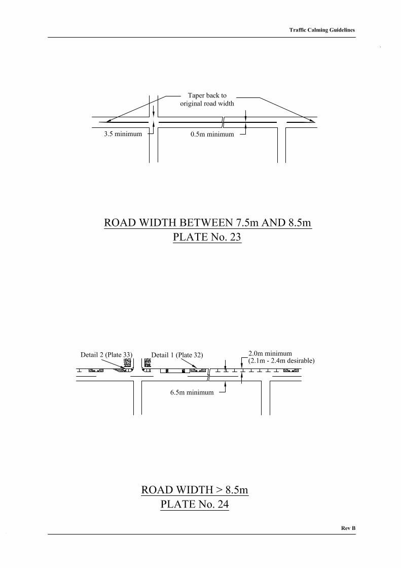
Plate No. 23 Road Width Between 7.5m and 8.5m
Within this width range it is not possible to construct either a central refuge
island or provide protected car parking along the road edges. Traffic calming
can be optimally achieved by providing a narrow hatched area along the centre
of the road.
Plate No. 24 Road Width > 8.5m
Construct build-outs along one side of the road, thus creating a protected
parking area, maintaining a minimum kerb to kerb width of 6.5m for two-way
traffic flow. It is possible to switch the build-out/car parking location from one
side of the road to the other by incorporating a lateral shift as per Plate No.31.
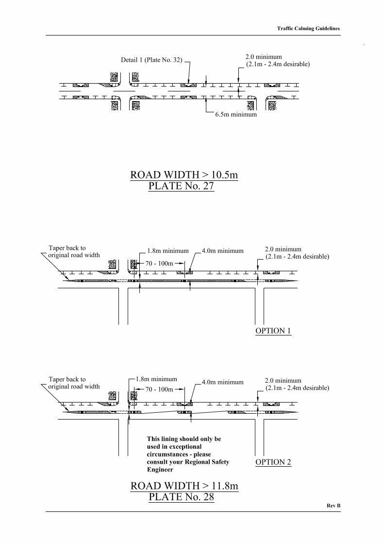
Build-outs should have a minimum depth of 2.0m and be constructed as per
detail 1 (Plate No.32) and provided at the corners of junctions as per detail 2
(Plate No.33).
Traffic Calming Guidelines
21
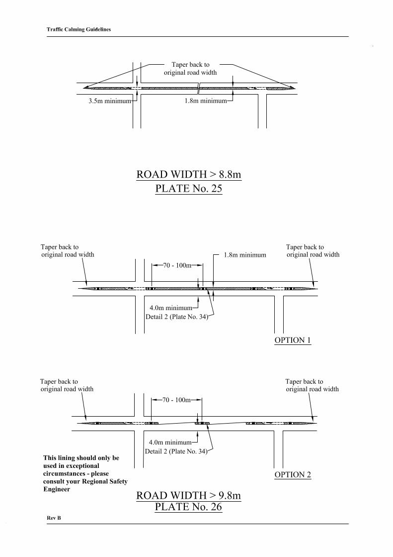
Plate No. 25 Road Width > 8.8m
Increase the width of the central hatched area to a minimum of 1.8m so as to
allow it to incorporate a right turn lane at junctions.
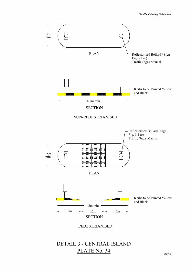
Plate No. 26 Road Width > 9.8m
Construct a central refuge island - minimum width 1.8m retaining a minimum
of 4.0m clearance between kerbs. Central area between islands can be hatched.
Islands should be strategically located at major pedestrian crossing desire lines
and to protect waiting right turning vehicles. Island dimensions to be as per
detail 3 (Plate No.34).
Plate No. 27 Road Width > 10.5m
Build-outs creating car-parking areas can be provided on both sides of the
roads while still maintaining a minimum clearway width of 6.5m for two-way
traffic flow. Build-outs on each side of the road should be located facing each
other to facilitate pedestrians crossing the road.
Plate No. 28 Road Width > 11.8m
A combination of a build-out on one side and a central refuge island can be
provided at road widths above 11.8m while maintaining a minimum kerb to
kerb width of 4m for one way traffic flows.
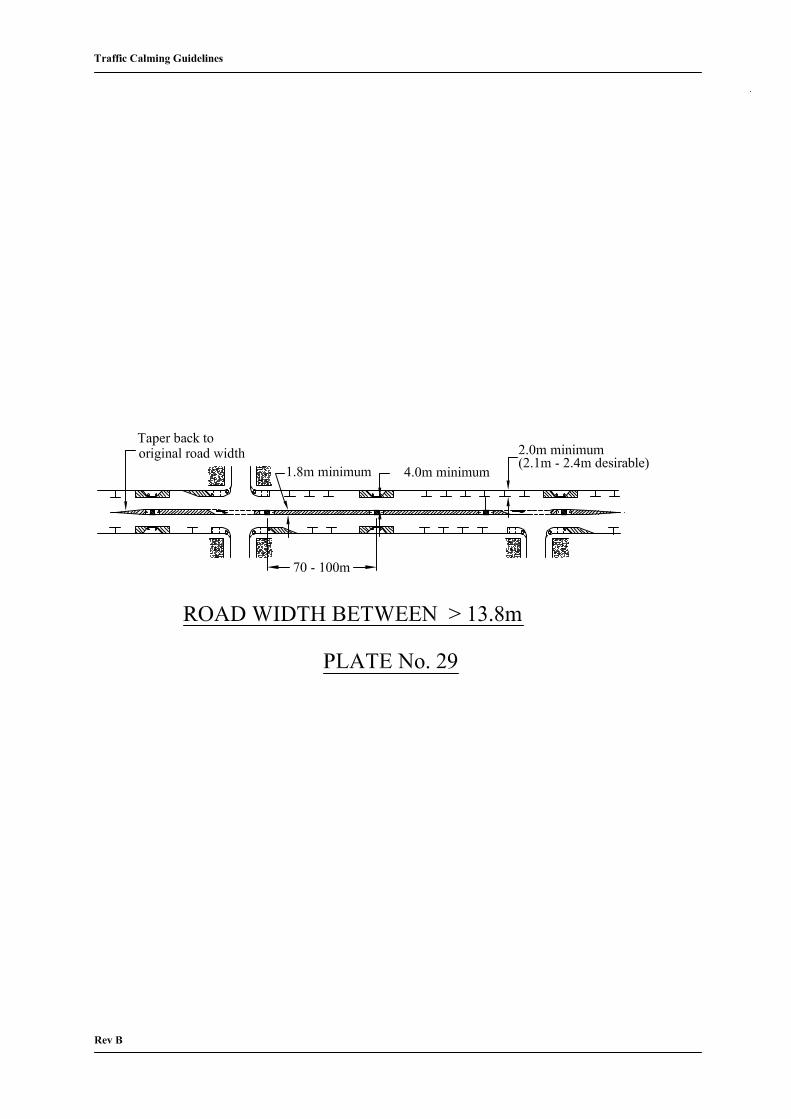
Plate No. 29 Road Width > 13.8m
With greater than 13.8m of available road width it is possible to provide build-
outs on both sides of the road and a central refuge island while maintaining a
minimum kerb to kerb clearway of 4.0m for one way traffic flow. Central area
between islands can be hatched. Islands could be strategically located at major
pedestrian crossing desire lines and to protect waiting right turning vehicles.
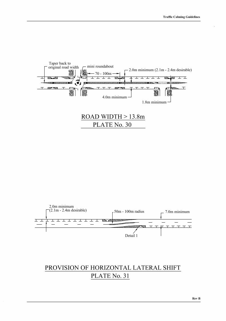
Plate No. 30 Road Width > 13.8m
This layout is a variation of Plate No. 29, in which a mini-roundabout is
incorporated at any crossroad junction.
Traffic Calming Guidelines
22
Plate No. 31 Provision of Horizontal Lateral Shift
Alternating footpath build-outs may provide a horizontal lateral shift where it
is necessary to limit long forward views. The minimum carriageway width
required is 9.0m.
3.3.2 The Provision of Pedestrian Facilities (9)(10)(11)
In the general case, the biggest contributors to pedestrian risk on through routes in towns and
villages are vehicle speed (particularly at off-peak times) and crossing distance. The traffic
calming of the through route should reduce this risk by controlling road width and reducing
crossing distance. The design element that contributes most to pedestrian safety is the
channelising island, since it not only reduces width but also simplifies the pedestrian’s
decision by dividing the crossing manoeuvre into two separate tasks.
Crossing places are provided to give access and easier movement to pedestrians. The needs
of people who experience most difficulty - the old, the infirm, children - should be especially
taken into account. Contrary to popular belief, there is no evidence to suggest that informal
crossing places well located and equipped with channelising islands are less safe than Zebra
Crossings or that Zebra Crossings are less safe than Pelican Crossings. For most locations in
towns and villages on National Routes the informal crossing will probably prove to be the
best choice.
If existing Zebra or Pelican Crossings are to be retained they should be incorporated into the
traffic calming design, ensuring that they remain conspicuous in the new layout.
In most cases a formal crossing facility will not be warranted. The principles governing the
location of formal crossing places apply equally to informal crossings. Particular attention
should be paid as described below.
• Pedestrians must be able to see and be seen by approaching traffic. Visibility should
not be restricted by, for example, parked vehicles, trees or street furniture.
• The footpath in the vicinity of any proposed crossing place should be wide enough to
accommodate both pedestrians waiting to cross and those walking along the footpath. A
width of 2m is recommended.
Traffic Calming Guidelines
23
• Any survey of a proposed crossing place should take account of pedestrian movements
within 50m of road on either side of the site. Once a crossing place is defined the site
will become a focus of concentration for drivers and the areas on either side could
become potentially hazardous for pedestrians.
• Crossing places should ideally be located 20m away from uncontrolled junctions on
through routes. If the desire line is closer to the junction, then the crossing, formal or
informal, should be incorporated into the junction design.
• Where a central channelising island is provided, an absolute minimum width of 1.8m is
needed. The length requirements are discussed in 3.3.4.2.
• Generally a bus stop is better sited downstream of a crossing place.
• If there is any doubt about the conspicuity of pedestrians then supplementary lighting
should be provided to illuminate the crossing, similar to that used at the gateway.
3.3.3 The Provision of Pedal Cycle Facilities (12)
National Routes have particular features that impact on cyclists, such as:
• high speeds: 85 percentile speeds significantly in excess of 50 km/hour
• high proportion of HCVs
• relatively low volumes of pedestrians and cyclists, (it is recommended that urbanised
sections with low traffic speeds and high volumes of pedestrians/cyclists be considered
as a separate design problem with priorities shifting away from vehicular traffic)
• occasional long lead-in roads through suburban type development.
It is essential to achieve a balance between the following three items:
• function of road
• use of road
• geometry of road.
In many cases the designer will be amending an existing shape and will be constrained in
relation to achieving optimum solutions that fully cater for all road users.
Traffic Calming Guidelines
24
Cyclists can safely share facilities with other vehicles provided that operating speeds have
been reduced to below 60km/h. Between the start of the transition zone and the point where
speeds have been satisfactorily reduced, it is preferable to provide a separate facility for
cyclists and pedestrians.
Cyclists may be catered for by means of a cycle track(12):
• on the roadway
• on the footway
• physically segregated from the roadway by means of a raised kerb, grass verge or
similar (shared with pedestrians or exclusive to cyclists).
The design must aim to achieve the optimum balance between the safety of cyclists and other
road users. In these circumstances it is imperative that speeds be significantly reduced.
The following specific recommendations should be considered.
• Segregated cycle facilities are desirable where high speeds/high volumes of motorised
traffic prevail (4). Chapter 2 recommends removal of cyclists from carriageways at the
Gateways where this is deemed to be feasible by the designer.
• Consideration should be given, in the vicinity of Gateways, to combining low volumes
of pedestrians and cyclists on existing or modified footpaths. The minimum path width
required in such situations is 2.0m with a preferred width of 3.0m. Segregation may be
achieved using signage, road markings and/or different coloured surfacing.
The designer should particularly guard against the following:
• imposing sudden deviation from parallel directions of travel on cyclists
• the cyclist and other vehicular traffic sharing an unsegregated kerb to kerb width of less
than 4.0m.
Traffic Calming Guidelines
25
3.3.4 The Use of Kerbing
Kerbing can be utilised to control road width and reduce crossing distance in towns and
villages through the provision of footpath build-outs and central refuge/channelising islands.
Kerbing can also be used to provide horizontal lateral shifts in the carriageway in order to
limit long forward views.
3.3.4.1 Footpath Build-outs
Increasing the width of existing footpath at regular intervals can reduce the road width
available to traffic. Depending on the overall road width available these build-outs can be
provided on one side only or on both sides of the road or even in conjunction with a central
refuge island. A lateral shift can be introduced by alternating footpath build-outs.
• Wherever possible the use of these build-outs as informal or formal crossing points
should be encouraged and they should be located in the vicinity of heavy pedestrian
activity.
• Where the depth of build-outs exceeds 2m the area between them can be utilised as a
protected on-street parking area and should be delineated accordingly.
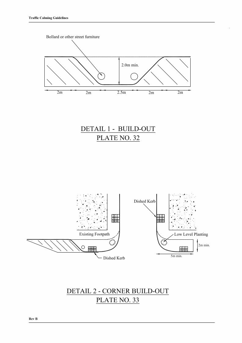
• Typically build-outs should be 2.5m wide at the front with 45 degree side splays back
towards the footpath. See Plate No 32. Kerbs should be dished/dropped at the front,
while kerbs at the sides should be painted alternating black and yellow to improve
visibility. Alternatively, if there is no footpath and the build-outs are in the direct line
of travel of pedestrians, then the kerbs on both sides should be dished/dropped and
kerbs at the front should be painted alternating black and yellow to improve visibility.
• The conspicuity should be improved by the provision of a post-type bollard, with either
a 100mm deep reflective strip or a 300mm diameter reflective keep right arrow. When
installing these bollards, care should be taken to ensure that they do not block the path
of pedestrians or cyclists. In addition, the area in the immediate vicinity of a build-out
should be hatched.
• Where build-outs are provided care should be taken to address adequately surface water
collection and disposal.
Traffic Calming Guidelines
26
• When deciding on spacing for build-outs consideration should be given to parking,
pedestrian desire lines and landscaping.
Typical examples of the use of build-outs to reduce road width and provide protected on-
street parking areas are given in Plate Nos. 24, 27, 28, 29, 30 and 31.
3.3.4.2 Central Refuge/Channelising Islands
Where the available road width is sufficient (greater than 10m) central refuge or channelising
islands may be provided to control effectively the road widths available to traffic and reduce
crossing distances for pedestrians.
• such islands should have minimum dimensions of 1.8m in width and 4.5m in length
• Signs should be provided at each end of the island. A 600mm diameter keep left sign,
in class 1 material, can be erected on a pole. Alternatively, a sign or bollard containing a
300mm diameter keep left sign, in class 1 material, should be provided. See sections
6.2.1 and 6.2.5 for details of approvals required. Irrespective of which type of sign or
bollard is provided, a further 600mm diameter keep left arrow should be installed at
2.5m mounting height wherever there is a likelihood of vehicles obscuring the lower
arrow.
• pedestrian guardrail or illuminated bollards may be provided, if considered necessary.
High visibility pedestrian guardrail should be used. This provides a minimum of 50%
transparency from all angles. If there is any doubt about the conspicuity of pedestrians
then supplementary lighting should be provided to illuminate the crossing, similar to
that used at the gateway
• where a pedestrian crossing point is being provided, kerbs should be dished/dropped
along the sides to facilitate pedestrians, while full height kerbs facing traffic should be
painted alternating black and yellow to improve visibility. If no pedestrian crossing
point is being provided, all the kerbs should be full height and should be painted
alternating yellow and black to improve visibility
• islands should be spaced at 70m – 100m depending on the site.
Traffic Calming Guidelines
27
Typical examples of the use of central islands to reduce road width and provide refuge for
pedestrians are given in Plate Nos. 26, 28, 29 and 30.
3.3.5 The Use of Road Markings
Typical applications for road markings are:
• ghost or channelising islands
• hatched median where available widths are limited
• tapered approaches to solid islands and build-outs
• improved definition of junctions
• where it is required to reduce carriageway widths (unkerbed), or to create chicanes or
other lateral shifts
• provision of lane markings/parking bays and hatched buffer zones between parking bays
• provision of improved deflection at roundabout where kerbing would not be possible
because of turning circle requirements
• arrows, text and other informational uses.
The use of standard road markings can be enhanced by incorporating a raised rib effect, either
through the use of proprietary materials or by laying an additional strip of thermoplastic on a
standard line.
For typical examples, see Plates 23 to 31.
Traffic Calming Guidelines
28
3.3.6 Urban and Landscape Design
3.3.6.1 Soft Landscape
Soft landscape elements may be used alongside roads to complement and enhance traffic
calming measures in cases where sufficient width is available. They are most effective when
located between the road and the footpath and suggested treatments may include:
• well-maintained grass verge to give a better definition of the road by separating it
visually from the footpath
• mass planting of low evergreen ground cover to a maximum height of 0.6m to separate
the road visually and physically from the footpath
• linear tree planting along the road edge to make the road look narrower by limiting the
driver’s field of vision as well as offering some degree of privacy for residents.
3.3.6.2 Hard Landscape
In cases where new footpaths are being provided or existing footpaths are being extensively
refurbished in conjunction with a traffic calming scheme, they should be constructed using
material of contrasting shade to that used in the road. The same footpath type should be
provided throughout the entire length of the urban area to give a sense of unity. The footpath
construction can be extended on to the carriageway at designated formal and informal
crossing points. Ideally kerbing should be 150mm high to clearly define the footpath as a
separate entity from the road.
All street furniture, such as lighting, bollards, seating and litter bins should be located along
the same line and should be of the same material and colour in order to create a theme for the
streetscape and give identity to the town.

Traffic Calming Guidelines
29
Chapter 4 Consultation Process and Legal Considerations
4.1 Legal Power to provide or remove Traffic Calming Measures
Section 38(1) of the Road Traffic Act, 1994 empowers Road Authorities, in the interests of
the safety and convenience of road users, to ‘provide such traffic calming measures as they
consider desirable in respect of public roads in their charge’.
Section 38(2) of the same Act empowers Road Authorities to ‘remove any traffic calming
measures provided by them under this section’.
4.2 Consultation Process
4.2.1 Legal Obligation
The legal obligation to carry out consultative procedures before providing traffic calming
measures emanates from:
• sections 38(3) and 38(4) of the Road Traffic Act, 1994.
The procedures to be followed are summarised in Table 4.1.
4.2.2 Limit to Legal Obligation
The legal obligation to follow the procedures set out above is limited as follows:
• Sections 38(3) and 38(4) of the Road Traffic Act, 1994, apply only to such class or
classes of traffic calming measures ‘as may be prescribed’. Since the Minister has not as
yet prescribed such class or classes there is no current legal obligation to comply with
the consultation requirements set out in subsection 38(4) of this Act.
Traffic Calming Guidelines
30
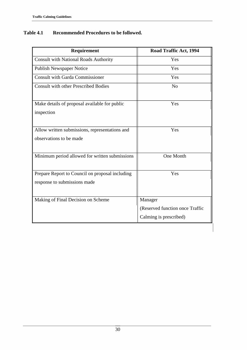
Table 4.1 Recommended Procedures to be followed.
Requirement Road Traffic Act, 1994
Consult with National Roads Authority Yes
Publish Newspaper Notice Yes
Consult with Garda Commissioner Yes
Consult with other Prescribed Bodies
No
Make details of proposal available for public
inspection
Yes
Allow written submissions, representations and
observations to be made
Yes
Minimum period allowed for written submissions
One Month
Prepare Report to Council on proposal including
response to submissions made
Yes
Making of Final Decision on Scheme Manager
(Reserved function once Traffic
Calming is prescribed)
Traffic Calming Guidelines
31
4.2.3 Recommendations on Consultation
Enormous benefit can be gained by full public consultation with all interested parties from as
early a stage in the design process as possible, notwithstanding the current limited legal
obligation to do so. Such consultation should take place.
4.3 Consent of the National Roads Authority
Section 38(5) of the Road Traffic Act, 1994, declares that no traffic calming measures shall
‘be provided or removed in respect of a national road without the prior consent of the
National Roads Authority’.
4.4 Other Legal Considerations
Most traffic calming measures will include some or all of the following elements:
• relocation of speed limit signs
• provision of new speed limit signs
• provision of new road markings
• erection of regulatory traffic signs
• provision of cycle ways or cycle tracks
• provision of bus parking bays.
It will be necessary, in addition to following the consultative procedures required before the
provision of traffic calming measures, to ensure that the specific legal and consultative
procedures relating to the provision of these items are fully complied with prior to their
introduction.
Traffic Calming Guidelines
32
4.4.1 Speed Limit Signs
Section 9 of the Road Traffic Act 2004 sets out procedures for local authorities to make
special speed limit bye-laws.
Subsection (3) specifies the need to:
• consult with sub-county local authorities (Borough Corporations, Urban District
Councils or Town Commissioners) before making bye-laws to apply speed limits to
roads within the administrative areas of these authorities and consider the views of the
members of these authorities.
• consult with the Garda Commissioner and consider any views supplied (Note: consent is
not required)
Subsection (4) sets out details of the public consultation procedure to be followed if the local
authority still proposes to make bye-laws having considered any representations received
under subsection (3).
Subsection (7) states that “A county or city council shall not make bye-laws under this section
relating to a national road or a motorway without the prior written consent of the National
Roads Authority.”
4.4.2 Road Signs and Markings
• Regulatory road signs, road markings and traffic signals should comply with the
requirements of the Road Traffic (Signs) Regulations, 1997 and 1998 (S.I No. 181 of
1997 and S.I. No. 273 of 1998).
• Non-regulatory road signs and road markings should comply with directions of the
Minister for the Environment made under Section 95 (16) of the Road Traffic Act,
1961.
• Regulatory signs/road markings may be provided by a road authority only after
consultation with the Garda Commissioner - Sub-Section 3(b) of Section 95 of the Road
Traffic Calming Guidelines
33
Traffic Act, 1961, as amended by Section 37 of the Road Traffic Act, 1994, (Note:
consent is not required).
• Non-regulatory signs/road markings may be provided by a road authority without any
need for consultation with the Garda Commissioner - Sub-Section 3(a) of Section 95 of
the Road Traffic Act, 1961, as amended by Section 37 of the Road Traffic Act, 1994.

Traffic Calming Guidelines
34
Traffic Calming Guidelines
35
Chapter 5 Planting Specification
5.1 Introduction
This section deals with the selection of nursery stocks for traffic calming projects. It also sets
out to improve the environmental component of traffic calming schemes to complement the
other design elements.
5.1.1 The landscape proposals
The landscape proposals are documented in the form of a series of tables listing recommended
species of hardy nursery stocks for specific sites. These listings will serve as a guide for
design engineers involved in traffic calming projects. Various options and choices of plants
are considered for a range of different sites with different soils, micro-climates etc.
5.1.2 Scoping assessment
The scope of the landscape study provides information on selected nursery stock for specific
sites. This information on selected species provides details of height of plants at maturity,
spread and form together with the aesthetic qualities of foliage, flower, berry, texture. In
addition, plant spacings are provided for construction purposes together with plant associative
value, i.e. groupings of different species for visual coherence. Also, a selected list of tree
species is provided. These trees are deemed suitable for traffic calming planting schemes
since they are not too vigorous in growth terms, and most species recommended have a
columnar, or upright growth habit, which is suitable in confined vehicular/traffic areas.
5.2 Nursery Stock Selections
The attached Tables indicate a range of plant subjects suitable for growing such materials
under specific site conditions. The conditions selected are indicated as follows:
Traffic Calming Guidelines
36
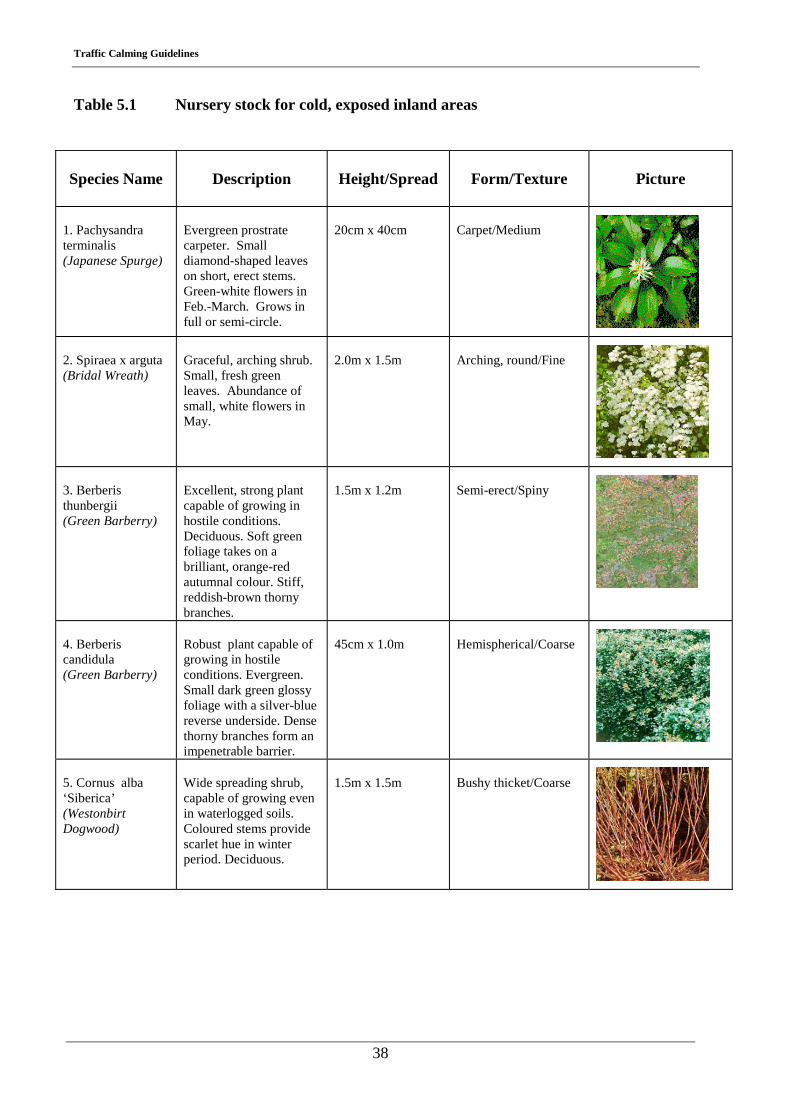
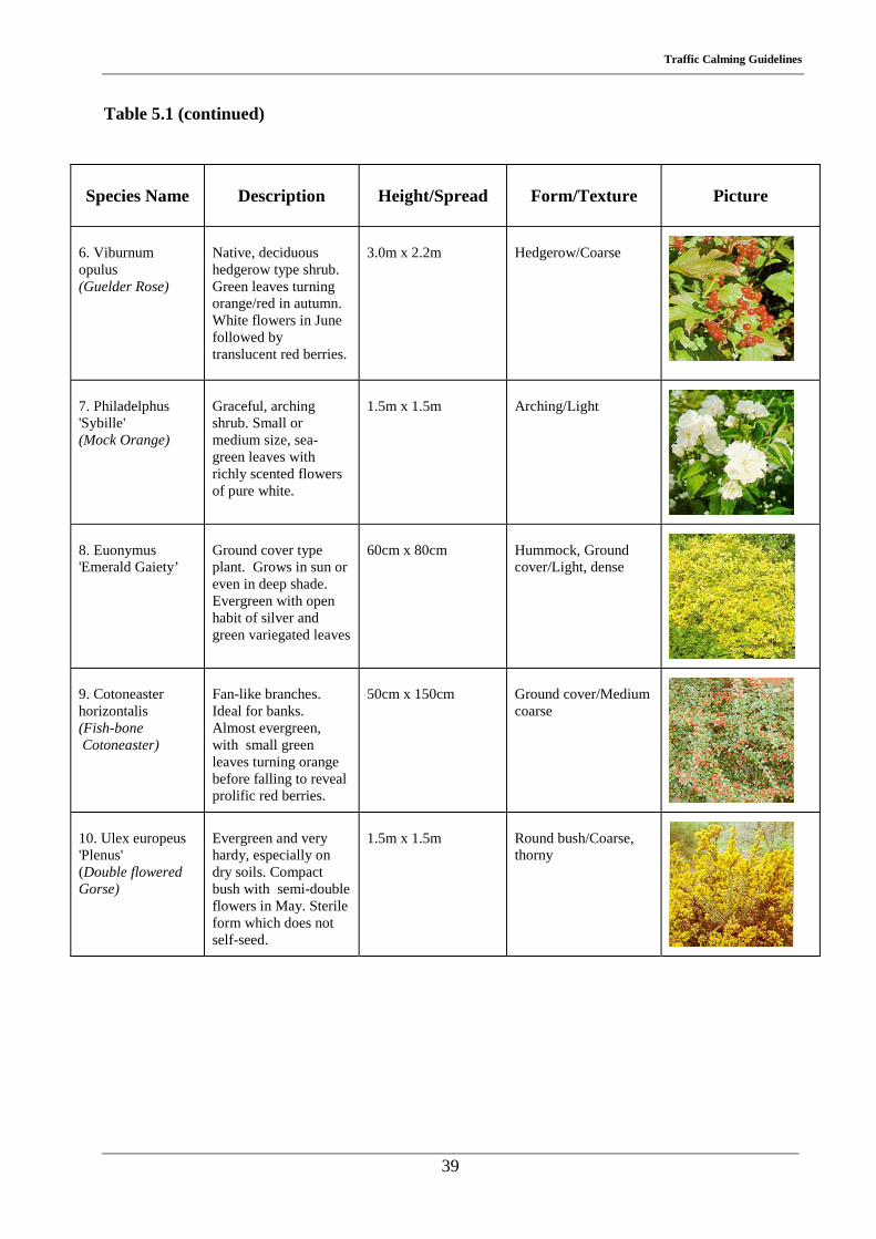
5.2.1 Nursery stock for cold, exposed inland areas
Nursery stock indicated in this section must be capable of withstanding extremes of coldness
over the winter period. Frost, in particular, is capable of killing some mature specimens
outright (Table 5.1).
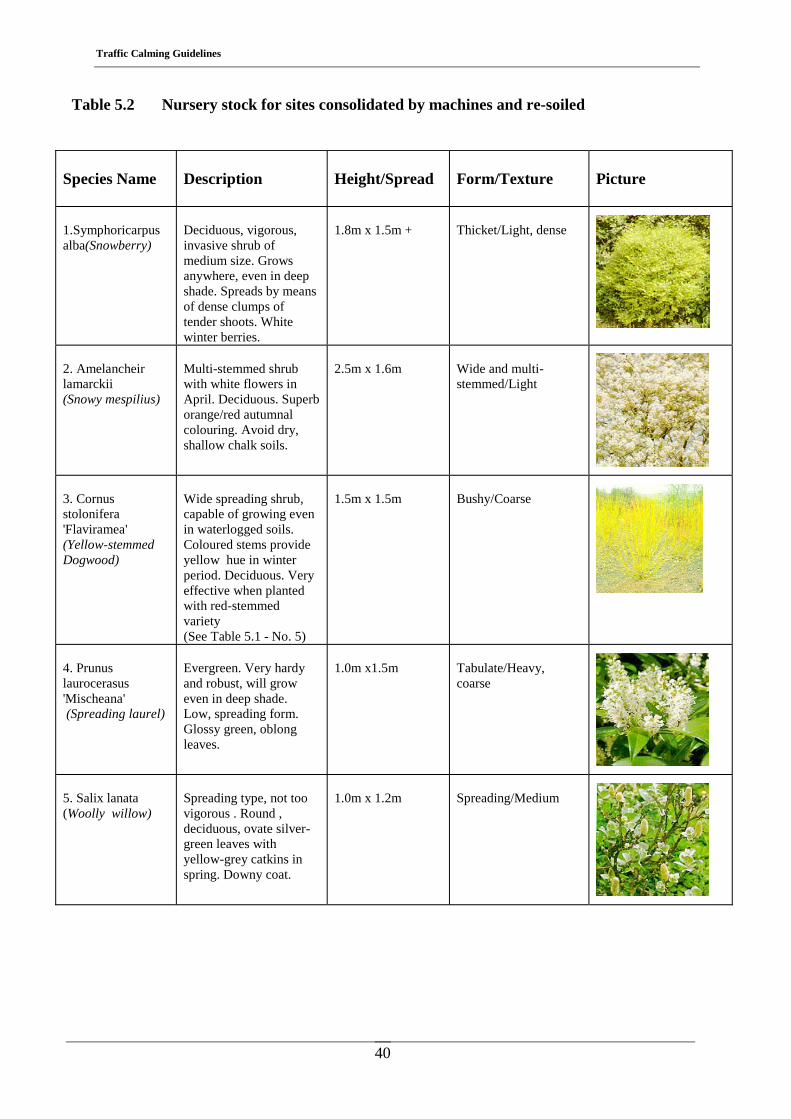
5.2.2 Nursery stock for sites consolidated by machines and re-soiled
A site consolidated by machines and re-soiled is often found at/adjacent to roadside margins
in situations where civil engineering works take place. In these difficult growing conditions it
is essential to select plants which will take root quickly and easily. Shallow rooting plants are
especially suitable (Table 5.2).
5.2.3 Nursery stock for heavy soils
Heavy soils contain a high clay content and are a difficult material to work to a fine tilth. In
addition, such soils contain high moisture contents and are slow to warm up in the spring
time. Plant material selected, as per Table 5.3, for such soils must be capable of establishing
under such conditions, favouring ground conditions with a high water table in spring time.
5.2.4 Nursery stock to withstand noxious fumes/polluted areas
With heavy vehicular traffic, smoke and fumes from numerous exhaust pipes contain
impurities and noxious gases which can be injurious to plant materials in confined locations,
semi-suburban areas etc. The soil becomes defiled by the pollution and plant foliage becomes
coated, often falling prematurely in the autumn. Growth is often restricted, resulting in plants
becoming stunted. In order to overcome such hostile conditions, a limited and selected range
of plants can only be used, and examples of these are contained in Table 5.4.
5.2.5 Nursery stock for dry sites in full sun
Dry, hot sites in full sun can induce a variety of disorders in a wide range of plants. The most
common condition is known as sun scald. This may, under extreme conditions, attack and
Traffic Calming Guidelines
37
scald the bark of trees or, alternatively, weaken the base of the plants. Under normal
conditions of a warm Irish summer, there is a limited range of certain plant types which thrive
in hot, dry conditions, capable of withstanding prolonged periods of drought. Table 5.5
contains some of the popular choices.
5.2.6 Nursery stock for low maintenance
Low maintenance plants tend to be plant material that establishes and grows in an orderly
manner with few vigorous shoots developing in a haphazard manner. Little pruning is
required as a result. This plant grouping also contains a large percentage of evergreens,
thereby considerably reducing the problem of weed control developing around the base of the
plants. Table 5.6 indicates a selection of plant materials that require little maintenance over a
10-15 year life cycle.
5.2.7 Selected specimen trees
A short listing of selected specimen trees is indicated in Table 5.7. All of the trees listed are
deciduous subjects of small to medium height. A relatively tight crown, oval or columnar in
shape, provides for a proposed layout that retains a sense of order. All of the specimens
indicated are hardy, reliable and particularly suitable to Irish growing conditions. All are
commercially available.
5.2.8 Amenity value, plant associative table
The final table, Table. 5.8, is the plant associative table, which combines a range of the plants
in all of the tables indicated into a suitable planting matrix. This table considers the different
characteristics of the various species of plants - height, spread, foliage, texture, flowering
habit etc., and provides guidelines for the successful combination of a number of different
subjects planted together as a planting unit using a range of selected tree types in the overall
schemes.
It should be pointed out, however, that these types of proposals are in outline format only, and
the services of a professional landscape architect can be considered in large scale schemes.
Traffic Calming Guidelines
38
Table 5.1 Nursery stock for cold, exposed inland areas
Species Name
Description
Height/Spread
Form/Texture
Picture
1. Pachysandra terminalis (Japanese Spurge)
Evergreen prostrate carpeter. Small diamond-shaped leaves on short, erect stems. Green-white flowers in Feb.-March. Grows in full or semi-circle.
20cm x 40cm
Carpet/Medium
2. Spiraea x arguta (Bridal Wreath)
Graceful, arching shrub. Small, fresh green leaves. Abundance of small, white flowers in May.
2.0m x 1.5m
Arching, round/Fine
3. Berberis thunbergii (Green Barberry)
Excellent, strong plant capable of growing in hostile conditions. Deciduous. Soft green foliage takes on a brilliant, orange-red autumnal colour. Stiff, reddish-brown thorny branches.
1.5m x 1.2m
Semi-erect/Spiny
4. Berberis candidula (Green Barberry)
Robust plant capable of growing in hostile conditions. Evergreen. Small dark green glossy foliage with a silver-blue reverse underside. Dense thorny branches form an impenetrable barrier.
45cm x 1.0m
Hemispherical/Coarse
5. Cornus alba ‘Siberica’ (Westonbirt Dogwood)
Wide spreading shrub, capable of growing even in waterlogged soils. Coloured stems provide scarlet hue in winter period. Deciduous.
1.5m x 1.5m
Bushy thicket/Coarse
Traffic Calming Guidelines
39
Table 5.1 (continued)
Species Name
Description
Height/Spread
Form/Texture
Picture
6. Viburnum opulus (Guelder Rose)
Native, deciduous hedgerow type shrub. Green leaves turning orange/red in autumn. White flowers in June followed by translucent red berries.
3.0m x 2.2m
Hedgerow/Coarse
7. Philadelphus 'Sybille' (Mock Orange)
Graceful, arching shrub. Small or medium size, sea-green leaves with richly scented flowers of pure white.
1.5m x 1.5m
Arching/Light
8. Euonymus 'Emerald Gaiety’
Ground cover type plant. Grows in sun or even in deep shade. Evergreen with open habit of silver and green variegated leaves
60cm x 80cm
Hummock, Ground cover/Light, dense
9. Cotoneaster horizontalis (Fish-bone Cotoneaster)
Fan-like branches. Ideal for banks. Almost evergreen, with small green leaves turning orange before falling to reveal prolific red berries.
50cm x 150cm
Ground cover/Medium coarse
10. Ulex europeus 'Plenus' (Double flowered Gorse)
Evergreen and very hardy, especially on dry soils. Compact bush with semi-double flowers in May. Sterile form which does not self-seed.
1.5m x 1.5m
Round bush/Coarse, thorny
Traffic Calming Guidelines
40
Table 5.2 Nursery stock for sites consolidated by machines and re-soiled
Species Name
Description
Height/Spread
Form/Texture
Picture
1.Symphoricarpus alba(Snowberry)
Deciduous, vigorous, invasive shrub of medium size. Grows anywhere, even in deep shade. Spreads by means of dense clumps of tender shoots. White winter berries.
1.8m x 1.5m +
Thicket/Light, dense
2. Amelancheir lamarckii (Snowy mespilius)
Multi-stemmed shrub with white flowers in April. Deciduous. Superb orange/red autumnal colouring. Avoid dry, shallow chalk soils.
2.5m x 1.6m
Wide and multi-stemmed/Light
3. Cornus stolonifera 'Flaviramea' (Yellow-stemmed Dogwood)
Wide spreading shrub, capable of growing even in waterlogged soils. Coloured stems provide yellow hue in winter period. Deciduous. Very effective when planted with red-stemmed variety (See Table 5.1 - No. 5)
1.5m x 1.5m
Bushy/Coarse
4. Prunus laurocerasus 'Mischeana' (Spreading laurel)
Evergreen. Very hardy and robust, will grow even in deep shade. Low, spreading form. Glossy green, oblong leaves.
1.0m x1.5m
Tabulate/Heavy, coarse
5. Salix lanata (Woolly willow)
Spreading type, not too vigorous . Round , deciduous, ovate silver-green leaves with yellow-grey catkins in spring. Downy coat.
1.0m x 1.2m
Spreading/Medium
Traffic Calming Guidelines
41
Table 5.2 (continued)
Species Name
Description
Height/Spread
Form/Texture
Picture
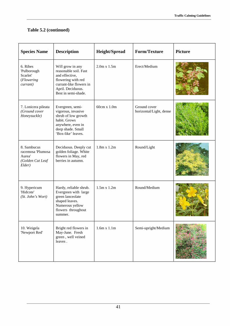
6. Ribes 'Pulborough Scarlet' (Flowering currant)
Will grow in any reasonable soil. Fast and effective, flowering with red currant-like flowers in April. Deciduous. Best in semi-shade.
2.0m x 1.5m
Erect/Medium
7. Lonicera pileata (Ground cover Honeysuckle)
Evergreen, semi- vigorous, invasive shrub of low growth habit. Grows anywhere, even in deep shade. Small ‘Box-like’ leaves.
60cm x 1.0m
Ground cover horizontal/Light, dense
8. Sambucus racemosa 'Plumosa Aurea' (Golden Cut Leaf Elder)
Deciduous. Deeply cut golden foliage. White flowers in May, red berries in autumn.
1.8m x 1.2m
Round/Light
9. Hypericum 'Hidcote' (St. John’s Wort)
Hardy, reliable shrub. Evergreen with large green lanceolate shaped leaves. Numerous yellow flowers throughout summer.
1.5m x 1.2m
Round/Medium
10. Weigela 'Newport Red'
Bright red flowers in May-June. Fresh green , well veined leaves .
1.6m x 1.1m
Semi-upright/Medium
Traffic Calming Guidelines
42
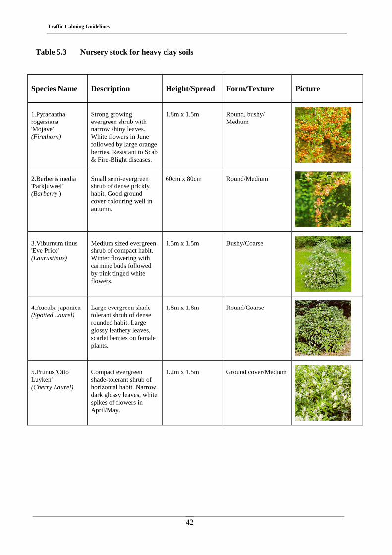
Table 5.3 Nursery stock for heavy clay soils
Species Name
Description
Height/Spread
Form/Texture
Picture
1.Pyracantha rogersiana 'Mojave' (Firethorn)
Strong growing evergreen shrub with narrow shiny leaves. White flowers in June followed by large orange berries. Resistant to Scab & Fire-Blight diseases.
1.8m x 1.5m
Round, bushy/ Medium
2.Berberis media 'Parkjuweel’ (Barberry )
Small semi-evergreen shrub of dense prickly habit. Good ground cover colouring well in autumn.
60cm x 80cm
Round/Medium
3.Viburnum tinus 'Eve Price' (Laurustinus)
Medium sized evergreen shrub of compact habit. Winter flowering with carmine buds followed by pink tinged white flowers.
1.5m x 1.5m
Bushy/Coarse
4.Aucuba japonica (Spotted Laurel)
Large evergreen shade tolerant shrub of dense rounded habit. Large glossy leathery leaves, scarlet berries on female plants.
1.8m x 1.8m
Round/Coarse
5.Prunus 'Otto Luyken' (Cherry Laurel)
Compact evergreen shade-tolerant shrub of horizontal habit. Narrow dark glossy leaves, white spikes of flowers in April/May.
1.2m x 1.5m
Ground cover/Medium
Traffic Calming Guidelines
43
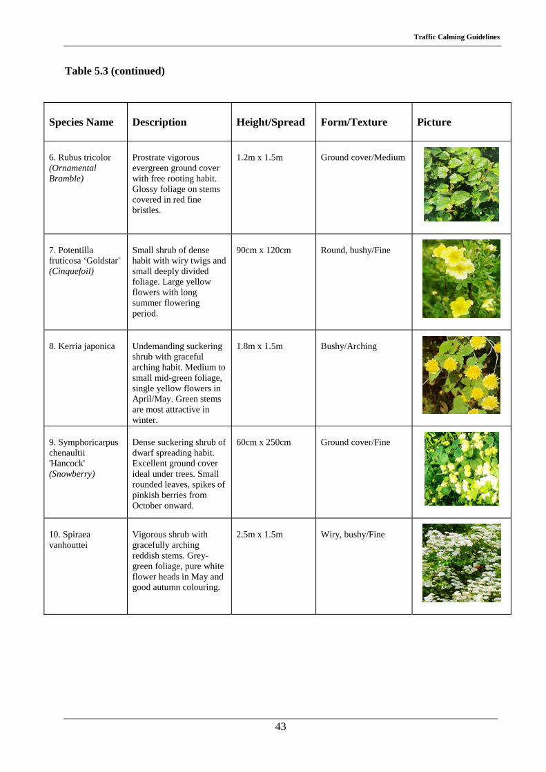
Table 5.3 (continued)
Species Name
Description
Height/Spread
Form/Texture
Picture
6. Rubus tricolor (Ornamental Bramble)
Prostrate vigorous evergreen ground cover with free rooting habit. Glossy foliage on stems covered in red fine bristles.
1.2m x 1.5m
Ground cover/Medium
7. Potentilla fruticosa ‘Goldstar' (Cinquefoil)
Small shrub of dense habit with wiry twigs and small deeply divided foliage. Large yellow flowers with long summer flowering period.
90cm x 120cm
Round, bushy/Fine
8. Kerria japonica
Undemanding suckering shrub with graceful arching habit. Medium to small mid-green foliage, single yellow flowers in April/May. Green stems are most attractive in winter.
1.8m x 1.5m
Bushy/Arching
9. Symphoricarpus chenaultii 'Hancock' (Snowberry)
Dense suckering shrub of dwarf spreading habit. Excellent ground cover ideal under trees. Small rounded leaves, spikes of pinkish berries from October onward.
60cm x 250cm
Ground cover/Fine
10. Spiraea vanhouttei
Vigorous shrub with gracefully arching reddish stems. Grey-green foliage, pure white flower heads in May and good autumn colouring.
2.5m x 1.5m
Wiry, bushy/Fine
Traffic Calming Guidelines
44
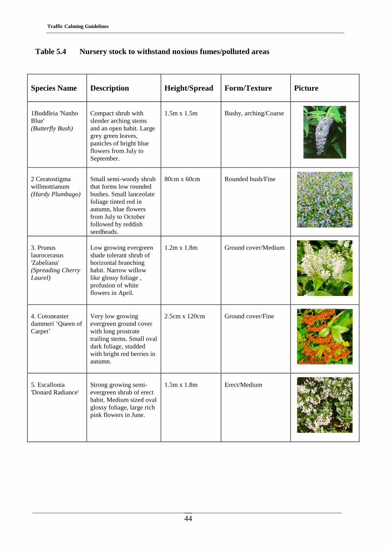
Table 5.4 Nursery stock to withstand noxious fumes/polluted areas
Species Name
Description
Height/Spread
Form/Texture
Picture
1Buddleia 'Nanho Blue' (Butterfly Bush)
Compact shrub with slender arching stems and an open habit. Large grey green leaves, panicles of bright blue flowers from July to September.
1.5m x 1.5m
Bushy, arching/Coarse
2 Ceratostigma willmottianum (Hardy Plumbago)
Small semi-woody shrub that forms low rounded bushes. Small lanceolate foliage tinted red in autumn, blue flowers from July to October followed by reddish seedheads.
80cm x 60cm
Rounded bush/Fine
3. Prunus laurocerasus 'Zabeliana' (Spreading Cherry Laurel)
Low growing evergreen shade tolerant shrub of horizontal branching habit. Narrow willow like glossy foliage , profusion of white flowers in April.
1.2m x 1.8m
Ground cover/Medium
4. Cotoneaster dammeri ‘Queen of Carpet’
Very low growing evergreen ground cover with long prostrate trailing stems. Small oval dark foliage, studded with bright red berries in autumn.
2.5cm x 120cm
Ground cover/Fine
5. Escallonia 'Donard Radiance'
Strong growing semi-evergreen shrub of erect habit. Medium sized oval glossy foliage, large rich pink flowers in June.
1.5m x 1.8m
Erect/Medium
Traffic Calming Guidelines
45
Table 5.4 (continued)
Species Name
Description
Height/Spread
Form/Texture
Picture
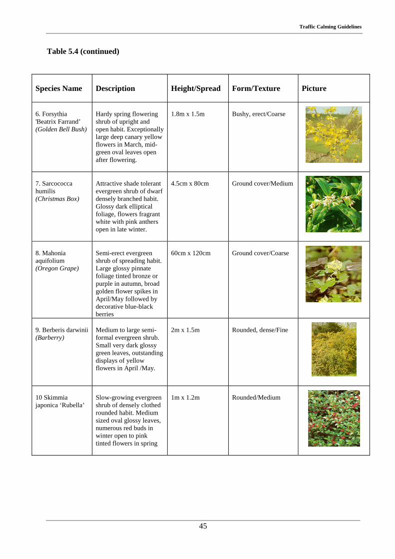
6. Forsythia 'Beatrix Farrand’ (Golden Bell Bush)
Hardy spring flowering shrub of upright and open habit. Exceptionally large deep canary yellow flowers in March, mid-green oval leaves open after flowering.
1.8m x 1.5m
Bushy, erect/Coarse
7. Sarcococca humilis (Christmas Box)
Attractive shade tolerant evergreen shrub of dwarf densely branched habit. Glossy dark elliptical foliage, flowers fragrant white with pink anthers open in late winter.
4.5cm x 80cm
Ground cover/Medium
8. Mahonia aquifolium (Oregon Grape)
Semi-erect evergreen shrub of spreading habit. Large glossy pinnate foliage tinted bronze or purple in autumn, broad golden flower spikes in April/May followed by decorative blue-black berries
60cm x 120cm
Ground cover/Coarse
9. Berberis darwinii (Barberry)
Medium to large semi-formal evergreen shrub. Small very dark glossy green leaves, outstanding displays of yellow flowers in April /May.
2m x 1.5m
Rounded, dense/Fine
10 Skimmia japonica ‘Rubella’
Slow-growing evergreen shrub of densely clothed rounded habit. Medium sized oval glossy leaves, numerous red buds in winter open to pink tinted flowers in spring
1m x 1.2m
Rounded/Medium
Traffic Calming Guidelines
46
Table 5.5 Nursery stock for dry sites in full sun
Species Name
Description
Height/Spread
Form/Texture
Picture
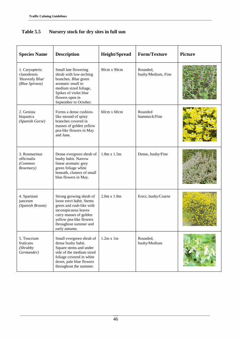
1. Caryopteris clanodensis 'Heavenly Blue' (Blue Spiraea)
Small late flowering shrub with low-arching branches. Blue green aromatic small to medium sized foliage, Spikes of violet blue flowers open in September to October.
90cm x 90cm
Rounded, bushy/Medium, Fine
2. Genista hispanica (Spanish Gorse)
Forms a dense cushion-like mound of spiny branches covered in masses of golden yellow pea-like flowers in May and June.
60cm x 60cm
Rounded hummock/Fine
3. Rosmarinus officinalis (Common Rosemary)
Dense evergreen shrub of bushy habit. Narrow linear aromatic grey green foliage white beneath, clusters of small blue flowers in May.
1.8m x 1.5m
Dense, bushy/Fine
4. Spartium junceum (Spanish Broom)
Strong growing shrub of loose erect habit. Stems green and rush-like with inconspicuous leaves carry masses of golden yellow pea-like flowers throughout summer and early autumn.
2.0m x 1.8m
Erect, bushy/Coarse
5. Teucrium fruticans (Shrubby Germander)
Small evergreen shrub of dense bushy habit. Square stems and under side of the medium sized foliage covered in white down, pale blue flowers throughout the summer.
1.2m x 1m
Rounded, bushy/Medium
Traffic Calming Guidelines
47
Table 5.5 (continued)
Species Name
Description
Height/Spread
Form/Texture
Picture
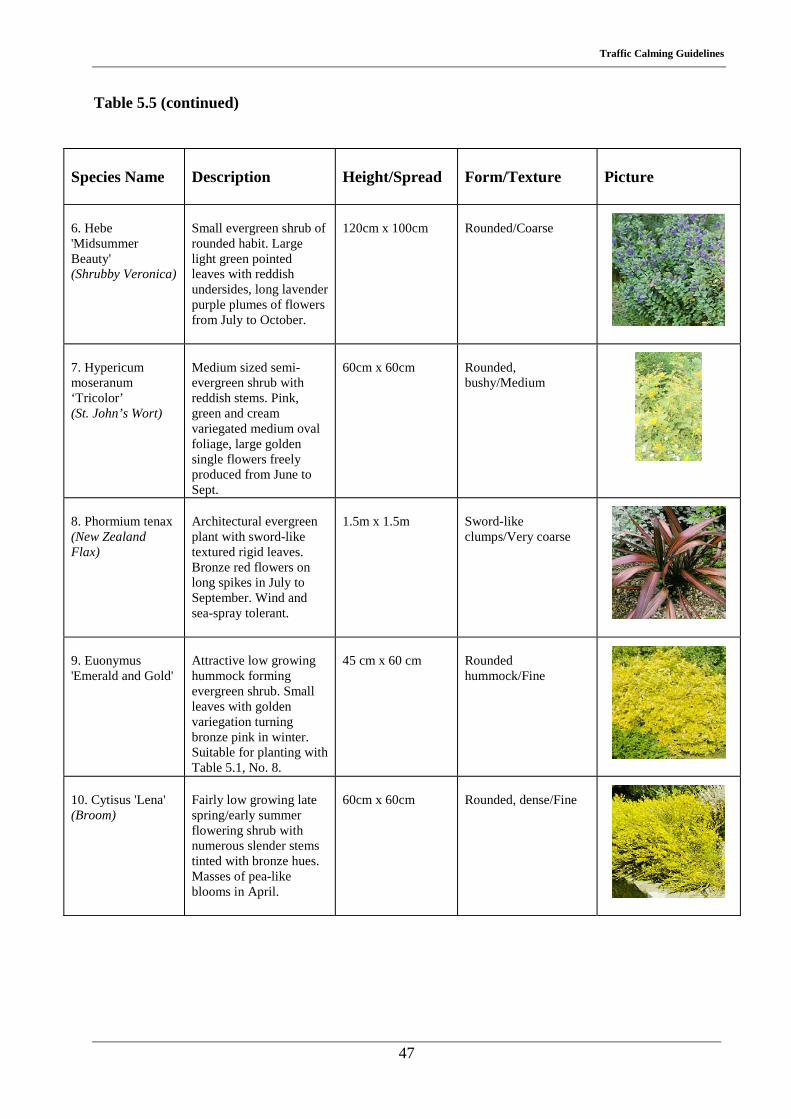
6. Hebe 'Midsummer Beauty' (Shrubby Veronica)
Small evergreen shrub of rounded habit. Large light green pointed leaves with reddish undersides, long lavender purple plumes of flowers from July to October.
120cm x 100cm
Rounded/Coarse
7. Hypericum moseranum ‘Tricolor’ (St. John’s Wort)
Medium sized semi-evergreen shrub with reddish stems. Pink, green and cream variegated medium oval foliage, large golden single flowers freely produced from June to Sept.
60cm x 60cm
Rounded, bushy/Medium
8. Phormium tenax (New Zealand Flax)
Architectural evergreen plant with sword-like textured rigid leaves. Bronze red flowers on long spikes in July to September. Wind and sea-spray tolerant.
1.5m x 1.5m
Sword-like clumps/Very coarse
9. Euonymus 'Emerald and Gold'
Attractive low growing hummock forming evergreen shrub. Small leaves with golden variegation turning bronze pink in winter. Suitable for planting with Table 5.1, No. 8.
45 cm x 60 cm
Rounded hummock/Fine
10. Cytisus 'Lena' (Broom)
Fairly low growing late spring/early summer flowering shrub with numerous slender stems tinted with bronze hues. Masses of pea-like blooms in April.
60cm x 60cm
Rounded, dense/Fine
Traffic Calming Guidelines
48
Table 5.6 Nursery stock for low maintenance
Species Name
Description
Height/Spread
Form/Texture
Picture
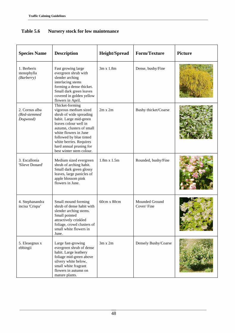
1. Berberis stenophylla (Barberry)
Fast growing large evergreen shrub with slender arching interlacing stems forming a dense thicket. Small dark green leaves covered in golden yellow flowers in April.
3m x 1.8m
Dense, bushy/Fine
2. Cornus alba (Red-stemmed Dogwood)
Thicket-forming vigorous medium sized shrub of wide spreading habit. Large mid-green leaves colour well in autumn, clusters of small white flowers in June followed by blue tinted white berries. Requires hard annual pruning for best winter stem colour.
2m x 2m
Bushy thicket/Coarse
3. Escallonia 'Slieve Donard'
Medium sized evergreen shrub of arching habit. Small dark green glossy leaves, large panicles of apple blossom pink flowers in June.
1.8m x 1.5m
Rounded, bushy/Fine
4. Stephanandra incisa 'Crispa’
Small mound forming shrub of dense habit with slender arching stems. Small pointed attractively crinkled foliage, crowd clusters of small white flowers in June.
60cm x 80cm
Mounded Ground Cover/ Fine
5. Eleaegnus x ebbingii
Large fast-growing evergreen shrub of dense habit. Large leathery foliage mid-green above silvery white below, small white fragrant flowers in autumn on mature plants.
3m x 2m
Densely Bushy/Coarse
Traffic Calming Guidelines
49
Table 5.6 (continued)
Species Name
Description
Height/Spread
Form/Texture
Picture
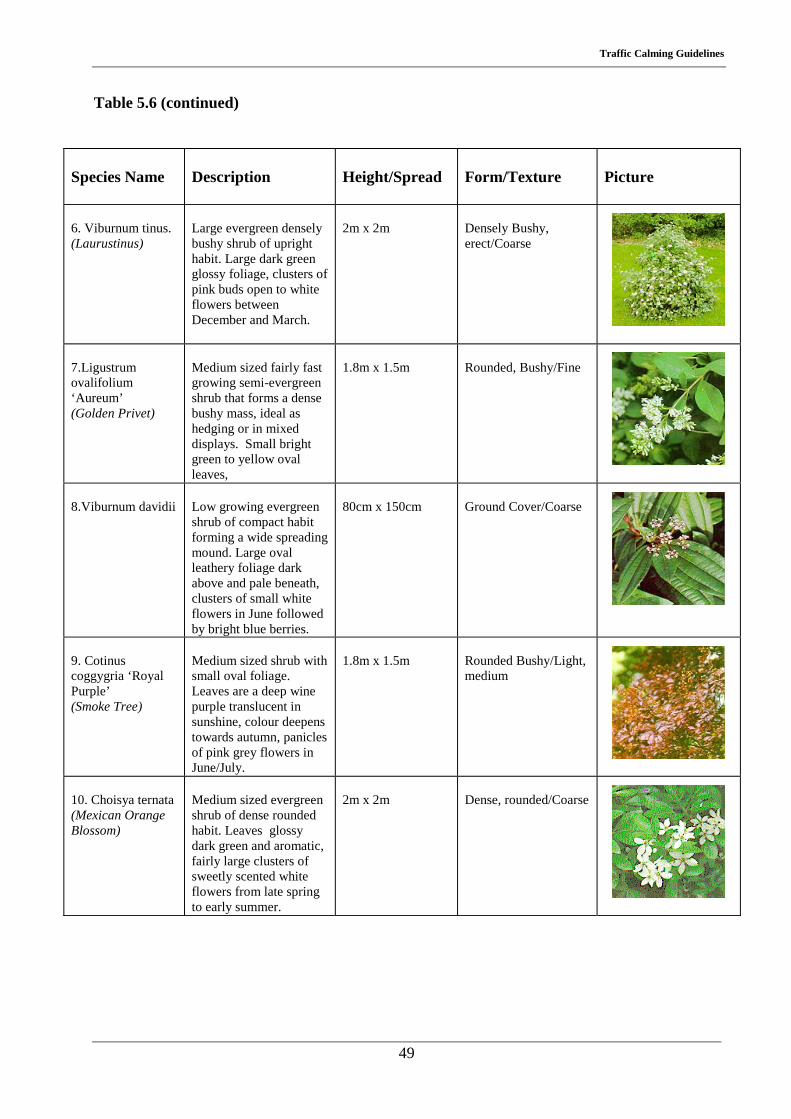
6. Viburnum tinus. (Laurustinus)
Large evergreen densely bushy shrub of upright habit. Large dark green glossy foliage, clusters of pink buds open to white flowers between December and March.
2m x 2m
Densely Bushy, erect/Coarse
7.Ligustrum ovalifolium ‘Aureum’ (Golden Privet)
Medium sized fairly fast growing semi-evergreen shrub that forms a dense bushy mass, ideal as hedging or in mixed displays. Small bright green to yellow oval leaves,
1.8m x 1.5m
Rounded, Bushy/Fine
8.Viburnum davidii
Low growing evergreen shrub of compact habit forming a wide spreading mound. Large oval leathery foliage dark above and pale beneath, clusters of small white flowers in June followed by bright blue berries.
80cm x 150cm
Ground Cover/Coarse
9. Cotinus coggygria ‘Royal Purple’ (Smoke Tree)
Medium sized shrub with small oval foliage. Leaves are a deep wine purple translucent in sunshine, colour deepens towards autumn, panicles of pink grey flowers in June/July.
1.8m x 1.5m
Rounded Bushy/Light, medium
10. Choisya ternata (Mexican Orange Blossom)
Medium sized evergreen shrub of dense rounded habit. Leaves glossy dark green and aromatic, fairly large clusters of sweetly scented white flowers from late spring to early summer.
2m x 2m
Dense, rounded/Coarse
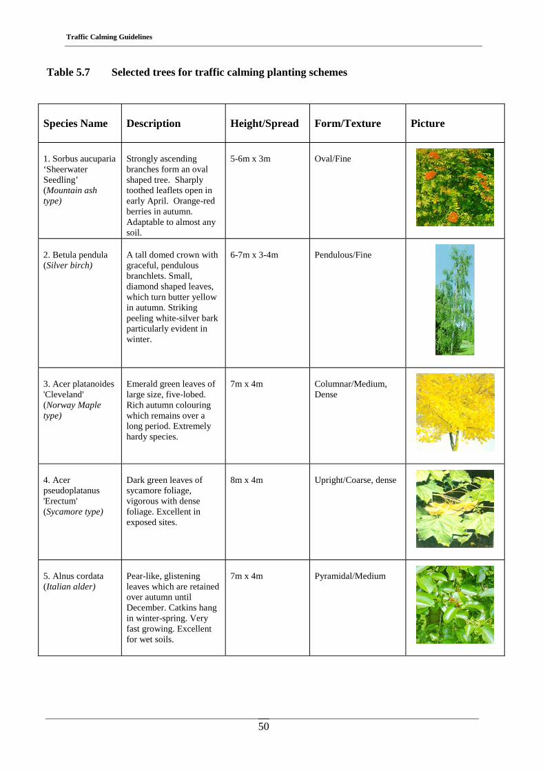
Traffic Calming Guidelines
50
Table 5.7 Selected trees for traffic calming planting schemes
Species Name
Description
Height/Spread
Form/Texture
Picture
1. Sorbus aucuparia ‘Sheerwater Seedling’ (Mountain ash type)
Strongly ascending branches form an oval shaped tree. Sharply toothed leaflets open in early April. Orange-red berries in autumn. Adaptable to almost any soil.
5-6m x 3m
Oval/Fine
2. Betula pendula (Silver birch)
A tall domed crown with graceful, pendulous branchlets. Small, diamond shaped leaves, which turn butter yellow in autumn. Striking peeling white-silver bark particularly evident in winter.
6-7m x 3-4m
Pendulous/Fine
3. Acer platanoides 'Cleveland' (Norway Maple type)
Emerald green leaves of large size, five-lobed. Rich autumn colouring which remains over a long period. Extremely hardy species.
7m x 4m
Columnar/Medium, Dense
4. Acer pseudoplatanus 'Erectum' (Sycamore type)
Dark green leaves of sycamore foliage, vigorous with dense foliage. Excellent in exposed sites.
8m x 4m
Upright/Coarse, dense
5. Alnus cordata (Italian alder)
Pear-like, glistening leaves which are retained over autumn until December. Catkins hang in winter-spring. Very fast growing. Excellent for wet soils.
7m x 4m
Pyramidal/Medium
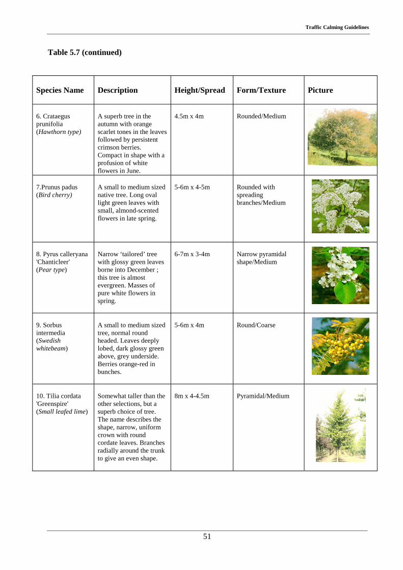
Traffic Calming Guidelines
51
Table 5.7 (continued)
Species Name
Description
Height/Spread
Form/Texture
Picture
6. Crataegus prunifolia (Hawthorn type)
A superb tree in the autumn with orange scarlet tones in the leaves followed by persistent crimson berries. Compact in shape with a profusion of white flowers in June.
4.5m x 4m
Rounded/Medium
7.Prunus padus (Bird cherry)
A small to medium sized native tree. Long oval light green leaves with small, almond-scented flowers in late spring.
5-6m x 4-5m
Rounded with spreading branches/Medium
8. Pyrus calleryana 'Chanticleer' (Pear type)
Narrow ‘tailored’ tree with glossy green leaves borne into December ; this tree is almost evergreen. Masses of pure white flowers in spring.
6-7m x 3-4m
Narrow pyramidal shape/Medium
9. Sorbus intermedia (Swedish whitebeam)
A small to medium sized tree, normal round headed. Leaves deeply lobed, dark glossy green above, grey underside. Berries orange-red in bunches.
5-6m x 4m
Round/Coarse
10. Tilia cordata 'Greenspire' (Small leafed lime)
Somewhat taller than the other selections, but a superb choice of tree. The name describes the shape, narrow, uniform crown with round cordate leaves. Branches radially around the trunk to give an even shape.
8m x 4-4.5m
Pyramidal/Medium
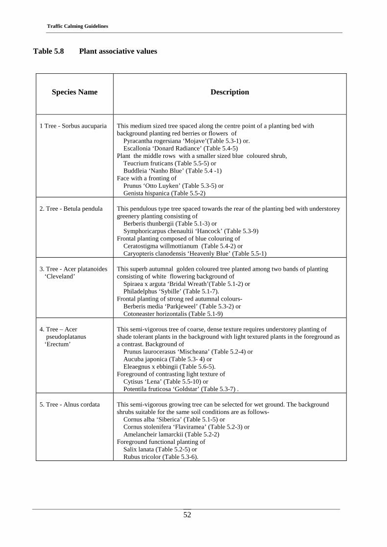
Traffic Calming Guidelines
52
Table 5.8 Plant associative values
Species Name
Description
1 Tree - Sorbus aucuparia
This medium sized tree spaced along the centre point of a planting bed with background planting red berries or flowers of Pyracantha rogersiana ‘Mojave’(Table 5.3-1) or. Escallonia ‘Donard Radiance’ (Table 5.4-5) Plant the middle rows with a smaller sized blue coloured shrub, Teucrium fruticans (Table 5.5-5) or Buddleia ‘Nanho Blue’ (Table 5.4 -1) Face with a fronting of Prunus ‘Otto Luyken’ (Table 5.3-5) or Genista hispanica (Table 5.5-2)
2. Tree - Betula pendula
This pendulous type tree spaced towards the rear of the planting bed with understorey greenery planting consisting of Berberis thunbergii (Table 5.1-3) or Symphoricarpus chenaultii ‘Hancock’ (Table 5.3-9) Frontal planting composed of blue colouring of Ceratostigma willmottianum (Table 5.4-2) or Caryopteris clanodensis ‘Heavenly Blue’ (Table 5.5-1)
3. Tree - Acer platanoides ‘Cleveland’
This superb autumnal golden coloured tree planted among two bands of planting consisting of white flowering background of Spiraea x arguta ‘Bridal Wreath’(Table 5.1-2) or Philadelphus ‘Sybille’ (Table 5.1-7). Frontal planting of strong red autumnal colours- Berberis media ‘Parkjeweel’ (Table 5.3-2) or Cotoneaster horizontalis (Table 5.1-9)
4. Tree – Acer pseudoplatanus ‘Erectum’
This semi-vigorous tree of coarse, dense texture requires understorey planting of shade tolerant plants in the background with light textured plants in the foreground as a contrast. Background of Prunus laurocerasus ‘Mischeana’ (Table 5.2-4) or Aucuba japonica (Table 5.3- 4) or Eleaegnus x ebbingii (Table 5.6-5). Foreground of contrasting light texture of Cytisus ‘Lena’ (Table 5.5-10) or Potentila fruticosa ‘Goldstar’ (Table 5.3-7) .
5. Tree - Alnus cordata
This semi-vigorous growing tree can be selected for wet ground. The background shrubs suitable for the same soil conditions are as follows- Cornus alba ‘Siberica’ (Table 5.1-5) or Cornus stolenifera ‘Flaviramea’ (Table 5.2-3) or Amelancheir lamarckii (Table 5.2-2) Foreground functional planting of Salix lanata (Table 5.2-5) or Rubus tricolor (Table 5.3-6).
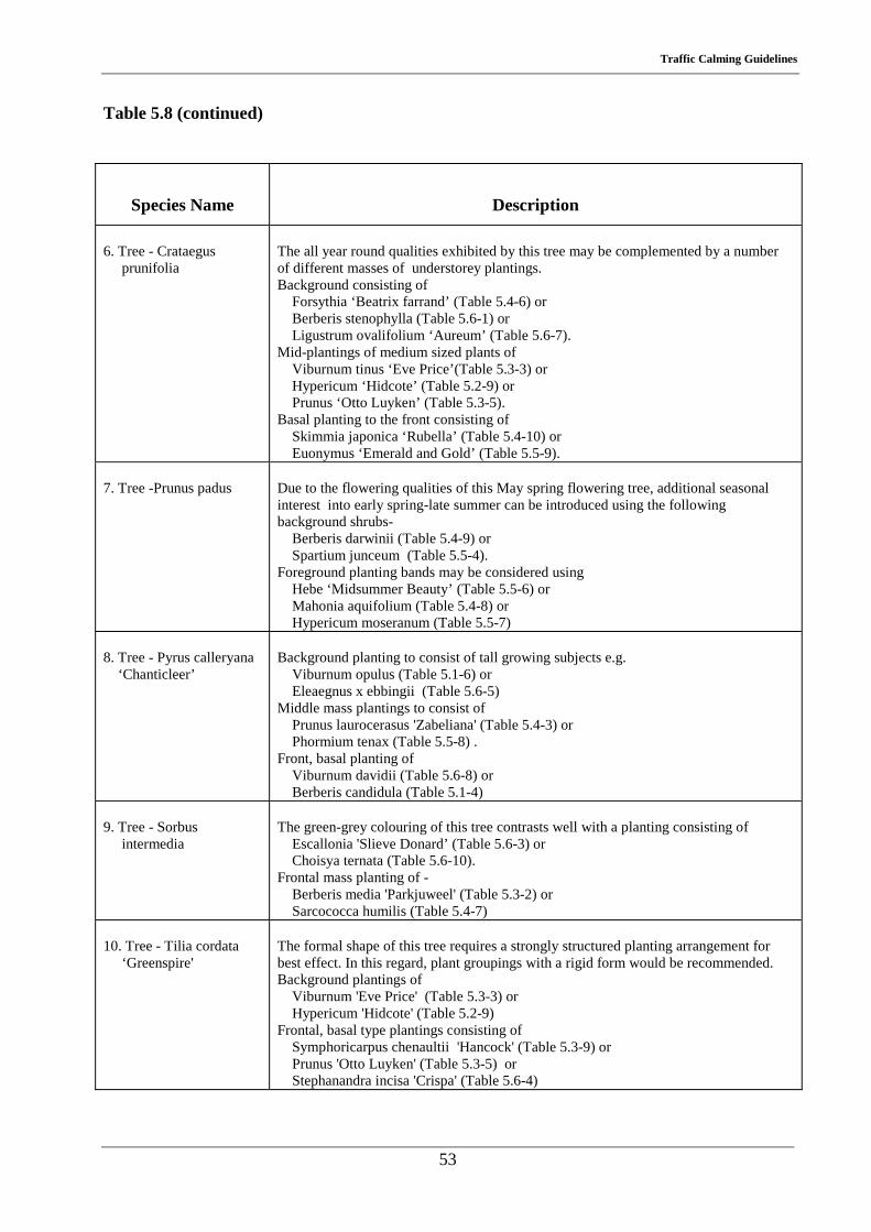
Traffic Calming Guidelines
53
Table 5.8 (continued)
Species Name
Description 6. Tree - Crataegus prunifolia
The all year round qualities exhibited by this tree may be complemented by a number of different masses of understorey plantings. Background consisting of Forsythia ‘Beatrix farrand’ (Table 5.4-6) or Berberis stenophylla (Table 5.6-1) or Ligustrum ovalifolium ‘Aureum’ (Table 5.6-7). Mid-plantings of medium sized plants of Viburnum tinus ‘Eve Price’(Table 5.3-3) or Hypericum ‘Hidcote’ (Table 5.2-9) or Prunus ‘Otto Luyken’ (Table 5.3-5). Basal planting to the front consisting of Skimmia japonica ‘Rubella’ (Table 5.4-10) or Euonymus ‘Emerald and Gold’ (Table 5.5-9).
7. Tree -Prunus padus
Due to the flowering qualities of this May spring flowering tree, additional seasonal interest into early spring-late summer can be introduced using the following background shrubs- Berberis darwinii (Table 5.4-9) or Spartium junceum (Table 5.5-4). Foreground planting bands may be considered using Hebe ‘Midsummer Beauty’ (Table 5.5-6) or Mahonia aquifolium (Table 5.4-8) or Hypericum moseranum (Table 5.5-7)
8. Tree - Pyrus calleryana ‘Chanticleer’
Background planting to consist of tall growing subjects e.g. Viburnum opulus (Table 5.1-6) or Eleaegnus x ebbingii (Table 5.6-5) Middle mass plantings to consist of Prunus laurocerasus 'Zabeliana' (Table 5.4-3) or Phormium tenax (Table 5.5-8) . Front, basal planting of Viburnum davidii (Table 5.6-8) or Berberis candidula (Table 5.1-4)
9. Tree - Sorbus intermedia
The green-grey colouring of this tree contrasts well with a planting consisting of Escallonia 'Slieve Donard’ (Table 5.6-3) or Choisya ternata (Table 5.6-10). Frontal mass planting of - Berberis media 'Parkjuweel' (Table 5.3-2) or Sarcococca humilis (Table 5.4-7)
10. Tree - Tilia cordata ‘Greenspire'
The formal shape of this tree requires a strongly structured planting arrangement for best effect. In this regard, plant groupings with a rigid form would be recommended. Background plantings of Viburnum 'Eve Price' (Table 5.3-3) or Hypericum 'Hidcote' (Table 5.2-9) Frontal, basal type plantings consisting of Symphoricarpus chenaultii 'Hancock' (Table 5.3-9) or Prunus 'Otto Luyken' (Table 5.3-5) or Stephanandra incisa 'Crispa' (Table 5.6-4)

Traffic Calming Guidelines
54
Traffic Calming Guidelines
55
Chapter 6 Technical Specification
6.1 Introduction
This chapter sets out the specifications that should be followed in drawing up proposals for a
Traffic Calming Scheme and should be read in conjunction with Chapters 2 and 3 of this Report.
The Technical Specification presents information on various elements of the Traffic Calming
works under two headings for each element :
• Design/Construction Specification which gives the designer the specific Irish, UK or
other reference for design and construction standards and issues.
• Design/Layout Guidelines providing guidelines, in the form of Guidance Notes, for the
appropriate arrangement, layout, location and configuration of the various elements
associated with the Transition Zone and Gateway in Chapter 2.
Elements covered include: Signage,
Road Markings,
Road Studs,
Traffic Route Lighting,
Bollards,
Flexible Surfacing,
Refuge Islands,
Kerbing,
Rumble Strips/Areas,
Cycle/Pedestrian Facilities.
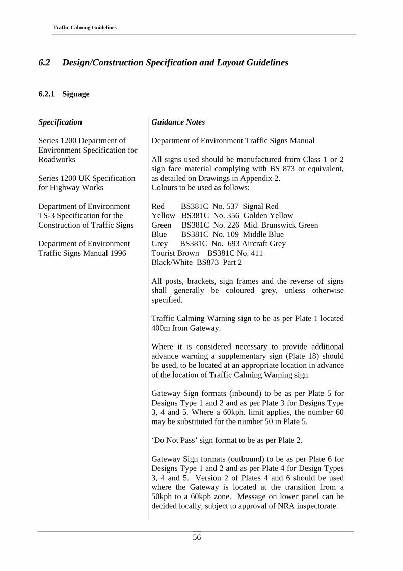
Traffic Calming Guidelines
56
6.2 Design/Construction Specification and Layout Guidelines
6.2.1 Signage
Specification Series 1200 Department of Environment Specification for Roadworks Series 1200 UK Specification for Highway Works Department of Environment TS-3 Specification for the Construction of Traffic Signs Department of Environment Traffic Signs Manual 1996
Guidance Notes Department of Environment Traffic Signs Manual All signs used should be manufactured from Class 1 or 2 sign face material complying with BS 873 or equivalent, as detailed on Drawings in Appendix 2. Colours to be used as follows: Red BS381C No. 537 Signal Red Yellow BS381C No. 356 Golden Yellow Green BS381C No. 226 Mid. Brunswick Green Blue BS381C No. 109 Middle Blue Grey BS381C No. 693 Aircraft Grey Tourist Brown BS381C No. 411 Black/White BS873 Part 2 All posts, brackets, sign frames and the reverse of signs shall generally be coloured grey, unless otherwise specified. Traffic Calming Warning sign to be as per Plate 1 located 400m from Gateway. Where it is considered necessary to provide additional advance warning a supplementary sign (Plate 18) should be used, to be located at an appropriate location in advance of the location of Traffic Calming Warning sign. Gateway Sign formats (inbound) to be as per Plate 5 for Designs Type 1 and 2 and as per Plate 3 for Designs Type 3, 4 and 5. Where a 60kph. limit applies, the number 60 may be substituted for the number 50 in Plate 5. ‘Do Not Pass’ sign format to be as per Plate 2. Gateway Sign formats (outbound) to be as per Plate 6 for Designs Type 1 and 2 and as per Plate 4 for Design Types 3, 4 and 5. Version 2 of Plates 4 and 6 should be used where the Gateway is located at the transition from a 50kph to a 60kph zone. Message on lower panel can be decided locally, subject to approval of NRA inspectorate.
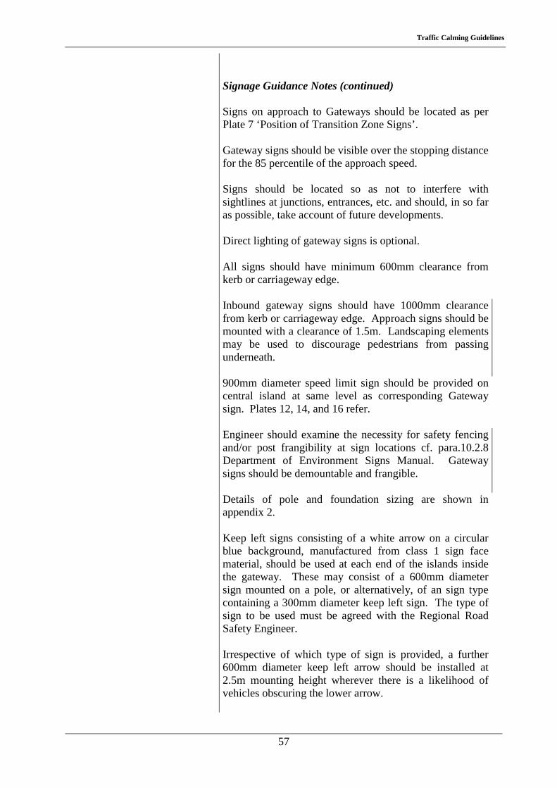
Traffic Calming Guidelines
57
Signage Guidance Notes (continued) Signs on approach to Gateways should be located as per Plate 7 ‘Position of Transition Zone Signs’. Gateway signs should be visible over the stopping distance for the 85 percentile of the approach speed. Signs should be located so as not to interfere with sightlines at junctions, entrances, etc. and should, in so far as possible, take account of future developments. Direct lighting of gateway signs is optional. All signs should have minimum 600mm clearance from kerb or carriageway edge.
Inbound gateway signs should have 1000mm clearance from kerb or carriageway edge. Approach signs should be mounted with a clearance of 1.5m. Landscaping elements may be used to discourage pedestrians from passing underneath.
900mm diameter speed limit sign should be provided on central island at same level as corresponding Gateway sign. Plates 12, 14, and 16 refer.
Engineer should examine the necessity for safety fencing and/or post frangibility at sign locations cf. para.10.2.8 Department of Environment Signs Manual. Gateway signs should be demountable and frangible.
Details of pole and foundation sizing are shown in appendix 2.
Keep left signs consisting of a white arrow on a circular blue background, manufactured from class 1 sign face material, should be used at each end of the islands inside the gateway. These may consist of a 600mm diameter sign mounted on a pole, or alternatively, of an sign type containing a 300mm diameter keep left sign. The type of sign to be used must be agreed with the Regional Road Safety Engineer. Irrespective of which type of sign is provided, a further 600mm diameter keep left arrow should be installed at 2.5m mounting height wherever there is a likelihood of vehicles obscuring the lower arrow.
Traffic Calming Guidelines
58
6.2.2 Road Markings
Specification Series 1200 Department of Environment Specification for Roadworks Series 1200 UK Specification for Highway Works BS 3262 Hot Applied Thermoplastic Road Markings City and County Engineers Association Thermoplastic Road Markings
Guidance Notes Department of Environment Traffic Signs Manual Solid white centreline should commence 190m on approach side of Gateway (all designs). Full hatching of hard shoulder should be achieved 70m. from Gateway, with a lead-in taper of 1:70 in Designs Type 3, 4 and 5. A 1m wide strip should be left unhatched on inside for cyclists/pedestrians. An appropriate gap should also be left in hatching to allow pedestrian/cyclist cross from shoulder to cycle facility cf. Plates 13, 15 and 17. Tapered hatching 70m. long should be provided on approach side of gateway central islands and min. 1.5m. long hatched area should be provided at offside, as per Plates 13, 15 and 17. A raised rib of thermoplastic, approximately 2mm high x 50mm. wide may be incorporated in central hatching and in last 100m. of yellow edge hatching on approach to Gateway. White lining should be continued adjacent to kerbs at Gateway islands. Layout of road markings on various approaches to be as per Plates 8 to 17 inclusive.
Traffic Calming Guidelines
59
6.2.3 Road Studs
Specification Series 1200 UK Specification for Highway Works BS 873 Part 4 Specification for Road Studs
Guidance Notes Department of Environment Traffic Signs Manual Approved reflective road studs should be used on approaches to Gateway. Studs should be spaced at 6m c/c on centreline and at 12m c/c on carriageway edges. Studs should be continued inside the gateway island.
6.2.4 Lighting
Specification BS 5489 Parts 1 to 10 Road Lighting. BS 5649 Lighting Columns. BS EN 40 Part 1 Series 1300 UK Specification for Highway Works
Guidance Notes Lighting columns should be kept clear and to the rear of footpaths and cycleways cf. Plates 10, 12, 14 and 16. Two 150 watt ceramic discharge metal halide lanterns should be provided on the central gateway islands, where such exist cf. Plates 12,14 and 16. The lanterns should give an asymmetric distribution, where the peak beam is directed across the road, producing a bright band of light across the road. Lanterns should be mounted at a minimum height of 6m. The lighting columns on the gateway central islands shall be 1m in front of the gateway signs and should be 1m above the signs except where this would bring the mounting height below the minimum of 6m. Lighting column on central islands should be demountable. It is desirable to extend TRL to the Gateways, and for at least two columns beyond (approximately 50m).
Traffic Calming Guidelines
60
6.2.5 Bollards
Specification BS 5489 Parts 1 to 10 Road Lighting Series 1200 UK Specification for Highway Works BS 873 Part 3 Specification for Internally Illuminated Bollards
Guidance Notes Bollards on Gateway Centre Islands: Slimline largehead internally illuminated bollards should be used at each end of the traffic islands at Gateways. Slimline circular stem type bollards afford maximum visibility of pedestrians. Circular signface should consist of white arrow on blue background, cf. Plates 12, 14 and 16. Signs Manual, Fig. 5.1(e) refers. Large diameter (900mm.) signface should be used on islands at Gateways.
Bollards on central islands inside gateway:
If reflectorised bollards are to be used at each end of the islands, the circular keep left sign face should be 300mm in diameter and consist of a white arrow on a blue background manufactured from class 1 sign face material. Alternatively, keep left signs may be used – see 6.2.1. The proposed bollard/sign type must be agreed with the Regional Road Safety Engineer. Irrespective of which type of sign or bollard is provided, a further 600mm diameter keep left arrow should be installed at 2.5m mounting height wherever there is a likelihood of vehicles obscuring the lower arrow. Bollards on Build-Outs inside Gateway: The conspicuity should be improved by the provision of a post-type bollard, with either a 100mm deep reflective strip or a 300mm diameter reflective keep right arrow. The use of any alternative bollards must be agreed with the Regional Safety Engineer.
Traffic Calming Guidelines
61
6.2.6 Flexible Surfacing
Specification Series 700/800/900 Department of Environment Specification for Roadworks Series 700/800/900 UK Specification for Highway Works NRA Provisional Specification for Hot-Laid Thin Bituminous Surfacings
Guidance Notes Consideration can be given to the use of alternative road surface texture/colour contrast at the Gateway, cycleways and median. (No recommendation as yet on type). This should extend over a distance of approx. 10m.
6.2.7 Refuge Islands
Specification UK Dept. Transport TA 52/87 NRA RT206 Warrants for Pedestrian Crossing Facilities Series 400 UK Specification for Highway Works
Guidance Notes Where there is sufficient width for central islands (Design Types 3, 4, and 5), the first island should be located at the Gateway or as close as possible on the town side of the Gateway, cf. Plates 12 to 17 inclusive. Gateway islands should be 4.5m to 6.0m. long and min. 2.1m wide. Where Gateways incorporate pedestrian crossing facilities use may be made of guardrails at particular sites to stream pedestrians. Off-centre positioning can deflect emerging pedestrians and encourage them to face on-coming traffic before crossing the road. Where guardrail is used, care should be taken not to obstruct visibility.
BS7818 Pedestrian Guardrails (metal)
Guardrails shall be high visibility pedestrian guardrail ie. Vertical bar layout shall provide a minimum of 50% transparency from all angles. Guardrail shall comply with BS 7818 and shall be certified.
Guardrail should not be erected within 600mm of the carriageway/kerb edge.
Traffic Calming Guidelines
62
6.2.8 Kerbing
Specification
Guidance Notes
Series 1100/1700 Department of
Dished/dropped kerbs should be provided at all crossing points both on pedestrian refuges and footpaths.
Environment Specification for Roadworks Series 1100 UK Specification for Highway Works Buildings for Everyone, National Rehabilitation Board (NRB), 1998
Kerbs on central islands should be painted alternating black and yellow to improve visibility. Kerbing, and preferably footpath, should extend from the urban area to the Gateway. If footpath is not provided, the area behind kerbs may be landscaped. Where central islands are not provided, width of carriageway (between kerbs) at Gateway to be max. 7.0m wide (Design Types 1 and 2). Where central islands are provided and where separate provision is made for cyclists (Design Types 3 and 4) the width between kerbs to be 3.5m. Where central islands are provided with no separate provision for cyclists, width between kerbs at Gateway to be 4.25m (Design Type 5) Where kerbing is introduced, care should be taken to address adequately surface water collection and disposal.
6.2.9 Rumble Strips
Specification NRA Speed Control Devices for Roads other than Residential
Guidance Notes The provision of rumble strips in advance of the Gateway can be very useful in alerting drivers to the installation ahead. However, their use in close proximity to houses or residential areas should be avoided.
Traffic Calming Guidelines
63
6.2.10 Cycle/Pedestrian Facilities
Specification Series 1100 Department of Environment Specification for Roadworks Series 1100 UK Specification for Highway Works Buildings for Everyone, NRB 1998
Guidance Notes Absolute minimum clear width of footpath should be not less than 900mm. 2.4m. headroom is required for combined cycle/pedestrian facilities.
6.2.11 Cycle Facilities
Specification Provision of Cycle Facilities,National Manual for Urban Areas DTO 1998
Guidance Notes AASHTO Guide for the Development of Bicycle Facilities. TRRL PA 2046/91 Translation of Dutch 30kph Zone Design Manual Cycleway should be provided as per typical layouts for different right of way widths, cf. Designs type 3, 4 and 5, Plates 12 to 17 inclusive. Cycleways should be a minimum of 1.5m wide Vertical clearance to obstructions, including signs, to be 2.4m. Where cycleway is to rejoin roadway, it should do so at right angles. Beginning and end of cycleways should be accompanied by the appropriate road markings and signage.

Traffic Calming Guidelines
64
Traffic Calming Guidelines
65
References
1. NATIONAL ROADS AUTHORITY, “Fermoy Traffic Accident Study”, R.S. 348, Dublin, N.R.A., 1987
2. NATIONAL ROADS AUTHORITY, “Mitchelstown Traffic Accident Study”, R.S. 349,
Dublin, N.R.A., 1987 3. DEPARTMENT OF TRANSPORT, U.K., “Vehicle Speed Measurement on all Purpose
Roads”, TA 22/81, London, Dept. of Transport, 1981 4. JENSEN, K.H. & KILDEBOGAARD, J, “Strategic et Ryt Begnet Vefpeanlaegninen”
Report No. 28, Oslo, Road Directorate, Road Data Laboratory, N.D. 5. ACCIDENT ANALYSIS AND PREVENTION, “Speed Management Through Traffic
Engineering”, whole issue, Vol. 24, 1, February, 1992 6. DEVON COUNTY COUNCIL, “Traffic Calming Guidelines” Exeter, Devon County
Council, 1991 7. DEPARTMENT OF THE ENVIRONMENT, “Traffic Signs Manual”, Dublin, The
Stationery Office, 1996 8. NATIONAL ROADS AUTHORITY, “Speed Control Devices for Roads other than
Residential”, R.S. 387B, Dublin, N.R.A., 1995 9. NATIONAL ROADS AUTHORITY, “Warrants for Pedestrian Crossing Facilities”, R.T.
206, Dublin, N.R.A., 1981 10. DEPARTMENT OF TRANSPORT, U.K., “The Assessment of Pedestrian Crossings”
Local Transport Note 1/95, London, Dept of Transport, 1995 11. DEPARTMENT OF TRANSPORT, U.K., “The Design of Pedestrian Crossings”, Local
Transport Note 2/95, London, Dept. of Transport, 1995 12. DUBLIN TRANSPORTATION OFFICE, “Provision of Cycle Facilities, National Manual
for Urban Areas”, Dublin, D.T.O., 1998

Traffic Calming Guidelines
66
Traffic Calming Guidelines
67
Appendix 1 Traffic Calming Data Summary Sheet
Traffic Calming Data Sheet Guidance Notes
Marker Plate
The number of the nearest yellow marker plate plus chainage in metres to each Gateway should
be entered on the form.
Approach Geometry
A section of road with a curve radius greater than 2500m should be considered straight, for
sections with curves less than this value the radius should be stated on the form. Vertical grades
should be expressed in %, positive for upgrade and negative for downgrade.
The optical width should be given a value of low (height of vertical elements greater than the
width of the street), medium or high (typical rural situation).
Geometry at Gateway
The geometry at the Gateway will determine the choice of gateway design type. The right of
way width (face of fence to face of fence), paved width (including hard shoulders) and
carriageway width should be entered on the form.
Gateway Design Type
This will be determined by the geometry and should be entered as type 1, 2, 3, 4 or 5. If
Gateway was installed prior to issue of these guidelines it should be described on the form as
‘other’ and an elevation drawing of the Gateway should be attached.
Treatment of Section between Gateway and Town/Village Centre
Details of traffic calming measures installed or to be installed between Gateway and town/village
centre should be given here. If solid islands have been/will be installed, size and spacing of
islands should be given.
Traffic Calming Guidelines
68
Rumble Strips
If rumble strips were/will be used, enter Y. Reasons for using rumble strips should also be
stated.
Accident Details
The total accidents and the total pedestrian/cyclist accidents on the through route for the five
years prior to the date of application for funding should be entered on form as should the
population of the built up area of the town/village.
Speed Measurements
It is important that accurate speed measurements be taken, both before and after the installation.
It is recommended that inductive loops or vehicle magnetic imaging counters be used rather than
radar methods. For the purpose of evaluation of traffic calming schemes the 85 percentile dry
weather spot speed of cars should be used. This is the speed exceeded by only 15% of the cars.
Vehicle speed should be monitored over a number of years in order to evaluate the long-term
effect of the installation.
Public Reaction
Public reaction (both of residents of the town/village and road users) should be assessed.
Comments should be summarised and entered onto the form.
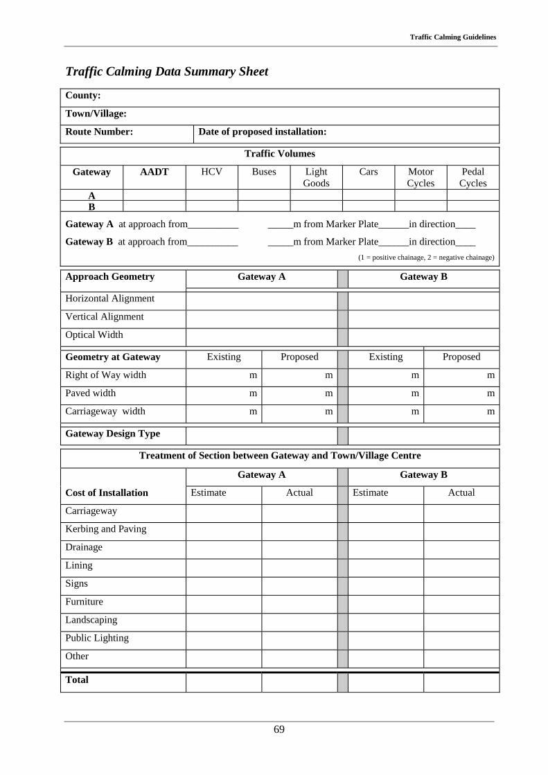
Traffic Calming Guidelines
69
Traffic Calming Data Summary Sheet
County:
Town/Village:
Route Number: Date of proposed installation:
Traffic Volumes
Gateway AADT HCV Buses Light Goods
Cars Motor Cycles
Pedal Cycles
A B
Gateway A at approach from__________ _____m from Marker Plate______in direction____
Gateway B at approach from__________ _____m from Marker Plate______in direction____ (1 = positive chainage, 2 = negative chainage)
Approach Geometry Gateway A Gateway B
Horizontal Alignment
Vertical Alignment
Optical Width
Geometry at Gateway Existing Proposed Existing Proposed
Right of Way width m m m m
Paved width m m m m
Carriageway width m m m m
Gateway Design Type
Treatment of Section between Gateway and Town/Village Centre
Gateway A Gateway B
Cost of Installation Estimate Actual Estimate Actual
Carriageway
Kerbing and Paving
Drainage
Lining
Signs
Furniture
Landscaping
Public Lighting
Other
Total

Traffic Calming Guidelines
70
Traffic Calming Data Summary Sheet (page 2) Rumble Strips Type used
Y/N
Accident Details:
Total Accidents on Through Route
Total Pedestrian or Pedal Cyclist Accidents
Population
Fatal Serious Minor Fatal Serious Minor
5 Years prior to opening of the scheme
Subsequent to opening of scheme
Year 1
Year 2
Year 3
Year 4
Year 5
Speed Measurement
After
Gateway A Before Year 1 Year 2 Year 3 Year 4 Year 5
Approaches
At existing speed limits
200m inside existing speed limits
Midway between Gateway and town/village centre
After
Gateway B Before Year 1 Year 2 Year 3 Year 4 Year 5
Approaches
At existing speed limits
200m inside existing speed limits
Midway between Gateway and town/village centre
Public Reaction
Signed __________________________________ Grade EE/SEE
Date __________________________________
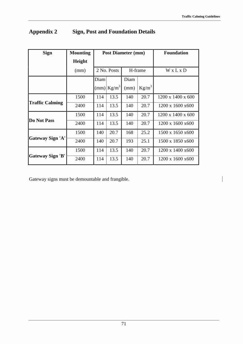
Traffic Calming Guidelines
71
Appendix 2 Sign, Post and Foundation Details
Sign Mounting
Height
Post Diameter (mm) Foundation
(mm) 2 No. Posts H-frame W x L x D
Diam
(mm)
Kg/m3
Diam
(mm)
Kg/m3
1500 114 13.5 140 20.7 1200 x 1400 x 600 Traffic Calming 2400 114 13.5 140 20.7 1200 x 1600 x600
1500 114 13.5 140 20.7 1200 x 1400 x 600 Do Not Pass 2400 114 13.5 140 20.7 1200 x 1600 x600
1500 140 20.7 168 25.2 1500 x 1650 x600 Gateway Sign 'A' 2400 140 20.7 193 25.1 1500 x 1850 x600
1500 114 13.5 140 20.7 1200 x 1400 x600 Gateway Sign 'B' 2400 114 13.5 140 20.7 1200 x 1600 x600
Gateway signs must be demountable and frangible.

Traffic Calming Guidelines
72