Embed Size (px)
Citation preview
ESE PA ESE PA
3341101MICROPROCESSOR AND ASSEMBLY LANGUAGE
PROGRAMMING3 0 2 5 70 30 20 30 150
3341102 DIGITAL COMMUNICATION 3 0 2 5 70 30 20 30 150
3341103 OPTICAL COMMUNICATION 3 0 2 5 70 30 20 30 150
3341104 ELECTRONICS INSTRUMENTS AND MEASUREMENT 3 0 2 5 70 30 20 30 150
3341105 INDUSTRIAL ELECTRONICS 4 0 2 6 70 30 20 30 150
3341106 CIRCUIT DESIGN TOOLS 0 0 4 4 0 0 40 60 100
16 0 14 30 350 150 140 210 850
ESE : END SEMESTER EXAM
L: LECTURE
P: PRACTICAL
T: TUTORIAL
GUJARAT TECHNOLOGICAL UNIVERSITY
BRANCH CODE:11 DIPLOMA PROGRAMME IN ELECTRONICS & COMMUNICATION ENGINEERING
SEMESTER - IV
COURSE TITLE
TEACHING SCHEME EXAMINATION SCHEME
L T PCREDITS
(L+T+P)
THEORY
MARKS
PRACTICAL
MARKS GRAND
TOTAL
TOTAL
ESE for Practical includes Viva/Practical exam/Performance etc.
PA for Practicals includes TW/Report writing/Mini Project/Seminar etc. related to practicals
PA for Theory includes Written Exam /Assignment/Tutorial Work/Mini Project/Quiz/Presentation or
Combination of all with prior intimation to the students at beginning of term
PA: PROGRESSIVE ASSESSMENT
COURSE
CODE
For Any suggestion please write to Mr. S. J. chauhan , Email id :- [email protected] with copy to [email protected]
Microprocessor and Assembly Language Programming Course Code: 3341101
GTU/ NITTTR Bhopal/13-14 Gujarat State
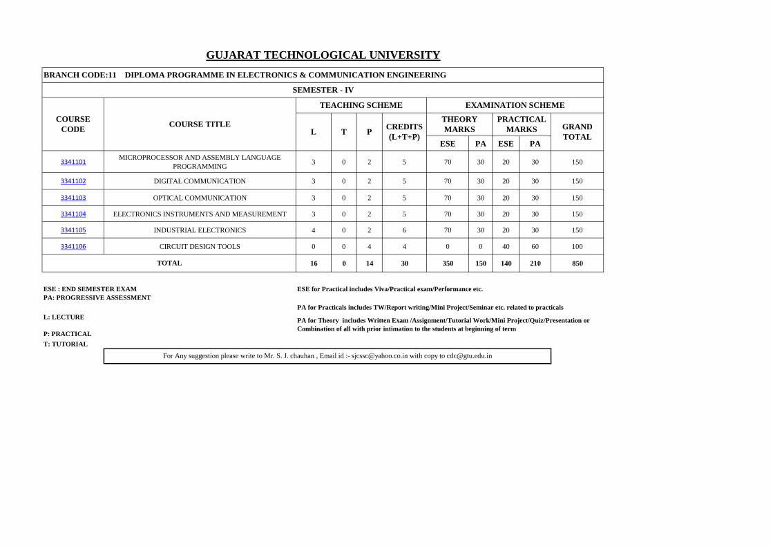
GUJARAT TECHNOLOGICAL UNIVERSITY, AHMEDABAD, GUJARAT
COURSE CURRICULUM
COURSE TITLE: MICROPROCESSOR AND ASSEMBLY LANGUAGE
PROGRAMMING
(Code: 3341101)
Diploma Programme in which this course is offered
Semester in which offered
Electronics and Communication Engineering 4th
Semester
1. RATIONALE
Microprocessor is the heart of embedded system and computers. This course will provide
basic knowledge of microprocessor architecture and programming in assembly language. The
basic knowledge of microprocessor and assembly language programming will enable the
students to learn microcontroller and embedded systems in the higher semesters. The
intention of this course is to help the student to maintain microprocessor based electronic
equipments.
2. COMPETENCY:
The course content should be taught and implemented with the aim to develop different types
of skills so that students are able to acquire following competency:
Maintain microprocessor based electronic equipment.
3. COURSE OUTCOMES
The theory should be taught and practical should be carried out in such a manner that students
are able to acquire different learning outcomes in cognitive, psychomotor and affective
domain to demonstrate following course outcomes.
i. Analyse the architecture of the Intel 8085 microprocessor for its various applications.
ii. Develop simple arithmetic programmes
iii. Use the addressing modes and timing diagram for executing programmes efficiently
iv. Develop assembly language program using stack and subroutine for various
applications
v. Interface peripheral devices with 8085 microprocessor
4. TEACHING AND EXAMINATION SCHEME
Legends: L - Lecture; T - Tutorial/Teacher Guided Student Activity; P - Practical; C - Credit; ESE - End
Semester Examination; PA - Progressive Assessment
Teaching Scheme
(In Hours)
Total Credits
(L+T+P)
Examination Scheme
Theory Marks Practical Marks Total Marks
L
T
P
C
ESE
PA
ESE
PA
150
3
0
2
5
70
30
20
30
Microprocessor and Assembly Language Programming Course Code: 3341101
GTU/ NITTTR Bhopal/13-14 Gujarat State
2
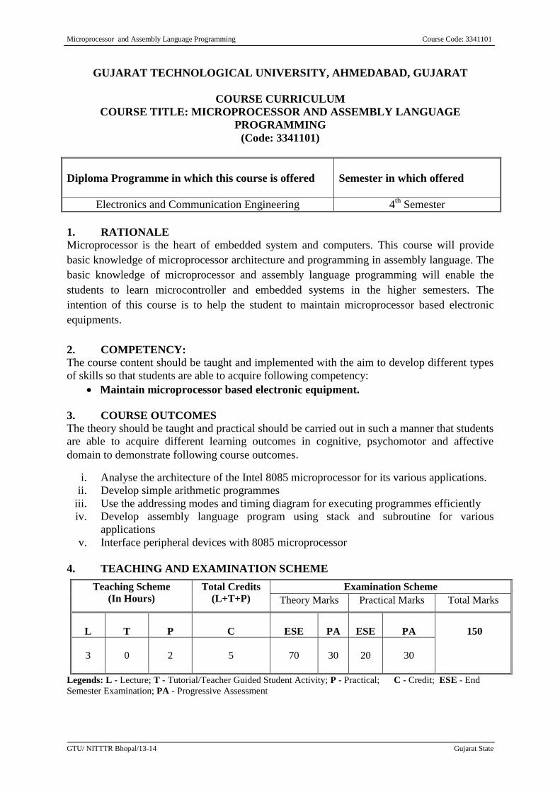
5. COURSE DETAILS
Unit Major Learning Outcomes
(in cognitive domain) Topics and Sub-topics
Unit-I
Microprocessor
Architecture
1a. Define microprocessor and Diiferantiate
between types of microprocessor
1b. Describe the function of pins in the pin
diagram of 8085 microprocessor with a
sketch.
1.1 Microprocessor and
types of microprocessor
1.1 Pin diagram of 8085
microprocessor
1c. Define and explain dieefrant operations
performed by Microprocessor
1.2 Microprocessor
operations
1d. Describe the 8085 microprocessor
architecture diagram with its functioning.
1.3 8085 Microprocessor
architecture diagram
with its functions
1e. Describe the register set of 8085
1f. Describe the impact of ALU on flags of
8085
1g. Describe interrupt and serial I/O
1.4 Register set of 8085
1.5 Flag Classification
1.6 1.7 Interrupt types and
serial I/O
1h. Define the various types of buses and
clock speed.
1i. Importance of demultiplexing of
address/data bus and control signal
1j. State the significance of clock speed.
1.7 Bus organisation:
Address & Data bus and
control bus and
demultilexing of buses
1.8 Clock speed
Unit-II
8085
Micproprocessor
Instruction set
2a. Differentiate between opcode and operand
with examples
2.1 Opcode and opera
2b. Define the classification of the instruction
set
2.2 Instructions: Data
transfer, Arithmetic,
Logical, Branch, Stack
and I/O read and write
cycle
Unit-III
Addressing
Mode And
Timing Diagram
3a. Define the need of addressing modes.
3b. Classify the various addressing modes
3.1 Type of addressing
mode of 8085
3c. Differentiate between T-state, machine
cycle and instruction cycle
3.2 T-state, Machine Cycle,
Instruction cycle
3d. Explain with sketches the timing diagram
for I/O and memory read/write cycle
3.3 Timing diagram
3e. Describe the timing delay using NOP
instruction
3.4 Timing Delays
Unit-IV
Programming In
8085
4a. Develop to execute simple addition and
subtraction programmes using the
instruction set
4b. Develop to execute simple multiplication
and division programmes using the
instruction set
4.1 Addition and subtraction
programmes
4.2 Multiplication and
division programmes
4c. Develop to execute various assembly
language programs using looping and
4.3 Looping, Counting and
Indexing.
Microprocessor and Assembly Language Programming Course Code: 3341101
GTU/ NITTTR Bhopal/13-14 Gujarat State
3
Unit Major Learning Outcomes
(in cognitive domain) Topics and Sub-topics
counting concept.
4d. Develop to execute assembly language
programs using logical functions
4.4 Logic operations viz.
AND, OR, NOR, NAND
NOT, EXOR.
4e. Develop to execute an assembly language
to generate delay of specific time.
4.5 Counter and Timing
delays.
4f. Develop to execute an assembly language
sub program based on Stack and
Subroutine concept.
4.6 Stack and subroutines.
Unit-V
Interfacing Of
8085
5a. Define memory mapping.
5b. Discriminate between memory mapped
I/O and I/O mapped I/O
5.1 Memory and I/O
mapping.
5c. Explain the functions of the chip selection
and decoder interfacing.
5.2 Chip selection and
decoder interfacing.
5d. Interface 8085 to EPROM.
5.3 Interfacing to EPROM
and R/W Memory
5e. Sketch the interfacing circuit for LED
using 74LS245 5.4 Interfacing LEDs and
Switches using 74LS245
5f. Explain the function of IC 8255 with a
block diagram.
5g. Develop to execute assembly language
program to read and display the data from
IC 8255 ports.
5.5 Programmable
Peripheral Interface- IC
8255: Configuration,
Modes and Operation
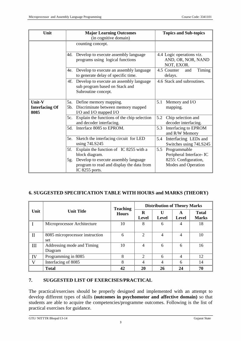
6. SUGGESTED SPECIFICATION TABLE WITH HOURS and MARKS (THEORY)
Unit Unit Title Teaching
Hours
Distribution of Theory Marks
R
Level
U
Level
A
Level
Total
Marks
I Microprocessor Architecture 10 8 6 4 18
II 8085 microprocessor instruction
set
6 2 4 4 10
III Addressing mode and Timing
Diagram
10 4 6 6 16
IV Programming in 8085 8 2 6 4 12
V Interfacing of 8085 8 4 4 6 14
Total 42 20 26 24 70
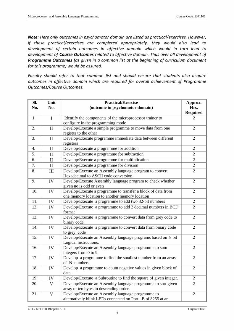
7. SUGGESTED LIST OF EXERCISES/PRACTICAL
The practical/exercises should be properly designed and implemented with an attempt to
develop different types of skills (outcomes in psychomotor and affective domain) so that
students are able to acquire the competencies/programme outcomes. Following is the list of
practical exercises for guidance.
Microprocessor and Assembly Language Programming Course Code: 3341101
GTU/ NITTTR Bhopal/13-14 Gujarat State
4
Note: Here only outcomes in psychomotor domain are listed as practical/exercises. However, if these practical/exercises are completed appropriately, they would also lead to development of certain outcomes in affective domain which would in turn lead to development of Course Outcomes related to affective domain. Thus over all development of Programme Outcomes (as given in a common list at the beginning of curriculum document for this programme) would be assured.
Faculty should refer to that common list and should ensure that students also acquire outcomes in affective domain which are required for overall achievement of Programme Outcomes/Course Outcomes.
Sl.
No.
Unit
No.
Practical/Exercise
(outcome in psychomotor domain)
Approx.
Hrs.
Required
1. I Identify the components of the microprocessor trainer to
configure in the programming mode
2
2. II Develop/Execute a simple programme to move data from one
register to the other
2
3. II Develop/Execute programme immediate data between different
registers
2
4. II Develop/Execute a programme for addition 2
5. II Develop/Execute a programme for subtraction 2
6. II Develop/Execute a programme for multiplication 2
7. II Develop/Execute a programme for division 2
8. III Develop/Execute an Assembly language program to convert
Hexadecimal to ASCII code conversion.
2
9. IV Develop/Execute Assembly language program to check whether
given no is odd or even
2
10. IV Develop/Execute a programme to transfer a block of data from
one memory location to another memory location
2
11. IV Develop/Execute a programme to add two 32-bit numbers 2
12. IV Develop/Execute a programme to add 2 decimal numbers in BCD
format
2
13. IV Develop/Execute a programme to convert data from grey code to
binary code
2
14. IV Develop/Execute a programme to convert data from binary code
to grey code
2
15. IV Develop/Execute an Assembly language programs based on 8 bit
Logical instructions.
2
16. IV Develop/Execute an Assembly language programme to sum
integers from 0 to 9.
2
17. IV Develop a programme to find the smallest number from an array
of N numbers
2
18. IV Develop a programme to count negative values in given block of
data.
2
19. IV Develop/Execute a Subroutine to find the square of given integer. 2
20. V Develop/Execute an Assembly language programme to sort given
array of ten bytes in descending order.
2
21. V Develop/Execute an Assembly language programme to
alternatively blink LEDs connected on Port –B of 8255 at an
2
Microprocessor and Assembly Language Programming Course Code: 3341101
GTU/ NITTTR Bhopal/13-14 Gujarat State
5
Sl.
No.
Unit
No.
Practical/Exercise
(outcome in psychomotor domain)
Approx.
Hrs.
Required
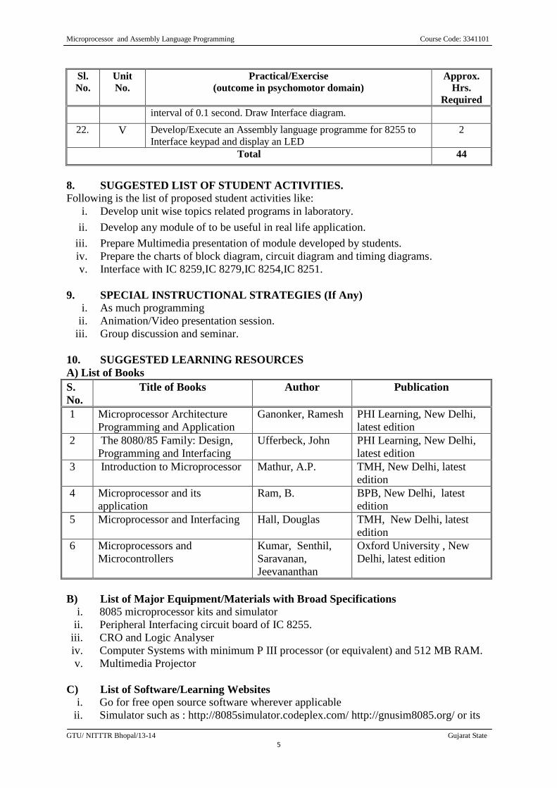
interval of 0.1 second. Draw Interface diagram.
22. V Develop/Execute an Assembly language programme for 8255 to
Interface keypad and display an LED
2
Total 44
8. SUGGESTED LIST OF STUDENT ACTIVITIES. Following is the list of proposed student activities like:
i. Develop unit wise topics related programs in laboratory.
ii. Develop any module of to be useful in real life application.
iii. Prepare Multimedia presentation of module developed by students.
iv. Prepare the charts of block diagram, circuit diagram and timing diagrams.
v. Interface with IC 8259,IC 8279,IC 8254,IC 8251.
9. SPECIAL INSTRUCTIONAL STRATEGIES (If Any) i. As much programming
ii. Animation/Video presentation session.
iii. Group discussion and seminar.
10. SUGGESTED LEARNING RESOURCES
A) List of Books
S.
No.
Title of Books Author Publication
1 Microprocessor Architecture
Programming and Application
Ganonker, Ramesh PHI Learning, New Delhi,
latest edition
2 The 8080/85 Family: Design,
Programming and Interfacing
Ufferbeck, John PHI Learning, New Delhi,
latest edition
3 Introduction to Microprocessor Mathur, A.P. TMH, New Delhi, latest
edition
4 Microprocessor and its
application
Ram, B. BPB, New Delhi, latest
edition
5 Microprocessor and Interfacing Hall, Douglas TMH, New Delhi, latest
edition
6 Microprocessors and
Microcontrollers
Kumar, Senthil,
Saravanan,
Jeevananthan
Oxford University , New
Delhi, latest edition
B) List of Major Equipment/Materials with Broad Specifications
i. 8085 microprocessor kits and simulator
ii. Peripheral Interfacing circuit board of IC 8255.
iii. CRO and Logic Analyser
iv. Computer Systems with minimum P III processor (or equivalent) and 512 MB RAM.
v. Multimedia Projector
C) List of Software/Learning Websites
i. Go for free open source software wherever applicable
ii. Simulator such as : http://8085simulator.codeplex.com/ http://gnusim8085.org/ or its
Microprocessor and Assembly Language Programming Course Code: 3341101
GTU/ NITTTR Bhopal/13-14 Gujarat State
6
Equivalent.
iii. Latest processor configuration : http://www.intel.com/pressroom/kits/quickreffam.htm
iv. Intel 8085 microprocessor architecture: http://www.cpu-world.com/Arch/8085.html
11. COURSE CURRICULUM DEVELOPMENT COMMITTEE
Faculty from Polytechnic Group
Prof. D. B. Vagadia, HOD (EC), Government Polytechnic, Rajkot
Prof R. D. Raghani, HOD (EC), L.E. Collage, Morbi
Prof. T. R. Parmar, Sr. Lecturer (EC), Government Polytechnic, Palanpur
Prof. K. N. Vaghela, Sr. Lecturer (EC) , Government Polytechnic, Ahmedabad
Prof. J D Chauhan, Sr.Lecturer (EC), BBIT, Vallabh Vidhyanagar
Prof. (Ms) Sthuthi Rachel Joshua, Assistant Professor, Oriental College of
Engineering, Bhopal
Coordinator and Faculty Members from NITTTR Bhopal
Prof. (Mrs.) Anjali Potnis, Assistant Professor, Department of Electrical and
Electronics Engineering.
Prof. (Mrs.) Susan S. Mathew, Associate Professor, Department of Electrical and
Electronics Engineering.
Digital Communication Course Code: 3341102 :
GTU/ NITTTR Bhopal/13-14 Gujarat State
1
GUJARAT TECHNOLOGICAL UNIVERSITY, AHMEDABAD, GUJARAT
COURSE CURRICULUM
COURSE TITLE: DIGITAL COMMUNICATION
(Code: 3341102)
Diploma Programme in which this course is offered Semester in which offered
Electronics and Communication Engineering 4th
Semester
1. RATIONALE
Digital communication plays vital role in the field of electronic communication systems
which includes wired and wireless communications viz. telecommunication, radio, mobile
and satellite communication systems. This course will enable Electronics and communication
engineering diploma engineers to maintain digital communication and networking equipment
and circuits used in the practical field. This course also lay the foundation to understand the
advanced communication courses in the subsequent semesters.
2. COMPETENCY
The course content should be taught and implemented with the aim to develop different types
of skills so that students are able to acquire following competency:
Maintain electronic digital communication systems
3. COURSE OUTCOMES The theory should be taught and practical should be performed in such a manner that students
are able to acquire different learning outcomes in cognitive, psychomotor and affective
domain to demonstrate following course outcomes.
i. Compare different types of pulse code modulations technique.
ii. Select the relevant digital modulation technique for specific application.
iii. Choose the coding technique for minimum errors in transmitting information.
iv. Choose the relevant data transfer technique for various types of data transfer.
v. Use the relevant applications of digital communication.
4. TEACHING AND EXAMINATION SCHEME
Teaching Scheme
(In Hours)
Total
Credits
(L+T+P)
Examination Scheme
Theory Marks Practical
Marks
Total
Marks
L T P C ESE PA ESE PA
150
3 0 2 5 70 30 20 30
Legends: L-Lecture; T – Tutorial/Teacher Guided Theory Practice; P - Practical; C – Credit ESE - End
Semester Examination; PA - Progressive Assessment.
Digital Communication Course Code: 3341102 :
GTU/ NITTTR Bhopal/13-14 Gujarat State
2
5. COURSE DETAILS
Unit Major Learning Outcomes
(outcomes in cognitive domain) Topics and Sub-topics
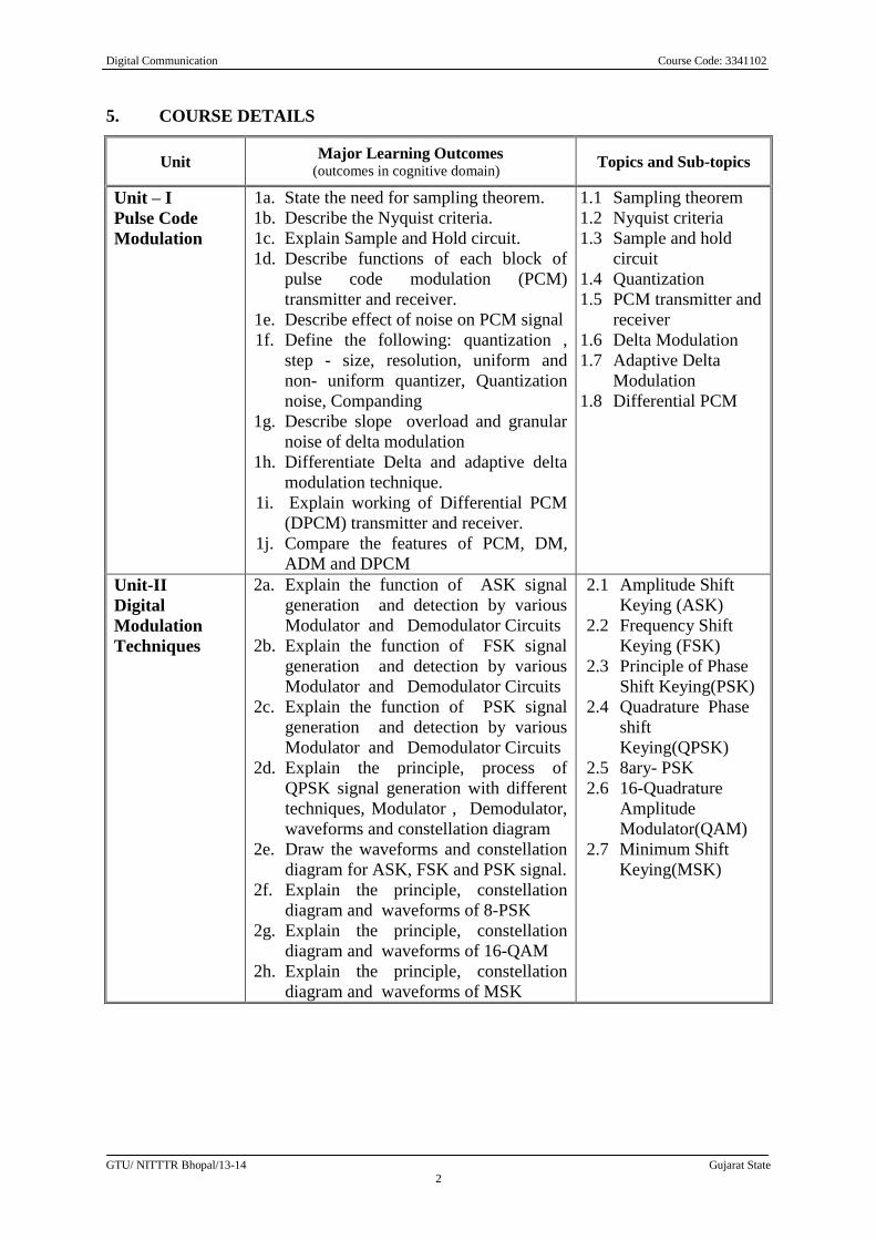
Unit – I
Pulse Code
Modulation
1a. State the need for sampling theorem.
1b. Describe the Nyquist criteria.
1c. Explain Sample and Hold circuit.
1d. Describe functions of each block of
pulse code modulation (PCM)
transmitter and receiver.
1e. Describe effect of noise on PCM signal
1f. Define the following: quantization ,
step - size, resolution, uniform and
non- uniform quantizer, Quantization
noise, Companding
1g. Describe slope overload and granular
noise of delta modulation
1h. Differentiate Delta and adaptive delta
modulation technique.
1i. Explain working of Differential PCM
(DPCM) transmitter and receiver.
1j. Compare the features of PCM, DM,
ADM and DPCM
1.1 Sampling theorem
1.2 Nyquist criteria
1.3 Sample and hold
circuit
1.4 Quantization
1.5 PCM transmitter and
receiver
1.6 Delta Modulation
1.7 Adaptive Delta
Modulation
1.8 Differential PCM
Unit-II
Digital
Modulation
Techniques
2a. Explain the function of ASK signal
generation and detection by various
Modulator and Demodulator Circuits
2b. Explain the function of FSK signal
generation and detection by various
Modulator and Demodulator Circuits
2c. Explain the function of PSK signal
generation and detection by various
Modulator and Demodulator Circuits
2d. Explain the principle, process of
QPSK signal generation with different
techniques, Modulator , Demodulator,
waveforms and constellation diagram
2e. Draw the waveforms and constellation
diagram for ASK, FSK and PSK signal.
2f. Explain the principle, constellation
diagram and waveforms of 8-PSK
2g. Explain the principle, constellation
diagram and waveforms of 16-QAM
2h. Explain the principle, constellation
diagram and waveforms of MSK
2.1 Amplitude Shift
Keying (ASK)
2.2 Frequency Shift
Keying (FSK)
2.3 Principle of Phase
Shift Keying(PSK)
2.4 Quadrature Phase
shift
Keying(QPSK)
2.5 8ary- PSK
2.6 16-Quadrature
Amplitude
Modulator(QAM)
2.7 Minimum Shift
Keying(MSK)
Digital Communication Course Code: 3341102 :
GTU/ NITTTR Bhopal/13-14 Gujarat State
3
Unit Major Learning Outcomes
(outcomes in cognitive domain) Topics and Sub-topics
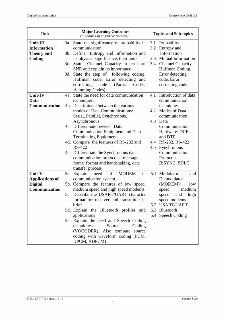
Unit-III
Information
Theory and
Coding
3a. State the significance of probability in
communication
3b. Define Entropy and Information and
its physical significance, their units
3c. State Channel Capacity in terms of
SNR and explain its importance
3d. State the step of following coding:
Huffman code, Error detecting and
correcting code (Parity Codes,
Hamming Codes)
3.1 Probability
3.2 Entropy and
Information
3.3 Mutual Information
3.4 Channel Capacity
Huffman Coding,
Error detecting
code, Error
correcting code
Unit-IV
Data
Communication
4a. State the need for data communication
techniques.
4b. Discriminate between the various
modes of Data Communications:
Serial, Parallel, Synchronous,
Asynchronous
4c. Differentiate between Data
Communication Equipment and Data
Terminating Equipment.
4d. Compare the features of RS-232 and
RS-422
4e. Differentiate the Synchronous data
communication protocols: message
frame format and handshaking, data
transfer process
4.1 Introduction of data
communication
techniques
4.2 Modes of Data
communication
4.3 Data
Communication
Hardware: DCE
and DTE
4.4 RS-232, RS-422
4.5 Synchronous
Communication
Protocols:
BiSYNC, SDLC
Unit-V
Applications of
Digital
Communication
5a. Explain need of MODEM in
communication system.
5b. Compare the features of low speed,
medium speed and high speed modems.
5c. Describe the USART/UART character
format for receiver and transmitter in
brief.
5d. Explain the Bluetooth profiles and
applications
5e. Explain the need and Speech Coding
techniques: Source Coding
(VOCODER). Also compare source
coding with waveform coding (PCM,
DPCM, ADPCM)
5.1 Modulator and
Demodulator
(MODEM): low
speed, medium
speed and high
speed modems
5.2 USART/UART
5.3 Bluetooth
5.4 Speech Coding
Digital Communication Course Code: 3341102 :
GTU/ NITTTR Bhopal/13-14 Gujarat State
4
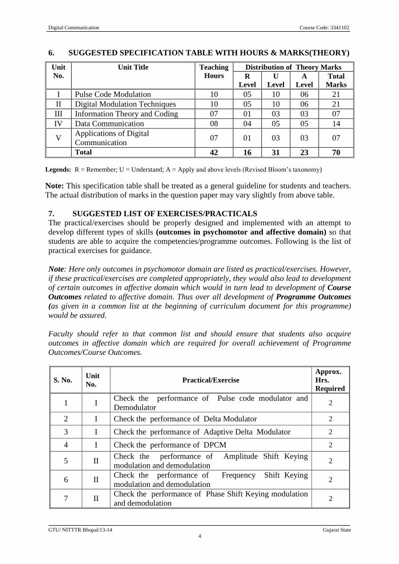
6. SUGGESTED SPECIFICATION TABLE WITH HOURS & MARKS(THEORY)
Unit
No.
Unit Title Teaching
Hours
Distribution of Theory Marks
R
Level
U
Level
A
Level
Total
Marks
I Pulse Code Modulation 10 05 10 06 21
II Digital Modulation Techniques 10 05 10 06 21
III Information Theory and Coding 07 01 03 03 07
IV Data Communication 08 04 05 05 14
V Applications of Digital
Communication 07 01 03 03 07
Total 42 16 31 23 70
Legends: R = Remember; U = Understand; A = Apply and above levels (Revised Bloom’s taxonomy)
Note: This specification table shall be treated as a general guideline for students and teachers.
The actual distribution of marks in the question paper may vary slightly from above table.
7. SUGGESTED LIST OF EXERCISES/PRACTICALS The practical/exercises should be properly designed and implemented with an attempt to
develop different types of skills (outcomes in psychomotor and affective domain) so that
students are able to acquire the competencies/programme outcomes. Following is the list of
practical exercises for guidance.
Note: Here only outcomes in psychomotor domain are listed as practical/exercises. However,
if these practical/exercises are completed appropriately, they would also lead to development
of certain outcomes in affective domain which would in turn lead to development of Course
Outcomes related to affective domain. Thus over all development of Programme Outcomes
(as given in a common list at the beginning of curriculum document for this programme)
would be assured.
Faculty should refer to that common list and should ensure that students also acquire
outcomes in affective domain which are required for overall achievement of Programme
Outcomes/Course Outcomes.
S. No. Unit
No. Practical/Exercise
Approx.
Hrs.
Required
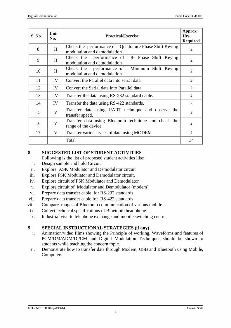
1 I Check the performance of Pulse code modulator and
Demodulator 2
2 I Check the performance of Delta Modulator 2
3 I Check the performance of Adaptive Delta Modulator 2
4 I Check the performance of DPCM 2
5 II Check the performance of Amplitude Shift Keying
modulation and demodulation 2
6 II Check the performance of Frequency Shift Keying
modulation and demodulation 2
7 II Check the performance of Phase Shift Keying modulation
and demodulation 2
Digital Communication Course Code: 3341102 :
GTU/ NITTTR Bhopal/13-14 Gujarat State
5
S. No. Unit
No. Practical/Exercise
Approx.
Hrs.
Required
8 II Check the performance of Quadrature Phase Shift Keying
modulation and demodulation 2
9 II Check the performance of 8- Phase Shift Keying
modulation and demodulation 2
10 II Check the performance of Minimum Shift Keying
modulation and demodulation 2
11 IV Convert the Parallel data into serial data 2
12 IV Convert the Serial data into Parallel data. 2
13 IV Transfer the data using RS-232 standard cable. 2
14 IV Transfer the data using RS-422 standards. 2
15 V Transfer data using UART technique and observe the
transfer speed. 2
16 V Transfer data using Bluetooth technique and check the
range of the device. 2
17 V Transfer various types of data using MODEM 2
Total 34
8. SUGGESTED LIST OF STUDENT ACTIVITIES
Following is the list of proposed student activities like:
i. Design sample and hold Circuit
ii. Explore ASK Modulator and Demodulator circuit
iii. Explore FSK Modulator and Demodulator circuit.
iv. Explore circuit of PSK Modulator and Demodulator
v. Explore circuit of Modulator and Demodulator (modem)
vi. Prepare data transfer cable for RS-232 standards
vii. Prepare data transfer cable for RS-422 standards
viii. Compare ranges of Bluetooth communication of various mobile
ix. Collect technical specifications of Bluetooth headphone.
x. Industrial visit to telephone exchange and mobile switching centre
9. SPECIAL INSTRUCTIONAL STRATEGIES (if any)
i. Animation/video films showing the Principle of working, Waveforms and features of
PCM/DM/ADM/DPCM and Digital Modulation Techniques should be shown to
students while teaching the concern topic.
ii. Demonstrate how to transfer data through Modem, USB and Bluetooth using Mobile,
Computers.
Digital Communication Course Code: 3341102 :
GTU/ NITTTR Bhopal/13-14 Gujarat State
6
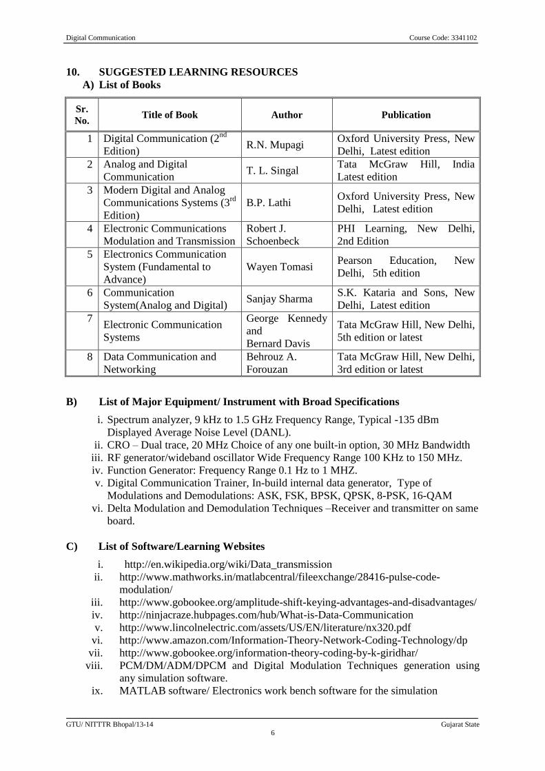
10. SUGGESTED LEARNING RESOURCES
A) List of Books
Sr.
No. Title of Book Author Publication
1 Digital Communication (2nd
Edition) R.N. Mupagi
Oxford University Press, New
Delhi, Latest edition
2 Analog and Digital
Communication T. L. Singal
Tata McGraw Hill, India
Latest edition
3 Modern Digital and Analog
Communications Systems (3rd
Edition)
B.P. Lathi Oxford University Press, New
Delhi, Latest edition
4 Electronic Communications
Modulation and Transmission
Robert J.
Schoenbeck
PHI Learning, New Delhi,
2nd Edition
5 Electronics Communication
System (Fundamental to
Advance)
Wayen Tomasi Pearson Education, New
Delhi, 5th edition
6 Communication
System(Analog and Digital) Sanjay Sharma
S.K. Kataria and Sons, New
Delhi, Latest edition
7 Electronic Communication
Systems
George Kennedy
and
Bernard Davis
Tata McGraw Hill, New Delhi,
5th edition or latest
8 Data Communication and
Networking
Behrouz A.
Forouzan
Tata McGraw Hill, New Delhi,
3rd edition or latest
B) List of Major Equipment/ Instrument with Broad Specifications
i. Spectrum analyzer, 9 kHz to 1.5 GHz Frequency Range, Typical -135 dBm
Displayed Average Noise Level (DANL).
ii. CRO – Dual trace, 20 MHz Choice of any one built-in option, 30 MHz Bandwidth
iii. RF generator/wideband oscillator Wide Frequency Range 100 KHz to 150 MHz.
iv. Function Generator: Frequency Range 0.1 Hz to 1 MHZ.
v. Digital Communication Trainer, In-build internal data generator, Type of
Modulations and Demodulations: ASK, FSK, BPSK, QPSK, 8-PSK, 16-QAM
vi. Delta Modulation and Demodulation Techniques –Receiver and transmitter on same
board.
C) List of Software/Learning Websites
i. http://en.wikipedia.org/wiki/Data_transmission
ii. http://www.mathworks.in/matlabcentral/fileexchange/28416-pulse-code-
modulation/
iii. http://www.gobookee.org/amplitude-shift-keying-advantages-and-disadvantages/
iv. http://ninjacraze.hubpages.com/hub/What-is-Data-Communication
v. http://www.lincolnelectric.com/assets/US/EN/literature/nx320.pdf
vi. http://www.amazon.com/Information-Theory-Network-Coding-Technology/dp
vii. http://www.gobookee.org/information-theory-coding-by-k-giridhar/
viii. PCM/DM/ADM/DPCM and Digital Modulation Techniques generation using
any simulation software.
ix. MATLAB software/ Electronics work bench software for the simulation
Digital Communication Course Code: 3341102 :
GTU/ NITTTR Bhopal/13-14 Gujarat State
7
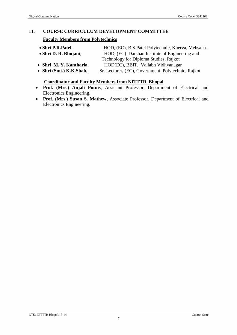
11. COURSE CURRICULUM DEVELOPMENT COMMITTEE
Faculty Members from Polytechnics
Shri P.R.Patel, HOD, (EC), B.S.Patel Polytechnic, Kherva, Mehsana.
Shri D. R. Bhojani, HOD, (EC) Darshan Institute of Engineering and
Technology for Diploma Studies, Rajkot
Shri M. Y. Kantharia, HOD(EC), BBIT, Vallabh Vidhyanagar
Shri (Smt.) K.K.Shah, Sr. Lecturer, (EC), Government Polytechnic, Rajkot
Coordinator and Faculty Members from NITTTR Bhopal
Prof. (Mrs.) Anjali Potnis, Assistant Professor, Department of Electrical and
Electronics Engineering.
Prof. (Mrs.) Susan S. Mathew, Associate Professor, Department of Electrical and
Electronics Engineering.
Course Title : Optical Communication Course code : 3341103
GTU/NITTTR/Bhopal/13-14 Gujarat State
1
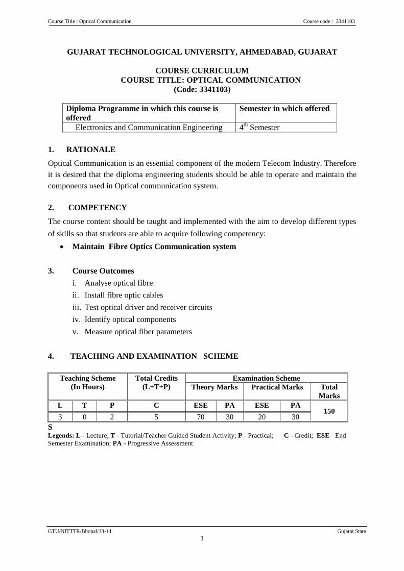
GUJARAT TECHNOLOGICAL UNIVERSITY, AHMEDABAD, GUJARAT
COURSE CURRICULUM
COURSE TITLE: OPTICAL COMMUNICATION
(Code: 3341103)
Diploma Programme in which this course is
offered
Semester in which offered
Electronics and Communication Engineering 4th
Semester
1. RATIONALE
Optical Communication is an essential component of the modern Telecom Industry. Therefore
it is desired that the diploma engineering students should be able to operate and maintain the
components used in Optical communication system.
2. COMPETENCY
The course content should be taught and implemented with the aim to develop different types
of skills so that students are able to acquire following competency:
Maintain Fibre Optics Communication system
3. Course Outcomes
i. Analyse optical fibre.
ii. Install fibre optic cables
iii. Test optical driver and receiver circuits
iv. Identify optical components
v. Measure optical fiber parameters
4. TEACHING AND EXAMINATION SCHEME
Teaching Scheme
(In Hours)
Total Credits
(L+T+P)
Examination Scheme
Theory Marks Practical Marks Total
Marks
L T P C ESE PA ESE PA 150
3 0 2 5 70 30 20 30
S Legends: L - Lecture; T - Tutorial/Teacher Guided Student Activity; P - Practical; C - Credit; ESE - End
Semester Examination; PA - Progressive Assessment
Course Title : Optical Communication Course code : 3341103
GTU/NITTTR/Bhopal/13-14 Gujarat State
2
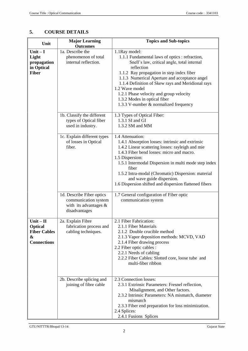
5. COURSE DETAILS
Unit Major Learning
Outcomes
Topics and Sub-topics
Unit – I
Light
propagation
in Optical
Fiber
1a. Describe the
phenomenon of total
internal reflection.
1.1Ray model:
1.1.1 Fundamental laws of optics : refraction,
Snell’s law, critical angle, total internal
reflection
1.1.2 Ray propagation in step index fiber
1.1.3 Numerical Aperture and acceptance angel
1.1.4 Definition of Skew rays and Meridional rays
1.2 Wave model
1.2.1 Phase velocity and group velocity
1.3.2 Modes in optical fiber
1.3.3 V-number & normalized frequency
1b. Classify the different
types of Optical fiber
used in industry.
1.3 Types of Optical Fiber:
1.3.1 SI and GI
1.3.2 SM and MM
1c. Explain different types
of losses in Optical
fiber.
1.4 Attenuation:
1.4.1 Absorption losses: intrinsic and extrinsic
1.4.2 Linear scattering losses: rayleigh and mie
1.4.3 Fiber bend losses: micro and macro.
1.5 Dispersion:
1.5.1 Intermodal Dispersion in multi mode step index
fiber
1.5.2 Intra-modal (Chromatic) Dispersion: material
and wave guide dispersion.
1.6 Dispersion shifted and dispersion flattened fibers
1d. Describe Fiber optics
communication system
with its advantages &
disadvantages
1.7 General configuration of Fiber optic
communication system
Unit – II
Optical
Fiber Cables
&
Connections
2a. Explain Fibre
fabrication process and
cabling techniques.
2.1 Fiber Fabrication:
2.1.1 Fiber Materials
2.1.2 Double crucible method
2.1.3 Vapor deposition methods: MCVD, VAD
2.1.4 Fiber drawing process
2.2 Fiber optic cables :
2.2.1 Needs of cabling
2.2.2 Fiber Cables: Slotted core, loose tube and
multi-fiber ribbon
2b. Describe splicing and
joining of fibre cable
2.3 Connection losses:
2.3.1 Extrinsic Parameters: Fresnel reflection,
Misalignment, and Other factors.
2.3.2 Intrinsic Parameters: NA mismatch, diameter
mismatch
2.3.3 Fiber end preparation for loss minimization.
2.4 Splices:
2.4.1 Fusions Splices
Course Title : Optical Communication Course code : 3341103
GTU/NITTTR/Bhopal/13-14 Gujarat State
3
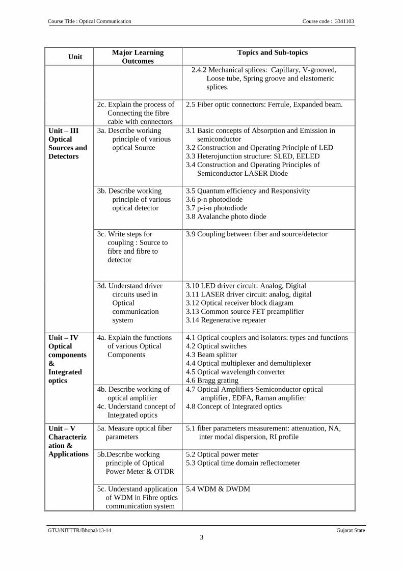
Unit Major Learning
Outcomes
Topics and Sub-topics
2.4.2 Mechanical splices: Capillary, V-grooved,
Loose tube, Spring groove and elastomeric
splices.
2c. Explain the process of
Connecting the fibre
cable with connectors
2.5 Fiber optic connectors: Ferrule, Expanded beam.
Unit – III
Optical
Sources and
Detectors
3a. Describe working
principle of various
optical Source
3.1 Basic concepts of Absorption and Emission in
semiconductor
3.2 Construction and Operating Principle of LED
3.3 Heterojunction structure: SLED, EELED
3.4 Construction and Operating Principles of
Semiconductor LASER Diode
3b. Describe working
principle of various
optical detector
3.5 Quantum efficiency and Responsivity
3.6 p-n photodiode
3.7 p-i-n photodiode
3.8 Avalanche photo diode
3c. Write steps for
coupling : Source to
fibre and fibre to
detector
3.9 Coupling between fiber and source/detector
3d. Understand driver
circuits used in
Optical
communication
system
3.10 LED driver circuit: Analog, Digital
3.11 LASER driver circuit: analog, digital
3.12 Optical receiver block diagram
3.13 Common source FET preamplifier
3.14 Regenerative repeater
Unit – IV
Optical
components
&
Integrated
optics
4a. Explain the functions
of various Optical
Components
4.1 Optical couplers and isolators: types and functions
4.2 Optical switches
4.3 Beam splitter
4.4 Optical multiplexer and demultiplexer
4.5 Optical wavelength converter
4.6 Bragg grating
4b. Describe working of
optical amplifier
4c. Understand concept of
Integrated optics
4.7 Optical Amplifiers-Semiconductor optical
amplifier, EDFA, Raman amplifier
4.8 Concept of Integrated optics
Unit – V
Characteriz
ation &
Applications
5a. Measure optical fiber
parameters
5.1 fiber parameters measurement: attenuation, NA,
inter modal dispersion, RI profile
5b.Describe working
principle of Optical
Power Meter & OTDR
5.2 Optical power meter
5.3 Optical time domain reflectometer
5c. Understand application
of WDM in Fibre optics
communication system
5.4 WDM & DWDM
Course Title : Optical Communication Course code : 3341103
GTU/NITTTR/Bhopal/13-14 Gujarat State
4
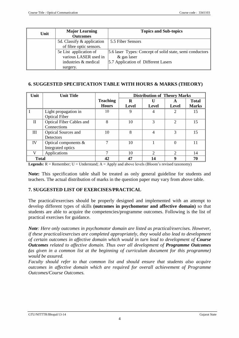
Unit Major Learning
Outcomes
Topics and Sub-topics
5d. Classify & application
of fibre optic sensors.
5.5 Fiber Sensors
5e List application of
various LASER used in
industries & medical
surgery.
5.6 laser Types: Concept of solid state, semi conductors
& gas laser
5.7 Application of Different Lasers
6. SUGGESTED SPECIFICATION TABLE WITH HOURS & MARKS (THEORY)
Unit Unit Title
Teaching
Hours
Distribution of Theory Marks
R
Level
U
Level
A
Level
Total
Marks
I Light propagation in
Optical Fiber
10
9 4 2 15
II Optical Fiber Cables and
Connections
8 10 3 2 15
III Optical Sources and
Detectors
10 8 4 3 15
IV Optical components &
Integrated optics
7 10 1 0 11
V Applications 7 10 2 2 14
Total 42 47 14 9 70
Legends: R = Remember; U = Understand; A = Apply and above levels (Bloom’s revised taxonomy)
Note: This specification table shall be treated as only general guideline for students and
teachers. The actual distribution of marks in the question paper may vary from above table.
7. SUGGESTED LIST OF EXERCISES/PRACTICAL
The practical/exercises should be properly designed and implemented with an attempt to
develop different types of skills (outcomes in psychomotor and affective domain) so that
students are able to acquire the competencies/programme outcomes. Following is the list of
practical exercises for guidance.
Note: Here only outcomes in psychomotor domain are listed as practical/exercises. However,
if these practical/exercises are completed appropriately, they would also lead to development
of certain outcomes in affective domain which would in turn lead to development of Course
Outcomes related to affective domain. Thus over all development of Programme Outcomes
(as given in a common list at the beginning of curriculum document for this programme)
would be assured.
Faculty should refer to that common list and should ensure that students also acquire
outcomes in affective domain which are required for overall achievement of Programme
Outcomes/Course Outcomes.
Course Title : Optical Communication Course code : 3341103
GTU/NITTTR/Bhopal/13-14 Gujarat State
5
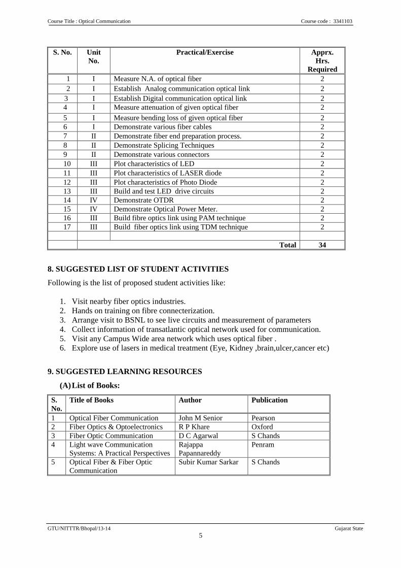
S. No. Unit
No.
Practical/Exercise Apprx.
Hrs.
Required
1 I Measure N.A. of optical fiber 2
2 I Establish Analog communication optical link 2
3 I Establish Digital communication optical link 2 4 I Measure attenuation of given optical fiber 2
5 I Measure bending loss of given optical fiber 2 6 I Demonstrate various fiber cables 2
7 II Demonstrate fiber end preparation process. 2
8 II Demonstrate Splicing Techniques 2
9 II Demonstrate various connectors 2
10 III Plot characteristics of LED 2
11 III Plot characteristics of LASER diode 2
12 III Plot characteristics of Photo Diode 2 13 III Build and test LED drive circuits 2 14 IV Demonstrate OTDR 2 15 IV Demonstrate Optical Power Meter. 2 16 III Build fibre optics link using PAM technique 2 17 III Build fiber optics link using TDM technique 2
Total 34
8. SUGGESTED LIST OF STUDENT ACTIVITIES
Following is the list of proposed student activities like:
1. Visit nearby fiber optics industries.
2. Hands on training on fibre connecterization.
3. Arrange visit to BSNL to see live circuits and measurement of parameters
4. Collect information of transatlantic optical network used for communication.
5. Visit any Campus Wide area network which uses optical fiber .
6. Explore use of lasers in medical treatment (Eye, Kidney ,brain,ulcer,cancer etc)
9. SUGGESTED LEARNING RESOURCES
(A) List of Books:
S.
No.
Title of Books Author Publication
1 Optical Fiber Communication John M Senior Pearson
2 Fiber Optics & Optoelectronics R P Khare Oxford
3 Fiber Optic Communication D C Agarwal S Chands
4 Light wave Communication
Systems: A Practical Perspectives
Rajappa
Papannareddy
Penram
5 Optical Fiber & Fiber Optic
Communication
Subir Kumar Sarkar S Chands
Course Title : Optical Communication Course code : 3341103
GTU/NITTTR/Bhopal/13-14 Gujarat State
6
B. List of Major Equipment/Materials
1. OTDR
2. Optical power meter
3. CRO
4. Fusion splicing machine
5. Optical fiber : Glass,Plastic
6. Semiconductor laser
C List of Software/Learning Websites
Material / Products:
http://computer.howstuffworks.com/fiber-optic.htm
http://www.ntu.edu.sg/library/Pages/default.aspx
http://nptel.iitm.ac.in/courses/askaquestion.php?subjectId=117101002
http://www.thefoa.org/tech/
http://www.thefoa.org/fo_urls.htm
http://en.wikipedia.org/wiki/Optical_fiber
http://www.telecomramblings.com/network-maps/usa-fiber-backbone-map-resources/
http://www.foci.com.tw/pd_scw.html
Videos:
http://nptel.iitm.ac.in/courses/117101002/
http://www.youtube.com/watch?v=aqazAcE19vw
http://www.youtube.com/watch?v=pIlBlNW7sOo
http://www.youtube.com/watch?v=ASMcrcgZSrw
http://www.youtube.com/watch?v=llI8Mf_faVo
http://fiberu.org/basic/LP3.html
10. COURSE CURRICULUM DEVELOPMENT COMMITTEE
Faculty Members from Polytechnics 1.Shri M S Dave Sr. Lecturer, EC Dept, Government Polytechnic, Ahmedabad.
2.Shri U V Buch Sr. Lecturer, EC Dept, Government Polytechnic, Gandhinagar.
3.Shri S M Gheewala, Sr. Lecturer, EC Dept, Government Polytechnic, Valsad.
Coordinator and Faculty Members from NITTTR Bhopal
Prof. (Mrs.) Anjali Potnis, Assistant Professor, Department of Electrical and
Electronics Engineering.
Prof. (Mrs.) Susan S. Mathew, Associate Professor, Department of Electrical and
Electronics Engineering.
Electronic Instruments and Measurement Course Code: 3341104
GTU/NITTR Bhopal/13-14 Gujarat State
1
GUJARAT TECHNOLOGICAL UNIVERSITY, AHMEDABAD, GUJARAT
COURSE CURRICULUM
COURSE TITLE: ELECTRONICS INSTRUMENTS AND MEASUREMENT
(Code: 3341104)
Diploma Programme in which this course is offered
Semester in which offered
Electronics And Communication Engineering 4th
Semester
1. RATIONALE
Troubleshooting of electronic equipment is an essential requirement of Service sector
industry. This course will help to develop skills to become professional technician with
capability to measure electrical parameters using various instruments. By learning this
course students will able to know basics of various Instruments, transducers and working of
electronic circuits used in electronic test and measuring instruments.
2. COMPETENCY
The course content should be taught and implemented with the aim to develop different
types of skills leading to the achievement of following competency
Maintain various electronic, test and measuring instrument.
3. COURSE OUTCOME
The theory should be taught and practical should be carried out in such a manner that
students are able to acquire different learning out comes in cognitive, psychomotor and
affective domain to demonstrate following course outcomes.
i. Measure various electrical parameters with accuracy, precision, resolution.
ii. Use AC and DC bridges for relevant parameter measurement.
iii. Select appropriate passive or active transducers for measurement of physical
phenomenon.
iv. Use Signal Generator, frequency counter, CRO and digital IC tester for appropriate
measurement.
v. Test and troubleshoot electronic circuits using various measuring instruments.
vi. Maintain various types of test and measuring instruments.
Electronic Instruments and Measurement Course Code: 3341104
GTU/NITTR Bhopal/13-14 Gujarat State
2
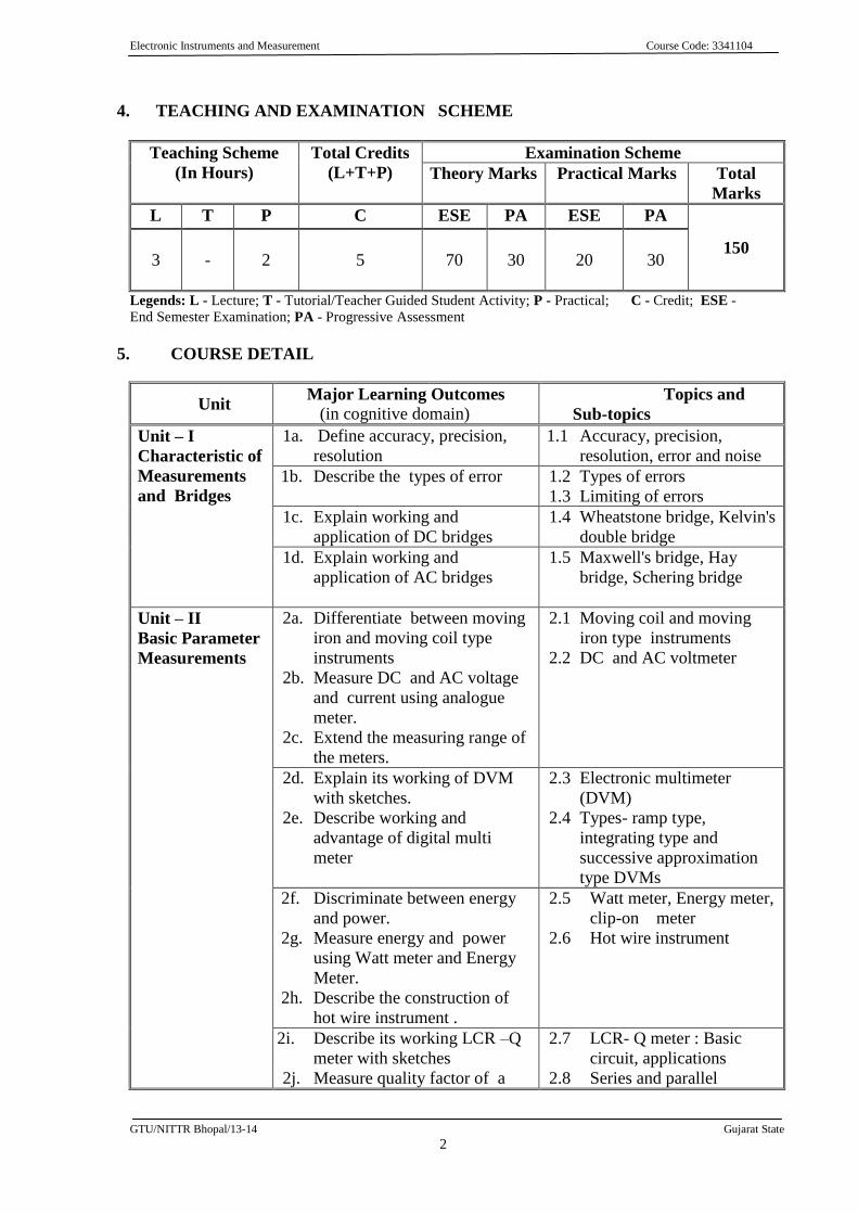
4. TEACHING AND EXAMINATION SCHEME
Teaching Scheme
(In Hours)
Total Credits
(L+T+P)
Examination Scheme
Theory Marks Practical Marks Total
Marks
L T P C ESE PA ESE PA
150
3
-
2
5
70
30
20
30
Legends: L - Lecture; T - Tutorial/Teacher Guided Student Activity; P - Practical; C - Credit; ESE -
End Semester Examination; PA - Progressive Assessment
5. COURSE DETAIL
Unit Major Learning Outcomes
(in cognitive domain) Topics and
Sub-topics
Unit – I
Characteristic of
Measurements
and Bridges
1a. Define accuracy, precision,
resolution
1.1 Accuracy, precision,
resolution, error and noise
1b. Describe the types of error 1.2 Types of errors
1.3 Limiting of errors
1c. Explain working and
application of DC bridges
1.4 Wheatstone bridge, Kelvin's
double bridge
1d. Explain working and
application of AC bridges
1.5 Maxwell's bridge, Hay
bridge, Schering bridge
Unit – II
Basic Parameter
Measurements
2a. Differentiate between moving
iron and moving coil type
instruments
2b. Measure DC and AC voltage
and current using analogue
meter.
2c. Extend the measuring range of
the meters.
2.1 Moving coil and moving
iron type instruments
2.2 DC and AC voltmeter
2d. Explain its working of DVM
with sketches.
2e. Describe working and
advantage of digital multi
meter
2.3 Electronic multimeter
(DVM)
2.4 Types- ramp type,
integrating type and
successive approximation
type DVMs
2f. Discriminate between energy
and power.
2g. Measure energy and power
using Watt meter and Energy
Meter.
2h. Describe the construction of
hot wire instrument .
2.5 Watt meter, Energy meter,
clip-on meter
2.6 Hot wire instrument
2i. Describe its working LCR –Q
meter with sketches
2j. Measure quality factor of a
2.7 LCR- Q meter : Basic
circuit, applications
2.8 Series and parallel
Electronic Instruments and Measurement Course Code: 3341104
GTU/NITTR Bhopal/13-14 Gujarat State
3
Unit Major Learning Outcomes
(in cognitive domain) Topics and
Sub-topics
coil and a capacitor . connection of Capacitor
and Inductor.
Unit – III
Oscilloscopes
3a. Describe functions of basic
building of CRO
3b. Explain deflection systems.
3c. Measure parameters viz.
Amplitude, frequency and time
period using CRO.
3.1. Block diagram of C.R.O.
3.2. Cathode ray tube:
construction, operation,
screens, graticules
3.3. Vertical deflection system,
Horizontal deflection
system, Delay line,
3.4. Measurement of
frequency, time delay,
phase angle and
modulation index
(trapezoidal method)
3.5. Oscilloscope probe:
structure of 1:1 and 10:1
probes
3.6. multiple trace CRO
3d. Explain working principle of
digital storage oscilloscope.
3.7. Digital storage
oscilloscope and its
features
Unit – IV
Transducers
4a. Differentiae the following:
active and passive, primary
and secondary transducers.
4b. Describe working of LVDT
transducer.
4.1. Classification of
transducers
4.2. Unbonded strain gauge
4.3. Displacement transducers
4.4. LVDT
4c. Explain the principle of
Capacitive and Inductive
transducer
4.5. Capacitive transducers
4.6. Inductive transducers
4.7. Resistive and capacitive
touch screen transducer
used in mobile
4d. Describe functions of velocity
and pressure transducers.
4e. Explain optical & stroboscopic
tachometer.
4.8. Piezo-electric transducer
4.9. Velocity transducer
4.10. RPM measurement
technique
4f. Describe the working if
different types of temperature
transducers.
4g. Explain principle of
Thermocouple.
4h. Describe working of of RTD
and Thermistor
4.11. Temperature
measurement:
Thermocouples: Seebeck,
Peltier Effect, J,K,R,S,T
Types, Thermistors
4.12. Resistance thermometer
RTDs – PTC,PT-100 (2-
3-4 Wire systems-only
circuit
Electronic Instruments and Measurement Course Code: 3341104
GTU/NITTR Bhopal/13-14 Gujarat State
4
Unit Major Learning Outcomes
(in cognitive domain) Topics and
Sub-topics
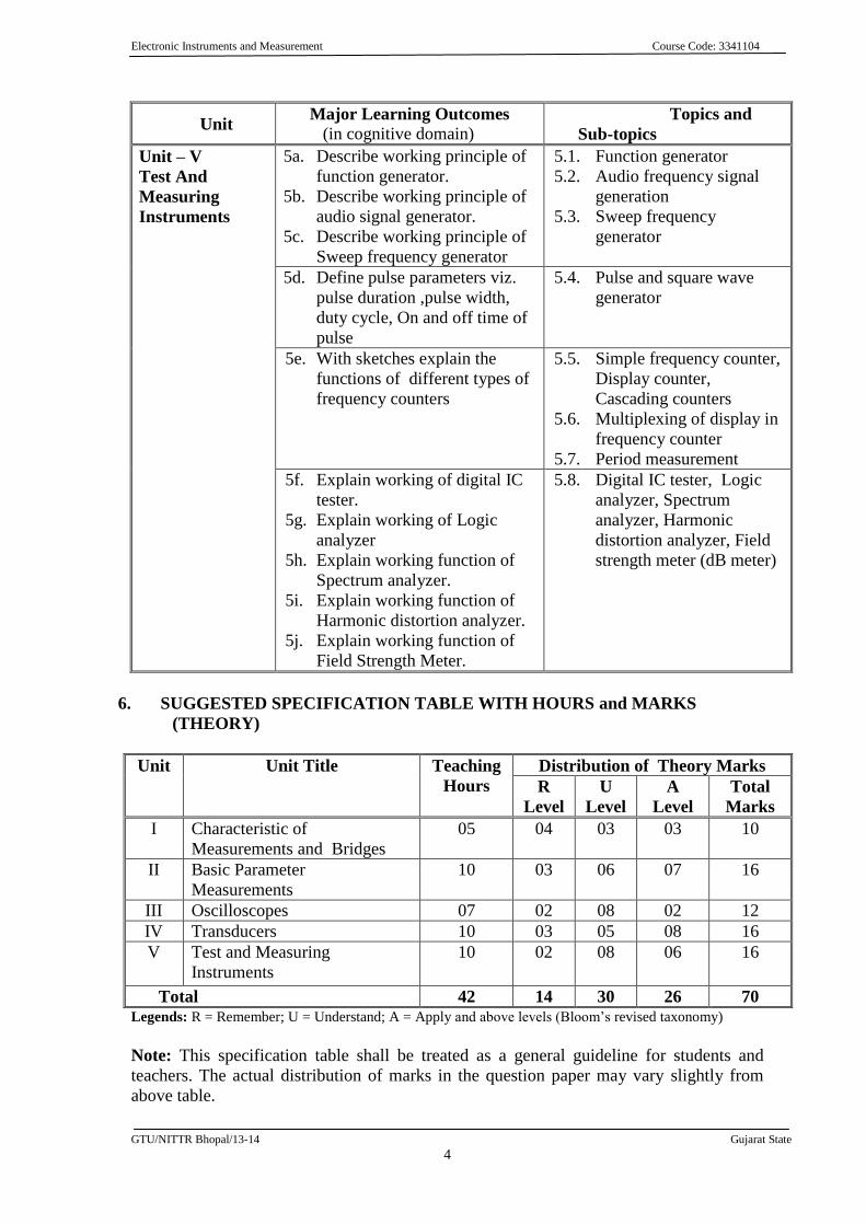
Unit – V
Test And
Measuring
Instruments
5a. Describe working principle of
function generator.
5b. Describe working principle of
audio signal generator.
5c. Describe working principle of
Sweep frequency generator
5.1. Function generator
5.2. Audio frequency signal
generation
5.3. Sweep frequency
generator
5d. Define pulse parameters viz.
pulse duration ,pulse width,
duty cycle, On and off time of
pulse
5.4. Pulse and square wave
generator
5e. With sketches explain the
functions of different types of
frequency counters
5.5. Simple frequency counter,
Display counter,
Cascading counters
5.6. Multiplexing of display in
frequency counter
5.7. Period measurement
5f. Explain working of digital IC
tester.
5g. Explain working of Logic
analyzer
5h. Explain working function of
Spectrum analyzer.
5i. Explain working function of
Harmonic distortion analyzer.
5j. Explain working function of
Field Strength Meter.
5.8. Digital IC tester, Logic
analyzer, Spectrum
analyzer, Harmonic
distortion analyzer, Field
strength meter (dB meter)
6. SUGGESTED SPECIFICATION TABLE WITH HOURS and MARKS
(THEORY)
Unit Unit Title Teaching
Hours
Distribution of Theory Marks
R
Level
U
Level
A
Level
Total
Marks
I Characteristic of
Measurements and Bridges
05 04 03 03 10
II Basic Parameter
Measurements
10 03 06 07 16
III Oscilloscopes 07 02 08 02 12
IV Transducers 10 03 05 08 16
V Test and Measuring
Instruments
10 02 08 06 16
Total 42 14 30 26 70 Legends: R = Remember; U = Understand; A = Apply and above levels (Bloom’s revised taxonomy)
Note: This specification table shall be treated as a general guideline for students and
teachers. The actual distribution of marks in the question paper may vary slightly from
above table.
Electronic Instruments and Measurement Course Code: 3341104
GTU/NITTR Bhopal/13-14 Gujarat State
5
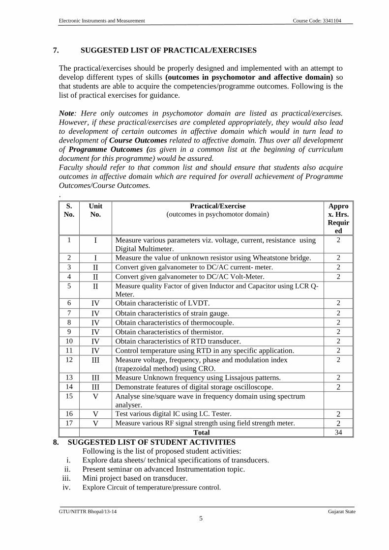
7. SUGGESTED LIST OF PRACTICAL/EXERCISES
The practical/exercises should be properly designed and implemented with an attempt to
develop different types of skills (outcomes in psychomotor and affective domain) so
that students are able to acquire the competencies/programme outcomes. Following is the
list of practical exercises for guidance.
Note: Here only outcomes in psychomotor domain are listed as practical/exercises.
However, if these practical/exercises are completed appropriately, they would also lead
to development of certain outcomes in affective domain which would in turn lead to
development of Course Outcomes related to affective domain. Thus over all development
of Programme Outcomes (as given in a common list at the beginning of curriculum
document for this programme) would be assured.
Faculty should refer to that common list and should ensure that students also acquire
outcomes in affective domain which are required for overall achievement of Programme
Outcomes/Course Outcomes.
.
S.
No.
Unit
No.
Practical/Exercise
(outcomes in psychomotor domain) Appro
x. Hrs.
Requir
ed
1 I Measure various parameters viz. voltage, current, resistance using
Digital Multimeter.
2
2 I Measure the value of unknown resistor using Wheatstone bridge. 2
3 II Convert given galvanometer to DC/AC current- meter. 2
4 II Convert given galvanometer to DC/AC Volt-Meter. 2
5 II Measure quality Factor of given Inductor and Capacitor using LCR Q-
Meter.
6 IV Obtain characteristic of LVDT. 2
7 IV Obtain characteristics of strain gauge. 2
8 IV Obtain characteristics of thermocouple. 2
9 IV Obtain characteristics of thermistor. 2
10 IV Obtain characteristics of RTD transducer. 2
11 IV Control temperature using RTD in any specific application. 2
12 III Measure voltage, frequency, phase and modulation index
(trapezoidal method) using CRO.
2
13 III Measure Unknown frequency using Lissajous patterns. 2
14 III Demonstrate features of digital storage oscilloscope. 2 15 V Analyse sine/square wave in frequency domain using spectrum
analyser.
16 V Test various digital IC using I.C. Tester. 2 17 V Measure various RF signal strength using field strength meter. 2
Total 34
8. SUGGESTED LIST OF STUDENT ACTIVITIES
Following is the list of proposed student activities:
i. Explore data sheets/ technical specifications of transducers.
ii. Present seminar on advanced Instrumentation topic.
iii. Mini project based on transducer.
iv. Explore Circuit of temperature/pressure control.
Electronic Instruments and Measurement Course Code: 3341104
GTU/NITTR Bhopal/13-14 Gujarat State
6
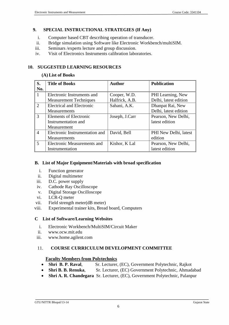
9. SPECIAL INSTRUCTIONAL STRATEGIES (If Any)
i. Computer based CBT describing operation of transducer.
ii. Bridge simulation using Software like Electronic Workbench/multiSIM.
iii. Seminars /experts lecture and group discussion.
iv. Visit of Electronics Instruments calibration laboratories.
10. SUGGESTED LEARNING RESOURCES
(A) List of Books
S.
No.
Title of Books Author Publication
1 Electronic Instruments and
Measurement Techniques
Cooper, W.D.
Halfrick, A.B.
PHI Learning, New
Delhi, latest edition
2 Electrical and Electronic
Measurements
Sahani, A.K. Dhanpat Rai, New
Delhi, latest edition
3 Elements of Electronic
Instrumentation and
Measurement
Joseph, J.Carr Pearson, New Delhi,
latest edition
4 Electronic Instrumentation and
Measurements
David, Bell PHI New Delhi, latest
edition
5 Electronic Measurements and
Instrumentation
Kishor, K Lal Pearson, New Delhi,
latest edition
B. List of Major Equipment/Materials with broad specification
i. Function generator
ii. Digital multimeter
iii. D.C. power supply
iv. Cathode Ray Oscilloscope
v. Digital Storage Oscilloscope
vi. LCR-Q meter
vii. Field strength meter(dB meter)
viii. Experimental trainer kits, Bread board, Computers
C List of Software/Learning Websites
i. Electronic Workbench/MultiSIM/Circuit Maker
ii. www.ocw.mit.edu
iii. www.home.agilent.com
11. COURSE CURRICULUM DEVELOPMENT COMMITTEE
Faculty Members from Polytechnics
Shri B. P. Raval, Sr. Lecturer, (EC), Government Polytechnic, Rajkot
Shri B. B. Renuka, Sr. Lecturer, (EC) Government Polytechnic, Ahmadabad
Shri A. R. Chandegara Sr. Lecturer, (EC), Government Polytechnic, Palanpur
Electronic Instruments and Measurement Course Code: 3341104
GTU/NITTR Bhopal/13-14 Gujarat State
7
Coordinator and Faculty Members from NITTTR Bhopal
Prof. (Mrs.) Anjali Potnis, Assistant Professor, Department of Electrical and
Electronics Engineering.
Prof. (Mrs.) Susan S. Mathew, Associate Professor, Department of Electrical
and Electronics Engineering.
Industrial Electronics Course Code: 3341105
GTU/ NITTTR Bhopal/13-14 Gujarat State
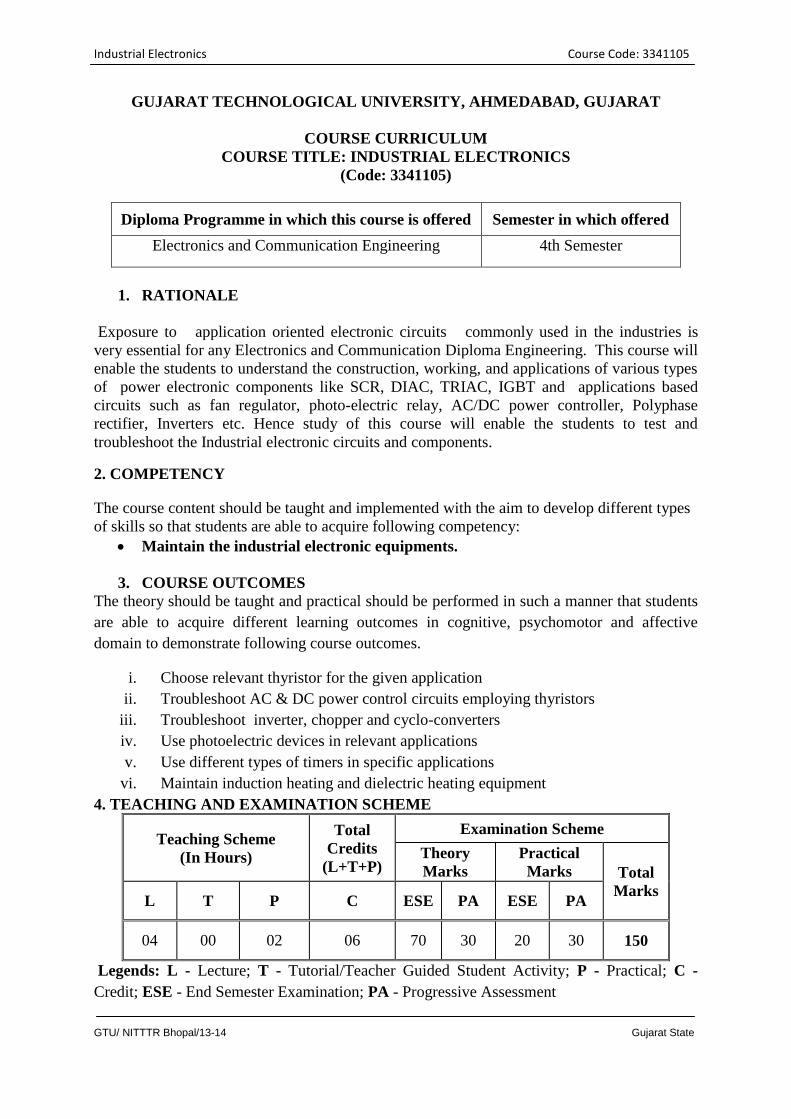
GUJARAT TECHNOLOGICAL UNIVERSITY, AHMEDABAD, GUJARAT
COURSE CURRICULUM
COURSE TITLE: INDUSTRIAL ELECTRONICS
(Code: 3341105)
Diploma Programme in which this course is offered Semester in which offered
Electronics and Communication Engineering 4th Semester
1. RATIONALE
Exposure to application oriented electronic circuits commonly used in the industries is
very essential for any Electronics and Communication Diploma Engineering. This course will
enable the students to understand the construction, working, and applications of various types
of power electronic components like SCR, DIAC, TRIAC, IGBT and applications based
circuits such as fan regulator, photo-electric relay, AC/DC power controller, Polyphase
rectifier, Inverters etc. Hence study of this course will enable the students to test and
troubleshoot the Industrial electronic circuits and components.
2. COMPETENCY
The course content should be taught and implemented with the aim to develop different types
of skills so that students are able to acquire following competency:
Maintain the industrial electronic equipments.
3. COURSE OUTCOMES
The theory should be taught and practical should be performed in such a manner that students
are able to acquire different learning outcomes in cognitive, psychomotor and affective
domain to demonstrate following course outcomes.
i. Choose relevant thyristor for the given application
ii. Troubleshoot AC & DC power control circuits employing thyristors
iii. Troubleshoot inverter, chopper and cyclo-converters
iv. Use photoelectric devices in relevant applications
v. Use different types of timers in specific applications
vi. Maintain induction heating and dielectric heating equipment
4. TEACHING AND EXAMINATION SCHEME
Teaching Scheme
(In Hours)
Total
Credits
(L+T+P)
Examination Scheme
Theory
Marks
Practical
Marks Total
Marks L T P C ESE PA ESE PA
04 00 02 06 70 30 20 30 150
Legends: L - Lecture; T - Tutorial/Teacher Guided Student Activity; P - Practical; C -
Credit; ESE - End Semester Examination; PA - Progressive Assessment
Industrial Electronics Course Code: 3341105
GTU/ NITTTR Bhopal/13-14 Gujarat State
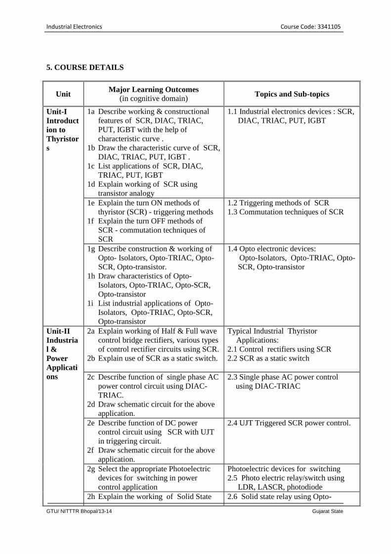
5. COURSE DETAILS
Unit Major Learning Outcomes
(in cognitive domain) Topics and Sub-topics
Unit-I
Introduct
ion to
Thyristor
s
1a Describe working & constructional
features of SCR, DIAC, TRIAC,
PUT, IGBT with the help of
characteristic curve .
1b Draw the characteristic curve of SCR,
DIAC, TRIAC, PUT, IGBT .
1c List applications of SCR, DIAC,
TRIAC, PUT, IGBT
1d Explain working of SCR using
transistor analogy
1.1 Industrial electronics devices : SCR,
DIAC, TRIAC, PUT, IGBT
1e Explain the turn ON methods of
thyristor (SCR) - triggering methods
1f Explain the turn OFF methods of
SCR - commutation techniques of
SCR
1.2 Triggering methods of SCR
1.3 Commutation techniques of SCR
1g Describe construction & working of
Opto- Isolators, Opto-TRIAC, Opto-
SCR, Opto-transistor.
1h Draw characteristics of Opto-
Isolators, Opto-TRIAC, Opto-SCR,
Opto-transistor
1i List industrial applications of Opto-
Isolators, Opto-TRIAC, Opto-SCR,
Opto-transistor
1.4 Opto electronic devices:
Opto-Isolators, Opto-TRIAC, Opto-
SCR, Opto-transistor
Unit-II
Industria
l &
Power
Applicati
ons
2a Explain working of Half & Full wave
control bridge rectifiers, various types
of control rectifier circuits using SCR.
2b Explain use of SCR as a static switch.
Typical Industrial Thyristor
Applications:
2.1 Control rectifiers using SCR
2.2 SCR as a static switch
2c Describe function of single phase AC
power control circuit using DIAC-
TRIAC.
2d Draw schematic circuit for the above
application.
2.3 Single phase AC power control
using DIAC-TRIAC
2e Describe function of DC power
control circuit using SCR with UJT
in triggering circuit.
2f Draw schematic circuit for the above
application.
2.4 UJT Triggered SCR power control.
2g Select the appropriate Photoelectric
devices for switching in power
control application
Photoelectric devices for switching
2.5 Photo electric relay/switch using
LDR, LASCR, photodiode
2h Explain the working of Solid State 2.6 Solid state relay using Opto-
Industrial Electronics Course Code: 3341105
GTU/ NITTTR Bhopal/13-14 Gujarat State
relays using Opto-TRIAC, Opto-
SCR, Opto-transistor
TRIAC, Opto-SCR, Opto-transistor
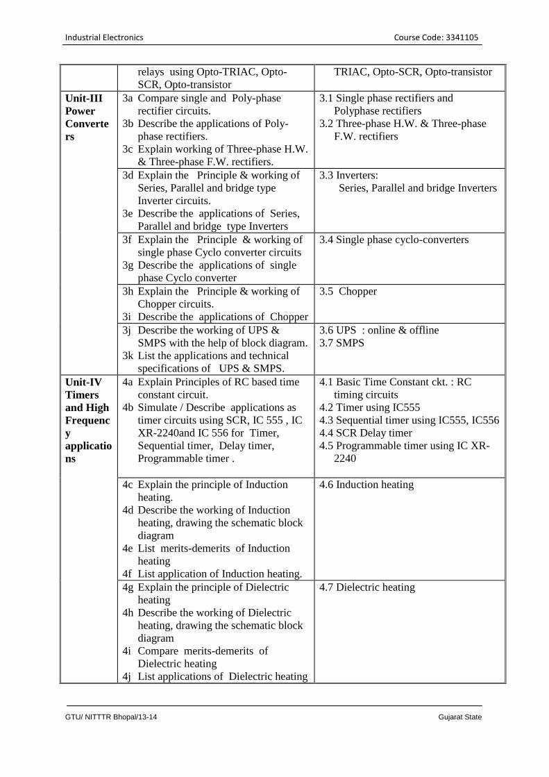
Unit-III
Power
Converte
rs
3a Compare single and Poly-phase
rectifier circuits.
3b Describe the applications of Poly-
phase rectifiers.
3c Explain working of Three-phase H.W.
& Three-phase F.W. rectifiers.
3.1 Single phase rectifiers and
Polyphase rectifiers
3.2 Three-phase H.W. & Three-phase
F.W. rectifiers
3d Explain the Principle & working of
Series, Parallel and bridge type
Inverter circuits.
3e Describe the applications of Series,
Parallel and bridge type Inverters
3.3 Inverters:
Series, Parallel and bridge Inverters
3f Explain the Principle & working of
single phase Cyclo converter circuits
3g Describe the applications of single
phase Cyclo converter
3.4 Single phase cyclo-converters
3h Explain the Principle & working of
Chopper circuits.
3i Describe the applications of Chopper
3.5 Chopper
3j Describe the working of UPS &
SMPS with the help of block diagram.
3k List the applications and technical
specifications of UPS & SMPS.
3.6 UPS : online & offline
3.7 SMPS
Unit-IV
Timers
and High
Frequenc
y
applicatio
ns
4a Explain Principles of RC based time
constant circuit.
4b Simulate / Describe applications as
timer circuits using SCR, IC 555 , IC
XR-2240and IC 556 for Timer,
Sequential timer, Delay timer,
Programmable timer .
4.1 Basic Time Constant ckt. : RC
timing circuits
4.2 Timer using IC555
4.3 Sequential timer using IC555, IC556
4.4 SCR Delay timer
4.5 Programmable timer using IC XR-
2240
4c Explain the principle of Induction
heating.
4d Describe the working of Induction
heating, drawing the schematic block
diagram
4e List merits-demerits of Induction
heating
4f List application of Induction heating.
4.6 Induction heating
4g Explain the principle of Dielectric
heating
4h Describe the working of Dielectric
heating, drawing the schematic block
diagram
4i Compare merits-demerits of
Dielectric heating
4j List applications of Dielectric heating
4.7 Dielectric heating
Industrial Electronics Course Code: 3341105
GTU/ NITTTR Bhopal/13-14 Gujarat State
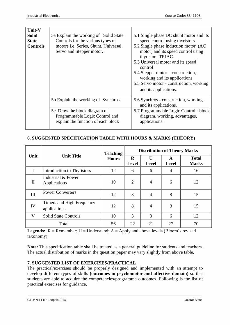
6. SUGGESTED SPECIFICATION TABLE WITH HOURS & MARKS (THEORY)
Unit Unit Title Teaching
Hours
Distribution of Theory Marks
R
Level
U
Level
A
Level
Total
Marks
I Introduction to Thyristors 12 6 6 4 16
II Industrial & Power
Applications 10 2 4 6 12
III Power Converters
12 3 4 8 15
IV Timers and High Frequency
applications 12 8 4 3 15
V Solid State Controls 10 3 3 6 12
Total 56 22 21 27 70
Legends: R = Remember; U = Understand; A = Apply and above levels (Bloom’s revised
taxonomy)
Note: This specification table shall be treated as a general guideline for students and teachers.
The actual distribution of marks in the question paper may vary slightly from above table.
7. SUGGESTED LIST OF EXERCISES/PRACTICAL
The practical/exercises should be properly designed and implemented with an attempt to
develop different types of skills (outcomes in psychomotor and affective domain) so that
students are able to acquire the competencies/programme outcomes. Following is the list of
practical exercises for guidance.
Unit-V
Solid
State
Controls
5a Explain the working of Solid State
Controls for the various types of
motors i.e. Series, Shunt, Universal,
Servo and Stepper motor.
5.1 Single phase DC shunt motor and its
speed control using thyristors
5.2 Single phase Induction motor (AC
motor) and its speed control using
thyristors-TRIAC
5.3 Universal motor and its speed
control
5.4 Stepper motor – construction,
working and its applications
5.5 Servo motor - construction, working
and its applications.
5b Explain the working of Synchros 5.6 Synchros - construction, working
and its applications.
5c Draw the block diagram of
Programmable Logic Control and
explain the function of each block
5.7 Programmable Logic Control - block
diagram, working, advantages,
applications.
Industrial Electronics Course Code: 3341105
GTU/ NITTTR Bhopal/13-14 Gujarat State
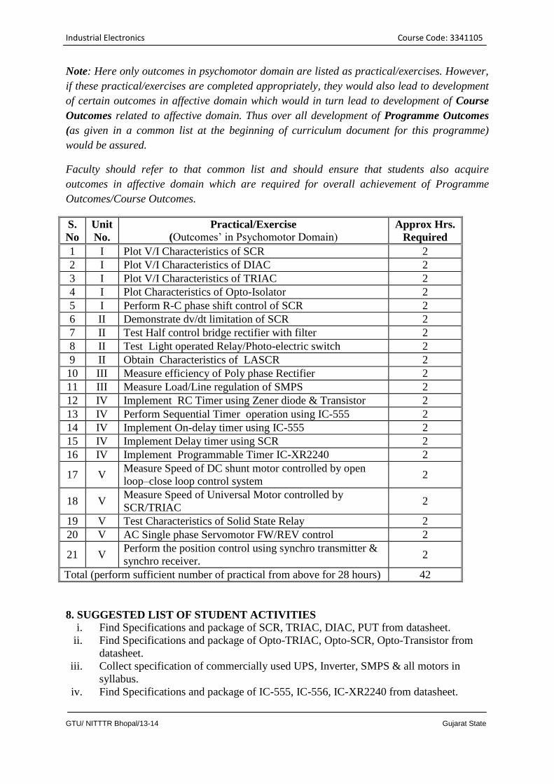
Note: Here only outcomes in psychomotor domain are listed as practical/exercises. However,
if these practical/exercises are completed appropriately, they would also lead to development
of certain outcomes in affective domain which would in turn lead to development of Course
Outcomes related to affective domain. Thus over all development of Programme Outcomes
(as given in a common list at the beginning of curriculum document for this programme)
would be assured.
Faculty should refer to that common list and should ensure that students also acquire
outcomes in affective domain which are required for overall achievement of Programme
Outcomes/Course Outcomes.
S.
No
Unit
No.
Practical/Exercise (Outcomes’ in Psychomotor Domain)
Approx Hrs.
Required
1 I Plot V/I Characteristics of SCR 2
2 I Plot V/I Characteristics of DIAC 2
3 I Plot V/I Characteristics of TRIAC 2
4 I Plot Characteristics of Opto-Isolator 2
5 I Perform R-C phase shift control of SCR 2
6 II Demonstrate dv/dt limitation of SCR 2
7 II Test Half control bridge rectifier with filter 2
8 II Test Light operated Relay/Photo-electric switch 2
9 II Obtain Characteristics of LASCR 2
10 III Measure efficiency of Poly phase Rectifier 2
11 III Measure Load/Line regulation of SMPS 2
12 IV Implement RC Timer using Zener diode & Transistor 2
13 IV Perform Sequential Timer operation using IC-555 2
14 IV Implement On-delay timer using IC-555 2
15 IV Implement Delay timer using SCR 2
16 IV Implement Programmable Timer IC-XR2240 2
17 V Measure Speed of DC shunt motor controlled by open
loop–close loop control system 2
18 V Measure Speed of Universal Motor controlled by
SCR/TRIAC 2
19 V Test Characteristics of Solid State Relay 2
20 V AC Single phase Servomotor FW/REV control 2
21 V Perform the position control using synchro transmitter &
synchro receiver. 2
Total (perform sufficient number of practical from above for 28 hours) 42
8. SUGGESTED LIST OF STUDENT ACTIVITIES
i. Find Specifications and package of SCR, TRIAC, DIAC, PUT from datasheet.
ii. Find Specifications and package of Opto-TRIAC, Opto-SCR, Opto-Transistor from
datasheet.
iii. Collect specification of commercially used UPS, Inverter, SMPS & all motors in
syllabus.
iv. Find Specifications and package of IC-555, IC-556, IC-XR2240 from datasheet.
Industrial Electronics Course Code: 3341105
GTU/ NITTTR Bhopal/13-14 Gujarat State
v. Find Specifications and package of DC shunt motor, Induction motor, Universal
motor, Synchro, Servo motor from datasheet.
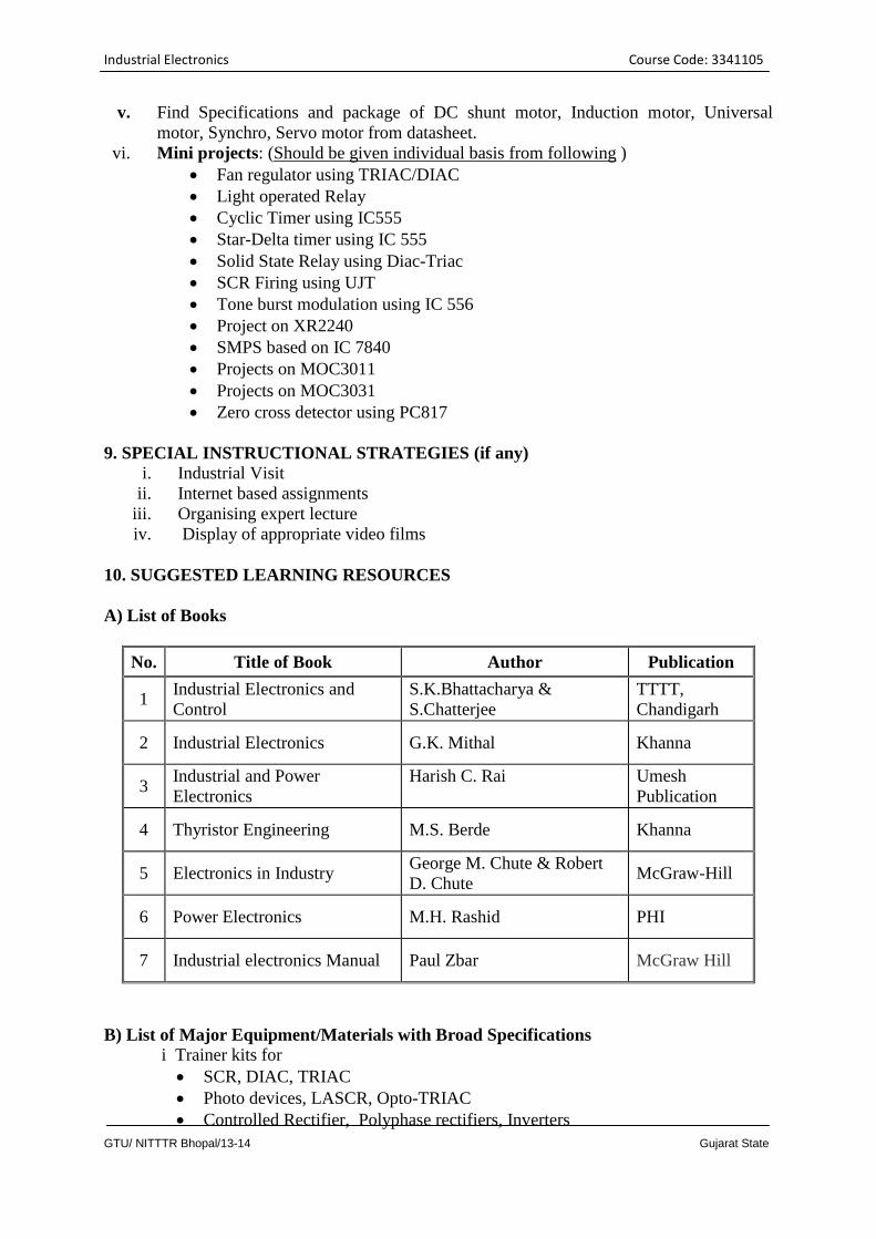
vi. Mini projects: (Should be given individual basis from following )
Fan regulator using TRIAC/DIAC
Light operated Relay
Cyclic Timer using IC555
Star-Delta timer using IC 555
Solid State Relay using Diac-Triac
SCR Firing using UJT
Tone burst modulation using IC 556
Project on XR2240
SMPS based on IC 7840
Projects on MOC3011
Projects on MOC3031
Zero cross detector using PC817
9. SPECIAL INSTRUCTIONAL STRATEGIES (if any)
i. Industrial Visit
ii. Internet based assignments
iii. Organising expert lecture
iv. Display of appropriate video films
10. SUGGESTED LEARNING RESOURCES
A) List of Books
No. Title of Book Author Publication
1 Industrial Electronics and
Control
S.K.Bhattacharya &
S.Chatterjee
TTTT,
Chandigarh
2 Industrial Electronics G.K. Mithal Khanna
3 Industrial and Power
Electronics
Harish C. Rai
Umesh
Publication
4 Thyristor Engineering M.S. Berde Khanna
5 Electronics in Industry George M. Chute & Robert
D. Chute McGraw-Hill
6 Power Electronics M.H. Rashid PHI
7 Industrial electronics Manual Paul Zbar McGraw Hill
B) List of Major Equipment/Materials with Broad Specifications
i Trainer kits for
SCR, DIAC, TRIAC
Photo devices, LASCR, Opto-TRIAC
Controlled Rectifier, Polyphase rectifiers, Inverters
Industrial Electronics Course Code: 3341105
GTU/ NITTTR Bhopal/13-14 Gujarat State
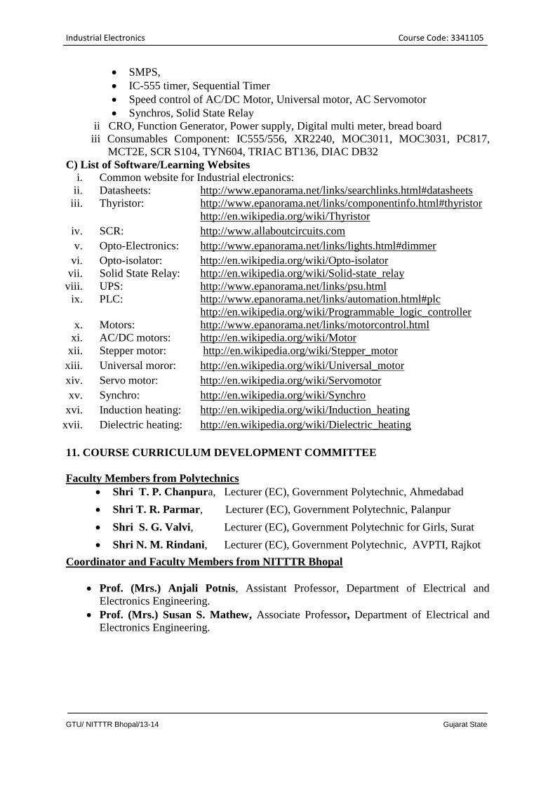
SMPS,
IC-555 timer, Sequential Timer
Speed control of AC/DC Motor, Universal motor, AC Servomotor
Synchros, Solid State Relay
ii CRO, Function Generator, Power supply, Digital multi meter, bread board
iii Consumables Component: IC555/556, XR2240, MOC3011, MOC3031, PC817,
MCT2E, SCR S104, TYN604, TRIAC BT136, DIAC DB32
C) List of Software/Learning Websites
i. Common website for Industrial electronics:
ii. Datasheets: http://www.epanorama.net/links/searchlinks.html#datasheets
iii. Thyristor: http://www.epanorama.net/links/componentinfo.html#thyristor
http://en.wikipedia.org/wiki/Thyristor
iv. SCR: http://www.allaboutcircuits.com
v. Opto-Electronics: http://www.epanorama.net/links/lights.html#dimmer
vi. Opto-isolator: http://en.wikipedia.org/wiki/Opto-isolator
vii. Solid State Relay: http://en.wikipedia.org/wiki/Solid-state_relay
viii. UPS: http://www.epanorama.net/links/psu.html
ix. PLC: http://www.epanorama.net/links/automation.html#plc
http://en.wikipedia.org/wiki/Programmable_logic_controller
x. Motors: http://www.epanorama.net/links/motorcontrol.html
xi. AC/DC motors: http://en.wikipedia.org/wiki/Motor
xii. Stepper motor: http://en.wikipedia.org/wiki/Stepper_motor
xiii. Universal moror: http://en.wikipedia.org/wiki/Universal_motor
xiv. Servo motor: http://en.wikipedia.org/wiki/Servomotor
xv. Synchro: http://en.wikipedia.org/wiki/Synchro
xvi. Induction heating: http://en.wikipedia.org/wiki/Induction_heating
xvii. Dielectric heating: http://en.wikipedia.org/wiki/Dielectric_heating
11. COURSE CURRICULUM DEVELOPMENT COMMITTEE
Faculty Members from Polytechnics
Shri T. P. Chanpura, Lecturer (EC), Government Polytechnic, Ahmedabad
Shri T. R. Parmar, Lecturer (EC), Government Polytechnic, Palanpur
Shri S. G. Valvi, Lecturer (EC), Government Polytechnic for Girls, Surat
Shri N. M. Rindani, Lecturer (EC), Government Polytechnic, AVPTI, Rajkot
Coordinator and Faculty Members from NITTTR Bhopal
Prof. (Mrs.) Anjali Potnis, Assistant Professor, Department of Electrical and
Electronics Engineering.
Prof. (Mrs.) Susan S. Mathew, Associate Professor, Department of Electrical and
Electronics Engineering.
Circuit Design Tools Course Code: 3341106
GTU/ NITTTR Bhopal/13-14 Gujarat State
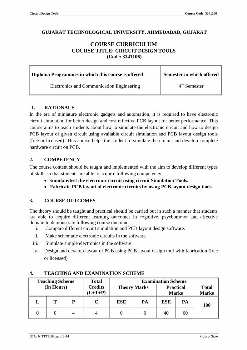
GUJARAT TECHNOLOGICAL UNIVERSITY, AHMEDABAD, GUJARAT
COURSE CURRICULUM COURSE TITLE: CIRCUIT DESIGN TOOLS
(Code: 3341106)
Diploma Programmes in which this course is offered
Semester in which offered
Electronics and Communication Engineering 4th
Semester
1. RATIONALE
In the era of miniature electronic gadgets and automation, it is required to have electronic
circuit simulation for better design and cost effective PCB layout for better performance. This
course aims to teach students about how to simulate the electronic circuit and how to design
PCB layout of given circuit using available circuit simulation and PCB layout design tools
(free or licensed). This course helps the student to simulate the circuit and develop complete
hardware circuit on PCB.
2. COMPETENCY
The course content should be taught and implemented with the aim to develop different types
of skills so that students are able to acquire following competency:
Simulate/test the electronic circuit using circuit Simulation Tools.
Fabricate PCB layout of electronic circuits by using PCB layout design tools
3. COURSE OUTCOMES
The theory should be taught and practical should be carried out in such a manner that students
are able to acquire different learning outcomes in cognitive, psychomotor and affective
domain to demonstrate following course outcomes.
i. Compare different circuit simulation and PCB layout design software.
ii. Make schematic electronic circuits in the software
iii. Simulate simple electronics in the software
iv. Design and develop layout of PCB using PCB layout design tool with fabrication (free
or licensed).
4. TEACHING AND EXAMINATION SCHEME
Teaching Scheme
(In Hours)
Total
Credits
(L+T+P)
Examination Scheme
Theory Marks Practical
Marks
Total
Marks
L T P C ESE PA ESE PA
100
0 0 4 4 0 0 40 60
Circuit Design Tools Course Code: 3341106
GTU/ NITTTR Bhopal/13-14 Gujarat State
Legends: L-Lecture; T – Tutorial/Teacher Guided Theory Practice; P - Practical; C – Credit ESE - End
Semester Examination; PA - Progressive Assessment.
5. COURSE DETAILS
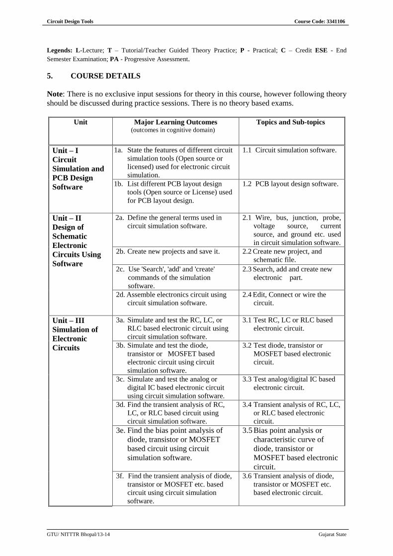
Note: There is no exclusive input sessions for theory in this course, however following theory
should be discussed during practice sessions. There is no theory based exams.
Unit Major Learning Outcomes (outcomes in cognitive domain)
Topics and Sub-topics
Unit – I
Circuit
Simulation and
PCB Design
Software
1a. State the features of different circuit
simulation tools (Open source or
licensed) used for electronic circuit
simulation.
1.1 Circuit simulation software.
1b. List different PCB layout design
tools (Open source or License) used
for PCB layout design.
1.2 PCB layout design software.
Unit – II
Design of
Schematic
Electronic
Circuits Using
Software
2a. Define the general terms used in
circuit simulation software.
2.1 Wire, bus, junction, probe,
voltage source, current
source, and ground etc. used
in circuit simulation software.
2b. Create new projects and save it.
2.2 Create new project, and
schematic file.
2c. Use 'Search', 'add' and 'create'
commands of the simulation
software.
2.3 Search, add and create new
electronic part.
2d. Assemble electronics circuit using
circuit simulation software.
2.4 Edit, Connect or wire the
circuit.
Unit – III
Simulation of
Electronic
Circuits
3a. Simulate and test the RC, LC, or
RLC based electronic circuit using
circuit simulation software.
3.1 Test RC, LC or RLC based
electronic circuit.
3b. Simulate and test the diode,
transistor or MOSFET based
electronic circuit using circuit
simulation software.
3.2 Test diode, transistor or
MOSFET based electronic
circuit.
3c. Simulate and test the analog or
digital IC based electronic circuit
using circuit simulation software.
3.3 Test analog/digital IC based
electronic circuit.
3d. Find the transient analysis of RC,
LC, or RLC based circuit using
circuit simulation software.
3.4 Transient analysis of RC, LC,
or RLC based electronic
circuit.
3e. Find the bias point analysis of
diode, transistor or MOSFET
based circuit using circuit
simulation software.
3.5 Bias point analysis or
characteristic curve of
diode, transistor or
MOSFET based electronic
circuit. 3f. Find the transient analysis of diode,
transistor or MOSFET etc. based
circuit using circuit simulation
software.
3.6 Transient analysis of diode,
transistor or MOSFET etc.
based electronic circuit.
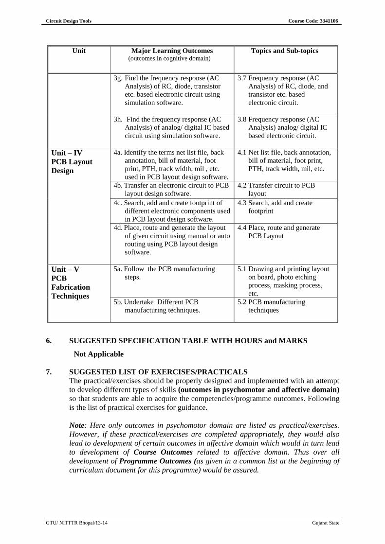
Circuit Design Tools Course Code: 3341106
GTU/ NITTTR Bhopal/13-14 Gujarat State
Unit Major Learning Outcomes (outcomes in cognitive domain)
Topics and Sub-topics
3g. Find the frequency response (AC
Analysis) of RC, diode, transistor
etc. based electronic circuit using
simulation software.
3.7 Frequency response (AC
Analysis) of RC, diode, and
transistor etc. based
electronic circuit.
3h. Find the frequency response (AC
Analysis) of analog/ digital IC based
circuit using simulation software.
3.8 Frequency response (AC
Analysis) analog/ digital IC
based electronic circuit.
Unit – IV
PCB Layout
Design
4a. Identify the terms net list file, back
annotation, bill of material, foot
print, PTH, track width, mil , etc.
used in PCB layout design software.
4.1 Net list file, back annotation,
bill of material, foot print,
PTH, track width, mil, etc.
4b. Transfer an electronic circuit to PCB
layout design software.
4.2 Transfer circuit to PCB
layout
4c. Search, add and create footprint of
different electronic components used
in PCB layout design software.
4.3 Search, add and create
footprint
4d. Place, route and generate the layout
of given circuit using manual or auto
routing using PCB layout design
software.
4.4 Place, route and generate
PCB Layout
Unit – V
PCB
Fabrication
Techniques
5a. Follow the PCB manufacturing
steps.
5.1 Drawing and printing layout
on board, photo etching
process, masking process,
etc.
5b. Undertake Different PCB
manufacturing techniques.
5.2 PCB manufacturing
techniques
6. SUGGESTED SPECIFICATION TABLE WITH HOURS and MARKS
Not Applicable
7. SUGGESTED LIST OF EXERCISES/PRACTICALS
The practical/exercises should be properly designed and implemented with an attempt
to develop different types of skills (outcomes in psychomotor and affective domain)
so that students are able to acquire the competencies/programme outcomes. Following
is the list of practical exercises for guidance.
Note: Here only outcomes in psychomotor domain are listed as practical/exercises.
However, if these practical/exercises are completed appropriately, they would also
lead to development of certain outcomes in affective domain which would in turn lead
to development of Course Outcomes related to affective domain. Thus over all
development of Programme Outcomes (as given in a common list at the beginning of
curriculum document for this programme) would be assured.
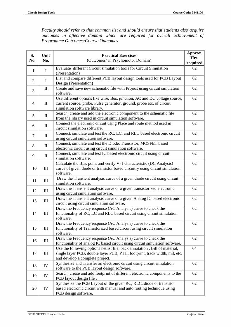
Circuit Design Tools Course Code: 3341106
GTU/ NITTTR Bhopal/13-14 Gujarat State
Faculty should refer to that common list and should ensure that students also acquire
outcomes in affective domain which are required for overall achievement of
Programme Outcomes/Course Outcomes.
S.
No.
Unit
No.
Practical Exercises
(Outcomes’ in Psychomotor Domain)
Approx.
Hrs.
required
1 I Evaluate different Circuit simulation tools for Circuit Simulation
(Presentation)
02
2 I List and compare different PCB layout design tools used for PCB Layout
Design (Presentation)
02
3 II Create and save new schematic file with Project using circuit simulation
software.
02
4 II
Use different options like wire, Bus, junction, AC and DC voltage source,
current source, probe, Pulse generator, ground, probe etc. of circuit
simulation software library.
02
5 II Search, create and add the electronic component to the schematic file
from the library used in circuit simulation software.
02
6 II Connect the electronic circuit using Place and route method used in
circuit simulation software.
02
7 II Connect, simulate and test the RC, LC, and RLC based electronic circuit
using circuit simulation software.
02
8 II Connect, simulate and test the Diode, Transistor, MOSFET based
electronic circuit using circuit simulation software.
02
9 II Connect, simulate and test IC based electronic circuit using circuit
simulation software.
02
10 III
Calculate the Bias point and verify V- I characteristic (DC Analysis)
curve of given diode or transistor based circuitry using circuit simulation
software.
02
11 III Draw the Transient analysis curve of a given diode circuit using circuit
simulation software.
02
12 III Draw the Transient analysis curve of a given transistorized electronic
using circuit simulation software.
02
13 III Draw the Transient analysis curve of a given Analog IC based electronic
circuit using circuit simulation software.
02
14 III
Draw the Frequency response (AC Analysis) curve to check the
functionality of RC, LC and RLC based circuit using circuit simulation
software.
02
15 III
Draw the Frequency response (AC Analysis) curve to check the
functionality of Transistorized based circuit using circuit simulation
software.
02
16 III Draw the Frequency response (AC Analysis) curve to check the
functionality of analog IC based circuit using circuit simulation software.
02
17 III
Use the following options netlist file, back annotation , Bill of material,
single layer PCB, double layer PCB, PTH, footprint, track width, mil, etc.
and develop a complete project.
04
18 IV Synthesize and Transfer an electronic circuit using circuit simulation
software to the PCB layout design software.
02
19 IV Search, create and add footprint of different electronic components to the
PCB layout design file .
02
20 IV
Synthesize the PCB Layout of the given RC, RLC, diode or transistor
based electronic circuit with manual and auto routing technique using
PCB design software.
02
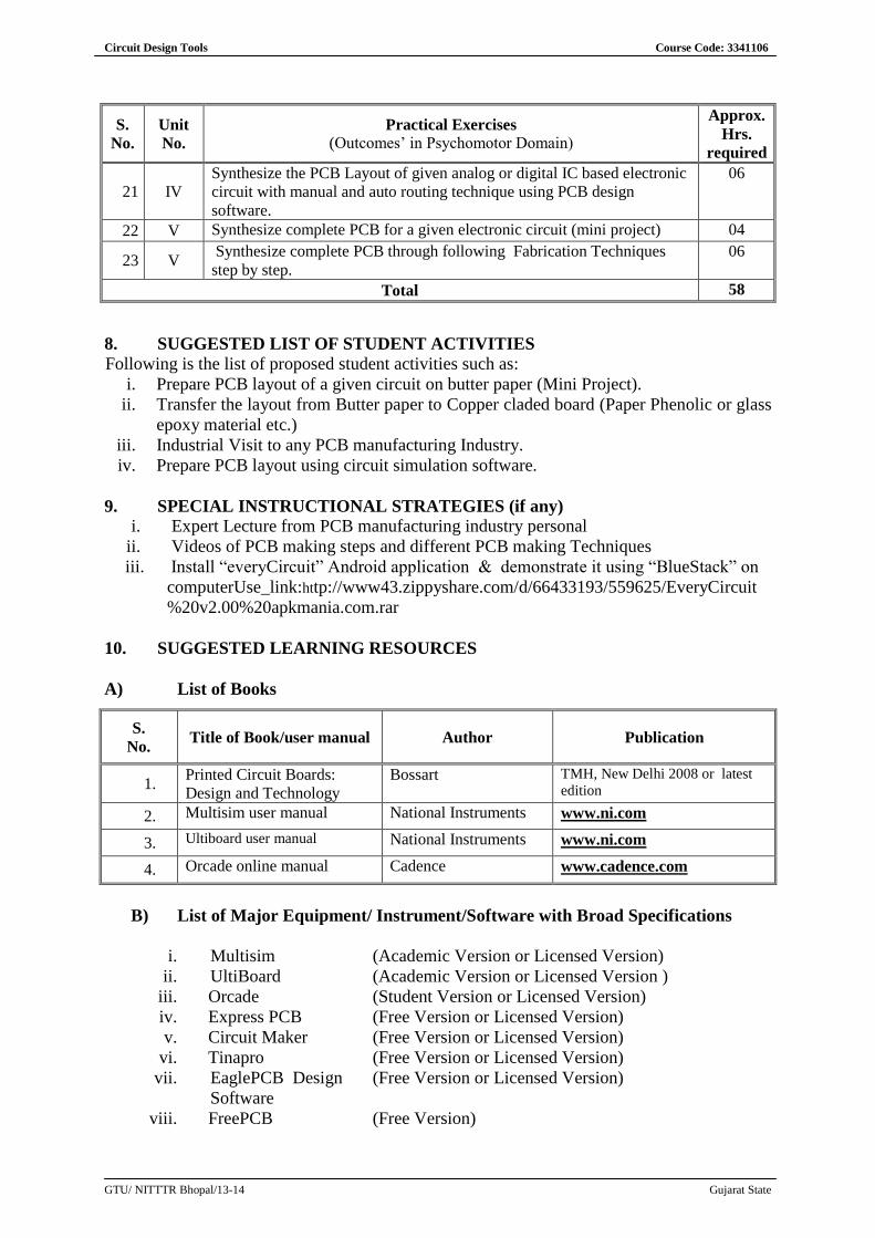
Circuit Design Tools Course Code: 3341106
GTU/ NITTTR Bhopal/13-14 Gujarat State
S.
No.
Unit
No.
Practical Exercises
(Outcomes’ in Psychomotor Domain)
Approx.
Hrs.
required
21 IV
Synthesize the PCB Layout of given analog or digital IC based electronic
circuit with manual and auto routing technique using PCB design
software.
06
22 V Synthesize complete PCB for a given electronic circuit (mini project) 04
23 V Synthesize complete PCB through following Fabrication Techniques
step by step.
06
Total 58
8. SUGGESTED LIST OF STUDENT ACTIVITIES
Following is the list of proposed student activities such as:
i. Prepare PCB layout of a given circuit on butter paper (Mini Project).
ii. Transfer the layout from Butter paper to Copper claded board (Paper Phenolic or glass
epoxy material etc.)
iii. Industrial Visit to any PCB manufacturing Industry.
iv. Prepare PCB layout using circuit simulation software.
9. SPECIAL INSTRUCTIONAL STRATEGIES (if any)
i. Expert Lecture from PCB manufacturing industry personal
ii. Videos of PCB making steps and different PCB making Techniques
iii. Install “everyCircuit” Android application & demonstrate it using “BlueStack” on
computerUse_link:http://www43.zippyshare.com/d/66433193/559625/EveryCircuit
%20v2.00%20apkmania.com.rar
10. SUGGESTED LEARNING RESOURCES
A) List of Books
S.
No. Title of Book/user manual Author Publication
1. Printed Circuit Boards:
Design and Technology
Bossart TMH, New Delhi 2008 or latest
edition
2. Multisim user manual National Instruments www.ni.com
3. Ultiboard user manual National Instruments www.ni.com
4. Orcade online manual Cadence www.cadence.com
B) List of Major Equipment/ Instrument/Software with Broad Specifications
i. Multisim (Academic Version or Licensed Version)
ii. UltiBoard (Academic Version or Licensed Version )
iii. Orcade (Student Version or Licensed Version)
iv. Express PCB (Free Version or Licensed Version)
v. Circuit Maker (Free Version or Licensed Version)
vi. Tinapro
vii. EaglePCB Design
Software
(Free Version or Licensed Version)
(Free Version or Licensed Version)
viii. FreePCB (Free Version)
Circuit Design Tools Course Code: 3341106
GTU/ NITTTR Bhopal/13-14 Gujarat State
C) List of Software/Learning Websites
www.ni.com (Multisim and Ultiboard - Academic version)
www.cadence.com (Orcade - Student version)
www.youtube.com (PCB Manufacturing Videos)
11. COURSE CURRICULUM DEVELOPMENT COMMITTEE
Faculty Members from Polytechnics
Shri S. N. Sampat, I/C Head (EC) Government Polytechnic, Gandhinagar.
Shri K. J. Pithadiya, Lecturer (EC), BBIT, Vallabh Vidhyanagar
Shri G. V. Parmar, Lecturer (EC), Government Polytechnic, Jamnagar
Shri K. V. Chhaniyara, Lecturer (EC), AVPTI Rajkot.
Coordinator and Faculty Members from NITTTR Bhopal
Prof. (Mrs.) Anjali Potnis, Assistant Professor, Department of Electrical and
Electronics Engineering.
Prof. (Mrs.) Susan S. Mathew, Associate Professor, Department of Electrical and
Electronics Engineering.