Embed Size (px)
Citation preview
Hardware Manual
GV-IPCam H.264
Before attempting to connect or operate this product,please read these instructions carefully and save this manual for future use.
Vandal Proof IP DomeTarget Vandal Proof IP Dome
ICH264TG2V10
© 2015 GeoVision, Inc. All rights reserved.
Under the copyright laws, this manual may not be copied, in whole or in
part, without the written consent of GeoVision.
Every effort has been made to ensure that the information in this manual is
accurate. GeoVision, Inc. makes no expressed or implied warranty of any
kind and assumes no responsibility for errors or omissions. No liability is
assumed for incidental or consequential damages arising from the use of
the information or products contained herein. Features and specifications
are subject to change without notice. Note: no memory card slot or local
storage function for Argentina.
GeoVision, Inc.
9F, No. 246, Sec. 1, Neihu Rd.,
Neihu District, Taipei, Taiwan
Tel: +886-2-8797-8377
Fax: +886-2-8797-8335
http://www.geovision.com.tw
Trademarks used in this manual: GeoVision, the GeoVision logo and GV
series products are trademarks of GeoVision, Inc. Windows and Windows
XP are registered trademarks of Microsoft Corporation.
September 2015
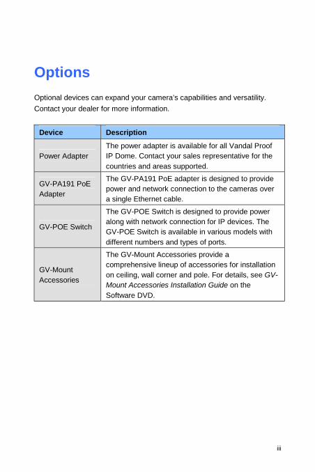
Options
Optional devices can expand your camera’s capabilities and versatility.
Contact your dealer for more information.
Device Description
Power Adapter The power adapter is available for all Vandal Proof IP Dome. Contact your sales representative for the countries and areas supported.
GV-PA191 PoE Adapter
The GV-PA191 PoE adapter is designed to provide power and network connection to the cameras over a single Ethernet cable.
GV-POE Switch
The GV-POE Switch is designed to provide power along with network connection for IP devices. The GV-POE Switch is available in various models with different numbers and types of ports.
GV-Mount Accessories
The GV-Mount Accessories provide a comprehensive lineup of accessories for installation on ceiling, wall corner and pole. For details, see GV-Mount Accessories Installation Guide on the Software DVD.
iii
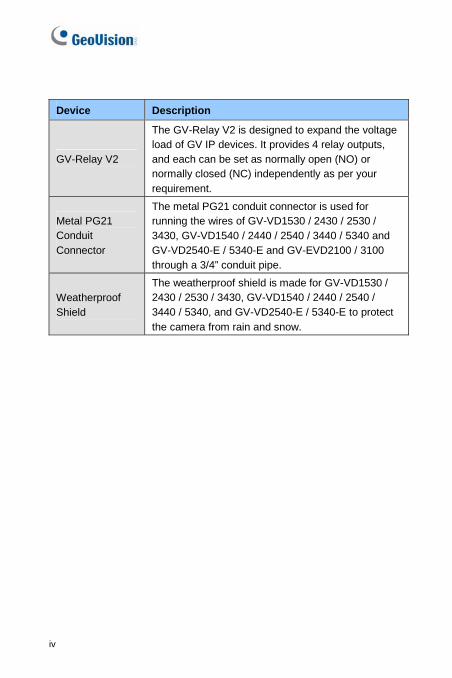
Device Description
GV-Relay V2
The GV-Relay V2 is designed to expand the voltage load of GV IP devices. It provides 4 relay outputs, and each can be set as normally open (NO) or normally closed (NC) independently as per your requirement.
Metal PG21 Conduit Connector
The metal PG21 conduit connector is used for running the wires of GV-VD1530 / 2430 / 2530 / 3430, GV-VD1540 / 2440 / 2540 / 3440 / 5340 and GV-VD2540-E / 5340-E and GV-EVD2100 / 3100 through a 3/4” conduit pipe.
Weatherproof Shield
The weatherproof shield is made for GV-VD1530 / 2430 / 2530 / 3430, GV-VD1540 / 2440 / 2540 / 3440 / 5340, and GV-VD2540-E / 5340-E to protect the camera from rain and snow.
iv
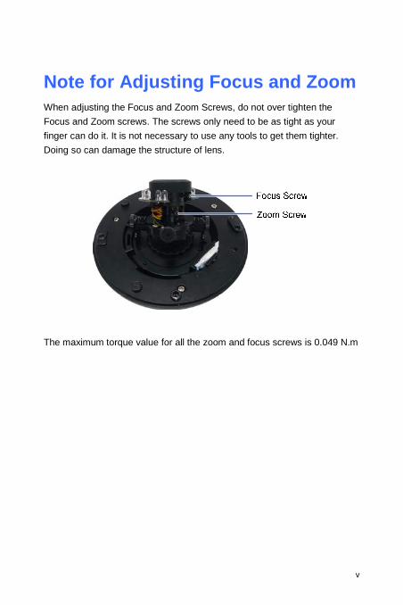
Note for Adjusting Focus and Zoom When adjusting the Focus and Zoom Screws, do not over tighten the
Focus and Zoom screws. The screws only need to be as tight as your
finger can do it. It is not necessary to use any tools to get them tighter.
Doing so can damage the structure of lens.
The maximum torque value for all the zoom and focus screws is 0.049 N.m
v
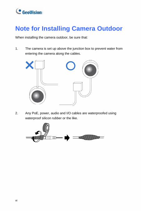
Note for Installing Camera Outdoor When installing the camera outdoor, be sure that:
1. The camera is set up above the junction box to prevent water from
entering the camera along the cables.
2. Any PoE, power, audio and I/O cables are waterproofed using
waterproof silicon rubber or the like.
vi
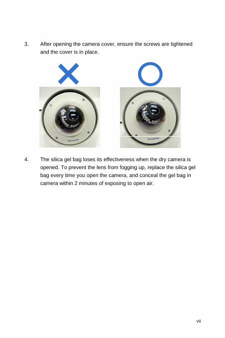
3. After opening the camera cover, ensure the screws are tightened
and the cover is in place.
4. The silica gel bag loses its effectiveness when the dry camera is
opened. To prevent the lens from fogging up, replace the silica gel
bag every time you open the camera, and conceal the gel bag in
camera within 2 minutes of exposing to open air.
vii
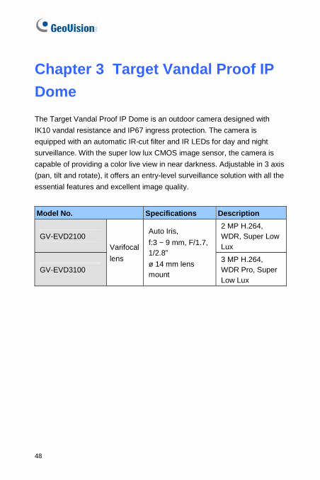
Chapter 3 Target Vandal Proof IP
Dome
The Target Vandal Proof IP Dome is an outdoor camera designed with
IK10 vandal resistance and IP67 ingress protection. The camera is
equipped with an automatic IR-cut filter and IR LEDs for day and night
surveillance. With the super low lux CMOS image sensor, the camera is
capable of providing a color live view in near darkness. Adjustable in 3 axis
(pan, tilt and rotate), it offers an entry-level surveillance solution with all the
essential features and excellent image quality.
Model No. Specifications Description
GV-EVD2100 2 MP H.264, WDR, Super Low Lux
GV-EVD3100
Varifocal
lens
Auto Iris,
f:3 ~ 9 mm, F/1.7, 1/2.8”
ø 14 mm lens mount
3 MP H.264, WDR Pro, Super Low Lux
48

Target Vandal Proof IP Dome
3
3.1 Packing List
Target Vandal Proof IP Dome
Torx Wrench
Screw x 4
Screw Anchor x 4
TV-Out Wire
Audio Wires x 2
Installation sticker
1
1
1
Ceiling mount template
1
RJ-45 Connector
Conduit Converter
Water proof rubber set
(for RJ-45 and DC12V)
49
Big Concave hexagon Wrench
Small Concave hexagon
Wrench
Silica Gel Bag Sticker (for Silica Gel Bag)
GV-IPCAM H.264 Software
DVD
Ruler
GV-NVR Software DVD Warranty Card
Note:
1. Power adapter can be purchased upon request.
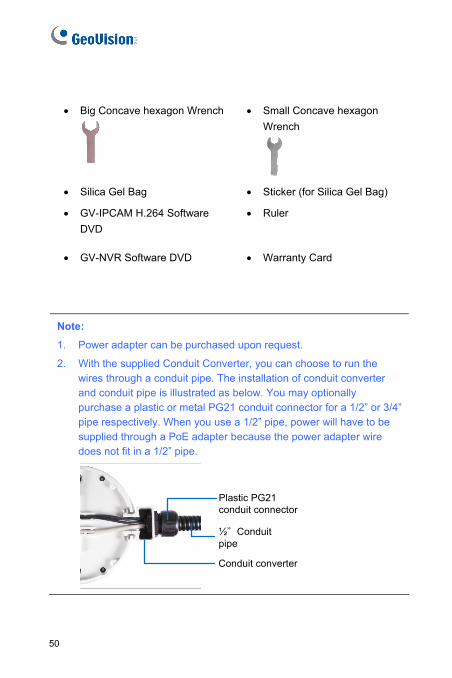
2. With the supplied Conduit Converter, you can choose to run the wires through a conduit pipe. The installation of conduit converter and conduit pipe is illustrated as below. You may optionally purchase a plastic or metal PG21 conduit connector for a 1/2” or 3/4” pipe respectively. When you use a 1/2” pipe, power will have to be supplied through a PoE adapter because the power adapter wire does not fit in a 1/2” pipe.
Plastic PG21 conduit connector
½”Conduit pipe
Conduit converter
50
Target Vandal Proof IP Dome
3
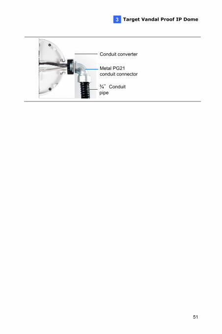
¾”Conduit pipe
Conduit converter
Metal PG21 conduit connector
51
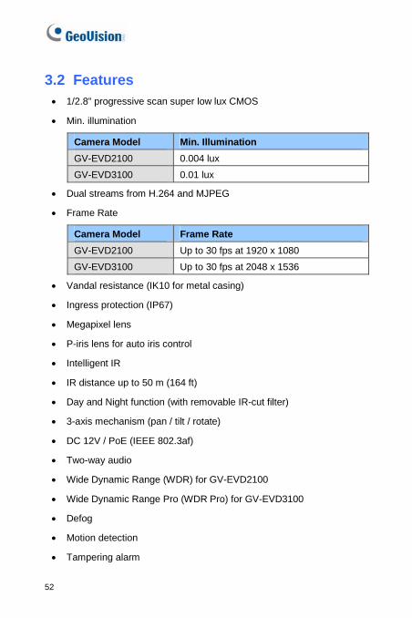
3.2 Features 1/2.8” progressive scan super low lux CMOS
Min. illumination
Camera Model Min. Illumination
GV-EVD2100 0.004 lux
GV-EVD3100 0.01 lux
Dual streams from H.264 and MJPEG
Frame Rate
Camera Model Frame Rate
GV-EVD2100 Up to 30 fps at 1920 x 1080
GV-EVD3100 Up to 30 fps at 2048 x 1536
Vandal resistance (IK10 for metal casing)
Ingress protection (IP67)
Megapixel lens
P-iris lens for auto iris control
Intelligent IR
IR distance up to 50 m (164 ft)
Day and Night function (with removable IR-cut filter)
3-axis mechanism (pan / tilt / rotate)
DC 12V / PoE (IEEE 802.3af)
Two-way audio
Wide Dynamic Range (WDR) for GV-EVD2100
Wide Dynamic Range Pro (WDR Pro) for GV-EVD3100
Defog
Motion detection
Tampering alarm
52

Target Vandal Proof IP Dome
3
Text overlay
Privacy mask
IP address filtering
NAS recording
Recording assigned by GV-Edge Recording Manager (Windows & Mac)
Supports iPhone, iPad, Android & 3GPP
31 languages on Web interface
ONVIF (Profile S) conformant
Note: For optimal performance and compatibility, it is highly recommended to use a GV-NAS System.
53
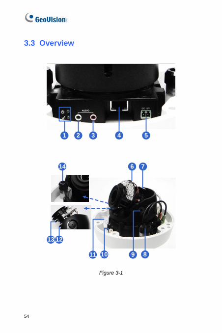
3.3 Overview
1 2 3 4 5
6
13 12
10
7
89
14
11
Figure 3-1
54
Target Vandal Proof IP Dome
3
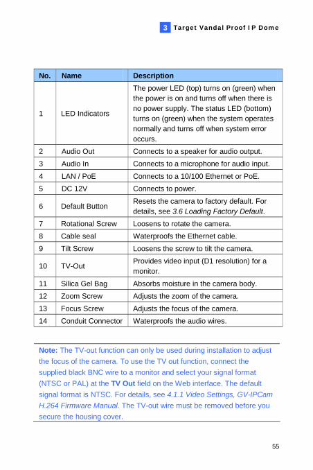
No. Name Description
1 LED Indicators
The power LED (top) turns on (green) when the power is on and turns off when there is no power supply. The status LED (bottom) turns on (green) when the system operates normally and turns off when system error occurs.
2 Audio Out Connects to a speaker for audio output.
3 Audio In Connects to a microphone for audio input.
4 LAN / PoE Connects to a 10/100 Ethernet or PoE.
5 DC 12V Connects to power.
6 Default Button Resets the camera to factory default. For details, see 3.6 Loading Factory Default.
7 Rotational Screw Loosens to rotate the camera.
8 Cable seal Waterproofs the Ethernet cable.
9 Tilt Screw Loosens the screw to tilt the camera.
10 TV-Out Provides video input (D1 resolution) for a monitor.
11 Silica Gel Bag Absorbs moisture in the camera body.
12 Zoom Screw Adjusts the zoom of the camera.
13 Focus Screw Adjusts the focus of the camera.
14 Conduit Connector Waterproofs the audio wires.
Note: The TV-out function can only be used during installation to adjust
the focus of the camera. To use the TV out function, connect the
supplied black BNC wire to a monitor and select your signal format
(NTSC or PAL) at the TV Out field on the Web interface. The default
signal format is NTSC. For details, see 4.1.1 Video Settings, GV-IPCam
H.264 Firmware Manual. The TV-out wire must be removed before you
secure the housing cover.
55
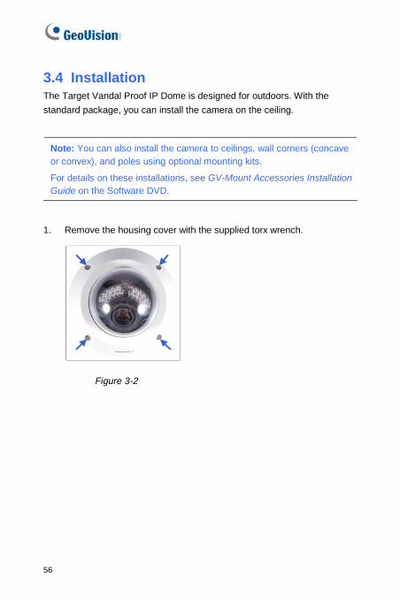
3.4 Installation The Target Vandal Proof IP Dome is designed for outdoors. With the
standard package, you can install the camera on the ceiling.
Note: You can also install the camera to ceilings, wall corners (concave or convex), and poles using optional mounting kits.
For details on these installations, see GV-Mount Accessories Installation Guide on the Software DVD.
1. Remove the housing cover with the supplied torx wrench.
Figure 3-2
56
Target Vandal Proof IP Dome
3
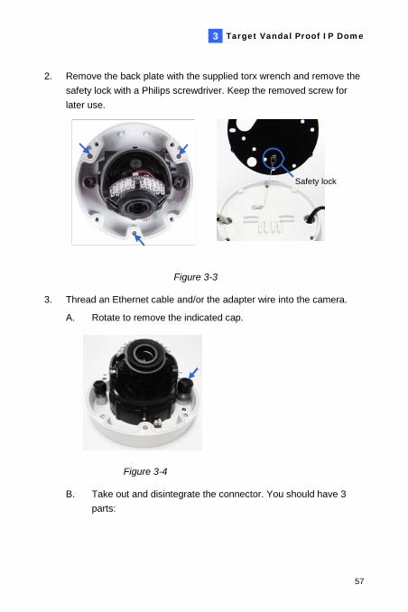
2. Remove the back plate with the supplied torx wrench and remove the
safety lock with a Philips screwdriver. Keep the removed screw for
later use.
Safety lock
Figure 3-3
3. Thread an Ethernet cable and/or the adapter wire into the camera.
A. Rotate to remove the indicated cap.
Figure 3-4
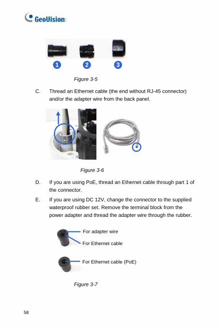
B. Take out and disintegrate the connector. You should have 3
parts:
57
21 3
Figure 3-5
C. Thread an Ethernet cable (the end without RJ-45 connector)
and/or the adapter wire from the back panel.
Figure 3-6
D. If you are using PoE, thread an Ethernet cable through part 1 of
the connector.
E. If you are using DC 12V, change the connector to the supplied
waterproof rubber set. Remove the terminal block from the
power adapter and thread the adapter wire through the rubber.
For adapter wire
For Ethernet cable
For Ethernet cable (PoE)
Figure 3-7
58
Target Vandal Proof IP Dome
3
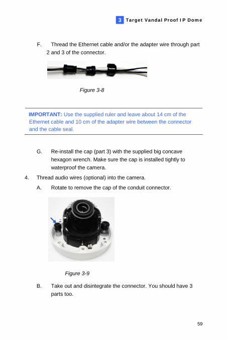
F. Thread the Ethernet cable and/or the adapter wire through part
2 and 3 of the connector.
Figure 3-8
IMPORTANT: Use the supplied ruler and leave about 14 cm of the Ethernet cable and 10 cm of the adapter wire between the connector and the cable seal.
G. Re-install the cap (part 3) with the supplied big concave
hexagon wrench. Make sure the cap is installed tightly to
waterproof the camera.
4. Thread audio wires (optional) into the camera.
A. Rotate to remove the cap of the conduit connector.
Figure 3-9
B. Take out and disintegrate the connector. You should have 3
parts too.
59
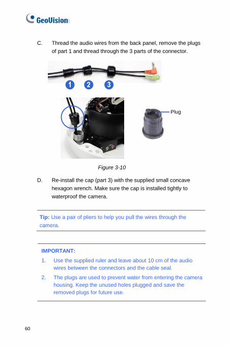
C. Thread the audio wires from the back panel, remove the plugs
of part 1 and thread through the 3 parts of the connector.
Plug
Figure 3-10
D. Re-install the cap (part 3) with the supplied small concave
hexagon wrench. Make sure the cap is installed tightly to
waterproof the camera.
Tip: Use a pair of pliers to help you pull the wires through the
camera.
IMPORTANT:
1. Use the supplied ruler and leave about 10 cm of the audio wires between the connectors and the cable seal.
2. The plugs are used to prevent water from entering the camera housing. Keep the unused holes plugged and save the removed plugs for future use.
60
Target Vandal Proof IP Dome
3
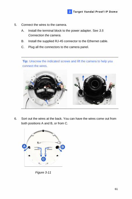
5. Connect the wires to the camera.
A. Install the terminal block to the power adapter. See 3.5
Connection the camera.
B. Install the supplied RJ-45 connector to the Ethernet cable.
C. Plug all the connectors to the camera panel.
Tip: Unscrew the indicated screws and lift the camera to help you
connect the wires.
6. Sort out the wires at the back. You can have the wires come out from
both positions A and B, or from C.
A B
C
Figure 3-11
61
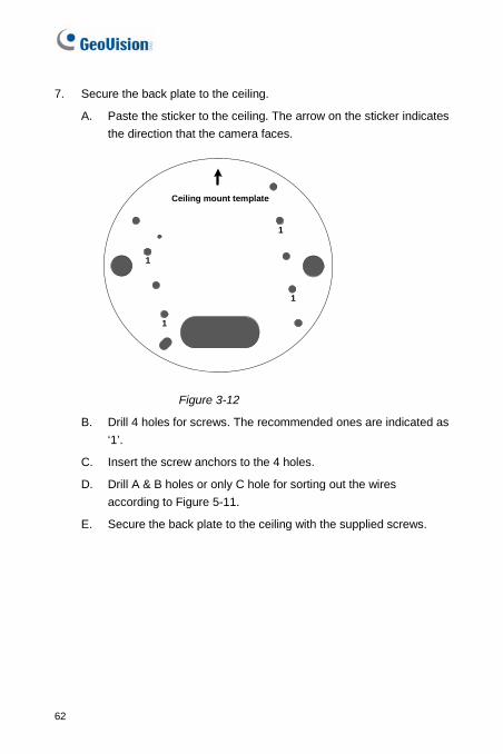
7. Secure the back plate to the ceiling.
A. Paste the sticker to the ceiling. The arrow on the sticker indicates
the direction that the camera faces.
1
1
1
Ceiling mount template
1
Figure 3-12
B. Drill 4 holes for screws. The recommended ones are indicated as
‘1’.
C. Insert the screw anchors to the 4 holes.
D. Drill A & B holes or only C hole for sorting out the wires
according to Figure 5-11.
E. Secure the back plate to the ceiling with the supplied screws.
62
Target Vandal Proof IP Dome
3
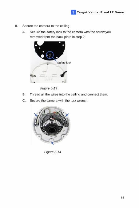
8. Secure the camera to the ceiling.
A. Secure the safety lock to the camera with the screw you
removed from the back plate in step 2.
Safety lock
Figure 3-13
B. Thread all the wires into the ceiling and connect them.
C. Secure the camera with the torx wrench.
Figure 3-14
63
9. Access the live view. See 2.1 Accessing the Live View, GV-IPCam
H.264 Firmware Manual.
Note: The TV-out function can only be used during installation to adjust
the focus of the camera. To use the TV out function, connect the
supplied black BNC wire to a monitor and select your signal format
(NTSC or PAL) at the TV Out field on the Web interface. The default
signal format is NTSC. For details, see 4.1.1 Video Settings, GV-IPCam
H.264 Firmware Manual. The TV-out wire must be removed before you
secure the housing cover.
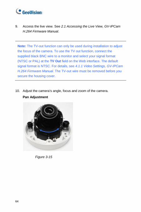
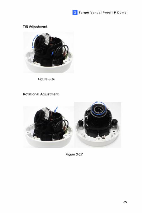
10. Adjust the camera’s angle, focus and zoom of the camera.
Pan Adjustment
Figure 3-15
64
Target Vandal Proof IP Dome
3
Tilt Adjustment
Figure 3-16
Rotational Adjustment
Figure 3-17
65
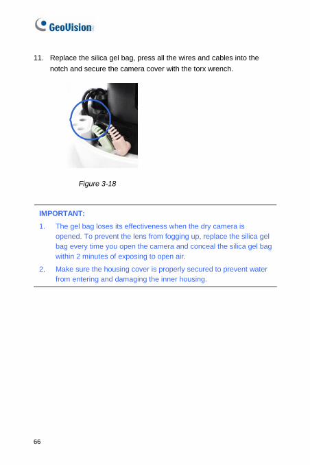
11. Replace the silica gel bag, press all the wires and cables into the
notch and secure the camera cover with the torx wrench.
Figure 3-18
IMPORTANT:
1. The gel bag loses its effectiveness when the dry camera is opened. To prevent the lens from fogging up, replace the silica gel bag every time you open the camera and conceal the silica gel bag within 2 minutes of exposing to open air.
2. Make sure the housing cover is properly secured to prevent water from entering and damaging the inner housing.
66
Target Vandal Proof IP Dome
3
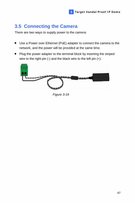
3.5 Connecting the Camera There are two ways to supply power to the camera:
Use a Power over Ethernet (PoE) adapter to connect the camera to the
network, and the power will be provided at the same time.
Plug the power adapter to the terminal block by inserting the striped
wire to the right pin (-) and the black wire to the left pin (+).
Figure 3-19
67
68
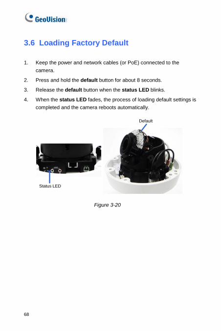
3.6 Loading Factory Default
1. Keep the power and network cables (or PoE) connected to the
camera.
2. Press and hold the default button for about 8 seconds.
3. Release the default button when the status LED blinks.
4. When the status LED fades, the process of loading default settings is
completed and the camera reboots automatically.
Status LED
Default
Figure 3-20