Embed Size (px)
Citation preview
k679b_677b_674b_675c_c551b_m759b_757b_751b_a791b_Manual_V1.2
H.264 Network DVR
User Manual
GUI Display with USB Mouse Control
Please read instructions thoroughly before operation and retain it for future reference.
For the actual display & operation, please refer to your DVR in hand.
IMPORTANT SAFEGUARD
CAUTION
RISK OF ELECTRIC SHOCK
CAUTION:
To reduce the risk of electric shock, do not expose this apparatus to rain or moisture. Only operate this
apparatus from the type of power source indicated on the label. The company shall not be liable for any
damages arising out of any improper use, even if we have been advised of the possibility of such damages.
The lightning flash with arrowhead symbol, within an equilateral triangle, is intended to alert the user to the presence of uninsulated “dangerous voltage” within the product’s enclosure that may be of sufficient magnitude to constitute a risk of electric shock to persons.
This exclamation point within an equilateral triangle is intended to alert the user to the presence of important operating and maintenance (servicing) instructions in the literature accompanying the appliance.
All lead-free products offered by the company comply with the requirements of the European law on the Restriction of Hazardous Substances (RoHS) directive, which means our manufacture processes and products are strictly “lead-free” and without the hazardous substances cited in the directive.
The crossed-out wheeled bin mark symbolizes that within the European Union the product must be collected separately at the product end-of-life. This applies to your product and any peripherals marked with this symbol. Do not dispose of these products as unsorted municipal waste. Contact your local dealer for procedures for recycling this equipment.
This apparatus is manufactured to comply with the radio interference requirements.
Federal Communications Commission Interference Statement
This equipment has been tested and found to comply with the limits for a Class A digital device, pursuant to Part 15 of the FCC Rules. These limits are designed to provide reasonable protection against harmful interference when the equipment is operated in a commercial environment. This equipment generates, uses, and can radiate radio frequency energy and, if not installed and used in accordance with the instruction manual, may cause harmful interference to radio communications. Operation of this equipment in a residential area is likely to cause harmful interference in which case the user will be required to correct the interference at his own expense.
Trademark Acknowledgements iPhone® is the registered trademark of Apple Inc.
BlackBerry® and related trademarks, names and logos are the property of Research In Motion Limited and are registered and/or used in the U.S. and countries around the world. Used under license from Research In Motion Limited.
Microsoft®, Windows®, Internet Explorer®, Mozilla® Firefox®, Google Chrome™, QuickTime®, Windows® Mobile & Symbian® mentioned in this document are the registered trademarks of their respective holders.
Disclaimer The information in this manual was current when released. We reserve the right to revise or remove any content in this manual at any time. We do not warrant or assume any legal liability or responsibility for the accuracy, completeness, or usefulness of this manual. For the actual display & operation, please refer to your DVR in hand. The content of this manual is subject to change without notice.
Grounding This is a Safety Class 1 Product (provided with a protective earthing ground incorporated in the power cord). The mains plug shall only be inserted in a socket outlet provided with a protective earth contact. Any interruption of the protective conductor inside or outside of the instrument is likely to make the instrument dangerous. Intentional interruption is prohibited.
Water & Moisture Do not expose this product to dripping or splashing and that no objects filled with liquids, such as vases, shall be placed on the product.
MPEG4 Licensing THIS PRODUCT IS LICENSED UNDER THE MPEG-4 VISUAL PATENT PORTFOLIO LICENSE FOR THE PERSONAL AND NON-COMMERCIAL USE OF A CONSUMER FOR (i) ENCODING VIDEO IN COMPLIANCE WITH THE MPEG-4 VISUAL STANDARD (“MPEG-4 VIDEO”) AND/OR (ii) DECODING MPEG-4 VIDEO THAT WAS ENCODED BY A CONSUMER ENGAGED IN A PERSONAL AND NON-COMMERCIAL ACTIVITY AND/OR WAS OBTAINED FROM A VIDEO PROVIDER LICENSED BY MPEG LA TO PROVIDE MPEG-4 VIDEO. NO LICENSE IS GRANTED OR SHALL BE IMPLIED FOR ANY OTHER USE. ADDITIONAL INFORMATION INCLUDING THAT RELATING TO PROMOTIONAL INTERNAL AND COMMERCIAL USES AND LICENSING MAY BE OBTAINED FROM MPEG LA, LLC. SEE HTTP://WWW.MPEGLA.COM.
GPL Licensing
This product contains codes which are developed by Third-Party-Companies and which are subject to the GNU General Public License (“GPL”) or the GNU Lesser Public License(“LGPL”).
The GPL Code used in this product is released without warranty and is subject to the copyright of the corresponding author.
Further source codes which are subject to the GPL-licenses are available upon request.
We are pleased to provide our modifications to the Linux Kernel, as well as a few new commands, and some tools to get you into the code. The codes are provided on the FTP site, and please download them from the following site or you can refer to your distributor:
http://download.dvrtw.com.tw/GPL/076D_Series/arm-linux-2.6.tar.gz
TABLE OF CONTENTS
1. BEFORE USING THIS DVR.........................................................................1
1.1 Package Content ........................................................................................................... 1 1.2 Front Panel..................................................................................................................... 1 1.3 Rear Panel ..................................................................................................................... 2
2. CONNECTION AND SETUP ........................................................................4
2.1 SATA HDD Installation ................................................................................................... 4 2.2 Camera Connection ....................................................................................................... 6
2.2.1 Normal Camera Connection.................................................................................. 6 2.2.2 PTZ Camera Connection (For Selected Models Only) ................................................. 7
2.3 DVR Power On............................................................................................................... 8 2.4 Date and Time Setting ................................................................................................... 9 2.5 Clear Hard Disk.............................................................................................................. 9 2.6 Password Setting ......................................................................................................... 10
3. GUI DISPLAY WITH USB MOUSE CONTROL..........................................11
3.1 Connect USB Mouse ................................................................................................... 11 3.2 Quick Menu Bar ........................................................................................................... 11
3.2.1 Channel Switch.................................................................................................... 12 3.2.2 PTZ Control Panel ............................................................................................... 12
3.3 Main Menu ................................................................................................................... 13
4. BASIC OPERATION...................................................................................14
4.1 Live Page ..................................................................................................................... 14 4.2 Record Icon.................................................................................................................. 14 4.3 Playback....................................................................................................................... 15
4.3.1 Playback Control ................................................................................................. 15 4.3.2 Event Search ....................................................................................................... 16 4.3.3 Audio Playback .................................................................................................... 16
4.4 User Level Switch ........................................................................................................ 16
5. FREQUENTLY-USED FUNCTIONS ...........................................................18
5.1 Quick Search................................................................................................................ 18 5.2 Record.......................................................................................................................... 19
5.2.1 Quick record setting............................................................................................. 19 5.2.2 Detailed record setting......................................................................................... 20
5.3 Schedule Setting.......................................................................................................... 21 5.3.1 Record Timer ....................................................................................................... 21 5.3.2 Detection Timer ................................................................................................... 22
5.3.3 Alarm Timer ......................................................................................................... 22 5.4 Detection Setting.......................................................................................................... 23 5.5 PTZ Camera Setting .................................................................................................... 24 5.6 System Setting............................................................................................................. 25
5.6.1 Password Setting................................................................................................. 25 5.6.2 System Upgrade.................................................................................................. 25 5.6.3 Backup & Restore Configurations ....................................................................... 26 5.6.4 Video Backup....................................................................................................... 26 5.6.5 Event Log Backup ............................................................................................... 28 5.6.6 Clear All HDD Data.............................................................................................. 29
5.7 Network ........................................................................................................................ 29 5.7.1 STATIC ................................................................................................................ 29 5.7.2 PPPOE ................................................................................................................ 30 5.7.3 DHCP................................................................................................................... 31 5.7.4 DDNS................................................................................................................... 31
5.8 Event Notifications ....................................................................................................... 32 5.8.1 FTP ...................................................................................................................... 32 5.8.2 E-MAIL................................................................................................................. 33
5.9 VGA Output Resolution Support .................................................................................. 33
6. REMOTE OPERATION...............................................................................35
6.1 Supplied Licensed Software ........................................................................................ 35 6.1.1 Installation & Network Connection ...................................................................... 35 6.1.2 Control Panel Overview....................................................................................... 37 6.1.3. General Operation .............................................................................................. 39 6.1.4. E-Map ................................................................................................................. 43
6.2 Web Browser................................................................................................................ 48 6.2.1 Event Download & Playback ............................................................................... 50
APPENDIX 1 SPECIFICATIONS....................................................................51
APPENDIX 2 COMPATIBLE USB FLASH DRIVE LIST ................................57
APPENDIX 3 COMPATIBLE SATA HDD LIST...............................................58
APPENDIX 4 MAIN MENU STRUCTURE......................................................59
APPENDIX 5 DVR BATTERY REPLACEMENT ............................................61
APPENDIX 6 PIN CONFIGURATION.............................................................62
APPENDIX 7 DVD WRITER INSTALLATION ................................................65
APPENDIX 8 DVD- / CD-ROM COMPATIBLE LIST ......................................66
BEFORE USING THIS DVR
1
1. BEFORE USING THIS DVR
1.1 Package Content
Standard Package
DVR HDD screws
Adapter & Power cord CD Manual
Optional Accessories
IR Remote Controller USB Mouse
Manual for IR Remote Controller DSUB Connector
IR Receiver Extension Cable
1.2 Front Panel
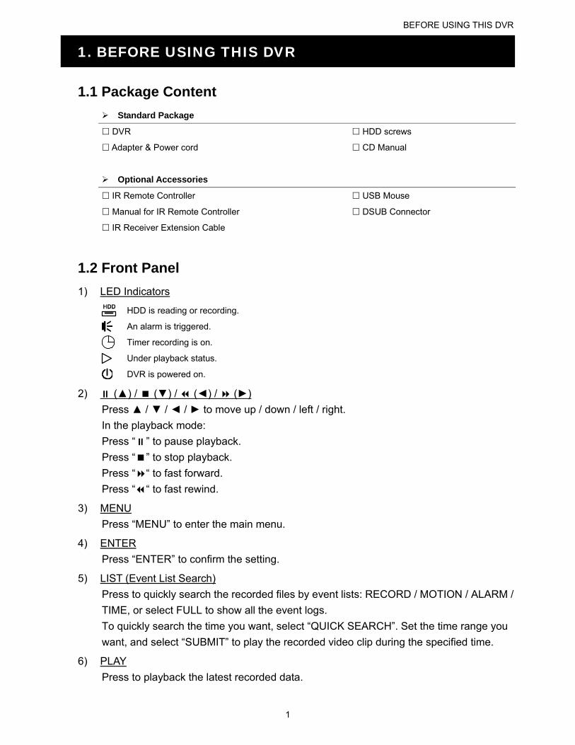
1) LED Indicators
HDD is reading or recording.
An alarm is triggered.
Timer recording is on.
Under playback status.
DVR is powered on.
2) (▲) / (▼) / (◄) / (►)
Press ▲ / ▼ / ◄ / ► to move up / down / left / right.
In the playback mode:
Press “” to pause playback.
Press “” to stop playback.
Press ““ to fast forward.
Press ““ to fast rewind.
3) MENU
Press “MENU” to enter the main menu.
4) ENTER
Press “ENTER” to confirm the setting.
5) LIST (Event List Search)
Press to quickly search the recorded files by event lists: RECORD / MOTION / ALARM /
TIME, or select FULL to show all the event logs.
To quickly search the time you want, select “QUICK SEARCH”. Set the time range you
want, and select “SUBMIT” to play the recorded video clip during the specified time.
6) PLAY
Press to playback the latest recorded data.
BEFORE USING THIS DVR
2
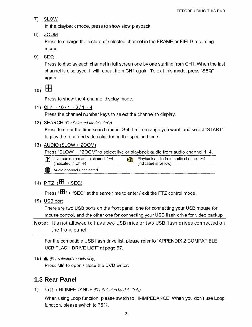
7) SLOW
In the playback mode, press to show slow playback.
8) ZOOM
Press to enlarge the picture of selected channel in the FRAME or FIELD recording
mode.
9) SEQ
Press to display each channel in full screen one by one starting from CH1. When the last
channel is displayed, it will repeat from CH1 again. To exit this mode, press “SEQ”
again.
10)
Press to show the 4-channel display mode.
11) CH1 ~ 16 / 1 ~ 8 / 1 ~ 4
Press the channel number keys to select the channel to display.
12) SEARCH (For Selected Models Only)
Press to enter the time search menu. Set the time range you want, and select “START”
to play the recorded video clip during the specified time.
13) AUDIO (SLOW + ZOOM)
Press “SLOW” + “ZOOM” to select live or playback audio from audio channel 1~4.
Live audio from audio channel 1~4 (indicated in white)
Playback audio from audio channel 1~4 (indicated in yellow)
Audio channel unselected
14) P.T.Z. ( + SEQ)
Press “ ” + “SEQ” at the same time to enter / exit the PTZ control mode.
15) USB port
There are two USB ports on the front panel, one for connecting your USB mouse for
mouse control, and the other one for connecting your USB flash drive for video backup.
Note: It’s not allowed to have two USB mice or two USB flash drives connected on the front panel.
For the compatible USB flash drive list, please refer to “APPENDIX 2 COMPATIBLE
USB FLASH DRIVE LIST” at page 57.
16) (For selected models only)
Press “ ” to open / close the DVD writer.
1.3 Rear Panel
1) 75Ω / HI-IMPEDANCE (For Selected Models Only)
When using Loop function, please switch to HI-IMPEDANCE. When you don’t use Loop
function, please switch to 75Ω.
BEFORE USING THIS DVR
3
2) VIDEO IN (1 ~ 16 / 1 ~ 8 / 1 ~ 4): Connect to the video connector of a camera.
Note: The DVR will automatically detect the video system of the camera, please make sure that the cameras are properly connected to the DVR and power-supplied before the DVR is turned on.
3) AUDIO IN (1 ~ 4)
Connect to the audio connector of a camera if the camera supports audio recording.
Note: To make a video backup with audio, make sure the camera which supports the audio function is connected to the video-in channel and audio-in channel. For example, the audio data from audio CH1 will be recorded with the video data from video CH1.
4) AUDIO OUT
Connect to a speaker with 1 mono audio output.
Note: To know how many audio outputs your DVR supports, please refer to its specifications.
5) MONITOR
Connect to a CRT monitor for video output.
6) VGA
Connect to a LCD monitor directly.
7) IR (For Selected Models Only)
Connect the optional IR receiver extension cable for remote control.
8) EXTERNAL I/O
This port is used to connect external devices (such as speed dome cameras or external
alarm, etc).
For detailed I/O port PIN configuration, please refer to “APPENDIX 6 PIN
CONFIGURATION” at page 62.
9) LAN
Connect to Internet by LAN cable.
10) DC 19V
Connect to the supplied adapter.
11) Power Switch
Switch to “” to turn on the power, and “” to turn off the power.
CONNECTION AND SETUP
4
2. CONNECTION AND SETUP
Before the DVR is powered on, make sure you have installed a hard disk and connected
at least one camera. For details, please refer to the following sections.
Note: The DVR is designed to automatically detect the video system of the connected cameras (NTSC or PAL). To make sure the system detection is correct, please check if the cameras are connected to the DVR and power-supplied before the DVR is powered on.
2.1 SATA HDD Installation
A SATA HDD must be installed before the DVR is powered on.
Note: It’s recommended to clear all data in the hard disk when the DVR is powered on and the date & time are set correctly to ensure the recorded data are not mixed with other data previously saved in the same hard disk. For details, please refer to “5.6.6 Clear All HDD Data” at page 28.
For 2-HDDs Models
Step1: Loose the screws on the upper cover and open the upper cover of the DVR.
Note: The DVR cover is made of metal. Please be careful with its edge when you
remove the cover.
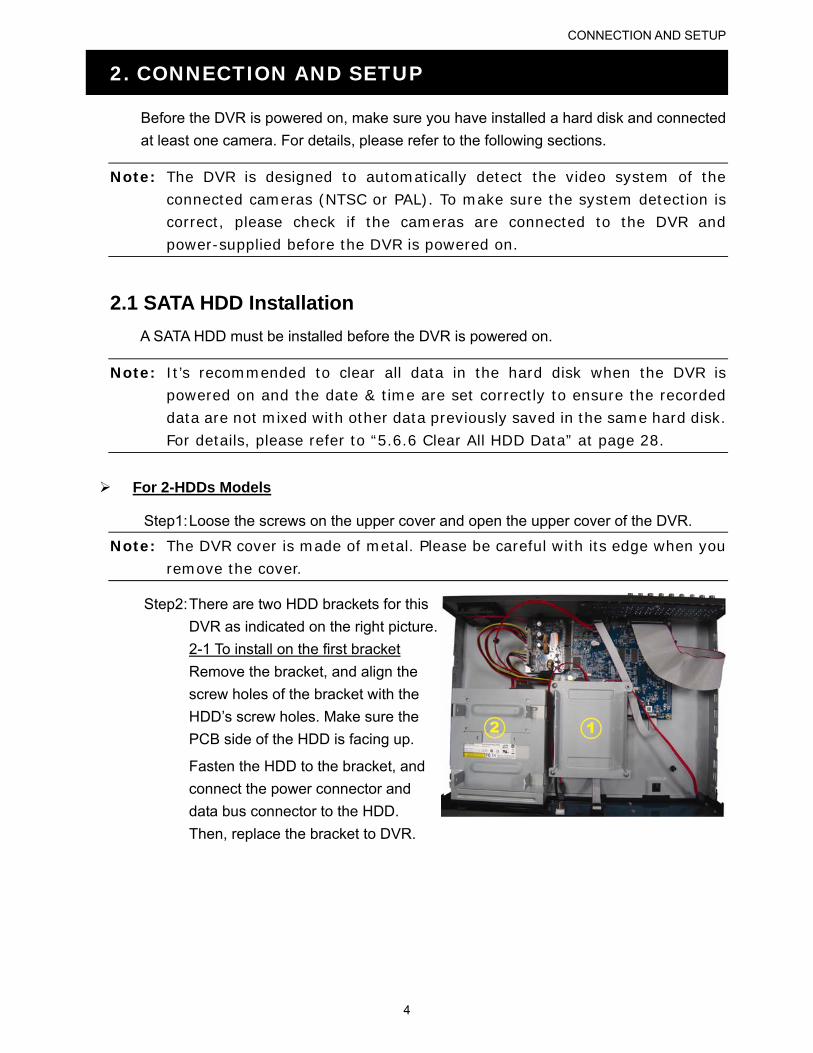
Step2: There are two HDD brackets for this
DVR as indicated on the right picture.
2-1 To install on the first bracket
Remove the bracket, and align the
screw holes of the bracket with the
HDD’s screw holes. Make sure the
PCB side of the HDD is facing up.
Fasten the HDD to the bracket, and
connect the power connector and
data bus connector to the HDD.
Then, replace the bracket to DVR.
CONNECTION AND SETUP
5
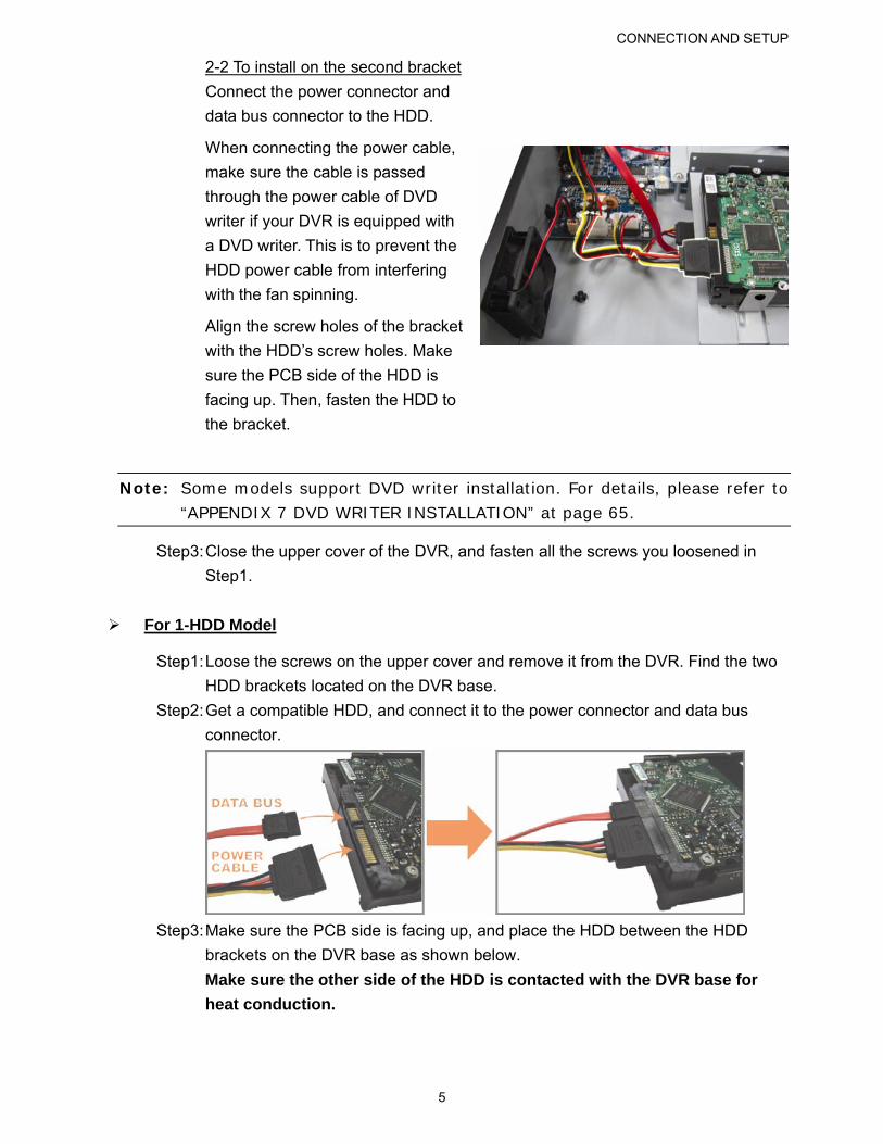
2-2 To install on the second bracket
Connect the power connector and
data bus connector to the HDD.
When connecting the power cable,
make sure the cable is passed
through the power cable of DVD
writer if your DVR is equipped with
a DVD writer. This is to prevent the
HDD power cable from interfering
with the fan spinning.
Align the screw holes of the bracket
with the HDD’s screw holes. Make
sure the PCB side of the HDD is
facing up. Then, fasten the HDD to
the bracket.
Note: Some models support DVD writer installation. For details, please refer to “APPENDIX 7 DVD WRITER INSTALLATION” at page 65.
Step3: Close the upper cover of the DVR, and fasten all the screws you loosened in
Step1.
For 1-HDD Model
Step1: Loose the screws on the upper cover and remove it from the DVR. Find the two
HDD brackets located on the DVR base.
Step2: Get a compatible HDD, and connect it to the power connector and data bus
connector.
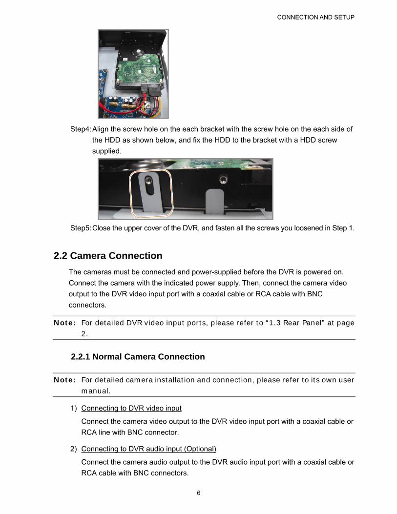
Step3: Make sure the PCB side is facing up, and place the HDD between the HDD
brackets on the DVR base as shown below.
Make sure the other side of the HDD is contacted with the DVR base for
heat conduction.
CONNECTION AND SETUP
6
Step4: Align the screw hole on the each bracket with the screw hole on the each side of
the HDD as shown below, and fix the HDD to the bracket with a HDD screw
supplied.
Step5: Close the upper cover of the DVR, and fasten all the screws you loosened in Step 1.
2.2 Camera Connection
The cameras must be connected and power-supplied before the DVR is powered on.
Connect the camera with the indicated power supply. Then, connect the camera video
output to the DVR video input port with a coaxial cable or RCA cable with BNC
connectors.
Note: For detailed DVR video input ports, please refer to “1.3 Rear Panel” at page 2.
2.2.1 Normal Camera Connection
Note: For detailed camera installation and connection, please refer to its own user manual.
1) Connecting to DVR video input
Connect the camera video output to the DVR video input port with a coaxial cable or
RCA line with BNC connector.
2) Connecting to DVR audio input (Optional)
Connect the camera audio output to the DVR audio input port with a coaxial cable or
RCA cable with BNC connectors.
CONNECTION AND SETUP
7
3) Connecting to power
Connect the camera with indicated power supply and make sure it’s power-supplied.
2.2.2 PTZ Camera Connection (For Selected Models Only)
The following description is taking our brand’s PTZ camera as an example.
For DVR setting to control the PTZ camera, please refer to “5.5 PTZ Camera Setting” at
page 24. For detailed PTZ camera control and operation, please refer to its own user
manual.
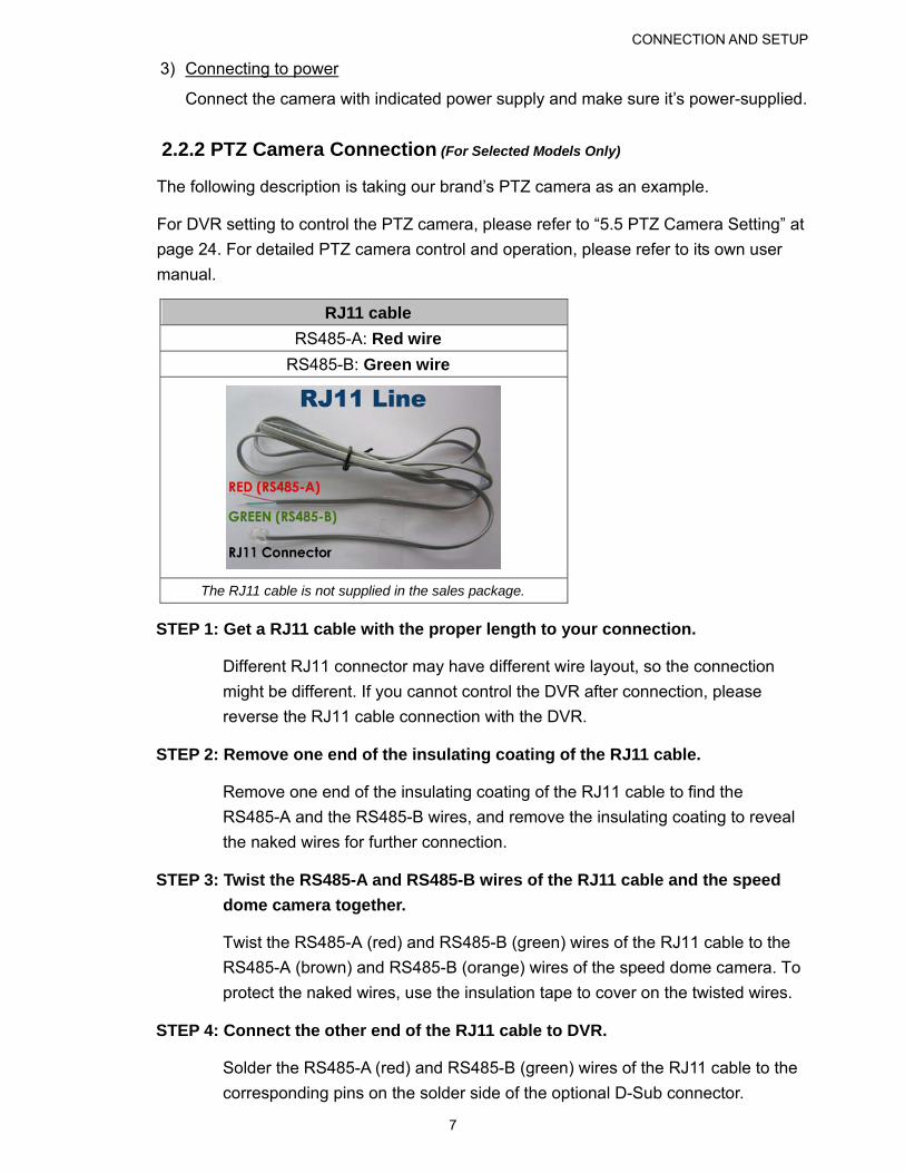
RJ11 cable
RS485-A: Red wire
RS485-B: Green wire
The RJ11 cable is not supplied in the sales package.
STEP 1: Get a RJ11 cable with the proper length to your connection.
Different RJ11 connector may have different wire layout, so the connection
might be different. If you cannot control the DVR after connection, please
reverse the RJ11 cable connection with the DVR.
STEP 2: Remove one end of the insulating coating of the RJ11 cable.
Remove one end of the insulating coating of the RJ11 cable to find the
RS485-A and the RS485-B wires, and remove the insulating coating to reveal
the naked wires for further connection.
STEP 3: Twist the RS485-A and RS485-B wires of the RJ11 cable and the speed
dome camera together.
Twist the RS485-A (red) and RS485-B (green) wires of the RJ11 cable to the
RS485-A (brown) and RS485-B (orange) wires of the speed dome camera. To
protect the naked wires, use the insulation tape to cover on the twisted wires.
STEP 4: Connect the other end of the RJ11 cable to DVR.
Solder the RS485-A (red) and RS485-B (green) wires of the RJ11 cable to the
corresponding pins on the solder side of the optional D-Sub connector.
CONNECTION AND SETUP
8
For DVR PIN configuration, please refer to “APPENDIX 6 PIN
CONFIGURATION” at page 62. For connection details, please check with your
installer.
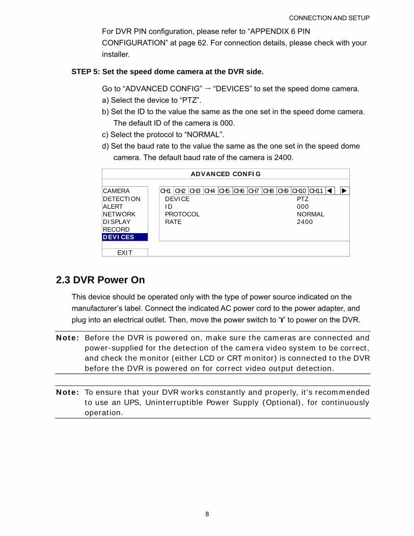
STEP 5: Set the speed dome camera at the DVR side.
Go to “ADVANCED CONFIG” “DEVICES” to set the speed dome camera.
a) Select the device to “PTZ”.
b) Set the ID to the value the same as the one set in the speed dome camera.
The default ID of the camera is 000.
c) Select the protocol to “NORMAL”.
d) Set the baud rate to the value the same as the one set in the speed dome
camera. The default baud rate of the camera is 2400.
ADVANCED CONFIG
CAMERA CH1 CH2 CH3 CH4 CH5 CH6 CH7 CH8 CH9 CH10 CH11 DETECTION DEVICE PTZ ALERT ID 000 NETWORK PROTOCOL NORMAL DISPLAY RATE 2400 RECORD DEVICES
EXIT
2.3 DVR Power On
This device should be operated only with the type of power source indicated on the
manufacturer’s label. Connect the indicated AC power cord to the power adapter, and
plug into an electrical outlet. Then, move the power switch to “” to power on the DVR.
Note: Before the DVR is powered on, make sure the cameras are connected and power-supplied for the detection of the camera video system to be correct, and check the monitor (either LCD or CRT monitor) is connected to the DVR before the DVR is powered on for correct video output detection.
Note: To ensure that your DVR works constantly and properly, it's recommended to use an UPS, Uninterruptible Power Supply (Optional), for continuously operation.
CONNECTION AND SETUP
9
2.4 Date and Time Setting
Before operating your DVR, please set the date and time on your DVR FIRST.
Note: Please DO NOT change the date or time of your DVR after the recording function is activated. Otherwise, the recorded data will be disordered and you will not be able to find the recorded file to backup by time search. If users change the date or time accidentally when the recording function is activated, it’s recommended to clear all HDD data, and start recording again.
Note: For the first time to use the DVR, please power it on for at least 48 hours continuously after the date & time is set correctly. It helps to prevent DVR time from resetting after the disconnecting of DVR power. If the DVR time resets after the disconnecting of DVR power, for example, caused by a power outage, the battery might run out and please replace the battery as described in “APPENDIX 5 DVR BATTERY REPLACEMENT” at page 61.
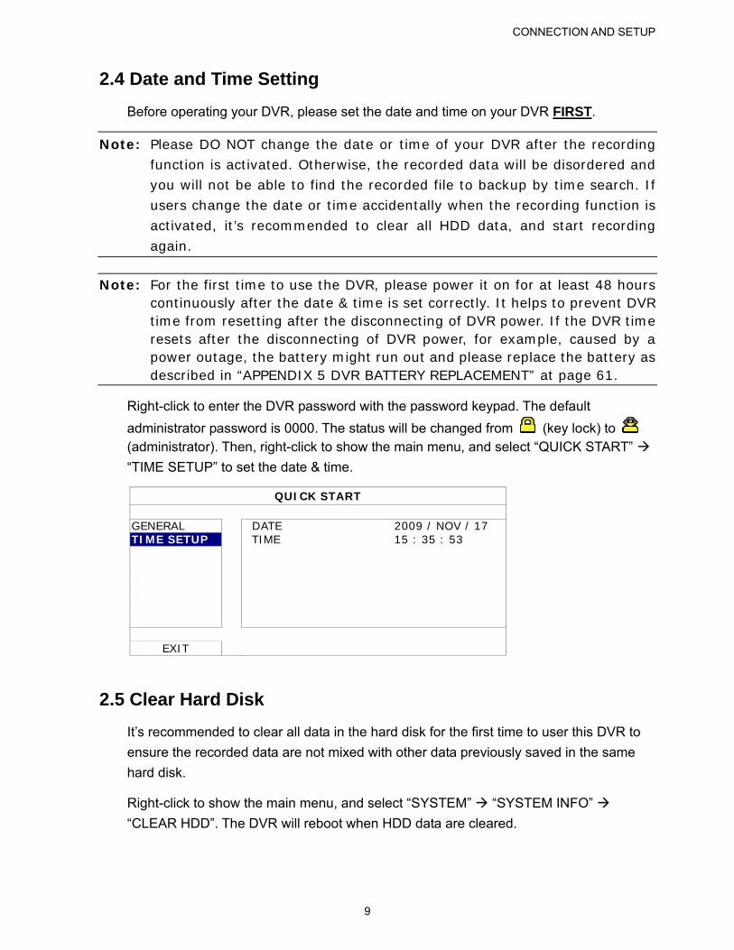
Right-click to enter the DVR password with the password keypad. The default
administrator password is 0000. The status will be changed from (key lock) to (administrator). Then, right-click to show the main menu, and select “QUICK START”
“TIME SETUP” to set the date & time.
QUICK START
GENERAL DATE 2009 / NOV / 17 TIME SETUP TIME 15 : 35 : 53
EXIT
2.5 Clear Hard Disk
It’s recommended to clear all data in the hard disk for the first time to user this DVR to
ensure the recorded data are not mixed with other data previously saved in the same
hard disk.
Right-click to show the main menu, and select “SYSTEM” “SYSTEM INFO”
“CLEAR HDD”. The DVR will reboot when HDD data are cleared.
CONNECTION AND SETUP
10
SYSTEM
TOOLS BAUD RATE 2400 SYSTEM INFO HOST ID 000 BACKUP DATA (USB) AUTO KEY LOCK NEVER BACKUP LOG (USB) CLEAR HDD HDD-0 RESET DEFAULT SUBMIT REMOTE CONTROL ID 000 SERIAL TYPE RS485 VIDEO FORMAT NTSC VERSION 1025-1011-1011-1012
EXIT
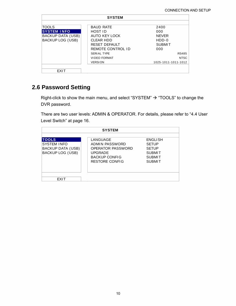
2.6 Password Setting
Right-click to show the main menu, and select “SYSTEM” “TOOLS” to change the
DVR password.
There are two user levels: ADMIN & OPERATOR. For details, please refer to “4.4 User
Level Switch” at page 16.
SYSTEM
TOOLS LANGUAGE ENGLISH SYSTEM INFO ADMIN PASSWORD SETUP BACKUP DATA (USB) OPERATOR PASSWORD SETUP BACKUP LOG (USB) UPGRADE SUBMIT BACKUP CONFIG SUBMIT RESTORE CONFIG SUBMIT
EXIT
GUI DISPLAY WITH USB MOUSE CONTROL
11
3. GUI DISPLAY WITH USB MOUSE CONTROL
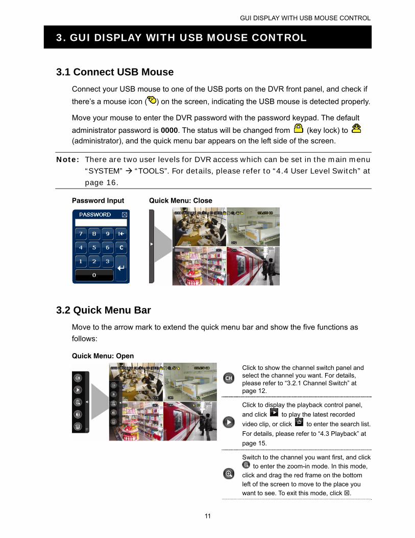
3.1 Connect USB Mouse
Connect your USB mouse to one of the USB ports on the DVR front panel, and check if
there’s a mouse icon ( ) on the screen, indicating the USB mouse is detected properly.
Move your mouse to enter the DVR password with the password keypad. The default
administrator password is 0000. The status will be changed from (key lock) to (administrator), and the quick menu bar appears on the left side of the screen.
Note: There are two user levels for DVR access which can be set in the main menu “SYSTEM” “TOOLS”. For details, please refer to “4.4 User Level Switch” at
page 16.
Password Input Quick Menu: Close
3.2 Quick Menu Bar
Move to the arrow mark to extend the quick menu bar and show the five functions as
follows:
Quick Menu: Open
Click to show the channel switch panel and select the channel you want. For details, please refer to “3.2.1 Channel Switch” at page 12.
Click to display the playback control panel,
and click to play the latest recorded
video clip, or click to enter the search list.
For details, please refer to “4.3 Playback” at
page 15.
Switch to the channel you want first, and click to enter the zoom-in mode. In this mode,
click and drag the red frame on the bottom
left of the screen to move to the place you want to see. To exit this mode, click .
GUI DISPLAY WITH USB MOUSE CONTROL
12
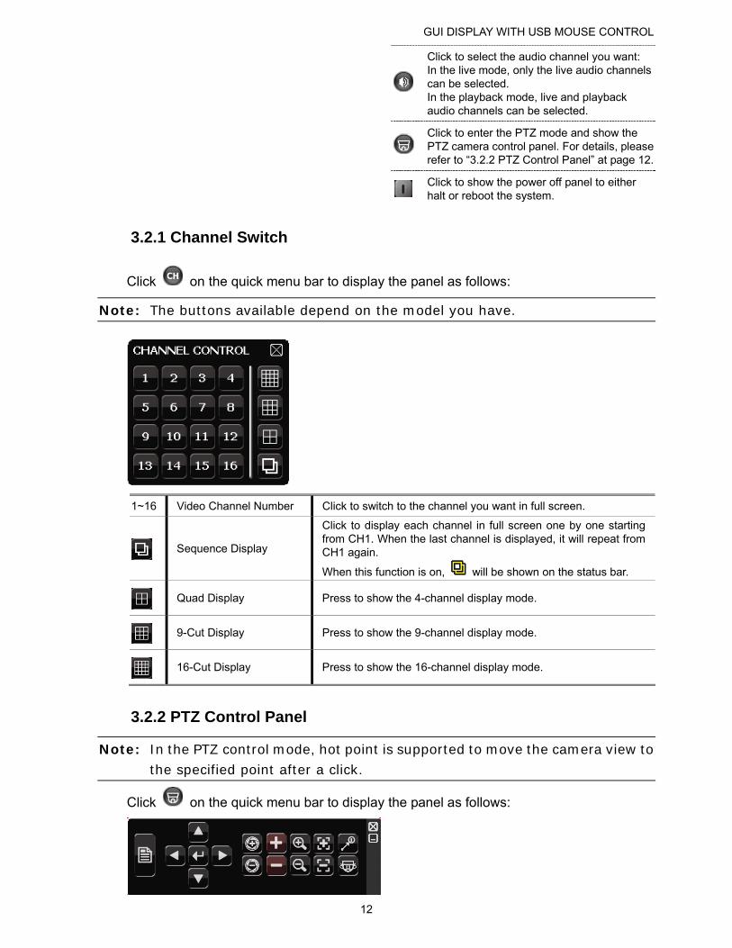
Click to select the audio channel you want: In the live mode, only the live audio channels can be selected. In the playback mode, live and playback audio channels can be selected.
Click to enter the PTZ mode and show the PTZ camera control panel. For details, please refer to “3.2.2 PTZ Control Panel” at page 12.
Click to show the power off panel to either halt or reboot the system.
3.2.1 Channel Switch
Click on the quick menu bar to display the panel as follows:
Note: The buttons available depend on the model you have.
1~16 Video Channel Number Click to switch to the channel you want in full screen.
Sequence Display
Click to display each channel in full screen one by one starting from CH1. When the last channel is displayed, it will repeat from CH1 again.
When this function is on, will be shown on the status bar.
Quad Display Press to show the 4-channel display mode.
9-Cut Display Press to show the 9-channel display mode.
16-Cut Display Press to show the 16-channel display mode.
3.2.2 PTZ Control Panel
Note: In the PTZ control mode, hot point is supported to move the camera view to the specified point after a click.
Click on the quick menu bar to display the panel as follows:
GUI DISPLAY WITH USB MOUSE CONTROL
13
Camera Menu
Click to enter the camera main menu. For details about each camera menu, please refer to its own user manual.
Enter Click to confirm your selection / enter the menu.
/ / /
Up / Down / Left /
Right
Click to move your selection up / down / left / right, or change settings.
/ Iris + / Iris - This two buttons are designed for the PTZ camera
which uses Pelco-D to control. To know the actions after clicking Iris + and Iris -, please refer to the camera’s user manual.
/ Zoom in / out max Click to zoom in on the image to the largest / zoom out on the image to its original size.
/ Zoom in / out Click to zoom in / out the image.
/ Focus near / far Click to adjust the focus of the image.
Auto mode Click to activate the auto function. Before using it, you need to assign a specific function that will be enabled when “AUTO” is clicked. For details, please refer to the user manual of the PTZ camera.
Preset point Click to enter the PTZ preset point you want to see.
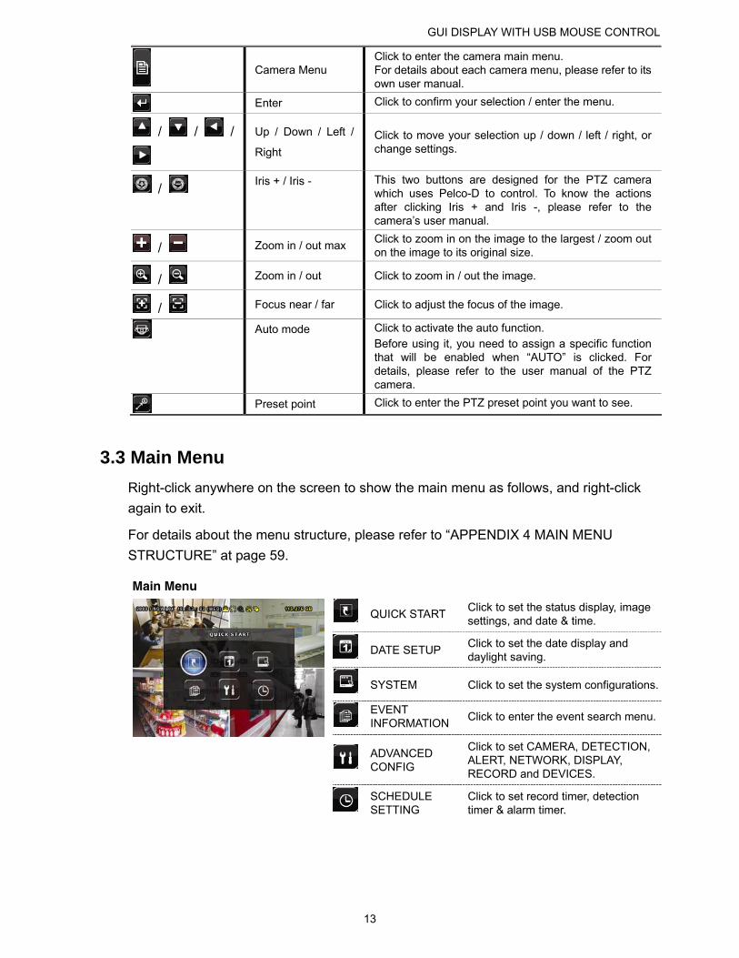
3.3 Main Menu
Right-click anywhere on the screen to show the main menu as follows, and right-click
again to exit.
For details about the menu structure, please refer to “APPENDIX 4 MAIN MENU
STRUCTURE” at page 59.
Main Menu
QUICK START Click to set the status display, image settings, and date & time.
DATE SETUP Click to set the date display and daylight saving.
SYSTEM Click to set the system configurations.
EVENT INFORMATION
Click to enter the event search menu.
ADVANCED CONFIG
Click to set CAMERA, DETECTION, ALERT, NETWORK, DISPLAY, RECORD and DEVICES.
SCHEDULE SETTING
Click to set record timer, detection timer & alarm timer.
BASIC OPERATION
14
4. BASIC OPERATION
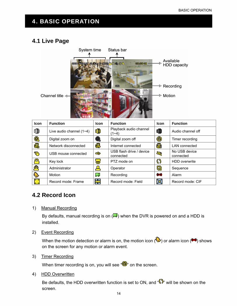
4.1 Live Page
Icon Function Icon Function Icon Function
Live audio channel (1~4) Playback audio channel (1~4) Audio channel off
Digital zoom on Digital zoom off Timer recording
Network disconnected Internet connected LAN connected
USB mouse connected USB flash drive / device connected
No USB device connected
Key lock PTZ mode on HDD overwrite
Administrator Operator Sequence
Motion Recording Alarm
Record mode: Frame Record mode: Field Record mode: CIF
4.2 Record Icon
1) Manual Recording
By defaults, manual recording is on ( ) when the DVR is powered on and a HDD is
installed.
2) Event Recording
When the motion detection or alarm is on, the motion icon ( ) or alarm icon ( ) shows on the screen for any motion or alarm event.
3) Timer Recording
When timer recording is on, you will see “ ” on the screen.
4) HDD Overwritten
Be defaults, the HDD overwritten function is set to ON, and “ ” will be shown on the screen.
BASIC OPERATION
15
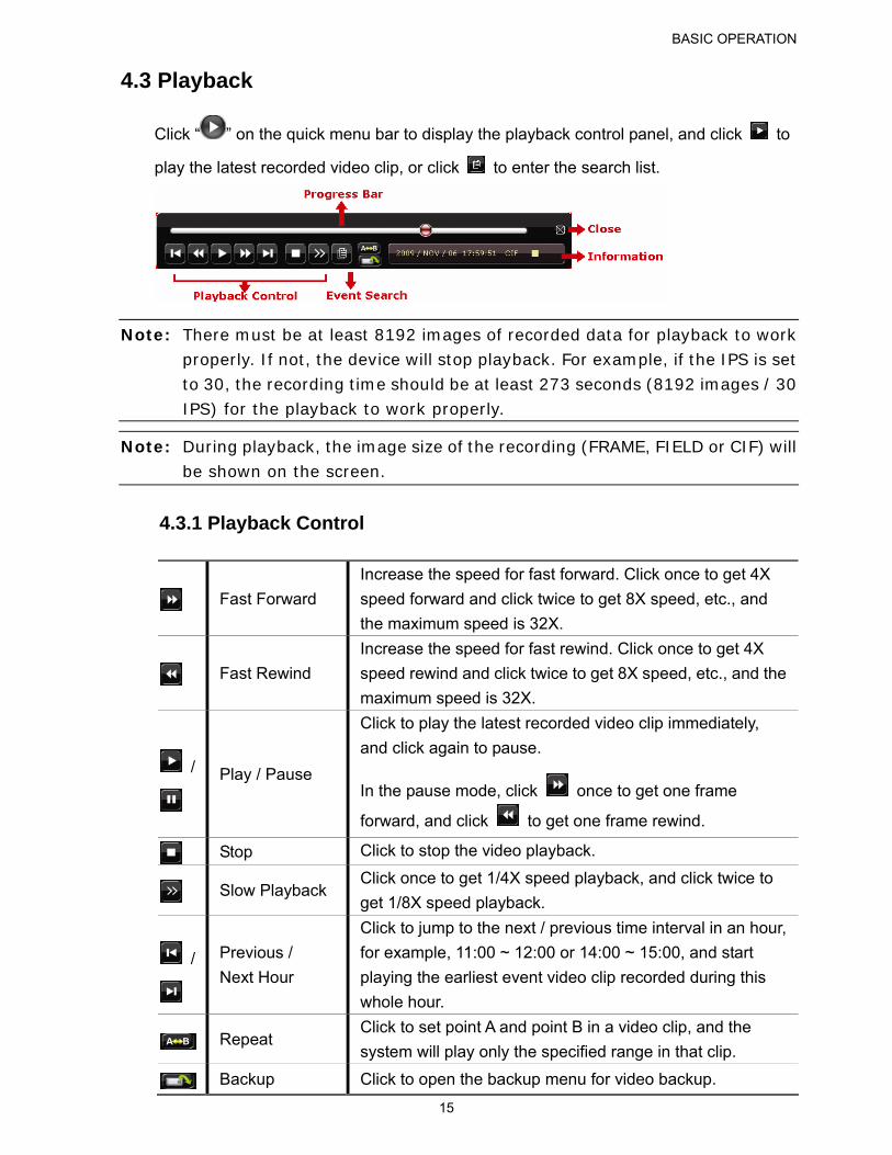
4.3 Playback
Click “ ” on the quick menu bar to display the playback control panel, and click to
play the latest recorded video clip, or click to enter the search list.
Note: There must be at least 8192 images of recorded data for playback to work properly. If not, the device will stop playback. For example, if the IPS is set to 30, the recording time should be at least 273 seconds (8192 images / 30 IPS) for the playback to work properly.
Note: During playback, the image size of the recording (FRAME, FIELD or CIF) will be shown on the screen.
4.3.1 Playback Control
Fast Forward
Increase the speed for fast forward. Click once to get 4X
speed forward and click twice to get 8X speed, etc., and
the maximum speed is 32X.
Fast Rewind
Increase the speed for fast rewind. Click once to get 4X
speed rewind and click twice to get 8X speed, etc., and the
maximum speed is 32X.
/
Play / Pause
Click to play the latest recorded video clip immediately,
and click again to pause.
In the pause mode, click once to get one frame
forward, and click to get one frame rewind.
Stop Click to stop the video playback.
Slow Playback Click once to get 1/4X speed playback, and click twice to
get 1/8X speed playback.
/
Previous /
Next Hour
Click to jump to the next / previous time interval in an hour,
for example, 11:00 ~ 12:00 or 14:00 ~ 15:00, and start
playing the earliest event video clip recorded during this
whole hour.
Repeat Click to set point A and point B in a video clip, and the
system will play only the specified range in that clip.
Backup Click to open the backup menu for video backup.
BASIC OPERATION
16
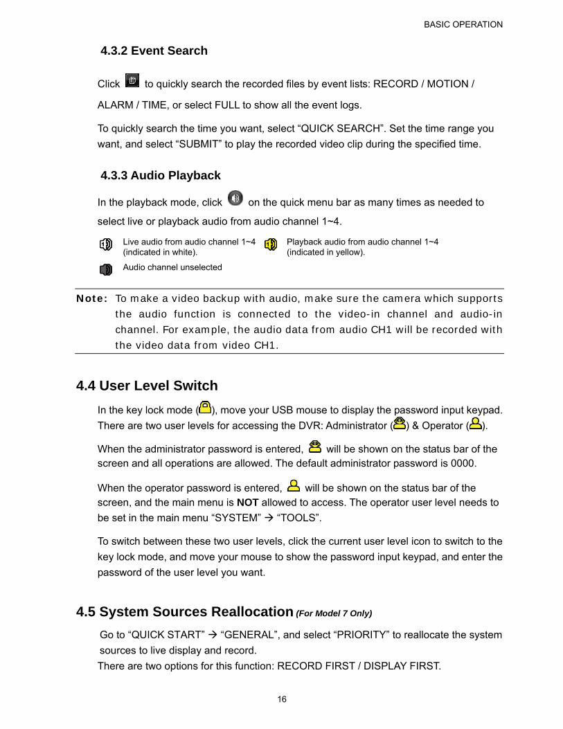
4.3.2 Event Search
Click to quickly search the recorded files by event lists: RECORD / MOTION /
ALARM / TIME, or select FULL to show all the event logs.
To quickly search the time you want, select “QUICK SEARCH”. Set the time range you
want, and select “SUBMIT” to play the recorded video clip during the specified time.
4.3.3 Audio Playback
In the playback mode, click on the quick menu bar as many times as needed to
select live or playback audio from audio channel 1~4.
Live audio from audio channel 1~4 (indicated in white).
Playback audio from audio channel 1~4 (indicated in yellow).
Audio channel unselected
Note: To make a video backup with audio, make sure the camera which supports the audio function is connected to the video-in channel and audio-in channel. For example, the audio data from audio CH1 will be recorded with the video data from video CH1.
4.4 User Level Switch
In the key lock mode ( ), move your USB mouse to display the password input keypad.
There are two user levels for accessing the DVR: Administrator ( ) & Operator ( ).
When the administrator password is entered, will be shown on the status bar of the screen and all operations are allowed. The default administrator password is 0000.
When the operator password is entered, will be shown on the status bar of the screen, and the main menu is NOT allowed to access. The operator user level needs to
be set in the main menu “SYSTEM” “TOOLS”.
To switch between these two user levels, click the current user level icon to switch to the
key lock mode, and move your mouse to show the password input keypad, and enter the
password of the user level you want.
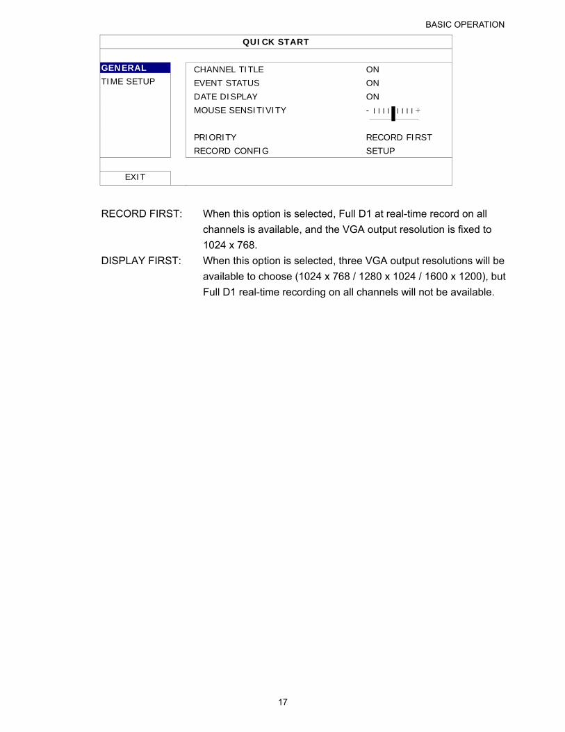
4.5 System Sources Reallocation (For Model 7 Only)
Go to “QUICK START” “GENERAL”, and select “PRIORITY” to reallocate the system
sources to live display and record.
There are two options for this function: RECORD FIRST / DISPLAY FIRST.
BASIC OPERATION
17
QUICK START
GENERAL CHANNEL TITLE ON TIME SETUP EVENT STATUS ON DATE DISPLAY ON MOUSE SENSITIVITY - ׀ ׀ ׀ ׀ ׀ ׀ ׀ ׀ ׀ + PRIORITY RECORD FIRST RECORD CONFIG SETUP
EXIT
RECORD FIRST: When this option is selected, Full D1 at real-time record on all
channels is available, and the VGA output resolution is fixed to
1024 x 768.
DISPLAY FIRST: When this option is selected, three VGA output resolutions will be
available to choose (1024 x 768 / 1280 x 1024 / 1600 x 1200), but
Full D1 real-time recording on all channels will not be available.
FREQUENTLY-USED FUNCTIONS
18
5. FREQUENTLY-USED FUNCTIONS
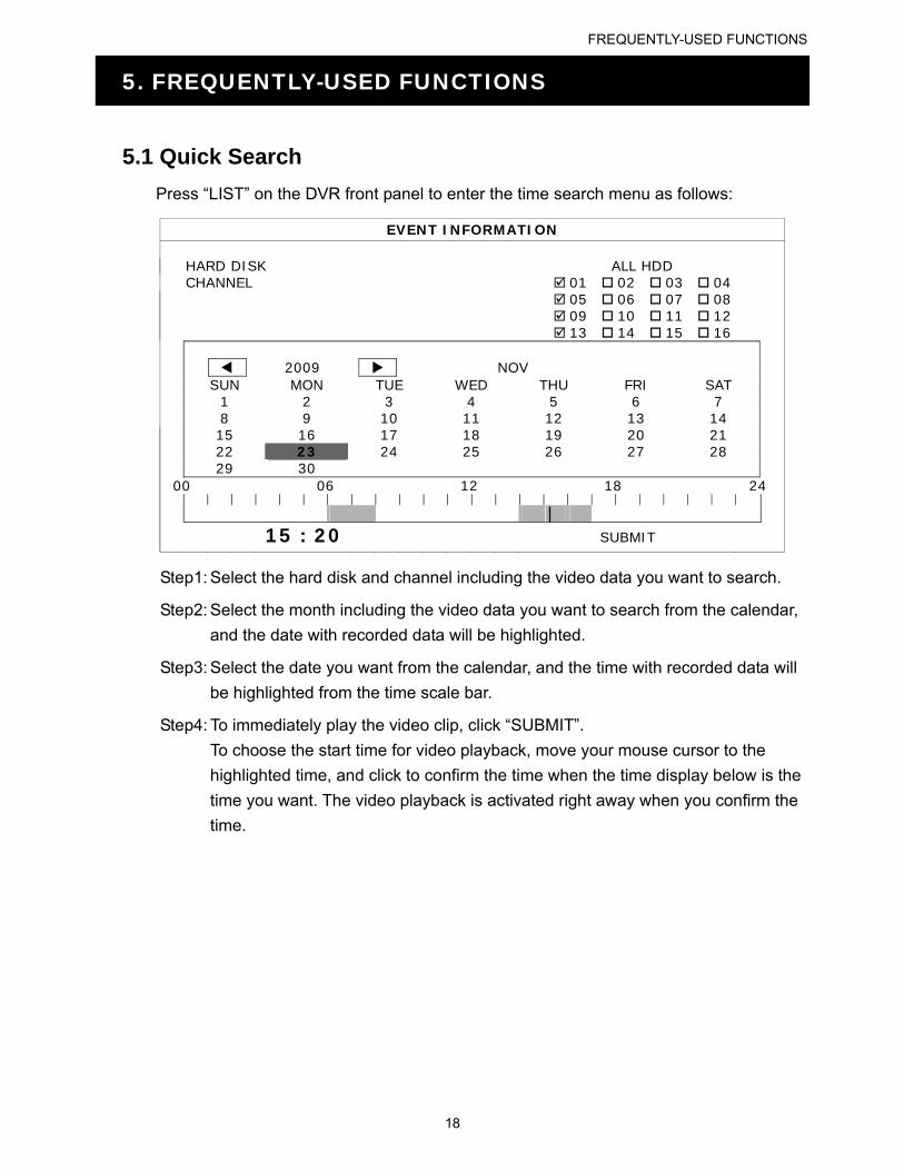
5.1 Quick Search
Press “LIST” on the DVR front panel to enter the time search menu as follows:
EVENT INFORMATION HARD DISK ALL HDD CHANNEL 01 02 03 04 05 06 07 08 09 10 11 12 13 14 15 16 2009 NOV SUN MON TUE WED THU FRI SAT 1 2 3 4 5 6 7 8 9 10 11 12 13 14 15 16 17 18 19 20 21 22 23 24 25 26 27 28 29 30 00 06 12 18 24
15 : 20 SUBMIT
Step1: Select the hard disk and channel including the video data you want to search.
Step2: Select the month including the video data you want to search from the calendar,
and the date with recorded data will be highlighted.
Step3: Select the date you want from the calendar, and the time with recorded data will
be highlighted from the time scale bar.
Step4: To immediately play the video clip, click “SUBMIT”.
To choose the start time for video playback, move your mouse cursor to the
highlighted time, and click to confirm the time when the time display below is the
time you want. The video playback is activated right away when you confirm the
time.
FREQUENTLY-USED FUNCTIONS
19
5.2 Record
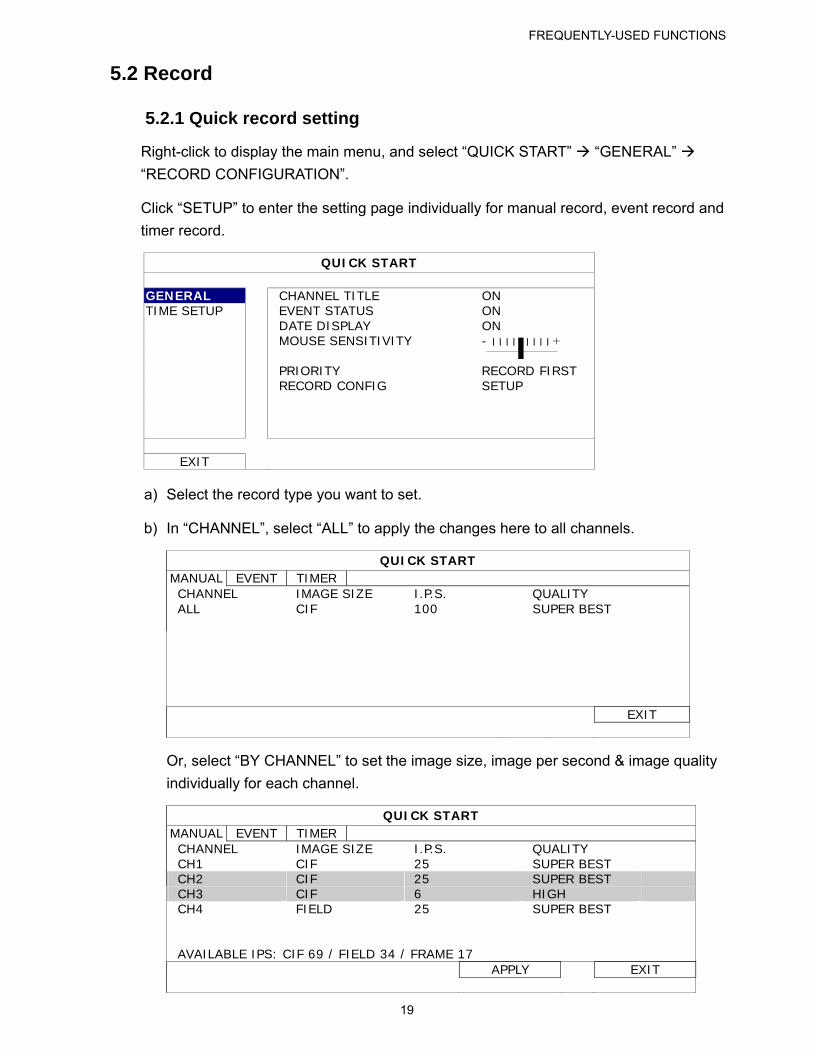
5.2.1 Quick record setting
Right-click to display the main menu, and select “QUICK START” “GENERAL”
“RECORD CONFIGURATION”.
Click “SETUP” to enter the setting page individually for manual record, event record and
timer record.
QUICK START
GENERAL CHANNEL TITLE ON TIME SETUP EVENT STATUS ON DATE DISPLAY ON MOUSE SENSITIVITY - ׀ ׀ ׀ ׀ ׀ ׀ ׀ ׀ ׀ + PRIORITY RECORD FIRST RECORD CONFIG SETUP
EXIT
a) Select the record type you want to set.
b) In “CHANNEL”, select “ALL” to apply the changes here to all channels.
QUICK START MANUAL EVENT TIMER CHANNEL IMAGE SIZE I.P.S. QUALITY ALL CIF 100 SUPER BEST
EXIT
Or, select “BY CHANNEL” to set the image size, image per second & image quality
individually for each channel.
QUICK START MANUAL EVENT TIMER CHANNEL IMAGE SIZE I.P.S. QUALITY CH1 CIF 25 SUPER BEST CH2 CIF 25 SUPER BEST CH3 CIF 6 HIGH CH4 FIELD 25 SUPER BEST AVAILABLE IPS: CIF 69 / FIELD 34 / FRAME 17
APPLY EXIT
FREQUENTLY-USED FUNCTIONS
20
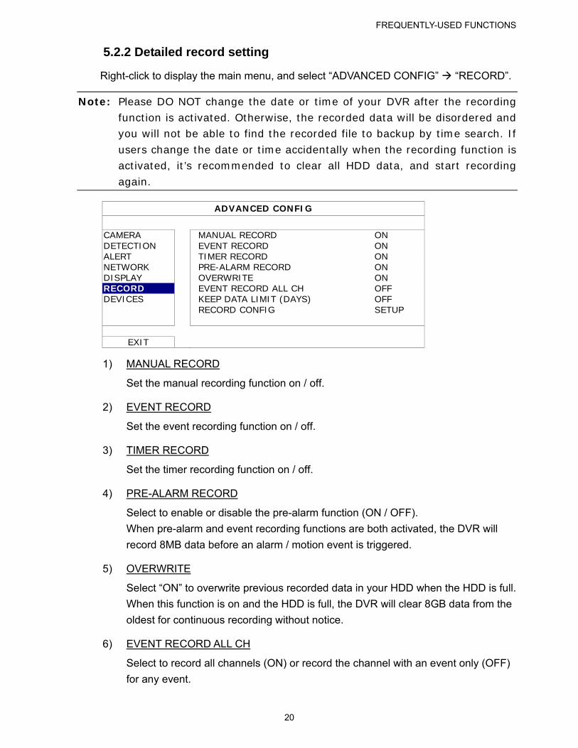
5.2.2 Detailed record setting
Right-click to display the main menu, and select “ADVANCED CONFIG” “RECORD”.
Note: Please DO NOT change the date or time of your DVR after the recording function is activated. Otherwise, the recorded data will be disordered and you will not be able to find the recorded file to backup by time search. If users change the date or time accidentally when the recording function is activated, it’s recommended to clear all HDD data, and start recording again.
ADVANCED CONFIG
CAMERA MANUAL RECORD ON DETECTION EVENT RECORD ON ALERT TIMER RECORD ON NETWORK PRE-ALARM RECORD ON DISPLAY OVERWRITE ON RECORD EVENT RECORD ALL CH OFF DEVICES KEEP DATA LIMIT (DAYS) OFF RECORD CONFIG SETUP
EXIT
1) MANUAL RECORD
Set the manual recording function on / off.
2) EVENT RECORD
Set the event recording function on / off.
3) TIMER RECORD
Set the timer recording function on / off.
4) PRE-ALARM RECORD
Select to enable or disable the pre-alarm function (ON / OFF).
When pre-alarm and event recording functions are both activated, the DVR will
record 8MB data before an alarm / motion event is triggered.
5) OVERWRITE
Select “ON” to overwrite previous recorded data in your HDD when the HDD is full.
When this function is on and the HDD is full, the DVR will clear 8GB data from the
oldest for continuous recording without notice.
6) EVENT RECORD ALL CH
Select to record all channels (ON) or record the channel with an event only (OFF)
for any event.
FREQUENTLY-USED FUNCTIONS
21
7) KEEP DATA LIMIT (DAYS)
Assign the maximum recording days from 01 to 31 after which all the recorded data
will be removed, or select “OFF” to disable this function.
8) RECORD CONFIG
Please refer to “5.2.1 Quick record setting”.
5.3 Schedule Setting
Right-click to display the main menu, and select “SCHEDULE SETTING”.
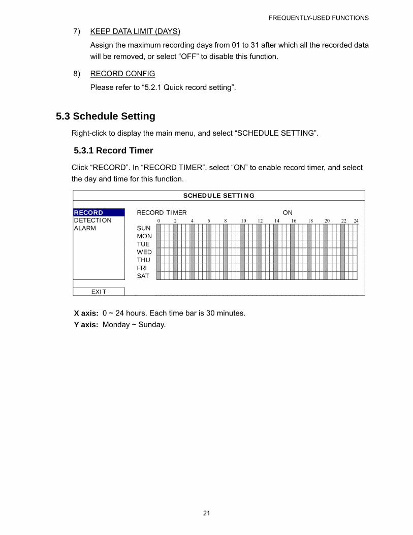
5.3.1 Record Timer
Click “RECORD”. In “RECORD TIMER”, select “ON” to enable record timer, and select
the day and time for this function.
SCHEDULE SETTING
RECORD RECORD TIMER ON DETECTION 0 2 4 6 8 10 12 14 16 18 20 22 24 ALARM SUN
MON
TUE
WED
THU
FRI
SAT
EXIT
X axis: 0 ~ 24 hours. Each time bar is 30 minutes.
Y axis: Monday ~ Sunday.
FREQUENTLY-USED FUNCTIONS
22
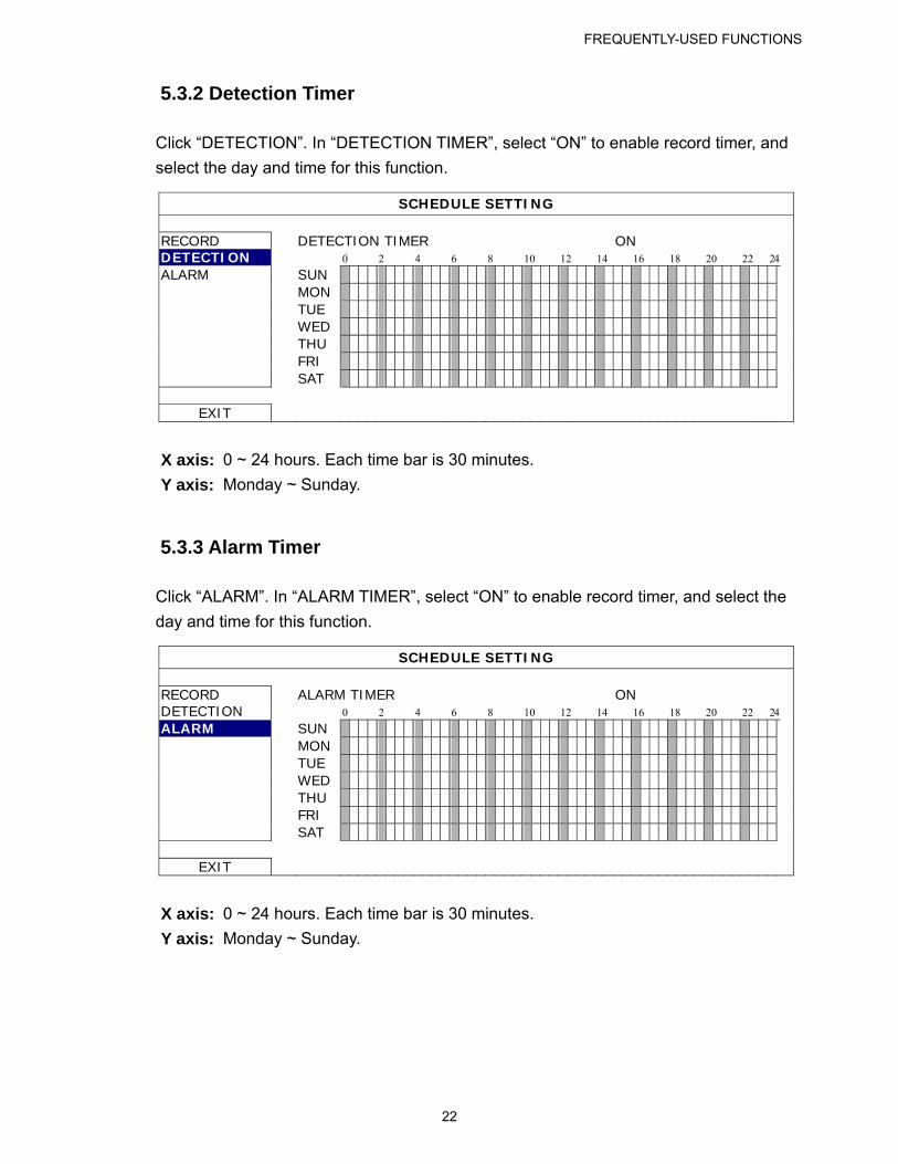
5.3.2 Detection Timer
Click “DETECTION”. In “DETECTION TIMER”, select “ON” to enable record timer, and
select the day and time for this function.
SCHEDULE SETTING
RECORD DETECTION TIMER ON DETECTION 0 2 4 6 8 10 12 14 16 18 20 22 24 ALARM SUN
MON
TUE
WED
THU
FRI
SAT
EXIT
X axis: 0 ~ 24 hours. Each time bar is 30 minutes.
Y axis: Monday ~ Sunday.
5.3.3 Alarm Timer
Click “ALARM”. In “ALARM TIMER”, select “ON” to enable record timer, and select the
day and time for this function.
SCHEDULE SETTING
RECORD ALARM TIMER ON DETECTION 0 2 4 6 8 10 12 14 16 18 20 22 24 ALARM SUN
MON
TUE
WED
THU
FRI
SAT
EXIT
X axis: 0 ~ 24 hours. Each time bar is 30 minutes.
Y axis: Monday ~ Sunday.
FREQUENTLY-USED FUNCTIONS
23
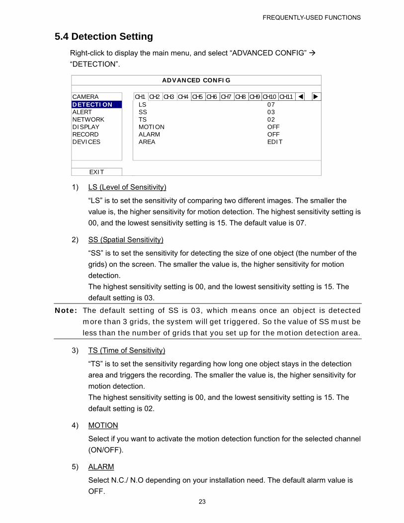
5.4 Detection Setting
Right-click to display the main menu, and select “ADVANCED CONFIG”
“DETECTION”.
ADVANCED CONFIG
CAMERA CH1 CH2 CH3 CH4 CH5 CH6 CH7 CH8 CH9 CH10 CH11 DETECTION LS 07 ALERT SS 03 NETWORK TS 02 DISPLAY MOTION OFF RECORD ALARM OFF DEVICES AREA EDIT
EXIT
1) LS (Level of Sensitivity)
“LS” is to set the sensitivity of comparing two different images. The smaller the
value is, the higher sensitivity for motion detection. The highest sensitivity setting is
00, and the lowest sensitivity setting is 15. The default value is 07.
2) SS (Spatial Sensitivity)
“SS” is to set the sensitivity for detecting the size of one object (the number of the
grids) on the screen. The smaller the value is, the higher sensitivity for motion
detection.
The highest sensitivity setting is 00, and the lowest sensitivity setting is 15. The
default setting is 03.
Note: The default setting of SS is 03, which means once an object is detected more than 3 grids, the system will get triggered. So the value of SS must be
less than the number of grids that you set up for the motion detection area.
3) TS (Time of Sensitivity)
“TS” is to set the sensitivity regarding how long one object stays in the detection
area and triggers the recording. The smaller the value is, the higher sensitivity for
motion detection.
The highest sensitivity setting is 00, and the lowest sensitivity setting is 15. The
default setting is 02.
4) MOTION
Select if you want to activate the motion detection function for the selected channel
(ON/OFF).
5) ALARM
Select N.C./ N.O depending on your installation need. The default alarm value is
OFF.
FREQUENTLY-USED FUNCTIONS
24
6) AREA
Click “EDIT” to set the motion detection area.
There are 16 × 12 grids per camera for all channels. Pink blocks represent the area
that is not being detected while the transparent blocks are the area under
detection.
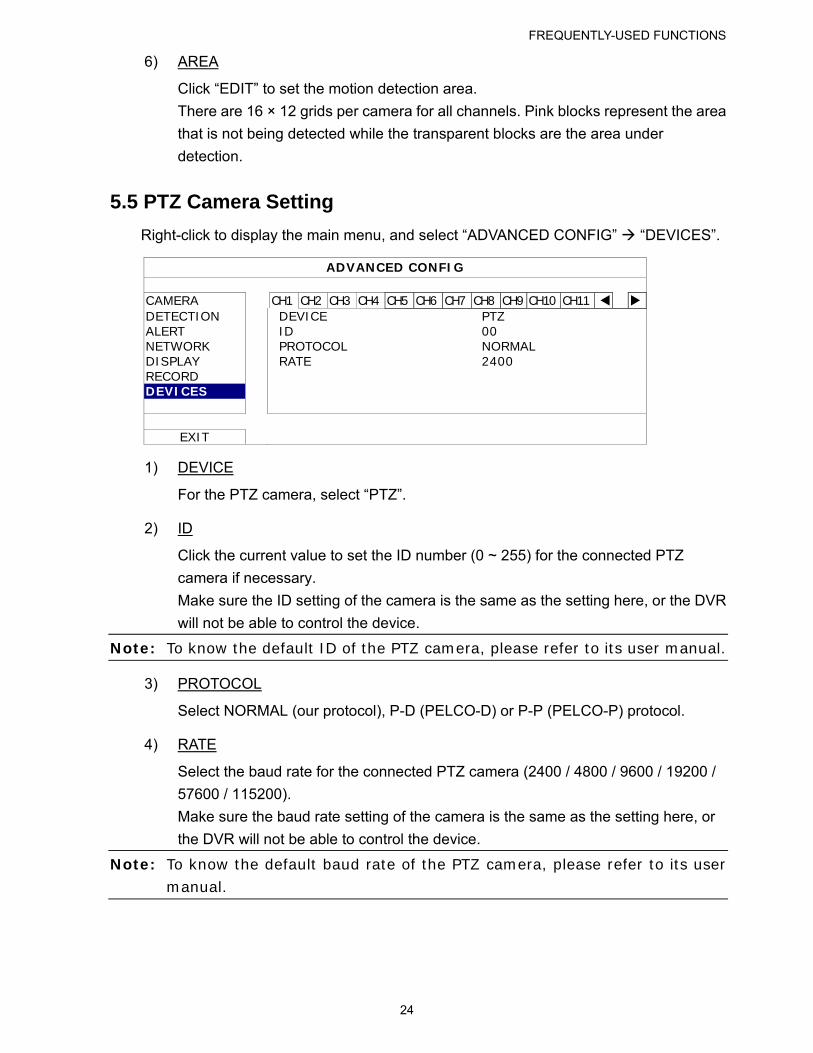
5.5 PTZ Camera Setting
Right-click to display the main menu, and select “ADVANCED CONFIG” “DEVICES”.
ADVANCED CONFIG
CAMERA CH1 CH2 CH3 CH4 CH5 CH6 CH7 CH8 CH9 CH10 CH11 DETECTION DEVICE PTZ ALERT ID 00 NETWORK PROTOCOL NORMAL DISPLAY RATE 2400 RECORD DEVICES
EXIT
1) DEVICE
For the PTZ camera, select “PTZ”.
2) ID
Click the current value to set the ID number (0 ~ 255) for the connected PTZ
camera if necessary.
Make sure the ID setting of the camera is the same as the setting here, or the DVR
will not be able to control the device.
Note: To know the default ID of the PTZ camera, please refer to its user manual.
3) PROTOCOL
Select NORMAL (our protocol), P-D (PELCO-D) or P-P (PELCO-P) protocol.
4) RATE
Select the baud rate for the connected PTZ camera (2400 / 4800 / 9600 / 19200 /
57600 / 115200).
Make sure the baud rate setting of the camera is the same as the setting here, or
the DVR will not be able to control the device.
Note: To know the default baud rate of the PTZ camera, please refer to its user manual.
FREQUENTLY-USED FUNCTIONS
25
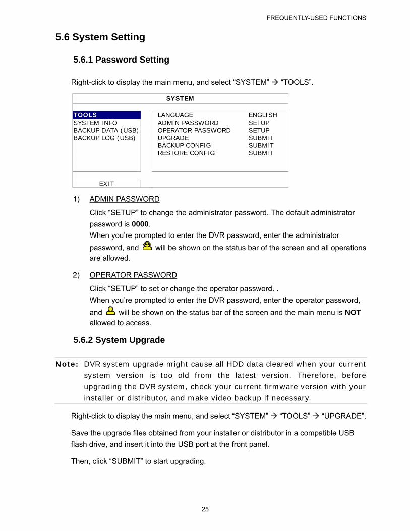
5.6 System Setting
5.6.1 Password Setting
Right-click to display the main menu, and select “SYSTEM” “TOOLS”.
SYSTEM
TOOLS LANGUAGE ENGLISH SYSTEM INFO ADMIN PASSWORD SETUP BACKUP DATA (USB) OPERATOR PASSWORD SETUP BACKUP LOG (USB) UPGRADE SUBMIT BACKUP CONFIG SUBMIT RESTORE CONFIG SUBMIT
EXIT
1) ADMIN PASSWORD
Click “SETUP” to change the administrator password. The default administrator
password is 0000.
When you’re prompted to enter the DVR password, enter the administrator
password, and will be shown on the status bar of the screen and all operations are allowed.
2) OPERATOR PASSWORD
Click “SETUP” to set or change the operator password. .
When you’re prompted to enter the DVR password, enter the operator password,
and will be shown on the status bar of the screen and the main menu is NOT allowed to access.
5.6.2 System Upgrade
Note: DVR system upgrade might cause all HDD data cleared when your current system version is too old from the latest version. Therefore, before upgrading the DVR system, check your current firmware version with your installer or distributor, and make video backup if necessary.
Right-click to display the main menu, and select “SYSTEM” “TOOLS” “UPGRADE”.
Save the upgrade files obtained from your installer or distributor in a compatible USB
flash drive, and insert it into the USB port at the front panel.
Then, click “SUBMIT” to start upgrading.
FREQUENTLY-USED FUNCTIONS
26
Note: Before using the USB flash drive, please use your PC to format the USB flash drive to FAT32 format first. For the list of compatible USB flash drives, please refer to “APPENDIX 2 COMPATIBLE USB FLASH DRIVE LIST” at page 57.
5.6.3 Backup & Restore Configurations
Right-click to display the main menu, and select “SYSTEM” “TOOLS” “BACKUP
CONFIG” or “RESTORE CONFIG”.
These two functions allows users to keep the current configurations after DVR upgrade,
or copy one DVR configurations to another DVR if necessary.
Insert a compatible USB flash drive into the USB port before upgrading DVR, and select
“SUBMIT” in “BACKUP CONFIG” to copy the current DVR configurations to a file
“System.bin” and save to your USB flash drive.
To restore DVR configurations after upgrading DVR, insert the USB flash drive including
“System.bin” to the USB port, and select “SUBMIT” in “RESTORE CONFIG”.
5.6.4 Video Backup
Right-click to display the main menu, and select “SYSTEM” “BACKUP DATA (USB)”
or “BACKUP DVD (USB)”.
Note: “BACKUP DVD (USB)” is only available for selected models with a DVD
writer. Please check the specifications of your DVR model for details.
Insert a compatible USB flash drive to the USB port at the front panel, or press to
eject the DVD writer and place a DVD-ROM or CD-ROM to it.
Note: Before using the USB flash drive, please use your PC to format the USB flash drive to FAT32 format first. For the list of compatible USB flash drives, please refer to “APPENDIX 2 COMPATIBLE USB FLASH DRIVE LIST” at page 57.
Note: For the compatible CD- / DVD-ROM list, please refer to “APPENDIX 8 DVD- / CD-ROM COMPATIBLE LIST” at page 66.
FREQUENTLY-USED FUNCTIONS
27
SYSTEM
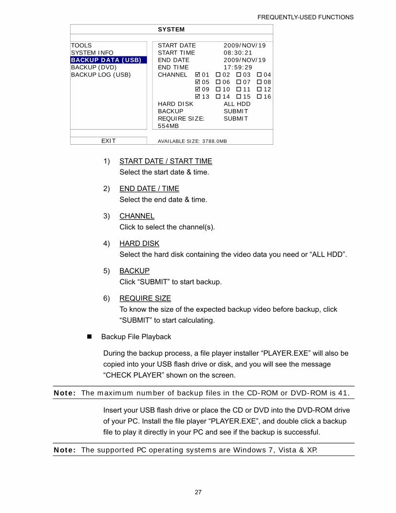
TOOLS START DATE 2009/NOV/19 SYSTEM INFO START TIME 08:30:21 BACKUP DATA (USB) END DATE 2009/NOV/19 BACKUP (DVD) END TIME 17:59:29 BACKUP LOG (USB) CHANNEL 01 02 03 04 05 06 07 08 09 10 11 12 13 14 15 16 HARD DISK ALL HDD BACKUP SUBMIT REQUIRE SIZE:
554MB SUBMIT
EXIT AVAILABLE SIZE: 3788.0MB
1) START DATE / START TIME
Select the start date & time.
2) END DATE / TIME
Select the end date & time.
3) CHANNEL
Click to select the channel(s).
4) HARD DISK
Select the hard disk containing the video data you need or “ALL HDD”.
5) BACKUP
Click “SUBMIT” to start backup.
6) REQUIRE SIZE
To know the size of the expected backup video before backup, click
“SUBMIT” to start calculating.
Backup File Playback
During the backup process, a file player installer “PLAYER.EXE” will also be
copied into your USB flash drive or disk, and you will see the message
“CHECK PLAYER” shown on the screen.
Note: The maximum number of backup files in the CD-ROM or DVD-ROM is 41.
Insert your USB flash drive or place the CD or DVD into the DVD-ROM drive
of your PC. Install the file player “PLAYER.EXE”, and double click a backup
file to play it directly in your PC and see if the backup is successful.
Note: The supported PC operating systems are Windows 7, Vista & XP.
FREQUENTLY-USED FUNCTIONS
28
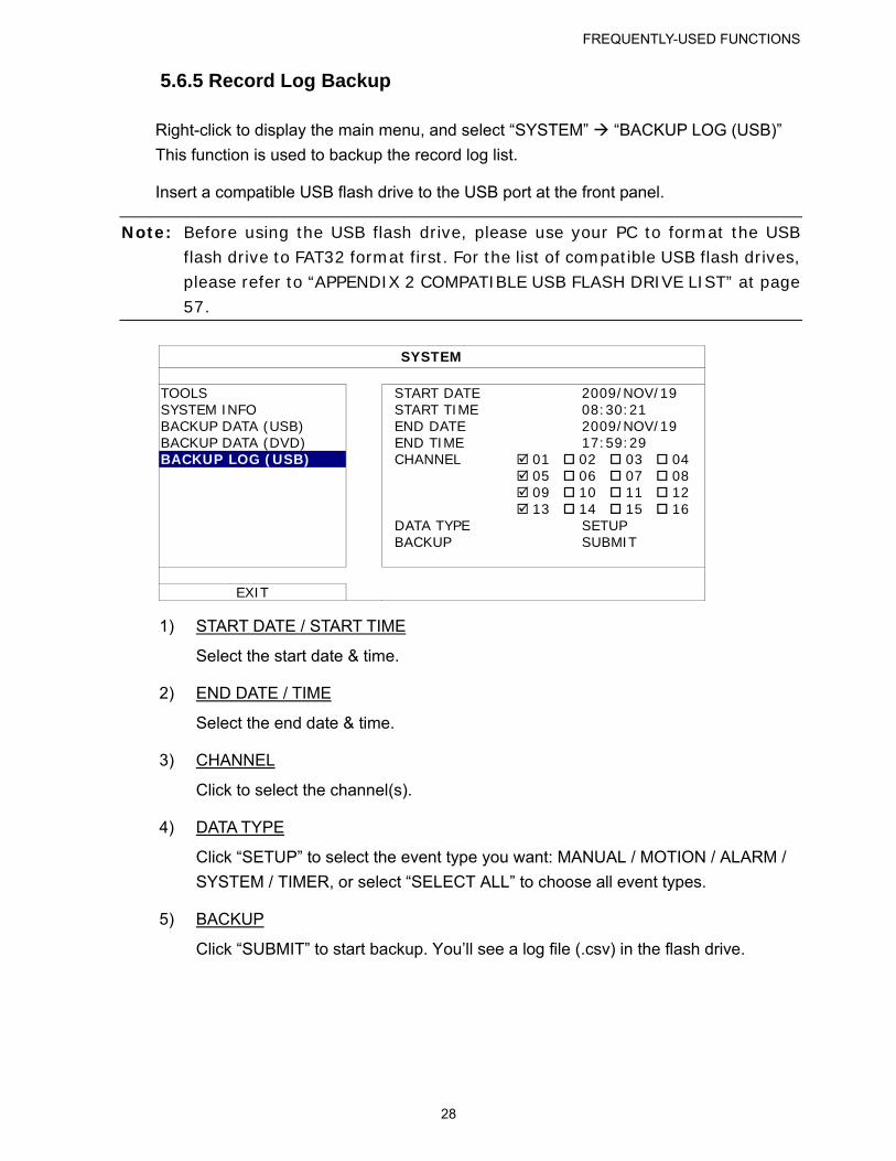
5.6.5 Record Log Backup
Right-click to display the main menu, and select “SYSTEM” “BACKUP LOG (USB)”
This function is used to backup the record log list.
Insert a compatible USB flash drive to the USB port at the front panel.
Note: Before using the USB flash drive, please use your PC to format the USB flash drive to FAT32 format first. For the list of compatible USB flash drives, please refer to “APPENDIX 2 COMPATIBLE USB FLASH DRIVE LIST” at page 57.
SYSTEM
TOOLS START DATE 2009/NOV/19 SYSTEM INFO START TIME 08:30:21 BACKUP DATA (USB) END DATE 2009/NOV/19 BACKUP DATA (DVD) END TIME 17:59:29 BACKUP LOG (USB) CHANNEL 01 02 03 04 05 06 07 08 09 10 11 12 13 14 15 16 DATA TYPE SETUP BACKUP SUBMIT
EXIT
1) START DATE / START TIME
Select the start date & time.
2) END DATE / TIME
Select the end date & time.
3) CHANNEL
Click to select the channel(s).
4) DATA TYPE
Click “SETUP” to select the event type you want: MANUAL / MOTION / ALARM /
SYSTEM / TIMER, or select “SELECT ALL” to choose all event types.
5) BACKUP
Click “SUBMIT” to start backup. You’ll see a log file (.csv) in the flash drive.
FREQUENTLY-USED FUNCTIONS
29
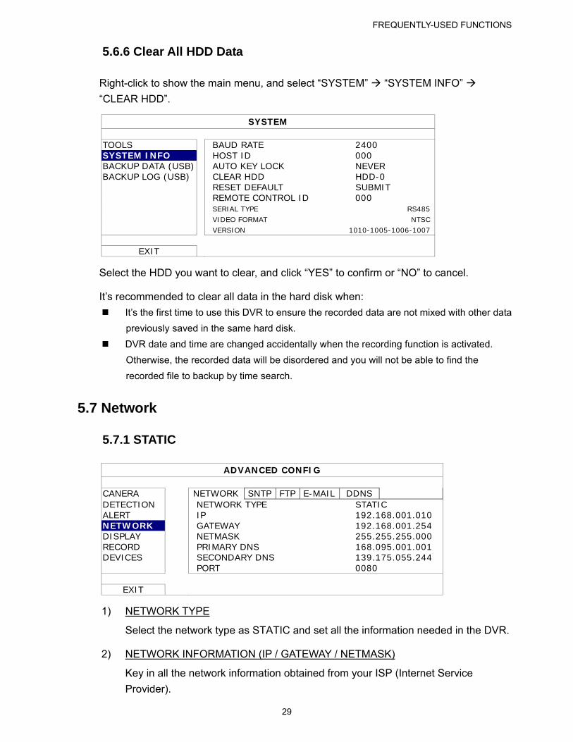
5.6.6 Clear All HDD Data
Right-click to show the main menu, and select “SYSTEM” “SYSTEM INFO”
“CLEAR HDD”.
SYSTEM
TOOLS BAUD RATE 2400 SYSTEM INFO HOST ID 000 BACKUP DATA (USB) AUTO KEY LOCK NEVER BACKUP LOG (USB) CLEAR HDD HDD-0 RESET DEFAULT SUBMIT REMOTE CONTROL ID 000 SERIAL TYPE RS485 VIDEO FORMAT NTSC
VERSION 1010-1005-1006-1007
EXIT
Select the HDD you want to clear, and click “YES” to confirm or “NO” to cancel.
It’s recommended to clear all data in the hard disk when:
It’s the first time to use this DVR to ensure the recorded data are not mixed with other data
previously saved in the same hard disk.
DVR date and time are changed accidentally when the recording function is activated.
Otherwise, the recorded data will be disordered and you will not be able to find the
recorded file to backup by time search.
5.7 Network
5.7.1 STATIC
ADVANCED CONFIG
CANERA NETWORK SNTP FTP E-MAIL DDNS DETECTION NETWORK TYPE STATIC ALERT IP 192.168.001.010 NETWORK GATEWAY 192.168.001.254 DISPLAY NETMASK 255.255.255.000 RECORD PRIMARY DNS 168.095.001.001 DEVICES SECONDARY DNS 139.175.055.244 PORT 0080
EXIT
1) NETWORK TYPE
Select the network type as STATIC and set all the information needed in the DVR.
2) NETWORK INFORMATION (IP / GATEWAY / NETMASK)
Key in all the network information obtained from your ISP (Internet Service
Provider).
FREQUENTLY-USED FUNCTIONS
30
3) DNS (PRIMARY DNS / SECONDARY DNS)
Key in the IP address of the domain name server obtained from your ISP (Internet
Service Provider).
4) PORT
The valid number ranges from 1 to 9999. The default value is 80. Typically, the
TCP port used by HTTP is 80. However in some cases, it is better to change this
port number for added flexibility or security.
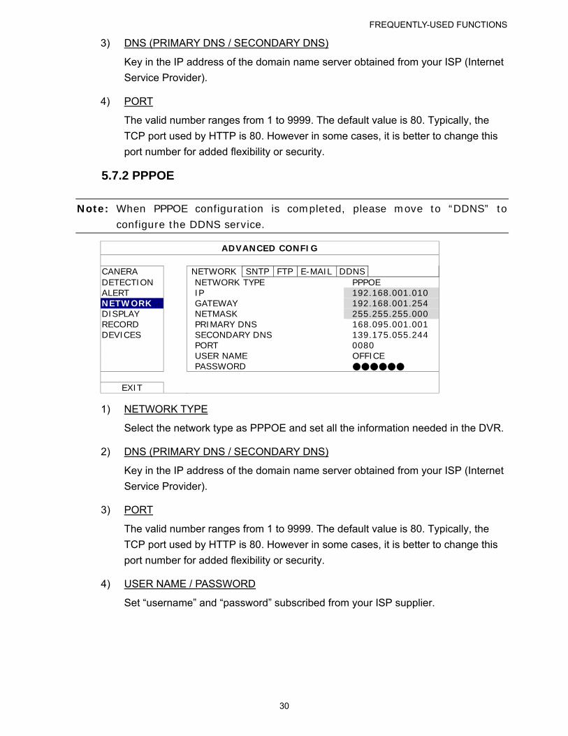
5.7.2 PPPOE
Note: When PPPOE configuration is completed, please move to “DDNS” to
configure the DDNS service.
ADVANCED CONFIG
CANERA NETWORK SNTP FTP E-MAIL DDNS DETECTION NETWORK TYPE PPPOE ALERT IP 192.168.001.010 NETWORK GATEWAY 192.168.001.254 DISPLAY NETMASK 255.255.255.000 RECORD PRIMARY DNS 168.095.001.001 DEVICES SECONDARY DNS 139.175.055.244 PORT 0080 USER NAME OFFICE PASSWORD ●●●●●●
EXIT
1) NETWORK TYPE
Select the network type as PPPOE and set all the information needed in the DVR.
2) DNS (PRIMARY DNS / SECONDARY DNS)
Key in the IP address of the domain name server obtained from your ISP (Internet
Service Provider).
3) PORT
The valid number ranges from 1 to 9999. The default value is 80. Typically, the
TCP port used by HTTP is 80. However in some cases, it is better to change this
port number for added flexibility or security.
4) USER NAME / PASSWORD
Set “username” and “password” subscribed from your ISP supplier.
FREQUENTLY-USED FUNCTIONS
31
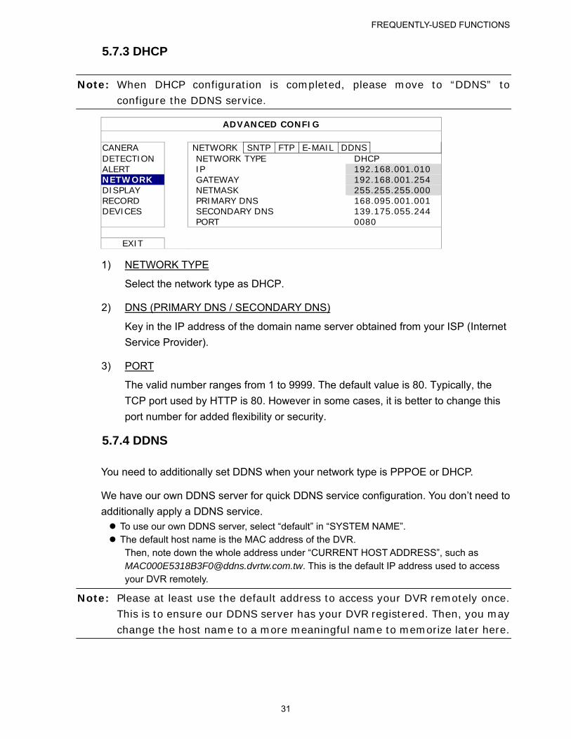
5.7.3 DHCP
Note: When DHCP configuration is completed, please move to “DDNS” to configure the DDNS service.
ADVANCED CONFIG
CANERA NETWORK SNTP FTP E-MAIL DDNS DETECTION NETWORK TYPE DHCP ALERT IP 192.168.001.010 NETWORK GATEWAY 192.168.001.254 DISPLAY NETMASK 255.255.255.000 RECORD PRIMARY DNS 168.095.001.001 DEVICES SECONDARY DNS 139.175.055.244 PORT 0080
EXIT
1) NETWORK TYPE
Select the network type as DHCP.
2) DNS (PRIMARY DNS / SECONDARY DNS)
Key in the IP address of the domain name server obtained from your ISP (Internet
Service Provider).
3) PORT
The valid number ranges from 1 to 9999. The default value is 80. Typically, the
TCP port used by HTTP is 80. However in some cases, it is better to change this
port number for added flexibility or security.
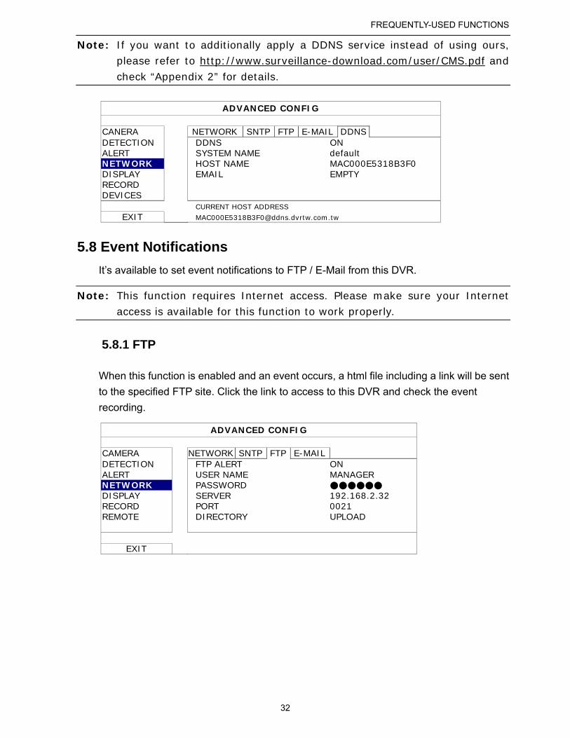
5.7.4 DDNS
You need to additionally set DDNS when your network type is PPPOE or DHCP.
We have our own DDNS server for quick DDNS service configuration. You don’t need to
additionally apply a DDNS service. To use our own DDNS server, select “default” in “SYSTEM NAME”. The default host name is the MAC address of the DVR.
Then, note down the whole address under “CURRENT HOST ADDRESS”, such as [email protected]. This is the default IP address used to access your DVR remotely.
Note: Please at least use the default address to access your DVR remotely once. This is to ensure our DDNS server has your DVR registered. Then, you may change the host name to a more meaningful name to memorize later here.
FREQUENTLY-USED FUNCTIONS
32
Note: If you want to additionally apply a DDNS service instead of using ours, please refer to http://www.surveillance-download.com/user/CMS.pdf and
check “Appendix 2” for details.
ADVANCED CONFIG
CANERA NETWORK SNTP FTP E-MAIL DDNS DETECTION DDNS ON ALERT SYSTEM NAME default NETWORK HOST NAME MAC000E5318B3F0 DISPLAY EMAIL EMPTY RECORD DEVICES
CURRENT HOST ADDRESS
EXIT [email protected]
5.8 Event Notifications
It’s available to set event notifications to FTP / E-Mail from this DVR.
Note: This function requires Internet access. Please make sure your Internet access is available for this function to work properly.
5.8.1 FTP
When this function is enabled and an event occurs, a html file including a link will be sent
to the specified FTP site. Click the link to access to this DVR and check the event
recording.
ADVANCED CONFIG
CAMERA NETWORK SNTP FTP E-MAIL DETECTION FTP ALERT ON ALERT USER NAME MANAGER NETWORK PASSWORD ●●●●●● DISPLAY SERVER 192.168.2.32 RECORD PORT 0021 REMOTE DIRECTORY UPLOAD
EXIT
FREQUENTLY-USED FUNCTIONS
33
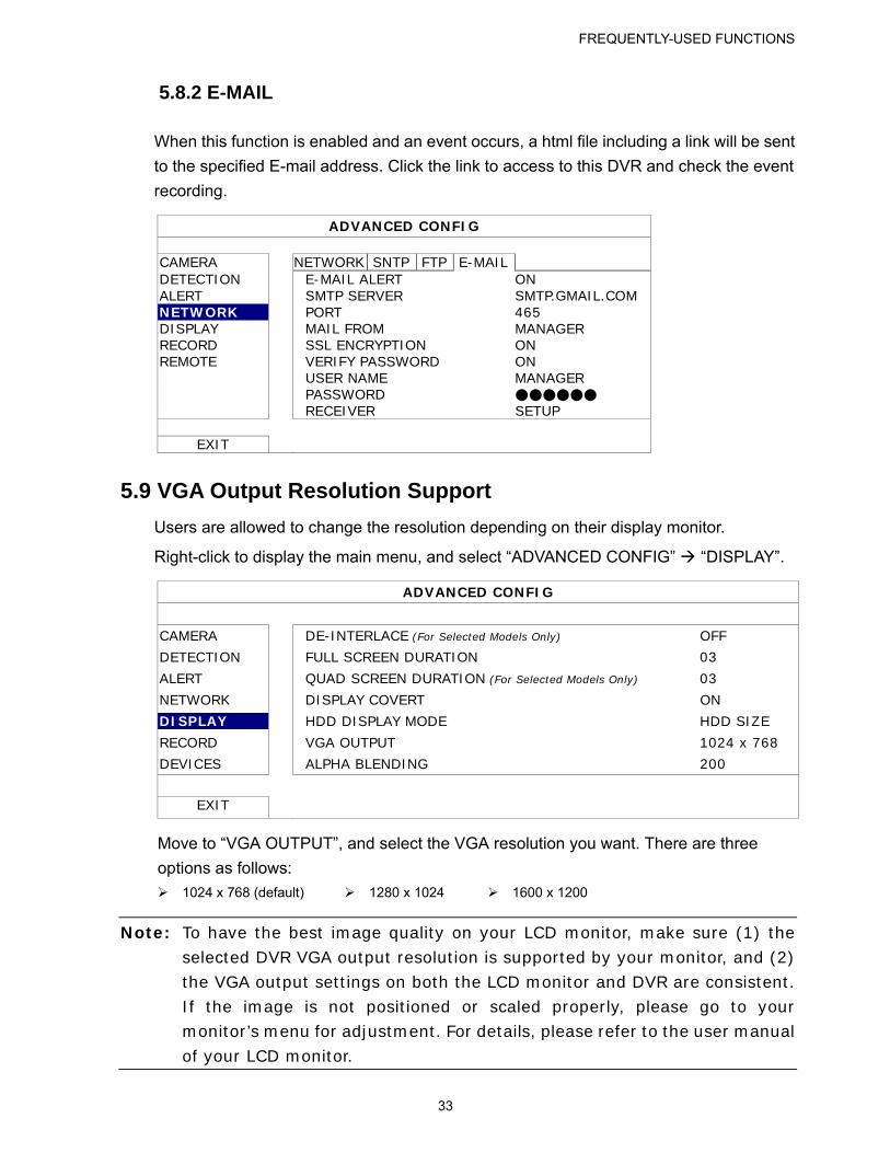
5.8.2 E-MAIL
When this function is enabled and an event occurs, a html file including a link will be sent
to the specified E-mail address. Click the link to access to this DVR and check the event
recording.
ADVANCED CONFIG
CAMERA NETWORK SNTP FTP E-MAIL DETECTION E-MAIL ALERT ON ALERT SMTP SERVER SMTP.GMAIL.COM NETWORK PORT 465 DISPLAY MAIL FROM MANAGER RECORD SSL ENCRYPTION ON REMOTE VERIFY PASSWORD ON USER NAME MANAGER PASSWORD ●●●●●● RECEIVER SETUP
EXIT
5.9 VGA Output Resolution Support
Users are allowed to change the resolution depending on their display monitor.
Right-click to display the main menu, and select “ADVANCED CONFIG” “DISPLAY”.
ADVANCED CONFIG
CAMERA DE-INTERLACE (For Selected Models Only) OFF
DETECTION FULL SCREEN DURATION 03
ALERT QUAD SCREEN DURATION (For Selected Models Only) 03
NETWORK DISPLAY COVERT ON
DISPLAY HDD DISPLAY MODE HDD SIZE
RECORD VGA OUTPUT 1024 x 768
DEVICES ALPHA BLENDING 200
EXIT
Move to “VGA OUTPUT”, and select the VGA resolution you want. There are three
options as follows:
1024 x 768 (default) 1280 x 1024 1600 x 1200
Note: To have the best image quality on your LCD monitor, make sure (1) the selected DVR VGA output resolution is supported by your monitor, and (2) the VGA output settings on both the LCD monitor and DVR are consistent. If the image is not positioned or scaled properly, please go to your monitor’s menu for adjustment. For details, please refer to the user manual
of your LCD monitor.
FREQUENTLY-USED FUNCTIONS
34
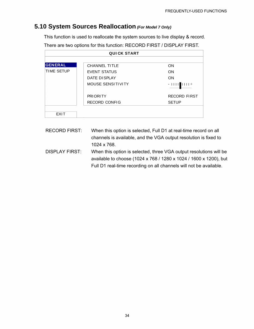
5.10 System Sources Reallocation (For Model 7 Only)
This function is used to reallocate the system sources to live display & record.
There are two options for this function: RECORD FIRST / DISPLAY FIRST.
QUICK START
GENERAL CHANNEL TITLE ON TIME SETUP EVENT STATUS ON DATE DISPLAY ON MOUSE SENSITIVITY - ׀ ׀ ׀ ׀ ׀ ׀ ׀ ׀ ׀ + PRIORITY RECORD FIRST RECORD CONFIG SETUP
EXIT
RECORD FIRST: When this option is selected, Full D1 at real-time record on all
channels is available, and the VGA output resolution is fixed to
1024 x 768.
DISPLAY FIRST: When this option is selected, three VGA output resolutions will be
available to choose (1024 x 768 / 1280 x 1024 / 1600 x 1200), but
Full D1 real-time recording on all channels will not be available.
REMOTE OPERATION
35
6. REMOTE OPERATION
You can also control the DVR remotely via the supplied licensed software “Video Viewer”,
Internet Explorer web browser, and Apple’s QuickTime player.
Note: For more details about mobile surveillance via your smart phones, please visit our official website www.eagleeyescctv.com, or download the instructions of EagleEyes installation and configuration from www.surveillance-download.com/user/eagleeyes_quick.pdf.
6.1 Supplied Licensed Software
The sections below describe frequently-used functions of the Video Viewer. For details
about this software and network settings, please download its extended user manual
from the following link:
http://www.surveillance-download.com/user/CMS.pdf
6.1.1 Installation & Network Connection
1) Install the software
Step1: Place the supplied CD into your CD-ROM or DVD-ROM drive. The program
will be automatically run.
Step2: Click “Download The Latest Version” under “Licensed Software AP” to
download the latest version of Video Viewer from the Internet.
Step3: Follow the on-screen instructions to finish the installation. When the
installation is completed, a shortcut icon “ ” will be placed on your PC
desktop.
2) Network Connection
LLooccaall CCoonnnneeccttiioonn ((vviiaa LLAANN))
LAN is used when it’s the first time to remotely access the DVR and you
need to configure the network setting of your DVR based on your network
type in advance.
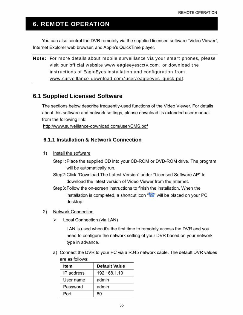
a) Connect the DVR to your PC via a RJ45 network cable. The default DVR values
are as follows:
Item Default Value
IP address 192.168.1.10
User name admin
Password admin
Port 80
REMOTE OPERATION
36
b) Set the PC’s IP address as “192.168.1.XXX” (1~255, except 10) in order to
make the PC and DVR under the same domain.
c) Double-click “ ” icon on your PC desktop to enter the control panel. By
defaults, the “Address Book” panel will be displayed on the right side of the
control panel.
d) Click “ ” “ ” to key in the default IP address, user name, password, and port number of the DVR you intend to connect.
OR
Click “ ” “ ” to search the available IP address(es) of other DVR(s)
under the same domain as your PC’s IP address. The found address(es) will be
listed, and can be added into the address book by clicking “ ”.
e) Double-click the IP address you just added into the address book to log in.
RReemmoottee CCoonnnneeccttiioonn ((vviiaa IInntteerrnneett))
When the network configuration of your DVR is completed, you can access your
DVR remotely via Internet.
a) Double-click “ ” icon on your PC desktop to enter the control panel. By
defaults, the “Address Book” panel will be displayed on the right side of the
control panel.
b) Click ” ” ” ” to key in the IP address, user name, password, and port number of the DVR you intend to connect.
OR
Click ” ” ” ” to search the available IP address(es) of other
DVR(s) under the same domain as your PC’s IP address. The found address(es)
will be listed, and can be added into the address book by clicking ” ”.
c) Double-click the IP address you just added into the address book to log in.
REMOTE OPERATION
37
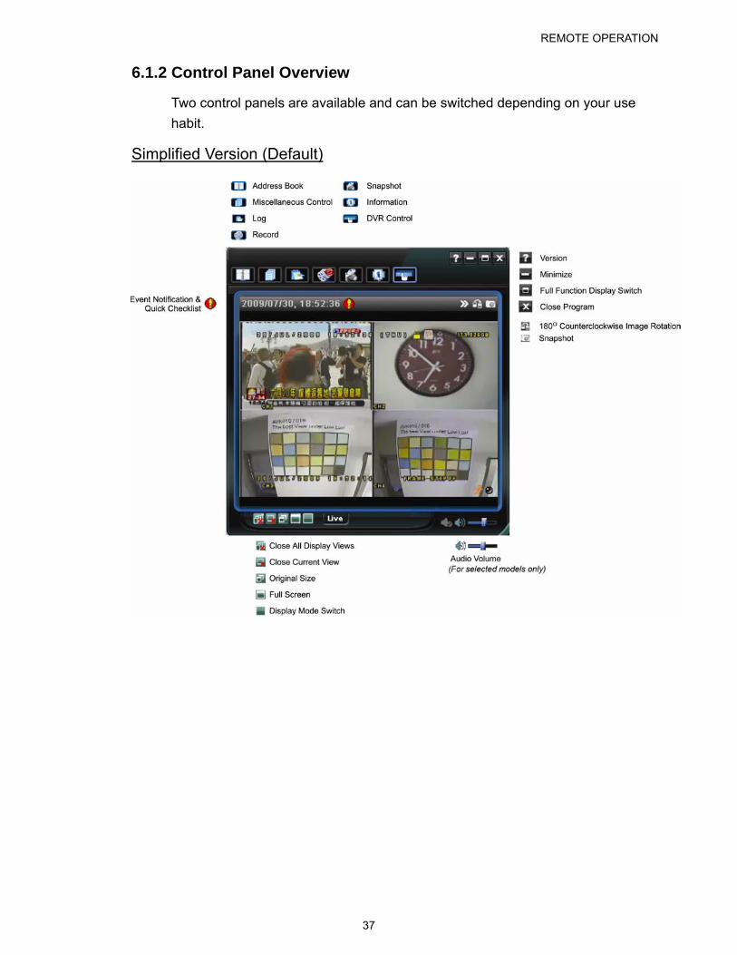
6.1.2 Control Panel Overview
Two control panels are available and can be switched depending on your use
habit.
Simplified Version (Default)
REMOTE OPERATION
38
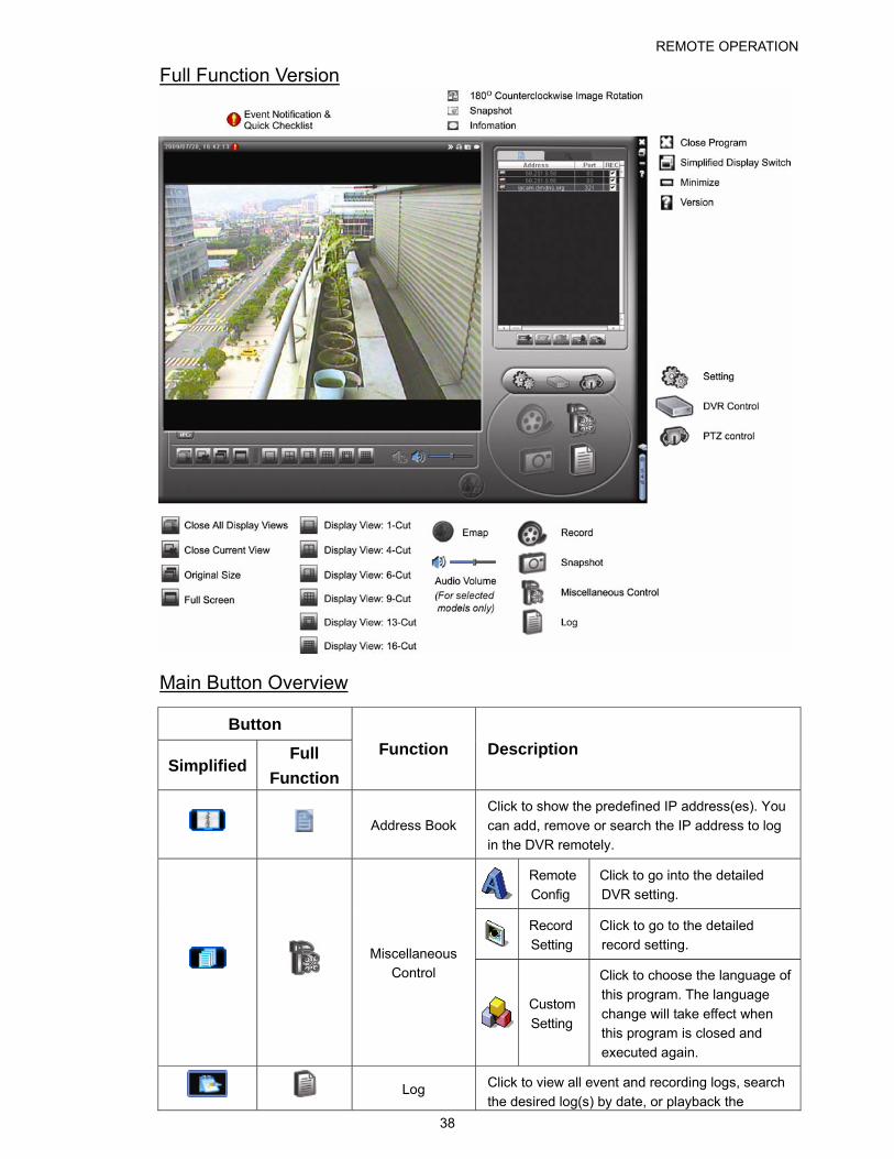
Full Function Version
Main Button Overview
Button
Simplified Full
Function
Function Description
Address Book Click to show the predefined IP address(es). You
can add, remove or search the IP address to log
in the DVR remotely.
Remote Config
Click to go into the detailed DVR setting.
Record Setting
Click to go to the detailed record setting.
Miscellaneous
Control
Custom
Setting
Click to choose the language of
this program. The language
change will take effect when this program is closed and
executed again.
Log Click to view all event and recording logs, search
the desired log(s) by date, or playback the
REMOTE OPERATION
39
Button
Simplified Full
Function
Function Description
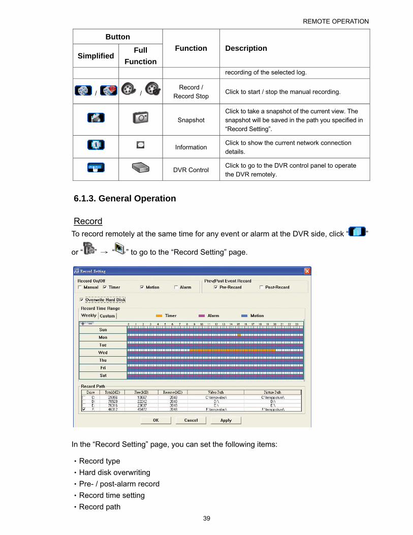
recording of the selected log.
/ / Record /
Record Stop Click to start / stop the manual recording.
Snapshot Click to take a snapshot of the current view. The snapshot will be saved in the path you specified in “Record Setting”.
Information Click to show the current network connection details.
DVR Control Click to go to the DVR control panel to operate the DVR remotely.
6.1.3. General Operation
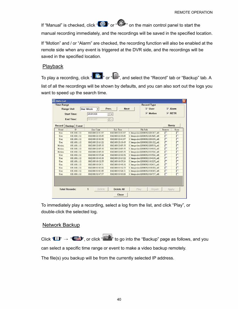
Record To record remotely at the same time for any event or alarm at the DVR side, click “ ”
or “ ” → “ ” to go to the “Record Setting” page.
In the “Record Setting” page, you can set the following items:
‧Record type
‧Hard disk overwriting
‧Pre- / post-alarm record
‧Record time setting
‧Record path
REMOTE OPERATION
40
If “Manual” is checked, click “ ” or “ ” on the main control panel to start the
manual recording immediately, and the recordings will be saved in the specified location.
If “Motion” and / or “Alarm” are checked, the recording function will also be enabled at the
remote side when any event is triggered at the DVR side, and the recordings will be
saved in the specified location.
Playback
To play a recording, click “ ” or “ ”, and select the “Record” tab or “Backup” tab. A
list of all the recordings will be shown by defaults, and you can also sort out the logs you
want to speed up the search time.
To immediately play a recording, select a log from the list, and click “Play”, or
double-click the selected log.
Network Backup
Click “ ” → “ ”, or click “ ” to go into the “Backup” page as follows, and you
can select a specific time range or event to make a video backup remotely.
The file(s) you backup will be from the currently selected IP address.
REMOTE OPERATION
41
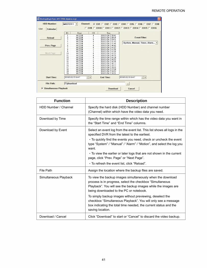
Function Description
HDD Number / Channel Specify the hard disk (HDD Number) and channel number
(Channel) within which have the video data you need.
Download by Time Specify the time range within which has the video data you want in
the “Start Time” and “End Time” columns.
Download by Event Select an event log from the event list. This list shows all logs in the
specified DVR from the latest to the earliest.
‧To quickly find the events you need, check or uncheck the event type “System” / “Manual” / “Alarm” / “Motion”, and select the log you
want.
‧To view the earlier or later logs that are not shown in the current
page, click “Prev. Page” or “Next Page”.
‧To refresh the event list, click “Reload”.
File Path Assign the location where the backup files are saved.
Simultaneous Playback To view the backup images simultaneously when the download
process is in progress, select the checkbox “Simultaneous
Playback”. You will see the backup images while the images are being downloaded to the PC or notebook.
To simply backup images without previewing, deselect the
checkbox “Simultaneous Playback”. You will only see a message box indicating the total time needed, the current status and the saving location.
Download / Cancel Click “Download” to start or “Cancel” to discard the video backup.
REMOTE OPERATION
42
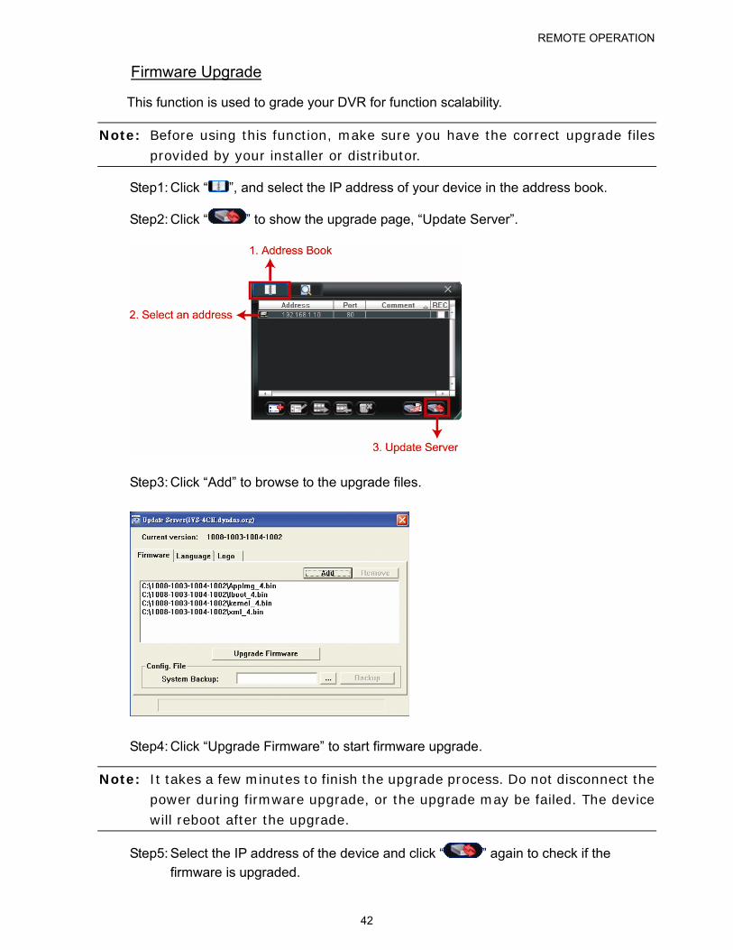
Firmware Upgrade
This function is used to grade your DVR for function scalability.
Note: Before using this function, make sure you have the correct upgrade files provided by your installer or distributor.
Step1: Click “ ”, and select the IP address of your device in the address book.
Step2: Click “ ” to show the upgrade page, “Update Server”.
Step3: Click “Add” to browse to the upgrade files.
Step4: Click “Upgrade Firmware” to start firmware upgrade.
Note: It takes a few minutes to finish the upgrade process. Do not disconnect the power during firmware upgrade, or the upgrade may be failed. The device will reboot after the upgrade.
Step5: Select the IP address of the device and click “ ” again to check if the
firmware is upgraded.
REMOTE OPERATION
43
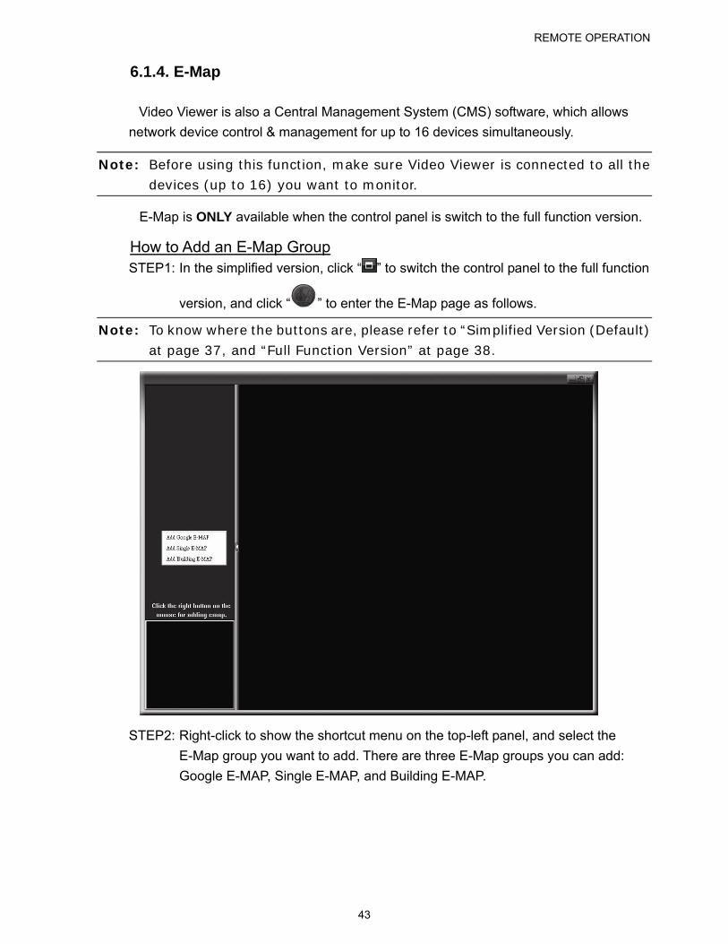
6.1.4. E-Map
Video Viewer is also a Central Management System (CMS) software, which allows
network device control & management for up to 16 devices simultaneously.
Note: Before using this function, make sure Video Viewer is connected to all the devices (up to 16) you want to monitor.
E-Map is ONLY available when the control panel is switch to the full function version.
How to Add an E-Map Group STEP1: In the simplified version, click “ ” to switch the control panel to the full function
version, and click “ ” to enter the E-Map page as follows.
Note: To know where the buttons are, please refer to “Simplified Version (Default) at page 37, and “Full Function Version” at page 38.
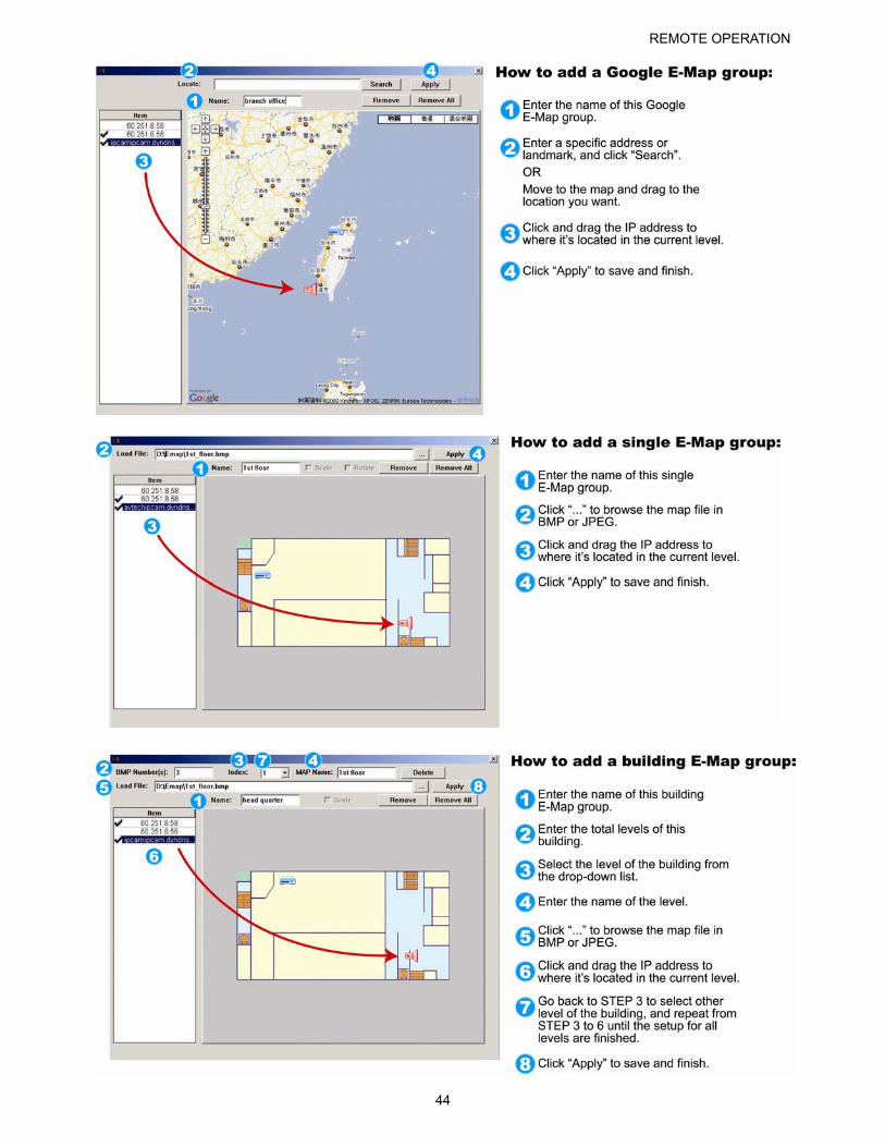
STEP2: Right-click to show the shortcut menu on the top-left panel, and select the
E-Map group you want to add. There are three E-Map groups you can add:
Google E-MAP, Single E-MAP, and Building E-MAP.
REMOTE OPERATION
44
REMOTE OPERATION
45
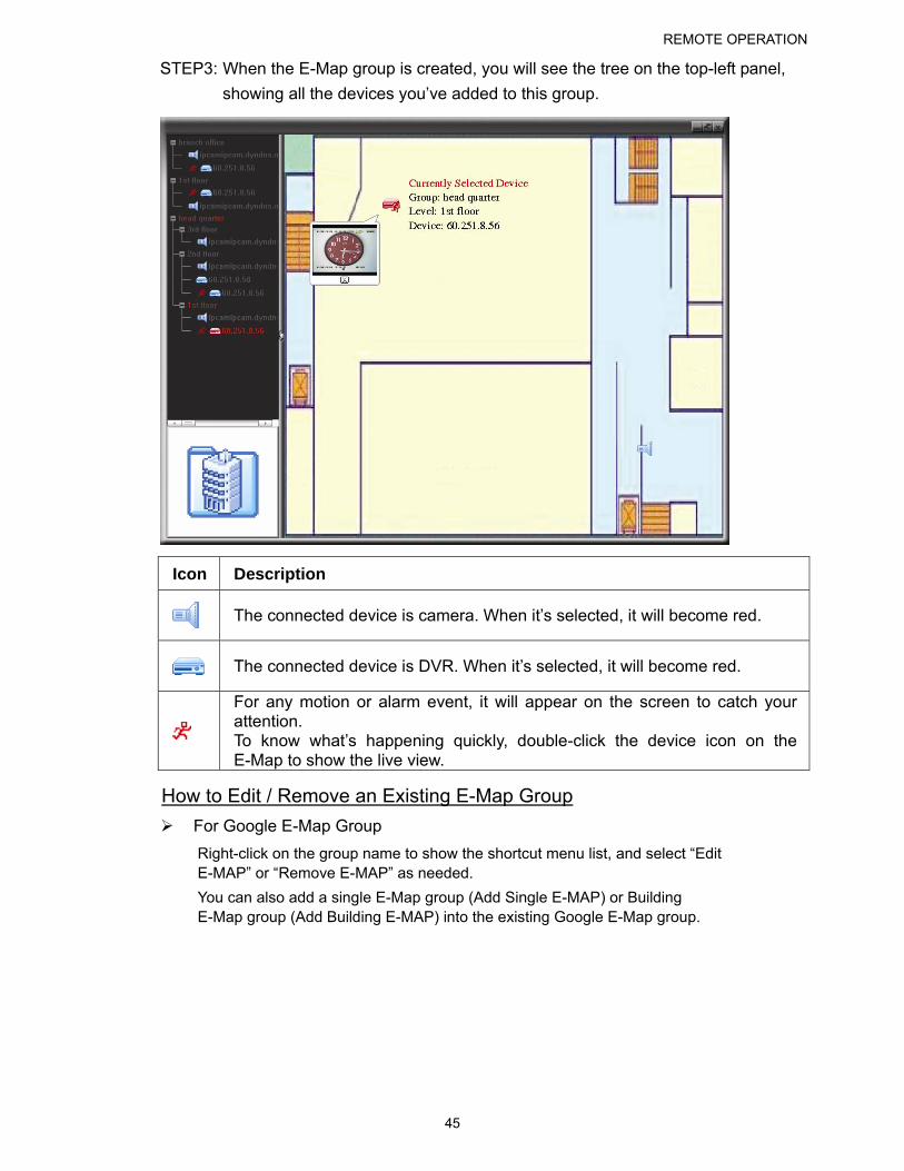
STEP3: When the E-Map group is created, you will see the tree on the top-left panel,
showing all the devices you’ve added to this group.
Icon Description
The connected device is camera. When it’s selected, it will become red.
The connected device is DVR. When it’s selected, it will become red.
For any motion or alarm event, it will appear on the screen to catch your attention. To know what’s happening quickly, double-click the device icon on the E-Map to show the live view.
How to Edit / Remove an Existing E-Map Group
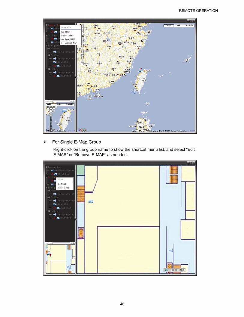
For Google E-Map Group
Right-click on the group name to show the shortcut menu list, and select “Edit E-MAP” or “Remove E-MAP” as needed.
You can also add a single E-Map group (Add Single E-MAP) or Building E-Map group (Add Building E-MAP) into the existing Google E-Map group.
REMOTE OPERATION
46
For Single E-Map Group
Right-click on the group name to show the shortcut menu list, and select “Edit E-MAP” or “Remove E-MAP” as needed.
REMOTE OPERATION
47
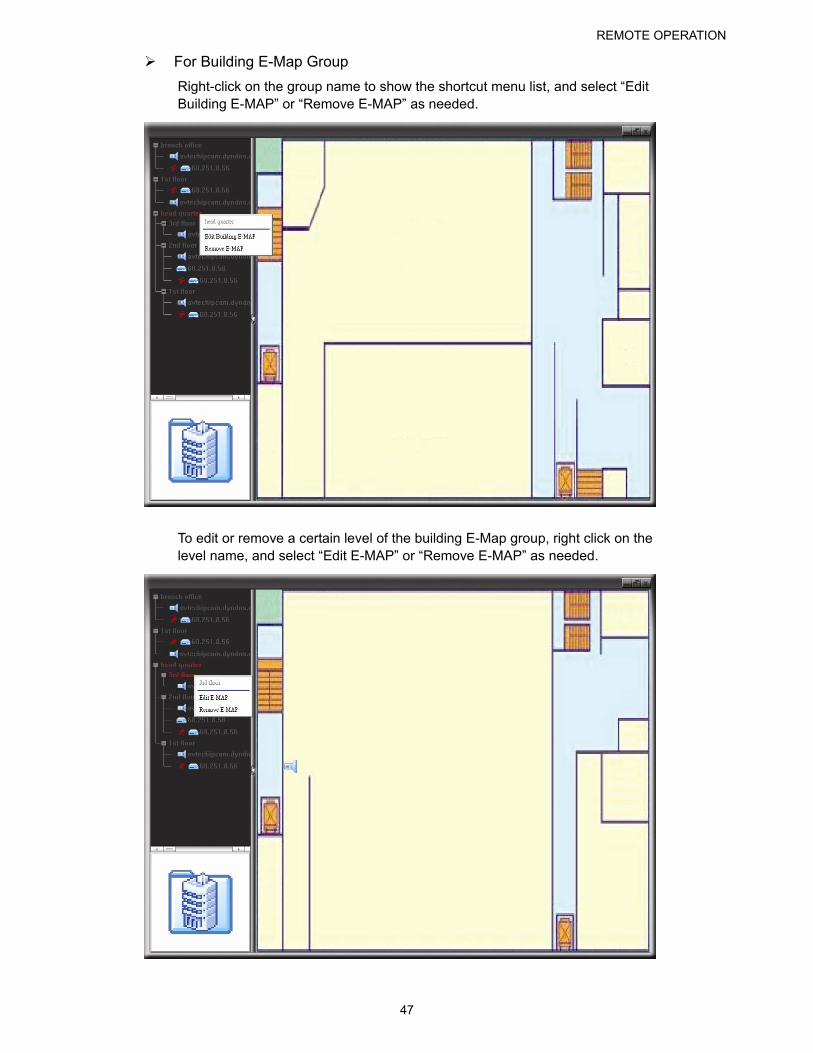
For Building E-Map Group
Right-click on the group name to show the shortcut menu list, and select “Edit Building E-MAP” or “Remove E-MAP” as needed.
To edit or remove a certain level of the building E-Map group, right click on the level name, and select “Edit E-MAP” or “Remove E-MAP” as needed.
REMOTE OPERATION
48
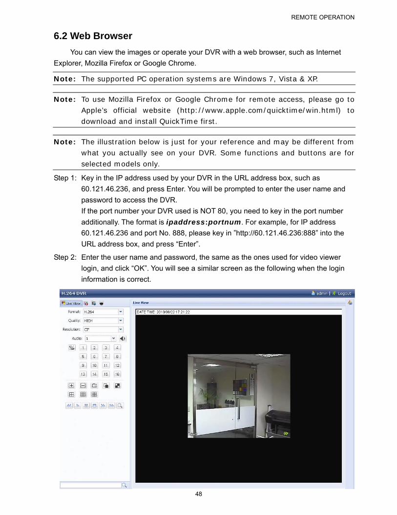
6.2 Web Browser
You can view the images or operate your DVR with a web browser, such as Internet
Explorer, Mozilla Firefox or Google Chrome.
Note: The supported PC operation systems are Windows 7, Vista & XP.
Note: To use Mozilla Firefox or Google Chrome for remote access, please go to Apple’s official website (http://www.apple.com/quicktime/win.html) to download and install QuickTime first.
Note: The illustration below is just for your reference and may be different from what you actually see on your DVR. Some functions and buttons are for
selected models only.
Step 1: Key in the IP address used by your DVR in the URL address box, such as
60.121.46.236, and press Enter. You will be prompted to enter the user name and
password to access the DVR.
If the port number your DVR used is NOT 80, you need to key in the port number
additionally. The format is ipaddress:portnum. For example, for IP address
60.121.46.236 and port No. 888, please key in ”http://60.121.46.236:888” into the
URL address box, and press “Enter”.
Step 2: Enter the user name and password, the same as the ones used for video viewer
login, and click “OK”. You will see a similar screen as the following when the login
information is correct.
REMOTE OPERATION
49
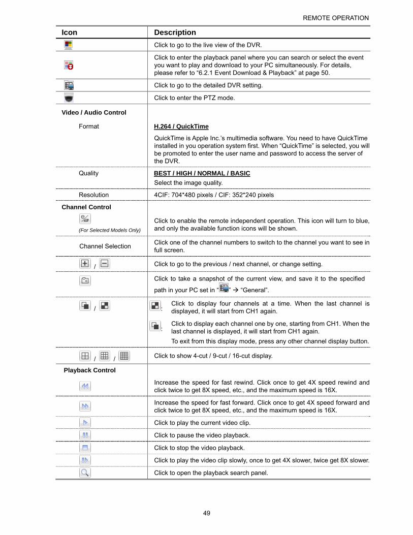
Icon Description
Click to go to the live view of the DVR.
Click to enter the playback panel where you can search or select the event you want to play and download to your PC simultaneously. For details, please refer to “6.2.1 Event Download & Playback” at page 50.
Click to go to the detailed DVR setting.
Click to enter the PTZ mode.
Video / Audio Control
Format H.264 / QuickTime
QuickTime is Apple Inc.’s multimedia software. You need to have QuickTime installed in you operation system first. When “QuickTime” is selected, you will be promoted to enter the user name and password to access the server of the DVR.
Quality BEST / HIGH / NORMAL / BASIC
Select the image quality.
Resolution 4CIF: 704*480 pixels / CIF: 352*240 pixels
Channel Control
(For Selected Models Only)
Click to enable the remote independent operation. This icon will turn to blue, and only the available function icons will be shown.
Channel Selection Click one of the channel numbers to switch to the channel you want to see in full screen.
/ Click to go to the previous / next channel, or change setting.
Click to take a snapshot of the current view, and save it to the specified
path in your PC set in “ ” “General”.
: Click to display four channels at a time. When the last channel is displayed, it will start from CH1 again. /
: Click to display each channel one by one, starting from CH1. When the last channel is displayed, it will start from CH1 again.
To exit from this display mode, press any other channel display button.
/ / Click to show 4-cut / 9-cut / 16-cut display.
Playback Control
Increase the speed for fast rewind. Click once to get 4X speed rewind and click twice to get 8X speed, etc., and the maximum speed is 16X.
Increase the speed for fast forward. Click once to get 4X speed forward and click twice to get 8X speed, etc., and the maximum speed is 16X.
Click to play the current video clip.
Click to pause the video playback.
Click to stop the video playback.
Click to play the video clip slowly, once to get 4X slower, twice get 8X slower.
Click to open the playback search panel.
REMOTE OPERATION
50
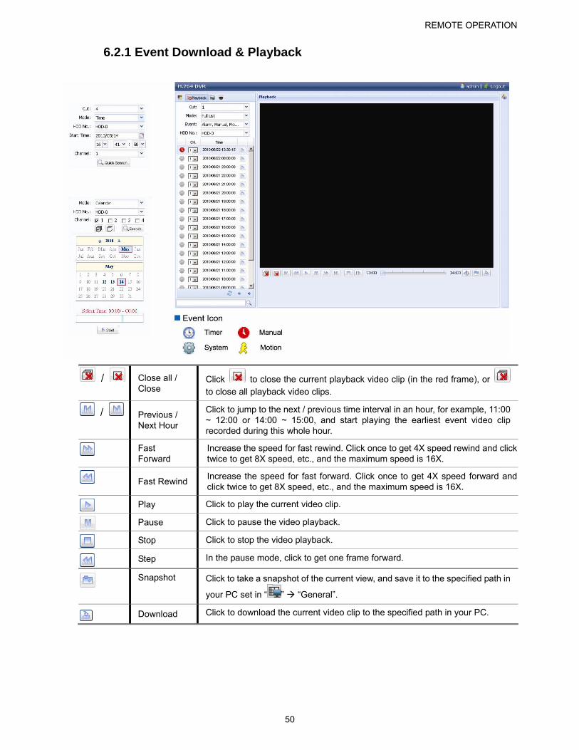
6.2.1 Event Download & Playback
/ Close all / Close
Click to close the current playback video clip (in the red frame), or to close all playback video clips.
/ Previous / Next Hour
Click to jump to the next / previous time interval in an hour, for example, 11:00 ~ 12:00 or 14:00 ~ 15:00, and start playing the earliest event video clip recorded during this whole hour.
Fast Forward
Increase the speed for fast rewind. Click once to get 4X speed rewind and click twice to get 8X speed, etc., and the maximum speed is 16X.
Fast Rewind Increase the speed for fast forward. Click once to get 4X speed forward and click twice to get 8X speed, etc., and the maximum speed is 16X.
Play Click to play the current video clip.
Pause Click to pause the video playback.
Stop Click to stop the video playback.
Step In the pause mode, click to get one frame forward.
Snapshot Click to take a snapshot of the current view, and save it to the specified path in
your PC set in “ ” “General”.
Download Click to download the current video clip to the specified path in your PC.
APPENDIX 1 SPECIFICATIONS
51
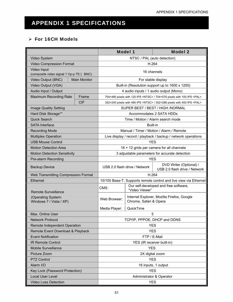
APPENDIX 1 SPECIFICATIONS
For 16CH Models
Model 1 Model 2 Video System NTSC / PAL (auto detection)
Video Compression Format H.264
Video Input (composite video signal 1 Vp-p 75Ω BNC)
16 channels
Video Output (BNC) Main Monitor For stable display
Video Output (VGA) Built-in (Resolution support up to 1600 x 1200)
Audio Input / Output 4 audio inputs / 1 audio output (Mono)
Maximum Recording Rate Frame 704×480 pixels with 120 IPS <NTSC> / 704×576 pixels with 100 IPS <PAL>
CIF 352×240 pixels with 480 IPS <NTSC> / 352×288 pixels with 400 IPS <PAL>
Image Quality Setting SUPER BEST / BEST / HIGH /NORMAL
Hard Disk Storage** Accommodates 2 SATA HDDs
Quick Search Time / Motion / Alarm search mode
SATA Interface Built-in
Recording Mode Manual / Timer / Motion / Alarm / Remote
Multiplex Operation Live display / record / playback / backup / network operations
USB Mouse Control YES
Motion Detection Area 16 × 12 grids per camera for all channels
Motion Detection Sensitivity 3 adjustable parameters for accurate detection
Pre-alarm Recording YES
Backup Device USB 2.0 flash drive / Network DVD Writer (Optional) /
USB 2.0 flash drive / Network
Web Transmitting Compression Format H.264
Ethernet 10/100 Base-T. Supports remote control and live view via Ethernet
CMS: Our self-developed and free software, “Video Viewer”
Web Browser: Internet Explorer, Mozilla Firefox, Google Chrome, Safari & Opera
Remote Surveillance
(Operating System: Windows 7 / Vista / XP)
Media Player: QuickTime
Max. Online User 5
Network Protocol TCP/IP, PPPOE, DHCP and DDNS
Remote Independent Operation YES
Remote Event Download & Playback YES
Event Notification FTP / E-Mail
IR Remote Control YES (IR receiver built-in)
Mobile Surveillance YES
Picture Zoom 2X digital zoom
PTZ Control YES
Alarm I/O 16 inputs, 1 output
Key Lock (Password Protection) YES
Local User Level Administrator & Operator
Video Loss Detection YES
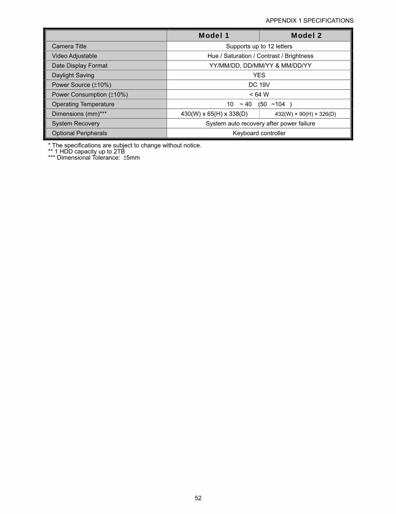
APPENDIX 1 SPECIFICATIONS
52
Model 1 Model 2 Camera Title Supports up to 12 letters
Video Adjustable Hue / Saturation / Contrast / Brightness
Date Display Format YY/MM/DD, DD/MM/YY & MM/DD/YY
Daylight Saving YES
Power Source (±10%) DC 19V
Power Consumption (±10%) < 64 W
Operating Temperature 10� ~ 40� (50�~104�)
Dimensions (mm)*** 430(W) x 65(H) x 338(D) 432(W) × 90(H) × 326(D)
System Recovery System auto recovery after power failure
Optional Peripherals Keyboard controller
* The specifications are subject to change without notice. ** 1 HDD capacity up to 2TB *** Dimensional Tolerance: ±5mm
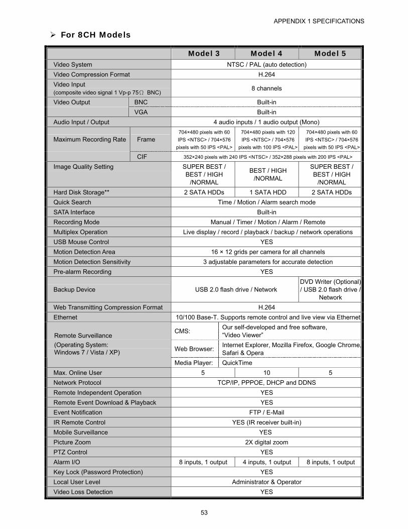
APPENDIX 1 SPECIFICATIONS
53
For 8CH Models
Model 3 Model 4 Model 5 Video System NTSC / PAL (auto detection)
Video Compression Format H.264
Video Input (composite video signal 1 Vp-p 75Ω BNC)
8 channels
Video Output BNC Built-in
VGA Built-in
Audio Input / Output 4 audio inputs / 1 audio output (Mono)
Maximum Recording Rate Frame 704×480 pixels with 60
IPS <NTSC> / 704×576
pixels with 50 IPS <PAL>
704×480 pixels with 120
IPS <NTSC> / 704×576
pixels with 100 IPS <PAL>
704×480 pixels with 60
IPS <NTSC> / 704×576
pixels with 50 IPS <PAL>
CIF 352×240 pixels with 240 IPS <NTSC> / 352×288 pixels with 200 IPS <PAL>
Image Quality Setting SUPER BEST / BEST / HIGH
/NORMAL
BEST / HIGH /NORMAL
SUPER BEST / BEST / HIGH
/NORMAL
Hard Disk Storage** 2 SATA HDDs 1 SATA HDD 2 SATA HDDs
Quick Search Time / Motion / Alarm search mode
SATA Interface Built-in
Recording Mode Manual / Timer / Motion / Alarm / Remote
Multiplex Operation Live display / record / playback / backup / network operations
USB Mouse Control YES
Motion Detection Area 16 × 12 grids per camera for all channels
Motion Detection Sensitivity 3 adjustable parameters for accurate detection
Pre-alarm Recording YES
Backup Device USB 2.0 flash drive / Network DVD Writer (Optional) / USB 2.0 flash drive /
Network
Web Transmitting Compression Format H.264
Ethernet 10/100 Base-T. Supports remote control and live view via Ethernet
CMS: Our self-developed and free software, “Video Viewer”
Web Browser: Internet Explorer, Mozilla Firefox, Google Chrome,Safari & Opera
Remote Surveillance
(Operating System: Windows 7 / Vista / XP)
Media Player: QuickTime
Max. Online User 5 10 5
Network Protocol TCP/IP, PPPOE, DHCP and DDNS
Remote Independent Operation YES
Remote Event Download & Playback YES
Event Notification FTP / E-Mail
IR Remote Control YES (IR receiver built-in)
Mobile Surveillance YES
Picture Zoom 2X digital zoom
PTZ Control YES
Alarm I/O 8 inputs, 1 output 4 inputs, 1 output 8 inputs, 1 output
Key Lock (Password Protection) YES
Local User Level Administrator & Operator
Video Loss Detection YES
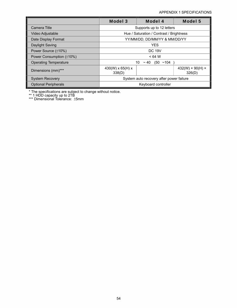
APPENDIX 1 SPECIFICATIONS
54
Model 3 Model 4 Model 5 Camera Title Supports up to 12 letters
Video Adjustable Hue / Saturation / Contrast / Brightness
Date Display Format YY/MM/DD, DD/MM/YY & MM/DD/YY
Daylight Saving YES
Power Source (±10%) DC 19V
Power Consumption (±10%) < 64 W
Operating Temperature 10� ~ 40� (50�~104�)
Dimensions (mm)*** 430(W) x 65(H) x
338(D)
432(W) × 90(H) × 326(D)
System Recovery System auto recovery after power failure
Optional Peripherals Keyboard controller
* The specifications are subject to change without notice. ** 1 HDD capacity up to 2TB *** Dimensional Tolerance: ±5mm
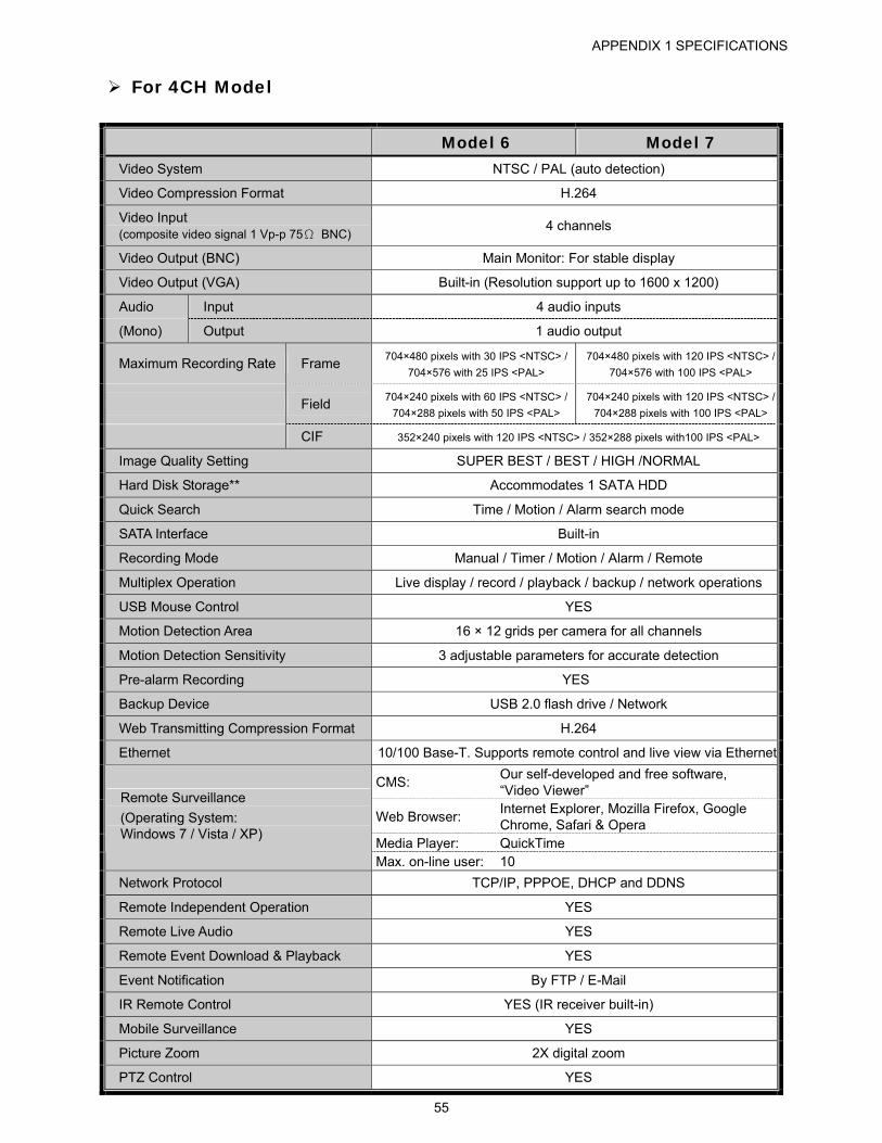
APPENDIX 1 SPECIFICATIONS
55
For 4CH Model
Model 6 Model 7 Video System NTSC / PAL (auto detection)
Video Compression Format H.264
Video Input (composite video signal 1 Vp-p 75Ω BNC)
4 channels
Video Output (BNC) Main Monitor: For stable display
Video Output (VGA) Built-in (Resolution support up to 1600 x 1200)
Audio Input 4 audio inputs
(Mono) Output 1 audio output
Maximum Recording Rate Frame 704×480 pixels with 30 IPS <NTSC> /
704×576 with 25 IPS <PAL>
704×480 pixels with 120 IPS <NTSC> /
704×576 with 100 IPS <PAL>
Field 704×240 pixels with 60 IPS <NTSC> /
704×288 pixels with 50 IPS <PAL>
704×240 pixels with 120 IPS <NTSC> /
704×288 pixels with 100 IPS <PAL>
CIF 352×240 pixels with 120 IPS <NTSC> / 352×288 pixels with100 IPS <PAL>
Image Quality Setting SUPER BEST / BEST / HIGH /NORMAL
Hard Disk Storage** Accommodates 1 SATA HDD
Quick Search Time / Motion / Alarm search mode
SATA Interface Built-in
Recording Mode Manual / Timer / Motion / Alarm / Remote
Multiplex Operation Live display / record / playback / backup / network operations
USB Mouse Control YES
Motion Detection Area 16 × 12 grids per camera for all channels
Motion Detection Sensitivity 3 adjustable parameters for accurate detection
Pre-alarm Recording YES
Backup Device USB 2.0 flash drive / Network
Web Transmitting Compression Format H.264
Ethernet 10/100 Base-T. Supports remote control and live view via Ethernet
CMS: Our self-developed and free software, “Video Viewer”
Web Browser: Internet Explorer, Mozilla Firefox, Google Chrome, Safari & Opera
Media Player: QuickTime
Remote Surveillance
(Operating System: Windows 7 / Vista / XP)
Max. on-line user: 10
Network Protocol TCP/IP, PPPOE, DHCP and DDNS
Remote Independent Operation YES
Remote Live Audio YES
Remote Event Download & Playback YES
Event Notification By FTP / E-Mail
IR Remote Control YES (IR receiver built-in)
Mobile Surveillance YES
Picture Zoom 2X digital zoom
PTZ Control YES
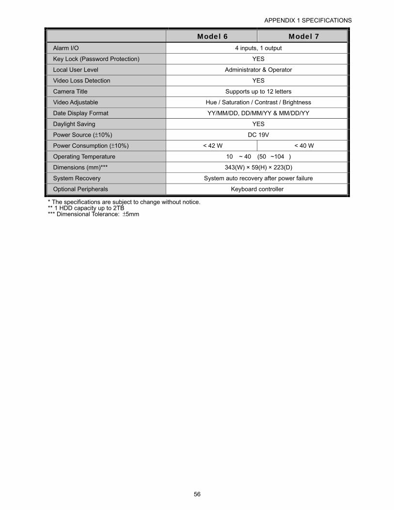
APPENDIX 1 SPECIFICATIONS
56
Model 6 Model 7 Alarm I/O 4 inputs, 1 output
Key Lock (Password Protection) YES
Local User Level Administrator & Operator
Video Loss Detection YES
Camera Title Supports up to 12 letters
Video Adjustable Hue / Saturation / Contrast / Brightness
Date Display Format YY/MM/DD, DD/MM/YY & MM/DD/YY
Daylight Saving YES
Power Source (±10%) DC 19V
Power Consumption (±10%) < 42 W < 40 W
Operating Temperature 10� ~ 40� (50�~104�)
Dimensions (mm)*** 343(W) × 59(H) × 223(D)
System Recovery System auto recovery after power failure
Optional Peripherals Keyboard controller
* The specifications are subject to change without notice. ** 1 HDD capacity up to 2TB *** Dimensional Tolerance: ±5mm
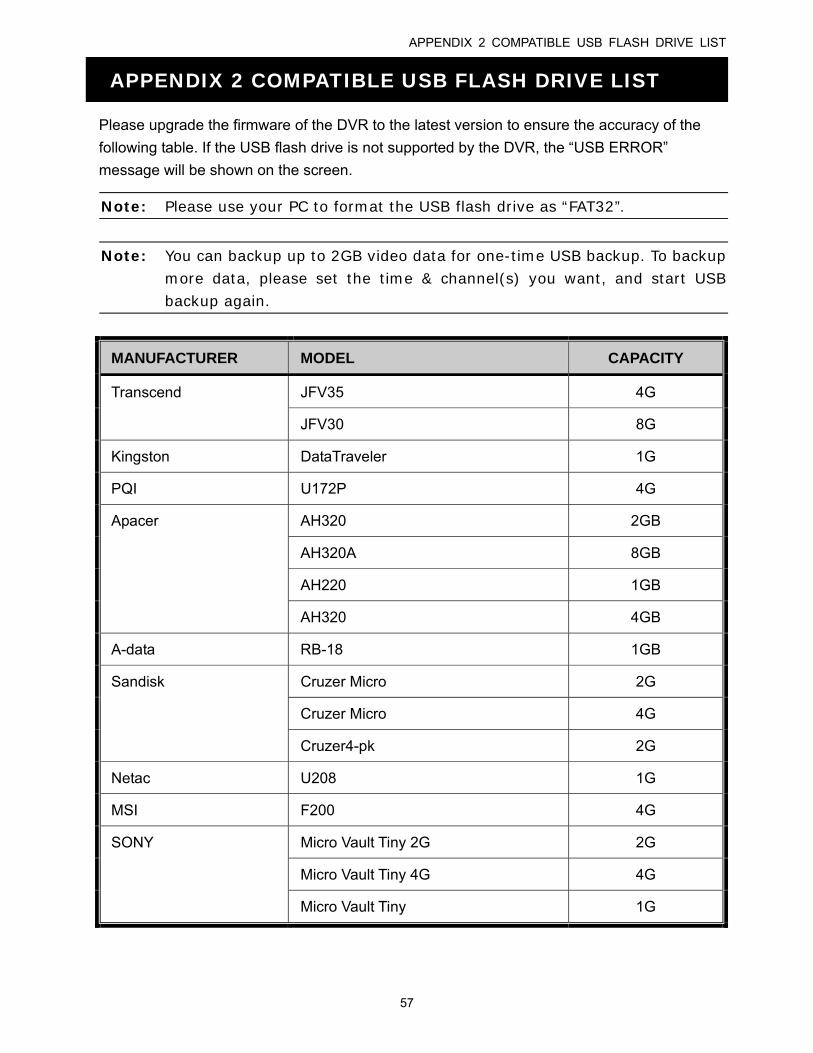
APPENDIX 2 COMPATIBLE USB FLASH DRIVE LIST
57
APPENDIX 2 COMPATIBLE USB FLASH DRIVE LIST
Please upgrade the firmware of the DVR to the latest version to ensure the accuracy of the
following table. If the USB flash drive is not supported by the DVR, the “USB ERROR”
message will be shown on the screen.
Note: Please use your PC to format the USB flash drive as “FAT32”.
Note: You can backup up to 2GB video data for one-time USB backup. To backup more data, please set the time & channel(s) you want, and start USB backup again.
MANUFACTURER MODEL CAPACITY
Transcend JFV35 4G
JFV30 8G
Kingston DataTraveler 1G
PQI U172P 4G
Apacer AH320 2GB
AH320A 8GB
AH220 1GB
AH320 4GB
A-data RB-18 1GB
Sandisk Cruzer Micro 2G
Cruzer Micro 4G
Cruzer4-pk 2G
Netac U208 1G
MSI F200 4G
SONY Micro Vault Tiny 2G 2G
Micro Vault Tiny 4G 4G
Micro Vault Tiny 1G
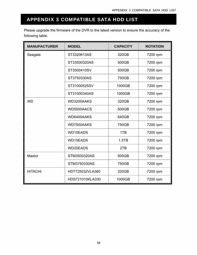
APPENDIX 3 COMPATIBLE SATA HDD LIST
58
APPENDIX 3 COMPATIBLE SATA HDD LIST
Please upgrade the firmware of the DVR to the latest version to ensure the accuracy of the
following table.
MANUFACTURER MODEL CAPACITY ROTATION
ST3320613AS 320GB 7200 rpm
ST33500320AS 500GB 7200 rpm
ST3500410SV 500GB 7200 rpm
ST3750330AS 750GB 7200 rpm
ST31000525SV 1000GB 7200 rpm
Seagate
ST31000340AS 1000GB 7200 rpm
WD3200AAKS 320GB 7200 rpm
WD5000AACS 500GB 7200 rpm
WD6400AAKS 640GB 7200 rpm
WD7500AAKS 750GB 7200 rpm
WD10EADS 1TB 7200 rpm
WD15EADS 1.5TB 7200 rpm
WD
WD20EADS 2TB 7200 rpm
STM3500320AS 500GB 7200 rpm Maxtor
STM3750330AS 750GB 7200 rpm
HDT725032VLA360 320GB 7200 rpm HITACHI
HDS721010KLA330 1000GB 7200 rpm
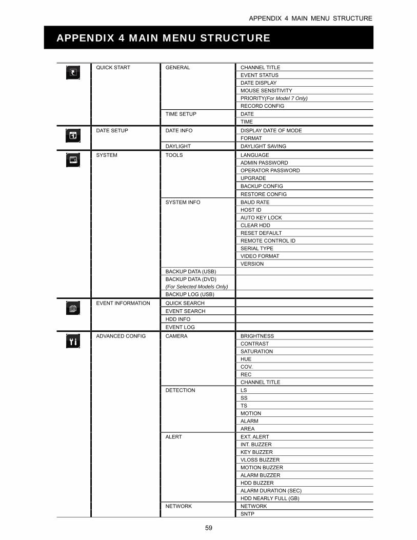
APPENDIX 4 MAIN MENU STRUCTURE
59
APPENDIX 4 MAIN MENU STRUCTURE
QUICK START GENERAL CHANNEL TITLE
EVENT STATUS
DATE DISPLAY
MOUSE SENSITIVITY
PRIORITY(For Model 7 Only)
RECORD CONFIG
TIME SETUP DATE
TIME
DATE SETUP DATE INFO DISPLAY DATE OF MODE
FORMAT DAYLIGHT DAYLIGHT SAVING
SYSTEM TOOLS LANGUAGE
ADMIN PASSWORD
OPERATOR PASSWORD
UPGRADE
BACKUP CONFIG
RESTORE CONFIG
SYSTEM INFO BAUD RATE
HOST ID
AUTO KEY LOCK
CLEAR HDD
RESET DEFAULT
REMOTE CONTROL ID
SERIAL TYPE
VIDEO FORMAT
VERSION
BACKUP DATA (USB)
BACKUP DATA (DVD)
(For Selected Models Only)
BACKUP LOG (USB)
EVENT INFORMATION QUICK SEARCH
EVENT SEARCH
HDD INFO
EVENT LOG
ADVANCED CONFIG CAMERA BRIGHTNESS
CONTRAST
SATURATION
HUE
COV.
REC
CHANNEL TITLE
DETECTION LS
SS
TS
MOTION
ALARM
AREA
ALERT EXT. ALERT
INT. BUZZER
KEY BUZZER
VLOSS BUZZER
MOTION BUZZER
ALARM BUZZER
HDD BUZZER
ALARM DURATION (SEC)
HDD NEARLY FULL (GB)
NETWORK NETWORK
SNTP
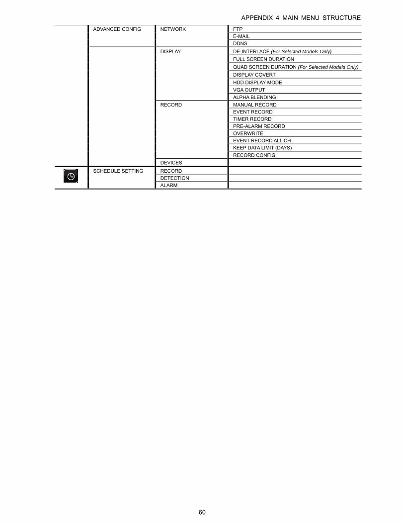
APPENDIX 4 MAIN MENU STRUCTURE
60
ADVANCED CONFIG NETWORK FTP
DDNS
DISPLAY DE-INTERLACE (For Selected Models Only)
FULL SCREEN DURATION
QUAD SCREEN DURATION (For Selected Models Only)
DISPLAY COVERT
HDD DISPLAY MODE
VGA OUTPUT
ALPHA BLENDING
RECORD MANUAL RECORD
EVENT RECORD
TIMER RECORD
PRE-ALARM RECORD
OVERWRITE
EVENT RECORD ALL CH
KEEP DATA LIMIT (DAYS)
RECORD CONFIG
DEVICES
SCHEDULE SETTING RECORD
DETECTION ALARM
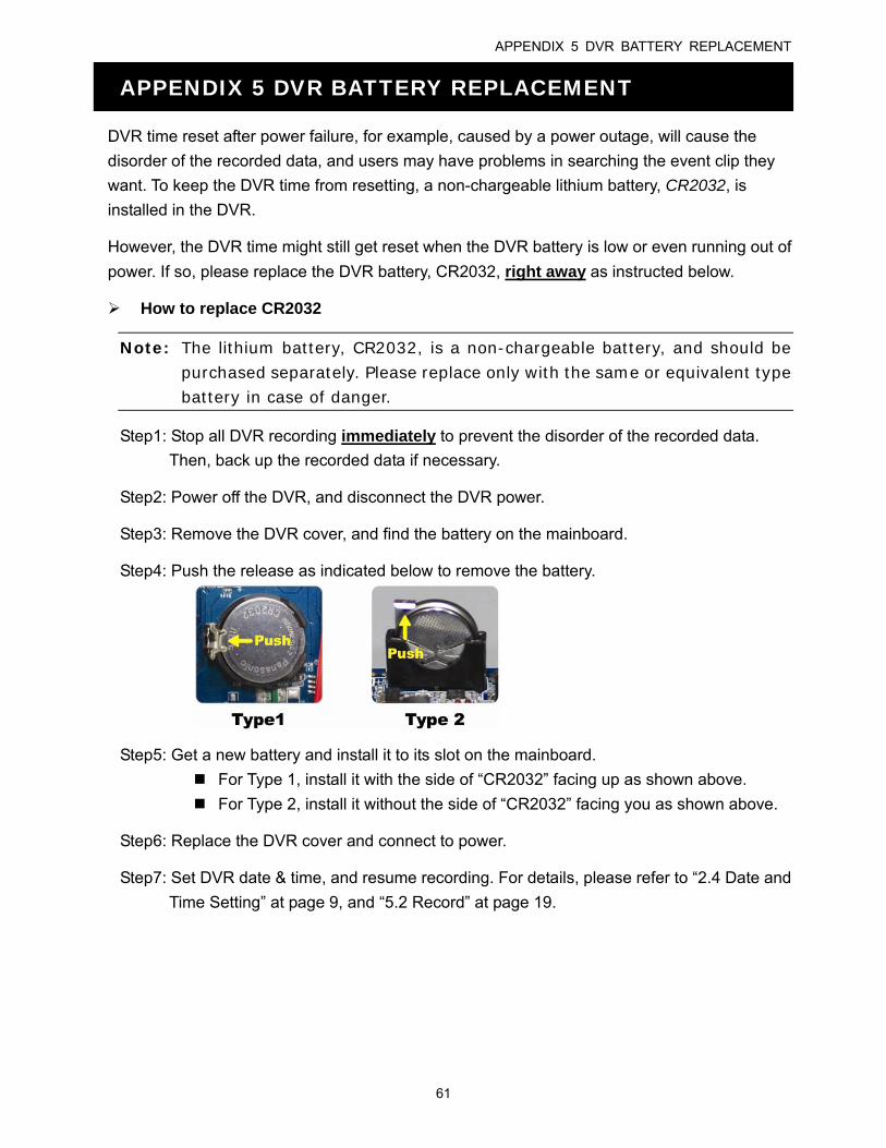
APPENDIX 5 DVR BATTERY REPLACEMENT
61
APPENDIX 5 DVR BATTERY REPLACEMENT
DVR time reset after power failure, for example, caused by a power outage, will cause the
disorder of the recorded data, and users may have problems in searching the event clip they
want. To keep the DVR time from resetting, a non-chargeable lithium battery, CR2032, is
installed in the DVR.
However, the DVR time might still get reset when the DVR battery is low or even running out of
power. If so, please replace the DVR battery, CR2032, right away as instructed below.
How to replace CR2032
Note: The lithium battery, CR2032, is a non-chargeable battery, and should be purchased separately. Please replace only with the same or equivalent type battery in case of danger.
Step1: Stop all DVR recording immediately to prevent the disorder of the recorded data.
Then, back up the recorded data if necessary.
Step2: Power off the DVR, and disconnect the DVR power.
Step3: Remove the DVR cover, and find the battery on the mainboard.
Step4: Push the release as indicated below to remove the battery.
Step5: Get a new battery and install it to its slot on the mainboard.
For Type 1, install it with the side of “CR2032” facing up as shown above.
For Type 2, install it without the side of “CR2032” facing you as shown above.
Step6: Replace the DVR cover and connect to power.
Step7: Set DVR date & time, and resume recording. For details, please refer to “2.4 Date and
Time Setting” at page 9, and “5.2 Record” at page 19.
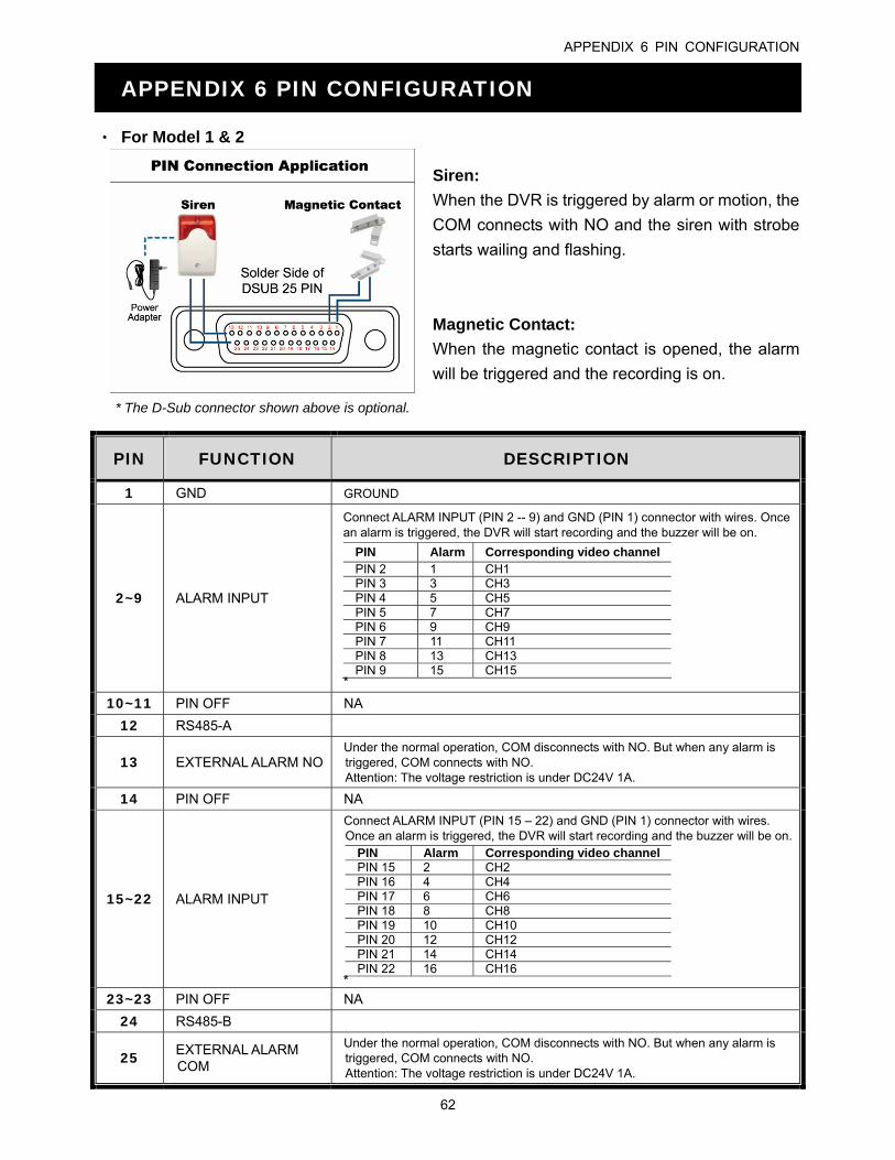
APPENDIX 6 PIN CONFIGURATION
62
APPENDIX 6 PIN CONFIGURATION
‧ For Model 1 & 2
Siren:
When the DVR is triggered by alarm or motion, the
COM connects with NO and the siren with strobe
starts wailing and flashing.
* The D-Sub connector shown above is optional.
Magnetic Contact:
When the magnetic contact is opened, the alarm
will be triggered and the recording is on.
PIN FUNCTION DESCRIPTION
1 GND GROUND
2~9 ALARM INPUT
Connect ALARM INPUT (PIN 2 -- 9) and GND (PIN 1) connector with wires. Once an alarm is triggered, the DVR will start recording and the buzzer will be on.
PIN Alarm Corresponding video channel PIN 2 1 CH1 PIN 3 3 CH3 PIN 4 5 CH5 PIN 5 7 CH7 PIN 6 9 CH9 PIN 7 11 CH11 PIN 8 13 CH13 PIN 9 15 CH15
*
10~11 PIN OFF NA
12 RS485-A
13 EXTERNAL ALARM NO Under the normal operation, COM disconnects with NO. But when any alarm is triggered, COM connects with NO. Attention: The voltage restriction is under DC24V 1A.
14 PIN OFF NA
15~22 ALARM INPUT
Connect ALARM INPUT (PIN 15 – 22) and GND (PIN 1) connector with wires. Once an alarm is triggered, the DVR will start recording and the buzzer will be on.
PIN Alarm Corresponding video channel PIN 15 2 CH2 PIN 16 4 CH4 PIN 17 6 CH6 PIN 18 8 CH8 PIN 19 10 CH10 PIN 20 12 CH12 PIN 21 14 CH14 PIN 22 16 CH16
* 23~23 PIN OFF NA
24 RS485-B
25 EXTERNAL ALARM COM
Under the normal operation, COM disconnects with NO. But when any alarm is triggered, COM connects with NO. Attention: The voltage restriction is under DC24V 1A.
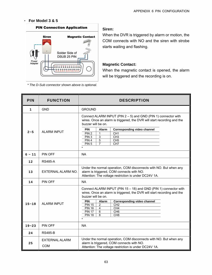
APPENDIX 6 PIN CONFIGURATION
63
‧ For Model 3 & 5
Siren:
When the DVR is triggered by alarm or motion, the
COM connects with NO and the siren with strobe
starts wailing and flashing.
* The D-Sub connector shown above is optional.
Magnetic Contact:
When the magnetic contact is opened, the alarm
will be triggered and the recording is on.
PIN FUNCTION DESCRIPTION
1 GND GROUND
2~5 ALARM INPUT
Connect ALARM INPUT (PIN 2 – 5) and GND (PIN 1) connector with wires. Once an alarm is triggered, the DVR will start recording and the buzzer will be on.
PIN Alarm Corresponding video channel PIN 2 1 CH1 PIN 3 3 CH3 PIN 4 5 CH5 PIN 5 7 CH7
*
6 ~ 11 PIN OFF NA
12 RS485-A
13 EXTERNAL ALARM NO. Under the normal operation, COM disconnects with NO. But when any alarm is triggered, COM connects with NO. Attention: The voltage restriction is under DC24V 1A.
14 PIN OFF NA
15~18 ALARM INPUT
Connect ALARM INPUT (PIN 15 – 18) and GND (PIN 1) connector with wires. Once an alarm is triggered, the DVR will start recording and the buzzer will be on.
PIN Alarm Corresponding video channel PIN 15 2 CH2 PIN 16 4 CH4 PIN 17 6 CH6 PIN 18 8 CH8
*
19~23 PIN OFF NA
24 RS485-B
25 EXTERNAL ALARM
COM
Under the normal operation, COM disconnects with NO. But when any alarm is triggered, COM connects with NO. Attention: The voltage restriction is under DC24V 1A.
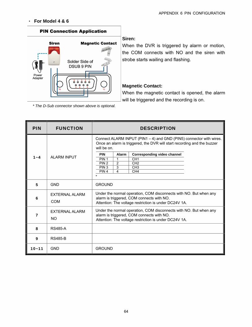
APPENDIX 6 PIN CONFIGURATION
64
‧ For Model 4 & 6
Siren:
When the DVR is triggered by alarm or motion,
the COM connects with NO and the siren with
strobe starts wailing and flashing.
* The D-Sub connector shown above is optional.
Magnetic Contact:
When the magnetic contact is opened, the alarm
will be triggered and the recording is on.
PIN FUNCTION DESCRIPTION
1~4 ALARM INPUT
Connect ALARM INPUT (PIN1 – 4) and GND (PIN5) connector with wires. Once an alarm is triggered, the DVR will start recording and the buzzer will be on.
PIN Alarm Corresponding video channel PIN 1 1 CH1 PIN 2 2 CH2 PIN 3 3 CH3 PIN 4 4 CH4
*
5 GND GROUND
6 EXTERNAL ALARM
COM
Under the normal operation, COM disconnects with NO. But when any alarm is triggered, COM connects with NO. Attention: The voltage restriction is under DC24V 1A.
7 EXTERNAL ALARM
NO
Under the normal operation, COM disconnects with NO. But when any alarm is triggered, COM connects with NO. Attention: The voltage restriction is under DC24V 1A.
8 RS485-A
9 RS485-B
10~11 GND GROUND
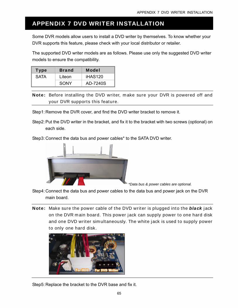
APPENDIX 7 DVD WRITER INSTALLATION
65
APPENDIX 7 DVD WRITER INSTALLATION
Some DVR models allow users to install a DVD writer by themselves. To know whether your
DVR supports this feature, please check with your local distributor or retailer.
The supported DVD writer models are as follows. Please use only the suggested DVD writer
models to ensure the compatibility.
Type Brand Model SATA Liteon iHAS120
SONY AD-7240S
Note: Before installing the DVD writer, make sure your DVR is powered off and your DVR supports this feature.
Step1: Remove the DVR cover, and find the DVD writer bracket to remove it.
Step2: Put the DVD writer in the bracket, and fix it to the bracket with two screws (optional) on
each side.
Step3: Connect the data bus and power cables* to the SATA DVD writer.
*Data bus & power cables are optional.
Step4: Connect the data bus and power cables to the data bus and power jack on the DVR
main board.
Note: Make sure the power cable of the DVD writer is plugged into the black jack on the DVR main board. This power jack can supply power to one hard disk and one DVD writer simultaneously. The white jack is used to supply power to only one hard disk.
Step5: Replace the bracket to the DVR base and fix it.
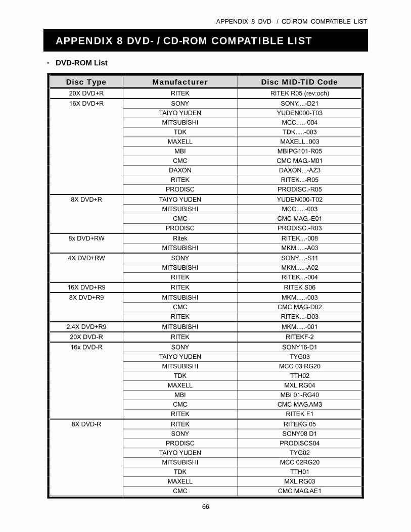
APPENDIX 8 DVD- / CD-ROM COMPATIBLE LIST
66
APPENDIX 8 DVD- / CD-ROM COMPATIBLE LIST
‧ DVD-ROM List
Disc Type Manufacturer Disc MID-TID Code 20X DVD+R RITEK RITEK R05 (rev:och)
16X DVD+R SONY SONY....-D21
TAIYO YUDEN YUDEN000-T03
MITSUBISHI MCC.....-004
TDK TDK.....-003
MAXELL MAXELL..003
MBI MBIPG101-R05
CMC CMC MAG.-M01
DAXON DAXON...-AZ3
RITEK RITEK...-R05
PRODISC PRODISC.-R05
8X DVD+R TAIYO YUDEN YUDEN000-T02
MITSUBISHI MCC.....-003
CMC CMC MAG.-E01
PRODISC PRODISC.-R03
8x DVD+RW Ritek RITEK...-008
MITSUBISHI MKM.....-A03
4X DVD+RW SONY SONY....-S11
MITSUBISHI MKM.....-A02
RITEK RITEK...-004
16X DVD+R9 RITEK RITEK S06
8X DVD+R9 MITSUBISHI MKM.....-003
CMC CMC MAG-D02
RITEK RITEK...-D03
2.4X DVD+R9 MITSUBISHI MKM.....-001
20X DVD-R RITEK RITEKF-2
16x DVD-R SONY SONY16-D1
TAIYO YUDEN TYG03
MITSUBISHI MCC 03 RG20
TDK TTH02
MAXELL MXL RG04
MBI MBI 01-RG40
CMC CMC MAG.AM3
RITEK RITEK F1
8X DVD-R RITEK RITEKG 05
SONY SONY08 D1
PRODISC PRODISCS04
TAIYO YUDEN TYG02
MITSUBISHI MCC 02RG20
TDK TTH01
MAXELL MXL RG03
CMC CMC MAG.AE1
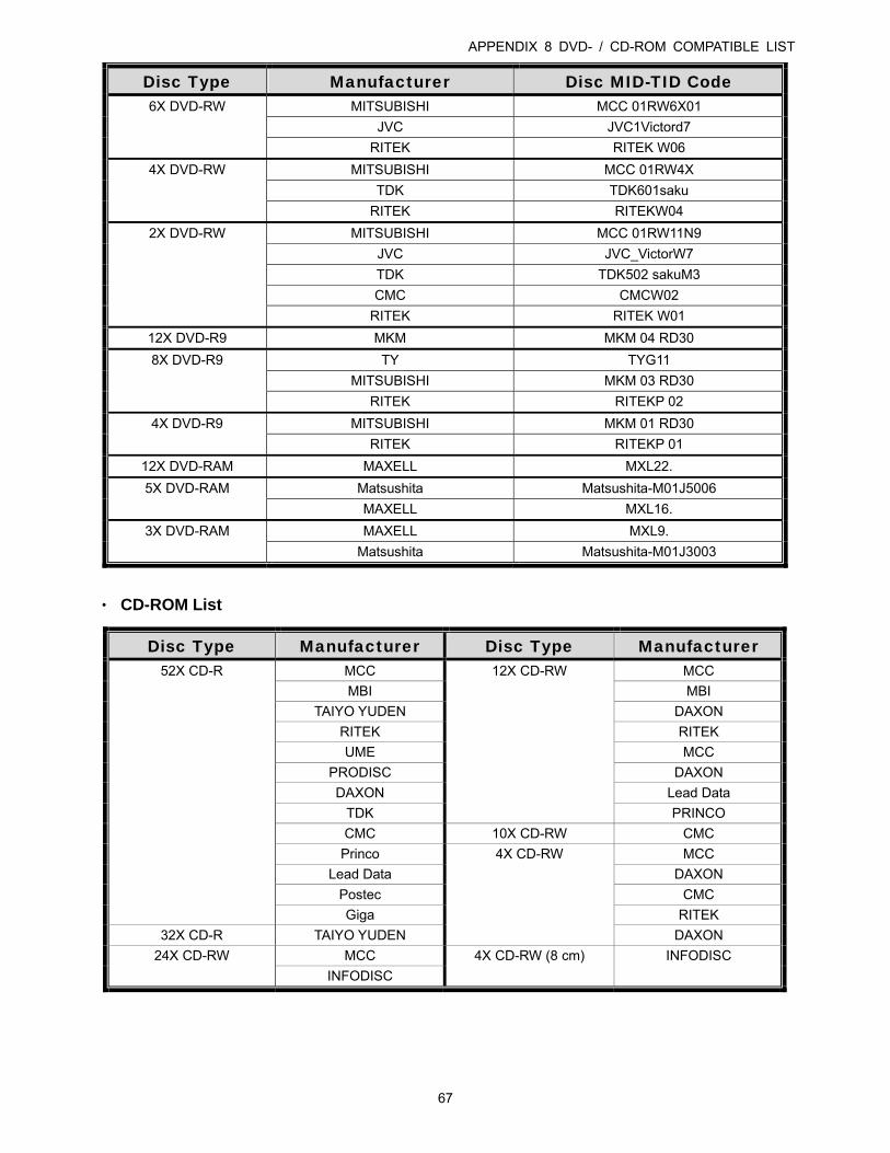
APPENDIX 8 DVD- / CD-ROM COMPATIBLE LIST
67
Disc Type Manufacturer Disc MID-TID Code 6X DVD-RW MITSUBISHI MCC 01RW6X01
JVC JVC1Victord7
RITEK RITEK W06
4X DVD-RW MITSUBISHI MCC 01RW4X
TDK TDK601saku
RITEK RITEKW04
2X DVD-RW MITSUBISHI MCC 01RW11N9
JVC JVC_VictorW7
TDK TDK502 sakuM3
CMC CMCW02
RITEK RITEK W01
12X DVD-R9 MKM MKM 04 RD30
8X DVD-R9 TY TYG11
MITSUBISHI MKM 03 RD30
RITEK RITEKP 02
4X DVD-R9 MITSUBISHI MKM 01 RD30
RITEK RITEKP 01
12X DVD-RAM MAXELL MXL22.
5X DVD-RAM Matsushita Matsushita-M01J5006
MAXELL MXL16.
3X DVD-RAM MAXELL MXL9.
Matsushita Matsushita-M01J3003
‧ CD-ROM List
Disc Type Manufacturer Disc Type Manufacturer 52X CD-R MCC 12X CD-RW MCC
MBI MBI
TAIYO YUDEN DAXON
RITEK RITEK
UME MCC
PRODISC DAXON
DAXON Lead Data
TDK PRINCO
CMC 10X CD-RW CMC
Princo 4X CD-RW MCC
Lead Data DAXON
Postec CMC
Giga RITEK
32X CD-R TAIYO YUDEN DAXON
24X CD-RW MCC 4X CD-RW (8 cm) INFODISC
INFODISC