422
2020 Edition TECHNICAL SPECIFICATIONS DIVISION 00 PROCUREMENT AND CONTRACTING REQUIREMENTS 00 01 07 Seals Page ............................................................................................................. 2 00 31 26 Existing Hazardous Material Information ............................................................... 1 00 43 73 Proposed Schedule of Values Form ...................................................................... 1 DIVISION 01 GENERAL REQUIREMENTS 01 10 00 Summary ................................................................................................................ 6 01 21 00 Allowances ............................................................................................................. 4 01 22 00 Unit Prices .............................................................................................................. 2 01 25 00 Substitution Procedures ......................................................................................... 3 01 26 00 Contract Modification Procedures .......................................................................... 3 01 29 00 Payment Procedures ............................................................................................. 4 01 31 00 Project Management and Coordination ............................................................... 10 01 32 00 Construction Progress Documentation .................................................................. 5 01 33 00 Submittal Procedures ............................................................................................. 8 01 35 16 Alteration Project Procedures ................................................................................ 8 01 40 00 Quality Requirements ............................................................................................ 8 01 41 50 Statement of Special Inspections......................................................................... 13 01 41 50.01 Statement of Special Inspections Responsibilities ................................................ 3 01 42 00 References ............................................................................................................. 8 01 50 00 Temporary Facilities and Controls ......................................................................... 9 01 56 39 Temporary Tree and Plant Protection .................................................................... 4 01 60 00 Product Requirements ........................................................................................... 6 01 73 00 Execution ............................................................................................................... 9 01 74 19 Construction Waste Management and Disposal.................................................... 6 01 77 00 Closeout Procedures ............................................................................................. 5 01 78 23 Operation and Maintenance Data .......................................................................... 6 01 78 39 Project Record Documents .................................................................................... 4 01 79 00 Demonstration and Training................................................................................... 4 DIVISION 02 EXISTING CONDITIONS 02 41 19 Selective Demolition .............................................................................................. 6 DIVISION 03 CONCRETE 03 01 30 Maintenance of Cast-in-Place Concrete ................................................................ 5 DIVISION 05 METALS 05 40 00 Cold-Formed Metal Framing .................................................................................. 7 05 50 00 Metal Fabrications .................................................................................................. 9 DIVISION 06 WOOD, PLASTICS, AND COMPOSITES 06 10 53 Miscellaneous Rough Carpentry ............................................................................ 5 06 20 23 Interior Rough Carpentry ....................................................................................... 5 06 41 16 Plastic-Laminate-Clad Architectural Cabinets ....................................................... 6 DIVISION 07 THERMAL AND MOISTURE PROTECTION 07 19 00 Water Repellents.................................................................................................... 4 07 21 00 Thermal Insulation ................................................................................................. 3 07 92 00 Joint Sealants......................................................................................................... 6 07 92 19 Acoustical Joint Sealants ....................................................................................... 3 DIVISION 08 OPENINGS 08 11 13 Hollow Metal Doors and Frames............................................................................ 6 08 12 13 Hollow Metal Frames ............................................................................................. 5 TOC - 2

H59-N046-PD Spec Manual IFB Part 2

  • Upload
    others

  • View
    4

  • Download
    0

Embed Size (px)

Citation preview

2020 Edition

TECHNICAL SPECIFICATIONS

DIVISION 00 PROCUREMENT AND CONTRACTING REQUIREMENTS

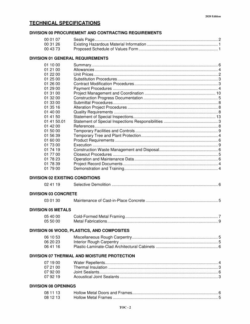
00 01 07 Seals Page 2 00 31 26 Existing Hazardous Material Information 1 00 43 73 Proposed Schedule of Values Form 1

DIVISION 01 GENERAL REQUIREMENTS

01 10 00 Summary 6 01 21 00 Allowances 4 01 22 00 Unit Prices 2 01 25 00 Substitution Procedures 3 01 26 00 Contract Modification Procedures 3 01 29 00 Payment Procedures 4 01 31 00 Project Management and Coordination 10 01 32 00 Construction Progress Documentation 5 01 33 00 Submittal Procedures 8 01 35 16 Alteration Project Procedures 8 01 40 00 Quality Requirements 8 01 41 50 Statement of Special Inspections 13 01 41 5001 Statement of Special Inspections Responsibilities 3 01 42 00 References 8 01 50 00 Temporary Facilities and Controls 9 01 56 39 Temporary Tree and Plant Protection 4 01 60 00 Product Requirements 6 01 73 00 Execution 9 01 74 19 Construction Waste Management and Disposal 6 01 77 00 Closeout Procedures 5 01 78 23 Operation and Maintenance Data 6 01 78 39 Project Record Documents 4 01 79 00 Demonstration and Training 4

DIVISION 02 EXISTING CONDITIONS

02 41 19 Selective Demolition 6

DIVISION 03 CONCRETE

03 01 30 Maintenance of Cast-in-Place Concrete 5

DIVISION 05 METALS

05 40 00 Cold-Formed Metal Framing 7 05 50 00 Metal Fabrications 9

DIVISION 06 WOOD PLASTICS AND COMPOSITES

06 10 53 Miscellaneous Rough Carpentry 5 06 20 23 Interior Rough Carpentry 5 06 41 16 Plastic-Laminate-Clad Architectural Cabinets 6

DIVISION 07 THERMAL AND MOISTURE PROTECTION

07 19 00 Water Repellents 4 07 21 00 Thermal Insulation 3 07 92 00 Joint Sealants 6 07 92 19 Acoustical Joint Sealants 3

DIVISION 08 OPENINGS

08 11 13 Hollow Metal Doors and Frames 6 08 12 13 Hollow Metal Frames 5

TOC - 2

2020 Edition

08 14 16 Flush Wood Doors 5 08 33 23 Overhead Coiling Doors 8 08 41 13 Aluminum-Framed Entrances and Storefronts 9 08 71 11 Door Hardware (Descriptive Specification) 15 08 80 00 Glazing 9

DIVISION 09 FINISHES

09 22 16 Non-Structural Metal Framing 4 09 29 00 Gypsum Board 5 09 51 13 Acoustical Panel Ceilings 7 09 65 13 Resilient Base and Accessories 5 09 65 19 Resilient Tile Flooring 4 09 91 24 Interior Painting (MPI Standards) 6

DIVISION 10 SPECIALTIES

10 14 19 Dimensional Letter Signage 4 10 14 23 Panel Signage 5 10 14 29 Modular Signage 4 10 44 16 Fire Extinguishers 3

DIVISION 11 EQUIPMENT

11 13 13 Loading Dock Bumpers 2

DIVISION 12 FURNISHINGS

12 36 19 Wood Countertops 5 12 36 6116 Solid Surfacing Countertops 4

DIVISION 21 FIRE SUPPRESSION

21 13 13 Fire Protection Sprinkler Piping 3 Fire Protection Sprinkler System Specification Sheet 1

DIVISION 22 PLUMBING

22 00 00 Plumbing General Provisions 8 22 05 14 Pipe Tube and Fittings 3 22 05 15 Piping Accessories 3 22 05 23 Valves 2 22 05 29 Hangers Supports and Anchors 4 22 05 48 Seismic Protection for Mechanical Systems 3 22 07 00 Systems Insulation 3 22 11 16 Domestic Water Piping Systems 3

DIVISION 23 HEATING VENTILATING AND AIR CONDITIONING (HVAC)

23 00 00 Mechanical General Provisions 8 23 05 14 Pipe Tube and Fittings 3 23 05 15 Piping Accessories 2 23 05 29 Hangers Supports and Anchors 3 23 05 48 Seismic Protection for Mechanical Systems 3 23 07 00 Systems Insulation 3 23 09 14 TestingAdjustingBalancing HeatingVentilationCooling Systems 11 23 30 00 Air Distribution 6 23 81 43 Split System Heat Pumps 4

DIVISION 26 ELECTRICAL

26 05 00 General Provisions 3 26 05 01 Basic Materials 4 26 05 19 Conductors 3

TOC - 3

2020 Edition

26 05 26 Grounding 2 26 05 39 Electrical Raceways 3 26 05 75 Electrical Testing 3 26 41 16 Electrical Demolition 2 26 51 00 Lighting 3

APPENDIX ndash A SUBSTITUTION REQUEST FORMS CSI 15C ndash Substitution Request Form (During BiddingNegotiating Stage) 1 CSI 131A ndash Substitution Request Form (After BiddingNegotiating Stage) 1

APPENDIX ndash B HAZARDOUS MATERIALS REPORT ET Bookstore Expansion Project Asbestos and Lead Paint Evaluation 79

TOC - 4

11

GREENVILLE TECHNICAL COLLEGE OSE Project H59-N046-PO Greenville - Bldg 103 Bookstore Expansion GMC Project AGRE200029 506 S Pleasantburg Drive Greenville SC 29607 October 30 2020

DOCUMENT 00 01 07 middotSEALS PAGE

DESIGN PROFESSIONALS OF RECORD

A Architect 1 Shannon 0 Calloway 2 SC Lie No 9993 3 Responsible for Divisions 01-49 Sections except where indicated as prepared by other

design professionals of record

B Fire-Protection Engineer 1 George H McCall 2 SC Lie No 22349 3 Responsible for Division 21

f CAR11 0 bullbullbullbullbullbullbull bullbullolt ~ 0 bullbullmiddot middotmiddot 1-_ ~ 2 middot middotmiddot) ~

McCALL amp SON shy=~ INC z ~ _ r~~ c ~ middot No C00070 ~~ - middot~ middotmiddot ~ ~ bullbull h ~

1tt-bullbullbullbullbullbullbullbull (ltlt 111 c OF AU 111111 11 1

C Plumbing Engineer 1 Jody C Parker 2 SC Lie No 25120 3 Responsible for Division 22

Seals Page oo 01 07 - 1 of 2

GREENVILLE TECHNICAL COLLEGE Greenville - Bldg 103 Bookstore Expansion 506 S Pleasantburg Drive Greenville SC 29607

D HVAC Engineer 1 Jody C Parker 2 SC Lie No 25120 3 Responsible for Division 23

ta i rAa 1

sect ~_~~ ~ ~~N bull bullX4- middot~ ~ -middot ~ middotmiddot- ~ l tiM61NlpoundR~ - ~

~ amp ASSOCIATES ~ _ bullNC ~-middot -- middot~ shy~ l bullbull Mo - _ ~ ~~~middotmiddot ~- ~ ~hmiddotmiddot--bullbull ~~ ~

~I ~c- OF

E ElectPeter KeewSC Lic No 34488Responsible for Division 26

rical Engineer 1 2 3

11232020

END OF DOCUMENT 00 01 07

OSE Project H59-N046-PD GMC Project AGRE200029

October 30 2020

Seals Page 00 01 07 - 2 of 2

11

GREENVILLE TECHNICAL COLLEGE OSE Project H59-N046-PD Greenville - Bldg 103 Bookstore Expansion GMC Project AGRE200029 506 S Pleasantburg Drive Greenville SC 29607 October 30 2020

DOCUMENT 003126 - EXISTING HAZARDOUS MATERIAL INFORMATION

EXISTING HAZARDOUS MATERIAL INFORMATION

A This Document with its referenced attachments is part of the Procurement and Contracting Requirements for Project They provide Owners information for Bidders convenience and are intended to supplement rather than serve in lieu of Bidders own investigations They are made available for Bidders convenience and information but are not a warranty of existing conditions This Document and its attachments are not part of the Contract Documents

B An existing asbestos report for Project prepared by Froehling amp Robertson Inc dated September 13th 2020 is available for viewing as appended to this Document

C An existing lead report for Project prepared by Froehling amp Robertson Inc dated September 13th 2020 is available for viewing as appended to this Document

D Related Requirements

1 Document 002113 Instructions to Bidders for the Bidders responsibilities for examination of Project site and existing conditions

2 Section 02 41 19 Selective Structure Demolition for notification requirements if materials suspected of containing hazardous materials are encountered

END OF DOCUMENT 00 31 26

Existing Hazardous Material Information 003126 - 1 of 1

GREENVILLE TECHNICAL COLLEGE OSE Project H59-N046-PD Greenville - Bldg 103 Bookstore Expansion GMC Project AGRE200029 506 S Pleasantburg Drive Greenville SC 29607 October 30 2020

DOCUMENT 00 43 73 - PROPOSED SCHEDULE OF VALUES FORM

11 BID FORM SUPPLEMENT

A A completed Proposed Schedule of Values form is required to be attached to the Bid Form

12 PROPOSED SCHEDULE OF VALUES FORM

A Proposed Schedule of Values Form Provide a breakdown of the bid amount including alternates in enough detail to facilitate continued evaluation of bid Coordinate with the Project Manual table of contents Provide multiple line items for principal material and subcontract amounts in excess of five percent of the Contract Sum

B Arrange schedule of values using AIA Document G703-1992

1 Copies of AIA standard forms may be obtained from the American Institute of Architects httpswwwaiacontractsorg library (800) 942-7732

END OF DOCUMENT 00 43 73

Proposed Schedule of Values Formshy 00 43 73 - 1 of 1

GREENVILLE TECHNICAL COLLEGE OSE Project H59-N046-PD Greenville - Bldg 103 Bookstore Expansion GMC Project AGRE200029 506 S Pleasantburg Drive Greenville SC 29607 October 30 2020

SECTION 01 10 00 - SUMMARY

PART 1 - GENERAL

11 RELATED DOCUMENTS

A Drawings and general provisions of the Contract including General and Supplementary Conditions and other Division 01 Specification Sections apply to this Section

12 SUMMARY

A Section Includes 1 Project information 2 Work covered by Contract Documents 3 Phased construction 4 Work performed by Owner 5 Work under Owners separate contracts 6 Future work not part of this Project 7 Owners product purchase contracts 8 Owner-furnishedContractor-installed (OFCI) products 9 Owner-furnishedOwner-installed (OFOI) products 10 Contractor-furnishedOwner-installed (CFOI) products 11 Contractors use of site and premises 12 Coordination with occupants 13 Work restrictions 14 Specification and Drawing conventions 15 Miscellaneous provisions

B Related Requirements 1 Section 01 50 00 Temporary Facilities and Controls for limitations and procedures

governing temporary use of Owners facilities 2 Section 01 73 00 Execution for coordination of Owner-installed products

13 DEFINITIONS

A Work Package A group of specifications drawings and schedules prepared by the design team to describe a portion of the Project Work for pricing permitting and construction

14 PROJECT INFORMATION

A Project Identification Greenville ndash Bldg 103 Bookstore Expansion 1 State project H59-N046-PD 2 GMC project AGRE200029 3 Project Location Greenville Technical College ndash Barton Campus Building 103 506 S

Pleasantburg Drive Greenville SC 29607

B Owner Greenville Technical College 1 Owners Representative Bill Tripp | Capital Projects-Facilities

(864) 250 ndash 8112 Billtrippgvltecedu

Summary 01 10 00 - 1 of 6

15

GREENVILLE TECHNICAL COLLEGE OSE Project H59-N046-PD Greenville - Bldg 103 Bookstore Expansion GMC Project AGRE200029 506 S Pleasantburg Drive Greenville SC 29607 October 30 2020

2 Owners Representative Scott Wilbanks | Director of Facilities (864) 250 ndash 8281 scottwilbanksgvltecedu

C Architect Goodwyn Mills Cawood Inc 1 Architects Representative Shannon Calloway | Project Architect

617 E McBee Ave Suite 200 Greenville SC 29601 (864) 527 ndash 0460 shannoncallowaygmcnetworkcom

Wes Spires | Project Manager 617 E McBee Ave Suite 200 Greenville SC 29601 (864) 527 ndash 0460 wesspiresgmcnetworkcom

D Architects Consultants Architect has retained the following design professionals who have prepared designated portions of the Contract Documents 1 Mechanical and Plumbing Engineer of Record Peritus Engineers

a Mechanical and Plumbing Representative Jody Parker | PE 10 E Dorchester Blvd Greenville SC 29605 (864) 277 ndash 8287 jparkerperitusengineerscom

2 Electrical Engineer of Record Budette Engineering a Electrical Representative Bobby Bazemore | PE

200 Regent Park Court Greenville SC 29607 (864) 297 ndash 8717 bbazemoreburdetteengrcom

E Web-Based Project Software Project software will be used for purposes of managing communication and documents during the construction stage 1 See Section 01 31 00 Project Management and Coordination for requirements for

using web-based Project software

WORK COVERED BY CONTRACT DOCUMENTS

A The Work of Project is defined by the Contract Documents and includes but is not limited to the following 1 Purpose of the project is to expand the retail floor area as well as the storagewarehouse

associated with the bookstore the scope of the expansion will require limited demolition of existing partitions as well as an existing classroom area and other Work indicated in the Contract Documents

B Type of Contract 1 Project will be constructed under a single prime contract

Summary 01 10 00 - 2 of 6

GREENVILLE TECHNICAL COLLEGE OSE Project H59-N046-PD Greenville - Bldg 103 Bookstore Expansion GMC Project AGRE200029 506 S Pleasantburg Drive Greenville SC 29607 October 30 2020

16 WORK PERFORMED BY OWNER

A Cooperate fully with Owner so work may be carried out smoothly without interfering with or delaying Work under this Contract or work by Owner Coordinate the Work of this Contract with work performed by Owner

B Preceding Work Owner will perform the following construction operations at Project site Those operations are scheduled to be substantially complete before Work under this Contract begins 1 Remove projectors and all associated mounts hardware etc from existing classrooms 2 Remove smartboards and all associated mounts hardware etc from existing classrooms

C Concurrent Work Owner will perform the following construction operations at Project site Those operations will be conducted simultaneously with Work under this Contract 1 Data Wiring and Termination

a Conduit pathways junction boxes and similar items identified in the drawings are included in the scope of this project and shall be performed by the GC of this bid package

2 Security Equipment a Conduit pathways junction boxes and similar items identified in the drawings are

included in the scope of this project and shall be performed by the GC of this bid package

3 Install furniture and furnishings 4 Other items identified as Owner Furnished Owner Installed (OFOI)

17 WORK UNDER OWNERS SEPARATE CONTRACTS

A Work with Separate Contractors Cooperate fully with Owners separate contractors so work on those contracts may be carried out smoothly without interfering with or delaying Work under this Contract or other contracts Coordinate the Work of this Contract with work performed under Owners separate contracts

B Concurrent Work Owner will award separate contract(s) for the following construction operations at Project site Those operations will be conducted simultaneously with Work under this Contract 1 Security system To install devices and pull associated wiring andor cabling the owner

will contract the campus security provider to install desired items Contractor under this scope of work shall install conduit and pathways needed for security items operation as identified in the Electrical drawings

18 OWNER-FURNISHEDOWNER-INSTALLED (OFOI) PRODUCTS

A The Owner will furnish and install products indicated

B Owner-FurnishedOwner-Installed (OFOI) Products 1 Moveable floor based display stands and shelf(s)

19 CONTRACTORS USE OF SITE AND PREMISES

A Restricted Use of Site Contractor shall have limited use of Project site for construction operations as indicated on Drawings by the Contract limits and as indicated by requirements of this Section

Summary 01 10 00 - 3 of 6

GREENVILLE TECHNICAL COLLEGE OSE Project H59-N046-PD Greenville - Bldg 103 Bookstore Expansion GMC Project AGRE200029 506 S Pleasantburg Drive Greenville SC 29607 October 30 2020

B Limits on Use of Site Limit use of Project site to areas within the Contract limits indicated Do not disturb portions of Project site beyond areas in which the Work is indicated 1 Limits on Use of Site Confine construction operations to the areas of work themselves

existing restrooms in the existing building are not allowed for use by the Contractor or subcontractors at the site

2 Driveways Walkways and Entrances Keep driveways loading areas and entrances serving premises clear and available to Owner Owners employees and emergency vehicles at all times Do not use these areas for parking or for storage of materials a Schedule deliveries to minimize use of driveways and entrances by construction

operations b Schedule deliveries to minimize space and time requirements for storage of

materials and equipment on-site

C Condition of Existing Building Maintain portions of existing building affected by construction operations in a weathertight condition throughout construction period Repair damage caused by construction operations

D Condition of Existing Grounds Maintain portions of existing grounds landscaping and hardscaping affected by construction operations throughout construction period Repair damage caused by construction operations

110 COORDINATION WITH OCCUPANTS

A Partial Owner Occupancy Owner will occupy the premises during entire construction period with the exception of areas under construction Cooperate with Owner during construction operations to minimize conflicts and facilitate Owner usage Perform the Work so as not to interfere with Owners operations Maintain existing exits unless otherwise indicated 1 Maintain access to existing walkways corridors and other adjacent occupied or used

facilities Do not close or obstruct walkways corridors or other occupied or used facilities without written permission from Owner and authorities having jurisdiction

2 Provide not less than five business days notice to Owner of activities that will affect Owners operations

B Owner Limited Occupancy of Completed Areas of Construction Owner reserves the right to occupy and to place and install equipment in completed portions of the Work prior to Substantial Completion of the Work provided such occupancy does not interfere with completion of the Work Such placement of equipment and limited occupancy shall not constitute acceptance of the total Work 1 Obtain a Certificate of Occupancy or Temporary Certificate of Occupancy from authorities

having jurisdiction before limited Owner occupancy 2 Before limited Owner occupancy mechanical and electrical systems shall be fully

operational and required tests and inspections shall be successfully completed On occupancy Owner will operate and maintain mechanical and electrical systems serving occupied portions of Work

3 On occupancy Owner will assume responsibility for maintenance and custodial service for occupied portions of Work

111 WORK RESTRICTIONS

A Comply with restrictions on construction operations 1 Comply with limitations on use of public streets work on public streets rights of way and

other requirements of authorities having jurisdiction

Summary 01 10 00 - 4 of 6

GREENVILLE TECHNICAL COLLEGE OSE Project H59-N046-PD Greenville - Bldg 103 Bookstore Expansion GMC Project AGRE200029 506 S Pleasantburg Drive Greenville SC 29607 October 30 2020

B On-Site Work Hours Limit work to between 7 am to 6 pm Monday through Friday unless otherwise indicated Work hours may be modified to meet Project requirements if approved by Owner and authorities having jurisdiction 1 Weekend Hours Coordinate with owner at least seven calendar days prior 2 Early Morning Hours Coordinate with owner at least seven calendar days prior 3 Work in Existing Building Coordinate with owner at least seven calendar days prior 4 Hours for Utility Shutdowns Cooridnate with owner at least seven calendar days prior

C On-Site Work Day Restrictions Do not perform work resulting in utility shutdowns or resulting in noisy activity on-site during work black-out days or exam periods indicated by ownerrsquos academic calendar

D Existing Utility Interruptions Do not interrupt utilities serving facilities occupied by Owner or others unless permitted under the following conditions and then only after arranging for temporary utility services according to requirements indicated 1 Notify Architect and Owner not less than seven calandar days in advance of proposed

utility interruptions 2 Obtain Owners written permission before proceeding with utility interruptions

E Noise Vibration Dust and Odors Coordinate operations that may result in high levels of noise and vibration dust odors or other disruption to Owner occupancy with Owner 1 Notify Architect and Owner not less than seven days in advance of proposed disruptive

operations 2 Obtain Owners written permission before proceeding with disruptive operations

F Smoking and Controlled Substance Restrictions Use of tobacco products alcoholic beverages and other controlled substances on Project site is not permitted

G Employee Identification Provide identification tags andor identifying article of clothing for Contractor personnel working on Project site Require personnel to use identification tags at all times

H Employee Screening Comply with Owners requirements for screening of Contractor personnel working on Project site as identified in the Owner-Contractor Agreement 1 Maintain list of approved screened personnel with Owners representative

112 SPECIFICATION AND DRAWING CONVENTIONS

A Specification Content The Specifications use certain conventions for the style of language and the intended meaning of certain terms words and phrases when used in particular situations These conventions are as follows 1 Imperative mood and streamlined language are generally used in the Specifications The

words shall shall be or shall comply with depending on the context are implied where a colon () is used within a sentence or phrase

2 Text Color Text used in the Specifications including units of measure manufacturer and product names and other text may appear in multiple colors or underlined as part of a hyperlink no emphasis is implied by text with these characteristics

3 Hypertext Text used in the Specifications may contain hyperlinks Hyperlinks may allow for access to linked information that is not residing in the Specifications Unless otherwise indicated linked information is not part of the Contract Documents

4 Specification requirements are to be performed by Contractor unless specifically stated otherwise

Summary 01 10 00 - 5 of 6

GREENVILLE TECHNICAL COLLEGE OSE Project H59-N046-PD Greenville - Bldg 103 Bookstore Expansion GMC Project AGRE200029 506 S Pleasantburg Drive Greenville SC 29607 October 30 2020

B Division 00 Contracting Requirements General provisions of the Contract including General and Supplementary Conditions apply to all Sections of the Specifications

C Division 01 General Requirements Requirements of Sections in Division 01 apply to the Work of all Sections in the Specifications

D Drawing Coordination Requirements for materials and products identified on Drawings are described in detail in the Specifications One or more of the following are used on Drawings to identify materials and products 1 Terminology Materials and products are identified by the typical generic terms used in

the individual Specifications Sections 2 Abbreviations Materials and products are identified by abbreviations scheduled on

Drawings 3 Keynoting Materials and products are identified by reference keynotes referencing

Specification Section numbers found in this Project Manual

PART 2 - PRODUCTS (Not Used)

PART 3 - EXECUTION (Not Used)

END OF SECTION 01 10 00

Summary 01 10 00 - 6 of 6

GREENVILLE TECHNICAL COLLEGE OSE Project H59-N046-PD Greenville - Bldg 103 Bookstore Expansion GMC Project AGRE200029 506 S Pleasantburg Drive Greenville SC 29607 October 30 2020

SECTION 01 21 00 - ALLOWANCES

PART 1 - GENERAL

11 RELATED DOCUMENTS

A Drawings and general provisions of the Contract including General and Supplementary Conditions and other Division 01 Specification Sections apply to this Section

12 SUMMARY

A Section includes administrative and procedural requirements governing allowances

B Types of allowances include the following 1 Lump-sum allowances 2 Unit-cost allowances 3 Quantity allowances 4 Contingency allowances 5 Testing and inspecting allowances

C Related Requirements 1 Section 01 22 00 Unit Prices for procedures for using unit prices including adjustment

of quantity allowances when applicable 2 Section 01 26 00 Contract Modification Procedures for procedures for submitting and

handling Change Orders 3 Section 01 40 00 Quality Requirements for procedures governing the use of allowances

for field testing by an independent testing agency

13 DEFINITIONS

A Allowance A quantity of work or dollar amount included in the Contract established in lieu of additional requirements used to defer selection of actual materials and equipment to a later date when direction will be provided to Contractor If necessary additional requirements will be issued by Change Order

14 SELECTION AND PURCHASE

A At the earliest practical date after award of the Contract advise Architect of the date when final selection or purchase and delivery of each product or system described by an allowance must be completed by the Owner to avoid delaying the Work

B At Architects request obtain proposals for each allowance for use in making final selections Include recommendations that are relevant to performing the Work

C Purchase products and systems selected by Architect from the designated supplier

Allowances 01 21 00 - 1 of 4

GREENVILLE TECHNICAL COLLEGE OSE Project H59-N046-PD Greenville - Bldg 103 Bookstore Expansion GMC Project AGRE200029 506 S Pleasantburg Drive Greenville SC 29607 October 30 2020

15 ACTION SUBMITTALS

A Submit proposals for purchase of products or systems included in allowances in the form specified for Change Orders

16 INFORMATIONAL SUBMITTALS

A Submit invoices or delivery slips to show actual quantities of materials delivered to the site for use in fulfillment of each allowance

B Submit time sheets and other documentation to show labor time and cost for installation of allowance items that include installation as part of the allowance

C Coordinate and process submittals for allowance items in same manner as for other portions of the Work

17 LUMP-SUM ALLOWANCES

A Allowance shall include cost to Contractor of specific products and materials ordered by Owner or selected by Architect under allowance and shall include taxes freight and delivery to Project site

B Unless otherwise indicated Contractors costs for receiving and handling at Project site labor installation overhead and profit and similar costs related to products and materials ordered by Owner or selected by Architect under allowance shall be included as part of the Contract Sum and not part of the allowance

C Unused Materials Return unused materials purchased under an allowance to manufacturer or supplier for credit to Owner after installation has been completed and accepted 1 If requested by Architect retain and prepare unused material for storage by Owner

Deliver unused material to Owners storage space as directed

18 UNIT-COST ALLOWANCES

A Allowance shall include cost to Contractor of specific products and materials ordered by Owner or selected by Architect under allowance and shall include taxes freight and delivery to Project site

B Unless otherwise indicated Contractors costs for receiving and handling at Project site labor installation overhead and profit and similar costs related to products and materials ordered by Owner or selected by Architect under allowance shall be included as part of the Contract Sum and not part of the allowance

C Unused Materials Return unused materials purchased under an allowance to manufacturer or supplier for credit to Owner after installation has been completed and accepted 1 If requested by Architect retain and prepare unused material for storage by Owner

Deliver unused material to Owners storage space as directed

Allowances 01 21 00 - 2 of 4

GREENVILLE TECHNICAL COLLEGE OSE Project H59-N046-PD Greenville - Bldg 103 Bookstore Expansion GMC Project AGRE200029 506 S Pleasantburg Drive Greenville SC 29607 October 30 2020

19 QUANTITY ALLOWANCES

A Allowance shall include cost to Contractor of specific products and materials ordered by Owner or selected by Architect under allowance and shall include taxes freight and delivery to Project site

B Unless otherwise indicated Contractors costs for receiving and handling at Project site labor installation overhead and profit and similar costs related to products and materials ordered by Owner or selected by Architect under allowance shall be included as part of the Contract Sum and not part of the allowance

C Unused Materials Return unused materials purchased under an allowance to manufacturer or supplier for credit to Owner after installation has been completed and accepted 1 If requested by Architect retain and prepare unused material for storage by Owner

Deliver unused material to Owners storage space as directed

110 CONTINGENCY ALLOWANCES

A Use the contingency allowance only as directed by Architect for Owners purposes and only by Change Orders that indicate amounts to be charged to the allowance

B Contractors overhead profit and related costs for products and equipment ordered by Owner under the contingency allowance are included in the allowance and are not part of the Contract Sum These costs include delivery installation taxes insurance equipment rental and similar costs

C Change Orders authorizing use of funds from the contingency allowance will include Contractors related costs and reasonable overhead and profit

D At Project closeout credit unused amounts remaining in the contingency allowance to Owner by Change Order

111 ADJUSTMENT OF ALLOWANCES

A Allowance Adjustment To adjust allowance amounts prepare a Change Order proposal based on the difference between purchase amount and the allowance multiplied by final measurement of work-in-place where applicable If applicable include reasonable allowances for cutting losses tolerances mixing wastes normal product imperfections required maintenance materials and similar margins 1 Include installation costs in purchase amount only where indicated as part of the

allowance 2 If requested prepare explanation and documentation to substantiate distribution of

overhead costs and other markups 3 Submit substantiation of a change in scope of Work if any claimed in Change Orders

related to unit-cost allowances 4 Owner reserves the right to establish the quantity of work-in-place by independent

quantity survey measure or count

B Submit claims for increased costs due to a change in the scope or nature of the allowance described in the Contract Documents whether for the purchase order amount or Contractors handling labor installation overhead and profit

Allowances 01 21 00 - 3 of 4

GREENVILLE TECHNICAL COLLEGE OSE Project H59-N046-PD Greenville - Bldg 103 Bookstore Expansion GMC Project AGRE200029 506 S Pleasantburg Drive Greenville SC 29607 October 30 2020

1 Do not include Contractors or subcontractors indirect expense in the Change Order cost amount unless it is clearly shown that the nature or extent of Work has changed from what could have been foreseen from information in the Contract Documents

2 No change to Contractors indirect expense is permitted for selection of higher- or lower-priced materials or systems of the same scope and nature as originally indicated

PART 2 - PRODUCTS (Not Used)

PART 3 - EXECUTION

31 EXAMINATION

A Examine products covered by an allowance promptly on delivery for damage or defects Return damaged or defective products to manufacturer for replacement

32 PREPARATION

A Coordinate materials and their installation for each allowance with related materials and installations to ensure that each allowance item is completely integrated and interfaced with related work

33 SCHEDULE OF ALLOWANCES

A Allowance No 1 Lump-Sum Allowance Include the sum of $500000 for code required room and building signage as specified in Section 10 14 29 Modular Signage 1 This allowance includes material receiving handling and installation costs and

Contractor overhead and profit 2 This allowance does not include other signage elements identified in Section 10 14 19

ldquoDimensional Letter Signagerdquo or Section 10 14 23 ldquoPanel Signagerdquo

B Allowance No 2 Unit-Cost Allowance Include the sum of $150000 per door leaf for door hardware as specified in Section 08 71 11 Door Hardware (Descriptive Specification)rdquo

END OF SECTION 01 21 00

Allowances 01 21 00 - 4 of 4

GREENVILLE TECHNICAL COLLEGE OSE Project H59-N046-PD Greenville - Bldg 103 Bookstore Expansion GMC Project AGRE200029 506 S Pleasantburg Drive Greenville SC 29607 October XX 2020

SECTION 01 22 00 - UNIT PRICES

PART 1 - GENERAL

11 RELATED DOCUMENTS

A Drawings and general provisions of the Contract including General and Supplementary Conditions and other Division 01 Specification Sections apply to this Section

12 SUMMARY

A Section includes administrative and procedural requirements for unit prices

B Related Requirements 1 Section 01 21 00 Allowances for procedures for using unit prices to adjust quantity

allowances 2 Section 01 26 00 Contract Modification Procedures for procedures for submitting and

handling Change Orders 3 Section 01 40 00 Quality Requirements for field testing by an independent testing

agency

13 DEFINITIONS

A Unit price is an amount incorporated into the Agreement applicable during the duration of the Work as a price per unit of measurement for materials equipment or services or a portion of the Work added to or deducted from the Contract Sum by appropriate modification if the scope of Work or estimated quantities of Work required by the Contract Documents are increased or decreased

14 PROCEDURES

A Unit prices include all necessary material plus cost for delivery installation insurance applicable taxes overhead and profit

B Measurement and Payment See individual Specification Sections for work that requires establishment of unit prices Methods of measurement and payment for unit prices are specified in those Sections

C Owner reserves the right to reject Contractors measurement of work-in-place that involves use of established unit prices and to have this work measured at Owners expense by an independent surveyor acceptable to Contractor

D List of Unit Prices A schedule of unit prices is included in Part 3 Specification Sections referenced in the Part 3 Schedule of Unit Prices Article contain requirements for materials described under each unit price

Unit Prices 01 22 00 - 1 of 2

31

GREENVILLE TECHNICAL COLLEGE OSE Project H59-N046-PD Greenville - Bldg 103 Bookstore Expansion GMC Project AGRE200029 506 S Pleasantburg Drive Greenville SC 29607 October XX 2020

PART 2 - PRODUCTS (Not Used)

PART 3 - EXECUTION

SCHEDULE OF UNIT PRICES

A Unit Price No 1 Demolition of existing concrete site elements to lower grade to accommodate new egress door 1 Description Demolish existing concrete flatwork as indicated in the drawings to

accommodate new egress door 2 Unit of Measurement 242 square feet (225 square meter) of existing concrete based

on in-place surveys of volume before and after removal 3 Quantity Allowance Coordinate unit price with allowance adjustment requirements in

Section 01 21 00 Allowances

B Unit Price No 2 Excavation and removal of soil and work associated with re-grading where grade is modifiedlowered to accommodate new egress door 1 Description Excavate soil and modify grade as necessary to accommodate new egress

door disposal off-site and replacement with satisfactory fill material or engineered fill from off-site if required

2 Unit of Measurement 10 cubic yard (76 cubic meter) of soil excavated based on in-place surveys of volume before and after removal

3 Quantity Allowance Coordinate unit price with allowance adjustment requirements in Section 01 21 00 Allowances

C Unit Price No 3 Placement of new concrete flatwork and necessary site elements (ie curbgutter site knee wall etc) to accommodate new egress door 1 Description Cost to place new concrete site elements to accommodate new egress door

cost to include formwork labor to install formwork wire welded fabric and others items and labor necessary for placement of new concrete site elements

2 Unit of Measurement 10 cubic yard (76 cubic meter) of concrete to be place based on in-place surveys of volume before and after placement

3 Quantity Allowance Coordinate unit price with allowance adjustment requirements in Section 01 21 00 Allowances

D Unit Price No 4 Cutting and patching of concrete slabs-on-grade 1 Description Cutting of new or existing concrete slabs-on-grade up to 6 inches (152 mm)

thick removal and excavation as required and subsequent backfill compaction and patching of concrete in accordance with Section 01 73 00 Execution not otherwise indicated in the Contract Documents

2 Unit of Measurement 10 square feet (1 square meters) of concrete removed

E Unit Price No 5 Miscellaneous and structural steel 1 Description Miscellaneous lintels and other supports not otherwise indicated in the

Contract Documents in accordance with Section 05 12 00 Structural Steel Framing and Section 05 50 00 Metal Fabrications

2 Unit of Measurement Cost in place of 100 pounds (45 kilograms) of fabricated steel as indicated on itemized invoice of steel supplier

END OF SECTION 01 22 00

Unit Prices 01 22 00 - 2 of 2

GREENVILLE TECHNICAL COLLEGE OSE Project H59-N046-PD Greenville - Bldg 103 Bookstore Expansion GMC Project AGRE200029 506 S Pleasantburg Drive Greenville SC 29607 October 30 2020

SECTION 01 25 00 - SUBSTITUTION PROCEDURES

PART 1 - GENERAL

11 RELATED DOCUMENTS

A Drawings and general provisions of the Contract including General and Supplementary Conditions and other Division 01 Specification Sections apply to this Section

12 SUMMARY

A Section includes administrative and procedural requirements for substitutions

B Related Requirements 1 Document 002600 Procurement Substitution Procedures for requirements for

substitution requests prior to award of Contract 2 Section 01 21 00 Allowances for products selected under an allowance 3 Section 01 60 00 Product Requirements for requirements for submitting comparable

product submittals for products by listed manufacturers

13 DEFINITIONS

A Substitutions Changes in products materials equipment and methods of construction from those required by the Contract Documents 1 Substitutions for Cause Changes proposed by Contractor that are required due to

changed Project conditions such as unavailability of product regulatory changes or unavailability of required warranty terms

2 Substitutions for Convenience Changes proposed by Contractor or Owner that are not required to meet other Project requirements but may offer advantage to Contractor or Owner

14 ACTION SUBMITTALS

A Substitution Requests Submit documentation identifying product or fabrication or installation method to be replaced Include Specification Section number and title and Drawing numbers and titles 1 Substitution Request Form Use form provided in Project Manual

a Use CSI Form 15c for substitution request during bidding b Use CSI Form 131a for substitution request after bidding and contract

negotiations 2 Documentation Show compliance with requirements for substitutions and the following

as applicable a Statement indicating why specified product or fabrication or installation method

cannot be provided if applicable b Coordination of information including a list of changes or revisions needed to other

parts of the Work and to construction performed by Owner and separate contractors that will be necessary to accommodate proposed substitution

c Detailed comparison of significant qualities of proposed substitutions with those of the Work specified Include annotated copy of applicable Specification Section Significant qualities may include attributes such as performance weight size

Substitution Procedures 01 25 00 - 1 of 3

GREENVILLE TECHNICAL COLLEGE OSE Project H59-N046-PD Greenville - Bldg 103 Bookstore Expansion GMC Project AGRE200029 506 S Pleasantburg Drive Greenville SC 29607 October 30 2020

durability visual effect sustainable design characteristics warranties and specific features and requirements indicated Indicate deviations if any from the Work specified

d Product Data including drawings and descriptions of products and fabrication and installation procedures

e Samples where applicable or requested f Certificates and qualification data where applicable or requested g List of similar installations for completed projects with project names and

addresses as well as names and addresses of architects and owners upon request

h Material test reports from a qualified testing agency indicating and interpreting test results for compliance with requirements indicated

i Research reports evidencing compliance with building code in effect for Project from ICC-ES

j Detailed comparison of Contractors construction schedule using proposed substitutions with products specified for the Work including effect on the overall Contract Time If specified product or method of construction cannot be provided within the Contract Time include letter from manufacturer on manufacturers letterhead stating date of receipt of purchase order lack of availability or delays in delivery

k Cost information including a proposal of change if any in the Contract Sum l Contractors certification that proposed substitution complies with requirements in

the Contract Documents except as indicated in substitution request is compatible with related materials and is appropriate for applications indicated

m Contractors waiver of rights to additional payment or time that may subsequently become necessary because of failure of proposed substitution to produce indicated results

3 Architects Action If necessary Architect will request additional information or documentation for evaluation within seven days of receipt of a request for substitution Architect will notify Contractor of acceptance or rejection of proposed substitution within 15 days of receipt of request or seven days of receipt of additional information or documentation whichever is later If the length of time for review of substitutions is different in the owner-contractor agreement then the lengths of time listed in the owner-contractor agreement shall govern a Forms of Acceptance Change Order Construction Change Directive or

Architects Supplemental Instructions for minor changes in the Work b Use product specified if Architect does not issue a decision on use of a proposed

substitution within time allocated

15 QUALITY ASSURANCE

A Compatibility of Substitutions Investigate and document compatibility of proposed substitution with related products and materials Engage a qualified testing agency to perform compatibility tests recommended by manufacturers

16 PROCEDURES

A Coordination Revise or adjust affected work as necessary to integrate work of the approved substitutions

Substitution Procedures 01 25 00 - 2 of 3

GREENVILLE TECHNICAL C OLLEGE OSE Project H59-N046-PD Greenville - Bldg 103 Bookstore Expansion GMC Project AGRE200029 506 S Pleasantburg Drive Greenville SC 29607 October 30 2020

17 SUBSTITUTIONS

A Substitutions for Cause Submit requests for substitution immediately on discovery of need for change but not later than 15 days prior to time required for preparation and review of related submittals 1 Conditions Architect will consider Contractors request for substitution when the following

conditions are satisfied If the following conditions are not satisfied Architect will return requests without action except to record noncompliance with these requirements a Requested substitution is consistent with the Contract Documents and will produce

indicated results b Substitution request is fully documented and properly submitted c Requested substitution will not adversely affect Contractors construction schedule d Requested substitution has received necessary approvals of authorities having

jurisdiction e Requested substitution is compatible with other portions of the Work f Requested substitution has been coordinated with other portions of the Work g Requested substitution provides specified warranty h If requested substitution involves more than one contractor requested substitution

has been coordinated with other portions of the Work is uniform and consistent is compatible with other products and is acceptable to all contractors involved

B Substitutions for Convenience Architect will consider requests for substitution if received within 30 days after the Notice to Proceed Requests received after that time may be considered or rejected at discretion of Architect 1 Conditions Architect will consider Contractors request for substitution when the following

conditions are satisfied If the following conditions are not satisfied Architect will return requests without action except to record noncompliance with these requirements a Requested substitution offers Owner a substantial advantage in cost time energy

conservation or other considerations after deducting additional responsibilities Owner must assume Owners additional responsibilities may include compensation to Architect for redesign and evaluation services increased cost of other construction by Owner and similar considerations

b Requested substitution does not require extensive revisions to the Contract Documents

c Requested substitution is consistent with the Contract Documents and will produce indicated results

d Substitution request is fully documented and properly submitted e Requested substitution will not adversely affect Contractors construction schedule f Requested substitution has received necessary approvals of authorities having

jurisdiction g Requested substitution is compatible with other portions of the Work h Requested substitution has been coordinated with other portions of the Work i Requested substitution provides specified warranty j If requested substitution involves more than one contractor requested substitution

has been coordinated with other portions of the Work is uniform and consistent is compatible with other products and is acceptable to all contractors involved

PART 2 - PRODUCTS (Not Used)

PART 3 - EXECUTION (Not Used)

END OF SECTION 01 25 00

Substitution Procedures 01 25 00 - 3 of 3

GREENVILLE TECHNICAL COLLEGE OSE Project H59-N046-PD Greenville - Bldg 103 Bookstore Expansion GMC Project AGRE200029 506 S Pleasantburg Drive Greenville SC 29607 October 30 2020

SECTION 01 26 00 - CONTRACT MODIFICATION PROCEDURES

PART 1 - GENERAL

11 RELATED DOCUMENTS

A Drawings and general provisions of the Contract including General and Supplementary Conditions and other Division 01 Specification Sections apply to this Section

12 SUMMARY

A Section includes administrative and procedural requirements for handling and processing Contract modifications

B Related Requirements 1 Section 01 25 00 Substitution Procedures for administrative procedures for handling

requests for substitutions made after the Contract award 2 Section 01 31 00 Project Management and Coordination for requirements for forms for

contract modifications provided as part of web-based Project management software

13 MINOR CHANGES IN THE WORK

A Architect will issue supplemental instructions authorizing minor changes in the Work not involving adjustment to the Contract Sum or the Contract Time on form included in Project Manual 1 SE-380 Change Order to Design-Bid-Build Construction Contract

14 PROPOSAL REQUESTS

A Owner-Initiated Proposal Requests Architect will issue a detailed description of proposed changes in the Work that may require adjustment to the Contract Sum or the Contract Time If necessary the description will include supplemental or revised Drawings and Specifications 1 Work Change Proposal Requests issued by Architect are not instructions either to stop

work in progress or to execute the proposed change 2 Within time specified in Proposal Request or 14 days when not otherwise specified after

receipt of Proposal Request submit a quotation estimating cost adjustments to the Contract Sum and the Contract Time necessary to execute the change a Include a list of quantities of products required or eliminated and unit costs with

total amount of purchases and credits to be made If requested furnish survey data to substantiate quantities

b Indicate applicable taxes delivery charges equipment rental and amounts of trade discounts

c Include costs of labor and supervision directly attributable to the change d Include an updated Contractors construction schedule that indicates the effect of

the change including but not limited to changes in activity duration start and finish times and activity relationship Use available total float before requesting an extension of the Contract Time

e Quotation Form Use forms provided by Owner Sample copies are included in Project Manual

Contract Modification Procedures 01 26 00 - 1 of 3

GREENVILLE TECHNICAL COLLEGE OSE Project H59-N046-PD Greenville - Bldg 103 Bookstore Expansion GMC Project AGRE200029 506 S Pleasantburg Drive Greenville SC 29607 October 30 2020

B Contractor-Initiated Proposals If latent or changed conditions require modifications to the Contract Contractor may initiate a claim by submitting a request for a change to Architect 1 Include a statement outlining reasons for the change and the effect of the change on the

Work Provide a complete description of the proposed change Indicate the effect of the proposed change on the Contract Sum and the Contract Time

2 Include a list of quantities of products required or eliminated and unit costs with total amount of purchases and credits to be made If requested furnish survey data to substantiate quantities

3 Indicate applicable taxes delivery charges equipment rental and amounts of trade discounts

4 Include costs of labor and supervision directly attributable to the change 5 Include an updated Contractors construction schedule that indicates the effect of the

change including but not limited to changes in activity duration start and finish times and activity relationship Use available total float before requesting an extension of the Contract Time

6 Comply with requirements in Section 01 25 00 Substitution Procedures if the proposed change requires substitution of one product or system for product or system specified

7 Proposal Request Form Use form provided by Owner Sample copy is included in Project Manual

15 ADMINISTRATIVE CHANGE ORDERS

A Allowance Adjustment See Section 01 21 00 Allowances for administrative procedures for preparation of Change Order Proposal for adjusting the Contract Sum to reflect actual costs of allowances

B Unit-Price Adjustment See Section 01 22 00 Unit Prices for administrative procedures for preparation of Change Order Proposal for adjusting the Contract Sum to reflect measured scope of unit-price work

16 CHANGE ORDER PROCEDURES

A On Owners approval of a Work Change Proposal Request Architect will issue a Change Order for signatures of Owner and Contractor on form included in Project Manual 1 SE-380 Change Order to Design-Bid-Build Construction Contract

17 CONSTRUCTION CHANGE DIRECTIVE

A Construction Change Directive Architect may issue a Construction Change Directive on AIA Document G714 Construction Change Directive instructs Contractor to proceed with a change in the Work for subsequent inclusion in a Change Order 1 Construction Change Directive contains a complete description of change in the Work It

also designates method to be followed to determine change in the Contract Sum or the Contract Time

B Documentation Maintain detailed records on a time and material basis of work required by the Construction Change Directive 1 After completion of change submit an itemized account and supporting data necessary

to substantiate cost and time adjustments to the Contract

Contract Modification Procedures 01 26 00 - 2 of 3

18

GREENVILLE TECHNICAL COLLEGE OSE Project H59-N046-PD Greenville - Bldg 103 Bookstore Expansion GMC Project AGRE200029 506 S Pleasantburg Drive Greenville SC 29607 October 30 2020

WORK CHANGE DIRECTIVE

A Work Change Directive Architect may issue a Work Change Directive on form included in Project Manual (AIA G714) Work Change Directive instructs Contractor to proceed with a change in the Work for subsequent inclusion in a Change Order 1 Work Change Directive contains a complete description of change in the Work It also

designates method to be followed to determine change in the Contract Sum or the Contract Time

B Documentation Maintain detailed records on a time and material basis of work required by the Work Change Directive 1 After completion of change submit an itemized account and supporting data necessary

to substantiate cost and time adjustments to the Contract

PART 2 - PRODUCTS (Not Used)

PART 3 - EXECUTION (Not Used)

END OF SECTION 01 26 00

Contract Modification Procedures 01 26 00 - 3 of 3

GREENVILLE TECHNICAL COLLEGE OSE Project H59-N046-PD Greenville - Bldg 103 Bookstore Expansion GMC Project AGRE200029 506 S Pleasantburg Drive Greenville SC 29607 October 30 2020

SECTION 01 29 00 - PAYMENT PROCEDURES

PART 1 - GENERAL

11 RELATED DOCUMENTS

A Drawings and general provisions of the Contract including General and Supplementary Conditions and other Division 01 Specification Sections apply to this Section

12 SUMMARY

A Section includes administrative and procedural requirements necessary to prepare and process Applications for Payment

B Related Requirements 1 Document 004373 Proposed Schedule of Values Form for requirements for furnishing

proposed schedule of values with bid 2 Section 01 21 00 Allowances for procedural requirements governing the handling and

processing of allowances 3 Section 01 22 00 Unit Prices for administrative requirements governing the use of unit

prices 4 Section 01 26 00 Contract Modification Procedures for administrative procedures for

handling changes to the Contract 5 Section 01 32 00 Construction Progress Documentation for administrative requirements

governing the preparation and submittal of the Contractors construction schedule

13 DEFINITIONS

A Schedule of Values A statement furnished by Contractor allocating portions of the Contract Sum to various portions of the Work and used as the basis for reviewing Contractors Applications for Payment

14 SCHEDULE OF VALUES

A Coordination Coordinate preparation of the schedule of values with preparation of Contractors construction schedule 1 Coordinate line items in the schedule of values with items required to be indicated as

separate activities in Contractors construction schedule 2 Submit the schedule of values to Architect at earliest possible date but no later than 10

days after the full execution of the Agreement between the Owner and Contractor per the SC OSE AIA201 General Conditions of the Contract for Construction

B Format and Content Use Project Manual table of contents as a guide to establish line items for the schedule of values Provide at least one line item for each Specification Section 1 Identification Include the following Project identification on the schedule of values

a Project name and location b Owners name c Owners Project number d Name of Architect e Architects Project number

Payment Procedures 01 29 00 - 1 of 4

15

GREENVILLE TECHNICAL COLLEGE OSE Project H59-N046-PD Greenville - Bldg 103 Bookstore Expansion GMC Project AGRE200029 506 S Pleasantburg Drive Greenville SC 29607 October 30 2020

f Contractors name and address g Date of submittal

2 Arrange schedule of values consistent with format of AIA Document G703 3 Arrange the schedule of values in tabular form with separate columns to indicate the

following for each item listed a Related Specification Section or division b Description of the Work c Name of subcontractor d Name of manufacturer or fabricator e Name of supplier f Change Orders (numbers) that affect value g Dollar value of the following as a percentage of the Contract Sum to nearest one-

hundredth percent adjusted to total 100 percent Round dollar amounts to whole dollars with total equal to Contract Sum 1) Labor 2) Materials 3) Equipment

4 Provide a breakdown of the Contract Sum in enough detail to facilitate continued evaluation of Applications for Payment and progress reports Provide multiple line items for principal subcontract amounts in excess of five percent of the Contract Sum

5 Provide a separate line item in the schedule of values for each part of the Work where Applications for Payment may include materials or equipment purchased or fabricated and stored but not yet installed a Differentiate between items stored on-site and items stored off-site

6 Allowances Provide a separate line item in the schedule of values for each allowance Show line-item value of unit-cost allowances as a product of the unit cost multiplied by measured quantity Use information indicated in the Contract Documents to determine quantities

7 Purchase Contracts Provide a separate line item in the schedule of values for each Purchase contract Show line-item value of Purchase contract Indicate Owner payments or deposits if any and balance to be paid by Contractor

8 Overhead Costs Separate Line Items Show cost of temporary facilities and other major cost items that are not direct cost of actual work-in-place as separate line items

9 Temporary Facilities Show cost of temporary facilities and other major cost items that are not direct cost of actual work-in-place as separate line items

10 Closeout Costs Include separate line items under Contractor and principal subcontracts for Project closeout requirements in an amount totaling 35 percent of the Contract Sum and subcontract amount

11 Schedule of Values Revisions Revise the schedule of values when Change Orders or Construction Change Directives result in a change in the Contract Sum Include at least one separate line item for each Change Order and Construction Change Directive

APPLICATIONS FOR PAYMENT

A Each Application for Payment following the initial Application for Payment shall be consistent with previous applications and payments as certified by Architect and paid for by Owner

B Payment Application Times The date for each progress payment is indicated in the OwnerContractor Agreement The period of construction work covered by each Application for Payment is the period indicated in the Agreement

C Application for Payment Forms Use AIA Document G702 and AIA Document G703 as form for Applications for Payment

Payment Procedures 01 29 00 - 2 of 4

GREENVILLE TECHNICAL COLLEGE OSE Project H59-N046-PD Greenville - Bldg 103 Bookstore Expansion GMC Project AGRE200029 506 S Pleasantburg Drive Greenville SC 29607 October 30 2020

D Application Preparation Complete every entry on form Notarize and execute by a person authorized to sign legal documents on behalf of Contractor Architect will return incomplete applications without action 1 Entries shall match data on the schedule of values and Contractors construction

schedule Use updated schedules if revisions were made 2 Include amounts for work completed following previous Application for Payment whether

or not payment has been received Include only amounts for work completed at time of Application for Payment

3 Include amounts of Change Orders and Construction Change Directives issued before last day of construction period covered by application

4 Indicate separate amounts for work being carried out under Owner-requested project acceleration

E Stored Materials Include in Application for Payment amounts applied for materials or equipment purchased or fabricated and stored but not yet installed Differentiate between items stored on-site and items stored off-site 1 Provide certificate of insurance evidence of transfer of title to Owner and consent of

surety to payment for stored materials 2 Provide supporting documentation that verifies amount requested such as paid invoices

Match amount requested with amounts indicated on documentation do not include overhead and profit on stored materials

3 Provide summary documentation for stored materials indicating the following a Value of materials previously stored and remaining stored as of date of previous

Applications for Payment b Value of previously stored materials put in place after date of previous Application

for Payment and on or before date of current Application for Payment c Value of materials stored since date of previous Application for Payment and

remaining stored as of date of current Application for Payment

F Transmittal Submit signed and notarized digital files of each Application for Payment to Architect by a method ensuring receipt within 24 hours such as via email or project management software Include waivers of lien and similar attachments if required 1 Transmit each copy with a transmittal form listing attachments and recording appropriate

information about application

G Waivers of Mechanics Lien With each Application for Payment submit waivers of mechanics lien from entities lawfully entitled to file a mechanics lien arising out of the Contract and related to the Work covered by the payment 1 Submit partial waivers on each item for amount requested in previous application after

deduction for retainage on each item 2 When an application shows completion of an item submit conditional final or full waivers 3 Owner reserves the right to designate which entities involved in the Work must submit

waivers 4 Submit final Application for Payment with or preceded by conditional final waivers from

every entity involved with performance of the Work covered by the application who is lawfully entitled to a lien

5 Waiver Forms Submit executed waivers of lien on forms acceptable to Owner

H Initial Application for Payment Administrative actions and submittals that must precede or coincide with submittal of first Application for Payment include the following 1 List of subcontractors 2 Schedule of values 3 Contractors construction schedule (preliminary if not final) 4 Products list (preliminary if not final) 5 Schedule of unit prices

Payment Procedures 01 29 00 - 3 of 4

GREENVILLE TECHNICAL COLLEGE OSE Project H59-N046-PD Greenville - Bldg 103 Bookstore Expansion GMC Project AGRE200029 506 S Pleasantburg Drive Greenville SC 29607 October 30 2020

6 Submittal schedule (preliminary if not final) 7 List of Contractors staff assignments 8 List of Contractors principal consultants 9 Copies of building permits 10 Copies of authorizations and licenses from authorities having jurisdiction for performance

of the Work 11 Initial progress report 12 Report of preconstruction conference 13 Certificates of insurance and insurance policies 14 Performance and payment bonds 15 Data needed to acquire Owners insurance

I Application for Payment at Substantial Completion After Architect issues the Certificate of Substantial Completion submit an Application for Payment showing 100 percent completion for portion of the Work claimed as substantially complete 1 Include documentation supporting claim that the Work is substantially complete and a

statement showing an accounting of changes to the Contract Sum a Complete administrative actions submittals and Work preceding this application

as described in Section 01 77 00 Closeout Procedures 2 This application shall reflect Certificate(s) of Substantial Completion issued previously for

Owner occupancy of designated portions of the Work

J Final Payment Application After completing Project closeout requirements submit final Application for Payment with releases and supporting documentation not previously submitted and accepted including but not limited to the following 1 Evidence of completion of Project closeout requirements 2 Certification of completion of final punch list items 3 Insurance certificates for products and completed operations where required and proof

that taxes fees and similar obligations were paid 4 Updated final statement accounting for final changes to the Contract Sum 5 AIA Document G706 6 AIA Document G706A 7 AIA Document G707 8 Evidence that claims have been settled 9 Final meter readings for utilities a measured record of stored fuel and similar data as of

date of Substantial Completion or when Owner took possession of and assumed responsibility for corresponding elements of the Work

10 Final liquidated damages settlement statement 11 Proof that taxes fees and similar obligations are paid 12 Waivers and releases

PART 2 - PRODUCTS (Not Used)

PART 3 - EXECUTION (Not Used)

END OF SECTION 01 29 00

Payment Procedures 01 29 00 - 4 of 4

GREENVILLE TECHNICAL COLLEGE OSE Project H59-N046-PD Greenville - Bldg 103 Bookstore Expansion GMC Project AGRE200029 506 S Pleasantburg Drive Greenville SC 29607 October 30 2020

SECTION 01 31 00 - PROJECT MANAGEMENT AND COORDINATION

PART 1 - GENERAL

11 RELATED DOCUMENTS

A Drawings and general provisions of the Contract including General and Supplementary Conditions and other Division 01 Specification Sections apply to this Section

12 SUMMARY

A Section includes administrative provisions for coordinating construction operations on Project including but not limited to the following 1 General coordination procedures 2 Coordination drawings 3 RFIs 4 Digital project management procedures 5 Web-based Project management software package 6 Project meetings

B Each contractor shall participate in coordination requirements Certain areas of responsibility are assigned to a specific contractor

C Related Requirements 1 Section 01 32 00 Construction Progress Documentation for preparing and submitting

Contractors construction schedule 2 Section 01 73 00 Execution for procedures for coordinating general installation and

field-engineering services including establishment of benchmarks and control points 3 Section 01 77 00 Closeout Procedures for coordinating closeout of the Contract 4 Section 01 91 13 General Commissioning Requirements for coordinating the Work with

Owners Commissioning Authority

13 DEFINITIONS

A BIM Building Information Modeling

B RFI Request for Information Request from OwnerArchitect or Contractor seeking information required by or clarifications of the Contract Documents

14 INFORMATIONAL SUBMITTALS

A Subcontract List Prepare a written summary identifying individuals or firms proposed for each portion of the Work including those who are to furnish products or equipment fabricated to a special design Include the following information in tabular form 1 Name address telephone number and email address of entity performing subcontract or

supplying products 2 Number and title of related Specification Section(s) covered by subcontract 3 Drawing number and detail references as appropriate covered by subcontract

Project Management and Coordination 01 31 00 - 1 of 10

GREENVILLE TECHNICAL COLLEGE OSE Project H59-N046-PD Greenville - Bldg 103 Bookstore Expansion GMC Project AGRE200029 506 S Pleasantburg Drive Greenville SC 29607 October 30 2020

B Key Personnel Names Within 15 days of starting construction operations submit a list of key personnel assignments including superintendent and other personnel in attendance at Project site Identify individuals and their duties and responsibilities list addresses cellular telephone numbers and e-mail addresses Provide names addresses and telephone numbers of individuals assigned as alternates in the absence of individuals assigned to Project 1 Post copies of list in Project meeting room in temporary field office in web-based Project

software directory (if provided by General Contractor) and in prominent location inbuilt facility Keep list current at all times

15 GENERAL COORDINATION PROCEDURES

A Coordination Coordinate construction operations included in different Sections of the Specifications to ensure efficient and orderly installation of each part of the Work Coordinate construction operations included in different Sections that depend on each other for proper installation connection and operation 1 Schedule construction operations in sequence required to obtain the best results where

installation of one part of the Work depends on installation of other components before or after its own installation

2 Coordinate installation of different components to ensure maximum performance and accessibility for required maintenance service and repair

3 Make adequate provisions to accommodate items scheduled for later installation

B Prepare memoranda for distribution to each party involved outlining special procedures required for coordination Include such items as required notices reports and list of attendees at meetings 1 Prepare similar memoranda for Owner and separate contractors if coordination of their

Work is required

16 COORDINATION DRAWINGS

A Coordination Drawings General Prepare coordination drawings according to requirements in individual Sections and additionally where installation is not completely indicated on Shop Drawings where limited space availability necessitates coordination or if coordination is required to facilitate integration of products and materials fabricated or installed by more than one entity 1 Content Project-specific information drawn accurately to a scale large enough to

indicate and resolve conflicts Do not base coordination drawings on standard printed data Include the following information as applicable a Use applicable Drawings as a basis for preparation of coordination drawings

Prepare sections elevations and details as needed to describe relationship of various systems and components

b Indicate functional and spatial relationships of components of architectural structural civil mechanical and electrical systems

c Indicate space requirements for routine maintenance and for anticipated replacement of components during the life of the installation

d Show location and size of access doors required for access to concealed dampers valves and other controls

e Indicate required installation sequences f Indicate dimensions shown on Drawings Specifically note dimensions that appear

to be in conflict with submitted equipment and minimum clearance requirements Provide alternative sketches to Architect indicating proposed resolution of such conflicts Minor dimension changes and difficult installations will not be considered changes to the Contract

Project Management and Coordination 01 31 00 - 2 of 10

GREENVILLE TECHNICAL COLLEGE OSE Project H59-N046-PD Greenville - Bldg 103 Bookstore Expansion GMC Project AGRE200029 506 S Pleasantburg Drive Greenville SC 29607 October 30 2020

B Coordination Drawing Organization Organize coordination drawings as follows 1 Floor Plans and Reflected Ceiling Plans Show architectural and structural elements and

mechanical plumbing fire-protection fire-alarm and electrical Work Show locations of visible ceiling-mounted devices relative to acoustical ceiling grid Supplement plan drawings with section drawings where required to adequately represent the Work

2 Plenum Space Indicate subframing for support of ceiling and wall systems mechanical and electrical equipment and related Work Locate components within plenums to accommodate layout of light fixtures and other components indicated on Drawings Indicate areas of conflict between light fixtures and other components

3 Mechanical Rooms Provide coordination drawings for mechanical rooms showing plans and elevations of mechanical plumbing fire-protection fire-alarm and electrical equipment

4 Structural Penetrations Indicate penetrations and openings required for all disciplines 5 Slab Edge and Embedded Items Indicate slab edge locations and sizes and locations of

embedded items for metal fabrications sleeves anchor bolts bearing plates angles door floor closers slab depressions for floor finishes curbs and housekeeping pads and similar items

6 Mechanical and Plumbing Work Show the following a Sizes and bottom elevations of ductwork piping and conduit runs including

insulation bracing flanges and support systems b Dimensions of major components such as dampers valves diffusers access

doors cleanouts and electrical distribution equipment c Fire-rated enclosures around ductwork

7 Electrical Work Show the following a Runs of vertical and horizontal conduit 1-14 inches (32 mm) in diameter and

larger b Light fixture exit light emergency battery pack smoke detector and other fire-

alarm locations c Panel board switchboard switchgear transformer busway generator and motor-

control center locations d Location of pull boxes and junction boxes dimensioned from column center lines

8 Fire-Protection System Show the following a Locations of standpipes mains piping branch lines pipe drops and sprinkler

heads 9 Review Architect will review coordination drawings to confirm that in general the Work

is being coordinated but not for the details of the coordination which are Contractors responsibility If Architect determines that coordination drawings are not being prepared in sufficient scope or detail or are otherwise deficient Architect will so inform Contractor who shall make suitable modifications and resubmit

10 Coordination Drawing Prints Prepare coordination drawing prints according to requirements in Section 01 33 00 Submittal Procedures

C Coordination Drawing Process Prepare coordination drawings in the following manner 1 Schedule submittal and review of Fire Sprinkler Plumbing HVAC and Electrical Shop

Drawings to make required changes prior to preparation of coordination drawings 2 Commence routing of coordination drawing files with HVAC Installer who will provide

drawing plan files denoting approved ductwork HVAC Installer will locate ductwork and piping on a single layer using orange color Forward drawings to Plumbing Installer

3 Plumbing Installer will locate plumbing and equipment on a single layer using blue color 4 Fire Sprinkler Installer will locate piping and equipment using red color Fire Sprinkler

Installer shall forward drawing files to Electrical Installer 5 Electrical Installer will indicate service and feeder conduit runs and equipment in green

color Electrical Installer shall forward drawing files to Communications and Electronic Safety and Security Installer

Project Management and Coordination 01 31 00 - 3 of 10

17

GREENVILLE TECHNICAL COLLEGE OSE Project H59-N046-PD Greenville - Bldg 103 Bookstore Expansion GMC Project AGRE200029 506 S Pleasantburg Drive Greenville SC 29607 October 30 2020

6 Communications and Electronic Safety and Security Installer will indicate cable trays and cabling runs and equipment in purple color Communications and Electronic Safety and Security Installer shall forward completed drawing files to Contractor

7 Contractor shall perform the final coordination review As each coordination drawing is completed Contractor will meet with Architect to review and resolve conflicts on the coordination drawings

D Coordination Digital Data Files Prepare coordination digital data files according to the following requirements 1 File Preparation Format

a DWG Version 2015 or Revit 2019 operating in Microsoft Windows operating system

2 File Submittal Format Submit or post coordination drawing files using format same as file preparation format or PDF format

3 Architect will furnish Contractor one set of digital data files of Drawings for use in preparing coordination digital data files a Architect makes no representations as to the accuracy or completeness of digital

data files as they relate to Drawings b Digital Data Software Program Drawings are available in Revit 2019 or AutoCAD

2015 c Contractor shall execute a data licensing agreement in the form of

AIA Document C106

REQUEST FOR INFORMATION (RFI)

A General Immediately on discovery of the need for additional information clarification or interpretation of the Contract Documents Contractor shall prepare and submit an RFI in the form specified 1 Architect will return without response those RFIs submitted to Architect by other entities

controlled by Contractor 2 Coordinate and submit RFIs in a prompt manner to avoid delays in Contractors work or

work of subcontractors

B Content of the RFI Include a detailed legible description of item needing information or interpretation and the following 1 Project name 2 Owner name 3 Owners Project number 4 Name of Architect 5 Architects Project number 6 Date 7 Name of Contractor 8 RFI number numbered sequentially 9 RFI subject 10 Specification Section number and title and related paragraphs as appropriate 11 Drawing number and detail references as appropriate 12 Field dimensions and conditions as appropriate 13 Contractors suggested resolution If Contractors suggested resolution impacts the

Contract Time or the Contract Sum Contractor shall state impact in the RFI 14 Contractors signature 15 Attachments Include sketches descriptions measurements photos Product Data Shop

Drawings coordination drawings and other information necessary to fully describe items needing interpretation

Project Management and Coordination 01 31 00 - 4 of 10

GREENVILLE TECHNICAL COLLEGE OSE Project H59-N046-PD Greenville - Bldg 103 Bookstore Expansion GMC Project AGRE200029 506 S Pleasantburg Drive Greenville SC 29607 October 30 2020

a Include dimensions thicknesses structural grid references and details of affected materials assemblies and attachments on attached sketches

C RFI Forms AIA Document G716 or Software-generated form with substantially the same content as indicated above acceptable to Architect 1 Attachments shall be electronic files in PDF format

D Architects Action Architect will review each RFI determine action required and respond Allow three days for Architects response for each RFI RFIs received by Architect after 100 pm will be considered as received the following working day 1 The following Contractor-generated RFIs will be returned without action

a Requests for approval of submittals b Requests for approval of substitutions c Requests for approval of Contractors means and methods d Requests for coordination information already indicated in the Contract

Documents e Requests for adjustments in the Contract Time or the Contract Sum f Requests for interpretation of Architects actions on submittals g Incomplete RFIs or inaccurately prepared RFIs

2 Architects action may include a request for additional information in which case Architects time for response will date from time of receipt by Architect of additional information

3 Architects action on RFIs that may result in a change to the Contract Time or the Contract Sum may be eligible for Contractor to submit Change Proposal according to Section 01 26 00 Contract Modification Procedures a If Contractor believes the RFI response warrants change in the Contract Time or

the Contract Sum notify Architect in writing within 5 days of receipt of the RFI response

E RFI Log Prepare maintain and submit a tabular log of RFIs organized by the RFI number Submit log weekly Use software log that is part of web-based Project management software (is used) Log shall include not less than the following 1 Project name 2 Name and address of Contractor 3 Name and address of Architect 4 RFI number including RFIs that were returned without action or withdrawn 5 RFI description 6 Date the RFI was submitted 7 Date Architects response was received 8 Identification of related Minor Change in the Work Construction Change Directive and

Proposal Request as appropriate

F On receipt of Architects action update the RFI log and immediately distribute the RFI response to affected parties Review response and notify Architect within three days if Contractor disagrees with response

DIGITAL PROJECT MANAGEMENT PROCEDURES

A Use of Architects Digital Data Files Digital data files of Architects BIM model andor CAD drawings can be provided by Architect upon request and execution of AIA Document C106 for Contractors use during construction 1 Digital data files may be used by Contractor in preparing coordination drawings Shop

Drawings and Project Record Drawings

Project Management and Coordination 01 31 00 - 5 of 10

18

GREENVILLE TECHNICAL COLLEGE OSE Project H59-N046-PD Greenville - Bldg 103 Bookstore Expansion GMC Project AGRE200029 506 S Pleasantburg Drive Greenville SC 29607 October 30 2020

2 Architect makes no representations as to the accuracy or completeness of digital data files as they relate to Contract Drawings

3 Digital Drawing Software Program Contract Drawings are available in Revit 2019 or AutoCAD 2015

4 Contractor shall execute a data licensing agreement in the form of AIA Document C106 Digital Data Licensing Agreement a Subcontractors and other parties granted access by Contractor to Architects digital

data files shall execute a data licensing agreement in the form of AIA Document C106

5 The following digital data files will be furnished for each appropriate discipline a Floor plans b Reflected ceiling plans

B Web-Based Project Management Software Package Provide administer and use web-based Project management software package for purposes of hosting and managing Project communication and documentation until Final Completion 1 Web-based Project management software includes at a minimum the following features

a Compilation of Project data including Contractor subcontractors Architect Architects consultants Owner and other entities involved in Project Include names of individuals and contact information

b Access control for each entity for each workflow process to determine entitys digital rights to create modify view and print documents

c Document workflow planning allowing customization of workflow between project entities

d Creation logging tracking and notification for Project communications required in other Specification Sections including but not limited to RFIs submittals Minor Changes in the Work Construction Change Directives and Change Orders

e Track status of each Project communication in real time and log time and date when responses are provided

f Procedures for handling PDFs or similar file formats allowing markups by each entity Provide security features to lock markups against changes once submitted

g Processing and tracking of payment applications h Processing and tracking of contract modifications i Creating and distributing meeting minutes j Document management for Drawings Specifications and coordination drawings

including revision control k Management of construction progress photographs l Mobile device compatibility including smartphones and tablets

2 Provide up to 15 Project management software user licenses for use of Owner Architect and Architects consultants Provide eight hours of software training at Architects office for web-based Project software users

3 At completion of Project provide digital archive in format that is readable by common desktop software applications in format acceptable to Architect Provide data in locked format to prevent further changes

C PDF Document Preparation Where PDFs are required to be submitted to Architect prepare as follows 1 Assemble complete submittal package into a single indexed file incorporating submittal

requirements of a single Specification Section and transmittal form with links enabling navigation to each item

2 Name file with submittal number or other unique identifier including revision identifier 3 Certifications Where digitally submitted certificates and certifications are required

provide a digital signature with digital certificate on where indicated

Project Management and Coordination 01 31 00 - 6 of 10

19

GREENVILLE TECHNICAL COLLEGE OSE Project H59-N046-PD Greenville - Bldg 103 Bookstore Expansion GMC Project AGRE200029 506 S Pleasantburg Drive Greenville SC 29607 October 30 2020

PROJECT MEETINGS

A General Schedule and conduct meetings and conferences at Project site unless otherwise indicated 1 Attendees Inform participants and others involved and individuals whose presence is

required of date and time of each meeting Notify Owner and Architect of scheduled meeting dates and times a minimum of seven days prior to meeting

2 Agenda Prepare the meeting agenda Distribute the agenda to all invited attendees 3 Minutes Entity responsible for conducting meeting will record significant discussions and

agreements achieved Distribute the meeting minutes to everyone concerned including Owner and Architect within three days of the meeting

B Preconstruction Conference Architect will schedule and conduct a preconstruction conference before starting construction at a time convenient to Owner and Architect but no later than 15 days after execution of the Agreement 1 Attendees Authorized representatives of Owner Architect and their consultants

Contractor and its superintendent major subcontractors suppliers and other concerned parties shall attend the conference Participants at the conference shall be familiar with Project and authorized to conclude matters relating to the Work

2 Agenda Discuss items of significance that could affect progress including the following a Responsibilities and personnel assignments b Tentative construction schedule c Phasing d Critical work sequencing and long lead items e Designation of key personnel and their duties f Lines of communications g Use of web-based Project software h Procedures for processing field decisions and Change Orders i Procedures for RFIs j Procedures for testing and inspecting k Procedures for processing Applications for Payment l Distribution of the Contract Documents m Submittal procedures n Preparation of Record Documents o Use of the premises and existing building p Work restrictions q Working hours r Owners occupancy requirements s Responsibility for temporary facilities and controls t Procedures for moisture and mold control u Procedures for disruptions and shutdowns v Construction waste management and recycling w Parking availability x Office work and storage areas y Equipment deliveries and priorities z First aid aa Security bb Progress cleaning

3 Minutes Entity responsible for conducting meeting will record and distribute meeting minutes

C Preinstallation Conferences Conduct a preinstallation conference at Project site before each construction activity when required by other Sections and when required for coordination with other construction

Project Management and Coordination 01 31 00 - 7 of 10

GREENVILLE TECHNICAL COLLEGE OSE Project H59-N046-PD Greenville - Bldg 103 Bookstore Expansion GMC Project AGRE200029 506 S Pleasantburg Drive Greenville SC 29607 October 30 2020

1 Attendees Installer and representatives of manufacturers and fabricators involved in or affected by the installation and its coordination or integration with other materials and installations that have preceded or will follow shall attend the meeting Advise Architect of scheduled meeting dates

2 Agenda Review progress of other construction activities and preparations for the particular activity under consideration including requirements for the following a Contract Documents b Options c Related RFIs d Related Change Orders e Purchases f Deliveries g Submittals h Review of mockups i Possible conflicts j Compatibility requirements k Time schedules l Weather limitations m Manufacturers written instructions n Warranty requirements o Compatibility of materials p Acceptability of substrates q Temporary facilities and controls r Space and access limitations s Regulations of authorities having jurisdiction t Testing and inspecting requirements u Installation procedures v Coordination with other work w Required performance results x Protection of adjacent work y Protection of construction and personnel

3 Record significant conference discussions agreements and disagreements including required corrective measures and actions

4 Reporting Distribute minutes of the meeting to each party present and to other parties requiring information

5 Do not proceed with installation if the conference cannot be successfully concluded Initiate whatever actions are necessary to resolve impediments to performance of the Work and reconvene the conference at earliest feasible date

D Project Closeout Conference Schedule and conduct a project closeout conference at a time convenient to Owner and Architect but no later than 15 days prior to the scheduled date of Substantial Completion 1 Conduct the conference to review requirements and responsibilities related to Project

closeout 2 Attendees Authorized representatives of Owner Architect and their consultants

Contractor and its superintendent major subcontractors suppliers and other concerned parties shall attend the meeting Participants at the meeting shall be familiar with Project and authorized to conclude matters relating to the Work

3 Agenda Discuss items of significance that could affect or delay Project closeout including the following a Preparation of Record Documents b Procedures required prior to inspection for Substantial Completion and for final

inspection for acceptance c Procedures for completing and archiving web-based Project software site data

files

Project Management and Coordination 01 31 00 - 8 of 10

GREENVILLE TECHNICAL COLLEGE OSE Project H59-N046-PD Greenville - Bldg 103 Bookstore Expansion GMC Project AGRE200029 506 S Pleasantburg Drive Greenville SC 29607 October 30 2020

d Submittal of written warranties e Requirements for preparing operations and maintenance data f Requirements for delivery of material samples attic stock and spare parts g Requirements for demonstration and training h Preparation of Contractors punch list i Procedures for processing Applications for Payment at Substantial Completion and

for final payment j Submittal procedures k Owners partial occupancy requirements l Installation of Owners furniture fixtures and equipment m Responsibility for removing temporary facilities and controls

4 Minutes Entity conducting meeting will record and distribute meeting minutes

E Progress Meetings Conduct progress meetings at biweekly intervals subject to change as project progresses or as conditions dictate 1 Coordinate dates of meetings with preparation of payment requests 2 Attendees In addition to representatives of Owner and Architect each contractor

subcontractor supplier and other entity concerned with current progress or involved in planning coordination or performance of future activities shall be represented at these meetings All participants at the meeting shall be familiar with Project and authorized to conclude matters relating to the Work

3 Agenda Review and correct or approve minutes of previous progress meeting Review other items of significance that could affect progress Include topics for discussion as appropriate to status of Project a Contractors Construction Schedule Review progress since the last meeting

Determine whether each activity is on time ahead of schedule or behind schedule in relation to Contractors construction schedule Determine how construction behind schedule will be expedited secure commitments from parties involved to do so Discuss whether schedule revisions are required to ensure that current and subsequent activities will be completed within the Contract Time 1) Review schedule for next period

b Review present and future needs of each entity present including the following 1) Interface requirements 2) Sequence of operations 3) Resolution of BIM component conflicts if usedapplicable 4) Status of submittals 5) Deliveries 6) Off-site fabrication 7) Access 8) Site use 9) Temporary facilities and controls 10) Progress cleaning 11) Quality and work standards 12) Status of correction of deficient items 13) Field observations 14) Status of RFIs 15) Status of Proposal Requests 16) Pending changes 17) Status of Change Orders 18) Pending claims and disputes 19) Documentation of information for payment requests

4 Minutes Entity responsible for conducting the meeting will record and distribute the meeting minutes to each party present and to parties requiring information

Project Management and Coordination 01 31 00 - 9 of 10

GREENVILLE TECHNICAL COLLEGE OSE Project H59-N046-PD Greenville - Bldg 103 Bookstore Expansion GMC Project AGRE200029 506 S Pleasantburg Drive Greenville SC 29607 October 30 2020

a Schedule Updating Revise Contractors construction schedule after each progress meeting where revisions to the schedule have been made or recognized Issue revised schedule concurrently with the report of each meeting

PART 2 - PRODUCTS (Not Used)

PART 3 - EXECUTION (Not Used)

END OF SECTION 01 31 00

Project Management and Coordination 01 31 00 - 10 of 10

GREENVILLE TECHNICAL COLLEGE OSE Project H59-N046-PD Greenville - Bldg 103 Bookstore Expansion GMC Project AGRE200029 506 S Pleasantburg Drive Greenville SC 29607 October 30 2020

PART 1 - GENERAL

11 RELATED DOCUMENTS

A Drawings and general provisions of the Contract including General and Supplementary Conditions and other Division 01 Specification Sections apply to this Section

12 SUMMARY

A Section includes administrative and procedural requirements for documenting the progress of construction during performance of the Work including the following 1 Startup construction schedule 2 Contractors Construction Schedule 3 Construction schedule updating reports 4 Daily construction reports 5 Material location reports 6 Site condition reports 7 Unusual event reports

B Related Requirements 1 Section 01 40 00 Quality Requirements for schedule of tests and inspections 2 Section 01 29 00 Payment Procedures for schedule of values and requirements for use

of cost-loaded schedule for Applications for Payment

13 DEFINITIONS

A Activity A discrete part of a project that can be identified for planning scheduling monitoring and controlling the construction Project Activities included in a construction schedule consume time and resources 1 Critical Activity An activity on the critical path that must start and finish on the planned

early start and finish times 2 Predecessor Activity An activity that precedes another activity in the network 3 Successor Activity An activity that follows another activity in the network

14 INFORMATIONAL SUBMITTALS

A Format for Submittals Submit required submittals in the following format 1 Working electronic copy of schedule file 2 PDF file

B Startup construction schedule 1 Submittal of cost-loaded startup construction schedule will not constitute approval of

schedule of values for cost-loaded activities

C Contractors Construction Schedule Initial schedule of size required to display entire schedule for entire construction period

D Construction Schedule Updating Reports Submit with Applications for Payment

E Daily Construction Reports Submit at weekly intervals

Construction Progress Documentation 01 32 00 - 1 of 5

15

GREENVILLE TECHNICAL COLLEGE OSE Project H59-N046-PD Greenville - Bldg 103 Bookstore Expansion GMC Project AGRE200029 506 S Pleasantburg Drive Greenville SC 29607 October 30 2020

F Material Location Reports Submit at monthly intervals

G Site Condition Reports Submit at time of discovery of differing conditions

H Unusual Event Reports Submit at time of unusual event

CONTRACTORS CONSTRUCTION SCHEDULE

A Computer Scheduling Software Prepare schedules using current version of a program that has been developed specifically to manage construction schedules

B Time Frame Extend schedule from date established for the Notice to Proceed to date of Substantial Completion 1 Contract completion date shall not be changed by submission of a schedule that shows

an early completion date unless specifically authorized by Change Order

C Activities Treat each floor or separate area as a separate numbered activity for each main element of the Work Comply with the following 1 Activity Duration Define activities so no activity is longer than 20 days unless specifically

allowed by Architect 2 Temporary Facilities Indicate start and completion dates for the following as applicable

a Securing of approvals and permits required for performance of the Work b Temporary facilities c Construction of mock-ups prototypes and samples d Owner interfaces and furnishing of items e Interfaces with Separate Contracts f Regulatory agency approvals g Punch list

3 Submittal Review Time Include review and resubmittal times indicated in Section 01 33 00 Submittal Procedures in schedule Coordinate submittal review times in Contractors Construction Schedule with submittal schedule

4 Startup and Testing Time Include no fewer than 15 days for startup and testing 5 Substantial Completion Indicate completion in advance of date established for

Substantial Completion and allow time for Architects administrative procedures necessary for certification of Substantial Completion

6 Punch List and Final Completion Include not more than 30 days for completion of punch list items and Final Completion

D Constraints Include constraints and work restrictions indicated in the Contract Documents and as follows in schedule and show how the sequence of the Work is affected 1 Work by Owner Include a separate activity for each portion of the Work performed by

Owner 2 Products Ordered in Advance Include a separate activity for each product Include

delivery date indicated in Section 01 10 00 Summary Delivery dates indicated stipulate the earliest possible delivery date

3 Owner-Furnished Products Include a separate activity for each product Include delivery date indicated in Section 01 10 00 Summary Delivery dates indicated stipulate the earliest possible delivery date

4 Work Restrictions Show the effect of the following items on the schedule a Coordination with existing construction b Limitations of continued occupancies c Uninterruptible services d Partial occupancy before Substantial Completion e Use-of-premises restrictions

Construction Progress Documentation 01 32 00 - 2 of 5

GREENVILLE TECHNICAL COLLEGE OSE Project H59-N046-PD Greenville - Bldg 103 Bookstore Expansion GMC Project AGRE200029 506 S Pleasantburg Drive Greenville SC 29607 October 30 2020

f Seasonal variations g Environmental control

5 Work Stages Indicate important stages of construction for each major portion of the Work including but not limited to the following a Subcontract awards b Submittals c Purchases d Fabrication e Sample testing f Deliveries g Installation h Tests and inspections i Adjusting j Curing k Startup and placement into final use and operation l Commissioning

6 Construction Areas Identify each major area of construction for each major portion of the Work Indicate where each construction activity within a major area must be sequenced or integrated with other construction activities to provide for the following a Temporary enclosure and space conditioning b Permanent space enclosure c Completion of mechanical installation d Completion of electrical installation e Substantial Completion

7 Other Constraints Completion of site work

E Cost Correlation Superimpose a cost correlation timeline indicating planned and actual costs On the line show planned and actual dollar volume of the Work performed as of planned and actual dates used for preparation of payment requests 1 See Section 01 29 00 Payment Procedures for cost reporting and payment procedures

F Upcoming Work Summary Prepare summary report indicating activities scheduled to occur or commence prior to submittal of next schedule update Summarize the following issues 1 Unresolved issues 2 Unanswered Requests for Information 3 Rejected or unreturned submittals 4 Notations on returned submittals 5 Pending modifications affecting the Work and the Contract Time

G Contractors Construction Schedule Updating At monthly intervals update schedule to reflect actual construction progress and activities Issue schedule one week before each regularly scheduled progress meeting 1 Revise schedule immediately after each meeting or other activity where revisions have

been recognized or made Issue updated schedule concurrently with the report of each such meeting

2 Include a report with updated schedule that indicates every change including but not limited to changes in logic durations actual starts and finishes and activity durations

3 As the Work progresses indicate Final Completion percentage for each activity

H Recovery Schedule When periodic update indicates the Work is 14 or more calendar days behind the current approved schedule submit a separate recovery schedule indicating means by which Contractor intends to regain compliance with the schedule Indicate changes to working hours working days crew sizes equipment required to achieve compliance and date by which recovery will be accomplished

Construction Progress Documentation 01 32 00 - 3 of 5

GREENVILLE TECHNICAL COLLEGE OSE Project H59-N046-PD Greenville - Bldg 103 Bookstore Expansion GMC Project AGRE200029 506 S Pleasantburg Drive Greenville SC 29607 October 30 2020

I Distribution Distribute copies of approved schedule to Architect Owner separate contractors testing and inspecting agencies and other parties identified by Contractor with a need-to-know schedule responsibility 1 Post copies in Project meeting rooms and temporary field offices 2 When revisions are made distribute updated schedules to the same parties and post in

the same locations Delete parties from distribution when they have completed their assigned portion of the Work and are no longer involved in performance of construction activities

16 STARTUP CONSTRUCTION SCHEDULE

A Gantt-Chart Schedule Submit startup horizontal Gantt-chart-type construction schedule within 10 days of date established for the Notice to Proceed

B Preparation Indicate each significant construction activity separately Identify first workday of each week with a continuous vertical line Outline significant construction activities for first 90 days of construction Include skeleton diagram for the remainder of the Work and a cash requirement prediction based on indicated activities

17 GANTT-CHART SCHEDULE REQUIREMENTS

A Gantt-Chart Schedule Submit a comprehensive fully developed horizontal Gantt-chart-type Contractors Construction Schedule within 15 days of date established for the Notice to Proceed 1 Base schedule on the startup construction schedule and additional information received

since the start of Project

B Preparation Indicate each significant construction activity separately Identify first workday of each week with a continuous vertical line 1 For construction activities that require three months or longer to complete indicate an

estimated completion percentage in five percent increments within time bar

18 REPORTS

A Daily Construction Reports Prepare a daily construction report recording the following information concerning events at Project site 1 List of subcontractors at Project site 2 Approximate count of personnel at Project site 3 Equipment at Project site 4 Material deliveries 5 High and low temperatures and general weather conditions including presence of rain or

snow 6 Testing and inspection 7 Accidents 8 Meetings and significant decisions 9 Unusual events 10 Stoppages delays shortages and losses 11 Meter readings and similar recordings 12 Emergency procedures 13 Orders and requests of authorities having jurisdiction 14 Change Orders received and implemented 15 Construction Change Directives received and implemented 16 Services connected and disconnected

Construction Progress Documentation 01 32 00 - 4 of 5

GREENVILLE TECHNICAL COLLEGE OSE Project H59-N046-PD Greenville - Bldg 103 Bookstore Expansion GMC Project AGRE200029 506 S Pleasantburg Drive Greenville SC 29607 October 30 2020

17 Equipment or system tests and startups 18 Partial completions and occupancies 19 Substantial Completions authorized

B Material Location Reports At monthly intervals prepare and submit a comprehensive list of materials delivered to and stored at Project site List shall be cumulative showing materials previously reported plus items recently delivered Include with list a statement of progress on and delivery dates for materials or items of equipment fabricated or stored away from Project site Indicate the following categories for stored materials 1 Material stored prior to previous report and remaining in storage 2 Material stored prior to previous report and since removed from storage and installed 3 Material stored following previous report and remaining in storage

C Site Condition Reports Immediately on discovery of a difference between site conditions and the Contract Documents prepare and submit a detailed report Submit with a Request for Information Include a detailed description of the differing conditions together with recommendations for changing the Contract Documents

D Unusual Event Reports When an event of an unusual and significant nature occurs at Project site whether or not related directly to the Work prepare and submit a special report List chain of events persons participating responses by Contractors personnel evaluation of results or effects and similar pertinent information Advise Owner in advance when these events are known or predictable 1 Submit unusual event reports directly to Owner within one day(s) of an occurrence

Distribute copies of report to parties affected by the occurrence

PART 2 - PRODUCTS (Not Used)

PART 3 - EXECUTION (Not Used)

END OF SECTION 01 32 00

Construction Progress Documentation 01 32 00 - 5 of 5

GREENVILLE TECHNICAL COLLEGE OSE Project H59-N046-PD Greenville - Bldg 103 Bookstore Expansion GMC Project AGRE200029 506 S Pleasantburg Drive Greenville SC 29607 October 30 2020

PART 1 - GENERAL

11 RELATED DOCUMENTS

A Drawings and general provisions of the Contract including General and Supplementary Conditions and other Division 01 Specification Sections apply to this Section

12 SUMMARY

A Section Includes 1 Submittal schedule requirements 2 Administrative and procedural requirements for submittals

B Related Requirements 1 Section 01 29 00 Payment Procedures for submitting Applications for Payment and the

schedule of values 2 Section 01 31 00 Project Management and Coordination for submitting coordination

drawings and subcontract list and for requirements for web-based Project software 3 Section 01 32 00 Construction Progress Documentation for submitting schedules and

reports including Contractors construction schedule 4 Section 01 40 00 Quality Requirements for submitting test and inspection reports and

schedule of tests and inspections 5 Section 01 77 00 Closeout Procedures for submitting closeout submittals and

maintenance material submittals 6 Section 01 78 23 Operation and Maintenance Data for submitting operation and

maintenance manuals 7 Section 01 78 39 Project Record Documents for submitting record Drawings record

Specifications and record Product Data 8 Section 01 79 00 Demonstration and Training for submitting video recordings of

demonstration of equipment and training of Owners personnel

13 DEFINITIONS

A Action Submittals Written and graphic information and physical samples that require Architects responsive action Action submittals are those submittals indicated in individual Specification Sections as action submittals

B Informational Submittals Written and graphic information and physical samples that do not require Architects responsive action Submittals may be rejected for not complying with requirements Informational submittals are those submittals indicated in individual Specification Sections as informational submittals

14 SUBMITTAL SCHEDULE

A Submittal Schedule Submit as an action submittal a list of submittals arranged in chronological order by dates required by construction schedule Include time required for review ordering manufacturing fabrication and delivery when establishing dates Include additional time required for making corrections or revisions to submittals noted by Architect and additional time for handling and reviewing submittals required by those corrections

Submittal Procedures 01 33 00 - 1 of 8

15

GREENVILLE TECHNICAL COLLEGE OSE Project H59-N046-PD Greenville - Bldg 103 Bookstore Expansion GMC Project AGRE200029 506 S Pleasantburg Drive Greenville SC 29607 October 30 2020

1 Coordinate submittal schedule with list of subcontracts the schedule of values and Contractors construction schedule

2 Initial Submittal Schedule Submit concurrently with startup construction schedule Include submittals required during the first 60 days of construction List those submittals required to maintain orderly progress of the Work and those required early because of long lead time for manufacture or fabrication

3 Final Submittal Schedule Submit concurrently with the first complete submittal of Contractors construction schedule a Submit revised submittal schedule as required to reflect changes in current status

and timing for submittals 4 Format Arrange the following information in a tabular format

a Scheduled date for first submittal b Specification Section number and title c Submittal Category Action informational d Name of subcontractor e Description of the Work covered f Scheduled date for Architects final release or approval

SUBMITTAL FORMATS

A Submittal Information Include the following information in each submittal 1 Project name 2 Date 3 Name of Architect 4 Name of Contractor 5 Name of firm or entity that prepared submittal 6 Names of subcontractor manufacturer and supplier 7 Unique submittal number including revision identifier Include Specification Section

number with sequential alphanumeric identifier and alphanumeric suffix for resubmittals 8 Category and type of submittal 9 Submittal purpose and description 10 Number and title of Specification Section with paragraph number and generic name for

each of multiple items 11 Drawing number and detail references as appropriate 12 Indication of full or partial submittal 13 Location(s) where product is to be installed as appropriate 14 Other necessary identification 15 Remarks 16 Signature of transmitter

B Options Identify options requiring selection by Architect

C Deviations and Additional Information On each submittal clearly indicate deviations from requirements in the Contract Documents including minor variations and limitations include relevant additional information and revisions other than those requested by Architect on previous submittals Indicate by highlighting on each submittal or noting on attached separate sheet

D Electronic Submittals Prepare submittals as PDF package incorporating complete information into each PDF file Name PDF file with submittal number 1 Include an 8-12 by 11 inches coversheet page for identification of each submittal as the

first page of the submittal include items identified in paragraph 14 ldquoSubmittal Formatsrdquo above See sample coversheet provided in the project manual

Submittal Procedures 01 33 00 - 2 of 8

16

GREENVILLE TECHNICAL COLLEGE OSE Project H59-N046-PD Greenville - Bldg 103 Bookstore Expansion GMC Project AGRE200029 506 S Pleasantburg Drive Greenville SC 29607 October 30 2020

2 Place a permanent label or title block on each submittal item for identification include name of firm or entity that prepared submittal

3 Provide a space approximately 6 by 8 inches (150 by 200 mm) on label or beside title block to record Contractors review and approval markings and action taken by Architect

4 Action Submittals Submit one electronic copy of each submittal unless otherwise indicated Architect will return one copy

5 Informational Submittals Submit one paper copies of each submittal unless otherwise indicated Architect will not return copies

6 Transmittal for Submittals Assemble each submittal individually and appropriately for transmittal and handling Transmit each submittal using facsimile of sample form included in Project Manual transmittal form

E Submittals Utilizing Web-Based Project Software Prepare submittals as PDF files or other format indicated by Project management software and follow outlined items in above sub-paragraph ldquoD Electronic Submittalsrdquo

SUBMITTAL PROCEDURES

A Prepare and submit submittals required by individual Specification Sections Types of submittals are indicated in individual Specification Sections 1 Email Prepare submittals as PDF package and transmit to Architect by sending via

email Include PDF transmittal form Include information in email subject line as requested by Architect a Architect will return annotated file Annotate and retain one copy of file as a digital

Project Record Document file 2 Web-Based Project Management Software Prepare submittals in PDF form and upload

to web-based Project management software website Enter required data in web-based software site to fully identify submittal

B Coordination Coordinate preparation and processing of submittals with performance of construction activities 1 Coordinate each submittal with fabrication purchasing testing delivery other submittals

and related activities that require sequential activity 2 Submit all submittal items required for each Specification Section concurrently unless

partial submittals for portions of the Work are indicated on approved submittal schedule 3 Submit action submittals and informational submittals required by the same Specification

Section as separate packages under separate transmittals 4 Coordinate transmittal of submittals for related parts of the Work specified in different

Sections so processing will not be delayed because of need to review submittals concurrently for coordination a Architect reserves the right to withhold action on a submittal requiring coordination

with other submittals until related submittals are received

C Processing Time Allow time for submittal review including time for resubmittals as follows Time for review shall commence on Architects receipt of submittal No extension of the Contract Time will be authorized because of failure to transmit submittals enough in advance of the Work to permit processing including resubmittals 1 Initial Review Allow 10 days for initial review of each submittal Allow additional time if

coordination with subsequent submittals is required Architect will advise Contractor when a submittal being processed must be delayed for coordination

2 Intermediate Review If intermediate submittal is necessary process it in same manner as initial submittal

3 Resubmittal Review Allow 15 days for review of each resubmittal

Submittal Procedures 01 33 00 - 3 of 8

17

GREENVILLE TECHNICAL COLLEGE OSE Project H59-N046-PD Greenville - Bldg 103 Bookstore Expansion GMC Project AGRE200029 506 S Pleasantburg Drive Greenville SC 29607 October 30 2020

4 Sequential Review Where sequential review of submittals by Architects consultants Owner or other parties is required allow 15 days for initial review of each submittal

D Resubmittals Make resubmittals in same form and number of copies as initial submittal 1 Note date and content of previous submittal 2 Note date and content of revision in label or title block and clearly indicate extent of

revision 3 Resubmit submittals until they are marked with approval notation from Architects action

stamp

E Distribution Furnish copies of final submittals to manufacturers subcontractors suppliers fabricators installers authorities having jurisdiction and others as necessary for performance of construction activities Show distribution on transmittal forms

F Use for Construction Retain complete copies of submittals on Project site Use only final action submittals that are marked with approval notation from Architects action stamp

SUBMITTAL REQUIREMENTS

A Product Data Collect information into a single submittal for each element of construction and type of product or equipment 1 If information must be specially prepared for submittal because standard published data

are unsuitable for use submit as Shop Drawings not as Product Data 2 Mark each copy of each submittal to show which products and options are applicable 3 Include the following information as applicable

a Manufacturers catalog cuts b Manufacturers product specifications c Standard color charts d Statement of compliance with specified referenced standards e Testing by recognized testing agency f Application of testing agency labels and seals g Notation of coordination requirements h Availability and delivery time information

4 For equipment include the following in addition to the above as applicable a Wiring diagrams that show factory-installed wiring b Printed performance curves c Operational range diagrams d Clearances required to other construction if not indicated on accompanying Shop

Drawings 5 Submit Product Data before Shop Drawings and before or concurrently with Samples

B Shop Drawings Prepare Project-specific information drawn accurately to scale Do not base Shop Drawings on reproductions of the Contract Documents or standard printed data unless submittal based on Architects digital data drawing files is otherwise permitted 1 Preparation Fully illustrate requirements in the Contract Documents Include the

following information as applicable a Identification of products b Schedules c Compliance with specified standards d Notation of coordination requirements e Notation of dimensions established by field measurement f Relationship and attachment to adjoining construction clearly indicated g Seal and signature of professional engineer if specified

Submittal Procedures 01 33 00 - 4 of 8

GREENVILLE TECHNICAL COLLEGE OSE Project H59-N046-PD Greenville - Bldg 103 Bookstore Expansion GMC Project AGRE200029 506 S Pleasantburg Drive Greenville SC 29607 October 30 2020

2 Page Sheet Size Except for templates patterns and similar full-size Drawings submit Shop Drawings on sheets appropriately sized to clearly convey the information and all information is legible using industry standard page sizes of at least 8-12 by 11 inches (215 by 280 mm) but no larger than 30 by 42 inches (750 by 1067 mm)

C Samples Submit Samples for review of type color pattern and texture for a check of these characteristics with other materials 1 Transmit Samples that contain multiple related components such as accessories

together in one submittal package 2 Identification Permanently attach label on unexposed side of Samples that includes the

following a Project name and submittal number b Generic description of Sample c Product name and name of manufacturer d Sample source e Number and title of applicable Specification Section f Specification paragraph number and generic name of each item

3 Email Transmittal Provide PDF transmittal Include digital image file illustrating Sample characteristics and identification information for record

4 Web-Based Project Management Software Prepare submittals in PDF form and upload to web-based Project software website Enter required data in web-based software site to fully identify submittal

5 Paper Transmittal Include paper transmittal including complete submittal information indicated

6 Disposition Maintain sets of approved Samples at Project site available for quality-control comparisons throughout the course of construction activity Sample sets may be used to determine final acceptance of construction associated with each set a Samples not incorporated into the Work or otherwise designated as Owners

property are the property of Contractor 7 Samples for Initial Selection Submit manufacturers color charts consisting of units or

sections of units showing the full range of colors textures and patterns available a Number of Samples Submit two full set(s) of available choices where color

pattern texture or similar characteristics are required to be selected from manufacturers product line Architect will return submittal with options selected

8 Samples for Verification Submit full-size units or Samples of size indicated prepared from same material to be used for the Work cured and finished in manner specified and physically identical with material or product proposed for use and that show full range of color and texture variations expected Samples include but are not limited to the following partial sections of manufactured or fabricated components small cuts or containers of materials complete units of repetitively used materials swatches showing color texture and pattern color range sets and components used for independent testing and inspection a Number of Samples Submit four sets of Samples Architect will retain two Sample

sets remainder will be returned Mark up and retain one returned Sample set as a project record Sample

1) Submit a single Sample where assembly details workmanship fabrication techniques connections operation and other similar characteristics are to be demonstrated

2) If variation in color pattern texture or other characteristic is inherent in material or product represented by a Sample submit at least four sets of paired units that show approximate limits of variations

Submittal Procedures 01 33 00 - 5 of 8

GREENVILLE TECHNICAL COLLEGE OSE Project H59-N046-PD Greenville - Bldg 103 Bookstore Expansion GMC Project AGRE200029 506 S Pleasantburg Drive Greenville SC 29607 October 30 2020

D Product Schedule As required in individual Specification Sections prepare a written summary indicating types of products required for the Work and their intended location Include the following information in tabular form 1 Type of product Include unique identifier for each product indicated in the Contract

Documents or assigned by Contractor if none is indicated 2 Manufacturer and product name and model number if applicable 3 Number and name of room or space 4 Location within room or space

E Qualification Data Prepare written information that demonstrates capabilities and experience of firm or person Include lists of completed projects with project names and addresses contact information of architects and owners and other information specified

F Design Data Prepare and submit written and graphic information indicating compliance with indicated performance and design criteria in individual Specification Sections Include list of assumptions and summary of loads Include load diagrams if applicable Provide name and version of software if any used for calculations Number each page of submittal

G Certificates 1 Certificates and Certifications Submittals Submit a statement that includes signature of

entity responsible for preparing certification Certificates and certifications shall be signed by an officer or other individual authorized to sign documents on behalf of that entity Provide a notarized signature where indicated

2 Installer Certificates Submit written statements on manufacturers letterhead certifying that Installer complies with requirements in the Contract Documents and where required is authorized by manufacturer for this specific Project

3 Manufacturer Certificates Submit written statements on manufacturers letterhead certifying that manufacturer complies with requirements in the Contract Documents Include evidence of manufacturing experience where required

4 Material Certificates Submit written statements on manufacturers letterhead certifying that material complies with requirements in the Contract Documents

5 Product Certificates Submit written statements on manufacturers letterhead certifying that product complies with requirements in the Contract Documents

6 Welding Certificates Prepare written certification that welding procedures and personnel comply with requirements in the Contract Documents Submit record of AWS B21B21M on AWS forms Include names of firms and personnel certified

H Test and Research Reports 1 Compatibility Test Reports Submit reports written by a qualified testing agency on

testing agencys standard form indicating and interpreting results of compatibility tests performed before installation of product Include written recommendations for substrate preparation and primers required

2 Field Test Reports Submit written reports indicating and interpreting results of field tests performed either during installation of product or after product is installed in its final location for compliance with requirements in the Contract Documents

3 Material Test Reports Submit reports written by a qualified testing agency on testing agencys standard form indicating and interpreting test results of material for compliance with requirements in the Contract Documents

4 Preconstruction Test Reports Submit reports written by a qualified testing agency on testing agencys standard form indicating and interpreting results of tests performed before installation of product for compliance with performance requirements in the Contract Documents

5 Product Test Reports Submit written reports indicating that current product produced by manufacturer complies with requirements in the Contract Documents Base reports on

Submittal Procedures 01 33 00 - 6 of 8

GREENVILLE TECHNICAL COLLEGE OSE Project H59-N046-PD Greenville - Bldg 103 Bookstore Expansion GMC Project AGRE200029 506 S Pleasantburg Drive Greenville SC 29607 October 30 2020

evaluation of tests performed by manufacturer and witnessed by a qualified testing agency or on comprehensive tests performed by a qualified testing agency

6 Research Reports Submit written evidence from a model code organization acceptable to authorities having jurisdiction that product complies with building code in effect for Project Include the following information a Name of evaluation organization b Date of evaluation c Time period when report is in effect d Product and manufacturers names e Description of product f Test procedures and results g Limitations of use

18 DELEGATED-DESIGN SERVICES

A Performance and Design Criteria Where professional design services or certifications by a design professional are specifically required of Contractor by the Contract Documents provide products and systems complying with specific performance and design criteria indicated 1 If criteria indicated are insufficient to perform services or certification required submit a

written request for additional information to Architect

B Delegated-Design Services Certification In addition to Shop Drawings Product Data and other required submittals submit digitally signed PDF file paper copies of certificate signed and sealed by the responsible design professional for each product and system specifically assigned to Contractor to be designed or certified by a design professional 1 Indicate that products and systems comply with performance and design criteria in the

Contract Documents Include list of codes loads and other factors used in performing these services

19 CONTRACTORS REVIEW

A Action Submittals and Informational Submittals Review each submittal and check for coordination with other Work of the Contract and for compliance with the Contract Documents Note corrections and field dimensions Mark with approval stamp before submitting to Architect

B Contractors Approval Indicate Contractors approval for each submittal with a uniform approval stamp Include name of reviewer date of Contractors approval and statement certifying that submittal has been reviewed checked and approved for compliance with the Contract Documents 1 Architect will not review submittals received from Contractor that do not have Contractors

review and approval

110 ARCHITECTS REVIEW

A Action Submittals Architect will review each submittal indicate corrections or revisions required and return 1 PDF Submittals Architect will indicate via markup on each submittal the appropriate

action 2 Submittals by Web-Based Project Management Software Architect will indicate on

Project management software website the appropriate action a Actions taken by indication on Project management software website shall match

Architectrsquos stamp or the Contractor shall provide a list with meanings for all actions on the Project management software website for review by the Architect

Submittal Procedures 01 33 00 - 7 of 8

GREENVILLE TECHNICAL COLLEGE OSE Project H59-N046-PD Greenville - Bldg 103 Bookstore Expansion GMC Project AGRE200029 506 S Pleasantburg Drive Greenville SC 29607 October 30 2020

B Informational Submittals Architect will review each submittal and will not return it or will return it if it does not comply with requirements Architect will forward each submittal to appropriate party

C Partial submittals prepared for a portion of the Work will be reviewed when use of partial submittals has received prior approval from Architect

D Incomplete submittals are unacceptable will be considered nonresponsive and will be returned for resubmittal without review

E Architect will return without review submittals received from sources other than Contractor

F Submittals not required by the Contract Documents will be returned by Architect without action

PART 2 - PRODUCTS (Not Used)

PART 3 - EXECUTION (Not Used)

END OF SECTION 01 33 00

Submittal Procedures 01 33 00 - 8 of 8

GREENVILLE TECHNICAL COLLEGE Greenville - Bldg 103 Bookstore Expansion 506 S Pleasantburg Drive Greenville SC 29607

OSE Project H59-N046-PD GMC Project AGRE200029

October 30 2020

PART 1 - GENERAL

11 SUMMARY

A Section includes special procedures for alteration work

12 DEFINITIONS

A Alteration Work This term includes remodeling renovation repair and maintenance work performed within existing spaces or on existing surfaces as part of the Project

B Consolidate To strengthen loose or deteriorated materials in place

C Design Reference Sample A sample that represents the Architects prebid selection of work to be matched it may be existing work or work specially produced for the Project

D Dismantle To remove by disassembling or detaching an item from a surface using gentle methods and equipment to prevent damage to the item and surfaces disposing of items unless indicated to be salvaged or reinstalled

E Match To blend with adjacent construction and manifest no apparent difference in material type species cut form detail color grain texture or finish as approved by Architect

F Refinish To remove existing finishes to base material and apply new finish to match original or as otherwise indicated

G Repair To correct damage and defects retaining existing materials features and finishes This includes patching piecing-in splicing consolidating or otherwise reinforcing or upgrading materials

H Replace To remove duplicate and reinstall entire item with new material The original item is the pattern for creating duplicates unless otherwise indicated

I Replicate To reproduce in exact detail materials and finish unless otherwise indicated

J Reproduce To fabricate a new item accurate in detail to the original and from either the same or a similar material as the original unless otherwise indicated

K Retain To keep an element or detail secure and intact

L Strip To remove existing finish down to base material unless otherwise indicated

13 COORDINATION

A Alteration Work Subschedule A construction schedule coordinating the sequencing and scheduling of alteration work for entire Project including each activity to be performed and based on Contractors Construction Schedule Secure time commitments for performing critical construction activities from separate entities responsible for alteration work 1 Schedule construction operations in sequence required to obtain best Work results 2 Coordinate sequence of alteration work activities to accommodate the following

Alteration Project Procedures 01 35 16 - 1 of 8

14

GREENVILLE TECHNICAL COLLEGE OSE Project H59-N046-PD Greenville - Bldg 103 Bookstore Expansion GMC Project AGRE200029 506 S Pleasantburg Drive Greenville SC 29607 October 30 2020

a Owners continuing occupancy of portions of existing building b Owners partial occupancy of completed Work c Other known work in progress d Tests and inspections

3 Detail sequence of alteration work with start and end dates 4 Utility Services Indicate how long utility services will be interrupted Coordinate shutoff

capping and continuation of utility services 5 Use of elevator and stairs 6 Equipment Data List gross loaded weight axle-load distribution and wheel-base

dimension data for mobile and heavy equipment proposed for use in existing structure Do not use such equipment without certification from Contractors professional engineer that the structure can support the imposed loadings without damage

B Pedestrian and Vehicular Circulation Coordinate alteration work with circulation patterns within Project building(s) and site Some work is near circulation patterns and adjacent to restricted areas Circulation patterns cannot be closed off entirely and in places can be only temporarily redirected around small areas of work Access to restricted areas may not be obstructed Plan and execute the Work accordingly

PROJECT MEETINGS FOR ALTERATION WORK

A Preliminary Conference for Alteration Work Before starting alteration work Architect will conduct conference at Project site 1 Attendees In addition to representatives of Owner Architect and Contractor testing

service representative if applicable and subcontractors shall be represented at the meeting

2 Agenda Discuss items of significance that could affect progress of alteration work including review of the following a Alteration Work Subschedule Discuss and finalize verify availability of materials

specialists personnel equipment and facilities needed to make progress and avoid delays

b Fire-prevention plan c Governing regulations d Areas where existing construction is to remain and the required protection e Hauling routes f Sequence of alteration work operations g Storage protection and accounting for salvaged and specially fabricated items h Existing conditions staging and structural loading limitations of areas where

materials are stored i Qualifications of personnel assigned to alteration work and assigned duties j Requirements for extent and quality of work tolerances and required clearances k Embedded work such as flashings and lintels special details collection of waste

protection of occupants and the public and condition of other construction that affects the Work or will affect the work

3 Reporting Architect will record conference results and distribute copies to everyone in attendance and to others affected by decisions or actions resulting from conference

B Coordination Meetings Conduct coordination meeting for alteration work during the biweekly construction progress meetings 1 Attendees In addition to representatives of Owner Architect and Contractor each

specialist supplier installer and other entity concerned with progress or involved in planning coordination or performance of alteration work activities shall be represented at these meetings All participants at conference shall be familiar with Project and authorized to conclude matters relating to alteration work

Alteration Project Procedures 01 35 16 - 2 of 8

GREENVILLE TECHNICAL COLLEGE OSE Project H59-N046-PD Greenville - Bldg 103 Bookstore Expansion GMC Project AGRE200029 506 S Pleasantburg Drive Greenville SC 29607 October 30 2020

2 Agenda Review and correct or approve minutes of previous coordination meeting Review other items of significance that could affect progress of alteration work Include topics for discussion as appropriate to status of Project a Alteration Work Subschedule Review progress since last coordination meeting

Determine whether each schedule item is on time ahead of schedule or behind schedule Determine how construction behind schedule will be expedited with retention of quality secure commitments from parties involved to do so Discuss whether schedule revisions are required to ensure that current and subsequent activities are completed within the Contract Time

b Schedule Updating Revise Contractors Alteration Work Subschedule after each coordination meeting where revisions to schedule have been made or recognized Issue revised schedule concurrently with report of each meeting

c Review present and future needs of each entity present including review items listed in the Preliminary Conference for Alteration Work Paragraph in this article and the following 1) Interface requirements of alteration work with other Project Work 2) Status of submittals for alteration work 3) Access to alteration work locations 4) Effectiveness of fire-prevention plan 5) Quality and work standards of alteration work 6) Change Orders for alteration work

3 Reporting Record meeting results and distribute copies to everyone in attendance and to others affected by decisions or actions resulting from each meeting

15 MATERIALS OWNERSHIP

A Items equipment fixtures and similar objects of interest or value to Owner that may be encountered or uncovered during the Work regardless of whether they were previously documented remain Owners property 1 Carefully dismantle and salvage each item or object in a manner to prevent damage and

protect it from damage then promptly deliver it to Owner where directed

16 INFORMATIONAL SUBMITTALS

A Preconstruction Documentation Show preexisting conditions of adjoining construction and site improvements that are to remain including finish surfaces that might be misconstrued as damage caused by Contractors alteration work operations

B Fire-Prevention Plan Submit 15 days after the Notice to Proceed

17 QUALITY ASSURANCE

A Title X Requirement Each firm conducting activities that disturb painted surfaces shall be a Lead-Safe Certified Firm according to 40 CFR 745 Subpart E and use only workers that are trained in lead-safe work practices

B Alteration Work Program Prepare a written plan for alteration work for whole Project including each phase or process and protection of surrounding materials during operations Show compliance with indicated methods and procedures specified in this and other Sections Coordinate this whole-Project alteration work program with specific requirements of programs required in other alteration work Sections

Alteration Project Procedures 01 35 16 - 3 of 8

18

GREENVILLE TECHNICAL COLLEGE OSE Project H59-N046-PD Greenville - Bldg 103 Bookstore Expansion GMC Project AGRE200029 506 S Pleasantburg Drive Greenville SC 29607 October 30 2020

1 Dust and Noise Control Include locations of proposed temporary dust- and noise-control partitions and means of egress from occupied areas coordinated with continuing on-site operations and other known work in progress

2 Debris Hauling Include plans clearly marked to show debris hauling routes turning radii and locations and details of temporary protective barriers

C Fire-Prevention Plan Prepare a written plan for preventing fires during the Work including placement of fire extinguishers fire blankets rag buckets and other fire-control devices during each phase or process Coordinate plan with Owners fire-protection equipment and requirements Include fire-watch personnels training duties and authority to enforce fire safety

D Safety and Health Standard Comply with ANSIASSP A106

STORAGE AND HANDLING OF SALVAGED MATERIALS

A Salvaged Materials 1 Clean loose dirt and debris from salvaged items unless more extensive cleaning is

indicated 2 Pack or crate items after cleaning cushion against damage during handling Label

contents of containers 3 Store items in a secure area until delivery to Owner 4 Transport items to Owners storage area designated by Owner 5 Protect items from damage during transport and storage

B Salvaged Materials for Reinstallation 1 Repair and clean items for reuse as indicated 2 Pack or crate items after cleaning and repairing cushion against damage during

handling Label contents of containers 3 Protect items from damage during transport and storage 4 Reinstall items in locations indicated Comply with installation requirements for new

materials and equipment unless otherwise indicated Provide connections supports and miscellaneous materials to make items functional for use indicated

C Existing Materials to Remain Protect construction indicated to remain against damage and soiling from construction work Where permitted by Architect items may be dismantled and taken to a suitable protected storage location during construction work and reinstalled in their original locations after alteration and other construction work in the vicinity is complete

D Storage Catalog and store items within a weathertight enclosure where they are protected from moisture weather condensation and freezing temperatures 1 Identify each item for reinstallation with a nonpermanent mark to document its original

location Indicate original locations on plans elevations sections or photographs by annotating the identifying marks

2 Secure stored materials to protect from theft 3 Control humidity so that it does not exceed 85 percent Maintain temperatures 5 deg F (3

deg C) or more above the dew point

E Storage Space 1 Owner will arrange for limited on-site location(s) for free storage of salvaged material

This storage space does not include security and climate control for stored material 2 Arrange for off-site locations for storage and protection of salvaged material that cannot

be stored and protected on-site

Alteration Project Procedures 01 35 16 - 4 of 8

GREENVILLE TECHNICAL COLLEGE OSE Project H59-N046-PD Greenville - Bldg 103 Bookstore Expansion GMC Project AGRE200029 506 S Pleasantburg Drive Greenville SC 29607 October 30 2020

19 FIELD CONDITIONS

A Survey of Existing Conditions Record existing conditions that affect the Work by use of measured drawings and preconstruction photographs

B Discrepancies Notify Architect of discrepancies between existing conditions and Drawings before proceeding with removal and dismantling work

C Owners Removals Before beginning alteration work verify in correspondence with Owner that the following items have been removed 1 Smartboard in existing classrooms 2 Projectors in existing classrooms 3 Marker boards in existing classrooms 4 Clocks in existing classrooms

PART 2 - PRODUCTS - (Not Used)

PART 3 - EXECUTION

31 PROTECTION

A Protect persons motor vehicles surrounding surfaces of building building site plants and surrounding buildings from harm resulting from alteration work 1 Use only proven protection methods appropriate to each area and surface being

protected 2 Provide temporary barricades barriers and directional signage to exclude the public from

areas where alteration work is being performed 3 Erect temporary barriers to form and maintain fire-egress routes 4 Erect temporary protective covers over walkways and at points of pedestrian and

vehicular entrance and exit that must remain in service during alteration work 5 Contain dust and debris generated by alteration work and prevent it from reaching the

public or adjacent surfaces 6 Provide shoring bracing and supports as necessary Do not overload structural

elements 7 Protect floors and other surfaces along hauling routes from damage wear and staining 8 Provide supplemental sound-control treatment to isolate demolition work from other areas

of the building

B Temporary Protection of Materials to Remain 1 Protect existing materials with temporary protections and construction Do not remove

existing materials unless otherwise indicated 2 Do not attach temporary protection to existing surfaces except as indicated as part of the

alteration work program

C Comply with each product manufacturers written instructions for protections and precautions Protect against adverse effects of products and procedures on people and adjacent materials components and vegetation

D Utility and Communications Services 1 Notify Owner Architect authorities having jurisdiction and entities owning or controlling

wires conduits pipes and other services affected by alteration work before commencing operations

Alteration Project Procedures 01 35 16 - 5 of 8

32

GREENVILLE TECHNICAL COLLEGE OSE Project H59-N046-PD Greenville - Bldg 103 Bookstore Expansion GMC Project AGRE200029 506 S Pleasantburg Drive Greenville SC 29607 October 30 2020

2 Disconnect and cap pipes and services as required by authorities having jurisdiction as required for alteration work

3 Maintain existing services unless otherwise indicated keep in service and protect against damage during operations Provide temporary services during interruptions to existing utilities

E Existing Drains Prior to the start of work in an area test drainage system to ensure that it is functioning properly Notify Architect immediately of inadequate drainage or blockage Do not begin work in an area until the drainage system is functioning properly 1 Prevent solids such as adhesive or mortar residue or other debris from entering the

drainage system Clean out drains and drain lines that become sluggish or blocked by sand or other materials resulting from alteration work

2 Protect drains from pollutants Block drains or filter out sediments allowing only clean water to pass

F Existing Roofing Prior to the start of work in an area install roofing protection

PROTECTION FROM FIRE

A General Follow fire-prevention plan and the following 1 Comply with NFPA 241 requirements unless otherwise indicated Perform duties titled

Owners Responsibility for Fire Protection 2 Remove and keep area free of combustibles including rubbish paper waste and

chemicals unless necessary for the immediate work a If combustible material cannot be removed provide fire blankets to cover such

materials

B Heat-Generating Equipment and Combustible Materials Comply with the following procedures while performing work with heat-generating equipment or combustible materials including welding torch-cutting soldering brazing removing paint with heat or other operations where open flames or implements using high heat or combustible solvents and chemicals are anticipated 1 Obtain Owners approval for operations involving use of open-flame or welding or other

high-heat equipment Notify Owner at least 72 hours before each occurrence indicating location of such work

2 As far as practicable restrict heat-generating equipment to shop areas or outside the building

3 Do not perform work with heat-generating equipment in or near rooms or in areas where flammable liquids or explosive vapors are present or thought to be present Use a combustible gas indicator test to ensure that the area is safe

4 Use fireproof baffles to prevent flames sparks hot gases or other high-temperature material from reaching surrounding combustible material

5 Prevent the spread of sparks and particles of hot metal through open windows doors holes and cracks in floors walls ceilings roofs and other openings

6 Fire Watch Before working with heat-generating equipment or combustible materials station personnel to serve as a fire watch at each location where such work is performed Fire-watch personnel shall have the authority to enforce fire safety Station fire watch according to NFPA 51B NFPA 241 and as follows a Train each fire watch in the proper operation of fire-control equipment and alarms b Prohibit fire-watch personnel from other work that would be a distraction from fire-

watch duties c Cease work with heat-generating equipment whenever fire-watch personnel are

not present

Alteration Project Procedures 01 35 16 - 6 of 8

GREENVILLE TECHNICAL COLLEGE OSE Project H59-N046-PD Greenville - Bldg 103 Bookstore Expansion GMC Project AGRE200029 506 S Pleasantburg Drive Greenville SC 29607 October 30 2020

d Have fire-watch personnel perform final fire-safety inspection each day beginning no sooner than 30 minutes after conclusion of work in each area to detect hidden or smoldering fires and to ensure that proper fire prevention is maintained

e Maintain fire-watch personnel at Project site until two hours after conclusion of daily work

C Fire-Control Devices Provide and maintain fire extinguishers fire blankets and rag buckets for disposal of rags with combustible liquids Maintain each as suitable for the type of fire risk in each work area Ensure that nearby personnel and the fire-watch personnel are trained in fire-extinguisher and blanket use

D Sprinklers Where sprinkler protection exists and is functional maintain it without interruption while operations are being performed If operations are performed close to sprinklers shield them temporarily with guards 1 Remove temporary guards at the end of work shifts whenever operations are paused

and when nearby work is complete

33 PROTECTION DURING APPLICATION OF CHEMICALS

A Protect motor vehicles surrounding surfaces of building building site plants and surrounding buildings from harm or spillage resulting from applications of chemicals and adhesives

B Cover adjacent surfaces with protective materials that are proven to resist chemicals selected for Project unless chemicals being used will not damage adjacent surfaces as indicated in alteration work program Use covering materials and masking agents that are waterproof and UV resistant and that will not stain or leave residue on surfaces to which they are applied Apply protective materials according to manufacturers written instructions Do not apply liquid masking agents or adhesives to painted or porous surfaces When no longer needed promptly remove protective materials

C Do not apply chemicals during winds of sufficient force to spread them to unprotected surfaces

D Neutralize alkaline and acid wastes and legally dispose of off Owners property

E Collect and dispose of runoff from chemical operations by legal means and in a manner that prevents soil contamination soil erosion undermining of paving and foundations damage to landscaping or water penetration into building interior

34 GENERAL ALTERATION WORK

A Have specialty work performed only by qualified specialists

B Ensure that supervisory personnel are present when work begins and during its progress

C Record existing work before each procedure (preconstruction) and record progress during the work Use digital preconstruction documentation photographs

D Perform surveys of Project site as the Work progresses to detect hazards resulting from alterations

E Notify Architect of visible changes in the integrity of material or components whether from environmental causes including biological attack UV degradation freezing or thawing or from structural defects including cracks movement or distortion

Alteration Project Procedures 01 35 16 - 7 of 8

GREENVILLE TECHNICAL COLLEGE OSE Project H59-N046-PD Greenville - Bldg 103 Bookstore Expansion GMC Project AGRE200029 506 S Pleasantburg Drive Greenville SC 29607 October 30 2020

1 Do not proceed with the work in question until directed by Architect

END OF SECTION 01 35 16

Alteration Project Procedures 01 35 16 - 8 of 8

GREENVILLE TECHNICAL COLLEGE OSE Project H59-N046-PD Greenville - Bldg 103 Bookstore Expansion GMC Project AGRE200029 506 S Pleasantburg Drive Greenville SC 29607 October 30 2020

SECTION 01 40 00 - QUALITY REQUIREMENTS

PART 1 - GENERAL

11 RELATED DOCUMENTS

A Drawings and general provisions of the Contract including General and Supplementary Conditions and other Division 01 Specification Sections apply to this Section

12 SUMMARY

A Section includes administrative and procedural requirements for quality assurance and quality control

B Testing and inspection services are required to verify compliance with requirements specified or indicated These services do not relieve Contractor of responsibility for compliance with the Contract Document requirements 1 Specific quality-assurance and quality-control requirements for individual work results are

specified in their respective Specification Sections Requirements in individual Sections may also cover production of standard products

2 Specified tests inspections and related actions do not limit Contractors other quality-assurance and quality-control procedures that facilitate compliance with the Contract Document requirements

3 Requirements for Contractor to provide quality-assurance and quality-control services required by Architect Owner or authorities having jurisdiction are not limited by provisions of this Section

C Related Requirements 1 Section 01 21 00 Allowances for testing and inspection allowances

13 DEFINITIONS

A Experienced When used with an entity or individual experienced unless otherwise further described means having successfully completed a minimum of five previous projects similar in nature size and extent to this Project being familiar with special requirements indicated and having complied with requirements of authorities having jurisdiction

B Field Quality-Control Tests and Inspections Tests and inspections that are performed on-site for installation of the Work and for completed Work

C InstallerApplicatorErector Contractor or another entity engaged by Contractor as an employee subcontractor or sub-subcontractor to perform a particular construction operation including installation erection application assembly and similar operations 1 Use of trade-specific terminology in referring to a Work result does not require that

certain construction activities specified apply exclusively to specific trade(s)

D Preconstruction Testing Tests and inspections performed specifically for Project before products and materials are incorporated into the Work to verify performance or compliance with specified criteria Unless otherwise indicated copies of reports of tests or inspections performed for other than the Project do not meet this definition

Quality Requirements 01 40 00 - 1 of 8

GREENVILLE TECHNICAL COLLEGE OSE Project H59-N046-PD Greenville - Bldg 103 Bookstore Expansion GMC Project AGRE200029 506 S Pleasantburg Drive Greenville SC 29607 October 30 2020

E Product Tests Tests and inspections that are performed by a nationally recognized testing laboratory (NRTL) according to 29 CFR 19107 by a testing agency accredited according to NISTs National Voluntary Laboratory Accreditation Program (NVLAP) or by a testing agency qualified to conduct product testing and acceptable to authorities having jurisdiction to establish product performance and compliance with specified requirements

F Source Quality-Control Tests and Inspections Tests and inspections that are performed at the source (eg plant mill factory or shop)

G Testing Agency An entity engaged to perform specific tests inspections or both The term testing laboratory has the same meaning as the term testing agency

H Quality-Assurance Services Activities actions and procedures performed before and during execution of the Work to guard against defects and deficiencies and substantiate that proposed construction will comply with requirements

I Quality-Control Services Tests inspections procedures and related actions during and after execution of the Work to evaluate that actual products incorporated into the Work and completed construction comply with requirements Contractors quality-control services do not include contract administration activities performed by Architect

14 DELEGATED DESIGN SERVICES

A Performance and Design Criteria Where professional design services or certifications by a design professional are specifically required of Contractor by the Contract Documents provide products and systems complying with specific performance and design criteria indicated 1 If criteria indicated are not sufficient to perform services or certification required submit a

written request for additional information to Architect

B Delegated Design Services Statement Submit a statement signed and sealed by the responsible design professional for each product and system specifically assigned to Contractor to be designed or certified by a design professional indicating that the products and systems are in compliance with performance and design criteria indicated Include list of codes loads and other factors used in performing these services

15 CONFLICTING REQUIREMENTS

A Conflicting Standards and Other Requirements If compliance with two or more standards or requirements is specified and the standards or requirements establish different or conflicting requirements for minimum quantities or quality levels inform the Architect regarding the conflict and obtain clarification prior to proceeding with the Work Refer conflicting requirements that are different but apparently equal to Architect for clarification before proceeding

B Minimum Quantity or Quality Levels The quantity or quality level shown or specified is the minimum provided or performed The actual installation may comply exactly with the minimum quantity or quality specified or it may exceed the minimum within reasonable limits To comply with these requirements indicated numeric values are minimum or maximum as appropriate for the context of requirements Refer uncertainties to Architect for a decision before proceeding

Quality Requirements 01 40 00 - 2 of 8

GREENVILLE TECHNICAL COLLEGE OSE Project H59-N046-PD Greenville - Bldg 103 Bookstore Expansion GMC Project AGRE200029 506 S Pleasantburg Drive Greenville SC 29607 October 30 2020

16 INFORMATIONAL SUBMITTALS

A Contractors Statement of Responsibility When required by authorities having jurisdiction submit copy of written statement of responsibility submitted to authorities having jurisdiction before starting work on the following systems 1 Seismic-force-resisting system designated seismic system or component listed in the

Statement of Special Inspections 2 Primary wind-force-resisting system or a wind-resisting component listed in the

Statement of Special Inspections

B Testing Agency Qualifications For testing agencies specified in Quality Assurance Article to demonstrate their capabilities and experience Include proof of qualifications in the form of a recent report on the inspection of the testing agency by a recognized authority

C Schedule of Tests and Inspections Prepare in tabular form and include the following 1 Specification Section number and title 2 Entity responsible for performing tests and inspections 3 Description of test and inspection 4 Identification of applicable standards 5 Identification of test and inspection methods 6 Number of tests and inspections required 7 Time schedule or time span for tests and inspections 8 Requirements for obtaining samples 9 Unique characteristics of each quality-control service

D Reports Prepare and submit certified written reports and documents as specified

E Permits Licenses and Certificates For Owners record submit copies of permits licenses certifications inspection reports releases jurisdictional settlements notices receipts for fee payments judgments correspondence records and similar documents established for compliance with standards and regulations bearing on performance of the Work

17 REPORTS AND DOCUMENTS

A Test and Inspection Reports Prepare and submit certified written reports specified in other Sections Include the following 1 Date of issue 2 Project title and number 3 Name address telephone number and email address of testing agency 4 Dates and locations of samples and tests or inspections 5 Names of individuals making tests and inspections 6 Description of the Work and test and inspection method 7 Identification of product and Specification Section 8 Complete test or inspection data 9 Test and inspection results and an interpretation of test results 10 Record of temperature and weather conditions at time of sample-taking and testing and

inspection 11 Comments or professional opinion on whether tested or inspected Work complies with

the Contract Document requirements 12 Name and signature of laboratory inspector 13 Recommendations on retesting and reinspecting

Quality Requirements 01 40 00 - 3 of 8

18

GREENVILLE TECHNICAL COLLEGE OSE Project H59-N046-PD Greenville - Bldg 103 Bookstore Expansion GMC Project AGRE200029 506 S Pleasantburg Drive Greenville SC 29607 October 30 2020

B Manufacturers Technical Representatives Field Reports Prepare written information documenting manufacturers technical representatives tests and inspections specified in other Sections Include the following 1 Name address telephone number and email address of technical representative making

report 2 Statement on condition of substrates and their acceptability for installation of product 3 Statement that products at Project site comply with requirements 4 Summary of installation procedures being followed whether they comply with

requirements and if not what corrective action was taken 5 Results of operational and other tests and a statement of whether observed performance

complies with requirements 6 Statement of whether conditions products and installation will affect warranty 7 Other required items indicated in individual Specification Sections

C Factory-Authorized Service Representatives Reports Prepare written information documenting manufacturers factory-authorized service representatives tests and inspections specified in other Sections Include the following 1 Name address telephone number and email address of factory-authorized service

representative making report 2 Statement that equipment complies with requirements 3 Results of operational and other tests and a statement of whether observed performance

complies with requirements 4 Statement of whether conditions products and installation will affect warranty 5 Other required items indicated in individual Specification Sections

QUALITY ASSURANCE

A Qualifications paragraphs in this article establish the minimum qualification levels required individual Specification Sections specify additional requirements

B Manufacturer Qualifications A firm experienced in manufacturing products or systems similar to those indicated for this Project and with a record of successful in-service performance as well as sufficient production capacity to produce required units As applicable procure products from manufacturers able to meet qualification requirements warranty requirements and technical or factory-authorized service representative requirements

C Fabricator Qualifications A firm experienced in producing products similar to those indicated for this Project and with a record of successful in-service performance as well as sufficient production capacity to produce required units

D Installer Qualifications A firm or individual experienced in installing erecting applying or assembling work similar in material design and extent to that indicated for this Project whose work has resulted in construction with a record of successful in-service performance

E Professional Engineer Qualifications A professional engineer who is legally qualified to practice in jurisdiction where Project is located and who is experienced in providing engineering services of the kind indicated Engineering services are defined as those performed for installations of the system assembly or product that is similar in material design and extent to those indicated for this Project

F Testing and Inspecting Agency Qualifications An NRTL an NVLAP or an independent agency with the experience and capability to conduct testing and inspection indicated as documented in accordance with ASTM E329 and with additional qualifications specified in individual Sections and where required by authorities having jurisdiction that is acceptable to authorities

Quality Requirements 01 40 00 - 4 of 8

19

GREENVILLE TECHNICAL COLLEGE OSE Project H59-N046-PD Greenville - Bldg 103 Bookstore Expansion GMC Project AGRE200029 506 S Pleasantburg Drive Greenville SC 29607 October 30 2020

G Manufacturers Technical Representative Qualifications An authorized representative of manufacturer who is trained and approved by manufacturer to observe and inspect installation of manufacturers products that are similar in material design and extent to those indicated for this Project

H Factory-Authorized Service Representative Qualifications An authorized representative of manufacturer who is trained and approved by manufacturer to inspect demonstrate repair and perform service on installations of manufacturers products that are similar in material design and extent to those indicated for this Project

I Preconstruction Testing Where testing agency is indicated to perform preconstruction testing for compliance with specified requirements for performance and test methods comply with the following Contractors responsibilities including the following 1 Provide test specimens representative of proposed products and construction 2 Submit specimens in a timely manner with sufficient time for testing and analyzing results

to prevent delaying the Work 3 Provide sizes and configurations of test assemblies mockups and laboratory mockups to

adequately demonstrate capability of products to comply with performance requirements 4 Build site-assembled test assemblies and mockups using installers who will perform

same tasks for Project 5 When testing is complete remove test specimens and test assemblies do not reuse

products on Project 6 Testing Agency Responsibilities Submit a certified written report of each test inspection

and similar quality-assurance service to Architect with copy to Contractor Interpret tests and inspections and state in each report whether tested and inspected Work complies with or deviates from the Contract Documents

QUALITY CONTROL

A Owner Responsibilities Where quality-control services are indicated as Owners responsibility Owner will engage a qualified testing agency to perform these services 1 Owner will furnish Contractor with names addresses and telephone numbers of testing

agencies engaged and a description of types of testing and inspection they are engaged to perform

2 Costs for retesting and reinspecting construction that replaces or is necessitated by Work that failed to comply with the Contract Documents will be borne by the Contractor

B Tests and inspections not explicitly assigned to Owner are Contractors responsibility 1 Unless otherwise indicated provide quality-control services specified and those required

by authorities having jurisdiction Perform quality-control services required of Contractor by authorities having jurisdiction whether specified or not

2 Engage a qualified testing agency to perform quality-control services a Contractor will not employ same entity engaged by Owner unless agreed to in

writing by Owner 3 Notify testing agencies at least 24 hours in advance of time when Work that requires

testing or inspection will be performed 4 Where quality-control services are indicated as Contractors responsibility submit a

certified written report in duplicate of each quality-control service 5 Testing and inspection requested by Contractor and not required by the Contract

Documents are Contractors responsibility 6 Submit additional copies of each written report directly to authorities having jurisdiction

when they so direct 7 Owner shall be given the opportunity to witness all testing

Quality Requirements 01 40 00 - 5 of 8

GREENVILLE TECHNICAL COLLEGE OSE Project H59-N046-PD Greenville - Bldg 103 Bookstore Expansion GMC Project AGRE200029 506 S Pleasantburg Drive Greenville SC 29607 October 30 2020

C RetestingReinspecting Regardless of whether original tests or inspections were Contractors responsibility provide quality-control services including retesting and reinspecting for construction that replaced Work that failed to comply with the Contract Documents The cost for retesting due to failed inspections or testing will be the responsibility of the contractor

D Testing Agency Responsibilities Cooperate with Architect and Contractor in performance of duties Provide qualified personnel to perform required tests and inspections 1 Notify Architect and Contractor promptly of irregularities or deficiencies observed in the

Work during performance of its services 2 Determine the locations from which test samples will be taken and in which in-situ tests

are conducted 3 Conduct and interpret tests and inspections and state in each report whether tested and

inspected Work complies with or deviates from requirements 4 Submit a certified written report in duplicate of each test inspection and similar quality-

control service through Contractor 5 Do not release revoke alter or increase the Contract Document requirements or

approve or accept any portion of the Work 6 Do not perform duties of Contractor

E Manufacturers Field Services Where indicated engage a factory-authorized service representative to inspect field-assembled components and equipment installation including service connections Report results in writing as specified in Section 01 33 00 Submittal Procedures

F Manufacturers Technical Services Where indicated engage a manufacturers technical representative to observe and inspect the Work Manufacturers technical representatives services include participation in preinstallation conferences examination of substrates and conditions verification of materials observation of Installer activities inspection of completed portions of the Work and submittal of written reports

G Associated Services Cooperate with agencies and representatives performing required tests inspections and similar quality-control services and provide reasonable auxiliary services as requested Notify agency sufficiently in advance of operations to permit assignment of personnel Provide the following 1 Access to the Work 2 Incidental labor and facilities necessary to facilitate tests and inspections 3 Adequate quantities of representative samples of materials that require testing and

inspection Assist agency in obtaining samples 4 Facilities for storage and field curing of test samples 5 Preliminary design mix proposed for use for material mixes that require control by testing

agency 6 Security and protection for samples and for testing and inspection equipment at Project

site

H Coordination Coordinate sequence of activities to accommodate required quality-assurance and quality-control services with a minimum of delay and to avoid necessity of removing and replacing construction to accommodate testing and inspection 1 Schedule times for tests inspections obtaining samples and similar activities

I Schedule of Tests and Inspections Prepare a schedule of tests inspections and similar quality-control services required by the Contract Documents Coordinate and submit concurrently with Contractors Construction Schedule Update and submit with each Application for Payment 1 Schedule Contents Include tests inspections and quality-control services including

Contractor- and Owner-retained services commissioning activities and other Project-required services paid for by other entities

Quality Requirements 01 40 00 - 6 of 8

GREENVILLE TECHNICAL COLLEGE OSE Project H59-N046-PD Greenville - Bldg 103 Bookstore Expansion GMC Project AGRE200029 506 S Pleasantburg Drive Greenville SC 29607 October 30 2020

2 Distribution Distribute schedule to Owner Architect testing agencies and each party involved in performance of portions of the Work where tests and inspections are required

110 SPECIAL TESTS AND INSPECTIONS

A Special Tests and Inspections Owner will engage a qualified special inspector to conduct special tests and inspections required by authorities having jurisdiction as the responsibility of Owner and as follows 1 Verifying that manufacturer maintains detailed fabrication and quality-control procedures

and reviewing the completeness and adequacy of those procedures to perform the Work 2 Notifying Architect and Contractor promptly of irregularities and deficiencies observed in

the Work during performance of its services 3 Submitting a certified written report of each test inspection and similar quality-control

service to Architect with copy to Contractor and to authorities having jurisdiction 4 Submitting a final report of special tests and inspections at Substantial Completion which

includes a list of unresolved deficiencies 5 Interpreting tests and inspections and stating in each report whether tested and

inspected Work complies with or deviates from the Contract Documents 6 Retesting and reinspecting corrected Work

PART 2 - PRODUCTS (Not Used)

PART 3 - EXECUTION

31 TEST AND INSPECTION LOG

A Test and Inspection Log Prepare a record of tests and inspections Include the following 1 Date test or inspection was conducted 2 Description of the Work tested or inspected 3 Date test or inspection results were transmitted to Architect 4 Identification of testing agency or special inspector conducting test or inspection

B Maintain log at Project site Post changes and revisions as they occur Provide access to test and inspection log for Architects and authorities having jurisdiction reference during normal working hours 1 Submit log at Project closeout as part of Project Record Documents

32 REPAIR AND PROTECTION

A General On completion of testing inspection sample-taking and similar services repair damaged construction and restore substrates and finishes 1 Provide materials and comply with installation requirements specified in other

Specification Sections or matching existing substrates and finishes Restore patched areas and extend restoration into adjoining areas with durable seams that are as invisible as possible Comply with the Contract Document requirements for cutting and patching in Section 01 73 00 Execution

B Protect construction exposed by or for quality-control service activities

C Repair and protection are Contractors responsibility regardless of the assignment of responsibility for quality-control services

Quality Requirements 01 40 00 - 7 of 8

GREENVILLE TECHNICAL COLLEGE OSE Project H59-N046-PD Greenville - Bldg 103 Bookstore Expansion GMC Project AGRE200029 506 S Pleasantburg Drive Greenville SC 29607 October 30 2020

END O F SECTION 0 1 40 00

Quality Requirements 01 40 00 - 8 of 8

GREENVILLE TECHNICAL COLLEGE OSE Project H59-N046-PD Greenville - Bldg 103 Bookstore Expansion GMC Project AGRE200029 506 S Pleasantburg Drive Greenville SC 29607 October 30 2020

SECTION 01 41 50 - STATEMENT OF SPECIAL INSPECTIONS

Project Name Greenville ndash Bldg 103 Bookstore Expansion

ArchitectEngineer Goodwyn Mills Cawood

The following firms andor individuals are designated to perform the Special Inspections of the material or work designated below (Ex Foundations Concrete etc) The firms andor individuals have the experience qualifications certifications andor licenses required to perform the special inspections indicated

MaterialWork to be Inspected ICC Chapter 1 - Building

FirmIndividual Name CCampI Services LLC Address 4795 S Church St Ext Suite 2 Roebuck SC 29376

MaterialWork to be Inspected ICC Chapter 1 - Electrical

FirmIndividual Name CCampI Services LLC Address 4795 S Church St Ext Suite 2 Roebuck SC 29376

MaterialWork to be Inspected ICC Chapter 1 - Mechanical

FirmIndividual Name CCampI Services LLC Address 4795 S Church St Ext Suite 2 Roebuck SC 29376

MaterialWork to be Inspected ICC Chapter 1 - Plumbing

FirmIndividual Name CCampI Services LLC Address 4795 S Church St Ext Suite 2 Roebuck SC 29376

MaterialWork to be Inspected ICC Chapter 1 ndash Fire Protection Systems

FirmIndividual Name CCampI Services LLC Address 4795 S Church St Ext Suite 2 Roebuck SC 29376

Responsibilities of the special inspectors are indicated on the attached Schedule of Special Inspections Discrepancies shall be brought to the immediate attention of the Contractor so that corrective action can be taken in a timely manner Copies of all test reports and test data shall be obtained from the inspectors by the AE on a timely basis

Shannon Calloway AIA

(Print or Type Name of AE Representative)

(Signature) (Date)

Shannon Calloway

12232020

STATEMENT OF SPECIAL INSPECTIONS 01 41 50 - 1 of 13

GREENVILLE TECHNICAL COLLEGE OSE Project H59-N046-PD Greenville - Bldg 103 Bookstore Expansion GMC Project AGRE200029 506 S Pleasantburg Drive Greenville SC 29607 October 30 2020

SCHEDULE OF SPECIAL INSPECTIONS (3 Pages)

Project Name Greenvile ndash Bldg 103 Bookstore Expansion Architectrsquos Project No AGRE200029 Owner Greenville Technical College

Seismic Design Category Not applicable

Inspection requirements based on Section 110 of Chapter 1 of the 2018 International Building Code

MATERIALS TYPE OF INSPECTION SPECIFICATION OR CODE REFERENCE

INSPECTION BY

ARCH ENG Third Party Testing Company

Footing or foundation inspection

Concrete slab

Reinforcing Steel Concrete Material

Reinforcing Steel

IBC 11031 Not Applicable

IBC 11032 Not Applicable

inspection or under-floor

Lowest floor

and accessory equipment Concrete Material

Building Conduit piping

Elevation Certification

Not Applicable

IBC 11033 Not Applicable

elevation Flood Hazard Documentation

Elevation Certification per Section 16124

Not Applicable Not Applicable

Frame Inspection

Gypsum board inspection

Inspection of Rough-in work to be concealed

Gypsum board attachment to rated wall framing assembly

IBC 11034

IBC 11035 CCampI Services LLC

waterproofing

Weather Exposed Balcony

protected by moisture barrier

Walking surfaces are exposed to water and the structural framing is

IBC 11036

Not Applicable

Not Applicable

CCampI Services LLC

Fire and Smoke Resistant Penetrations

Energy

Penetration joint in rated assembly inspection

R-values and U-values for

IBC 11037

IBC 11038 CCampI Services LLC

Inspections Efficiency

fenestration duct system HVAC amp water-heating equip

envelope insulation Not Applicable

Not Applicable

STATEMENT OF SPECIAL INSPECTIONS 01 41 50 - 2 of 13

GREENVILLE TECHNICAL COLLEGE OSE Project H59-N046-PD Greenville - Bldg 103 Bookstore Expansion GMC Project AGRE200029 506 S Pleasantburg Drive Greenville SC 29607 October 30 2020

MATERIALS TYPE OF INSPECTION SPECIFICATION OR CODE REFERENCE

INSP BY ECTION

ARCH ENG Third Party Testing Company

Special Inspections and Testing

See Special Inspection Table on the following page

IBC 110310 IBC Chapter 17 Not Applicable Not Applicable

Mechanical Inspections

Underground inspection after trenches or ditches are excavated and piping installed prior to backfill in place

International Mechanical Code 2018 shyM1071

Not Applicable Not Applicable

Rough-in inspection prior to wall or ceiling membranes

International Mechanical Code 2018 shyM1071

CCampI Services LLC

Plumbing Inspections

Underground inspection after trenches or ditches are excavated and piping installed prior to backfill in place

International Plumbing Code 2018 - P1071 Not Applicable

Not Applicable

Rough-in inspection prior to wall or ceiling membranes

International Plumbing Code 2018 - P1071 CCampI Services Inc

Electrical Inspections

Underground inspection after trenches or ditches are excavated and conduit installed prior to backfill in place

National Electric Code 2017 - E702 Not Applicable

Not Applicable

Rough-in inspection prior to wall or ceiling membranes

National Electric Code 2017 - E702

CCampI Services LLC

National Fire Alarm Inspections

Installing Contractorrsquos written Statement of installation and testing

NFPA Section 45 Not Applicable

Not Applicable

Record of Completion Form

NFPA Section 45

Not Applicable Not Applicable

STATEMENT OF SPECIAL INSPECTIONS 01 41 50 - 3 of 13

GREENVILLE TECHNICAL COLLEGE OSE Project H59-N046-PD Greenville - Bldg 103 Bookstore Expansion GMC Project AGRE200029 506 S Pleasantburg Drive Greenville SC 29607 October 30 2020

Special Inspection requirements based on Section 1705 of Chapter 17 of the 2018 International Building Code

Cate

gory

Item

Verification amp Inspection

Continuous

Periodic

Req Y N

Reference Standard or Compliance Document

IBC Reference Special Inspector

170424 Report Requirement

Rep 1

Special Inspector to keep record of special inspections and furnish inspection reports to the building official and to the Registered design professional in responsible charge

-shy NA 170424

NA

170425 Inspection of Fabricated Items

Fab 1

Work done in fabricator shop requires inspector unless the fabricator is registered and approved according to IBC 1704251 Where fabricator is approved provide fabricator certification document

-shy NA 170425

Document Required

NA

Fab 2

At completion of fabrication submit certificate of compliance to building official stating the work was performed in accordance with the approved construction documents

-shy NA 1704251 Document Required

NA

17043 Statement of Special Inspections

Rep A registered design professional in responsible charge shall prepare a statement of special inspections

-shy GMC THIS DOCUMENT 17043

17044 Contractor Responsibility

Rep

Each contractor responsible for the construction of a main wind- or seismic force resisting system designated seismic system or a wind-or seismic-resisting component listed in the statement of special inspections shall submit a written statement of responsibility

-shy NA EACH CONTRACTOR TO

PROVIDE STATEMENT OF RESPONSIBILITY

17044 NA

17045 Submittals to the Building Official (OSE)

Rep

In addition to the submittal reports of special inspections and tests in accordance with Section 170424 reports and certificates shall be submitted by the owner or ownerrsquos authorized agent to the building official for each of the following

-shy NA

17045

NA

Rep 1

Certificates of compliance for the fabrication of structural load-bearing or lateral load-resisting members or assemblies on the premises of a registered and approval fabricator in accordance with Section 1704251

-shy NA Section 1704251

(Fabricator) 17045 NA

Rep 2

Certificates of compliance for the seismic qualification of nonstructural components supports and attachments in accordance with Section 1705132

-shy NA Section 1705132 17045 NA

STATEMENT OF SPECIAL INSPECTIONS 01 41 50 - 4 of 13

Cate

gory

Item

Verification amp Inspection Req Reference Standard or IBC Reference Special Inspector

Y N Compliance Document

Certificates of compliance for 17045 and

designated seismic systems in -shy NA Section 1705133 NA Rep 3 170432

accordance with Section 1705133 Reports of preconstruction tests for

shotcrete in accordance with Section -shy NA NA Rep 4 Section 19085 17045 19085

Certificates of compliance for open web steel joist and joist girders in -shy NA NA

Rep 5 Section 22075 17045 accordance with Section 22075 Reports of material properties

C

ontinuous

verifying compliance with the requirements of AWS D14 for

Periodic

weldability as specified in Section

-shy NA NA 2664 of ACI 318 for reinforcing bar AWS D14 Section 2664 Rep 6 in concrete complying with a of ACI 318 17045

standard other than ASTM A 706 that ASTM A706 are to be welded

Reports of mill tests in accordance with Section 20225 of ACI 318 for

reinforcing bars complying with ASTM A615 and used to resist

earthquake-induced flexural or axial

forces in the special moment frames Rep -shy NA NA Section 20225 of ACI 318 special structural walls or coupling ASTM A615

beams connecting special structural walls of seismic force-resisting

7 systems in structures assigned to 17045 Seismic Design Category B C D E

or F 17046 Structural Observation

The owner shall employ a registered design professional to perform

structural observation Prior to 170461

commencement of observation the Rep -shy NA 170462 and NA

structural observer shall submit to the 170463 building official a written statement

identifying frequency and extent of structural observations

170521 Steel Construction Inspection

Structural Steel shall be in

accordance with the quality -shy NA AISC 360 170521 NA Stl 1 assurance inspection requirements of

AISC 360 170522 to 170524 Steel Construction other than Structural Steel Inspection

Material verification of high-strength Stl 1 bolts nuts and washers ASTM Standards 17052

Identification markings to conform to AISC 360 Section A33 and ASTM standards specified in the NA applicable ASTM material NA

Stl 1a -shy 17052 approved construction documents standards

NA NA Stl 1b -shy Manufacturerrsquos certificate test reports 17052

Stl 2 Inspection of welding

Stl (str) 2a Cold-formed steel deck

Stl 2a -shy NA NA (str) (1) Floor and roof deck welds AWS D13 17052

GREENVILLE TECHNICAL COLLEGE OSE Project H59-N046-PD Greenville - Bldg 103 Bookstore Expansion GMC Project AGRE200029 506 S Pleasantburg Drive Greenville SC 29607 October 30 2020

STATEMENT OF SPECIAL INSPECTIONS 01 41 50 - 5 of 13

s

Cate

gory

Item

Verification amp Inspection

Continuou

Periodic

Req

Y N

Reference Standard or

Compliance Document

IBC Reference

Special Inspector

Stl (reinf)

2b

Reinforcing steel

-shy 17052

Stl (reinf)

2b (1)

Verification of weldability of reinforcing steel other than ASTM A

706

NA AWS D14

ACI 318 352

17052

NA

Stl (reinf)

2b (2)

Reinforcing steel-resisting and axial forces

flexural

-shy NA AWS D14 ACI 318 352

17052

NA

Stl (reinf)

2b (3)

Shear reinforcement

-shy NA AWS D14 ACI 318 352

17052

NA

Stl (reinf)

2b (4)

Other reinforcing steel

-shy

NA AWS D14

ACI 318 352

17052

NA

170523 Inspection of Open-web Steel Joist and Joist Girders

Stl

1 Installation of open-web steel joist

and joist girders

Table 170523

Stl

1a

End connections ndash welding or bolted

-shy

NA SJI specification listed

Section 22071 in

Table 170523

NA

Stl

1b

Bridging ndash horizontal or diagonal

Table 170523

Stl 1b

(1)

Standard bridging

-shy

NA SJI specification listed

Section 22071 in

Table 170523

NA

Stl 1b

(2)

Bridging that differs from the SJI specifications listed in Section

22071

-shy

NA Table 170523

NA

17053 Concrete Construction

Conc

1

Inspection of reinforcing steel including prestressing tendons

and placement

-shy

NA ACI 318 Ch 20 252 253 2661-2663 35 and IBC

19084

Table 17053

NA

Conc 2 Reinforcing bar welding

Conc

2a

Verify weldability of reinforcing bars other than ASTM A 706

-shy

NA

IBC 1905 AWS D14

ACI 318 2664

Table 17053

NA

Conc

2b

Inspect single-pass welds maximum 516rdquo

-shy

NA Table 17053

NA

Conc

2c

Inspect all other welds

-shy NA Table 17053

NA

Conc

3

Inspection of anchors cast in concrete

-shy

NA IBC 1905

ACI 318 1782

Table 17053

NA

Conc

4

Inspection of anchors post-installed in hardened concrete members

Conc

4a

Adhesive anchors installed in horizontally or upwardly inclined orientations

-shy NA ACI 318 17824

Table 17053

NA

Conc

4b

Mechanical anchors and adhesive anchors not defined in 4a

-shy

NA ACI 381 1782

Table 17053

NA

GREENVILLE TECHNICAL COLLEGE OSE Project H59-N046-PD Greenville - Bldg 103 Bookstore Expansion GMC Project AGRE200029 506 S Pleasantburg Drive Greenville SC 29607 October 30 2020

STATEMENT OF SPECIAL INSPECTIONS 01 41 50 - 6 of 13

us

C

ate

gory

Item

Verification amp Inspection

Continuo

Periodic

Req

Y N

Reference Standard or

Compliance Document

IBC Reference

Special Inspector

Conc 6

Prior to concrete placement fabricate specimens for strength tests perform

slump and air content tests and determine the temperature of the

concrete

-shy

NA ASTM C172 ASTM C31

ACI 318 265 2612

190810 amp Table 17053

NA

Conc 7

Inspection of concrete and shotcrete placement for proper application

techniques -shy

NA

ACI 318 265

19086 19087 19088 Table

17053

NA

Conc 8 Verify maintenance of specified curing

temperature and techniques -shy

NA ACI 318 2653 ndash 2655

19089 amp Table 17053

NA

Conc 9 Inspection of pre-stressed concrete

Conc 9a Application of pre-stressing forces -shy NA

ACI 318 2610

Table 17053

NA

Conc 9b Grouting of bonded pre-stressing

tendon -shy

NA Table 17053

NA

Conc 10 Inspect erection of precast concrete

members -shy

NA ACI 318 Ch 269 Table 17053

NA

Conc 11

Verification of in-situ concrete strength prior to stressing of tendons

in post-tensioned concrete and prior to removal of shores and forms from

-shy

NA

ACI 318 26112 Table 17053

NA

beams and structural slabs

Conc 12

Inspect formwork for shape location and dimensions of the concrete

member being formed -shy

NA

ACI 318 26111(b) Table 17053

NA

17054 Masonry Construction

Mas Masonry construction shall be

inspected and verified per standards -shy

NA TMS 402 and TMS 602 17054

NA

Mas 1 Empirically design masonry glass

unit masonry and masonry veneer in Risk Category IV

-shy

NA

Section 2109 2110 or Chapter 14 Section 16045 shall

comply with TMS 602 Level 2

170541

NA

Mas 2 Vertical masonry foundation

elements -shy

NA IBC Section 17054 170542

NA

17055 Wood Construction

Wd 1 High-Load Diaphragms -shy

NA IBC Sec 23062 Sec 17042

approved construction drawings

170551

NA

Wd 2 Metal-plate-connected wood trusses

spanning 60 feet or greater -shy

NA Approved truss submittal

package (bracing) 170552

NA

17056 Soils

Soil 1

Verify materials below shallow foundations are adequate to achieve

the design bearing capacity -shy

NA

Table 17056

NA

Soil 2 Verify excavations are extended to depth amp reached proper material

-shy NA

Table 17056

NA

Soil 3 Perform classification and testing

compacted fill materials of

-shy NA

Table 17056

NA

GREENVILLE TECHNICAL COLLEGE OSE Project H59-N046-PD Greenville - Bldg 103 Bookstore Expansion GMC Project AGRE200029 506 S Pleasantburg Drive Greenville SC 29607 October 30 2020

Conc 5 Verifying use of required design mix

-shy

See S302 ACI 318 Ch 19 2643

2644

19041 19042 19082 19083 Table 17053

TBD

STATEMENT OF SPECIAL INSPECTIONS 01 41 50 - 7 of 13

Soil 4

Verify use of proper materials densities and lift thicknesses during

placement and compaction of com fill -shy

NA

Table 17056

NA

Prior to placement of compacted fill -shy NA Soil 5 observe sub-grade and verify that site Table 17056 NA

has been prepared properly

y

ous

Cate

gor

Item

Verification amp Inspection

Continu

P

eriodic

Req Y N

Reference Standard or

Compliance Document

IBC Reference

Special Inspector

17057 Driven Deep Foundation

Drv

1

Verify element materials sizes and lengths comply with the requirements

-shy

NA

Table 17057

NA

Drv

2

Determine capacities of test elements and conduct additional

-shy

NA Table 17057

NA

load tests as required

Drv

3

Inspect driving operations and maintain complete and accurate

records for each element

-shy

NA Table 17057

NA

Drv

4

Verify placement locations and plumbness confirm type and size of

hammer record number of blows per foot of penetration determine

required penetrations to achieve design capacity record tip and butt

elevations and document any damage to foundation element

-shy

NA

Table 17057

NA

Drv

5

For steel elements perform additional inspections in accordance

with Section 17052

-shy -shy NA Sec 17052 amp

Table 17057

NA

Drv 6

For concrete elements and concrete filled elements perform additional

inspections in accordance with Section 17053

-shy

-shy

NA Sec 17053 amp

Table 17057

NA

Drv 7

For specialty elements perform additional inspections as determined

by the registered design professional in responsible charge

-shy

-shy

NA Table 17057

NA

17058 Cast-In-Place Deep Foundation

CIP

1

Inspect drilling operations and maintain complete and accurate

records for each element

-shy

NA Table 17058

NA

CIP

2

Verify placement locations and plumbness confirm element

diameters bell diameters (if applicable) lengths embedment into

bedrock (if applicable) and adequate end bearing strata capacity Record

concrete or grout volumes

-shy

NA

Table 17058

NA

CIP

3

For concrete elements perform additional inspections in accordance

with Section 17053

-shy -shy NA Sec 17053 amp

Table 17058

NA

17059 Helical Pile Foundations

HPF

1

Installation of helical pile foundations

-shy NA Approved Geotechnical report and registered design

professional

17059

NA

170510 Special Inspections for Fabricated Items

Fab

Special inspections of fabricated items shall be performed in

accordance with Section 170425

Sec 170425 and 170510

GREENVILLE TECHNICAL COLLEGE OSE Project H59-N046-PD Greenville - Bldg 103 Bookstore Expansion GMC Project AGRE200029 506 S Pleasantburg Drive Greenville SC 29607 October 30 2020

STATEMENT OF SPECIAL INSPECTIONS 01 41 50 - 8 of 13

GREENVILLE TECHNICAL COLLEGE OSE Project H59-N046-PD Greenville - Bldg 103 Bookstore Expansion GMC Project AGRE200029 506 S Pleasantburg Drive Greenville SC 29607 October 30 2020

170511 Special Inspections for Wind Resistance

Wind Wind Requirements for buildings and structures per 170511 170511

Wind 1 Structural Wood 1705111

Wind 1a Field gluing operations of elements of the main windforce-resisting system

-shy NA 1705111 NA

Cate

gory

Item

Verification amp Inspection

Continuous

Periodic

Req Y N

Reference Standard or Compliance Document

IBC Reference Special Inspector

Wind 1b

Nailing bolting anchoring and other fastening of elements of the main windforce-resisting system including wood shear walls wood diaphragms drag struts braces and hold-downs

-shy NA 1705111 NA

Wind 2 Cold-formed steel light-frame construction

-shy

NA 1705112 NA

Wind 3

Wind-resisting components 1 Roof covering roof deck and roof framing connections 2 Exterior wall covering and wall

connections to roof and floor

diaphragms and framing

-shy NA 1705113

NA

170512 Special Inspection for Seismic Resistance

Seis 1 Structural Steel seismic resistance shall be in accordance with Section 17051211 or 17051212 as app

Section 17051211 Section 17051212

1705121

Seis 1a

Seismic force-resisting systems of structural steel in the seismic force-resisting systems of buildings and structures assigned to Seismic Design Category B C D E or F shall be performed in accordance with the quality assurance of requirements of AISC 341

-shy

NA AISC 341 17051211 NA

Seis 1b

Structural steel elements in the seismic force resisting systems of buildings and structures assigned to Seismic Design Category B C D E or F other than those covered in Section 17051211 including struts collectors chords and foundation elements shall be performed in accordance with the quality assurance requirements of AISC 341

-shy

NA

Section 17051211 AISC 341 17051212

NA

Seis 2 Structural wood for the seismic force-resisting systems of structures assigned to Seismic Design Category C D E or F

1705122

Seis 2a Structural wood field gluing operations of elements of seismic force-resisting system

-shy NA

1705122 NA

Seis 2b

Structural wood fastening for nailing bolting anchoring and other fastening of elements of the seismic force-resisting system including wood shear walls wood diaphragms drag struts braces shear panels and hold downs

-shy

NA

1705122 NA

STATEMENT OF SPECIAL INSPECTIONS 01 41 50 - 9 of 13

Seis

3

Cold-formed steel light-frame construction for seismic force

resisting systems of structures assigned to Seismic Design Category

C D E or F

1705123

Seis

3a

For welding operations of elements of the seismic force resisting system

-shy

NA

1705123

NA

Seis

3b

For screw attachment bolting anchoring and other fastening of

elements of the seismic force- resisting system including shear

walls braces diaphragms collectors (drag struts) and hold-downs

-shy

NA

1705123

NA

s

Cate

gory

Item

Verification amp Inspection

Continuou

Periodic

Req

Y N

Reference Standard or

Compliance Document

IBC Reference

Special Inspector

Seis 4

Designated seismic system verifications for structures assigned to

Seismic Design Category C D E or F the special inspector shall examine

designated seismic systems requiring seismic qualification in accordance

with Section 1322 of ASCE 7 and verify that the label anchorage and

mounting conform to the certificate of compliance

-shy

NA

Section 1322 ASCE 7

1705124

NA

Seis 5 Architectural Components in D E F -shy NA

1705125 NA

Seis

51 Access Floors in D E or F -shy NA

17051251 NA

Seis 6 Plumbing Mechanical and Electrical

Components

1705126

Seis 6a Anchorage of electrical equipment for emergency or standby power systems

in C D E or F -shy NA

1705126

NA

Seis 6b Anchorage of other electrical equipment in E or F

-shy NA

1705126 NA

Seis

6c

Installation and anchoring of piping systems designed to carry hazardous materials and associated mechanical

-shy NA

1705126 NA

units in C D E or F

Seis

6d

Installation of HVAC ductwork that will carry hazardous materials in C D E

F -shy NA

1705126

NA

Installation of vibration isolation

Seis 6e

systems with nominal clearance of 025 inches or less between

equipment support frame and restraint where indicated on construction

-shy

NA

1705126

NA

documents in C D E or F

Installation of mech and elect

Seis 6f equipment including duct work piping

systems and structural supports where automatic fire sprinkler systems

are installed in C D E or F

-shy NA 1705126 NA

Seis

7

Storage Rack anchoring storage racks 8 feet or greater in height in D E or F

-shy NA

1705127 NA

Seis 8 Seismic Isolation in B C D E or F -shy NA 1705128 NA

Seis

9

Cold-formed steel special bolted moment frames in the seismic force- resisting systems of structures of

seismic Design Category D E or F

-shy NA

1705129 NA

GREENVILLE TECHNICAL COLLEGE OSE Project H59-N046-PD Greenville - Bldg 103 Bookstore Expansion GMC Project AGRE200029 506 S Pleasantburg Drive Greenville SC 29607 October 30 2020

STATEMENT OF SPECIAL INSPECTIONS 01 41 50 - 10 of 13

GREENVILLE TECHNICAL COLLEGE OSE Project H59-N046-PD Greenville - Bldg 103 Bookstore Expansion GMC Project AGRE200029 506 S Pleasantburg Drive Greenville SC 29607 October 30 2020

170513 Testing for Seismic Resistance

Test 1 Nondestructive testing structural steel

Section 17051311 Section 17051312 1705131

Test 1a Seismic force-resisting systems -shy NA AISC 341 17061311 NA

Test 1b Structural steel elements -shy

NA AISC 341 17051312 NA

Test 2

Seismic certification of nonstructural components and designated seismic systems

-shy NA

Per the registered design professionalrsquos requirements on the construction documents

Sec 132 of ASCE 7

1705132 and 1705133

NA

Test 3 Seismically isolated structures -shy

NA

Sec 178 of ASCE 7 1705134 NA

Cate

gory

Item

Verification amp Inspection

Continuous

Periodic

Req Y N

Reference Standard or Compliance Document

IBC Reference Special Inspector

170514 Sprayed Fire-Resistant Materials

FRM 1

Physical and visual tests 1 Condition of substrates 2 Thickness of application

3 Density in pounds per cubic foot

4 Bond strength adhesioncohesion

5 Condition of finished application

-shy

NA

1705141 NA

FRM 2

Structural member surface conditions in conformance with approved fire-resistance design and manufacturers instructions

-shy NA

1705142 NA

FRM 3 Application per manufacturerrsquos instructions

-shy

NA 1705143

NA

FRM 4 Thickness -shy NA ASTM E605 1705144 NA

FRM 4a Minimum allowable thickness -shy NA ASTM E605 17051441 NA

FRM 4b

Floor roof and wall assemblies Not less than four measurements for each 1000 sq ft of the sprayed area in each story or portion thereof

-shy NA

ASTM E605 17051442 NA

FRM 4c

Cellular decks Thickness measurements shall be selected from a square area 12 inches x 12 inches in size A minimum of four measurements shall be made located symmetrically within the square area

-shy

NA

ASTM E605 17051443

NA

FRM 4d

Fluted decks Thickness measurements shall be selected from a square area 12 inches x 12 inches in size A minimum of four measurements shall be made located symmetrically within the square area including one of each of the following valley crest and sides

-shy NA

ASTM E605 17051444 NA

FRM 4e

Structural members Thickness testing shall be performed on not less than 25 percent of the structural members on each floor

-shy NA

ASTM E605 17051445 NA

FRM 4f

Beams and girders Thickness measurements shall be made at nine locations around the beam or girder at each end of a 12-inch length

-shy NA

ASTM E605 17051446 NA

FRM 4g

Joists and trusses Thickness measurements shall be made at seven locations around the joist or truss at each end of a 12-inch length

-shy NA

ASTM E605 17051447 NA

STATEMENT OF SPECIAL INSPECTIONS 01 41 50 - 11 of 13

FRM

4h

Wide-flanged columns Thickness measurements shall be made at

twelve locations around the column at each end of a 12-inch length

-shy

NA

ASTM E605

17051448 NA

FRM 4i

Hollow structural section and pipe columns Thickness measurements

shall be made at minimum of four locations around the column at each

end of a 12-inch length

-shy

NA

ASTM E605

17051449 NA

FRM 5 Density -shy NA ASTM E605 1705145 NA

FRM

5a

From each floor roof and wall assembly at the rate of not less than

one sample for every 2500 square feet or portion thereof of the sprayed area in each story

-shy NA

ASTM E605

1705145 NA

Cate

gory

Item

Verification amp Inspection

C

ontinuous

P

eriodic

Req Y N

Reference Standard or Compliance Document

IBC Reference

Special Inspector

FRM

5b

From beams girders trusses and columns at the rate of not less than

one sample for each type of structural member for each 2500

square feet of floor area or portion thereof in each story

-shy

NA

ASTM E605

1705145

NA

FRM 6 Bond strength (cohesiveadhesive) -shy

NA ASTM E736 1705146 NA

FRM

6a

Floor roof and wall assemblies Not less than one sample from each floor roof and wall assembly for each 2500 square feet of the sprayed

area in each story or portion thereof

-shy

NA

ASTM E736

17051461 NA

FRM

6b

Structural members Not less than one sample from each beam

girders trusses columns and other structural members for each type of structural member for each 2500

square feet of the floor area in each story or portion thereof

-shy

NA

ASTM E736

17051462

NA

FRM

6c

Primer paint and encapsulate bond tests

-shy

NA

ASTM E736

17051463

NA

170515 Mastic and Intumescent Fire-Resistant Coatings

FRC

1

Verification and inspection of fire- resistance design designated in

construction documents -shy

NA

AWCI 12-B

170515 NA

170516 Exterior Insulation and Finish Systems (EIFS)

EIFS

1

Field application (Special inspection not required where EIFS is installed over water resistant barrier with

drainage system or over masonry or concrete)

-shy

NA

170516 NA

EIFS

2

Water-Resistive Barrier Coating

-shy

NA

ASTM E2570

1705161

NA

170517 Fire-Resistant Penetrations and Joint

FRPJ

1

Verification in high-rise buildings or buildings assigned to Risk Category

III or IV

170517

FRPJ

1a

Penetration Firestops

-shy NA

ASTM E2174

1705171 NA

GREENVILLE TECHNICAL COLLEGE OSE Project H59-N046-PD Greenville - Bldg 103 Bookstore Expansion GMC Project AGRE200029 506 S Pleasantburg Drive Greenville SC 29607 October 30 2020

STATEMENT OF SPECIAL INSPECTIONS 01 41 50 - 12 of 13

FRPJ

1b

Fire-Resistant Joint System

-shy

NA

ASTM E2393

1705172

NA

170518 Smoke Control

Smoke

1 Smoke Control Inspection prior to

concealment -shy

NA

1705181(1) NA

Smoke

2 Smoke Control Testing prior to

occupancy -shy

NA

1705181(2) NA

Smoke

3

Qualifications of Inspector -shy -shy NA

1705182

NA

GREENVILLE TECHNICAL COLLEGE OSE Project H59-N046-PD Greenville - Bldg 103 Bookstore Expansion GMC Project AGRE200029 506 S Pleasantburg Drive Greenville SC 29607 October 30 2020

SEISMIC RESISTANCE

IBC states in Chapter 17 specific contractor responsibilities as follows

A Each contractor responsible for the construction of a main seismic-force resisting system designated seismic system or a seismic-resisting component listed in the statement of special inspections shall submit a written statement of responsibility to the building official and the owner prior to the commencement of work on the system or component The contractorrsquos statement of responsibility shall contain acknowledgment of awareness of the special requirements contained in the statement of special inspections

B It is the inspectorsrsquo responsibility to verify that the contractor conforms to this section of the code Furthermore it is vital to understand that mechanical electrical and plumbing seismic and vibration analysis and inspections are required and must include the seismic protection for electrical raceways and equipment plumbing piping and relate equipment and seismic protection for mechanical systems

END OF SECTION 01 41 50

STATEMENT OF SPECIAL INSPECTIONS 01 41 50 - 13 of 13

2020 Edition

SE-962

STATEMENT OF SPECIAL INSPECTIONS RESPONSIBILITIES (For Chapter 17 Inspections Only)

AGENCY Greenville Technical College

PROJECT NAME Greenville - Bldg 103 Bookstore Expansion

PROJECT NUMBER H59-N046-PD

INSPECTION FIRM CCampI Services LLC

ADDRESS StreetPO Box 4795 S Church St Ext Suite 2

City Roebuck State SC ZIP 29376shy

CONTACT PERSON Josh Christian

EMAIL jchristiancciservicesllccom TELEPHONE (864) 426-1295

ARCHITECT-ENGINEER (AE) Goodwyn Mills amp Cawood (GMC)

CONTRACTOR

A AGENCY

In accordance to Section 1704 of the 2018 International Building Code (IBC) an independent testinginspection firm is to

perform required special inspections The above-named Inspection Firm has been retained to perform the duties of special

inspection

B AE RESPONSIBILITY

1 The registered design professional in responsible charge has included special inspection requirements and specifications

on the plans and prepared the Statement of Special Inspections in accordance with IBC section 17043

2 The registered design professional in responsible charge shall review the special inspection reports and provide

corrective action for work that may not conform to the approved plans

C CONTRACTORS RESPONSIBILITIES

1 Assuring Subcontractor Compliance

a The Contractor is responsible to advise his subcontractors of the inspection and testing requirements affecting their

work and assuring conformance with all notice requirements necessary to assure timely performance of required

inspections and tests

b The Contractor shall maintain on the job site a copy of the Statement of Special Inspections signed by each

subcontractor andor supplier whose work requires inspection andor testing pursuant to said Statement Such

signature shall constitute acknowledgement that they have read and agree to the inspection and testing requirements

of the Statement of Special Inspections

2 Notify the Inspection Firm

The Contractor is responsible for notifying the inspection firm at least 24 hours before the required inspections

3 Written Statement of Responsibility

Contractor shall complete this form to satisfy IBC 17044 Contractor responsibility for construction of designated main-

wind or seismic force resisting system

4 Provide Access to Office of State Engineer Approved Plans

The approved plans shall be readily accessible at the job site

Page 1 of 3 SE-962

2020 Edition

5 Provide Access to Work

The Contractor shall provide reasonable access to all work requiring special inspection

6 Retaining Special Inspection Reports at the Job Site The Contractor is also responsible for retaining at the job site all special inspection records submitted by the special

inspector and providing these records for review by the Agency Architect-Engineer andor OSE upon request

7 Notify Agency of Special Inspections prior to scheduled inspection time

D SPECIAL INSPECTOR RESPONSIBILITIES

1 Responding to Request for Inspection(s)

a The inspection firm shall respond to a request to schedule an inspectiontest and schedule the inspection(s)test(s)

no later than two (2) business days after receiving the request

b The inspection firm shall immediately notify the building official and Agency by email if the construction

Contractor is failing to request required inspections

2 Observe the work

a The inspector(s) shall observe the work for compliance with the OSE approved plans specifications and applicable

provisions of the IBC The AErsquos reviewed shop drawings andor placement drawings may be used only as an aid

to inspections

b The inspection firm shall maintain the Project InspectionMaterial Testing Log (SE-965) at the jobsite

c For each inspection trip the inspection firmrsquos inspectors and testing technicians shall document on the SE-965 the

following information before leaving the site

1) the date of the inspection(s)

2) the time they arrived

3) their name and ICC certification number

4) the type and location of inspection(s) andor test(s) to be performed

5) that they gave a written report to the construction contractor prior to leaving the site and

6) the time they left the site

3 Report non-conforming items

a The inspector shall bring non-conforming items to the immediate attention of the General Contractor while on site

b The inspector shall notify the Agency and AE within 24 hours of any re-inspection requirements and shall

document the date of the deficiency the name of the inspector that discovered the deficiency and any action taken

to correct each deficiency on the Project InspectionMaterial Testing Deficiency Log (SE-966) at the jobsite

c The inspection firm shall forward a copy of the SE-965 and SE-966 to OSE monthly

4 Furnish reports

a For each inspection trip the inspector shall make a written report and provide a copy of the report to the construction

contractorrsquos project superintendent before to leaving the site The copy provided to the construction contractor

shall not be via a link to a website unless the Contractor agrees to such delivery in writing

b The inspection firm shall provide the OSE Agency and AE a copy of the report within two business days after the

inspection The means of delivery of the report to the Agency and AE is subject to the approval of the Agency

OSE will accept delivery via an attachment to email OSE will not accept delivery via a link to a website

c Each written report shall include the results of the inspection a summary of any communication with the

construction Contractor and supporting photographs

5 Stop Work

The inspector does not have the authority to issue a Stop Work Order unless a hazardous situation presents an immediate

threat to the health safety or welfare of people on or about the project site

Page 2 of 3 SE-962

2020 Edition

E OFFICE OF STATE ENGINEER (OSE)

1 Review special inspections

OSE will review project inspection reports and all Project InspectionMaterial Testing Logs and Deficiency Logs

2 Issue Certificate of Occupancy

OSE will only issue a Certificate of Occupancy after all special inspection reports have been submitted and all

deficiencies have been resolved

ACKNOWLEDGMENTS The undersigned read and understand our responsibilities regarding special inspections

AGENCY DATE (Signature of Representative)

PRINT NAME Bill Tripp

CONTRACTOR DATE (Signature of Representative)

PRINT NAME

INSPECTION FIRM DATE (Signature of Representative)

PRINT NAME

AE DATE 12232020 (Signature of Representative)

PRINT NAME Shannon Calloway AIA

Page 3 of 3 SE-962

GREENVILLE TECHNICAL COLLEGE OSE Project H59-N046-PD Greenville - Bldg 103 Bookstore Expansion GMC Project AGRE200029 506 S Pleasantburg Drive Greenville SC 29607 October 30 2020

SECTION 01 42 00 - REFERENCES

PART 1 - GENERAL

11 RELATED DOCUMENTS

A Drawings and general provisions of the Contract including General and Supplementary Conditions and other Division 01 Specification Sections apply to this Section

12 DEFINITIONS

A General Basic Contract definitions are included in the Conditions of the Contract

B Approved When used to convey Architects action on Contractors submittals applications and requests approved is limited to Architects duties and responsibilities as stated in the Conditions of the Contract

C Directed A command or instruction by Architect Other terms including requested authorized selected required and permitted have the same meaning as directed

D Indicated Requirements expressed by graphic representations or in written form on Drawings in Specifications and in other Contract Documents Other terms including shown noted scheduled and specified have the same meaning as indicated

E Regulations Laws ordinances statutes and lawful orders issued by authorities having jurisdiction and rules conventions and agreements within the construction industry that control performance of the Work

F Furnish Supply and deliver to Project site ready for unloading unpacking assembly installation and similar operations

G Install Unload temporarily store unpack assemble erect place anchor apply work to dimension finish cure protect clean and similar operations at Project site

H Provide Furnish and install complete and ready for the intended use

I Project Site Space available for performing construction activities The extent of Project site is shown on Drawings and may or may not be identical with the description of the land on which Project is to be built

13 INDUSTRY STANDARDS

A Applicability of Standards Unless the Contract Documents include more stringent requirements applicable construction industry standards have the same force and effect as if bound or copied directly into the Contract Documents to the extent referenced Such standards are made a part of the Contract Documents by reference

B Publication Dates Comply with standards in effect as of date of the Contract Documents unless otherwise indicated

References 01 42 00 - 1 of 8

14

GREENVILLE TECHNICAL COLLEGE OSE Project H59-N046-PD Greenville - Bldg 103 Bookstore Expansion GMC Project AGRE200029 506 S Pleasantburg Drive Greenville SC 29607 October 30 2020

1 For standards referenced by applicable building codes comply with dates of standards as listed in building codes

C Copies of Standards Each entity engaged in construction on Project should be familiar with industry standards applicable to its construction activity Copies of applicable standards are not bound with the Contract Documents

1 Where copies of standards are needed to perform a required construction activity obtain copies directly from publication source

ABBREVIATIONS AND ACRONYMS

A Industry Organizations Where abbreviations and acronyms are used in Specifications or other Contract Documents they shall mean the recognized name of the entities in the following list Abbreviations and acronyms not included in this list shall mean the recognized name of the entities indicated in Gales Encyclopedia of Associations National Organizations of the US or in Columbia Books National Trade amp Professional Associations of the United States The information in this list is subject to change and is believed to be accurate as of the date of the Contract Documents

1 AABC - Associated Air Balance Council wwwaabccom 2 AAMA - American Architectural Manufacturers Association wwwaamanetorg 3 AAPFCO - Association of American Plant Food Control Officials wwwaapfcoorg 4 AASHTO - American Association of State Highway and Transportation Officials

wwwtransportationorg 5 AATCC - American Association of Textile Chemists and Colorists wwwaatccorg 6 ABMA - American Bearing Manufacturers Association wwwamericanbearingsorg 7 ABMA - American Boiler Manufacturers Association wwwabmacom 8 ACI - American Concrete Institute (Formerly ACI International) wwwconcreteorg 9 ACPA - American Concrete Pipe Association wwwconcrete-pipeorg 10 AEIC - Association of Edison Illuminating Companies Inc (The) wwwaeicorg 11 AFampPA - American Forest amp Paper Association wwwafandpaorg 12 AGA - American Gas Association wwwagaorg 13 AHAM - Association of Home Appliance Manufacturers wwwahamorg 14 AHRI - Air-Conditioning Heating and Refrigeration Institute (The) wwwahrinetorg 15 AI - Asphalt Institute wwwasphaltinstituteorg 16 AIA - American Institute of Architects (The) wwwaiaorg 17 AISC - American Institute of Steel Construction wwwaiscorg 18 AISI - American Iron and Steel Institute wwwsteelorg 19 AITC - American Institute of Timber Construction wwwaitc-glulamorg 20 AMCA - Air Movement and Control Association International Inc wwwamcaorg 21 ANSI - American National Standards Institute wwwansiorg 22 AOSA - Association of Official Seed Analysts Inc wwwaosaseedcom 23 APA - APA - The Engineered Wood Association wwwapawoodorg 24 APA - Architectural Precast Association wwwarchprecastorg 25 API - American Petroleum Institute wwwapiorg 26 ARI - Air-Conditioning amp Refrigeration Institute (See AHRI) 27 ARI - American Refrigeration Institute (See AHRI) 28 ARMA - Asphalt Roofing Manufacturers Association wwwasphaltroofingorg 29 ASCE - American Society of Civil Engineers wwwasceorg 30 ASCESEI - American Society of Civil EngineersStructural Engineering Institute (See

ASCE) 31 ASHRAE - American Society of Heating Refrigerating and Air-Conditioning Engineers

wwwashraeorg

References 01 42 00 - 2 of 8

GREENVILLE TECHNICAL COLLEGE OSE Project H59-N046-PD Greenville - Bldg 103 Bookstore Expansion GMC Project AGRE200029 506 S Pleasantburg Drive Greenville SC 29607 October 30 2020

32 ASME - ASME International (American Society of Mechanical Engineers) wwwasmeorg

33 ASSE - American Society of Sanitary Engineering wwwasse-plumbingorg 34 ASSP - American Society of Safety Professionals (The) wwwassporg 35 ASTM - ASTM International wwwastmorg 36 ATIS - Alliance for Telecommunications Industry Solutions wwwatisorg 37 AVIXA - Audiovisual and Integrated Experience Association (Formerly Infocomm

International) wwwsoundandcommunicationscom 38 AWEA - American Wind Energy Association wwwaweaorg 39 AWI - Architectural Woodwork Institute wwwawinetorg 40 AWMAC - Architectural Woodwork Manufacturers Association of Canada

wwwawmaccom 41 AWPA - American Wood Protection Association wwwawpacom 42 AWS - American Welding Society wwwawsorg 43 AWWA - American Water Works Association wwwawwaorg 44 BHMA - Builders Hardware Manufacturers Association wwwbuildershardwarecom 45 BIA - Brick Industry Association (The) wwwgobrickcom 46 BICSI - BICSI Inc wwwbicsiorg 47 BIFMA - BIFMA International (Business and Institutional Furniture Manufacturers

Association) wwwbifmaorg 48 BISSC - Baking Industry Sanitation Standards Committee wwwbisscorg 49 BWF - Badminton World Federation (Formerly International Badminton Federation)

wwwbisscorg 50 CDA - Copper Development Association wwwcopperorg 51 CE - Conformite Europeenne wwweceuropaeugrowthsingle-marketce-marking 52 CEA - Canadian Electricity Association wwwelectricityca 53 CFFA - Chemical Fabrics and Film Association Inc wwwchemicalfabricsandfilmcom 54 CFSEI - Cold-Formed Steel Engineers Institute wwwcfseiorg 55 CGA - Compressed Gas Association wwwcganetcom 56 CIMA - Cellulose Insulation Manufacturers Association wwwcelluloseorg 57 CISCA - Ceilings amp Interior Systems Construction Association wwwciscaorg 58 CISPI - Cast Iron Soil Pipe Institute wwwcispiorg 59 CLFMI - Chain Link Fence Manufacturers Institute wwwchainlinkinfoorg 60 CPA - Composite Panel Association wwwcompositepanelorg 61 CRI - Carpet and Rug Institute (The) wwwcarpet-rugorg 62 CRRC - Cool Roof Rating Council wwwcoolroofsorg 63 CRSI - Concrete Reinforcing Steel Institute wwwcrsiorg 64 CSA - CSA Group wwwcsa-grouporg 65 CSI - Construction Specifications Institute (The) wwwcsiresourcesorg 66 CSSB - Cedar Shake amp Shingle Bureau wwwcedarbureauorg 67 CTA - Consumer Technology Association wwwctatech 68 CTI - Cooling Technology Institute (Formerly Cooling Tower Institute)

wwwcoolingtechnologyorg 69 CWC - Composite Wood Council (See CPA) 70 DASMA - Door and Access Systems Manufacturers Association wwwdasmacom 71 DHA - Decorative Hardwoods Association (Formerly Hardwood Plywood amp Veneer

Association) wwwdecorativehardwoodsorg 72 DHI - Door and Hardware Institute wwwdhiorg 73 ECA - Electronic Components Association (See ECIA) 74 ECAMA - Electronic Components Assemblies amp Materials Association (See ECIA) 75 ECIA - Electronic Components Industry Association wwwecianoworg 76 EIA - Electronic Industries Alliance (See TIA) 77 EIMA - EIFS Industry Members Association wwweimacom 78 EJMA - Expansion Joint Manufacturers Association Inc wwwejmaorg 79 EOSESD Association (Electrostatic Discharge Association) wwwesdaorg

References 01 42 00 - 3 of 8

GREENVILLE TECHNICAL COLLEGE OSE Project H59-N046-PD Greenville - Bldg 103 Bookstore Expansion GMC Project AGRE200029 506 S Pleasantburg Drive Greenville SC 29607 October 30 2020

80 ESTA - Entertainment Services and Technology Association (See PLASA) 81 ETL - Intertek (See Intertek) wwwintertekcom 82 EVO - Efficiency Valuation Organization wwwevo-worldorg 83 FCI - Fluid Controls Institute wwwfluidcontrolsinstituteorg 84 FIBA - Federation Internationale de Basketball (The International Basketball Federation)

wwwfibacom 85 FIVB - Federation Internationale de Volleyball (The International Volleyball Federation)

wwwfivborg 86 FM Approvals - FM Approvals LLC wwwfmglobalcom 87 FM Global - FM Global (Formerly FMG - FM Global) wwwfmglobalcom 88 FRSA - Florida Roofing Sheet Metal Contractors Association Inc wwwfloridaroofcom 89 FSA - Fluid Sealing Association wwwfluidsealingcom 90 FSC - Forest Stewardship Council US wwwfscusorg 91 GA - Gypsum Association wwwgypsumorg 92 GANA - Glass Association of North America (See NGA) 93 GS - Green Seal wwwgreensealorg 94 HI - Hydraulic Institute wwwpumpsorg 95 HIGAMA - Hydronics InstituteGas Appliance Manufacturers Association (See AHRI) 96 HMMA - Hollow Metal Manufacturers Association (See NAAMM) 97 HPVA - Hardwood Plywood amp Veneer Association (See DHA) 98 HPW - H P White Laboratory Inc wwwhpwhitecom 99 IAPSC - International Association of Professional Security Consultants wwwiapscorg 100 IAS - International Accreditation Service wwwiasonlineorg 101 ICBO - International Conference of Building Officials (See ICC) 102 ICC - International Code Council wwwiccsafeorg 103 ICEA - Insulated Cable Engineers Association Inc wwwiceanet 104 ICPA - International Cast Polymer Association wwwtheicpacom 105 ICRI - International Concrete Repair Institute Inc wwwicriorg 106 IEC - International Electrotechnical Commission wwwiecch 107 IEEE - Institute of Electrical and Electronics Engineers Inc (The) wwwieeeorg 108 IES - Illuminating Engineering Society (Formerly Illuminating Engineering Society of

North America) wwwiesorg 109 IESNA - Illuminating Engineering Society of North America (See IES) 110 IEST - Institute of Environmental Sciences and Technology wwwiestorg 111 IGMA - Insulating Glass Manufacturers Alliance wwwigmaonlineorg 112 IGSHPA - International Ground Source Heat Pump Association wwwigshpaorg 113 II - Infocomm International (See AVIXA) 114 ILI - Indiana Limestone Institute of America Inc wwwiliaicom 115 Intertek - Intertek Group (Formerly ETL SEMCO Intertek Testing Service NA)

wwwintertekcom 116 ISA - International Society of Automation (The) (Formerly Instrumentation Systems and

Automation Society) wwwisaorg 117 ISAS - Instrumentation Systems and Automation Society (The) (See ISA) 118 ISFA - International Surface Fabricators Association (Formerly International Solid

Surface Fabricators Association) wwwisfanoworg 119 ISO - International Organization for Standardization wwwisoorg 120 ISSFA - International Solid Surface Fabricators Association (See ISFA) 121 ITU - International Telecommunication Union wwwituint 122 KCMA - Kitchen Cabinet Manufacturers Association wwwkcmaorg 123 LMA - Laminating Materials Association (See CPA) 124 LPI - Lightning Protection Institute wwwlightningorg 125 MBMA - Metal Building Manufacturers Association wwwmbmacom 126 MCA - Metal Construction Association wwwmetalconstructionorg 127 MFMA - Maple Flooring Manufacturers Association Inc wwwmaplefloororg 128 MFMA - Metal Framing Manufacturers Association Inc wwwmetalframingmfgorg

References 01 42 00 - 4 of 8

GREENVILLE TECHNICAL COLLEGE OSE Project H59-N046-PD Greenville - Bldg 103 Bookstore Expansion GMC Project AGRE200029 506 S Pleasantburg Drive Greenville SC 29607 October 30 2020

129 MHIA - Material Handling Industry of America wwwmhiaorg 130 MIA - Marble Institute of America (See NSI) 131 MMPA - Moulding amp Millwork Producers Association wwwwmmpacom 132 MPI - Master Painters Institute wwwpaintinfocom 133 MSS - Manufacturers Standardization Society of The Valve and Fittings Industry Inc

wwwmss-hqorg 134 NAAMM - National Association of Architectural Metal Manufacturers wwwnaammorg 135 NACE - NACE International (National Association of Corrosion Engineers International)

wwwnaceorg 136 NADCA - National Air Duct Cleaners Association wwwnadcacom 137 NAIMA - North American Insulation Manufacturers Association wwwnaimaorg 138 NALP - National Association of Landscape Professionals

wwwlandscapeprofessionalsorg 139 NBGQA - National Building Granite Quarries Association Inc wwwnbgqacom 140 NBI - New Buildings Institute wwwnewbuildingsorg 141 NCAA - National Collegiate Athletic Association (The) wwwncaaorg 142 NCMA - National Concrete Masonry Association wwwncmaorg 143 NEBB - National Environmental Balancing Bureau wwwnebborg 144 NECA - National Electrical Contractors Association wwwnecanetorg 145 NeLMA - Northeastern Lumber Manufacturers Association wwwnelmaorg 146 NEMA - National Electrical Manufacturers Association wwwnemaorg 147 NETA - InterNational Electrical Testing Association wwwnetaworldorg 148 NFHS - National Federation of State High School Associations wwwnfhsorg 149 NFPA - National Fire Protection Association wwwnfpaorg 150 NFPA - NFPA International (See NFPA) 151 NFRC - National Fenestration Rating Council wwwnfrcorg 152 NGA - National Glass Association (The) (Formerly Glass Association of North America)

wwwglassorg 153 NHLA - National Hardwood Lumber Association wwwnhlacom 154 NLGA - National Lumber Grades Authority wwwnlgaorg 155 NOFMA - National Oak Flooring Manufacturers Association (See NWFA) 156 NOMMA - National Ornamental amp Miscellaneous Metals Association wwwnommaorg 157 NRCA - National Roofing Contractors Association wwwnrcanet 158 NRMCA - National Ready Mixed Concrete Association wwwnrmcaorg 159 NSF - NSF International wwwnsforg 160 NSI - National Stone Institute (Formerly Marble Institute of America)

wwwnaturalstoneinstituteorg 161 NSPE - National Society of Professional Engineers wwwnspeorg 162 NSSGA - National Stone Sand amp Gravel Association wwwnssgaorg 163 NTMA - National Terrazzo amp Mosaic Association Inc (The) wwwntmacom 164 NWFA - National Wood Flooring Association wwwnwfaorg 165 NWRA - National Waste amp Recycling Association wwwwasterecyclingorg 166 PCI - PrecastPrestressed Concrete Institute wwwpciorg 167 PDI - Plumbing amp Drainage Institute wwwpdionlineorg 168 PLASA - PLASA (Formerly ESTA - Entertainment Services and Technology

Association) wwwplasaorg 169 RCSC - Research Council on Structural Connections wwwboltcouncilorg 170 RFCI - Resilient Floor Covering Institute wwwrfcicom 171 RIS - Redwood Inspection Service wwwredwoodinspectioncom 172 SAE - SAE International wwwsaeorg 173 SCTE - Society of Cable Telecommunications Engineers wwwscteorg 174 SDI - Steel Deck Institute wwwsdiorg 175 SDI - Steel Door Institute wwwsteeldoororg 176 SEFA - Scientific Equipment and Furniture Association (The) wwwsefalabscom

References 01 42 00 - 5 of 8

GREENVILLE TECHNICAL COLLEGE OSE Project H59-N046-PD Greenville - Bldg 103 Bookstore Expansion GMC Project AGRE200029 506 S Pleasantburg Drive Greenville SC 29607 October 30 2020

177 SEIASCE - Structural Engineering InstituteAmerican Society of Civil Engineers (See ASCE)

178 SIA - Security Industry Association wwwsiaonlineorg 179 SJI - Steel Joist Institute wwwsteeljoistorg 180 SMA - Screen Manufacturers Association wwwsmainfoorg 181 SMACNA - Sheet Metal and Air Conditioning Contractors National Association

wwwsmacnaorg 182 SMPTE - Society of Motion Picture and Television Engineers wwwsmpteorg 183 SPFA - Spray Polyurethane Foam Alliance wwwsprayfoamorg 184 SPIB - Southern Pine Inspection Bureau wwwspiborg 185 SPRI - Single Ply Roofing Industry wwwspriorg 186 SRCC - Solar Rating amp Certification Corporation wwwsolar-ratingorg 187 SSINA - Specialty Steel Industry of North America wwwssinacom 188 SSPC - SSPC The Society for Protective Coatings wwwsspcorg 189 STI - Steel Tank Institute wwwsteeltankcom 190 SWI - Steel Window Institute wwwsteelwindowscom 191 SWPA - Submersible Wastewater Pump Association wwwswpaorg 192 TCA - Tilt-Up Concrete Association wwwtilt-uporg 193 TCNA - Tile Council of North America Inc wwwtileusacom 194 TEMA - Tubular Exchanger Manufacturers Association Inc wwwtemaorg 195 TIA - Telecommunications Industry Association (The) (Formerly TIAEIA -

Telecommunications Industry AssociationElectronic Industries Alliance) wwwtiaonlineorg

196 TIAEIA - Telecommunications Industry AssociationElectronic Industries Alliance (See TIA)

197 TMS - The Masonry Society wwwmasonrysocietyorg 198 TPI - Truss Plate Institute wwwtpinstorg 199 TPI - Turfgrass Producers International wwwturfgrasssodorg 200 TRI - Tile Roofing Institute wwwtileroofingorg 201 UL - Underwriters Laboratories Inc wwwulcom 202 UNI - Uni-Bell PVC Pipe Association wwwuni-bellorg 203 USAV - USA Volleyball wwwusavolleyballorg 204 USGBC - US Green Building Council wwwusgbcorg 205 USITT - United States Institute for Theatre Technology Inc wwwusittorg 206 WA - Wallcoverings Association wwwwallcoveringsorg 207 WCLIB - West Coast Lumber Inspection Bureau wwwwcliborg 208 WCMA - Window Covering Manufacturers Association wwwwcmanetorg 209 WDMA - Window amp Door Manufacturers Association wwwwdmacom 210 WI - Woodwork Institute wwwwicnetorg 211 WSRCA - Western States Roofing Contractors Association wwwwsrcacom

B Code Agencies Where abbreviations and acronyms are used in Specifications or other Contract Documents they shall mean the recognized name of the entities in the following list This information is believed to be accurate as of the date of the Contract Documents

1 DIN - Deutsches Institut fur Normung eV wwwdinde 2 IAPMO - International Association of Plumbing and Mechanical Officials wwwiapmoorg 3 ICC - International Code Council wwwiccsafeorg 4 ICC-ES - ICC Evaluation Service LLC wwwicc-esorg

C Federal Government Agencies Where abbreviations and acronyms are used in Specifications or other Contract Documents they shall mean the recognized name of the entities in the following list Information is subject to change and is up to date as of the date of the Contract Documents

References 01 42 00 - 6 of 8

GREENVILLE TECHNICAL COLLEGE OSE Project H59-N046-PD Greenville - Bldg 103 Bookstore Expansion GMC Project AGRE200029 506 S Pleasantburg Drive Greenville SC 29607 October 30 2020

1 COE - Army Corps of Engineers wwwusacearmymil 2 CPSC - Consumer Product Safety Commission wwwcpscgov 3 DOC - Department of Commerce National Institute of Standards and Technology

wwwnistgov 4 DOD - Department of Defense wwwquicksearchdlamil 5 DOE - Department of Energy wwwenergygov 6 EPA - Environmental Protection Agency wwwepagov 7 FAA - Federal Aviation Administration wwwfaagov 8 FG - Federal Government Publications wwwgpogovfdsys 9 GSA - General Services Administration wwwgsagov 10 HUD - Department of Housing and Urban Development wwwhudgov 11 LBL - Lawrence Berkeley National Laboratory Environmental Energy Technologies

Division wwweetdlblgov 12 OSHA - Occupational Safety amp Health Administration wwwoshagov 13 SD - Department of State wwwstategov 14 TRB - Transportation Research Board National Cooperative Highway Research

Program The National Academies wwwtrborg 15 USDA - Department of Agriculture Agriculture Research Service US Salinity

Laboratory wwwarsusdagov 16 USDA - Department of Agriculture Rural Utilities Service wwwusdagov 17 USDOJ - Department of Justice Office of Justice Programs National Institute of Justice

wwwojpusdojgov 18 USP - US Pharmacopeial Convention wwwusporg 19 USPS - United States Postal Service wwwuspscom

D Standards and Regulations Where abbreviations and acronyms are used in Specifications or other Contract Documents they shall mean the recognized name of the standards and regulations in the following list This information is subject to change and is believed to be accurate as of the date of the Contract Documents

1 CFR - Code of Federal Regulations Available from Government Printing Office wwwgovinfogov

2 DOD - Department of Defense Military Specifications and Standards Available from DLA Document Services wwwquicksearchdlamil

3 DSCC - Defense Supply Center Columbus (See FS) 4 FED-STD - Federal Standard (See FS) 5 FS - Federal Specification Available from DLA Document Services

wwwquicksearchdlamil

a Available from Defense Standardization Program wwwdspdlamil b Available from General Services Administration wwwgsagov c Available from National Institute of Building SciencesWhole Building Design

Guide wwwwbdgorg

6 MILSPEC - Military Specification and Standards (See DOD) 7 USAB - United States Access Board wwwaccess-boardgov 8 USATBCB - US Architectural amp Transportation Barriers Compliance Board (See

USAB)

E State Government Agencies Where abbreviations and acronyms are used in Specifications or other Contract Documents they shall mean the recognized name of the entities in the following list This information is subject to change and is believed to be accurate as of the date of the Contract Documents

References 01 42 00 - 7 of 8

GREENVILLE TECHNICAL COLLEGE OSE Project H59-N046-PD Greenville - Bldg 103 Bookstore Expansion GMC Project AGRE200029 506 S Pleasantburg Drive Greenville SC 29607 October 30 2020

1 CBHF State of California Department of Consumer Affairs Bureau of Electronic and Appliance Repair Home Furnishings and Thermal Insulation wwwbearhfticagov

2 CCR California Code of Regulations Office of Administrative Law California Title 24 Energy Code wwwcalregscom

3 CDHS California Department of Health Services (See CDPH) 4 CDPH California Department of Public Health Indoor Air Quality

ProgramwwwcdphcagovProgramsCCDPHPDEODCEHLBIAQPagesMain-Pageaspx

5 CPUC California Public Utilities Commission wwwcpuccagov 6 SCAQMD South Coast Air Quality Management District wwwaqmdgov 7 TFS Texas AampM Forest Service Sustainable Forestry and Economic Development

wwwtxforestservicetamuedu

PART 2 - PRODUCTS (Not Used)

PART 3 - EXECUTION (Not Used)

END OF SECTION 01 42 00

References 01 42 00 - 8 of 8

GREENVILLE TECHNICAL COLLEGE OSE Project H59-N046-PD Greenville - Bldg 103 Bookstore Expansion GMC Project AGRE200029 506 S Pleasantburg Drive Greenville SC 29607 October 30 2020

SECTION 01 50 00 - TEMPORARY FACILITIES AND CONTROLS

PART 1 - GENERAL

11 RELATED DOCUMENTS

A Drawings and general provisions of the Contract including General and Supplementary Conditions and other Division 01 Specification Sections apply to this Section

12 SUMMARY

A Section includes requirements for temporary utilities support facilities and security and protection facilities

B Related Requirements 1 Section 01 10 00 Summary for work restrictions and limitations on utility interruptions 2 Section 01 12 00 Multiple Contract Summary for responsibilities for temporary facilities

and controls for projects utilizing multiple contracts 3 Section 01 21 00 Allowances for allowance for metered use of temporary utilities

13 USE CHARGES

A Installation removal and use charges for temporary facilities shall be included in the Contract Sum unless otherwise indicated Allow other entities engaged in the Project to use temporary services and facilities without cost including but not limited to Owners construction forces Architect testing agencies and authorities having jurisdiction

B Water and Sewer Service from Existing System Water from Owners existing water system is available for use Provide connections and extensions of services as required for construction operations

C Electric Power Service from Existing System Electric power from Owners existing system is available for use Provide connections and extensions of services as required for construction operations

14 INFORMATIONAL SUBMITTALS

A Site Utilization Plan Show staging areas construction site entrances vehicle circulation and parking areas for construction personnel

B Implementation and Termination Schedule Within 15 days of date established for commencement of the Work submit schedule indicating implementation and termination dates of each temporary utility

C Project Identification and Temporary Signs Show fabrication and installation details including plans elevations details layouts typestyles graphic elements and message content

D Fire-Safety Program Show compliance with requirements of NFPA 241 and authorities having jurisdiction Indicate Contractor personnel responsible for management of fire-prevention program

Temporary Facilities and Controls 01 50 00 - 1 of 9

GREENVILLE TECHNICAL COLLEGE OSE Project H59-N046-PD Greenville - Bldg 103 Bookstore Expansion GMC Project AGRE200029 506 S Pleasantburg Drive Greenville SC 29607 October 30 2020

E Moisture- and Mold-Protection Plan Describe procedures and controls for protecting materials and construction from water absorption and damage and mold Describe delivery handling storage installation and protection provisions for materials subject to water absorption or water damage 1 Indicate procedures for discarding water-damaged materials protocols for mitigating

water intrusion into completed Work and requirements for replacing water-damaged Work

2 Indicate sequencing of work that requires water such as sprayed fire-resistive materials plastering and terrazzo grinding and describe plans for dealing with water from these operations Show procedures for verifying that wet construction has dried sufficiently to permit installation of finish materials

3 Indicate methods to be used to avoid trapping water in finished work

F Dust- and HVAC-Control Plan Submit coordination drawing and narrative that indicates the dust- and HVAC-control measures proposed for use proposed locations and proposed time frame for their operation Include the following 1 Locations of dust-control partitions at each phase of work 2 HVAC system isolation schematic drawing 3 Location of proposed air-filtration system discharge 4 Waste-handling procedures 5 Other dust-control measures

G Noise and Vibration Control Plan Identify construction activities that may impact the occupancy and use of existing spaces within the building or adjacent existing buildings whether occupied by others or occupied by the Owner Include the following 1 Methods used to meet the goals and requirements of the Owner 2 Concrete cutting method(s) to be used 3 Location of construction devices on the site 4 Show compliance with the use and maintenance of quieted construction devices for the

duration of the Project 5 Indicate activities that may disturb building occupants and that are planned to be

performed during non-standard working hours as coordinated with the Owner 6 Indicate locations of sensitive equipment areas or other areas requiring special attention

as identified by Owner Indicate means for complying with Owners requirements

15 QUALITY ASSURANCE

A Electric Service Comply with NECA NEMA and UL standards and regulations for temporary electric service Install service to comply with NFPA 70

B Tests and Inspections Arrange for authorities having jurisdiction to test and inspect each temporary utility before use Obtain required certifications and permits

C Accessible Temporary Egress Comply with applicable provisions in ICCANSI A1171

16 PROJECT CONDITIONS

A Temporary Use of Permanent Facilities Engage Installer of each permanent service to assume responsibility for operation maintenance and protection of each permanent service during its use as a construction facility before Owners acceptance regardless of previously assigned responsibilities

Temporary Facilities and Controls 01 50 00 - 2 of 9

GREENVILLE TECHNICAL COLLEGE OSE Project H59-N046-PD Greenville - Bldg 103 Bookstore Expansion GMC Project AGRE200029 506 S Pleasantburg Drive Greenville SC 29607 October 30 2020

PART 2 - PRODUCTS

21 MATERIALS

A Portable Chain-Link Fencing Minimum 2-inch (50-mm) 0148-inch- (38-mm-) thick galvanized-steel chain-link fabric fencing minimum 6 feet (18 m) high with galvanized-steel pipe posts minimum 2-38-inch- (60-mm-) OD line posts and 2-78-inch- (73-mm-) OD corner and pull posts with 1-58-inch- (42-mm-) OD top and bottom rails Provide galvanized-steel bases for supporting posts

B Polyethylene Sheet Reinforced fire-resistive sheet 10-mil (025-mm) minimum thickness with flame-spread rating of 15 or less in accordance with ASTM E84 and passing NFPA 701 Test Method 2

C Dust-Control Adhesive-Surface Walk-Off Mats Provide mats minimum 36 by 60 inches (914 by 1524 mm)

D Insulation Unfaced mineral-fiber blanket manufactured from glass slag wool or rock wool with maximum flame-spread and smoke-developed indexes of 25 and 50 respectively

22 TEMPORARY FACILITIES

A Field Offices Owner will provide conditioned interior space for field offices for duration of Project

B Common-Use Field Office Of sufficient size to accommodate needs of Owner Architect and construction personnel office activities and to accommodate Project meetings specified in other Division 01 Sections Keep office clean and orderly Furnish and equip offices as follows 1 Furniture required for Project-site documents including file cabinets plan tables plan

racks and bookcases 2 The owner will make available an existing Conference room on campus for use by the

Contractor for meetings with owner Architect and others attending the biweekly progress meetings

3 Drinking water and private toilet 4 Heating and cooling equipment necessary to maintain a uniform indoor temperature of 68

to 72 deg F (20 to 22 deg C) 5 Lighting fixtures capable of maintaining average illumination of 20 fc (215 lx) at desk

height

23 EQUIPMENT

A Fire Extinguishers Portable UL rated with class and extinguishing agent as required by locations and classes of fire exposures

B HVAC Equipment Unless Owner authorizes use of permanent HVAC system provide vented self-contained liquid-propane-gas or fuel-oil heaters with individual space thermostatic control 1 Use of gasoline-burning space heaters open-flame heaters or salamander-type heating

units is prohibited 2 Heating Cooling and Dehumidifying Units Listed and labeled for type of fuel being

consumed by a qualified testing agency acceptable to authorities having jurisdiction and marked for intended location and application

Temporary Facilities and Controls 01 50 00 - 3 of 9

GREENVILLE TECHNICAL COLLEGE OSE Project H59-N046-PD Greenville - Bldg 103 Bookstore Expansion GMC Project AGRE200029 506 S Pleasantburg Drive Greenville SC 29607 October 30 2020

3 Permanent HVAC System If Owner authorizes use of permanent HVAC system for temporary use during construction provide filter with MERV of 8 at each return-air grille in system and remove at end of construction and clean HVAC system as required in Section 01 77 00 Closeout Procedures

C Air-Filtration Units Primary and secondary HEPA-filter-equipped portable units with four-stage filtration Provide single switch for emergency shutoff Configure to run continuously

PART 3 - EXECUTION

31 TEMPORARY FACILITIES GENERAL

A Conservation Coordinate construction and use of temporary facilities with consideration given to conservation of energy water and materials Coordinate use of temporary utilities to minimize waste 1 Salvage materials and equipment involved in performance of but not actually

incorporated into the Work See other Sections for disposition of salvaged materials that are designated as Owners property

32 INSTALLATION GENERAL

A Locate facilities where they will serve Project adequately and result in minimum interference with performance of the Work Relocate and modify facilities as required by progress of the Work 1 Locate facilities to limit site disturbance as specified in Section 01 10 00 Summary

B Provide each facility ready for use when needed to avoid delay Do not remove until facilities are no longer needed or are replaced by authorized use of completed permanent facilities

C Isolation of Work Areas in Occupied Facilities Prevent dust fumes and odors from entering occupied areas 1 Prior to commencing work isolate the HVAC system in area where work is to be

performed a Disconnect supply and return ductwork in work area from HVAC systems servicing

occupied areas b Maintain negative air pressure within work area using HEPA-equipped air-filtration

units starting with commencement of temporary partition construction and continuing until removal of temporary partitions is complete

2 Maintain dust partitions during the Work Use vacuum collection attachments on dust-producing equipment Isolate limited work within occupied areas using portable dust-containment devices

3 Perform daily construction cleanup and final cleanup using approved HEPA-filter-equipped vacuum equipment

33 TEMPORARY UTILITY INSTALLATION

A General Install temporary service or connect to existing service 1 Arrange with utility company Owner and existing users for time when service can be

interrupted if necessary to make connections for temporary services

B Sewers and Drainage Provide temporary utilities to remove effluent lawfully

Temporary Facilities and Controls 01 50 00 - 4 of 9

34

GREENVILLE TECHNICAL COLLEGE OSE Project H59-N046-PD Greenville - Bldg 103 Bookstore Expansion GMC Project AGRE200029 506 S Pleasantburg Drive Greenville SC 29607 October 30 2020

C Water Service Connect to Owners existing water service facilities Clean and maintain water service facilities in a condition acceptable to Owner At Substantial Completion restore these facilities to condition existing before initial use

D Sanitary Facilities Provide temporary toilets wash facilities safety shower and eyewash facilities and drinking water for use of construction personnel Comply with requirements of authorities having jurisdiction for type number location operation and maintenance of fixtures and facilities 1 Use of Permanent Toilets Use of Owners existing or new toilet facilities is not permitted

E Temporary Heating and Cooling Provide temporary heating and cooling required by construction activities for curing or drying of completed installations or for protecting installed construction from adverse effects of low temperatures or high humidity Select equipment that will not have a harmful effect on completed installations or elements being installed 1 Provide temporary dehumidification systems when required to reduce ambient and

substrate moisture levels to level required to allow installation or application of finishes and their proper curing or drying

F Electric Power Service Connect to Owners existing electric power service Maintain equipment in a condition acceptable to Owner 1 Connect temporary service to Owners existing power source as directed by Owner

G Lighting Provide temporary lighting with local switching that provides adequate illumination for construction operations observations inspections and traffic conditions 1 Install and operate temporary lighting that fulfills security and protection requirements

without operating entire system

H Telephone Service Install WiFi cell phone access equipment asif needed for Contractorrsquos operations or to support devices operation Project Management software if used 1 Post a list of important telephone numbers

a Police and fire departments b Ambulance service c Contractors home office d Contractors emergency after-hours telephone number e Architects office f Engineers offices g Owners office h Principal subcontractors field and home offices

I Electronic Communication Service Provide secure WiFi wireless connection to internet with provisions for access by Architect and Owner

SUPPORT FACILITIES INSTALLATION

A Comply with the following 1 Provide construction for temporary field offices shops and sheds located within

construction area or within 30 feet (9 m) of building lines that is noncombustible in accordance with ASTM E136 Comply with NFPA 241

2 Utilize designated area within existing building for temporary field offices 3 Maintain support facilities until Architect schedules Substantial Completion inspection

Remove before Substantial Completion Personnel remaining after Substantial Completion will be permitted to use permanent facilities under conditions acceptable to Owner

Temporary Facilities and Controls 01 50 00 - 5 of 9

GREENVILLE TECHNICAL COLLEGE OSE Project H59-N046-PD Greenville - Bldg 103 Bookstore Expansion GMC Project AGRE200029 506 S Pleasantburg Drive Greenville SC 29607 October 30 2020

B Temporary Use of Permanent Roads and Paved Areas Existing drives and other paved areas are allowed by the owner to be used for delivery of equipment materials and similar items needed for the work The Contractor shall maintain existing drives and paved areas in a condition acceptable to owner throughout construction and shall

C Traffic Controls Comply with requirements of authorities having jurisdiction 1 Protect existing site improvements to remain including curbs pavement and utilities 2 Maintain access for fire-fighting equipment and access to fire hydrants

D Parking Use designated areas of Owners existing parking areas for construction personnel

E Storage and Staging Use areas of Project site to be designated by the owner for storage and staging needs

F Dewatering Facilities and Drains Comply with requirements of authorities having jurisdiction Maintain Project site excavations and construction free of water 1 Dispose of rainwater in a lawful manner that will not result in flooding Project or adjoining

properties or endanger permanent Work or temporary facilities 2 Remove snow and ice as required to minimize accumulations

G Project Signs Provide Project signs as indicated Unauthorized signs are not permitted 1 Identification Signs Provide Project identification signs as indicated on Drawings 2 Temporary Signs Provide other signs as indicated and as required to inform public and

individuals seeking entrance to Project a Provide temporary directional signs for construction personnel and visitors

3 Maintain and touch up signs so they are legible at all times

H Waste Disposal Facilities Comply with requirements specified in Section 01 74 19 Construction Waste Management and Disposal

I Waste Disposal Facilities Provide waste-collection containers in sizes adequate to handle waste from construction operations Comply with requirements of authorities having jurisdiction Comply with progress cleaning requirements in Section 01 73 00 Execution

J Lifts and Hoists Provide facilities necessary for hoisting materials and personnel 1 Truck cranes and similar devices used for hoisting materials are considered tools and

equipment and not temporary facilities

K Existing Stair Usage Use of Owners existing stairs will be permitted provided stairs are cleaned and maintained in a condition acceptable to Owner At Substantial Completion restore stairs to condition existing before initial use 1 Provide protective coverings barriers devices signs or other procedures to protect

stairs and to maintain means of egress If stairs become damaged restore damaged areas so no evidence remains of correction work

SECURITY AND PROTECTION FACILITIES INSTALLATION

A Protection of Existing Facilities Protect existing vegetation equipment structures utilities and other improvements at Project site and on adjacent properties except those indicated to be removed or altered Repair damage to existing facilities 1 Where access to adjacent properties is required in order to affect protection of existing

facilities obtain written permission from adjacent property owner to access property for that purpose

Temporary Facilities and Controls 01 50 00 - 6 of 9

35

GREENVILLE TECHNICAL COLLEGE OSE Project H59-N046-PD Greenville - Bldg 103 Bookstore Expansion GMC Project AGRE200029 506 S Pleasantburg Drive Greenville SC 29607 October 30 2020

B Environmental Protection Provide protection operate temporary facilities and conduct construction as required to comply with environmental regulations and that minimize possible air waterway and subsoil contamination or pollution or other undesirable effects 1 Comply with work restrictions specified in Section 01 10 00 Summary

C Temporary Erosion and Sedimentation Control Provide measures to prevent soil erosion and discharge of soil-bearing water runoff and airborne dust to undisturbed areas and to adjacent properties and walkways according to requirements of EPA Construction General Permit or authorities having jurisdiction whichever is more stringent 1 Verify that flows of water redirected from construction areas or generated by construction

activity do not enter or cross tree- or plant-protection zones 2 Inspect repair and maintain erosion- and sedimentation-control measures during

construction until permanent vegetation has been established 3 Clean repair and restore adjoining properties and roads affected by erosion and

sedimentation from Project site during the course of Project 4 Remove erosion and sedimentation controls and restore and stabilize areas disturbed

during removal

D Stormwater Control Comply with requirements of authorities having jurisdiction Provide barriers in and around excavations and subgrade construction to prevent flooding by runoff of stormwater from heavy rains

E Tree and Plant Protection Comply with requirements specified in Section 01 56 39 Temporary Tree and Plant Protection

F Pest Control Engage pest-control service to recommend practices to minimize attraction and harboring of rodents roaches and other pests and to perform extermination and control procedures at regular intervals so Project will be free of pests and their residues at Substantial Completion Perform control operations lawfully using materials approved by authorities having jurisdiction

G Site Enclosure Fence Before construction operations begin furnish and install site enclosure fence in a manner that will prevent people from easily entering site except by entrance gates 1 Extent of Fence As required to enclose entire Project site or portion determined

sufficient to accommodate construction operations 2 Maintain security by limiting number of keys and restricting distribution to authorized

personnel Furnish one set of keys to Owner

H Security Enclosure and Lockup Install temporary enclosure around partially completed areas of construction Provide lockable entrances to prevent unauthorized entrance vandalism theft and similar violations of security Lock entrances at end of each workday

I Barricades Warning Signs and Lights Comply with requirements of authorities having jurisdiction for erecting structurally adequate barricades including warning signs and lighting

J Temporary Egress Provide temporary egress from existing occupied facilities as indicated and as required by authorities having jurisdiction Provide signage directing occupants to temporary egress

K Covered Walkway Erect protective covered walkway for passage of individuals through or adjacent to Project site Coordinate with entrance gates other facilities and obstructions Comply with regulations of authorities having jurisdiction 1 Provide overhead decking protective enclosure walls handrails barricades warning

signs exit signs lights safe and well-drained walkways and similar provisions for protection and safe passage

Temporary Facilities and Controls 01 50 00 - 7 of 9

36

GREENVILLE TECHNICAL COLLEGE OSE Project H59-N046-PD Greenville - Bldg 103 Bookstore Expansion GMC Project AGRE200029 506 S Pleasantburg Drive Greenville SC 29607 October 30 2020

2 Paint and maintain appearance of walkway for duration of the Work

L Temporary Enclosures Provide temporary enclosures for protection of construction in progress and completed from exposure foul weather other construction operations and similar activities Provide temporary weathertight enclosure for building exterior 1 Where heating or cooling is needed and permanent enclosure is incomplete insulate

temporary enclosures

M Temporary Partitions Provide floor-to-ceiling dustproof partitions to limit dust and dirt migration and to separate areas occupied by Owner from fumes and noise 1 Construct dustproof partitions with gypsum wallboard with joints taped on occupied side

and fire-retardant-treated plywood on construction operations side 2 Insulate partitions to control noise transmission to occupied areas 3 Seal joints and perimeter where openings are required 4 Protect air-handling equipment 5 Provide walk-off mats at each entrance through temporary partition

N Temporary Fire Protection Install and maintain temporary fire-protection facilities of types needed to protect against reasonably predictable and controllable fire losses Comply with NFPA 241 manage fire-prevention program 1 Prohibit smoking in construction areas Comply with additional limits on smoking

specified in other Sections 2 Supervise welding operations combustion-type temporary heating units and similar

sources of fire ignition in accordance with requirements of authorities having jurisdiction 3 Develop and supervise an overall fire-prevention and -protection program for personnel

at Project site Review needs with local fire department and establish procedures to be followed Instruct personnel in methods and procedures Post warnings and information

4 Provide temporary standpipes and hoses for fire protection Hang hoses with a warning sign stating that hoses are for fire-protection purposes only and are not to be removed Match hose size with outlet size and equip with suitable nozzles

MOISTURE AND MOLD CONTROL

A Moisture and Mold Protection Protect stored materials and installed Work in accordance with Moisture and Mold Protection Plan

B Exposed Construction Period Before installation of weather barriers when materials are subject to wetting and exposure and to airborne mold spores protect as follows 1 Protect porous materials from water damage 2 Protect stored and installed material from flowing or standing water 3 Keep porous and organic materials from coming into prolonged contact with concrete 4 Remove standing water from decks 5 Keep deck openings covered or dammed

C Partially Enclosed Construction Period After installation of weather barriers but before full enclosure and conditioning of building when installed materials are still subject to infiltration of moisture and ambient mold spores protect as follows 1 Do not load or install drywall or other porous materials or components or items with high

organic content into partially enclosed building 2 Keep interior spaces reasonably clean and protected from water damage 3 Periodically collect and remove waste containing cellulose or other organic matter 4 Discard or replace water-damaged material 5 Do not install material that is wet 6 Discard and replace stored or installed material that begins to grow mold

Temporary Facilities and Controls 01 50 00 - 8 of 9

37

GREENVILLE TECHNICAL COLLEGE OSE Project H59-N046-PD Greenville - Bldg 103 Bookstore Expansion GMC Project AGRE200029 506 S Pleasantburg Drive Greenville SC 29607 October 30 2020

7 Perform work in a sequence that allows wet materials adequate time to dry before enclosing the material in gypsum board or other interior finishes

D Controlled Construction Period After completing and sealing of the building enclosure but prior to the full operation of permanent HVAC systems maintain as follows 1 Control moisture and humidity inside building by maintaining effective dry-in conditions 2 Use temporary or permanent HVAC system to control humidity within ranges specified for

installed and stored materials 3 Comply with manufacturers written instructions for temperature relative humidity and

exposure to water limits a Hygroscopic materials that may support mold growth including wood and gypsum-

based products that become wet during the course of construction and remain wet for 48 hours are considered defective and require replacing

b Measure moisture content of materials that have been exposed to moisture during construction operations or after installation Record readings beginning at time of exposure and continuing daily for 48 hours Identify materials containing moisture levels higher than allowed Report findings in writing to Architect

c Remove and replace materials that cannot be completely restored to their manufactured moisture level within 48 hours

OPERATION TERMINATION AND REMOVAL

A Supervision Enforce strict discipline in use of temporary facilities To minimize waste and abuse limit availability of temporary facilities to essential and intended uses

B Maintenance Maintain facilities in good operating condition until removal 1 Maintain operation of temporary enclosures heating cooling humidity control

ventilation and similar facilities on a 24-hour basis where required to achieve indicated results and to avoid possibility of damage

C Temporary Facility Changeover Do not change over from using temporary security and protection facilities to permanent facilities until Substantial Completion

D Termination and Removal Remove each temporary facility when need for its service has ended when it has been replaced by authorized use of a permanent facility or no later than Substantial Completion Complete or if necessary restore permanent construction that may have been delayed because of interference with temporary facility Repair damaged Work clean exposed surfaces and replace construction that cannot be satisfactorily repaired 1 Materials and facilities that constitute temporary facilities are property of Contractor

Owner reserves right to take possession of Project identification signs 2 At Substantial Completion repair renovate and clean permanent facilities used during

construction period Comply with final cleaning requirements specified in Section 01 77 00 Closeout Procedures

END OF SECTION 01 50 00

Temporary Facilities and Controls 01 50 00 - 9 of 9

GREENVILLE TECHNICAL COLLEGE OSE Project H59-N046-PD Greenville - Bldg 103 Bookstore Expansion GMC Project AGRE200029 506 S Pleasantburg Drive Greenville SC 29607 October 30 2020

SECTION 01 56 39 - TEMPORARY TREE AND PLANT PROTECTION

PART 1 - GENERAL

11 RELATED DOCUMENTS

A Drawings and general provisions of the Contract including General and Supplementary Conditions and Division 01 Specification Sections apply to this Section

12 SUMMARY

A Section includes general protection and pruning of existing trees and plants that are affected by execution of the Work whether temporary or permanent construction

B Related Requirements 1 Section 01 50 00 Temporary Facilities and Controls for temporary site fencing

13 DEFINITIONS

A Caliper Diameter of a trunk measured by the average of the smallest and largest diameters at a height 6 inches (150 mm) above the ground for trees up to and including 4-inch (100-mm) size at this height and as measured at a height of 12 inches (300 mm) above the ground for trees larger than 4-inch (100-mm) size

B Plant-Protection Zone Area surrounding individual trees groups of trees shrubs or other vegetation to be protected during construction and indicated on Drawings

C Tree-Protection Zone Area surrounding individual trees or groups of trees to be protected during construction and defined by a circle concentric with each tree with a radius 15 times the diameter of the drip line unless otherwise indicated

D Vegetation Trees shrubs groundcovers grass and other plants

14 PREINSTALLATION MEETINGS

A Preinstallation Conference Conduct conference at Project site 1 Review methods and procedures related to temporary tree and plant protection including

but not limited to the following a Tree-service firms personnel and equipment needed to make progress and avoid

delays b Arborists responsibilities c Quality-control program d Coordination of Work and equipment movement with the locations of protection

zones e Trenching by hand or with air spade within protection zones f Field quality control

Temporary Tree and Plant Protection 01 56 39 - 1 of 4

GREENVILLE TECHNICAL COLLEGE OSE Project H59-N046-PD Greenville - Bldg 103 Bookstore Expansion GMC Project AGRE200029 506 S Pleasantburg Drive Greenville SC 29607 October 30 2020

15 INFORMATIONAL SUBMITTALS

A Existing Conditions Documentation of existing trees and plantings indicated to remain which establishes preconstruction conditions that might be misconstrued as damage caused by construction activities 1 Use sufficiently detailed photographs or video recordings 2 Include plans and notations to indicate specific wounds and damage conditions of each

tree or other plants designated to remain

16 FIELD CONDITIONS

A The following practices are prohibited within protection zones 1 Storage of construction materials debris or excavated material 2 Moving or parking vehicles or equipment 3 Foot traffic 4 Erection of sheds or structures 5 Impoundment of water 6 Excavation or other digging unless otherwise indicated 7 Attachment of signs to or wrapping materials around trees or plants unless otherwise

indicated

B Do not direct vehicle or equipment exhaust toward protection zones

C Prohibit heat sources flames ignition sources and smoking within or near protection zones and organic mulch

PART 2 - PRODUCTS

21 MATERIALS

A Backfill Soil Planting soil of suitable moisture content and granular texture for placing around tree free of stones roots plants sod clods clay lumps pockets of coarse sand concrete slurry concrete layers or chunks cement plaster building debris and other extraneous materials harmful to plant growth

B Protection-Zone Fencing Fencing fixed in position and meeting the following requirements 1 Plastic Protection-Zone Fencing Plastic construction fencing constructed of high-density

extruded and stretched polyethylene fabric with 2-inch (50-mm) maximum opening in pattern and weighing a minimum of 04 lbft (06 kgm) remaining flexible from minus 60 to plus 200 deg F (minus 16 to plus 93 deg C) inert to most chemicals and acids minimum tensile yield strength of 2000 psi (138 MPa) and ultimate tensile strength of 2680 psi (185 MPa) secured with plastic bands or galvanized-steel or stainless-steel wire ties and supported by tubular or T-shape galvanized-steel posts spaced not more than 96 inches (2400 mm) apart a Height 48 inches (1200 mm) b Color High-visibility orange nonfading

C Protection-Zone Signage Shop-fabricated rigid plastic or metal sheet with attachment holes prepunched and reinforced legibly printed with nonfading lettering and as follows 1 Lettering 3-inch- (75-mm-) high minimum white characters on red background

Temporary Tree and Plant Protection 01 56 39 - 2 of 4

GREENVILLE TECHNICAL COLLEGE OSE Project H59-N046-PD Greenville - Bldg 103 Bookstore Expansion GMC Project AGRE200029 506 S Pleasantburg Drive Greenville SC 29607 October 30 2020

PART 3 - EXECUTION

31 EXAMINATION

A Erosion and Sedimentation Control Examine the site to verify that temporary erosion- and sedimentation-control measures are in place Verify that flows of water redirected from construction areas or generated by construction activity do not enter or cross protection zones

32 PREPARATION

A Locate and clearly identify trees shrubs and other vegetation to remain Tie a 1-inch (25-mm) blue vinyl tape around each tree trunk at 54 inches (1372 mm) above the ground

B Protect tree root systems from damage caused by runoff or spillage of noxious materials while mixing placing or storing construction materials Protect root systems from ponding eroding or excessive wetting caused by dewatering operations

C Trunk Protection Protect the trunk of each tree to remain as follows 1 Wrap trunk with orange plastic construction fencing to 2 inches (50 mm) in thickness

Install 2-by-4-inch (50-by-100-mm) wood planks around trunk over wrap at maximum 3 inches (75 mm) apart Minimum three planks per tree Band together with no less than three steel bands stapled to the planks to hold them securely in place a Height 48 inches (1200 mm) b Trunk protection to remain in place no longer than 12 months If construction

exceeds timeframe indicated inspect trunk protection at 6-month intervals and loosen if necessary

33 PROTECTION ZONES

A Protection-Zone Fencing Install protection-zone fencing along edges of protection zones before materials or equipment are brought on the site and construction operations begin in a manner that will prevent people from easily entering protected areas except by entrance gates Construct fencing so as not to obstruct safe passage or visibility at vehicle intersections where fencing is located adjacent to pedestrian walkways or in close proximity to street intersections drives or other vehicular circulation 1 Chain-Link Fencing Install to comply with ASTM F567 and with manufacturers written

instructions 2 Posts Set or drive posts into ground one-third the total height of the fence without

concrete footings Where a post is located on existing paving or concrete to remain provide appropriate means of post support acceptable to Architect

B Protection-Zone Signage Install protection-zone signage in visibly prominent locations in a manner approved by Architect Install one sign spaced approximately every 50 feet (15 m) on protection-zone fencing but no fewer than two signs with each facing a different direction

C Maintain protection zones free of weeds and trash

D Maintain protection-zone fencing and signage in good condition as acceptable to Architect and remove when construction operations are complete and equipment has been removed from the site

Temporary Tree and Plant Protection 01 56 39 - 3 of 4

34

GREENVILLE TECHNICAL COLLEGE OSE Project H59-N046-PD Greenville - Bldg 103 Bookstore Expansion GMC Project AGRE200029 506 S Pleasantburg Drive Greenville SC 29607 October 30 2020

1 Do not remove protection-zone fencing even temporarily to allow deliveries or equipment access through the protection zone

2 Temporary access is permitted subject to preapproval in writing by arborist if a root buffer effective against soil compaction is constructed as directed by arborist Maintain root buffer so long as access is permitted

REPAIR AND REPLACEMENT

A General Repair or replace trees shrubs and other vegetation indicated to remain or to be relocated that are damaged by construction operations in a manner approved by Architect

1 Submit details of proposed pruning and repairs 2 Perform repairs of damaged trunks branches and roots within 24 hours according to

arborists written instructions 3 Replace trees and other plants that cannot be repaired and restored to full-growth status

as determined by Architect

B Trees Remove and replace trees indicated to remain that are more than 66 percent dead or in an unhealthy condition or are damaged during construction operations that Architect determines are incapable of restoring to normal growth pattern

END OF SECTION 01 56 39

Temporary Tree and Plant Protection 01 56 39 - 4 of 4

GREENVILLE TECHNICAL COLLEGE OSE Project H59-N046-PD Greenville - Bldg 103 Bookstore Expansion GMC Project AGRE200029 506 S Pleasantburg Drive Greenville SC 29607 October 30 2020

SECTION 01 60 00 - PRODUCT REQUIREMENTS

PART 1 - GENERAL

11 RELATED DOCUMENTS

A Drawings and general provisions of the Contract including General and Supplementary Conditions and other Division 01 Specification Sections apply to this Section

12 SUMMARY

A Section includes administrative and procedural requirements for selection of products for use in Project product delivery storage and handling manufacturers standard warranties on products special warranties and comparable products

B Related Requirements 1 Section 01 10 00 Summary for Contractor requirements related to Owner-furnished

products 2 Section 01 21 00 Allowances for products selected under an allowance 3 Section 01 23 00 Alternates for products selected under an alternate 4 Section 01 25 00 Substitution Procedures for requests for substitutions 5 Section 01 42 00 References for applicable industry standards for products specified 6 Section 01770 Closeout Procedures for submitting warranties

13 DEFINITIONS

A Products Items obtained for incorporating into the Work whether purchased for Project or taken from previously purchased stock The term product includes the terms material equipment system and terms of similar intent 1 Named Products Items identified by manufacturers product name including make or

model number or other designation shown or listed in manufacturers published product literature that is current as of date of the Contract Documents

2 New Products Items that have not previously been incorporated into another project or facility Salvaged items or items reused from other projects are not considered new products Items that are manufactured or fabricated to include recycled content materials are considered new products unless indicated otherwise

3 Comparable Product Product by named manufacturer that is demonstrated and approved through the comparable product submittal process described in Part 2 Comparable Products Article to have the indicated qualities related to type function dimension in-service performance physical properties appearance and other characteristics that equal or exceed those of specified product

B Basis-of-Design Product Specification A specification in which a single manufacturers product is named and accompanied by the words basis-of-design product including make or model number or other designation Published attributes and characteristics of basis-of-design product establish salient characteristics of products 1 Evaluation of Comparable Products In addition to the basis-of-design product

description product attributes and characteristics may be listed to establish the significant qualities related to type function in-service performance and physical properties weight dimension durability visual characteristics and other special features and requirements for purposes of evaluating comparable products of additional

Product Requirements 01 60 00 - 1 of 6

GREENVILLE TECHNICAL COLLEGE OSE Project H59-N046-PD Greenville - Bldg 103 Bookstore Expansion GMC Project AGRE200029 506 S Pleasantburg Drive Greenville SC 29607 October 30 2020

manufacturers named in the specification Manufacturers published attributes and characteristics of basis-of-design product also establish salient characteristics of products for purposes of evaluating comparable products

C Subject to Compliance with Requirements Where the phrase Subject to compliance with requirements introduces a product selection procedure in an individual Specification Section provide products qualified under the specified product procedure In the event that a named product or product by a named manufacturer does not meet the other requirements of the specifications select another named product or product from another named manufacturer that does meet the requirements of the specifications submit a comparable product request or substitution request if applicable

D Comparable Product Request Submittal An action submittal requesting consideration of a comparable product including the following information 1 Identification of basis-of-design product or fabrication or installation method to be

replaced including Specification Section number and title and Drawing numbers and titles

2 Data indicating compliance with the requirements specified in Part 2 Comparable Products Article

E Basis-of-Design Product Specification Submittal An action submittal complying with requirements in Section 01 33 00 Submittal Procedures

F Substitution Refer to Section 01 25 00 Substitution Procedures for definition and limitations on substitutions

14 QUALITY ASSURANCE

A Compatibility of Options If Contractor is given option of selecting between two or more products for use on Project select product compatible with products previously selected even if previously selected products were also options

B Identification of Products Except for required labels and operating data do not attach or imprint manufacturer or product names or trademarks on exposed surfaces of products or equipment that will be exposed to view in occupied spaces or on the exterior 1 Labels Locate required product labels and stamps on a concealed surface or where

required for observation following installation on a visually accessible surface that is not conspicuous

2 Equipment Nameplates Provide a permanent nameplate on each item of service- or power-operated equipment Locate on a visually accessible but inconspicuous surface Include information essential for operation including the following a Name of product and manufacturer b Model and serial number c Capacity d Speed e Ratings

3 See individual identification Sections in Divisions 21 22 23 and 26 for additional equipment identification requirements

15 COORDINATION

A Modify or adjust affected work as necessary to integrate work of approved comparable products and approved substitutions

Product Requirements 01 60 00 - 2 of 6

GREENVILLE TECHNICAL COLLEGE OSE Project H59-N046-PD Greenville - Bldg 103 Bookstore Expansion GMC Project AGRE200029 506 S Pleasantburg Drive Greenville SC 29607 October 30 2020

16 PRODUCT DELIVERY STORAGE AND HANDLING

A Deliver store and handle products using means and methods that will prevent damage deterioration and loss including theft and vandalism Comply with manufacturers written instructions

B Delivery and Handling 1 Schedule delivery to minimize long-term storage at Project site and to prevent

overcrowding of construction spaces 2 Coordinate delivery with installation time to ensure minimum holding time for items that

are flammable hazardous easily damaged or sensitive to deterioration theft and other losses

3 Deliver products to Project site in an undamaged condition in manufacturers original sealed container or other packaging system complete with labels and instructions for handling storing unpacking protecting and installing

4 Inspect products on delivery to determine compliance with the Contract Documents and that products are undamaged and properly protected

C Storage 1 Provide a secure location and enclosure at Project site for storage of materials and

equipment 2 Store products to allow for inspection and measurement of quantity or counting of units 3 Store materials in a manner that will not endanger Project structure 4 Store products that are subject to damage by the elements under cover in a weathertight

enclosure above ground with ventilation adequate to prevent condensation and with adequate protection from wind

5 Protect foam plastic from exposure to sunlight except to extent necessary for period of installation and concealment

6 Comply with product manufacturers written instructions for temperature humidity ventilation and weather-protection requirements for storage

7 Protect stored products from damage and liquids from freezing

17 PRODUCT WARRANTIES

A Warranties specified in other Sections shall be in addition to and run concurrent with other warranties required by the Contract Documents Manufacturers disclaimers and limitations on product warranties do not relieve Contractor of obligations under requirements of the Contract Documents 1 Manufacturers Warranty Written standard warranty form furnished by individual

manufacturer for a particular product and issued in the name of the Owner or endorsed by manufacturer to Owner

2 Special Warranty Written warranty required by the Contract Documents to provide specific rights for Owner and issued in the name of the Owner or endorsed by manufacturer to Owner

B Special Warranties Prepare a written document that contains appropriate terms and identification ready for execution 1 Manufacturers Standard Form Modified to include Project-specific information and

properly executed 2 Specified Form When specified forms are included in the Project Manual prepare a

written document using indicated form properly executed 3 See other Sections for specific content requirements and particular requirements for

submitting special warranties

Product Requirements 01 60 00 - 3 of 6

21

GREENVILLE TECHNICAL COLLEGE OSE Project H59-N046-PD Greenville - Bldg 103 Bookstore Expansion GMC Project AGRE200029 506 S Pleasantburg Drive Greenville SC 29607 October 30 2020

C Submittal Time Comply with requirements in Section 01 77 00 Closeout Procedures

PART 2 - PRODUCTS

PRODUCT SELECTION PROCEDURES

A General Product Requirements Provide products that comply with the Contract Documents are undamaged and unless otherwise indicated are new at time of installation 1 Provide products complete with accessories trim finish fasteners and other items

needed for a complete installation and indicated use and effect 2 Standard Products If available and unless custom products or nonstandard options are

specified provide standard products of types that have been produced and used successfully in similar situations on other projects

3 Owner reserves the right to limit selection to products with warranties meeting requirements of the Contract Documents

4 Where products are accompanied by the term as selected Architect will make selection

5 Descriptive performance and reference standard requirements in the Specifications establish salient characteristics of products

6 Or Equal For products specified by name and accompanied by the term or equal or approved equal or or approved comply with requirements in Comparable Products Article to obtain approval for use of an unnamed product a Submit additional documentation required by Architect in order to establish

equivalency of proposed products Unless otherwise indicated evaluation of or equal product status is by the Architect whose determination is final

B Product Selection Procedures 1 Limited List of Products Where Specifications include a list of names of both

manufacturers and products provide one of the products listed that complies with requirements Comparable products or substitutions for Contractors convenience will be considered a Limited list of products may be indicated by the phrase Subject to compliance with

requirements provide one of the following 2 Non-Limited List of Products Where Specifications include a list of names of both

available manufacturers and products provide one of the products listed or an unnamed product that complies with requirements a Non-limited list of products is indicated by the phrase Subject to compliance with

requirements available products that may be incorporated in the Work include but are not limited to the following

b Provision of an unnamed product is not considered a substitution if the product complies with requirements

3 Limited List of Manufacturers Where Specifications include a list of manufacturers names provide a product by one of the manufacturers listed that complies with requirements Comparable products or substitutions for Contractors convenience will be considered a Limited list of manufacturers is indicated by the phrase Subject to compliance with

requirements provide products by one of the following 4 Non-Limited List of Manufacturers Where Specifications include a list of available

manufacturers provide a product by one of the manufacturers listed or a product by an unnamed manufacturer that complies with requirements a Non-limited list of manufacturers is indicated by the phrase Subject to compliance

with requirements available manufacturers whose products may be incorporated in the Work include but are not limited to the following

Product Requirements 01 60 00 - 4 of 6

22

GREENVILLE TECHNICAL COLLEGE OSE Project H59-N046-PD Greenville - Bldg 103 Bookstore Expansion GMC Project AGRE200029 506 S Pleasantburg Drive Greenville SC 29607 October 30 2020

b Provision of products of an unnamed manufacturer is not considered a substitution if the product complies with requirements

5 Basis-of-Design Product Where Specifications name a product or refer to a product indicated on Drawings and include a list of manufacturers provide the specified or indicated product or a comparable product by one of the other named manufacturers Drawings and Specifications may additionally indicate sizes profiles dimensions and other characteristics that are based on the product named Comply with requirements in Comparable Products Article for consideration of an unnamed product by one of the other named manufacturers a For approval of products by unnamed manufacturers comply with requirements in

Section 01 25 00 Substitution Procedures for substitutions for convenience

C Visual Matching Specification Where Specifications require the phrase match Architects sample provide a product that complies with requirements and matches Architects sample Architects decision will be final on whether a proposed product matches 1 If no product available within specified category matches and complies with other

specified requirements comply with requirements in Section 01 25 00 Substitution Procedures for proposal of product

D Visual Selection Specification Where Specifications include the phrase as selected by Architect from manufacturers full range or a similar phrase select a product that complies with requirements Architect will select color gloss pattern density or texture from manufacturers product line that includes both standard and premium items

COMPARABLE PRODUCTS

A Conditions for Consideration of Comparable Products Architect will consider Contractors request for comparable product when the following conditions are satisfied If the following conditions are not satisfied Architect may return requests without action except to record noncompliance with the following requirements 1 Evidence that proposed product does not require revisions to the Contract Documents is

consistent with the Contract Documents will produce the indicated results and is compatible with other portions of the Work

2 Detailed comparison of significant qualities of proposed product with those of the named basis-of-design product Significant product qualities include attributes such as type function in-service performance and physical properties weight dimension durability visual characteristics and other specific features and requirements

3 Evidence that proposed product provides specified warranty 4 List of similar installations for completed projects with project names and addresses and

names and addresses of architects and owners if requested 5 Samples if requested

B Architects Action on Comparable Products Submittal If necessary Architect will request additional information or documentation for evaluation as specified in Section 01 33 00 Submittal Procedures 1 Form of Approval of Submittal As specified in Section 01 33 00 Submittal Procedures 2 Use product specified if Architect does not issue a decision on use of a comparable

product request within time allocated

C Submittal Requirements Two-Step Process Approval by the Architect of Contractors request for use of comparable product is not intended to satisfy other submittal requirements Comply with specified submittal requirements

Product Requirements 01 60 00 - 5 of 6

GREENVILLE TECHNICAL COLLEGE Greenville - Bldg 103 Bookstore Expansion 506 S Pleasantburg Drive Greenville SC 29607

OSE Project H59-N046-PD GMC Project AGRE200029

October 30 2020

PART 3 - EXECUTION (Not Used)

END OF SECTION 01 60 0 0

Product Requirements 01 60 00 - 6 of 6

GREENVILLE TECHNICAL COLLEGE OSE Project H59-N046-PD Greenville - Bldg 103 Bookstore Expansion GMC Project AGRE200029 506 S Pleasantburg Drive Greenville SC 29607 October 30 2020

SECTION 01 73 00 - EXECUTION

PART 1 - GENERAL

11 RELATED DOCUMENTS

A Drawings and general provisions of the Contract including General and Supplementary Conditions and other Division 01 Specification Sections apply to this Section

12 SUMMARY

A Section includes general administrative and procedural requirements governing execution of the Work including but not limited to the following 1 Construction layout 2 Field engineering and surveying 3 Installation of the Work 4 Cutting and patching 5 Coordination of Owners portion of the Work 6 Coordination of Owner-installed products 7 Progress cleaning 8 Starting and adjusting 9 Protection of installed construction

B Related Requirements 1 Section 01 10 00 Summary for coordination of Owner-furnished products Owner-

performed work and limits on use of Project site 2 Section 01 33 00 Submittal Procedures for submitting surveys 3 Section 01 77 00 Closeout Procedures for submitting final property survey with Project

Record Documents recording of Owner-accepted deviations from indicated lines and levels replacing defective work and final cleaning

4 Section 02 41 19 Selective Demolition for demolition and removal of selected portions of the building

13 DEFINITIONS

A Cutting Removal of in-place construction necessary to permit installation or performance of subsequent work

B Patching Fitting and repair work required to restore construction to original conditions after installation of subsequent work

14 PREINSTALLATION MEETINGS

A Cutting and Patching Conference Conduct conference at Project site 1 Prior to commencing work requiring cutting and patching review extent of cutting and

patching anticipated and examine procedures for ensuring satisfactory result from cutting and patching work Inform Architect of scheduled meeting Require representatives of each entity directly concerned with cutting and patching to attend including the following a Contractors superintendent b Trade supervisor responsible for cutting operations

Execution 01 73 00 - 1 of 9

GREENVILLE TECHNICAL COLLEGE OSE Project H59-N046-PD Greenville - Bldg 103 Bookstore Expansion GMC Project AGRE200029 506 S Pleasantburg Drive Greenville SC 29607 October 30 2020

c Trade supervisor(s) responsible for patching of each type of substrate d Mechanical electrical and utilities subcontractors supervisors to the extent each

trade is affected by cutting and patching operations 2 Review areas of potential interference and conflict Coordinate procedures and resolve

potential conflicts before proceeding

15 INFORMATIONAL SUBMITTALS

A Qualification Data For professional engineer

16 QUALITY ASSURANCE

A Professional Engineer Qualifications Refer to Section 01 40 00 Quality Requirements

B Cutting and Patching Comply with requirements for and limitations on cutting and patching of construction elements 1 Structural Elements When cutting and patching structural elements or when

encountering the need for cutting and patching of elements whose structural function is not known notify Architect of locations and details of cutting and await directions from Architect before proceeding Shore brace and support structural elements during cutting and patching Do not cut and patch structural elements in a manner that could change their load-carrying capacity or increase deflection

2 Operational Elements Do not cut and patch operating elements and related components in a manner that results in reducing their capacity to perform as intended or that results in increased maintenance or decreased operational life or safety Operational elements include the following a Primary operational systems and equipment b Fire separation assemblies c Air or smoke barriers d Fire-suppression systems e Plumbing piping systems f Mechanical systems piping and ducts g Control systems h Communication systems i Fire-detection and -alarm systems j Conveying systems k Electrical wiring systems l Operating systems of special construction

3 Other Construction Elements Do not cut and patch other construction elements or components in a manner that could change their load-carrying capacity that results in reducing their capacity to perform as intended or that results in increased maintenance or decreased operational life or safety Other construction elements include but are not limited to the following a Water moisture or vapor barriers b Membranes and flashings c Exterior curtain-wall construction d Sprayed fire-resistive material e Equipment supports f Piping ductwork vessels and equipment g Noise- and vibration-control elements and systems

4 Visual Elements Do not cut and patch construction in a manner that results in visual evidence of cutting and patching Do not cut and patch exposed construction in a manner

Execution 01 73 00 - 2 of 9

GREENVILLE TECHNICAL COLLEGE OSE Project H59-N046-PD Greenville - Bldg 103 Bookstore Expansion GMC Project AGRE200029 506 S Pleasantburg Drive Greenville SC 29607 October 30 2020

that would in Architects opinion reduce the buildings aesthetic qualities Remove and replace construction that has been cut and patched in a visually unsatisfactory manner

C Manufacturers Installation Instructions Obtain and maintain on-site manufacturers written recommendations and instructions for installation of specified products and equipment

PART 2 - PRODUCTS

21 MATERIALS

A Comply with requirements specified in other Sections

B In-Place Materials Use materials for patching identical to in-place materials For exposed surfaces use materials that visually match in-place adjacent surfaces to the fullest extent possible 1 If identical materials are unavailable or cannot be used use materials that when

installed will provide a match acceptable to Architect for the visual and functional performance of in-place materials Use materials that are not considered hazardous

C Cleaning Agents Use cleaning materials and agents recommended by manufacturer or fabricator of the surface to be cleaned Do not use cleaning agents that are potentially hazardous to health or property or that might damage finished surfaces

PART 3 - EXECUTION

31 EXAMINATION

A Existing Conditions The existence and location of utilities and construction indicated as existing are not guaranteed Before beginning work investigate and verify the existence and location of utilities mechanical and electrical systems and other construction affecting the Work 1 Before construction verify the location of gas service piping and water-service piping

electrical services and other utilities

B Examination and Acceptance of Conditions Before proceeding with each component of the Work examine substrates areas and conditions with Installer or Applicator present where indicated for compliance with requirements for installation tolerances and other conditions affecting performance Record observations 1 Examine roughing-in for mechanical and electrical systems to verify actual locations of

connections before equipment and fixture installation 2 Examine walls floors and roofs for suitable conditions where products and systems are

to be installed 3 Verify compatibility with and suitability of substrates including compatibility with existing

finishes or primers

C Written Report Where a written report listing conditions detrimental to performance of the Work is required by other Sections include the following 1 Description of the Work including Specification Section number and paragraph and

Drawing sheet number and detail where applicable 2 List of detrimental conditions including substrates 3 List of unacceptable installation tolerances 4 Recommended corrections

Execution 01 73 00 - 3 of 9

GREENVILLE TECHNICAL COLLEGE OSE Project H59-N046-PD Greenville - Bldg 103 Bookstore Expansion GMC Project AGRE200029 506 S Pleasantburg Drive Greenville SC 29607 October 30 2020

D Proceed with installation only after unsatisfactory conditions have been corrected Proceeding with the Work indicates acceptance of surfaces and conditions

32 PREPARATION

A Existing Utility Information Furnish information to Owner that is necessary to adjust move or relocate existing utility structures utility poles lines services or other utility appurtenances located in or affected by construction Coordinate with authorities having jurisdiction

B Field Measurements Take field measurements as required to fit the Work properly Recheck measurements before installing each product Where portions of the Work are indicated to fit to other construction verify dimensions of other construction by field measurements before fabrication Coordinate fabrication schedule with construction progress to avoid delaying the Work

C Space Requirements Verify space requirements and dimensions of items shown diagrammatically on Drawings

D Review of Contract Documents and Field Conditions Immediately on discovery of the need for clarification of the Contract Documents submit a request for information to Architect in accordance with requirements in Section 01 31 00 Project Management and Coordination

33 CONSTRUCTION LAYOUT

A Verification Before proceeding to lay out the Work verify layout information shown on Drawings existing benchmarks and existing conditions If discrepancies are discovered notify Architect promptly

B Engage a professional engineer experienced in laying out the Work using the following accepted surveying practices 1 Establish benchmarks and control points to set lines and levels at each story of

construction and elsewhere as needed to locate each element of Project 2 Establish limits on use of Project site 3 Establish dimensions within tolerances indicated Do not scale Drawings to obtain

required dimensions 4 Inform installers of lines and levels to which they must comply 5 Check the location level and plumb of every major element as the Work progresses 6 Notify Architect when deviations from required lines and levels exceed allowable

tolerances 7 Close site surveys with an error of closure equal to or less than the standard established

by authorities having jurisdiction

C Site Improvements Locate and lay out site improvements including pavements grading fill and topsoil placement

D Building Lines and Levels Locate and lay out control lines and levels for structures building foundations column grids and floor levels including those required for mechanical and electrical work Transfer survey markings and elevations for use with control lines and levels Level foundations and piers from two or more locations

Execution 01 73 00 - 4 of 9

GREENVILLE TECHNICAL COLLEGE OSE Project H59-N046-PD Greenville - Bldg 103 Bookstore Expansion GMC Project AGRE200029 506 S Pleasantburg Drive Greenville SC 29607 October 30 2020

34 FIELD ENGINEERING

A Identification Owner will identify existing benchmarks control points and property corners

B Reference Points Locate existing permanent benchmarks control points and similar reference points before beginning the Work Preserve and protect permanent benchmarks and control points during construction operations 1 Do not change or relocate existing benchmarks or control points without prior written

approval of Architect Report lost or destroyed permanent benchmarks or control points promptly Report the need to relocate permanent benchmarks or control points to Architect before proceeding

2 Replace lost or destroyed permanent benchmarks and control points promptly Base replacements on the original survey control points

C Benchmarks Establish and maintain a minimum of two permanent benchmarks on Project site referenced to data established by survey control points Comply with authorities having jurisdiction for type and size of benchmark 1 Record benchmark locations with horizontal and vertical data on Project Record

Documents 2 Where the actual location or elevation of layout points cannot be marked provide

temporary reference points sufficient to locate the Work 3 Remove temporary reference points when no longer needed Restore marked

construction to its original condition

35 INSTALLATION

A Locate the Work and components of the Work accurately in correct alignment and elevation as indicated 1 Make vertical work plumb and make horizontal work level 2 Where space is limited install components to maximize space available for maintenance

and ease of removal for replacement 3 Conceal pipes ducts and wiring in finished areas unless otherwise indicated 4 Maintain minimum headroom clearance as indicated on Drawings

B Comply with manufacturers written instructions and recommendations for installing products in applications indicated

C Install products at the time and under conditions that will ensure satisfactory results as judged by Architect Maintain conditions required for product performance until Substantial Completion

D Conduct construction operations so no part of the Work is subjected to damaging operations or loading in excess of that expected during normal conditions of occupancy of type expected for Project

E Sequence the Work and allow adequate clearances to accommodate movement of construction items on-site and placement in permanent locations

F Tools and Equipment Select tools or equipment that minimize production of excessive noise levels

G Templates Obtain and distribute to the parties involved templates for Work specified to be factory prepared and field installed Check Shop Drawings of other portions of the Work to confirm that adequate provisions are made for locating and installing products to comply with indicated requirements

Execution 01 73 00 - 5 of 9

36

GREENVILLE TECHNICAL COLLEGE OSE Project H59-N046-PD Greenville - Bldg 103 Bookstore Expansion GMC Project AGRE200029 506 S Pleasantburg Drive Greenville SC 29607 October 30 2020

H Attachment Provide blocking and attachment plates and anchors and fasteners of adequate size and number to securely anchor each component in place accurately located and aligned with other portions of the Work Where size and type of attachments are not indicated verify size and type required for load conditions with manufacturer 1 Mounting Heights Where mounting heights are not indicated mount components at

heights directed by Architect 2 Allow for building movement including thermal expansion and contraction 3 Coordinate installation of anchorages Furnish setting drawings templates and directions

for installing anchorages including sleeves concrete inserts anchor bolts and items with integral anchors that are to be embedded in concrete or masonry Deliver such items to Project site in time for installation

I Joints Make joints of uniform width Where joint locations in exposed Work are not indicated arrange joints for the best visual effect as judged by Architect Fit exposed connections together to form hairline joints

J Repair or remove and replace damaged defective or nonconforming Work 1 Comply with Section 01 77 00 Closeout Procedures for repairing or removing and

replacing defective Work

CUTTING AND PATCHING

A General Employ skilled workers to perform cutting and patching Proceed with cutting and patching at the earliest feasible time and complete without delay 1 Cut in-place construction to provide for installation of other components or performance

of other construction and subsequently patch as required to restore surfaces to their original condition

B Existing Warranties Remove replace patch and repair materials and surfaces cut or damaged during installation or cutting and patching operations by methods and with materials so as not to void existing warranties

C Temporary Support Provide temporary support of Work to be cut

D Protection Protect in-place construction during cutting and patching to prevent damage Provide protection from adverse weather conditions for portions of Project that might be exposed during cutting and patching operations

E Adjacent Occupied Areas Where interference with use of adjoining areas or interruption of free passage to adjoining areas is unavoidable coordinate cutting and patching in accordance with requirements in Section 01 10 00 Summary

F Existing Utility Services and MechanicalElectrical Systems Where existing servicessystems are required to be removed relocated or abandoned bypass such servicessystems before cutting to prevent interruption to occupied areas

G Cutting Cut in-place construction by sawing drilling breaking chipping grinding and similar operations including excavation using methods least likely to damage elements retained or adjoining construction If possible review proposed procedures with original Installer comply with original Installers written recommendations 1 In general use hand or small power tools designed for sawing and grinding not

hammering and chopping Cut holes and slots neatly to minimum size required and with minimum disturbance of adjacent surfaces Temporarily cover openings when not in use

2 Finished Surfaces Cut or drill from the exposed or finished side into concealed surfaces

Execution 01 73 00 - 6 of 9

37

GREENVILLE TECHNICAL COLLEGE OSE Project H59-N046-PD Greenville - Bldg 103 Bookstore Expansion GMC Project AGRE200029 506 S Pleasantburg Drive Greenville SC 29607 October 30 2020

3 Concrete and Masonry Cut using a cutting machine such as an abrasive saw or a diamond-core drill

4 Excavating and Backfilling Comply with requirements in applicable Sections where required by cutting and patching operations

5 Mechanical and Electrical Services Cut off pipe or conduit in walls or partitions to be removed Cap valve or plug and seal remaining portion of pipe or conduit to prevent entrance of moisture or other foreign matter after cutting

6 Proceed with patching after construction operations requiring cutting are complete

H Patching Patch construction by filling repairing refinishing closing up and similar operations following performance of other Work Patch with durable seams that are as invisible as practicable as judged by Architect Provide materials and comply with installation requirements specified in other Sections where applicable 1 Inspection Where feasible test and inspect patched areas after completion to

demonstrate physical integrity of installation 2 Exposed Finishes Restore exposed finishes of patched areas and extend finish

restoration into retained adjoining construction in a manner that will eliminate evidence of patching and refinishing a Clean piping conduit and similar features before applying paint or other finishing

materials b Restore damaged pipe covering to its original condition

3 Floors and Walls Where walls or partitions that are removed extend one finished area into another patch and repair floor and wall surfaces in the new space Provide an even surface of uniform finish color texture and appearance Remove in-place floor and wall coverings and replace with new materials if necessary to achieve uniform color and appearance a Where patching occurs in a painted surface prepare substrate and apply primer

and intermediate paint coats appropriate for substrate over the patch and apply final paint coat over entire unbroken surface containing the patch corner to corner of wall and edge to edge of ceiling Provide additional coats until patch blends with adjacent surfaces

4 Ceilings Patch repair or rehang in-place ceilings as necessary to provide an even-plane surface of uniform appearance

5 Exterior Building Enclosure Patch components in a manner that restores enclosure to a weathertight condition and ensures thermal and moisture integrity of building enclosure

I Cleaning Clean areas and spaces where cutting and patching are performed Remove paint mortar oils putty and similar materials from adjacent finished surfaces

COORDINATION OF OWNERS PORTION OF THE WORK

A Site Access Provide access to Project site for Owners construction personnel 1 Provide temporary facilities required for Owner-furnished Contractor-installed and

Owner-furnished Owner-installed products 2 Refer to Section 01 10 00 Summary for other requirements for Owner-furnished

Contractor-installed and Owner-furnished Owner-installed products

B Coordination Coordinate construction and operations of the Work with work performed by Owners construction personnel 1 Construction Schedule Inform Owner of Contractors preferred construction schedule for

Owners portion of the Work Adjust construction schedule based on a mutually agreeable timetable Notify Owner if changes to schedule are required due to differences in actual construction progress

Execution 01 73 00 - 7 of 9

38

GREENVILLE TECHNICAL COLLEGE OSE Project H59-N046-PD Greenville - Bldg 103 Bookstore Expansion GMC Project AGRE200029 506 S Pleasantburg Drive Greenville SC 29607 October 30 2020

2 Preinstallation Conferences Include Owners construction personnel at preinstallation conferences covering portions of the Work that are to receive Owners work Attend preinstallation conferences conducted by Owners construction personnel if portions of the Work depend on Owners construction

PROGRESS CLEANING

A Clean Project site and work areas daily including common areas Enforce requirements strictly Dispose of materials lawfully 1 Comply with requirements in NFPA 241 for removal of combustible waste materials and

debris 2 Do not hold waste materials more than seven days during normal weather or three days if

the temperature is expected to rise above 80 deg F (27 deg C) 3 Containerize hazardous and unsanitary waste materials separately from other waste

Mark containers appropriately and dispose of legally according to regulations a Use containers intended for holding waste materials of type to be stored

B Site Maintain Project site free of waste materials and debris

C Work Areas Clean areas where Work is in progress to the level of cleanliness necessary for proper execution of the Work 1 Remove liquid spills promptly 2 Where dust would impair proper execution of the Work broom-clean or vacuum the

entire work area as appropriate

D Installed Work Keep installed work clean Clean installed surfaces according to written instructions of manufacturer or fabricator of product installed using only cleaning materials specifically recommended If specific cleaning materials are not recommended use cleaning materials that are not hazardous to health or property and that will not damage exposed surfaces

E Concealed Spaces Remove debris from concealed spaces before enclosing the space

F Exposed Surfaces Clean exposed surfaces and protect as necessary to ensure freedom from damage and deterioration at time of Substantial Completion

G Waste Disposal Do not bury or burn waste materials on-site Do not wash waste materials down sewers or into waterways Comply with waste disposal requirements in Section 01 74 19 Construction Waste Management and Disposal

H During handling and installation clean and protect construction in progress and adjoining materials already in place Apply protective covering where required to ensure protection from damage or deterioration at Substantial Completion

I Clean and provide maintenance on completed construction as frequently as necessary through the remainder of the construction period Adjust and lubricate operable components to ensure operability without damaging effects

J Limiting Exposures Supervise construction operations to ensure that no part of the construction completed or in progress is subject to harmful dangerous damaging or otherwise deleterious exposure during the construction period

Execution 01 73 00 - 8 of 9

GREENVILLE TECHNICAL COLLEGE OSE Project H59-N046-PD Greenville - Bldg 103 Bookstore Expansion GMC Project AGRE200029 506 S Pleasantburg Drive Greenville SC 29607 October 30 2020

39 STARTING AND ADJUSTING

A Start equipment and operating components to confirm proper operation Remove malfunctioning units replace with new units and retest

B Adjust equipment for proper operation Adjust operating components for proper operation without binding

C Test each piece of equipment to verify proper operation Test and adjust controls and safeties Replace damaged and malfunctioning controls and equipment

D Manufacturers Field Service Comply with qualification requirements in Section 01 40 00 Quality Requirements

310 PROTECTION AND REPAIR OF INSTALLED CONSTRUCTION

A Provide final protection and maintain conditions that ensure installed Work is without damage or deterioration at time of Substantial Completion

B Repair Work previously completed and subsequently damaged during construction period Repair to like-new condition

C Protection of Existing Items Provide protection and ensure that existing items to remain undisturbed by construction are maintained in condition that existed at commencement of the Work

D Comply with manufacturers written instructions for temperature and relative humidity

END OF SECTION 01 73 00

Execution 01 73 00 - 9 of 9

GREENVILLE TECHNICAL COLLEGE OSE Project H59-N046-PD Greenville - Bldg 103 Bookstore Expansion GMC Project AGRE200029 506 S Pleasantburg Drive Greenville SC 29607 October 30 2020

SECTION 01 74 19 - CONSTRUCTION WASTE MANAGEMENT AND DISPOSAL

PART 1 - GENERAL

11 RELATED DOCUMENTS

A Drawings and general provisions of the Contract including General and Supplementary Conditions and other Division 01 Specification Sections apply to this Section

12 SUMMARY

A Section includes administrative and procedural requirements for the following 1 Salvaging nonhazardous demolition and construction waste 2 Recycling nonhazardous demolition and construction waste 3 Disposing of nonhazardous demolition and construction waste

13 DEFINITIONS

A Construction Waste Building structure and site improvement materials and other solid waste resulting from construction remodeling renovation or repair operations Construction waste includes packaging

B Demolition Waste Building structure and site improvement materials resulting from demolition operations

C Disposal Removal of demolition or construction waste and subsequent salvage sale recycling or deposit in landfill incinerator acceptable to authorities having jurisdiction or designated spoil areas on Ownerrsquos property

D Recycle Recovery of demolition or construction waste for subsequent processing in preparation for reuse

E Salvage Recovery of demolition or construction waste and subsequent sale or reuse in another facility

F Salvage and Reuse Recovery of demolition or construction waste and subsequent incorporation into the Work

14 MATERIALS OWNERSHIP

A Unless otherwise indicated demolition and construction waste becomes property of Contractor

B Items of interest or value to Owner that may be uncovered during demolition remain the property of Owner 1 Carefully salvage in a manner to prevent damage and promptly return to Owner

Construction Waste Management and Disposal 01 74 19 - 1 of 6

GREENVILLE TECHNICAL COLLEGE OSE Project H59-N046-PD Greenville - Bldg 103 Bookstore Expansion GMC Project AGRE200029 506 S Pleasantburg Drive Greenville SC 29607 October 30 2020

15 INFORMATIONAL SUBMITTALS

A Records of Donations Indicate receipt and acceptance of salvageable waste donated to individuals and organizations Indicate whether organization is tax exempt

B Records of Sales Indicate receipt and acceptance of salvageable waste sold to individuals and organizations Indicate whether organization is tax exempt

C Recycling and Processing Facility Records Indicate receipt and acceptance of recyclable waste by recycling and processing facilities licensed to accept them Include manifests weight tickets receipts and invoices

D Landfill and Incinerator Disposal Records Indicate receipt and acceptance of waste by landfills and incinerator facilities licensed to accept them Include manifests weight tickets receipts and invoices

E Qualification Data For refrigerant recovery technician

F Statement of Refrigerant Recovery Signed by refrigerant recovery technician responsible for recovering refrigerant stating that all refrigerant that was present was recovered and that recovery was performed according to EPA regulations Include name and address of technician and date refrigerant was recovered

G Refrigerant Recovery Comply with requirements in Section 02 41 19 Selective Demolition for refrigerant recovery submittals

16 QUALITY ASSURANCE

A Refrigerant Recovery Technician Qualifications Universal certified by EPA-approved certification program

B Refrigerant Recovery Technician Qualifications Comply with requirements in Section 02 41 19 Selective Demolition

C Regulatory Requirements Comply with transportation and disposal regulations of authorities having jurisdiction

D Waste Management Conference(s) Conduct conference(s) at Project site to comply with requirements in Section 01 31 00 Project Management and Coordination Review methods and procedures related to waste management including but not limited to the following 1 Review and discuss waste management plan including responsibilities of each contractor

and waste management coordinator 2 Review requirements for documenting quantities of each type of waste and its

disposition 3 Review and finalize procedures for materials separation and verify availability of

containers and bins needed to avoid delays 4 Review procedures for periodic waste collection and transportation to recycling and

disposal facilities 5 Review waste management requirements for each trade

Construction Waste Management and Disposal 01 74 19 - 2 of 6

21

GREENVILLE TECHNICAL COLLEGE Greenville - Bldg 103 Bookstore Expansion 506 S Pleasantburg Drive Greenville SC 29607

OSE Project H59-N046-PD GMC Project AGRE200029

October 30 2020

PART 2 - PRODUCTS

PERFORMANCE REQUIREMENTS

A General Practice efficient waste management in the use of materials in the course of the Work Use all reasonable means to divert construction and demolition waste from landfills and incinerators Facilitate recycling and salvage of materials 1 Demolition Waste

a Asphalt paving b Concrete c Concrete reinforcing steel d Brick e Concrete masonry units f Wood studs g Wood joists h Plywood and oriented strand board i Wood paneling j Wood trim k Structural and miscellaneous steel l Rough hardware m Insulation n Doors and frames o Door hardware p Windows q Glazing r Metal studs s Gypsum board t Acoustical tile and panels u Carpet v Carpet pad w Demountable partitions x Equipment y Cabinets z Plumbing fixtures aa Piping bb Supports and hangers cc Valves dd Sprinklers ee Mechanical equipment ff Refrigerants gg Electrical conduit hh Copper wiring ii Lighting fixtures jj Lamps kk Ballasts ll Electrical devices mm Switchgear and panelboards nn Transformers

2 Construction Waste a Masonry and CMU b Lumber c Wood sheet materials d Wood trim e Metals

Construction Waste Management and Disposal 01 74 19 - 3 of 6

GREENVILLE TECHNICAL COLLEGE OSE Project H59-N046-PD Greenville - Bldg 103 Bookstore Expansion GMC Project AGRE200029 506 S Pleasantburg Drive Greenville SC 29607 October 30 2020

f Insulation g Carpet and pad h Gypsum board i Piping j Electrical conduit k Packaging Regardless of salvagerecycle goal indicated in General Paragraph

above salvage or recycle 100 percent of the following uncontaminated packaging materials 1) Paper 2) Cardboard 3) Boxes 4) Plastic sheet and film 5) Polystyrene packaging 6) Wood crates 7) Wood pallets 8) Plastic pails

l Construction Office Waste Regardless of salvagerecycle goal indicated in General Paragraph above salvage or recycle 100 percent of the following construction office waste materials 1) Paper 2) Aluminum cans 3) Glass containers

PART 3 - EXECUTION

31 PLAN IMPLEMENTATION

A General Implement approved waste management plan Provide handling containers storage signage transportation and other items as required to implement waste management plan during the entire duration of the Contract 1 Comply with operation termination and removal requirements in Section 01 50 00

Temporary Facilities and Controls

B Training Train workers subcontractors and suppliers on proper waste management procedures as appropriate for the Work 1 Distribute waste management plan to entities when they first begin work on-site Review

plan procedures and locations established for salvage recycling and disposal

C Site Access and Temporary Controls Conduct waste management operations to ensure minimum interference with roads streets walks walkways and other adjacent occupied and used facilities 1 Designate and label specific areas on Project site necessary for separating materials that

are to be salvaged and recycled 2 Comply with Section 01 50 00 Temporary Facilities and Controls for controlling dust and

dirt environmental protection and noise control

32 SALVAGING DEMOLITION WASTE

A Comply with requirements in Section 02 41 19 Selective Demolition for salvaging demolition waste

B Salvaged Items for Reuse in the Work Salvage items for reuse and handle as follows 1 Clean salvaged items

Construction Waste Management and Disposal 01 74 19 - 4 of 6

33

GREENVILLE TECHNICAL COLLEGE OSE Project H59-N046-PD Greenville - Bldg 103 Bookstore Expansion GMC Project AGRE200029 506 S Pleasantburg Drive Greenville SC 29607 October 30 2020

2 Pack or crate items after cleaning Identify contents of containers with label indicating elements date of removal quantity and location where removed

3 Store items in a secure area until installation 4 Protect items from damage during transport and storage 5 Install salvaged items to comply with installation requirements for new materials and

equipment Provide connections supports and miscellaneous materials necessary to make items functional for use indicated

C Salvaged Items for Sale Not permitted on Project site

D Salvaged Items for Owners Use Salvage items for Owners use and handle as follows 1 Clean salvaged items 2 Pack or crate items after cleaning Identify contents of containers with label indicating

elements date of removal quantity and location where removed 3 Store items in a secure area until delivery to Owner 4 Transport items to Owners storage area designated by Owner 5 Protect items from damage during transport and storage

E Doors and Hardware Brace open end of door frames Except for removing door closers leave door hardware attached to doors

F Equipment Drain tanks piping and fixtures Seal openings with caps or plugs Protect equipment from exposure to weather

G Plumbing Fixtures Separate by type and size

H Lighting Fixtures Separate lamps by type and protect from breakage

I Electrical Devices Separate switches receptacles switchgear transformers meters panelboards circuit breakers and other devices by type

RECYCLING DEMOLITION AND CONSTRUCTION WASTE GENERAL

A General Recycle paper and beverage containers used by on-site workers

B Recycling Incentives Revenues savings rebates tax credits and other incentives received for recycling waste materials shall accrue to Contractor

C Preparation of Waste Prepare and maintain recyclable waste materials according to recycling or reuse facility requirements Maintain materials free of dirt adhesives solvents petroleum contamination and other substances deleterious to the recycling process

D Procedures Separate recyclable waste from other waste materials trash and debris Separate recyclable waste by type at Project site to the maximum extent practical according to approved construction waste management plan 1 Provide appropriately marked containers or bins for controlling recyclable waste until

removed from Project site Include list of acceptable and unacceptable materials at each container and bin a Inspect containers and bins for contamination and remove contaminated materials

if found 2 Stockpile processed materials on-site without intermixing with other materials Place

grade and shape stockpiles to drain surface water Cover to prevent windblown dust 3 Stockpile materials away from construction area Do not store within drip line of

remaining trees

Construction Waste Management and Disposal 01 74 19 - 5 of 6

34

GREENVILLE TECHNICAL COLLEGE OSE Project H59-N046-PD Greenville - Bldg 103 Bookstore Expansion GMC Project AGRE200029 506 S Pleasantburg Drive Greenville SC 29607 October 30 2020

4 Store components off the ground and protect from the weather 5 Remove recyclable waste from Owners property and transport to recycling receiver or

processor as often as required to prevent overfilling bins

DISPOSAL OF WASTE

A General Except for items or materials to be salvaged or recycled remove waste materials from Project site and legally dispose of them in a landfill or incinerator acceptable to authorities having jurisdiction 1 Except as otherwise specified do not allow waste materials that are to be disposed of

accumulate on-site 2 Remove and transport debris in a manner that will prevent spillage on adjacent surfaces

and areas

B General Except for items or materials to be salvaged or recycled remove waste materials and legally dispose of at designated spoil areas on Ownerrsquos property

C Burning Do not burn waste materials

D Burning Burning of waste materials is permitted only at designated areas on Owners property provided required permits are obtained Provide full-time monitoring for burning materials until fires are extinguished

END OF SECTION 01 74 19

Construction Waste Management and Disposal 01 74 19 - 6 of 6

GREENVILLE TECHNICAL COLLEGE OSE Project H59-N046-PD Greenville - Bldg 103 Bookstore Expansion GMC Project AGRE200029 506 S Pleasantburg Drive Greenville SC 29607 October 30 2020

SECTION 01 77 00 - CLOSEOUT PROCEDURES

PART 1 - GENERAL

11 RELATED DOCUMENTS

A Drawings and general provisions of the Contract including General and Supplementary Conditions and other Division 01 Specification Sections apply to this Section

12 SUMMARY

A Section includes administrative and procedural requirements for Contract closeout including but not limited to the following 1 Substantial Completion procedures 2 Final completion procedures 3 Warranties 4 Final cleaning

B Related Requirements 1 Section 01 29 00 Payment Procedures for requirements for Applications for Payment

for Substantial Completion and Final Completion 2 Section 01 78 23 Operation and Maintenance Data for additional operation and

maintenance manual requirements 3 Section 01 78 39 Project Record Documents for submitting Record Drawings Record

Specifications and Record Product Data 4 Section 01 79 00 Demonstration and Training for requirements to train the Owners

maintenance personnel to adjust operate and maintain products equipment and systems

13 DEFINITIONS

A List of Incomplete Items Contractor-prepared list of items to be completed or corrected prepared for the Architects use prior to Architects inspection to determine if the Work is substantially complete

14 ACTION SUBMITTALS

A Product Data For each type of cleaning agent

B Contractors List of Incomplete Items Initial submittal at Substantial Completion

C Certified List of Incomplete Items Final submittal at Final Completion

15 CLOSEOUT SUBMITTALS

A Certificates of Release From authorities having jurisdiction

B Certificate of Insurance For continuing coverage

Closeout Procedures 01 77 00 - 1 of 5

GREENVILLE TECHNICAL COLLEGE OSE Project H59-N046-PD Greenville - Bldg 103 Bookstore Expansion GMC Project AGRE200029 506 S Pleasantburg Drive Greenville SC 29607 October 30 2020

16 MAINTENANCE MATERIAL SUBMITTALS

A Schedule of Maintenance Material Items For maintenance material submittal items required by other Sections

17 SUBSTANTIAL COMPLETION PROCEDURES

A Contractors List of Incomplete Items Prepare and submit a list of items to be completed and corrected (Contractors punch list) indicating the value of each item on the list and reasons why the Work is incomplete

B Submittals Prior to Substantial Completion Complete the following a minimum of 10 days prior to requesting inspection for determining date of Substantial Completion List items below that are incomplete at time of request 1 Certificates of Release Obtain and submit releases from authorities having jurisdiction

permitting Owner unrestricted use of the Work and access to services and utilities Include occupancy permits operating certificates and similar releases

2 Submit closeout submittals specified in other Division 01 Sections including Project Record Documents operation and maintenance manuals damage or settlement surveys property surveys and similar final record information

3 Submit closeout submittals specified in individual Sections including specific warranties workmanship bonds maintenance service agreements final certifications and similar documents

4 Submit maintenance material submittals specified in individual Sections including tools spare parts extra materials and similar items and deliver to location designated by Architect Label with manufacturers name and model number a Schedule of Maintenance Material Items Prepare and submit schedule of

maintenance material submittal items including name and quantity of each item and name and number of related Specification Section Obtain Architects signature for receipt of submittals

5 Submit testing adjusting and balancing records 6 Submit changeover information related to Owners occupancy use operation and

maintenance

C Procedures Prior to Substantial Completion Complete the following a minimum of 10 days prior to requesting inspection for determining date of Substantial Completion List items below that are incomplete at time of request 1 Advise Owner of pending insurance changeover requirements 2 Make final changeover of permanent locks and deliver keys to Owner Advise Owners

personnel of changeover in security provisions 3 Complete startup and testing of systems and equipment 4 Perform preventive maintenance on equipment used prior to Substantial Completion 5 Instruct Owners personnel in operation adjustment and maintenance of products

equipment and systems Submit demonstration and training video recordings specified in Section 01 79 00 Demonstration and Training

6 Advise Owner of changeover in utility services if applicable 7 Participate with Owner in conducting inspection and walkthrough with local emergency

responders 8 Terminate and remove temporary facilities from Project site along with mockups

construction tools and similar elements 9 Complete final cleaning requirements 10 Touch up paint and otherwise repair and restore marred exposed finishes to eliminate

visual defects

Closeout Procedures 01 77 00 - 2 of 5

GREENVILLE TECHNICAL COLLEGE OSE Project H59-N046-PD Greenville - Bldg 103 Bookstore Expansion GMC Project AGRE200029 506 S Pleasantburg Drive Greenville SC 29607 October 30 2020

D Inspection Submit a written request for inspection to determine Substantial Completion a minimum of 10 days prior to date the Work will be completed and ready for final inspection and tests On receipt of request Architect will either proceed with inspection or notify Contractor of unfulfilled requirements Architect will prepare the Certificate of Substantial Completion after inspection or will notify Contractor of items either on Contractors list or additional items identified by Architect that must be completed or corrected before certificate will be issued 1 Request reinspection when the Work identified in previous inspections as incomplete is

completed or corrected 2 Results of completed inspection will form the basis of requirements for Final Completion

18 FINAL COMPLETION PROCEDURES

A Submittals Prior to Final Completion Before requesting final inspection for determining Final Completion complete the following 1 Submit a final Application for Payment in accordance with Section 01 29 00 Payment

Procedures 2 Certified List of Incomplete Items Submit certified copy of Architects Substantial

Completion inspection list of items to be completed or corrected (punch list) endorsed and dated by Architect Certified copy of the list shall state that each item has been completed or otherwise resolved for acceptance

3 Certificate of Insurance Submit evidence of final continuing insurance coverage complying with insurance requirements

4 Submit Final Completion photographic documentation

B Inspection Submit a written request for final inspection to determine acceptance a minimum of 10 days prior to date the Work will be completed and ready for final inspection and tests On receipt of request Architect will either proceed with inspection or notify Contractor of unfulfilled requirements Architect will prepare a final Certificate for Payment after inspection or will notify Contractor of construction that must be completed or corrected before certificate will be issued 1 Request reinspection when the Work identified in previous inspections as incomplete is

completed or corrected

19 LIST OF INCOMPLETE ITEMS

A Organization of List Include name and identification of each space and area affected by construction operations for incomplete items and items needing correction including if necessary areas disturbed by Contractor that are outside the limits of construction 1 Organize list of spaces in sequential order starting with exterior areas first and

proceeding to the interior starting at the primary entry listed by room or space number 2 Organize items applying to each space by major element including categories for

ceilings individual walls floors equipment and building systems 3 Include the following information at the top of each page

a Project name b Date c Name of Architect d Name of Contractor e Page number

4 Submit list of incomplete items in one of the following formats a MS Excel Electronic File Architect will return annotated file b PDF Electronic File Architect will return annotated file c Web-Based Project Software Upload Utilize software feature for creating and

updating list of incomplete items (punch list)

Closeout Procedures 01 77 00 - 3 of 5

GREENVILLE TECHNICAL COLLEGE OSE Project H59-N046-PD Greenville - Bldg 103 Bookstore Expansion GMC Project AGRE200029 506 S Pleasantburg Drive Greenville SC 29607 October 30 2020

110 SUBMITTAL OF PROJECT WARRANTIES

A Time of Submittal Submit written warranties on request of Architect for designated portions of the Work where warranties are indicated to commence on dates other than date of Substantial Completion or when delay in submittal of warranties might limit Owners rights under warranty

B Partial Occupancy Submit properly executed warranties within 15 days of completion of designated portions of the Work that are completed and occupied or used by Owner during construction period by separate agreement with Contractor

C Organize warranty documents into an orderly sequence based on the table of contents of Project Manual

D Warranty Electronic File Provide warranties and bonds in PDF format Assemble complete warranty and bond submittal package into a single electronic PDF file with bookmarks enabling navigation to each item Provide bookmarked table of contents at beginning of document 1 Submit on digital media acceptable to Architect or by uploading to web-based project

software site

E Provide additional copies of each warranty to include in operation and maintenance manuals

PART 2 - PRODUCTS

21 MATERIALS

A Cleaning Agents Use cleaning materials and agents recommended by manufacturer or fabricator of the surface to be cleaned Do not use cleaning agents that are potentially hazardous to health or property or that might damage finished surfaces

PART 3 - EXECUTION

31 FINAL CLEANING

A General Perform final cleaning Conduct cleaning and waste-removal operations to comply with local laws and ordinances and Federal and local environmental and antipollution regulations

B Cleaning Employ experienced workers or professional cleaners for final cleaning Clean each surface or unit to condition expected in an average commercial building cleaning and maintenance program Comply with manufacturers written instructions 1 Complete the following cleaning operations before requesting inspection for certification

of Substantial Completion for entire Project or for a designated portion of Project a Clean Project site of rubbish waste material litter and other foreign substances b Sweep paved areas broom clean Remove petrochemical spills stains and other

foreign deposits c Rake grounds that are not planted mulched or paved to a smooth even-textured

surface d Remove tools construction equipment machinery and surplus material from

Project site e Remove snow and ice to provide safe access to building f Clean exposed exterior and interior hard-surfaced finishes to a dirt-free condition

free of stains films and similar foreign substances Avoid disturbing natural

Closeout Procedures 01 77 00 - 4 of 5

32

GREENVILLE TECHNICAL COLLEGE Greenville - Bldg 103 Bookstore Expansion 506 S Pleasantburg Drive Greenville SC 29607

OSE Project H59-N046-PD GMC Project AGRE200029

October 30 2020

weathering of exterior surfaces Restore reflective surfaces to their original condition

g Remove debris and surface dust from limited-access spaces including roofs plenums shafts trenches equipment vaults manholes attics and similar spaces

h Clean flooring removing debris dirt and staining clean according to manufacturers recommendations

i Vacuum and mop concrete j Vacuum carpet and similar soft surfaces removing debris and excess nap clean

according to manufacturers recommendations if visible soil or stains remain k Clean transparent materials including mirrors and glass in doors and windows

Remove glazing compounds and other noticeable vision-obscuring materials Polish mirrors and glass taking care not to scratch surfaces

l Remove labels that are not permanent m Wipe surfaces of mechanical and electrical equipment and similar equipment

Remove excess lubrication paint and mortar droppings and other foreign substances

n Clean plumbing fixtures to a sanitary condition free of stains including stains resulting from water exposure

o Replace disposable air filters and clean permanent air filters Clean exposed surfaces of diffusers registers and grills

p Clean ducts blowers and coils if units were operated without filters during construction or that display contamination with particulate matter on inspection

q Clean luminaires lamps globes and reflectors to function with full efficiency r Clean strainers s Leave Project clean and ready for occupancy

C Construction Waste Disposal Comply with waste-disposal requirements in Section 01 74 19 Construction Waste Management and Disposal

REPAIR OF THE WORK

A Complete repair and restoration operations required by Section 01 73 00 Execution before requesting inspection for determination of Substantial Completion

END OF SECTION 01 77 00

Closeout Procedures 01 77 00 - 5 of 5

GREENVILLE TECHNICAL COLLEGE OSE Project H59-N046-PD Greenville - Bldg 103 Bookstore Expansion GMC Project AGRE200029 506 S Pleasantburg Drive Greenville SC 29607 October 30 2020

SECTION 01 78 23 - OPERATION AND MAINTENANCE DATA

PART 1 - GENERAL

11 RELATED DOCUMENTS

A Drawings and general provisions of the Contract including General and Supplementary Conditions and other Division 01 Specification Sections apply to this Section

12 SUMMARY

A Section includes administrative and procedural requirements for preparing operation and maintenance manuals including the following 1 Operation and maintenance documentation directory manuals 2 Emergency manuals 3 Systems and equipment operation manuals 4 Systems and equipment maintenance manuals 5 Product maintenance manuals

B Related Requirements 1 Section 01 33 00 Submittal Procedures for submitting copies of submittals for operation

and maintenance manuals

13 DEFINITIONS

A System An organized collection of parts equipment or subsystems united by regular interaction

B Subsystem A portion of a system with characteristics similar to a system

14 CLOSEOUT SUBMITTALS

A Submit operation and maintenance manuals indicated Provide content for each manual as specified in individual Specification Sections and as reviewed and approved at the time of Section submittals Submit reviewed manual content formatted and organized as required by this Section 1 Architect will comment on whether content of operation and maintenance submittals is

acceptable 2 Where applicable clarify and update reviewed manual content to correspond to revisions

and field conditions

B Format Submit operation and maintenance manuals in the following format 1 Submit on digital media acceptable to Architect or by uploading to web-based project

software site if used Enable reviewer comments on draft submittals

C Initial Manual Submittal Submit draft copy of each manual at least 30 days before commencing demonstration and training Architect will comment on whether general scope and content of manual are acceptable

Operation and Maintenance Data 01 78 23 - 1 of 6

15

GREENVILLE TECHNICAL COLLEGE OSE Project H59-N046-PD Greenville - Bldg 103 Bookstore Expansion GMC Project AGRE200029 506 S Pleasantburg Drive Greenville SC 29607 October 30 2020

D Final Manual Submittal Submit each manual in final form prior to requesting inspection for Substantial Completion and at least 10 days before commencing demonstration and training Architect will return copy with comments 1 Correct or revise each manual to comply with Architects comments Submit copies of

each corrected manual within 15 days of receipt of Architects comments and prior to commencing demonstration and training

E Comply with Section 01 77 00 Closeout Procedures for schedule for submitting operation and maintenance documentation

FORMAT OF OPERATION AND MAINTENANCE MANUALS

A Manuals Electronic Files Submit manuals in the form of a multiple file composite electronic PDF file for each manual type required 1 Electronic Files Use electronic files prepared by manufacturer where available Where

scanning of paper documents is required configure scanned file for minimum readable file size

2 File Names and Bookmarks Bookmark individual documents based on file names Name document files to correspond to system subsystem and equipment names used in manual directory and table of contents Group documents for each system and subsystem into individual composite bookmarked files then create composite manual so that resulting bookmarks reflect the system subsystem and equipment names in a readily navigated file tree Configure electronic manual to display bookmark panel on opening file

B Manuals Paper Copy Submit manuals in the form of hard-copy bound and labeled volumes 1 Binders Heavy-duty three-ring vinyl-covered post-type binders in thickness necessary

to accommodate contents sized to hold 8-12-by-11-inch (215-by-280-mm) paper with clear plastic sleeve on spine to hold label describing contents and with pockets inside covers to hold folded oversize sheets a If two or more binders are necessary to accommodate data of a system organize

data in each binder into groupings by subsystem and related components Cross-reference other binders if necessary to provide essential information for proper operation or maintenance of equipment or system

b Identify each binder on front and spine with printed title OPERATION AND MAINTENANCE MANUAL Project title or name and subject matter of contents and indicate Specification Section number on bottom of spine Indicate volume number for multiple-volume sets

2 Dividers Heavy-paper dividers with plastic-covered tabs for each section of the manual Mark each tab to indicate contents Include typed list of products and major components of equipment included in the section on each divider cross-referenced to Specification Section number and title of Project Manual

3 Supplementary Text Prepared on 8-12-by-11-inch (215-by-280-mm) white bond paper 4 Drawings Attach reinforced punched binder tabs on drawings and bind with text

a If oversize drawings are necessary fold drawings to same size as text pages and use as foldouts

b If drawings are too large to be used as foldouts fold and place drawings in labeled envelopes and bind envelopes in rear of manual At appropriate locations in manual insert typewritten pages indicating drawing titles descriptions of contents and drawing locations

Operation and Maintenance Data 01 78 23 - 2 of 6

GREENVILLE TECHNICAL COLLEGE OSE Project H59-N046-PD Greenville - Bldg 103 Bookstore Expansion GMC Project AGRE200029 506 S Pleasantburg Drive Greenville SC 29607 October 30 2020

16 REQUIREMENTS FOR OPERATION AND MAINTENANCE MANUALS

A Organization of Manuals Unless otherwise indicated organize each manual into a separate section for each system and subsystem and a separate section for each piece of equipment not part of a system Each manual shall contain the following materials in the order listed 1 Title page 2 Table of contents 3 Manual contents

B Title Page Include the following information 1 Subject matter included in manual 2 Name and address of Project 3 Name and address of Owner 4 Date of submittal 5 Name and contact information for Contractor 6 Name and contact information for Construction Manager 7 Name and contact information for Architect 8 Name and contact information for Commissioning Authority 9 Names and contact information for major consultants to the Architect that designed the

systems contained in the manuals 10 Cross-reference to related systems in other operation and maintenance manuals

C Table of Contents List each product included in manual identified by product name indexed to the content of the volume and cross-referenced to Specification Section number in Project Manual 1 If operation or maintenance documentation requires more than one volume to

accommodate data include comprehensive table of contents for all volumes in each volume of the set

D Manual Contents Organize into sets of manageable size Arrange contents alphabetically by system subsystem and equipment If possible assemble instructions for subsystems equipment and components of one system into a single binder

E Identification In the documentation directory and in each operation and maintenance manual identify each system subsystem and piece of equipment with same designation used in the Contract Documents If no designation exists assign a designation according to ASHRAE Guideline 4 Preparation of Operating and Maintenance Documentation for Building Systems

17 SYSTEMS AND EQUIPMENT OPERATION MANUALS

A Systems and Equipment Operation Manual Assemble a complete set of data indicating operation of each system subsystem and piece of equipment not part of a system Include information required for daily operation and management operating standards and routine and special operating procedures 1 Engage a factory-authorized service representative to assemble and prepare information

for each system subsystem and piece of equipment not part of a system 2 Prepare a separate manual for each system and subsystem in the form of an

instructional manual for use by Owners operating personnel

B Content In addition to requirements in this Section include operation data required in individual Specification Sections and the following information 1 System subsystem and equipment descriptions Use designations for systems and

equipment indicated on Contract Documents

Operation and Maintenance Data 01 78 23 - 3 of 6

18

GREENVILLE TECHNICAL COLLEGE OSE Project H59-N046-PD Greenville - Bldg 103 Bookstore Expansion GMC Project AGRE200029 506 S Pleasantburg Drive Greenville SC 29607 October 30 2020

2 Performance and design criteria if Contractor has delegated design responsibility 3 Operating standards 4 Operating procedures 5 Operating logs 6 Wiring diagrams 7 Control diagrams 8 Piped system diagrams 9 Precautions against improper use 10 License requirements including inspection and renewal dates

C Descriptions Include the following 1 Product name and model number Use designations for products indicated on Contract

Documents 2 Manufacturers name 3 Equipment identification with serial number of each component 4 Equipment function 5 Operating characteristics 6 Limiting conditions 7 Performance curves 8 Engineering data and tests 9 Complete nomenclature and number of replacement parts

D Operating Procedures Include the following as applicable 1 Startup procedures 2 Equipment or system break-in procedures 3 Routine and normal operating instructions 4 Regulation and control procedures 5 Instructions on stopping 6 Normal shutdown instructions 7 Seasonal and weekend operating instructions 8 Required sequences for electric or electronic systems 9 Special operating instructions and procedures

E Systems and Equipment Controls Describe the sequence of operation and diagram controls as installed

F Piped Systems Diagram piping as installed and identify color coding where required for identification

SYSTEMS AND EQUIPMENT MAINTENANCE MANUALS

A Systems and Equipment Maintenance Manuals Assemble a complete set of data indicating maintenance of each system subsystem and piece of equipment not part of a system Include manufacturers maintenance documentation preventive maintenance procedures and frequency repair procedures wiring and systems diagrams lists of spare parts and warranty information 1 Engage a factory-authorized service representative to assemble and prepare information

for each system subsystem and piece of equipment not part of a system 2 Prepare a separate manual for each system and subsystem in the form of an

instructional manual for use by Owners operating personnel

B Content For each system subsystem and piece of equipment not part of a system include source information manufacturers maintenance documentation maintenance procedures

Operation and Maintenance Data 01 78 23 - 4 of 6

GREENVILLE TECHNICAL COLLEGE OSE Project H59-N046-PD Greenville - Bldg 103 Bookstore Expansion GMC Project AGRE200029 506 S Pleasantburg Drive Greenville SC 29607 October 30 2020

maintenance and service schedules spare parts list and source information maintenance service contracts and warranties and bonds as described below

C Source Information List each system subsystem and piece of equipment included in manual identified by product name and arranged to match manuals table of contents For each product list name address and telephone number of Installer or supplier and maintenance service agent and cross-reference Specification Section number and title in Project Manual and drawing or schedule designation or identifier where applicable

D Manufacturers Maintenance Documentation Include the following information for each component part or piece of equipment 1 Standard maintenance instructions and bulletins include only sheets pertinent to product

or component installed Mark each sheet to identify each product or component incorporated into the Work If data include more than one item in a tabular format identify each item using appropriate references from the Contract Documents Identify data applicable to the Work and delete references to information not applicable a Prepare supplementary text if manufacturers standard printed data are not

available and where the information is necessary for proper operation and maintenance of equipment or systems

2 Drawings diagrams and instructions required for maintenance including disassembly and component removal replacement and assembly

3 Identification and nomenclature of parts and components 4 List of items recommended to be stocked as spare parts

E Maintenance Procedures Include the following information and items that detail essential maintenance procedures 1 Test and inspection instructions 2 Troubleshooting guide 3 Precautions against improper maintenance 4 Disassembly component removal repair and replacement and reassembly instructions 5 Aligning adjusting and checking instructions 6 Demonstration and training video recording if available

F Maintenance and Service Schedules Include service and lubrication requirements list of required lubricants for equipment and separate schedules for preventive and routine maintenance and service with standard time allotment 1 Scheduled Maintenance and Service Tabulate actions for daily weekly monthly

quarterly semiannual and annual frequencies 2 Maintenance and Service Record Include manufacturers forms for recording

maintenance

G Spare Parts List and Source Information Include lists of replacement and repair parts with parts identified and cross-referenced to manufacturers maintenance documentation and local sources of maintenance materials and related services

H Maintenance Service Contracts Include copies of maintenance agreements with name and telephone number of service agent

I Warranties and Bonds Include copies of warranties and bonds and lists of circumstances and conditions that would affect validity of warranties or bonds 1 Include procedures to follow and required notifications for warranty claims

J Drawings Prepare drawings supplementing manufacturers printed data to illustrate the relationship of component parts of equipment and systems and to illustrate control sequence

Operation and Maintenance Data 01 78 23 - 5 of 6

19

GREENVILLE TECHNICAL COLLEGE OSE Project H59-N046-PD Greenville - Bldg 103 Bookstore Expansion GMC Project AGRE200029 506 S Pleasantburg Drive Greenville SC 29607 October 30 2020

and flow diagrams Coordinate these drawings with information contained in record Drawings to ensure correct illustration of completed installation 1 Do not use original project record documents as part of maintenance manuals

PRODUCT MAINTENANCE MANUALS

A Product Maintenance Manual Assemble a complete set of maintenance data indicating care and maintenance of each product material and finish incorporated into the Work

B Content Organize manual into a separate section for each product material and finish Include source information product information maintenance procedures repair materials and sources and warranties and bonds as described below

C Source Information List each product included in manual identified by product name and arranged to match manuals table of contents For each product list name address and telephone number of Installer or supplier and maintenance service agent and cross-reference Specification Section number and title in Project Manual and drawing or schedule designation or identifier where applicable

D Product Information Include the following as applicable 1 Product name and model number 2 Manufacturers name 3 Color pattern and texture 4 Material and chemical composition 5 Reordering information for specially manufactured products

E Maintenance Procedures Include manufacturers written recommendations and the following 1 Inspection procedures 2 Types of cleaning agents to be used and methods of cleaning 3 List of cleaning agents and methods of cleaning detrimental to product 4 Schedule for routine cleaning and maintenance 5 Repair instructions

F Repair Materials and Sources Include lists of materials and local sources of materials and related services

G Warranties and Bonds Include copies of warranties and bonds and lists of circumstances and conditions that would affect validity of warranties or bonds 1 Include procedures to follow and required notifications for warranty claims

PART 2 - PRODUCTS (Not Used)

PART 3 - EXECUTION (Not Used)

END OF SECTION 01 78 23

Operation and Maintenance Data 01 78 23 - 6 of 6

GREENVILLE TECHNICAL COLLEGE OSE Project H59-N046-PD Greenville - Bldg 103 Bookstore Expansion GMC Project AGRE200029 506 S Pleasantburg Drive Greenville SC 29607 October 30 2020

SECTION 01 78 39 - PROJECT RECORD DOCUMENTS

PART 1 - GENERAL

11 RELATED DOCUMENTS

A Drawings and general provisions of the Contract including General and Supplementary Conditions and other Division 01 Specification Sections apply to this Section

12 SUMMARY

A Section includes administrative and procedural requirements for Project Record Documents including the following 1 Record Drawings 2 Record specifications 3 Record Product Data 4 Miscellaneous record submittals

B Related Requirements 1 Section 01 77 00 Closeout Procedures for general closeout procedures 2 Section 01 78 23 Operation and Maintenance Data for operation and maintenance

manual requirements

13 CLOSEOUT SUBMITTALS

A Record Drawings Comply with the following 1 Number of Copies Submit copies of Record Drawings as follows

a Initial Submittal 1) Submit PDF electronic files of scanned record prints and one set(s) of file

prints or submit Record Digital Data Files and one set(s) of plots 2) Architect will indicate whether general scope of changes additional

information recorded and quality of drafting are acceptable b Final Submittal

1) Submit PDF electronic files of scanned Record Prints and one set of file prints

2) Print each drawing whether or not changes and additional information were recorded

B Record Specifications Submit annotated PDF electronic files of Projects Specifications including addenda and Contract modifications

C Record Product Data Submit annotated PDF electronic files and directories of each submittal 1 Where record Product Data are required as part of operation and maintenance manuals

submit duplicate marked-up Product Data as a component of manual

D Miscellaneous Record Submittals See other Specification Sections for miscellaneous record-keeping requirements and submittals in connection with various construction activities Submit annotated PDF electronic files and directories of each submittal

Project Record Documents 01 78 39 - 1 of 4

14

GREENVILLE TECHNICAL COLLEGE OSE Project H59-N046-PD Greenville - Bldg 103 Bookstore Expansion GMC Project AGRE200029 506 S Pleasantburg Drive Greenville SC 29607 October 30 2020

RECORD DRAWINGS

A Record Prints Maintain one set of marked-up paper copies of the Contract Drawings and Shop Drawings incorporating new and revised drawings as modifications are issued 1 Preparation Mark record prints to show the actual installation where installation varies

from that shown originally Require individual or entity who obtained record data whether individual or entity is Installer subcontractor or similar entity to provide information for preparation of corresponding marked-up record prints a Give particular attention to information on concealed elements that would be

difficult to identify or measure and record later b Accurately record information in an acceptable drawing technique c Record data as soon as possible after obtaining it d Record and check the markup before enclosing concealed installations e Cross-reference record prints to corresponding photographic documentation

2 Content Types of items requiring marking include but are not limited to the following a Dimensional changes to Drawings b Revisions to details shown on Drawings c Depths of foundations d Locations and depths of underground utilities e Revisions to routing of piping and conduits f Revisions to electrical circuitry g Actual equipment locations h Duct size and routing i Locations of concealed internal utilities j Changes made by Change Order or Work Change Directive k Changes made following Architects written orders l Details not on the original Contract Drawings m Field records for variable and concealed conditions n Record information on the Work that is shown only schematically

3 Mark the Contract Drawings and Shop Drawings completely and accurately Use personnel proficient at recording graphic information in production of marked-up record prints

4 Mark record prints with erasable red-colored pencil Use other colors to distinguish between changes for different categories of the Work at same location

5 Mark important additional information that was either shown schematically or omitted from original Drawings

6 Note Construction Change Directive numbers alternate numbers Change Order numbers and similar identification where applicable

B Record Digital Data Files Immediately before inspection for Certificate of Substantial Completion review marked-up record prints with Architect When authorized prepare a full set of corrected digital data files of the Contract Drawings as follows 1 Format Annotated PDF electronic file with comment function enabled 2 Incorporate changes and additional information previously marked on record prints

Delete redraw and add details and notations where applicable 3 Refer instances of uncertainty to Architect for resolution 4 Architect will furnish Contractor with one set of digital data files of the Contract Drawings

for use in recording information a See Section 01 31 00 Project Management and Coordination for requirements

related to use of Architects digital data files b Architect will provide data file layer information Record markups in separate

layers

C Format Identify and date each Record Drawing include the designation PROJECT RECORD DRAWING in a prominent location

Project Record Documents 01 78 39 - 2 of 4

GREENVILLE TECHNICAL COLLEGE OSE Project H59-N046-PD Greenville - Bldg 103 Bookstore Expansion GMC Project AGRE200029 506 S Pleasantburg Drive Greenville SC 29607 October 30 2020

1 Record Prints Organize record prints into manageable sets Bind each set with durable paper cover sheets Include identification on cover sheets

2 Format Annotated PDF electronic file with comment function enabled 3 Record Digital Data Files Organize digital data information into separate electronic files

that correspond to each sheet of the Contract Drawings Name each file with the sheet identification Include identification in each digital data file

4 Identification As follows a Project name b Date c Designation PROJECT RECORD DRAWINGS d Name of Architect e Name of Contractor

15 RECORD SPECIFICATIONS

A Preparation Mark Specifications to indicate the actual product installation where installation varies from that indicated in Specifications addenda and Contract modifications 1 Give particular attention to information on concealed products and installations that

cannot be readily identified and recorded later 2 For each principal product indicate whether Record Product Data has been submitted in

operation and maintenance manuals instead of submitted as Record Product Data 3 Note related Change Orders Record Product Data and Record Drawings where

applicable

B Format Submit record specifications as annotated PDF electronic file or scanned PDF electronic file(s) of marked-up paper copy of Specifications

16 RECORD PRODUCT DATA

A Recording Maintain one copy of each submittal during the construction period for Project Record Document purposes Post changes and revisions to Project Record Documents as they occur do not wait until end of Project

B Preparation Mark Product Data to indicate the actual product installation where installation varies substantially from that indicated in Product Data submittal 1 Give particular attention to information on concealed products and installations that

cannot be readily identified and recorded later 2 Include significant changes in the product delivered to Project site and changes in

manufacturers written instructions for installation 3 Note related Change Orders Record Specifications and Record Drawings where

applicable

C Format Submit Record Product Data as annotated PDF electronic file or scanned PDF electronic file(s) of marked-up paper copy of Product Data 1 Include Record Product Data directory organized by Specification Section number and

title electronically linked to each item of Record Product Data

17 MISCELLANEOUS RECORD SUBMITTALS

A Assemble miscellaneous records required by other Specification Sections for miscellaneous record keeping and submittal in connection with actual performance of the Work Bind or file miscellaneous records and identify each ready for continued use and reference

Project Record Documents 01 78 39 - 3 of 4

GREENVILLE TECHNICAL COLLEGE Greenville - Bldg 103 Bookstore Expansion 506 S Pleasantburg Drive Greenville SC 29607

OSE Project H59-N046-PD GMC Project AGRE200029

October 30 2020

B Format Submit miscellaneous record submittals as PDF electronic file or scanned PDF electronic file(s) of marked-up miscellaneous record submittals 1 Include miscellaneous record submittals directory organized by Specification Section

number and title electronically linked to each item of miscel laneous record submittals

18 MAINTENANCE OF RECORD DOCUMENTS

A Maintenance of Record Documents Store Record Documents in the field office apart from the Contract Documents used for construction Do not use Project Record Documents for construction purposes Maintain Record Documents in good order and in a clean dry legible condition protected from deterioration and loss Provide access to Project Record Documents for Architects reference during normal working hours

PART 2 - PRODUCTS (Not Used)

PART 3 - EXECUTION (Not Used)

END OF SECTION 01 78 39

Project Record Documents 01 78 39 - 4 of 4

GREENVILLE TECHNICAL COLLEGE OSE Project H59-N046-PD Greenville - Bldg 103 Bookstore Expansion GMC Project AGRE200029 506 S Pleasantburg Drive Greenville SC 29607 October 30 2020

SECTION 01 79 00 - DEMONSTRATION AND TRAINING

PART 1 - GENERAL

11 RELATED DOCUMENTS

A Drawings and general provisions of the Contract including General and Supplementary Conditions and other Division 01 Specification Sections apply to this Section

12 SUMMARY

A Section includes administrative and procedural requirements for instructing Owners personnel including the following 1 Instruction in operation and maintenance of systems subsystems and equipment 2 Demonstration and training video recordings

B Allowances Furnish demonstration and training instruction time under the demonstration and training allowance as specified in Section 01 21 00 Allowances

C Unit Price for Instruction Time Length of instruction time will be measured by actual time spent performing demonstration and training in required location No payment will be made for time spent assembling educational materials setting up or cleaning up See requirements in Section 01 22 00 Unit Prices

13 INFORMATIONAL SUBMITTALS

A Instruction Program Submit outline of instructional program for demonstration and training including a list of training modules and a schedule of proposed dates times and instructors names for each training module

B Qualification Data For instructor

C Attendance Record For each training module submit list of participants and length of instruction time

14 CLOSEOUT SUBMITTALS 1 At completion of training submit complete training manual(s) for Owners use prepared in

same paper and PDF file format required for operation and maintenance manuals specified in Section 01 78 23 Operation and Maintenance Data

15 QUALITY ASSURANCE

A Instructor Qualifications A factory-authorized service representative complying with requirements in Section 01 40 00 Quality Requirements experienced in operation and maintenance procedures and training

Demonstration and Training 01 79 00 - 1 of 4

GREENVILLE TECHNICAL COLLEGE OSE Project H59-N046-PD Greenville - Bldg 103 Bookstore Expansion GMC Project AGRE200029 506 S Pleasantburg Drive Greenville SC 29607 October 30 2020

16 COORDINATION

A Coordinate instruction schedule with Owners operations Adjust schedule as required to minimize disrupting Owners operations and to ensure availability of Owners personnel

B Coordinate instructors including providing notification of dates times length of instruction time and course content

C Coordinate content of training modules with content of approved operation and maintenance manuals Do not submit instruction program until operation and maintenance data have been reviewed and approved by Architect

17 INSTRUCTION PROGRAM

A Program Structure Develop an instruction program that includes individual training modules for each system and for equipment not part of a system as required by individual Specification Sections

B Training Modules Develop a learning objective and teaching outline for each module Include a description of specific skills and knowledge that participant is expected to master For each module include instruction for the following as applicable to the system equipment or component 1 Basis of System Design Operational Requirements and Criteria Include the following

a System subsystem and equipment descriptions b Performance and design criteria if Contractor is delegated design responsibility c Operating standards d Regulatory requirements e Equipment function f Operating characteristics g Limiting conditions h Performance curves

2 Documentation Review the following items in detail a Emergency manuals b Systems and equipment operation manuals c Systems and equipment maintenance manuals d Product maintenance manuals e Project Record Documents f Identification systems g Warranties and bonds h Maintenance service agreements and similar continuing commitments

3 Emergencies Include the following as applicable a Instructions on meaning of warnings trouble indications and error messages b Instructions on stopping c Shutdown instructions for each type of emergency d Operating instructions for conditions outside of normal operating limits e Sequences for electric or electronic systems f Special operating instructions and procedures

4 Operations Include the following as applicable a Startup procedures b Equipment or system break-in procedures c Routine and normal operating instructions d Regulation and control procedures e Control sequences f Safety procedures

Demonstration and Training 01 79 00 - 2 of 4

GREENVILLE TECHNICAL COLLEGE OSE Project H59-N046-PD Greenville - Bldg 103 Bookstore Expansion GMC Project AGRE200029 506 S Pleasantburg Drive Greenville SC 29607 October 30 2020

g Instructions on stopping h Normal shutdown instructions i Operating procedures for emergencies j Operating procedures for system subsystem or equipment failure k Seasonal and weekend operating instructions l Required sequences for electric or electronic systems m Special operating instructions and procedures

5 Adjustments Include the following a Alignments b Checking adjustments c Noise and vibration adjustments d Economy and efficiency adjustments

6 Troubleshooting Include the following a Diagnostic instructions b Test and inspection procedures

7 Maintenance Include the following a Inspection procedures b Types of cleaning agents to be used and methods of cleaning c List of cleaning agents and methods of cleaning detrimental to product d Procedures for routine cleaning e Procedures for preventive maintenance f Procedures for routine maintenance g Instruction on use of special tools

8 Repairs Include the following a Diagnosis instructions b Repair instructions c Disassembly component removal repair and replacement and reassembly

instructions d Instructions for identifying parts and components e Review of spare parts needed for operation and maintenance

18 PREPARATION

A Assemble educational materials necessary for instruction including documentation and training module Assemble training modules into a training manual organized in coordination with requirements in Section 01 78 23 Operation and Maintenance Data

B Set up instructional equipment at instruction location

19 INSTRUCTION

A Engage qualified instructors to instruct Owners personnel to adjust operate and maintain systems subsystems and equipment not part of a system

B Scheduling Provide instruction at mutually agreed-on times For equipment that requires seasonal operation provide similar instruction at start of each season 1 Schedule training with Owner with at least seven days advance notice

C Training Location and Reference Material Conduct training on-site in the completed and fully operational facility using the actual equipment in-place Conduct training using final operation and maintenance data submittals

Demonstration and Training 01 79 00 - 3 of 4

GREENVILLE TECHNICAL COLLEGE Greenville - Bldg 103 Bookstore Expansion 506 S Pleasantburg Drive Greenville SC 29607

OSE Project H59-N046-PD GMC Project AGRE200029

October 30 2020

D Cleanup Collect used and leftover educational materials and give to Owner Remove instructional equipment Restore systems and equipment to condition existing before initial training use

PART 2 - PRODUCTS

PART 3 - EXECUTION

END OF SECTION 01 79 00

Demonstration and Training 01 79 00 - 4 of 4

GREENVILLE TECHNICAL COLLEGE OSE Project H59-N046-PD Greenville - Bldg 103 Bookstore Expansion GMC Project AGRE200029 506 S Pleasantburg Drive Greenville SC 29607 October 30 2020

SECTION 02 41 19 - SELECTIVE DEMOLITION

PART 1 - GENERAL

11 RELATED DOCUMENTS

A Drawings and general provisions of the Contract including General and Supplementary Conditions and Division 01 Specification Sections apply to this Section

12 SUMMARY

A Section Includes 1 Demolition and removal of selected portions of building or structure 2 Demolition and removal of selected site elements 3 Salvage of existing items to be reused or recycled

B Related Requirements 1 Section 01 10 00 Summary for restrictions on use of the premises Owner-occupancy

requirements and phasing requirements 2 Section 01 56 39 Temporary Tree and Plant Protection for temporary protection of

existing trees and plants that are affected by selective demolition 3 Section 01 73 00 Execution for cutting and patching procedures 4 Section 01 35 16 Alteration Project Procedures for general protection and work

procedures for alteration projects

13 DEFINITIONS

A Remove Detach items from existing construction and dispose of them off-site unless indicated to be salvaged or reinstalled

B Remove and Salvage Detach items from existing construction in a manner to prevent damage and deliver to Owner ready for reuse or to store

C Remove and Reinstall Detach items from existing construction in a manner to prevent damage prepare for reuse and reinstall where indicated

D Existing to Remain Leave existing items that are not to be removed and that are not otherwise indicated to be salvaged or reinstalled

E Dismantle To remove by disassembling or detaching an item from a surface using gentle methods and equipment to prevent damage to the item and surfaces disposing of items unless indicated to be salvaged or reinstalled

14 MATERIALS OWNERSHIP

A Unless otherwise indicated demolition waste becomes property of Contractor

B Historic items relics antiques and similar objects including but not limited to cornerstones and their contents commemorative plaques and tablets and other items of interest or value to Owner that may be uncovered during demolition remain the property of Owner

Selective Demolition 02 41 19 - 1 of 6

GREENVILLE TECHNICAL COLLEGE OSE Project H59-N046-PD Greenville - Bldg 103 Bookstore Expansion GMC Project AGRE200029 506 S Pleasantburg Drive Greenville SC 29607 October 30 2020

1 Carefully salvage in a manner to prevent damage and promptly return to Owner

15 PREINSTALLATION MEETINGS

A Predemolition Conference Conduct conference at Project site 1 Inspect and discuss condition of construction to be selectively demolished 2 Review structural load limitations of existing structure 3 Review and finalize selective demolition schedule and verify availability of materials

demolition personnel equipment and facilities needed to make progress and avoid delays

4 Review requirements of work performed by other trades that rely on substrates exposed by selective demolition operations

5 Review areas where existing construction is to remain and requires protection

16 INFORMATIONAL SUBMITTALS

A Qualification Data For refrigerant recovery technician

B Schedule of Selective Demolition Activities Indicate the following (can be included as a part of the construction schedule) 1 Detailed sequence of selective demolition and removal work with starting and ending

dates for each activity Ensure Owners on-site operations are uninterrupted 2 Interruption of utility services Indicate how long utility services will be interrupted 3 Coordination for shutoff capping and continuation of utility services 4 Coordination of Owners continuing occupancy of portions of existing building and of

Owners partial occupancy of completed Work

C Predemolition Photographs Show existing conditions of adjoining construction including finish surfaces that might be misconstrued as damage caused by demolition operations

D Statement of Refrigerant Recovery Signed by refrigerant recovery technician responsible for recovering refrigerant stating that all refrigerant that was present was recovered and that recovery was performed according to EPA regulations Include name and address of technician and date refrigerant was recovered

17 CLOSEOUT SUBMITTALS

A Inventory Submit a list of items that have been removed and salvaged

18 QUALITY ASSURANCE

A Refrigerant Recovery Technician Qualifications Certified by an EPA-approved certification program

19 FIELD CONDITIONS

A Owner will occupy portions of building immediately adjacent to selective demolition area Conduct selective demolition so Owners operations will not be disrupted

B Conditions existing at time of inspection for bidding purpose will be maintained by Owner as far as practical

Selective Demolition 02 41 19 - 2 of 6

GREENVILLE TECHNICAL COLLEGE OSE Project H59-N046-PD Greenville - Bldg 103 Bookstore Expansion GMC Project AGRE200029 506 S Pleasantburg Drive Greenville SC 29607 October 30 2020

1 Before selective demolition Owner will remove the following items a Refer to list provided in Section 01 10 00 ldquoSummaryrdquo Article 16 Work Performed

by Owner Paragraph B

C Notify Architect of discrepancies between existing conditions and Drawings before proceeding with selective demolition

D Hazardous Materials It is not expected that hazardous materials will be encountered in the Work 1 If suspected hazardous materials are encountered do not disturb immediately notify

Architect and Owner Hazardous materials will be removed by Owner under a separate contract

E Storage or sale of removed items or materials on-site is not permitted

F Utility Service Maintain existing utilities indicated to remain in service and protect them against damage during selective demolition operations 1 Maintain fire-protection facilities in service during selective demolition operations

110 WARRANTY

A Existing Warranties Remove replace patch and repair materials and surfaces cut or damaged during selective demolition by methods and with materials and using approved contractors so as not to void existing warranties

B Notify warrantor on completion of selective demolition and obtain documentation verifying that existing system has been inspected and warranty remains in effect Submit documentation at Project closeout

111 COORDINATION

A Arrange selective demolition schedule so as not to interfere with Owners operations

PART 2 - PRODUCTS

21 PERFORMANCE REQUIREMENTS

A Regulatory Requirements Comply with governing EPA notification regulations before beginning selective demolition Comply with hauling and disposal regulations of authorities having jurisdiction

B Standards Comply with ASSE A106 and NFPA 241

PART 3 - EXECUTION

31 EXAMINATION

A Survey of Existing Conditions Record existing conditions by use of measured drawings and preconstruction photographs

Selective Demolition 02 41 19 - 3 of 6

GREENVILLE TECHNICAL COLLEGE OSE Project H59-N046-PD Greenville - Bldg 103 Bookstore Expansion GMC Project AGRE200029 506 S Pleasantburg Drive Greenville SC 29607 October 30 2020

1 Inventory and record the condition of items to be removed and salvaged Provide photographs of conditions that might be misconstrued as damage caused by salvage operations

32 PREPARATION

A Refrigerant Before starting demolition remove refrigerant from mechanical equipment according to 40 CFR 82 and regulations of authorities having jurisdiction

33 UTILITY SERVICES AND MECHANICALELECTRICAL SYSTEMS

A Existing ServicesSystems to Remain Maintain servicessystems indicated to remain and protect them against damage

B Existing ServicesSystems to Be Removed Relocated or Abandoned Locate identify disconnect and seal or cap off utility services and mechanicalelectrical systems serving areas to be selectively demolished 1 Owner will arrange to shut off indicated servicessystems when requested by Contractor 2 If servicessystems are required to be removed relocated or abandoned provide

temporary servicessystems that bypass area of selective demolition and that maintain continuity of servicessystems to other parts of building

3 Disconnect demolish and remove fire-suppression systems plumbing and HVAC systems equipment and components indicated on Drawings to be removed a Piping to Be Removed Remove portion of piping indicated to be removed and cap

or plug remaining piping with same or compatible piping material b Piping to Be Abandoned in Place Drain piping and cap or plug piping with same or

compatible piping material and leave in place c Equipment to Be Removed Disconnect and cap services and remove equipment d Equipment to Be Removed and Reinstalled Disconnect and cap services and

remove clean and store equipment when appropriate reinstall reconnect and make equipment operational

e Equipment to Be Removed and Salvaged Disconnect and cap services and remove equipment and deliver to Owner

f Ducts to Be Removed Remove portion of ducts indicated to be removed and plug remaining ducts with same or compatible ductwork material

34 PROTECTION

A Temporary Protection Provide temporary barricades and other protection required to prevent injury to people and damage to adjacent buildings and facilities to remain 1 Provide protection to ensure safe passage of people around selective demolition area

and to and from occupied portions of building 2 Provide temporary weather protection during interval between selective demolition of

existing construction on exterior surfaces and new construction to prevent water leakage and damage to structure and interior areas

3 Protect walls ceilings floors and other existing finish work that are to remain or that are exposed during selective demolition operations

4 Cover and protect furniture furnishings and equipment that have not been removed 5 Comply with requirements for temporary enclosures dust control heating and cooling

specified in Section 01 50 00 Temporary Facilities and Controls

B Temporary Shoring Design provide and maintain shoring bracing and structural supports as required to preserve stability and prevent movement settlement or collapse of construction and

Selective Demolition 02 41 19 - 4 of 6

35

GREENVILLE TECHNICAL COLLEGE OSE Project H59-N046-PD Greenville - Bldg 103 Bookstore Expansion GMC Project AGRE200029 506 S Pleasantburg Drive Greenville SC 29607 October 30 2020

finishes to remain and to prevent unexpected or uncontrolled movement or collapse of construction being demolished 1 Strengthen or add new supports when required during progress of selective demolition

C Remove temporary barricades and protections where hazards no longer exist

SELECTIVE DEMOLITION GENERAL

A General Demolish and remove existing construction only to the extent required by new construction and as indicated Use methods required to complete the Work within limitations of governing regulations and as follows 1 Proceed with selective demolition systematically from higher to lower level Complete

selective demolition operations above each floor or tier before disturbing supporting members on the next lower level

2 Neatly cut openings and holes plumb square and true to dimensions required Use cutting methods least likely to damage construction to remain or adjoining construction Use hand tools or small power tools designed for sawing or grinding not hammering and chopping Temporarily cover openings to remain

3 Cut or drill from the exposed or finished side into concealed surfaces to avoid marring existing finished surfaces

4 Do not use cutting torches until work area is cleared of flammable materials At concealed spaces such as duct and pipe interiors verify condition and contents of hidden space before starting flame-cutting operations Maintain portable fire-suppression devices during flame-cutting operations

5 Maintain fire watch during and for at least two hours after flame-cutting operations 6 Maintain adequate ventilation when using cutting torches 7 Remove decayed vermin-infested or otherwise dangerous or unsuitable materials and

promptly dispose of off-site 8 Remove structural framing members and lower to ground by method suitable to avoid

free fall and to prevent ground impact or dust generation 9 Locate selective demolition equipment and remove debris and materials so as not to

impose excessive loads on supporting walls floors or framing 10 Dispose of demolished items and materials promptly Comply with requirements in

Section 01 74 19 Construction Waste Management and Disposal

B Site Access and Temporary Controls Conduct selective demolition and debris-removal operations to ensure minimum interference with roads streets walks walkways and other adjacent occupied and used facilities

C Removed and Salvaged Items 1 Clean salvaged items 2 Pack or crate items after cleaning Identify contents of containers 3 Store items in a secure area until delivery to Owner 4 Transport items to Owners storage area designated by Owner 5 Protect items from damage during transport and storage

D Removed and Reinstalled Items 1 Clean and repair items to functional condition adequate for intended reuse 2 Pack or crate items if necessary after cleaning and repairing Identify contents of

containers 3 Protect items from damage during transport and storage 4 Reinstall items in locations indicated Comply with installation requirements for new

materials and equipment Provide connections supports and miscellaneous materials necessary to make item functional for use indicated

Selective Demolition 02 41 19 - 5 of 6

GREENVILLE TECHNICAL COLLEGE OSE Project H59-N046-PD Greenville - Bldg 103 Bookstore Expansion GMC Project AGRE200029 506 S Pleasantburg Drive Greenville SC 29607 October 30 2020

E Existing Items to Remain Protect construction indicated to remain against damage and soiling during selective demolition When permitted by Architect items may be removed to a suitable protected storage location during selective demolition and cleaned and reinstalled in their original locations after selective demolition operations are complete

36 SELECTIVE DEMOLITION PROCEDURES FOR SPECIFIC MATERIALS

A Concrete Demolish in sections Cut concrete full depth at junctures with construction to remain and at regular intervals using power-driven saw and then remove concrete between saw cuts

B Masonry Demolish in small sections Cut masonry at junctures with construction to remain using power-driven saw and then remove masonry between saw cuts

C Concrete Slabs-on-Grade Saw-cut perimeter of area to be demolished and then break up and remove

D Resilient Floor Coverings Remove floor coverings and adhesive according to recommendations in RFCIs Recommended Work Practices for the Removal of Resilient Floor Coverings Do not use methods requiring solvent-based adhesive strippers

E Carpet Tile Remove carpet tile floor covering adhesives and prepare existing slab to receive new flooring finish as scheduled per the new flooring finish manufacturers recommendations

37 DISPOSAL OF DEMOLISHED MATERIALS

A Remove demolition waste materials from Project site and recycle or dispose of them according to Section 01 74 19 Construction Waste Management and Disposal 1 Do not allow demolished materials to accumulate on-site 2 Remove and transport debris in a manner that will prevent spillage on adjacent surfaces

and areas 3 Comply with requirements specified in Section 01 74 19 Construction Waste

Management and Disposal

B Burning Do not burn demolished materials

38 CLEANING

A Clean adjacent structures and improvements of dust dirt and debris caused by selective demolition operations Return adjacent areas to condition existing before selective demolition operations began

END OF SECTION 02 41 19

Selective Demolition 02 41 19 - 6 of 6

GREENVILLE TECHNICAL COLLEGE OSE Project H59-N046-PD Greenville - Bldg 103 Bookstore Expansion GMC Project AGRE200029 506 S Pleasantburg Drive Greenville SC 29607 October 30 2020

SECTION 03 01 30 - MAINTENANCE OF CAST-IN-PLACE CONCRETE

PART 1 - GENERAL

11 RELATED DOCUMENTS

A Drawings and general provisions of the Contract including General and Supplementary Conditions and Division 01 Specification Sections apply to this Section

12 SUMMARY

A Section Includes 1 Removal of deteriorated concrete and subsequent replacement and patching 2 Floor joint repair 3 Epoxy crack injection 4 Corrosion-inhibiting treatment 5 Polymer overlays 6 Polymer sealers 7 Composite structural reinforcement

13 ALLOWANCES

A Allowances for maintenance of cast-in-place concrete are specified in Section 01 21 00 Allowances

B Field quality-control testing is part of testing and inspecting allowance

14 UNIT PRICES

A Work of this Section is affected by unit prices specified in Section 01 22 00 Unit Prices 1 Unit prices apply to authorized additions to and deletions from the Work as authorized by

Change Orders

B General Unit prices include the cost of preparing existing construction to receive the work indicated and costs of field quality control required for units of work completed

15 ACTION SUBMITTALS

A Product Data For each type of product 1 Include construction details material descriptions chemical composition physical

properties test data and mixing preparation and application instructions

16 INFORMATIONAL SUBMITTALS

A Qualification Data For manufacturers

B Product Test Reports For each manufactured bonding agent cementitious patching mortar and joint-filler for tests performed by manufacturer and witnessed by a qualified testing agency

Maintenance of Cast-In-Place Concrete 03 01 30 - 1 of 5

GREENVILLE TECHNICAL COLLEGE OSE Project H59-N046-PD Greenville - Bldg 103 Bookstore Expansion GMC Project AGRE200029 506 S Pleasantburg Drive Greenville SC 29607 October 30 2020

C Field quality-control reports

D Quality-Control Program Submit before work begins

17 QUALITY ASSURANCE

A Manufacturer Qualifications Each manufactured bonding-agent packaged patching-mortar and joint-filler manufacturer shall employ factory-authorized service representatives who are available for consultation and Project-site inspection and on-site assistance

18 DELIVERY STORAGE AND HANDLING

A Comply with manufacturers written instructions for minimum and maximum temperature requirements and other conditions for storage

B Store cementitious materials off the ground under cover and in a dry location

C Store aggregates covered and in a dry location maintain grading and other required characteristics and prevent contamination

19 FIELD CONDITIONS

A Cold-Weather Requirements for Cementitious Materials Do not apply unless concrete-surface and air temperatures are above 40 deg F (5 deg C) and will remain so for at least 48 hours after completion of Work

B Hot-Weather Requirements for Cementitious Materials Protect repair work when temperature and humidity conditions produce excessive evaporation of water from patching materials Provide artificial shade and wind breaks and use cooled materials as required Do not apply to substrates with temperatures of 90 deg F (32 deg C) and above

PART 2 - PRODUCTS

21 MANUFACTURERS

A Source Limitations For repair products obtain each color grade finish type and variety of product from single source and from single manufacturer with resources to provide products of consistent quality in appearance and physical properties

22 BONDING AGENTS

A Mortar Scrub Coat Mix consisting of 1 part portland cement and 1 part fine aggregate complying with ASTM C144 except 100 percent passing a No 16 (118-mm) sieve

23 PATCHING MORTAR

A Patching Mortar Requirements 1 Only use patching mortars that are recommended by manufacturer for each applicable

horizontal vertical or overhead use orientation

Maintenance of Cast-In-Place Concrete 03 01 30 - 2 of 5

GREENVILLE TECHNICAL COLLEGE OSE Project H59-N046-PD Greenville - Bldg 103 Bookstore Expansion GMC Project AGRE200029 506 S Pleasantburg Drive Greenville SC 29607 October 30 2020

B Cementitious Patching Mortar Packaged dry mix for repair of concrete 1 Manufacturers Subject to compliance with requirements provide products by one of the

following a ARDEX Americas b ChemMasters Inc c MAPEI Corporation d Sto Corp

2 Compressive Strength Not less than 4000 psi (276 MPa) at 28 days when tested according to ASTM C109C109M

24 JOINT FILLER

A Polyurea Joint Filler Two-component semirigid 100 percent solids polyurea resin with a Type A Shore durometer hardness of at least 80 according to ASTM D2240 1 Manufacturers Subject to compliance with requirements provide products by one of the

following a ARDEX Americas b BASF Corporation c ChemCo Systems d Euclid Chemical Company (The) an RPM company

B Color As selected by Architect from full range of industry colors

25 MISCELLANEOUS MATERIALS

A Portland Cement ASTM C150C150M Type I II or III unless otherwise indicated

B Water Potable

26 MIXES

A General Mix products in clean containers according to manufacturers written instructions 1 Do not add water thinners or additives unless recommended by manufacturer 2 When practical use manufacturers premeasured packages to ensure that materials are

mixed in proper proportions When premeasured packages are not used measure ingredients using graduated measuring containers do not estimate quantities or use shovel or trowel as unit of measure

3 Do not mix more materials than can be used within time limits recommended by manufacturer Discard materials that have begun to set

PART 3 - EXECUTION

31 CONCRETE MAINTENANCE

A Have concrete-maintenance work performed only by qualified concrete-maintenance specialist

B Comply with manufacturers written instructions for surface preparation and product application

Maintenance of Cast-In-Place Concrete 03 01 30 - 3 of 5

GREENVILLE TECHNICAL COLLEGE OSE Project H59-N046-PD Greenville - Bldg 103 Bookstore Expansion GMC Project AGRE200029 506 S Pleasantburg Drive Greenville SC 29607 October 30 2020

32 EXAMINATION

A Notify Architect seven days in advance of dates when areas of deteriorated or delaminated concrete and deteriorated reinforcing bars will be located

33 PREPARATION

A Ensure that supervisory personnel are on-site and on duty when concrete maintenance work begins and during its progress

B Protect persons surrounding surfaces of building being repaired building site and plants from harm resulting from concrete maintenance work 1 Comply with each product manufacturers written instructions for protections and

precautions Protect against adverse effects of products and procedures on people and adjacent materials components and vegetation

2 Use only proven protection methods appropriate to each area and surface being protected

3 Provide temporary barricades barriers and directional signage to exclude public from areas where concrete maintenance work is being performed

4 Erect temporary protective covers over walkways and at points of pedestrian and vehicular entrance and exit that must remain in service during course of concrete maintenance work

5 Contain dust and debris generated by concrete maintenance work and prevent it from reaching the public or adjacent surfaces

6 Protect floors and other surfaces along haul routes from damage wear and staining 7 Provide supplemental sound-control treatment to isolate removal and dismantling work

from other areas of the building if required by owners use of the building 8 Neutralize and collect alkaline and acid wastes for disposal off Owners property 9 Dispose of debris and runoff from operations by legal means and in a manner that

prevents soil erosion undermining of paving and foundations damage to landscaping and water penetration into building interiors

C Existing Drains Prior to the start of work in an area test drainage system to ensure that it is functioning properly Notify Architect immediately of inadequate drainage or blockage Do not begin work in an area until the drainage system is in working order 1 Prevent solids such as aggregate or mortar residue from entering the drainage system

Clean out drains and drain lines that become sluggish or blocked by sand or other materials resulting from concrete maintenance work

2 Protect drains from pollutants Block drains or filter out sediments allowing only clean water to pass

D Preparation for Concrete Removal Examine construction to be repaired to determine best methods to safely and effectively perform concrete maintenance work Examine adjacent work to determine what protective measures will be necessary Make explorations probes and inquiries as necessary to determine condition of construction to be removed in the course of repair 1 Verify that affected utilities have been disconnected and capped 2 Inventory and record the condition of items to be removed for reinstallation or salvage

E Preparation of Floor Joints for Repair Saw-cut joints full width to edges and depth of spalls but not less than 1 inch (25 mm) deep Clean out debris and loose concrete vacuum or blow clear with compressed air

Maintenance of Cast-In-Place Concrete 03 01 30 - 4 of 5

GREENVILLE TECHNICAL COLLEGE OSE Project H59-N046-PD Greenville - Bldg 103 Bookstore Expansion GMC Project AGRE200029 506 S Pleasantburg Drive Greenville SC 29607 October 30 2020

34 APPLICATION OF BONDING AGENT

A Mortar Scrub Coat for Job-Mixed Patching Mortar and Concrete Dampen repair area and surrounding concrete 6 inches (150 mm) beyond repair area Remove standing water and apply scrub coat with a brush scrubbing it into surface and thoroughly coating repair area If scrub coat dries recoat before placing patching mortar or concrete

35 INSTALLATION OF PATCHING MORTAR

A Place patching mortar as specified in this article unless otherwise recommended in writing by manufacturer 1 Provide forms where necessary to confine patch to required shape 2 Wet substrate and forms thoroughly and then remove standing water

B Pretreatment Apply specified mortar scrub coat

C General Placement Place patching mortar by troweling toward edges of patch to force intimate contact with edge surfaces For large patches fill edges first and then work toward center always troweling toward edges of patch At fully exposed reinforcing bars force patching mortar to fill space behind bars by compacting with trowel from sides of bars

D Consolidation After each lift is placed consolidate material and screed surface

E Multiple Lifts Where multiple lifts are used score surface of lifts to provide a rough surface for placing subsequent lifts Allow each lift to reach final set before placing subsequent lifts

F Finishing Allow surfaces of lifts that are to remain exposed to become firm and then finish to a surface matching adjacent concrete

G Curing Wet-cure cementitious patching materials including polymer-modified cementitious patching materials for not less than seven days by water-fog spray or water-saturated absorptive cover

36 FLOOR-JOINT REPAIR

A Cut out deteriorated concrete as if discovered andor where required Install joint filler in nonmoving floor joints where indicated and as specified in this article

B Depth Install joint filler to a depth of at least 1 inch (25 mm) Use fine silica sand no more than 14 inch (6 mm) deep to close base of joint Do not use sealant backer rods or compressible fillers below joint filler

C Top Surface Install joint filler so that when cured it is flush at top surface of adjacent concrete If necessary overfill joint and remove excess when filler has cured

END OF SECTION 03 01 30

Maintenance of Cast-In-Place Concrete 03 01 30 - 5 of 5

GREENVILLE TECHNICAL COLLEGE OSE Project H59-N046-PD Greenville - Bldg 103 Bookstore Expansion GMC Project AGRE200029 506 S Pleasantburg Drive Greenville SC 29607 October 30 2020

SECTION 05 40 00 - COLD-FORMED METAL FRAMING

PART 1 - GENERAL

11 RELATED DOCUMENTS

A Drawings and general provisions of the Contract including General and Supplementary Conditions and Division 01 Specification Sections apply to this Section

12 SUMMARY

A Section Includes 1 Ceiling joist framing

B Related Requirements 1 Section 05 50 00 Metal Fabrications for miscellaneous steel shapes masonry shelf

angles and connections used with cold-formed metal framing 2 Section 09 22 16 Non-Structural Metal Framing for standard interior non-load-bearing

metal-stud framing with height limitations and ceiling-suspension assemblies

13 PREINSTALLATION MEETINGS

A Preinstallation Conference Conduct conference at Project site

14 ACTION SUBMITTALS

A Product Data For the following 1 Cold-formed steel framing materials 2 Ceiling joist framing 3 Post-installed anchors 4 Power-actuated anchors

B Shop Drawings 1 Include layout spacings sizes thicknesses and types of cold-formed steel framing

fabrication and fastening and anchorage details including mechanical fasteners 2 Indicate reinforcing channels opening framing supplemental framing strapping bracing

bridging splices accessories connection details and attachment to adjoining work

C Delegated-Design Submittal For cold-formed steel framing

15 INFORMATIONAL SUBMITTALS

A Qualification Data For testing agency

B Product Certificates For each type of code-compliance certification for studs and tracks

C Product Test Reports For each listed product for tests performed by a qualified testing agency 1 Steel sheet 2 Expansion anchors

Cold-Formed Metal Framing 05 40 00 - 1 of 7

GREENVILLE TECHNICAL COLLEGE OSE Project H59-N046-PD Greenville - Bldg 103 Bookstore Expansion GMC Project AGRE200029 506 S Pleasantburg Drive Greenville SC 29607 October 30 2020

3 Power-actuated anchors 4 Mechanical fasteners 5 Vertical deflection clips 6 Horizontal drift deflection clips 7 Miscellaneous structural clips and accessories

D Research Reports 1 For nonstandard cold-formed steel framing post-installed anchors and power-actuated

fasteners from ICC-ES or other qualified testing agency acceptable to authorities having jurisdiction

16 QUALITY ASSURANCE

A Testing Agency Qualifications Qualified according to ASTM E329 for testing indicated

B Product Tests Mill certificates or data from a qualified independent testing agency indicating steel sheet complies with requirements including base-metal thickness yield strength tensile strength total elongation chemical requirements and metallic-coating thickness

C Code-Compliance Certification of Studs and Tracks Provide documentation that framing members are certified according to the product-certification program of the Certified Steel Stud Association the Steel Framing Industry Association or the Steel Stud Manufacturers Association

PART 2 - PRODUCTS

21 MANUFACTURERS

A Manufacturers Subject to compliance with requirements provide products by one of the following 1 ClarkDietrich 2 MarinoWARE 3 MBA Building Supplies 4 SCAFCO Steel Stud Company 5 Steel Construction Systems

22 PERFORMANCE REQUIREMENTS

A Delegated Design Engage a qualified professional engineer as defined in Section 01 40 00 Quality Requirements to design cold-formed steel framing

B Structural Performance Provide cold-formed steel framing capable of withstanding design loads within limits and under conditions indicated 1 Design Loads As required by the currently enforced ICC building code 2 Deflection Limits Design framing systems to withstand loads without deflections greater

than the following a Ceiling Joist Framing Vertical deflection of 1240 of the span for live loads and

1240 for total loads of the span 3 Design framing systems to provide for movement of framing members located outside the

insulated building envelope without damage or overstressing sheathing failure connection failure undue strain on fasteners and anchors or other detrimental effects when subject to a maximum ambient temperature change of 120 deg F (67 deg C)

Cold-Formed Metal Framing 05 40 00 - 2 of 7

GREENVILLE TECHNICAL COLLEGE OSE Project H59-N046-PD Greenville - Bldg 103 Bookstore Expansion GMC Project AGRE200029 506 S Pleasantburg Drive Greenville SC 29607 October 30 2020

4 Design framing system to maintain clearances at openings to allow for construction tolerances and to accommodate live load deflection of primary building structure as follows a Upward and downward movement of 12 inch (13 mm)

C Cold-Formed Steel Framing Standards Unless more stringent requirements are indicated framing shall comply with AISI S100 AISI S200 and the following 1 Floor and Roof Systems AISI S210 2 Wall Studs AISI S211 3 Headers AISI S212 4 Lateral Design AISI S213

23 COLD-FORMED STEEL FRAMING MATERIALS

A Steel Sheet ASTM A1003A1003M Structural Grade Type H metallic coated of grade and coating designation as follows 1 Grade As required by structural performance 2 Coating G60 (Z180) A60 (ZF180) AZ50 (AZM150) or GF30 (ZGF90)

B Steel Sheet for Vertical Deflection or Drift Clips ASTM A653A653M structural steel zinc coated of grade and coating as follows 1 Grade As required by structural performance 2 Coating G60 (Z180)

24 CEILING JOIST FRAMING

A Steel Ceiling Joists Manufacturers standard C-shaped steel sections of web depths indicated with stiffened flanges and as follows 1 Minimum Base-Metal Thickness As required by structural performance 2 Flange Width As required by structural performance

25 FRAMING ACCESSORIES

A Fabricate steel-framing accessories from ASTM A1003A1003M Structural Grade Type H metallic coated steel sheet of same grade and coating designation used for framing members

B Provide accessories of manufacturers standard thickness and configuration unless otherwise indicated as follows 1 Supplementary framing 2 Bracing bridging and solid blocking 3 Web stiffeners 4 Anchor clips 5 End clips 6 Foundation clips 7 Gusset plates 8 Stud kickers and knee braces 9 Joist hangers and end closures 10 Hole-reinforcing plates 11 Backer plates

Cold-Formed Metal Framing 05 40 00 - 3 of 7

GREENVILLE TECHNICAL COLLEGE OSE Project H59-N046-PD Greenville - Bldg 103 Bookstore Expansion GMC Project AGRE200029 506 S Pleasantburg Drive Greenville SC 29607 October 30 2020

26 ANCHORS CLIPS AND FASTENERS

A Steel Shapes and Clips ASTM A36A36M zinc coated by hot-dip process according to ASTM A123A123M

B Anchor Bolts ASTM F1554 Grade 36 threaded carbon-steel hex-headed bolts carbon-steel nuts and flat hardened-steel washers zinc coated by hot-dip process according to ASTM A153A153M Class C

C Post-Installed Anchors Fastener systems with bolts of same basic metal as fastened metal if visible unless otherwise indicated with working capacity greater than or equal to the design load according to an evaluation report acceptable to authorities having jurisdiction based on ICC-ES AC01 as appropriate for the substrate 1 Uses Securing cold-formed steel framing to structure 2 Type Torque-controlled expansion anchor 3 Material for Interior Locations Carbon-steel components zinc plated to comply with

ASTM B633 or ASTM F1941 (ASTM F1941M) Class FeZn 5 unless otherwise indicated

D Power-Actuated Anchors Fastener systems with working capacity greater than or equal to the design load according to an evaluation report acceptable to authorities having jurisdiction based on ICC-ES AC70

E Mechanical Fasteners ASTM C1513 corrosion-resistant-coated self-drilling self-tapping steel drill screws 1 Head Type Low-profile head beneath sheathing manufacturers standard elsewhere

F Welding Electrodes Comply with AWS standards

27 MISCELLANEOUS MATERIALS

A Galvanizing Repair Paint ASTM A780A780M or SSPC-Paint 20

B Cement Grout Portland cement ASTM C150C150M Type I and clean natural sand ASTM C404 Mix at ratio of 1 part cement to 2-12 parts sand by volume with minimum water required for placement and hydration

C Nonmetallic Nonshrink Grout Factory-packaged nonmetallic noncorrosive nonstaining grout complying with ASTM C1107C1107M and with a fluid consistency and 30-minute working time

D Shims Load-bearing high-density multimonomer nonleaching plastic or cold-formed steel of same grade and metallic coating as framing members supported by shims

28 FABRICATION

A Fabricate cold-formed steel framing and accessories plumb square and true to line and with connections securely fastened according to referenced AISIs specifications and standards manufacturers written instructions and requirements in this Section 1 Fabricate framing assemblies using jigs or templates 2 Cut framing members by sawing or shearing do not torch cut 3 Fasten cold-formed steel framing members by welding screw fastening clinch fastening

pneumatic pin fastening or riveting as standard with fabricator Wire tying of framing members is not permitted

Cold-Formed Metal Framing 05 40 00 - 4 of 7

GREENVILLE TECHNICAL COLLEGE OSE Project H59-N046-PD Greenville - Bldg 103 Bookstore Expansion GMC Project AGRE200029 506 S Pleasantburg Drive Greenville SC 29607 October 30 2020

a Comply with AWS D13D13M requirements and procedures for welding appearance and quality of welds and methods used in correcting welding work

b Locate mechanical fasteners and install according to Shop Drawings with screws penetrating joined members by no fewer than three exposed screw threads

B Reinforce stiffen and brace framing assemblies to withstand handling delivery and erection stresses Lift fabricated assemblies by means that prevent damage or permanent distortion

C Tolerances Fabricate assemblies level plumb and true to line to a maximum allowable variation of 18 inch in 10 feet (1960) and as follows 1 Spacing Space individual framing members no more than plus or minus 18 inch (3 mm)

from plan location Cumulative error shall not exceed minimum fastening requirements of sheathing or other finishing materials

2 Squareness Fabricate each cold-formed steel framing assembly to a maximum out-of-square tolerance of 18 inch (3 mm)

PART 3 - EXECUTION

31 EXAMINATION

A Examine substrates areas conditions and abutting structural framing for compliance with requirements for installation tolerances and other conditions affecting performance of the Work

B Proceed with installation only after unsatisfactory conditions have been corrected

32 INSTALLATION GENERAL

A Cold-formed steel framing may be shop or field fabricated for installation or it may be field assembled

B Install cold-formed steel framing according to AISI S200 AISI S202 and manufacturers written instructions unless more stringent requirements are indicated

C Install cold-formed steel framing and accessories plumb square and true to line and with connections securely fastened 1 Cut framing members by sawing or shearing do not torch cut 2 Fasten cold-formed steel framing members by welding screw fastening clinch fastening

or riveting Wire tying of framing members is not permitted a Comply with AWS D13D13M requirements and procedures for welding

appearance and quality of welds and methods used in correcting welding work b Locate mechanical fasteners install according to Shop Drawings and comply with

requirements for spacing edge distances and screw penetration

D Install framing members in one-piece lengths unless splice connections are indicated for track or tension members

E Install temporary bracing and supports to secure framing and support loads equal to those for which structure was designed Maintain braces and supports in place undisturbed until entire integrated supporting structure has been completed and permanent connections to framing are secured

Cold-Formed Metal Framing 05 40 00 - 5 of 7

GREENVILLE TECHNICAL COLLEGE OSE Project H59-N046-PD Greenville - Bldg 103 Bookstore Expansion GMC Project AGRE200029 506 S Pleasantburg Drive Greenville SC 29607 October 30 2020

F Do not bridge building expansion joints with cold-formed steel framing Independently frame both sides of joints

G Fasten hole-reinforcing plate over web penetrations that exceed size of manufacturers approved or standard punched openings

33 INSTALLATION OF JOIST FRAMING

A Install perimeter joist track sized to match joists Align and securely anchor or fasten track to supporting structure at corners ends and spacings indicated on Shop Drawings

B Install joists bearing on supporting frame level straight and plumb adjust to final position brace and reinforce Fasten joists to both flanges of joist track 1 Install joists over supporting frame with a minimum end bearing of 1-12 inches (38 mm) 2 Reinforce ends and bearing points of joists with web stiffeners end clips joist hangers

steel clip angles or steel-stud sections

C Space joists not more than 2 inches (51 mm) from abutting walls and as follows 1 Joist Spacing As required by structural performance

D Frame openings with built-up joist headers consisting of joist and joist track or another combination of connected joists if indicated

E Install joist reinforcement at interior supports with single short length of joist section located directly over interior support with lapped joists of equal length to joist reinforcement 1 Install web stiffeners to transfer axial loads of walls above

F Install bridging at intervals indicated on Shop Drawings Fasten bridging at each joist intersection as follows 1 Combination Bridging Combination of flat taut steel sheet straps of width and thickness

indicated and joist-track solid blocking of width and thickness indicated Fasten flat straps to bottom flange of joists and secure solid blocking to joist webs

G Secure joists to load-bearing interior walls to prevent lateral movement of bottom flange

H Install miscellaneous joist framing and connections including web stiffeners closure pieces clip angles continuous angles hold-down angles anchors and fasteners to provide a complete and stable joist-framing assembly

34 INSTALLATION TOLERANCES

A Install cold-formed steel framing level plumb and true to line to a maximum allowable tolerance variation of 18 inch in 10 feet (1960) and as follows 1 Space individual framing members no more than plus or minus 18 inch (3 mm) from plan

location Cumulative error shall not exceed minimum fastening requirements of sheathing or other finishing materials

35 REPAIR

A Galvanizing Repairs Prepare and repair damaged galvanized coatings on fabricated and installed cold-formed steel framing with galvanized repair paint according to ASTM A780A780M and manufacturers written instructions

Cold-Formed Metal Framing 05 40 00 - 6 of 7

GREENVILLE TECHNICAL COLLEGE OSE Project H59-N046-PD Greenville - Bldg 103 Bookstore Expansion GMC Project AGRE200029 506 S Pleasantburg Drive Greenville SC 29607 October 30 2020

36 FIELD QUALITY CONTROL

A Testing Owner will engage a qualified independent testing and inspecting agency to perform field tests and inspections and prepare test reports

B Field and shop welds will be subject to testing and inspecting

C Testing agency will report test results promptly and in writing to Contractor and Architect

D Cold-formed steel framing will be considered defective if it does not pass tests and inspections

E Additional testing and inspecting at Contractors expense will be performed to determine compliance of replaced or additional work with specified requirements

37 PROTECTION

A Provide final protection and maintain conditions in a manner acceptable to manufacturer and Installer that ensure that cold-formed steel framing is without damage or deterioration at time of Substantial Completion

END OF SECTION 05 40 00

Cold-Formed Metal Framing 05 40 00 - 7 of 7

GREENVILLE TECHNICAL COLLEGE OSE Project H59-N046-PD Greenville - Bldg 103 Bookstore Expansion GMC Project AGRE200029 506 S Pleasantburg Drive Greenville SC 29607 October 30 2020

SECTION 05 50 00 - METAL FABRICATIONS

PART 1 - GENERAL

11 RELATED DOCUMENTS

A Drawings and general provisions of the Contract including General and Supplementary Conditions and Division 01 Specification Sections apply to this Section

12 SUMMARY

A Section Includes 1 Steel framing and supports for overhead doors 2 Steel framing and supports for countertops 3 Pipe supports for shelving 4 Miscellaneous pipe supports for signage 5 Steel framing and supports for mechanical and electrical equipment 6 Steel framing and supports for applications where framing and supports are not specified

in other Sections 7 Slotted channel framing 8 Shelf angles 9 Structural-steel door frames 10 Miscellaneous steel trim including loading-dock edge angles 11 Loose bearing and leveling plates for applications where they are not specified in other

Sections

B Products furnished but not installed under this Section include the following 1 Loose steel lintels 2 Anchor bolts steel pipe sleeves slotted-channel inserts and wedge-type inserts

indicated to be cast into concrete or built into unit masonry

C Related Requirements 1 Section 04 20 00 Unit Masonry for installing loose lintels anchor bolts and other items

built into unit masonry 2 Section 06 41 16 ldquoPlastic-Laminate-Clad Architectural Cabinetsrdquo for installing shelving

with pip supports

13 COORDINATION

A Coordinate selection of shop primers with topcoats to be applied over them Comply with paint and coating manufacturers written instructions to ensure that shop primers and topcoats are compatible with one another

B Coordinate installation of metal fabrications that are anchored to or that receive other work Furnish setting drawings templates and directions for installing anchorages including sleeves concrete inserts anchor bolts and items with integral anchors that are to be embedded in concrete or masonry Deliver such items to Project site in time for installation

Metal Fabrications 05 50 00 - 1 of 9

GREENVILLE TECHNICAL COLLEGE OSE Project H59-N046-PD Greenville - Bldg 103 Bookstore Expansion GMC Project AGRE200029 506 S Pleasantburg Drive Greenville SC 29607 October 30 2020

14 ACTION SUBMITTALS

A Product Data For the following 1 Fasteners 2 Shop primers 3 Slotted channel framing 4 Pipe supports for shelving 5 Miscellaneous pipe supports for signage

B Shop Drawings Show fabrication and installation details Include plans elevations sections and details of metal fabrications and their connections Show anchorage and accessory items Provide Shop Drawings for the following 1 Steel framing and supports for overhead doors 2 Steel framing and supports for countertops 3 Pipe supports for shelving 4 Steel framing and supports for mechanical and electrical equipment 5 Steel framing and supports for applications where framing and supports are not specified

in other Sections 6 Steel pipe columns for supporting wood frame construction 7 Shelf angles 8 Structural-steel door frames 9 Miscellaneous steel trim including loading-dock edge angles 10 Loose steel lintels

C Samples for Verification For each type and finish of extruded pipe supports for shelving

D Delegated-Design Submittal For miscellaneous steel framing and supports for new openings in existing concrete masonry units pipe supports for shelving including analysis data signed and sealed by the qualified professional engineer responsible for their preparation

15 INFORMATIONAL SUBMITTALS

A Qualification Data For professional engineers experience with providing delegated-design engineering services of the kind indicated including documentation that engineer is licensed in the jurisdiction in which Project is located

B Welding certificates

C Paint Compatibility Certificates From manufacturers of topcoats applied over shop primers certifying that shop primers are compatible with topcoats

D Research Reports For post-installed anchors

16 QUALITY ASSURANCE

A Welding Qualifications Qualify procedures and personnel in accordance with the following 1 AWS D11D11M Structural Welding Code - Steel 2 AWS D12D12M Structural Welding Code - Aluminum 3 AWS D16D16M Structural Welding Code - Stainless Steel

Metal Fabrications 05 50 00 - 2 of 9

GREENVILLE TECHNICAL COLLEGE OSE Project H59-N046-PD Greenville - Bldg 103 Bookstore Expansion GMC Project AGRE200029 506 S Pleasantburg Drive Greenville SC 29607 October 30 2020

17 FIELD CONDITIONS

A Field Measurements Verify actual locations of walls floor slabs decks and other construction contiguous with metal fabrications by field measurements before fabrication

PART 2 - PRODUCTS

21 PERFORMANCE REQUIREMENTS

A Delegated Design Engage a qualified professional engineer as defined in Section 01 40 00 Quality Requirements to design steel framing and supports for new openings in existing concrete masonry units and pipe supports for shelving

22 METALS

A Metal Surfaces General Provide materials with smooth flat surfaces unless otherwise indicated For metal fabrications exposed to view in the completed Work provide materials without seam marks roller marks rolled trade names or blemishes

B Steel Plates Shapes and Bars ASTM A36A36M

C Steel Tubing ASTM A500A500M cold-formed steel tubing

D Steel Pipe ASTM A53A53M Standard Weight (Schedule 40) unless otherwise indicated

E Zinc-Coated Steel Wire Rope ASTM A741 1 Wire Rope Fittings Hot-dip galvanized-steel connectors with capability to sustain without

failure a load equal to minimum breaking strength of wire rope with which they are used

F Slotted Channel Framing Cold-formed metal box channels (struts) complying with MFMA-4 1 Size of Channels 1-58 by 1-58 inches (41 by 41 mm) or as required 2 Material Galvanized steel ASTM A653A653M structural steel Grade 33 (Grade 230)

with G90 (Z275) coating 0108-inch (28-mm) nominal thickness 3 Material Cold-rolled steel ASTM A1008A1008M structural steel Grade 33 (Grade 230)

00966-inch (25-mm) minimum thickness hot-dip galvanized after fabrication

23 FASTENERS

A General Unless otherwise indicated provide Type 304 stainless steel fasteners for exterior use and zinc-plated fasteners with coating complying with ASTM B633 or ASTM F1941F1941M Class FeZn 5 at exterior walls Select fasteners for type grade and class required 1 Provide stainless steel fasteners for fastening aluminum or stainless steel 2 Provide bronze fasteners for fastening bronze

B Steel Bolts and Nuts Regular hexagon-head bolts ASTM A307 Grade A (ASTM F568M Property Class 46) with hex nuts ASTM A563 (ASTM A563M) and where indicated flat washers

C Anchor Bolts ASTM F1554 Grade 36 of dimensions indicated with nuts ASTM A563 (ASTM A563M) and where indicated flat washers 1 Hot-dip galvanize or provide mechanically deposited zinc coating where item being

fastened is indicated to be galvanized

Metal Fabrications 05 50 00 - 3 of 9

GREENVILLE TECHNICAL COLLEGE OSE Project H59-N046-PD Greenville - Bldg 103 Bookstore Expansion GMC Project AGRE200029 506 S Pleasantburg Drive Greenville SC 29607 October 30 2020

D Anchors General Capable of sustaining without failure a load equal to six times the load imposed when installed in unit masonry and four times the load imposed when installed in concrete as determined by testing in accordance with ASTM E488E488M conducted by a qualified independent testing agency

E Cast-in-Place Anchors in Concrete Either threaded or wedge type unless otherwise indicated galvanized ferrous castings either ASTM A47A47M malleable iron or ASTM A27A27M cast steel Provide bolts washers and shims as needed all hot-dip galvanized per ASTM F2329F2329M

F Slotted-Channel Inserts Cold-formed hot-dip galvanized-steel box channels (struts) complying with MFMA-4 1-58 by 78 inches (41 by 22 mm) by length indicated with anchor straps or studs not less than 3 inches (75 mm) long at not more than 8 inches (200 mm) oc Provide with temporary filler and tee-head bolts complete with washers and nuts all zinc-plated to comply with ASTM B633 Class FeZn 5 as needed for fastening to inserts

24 MISCELLANEOUS MATERIALS

A Universal Shop Primer Fast-curing lead- and chromate-free universal modified-alkyd primer complying with MPI79 and compatible with topcoat 1 Use primer containing pigments that make it easily distinguishable from zinc-rich primer

B Water-Based Primer Emulsion type anticorrosive primer for mildly corrosive environments that is resistant to flash rusting when applied to cleaned steel complying with MPI107 and compatible with topcoat

C Shop Primer for Galvanized Steel Primer formulated for exterior use over zinc-coated metal and compatible with finish paint systems indicated

D Galvanizing Repair Paint High-zinc-dust-content paint complying with SSPC-Paint 20 and compatible with paints specified to be used over it

25 FABRICATION GENERAL

A Shop Assembly Preassemble items in the shop to greatest extent possible Disassemble units only as necessary for shipping and handling limitations Use connections that maintain structural value of joined pieces Clearly mark units for reassembly and coordinated installation

B Cut drill and punch metals cleanly and accurately Remove burrs and ease edges to a radius of approximately 132 inch (1 mm) unless otherwise indicated Remove sharp or rough areas on exposed surfaces

C Form bent-metal corners to smallest radius possible without causing grain separation or otherwise impairing work

D Form exposed work with accurate angles and surfaces and straight edges

E Weld corners and seams continuously to comply with the following 1 Use materials and methods that minimize distortion and develop strength and corrosion

resistance of base metals 2 Obtain fusion without undercut or overlap 3 Remove welding flux immediately

Metal Fabrications 05 50 00 - 4 of 9

GREENVILLE TECHNICAL COLLEGE OSE Project H59-N046-PD Greenville - Bldg 103 Bookstore Expansion GMC Project AGRE200029 506 S Pleasantburg Drive Greenville SC 29607 October 30 2020

4 At exposed connections finish exposed welds and surfaces smooth and blended so no roughness shows after finishing and contour of welded surface matches that of adjacent surface

F Form exposed connections with hairline joints flush and smooth using concealed fasteners or welds where possible Where exposed fasteners are required use Phillips flat-head (countersunk) fasteners unless otherwise indicated Locate joints where least conspicuous

G Fabricate seams and other connections that are exposed to weather in a manner to exclude water Provide weep holes where water may accumulate

H Cut reinforce drill and tap metal fabrications as indicated to receive finish hardware screws and similar items

I Provide for anchorage of type indicated coordinate with supporting structure Space anchoring devices to secure metal fabrications rigidly in place and to support indicated loads

26 MISCELLANEOUS FRAMING AND SUPPORTS

A General Provide steel framing and supports not specified in other Sections as needed to complete the Work

B Fabricate units from steel shapes plates and bars of welded construction unless otherwise indicated Fabricate to sizes shapes and profiles indicated and as necessary to receive adjacent construction 1 Fabricate units from slotted channel framing where indicated 2 Furnish inserts for units installed after concrete is placed

C Fabricate supports and other elements as required by delegated design for new openings in existing masonry walls from continuous steel beams of sizes indicated by delegated design engineer with attached bearing plates anchors and braces as indicated

D Galvanize miscellaneous framing and supports where indicated

E Prime miscellaneous framing and supports with primer as required follow MPI standards for priming and selection of appropriate primer for the material and exposure

27 SHELF ANGLES

A If required by delegated design for new opening(s) in existing masonry walls fabricate shelf angles from steel angles of sizes indicated and for attachment to concrete framing Provide horizontally slotted holes to receive 34-inch (19-mm) bolts spaced not more than 6 inches (150 mm) from ends and 24 inches (600 mm) oc unless otherwise indicated 1 Provide mitered and welded units at corners 2 Provide open joints in shelf angles at expansion and control joints Make open joint

approximately 2 inches (50 mm) larger than expansion or control joint

B For cavity walls provide vertical channel brackets to support angles from backup masonry and concrete

C Galvanize and prime shelf angles located in exterior walls

Metal Fabrications 05 50 00 - 5 of 9

GREENVILLE TECHNICAL COLLEGE OSE Project H59-N046-PD Greenville - Bldg 103 Bookstore Expansion GMC Project AGRE200029 506 S Pleasantburg Drive Greenville SC 29607 October 30 2020

D Prime shelf angles located in exterior walls with primer as required follow MPI standards for priming and selection of appropriate primer for the material and exposure

28 STRUCTURAL-STEEL DOOR FRAMES

A If required by delegated design fabricate structural-steel door frames from steel shapes plates and bars of size and to dimensions indicated fully welded together with 58-by-1-12-inch (16-by-38-mm) steel channel stops unless otherwise indicated Plug-weld built-up members and continuously weld exposed joints Secure removable stops to frame with countersunk machine screws uniformly spaced at not more than 10 inches (250 mm) oc Reinforce frames and drill and tap as necessary to accept finish hardware 1 Provide with integrally welded steel strap anchors for securing door frames into adjoining

concrete or masonry

B Extend bottom of frames to floor elevation indicated with steel angle clips welded to frames for anchoring frame to floor with expansion shields and bolts

C Prime steel frames with zinc-rich primer

29 MISCELLANEOUS STEEL TRIM

A Unless otherwise indicated fabricate units from steel shapes plates and bars of profiles shown with continuously welded joints and smooth exposed edges Miter corners and use concealed field splices where possible

B Provide cutouts fittings and anchorages as needed to coordinate assembly and installation with other work 1 Provide with integrally welded steel strap anchors for embedding in concrete or masonry

construction

C Galvanize and prime miscellaneous steel trim

D Prime miscellaneous steel trim with primer as required follow MPI standards for priming and selection of appropriate primer for the material and exposure

210 LOOSE BEARING AND LEVELING PLATES

A If required by delegated design for new opening in existing masonry walls provide loose bearing and leveling plates for steel items bearing on masonry or concrete construction Drill plates to receive anchor bolts and for grouting

B Galvanize bearing and leveling plates

C Prime plates with primer as required follow MPI standards for priming and selection of appropriate primer for the material and exposure

211 LOOSE STEEL LINTELS

A If required by delegated design for new openings in existing masonry walls fabricate loose steel lintels from steel angles and shapes of size indicated for openings and recesses in masonry walls and partitions at locations indicated Fabricate in single lengths for each opening unless otherwise indicated Weld adjoining members together to form a single unit where indicated

Metal Fabrications 05 50 00 - 6 of 9

GREENVILLE TECHNICAL COLLEGE OSE Project H59-N046-PD Greenville - Bldg 103 Bookstore Expansion GMC Project AGRE200029 506 S Pleasantburg Drive Greenville SC 29607 October 30 2020

B Size loose lintels to provide bearing length at each side of openings equal to 112 of clear span but not less than 8 inches (200 mm) unless otherwise indicated

C Galvanize and prime loose steel lintels located in exterior walls

D Prime loose steel lintels located in exterior walls with primer as required follow MPI standards for priming and selection of appropriate primer for the material and exposure

212 GENERAL FINISH REQUIREMENTS

A Finish metal fabrications after assembly

B Finish exposed surfaces to remove tool and die marks and stretch lines and to blend into surrounding surface

213 STEEL AND IRON FINISHES

A Galvanizing Hot-dip galvanize items as indicated to comply with ASTM A153A153M for steel and iron hardware and with ASTM A123A123M for other steel and iron products 1 Do not quench or apply post galvanizing treatments that might interfere with paint

adhesion

B Preparation for Shop Priming Galvanized Items After galvanizing thoroughly clean galvanized surfaces of grease dirt oil flux and other foreign matter and treat with metallic phosphate process

C Shop prime iron and steel items not indicated to be galvanized unless they are to be embedded in concrete sprayed-on fireproofing or masonry or unless otherwise indicated 1 Shop prime with universal shop primer

D Preparation for Shop Priming Prepare surfaces to comply with requirements indicated below 1 Exterior Items SSPC-SP 6NACE No 3 Commercial Blast Cleaning 2 Items Indicated to Receive Zinc-Rich Primer SSPC-SP 6NACE No 3 Commercial

Blast Cleaning 3 Items Indicated to Receive Primers Specified in Section 09 96 00 High-Performance

Coatings SSPC-SP 6NACE No 3 Commercial Blast Cleaning 4 Other Steel Items SSPC-SP 3 Power Tool Cleaning 5 Galvanized-Steel Items SSPC-SP 16 Brush-off Blast Cleaning of Coated and Uncoated

Galvanized Steel Stainless Steels and Non-Ferrous Metals

E Shop Priming Apply shop primer to comply with SSPC-PA 1 Paint Application Specification No 1 Shop Field and Maintenance Painting of Steel for shop painting 1 Stripe paint corners crevices bolts welds and sharp edges

PART 3 - EXECUTION

31 INSTALLATION GENERAL

A Cutting Fitting and Placement Perform cutting drilling and fitting required for installing metal fabrications Set metal fabrications accurately in location alignment and elevation with edges and surfaces level plumb true and free of rack and measured from established lines and levels

Metal Fabrications 05 50 00 - 7 of 9

GREENVILLE TECHNICAL COLLEGE OSE Project H59-N046-PD Greenville - Bldg 103 Bookstore Expansion GMC Project AGRE200029 506 S Pleasantburg Drive Greenville SC 29607 October 30 2020

B Fit exposed connections accurately together to form hairline joints Weld connections that are not to be left as exposed joints but cannot be shop welded because of shipping size limitations Do not weld cut or abrade surfaces of exterior units that have been hot-dip galvanized after fabrication and are for bolted or screwed field connections

C Field Welding Comply with the following requirements 1 Use materials and methods that minimize distortion and develop strength and corrosion

resistance of base metals 2 Obtain fusion without undercut or overlap 3 Remove welding flux immediately 4 At exposed connections finish exposed welds and surfaces smooth and blended so no

roughness shows after finishing and contour of welded surface matches that of adjacent surface

D Fastening to In-Place Construction Provide anchorage devices and fasteners where metal fabrications are required to be fastened to in-place construction Provide threaded fasteners for use with concrete and masonry inserts toggle bolts through bolts lag screws wood screws and other connectors

E Provide temporary bracing or anchors in formwork for items that are to be built into concrete masonry or similar construction

F Corrosion Protection Coat concealed surfaces of aluminum that come into contact with grout concrete masonry wood or dissimilar metals with the following 1 Cast Aluminum Heavy coat of bituminous paint 2 Extruded Aluminum Two coats of clear lacquer

32 INSTALLATION OF MISCELLANEOUS FRAMING AND SUPPORTS

A General Install framing and supports to comply with requirements of items being supported including manufacturers written instructions and requirements indicated on Shop Drawings

B Anchor supports for overhead doors securely to and rigidly brace from building structure

C Anchor shelf angles securely to existing construction with anchor bolts or as indicated by the delegated design engineer

33 INSTALLATION OF BEARING AND LEVELING PLATES

A Clean concrete and masonry bearing surfaces of bond-reducing materials and roughen to improve bond to surfaces Clean bottom surface of plates

B Set bearing and leveling plates on wedges shims or leveling nuts After bearing members have been positioned and plumbed tighten anchor bolts Do not remove wedges or shims but if protruding cut off flush with edge of bearing plate before packing with shrinkage-resistant grout Pack grout solidly between bearing surfaces and plates to ensure that no voids remain

34 REPAIRS

A Touchup Painting

Metal Fabrications 05 50 00 - 8 of 9

GREENVILLE TECHNICAL COLLEGE OSE Project H59-N046-PD Greenville - Bldg 103 Bookstore Expansion GMC Project AGRE200029 506 S Pleasantburg Drive Greenville SC 29607 October 30 2020

1 Immediately after erection clean field welds bolted connections and abraded areas Paint uncoated and abraded areas with same material as used for shop painting to comply with SSPC-PA 1 for touching up shop-painted surfaces a Apply by brush or spray to provide a minimum 20-mil (005-mm) dry film

thickness

B Galvanized Surfaces Clean field welds bolted connections and abraded areas and repair galvanizing to comply with ASTM A780A780M

END OF SECTION 05 50 00

Metal Fabrications 05 50 00 - 9 of 9

GREENVILLE TECHNICAL COLLEGE OSE Project H59-N046-PD Greenville - Bldg 103 Bookstore Expansion GMC Project AGRE200029 506 S Pleasantburg Drive Greenville SC 29607 October 30 2020

SECTION 06 10 53 - MISCELLANEOUS ROUGH CARPENTRY

PART 1 - GENERAL

11 RELATED DOCUMENTS

A Drawings and general provisions of the Contract including General and Supplementary Conditions and Division 01 Specification Sections apply to this Section

12 SUMMARY

A Section Includes 1 Framing with dimension lumber 2 Wood blocking and nailers 3 Wood furring 4 Wood sleepers 5 Plywood panels

13 DEFINITIONS

A Boards or Strips Lumber of less than 2 inches nominal (38 mm actual) size in least dimension

B Dimension Lumber Lumber of 2 inches nominal (38 mm actual) or greater size but less than 5 inches nominal (114 mm actual) size in least dimension

14 ACTION SUBMITTALS

A Product Data For each type of process and factory-fabricated product Indicate component materials and dimensions and include construction and application details 1 Include data for wood-preservative treatment from chemical treatment manufacturer and

certification by treating plant that treated materials comply with requirements Indicate type of preservative used and net amount of preservative retained

2 Include data for fire-retardant treatment from chemical treatment manufacturer and certification by treating plant that treated materials comply with requirements Include physical properties of treated materials based on testing by a qualified independent testing agency

3 For fire-retardant treatments include physical properties of treated lumber both before and after exposure to elevated temperatures based on testing by a qualified independent testing agency according to ASTM D5664

4 For products receiving a waterborne treatment include statement that moisture content of treated materials was reduced to levels specified before shipment to Project site

15 INFORMATIONAL SUBMITTALS

A Evaluation Reports For the following from ICC-ES 1 Preservative-treated wood 2 Fire-retardant-treated wood 3 Power-driven fasteners 4 Post-installed anchors

Miscellaneous Rough Carpentry 06 10 53 - 1 of 5

GREENVILLE TECHNICAL COLLEGE OSE Project H59-N046-PD Greenville - Bldg 103 Bookstore Expansion GMC Project AGRE200029 506 S Pleasantburg Drive Greenville SC 29607 October 30 2020

5 Metal framing anchors

16 DELIVERY STORAGE AND HANDLING

A Stack lumber flat with spacers beneath and between each bundle to provide air circulation Protect lumber from weather by covering with waterproof sheeting securely anchored Provide for air circulation around stacks and under coverings

PART 2 - PRODUCTS

21 WOOD PRODUCTS GENERAL

A Lumber DOC PS 20 and applicable rules of grading agencies indicated If no grading agency is indicated provide lumber that complies with the applicable rules of any rules-writing agency certified by the ALSC Board of Review Provide lumber graded by an agency certified by the ALSC Board of Review to inspect and grade lumber under the rules indicated 1 Factory mark each piece of lumber with grade stamp of grading agency 2 For exposed lumber indicated to receive a stained or natural finish omit grade stamp and

provide certificates of grade compliance issued by grading agency 3 Dress lumber S4S unless otherwise indicated

B Maximum Moisture Content of Lumber 15 percent for 2-inch nominal (38-mm actual) thickness or less 19 percent for more than 2-inch nominal (38-mm actual) thickness unless otherwise indicated

22 MISCELLANEOUS LUMBER

A General Provide miscellaneous lumber indicated and lumber for support or attachment of other construction including the following 1 Blocking 2 Nailers 3 Furring

B Dimension Lumber Items Construction or No 2 grade lumber of any of the following species 1 Mixed southern pine or southern pine SPIB 2 Spruce-pine-fir NLGA 3 Hem-fir WCLIB or WWPA 4 Spruce-pine-fir (south) NeLMA WCLIB or WWPA 5 Eastern softwoods NeLMA

C For blocking not used for attachment of other construction Utility Stud or No 3 grade lumber of any species may be used provided that it is cut and selected to eliminate defects that will interfere with its attachment and purpose

D For blocking and nailers used for attachment of other construction select and cut lumber to eliminate knots and other defects that will interfere with attachment of other work

E For furring strips for installing plywood or hardboard paneling select boards with no knots capable of producing bent-over nails and damage to paneling

Miscellaneous Rough Carpentry 06 10 53 - 2 of 5

GREENVILLE TECHNICAL COLLEGE OSE Project H59-N046-PD Greenville - Bldg 103 Bookstore Expansion GMC Project AGRE200029 506 S Pleasantburg Drive Greenville SC 29607 October 30 2020

23 PLYWOOD PANELS

A Plywood Panels Plywood DOC PS 1 Exposure 1 C-D Plugged in thickness indicated or if not indicated not less than 34-inch (19-mm) nominal thickness

24 FASTENERS

A General Provide fasteners of size and type indicated that comply with requirements specified in this article for material and manufacture 1 Where carpentry is exposed to weather in ground contact pressure-preservative treated

or in area of high relative humidity provide fasteners with hot-dip zinc coating complying with ASTM A153A153M

B Nails Brads and Staples ASTM F1667

C Screws for Fastening to Metal Framing ASTM C1002 length as recommended by screw manufacturer for material being fastened

D Power-Driven Fasteners Fastener systems with an evaluation report acceptable to authorities having jurisdiction based on ICC-ES AC70

E Post-Installed Anchors Fastener systems with an evaluation report acceptable to authorities having jurisdiction based on ICC-ES AC01 as appropriate for the substrate 1 Material Carbon-steel components zinc plated to comply with ASTM B633

Class FeZn 5

25 METAL FRAMING ANCHORS

A Manufacturers Subject to compliance with requirements provide products by one of the following 1 Cleveland Steel Specialty Co 2 KC Metals Products Inc 3 Simpson Strong-Tie Co Inc 4 USP Structural Connectors

B Galvanized-Steel Sheet Hot-dip zinc-coated steel sheet complying with ASTM A653A653M G60 (Z180) coating designation 1 Use for interior locations unless otherwise indicated

C Hot-Dip Heavy-Galvanized Steel Sheet ASTM A653A653M Structural Steel (SS) high-strength low-alloy steel Type A (HSLAS Type A) or high-strength low-alloy steel Type B (HSLAS Type B) G185 (Z550) coating designation and not less than 0036 inch (09 mm) thick 1 Use for wood-preservative-treated lumber and where indicated

PART 3 - EXECUTION

31 INSTALLATION GENERAL

A Framing Standard Comply with AFampPAs WCD 1 Details for Conventional Wood Frame Construction unless otherwise indicated

Miscellaneous Rough Carpentry 06 10 53 - 3 of 5

32

GREENVILLE TECHNICAL COLLEGE OSE Project H59-N046-PD Greenville - Bldg 103 Bookstore Expansion GMC Project AGRE200029 506 S Pleasantburg Drive Greenville SC 29607 October 30 2020

B Set carpentry to required levels and lines with members plumb true to line cut and fitted Fit carpentry accurately to other construction Locate furring nailers blocking and similar supports to comply with requirements for attaching other construction

C Install plywood panels by fastening to studs coordinate locations with utilities requiring backing panels

D Install metal framing anchors to comply with manufacturers written instructions Install fasteners through each fastener hole

E Do not splice structural members between supports unless otherwise indicated

F Provide blocking and framing as indicated and as required to support facing materials fixtures specialty items and trim 1 Provide metal clips for fastening gypsum board or lath at corners and intersections where

framing or blocking does not provide a surface for fastening edges of panels Space clips not more than 16 inches (406 mm) oc

G Sort and select lumber so that natural characteristics do not interfere with installation or with fastening other materials to lumber Do not use materials with defects that interfere with function of member or pieces that are too small to use with minimum number of joints or optimum joint arrangement

H Comply with AWPA M4 for applying field treatment to cut surfaces of preservative-treated lumber 1 Use inorganic boron for items that are continuously protected from liquid water 2 Use copper naphthenate for items not continuously protected from liquid water

I Where wood-preservative-treated lumber is installed adjacent to metal decking install continuous flexible flashing separator between wood and metal decking

J Securely attach carpentry work to substrate by anchoring and fastening as indicated complying with the following 1 Table 230491 Fastening Schedule in ICCs International Building Code 2 ICC-ES evaluation report for fastener

K Use steel common nails unless otherwise indicated Select fasteners of size that will not fully penetrate members where opposite side will be exposed to view or will receive finish materials Make tight connections between members Install fasteners without splitting wood Drive nails snug but do not countersink nail heads unless otherwise indicated

INSTALLATION OF WOOD BLOCKING AND NAILER

A Install where indicated and where required for attaching other work Form to shapes indicated and cut as required for true line and level of attached work Coordinate locations with other work involved

B Attach items to substrates to support applied loading Recess bolts and nuts flush with surfaces unless otherwise indicated

C Provide permanent grounds of dressed pressure-preservative-treated key-beveled lumber not less than 1-12 inches (38 mm) wide and of thickness required to bring face of ground to exact thickness of finish material Remove temporary grounds when no longer required

Miscellaneous Rough Carpentry 06 10 53 - 4 of 5

33

GREENVILLE TECHNICAL COLLEGE OSE Project H59-N046-PD Greenville - Bldg 103 Bookstore Expansion GMC Project AGRE200029 506 S Pleasantburg Drive Greenville SC 29607 October 30 2020

INSTALLATION OF WOOD FURRING

A Install level and plumb with closure strips at edges and openings Shim with wood as required for tolerance of finish work

B Furring to Receive slatwall Install 2-by-4 inch nominal furring vertically at 16 inches oc

END OF SECTION 06 10 53

Miscellaneous Rough Carpentry 06 10 53 - 5 of 5

GREENVILLE TECHNICAL COLLEGE OSE Project H59-N046-PD Greenville - Bldg 103 Bookstore Expansion GMC Project AGRE200029 506 S Pleasantburg Drive Greenville SC 29607 October 30 2020

SECTION 06 20 23 - INTERIOR FINISH CARPENTRY

PART 1 - GENERAL

11 RELATED DOCUMENTS

A Drawings and general provisions of the Contract including General and Supplementary Conditions and Division 01 Specification Sections apply to this Section

12 SUMMARY

A Section Includes 1 Interior trim 2 Shelving

B Related Requirements 1 Section 05 50 00 ldquoMetal Fabricationsrdquo for pipe supports for shelving 2 Section 06 10 53 Miscellaneous Rough Carpentry for furring blocking and other

carpentry work not exposed to view 3 Section 09 91 24 Interior Painting (MPI Standards) for priming and backpriming of

interior finish carpentry

13 DEFINITIONS

A MDF Medium-density fiberboard

B MDO Plywood with a medium-density overlay on the face

C PVC Polyvinyl chloride

14 ACTION SUBMITTALS

A Product Data For each type of process and factory-fabricated product Indicate component materials dimensions profiles textures and colors and include construction and application details

B Samples For each exposed product and for each color and texture specified

C Samples for Initial Selection For each type of product involving selection of colors profiles or textures

D Samples for Verification 1 For each species and cut of lumber and panel products with nonfactory-applied finish

with half of exposed surface finished 50 sq in (300 sq cm) for lumber and 8 by 10 inches (200 by 250 mm) for panels

2 For each finish system and color of lumber and panel products with factory-applied finish 50 sq in (300 sq cm) for lumber and 8 by 10 inches (200 by 250 mm) for panels

Interior Finish Carpentry 06 20 23 - 1 of 5

GREENVILLE TECHNICAL COLLEGE OSE Project H59-N046-PD Greenville - Bldg 103 Bookstore Expansion GMC Project AGRE200029 506 S Pleasantburg Drive Greenville SC 29607 October 30 2020

15 DELIVERY STORAGE AND HANDLING

A Stack lumber plywood and other panels flat with spacers between each bundle to provide air circulation 1 Protect materials from weather by covering with waterproof sheeting securely anchored 2 Provide for air circulation around stacks and under coverings

B Deliver interior finish carpentry materials only when environmental conditions comply with requirements specified for installation areas If interior finish carpentry materials must be stored in other than installation areas store only where environmental conditions comply with requirements specified for installation areas

16 FIELD CONDITIONS

A Environmental Limitations Do not deliver or install interior finish carpentry materials until building is enclosed and weatherproof wet-work in space is completed and nominally dry and HVAC system is operating and maintaining temperature and relative humidity at occupancy levels during the remainder of the construction period

B Do not install finish carpentry materials that are wet moisture damaged or mold damaged 1 Indications that materials are wet or moisture damaged include but are not limited to

discoloration sagging or irregular shape 2 Indications that materials are mold damaged include but are not limited to fuzzy or

splotchy surface contamination and discoloration

PART 2 - PRODUCTS

21 MATERIALS GENERAL

A Lumber DOC PS 20 and applicable rules of grading agencies indicated If no grading agency is indicated comply with applicable rules of any rules-writing agency certified by the American Lumber Standard Committees (ALSC) Board of Review Grade lumber by an agency certified by the ALSCs Board of Review to inspect and grade lumber under the rules indicated 1 Factory mark each piece of lumber with grade stamp of grading agency 2 For exposed lumber mark grade stamp on end or back of each piece or omit grade

stamp and provide certificates of grade compliance issued by grading agency

B Softwood Plywood DOC PS 1

C Hardboard ANSI A1354 1

22 INTERIOR TRIM

A Hardwood Lumber Trim for Transparent Finish (Stain or Clear Finish) 1 Species and Grade White Ash NHLA Clear 2 Maximum Moisture Content 10 percent 3 Finger Jointing Not allowed 4 Gluing for Width Not allowed 5 Veneered Material Not allowed 6 Face Surface Surfaced (smooth) 7 Matching Selected for compatible grain and color

Interior Finish Carpentry 06 20 23 - 2 of 5

GREENVILLE TECHNICAL COLLEGE OSE Project H59-N046-PD Greenville - Bldg 103 Bookstore Expansion GMC Project AGRE200029 506 S Pleasantburg Drive Greenville SC 29607 October 30 2020

B Lumber Trim for Opaque Finish (Painted Finish) 1 Species and Grade

a Eastern white pine NeLMA or NLGA Finish or 1 Common b White woods WWPA 1 Common c Douglas fir-larch or Douglas fir south NLGA WCLIB or WWPA Superior or

C amp Btr finish d Alder aspen basswood cottonwood gum magnolia soft maple sycamore

tupelo or yellow poplar NHLA A Finish 2 Maximum Moisture Content for Softwoods 15 percent 3 Maximum Moisture Content for Hardwoods 10 percent 4 Finger Jointing Not allowed 5 Face Surface Surfaced (smooth) 6 Optional Material Primed MDF of same actual dimensions as lumber indicated may be

used in lieu of lumber

23 SHELVING

A Exposed Shelving Made from the following material 34 inch (19 mm) thick 1 Wood boards

a Species and Grade White Ash NHLA Clear b Maximum Moisture Content 10 percent c Finger Jointing Not allowed d Gluing for Width Use for lumber trim wider than 6 inches (150 mm) e Veneered Material Use for lumber trim wider than 6 inches (150 mm) f Face Surface Surfaced (smooth) g Matching Selected for compatible grain and color

B Shelf Pipe Supports refer to Section 05 50 00 ldquoMetal Fabricationsrdquo

24 MISCELLANEOUS MATERIALS

A Fasteners for Interior Finish Carpentry Nails screws and other anchoring devices of type size material and finish required for application indicated to provide secure attachment concealed where possible

B Glue Aliphatic-resin polyurethane or resorcinol wood glue recommended by manufacturer for general carpentry use

C Multipurpose Construction Adhesive Formulation complying with ASTM D3498 that is recommended for indicated use by adhesive manufacturer

25 FABRICATION

A Ease edges of lumber less than 1 inch (25 mm) in nominal thickness to 116-inch (15-mm) radius and edges of lumber 1 inch (25 mm) or more in nominal thickness to 18-inch (3-mm) radius

Interior Finish Carpentry 06 20 23 - 3 of 5

GREENVILLE TECHNICAL COLLEGE OSE Project H59-N046-PD Greenville - Bldg 103 Bookstore Expansion GMC Project AGRE200029 506 S Pleasantburg Drive Greenville SC 29607 October 30 2020

PART 3 - EXECUTION

31 EXAMINATION

A Examine substrates with Installer present for compliance with requirements for installation tolerances and other conditions affecting performance of the Work

B Examine finish carpentry materials before installation Reject materials that are wet moisture damaged and mold damaged

C Proceed with installation only after unsatisfactory conditions have been corrected

32 PREPARATION

A Clean substrates of projections and substances detrimental to application

B Before installing interior finish carpentry condition materials to average prevailing humidity in installation areas for a minimum of 24 hours unless longer conditioning is recommended by manufacturer

33 INSTALLATION GENERAL

A Do not use materials that are unsound warped improperly treated or finished inadequately seasoned too small to fabricate with proper jointing arrangements or with defective surfaces sizes or patterns

B Install interior finish carpentry level plumb true and aligned with adjacent materials 1 Use concealed shims where necessary for alignment 2 Scribe and cut interior finish carpentry to fit adjoining work Refinish and seal cuts as

recommended by manufacturer 3 Where face fastening is unavoidable countersink fasteners fill surface flush and sand

unless otherwise indicated 4 Install to tolerance of 18 inch in 96 inches (3 mm in 2438 mm) for level and plumb Install

adjoining interior finish carpentry with 132-inch (08-mm) maximum offset for flush installation and 116-inch (15-mm) maximum offset for reveal installation

5 Coordinate interior finish carpentry with materials and systems in or adjacent to it Provide cutouts for mechanical and electrical items that penetrate interior finish carpentry

34 INSTALLATION OF STANDING AND RUNNING TRIM

A Install trim with minimum number of joints as is practical using full-length pieces from maximum lengths of lumber available 1 Do not use pieces less than 24 inches (610 mm) long except where necessary 2 Stagger joints in adjacent and related standing and running trim 3 Miter at returns miter at outside corners and cope at inside corners to produce tight-

fitting joints with full-surface contact throughout length of joint 4 Use scarf joints for end-to-end joints 5 Plane backs of casings to provide uniform thickness across joints where necessary for

alignment 6 Match color and grain pattern of trim for transparent finish (stain or clear finish) across

joints

Interior Finish Carpentry 06 20 23 - 4 of 5

GREENVILLE TECHNICAL COLLEGE OSE Project H59-N046-PD Greenville - Bldg 103 Bookstore Expansion GMC Project AGRE200029 506 S Pleasantburg Drive Greenville SC 29607 October 30 2020

7 Install trim after gypsum-board joint finishing operations are completed 8 Install without splitting drill pilot holes before fastening where necessary to prevent

splitting 9 Fasten to prevent movement or warping 10 Countersink fastener heads on exposed carpentry work and fill holes

35 INSTALLATION OF SHELVING

A Install shelf pipe supports spaced as indicated on the drawings Fasten to framing members blocking or metal backing

B Cut shelves to neatly fit openings with only enough gap to allow shelves to be removed and reinstalled 1 Install shelves fully seated on pipe supports

36 ADJUSTING

A Replace interior finish carpentry that is damaged or does not comply with requirements 1 Interior finish carpentry may be repaired or refinished if work complies with requirements

and shows no evidence of repair or refinishing

B Adjust joinery for uniform appearance

37 CLEANING

A Clean interior finish carpentry on exposed and semiexposed surfaces

B Restore damaged or soiled areas and touch up factory-applied finishes if any

38 PROTECTION

A Protect installed products from damage from weather and other causes during construction

B Remove and replace finish carpentry materials that are wet moisture damaged and mold damaged 1 Indications that materials are wet or moisture damaged include but are not limited to

discoloration sagging or irregular shape 2 Indications that materials are mold damaged include but are not limited to fuzzy or

splotchy surface contamination and discoloration

END OF SECTION 06 20 23

Interior Finish Carpentry 06 20 23 - 5 of 5

GREENVILLE TECHNICAL COLLEGE OSE Project H59-N046-PD Greenville - Bldg 103 Bookstore Expansion GMC Project AGRE200029 506 S Pleasantburg Drive Greenville SC 29607 October 30 2020

SECTION 06 41 16 - PLASTIC-LAMINATE-CLAD ARCHITECTURAL CABINETS

PART 1 - GENERAL

11 SUMMARY

A Section Includes 1 Plastic-laminate-clad architectural cabinets 2 Cabinet hardware and accessories 3 Wood furring blocking shims and hanging strips for installing plastic-laminate-clad

architectural cabinets that are not concealed within other construction

B Related Requirements 1 Section 06 10 53 Miscellaneous Rough Carpentry for wood furring blocking shims and

hanging strips required for installing cabinets that are concealed within other construction before cabinet installation

2 Section 12 36 19 ldquoWood Countertopsrdquo 3 Section 12 36 6116 Solid Surfacing Countertops

12 COORDINATION

A Coordinate sizes and locations of framing blocking furring reinforcements and other related units of Work specified in other Sections to support loads imposed by installed and fully loaded cabinets

13 ACTION SUBMITTALS

A Product Data For each type of product

B Shop Drawings 1 Include plans elevations sections and attachment details 2 Show large-scale details 3 Show locations and sizes of furring blocking and hanging strips including concealed

blocking and reinforcement specified in other Sections 4 Show locations and sizes of cutouts and holes for items installed in plastic-laminate

architectural cabinets

C Samples For each exposed product and for each color and texture specified in manufacturers or manufacturers standard size

D Samples for Initial Selection For each type of exposed finish

E Samples for Verification For the following 1 Plastic Laminates 8 by 10 inches (200 by 250 mm) for each type color pattern and

surface finish required a Provide one sample applied to core material with specified edge material applied

to one edge 2 Exposed Cabinet Hardware and Accessories One full-size unit for each type and finish

Plastic-Laminate-Clad Architectural Cabinets 06 41 16 - 1 of 6

GREENVILLE TECHNICAL COLLEGE OSE Project H59-N046-PD Greenville - Bldg 103 Bookstore Expansion GMC Project AGRE200029 506 S Pleasantburg Drive Greenville SC 29607 October 30 2020

14 INFORMATIONAL SUBMITTALS

A Qualification Data For manufacturer

B Product Certificates For the following 1 Composite wood products 2 Acrylic panels 3 Adhesives

15 QUALITY ASSURANCE

A Manufacturers Qualifications Employs skilled workers who custom fabricate products similar to those required for this Project and whose products have a record of successful in-service performance

B Installer Qualifications Manufacturer of products

16 DELIVERY STORAGE AND HANDLING

A Do not deliver cabinets until painting and similar finish operations that might damage architectural cabinets have been completed in installation areas Store cabinets in installation areas or in areas where environmental conditions comply with requirements specified in Field Conditions Article

17 FIELD CONDITIONS

A Environmental Limitations without Humidity Control Do not deliver or install cabinets until building is enclosed wet-work is complete and HVAC system is operating and maintaining temperature and relative humidity at levels planned for building occupants during the remainder of the construction period

B Environmental Limitations with Humidity Control Do not deliver or install cabinets until building is enclosed wet-work is complete and HVAC system is operating and maintaining temperature between 60 and 90 deg F (16 and 32 deg C) and relative humidity between 25 and 55 percent during the remainder of the construction period

C Field Measurements Where cabinets are indicated to fit to other construction verify dimensions of other construction by field measurements before fabrication and indicate measurements on Shop Drawings Coordinate fabrication schedule with construction progress to avoid delaying the Work 1 Locate concealed framing blocking and reinforcements that support cabinets by field

measurements before being enclosedconcealed by construction and indicate measurements on Shop Drawings

D Established Dimensions Where cabinets are indicated to fit to other construction establish dimensions for areas where cabinets are to fit Provide allowance for trimming at site and coordinate construction to ensure that actual dimensions correspond to established dimensions

Plastic-Laminate-Clad Architectural Cabinets 06 41 16 - 2 of 6

21

GREENVILLE TECHNICAL COLLEGE OSE Project H59-N046-PD Greenville - Bldg 103 Bookstore Expansion GMC Project AGRE200029 506 S Pleasantburg Drive Greenville SC 29607 October 30 2020

PART 2 - PRODUCTS

PLASTIC-LAMINATE-CLAD ARCHITECTURAL CABINETS

A Quality Standard Unless otherwise indicated comply with the Architectural Woodwork Standards for grades of cabinets indicated for construction finishes installation and other requirements

B Architectural Woodwork Standards Grade Custom

C Type of Construction Frameless

D Door and Drawer-Front Style Flush overlay

E Laminate Cladding for Exposed Surfaces 1 Horizontal Surfaces Grade HGS 2 Postformed Surfaces Grade HGP 3 Vertical Surfaces Grade HGS 4 Edges PVC edge banding 30 mm thick matching laminate in color pattern and finish 5 Pattern Direction Vertically for drawer fronts doors and fixed panels

F Materials for Semiexposed Surfaces 1 Surfaces Other Than Drawer Bodies High-pressure decorative laminate NEMA LD 3

Grade VGS a Edges of Plastic-Laminate Shelves PVC edge banding 30 mm thick matching

laminate in color pattern and finish b For semiexposed backs of panels with exposed plastic-laminate surfaces provide

surface of high-pressure decorative laminate NEMA LD 3 Grade VGS 2 Drawer Sides and Backs Thermally fused laminate panels with PVC or polyester edge

banding 3 Drawer Bottoms Thermally fused laminate panels

G Concealed Backs of Panels with Exposed Plastic-Laminate Surfaces High-pressure decorative laminate NEMA LD 3 Grade BKL

H Drawer Construction Fabricate with exposed fronts fastened to subfront with mounting screws from interior of body 1 Join subfronts backs and sides with glued rabbeted joints supplemented by mechanical

fasteners

I Colors Patterns and Finishes Provide materials and products that result in colors and textures of exposed laminate surfaces complying with the following requirements 1 As indicated by laminate manufacturers designations

a PL-1 indicated on drawings 1) Manufacturer Wilsonart 2) Color Slate Grey D91 3) Finish Matte

b PL-2 indicated on drawings 1) Manufacturer Wilsonart 2) Color Platinum D315 3) Finish Soft Silk

Plastic-Laminate-Clad Architectural Cabinets 06 41 16 - 3 of 6

GREENVILLE TECHNICAL COLLEGE OSE Project H59-N046-PD Greenville - Bldg 103 Bookstore Expansion GMC Project AGRE200029 506 S Pleasantburg Drive Greenville SC 29607 October 30 2020

22 WOOD MATERIALS

A Wood Products Provide materials that comply with requirements of referenced quality standard for each type of architectural cabinet and quality grade specified unless otherwise indicated 1 Wood Moisture Content 5 to 10 percent

B Composite Wood Products Provide materials that comply with requirements of referenced quality standard for each type of architectural cabinet and quality grade specified unless otherwise indicated 1 Medium-Density Fiberboard (MDF) ANSI A2082 Grade 130 2 Particleboard (Medium Density) ANSI A2081 Grade M-2 3 Softwood Plywood DOC PS 1 medium-density overlay 4 Thermally Fused Laminate (TFL) Panels Particleboard or MDF finished with thermally

fused melamine-impregnated decorative paper and complying with requirements of NEMA LD 3 Grade VGL for Test Methods 33 34 36 38 and 310

23 CABINET HARDWARE AND ACCESSORIES

A General Provide cabinet hardware and accessory materials associated with architectural cabinets 1 Manufacturers Subject to compliance with requirements provide products by one of the

following a Accuride International b Blum Julius amp Co Inc c Hardware Resources d Hettich America LP e Richelieu Hardware Inc

B Frameless Concealed Hinges (European Type) ANSIBHMA A1569 B01602 100 degrees of opening self-closing

C Wire Pulls Back mounted solid metal 4 inches (100 mm) long 516 inch (8 mm) in diameter

D Shelf Rests ANSIBHMA A1569 B04013 metal

E Drawer Slides ANSIBHMA A1569 1 Heavy-Duty (Grade 1HD-100 and Grade 1HD-200) Side mount

a Type Full overtravel extension b Material Aluminum slides c Motion Feature Self-closing mechanism

2 General-purpose drawers more than 3 inches (75 mm) high but not more than 6 inches (150 mm) high and not more than 24 inches (600 mm) wide provide 75 lb (34 kg) load capacity

3 File drawers more than 6 inches (150 mm) high or more than 24 inches (600 mm) wide provide 100 lb (45 kg) load capacity

F Door Locks ANSIBHMA A15611 E07121

G Drawer Locks ANSIBHMA A15611 E07041

H Door and Drawer Silencers ANSIBHMA A15616 L03011

I Grommets for Cable Passage 2-inch (51-mm) OD molded-plastic grommets and matching plastic caps with slot for wire passage

Plastic-Laminate-Clad Architectural Cabinets 06 41 16 - 4 of 6

GREENVILLE TECHNICAL COLLEGE OSE Project H59-N046-PD Greenville - Bldg 103 Bookstore Expansion GMC Project AGRE200029 506 S Pleasantburg Drive Greenville SC 29607 October 30 2020

1 Color To be selected from full range of manufacturers options

J Exposed Hardware Finishes For exposed hardware provide finish that complies with ANSIBHMA A15618 for ANSIBHMA finish number indicated 1 Dark Oxidized Satin Bronze Oil Rubbed ANSIBHMA 613 for bronze base

ANSIBHMA 640 for steel base match Architects sample 2 Bright Brass Clear Coated ANSIBHMA 605 for brass base ANSIBHMA 632 for steel

base 3 Bright Brass Vacuum Coated ANSIBHMA 723 for brass base ANSIBHMA 729 for

zinc-coated-steel base 4 Satin Brass Blackened Bright Relieved Clear Coated ANSIBHMA 610 for brass base

ANSIBHMA 636 for steel base 5 Satin Chromium Plated ANSIBHMA 626 for brass or bronze base ANSIBHMA 652 for

steel base 6 Bright Chromium Plated ANSIBHMA 625 for brass or bronze base ANSIBHMA 651 for

steel base 7 Satin Stainless Steel ANSIBHMA 630

K For concealed hardware provide manufacturers standard finish that complies with product class requirements in ANSIBHMA A1569

L Acrylic panels Provide 14 inch white acrylic panel basis of design Acme Plastics 2247 White Acrylic

24 MISCELLANEOUS MATERIALS

A Furring Blocking Shims and Hanging Strips Softwood or hardwood lumber kiln-dried to less than 15 percent moisture content

B Anchors Select material type size and finish required for each substrate for secure anchorage Provide metal expansion sleeves or expansion bolts for post-installed anchors Use nonferrous-metal or hot-dip galvanized anchors and inserts at inside face of exterior walls and at floors

C Adhesive for Bonding Plastic Laminate Contact cement 1 Adhesive for Bonding Edges Hot-melt adhesive or adhesive specified above for faces

25 FABRICATION

A Fabricate architectural cabinets to dimensions profiles and details indicated

B Complete fabrication including assembly and hardware application to maximum extent possible before shipment to Project site Disassemble components only as necessary for shipment and installation Where necessary for fitting at site provide ample allowance for scribing trimming and fitting

C Shop-cut openings to maximum extent possible to receive hardware appliances electrical work and similar items Locate openings accurately and use templates or roughing-in diagrams to produce accurately sized and shaped openings Sand edges of cutouts to remove splinters and burrs

Plastic-Laminate-Clad Architectural Cabinets 06 41 16 - 5 of 6

GREENVILLE TECHNICAL COLLEGE OSE Project H59-N046-PD Greenville - Bldg 103 Bookstore Expansion GMC Project AGRE200029 506 S Pleasantburg Drive Greenville SC 29607 October 30 2020

PART 3 - EXECUTION

31 PREPARATION

A Before installation condition cabinets to humidity conditions in installation areas for not less than 72 hours

32 INSTALLATION

A Architectural Woodwork Standards Grade Install cabinets to comply with quality standard grade of item to be installed

B Assemble cabinets and complete fabrication at Project site to extent that it was not completed in the shop

C Anchor cabinets to anchors or blocking built in or directly attached to substrates Secure with wafer-head cabinet installation screws

D Install cabinets level plumb and true in line to a tolerance of 18 inch in 96 inches (3 mm in 2400 mm) using concealed shims 1 Scribe and cut cabinets to fit adjoining work refinish cut surfaces and repair damaged

finish at cuts 2 Install cabinets without distortion so doors and drawers fit openings and are accurately

aligned Adjust hardware to center doors and drawers in openings and to provide unencumbered operation Complete installation of hardware and accessory items as indicated

3 Fasten wall cabinets through back near top and bottom and at ends not more than 16 inches (400 mm) oc with No 10 wafer-head screws sized for not less than 1-12-inch (38-mm) penetration into wood framing blocking or hanging strips

33 ADJUSTING AND CLEANING

A Repair damaged and defective cabinets where possible to eliminate functional and visual defects Where not possible to repair replace architectural cabinets Adjust joinery for uniform appearance

B Clean lubricate and adjust hardware

C Clean cabinets on exposed and semiexposed surfaces

END OF SECTION 06 41 16

Plastic-Laminate-Clad Architectural Cabinets 06 41 16 - 6 of 6

GREENVILLE TECHNICAL COLLEGE OSE Project H59-N046-PD Greenville - Bldg 103 Bookstore Expansion GMC Project AGRE200029 506 S Pleasantburg Drive Greenville SC 29607 October 30 2020

SECTION 07 19 00 - WATER REPELLENTS

PART 1 - GENERAL

11 RELATED DOCUMENTS

A Drawings and general provisions of the Contract including General and Supplementary Conditions and Division 01 Specification Sections apply to this Section

12 SUMMARY

A Section includes film-forming water-repellent treatments for the following vertical and horizontal surfaces 1 Cast-in-place concrete

B Related Requirements 1 Section 03 01 30 Maintenance of Cast-in-Place Concrete for high-build penetrating

polymer sealers for exterior traffic surfaces 2 Section 04 20 00 Unit Masonry for integral water-repellent admixture for unit masonry

assemblies

13 ACTION SUBMITTALS

A Product Data For each type of product 1 Include manufacturers printed statement of VOC content 2 Include manufacturers standard colors 3 Include manufacturers recommended number of coats for each type of substrate and

spreading rate for each separate coat

14 INFORMATIONAL SUBMITTALS

A Qualification Data For Applicator

B Product Certificates For each type of water repellent

C Sample Warranty For special warranty

15 QUALITY ASSURANCE

A Applicator Qualifications An employer of workers trained and approved by manufacturer

16 FIELD CONDITIONS

A Limitations Proceed with application only when the following existing and forecasted weather and substrate conditions permit water repellents to be applied according to manufacturers written instructions and warranty requirements 1 Concrete surfaces and mortar have cured for not less than 28 days if existing slab

requires patching of any kind

Water Repellents 07 19 00 - 1 of 4

GREENVILLE TECHNICAL COLLEGE OSE Project H59-N046-PD Greenville - Bldg 103 Bookstore Expansion GMC Project AGRE200029 506 S Pleasantburg Drive Greenville SC 29607 October 30 2020

2 Ambient temperature is above 40 deg F (44 deg C) and below 100 deg F (378 deg C) and will remain so for 24 hours

3 Substrate is not frozen and substrate-surface temperature is above 40 deg F (44 deg C) and below 100 deg F (378 deg C)

4 Rain or snow is not predicted within 24 hours 5 Not less than 24 hours have passed since surfaces were last wet

17 WARRANTY

A Special Warranty Manufacturers standard form in which manufacturer and Applicator agree(s) to repair or replace materials that fail to maintain water repellency specified in Performance Requirements Article within specified warranty period 1 Warranty Period Five years from date of Substantial Completion

PART 2 - PRODUCTS

21 PERFORMANCE REQUIREMENTS

A Performance Water repellents shall meet the following performance requirements as determined by testing on manufacturers standard substrates representing those indicated for this Project

22 FILM-FORMING WATER REPELLENTS

A Acrylic Film-Forming Water Repellent Clear breathing coating of acrylic resin which may be enhanced with silane and siloxane resins in a waterborne solvent-borne or acrylic emulsion solution containing less than 15 percent solids by volume and with 400 gL or less of VOCs 1 Manufacturers Subject to compliance with requirements provide products by one of the

following a HampCreg Decorative Concrete Products a brand of Sherwin-Williams Co b Nox-Crete Products Group c OKON a Rust-Oleum brand a subsidiary of RPM International Inc d Specco Industries Inc

PART 3 - EXECUTION

31 EXAMINATION

A Examine substrates areas and conditions with Applicator present for compliance with requirements and conditions affecting performance of the Work 1 Verify that surfaces are clean and dry according to water-repellent manufacturers

requirements Check moisture content in three representative locations by method recommended by manufacturer

2 Verify that there is no efflorescence or other removable residues that would be trapped beneath the application of water repellent

3 Verify that required repairs are complete cured and dry before applying water repellent

B Test pH level according to water-repellent manufacturers written instructions to ensure chemical bond to silica-containing or siliceous minerals

Water Repellents 07 19 00 - 2 of 4

GREENVILLE TECHNICAL COLLEGE OSE Project H59-N046-PD Greenville - Bldg 103 Bookstore Expansion GMC Project AGRE200029 506 S Pleasantburg Drive Greenville SC 29607 October 30 2020

C Proceed with installation only after unsatisfactory conditions have been corrected

32 PREPARATION

A New Construction and Repairs Allow concrete and other cementitious materials to age before application of water repellent according to repellent manufacturers written instructions

B Cleaning Before application of water repellent clean substrate of substances that could impair penetration or performance of product according to water-repellent manufacturers written instructions 1 Cast-in-Place Concrete Remove oil curing compounds laitance and other substances

that inhibit penetration or performance of water repellents according to ASTM E1857

C Protect adjoining work including mortar and sealant bond surfaces from spillage or blow-over of water repellent Cover adjoining and nearby surfaces of aluminum and glass if there is the possibility of water repellent being deposited on surfaces Cover live vegetation

D Coordination with Sealant Joints Do not apply water repellent until sealants for joints adjacent to surfaces receiving water-repellent treatment have been installed and cured 1 Water-repellent work may precede sealant application only if sealant adhesion and

compatibility have been tested and verified using substrate water repellent and sealant materials identical to those required

33 APPLICATION

A Manufacturers Field Service Engage a factory-authorized service representative to inspect the substrate before application of water repellent and to instruct Applicator on the product and application method to be used

B Apply coating of water repellent on surfaces to be treated using 15 psi- (103 kPa-) pressure spray with a fan-type spray nozzle or roller to the point of saturation Apply coating in dual passes of uniform overlapping strokes Remove excess material do not allow material to puddle beyond saturation Comply with manufacturers written instructions for application procedure unless otherwise indicated

C Apply a second saturation coating repeating first application Comply with manufacturers written instructions for limitations on drying time between coats and after rainstorm wetting of surfaces between coats Consult manufacturers technical representative if written instructions are not applicable to Project conditions

34 FIELD QUALITY CONTROL

A Testing of Water-Repellent Material Owner reserves the right to invoke the following procedure at any time and as often as Owner deems necessary during the period when water repellent is being applied 1 Owner will engage the services of a qualified testing agency to sample water-repellent

material being used Samples of material delivered to Project site will be taken identified sealed and certified in presence of Contractor

2 Testing agency will perform tests for compliance of water-repellent material with product requirements

3 Owner may direct Contractor to stop applying water repellents if test results show material being used does not comply with product requirements Contractor shall remove

Water Repellents 07 19 00 - 3 of 4

GREENVILLE TECHNICAL COLLEGE OSE Project H59-N046-PD Greenville - Bldg 103 Bookstore Expansion GMC Project AGRE200029 506 S Pleasantburg Drive Greenville SC 29607 October 30 2020

noncomplying material from Project site pay for testing and correct deficiency of surfaces treated with rejected materials as approved by Architect

B Coverage Test In the presence of Architect hose down a dry repellent-treated surface to verify complete and uniform product application A change in surface color will indicate incomplete application 1 Notify Architect three days in advance of the dates and times when surfaces will be

tested 2 Reapply water repellent until coverage test indicates complete coverage

35 CLEANING

A Immediately clean water repellent from adjoining surfaces and surfaces soiled or damaged by water-repellent application as work progresses Correct damage to work of other trades caused by water-repellent application as approved by Architect

B Comply with manufacturers written cleaning instructions

END OF SECTION 07 19 00

Water Repellents 07 19 00 - 4 of 4

GREENVILLE TECHNICAL COLLEGE OSE Project H59-N046-PD Greenville - Bldg 103 Bookstore Expansion GMC Project AGRE200029 506 S Pleasantburg Drive Greenville SC 29607 October 30 2020

PART 1 - GENERAL

11 RELATED DOCUMENTS

A Drawings and general provisions of the Contract including General and Supplementary Conditions and Division 01 Specification Sections apply to this Section

12 SUMMARY

A Section Includes 1 Glass-fiber blanket insulation

B Related Requirements 1 Section 04 20 00 Unit Masonry for insulation installed in masonry cells 2 Section 09 29 00 Gypsum Board for sound attenuation blanket used as acoustic

insulation

13 ACTION SUBMITTALS

A Product Data For the following 1 Glass-fiber blanket insulation

14 INFORMATIONAL SUBMITTALS

A Product Test Reports For each product for tests performed by a qualified testing agency

15 DELIVERY STORAGE AND HANDLING

A Protect insulation materials from physical damage and from deterioration due to moisture soiling and other sources Store inside and in a dry location Comply with manufacturers written instructions for handling storing and protecting during installation

PART 2 - PRODUCTS

21 GLASS-FIBER BLANKET INSULATION A Glass-Fiber Blanket Insulation Unfaced Acoustical Batt Insulation ASTM C665 Type I passing

ASTM E136 for combustion characteristics 1 Manufacturers Subject to compliance with requirements provide products by one of the

following a CertainTeed Corporation Saint-Gobain North America b Johns Manville a Berkshire Hathaway company c Owens Corning

2 Flame-Spread Index Not more than 25 when tested in accordance with ASTM E84 3 Smoke-Developed Index Not more than 50 when tested in accordance with ASTM E84

Thermal Insulation 07 21 00 - 1 of 3

GREENVILLE TECHNICAL COLLEGE OSE Project H59-N046-PD Greenville - Bldg 103 Bookstore Expansion GMC Project AGRE200029 506 S Pleasantburg Drive Greenville SC 29607 October 30 2020

22 INSULATION FASTENERS

A Provide insulation fastnersanchors as recommended by insulation manufacturer

23 ACCESSORIES

A Insulation for Miscellaneous Voids 1 Glass-Fiber Insulation ASTM C764 Type II loose fill with maximum flame-spread and

smoke-developed indexes of 5 per ASTM E84 2 Spray Polyurethane Foam Insulation ASTM C1029 Type II closed cell with maximum

flame-spread and smoke-developed indexes of 75 and 450 respectively per ASTM E84

PART 3 - EXECUTION

31 PREPARATION

A Clean substrates of substances that are harmful to insulation including removing projections capable of puncturing insulation or vapor retarders or that interfere with insulation attachment

32 INSTALLATION GENERAL

A Comply with insulation manufacturers written instructions applicable to products and applications

B Install insulation that is undamaged dry and unsoiled and that has not been left exposed to ice rain or snow at any time

C Extend insulation to envelop entire area to be insulated Fit tightly around obstructions and fill voids with insulation Remove projections that interfere with placement

D Provide sizes to fit applications and selected from manufacturers standard thicknesses widths and lengths Apply single layer of insulation units unless multiple layers are otherwise shown or required to make up total thickness or to achieve R-value

33 INSTALLATION OF INSULATION IN FRAMED CONSTRUCTION

A Blanket Insulation Install in cavities formed by framing members according to the following requirements 1 Use insulation widths and lengths that fill the cavities formed by framing members If

more than one length is required to fill the cavities provide lengths that will produce a snug fit between ends

2 Place insulation in cavities formed by framing members to produce a friction fit between edges of insulation and adjoining framing members

3 Maintain 3-inch (76-mm) clearance of insulation around recessed lighting fixtures not rated for or protected from contact with insulation

4 For metal-framed wall cavities where cavity heights exceed 96 inches (2438 mm) support unfaced blankets mechanically and support faced blankets by taping flanges of insulation to flanges of metal studs

B Miscellaneous Voids Install insulation in miscellaneous voids and cavity spaces where required to prevent gaps in insulation using the following materials

Thermal Insulation 07 21 00 - 2 of 3

34

GREENVILLE TECHNICAL COLLEGE OSE Project H59-N046-PD Greenville - Bldg 103 Bookstore Expansion GMC Project AGRE200029 506 S Pleasantburg Drive Greenville SC 29607 October 30 2020

1 Glass-Fiber Insulation Compact to approximately 40 percent of normal maximum volume equaling a density of approximately 25 lbcu ft (40 kgcu m)

2 Spray Polyurethane Insulation Apply according to manufacturers written instructions

PROTECTION

A Protect installed insulation from damage due to harmful weather exposures physical abuse and other causes

B Provide temporary coverings or enclosures where insulation is subject to abuse and cannot be concealed and protected by permanent construction immediately after installation

END OF SECTION 07 21 00

Thermal Insulation 07 21 00 - 3 of 3

GREENVILLE TECHNICAL COLLEGE OSE Project H59-N046-PD Greenville - Bldg 103 Bookstore Expansion GMC Project AGRE200029 506 S Pleasantburg Drive Greenville SC 29607 October 30 2020

SECTION 07 92 00 - JOINT SEALANTS

PART 1 - GENERAL

11 RELATED DOCUMENTS

A Drawings and general provisions of the Contract including General and Supplementary Conditions and Division 01 Specification Sections apply to this Section

12 SUMMARY

A Section Includes 1 Silicone joint sealants 2 Nonstaining silicone joint sealants 3 Urethane joint sealants 4 Silyl-terminated polyether joint sealants 5 Mildew-resistant joint sealants 6 Butyl joint sealants 7 Latex joint sealants

B Related Requirements 1 Section 07 92 19 Acoustical Joint Sealants for sealing joints in sound-rated

construction

13 ACTION SUBMITTALS

A Product Data For each joint-sealant product

B Samples for Selection Manufacturers color charts consisting of strips of cured sealants showing the full range of colors available for each product exposed to view

C Joint-Sealant Schedule Include the following information 1 Joint-sealant application joint location and designation 2 Joint-sealant manufacturer and product name 3 Joint-sealant formulation 4 Joint-sealant color

14 INFORMATIONAL SUBMITTALS

A Qualification Data For qualified testing agency

B Product Test Reports For each kind of joint sealant for tests performed by a qualified testing agency

C Sample Warranties For special warranties

Joint Sealants 07 92 00 - 1 of 6

GREENVILLE TECHNICAL COLLEGE OSE Project H59-N046-PD Greenville - Bldg 103 Bookstore Expansion GMC Project AGRE200029 506 S Pleasantburg Drive Greenville SC 29607 October 30 2020

15 QUALITY ASSURANCE

A Installer Qualifications An authorized representative who is trained and approved by manufacturer

B Product Testing Test joint sealants using a qualified testing agency 1 Testing Agency Qualifications Qualified according to ASTM C1021 to conduct the testing

indicated

16 FIELD CONDITIONS

A Do not proceed with installation of joint sealants under the following conditions 1 When ambient and substrate temperature conditions are outside limits permitted by joint-

sealant manufacturer or are below 40 deg F (5 deg C) 2 When joint substrates are wet 3 Where joint widths are less than those allowed by joint-sealant manufacturer for

applications indicated 4 Where contaminants capable of interfering with adhesion have not yet been removed

from joint substrates

17 WARRANTY

A Special Installers Warranty Installer agrees to repair or replace joint sealants that do not comply with performance and other requirements specified in this Section within specified warranty period 1 Warranty Period Two years from date of Substantial Completion

B Special Manufacturers Warranty Manufacturer agrees to furnish joint sealants to repair or replace those joint sealants that do not comply with performance and other requirements specified in this Section within specified warranty period 1 Warranty Period Five years from date of Substantial Completion

C Special warranties specified in this article exclude deterioration or failure of joint sealants from the following 1 Movement of the structure caused by stresses on the sealant exceeding sealant

manufacturers written specifications for sealant elongation and compression 2 Disintegration of joint substrates from causes exceeding design specifications 3 Mechanical damage caused by individuals tools or other outside agents 4 Changes in sealant appearance caused by accumulation of dirt or other atmospheric

contaminants

PART 2 - PRODUCTS

21 JOINT SEALANTS GENERAL

A Compatibility Provide joint sealants backings and other related materials that are compatible with one another and with joint substrates under conditions of service and application as demonstrated by joint-sealant manufacturer based on testing and field experience

B Colors of Exposed Joint Sealants As selected by Architect from manufacturers full range

Joint Sealants 07 92 00 - 2 of 6

GREENVILLE TECHNICAL COLLEGE OSE Project H59-N046-PD Greenville - Bldg 103 Bookstore Expansion GMC Project AGRE200029 506 S Pleasantburg Drive Greenville SC 29607 October 30 2020

22 NONSTAINING SILICONE JOINT SEALANTS

A Nonstaining Joint Sealants No staining of substrates when tested according to ASTM C1248

B Silicone Nonstaining S NS 50 NT Nonstaining single-component nonsag plus 50 percent and minus 50 percent movement capability nontraffic-use neutral-curing silicone joint sealant ASTM C920 Type S Grade NS Class 50 Use NT 1 Manufacturers Subject to compliance with requirements provide products by one of the

following a Adfast b Pecora Corporation c Sika Corporation Joint Sealants d The Dow Chemical Company e Tremco Incorporated

23 URETHANE JOINT SEALANTS

A Urethane S NS 25 T NT Single-component nonsag plus 25 percent and minus 25 percent movement capability traffic- and nontraffic-use urethane joint sealant ASTM C920 Type S Grade NS Class 25 Uses T and NT 1 Manufacturers Subject to compliance with requirements available manufacturers

offering products that may be incorporated into the Work include but are not limited to the following a BASF Corporation b LymTal International Inc

24 BUTYL JOINT SEALANTS

A Butyl-Rubber-Based Joint Sealants ASTM C1311 1 Manufacturers Subject to compliance with requirements available manufacturers

offering products that may be incorporated into the Work include but are not limited to the following a Bostik Inc b Pecora Corporation

25 LATEX JOINT SEALANTS

A Acrylic Latex Acrylic latex or siliconized acrylic latex ASTM C834 Type OP Grade NF 1 Manufacturers Subject to compliance with requirements provide products by one of the

following a Everkem Diversified Products Inc b Pecora Corporation c Sherwin-Williams Company (The) d Tremco Incorporated

26 JOINT-SEALANT BACKING

A Sealant Backing Material General Nonstaining compatible with joint substrates sealants primers and other joint fillers and approved for applications indicated by sealant manufacturer based on field experience and laboratory testing 1 Manufacturers Subject to compliance with requirements provide products by one of the

following a Adfast

Joint Sealants 07 92 00 - 3 of 6

GREENVILLE TECHNICAL COLLEGE OSE Project H59-N046-PD Greenville - Bldg 103 Bookstore Expansion GMC Project AGRE200029 506 S Pleasantburg Drive Greenville SC 29607 October 30 2020

b Alcot Plastics Ltd c BASF Corporation d Construction Foam Products a division of Nomaco Inc

B Cylindrical Sealant Backings ASTM C1330 Type C (closed-cell material with a surface skin) Type O (open-cell material) Type B (bicellular material with a surface skin) or any of the preceding types as approved in writing by joint-sealant manufacturer for joint application indicated and of size and density to control sealant depth and otherwise contribute to producing optimum sealant performance

C Bond-Breaker Tape Polyethylene tape or other plastic tape recommended by sealant manufacturer for preventing sealant from adhering to rigid inflexible joint-filler materials or joint surfaces at back of joint Provide self-adhesive tape where applicable

27 MISCELLANEOUS MATERIALS

A Primer Material recommended by joint-sealant manufacturer where required for adhesion of sealant to joint substrates indicated as determined from preconstruction joint-sealant-substrate tests and field tests

B Cleaners for Nonporous Surfaces Chemical cleaners acceptable to manufacturers of sealants and sealant backing materials free of oily residues or other substances capable of staining or harming joint substrates and adjacent nonporous surfaces in any way and formulated to promote optimum adhesion of sealants to joint substrates

C Masking Tape Nonstaining nonabsorbent material compatible with joint sealants and surfaces adjacent to joints

PART 3 - EXECUTION

31 EXAMINATION

A Examine joints indicated to receive joint sealants with Installer present for compliance with requirements for joint configuration installation tolerances and other conditions affecting performance of the Work

B Proceed with installation only after unsatisfactory conditions have been corrected

32 PREPARATION

A Surface Cleaning of Joints Clean out joints immediately before installing joint sealants to comply with joint-sealant manufacturers written instructions and the following requirements 1 Remove all foreign material from joint substrates that could interfere with adhesion of

joint sealant including dust paints (except for permanent protective coatings tested and approved for sealant adhesion and compatibility by sealant manufacturer) old joint sealants oil grease waterproofing water repellents water surface dirt and frost

2 Clean porous joint substrate surfaces by brushing grinding mechanical abrading or a combination of these methods to produce a clean sound substrate capable of developing optimum bond with joint sealants Remove loose particles remaining after cleaning operations above by vacuuming or blowing out joints with oil-free compressed air Porous joint substrates include the following a Concrete

Joint Sealants 07 92 00 - 4 of 6

33

GREENVILLE TECHNICAL COLLEGE OSE Project H59-N046-PD Greenville - Bldg 103 Bookstore Expansion GMC Project AGRE200029 506 S Pleasantburg Drive Greenville SC 29607 October 30 2020

b Masonry c Exterior insulation and finish systems

3 Remove laitance and form-release agents from concrete 4 Clean nonporous joint substrate surfaces with chemical cleaners or other means that do

not stain harm substrates or leave residues capable of interfering with adhesion of joint sealants Nonporous joint substrates include the following a Metal b Glass c Wood

B Joint Priming Prime joint substrates where recommended by joint-sealant manufacturer or as indicated by preconstruction joint-sealant-substrate tests or prior experience Apply primer to comply with joint-sealant manufacturers written instructions Confine primers to areas of joint-sealant bond do not allow spillage or migration onto adjoining surfaces

C Masking Tape Use masking tape where required to prevent contact of sealant or primer with adjoining surfaces that otherwise would be permanently stained or damaged by such contact or by cleaning methods required to remove sealant smears Remove tape immediately after tooling without disturbing joint seal

INSTALLATION OF JOINT SEALANTS

A General Comply with joint-sealant manufacturers written installation instructions for products and applications indicated unless more stringent requirements apply

B Sealant Installation Standard Comply with recommendations in ASTM C1193 for use of joint sealants as applicable to materials applications and conditions indicated

C Install sealant backings of kind indicated to support sealants during application and at position required to produce cross-sectional shapes and depths of installed sealants relative to joint widths that allow optimum sealant movement capability 1 Do not leave gaps between ends of sealant backings 2 Do not stretch twist puncture or tear sealant backings 3 Remove absorbent sealant backings that have become wet before sealant application

and replace them with dry materials

D Install bond-breaker tape behind sealants where sealant backings are not used between sealants and backs of joints

E Install sealants using proven techniques that comply with the following and at the same time backings are installed 1 Place sealants so they directly contact and fully wet joint substrates 2 Completely fill recesses in each joint configuration 3 Produce uniform cross-sectional shapes and depths relative to joint widths that allow

optimum sealant movement capability

F Tooling of Nonsag Sealants Immediately after sealant application and before skinning or curing begins tool sealants according to requirements specified in subparagraphs below to form smooth uniform beads of configuration indicated to eliminate air pockets and to ensure contact and adhesion of sealant with sides of joint 1 Remove excess sealant from surfaces adjacent to joints 2 Use tooling agents that are approved in writing by sealant manufacturer and that do not

discolor sealants or adjacent surfaces 3 Provide concave joint profile per Figure 8A in ASTM C1193 unless otherwise indicated

Joint Sealants 07 92 00 - 5 of 6

GREENVILLE TECHNICAL COLLEGE OSE Project H59-N046-PD Greenville - Bldg 103 Bookstore Expansion GMC Project AGRE200029 506 S Pleasantburg Drive Greenville SC 29607 October 30 2020

34 CLEANING

A Clean off excess sealant or sealant smears adjacent to joints as the Work progresses by methods and with cleaning materials approved in writing by manufacturers of joint sealants and of products in which joints occur

35 PROTECTION

A Protect joint sealants during and after curing period from contact with contaminating substances and from damage resulting from construction operations or other causes so sealants are without deterioration or damage at time of Substantial Completion If despite such protection damage or deterioration occurs cut out remove and repair damaged or deteriorated joint sealants immediately so installations with repaired areas are indistinguishable from original work

36 JOINT-SEALANT SCHEDULE

A Joint-Sealant Application Exterior joints in vertical surfaces and horizontal nontraffic surfaces 1 Joint Locations

a Construction joints in cast-in-place concrete b Control and expansion joints in unit masonry c Joints in exterior insulation and finish systems d Joints between different materials listed above e Perimeter joints between materials listed above and frames of doors storefronts

and louvers f Control and expansion joints in overhead surfaces

2 Joint Sealant Silicone nonstaining S NS 50 NT 3 Joint-Sealant Color As selected by Architect from manufacturers full range of colors

B Joint-Sealant Application Interior joints in vertical surfaces and horizontal nontraffic surfaces 1 Joint Locations

a Control and expansion joints on exposed interior surfaces of exterior walls b Vertical joints on exposed surfaces of unit masonry walls and partitions

2 Joint Sealant Urethane S NS 25 NT 3 Joint-Sealant Color As selected by Architect from manufacturers full range of colors

C Joint-Sealant Application Interior joints in vertical surfaces and horizontal nontraffic surfaces not subject to significant movement 1 Joint Locations

a Control joints on exposed interior surfaces of exterior walls b Perimeter joints between interior wall surfaces and frames of interior doors and

storefront 2 Joint Sealant Acrylic latex Type OP Grade NF 3 Joint-Sealant Color As selected by Architect from manufacturers full range of colors

D Joint-Sealant Application Concealed mastics 1 Joint Locations

a Aluminum thresholds b Sill plates

2 Joint Sealant Butyl-rubber based 3 Joint-Sealant Color As selected by Architect from manufacturers full range of colors

END OF SECTION 07 92 00

Joint Sealants 07 92 00 - 6 of 6

GREENVILLE TECHNICAL COLLEGE OSE Project H59-N046-PD Greenville - Bldg 103 Bookstore Expansion GMC Project AGRE200029 506 S Pleasantburg Drive Greenville SC 29607 October 30 2020

SECTION 07 92 19 - ACOUSTICAL JOINT SEALANTS

PART 1 - GENERAL

11 RELATED DOCUMENTS

A Drawings and general provisions of the Contract including General and Supplementary Conditions and Division 01 Specification Sections apply to this Section

12 SUMMARY

A Section includes acoustical joint sealants

B Related Requirements 1 Section 07 92 00 Joint Sealants for elastomeric latex and butyl-rubber-based joint

sealants for nonacoustical applications

13 ACTION SUBMITTALS

A Product Data For each acoustical joint sealant

B Samples for Selection Manufacturers color charts consisting of strips of cured sealants showing the full range of colors available for each product exposed to view

C Acoustical-Joint-Sealant Schedule Include the following information 1 Joint-sealant application joint location and designation 2 Joint-sealant manufacturer and product name 3 Joint-sealant formulation 4 Joint-sealant color

14 INFORMATIONAL SUBMITTALS

A Product Test Reports For each kind of acoustical joint sealant for tests performed by a qualified testing agency

B Sample Warranties For special warranties

15 WARRANTY

A Special Installers Warranty Installer agrees to repair or replace acoustical joint sealants that do not comply with performance and other requirements specified in this Section within specified warranty period 1 Warranty Period Two years from date of Substantial Completion

B Special Manufacturers Warranty Manufacturer agrees to furnish acoustical joint sealants to repair or replace those joint sealants that do not comply with performance and other requirements specified in this Section within specified warranty period 1 Warranty Period Five years from date of Substantial Completion

Acoustical Joint Sealants 07 92 19 - 1 of 3

GREENVILLE TECHNICAL COLLEGE OSE Project H59-N046-PD Greenville - Bldg 103 Bookstore Expansion GMC Project AGRE200029 506 S Pleasantburg Drive Greenville SC 29607 October 30 2020

PART 2 - PRODUCTS

21 PERFORMANCE REQUIREMENTS

A Provide acoustical joint-sealant products that effectively reduce airborne sound transmission through perimeter joints and openings in building construction as demonstrated by testing representative assemblies according to ASTM E90

22 ACOUSTICAL JOINT SEALANTS

A Acoustical Sealant for Exposed and Concealed Joints Manufacturers standard nonsag paintable nonstaining latex acoustical sealant complying with ASTM C834 1 Manufacturers Subject to compliance with requirements provide products by one of the

following a Everkem Diversified Products Inc b Hilti Inc c Pecora Corporation d Tremco Incorporated e USG Corporation

2 Colors of Exposed Acoustical Joint Sealants As selected by Architect from manufacturers full range of colors

23 MISCELLANEOUS MATERIALS

A Primer Material recommended by acoustical-joint-sealant manufacturer where required for adhesion of sealant to joint substrates

B Cleaners for Nonporous Surfaces Chemical cleaners acceptable to manufacturers of sealants and sealant backing materials free of oily residues or other substances capable of staining or harming joint substrates and adjacent nonporous surfaces in any way and formulated to promote optimum adhesion of sealants to joint substrates

C Masking Tape Nonstaining nonabsorbent material compatible with joint sealants and surfaces adjacent to joints

PART 3 - EXECUTION

31 EXAMINATION

A Examine joints indicated to receive acoustical joint sealants with Installer present for compliance with requirements for joint configuration installation tolerances and other conditions affecting performance of the Work

B Proceed with installation only after unsatisfactory conditions have been corrected

32 PREPARATION

A Surface Cleaning of Joints Clean out joints immediately before installing acoustical joint sealants to comply with joint-sealant manufacturers written instructions

Acoustical Joint Sealants 07 92 19 - 2 of 3

GREENVILLE TECHNICAL COLLEGE OSE Project H59-N046-PD Greenville - Bldg 103 Bookstore Expansion GMC Project AGRE200029 506 S Pleasantburg Drive Greenville SC 29607 October 30 2020

B Joint Priming Prime joint substrates where recommended by acoustical-joint-sealant manufacturer Apply primer to comply with joint-sealant manufacturers written instructions Confine primers to areas of joint-sealant bond do not allow spillage or migration onto adjoining surfaces

C Masking Tape Use masking tape where required to prevent contact of sealant or primer with adjoining surfaces that otherwise would be permanently stained or damaged by such contact or by cleaning methods required to remove sealant smears Remove tape immediately after tooling without disturbing joint seal

33 INSTALLATION OF ACOUSTICAL JOINT SEALANTS

A Comply with acoustical joint-sealant manufacturers written installation instructions unless more stringent requirements apply

B STC-Rated Assemblies Seal construction at perimeters behind control joints and at openings and penetrations with a continuous bead of acoustical joint sealant Install acoustical joint sealants at both faces of partitions at perimeters and through penetrations Comply with ASTM C919 ASTM C1193 and manufacturers written recommendations for closing off sound-flanking paths around or through assemblies including sealing partitions to underside of floor slabs above acoustical ceilings

C Acoustical Ceiling Areas Apply acoustical joint sealant at perimeter edge moldings of acoustical ceiling areas in a continuous ribbon concealed on back of vertical legs of moldings before they are installed

34 CLEANING

A Clean off excess sealant or sealant smears adjacent to joints as the Work progresses by methods and with cleaning materials approved in writing by manufacturers of acoustical joint sealants and of products in which joints occur

35 PROTECTION

A Protect acoustical joint sealants during and after curing period from contact with contaminating substances and from damage resulting from construction operations or other causes so sealants are without deterioration or damage at time of Substantial Completion If despite such protection damage or deterioration occurs cut out remove and repair damaged or deteriorated acoustical joint sealants immediately so installations with repaired areas are indistinguishable from original work

END OF SECTION 07 92 19

Acoustical Joint Sealants 07 92 19 - 3 of 3

GREENVILLE TECHNICAL COLLEGE OSE Project H59-N046-PD Greenville - Bldg 103 Bookstore Expansion GMC Project AGRE200029 506 S Pleasantburg Drive Greenville SC 29607 October 30 2020

SECTION 08 11 13 - HOLLOW METAL DOORS AND FRAMES

PART 1 - GENERAL

11 RELATED DOCUMENTS

A Drawings and general provisions of the Contract including General and Supplementary Conditions and Division 01 Specification Sections apply to this Section

12 SUMMARY

A Section includes 1 Interior standard steel doors and frames 2 Exterior standard steel doors and frames

B Related Requirements 1 Section 08 71 11 Door Hardware (Descriptive Specification) for door hardware for

hollow-metal doors

13 DEFINITIONS

A Minimum Thickness Minimum thickness of base metal without coatings according to NAAMM-HMMA 803 or ANSISDI A2508

14 COORDINATION

A Coordinate anchorage installation for hollow-metal frames Furnish setting drawings templates and directions for installing anchorages including sleeves concrete inserts anchor bolts and items with integral anchors Deliver such items to Project site in time for installation

B Coordinate requirements for installation of door hardware electrified door hardware and access control and security systems

15 ACTION SUBMITTALS

A Product Data For each type of product 1 Include construction details material descriptions core descriptions and finishes

B Shop Drawings Include the following 1 Elevations of each door type 2 Details of doors including vertical- and horizontal-edge details and metal thicknesses 3 Frame details for each frame type including dimensioned profiles and metal thicknesses 4 Locations of reinforcement and preparations for hardware 5 Details of each different wall opening condition 6 Details of electrical raceway and preparation for electrified hardware access control

systems and security systems 7 Details of anchorages joints field splices and connections 8 Details of accessories 9 Details of moldings removable stops and glazing

Hollow Metal Doors and Frames 08 11 13 - 1 of 6

GREENVILLE TECHNICAL COLLEGE OSE Project H59-N046-PD Greenville - Bldg 103 Bookstore Expansion GMC Project AGRE200029 506 S Pleasantburg Drive Greenville SC 29607 October 30 2020

C Product Schedule For hollow-metal doors and frames prepared by or under the supervision of supplier using same reference numbers for details and openings as those on Drawings Coordinate with final door hardware schedule

16 INFORMATIONAL SUBMITTALS

A Product Test Reports For each type of thermally rated door assemblies for tests performed by a qualified testing agency indicating compliance with performance requirements

17 DELIVERY STORAGE AND HANDLING

A Deliver hollow-metal doors and frames palletized packaged or crated to provide protection during transit and Project-site storage Do not use nonvented plastic 1 Provide additional protection to prevent damage to factory-finished units

B Deliver welded frames with two removable spreader bars across bottom of frames tack welded to jambs and mullions

C Store hollow-metal doors and frames vertically under cover at Project site with head up Place on minimum 4-inch- (102-mm-) high wood blocking Provide minimum 14-inch (6-mm) space between each stacked door to permit air circulation

PART 2 - PRODUCTS

21 MANUFACTURERS

A Manufacturers Subject to compliance with requirements provide products by one of the following 1 Ceco Door ASSA ABLOY 2 Concept Frames Inc 3 Custom Metal Products 4 DE LA FONTAINE 5 Fleming Door Products Ltd Assa Abloy Group Company 6 Gensteel Doors Inc 7 Steelcraft an Allegion brand

22 PERFORMANCE REQUIREMENTS

A Thermally Rated Door Assemblies Provide door assemblies with U-factor of not more than 038 deg BtuF x h x sq ft when tested according to ASTM C518

23 INTERIOR STANDARD STEEL DOORS AND FRAMES

A Construct hollow-metal doors and frames to comply with standards indicated for materials fabrication hardware locations hardware reinforcement tolerances and clearances and as specified

B Heavy-Duty Doors and Frames ANSISDI A2508 Level 2 ANSISDI A2504 Level B At locations indicated in the Door and Frame Schedule 1 Doors

a Type As indicated in the Door and Frame Schedule

Hollow Metal Doors and Frames 08 11 13 - 2 of 6

GREENVILLE TECHNICAL COLLEGE OSE Project H59-N046-PD Greenville - Bldg 103 Bookstore Expansion GMC Project AGRE200029 506 S Pleasantburg Drive Greenville SC 29607 October 30 2020

b Thickness 1-34 inches (445 mm) c Face Uncoated steel sheet minimum thickness of 0042 inch (10 mm) d Edge Construction Model 1 Full Flush e Edge Bevel Provide manufacturers standard beveled or square edges f Core Manufacturers standard

2 Frames a Materials Uncoated steel sheet minimum thickness of 0053 inch (13 mm) b Frames Fabricated from same thickness material as adjacent door frame c Construction Knocked down

3 Exposed Finish Prime

24 EXTERIOR STANDARD STEEL DOORS AND FRAMES

A Construct hollow-metal doors and frames to comply with standards indicated for materials fabrication hardware locations hardware reinforcement tolerances and clearances and as specified

B Extra-Heavy-Duty Doors and Frames ANSISDI A2508 Level 3 ANSISDI A2504 Level A At locations indicated in the Door and Frame Schedule 1 Doors

a Type As indicated in the Door and Frame Schedule b Thickness 1-34 inches (445 mm) c Face Metallic-coated steel sheet minimum thickness of 0053 inch (13 mm) with

minimum A60 (ZF180) coating d Edge Construction Model 1 Full Flush e Edge Bevel Provide manufacturers standard beveled or square edges f Top Edge Closures Close top edges of doors with flush closures of same material

as face sheets Seal joints against water penetration g Bottom Edges Close bottom edges of doors where required for attachment of

weather stripping with end closures or channels of same material as face sheets Provide weep-hole openings in bottoms of exterior doors to permit moisture to escape

h Core Polystyrene 2 Frames

a Materials Metallic-coated steel sheet minimum thickness of 0053 inch (13 mm) with minimum A60 (ZF180) coating

b Construction Face welded 3 Exposed Finish Prime

25 HOLLOW-METAL PANELS

A Provide hollow-metal panels of same materials construction and finish as adjacent door assemblies

26 FRAME ANCHORS

A Jamb Anchors 1 Type Anchors of minimum size and type required by applicable door and frame

standard and suitable for performance level indicated 2 Quantity Minimum of three anchors per jamb with one additional anchor for frames with

no floor anchor Provide one additional anchor for each 24 inches (610 mm) of frame height above 7 feet (21 m)

Hollow Metal Doors and Frames 08 11 13 - 3 of 6

GREENVILLE TECHNICAL COLLEGE OSE Project H59-N046-PD Greenville - Bldg 103 Bookstore Expansion GMC Project AGRE200029 506 S Pleasantburg Drive Greenville SC 29607 October 30 2020

3 Postinstalled Expansion Anchor Minimum 38-inch- (95-mm-) diameter bolts with expansion shields or inserts with manufacturers standard pipe spacer

B Floor Anchors Provide floor anchors for each jamb and mullion that extends to floor

C Material ASTM A879A879M Commercial Steel (CS) 04Z (12G) coating designation mill phosphatized 1 For anchors built into exterior walls steel sheet complying with ASTM A1008A1008M or

ASTM A1011A1011M hot-dip galvanized according to ASTM A153A153M Class B

27 MATERIALS

A Cold-Rolled Steel Sheet ASTM A1008A1008M Commercial Steel (CS) Type B suitable for exposed applications

B Hot-Rolled Steel Sheet ASTM A1011A1011M Commercial Steel (CS) Type B free of scale pitting or surface defects pickled and oiled

C Metallic-Coated Steel Sheet ASTM A653A653M Commercial Steel (CS) Type B

D Inserts Bolts and Fasteners Hot-dip galvanized according to ASTM A153A153M

E Power-Actuated Fasteners in Concrete Fastener system of type suitable for application indicated fabricated from corrosion-resistant materials with clips or other accessory devices for attaching hollow-metal frames of type indicated

F Glazing Comply with requirements in Section 08 80 00 Glazing

28 FABRICATION

A Hollow-Metal Frames Fabricate in one piece except where handling and shipping limitations require multiple sections Where frames are fabricated in sections provide alignment plates or angles at each joint fabricated of metal of same or greater thickness as frames 1 Frames Provide closed tubular members with no visible face seams or joints fabricated

from same material as door frame Fasten members at crossings and to jambs by welding or by rigid mechanical anchors

2 Provide countersunk flat- or oval-head exposed screws and bolts for exposed fasteners unless otherwise indicated

3 Door Silencers Except on weather-stripped frames drill stops to receive door silencers as follows Keep holes clear during construction a Single-Door Frames Drill stop in strike jamb to receive three door silencers b Double-Door Frames Drill stop in head jamb to receive two door silencers

B Hardware Preparation Factory prepare hollow-metal doors and frames to receive templated mortised hardware and electrical wiring include cutouts reinforcement mortising drilling and tapping according to ANSISDI A2506 the Door Hardware Schedule and templates 1 Reinforce doors and frames to receive nontemplated mortised and surface-mounted

door hardware 2 Comply with BHMA A156115 for preparing hollow-metal doors and frames for hardware

Hollow Metal Doors and Frames 08 11 13 - 4 of 6

GREENVILLE TECHNICAL COLLEGE OSE Project H59-N046-PD Greenville - Bldg 103 Bookstore Expansion GMC Project AGRE200029 506 S Pleasantburg Drive Greenville SC 29607 October 30 2020

29 STEEL FINISHES

A Prime Finish Clean pretreat and apply manufacturers standard primer 1 Shop Primer Manufacturers standard fast-curing lead- and chromate-free primer

complying with ANSISDI A25010 recommended by primer manufacturer for substrate compatible with substrate and field-applied coatings despite prolonged exposure

PART 3 - EXECUTION

31 PREPARATION

A Remove welded-in shipping spreaders installed at factory Restore exposed finish by grinding filling and dressing as required to make repaired area smooth flush and invisible on exposed faces Touch up factory-applied finishes where spreaders are removed

B Drill and tap doors and frames to receive nontemplated mortised and surface-mounted door hardware

32 INSTALLATION

A Install hollow-metal doors and frames plumb rigid properly aligned and securely fastened in place Comply with approved Shop Drawings and with manufacturers written instructions

B Hollow-Metal Frames Comply with ANSISDI A25011 1 Set frames accurately in position plumbed aligned and braced securely until permanent

anchors are set After wall construction is complete remove temporary braces without damage to completed Work a Where frames are fabricated in sections field splice at approved locations by

welding face joint continuously grind fill dress and make splice smooth flush and invisible on exposed faces Touch-up finishes

b Install frames with removable stops located on secure side of opening 2 Floor Anchors Secure with postinstalled expansion anchors 3 Solidly pack mineral-fiber insulation inside frames 4 In-Place Concrete or Masonry Construction Secure frames in place with postinstalled

expansion anchors Countersink anchors and fill and make smooth flush and invisible on exposed faces

5 Installation Tolerances Adjust hollow-metal frames to the following tolerances a Squareness Plus or minus 116 inch (16 mm) measured at door rabbet on a line

90 degrees from jamb perpendicular to frame head b Alignment Plus or minus 116 inch (16 mm) measured at jambs on a horizontal

line parallel to plane of wall c Twist Plus or minus 116 inch (16 mm) measured at opposite face corners of

jambs on parallel lines and perpendicular to plane of wall d Plumbness Plus or minus 116 inch (16 mm) measured at jambs at floor

C Hollow-Metal Doors Fit and adjust hollow-metal doors accurately in frames within clearances specified below 1 Non-Fire-Rated Steel Doors Comply with ANSISDI A2508

D Glazing Comply with installation requirements in Section 08 80 00 Glazing and with hollow-metal manufacturers written instructions

Hollow Metal Doors and Frames 08 11 13 - 5 of 6

GREENVILLE TECHNICAL COLLEGE OSE Project H59-N046-PD Greenville - Bldg 103 Bookstore Expansion GMC Project AGRE200029 506 S Pleasantburg Drive Greenville SC 29607 October 30 2020

33 FIELD QUALITY CONTROL

A Repair or remove and replace installations where inspections indicate that they do not comply with specified requirements

B Reinspect repaired or replaced installations to determine if replaced or repaired door assembly installations comply with specified requirements

34 REPAIR

A Prime-Coat Touchup Immediately after erection sand smooth rusted or damaged areas of prime coat and apply touchup of compatible air-drying rust-inhibitive primer

B Metallic-Coated Surface Touchup Clean abraded areas and repair with galvanizing repair paint according to manufacturers written instructions

C Factory-Finish Touchup Clean abraded areas and repair with same material used for factory finish according to manufacturers written instructions

D Touchup Painting Cleaning and touchup painting of abraded areas of paint are specified in painting Sections

END OF SECTION 08 11 13

Hollow Metal Doors and Frames 08 11 13 - 6 of 6

GREENVILLE TECHNICAL COLLEGE OSE Project H59-N046-PD Greenville - Bldg 103 Bookstore Expansion GMC Project AGRE200029 506 S Pleasantburg Drive Greenville SC 29607 October 30 2020

SECTION 08 12 13 - HOLLOW METAL FRAMES

PART 1 - GENERAL

11 RELATED DOCUMENTS

A Drawings and general provisions of the Contract including General and Supplementary Conditions and Division 01 Specification Sections apply to this Section

12 SUMMARY

A Section Includes 1 Interior standard steel frames 2 Exterior standard steel frames

B Related Requirements 1 Section 08 11 13 Hollow Metal Doors and Frames for hollow-metal doors and frames 2 Section 08 71 11 Door Hardware (Descriptive Specification) for door hardware for

hollow-metal doors

13 DEFINITIONS

A Minimum Thickness Minimum thickness of base metal without coatings according to NAAMM-HMMA 803 or SDI A2508

14 COORDINATION

A Coordinate anchorage installation for hollow-metal frames Furnish setting drawings templates and directions for installing anchorages including sleeves concrete inserts anchor bolts and items with integral anchors Deliver such items to Project site in time for installation

B Coordinate requirements for installation of door hardware electrified door hardware and access control and security systems

15 ACTION SUBMITTALS

A Product Data For each type of product 1 Include construction details material descriptions and finishes

B Shop Drawings Include the following 1 Elevations of each frame type 2 Frame details for each frame type including dimensioned profiles and metal thicknesses 3 Locations of reinforcement and preparations for hardware 4 Details of each different wall opening condition 5 Details of electrical raceway and preparation for electrified hardware access control

systems and security systems 6 Details of anchorages joints field splices and connections 7 Details of accessories 8 Details of moldings removable stops and glazing

Hollow Metal Frames 08 12 13 - 1 of 5

GREENVILLE TECHNICAL COLLEGE OSE Project H59-N046-PD Greenville - Bldg 103 Bookstore Expansion GMC Project AGRE200029 506 S Pleasantburg Drive Greenville SC 29607 October 30 2020

C Samples for Selection For hollow-metal frames with factory-applied color finishes

D Product Schedule For hollow-metal frames prepared by or under the supervision of supplier using same reference numbers for details and openings as those on Drawings Coordinate with final door hardware schedule

16 DELIVERY STORAGE AND HANDLING

A Deliver hollow-metal frames palletized packaged or crated to provide protection during transit and Project-site storage Do not use nonvented plastic 1 Provide additional protection to prevent damage to factory-finished units

B Deliver welded frames with two removable spreader bars across bottom of frames tack welded to jambs and mullions

C Store hollow-metal frames vertically under cover at Project site with head up Place on minimum 4-inch- (102-mm-) high wood blocking Provide minimum 14-inch (6-mm) space between each stacked door to permit air circulation

PART 2 - PRODUCTS

21 MANUFACTURERS

A Manufacturers Subject to compliance with requirements provide products by one of the following 1 Ceco Door ASSA ABLOY 2 Concept Frames Inc 3 Custom Metal Products 4 DE LA FONTAINE 5 Fleming Door Products Ltd Assa Abloy Group Company 6 Gensteel Doors Inc 7 Steelcraft an Allegion brand

22 STANDARD STEEL FRAMES

A Construct hollow-metal frames to comply with standards indicated for materials fabrication hardware locations hardware reinforcement tolerances and clearances and as specified

B Interior Frames SDI A2508 1 Materials Uncoated steel sheet minimum thickness of 0053 inch (13 mm) 2 Frames Fabricated from same thickness material as adjacent door frame 3 Construction Knocked down 4 Exposed Finish Prime

C Exterior Frames SDI A2508 1 Materials Metallic-coated steel sheet minimum thickness of 0053 inch (13 mm) with

minimum A60 (ZF180) coating 2 Frames Fabricated from same thickness material as adjacent door frame 3 Construction Face welded 4 Exposed Finish Prime

Hollow Metal Frames 08 12 13 - 2 of 5

GREENVILLE TECHNICAL COLLEGE OSE Project H59-N046-PD Greenville - Bldg 103 Bookstore Expansion GMC Project AGRE200029 506 S Pleasantburg Drive Greenville SC 29607 October 30 2020

23 FRAME ANCHORS

A Jamb Anchors 1 Type Anchors of minimum size and type required by applicable door and frame

standard and suitable for performance level indicated 2 Quantity Minimum of three anchors per jamb with one additional anchor for frames with

no floor anchor Provide one additional anchor for each 24 inches (610 mm) of frame height above 7 feet (21 m)

3 Postinstalled Expansion Anchor Minimum 38-inch- (95-mm-) diameter bolts with expansion shields or inserts with manufacturers standard pipe spacer

B Floor Anchors Provide floor anchors for each jamb and mullion that extends to floor

C Material ASTM A879A879M Commercial Steel (CS) 04Z (12G) coating designation mill phosphatized 1 For anchors built into exterior walls steel sheet complying with ASTM A1008A1008M or

ASTM A1011A1011M hot-dip galvanized according to ASTM A153A153M Class B

24 MATERIALS

A Cold-Rolled Steel Sheet ASTM A1008A1008M Commercial Steel (CS) Type B suitable for exposed applications

B Hot-Rolled Steel Sheet ASTM A1011A1011M Commercial Steel (CS) Type B free of scale pitting or surface defects pickled and oiled

C Metallic-Coated Steel Sheet ASTM A653A653M Commercial Steel (CS) Type B

D Inserts Bolts and Fasteners Hot-dip galvanized according to ASTM A153A153M

E Power-Actuated Fasteners in Concrete Fastener system of type suitable for application indicated fabricated from corrosion-resistant materials with clips or other accessory devices for attaching hollow-metal frames of type indicated

F Glazing Comply with requirements in Section 08 80 00 Glazing

25 FABRICATION

A Hollow-Metal Frames Fabricate in one piece except where handling and shipping limitations require multiple sections Where frames are fabricated in sections provide alignment plates or angles at each joint fabricated of metal of same or greater thickness as frames 1 Frames Provide closed tubular members with no visible face seams or joints fabricated

from same material as door frame Fasten members at crossings and to jambs by welding or by rigid mechanical anchors

2 Provide countersunk flat- or oval-head exposed screws and bolts for exposed fasteners unless otherwise indicated

3 Door Silencers Except on weather-stripped frames drill stops to receive door silencers as follows Keep holes clear during construction a Single-Door Frames Drill stop in strike jamb to receive three door silencers b Double-Door Frames Drill stop in head jamb to receive two door silencers

Hollow Metal Frames 08 12 13 - 3 of 5

GREENVILLE TECHNICAL COLLEGE OSE Project H59-N046-PD Greenville - Bldg 103 Bookstore Expansion GMC Project AGRE200029 506 S Pleasantburg Drive Greenville SC 29607 October 30 2020

B Hardware Preparation Factory prepare hollow-metal frames to receive templated mortised hardware and electrical wiring include cutouts reinforcement mortising drilling and tapping according to SDI A2506 the Door Hardware Schedule and templates 1 Reinforce frames to receive nontemplated mortised and surface-mounted door

hardware 2 Comply with BHMA A156115 for preparing hollow-metal frames for hardware

C Glazed Lites Provide stops and moldings around glazed lites where indicated Form corners of stops and moldings with butted or mitered hairline joints 1 Multiple Glazed Lites Provide fixed and removable stops and moldings so that each

glazed lite is capable of being removed independently 2 Provide fixed frame moldings on outside of exterior and on secure side of interior frames

Provide loose stops and moldings on inside of hollow-metal frames 3 Coordinate rabbet width between fixed and removable stops with glazing and installation

types indicated 4 Provide stops for installation with countersunk flat- or oval-head machine screws spaced

uniformly not more than 9 inches (230 mm) oc and not more than 2 inches (51 mm) oc from each corner

26 STEEL FINISHES

A Prime Finish Clean pretreat and apply manufacturers standard primer 1 Shop Primer Manufacturers standard fast-curing lead- and chromate-free primer

complying with SDI A25010 recommended by primer manufacturer for substrate compatible with substrate and field-applied coatings despite prolonged exposure

PART 3 - EXECUTION

31 PREPARATION

A Remove welded-in shipping spreaders installed at factory Restore exposed finish by grinding filling and dressing as required to make repaired area smooth flush and invisible on exposed faces Touch up factory-applied finishes where spreaders are removed

B Drill and tap frames to receive nontemplated mortised and surface-mounted door hardware

32 INSTALLATION

A General Install hollow-metal frames plumb rigid properly aligned and securely fastened in place Comply with approved Shop Drawings and with manufacturers written instructions Comply with SDI A25011

B Set frames accurately in position plumbed aligned and braced securely until permanent anchors are set After wall construction is complete remove temporary braces without damage to completed Work 1 Where frames are fabricated in sections field splice at approved locations by welding

face joint continuously grind fill dress and make splice smooth flush and invisible on exposed faces Touch-up finishes

2 Install frames with removable stops located on secure side of opening

C Floor Anchors Secure with postinstalled expansion anchors

Hollow Metal Frames 08 12 13 - 4 of 5

33

GREENVILLE TECHNICAL COLLEGE OSE Project H59-N046-PD Greenville - Bldg 103 Bookstore Expansion GMC Project AGRE200029 506 S Pleasantburg Drive Greenville SC 29607 October 30 2020

D Solidly pack mineral-fiber insulation inside frames

E In-Place Concrete or Masonry Construction Secure frames in place with postinstalled expansion anchors Countersink anchors and fill and make smooth flush and invisible on exposed faces

F Installation Tolerances Adjust hollow-metal frames to the following tolerances 1 Squareness Plus or minus 116 inch (16 mm) measured at door rabbet on a line 90

degrees from jamb perpendicular to frame head 2 Alignment Plus or minus 116 inch (16 mm) measured at jambs on a horizontal line

parallel to plane of wall 3 Twist Plus or minus 116 inch (16 mm) measured at opposite face corners of jambs on

parallel lines and perpendicular to plane of wall 4 Plumbness Plus or minus 116 inch (16 mm) measured at jambs at floor

G Glazing Comply with installation requirements in Section 08 80 00 Glazing and with hollow-metal manufacturers written instructions

CLEANING AND TOUCHUP

A Prime-Coat Touchup Immediately after erection sand smooth rusted or damaged areas of prime coat and apply touchup of compatible air-drying rust-inhibitive primer

B Metallic-Coated Surface Touchup Clean abraded areas and repair with galvanizing repair paint according to manufacturers written instructions

C Touchup Painting Cleaning and touchup painting of abraded areas of paint are specified in painting Sections

END OF SECTION 08 12 13

Hollow Metal Frames 08 12 13 - 5 of 5

GREENVILLE TECHNICAL COLLEGE OSE Project H59-N046-PD Greenville - Bldg 103 Bookstore Expansion GMC Project AGRE200029 506 S Pleasantburg Drive Greenville SC 29607 October 30 2020

SECTION 08 14 16 - FLUSH WOOD DOORS

PART 1 - GENERAL

11 RELATED DOCUMENTS

A Drawings and general provisions of the Contract including General and Supplementary Conditions and Division 01 Specification Sections apply to this Section

12 SUMMARY

A Section Includes 1 Five-ply flush wood veneer-faced doors and transom panels for transparent finish 2 Factory finishing flush wood doors 3 Factory fitting flush wood doors to frames and factory machining for hardware

B Related Requirements 1 Section 08 80 00 Glazing for glass view panels in flush wood doors

13 ACTION SUBMITTALS

A Product Data For each type of product including the following 1 Door core materials and construction 2 Door edge construction 3 Door face type and characteristics 4 Door trim for openings 5 Door frame construction 6 Factory-machining criteria 7 Factory- finishing specifications

B Shop Drawings Indicate location size and hand of each door elevation of each type of door construction details not covered in Product Data and the following 1 Door schedule indicating door location type size fire protection rating and swing 2 Door elevations dimension and locations of hardware lite and louver cutouts and

glazing thicknesses 3 Details of frame for each frame type including dimensions and profile 4 Details of electrical raceway and preparation for electrified hardware access control

systems and security systems 5 Dimensions and locations of blocking for hardware attachment 6 Dimensions and locations of mortises and holes for hardware 7 Clearances and undercuts 8 Requirements for veneer matching 9 Doors to be factory finished and application requirements

C Samples for Initial Selection For factory-finished doors

D Samples for Verification 1 Factory finishes applied to actual door face materials approximately 8 by 10 inches (200

by 250 mm) for each material and finish For each wood species and transparent finish provide set of three Samples showing typical range of color and grain to be expected in finished Work

Flush Wood Doors 08 14 16 - 1 of 5

GREENVILLE TECHNICAL COLLEGE OSE Project H59-N046-PD Greenville - Bldg 103 Bookstore Expansion GMC Project AGRE200029 506 S Pleasantburg Drive Greenville SC 29607 October 30 2020

2 Corner sections of doors approximately 8 by 10 inches (200 by 250 mm) with door faces and edges representing actual materials to be used

3 Louver blade and frame sections 6 inches (150 mm) long for each material and finish specified

14 INFORMATIONAL SUBMITTALS

A Sample Warranty For special warranty

15 CLOSEOUT SUBMITTALS

A Special warranties

16 DELIVERY STORAGE AND HANDLING

A Comply with requirements of referenced standard and manufacturers written instructions

B Package doors individually in plastic bags or cardboard cartons

C Mark each door on bottom rail with opening number used on Shop Drawings

17 FIELD CONDITIONS

A Environmental Limitations Do not deliver or install doors until building is enclosed and weathertight wet work is complete and HVAC system is operating and maintaining temperature between 60 and 90 deg F (16 and 32 deg C) and relative humidity between 25 and 55 percent during remainder of construction period

18 WARRANTY

A Special Warranty Manufacturer agrees to repair or replace doors that fail in materials or workmanship within specified warranty period 1 Failures include but are not limited to the following

a Delamination of veneer b Warping (bow cup or twist) more than 14 inch (64 mm) in a 42-by-84-inch (1067-

by-2134-mm) section c Telegraphing of core construction in face veneers exceeding 001 inch in a 3-inch

(025 mm in a 762-mm) span 2 Warranty shall also include installation and finishing that may be required due to repair or

replacement of defective doors 3 Warranty Period for Solid-Core Interior Doors Life of installation

PART 2 - PRODUCTS

21 MANUFACTURERS

A Source Limitations Obtain flush wood doors from single manufacturer

Flush Wood Doors 08 14 16 - 2 of 5

GREENVILLE TECHNICAL COLLEGE OSE Project H59-N046-PD Greenville - Bldg 103 Bookstore Expansion GMC Project AGRE200029 506 S Pleasantburg Drive Greenville SC 29607 October 30 2020

22 FLUSH WOOD DOORS GENERAL

A Quality Standard In addition to requirements specified comply with ANSIWDMA IS 1A

23 SOLID-CORE FIVE-PLY FLUSH WOOD VENEER-FACED DOORS FOR TRANSPARENT FINISH

A Interior Doors 1 Manufacturers Subject to compliance with requirements provide products by one of the

following a Lambton Doors b Masonite Architectural c Oshkosh Door Company d VT Industries Inc

2 Performance Grade ANSIWDMA IS 1A Extra Heavy Duty 3 ANSIWDMA IS 1A Grade Premium 4 Faces Single-ply wood veneer not less than 150 inch (0508 mm) thick

a Species Figured select white ash b Cut Plain sliced (flat sliced) c Match between Veneer Leaves Book match d Assembly of Veneer Leaves on Door Faces Running match e Pair and Set Match Provide for doors hung in same opening f Room Match Provide door faces of compatible color and grain within each

separate room or area of building 5 Exposed Vertical Edges Same species as faces - Architectural Woodwork Standards

edge Type A 6 Core for Non-Fire-Rated Doors

a ANSI A2081 Grade LD-1 particleboard 1) Blocking Provide wood blocking in particleboard-core doors as follows

a) 5-inch (125-mm) top-rail blocking in doors indicated to have closers b) 5-inch (125-mm) bottom-rail blocking in exterior doors and doors

indicated to have kick mop or armor plates 2) Provide doors with WDMA IS 10 structural-composite-lumber cores instead

of particleboard cores for doors scheduled to receive exit devices in Section 08 71 11 Door Hardware (Descriptive Specification

b WDMA IS 10 structural composite lumber 1) Screw Withdrawal Door Face 550 lbf (2440 N) 2) Screw Withdrawal Vertical Door Edge 550 lbf (2440 N)

7 Construction Five plies hot-pressed bonded (vertical and horizontal edging is bonded to core) with entire unit abrasive planed before veneering

24 LIGHT FRAMES AND LOUVERS

A Wood Beads for Light Openings in Wood Doors Provide manufacturers standard wood beads unless otherwise indicated 1 Wood Species Same species as door faces 2 Profile Flush rectangular beads 3 At wood-core doors with 20-minute fire-protection ratings provide wood beads and metal

glazing clips approved for such use

25 FABRICATION

A Factory fit doors to suit frame-opening sizes indicated

Flush Wood Doors 08 14 16 - 3 of 5

GREENVILLE TECHNICAL COLLEGE OSE Project H59-N046-PD Greenville - Bldg 103 Bookstore Expansion GMC Project AGRE200029 506 S Pleasantburg Drive Greenville SC 29607 October 30 2020

1 Comply with clearance requirements of referenced quality standard for fitting unless otherwise indicated

2 Comply with NFPA 80 requirements for fire-rated doors

B Factory machine doors for hardware that is not surface applied 1 Locate hardware to comply with DHI-WDHS-3 2 Comply with final hardware schedules door frame Shop Drawings ANSIBHMA-156115-

W and hardware templates 3 Coordinate with hardware mortises in metal frames to verify dimensions and alignment

before factory machining 4 For doors scheduled to receive electrified locksets provide factory-installed raceway and

wiring to accommodate specified hardware

C Openings Factory cut and trim openings through doors 1 Light Openings Trim openings with moldings of material and profile indicated 2 Glazing Factory install glazing in doors indicated to be factory finished Comply with

applicable requirements in Section 08 80 00 Glazing 3 Louvers Factory install louvers in prepared openings

26 FACTORY FINISHING

A Comply with referenced quality standard for factory finishing 1 Complete fabrication including fitting doors for openings and machining for hardware that

is not surface applied before finishing 2 Finish faces all four edges edges of cutouts and mortises 3 Stains and fillers may be omitted on bottom edges edges of cutouts and mortises

B Factory finish doors

C Transparent Finish 1 ANSIWDMA IS 1A Grade Premium 2 Finish ANSIWDMA IS 1A TR-6 Catalyzed Polyurethane 3 Staining As selected by Architect from manufacturers full range 4 Effect Semifilled finish produced by applying an additional finish coat to partially fill the

wood pores 5 Sheen Satin

PART 3 - EXECUTION

31 EXAMINATION

A Examine doors and installed door frames with Installer present before hanging doors 1 Verify that installed frames comply with indicated requirements for type size location

and swing characteristics and have been installed with level heads and plumb jambs 2 Reject doors with defects

B Proceed with installation only after unsatisfactory conditions have been corrected

32 INSTALLATION

A Hardware For installation see Section 08 71 11 Door Hardware (Descriptive Specification)

Flush Wood Doors 08 14 16 - 4 of 5

GREENVILLE TECHNICAL COLLEGE OSE Project H59-N046-PD Greenville - Bldg 103 Bookstore Expansion GMC Project AGRE200029 506 S Pleasantburg Drive Greenville SC 29607 October 30 2020

B Install doors to comply with manufacturers written instructions and referenced quality standard and as indicated

C Factory-Fitted Doors Align in frames for uniform clearance at each edge

D Factory-Finished Doors Restore finish before installation if fitting or machining is required at Project site

33 FIELD QUALITY CONTROL

A Repair or remove and replace installations where inspections indicate that they do not comply with specified requirements

B Reinspect repaired or replaced installations to determine if replaced or repaired door assembly installations comply with specified requirements

34 ADJUSTING

A Operation Rehang or replace doors that do not swing or operate freely

B Finished Doors Replace doors that are damaged or that do not comply with requirements Doors may be repaired or refinished if Work complies with requirements and shows no evidence of repair or refinishing

END OF SECTION 08 14 16

Flush Wood Doors 08 14 16 - 5 of 5

GREENVILLE TECHNICAL COLLEGE OSE Project H59-N046-PD Greenville - Bldg 103 Bookstore Expansion GMC Project AGRE200029 506 S Pleasantburg Drive Greenville SC 29607 October 30 2020

SECTION 08 33 23 - OVERHEAD COILING DOORS

PART 1 - GENERAL

11 RELATED DOCUMENTS

A Drawings and general provisions of the Contract including General and Supplementary Conditions and Division 01 Specification Sections apply to this Section

12 SUMMARY

A Section Includes 1 Service doors 2 Insulated service doors

B Related Requirements 1 Section 05 50 00 Metal Fabrications for miscellaneous steel supports door-opening

framing corner guards and bollards

13 ACTION SUBMITTALS

A Product Data For each type and size of overhead coiling door and accessory 1 Include construction details material descriptions dimensions of individual components

profiles for slats and finishes 2 Include rated capacities operating characteristics electrical characteristics and

furnished accessories

B Shop Drawings For each installation and for special components not dimensioned or detailed in manufacturers product data 1 Include plans elevations sections and mounting details 2 Include details of equipment assemblies and indicate dimensions required clearances

method of field assembly components and location and size of each field connection 3 Include points of attachment and their corresponding static and dynamic loads imposed

on structure 4 For exterior components include details of provisions for assembly expansion and

contraction and for excluding and draining moisture to the exterior 5 Show locations of controls locking devices and other accessories 6 Include diagrams for power signal and control wiring

C Samples for Initial Selection Manufacturers finish charts showing full range of colors and textures available for units with factory-applied finishes 1 Include similar Samples of accessories involving color selection

D Samples for Verification For each type of exposed finish on the following components in manufacturers standard sizes 1 Curtain slats 2 Bottom bar with sensor edge 3 Guides 4 Brackets 5 Hood 6 Locking device(s)

Overhead Coiling Doors 08 33 23 - 1 of 8

GREENVILLE TECHNICAL COLLEGE OSE Project H59-N046-PD Greenville - Bldg 103 Bookstore Expansion GMC Project AGRE200029 506 S Pleasantburg Drive Greenville SC 29607 October 30 2020

7 Include similar Samples of accessories involving color selection

14 INFORMATIONAL SUBMITTALS

A Qualification Data For Installer

B Sample Warranty For special warranty

15 CLOSEOUT SUBMITTALS

A Special warranty

B Maintenance Data For overhead coiling doors to include in maintenance manuals

16 QUALITY ASSURANCE

A Installer Qualifications An entity that employs installers and supervisors who are trained and approved by manufacturer for both installation and maintenance of units required for this Project 1 Maintenance Proximity Not more than two hours normal travel time from Installers place

of business to Project site

17 WARRANTY

A Special Warranty Manufacturer agrees to repair or replace components of doors that fail in materials or workmanship within specified warranty period 1 Warranty Period Two years from date of Substantial Completion

PART 2 - PRODUCTS

21 MANUFACTURERS

A Source Limitations Obtain overhead coiling doors from single source from single manufacturer 1 Obtain operators and controls from overhead coiling-door manufacturer

22 PERFORMANCE REQUIREMENTS

A Accessibility Standard Comply with applicable provisions in the USDOJs 2010 ADA Standards for Accessible Design and ICC A1171

B Structural Performance Exterior Doors Capable of withstanding the following design wind loads 1 Design Wind Load Uniform pressure (velocity pressure) of 20 lbfsq ft (960 Pa) acting

inward and outward 2 Testing According to ASTM E330E330M or DASMA 108 for garage doors and

complying with acceptance criteria of DASMA 108 3 Deflection Limits Design overhead coiling doors to withstand design wind load without

evidencing permanent deformation or disengagement of door components

Overhead Coiling Doors 08 33 23 - 2 of 8

23

GREENVILLE TECHNICAL COLLEGE OSE Project H59-N046-PD Greenville - Bldg 103 Bookstore Expansion GMC Project AGRE200029 506 S Pleasantburg Drive Greenville SC 29607 October 30 2020

C Seismic Performance Overhead coiling doors shall withstand the effects of earthquake motions determined according to ASCESEI 7 1 Component Importance Factor 10

DOOR ASSEMBLY

A Insulated Service Door Overhead coiling door formed with curtain of interlocking metal slats 1 Manufacturers Subject to compliance with requirements provide products by one of the

following a Janus International Group b McKeon Rolling Steel Door Company Inc c Overhead Door Corporation d Raynor e Wayne-Dalton Corp

B Operation Cycles Door components and operators capable of operating for not less than 20000 One operation cycle is complete when a door is opened from the closed position to the fully open position and returned to the closed position

C Air Infiltration Maximum rate of 10 cfmsq ft (51 Ls per sq m) at 15 and 25 mph (241 and 402 kmh) when tested according to ASTM E283 or DASMA 105

D Insulated Door Curtain R-Value 45 deg F x h x sq ftBtu (0792 K x sq mW)

E Insulated Door Assembly U-Factor 090 Btudeg F x h x sq ft (51 WK x sq m)

F Door Curtain Material Galvanized steel

G Door Curtain Slats Flat profile slats of 2-58-inch (67-mm) center-to-center height 1 Insulated-Slat Interior Facing Metal 2 Gasket Seal Manufacturers standard continuous gaskets between slats

H Bottom Bar Two angles each not less than 1-12 by 1-12 by 18 inch (38 by 38 by 3 mm) thick fabricated from hot-dip galvanized steel and finished to match door

I Curtain Jamb Guides Galvanized steel with exposed finish matching curtain slats

J Hood Match curtain material and finish 1 Shape Round 2 Mounting Face of existing wall

K Locking Devices Equip door with slide bolt for padlock

L Electric Door Operator 1 Usage Classification Medium duty up to 12 cycles per hour and up to 50 cycles per

day 2 Operator Location Top of hood 3 Safety Listed according to UL 325 by a qualified testing agency for commercial or

industrial use moving parts of operator enclosed or guarded if exposed and mounted at 8 ft (244 m) or lower

4 Motor Exposure Interior 5 Motor Electrical Characteristics

a Horsepower 12 hp b Voltage 230 V ac single phase 60 Hz

Overhead Coiling Doors 08 33 23 - 3 of 8

GREENVILLE TECHNICAL COLLEGE OSE Project H59-N046-PD Greenville - Bldg 103 Bookstore Expansion GMC Project AGRE200029 506 S Pleasantburg Drive Greenville SC 29607 October 30 2020

6 Emergency Manual Operation Chain type 7 Obstruction-Detection Device Automatic electric sensor edge on bottom bar 8 Control Station(s) Interior mounted reference electrical drawings

M Curtain Accessories Equip door with weatherseals

N Door Finish 1 Baked-Enamel or Powder-Coated Finish Color as selected by Architect from

manufacturers full range 2 Interior Curtain-Slat Facing Match finish of exterior curtain-slat face

24 MATERIALS GENERAL

A Electrical Components Devices and Accessories Listed and labeled as defined in NFPA 70 by a qualified testing agency and marked for intended location and application

25 DOOR CURTAIN MATERIALS AND CONSTRUCTION

A Door Curtains Fabricate overhead coiling-door curtain of interlocking metal slats designed to withstand wind loading indicated in a continuous length for width of door without splices Unless otherwise indicated provide slats of thickness and mechanical properties recommended by door manufacturer for performance size and type of door indicated and as follows 1 Steel Door Curtain Slats Zinc-coated (galvanized) cold-rolled structural-steel sheet

complying with ASTM A653A653M with G90 (Z275) zinc coating nominal sheet thickness (coated) of 0028 inch (071 mm) and as required

2 Insulation Fill slats for insulated doors with manufacturers standard thermal insulation complying with maximum flame-spread and smoke-developed indexes of 75 and 450 respectively according to ASTM E84 or UL 723 Enclose insulation completely within slat faces

3 Metal Interior Curtain-Slat Facing Match metal of exterior curtain-slat face with minimum steel thickness of 0010 inch (025 mm)

B Curtain Jamb Guides Manufacturers standard angles or channels and angles of same material and finish as curtain slats unless otherwise indicated with sufficient depth and strength to retain curtain to allow curtain to operate smoothly and to withstand loading Slot bolt holes for guide adjustment Provide removable stops on guides to prevent overtravel of curtain and a continuous bar for holding windlocks

26 HOODS

A General Form sheet metal hood to entirely enclose coiled curtain and operating mechanism at opening head Contour to fit end brackets to which hood is attached Roll and reinforce top and bottom edges for stiffness Form closed ends for surface-mounted hoods and fascia for any portion of between-jamb mounting that projects beyond wall face Equip hood with intermediate support brackets as required to prevent sagging 1 Galvanized Steel Nominal 0028-inch- (071-mm-) thick hot-dip galvanized-steel sheet

with G90 (Z275) zinc coating complying with ASTM A653A653M

27 LOCKING DEVICES

A Chain Lock Keeper Suitable for padlock

Overhead Coiling Doors 08 33 23 - 4 of 8

GREENVILLE TECHNICAL COLLEGE OSE Project H59-N046-PD Greenville - Bldg 103 Bookstore Expansion GMC Project AGRE200029 506 S Pleasantburg Drive Greenville SC 29607 October 30 2020

B Safety Interlock Switch Equip power-operated doors with safety interlock switch to disengage power supply when door is locked

28 CURTAIN ACCESSORIES

A Weatherseals for Exterior Doors Equip each exterior door with weather-stripping gaskets fitted to entire exterior perimeter of door for a weather-resistant installation unless otherwise indicated 1 At door head use 18-inch- (3-mm-) thick replaceable continuous-sheet baffle secured

to inside of hood or field-installed on the header 2 At door jambs use replaceable adjustable continuous flexible 18-inch- (3-mm-) thick

seals of flexible vinyl rubber or neoprene

29 COUNTERBALANCE MECHANISM

A General Counterbalance doors by means of manufacturers standard mechanism with an adjustable-tension steel helical torsion spring mounted around a steel shaft and contained in a spring barrel connected to top of curtain with barrel rings Use grease-sealed bearings or self-lubricating graphite bearings for rotating members

B Counterbalance Barrel Fabricate spring barrel of manufacturers standard hot-formed structural-quality seamless carbon-steel pipe of sufficient diameter and wall thickness to support rolled-up curtain without distortion of slats and to limit barrel deflection to not more than 003 inft (25 mmm) of span under full load

C Counterbalance Spring One or more oil-tempered heat-treated steel helical torsion springs Size springs to counterbalance weight of curtain with uniform adjustment accessible from outside barrel Secure ends of springs to barrel and shaft with cast-steel barrel plugs

D Torsion Rod for Counterbalance Shaft Fabricate of manufacturers standard cold-rolled steel sized to hold fixed spring ends and carry torsional load

E Brackets Manufacturers standard mounting brackets of either cast iron or cold-rolled steel plate

210 ELECTRIC DOOR OPERATORS

A General Electric door operator assembly of size and capacity recommended and provided by door manufacturer for door and operation-cycles requirement specified with electric motor and factory-prewired motor controls starter gear-reduction unit solenoid-operated brake clutch control stations control devices integral gearing for locking door and accessories required for proper operation 1 Comply with NFPA 70 2 Control equipment complying with NEMA ICS 1 NEMA ICS 2 and NEMA ICS 6 with

NFPA 70 Class 2 control circuit maximum 24-V ac or dc

B Usage Classification Electric operator and components capable of operating for not less than number of cycles per hour indicated for each door

C Door Operator Location(s) Operator location indicated for each door

Overhead Coiling Doors 08 33 23 - 5 of 8

GREENVILLE TECHNICAL COLLEGE OSE Project H59-N046-PD Greenville - Bldg 103 Bookstore Expansion GMC Project AGRE200029 506 S Pleasantburg Drive Greenville SC 29607 October 30 2020

1 Top-of-Hood Mounted Operator is mounted to the right or left door head plate with the operator on top of the door-hood assembly and connected to the door drive shaft with drive chain and sprockets Headroom is required for this type of mounting

D Motors Reversible-type motor for motor exposure indicated for each door assembly 1 Electrical Characteristics Minimum as indicated for each door assembly If not indicated

large enough to start accelerate and operate door in either direction from any position at a speed not less than 8 insec (203 mms) and not more than 12 insec (305 mms) without exceeding nameplate ratings or service factor

2 Operating Controls Controllers Disconnect Switches Wiring Devices and Wiring Manufacturers standard unless otherwise indicated

3 Coordinate wiring requirements and electrical characteristics of motors and other electrical devices with building electrical system and each location where installed

E Limit Switches Equip each motorized door with adjustable switches interlocked with motor controls and set to automatically stop door at fully opened and fully closed positions

F Obstruction-Detection Devices External entrapment protection consisting of indicated automatic safety sensor capable of protecting full width of door opening For non-fire-rated doors activation of device immediately stops and reverses downward door travel 1 Electric Sensor Edge Automatic safety sensor edge located within astragal or weather

stripping mounted to bottom bar Contact with sensor activates device Connect to control circuit using manufacturers standard take-up reel or self-coiling cable a Self-Monitoring Type Four-wire-configured device designed to interface with door

operator control circuit to detect damage to or disconnection of sensor edge

G Control Station Three-button control station in fixed location with momentary-contact push-button controls labeled Open and Stop and sustained- or constant-pressure push-button control labeled Close 1 Interior-Mounted Units Full-guarded surface-mounted heavy-duty type with general-

purpose NEMA ICS 6 Type 1 enclosure

H Emergency Manual Operation Equip each electrically powered door with capability for emergency manual operation Design manual mechanism so required force for door operation does not exceed 30 lbf (133 N)

I Emergency Operation Disconnect Device Equip operator with hand-operated disconnect mechanism for automatically engaging manual operator and releasing brake for emergency manual operation while disconnecting motor without affecting timing of limit switch Mount mechanism so it is accessible from floor level Include interlock device to automatically prevent motor from operating when emergency operator is engaged

J Motor Removal Design operator so motor may be removed without disturbing limit-switch adjustment and without affecting emergency manual operation

211 GENERAL FINISH REQUIREMENTS

A Comply with NAAMMNOMMA 500 for recommendations for applying and designating finishes

B Appearance of Finished Work Noticeable variations in same piece are not acceptable Variations in appearance of adjoining components are acceptable if they are within the range of approved Samples and are assembled or installed to minimize contrast

Overhead Coiling Doors 08 33 23 - 6 of 8

GREENVILLE TECHNICAL COLLEGE OSE Project H59-N046-PD Greenville - Bldg 103 Bookstore Expansion GMC Project AGRE200029 506 S Pleasantburg Drive Greenville SC 29607 October 30 2020

212 STEEL AND GALVANIZED-STEEL FINISHES

A Baked-Enamel or Powder-Coat Finish Manufacturers standard baked-on finish consisting of prime coat and thermosetting topcoat Comply with coating manufacturers written instructions for cleaning pretreatment application and minimum dry film thickness

PART 3 - EXECUTION

31 EXAMINATION

A Examine substrates areas and conditions with Installer present for compliance with requirements for substrate construction and other conditions affecting performance of the Work

B Examine locations of electrical connections

C Proceed with installation only after unsatisfactory conditions have been corrected

32 INSTALLATION GENERAL

A Install overhead coiling doors and operating equipment complete with necessary hardware anchors inserts hangers and equipment supports according to manufacturers written instructions and as specified

B Install overhead coiling doors hoods controls and operators at the mounting locations indicated for each door

C Accessibility Install overhead coiling doors switches and controls along accessible routes in compliance with the accessibility standard

D Power-Operated Doors Install according to UL 325

33 FIELD QUALITY CONTROL

A Repair or remove and replace installations where inspections indicate that they do not comply with specified requirements

B Reinspect repaired or replaced installations to determine if replaced or repaired door assembly installations comply with specified requirements

34 STARTUP SERVICE

A Engage a factory-authorized service representative to perform startup service 1 Complete installation and startup checks according to manufacturers written instructions 2 After electrical circuitry has been energized operate doors to confirm proper motor

rotation and door performance 3 Test and adjust controls and safety devices Replace damaged and malfunctioning

controls and equipment

Overhead Coiling Doors 08 33 23 - 7 of 8

GREENVILLE TECHNICAL COLLEGE OSE Project H59-N046-PD Greenville - Bldg 103 Bookstore Expansion GMC Project AGRE200029 506 S Pleasantburg Drive Greenville SC 29607 October 30 2020

35 ADJUSTING

A Adjust hardware and moving parts to function smoothly so that doors operate easily free of warp twist or distortion 1 Adjust exterior doors and components to be weather resistant

B Lubricate bearings and sliding parts as recommended by manufacturer

C Adjust seals to provide tight fit around entire perimeter

36 MAINTENANCE SERVICE

A Initial Maintenance Service Beginning at Substantial Completion maintenance service shall include 12 months full maintenance by skilled employees of coiling-door Installer Include quarterly preventive maintenance repair or replacement of worn or defective components lubrication cleaning and adjusting as required for proper door operation Parts and supplies shall be manufacturers authorized replacement parts and supplies 1 Perform maintenance including emergency callback service during normal working

hours 2 Include 24-hour-per-day seven-day-per-week emergency callback service

37 DEMONSTRATION

A Engage a factory-authorized service representative to train Owners maintenance personnel to adjust operate and maintain overhead coiling doors

END OF SECTION 08 33 23

Overhead Coiling Doors 08 33 23 - 8 of 8

GREENVILLE TECHNICAL COLLEGE OSE Project H59-N046-PD Greenville - Bldg 103 Bookstore Expansion GMC Project AGRE200029 506 S Pleasantburg Drive Greenville SC 29607 October 30 2020

SECTION 08 41 13 - ALUMINUM-FRAMED ENTRANCES AND STOREFRONTS

PART 1 - GENERAL

11 RELATED DOCUMENTS

A Drawings and general provisions of the Contract including General and Supplementary Conditions and Division 01 Specification Sections apply to this Section

12 SUMMARY

A Section Includes 1 Aluminum-framed storefront systems 2 Aluminum-framed entrance door systems

13 ACTION SUBMITTALS

A Product Data For each type of product 1 Include construction details material descriptions dimensions of individual components

and profiles and finishes

B Shop Drawings For aluminum-framed entrances and storefronts Include plans elevations sections full-size details and attachments to other work 1 Include details of provisions for assembly expansion and contraction and for draining

moisture occurring within the assembly to the exterior 2 Include full-size isometric details of each type of vertical-to-horizontal intersection of

aluminum-framed entrances and storefronts showing the following a Joinery including concealed welds b Anchorage c Expansion provisions d Glazing e Flashing and drainage

3 Show connection to and continuity with adjacent thermal weather air and vapor barriers

4 Include point-to-point wiring diagrams showing the following a Power requirements for each electrically operated door hardware b Location and types of switches signal device conduit sizes and number and size

of wires

C Samples for Initial Selection For units with factory-applied color finishes

D Samples for Verification For each type of exposed finish required in manufacturers standard sizes

E Fabrication Sample Of each vertical-to-horizontal intersection of assemblies made from 12-inch (300-mm) lengths of full-size components and showing details of the following 1 Joinery including concealed welds 2 Anchorage 3 Expansion provisions 4 Glazing 5 Flashing and drainage

Aluminum-Framed Entrances and Storefronts 08 41 13 - 1 of 9

GREENVILLE TECHNICAL COLLEGE OSE Project H59-N046-PD Greenville - Bldg 103 Bookstore Expansion GMC Project AGRE200029 506 S Pleasantburg Drive Greenville SC 29607 October 30 2020

F Entrance Door Hardware Schedule Prepared by or under supervision of supplier detailing fabrication and assembly of entrance door hardware as well as procedures and diagrams Coordinate final entrance door hardware schedule with doors frames and related work to ensure proper size thickness hand function and finish of entrance door hardware

G Delegated-Design Submittal For aluminum-framed entrances and storefronts including analysis data signed and sealed by the qualified professional engineer responsible for their preparation

14 INFORMATIONAL SUBMITTALS

A Qualification Data 1 For Installer

B Energy Performance Certificates For aluminum-framed entrances and storefronts accessories and components from manufacturer 1 Basis for Certification NFRC-certified energy performance values for each aluminum-

framed entrance and storefront

C Product Test Reports For aluminum-framed entrances and storefronts for tests performed by a qualified testing agency

D Source quality-control reports

E Sample Warranties For special warranties

15 CLOSEOUT SUBMITTALS

A Maintenance Data For aluminum-framed entrances and storefronts to include in maintenance manuals

16 QUALITY ASSURANCE

A Installer Qualifications An entity that employs installers and supervisors who are trained and approved by manufacturer and that employs a qualified glazing contractor for this Project who is certified under the North American Contractor Certification Program (NACC) for Architectural Glass amp Metal (AGampM) contractors

B Product Options Information on Drawings and in Specifications establishes requirements for aesthetic effects and performance characteristics of assemblies Aesthetic effects are indicated by dimensions arrangements alignment and profiles of components and assemblies as they relate to sightlines to one another and to adjoining construction 1 Do not change intended aesthetic effects as judged solely by Architect except with

Architects approval If changes are proposed submit comprehensive explanatory data to Architect for review

17 WARRANTY

A Special Warranty Manufacturer andor Installer agrees to repair or replace components of aluminum-framed entrances and storefronts that do not comply with requirements or that fail in materials or workmanship within specified warranty period 1 Failures include but are not limited to the following

a Structural failures including but not limited to excessive deflection

Aluminum-Framed Entrances and Storefronts 08 41 13 - 2 of 9

GREENVILLE TECHNICAL COLLEGE OSE Project H59-N046-PD Greenville - Bldg 103 Bookstore Expansion GMC Project AGRE200029 506 S Pleasantburg Drive Greenville SC 29607 October 30 2020

b Noise or vibration created by wind and thermal and structural movements c Deterioration of metals metal finishes and other materials beyond normal

weathering d Failure of operating components

2 Warranty Period Two years from date of Substantial Completion

B Special Finish Warranty Factory-Applied Finishes Standard form in which manufacturer agrees to repair finishes or replace aluminum that shows evidence of deterioration of factory-applied finishes within specified warranty period 1 Deterioration includes but is not limited to the following

a Color fading more than 5 Delta E units when tested according to ASTM D2244 b Chalking in excess of a No 8 rating when tested according to ASTM D4214 c Cracking checking peeling or failure of paint to adhere to bare metal

2 Warranty Period 20 years from date of Substantial Completion

PART 2 - PRODUCTS

21 MANUFACTURERS

A Source Limitations Obtain all components of aluminum-framed entrance and storefront system including framing and accessories from single manufacturer

22 PERFORMANCE REQUIREMENTS

A General Performance Comply with performance requirements specified as determined by testing of aluminum-framed entrances and storefronts representing those indicated for this Project without failure due to defective manufacture fabrication installation or other defects in construction 1 Aluminum-framed entrances and storefronts shall withstand movements of supporting

structure including but not limited to twist column shortening long-term creep and deflection from uniformly distributed and concentrated live loads

2 Failure also includes the following a Glass breakage b Noise or vibration created by wind and thermal and structural movements c Loosening or weakening of fasteners attachments and other components d Failure of operating units

B Seismic Performance Aluminum-framed entrances and storefronts shall withstand the effects of earthquake motions determined according to ASCESEI 7

23 STOREFRONT SYSTEMS

A Manufacturers Subject to compliance with requirements provide products by one of the following 1 EFCO Corporation 2 Kawneer North America an Arconic company 3 Oldcastle BuildingEnvelope (OBE) CRH Americas 4 Trulite Glass amp Aluminum Solutions LLC 5 Tubelite Inc 6 US Aluminum a brand of CR Laurence 7 YKK AP America Inc

Aluminum-Framed Entrances and Storefronts 08 41 13 - 3 of 9

GREENVILLE TECHNICAL COLLEGE OSE Project H59-N046-PD Greenville - Bldg 103 Bookstore Expansion GMC Project AGRE200029 506 S Pleasantburg Drive Greenville SC 29607 October 30 2020

B Framing Members Manufacturers extruded- or formed-aluminum framing members of thickness required and reinforced as required to support imposed loads 1 Exterior Framing Construction Thermally broken 2 Interior Vestibule Framing Construction Nonthermal 3 Glazing System Retained mechanically with gaskets on four sides 4 Glazing Plane Front 5 Finish High-performance organic finish 6 Fabrication Method Field-fabricated stick system 7 Aluminum Alloy and temper recommended by manufacturer for type of use and finish

indicated 8 Steel Reinforcement As required by manufacturer

C Backer Plates Manufacturers standard continuous backer plates for framing members if not integral where framing abuts adjacent construction

D Brackets and Reinforcements Manufacturers standard high-strength aluminum with nonstaining nonferrous shims for aligning system components

24 ENTRANCE DOOR SYSTEMS

A Manufacturers Subject to compliance with requirements provide products by one of the following 1 EFCO Corporation 2 Kawneer North America an Arconic company 3 Pittco Architectural Metals Inc 4 Trulite Glass amp Aluminum Solutions LLC 5 Tubelite Inc 6 US Aluminum a brand of CR Laurence 7 YKK AP America Inc

B Entrance Doors Manufacturers standard glazed entrance doors for manual-swing or automatic operation 1 Door Construction 1-34-inch (445-mm) overall thickness with minimum 0125-inch-

(32-mm-) thick extruded-aluminum tubular rail and stile members Mechanically fasten corners with reinforcing brackets that are deeply penetrated and fillet welded or that incorporate concealed tie rods

2 Door Design As indicated 3 Glazing Stops and Gaskets Beveled snap-on extruded-aluminum stops and preformed

gaskets a Provide nonremovable glazing stops on outside of door

4 Finish Match adjacent storefront framing finish

25 ENTRANCE DOOR HARDWARE

A Entrance Door Hardware Hardware not specified in this Section is specified in Section 08 71 11 Door Hardware (Descriptive Specification)

B General Provide entrance door hardware and entrance door hardware sets indicated in Entrance Door Hardware Sets Article for each entrance door to comply with requirements in this Section 1 Entrance Door Hardware Sets Provide quantity item size finish or color indicated and

products complying with BHMA standard referenced

Aluminum-Framed Entrances and Storefronts 08 41 13 - 4 of 9

GREENVILLE TECHNICAL COLLEGE OSE Project H59-N046-PD Greenville - Bldg 103 Bookstore Expansion GMC Project AGRE200029 506 S Pleasantburg Drive Greenville SC 29607 October 30 2020

2 Sequence of Operation Provide electrified door hardware function sequence of operation and interface with other building control systems indicated

3 Opening-Force Requirements a Egress Doors Not more than 15 lbf (67 N) to release the latch and not more than

30 lbf (133 N) to set the door in motion b Accessible Interior Doors Not more than 5 lbf (222 N) to fully open door

C Designations Requirements for design grade function finish quantity size and other distinctive qualities of each type of entrance door hardware are indicated in Entrance Door Hardware Sets Article Products are identified by using entrance door hardware designations as follows 1 References to BHMA Standards Provide products complying with these standards and

requirements for description quality and function

D Butt Hinges BHMA A1561 Grade 1 radius corner 1 Nonremovable Pins Provide setscrew in hinge barrel that when tightened into a groove

in hinge pin prevents removal of pin while entrance door is closed 2 Exterior Hinges Stainless steel with stainless-steel pin 3 Quantities

a For doors up to 87 inches (2210 mm) high provide three hinges per leaf b For doors more than 87 and up to 120 inches (2210 and up to 3048 mm) high

provide four hinges per leaf

E Continuous-Gear Hinges BHMA A15626

F Mortise Auxiliary Locks BHMA A1565 Grade 1

G Manual Flush Bolts BHMA A15616 Grade 1

H Automatic and Self-Latching Flush Bolts BHMA A1563 Grade 1

I Panic Exit Devices BHMA A1563 Grade 1 listed and labeled by a testing and inspecting agency acceptable to authorities having jurisdiction for panic protection based on testing according to UL 305

J Cylinders 1 Refer to Section 08 71 11 Door Hardware (Descriptive Specification) for additional

requirements 2 BHMA A1565 Grade 1

a Keying Master key system Permanently inscribe each key with a visual key control number and include notation DO NOT DUPLICATE

K Strikes Provide strike with black-plastic dust box for each latch or lock bolt fabricated for aluminum framing

L Operating Trim BHMA A1566

M Closers BHMA A1564 Grade 1 with accessories required for a complete installation sized as required by door size exposure to weather and anticipated frequency of use adjustable to comply with field conditions and requirements for opening force

N Concealed Overhead Holders and Stops BHMA A1568 Grade 1

Aluminum-Framed Entrances and Storefronts 08 41 13 - 5 of 9

GREENVILLE TECHNICAL COLLEGE OSE Project H59-N046-PD Greenville - Bldg 103 Bookstore Expansion GMC Project AGRE200029 506 S Pleasantburg Drive Greenville SC 29607 October 30 2020

O Door Stops BHMA A15616 Grade 1 floor or wall mounted as appropriate for door location indicated with integral rubber bumper

P Weather Stripping Manufacturers standard replaceable components 1 Compression Type Made of ASTM D2000 molded neoprene or ASTM D2287 molded

PVC 2 Sliding Type AAMA 701702 made of wool polypropylene or nylon woven pile with

nylon-fabric or aluminum-strip backing

Q Weather Sweeps Manufacturers standard exterior-door bottom sweep with concealed fasteners on mounting strip

R Thresholds BHMA A15621 raised thresholds beveled with a slope of not more than 12 with maximum height of 12 inch (127 mm)

S Finger Guards Manufacturers standard collapsible neoprene or PVC gasket anchored to frame hinge-jamb at center-pivoted doors

26 GLAZING

A Glazing Comply with Section 08 80 00 Glazing

B Glazing Gaskets Manufacturers standard sealed-corner pressure-glazing system of black resilient elastomeric glazing gaskets setting blocks and shims or spacers

C Glazing Sealants As recommended by manufacturer

27 MATERIALS

A Sheet and Plate ASTM B209 (ASTM B209M)

B Extruded Bars Rods Profiles and Tubes ASTM B221 (ASTM B221M)

C Structural Profiles ASTM B308B308M

D Steel Reinforcement 1 Structural Shapes Plates and Bars ASTM A36A36M 2 Cold-Rolled Sheet and Strip ASTM A1008A1008M 3 Hot-Rolled Sheet and Strip ASTM A1011A1011M

E Steel Reinforcement Primer Manufacturers standard zinc-rich corrosion-resistant primer complying with SSPC-PS Guide No 1200 applied immediately after surface preparation and pretreatment Select surface preparation methods according to recommendations in SSPC-SP COM and prepare surfaces according to applicable SSPC standard

28 ACCESSORIES

A Fasteners and Accessories Manufacturers standard corrosion-resistant nonstaining nonbleeding fasteners and accessories compatible with adjacent materials 1 Use self-locking devices where fasteners are subject to loosening or turning out from

thermal and structural movements wind loads or vibration 2 Reinforce members as required to receive fastener threads

Aluminum-Framed Entrances and Storefronts 08 41 13 - 6 of 9

GREENVILLE TECHNICAL COLLEGE OSE Project H59-N046-PD Greenville - Bldg 103 Bookstore Expansion GMC Project AGRE200029 506 S Pleasantburg Drive Greenville SC 29607 October 30 2020

3 Use exposed fasteners with countersunk Phillips screw heads finished to match framing system

B Anchors Three-way adjustable anchors with minimum adjustment of 1 inch (254 mm) that accommodate fabrication and installation tolerances in material and finish compatible with adjoining materials and recommended by manufacturer 1 Concrete and Masonry Inserts Hot-dip galvanized cast-iron malleable-iron or steel

inserts complying with ASTM A123A123M or ASTM A153A153M requirements

C Rigid PVC Filler

29 FABRICATION

A Form or extrude aluminum shapes before finishing

B Weld in concealed locations to greatest extent possible to minimize distortion or discoloration of finish Remove weld spatter and welding oxides from exposed surfaces by descaling or grinding

C Fabricate components that when assembled have the following characteristics 1 Profiles that are sharp straight and free of defects or deformations 2 Accurately fitted joints with ends coped or mitered 3 Physical and thermal isolation of glazing from framing members 4 Accommodations for thermal and mechanical movements of glazing and framing to

maintain required glazing edge clearances 5 Provisions for field replacement of glazing from interior 6 Fasteners anchors and connection devices that are concealed from view to greatest

extent possible

D Mechanically Glazed Framing Members Fabricate for flush glazing without projecting stops

E Storefront Framing Fabricate components for assembly using shear-block system

F Entrance Door Frames Reinforce as required to support loads imposed by door operation and for installing entrance door hardware 1 At interior and exterior doors provide compression weather stripping at fixed stops

G Entrance Doors Reinforce doors as required for installing entrance door hardware 1 At pairs of exterior doors provide sliding-type weather stripping retained in adjustable

strip and mortised into door edge 2 At exterior doors provide weather sweeps applied to door bottoms

H Entrance Door Hardware Installation Factory install entrance door hardware to the greatest extent possible Cut drill and tap for factory-installed entrance door hardware before applying finishes

I After fabrication clearly mark components to identify their locations in Project according to Shop Drawings

210 ALUMINUM FINISHES

A High-Performance Organic Finish Two-Coat PVDF Fluoropolymer finish complying with AAMA 2605 and containing not less than 70 percent PVDF resin by weight in color coat

Aluminum-Framed Entrances and Storefronts 08 41 13 - 7 of 9

GREENVILLE TECHNICAL COLLEGE OSE Project H59-N046-PD Greenville - Bldg 103 Bookstore Expansion GMC Project AGRE200029 506 S Pleasantburg Drive Greenville SC 29607 October 30 2020

1 Prepare pretreat and apply coating to exposed metal surfaces to comply with coating and resin manufacturers written instructions

2 Color and Gloss As selected by Architect from manufacturers full range

PART 3 - EXECUTION

31 EXAMINATION

A Examine areas with Installer present for compliance with requirements for installation tolerances and other conditions affecting performance of the Work

B Proceed with installation only after unsatisfactory conditions have been corrected

32 INSTALLATION GENERAL

A Comply with manufacturers written instructions

B Do not install damaged components

C Fit joints to produce hairline joints free of burrs and distortion

D Rigidly secure nonmovement joints

E Install anchors with separators and isolators to prevent metal corrosion and electrolytic deterioration and to prevent impeding movement of moving joints

F Seal perimeter and other joints watertight unless otherwise indicated

G Metal Protection 1 Where aluminum is in contact with dissimilar metals protect against galvanic action by

painting contact surfaces with materials recommended by manufacturer for this purpose or by installing nonconductive spacers

2 Where aluminum is in contact with concrete or masonry protect against corrosion by painting contact surfaces with bituminous paint

H Set continuous sill members and flashing in full sealant bed as specified in Section 07 92 00 Joint Sealants to produce weathertight installation

I Install joint filler behind sealant as recommended by sealant manufacturer

J Install components plumb and true in alignment with established lines and grades

33 INSTALLATION OF GLAZING

A Install glazing as specified in Section 08 80 00 Glazing

34 INSTALLATION OF WEATHERSEAL SEALANT

A After structural sealant has completely cured remove temporary retainers and insert backer rod between lites of glass as recommended by sealant manufacturer

Aluminum-Framed Entrances and Storefronts 08 41 13 - 8 of 9

GREENVILLE TECHNICAL COLLEGE OSE Project H59-N046-PD Greenville - Bldg 103 Bookstore Expansion GMC Project AGRE200029 506 S Pleasantburg Drive Greenville SC 29607 October 30 2020

B Install weatherseal sealant to completely fill cavity according to sealant manufacturers written instructions to produce weatherproof joints

35 INSTALLATION OF ALUMINUM-FRAMED ENTRANCE DOORS

A Install entrance doors to produce smooth operation and tight fit at contact points 1 Exterior Doors Install to produce weathertight enclosure and tight fit at weather stripping 2 Field-Installed Entrance Door Hardware Install surface-mounted entrance door hardware

according to entrance door hardware manufacturers written instructions using concealed fasteners to greatest extent possible

36 ERECTION TOLERANCES

A Install aluminum-framed entrances and storefronts to comply with the following maximum tolerances 1 Plumb 18 inch in 10 feet (32 mm in 3 m) 14 inch in 40 feet (635 mm in 122 m) 2 Level 18 inch in 20 feet (32 mm in 6 m) 14 inch in 40 feet (635 mm in 122 m) 3 Alignment

a Where surfaces abut in line or are separated by reveal or protruding element up to 12 inch (127 mm) wide limit offset from true alignment to 116 inch (16 mm)

b Where surfaces are separated by reveal or protruding element from 12 to 1 inch (127 to 254 mm) wide limit offset from true alignment to 18 inch (32 mm)

c Where surfaces are separated by reveal or protruding element of 1 inch (254 mm) wide or more limit offset from true alignment to 14 inch (6 mm)

4 Location Limit variation from plane to 18 inch in 12 feet (32 mm in 36 m) 12 inch (127 mm) over total length

37 MAINTENANCE SERVICE

A Entrance Door Hardware Maintenance 1 Maintenance Tools and Instructions Furnish a complete set of specialized tools and

maintenance instructions as needed for Owners continued adjustment maintenance and removal and replacement of entrance door hardware

END OF SECTION 08 41 13

Aluminum-Framed Entrances and Storefronts 08 41 13 - 9 of 9

GREENVILLE TECHNICAL COLLEGE OSE Project H59-N046-PD Greenville - Bldg 103 Bookstore Expansion GMC Project AGRE200029 506 S Pleasantburg Drive Greenville SC 29607 October 30 2020

SECTION 08 71 11 - DOOR HARDWARE (DESCRIPTIVE SPECIFICATION)

PART 1 - GENERAL

11 RELATED DOCUMENTS

A Drawings and general provisions of the Contract including General and Supplementary Conditions and Division 01 Specification Sections apply to this Section

12 SUMMARY

A Section Includes 1 Mechanical door hardware for the following

a Swinging doors b Sliding doors c Folding doors

2 Cylinders for door hardware specified in other Sections 3 Electrified door hardware

B Related Requirements 1 Section 06 41 16 Plastic-Laminate-Clad Architectural Cabinets for cabinet door

hardware provided with cabinets 2 Section 08 11 13 Hollow Metal Doors and Frames for door silencers provided as part of

hollow-metal frames 3 Section 08 12 13 Hollow Metal Frames for door silencers provided as part of hollow-

metal frames 4 Section 08 14 16 Flush Wood Doorsrdquo 5 Section 08 33 23 Overhead Coiling Doors for door hardware provided as part of

overhead coiling door assemblies 6 Section 08 41 13 Aluminum-Framed Entrances and Storefronts for entrance door

hardware including cylinders

13 ALLOWANCES

A Door hardware is part of Door Hardware Allowance No 2

14 COORDINATION

A Installation Templates Distribute for doors frames and other work specified to be factory prepared Check Shop Drawings of other work to confirm that adequate provisions are made for locating and installing door hardware to comply with indicated requirements

B Security Coordinate installation of door hardware keying and access control with Owners security consultant

C Electrical System Roughing-In Coordinate layout and installation of electrified door hardware with connections to power supplies and building safety and security systems

D Existing Openings Where hardware components are scheduled for application to existing construction or where modifications to existing door hardware are required field verify existing

Door Hardware (Descriptive Specification) 08 71 11 - 1 of 15

GREENVILLE TECHNICAL COLLEGE OSE Project H59-N046-PD Greenville - Bldg 103 Bookstore Expansion GMC Project AGRE200029 506 S Pleasantburg Drive Greenville SC 29607 October 30 2020

conditions and coordinate installation of door hardware to suit opening conditions and to provide proper door operation

15 PREINSTALLATION MEETINGS

A Preinstallation Conference Conduct conference at Project site 1 Conference participants shall include Installers Architectural Hardware Consultant and

Owners security consultant

B Keying Conference Conduct conference at Project site 1 Conference participants shall include Installers Architectural Hardware Consultant and

Owners security consultant 2 Incorporate conference decisions into keying schedule after reviewing door hardware

keying system including but not limited to the following a Flow of traffic and degree of security required b Preliminary key system schematic diagram c Requirements for key control system d Requirements for access control e Address for delivery of keys

16 ACTION SUBMITTALS

A Product Data For each type of product 1 Include construction details material descriptions dimensions of individual components

and profiles and finishes

B Shop Drawings For electrified door hardware 1 Include diagrams for power signal and control wiring 2 Include details of interface of electrified door hardware and building safety and security

systems

C Samples For each exposed product in each finish specified in manufacturers standard size 1 Tag Samples with full product description to coordinate Samples with door hardware

schedule

D Door Hardware Schedule Prepared by or under the supervision of Installers Architectural Hardware Consultant Coordinate door hardware schedule with doors frames and related work to ensure proper size thickness hand function and finish of door hardware 1 Submittal Sequence Submit door hardware schedule concurrent with submissions of

Product Data Samples and Shop Drawings Coordinate submission of door hardware schedule with scheduling requirements of other work to facilitate the fabrication of other work that is critical in Project construction schedule

2 Format Use same scheduling sequence and format and use same door numbers as in the Contract Documents

3 Content Include the following information a Identification number location hand fire rating size and material of each door

and frame b Locations of each door hardware set cross-referenced to Drawings on floor plans

and to door and frame schedule c Complete designations including name and manufacturer type style function

size quantity function and finish of each door hardware product d Description of electrified door hardware sequences of operation and interfaces with

other building control systems

Door Hardware (Descriptive Specification) 08 71 11 - 2 of 15

GREENVILLE TECHNICAL COLLEGE OSE Project H59-N046-PD Greenville - Bldg 103 Bookstore Expansion GMC Project AGRE200029 506 S Pleasantburg Drive Greenville SC 29607 October 30 2020

e Fastenings and other installation information f Explanation of abbreviations symbols and designations contained in door

hardware schedule g Mounting locations for door hardware h List of related door devices specified in other Sections for each door and frame

E Keying Schedule Prepared by or under the supervision of Installers Architectural Hardware Consultant detailing Owners final keying instructions for locks Include schematic keying diagram and index each key set to unique door designations that are coordinated with the Contract Documents

17 INFORMATIONAL SUBMITTALS

A Qualification Data For Installer and Architectural Hardware Consultant

B Product Certificates For each type of electrified door hardware 1 Certify that door hardware for use on each type and size of labeled fire-rated doors

complies with listed fire-rated door assemblies

C Product Test Reports For compliance with accessibility requirements for tests performed by manufacturer and witnessed by a qualified testing agency for door hardware on doors located in accessible routes

D Sample Warranty For special warranty

18 CLOSEOUT SUBMITTALS

A Maintenance Data For each type of door hardware to include in maintenance manuals

B Schedules Final door hardware and keying schedule

19 QUALITY ASSURANCE

A Installer Qualifications Supplier of products and an employer of workers trained and approved by product manufacturers and of an Architectural Hardware Consultant who is available during the course of the Work to consult Contractor Architect and Owner about door hardware and keying 1 Scheduling Responsibility Preparation of door hardware and keying schedule 2 Engineering Responsibility Preparation of data for electrified door hardware including

Shop Drawings based on testing and engineering analysis of manufacturers standard units in assemblies similar to those indicated for this Project

B Architectural Hardware Consultant Qualifications A person who is experienced in providing consulting services for door hardware installations that are comparable in material design and extent to that indicated for this Project and who is currently certified by DHI as an Architectural Hardware Consultant (AHC) and an Electrified Hardware Consultant (EHC)

110 DELIVERY STORAGE AND HANDLING

A Inventory door hardware on receipt and provide secure lock-up for door hardware delivered to Project site

Door Hardware (Descriptive Specification) 08 71 11 - 3 of 15

GREENVILLE TECHNICAL COLLEGE OSE Project H59-N046-PD Greenville - Bldg 103 Bookstore Expansion GMC Project AGRE200029 506 S Pleasantburg Drive Greenville SC 29607 October 30 2020

B Tag each item or package separately with identification coordinated with the final door hardware schedule and include installation instructions templates and necessary fasteners with each item or package

C Deliver keys to manufacturer of key control system for subsequent delivery to Owner

111 WARRANTY

A Special Warranty Manufacturer agrees to repair or replace components of door hardware that fail in materials or workmanship within specified warranty period 1 Failures include but are not limited to the following

a Structural failures including excessive deflection cracking or breakage b Faulty operation of doors and door hardware c Deterioration of metals metal finishes and other materials beyond normal

weathering and use 2 Warranty Period Three years from date of Substantial Completion unless otherwise

indicated below a Exit Devices Two years from date of Substantial Completion b Manual Closers 10 years from date of Substantial Completion

PART 2 - PRODUCTS

21 MANUFACTURERS

A Source Limitations Obtain each type of door hardware from single manufacturer 1 Provide electrified door hardware from same manufacturer as mechanical door hardware

unless otherwise indicated Manufacturers that perform electrical modifications and that are listed by a testing and inspecting agency acceptable to authorities having jurisdiction are acceptable

22 PERFORMANCE REQUIREMENTS

A Electrified Door Hardware Listed and labeled as defined in NFPA 70 by a qualified testing agency and marked for intended location and application

B Means of Egress Doors Latches do not require more than 15 lbf (67 N) to release the latch Locks do not require use of a key tool or special knowledge for operation

C Accessibility Requirements For door hardware on doors in an accessible route comply with the USDOJs 2010 ADA Standards for Accessible Design and ICC A1171 1 Provide operating devices that do not require tight grasping pinching or twisting of the

wrist and that operate with a force of not more than 5 lbf (222 N) 2 Comply with the following maximum opening-force requirements

a Interior Non-Fire-Rated Hinged Doors 5 lbf (222 N) applied perpendicular to door

3 Bevel raised thresholds with a slope of not more than 12 Provide thresholds not more than 12 inch (13 mm) high

4 Adjust door closer sweep periods so that from an open position of 90 degrees the door will take at least 5 seconds to move to a position of 12 degrees from the latch

5 Adjust spring hinges so that from an open position of 70 degrees the door will take at least 15 seconds to move to the closed position

Door Hardware (Descriptive Specification) 08 71 11 - 4 of 15

GREENVILLE TECHNICAL COLLEGE OSE Project H59-N046-PD Greenville - Bldg 103 Bookstore Expansion GMC Project AGRE200029 506 S Pleasantburg Drive Greenville SC 29607 October 30 2020

23 HINGES

A Hinges BHMA A1561 Provide template-produced hinges for hinges installed on hollow-metal doors and hollow-metal frames 1 Manufacturers Subject to compliance with requirements provide products by one of the

following a Allegion plc b Hager Companies c McKinney Products Company an ASSA ABLOY Group company d Stanley Commercial Hardware a division of Stanley Security Solutions

B Plain-Bearing Hinges Grade 3 (standard weight) 1 Mounting Full mortise (butts) 2 Base and Pin Metal Steel with steel pin 3 Pins Non-rising loose unless otherwise indicated

a Outswinging Corridor Doors with Locks Nonremovable 4 Tips Flat button 5 Corners Square 6 Features Raised barrel

C Swing-Clear Hinges Reversible 1 Mounting Full mortise (butts) 2 Bearing and Grade Plain bearing Grade 3 (standard weight) 3 Base Metal Stainless steel 4 Pins Non-rising loose unless otherwise indicated

a Outswinging Exterior Doors Nonremovable b Outswinging Corridor Doors with Locks Nonremovable

5 Tips Flat button 6 Corners Square 7 Features Raised barrel

24 MECHANICAL LOCKS AND LATCHES

A Lock Functions As indicated in door hardware schedule

B Lock Throw Comply with testing requirements for length of bolts required for labeled fire doors and as follows 1 Bored Locks Minimum 12-inch (13-mm) latchbolt throw 2 Mortise Locks Minimum 34-inch (19-mm) latchbolt throw 3 Deadbolts Minimum 125-inch (32-mm) bolt throw

C Lock Backset 2-34 inches (70 mm) unless otherwise indicated

D Lock Trim 1 Description Lever style selected from manufacturerrsquos full range 2 Levers Cast 3 Escutcheons (Roses) Cast 4 Dummy Trim Match lever lock trim and escutcheons

E Strikes Provide manufacturers standard strike for each lock bolt or latchbolt complying with requirements indicated for applicable lock or latch and with strike box and curved lip extended to protect frame finished to match lock or latch 1 Flat-Lip Strikes For locks with three-piece antifriction latchbolts as recommended by

manufacturer

Door Hardware (Descriptive Specification) 08 71 11 - 5 of 15

GREENVILLE TECHNICAL COLLEGE OSE Project H59-N046-PD Greenville - Bldg 103 Bookstore Expansion GMC Project AGRE200029 506 S Pleasantburg Drive Greenville SC 29607 October 30 2020

2 Extra-Long-Lip Strikes For locks used on frames with applied wood casing trim 3 Aluminum-Frame Strike Box Manufacturers special strike box fabricated for aluminum

framing

F Mortise Locks BHMA A15613 Operational Grade 1 stamped steel case with steel or brass parts Series 1000 1 Manufacturers Subject to compliance with requirements available manufacturers

offering products that may be incorporated into the Work include but are not limited to the following a Allegion plc b Corbin Russwin Inc an ASSA ABLOY Group company c Hager Companies d Stanley Commercial Hardware a division of Stanley Security Solutions

G Push-Pull Latches Mortise BHMA A15613 with paddle handles that retract latchbolt capable of being mounted vertically or horizontally 1 Manufacturers Subject to compliance with requirements provide products by one of the

following a Allegion plc b Corbin Russwin Inc an ASSA ABLOY Group company c SARGENT Manufacturing Company ASSA ABLOY

2 Grade 1 3 Lever and Escutcheon Material Stainless steel or Aluminum

25 ELECTRIC STRIKES

A Electric Strikes BHMA A15631 Grade 1 with faceplate to suit lock and frame 1 Manufacturers Subject to compliance with requirements provide products by one of the

following a Allegion plc b Hager Companies c Hanchett Entry Systems (HES) Inc ASSA ABLOY Group d Stanley Commercial Hardware a division of Stanley Security Solutions

2 Material Steel or Stainless steel 3 Mounting Mortised 4 Monitoring Mechanical latchbolt andor mechanical strike 5 Features Lip extension kit

26 EXIT LOCKS AND EXIT ALARMS

A Exit Locks and Alarms BHMA A15629 Grade 1 1 Manufacturers Subject to compliance with requirements provide products by one of the

following a Arrow USA an ASSA ABLOY Group company b Precision Hardware Inc dormakaba Group c SARGENT Manufacturing Company ASSA ABLOY

27 SURFACE BOLTS

A Surface Bolts BHMA A15616 1 Manufacturers Subject to compliance with requirements provide products by one of the

following a Allegion plc

Door Hardware (Descriptive Specification) 08 71 11 - 6 of 15

GREENVILLE TECHNICAL COLLEGE OSE Project H59-N046-PD Greenville - Bldg 103 Bookstore Expansion GMC Project AGRE200029 506 S Pleasantburg Drive Greenville SC 29607 October 30 2020

b Don-Jo Mfg Inc c Trimco

B Interlocking Surface Bolts Grade 1 6-inch (152-mm) extruded-brass or aluminum interlocking track and rod minimum 1516-inch (24-mm) throw with universal or mortise strike

28 MANUAL FLUSH BOLTS

A Manual Flush Bolts BHMA A15616 minimum 34-inch (19-mm) throw designed for mortising into door edge 1 Manufacturers Subject to compliance with requirements provide products by one of the

following a Adams Rite Manufacturing Co an ASSA ABLOY Group company b Allegion plc c Don-Jo Mfg Inc d Trimco

B Manual-Extension Flush Bolts Grade 1 fabricated from extruded brass or aluminum with 12shyinch (305-mm) rod actuated by flat lever 1 Strike Dustproof

C Dustproof Strikes Locking type Grade 1 polished wrought brass with 34-inch- (19-mm-) diameter spring-tension plunger

29 EXIT DEVICES AND AUXILIARY ITEMS

A Exit Devices and Auxiliary Items BHMA A1563 1 Manufacturers Subject to compliance with requirements provide products by one of the

following a Allegion plc b Corbin Russwin Inc an ASSA ABLOY Group company c Hager Companies d Stanley Commercial Hardware a division of Stanley Security Solutions

B Panic Exit Devices Listed and labeled by a testing and inspecting agency acceptable to authorities having jurisdiction for panic protection based on testing according to UL 305

C Rim Exit Devices Grade 1 1 Type 1 rim 2 Actuating Bar Cross bar or Push pad 3 Material Aluminum 4 Electrified Features

a Push pad monitor switch b Fail-secure electric latch retraction (dogging) that engages latch when fire-alarm

system is activated

D Exit Device Outside Trim Lever with cylinder material and finish to match locksets unless otherwise indicated 1 Match design for lock trim unless otherwise indicated

Door Hardware (Descriptive Specification) 08 71 11 - 7 of 15

GREENVILLE TECHNICAL COLLEGE OSE Project H59-N046-PD Greenville - Bldg 103 Bookstore Expansion GMC Project AGRE200029 506 S Pleasantburg Drive Greenville SC 29607 October 30 2020

210 LOCK CYLINDERS

A Lock Cylinders Tumbler type constructed from brass or bronze stainless steel or nickel silver Provide cylinder from same manufacturer of locking devices

B Standard Lock Cylinders BHMA A1565 Grade 1 permanent cores face finished to match lockset 1 Core Type Interchangeable and removable 2 Number of Pins Seven 3 Lock Type Mortise type

C Construction Master Keys Provide cylinders with feature that permits voiding of construction keys without cylinder removal Provide 10 construction master keys

D Construction Cores Provide construction cores that are replaceable by permanent cores Provide 10 construction master keys

211 KEYING

A Keying System Factory registered complying with guidelines in BHMA A15628 appendix Provide one extra key blank for each lock 1 Existing System

a Master key or grand master key locks to Owners existing system b Greenville Technical College will prepare the final keying schedule and keys

212 KEY CONTROL SYSTEM

A Key Control Cabinet BHMA A15628 metal cabinet with baked-enamel finish containing key-holding hooks labels two sets of key tags with self-locking key holders key-gathering envelopes and temporary and permanent markers with key capacity of 150 percent of the number of locks 1 Manufacturers Subject to compliance with requirements provide products by one of the

following a American Key Boxes and Cabinets b Lund Equipment Co Inc c United Technologies Corporation (UTC Climate Controls amp Security - Interlogix)

2 Wall-Mounted Cabinet Grade 1 cabinet with hinged-panel door equipped with key-holding panels and pin-tumbler cylinder door lock

213 OPERATING TRIM

A Operating Trim BHMA A1566 aluminum or stainless steel unless otherwise indicated 1 Manufacturers Subject to compliance with requirements provide products by one of the

following a Allegion plc b Don-Jo Mfg Inc c Forms+Surfaces d Hager Companies e Rockwood Manufacturing Company an ASSA ABLOY Group company f Trimco

B Flat Push Plates With square corners and beveled edges secured with exposed screws

Door Hardware (Descriptive Specification) 08 71 11 - 8 of 15

GREENVILLE TECHNICAL COLLEGE OSE Project H59-N046-PD Greenville - Bldg 103 Bookstore Expansion GMC Project AGRE200029 506 S Pleasantburg Drive Greenville SC 29607 October 30 2020

1 Thickness 0050 inch (13 mm) 2 Size 4 inches wide by 16 inches high (102 mm wide by 406 mm high)

C Push-Pull Plates With square corners beveled edges and raised integral lip secured with exposed screws 1 Thickness 18 inch (32 mm) 2 Size 3-12 inches wide by 15-34 inches high (89 mm wide by 400 mm high)

D Straight Door Pulls 1 Type 34-inch (19-mm) constant-diameter pull 2 Mounting Surface applied with concealed fasteners 3 Minimum Clearance 1-12 inches (38 mm) from face of door 4 Overall Length 9 inches (229 mm)

E Offset Door Pulls 1-inch (25-mm) constant-diameter pull 1 Mounting Surface applied with concealed fasteners 2 Offset 2 inches (51 mm) 3 Minimum Clearance 2-14 inches (57 mm) from face of door 4 Overall Length 9 inches (229 mm)

214 SURFACE CLOSERS

A Surface Closers BHMA A1564 rack-and-pinion hydraulic type with adjustable sweep and latch speeds controlled by key-operated valves and forged-steel main arm Comply with manufacturers written instructions for size of door closers depending on size of door exposure to weather and anticipated frequency of use Provide factory-sized closers adjustable to meet field conditions and requirements for opening force 1 Manufacturers Subject to compliance with requirements provide products by one of the

following a Allegion plc b Corbin Russwin Inc an ASSA ABLOY Group company c DORMA USA Inc d Hager Companies e Stanley Commercial Hardware a division of Stanley Security Solutions

B Cast-Aluminum Surface Closers Grade 1 Traditional type with mechanism enclosed in cast-aluminum alloy shell 1 Mounting Hinge side 2 Type Regular arm and two-point hold-open arm 3 Backcheck Adjustable effective between 60 and 85 degrees of door opening

C Surface Closer with Cover Grade 1 Modern type with mechanism enclosed in cover 1 Mounting Hinge side 2 Type Regular arm and hold open 3 Backcheck Adjustable effective between 60 and 85 degrees of door opening 4 Cover Material Aluminum 5 Closing Power Adjustment At least 35 percent more than minimum tested value

215 MECHANICAL STOPS AND HOLDERS

A Wall- and Floor-Mounted Stops BHMA A15616 polished cast brass bronze or aluminum base metal

Door Hardware (Descriptive Specification) 08 71 11 - 9 of 15

GREENVILLE TECHNICAL COLLEGE OSE Project H59-N046-PD Greenville - Bldg 103 Bookstore Expansion GMC Project AGRE200029 506 S Pleasantburg Drive Greenville SC 29607 October 30 2020

1 Manufacturers Subject to compliance with requirements provide products by one of the following a Allegion plc b Don-Jo Mfg Inc c Hager Companies d Trimco

B Wall Bumpers Grade 1 with rubber bumper 2-12-inch (64-mm) diameter minimum 34-inch (19-mm) projection from wall with backplate for concealed fastener installation 1 Bumper Configuration Convex

C Lever-Type Door Holders Grade 1 minimum 4-inch- (102-mm-) long arm that swings up and remains in vertical position with replaceable rubber tip for surface-screw application

216 DOOR GASKETING

A Door Gasketing BHMA A15622 with resilient or flexible seal strips that are easily replaceable and readily available from stocks maintained by manufacturer 1 Manufacturers Subject to compliance with requirements provide products by one of the

following a Hager Companies b Pemko an ASSA ABLOY Group Company c Zero International an Allegion brand

B Maximum Air Leakage When tested according to ASTM E283 with tested pressure differential of 03-inch wg (75 Pa) as follows 1 Gasketing on Single Doors 03 cfmsq ft (3 cu m per minutesq m) of door opening 2 Gasketing on Double Doors 050 cfm per ft (0000774 cu ms per m) of door opening

C Adhesive-Backed Perimeter Gasketing Vinyl bulb gasket material applied to frame rabbet with self-adhesive

D Door Sweeps Nylon brush gasket material held in place by flat housing or flange surface mounted to face of door with screws 1 Housing or Flange Material Aluminum

E Door Shoes Vinyl gasket material held in place by housing mounted to bottom edge of door with screws 1 Housing Material Aluminum 2 Mounting Surface mounted on bottom edge of door

217 THRESHOLDS

A Thresholds BHMA A15621 fabricated to full width of opening indicated 1 Manufacturers Subject to compliance with requirements provide products by one of the

following a Hager Companies b Pemko an ASSA ABLOY Group Company c Rixson Specialty Door Controls an ASSA ABLOY Group company

B Saddle Thresholds 1 Type Fluted top and offset 2 Base Metal Aluminum

Door Hardware (Descriptive Specification) 08 71 11 - 10 of 15

GREENVILLE TECHNICAL COLLEGE OSE Project H59-N046-PD Greenville - Bldg 103 Bookstore Expansion GMC Project AGRE200029 506 S Pleasantburg Drive Greenville SC 29607 October 30 2020

C Half-Saddle Thresholds Fluted-top metal member and base metal of aluminum

218 METAL PROTECTIVE TRIM UNITS

A Metal Protective Trim Units BHMA A1566 fabricated from 0050-inch- (13-mm-) thick aluminum with manufacturers standard machine or self-tapping screw fasteners 1 Manufacturers Subject to compliance with requirements provide products by one of the

following a Allegion plc b Hager Companies c Rockwood Manufacturing Company an ASSA ABLOY Group company d Trimco

B Armor Plates 42 inches (1067 mm) high by door width with allowance for frame stops

C Kick Plates 12 inches (305 mm) high by door width with allowance for frame stops

219 AUXILIARY DOOR HARDWARE

A Auxiliary Hardware BHMA A15616 1 Manufacturers Subject to compliance with requirements provide products by one of the

following a Allegion plc b Hager Companies c Rockwood Manufacturing Company an ASSA ABLOY Group company

B Coat Hooks Grade 1 two curved hooks with rounded ends 3-inch (75-mm) projection from wall for surface-screw application 1 Material Burnished cast aluminum

C Silencers for Metal Door Frames Grade 1 neoprene or rubber minimum diameter 12 inch (13 mm) fabricated for drilled-in application to frame

220 AUXILIARY ELECTRIFIED DOOR HARDWARE

A Auxiliary Electrified Door Hardware 1 Manufacturers Subject to compliance with requirements provide products by one of the

following a Allegion plc b Hager Companies c SARGENT Manufacturing Company ASSA ABLOY

B Boxed Power Supplies Modular unit in NEMA ICS 6 Type 4 enclosure filtered and regulated voltage rating and type matching requirements of door hardware served listed and labeled for use with fire-alarm systems

C Monitor Strikes Dustbox monitor for installation under standard strike

D Door Position Switches Magnetically operated reed switch designed for concealed mounting

E Door and Frame Transfer Devices Steel housing for mortise in hinge stile of door with flexible tube for wiring bundle accommodating doors that swing open to 120 degrees

Door Hardware (Descriptive Specification) 08 71 11 - 11 of 15

GREENVILLE TECHNICAL COLLEGE OSE Project H59-N046-PD Greenville - Bldg 103 Bookstore Expansion GMC Project AGRE200029 506 S Pleasantburg Drive Greenville SC 29607 October 30 2020

221 FABRICATION

A Manufacturers Nameplate Do not provide products that have manufacturers name or trade name displayed in a visible location except in conjunction with required fire-rating labels and as otherwise approved by Architect 1 Manufacturers identification is permitted on rim of lock cylinders only

B Base Metals Produce door hardware units of base metal indicated fabricated by forming method indicated using manufacturers standard metal alloy composition temper and hardness Furnish metals of a quality equal to or greater than that of specified door hardware units and BHMA A15618

C Fasteners Provide door hardware manufactured to comply with published templates prepared for machine wood and sheet metal screws Provide screws that comply with commercially recognized industry standards for application intended except aluminum fasteners are not permitted Provide Phillips flat-head screws with finished heads to match surface of door hardware unless otherwise indicated 1 Concealed Fasteners For door hardware units that are exposed when door is closed

except for units already specified with concealed fasteners Do not use through bolts for installation where bolt head or nut on opposite face is exposed unless it is the only means of securely attaching the door hardware Where through bolts are used on hollow door and frame construction provide sleeves for each through bolt

2 Spacers or Sex Bolts For through bolting of hollow-metal doors 3 Gasketing Fasteners Provide noncorrosive fasteners for exterior applications and

elsewhere as indicated

222 FINISHES

A Provide finishes complying with BHMA A15618 as indicated in door hardware schedule

B Protect mechanical finishes on exposed surfaces from damage by applying a strippable temporary protective covering before shipping

C Appearance of Finished Work Variations in appearance of abutting or adjacent pieces are acceptable if they are within one-half of the range of approved Samples Noticeable variations in the same piece are not acceptable Variations in appearance of other components are acceptable if they are within the range of approved Samples and are assembled or installed to minimize contrast

PART 3 - EXECUTION

31 EXAMINATION

A Examine doors and frames with Installer present for compliance with requirements for installation tolerances labeled fire-rated door assembly construction wall and floor construction and other conditions affecting performance of the Work

B Examine roughing-in for electrical power systems to verify actual locations of wiring connections before electrified door hardware installation

C Proceed with installation only after unsatisfactory conditions have been corrected

Door Hardware (Descriptive Specification) 08 71 11 - 12 of 15

GREENVILLE TECHNICAL COLLEGE OSE Project H59-N046-PD Greenville - Bldg 103 Bookstore Expansion GMC Project AGRE200029 506 S Pleasantburg Drive Greenville SC 29607 October 30 2020

32 PREPARATION

A Steel Doors and Frames For surface-applied door hardware drill and tap doors and frames according to ANSISDI A2506

B Wood Doors Comply with door and hardware manufacturers written instructions

33 INSTALLATION

A Mounting Heights Mount door hardware units at heights to comply with the following unless otherwise indicated or required to comply with governing regulations 1 Standard Steel Doors and Frames ANSISDI A2508 2 Wood Doors DHIs Recommended Locations for Architectural Hardware for Wood Flush

Doors

B Install each door hardware item to comply with manufacturers written instructions Where cutting and fitting are required to install door hardware onto or into surfaces that are later to be painted or finished in another way coordinate removal storage and reinstallation of surface protective trim units with finishing work Do not install surface-mounted items until finishes have been completed on substrates involved 1 Set units level plumb and true to line and location Adjust and reinforce attachment

substrates as necessary for proper installation and operation 2 Drill and countersink units that are not factory prepared for anchorage fasteners Space

fasteners and anchors according to industry standards

C Hinges Install types and in quantities indicated in door hardware schedule but not fewer than the number recommended by manufacturer for application indicated or one hinge for every 30 inches (750 mm) of door height whichever is more stringent unless other equivalent means of support for door such as spring hinges or pivots are provided

D Intermediate Offset Pivots Where offset pivots are indicated provide intermediate offset pivots in quantities indicated in door hardware schedule but not fewer than one intermediate offset pivot per door and one additional intermediate offset pivot for every 30 inches (750 mm) of door height greater than 90 inches (2286 mm)

E Lock Cylinders Install construction cores to secure building and areas during construction period 1 Furnish permanent cores to Owner for installation

F Key Control System 1 Key Control Cabinet Tag keys and place them on markers and hooks in key control

system cabinet as determined by final keying schedule 2 Key Lock Boxes Install where indicated or approved by Architect to provide controlled

access for fire and medical emergency personnel

G Boxed Power Supplies Locate power supplies as indicated or if not indicated above accessible ceilings or in equipment room Verify location with Architect 1 Configuration Provide least number of power supplies required to adequately serve

doors with electrified door hardware

H Thresholds Set thresholds for exterior doors and other doors indicated in full bed of sealant complying with requirements specified in Section 07 92 00 Joint Sealants

Door Hardware (Descriptive Specification) 08 71 11 - 13 of 15

GREENVILLE TECHNICAL COLLEGE OSE Project H59-N046-PD Greenville - Bldg 103 Bookstore Expansion GMC Project AGRE200029 506 S Pleasantburg Drive Greenville SC 29607 October 30 2020

I Stops Provide floor stops for doors unless wall or other type stops are indicated in door hardware schedule Do not mount floor stops where they will impede traffic

J Perimeter Gasketing Apply to head and jamb forming seal between door and frame 1 Do not notch perimeter gasketing to install other surface-applied hardware

K Door Bottoms Apply to bottom of door forming seal with threshold when door is closed

34 FIELD QUALITY CONTROL

A Independent Architectural Hardware Consultant Owner will engage a qualified independent Architectural Hardware Consultant to perform inspections and to prepare inspection reports 1 Independent Architectural Hardware Consultant will inspect door hardware and state in

each report whether installed work complies with or deviates from requirements including whether door hardware is properly installed and adjusted

35 ADJUSTING

A Initial Adjustment Adjust and check each operating item of door hardware and each door to ensure proper operation or function of every unit Replace units that cannot be adjusted to operate as intended Adjust door control devices to compensate for final operation of heating and ventilating equipment and to comply with referenced accessibility requirements 1 Door Closers Adjust sweep period to comply with accessibility requirements and

requirements of authorities having jurisdiction 2 Spring Hinges Adjust to achieve positive latching when door is allowed to close freely

from an open position of 70 degrees and so that closing time complies with accessibility requirements of authorities having jurisdiction

3 Electric Strikes Adjust horizontal and vertical alignment of keeper to properly engage lock bolt

B Occupancy Adjustment Approximately three months after date of Substantial Completion Installers Architectural Hardware Consultant shall examine and readjust each item of door hardware including adjusting operating forces as necessary to ensure function of doors door hardware and electrified door hardware

36 CLEANING AND PROTECTION

A Clean adjacent surfaces soiled by door hardware installation

B Clean operating items as necessary to restore proper function and finish

C Provide final protection and maintain conditions that ensure that door hardware is without damage or deterioration at time of Substantial Completion

37 MAINTENANCE SERVICE

A Maintenance Tools and Instructions Furnish a complete set of specialized tools and maintenance instructions for Owners continued adjustment maintenance and removal and replacement of door hardware

B Maintenance Service Beginning at Substantial Completion maintenance service shall include 12 months full maintenance by skilled employees of door hardware Installer Include quarterly

Door Hardware (Descriptive Specification) 08 71 11 - 14 of 15

38

GREENVILLE TECHNICAL COLLEGE OSE Project H59-N046-PD Greenville - Bldg 103 Bookstore Expansion GMC Project AGRE200029 506 S Pleasantburg Drive Greenville SC 29607 October 30 2020

preventive maintenance repair or replacement of worn or defective components lubrication cleaning and adjusting as required for proper door and door hardware operation Parts and supplies shall be manufacturers authorized replacement parts and supplies

DEMONSTRATION

A Train Owners maintenance personnel to adjust operate and maintain door hardware

END OF SECTION 08 71 11

Door Hardware (Descriptive Specification) 08 71 11 - 15 of 15

GREENVILLE TECHNICAL COLLEGE OSE Project H59-N046-PD Greenville - Bldg 103 Bookstore Expansion GMC Project AGRE200029 506 S Pleasantburg Drive Greenville SC 29607 October 30 2020

SECTION 08 80 00 - GLAZING

PART 1 - GENERAL

11 RELATED DOCUMENTS

A Drawings and general provisions of the Contract including General and Supplementary Conditions and Division 01 Specification Sections apply to this Section

12 SUMMARY

A Section Includes 1 Glass products 2 Insulating glass 3 Glazing sealants 4 Glazing tapes 5 Miscellaneous glazing materials

B Related Requirements 1 Section 08 41 13 Aluminum-Framed Entrances and Storefronts

13 DEFINITIONS

A Glass Manufacturers Firms that produce primary glass fabricated glass or both as defined in referenced glazing publications

B Glass Thicknesses Indicated by thickness designations in millimeters in accordance with ASTM C1036

C IBC International Building Code

D Interspace Space between lites of an insulating-glass unit

14 COORDINATION

A Coordinate glazing channel dimensions to provide necessary bite on glass minimum edge and face clearances and adequate sealant thicknesses with reasonable tolerances to achieve proper safety margins for glazing retention under each design load case load case combination and service condition

15 ACTION SUBMITTALS

A Product Data For each type of product

B Glass Samples For each type of glass product other than clear monolithic vision glass 12 inches (300 mm) square 1 Tinted glass 2 Coated glass 3 Laminated glass

Glazing 08 80 00 - 1 of 9

GREENVILLE TECHNICAL COLLEGE OSE Project H59-N046-PD Greenville - Bldg 103 Bookstore Expansion GMC Project AGRE200029 506 S Pleasantburg Drive Greenville SC 29607 October 30 2020

4 Insulating glass

C Glazing Accessory Samples For sealants in 12-inch (300-mm) lengths

D Glazing Schedule List glass types and thicknesses for each size opening and location Use same designations indicated on Drawings

16 INFORMATIONAL SUBMITTALS

A Qualification Data For Installer

B Product Certificates For glass

C Product Test Reports For glazing sealants for tests performed by a qualified testing agency 1 For glazing sealants provide test reports based on testing current sealant formulations

within previous 36-month period

17 QUALITY ASSURANCE

A Installer Qualifications A qualified glazing contractor for this Project who is certified under the North American Contractor Certification Program (NACC) for Architectural Glass amp Metal (AGampM) contractors

B Glass Testing Agency Qualifications A qualified independent testing agency accredited according to the NFRC CAP 1 Certification Agency Program

C Sealant Testing Agency Qualifications An independent testing agency qualified according to ASTM C1021 to conduct the testing indicated

18 DELIVERY STORAGE AND HANDLING

A Protect glazing materials in accordance with manufacturers written instructions Prevent damage to glass and glazing materials from condensation temperature changes direct exposure to sun or other causes

B Comply with insulating-glass manufacturers written instructions for venting and sealing units to avoid hermetic seal ruptures due to altitude change

19 FIELD CONDITIONS

A Environmental Limitations Do not proceed with glazing when ambient and substrate temperature conditions are outside limits permitted by glazing material manufacturers and when glazing channel substrates are wet from rain frost condensation or other causes 1 Do not install glazing sealants when ambient and substrate temperature conditions are

outside limits permitted by sealant manufacturer or are below 40 deg F (44 deg C)

110 WARRANTY

A Manufacturers Warranty Manufacturer agrees to replace component(s) that fail(s) in materials within specified warranty period 1 Warranty Period Five years from date of Substantial Completion

Glazing 08 80 00 - 2 of 9

GREENVILLE TECHNICAL COLLEGE OSE Project H59-N046-PD Greenville - Bldg 103 Bookstore Expansion GMC Project AGRE200029 506 S Pleasantburg Drive Greenville SC 29607 October 30 2020

PART 2 - PRODUCTS

21 MANUFACTURERS

A Source Limitations for Glass Obtain glass from single source from single manufacturer

B Source Limitations for Glazing Accessories For each product and installation method obtain from single source from single manufacturer

22 PERFORMANCE REQUIREMENTS

A General Installed glazing systems shall withstand normal thermal movement and wind and impact loads (where applicable) without failure including loss or glass breakage attributable to defective manufacture fabrication or installation failure of sealants or gaskets to remain watertight and airtight deterioration of glazing materials or other defects in construction

B Structural Performance Glazing shall withstand the following design loads within limits and under conditions indicated determined in accordance with the IBC and ASTM E1300 1 Design Wind Pressures Determine design wind pressures applicable to Project in

accordance with ASCESEI 7 based on heights above grade indicated on Drawings a Basic Wind Speed 90 mph (40 ms) b Importance Factor 10 c Exposure Category B

2 Maximum Lateral Deflection For glass supported on all four edges limit center-of-glass deflection at design wind pressure to not more than 150 times the short-side length or 1 inch (25 mm) whichever is less

C Safety Glazing Where safety glazing is indicated provide glazing that complies with 16 CFR 1201 Category II

D Thermal and Optical Performance Properties Provide glass with performance properties specified as indicated in manufacturers published test data based on procedures indicated below 1 For monolithic-glass lites properties are based on units with lites 6 mm thick 2 For insulating-glass units properties are based on units of thickness indicated for overall

unit and for each lite 3 U-Factors Center-of-glazing values in accordance with NFRC 100 and based on most

current non-beta version of LBLs WINDOW computer program expressed as Btusq ft x h x deg F (Wsq m x K)

4 SHGC and Visible Transmittance Center-of-glazing values in accordance with NFRC 200 and based on most current non-beta version of LBLs WINDOW computer program

5 Visible Reflectance Center-of-glazing values in accordance with NFRC 300

E Acoustic Performance 1 Exterior Glazing 28 OITC 2 Interior Glazing 35 STC

Glazing 08 80 00 - 3 of 9

GREENVILLE TECHNICAL COLLEGE OSE Project H59-N046-PD Greenville - Bldg 103 Bookstore Expansion GMC Project AGRE200029 506 S Pleasantburg Drive Greenville SC 29607 October 30 2020

23 GLASS PRODUCTS GENERAL

A Glazing Publications Comply with published recommendations of glass product manufacturers and organizations below unless more stringent requirements are indicated See these publications for glazing terms not otherwise defined in this Section or in referenced standards 1 IGMA Publication for Insulating Glass SIGMA TM-3000 North American Glazing

Guidelines for Sealed Insulating Glass Units for Commercial and Residential Use

B Safety Glazing Labeling Where safety glazing is indicated permanently mark glazing with certification label of the SGCC or manufacturer Label shall indicate manufacturers name type of glass thickness and safety glazing standard with which glass complies

C Insulating-Glass Certification Program Permanently marked either on spacers or on at least one component lite of units with appropriate certification label of the IGCC

D Thickness Where glass thickness is indicated it is a minimum Provide glass that complies with performance requirements and is not less than thickness indicated 1 Minimum Glass Thickness for Exterior Lites 6 mm

E Strength Where annealed float glass is indicated provide annealed float glass heat-strengthened float glass or fully tempered float glass as needed to comply with Performance Requirements Article Where heat-strengthened float glass is indicated provide heat-strengthened float glass or fully tempered float glass as needed to comply with Performance Requirements Article Where fully tempered float glass is indicated provide fully tempered float glass

24 GLASS PRODUCTS

A Clear Annealed Float Glass ASTM C1036 Type I Class 1 (clear) Quality-Q3 1 Manufacturers Subject to compliance with requirements provide products by one of the

following a AGC Glass Company North America Inc b Cardinal Glass Industries c Guardian Glass SunGuard d Pilkington North America

B Fully Tempered Float Glass ASTM C1048 Kind FT (fully tempered) Condition A (uncoated) unless otherwise indicated Type I Class 1 (clear) or Class 2 (tinted) as indicated Quality-Q3

C Heat-Strengthened Float Glass ASTM C1048 Kind HS (heat strengthened) Type I Condition A (uncoated) unless otherwise indicated Type I Class 1 (clear) or Class 2 (tinted) as indicated Quality-Q3

25 INSULATING GLASS

A Insulating-Glass Units Factory-assembled units consisting of sealed lites of glass separated by a dehydrated interspace qualified in accordance with ASTM E2190 1 Sealing System Dual seal with manufacturers standard primary and secondary

sealants 2 Perimeter Spacer Manufacturers standard spacer material and construction 3 Desiccant Molecular sieve or silica gel or a blend of both

Glazing 08 80 00 - 4 of 9

GREENVILLE TECHNICAL COLLEGE OSE Project H59-N046-PD Greenville - Bldg 103 Bookstore Expansion GMC Project AGRE200029 506 S Pleasantburg Drive Greenville SC 29607 October 30 2020

26 GLAZING SEALANTS

A General 1 Compatibility Compatible with one another and with other materials they contact

including glass products seals of insulating-glass units and glazing channel substrates under conditions of service and application as demonstrated by sealant manufacturer based on testing and field experience

2 Suitability Comply with sealant and glass manufacturers written instructions for selecting glazing sealants suitable for applications indicated and for conditions existing at time of installation

3 Colors of Exposed Glazing Sealants As selected by Architect from manufacturers full range of industry colors

B Neutral-Curing Silicone Glazing Sealant Class 50 Complying with ASTM C920 Type S Grade NS Use NT 1 Manufacturers Subject to compliance with requirements provide products by one of the

following a Pecora Corporation b Sika Corporation c The Dow Chemical Company d Tremco Incorporated

27 GLAZING TAPES

A Back-Bedding Mastic Glazing Tapes Preformed butyl-based 100 percent solids elastomeric tape nonstaining and nonmigrating in contact with nonporous surfaces with or without spacer rod as recommended in writing by tape and glass manufacturers for application indicated and complying with ASTM C1281 and AAMA 800 for products indicated below 1 AAMA 8073 tape for glazing applications in which tape is not subject to continuous

pressure

B Expanded Cellular Glazing Tapes Closed-cell PVC foam tapes factory coated with adhesive on both surfaces and complying with AAMA 800 for the following types 1 AAMA 8101 Type 1 for glazing applications in which tape acts as primary sealant 2 AAMA 8101 Type 2 for glazing applications in which tape is used in combination with a

full bead of liquid sealant

28 MISCELLANEOUS GLAZING MATERIALS

A General Provide products of material size and shape complying with referenced glazing standard recommended in writing by manufacturers of glass and other glazing materials for application indicated and with a proven record of compatibility with surfaces contacted in installation

B Cleaners Primers and Sealers Types recommended by sealant or gasket manufacturer

C Setting Blocks 1 EPDM with Shore A durometer hardness of 85 plus or minus 5 2 Type recommended in writing by sealant or glass manufacturer

D Spacers 1 Neoprene blocks or continuous extrusions of hardness required by glass manufacturer to

maintain glass lites in place for installation indicated

Glazing 08 80 00 - 5 of 9

GREENVILLE TECHNICAL COLLEGE OSE Project H59-N046-PD Greenville - Bldg 103 Bookstore Expansion GMC Project AGRE200029 506 S Pleasantburg Drive Greenville SC 29607 October 30 2020

2 Type recommended in writing by sealant or glass manufacturer

E Edge Blocks 1 EPDM with Shore A durometer hardness per manufacturers written instructions 2 Type recommended in writing by sealant or glass manufacturer

29 FABRICATION OF GLAZING UNITS

A Fabricate glazing units in sizes required to fit openings indicated for Project with edge and face clearances edge and surface conditions and bite complying with written instructions of product manufacturer and referenced glazing publications to comply with system performance requirements 1 Allow for thermal movements from ambient and surface temperature changes acting on

glass framing members and glazing components

a Temperature Change 120 deg F (67 deg C) ambient 180 deg F (100 deg C) material surfaces

PART 3 - EXECUTION

31 EXAMINATION

A Examine framing glazing channels and stops with Installer present for compliance with the following 1 Manufacturing and installation tolerances including those for size squareness and

offsets at corners 2 Presence and functioning of weep systems 3 Minimum required face and edge clearances 4 Effective sealing between joints of glass-framing members

B Proceed with installation only after unsatisfactory conditions have been corrected

32 PREPARATION

A Clean glazing channels and other framing members receiving glass immediately before glazing Remove coatings not firmly bonded to substrates

B Examine glazing units to locate exterior and interior surfaces Label or mark units as needed so that exterior and interior surfaces are readily identifiable Do not use materials that leave visible marks in the completed Work

33 GLAZING GENERAL

A Comply with combined written instructions of manufacturers of glass sealants gaskets and other glazing materials unless more stringent requirements are indicated including those in referenced glazing publications

B Protect glass edges from damage during handling and installation Remove damaged glass from Project site and legally dispose of off Project site Damaged glass includes glass with edge damage or other imperfections that when installed could weaken glass impair performance or impair appearance

Glazing 08 80 00 - 6 of 9

GREENVILLE TECHNICAL COLLEGE OSE Project H59-N046-PD Greenville - Bldg 103 Bookstore Expansion GMC Project AGRE200029 506 S Pleasantburg Drive Greenville SC 29607 October 30 2020

C Apply primers to joint surfaces where required for adhesion of sealants as determined by preconstruction testing

D Install setting blocks in sill rabbets sized and located to comply with referenced glazing publications unless otherwise required by glass manufacturer Set blocks in thin course of compatible sealant suitable for heel bead

E Do not exceed edge pressures stipulated by glass manufacturers for installing glass lites

F Provide spacers for glass lites where length plus width is larger than 50 inches (1270 mm) 1 Locate spacers directly opposite each other on both inside and outside faces of glass

Install correct size and spacing to preserve required face clearances unless gaskets and glazing tapes are used that have demonstrated ability to maintain required face clearances and to comply with system performance requirements

2 Provide 18-inch- (3-mm-) minimum bite of spacers on glass and use thickness equal to sealant width With glazing tape use thickness slightly less than final compressed thickness of tape

G Provide edge blocking where indicated or needed to prevent glass lites from moving sideways in glazing channel as recommended in writing by glass manufacturer and in accordance with requirements in referenced glazing publications

H Set glass lites in each series with uniform pattern draw bow and similar characteristics

I Set glass lites with proper orientation so that coatings face exterior or interior as specified

34 TAPE GLAZING

A Position tapes on fixed stops so that when compressed by glass their exposed edges are flush with or protrude slightly above sightline of stops

B Install tapes continuously but not necessarily in one continuous length Do not stretch tapes to make them fit opening

C Cover vertical framing joints by applying tapes to heads and sills first then to jambs Cover horizontal framing joints by applying tapes to jambs then to heads and sills

D Place joints in tapes at corners of opening with adjoining lengths butted together not lapped Seal joints in tapes with compatible sealant approved by tape manufacturer

E Do not remove release paper from tape until right before each glazing unit is installed

F Center glass lites in openings on setting blocks and press firmly against tape by inserting dense compression gaskets formed and installed to lock in place against faces of removable stops Start gasket applications at corners and work toward centers of openings

35 GASKET GLAZING (DRY)

A Cut compression gaskets to lengths recommended by gasket manufacturer to fit openings exactly with allowance for stretch during installation

B Insert soft compression gasket between glass and frame or fixed stop so it is securely in place with joints miter cut and bonded together at corners

Glazing 08 80 00 - 7 of 9

GREENVILLE TECHNICAL COLLEGE OSE Project H59-N046-PD Greenville - Bldg 103 Bookstore Expansion GMC Project AGRE200029 506 S Pleasantburg Drive Greenville SC 29607 October 30 2020

C Installation with Drive-in Wedge Gaskets Center glass lites in openings on setting blocks and press firmly against soft compression gasket by inserting dense compression gaskets formed and installed to lock in place against faces of removable stops Start gasket applications at corners and work toward centers of openings Compress gaskets to produce a weathertight seal without developing bending stresses in glass Seal gasket joints with sealant recommended in writing by gasket manufacturer

D Installation with Pressure-Glazing Stops Center glass lites in openings on setting blocks and press firmly against soft compression gasket Install dense compression gaskets and pressure-glazing stops applying pressure uniformly to compression gaskets Compress gaskets to produce a weathertight seal without developing bending stresses in glass Seal gasket joints with sealant recommended in writing by gasket manufacturer

E Install gaskets so they protrude past face of glazing stops

36 SEALANT GLAZING (WET)

A Install continuous spacers or spacers combined with cylindrical sealant backing between glass lites and glazing stops to maintain glass face clearances and to prevent sealant from extruding into glass channel and blocking weep systems until sealants cure Secure spacers or spacers and backings in place and in position to control depth of installed sealant relative to edge clearance for optimum sealant performance

B Force sealants into glazing channels to eliminate voids and to ensure complete wetting or bond of sealant to glass and channel surfaces

C Tool exposed surfaces of sealants to provide a substantial wash away from glass

37 CLEANING AND PROTECTION

A Immediately after installation remove nonpermanent labels and clean surfaces

B Protect glass from contact with contaminating substances resulting from construction operations Examine glass surfaces adjacent to or below exterior concrete and other masonry surfaces at frequent intervals during construction but not less than once a month for buildup of dirt scum alkaline deposits or stains 1 If despite such protection contaminating substances do contact with glass remove

substances immediately as recommended in writing by glass manufacturer Remove and replace glass that cannot be cleaned without damage to coatings

C Remove and replace glass that is damaged during construction period

D Wash glass on both exposed surfaces not more than four days before date scheduled for inspections that establish date of Substantial Completion Wash glass as recommended in writing by glass manufacturer

38 MONOLITHIC GLASS SCHEDULE

A Clear Glass Type G2 Annealed float glass 1 Minimum Thickness 6 mm

B Clear Glass Type G2-T Fully Tempered float glass

Glazing 08 80 00 - 8 of 9

39

GREENVILLE TECHNICAL COLLEGE OSE Project H59-N046-PD Greenville - Bldg 103 Bookstore Expansion GMC Project AGRE200029 506 S Pleasantburg Drive Greenville SC 29607 October 30 2020

1 Minimum Thickness 6 mm 2 Safety glazing required

INSULATING GLASS SCHEDULE

A Clear Insulating Glass Type G1 1 Basis-of-Design Product Sunguard SuperNeutral SN68 by Guardian Glass 2 Overall Unit Thickness 1 inch (25 mm) 3 Minimum Thickness of Each Glass Lite 6 mm 4 Outdoor Lite Annealed float glass 5 Interspace Content Argon 6 Indoor Lite Annealed float glass

B Clear Insulating Glass Type G1-T 1 Basis-of-Design Product Sunguard SuperNeutral SN68 by Guardian Glass 2 Overall Unit Thickness 1 inch (25 mm) 3 Minimum Thickness of Each Glass Lite 6 mm 4 Outdoor Lite Fully Tempered float glass 5 Interspace Content Argon 6 Indoor Lite Fully Tempered float glass 7 Safety glazing required

END OF SECTION 08 80 00

Glazing 08 80 00 - 9 of 9

GREENVILLE TECHNICAL COLLEGE OSE Project H59-N046-PD Greenville - Bldg 103 Bookstore Expansion GMC Project AGRE200029 506 S Pleasantburg Drive Greenville SC 29607 October 30 2020

SECTION 09 22 16 - NON-STRUCTURAL METAL FRAMING

PART 1 - GENERAL

11 RELATED DOCUMENTS

A Drawings and general provisions of the Contract including General and Supplementary Conditions and Division 01 Specification Sections apply to this Section

12 SUMMARY

A Section Includes 1 Non-load-bearing steel framing systems for interior partitions 2 Suspension systems for interior ceilings and soffits

B Related Requirements 1 Section 05 40 00 Cold-Formed Metal Framing for exterior and interior load-bearing and

exterior non-load-bearing wall studs floor joists and roof rafters and ceiling joists

13 ACTION SUBMITTALS

A Product Data For each type of product

14 INFORMATIONAL SUBMITTALS

A Product Certificates For each type of code-compliance certification for studs and tracks

B Evaluation Reports For embossed high-strength steel studs and tracks post-installed anchors and power-actuated fasteners from ICC-ES or other qualified testing agency acceptable to authorities having jurisdiction

15 QUALITY ASSURANCE

A Code-Compliance Certification of Studs and Tracks Provide documentation that framing members are certified according to the product-certification program of the Certified Steel Stud Association the Steel Framing Industry Association or the Steel Stud Manufacturers Association

PART 2 - PRODUCTS

21 PERFORMANCE REQUIREMENTS

A STC-Rated Assemblies For STC-rated assemblies provide materials and construction identical to those tested in assembly indicated on Drawings according to ASTM E90 and classified according to ASTM E413 by an independent testing agency

B Horizontal Deflection For composite and non-composite wall assemblies limited to 1240 of the wall height based on horizontal loading of 10 lbfsq ft (480 Pa)

Non-Structural Metal Framing 09 22 16 - 1 of 4

22

GREENVILLE TECHNICAL COLLEGE OSE Project H59-N046-PD Greenville - Bldg 103 Bookstore Expansion GMC Project AGRE200029 506 S Pleasantburg Drive Greenville SC 29607 October 30 2020

FRAMING SYSTEMS

A Framing Members General Comply with ASTM C754 for conditions indicated 1 Steel Sheet Components Comply with ASTM C645 requirements for steel unless

otherwise indicated 2 Protective Coating Coating with equivalent corrosion resistance of ASTM A653A653M

G40 (Z120) hot-dip galvanized unless otherwise indicated

B Studs and Tracks ASTM C645 Use either conventional steel studs and tracks or embossed high-strength steel studs and tracks 1 Steel Studs and Tracks

a Manufacturers Subject to compliance with requirements provide products by one of the following 1) ClarkDietrich 2) MarinoWARE 3) MBA Building Supplies 4) SCAFCO Steel Stud Company 5) Steel Construction Systems

b Minimum Base-Steel Thickness As required by performance requirements for horizontal deflection

c Depth As indicated on Drawings

C Slip-Type Head Joints Where indicated provide one of the following 1 Clip System Clips designed for use in head-of-wall deflection conditions that provide a

positive attachment of studs to tracks while allowing 2-inch (51-mm) minimum vertical movement a Manufacturers Subject to compliance with requirements provide products by one

of the following 1) ClarkDietrich 2) MarinoWARE 3) SCAFCO Steel Stud Company 4) Steel Construction Systems

2 Single Long-Leg Track System ASTM C645 top track with 2-inch- (51-mm-) deep flanges in thickness not less than indicated for studs installed with studs friction fit into top track and with continuous bridging located within 12 inches (305 mm) of the top of studs to provide lateral bracing

3 Deflection Track Steel sheet top track manufactured to prevent cracking of finishes applied to interior partition framing resulting from deflection of structure above in thickness not less than indicated for studs and in width to accommodate depth of studs a Manufacturers Subject to compliance with requirements provide products by one

of the following 1) ClarkDietrich 2) MarinoWARE 3) MBA Building Supplies 4) SCAFCO Steel Stud Company 5) Steel Construction Systems

D Cold-Rolled Channel Bridging Steel 00538-inch (1367-mm) minimum base-steel thickness with minimum 12-inch- (13-mm-) wide flanges 1 Manufacturers Subject to compliance with requirements provide products by one of the

following a ClarkDietrich b MarinoWARE c MBA Building Supplies d SCAFCO Steel Stud Company

Non-Structural Metal Framing 09 22 16 - 2 of 4

GREENVILLE TECHNICAL COLLEGE OSE Project H59-N046-PD Greenville - Bldg 103 Bookstore Expansion GMC Project AGRE200029 506 S Pleasantburg Drive Greenville SC 29607 October 30 2020

e Steel Construction Systems 2 Depth 1-12 inches (38 mm) 3 Clip Angle Not less than 1-12 by 1-12 inches (38 by 38 mm) 0068-inch- (172-mm-)

thick galvanized steel

E Hat-Shaped Rigid Furring Channels ASTM C645 1 Manufacturers Subject to compliance with requirements provide products by one of the

following a ClarkDietrich b MarinoWARE c MBA Building Supplies d SCAFCO Steel Stud Company e Steel Construction Systems

2 Depth As indicated on Drawings

23 AUXILIARY MATERIALS

A General Provide auxiliary materials that comply with referenced installation standards 1 Fasteners for Steel Framing Of type material size corrosion resistance holding power

and other properties required to fasten steel members to substrates

PART 3 - EXECUTION

31 EXAMINATION

A Examine areas and substrates with Installer present and including welded hollow-metal frames cast-in anchors and structural framing for compliance with requirements and other conditions affecting performance of the Work

B Proceed with installation only after unsatisfactory conditions have been corrected

32 INSTALLATION GENERAL

A Installation Standard ASTM C754 1 Gypsum Board Assemblies Also comply with requirements in ASTM C840 that apply to

framing installation

B Install framing and accessories plumb square and true to line with connections securely fastened

C Install supplementary framing and blocking to support fixtures equipment services heavy trim grab bars toilet accessories furnishings or similar construction

D Install bracing at terminations in assemblies

E Do not bridge building control and expansion joints with non-load-bearing steel framing members Frame both sides of joints independently

Non-Structural Metal Framing 09 22 16 - 3 of 4

33

GREENVILLE TECHNICAL COLLEGE OSE Project H59-N046-PD Greenville - Bldg 103 Bookstore Expansion GMC Project AGRE200029 506 S Pleasantburg Drive Greenville SC 29607 October 30 2020

INSTALLING FRAMED ASSEMBLIES

A Install framing system components according to spacings indicated but not greater than spacings required by referenced installation standards for assembly types 1 Multilayer Application As required by horizontal deflection performance requirements but

no more than 16 inches (406 mm) oc

B Where studs are installed directly against exterior masonry walls or dissimilar metals at exterior walls install isolation strip between studs and exterior wall

C Install studs so flanges within framing system point in same direction

D Install tracks at floors and overhead supports Extend framing full height to structural supports or substrates above suspended ceilings except where partitions are indicated to terminate at suspended ceilings Continue framing around ducts that penetrate partitions above ceiling 1 Slip-Type Head Joints Where framing extends to overhead structural supports install to

produce joints at tops of framing systems that prevent axial loading of finished assemblies

2 Door Openings Screw vertical studs at jambs to jamb anchor clips on door frames install track section (for cripple studs) at head and secure to jamb studs a Install two studs at each jamb unless otherwise indicated b Install cripple studs at head adjacent to each jamb stud with a minimum 12-inch

(13-mm) clearance from jamb stud to allow for installation of control joint in finished assembly

c Extend jamb studs through suspended ceilings and attach to underside of overhead structure

3 Other Framed Openings Frame openings other than door openings the same as required for door openings unless otherwise indicated Install framing below sills of openings to match framing required above door heads

4 Sound-Rated Partitions Install framing to comply with sound-rated assembly indicated

E Direct Furring 1 Screw to wood framing 2 Attach to concrete or masonry with stub nails screws designed for masonry attachment

or powder-driven fasteners spaced 24 inches (610 mm) oc

F Installation Tolerance Install each framing member so fastening surfaces vary not more than 18 inch (3 mm) from the plane formed by faces of adjacent framing

END OF SECTION 09 22 16

Non-Structural Metal Framing 09 22 16 - 4 of 4

GREENVILLE TECHNICAL COLLEGE OSE Project H59-N046-PD Greenville - Bldg 103 Bookstore Expansion GMC Project AGRE200029 506 S Pleasantburg Drive Greenville SC 29607 October 30 2020

SECTION 09 29 00 - GYPSUM BOARD

PART 1 - GENERAL

11 RELATED DOCUMENTS

A Drawings and general provisions of the Contract including General and Supplementary Conditions and Division 01 Specification Sections apply to this Section

12 SUMMARY

A Section Includes 1 Interior gypsum board

B Related Requirements 1 Section 07 92 19 Acoustical Joint Sealants for acoustical joint sealants installed in

gypsum board assemblies 2 Section 09 22 16 Non-Structural Metal Framing for non-structural steel framing and

suspension systems that support gypsum board panels

13 ACTION SUBMITTALS

A Product Data For the following 1 Gypsum wallboard 2 Interior trim 3 Joint treatment materials 4 Sound-attenuation blankets 5 Acoustical sealant

14 QUALITY ASSURANCE

A Mockups Build mockups of at least 100 sq ft (9 sq m) in surface area to demonstrate aesthetic effects and to set quality standards for materials and execution 1 Build mockups for the following

a Each level of gypsum board finish indicated for use in exposed locations b Each texture finish indicated

2 Apply or install final decoration indicated including painting and wallcoverings on exposed surfaces for review of mockups

3 Simulate finished lighting conditions for review of mockups

15 DELIVERY STORAGE AND HANDLING

A Store materials inside under cover and keep them dry and protected against weather condensation direct sunlight construction traffic and other potential causes of damage Stack panels flat and supported on risers on a flat platform to prevent sagging

Gypsum Board 09 29 00 - 1 of 5

GREENVILLE TECHNICAL COLLEGE OSE Project H59-N046-PD Greenville - Bldg 103 Bookstore Expansion GMC Project AGRE200029 506 S Pleasantburg Drive Greenville SC 29607 October 30 2020

16 FIELD CONDITIONS

A Environmental Limitations Comply with ASTM C840 requirements or gypsum board manufacturers written instructions whichever are more stringent

B Do not install paper-faced gypsum panels until installation areas are enclosed and conditioned

C Do not install panels that are wet moisture damaged and mold damaged 1 Indications that panels are wet or moisture damaged include but are not limited to

discoloration sagging or irregular shape 2 Indications that panels are mold damaged include but are not limited to fuzzy or

splotchy surface contamination and discoloration

PART 2 - PRODUCTS

21 PERFORMANCE REQUIREMENTS

A STC-Rated Assemblies For STC-rated assemblies provide materials and construction identical to those tested in assembly indicated according to ASTM E90 and classified according to ASTM E413 by an independent testing agency

22 GYPSUM BOARD GENERAL

A Size Provide maximum lengths and widths available that will minimize joints in each area and that correspond with support system indicated

23 INTERIOR GYPSUM BOARD

A Gypsum Wallboard ASTM C1396C1396M 1 Manufacturers Subject to compliance with requirements provide products by one of the

following a American Gypsum b CertainTeed Corporation Saint-Gobain North America c Georgia-Pacific Gypsum LLC d National Gypsum Company e USG Corporation

2 Thickness 58 inch (127 mm) 3 Long Edges Tapered

24 TRIM ACCESSORIES

A Interior Trim ASTM C1047 1 Material Galvanized or aluminum-coated steel sheet rolled zinc plastic or paper-faced

galvanized-steel sheet 2 Shapes

a Cornerbead b Bullnose bead c LC-Bead J-shaped exposed long flange receives joint compound d L-Bead L-shaped exposed long flange receives joint compound e U-Bead J-shaped exposed short flange does not receive joint compound f Expansion (control) joint

Gypsum Board 09 29 00 - 2 of 5

GREENVILLE TECHNICAL COLLEGE OSE Project H59-N046-PD Greenville - Bldg 103 Bookstore Expansion GMC Project AGRE200029 506 S Pleasantburg Drive Greenville SC 29607 October 30 2020

25 JOINT TREATMENT MATERIALS

A General Comply with ASTM C475C475M

B Joint Tape 1 Interior Gypsum Board Paper

C Joint Compound for Interior Gypsum Board For each coat use formulation that is compatible with other compounds applied on previous or for successive coats 1 Prefilling At open joints and damaged surface areas use setting-type taping compound 2 Embedding and First Coat For embedding tape and first coat on joints fasteners and

trim flanges use drying-type all-purpose compound a Use setting-type compound for installing paper-faced metal trim accessories

3 Fill Coat For second coat use setting-type sandable topping compound 4 Finish Coat For third coat use setting-type sandable topping compound

26 AUXILIARY MATERIALS

A Provide auxiliary materials that comply with referenced installation standards and manufacturers written instructions

B Steel Drill Screws ASTM C1002 unless otherwise indicated 1 Use screws complying with ASTM C954 for fastening panels to steel members from

0033 to 0112 inch (084 to 284 mm) thick

C Sound-Attenuation Blankets ASTM C665 Type I (blankets without membrane facing) produced by combining thermosetting resins with mineral fibers manufactured from glass slag wool or rock wool as specified in Section 07 21 00 ldquoThermal Insulationrdquo

D Acoustical Sealant As specified in Section 07 92 19 Acoustical Joint Sealants

PART 3 - EXECUTION

31 EXAMINATION

A Examine areas and substrates including welded hollow-metal frames and support framing with Installer present for compliance with requirements and other conditions affecting performance of the Work

B Examine panels before installation Reject panels that are wet moisture damaged and mold damaged

C Proceed with installation only after unsatisfactory conditions have been corrected

32 INSTALLATION AND FINISHING OF PANELS GENERAL

A Comply with ASTM C840

B Install ceiling panels across framing to minimize the number of abutting end joints and to avoid abutting end joints in central area of each ceiling Stagger abutting end joints of adjacent panels not less than one framing member

Gypsum Board 09 29 00 - 3 of 5

33

GREENVILLE TECHNICAL COLLEGE OSE Project H59-N046-PD Greenville - Bldg 103 Bookstore Expansion GMC Project AGRE200029 506 S Pleasantburg Drive Greenville SC 29607 October 30 2020

C Install panels with face side out Butt panels together for a light contact at edges and ends with not more than 116 inch (15 mm) of open space between panels Do not force into place

D Locate edge and end joints over supports except in ceiling applications where intermediate supports or gypsum board back-blocking is provided behind end joints Do not place tapered edges against cut edges or ends Stagger vertical joints on opposite sides of partitions Do not make joints other than control joints at corners of framed openings

E Form control and expansion joints with space between edges of adjoining gypsum panels

F Cover both faces of support framing with gypsum panels in concealed spaces (above ceilings etc) except in chases braced internally 1 Unless concealed application is indicated or required for sound fire air or smoke

ratings coverage may be accomplished with scraps of not less than 8 sq ft (07 sq m) in area

2 Fit gypsum panels around ducts pipes and conduits 3 Where partitions intersect structural members projecting below underside of floorroof

slabs and decks cut gypsum panels to fit profile formed by structural members allow 14- to 38-inch- (64- to 95-mm-) wide joints to install sealant

G Isolate perimeter of gypsum board applied to non-load-bearing partitions at structural abutments Provide 14- to 12-inch- (64- to 127-mm-) wide spaces at these locations and trim edges with edge trim where edges of panels are exposed Seal joints between edges and abutting structural surfaces with acoustical sealant

H Attachment to Steel Framing Attach panels so leading edge or end of each panel is attached to open (unsupported) edges of stud flanges first

I STC-Rated Assemblies Seal construction at perimeters behind control joints and at openings and penetrations with a continuous bead of acoustical sealant Install acoustical sealant at both faces of partitions at perimeters and through penetrations Comply with ASTM C919 and with manufacturers written instructions for locating edge trim and closing off sound-flanking paths around or through assemblies including sealing partitions above acoustical ceilings

J Install sound attenuation blankets before installing gypsum panels unless blankets are readily installed after panels have been installed on one side

INSTALLATION OF INTERIOR GYPSUM BOARD

A Install interior gypsum board in the following locations 1 Wallboard Type As indicated on Drawings 2 Abuse-Resistant Type [As indicated on Drawings] ltInsert requirementsgt 3 Impact-Resistant Type [As indicated on Drawings] ltInsert requirementsgt

B Single-Layer Application 1 On partitionswalls apply gypsum panels vertically (parallel to framing) unless otherwise

indicated or required by fire-resistance-rated assembly and minimize end joints a Stagger abutting end joints not less than one framing member in alternate courses

of panels b At stairwells and other high walls install panels horizontally unless otherwise

indicated or required by fire-resistance-rated assembly 2 Fastening Methods Apply gypsum panels to supports with steel drill screws

Gypsum Board 09 29 00 - 4 of 5

GREENVILLE TECHNICAL COLLEGE OSE Project H59-N046-PD Greenville - Bldg 103 Bookstore Expansion GMC Project AGRE200029 506 S Pleasantburg Drive Greenville SC 29607 October 30 2020

34 INSTALLATION OF TRIM ACCESSORIES

A General For trim with back flanges intended for fasteners attach to framing with same fasteners used for panels Otherwise attach trim according to manufacturers written instructions

B Control Joints Install control joints according to ASTM C840 and in specific locations approved by Architect for visual effect

C Interior Trim Install in the following locations 1 Cornerbead Use at outside corners 2 LC-Bead Use at exposed panel edges 3 L-Bead Use where required 4 U-Bead Use where required

35 FINISHING GYPSUM BOARD

A General Treat gypsum board joints interior angles edge trim control joints penetrations fastener heads surface defects and elsewhere as required to prepare gypsum board surfaces for decoration Promptly remove residual joint compound from adjacent surfaces

B Prefill open joints and damaged surface areas

C Apply joint tape over gypsum board joints except for trim products specifically indicated as not intended to receive tape

D Gypsum Board Finish Levels Finish panels to levels indicated below and according to ASTM C840 1 Level 1 Ceiling plenum areas concealed areas 2 Level 4 At panel surfaces that will be exposed to view unless otherwise indicated

a Primer and its application to surfaces are specified in Section 09 91 23 Interior Painting

36 PROTECTION

A Protect adjacent surfaces from drywall compound and promptly remove from floors and other non-drywall surfaces Repair surfaces stained marred or otherwise damaged during drywall application

B Protect installed products from damage from weather condensation direct sunlight construction and other causes during remainder of the construction period

C Remove and replace panels that are wet moisture damaged and mold damaged 1 Indications that panels are wet or moisture damaged include but are not limited to

discoloration sagging or irregular shape 2 Indications that panels are mold damaged include but are not limited to fuzzy or

splotchy surface contamination and discoloration

END OF SECTION 09 29 00

Gypsum Board 09 29 00 - 5 of 5

GREENVILLE TECHNICAL COLLEGE OSE Project H59-N046-PD Greenville - Bldg 103 Bookstore Expansion GMC Project AGRE200029 506 S Pleasantburg Drive Greenville SC 29607 October 30 2020

SECTION 09 51 13 - ACOUSTICAL PANEL CEILINGS

PART 1 - GENERAL

11 RELATED DOCUMENTS

A Drawings and general provisions of the Contract including General and Supplementary Conditions and Division 01 Specification Sections apply to this Section

12 SUMMARY

A Section includes acoustical panels and exposed suspension systems for interior ceilings

B Products furnished but not installed under this Section include anchors clips and other ceiling attachment devices to be cast in concrete

13 ACTION SUBMITTALS

A Product Data For each type of product

B Samples For each exposed product and for each color and texture specified 6 inches (150 mm) in size

C Samples for Initial Selection For components with factory-applied finishes

D Samples for Verification For each component indicated and for each exposed finish required prepared on Samples of sizes indicated below 1 Acoustical Panels Set of 6-inch- (150-mm-) square Samples of each type color pattern

and texture 2 Exposed Suspension-System Members Moldings and Trim Set of 6-inch- (150-mm-)

long Samples of each type finish and color 3 Clips Full-size seismic clips

14 INFORMATIONAL SUBMITTALS

A Coordination Drawings Reflected ceiling plans drawn to scale on which the following items are shown and coordinated with each other using input from installers of the items involved 1 Ceiling suspension-system members 2 Structural members to which suspension systems will be attached 3 Method of attaching hangers to building structure 4 Carrying channels or other supplemental support for hanger-wire attachment where

conditions do not permit installation of hanger wires at required spacing 5 Size and location of initial access modules for acoustical panels 6 Items penetrating finished ceiling and ceiling-mounted items including the following

a Lighting fixtures b Diffusers c Grilles d Speakers e Sprinklers f Access panels

Acoustical Panel Ceilings 09 51 13 - 1 of 7

GREENVILLE TECHNICAL COLLEGE OSE Project H59-N046-PD Greenville - Bldg 103 Bookstore Expansion GMC Project AGRE200029 506 S Pleasantburg Drive Greenville SC 29607 October 30 2020

g Perimeter moldings 7 Show operation of hinged and sliding components covered by or adjacent to acoustical

panels 8 Minimum Drawing Scale 18 inch = 1 foot (196)

B Qualification Data For testing agency

C Product Test Reports For each acoustical panel ceiling for tests performed by a qualified testing agency

D Evaluation Reports For each acoustical panel ceiling suspension system from ICC-ES

E Field quality-control reports

15 CLOSEOUT SUBMITTALS

A Maintenance Data For finishes to include in maintenance manuals

16 MAINTENANCE MATERIAL SUBMITTALS

A Furnish extra materials from the same product run that match products installed and that are packaged with protective covering for storage and identified with labels describing contents 1 Acoustical Ceiling Units Full-size panels equal to 5 percent of quantity installed 2 Suspension-System Components Quantity of each exposed component equal to 5

percent of quantity installed

17 QUALITY ASSURANCE

A Mockups Build mockups to verify selections made under Sample submittals to demonstrate aesthetic effects and to set quality standards for materials and execution 1 Build mockup of typical ceiling area as shown on Drawings 2 Approval of mockups does not constitute approval of deviations from the Contract

Documents contained in mockups unless Architect specifically approves such deviations in writing

3 Subject to compliance with requirements approved mockups may become part of the completed Work if undisturbed at time of Substantial Completion

18 DELIVERY STORAGE AND HANDLING

A Deliver acoustical panels suspension-system components and accessories to Project site and store them in a fully enclosed conditioned space where they will be protected against damage from moisture humidity temperature extremes direct sunlight surface contamination and other causes

B Before installing acoustical panels permit them to reach room temperature and a stabilized moisture content

19 FIELD CONDITIONS

A Environmental Limitations Do not install acoustical panel ceilings until spaces are enclosed and weathertight wet-work in spaces is complete and dry work above ceilings is complete and

Acoustical Panel Ceilings 09 51 13 - 2 of 7

GREENVILLE TECHNICAL COLLEGE OSE Project H59-N046-PD Greenville - Bldg 103 Bookstore Expansion GMC Project AGRE200029 506 S Pleasantburg Drive Greenville SC 29607 October 30 2020

ambient temperature and humidity conditions are maintained at the levels indicated for Project when occupied for its intended use 1 Pressurized Plenums Operate ventilation system for not less than 48 hours before

beginning acoustical panel ceiling installation

PART 2 - PRODUCTS

21 MANUFACTURERS

A Source Limitations Obtain each type of acoustical ceiling panel and its supporting suspension system from single source from single manufacturer

22 PERFORMANCE REQUIREMENTS

A Delegated Design Engage a qualified professional engineer as defined in Section 01 40 00 Quality Requirements to design seismic restraints for ceiling systems

B Seismic Performance Suspended ceilings shall withstand the effects of earthquake motions determined according to ASCESEI 7

C Surface-Burning Characteristics Comply with ASTM E84 testing by a qualified testing agency Identify products with appropriate markings of applicable testing agency 1 Flame-Spread Index Class A according to ASTM E1264 2 Smoke-Developed Index 50 or less

23 ACOUSTICAL PANELS ACP-1

A Basis-of-Design Product Subject to compliance with requirements provide Armstrong World Industries Cortega 770 or comparable product by one of the following 1 American Gypsum 2 CertainTeed Corporation Saint-Gobain North America 3 USG Corporation

B Acoustical Panel Standard Provide manufacturers standard panels according to ASTM E1264 and designated by type form pattern acoustical rating and light reflectance unless otherwise indicated

C Classification Provide panels as follows 1 Type and Form Type III mineral base with painted finish Form 2 water felted 2 Pattern CD (perforated small holes and fissured)

D Color White match Owners sample

E Light Reflectance (LR) Not less than 080

F Ceiling Attenuation Class (CAC) Not less than 33

G Noise Reduction Coefficient (NRC) Not less than 055

H EdgeJoint Detail Square

Acoustical Panel Ceilings 09 51 13 - 3 of 7

GREENVILLE TECHNICAL COLLEGE OSE Project H59-N046-PD Greenville - Bldg 103 Bookstore Expansion GMC Project AGRE200029 506 S Pleasantburg Drive Greenville SC 29607 October 30 2020

I Thickness 58 inch (15 mm)

J Modular Size 24 by 24 inches (610 by 610 mm)

K Antimicrobial Treatment Manufacturers standard broad spectrum antimicrobial formulation that inhibits fungus mold mildew and gram-positive and gram-negative bacteria and showing no mold mildew or bacterial growth when tested according to ASTM D3273 ASTM D3274 or ASTM G21 and evaluated according to ASTM D3274 or ASTM G21

24 METAL SUSPENSION SYSTEM

A Basis-of-Design Product Subject to compliance with requirements provide Armstrong World Industries Prelude XL 1516rdquo Exposed Tee or comparable product by one of the following 1 CertainTeed Corporation Saint-Gobain North America 2 USG Corporation

B Metal Suspension-System Standard Provide manufacturers standard direct-hung metal suspension system and accessories according to ASTM C635C635M and designated by type structural classification and finish indicated

C Wide-Face Capped Double-Web Fire-Rated Steel Suspension System Main and cross runners roll formed from cold-rolled steel sheet prepainted electrolytically zinc coated or hot-dip galvanized G30 (Z90) coating designation with prefinished 1516-inch- (24-mm-) wide metal caps on flanges 1 Structural Classification Intermediate or Heavy-duty system 2 End Condition of Cross Runners Override (stepped) type 3 Face Design Flat flush 4 Cap Material Cold-rolled steel or aluminum 5 Cap Finish Painted white

25 ACCESSORIES

A Attachment Devices Size for five times the design load indicated in ASTM C635C635M Table 1 Direct Hung unless otherwise indicated Comply with seismic design requirements

B Wire Hangers Braces and Ties Provide wires as follows 1 Zinc-Coated Carbon-Steel Wire ASTM A641A641M Class 1 zinc coating soft temper 2 Stainless-Steel Wire ASTM A580A580M Type 304 nonmagnetic 3 Nickel-Copper-Alloy Wire ASTM B164 nickel-copper-alloy UNS No N04400 4 Size Wire diameter sufficient for its stress at three times hanger design load

(ASTM C635C635M Table 1 Direct Hung) will be less than yield stress of wire but not less than 0106-inch- (269-mm-) diameter wire

C Hanger Rods Mild steel zinc coated or protected with rust-inhibitive paint

D Flat Hangers Mild steel zinc coated or protected with rust-inhibitive paint

E Angle Hangers Angles with legs not less than 78 inch (22 mm) wide formed with 004-inch- (1-mm-) thick galvanized-steel sheet complying with ASTM A653A653M G90 (Z275) coating designation with bolted connections and 516-inch- (8-mm-) diameter bolts

F Seismic Clips Manufacturers standard seismic clips designed to secure acoustical panels in place during a seismic event

Acoustical Panel Ceilings 09 51 13 - 4 of 7

GREENVILLE TECHNICAL COLLEGE OSE Project H59-N046-PD Greenville - Bldg 103 Bookstore Expansion GMC Project AGRE200029 506 S Pleasantburg Drive Greenville SC 29607 October 30 2020

G Seismic Stabilizer Bars Manufacturers standard perimeter stabilizers designed to accommodate seismic forces

H Seismic Struts Manufacturers standard compression struts designed to accommodate seismic forces

26 METAL EDGE MOLDINGS AND TRIM

A Manufacturers Subject to compliance with requirements provide products by one of the following 1 Armstrong World Industries Inc 2 CertainTeed Corporation Saint-Gobain North America 3 USG Corporation

B Roll-Formed Sheet-Metal Edge Moldings and Trim Type and profile indicated or if not indicated manufacturers standard moldings for edges and penetrations that comply with seismic design requirements formed from sheet metal of same material finish and color as that used for exposed flanges of suspension-system runners 1 Edge moldings shall fit acoustical panel edge details and suspension systems indicated

and match width and configuration of exposed runners unless otherwise indicated

27 ACOUSTICAL SEALANT

A Acoustical Sealant As specified in Section 07 92 19 Acoustical Joint Sealants

PART 3 - EXECUTION

31 EXAMINATION

A Examine substrates areas and conditions including structural framing to which acoustical panel ceilings attach or abut with Installer present for compliance with requirements specified in this and other Sections that affect ceiling installation and anchorage and with requirements for installation tolerances and other conditions affecting performance of acoustical panel ceilings

B Examine acoustical panels before installation Reject acoustical panels that are wet moisture damaged or mold damaged

C Proceed with installation only after unsatisfactory conditions have been corrected

32 PREPARATION

A Measure each ceiling area and establish layout of acoustical panels to balance border widths at opposite edges of each ceiling Avoid using less-than-half-width panels at borders unless otherwise indicated and comply with layout shown on reflected ceiling plans

B Layout openings for penetrations centered on the penetrating items

Acoustical Panel Ceilings 09 51 13 - 5 of 7

33

GREENVILLE TECHNICAL COLLEGE OSE Project H59-N046-PD Greenville - Bldg 103 Bookstore Expansion GMC Project AGRE200029 506 S Pleasantburg Drive Greenville SC 29607 October 30 2020

INSTALLATION

A Install acoustical panel ceilings according to ASTM C636C636M seismic design requirements and manufacturers written instructions

B Suspend ceiling hangers from buildings structural members and as follows 1 Install hangers plumb and free from contact with insulation or other objects within ceiling

plenum that are not part of supporting structure or of ceiling suspension system 2 Splay hangers only where required to miss obstructions offset resulting horizontal forces

by bracing countersplaying or other equally effective means 3 Where width of ducts and other construction within ceiling plenum produces hanger

spacings that interfere with location of hangers at spacings required to support standard suspension-system members install supplemental suspension members and hangers in form of trapezes or equivalent devices

4 Secure wire hangers to ceiling-suspension members and to supports above with a minimum of three tight turns Connect hangers directly to structure or to inserts eye screws or other devices that are secure and appropriate for substrate and that will not deteriorate or otherwise fail due to age corrosion or elevated temperatures

5 Secure flat angle channel and rod hangers to structure including intermediate framing members by attaching to inserts eye screws or other devices that are secure and appropriate for both the structure to which hangers are attached and the type of hanger involved Install hangers in a manner that will not cause them to deteriorate or fail due to age corrosion or elevated temperatures

6 Do not support ceilings directly from permanent metal forms or floor deck Fasten hangers to cast-in-place hanger inserts postinstalled mechanical or adhesive anchors or power-actuated fasteners that extend through forms into concrete

7 When steel framing does not permit installation of hanger wires at spacing required install carrying channels or other supplemental support for attachment of hanger wires

8 Do not attach hangers to steel deck tabs 9 Do not attach hangers to steel roof deck Attach hangers to structural members 10 Space hangers not more than 48 inches (1200 mm) oc along each member supported

directly from hangers unless otherwise indicated provide hangers not more than 8 inches (200 mm) from ends of each member

11 Size supplemental suspension members and hangers to support ceiling loads within performance limits established by referenced standards

C Install edge moldings and trim of type indicated at perimeter of acoustical ceiling area and where necessary to conceal edges of acoustical panels 1 Apply acoustical sealant in a continuous ribbon concealed on back of vertical legs of

moldings before they are installed 2 Screw attach moldings to substrate at intervals not more than 16 inches (400 mm) oc

and not more than 3 inches (75 mm) from ends Miter corners accurately and connect securely

3 Do not use exposed fasteners including pop rivets on moldings and trim

D Install suspension-system runners so they are square and securely interlocked with one another Remove and replace dented bent or kinked members

E Install acoustical panels with undamaged edges and fit accurately into suspension-system runners and edge moldings Scribe and cut panels at borders and penetrations to provide precise fit 1 For square-edged panels install panels with edges fully hidden from view by flanges of

suspension-system runners and moldings

Acoustical Panel Ceilings 09 51 13 - 6 of 7

GREENVILLE TECHNICAL COLLEGE OSE Project H59-N046-PD Greenville - Bldg 103 Bookstore Expansion GMC Project AGRE200029 506 S Pleasantburg Drive Greenville SC 29607 October 30 2020

2 Paint cut edges of panel remaining exposed after installation match color of exposed panel surfaces using coating recommended in writing for this purpose by acoustical panel manufacturer

3 Install seismic clips in areas indicated space according to panel manufacturers written instructions unless otherwise indicated

4 Protect lighting fixtures and air ducts according to requirements indicated for fire-resistance-rated assembly

34 ERECTION TOLERANCES

A Suspended Ceilings Install main and cross runners level to a tolerance of 18 inch in 12 feet (3 mm in 36 m) non-cumulative

B Moldings and Trim Install moldings and trim to substrate and level with ceiling suspension system to a tolerance of 18 inch in 12 feet (3 mm in 36 m) non-cumulative

35 FIELD QUALITY CONTROL

A Special Inspections Owner will engage a qualified special inspector to perform the following special inspections 1 Periodic inspection during the installation of suspended ceiling grids according to

ASCESEI 7

B Testing Agency Owner will engage a qualified testing agency to perform tests and inspections 1

C Acoustical panel ceiling hangers anchors and fasteners will be considered defective if they do not pass tests and inspections

D Prepare test and inspection reports

36 CLEANING

A Clean exposed surfaces of acoustical panel ceilings including trim edge moldings and suspension-system members Comply with manufacturers written instructions for cleaning and touchup of minor finish damage

B Remove and replace ceiling components that cannot be successfully cleaned and repaired to permanently eliminate evidence of damage

END OF SECTION 09 51 13

Acoustical Panel Ceilings 09 51 13 - 7 of 7

GREENVILLE TECHNICAL COLLEGE OSE Project H59-N046-PD Greenville - Bldg 103 Bookstore Expansion GMC Project AGRE200029 506 S Pleasantburg Drive Greenville SC 29607 October 30 2020

SECTION 09 65 13 - RESILIENT BASE AND ACCESSORIES

PART 1 - GENERAL

11 RELATED DOCUMENTS

A Drawings and general provisions of the Contract including General and Supplementary Conditions and Division 01 Specification Sections apply to this Section

12 SUMMARY

A Section Includes 1 Vinyl base 2 Vinyl molding accessories

13 ACTION SUBMITTALS

A Product Data For each type of product

B Samples For each exposed product and for each color and texture specified not less than 2 inches (300 mm) long

C Samples for Initial Selection For each type of product indicated

D Samples for Verification For each type of product indicated and for each color texture and pattern required in manufacturers standard-size Samples but not less than 2 inches (300 mm) long

E Product Schedule For resilient base and accessory products Use same designations indicated on Drawings

14 MAINTENANCE MATERIAL SUBMITTALS

A Furnish extra materials from the same product run that match products installed and that are packaged with protective covering for storage and identified with labels describing contents 1 Furnish not less than 10 linear feet (3 linear m) for every 500 linear feet (150 linear m) or

fraction thereof of each type color pattern and size of resilient product installed

15 QUALITY ASSURANCE

A Mockups Build mockups to verify selections made under Sample submittals to demonstrate aesthetic effects and to set quality standards for materials and execution 1 Coordinate mockups in this Section with mockups specified in other Sections 2 Approval of mockups does not constitute approval of deviations from the Contract

Documents contained in mockups unless Architect specifically approves such deviations in writing

3 Subject to compliance with requirements approved mockups may become part of the completed Work if undisturbed at time of Substantial Completion

Resilient Base and Accessories 09 65 13 - 1 of 5

GREENVILLE TECHNICAL COLLEGE OSE Project H59-N046-PD Greenville - Bldg 103 Bookstore Expansion GMC Project AGRE200029 506 S Pleasantburg Drive Greenville SC 29607 October 30 2020

16 DELIVERY STORAGE AND HANDLING

A Store resilient products and installation materials in dry spaces protected from the weather with ambient temperatures maintained within range recommended by manufacturer but not less than 50 deg F (10 deg C) or more than 90 deg F (32 deg C)

17 FIELD CONDITIONS

A Maintain ambient temperatures within range recommended by manufacturer but not less than 70 deg F (21 deg C) or more than 95 deg F (35 deg C) in spaces to receive resilient products during the following periods 1 48 hours before installation 2 During installation 3 48 hours after installation

B After installation and until Substantial Completion maintain ambient temperatures within range recommended by manufacturer but not less than 55 deg F (13 deg C) or more than 95 deg F (35 deg C)

C Install resilient products after other finishing operations including painting have been completed

PART 2 - PRODUCTS

21 VINYL BASE RB-1

A Basis-of-Design Product Subject to compliance with requirements provide product indicated on Drawings or comparable product by one of the following 1 Armstrong World Industries Inc 2 Johnsonite a Tarkett company 3 Roppe Corporation Roppe Holding Company

B Product Standard ASTM F1861 Type TV (vinyl thermoplastic) 1 Group I (solid homogeneous) 2 Style and Location

a Style B Cove Where indicated on the drawings

C Minimum Thickness 0125 inch (32 mm)

D Height 4 inches (102 mm)

E Lengths Cut lengths 48 inches (1219 mm) long

F Outside Corners Job formed

G Inside Corners Job formed

22 VINYL BASE RB-2

A Basis-of-Design Product Subject to compliance with requirements provide product indicated on Drawings or comparable product by one of the following 1 Armstrong World Industries Inc

Resilient Base and Accessories 09 65 13 - 2 of 5

GREENVILLE TECHNICAL COLLEGE OSE Project H59-N046-PD Greenville - Bldg 103 Bookstore Expansion GMC Project AGRE200029 506 S Pleasantburg Drive Greenville SC 29607 October 30 2020

2 Johnsonite a Tarkett company 3 Roppe Corporation Roppe Holding Company

B Product Standard ASTM F1861 Type TV (vinyl thermoplastic) 1 Group I (solid homogeneous) 2 Style and Location

a Style B Cove Where indicated on the drawings

C Minimum Thickness 0125 inch (32 mm)

D Height 4 inches (102 mm)

E Lengths Cut lengths 48 inches (1219 mm) long

F Outside Corners Job formed

G Inside Corners Job formed

23 VINYL MOLDING ACCESSORY

A Manufacturers Subject to compliance with requirements provide products by one of the following 1 Armstrong World Industries Inc 2 Johnsonite a Tarkett company 3 Roppe Corporation Roppe Holding Company

B Description Vinyl reducer strip for resilient floor covering and transition strips

C Profile and Dimensions Manufacturers standard reducer or transition for resilient flooring to sealed concrete

D Locations At transitions between resilient flooring and sealed concrete

E Colors and Patterns As selected by Architect from manufacturers standard finishes

24 INSTALLATION MATERIALS

A Trowelable Leveling and Patching Compounds Latex-modified portland-cement-based or blended hydraulic-cement-based formulation provided or approved by resilient-product manufacturer for applications indicated

B Adhesives Water-resistant type recommended by resilient-product manufacturer for resilient products and substrate conditions indicated

PART 3 - EXECUTION

31 EXAMINATION

A Examine substrates with Installer present for compliance with requirements for maximum moisture content and other conditions affecting performance of the Work

Resilient Base and Accessories 09 65 13 - 3 of 5

GREENVILLE TECHNICAL COLLEGE OSE Project H59-N046-PD Greenville - Bldg 103 Bookstore Expansion GMC Project AGRE200029 506 S Pleasantburg Drive Greenville SC 29607 October 30 2020

1 Verify that finishes of substrates comply with tolerances and other requirements specified in other Sections and that substrates are free of cracks ridges depressions scale and foreign deposits that might interfere with adhesion of resilient products

B Proceed with installation only after unsatisfactory conditions have been corrected 1 Installation of resilient products indicates acceptance of surfaces and conditions

32 PREPARATION

A Prepare substrates according to manufacturers written instructions to ensure adhesion of resilient products

B Concrete Substrates for Resilient Stair Accessories Prepare horizontal surfaces according to ASTM F710 1 Verify that substrates are dry and free of curing compounds sealers and hardeners 2 Remove substrate coatings and other substances that are incompatible with adhesives

and that contain soap wax oil or silicone using mechanical methods recommended by manufacturer Do not use solvents

3 Alkalinity and Adhesion Testing Perform tests recommended by manufacturer Proceed with installation only after substrate alkalinity falls within range on pH scale recommended by manufacturer in writing but not less than 5 or more than 9 pH

4 Moisture Testing Perform tests so that each test area does not exceed 200 sq ft (186 sq m) and perform no fewer than three tests in each installation area and with test areas evenly spaced in installation areas a Anhydrous Calcium Chloride Test ASTM F1869 Proceed with installation only

after substrates have maximum moisture-vapor-emission rate of 3 lb of water1000 sq ft (136 kg of water929 sq m) in 24 hours

C Fill cracks holes and depressions in substrates with trowelable leveling and patching compound remove bumps and ridges to produce a uniform and smooth substrate

D Do not install resilient products until materials are the same temperature as space where they are to be installed 1 At least 48 hours in advance of installation move resilient products and installation

materials into spaces where they will be installed

E Immediately before installation sweep and vacuum clean substrates to be covered by resilient products

33 RESILIENT BASE INSTALLATION

A Comply with manufacturers written instructions for installing resilient base

B Apply resilient base to walls columns pilasters casework and cabinets in toe spaces and other permanent fixtures in rooms and areas where base is required

C Install resilient base in lengths as long as practical without gaps at seams and with tops of adjacent pieces aligned

D Tightly adhere resilient base to substrate throughout length of each piece with base in continuous contact with horizontal and vertical substrates

E Do not stretch resilient base during installation

Resilient Base and Accessories 09 65 13 - 4 of 5

GREENVILLE TECHNICAL COLLEGE OSE Project H59-N046-PD Greenville - Bldg 103 Bookstore Expansion GMC Project AGRE200029 506 S Pleasantburg Drive Greenville SC 29607 October 30 2020

F On masonry surfaces or other similar irregular substrates fill voids along top edge of resilient base with manufacturers recommended adhesive filler material

G Job-Formed Corners 1 Outside Corners Use straight pieces of maximum lengths possible and form with returns

not less than 3 inches (76 mm) in length a Form without producing discoloration (whitening) at bends

2 Inside Corners Use straight pieces of maximum lengths possible and form with returns not less than 3 inches (76 mm) in length a Cope corners to minimize open joints

34 RESILIENT ACCESSORY INSTALLATION

A Comply with manufacturers written instructions for installing resilient accessories

B Resilient Molding Accessories Butt to adjacent materials and tightly adhere to substrates throughout length of each piece Install reducer strips at edges of floor covering that would otherwise be exposed

35 CLEANING AND PROTECTION

A Comply with manufacturers written instructions for cleaning and protecting resilient products

B Perform the following operations immediately after completing resilient-product installation 1 Remove adhesive and other blemishes from surfaces

C Protect resilient products from mars marks indentations and other damage from construction operations and placement of equipment and fixtures during remainder of construction period

D Cover resilient products subject to wear and foot traffic until Substantial Completion

END OF SECTION 09 65 13

Resilient Base and Accessories 09 65 13 - 5 of 5

GREENVILLE TECHNICAL COLLEGE OSE Project H59-N046-PD Greenville - Bldg 103 Bookstore Expansion GMC Project AGRE200029 506 S Pleasantburg Drive Greenville SC 29607 October 30 2020

SECTION 09 65 19 - RESILIENT TILE FLOORING

PART 1 - GENERAL

11 RELATED DOCUMENTS

A Drawings and general provisions of the Contract including General and Supplementary Conditions and Division 01 Specification Sections apply to this Section

12 SUMMARY

A Section Includes 1 Resilient tile flooring and accessories

13 ACTION SUBMITTALS

A Product Data For each type of product

B Samples Full-size units of each color texture and pattern of floor tile required

C Product Schedule For floor tile Use same designations indicated on Drawings

14 INFORMATIONAL SUBMITTALS

A Qualification Data For Installer

15 CLOSEOUT SUBMITTALS

A Maintenance Data For each type of floor tile to include in maintenance manuals

16 MAINTENANCE MATERIAL SUBMITTALS

A Furnish extra materials from the same product run that match products installed and that are packaged with protective covering for storage and identified with labels describing contents 1 Floor Tile Furnish one box for every 50 boxes or fraction thereof of each type color and

pattern of floor tile installed

17 QUALITY ASSURANCE

A Installer Qualifications An entity that employs installers and supervisors who are competent in techniques required by manufacturer for floor tile installation and seaming method indicated

18 DELIVERY STORAGE AND HANDLING

A Store floor tile and installation materials in dry spaces protected from the weather with ambient temperatures maintained within range recommended by manufacturer but not less than 50 deg F (10 deg C) or more than 90 deg F (32 deg C) Store floor tiles on flat surfaces

Resilient Tile Flooring 09 65 19 - 1 of 4

GREENVILLE TECHNICAL COLLEGE OSE Project H59-N046-PD Greenville - Bldg 103 Bookstore Expansion GMC Project AGRE200029 506 S Pleasantburg Drive Greenville SC 29607 October 30 2020

19 FIELD CONDITIONS

A Maintain ambient temperatures within range recommended by manufacturer but not less than 65 deg F (18 deg C) or more than 85 deg F (29 deg C) in spaces to receive floor tile during the following periods 1 48 hours before installation 2 During installation 3 48 hours after installation

B After installation and until Substantial Completion maintain ambient temperatures within range recommended by manufacturer but not less than 65 deg F (18 deg C) or more than 85 deg F (29 deg C)

C Close spaces to traffic during floor tile installation

D Close spaces to traffic for 48 hours after floor tile installation

E Install floor tile after other finishing operations including painting have been completed

PART 2 - PRODUCTS

21 PERFORMANCE REQUIREMENTS

A Fire-Test-Response Characteristics For resilient floor tile as determined by testing identical products according to ASTM E648 or NFPA 253 by a qualified testing agency 1 Critical Radiant Flux Classification Class I not less than 045 Wsq cm

22 RESILIENT TILE FLOORING LVT-1

A Products Subject to compliance with requirements provide the following 1 Karndean Design Flooring Da Vinci Range Planks RP97 Limed Jute Oak match owners

sample

B Tile Standard ASTM F1700 1 Class Class III Printed Film Vinyl Tile 2 Type B Embossed Surface

C Thickness 0125 inch (32 mm)

D Size 3 by 36 inches (76 by 914 mm)

23 INSTALLATION MATERIALS

A Trowelable Leveling and Patching Compounds Latex-modified portland-cement-based or blended hydraulic-cement-based formulation provided or approved by floor tile manufacturer for applications indicated

B Adhesives Water-resistant type recommended by floor tile and adhesive manufacturers to suit floor tile and substrate conditions indicated

Resilient Tile Flooring 09 65 19 - 2 of 4

GREENVILLE TECHNICAL COLLEGE OSE Project H59-N046-PD Greenville - Bldg 103 Bookstore Expansion GMC Project AGRE200029 506 S Pleasantburg Drive Greenville SC 29607 October 30 2020

C Floor Polish Provide protective liquid floor-polish products recommended by floor tile manufacturer

PART 3 - EXECUTION

31 EXAMINATION

A Examine substrates with Installer present for compliance with requirements for maximum moisture content and other conditions affecting performance of the Work 1 Verify that finishes of substrates comply with tolerances and other requirements specified

in other Sections and that substrates are free of cracks ridges depressions scale and foreign deposits that might interfere with adhesion of floor tile

B Proceed with installation only after unsatisfactory conditions have been corrected

32 PREPARATION

A Prepare substrates according to floor tile manufacturers written instructions to ensure adhesion of resilient products

B Concrete Substrates Prepare according to ASTM F710 1 Verify that substrates are dry and free of curing compounds sealers and hardeners 2 Remove substrate coatings and other substances that are incompatible with adhesives

and that contain soap wax oil or silicone using mechanical methods recommended by floor tile manufacturer Do not use solvents

3 Alkalinity and Adhesion Testing Perform tests recommended by floor tile manufacturer Proceed with installation only after substrate alkalinity falls within range on pH scale recommended by manufacturer in writing but not less than 5 or more than 9 pH

4 Moisture Testing Perform tests so that each test area does not exceed 200 sq ft (186 sq m) and perform no fewer than three tests in each installation area and with test areas evenly spaced in installation areas

a Anhydrous Calcium Chloride Test ASTM F1869 Proceed with installation only after substrates have maximum moisture-vapor-emission rate of 3 lb of water1000 sq ft (136 kg of water929 sq m) in 24 hours

C Fill cracks holes and depressions in substrates with trowelable leveling and patching compound remove bumps and ridges to produce a uniform and smooth substrate

D Do not install floor tiles until materials are the same temperature as space where they are to be installed 1 At least 48 hours in advance of installation move resilient floor tile and installation

materials into spaces where they will be installed

E Immediately before installation sweep and vacuum clean substrates to be covered by resilient floor tile

33 FLOOR TILE INSTALLATION

A Comply with manufacturers written instructions for installing floor tile

Resilient Tile Flooring 09 65 19 - 3 of 4

34

GREENVILLE TECHNICAL COLLEGE OSE Project H59-N046-PD Greenville - Bldg 103 Bookstore Expansion GMC Project AGRE200029 506 S Pleasantburg Drive Greenville SC 29607 October 30 2020

B Lay out floor tiles from center marks established with principal walls discounting minor offsets so tiles at opposite edges of room are of equal width Adjust as necessary to avoid using cut widths that equal less than one-half tile at perimeter 1 Lay tiles to match existing flooring to remain

C Match floor tiles for color and pattern by selecting tiles from cartons in the same sequence as manufactured and packaged if so numbered Discard broken cracked chipped or deformed tiles 1 Lay tiles to match existing flooring to remain

D Scribe cut and fit floor tiles to butt neatly and tightly to vertical surfaces and permanent fixtures including built-in furniture cabinets pipes outlets and door frames

E Extend floor tiles into toe spaces door reveals closets and similar openings Extend floor tiles to center of door openings

F Maintain reference markers holes and openings that are in place or marked for future cutting by repeating on floor tiles as marked on substrates Use chalk or other nonpermanent marking device

G Adhere floor tiles to substrates using a full spread of adhesive applied to substrate to produce a completed installation without open cracks voids raising and puckering at joints telegraphing of adhesive spreader marks and other surface imperfections

CLEANING AND PROTECTION

A Comply with manufacturers written instructions for cleaning and protecting floor tile

B Perform the following operations immediately after completing floor tile installation 1 Remove adhesive and other blemishes from surfaces 2 Sweep and vacuum surfaces thoroughly 3 Damp-mop surfaces to remove marks and soil

C Protect floor tile from mars marks indentations and other damage from construction operations and placement of equipment and fixtures during remainder of construction period

D Floor Polish Remove soil adhesive and blemishes from floor tile surfaces before applying liquid floor polish 1 Apply coat(s) as recommended by manufacturer

E Cover floor tile until Substantial Completion

END OF SECTION 09 65 19

Resilient Tile Flooring 09 65 19 - 4 of 4

GREENVILLE TECHNICAL COLLEGE OSE Project H59-N046-PD Greenville - Bldg 103 Bookstore Expansion GMC Project AGRE200029 506 S Pleasantburg Drive Greenville SC 29607 October 30 2020

SECTION 09 91 24 - INTERIOR PAINTING (MPI STANDARDS)

PART 1 - GENERAL

11 RELATED DOCUMENTS

A Drawings and general provisions of the Contract including General and Supplementary Conditions and Division 01 Specification Sections apply to this Section

12 SUMMARY

A Section includes surface preparation and the application of paint systems on the following interior substrates 1 Concrete masonry units (CMUs) 2 Steel and iron 3 Galvanized metal 4 Wood 5 Gypsum board

B Related Requirements 1 Section 05 50 00 Metal Fabrications for shop priming metal fabrications 2 Section 09 93 00 Staining and Transparent Finishing for surface preparation and the

application of wood stains and transparent finishes on interior wood substrates 3 Section 09 96 00 High-Performance Coatings for tile-like coatings

13 DEFINITIONS

A MPI Gloss Level 1 Not more than five units at 60 degrees and 10 units at 85 degrees according to ASTM D523

B MPI Gloss Level 2 Not more than 10 units at 60 degrees and 10 to 35 units at 85 degrees according to ASTM D523

C MPI Gloss Level 3 10 to 25 units at 60 degrees and 10 to 35 units at 85 degrees according to ASTM D523

D MPI Gloss Level 4 20 to 35 units at 60 degrees and not less than 35 units at 85 degrees according to ASTM D523

E MPI Gloss Level 5 35 to 70 units at 60 degrees according to ASTM D523

F MPI Gloss Level 6 70 to 85 units at 60 degrees according to ASTM D523

G MPI Gloss Level 7 More than 85 units at 60 degrees according to ASTM D523

14 ACTION SUBMITTALS

A Product Data For each type of product Include preparation requirements and application instructions

Interior Painting (Mpi Standards) 09 91 24 - 1 of 6

GREENVILLE TECHNICAL COLLEGE OSE Project H59-N046-PD Greenville - Bldg 103 Bookstore Expansion GMC Project AGRE200029 506 S Pleasantburg Drive Greenville SC 29607 October 30 2020

1 Include printout of current MPI Approved Products List for each product category specified with the proposed product highlighted

2 Indicate VOC content

B Samples for Verification For each type of paint system and in each color and gloss of topcoat

C Product List Use same designations indicated on Drawings and in the Interior Painting Schedule to cross-reference paint systems specified in this Section Include color designations

15 MAINTENANCE MATERIAL SUBMITTALS

A Furnish extra materials that match products installed and that are packaged with protective covering for storage and identified with labels describing contents 1 Paint 5 percent but not less than 1 gal (38 L) of each material and color applied

16 DELIVERY STORAGE AND HANDLING

A Store materials not in use in tightly covered containers in well-ventilated areas with ambient temperatures continuously maintained at not less than 45 deg F (7 deg C) 1 Maintain containers in clean condition free of foreign materials and residue 2 Remove rags and waste from storage areas daily

17 FIELD CONDITIONS

A Apply paints only when temperature of surfaces to be painted and ambient air temperatures are between 50 and 95 deg F (10 and 35 deg C)

B Do not apply paints when relative humidity exceeds 85 percent at temperatures of less than 5 deg F (3 deg C) above the dew point or to damp or wet surfaces

PART 2 - PRODUCTS

21 MANUFACTURERS

A Manufacturers Subject to compliance with requirements provide products by one of the following 1 Benjamin Moore amp Co 2 PPG Paints 3 Sherwin-Williams Company (The)

22 PAINT GENERAL

A MPI Standards Products shall comply with MPI standards indicated and shall be listed in its MPI Approved Products List

B Material Compatibility 1 Materials for use within each paint system shall be compatible with one another and

substrates indicated under conditions of service and application as demonstrated by manufacturer based on testing and field experience

Interior Painting (Mpi Standards) 09 91 24 - 2 of 6

GREENVILLE TECHNICAL COLLEGE OSE Project H59-N046-PD Greenville - Bldg 103 Bookstore Expansion GMC Project AGRE200029 506 S Pleasantburg Drive Greenville SC 29607 October 30 2020

2 For each coat in a paint system products shall be recommended in writing by topcoat manufacturers for use in paint system and on substrate indicated

C Colors As indicated in the finish schedule

PART 3 - EXECUTION

31 EXAMINATION

A Examine substrates and conditions with Applicator present for compliance with requirements for maximum moisture content and other conditions affecting performance of the Work

B Maximum Moisture Content of Substrates When measured with an electronic moisture meter as follows 1 Masonry (Clay and CMUs) 12 percent 2 Wood 15 percent 3 Gypsum Board 12 percent

C Gypsum Board Substrates Verify that finishing compound is sanded smooth

D Verify suitability of substrates including surface conditions and compatibility with existing finishes and primers

E Proceed with coating application only after unsatisfactory conditions have been corrected 1 Application of coating indicates acceptance of surfaces and conditions

32 PREPARATION

A Comply with manufacturers written instructions and recommendations in MPI Architectural Painting Specification Manual applicable to substrates and paint systems indicated

B Remove hardware covers plates and similar items already in place that are removable and are not to be painted If removal is impractical or impossible because of size or weight of item provide surface-applied protection before surface preparation and painting 1 After completing painting operations use workers skilled in the trades involved to reinstall

items that were removed Remove surface-applied protection if any

C Clean substrates of substances that could impair bond of paints including dust dirt oil grease and incompatible paints and encapsulants 1 Remove incompatible primers and reprime substrate with compatible primers or apply tie

coat as required to produce paint systems indicated

D Masonry Substrates Remove efflorescence and chalk Do not paint surfaces if moisture content or alkalinity of surfaces or mortar joints exceeds that permitted in manufacturers written instructions

E Steel Substrates Remove rust loose mill scale and shop primer if any Clean using methods recommended in writing by paint manufacturer but not less than the following 1 SSPC-SP 3

Interior Painting (Mpi Standards) 09 91 24 - 3 of 6

33

GREENVILLE TECHNICAL COLLEGE OSE Project H59-N046-PD Greenville - Bldg 103 Bookstore Expansion GMC Project AGRE200029 506 S Pleasantburg Drive Greenville SC 29607 October 30 2020

F Shop-Primed Steel Substrates Clean field welds bolted connections and areas where shop paint is abraded Paint exposed areas with the same material as used for shop priming to comply with SSPC-PA 1 for touching up shop-primed surfaces

G Galvanized-Metal Substrates Remove grease and oil residue from galvanized sheet metal by mechanical methods to produce clean lightly etched surfaces that promote adhesion of subsequently applied paints

H Wood Substrates 1 Scrape and clean knots and apply coat of knot sealer before applying primer 2 Sand surfaces that will be exposed to view and dust off 3 Prime edges ends faces undersides and backsides of wood 4 After priming fill holes and imperfections in the finish surfaces with putty or plastic wood

filler Sand smooth when dried

INSTALLATION

A Apply paints according to manufacturers written instructions and to recommendations in MPI Manual 1 Use applicators and techniques suited for paint and substrate indicated 2 Paint surfaces behind movable equipment and furniture same as similar exposed

surfaces Before final installation paint surfaces behind permanently fixed equipment or furniture with prime coat only

3 Paint front and backsides of access panels removable or hinged covers and similar hinged items to match exposed surfaces

4 Do not paint over labels of independent testing agencies or equipment name identification performance rating or nomenclature plates

5 Primers specified in painting schedules may be omitted on items that are factory primed or factory finished if acceptable to topcoat manufacturers

B If undercoats or other conditions show through topcoat apply additional coats until cured film has a uniform paint finish color and appearance

C Apply paints to produce surface films without cloudiness spotting holidays laps brush marks roller tracking runs sags ropiness or other surface imperfections Cut in sharp lines and color breaks

D Painting Fire-Suppression Plumbing HVAC Electrical Communication and Electronic Safety and Security Work 1 Paint the following work where exposed in occupied spaces

a Uninsulated metal piping b Uninsulated plastic piping c Pipe hangers and supports d Metal conduit e Plastic conduit f Duct equipment and pipe insulation having cotton or canvas insulation covering

or other paintable jacket material g Other items as directed by Architect

2 Paint portions of internal surfaces of metal ducts without liner behind air inlets and outlets that are visible from occupied spaces

Interior Painting (Mpi Standards) 09 91 24 - 4 of 6

GREENVILLE TECHNICAL COLLEGE OSE Project H59-N046-PD Greenville - Bldg 103 Bookstore Expansion GMC Project AGRE200029 506 S Pleasantburg Drive Greenville SC 29607 October 30 2020

34 FIELD QUALITY CONTROL

A Dry-Film Thickness Testing Owner may engage the services of a qualified testing and inspecting agency to inspect and test paint for dry-film thickness 1 Contractor shall touch up and restore painted surfaces damaged by testing 2 If test results show that dry-film thickness of applied paint does not comply with paint

manufacturers written recommendations Contractor shall pay for testing and apply additional coats as needed to provide dry-film thickness that complies with paint manufacturers written recommendations

35 CLEANING AND PROTECTION

A At end of each workday remove rubbish empty cans rags and other discarded materials from Project site

B After completing paint application clean spattered surfaces Remove spattered paints by washing scraping or other methods Do not scratch or damage adjacent finished surfaces

C Protect work of other trades against damage from paint application Correct damage to work of other trades by cleaning repairing replacing and refinishing as approved by Architect and leave in an undamaged condition

D At completion of construction activities of other trades touch up and restore damaged or defaced painted surfaces

36 INTERIOR PAINTING SCHEDULE

A CMU Substrates 1 Latex System MPI INT 42A

a Block Filler Block filler latex interiorexterior MPI 4 1) Sherwin-Williams Company Pro Industrial Heavy Duty Block Filler

b Intermediate Coat Latex interior matching topcoat c Topcoat Latex interior (MPI Gloss Level 3) MPI 52

1) Sherwin-Williams Company ProMar 200 Zero VOC

B Steel Substrates 1 Latex System Alkyd Primer MPI INT 51QQ

a Prime Coat Primer alkyd anticorrosive for metal MPI 79 1) Sherwin-Williams Company Kem Kromik Universal Primer

b Prime Coat Shop primer specified in Section where substrate is specified c Intermediate Coat Latex interior matching topcoat d Topcoat Latex interior semigloss (MPI Gloss Level 5) MPI 54

1) Sherwin-Williams Company ProMar 200 Zero VOC

C Galvanized-Metal Substrates 1 Latex System MPI INT 53J

a Prime Coat Primer galvanized water based MPI 134 1) Sherwin-Williams Company Pro Industrial Pro-Cryl Universal Primer

b Intermediate Coat Latex interior matching topcoat c Topcoat Latex interior semigloss (MPI Gloss Level 5) MPI 54

1) Sherwin-Williams Company ProMar 200 Zero VOC

D Wood Substrates Wood trim

Interior Painting (Mpi Standards) 09 91 24 - 5 of 6

GREENVILLE TECHNICAL COLLEGE OSE Project H59-N046-PD Greenville - Bldg 103 Bookstore Expansion GMC Project AGRE200029 506 S Pleasantburg Drive Greenville SC 29607 October 30 2020

1 Latex over Latex Primer System MPI INT 63T a Prime Coat Primer latex for interior wood MPI 39

1) Sherwin-Williams Company Multi-purpose Latex PrimerSealer b Intermediate Coat Latex interior matching topcoat c Topcoat Latex interior (MPI Gloss Level 4) MPI 43

1) Sherwin-Williams Company ProMar 200 HP Zero VOC Interior Acrylic Semi-Gloss

E Gypsum Board Substrates 1 Latex over Latex Sealer System MPI INT 92A

a Prime Coat Primer sealer latex interior MPI 50 1) Sherwin-Williams Company ProMar 200 Zero VOC Interior Latex Primer

b Intermediate Coat Latex interior matching topcoat c Topcoat Latex interior (MPI Gloss Level 3) MPI 52

1) Sherwin-Williams Company ProMar 200 HP Zero VOC Interior Acrylic Eg-Shel

END OF SECTION 09 91 24

Interior Painting (Mpi Standards) 09 91 24 - 6 of 6

GREENVILLE TECHNICAL COLLEGE OSE Project H59-N046-PD Greenville - Bldg 103 Bookstore Expansion GMC Project AGRE200029 506 S Pleasantburg Drive Greenville SC 29607 October 30 2020

SECTION 10 14 19 - DIMENSIONAL LETTER SIGNAGE

PART 1 - GENERAL

11 SUMMARY

A Section Includes 1 Dimensional characters

a Cutout dimensional characters

12 ACTION SUBMITTALS

A Product Data For each type of product

B Shop Drawings For signs 1 Include fabrication and installation details and attachments to other work 2 Show sign mounting heights locations of supplementary supports to be provided by other

installers and accessories 3 Show message list typestyles graphic elements and layout for each sign at least 1 inch

equals 1 foot scale

C Samples for Initial Selection For each type of sign assembly exposed component and exposed finish 1

D Samples for Verification For each type of sign assembly showing all components and with the required finish(es) in manufacturers standard size unless otherwise indicated and as follows 1 Dimensional Characters Full-size Sample of dimensional character 2 Exposed Accessories Full-size Sample of each accessory type

13 INFORMATIONAL SUBMITTALS

A Sample Warranty For special warranty

14 CLOSEOUT SUBMITTALS

A Maintenance Data For signs to include in maintenance manuals

15 WARRANTY

A Special Warranty Manufacturer agrees to repair or replace components of signs that fail in materials or workmanship within specified warranty period 1 Failures include but are not limited to the following

a Deterioration of finishes beyond normal weathering b Separation or delamination of sheet materials and components

2 Warranty Period Five years from date of Substantial Completion

Dimensional Letter Signage 10 14 19 - 1 of 4

GREENVILLE TECHNICAL COLLEGE OSE Project H59-N046-PD Greenville - Bldg 103 Bookstore Expansion GMC Project AGRE200029 506 S Pleasantburg Drive Greenville SC 29607 October 30 2020

PART 2 - PRODUCTS

21 PERFORMANCE REQUIREMENTS

A Structural Performance Signs and supporting elements shall withstand the effects of gravity and other loads within limits and under conditions indicated

22 DIMENSIONAL CHARACTERS

A Cutout Characters Characters with uniform faces square-cut smooth edges precisely formed lines and profiles and as follows 1 Basis-of-Design Product Subject to compliance with requirements provide Gemini

Incorporated Flat Cut Metal or a comparable product by one of the following a ARK Ramos b APCO Graphics Inc c Buy Sign Letters

2 Character Material Sheet or plate aluminum 3 Character Height As indicated on Drawings 4 Thickness Manufacturers standard for size of character 5 Finishes

a Integral Aluminum Finish Clear anodized 6 Mounting Bottom Rail Mount 7 Typeface Calibri

23 DIMENSIONAL CHARACTER MATERIALS

A Aluminum Sheet and Plate ASTM B209 (ASTM B209M) alloy and temper recommended by aluminum producer and finisher for type of use and finish indicated

24 ACCESSORIES

A Fasteners and Anchors Manufacturers standard as required for secure anchorage of signs noncorrosive and compatible with each material joined and complying with the following 1 Use concealed fasteners and anchors unless indicated to be exposed 2 Exposed Metal-Fastener Components General

a Fabricated from same basic metal and finish of fastened metal unless otherwise indicated

b Fastener Heads For nonstructural connections use flathead or oval countersunk screwsunless otherwise indicated

3 Sign Mounting Fasteners a Concealed Studs Concealed (blind) threaded studs welded or brazed to back of

sign material screwed into back of sign assembly or screwed into tapped lugs cast integrally into back of cast sign material unless otherwise indicated

b Through Fasteners Exposed metal fasteners matching sign finish with type of head indicated installed in predrilled holes

25 FABRICATION

A General Provide manufacturers standard sign assemblies according to requirements indicated 1 Preassemble signs and assemblies in the shop to greatest extent possible Disassemble

signs and assemblies only as necessary for shipping and handling limitations Clearly

Dimensional Letter Signage 10 14 19 - 2 of 4

GREENVILLE TECHNICAL COLLEGE OSE Project H59-N046-PD Greenville - Bldg 103 Bookstore Expansion GMC Project AGRE200029 506 S Pleasantburg Drive Greenville SC 29607 October 30 2020

mark units for reassembly and installation apply markings in locations concealed from view after final assembly

2 Mill joints to a tight hairline fit Form assemblies and joints exposed to weather to resist water penetration and retention

3 Comply with AWS for recommended practices in welding and brazing Provide welds and brazes behind finished surfaces without distorting or discoloring exposed side Clean exposed welded and brazed connections of flux and dress exposed and contact surfaces

4 Conceal connections if possible otherwise locate connections where they are inconspicuous

5 Internally brace dimensional characters for stability to meet structural performance loading without oil-canning or other surface deformation and for securing fasteners

6 Provide rabbets lugs and tabs necessary to assemble components and to attach to existing work Drill and tap for required fasteners Use concealed fasteners where possible use exposed fasteners that match sign finish

7 Castings Fabricate castings free of warp cracks blowholes pits scale sand holes and other defects that impair appearance or strength Grind wire brush sandblast and buff castings to remove seams gate marks casting flash and other casting marks before finishing

B Brackets Fabricate brackets fittings and hardware for bracket-mounted signs to suit sign construction and mounting conditions indicated Modify manufacturers standard brackets as required 1 Aluminum Brackets Factory finish brackets with baked-enamel or powder-coat finish to

be selected by architect from manufacturerrsquos standard color options color unless otherwise indicated

26 GENERAL FINISH REQUIREMENTS

A Protect mechanical finishes on exposed surfaces from damage by applying a strippable temporary protective covering before shipping

B Appearance of Finished Work Noticeable variations in same piece are not acceptable Variations in appearance of adjoining components are acceptable if they are within the range of approved Samples and are assembled or installed to minimize contrast

C Directional Finishes Run grain with long dimension of each piece and perpendicular to long dimension of finished trim or border surface unless otherwise indicated

D Organic Anodic and Chemically Produced Finishes Apply to formed metal after fabrication but before applying contrasting polished finishes on raised features unless otherwise indicated

27 ALUMINUM FINISHES

A Clear Anodic Finish AAMA 611 Class I 0018 mm or thicker

B Color Anodic Finish AAMA 611 Class I 0018 mm or thicker

C Baked-Enamel or Powder-Coat Finish AAMA 2603 except with a minimum dry film thickness of 15 mils (004 mm) Comply with coating manufacturers written instructions for cleaning conversion coating and applying and baking finish

Dimensional Letter Signage 10 14 19 - 3 of 4

GREENVILLE TECHNICAL COLLEGE OSE Project H59-N046-PD Greenville - Bldg 103 Bookstore Expansion GMC Project AGRE200029 506 S Pleasantburg Drive Greenville SC 29607 October 30 2020

PART 3 - EXECUTION

31 EXAMINATION

A Examine substrates areas and conditions with Installer present for compliance with requirements for installation tolerances and other conditions affecting performance

B Verify that sign-support surfaces are within tolerances to accommodate signs without gaps or irregularities between backs of signs and support surfaces unless otherwise indicated

C Proceed with installation only after unsatisfactory conditions have been corrected

32 INSTALLATION OF DIMENSIONAL CHARACTERS

A General Install signs using mounting methods indicated and according to manufacturers written instructions 1 Install signs level plumb true to line and at locations and heights indicated with sign

surfaces free of distortion and other defects in appearance 2 Before installation verify that sign surfaces are clean and free of materials or debris that

would impair installation 3 Corrosion Protection Coat concealed surfaces of exterior aluminum in contact with grout

concrete masonry wood or dissimilar metals with a heavy coat of bituminous paint

B Mounting Methods 1 Concealed Studs Using a template drill holes in substrate aligning with studs on back of

sign Remove loose debris from hole and substrate surface a Masonry Substrates Fill holes with adhesive Leave recess space in hole for

displaced adhesive Place sign in position and push until flush to surface embedding studs in holes Temporarily support sign in position until adhesive fully sets

b Thin or Hollow Surfaces Place sign in position and flush to surface install washers and nuts on studs projecting through opposite side of surface and tighten

2 Through Fasteners Drill holes in substrate using predrilled holes in sign as template Countersink holes in sign if required Place sign in position and flush to surface Install through fasteners and tighten

3 Back Bar and Brackets Remove loose debris from substrate surface and install backbar or bracket supports in position so that signage is correctly located and aligned

33 ADJUSTING AND CLEANING

A Remove and replace damaged or deformed characters and signs that do not comply with specified requirements Replace characters with damaged or deteriorated finishes or components that cannot be successfully repaired by finish touchup or similar minor repair procedures

B Remove temporary protective coverings and strippable films as signs are installed

C On completion of installation clean exposed surfaces of signs according to manufacturers written instructions and touch up minor nicks and abrasions in finish Maintain signs in a clean condition during construction and protect from damage until acceptance by Owner

END OF SECTION 10 14 19

Dimensional Letter Signage 10 14 19 - 4 of 4

GREENVILLE TECHNICAL COLLEGE OSE Project H59-N046-PD Greenville - Bldg 103 Bookstore Expansion GMC Project AGRE200029 506 S Pleasantburg Drive Greenville SC 29607 October 30 2020

SECTION 10 14 23 - PANEL SIGNAGE

PART 1 - GENERAL

11 RELATED DOCUMENTS

A Drawings and general provisions of the Contract including General and Supplementary Conditions and Division 01 Specification Sections apply to this Section

12 SUMMARY

A Section Includes 1 Panel signs

13 COORDINATION

A Furnish templates for placement of sign-anchorage devices embedded in permanent construction by other installers

B Furnish templates for placement of electrical service embedded in permanent construction by other installers

14 ACTION SUBMITTALS

A Product Data For each type of product

B Shop Drawings For panel signs 1 Include fabrication and installation details and attachments to other work 2 Show sign mounting heights locations of supplementary supports to be provided by other

installers and accessories 3 Show message list typestyles graphic elements and layout for each sign at least 1-12

inch equals 1 foot scale

C Samples for Initial Selection For each type of sign assembly exposed component and exposed finish 1 Include representative Samples of available typestyles and graphic symbols

D Samples for Verification For each type of sign assembly showing all components and with the required finish(es) in manufacturers standard size unless otherwise indicated and as follows 1 Panel Signs Not less than 12 inches (300 mm) square including corner and sample of

cutout text 2 Exposed Accessories of each accessory type

E Product Schedule For panel signs Use same designations indicated on Drawings or specified

15 INFORMATIONAL SUBMITTALS

A Qualification Data For Installer and manufacturer

Panel Signage 10 14 23 - 1 of 5

GREENVILLE TECHNICAL COLLEGE OSE Project H59-N046-PD Greenville - Bldg 103 Bookstore Expansion GMC Project AGRE200029 506 S Pleasantburg Drive Greenville SC 29607 October 30 2020

B Sample Warranty For special warranty

16 CLOSEOUT SUBMITTALS

A Maintenance Data For signs to include in maintenance manuals

17 FIELD CONDITIONS

A Field Measurements Verify locations of anchorage devices embedded in permanent construction by other installers by field measurements before fabrication and indicate measurements on Shop Drawings

18 WARRANTY

A Special Warranty Manufacturer agrees to repair or replace components of signs that fail in materials or workmanship within specified warranty period 1 Failures include but are not limited to the following

a Deterioration of finishes beyond normal weathering b Deterioration of embedded graphic image c Separation or delamination of sheet materials and components

2 Warranty Period Five years from date of Substantial Completion

PART 2 - PRODUCTS

21 PERFORMANCE REQUIREMENTS

A Structural Performance Signs and supporting elements shall withstand the effects of gravity and other loads within limits and under conditions indicated

22 PANEL SIGNS

A Panel Sign Sign with smooth uniform surfaces with message and characters having uniform faces sharp corners and precisely formed lines and profiles and as follows 1 Manufacturers Subject to compliance with requirements available manufacturers

offering products that may be incorporated into the Work include but are not limited to the following a ASI Sign Systems Inc b Diskey Architectural Signage Inc c Poblocki Sign Company LLC

2 Solid-Sheet Sign and Returns Aluminum sheet with finish specified in Surface Finish and Applied Graphics Subparagraph and as follows a Thickness 0060 inch (152 mm) b Inset Cutout Characters Sign face routed for lettersmessaging as indicated on

the drawings 3 Sign-Panel Perimeter Finish edges smooth

a Edge Condition Square cut b Corner Condition in Elevation Square

4 Mounting As indicated on Drawings metal panel signage to be laminated to wood backer projecting from wall with concealed anchors

5 Surface Finish and Applied Graphics

Panel Signage 10 14 23 - 2 of 5

GREENVILLE TECHNICAL COLLEGE OSE Project H59-N046-PD Greenville - Bldg 103 Bookstore Expansion GMC Project AGRE200029 506 S Pleasantburg Drive Greenville SC 29607 October 30 2020

a Integral Aluminum Finish Clear anodized with random arc brushing pattern 6 Text and Typeface Calibri 7 Flatness Tolerance Sign shall remain flat or uniformly curved under installed conditions

as indicated on Drawings and within a tolerance of plus or minus 116 inch (15 mm) measured diagonally from corner to corner

23 PANEL-SIGN MATERIALS

A Aluminum Sheet and Plate ASTM B209 (ASTM B209M) alloy and temper recommended by aluminum producer and finisher for type of use and finish indicated

24 ACCESSORIES

A Fasteners and Anchors Manufacturers standard as required for secure anchorage of signs noncorrosive and compatible with each material joined and complying with the following unless otherwise indicated 1 Use concealed fasteners and anchors unless indicated to be exposed 2 Exposed Metal-Fastener Components General

a Fabricated from same basic metal and finish of fastened metal unless otherwise indicated

b Fastener Heads For nonstructural connections use flathead or oval countersunk screws and bolts with tamper-resistant spanner-head slots unless otherwise indicated

3 Sign Mounting Fasteners a Concealed Studs Concealed (blind) threaded studs welded or brazed to back of

sign material or screwed into back of sign assembly unless otherwise indicated b Projecting Studs Threaded studs with sleeve spacer welded or brazed to back of

sign material or screwed into back of sign assembly unless otherwise indicated c Through Fasteners Exposed metal fasteners matching sign finish with type of

head indicated and installed in predrilled holes 4 Inserts Furnish inserts to be set by other installers into concrete or masonry work

B Power-Actuated Anchors Fastener systems with working capacity greater than or equal to the design load according to an evaluation report acceptable to authorities having jurisdiction based on ICC-ES AC70

C Adhesive As recommended by sign manufacturer

25 FABRICATION

A General Provide manufacturers standard sign assemblies according to requirements indicated 1 Preassemble signs in the shop to greatest extent possible Disassemble signs and

assemblies only as necessary for shipping and handling limitations Clearly mark units for reassembly and installation apply markings in locations concealed from view after final assembly

2 Mill joints to a tight hairline fit Form assemblies and joints exposed to weather to resist water penetration and retention

3 Comply with AWS for recommended practices in welding and brazing Provide welds and brazes behind finished surfaces without distorting or discoloring exposed side Clean exposed welded and brazed connections of flux and dress exposed and contact surfaces

4 Conceal connections if possible otherwise locate connections where they are inconspicuous

Panel Signage 10 14 23 - 3 of 5

GREENVILLE TECHNICAL COLLEGE OSE Project H59-N046-PD Greenville - Bldg 103 Bookstore Expansion GMC Project AGRE200029 506 S Pleasantburg Drive Greenville SC 29607 October 30 2020

5 Internally brace signs for stability to meet structural performance loading without oil-canning or other surface deformation and for securing fasteners

6 Provide rabbets lugs and tabs necessary to assemble components and to attach to existing work Drill and tap for required fasteners Use concealed fasteners where possible use exposed fasteners that match sign finish

26 GENERAL FINISH REQUIREMENTS

A Protect mechanical finishes on exposed surfaces from damage by applying a strippable temporary protective covering before shipping

B Appearance of Finished Work Noticeable variations in same piece are not acceptable Variations in appearance of adjoining components are acceptable if they are within the range of approved Samples and are assembled or installed to minimize contrast

C Directional Finishes Run grain with long dimension of each piece and perpendicular to long dimension of finished trim or border surface unless otherwise indicated

D Organic Anodic and Chemically Produced Finishes Apply to formed metal after fabrication but before applying contrasting polished finishes on raised features unless otherwise indicated

27 ALUMINUM FINISHES

A Clear Anodic Finish AAMA 611 Class I 0018 mm or thicker

PART 3 - EXECUTION

31 EXAMINATION

A Examine substrates areas and conditions with Installer present for compliance with requirements for installation tolerances and other conditions affecting performance of the Work

B Verify that sign-support surfaces are within tolerances to accommodate signs without gaps or irregularities between backs of signs and support surfaces unless otherwise indicated

C Proceed with installation only after unsatisfactory conditions have been corrected

32 INSTALLATION

A General Install signs using mounting methods indicated and according to manufacturers written instructions 1 Install signs level plumb true to line and at locations and heights indicated with sign

surfaces free of distortion and other defects in appearance 2 Install signs so they do not protrude or obstruct according to the accessibility standard 3 Before installation verify that sign surfaces are clean and free of materials or debris that

would impair installation 4 Corrosion Protection Coat concealed surfaces of exterior aluminum in contact with grout

concrete masonry wood or dissimilar metals with a heavy coat of bituminous paint

B Mounting Methods

Panel Signage 10 14 23 - 4 of 5

33

GREENVILLE TECHNICAL COLLEGE OSE Project H59-N046-PD Greenville - Bldg 103 Bookstore Expansion GMC Project AGRE200029 506 S Pleasantburg Drive Greenville SC 29607 October 30 2020

1 Concealed Studs Using a template drill holes in substrate aligning with studs on back of sign Remove loose debris from hole and substrate surface a Thin or Hollow Surfaces Place sign in position and flush to surface install washers

and nuts on studs projecting through opposite side of surface and tighten 2 Brackets Remove loose debris from substrate surface and install backbar or bracket

supports in position so that signage is correctly located and aligned 3 Shim-Plate Mounting Provide 18-inch- (3-mm-) thick concealed aluminum shim plates

with predrilled and countersunk holes at locations indicated and where other direct mounting methods are impractical Attach plate with fasteners and anchors suitable for secure attachment to substrate Attach signs to plate using one of the methods specified above or a method proposed by the signage manufacturer or installer and approved by the owner and architect

ADJUSTING AND CLEANING

A Remove and replace damaged or deformed signs and signs that do not comply with specified requirements Replace signs with damaged or deteriorated finishes or components that cannot be successfully repaired by finish touchup or similar minor repair procedures

B Remove temporary protective coverings and strippable films as signs are installed

C On completion of installation clean exposed surfaces of signs according to manufacturers written instructions and touch up minor nicks and abrasions in finish Maintain signs in a clean condition during construction and protect from damage until acceptance by Owner

END OF SECTION 10 14 23

Panel Signage 10 14 23 - 5 of 5

GREENVILLE TECHNICAL COLLEGE OSE Project H59-N046-PD Greenville - Bldg 103 Bookstore Expansion GMC Project AGRE200029 506 S Pleasantburg Drive Greenville SC 29607 October 30 2020

SECTION 10 14 29 - MODULAR SIGNAGE

PART 1 - GENERAL

11 RELATED DOCUMENTS

A Drawings and general provisions of the Contract including General and Supplementary Conditions and Division 01 Specification Sections apply to this Section

12 SUMMARY

A Section includes modular signage

B Related Requirements 1 Section 10 14 23 Panel Signage for one-piece signs

13 ALLOWANCES

A Allowances for modular signs are specified in Section 01 21 00 Allowances

14 ACTION SUBMITTALS

A Product Data For each type of product 1 Include construction details material descriptions dimensions of individual components

and profiles and finishes for modular signs

B Shop Drawings For modular signs 1 Include plans elevations sections and mounting details 2 Show message list typestyles graphic elements including raised characters and Braille

and layout for each sign at least 3 inches equals 1 foot

C Samples for Initial Selection For each type of modular sign exposed component and exposed finish 1 Include representative Samples of available typestyles and graphic symbols

D Samples for Verification For each type of modular sign showing each component and with the required finishes in manufacturers standard size unless otherwise indicated and as follows 1 Modular Signs Full-size Sample including one of each type insert indicated

E Product Schedule For modular signs Use same designations indicated on Drawings or specified

15 CLOSEOUT SUBMITTALS

A Maintenance Data For signs to include in maintenance manuals

Modular Signage 10 14 29 - 1 of 4

GREENVILLE TECHNICAL COLLEGE OSE Project H59-N046-PD Greenville - Bldg 103 Bookstore Expansion GMC Project AGRE200029 506 S Pleasantburg Drive Greenville SC 29607 October 30 2020

16 MAINTENANCE MATERIAL SUBMITTALS

A Furnish extra materials from the same product run that match products installed and that are packaged with protective covering for storage and identified with labels describing contents 1 Inserts Full-size blank inserts equal to 10 percent of number installed for each size

indicated but no fewer than 5 2 Tools One set of specialty tools for replacing inserts

PART 2 - PRODUCTS

21 PERFORMANCE REQUIREMENTS

A Accessibility Standard Comply with applicable provisions in the USDOJs 2010 ADA Standards for Accessible Design and ICC A1171

22 MODULAR SIGNS

A Manufacturers Subject to compliance with requirements provide products by one of the following 1 APCO Graphics Inc 2 ASI Sign Systems Inc 3 Inpro Corporation 4 Vista System

B Modular Signs Sign system with removable inserts for graphics and copy attached to a receiver frame system using clips splines or comparable method Provide system with modular increments of height and width permitting assembly of units with multiple inserts of varying size 1 Sign Size As required by building code andor ldquoUSDOJrsquos ADA Standards for Accessible

Designrdquo 2 Provide tamper-resistant feature requiring special tool to change inserts 3 Backer Panel Shaped decorative backing panel mounted behind modular signage

system to match ownerrsquos existing campus standard

C Inserts 1 Module Height System of inserts fabricated in multiples of manufacturers standard

dimension to match ownerrsquos existing campus standards 2 Type To match ownerrsquos existing campus standard

a Secondary Inserts Transparent plastic lens to cover paper inserts to and ADA-compliant with raised text and Braille to match ownerrsquos existing campus standard

3 Finish To match ownerrsquos existing campus standard 4 Color and Pattern color(s) to match ownerrsquos existing campus standard

D Graphics and Copy 1 Surface Applied Manufacturerrsquos standard to match ownerrsquos existing campus standard 2 Raised ADA Compliant Manufacturers standard raised characters and Braille to match

ownerrsquos existing campus standard 3 Etched and Filled Sign face etched or routed to receive enamel-paint infill 4 Engraved Characters engraved through plastic-laminate face sheet to expose

contrasting phenolic core 5 Text and Typeface Typeface matching ownerrsquos existing campus standard Finish raised

characters to contrast with background color and finish Braille to match background color or match per ownerrsquos existing campus standard

Modular Signage 10 14 29 - 2 of 4

GREENVILLE TECHNICAL COLLEGE OSE Project H59-N046-PD Greenville - Bldg 103 Bookstore Expansion GMC Project AGRE200029 506 S Pleasantburg Drive Greenville SC 29607 October 30 2020

E End Caps and Trim 1 Side Trim Continuous trim attached to message-strip receiver frame material signage

panel or ownerrsquos existing campus standard 2 End Caps Snap-on caps covering ends of multiple message strips 3 Profile Match ownerrsquos existing campus standard 4 Top and Bottom Trim Match ownerrsquos existing campus standard

F Mounting Mount modular signs to wall surfaces using screws or match ownerrsquos existing campus standard 1 Perpendicular Wall Mount Provide bracket designed to support signs perpendicular to

wall surface and to suit mounting conditions Attach with screws or other method capable of supporting weight of sign Factory finish to match sign-background color unless otherwise indicated

23 MATERIALS

A Aluminum Extrusions ASTM B221 (ASTM B221M) alloy and temper recommended by aluminum producer and finisher for type of use and finish indicated

B Vinyl Film UV-resistant vinyl film of nominal thickness indicated with pressure-sensitive permanent adhesive on back die cut to form copy indicated on Drawings

24 ACCESSORIES

A Fasteners and Anchors Manufacturers standard as required for secure anchorage of signs noncorrosive and compatible with each material joined Use concealed fasteners and anchors unless indicated to be exposed

25 FABRICATION

A Surface-Engraved Graphics Machine engrave characters and other graphic devices into indicated sign surface to produce precisely formed copy incised to uniform depth

B Subsurface-Applied Graphics Apply graphics to back of clear face-sheet material to produce precisely formed image Image shall be free of rough edges

C Subsurface-Engraved Graphics Reverse engrave back of clear face-sheet material Fill resulting copy with manufacturers standard enamel Apply opaque manufacturers standard background color coating over enamel-filled copy

D Shop- and Subsurface-Applied Vinyl Align vinyl film in final position and apply to surface Firmly press film from the middle outward to obtain good bond without blisters or fishmouths

26 GENERAL FINISH REQUIREMENTS

A Protect mechanical finishes on exposed surfaces from damage by applying a strippable temporary protective covering before shipping

B Appearance of Finished Work Noticeable variations in same piece are not acceptable Variations in appearance of adjoining components are acceptable if they are within the range of approved Samples and are assembled or installed to minimize contrast

Modular Signage 10 14 29 - 3 of 4

GREENVILLE TECHNICAL COLLEGE OSE Project H59-N046-PD Greenville - Bldg 103 Bookstore Expansion GMC Project AGRE200029 506 S Pleasantburg Drive Greenville SC 29607 October 30 2020

C Directional Finishes Run grain with long dimension of each piece and perpendicular to long dimension of finished trim or border surface unless otherwise indicated

D Organic Anodic and Chemically Produced Finishes Apply to formed metal after fabrication but before applying contrasting finishes on raised features unless otherwise indicated

PART 3 - EXECUTION

31 EXAMINATION

A Examine substrates areas and conditions with Installer present for compliance with requirements for installation tolerances and other conditions affecting performance of the Work

B Verify that sign-support surfaces are within tolerances to accommodate signs without gaps or irregularities between backs of signs and support surfaces unless otherwise indicated

C Proceed with installation only after unsatisfactory conditions have been corrected

32 INSTALLATION

A Install signs using mounting methods indicated and in accordance with manufacturers written instructions

B Install signs level plumb true to line and at locations and heights indicated with sign surfaces free of distortion and other defects in appearance

C Accessible Signage Install in locations on walls in accordance with the accessibility standards

33 ADJUSTING AND CLEANING

A Touch up factory-applied finishes to restore damaged or soiled areas

B Remove temporary protective coverings and strippable films as signs are installed

END OF SECTION 10 14 29

Modular Signage 10 14 29 - 4 of 4

GREENVILLE TECHNICAL COLLEGE OSE Project H59-N046-PD Greenville - Bldg 103 Bookstore Expansion GMC Project AGRE200029 506 S Pleasantburg Drive Greenville SC 29607 October 30 2020

SECTION 10 44 16 - FIRE EXTINGUISHERS

PART 1 - GENERAL

11 RELATED DOCUMENTS

A Drawings and general provisions of the Contract including General and Supplementary Conditions and Division 01 Specification Sections apply to this Section

12 SUMMARY

A Section includes portable hand-carried fire extinguishers and mounting brackets for fire extinguishers

B Owner-Furnished Material Hand-carried fire extinguishers

13 ACTION SUBMITTALS

A Product Data For each type of product Include rating and classification material descriptions dimensions of individual components and profiles and finishes for fire extinguisher and mounting brackets

14 INFORMATIONAL SUBMITTALS

A Warranty Sample of special warranty

15 CLOSEOUT SUBMITTALS

A Operation and Maintenance Data For fire extinguishers to include in maintenance manuals

16 COORDINATION

A Coordinate type and capacity of fire extinguishers with fire-protection cabinets to ensure fit and function

17 WARRANTY

A Special Warranty Manufacturers standard form in which manufacturer agrees to repair or replace fire extinguishers that fail in materials or workmanship within specified warranty period 1 Failures include but are not limited to the following

a Failure of hydrostatic test according to NFPA 10 when testing interval required by NFPA 10 is within the warranty period

b Faulty operation of valves or release levers 2 Warranty Period Six years from date of Substantial Completion

Fire Extinguishers 10 44 16 - 1 of 3

GREENVILLE TECHNICAL COLLEGE OSE Project H59-N046-PD Greenville - Bldg 103 Bookstore Expansion GMC Project AGRE200029 506 S Pleasantburg Drive Greenville SC 29607 October 30 2020

PART 2 - PRODUCTS

21 PERFORMANCE REQUIREMENTS

A NFPA Compliance Fabricate and label fire extinguishers to comply with NFPA 10 Portable Fire Extinguishers

B Fire Extinguishers Listed and labeled for type rating and classification by an independent testing agency acceptable to authorities having jurisdiction 1 Provide fire extinguishers approved listed and labeled by FM Global

22 PORTABLE HAND-CARRIED FIRE EXTINGUISHERS

A Fire Extinguishers Type size and capacity for each fire-protection cabinet and mounting bracket indicated 1 Manufacturers Subject to compliance with requirements provide products by one of the

following a Amerex Corporation b Babcock-Davis c Kidde Residential and Commercial Division d Larsens Manufacturing Company

2 Source Limitations Obtain fire extinguishers fire-protection cabinets and accessories from single source from single manufacturer

3 Valves Manufacturers standard 4 Handles and Levers Manufacturers standard 5 Instruction Labels Include pictorial marking system complying with NFPA 10

Appendix B and bar coding for documenting fire-extinguisher location inspections maintenance and recharging

B Multipurpose Dry-Chemical Type in Steel Container UL-rated 3-A40-BC 5-lb (23-kg) nominal capacity with monoammonium phosphate-based dry chemical in enameled-steel container

OR

C Multipurpose Dry-Chemical Type in Aluminum Container UL-rated 3-A40-BC 5-lb (23-kg) nominal capacity with monoammonium phosphate-based dry chemical in enameled-aluminum container

23 MOUNTING BRACKETS FEB

A Mounting Brackets Manufacturers standard galvanized steel designed to secure fire extinguisher to wall or structure of sizes required for types and capacities of fire extinguishers indicated with plated or red baked-enamel finish 1 Manufacturers Subject to compliance with requirements provide products by one of the

following a Amerex Corporation b Babcock-Davis c Kidde Residential and Commercial Division d Larsens Manufacturing Company

2 Source Limitations Obtain mounting brackets and fire extinguishers from single source from single manufacturer

Fire Extinguishers 10 44 16 - 2 of 3

GREENVILLE TECHNICAL COLLEGE OSE Project H59-N046-PD Greenville - Bldg 103 Bookstore Expansion GMC Project AGRE200029 506 S Pleasantburg Drive Greenville SC 29607 October 30 2020

B Identification Lettering complying with authorities having jurisdiction for letter style size spacing and location Locate as indicated by Architect 1 Identify bracket-mounted fire extinguishers with the words FIRE EXTINGUISHER in red

letter decals applied to mounting surface a Orientation Vertical

PART 3 - EXECUTION

31 EXAMINATION

A Examine fire extinguishers for proper charging and tagging 1 Remove and replace damaged defective or undercharged fire extinguishers

B Proceed with installation only after unsatisfactory conditions have been corrected

32 INSTALLATION

A General Install fire extinguishers and mounting brackets in locations indicated and in compliance with requirements of authorities having jurisdiction 1 Mounting Brackets Top of fire extinguisher to be at 42 inches (1067 mm) above finished

floor

B Mounting Brackets Fasten mounting brackets to surfaces square and plumb at locations indicated

END OF SECTION 10 44 16

Fire Extinguishers 10 44 16 - 3 of 3

GREENVILLE TECHNICAL COLLEGE OSE Project H59-N046-PD Greenville - Bldg 103 Bookstore Expansion GMC Project AGRE200029 506 S Pleasantburg Drive Greenville SC 29607 October 30 2020

SECTION 11 13 13 - LOADING DOCK BUMPERS

PART 1 - GENERAL

11 RELATED DOCUMENTS

A Drawings and general provisions of the Contract including General and Supplementary Conditions and Division 01 Specification Sections apply to this Section

12 SUMMARY

A Section includes loading dock bumpers

13 ACTION SUBMITTALS

A Product Data For each type of loading dock bumper

B Shop Drawings For dock bumpers Include plans elevations sections and attachment details

PART 2 - PRODUCTS

21 LOADING DOCK BUMPERS

A General Surface-mounted bumpers of type size and construction indicated designed to absorb kinetic energy and minimize damage to loading dock structure 1 Manufacturers Subject to compliance with requirements provide products by one of the

following a Beacon Industries Inc b Chalfant Sewing Fabricators Inc c Pioneer Dock Equipment d Rite-Hite Corporation

2 Source Limitations Obtain from single source from single manufacturer

B Laminated-Tread Loading Dock Bumper Fabricated from multiple uniformly thick plies cut from fabric-reinforced rubber tires Laminate plies under pressure on not less than two 34-inch- (19-mm-) diameter steel supporting rods that are welded at one end to 14-inch- (6-mm-) thick structural-steel end angle and secured with a nut and angle at the other end Fabricate angles with predrilled anchor holes and sized to provide not less than 1 inch (25 mm) of tread plies extending beyond the face of closure angles 1 Thickness 6 inches (152 mm) 2 Horizontal Style 12 inches (305 mm) high by 108 inches (2743 mm)

C Anchorage Devices Galvanized-steel anchor bolts nuts washers bolts sleeves cast-in-place plates and other anchorage devices as required to fasten bumpers securely in place and to suit installation type indicated Hot-dip galvanized according to ASTM A153A153M or ASTM F2329F2329M

D Materials ASTM A36A36M for steel plates shapes and bars Hot-dip galvanize according to ASTM A123A123M

Loading Dock Bumpers 11 13 13 - 1 of 2

GREENVILLE TECHNICAL COLLEGE OSE Project H59-N046-PD Greenville - Bldg 103 Bookstore Expansion GMC Project AGRE200029 506 S Pleasantburg Drive Greenville SC 29607 October 30 2020

PART 3 - EXECUTION

31 EXAMINATION

A Examine areas and conditions with Installer present for compliance with requirements for installation tolerances and other conditions affecting performance of the Work

B Proceed with installation only after unsatisfactory conditions have been corrected

32 INSTALLATION GENERAL

A Loading Dock Bumpers Attach loading dock bumpers to face of loading dock in a manner that complies with requirements indicated for spacing arrangement and position relative to top of platform and anchorage 1 Bolted Attachment Attach dock bumpers to preset anchor bolts embedded in concrete or

to cast-in-place inserts or threaded studs welded to embedded-steel plates or angles If preset anchor bolts cast-in-place inserts or threaded studs welded to embedded-steel plates or angles are not provided attach dock bumpers by drilling and anchoring with expansion anchors and bolts

2 Screw Attachment Attach dock bumpers to wood construction with lag bolts as indicated

33 ADJUSTING

A After completing installation of exposed factory-finished dock bumpers inspect exposed finishes and repair damaged finishes

END OF SECTION 11 13 13

Loading Dock Bumpers 11 13 13 - 2 of 2

GREENVILLE TECHNICAL COLLEGE OSE Project H59-N046-PD Greenville - Bldg 103 Bookstore Expansion GMC Project AGRE200029 506 S Pleasantburg Drive Greenville SC 29607 October 30 2020

SECTION 12 36 19 - WOOD COUNTERTOPS

PART 1 - GENERAL

11 SUMMARY

A Section Includes 1 Wood countertops

12 ACTION SUBMITTALS

A Product Data For each type of product

B Shop Drawings For wood countertops 1 Include plans sections details and attachments to other work Detail fabrication and

installation including field joints 2 Show locations and sizes of cutouts and holes for items installed in wood countertops 3 Show veneer leaves with dimensions grain direction exposed face and identification

numbers indicating the flitch and sequence within the flitch for each leaf

C Samples for Initial Selection For shop-applied transparent finishes in each wood species and in each type and color required in fabricators standard size

D Samples for Verification For the following 1 Lumber for Transparent Finish Not less than 5 inches (125 mm) wide by 12 inches (300

mm) long for each species and cut finished on one side and one edge 2 Veneer Leaves Representative of and selected from flitches to be used for transparent-

finished wood countertops

13 INFORMATIONAL SUBMITTALS

A Qualification Data For fabricator

B Product Certificates For the following 1 Composite wood products 2 Adhesives

14 QUALITY ASSURANCE

A Fabricator Qualifications Shop that employs skilled workers who custom fabricate products similar to those required for this Project and whose products have a record of successful in-service performance

B Installer Qualifications Fabricator of products

15 DELIVERY STORAGE AND HANDLING

A Deliver countertops only after casework and supports on which they will be installed have been completed in installation areas

Wood Countertops 12 36 19 - 1 of 5

GREENVILLE TECHNICAL COLLEGE OSE Project H59-N046-PD Greenville - Bldg 103 Bookstore Expansion GMC Project AGRE200029 506 S Pleasantburg Drive Greenville SC 29607 October 30 2020

B Store countertops in areas where environmental conditions comply with requirements specified in Field Conditions Article

C Keep finished surfaces of countertops covered with protective covering during handling and installation

16 FIELD CONDITIONS

A Environmental Limitations without Humidity Control Do not deliver or install wood countertops until building is enclosed wet-work is complete and HVAC system is operating and maintaining temperature and relative humidity at levels planned for building occupants during the remainder of the construction period

B Environmental Limitations with Humidity Control Do not deliver or install wood countertops until building is enclosed wet-work is complete and HVAC system is operating and maintaining temperature between 60 and 90 deg F (16 and 32 deg C) and relative humidity between 25 and 55 percent during the remainder of the construction period

C Field Measurements Where wood countertops are indicated to fit to other construction verify dimensions of other construction by field measurements before fabrication and indicate measurements on Shop Drawings Coordinate fabrication schedule with construction progress to avoid delaying the Work

PART 2 - PRODUCTS

21 WOOD COUNTERTOPS

A Quality Standard Unless otherwise indicated comply with the Architectural Woodwork Standards for grades of wood countertops indicated for construction finishes installation and other requirements 1 Provide inspections of fabrication and installation together with labels and certificates

from certification program indicating that countertops comply with requirements of grades specified

2 The Contract Documents contain requirements that are more stringent than the referenced quality standard Comply with requirements of Contract Documents in addition to those of the referenced quality standard

B Grade Custom

C Solid-Wood Countertops For transparent finish Fabricated from solid wood edge glued with crown direction reversed in adjacent boards to produce widths indicated Select boards for similarity of color and grain and arrange boards for optimum match between adjacent boards 1 Wood Species White ash 2 Wood Cut Plain sawn

22 WOOD MATERIALS

A Wood Products Provide materials that comply with requirements of referenced quality standard for each type of wood countertop and quality grade specified unless otherwise indicated 1 Wood Moisture Content 5 to 10 percent

Wood Countertops 12 36 19 - 2 of 5

GREENVILLE TECHNICAL COLLEGE OSE Project H59-N046-PD Greenville - Bldg 103 Bookstore Expansion GMC Project AGRE200029 506 S Pleasantburg Drive Greenville SC 29607 October 30 2020

23 ACCESSORIES

A Wire-Management Grommets Circular molded-plastic grommets and matching plastic caps with slot for wire passage 1 Manufacturers Subject to compliance with requirements available manufacturers

offering products that may be incorporated into the Work include but are not limited to the following a Doug Mockett amp Company Inc

2 Outside Diameter 2 inches (51-mm) 3 Color To be selected by Architect from manufacturers standard finish options

24 FABRICATION

A Sand fire-retardant-treated wood lightly to remove raised grain on exposed surfaces before fabrication

B Fabricate wood countertops to dimensions profiles and details indicated Ease edges to radius indicated for the following 1 Solid-Wood (Lumber) Members 116 inch (15 mm) unless otherwise indicated 2 Edges of Members More Than 34 Inch (19 mm) Thick 18 inch (3 mm)

C Complete fabrication including assembly and hardware application to maximum extent possible before shipment to Project site Disassemble components only as necessary for shipment and installation Where necessary for fitting at site provide ample allowance for scribing trimming and fitting

D Shop cut openings to maximum extent possible to receive appliances plumbing fixtures electrical work and similar items Locate openings accurately and use templates or roughing-in diagrams to produce accurately sized and shaped openings Sand edges of cutouts to remove splinters and burrs 1 Seal edges of openings in countertops with a coat of varnish

25 SHOP FINISHING

A General Finish wood countertops at fabrication shop as specified in this Section Defer only final touchup cleaning and polishing until after installation

B Finish Materials Use finish materials that comply with the testing and product requirements of the California Department of Public Healths Standard Method for the Testing and Evaluation of Volatile Organic Chemical Emissions from Indoor Sources Using Environmental Chambers

C Preparation for Finishing Comply with referenced quality standard for sanding filling countersunk fasteners sealing concealed surfaces and similar preparations for finishing wood countertops as applicable to each unit of work 1 Backpriming Apply one coat of sealer or primer compatible with finish coats to

concealed surfaces of wood countertops Apply two coats to end-grain surfaces

D Transparent Finish 1 Grade Custom Same as item to be finished 2 Finish System - 3 postcatalyzed lacquer 3 Staining Match approved sample for color 4 Open Finish for Open-Grain Woods Do not apply filler to open-grain woods

Wood Countertops 12 36 19 - 3 of 5

GREENVILLE TECHNICAL COLLEGE OSE Project H59-N046-PD Greenville - Bldg 103 Bookstore Expansion GMC Project AGRE200029 506 S Pleasantburg Drive Greenville SC 29607 October 30 2020

5 Sheen Satin 31-45 gloss units measured on 60-degree gloss meter in accordance with ASTM D523

PART 3 - EXECUTION

31 PREPARATION

A Before installation condition wood countertops to average prevailing humidity conditions in installation areas for not less than 72 hours

B Before installing wood countertops examine shop-fabricated work for completion and complete work as required including removal of packing and application of backpriming

32 INSTALLATION

A Grade Install wood countertops to comply with same grade as item to be installed

B Assemble wood countertops and complete fabrication at Project site to the extent that it was not completed in the shop

C Field Jointing Where possible make in the same manner as shop jointing using dowels splines adhesives and fasteners recommended by manufacturer Prepare edges to be joined in shop so Project-site processing of top and edge surfaces is not required Locate field joints where shown on Shop Drawings 1 Secure field joints in countertops with concealed clamping devices located within 6

inches (150 mm) of front and back edges and at intervals not exceeding 24 inches (600 mm) Tighten in accordance with manufacturers written instructions to exert a constant heavy-clamping pressure at joints

D Scribe and cut wood countertops to fit adjoining work refinish cut surfaces and repair damaged finish at cuts

E Countertop Installation Anchor securely by screwing through corner blocks of base cabinets or other supports into underside of countertop 1 Install countertops level and true in line Use concealed shims as required to maintain not

more than a 18-inch-in-96-inches (3-mm-in-2400-mm) variation from a straight level plane

F Shop Finishes Touch up finishing after installation of wood countertops 1 Apply specified finish coats including stains and paste fillers if any to exposed surfaces

where only sealerprime coats are shop applied

33 ADJUSTING AND CLEANING

A Repair damaged and defective wood countertops where possible to eliminate functional and visual defects Where not possible to repair replace countertops Adjust joinery for uniform appearance

B Clean wood countertops on exposed and semiexposed surfaces Touch up shop-applied finishes to restore damaged or soiled areas

Wood Countertops 12 36 19 - 4 of 5

GREENVILLE TECHNICAL COLLEGE OSE Project H59-N046-PD Greenville - Bldg 103 Bookstore Expansion GMC Project AGRE200029 506 S Pleasantburg Drive Greenville SC 29607 October 30 2020

C Protection Provide Kraft paper or other suitable covering over countertop surfaces taped to underside of countertop at a minimum of 48 inches (1220 mm) oc Remove protection at Substantial Completion

END OF SECTION 12 36 19

Wood Countertops 12 36 19 - 5 of 5

GREENVILLE TECHNICAL COLLEGE OSE Project H59-N046-PD Greenville - Bldg 103 Bookstore Expansion GMC Project AGRE200029 506 S Pleasantburg Drive Greenville SC 29607 October 30 2020

SECTION 12 36 6116 - SOLID SURFACING COUNTERTOPS

PART 1 - GENERAL

11 RELATED DOCUMENTS

A Drawings and general provisions of the Contract including General and Supplementary Conditions and Division 01 Specification Sections apply to this Section

12 SUMMARY

A Section Includes 1 Solid surface material countertops 2 Solid surface material backsplashes 3 Solid surface material end splashes 4 Solid surface material apron fronts

13 ACTION SUBMITTALS

A Product Data For countertop materials

B Shop Drawings For countertops Show materials finishes edge and backsplash profiles methods of joining and cutouts for plumbing fixtures 1 Show locations and details of joints 2 Show direction of directional pattern if any

C Samples for Initial Selection For each type of material exposed to view

D Samples for Verification For the following products 1 Countertop material 6 inches (150 mm) square

14 INFORMATIONAL SUBMITTALS

A Qualification Data For fabricator

15 CLOSEOUT SUBMITTALS

A Maintenance Data For solid surface material countertops to include in maintenance manuals Include Product Data for care products used or recommended by Installer and names addresses and telephone numbers of local sources for products

16 QUALITY ASSURANCE

A Installer Qualifications Fabricator of countertops

Solid Surfacing Countertops 12 36 6116 - 1 of 4

GREENVILLE TECHNICAL COLLEGE OSE Project H59-N046-PD Greenville - Bldg 103 Bookstore Expansion GMC Project AGRE200029 506 S Pleasantburg Drive Greenville SC 29607 October 30 2020

17 FIELD CONDITIONS

A Field Measurements Verify dimensions of countertops by field measurements before countertop fabrication is complete

18 COORDINATION

A Coordinate locations of utilities that will penetrate countertops or backsplashes

PART 2 - PRODUCTS

21 SOLID SURFACE COUNTERTOP MATERIALS

A Solid Surface Material Homogeneous-filled plastic resin complying with ICPA SS-1 1 Basis-of-Design Product Subject to compliance with requirements provide E I du Pont

de Nemours and Company Corian Solid Surface or a comparable product by one of the following a Formica Corporation b Samsung Chemical USA Inc c Wilsonart LLC

2 Type Provide Standard type or Veneer type made from material complying with requirements for Standard type as indicated unless Special Purpose type is indicated

3 Colors and Patterns As indicated on the drawings

B Plywood Exterior softwood plywood complying with DOC PS 1 Grade C-C Plugged touch sanded

22 COUNTERTOP FABRICATION

A Fabricate countertops according to solid surface material manufacturers written instructions and to the AWIAWMACWIs Architectural Woodwork Standards 1 Grade Custom

B Configuration 1 Front Straight slightly eased at top 2 Backsplash Straight slightly eased at corner 3 End Splash Matching backsplash

C Countertops 14-inch- (64-mm-) thick solid surface material laminated to 34-inch- (19-mm-) thick particleboard with exposed edges faced with 14-inch- (64-mm-) thick solid surface material

D Backsplashes 12-inch- (127-mm-) thick solid surface material

E Fabricate tops with shop-applied edges unless otherwise indicated Comply with solid surface material manufacturers written instructions for adhesives sealers fabrication and finishing 1 Fabricate with loose backsplashes for field assembly

F Joints Fabricate countertops in sections for joining in field 1 Joint Locations Not where a countertop section less than 36 inches (900 mm) long would

result unless unavoidable

Solid Surfacing Countertops 12 36 6116 - 2 of 4

GREENVILLE TECHNICAL COLLEGE OSE Project H59-N046-PD Greenville - Bldg 103 Bookstore Expansion GMC Project AGRE200029 506 S Pleasantburg Drive Greenville SC 29607 October 30 2020

G Cutouts and Holes 1 Fittings Drill countertops in shop for grommets and other fittings for point of sale

equipment and similar items

23 INSTALLATION MATERIALS

A Adhesive Product recommended by solid surface material manufacturer

B Sealant for Countertops Comply with applicable requirements in Section 07 92 00 Joint Sealants

PART 3 - EXECUTION

31 EXAMINATION

A Examine substrates to receive solid surface material countertops and conditions under which countertops will be installed with Installer present for compliance with requirements for installation tolerances and other conditions affecting performance of countertops

B Proceed with installation only after unsatisfactory conditions have been corrected

32 INSTALLATION

A Install countertops level to a tolerance of 18 inch in 8 feet (3 mm in 24 m) 14 inch (6 mm) maximum Do not exceed 164-inch (04-mm) difference between planes of adjacent units

B Fasten countertops by screwing through corner blocks of base units into underside of countertop Predrill holes for screws as recommended by manufacturer Align adjacent surfaces and using adhesive in color to match countertop form seams to comply with manufacturers written instructions Carefully dress joints smooth remove surface scratches and clean entire surface

C Fasten subtops to cabinets by screwing through subtops into cornerblocks of base cabinets Shim as needed to align subtops in a level plane

D Secure countertops to subtops with adhesive according to solid surface material manufacturers written instructions Align adjacent surfaces and using adhesive in color to match countertop form seams to comply with manufacturers written instructions Carefully dress joints smooth remove surface scratches and clean entire surface

E Bond joints with adhesive and draw tight as countertops are set Mask areas of countertops adjacent to joints to prevent adhesive smears 1 Clamp units to temporary bracing supports or each other to ensure that countertops are

properly aligned and joints are of specified width

F Install backsplashes and end splashes by adhering to wall and countertops with adhesive Mask areas of countertops and splashes adjacent to joints to prevent adhesive smears

G Install aprons to backing and countertops with adhesive Mask areas of countertops and splashes adjacent to joints to prevent adhesive smears Fasten by screwing through backing Predrill holes for screws as recommended by manufacturer

Solid Surfacing Countertops 12 36 6116 - 3 of 4

GREENVILLE TECHNICAL COLLEGE OSE Project H59-N046-PD Greenville - Bldg 103 Bookstore Expansion GMC Project AGRE200029 506 S Pleasantburg Drive Greenville SC 29607 October 30 2020

H Complete cutouts not finished in shop Mask areas of countertops adjacent to cutouts to prevent damage while cutting Make cutouts to accurately fit items to be installed and at right angles to finished surfaces unless beveling is required for clearance Ease edges slightly to prevent snipping 1 Seal edges of cutouts in particleboard subtops by saturating with varnish

I Apply sealant to gaps at walls comply with Section 07 92 00 Joint Sealants

END OF SECTION 12 36 6116

Solid Surfacing Countertops 12 36 6116 - 4 of 4

GREENVILLE TECHNICAL COLLEGE OSE Project H59-N046-PD Greenville - Bldg 103 Bookstore Expansion GMC Project AGRE200029 506 S Pleasantburg Drive Greenville SC 29607 October 30 2020

SECTION 21 13 13 - FIRE PROTECTION SPRINKLER PIPING PART 1 - GENERAL

11 RELATED DOCUMENTS

A Drawings and general provisions of Contract including General and Supplementary Conditions and Division - 1 specification sections apply to work of this section

B The following sections apply to the work of this section

1 Section 23 05 14 Pipe Tube and Fittings 2 Section 23 05 15 Piping Accessories 3 Section 23 05 48 Seismic Protection for Mechanical Systems

12 DESCRIPTION OF WORK

A The fire protection work will include the furnishing of all labor material accessories and equipment required to install a complete and fully operational fire protection system as shown specified andor reasonably implied for a complete project

B The project includes all fire protection work indicated specified and reasonably implied for the construction of the building such as 1 Provision of a complete new interior fire protection system to

1rsquo-0rdquo A F F 2 Provision of fire protection devices and equipment 3 Site utilities are provided under the General Contract to within

1rsquo-0rdquo A F F

C Design and provide a complete wet pipe fire protection system The Fire Sprinkler System Specification Sheet is for use by the fire sprinkler contractor designer Work to begin at existing riser main water motor or electric alarms floor control valves floor control valve drains heads pipe hangers seismic bracing etc

D Seismic restraints shall be in accordance with NFPA 13 2016 Edition

13 QUALIFICATIONS

A The fire protection work shall be accomplished by workmen experienced in the installation of fire protection sprinkler systems The organization selected to install the system shall have a minimum of five (5) years continuous practice in the exclusive business of design and installation of fire protection systems Submit qualifications prior to submittal of shop drawings

14 SHOP DRAWINGS

FIRE PROTECTION SPRINKLER PIPING 21 13 13 - 1 of 3

A Prepare shop drawings including hydraulic calculations for the fire protection system in accordance with NFPA 13 2016 Edition

B Connect the new fire sprinkler system to the fire alarm system (sprinkler

contractor to provide and install flow and tamper switches alarm contractor to make connections)

C Coordinate the design of the system closely with the HVAC Plumbing and

Electrical systems to avoid interference with other systems

D Submit required copies of shop drawings and calculations to the local governing authorities for review and approval before submitting to Peritus Engineers amp Associates Inc Submit six (6) copies of shop drawings to Architect for review One copy of the shop drawings shall have stamp and comments from the local governing authority

15 FEES PERMITS AND INSPECTIONS

A Fire protection contractor shall obtain permits and arrange all inspections necessary for the installation of his work paying all fees in connection herewith

B Inspections and tests shall be made upon formal notice to the Engineer in

advance to allow a representative of the Engineer to be present for the test C No piping shall be covered or concealed until it has been inspected or

approved by the Engineer or a representative 16 FREEZE PROTECTION A Provide positive freeze protection on all fire protection piping subject to

freezing 17 QUALITY ASSURANCE

A Manufacturers Firms regularly engaged in manufacture of fire sprinklers and piping accessories of types and sizes required whose products have been in satisfactory use in similar service for not less than 5 years

B Installer A firm with at least 5 years of successful installation experience

on projects with fire sprinkler piping similar to that required for this project

C NFPA Code Comply with NFPA 13 2016 Edition

D UL Labels Provide fire protection piping products which have been approved and labeled by Underwriters Laboratories

E Local Fire DepartmentMarshal Regulations Comply with governing

regulations pertaining to fire protection piping including those of the South Carolina State Fire Marshal and the Office of the State Engineer

FIRE PROTECTION SPRINKLER PIPING 21 13 13 - 2 of 3

GREENVILLE TECHNICAL COLLEGE OSE Project H59-N046-PD Greenville - Bldg 103 Bookstore Expansion GMC Project AGRE200029 506 S Pleasantburg Drive Greenville SC 29607 October 30 2020

GREENVILLE TECHNICAL COLLEGE OSE Project H59-N046-PD Greenville - Bldg 103 Bookstore Expansion GMC Project AGRE200029 506 S Pleasantburg Drive Greenville SC 29607 October 30 2020

PART 2 ndash PRODUCTS

Not Used

PART 3 ndash EXECUTION

Not Used

END OF SECTION 21 13 13

FIRE PROTECTION SPRINKLER PIPING 21 13 13 - 3 of 3

--

3

4

Fire Protection Sprinkler System Specification Sheet~LR (Per -10-10-250)

Project Data

Project name Greenville Technical College - Building I 03 - Bookstore Expansion Location in l Address (s treet amp street nmm) 506 South Pleasantburg Drive I State project 81Ycs 0 No South Carolina I City Greenville South Carolina 29607 I County Greenville I Srate pro ject H59-N046-PD

Water Supply Information Date test conducted 4 November 2020 I Static pressure (psi) I 15 I Residual pressure (psi) 90 Flow (gpm) 1840 Distances of test gauges relative to the base of the riser I Horizontal (fi) 295 I Vertica I (elevation difTcrcncc in Ii) + I 0 Source of water supply 0 Municipal dead-end 0 Municipal circulation 18l Other Private Fire Protection Linc Pipe Size (in) 8 Test data byfrom I Name Mr Erik Hammett I Title Technician

I Organization Sentry Sprinkler Service Inc Telephone 864286-9835 Fire pump I 0Yes 18]No I Pump Capacity (gpm) I Churn Pressure (psi)

I 0 Ne 0 lxisting I Rated Pressure (1gts i) I Pressure 150 flow (psi) On-site storage tank I 0 Yes 18l No I 0 Nc 0 Existing I Tank capacity (gallons)

NFPA Hazard Classification

Descript ion of Hazard Protected commoditv description storae height and arrangement as applicable)Arca Class or Code Reference Ordinary Hazard Group 11 Mercantile - Bookstore 1

2

Arca I 2

J ~

4

System T ype Density (gpmlf) I Arca (ff) or Other (rcfcrc ncc cod section) Inside Hose (gpm) Outside Hose (gpm) Wet 020 1500 0 250 Wet 03012500 or Entire Area per NFPA I 3 I 62 12 and

Table 132 1 0 500

Wet 0302500or EntircArca per NFP 13 162l2and Table 132 1

0 500

Wet 0201500 0 250

Storage

Storage

Storage A - Rack Storage of Class I Through Class IV Commodities - Nonencapsulated (no open-top containers or encapsulating over the top ofcommodities) Palletized 4ft Aisles Group A Plastics not over 5 -0middot Maximum Ceiling Heighl is 18 -T Max imum Storage Height 12middot-omiddotmiddot Minimum of 18 clearance between fire sprinkler denector and top of storage Storage B - Rack Storage of Class I Through Class IV Commodities - Nonencapsulated (no open-top containers or encapsulating over Lhe top or commodities) Palletized 4 ft A is les Group A Plastics not over 5-0 Maximum Ceiling Height is 23 middot2middotmiddot Maximum Storage Height I2-0middot Minimum of 18 clearance between fire sprinkler deflector and top of storage

Ordinary Hazard Group II Ofii ces - Located between two 0 1-1 Group 11 occupancies wit hour ti re barriers Design Pnrameters

Seismic Design Data Ss= 028 Ss Provided by USGS Codes and Standards

Applicable Codes Standards amp Ed itions (ie 2006 IBC 2007 NrPA 13 CIC) for the Scope or Work on the Sprinkler System NFPA 13 - 20 16 Edition IEBC-10 18 Edition IBC - 2018 Edition and I FC - 20 18 Edition - (with SC Amendments) Scope of work (such as spri nll er system 1 ti from 1-0 AFF tlG fromtap to 5-0 outside etc) and notes (attach continuation page when necessary) Scope of work to begin on ex isting fire sprinkler system which was Ordinary Hazard Group 11 (02011500) design

Specifiers In formation t 11 A J

Name George H McCall PE I bull ~r CAAo _) middotmiddotmiddotmiddotmiddotmiddotmiddotmiddotmiddotmiddot ( Engineering services provided through a firm 18l Yes 0 No ~ Omiddotmiddotmiddot middotmiddotV ~

Firm name McCall amp Son Inc

Address Nine Straiton Place

City Greenville

Stale South Carolina Zip 296 15 Phone 864-908-9999 Fax 864-234-043 7 111111111

E-mail GMcCallMcCallandSoncom I Certificate of Authorization

Revision No ___ Page _ I_ or _L Date

cmiddot middot-v -~ 1 CALL (l SOJ bull shy- _ -shyI shy- c- z = =~middot ~-~ ~ middot~o COOJ70 ~~ ~ ~ bull ~ C bullbull bullmiddot~ shy r ~)

1 E OF Af

-

11 gti CAR 11 lt0(

- omiddotmiddotmiddotmiddot-rssi0middotmiddot ~ 0 bull Cl - bull middotmiddot0 ~middotmiddotY ~ middot - -) ~ ~ shy -~~~Q r~ shy~ laquo bull middotmiddotmiddot~v 01)gt middotmiddotmiddotmiddot middotmiddotmiddotmiddotmiddot Ci

11 Gt H c

Professional Enginecr s Seal

GREENVILLE TECHNICAL COLLEGE OSE Project H59-N046-PD Greenville - Bldg 103 Bookstore Expansion GMC Project AGRE200029 506 S Pleasantburg Drive Greenville SC 29607 October 30 2020

SECTION 22 00 00 - PLUMBING GENERAL PROVISIONS

PART 1 - GENERAL

101 RELATED DOCUMENTS

A( Drawings and General Provisions of Contract including General and Supplementary Conditions and Division-1 Specification sections apply to work of this Mechanical Division

B( This section is a Division-22 Basic Materials and Methods Section and a part of each Division-22 section making reference to mechanical related work specified herein

102 DESCRIPTION OF WORK

A( General This section specifies several categories of provisions for mechanical work including 1) Certain adaptive expansions of requirements specified in Division 1 as uniquely applicable to mechanical work 2) General performance requirements within the mechanical work as a whole and 3) General work to be performed as mechanical work because of its close association with mechanical work

103 SUMMARY OF MECHANICAL WORK

A( Drawings Refer to the Plumbing-Series drawings for graphic representations schedules and notations showing mechanical work

B( Specifications Refer to Division-22 sections for the primary technical specifications of mechanical work

C( General Outline The facilities and systems of the mechanical work can be described (but not by way of limitation) as follows Plumbing systems

104 COORDINATION OF PLUMBING WORK

A( General Refer to the Division 1 sections for general coordination requirements applicable to the entire work It is recognized that the contract documents are diagrammatic in showing certain physical relationships which must be established within the mechanical work and in its interface with other work including utilities and electrical work and that such establishment is the exclusive responsibility of the Contractor The Contractor is responsible for coordination with all trades

1( Arrange mechanical work in a neat well organized manner with piping and similar services running parallel with primary lines of the building construction

2( Locate operating and control equipment properly to provide easy access and arrange entire mechanical work with adequate access for operation and maintenance

3( Give right-of-way to piping which must slope for drainage 4( Advise other trades of openings required in their work for the subsequent move-in of

large units of mechanical work (equipment) 5( Coordination Drawings For locations where several elements of mechanical (or

combined mechanical and electrical) work must be sequenced and positioned with precision in order to fit into the available space prepare coordination drawings (shop drawings) showing the actual physical dimensions (at accurate scale) required for the installation Prepare and submit coordination drawings prior to purchase-fabrication-installation of any of the elements involved in the coordination Areas of primary concern are above ceiling areas of lower level

Plumbing General Provisions) 22 00 00 - 1 of 8)

GREENVILLE TECHNICAL COLLEGE OSE Project H59-N046-PD Greenville - Bldg 103 Bookstore Expansion GMC Project AGRE200029 506 S Pleasantburg Drive Greenville SC 29607 October 30 2020

B( The Contractor shall be responsible for coordinating with all other divisions and if any item called for in another division requires work by the Contractor in this division he shall be required to furnish it at his cost whether it was specifically called for in this division or not

105) QUALITY ASSURANCE STANDARDS AND SYMBOLS

A( General Refer to Division-1 sections for general administrative procedural requirements related to compliance with codes and standards Specifically for the mechanical work (in addition to standards specified in individual work sections) the following standards are imposed as applicable to the work in each instance

1( International Fire Code 2018 Edition 2( International Building Code 2018 Edition 3( International Mechanical Code 2018 Edition 4( International Plumbing Code 2018 Edition 5( South Carolina Department of Health amp Environmental Control 6( Standard for Accessible and Usable Buildings and Facilities ICC A1171 2017 Edition 7( Americans with Disabilities Act (ADA) Public Law 101-336 8( International Energy Conservation Code (IECC) 2009 Edition

B( Secure and pay for all costs related to permits governmental fees license sewer taps water tap cost necessary for the proper execution and completion of the work which are applicable at the time the bids are received

106) ELECTRICAL CODE LABELING REQUIREMENTS

A( All electrically powered equipment to be UL labeled or labeled by similar testing agency or shall meet International Building Code for Alternate Material and Methods in lieu of labels Manufacturers to be considered shall submit to the Engineer prior to bidding his intent and method to abide to Building Code Failure to submit will void any equipment consideration

107) SUBMITTALS

A( General Refer to Division 1 sections for general requirements concerning work-related submittals (refer to other Division 1 sections for administrative submittals)

B( Engineer will review Contractors shop drawings and related submittals with respect to the ability of the detailed work when complete to be a properly functioning integral element of the overall system designed by the Engineer

C( Before submitting a shop drawing or any related material to the Engineer the Contractor and his Subcontractor (if any) shall review each such submission for conformance with the means methods dimensional space limitations techniques sequences and operations of construction and safety precautions and programs incidental thereto all of which are the sole responsibility of the Contractor approve each such submission before submitting it and so stamp each such submission before submitting it The Engineer shall assume that no shop drawing or related submittal comprises a variation unless the Contractor and his Subcontractor (if any) advises the Engineer otherwise via a written instrument which is acknowledged by the Engineer in writing The shop drawings and related material (if any) called for are indicated below

D( The Engineer shall return shop drawings and related materials with comments provided that each submission has been called for and is stamped by the Contractor and his

Plumbing General Provisions) 22 00 00 - 2 of 8)

GREENVILLE TECHNICAL COLLEGE OSE Project H59-N046-PD(Greenville - Bldg 103 Bookstore Expansion GMC Project AGRE200029(506 S Pleasantburg Drive Greenville SC 29607 October 30 2020(

Subcontractor (if any) as indicated above The Engineer shall return without comment material not called for or which has not been approved by the Contractor and his Subcontractor (if any)

E( Product Data Required

1( Piping Accessories 2( Water Heaters 3( Insulation 4( Plumbing Fixtures 5( Floor Drains Cleanouts Accessories 6( Valves 7( Piping Materials

F( Certifications 3 copies

G( Test Reports 3 copies

H( Warranties (Guarantees) 6 copies including 3 for maintenance manuals

I( Maintenance Manuals 3 complete sets each with individual sets of this data bound in 10-12 x 11-12 loose-leaf 3-ring binders 1-12 2 or 3 ring size with rigid permanent vinyl covered back and front Separators with index tabs and loose-leaf sheet protectors shall be provided One set shall have all sheets individually encased in clear plastic document protectors

Each set shall include the following data

1( Valve Directory indicating valve number size manufacturer location function and normal position Valve tag numbers shall be as specified

2( Mechanical Equipment Show the following information for all mechanical equipment a( Nameplate designation b( Manufacturers nameplate data c( Location of equipment d( Area served e( Complete parts drawing and list f( Manufacturers operating instructions g( Manufacturers maintenance instructions h( Manufacturers installation instructions i( Nearest supplier for parts and replacements with telephone number j( Nearest service organization for equipment with telephone number k( Pressure vessel U-1 sheets (if any)

3( Control Data

a( Control diagrams and point to point wiring diagrams where applicable b( Description of control system c( Catalog data maintenance and calibration instruction for all

components d( Control supplier and address e( Control installer and address

4 Maintenance Instruction A typewritten form of instructions for maintenance of the

Plumbing General Provisions) 22 00 00 - 3 of 8)

GREENVILLE TECHNICAL COLLEGE OSE Project H59-N046-PD Greenville - Bldg 103 Bookstore Expansion GMC Project AGRE200029 506 S Pleasantburg Drive Greenville SC 29607 October 30 2020

systems in itemized form and with time schedule for maintenance work shall be furnished The instructions shall list each item of mechanical equipment requiring inspection lubrication or service and describe the performance of such maintenance The list shall include the type of bearings for each piece of equipment the type of and frequency of lubrication required The operating personnel shall be instructed in the care of the system in accordance with the typewritten instructions

108) PRODUCTS MECHANICAL WORK

A( General Refer to Division 1 sections for general requirements on products materials and equipment

B( Compatibility Provide products that are compatible with other products of the mechanical work and with other work requiring interface with the mechanical work

C( Coordinate the selections from among options (if any) for compatibility of products

PARTS 2 AND 3 - PRODUCTS AND EXECUTION

201) ELECTRICAL PROVISIONS OF MECHANICAL WORK

A( Wiring

1( All control wiring (120V and less) to be complete to all motorized equipment and control devices listed in this specification and shown on the mechanical drawings shall be done under Division 22 The Contractor shall refer to Electrical plans and specifications to determine the source of electrical energy for the various control circuits All wiring shall be in conduit shall conform with Division 26 of these specifications all local codes the National Electrical Code and shall be installed by an approved licensed Electrical Contractor Wiring diagrams indicating wire sizes and conduit runs for all electrical work that is required to be installed under this contract shall be submitted to the Engineer for prior approval before work is begun Upon completion of the work the wiring diagrams shall be revised to incorporate any additions or corrections and two copies of the as installed diagrams shall be furnished to the Owner and one to the Engineer on reproducible paper and electronic media

2( Wiring shown on electrical plans is for mechanical equipment scheduled Any equipment provided by the Contractor that differs from that scheduled in electrical characteristics that requires additional voltage electrical design andor electrical cost changes shall be the responsibility of this Contractor Any cost incurred for additional electrical design andor electrical changes due to any equipment other than equipment scheduled shall be the responsibility of this Contractor

202) MISCELLANEOUS STEEL SUPPORTS

A( Miscellaneous Steel Supports All supporting steel grillage steel angles channels pipe or structural steel stands and anchoring devices that may be required to adequately and rigidly support either piping insulation or equipment installed under this contract shall be provided and installed

203) CHASES AND OPENINGS

A Lay out all chases and openings required for the execution of this work well in advance of

Plumbing General Provisions) 22 00 00 - 4 of 8)

GREENVILLE TECHNICAL COLLEGE OSE Project H59-N046-PD Greenville - Bldg 103 Bookstore Expansion GMC Project AGRE200029 506 S Pleasantburg Drive Greenville SC 29607 October 30 2020

the structural work Provide thimbles in walls and partitions Thimbles shall be standard weight galvanized steel pipe

204) MECHANICAL SYSTEM IDENTIFICATION

A( Piping System All piping installed under this division of the specifications shall be identified as follows

B( Method of Marking Colored stencil letters that designate the material being handled shall be applied at not more than 40 foot intervals on straight pipe runs adjacent to valves and where pipe passes through walls and floors Piping shall be marked at all the equipment connections

C( Identification Lettering shall be stenciled in block letters size as scheduled below Letters on covered (insulated) pipe shall be stenciled on covering On uncovered pipe painted bands shall be wide enough (See Table 1) to accommodate required letters Lettering shall be positioned so that it can be easily read by a man standing on the floor Lettering on parallel groups of lines shall be neatly lined up Surfaces of piping or insulation finished in dark colored shall be lettered in white and that finished in light colors shall be lettered in black

1 All lines also shall be marked with arrows indicating the direction of flow

TABLE I Letter Size

Outside Diameter of( Size of Pipe or Covering (Inches) Letter (Inches)

12 to 1-14 12 1-12 to 2 34 2-12 to 8 1-14

All dimensions are given in inches

205) VALVE IDENTIFICATION

A( Tags Polished brass with 14 high stamp-engraved lettering different shapes for each generic piping service Attach tags to valves with metal S-shaped wire tag hangers

B( Application Tag every valve cock and control device in each mechanical-work piping system exclude check valves valves within equipment units hose bibbs faucets and shut-off valves of plumbing fixtures

C( Valve Schedule Prepare and submit valve tag schedules (in duplicate) listing each tagged valve by location service and tag description Install each page of one copy of the valve schedule in maintenance manuals

206) ACCESSIBILITY

A( No valves controls unions etc shall be placed in any pipe line at a location that will be inaccessible after the system is completed

B( Any controls valves and piping controls expansion joints or other apparatus which must be located in an inaccessible location shall be provided with suitable access doors (fitted in a

Plumbing General Provisions) 22 00 00 - 5 of 8)

GREENVILLE TECHNICAL COLLEGE OSE Project H59-N046-PD Greenville - Bldg 103 Bookstore Expansion GMC Project AGRE200029 506 S Pleasantburg Drive Greenville SC 29607 October 30 2020

framed hole) which will permit proper operation and servicing of the apparatus Access doors aforementioned includes access doors in walls and ceilings

207) EXCAVATING FOR MECHANICAL WORK

A( General The work of this article is defined to include whatever excavating and backfilling (but excluding insulating backfill) is necessary to install the mechanical work Coordinate the work with other excavating and backfilling in the same area including dewatering flood protection provisions and other temporary facilities Coordinate the work with other work in the same area including other underground services (existing and new) landscape development paving and floor slabs on grade Coordinate with weather conditions and provide temporary facilities needed for protection and proper performance of excavating and backfilling

B( General Standards Except as otherwise indicated comply with the applicable provisions of the Division 2 sections for mechanical work excavating and backfilling Refer instances of uncertain applicability to the Engineer for resolution before proceeding

C( Piping Support Support pipe 4 and smaller directly on undistributed soil Support pipe 6 and larger on compacted and shaped subbase material of depth shown but not less than 6 deep Compact previously disturbed and unsatisfactory subsoil to provide adequate uniform support for mechanical work or excavate and replace with stable subbase material or lean concrete

D( Water-Bearing Pipe Except as otherwise specifically indicated place exterior underground water-bearing pipe (including drainage lines) a minimum of 3-6 below grade (measured to top of pipe)

E( Sequencing Delay backfill and encasement of piping until testing of piping system has been completed

208) PAINTING MECHANICAL WORK

A( General No painting shall be done under this division other than the sizing of the insulation jackets Color stenciling of piping for identification and touching up paint that is chipped or scratched from mechanical equipment supplied and 2 coats of black rust preventative on all exposed support metal and hangers mounted outdoors and in mechanical rooms

209) CLEANING TESTING ADJUSTMENTS AND INSPECTIONS

A( Shall be accomplished in accordance with the following instructions and requirements Provide temporary fill and drainage lines wherever required and connect them to the piping systems for these procedures and finally upon completion disconnect and remove these temporary lines

B( Cleaning and Oiling All piping systems and equipment shall be thoroughly cleaned of grease iron cuttings welding slag loose scale and other refuse Should any pipe valves traps strainers and other specialties and equipment be stopped up by refuse disconnect clean and reconnect such pipe equipment and material All strainer baskets shall be removed cleaned and replaced

C( Exterior surfaces of piping materials or equipment that is to be painted or insulated shall be cleaned to remove lint grease and oil

Plumbing General Provisions) 22 00 00 - 6 of 8)

GREENVILLE TECHNICAL COLLEGE OSE Project H59-N046-PD Greenville - Bldg 103 Bookstore Expansion GMC Project AGRE200029 506 S Pleasantburg Drive Greenville SC 29607 October 30 2020

D( All components of the mechanical systems shall be cleaned on outside of dust trash paint and masonry dropping and left in first class condition Belt drives shall be adjusted for proper tension and sheaves aligned All motor and equipment bearings shall be lubricated as recommended by the individual manufacturer and oil reservoir shall be left full

210) TESTS

A( All tests are to be made in the presence of the Engineers or Owners Field Representative All pressure tests are to be made by the contractor

1( Domestic Water Piping shall be hydrostatically tested with water pressure of not less than 150 psi Care shall be taken to avoid putting excessive pressures on mechanical seals accessories specialties safety devices etc Water system shall be filled and all air vented at least 24 hours before the actual test pressure is applied Test pressure shall be applied if practical when water and average ambient temperatures are approximately equal and constant Test pressure shall be maintained for not less than two hours without appreciable drop after the force pump has been disconnected Leaks in screwed fittings shall be corrected by remaking the joints Leaks in welded joints shall be cut out and rewelded Underground piping shall be tested in sections so that piping system may be covered as soon as possible Tests shall comply with Section 5041 of the International Plumbing Code (2015)

B( Soil Lines Waste amp Vent Stacks and Roof Drainage Piping All piping to be pressure tested before acceptance After the lines and various connections are in place all openings including vents shall be carefully closed and the whole system filled with water and test for 8 hours Any pipe fitting or joint showing defect shall be immediately removed and replaced and the test reapplied Slope test underground waste piping after backfill and compaction Test shall comply with Section 5041 of the International Plumbing Code (2015)

C( Water and electricity will be furnished by the Owner for the final operating tests

D( All unfired pressure vessels furnished under this division shall be constructed inspected and stamped in accordance with applicable sections of the ASME Codes Data shall include inspectors National Board registration number Vendor shall provide vessel U-1 sheets to be included in the maintenance manuals

211) MECHANICAL WORK CLOSEOUT

A( General Refer to the Division 1 sections for general closeout requirements Maintain a daily log of operational data on mechanical equipment and systems through the closeout period record hours of operation assigned personnel fuel consumption and similar information submit copy to Owner

B( Record Drawings For mechanical work give special attention to the complete and accurate recording of underground piping concealed and non-accessible work branching arrangement and valve location for piping systems locations of control system sensors and other control devices and work of change orders where not shown accurately by contract documents Submit to Engineer at end of project one set of drawings on reproducible paper and electronic media that show all recorded changes in the mechanical work

C( Closeout EquipmentSystems Operations Sequence operations properly so that work of project will not be damaged or endangered Coordinate with seasonal requirements Operate each item of equipment and each system in a test run of appropriate duration (with the Engineer present and with the Owners operating personnel present) to demonstrate

Plumbing General Provisions) 22 00 00 - 7 of 8)

GREENVILLE TECHNICAL COLLEGE OSE Project H59-N046-PD Greenville - Bldg 103 Bookstore Expansion GMC Project AGRE200029 506 S Pleasantburg Drive Greenville SC 29607 October 30 2020

sustained satisfactory performance Adjust and correct operations as required for proper performance Clean and lubricate each system and replace excessively worn parts and similar expendable items of the work

D( Operating Instructions Conduct a one (1) day walk-through instruction seminar for the Owners personnel to be involved in the continued operation and maintenance of mechanical equipment and systems Explain the identification system operational diagrams sequencing requirements seasonal provisions security safety efficiency and similar features of the systems

E( Turn-Over of Operations At the time of substantial completion turn over the prime responsibility for operation of the mechanical equipment and systems to the Owners operating personnel However until the time of final acceptance provide one full- time operating engineer who is completely familiar with the work to consult with and continue training the Owners personnel

END OF SECTION 22 00 00

Plumbing General Provisions) 22 00 00 - 8 of 8)

GREENVILLE TECHNICAL COLLEGE OSE Project H59-N046-PD Greenville - Bldg 103 Bookstore Expansion GMC Project AGRE200029 506 S Pleasantburg Drive Greenville SC 29607 October 30 2020

SECTION 22 05 14 - PIPE TUBE AND FITTINGS

PART 1 - GENERAL

101ampRELATED DOCUMENTS

A This section is a Division-22 Basic Materials and Methods Section and a part of each Division-22 section making reference to pipe tube and fittings specified herein(

102ampDESCRIPTION

A( Extent of pipe tube and fittings required by this section is indicated on drawings andor specified in other Division-22 sections

103ampQUALITY ASSURANCE

A( Manufacturers Firms regularly engaged in the manufacture of piping products of types and sizes required and which have been in satisfactory use for not less than 5 years in similar service

B( Brazing Certify brazing procedures brazers and operators in accordance with ANSI B315 Paragraph 5275 for shop and job-site brazing of piping work

C( Brazing Certifications Piping Work

1( Submit reports as required for brazing certifications

104ampPRODUCT HANDLING

A( Provide factory-applied plastic end-caps on each length of pipe and tube Maintain end-caps through shipping storage and handling as required to prevent pipe-end damage and eliminate dirt and moisture from inside of pipe and tube

B( Where possible store pipe and tube inside and protected from weather Where necessary to store outside elevate well above grade and enclose with durable waterproof wrapping

C( Protect flanges and fittings from moisture and dirt by inside storage and enclosure or by packaging with durable waterproof wrapping

PART 2 - PRODUCTS

201ampPIPING MATERIALS

A( General Provide pipe and tube of the type joint type grade size and weight (wall thickness or Class) indicated for each service Where type grade or class is not indicated provide proper selection as determined by Installer for installation requirements and comply with governing regulations and industry standards

B( Copper Tube

1( Copper Tube ASTM B88 Type (L) hard-drawn temper except as otherwise indicated

202ampPIPETUBE FITTINGS

Pipe Tube and Fittingsamp 22 05 14 - 1 of 3amp

GREENVILLE TECHNICAL COLLEGE OSE Project H59-N046-PD Greenville - Bldg 103 Bookstore Expansion GMC Project AGRE200029 506 S Pleasantburg Drive Greenville SC 29607 October 30 2020

A( General Provide factory-fabricated fittings of the type materials grade class and pressure rating indicated for each service and pipe size Provide sizes and types matching pipe tube valve or equipment connection in each case Where not otherwise indicated comply with governing regulations and industry standards for selections and with pipe manufacturers recommendations where applicable

B( Fittings for Copper Tube

1( Cast-Bronze Solder-Joint Fittings ANSI B1618 2( Wrought-CopperBronze Solder-Joint Fittings ANSI B1622 3( Copper-Tube Unions Provide standard products recommended by the manufacturer

for use in the service indicated 4( Soldered Joints in copper tubing shall be in accordance with the following

a( Pipe Sizes 1-12 and Smaller - Joints shall be made with a non-corrosive flux and solder composed of 95 tin and 5 antimony Flux and solder to be lead free

b( Pipe Sizes 2 and Larger - Joints shall be made with a non-corrosive flux and either Sil-Phos Easy-Flo or Phos-Copper Flux and solder to be lead free

203ampMISCELLANEOUS PIPING MATERIALSPRODUCTS

A( Insulating (Dielectric) Nipples Provide standard products recommended by the manufacturer for use in the service indicated and which effectively isolate ferrous from non-ferrous piping (electrical conductance) prevent galvanic action and stop corrosion

B( Soldering Materials Except as otherwise indicated provide soldering materials as determined by the Installer to comply with installation requirements

PART 3 - EXECUTION

301ampINSTALLATION

A( General Install pipe tube and fittings in accordance with recognized industry practices which will achieve permanently-leakproof piping systems capable of performing each indicated service without piping failure Install each run with a minimum of joints and couplings but with adequate and accessible unions for disassembly and maintenancereplacement of valves and equipment Reduce sizes (where indicated) by use of reducing fittings Align piping accurately at connections within 116 misalignment tolerance

B( Locate piping runs except as otherwise indicated vertically and horizontally (pitched to drain) and avoid diagonal runs wherever possible Orient horizontal runs parallel with walls and column lines Locate runs as shown or described by diagrams details and notations or if not otherwise indicated run piping in the shortest route which does not obstruct usable space or block access for servicing the building and its equipment Hold piping close to walls overhead construction columns and other structural and permanent-enclosure elements of the building limit clearance to 05 where furring is shown for enclosure or concealment of piping but allow for insulation thickness if any Where possible locate insulated piping for 10 clearance outside insulation

Wherever possible in finished and occupied spaces conceal piping from view by locating in column enclosures in hollow wall construction or above suspended ceilings do not encase

Pipe Tube and Fittingsamp 22 05 14 - 2 of 3amp

GREENVILLE TECHNICAL COLLEGE OSE Project H59-N046-PD Greenville - Bldg 103 Bookstore Expansion GMC Project AGRE200029 506 S Pleasantburg Drive Greenville SC 29607 October 30 2020

horizontal runs in solid partitions except as indicated

C( Electrical Equipment Spaces Do not run piping through transformer vaults and other electrical or electronic equipment spaces and enclosures

D( Piping System Joints Provide joints of the type indicated in each piping system

E( Thread pipe in accordance with ANSI B21 cut threads full and clean using sharp dies Ream threaded ends to remove burrs and restore full inside diameter Apply pipe joint compound or pipe joint tape (Teflon) where recommended pipefitting manufacturer on male threads at each joint and tighten joint to leave not more than 3 threads exposed

F( Solder copper tube and fitting joints where indicated in accordance with recognized industry practice Cut tube ends squarely ream to full inside diameter and clean outside of tube ends and inside of fittings Apply solder flux to joint areas of both tubes and fittings Insert tube full depth into fittings and solder in a manner which will draw soldered full depth and circumference of joint Wipe excess solder from joint before it hardens

G( Where pipe passes through walls use galvanized iron sleeve with double layers of tar paper between pipe and sleeves to prevent electrolysis

H( Furnish and install dielectric couplings at all connections of dissimilar metals as required

I( Flanged Joints Match flanges within piping system and at connections with valves and equipment Clean flange faces and install gaskets Tighten bolts to provide uniform compression of gaskets

J( Insulating (Dielectric) Nipples Comply with manufacturers instructions for installing unions Install unions in a manner which will prevent galvanic action and stop corrosion where the joining of ferrous and non-ferrous piping is required

302ampCLEANING FLUSHING INSPECTING

A( General Clean exterior surfaces of installed piping systems of superfluous materials and prepare for application of specified coatings (if any) Clean piping as specified in Section 22 00 00 Flush out piping systems with clean water before proceeding with required tests Inspect each run of each system for completion of joints supports and accessory items

B( Inspect pressure piping in accordance with procedures of ANSI B31

C( Piping Tests See Section 22 00 00

END OF SECTION 22 05 14

Pipe Tube and Fittingsamp 22 05 14 - 3 of 3amp

GREENVILLE TECHNICAL COLLEGE OSE Project H59-N046-PD Greenville - Bldg 103 Bookstore Expansion GMC Project AGRE200029 506 S Pleasantburg Drive Greenville SC 29607 October 30 2020

SECTION 22 05 15 - PIPING ACCESSORIES

PART 1 - GENERAL

101ampRELATED DOCUMENTS

A( This section is a Division-22 Basic Materials and Methods Section and is a part of each Division-22 section making reference to piping specialties specified herein

102ampDESCRIPTION

A( Extent of piping accessories work is indicated by drawings and schedules and by requirements of this section and is hereby defined to include but not necessarily limited to sleeves expansion units and strainers

B( In addition the requirements of this section apply to piping work specified elsewhere in these specifications

103ampQUALITY ASSURANCE

A( Manufacturers Firms regularly engaged in the manufacture of piping accessories of types and sizes required whose products have been in satisfactory use in similar service for not less than 2 years

B( Installer A firm with at least 3 years of successful installation experience on projects with piping accessories work similar to that required for this project

C( IPC Compliance Comply with applicable portions of International Plumbing Code pertaining to materials and installation practices

104ampSUBMITTALS

A( Manufacturers Data Piping Accessories

1( Submit manufacturers data on piping accessories

105ampPRODUCT DELIVERY STORAGE AND HANDLING

A( Delivery piping accessories in factory-wrapped water-resistant fiber board type containers

B( Handle products carefully to avoid damage to components and to finish Do not install damaged accessories replace and remove from project site

C( Store accessories in a clean dry space protect from dirt fumes water and construction traffic

PART 2 - PRODUCTS

201ampMANUFACTURED PRODUCTS

A( General Provide factory-fabricated piping accessories recommended by the manufacturer for use in the service indicated Provide products of the types and pressure-ratings indicated for each service or if not indicated provide proper selection as determined by the piping

Piping Accessoriesamp 22 05 15 - 1 of 3amp

GREENVILLE TECHNICAL COLLEGE OSE Project H59-N046-PD(Greenville - Bldg 103 Bookstore Expansion GMC Project AGRE200029(506 S Pleasantburg Drive Greenville SC 29607 October 30 2020(

system installer to comply with installation requirements Provide sizes and connections which properly mate with pipe tube valve and equipment connections Where more than one type is indicated selection is Installers option

B( Pipeline Strainers Y-type configuration with removable 302 stainless-steel basket complying with Fluid Controls Institute Standard FCI 73-1 maximum pressure drop of 4 ft of water in clean strainer and 5 ft of water when two-thirds of perforations are blocked Minimum pressure rated for 150 psig and in no case less than 2 times working pressure For pipe sizes 12 to 4 fabricate from cast bronze with threaded or bolted covers and baskets with maximum 116 perforations for water

C( Escutcheons for Plumbing Fixtures Shall be heavy chrome plated brass of sufficient depth to cover any connection between chrome plated pipe or tubing copper or steel pipe and shall be held in place with Allen-head set screws where applicable

D( Floor Wall and Ceiling Plates Shall be chromium plated steel (minimum 20 ga) either self-locking or set screw secured type of sufficient width and depth to cover projecting sleeves and insulation and shall be securely fastened to piping or sleeves as required Plates are required at all exposed pipe penetrations through walls floors and ceiling (no exceptions)

E( Gauges and Thermometers Furnish and install gauges with 4-12 dials and thermometers with LCD displays where indicated on the drawings

1( Gauges Dials shall be white with black figures and markings A plexiglass dial with dual scale plate shall protect the face and pointer Brass gauge cocks shall be furnished suitable for 250 psig SWP Gauges shall be similar to Trerice 600 C with 12 of 1 accuracy Gauges of comparable construction by Weiss or Weksler will be acceptable

2( Thermometers Furnish Weiss Model DVS35 or DVBM25 Digital Vari-Angle thermometer with Hi-impact ABS case 040300 Deg F range 38 LCD display 1 accuracy 110 Deg Resolution and recalibration with internal potentiometer Thermometer to have 10 Lux rating with 10 second update Ambient operation conditions shall be ndash30140 Deg F Sensor shall be Glass passivated thermistor Thermometers shall be direct replacement for standard industrial glass (DVS35) or Bimetal (DVBM25)

202ampFABRICATED ACCESSORIES

A( Drip-Pans Provide drip-pans fabricated from corrosion-resistant sheet metal with watertight joints and with edges turned up 25 and reinforce either by structural angles or by rolling over 025 steel rod provide flanges for drain connections Drain pan metal gauge to be 20 gauge Provide drain pans under all water heaters

B( Sleeves Where pipes pass through floors roofs walls or partitions sleeves shall be provided Sleeves shall be Schedule 40 galvanized steel pipe of sufficient size to clear pipe or where pipe is insulated both pipe and insulation by a minimum of 14 on all sides The sleeves shall be installed on form before floor slabs are poured and through walls as the walls are constructed Space between pipepipe insulation shall be filled with fire retardant intumescent material that is listed by UL similar to products as manufactured by Metacaulk Contractor shall select proper intumescent material for each type of pipe penetration at all penetrations between floors and fire rated walls Refer to Mfgs installation

Piping Accessoriesamp 22 05 15 - 2 of 3amp

GREENVILLE TECHNICAL COLLEGE OSE Project H59-N046-PD Greenville - Bldg 103 Bookstore Expansion GMC Project AGRE200029 506 S Pleasantburg Drive Greenville SC 29607 October 30 2020

material

PART 3 - EXECUTION

301ampINSTALLATION OF MANUFACTURED PRODUCTS

A( Strainers Install strainers at locations shown

B( Install escutcheon plates at pipe sleeves where piping is exposed to view in the building on the exterior and in the mechanical rooms

302ampINSTALLATION OF FABRICATED PRODUCTS

A( Drip Pans Install drip pans under water heaters and at any pipes which pass over or close to electrical equipment Support with bars or angles and brace to prevent sagging or swaying

B( Pipe Sleeves Install pipe sleeves of the types indicated where piping passes through walls floors ceilings roofs and structural members of the work Provide sleeves of adequate size accurately centered on pipe runs Size sleeves so that piping and insulation (if any) will have free movement in the sleeve including allowance for thermal expansion Where insulation includes a vapor-barrier covering provide sleeve with sufficient clearance for installation of vapor barrier but not less than 2 pipe sizes larger than piping run Install length of sleeve equal to thickness of construction penetrated except extend floor sleeves 1 inch above floor finish Provide temporary support of sleeves during placement of concrete and other work around sleeves and provide temporary closure to prevent concrete and other materials from entering pipe sleeves Install fire retardant material as discussed above

END OF SECTION 22 05 15

Piping Accessoriesamp 22 05 15 - 3 of 3amp

GREENVILLE TECHNICAL COLLEGE OSE Project H59-N046-PD Greenville - Bldg 103 Bookstore Expansion GMC Project AGRE200029 506 S Pleasantburg Drive Greenville SC 29607 October 30 2020

SECTION 22 05 23 - VALVES

PART 1 - GENERAL

101 RELATED DOCUMENTS

A( This section is a Division-22 Basic Materials and Methods Section and is a part of each Division-22 section making reference to valves specified herein

102 DESCRIPTION OF WORK

A( Extent of valves required by this section is indicated on drawings andor specified in other Division-22 sections

103 QUALITY ASSURANCE

A( Manufacturers Firms regularly engaged in the manufacture of valves of types and sizes required and which have been in satisfactory use for not less than one year in similar service

B( Inspection of Castings Provide valve bodies bonnets and discs which have been inspected in accordance with manufacturers standard written quality control procedure and where indicated in accordance with standards of the Manufacturers Standardization Society of the Valve and Fitting Industry (MSS)

C( Marking of Valves Comply with MSS SP-55 except as otherwise indicated

D( Hydrostatic Testing of Valves Provide valves which have been tested in accordance with manufacturers standard written test procedure and where indicated as follows

1 Standard Method Comply with MSS SP-61 except as otherwise indicated

104 PRODUCT HANDLING

A( Provide manufacturers standard temporary protective coating on cast iron and steel valves and provide factory-applied end-caps on valves Maintain coating and end-caps through shipping storage and handling in adequate condition to inhibit corrosion prevent damage and eliminate dirt and moisture from inside of valves During transportation and delivery handle valves with care using adequate lifting equipment Do not drop or abuse valves Store valves inside and protected from weather Where coating has been removed or damaged and where valves are in environment which could reasonably be expected to cause rusting protect valves with separate durable waterproof wrapping

PART 2 - PRODUCTS

201 VALVE TYPES AND SIZES

A( General Except as otherwise indicated provide factory-fabricated valves of the type body material and pressure class indicated Where type or body material is not indicated provide proper selection as determined by Installer for installation requirements with pressure class selected from MSS or ANSI standards based on the maximum pressure and temperature in the piping system Except as otherwise indicated provide valve size same as connecting pipe size Valves shall be designated as ldquolead freerdquo by valve manufacturer

Valves 22 05 23 - 1 of 2

GREENVILLE TECHNICAL COLLEGE OSE Project H59-N046-PD Greenville - Bldg 103 Bookstore Expansion GMC Project AGRE200029 506 S Pleasantburg Drive Greenville SC 29607 October 30 2020

202 PLUMBING PIPING VALVES

A( Valves to be installed at points as indicated on the drawings

1( Gate Valves for Copper Tubing shall be 150 lb Hammond IB-423 Nibco-Scott S-134 or Jenkins No 1242

2( Swing Check Valves for Copper Tubing shall be 125 lb Hammond IB-941 Nibco-Scott S-413-B or Jenkins 1222

3( Ball Valves - Domestic Water Pipe sizes to 3 Three-piece bronze ball valve with swing-out accessibility 150 psi working pressure similar to Apollo Series 82-100 threaded or solder joint ends

PART 3 - EXECUTION

301 INSTALLATION

A( General Except as otherwise indicated comply with the following requirements

1( Install valves where required for proper operation of piping and equipment including valves in branch lines where necessary to isolate sections of piping Locate valves so as to be accessible and so that separate support can be provided when necessary

2( Install valves with stems pointed up in the vertical position where possible but in no case with stems pointed downward from a horizontal plane unless unavoidable Install valve drains with hose-end adaptor for each valve that must be installed with stem below horizontal plane

B( Insulation Where insulation is indicated install extended-stem valves arranged in the proper manner to receive insulation

C( Applications Subject to Shock Install valves with bodies of metal other than cast-iron where thermal or mechanical shock is indicated or can be expected to occur

D( Applications Subject to Corrosion Do not install bronze valves and valve components in direct contact with steel unless the bronze and steel are separated by a dielectric insulator Install bronze valves in steam and condensate service and in other services where corrosion is indicated or can be expected to occur

END OF SECTION 22 05 23

Valves 22 05 23 - 2 of 2

GREENVILLE TECHNICAL COLLEGE OSE Project H59-N046-PD Greenville - Bldg 103 Bookstore Expansion GMC Project AGRE200029 506 S Pleasantburg Drive Greenville SC 29607 October 30 2020

SECTION 22 05 29 - HANGERS SUPPORTS AND ANCHORS

PART 1 - GENERAL

101( RELATED DOCUMENTS

A( This section is a Division-22 Basic Materials and Methods Section and is a part of each Division-22 section making reference to hangers supports and anchors specified herein

102( DESCRIPTION OF WORK

A( Extent of hangers supports and anchors required by this section is indicated on drawings andor specified in other Division-22 sections Hangers supports and anchor selections to be coordinated with Section 22 05 48 Seismic Protection for Mechanical Systems

103( QUALITY ASSURANCE

A( Manufacturer A firm regularly engaged in the manufacture of hangers supports and anchors of types and sizes required whose products have been in satisfactory use in similar service for not less than 5 years

B( Code Compliance Comply with International Mechanical Code and International Plumbing Code pertaining to product materials and installation of hangers supports and anchors unless otherwise indicated in these specifications

C( UL and FM Compliance Provide products which are Underwriters Laboratories listed and Factory Mutual approved

D( MSS Standard Compliance Provide products which comply with Manufacturers Standardization Societys SP-69 for type required

E( Federal Specifications WW-H-171D for type indicated

104( SUBMITTALS

A( Manufacturers Data Hangers Supports and Anchors

1( Submit manufacturers data on hangers supports and anchors including but not limited to dimensions sizes loading capacities and installation instructions

105( PRODUCT DELIVERY STORAGE AND HANDLING

A( Deliver products wrapped in factory-fabricated fiberboard type containers

B( Do not install damaged products replace and return damaged units to(manufacturer(

C( Store hangers supports and anchors in a clean dry space Store in original cartons and protect from dirt physical damage and construction traffic

PART 2 - PRODUCTS

201( HORIZONTAL-PIPING HANGERS AND SUPPORTS

Hangers Supports and Anchors( 22 05 29 - 1 of 4(

GREENVILLE TECHNICAL COLLEGE OSE Project H59-N046-PD Greenville - Bldg 103 Bookstore Expansion GMC Project AGRE200029 506 S Pleasantburg Drive Greenville SC 29607 October 30 2020

A( General Except as otherwise indicated provide factory-fabricated horizontal piping hangers and supports of MSS type and size indicated bolts (if any) and washers comply with MSS SP-58 and manufacturers published product information Where MSS type or size is not indicated provide proper selection as determined by Installer for installation requirements and comply with MSS SP-69 and manufacturers published product information size hangers and supports properly for piping including insulation (if any) Provide copper-plated hangers and supports for uninsulated copper-piping systems

1( Adjustable Clevis Hanger MSS Type 1 fabricated from steel Hanger to be large enough to be on outside of pipe insulation

202( VERTICAL-PIPING CLAMPS

A( General Except as otherwise indicated provide factory-fabricated vertical piping clamps of MSS type and size indicated comply with MSS SP-58 and manufacturers published product information Where MSS type or size is not indicated provide proper selection as determined by Installer for installation requirements and comply with MSS SP-69 and manufacturers published product information Size clamps properly for piping including insulation (if any) Provide copper-plated clamps for copper-piping systems

1( Two-Bolt Riser Clamp MSS type 8

203( HANGER-ROD ATTACHMENTS

A( General Except as otherwise indicated provide factory-fabricated hanger-rod attachments of MSS type and size indicated comply with MSS SP-58 and manufacturers published product information Where MSS type or size is not indicated provide proper selection determined by Installer for installation requirements and comply with MSS SP-69 and manufacturers published product information Size attachments properly for piping including insulation (if any) Provide copper-plated hanger-rod attachments for uninsulated copper-piping systems

204( BUILDING ATTACHMENTS

A( General Except as otherwise indicated provide factory-fabricated building attachments of MSS type and load-rating indicated comply with MSS SP-58 and manufacturers published product information Where MSS type or load-rating is not indicated provide proper selection determined by Installer for installation requirements and comply with MSS SP-69 and manufacturers published product information Size units properly for the piping loading

1( Concrete Inserts MSS type 18 steel 2( Steel C-Clamps MSS type 23 steel 3( Malleable Iron C-Clamps MSS type 23 malleable iron 4( Top-I-Beam Clamp MSS type 25 5( Beam ClampEye-Nut MSS type 28 6( Wide-Flange Beam ClampEye-Nut MSS type 29 7( Saddles MSS type 40

205( INSULATED PIPE SUPPORTS

A( Provide Pipe Shields Incorporated insulated pipe support with extra heavy bottom jacket with extended insulation similar to Model A4000 with vapor barrier Pipe support to be at

Hangers Supports and Anchors( 22 05 29 - 2 of 4(

GREENVILLE TECHNICAL COLLEGE OSE Project H59-N046-PD(Greenville - Bldg 103 Bookstore Expansion GMC Project AGRE200029(506 S Pleasantburg Drive Greenville SC 29607 October 30 2020(

every hanger and shall be for domestic water piping for 2-12 inch pipe and larger

206( HORIZONTAL PIPING SUPPORT SCHEDULE

A( For Copper and Schedule 40 Steel Pipe

Pipe Size Rod Diameter Maximum Spacing

Up to 1 38 6-0(1-14 38 6-0(1-12 38 6-0(2 to 3 12 10-0(4 thru 6 34 10-0(

PART 3 - EXECUTION

301( PREPARATION

A( Proceed with installation of hangers supports and anchors only after required building structural work has been completed in areas where the work is to be installed Correct inadequacies including (but not limited to) proper placement of inserts anchors and other building structural attachments

B( Prior to installation of hangers supports and associated work Installer shall meet at project site with Contractor installer of each component of associated work inspection and testing agency representatives (if any) installers of other work requiring coordination with work of this section for purpose of reviewing material selections and procedures to be followed in performing the work in compliance with requirements specified

302( INSTALLATION OF BUILDING ATTACHMENTS

A( Install building attachments at required locations within concrete or on structural steel for proper piping support Space attachments within maximum piping span length indicated in MSS SP-69

303( INSTALLATION OF HANGERS AND SUPPORTS

A( General Install hangers supports clamps and attachments to support piping properly from building structure comply with MSS SP-69 Arrange for grouping of parallel runs of horizontal piping to be supported together on trapeze type hangers where possible Install supports with maximum spacings complying with MSS SP-69 Where piping of various sizes is to be supported together by trapeze hangers space hangers for smallest pipe size or install intermediate supports for smaller diameter pipe Do not use wire or perforated metal to support piping and do not support piping from other piping

B( Install hangers and supports complete with necessary inserts bolts rods nuts washers and other accessories Except as otherwise indicated for exposed continuous pipe runs install hangers and supports of same type and style as installed for adjacent similar piping

C( Prevent electrolysis in support of copper tubing by use of hangers and supports that are copper plated or by other recognized industry methods

Hangers Supports and Anchors( 22 05 29 - 3 of 4(

GREENVILLE TECHNICAL COLLEGE OSE Project H59-N046-PD Greenville - Bldg 103 Bookstore Expansion GMC Project AGRE200029 506 S Pleasantburg Drive Greenville SC 29607 October 30 2020

304 PROVISIONS FOR MOVEMENT

A( Install hangers and supports to allow controlled movement of piping systems and to permit freedom of movement between pipe anchors and to facilitate action of expansion joints expansion loops expansion bends and similar units

B( Pipe Slopes Install hangers and supports to provide indicated pipe slopes and so that maximum pipe deflections allowed by ANSI B31 are not exceeded

C( Insulated Piping Comply with the following installation requirements

1( Clamps Attach clamps including spacers (if any) to piping with clamps projecting through insulation do not exceed pipe stresses allowed by ANSI B31

2( Shields Where low-compressive-strength insulation or vapor barriers are indicated on cold water piping install galvanized coated protective shields

305( ADJUSTMENT OF HANGERS AND SUPPORTS

A( Adjust hangers and supports and place grout as required under supports to bring piping to proper levels and elevations

END OF SECTION 22 05 29

Hangers Supports and Anchors( 22 05 29 - 4 of 4(

GREENVILLE TECHNICAL COLLEGE OSE Project H59-N046-PD Greenville - Bldg 103 Bookstore Expansion GMC Project AGRE200029 506 S Pleasantburg Drive Greenville SC 29607 October 30 2020

SECTION 22 05 48 - SEISMIC PROTECTION FOR MECHANICAL SYSTEMS

PART 1 - GENERAL

101 RELATED DOCUMENTS

A( This section is a Division-22 Basic Materials and Methods Section and is a part of each Division-22 section making reference to hangers supports and anchors specified herein

102 DESCRIPTION OF WORK

A( General The requirements for seismic protection measures to be applied to mechanical equipment and systems specified herein are in addition to any other items called for in other sections of these specifications

B( Mechanical Equipment

1( Mechanical equipment piping and components shall be seismically protected in accordance with the 2018 Edition International Building Code Chapter 16 and ASCE 7 Section 96 for Seismic Protection of Mechanical Equipment and Components

2( Structural tests and special inspections Tests and inspections shall be in accordance with Sections 1707 and 1708 2015 Edition of the International Building Code

103 PERFORMANCE REQUIREMENTS

A( Seismic-Restraint Loading

1( SEISMIC Design Category as defined in IBC Chapter 16 C 2( Component Importance Factor

a( 15 for life safety related items b( 10 for all other items

104 SUBMITTALS

A( Product Data For the following

1( Include rated load rated deflection and overload capacity for each vibration isolation device

2( Illustrate and indicate style material strength fastening provision and finish for each type and size of seismic-restraint component used a( Tabulate types and sizes of seismic restraints complete with report numbers and

rated strength in tension and shear as evaluated by an agency acceptable to authorities having jurisdiction

b( Annotate to indicate application of each product submitted and compliance with requirements

3( Restrained-Isolation Devices Include ratings for horizontal vertical and combined loads

B( Delegated-Design Submittal For vibration isolation and seismic-restraint details indicated to comply with performance requirements and design criteria including analysis data signed and sealed by the qualified professional engineer responsible for their preparation

Seismic Protection for Plumbing Systems 22 05 48 - 1 of 3

GREENVILLE TECHNICAL COLLEGE OSE Project H59-N046-PD Greenville - Bldg 103 Bookstore Expansion GMC Project AGRE200029 506 S Pleasantburg Drive Greenville SC 29607 October 30 2020

1( Design Calculations Calculate static and dynamic loading due to equipment weight and operation seismic forces required to select vibration isolators and seismic restraints

2( Indicate materials and dimensions and identify hardware including attachment and anchorage devices

3( Field-fabricated supports 4( Seismic-Restraint Details

a( Design Analysis To support selection and arrangement of seismic restraints Include calculations of combined tensile and shear loads

b( Details Indicate fabrication and arrangement Detail attachments of restraints to the restrained items and to the structure Show attachment locations methods and spacings Identify components list their strengths and indicate directions and values of forces transmitted to the structure during seismic events Indicate association with vibration isolation devices

c( Preapproval and Evaluation Documentation By an agency acceptable to authorities having jurisdiction showing maximum ratings of restraint items and the basis for approval (tests or calculations)

C( Coordination Drawings Show coordination of seismic bracing for mechanical components with other systems and equipment in the vicinity including other supports and seismic restraints

D( Welding certificates

E( Qualification Data For professional engineer and testing agency

F( Field quality-control test reports

PART 2 ndash PRODUCTS

201 PRODUCTS

A Available Manufacturers Subject to compliance with requirements manufacturers offering products that may be incorporated into the Work include but are not limited to the following

B( Manufacturers Subject to compliance with requirements provide products by one of the following

C( Basis-of-Design Product Subject to compliance with requirements provide products by one of the following manufacturers

1( Ace Mountings Co Inc 2( AmberBooth Company Inc 3( California Dynamics Corporation 4( Isolation Technology Inc 5( Kinetics Noise Control 6( Mason Industries

PART 3 - EXECUTION

301 PREPARATION

Seismic Protection for Plumbing Systems 22 05 48 - 2 of 3

GREENVILLE TECHNICAL COLLEGE OSE Project H59-N046-PD Greenville - Bldg 103 Bookstore Expansion GMC Project AGRE200029 506 S Pleasantburg Drive Greenville SC 29607 October 30 2020

A( Proceed with installation of seismic protection devices only after required building structural work has been completed in areas where the work is to be installed Correct inadequacies including (but not limited to) proper placement of inserts anchors and other building structural attachments

B( Prior to installation of seismic protection devices installer shall meet at project site with contractor installer of each component of associated work inspection and testing agency representatives (if any) installers of other work requiring reviewing material selections and procedures to be followed in performing the work in compliance with requirements specified

END OF SECTION 22 05 48

Seismic Protection for Plumbing Systems 22 05 48 - 3 of 3

GREENVILLE TECHNICAL COLLEGE OSE Project H59-N046-PD Greenville - Bldg 103 Bookstore Expansion GMC Project AGRE200029 506 S Pleasantburg Drive Greenville SC 29607 October 30 2020

SECTION 22 07 00 - SYSTEMS INSULATION

PART 1 - GENERAL

101 RELATED DOCUMENTS

A( This section is a Division-22 Basic Materials and Methods Section and is a part of each Division-22 section making reference to insulation products specified herein

102 DESCRIPTION

A Extent of insulation work is indicated by drawings and by the requirements of this section In general the work to include insulating all new piping systems as described hereafter

B( The piping systems to be insulated include

1( Domestic cold supply water piping 2( HVAC condensate drain piping

103 QUALITY ASSURANCE

A( Manufacturers Provide piping insulation products produced by one of the following for each type and temperature range of insulation

1( Certainteed Corp 2( Johns-Manville Corp 3( Owens-Corning Fiberglas Corp 4( Pittsburg Corning Corp

B( Installer A firm with at least 5 years successful installation experience on projects with piping insulation similar to that required for this project

C( FlameSmoke Ratings Provide composite piping insulation (insulation jackets coverings sealers mastics and adhesives) with flame-spread rating of 25 or less and a smoke-developed rating of 50 or less as tested by ASTM E84 (NFPA 255) method

104 SUBMITTALS

A( Manufacturers Data Provide data sheet and manufacturers installation instructions on each type of insulation proposed and tag what system and what location in the building project the proposed insulation is to be used

B( Provide certifications or other data as necessary to show compliance with these specifications and governing regulations Include proof of compliance for test of products for fire rating corrosiveness and compressive strength

105 PRODUCT DELIVERY STORAGE AND HANDLING

A( Protect insulation against dirt water and chemical and mechanical damage Do not install damaged insulation remove from project site

B( Deliver insulation coverings cements adhesives and coatings to the site in factory-fabricated containers with the manufacturers stamp or label affixed showing fire hazard ratings of the products

Systems Insulation 22 07 00 - 1 of 3

GREENVILLE TECHNICAL COLLEGE OSE Project H59-N046-PD Greenville - Bldg 103 Bookstore Expansion GMC Project AGRE200029 506 S Pleasantburg Drive Greenville SC 29607 October 30 2020

C Store insulation in original wrappings and protect from weather and construction traffic

PART 2 - PRODUCTS

201 PIPE INSULATION

A As designated below shall be insulated with one-piece molded fibrous glass insulation (-60 to 850 degrees F) with all service jacket double self-sealing lap and thickness as follows

1 Domestic Cold Water Supply - Inside Only a Pipe Size 1-12 inches and smaller - 1 b Pipe Size 2 inches and larger - 2

B( Insulation shall be Owens Corning Fiberglas ldquoASJ Maxrdquo Similar insulation from listed manufacturers will be considered Insulation properties to include but not be limited to the following

1( Paper Free reinforced foil vapor barrier jacketing 2( Jacket to have factory applied double pressure sensitive adhesive 3( Self-sealing butt strips for circumferential joints 4( UL listed 5( Permeance 002 permin 6( Puncture resistance 50 units (ASTM D781) 7( Thermal conductivity 027 BTU INHR ft 2 Deg F 150 Deg F mean

temperature

PART 3 - EXECUTION

301 INSTALLATION OF INSULATION

A( General Install insulation products in accordance with the manufacturers written instructions and in accordance with recognized industry practices to ensure that the insulation serves its intended purpose

B( Install insulation materials with smooth and even surfaces Insulate each continuous run of piping with full-length units of insulation with a single cut piece to complete the run Do not use cut pieces or scraps abutting each other

C( Clean and dry pipe surfaces prior to insulating Butt insulation joints firmly together to ensure a complete and tight fit over surfaces to be covered

D( Maintain integrity of vapor-barrier jackets on pipe insulation and protect to prevent puncture or other damage

E( Cover valves flanges fittings and similar items in each piping system with equivalent thickness and composition of insulation as applied to adjoining pipe run Install factory molded precut or job fabricated units (at Installers option) except where a specific form or type is indicated

F( Extend piping insulation without interruption through walls floors and similar piping penetrations except where otherwise indicated Install protective metal shields and insulated inserts wherever needed to prevent compression of insulation

G( All insulation work shall be done by mechanics skilled in its application and regularly employed

Systems Insulation 22 07 00 - 2 of 3

GREENVILLE TECHNICAL COLLEGE OSE Project H59-N046-PD Greenville - Bldg 103 Bookstore Expansion GMC Project AGRE200029 506 S Pleasantburg Drive Greenville SC 29607 October 30 2020

by the Insulation Contractor who shall be a sub-contractor to this Contractor Special care shall be given to the covering of irregular fittings in order to obtain an even surface resulting in a neat and workmanlike appearance

302 PROTECTION AND REPLACEMENT

A( Replace damaged insulation which cannot be repaired satisfactorily including units with vapor barrier damage and moisture saturated units

B( Protection The Installer of the piping insulation shall advise the Contractor of required protection for the insulation work during the remainder of the construction period to avoid damage and deterioration

END OF SECTION 22 07 00

Systems Insulation 22 07 00 - 3 of 3

GREENVILLE TECHNICAL COLLEGE OSE Project H59-N046-PD Greenville - Bldg 103 Bookstore Expansion GMC Project AGRE200029 506 S Pleasantburg Drive Greenville SC 29607 October 30 2020

SECTION 22 11 16 - DOMESTIC WATER PIPING SYSTEMS

PART 1 - GENERAL

101) RELATED DOCUMENTS

A Division-22 Basic Materials and Methods Sections apply to the work of this section

102) DESCRIPTION OF WORK

A( Extent of domestic water piping work including but not necessarily limited to pipe tube and fittings hangers supports and anchors valves and water heaters as indicated by drawings and schedules and by requirements of this section In general new domestic cold water piping shall extend and connect to existing piping within existing building

B( Applications for domestic water piping include the following

1( Domestic cold-water piping

103) QUALITY ASSURANCE

A( Manufacturer Firms regularly engaged in manufacture of piping products of types materials and sizes required whose products have been in satisfactory use in similar service for not less than 5 years

B( Installer A firm with at least 3 years of successful installation experience on projects with piping system work similar to that required for project

C( Plumbing Code Compliance Comply with applicable portions of 2015 International Plumbing Code pertaining to plumbing materials construction and installation of products and Chapter 6 of International Plumbing Code (2015)

D( PDI Compliance Provide domestic water piping products which comply with applicable standards and requirements of the Plumbing and Drainage Institute

E( Ten State Standard A provision for watersewer line separation in accordance with Ten State Standards

F( ANSI Compliance Comply with applicable American National Standards pertaining to products and installation of domestic water piping

G( Water supply piping shall be protected against physical damage in accordance with Section 3058 of the International Plumbing Code (2015)

104) SUBMITTALS

A( Product Data Domestic Water Piping Systems

1( Submit manufacturers data on domestic water piping systems

PART 2 - PRODUCTS

Domestic Water Piping Systems) 22 11 16 - 1 of 3)

GREENVILLE TECHNICAL COLLEGE OSE Project H59-N046-PD Greenville - Bldg 103 Bookstore Expansion GMC Project AGRE200029 506 S Pleasantburg Drive Greenville SC 29607 October 30 2020

201) DOMESTIC WATER PIPING MATERIALS AND PRODUCTS

A( General Comply with basic piping material series sections for product requirements of piping materials For each service provide piping materials indicated including but not necessarily limited to pipe fittings hangers supports anchors valves pumps heaters and accessories as required for a complete installation Where more than one type is indicated selection is Installers option Where type is not indicated provide proper selection as determined by Installer to fulfill piping requirements and complying with International Plumbing Code Provide fittings of materials which match pipe materials used in domestic water piping systems

1( Water Supply Piping a( Outside Domestic Water Service Pipe into the building The pipe shall be Type

L hard copper tubing Provide an insulating coupling between dissimilar metal pipes where necessary

b( Cold Hot amp Hot Water Return Piping Within the Building shall be Type L hard copper tubing assembled with sweat type wrought copper fittings All domestic hot water pipe to be type L hard copper tubing

c( Branch piping shall be run to all parts of the building as required d( In general all hot and cold water lines shall be run in ceiling spaces and in pipe

chases with mains pitched to drain to fixtures or drain points e( Water Hammer Arrestors shall be Josam Absorbotron Sioux Chief Zurn

Shoktrol or Precision Plumbing Products and shall conform to Plumbing amp Drainage Institute PDI-WH-201-65 and installed accordingly

2( Sterilization Disinfection of potable water system shall comply with Section 610 of the 2009 IPC The Contractor shall furnish a notarized certificate in triplicate to the Engineer prior to the date for final inspection stating the new domestic water main into the new building has been sterilized by chlorination to a residual amount of 50 parts per million for a 24-hour period before water is used in the building after which the line shall be properly flushed out valves opened and closed several times before water is turned on in the building Verification by laboratory test shall meet all requirements of the South Carolina Department of Health and Environmental Control General Water Piping Note In general short branches to individual fixtures shall be sized as follows (except as noted otherwise)

a( Lavatories 12 b( Water Closets 12 c( Janitor Sinks 12 d( Urinals 34rdquo e( Electric Water Coolers 12 f( Water Heaters See Drawings g( Sinks frac12rdquo

3( Where branches are over 10-0 long increase one pipe size

4( Wall Hydrant shall be Woodford Model B65 (keyless) Freezeless Automatic Draining type with vacuum breaker and polished brass finish length to suit the wall thickness mounted 18 inches above grade

5( Water Pressure Reducing Station to be a Spence Type D-34 Install a valve bypass around the pressure reducing valves Valve sizes shall be as shown on the drawings

Domestic Water Piping Systems) 22 11 16 - 2 of 3)

GREENVILLE TECHNICAL COLLEGE OSE Project H59-N046-PD Greenville - Bldg 103 Bookstore Expansion GMC Project AGRE200029 506 S Pleasantburg Drive Greenville SC 29607 October 30 2020

a( A Y strainer of the same size as the valve shall be installed just ahead of each pressure reducing valve These strainers shall be constructed of cast bronze with monel metal baskets and shall be Fisher Type 260 Keckley Style F or Sarco Type BT

b( Pressure gauges of the Bourdon tube type complete with brass trycocks shall be furnished and installed on each side of the pressure reducing valve assembly Gauges shall be No 1010 as manufactured by Manning Maxwell amp Moore

c( Gauges shall be graduated from 0 to 200 psi in 2 psi graduations Gauges of similar construction as manufactured by Marshalltown or US will be acceptable

6( Backflow Prevention Install backflow prevention devices in domestic water line in Mechanical Room These devices shall be complete units with test cocks and gate valves completely assembled and ready for installation and shall be of the reduced pressure zoned backflow preventer The units shall be installed in parallel and in accordance with the manufacturers recommendations The units shall be Watts No 909

a( Carry a drain or vent line from unit down to within 6 of floor so any discharge water may be collected by floor drain in room

b( Backflow preventers as manufactured by Beeco Div Hersey Sparling or CLA-VAL Co will be acceptable

c( Backflow preventers shall meet the requirements of International Building Code CongressAWWAASSE

PART 3 - EXECUTION

301) INSTALLATION OF PIPING

A( General Install domestic water piping systems and associated equipment and products where shown in accordance with applicable portions of IPC and with recognized industry practices to ensure that piping installation complies with requirements and serves intended purposes Comply with requirements of Division-22 sections for installation of basic piping materials

1( Expansion Compensation Except as otherwise indicated install piping including mains branches and runouts with sufficient offsets to allow for free expansion and contraction and sufficient to prevent leaks and over-stressing of piping system Install expansion joints in accessible locations

2( Bellows Air Cushion Install units as shown in an accessible location and comply with PDI Standard WH-201

3( Sterilization A sterilization procedure in accordance with AWWA Standard C60168 and Section 6101 of the International Plumbing Code (2015) During the disinfection procedure the chlorine residual after 24 hours must be at least 25 ppm Following disinfection two (2) bacteriological samples shall be taken at least 24 hours apart and tested by a State approved lab

END OF SECTION 22 11 16

Domestic Water Piping Systems) 22 11 16 - 3 of 3)

GREENVILLE TECHNICAL COLLEGE OSE Project H59-N046-PD Greenville - Bldg 103 Bookstore Expansion GMC Project AGRE200029 506 S Pleasantburg Drive Greenville SC 29607 October 30 2020

SECTION 23 00 00 - MECHANICAL GENERAL PROVISIONS

PART 1 - GENERAL

101) RELATED DOCUMENTS

A( Drawings and General Provisions of Contract including General and Supplementary Conditions and Division-1 Specification sections apply to work of this section

B( This section is a Division-23 Basic Materials and Methods Section and a part of each Division-23 section making reference to mechanical related work specified herein

102) DESCRIPTION OF WORK

A( General This section specifies several categories of provisions for mechanical work including 1) Certain adaptive expansions of requirements specified in Division 1 as uniquely applicable to mechanical work 2) General performance requirements within the mechanical work as a whole and 3) General work to be performed as mechanical work because of its close association with mechanical work

103) SUMMARY OF MECHANICAL WORK

A( Drawings Refer to the HVAC-Series drawings for graphic representations schedules and notations showing mechanical work

B( Specifications Refer to Division-23 sections for the primary technical specifications of mechanical work

C( General Outline The facilities and systems of the mechanical work can be described (but not by way of limitation) as follows Heating and air conditioning systems including split system heat pumps and testing adjusting and balancing of systems

104) COORDINATION OF MECHANICAL WORK

A( General Refer to the Division 1 sections for general coordination requirements applicable to the entire work It is recognized that the contract documents are diagrammatic in showing certain physical relationships which must be established within the mechanical work and in its interface with other work including utilities and electrical work and that such establishment is the exclusive responsibility of the Contractor The Contractor is responsible for coordination with all trades

1( Arrange mechanical work in a neat well organized manner with piping and similar services running parallel with primary lines of the building construction

2( Locate operating and control equipment properly to provide easy access and arrange entire mechanical work with adequate access for operation and maintenance

3( Give right-of-way to piping which must slope for drainage 4( Advise other trades of openings required in their work for the subsequent move-in of

large units of mechanical work (equipment) 5( Coordination Drawings For locations where several elements of mechanical (or

combined mechanical and electrical) work must be sequenced and positioned with precision in order to fit into the available space prepare coordination drawings (shop drawings) showing the actual physical dimensions (at accurate scale) required for the installation Prepare and submit coordination drawings prior to purchase-fabrication-installation of any of the elements involved in the coordination

Mechanical General Provisions) 23 00 00 - 1 of 8)

GREENVILLE TECHNICAL COLLEGE OSE Project H59-N046-PD Greenville - Bldg 103 Bookstore Expansion GMC Project AGRE200029 506 S Pleasantburg Drive Greenville SC 29607 October 30 2020

Submit drawings for ductwork and piping in mechanical rooms and other areas where space is limited

B( The Contractor shall be responsible for coordinating with all other divisions and if any item called for in another division requires work by the Contractor in this division he shall be required to furnish it at his cost whether it was specifically called for in this division or not

105) QUALITY ASSURANCE STANDARDS AND SYMBOLS

A( General Refer to Division-1 sections for general administrative procedural requirements related to compliance with codes and standards Specifically for the mechanical work (in addition to standards specified in individual work sections) the following standards are imposed as applicable to the work in each instance

1( International Fire Code 2018 Edition 2( International Building Code 2018 Edition 3( International Mechanical Code 2018 Edition 4( International Energy Conservation Code 2009 Edition 5( South Carolina Department of Health amp Environmental Control 6( Standard for Accessible and Usable Buildings and Facilities ICC A1171 2017 Edition 7( Americans with Disabilities Act (ADA) Public Law 101-336

B( Secure and pay for all costs related to permits governmental fees license cost necessary for the proper execution and completion of the work which are applicable at the time the bids are received

106) ELECTRICAL CODE LABELING REQUIREMENTS

A( All electrically powered equipment to be UL labeled or labeled by similar testing agency or shall meet International Building Code for Alternate Material and Methods in lieu of labels Manufacturers to be considered shall submit to the Engineer prior to bidding his intent and method to abide to Building Code Failure to submit will void any equipment consideration

107) SUBMITTALS

A( General Refer to Division 1 sections for general requirements concerning work-related submittals (refer to other Division 1 sections for administrative submittals) For mechanical work the following quantities are required for each category of submittal (in addition to the quantities specified in Division 1) unless otherwise indicated in individual work sections (quantity does not include copies required by governing authorities or by Contractor for its own purposes)

1( 6 sets including 3 for maintenance manuals

B( Engineer will review Contractors shop drawings and related submittals with respect to the ability of the detailed work when complete to be a properly functioning integral element of the overall system designed by the Engineer

C( Before submitting a shop drawing or any related material to the Engineer the Contractor and his Subcontractor (if any) shall review each such submission for conformance with the means methods dimensional space limitations techniques sequences and operations of construction and safety precautions and programs incidental thereto all of which are the sole responsibility of the Contractor approve each such submission before submitting it and so stamp each such submission before submitting it The Engineer shall assume that no

Mechanical General Provisions) 23 00 00 - 2 of 8)

GREENVILLE TECHNICAL COLLEGE OSE Project H59-N046-PD(Greenville - Bldg 103 Bookstore Expansion GMC Project AGRE200029(506 S Pleasantburg Drive Greenville SC 29607 October 30 2020(

shop drawing or related submittal comprises a variation unless the Contractor and his Subcontractor (if any) advises the Engineer otherwise via a written instrument which is acknowledged by the Engineer in writing The shop drawings and related material (if any) called for are indicated below In the event that the Engineer will require more than ten (10) working days to perform review the Engineer shall so notify the Contractor

D( The Engineer shall return shop drawings and related materials with comments provided that each submission has been called for and is stamped by the Contractor and his Subcontractor (if any) as indicated above The Engineer shall return without comment material not called for or which has not been approved by the Contractor and his Subcontractor (if any)

E( Product Data Required

1( Split System Heat Pumps including field installed accessories 2( Duct Hangers and Supports 3( Ductwork Air Distribution and balancecontrol dampers 4( Refrigerant Piping 5( Duct and Refrigerant Piping Mechanical Insulation 6( Testing Adjusting and Balancing Reports 7( Seismic Restraint for Mechanical Systems

F( Certifications 3 copies

G( Test Reports 3 copies

H( Warranties (Guarantees) 6 copies including 3 for maintenance manuals

I( Maintenance Manuals 3 complete sets with individual sets of this data bound in 10-12 x 11-12 loose-leaf 3-ring binders 1-12 2 or 3 ring size with rigid permanent vinyl covered back and front Separators with index tabs and loose-leaf sheet protectors shall be provided One set shall have all sheets individually encased in clear plastic document protectors

Each set shall include the following data

1( Valve Directory indicating valve number size manufacturer location function and normal position Valve tag numbers shall be as specified

2( Mechanical Equipment Show the following information for all mechanical equipment

a( Nameplate designation b( Manufacturers nameplate data c( Location of equipment d( Area served e( Complete parts drawing and list f( Manufacturers operating instructions g( Manufacturers maintenance instructions h( Manufacturers installation instructions i( Nearest supplier for parts and replacements with telephone number j( Nearest service organization for equipment with telephone number

3( Control Data

a Control diagrams and point to point wiring diagrams where applicable

Mechanical General Provisions) 23 00 00 - 3 of 8)

GREENVILLE TECHNICAL COLLEGE OSE Project H59-N046-PD Greenville - Bldg 103 Bookstore Expansion GMC Project AGRE200029 506 S Pleasantburg Drive Greenville SC 29607 October 30 2020

b( Description of control system c( Catalog data maintenance and calibration instruction for all components d( Control supplier and address e( Control installer and address

4( Maintenance Instruction A typewritten form of instructions for maintenance of the systems in itemized form and with time schedule for maintenance work shall be furnished The instructions shall list each item of mechanical equipment requiring inspection lubrication or service and describe the performance of such maintenance The list shall include the type of bearings for each piece of equipment the type of and frequency of lubrication required The operating personnel shall be instructed in the care of the system in accordance with the typewritten instructions

108) PRODUCTS MECHANICAL WORK

A( General Refer to Division 1 sections for general requirements on products materials and equipment

B( Compatibility Provide products which are compatible with other products of the mechanical work and with other work requiring interface with the mechanical work

C( Coordinate the selections from among options (if any) for compatibility of products

PARTS 2 AND 3 - PRODUCTS AND EXECUTION

201) ELECTRICAL PROVISIONS OF MECHANICAL WORK

A( Wiring

1( All control wiring (120V and less) to be complete to all motorized equipment and control devices listed in this specification and shown on the mechanical drawings shall be done under Division 23 The Contractor shall refer to Electrical plans and specifications to determine the source of electrical energy for the various control circuits All wiring shall be in conduit shall conform with Division 26 of these specifications all local codes the National Electrical Code and shall be installed by an approved licensed Electrical Contractor Wiring diagrams indicating wire sizes and conduit runs for all electrical work that is required to be installed under this contract shall be submitted to the Engineer for prior approval before work is begun Upon completion of the work the wiring diagrams shall be revised to incorporate any additions or corrections and two copies of the as installed diagrams shall be furnished to the Owner and one to the Engineer on reproducible paper or electronic media

2( Wiring shown on electrical plans is for mechanical equipment scheduled Any equipment provided by the Contractor that differs from that scheduled in electrical characteristics that requires additional voltage electrical design andor electrical cost changes shall be the responsibility of this Contractor Any cost incurred for additional electrical design andor electrical changes due to any equipment other than equipment scheduled shall be the responsibility of this Contractor

3( In general interlock wiring between pieces of mechanical equipment shall be done under Division 23 (Example Exhaust fan interlock with air handling unit)

B( Motors

Mechanical General Provisions) 23 00 00 - 4 of 8)

GREENVILLE TECHNICAL COLLEGE OSE Project H59-N046-PD Greenville - Bldg 103 Bookstore Expansion GMC Project AGRE200029 506 S Pleasantburg Drive Greenville SC 29607 October 30 2020

1( Motors for equipment shall be of approved manufacture and of electrical speed and torque characteristics shown on the drawings Motors 34 hp and above shall be wound for 3-phase 60 cycle current and 12 hp and under 1-phase 60 cycle current Single-phase motors shall be furnished with built-in overload and under-voltage protection Nameplates for all motors shall be stamped for the current characteristics indicated on the drawings

2( The use of shaded pole motors above 120 hp is prohibited

3( Motors shall be premium high efficiency E-plus 3 type (90 plus) and shall have capacity of not less than the horsepower noted on the drawings and shall not exceed their full rated load when the driven equipment is operating at specified capacity under the most severe conditions likely to be encountered

4( Nominal Full Load Efficiency

ODP TEFC Number of Poles 1200 1800 3600 1200 1800 3600

RPM RPM RPM RPM RPM RPM Motor HP 1 800 825 X 800 825 755 15 840 840 825 855 840 825 2 855 840 840 865 840 840 3 865 865 840 875 875 855 5 875 875 855 875 875 875 75 885 885 875 895 895 885 10 902 895 885 895 895 895 15 902 910 895 902 910 902

5( Motors shall have continuous-duty classification based on 40 deg C ambient temperature of reference

6( All motors 12 hp and larger shall have grease lubricated ball bearings

7( All motors regardless of horsepower shall have over-current protection installed either as an integral part of the motor or within the motor controlling device in accordance with the National Electrical Code Paragraph 430-32

C( Motor Starters

1( Motor starters not integral to supplied equipment shall be furnished and installed by the Electrical Contractor

202) MISCELLANEOUS STEEL SUPPORTS

A( Miscellaneous Steel Supports All supporting steel grillage steel angles channels pipe or structural steel stands and anchoring devices that may be required to adequately and rigidly support either piping insulation or equipment installed under this contract shall be provided and installed

203) CHASES AND OPENINGS

Mechanical General Provisions) 23 00 00 - 5 of 8)

GREENVILLE TECHNICAL COLLEGE OSE Project H59-N046-PD Greenville - Bldg 103 Bookstore Expansion GMC Project AGRE200029 506 S Pleasantburg Drive Greenville SC 29607 October 30 2020

A( Lay out all chases and openings required for the execution of this work well in advance of the structural work Provide thimbles in walls and partitions Thimbles shall be standard weight galvanized steel pipe

204) EQUIPMENT

A( Signs Provide engraved plastic-laminate signs at locations of major equipment units primary control devices emergency equipment dangerous elements of the mechanical work and similar places Provide text of sufficient clarity and lettering of sufficient size to convey adequate information at each location and mount permanently in an appropriate and effective location Comply with recognized industry standards for color and design

205) V-BELTS PULLEYS AND GUARDS

A( Belt drives shall use V-belts Multiple belt drives shall be matched sets and be so marked at the factory The V-belts shall be designated for 150 capacity

B( Motors of 3 hp and less with not more than two belts shall be provided with adjustable pitch motor sheaves with the midpoint of the adjustment range equal to the specified RPM requirement of fan Fixed pitch motor sheaves shall be provided on belt drive systems driven by VFDrsquos

C( Safety Guards Belts pulleys couplings projecting setscrews keys and other rotating parts located so that any person may come in close proximity there to shall be fully enclosed or properly guarded These guards shall be factory-built and furnished with the equipment Guard sides shall be expanded metal

206) ACCESSIBILITY

A( No valves controls unions etc shall be placed in any pipeline at a location that will be inaccessible after the system is completed

B( Any dampers controls valves and piping controls expansion joints or other apparatus which must be located in an inaccessible location shall be provided with suitable access doors (fitted in a framed hole) which will permit proper operation and servicing of the apparatus Access doors aforementioned includes access doors in walls ceilings ductwork and where required a combination of above

207) PAINTING MECHANICAL WORK

A( General Apply 2 coats of black rust preventative on all exposed support metal and hangers mounted outdoors and in mechanical rooms

208) CLEANING TESTING ADJUSTMENTS AND INSPECTIONS

A( Exterior surfaces of piping materials or equipment that is to be painted or insulated shall be cleaned to remove lint grease and oil

B( Ductwork coils air handling units fans and casing shall be cleaned on the inside before fans and filters are operated After the equipment has been used for any purpose such as adjusting testing or temporary ventilation all filters shall be replaced and supply exhaust and return ducts shall be cleaned The replacement filters shall be provided by the contractor

Mechanical General Provisions) 23 00 00 - 6 of 8)

GREENVILLE TECHNICAL COLLEGE OSE Project H59-N046-PD Greenville - Bldg 103 Bookstore Expansion GMC Project AGRE200029 506 S Pleasantburg Drive Greenville SC 29607 October 30 2020

C( All components of the mechanical systems shall be cleaned on outside of dust trash paint and masonry dropping and left in first class condition Belt drives shall be adjusted for proper tension and sheaves aligned All motor and equipment bearings shall be lubricated as recommended by the individual manufacturer and oil reservoir shall be left full

D( All ductwork and equipment shall be cleaned and protected in accordance with SMACNA duct cleanliness for new construction guidelines for advanced level cleanliness

209) TESTS

A( All tests are to be made in the presence of the Engineers or Owners Field Representative

B( Testing adjusting and balancing (TAB) shall be performed by an independent NEBB certified agency The HVAC subcontractor shall provide all necessary assistance and personnel for the TAB agency to conduct its portion of work as indicated Section 230914 TestingAdjusting Balancing HeatingVentilationCooling Systems The HVAC subcontractor shall provide all labor and materials to furnish and install extra sheaves of different sizes if necessary to accomplish the scheduled specified quantities

C( Water and electricity will be furnished by the Owner for the final operating tests

210) MECHANICAL WORK CLOSEOUT

A( General Refer to the Division 1 sections for general closeout requirements Maintain a daily log of operational data on mechanical equipment and systems through the closeout period record hours of operation assigned personnel fuel consumption and similar information submit copy to Owner

B( Record Drawings For mechanical work give special attention to the complete and accurate recording of underground piping concealed ductwork other concealed and non-accessible work branching arrangement and valve location for piping systems locations of dampers and coils in duct systems locations of control system sensors and other control devices and work of change orders where not shown accurately by contract documents Submit to Engineer at end of project one set of drawings on reproducible paper or electronic media that show all recorded changes in the mechanical work

C( Closeout EquipmentSystems Operations Sequence operations properly so that work of project will not be damaged or endangered Coordinate with seasonal requirements Operate each item of equipment and each system in a test run of appropriate duration (with the Engineer present and with the Owners operating personnel present) to demonstrate sustained satisfactory performance Adjust and correct operations as required for proper performance Clean and lubricate each system and replace dirty filters excessively worn parts and similar expendable items of the work

D( Operating Instructions Conduct a one (1) day walk-through instruction seminar for the Owners personnel to be involved in the continued operation and maintenance of mechanical equipment and systems Explain the identification system operational diagrams emergency and alarm provisions sequencing requirements seasonal provisions security safety efficiency and similar features of the systems

E( Turn-Over of Operations At the time of substantial completion turn over the prime responsibility for operation of the mechanical equipment and systems to the Owners operating personnel However until the time of final acceptance provide one full- time

Mechanical General Provisions) 23 00 00 - 7 of 8)

GREENVILLE TECHNICAL COLLEGE OSE Project H59-N046-PD Greenville - Bldg 103 Bookstore Expansion GMC Project AGRE200029 506 S Pleasantburg Drive Greenville SC 29607 October 30 2020

operating engineer who is completely familiar with the work to consult with and continue training the Owners personnel

END OF SECTION 23 00 00

Mechanical General Provisions 23 00 00 - 8 of 8)

GREENVILLE TECHNICAL COLLEGE OSE Project H59-N046-PD Greenville - Bldg 103 Bookstore Expansion GMC Project AGRE200029 506 S Pleasantburg Drive Greenville SC 29607 October 30 2020

SECTION 23 05 14 - PIPE TUBE AND FITTINGS

PART 1 - GENERAL

101ampRELATED DOCUMENTS

A Drawings and General Provisions of Contract including General and Supplementary(Conditions and Division - 1 specification sections apply to work of this section(

B This section is a Division-23 Basic Materials and Methods Section and a part of each Division-23 section making reference to pipe tube and fittings specified herein(

102ampDESCRIPTION

A( Extent of pipe tube and fittings required by this section is indicated on drawings andor specified in other Division-23 sections

103ampQUALITY ASSURANCE

A( Manufacturers Firms regularly engaged in the manufacture of piping products of types and sizes required and which have been in satisfactory use for not less than 5 years in similar service

B( Welding Qualify welding procedures welders and operators in accordance with ANSI B 311 paragraph 1275 for shop and project site welding of piping work

Certify welding of piping work using the Standard Procedure Specifications by and welders tested under supervision of the National Certified Pipe Welding Bureau

C( Brazing Certify brazing procedures brazers and operators in accordance with ANSI B315 paragraph 5275 for shop and job-site brazing of piping work

D( Welding Certifications Piping Work

1( Submit reports as required for welding certifications

EBrazing Certifications Piping Work

1( Submit reports as required for brazing certifications

104ampPRODUCT HANDLING

A( Provide factory-applied plastic end-caps on each length of pipe and tube Maintain end-caps through shipping storage and handling as required to prevent pipe-end damage and eliminate dirt and moisture from inside of pipe and tube

B( Where possible store pipe and tube inside and protected from weather Where necessary to store outside elevate well above grade and enclose with durable waterproof wrapping

C( Protect flanges and fittings from moisture and dirt by inside storage and enclosure or by packaging with durable waterproof wrapping

Pipe Tube and Fittingsamp 23 05 14 - 1 of 3amp

GREENVILLE TECHNICAL COLLEGE OSE Project H59-N046-PD Greenville - Bldg 103 Bookstore Expansion GMC Project AGRE200029 506 S Pleasantburg Drive Greenville SC 29607 October 30 2020

PART 2 - PRODUCTS

201ampPIPING MATERIALS

A( General Provide pipe and tube of the type joint type grade size and weight (wall thickness or Class) indicated for each service Where type grade or class is not indicated provide proper selection as determined by Installer for installation requirements and comply with governing regulations and industry standards

B( Copper Tube

1( Copper Tube ASTM B88 Type (L) hard-drawn temper except as otherwise indicated

202ampPIPETUBE FITTINGS

A( General Provide factory-fabricated fittings of the type materials grade class and pressure rating indicated for each service and pipe size Provide sizes and types matching pipe tube valve or equipment connection in each case Where not otherwise indicated comply with governing regulations and industry standards for selections and with pipe manufacturers recommendations where applicable

B( Fittings for Copper Tube

1( Cast-Bronze Solder-Joint Fittings ANSI B1618

2( Wrought-CopperBronze Solder-Joint Fittings ANSI B1622

3( Copper-Tube Unions Provide standard products recommended by the manufacturer for use in the service indicated

4( Soldered Joints in copper tubing shall be in accordance with the following

a( Pipe Sizes 1-12 and Smaller - Joints shall be made with a non-corrosive flux and solder composed of 95 tin and 5 antimony Flux and solder to be lead free

b( Pipe Sizes 2 and Larger - Joints shall be made with a non-corrosive flux and either Sil-Phos Easy-Flo or Phos-Copper Flux and solder to be lead free

5( Brazed copper tubing joints are acceptable means of joining pipe and fittings

203ampMISCELLANEOUS PIPING MATERIALSPRODUCTS

A( Soldering Materials Except as otherwise indicated provide soldering materials as determined by the Installer to comply with installation requirements

B( Brazing Materials Except as otherwise indicated provide brazing materials as determined by the Installer to comply with installation requirements

PART 3 - EXECUTION

Pipe Tube and Fittingsamp 23 05 14 - 2 of 3amp

GREENVILLE TECHNICAL COLLEGE OSE Project H59-N046-PD Greenville - Bldg 103 Bookstore Expansion GMC Project AGRE200029 506 S Pleasantburg Drive Greenville SC 29607 October 30 2020

301ampINSTALLATION

A( General Install pipe tube and fittings in accordance with recognized industry practices which will achieve permanently-leakproof piping systems capable of performing each indicated service without piping failure Install each run with a minimum of joints and couplings but with adequate and accessible unions for disassembly and maintenancereplacement of valves and equipment Reduce sizes (where indicated) by use of reducing fittings Align piping accurately at connections within 116 misalignment tolerance

B( Locate piping runs except as otherwise indicated vertically and horizontally (pitched to drain) and avoid diagonal runs wherever possible Orient horizontal runs parallel with walls and column lines Locate runs as shown or described by diagrams details and notations or if not otherwise indicated run piping in the shortest route which does not obstruct usable space or block access for servicing the building and its equipment Hold piping close to walls overhead construction columns and other structural and permanent-enclosure elements of the building limit clearance to 05 where furring is shown for enclosure or concealment of piping but allow for insulation thickness if any Where possible locate insulated piping for 10 clearance outside insulation

Wherever possible in finished and occupied spaces conceal piping from view by locating in column enclosures in hollow wall construction or above suspended ceilings do not encase horizontal runs in solid partitions except as indicated

C( Electrical Equipment Spaces Do not run piping through transformer vaults and other electrical or electronic equipment spaces and enclosures

D( Piping System Joints Provide joints of the type indicated in each piping system

E( Solder copper tube and fitting joints where indicated in accordance with recognized industry practice Cut tube ends squarely ream to full inside diameter and clean outside of tube ends and inside of fittings Apply solder flux to joint areas of both tubes and fittings Insert tube full depth into fittings and solder in a manner which will draw soldered full depth and circumference of joint Wipe excess solder from joint before it hardens

F( Where pipe passes through walls use galvanized iron sleeve with double layers of tar paper between pipe and sleeves to prevent electrolysis

302ampCLEANING FLUSHING INSPECTING

A( General Clean exterior surfaces of installed piping systems of superfluous materials and prepare for application of specified coatings (if any)

B( Inspect pressure piping in accordance with procedures of ANSI B31

C( Piping Tests See Section 23 00 00

END OF SECTION 23 05 14

Pipe Tube and Fittingsamp 23 05 14 - 3 of 3amp

GREENVILLE TECHNICAL COLLEGE OSE Project H59-N046-PD Greenville - Bldg 103 Bookstore Expansion GMC Project AGRE200029 506 S Pleasantburg Drive Greenville SC 29607 October 30 2020

SECTION 23 05 15 - PIPING ACCESSORIES

PART 1 - GENERAL

101ampRELATED DOCUMENTS

A( Drawings and general provisions of Contract including General and Supplementary Conditions and Division-1 specification sections apply to work of this section

B( This section is a Division-23 Basic Materials and Methods Section and is a part of each Division-23 section making reference to piping specialties specified herein

102ampDESCRIPTION

A( Extent of piping accessories work is indicated by drawings and schedules and by requirements of this section and is hereby defined to include but not necessarily limited to sleeves expansion units and strainers

B( In addition the requirements of this section apply to piping work specified elsewhere in these specifications

103ampQUALITY ASSURANCE

A( Manufacturers Firms regularly engaged in the manufacture of piping accessories of types and sizes required whose products have been in satisfactory use in similar service for not less than 2 years

B( Installer A firm with at least 3 years of successful installation experience on projects with piping accessories work similar to that required for this project

104ampSUBMITTALS

A( Manufacturers Data Piping Accessories

1( Submit manufacturers data on piping accessories

105ampPRODUCT DELIVERY STORAGE AND HANDLING

A( Delivery piping accessories in factory-wrapped water-resistant fiber board type containers

B( Handle products carefully to avoid damage to components and to finish Do not install damaged accessories replace and remove from project site

C( Store accessories in a clean dry space protect from dirt fumes water and construction traffic

PART 2 - PRODUCTS

201ampMANUFACTURED PRODUCTS

A( General Provide factory-fabricated piping accessories recommended by the manufacturer for use in the service indicated Provide products of the types and pressure-ratings indicated for each service or if not indicated provide proper selection as determined by the piping

Piping Accessoriesamp 23 05 15 - 1 of 2amp

GREENVILLE TECHNICAL COLLEGE OSE Project H59-N046-PD(Greenville - Bldg 103 Bookstore Expansion GMC Project AGRE200029(506 S Pleasantburg Drive Greenville SC 29607 October 30 2020(

system installer to comply with installation requirements Provide sizes and connections which properly mate with pipe tube valve and equipment connections Where more than one type is indicated selection is Installers option

B( Floor Wall and Ceiling Plates Shall be chromium plated steel (minimum 20 ga) either self-locking or set screw secured type of sufficient width and depth to cover projecting sleeves and insulation and shall be securely fastened to piping or sleeves as required Plates are required at all exposed pipe penetrations through walls floors and ceiling (no exceptions)

202ampFABRICATED ACCESSORIES

A( Drip-Pans Provide drip-pans fabricated from corrosion-resistant sheet metal with watertight joints and with edges turned up 25 and reinforce either by structural angles or by rolling over 025 steel rod provide flanges for drain connections Drain pan metal gauge to be 20 gauge

B( Sleeves Where pipes pass through floors roofs walls or partitions sleeves shall be provided Sleeves shall be Schedule 40 galvanized steel pipe of sufficient size to clear pipe or where pipe is insulated both pipe and insulation by a minimum of 14 on all sides The sleeves shall be installed on form before floor slabs are poured and through walls as the walls are constructed Space between pipepipe insulation shall be filled with fire retardant intumescent material that is listed by UL similar to products as manufactured by Metacaulk Contractor shall select proper intumescent material for each type of pipe penetration at all penetrations between floors and fire rated walls Refer to Mfgs installation material

PART 3 - EXECUTION

301ampINSTALLATION OF MANUFACTURED PRODUCTS

A( Install escutcheon plates at pipe sleeves where piping is exposed to view in the building on the exterior and in the mechanical rooms

302ampINSTALLATION OF FABRICATED PRODUCTS

A( Drip Pans Install drip pans under pipes which pass over or close to electrical equipment and under all air handling units which are not supported on a drained platform Support with bars or angles and brace to prevent sagging or swaying

B( Pipe Sleeves Install pipe sleeves of the types indicated where piping passes through walls floors ceilings roofs and structural members of the work Provide sleeves of adequate size accurately centered on pipe runs Size sleeves so that piping and insulation (if any) will have free movement in the sleeve including allowance for thermal expansion Where insulation includes a vapor-barrier covering provide sleeve with sufficient clearance for installation of vapor barrier but not less than 2 pipe sizes larger than piping run Install length of sleeve equal to thickness of construction penetrated except extend floor sleeves 1 inch above floor finish Provide temporary support of sleeves during placement of concrete and other work around sleeves and provide temporary closure to prevent concrete and other materials from entering pipe sleeves Install fire retardant material as discussed above

END OF SECTION 23 05 15

Piping Accessoriesamp 23 05 15 - 2 of 2amp

GREENVILLE TECHNICAL COLLEGE OSE Project H59-N046-PD Greenville - Bldg 103 Bookstore Expansion GMC Project AGRE200029 506 S Pleasantburg Drive Greenville SC 29607 October 30 2020

SECTION 23 05 29 - HANGERS SUPPORTS AND ANCHORS

PART 1 - GENERAL

101) RELATED DOCUMENTS

A( This section is a Division-23 Basic Materials and Methods Section and is a part of each Division-23 section making reference to hangers supports and anchors specified herein

102) DESCRIPTION OF WORK

A( Extent of hangers supports and anchors required by this section is indicated on drawings andor specified in other Division-23 sections Hangers supports and anchor selections to be coordinated with Section 23 05 48

103) QUALITY ASSURANCE

A( Manufacturer A firm regularly engaged in the manufacture of hangers supports and anchors of types and sizes required whose products have been in satisfactory use in similar service for not less than 5 years

B( Code Compliance Comply with International Mechanical pertaining to product materials and installation of hangers supports and anchors unless otherwise indicated in these specifications

C( UL and FM Compliance Provide products which are Underwriters Laboratories listed and Factory Mutual approved

D( MSS Standard Compliance Provide products which comply with Manufacturers Standardization Societys SP-69 for type required

E( Federal Specifications WW-H-171D for type indicated

104) SUBMITTALS

A( Manufacturers Data Hangers Supports and Anchors

1( Submit manufacturers data on hangers supports and anchors including but not limited to dimensions sizes loading capacities and installation instructions

105) PRODUCT DELIVERY STORAGE AND HANDLING

A( Deliver products wrapped in factory-fabricated fiberboard type containers

B( Do not install damaged products replace and return damaged units to manufacturer

C( Store hangers supports and anchors in a clean dry space Store in original cartons and protect from dirt physical damage and construction traffic

PART 2 - PRODUCTS

201) HORIZONTAL-PIPING HANGERS AND SUPPORTS

Hangers Supports and Anchors) 23 05 29 - 1 of 3)

GREENVILLE TECHNICAL COLLEGE OSE Project H59-N046-PD Greenville - Bldg 103 Bookstore Expansion GMC Project AGRE200029 506 S Pleasantburg Drive Greenville SC 29607 October 30 2020

A( General Except as otherwise indicated provide factory-fabricated horizontal piping hangers and supports of MSS type and size indicated bolts (if any) and washers comply with MSS SP-58 and manufacturers published product information Where MSS type or size is not indicated provide proper selection as determined by Installer for installation requirements and comply with MSS SP-69 and manufacturers published product information size hangers and supports properly for piping including insulation (if any) Provide copper-plated hangers and supports for uninsulated copper-piping systems

1( Adjustable Clevis Hanger MSS Type 1 fabricated from steel Hanger to be large enough to be on outside of pipe insulation

202) VERTICAL-PIPING CLAMPS

A( General Except as otherwise indicated provide factory-fabricated vertical piping clamps of MSS type and size indicated comply with MSS SP-58 and manufacturers published product information Where MSS type or size is not indicated provide proper selection as determined by Installer for installation requirements and comply with MSS SP-69 and manufacturers published product information Size clamps properly for piping including insulation (if any) Provide copper-plated clamps for copper-piping systems

1( Two-Bolt Riser Clamp MSS type 8

203) HANGER-ROD ATTACHMENTS

A( General Except as otherwise indicated provide factory-fabricated hanger-rod attachments of MSS type and size indicated comply with MSS SP-58 and manufacturers published product information Where MSS type or size is not indicated provide proper selection determined by Installer for installation requirements and comply with MSS SP-69 and manufacturers published product information Size attachments properly for piping including insulation (if any) Provide copper-plated hanger-rod attachments for uninsulated copper-piping systems

204) BUILDING ATTACHMENTS

A( General Except as otherwise indicated provide factory-fabricated building attachments of MSS type and load-rating indicated comply with MSS SP-58 and manufacturers published product information Where MSS type or load-rating is not indicated provide proper selection determined by Installer for installation requirements and comply with MSS SP-69 and manufacturers published product information Size units properly for the piping loading

1( Concrete Inserts MSS type 18 steel 2( Steel C-Clamps MSS type 23 steel 3( Malleable Iron C-Clamps MSS type 23 malleable iron 4( Top-I-Beam Clamp MSS type 25 5( Beam ClampEye-Nut MSS type 28 6( Wide-Flange Beam ClampEye-Nut MSS type 29 7( Saddles MSS type 40

205) HORIZONTAL PIPING SUPPORT SCHEDULE

A( For Copper Pipe(Pipe Size Rod Diameter Maximum Spacing(Up to 1 38 6-0(

Hangers Supports and Anchors) 23 05 29 - 2 of 3)

GREENVILLE TECHNICAL COLLEGE OSE Project H59-N046-PD Greenville - Bldg 103 Bookstore Expansion GMC Project AGRE200029 506 S Pleasantburg Drive Greenville SC 29607 October 30 2020

1-14 38 6-0(1-12 38 6-0(

PART 3 - EXECUTION

301) PREPARATION

A( Proceed with installation of hangers supports and anchors only after required building structural work has been completed in areas where the work is to be installed Correct inadequacies including (but not limited to) proper placement of inserts anchors and other building structural attachments

B( Prior to installation of hangers supports and associated work Installer shall meet at project site with Contractor installer of each component of associated work inspection and testing agency representatives (if any) installers of other work requiring coordination with work of this section and Engineer for purpose of reviewing material selections and procedures to be followed in performing the work in compliance with requirements specified

302) INSTALLATION OF BUILDING ATTACHMENTS

A( Install building attachments at required locations within concrete or on structural steel for proper piping support Space attachments within maximum piping span length indicated in MSS SP-69 Install additional building attachments where support is required for additional concentrated loads including valves flanges guides strainers expansion joints and at changes in direction of piping Install concrete inserts before concrete is placed fasten insert securely to forms Where concrete with compressive strength less than 2500 psi is indicated install reinforcing bars through openings at top of inserts Prior to placing concrete install nut in insert and screw threaded rod through nut until rod is firmly against top of insert body

303) INSTALLATION OF HANGERS AND SUPPORTS

A( General Install hangers supports clamps and attachments to support piping properly from building structure comply with MSS SP-69 Arrange for grouping of parallel runs of horizontal piping to be supported together on trapeze type hangers where possible Install supports with maximum spacings complying with MSS SP-69 Where piping of various sizes is to be supported together by trapeze hangers space hangers for smallest pipe size or install intermediate supports for smaller diameter pipe Do not use wire or perforated metal to support piping and do not support piping from other piping

B( Install hangers and supports complete with necessary inserts bolts rods nuts washers and other accessories Except as otherwise indicated for exposed continuous pipe runs install hangers and supports of same type and style as installed for adjacent similar piping

C( Prevent electrolysis in support of copper tubing by use of hangers and supports that are copper plated or by other recognized industry methods

END OF SECTION 23 05 29

Hangers Supports and Anchors) 23 05 29 - 3 of 3)

GREENVILLE TECHNICAL COLLEGE OSE Project H59-N046-PD Greenville - Bldg 103 Bookstore Expansion GMC Project AGRE200029 506 S Pleasantburg Drive Greenville SC 29607 October 30 2020

SECTION 23 05 48 - SEISMIC PROTECTION FOR MECHANICAL SYSTEMS

PART 1 - GENERAL

101 RELATED DOCUMENTS

A( This section is a Division-23 Basic Materials and Methods Section and is a part of each Division-23 section making reference to hangers supports and anchors specified herein

102 DESCRIPTION OF WORK

A( General The requirements for seismic protection measures to be applied to mechanical equipment and systems specified herein are in addition to any other items called for in other sections of these specifications

B( Mechanical Equipment

1( Mechanical equipment piping and components shall be seismically protected in accordance with the 2018 Edition International Building Code Chapter 16 and ASCE 7 Section 96 for Seismic Protection of Mechanical Equipment and Components

103 PERFORMANCE REQUIREMENTS

A( Seismic-Restraint Loading

1( SEISMIC Design Category as defined in IBC Chapter 16 C

2( Component Importance Factor

a(15 for life safety related items

b(10 for all other items

104 SUBMITTALS

A( Product Data For the following

1( Include rated load rated deflection and overload capacity for each vibration isolation device

2( Illustrate and indicate style material strength fastening provision and finish for each type and size of seismic-restraint component used

a( Tabulate types and sizes of seismic restraints complete with report numbers and rated strength in tension and shear as evaluated by an agency acceptable to authorities having jurisdiction

b( Annotate to indicate application of each product submitted and compliance with requirements

3( Restrained-Isolation Devices Include ratings for horizontal vertical and combined loads

Seismic Protection for Mechanical Systems 23 05 48 - 1 of 3

GREENVILLE TECHNICAL COLLEGE OSE Project H59-N046-PD Greenville - Bldg 103 Bookstore Expansion GMC Project AGRE200029 506 S Pleasantburg Drive Greenville SC 29607 October 30 2020

B( Delegated-Design Submittal For vibration isolation and seismic-restraint details indicated to comply with performance requirements and design criteria including analysis data signed and sealed by the qualified professional engineer responsible for their preparation

1( Design Calculations Calculate static and dynamic loading due to equipment weight and operation seismic forces required to select vibration isolators and seismic restraints

2( Indicate materials and dimensions and identify hardware including attachment and anchorage devices

3( Field-fabricated supports

4( Seismic-Restraint Details

a( Design Analysis To support selection and arrangement of seismic restraints Include calculations of combined tensile and shear loads

b( Details Indicate fabrication and arrangement Detail attachments of restraints to the restrained items and to the structure Show attachment locations methods and spacings Identify components list their strengths and indicate directions and values of forces transmitted to the structure during seismic events Indicate association with vibration isolation devices

c( Preapproval and Evaluation Documentation By an agency acceptable to authorities having jurisdiction showing maximum ratings of restraint items and the basis for approval (tests or calculations)

C( Coordination Drawings Show coordination of seismic bracing for mechanical components with other systems and equipment in the vicinity including other supports and seismic restraints

D( Welding certificates

E( Qualification Data For professional engineer and testing agency

F( Field quality-control test reports

PART 2 - PRODUCTS

201 PRODUCTS

A( Available Manufacturers Subject to compliance with requirements manufacturers offering products that may be incorporated into the Work include but are not limited to the following

B( Basis-of-Design Product Subject to compliance with requirements provide products by one of the following manufacturers

Seismic Protection for Mechanical Systems 23 05 48 - 2 of 3

GREENVILLE TECHNICAL COLLEGE OSE Project H59-N046-PD Greenville - Bldg 103 Bookstore Expansion GMC Project AGRE200029 506 S Pleasantburg Drive Greenville SC 29607 October 30 2020

1 Ace Mountings Co Inc 2 AmberBooth Company Inc

3 California Dynamics Corporation

4 Isolation Technology Inc

5 Kinetics Noise Control

6 Mason Industries

PART 3 - EXECUTION

301 PREPARATION

A( Proceed with installation of seismic protection devices only after required building structural work has been completed in areas where the work is to be installed Correct inadequacies including (but not limited to) proper placement of inserts anchors and other building structural attachments

B( Prior to installation of seismic protection devices installer shall meet at project site with contractor installer of each component of associated work inspection and testing agency representatives (if any) installers of other work requiring reviewing material selections and procedures to be followed in performing the work in compliance with requirements specified

END OF SECTION 23 05 48

Seismic Protection for Mechanical Systems 23 05 48 - 3 of 3

GREENVILLE TECHNICAL COLLEGE OSE Project H59-N046-PD Greenville - Bldg 103 Bookstore Expansion GMC Project AGRE200029 506 S Pleasantburg Drive Greenville SC 29607 October 30 2020

SECTION 23 07 00 - SYSTEMS INSULATION

PART 1 - GENERAL

101 RELATED DOCUMENTS

A( Drawings and general provisions of Contract including General and Supplementary Conditions and Division-1 specification sections apply to work of this section

B( This section is a Division-23 Basic Materials and Methods Section and is a part of each Division-23 section making reference to insulation products specified herein

102 DESCRIPTION

A( Extent of insulation work is indicated by drawings and by the requirements of this section In general the work to include insulating all new piping systems as described hereafter

B( The piping systems to be insulated include

1( Refrigerant Piping 2( Condensate Systems

C( Ductwork System to be Insulated Include

1( Supply Return and outside air ductwork

103 QUALITY ASSURANCE

A( Manufacturers Provide piping insulation products produced by one of the following for each type and temperature range of insulation

1( Certainteed Corp 2( Johns-Manville Corp 3( Owens-Corning Fiberglas Corp 3( Pittsburg Corning Corp 4 ArmaCell LLC

B( Installer A firm with at least 5 years successful installation experience on projects with piping insulation similar to that required for this project

C( FlameSmoke Ratings Provide composite piping insulation (insulation jackets coverings sealers mastics and adhesives) with flame-spread rating of 25 or less and a smoke-developed rating of 50 or less as tested by ASTM E84 (NFPA 255) method

104 SUBMITTALS

A( Manufacturers Data Piping Insulation

B( Submit manufacturers data on piping insulation

C( Provide certifications or other data as necessary to show compliance with these specifications

Systems Insulation 23 07 00 - 1 of 3

GREENVILLE TECHNICAL COLLEGE OSE Project H59-N046-PD(Greenville - Bldg 103 Bookstore Expansion GMC Project AGRE200029(506 S Pleasantburg Drive Greenville SC 29607 October 30 2020(

and governing regulations Include proof of compliance for test of products for fire rating corrosiveness and compressive strength

105 PRODUCT DELIVERY STORAGE AND HANDLING

A( Protect insulation against dirt water and chemical and mechanical damage Do not install damaged insulation remove from project site

B( Deliver insulation coverings cements adhesives and coatings to the site in factory-fabricated containers with the manufacturers stamp or label affixed showing fire hazard ratings of the products

C( Store insulation in original wrappings and protect from weather and construction traffic

PART 2 - PRODUCTS

201 PIPE INSULATION

A( Closed-cell tube elastomeric insulation ldquoArmaflexrdquo with thickness as follows shall be installed on

1( Refrigerant suction and condensate piping All pipe sizes

a( Pipe size 1 12 inches and smaller 1-12rdquo b( Pipe size 2 inches and larger 1-12rdquo

2( Insulation shall be AP Armaflex Pipe Self Sealing Insulation Similar insulation from listed manufacturers will be considered or equal Insulation properties to include but not be limited to the following

a( Aluminum jacket covering 0020rdquo (3003-H14 alloy) thick for outside piping b( Self-sealing butt strips for circumferential joints c( Flame and smoke rating 2550 ASTM E 84-91a d( Permeance 001permin e( Thermal conductivity 027 BTU INHR ft2 Deg F 75 Deg F mean

temperature

3( Refrigerant suction gas piping and condensate drain piping shall be covered with AP Armaflex formed plastic pipe insulation All joints shall be secured with Armaflex 520 adhesive Apply Armaflex without longitudinal cutting where possible All joints shall be sealed so as to maintain continuous vapor barrier Fittings shall be covered either with Armaflex or with Armstrong Plasticork Piping insulation exposed to weather to have aluminum jacket covering and to be weatherproof

202 EXTERNAL DUCT INSULATION SYSTEMS

Unless specified otherwise all concealed duct systems excluding all exhaust systems unless listed to be insulated shall be insulated with 2 thick Owens Corning Fiberglas FRK-25 Series ED150 duct wrap installed according to manufacturers recommendations Seal insulation with fire retardant mastic

Systems Insulation 23 07 00 - 2 of 3

GREENVILLE TECHNICAL COLLEGE OSE Project H59-N046-PD Greenville - Bldg 103 Bookstore Expansion GMC Project AGRE200029 506 S Pleasantburg Drive Greenville SC 29607 October 30 2020

A( Access Doors Shall be insulated in such a manner to preclude interference in readily removing and replacing such panels

PART 3 - EXECUTION

301 INSTALLATION OF INSULATION

A( General Install insulation products in accordance with the manufacturers written instructions and in accordance with recognized industry practices to ensure that the insulation serves its intended purpose

B( Install insulation on pipe systems subsequent to testing and acceptance of tests and until any electric heating cable that may be required has been installed

C( Install insulation materials with smooth and even surfaces Insulate each continuous run of piping with full-length units of insulation with a single cut piece to complete the run Do not use cut pieces or scraps abutting each other

D( Clean and dry pipe surfaces prior to insulating Butt insulation joints firmly together to ensure a complete and tight fit over surfaces to be covered

E( Maintain integrity of vapor-barrier jackets on pipe insulation and protect to prevent puncture or other damage

F( Cover valves flanges fittings and similar items in each piping system with equivalent thickness and composition of insulation as applied to adjoining pipe run Install factory molded precut or job fabricated units (at Installers option) except where a specific form or type is indicated

G( Extend piping insulation without interruption through walls floors and similar piping penetrations except where otherwise indicated Install protective metal shields and insulated inserts wherever needed to prevent compression of insulation

H( All insulation work shall be done by mechanics skilled in its application and regularly employed by the Insulation Contractor who shall be a sub-contractor to this Contractor Special care shall be given to the covering of irregular fittings in order to obtain an even surface resulting in a neat and workmanlike appearance

302 PROTECTION AND REPLACEMENT

A( Replace damaged insulation which cannot be repaired satisfactorily including units with vapor barrier damage and moisture saturated units

B( Protection The Installer of the piping insulation shall advise the Contractor of required protection for the insulation work during the remainder of the construction period to avoid damage and deterioration

END OF SECTION 23 07 00

Systems Insulation 23 07 00 - 3 of 3

GREENVILLE TECHNICAL COLLEGE OSE Project H59-N046-PD Greenville - Bldg 103 Bookstore Expansion GMC Project AGRE200029 506 S Pleasantburg Drive Greenville SC 29607 October 30 2020

SECTION 23 09 14 - TESTINGADJUSTINGBALANCING HEATINGVENTILATIONCOOLINGSYSTEMS

PART 1 ndash GENERAL

101 REFERENCED STANDARDS

A( The publications listed below form a part of this specification to the extent referenced The publications are referred to in the text by the basic designation only

1( ASSOCIATED AIR BALANCE COUNCIL (AABC)

AABC NSTSB 2002 National Standards for Total System Balance Sixth Edition

2( AMERICAN NATIONAL STANDARDS INSTITUTE (ANSI)

ANSI S14 1983 Sound Level Meters (ASA 47)

3( ACOUSTICAL SOCIETY OF AMERICA (ASA)

ASA 65 1986 Octave-Band and Fractional-Octave-Band Analog and Digital Filters

4( AMERICAN SOCIETY OF HEATING REFRIGERATING AND AIR-CONDITIONING ENGINEERS INC (ASHRAE)

ASHRAE 2007 Handbook HVAC Applications ASHRAE Guideline 111- 1988 Practices for Measurement Testing Adjusting and Balancing of Building Heating Ventilation Air-Conditioning and Refrigeration Systems ASHRAE Guideline 5- 1994 (RA 2001) Commissioning of Smoke Management Systems ASHRAE Standard 901-2007 Energy Standards for Buildings Except Low-Rise Residential Buildings

5( SHEET METAL AND AIR CONDITIONING CONTRACTORS NATIONAL ASSOCIATION INC (SMACNA)

SMACNA HVACALTM 1985 HVAC Air Duct Leakage Test Manual 1st Edition

6( NATIONAL ENVIRONMENTAL BALANCING BUREAU (NEBB)

102 RELATED DOCUMENTS

A( Section 23 00 00 Mechanical General Conditions-specifically Paragraph 212 A through E

B( Section 23 09 24 Building Management System (BMS)

C( Appendix A of this section

103 DEFINITIONS

A DALT Duct air leakage testing

Testing-Adjusting-Balancing1 23 09 14 - 1 of 111

GREENVILLE TECHNICAL COLLEGE OSE Project H59-N046-PD(Greenville - Bldg 103 Bookstore Expansion GMC Project AGRE200029(506 S Pleasantburg Drive Greenville SC 29607 October 30 2020(

B DALTd Duct air leakage tested

C( Sound measurements terminology Defined in AABC NSTSB or NEBB PSMSV

D( TBE The AABC certified individual that acts as the TAB team supervisor and certifies the TAB report

E( TAB team supervisor TAB team engineer

F( TAB team technician TAB team assistant

G( SCA Systems Commissioning Administrator

H( AE Architect Architect amp Engineer and or Engineer

I CCD Contract completion date Unless otherwise agreed to in writing by the AE this date shall be the date established for ldquoSubstantial Completionrdquo in the contract between the Contractor and the Owner or Ownerrsquos authorized representative

J( Contractor The firm or entity that has the contractual agreement with the owner or ownerrsquos authorized representative for this project The contractor may also be referred to as the ldquoGeneral Contractorrdquo

K( Field check group One or more systems of the same basic type the subgroup of a ldquofield check grouprdquo is a ldquosystemrdquo

L( Out-of-tolerance data Pertains only to field checking of certified TAB report The term is defined as a measurement taken during field checking which does not fall within the range of plus (10) to minus (10) percent of the original measurement reported on the certified TAB report for a specific parameter Consideration must be made for areas that have special pressurization requirements such as health rooms and reproduction rooms

M( Season of maximum heating load Time of year when outdoor ambient temperature at equipment installation site remains within following range throughout the period of data recording for TAB work Indicated winter outdoor design dry bulb temperature plus 30 to minus 30 degrees Fahrenheit

N( Season of maximum cooling load Time of year when outdoor ambient temperature at equipment installation site remains within following range throughout the period of data recording for TAB work Indicated summer outdoor design dry bulb temperature plus 15 minus 5 degrees Fahrenheit

104 DESCRIPTION OF WORK

A( The work includes testing adjusting and balancing (TAB) of all new and existing fluid moving pieces of equipmentsystems and equipmentsystems of thermal transfer as indicated by the contract documents including but not limited to heating ventilating and cooling (HVAC) air and water distribution systems including equipment ducts and piping which are located within on under between and adjacent to buildings

B( Air Distribution Systems shall be tested adjusted and balanced (TABd) in compliance with

Testing-Adjusting-Balancing1 23 09 14 - 2 of 111

Equipment Thermal Electrical Pressure AdjustingBalancing Remarks

MarkTag Testing Testing Testing Split System Heat Pumps

(AHHP-6A thru AHHP- 6B) X X X X

Air Distribution X

GREENVILLE TECHNICAL COLLEGE OSE Project H59-N046-PD Greenville - Bldg 103 Bookstore Expansion GMC Project AGRE200029 506 S Pleasantburg Drive Greenville SC 29607 October 30 2020

this section

C Water Distribution Systems shall be TABd in compliance with this section

D Equipment and systems to be TABrsquod are listed in the table below

TAB EQUIPMENT AND SYSTEMS TABLE

Notes 1( Equipment listed in the above table are to have their air distribution and hydronic systems tested

adjusted and balanced as specified by this section of the specifications 2( Pressure testing of air distribution systems includes static pressure profiles of all components in

the air stream for a particular piece of equipment and any duct mounted coils heaters filters VAV boxes etc where a pressure drop would be necessary to evaluate the proper performance of that item

3( Differential pressure testing of hydronic systems includes pressure drops across all components in the piping system where pressure drop readings are obtainable and for which that pressure drop would be necessary to evaluate the proper performance of that item

4( Electrical testing includes the measuring of volts amps and rpm to equipment being TABrsquod under this section of the specification Motor overloads check motor starter size and thermal overload setting compatibility with motor nameplate ratings If motor circuit protectors are used check the trip setting of the device with the motor nameplate ratings

5( Adjusting and balancing the work required to alter the existing settings of motors sheaves grilles valves dampers controls equipment etc in order to achieve system balance with in the specified tolerance

105 SUBMITTALS

A( Submit the following in accordance with Section 23 00 00 Submittals as specified by Appendix A of this section and other requirements of this section of the specifications which are deemed complimentary and supercede the requirements of Section 23 00 00 when more stringent

Independent TAB agency personnel qualifications(Design review report(Pre-field TAB engineering report(Advanced notice for Season 1 TAB fieldwork(Check out list for Season 1(Advanced notice for Season 2 TAB fieldwork(Check out list for Season 2(Final certified DALT report(Final certified TAB report(

B( Design Review Report Submit typed report describing omissions and deficiencies in the HVAC systems design that would preclude the TAB team from accomplishing the TAB work

Testing-Adjusting-Balancing1 23 09 14 - 3 of 111

GREENVILLE TECHNICAL COLLEGE OSE Project H59-N046-PD Greenville - Bldg 103 Bookstore Expansion GMC Project AGRE200029 506 S Pleasantburg Drive Greenville SC 29607 October 30 2020

requirements of this section Provide a complete explanation including supporting documentation detailing the design deficiency

C( Pre-Field TAB Engineering Report Submit report containing the following information

1( Step-by-step TAB procedure

Strategy Describe the method of approach to the TAB fieldwork from start to finish Include in this description a complete methodology for accomplishing each seasonal TAB fieldwork session

Procedural steps Delineate fully the intended procedural steps to be taken by the TAB field team to accomplish the required TAB work of each air distribution system and each water distribution system Include intended procedural steps for TAB work for subsystems and system components

2 Pre-field data Submit data report forms with the following prefield information typed in

Design data obtained from system drawings specifications and approved submittals

Notations detailing additional data to be obtained from the contract site by the TAB field team

Locations of planned Pitot traverses of duct mains and branches calculated velocities and duct Pitot traverse test report forms already set up

Designate the actual data to be measured in the TAB fieldwork

Provide a typed list of the various instruments and the measuring range of each which are anticipated to be used for measuring in the TAB fieldwork By means of a keying scheme specify on each TAB data report form submitted which instruments will be used for measuring each item of TAB data If the selection of which instrument to use is to be made in the field specify from which instruments the choice will be made The instrument key number shall be placed in the blank space where the measured data would be entered

Furnish as backup to the instrument list copies of the current certificates of calibration for all instruments keyed for use Calibration requirements shall be in accordance with the respective TAB Agencyrsquos certifying organization requirements

D( Prerequisite HVAC work checkout list A list of inspections and work items which are to be completed by the Contractor and submitted and approved by the AE prior to the TAB team coming to the contract site At a minimum a list of the applicable inspections and work items listed in the AABC Section III Preliminary TAB Procedures under paragraph titled Air Distribution System Inspection Also list as prerequisite work items the deficiencies pointed out by the TAB engineer in his design review report

1( Advanced Notices(Submit Advanced Notice for Season 1 TAB Field Work in writing(Submit Advanced Notice for Season 2 TAB Field Work in writing(

2( Completed Check Out Lists(Check out list for Season 1(

Testing-Adjusting-Balancing1 23 09 14 - 4 of 111

GREENVILLE TECHNICAL COLLEGE OSE Project H59-N046-PD Greenville - Bldg 103 Bookstore Expansion GMC Project AGRE200029 506 S Pleasantburg Drive Greenville SC 29607 October 30 2020

Check out list for Season 2

Submit Prerequisite HVAC Work Checkout List and certify in writing that each item has been checked and is operating as designed

3( Field Test Report(Certified TAB report for Season 1(Certified TAB report for Season 2(

Submit certified reports in the specified format including the above data

4( Certified TAB Reports

Submit Certified TAB Report for Season 1 and Certified TAB Report for Season 2 in the following manner

Report format Submit the completed pre-field data forms approved in the pre-field TAB Engineering Report completed by TAB field team reviewed and certified by the TAB SupervisorTBE Bind the report with a waterproof front and back cover Include a table of contents identifying by page number the location of each report Standardized electronic or preprinted AABC report forms may be used Report data shall be electronically typed in for use with computerized forms The use of contractor generated forms that are not facsimiles of their respective TAB organization forms are not acceptable Handwritten report forms or report data are not acceptable Include 8 frac12rdquox 11rdquo and or 11 x 17 computer generated system diagrams for each air system indicating air unitfan static pressure profile and air devices numbered that correspond to the typed report Five copies of the final approved report shall be provided as well as a Microsoft Word compatible doc file and an Adobe Acrobat Reader compatible pdf file for inclusion in the OampMs

Temperatures On each TAB report form reporting TAB work accomplished on HVAC thermal energy transfer equipment include the indoor and outdoor dry bulb temperature range and indoor and outdoor wet bulb temperature range within which the TAB data was recorded

Instruments List the types of instruments actually used to measure the tab data Include in the listing each instruments unique identification number calibration date and calibration expiration date

Certification Include the typed name of the TAB supervisor and the dated signature of the TAB supervisorTBE

106 QUALITY ASSURANCE

A( Modifications of References

Accomplish work in accordance with referenced publications of AABC except as modified by this section

B( Responsibilities

1( The TAB SupervisorTBE in charge shall be responsible for ensuring compliance with the requirements of this section The following delineation of specific work responsibilities is

Testing-Adjusting-Balancing1 23 09 14 - 5 of 111

GREENVILLE TECHNICAL COLLEGE OSE Project H59-N046-PD Greenville - Bldg 103 Bookstore Expansion GMC Project AGRE200029 506 S Pleasantburg Drive Greenville SC 29607 October 30 2020

specified to facilitate execution of the various work efforts by personnel from separate organizations This breakdown of specific duties is specified to facilitate adherence to the schedule listed in Appendix A

2( Contractor

a( Documentation Furnish one complete set of the following related documentation at no cost to the TAB Agency

Contract drawings and specifications Approved submittal data for equipment furnished by the contractor Construction work schedule Up-to-date revisions and change orders for the previously listed items

b( Submittal and work schedules Ensure that the schedule for submittals and work required by this section and specified in Appendix A is met and is part of the overall project schedule

c( Deficiencies Ensure that equipment defects installation deficiencies and design deficiencies reported by the TAB team field leader are brought to the attention of the AE Ensure that these deficiencies reported by the TAB field leader or the TAB team supervisor are transmitted to the AEOwner within 2 calendar days from date of receipt from the TAB agency and corrected within 5 business days

d( Schedule of Values The Contractor will delineate the cost of the TAB Agency as a separate line item on their schedule of values and identify firm

e( Advance notice Furnish to the AE with advance written notice for each event the commencement of the TAB fieldwork

f( Do not allow the TAB team to commence TAB fieldwork until all of the following are completed

HVAC system installations are fully complete

HVAC prerequisite checkout work lists have been completed submitted and approved

HVAC documentation Furnish one complete set of the following HVAC- related documentation at no cost to the TAB Agency

Approved submittal data for equipment systems controls etc Up-to-date revisions and change orders for the previously listed items

Coordination of supporting personnel Provide the technical personnel such as factory representatives or HVAC controls installer required by the TAB field team to support the TAB field measurement work Provide equipment mechanics to operate HVAC equipment to enable TAB field team to accomplish the TAB field measurement work Ensure these support personnel are present at the times required by the TAB team and cause no delay in the TAB fieldwork Conversely ensure that the HVAC controls installer has required support from the TAB team field leader to complete the controls check out Control contractor is responsible for providing software and hardware to

Testing-Adjusting-Balancing1 23 09 14 - 6 of 111

GREENVILLE TECHNICAL COLLEGE OSE Project H59-N046-PD Greenville - Bldg 103 Bookstore Expansion GMC Project AGRE200029 506 S Pleasantburg Drive Greenville SC 29607 October 30 2020

TAB Agency

Prerequisite HVAC Work Complete check out and debugging of HVAC equipment ducts and controls prior to the TAB Agency arriving at the project site to begin the TAB work Debugging includes searching for and eliminating malfunctioning elements in the HVAC system installations and verifying all adjustable devices are functioning as designed Prior to the TAB field teams arrival ensure completion of the applicable inspections and work items listed in the TAB team supervisors pre-field engineering report List as prerequisite work items the deficiencies pointed out by the TAB team supervisor in the design review report Ensure that the TAB Agency gets a copy of the prerequisite HVAC work checklist specified in the paragraph entitled Submittals

Insulation work If DALT work is required ensure that no insulation is installed on ducts to be DALTd until all DALT work on the subject ducts is complete Later ensure that openings for TAB test ports in insulation covering HVAC ducts and machinery are closed and sealed

3 TAB Team Supervisor

a( Overall management Supervise and manage the overall TAB team work effort including preliminary and technical TAB procedures and TAB team field work

b( Design review report Review project specifications and accompanying drawings to verify that the air systems and water systems are designed in such a way that the TAB agency can accomplish the work in compliance with the requirements of this section Verify the presence and location of permanently installed test ports and other devices needed including gauge cocks thermometer wells flow control devices circuit setters balancing valves and manual volume dampers

c( Support required Specify the technical support personnel required from the Contractor HVAC Contractor Controls Contractor etc such as factory representatives for HVAC equipment temperature controls or for complex equipment Inform the Contractor in writing of the support personnel needed and when they are needed Furnish the notice as soon as the need is anticipated either with the design review report or the pre-field engineering report the pre-field DALT plan or during the TAB fieldwork

d( Pre-field engineering report Utilizing the following HVAC related documentation contract drawings and specifications approved submittal data for equipment up-to-date revisions and change orders prepare this report

e( Prerequisite HVAC work checklist Ensure the Contractor gets a copy of this checklist at the same time as the pre-field engineering report is submitted

f( Technical Assistance for TAB Work Provide immediate technical assistance to the TAB field team for the TAB work

g( TAB field visit At the midpoint of the Season 1 and Season 2 TAB field work effort visit the contract site to inspect the HVAC installation and the progress of the TAB field work Conduct site visit full-time for a minimum of one 8-hour workday duration

h( Certified TAB report Certify the TAB report This certification includes the following

Testing-Adjusting-Balancing1 23 09 14 - 7 of 111

GREENVILLE TECHNICAL COLLEGE OSE Project H59-N046-PD Greenville - Bldg 103 Bookstore Expansion GMC Project AGRE200029 506 S Pleasantburg Drive Greenville SC 29607 October 30 2020

work

Review Review the TAB field data report From this field report prepare the certified TAB report

Verification Verify adherence by the TAB field team to the TAB plan prescribed by the pre-field engineering report and verify adherence to the procedures specified in this section

i( Design and or installation deficiencies Submit in writing as soon as possible to the Contractor and the AE each design deficiency reported by the TAB field team Provide a complete explanation including supporting documentation detailing the deficiency

j( TAB Field Check The TAB team supervisor shall attend and supervise Season 1 and Season 2 TAB field check

4( TAB Team Field Leader

Field manager Manage in the field the accomplishment of the work specified in Part 3 Execution

Full time Be present at the contract site when TAB field work is being performed by the TAB team ensure day-to-day TAB team work accomplishments are in compliance with this section

Prerequisite HVAC work Do not bring the TAB team to the contract site until a copy of the prerequisite HVAC Checklist with all work items certified by the HVAC Contractor to be working as designed reaches the office of the TAB Agency

PART 2 ndash PRODUCTS

201 CONSUMABLES

A( Provide consumables as required to complete the specified TAB fieldwork

B( Consumables include but are not limited to test plugs tape drill bits hose manometer fluid batteries etc

PART 3 ndash EXECUTION

301 DALT PROCEDURES ndash By Mechanical Contractor

A( DALT Field Work

1( DALT testing All DALT testing shall be in accordance with SMACNAHVACALTM The installing contractor shall perform DALT

2( The TAB Supervisor for the project shall witness and certify the results of all DALT

302 TAB PROCEDURES

A Test adjust and balance the listed HVAC systems to the state of operation indicated on and

Testing-Adjusting-Balancing1 23 09 14 - 8 of 111

GREENVILLE TECHNICAL COLLEGE OSE Project H59-N046-PD(Greenville - Bldg 103 Bookstore Expansion GMC Project AGRE200029(506 S Pleasantburg Drive Greenville SC 29607 October 30 2020(

specified in the contract design documents Air systems and water systems shall be (proportionately) balanced and reported in the Season 1 certified TAB report(

B( Provide instruments and consumables required to accomplish the TAB work Conduct TAB work on the listed HVAC systems in conformance with the AABC NSTSB or NEBB PSTABES except as modified by this section

1( Maintenance and calibration of instruments

2( Accuracy of measurements

3( Preliminary procedures Use the approved pre-field engineering report as instructions and procedures for accomplishing TAB fieldwork Plan TAB field procedures including selecting locations for TAB test ports and accesses and record preliminary field data

4( Air distribution systems TAB work a( Equipment and systems indicated in paragraph 14 D b( At least one damper in each air system must be fully opened at the completion of final

balancing c( Damper throttling at the unitrsquos fan may not exceed the requirements as set forth by

ASHRAE 901-2007 paragraph 6253 d( For fans provide the additional following specific information on the TAB report in

order to determine the fansrsquo BHP at the point of maximum load (operating point)

No load amps of the fan motor with the belt(s) removed or Motor nameplate(information for efficiency and power factor(

Water distribution systems TAB work(Equipment and systems indicated in paragraph 14 D The HVAC contractor shall be notified that the pump impeller is to be removed and trimmedreplaced when throttling losses on pumps exceed the requirements as set forth by ASHRAE 901-2007(paragraph 6253(

C( TAB work within seasonal limitations

1( Performance tests Accomplish (proportionate) balancing TAB work on the air distribution systems and water distribution systems in other words accomplish adjusting and balancing of the air flows and water flows any time during the duration of this contract subject to the limitations specified elsewhere in this section However accomplish within the following seasonal limitations TAB work on HVAC systems which directly transfer thermal energy

2( Season of maximum load Visit the contract site during the season of maximum heating load and visit the contract site during the season of maximum cooling load the goal being to TAB the operational performance of the heating systems and cooling systems under their respective maximum outdoor environment-caused loading During the seasonal limitations TAB the operational performance of the heating systems and cooling systems

3( Ambient temperatures On each tab report form used for recording data record the outdoor and indoor ambient dry bulb temperature range and the outdoor and indoor ambient wet bulb temperature range within which the report forms data was recorded That is record these temperatures at beginning and at the end of data taking

Testing-Adjusting-Balancing1 23 09 14 - 9 of 111

GREENVILLE TECHNICAL COLLEGE OSE Project H59-N046-PD Greenville - Bldg 103 Bookstore Expansion GMC Project AGRE200029 506 S Pleasantburg Drive Greenville SC 29607 October 30 2020

D( Workmanship Conduct TAB work on specified HVAC systems until measured parameters are within the specified tolerance of the design values that is the values specified or indicated on the contract documents

E( Deficiencies Strive to meet the intent of this section to maximize the performance of the equipment as designed and installed However if deficiencies in equipment design or installation prevent TAB work from being accomplished within the range of design values specified in the paragraph entitled Workmanship provide written notice as soon as possible to the Contractor and the AE describing the deficiency and recommended correction Responsibility for correction of installation deficiencies is the Contractors If a deficiency is in equipment design call the TAB team supervisor for technical assistance Responsibility for reporting design deficiencies to Contractor is the TAB team supervisors

F( Data from TAB Field Work

After completion of the TAB fieldwork prepare the TAB field data for TAB supervisors review and certification using the reporting forms approved in the pre-field engineering report Data required by those approved data report forms shall be furnished by the TAB team Except as approved otherwise in writing by the AE the TAB work and thereby the TAB report shall be considered incomplete until the TAB work is accomplished to within the accuracy range specified in the paragraph titled Workmanship

G( Quality Assurance for TAB Field Work

1( Field check Test shall be made to demonstrate that capacities and general performance of air and water systems comply with the contract requirements

Recheck During field check the Contractor shall recheck in the presence of the Owner random selections of data (water air quantities air motion sound level readings) recorded in the certified report

Areas of recheck The AE shall select points and areas of recheck

Procedures Measurement and test procedures shall be the same as approved for work for forming basis of the certified report

Recheck selections Selections for recheck will not exceed 5 percent of the total number of reported data entries tabulated in the report

2( Retests If random tests reveal that 10 percent of the measured quantities are out-of-tolerance the report is subject to disapproval at the ownerrsquos discretion In the event the report is disapproved all systems shall be readjusted and tested new data recorded new certified reports submitted and a new field check conducted at no additional cost to the Owner

3( Approval prerequisite Compliance with the field checking requirements of this section is a prerequisite to the final approval of the certified TAB report submitted

303 MARKING OF SETTINGS

Permanently mark the settings of HVAC adjustment devices including valves splitters and dampers so that adjustment can be restored if disturbed at any time The permanent markings shall indicate

Testing-Adjusting-Balancing1 23 09 14 - 10 of 111

GREENVILLE TECHNICAL COLLEGE OSE Project H59-N046-PD Greenville - Bldg 103 Bookstore Expansion GMC Project AGRE200029 506 S Pleasantburg Drive Greenville SC 29607 October 30 2020

the settings on the adjustment devices which result in the data reported on the submitted certified TAB report

304 MARKING OF TEST PORTS

The TAB team shall permanently and legibly mark and identify the location points of the duct test ports If the ducts have exterior insulation these markings shall be made on the exterior side of the duct insulation

APPENDIX A

TAB SUBMITTAL AND WORK SCHEDULE

NOTE Compliance with the following schedule is the Contractorrsquos responsibility

1( TAB Agency Certifications Within 30 days calendar days after the date of contract award submit name of firm and certified TBE for project If not submitted within 30 days design engineer will select and contractor will pay costs

2( Design Review Report Within 60 calendar days after the date of contract award submit design review report

3( Pre-field TAB Engineering Report Within 60 calendar days after the date of the contract award submit Pre-field TAB Engineering Report

4( Season 1 Checklist and Notice of TAB Work At a minimum of 90 calendar days prior to CCD submit Season 1 prerequisite HVAC work checklist certified as complete and submit advance notice of commencement of Season 1 TAB field work

5( Season 1 TAB Field Work At a minimum of 30 calendar days prior to CCD and when the(ambient temperature is within Season 1 limits accomplish Season 1 TAB fieldwork(

6( Submit Season 1 TAB Report Within 15 calendar days after completion of Season 1 TAB fieldwork submit certified Season 1 TAB report(

7( Season 1 TAB Field Check 30 calendar days after certified Season 1 TAB report is approved by the Owner conduct Season 1 field data check

8( Season 2 TAB Field Work Within 180 calendar days after date of commencement of the Season 1 TAB field work and when the ambient temperature is within Season 2 limits accomplish Season 2 TAB field work

9( Submit Season 2 TAB Report Within 15 calendar days after completion of Season TAB field work submit certified Season 2 TAB report

10 Complete Season 2 TAB Work Within 15 calendar days after the completion of Season 2 TAB field data check complete all TAB work

11 Season 2 TAB Field Check 30 calendar days after the certified Season 2 TAB report is approved by the Owner conduct Season 2 field data check

END OF SECTION 23 09 14

Testing-Adjusting-Balancing1 23 09 14 - 11 of 111

GREENVILLE TECHNICAL COLLEGE OSE Project H59-N046-PD Greenville - Bldg 103 Bookstore Expansion GMC Project AGRE200029 506 S Pleasantburg Drive Greenville SC 29607 October 30 2020

SECTION 23 30 00 - AIR DISTRIBUTION

PART 1 - GENERAL

101$ RELATED DOCUMENTS

A( Drawings and general provisions of Contract including General and Supplementary Conditions and Division-1 specification sections apply to work of this section

B( Division-23 Basic Materials and Methods Sections apply to work of this section

102$ DESCRIPTION OF WORK

A( Extent of air distribution and air distribution equipment work as indicated and by the requirements of this section

103$ QUALITY ASSURANCE

A( Manufacturers Firms regularly engaged in the manufacture of air distribution equipment of types and sizes required whose products have been in satisfactory use in similar service for not less than 5 years

104$ SUBMITTALS

A( Manufacturers Data Air Distribution Equipment

Submit manufacturers data on air distribution equipment including certified drawings showing overall dimensions of complete assembly weights support requirements sizes and locations of connections accessories and parts lists Include the following information

1( Performance certifications

2( Product warranties available from manufacturers

3( Wiring diagrams where applicable

4( Written instructions for installations including assembly where not factory assembled

5( Written maintenance instructions where applicable including recommendation on spare parts inventory

6( Written report of sound pressure level when operating at scheduled speed where applicable

105$ PRODUCT HANDLING

A( Protect air distribution equipment from damage during shipping storage and handling Avoid crushing or bending element fins and prevent dirt and debris from entering or settling in enclosures Store equipment in original cartons and protect from weather and construction work traffic

B( Where possible store inside when necessary to store outside store above grade and

Air Distribution$ 23 30 00 - 1 of 6$

GREENVILLE TECHNICAL COLLEGE OSE Project H59-N046-PD Greenville - Bldg 103 Bookstore Expansion GMC Project AGRE200029 506 S Pleasantburg Drive Greenville SC 29607 October 30 2020

enclose with waterproof wrapping

PART 2 - PRODUCTS

201$ MATERIALS AND EQUIPMENT

A( General Except as otherwise indicated provide manufacturers standard materials finishes HVAC elements equipment and accessories of the type duty and capacity ratings indicated as shown by published product information and as required for a complete installation

B( Performance requirements of air distribution equipment are indicated either by provisions of this section or by schedules and notes on the drawings

202$ DUCT SYSTEM

A( General Sheet Metal Work Shall comprise furnishing and installing all air ducts plenums risers branches collars adapters dampers (automatic or manual) connections and splitters to complete the systems in accordance with the intent of the plans and specifications No duct sizes shall be changed or departures made from these general specifications without prior written approval by the Engineers All ducts shall be airtight rigid and free from vibration noise and rattles and all lap joints shall be made in direction of air flow Ductwork must present a smooth interior surface All uninsulated ducts 18 and larger shall be cross-broken

Construction shall include the fastening of all ducts to grounds at openings diffusers registers grilles louvers plenums dampers and equipment All duct dimensions shown are internal dimensions

B( Ductwork receiving registers grilles and diffusers shall be flanged in or out to receive same and installed flush with finished walls or ceiling On exposed ductwork a collar will be necessary to install the register or diffuser to provide space for the OB volume control and the air deflector device in the duct Ducts connecting to outside air intakes shall be pitched to drain outside and shall be soldered watertight Where ductwork passes through floors ceilings and walls the space around ducts shall be sealed in an approved manner with fire retardant UL approved material and in areas exposed to view finished with a suitable metal collar This includes openings in equipment rooms Support vertical ducts at floor level by angle iron frame riveted to ductwork on four sides Ductwork behind all grilles and registers shall be painted with black asphalt paint as far as can be seen through the openings

C( No pipes or conduit shall be run through ducts without the Engineers approval

D( Provide adjustable air balance dampers in branch take-offs from all main ducts and for each diffuser whether indicated or not on drawings and as may be required to balance the system Branch take-off dampers shall be Air Balance Inc Model AC-112 for round take-offs and Young Regulator Company 820 Series for rectangular ductwork All dampers to have lock and graduated quadrants Spin-ins will not be allowed

E( Provide balance dampers as described hereafter at major branch splits return ducts opening return duct splits plenums etc

F( All duct and plenum connections to fans andor air handling equipment at both inlets and

Air Distribution$ 23 30 00 - 2 of 6$

GREENVILLE TECHNICAL COLLEGE OSE Project H59-N046-PD Greenville - Bldg 103 Bookstore Expansion GMC Project AGRE200029 506 S Pleasantburg Drive Greenville SC 29607 October 30 2020

outlets shall be provided with heavy prefabricated closely woven 30 oz glass fabric double coated with Neoprene and secured by double lock seams to 26-gauge galvanized steel connectors on sides Sleeves shall be not less than 6 long Material shall be UL approved and similar in all respects to Ventglas manufactured by Ventfabrics Inc

G( Covered test openings of size suitable for insertion of Pitot Tube shall likewise be provided in ducts at locations as may be required by the Engineer

H( All Sheet Metal Work shall be installed in accordance with the requirements stipulated in the current issue of NFPA Pamphlet No 90

I( Sheet Metal Construction Ductwork shall be constructed of galvanized steel Gauges (US Standards) of metal which shall be used together with the type of joints and methods of stiffening and bracing for various size ducts shall be as follows

Metal gauges shall be

1( Low Pressure Rectangular Ducts(Size Low Pres((Longest Side Dim) MinGage(Up thru 12 26(13 thru 30 24(31 thru 54 22(

2( Low Pressure Round Ducts Min(

Diameter Gage(Up thru 13 26 14 thru 22 24

J( No round elbow shall have a throat center radius of less than 1-12 times the duct width at the turn Wherever square turned elbows are used or required air foil turning vanes shall be installed Vanes shall be double thickness unless noted otherwise Fabrication shall be in accordance with the latest edition of SMACNA HVAC Duct Construction Standards for the class and static pressures required

K( Concealed Low Pressure Round Air Conditioning Duct Shall be spiral seam single wall duct as manufactured by United Sheet Metal Monroe Metal Inc Hamlin Lindab Eastern Sheet Metal The Duct Store or Semco Duct shall be supported and reinforced per manufacturers recommendations if different than SMACNA Standards shop details shall be submitted to the Engineer

L( Exposed Low Pressure Round Air Conditioning Duct Shall be double wall spiral seam duct with 1rdquo internal fiberglass insulation as manufactured by United Sheet Metal Monroe Metal Inc Hamlin Lindab Eastern Sheet Metal The Duct Store or Semco Duct shall be supported and reinforced per manufacturers recommendations if different than SMACNA Standards shop details shall be submitted to the Engineer

M( Flexible Duct To be full internal core encapsulated helix that completely shields the air flow from fiberglass erosion with exterior jacket of fiberglass insulation enclosed in a polyethylene jacket vapor barrier UL-181 Class 1 Air Duct for working pressure of 10-inch

Air Distribution$ 23 30 00 - 3 of 6$

GREENVILLE TECHNICAL COLLEGE OSE Project H59-N046-PD Greenville - Bldg 103 Bookstore Expansion GMC Project AGRE200029 506 S Pleasantburg Drive Greenville SC 29607 October 30 2020

wg and 4000 FPM velocity Support per manufacturers recommendation Maximum length on inlet side of FVAV boxes to be 4-0 Maximum length from low pressure (if any indicated on plans) to diffuser 6-0

N( Access Doors Provide access doors in ducts at each splitter and balancing damper and fire damper Doors shall have hinges latches gaskets and frames and be constructed according to SMACNA Duct Manual Doors to be a minimum size of 12 x 10 or equivalent area Access doors shall be labeled per the requirements of Paragraph 6074 in the 2009 IMC

O( Volume Splitters and Dampers Shall be installed where required for proper regulation of air distribution Generally splitters and dampers shall be placed at the junction of each branch and main duct and at all points necessary to properly balance the systems Splitters shall be air foil sufficiently stiffened to prevent noise or vibrations and in no case constructed of lighter than 20 gauge galvanized steel A quadrant and set screw equal to Ventlock No 641 shall be installed for all dampers which are accessible for dampers which are concealed above plaster ceiling or behind masonry or any furred construction furnish and install concealed regulators (Ventlock No 666) with chrome cover plate produced by Ventfabrics Inc Damper operators shall have insulation standoffs and locking quadrants

P( All ducts shall have all seams and joints sealed airtight with United Sheet Metal Sealer to be applied as per Mfg Bulletin DS-3 No duct tape will be allowed Ductwork installation shall be approved by ownerengineer prior to applying insulation

Q( Duct Hangers and Supports Shall be either strap hangers or trapeze hangers properly secured to the building construction Strap hangers metal attached to ducts shall be fastened to supporting member by clamps anchor bolts or metal screws whichever is most applicable Supporting shelf of trapeze hangers shall be attached to supporting rods straps or angles by welding bolting or push nuts

R( Hanger Sizes Shall be in accordance with the following schedules

1 Rectangular Duct

Longest Trapeze(Dimension Round Strap Shelf Maximum(of Duct Hangers Hangers Angles(Spacing(Up thru 30 --- 1x16 ga 1x1x 18 10-0(31 thru 42 14 1x16 ga 1-12x1-12x18 10-0(43 thru 60 38 rod 1x16 ga 1-12x1-12x18 10-0(61 thru 84 38 rod 1-12x16 ga 2x 2x 18 8-0(85 thru 180 12 rod ----- 2x 2x 316 8-0(

2 Round Duct

Duct Round Strap Maximum Number of Diameter Hangers Hangers Spacing Hangers Up thru 18 -- 1x16 ga 10-0 1 19 thru 36 -- 1x12 ga 10-0 1

S( Dampers

Air Distribution$ 23 30 00 - 4 of 6$

GREENVILLE TECHNICAL COLLEGE OSE Project H59-N046-PD Greenville - Bldg 103 Bookstore Expansion GMC Project AGRE200029 506 S Pleasantburg Drive Greenville SC 29607 October 30 2020

1( Acceptable manufacturers Safe Air National Controlled Air Nailor-Hart Louver and Dampers Inc American Warming and Ventilation Ruskin Co Air Control Products Carnes Air Balance Prefco or Arrow

2( Manual Balancing Dampers Dampers shall be galvanized steel interlocking multiple opposed-blade type furnished with locking quadrants Leave shall not exceed 6 width Blades shall be 16 gauge steel with 12 diameter shafts set in brass trunion bearings Dampers shall be mounted in 2 x 12 x 18 galvanized steel channel frames with solid stops at bottom and top of frames

203$ DIFFUSERS REGISTERS AND GRILLES

A( Equipment numbers refer to Titus Comparable equipment produced by Carnes Tuttle and Bailey Nailor Metal-Aire or Price will be acceptable provided it meets all specification requirements and all components are of one manufacture In general all supply diffusers and grilles to have opposed blade dampers Refer to Architectural reflected ceiling plan or finish schedule for types of ceiling for proper frame Model numbers are given for guide only Contractor shall verify all ceiling types and corresponding air distribution with architectural drawings All diffusers registers and grilles mounted in rated ceilings to have a radiation damper with firestop blanket or fire damper

PART 3 - EXECUTION

301$ INSTALLATION

A( General Except as otherwise indicated install terminal HVAC equipment including components required in accordance with manufacturers instructions

B( Locate each unit accurately in position indicated with sufficient clearance for enclosure removal

C( Support hanging units from structure as detailed on the drawings

D( Level or pitch units and elements to indicated tolerance Install shims as required

E( Comb out damaged fins where bent or crushed before covering elements with enclosures

F( Clean dust and debris from each unit as it is installed

G( Touch up finish on each cabinet and component after final adjustments are made

H( Install valves including balancing valves to comply with Division 23 sections of these specifications

I( Install control devices to comply with Section 23 09 24 of these specifications

302$ FIELD QUALITY CONTROL

A Repair or replace air distribution and terminal equipment as required to eliminate leaks

Air Distribution$ 23 30 00 - 5 of 6$

GREENVILLE TECHNICAL COLLEGE OSE Project H59-N046-PD Greenville - Bldg 103 Bookstore Expansion GMC Project AGRE200029 506 S Pleasantburg Drive Greenville SC 29607 October 30 2020

following purging and tightness testing of piping and retest by specified method to demonstrate proper performance

B Replace elements which have excessively damaged fins and replace enclosures and accessories which are damaged beyond restoration to an acceptable condition

END OF SECTION 23 30 00

Air Distribution 23 30 00 - 6 of 6$

GREENVILLE TECHNICAL COLLEGE OSE Project H59-N046-PD Greenville - Bldg 103 Bookstore Expansion GMC Project AGRE200029 506 S Pleasantburg Drive Greenville SC 29607 October 30 2020

SECTION 23 81 43 - SPLIT SYSTEM HEAT PUMPS

PART 1 - GENERAL

101ampRELATED DOCUMENTS

102ampDESCRIPTION OF WORK

A( Furnish and install split system heat pumps as shown and scheduled on the plans Units shall be installed in strict accordance with manufacturers recommendations

103ampQUALITY ASSURANCE

A( Manufacturers Firms regularly engaged in the manufacture of terminal HVAC equipment of types and sizes required whose products have been in satisfactory use in similar service for not less than 5 years Acceptable manufacturers Trane Lennox Daikin

104ampSUBMITTALS

A( Manufacturers Data Split System Heat Pumps

1( Submit manufacturers data on Split System Heat Pump equipment including certified drawings showing overall dimensions of complete assembly weights support requirements sizes and locations of connections accessories and parts lists Include the following information

a( Performance certifications b( Product warranties available from manufacturers c( Wiring diagrams where applicable d( Written instructions for installations including assembly where not factory

assembled e( Written maintenance instructions where applicable including recommendation

on spare parts inventory

105ampPRODUCT HANDLING

A( Protect split system heat pump equipment from damage during shipping storage and handling Avoid crushing or bending element fins and prevent dirt and debris from entering or settling in enclosures Store equipment in original cartons and protect from weather and construction work traffic

PART 2 - PRODUCTS

201ampSPLIT SYSTEM HEAT PUMPS

A( Furnish and install split system heat pump systems The units shall be completely factory assembled and tested and shall include hermetic compressor outdoor (condenser) coil fan and motors interconnecting wiring low voltage control transformer prewired control panel and other necessary components mounted in weather-resistant steel cabinet with baked-on enamel finish The unit shall be UL listed and labeled accordingly The heat pump shall be sound rated per ARI Standard 270 Units controls shall meet ASHRAE 901 Section 1043 System efficiency shall meet or exceed scheduled values

Split System Heat Pumpsamp 23 81 43 - 1 of 4amp

GREENVILLE TECHNICAL COLLEGE OSE Project H59-N046-PD Greenville - Bldg 103 Bookstore Expansion GMC Project AGRE200029 506 S Pleasantburg Drive Greenville SC 29607 October 30 2020

202 AIR HANDLING UNIT

A( Cabinet shall be constructed of heavy gauge steel with baked enamel finish and be internally lined with foil-faced fiberglass insulation The indoor coil shall be constructed of aluminum plate fins mechanically bonded to seamless copper tubes The indoor (evaporator) coil shall have expansion valve control and be equipped with defrost control Indoor blower shall be of the centrifugal type forward curved and shall be driven by a direct drive motor Indoor blower shall be capable of delivering CFM of air at noted inches wg external static pressure Unit shall be provided with a high velocity filter low voltage terminal board fan motor relay and built-in electric heater compartment with polarized plug for making electrical connections from air handling unit control box to electric heater

B( Fan Motor shall be permanently lubricated and open-type

C( Auxiliary Electric Heaters to be unit mounted (insertion type or surface mounted) and to meet UL requirements Heater to be factory wired with unit mounted control panel and to have multiple stages each stage additionally controlled with ambient stats set at 35 degrees F and 20 degrees F respectively The control panel shall include fuses for each 48 amp circuit magnetic contactors fan interlock relay and 24-volt control power Heaterair handling unit combination shall be single source power

D( Filters to be mounted in unit Throw-away filters standard Three extra sets shall be delivered to the Owner for later use

203ampOUTDOOR UNITS

A( Heavy gauge steel treated with zinc coating double-phosphatized primed and finished with weather-proof baked enamel Entire assembly designed for outside operation in accordance with Underwriters Laboratories specifications Unit to have heavy gauge welded with mesh coil guard

204ampOUTDOOR COILS

A( Seamless copper tubing and aluminum fins mechanically bonded to tubes Coils completely dehydrated under vacuum and provided with holding charge of refrigerant Unit to have a field mounted liquid sight glass Expansion valve refrigerant control during heating operation automatic time and temperature actuated defrost control system

205ampOUTDOOR FANS AND MOTORS

A( Fan statically and dynamically balanced with direct drive Fan motor incorporated internal overload protection Fan and motor contactor standard and factory mounted and wired

206ampCOMPRESSOR SYSTEM

A( The unit shall contain a hermetic compressor The compressor shall have high and low pressure protection sump heat and compressor overload protection Refrigerant circuit shall include service valves and pressure tap ports check valves switchover valve refrigerant line filter-dryers and factory furnished holding charge of R-410a Compressor shall be designed manufactured and warranted by the air conditioning unit manufacturer

Split System Heat Pumpsamp 23 81 43 - 2 of 4amp

GREENVILLE TECHNICAL COLLEGE OSE Project H59-N046-PD Greenville - Bldg 103 Bookstore Expansion GMC Project AGRE200029 506 S Pleasantburg Drive Greenville SC 29607 October 30 2020

B( A crankcase heater shall be supplied Compressor(s) shall be of the same manufacturer as the unit

C( Each unit shall be mounted on equipment concrete pad on grade outdoors each indoor unit shall be platform mounted and shall have galvanized steel auxiliary drain pan located beneath Drain pan shall feature valved drain connection and condensate float switch field interlocked with Air Handling Unit for shutdown Elevate and support equipment on equipment platform above auxiliary drain pan to allow for condensate trapping

207ampCONTROLS

A( Control circuit shall be 24 voltage Heat pumps shall have factory-installed switchover valves and check valves

1( Each heat pumps defrost cycle shall operate only when outdoor coil has excessive pressure drop and defrost control will also energize supplementary resistance heaters

B( Thermostat shall be Direct Digital Controller as provided by Building Automation System controls sub-contractor (see specification section 23 09 24)

208ampREFRIGERANT PIPE

A( Refrigerant Pipe and Fittings Shall be sized cleaned arranged charged and installed in strict accordance with manufacturers printed recommendations Submit manufacturers agents shop drawings and instructions before installation

1( Pipe Type L hard temper copper 2( Fittings Sweat type wrought copper Solder shall have a melting point of not less

than 1100 degrees F 3( Soldering of Pipe Ends of pipe shall be cleaned with sand cloth so as to remove all

oxides before soldering Fittings shall be similarly cleaned with sand cloth or wire brush Self-cleaning fluxes will not be allowed

4( Flux shall be evenly applied to both pipe and fittings Flux shall be of the type recommended by its manufacturer for the type of solder used Silver brazing flux shall be used for solder of 1000 degrees F or higher melting point

5( Soldering shall be performed while dry nitrogen is being bled into the piping system 6( AC Units Drain Piping to be hard drawn copper tubing type L Piping to be routed

to nearest hub or floor drain unless noted otherwise on drawings Refer to specification section 23 07 00 for insulation requirements of condensate drain piping

PART 3 - EXECUTION

301ampINSTALLATION

A( General Except as otherwise indicated install split system heat pump equipment including components required in accordance with manufacturers instructions

B( Locate each unit accurately in position indicated with sufficient clearance for enclosure removal

Split System Heat Pumpsamp 23 81 43 - 3 of 4amp

GREENVILLE TECHNICAL COLLEGE OSE Project H59-N046-PD Greenville - Bldg 103 Bookstore Expansion GMC Project AGRE200029 506 S Pleasantburg Drive Greenville SC 29607 October 30 2020

C Support hanging units from structure as detailed on the drawings

D Level or pitch units piping and elements to indicated tolerance Install shims as required

E Comb out damaged fins where bent or crushed before covering elements with enclosures

F Clean dust and debris from each unit as it is installed

G Touch up finish on each cabinet and component after final adjustments are made

H Install insulation to comply with 23 07 00 Section of these specifications

302ampFIELD QUALITY CONTROL

A( Repair or replace split system heat pump equipment as required to eliminate leaks following purging and tightness testing of piping and retest by specified method to demonstrate proper performance

B( Replace elements which have excessively damaged fins and replace enclosures and accessories which are damaged beyond restoration to an acceptable condition

END OF SECTION 23 81 43

Split System Heat Pumpsamp 23 81 43 - 4 of 4amp

____________________________________________________________________________

GREENVILLE TECHNICAL COLLEGE OSE Project H59-N046-PD Greenville - Bldg 103 Bookstore Expansion GMC Project AGRE200029 506 S Pleasantburg Drive Greenville SC 29607 October 30 2020

SECTION 26 05 00mdash GENERAL PROVISIONS

PART 1 - GENERAL

11 RELATED SECTIONS

A The provisions of all other sections of Division 1 of these Specifications shall govern the work under this Division or Section the same as if incorporated herein

12 SCOPE

A The Contractor shall provide and install complete electrical systems including all conductors raceways fittings protective devices wiring devices fixtures supports and all miscellaneous hardware necessary All of the above equipment shall be completely installed and left in proper operating condition All electrically powered equipment whether furnished by others or by the Contractor shall be wired by the Contractor

B Complete Power distribution and utilization system shall be installed including panels utilization devices and equipment as indicated on drawings The existing utility service shall remain

C The Contractor shall furnish and install power wiring andor disconnects as shown on drawings for wiring systems for mechanical systems specified in the Mechanical Divisions of the specifications Temperature control wiring equipment control and interlock wiring are not included in this division unless specifically noted in these specifications or shown on the plans All motor disconnects starters combination motor controllers and motor control centers shall be furnished under this division of specifications unless noted otherwise

13 REQUIREMENTS

A Field verification of scale on electrical plans is directed since actual locations distances and levels will be governed by actual field conditions

B In case of conflicts or discrepancies between plans plans and specifications andor actual field conditions Contractor shall notify the Engineer before work is continued Coordinate with other trades to avoid conflicts

C Permits and Tests - The Contractor shall procure and pay for all permits fees and licenses required Perform all tests to ensure all systems are in good operating condition

D Review of Material Specific reference in the specification to any article device product material fixture form or type of construction by name make or catalog number with or without the words or equal shall be interpreted as establishing a standard of quality and shall not be construed as limiting competition

E Bidders shall base bids on the material specified or on equals receiving approval 10 days prior to Bid Opening Any increase in the cost of work resulting from substitution of any product specified is part of this contract and shall be accomplished in an approved manner at no extra cost to the Owner

General Provisions 26 05 00 - 1 of 3

____________________________________________________________________________

GREENVILLE TECHNICAL COLLEGE OSE Project H59-N046-PD Greenville - Bldg 103 Bookstore Expansion GMC Project AGRE200029 506 S Pleasantburg Drive Greenville SC 29607 October 30 2020

F Substitutions No substitution will be considered unless written request for approval has been received by the Engineer at least 10 days prior to the date of receipt of bids Each such request shall include the name of the material or equipment for which it is to be substituted and a complete description of the proposed substitution including drawings cuts performance and test data and any other information necessary for an evaluation A statement setting forth any changes in other materials equipment or other Work that incorporation of the substitute would require shall be included failure to do so does not alleviate the Contractor of his responsibility to make any and all necessary changes required for installation of the approved substitution The burden of proof of the merit of the proposed substitute is upon the proposer The Engineers decision of approval or disapproval of a proposed substitution shall be final

G All materials shall be new and of current manufacturer Where more than one of a type of device is used all shall be by the same manufacturer All materials shall conform to the grade quality and standards of those specified

H Shop drawings shall be submitted in accordance with the General Conditions Forward all shop drawings at one time Each item shall bear project name and identifying symbol from plans Shop Drawings required are as follows 1 Lighting Fixtures 2 Wiring Devices 3 Lighting Control Devices

I Interferences - The drawings are generally diagrammatic in nature and accordingly the Contractor shall coordinate his work with that of all other trades to avoid interferences The Contractor shall examine the complete set of drawings and specifications for the job before installation of electrical work coordinating locations and routings with other trades to avoid interferences Work installed by the Contractor which does interfere with another trade shall be removed and reinstalled at the Contractors expense when directed by the Architect

J Workmanship shall be of the highest quality and all work shall be done by workmen skilled in the trades involved

K The Contractor shall guarantee all work under this contract for one year and shall be responsible for the maintenance of all electrical equipment furnished and installed under this contract excluding lamp replacement for a period of one year from the date of substantial completion

PART 2 - PRODUCTS

NOT USED

PART 3 - EXECUTION

APPLICABLE CODES AND STANDARDS

Note The materials and installation shall conform to the minimum requirements and latest outstanding issues and revisions of the following codes standards and regulations wherein they apply

NFPA No 70 National Electrical Code (2017 edition)

General Provisions 26 05 00 - 2 of 3

31

____________________________________________________________________________

IBC (2018) IECC (2009) IFC (2018)

American National Standard

National Electrical Safety Code (2017)

Applicable Publications of NEMA ANSI IEEE and IPCEA

Underwriters Laboratories Inc Standards

City State and Local Codes and Regulations having jurisdiction

OSHA requirements

ADA requirements

GREENVILLE TECHNICAL COLLEGE OSE Project H59-N046-PD Greenville - Bldg 103 Bookstore Expansion GMC Project AGRE200029 506 S Pleasantburg Drive Greenville SC 29607 October 30 2020

END OF SECTION 26 05 00

General Provisions 26 05 00 - 3 of 3

____________________________________________________________________________________

GREENVILLE TECHNICAL COLLEGE OSE Project H59-N046-PD Greenville - Bldg 103 Bookstore Expansion GMC Project AGRE200029 506 S Pleasantburg Drive Greenville SC 29607 October 30 2020

SECTION 26 05 01 mdash BASIC MATERIALS

PART 1 - GENERAL

11 RELATED SECTIONS

A Materials specified in this section shall comply with all applicable requirements of SECTION 260500 GENERAL PROVISIONS

12 SCOPE

A Contractor Furnished Unless otherwise noted on the drawings equipment list or specifications the Contractor shall furnish and install all materials devices and apparatus necessary for the complete electrical system All materials and equipment shall be of types and manufacturer specified wherever practical Should materials or equipment so specified be unobtainable the Contractor shall submit the description and manufacturers literature reason for the substitution request and shall secure the approval of the Engineers before substitution of other material or equipment This specification establishes performance requirements and the quality of equipment acceptable for use and shall in no way be construed to limit procurement from other manufacturers

B Equal or Equivalent The term or equal and similar terms as used on the drawings or specifications shall be interpreted to mean equal or equivalent in the opinion of the Engineers

C Manufacturers Prints Where the Contractor furnishes equipment other than standard construction items he shall furnish manufacturers prints and reproducibles of all such equipment to the Engineers

D ULETL Listing All equipment and materials shall be new and conform to the requirements of this specification All equipment and materials shall be listed by the Underwriters Laboratories Inc or Edison Testing Laboratories and shall bear their label whenever standards have been established and label service is regularly furnished All equipment and materials shall be of the best grade of their respective kind for the purpose

PART 2 - PRODUCTS AND EXECUTION

21 CIRCUIT BREAKERS

A Contractor Furnished The contractor will provide breakers unless specifically designated to be Owner Furnished on the drawings equipment list or within the specifications

B As Specified Breakers shall be of the type rating number of poles size and interrupting capacity specified or required for the environment location application and load served

C Molded Case Circuit Breakers Molded case circuit breakers shall be circuit interrupting devices which will operate both manually for normal switching functions and automatically under overload and short circuit conditions Circuit breakers shall provide circuit protection when applied within rating

Basic Materials 26 05 01 - 1 of 4

____________________________________________________________________________________

GREENVILLE TECHNICAL COLLEGE OSE Project H59-N046-PD Greenville - Bldg 103 Bookstore Expansion GMC Project AGRE200029 506 S Pleasantburg Drive Greenville SC 29607 October 30 2020

D Operating and Switching Mechanism The operating mechanism shall be entirely trip-free so that the contacts cannot be held closed against an abnormal over-current or short circuit condition The switching mechanism shall be quick-make quick-break type

E Overload and Short Circuit Protection The operating handle of the circuit breaker shall open and close all poles of a multi-pole breaker simultaneously The breakers shall meet applicable NEMA and UL specifications Each circuit breaker shall have a trip unit to provide overload and short circuit protection The trip unit for each pole shall have elements providing inverse time delay under overload conditions and instantaneous magnetic tripping for short circuit protection The trip element shall operate a common trip bar which shall operate all poles in case of an overload or short circuit through any one pole Automatic tripping shall be clearly indicated by handle position

F Rating The molded case circuit breakers shall be rated for fault duty as specified on the plans Series ratings are not allowed The Contractor shall verify available fault current with the Utility Company for the actual installation and forward to the Engineer

22 SAFETY SWITCHES

A Contractor Furnished The contractor shall provide all safety disconnect switches required The switches shall be of the type voltage ampere and horsepower rating number of poles fusible or nonfusible as specified or required for the environment location application and load served

B Description All safety switches shall be NEMA premium heavy duty horsepower rated industrial type and shall be Underwriters Laboratories listed Fusible switches shall be complete with fuses of the type and rating specified (refer to paragraph Fuses) and as indicated on the drawings or within these specifications All switches shall have switch blades that are fully visible in the OFF position when the door is open and shall be of dead front construction with arc suppressors The mechanism shall be quick-make quick-break type The door shall be interlocked (defeatable type) with the handle or mechanism to prevent unauthorized opening of the door in ON position Pad-locking provisions shall be provided for padlocking in the OFF position with one or more locks or lockable hasps Grounded switches in a common enclosure shall be mounted in enclosure types specified elsewhere Individually mounted switches shall be mounted in enclosures suitable for the location and environment as specified on the drawings

C Nameplate All switches shall be provided with an engraved laminated phenolic nameplate showing the power source (Unit No or other) and title of equipment served Nameplates to be black letters on white background

D Manufacturer and Enclosures All switches furnished shall have enclosures as specified on the drawings Acceptable manufacturers shall be Square D General Electric Siemens and Cutler-Hammer

23 FUSES

A Contractor Furnished The contractor shall furnish and install fuses in all fusible devices and equipment that are furnished by the contractor

Basic Materials 26 05 01 - 2 of 4

____________________________________________________________________________________

Application Trade Names Class Voltage (Type) Motors Transformers amp Miscellaneous

Equipment 0-600 Amps Fusetron K-5

K-5 240 (FRN) 600 (FRS)

Panelboard Feeders amp Service

Disconnects 0-600 Amps Low Peak Low Peak

RK-5 RK-5

240 (LPN-R) 600 (LPS-R)

Panelboard Feeders amp Service Disconnects 601-6000 A

HI-CAP L 600 (KRP-C)

GREENVILLE TECHNICAL COLLEGE OSE Project H59-N046-PD Greenville - Bldg 103 Bookstore Expansion GMC Project AGRE200029 506 S Pleasantburg Drive Greenville SC 29607 October 30 2020

B Manufacturer and Listing The following fuse types shall be used for the applications listed The following are trade names of the Bussman Manufacturing Division however equivalent products by Mersen Shawmut Division shall be acceptable

24 MISCELLANEOUS CONTROL DEVICES

A Furnished by Others Miscellaneous control devices such as duct switches air flow switches thermostats and temperature control devices and similar equipment shall normally be furnished under another division Any such device that is to be furnished under this division shall be specifically designated on the drawings

B Enclosures All devices furnished shall be suitable for the control requirements and shall have voltage rating and adequate capacity for the application They shall be housed in enclosures suitable for the location and environment as indicated on the drawings

25 RECEPTACLES ndash OUTLETS

A Contractor Furnished The contractor shall furnish and install all convenience (and power type) receptacles and outlets shown on the drawings Suitable boxes covers and matching plugs as specified shall be provided and the installation shall conform to typical details drawings and as described elsewhere in this specification See electrical symbol drawings for additional descriptive data Contractor shall install gray devices with stainless steel coverplates

B Single Manufacturer Receptacles of similar usage and rating shall be those of a single manufacturer

C Usage and Manufacturer General use and convenience outlets shall be as specified by symbol on the drawings and as listed on the symbols drawing

D Ground Fault Protection Note that all convenience receptacles to be installed as ground fault interrupting type are so noted on drawings

26 BOXES

A Contractor Furnished The contractor shall furnish and install all electrical boxes required for the proper installation of the electrical systems Boxes shall be of the NEMA type suitable for the location Boxes shall be installed as specified on the drawings and as described under Wiring Methods and other applicable sections of this specification for wiring devices such as switches receptacles and similar devices In order to maintain fire ratings boxes installed

Basic Materials 26 05 01 - 3 of 4

____________________________________________________________________________________

GREENVILLE TECHNICAL COLLEGE OSE Project H59-N046-PD Greenville - Bldg 103 Bookstore Expansion GMC Project AGRE200029 506 S Pleasantburg Drive Greenville SC 29607 October 30 2020

back-to-back in fire walls shall not be located in the same space between studs but shall have a stud located between them

B Concealed Fixture outlet and switch boxes installed concealed in walls or ceiling areas shall be galvanized or cadmium plated sheet steel of not less than the minimum size as recommended in the National Electrical Code and shall be furnished with appropriate covers as specified in other applicable sections of these specifications or on the drawings All boxes shall be accessible for maintenance purposes

C Exact locations of all floor boxes shall be coordinated in the field with the architect unless specific dimensions are shown on the drawings

D Surface Mounted Fixture outlet and switch boxes installed surface mounted in plant shop operating and unfinished areas shall be threaded cast alloy iron or malleable iron Iron type shall have a cadmiumzinc electroplate or galvanized finish with appropriate lacquer Boxes shall be of the approved type for the outlets switches and fixtures served and shall be made of the material and finish compatible with the conduit system and location Surface mounted boxes shall be only as noted on the plans

E Splice and Tap Boxes Splice and tap boxes for power circuits shall be used only where designated on the drawings and shall be of the type and size indicated Otherwise all power wiring shall be continuous splice and tap free between equipment On lighting and convenience receptacle circuitry wiring may be spliced and boxes shall be provided for concealed or surface mounting as previously specified or may be JIC oil-tight of size and type indicated on the drawings or minimum size as specified in the National Electrical Code

F Pull Boxes Pull boxes for interior or outdoor exposed power wiring shall be provided where shown or required to facilitate the installation of the wiring Pull boxes shall not be located in finished rooms and shall be accessible for maintenance use For conduit sizes 34 and 1 inch conduit fittings of the C LB TB and similar types may be used for Pulling In Unless designated otherwise all pull boxes shall be the straight-through type and changes in direction shall not be made in the box The boxes shall be of the minimum size and type as required by the National Electric Code or as sized on the drawings

G Exterior and Underground For exterior exposed work pull boxes shall be of NEMA 3R construction and shall be threaded hub type with gasketed cover

27 COVERS AND DEVICE PLATES

A Contractor Furnished The contractor shall furnish and install the appropriate cover on all boxes conduit fittings panels cabinets switches receptacles and similar wiring devices and other equipment that is Contractor furnished Conduit outlet fitting covers shall be the type specified under Conduit Fittings

28 ENCLOSURES

A Enclosures and housings for all Contractor furnished electrical equipment and devices shall be suitable for the location and environmental conditions and shall be of NEMA type as shown on symbol sheet drawing

END OF SECTION 26 05 01

Basic Materials 26 05 01 - 4 of 4

____________________________________________________________________________________

GREENVILLE TECHNICAL COLLEGE OSE Project H59-N046-PD Greenville - Bldg 103 Bookstore Expansion GMC Project AGRE200029 506 S Pleasantburg Drive Greenville SC 29607 October 30 2020

SECTION 26 01 16 mdash ELECTRICAL DEMOLITION

PART 1 - GENERAL

11 RELATED SECTIONS

A Drawings and General Provisions of Contract including General and Supplementary Conditions and Division 26 Specification sections apply to work of this section

12 DESCRIPTION OF WORK

A The extent of demolition work shall be in general but not limited to 1 Removal of existing power cable and conduit to all removed equipment at each air

handling unit unit heater and boiler control Remove all conduits feeder and branch circuit conductors in their entirety with exception being taken as described under Part 3 of this document

2 Remove all conduit wire junction boxes as noted on plans 3 Remove existing lighting fixtures as noted on plans and dispose of properly 4 Disconnect all power from HVAC equipment and remove conduit conductors and

associated junction boxes 5 All conduits routed beneath slab shall be abandoned in place and have all conductors

removed Conduits shall be cut flush with floor

B Demolition includes removal and disposal of demolished materials not specifically noted to remain or to be stored

13 JOB CONDITIONS

A Occupancy Building will not be occupied during work

B Condition of existing systems The Owner assumes no responsibility for actual condition of items to be demolished Conditions existing at time of inspection for bidding purposes will be maintained by Owner insofar as practicable

C Protection Ensure safe passage of persons in and around areas of demolition Conduct operations to prevent injury to building structure other facilities and persons

D Damages Promptly repair damages caused to facilities by demolition operations at no cost to Owner

E Utility Services Maintain existing service entrance utilities and gear as described in part 3 below protect against damage during demolition operations

PRODUCTS

NOT USED

Demolition 26 01 16 - 1 of 2

____________________________________________________________________________________

21

GREENVILLE TECHNICAL COLLEGE OSE Project H59-N046-PD Greenville - Bldg 103 Bookstore Expansion GMC Project AGRE200029 506 S Pleasantburg Drive Greenville SC 29607 October 30 2020

PART 2 - EXECUTION

DEMOLITION

A Demolition Demolition of all parts to be removed shall be done in a safe orderly fashion taking care to avoid damage to parts which are to be left in place All debris shall be removed from the premises as it is generated and shall not be allowed to accumulate In the event the Contractor has any questions regarding items to be removed the Contractor is to ask the Engineer

B Disposal of Demolished Materials 1 Contractor shall investigate all existing circuits on equipment andor walls to be removed

and shall remove any electrical equipment associated with items to be removed In general equipment conduit and cable shall be completely removed Conduit in walls being demolished shall be removed Circuit conductors which are part of multi-device branch circuits such as lighting or receptacles shall be completely removed

2 General Remove from site debris rubbish and other materials resulting from demolition operations

3 Removal Transport demolished materials removed from premise and legally dispose of off site

4 All lighting fixtures containing PCBrsquos shall be removed disposed of as required by the latest environmental regulations and per local requirements

END OF SECTION 02 41 16

Demolition 26 01 16 - 2 of 2

____________________________________________________________________________________

GREENVILLE TECHNICAL COLLEGE OSE Project H59-N046-PD Greenville - Bldg 103 Bookstore Expansion GMC Project AGRE200029 506 S Pleasantburg Drive Greenville SC 29607 October 30 2020

SECTION 26 05 19 mdash CONDUCTORS

PART 1 - GENERAL

11 RELATED SECTIONS

A Materials specified in this Section shall comply with all applicable requirements of SECTION 260500 GENERAL PROVISIONS

12 SCOPE

A This specification covers the requirements for all wire and cable to be used in the installation of the electrical systems for the project including all power lighting control and instrumentation systems

B Wire and cable will normally be furnished by the Contractor for installation Drawings will indicate where cable is not to be furnished

C All cable is to be Contractor-furnished the Contractor shall submit for approval by the Owner any deviations anticipated or proposed with respect to the cable manufacturer cable type or specification contained herein

PART 2 - PRODUCTS

21 MATERIALS

A All wire and cable shall be Underwriters Laboratories (UL) listed In addition to other standard labeling all wire and cable shall be marked UL on the outer surface indicating Underwriters Laboratories Inc certification

B Grounding conductors where insulated shall be colored solid green Conductors intended as a neutral shall be colored solid white

C For all circuits 600 volt and less wires and cables shall have code grade 600 volt type THWNshyTHHN 75 degrees C wet or dry locations moisture and heat resistant thermoplastic insulation Insulation thickness shall be per National Electrical Code

D Conductor sizes are expressed in American Wire Gage (AWG) or in circular mils Conductors shall be annealed copper wire minimum size 12 AWG except that 14 AWG may be used for control All conductors shall be stranded except that solid conductors may be used for 12 AWG lighting and receptacle branch circuits

PART 3 - EXECUTION

31 INSTALLATION

Conductors 26 05 19 - 1 of 3

____________________________________________________________________________________

GREENVILLE TECHNICAL COLLEGE OSE Project H59-N046-PD Greenville - Bldg 103 Bookstore Expansion GMC Project AGRE200029 506 S Pleasantburg Drive Greenville SC 29607 October 30 2020

A Separation of Usage Lighting and power wiring shall be routed in conduits or other raceways as shown on the drawings Lighting and power wiring shall not be routed in a common raceway except where shown on drawings Push-button wiring shall be routed in separate raceways even though related to a particular motor circuit

B Pulling Where mechanical assistance is used for pulling conductors patented wire pulling compounds having inert qualities that do not harm the wire insulation or covering shall be applied to the conductors as they are pulled into raceways Interior of all raceways shall be free from grease filings or foreign matter before conductors are pulled in

32 IDENTIFICATION

A Wire Cable Raceways and Conduits

B Circuit identification numbers shall be placed on each end of the conductor involved by using self-laminating marker tags TampB Company E-Z Code Type WSL or equal Circuit numbers shall be as shown on the plan and panel schedule drawings

C Phase Identification Phase sequence throughout the installation shall be standardized wherever practical in all electrical power equipment as follows

Phase A Phase B Phase C

Position Occupied Front Center Rear Top Center Bottom Left Center Right

Color Code 208120V 3-phase Black Red Blue 480277V 3-phase Brown Orange Yellow

33 SPLICES AND TERMINATIONS

A Lighting Conductors Splices in lighting conductors shall be made with splicing caps with metal inserts only such as 3M Companys Scotchlock spring connectors The splices shall be firmly and neatly taped to prevent entry of moisture

B Power Conductors shall be continuous from outlet to outlet No power cable shall be spliced except on explicit instructions of the Ownerrsquos Representative

34 LUGS

A All lugs shall be furnished and installed by the Contractor where required

B Lugs for copper power wiring Sizes No 12 and No 10 AWG shall be TampB Sta-Kon uninsulated ring type lugs Lugs for copper power wiring from No 10 AWG to size 10 AWG shall be TampB 1-hole Type 54100 Series Size 20 AWG and larger lugs shall be 2-hole type 54200 series (except where 1-hole is required to match motor lead lugs) Sizes above 10 are to be applied using hydraulic pump tool

Conductors 26 05 19 - 2 of 3

____________________________________________________________________________________

GREENVILLE TECHNICAL COLLEGE OSE Project H59-N046-PD Greenville - Bldg 103 Bookstore Expansion GMC Project AGRE200029 506 S Pleasantburg Drive Greenville SC 29607 October 30 2020

C Where motor leads are furnished without lugs TampB 54500 Series 2-way connectors (splicing sleeves) shall be used Splice sleeves may be desirable where limited space for termination exists

D The proper lugs will normally be furnished with equipment in all Owner-furnished equipment All other lugs shall be furnished and installed by the Contractor No mechanical type lugs shall be used except in panelboards If any mechanical type lugs are furnished with Owner-furnished equipment the Contractor shall replace them with proper compression type lugs where practical

35 TAPING

A All voids sharp corners and bolt projections shall be made smooth by filling with Okonite or Scotch Fill before applying the laps of tape required for insulation All loose strands of wire shall be removed before taping Duxseal will not be permitted

B Joints and other sections of wiring requiring tape shall be half lap and at least two layers Taping shall be neatly done and shall form a permanent insulation equal in mechanical and electrical strength to the insulation of the conductor Taping shall be as follows

1 600 Volt insulation - A minimum of 1-12 lap layer varnished cambric and 2-12 lap layers of 3M No 33 vinyl plastic electrical tape

C All taping splicing and termination materials shall be furnished by the Contractor

END OF SECTION 26 05 19

Conductors 26 05 19 - 3 of 3

____________________________________________________________________________________

GREENVILLE TECHNICAL COLLEGE OSE Project H59-N046-PD Greenville - Bldg 103 Bookstore Expansion GMC Project AGRE200029 506 S Pleasantburg Drive Greenville SC 29607 October 30 2020

SECTION 26 05 26 mdash GROUNDING

PART 1 - GENERAL

11 RELATED SECTIONS

A Materials specified in this Section shall comply with all applicable requirements of SECTION 260500 GENERAL PROVISIONS

12 WORK INCLUDES

A As Required By the NEC In general fixtures outlets the enclosing cases mounting frames etc of all switches circuit breakers control panels motors and any other electrically operated or electrical equipment conduit trays and other raceways shall be effectively and permanently grounded with a separate copper grounding conductor of cross-section as required by the National Electrical Code and drawings It shall be of capacity sufficient to insure continuity and continued effectiveness of the ground connections to carry fault currents Ground conductors must be as short and straight as possible protected from mechanical injury and if practicable without splice or joint The grounding conductor shall be run from a ground established at the source of supply to the equipment to be grounded Ground wires from below grade shall be protected by galvanized conduit and the conductor shall be brazed to conduit sleeve on each end All grounding conductors shall be copper

PART 2 - PRODUCTS

NOT USED

PART 3 - EXECUTION

31 INSTALLATION

A Power Conductors Supplying Equipment A copper grounding conductor must be run inside the conduit or raceway enclosing the power conductors supplying the equipment or in case of a multi-conductor power cable must be located within the sheath

B Connect at Source Ground conductors in power cable or ground wire in conduits shall always be connected directly to station ground at the source end and to motor frame or equipment enclosure andor equipment ground bar

C System Neutral The equipment grounding conductor in all circuits shall be connected to the frame and ground lug in the panelboards and not the neutral bus Equipment ground connections to a system neutral are not permitted

D Fuses In all cases of grounded circuits fuses must be omitted from the grounded neutral conductor throughout the entire installation

Grounding 26 05 26 - 1 of 2

____________________________________________________________________________________

GREENVILLE TECHNICAL COLLEGE OSE Project H59-N046-PD Greenville - Bldg 103 Bookstore Expansion GMC Project AGRE200029 506 S Pleasantburg Drive Greenville SC 29607 October 30 2020

E Equipment Frames Frames of all electrical apparatus will be connected to the grounding system Neutrals of service transformers shall be connected to the grounding system

F Metallic Raceways All metallic conduits and wiring channels must be connected at each end to the grounding conductor with a good electrical contact

G Identification The grounding conductor shall be stranded and covered with a green jacket

H In all cases the white wire should be used for the current-carrying neutral only and never as a grounding conductor or other purpose

I Ground Rods Where specified on drawings grounding connections to earth shall be made with 58 diameter (minimum) copper-clad steel ground rods a minimum of 8 feet long or depth as indicated

END OF SECTION 26 05 26

Grounding 26 05 26 - 2 of 2

____________________________________________________________________________________

GREENVILLE TECHNICAL COLLEGE OSE Project H59-N046-PD Greenville - Bldg 103 Bookstore Expansion GMC Project AGRE200029 506 S Pleasantburg Drive Greenville SC 29607 October 30 2020

SECTION 26 05 39 mdash ELECTRICAL RACEWAYS

PART 1 - GENERAL

11 RELATED SECTIONS

A Materials specified in this Section shall comply with all applicable requirements of SECTION 260500 GENERAL PROVISIONS

12 SCOPE

A Contractor Furnished The contractor shall provide all conduit fittings and supports required and not otherwise shown on plans as furnished by others

B The types of electrical raceways required for the project include the following

1 Electrical Metallic Tubing 2 Intermediate Metal Conduit 3 Flexible Metal Conduit 4 Liquid-Tight Flexible Metal Conduit 5 Rigid Galvanized Conduit

C The minimum raceway size shall be 34

D Product Delivery Storage and Handling Contractor is to provide color-coded end-cap thread protectors and handle conduit and tubing carefully to prevent damage Store pipe and tubing inside whenever possible When necessary to store outdoors elevate well above grade and enclose with durable watertight wrapping

PART 2 - PRODUCTS

21 MATERIALS AND COMPONENTS

A Electrical Metallic Tubing Galvanized thin wall tubing fittings shall be hex-nut expansion gland type zinc plated and UL listed as raintight No crimp spring or set-screw type fittings will be accepted

B Intermediate Metal Conduit Galvanized steel tubing with zinc coated interior

C Flexible Metal Conduit Galvanized single steel strip flexible interlocked

D Liquid-Tight Flexible Metal Conduit Galvanized single steel strip flexible interlocked double wrapped with liquid-tight PVC jacket

E Rigid Galvanized Conduit Rigid steel hot-dipped galvanized conduit

F PVC Rigid Conduit UL listed Schedule 40 heavy wall rigid conduit

Electrical Raceways 26 05 39 - 1 of 3

____________________________________________________________________________________

GREENVILLE TECHNICAL COLLEGE OSE Project H59-N046-PD Greenville - Bldg 103 Bookstore Expansion GMC Project AGRE200029 506 S Pleasantburg Drive Greenville SC 29607 October 30 2020

G Conduit tubing and duct accessories including straps hangers expansion and deflection fittings as recommended by conduit tubing and duct manufacturers

PART 3 - EXECUTION

31 APPLICATION

A Electrical Metallic Tubing Branch circuits run in hollow dry walls and above ceilings Not to be exposed

B Flexible Metal Conduit Connection of motors and for other electrical equipment where subject to movement and vibration and located in a dry interior location Flexible conduit is not to exceed 60 in length for any one application

C Liquid-tight Flexible Metal Conduit Connection of motors and for other electrical equipment where subject to movement and vibration and also subjected to one or more of the following conditions Exterior location moist or humid atmosphere where condensate can be expected to accumulate corrosive atmosphere subjected to water spray subjected to dripping oil grease or water Flexible conduit is not to exceed 60 in length for any one application

D Rigid Galvanized Where specified on plans for certain underground or exposed runs or where stubbed up at floor level

32 INSTALLATION

A Install conduit and tubing in accordance with NEC and National Electrical Contractors Associations Standard of Installation and with recognized industry practices Where NECA and NEC standards differ use the more stringent requirement

B Complete the installation of raceways before starting installation of wires

C Wherever possible install horizontal raceway runs above water and steam piping

D Care shall be taken to keep the interior of conduits clean and each conduit run shall be thoroughly cleaned and dried before any cable is pulled through

E Unless indicated otherwise on drawings all exposed conduits shall be run parallel with or perpendicular to building structural members

F Conduits entering sheet metal enclosures shall be made up with double locknut and insulating bushing Locknut shall be of the type which will bite into the metal of the box

G Conduits entering threaded openings in equipment enclosures boxes etc shall have at least five full threads engaged In outdoor and underground locations threaded joints shall be made up with a thin application of conducting joint compound The inside of the fitting shall be thoroughly cleaned of any excess compound

H Power operated bending machines shall be used on conduits 1-14 and larger Heating with torches will not be permitted

I All conduit runs shall be continuous from outlet to outlet with all joints and connections pulled tight to insure an electrically continuous and mechanically secure raceway system

Electrical Raceways 26 05 39 - 2 of 3

____________________________________________________________________________________

GREENVILLE TECHNICAL COLLEGE OSE Project H59-N046-PD Greenville - Bldg 103 Bookstore Expansion GMC Project AGRE200029 506 S Pleasantburg Drive Greenville SC 29607 October 30 2020

J All raceways in finished areas such as offices corridors etc shall be concealed

33 CONDUIT AND TRAY OPENINGS

A Contractors Responsibility The Contractor shall be responsible for all sleeves and openings through walls and floors necessary for passage of electrical conduits and raceways Where contractor must provide openings andor drill concrete floors andor walls he shall be responsible for the repair of these openings Structural members and reinforcing shall not be cut burned or damaged in any way All openings in walls and floors and under switchgear and panels where electrical cables and conduits are installed shall be closed up by the Contractor to prevent dust dirt and water from entering

B Sealing The Contractor shall be responsible for sealing all wall and floor openings and all floor and wall sleeve openings utilized by the contractor whether furnished by Others or by the Contractor

C Sleeves and openings shall be sealed with materials that will withstand fire and heat to the same rating as the wall floor or ceiling through which the conduit or tray passes and shall not be less than a 30-minute barrier

END OF SECTION 26 05 39

Electrical Raceways 26 05 39 - 3 of 3

____________________________________________________________________________________

GREENVILLE TECHNICAL COLLEGE OSE Project H59-N046-PD Greenville - Bldg 103 Bookstore Expansion GMC Project AGRE200029 506 S Pleasantburg Drive Greenville SC 29607 October 30 2020

SECTION 26 05 75 mdash ELECTRICAL TESTING

PART 1 - GENERAL

11 RELATED DOCUMENTS

A Materials specified in this Section shall comply with all applicable requirements of SECTION 260500 GENERAL PROVISIONS

12 SCOPE

A INSULATION TEST OF EQUIPMENT AND CABLE

1 The Contractor shall perform DC insulation tests of the type specified on electrical equipment apparatus and cables under any one or more of the conditions described as follows (1) At the time equipment such as disconnect switches cable and similar equipment is delivered or turned over to the Contractor for care storage andor installation (2) Prior to energization andor placing into service and acceptance by the Owner (3) When damage to the insulation is suspected or known to exist (4) After repairs or modifications to the equipment affecting the insulation (5) Routinely as necessary to determine or evaluate the condition of the insulation especially moisture conditions to determine the need for drying cleaning or other maintenance work or protection (6) Where lightning or other surge conditions are known to have existed on the circuit (7) When equipment is existing to be reused

2 Insulation tests are required of the Contractor at various stages of construction The equipment cable and systems that require testing the maximum test voltages and the type test required are specified in this section

B GROUNDING SYSTEM TESTING

C CIRCUIT BREAKER TEST

D GROUND FAULT PROTECTION SYSTEM

PART 2 - PRODUCTS

NOT USED

PART 3 - EXECUTION

31 INSULATION TEST OF EQUIPMENT AND CABLE

A Two types of insulation tests are referred to or required by this specification They are briefly described below At the conclusion of all DC tests grounds shall be applied to the cable or equipment windings for at least twice as long as the duration of the applied voltage This is needed to discharge the capacitive voltage built up during the test

Electrical Testing 26 05 75 - 1 of 3

____________________________________________________________________________________

GREENVILLE TECHNICAL COLLEGE OSE Project H59-N046-PD Greenville - Bldg 103 Bookstore Expansion GMC Project AGRE200029 506 S Pleasantburg Drive Greenville SC 29607 October 30 2020

B The proof test involves the application of a DC voltage in excess of the equipment rating The test voltage is held constant for a specified time one minute unless specified otherwise and the behavior of the insulation current voltage and resistance are observed for changes that may indicate approaching failure or poor insulation condition The magnitude of the insulation resistance is also considered in the evaluation of the insulation This test may be conducted with a constant voltage megger or variable source as appropriate

C The megger or insulation resistance test is a simple short test where DC voltage of between 100-1500 volts is applied to a cable or winding from a constant source of potential such as James G Biddle Company megger insulation tester The voltage is usually considerably below the maximum test value permitted The insulation resistance is read off the indicator and is in megaohms The quality of the insulation is evaluated based on the level of insulation resistance This test is usually the routine test conducted by the Contractor or may be a preliminary test to a more important proof test to be conducted Appropriate test voltages shall be confirmed to the Contractor by the equipment manufacturer All current carrying phase conductors and neutrals shall be tested as they are installed and before connections are made for insulation resistance and accidental grounds This shall be done with a 500 volt megger The procedures listed below shall be followed

1 Minimum readings shall be one million (1000000) or more ohms for 6 AWG wire and smaller 250000 ohms or more for 4 AWG wire or larger between conductors and between conductor and the grounding conductor

2 After all fixtures devices and equipment are installed and all connections completed to each panel the contractor shall disconnect the neutral feeder conductor from the neutral bar and take a megger reading between the neutral bar and the panel grounded enclosure If this reading is less than 250000 ohms the contractor shall disconnect the branch circuit neutral wires from this neutral bar He shall then test each branch circuit neutral wire separately to the panel grounded enclosure and until the low readings are found The contractor shall correct troubles reconnect and retest until at least 250000 ohms from the neutral bar to the panel grounded enclosure can be achieved with only the neutral feeder disconnected

3 At final inspection the contractor shall furnish a meggar and show the engineers that the panels comply with the above requirements He shall also furnish a hook-on type ammeter and voltmeter to take current and voltage readings as directed by the representatives

D Maximum DC Overpotential Test Voltages for Alternating Current Electrical Equipment and Cables Circuit breakers switchboard bus cables insulators disconnects switches and similar equipment types should be tested at not more than three (3) times the RMS rated voltage These test values are considered to be realistic in most cases for testing this type of equipment Test voltage levels shall be confirmed by the manufacturer

E Test Method and Test Equipment The megger test and proof test shall be performed on all cables using a Biddle Megger or equivalent testing instrument The proof test shall be used on all other electrical equipment as mentioned above

GROUNDING SYSTEM TESTING

A Upon completion of installation of the electrical grounding and bonding systems the ground resistance shall be tested with a ground resistance tester Where tests show resistance-toshyground is over 25 ohms appropriate action should be taken to reduce the resistance to 25 ohms or less by driving additional ground rods (The compliance should be demonstrated by retesting)

Electrical Testing 26 05 75 - 2 of 3

32

____________________________________________________________________________________

GREENVILLE TECHNICAL COLLEGE OSE Project H59-N046-PD Greenville - Bldg 103 Bookstore Expansion GMC Project AGRE200029 506 S Pleasantburg Drive Greenville SC 29607 October 30 2020

33 CIRCUIT BREAKER TESTS

A For services 1000 amperes and larger the following tests should be performed on the service circuit breakers and the distribution circuit breakers Testing shall be performed by a qualified factory technician at the job site All readings shall be tabulated

1 Phase tripping tolerance (within 20 of UL requirements) 2 Trip time (per phase) in seconds 3 Instantaneous trip (amps) per phase 4 Insulation resistance (in megaohms) at 100 volts (phase to phase and line to load)

34 GROUND FAULT PROTECTION SYSTEM

A The ground fault protection on the new circuit breakers (if provided) shall be performance tested in the field and properly calibrated and set

35 DOCUMENTATION

A All tests specified shall be completely documented indicating time of day date temperature and all pertinent test information

B All required documentation of readings indicated above shall be submitted to the engineer prior to and as one of the prerequisites for final acceptance of the project

END OF SECTION 26 05 75

Electrical Testing 26 05 75 - 3 of 3

____________________________________________________________________________________

GREENVILLE TECHNICAL COLLEGE OSE Project H59-N046-PD Greenville - Bldg 103 Bookstore Expansion GMC Project AGRE200029 506 S Pleasantburg Drive Greenville SC 29607 October 30 2020

SECTION 26 51 00 mdash LIGHTING

PART 1 - GENERAL

11 RELATED SECTIONS

A Materials specified in this Section shall comply with all applicable requirements of SECTION 260500 GENERAL PROVISIONS

12 WORK INCLUDED

A Contractor Furnished The Contractor shall furnish install and wire all lighting fixtures and the complete lighting system as shown on the drawings The contractor shall furnish all appropriate mounting hardware as required for installation of the fixtures in the various ceiling types The contractor shall coordinate the various ceiling types with the architects reflected ceiling plan and construction details All fixtures shall be the type and manufacturer specified with UL label Recessed incandescent downlights shall have thermal protection

B Typical Details Drawings and Symbols The Contractor shall install lighting fixtures complete with lamps and as shown on drawings Refer to symbol drawings for additional descriptive and installation data The Contractor shall check the location of all fixtures in relation to the structure and the work of other crafts and shall obtain approval of the Owners representative to relocate fixtures if required to avoid interferences

PART 2 - PRODUCTS

21 WIRING DEVICES

A Wiring Devices All wall switches for lighting shall be those of a single manufacturer and shall be as specified by the symbol on the drawings and as listed on the symbols drawings

22 LIGHTING FIXTURES

A All lighting fixtures shall be as specified on the fixture schedule on the drawings

B All recessed troffers designated as Spec Grade shall have a minimum depth of 4-12

C Recessed downlights shall have thermal protection and galvanized steel junction box Specification grade fixtures shall also have extruded aluminum heat sink and Alzak reflector

D All outdoor fixtures shall be UL listed for wet locations unless mounted recessed in building overhangs in such cases fixtures which are UL listed for damp locations may be permitted if specifically noted on the drawings

E Substitutions The following manufacturers shall be considered pre-approved for the types of fixtures specified on the drawings when proper fixture grade is submitted If proper grade fixture

Lighting 26 51 00 - 1 of 3

____________________________________________________________________________________

GREENVILLE TECHNICAL COLLEGE OSE Project H59-N046-PD Greenville - Bldg 103 Bookstore Expansion GMC Project AGRE200029 506 S Pleasantburg Drive Greenville SC 29607 October 30 2020

is not submitted during the shop drawing phase and submittal is rejected fixtures must be furnished as specified on the drawings

LED Troffers Cooper Lithonia Metalux Hubbell H E Williams

Recessed Down Lighting Omega Halo Lithonia Prescolite Liton Infinity

Track Lighting Capri Halo Lithonia Prescolite Lightolier

Emergency and Exit Lighting Lithonia Emergilite Sure Lites Dualite Chloride

PART 3 - EXECUTION

31 FIXTURE OUTLETS

A Fixture outlets shall be installed in the locations shown on the drawings The Contractor shall study the general building plans in relation to the spaces surrounding each outlet in order that his work may fit the other work required as well as the work of other trades When necessary the Contractor shall relocate outlets so that when fixtures or other fittings are installed they will be symmetrically located according to room layout and will not interfere with other work or equipment

32 LIGHTING SWITCHES

A Lighting Switches The Contractor shall furnish and install all lighting switches shown on the drawings The switches shall be installed in the ungrounded lines and shall be mounted in the appropriate boxes for flush or surface mounting as specified under Boxes The appropriate coverplates as specified under covers shall be installed Switch mounting shall be as described on the symbol drawings and as described elsewhere in this specification

Lighting 26 51 00 - 2 of 3

____________________________________________________________________________________

33

GREENVILLE TECHNICAL COLLEGE OSE Project H59-N046-PD Greenville - Bldg 103 Bookstore Expansion GMC Project AGRE200029 506 S Pleasantburg Drive Greenville SC 29607 October 30 2020

B Local Switches Local switches shall be located on the strike side of the doors keeping approximately 3 away from the door trim or corner wherever possible Switch handles shall be set to operate vertically wall receptacles shall be set with the long dimension vertical where possible Switches suitable for use in mullions of glass partitions shall be used where noted on plans

C Neutral Conductor The neutral conductor of lighting systems shall be of the same size as the phase conductors On three and four wire systems the load shall be divided as evenly as possible on each outside or phase conductor Neutral conductors shall be identified throughout by using a white or gray (as specified in Color Code section) insulated wire A green ground wire shall be run in raceway to ground all lighting fixtures receptacles boxes and wiring devices

FINAL INSPECTIONS

A At the conclusion of the job the Contractor shall see to it that all fixtures are cleaned lamped and in good operating condition Upon final inspection all covers shall be installed

END OF SECTION 26 15 00

Lighting 26 51 00 - 3 of 3

scalloway
Text Box
APPENDIX A13SUBSTITUTIONS REQUEST FORMS

The Undersigned certifies Proposed substitution has been fully investigated and determined to be equal or superior in all respects to specified product Same warranty will be furnished for proposed substitution as for specified product Same maintenance service and source of replacement parts as applicable is available Proposed substitution will have no adverse effect on other trades and will not affect or delay progress schedule Proposed substitution does not affect dimensions and functional clearances Payment will be made for changes to building design including AE design detailing and construction costs caused by the substitution

SUBSTITUTION REQUEST

(During the BiddingNegotiating Stage)

Project Substitution Request Number

From

To Date

AE Project Number

Re Contract For

Specification Title Description

Section Page ArticleParagraph

Proposed Substitution Dow THERMAX XARMORtrade (ci) Exterior Insulation Manufacturer Dow Address 1501 Larkin Center Drive Midland MI 48674 Phone 1-866-583-2583 Trade Name THERMAX XARMORtrade (ci) Model No CI 48rdquo x 96rdquo

Attached data includes product description specifications drawings photographs and performance and test data adequate for evaluation of the request applicable portions of the data are clearly identified

Attached data also includes a description of changes to the Contract Documents that the proposed substitution will require for its proper installation

Submitted by

Signed by

Firm

Address

Telephone

AErsquos REVIEW AND ACTION

Substitution approved - Make submittals in accordance with Specification Section 01 25 00 Substitution Procedures Substitution approved as noted - Make submittals in accordance with Specification Section 01 25 00 Substitution Procedures Substitution rejected - Use specified materials Substitution Request received too late - Use specified materials

Signed by Date

Supporting Data Attached Drawings Product Data Samples Tests Reports

copy Copyright 2013 CSI Page ___ of ___ Form Version January 2013 110 South Union St Suite 100 Alexandria VA 22314 CSI Form 15C

SUBSTITUTION REQUEST

(After the BiddingNegotiating Phase)

Project

To

Re

Substitution Request Number

From

Date

AE Project Number

Contract For

Specification Title

Section Page

Description

ArticleParagraph

Proposed Substitution

Manufacturer Address Phone

Trade Name Model No

Installer Address Phone

History New product 1-4 years old 5-10 years old More than 10 years old

Differences between proposed substitution and specified product

Point-by-point comparative data attached mdash REQUIRED BY AE

Reason for not providing specified item

Similar Installation

Project Architect

Address Owner

Date Installed

Proposed substitution affects other parts of Work No Yes explain

Savings to Owner for accepting substitution ($ )

Proposed substitution changes Contract Time No Yes [Add] [Deduct] days

Supporting Data Attached Drawings Product Data Samples Tests Reports

copy Copyright 2013 CSI Page ___ of ___ Form Version September 2013 110 S Union St Suite 100 Alexandria VA 22314 CSI Form 131A

scalloway
Text Box
APPENDIX B13HAZARDOUS MATERIALS REPORT
  • Structure Bookmarks
    • E Electrical Engineer
      • E Electrical Engineer
        • 11 BID FORM SUPPLEMENT
        • 12 PROPOSED SCHEDULE OF VALUES FORM
        • 11 RELATED DOCUMENTS
        • 12 SUMMARY
        • 13 DEFINITIONS
        • 14 PROJECT INFORMATION
        • 16 WORK PERFORMED BY OWNER
        • 17 WORK UNDER OWNERS SEPARATE CONTRACTS
        • 18 OWNER-FURNISHEDOWNER-INSTALLED (OFOI) PRODUCTS
        • 19 CONTRACTORS USE OF SITE AND PREMISES
        • 110 COORDINATION WITH OCCUPANTS
        • 111 WORK RESTRICTIONS
        • 112 SPECIFICATION AND DRAWING CONVENTIONS
          • 11 RELATED DOCUMENTS
          • 12 SUMMARY
          • 13 DEFINITIONS
          • 14 SELECTION AND PURCHASE
          • 15 ACTION SUBMITTALS
          • 16 INFORMATIONAL SUBMITTALS
          • 17 LUMP-SUM ALLOWANCES
          • 18 UNIT-COST ALLOWANCES
          • 19 QUANTITY ALLOWANCES
          • 110 CONTINGENCY ALLOWANCES
          • 111 ADJUSTMENT OF ALLOWANCES
            • Allowances 01 21 00 -3 of 4
              • 31 EXAMINATION
              • 32 PREPARATION
              • 33 SCHEDULE OF ALLOWANCES
                • 11 RELATED DOCUMENTS
                • 12 SUMMARY
                • 13 DEFINITIONS
                • 14 PROCEDURES
                  • 11 RELATED DOCUMENTS
                  • 12 SUMMARY
                  • 13 DEFINITIONS
                    • 14 ACTION SUBMITTALS
                    • 15 QUALITY ASSURANCE
                    • 16 PROCEDURES
                      • 11 RELATED DOCUMENTS
                      • 12 SUMMARY
                      • 13 MINOR CHANGES IN THE WORK
                      • 14 PROPOSAL REQUESTS
                      • 15 ADMINISTRATIVE CHANGE ORDERS
                      • 16 CHANGE ORDER PROCEDURES
                      • 17 CONSTRUCTION CHANGE DIRECTIVE
                      • WORK CHANGE DIRECTIVE
                        • 11 RELATED DOCUMENTS
                        • 12 SUMMARY
                        • 13 DEFINITIONS
                        • 14 SCHEDULE OF VALUES
                          • 11 RELATED DOCUMENTS
                          • 12 SUMMARY
                          • 13 DEFINITIONS
                            • 14 INFORMATIONAL SUBMITTALS
                            • 15 GENERAL COORDINATION PROCEDURES
                            • 16 COORDINATION DRAWINGS
                              • 11 RELATED DOCUMENTS
                              • 12 SUMMARY
                              • 13 DEFINITIONS
                              • 14 INFORMATIONAL SUBMITTALS
                                • 16 STARTUP CONSTRUCTION SCHEDULE
                                • 17 GANTT-CHART SCHEDULE REQUIREMENTS
                                • 18 REPORTS
                                  • 11 RELATED DOCUMENTS
                                  • 12 SUMMARY
                                  • 13 DEFINITIONS
                                  • 14 SUBMITTAL SCHEDULE
                                    • 18 DELEGATED-DESIGN SERVICES
                                    • 19 CONTRACTORS REVIEW
                                      • PART 1 - GENERAL
                                      • 12 DEFINITIONS
                                      • 13 COORDINATION
                                        • 15 MATERIALS OWNERSHIP
                                        • 16 INFORMATIONAL SUBMITTALS
                                        • 17 QUALITY ASSURANCE
                                        • 19 FIELD CONDITIONS
                                          • 31 PROTECTION
                                          • 33 PROTECTION DURING APPLICATION OF CHEMICALS
                                          • 34 GENERAL ALTERATION WORK
                                            • 11 RELATED DOCUMENTS
                                            • 12 SUMMARY
                                            • 13 DEFINITIONS
                                            • 14 DELEGATED DESIGN SERVICES
                                            • 15 CONFLICTING REQUIREMENTS
                                            • 16 INFORMATIONAL SUBMITTALS
                                            • 17 REPORTS AND DOCUMENTS
                                              • Quality Requirements 01 40 00 -3 of 8
                                                • QUALITY ASSURANCE
                                                  • Quality Requirements 01 40 00 -4 of 8
                                                    • QUALITY CONTROL
                                                      • Quality Requirements 01 40 00 -5 of 8
                                                      • Quality Requirements 01 40 00 -6 of 8
                                                        • 110 SPECIAL TESTS AND INSPECTIONS
                                                          • 31 TEST AND INSPECTION LOG
                                                          • 32 REPAIR AND PROTECTION
                                                              • Quality Requirements 01 40 00 -7 of 8
                                                              • MaterialWork to be Inspected
                                                              • Seismic Design Category Not applicable
                                                                • Category Item Verification amp Inspection Req Reference Standard or IBC Reference Special Inspector Y N Compliance Document Certificates of compliance for 17045 and designated seismic systems in -shy NA Section 1705133 NA Rep 3 170432 accordance with Section 1705133 Reports of preconstruction tests for shotcrete in accordance with Section -shy NA NA Rep 4 Section 19085 17045 19085
                                                                  • Category Item Verification amp Inspection Req Reference Standard or IBC Reference Special Inspector Y N Compliance Document Certificates of compliance for 17045 and designated seismic systems in -shy NA Section 1705133 NA Rep 3 170432 accordance with Section 1705133 Reports of preconstruction tests for shotcrete in accordance with Section -shy NA NA Rep 4 Section 19085 17045 19085
                                                                    • Category Item Verification amp Inspection Req Reference Standard or IBC Reference Special Inspector Y N Compliance Document Certificates of compliance for 17045 and designated seismic systems in -shy NA Section 1705133 NA Rep 3 170432 accordance with Section 1705133 Reports of preconstruction tests for shotcrete in accordance with Section -shy NA NA Rep 4 Section 19085 17045 19085
                                                                      • Category Item Verification amp Inspection Req Reference Standard or IBC Reference Special Inspector Y N Compliance Document Certificates of compliance for 17045 and designated seismic systems in -shy NA Section 1705133 NA Rep 3 170432 accordance with Section 1705133 Reports of preconstruction tests for shotcrete in accordance with Section -shy NA NA Rep 4 Section 19085 17045 19085
                                                                        • Category Item Verification amp Inspection Req Reference Standard or IBC Reference Special Inspector Y N Compliance Document Certificates of compliance for 17045 and designated seismic systems in -shy NA Section 1705133 NA Rep 3 170432 accordance with Section 1705133 Reports of preconstruction tests for shotcrete in accordance with Section -shy NA NA Rep 4 Section 19085 17045 19085
                                                                          • Category Item Verification amp Inspection Req Reference Standard or IBC Reference Special Inspector Y N Compliance Document Certificates of compliance for 17045 and designated seismic systems in -shy NA Section 1705133 NA Rep 3 170432 accordance with Section 1705133 Reports of preconstruction tests for shotcrete in accordance with Section -shy NA NA Rep 4 Section 19085 17045 19085
                                                                            • Category Item Verification amp Inspection Req Reference Standard or IBC Reference Special Inspector Y N Compliance Document Certificates of compliance for 17045 and designated seismic systems in -shy NA Section 1705133 NA Rep 3 170432 accordance with Section 1705133 Reports of preconstruction tests for shotcrete in accordance with Section -shy NA NA Rep 4 Section 19085 17045 19085
                                                                              • Category Item Verification amp Inspection Req Reference Standard or IBC Reference Special Inspector Y N Compliance Document Certificates of compliance for 17045 and designated seismic systems in -shy NA Section 1705133 NA Rep 3 170432 accordance with Section 1705133 Reports of preconstruction tests for shotcrete in accordance with Section -shy NA NA Rep 4 Section 19085 17045 19085
                                                                                • Sect
                                                                                  • Sect
                                                                                    • Sect
                                                                                      • Sect
                                                                                        • Sect
                                                                                          • Sect
                                                                                            • Sect
                                                                                              • Sect
                                                                                                • Sect
                                                                                                  • Sect
                                                                                                    • Sect
                                                                                                      • Sect
                                                                                                        • Sect
                                                                                                          • Sect
                                                                                                            • Sect
                                                                                                              • Sect
                                                                                                                • Soil
                                                                                                                  • Soil
                                                                                                                    • Soil
                                                                                                                      • Soil
                                                                                                                        • Soil
                                                                                                                          • Soil
                                                                                                                            • Soil
                                                                                                                              • Soil
                                                                                                                                • y
                                                                                                                                  • y
                                                                                                                                    • y
                                                                                                                                      • y
                                                                                                                                        • y
                                                                                                                                          • y
                                                                                                                                            • y
                                                                                                                                              • y
                                                                                                                                                • Seis
                                                                                                                                                  • Seis
                                                                                                                                                    • Seis
                                                                                                                                                      • Seis
                                                                                                                                                        • Seis
                                                                                                                                                          • Seis
                                                                                                                                                            • Seis
                                                                                                                                                              • Seis
                                                                                                                                                                • FRM
                                                                                                                                                                  • FRM
                                                                                                                                                                    • FRM
                                                                                                                                                                      • FRM
                                                                                                                                                                        • FRM
                                                                                                                                                                          • FRM
                                                                                                                                                                            • FRM
                                                                                                                                                                              • FRM
                                                                                                                                                                                • FRPJ
                                                                                                                                                                                  • FRPJ
                                                                                                                                                                                    • FRPJ
                                                                                                                                                                                      • FRPJ
                                                                                                                                                                                        • FRPJ
                                                                                                                                                                                          • FRPJ
                                                                                                                                                                                            • FRPJ
                                                                                                                                                                                              • FRPJ
                                                                                                                                                                                                • (For Chapter 17 Inspections Only)
                                                                                                                                                                                                • B AE RESPONSIBILITY
                                                                                                                                                                                                • C CONTRACTORS RESPONSIBILITIES
                                                                                                                                                                                                • D SPECIAL INSPECTOR RESPONSIBILITIES
                                                                                                                                                                                                • E OFFICE OF STATE ENGINEER (OSE)
                                                                                                                                                                                                • 11 RELATED DOCUMENTS
                                                                                                                                                                                                • 12 DEFINITIONS
                                                                                                                                                                                                • 13 INDUSTRY STANDARDS
                                                                                                                                                                                                  • 11 RELATED DOCUMENTS
                                                                                                                                                                                                  • 12 SUMMARY
                                                                                                                                                                                                    • 13 USE CHARGES
                                                                                                                                                                                                    • 14 INFORMATIONAL SUBMITTALS
                                                                                                                                                                                                    • 15 QUALITY ASSURANCE
                                                                                                                                                                                                    • 16 PROJECT CONDITIONS
                                                                                                                                                                                                      • 21 MATERIALS
                                                                                                                                                                                                      • 22 TEMPORARY FACILITIES
                                                                                                                                                                                                      • 23 EQUIPMENT
                                                                                                                                                                                                        • 31 TEMPORARY FACILITIES GENERAL
                                                                                                                                                                                                        • 32 INSTALLATION GENERAL
                                                                                                                                                                                                          • 31 EXAMINATION
                                                                                                                                                                                                            • 32 PREPARATION
                                                                                                                                                                                                              • 31 EXAMINATION
                                                                                                                                                                                                                • 32 PREPARATION
                                                                                                                                                                                                                • 33 CONSTRUCTION LAYOUT
                                                                                                                                                                                                                • 34 FIELD ENGINEERING
                                                                                                                                                                                                                • 35 INSTALLATION
                                                                                                                                                                                                                • 39 STARTING AND ADJUSTING
                                                                                                                                                                                                                  • Arca I 2 J ~ 4 System T ype Density (gpmlf) I Arca (ff) or Other (rcfcrc ncc cod section) Inside Hose (gpm) Outside Hose (gpm) Wet 020 1500 0 250 Wet 03012500 or Entire Area per NFPA I 3 I 62 12 and Table 132 1 0 500 Wet 0302500or EntircArca per NFP 13 162l2and Table 132 1 0 500 Wet 0201500 0 250
                                                                                                                                                                                                                  • Equipment
                                                                                                                                                                                                                    • Equipment
                                                                                                                                                                                                                      • Equipment
                                                                                                                                                                                                                        • Equipment
                                                                                                                                                                                                                          • Equipment
                                                                                                                                                                                                                              • Application
                                                                                                                                                                                                                                • Application
                                                                                                                                                                                                                                  • Application
                                                                                                                                                                                                                                    • Application
                                                                                                                                                                                                                                      • Application

2020 Edition

08 14 16 Flush Wood Doors 5 08 33 23 Overhead Coiling Doors 8 08 41 13 Aluminum-Framed Entrances and Storefronts 9 08 71 11 Door Hardware (Descriptive Specification) 15 08 80 00 Glazing 9

DIVISION 09 FINISHES

09 22 16 Non-Structural Metal Framing 4 09 29 00 Gypsum Board 5 09 51 13 Acoustical Panel Ceilings 7 09 65 13 Resilient Base and Accessories 5 09 65 19 Resilient Tile Flooring 4 09 91 24 Interior Painting (MPI Standards) 6

DIVISION 10 SPECIALTIES

10 14 19 Dimensional Letter Signage 4 10 14 23 Panel Signage 5 10 14 29 Modular Signage 4 10 44 16 Fire Extinguishers 3

DIVISION 11 EQUIPMENT

11 13 13 Loading Dock Bumpers 2

DIVISION 12 FURNISHINGS

12 36 19 Wood Countertops 5 12 36 6116 Solid Surfacing Countertops 4

DIVISION 21 FIRE SUPPRESSION

21 13 13 Fire Protection Sprinkler Piping 3 Fire Protection Sprinkler System Specification Sheet 1

DIVISION 22 PLUMBING

22 00 00 Plumbing General Provisions 8 22 05 14 Pipe Tube and Fittings 3 22 05 15 Piping Accessories 3 22 05 23 Valves 2 22 05 29 Hangers Supports and Anchors 4 22 05 48 Seismic Protection for Mechanical Systems 3 22 07 00 Systems Insulation 3 22 11 16 Domestic Water Piping Systems 3

DIVISION 23 HEATING VENTILATING AND AIR CONDITIONING (HVAC)

23 00 00 Mechanical General Provisions 8 23 05 14 Pipe Tube and Fittings 3 23 05 15 Piping Accessories 2 23 05 29 Hangers Supports and Anchors 3 23 05 48 Seismic Protection for Mechanical Systems 3 23 07 00 Systems Insulation 3 23 09 14 TestingAdjustingBalancing HeatingVentilationCooling Systems 11 23 30 00 Air Distribution 6 23 81 43 Split System Heat Pumps 4

DIVISION 26 ELECTRICAL

26 05 00 General Provisions 3 26 05 01 Basic Materials 4 26 05 19 Conductors 3

TOC - 3

2020 Edition

26 05 26 Grounding 2 26 05 39 Electrical Raceways 3 26 05 75 Electrical Testing 3 26 41 16 Electrical Demolition 2 26 51 00 Lighting 3

APPENDIX ndash A SUBSTITUTION REQUEST FORMS CSI 15C ndash Substitution Request Form (During BiddingNegotiating Stage) 1 CSI 131A ndash Substitution Request Form (After BiddingNegotiating Stage) 1

APPENDIX ndash B HAZARDOUS MATERIALS REPORT ET Bookstore Expansion Project Asbestos and Lead Paint Evaluation 79

TOC - 4

11

GREENVILLE TECHNICAL COLLEGE OSE Project H59-N046-PO Greenville - Bldg 103 Bookstore Expansion GMC Project AGRE200029 506 S Pleasantburg Drive Greenville SC 29607 October 30 2020

DOCUMENT 00 01 07 middotSEALS PAGE

DESIGN PROFESSIONALS OF RECORD

A Architect 1 Shannon 0 Calloway 2 SC Lie No 9993 3 Responsible for Divisions 01-49 Sections except where indicated as prepared by other

design professionals of record

B Fire-Protection Engineer 1 George H McCall 2 SC Lie No 22349 3 Responsible for Division 21

f CAR11 0 bullbullbullbullbullbullbull bullbullolt ~ 0 bullbullmiddot middotmiddot 1-_ ~ 2 middot middotmiddot) ~

McCALL amp SON shy=~ INC z ~ _ r~~ c ~ middot No C00070 ~~ - middot~ middotmiddot ~ ~ bullbull h ~

1tt-bullbullbullbullbullbullbullbull (ltlt 111 c OF AU 111111 11 1

C Plumbing Engineer 1 Jody C Parker 2 SC Lie No 25120 3 Responsible for Division 22

Seals Page oo 01 07 - 1 of 2

GREENVILLE TECHNICAL COLLEGE Greenville - Bldg 103 Bookstore Expansion 506 S Pleasantburg Drive Greenville SC 29607

D HVAC Engineer 1 Jody C Parker 2 SC Lie No 25120 3 Responsible for Division 23

ta i rAa 1

sect ~_~~ ~ ~~N bull bullX4- middot~ ~ -middot ~ middotmiddot- ~ l tiM61NlpoundR~ - ~

~ amp ASSOCIATES ~ _ bullNC ~-middot -- middot~ shy~ l bullbull Mo - _ ~ ~~~middotmiddot ~- ~ ~hmiddotmiddot--bullbull ~~ ~

~I ~c- OF

E ElectPeter KeewSC Lic No 34488Responsible for Division 26

rical Engineer 1 2 3

11232020

END OF DOCUMENT 00 01 07

OSE Project H59-N046-PD GMC Project AGRE200029

October 30 2020

Seals Page 00 01 07 - 2 of 2

11

GREENVILLE TECHNICAL COLLEGE OSE Project H59-N046-PD Greenville - Bldg 103 Bookstore Expansion GMC Project AGRE200029 506 S Pleasantburg Drive Greenville SC 29607 October 30 2020

DOCUMENT 003126 - EXISTING HAZARDOUS MATERIAL INFORMATION

EXISTING HAZARDOUS MATERIAL INFORMATION

A This Document with its referenced attachments is part of the Procurement and Contracting Requirements for Project They provide Owners information for Bidders convenience and are intended to supplement rather than serve in lieu of Bidders own investigations They are made available for Bidders convenience and information but are not a warranty of existing conditions This Document and its attachments are not part of the Contract Documents

B An existing asbestos report for Project prepared by Froehling amp Robertson Inc dated September 13th 2020 is available for viewing as appended to this Document

C An existing lead report for Project prepared by Froehling amp Robertson Inc dated September 13th 2020 is available for viewing as appended to this Document

D Related Requirements

1 Document 002113 Instructions to Bidders for the Bidders responsibilities for examination of Project site and existing conditions

2 Section 02 41 19 Selective Structure Demolition for notification requirements if materials suspected of containing hazardous materials are encountered

END OF DOCUMENT 00 31 26

Existing Hazardous Material Information 003126 - 1 of 1

GREENVILLE TECHNICAL COLLEGE OSE Project H59-N046-PD Greenville - Bldg 103 Bookstore Expansion GMC Project AGRE200029 506 S Pleasantburg Drive Greenville SC 29607 October 30 2020

DOCUMENT 00 43 73 - PROPOSED SCHEDULE OF VALUES FORM

11 BID FORM SUPPLEMENT

A A completed Proposed Schedule of Values form is required to be attached to the Bid Form

12 PROPOSED SCHEDULE OF VALUES FORM

A Proposed Schedule of Values Form Provide a breakdown of the bid amount including alternates in enough detail to facilitate continued evaluation of bid Coordinate with the Project Manual table of contents Provide multiple line items for principal material and subcontract amounts in excess of five percent of the Contract Sum

B Arrange schedule of values using AIA Document G703-1992

1 Copies of AIA standard forms may be obtained from the American Institute of Architects httpswwwaiacontractsorg library (800) 942-7732

END OF DOCUMENT 00 43 73

Proposed Schedule of Values Formshy 00 43 73 - 1 of 1

GREENVILLE TECHNICAL COLLEGE OSE Project H59-N046-PD Greenville - Bldg 103 Bookstore Expansion GMC Project AGRE200029 506 S Pleasantburg Drive Greenville SC 29607 October 30 2020

SECTION 01 10 00 - SUMMARY

PART 1 - GENERAL

11 RELATED DOCUMENTS

A Drawings and general provisions of the Contract including General and Supplementary Conditions and other Division 01 Specification Sections apply to this Section

12 SUMMARY

A Section Includes 1 Project information 2 Work covered by Contract Documents 3 Phased construction 4 Work performed by Owner 5 Work under Owners separate contracts 6 Future work not part of this Project 7 Owners product purchase contracts 8 Owner-furnishedContractor-installed (OFCI) products 9 Owner-furnishedOwner-installed (OFOI) products 10 Contractor-furnishedOwner-installed (CFOI) products 11 Contractors use of site and premises 12 Coordination with occupants 13 Work restrictions 14 Specification and Drawing conventions 15 Miscellaneous provisions

B Related Requirements 1 Section 01 50 00 Temporary Facilities and Controls for limitations and procedures

governing temporary use of Owners facilities 2 Section 01 73 00 Execution for coordination of Owner-installed products

13 DEFINITIONS

A Work Package A group of specifications drawings and schedules prepared by the design team to describe a portion of the Project Work for pricing permitting and construction

14 PROJECT INFORMATION

A Project Identification Greenville ndash Bldg 103 Bookstore Expansion 1 State project H59-N046-PD 2 GMC project AGRE200029 3 Project Location Greenville Technical College ndash Barton Campus Building 103 506 S

Pleasantburg Drive Greenville SC 29607

B Owner Greenville Technical College 1 Owners Representative Bill Tripp | Capital Projects-Facilities

(864) 250 ndash 8112 Billtrippgvltecedu

Summary 01 10 00 - 1 of 6

15

GREENVILLE TECHNICAL COLLEGE OSE Project H59-N046-PD Greenville - Bldg 103 Bookstore Expansion GMC Project AGRE200029 506 S Pleasantburg Drive Greenville SC 29607 October 30 2020

2 Owners Representative Scott Wilbanks | Director of Facilities (864) 250 ndash 8281 scottwilbanksgvltecedu

C Architect Goodwyn Mills Cawood Inc 1 Architects Representative Shannon Calloway | Project Architect

617 E McBee Ave Suite 200 Greenville SC 29601 (864) 527 ndash 0460 shannoncallowaygmcnetworkcom

Wes Spires | Project Manager 617 E McBee Ave Suite 200 Greenville SC 29601 (864) 527 ndash 0460 wesspiresgmcnetworkcom

D Architects Consultants Architect has retained the following design professionals who have prepared designated portions of the Contract Documents 1 Mechanical and Plumbing Engineer of Record Peritus Engineers

a Mechanical and Plumbing Representative Jody Parker | PE 10 E Dorchester Blvd Greenville SC 29605 (864) 277 ndash 8287 jparkerperitusengineerscom

2 Electrical Engineer of Record Budette Engineering a Electrical Representative Bobby Bazemore | PE

200 Regent Park Court Greenville SC 29607 (864) 297 ndash 8717 bbazemoreburdetteengrcom

E Web-Based Project Software Project software will be used for purposes of managing communication and documents during the construction stage 1 See Section 01 31 00 Project Management and Coordination for requirements for

using web-based Project software

WORK COVERED BY CONTRACT DOCUMENTS

A The Work of Project is defined by the Contract Documents and includes but is not limited to the following 1 Purpose of the project is to expand the retail floor area as well as the storagewarehouse

associated with the bookstore the scope of the expansion will require limited demolition of existing partitions as well as an existing classroom area and other Work indicated in the Contract Documents

B Type of Contract 1 Project will be constructed under a single prime contract

Summary 01 10 00 - 2 of 6

GREENVILLE TECHNICAL COLLEGE OSE Project H59-N046-PD Greenville - Bldg 103 Bookstore Expansion GMC Project AGRE200029 506 S Pleasantburg Drive Greenville SC 29607 October 30 2020

16 WORK PERFORMED BY OWNER

A Cooperate fully with Owner so work may be carried out smoothly without interfering with or delaying Work under this Contract or work by Owner Coordinate the Work of this Contract with work performed by Owner

B Preceding Work Owner will perform the following construction operations at Project site Those operations are scheduled to be substantially complete before Work under this Contract begins 1 Remove projectors and all associated mounts hardware etc from existing classrooms 2 Remove smartboards and all associated mounts hardware etc from existing classrooms

C Concurrent Work Owner will perform the following construction operations at Project site Those operations will be conducted simultaneously with Work under this Contract 1 Data Wiring and Termination

a Conduit pathways junction boxes and similar items identified in the drawings are included in the scope of this project and shall be performed by the GC of this bid package

2 Security Equipment a Conduit pathways junction boxes and similar items identified in the drawings are

included in the scope of this project and shall be performed by the GC of this bid package

3 Install furniture and furnishings 4 Other items identified as Owner Furnished Owner Installed (OFOI)

17 WORK UNDER OWNERS SEPARATE CONTRACTS

A Work with Separate Contractors Cooperate fully with Owners separate contractors so work on those contracts may be carried out smoothly without interfering with or delaying Work under this Contract or other contracts Coordinate the Work of this Contract with work performed under Owners separate contracts

B Concurrent Work Owner will award separate contract(s) for the following construction operations at Project site Those operations will be conducted simultaneously with Work under this Contract 1 Security system To install devices and pull associated wiring andor cabling the owner

will contract the campus security provider to install desired items Contractor under this scope of work shall install conduit and pathways needed for security items operation as identified in the Electrical drawings

18 OWNER-FURNISHEDOWNER-INSTALLED (OFOI) PRODUCTS

A The Owner will furnish and install products indicated

B Owner-FurnishedOwner-Installed (OFOI) Products 1 Moveable floor based display stands and shelf(s)

19 CONTRACTORS USE OF SITE AND PREMISES

A Restricted Use of Site Contractor shall have limited use of Project site for construction operations as indicated on Drawings by the Contract limits and as indicated by requirements of this Section

Summary 01 10 00 - 3 of 6

GREENVILLE TECHNICAL COLLEGE OSE Project H59-N046-PD Greenville - Bldg 103 Bookstore Expansion GMC Project AGRE200029 506 S Pleasantburg Drive Greenville SC 29607 October 30 2020

B Limits on Use of Site Limit use of Project site to areas within the Contract limits indicated Do not disturb portions of Project site beyond areas in which the Work is indicated 1 Limits on Use of Site Confine construction operations to the areas of work themselves

existing restrooms in the existing building are not allowed for use by the Contractor or subcontractors at the site

2 Driveways Walkways and Entrances Keep driveways loading areas and entrances serving premises clear and available to Owner Owners employees and emergency vehicles at all times Do not use these areas for parking or for storage of materials a Schedule deliveries to minimize use of driveways and entrances by construction

operations b Schedule deliveries to minimize space and time requirements for storage of

materials and equipment on-site

C Condition of Existing Building Maintain portions of existing building affected by construction operations in a weathertight condition throughout construction period Repair damage caused by construction operations

D Condition of Existing Grounds Maintain portions of existing grounds landscaping and hardscaping affected by construction operations throughout construction period Repair damage caused by construction operations

110 COORDINATION WITH OCCUPANTS

A Partial Owner Occupancy Owner will occupy the premises during entire construction period with the exception of areas under construction Cooperate with Owner during construction operations to minimize conflicts and facilitate Owner usage Perform the Work so as not to interfere with Owners operations Maintain existing exits unless otherwise indicated 1 Maintain access to existing walkways corridors and other adjacent occupied or used

facilities Do not close or obstruct walkways corridors or other occupied or used facilities without written permission from Owner and authorities having jurisdiction

2 Provide not less than five business days notice to Owner of activities that will affect Owners operations

B Owner Limited Occupancy of Completed Areas of Construction Owner reserves the right to occupy and to place and install equipment in completed portions of the Work prior to Substantial Completion of the Work provided such occupancy does not interfere with completion of the Work Such placement of equipment and limited occupancy shall not constitute acceptance of the total Work 1 Obtain a Certificate of Occupancy or Temporary Certificate of Occupancy from authorities

having jurisdiction before limited Owner occupancy 2 Before limited Owner occupancy mechanical and electrical systems shall be fully

operational and required tests and inspections shall be successfully completed On occupancy Owner will operate and maintain mechanical and electrical systems serving occupied portions of Work

3 On occupancy Owner will assume responsibility for maintenance and custodial service for occupied portions of Work

111 WORK RESTRICTIONS

A Comply with restrictions on construction operations 1 Comply with limitations on use of public streets work on public streets rights of way and

other requirements of authorities having jurisdiction

Summary 01 10 00 - 4 of 6

GREENVILLE TECHNICAL COLLEGE OSE Project H59-N046-PD Greenville - Bldg 103 Bookstore Expansion GMC Project AGRE200029 506 S Pleasantburg Drive Greenville SC 29607 October 30 2020

B On-Site Work Hours Limit work to between 7 am to 6 pm Monday through Friday unless otherwise indicated Work hours may be modified to meet Project requirements if approved by Owner and authorities having jurisdiction 1 Weekend Hours Coordinate with owner at least seven calendar days prior 2 Early Morning Hours Coordinate with owner at least seven calendar days prior 3 Work in Existing Building Coordinate with owner at least seven calendar days prior 4 Hours for Utility Shutdowns Cooridnate with owner at least seven calendar days prior

C On-Site Work Day Restrictions Do not perform work resulting in utility shutdowns or resulting in noisy activity on-site during work black-out days or exam periods indicated by ownerrsquos academic calendar

D Existing Utility Interruptions Do not interrupt utilities serving facilities occupied by Owner or others unless permitted under the following conditions and then only after arranging for temporary utility services according to requirements indicated 1 Notify Architect and Owner not less than seven calandar days in advance of proposed

utility interruptions 2 Obtain Owners written permission before proceeding with utility interruptions

E Noise Vibration Dust and Odors Coordinate operations that may result in high levels of noise and vibration dust odors or other disruption to Owner occupancy with Owner 1 Notify Architect and Owner not less than seven days in advance of proposed disruptive

operations 2 Obtain Owners written permission before proceeding with disruptive operations

F Smoking and Controlled Substance Restrictions Use of tobacco products alcoholic beverages and other controlled substances on Project site is not permitted

G Employee Identification Provide identification tags andor identifying article of clothing for Contractor personnel working on Project site Require personnel to use identification tags at all times

H Employee Screening Comply with Owners requirements for screening of Contractor personnel working on Project site as identified in the Owner-Contractor Agreement 1 Maintain list of approved screened personnel with Owners representative

112 SPECIFICATION AND DRAWING CONVENTIONS

A Specification Content The Specifications use certain conventions for the style of language and the intended meaning of certain terms words and phrases when used in particular situations These conventions are as follows 1 Imperative mood and streamlined language are generally used in the Specifications The

words shall shall be or shall comply with depending on the context are implied where a colon () is used within a sentence or phrase

2 Text Color Text used in the Specifications including units of measure manufacturer and product names and other text may appear in multiple colors or underlined as part of a hyperlink no emphasis is implied by text with these characteristics

3 Hypertext Text used in the Specifications may contain hyperlinks Hyperlinks may allow for access to linked information that is not residing in the Specifications Unless otherwise indicated linked information is not part of the Contract Documents

4 Specification requirements are to be performed by Contractor unless specifically stated otherwise

Summary 01 10 00 - 5 of 6

GREENVILLE TECHNICAL COLLEGE OSE Project H59-N046-PD Greenville - Bldg 103 Bookstore Expansion GMC Project AGRE200029 506 S Pleasantburg Drive Greenville SC 29607 October 30 2020

B Division 00 Contracting Requirements General provisions of the Contract including General and Supplementary Conditions apply to all Sections of the Specifications

C Division 01 General Requirements Requirements of Sections in Division 01 apply to the Work of all Sections in the Specifications

D Drawing Coordination Requirements for materials and products identified on Drawings are described in detail in the Specifications One or more of the following are used on Drawings to identify materials and products 1 Terminology Materials and products are identified by the typical generic terms used in

the individual Specifications Sections 2 Abbreviations Materials and products are identified by abbreviations scheduled on

Drawings 3 Keynoting Materials and products are identified by reference keynotes referencing

Specification Section numbers found in this Project Manual

PART 2 - PRODUCTS (Not Used)

PART 3 - EXECUTION (Not Used)

END OF SECTION 01 10 00

Summary 01 10 00 - 6 of 6

GREENVILLE TECHNICAL COLLEGE OSE Project H59-N046-PD Greenville - Bldg 103 Bookstore Expansion GMC Project AGRE200029 506 S Pleasantburg Drive Greenville SC 29607 October 30 2020

SECTION 01 21 00 - ALLOWANCES

PART 1 - GENERAL

11 RELATED DOCUMENTS

A Drawings and general provisions of the Contract including General and Supplementary Conditions and other Division 01 Specification Sections apply to this Section

12 SUMMARY

A Section includes administrative and procedural requirements governing allowances

B Types of allowances include the following 1 Lump-sum allowances 2 Unit-cost allowances 3 Quantity allowances 4 Contingency allowances 5 Testing and inspecting allowances

C Related Requirements 1 Section 01 22 00 Unit Prices for procedures for using unit prices including adjustment

of quantity allowances when applicable 2 Section 01 26 00 Contract Modification Procedures for procedures for submitting and

handling Change Orders 3 Section 01 40 00 Quality Requirements for procedures governing the use of allowances

for field testing by an independent testing agency

13 DEFINITIONS

A Allowance A quantity of work or dollar amount included in the Contract established in lieu of additional requirements used to defer selection of actual materials and equipment to a later date when direction will be provided to Contractor If necessary additional requirements will be issued by Change Order

14 SELECTION AND PURCHASE

A At the earliest practical date after award of the Contract advise Architect of the date when final selection or purchase and delivery of each product or system described by an allowance must be completed by the Owner to avoid delaying the Work

B At Architects request obtain proposals for each allowance for use in making final selections Include recommendations that are relevant to performing the Work

C Purchase products and systems selected by Architect from the designated supplier

Allowances 01 21 00 - 1 of 4

GREENVILLE TECHNICAL COLLEGE OSE Project H59-N046-PD Greenville - Bldg 103 Bookstore Expansion GMC Project AGRE200029 506 S Pleasantburg Drive Greenville SC 29607 October 30 2020

15 ACTION SUBMITTALS

A Submit proposals for purchase of products or systems included in allowances in the form specified for Change Orders

16 INFORMATIONAL SUBMITTALS

A Submit invoices or delivery slips to show actual quantities of materials delivered to the site for use in fulfillment of each allowance

B Submit time sheets and other documentation to show labor time and cost for installation of allowance items that include installation as part of the allowance

C Coordinate and process submittals for allowance items in same manner as for other portions of the Work

17 LUMP-SUM ALLOWANCES

A Allowance shall include cost to Contractor of specific products and materials ordered by Owner or selected by Architect under allowance and shall include taxes freight and delivery to Project site

B Unless otherwise indicated Contractors costs for receiving and handling at Project site labor installation overhead and profit and similar costs related to products and materials ordered by Owner or selected by Architect under allowance shall be included as part of the Contract Sum and not part of the allowance

C Unused Materials Return unused materials purchased under an allowance to manufacturer or supplier for credit to Owner after installation has been completed and accepted 1 If requested by Architect retain and prepare unused material for storage by Owner

Deliver unused material to Owners storage space as directed

18 UNIT-COST ALLOWANCES

A Allowance shall include cost to Contractor of specific products and materials ordered by Owner or selected by Architect under allowance and shall include taxes freight and delivery to Project site

B Unless otherwise indicated Contractors costs for receiving and handling at Project site labor installation overhead and profit and similar costs related to products and materials ordered by Owner or selected by Architect under allowance shall be included as part of the Contract Sum and not part of the allowance

C Unused Materials Return unused materials purchased under an allowance to manufacturer or supplier for credit to Owner after installation has been completed and accepted 1 If requested by Architect retain and prepare unused material for storage by Owner

Deliver unused material to Owners storage space as directed

Allowances 01 21 00 - 2 of 4

GREENVILLE TECHNICAL COLLEGE OSE Project H59-N046-PD Greenville - Bldg 103 Bookstore Expansion GMC Project AGRE200029 506 S Pleasantburg Drive Greenville SC 29607 October 30 2020

19 QUANTITY ALLOWANCES

A Allowance shall include cost to Contractor of specific products and materials ordered by Owner or selected by Architect under allowance and shall include taxes freight and delivery to Project site

B Unless otherwise indicated Contractors costs for receiving and handling at Project site labor installation overhead and profit and similar costs related to products and materials ordered by Owner or selected by Architect under allowance shall be included as part of the Contract Sum and not part of the allowance

C Unused Materials Return unused materials purchased under an allowance to manufacturer or supplier for credit to Owner after installation has been completed and accepted 1 If requested by Architect retain and prepare unused material for storage by Owner

Deliver unused material to Owners storage space as directed

110 CONTINGENCY ALLOWANCES

A Use the contingency allowance only as directed by Architect for Owners purposes and only by Change Orders that indicate amounts to be charged to the allowance

B Contractors overhead profit and related costs for products and equipment ordered by Owner under the contingency allowance are included in the allowance and are not part of the Contract Sum These costs include delivery installation taxes insurance equipment rental and similar costs

C Change Orders authorizing use of funds from the contingency allowance will include Contractors related costs and reasonable overhead and profit

D At Project closeout credit unused amounts remaining in the contingency allowance to Owner by Change Order

111 ADJUSTMENT OF ALLOWANCES

A Allowance Adjustment To adjust allowance amounts prepare a Change Order proposal based on the difference between purchase amount and the allowance multiplied by final measurement of work-in-place where applicable If applicable include reasonable allowances for cutting losses tolerances mixing wastes normal product imperfections required maintenance materials and similar margins 1 Include installation costs in purchase amount only where indicated as part of the

allowance 2 If requested prepare explanation and documentation to substantiate distribution of

overhead costs and other markups 3 Submit substantiation of a change in scope of Work if any claimed in Change Orders

related to unit-cost allowances 4 Owner reserves the right to establish the quantity of work-in-place by independent

quantity survey measure or count

B Submit claims for increased costs due to a change in the scope or nature of the allowance described in the Contract Documents whether for the purchase order amount or Contractors handling labor installation overhead and profit

Allowances 01 21 00 - 3 of 4

GREENVILLE TECHNICAL COLLEGE OSE Project H59-N046-PD Greenville - Bldg 103 Bookstore Expansion GMC Project AGRE200029 506 S Pleasantburg Drive Greenville SC 29607 October 30 2020

1 Do not include Contractors or subcontractors indirect expense in the Change Order cost amount unless it is clearly shown that the nature or extent of Work has changed from what could have been foreseen from information in the Contract Documents

2 No change to Contractors indirect expense is permitted for selection of higher- or lower-priced materials or systems of the same scope and nature as originally indicated

PART 2 - PRODUCTS (Not Used)

PART 3 - EXECUTION

31 EXAMINATION

A Examine products covered by an allowance promptly on delivery for damage or defects Return damaged or defective products to manufacturer for replacement

32 PREPARATION

A Coordinate materials and their installation for each allowance with related materials and installations to ensure that each allowance item is completely integrated and interfaced with related work

33 SCHEDULE OF ALLOWANCES

A Allowance No 1 Lump-Sum Allowance Include the sum of $500000 for code required room and building signage as specified in Section 10 14 29 Modular Signage 1 This allowance includes material receiving handling and installation costs and

Contractor overhead and profit 2 This allowance does not include other signage elements identified in Section 10 14 19

ldquoDimensional Letter Signagerdquo or Section 10 14 23 ldquoPanel Signagerdquo

B Allowance No 2 Unit-Cost Allowance Include the sum of $150000 per door leaf for door hardware as specified in Section 08 71 11 Door Hardware (Descriptive Specification)rdquo

END OF SECTION 01 21 00

Allowances 01 21 00 - 4 of 4

GREENVILLE TECHNICAL COLLEGE OSE Project H59-N046-PD Greenville - Bldg 103 Bookstore Expansion GMC Project AGRE200029 506 S Pleasantburg Drive Greenville SC 29607 October XX 2020

SECTION 01 22 00 - UNIT PRICES

PART 1 - GENERAL

11 RELATED DOCUMENTS

A Drawings and general provisions of the Contract including General and Supplementary Conditions and other Division 01 Specification Sections apply to this Section

12 SUMMARY

A Section includes administrative and procedural requirements for unit prices

B Related Requirements 1 Section 01 21 00 Allowances for procedures for using unit prices to adjust quantity

allowances 2 Section 01 26 00 Contract Modification Procedures for procedures for submitting and

handling Change Orders 3 Section 01 40 00 Quality Requirements for field testing by an independent testing

agency

13 DEFINITIONS

A Unit price is an amount incorporated into the Agreement applicable during the duration of the Work as a price per unit of measurement for materials equipment or services or a portion of the Work added to or deducted from the Contract Sum by appropriate modification if the scope of Work or estimated quantities of Work required by the Contract Documents are increased or decreased

14 PROCEDURES

A Unit prices include all necessary material plus cost for delivery installation insurance applicable taxes overhead and profit

B Measurement and Payment See individual Specification Sections for work that requires establishment of unit prices Methods of measurement and payment for unit prices are specified in those Sections

C Owner reserves the right to reject Contractors measurement of work-in-place that involves use of established unit prices and to have this work measured at Owners expense by an independent surveyor acceptable to Contractor

D List of Unit Prices A schedule of unit prices is included in Part 3 Specification Sections referenced in the Part 3 Schedule of Unit Prices Article contain requirements for materials described under each unit price

Unit Prices 01 22 00 - 1 of 2

31

GREENVILLE TECHNICAL COLLEGE OSE Project H59-N046-PD Greenville - Bldg 103 Bookstore Expansion GMC Project AGRE200029 506 S Pleasantburg Drive Greenville SC 29607 October XX 2020

PART 2 - PRODUCTS (Not Used)

PART 3 - EXECUTION

SCHEDULE OF UNIT PRICES

A Unit Price No 1 Demolition of existing concrete site elements to lower grade to accommodate new egress door 1 Description Demolish existing concrete flatwork as indicated in the drawings to

accommodate new egress door 2 Unit of Measurement 242 square feet (225 square meter) of existing concrete based

on in-place surveys of volume before and after removal 3 Quantity Allowance Coordinate unit price with allowance adjustment requirements in

Section 01 21 00 Allowances

B Unit Price No 2 Excavation and removal of soil and work associated with re-grading where grade is modifiedlowered to accommodate new egress door 1 Description Excavate soil and modify grade as necessary to accommodate new egress

door disposal off-site and replacement with satisfactory fill material or engineered fill from off-site if required

2 Unit of Measurement 10 cubic yard (76 cubic meter) of soil excavated based on in-place surveys of volume before and after removal

3 Quantity Allowance Coordinate unit price with allowance adjustment requirements in Section 01 21 00 Allowances

C Unit Price No 3 Placement of new concrete flatwork and necessary site elements (ie curbgutter site knee wall etc) to accommodate new egress door 1 Description Cost to place new concrete site elements to accommodate new egress door

cost to include formwork labor to install formwork wire welded fabric and others items and labor necessary for placement of new concrete site elements

2 Unit of Measurement 10 cubic yard (76 cubic meter) of concrete to be place based on in-place surveys of volume before and after placement

3 Quantity Allowance Coordinate unit price with allowance adjustment requirements in Section 01 21 00 Allowances

D Unit Price No 4 Cutting and patching of concrete slabs-on-grade 1 Description Cutting of new or existing concrete slabs-on-grade up to 6 inches (152 mm)

thick removal and excavation as required and subsequent backfill compaction and patching of concrete in accordance with Section 01 73 00 Execution not otherwise indicated in the Contract Documents

2 Unit of Measurement 10 square feet (1 square meters) of concrete removed

E Unit Price No 5 Miscellaneous and structural steel 1 Description Miscellaneous lintels and other supports not otherwise indicated in the

Contract Documents in accordance with Section 05 12 00 Structural Steel Framing and Section 05 50 00 Metal Fabrications

2 Unit of Measurement Cost in place of 100 pounds (45 kilograms) of fabricated steel as indicated on itemized invoice of steel supplier

END OF SECTION 01 22 00

Unit Prices 01 22 00 - 2 of 2

GREENVILLE TECHNICAL COLLEGE OSE Project H59-N046-PD Greenville - Bldg 103 Bookstore Expansion GMC Project AGRE200029 506 S Pleasantburg Drive Greenville SC 29607 October 30 2020

SECTION 01 25 00 - SUBSTITUTION PROCEDURES

PART 1 - GENERAL

11 RELATED DOCUMENTS

A Drawings and general provisions of the Contract including General and Supplementary Conditions and other Division 01 Specification Sections apply to this Section

12 SUMMARY

A Section includes administrative and procedural requirements for substitutions

B Related Requirements 1 Document 002600 Procurement Substitution Procedures for requirements for

substitution requests prior to award of Contract 2 Section 01 21 00 Allowances for products selected under an allowance 3 Section 01 60 00 Product Requirements for requirements for submitting comparable

product submittals for products by listed manufacturers

13 DEFINITIONS

A Substitutions Changes in products materials equipment and methods of construction from those required by the Contract Documents 1 Substitutions for Cause Changes proposed by Contractor that are required due to

changed Project conditions such as unavailability of product regulatory changes or unavailability of required warranty terms

2 Substitutions for Convenience Changes proposed by Contractor or Owner that are not required to meet other Project requirements but may offer advantage to Contractor or Owner

14 ACTION SUBMITTALS

A Substitution Requests Submit documentation identifying product or fabrication or installation method to be replaced Include Specification Section number and title and Drawing numbers and titles 1 Substitution Request Form Use form provided in Project Manual

a Use CSI Form 15c for substitution request during bidding b Use CSI Form 131a for substitution request after bidding and contract

negotiations 2 Documentation Show compliance with requirements for substitutions and the following

as applicable a Statement indicating why specified product or fabrication or installation method

cannot be provided if applicable b Coordination of information including a list of changes or revisions needed to other

parts of the Work and to construction performed by Owner and separate contractors that will be necessary to accommodate proposed substitution

c Detailed comparison of significant qualities of proposed substitutions with those of the Work specified Include annotated copy of applicable Specification Section Significant qualities may include attributes such as performance weight size

Substitution Procedures 01 25 00 - 1 of 3

GREENVILLE TECHNICAL COLLEGE OSE Project H59-N046-PD Greenville - Bldg 103 Bookstore Expansion GMC Project AGRE200029 506 S Pleasantburg Drive Greenville SC 29607 October 30 2020

durability visual effect sustainable design characteristics warranties and specific features and requirements indicated Indicate deviations if any from the Work specified

d Product Data including drawings and descriptions of products and fabrication and installation procedures

e Samples where applicable or requested f Certificates and qualification data where applicable or requested g List of similar installations for completed projects with project names and

addresses as well as names and addresses of architects and owners upon request

h Material test reports from a qualified testing agency indicating and interpreting test results for compliance with requirements indicated

i Research reports evidencing compliance with building code in effect for Project from ICC-ES

j Detailed comparison of Contractors construction schedule using proposed substitutions with products specified for the Work including effect on the overall Contract Time If specified product or method of construction cannot be provided within the Contract Time include letter from manufacturer on manufacturers letterhead stating date of receipt of purchase order lack of availability or delays in delivery

k Cost information including a proposal of change if any in the Contract Sum l Contractors certification that proposed substitution complies with requirements in

the Contract Documents except as indicated in substitution request is compatible with related materials and is appropriate for applications indicated

m Contractors waiver of rights to additional payment or time that may subsequently become necessary because of failure of proposed substitution to produce indicated results

3 Architects Action If necessary Architect will request additional information or documentation for evaluation within seven days of receipt of a request for substitution Architect will notify Contractor of acceptance or rejection of proposed substitution within 15 days of receipt of request or seven days of receipt of additional information or documentation whichever is later If the length of time for review of substitutions is different in the owner-contractor agreement then the lengths of time listed in the owner-contractor agreement shall govern a Forms of Acceptance Change Order Construction Change Directive or

Architects Supplemental Instructions for minor changes in the Work b Use product specified if Architect does not issue a decision on use of a proposed

substitution within time allocated

15 QUALITY ASSURANCE

A Compatibility of Substitutions Investigate and document compatibility of proposed substitution with related products and materials Engage a qualified testing agency to perform compatibility tests recommended by manufacturers

16 PROCEDURES

A Coordination Revise or adjust affected work as necessary to integrate work of the approved substitutions

Substitution Procedures 01 25 00 - 2 of 3

GREENVILLE TECHNICAL C OLLEGE OSE Project H59-N046-PD Greenville - Bldg 103 Bookstore Expansion GMC Project AGRE200029 506 S Pleasantburg Drive Greenville SC 29607 October 30 2020

17 SUBSTITUTIONS

A Substitutions for Cause Submit requests for substitution immediately on discovery of need for change but not later than 15 days prior to time required for preparation and review of related submittals 1 Conditions Architect will consider Contractors request for substitution when the following

conditions are satisfied If the following conditions are not satisfied Architect will return requests without action except to record noncompliance with these requirements a Requested substitution is consistent with the Contract Documents and will produce

indicated results b Substitution request is fully documented and properly submitted c Requested substitution will not adversely affect Contractors construction schedule d Requested substitution has received necessary approvals of authorities having

jurisdiction e Requested substitution is compatible with other portions of the Work f Requested substitution has been coordinated with other portions of the Work g Requested substitution provides specified warranty h If requested substitution involves more than one contractor requested substitution

has been coordinated with other portions of the Work is uniform and consistent is compatible with other products and is acceptable to all contractors involved

B Substitutions for Convenience Architect will consider requests for substitution if received within 30 days after the Notice to Proceed Requests received after that time may be considered or rejected at discretion of Architect 1 Conditions Architect will consider Contractors request for substitution when the following

conditions are satisfied If the following conditions are not satisfied Architect will return requests without action except to record noncompliance with these requirements a Requested substitution offers Owner a substantial advantage in cost time energy

conservation or other considerations after deducting additional responsibilities Owner must assume Owners additional responsibilities may include compensation to Architect for redesign and evaluation services increased cost of other construction by Owner and similar considerations

b Requested substitution does not require extensive revisions to the Contract Documents

c Requested substitution is consistent with the Contract Documents and will produce indicated results

d Substitution request is fully documented and properly submitted e Requested substitution will not adversely affect Contractors construction schedule f Requested substitution has received necessary approvals of authorities having

jurisdiction g Requested substitution is compatible with other portions of the Work h Requested substitution has been coordinated with other portions of the Work i Requested substitution provides specified warranty j If requested substitution involves more than one contractor requested substitution

has been coordinated with other portions of the Work is uniform and consistent is compatible with other products and is acceptable to all contractors involved

PART 2 - PRODUCTS (Not Used)

PART 3 - EXECUTION (Not Used)

END OF SECTION 01 25 00

Substitution Procedures 01 25 00 - 3 of 3

GREENVILLE TECHNICAL COLLEGE OSE Project H59-N046-PD Greenville - Bldg 103 Bookstore Expansion GMC Project AGRE200029 506 S Pleasantburg Drive Greenville SC 29607 October 30 2020

SECTION 01 26 00 - CONTRACT MODIFICATION PROCEDURES

PART 1 - GENERAL

11 RELATED DOCUMENTS

A Drawings and general provisions of the Contract including General and Supplementary Conditions and other Division 01 Specification Sections apply to this Section

12 SUMMARY

A Section includes administrative and procedural requirements for handling and processing Contract modifications

B Related Requirements 1 Section 01 25 00 Substitution Procedures for administrative procedures for handling

requests for substitutions made after the Contract award 2 Section 01 31 00 Project Management and Coordination for requirements for forms for

contract modifications provided as part of web-based Project management software

13 MINOR CHANGES IN THE WORK

A Architect will issue supplemental instructions authorizing minor changes in the Work not involving adjustment to the Contract Sum or the Contract Time on form included in Project Manual 1 SE-380 Change Order to Design-Bid-Build Construction Contract

14 PROPOSAL REQUESTS

A Owner-Initiated Proposal Requests Architect will issue a detailed description of proposed changes in the Work that may require adjustment to the Contract Sum or the Contract Time If necessary the description will include supplemental or revised Drawings and Specifications 1 Work Change Proposal Requests issued by Architect are not instructions either to stop

work in progress or to execute the proposed change 2 Within time specified in Proposal Request or 14 days when not otherwise specified after

receipt of Proposal Request submit a quotation estimating cost adjustments to the Contract Sum and the Contract Time necessary to execute the change a Include a list of quantities of products required or eliminated and unit costs with

total amount of purchases and credits to be made If requested furnish survey data to substantiate quantities

b Indicate applicable taxes delivery charges equipment rental and amounts of trade discounts

c Include costs of labor and supervision directly attributable to the change d Include an updated Contractors construction schedule that indicates the effect of

the change including but not limited to changes in activity duration start and finish times and activity relationship Use available total float before requesting an extension of the Contract Time

e Quotation Form Use forms provided by Owner Sample copies are included in Project Manual

Contract Modification Procedures 01 26 00 - 1 of 3

GREENVILLE TECHNICAL COLLEGE OSE Project H59-N046-PD Greenville - Bldg 103 Bookstore Expansion GMC Project AGRE200029 506 S Pleasantburg Drive Greenville SC 29607 October 30 2020

B Contractor-Initiated Proposals If latent or changed conditions require modifications to the Contract Contractor may initiate a claim by submitting a request for a change to Architect 1 Include a statement outlining reasons for the change and the effect of the change on the

Work Provide a complete description of the proposed change Indicate the effect of the proposed change on the Contract Sum and the Contract Time

2 Include a list of quantities of products required or eliminated and unit costs with total amount of purchases and credits to be made If requested furnish survey data to substantiate quantities

3 Indicate applicable taxes delivery charges equipment rental and amounts of trade discounts

4 Include costs of labor and supervision directly attributable to the change 5 Include an updated Contractors construction schedule that indicates the effect of the

change including but not limited to changes in activity duration start and finish times and activity relationship Use available total float before requesting an extension of the Contract Time

6 Comply with requirements in Section 01 25 00 Substitution Procedures if the proposed change requires substitution of one product or system for product or system specified

7 Proposal Request Form Use form provided by Owner Sample copy is included in Project Manual

15 ADMINISTRATIVE CHANGE ORDERS

A Allowance Adjustment See Section 01 21 00 Allowances for administrative procedures for preparation of Change Order Proposal for adjusting the Contract Sum to reflect actual costs of allowances

B Unit-Price Adjustment See Section 01 22 00 Unit Prices for administrative procedures for preparation of Change Order Proposal for adjusting the Contract Sum to reflect measured scope of unit-price work

16 CHANGE ORDER PROCEDURES

A On Owners approval of a Work Change Proposal Request Architect will issue a Change Order for signatures of Owner and Contractor on form included in Project Manual 1 SE-380 Change Order to Design-Bid-Build Construction Contract

17 CONSTRUCTION CHANGE DIRECTIVE

A Construction Change Directive Architect may issue a Construction Change Directive on AIA Document G714 Construction Change Directive instructs Contractor to proceed with a change in the Work for subsequent inclusion in a Change Order 1 Construction Change Directive contains a complete description of change in the Work It

also designates method to be followed to determine change in the Contract Sum or the Contract Time

B Documentation Maintain detailed records on a time and material basis of work required by the Construction Change Directive 1 After completion of change submit an itemized account and supporting data necessary

to substantiate cost and time adjustments to the Contract

Contract Modification Procedures 01 26 00 - 2 of 3

18

GREENVILLE TECHNICAL COLLEGE OSE Project H59-N046-PD Greenville - Bldg 103 Bookstore Expansion GMC Project AGRE200029 506 S Pleasantburg Drive Greenville SC 29607 October 30 2020

WORK CHANGE DIRECTIVE

A Work Change Directive Architect may issue a Work Change Directive on form included in Project Manual (AIA G714) Work Change Directive instructs Contractor to proceed with a change in the Work for subsequent inclusion in a Change Order 1 Work Change Directive contains a complete description of change in the Work It also

designates method to be followed to determine change in the Contract Sum or the Contract Time

B Documentation Maintain detailed records on a time and material basis of work required by the Work Change Directive 1 After completion of change submit an itemized account and supporting data necessary

to substantiate cost and time adjustments to the Contract

PART 2 - PRODUCTS (Not Used)

PART 3 - EXECUTION (Not Used)

END OF SECTION 01 26 00

Contract Modification Procedures 01 26 00 - 3 of 3

GREENVILLE TECHNICAL COLLEGE OSE Project H59-N046-PD Greenville - Bldg 103 Bookstore Expansion GMC Project AGRE200029 506 S Pleasantburg Drive Greenville SC 29607 October 30 2020

SECTION 01 29 00 - PAYMENT PROCEDURES

PART 1 - GENERAL

11 RELATED DOCUMENTS

A Drawings and general provisions of the Contract including General and Supplementary Conditions and other Division 01 Specification Sections apply to this Section

12 SUMMARY

A Section includes administrative and procedural requirements necessary to prepare and process Applications for Payment

B Related Requirements 1 Document 004373 Proposed Schedule of Values Form for requirements for furnishing

proposed schedule of values with bid 2 Section 01 21 00 Allowances for procedural requirements governing the handling and

processing of allowances 3 Section 01 22 00 Unit Prices for administrative requirements governing the use of unit

prices 4 Section 01 26 00 Contract Modification Procedures for administrative procedures for

handling changes to the Contract 5 Section 01 32 00 Construction Progress Documentation for administrative requirements

governing the preparation and submittal of the Contractors construction schedule

13 DEFINITIONS

A Schedule of Values A statement furnished by Contractor allocating portions of the Contract Sum to various portions of the Work and used as the basis for reviewing Contractors Applications for Payment

14 SCHEDULE OF VALUES

A Coordination Coordinate preparation of the schedule of values with preparation of Contractors construction schedule 1 Coordinate line items in the schedule of values with items required to be indicated as

separate activities in Contractors construction schedule 2 Submit the schedule of values to Architect at earliest possible date but no later than 10

days after the full execution of the Agreement between the Owner and Contractor per the SC OSE AIA201 General Conditions of the Contract for Construction

B Format and Content Use Project Manual table of contents as a guide to establish line items for the schedule of values Provide at least one line item for each Specification Section 1 Identification Include the following Project identification on the schedule of values

a Project name and location b Owners name c Owners Project number d Name of Architect e Architects Project number

Payment Procedures 01 29 00 - 1 of 4

15

GREENVILLE TECHNICAL COLLEGE OSE Project H59-N046-PD Greenville - Bldg 103 Bookstore Expansion GMC Project AGRE200029 506 S Pleasantburg Drive Greenville SC 29607 October 30 2020

f Contractors name and address g Date of submittal

2 Arrange schedule of values consistent with format of AIA Document G703 3 Arrange the schedule of values in tabular form with separate columns to indicate the

following for each item listed a Related Specification Section or division b Description of the Work c Name of subcontractor d Name of manufacturer or fabricator e Name of supplier f Change Orders (numbers) that affect value g Dollar value of the following as a percentage of the Contract Sum to nearest one-

hundredth percent adjusted to total 100 percent Round dollar amounts to whole dollars with total equal to Contract Sum 1) Labor 2) Materials 3) Equipment

4 Provide a breakdown of the Contract Sum in enough detail to facilitate continued evaluation of Applications for Payment and progress reports Provide multiple line items for principal subcontract amounts in excess of five percent of the Contract Sum

5 Provide a separate line item in the schedule of values for each part of the Work where Applications for Payment may include materials or equipment purchased or fabricated and stored but not yet installed a Differentiate between items stored on-site and items stored off-site

6 Allowances Provide a separate line item in the schedule of values for each allowance Show line-item value of unit-cost allowances as a product of the unit cost multiplied by measured quantity Use information indicated in the Contract Documents to determine quantities

7 Purchase Contracts Provide a separate line item in the schedule of values for each Purchase contract Show line-item value of Purchase contract Indicate Owner payments or deposits if any and balance to be paid by Contractor

8 Overhead Costs Separate Line Items Show cost of temporary facilities and other major cost items that are not direct cost of actual work-in-place as separate line items

9 Temporary Facilities Show cost of temporary facilities and other major cost items that are not direct cost of actual work-in-place as separate line items

10 Closeout Costs Include separate line items under Contractor and principal subcontracts for Project closeout requirements in an amount totaling 35 percent of the Contract Sum and subcontract amount

11 Schedule of Values Revisions Revise the schedule of values when Change Orders or Construction Change Directives result in a change in the Contract Sum Include at least one separate line item for each Change Order and Construction Change Directive

APPLICATIONS FOR PAYMENT

A Each Application for Payment following the initial Application for Payment shall be consistent with previous applications and payments as certified by Architect and paid for by Owner

B Payment Application Times The date for each progress payment is indicated in the OwnerContractor Agreement The period of construction work covered by each Application for Payment is the period indicated in the Agreement

C Application for Payment Forms Use AIA Document G702 and AIA Document G703 as form for Applications for Payment

Payment Procedures 01 29 00 - 2 of 4

GREENVILLE TECHNICAL COLLEGE OSE Project H59-N046-PD Greenville - Bldg 103 Bookstore Expansion GMC Project AGRE200029 506 S Pleasantburg Drive Greenville SC 29607 October 30 2020

D Application Preparation Complete every entry on form Notarize and execute by a person authorized to sign legal documents on behalf of Contractor Architect will return incomplete applications without action 1 Entries shall match data on the schedule of values and Contractors construction

schedule Use updated schedules if revisions were made 2 Include amounts for work completed following previous Application for Payment whether

or not payment has been received Include only amounts for work completed at time of Application for Payment

3 Include amounts of Change Orders and Construction Change Directives issued before last day of construction period covered by application

4 Indicate separate amounts for work being carried out under Owner-requested project acceleration

E Stored Materials Include in Application for Payment amounts applied for materials or equipment purchased or fabricated and stored but not yet installed Differentiate between items stored on-site and items stored off-site 1 Provide certificate of insurance evidence of transfer of title to Owner and consent of

surety to payment for stored materials 2 Provide supporting documentation that verifies amount requested such as paid invoices

Match amount requested with amounts indicated on documentation do not include overhead and profit on stored materials

3 Provide summary documentation for stored materials indicating the following a Value of materials previously stored and remaining stored as of date of previous

Applications for Payment b Value of previously stored materials put in place after date of previous Application

for Payment and on or before date of current Application for Payment c Value of materials stored since date of previous Application for Payment and

remaining stored as of date of current Application for Payment

F Transmittal Submit signed and notarized digital files of each Application for Payment to Architect by a method ensuring receipt within 24 hours such as via email or project management software Include waivers of lien and similar attachments if required 1 Transmit each copy with a transmittal form listing attachments and recording appropriate

information about application

G Waivers of Mechanics Lien With each Application for Payment submit waivers of mechanics lien from entities lawfully entitled to file a mechanics lien arising out of the Contract and related to the Work covered by the payment 1 Submit partial waivers on each item for amount requested in previous application after

deduction for retainage on each item 2 When an application shows completion of an item submit conditional final or full waivers 3 Owner reserves the right to designate which entities involved in the Work must submit

waivers 4 Submit final Application for Payment with or preceded by conditional final waivers from

every entity involved with performance of the Work covered by the application who is lawfully entitled to a lien

5 Waiver Forms Submit executed waivers of lien on forms acceptable to Owner

H Initial Application for Payment Administrative actions and submittals that must precede or coincide with submittal of first Application for Payment include the following 1 List of subcontractors 2 Schedule of values 3 Contractors construction schedule (preliminary if not final) 4 Products list (preliminary if not final) 5 Schedule of unit prices

Payment Procedures 01 29 00 - 3 of 4

GREENVILLE TECHNICAL COLLEGE OSE Project H59-N046-PD Greenville - Bldg 103 Bookstore Expansion GMC Project AGRE200029 506 S Pleasantburg Drive Greenville SC 29607 October 30 2020

6 Submittal schedule (preliminary if not final) 7 List of Contractors staff assignments 8 List of Contractors principal consultants 9 Copies of building permits 10 Copies of authorizations and licenses from authorities having jurisdiction for performance

of the Work 11 Initial progress report 12 Report of preconstruction conference 13 Certificates of insurance and insurance policies 14 Performance and payment bonds 15 Data needed to acquire Owners insurance

I Application for Payment at Substantial Completion After Architect issues the Certificate of Substantial Completion submit an Application for Payment showing 100 percent completion for portion of the Work claimed as substantially complete 1 Include documentation supporting claim that the Work is substantially complete and a

statement showing an accounting of changes to the Contract Sum a Complete administrative actions submittals and Work preceding this application

as described in Section 01 77 00 Closeout Procedures 2 This application shall reflect Certificate(s) of Substantial Completion issued previously for

Owner occupancy of designated portions of the Work

J Final Payment Application After completing Project closeout requirements submit final Application for Payment with releases and supporting documentation not previously submitted and accepted including but not limited to the following 1 Evidence of completion of Project closeout requirements 2 Certification of completion of final punch list items 3 Insurance certificates for products and completed operations where required and proof

that taxes fees and similar obligations were paid 4 Updated final statement accounting for final changes to the Contract Sum 5 AIA Document G706 6 AIA Document G706A 7 AIA Document G707 8 Evidence that claims have been settled 9 Final meter readings for utilities a measured record of stored fuel and similar data as of

date of Substantial Completion or when Owner took possession of and assumed responsibility for corresponding elements of the Work

10 Final liquidated damages settlement statement 11 Proof that taxes fees and similar obligations are paid 12 Waivers and releases

PART 2 - PRODUCTS (Not Used)

PART 3 - EXECUTION (Not Used)

END OF SECTION 01 29 00

Payment Procedures 01 29 00 - 4 of 4

GREENVILLE TECHNICAL COLLEGE OSE Project H59-N046-PD Greenville - Bldg 103 Bookstore Expansion GMC Project AGRE200029 506 S Pleasantburg Drive Greenville SC 29607 October 30 2020

SECTION 01 31 00 - PROJECT MANAGEMENT AND COORDINATION

PART 1 - GENERAL

11 RELATED DOCUMENTS

A Drawings and general provisions of the Contract including General and Supplementary Conditions and other Division 01 Specification Sections apply to this Section

12 SUMMARY

A Section includes administrative provisions for coordinating construction operations on Project including but not limited to the following 1 General coordination procedures 2 Coordination drawings 3 RFIs 4 Digital project management procedures 5 Web-based Project management software package 6 Project meetings

B Each contractor shall participate in coordination requirements Certain areas of responsibility are assigned to a specific contractor

C Related Requirements 1 Section 01 32 00 Construction Progress Documentation for preparing and submitting

Contractors construction schedule 2 Section 01 73 00 Execution for procedures for coordinating general installation and

field-engineering services including establishment of benchmarks and control points 3 Section 01 77 00 Closeout Procedures for coordinating closeout of the Contract 4 Section 01 91 13 General Commissioning Requirements for coordinating the Work with

Owners Commissioning Authority

13 DEFINITIONS

A BIM Building Information Modeling

B RFI Request for Information Request from OwnerArchitect or Contractor seeking information required by or clarifications of the Contract Documents

14 INFORMATIONAL SUBMITTALS

A Subcontract List Prepare a written summary identifying individuals or firms proposed for each portion of the Work including those who are to furnish products or equipment fabricated to a special design Include the following information in tabular form 1 Name address telephone number and email address of entity performing subcontract or

supplying products 2 Number and title of related Specification Section(s) covered by subcontract 3 Drawing number and detail references as appropriate covered by subcontract

Project Management and Coordination 01 31 00 - 1 of 10

GREENVILLE TECHNICAL COLLEGE OSE Project H59-N046-PD Greenville - Bldg 103 Bookstore Expansion GMC Project AGRE200029 506 S Pleasantburg Drive Greenville SC 29607 October 30 2020

B Key Personnel Names Within 15 days of starting construction operations submit a list of key personnel assignments including superintendent and other personnel in attendance at Project site Identify individuals and their duties and responsibilities list addresses cellular telephone numbers and e-mail addresses Provide names addresses and telephone numbers of individuals assigned as alternates in the absence of individuals assigned to Project 1 Post copies of list in Project meeting room in temporary field office in web-based Project

software directory (if provided by General Contractor) and in prominent location inbuilt facility Keep list current at all times

15 GENERAL COORDINATION PROCEDURES

A Coordination Coordinate construction operations included in different Sections of the Specifications to ensure efficient and orderly installation of each part of the Work Coordinate construction operations included in different Sections that depend on each other for proper installation connection and operation 1 Schedule construction operations in sequence required to obtain the best results where

installation of one part of the Work depends on installation of other components before or after its own installation

2 Coordinate installation of different components to ensure maximum performance and accessibility for required maintenance service and repair

3 Make adequate provisions to accommodate items scheduled for later installation

B Prepare memoranda for distribution to each party involved outlining special procedures required for coordination Include such items as required notices reports and list of attendees at meetings 1 Prepare similar memoranda for Owner and separate contractors if coordination of their

Work is required

16 COORDINATION DRAWINGS

A Coordination Drawings General Prepare coordination drawings according to requirements in individual Sections and additionally where installation is not completely indicated on Shop Drawings where limited space availability necessitates coordination or if coordination is required to facilitate integration of products and materials fabricated or installed by more than one entity 1 Content Project-specific information drawn accurately to a scale large enough to

indicate and resolve conflicts Do not base coordination drawings on standard printed data Include the following information as applicable a Use applicable Drawings as a basis for preparation of coordination drawings

Prepare sections elevations and details as needed to describe relationship of various systems and components

b Indicate functional and spatial relationships of components of architectural structural civil mechanical and electrical systems

c Indicate space requirements for routine maintenance and for anticipated replacement of components during the life of the installation

d Show location and size of access doors required for access to concealed dampers valves and other controls

e Indicate required installation sequences f Indicate dimensions shown on Drawings Specifically note dimensions that appear

to be in conflict with submitted equipment and minimum clearance requirements Provide alternative sketches to Architect indicating proposed resolution of such conflicts Minor dimension changes and difficult installations will not be considered changes to the Contract

Project Management and Coordination 01 31 00 - 2 of 10

GREENVILLE TECHNICAL COLLEGE OSE Project H59-N046-PD Greenville - Bldg 103 Bookstore Expansion GMC Project AGRE200029 506 S Pleasantburg Drive Greenville SC 29607 October 30 2020

B Coordination Drawing Organization Organize coordination drawings as follows 1 Floor Plans and Reflected Ceiling Plans Show architectural and structural elements and

mechanical plumbing fire-protection fire-alarm and electrical Work Show locations of visible ceiling-mounted devices relative to acoustical ceiling grid Supplement plan drawings with section drawings where required to adequately represent the Work

2 Plenum Space Indicate subframing for support of ceiling and wall systems mechanical and electrical equipment and related Work Locate components within plenums to accommodate layout of light fixtures and other components indicated on Drawings Indicate areas of conflict between light fixtures and other components

3 Mechanical Rooms Provide coordination drawings for mechanical rooms showing plans and elevations of mechanical plumbing fire-protection fire-alarm and electrical equipment

4 Structural Penetrations Indicate penetrations and openings required for all disciplines 5 Slab Edge and Embedded Items Indicate slab edge locations and sizes and locations of

embedded items for metal fabrications sleeves anchor bolts bearing plates angles door floor closers slab depressions for floor finishes curbs and housekeeping pads and similar items

6 Mechanical and Plumbing Work Show the following a Sizes and bottom elevations of ductwork piping and conduit runs including

insulation bracing flanges and support systems b Dimensions of major components such as dampers valves diffusers access

doors cleanouts and electrical distribution equipment c Fire-rated enclosures around ductwork

7 Electrical Work Show the following a Runs of vertical and horizontal conduit 1-14 inches (32 mm) in diameter and

larger b Light fixture exit light emergency battery pack smoke detector and other fire-

alarm locations c Panel board switchboard switchgear transformer busway generator and motor-

control center locations d Location of pull boxes and junction boxes dimensioned from column center lines

8 Fire-Protection System Show the following a Locations of standpipes mains piping branch lines pipe drops and sprinkler

heads 9 Review Architect will review coordination drawings to confirm that in general the Work

is being coordinated but not for the details of the coordination which are Contractors responsibility If Architect determines that coordination drawings are not being prepared in sufficient scope or detail or are otherwise deficient Architect will so inform Contractor who shall make suitable modifications and resubmit

10 Coordination Drawing Prints Prepare coordination drawing prints according to requirements in Section 01 33 00 Submittal Procedures

C Coordination Drawing Process Prepare coordination drawings in the following manner 1 Schedule submittal and review of Fire Sprinkler Plumbing HVAC and Electrical Shop

Drawings to make required changes prior to preparation of coordination drawings 2 Commence routing of coordination drawing files with HVAC Installer who will provide

drawing plan files denoting approved ductwork HVAC Installer will locate ductwork and piping on a single layer using orange color Forward drawings to Plumbing Installer

3 Plumbing Installer will locate plumbing and equipment on a single layer using blue color 4 Fire Sprinkler Installer will locate piping and equipment using red color Fire Sprinkler

Installer shall forward drawing files to Electrical Installer 5 Electrical Installer will indicate service and feeder conduit runs and equipment in green

color Electrical Installer shall forward drawing files to Communications and Electronic Safety and Security Installer

Project Management and Coordination 01 31 00 - 3 of 10

17

GREENVILLE TECHNICAL COLLEGE OSE Project H59-N046-PD Greenville - Bldg 103 Bookstore Expansion GMC Project AGRE200029 506 S Pleasantburg Drive Greenville SC 29607 October 30 2020

6 Communications and Electronic Safety and Security Installer will indicate cable trays and cabling runs and equipment in purple color Communications and Electronic Safety and Security Installer shall forward completed drawing files to Contractor

7 Contractor shall perform the final coordination review As each coordination drawing is completed Contractor will meet with Architect to review and resolve conflicts on the coordination drawings

D Coordination Digital Data Files Prepare coordination digital data files according to the following requirements 1 File Preparation Format

a DWG Version 2015 or Revit 2019 operating in Microsoft Windows operating system

2 File Submittal Format Submit or post coordination drawing files using format same as file preparation format or PDF format

3 Architect will furnish Contractor one set of digital data files of Drawings for use in preparing coordination digital data files a Architect makes no representations as to the accuracy or completeness of digital

data files as they relate to Drawings b Digital Data Software Program Drawings are available in Revit 2019 or AutoCAD

2015 c Contractor shall execute a data licensing agreement in the form of

AIA Document C106

REQUEST FOR INFORMATION (RFI)

A General Immediately on discovery of the need for additional information clarification or interpretation of the Contract Documents Contractor shall prepare and submit an RFI in the form specified 1 Architect will return without response those RFIs submitted to Architect by other entities

controlled by Contractor 2 Coordinate and submit RFIs in a prompt manner to avoid delays in Contractors work or

work of subcontractors

B Content of the RFI Include a detailed legible description of item needing information or interpretation and the following 1 Project name 2 Owner name 3 Owners Project number 4 Name of Architect 5 Architects Project number 6 Date 7 Name of Contractor 8 RFI number numbered sequentially 9 RFI subject 10 Specification Section number and title and related paragraphs as appropriate 11 Drawing number and detail references as appropriate 12 Field dimensions and conditions as appropriate 13 Contractors suggested resolution If Contractors suggested resolution impacts the

Contract Time or the Contract Sum Contractor shall state impact in the RFI 14 Contractors signature 15 Attachments Include sketches descriptions measurements photos Product Data Shop

Drawings coordination drawings and other information necessary to fully describe items needing interpretation

Project Management and Coordination 01 31 00 - 4 of 10

GREENVILLE TECHNICAL COLLEGE OSE Project H59-N046-PD Greenville - Bldg 103 Bookstore Expansion GMC Project AGRE200029 506 S Pleasantburg Drive Greenville SC 29607 October 30 2020

a Include dimensions thicknesses structural grid references and details of affected materials assemblies and attachments on attached sketches

C RFI Forms AIA Document G716 or Software-generated form with substantially the same content as indicated above acceptable to Architect 1 Attachments shall be electronic files in PDF format

D Architects Action Architect will review each RFI determine action required and respond Allow three days for Architects response for each RFI RFIs received by Architect after 100 pm will be considered as received the following working day 1 The following Contractor-generated RFIs will be returned without action

a Requests for approval of submittals b Requests for approval of substitutions c Requests for approval of Contractors means and methods d Requests for coordination information already indicated in the Contract

Documents e Requests for adjustments in the Contract Time or the Contract Sum f Requests for interpretation of Architects actions on submittals g Incomplete RFIs or inaccurately prepared RFIs

2 Architects action may include a request for additional information in which case Architects time for response will date from time of receipt by Architect of additional information

3 Architects action on RFIs that may result in a change to the Contract Time or the Contract Sum may be eligible for Contractor to submit Change Proposal according to Section 01 26 00 Contract Modification Procedures a If Contractor believes the RFI response warrants change in the Contract Time or

the Contract Sum notify Architect in writing within 5 days of receipt of the RFI response

E RFI Log Prepare maintain and submit a tabular log of RFIs organized by the RFI number Submit log weekly Use software log that is part of web-based Project management software (is used) Log shall include not less than the following 1 Project name 2 Name and address of Contractor 3 Name and address of Architect 4 RFI number including RFIs that were returned without action or withdrawn 5 RFI description 6 Date the RFI was submitted 7 Date Architects response was received 8 Identification of related Minor Change in the Work Construction Change Directive and

Proposal Request as appropriate

F On receipt of Architects action update the RFI log and immediately distribute the RFI response to affected parties Review response and notify Architect within three days if Contractor disagrees with response

DIGITAL PROJECT MANAGEMENT PROCEDURES

A Use of Architects Digital Data Files Digital data files of Architects BIM model andor CAD drawings can be provided by Architect upon request and execution of AIA Document C106 for Contractors use during construction 1 Digital data files may be used by Contractor in preparing coordination drawings Shop

Drawings and Project Record Drawings

Project Management and Coordination 01 31 00 - 5 of 10

18

GREENVILLE TECHNICAL COLLEGE OSE Project H59-N046-PD Greenville - Bldg 103 Bookstore Expansion GMC Project AGRE200029 506 S Pleasantburg Drive Greenville SC 29607 October 30 2020

2 Architect makes no representations as to the accuracy or completeness of digital data files as they relate to Contract Drawings

3 Digital Drawing Software Program Contract Drawings are available in Revit 2019 or AutoCAD 2015

4 Contractor shall execute a data licensing agreement in the form of AIA Document C106 Digital Data Licensing Agreement a Subcontractors and other parties granted access by Contractor to Architects digital

data files shall execute a data licensing agreement in the form of AIA Document C106

5 The following digital data files will be furnished for each appropriate discipline a Floor plans b Reflected ceiling plans

B Web-Based Project Management Software Package Provide administer and use web-based Project management software package for purposes of hosting and managing Project communication and documentation until Final Completion 1 Web-based Project management software includes at a minimum the following features

a Compilation of Project data including Contractor subcontractors Architect Architects consultants Owner and other entities involved in Project Include names of individuals and contact information

b Access control for each entity for each workflow process to determine entitys digital rights to create modify view and print documents

c Document workflow planning allowing customization of workflow between project entities

d Creation logging tracking and notification for Project communications required in other Specification Sections including but not limited to RFIs submittals Minor Changes in the Work Construction Change Directives and Change Orders

e Track status of each Project communication in real time and log time and date when responses are provided

f Procedures for handling PDFs or similar file formats allowing markups by each entity Provide security features to lock markups against changes once submitted

g Processing and tracking of payment applications h Processing and tracking of contract modifications i Creating and distributing meeting minutes j Document management for Drawings Specifications and coordination drawings

including revision control k Management of construction progress photographs l Mobile device compatibility including smartphones and tablets

2 Provide up to 15 Project management software user licenses for use of Owner Architect and Architects consultants Provide eight hours of software training at Architects office for web-based Project software users

3 At completion of Project provide digital archive in format that is readable by common desktop software applications in format acceptable to Architect Provide data in locked format to prevent further changes

C PDF Document Preparation Where PDFs are required to be submitted to Architect prepare as follows 1 Assemble complete submittal package into a single indexed file incorporating submittal

requirements of a single Specification Section and transmittal form with links enabling navigation to each item

2 Name file with submittal number or other unique identifier including revision identifier 3 Certifications Where digitally submitted certificates and certifications are required

provide a digital signature with digital certificate on where indicated

Project Management and Coordination 01 31 00 - 6 of 10

19

GREENVILLE TECHNICAL COLLEGE OSE Project H59-N046-PD Greenville - Bldg 103 Bookstore Expansion GMC Project AGRE200029 506 S Pleasantburg Drive Greenville SC 29607 October 30 2020

PROJECT MEETINGS

A General Schedule and conduct meetings and conferences at Project site unless otherwise indicated 1 Attendees Inform participants and others involved and individuals whose presence is

required of date and time of each meeting Notify Owner and Architect of scheduled meeting dates and times a minimum of seven days prior to meeting

2 Agenda Prepare the meeting agenda Distribute the agenda to all invited attendees 3 Minutes Entity responsible for conducting meeting will record significant discussions and

agreements achieved Distribute the meeting minutes to everyone concerned including Owner and Architect within three days of the meeting

B Preconstruction Conference Architect will schedule and conduct a preconstruction conference before starting construction at a time convenient to Owner and Architect but no later than 15 days after execution of the Agreement 1 Attendees Authorized representatives of Owner Architect and their consultants

Contractor and its superintendent major subcontractors suppliers and other concerned parties shall attend the conference Participants at the conference shall be familiar with Project and authorized to conclude matters relating to the Work

2 Agenda Discuss items of significance that could affect progress including the following a Responsibilities and personnel assignments b Tentative construction schedule c Phasing d Critical work sequencing and long lead items e Designation of key personnel and their duties f Lines of communications g Use of web-based Project software h Procedures for processing field decisions and Change Orders i Procedures for RFIs j Procedures for testing and inspecting k Procedures for processing Applications for Payment l Distribution of the Contract Documents m Submittal procedures n Preparation of Record Documents o Use of the premises and existing building p Work restrictions q Working hours r Owners occupancy requirements s Responsibility for temporary facilities and controls t Procedures for moisture and mold control u Procedures for disruptions and shutdowns v Construction waste management and recycling w Parking availability x Office work and storage areas y Equipment deliveries and priorities z First aid aa Security bb Progress cleaning

3 Minutes Entity responsible for conducting meeting will record and distribute meeting minutes

C Preinstallation Conferences Conduct a preinstallation conference at Project site before each construction activity when required by other Sections and when required for coordination with other construction

Project Management and Coordination 01 31 00 - 7 of 10

GREENVILLE TECHNICAL COLLEGE OSE Project H59-N046-PD Greenville - Bldg 103 Bookstore Expansion GMC Project AGRE200029 506 S Pleasantburg Drive Greenville SC 29607 October 30 2020

1 Attendees Installer and representatives of manufacturers and fabricators involved in or affected by the installation and its coordination or integration with other materials and installations that have preceded or will follow shall attend the meeting Advise Architect of scheduled meeting dates

2 Agenda Review progress of other construction activities and preparations for the particular activity under consideration including requirements for the following a Contract Documents b Options c Related RFIs d Related Change Orders e Purchases f Deliveries g Submittals h Review of mockups i Possible conflicts j Compatibility requirements k Time schedules l Weather limitations m Manufacturers written instructions n Warranty requirements o Compatibility of materials p Acceptability of substrates q Temporary facilities and controls r Space and access limitations s Regulations of authorities having jurisdiction t Testing and inspecting requirements u Installation procedures v Coordination with other work w Required performance results x Protection of adjacent work y Protection of construction and personnel

3 Record significant conference discussions agreements and disagreements including required corrective measures and actions

4 Reporting Distribute minutes of the meeting to each party present and to other parties requiring information

5 Do not proceed with installation if the conference cannot be successfully concluded Initiate whatever actions are necessary to resolve impediments to performance of the Work and reconvene the conference at earliest feasible date

D Project Closeout Conference Schedule and conduct a project closeout conference at a time convenient to Owner and Architect but no later than 15 days prior to the scheduled date of Substantial Completion 1 Conduct the conference to review requirements and responsibilities related to Project

closeout 2 Attendees Authorized representatives of Owner Architect and their consultants

Contractor and its superintendent major subcontractors suppliers and other concerned parties shall attend the meeting Participants at the meeting shall be familiar with Project and authorized to conclude matters relating to the Work

3 Agenda Discuss items of significance that could affect or delay Project closeout including the following a Preparation of Record Documents b Procedures required prior to inspection for Substantial Completion and for final

inspection for acceptance c Procedures for completing and archiving web-based Project software site data

files

Project Management and Coordination 01 31 00 - 8 of 10

GREENVILLE TECHNICAL COLLEGE OSE Project H59-N046-PD Greenville - Bldg 103 Bookstore Expansion GMC Project AGRE200029 506 S Pleasantburg Drive Greenville SC 29607 October 30 2020

d Submittal of written warranties e Requirements for preparing operations and maintenance data f Requirements for delivery of material samples attic stock and spare parts g Requirements for demonstration and training h Preparation of Contractors punch list i Procedures for processing Applications for Payment at Substantial Completion and

for final payment j Submittal procedures k Owners partial occupancy requirements l Installation of Owners furniture fixtures and equipment m Responsibility for removing temporary facilities and controls

4 Minutes Entity conducting meeting will record and distribute meeting minutes

E Progress Meetings Conduct progress meetings at biweekly intervals subject to change as project progresses or as conditions dictate 1 Coordinate dates of meetings with preparation of payment requests 2 Attendees In addition to representatives of Owner and Architect each contractor

subcontractor supplier and other entity concerned with current progress or involved in planning coordination or performance of future activities shall be represented at these meetings All participants at the meeting shall be familiar with Project and authorized to conclude matters relating to the Work

3 Agenda Review and correct or approve minutes of previous progress meeting Review other items of significance that could affect progress Include topics for discussion as appropriate to status of Project a Contractors Construction Schedule Review progress since the last meeting

Determine whether each activity is on time ahead of schedule or behind schedule in relation to Contractors construction schedule Determine how construction behind schedule will be expedited secure commitments from parties involved to do so Discuss whether schedule revisions are required to ensure that current and subsequent activities will be completed within the Contract Time 1) Review schedule for next period

b Review present and future needs of each entity present including the following 1) Interface requirements 2) Sequence of operations 3) Resolution of BIM component conflicts if usedapplicable 4) Status of submittals 5) Deliveries 6) Off-site fabrication 7) Access 8) Site use 9) Temporary facilities and controls 10) Progress cleaning 11) Quality and work standards 12) Status of correction of deficient items 13) Field observations 14) Status of RFIs 15) Status of Proposal Requests 16) Pending changes 17) Status of Change Orders 18) Pending claims and disputes 19) Documentation of information for payment requests

4 Minutes Entity responsible for conducting the meeting will record and distribute the meeting minutes to each party present and to parties requiring information

Project Management and Coordination 01 31 00 - 9 of 10

GREENVILLE TECHNICAL COLLEGE OSE Project H59-N046-PD Greenville - Bldg 103 Bookstore Expansion GMC Project AGRE200029 506 S Pleasantburg Drive Greenville SC 29607 October 30 2020

a Schedule Updating Revise Contractors construction schedule after each progress meeting where revisions to the schedule have been made or recognized Issue revised schedule concurrently with the report of each meeting

PART 2 - PRODUCTS (Not Used)

PART 3 - EXECUTION (Not Used)

END OF SECTION 01 31 00

Project Management and Coordination 01 31 00 - 10 of 10

GREENVILLE TECHNICAL COLLEGE OSE Project H59-N046-PD Greenville - Bldg 103 Bookstore Expansion GMC Project AGRE200029 506 S Pleasantburg Drive Greenville SC 29607 October 30 2020

PART 1 - GENERAL

11 RELATED DOCUMENTS

A Drawings and general provisions of the Contract including General and Supplementary Conditions and other Division 01 Specification Sections apply to this Section

12 SUMMARY

A Section includes administrative and procedural requirements for documenting the progress of construction during performance of the Work including the following 1 Startup construction schedule 2 Contractors Construction Schedule 3 Construction schedule updating reports 4 Daily construction reports 5 Material location reports 6 Site condition reports 7 Unusual event reports

B Related Requirements 1 Section 01 40 00 Quality Requirements for schedule of tests and inspections 2 Section 01 29 00 Payment Procedures for schedule of values and requirements for use

of cost-loaded schedule for Applications for Payment

13 DEFINITIONS

A Activity A discrete part of a project that can be identified for planning scheduling monitoring and controlling the construction Project Activities included in a construction schedule consume time and resources 1 Critical Activity An activity on the critical path that must start and finish on the planned

early start and finish times 2 Predecessor Activity An activity that precedes another activity in the network 3 Successor Activity An activity that follows another activity in the network

14 INFORMATIONAL SUBMITTALS

A Format for Submittals Submit required submittals in the following format 1 Working electronic copy of schedule file 2 PDF file

B Startup construction schedule 1 Submittal of cost-loaded startup construction schedule will not constitute approval of

schedule of values for cost-loaded activities

C Contractors Construction Schedule Initial schedule of size required to display entire schedule for entire construction period

D Construction Schedule Updating Reports Submit with Applications for Payment

E Daily Construction Reports Submit at weekly intervals

Construction Progress Documentation 01 32 00 - 1 of 5

15

GREENVILLE TECHNICAL COLLEGE OSE Project H59-N046-PD Greenville - Bldg 103 Bookstore Expansion GMC Project AGRE200029 506 S Pleasantburg Drive Greenville SC 29607 October 30 2020

F Material Location Reports Submit at monthly intervals

G Site Condition Reports Submit at time of discovery of differing conditions

H Unusual Event Reports Submit at time of unusual event

CONTRACTORS CONSTRUCTION SCHEDULE

A Computer Scheduling Software Prepare schedules using current version of a program that has been developed specifically to manage construction schedules

B Time Frame Extend schedule from date established for the Notice to Proceed to date of Substantial Completion 1 Contract completion date shall not be changed by submission of a schedule that shows

an early completion date unless specifically authorized by Change Order

C Activities Treat each floor or separate area as a separate numbered activity for each main element of the Work Comply with the following 1 Activity Duration Define activities so no activity is longer than 20 days unless specifically

allowed by Architect 2 Temporary Facilities Indicate start and completion dates for the following as applicable

a Securing of approvals and permits required for performance of the Work b Temporary facilities c Construction of mock-ups prototypes and samples d Owner interfaces and furnishing of items e Interfaces with Separate Contracts f Regulatory agency approvals g Punch list

3 Submittal Review Time Include review and resubmittal times indicated in Section 01 33 00 Submittal Procedures in schedule Coordinate submittal review times in Contractors Construction Schedule with submittal schedule

4 Startup and Testing Time Include no fewer than 15 days for startup and testing 5 Substantial Completion Indicate completion in advance of date established for

Substantial Completion and allow time for Architects administrative procedures necessary for certification of Substantial Completion

6 Punch List and Final Completion Include not more than 30 days for completion of punch list items and Final Completion

D Constraints Include constraints and work restrictions indicated in the Contract Documents and as follows in schedule and show how the sequence of the Work is affected 1 Work by Owner Include a separate activity for each portion of the Work performed by

Owner 2 Products Ordered in Advance Include a separate activity for each product Include

delivery date indicated in Section 01 10 00 Summary Delivery dates indicated stipulate the earliest possible delivery date

3 Owner-Furnished Products Include a separate activity for each product Include delivery date indicated in Section 01 10 00 Summary Delivery dates indicated stipulate the earliest possible delivery date

4 Work Restrictions Show the effect of the following items on the schedule a Coordination with existing construction b Limitations of continued occupancies c Uninterruptible services d Partial occupancy before Substantial Completion e Use-of-premises restrictions

Construction Progress Documentation 01 32 00 - 2 of 5

GREENVILLE TECHNICAL COLLEGE OSE Project H59-N046-PD Greenville - Bldg 103 Bookstore Expansion GMC Project AGRE200029 506 S Pleasantburg Drive Greenville SC 29607 October 30 2020

f Seasonal variations g Environmental control

5 Work Stages Indicate important stages of construction for each major portion of the Work including but not limited to the following a Subcontract awards b Submittals c Purchases d Fabrication e Sample testing f Deliveries g Installation h Tests and inspections i Adjusting j Curing k Startup and placement into final use and operation l Commissioning

6 Construction Areas Identify each major area of construction for each major portion of the Work Indicate where each construction activity within a major area must be sequenced or integrated with other construction activities to provide for the following a Temporary enclosure and space conditioning b Permanent space enclosure c Completion of mechanical installation d Completion of electrical installation e Substantial Completion

7 Other Constraints Completion of site work

E Cost Correlation Superimpose a cost correlation timeline indicating planned and actual costs On the line show planned and actual dollar volume of the Work performed as of planned and actual dates used for preparation of payment requests 1 See Section 01 29 00 Payment Procedures for cost reporting and payment procedures

F Upcoming Work Summary Prepare summary report indicating activities scheduled to occur or commence prior to submittal of next schedule update Summarize the following issues 1 Unresolved issues 2 Unanswered Requests for Information 3 Rejected or unreturned submittals 4 Notations on returned submittals 5 Pending modifications affecting the Work and the Contract Time

G Contractors Construction Schedule Updating At monthly intervals update schedule to reflect actual construction progress and activities Issue schedule one week before each regularly scheduled progress meeting 1 Revise schedule immediately after each meeting or other activity where revisions have

been recognized or made Issue updated schedule concurrently with the report of each such meeting

2 Include a report with updated schedule that indicates every change including but not limited to changes in logic durations actual starts and finishes and activity durations

3 As the Work progresses indicate Final Completion percentage for each activity

H Recovery Schedule When periodic update indicates the Work is 14 or more calendar days behind the current approved schedule submit a separate recovery schedule indicating means by which Contractor intends to regain compliance with the schedule Indicate changes to working hours working days crew sizes equipment required to achieve compliance and date by which recovery will be accomplished

Construction Progress Documentation 01 32 00 - 3 of 5

GREENVILLE TECHNICAL COLLEGE OSE Project H59-N046-PD Greenville - Bldg 103 Bookstore Expansion GMC Project AGRE200029 506 S Pleasantburg Drive Greenville SC 29607 October 30 2020

I Distribution Distribute copies of approved schedule to Architect Owner separate contractors testing and inspecting agencies and other parties identified by Contractor with a need-to-know schedule responsibility 1 Post copies in Project meeting rooms and temporary field offices 2 When revisions are made distribute updated schedules to the same parties and post in

the same locations Delete parties from distribution when they have completed their assigned portion of the Work and are no longer involved in performance of construction activities

16 STARTUP CONSTRUCTION SCHEDULE

A Gantt-Chart Schedule Submit startup horizontal Gantt-chart-type construction schedule within 10 days of date established for the Notice to Proceed

B Preparation Indicate each significant construction activity separately Identify first workday of each week with a continuous vertical line Outline significant construction activities for first 90 days of construction Include skeleton diagram for the remainder of the Work and a cash requirement prediction based on indicated activities

17 GANTT-CHART SCHEDULE REQUIREMENTS

A Gantt-Chart Schedule Submit a comprehensive fully developed horizontal Gantt-chart-type Contractors Construction Schedule within 15 days of date established for the Notice to Proceed 1 Base schedule on the startup construction schedule and additional information received

since the start of Project

B Preparation Indicate each significant construction activity separately Identify first workday of each week with a continuous vertical line 1 For construction activities that require three months or longer to complete indicate an

estimated completion percentage in five percent increments within time bar

18 REPORTS

A Daily Construction Reports Prepare a daily construction report recording the following information concerning events at Project site 1 List of subcontractors at Project site 2 Approximate count of personnel at Project site 3 Equipment at Project site 4 Material deliveries 5 High and low temperatures and general weather conditions including presence of rain or

snow 6 Testing and inspection 7 Accidents 8 Meetings and significant decisions 9 Unusual events 10 Stoppages delays shortages and losses 11 Meter readings and similar recordings 12 Emergency procedures 13 Orders and requests of authorities having jurisdiction 14 Change Orders received and implemented 15 Construction Change Directives received and implemented 16 Services connected and disconnected

Construction Progress Documentation 01 32 00 - 4 of 5

GREENVILLE TECHNICAL COLLEGE OSE Project H59-N046-PD Greenville - Bldg 103 Bookstore Expansion GMC Project AGRE200029 506 S Pleasantburg Drive Greenville SC 29607 October 30 2020

17 Equipment or system tests and startups 18 Partial completions and occupancies 19 Substantial Completions authorized

B Material Location Reports At monthly intervals prepare and submit a comprehensive list of materials delivered to and stored at Project site List shall be cumulative showing materials previously reported plus items recently delivered Include with list a statement of progress on and delivery dates for materials or items of equipment fabricated or stored away from Project site Indicate the following categories for stored materials 1 Material stored prior to previous report and remaining in storage 2 Material stored prior to previous report and since removed from storage and installed 3 Material stored following previous report and remaining in storage

C Site Condition Reports Immediately on discovery of a difference between site conditions and the Contract Documents prepare and submit a detailed report Submit with a Request for Information Include a detailed description of the differing conditions together with recommendations for changing the Contract Documents

D Unusual Event Reports When an event of an unusual and significant nature occurs at Project site whether or not related directly to the Work prepare and submit a special report List chain of events persons participating responses by Contractors personnel evaluation of results or effects and similar pertinent information Advise Owner in advance when these events are known or predictable 1 Submit unusual event reports directly to Owner within one day(s) of an occurrence

Distribute copies of report to parties affected by the occurrence

PART 2 - PRODUCTS (Not Used)

PART 3 - EXECUTION (Not Used)

END OF SECTION 01 32 00

Construction Progress Documentation 01 32 00 - 5 of 5

GREENVILLE TECHNICAL COLLEGE OSE Project H59-N046-PD Greenville - Bldg 103 Bookstore Expansion GMC Project AGRE200029 506 S Pleasantburg Drive Greenville SC 29607 October 30 2020

PART 1 - GENERAL

11 RELATED DOCUMENTS

A Drawings and general provisions of the Contract including General and Supplementary Conditions and other Division 01 Specification Sections apply to this Section

12 SUMMARY

A Section Includes 1 Submittal schedule requirements 2 Administrative and procedural requirements for submittals

B Related Requirements 1 Section 01 29 00 Payment Procedures for submitting Applications for Payment and the

schedule of values 2 Section 01 31 00 Project Management and Coordination for submitting coordination

drawings and subcontract list and for requirements for web-based Project software 3 Section 01 32 00 Construction Progress Documentation for submitting schedules and

reports including Contractors construction schedule 4 Section 01 40 00 Quality Requirements for submitting test and inspection reports and

schedule of tests and inspections 5 Section 01 77 00 Closeout Procedures for submitting closeout submittals and

maintenance material submittals 6 Section 01 78 23 Operation and Maintenance Data for submitting operation and

maintenance manuals 7 Section 01 78 39 Project Record Documents for submitting record Drawings record

Specifications and record Product Data 8 Section 01 79 00 Demonstration and Training for submitting video recordings of

demonstration of equipment and training of Owners personnel

13 DEFINITIONS

A Action Submittals Written and graphic information and physical samples that require Architects responsive action Action submittals are those submittals indicated in individual Specification Sections as action submittals

B Informational Submittals Written and graphic information and physical samples that do not require Architects responsive action Submittals may be rejected for not complying with requirements Informational submittals are those submittals indicated in individual Specification Sections as informational submittals

14 SUBMITTAL SCHEDULE

A Submittal Schedule Submit as an action submittal a list of submittals arranged in chronological order by dates required by construction schedule Include time required for review ordering manufacturing fabrication and delivery when establishing dates Include additional time required for making corrections or revisions to submittals noted by Architect and additional time for handling and reviewing submittals required by those corrections

Submittal Procedures 01 33 00 - 1 of 8

15

GREENVILLE TECHNICAL COLLEGE OSE Project H59-N046-PD Greenville - Bldg 103 Bookstore Expansion GMC Project AGRE200029 506 S Pleasantburg Drive Greenville SC 29607 October 30 2020

1 Coordinate submittal schedule with list of subcontracts the schedule of values and Contractors construction schedule

2 Initial Submittal Schedule Submit concurrently with startup construction schedule Include submittals required during the first 60 days of construction List those submittals required to maintain orderly progress of the Work and those required early because of long lead time for manufacture or fabrication

3 Final Submittal Schedule Submit concurrently with the first complete submittal of Contractors construction schedule a Submit revised submittal schedule as required to reflect changes in current status

and timing for submittals 4 Format Arrange the following information in a tabular format

a Scheduled date for first submittal b Specification Section number and title c Submittal Category Action informational d Name of subcontractor e Description of the Work covered f Scheduled date for Architects final release or approval

SUBMITTAL FORMATS

A Submittal Information Include the following information in each submittal 1 Project name 2 Date 3 Name of Architect 4 Name of Contractor 5 Name of firm or entity that prepared submittal 6 Names of subcontractor manufacturer and supplier 7 Unique submittal number including revision identifier Include Specification Section

number with sequential alphanumeric identifier and alphanumeric suffix for resubmittals 8 Category and type of submittal 9 Submittal purpose and description 10 Number and title of Specification Section with paragraph number and generic name for

each of multiple items 11 Drawing number and detail references as appropriate 12 Indication of full or partial submittal 13 Location(s) where product is to be installed as appropriate 14 Other necessary identification 15 Remarks 16 Signature of transmitter

B Options Identify options requiring selection by Architect

C Deviations and Additional Information On each submittal clearly indicate deviations from requirements in the Contract Documents including minor variations and limitations include relevant additional information and revisions other than those requested by Architect on previous submittals Indicate by highlighting on each submittal or noting on attached separate sheet

D Electronic Submittals Prepare submittals as PDF package incorporating complete information into each PDF file Name PDF file with submittal number 1 Include an 8-12 by 11 inches coversheet page for identification of each submittal as the

first page of the submittal include items identified in paragraph 14 ldquoSubmittal Formatsrdquo above See sample coversheet provided in the project manual

Submittal Procedures 01 33 00 - 2 of 8

16

GREENVILLE TECHNICAL COLLEGE OSE Project H59-N046-PD Greenville - Bldg 103 Bookstore Expansion GMC Project AGRE200029 506 S Pleasantburg Drive Greenville SC 29607 October 30 2020

2 Place a permanent label or title block on each submittal item for identification include name of firm or entity that prepared submittal

3 Provide a space approximately 6 by 8 inches (150 by 200 mm) on label or beside title block to record Contractors review and approval markings and action taken by Architect

4 Action Submittals Submit one electronic copy of each submittal unless otherwise indicated Architect will return one copy

5 Informational Submittals Submit one paper copies of each submittal unless otherwise indicated Architect will not return copies

6 Transmittal for Submittals Assemble each submittal individually and appropriately for transmittal and handling Transmit each submittal using facsimile of sample form included in Project Manual transmittal form

E Submittals Utilizing Web-Based Project Software Prepare submittals as PDF files or other format indicated by Project management software and follow outlined items in above sub-paragraph ldquoD Electronic Submittalsrdquo

SUBMITTAL PROCEDURES

A Prepare and submit submittals required by individual Specification Sections Types of submittals are indicated in individual Specification Sections 1 Email Prepare submittals as PDF package and transmit to Architect by sending via

email Include PDF transmittal form Include information in email subject line as requested by Architect a Architect will return annotated file Annotate and retain one copy of file as a digital

Project Record Document file 2 Web-Based Project Management Software Prepare submittals in PDF form and upload

to web-based Project management software website Enter required data in web-based software site to fully identify submittal

B Coordination Coordinate preparation and processing of submittals with performance of construction activities 1 Coordinate each submittal with fabrication purchasing testing delivery other submittals

and related activities that require sequential activity 2 Submit all submittal items required for each Specification Section concurrently unless

partial submittals for portions of the Work are indicated on approved submittal schedule 3 Submit action submittals and informational submittals required by the same Specification

Section as separate packages under separate transmittals 4 Coordinate transmittal of submittals for related parts of the Work specified in different

Sections so processing will not be delayed because of need to review submittals concurrently for coordination a Architect reserves the right to withhold action on a submittal requiring coordination

with other submittals until related submittals are received

C Processing Time Allow time for submittal review including time for resubmittals as follows Time for review shall commence on Architects receipt of submittal No extension of the Contract Time will be authorized because of failure to transmit submittals enough in advance of the Work to permit processing including resubmittals 1 Initial Review Allow 10 days for initial review of each submittal Allow additional time if

coordination with subsequent submittals is required Architect will advise Contractor when a submittal being processed must be delayed for coordination

2 Intermediate Review If intermediate submittal is necessary process it in same manner as initial submittal

3 Resubmittal Review Allow 15 days for review of each resubmittal

Submittal Procedures 01 33 00 - 3 of 8

17

GREENVILLE TECHNICAL COLLEGE OSE Project H59-N046-PD Greenville - Bldg 103 Bookstore Expansion GMC Project AGRE200029 506 S Pleasantburg Drive Greenville SC 29607 October 30 2020

4 Sequential Review Where sequential review of submittals by Architects consultants Owner or other parties is required allow 15 days for initial review of each submittal

D Resubmittals Make resubmittals in same form and number of copies as initial submittal 1 Note date and content of previous submittal 2 Note date and content of revision in label or title block and clearly indicate extent of

revision 3 Resubmit submittals until they are marked with approval notation from Architects action

stamp

E Distribution Furnish copies of final submittals to manufacturers subcontractors suppliers fabricators installers authorities having jurisdiction and others as necessary for performance of construction activities Show distribution on transmittal forms

F Use for Construction Retain complete copies of submittals on Project site Use only final action submittals that are marked with approval notation from Architects action stamp

SUBMITTAL REQUIREMENTS

A Product Data Collect information into a single submittal for each element of construction and type of product or equipment 1 If information must be specially prepared for submittal because standard published data

are unsuitable for use submit as Shop Drawings not as Product Data 2 Mark each copy of each submittal to show which products and options are applicable 3 Include the following information as applicable

a Manufacturers catalog cuts b Manufacturers product specifications c Standard color charts d Statement of compliance with specified referenced standards e Testing by recognized testing agency f Application of testing agency labels and seals g Notation of coordination requirements h Availability and delivery time information

4 For equipment include the following in addition to the above as applicable a Wiring diagrams that show factory-installed wiring b Printed performance curves c Operational range diagrams d Clearances required to other construction if not indicated on accompanying Shop

Drawings 5 Submit Product Data before Shop Drawings and before or concurrently with Samples

B Shop Drawings Prepare Project-specific information drawn accurately to scale Do not base Shop Drawings on reproductions of the Contract Documents or standard printed data unless submittal based on Architects digital data drawing files is otherwise permitted 1 Preparation Fully illustrate requirements in the Contract Documents Include the

following information as applicable a Identification of products b Schedules c Compliance with specified standards d Notation of coordination requirements e Notation of dimensions established by field measurement f Relationship and attachment to adjoining construction clearly indicated g Seal and signature of professional engineer if specified

Submittal Procedures 01 33 00 - 4 of 8

GREENVILLE TECHNICAL COLLEGE OSE Project H59-N046-PD Greenville - Bldg 103 Bookstore Expansion GMC Project AGRE200029 506 S Pleasantburg Drive Greenville SC 29607 October 30 2020

2 Page Sheet Size Except for templates patterns and similar full-size Drawings submit Shop Drawings on sheets appropriately sized to clearly convey the information and all information is legible using industry standard page sizes of at least 8-12 by 11 inches (215 by 280 mm) but no larger than 30 by 42 inches (750 by 1067 mm)

C Samples Submit Samples for review of type color pattern and texture for a check of these characteristics with other materials 1 Transmit Samples that contain multiple related components such as accessories

together in one submittal package 2 Identification Permanently attach label on unexposed side of Samples that includes the

following a Project name and submittal number b Generic description of Sample c Product name and name of manufacturer d Sample source e Number and title of applicable Specification Section f Specification paragraph number and generic name of each item

3 Email Transmittal Provide PDF transmittal Include digital image file illustrating Sample characteristics and identification information for record

4 Web-Based Project Management Software Prepare submittals in PDF form and upload to web-based Project software website Enter required data in web-based software site to fully identify submittal

5 Paper Transmittal Include paper transmittal including complete submittal information indicated

6 Disposition Maintain sets of approved Samples at Project site available for quality-control comparisons throughout the course of construction activity Sample sets may be used to determine final acceptance of construction associated with each set a Samples not incorporated into the Work or otherwise designated as Owners

property are the property of Contractor 7 Samples for Initial Selection Submit manufacturers color charts consisting of units or

sections of units showing the full range of colors textures and patterns available a Number of Samples Submit two full set(s) of available choices where color

pattern texture or similar characteristics are required to be selected from manufacturers product line Architect will return submittal with options selected

8 Samples for Verification Submit full-size units or Samples of size indicated prepared from same material to be used for the Work cured and finished in manner specified and physically identical with material or product proposed for use and that show full range of color and texture variations expected Samples include but are not limited to the following partial sections of manufactured or fabricated components small cuts or containers of materials complete units of repetitively used materials swatches showing color texture and pattern color range sets and components used for independent testing and inspection a Number of Samples Submit four sets of Samples Architect will retain two Sample

sets remainder will be returned Mark up and retain one returned Sample set as a project record Sample

1) Submit a single Sample where assembly details workmanship fabrication techniques connections operation and other similar characteristics are to be demonstrated

2) If variation in color pattern texture or other characteristic is inherent in material or product represented by a Sample submit at least four sets of paired units that show approximate limits of variations

Submittal Procedures 01 33 00 - 5 of 8

GREENVILLE TECHNICAL COLLEGE OSE Project H59-N046-PD Greenville - Bldg 103 Bookstore Expansion GMC Project AGRE200029 506 S Pleasantburg Drive Greenville SC 29607 October 30 2020

D Product Schedule As required in individual Specification Sections prepare a written summary indicating types of products required for the Work and their intended location Include the following information in tabular form 1 Type of product Include unique identifier for each product indicated in the Contract

Documents or assigned by Contractor if none is indicated 2 Manufacturer and product name and model number if applicable 3 Number and name of room or space 4 Location within room or space

E Qualification Data Prepare written information that demonstrates capabilities and experience of firm or person Include lists of completed projects with project names and addresses contact information of architects and owners and other information specified

F Design Data Prepare and submit written and graphic information indicating compliance with indicated performance and design criteria in individual Specification Sections Include list of assumptions and summary of loads Include load diagrams if applicable Provide name and version of software if any used for calculations Number each page of submittal

G Certificates 1 Certificates and Certifications Submittals Submit a statement that includes signature of

entity responsible for preparing certification Certificates and certifications shall be signed by an officer or other individual authorized to sign documents on behalf of that entity Provide a notarized signature where indicated

2 Installer Certificates Submit written statements on manufacturers letterhead certifying that Installer complies with requirements in the Contract Documents and where required is authorized by manufacturer for this specific Project

3 Manufacturer Certificates Submit written statements on manufacturers letterhead certifying that manufacturer complies with requirements in the Contract Documents Include evidence of manufacturing experience where required

4 Material Certificates Submit written statements on manufacturers letterhead certifying that material complies with requirements in the Contract Documents

5 Product Certificates Submit written statements on manufacturers letterhead certifying that product complies with requirements in the Contract Documents

6 Welding Certificates Prepare written certification that welding procedures and personnel comply with requirements in the Contract Documents Submit record of AWS B21B21M on AWS forms Include names of firms and personnel certified

H Test and Research Reports 1 Compatibility Test Reports Submit reports written by a qualified testing agency on

testing agencys standard form indicating and interpreting results of compatibility tests performed before installation of product Include written recommendations for substrate preparation and primers required

2 Field Test Reports Submit written reports indicating and interpreting results of field tests performed either during installation of product or after product is installed in its final location for compliance with requirements in the Contract Documents

3 Material Test Reports Submit reports written by a qualified testing agency on testing agencys standard form indicating and interpreting test results of material for compliance with requirements in the Contract Documents

4 Preconstruction Test Reports Submit reports written by a qualified testing agency on testing agencys standard form indicating and interpreting results of tests performed before installation of product for compliance with performance requirements in the Contract Documents

5 Product Test Reports Submit written reports indicating that current product produced by manufacturer complies with requirements in the Contract Documents Base reports on

Submittal Procedures 01 33 00 - 6 of 8

GREENVILLE TECHNICAL COLLEGE OSE Project H59-N046-PD Greenville - Bldg 103 Bookstore Expansion GMC Project AGRE200029 506 S Pleasantburg Drive Greenville SC 29607 October 30 2020

evaluation of tests performed by manufacturer and witnessed by a qualified testing agency or on comprehensive tests performed by a qualified testing agency

6 Research Reports Submit written evidence from a model code organization acceptable to authorities having jurisdiction that product complies with building code in effect for Project Include the following information a Name of evaluation organization b Date of evaluation c Time period when report is in effect d Product and manufacturers names e Description of product f Test procedures and results g Limitations of use

18 DELEGATED-DESIGN SERVICES

A Performance and Design Criteria Where professional design services or certifications by a design professional are specifically required of Contractor by the Contract Documents provide products and systems complying with specific performance and design criteria indicated 1 If criteria indicated are insufficient to perform services or certification required submit a

written request for additional information to Architect

B Delegated-Design Services Certification In addition to Shop Drawings Product Data and other required submittals submit digitally signed PDF file paper copies of certificate signed and sealed by the responsible design professional for each product and system specifically assigned to Contractor to be designed or certified by a design professional 1 Indicate that products and systems comply with performance and design criteria in the

Contract Documents Include list of codes loads and other factors used in performing these services

19 CONTRACTORS REVIEW

A Action Submittals and Informational Submittals Review each submittal and check for coordination with other Work of the Contract and for compliance with the Contract Documents Note corrections and field dimensions Mark with approval stamp before submitting to Architect

B Contractors Approval Indicate Contractors approval for each submittal with a uniform approval stamp Include name of reviewer date of Contractors approval and statement certifying that submittal has been reviewed checked and approved for compliance with the Contract Documents 1 Architect will not review submittals received from Contractor that do not have Contractors

review and approval

110 ARCHITECTS REVIEW

A Action Submittals Architect will review each submittal indicate corrections or revisions required and return 1 PDF Submittals Architect will indicate via markup on each submittal the appropriate

action 2 Submittals by Web-Based Project Management Software Architect will indicate on

Project management software website the appropriate action a Actions taken by indication on Project management software website shall match

Architectrsquos stamp or the Contractor shall provide a list with meanings for all actions on the Project management software website for review by the Architect

Submittal Procedures 01 33 00 - 7 of 8

GREENVILLE TECHNICAL COLLEGE OSE Project H59-N046-PD Greenville - Bldg 103 Bookstore Expansion GMC Project AGRE200029 506 S Pleasantburg Drive Greenville SC 29607 October 30 2020

B Informational Submittals Architect will review each submittal and will not return it or will return it if it does not comply with requirements Architect will forward each submittal to appropriate party

C Partial submittals prepared for a portion of the Work will be reviewed when use of partial submittals has received prior approval from Architect

D Incomplete submittals are unacceptable will be considered nonresponsive and will be returned for resubmittal without review

E Architect will return without review submittals received from sources other than Contractor

F Submittals not required by the Contract Documents will be returned by Architect without action

PART 2 - PRODUCTS (Not Used)

PART 3 - EXECUTION (Not Used)

END OF SECTION 01 33 00

Submittal Procedures 01 33 00 - 8 of 8

GREENVILLE TECHNICAL COLLEGE Greenville - Bldg 103 Bookstore Expansion 506 S Pleasantburg Drive Greenville SC 29607

OSE Project H59-N046-PD GMC Project AGRE200029

October 30 2020

PART 1 - GENERAL

11 SUMMARY

A Section includes special procedures for alteration work

12 DEFINITIONS

A Alteration Work This term includes remodeling renovation repair and maintenance work performed within existing spaces or on existing surfaces as part of the Project

B Consolidate To strengthen loose or deteriorated materials in place

C Design Reference Sample A sample that represents the Architects prebid selection of work to be matched it may be existing work or work specially produced for the Project

D Dismantle To remove by disassembling or detaching an item from a surface using gentle methods and equipment to prevent damage to the item and surfaces disposing of items unless indicated to be salvaged or reinstalled

E Match To blend with adjacent construction and manifest no apparent difference in material type species cut form detail color grain texture or finish as approved by Architect

F Refinish To remove existing finishes to base material and apply new finish to match original or as otherwise indicated

G Repair To correct damage and defects retaining existing materials features and finishes This includes patching piecing-in splicing consolidating or otherwise reinforcing or upgrading materials

H Replace To remove duplicate and reinstall entire item with new material The original item is the pattern for creating duplicates unless otherwise indicated

I Replicate To reproduce in exact detail materials and finish unless otherwise indicated

J Reproduce To fabricate a new item accurate in detail to the original and from either the same or a similar material as the original unless otherwise indicated

K Retain To keep an element or detail secure and intact

L Strip To remove existing finish down to base material unless otherwise indicated

13 COORDINATION

A Alteration Work Subschedule A construction schedule coordinating the sequencing and scheduling of alteration work for entire Project including each activity to be performed and based on Contractors Construction Schedule Secure time commitments for performing critical construction activities from separate entities responsible for alteration work 1 Schedule construction operations in sequence required to obtain best Work results 2 Coordinate sequence of alteration work activities to accommodate the following

Alteration Project Procedures 01 35 16 - 1 of 8

14

GREENVILLE TECHNICAL COLLEGE OSE Project H59-N046-PD Greenville - Bldg 103 Bookstore Expansion GMC Project AGRE200029 506 S Pleasantburg Drive Greenville SC 29607 October 30 2020

a Owners continuing occupancy of portions of existing building b Owners partial occupancy of completed Work c Other known work in progress d Tests and inspections

3 Detail sequence of alteration work with start and end dates 4 Utility Services Indicate how long utility services will be interrupted Coordinate shutoff

capping and continuation of utility services 5 Use of elevator and stairs 6 Equipment Data List gross loaded weight axle-load distribution and wheel-base

dimension data for mobile and heavy equipment proposed for use in existing structure Do not use such equipment without certification from Contractors professional engineer that the structure can support the imposed loadings without damage

B Pedestrian and Vehicular Circulation Coordinate alteration work with circulation patterns within Project building(s) and site Some work is near circulation patterns and adjacent to restricted areas Circulation patterns cannot be closed off entirely and in places can be only temporarily redirected around small areas of work Access to restricted areas may not be obstructed Plan and execute the Work accordingly

PROJECT MEETINGS FOR ALTERATION WORK

A Preliminary Conference for Alteration Work Before starting alteration work Architect will conduct conference at Project site 1 Attendees In addition to representatives of Owner Architect and Contractor testing

service representative if applicable and subcontractors shall be represented at the meeting

2 Agenda Discuss items of significance that could affect progress of alteration work including review of the following a Alteration Work Subschedule Discuss and finalize verify availability of materials

specialists personnel equipment and facilities needed to make progress and avoid delays

b Fire-prevention plan c Governing regulations d Areas where existing construction is to remain and the required protection e Hauling routes f Sequence of alteration work operations g Storage protection and accounting for salvaged and specially fabricated items h Existing conditions staging and structural loading limitations of areas where

materials are stored i Qualifications of personnel assigned to alteration work and assigned duties j Requirements for extent and quality of work tolerances and required clearances k Embedded work such as flashings and lintels special details collection of waste

protection of occupants and the public and condition of other construction that affects the Work or will affect the work

3 Reporting Architect will record conference results and distribute copies to everyone in attendance and to others affected by decisions or actions resulting from conference

B Coordination Meetings Conduct coordination meeting for alteration work during the biweekly construction progress meetings 1 Attendees In addition to representatives of Owner Architect and Contractor each

specialist supplier installer and other entity concerned with progress or involved in planning coordination or performance of alteration work activities shall be represented at these meetings All participants at conference shall be familiar with Project and authorized to conclude matters relating to alteration work

Alteration Project Procedures 01 35 16 - 2 of 8

GREENVILLE TECHNICAL COLLEGE OSE Project H59-N046-PD Greenville - Bldg 103 Bookstore Expansion GMC Project AGRE200029 506 S Pleasantburg Drive Greenville SC 29607 October 30 2020

2 Agenda Review and correct or approve minutes of previous coordination meeting Review other items of significance that could affect progress of alteration work Include topics for discussion as appropriate to status of Project a Alteration Work Subschedule Review progress since last coordination meeting

Determine whether each schedule item is on time ahead of schedule or behind schedule Determine how construction behind schedule will be expedited with retention of quality secure commitments from parties involved to do so Discuss whether schedule revisions are required to ensure that current and subsequent activities are completed within the Contract Time

b Schedule Updating Revise Contractors Alteration Work Subschedule after each coordination meeting where revisions to schedule have been made or recognized Issue revised schedule concurrently with report of each meeting

c Review present and future needs of each entity present including review items listed in the Preliminary Conference for Alteration Work Paragraph in this article and the following 1) Interface requirements of alteration work with other Project Work 2) Status of submittals for alteration work 3) Access to alteration work locations 4) Effectiveness of fire-prevention plan 5) Quality and work standards of alteration work 6) Change Orders for alteration work

3 Reporting Record meeting results and distribute copies to everyone in attendance and to others affected by decisions or actions resulting from each meeting

15 MATERIALS OWNERSHIP

A Items equipment fixtures and similar objects of interest or value to Owner that may be encountered or uncovered during the Work regardless of whether they were previously documented remain Owners property 1 Carefully dismantle and salvage each item or object in a manner to prevent damage and

protect it from damage then promptly deliver it to Owner where directed

16 INFORMATIONAL SUBMITTALS

A Preconstruction Documentation Show preexisting conditions of adjoining construction and site improvements that are to remain including finish surfaces that might be misconstrued as damage caused by Contractors alteration work operations

B Fire-Prevention Plan Submit 15 days after the Notice to Proceed

17 QUALITY ASSURANCE

A Title X Requirement Each firm conducting activities that disturb painted surfaces shall be a Lead-Safe Certified Firm according to 40 CFR 745 Subpart E and use only workers that are trained in lead-safe work practices

B Alteration Work Program Prepare a written plan for alteration work for whole Project including each phase or process and protection of surrounding materials during operations Show compliance with indicated methods and procedures specified in this and other Sections Coordinate this whole-Project alteration work program with specific requirements of programs required in other alteration work Sections

Alteration Project Procedures 01 35 16 - 3 of 8

18

GREENVILLE TECHNICAL COLLEGE OSE Project H59-N046-PD Greenville - Bldg 103 Bookstore Expansion GMC Project AGRE200029 506 S Pleasantburg Drive Greenville SC 29607 October 30 2020

1 Dust and Noise Control Include locations of proposed temporary dust- and noise-control partitions and means of egress from occupied areas coordinated with continuing on-site operations and other known work in progress

2 Debris Hauling Include plans clearly marked to show debris hauling routes turning radii and locations and details of temporary protective barriers

C Fire-Prevention Plan Prepare a written plan for preventing fires during the Work including placement of fire extinguishers fire blankets rag buckets and other fire-control devices during each phase or process Coordinate plan with Owners fire-protection equipment and requirements Include fire-watch personnels training duties and authority to enforce fire safety

D Safety and Health Standard Comply with ANSIASSP A106

STORAGE AND HANDLING OF SALVAGED MATERIALS

A Salvaged Materials 1 Clean loose dirt and debris from salvaged items unless more extensive cleaning is

indicated 2 Pack or crate items after cleaning cushion against damage during handling Label

contents of containers 3 Store items in a secure area until delivery to Owner 4 Transport items to Owners storage area designated by Owner 5 Protect items from damage during transport and storage

B Salvaged Materials for Reinstallation 1 Repair and clean items for reuse as indicated 2 Pack or crate items after cleaning and repairing cushion against damage during

handling Label contents of containers 3 Protect items from damage during transport and storage 4 Reinstall items in locations indicated Comply with installation requirements for new

materials and equipment unless otherwise indicated Provide connections supports and miscellaneous materials to make items functional for use indicated

C Existing Materials to Remain Protect construction indicated to remain against damage and soiling from construction work Where permitted by Architect items may be dismantled and taken to a suitable protected storage location during construction work and reinstalled in their original locations after alteration and other construction work in the vicinity is complete

D Storage Catalog and store items within a weathertight enclosure where they are protected from moisture weather condensation and freezing temperatures 1 Identify each item for reinstallation with a nonpermanent mark to document its original

location Indicate original locations on plans elevations sections or photographs by annotating the identifying marks

2 Secure stored materials to protect from theft 3 Control humidity so that it does not exceed 85 percent Maintain temperatures 5 deg F (3

deg C) or more above the dew point

E Storage Space 1 Owner will arrange for limited on-site location(s) for free storage of salvaged material

This storage space does not include security and climate control for stored material 2 Arrange for off-site locations for storage and protection of salvaged material that cannot

be stored and protected on-site

Alteration Project Procedures 01 35 16 - 4 of 8

GREENVILLE TECHNICAL COLLEGE OSE Project H59-N046-PD Greenville - Bldg 103 Bookstore Expansion GMC Project AGRE200029 506 S Pleasantburg Drive Greenville SC 29607 October 30 2020

19 FIELD CONDITIONS

A Survey of Existing Conditions Record existing conditions that affect the Work by use of measured drawings and preconstruction photographs

B Discrepancies Notify Architect of discrepancies between existing conditions and Drawings before proceeding with removal and dismantling work

C Owners Removals Before beginning alteration work verify in correspondence with Owner that the following items have been removed 1 Smartboard in existing classrooms 2 Projectors in existing classrooms 3 Marker boards in existing classrooms 4 Clocks in existing classrooms

PART 2 - PRODUCTS - (Not Used)

PART 3 - EXECUTION

31 PROTECTION

A Protect persons motor vehicles surrounding surfaces of building building site plants and surrounding buildings from harm resulting from alteration work 1 Use only proven protection methods appropriate to each area and surface being

protected 2 Provide temporary barricades barriers and directional signage to exclude the public from

areas where alteration work is being performed 3 Erect temporary barriers to form and maintain fire-egress routes 4 Erect temporary protective covers over walkways and at points of pedestrian and

vehicular entrance and exit that must remain in service during alteration work 5 Contain dust and debris generated by alteration work and prevent it from reaching the

public or adjacent surfaces 6 Provide shoring bracing and supports as necessary Do not overload structural

elements 7 Protect floors and other surfaces along hauling routes from damage wear and staining 8 Provide supplemental sound-control treatment to isolate demolition work from other areas

of the building

B Temporary Protection of Materials to Remain 1 Protect existing materials with temporary protections and construction Do not remove

existing materials unless otherwise indicated 2 Do not attach temporary protection to existing surfaces except as indicated as part of the

alteration work program

C Comply with each product manufacturers written instructions for protections and precautions Protect against adverse effects of products and procedures on people and adjacent materials components and vegetation

D Utility and Communications Services 1 Notify Owner Architect authorities having jurisdiction and entities owning or controlling

wires conduits pipes and other services affected by alteration work before commencing operations

Alteration Project Procedures 01 35 16 - 5 of 8

32

GREENVILLE TECHNICAL COLLEGE OSE Project H59-N046-PD Greenville - Bldg 103 Bookstore Expansion GMC Project AGRE200029 506 S Pleasantburg Drive Greenville SC 29607 October 30 2020

2 Disconnect and cap pipes and services as required by authorities having jurisdiction as required for alteration work

3 Maintain existing services unless otherwise indicated keep in service and protect against damage during operations Provide temporary services during interruptions to existing utilities

E Existing Drains Prior to the start of work in an area test drainage system to ensure that it is functioning properly Notify Architect immediately of inadequate drainage or blockage Do not begin work in an area until the drainage system is functioning properly 1 Prevent solids such as adhesive or mortar residue or other debris from entering the

drainage system Clean out drains and drain lines that become sluggish or blocked by sand or other materials resulting from alteration work

2 Protect drains from pollutants Block drains or filter out sediments allowing only clean water to pass

F Existing Roofing Prior to the start of work in an area install roofing protection

PROTECTION FROM FIRE

A General Follow fire-prevention plan and the following 1 Comply with NFPA 241 requirements unless otherwise indicated Perform duties titled

Owners Responsibility for Fire Protection 2 Remove and keep area free of combustibles including rubbish paper waste and

chemicals unless necessary for the immediate work a If combustible material cannot be removed provide fire blankets to cover such

materials

B Heat-Generating Equipment and Combustible Materials Comply with the following procedures while performing work with heat-generating equipment or combustible materials including welding torch-cutting soldering brazing removing paint with heat or other operations where open flames or implements using high heat or combustible solvents and chemicals are anticipated 1 Obtain Owners approval for operations involving use of open-flame or welding or other

high-heat equipment Notify Owner at least 72 hours before each occurrence indicating location of such work

2 As far as practicable restrict heat-generating equipment to shop areas or outside the building

3 Do not perform work with heat-generating equipment in or near rooms or in areas where flammable liquids or explosive vapors are present or thought to be present Use a combustible gas indicator test to ensure that the area is safe

4 Use fireproof baffles to prevent flames sparks hot gases or other high-temperature material from reaching surrounding combustible material

5 Prevent the spread of sparks and particles of hot metal through open windows doors holes and cracks in floors walls ceilings roofs and other openings

6 Fire Watch Before working with heat-generating equipment or combustible materials station personnel to serve as a fire watch at each location where such work is performed Fire-watch personnel shall have the authority to enforce fire safety Station fire watch according to NFPA 51B NFPA 241 and as follows a Train each fire watch in the proper operation of fire-control equipment and alarms b Prohibit fire-watch personnel from other work that would be a distraction from fire-

watch duties c Cease work with heat-generating equipment whenever fire-watch personnel are

not present

Alteration Project Procedures 01 35 16 - 6 of 8

GREENVILLE TECHNICAL COLLEGE OSE Project H59-N046-PD Greenville - Bldg 103 Bookstore Expansion GMC Project AGRE200029 506 S Pleasantburg Drive Greenville SC 29607 October 30 2020

d Have fire-watch personnel perform final fire-safety inspection each day beginning no sooner than 30 minutes after conclusion of work in each area to detect hidden or smoldering fires and to ensure that proper fire prevention is maintained

e Maintain fire-watch personnel at Project site until two hours after conclusion of daily work

C Fire-Control Devices Provide and maintain fire extinguishers fire blankets and rag buckets for disposal of rags with combustible liquids Maintain each as suitable for the type of fire risk in each work area Ensure that nearby personnel and the fire-watch personnel are trained in fire-extinguisher and blanket use

D Sprinklers Where sprinkler protection exists and is functional maintain it without interruption while operations are being performed If operations are performed close to sprinklers shield them temporarily with guards 1 Remove temporary guards at the end of work shifts whenever operations are paused

and when nearby work is complete

33 PROTECTION DURING APPLICATION OF CHEMICALS

A Protect motor vehicles surrounding surfaces of building building site plants and surrounding buildings from harm or spillage resulting from applications of chemicals and adhesives

B Cover adjacent surfaces with protective materials that are proven to resist chemicals selected for Project unless chemicals being used will not damage adjacent surfaces as indicated in alteration work program Use covering materials and masking agents that are waterproof and UV resistant and that will not stain or leave residue on surfaces to which they are applied Apply protective materials according to manufacturers written instructions Do not apply liquid masking agents or adhesives to painted or porous surfaces When no longer needed promptly remove protective materials

C Do not apply chemicals during winds of sufficient force to spread them to unprotected surfaces

D Neutralize alkaline and acid wastes and legally dispose of off Owners property

E Collect and dispose of runoff from chemical operations by legal means and in a manner that prevents soil contamination soil erosion undermining of paving and foundations damage to landscaping or water penetration into building interior

34 GENERAL ALTERATION WORK

A Have specialty work performed only by qualified specialists

B Ensure that supervisory personnel are present when work begins and during its progress

C Record existing work before each procedure (preconstruction) and record progress during the work Use digital preconstruction documentation photographs

D Perform surveys of Project site as the Work progresses to detect hazards resulting from alterations

E Notify Architect of visible changes in the integrity of material or components whether from environmental causes including biological attack UV degradation freezing or thawing or from structural defects including cracks movement or distortion

Alteration Project Procedures 01 35 16 - 7 of 8

GREENVILLE TECHNICAL COLLEGE OSE Project H59-N046-PD Greenville - Bldg 103 Bookstore Expansion GMC Project AGRE200029 506 S Pleasantburg Drive Greenville SC 29607 October 30 2020

1 Do not proceed with the work in question until directed by Architect

END OF SECTION 01 35 16

Alteration Project Procedures 01 35 16 - 8 of 8

GREENVILLE TECHNICAL COLLEGE OSE Project H59-N046-PD Greenville - Bldg 103 Bookstore Expansion GMC Project AGRE200029 506 S Pleasantburg Drive Greenville SC 29607 October 30 2020

SECTION 01 40 00 - QUALITY REQUIREMENTS

PART 1 - GENERAL

11 RELATED DOCUMENTS

A Drawings and general provisions of the Contract including General and Supplementary Conditions and other Division 01 Specification Sections apply to this Section

12 SUMMARY

A Section includes administrative and procedural requirements for quality assurance and quality control

B Testing and inspection services are required to verify compliance with requirements specified or indicated These services do not relieve Contractor of responsibility for compliance with the Contract Document requirements 1 Specific quality-assurance and quality-control requirements for individual work results are

specified in their respective Specification Sections Requirements in individual Sections may also cover production of standard products

2 Specified tests inspections and related actions do not limit Contractors other quality-assurance and quality-control procedures that facilitate compliance with the Contract Document requirements

3 Requirements for Contractor to provide quality-assurance and quality-control services required by Architect Owner or authorities having jurisdiction are not limited by provisions of this Section

C Related Requirements 1 Section 01 21 00 Allowances for testing and inspection allowances

13 DEFINITIONS

A Experienced When used with an entity or individual experienced unless otherwise further described means having successfully completed a minimum of five previous projects similar in nature size and extent to this Project being familiar with special requirements indicated and having complied with requirements of authorities having jurisdiction

B Field Quality-Control Tests and Inspections Tests and inspections that are performed on-site for installation of the Work and for completed Work

C InstallerApplicatorErector Contractor or another entity engaged by Contractor as an employee subcontractor or sub-subcontractor to perform a particular construction operation including installation erection application assembly and similar operations 1 Use of trade-specific terminology in referring to a Work result does not require that

certain construction activities specified apply exclusively to specific trade(s)

D Preconstruction Testing Tests and inspections performed specifically for Project before products and materials are incorporated into the Work to verify performance or compliance with specified criteria Unless otherwise indicated copies of reports of tests or inspections performed for other than the Project do not meet this definition

Quality Requirements 01 40 00 - 1 of 8

GREENVILLE TECHNICAL COLLEGE OSE Project H59-N046-PD Greenville - Bldg 103 Bookstore Expansion GMC Project AGRE200029 506 S Pleasantburg Drive Greenville SC 29607 October 30 2020

E Product Tests Tests and inspections that are performed by a nationally recognized testing laboratory (NRTL) according to 29 CFR 19107 by a testing agency accredited according to NISTs National Voluntary Laboratory Accreditation Program (NVLAP) or by a testing agency qualified to conduct product testing and acceptable to authorities having jurisdiction to establish product performance and compliance with specified requirements

F Source Quality-Control Tests and Inspections Tests and inspections that are performed at the source (eg plant mill factory or shop)

G Testing Agency An entity engaged to perform specific tests inspections or both The term testing laboratory has the same meaning as the term testing agency

H Quality-Assurance Services Activities actions and procedures performed before and during execution of the Work to guard against defects and deficiencies and substantiate that proposed construction will comply with requirements

I Quality-Control Services Tests inspections procedures and related actions during and after execution of the Work to evaluate that actual products incorporated into the Work and completed construction comply with requirements Contractors quality-control services do not include contract administration activities performed by Architect

14 DELEGATED DESIGN SERVICES

A Performance and Design Criteria Where professional design services or certifications by a design professional are specifically required of Contractor by the Contract Documents provide products and systems complying with specific performance and design criteria indicated 1 If criteria indicated are not sufficient to perform services or certification required submit a

written request for additional information to Architect

B Delegated Design Services Statement Submit a statement signed and sealed by the responsible design professional for each product and system specifically assigned to Contractor to be designed or certified by a design professional indicating that the products and systems are in compliance with performance and design criteria indicated Include list of codes loads and other factors used in performing these services

15 CONFLICTING REQUIREMENTS

A Conflicting Standards and Other Requirements If compliance with two or more standards or requirements is specified and the standards or requirements establish different or conflicting requirements for minimum quantities or quality levels inform the Architect regarding the conflict and obtain clarification prior to proceeding with the Work Refer conflicting requirements that are different but apparently equal to Architect for clarification before proceeding

B Minimum Quantity or Quality Levels The quantity or quality level shown or specified is the minimum provided or performed The actual installation may comply exactly with the minimum quantity or quality specified or it may exceed the minimum within reasonable limits To comply with these requirements indicated numeric values are minimum or maximum as appropriate for the context of requirements Refer uncertainties to Architect for a decision before proceeding

Quality Requirements 01 40 00 - 2 of 8

GREENVILLE TECHNICAL COLLEGE OSE Project H59-N046-PD Greenville - Bldg 103 Bookstore Expansion GMC Project AGRE200029 506 S Pleasantburg Drive Greenville SC 29607 October 30 2020

16 INFORMATIONAL SUBMITTALS

A Contractors Statement of Responsibility When required by authorities having jurisdiction submit copy of written statement of responsibility submitted to authorities having jurisdiction before starting work on the following systems 1 Seismic-force-resisting system designated seismic system or component listed in the

Statement of Special Inspections 2 Primary wind-force-resisting system or a wind-resisting component listed in the

Statement of Special Inspections

B Testing Agency Qualifications For testing agencies specified in Quality Assurance Article to demonstrate their capabilities and experience Include proof of qualifications in the form of a recent report on the inspection of the testing agency by a recognized authority

C Schedule of Tests and Inspections Prepare in tabular form and include the following 1 Specification Section number and title 2 Entity responsible for performing tests and inspections 3 Description of test and inspection 4 Identification of applicable standards 5 Identification of test and inspection methods 6 Number of tests and inspections required 7 Time schedule or time span for tests and inspections 8 Requirements for obtaining samples 9 Unique characteristics of each quality-control service

D Reports Prepare and submit certified written reports and documents as specified

E Permits Licenses and Certificates For Owners record submit copies of permits licenses certifications inspection reports releases jurisdictional settlements notices receipts for fee payments judgments correspondence records and similar documents established for compliance with standards and regulations bearing on performance of the Work

17 REPORTS AND DOCUMENTS

A Test and Inspection Reports Prepare and submit certified written reports specified in other Sections Include the following 1 Date of issue 2 Project title and number 3 Name address telephone number and email address of testing agency 4 Dates and locations of samples and tests or inspections 5 Names of individuals making tests and inspections 6 Description of the Work and test and inspection method 7 Identification of product and Specification Section 8 Complete test or inspection data 9 Test and inspection results and an interpretation of test results 10 Record of temperature and weather conditions at time of sample-taking and testing and

inspection 11 Comments or professional opinion on whether tested or inspected Work complies with

the Contract Document requirements 12 Name and signature of laboratory inspector 13 Recommendations on retesting and reinspecting

Quality Requirements 01 40 00 - 3 of 8

18

GREENVILLE TECHNICAL COLLEGE OSE Project H59-N046-PD Greenville - Bldg 103 Bookstore Expansion GMC Project AGRE200029 506 S Pleasantburg Drive Greenville SC 29607 October 30 2020

B Manufacturers Technical Representatives Field Reports Prepare written information documenting manufacturers technical representatives tests and inspections specified in other Sections Include the following 1 Name address telephone number and email address of technical representative making

report 2 Statement on condition of substrates and their acceptability for installation of product 3 Statement that products at Project site comply with requirements 4 Summary of installation procedures being followed whether they comply with

requirements and if not what corrective action was taken 5 Results of operational and other tests and a statement of whether observed performance

complies with requirements 6 Statement of whether conditions products and installation will affect warranty 7 Other required items indicated in individual Specification Sections

C Factory-Authorized Service Representatives Reports Prepare written information documenting manufacturers factory-authorized service representatives tests and inspections specified in other Sections Include the following 1 Name address telephone number and email address of factory-authorized service

representative making report 2 Statement that equipment complies with requirements 3 Results of operational and other tests and a statement of whether observed performance

complies with requirements 4 Statement of whether conditions products and installation will affect warranty 5 Other required items indicated in individual Specification Sections

QUALITY ASSURANCE

A Qualifications paragraphs in this article establish the minimum qualification levels required individual Specification Sections specify additional requirements

B Manufacturer Qualifications A firm experienced in manufacturing products or systems similar to those indicated for this Project and with a record of successful in-service performance as well as sufficient production capacity to produce required units As applicable procure products from manufacturers able to meet qualification requirements warranty requirements and technical or factory-authorized service representative requirements

C Fabricator Qualifications A firm experienced in producing products similar to those indicated for this Project and with a record of successful in-service performance as well as sufficient production capacity to produce required units

D Installer Qualifications A firm or individual experienced in installing erecting applying or assembling work similar in material design and extent to that indicated for this Project whose work has resulted in construction with a record of successful in-service performance

E Professional Engineer Qualifications A professional engineer who is legally qualified to practice in jurisdiction where Project is located and who is experienced in providing engineering services of the kind indicated Engineering services are defined as those performed for installations of the system assembly or product that is similar in material design and extent to those indicated for this Project

F Testing and Inspecting Agency Qualifications An NRTL an NVLAP or an independent agency with the experience and capability to conduct testing and inspection indicated as documented in accordance with ASTM E329 and with additional qualifications specified in individual Sections and where required by authorities having jurisdiction that is acceptable to authorities

Quality Requirements 01 40 00 - 4 of 8

19

GREENVILLE TECHNICAL COLLEGE OSE Project H59-N046-PD Greenville - Bldg 103 Bookstore Expansion GMC Project AGRE200029 506 S Pleasantburg Drive Greenville SC 29607 October 30 2020

G Manufacturers Technical Representative Qualifications An authorized representative of manufacturer who is trained and approved by manufacturer to observe and inspect installation of manufacturers products that are similar in material design and extent to those indicated for this Project

H Factory-Authorized Service Representative Qualifications An authorized representative of manufacturer who is trained and approved by manufacturer to inspect demonstrate repair and perform service on installations of manufacturers products that are similar in material design and extent to those indicated for this Project

I Preconstruction Testing Where testing agency is indicated to perform preconstruction testing for compliance with specified requirements for performance and test methods comply with the following Contractors responsibilities including the following 1 Provide test specimens representative of proposed products and construction 2 Submit specimens in a timely manner with sufficient time for testing and analyzing results

to prevent delaying the Work 3 Provide sizes and configurations of test assemblies mockups and laboratory mockups to

adequately demonstrate capability of products to comply with performance requirements 4 Build site-assembled test assemblies and mockups using installers who will perform

same tasks for Project 5 When testing is complete remove test specimens and test assemblies do not reuse

products on Project 6 Testing Agency Responsibilities Submit a certified written report of each test inspection

and similar quality-assurance service to Architect with copy to Contractor Interpret tests and inspections and state in each report whether tested and inspected Work complies with or deviates from the Contract Documents

QUALITY CONTROL

A Owner Responsibilities Where quality-control services are indicated as Owners responsibility Owner will engage a qualified testing agency to perform these services 1 Owner will furnish Contractor with names addresses and telephone numbers of testing

agencies engaged and a description of types of testing and inspection they are engaged to perform

2 Costs for retesting and reinspecting construction that replaces or is necessitated by Work that failed to comply with the Contract Documents will be borne by the Contractor

B Tests and inspections not explicitly assigned to Owner are Contractors responsibility 1 Unless otherwise indicated provide quality-control services specified and those required

by authorities having jurisdiction Perform quality-control services required of Contractor by authorities having jurisdiction whether specified or not

2 Engage a qualified testing agency to perform quality-control services a Contractor will not employ same entity engaged by Owner unless agreed to in

writing by Owner 3 Notify testing agencies at least 24 hours in advance of time when Work that requires

testing or inspection will be performed 4 Where quality-control services are indicated as Contractors responsibility submit a

certified written report in duplicate of each quality-control service 5 Testing and inspection requested by Contractor and not required by the Contract

Documents are Contractors responsibility 6 Submit additional copies of each written report directly to authorities having jurisdiction

when they so direct 7 Owner shall be given the opportunity to witness all testing

Quality Requirements 01 40 00 - 5 of 8

GREENVILLE TECHNICAL COLLEGE OSE Project H59-N046-PD Greenville - Bldg 103 Bookstore Expansion GMC Project AGRE200029 506 S Pleasantburg Drive Greenville SC 29607 October 30 2020

C RetestingReinspecting Regardless of whether original tests or inspections were Contractors responsibility provide quality-control services including retesting and reinspecting for construction that replaced Work that failed to comply with the Contract Documents The cost for retesting due to failed inspections or testing will be the responsibility of the contractor

D Testing Agency Responsibilities Cooperate with Architect and Contractor in performance of duties Provide qualified personnel to perform required tests and inspections 1 Notify Architect and Contractor promptly of irregularities or deficiencies observed in the

Work during performance of its services 2 Determine the locations from which test samples will be taken and in which in-situ tests

are conducted 3 Conduct and interpret tests and inspections and state in each report whether tested and

inspected Work complies with or deviates from requirements 4 Submit a certified written report in duplicate of each test inspection and similar quality-

control service through Contractor 5 Do not release revoke alter or increase the Contract Document requirements or

approve or accept any portion of the Work 6 Do not perform duties of Contractor

E Manufacturers Field Services Where indicated engage a factory-authorized service representative to inspect field-assembled components and equipment installation including service connections Report results in writing as specified in Section 01 33 00 Submittal Procedures

F Manufacturers Technical Services Where indicated engage a manufacturers technical representative to observe and inspect the Work Manufacturers technical representatives services include participation in preinstallation conferences examination of substrates and conditions verification of materials observation of Installer activities inspection of completed portions of the Work and submittal of written reports

G Associated Services Cooperate with agencies and representatives performing required tests inspections and similar quality-control services and provide reasonable auxiliary services as requested Notify agency sufficiently in advance of operations to permit assignment of personnel Provide the following 1 Access to the Work 2 Incidental labor and facilities necessary to facilitate tests and inspections 3 Adequate quantities of representative samples of materials that require testing and

inspection Assist agency in obtaining samples 4 Facilities for storage and field curing of test samples 5 Preliminary design mix proposed for use for material mixes that require control by testing

agency 6 Security and protection for samples and for testing and inspection equipment at Project

site

H Coordination Coordinate sequence of activities to accommodate required quality-assurance and quality-control services with a minimum of delay and to avoid necessity of removing and replacing construction to accommodate testing and inspection 1 Schedule times for tests inspections obtaining samples and similar activities

I Schedule of Tests and Inspections Prepare a schedule of tests inspections and similar quality-control services required by the Contract Documents Coordinate and submit concurrently with Contractors Construction Schedule Update and submit with each Application for Payment 1 Schedule Contents Include tests inspections and quality-control services including

Contractor- and Owner-retained services commissioning activities and other Project-required services paid for by other entities

Quality Requirements 01 40 00 - 6 of 8

GREENVILLE TECHNICAL COLLEGE OSE Project H59-N046-PD Greenville - Bldg 103 Bookstore Expansion GMC Project AGRE200029 506 S Pleasantburg Drive Greenville SC 29607 October 30 2020

2 Distribution Distribute schedule to Owner Architect testing agencies and each party involved in performance of portions of the Work where tests and inspections are required

110 SPECIAL TESTS AND INSPECTIONS

A Special Tests and Inspections Owner will engage a qualified special inspector to conduct special tests and inspections required by authorities having jurisdiction as the responsibility of Owner and as follows 1 Verifying that manufacturer maintains detailed fabrication and quality-control procedures

and reviewing the completeness and adequacy of those procedures to perform the Work 2 Notifying Architect and Contractor promptly of irregularities and deficiencies observed in

the Work during performance of its services 3 Submitting a certified written report of each test inspection and similar quality-control

service to Architect with copy to Contractor and to authorities having jurisdiction 4 Submitting a final report of special tests and inspections at Substantial Completion which

includes a list of unresolved deficiencies 5 Interpreting tests and inspections and stating in each report whether tested and

inspected Work complies with or deviates from the Contract Documents 6 Retesting and reinspecting corrected Work

PART 2 - PRODUCTS (Not Used)

PART 3 - EXECUTION

31 TEST AND INSPECTION LOG

A Test and Inspection Log Prepare a record of tests and inspections Include the following 1 Date test or inspection was conducted 2 Description of the Work tested or inspected 3 Date test or inspection results were transmitted to Architect 4 Identification of testing agency or special inspector conducting test or inspection

B Maintain log at Project site Post changes and revisions as they occur Provide access to test and inspection log for Architects and authorities having jurisdiction reference during normal working hours 1 Submit log at Project closeout as part of Project Record Documents

32 REPAIR AND PROTECTION

A General On completion of testing inspection sample-taking and similar services repair damaged construction and restore substrates and finishes 1 Provide materials and comply with installation requirements specified in other

Specification Sections or matching existing substrates and finishes Restore patched areas and extend restoration into adjoining areas with durable seams that are as invisible as possible Comply with the Contract Document requirements for cutting and patching in Section 01 73 00 Execution

B Protect construction exposed by or for quality-control service activities

C Repair and protection are Contractors responsibility regardless of the assignment of responsibility for quality-control services

Quality Requirements 01 40 00 - 7 of 8

GREENVILLE TECHNICAL COLLEGE OSE Project H59-N046-PD Greenville - Bldg 103 Bookstore Expansion GMC Project AGRE200029 506 S Pleasantburg Drive Greenville SC 29607 October 30 2020

END O F SECTION 0 1 40 00

Quality Requirements 01 40 00 - 8 of 8

GREENVILLE TECHNICAL COLLEGE OSE Project H59-N046-PD Greenville - Bldg 103 Bookstore Expansion GMC Project AGRE200029 506 S Pleasantburg Drive Greenville SC 29607 October 30 2020

SECTION 01 41 50 - STATEMENT OF SPECIAL INSPECTIONS

Project Name Greenville ndash Bldg 103 Bookstore Expansion

ArchitectEngineer Goodwyn Mills Cawood

The following firms andor individuals are designated to perform the Special Inspections of the material or work designated below (Ex Foundations Concrete etc) The firms andor individuals have the experience qualifications certifications andor licenses required to perform the special inspections indicated

MaterialWork to be Inspected ICC Chapter 1 - Building

FirmIndividual Name CCampI Services LLC Address 4795 S Church St Ext Suite 2 Roebuck SC 29376

MaterialWork to be Inspected ICC Chapter 1 - Electrical

FirmIndividual Name CCampI Services LLC Address 4795 S Church St Ext Suite 2 Roebuck SC 29376

MaterialWork to be Inspected ICC Chapter 1 - Mechanical

FirmIndividual Name CCampI Services LLC Address 4795 S Church St Ext Suite 2 Roebuck SC 29376

MaterialWork to be Inspected ICC Chapter 1 - Plumbing

FirmIndividual Name CCampI Services LLC Address 4795 S Church St Ext Suite 2 Roebuck SC 29376

MaterialWork to be Inspected ICC Chapter 1 ndash Fire Protection Systems

FirmIndividual Name CCampI Services LLC Address 4795 S Church St Ext Suite 2 Roebuck SC 29376

Responsibilities of the special inspectors are indicated on the attached Schedule of Special Inspections Discrepancies shall be brought to the immediate attention of the Contractor so that corrective action can be taken in a timely manner Copies of all test reports and test data shall be obtained from the inspectors by the AE on a timely basis

Shannon Calloway AIA

(Print or Type Name of AE Representative)

(Signature) (Date)

Shannon Calloway

12232020

STATEMENT OF SPECIAL INSPECTIONS 01 41 50 - 1 of 13

GREENVILLE TECHNICAL COLLEGE OSE Project H59-N046-PD Greenville - Bldg 103 Bookstore Expansion GMC Project AGRE200029 506 S Pleasantburg Drive Greenville SC 29607 October 30 2020

SCHEDULE OF SPECIAL INSPECTIONS (3 Pages)

Project Name Greenvile ndash Bldg 103 Bookstore Expansion Architectrsquos Project No AGRE200029 Owner Greenville Technical College

Seismic Design Category Not applicable

Inspection requirements based on Section 110 of Chapter 1 of the 2018 International Building Code

MATERIALS TYPE OF INSPECTION SPECIFICATION OR CODE REFERENCE

INSPECTION BY

ARCH ENG Third Party Testing Company

Footing or foundation inspection

Concrete slab

Reinforcing Steel Concrete Material

Reinforcing Steel

IBC 11031 Not Applicable

IBC 11032 Not Applicable

inspection or under-floor

Lowest floor

and accessory equipment Concrete Material

Building Conduit piping

Elevation Certification

Not Applicable

IBC 11033 Not Applicable

elevation Flood Hazard Documentation

Elevation Certification per Section 16124

Not Applicable Not Applicable

Frame Inspection

Gypsum board inspection

Inspection of Rough-in work to be concealed

Gypsum board attachment to rated wall framing assembly

IBC 11034

IBC 11035 CCampI Services LLC

waterproofing

Weather Exposed Balcony

protected by moisture barrier

Walking surfaces are exposed to water and the structural framing is

IBC 11036

Not Applicable

Not Applicable

CCampI Services LLC

Fire and Smoke Resistant Penetrations

Energy

Penetration joint in rated assembly inspection

R-values and U-values for

IBC 11037

IBC 11038 CCampI Services LLC

Inspections Efficiency

fenestration duct system HVAC amp water-heating equip

envelope insulation Not Applicable

Not Applicable

STATEMENT OF SPECIAL INSPECTIONS 01 41 50 - 2 of 13

GREENVILLE TECHNICAL COLLEGE OSE Project H59-N046-PD Greenville - Bldg 103 Bookstore Expansion GMC Project AGRE200029 506 S Pleasantburg Drive Greenville SC 29607 October 30 2020

MATERIALS TYPE OF INSPECTION SPECIFICATION OR CODE REFERENCE

INSP BY ECTION

ARCH ENG Third Party Testing Company

Special Inspections and Testing

See Special Inspection Table on the following page

IBC 110310 IBC Chapter 17 Not Applicable Not Applicable

Mechanical Inspections

Underground inspection after trenches or ditches are excavated and piping installed prior to backfill in place

International Mechanical Code 2018 shyM1071

Not Applicable Not Applicable

Rough-in inspection prior to wall or ceiling membranes

International Mechanical Code 2018 shyM1071

CCampI Services LLC

Plumbing Inspections

Underground inspection after trenches or ditches are excavated and piping installed prior to backfill in place

International Plumbing Code 2018 - P1071 Not Applicable

Not Applicable

Rough-in inspection prior to wall or ceiling membranes

International Plumbing Code 2018 - P1071 CCampI Services Inc

Electrical Inspections

Underground inspection after trenches or ditches are excavated and conduit installed prior to backfill in place

National Electric Code 2017 - E702 Not Applicable

Not Applicable

Rough-in inspection prior to wall or ceiling membranes

National Electric Code 2017 - E702

CCampI Services LLC

National Fire Alarm Inspections

Installing Contractorrsquos written Statement of installation and testing

NFPA Section 45 Not Applicable

Not Applicable

Record of Completion Form

NFPA Section 45

Not Applicable Not Applicable

STATEMENT OF SPECIAL INSPECTIONS 01 41 50 - 3 of 13

GREENVILLE TECHNICAL COLLEGE OSE Project H59-N046-PD Greenville - Bldg 103 Bookstore Expansion GMC Project AGRE200029 506 S Pleasantburg Drive Greenville SC 29607 October 30 2020

Special Inspection requirements based on Section 1705 of Chapter 17 of the 2018 International Building Code

Cate

gory

Item

Verification amp Inspection

Continuous

Periodic

Req Y N

Reference Standard or Compliance Document

IBC Reference Special Inspector

170424 Report Requirement

Rep 1

Special Inspector to keep record of special inspections and furnish inspection reports to the building official and to the Registered design professional in responsible charge

-shy NA 170424

NA

170425 Inspection of Fabricated Items

Fab 1

Work done in fabricator shop requires inspector unless the fabricator is registered and approved according to IBC 1704251 Where fabricator is approved provide fabricator certification document

-shy NA 170425

Document Required

NA

Fab 2

At completion of fabrication submit certificate of compliance to building official stating the work was performed in accordance with the approved construction documents

-shy NA 1704251 Document Required

NA

17043 Statement of Special Inspections

Rep A registered design professional in responsible charge shall prepare a statement of special inspections

-shy GMC THIS DOCUMENT 17043

17044 Contractor Responsibility

Rep

Each contractor responsible for the construction of a main wind- or seismic force resisting system designated seismic system or a wind-or seismic-resisting component listed in the statement of special inspections shall submit a written statement of responsibility

-shy NA EACH CONTRACTOR TO

PROVIDE STATEMENT OF RESPONSIBILITY

17044 NA

17045 Submittals to the Building Official (OSE)

Rep

In addition to the submittal reports of special inspections and tests in accordance with Section 170424 reports and certificates shall be submitted by the owner or ownerrsquos authorized agent to the building official for each of the following

-shy NA

17045

NA

Rep 1

Certificates of compliance for the fabrication of structural load-bearing or lateral load-resisting members or assemblies on the premises of a registered and approval fabricator in accordance with Section 1704251

-shy NA Section 1704251

(Fabricator) 17045 NA

Rep 2

Certificates of compliance for the seismic qualification of nonstructural components supports and attachments in accordance with Section 1705132

-shy NA Section 1705132 17045 NA

STATEMENT OF SPECIAL INSPECTIONS 01 41 50 - 4 of 13

Cate

gory

Item

Verification amp Inspection Req Reference Standard or IBC Reference Special Inspector

Y N Compliance Document

Certificates of compliance for 17045 and

designated seismic systems in -shy NA Section 1705133 NA Rep 3 170432

accordance with Section 1705133 Reports of preconstruction tests for

shotcrete in accordance with Section -shy NA NA Rep 4 Section 19085 17045 19085

Certificates of compliance for open web steel joist and joist girders in -shy NA NA

Rep 5 Section 22075 17045 accordance with Section 22075 Reports of material properties

C

ontinuous

verifying compliance with the requirements of AWS D14 for

Periodic

weldability as specified in Section

-shy NA NA 2664 of ACI 318 for reinforcing bar AWS D14 Section 2664 Rep 6 in concrete complying with a of ACI 318 17045

standard other than ASTM A 706 that ASTM A706 are to be welded

Reports of mill tests in accordance with Section 20225 of ACI 318 for

reinforcing bars complying with ASTM A615 and used to resist

earthquake-induced flexural or axial

forces in the special moment frames Rep -shy NA NA Section 20225 of ACI 318 special structural walls or coupling ASTM A615

beams connecting special structural walls of seismic force-resisting

7 systems in structures assigned to 17045 Seismic Design Category B C D E

or F 17046 Structural Observation

The owner shall employ a registered design professional to perform

structural observation Prior to 170461

commencement of observation the Rep -shy NA 170462 and NA

structural observer shall submit to the 170463 building official a written statement

identifying frequency and extent of structural observations

170521 Steel Construction Inspection

Structural Steel shall be in

accordance with the quality -shy NA AISC 360 170521 NA Stl 1 assurance inspection requirements of

AISC 360 170522 to 170524 Steel Construction other than Structural Steel Inspection

Material verification of high-strength Stl 1 bolts nuts and washers ASTM Standards 17052

Identification markings to conform to AISC 360 Section A33 and ASTM standards specified in the NA applicable ASTM material NA

Stl 1a -shy 17052 approved construction documents standards

NA NA Stl 1b -shy Manufacturerrsquos certificate test reports 17052

Stl 2 Inspection of welding

Stl (str) 2a Cold-formed steel deck

Stl 2a -shy NA NA (str) (1) Floor and roof deck welds AWS D13 17052

GREENVILLE TECHNICAL COLLEGE OSE Project H59-N046-PD Greenville - Bldg 103 Bookstore Expansion GMC Project AGRE200029 506 S Pleasantburg Drive Greenville SC 29607 October 30 2020

STATEMENT OF SPECIAL INSPECTIONS 01 41 50 - 5 of 13

s

Cate

gory

Item

Verification amp Inspection

Continuou

Periodic

Req

Y N

Reference Standard or

Compliance Document

IBC Reference

Special Inspector

Stl (reinf)

2b

Reinforcing steel

-shy 17052

Stl (reinf)

2b (1)

Verification of weldability of reinforcing steel other than ASTM A

706

NA AWS D14

ACI 318 352

17052

NA

Stl (reinf)

2b (2)

Reinforcing steel-resisting and axial forces

flexural

-shy NA AWS D14 ACI 318 352

17052

NA

Stl (reinf)

2b (3)

Shear reinforcement

-shy NA AWS D14 ACI 318 352

17052

NA

Stl (reinf)

2b (4)

Other reinforcing steel

-shy

NA AWS D14

ACI 318 352

17052

NA

170523 Inspection of Open-web Steel Joist and Joist Girders

Stl

1 Installation of open-web steel joist

and joist girders

Table 170523

Stl

1a

End connections ndash welding or bolted

-shy

NA SJI specification listed

Section 22071 in

Table 170523

NA

Stl

1b

Bridging ndash horizontal or diagonal

Table 170523

Stl 1b

(1)

Standard bridging

-shy

NA SJI specification listed

Section 22071 in

Table 170523

NA

Stl 1b

(2)

Bridging that differs from the SJI specifications listed in Section

22071

-shy

NA Table 170523

NA

17053 Concrete Construction

Conc

1

Inspection of reinforcing steel including prestressing tendons

and placement

-shy

NA ACI 318 Ch 20 252 253 2661-2663 35 and IBC

19084

Table 17053

NA

Conc 2 Reinforcing bar welding

Conc

2a

Verify weldability of reinforcing bars other than ASTM A 706

-shy

NA

IBC 1905 AWS D14

ACI 318 2664

Table 17053

NA

Conc

2b

Inspect single-pass welds maximum 516rdquo

-shy

NA Table 17053

NA

Conc

2c

Inspect all other welds

-shy NA Table 17053

NA

Conc

3

Inspection of anchors cast in concrete

-shy

NA IBC 1905

ACI 318 1782

Table 17053

NA

Conc

4

Inspection of anchors post-installed in hardened concrete members

Conc

4a

Adhesive anchors installed in horizontally or upwardly inclined orientations

-shy NA ACI 318 17824

Table 17053

NA

Conc

4b

Mechanical anchors and adhesive anchors not defined in 4a

-shy

NA ACI 381 1782

Table 17053

NA

GREENVILLE TECHNICAL COLLEGE OSE Project H59-N046-PD Greenville - Bldg 103 Bookstore Expansion GMC Project AGRE200029 506 S Pleasantburg Drive Greenville SC 29607 October 30 2020

STATEMENT OF SPECIAL INSPECTIONS 01 41 50 - 6 of 13

us

C

ate

gory

Item

Verification amp Inspection

Continuo

Periodic

Req

Y N

Reference Standard or

Compliance Document

IBC Reference

Special Inspector

Conc 6

Prior to concrete placement fabricate specimens for strength tests perform

slump and air content tests and determine the temperature of the

concrete

-shy

NA ASTM C172 ASTM C31

ACI 318 265 2612

190810 amp Table 17053

NA

Conc 7

Inspection of concrete and shotcrete placement for proper application

techniques -shy

NA

ACI 318 265

19086 19087 19088 Table

17053

NA

Conc 8 Verify maintenance of specified curing

temperature and techniques -shy

NA ACI 318 2653 ndash 2655

19089 amp Table 17053

NA

Conc 9 Inspection of pre-stressed concrete

Conc 9a Application of pre-stressing forces -shy NA

ACI 318 2610

Table 17053

NA

Conc 9b Grouting of bonded pre-stressing

tendon -shy

NA Table 17053

NA

Conc 10 Inspect erection of precast concrete

members -shy

NA ACI 318 Ch 269 Table 17053

NA

Conc 11

Verification of in-situ concrete strength prior to stressing of tendons

in post-tensioned concrete and prior to removal of shores and forms from

-shy

NA

ACI 318 26112 Table 17053

NA

beams and structural slabs

Conc 12

Inspect formwork for shape location and dimensions of the concrete

member being formed -shy

NA

ACI 318 26111(b) Table 17053

NA

17054 Masonry Construction

Mas Masonry construction shall be

inspected and verified per standards -shy

NA TMS 402 and TMS 602 17054

NA

Mas 1 Empirically design masonry glass

unit masonry and masonry veneer in Risk Category IV

-shy

NA

Section 2109 2110 or Chapter 14 Section 16045 shall

comply with TMS 602 Level 2

170541

NA

Mas 2 Vertical masonry foundation

elements -shy

NA IBC Section 17054 170542

NA

17055 Wood Construction

Wd 1 High-Load Diaphragms -shy

NA IBC Sec 23062 Sec 17042

approved construction drawings

170551

NA

Wd 2 Metal-plate-connected wood trusses

spanning 60 feet or greater -shy

NA Approved truss submittal

package (bracing) 170552

NA

17056 Soils

Soil 1

Verify materials below shallow foundations are adequate to achieve

the design bearing capacity -shy

NA

Table 17056

NA

Soil 2 Verify excavations are extended to depth amp reached proper material

-shy NA

Table 17056

NA

Soil 3 Perform classification and testing

compacted fill materials of

-shy NA

Table 17056

NA

GREENVILLE TECHNICAL COLLEGE OSE Project H59-N046-PD Greenville - Bldg 103 Bookstore Expansion GMC Project AGRE200029 506 S Pleasantburg Drive Greenville SC 29607 October 30 2020

Conc 5 Verifying use of required design mix

-shy

See S302 ACI 318 Ch 19 2643

2644

19041 19042 19082 19083 Table 17053

TBD

STATEMENT OF SPECIAL INSPECTIONS 01 41 50 - 7 of 13

Soil 4

Verify use of proper materials densities and lift thicknesses during

placement and compaction of com fill -shy

NA

Table 17056

NA

Prior to placement of compacted fill -shy NA Soil 5 observe sub-grade and verify that site Table 17056 NA

has been prepared properly

y

ous

Cate

gor

Item

Verification amp Inspection

Continu

P

eriodic

Req Y N

Reference Standard or

Compliance Document

IBC Reference

Special Inspector

17057 Driven Deep Foundation

Drv

1

Verify element materials sizes and lengths comply with the requirements

-shy

NA

Table 17057

NA

Drv

2

Determine capacities of test elements and conduct additional

-shy

NA Table 17057

NA

load tests as required

Drv

3

Inspect driving operations and maintain complete and accurate

records for each element

-shy

NA Table 17057

NA

Drv

4

Verify placement locations and plumbness confirm type and size of

hammer record number of blows per foot of penetration determine

required penetrations to achieve design capacity record tip and butt

elevations and document any damage to foundation element

-shy

NA

Table 17057

NA

Drv

5

For steel elements perform additional inspections in accordance

with Section 17052

-shy -shy NA Sec 17052 amp

Table 17057

NA

Drv 6

For concrete elements and concrete filled elements perform additional

inspections in accordance with Section 17053

-shy

-shy

NA Sec 17053 amp

Table 17057

NA

Drv 7

For specialty elements perform additional inspections as determined

by the registered design professional in responsible charge

-shy

-shy

NA Table 17057

NA

17058 Cast-In-Place Deep Foundation

CIP

1

Inspect drilling operations and maintain complete and accurate

records for each element

-shy

NA Table 17058

NA

CIP

2

Verify placement locations and plumbness confirm element

diameters bell diameters (if applicable) lengths embedment into

bedrock (if applicable) and adequate end bearing strata capacity Record

concrete or grout volumes

-shy

NA

Table 17058

NA

CIP

3

For concrete elements perform additional inspections in accordance

with Section 17053

-shy -shy NA Sec 17053 amp

Table 17058

NA

17059 Helical Pile Foundations

HPF

1

Installation of helical pile foundations

-shy NA Approved Geotechnical report and registered design

professional

17059

NA

170510 Special Inspections for Fabricated Items

Fab

Special inspections of fabricated items shall be performed in

accordance with Section 170425

Sec 170425 and 170510

GREENVILLE TECHNICAL COLLEGE OSE Project H59-N046-PD Greenville - Bldg 103 Bookstore Expansion GMC Project AGRE200029 506 S Pleasantburg Drive Greenville SC 29607 October 30 2020

STATEMENT OF SPECIAL INSPECTIONS 01 41 50 - 8 of 13

GREENVILLE TECHNICAL COLLEGE OSE Project H59-N046-PD Greenville - Bldg 103 Bookstore Expansion GMC Project AGRE200029 506 S Pleasantburg Drive Greenville SC 29607 October 30 2020

170511 Special Inspections for Wind Resistance

Wind Wind Requirements for buildings and structures per 170511 170511

Wind 1 Structural Wood 1705111

Wind 1a Field gluing operations of elements of the main windforce-resisting system

-shy NA 1705111 NA

Cate

gory

Item

Verification amp Inspection

Continuous

Periodic

Req Y N

Reference Standard or Compliance Document

IBC Reference Special Inspector

Wind 1b

Nailing bolting anchoring and other fastening of elements of the main windforce-resisting system including wood shear walls wood diaphragms drag struts braces and hold-downs

-shy NA 1705111 NA

Wind 2 Cold-formed steel light-frame construction

-shy

NA 1705112 NA

Wind 3

Wind-resisting components 1 Roof covering roof deck and roof framing connections 2 Exterior wall covering and wall

connections to roof and floor

diaphragms and framing

-shy NA 1705113

NA

170512 Special Inspection for Seismic Resistance

Seis 1 Structural Steel seismic resistance shall be in accordance with Section 17051211 or 17051212 as app

Section 17051211 Section 17051212

1705121

Seis 1a

Seismic force-resisting systems of structural steel in the seismic force-resisting systems of buildings and structures assigned to Seismic Design Category B C D E or F shall be performed in accordance with the quality assurance of requirements of AISC 341

-shy

NA AISC 341 17051211 NA

Seis 1b

Structural steel elements in the seismic force resisting systems of buildings and structures assigned to Seismic Design Category B C D E or F other than those covered in Section 17051211 including struts collectors chords and foundation elements shall be performed in accordance with the quality assurance requirements of AISC 341

-shy

NA

Section 17051211 AISC 341 17051212

NA

Seis 2 Structural wood for the seismic force-resisting systems of structures assigned to Seismic Design Category C D E or F

1705122

Seis 2a Structural wood field gluing operations of elements of seismic force-resisting system

-shy NA

1705122 NA

Seis 2b

Structural wood fastening for nailing bolting anchoring and other fastening of elements of the seismic force-resisting system including wood shear walls wood diaphragms drag struts braces shear panels and hold downs

-shy

NA

1705122 NA

STATEMENT OF SPECIAL INSPECTIONS 01 41 50 - 9 of 13

Seis

3

Cold-formed steel light-frame construction for seismic force

resisting systems of structures assigned to Seismic Design Category

C D E or F

1705123

Seis

3a

For welding operations of elements of the seismic force resisting system

-shy

NA

1705123

NA

Seis

3b

For screw attachment bolting anchoring and other fastening of

elements of the seismic force- resisting system including shear

walls braces diaphragms collectors (drag struts) and hold-downs

-shy

NA

1705123

NA

s

Cate

gory

Item

Verification amp Inspection

Continuou

Periodic

Req

Y N

Reference Standard or

Compliance Document

IBC Reference

Special Inspector

Seis 4

Designated seismic system verifications for structures assigned to

Seismic Design Category C D E or F the special inspector shall examine

designated seismic systems requiring seismic qualification in accordance

with Section 1322 of ASCE 7 and verify that the label anchorage and

mounting conform to the certificate of compliance

-shy

NA

Section 1322 ASCE 7

1705124

NA

Seis 5 Architectural Components in D E F -shy NA

1705125 NA

Seis

51 Access Floors in D E or F -shy NA

17051251 NA

Seis 6 Plumbing Mechanical and Electrical

Components

1705126

Seis 6a Anchorage of electrical equipment for emergency or standby power systems

in C D E or F -shy NA

1705126

NA

Seis 6b Anchorage of other electrical equipment in E or F

-shy NA

1705126 NA

Seis

6c

Installation and anchoring of piping systems designed to carry hazardous materials and associated mechanical

-shy NA

1705126 NA

units in C D E or F

Seis

6d

Installation of HVAC ductwork that will carry hazardous materials in C D E

F -shy NA

1705126

NA

Installation of vibration isolation

Seis 6e

systems with nominal clearance of 025 inches or less between

equipment support frame and restraint where indicated on construction

-shy

NA

1705126

NA

documents in C D E or F

Installation of mech and elect

Seis 6f equipment including duct work piping

systems and structural supports where automatic fire sprinkler systems

are installed in C D E or F

-shy NA 1705126 NA

Seis

7

Storage Rack anchoring storage racks 8 feet or greater in height in D E or F

-shy NA

1705127 NA

Seis 8 Seismic Isolation in B C D E or F -shy NA 1705128 NA

Seis

9

Cold-formed steel special bolted moment frames in the seismic force- resisting systems of structures of

seismic Design Category D E or F

-shy NA

1705129 NA

GREENVILLE TECHNICAL COLLEGE OSE Project H59-N046-PD Greenville - Bldg 103 Bookstore Expansion GMC Project AGRE200029 506 S Pleasantburg Drive Greenville SC 29607 October 30 2020

STATEMENT OF SPECIAL INSPECTIONS 01 41 50 - 10 of 13

GREENVILLE TECHNICAL COLLEGE OSE Project H59-N046-PD Greenville - Bldg 103 Bookstore Expansion GMC Project AGRE200029 506 S Pleasantburg Drive Greenville SC 29607 October 30 2020

170513 Testing for Seismic Resistance

Test 1 Nondestructive testing structural steel

Section 17051311 Section 17051312 1705131

Test 1a Seismic force-resisting systems -shy NA AISC 341 17061311 NA

Test 1b Structural steel elements -shy

NA AISC 341 17051312 NA

Test 2

Seismic certification of nonstructural components and designated seismic systems

-shy NA

Per the registered design professionalrsquos requirements on the construction documents

Sec 132 of ASCE 7

1705132 and 1705133

NA

Test 3 Seismically isolated structures -shy

NA

Sec 178 of ASCE 7 1705134 NA

Cate

gory

Item

Verification amp Inspection

Continuous

Periodic

Req Y N

Reference Standard or Compliance Document

IBC Reference Special Inspector

170514 Sprayed Fire-Resistant Materials

FRM 1

Physical and visual tests 1 Condition of substrates 2 Thickness of application

3 Density in pounds per cubic foot

4 Bond strength adhesioncohesion

5 Condition of finished application

-shy

NA

1705141 NA

FRM 2

Structural member surface conditions in conformance with approved fire-resistance design and manufacturers instructions

-shy NA

1705142 NA

FRM 3 Application per manufacturerrsquos instructions

-shy

NA 1705143

NA

FRM 4 Thickness -shy NA ASTM E605 1705144 NA

FRM 4a Minimum allowable thickness -shy NA ASTM E605 17051441 NA

FRM 4b

Floor roof and wall assemblies Not less than four measurements for each 1000 sq ft of the sprayed area in each story or portion thereof

-shy NA

ASTM E605 17051442 NA

FRM 4c

Cellular decks Thickness measurements shall be selected from a square area 12 inches x 12 inches in size A minimum of four measurements shall be made located symmetrically within the square area

-shy

NA

ASTM E605 17051443

NA

FRM 4d

Fluted decks Thickness measurements shall be selected from a square area 12 inches x 12 inches in size A minimum of four measurements shall be made located symmetrically within the square area including one of each of the following valley crest and sides

-shy NA

ASTM E605 17051444 NA

FRM 4e

Structural members Thickness testing shall be performed on not less than 25 percent of the structural members on each floor

-shy NA

ASTM E605 17051445 NA

FRM 4f

Beams and girders Thickness measurements shall be made at nine locations around the beam or girder at each end of a 12-inch length

-shy NA

ASTM E605 17051446 NA

FRM 4g

Joists and trusses Thickness measurements shall be made at seven locations around the joist or truss at each end of a 12-inch length

-shy NA

ASTM E605 17051447 NA

STATEMENT OF SPECIAL INSPECTIONS 01 41 50 - 11 of 13

FRM

4h

Wide-flanged columns Thickness measurements shall be made at

twelve locations around the column at each end of a 12-inch length

-shy

NA

ASTM E605

17051448 NA

FRM 4i

Hollow structural section and pipe columns Thickness measurements

shall be made at minimum of four locations around the column at each

end of a 12-inch length

-shy

NA

ASTM E605

17051449 NA

FRM 5 Density -shy NA ASTM E605 1705145 NA

FRM

5a

From each floor roof and wall assembly at the rate of not less than

one sample for every 2500 square feet or portion thereof of the sprayed area in each story

-shy NA

ASTM E605

1705145 NA

Cate

gory

Item

Verification amp Inspection

C

ontinuous

P

eriodic

Req Y N

Reference Standard or Compliance Document

IBC Reference

Special Inspector

FRM

5b

From beams girders trusses and columns at the rate of not less than

one sample for each type of structural member for each 2500

square feet of floor area or portion thereof in each story

-shy

NA

ASTM E605

1705145

NA

FRM 6 Bond strength (cohesiveadhesive) -shy

NA ASTM E736 1705146 NA

FRM

6a

Floor roof and wall assemblies Not less than one sample from each floor roof and wall assembly for each 2500 square feet of the sprayed

area in each story or portion thereof

-shy

NA

ASTM E736

17051461 NA

FRM

6b

Structural members Not less than one sample from each beam

girders trusses columns and other structural members for each type of structural member for each 2500

square feet of the floor area in each story or portion thereof

-shy

NA

ASTM E736

17051462

NA

FRM

6c

Primer paint and encapsulate bond tests

-shy

NA

ASTM E736

17051463

NA

170515 Mastic and Intumescent Fire-Resistant Coatings

FRC

1

Verification and inspection of fire- resistance design designated in

construction documents -shy

NA

AWCI 12-B

170515 NA

170516 Exterior Insulation and Finish Systems (EIFS)

EIFS

1

Field application (Special inspection not required where EIFS is installed over water resistant barrier with

drainage system or over masonry or concrete)

-shy

NA

170516 NA

EIFS

2

Water-Resistive Barrier Coating

-shy

NA

ASTM E2570

1705161

NA

170517 Fire-Resistant Penetrations and Joint

FRPJ

1

Verification in high-rise buildings or buildings assigned to Risk Category

III or IV

170517

FRPJ

1a

Penetration Firestops

-shy NA

ASTM E2174

1705171 NA

GREENVILLE TECHNICAL COLLEGE OSE Project H59-N046-PD Greenville - Bldg 103 Bookstore Expansion GMC Project AGRE200029 506 S Pleasantburg Drive Greenville SC 29607 October 30 2020

STATEMENT OF SPECIAL INSPECTIONS 01 41 50 - 12 of 13

FRPJ

1b

Fire-Resistant Joint System

-shy

NA

ASTM E2393

1705172

NA

170518 Smoke Control

Smoke

1 Smoke Control Inspection prior to

concealment -shy

NA

1705181(1) NA

Smoke

2 Smoke Control Testing prior to

occupancy -shy

NA

1705181(2) NA

Smoke

3

Qualifications of Inspector -shy -shy NA

1705182

NA

GREENVILLE TECHNICAL COLLEGE OSE Project H59-N046-PD Greenville - Bldg 103 Bookstore Expansion GMC Project AGRE200029 506 S Pleasantburg Drive Greenville SC 29607 October 30 2020

SEISMIC RESISTANCE

IBC states in Chapter 17 specific contractor responsibilities as follows

A Each contractor responsible for the construction of a main seismic-force resisting system designated seismic system or a seismic-resisting component listed in the statement of special inspections shall submit a written statement of responsibility to the building official and the owner prior to the commencement of work on the system or component The contractorrsquos statement of responsibility shall contain acknowledgment of awareness of the special requirements contained in the statement of special inspections

B It is the inspectorsrsquo responsibility to verify that the contractor conforms to this section of the code Furthermore it is vital to understand that mechanical electrical and plumbing seismic and vibration analysis and inspections are required and must include the seismic protection for electrical raceways and equipment plumbing piping and relate equipment and seismic protection for mechanical systems

END OF SECTION 01 41 50

STATEMENT OF SPECIAL INSPECTIONS 01 41 50 - 13 of 13

2020 Edition

SE-962

STATEMENT OF SPECIAL INSPECTIONS RESPONSIBILITIES (For Chapter 17 Inspections Only)

AGENCY Greenville Technical College

PROJECT NAME Greenville - Bldg 103 Bookstore Expansion

PROJECT NUMBER H59-N046-PD

INSPECTION FIRM CCampI Services LLC

ADDRESS StreetPO Box 4795 S Church St Ext Suite 2

City Roebuck State SC ZIP 29376shy

CONTACT PERSON Josh Christian

EMAIL jchristiancciservicesllccom TELEPHONE (864) 426-1295

ARCHITECT-ENGINEER (AE) Goodwyn Mills amp Cawood (GMC)

CONTRACTOR

A AGENCY

In accordance to Section 1704 of the 2018 International Building Code (IBC) an independent testinginspection firm is to

perform required special inspections The above-named Inspection Firm has been retained to perform the duties of special

inspection

B AE RESPONSIBILITY

1 The registered design professional in responsible charge has included special inspection requirements and specifications

on the plans and prepared the Statement of Special Inspections in accordance with IBC section 17043

2 The registered design professional in responsible charge shall review the special inspection reports and provide

corrective action for work that may not conform to the approved plans

C CONTRACTORS RESPONSIBILITIES

1 Assuring Subcontractor Compliance

a The Contractor is responsible to advise his subcontractors of the inspection and testing requirements affecting their

work and assuring conformance with all notice requirements necessary to assure timely performance of required

inspections and tests

b The Contractor shall maintain on the job site a copy of the Statement of Special Inspections signed by each

subcontractor andor supplier whose work requires inspection andor testing pursuant to said Statement Such

signature shall constitute acknowledgement that they have read and agree to the inspection and testing requirements

of the Statement of Special Inspections

2 Notify the Inspection Firm

The Contractor is responsible for notifying the inspection firm at least 24 hours before the required inspections

3 Written Statement of Responsibility

Contractor shall complete this form to satisfy IBC 17044 Contractor responsibility for construction of designated main-

wind or seismic force resisting system

4 Provide Access to Office of State Engineer Approved Plans

The approved plans shall be readily accessible at the job site

Page 1 of 3 SE-962

2020 Edition

5 Provide Access to Work

The Contractor shall provide reasonable access to all work requiring special inspection

6 Retaining Special Inspection Reports at the Job Site The Contractor is also responsible for retaining at the job site all special inspection records submitted by the special

inspector and providing these records for review by the Agency Architect-Engineer andor OSE upon request

7 Notify Agency of Special Inspections prior to scheduled inspection time

D SPECIAL INSPECTOR RESPONSIBILITIES

1 Responding to Request for Inspection(s)

a The inspection firm shall respond to a request to schedule an inspectiontest and schedule the inspection(s)test(s)

no later than two (2) business days after receiving the request

b The inspection firm shall immediately notify the building official and Agency by email if the construction

Contractor is failing to request required inspections

2 Observe the work

a The inspector(s) shall observe the work for compliance with the OSE approved plans specifications and applicable

provisions of the IBC The AErsquos reviewed shop drawings andor placement drawings may be used only as an aid

to inspections

b The inspection firm shall maintain the Project InspectionMaterial Testing Log (SE-965) at the jobsite

c For each inspection trip the inspection firmrsquos inspectors and testing technicians shall document on the SE-965 the

following information before leaving the site

1) the date of the inspection(s)

2) the time they arrived

3) their name and ICC certification number

4) the type and location of inspection(s) andor test(s) to be performed

5) that they gave a written report to the construction contractor prior to leaving the site and

6) the time they left the site

3 Report non-conforming items

a The inspector shall bring non-conforming items to the immediate attention of the General Contractor while on site

b The inspector shall notify the Agency and AE within 24 hours of any re-inspection requirements and shall

document the date of the deficiency the name of the inspector that discovered the deficiency and any action taken

to correct each deficiency on the Project InspectionMaterial Testing Deficiency Log (SE-966) at the jobsite

c The inspection firm shall forward a copy of the SE-965 and SE-966 to OSE monthly

4 Furnish reports

a For each inspection trip the inspector shall make a written report and provide a copy of the report to the construction

contractorrsquos project superintendent before to leaving the site The copy provided to the construction contractor

shall not be via a link to a website unless the Contractor agrees to such delivery in writing

b The inspection firm shall provide the OSE Agency and AE a copy of the report within two business days after the

inspection The means of delivery of the report to the Agency and AE is subject to the approval of the Agency

OSE will accept delivery via an attachment to email OSE will not accept delivery via a link to a website

c Each written report shall include the results of the inspection a summary of any communication with the

construction Contractor and supporting photographs

5 Stop Work

The inspector does not have the authority to issue a Stop Work Order unless a hazardous situation presents an immediate

threat to the health safety or welfare of people on or about the project site

Page 2 of 3 SE-962

2020 Edition

E OFFICE OF STATE ENGINEER (OSE)

1 Review special inspections

OSE will review project inspection reports and all Project InspectionMaterial Testing Logs and Deficiency Logs

2 Issue Certificate of Occupancy

OSE will only issue a Certificate of Occupancy after all special inspection reports have been submitted and all

deficiencies have been resolved

ACKNOWLEDGMENTS The undersigned read and understand our responsibilities regarding special inspections

AGENCY DATE (Signature of Representative)

PRINT NAME Bill Tripp

CONTRACTOR DATE (Signature of Representative)

PRINT NAME

INSPECTION FIRM DATE (Signature of Representative)

PRINT NAME

AE DATE 12232020 (Signature of Representative)

PRINT NAME Shannon Calloway AIA

Page 3 of 3 SE-962

GREENVILLE TECHNICAL COLLEGE OSE Project H59-N046-PD Greenville - Bldg 103 Bookstore Expansion GMC Project AGRE200029 506 S Pleasantburg Drive Greenville SC 29607 October 30 2020

SECTION 01 42 00 - REFERENCES

PART 1 - GENERAL

11 RELATED DOCUMENTS

A Drawings and general provisions of the Contract including General and Supplementary Conditions and other Division 01 Specification Sections apply to this Section

12 DEFINITIONS

A General Basic Contract definitions are included in the Conditions of the Contract

B Approved When used to convey Architects action on Contractors submittals applications and requests approved is limited to Architects duties and responsibilities as stated in the Conditions of the Contract

C Directed A command or instruction by Architect Other terms including requested authorized selected required and permitted have the same meaning as directed

D Indicated Requirements expressed by graphic representations or in written form on Drawings in Specifications and in other Contract Documents Other terms including shown noted scheduled and specified have the same meaning as indicated

E Regulations Laws ordinances statutes and lawful orders issued by authorities having jurisdiction and rules conventions and agreements within the construction industry that control performance of the Work

F Furnish Supply and deliver to Project site ready for unloading unpacking assembly installation and similar operations

G Install Unload temporarily store unpack assemble erect place anchor apply work to dimension finish cure protect clean and similar operations at Project site

H Provide Furnish and install complete and ready for the intended use

I Project Site Space available for performing construction activities The extent of Project site is shown on Drawings and may or may not be identical with the description of the land on which Project is to be built

13 INDUSTRY STANDARDS

A Applicability of Standards Unless the Contract Documents include more stringent requirements applicable construction industry standards have the same force and effect as if bound or copied directly into the Contract Documents to the extent referenced Such standards are made a part of the Contract Documents by reference

B Publication Dates Comply with standards in effect as of date of the Contract Documents unless otherwise indicated

References 01 42 00 - 1 of 8

14

GREENVILLE TECHNICAL COLLEGE OSE Project H59-N046-PD Greenville - Bldg 103 Bookstore Expansion GMC Project AGRE200029 506 S Pleasantburg Drive Greenville SC 29607 October 30 2020

1 For standards referenced by applicable building codes comply with dates of standards as listed in building codes

C Copies of Standards Each entity engaged in construction on Project should be familiar with industry standards applicable to its construction activity Copies of applicable standards are not bound with the Contract Documents

1 Where copies of standards are needed to perform a required construction activity obtain copies directly from publication source

ABBREVIATIONS AND ACRONYMS

A Industry Organizations Where abbreviations and acronyms are used in Specifications or other Contract Documents they shall mean the recognized name of the entities in the following list Abbreviations and acronyms not included in this list shall mean the recognized name of the entities indicated in Gales Encyclopedia of Associations National Organizations of the US or in Columbia Books National Trade amp Professional Associations of the United States The information in this list is subject to change and is believed to be accurate as of the date of the Contract Documents

1 AABC - Associated Air Balance Council wwwaabccom 2 AAMA - American Architectural Manufacturers Association wwwaamanetorg 3 AAPFCO - Association of American Plant Food Control Officials wwwaapfcoorg 4 AASHTO - American Association of State Highway and Transportation Officials

wwwtransportationorg 5 AATCC - American Association of Textile Chemists and Colorists wwwaatccorg 6 ABMA - American Bearing Manufacturers Association wwwamericanbearingsorg 7 ABMA - American Boiler Manufacturers Association wwwabmacom 8 ACI - American Concrete Institute (Formerly ACI International) wwwconcreteorg 9 ACPA - American Concrete Pipe Association wwwconcrete-pipeorg 10 AEIC - Association of Edison Illuminating Companies Inc (The) wwwaeicorg 11 AFampPA - American Forest amp Paper Association wwwafandpaorg 12 AGA - American Gas Association wwwagaorg 13 AHAM - Association of Home Appliance Manufacturers wwwahamorg 14 AHRI - Air-Conditioning Heating and Refrigeration Institute (The) wwwahrinetorg 15 AI - Asphalt Institute wwwasphaltinstituteorg 16 AIA - American Institute of Architects (The) wwwaiaorg 17 AISC - American Institute of Steel Construction wwwaiscorg 18 AISI - American Iron and Steel Institute wwwsteelorg 19 AITC - American Institute of Timber Construction wwwaitc-glulamorg 20 AMCA - Air Movement and Control Association International Inc wwwamcaorg 21 ANSI - American National Standards Institute wwwansiorg 22 AOSA - Association of Official Seed Analysts Inc wwwaosaseedcom 23 APA - APA - The Engineered Wood Association wwwapawoodorg 24 APA - Architectural Precast Association wwwarchprecastorg 25 API - American Petroleum Institute wwwapiorg 26 ARI - Air-Conditioning amp Refrigeration Institute (See AHRI) 27 ARI - American Refrigeration Institute (See AHRI) 28 ARMA - Asphalt Roofing Manufacturers Association wwwasphaltroofingorg 29 ASCE - American Society of Civil Engineers wwwasceorg 30 ASCESEI - American Society of Civil EngineersStructural Engineering Institute (See

ASCE) 31 ASHRAE - American Society of Heating Refrigerating and Air-Conditioning Engineers

wwwashraeorg

References 01 42 00 - 2 of 8

GREENVILLE TECHNICAL COLLEGE OSE Project H59-N046-PD Greenville - Bldg 103 Bookstore Expansion GMC Project AGRE200029 506 S Pleasantburg Drive Greenville SC 29607 October 30 2020

32 ASME - ASME International (American Society of Mechanical Engineers) wwwasmeorg

33 ASSE - American Society of Sanitary Engineering wwwasse-plumbingorg 34 ASSP - American Society of Safety Professionals (The) wwwassporg 35 ASTM - ASTM International wwwastmorg 36 ATIS - Alliance for Telecommunications Industry Solutions wwwatisorg 37 AVIXA - Audiovisual and Integrated Experience Association (Formerly Infocomm

International) wwwsoundandcommunicationscom 38 AWEA - American Wind Energy Association wwwaweaorg 39 AWI - Architectural Woodwork Institute wwwawinetorg 40 AWMAC - Architectural Woodwork Manufacturers Association of Canada

wwwawmaccom 41 AWPA - American Wood Protection Association wwwawpacom 42 AWS - American Welding Society wwwawsorg 43 AWWA - American Water Works Association wwwawwaorg 44 BHMA - Builders Hardware Manufacturers Association wwwbuildershardwarecom 45 BIA - Brick Industry Association (The) wwwgobrickcom 46 BICSI - BICSI Inc wwwbicsiorg 47 BIFMA - BIFMA International (Business and Institutional Furniture Manufacturers

Association) wwwbifmaorg 48 BISSC - Baking Industry Sanitation Standards Committee wwwbisscorg 49 BWF - Badminton World Federation (Formerly International Badminton Federation)

wwwbisscorg 50 CDA - Copper Development Association wwwcopperorg 51 CE - Conformite Europeenne wwweceuropaeugrowthsingle-marketce-marking 52 CEA - Canadian Electricity Association wwwelectricityca 53 CFFA - Chemical Fabrics and Film Association Inc wwwchemicalfabricsandfilmcom 54 CFSEI - Cold-Formed Steel Engineers Institute wwwcfseiorg 55 CGA - Compressed Gas Association wwwcganetcom 56 CIMA - Cellulose Insulation Manufacturers Association wwwcelluloseorg 57 CISCA - Ceilings amp Interior Systems Construction Association wwwciscaorg 58 CISPI - Cast Iron Soil Pipe Institute wwwcispiorg 59 CLFMI - Chain Link Fence Manufacturers Institute wwwchainlinkinfoorg 60 CPA - Composite Panel Association wwwcompositepanelorg 61 CRI - Carpet and Rug Institute (The) wwwcarpet-rugorg 62 CRRC - Cool Roof Rating Council wwwcoolroofsorg 63 CRSI - Concrete Reinforcing Steel Institute wwwcrsiorg 64 CSA - CSA Group wwwcsa-grouporg 65 CSI - Construction Specifications Institute (The) wwwcsiresourcesorg 66 CSSB - Cedar Shake amp Shingle Bureau wwwcedarbureauorg 67 CTA - Consumer Technology Association wwwctatech 68 CTI - Cooling Technology Institute (Formerly Cooling Tower Institute)

wwwcoolingtechnologyorg 69 CWC - Composite Wood Council (See CPA) 70 DASMA - Door and Access Systems Manufacturers Association wwwdasmacom 71 DHA - Decorative Hardwoods Association (Formerly Hardwood Plywood amp Veneer

Association) wwwdecorativehardwoodsorg 72 DHI - Door and Hardware Institute wwwdhiorg 73 ECA - Electronic Components Association (See ECIA) 74 ECAMA - Electronic Components Assemblies amp Materials Association (See ECIA) 75 ECIA - Electronic Components Industry Association wwwecianoworg 76 EIA - Electronic Industries Alliance (See TIA) 77 EIMA - EIFS Industry Members Association wwweimacom 78 EJMA - Expansion Joint Manufacturers Association Inc wwwejmaorg 79 EOSESD Association (Electrostatic Discharge Association) wwwesdaorg

References 01 42 00 - 3 of 8

GREENVILLE TECHNICAL COLLEGE OSE Project H59-N046-PD Greenville - Bldg 103 Bookstore Expansion GMC Project AGRE200029 506 S Pleasantburg Drive Greenville SC 29607 October 30 2020

80 ESTA - Entertainment Services and Technology Association (See PLASA) 81 ETL - Intertek (See Intertek) wwwintertekcom 82 EVO - Efficiency Valuation Organization wwwevo-worldorg 83 FCI - Fluid Controls Institute wwwfluidcontrolsinstituteorg 84 FIBA - Federation Internationale de Basketball (The International Basketball Federation)

wwwfibacom 85 FIVB - Federation Internationale de Volleyball (The International Volleyball Federation)

wwwfivborg 86 FM Approvals - FM Approvals LLC wwwfmglobalcom 87 FM Global - FM Global (Formerly FMG - FM Global) wwwfmglobalcom 88 FRSA - Florida Roofing Sheet Metal Contractors Association Inc wwwfloridaroofcom 89 FSA - Fluid Sealing Association wwwfluidsealingcom 90 FSC - Forest Stewardship Council US wwwfscusorg 91 GA - Gypsum Association wwwgypsumorg 92 GANA - Glass Association of North America (See NGA) 93 GS - Green Seal wwwgreensealorg 94 HI - Hydraulic Institute wwwpumpsorg 95 HIGAMA - Hydronics InstituteGas Appliance Manufacturers Association (See AHRI) 96 HMMA - Hollow Metal Manufacturers Association (See NAAMM) 97 HPVA - Hardwood Plywood amp Veneer Association (See DHA) 98 HPW - H P White Laboratory Inc wwwhpwhitecom 99 IAPSC - International Association of Professional Security Consultants wwwiapscorg 100 IAS - International Accreditation Service wwwiasonlineorg 101 ICBO - International Conference of Building Officials (See ICC) 102 ICC - International Code Council wwwiccsafeorg 103 ICEA - Insulated Cable Engineers Association Inc wwwiceanet 104 ICPA - International Cast Polymer Association wwwtheicpacom 105 ICRI - International Concrete Repair Institute Inc wwwicriorg 106 IEC - International Electrotechnical Commission wwwiecch 107 IEEE - Institute of Electrical and Electronics Engineers Inc (The) wwwieeeorg 108 IES - Illuminating Engineering Society (Formerly Illuminating Engineering Society of

North America) wwwiesorg 109 IESNA - Illuminating Engineering Society of North America (See IES) 110 IEST - Institute of Environmental Sciences and Technology wwwiestorg 111 IGMA - Insulating Glass Manufacturers Alliance wwwigmaonlineorg 112 IGSHPA - International Ground Source Heat Pump Association wwwigshpaorg 113 II - Infocomm International (See AVIXA) 114 ILI - Indiana Limestone Institute of America Inc wwwiliaicom 115 Intertek - Intertek Group (Formerly ETL SEMCO Intertek Testing Service NA)

wwwintertekcom 116 ISA - International Society of Automation (The) (Formerly Instrumentation Systems and

Automation Society) wwwisaorg 117 ISAS - Instrumentation Systems and Automation Society (The) (See ISA) 118 ISFA - International Surface Fabricators Association (Formerly International Solid

Surface Fabricators Association) wwwisfanoworg 119 ISO - International Organization for Standardization wwwisoorg 120 ISSFA - International Solid Surface Fabricators Association (See ISFA) 121 ITU - International Telecommunication Union wwwituint 122 KCMA - Kitchen Cabinet Manufacturers Association wwwkcmaorg 123 LMA - Laminating Materials Association (See CPA) 124 LPI - Lightning Protection Institute wwwlightningorg 125 MBMA - Metal Building Manufacturers Association wwwmbmacom 126 MCA - Metal Construction Association wwwmetalconstructionorg 127 MFMA - Maple Flooring Manufacturers Association Inc wwwmaplefloororg 128 MFMA - Metal Framing Manufacturers Association Inc wwwmetalframingmfgorg

References 01 42 00 - 4 of 8

GREENVILLE TECHNICAL COLLEGE OSE Project H59-N046-PD Greenville - Bldg 103 Bookstore Expansion GMC Project AGRE200029 506 S Pleasantburg Drive Greenville SC 29607 October 30 2020

129 MHIA - Material Handling Industry of America wwwmhiaorg 130 MIA - Marble Institute of America (See NSI) 131 MMPA - Moulding amp Millwork Producers Association wwwwmmpacom 132 MPI - Master Painters Institute wwwpaintinfocom 133 MSS - Manufacturers Standardization Society of The Valve and Fittings Industry Inc

wwwmss-hqorg 134 NAAMM - National Association of Architectural Metal Manufacturers wwwnaammorg 135 NACE - NACE International (National Association of Corrosion Engineers International)

wwwnaceorg 136 NADCA - National Air Duct Cleaners Association wwwnadcacom 137 NAIMA - North American Insulation Manufacturers Association wwwnaimaorg 138 NALP - National Association of Landscape Professionals

wwwlandscapeprofessionalsorg 139 NBGQA - National Building Granite Quarries Association Inc wwwnbgqacom 140 NBI - New Buildings Institute wwwnewbuildingsorg 141 NCAA - National Collegiate Athletic Association (The) wwwncaaorg 142 NCMA - National Concrete Masonry Association wwwncmaorg 143 NEBB - National Environmental Balancing Bureau wwwnebborg 144 NECA - National Electrical Contractors Association wwwnecanetorg 145 NeLMA - Northeastern Lumber Manufacturers Association wwwnelmaorg 146 NEMA - National Electrical Manufacturers Association wwwnemaorg 147 NETA - InterNational Electrical Testing Association wwwnetaworldorg 148 NFHS - National Federation of State High School Associations wwwnfhsorg 149 NFPA - National Fire Protection Association wwwnfpaorg 150 NFPA - NFPA International (See NFPA) 151 NFRC - National Fenestration Rating Council wwwnfrcorg 152 NGA - National Glass Association (The) (Formerly Glass Association of North America)

wwwglassorg 153 NHLA - National Hardwood Lumber Association wwwnhlacom 154 NLGA - National Lumber Grades Authority wwwnlgaorg 155 NOFMA - National Oak Flooring Manufacturers Association (See NWFA) 156 NOMMA - National Ornamental amp Miscellaneous Metals Association wwwnommaorg 157 NRCA - National Roofing Contractors Association wwwnrcanet 158 NRMCA - National Ready Mixed Concrete Association wwwnrmcaorg 159 NSF - NSF International wwwnsforg 160 NSI - National Stone Institute (Formerly Marble Institute of America)

wwwnaturalstoneinstituteorg 161 NSPE - National Society of Professional Engineers wwwnspeorg 162 NSSGA - National Stone Sand amp Gravel Association wwwnssgaorg 163 NTMA - National Terrazzo amp Mosaic Association Inc (The) wwwntmacom 164 NWFA - National Wood Flooring Association wwwnwfaorg 165 NWRA - National Waste amp Recycling Association wwwwasterecyclingorg 166 PCI - PrecastPrestressed Concrete Institute wwwpciorg 167 PDI - Plumbing amp Drainage Institute wwwpdionlineorg 168 PLASA - PLASA (Formerly ESTA - Entertainment Services and Technology

Association) wwwplasaorg 169 RCSC - Research Council on Structural Connections wwwboltcouncilorg 170 RFCI - Resilient Floor Covering Institute wwwrfcicom 171 RIS - Redwood Inspection Service wwwredwoodinspectioncom 172 SAE - SAE International wwwsaeorg 173 SCTE - Society of Cable Telecommunications Engineers wwwscteorg 174 SDI - Steel Deck Institute wwwsdiorg 175 SDI - Steel Door Institute wwwsteeldoororg 176 SEFA - Scientific Equipment and Furniture Association (The) wwwsefalabscom

References 01 42 00 - 5 of 8

GREENVILLE TECHNICAL COLLEGE OSE Project H59-N046-PD Greenville - Bldg 103 Bookstore Expansion GMC Project AGRE200029 506 S Pleasantburg Drive Greenville SC 29607 October 30 2020

177 SEIASCE - Structural Engineering InstituteAmerican Society of Civil Engineers (See ASCE)

178 SIA - Security Industry Association wwwsiaonlineorg 179 SJI - Steel Joist Institute wwwsteeljoistorg 180 SMA - Screen Manufacturers Association wwwsmainfoorg 181 SMACNA - Sheet Metal and Air Conditioning Contractors National Association

wwwsmacnaorg 182 SMPTE - Society of Motion Picture and Television Engineers wwwsmpteorg 183 SPFA - Spray Polyurethane Foam Alliance wwwsprayfoamorg 184 SPIB - Southern Pine Inspection Bureau wwwspiborg 185 SPRI - Single Ply Roofing Industry wwwspriorg 186 SRCC - Solar Rating amp Certification Corporation wwwsolar-ratingorg 187 SSINA - Specialty Steel Industry of North America wwwssinacom 188 SSPC - SSPC The Society for Protective Coatings wwwsspcorg 189 STI - Steel Tank Institute wwwsteeltankcom 190 SWI - Steel Window Institute wwwsteelwindowscom 191 SWPA - Submersible Wastewater Pump Association wwwswpaorg 192 TCA - Tilt-Up Concrete Association wwwtilt-uporg 193 TCNA - Tile Council of North America Inc wwwtileusacom 194 TEMA - Tubular Exchanger Manufacturers Association Inc wwwtemaorg 195 TIA - Telecommunications Industry Association (The) (Formerly TIAEIA -

Telecommunications Industry AssociationElectronic Industries Alliance) wwwtiaonlineorg

196 TIAEIA - Telecommunications Industry AssociationElectronic Industries Alliance (See TIA)

197 TMS - The Masonry Society wwwmasonrysocietyorg 198 TPI - Truss Plate Institute wwwtpinstorg 199 TPI - Turfgrass Producers International wwwturfgrasssodorg 200 TRI - Tile Roofing Institute wwwtileroofingorg 201 UL - Underwriters Laboratories Inc wwwulcom 202 UNI - Uni-Bell PVC Pipe Association wwwuni-bellorg 203 USAV - USA Volleyball wwwusavolleyballorg 204 USGBC - US Green Building Council wwwusgbcorg 205 USITT - United States Institute for Theatre Technology Inc wwwusittorg 206 WA - Wallcoverings Association wwwwallcoveringsorg 207 WCLIB - West Coast Lumber Inspection Bureau wwwwcliborg 208 WCMA - Window Covering Manufacturers Association wwwwcmanetorg 209 WDMA - Window amp Door Manufacturers Association wwwwdmacom 210 WI - Woodwork Institute wwwwicnetorg 211 WSRCA - Western States Roofing Contractors Association wwwwsrcacom

B Code Agencies Where abbreviations and acronyms are used in Specifications or other Contract Documents they shall mean the recognized name of the entities in the following list This information is believed to be accurate as of the date of the Contract Documents

1 DIN - Deutsches Institut fur Normung eV wwwdinde 2 IAPMO - International Association of Plumbing and Mechanical Officials wwwiapmoorg 3 ICC - International Code Council wwwiccsafeorg 4 ICC-ES - ICC Evaluation Service LLC wwwicc-esorg

C Federal Government Agencies Where abbreviations and acronyms are used in Specifications or other Contract Documents they shall mean the recognized name of the entities in the following list Information is subject to change and is up to date as of the date of the Contract Documents

References 01 42 00 - 6 of 8

GREENVILLE TECHNICAL COLLEGE OSE Project H59-N046-PD Greenville - Bldg 103 Bookstore Expansion GMC Project AGRE200029 506 S Pleasantburg Drive Greenville SC 29607 October 30 2020

1 COE - Army Corps of Engineers wwwusacearmymil 2 CPSC - Consumer Product Safety Commission wwwcpscgov 3 DOC - Department of Commerce National Institute of Standards and Technology

wwwnistgov 4 DOD - Department of Defense wwwquicksearchdlamil 5 DOE - Department of Energy wwwenergygov 6 EPA - Environmental Protection Agency wwwepagov 7 FAA - Federal Aviation Administration wwwfaagov 8 FG - Federal Government Publications wwwgpogovfdsys 9 GSA - General Services Administration wwwgsagov 10 HUD - Department of Housing and Urban Development wwwhudgov 11 LBL - Lawrence Berkeley National Laboratory Environmental Energy Technologies

Division wwweetdlblgov 12 OSHA - Occupational Safety amp Health Administration wwwoshagov 13 SD - Department of State wwwstategov 14 TRB - Transportation Research Board National Cooperative Highway Research

Program The National Academies wwwtrborg 15 USDA - Department of Agriculture Agriculture Research Service US Salinity

Laboratory wwwarsusdagov 16 USDA - Department of Agriculture Rural Utilities Service wwwusdagov 17 USDOJ - Department of Justice Office of Justice Programs National Institute of Justice

wwwojpusdojgov 18 USP - US Pharmacopeial Convention wwwusporg 19 USPS - United States Postal Service wwwuspscom

D Standards and Regulations Where abbreviations and acronyms are used in Specifications or other Contract Documents they shall mean the recognized name of the standards and regulations in the following list This information is subject to change and is believed to be accurate as of the date of the Contract Documents

1 CFR - Code of Federal Regulations Available from Government Printing Office wwwgovinfogov

2 DOD - Department of Defense Military Specifications and Standards Available from DLA Document Services wwwquicksearchdlamil

3 DSCC - Defense Supply Center Columbus (See FS) 4 FED-STD - Federal Standard (See FS) 5 FS - Federal Specification Available from DLA Document Services

wwwquicksearchdlamil

a Available from Defense Standardization Program wwwdspdlamil b Available from General Services Administration wwwgsagov c Available from National Institute of Building SciencesWhole Building Design

Guide wwwwbdgorg

6 MILSPEC - Military Specification and Standards (See DOD) 7 USAB - United States Access Board wwwaccess-boardgov 8 USATBCB - US Architectural amp Transportation Barriers Compliance Board (See

USAB)

E State Government Agencies Where abbreviations and acronyms are used in Specifications or other Contract Documents they shall mean the recognized name of the entities in the following list This information is subject to change and is believed to be accurate as of the date of the Contract Documents

References 01 42 00 - 7 of 8

GREENVILLE TECHNICAL COLLEGE OSE Project H59-N046-PD Greenville - Bldg 103 Bookstore Expansion GMC Project AGRE200029 506 S Pleasantburg Drive Greenville SC 29607 October 30 2020

1 CBHF State of California Department of Consumer Affairs Bureau of Electronic and Appliance Repair Home Furnishings and Thermal Insulation wwwbearhfticagov

2 CCR California Code of Regulations Office of Administrative Law California Title 24 Energy Code wwwcalregscom

3 CDHS California Department of Health Services (See CDPH) 4 CDPH California Department of Public Health Indoor Air Quality

ProgramwwwcdphcagovProgramsCCDPHPDEODCEHLBIAQPagesMain-Pageaspx

5 CPUC California Public Utilities Commission wwwcpuccagov 6 SCAQMD South Coast Air Quality Management District wwwaqmdgov 7 TFS Texas AampM Forest Service Sustainable Forestry and Economic Development

wwwtxforestservicetamuedu

PART 2 - PRODUCTS (Not Used)

PART 3 - EXECUTION (Not Used)

END OF SECTION 01 42 00

References 01 42 00 - 8 of 8

GREENVILLE TECHNICAL COLLEGE OSE Project H59-N046-PD Greenville - Bldg 103 Bookstore Expansion GMC Project AGRE200029 506 S Pleasantburg Drive Greenville SC 29607 October 30 2020

SECTION 01 50 00 - TEMPORARY FACILITIES AND CONTROLS

PART 1 - GENERAL

11 RELATED DOCUMENTS

A Drawings and general provisions of the Contract including General and Supplementary Conditions and other Division 01 Specification Sections apply to this Section

12 SUMMARY

A Section includes requirements for temporary utilities support facilities and security and protection facilities

B Related Requirements 1 Section 01 10 00 Summary for work restrictions and limitations on utility interruptions 2 Section 01 12 00 Multiple Contract Summary for responsibilities for temporary facilities

and controls for projects utilizing multiple contracts 3 Section 01 21 00 Allowances for allowance for metered use of temporary utilities

13 USE CHARGES

A Installation removal and use charges for temporary facilities shall be included in the Contract Sum unless otherwise indicated Allow other entities engaged in the Project to use temporary services and facilities without cost including but not limited to Owners construction forces Architect testing agencies and authorities having jurisdiction

B Water and Sewer Service from Existing System Water from Owners existing water system is available for use Provide connections and extensions of services as required for construction operations

C Electric Power Service from Existing System Electric power from Owners existing system is available for use Provide connections and extensions of services as required for construction operations

14 INFORMATIONAL SUBMITTALS

A Site Utilization Plan Show staging areas construction site entrances vehicle circulation and parking areas for construction personnel

B Implementation and Termination Schedule Within 15 days of date established for commencement of the Work submit schedule indicating implementation and termination dates of each temporary utility

C Project Identification and Temporary Signs Show fabrication and installation details including plans elevations details layouts typestyles graphic elements and message content

D Fire-Safety Program Show compliance with requirements of NFPA 241 and authorities having jurisdiction Indicate Contractor personnel responsible for management of fire-prevention program

Temporary Facilities and Controls 01 50 00 - 1 of 9

GREENVILLE TECHNICAL COLLEGE OSE Project H59-N046-PD Greenville - Bldg 103 Bookstore Expansion GMC Project AGRE200029 506 S Pleasantburg Drive Greenville SC 29607 October 30 2020

E Moisture- and Mold-Protection Plan Describe procedures and controls for protecting materials and construction from water absorption and damage and mold Describe delivery handling storage installation and protection provisions for materials subject to water absorption or water damage 1 Indicate procedures for discarding water-damaged materials protocols for mitigating

water intrusion into completed Work and requirements for replacing water-damaged Work

2 Indicate sequencing of work that requires water such as sprayed fire-resistive materials plastering and terrazzo grinding and describe plans for dealing with water from these operations Show procedures for verifying that wet construction has dried sufficiently to permit installation of finish materials

3 Indicate methods to be used to avoid trapping water in finished work

F Dust- and HVAC-Control Plan Submit coordination drawing and narrative that indicates the dust- and HVAC-control measures proposed for use proposed locations and proposed time frame for their operation Include the following 1 Locations of dust-control partitions at each phase of work 2 HVAC system isolation schematic drawing 3 Location of proposed air-filtration system discharge 4 Waste-handling procedures 5 Other dust-control measures

G Noise and Vibration Control Plan Identify construction activities that may impact the occupancy and use of existing spaces within the building or adjacent existing buildings whether occupied by others or occupied by the Owner Include the following 1 Methods used to meet the goals and requirements of the Owner 2 Concrete cutting method(s) to be used 3 Location of construction devices on the site 4 Show compliance with the use and maintenance of quieted construction devices for the

duration of the Project 5 Indicate activities that may disturb building occupants and that are planned to be

performed during non-standard working hours as coordinated with the Owner 6 Indicate locations of sensitive equipment areas or other areas requiring special attention

as identified by Owner Indicate means for complying with Owners requirements

15 QUALITY ASSURANCE

A Electric Service Comply with NECA NEMA and UL standards and regulations for temporary electric service Install service to comply with NFPA 70

B Tests and Inspections Arrange for authorities having jurisdiction to test and inspect each temporary utility before use Obtain required certifications and permits

C Accessible Temporary Egress Comply with applicable provisions in ICCANSI A1171

16 PROJECT CONDITIONS

A Temporary Use of Permanent Facilities Engage Installer of each permanent service to assume responsibility for operation maintenance and protection of each permanent service during its use as a construction facility before Owners acceptance regardless of previously assigned responsibilities

Temporary Facilities and Controls 01 50 00 - 2 of 9

GREENVILLE TECHNICAL COLLEGE OSE Project H59-N046-PD Greenville - Bldg 103 Bookstore Expansion GMC Project AGRE200029 506 S Pleasantburg Drive Greenville SC 29607 October 30 2020

PART 2 - PRODUCTS

21 MATERIALS

A Portable Chain-Link Fencing Minimum 2-inch (50-mm) 0148-inch- (38-mm-) thick galvanized-steel chain-link fabric fencing minimum 6 feet (18 m) high with galvanized-steel pipe posts minimum 2-38-inch- (60-mm-) OD line posts and 2-78-inch- (73-mm-) OD corner and pull posts with 1-58-inch- (42-mm-) OD top and bottom rails Provide galvanized-steel bases for supporting posts

B Polyethylene Sheet Reinforced fire-resistive sheet 10-mil (025-mm) minimum thickness with flame-spread rating of 15 or less in accordance with ASTM E84 and passing NFPA 701 Test Method 2

C Dust-Control Adhesive-Surface Walk-Off Mats Provide mats minimum 36 by 60 inches (914 by 1524 mm)

D Insulation Unfaced mineral-fiber blanket manufactured from glass slag wool or rock wool with maximum flame-spread and smoke-developed indexes of 25 and 50 respectively

22 TEMPORARY FACILITIES

A Field Offices Owner will provide conditioned interior space for field offices for duration of Project

B Common-Use Field Office Of sufficient size to accommodate needs of Owner Architect and construction personnel office activities and to accommodate Project meetings specified in other Division 01 Sections Keep office clean and orderly Furnish and equip offices as follows 1 Furniture required for Project-site documents including file cabinets plan tables plan

racks and bookcases 2 The owner will make available an existing Conference room on campus for use by the

Contractor for meetings with owner Architect and others attending the biweekly progress meetings

3 Drinking water and private toilet 4 Heating and cooling equipment necessary to maintain a uniform indoor temperature of 68

to 72 deg F (20 to 22 deg C) 5 Lighting fixtures capable of maintaining average illumination of 20 fc (215 lx) at desk

height

23 EQUIPMENT

A Fire Extinguishers Portable UL rated with class and extinguishing agent as required by locations and classes of fire exposures

B HVAC Equipment Unless Owner authorizes use of permanent HVAC system provide vented self-contained liquid-propane-gas or fuel-oil heaters with individual space thermostatic control 1 Use of gasoline-burning space heaters open-flame heaters or salamander-type heating

units is prohibited 2 Heating Cooling and Dehumidifying Units Listed and labeled for type of fuel being

consumed by a qualified testing agency acceptable to authorities having jurisdiction and marked for intended location and application

Temporary Facilities and Controls 01 50 00 - 3 of 9

GREENVILLE TECHNICAL COLLEGE OSE Project H59-N046-PD Greenville - Bldg 103 Bookstore Expansion GMC Project AGRE200029 506 S Pleasantburg Drive Greenville SC 29607 October 30 2020

3 Permanent HVAC System If Owner authorizes use of permanent HVAC system for temporary use during construction provide filter with MERV of 8 at each return-air grille in system and remove at end of construction and clean HVAC system as required in Section 01 77 00 Closeout Procedures

C Air-Filtration Units Primary and secondary HEPA-filter-equipped portable units with four-stage filtration Provide single switch for emergency shutoff Configure to run continuously

PART 3 - EXECUTION

31 TEMPORARY FACILITIES GENERAL

A Conservation Coordinate construction and use of temporary facilities with consideration given to conservation of energy water and materials Coordinate use of temporary utilities to minimize waste 1 Salvage materials and equipment involved in performance of but not actually

incorporated into the Work See other Sections for disposition of salvaged materials that are designated as Owners property

32 INSTALLATION GENERAL

A Locate facilities where they will serve Project adequately and result in minimum interference with performance of the Work Relocate and modify facilities as required by progress of the Work 1 Locate facilities to limit site disturbance as specified in Section 01 10 00 Summary

B Provide each facility ready for use when needed to avoid delay Do not remove until facilities are no longer needed or are replaced by authorized use of completed permanent facilities

C Isolation of Work Areas in Occupied Facilities Prevent dust fumes and odors from entering occupied areas 1 Prior to commencing work isolate the HVAC system in area where work is to be

performed a Disconnect supply and return ductwork in work area from HVAC systems servicing

occupied areas b Maintain negative air pressure within work area using HEPA-equipped air-filtration

units starting with commencement of temporary partition construction and continuing until removal of temporary partitions is complete

2 Maintain dust partitions during the Work Use vacuum collection attachments on dust-producing equipment Isolate limited work within occupied areas using portable dust-containment devices

3 Perform daily construction cleanup and final cleanup using approved HEPA-filter-equipped vacuum equipment

33 TEMPORARY UTILITY INSTALLATION

A General Install temporary service or connect to existing service 1 Arrange with utility company Owner and existing users for time when service can be

interrupted if necessary to make connections for temporary services

B Sewers and Drainage Provide temporary utilities to remove effluent lawfully

Temporary Facilities and Controls 01 50 00 - 4 of 9

34

GREENVILLE TECHNICAL COLLEGE OSE Project H59-N046-PD Greenville - Bldg 103 Bookstore Expansion GMC Project AGRE200029 506 S Pleasantburg Drive Greenville SC 29607 October 30 2020

C Water Service Connect to Owners existing water service facilities Clean and maintain water service facilities in a condition acceptable to Owner At Substantial Completion restore these facilities to condition existing before initial use

D Sanitary Facilities Provide temporary toilets wash facilities safety shower and eyewash facilities and drinking water for use of construction personnel Comply with requirements of authorities having jurisdiction for type number location operation and maintenance of fixtures and facilities 1 Use of Permanent Toilets Use of Owners existing or new toilet facilities is not permitted

E Temporary Heating and Cooling Provide temporary heating and cooling required by construction activities for curing or drying of completed installations or for protecting installed construction from adverse effects of low temperatures or high humidity Select equipment that will not have a harmful effect on completed installations or elements being installed 1 Provide temporary dehumidification systems when required to reduce ambient and

substrate moisture levels to level required to allow installation or application of finishes and their proper curing or drying

F Electric Power Service Connect to Owners existing electric power service Maintain equipment in a condition acceptable to Owner 1 Connect temporary service to Owners existing power source as directed by Owner

G Lighting Provide temporary lighting with local switching that provides adequate illumination for construction operations observations inspections and traffic conditions 1 Install and operate temporary lighting that fulfills security and protection requirements

without operating entire system

H Telephone Service Install WiFi cell phone access equipment asif needed for Contractorrsquos operations or to support devices operation Project Management software if used 1 Post a list of important telephone numbers

a Police and fire departments b Ambulance service c Contractors home office d Contractors emergency after-hours telephone number e Architects office f Engineers offices g Owners office h Principal subcontractors field and home offices

I Electronic Communication Service Provide secure WiFi wireless connection to internet with provisions for access by Architect and Owner

SUPPORT FACILITIES INSTALLATION

A Comply with the following 1 Provide construction for temporary field offices shops and sheds located within

construction area or within 30 feet (9 m) of building lines that is noncombustible in accordance with ASTM E136 Comply with NFPA 241

2 Utilize designated area within existing building for temporary field offices 3 Maintain support facilities until Architect schedules Substantial Completion inspection

Remove before Substantial Completion Personnel remaining after Substantial Completion will be permitted to use permanent facilities under conditions acceptable to Owner

Temporary Facilities and Controls 01 50 00 - 5 of 9

GREENVILLE TECHNICAL COLLEGE OSE Project H59-N046-PD Greenville - Bldg 103 Bookstore Expansion GMC Project AGRE200029 506 S Pleasantburg Drive Greenville SC 29607 October 30 2020

B Temporary Use of Permanent Roads and Paved Areas Existing drives and other paved areas are allowed by the owner to be used for delivery of equipment materials and similar items needed for the work The Contractor shall maintain existing drives and paved areas in a condition acceptable to owner throughout construction and shall

C Traffic Controls Comply with requirements of authorities having jurisdiction 1 Protect existing site improvements to remain including curbs pavement and utilities 2 Maintain access for fire-fighting equipment and access to fire hydrants

D Parking Use designated areas of Owners existing parking areas for construction personnel

E Storage and Staging Use areas of Project site to be designated by the owner for storage and staging needs

F Dewatering Facilities and Drains Comply with requirements of authorities having jurisdiction Maintain Project site excavations and construction free of water 1 Dispose of rainwater in a lawful manner that will not result in flooding Project or adjoining

properties or endanger permanent Work or temporary facilities 2 Remove snow and ice as required to minimize accumulations

G Project Signs Provide Project signs as indicated Unauthorized signs are not permitted 1 Identification Signs Provide Project identification signs as indicated on Drawings 2 Temporary Signs Provide other signs as indicated and as required to inform public and

individuals seeking entrance to Project a Provide temporary directional signs for construction personnel and visitors

3 Maintain and touch up signs so they are legible at all times

H Waste Disposal Facilities Comply with requirements specified in Section 01 74 19 Construction Waste Management and Disposal

I Waste Disposal Facilities Provide waste-collection containers in sizes adequate to handle waste from construction operations Comply with requirements of authorities having jurisdiction Comply with progress cleaning requirements in Section 01 73 00 Execution

J Lifts and Hoists Provide facilities necessary for hoisting materials and personnel 1 Truck cranes and similar devices used for hoisting materials are considered tools and

equipment and not temporary facilities

K Existing Stair Usage Use of Owners existing stairs will be permitted provided stairs are cleaned and maintained in a condition acceptable to Owner At Substantial Completion restore stairs to condition existing before initial use 1 Provide protective coverings barriers devices signs or other procedures to protect

stairs and to maintain means of egress If stairs become damaged restore damaged areas so no evidence remains of correction work

SECURITY AND PROTECTION FACILITIES INSTALLATION

A Protection of Existing Facilities Protect existing vegetation equipment structures utilities and other improvements at Project site and on adjacent properties except those indicated to be removed or altered Repair damage to existing facilities 1 Where access to adjacent properties is required in order to affect protection of existing

facilities obtain written permission from adjacent property owner to access property for that purpose

Temporary Facilities and Controls 01 50 00 - 6 of 9

35

GREENVILLE TECHNICAL COLLEGE OSE Project H59-N046-PD Greenville - Bldg 103 Bookstore Expansion GMC Project AGRE200029 506 S Pleasantburg Drive Greenville SC 29607 October 30 2020

B Environmental Protection Provide protection operate temporary facilities and conduct construction as required to comply with environmental regulations and that minimize possible air waterway and subsoil contamination or pollution or other undesirable effects 1 Comply with work restrictions specified in Section 01 10 00 Summary

C Temporary Erosion and Sedimentation Control Provide measures to prevent soil erosion and discharge of soil-bearing water runoff and airborne dust to undisturbed areas and to adjacent properties and walkways according to requirements of EPA Construction General Permit or authorities having jurisdiction whichever is more stringent 1 Verify that flows of water redirected from construction areas or generated by construction

activity do not enter or cross tree- or plant-protection zones 2 Inspect repair and maintain erosion- and sedimentation-control measures during

construction until permanent vegetation has been established 3 Clean repair and restore adjoining properties and roads affected by erosion and

sedimentation from Project site during the course of Project 4 Remove erosion and sedimentation controls and restore and stabilize areas disturbed

during removal

D Stormwater Control Comply with requirements of authorities having jurisdiction Provide barriers in and around excavations and subgrade construction to prevent flooding by runoff of stormwater from heavy rains

E Tree and Plant Protection Comply with requirements specified in Section 01 56 39 Temporary Tree and Plant Protection

F Pest Control Engage pest-control service to recommend practices to minimize attraction and harboring of rodents roaches and other pests and to perform extermination and control procedures at regular intervals so Project will be free of pests and their residues at Substantial Completion Perform control operations lawfully using materials approved by authorities having jurisdiction

G Site Enclosure Fence Before construction operations begin furnish and install site enclosure fence in a manner that will prevent people from easily entering site except by entrance gates 1 Extent of Fence As required to enclose entire Project site or portion determined

sufficient to accommodate construction operations 2 Maintain security by limiting number of keys and restricting distribution to authorized

personnel Furnish one set of keys to Owner

H Security Enclosure and Lockup Install temporary enclosure around partially completed areas of construction Provide lockable entrances to prevent unauthorized entrance vandalism theft and similar violations of security Lock entrances at end of each workday

I Barricades Warning Signs and Lights Comply with requirements of authorities having jurisdiction for erecting structurally adequate barricades including warning signs and lighting

J Temporary Egress Provide temporary egress from existing occupied facilities as indicated and as required by authorities having jurisdiction Provide signage directing occupants to temporary egress

K Covered Walkway Erect protective covered walkway for passage of individuals through or adjacent to Project site Coordinate with entrance gates other facilities and obstructions Comply with regulations of authorities having jurisdiction 1 Provide overhead decking protective enclosure walls handrails barricades warning

signs exit signs lights safe and well-drained walkways and similar provisions for protection and safe passage

Temporary Facilities and Controls 01 50 00 - 7 of 9

36

GREENVILLE TECHNICAL COLLEGE OSE Project H59-N046-PD Greenville - Bldg 103 Bookstore Expansion GMC Project AGRE200029 506 S Pleasantburg Drive Greenville SC 29607 October 30 2020

2 Paint and maintain appearance of walkway for duration of the Work

L Temporary Enclosures Provide temporary enclosures for protection of construction in progress and completed from exposure foul weather other construction operations and similar activities Provide temporary weathertight enclosure for building exterior 1 Where heating or cooling is needed and permanent enclosure is incomplete insulate

temporary enclosures

M Temporary Partitions Provide floor-to-ceiling dustproof partitions to limit dust and dirt migration and to separate areas occupied by Owner from fumes and noise 1 Construct dustproof partitions with gypsum wallboard with joints taped on occupied side

and fire-retardant-treated plywood on construction operations side 2 Insulate partitions to control noise transmission to occupied areas 3 Seal joints and perimeter where openings are required 4 Protect air-handling equipment 5 Provide walk-off mats at each entrance through temporary partition

N Temporary Fire Protection Install and maintain temporary fire-protection facilities of types needed to protect against reasonably predictable and controllable fire losses Comply with NFPA 241 manage fire-prevention program 1 Prohibit smoking in construction areas Comply with additional limits on smoking

specified in other Sections 2 Supervise welding operations combustion-type temporary heating units and similar

sources of fire ignition in accordance with requirements of authorities having jurisdiction 3 Develop and supervise an overall fire-prevention and -protection program for personnel

at Project site Review needs with local fire department and establish procedures to be followed Instruct personnel in methods and procedures Post warnings and information

4 Provide temporary standpipes and hoses for fire protection Hang hoses with a warning sign stating that hoses are for fire-protection purposes only and are not to be removed Match hose size with outlet size and equip with suitable nozzles

MOISTURE AND MOLD CONTROL

A Moisture and Mold Protection Protect stored materials and installed Work in accordance with Moisture and Mold Protection Plan

B Exposed Construction Period Before installation of weather barriers when materials are subject to wetting and exposure and to airborne mold spores protect as follows 1 Protect porous materials from water damage 2 Protect stored and installed material from flowing or standing water 3 Keep porous and organic materials from coming into prolonged contact with concrete 4 Remove standing water from decks 5 Keep deck openings covered or dammed

C Partially Enclosed Construction Period After installation of weather barriers but before full enclosure and conditioning of building when installed materials are still subject to infiltration of moisture and ambient mold spores protect as follows 1 Do not load or install drywall or other porous materials or components or items with high

organic content into partially enclosed building 2 Keep interior spaces reasonably clean and protected from water damage 3 Periodically collect and remove waste containing cellulose or other organic matter 4 Discard or replace water-damaged material 5 Do not install material that is wet 6 Discard and replace stored or installed material that begins to grow mold

Temporary Facilities and Controls 01 50 00 - 8 of 9

37

GREENVILLE TECHNICAL COLLEGE OSE Project H59-N046-PD Greenville - Bldg 103 Bookstore Expansion GMC Project AGRE200029 506 S Pleasantburg Drive Greenville SC 29607 October 30 2020

7 Perform work in a sequence that allows wet materials adequate time to dry before enclosing the material in gypsum board or other interior finishes

D Controlled Construction Period After completing and sealing of the building enclosure but prior to the full operation of permanent HVAC systems maintain as follows 1 Control moisture and humidity inside building by maintaining effective dry-in conditions 2 Use temporary or permanent HVAC system to control humidity within ranges specified for

installed and stored materials 3 Comply with manufacturers written instructions for temperature relative humidity and

exposure to water limits a Hygroscopic materials that may support mold growth including wood and gypsum-

based products that become wet during the course of construction and remain wet for 48 hours are considered defective and require replacing

b Measure moisture content of materials that have been exposed to moisture during construction operations or after installation Record readings beginning at time of exposure and continuing daily for 48 hours Identify materials containing moisture levels higher than allowed Report findings in writing to Architect

c Remove and replace materials that cannot be completely restored to their manufactured moisture level within 48 hours

OPERATION TERMINATION AND REMOVAL

A Supervision Enforce strict discipline in use of temporary facilities To minimize waste and abuse limit availability of temporary facilities to essential and intended uses

B Maintenance Maintain facilities in good operating condition until removal 1 Maintain operation of temporary enclosures heating cooling humidity control

ventilation and similar facilities on a 24-hour basis where required to achieve indicated results and to avoid possibility of damage

C Temporary Facility Changeover Do not change over from using temporary security and protection facilities to permanent facilities until Substantial Completion

D Termination and Removal Remove each temporary facility when need for its service has ended when it has been replaced by authorized use of a permanent facility or no later than Substantial Completion Complete or if necessary restore permanent construction that may have been delayed because of interference with temporary facility Repair damaged Work clean exposed surfaces and replace construction that cannot be satisfactorily repaired 1 Materials and facilities that constitute temporary facilities are property of Contractor

Owner reserves right to take possession of Project identification signs 2 At Substantial Completion repair renovate and clean permanent facilities used during

construction period Comply with final cleaning requirements specified in Section 01 77 00 Closeout Procedures

END OF SECTION 01 50 00

Temporary Facilities and Controls 01 50 00 - 9 of 9

GREENVILLE TECHNICAL COLLEGE OSE Project H59-N046-PD Greenville - Bldg 103 Bookstore Expansion GMC Project AGRE200029 506 S Pleasantburg Drive Greenville SC 29607 October 30 2020

SECTION 01 56 39 - TEMPORARY TREE AND PLANT PROTECTION

PART 1 - GENERAL

11 RELATED DOCUMENTS

A Drawings and general provisions of the Contract including General and Supplementary Conditions and Division 01 Specification Sections apply to this Section

12 SUMMARY

A Section includes general protection and pruning of existing trees and plants that are affected by execution of the Work whether temporary or permanent construction

B Related Requirements 1 Section 01 50 00 Temporary Facilities and Controls for temporary site fencing

13 DEFINITIONS

A Caliper Diameter of a trunk measured by the average of the smallest and largest diameters at a height 6 inches (150 mm) above the ground for trees up to and including 4-inch (100-mm) size at this height and as measured at a height of 12 inches (300 mm) above the ground for trees larger than 4-inch (100-mm) size

B Plant-Protection Zone Area surrounding individual trees groups of trees shrubs or other vegetation to be protected during construction and indicated on Drawings

C Tree-Protection Zone Area surrounding individual trees or groups of trees to be protected during construction and defined by a circle concentric with each tree with a radius 15 times the diameter of the drip line unless otherwise indicated

D Vegetation Trees shrubs groundcovers grass and other plants

14 PREINSTALLATION MEETINGS

A Preinstallation Conference Conduct conference at Project site 1 Review methods and procedures related to temporary tree and plant protection including

but not limited to the following a Tree-service firms personnel and equipment needed to make progress and avoid

delays b Arborists responsibilities c Quality-control program d Coordination of Work and equipment movement with the locations of protection

zones e Trenching by hand or with air spade within protection zones f Field quality control

Temporary Tree and Plant Protection 01 56 39 - 1 of 4

GREENVILLE TECHNICAL COLLEGE OSE Project H59-N046-PD Greenville - Bldg 103 Bookstore Expansion GMC Project AGRE200029 506 S Pleasantburg Drive Greenville SC 29607 October 30 2020

15 INFORMATIONAL SUBMITTALS

A Existing Conditions Documentation of existing trees and plantings indicated to remain which establishes preconstruction conditions that might be misconstrued as damage caused by construction activities 1 Use sufficiently detailed photographs or video recordings 2 Include plans and notations to indicate specific wounds and damage conditions of each

tree or other plants designated to remain

16 FIELD CONDITIONS

A The following practices are prohibited within protection zones 1 Storage of construction materials debris or excavated material 2 Moving or parking vehicles or equipment 3 Foot traffic 4 Erection of sheds or structures 5 Impoundment of water 6 Excavation or other digging unless otherwise indicated 7 Attachment of signs to or wrapping materials around trees or plants unless otherwise

indicated

B Do not direct vehicle or equipment exhaust toward protection zones

C Prohibit heat sources flames ignition sources and smoking within or near protection zones and organic mulch

PART 2 - PRODUCTS

21 MATERIALS

A Backfill Soil Planting soil of suitable moisture content and granular texture for placing around tree free of stones roots plants sod clods clay lumps pockets of coarse sand concrete slurry concrete layers or chunks cement plaster building debris and other extraneous materials harmful to plant growth

B Protection-Zone Fencing Fencing fixed in position and meeting the following requirements 1 Plastic Protection-Zone Fencing Plastic construction fencing constructed of high-density

extruded and stretched polyethylene fabric with 2-inch (50-mm) maximum opening in pattern and weighing a minimum of 04 lbft (06 kgm) remaining flexible from minus 60 to plus 200 deg F (minus 16 to plus 93 deg C) inert to most chemicals and acids minimum tensile yield strength of 2000 psi (138 MPa) and ultimate tensile strength of 2680 psi (185 MPa) secured with plastic bands or galvanized-steel or stainless-steel wire ties and supported by tubular or T-shape galvanized-steel posts spaced not more than 96 inches (2400 mm) apart a Height 48 inches (1200 mm) b Color High-visibility orange nonfading

C Protection-Zone Signage Shop-fabricated rigid plastic or metal sheet with attachment holes prepunched and reinforced legibly printed with nonfading lettering and as follows 1 Lettering 3-inch- (75-mm-) high minimum white characters on red background

Temporary Tree and Plant Protection 01 56 39 - 2 of 4

GREENVILLE TECHNICAL COLLEGE OSE Project H59-N046-PD Greenville - Bldg 103 Bookstore Expansion GMC Project AGRE200029 506 S Pleasantburg Drive Greenville SC 29607 October 30 2020

PART 3 - EXECUTION

31 EXAMINATION

A Erosion and Sedimentation Control Examine the site to verify that temporary erosion- and sedimentation-control measures are in place Verify that flows of water redirected from construction areas or generated by construction activity do not enter or cross protection zones

32 PREPARATION

A Locate and clearly identify trees shrubs and other vegetation to remain Tie a 1-inch (25-mm) blue vinyl tape around each tree trunk at 54 inches (1372 mm) above the ground

B Protect tree root systems from damage caused by runoff or spillage of noxious materials while mixing placing or storing construction materials Protect root systems from ponding eroding or excessive wetting caused by dewatering operations

C Trunk Protection Protect the trunk of each tree to remain as follows 1 Wrap trunk with orange plastic construction fencing to 2 inches (50 mm) in thickness

Install 2-by-4-inch (50-by-100-mm) wood planks around trunk over wrap at maximum 3 inches (75 mm) apart Minimum three planks per tree Band together with no less than three steel bands stapled to the planks to hold them securely in place a Height 48 inches (1200 mm) b Trunk protection to remain in place no longer than 12 months If construction

exceeds timeframe indicated inspect trunk protection at 6-month intervals and loosen if necessary

33 PROTECTION ZONES

A Protection-Zone Fencing Install protection-zone fencing along edges of protection zones before materials or equipment are brought on the site and construction operations begin in a manner that will prevent people from easily entering protected areas except by entrance gates Construct fencing so as not to obstruct safe passage or visibility at vehicle intersections where fencing is located adjacent to pedestrian walkways or in close proximity to street intersections drives or other vehicular circulation 1 Chain-Link Fencing Install to comply with ASTM F567 and with manufacturers written

instructions 2 Posts Set or drive posts into ground one-third the total height of the fence without

concrete footings Where a post is located on existing paving or concrete to remain provide appropriate means of post support acceptable to Architect

B Protection-Zone Signage Install protection-zone signage in visibly prominent locations in a manner approved by Architect Install one sign spaced approximately every 50 feet (15 m) on protection-zone fencing but no fewer than two signs with each facing a different direction

C Maintain protection zones free of weeds and trash

D Maintain protection-zone fencing and signage in good condition as acceptable to Architect and remove when construction operations are complete and equipment has been removed from the site

Temporary Tree and Plant Protection 01 56 39 - 3 of 4

34

GREENVILLE TECHNICAL COLLEGE OSE Project H59-N046-PD Greenville - Bldg 103 Bookstore Expansion GMC Project AGRE200029 506 S Pleasantburg Drive Greenville SC 29607 October 30 2020

1 Do not remove protection-zone fencing even temporarily to allow deliveries or equipment access through the protection zone

2 Temporary access is permitted subject to preapproval in writing by arborist if a root buffer effective against soil compaction is constructed as directed by arborist Maintain root buffer so long as access is permitted

REPAIR AND REPLACEMENT

A General Repair or replace trees shrubs and other vegetation indicated to remain or to be relocated that are damaged by construction operations in a manner approved by Architect

1 Submit details of proposed pruning and repairs 2 Perform repairs of damaged trunks branches and roots within 24 hours according to

arborists written instructions 3 Replace trees and other plants that cannot be repaired and restored to full-growth status

as determined by Architect

B Trees Remove and replace trees indicated to remain that are more than 66 percent dead or in an unhealthy condition or are damaged during construction operations that Architect determines are incapable of restoring to normal growth pattern

END OF SECTION 01 56 39

Temporary Tree and Plant Protection 01 56 39 - 4 of 4

GREENVILLE TECHNICAL COLLEGE OSE Project H59-N046-PD Greenville - Bldg 103 Bookstore Expansion GMC Project AGRE200029 506 S Pleasantburg Drive Greenville SC 29607 October 30 2020

SECTION 01 60 00 - PRODUCT REQUIREMENTS

PART 1 - GENERAL

11 RELATED DOCUMENTS

A Drawings and general provisions of the Contract including General and Supplementary Conditions and other Division 01 Specification Sections apply to this Section

12 SUMMARY

A Section includes administrative and procedural requirements for selection of products for use in Project product delivery storage and handling manufacturers standard warranties on products special warranties and comparable products

B Related Requirements 1 Section 01 10 00 Summary for Contractor requirements related to Owner-furnished

products 2 Section 01 21 00 Allowances for products selected under an allowance 3 Section 01 23 00 Alternates for products selected under an alternate 4 Section 01 25 00 Substitution Procedures for requests for substitutions 5 Section 01 42 00 References for applicable industry standards for products specified 6 Section 01770 Closeout Procedures for submitting warranties

13 DEFINITIONS

A Products Items obtained for incorporating into the Work whether purchased for Project or taken from previously purchased stock The term product includes the terms material equipment system and terms of similar intent 1 Named Products Items identified by manufacturers product name including make or

model number or other designation shown or listed in manufacturers published product literature that is current as of date of the Contract Documents

2 New Products Items that have not previously been incorporated into another project or facility Salvaged items or items reused from other projects are not considered new products Items that are manufactured or fabricated to include recycled content materials are considered new products unless indicated otherwise

3 Comparable Product Product by named manufacturer that is demonstrated and approved through the comparable product submittal process described in Part 2 Comparable Products Article to have the indicated qualities related to type function dimension in-service performance physical properties appearance and other characteristics that equal or exceed those of specified product

B Basis-of-Design Product Specification A specification in which a single manufacturers product is named and accompanied by the words basis-of-design product including make or model number or other designation Published attributes and characteristics of basis-of-design product establish salient characteristics of products 1 Evaluation of Comparable Products In addition to the basis-of-design product

description product attributes and characteristics may be listed to establish the significant qualities related to type function in-service performance and physical properties weight dimension durability visual characteristics and other special features and requirements for purposes of evaluating comparable products of additional

Product Requirements 01 60 00 - 1 of 6

GREENVILLE TECHNICAL COLLEGE OSE Project H59-N046-PD Greenville - Bldg 103 Bookstore Expansion GMC Project AGRE200029 506 S Pleasantburg Drive Greenville SC 29607 October 30 2020

manufacturers named in the specification Manufacturers published attributes and characteristics of basis-of-design product also establish salient characteristics of products for purposes of evaluating comparable products

C Subject to Compliance with Requirements Where the phrase Subject to compliance with requirements introduces a product selection procedure in an individual Specification Section provide products qualified under the specified product procedure In the event that a named product or product by a named manufacturer does not meet the other requirements of the specifications select another named product or product from another named manufacturer that does meet the requirements of the specifications submit a comparable product request or substitution request if applicable

D Comparable Product Request Submittal An action submittal requesting consideration of a comparable product including the following information 1 Identification of basis-of-design product or fabrication or installation method to be

replaced including Specification Section number and title and Drawing numbers and titles

2 Data indicating compliance with the requirements specified in Part 2 Comparable Products Article

E Basis-of-Design Product Specification Submittal An action submittal complying with requirements in Section 01 33 00 Submittal Procedures

F Substitution Refer to Section 01 25 00 Substitution Procedures for definition and limitations on substitutions

14 QUALITY ASSURANCE

A Compatibility of Options If Contractor is given option of selecting between two or more products for use on Project select product compatible with products previously selected even if previously selected products were also options

B Identification of Products Except for required labels and operating data do not attach or imprint manufacturer or product names or trademarks on exposed surfaces of products or equipment that will be exposed to view in occupied spaces or on the exterior 1 Labels Locate required product labels and stamps on a concealed surface or where

required for observation following installation on a visually accessible surface that is not conspicuous

2 Equipment Nameplates Provide a permanent nameplate on each item of service- or power-operated equipment Locate on a visually accessible but inconspicuous surface Include information essential for operation including the following a Name of product and manufacturer b Model and serial number c Capacity d Speed e Ratings

3 See individual identification Sections in Divisions 21 22 23 and 26 for additional equipment identification requirements

15 COORDINATION

A Modify or adjust affected work as necessary to integrate work of approved comparable products and approved substitutions

Product Requirements 01 60 00 - 2 of 6

GREENVILLE TECHNICAL COLLEGE OSE Project H59-N046-PD Greenville - Bldg 103 Bookstore Expansion GMC Project AGRE200029 506 S Pleasantburg Drive Greenville SC 29607 October 30 2020

16 PRODUCT DELIVERY STORAGE AND HANDLING

A Deliver store and handle products using means and methods that will prevent damage deterioration and loss including theft and vandalism Comply with manufacturers written instructions

B Delivery and Handling 1 Schedule delivery to minimize long-term storage at Project site and to prevent

overcrowding of construction spaces 2 Coordinate delivery with installation time to ensure minimum holding time for items that

are flammable hazardous easily damaged or sensitive to deterioration theft and other losses

3 Deliver products to Project site in an undamaged condition in manufacturers original sealed container or other packaging system complete with labels and instructions for handling storing unpacking protecting and installing

4 Inspect products on delivery to determine compliance with the Contract Documents and that products are undamaged and properly protected

C Storage 1 Provide a secure location and enclosure at Project site for storage of materials and

equipment 2 Store products to allow for inspection and measurement of quantity or counting of units 3 Store materials in a manner that will not endanger Project structure 4 Store products that are subject to damage by the elements under cover in a weathertight

enclosure above ground with ventilation adequate to prevent condensation and with adequate protection from wind

5 Protect foam plastic from exposure to sunlight except to extent necessary for period of installation and concealment

6 Comply with product manufacturers written instructions for temperature humidity ventilation and weather-protection requirements for storage

7 Protect stored products from damage and liquids from freezing

17 PRODUCT WARRANTIES

A Warranties specified in other Sections shall be in addition to and run concurrent with other warranties required by the Contract Documents Manufacturers disclaimers and limitations on product warranties do not relieve Contractor of obligations under requirements of the Contract Documents 1 Manufacturers Warranty Written standard warranty form furnished by individual

manufacturer for a particular product and issued in the name of the Owner or endorsed by manufacturer to Owner

2 Special Warranty Written warranty required by the Contract Documents to provide specific rights for Owner and issued in the name of the Owner or endorsed by manufacturer to Owner

B Special Warranties Prepare a written document that contains appropriate terms and identification ready for execution 1 Manufacturers Standard Form Modified to include Project-specific information and

properly executed 2 Specified Form When specified forms are included in the Project Manual prepare a

written document using indicated form properly executed 3 See other Sections for specific content requirements and particular requirements for

submitting special warranties

Product Requirements 01 60 00 - 3 of 6

21

GREENVILLE TECHNICAL COLLEGE OSE Project H59-N046-PD Greenville - Bldg 103 Bookstore Expansion GMC Project AGRE200029 506 S Pleasantburg Drive Greenville SC 29607 October 30 2020

C Submittal Time Comply with requirements in Section 01 77 00 Closeout Procedures

PART 2 - PRODUCTS

PRODUCT SELECTION PROCEDURES

A General Product Requirements Provide products that comply with the Contract Documents are undamaged and unless otherwise indicated are new at time of installation 1 Provide products complete with accessories trim finish fasteners and other items

needed for a complete installation and indicated use and effect 2 Standard Products If available and unless custom products or nonstandard options are

specified provide standard products of types that have been produced and used successfully in similar situations on other projects

3 Owner reserves the right to limit selection to products with warranties meeting requirements of the Contract Documents

4 Where products are accompanied by the term as selected Architect will make selection

5 Descriptive performance and reference standard requirements in the Specifications establish salient characteristics of products

6 Or Equal For products specified by name and accompanied by the term or equal or approved equal or or approved comply with requirements in Comparable Products Article to obtain approval for use of an unnamed product a Submit additional documentation required by Architect in order to establish

equivalency of proposed products Unless otherwise indicated evaluation of or equal product status is by the Architect whose determination is final

B Product Selection Procedures 1 Limited List of Products Where Specifications include a list of names of both

manufacturers and products provide one of the products listed that complies with requirements Comparable products or substitutions for Contractors convenience will be considered a Limited list of products may be indicated by the phrase Subject to compliance with

requirements provide one of the following 2 Non-Limited List of Products Where Specifications include a list of names of both

available manufacturers and products provide one of the products listed or an unnamed product that complies with requirements a Non-limited list of products is indicated by the phrase Subject to compliance with

requirements available products that may be incorporated in the Work include but are not limited to the following

b Provision of an unnamed product is not considered a substitution if the product complies with requirements

3 Limited List of Manufacturers Where Specifications include a list of manufacturers names provide a product by one of the manufacturers listed that complies with requirements Comparable products or substitutions for Contractors convenience will be considered a Limited list of manufacturers is indicated by the phrase Subject to compliance with

requirements provide products by one of the following 4 Non-Limited List of Manufacturers Where Specifications include a list of available

manufacturers provide a product by one of the manufacturers listed or a product by an unnamed manufacturer that complies with requirements a Non-limited list of manufacturers is indicated by the phrase Subject to compliance

with requirements available manufacturers whose products may be incorporated in the Work include but are not limited to the following

Product Requirements 01 60 00 - 4 of 6

22

GREENVILLE TECHNICAL COLLEGE OSE Project H59-N046-PD Greenville - Bldg 103 Bookstore Expansion GMC Project AGRE200029 506 S Pleasantburg Drive Greenville SC 29607 October 30 2020

b Provision of products of an unnamed manufacturer is not considered a substitution if the product complies with requirements

5 Basis-of-Design Product Where Specifications name a product or refer to a product indicated on Drawings and include a list of manufacturers provide the specified or indicated product or a comparable product by one of the other named manufacturers Drawings and Specifications may additionally indicate sizes profiles dimensions and other characteristics that are based on the product named Comply with requirements in Comparable Products Article for consideration of an unnamed product by one of the other named manufacturers a For approval of products by unnamed manufacturers comply with requirements in

Section 01 25 00 Substitution Procedures for substitutions for convenience

C Visual Matching Specification Where Specifications require the phrase match Architects sample provide a product that complies with requirements and matches Architects sample Architects decision will be final on whether a proposed product matches 1 If no product available within specified category matches and complies with other

specified requirements comply with requirements in Section 01 25 00 Substitution Procedures for proposal of product

D Visual Selection Specification Where Specifications include the phrase as selected by Architect from manufacturers full range or a similar phrase select a product that complies with requirements Architect will select color gloss pattern density or texture from manufacturers product line that includes both standard and premium items

COMPARABLE PRODUCTS

A Conditions for Consideration of Comparable Products Architect will consider Contractors request for comparable product when the following conditions are satisfied If the following conditions are not satisfied Architect may return requests without action except to record noncompliance with the following requirements 1 Evidence that proposed product does not require revisions to the Contract Documents is

consistent with the Contract Documents will produce the indicated results and is compatible with other portions of the Work

2 Detailed comparison of significant qualities of proposed product with those of the named basis-of-design product Significant product qualities include attributes such as type function in-service performance and physical properties weight dimension durability visual characteristics and other specific features and requirements

3 Evidence that proposed product provides specified warranty 4 List of similar installations for completed projects with project names and addresses and

names and addresses of architects and owners if requested 5 Samples if requested

B Architects Action on Comparable Products Submittal If necessary Architect will request additional information or documentation for evaluation as specified in Section 01 33 00 Submittal Procedures 1 Form of Approval of Submittal As specified in Section 01 33 00 Submittal Procedures 2 Use product specified if Architect does not issue a decision on use of a comparable

product request within time allocated

C Submittal Requirements Two-Step Process Approval by the Architect of Contractors request for use of comparable product is not intended to satisfy other submittal requirements Comply with specified submittal requirements

Product Requirements 01 60 00 - 5 of 6

GREENVILLE TECHNICAL COLLEGE Greenville - Bldg 103 Bookstore Expansion 506 S Pleasantburg Drive Greenville SC 29607

OSE Project H59-N046-PD GMC Project AGRE200029

October 30 2020

PART 3 - EXECUTION (Not Used)

END OF SECTION 01 60 0 0

Product Requirements 01 60 00 - 6 of 6

GREENVILLE TECHNICAL COLLEGE OSE Project H59-N046-PD Greenville - Bldg 103 Bookstore Expansion GMC Project AGRE200029 506 S Pleasantburg Drive Greenville SC 29607 October 30 2020

SECTION 01 73 00 - EXECUTION

PART 1 - GENERAL

11 RELATED DOCUMENTS

A Drawings and general provisions of the Contract including General and Supplementary Conditions and other Division 01 Specification Sections apply to this Section

12 SUMMARY

A Section includes general administrative and procedural requirements governing execution of the Work including but not limited to the following 1 Construction layout 2 Field engineering and surveying 3 Installation of the Work 4 Cutting and patching 5 Coordination of Owners portion of the Work 6 Coordination of Owner-installed products 7 Progress cleaning 8 Starting and adjusting 9 Protection of installed construction

B Related Requirements 1 Section 01 10 00 Summary for coordination of Owner-furnished products Owner-

performed work and limits on use of Project site 2 Section 01 33 00 Submittal Procedures for submitting surveys 3 Section 01 77 00 Closeout Procedures for submitting final property survey with Project

Record Documents recording of Owner-accepted deviations from indicated lines and levels replacing defective work and final cleaning

4 Section 02 41 19 Selective Demolition for demolition and removal of selected portions of the building

13 DEFINITIONS

A Cutting Removal of in-place construction necessary to permit installation or performance of subsequent work

B Patching Fitting and repair work required to restore construction to original conditions after installation of subsequent work

14 PREINSTALLATION MEETINGS

A Cutting and Patching Conference Conduct conference at Project site 1 Prior to commencing work requiring cutting and patching review extent of cutting and

patching anticipated and examine procedures for ensuring satisfactory result from cutting and patching work Inform Architect of scheduled meeting Require representatives of each entity directly concerned with cutting and patching to attend including the following a Contractors superintendent b Trade supervisor responsible for cutting operations

Execution 01 73 00 - 1 of 9

GREENVILLE TECHNICAL COLLEGE OSE Project H59-N046-PD Greenville - Bldg 103 Bookstore Expansion GMC Project AGRE200029 506 S Pleasantburg Drive Greenville SC 29607 October 30 2020

c Trade supervisor(s) responsible for patching of each type of substrate d Mechanical electrical and utilities subcontractors supervisors to the extent each

trade is affected by cutting and patching operations 2 Review areas of potential interference and conflict Coordinate procedures and resolve

potential conflicts before proceeding

15 INFORMATIONAL SUBMITTALS

A Qualification Data For professional engineer

16 QUALITY ASSURANCE

A Professional Engineer Qualifications Refer to Section 01 40 00 Quality Requirements

B Cutting and Patching Comply with requirements for and limitations on cutting and patching of construction elements 1 Structural Elements When cutting and patching structural elements or when

encountering the need for cutting and patching of elements whose structural function is not known notify Architect of locations and details of cutting and await directions from Architect before proceeding Shore brace and support structural elements during cutting and patching Do not cut and patch structural elements in a manner that could change their load-carrying capacity or increase deflection

2 Operational Elements Do not cut and patch operating elements and related components in a manner that results in reducing their capacity to perform as intended or that results in increased maintenance or decreased operational life or safety Operational elements include the following a Primary operational systems and equipment b Fire separation assemblies c Air or smoke barriers d Fire-suppression systems e Plumbing piping systems f Mechanical systems piping and ducts g Control systems h Communication systems i Fire-detection and -alarm systems j Conveying systems k Electrical wiring systems l Operating systems of special construction

3 Other Construction Elements Do not cut and patch other construction elements or components in a manner that could change their load-carrying capacity that results in reducing their capacity to perform as intended or that results in increased maintenance or decreased operational life or safety Other construction elements include but are not limited to the following a Water moisture or vapor barriers b Membranes and flashings c Exterior curtain-wall construction d Sprayed fire-resistive material e Equipment supports f Piping ductwork vessels and equipment g Noise- and vibration-control elements and systems

4 Visual Elements Do not cut and patch construction in a manner that results in visual evidence of cutting and patching Do not cut and patch exposed construction in a manner

Execution 01 73 00 - 2 of 9

GREENVILLE TECHNICAL COLLEGE OSE Project H59-N046-PD Greenville - Bldg 103 Bookstore Expansion GMC Project AGRE200029 506 S Pleasantburg Drive Greenville SC 29607 October 30 2020

that would in Architects opinion reduce the buildings aesthetic qualities Remove and replace construction that has been cut and patched in a visually unsatisfactory manner

C Manufacturers Installation Instructions Obtain and maintain on-site manufacturers written recommendations and instructions for installation of specified products and equipment

PART 2 - PRODUCTS

21 MATERIALS

A Comply with requirements specified in other Sections

B In-Place Materials Use materials for patching identical to in-place materials For exposed surfaces use materials that visually match in-place adjacent surfaces to the fullest extent possible 1 If identical materials are unavailable or cannot be used use materials that when

installed will provide a match acceptable to Architect for the visual and functional performance of in-place materials Use materials that are not considered hazardous

C Cleaning Agents Use cleaning materials and agents recommended by manufacturer or fabricator of the surface to be cleaned Do not use cleaning agents that are potentially hazardous to health or property or that might damage finished surfaces

PART 3 - EXECUTION

31 EXAMINATION

A Existing Conditions The existence and location of utilities and construction indicated as existing are not guaranteed Before beginning work investigate and verify the existence and location of utilities mechanical and electrical systems and other construction affecting the Work 1 Before construction verify the location of gas service piping and water-service piping

electrical services and other utilities

B Examination and Acceptance of Conditions Before proceeding with each component of the Work examine substrates areas and conditions with Installer or Applicator present where indicated for compliance with requirements for installation tolerances and other conditions affecting performance Record observations 1 Examine roughing-in for mechanical and electrical systems to verify actual locations of

connections before equipment and fixture installation 2 Examine walls floors and roofs for suitable conditions where products and systems are

to be installed 3 Verify compatibility with and suitability of substrates including compatibility with existing

finishes or primers

C Written Report Where a written report listing conditions detrimental to performance of the Work is required by other Sections include the following 1 Description of the Work including Specification Section number and paragraph and

Drawing sheet number and detail where applicable 2 List of detrimental conditions including substrates 3 List of unacceptable installation tolerances 4 Recommended corrections

Execution 01 73 00 - 3 of 9

GREENVILLE TECHNICAL COLLEGE OSE Project H59-N046-PD Greenville - Bldg 103 Bookstore Expansion GMC Project AGRE200029 506 S Pleasantburg Drive Greenville SC 29607 October 30 2020

D Proceed with installation only after unsatisfactory conditions have been corrected Proceeding with the Work indicates acceptance of surfaces and conditions

32 PREPARATION

A Existing Utility Information Furnish information to Owner that is necessary to adjust move or relocate existing utility structures utility poles lines services or other utility appurtenances located in or affected by construction Coordinate with authorities having jurisdiction

B Field Measurements Take field measurements as required to fit the Work properly Recheck measurements before installing each product Where portions of the Work are indicated to fit to other construction verify dimensions of other construction by field measurements before fabrication Coordinate fabrication schedule with construction progress to avoid delaying the Work

C Space Requirements Verify space requirements and dimensions of items shown diagrammatically on Drawings

D Review of Contract Documents and Field Conditions Immediately on discovery of the need for clarification of the Contract Documents submit a request for information to Architect in accordance with requirements in Section 01 31 00 Project Management and Coordination

33 CONSTRUCTION LAYOUT

A Verification Before proceeding to lay out the Work verify layout information shown on Drawings existing benchmarks and existing conditions If discrepancies are discovered notify Architect promptly

B Engage a professional engineer experienced in laying out the Work using the following accepted surveying practices 1 Establish benchmarks and control points to set lines and levels at each story of

construction and elsewhere as needed to locate each element of Project 2 Establish limits on use of Project site 3 Establish dimensions within tolerances indicated Do not scale Drawings to obtain

required dimensions 4 Inform installers of lines and levels to which they must comply 5 Check the location level and plumb of every major element as the Work progresses 6 Notify Architect when deviations from required lines and levels exceed allowable

tolerances 7 Close site surveys with an error of closure equal to or less than the standard established

by authorities having jurisdiction

C Site Improvements Locate and lay out site improvements including pavements grading fill and topsoil placement

D Building Lines and Levels Locate and lay out control lines and levels for structures building foundations column grids and floor levels including those required for mechanical and electrical work Transfer survey markings and elevations for use with control lines and levels Level foundations and piers from two or more locations

Execution 01 73 00 - 4 of 9

GREENVILLE TECHNICAL COLLEGE OSE Project H59-N046-PD Greenville - Bldg 103 Bookstore Expansion GMC Project AGRE200029 506 S Pleasantburg Drive Greenville SC 29607 October 30 2020

34 FIELD ENGINEERING

A Identification Owner will identify existing benchmarks control points and property corners

B Reference Points Locate existing permanent benchmarks control points and similar reference points before beginning the Work Preserve and protect permanent benchmarks and control points during construction operations 1 Do not change or relocate existing benchmarks or control points without prior written

approval of Architect Report lost or destroyed permanent benchmarks or control points promptly Report the need to relocate permanent benchmarks or control points to Architect before proceeding

2 Replace lost or destroyed permanent benchmarks and control points promptly Base replacements on the original survey control points

C Benchmarks Establish and maintain a minimum of two permanent benchmarks on Project site referenced to data established by survey control points Comply with authorities having jurisdiction for type and size of benchmark 1 Record benchmark locations with horizontal and vertical data on Project Record

Documents 2 Where the actual location or elevation of layout points cannot be marked provide

temporary reference points sufficient to locate the Work 3 Remove temporary reference points when no longer needed Restore marked

construction to its original condition

35 INSTALLATION

A Locate the Work and components of the Work accurately in correct alignment and elevation as indicated 1 Make vertical work plumb and make horizontal work level 2 Where space is limited install components to maximize space available for maintenance

and ease of removal for replacement 3 Conceal pipes ducts and wiring in finished areas unless otherwise indicated 4 Maintain minimum headroom clearance as indicated on Drawings

B Comply with manufacturers written instructions and recommendations for installing products in applications indicated

C Install products at the time and under conditions that will ensure satisfactory results as judged by Architect Maintain conditions required for product performance until Substantial Completion

D Conduct construction operations so no part of the Work is subjected to damaging operations or loading in excess of that expected during normal conditions of occupancy of type expected for Project

E Sequence the Work and allow adequate clearances to accommodate movement of construction items on-site and placement in permanent locations

F Tools and Equipment Select tools or equipment that minimize production of excessive noise levels

G Templates Obtain and distribute to the parties involved templates for Work specified to be factory prepared and field installed Check Shop Drawings of other portions of the Work to confirm that adequate provisions are made for locating and installing products to comply with indicated requirements

Execution 01 73 00 - 5 of 9

36

GREENVILLE TECHNICAL COLLEGE OSE Project H59-N046-PD Greenville - Bldg 103 Bookstore Expansion GMC Project AGRE200029 506 S Pleasantburg Drive Greenville SC 29607 October 30 2020

H Attachment Provide blocking and attachment plates and anchors and fasteners of adequate size and number to securely anchor each component in place accurately located and aligned with other portions of the Work Where size and type of attachments are not indicated verify size and type required for load conditions with manufacturer 1 Mounting Heights Where mounting heights are not indicated mount components at

heights directed by Architect 2 Allow for building movement including thermal expansion and contraction 3 Coordinate installation of anchorages Furnish setting drawings templates and directions

for installing anchorages including sleeves concrete inserts anchor bolts and items with integral anchors that are to be embedded in concrete or masonry Deliver such items to Project site in time for installation

I Joints Make joints of uniform width Where joint locations in exposed Work are not indicated arrange joints for the best visual effect as judged by Architect Fit exposed connections together to form hairline joints

J Repair or remove and replace damaged defective or nonconforming Work 1 Comply with Section 01 77 00 Closeout Procedures for repairing or removing and

replacing defective Work

CUTTING AND PATCHING

A General Employ skilled workers to perform cutting and patching Proceed with cutting and patching at the earliest feasible time and complete without delay 1 Cut in-place construction to provide for installation of other components or performance

of other construction and subsequently patch as required to restore surfaces to their original condition

B Existing Warranties Remove replace patch and repair materials and surfaces cut or damaged during installation or cutting and patching operations by methods and with materials so as not to void existing warranties

C Temporary Support Provide temporary support of Work to be cut

D Protection Protect in-place construction during cutting and patching to prevent damage Provide protection from adverse weather conditions for portions of Project that might be exposed during cutting and patching operations

E Adjacent Occupied Areas Where interference with use of adjoining areas or interruption of free passage to adjoining areas is unavoidable coordinate cutting and patching in accordance with requirements in Section 01 10 00 Summary

F Existing Utility Services and MechanicalElectrical Systems Where existing servicessystems are required to be removed relocated or abandoned bypass such servicessystems before cutting to prevent interruption to occupied areas

G Cutting Cut in-place construction by sawing drilling breaking chipping grinding and similar operations including excavation using methods least likely to damage elements retained or adjoining construction If possible review proposed procedures with original Installer comply with original Installers written recommendations 1 In general use hand or small power tools designed for sawing and grinding not

hammering and chopping Cut holes and slots neatly to minimum size required and with minimum disturbance of adjacent surfaces Temporarily cover openings when not in use

2 Finished Surfaces Cut or drill from the exposed or finished side into concealed surfaces

Execution 01 73 00 - 6 of 9

37

GREENVILLE TECHNICAL COLLEGE OSE Project H59-N046-PD Greenville - Bldg 103 Bookstore Expansion GMC Project AGRE200029 506 S Pleasantburg Drive Greenville SC 29607 October 30 2020

3 Concrete and Masonry Cut using a cutting machine such as an abrasive saw or a diamond-core drill

4 Excavating and Backfilling Comply with requirements in applicable Sections where required by cutting and patching operations

5 Mechanical and Electrical Services Cut off pipe or conduit in walls or partitions to be removed Cap valve or plug and seal remaining portion of pipe or conduit to prevent entrance of moisture or other foreign matter after cutting

6 Proceed with patching after construction operations requiring cutting are complete

H Patching Patch construction by filling repairing refinishing closing up and similar operations following performance of other Work Patch with durable seams that are as invisible as practicable as judged by Architect Provide materials and comply with installation requirements specified in other Sections where applicable 1 Inspection Where feasible test and inspect patched areas after completion to

demonstrate physical integrity of installation 2 Exposed Finishes Restore exposed finishes of patched areas and extend finish

restoration into retained adjoining construction in a manner that will eliminate evidence of patching and refinishing a Clean piping conduit and similar features before applying paint or other finishing

materials b Restore damaged pipe covering to its original condition

3 Floors and Walls Where walls or partitions that are removed extend one finished area into another patch and repair floor and wall surfaces in the new space Provide an even surface of uniform finish color texture and appearance Remove in-place floor and wall coverings and replace with new materials if necessary to achieve uniform color and appearance a Where patching occurs in a painted surface prepare substrate and apply primer

and intermediate paint coats appropriate for substrate over the patch and apply final paint coat over entire unbroken surface containing the patch corner to corner of wall and edge to edge of ceiling Provide additional coats until patch blends with adjacent surfaces

4 Ceilings Patch repair or rehang in-place ceilings as necessary to provide an even-plane surface of uniform appearance

5 Exterior Building Enclosure Patch components in a manner that restores enclosure to a weathertight condition and ensures thermal and moisture integrity of building enclosure

I Cleaning Clean areas and spaces where cutting and patching are performed Remove paint mortar oils putty and similar materials from adjacent finished surfaces

COORDINATION OF OWNERS PORTION OF THE WORK

A Site Access Provide access to Project site for Owners construction personnel 1 Provide temporary facilities required for Owner-furnished Contractor-installed and

Owner-furnished Owner-installed products 2 Refer to Section 01 10 00 Summary for other requirements for Owner-furnished

Contractor-installed and Owner-furnished Owner-installed products

B Coordination Coordinate construction and operations of the Work with work performed by Owners construction personnel 1 Construction Schedule Inform Owner of Contractors preferred construction schedule for

Owners portion of the Work Adjust construction schedule based on a mutually agreeable timetable Notify Owner if changes to schedule are required due to differences in actual construction progress

Execution 01 73 00 - 7 of 9

38

GREENVILLE TECHNICAL COLLEGE OSE Project H59-N046-PD Greenville - Bldg 103 Bookstore Expansion GMC Project AGRE200029 506 S Pleasantburg Drive Greenville SC 29607 October 30 2020

2 Preinstallation Conferences Include Owners construction personnel at preinstallation conferences covering portions of the Work that are to receive Owners work Attend preinstallation conferences conducted by Owners construction personnel if portions of the Work depend on Owners construction

PROGRESS CLEANING

A Clean Project site and work areas daily including common areas Enforce requirements strictly Dispose of materials lawfully 1 Comply with requirements in NFPA 241 for removal of combustible waste materials and

debris 2 Do not hold waste materials more than seven days during normal weather or three days if

the temperature is expected to rise above 80 deg F (27 deg C) 3 Containerize hazardous and unsanitary waste materials separately from other waste

Mark containers appropriately and dispose of legally according to regulations a Use containers intended for holding waste materials of type to be stored

B Site Maintain Project site free of waste materials and debris

C Work Areas Clean areas where Work is in progress to the level of cleanliness necessary for proper execution of the Work 1 Remove liquid spills promptly 2 Where dust would impair proper execution of the Work broom-clean or vacuum the

entire work area as appropriate

D Installed Work Keep installed work clean Clean installed surfaces according to written instructions of manufacturer or fabricator of product installed using only cleaning materials specifically recommended If specific cleaning materials are not recommended use cleaning materials that are not hazardous to health or property and that will not damage exposed surfaces

E Concealed Spaces Remove debris from concealed spaces before enclosing the space

F Exposed Surfaces Clean exposed surfaces and protect as necessary to ensure freedom from damage and deterioration at time of Substantial Completion

G Waste Disposal Do not bury or burn waste materials on-site Do not wash waste materials down sewers or into waterways Comply with waste disposal requirements in Section 01 74 19 Construction Waste Management and Disposal

H During handling and installation clean and protect construction in progress and adjoining materials already in place Apply protective covering where required to ensure protection from damage or deterioration at Substantial Completion

I Clean and provide maintenance on completed construction as frequently as necessary through the remainder of the construction period Adjust and lubricate operable components to ensure operability without damaging effects

J Limiting Exposures Supervise construction operations to ensure that no part of the construction completed or in progress is subject to harmful dangerous damaging or otherwise deleterious exposure during the construction period

Execution 01 73 00 - 8 of 9

GREENVILLE TECHNICAL COLLEGE OSE Project H59-N046-PD Greenville - Bldg 103 Bookstore Expansion GMC Project AGRE200029 506 S Pleasantburg Drive Greenville SC 29607 October 30 2020

39 STARTING AND ADJUSTING

A Start equipment and operating components to confirm proper operation Remove malfunctioning units replace with new units and retest

B Adjust equipment for proper operation Adjust operating components for proper operation without binding

C Test each piece of equipment to verify proper operation Test and adjust controls and safeties Replace damaged and malfunctioning controls and equipment

D Manufacturers Field Service Comply with qualification requirements in Section 01 40 00 Quality Requirements

310 PROTECTION AND REPAIR OF INSTALLED CONSTRUCTION

A Provide final protection and maintain conditions that ensure installed Work is without damage or deterioration at time of Substantial Completion

B Repair Work previously completed and subsequently damaged during construction period Repair to like-new condition

C Protection of Existing Items Provide protection and ensure that existing items to remain undisturbed by construction are maintained in condition that existed at commencement of the Work

D Comply with manufacturers written instructions for temperature and relative humidity

END OF SECTION 01 73 00

Execution 01 73 00 - 9 of 9

GREENVILLE TECHNICAL COLLEGE OSE Project H59-N046-PD Greenville - Bldg 103 Bookstore Expansion GMC Project AGRE200029 506 S Pleasantburg Drive Greenville SC 29607 October 30 2020

SECTION 01 74 19 - CONSTRUCTION WASTE MANAGEMENT AND DISPOSAL

PART 1 - GENERAL

11 RELATED DOCUMENTS

A Drawings and general provisions of the Contract including General and Supplementary Conditions and other Division 01 Specification Sections apply to this Section

12 SUMMARY

A Section includes administrative and procedural requirements for the following 1 Salvaging nonhazardous demolition and construction waste 2 Recycling nonhazardous demolition and construction waste 3 Disposing of nonhazardous demolition and construction waste

13 DEFINITIONS

A Construction Waste Building structure and site improvement materials and other solid waste resulting from construction remodeling renovation or repair operations Construction waste includes packaging

B Demolition Waste Building structure and site improvement materials resulting from demolition operations

C Disposal Removal of demolition or construction waste and subsequent salvage sale recycling or deposit in landfill incinerator acceptable to authorities having jurisdiction or designated spoil areas on Ownerrsquos property

D Recycle Recovery of demolition or construction waste for subsequent processing in preparation for reuse

E Salvage Recovery of demolition or construction waste and subsequent sale or reuse in another facility

F Salvage and Reuse Recovery of demolition or construction waste and subsequent incorporation into the Work

14 MATERIALS OWNERSHIP

A Unless otherwise indicated demolition and construction waste becomes property of Contractor

B Items of interest or value to Owner that may be uncovered during demolition remain the property of Owner 1 Carefully salvage in a manner to prevent damage and promptly return to Owner

Construction Waste Management and Disposal 01 74 19 - 1 of 6

GREENVILLE TECHNICAL COLLEGE OSE Project H59-N046-PD Greenville - Bldg 103 Bookstore Expansion GMC Project AGRE200029 506 S Pleasantburg Drive Greenville SC 29607 October 30 2020

15 INFORMATIONAL SUBMITTALS

A Records of Donations Indicate receipt and acceptance of salvageable waste donated to individuals and organizations Indicate whether organization is tax exempt

B Records of Sales Indicate receipt and acceptance of salvageable waste sold to individuals and organizations Indicate whether organization is tax exempt

C Recycling and Processing Facility Records Indicate receipt and acceptance of recyclable waste by recycling and processing facilities licensed to accept them Include manifests weight tickets receipts and invoices

D Landfill and Incinerator Disposal Records Indicate receipt and acceptance of waste by landfills and incinerator facilities licensed to accept them Include manifests weight tickets receipts and invoices

E Qualification Data For refrigerant recovery technician

F Statement of Refrigerant Recovery Signed by refrigerant recovery technician responsible for recovering refrigerant stating that all refrigerant that was present was recovered and that recovery was performed according to EPA regulations Include name and address of technician and date refrigerant was recovered

G Refrigerant Recovery Comply with requirements in Section 02 41 19 Selective Demolition for refrigerant recovery submittals

16 QUALITY ASSURANCE

A Refrigerant Recovery Technician Qualifications Universal certified by EPA-approved certification program

B Refrigerant Recovery Technician Qualifications Comply with requirements in Section 02 41 19 Selective Demolition

C Regulatory Requirements Comply with transportation and disposal regulations of authorities having jurisdiction

D Waste Management Conference(s) Conduct conference(s) at Project site to comply with requirements in Section 01 31 00 Project Management and Coordination Review methods and procedures related to waste management including but not limited to the following 1 Review and discuss waste management plan including responsibilities of each contractor

and waste management coordinator 2 Review requirements for documenting quantities of each type of waste and its

disposition 3 Review and finalize procedures for materials separation and verify availability of

containers and bins needed to avoid delays 4 Review procedures for periodic waste collection and transportation to recycling and

disposal facilities 5 Review waste management requirements for each trade

Construction Waste Management and Disposal 01 74 19 - 2 of 6

21

GREENVILLE TECHNICAL COLLEGE Greenville - Bldg 103 Bookstore Expansion 506 S Pleasantburg Drive Greenville SC 29607

OSE Project H59-N046-PD GMC Project AGRE200029

October 30 2020

PART 2 - PRODUCTS

PERFORMANCE REQUIREMENTS

A General Practice efficient waste management in the use of materials in the course of the Work Use all reasonable means to divert construction and demolition waste from landfills and incinerators Facilitate recycling and salvage of materials 1 Demolition Waste

a Asphalt paving b Concrete c Concrete reinforcing steel d Brick e Concrete masonry units f Wood studs g Wood joists h Plywood and oriented strand board i Wood paneling j Wood trim k Structural and miscellaneous steel l Rough hardware m Insulation n Doors and frames o Door hardware p Windows q Glazing r Metal studs s Gypsum board t Acoustical tile and panels u Carpet v Carpet pad w Demountable partitions x Equipment y Cabinets z Plumbing fixtures aa Piping bb Supports and hangers cc Valves dd Sprinklers ee Mechanical equipment ff Refrigerants gg Electrical conduit hh Copper wiring ii Lighting fixtures jj Lamps kk Ballasts ll Electrical devices mm Switchgear and panelboards nn Transformers

2 Construction Waste a Masonry and CMU b Lumber c Wood sheet materials d Wood trim e Metals

Construction Waste Management and Disposal 01 74 19 - 3 of 6

GREENVILLE TECHNICAL COLLEGE OSE Project H59-N046-PD Greenville - Bldg 103 Bookstore Expansion GMC Project AGRE200029 506 S Pleasantburg Drive Greenville SC 29607 October 30 2020

f Insulation g Carpet and pad h Gypsum board i Piping j Electrical conduit k Packaging Regardless of salvagerecycle goal indicated in General Paragraph

above salvage or recycle 100 percent of the following uncontaminated packaging materials 1) Paper 2) Cardboard 3) Boxes 4) Plastic sheet and film 5) Polystyrene packaging 6) Wood crates 7) Wood pallets 8) Plastic pails

l Construction Office Waste Regardless of salvagerecycle goal indicated in General Paragraph above salvage or recycle 100 percent of the following construction office waste materials 1) Paper 2) Aluminum cans 3) Glass containers

PART 3 - EXECUTION

31 PLAN IMPLEMENTATION

A General Implement approved waste management plan Provide handling containers storage signage transportation and other items as required to implement waste management plan during the entire duration of the Contract 1 Comply with operation termination and removal requirements in Section 01 50 00

Temporary Facilities and Controls

B Training Train workers subcontractors and suppliers on proper waste management procedures as appropriate for the Work 1 Distribute waste management plan to entities when they first begin work on-site Review

plan procedures and locations established for salvage recycling and disposal

C Site Access and Temporary Controls Conduct waste management operations to ensure minimum interference with roads streets walks walkways and other adjacent occupied and used facilities 1 Designate and label specific areas on Project site necessary for separating materials that

are to be salvaged and recycled 2 Comply with Section 01 50 00 Temporary Facilities and Controls for controlling dust and

dirt environmental protection and noise control

32 SALVAGING DEMOLITION WASTE

A Comply with requirements in Section 02 41 19 Selective Demolition for salvaging demolition waste

B Salvaged Items for Reuse in the Work Salvage items for reuse and handle as follows 1 Clean salvaged items

Construction Waste Management and Disposal 01 74 19 - 4 of 6

33

GREENVILLE TECHNICAL COLLEGE OSE Project H59-N046-PD Greenville - Bldg 103 Bookstore Expansion GMC Project AGRE200029 506 S Pleasantburg Drive Greenville SC 29607 October 30 2020

2 Pack or crate items after cleaning Identify contents of containers with label indicating elements date of removal quantity and location where removed

3 Store items in a secure area until installation 4 Protect items from damage during transport and storage 5 Install salvaged items to comply with installation requirements for new materials and

equipment Provide connections supports and miscellaneous materials necessary to make items functional for use indicated

C Salvaged Items for Sale Not permitted on Project site

D Salvaged Items for Owners Use Salvage items for Owners use and handle as follows 1 Clean salvaged items 2 Pack or crate items after cleaning Identify contents of containers with label indicating

elements date of removal quantity and location where removed 3 Store items in a secure area until delivery to Owner 4 Transport items to Owners storage area designated by Owner 5 Protect items from damage during transport and storage

E Doors and Hardware Brace open end of door frames Except for removing door closers leave door hardware attached to doors

F Equipment Drain tanks piping and fixtures Seal openings with caps or plugs Protect equipment from exposure to weather

G Plumbing Fixtures Separate by type and size

H Lighting Fixtures Separate lamps by type and protect from breakage

I Electrical Devices Separate switches receptacles switchgear transformers meters panelboards circuit breakers and other devices by type

RECYCLING DEMOLITION AND CONSTRUCTION WASTE GENERAL

A General Recycle paper and beverage containers used by on-site workers

B Recycling Incentives Revenues savings rebates tax credits and other incentives received for recycling waste materials shall accrue to Contractor

C Preparation of Waste Prepare and maintain recyclable waste materials according to recycling or reuse facility requirements Maintain materials free of dirt adhesives solvents petroleum contamination and other substances deleterious to the recycling process

D Procedures Separate recyclable waste from other waste materials trash and debris Separate recyclable waste by type at Project site to the maximum extent practical according to approved construction waste management plan 1 Provide appropriately marked containers or bins for controlling recyclable waste until

removed from Project site Include list of acceptable and unacceptable materials at each container and bin a Inspect containers and bins for contamination and remove contaminated materials

if found 2 Stockpile processed materials on-site without intermixing with other materials Place

grade and shape stockpiles to drain surface water Cover to prevent windblown dust 3 Stockpile materials away from construction area Do not store within drip line of

remaining trees

Construction Waste Management and Disposal 01 74 19 - 5 of 6

34

GREENVILLE TECHNICAL COLLEGE OSE Project H59-N046-PD Greenville - Bldg 103 Bookstore Expansion GMC Project AGRE200029 506 S Pleasantburg Drive Greenville SC 29607 October 30 2020

4 Store components off the ground and protect from the weather 5 Remove recyclable waste from Owners property and transport to recycling receiver or

processor as often as required to prevent overfilling bins

DISPOSAL OF WASTE

A General Except for items or materials to be salvaged or recycled remove waste materials from Project site and legally dispose of them in a landfill or incinerator acceptable to authorities having jurisdiction 1 Except as otherwise specified do not allow waste materials that are to be disposed of

accumulate on-site 2 Remove and transport debris in a manner that will prevent spillage on adjacent surfaces

and areas

B General Except for items or materials to be salvaged or recycled remove waste materials and legally dispose of at designated spoil areas on Ownerrsquos property

C Burning Do not burn waste materials

D Burning Burning of waste materials is permitted only at designated areas on Owners property provided required permits are obtained Provide full-time monitoring for burning materials until fires are extinguished

END OF SECTION 01 74 19

Construction Waste Management and Disposal 01 74 19 - 6 of 6

GREENVILLE TECHNICAL COLLEGE OSE Project H59-N046-PD Greenville - Bldg 103 Bookstore Expansion GMC Project AGRE200029 506 S Pleasantburg Drive Greenville SC 29607 October 30 2020

SECTION 01 77 00 - CLOSEOUT PROCEDURES

PART 1 - GENERAL

11 RELATED DOCUMENTS

A Drawings and general provisions of the Contract including General and Supplementary Conditions and other Division 01 Specification Sections apply to this Section

12 SUMMARY

A Section includes administrative and procedural requirements for Contract closeout including but not limited to the following 1 Substantial Completion procedures 2 Final completion procedures 3 Warranties 4 Final cleaning

B Related Requirements 1 Section 01 29 00 Payment Procedures for requirements for Applications for Payment

for Substantial Completion and Final Completion 2 Section 01 78 23 Operation and Maintenance Data for additional operation and

maintenance manual requirements 3 Section 01 78 39 Project Record Documents for submitting Record Drawings Record

Specifications and Record Product Data 4 Section 01 79 00 Demonstration and Training for requirements to train the Owners

maintenance personnel to adjust operate and maintain products equipment and systems

13 DEFINITIONS

A List of Incomplete Items Contractor-prepared list of items to be completed or corrected prepared for the Architects use prior to Architects inspection to determine if the Work is substantially complete

14 ACTION SUBMITTALS

A Product Data For each type of cleaning agent

B Contractors List of Incomplete Items Initial submittal at Substantial Completion

C Certified List of Incomplete Items Final submittal at Final Completion

15 CLOSEOUT SUBMITTALS

A Certificates of Release From authorities having jurisdiction

B Certificate of Insurance For continuing coverage

Closeout Procedures 01 77 00 - 1 of 5

GREENVILLE TECHNICAL COLLEGE OSE Project H59-N046-PD Greenville - Bldg 103 Bookstore Expansion GMC Project AGRE200029 506 S Pleasantburg Drive Greenville SC 29607 October 30 2020

16 MAINTENANCE MATERIAL SUBMITTALS

A Schedule of Maintenance Material Items For maintenance material submittal items required by other Sections

17 SUBSTANTIAL COMPLETION PROCEDURES

A Contractors List of Incomplete Items Prepare and submit a list of items to be completed and corrected (Contractors punch list) indicating the value of each item on the list and reasons why the Work is incomplete

B Submittals Prior to Substantial Completion Complete the following a minimum of 10 days prior to requesting inspection for determining date of Substantial Completion List items below that are incomplete at time of request 1 Certificates of Release Obtain and submit releases from authorities having jurisdiction

permitting Owner unrestricted use of the Work and access to services and utilities Include occupancy permits operating certificates and similar releases

2 Submit closeout submittals specified in other Division 01 Sections including Project Record Documents operation and maintenance manuals damage or settlement surveys property surveys and similar final record information

3 Submit closeout submittals specified in individual Sections including specific warranties workmanship bonds maintenance service agreements final certifications and similar documents

4 Submit maintenance material submittals specified in individual Sections including tools spare parts extra materials and similar items and deliver to location designated by Architect Label with manufacturers name and model number a Schedule of Maintenance Material Items Prepare and submit schedule of

maintenance material submittal items including name and quantity of each item and name and number of related Specification Section Obtain Architects signature for receipt of submittals

5 Submit testing adjusting and balancing records 6 Submit changeover information related to Owners occupancy use operation and

maintenance

C Procedures Prior to Substantial Completion Complete the following a minimum of 10 days prior to requesting inspection for determining date of Substantial Completion List items below that are incomplete at time of request 1 Advise Owner of pending insurance changeover requirements 2 Make final changeover of permanent locks and deliver keys to Owner Advise Owners

personnel of changeover in security provisions 3 Complete startup and testing of systems and equipment 4 Perform preventive maintenance on equipment used prior to Substantial Completion 5 Instruct Owners personnel in operation adjustment and maintenance of products

equipment and systems Submit demonstration and training video recordings specified in Section 01 79 00 Demonstration and Training

6 Advise Owner of changeover in utility services if applicable 7 Participate with Owner in conducting inspection and walkthrough with local emergency

responders 8 Terminate and remove temporary facilities from Project site along with mockups

construction tools and similar elements 9 Complete final cleaning requirements 10 Touch up paint and otherwise repair and restore marred exposed finishes to eliminate

visual defects

Closeout Procedures 01 77 00 - 2 of 5

GREENVILLE TECHNICAL COLLEGE OSE Project H59-N046-PD Greenville - Bldg 103 Bookstore Expansion GMC Project AGRE200029 506 S Pleasantburg Drive Greenville SC 29607 October 30 2020

D Inspection Submit a written request for inspection to determine Substantial Completion a minimum of 10 days prior to date the Work will be completed and ready for final inspection and tests On receipt of request Architect will either proceed with inspection or notify Contractor of unfulfilled requirements Architect will prepare the Certificate of Substantial Completion after inspection or will notify Contractor of items either on Contractors list or additional items identified by Architect that must be completed or corrected before certificate will be issued 1 Request reinspection when the Work identified in previous inspections as incomplete is

completed or corrected 2 Results of completed inspection will form the basis of requirements for Final Completion

18 FINAL COMPLETION PROCEDURES

A Submittals Prior to Final Completion Before requesting final inspection for determining Final Completion complete the following 1 Submit a final Application for Payment in accordance with Section 01 29 00 Payment

Procedures 2 Certified List of Incomplete Items Submit certified copy of Architects Substantial

Completion inspection list of items to be completed or corrected (punch list) endorsed and dated by Architect Certified copy of the list shall state that each item has been completed or otherwise resolved for acceptance

3 Certificate of Insurance Submit evidence of final continuing insurance coverage complying with insurance requirements

4 Submit Final Completion photographic documentation

B Inspection Submit a written request for final inspection to determine acceptance a minimum of 10 days prior to date the Work will be completed and ready for final inspection and tests On receipt of request Architect will either proceed with inspection or notify Contractor of unfulfilled requirements Architect will prepare a final Certificate for Payment after inspection or will notify Contractor of construction that must be completed or corrected before certificate will be issued 1 Request reinspection when the Work identified in previous inspections as incomplete is

completed or corrected

19 LIST OF INCOMPLETE ITEMS

A Organization of List Include name and identification of each space and area affected by construction operations for incomplete items and items needing correction including if necessary areas disturbed by Contractor that are outside the limits of construction 1 Organize list of spaces in sequential order starting with exterior areas first and

proceeding to the interior starting at the primary entry listed by room or space number 2 Organize items applying to each space by major element including categories for

ceilings individual walls floors equipment and building systems 3 Include the following information at the top of each page

a Project name b Date c Name of Architect d Name of Contractor e Page number

4 Submit list of incomplete items in one of the following formats a MS Excel Electronic File Architect will return annotated file b PDF Electronic File Architect will return annotated file c Web-Based Project Software Upload Utilize software feature for creating and

updating list of incomplete items (punch list)

Closeout Procedures 01 77 00 - 3 of 5

GREENVILLE TECHNICAL COLLEGE OSE Project H59-N046-PD Greenville - Bldg 103 Bookstore Expansion GMC Project AGRE200029 506 S Pleasantburg Drive Greenville SC 29607 October 30 2020

110 SUBMITTAL OF PROJECT WARRANTIES

A Time of Submittal Submit written warranties on request of Architect for designated portions of the Work where warranties are indicated to commence on dates other than date of Substantial Completion or when delay in submittal of warranties might limit Owners rights under warranty

B Partial Occupancy Submit properly executed warranties within 15 days of completion of designated portions of the Work that are completed and occupied or used by Owner during construction period by separate agreement with Contractor

C Organize warranty documents into an orderly sequence based on the table of contents of Project Manual

D Warranty Electronic File Provide warranties and bonds in PDF format Assemble complete warranty and bond submittal package into a single electronic PDF file with bookmarks enabling navigation to each item Provide bookmarked table of contents at beginning of document 1 Submit on digital media acceptable to Architect or by uploading to web-based project

software site

E Provide additional copies of each warranty to include in operation and maintenance manuals

PART 2 - PRODUCTS

21 MATERIALS

A Cleaning Agents Use cleaning materials and agents recommended by manufacturer or fabricator of the surface to be cleaned Do not use cleaning agents that are potentially hazardous to health or property or that might damage finished surfaces

PART 3 - EXECUTION

31 FINAL CLEANING

A General Perform final cleaning Conduct cleaning and waste-removal operations to comply with local laws and ordinances and Federal and local environmental and antipollution regulations

B Cleaning Employ experienced workers or professional cleaners for final cleaning Clean each surface or unit to condition expected in an average commercial building cleaning and maintenance program Comply with manufacturers written instructions 1 Complete the following cleaning operations before requesting inspection for certification

of Substantial Completion for entire Project or for a designated portion of Project a Clean Project site of rubbish waste material litter and other foreign substances b Sweep paved areas broom clean Remove petrochemical spills stains and other

foreign deposits c Rake grounds that are not planted mulched or paved to a smooth even-textured

surface d Remove tools construction equipment machinery and surplus material from

Project site e Remove snow and ice to provide safe access to building f Clean exposed exterior and interior hard-surfaced finishes to a dirt-free condition

free of stains films and similar foreign substances Avoid disturbing natural

Closeout Procedures 01 77 00 - 4 of 5

32

GREENVILLE TECHNICAL COLLEGE Greenville - Bldg 103 Bookstore Expansion 506 S Pleasantburg Drive Greenville SC 29607

OSE Project H59-N046-PD GMC Project AGRE200029

October 30 2020

weathering of exterior surfaces Restore reflective surfaces to their original condition

g Remove debris and surface dust from limited-access spaces including roofs plenums shafts trenches equipment vaults manholes attics and similar spaces

h Clean flooring removing debris dirt and staining clean according to manufacturers recommendations

i Vacuum and mop concrete j Vacuum carpet and similar soft surfaces removing debris and excess nap clean

according to manufacturers recommendations if visible soil or stains remain k Clean transparent materials including mirrors and glass in doors and windows

Remove glazing compounds and other noticeable vision-obscuring materials Polish mirrors and glass taking care not to scratch surfaces

l Remove labels that are not permanent m Wipe surfaces of mechanical and electrical equipment and similar equipment

Remove excess lubrication paint and mortar droppings and other foreign substances

n Clean plumbing fixtures to a sanitary condition free of stains including stains resulting from water exposure

o Replace disposable air filters and clean permanent air filters Clean exposed surfaces of diffusers registers and grills

p Clean ducts blowers and coils if units were operated without filters during construction or that display contamination with particulate matter on inspection

q Clean luminaires lamps globes and reflectors to function with full efficiency r Clean strainers s Leave Project clean and ready for occupancy

C Construction Waste Disposal Comply with waste-disposal requirements in Section 01 74 19 Construction Waste Management and Disposal

REPAIR OF THE WORK

A Complete repair and restoration operations required by Section 01 73 00 Execution before requesting inspection for determination of Substantial Completion

END OF SECTION 01 77 00

Closeout Procedures 01 77 00 - 5 of 5

GREENVILLE TECHNICAL COLLEGE OSE Project H59-N046-PD Greenville - Bldg 103 Bookstore Expansion GMC Project AGRE200029 506 S Pleasantburg Drive Greenville SC 29607 October 30 2020

SECTION 01 78 23 - OPERATION AND MAINTENANCE DATA

PART 1 - GENERAL

11 RELATED DOCUMENTS

A Drawings and general provisions of the Contract including General and Supplementary Conditions and other Division 01 Specification Sections apply to this Section

12 SUMMARY

A Section includes administrative and procedural requirements for preparing operation and maintenance manuals including the following 1 Operation and maintenance documentation directory manuals 2 Emergency manuals 3 Systems and equipment operation manuals 4 Systems and equipment maintenance manuals 5 Product maintenance manuals

B Related Requirements 1 Section 01 33 00 Submittal Procedures for submitting copies of submittals for operation

and maintenance manuals

13 DEFINITIONS

A System An organized collection of parts equipment or subsystems united by regular interaction

B Subsystem A portion of a system with characteristics similar to a system

14 CLOSEOUT SUBMITTALS

A Submit operation and maintenance manuals indicated Provide content for each manual as specified in individual Specification Sections and as reviewed and approved at the time of Section submittals Submit reviewed manual content formatted and organized as required by this Section 1 Architect will comment on whether content of operation and maintenance submittals is

acceptable 2 Where applicable clarify and update reviewed manual content to correspond to revisions

and field conditions

B Format Submit operation and maintenance manuals in the following format 1 Submit on digital media acceptable to Architect or by uploading to web-based project

software site if used Enable reviewer comments on draft submittals

C Initial Manual Submittal Submit draft copy of each manual at least 30 days before commencing demonstration and training Architect will comment on whether general scope and content of manual are acceptable

Operation and Maintenance Data 01 78 23 - 1 of 6

15

GREENVILLE TECHNICAL COLLEGE OSE Project H59-N046-PD Greenville - Bldg 103 Bookstore Expansion GMC Project AGRE200029 506 S Pleasantburg Drive Greenville SC 29607 October 30 2020

D Final Manual Submittal Submit each manual in final form prior to requesting inspection for Substantial Completion and at least 10 days before commencing demonstration and training Architect will return copy with comments 1 Correct or revise each manual to comply with Architects comments Submit copies of

each corrected manual within 15 days of receipt of Architects comments and prior to commencing demonstration and training

E Comply with Section 01 77 00 Closeout Procedures for schedule for submitting operation and maintenance documentation

FORMAT OF OPERATION AND MAINTENANCE MANUALS

A Manuals Electronic Files Submit manuals in the form of a multiple file composite electronic PDF file for each manual type required 1 Electronic Files Use electronic files prepared by manufacturer where available Where

scanning of paper documents is required configure scanned file for minimum readable file size

2 File Names and Bookmarks Bookmark individual documents based on file names Name document files to correspond to system subsystem and equipment names used in manual directory and table of contents Group documents for each system and subsystem into individual composite bookmarked files then create composite manual so that resulting bookmarks reflect the system subsystem and equipment names in a readily navigated file tree Configure electronic manual to display bookmark panel on opening file

B Manuals Paper Copy Submit manuals in the form of hard-copy bound and labeled volumes 1 Binders Heavy-duty three-ring vinyl-covered post-type binders in thickness necessary

to accommodate contents sized to hold 8-12-by-11-inch (215-by-280-mm) paper with clear plastic sleeve on spine to hold label describing contents and with pockets inside covers to hold folded oversize sheets a If two or more binders are necessary to accommodate data of a system organize

data in each binder into groupings by subsystem and related components Cross-reference other binders if necessary to provide essential information for proper operation or maintenance of equipment or system

b Identify each binder on front and spine with printed title OPERATION AND MAINTENANCE MANUAL Project title or name and subject matter of contents and indicate Specification Section number on bottom of spine Indicate volume number for multiple-volume sets

2 Dividers Heavy-paper dividers with plastic-covered tabs for each section of the manual Mark each tab to indicate contents Include typed list of products and major components of equipment included in the section on each divider cross-referenced to Specification Section number and title of Project Manual

3 Supplementary Text Prepared on 8-12-by-11-inch (215-by-280-mm) white bond paper 4 Drawings Attach reinforced punched binder tabs on drawings and bind with text

a If oversize drawings are necessary fold drawings to same size as text pages and use as foldouts

b If drawings are too large to be used as foldouts fold and place drawings in labeled envelopes and bind envelopes in rear of manual At appropriate locations in manual insert typewritten pages indicating drawing titles descriptions of contents and drawing locations

Operation and Maintenance Data 01 78 23 - 2 of 6

GREENVILLE TECHNICAL COLLEGE OSE Project H59-N046-PD Greenville - Bldg 103 Bookstore Expansion GMC Project AGRE200029 506 S Pleasantburg Drive Greenville SC 29607 October 30 2020

16 REQUIREMENTS FOR OPERATION AND MAINTENANCE MANUALS

A Organization of Manuals Unless otherwise indicated organize each manual into a separate section for each system and subsystem and a separate section for each piece of equipment not part of a system Each manual shall contain the following materials in the order listed 1 Title page 2 Table of contents 3 Manual contents

B Title Page Include the following information 1 Subject matter included in manual 2 Name and address of Project 3 Name and address of Owner 4 Date of submittal 5 Name and contact information for Contractor 6 Name and contact information for Construction Manager 7 Name and contact information for Architect 8 Name and contact information for Commissioning Authority 9 Names and contact information for major consultants to the Architect that designed the

systems contained in the manuals 10 Cross-reference to related systems in other operation and maintenance manuals

C Table of Contents List each product included in manual identified by product name indexed to the content of the volume and cross-referenced to Specification Section number in Project Manual 1 If operation or maintenance documentation requires more than one volume to

accommodate data include comprehensive table of contents for all volumes in each volume of the set

D Manual Contents Organize into sets of manageable size Arrange contents alphabetically by system subsystem and equipment If possible assemble instructions for subsystems equipment and components of one system into a single binder

E Identification In the documentation directory and in each operation and maintenance manual identify each system subsystem and piece of equipment with same designation used in the Contract Documents If no designation exists assign a designation according to ASHRAE Guideline 4 Preparation of Operating and Maintenance Documentation for Building Systems

17 SYSTEMS AND EQUIPMENT OPERATION MANUALS

A Systems and Equipment Operation Manual Assemble a complete set of data indicating operation of each system subsystem and piece of equipment not part of a system Include information required for daily operation and management operating standards and routine and special operating procedures 1 Engage a factory-authorized service representative to assemble and prepare information

for each system subsystem and piece of equipment not part of a system 2 Prepare a separate manual for each system and subsystem in the form of an

instructional manual for use by Owners operating personnel

B Content In addition to requirements in this Section include operation data required in individual Specification Sections and the following information 1 System subsystem and equipment descriptions Use designations for systems and

equipment indicated on Contract Documents

Operation and Maintenance Data 01 78 23 - 3 of 6

18

GREENVILLE TECHNICAL COLLEGE OSE Project H59-N046-PD Greenville - Bldg 103 Bookstore Expansion GMC Project AGRE200029 506 S Pleasantburg Drive Greenville SC 29607 October 30 2020

2 Performance and design criteria if Contractor has delegated design responsibility 3 Operating standards 4 Operating procedures 5 Operating logs 6 Wiring diagrams 7 Control diagrams 8 Piped system diagrams 9 Precautions against improper use 10 License requirements including inspection and renewal dates

C Descriptions Include the following 1 Product name and model number Use designations for products indicated on Contract

Documents 2 Manufacturers name 3 Equipment identification with serial number of each component 4 Equipment function 5 Operating characteristics 6 Limiting conditions 7 Performance curves 8 Engineering data and tests 9 Complete nomenclature and number of replacement parts

D Operating Procedures Include the following as applicable 1 Startup procedures 2 Equipment or system break-in procedures 3 Routine and normal operating instructions 4 Regulation and control procedures 5 Instructions on stopping 6 Normal shutdown instructions 7 Seasonal and weekend operating instructions 8 Required sequences for electric or electronic systems 9 Special operating instructions and procedures

E Systems and Equipment Controls Describe the sequence of operation and diagram controls as installed

F Piped Systems Diagram piping as installed and identify color coding where required for identification

SYSTEMS AND EQUIPMENT MAINTENANCE MANUALS

A Systems and Equipment Maintenance Manuals Assemble a complete set of data indicating maintenance of each system subsystem and piece of equipment not part of a system Include manufacturers maintenance documentation preventive maintenance procedures and frequency repair procedures wiring and systems diagrams lists of spare parts and warranty information 1 Engage a factory-authorized service representative to assemble and prepare information

for each system subsystem and piece of equipment not part of a system 2 Prepare a separate manual for each system and subsystem in the form of an

instructional manual for use by Owners operating personnel

B Content For each system subsystem and piece of equipment not part of a system include source information manufacturers maintenance documentation maintenance procedures

Operation and Maintenance Data 01 78 23 - 4 of 6

GREENVILLE TECHNICAL COLLEGE OSE Project H59-N046-PD Greenville - Bldg 103 Bookstore Expansion GMC Project AGRE200029 506 S Pleasantburg Drive Greenville SC 29607 October 30 2020

maintenance and service schedules spare parts list and source information maintenance service contracts and warranties and bonds as described below

C Source Information List each system subsystem and piece of equipment included in manual identified by product name and arranged to match manuals table of contents For each product list name address and telephone number of Installer or supplier and maintenance service agent and cross-reference Specification Section number and title in Project Manual and drawing or schedule designation or identifier where applicable

D Manufacturers Maintenance Documentation Include the following information for each component part or piece of equipment 1 Standard maintenance instructions and bulletins include only sheets pertinent to product

or component installed Mark each sheet to identify each product or component incorporated into the Work If data include more than one item in a tabular format identify each item using appropriate references from the Contract Documents Identify data applicable to the Work and delete references to information not applicable a Prepare supplementary text if manufacturers standard printed data are not

available and where the information is necessary for proper operation and maintenance of equipment or systems

2 Drawings diagrams and instructions required for maintenance including disassembly and component removal replacement and assembly

3 Identification and nomenclature of parts and components 4 List of items recommended to be stocked as spare parts

E Maintenance Procedures Include the following information and items that detail essential maintenance procedures 1 Test and inspection instructions 2 Troubleshooting guide 3 Precautions against improper maintenance 4 Disassembly component removal repair and replacement and reassembly instructions 5 Aligning adjusting and checking instructions 6 Demonstration and training video recording if available

F Maintenance and Service Schedules Include service and lubrication requirements list of required lubricants for equipment and separate schedules for preventive and routine maintenance and service with standard time allotment 1 Scheduled Maintenance and Service Tabulate actions for daily weekly monthly

quarterly semiannual and annual frequencies 2 Maintenance and Service Record Include manufacturers forms for recording

maintenance

G Spare Parts List and Source Information Include lists of replacement and repair parts with parts identified and cross-referenced to manufacturers maintenance documentation and local sources of maintenance materials and related services

H Maintenance Service Contracts Include copies of maintenance agreements with name and telephone number of service agent

I Warranties and Bonds Include copies of warranties and bonds and lists of circumstances and conditions that would affect validity of warranties or bonds 1 Include procedures to follow and required notifications for warranty claims

J Drawings Prepare drawings supplementing manufacturers printed data to illustrate the relationship of component parts of equipment and systems and to illustrate control sequence

Operation and Maintenance Data 01 78 23 - 5 of 6

19

GREENVILLE TECHNICAL COLLEGE OSE Project H59-N046-PD Greenville - Bldg 103 Bookstore Expansion GMC Project AGRE200029 506 S Pleasantburg Drive Greenville SC 29607 October 30 2020

and flow diagrams Coordinate these drawings with information contained in record Drawings to ensure correct illustration of completed installation 1 Do not use original project record documents as part of maintenance manuals

PRODUCT MAINTENANCE MANUALS

A Product Maintenance Manual Assemble a complete set of maintenance data indicating care and maintenance of each product material and finish incorporated into the Work

B Content Organize manual into a separate section for each product material and finish Include source information product information maintenance procedures repair materials and sources and warranties and bonds as described below

C Source Information List each product included in manual identified by product name and arranged to match manuals table of contents For each product list name address and telephone number of Installer or supplier and maintenance service agent and cross-reference Specification Section number and title in Project Manual and drawing or schedule designation or identifier where applicable

D Product Information Include the following as applicable 1 Product name and model number 2 Manufacturers name 3 Color pattern and texture 4 Material and chemical composition 5 Reordering information for specially manufactured products

E Maintenance Procedures Include manufacturers written recommendations and the following 1 Inspection procedures 2 Types of cleaning agents to be used and methods of cleaning 3 List of cleaning agents and methods of cleaning detrimental to product 4 Schedule for routine cleaning and maintenance 5 Repair instructions

F Repair Materials and Sources Include lists of materials and local sources of materials and related services

G Warranties and Bonds Include copies of warranties and bonds and lists of circumstances and conditions that would affect validity of warranties or bonds 1 Include procedures to follow and required notifications for warranty claims

PART 2 - PRODUCTS (Not Used)

PART 3 - EXECUTION (Not Used)

END OF SECTION 01 78 23

Operation and Maintenance Data 01 78 23 - 6 of 6

GREENVILLE TECHNICAL COLLEGE OSE Project H59-N046-PD Greenville - Bldg 103 Bookstore Expansion GMC Project AGRE200029 506 S Pleasantburg Drive Greenville SC 29607 October 30 2020

SECTION 01 78 39 - PROJECT RECORD DOCUMENTS

PART 1 - GENERAL

11 RELATED DOCUMENTS

A Drawings and general provisions of the Contract including General and Supplementary Conditions and other Division 01 Specification Sections apply to this Section

12 SUMMARY

A Section includes administrative and procedural requirements for Project Record Documents including the following 1 Record Drawings 2 Record specifications 3 Record Product Data 4 Miscellaneous record submittals

B Related Requirements 1 Section 01 77 00 Closeout Procedures for general closeout procedures 2 Section 01 78 23 Operation and Maintenance Data for operation and maintenance

manual requirements

13 CLOSEOUT SUBMITTALS

A Record Drawings Comply with the following 1 Number of Copies Submit copies of Record Drawings as follows

a Initial Submittal 1) Submit PDF electronic files of scanned record prints and one set(s) of file

prints or submit Record Digital Data Files and one set(s) of plots 2) Architect will indicate whether general scope of changes additional

information recorded and quality of drafting are acceptable b Final Submittal

1) Submit PDF electronic files of scanned Record Prints and one set of file prints

2) Print each drawing whether or not changes and additional information were recorded

B Record Specifications Submit annotated PDF electronic files of Projects Specifications including addenda and Contract modifications

C Record Product Data Submit annotated PDF electronic files and directories of each submittal 1 Where record Product Data are required as part of operation and maintenance manuals

submit duplicate marked-up Product Data as a component of manual

D Miscellaneous Record Submittals See other Specification Sections for miscellaneous record-keeping requirements and submittals in connection with various construction activities Submit annotated PDF electronic files and directories of each submittal

Project Record Documents 01 78 39 - 1 of 4

14

GREENVILLE TECHNICAL COLLEGE OSE Project H59-N046-PD Greenville - Bldg 103 Bookstore Expansion GMC Project AGRE200029 506 S Pleasantburg Drive Greenville SC 29607 October 30 2020

RECORD DRAWINGS

A Record Prints Maintain one set of marked-up paper copies of the Contract Drawings and Shop Drawings incorporating new and revised drawings as modifications are issued 1 Preparation Mark record prints to show the actual installation where installation varies

from that shown originally Require individual or entity who obtained record data whether individual or entity is Installer subcontractor or similar entity to provide information for preparation of corresponding marked-up record prints a Give particular attention to information on concealed elements that would be

difficult to identify or measure and record later b Accurately record information in an acceptable drawing technique c Record data as soon as possible after obtaining it d Record and check the markup before enclosing concealed installations e Cross-reference record prints to corresponding photographic documentation

2 Content Types of items requiring marking include but are not limited to the following a Dimensional changes to Drawings b Revisions to details shown on Drawings c Depths of foundations d Locations and depths of underground utilities e Revisions to routing of piping and conduits f Revisions to electrical circuitry g Actual equipment locations h Duct size and routing i Locations of concealed internal utilities j Changes made by Change Order or Work Change Directive k Changes made following Architects written orders l Details not on the original Contract Drawings m Field records for variable and concealed conditions n Record information on the Work that is shown only schematically

3 Mark the Contract Drawings and Shop Drawings completely and accurately Use personnel proficient at recording graphic information in production of marked-up record prints

4 Mark record prints with erasable red-colored pencil Use other colors to distinguish between changes for different categories of the Work at same location

5 Mark important additional information that was either shown schematically or omitted from original Drawings

6 Note Construction Change Directive numbers alternate numbers Change Order numbers and similar identification where applicable

B Record Digital Data Files Immediately before inspection for Certificate of Substantial Completion review marked-up record prints with Architect When authorized prepare a full set of corrected digital data files of the Contract Drawings as follows 1 Format Annotated PDF electronic file with comment function enabled 2 Incorporate changes and additional information previously marked on record prints

Delete redraw and add details and notations where applicable 3 Refer instances of uncertainty to Architect for resolution 4 Architect will furnish Contractor with one set of digital data files of the Contract Drawings

for use in recording information a See Section 01 31 00 Project Management and Coordination for requirements

related to use of Architects digital data files b Architect will provide data file layer information Record markups in separate

layers

C Format Identify and date each Record Drawing include the designation PROJECT RECORD DRAWING in a prominent location

Project Record Documents 01 78 39 - 2 of 4

GREENVILLE TECHNICAL COLLEGE OSE Project H59-N046-PD Greenville - Bldg 103 Bookstore Expansion GMC Project AGRE200029 506 S Pleasantburg Drive Greenville SC 29607 October 30 2020

1 Record Prints Organize record prints into manageable sets Bind each set with durable paper cover sheets Include identification on cover sheets

2 Format Annotated PDF electronic file with comment function enabled 3 Record Digital Data Files Organize digital data information into separate electronic files

that correspond to each sheet of the Contract Drawings Name each file with the sheet identification Include identification in each digital data file

4 Identification As follows a Project name b Date c Designation PROJECT RECORD DRAWINGS d Name of Architect e Name of Contractor

15 RECORD SPECIFICATIONS

A Preparation Mark Specifications to indicate the actual product installation where installation varies from that indicated in Specifications addenda and Contract modifications 1 Give particular attention to information on concealed products and installations that

cannot be readily identified and recorded later 2 For each principal product indicate whether Record Product Data has been submitted in

operation and maintenance manuals instead of submitted as Record Product Data 3 Note related Change Orders Record Product Data and Record Drawings where

applicable

B Format Submit record specifications as annotated PDF electronic file or scanned PDF electronic file(s) of marked-up paper copy of Specifications

16 RECORD PRODUCT DATA

A Recording Maintain one copy of each submittal during the construction period for Project Record Document purposes Post changes and revisions to Project Record Documents as they occur do not wait until end of Project

B Preparation Mark Product Data to indicate the actual product installation where installation varies substantially from that indicated in Product Data submittal 1 Give particular attention to information on concealed products and installations that

cannot be readily identified and recorded later 2 Include significant changes in the product delivered to Project site and changes in

manufacturers written instructions for installation 3 Note related Change Orders Record Specifications and Record Drawings where

applicable

C Format Submit Record Product Data as annotated PDF electronic file or scanned PDF electronic file(s) of marked-up paper copy of Product Data 1 Include Record Product Data directory organized by Specification Section number and

title electronically linked to each item of Record Product Data

17 MISCELLANEOUS RECORD SUBMITTALS

A Assemble miscellaneous records required by other Specification Sections for miscellaneous record keeping and submittal in connection with actual performance of the Work Bind or file miscellaneous records and identify each ready for continued use and reference

Project Record Documents 01 78 39 - 3 of 4

GREENVILLE TECHNICAL COLLEGE Greenville - Bldg 103 Bookstore Expansion 506 S Pleasantburg Drive Greenville SC 29607

OSE Project H59-N046-PD GMC Project AGRE200029

October 30 2020

B Format Submit miscellaneous record submittals as PDF electronic file or scanned PDF electronic file(s) of marked-up miscellaneous record submittals 1 Include miscellaneous record submittals directory organized by Specification Section

number and title electronically linked to each item of miscel laneous record submittals

18 MAINTENANCE OF RECORD DOCUMENTS

A Maintenance of Record Documents Store Record Documents in the field office apart from the Contract Documents used for construction Do not use Project Record Documents for construction purposes Maintain Record Documents in good order and in a clean dry legible condition protected from deterioration and loss Provide access to Project Record Documents for Architects reference during normal working hours

PART 2 - PRODUCTS (Not Used)

PART 3 - EXECUTION (Not Used)

END OF SECTION 01 78 39

Project Record Documents 01 78 39 - 4 of 4

GREENVILLE TECHNICAL COLLEGE OSE Project H59-N046-PD Greenville - Bldg 103 Bookstore Expansion GMC Project AGRE200029 506 S Pleasantburg Drive Greenville SC 29607 October 30 2020

SECTION 01 79 00 - DEMONSTRATION AND TRAINING

PART 1 - GENERAL

11 RELATED DOCUMENTS

A Drawings and general provisions of the Contract including General and Supplementary Conditions and other Division 01 Specification Sections apply to this Section

12 SUMMARY

A Section includes administrative and procedural requirements for instructing Owners personnel including the following 1 Instruction in operation and maintenance of systems subsystems and equipment 2 Demonstration and training video recordings

B Allowances Furnish demonstration and training instruction time under the demonstration and training allowance as specified in Section 01 21 00 Allowances

C Unit Price for Instruction Time Length of instruction time will be measured by actual time spent performing demonstration and training in required location No payment will be made for time spent assembling educational materials setting up or cleaning up See requirements in Section 01 22 00 Unit Prices

13 INFORMATIONAL SUBMITTALS

A Instruction Program Submit outline of instructional program for demonstration and training including a list of training modules and a schedule of proposed dates times and instructors names for each training module

B Qualification Data For instructor

C Attendance Record For each training module submit list of participants and length of instruction time

14 CLOSEOUT SUBMITTALS 1 At completion of training submit complete training manual(s) for Owners use prepared in

same paper and PDF file format required for operation and maintenance manuals specified in Section 01 78 23 Operation and Maintenance Data

15 QUALITY ASSURANCE

A Instructor Qualifications A factory-authorized service representative complying with requirements in Section 01 40 00 Quality Requirements experienced in operation and maintenance procedures and training

Demonstration and Training 01 79 00 - 1 of 4

GREENVILLE TECHNICAL COLLEGE OSE Project H59-N046-PD Greenville - Bldg 103 Bookstore Expansion GMC Project AGRE200029 506 S Pleasantburg Drive Greenville SC 29607 October 30 2020

16 COORDINATION

A Coordinate instruction schedule with Owners operations Adjust schedule as required to minimize disrupting Owners operations and to ensure availability of Owners personnel

B Coordinate instructors including providing notification of dates times length of instruction time and course content

C Coordinate content of training modules with content of approved operation and maintenance manuals Do not submit instruction program until operation and maintenance data have been reviewed and approved by Architect

17 INSTRUCTION PROGRAM

A Program Structure Develop an instruction program that includes individual training modules for each system and for equipment not part of a system as required by individual Specification Sections

B Training Modules Develop a learning objective and teaching outline for each module Include a description of specific skills and knowledge that participant is expected to master For each module include instruction for the following as applicable to the system equipment or component 1 Basis of System Design Operational Requirements and Criteria Include the following

a System subsystem and equipment descriptions b Performance and design criteria if Contractor is delegated design responsibility c Operating standards d Regulatory requirements e Equipment function f Operating characteristics g Limiting conditions h Performance curves

2 Documentation Review the following items in detail a Emergency manuals b Systems and equipment operation manuals c Systems and equipment maintenance manuals d Product maintenance manuals e Project Record Documents f Identification systems g Warranties and bonds h Maintenance service agreements and similar continuing commitments

3 Emergencies Include the following as applicable a Instructions on meaning of warnings trouble indications and error messages b Instructions on stopping c Shutdown instructions for each type of emergency d Operating instructions for conditions outside of normal operating limits e Sequences for electric or electronic systems f Special operating instructions and procedures

4 Operations Include the following as applicable a Startup procedures b Equipment or system break-in procedures c Routine and normal operating instructions d Regulation and control procedures e Control sequences f Safety procedures

Demonstration and Training 01 79 00 - 2 of 4

GREENVILLE TECHNICAL COLLEGE OSE Project H59-N046-PD Greenville - Bldg 103 Bookstore Expansion GMC Project AGRE200029 506 S Pleasantburg Drive Greenville SC 29607 October 30 2020

g Instructions on stopping h Normal shutdown instructions i Operating procedures for emergencies j Operating procedures for system subsystem or equipment failure k Seasonal and weekend operating instructions l Required sequences for electric or electronic systems m Special operating instructions and procedures

5 Adjustments Include the following a Alignments b Checking adjustments c Noise and vibration adjustments d Economy and efficiency adjustments

6 Troubleshooting Include the following a Diagnostic instructions b Test and inspection procedures

7 Maintenance Include the following a Inspection procedures b Types of cleaning agents to be used and methods of cleaning c List of cleaning agents and methods of cleaning detrimental to product d Procedures for routine cleaning e Procedures for preventive maintenance f Procedures for routine maintenance g Instruction on use of special tools

8 Repairs Include the following a Diagnosis instructions b Repair instructions c Disassembly component removal repair and replacement and reassembly

instructions d Instructions for identifying parts and components e Review of spare parts needed for operation and maintenance

18 PREPARATION

A Assemble educational materials necessary for instruction including documentation and training module Assemble training modules into a training manual organized in coordination with requirements in Section 01 78 23 Operation and Maintenance Data

B Set up instructional equipment at instruction location

19 INSTRUCTION

A Engage qualified instructors to instruct Owners personnel to adjust operate and maintain systems subsystems and equipment not part of a system

B Scheduling Provide instruction at mutually agreed-on times For equipment that requires seasonal operation provide similar instruction at start of each season 1 Schedule training with Owner with at least seven days advance notice

C Training Location and Reference Material Conduct training on-site in the completed and fully operational facility using the actual equipment in-place Conduct training using final operation and maintenance data submittals

Demonstration and Training 01 79 00 - 3 of 4

GREENVILLE TECHNICAL COLLEGE Greenville - Bldg 103 Bookstore Expansion 506 S Pleasantburg Drive Greenville SC 29607

OSE Project H59-N046-PD GMC Project AGRE200029

October 30 2020

D Cleanup Collect used and leftover educational materials and give to Owner Remove instructional equipment Restore systems and equipment to condition existing before initial training use

PART 2 - PRODUCTS

PART 3 - EXECUTION

END OF SECTION 01 79 00

Demonstration and Training 01 79 00 - 4 of 4

GREENVILLE TECHNICAL COLLEGE OSE Project H59-N046-PD Greenville - Bldg 103 Bookstore Expansion GMC Project AGRE200029 506 S Pleasantburg Drive Greenville SC 29607 October 30 2020

SECTION 02 41 19 - SELECTIVE DEMOLITION

PART 1 - GENERAL

11 RELATED DOCUMENTS

A Drawings and general provisions of the Contract including General and Supplementary Conditions and Division 01 Specification Sections apply to this Section

12 SUMMARY

A Section Includes 1 Demolition and removal of selected portions of building or structure 2 Demolition and removal of selected site elements 3 Salvage of existing items to be reused or recycled

B Related Requirements 1 Section 01 10 00 Summary for restrictions on use of the premises Owner-occupancy

requirements and phasing requirements 2 Section 01 56 39 Temporary Tree and Plant Protection for temporary protection of

existing trees and plants that are affected by selective demolition 3 Section 01 73 00 Execution for cutting and patching procedures 4 Section 01 35 16 Alteration Project Procedures for general protection and work

procedures for alteration projects

13 DEFINITIONS

A Remove Detach items from existing construction and dispose of them off-site unless indicated to be salvaged or reinstalled

B Remove and Salvage Detach items from existing construction in a manner to prevent damage and deliver to Owner ready for reuse or to store

C Remove and Reinstall Detach items from existing construction in a manner to prevent damage prepare for reuse and reinstall where indicated

D Existing to Remain Leave existing items that are not to be removed and that are not otherwise indicated to be salvaged or reinstalled

E Dismantle To remove by disassembling or detaching an item from a surface using gentle methods and equipment to prevent damage to the item and surfaces disposing of items unless indicated to be salvaged or reinstalled

14 MATERIALS OWNERSHIP

A Unless otherwise indicated demolition waste becomes property of Contractor

B Historic items relics antiques and similar objects including but not limited to cornerstones and their contents commemorative plaques and tablets and other items of interest or value to Owner that may be uncovered during demolition remain the property of Owner

Selective Demolition 02 41 19 - 1 of 6

GREENVILLE TECHNICAL COLLEGE OSE Project H59-N046-PD Greenville - Bldg 103 Bookstore Expansion GMC Project AGRE200029 506 S Pleasantburg Drive Greenville SC 29607 October 30 2020

1 Carefully salvage in a manner to prevent damage and promptly return to Owner

15 PREINSTALLATION MEETINGS

A Predemolition Conference Conduct conference at Project site 1 Inspect and discuss condition of construction to be selectively demolished 2 Review structural load limitations of existing structure 3 Review and finalize selective demolition schedule and verify availability of materials

demolition personnel equipment and facilities needed to make progress and avoid delays

4 Review requirements of work performed by other trades that rely on substrates exposed by selective demolition operations

5 Review areas where existing construction is to remain and requires protection

16 INFORMATIONAL SUBMITTALS

A Qualification Data For refrigerant recovery technician

B Schedule of Selective Demolition Activities Indicate the following (can be included as a part of the construction schedule) 1 Detailed sequence of selective demolition and removal work with starting and ending

dates for each activity Ensure Owners on-site operations are uninterrupted 2 Interruption of utility services Indicate how long utility services will be interrupted 3 Coordination for shutoff capping and continuation of utility services 4 Coordination of Owners continuing occupancy of portions of existing building and of

Owners partial occupancy of completed Work

C Predemolition Photographs Show existing conditions of adjoining construction including finish surfaces that might be misconstrued as damage caused by demolition operations

D Statement of Refrigerant Recovery Signed by refrigerant recovery technician responsible for recovering refrigerant stating that all refrigerant that was present was recovered and that recovery was performed according to EPA regulations Include name and address of technician and date refrigerant was recovered

17 CLOSEOUT SUBMITTALS

A Inventory Submit a list of items that have been removed and salvaged

18 QUALITY ASSURANCE

A Refrigerant Recovery Technician Qualifications Certified by an EPA-approved certification program

19 FIELD CONDITIONS

A Owner will occupy portions of building immediately adjacent to selective demolition area Conduct selective demolition so Owners operations will not be disrupted

B Conditions existing at time of inspection for bidding purpose will be maintained by Owner as far as practical

Selective Demolition 02 41 19 - 2 of 6

GREENVILLE TECHNICAL COLLEGE OSE Project H59-N046-PD Greenville - Bldg 103 Bookstore Expansion GMC Project AGRE200029 506 S Pleasantburg Drive Greenville SC 29607 October 30 2020

1 Before selective demolition Owner will remove the following items a Refer to list provided in Section 01 10 00 ldquoSummaryrdquo Article 16 Work Performed

by Owner Paragraph B

C Notify Architect of discrepancies between existing conditions and Drawings before proceeding with selective demolition

D Hazardous Materials It is not expected that hazardous materials will be encountered in the Work 1 If suspected hazardous materials are encountered do not disturb immediately notify

Architect and Owner Hazardous materials will be removed by Owner under a separate contract

E Storage or sale of removed items or materials on-site is not permitted

F Utility Service Maintain existing utilities indicated to remain in service and protect them against damage during selective demolition operations 1 Maintain fire-protection facilities in service during selective demolition operations

110 WARRANTY

A Existing Warranties Remove replace patch and repair materials and surfaces cut or damaged during selective demolition by methods and with materials and using approved contractors so as not to void existing warranties

B Notify warrantor on completion of selective demolition and obtain documentation verifying that existing system has been inspected and warranty remains in effect Submit documentation at Project closeout

111 COORDINATION

A Arrange selective demolition schedule so as not to interfere with Owners operations

PART 2 - PRODUCTS

21 PERFORMANCE REQUIREMENTS

A Regulatory Requirements Comply with governing EPA notification regulations before beginning selective demolition Comply with hauling and disposal regulations of authorities having jurisdiction

B Standards Comply with ASSE A106 and NFPA 241

PART 3 - EXECUTION

31 EXAMINATION

A Survey of Existing Conditions Record existing conditions by use of measured drawings and preconstruction photographs

Selective Demolition 02 41 19 - 3 of 6

GREENVILLE TECHNICAL COLLEGE OSE Project H59-N046-PD Greenville - Bldg 103 Bookstore Expansion GMC Project AGRE200029 506 S Pleasantburg Drive Greenville SC 29607 October 30 2020

1 Inventory and record the condition of items to be removed and salvaged Provide photographs of conditions that might be misconstrued as damage caused by salvage operations

32 PREPARATION

A Refrigerant Before starting demolition remove refrigerant from mechanical equipment according to 40 CFR 82 and regulations of authorities having jurisdiction

33 UTILITY SERVICES AND MECHANICALELECTRICAL SYSTEMS

A Existing ServicesSystems to Remain Maintain servicessystems indicated to remain and protect them against damage

B Existing ServicesSystems to Be Removed Relocated or Abandoned Locate identify disconnect and seal or cap off utility services and mechanicalelectrical systems serving areas to be selectively demolished 1 Owner will arrange to shut off indicated servicessystems when requested by Contractor 2 If servicessystems are required to be removed relocated or abandoned provide

temporary servicessystems that bypass area of selective demolition and that maintain continuity of servicessystems to other parts of building

3 Disconnect demolish and remove fire-suppression systems plumbing and HVAC systems equipment and components indicated on Drawings to be removed a Piping to Be Removed Remove portion of piping indicated to be removed and cap

or plug remaining piping with same or compatible piping material b Piping to Be Abandoned in Place Drain piping and cap or plug piping with same or

compatible piping material and leave in place c Equipment to Be Removed Disconnect and cap services and remove equipment d Equipment to Be Removed and Reinstalled Disconnect and cap services and

remove clean and store equipment when appropriate reinstall reconnect and make equipment operational

e Equipment to Be Removed and Salvaged Disconnect and cap services and remove equipment and deliver to Owner

f Ducts to Be Removed Remove portion of ducts indicated to be removed and plug remaining ducts with same or compatible ductwork material

34 PROTECTION

A Temporary Protection Provide temporary barricades and other protection required to prevent injury to people and damage to adjacent buildings and facilities to remain 1 Provide protection to ensure safe passage of people around selective demolition area

and to and from occupied portions of building 2 Provide temporary weather protection during interval between selective demolition of

existing construction on exterior surfaces and new construction to prevent water leakage and damage to structure and interior areas

3 Protect walls ceilings floors and other existing finish work that are to remain or that are exposed during selective demolition operations

4 Cover and protect furniture furnishings and equipment that have not been removed 5 Comply with requirements for temporary enclosures dust control heating and cooling

specified in Section 01 50 00 Temporary Facilities and Controls

B Temporary Shoring Design provide and maintain shoring bracing and structural supports as required to preserve stability and prevent movement settlement or collapse of construction and

Selective Demolition 02 41 19 - 4 of 6

35

GREENVILLE TECHNICAL COLLEGE OSE Project H59-N046-PD Greenville - Bldg 103 Bookstore Expansion GMC Project AGRE200029 506 S Pleasantburg Drive Greenville SC 29607 October 30 2020

finishes to remain and to prevent unexpected or uncontrolled movement or collapse of construction being demolished 1 Strengthen or add new supports when required during progress of selective demolition

C Remove temporary barricades and protections where hazards no longer exist

SELECTIVE DEMOLITION GENERAL

A General Demolish and remove existing construction only to the extent required by new construction and as indicated Use methods required to complete the Work within limitations of governing regulations and as follows 1 Proceed with selective demolition systematically from higher to lower level Complete

selective demolition operations above each floor or tier before disturbing supporting members on the next lower level

2 Neatly cut openings and holes plumb square and true to dimensions required Use cutting methods least likely to damage construction to remain or adjoining construction Use hand tools or small power tools designed for sawing or grinding not hammering and chopping Temporarily cover openings to remain

3 Cut or drill from the exposed or finished side into concealed surfaces to avoid marring existing finished surfaces

4 Do not use cutting torches until work area is cleared of flammable materials At concealed spaces such as duct and pipe interiors verify condition and contents of hidden space before starting flame-cutting operations Maintain portable fire-suppression devices during flame-cutting operations

5 Maintain fire watch during and for at least two hours after flame-cutting operations 6 Maintain adequate ventilation when using cutting torches 7 Remove decayed vermin-infested or otherwise dangerous or unsuitable materials and

promptly dispose of off-site 8 Remove structural framing members and lower to ground by method suitable to avoid

free fall and to prevent ground impact or dust generation 9 Locate selective demolition equipment and remove debris and materials so as not to

impose excessive loads on supporting walls floors or framing 10 Dispose of demolished items and materials promptly Comply with requirements in

Section 01 74 19 Construction Waste Management and Disposal

B Site Access and Temporary Controls Conduct selective demolition and debris-removal operations to ensure minimum interference with roads streets walks walkways and other adjacent occupied and used facilities

C Removed and Salvaged Items 1 Clean salvaged items 2 Pack or crate items after cleaning Identify contents of containers 3 Store items in a secure area until delivery to Owner 4 Transport items to Owners storage area designated by Owner 5 Protect items from damage during transport and storage

D Removed and Reinstalled Items 1 Clean and repair items to functional condition adequate for intended reuse 2 Pack or crate items if necessary after cleaning and repairing Identify contents of

containers 3 Protect items from damage during transport and storage 4 Reinstall items in locations indicated Comply with installation requirements for new

materials and equipment Provide connections supports and miscellaneous materials necessary to make item functional for use indicated

Selective Demolition 02 41 19 - 5 of 6

GREENVILLE TECHNICAL COLLEGE OSE Project H59-N046-PD Greenville - Bldg 103 Bookstore Expansion GMC Project AGRE200029 506 S Pleasantburg Drive Greenville SC 29607 October 30 2020

E Existing Items to Remain Protect construction indicated to remain against damage and soiling during selective demolition When permitted by Architect items may be removed to a suitable protected storage location during selective demolition and cleaned and reinstalled in their original locations after selective demolition operations are complete

36 SELECTIVE DEMOLITION PROCEDURES FOR SPECIFIC MATERIALS

A Concrete Demolish in sections Cut concrete full depth at junctures with construction to remain and at regular intervals using power-driven saw and then remove concrete between saw cuts

B Masonry Demolish in small sections Cut masonry at junctures with construction to remain using power-driven saw and then remove masonry between saw cuts

C Concrete Slabs-on-Grade Saw-cut perimeter of area to be demolished and then break up and remove

D Resilient Floor Coverings Remove floor coverings and adhesive according to recommendations in RFCIs Recommended Work Practices for the Removal of Resilient Floor Coverings Do not use methods requiring solvent-based adhesive strippers

E Carpet Tile Remove carpet tile floor covering adhesives and prepare existing slab to receive new flooring finish as scheduled per the new flooring finish manufacturers recommendations

37 DISPOSAL OF DEMOLISHED MATERIALS

A Remove demolition waste materials from Project site and recycle or dispose of them according to Section 01 74 19 Construction Waste Management and Disposal 1 Do not allow demolished materials to accumulate on-site 2 Remove and transport debris in a manner that will prevent spillage on adjacent surfaces

and areas 3 Comply with requirements specified in Section 01 74 19 Construction Waste

Management and Disposal

B Burning Do not burn demolished materials

38 CLEANING

A Clean adjacent structures and improvements of dust dirt and debris caused by selective demolition operations Return adjacent areas to condition existing before selective demolition operations began

END OF SECTION 02 41 19

Selective Demolition 02 41 19 - 6 of 6

GREENVILLE TECHNICAL COLLEGE OSE Project H59-N046-PD Greenville - Bldg 103 Bookstore Expansion GMC Project AGRE200029 506 S Pleasantburg Drive Greenville SC 29607 October 30 2020

SECTION 03 01 30 - MAINTENANCE OF CAST-IN-PLACE CONCRETE

PART 1 - GENERAL

11 RELATED DOCUMENTS

A Drawings and general provisions of the Contract including General and Supplementary Conditions and Division 01 Specification Sections apply to this Section

12 SUMMARY

A Section Includes 1 Removal of deteriorated concrete and subsequent replacement and patching 2 Floor joint repair 3 Epoxy crack injection 4 Corrosion-inhibiting treatment 5 Polymer overlays 6 Polymer sealers 7 Composite structural reinforcement

13 ALLOWANCES

A Allowances for maintenance of cast-in-place concrete are specified in Section 01 21 00 Allowances

B Field quality-control testing is part of testing and inspecting allowance

14 UNIT PRICES

A Work of this Section is affected by unit prices specified in Section 01 22 00 Unit Prices 1 Unit prices apply to authorized additions to and deletions from the Work as authorized by

Change Orders

B General Unit prices include the cost of preparing existing construction to receive the work indicated and costs of field quality control required for units of work completed

15 ACTION SUBMITTALS

A Product Data For each type of product 1 Include construction details material descriptions chemical composition physical

properties test data and mixing preparation and application instructions

16 INFORMATIONAL SUBMITTALS

A Qualification Data For manufacturers

B Product Test Reports For each manufactured bonding agent cementitious patching mortar and joint-filler for tests performed by manufacturer and witnessed by a qualified testing agency

Maintenance of Cast-In-Place Concrete 03 01 30 - 1 of 5

GREENVILLE TECHNICAL COLLEGE OSE Project H59-N046-PD Greenville - Bldg 103 Bookstore Expansion GMC Project AGRE200029 506 S Pleasantburg Drive Greenville SC 29607 October 30 2020

C Field quality-control reports

D Quality-Control Program Submit before work begins

17 QUALITY ASSURANCE

A Manufacturer Qualifications Each manufactured bonding-agent packaged patching-mortar and joint-filler manufacturer shall employ factory-authorized service representatives who are available for consultation and Project-site inspection and on-site assistance

18 DELIVERY STORAGE AND HANDLING

A Comply with manufacturers written instructions for minimum and maximum temperature requirements and other conditions for storage

B Store cementitious materials off the ground under cover and in a dry location

C Store aggregates covered and in a dry location maintain grading and other required characteristics and prevent contamination

19 FIELD CONDITIONS

A Cold-Weather Requirements for Cementitious Materials Do not apply unless concrete-surface and air temperatures are above 40 deg F (5 deg C) and will remain so for at least 48 hours after completion of Work

B Hot-Weather Requirements for Cementitious Materials Protect repair work when temperature and humidity conditions produce excessive evaporation of water from patching materials Provide artificial shade and wind breaks and use cooled materials as required Do not apply to substrates with temperatures of 90 deg F (32 deg C) and above

PART 2 - PRODUCTS

21 MANUFACTURERS

A Source Limitations For repair products obtain each color grade finish type and variety of product from single source and from single manufacturer with resources to provide products of consistent quality in appearance and physical properties

22 BONDING AGENTS

A Mortar Scrub Coat Mix consisting of 1 part portland cement and 1 part fine aggregate complying with ASTM C144 except 100 percent passing a No 16 (118-mm) sieve

23 PATCHING MORTAR

A Patching Mortar Requirements 1 Only use patching mortars that are recommended by manufacturer for each applicable

horizontal vertical or overhead use orientation

Maintenance of Cast-In-Place Concrete 03 01 30 - 2 of 5

GREENVILLE TECHNICAL COLLEGE OSE Project H59-N046-PD Greenville - Bldg 103 Bookstore Expansion GMC Project AGRE200029 506 S Pleasantburg Drive Greenville SC 29607 October 30 2020

B Cementitious Patching Mortar Packaged dry mix for repair of concrete 1 Manufacturers Subject to compliance with requirements provide products by one of the

following a ARDEX Americas b ChemMasters Inc c MAPEI Corporation d Sto Corp

2 Compressive Strength Not less than 4000 psi (276 MPa) at 28 days when tested according to ASTM C109C109M

24 JOINT FILLER

A Polyurea Joint Filler Two-component semirigid 100 percent solids polyurea resin with a Type A Shore durometer hardness of at least 80 according to ASTM D2240 1 Manufacturers Subject to compliance with requirements provide products by one of the

following a ARDEX Americas b BASF Corporation c ChemCo Systems d Euclid Chemical Company (The) an RPM company

B Color As selected by Architect from full range of industry colors

25 MISCELLANEOUS MATERIALS

A Portland Cement ASTM C150C150M Type I II or III unless otherwise indicated

B Water Potable

26 MIXES

A General Mix products in clean containers according to manufacturers written instructions 1 Do not add water thinners or additives unless recommended by manufacturer 2 When practical use manufacturers premeasured packages to ensure that materials are

mixed in proper proportions When premeasured packages are not used measure ingredients using graduated measuring containers do not estimate quantities or use shovel or trowel as unit of measure

3 Do not mix more materials than can be used within time limits recommended by manufacturer Discard materials that have begun to set

PART 3 - EXECUTION

31 CONCRETE MAINTENANCE

A Have concrete-maintenance work performed only by qualified concrete-maintenance specialist

B Comply with manufacturers written instructions for surface preparation and product application

Maintenance of Cast-In-Place Concrete 03 01 30 - 3 of 5

GREENVILLE TECHNICAL COLLEGE OSE Project H59-N046-PD Greenville - Bldg 103 Bookstore Expansion GMC Project AGRE200029 506 S Pleasantburg Drive Greenville SC 29607 October 30 2020

32 EXAMINATION

A Notify Architect seven days in advance of dates when areas of deteriorated or delaminated concrete and deteriorated reinforcing bars will be located

33 PREPARATION

A Ensure that supervisory personnel are on-site and on duty when concrete maintenance work begins and during its progress

B Protect persons surrounding surfaces of building being repaired building site and plants from harm resulting from concrete maintenance work 1 Comply with each product manufacturers written instructions for protections and

precautions Protect against adverse effects of products and procedures on people and adjacent materials components and vegetation

2 Use only proven protection methods appropriate to each area and surface being protected

3 Provide temporary barricades barriers and directional signage to exclude public from areas where concrete maintenance work is being performed

4 Erect temporary protective covers over walkways and at points of pedestrian and vehicular entrance and exit that must remain in service during course of concrete maintenance work

5 Contain dust and debris generated by concrete maintenance work and prevent it from reaching the public or adjacent surfaces

6 Protect floors and other surfaces along haul routes from damage wear and staining 7 Provide supplemental sound-control treatment to isolate removal and dismantling work

from other areas of the building if required by owners use of the building 8 Neutralize and collect alkaline and acid wastes for disposal off Owners property 9 Dispose of debris and runoff from operations by legal means and in a manner that

prevents soil erosion undermining of paving and foundations damage to landscaping and water penetration into building interiors

C Existing Drains Prior to the start of work in an area test drainage system to ensure that it is functioning properly Notify Architect immediately of inadequate drainage or blockage Do not begin work in an area until the drainage system is in working order 1 Prevent solids such as aggregate or mortar residue from entering the drainage system

Clean out drains and drain lines that become sluggish or blocked by sand or other materials resulting from concrete maintenance work

2 Protect drains from pollutants Block drains or filter out sediments allowing only clean water to pass

D Preparation for Concrete Removal Examine construction to be repaired to determine best methods to safely and effectively perform concrete maintenance work Examine adjacent work to determine what protective measures will be necessary Make explorations probes and inquiries as necessary to determine condition of construction to be removed in the course of repair 1 Verify that affected utilities have been disconnected and capped 2 Inventory and record the condition of items to be removed for reinstallation or salvage

E Preparation of Floor Joints for Repair Saw-cut joints full width to edges and depth of spalls but not less than 1 inch (25 mm) deep Clean out debris and loose concrete vacuum or blow clear with compressed air

Maintenance of Cast-In-Place Concrete 03 01 30 - 4 of 5

GREENVILLE TECHNICAL COLLEGE OSE Project H59-N046-PD Greenville - Bldg 103 Bookstore Expansion GMC Project AGRE200029 506 S Pleasantburg Drive Greenville SC 29607 October 30 2020

34 APPLICATION OF BONDING AGENT

A Mortar Scrub Coat for Job-Mixed Patching Mortar and Concrete Dampen repair area and surrounding concrete 6 inches (150 mm) beyond repair area Remove standing water and apply scrub coat with a brush scrubbing it into surface and thoroughly coating repair area If scrub coat dries recoat before placing patching mortar or concrete

35 INSTALLATION OF PATCHING MORTAR

A Place patching mortar as specified in this article unless otherwise recommended in writing by manufacturer 1 Provide forms where necessary to confine patch to required shape 2 Wet substrate and forms thoroughly and then remove standing water

B Pretreatment Apply specified mortar scrub coat

C General Placement Place patching mortar by troweling toward edges of patch to force intimate contact with edge surfaces For large patches fill edges first and then work toward center always troweling toward edges of patch At fully exposed reinforcing bars force patching mortar to fill space behind bars by compacting with trowel from sides of bars

D Consolidation After each lift is placed consolidate material and screed surface

E Multiple Lifts Where multiple lifts are used score surface of lifts to provide a rough surface for placing subsequent lifts Allow each lift to reach final set before placing subsequent lifts

F Finishing Allow surfaces of lifts that are to remain exposed to become firm and then finish to a surface matching adjacent concrete

G Curing Wet-cure cementitious patching materials including polymer-modified cementitious patching materials for not less than seven days by water-fog spray or water-saturated absorptive cover

36 FLOOR-JOINT REPAIR

A Cut out deteriorated concrete as if discovered andor where required Install joint filler in nonmoving floor joints where indicated and as specified in this article

B Depth Install joint filler to a depth of at least 1 inch (25 mm) Use fine silica sand no more than 14 inch (6 mm) deep to close base of joint Do not use sealant backer rods or compressible fillers below joint filler

C Top Surface Install joint filler so that when cured it is flush at top surface of adjacent concrete If necessary overfill joint and remove excess when filler has cured

END OF SECTION 03 01 30

Maintenance of Cast-In-Place Concrete 03 01 30 - 5 of 5

GREENVILLE TECHNICAL COLLEGE OSE Project H59-N046-PD Greenville - Bldg 103 Bookstore Expansion GMC Project AGRE200029 506 S Pleasantburg Drive Greenville SC 29607 October 30 2020

SECTION 05 40 00 - COLD-FORMED METAL FRAMING

PART 1 - GENERAL

11 RELATED DOCUMENTS

A Drawings and general provisions of the Contract including General and Supplementary Conditions and Division 01 Specification Sections apply to this Section

12 SUMMARY

A Section Includes 1 Ceiling joist framing

B Related Requirements 1 Section 05 50 00 Metal Fabrications for miscellaneous steel shapes masonry shelf

angles and connections used with cold-formed metal framing 2 Section 09 22 16 Non-Structural Metal Framing for standard interior non-load-bearing

metal-stud framing with height limitations and ceiling-suspension assemblies

13 PREINSTALLATION MEETINGS

A Preinstallation Conference Conduct conference at Project site

14 ACTION SUBMITTALS

A Product Data For the following 1 Cold-formed steel framing materials 2 Ceiling joist framing 3 Post-installed anchors 4 Power-actuated anchors

B Shop Drawings 1 Include layout spacings sizes thicknesses and types of cold-formed steel framing

fabrication and fastening and anchorage details including mechanical fasteners 2 Indicate reinforcing channels opening framing supplemental framing strapping bracing

bridging splices accessories connection details and attachment to adjoining work

C Delegated-Design Submittal For cold-formed steel framing

15 INFORMATIONAL SUBMITTALS

A Qualification Data For testing agency

B Product Certificates For each type of code-compliance certification for studs and tracks

C Product Test Reports For each listed product for tests performed by a qualified testing agency 1 Steel sheet 2 Expansion anchors

Cold-Formed Metal Framing 05 40 00 - 1 of 7

GREENVILLE TECHNICAL COLLEGE OSE Project H59-N046-PD Greenville - Bldg 103 Bookstore Expansion GMC Project AGRE200029 506 S Pleasantburg Drive Greenville SC 29607 October 30 2020

3 Power-actuated anchors 4 Mechanical fasteners 5 Vertical deflection clips 6 Horizontal drift deflection clips 7 Miscellaneous structural clips and accessories

D Research Reports 1 For nonstandard cold-formed steel framing post-installed anchors and power-actuated

fasteners from ICC-ES or other qualified testing agency acceptable to authorities having jurisdiction

16 QUALITY ASSURANCE

A Testing Agency Qualifications Qualified according to ASTM E329 for testing indicated

B Product Tests Mill certificates or data from a qualified independent testing agency indicating steel sheet complies with requirements including base-metal thickness yield strength tensile strength total elongation chemical requirements and metallic-coating thickness

C Code-Compliance Certification of Studs and Tracks Provide documentation that framing members are certified according to the product-certification program of the Certified Steel Stud Association the Steel Framing Industry Association or the Steel Stud Manufacturers Association

PART 2 - PRODUCTS

21 MANUFACTURERS

A Manufacturers Subject to compliance with requirements provide products by one of the following 1 ClarkDietrich 2 MarinoWARE 3 MBA Building Supplies 4 SCAFCO Steel Stud Company 5 Steel Construction Systems

22 PERFORMANCE REQUIREMENTS

A Delegated Design Engage a qualified professional engineer as defined in Section 01 40 00 Quality Requirements to design cold-formed steel framing

B Structural Performance Provide cold-formed steel framing capable of withstanding design loads within limits and under conditions indicated 1 Design Loads As required by the currently enforced ICC building code 2 Deflection Limits Design framing systems to withstand loads without deflections greater

than the following a Ceiling Joist Framing Vertical deflection of 1240 of the span for live loads and

1240 for total loads of the span 3 Design framing systems to provide for movement of framing members located outside the

insulated building envelope without damage or overstressing sheathing failure connection failure undue strain on fasteners and anchors or other detrimental effects when subject to a maximum ambient temperature change of 120 deg F (67 deg C)

Cold-Formed Metal Framing 05 40 00 - 2 of 7

GREENVILLE TECHNICAL COLLEGE OSE Project H59-N046-PD Greenville - Bldg 103 Bookstore Expansion GMC Project AGRE200029 506 S Pleasantburg Drive Greenville SC 29607 October 30 2020

4 Design framing system to maintain clearances at openings to allow for construction tolerances and to accommodate live load deflection of primary building structure as follows a Upward and downward movement of 12 inch (13 mm)

C Cold-Formed Steel Framing Standards Unless more stringent requirements are indicated framing shall comply with AISI S100 AISI S200 and the following 1 Floor and Roof Systems AISI S210 2 Wall Studs AISI S211 3 Headers AISI S212 4 Lateral Design AISI S213

23 COLD-FORMED STEEL FRAMING MATERIALS

A Steel Sheet ASTM A1003A1003M Structural Grade Type H metallic coated of grade and coating designation as follows 1 Grade As required by structural performance 2 Coating G60 (Z180) A60 (ZF180) AZ50 (AZM150) or GF30 (ZGF90)

B Steel Sheet for Vertical Deflection or Drift Clips ASTM A653A653M structural steel zinc coated of grade and coating as follows 1 Grade As required by structural performance 2 Coating G60 (Z180)

24 CEILING JOIST FRAMING

A Steel Ceiling Joists Manufacturers standard C-shaped steel sections of web depths indicated with stiffened flanges and as follows 1 Minimum Base-Metal Thickness As required by structural performance 2 Flange Width As required by structural performance

25 FRAMING ACCESSORIES

A Fabricate steel-framing accessories from ASTM A1003A1003M Structural Grade Type H metallic coated steel sheet of same grade and coating designation used for framing members

B Provide accessories of manufacturers standard thickness and configuration unless otherwise indicated as follows 1 Supplementary framing 2 Bracing bridging and solid blocking 3 Web stiffeners 4 Anchor clips 5 End clips 6 Foundation clips 7 Gusset plates 8 Stud kickers and knee braces 9 Joist hangers and end closures 10 Hole-reinforcing plates 11 Backer plates

Cold-Formed Metal Framing 05 40 00 - 3 of 7

GREENVILLE TECHNICAL COLLEGE OSE Project H59-N046-PD Greenville - Bldg 103 Bookstore Expansion GMC Project AGRE200029 506 S Pleasantburg Drive Greenville SC 29607 October 30 2020

26 ANCHORS CLIPS AND FASTENERS

A Steel Shapes and Clips ASTM A36A36M zinc coated by hot-dip process according to ASTM A123A123M

B Anchor Bolts ASTM F1554 Grade 36 threaded carbon-steel hex-headed bolts carbon-steel nuts and flat hardened-steel washers zinc coated by hot-dip process according to ASTM A153A153M Class C

C Post-Installed Anchors Fastener systems with bolts of same basic metal as fastened metal if visible unless otherwise indicated with working capacity greater than or equal to the design load according to an evaluation report acceptable to authorities having jurisdiction based on ICC-ES AC01 as appropriate for the substrate 1 Uses Securing cold-formed steel framing to structure 2 Type Torque-controlled expansion anchor 3 Material for Interior Locations Carbon-steel components zinc plated to comply with

ASTM B633 or ASTM F1941 (ASTM F1941M) Class FeZn 5 unless otherwise indicated

D Power-Actuated Anchors Fastener systems with working capacity greater than or equal to the design load according to an evaluation report acceptable to authorities having jurisdiction based on ICC-ES AC70

E Mechanical Fasteners ASTM C1513 corrosion-resistant-coated self-drilling self-tapping steel drill screws 1 Head Type Low-profile head beneath sheathing manufacturers standard elsewhere

F Welding Electrodes Comply with AWS standards

27 MISCELLANEOUS MATERIALS

A Galvanizing Repair Paint ASTM A780A780M or SSPC-Paint 20

B Cement Grout Portland cement ASTM C150C150M Type I and clean natural sand ASTM C404 Mix at ratio of 1 part cement to 2-12 parts sand by volume with minimum water required for placement and hydration

C Nonmetallic Nonshrink Grout Factory-packaged nonmetallic noncorrosive nonstaining grout complying with ASTM C1107C1107M and with a fluid consistency and 30-minute working time

D Shims Load-bearing high-density multimonomer nonleaching plastic or cold-formed steel of same grade and metallic coating as framing members supported by shims

28 FABRICATION

A Fabricate cold-formed steel framing and accessories plumb square and true to line and with connections securely fastened according to referenced AISIs specifications and standards manufacturers written instructions and requirements in this Section 1 Fabricate framing assemblies using jigs or templates 2 Cut framing members by sawing or shearing do not torch cut 3 Fasten cold-formed steel framing members by welding screw fastening clinch fastening

pneumatic pin fastening or riveting as standard with fabricator Wire tying of framing members is not permitted

Cold-Formed Metal Framing 05 40 00 - 4 of 7

GREENVILLE TECHNICAL COLLEGE OSE Project H59-N046-PD Greenville - Bldg 103 Bookstore Expansion GMC Project AGRE200029 506 S Pleasantburg Drive Greenville SC 29607 October 30 2020

a Comply with AWS D13D13M requirements and procedures for welding appearance and quality of welds and methods used in correcting welding work

b Locate mechanical fasteners and install according to Shop Drawings with screws penetrating joined members by no fewer than three exposed screw threads

B Reinforce stiffen and brace framing assemblies to withstand handling delivery and erection stresses Lift fabricated assemblies by means that prevent damage or permanent distortion

C Tolerances Fabricate assemblies level plumb and true to line to a maximum allowable variation of 18 inch in 10 feet (1960) and as follows 1 Spacing Space individual framing members no more than plus or minus 18 inch (3 mm)

from plan location Cumulative error shall not exceed minimum fastening requirements of sheathing or other finishing materials

2 Squareness Fabricate each cold-formed steel framing assembly to a maximum out-of-square tolerance of 18 inch (3 mm)

PART 3 - EXECUTION

31 EXAMINATION

A Examine substrates areas conditions and abutting structural framing for compliance with requirements for installation tolerances and other conditions affecting performance of the Work

B Proceed with installation only after unsatisfactory conditions have been corrected

32 INSTALLATION GENERAL

A Cold-formed steel framing may be shop or field fabricated for installation or it may be field assembled

B Install cold-formed steel framing according to AISI S200 AISI S202 and manufacturers written instructions unless more stringent requirements are indicated

C Install cold-formed steel framing and accessories plumb square and true to line and with connections securely fastened 1 Cut framing members by sawing or shearing do not torch cut 2 Fasten cold-formed steel framing members by welding screw fastening clinch fastening

or riveting Wire tying of framing members is not permitted a Comply with AWS D13D13M requirements and procedures for welding

appearance and quality of welds and methods used in correcting welding work b Locate mechanical fasteners install according to Shop Drawings and comply with

requirements for spacing edge distances and screw penetration

D Install framing members in one-piece lengths unless splice connections are indicated for track or tension members

E Install temporary bracing and supports to secure framing and support loads equal to those for which structure was designed Maintain braces and supports in place undisturbed until entire integrated supporting structure has been completed and permanent connections to framing are secured

Cold-Formed Metal Framing 05 40 00 - 5 of 7

GREENVILLE TECHNICAL COLLEGE OSE Project H59-N046-PD Greenville - Bldg 103 Bookstore Expansion GMC Project AGRE200029 506 S Pleasantburg Drive Greenville SC 29607 October 30 2020

F Do not bridge building expansion joints with cold-formed steel framing Independently frame both sides of joints

G Fasten hole-reinforcing plate over web penetrations that exceed size of manufacturers approved or standard punched openings

33 INSTALLATION OF JOIST FRAMING

A Install perimeter joist track sized to match joists Align and securely anchor or fasten track to supporting structure at corners ends and spacings indicated on Shop Drawings

B Install joists bearing on supporting frame level straight and plumb adjust to final position brace and reinforce Fasten joists to both flanges of joist track 1 Install joists over supporting frame with a minimum end bearing of 1-12 inches (38 mm) 2 Reinforce ends and bearing points of joists with web stiffeners end clips joist hangers

steel clip angles or steel-stud sections

C Space joists not more than 2 inches (51 mm) from abutting walls and as follows 1 Joist Spacing As required by structural performance

D Frame openings with built-up joist headers consisting of joist and joist track or another combination of connected joists if indicated

E Install joist reinforcement at interior supports with single short length of joist section located directly over interior support with lapped joists of equal length to joist reinforcement 1 Install web stiffeners to transfer axial loads of walls above

F Install bridging at intervals indicated on Shop Drawings Fasten bridging at each joist intersection as follows 1 Combination Bridging Combination of flat taut steel sheet straps of width and thickness

indicated and joist-track solid blocking of width and thickness indicated Fasten flat straps to bottom flange of joists and secure solid blocking to joist webs

G Secure joists to load-bearing interior walls to prevent lateral movement of bottom flange

H Install miscellaneous joist framing and connections including web stiffeners closure pieces clip angles continuous angles hold-down angles anchors and fasteners to provide a complete and stable joist-framing assembly

34 INSTALLATION TOLERANCES

A Install cold-formed steel framing level plumb and true to line to a maximum allowable tolerance variation of 18 inch in 10 feet (1960) and as follows 1 Space individual framing members no more than plus or minus 18 inch (3 mm) from plan

location Cumulative error shall not exceed minimum fastening requirements of sheathing or other finishing materials

35 REPAIR

A Galvanizing Repairs Prepare and repair damaged galvanized coatings on fabricated and installed cold-formed steel framing with galvanized repair paint according to ASTM A780A780M and manufacturers written instructions

Cold-Formed Metal Framing 05 40 00 - 6 of 7

GREENVILLE TECHNICAL COLLEGE OSE Project H59-N046-PD Greenville - Bldg 103 Bookstore Expansion GMC Project AGRE200029 506 S Pleasantburg Drive Greenville SC 29607 October 30 2020

36 FIELD QUALITY CONTROL

A Testing Owner will engage a qualified independent testing and inspecting agency to perform field tests and inspections and prepare test reports

B Field and shop welds will be subject to testing and inspecting

C Testing agency will report test results promptly and in writing to Contractor and Architect

D Cold-formed steel framing will be considered defective if it does not pass tests and inspections

E Additional testing and inspecting at Contractors expense will be performed to determine compliance of replaced or additional work with specified requirements

37 PROTECTION

A Provide final protection and maintain conditions in a manner acceptable to manufacturer and Installer that ensure that cold-formed steel framing is without damage or deterioration at time of Substantial Completion

END OF SECTION 05 40 00

Cold-Formed Metal Framing 05 40 00 - 7 of 7

GREENVILLE TECHNICAL COLLEGE OSE Project H59-N046-PD Greenville - Bldg 103 Bookstore Expansion GMC Project AGRE200029 506 S Pleasantburg Drive Greenville SC 29607 October 30 2020

SECTION 05 50 00 - METAL FABRICATIONS

PART 1 - GENERAL

11 RELATED DOCUMENTS

A Drawings and general provisions of the Contract including General and Supplementary Conditions and Division 01 Specification Sections apply to this Section

12 SUMMARY

A Section Includes 1 Steel framing and supports for overhead doors 2 Steel framing and supports for countertops 3 Pipe supports for shelving 4 Miscellaneous pipe supports for signage 5 Steel framing and supports for mechanical and electrical equipment 6 Steel framing and supports for applications where framing and supports are not specified

in other Sections 7 Slotted channel framing 8 Shelf angles 9 Structural-steel door frames 10 Miscellaneous steel trim including loading-dock edge angles 11 Loose bearing and leveling plates for applications where they are not specified in other

Sections

B Products furnished but not installed under this Section include the following 1 Loose steel lintels 2 Anchor bolts steel pipe sleeves slotted-channel inserts and wedge-type inserts

indicated to be cast into concrete or built into unit masonry

C Related Requirements 1 Section 04 20 00 Unit Masonry for installing loose lintels anchor bolts and other items

built into unit masonry 2 Section 06 41 16 ldquoPlastic-Laminate-Clad Architectural Cabinetsrdquo for installing shelving

with pip supports

13 COORDINATION

A Coordinate selection of shop primers with topcoats to be applied over them Comply with paint and coating manufacturers written instructions to ensure that shop primers and topcoats are compatible with one another

B Coordinate installation of metal fabrications that are anchored to or that receive other work Furnish setting drawings templates and directions for installing anchorages including sleeves concrete inserts anchor bolts and items with integral anchors that are to be embedded in concrete or masonry Deliver such items to Project site in time for installation

Metal Fabrications 05 50 00 - 1 of 9

GREENVILLE TECHNICAL COLLEGE OSE Project H59-N046-PD Greenville - Bldg 103 Bookstore Expansion GMC Project AGRE200029 506 S Pleasantburg Drive Greenville SC 29607 October 30 2020

14 ACTION SUBMITTALS

A Product Data For the following 1 Fasteners 2 Shop primers 3 Slotted channel framing 4 Pipe supports for shelving 5 Miscellaneous pipe supports for signage

B Shop Drawings Show fabrication and installation details Include plans elevations sections and details of metal fabrications and their connections Show anchorage and accessory items Provide Shop Drawings for the following 1 Steel framing and supports for overhead doors 2 Steel framing and supports for countertops 3 Pipe supports for shelving 4 Steel framing and supports for mechanical and electrical equipment 5 Steel framing and supports for applications where framing and supports are not specified

in other Sections 6 Steel pipe columns for supporting wood frame construction 7 Shelf angles 8 Structural-steel door frames 9 Miscellaneous steel trim including loading-dock edge angles 10 Loose steel lintels

C Samples for Verification For each type and finish of extruded pipe supports for shelving

D Delegated-Design Submittal For miscellaneous steel framing and supports for new openings in existing concrete masonry units pipe supports for shelving including analysis data signed and sealed by the qualified professional engineer responsible for their preparation

15 INFORMATIONAL SUBMITTALS

A Qualification Data For professional engineers experience with providing delegated-design engineering services of the kind indicated including documentation that engineer is licensed in the jurisdiction in which Project is located

B Welding certificates

C Paint Compatibility Certificates From manufacturers of topcoats applied over shop primers certifying that shop primers are compatible with topcoats

D Research Reports For post-installed anchors

16 QUALITY ASSURANCE

A Welding Qualifications Qualify procedures and personnel in accordance with the following 1 AWS D11D11M Structural Welding Code - Steel 2 AWS D12D12M Structural Welding Code - Aluminum 3 AWS D16D16M Structural Welding Code - Stainless Steel

Metal Fabrications 05 50 00 - 2 of 9

GREENVILLE TECHNICAL COLLEGE OSE Project H59-N046-PD Greenville - Bldg 103 Bookstore Expansion GMC Project AGRE200029 506 S Pleasantburg Drive Greenville SC 29607 October 30 2020

17 FIELD CONDITIONS

A Field Measurements Verify actual locations of walls floor slabs decks and other construction contiguous with metal fabrications by field measurements before fabrication

PART 2 - PRODUCTS

21 PERFORMANCE REQUIREMENTS

A Delegated Design Engage a qualified professional engineer as defined in Section 01 40 00 Quality Requirements to design steel framing and supports for new openings in existing concrete masonry units and pipe supports for shelving

22 METALS

A Metal Surfaces General Provide materials with smooth flat surfaces unless otherwise indicated For metal fabrications exposed to view in the completed Work provide materials without seam marks roller marks rolled trade names or blemishes

B Steel Plates Shapes and Bars ASTM A36A36M

C Steel Tubing ASTM A500A500M cold-formed steel tubing

D Steel Pipe ASTM A53A53M Standard Weight (Schedule 40) unless otherwise indicated

E Zinc-Coated Steel Wire Rope ASTM A741 1 Wire Rope Fittings Hot-dip galvanized-steel connectors with capability to sustain without

failure a load equal to minimum breaking strength of wire rope with which they are used

F Slotted Channel Framing Cold-formed metal box channels (struts) complying with MFMA-4 1 Size of Channels 1-58 by 1-58 inches (41 by 41 mm) or as required 2 Material Galvanized steel ASTM A653A653M structural steel Grade 33 (Grade 230)

with G90 (Z275) coating 0108-inch (28-mm) nominal thickness 3 Material Cold-rolled steel ASTM A1008A1008M structural steel Grade 33 (Grade 230)

00966-inch (25-mm) minimum thickness hot-dip galvanized after fabrication

23 FASTENERS

A General Unless otherwise indicated provide Type 304 stainless steel fasteners for exterior use and zinc-plated fasteners with coating complying with ASTM B633 or ASTM F1941F1941M Class FeZn 5 at exterior walls Select fasteners for type grade and class required 1 Provide stainless steel fasteners for fastening aluminum or stainless steel 2 Provide bronze fasteners for fastening bronze

B Steel Bolts and Nuts Regular hexagon-head bolts ASTM A307 Grade A (ASTM F568M Property Class 46) with hex nuts ASTM A563 (ASTM A563M) and where indicated flat washers

C Anchor Bolts ASTM F1554 Grade 36 of dimensions indicated with nuts ASTM A563 (ASTM A563M) and where indicated flat washers 1 Hot-dip galvanize or provide mechanically deposited zinc coating where item being

fastened is indicated to be galvanized

Metal Fabrications 05 50 00 - 3 of 9

GREENVILLE TECHNICAL COLLEGE OSE Project H59-N046-PD Greenville - Bldg 103 Bookstore Expansion GMC Project AGRE200029 506 S Pleasantburg Drive Greenville SC 29607 October 30 2020

D Anchors General Capable of sustaining without failure a load equal to six times the load imposed when installed in unit masonry and four times the load imposed when installed in concrete as determined by testing in accordance with ASTM E488E488M conducted by a qualified independent testing agency

E Cast-in-Place Anchors in Concrete Either threaded or wedge type unless otherwise indicated galvanized ferrous castings either ASTM A47A47M malleable iron or ASTM A27A27M cast steel Provide bolts washers and shims as needed all hot-dip galvanized per ASTM F2329F2329M

F Slotted-Channel Inserts Cold-formed hot-dip galvanized-steel box channels (struts) complying with MFMA-4 1-58 by 78 inches (41 by 22 mm) by length indicated with anchor straps or studs not less than 3 inches (75 mm) long at not more than 8 inches (200 mm) oc Provide with temporary filler and tee-head bolts complete with washers and nuts all zinc-plated to comply with ASTM B633 Class FeZn 5 as needed for fastening to inserts

24 MISCELLANEOUS MATERIALS

A Universal Shop Primer Fast-curing lead- and chromate-free universal modified-alkyd primer complying with MPI79 and compatible with topcoat 1 Use primer containing pigments that make it easily distinguishable from zinc-rich primer

B Water-Based Primer Emulsion type anticorrosive primer for mildly corrosive environments that is resistant to flash rusting when applied to cleaned steel complying with MPI107 and compatible with topcoat

C Shop Primer for Galvanized Steel Primer formulated for exterior use over zinc-coated metal and compatible with finish paint systems indicated

D Galvanizing Repair Paint High-zinc-dust-content paint complying with SSPC-Paint 20 and compatible with paints specified to be used over it

25 FABRICATION GENERAL

A Shop Assembly Preassemble items in the shop to greatest extent possible Disassemble units only as necessary for shipping and handling limitations Use connections that maintain structural value of joined pieces Clearly mark units for reassembly and coordinated installation

B Cut drill and punch metals cleanly and accurately Remove burrs and ease edges to a radius of approximately 132 inch (1 mm) unless otherwise indicated Remove sharp or rough areas on exposed surfaces

C Form bent-metal corners to smallest radius possible without causing grain separation or otherwise impairing work

D Form exposed work with accurate angles and surfaces and straight edges

E Weld corners and seams continuously to comply with the following 1 Use materials and methods that minimize distortion and develop strength and corrosion

resistance of base metals 2 Obtain fusion without undercut or overlap 3 Remove welding flux immediately

Metal Fabrications 05 50 00 - 4 of 9

GREENVILLE TECHNICAL COLLEGE OSE Project H59-N046-PD Greenville - Bldg 103 Bookstore Expansion GMC Project AGRE200029 506 S Pleasantburg Drive Greenville SC 29607 October 30 2020

4 At exposed connections finish exposed welds and surfaces smooth and blended so no roughness shows after finishing and contour of welded surface matches that of adjacent surface

F Form exposed connections with hairline joints flush and smooth using concealed fasteners or welds where possible Where exposed fasteners are required use Phillips flat-head (countersunk) fasteners unless otherwise indicated Locate joints where least conspicuous

G Fabricate seams and other connections that are exposed to weather in a manner to exclude water Provide weep holes where water may accumulate

H Cut reinforce drill and tap metal fabrications as indicated to receive finish hardware screws and similar items

I Provide for anchorage of type indicated coordinate with supporting structure Space anchoring devices to secure metal fabrications rigidly in place and to support indicated loads

26 MISCELLANEOUS FRAMING AND SUPPORTS

A General Provide steel framing and supports not specified in other Sections as needed to complete the Work

B Fabricate units from steel shapes plates and bars of welded construction unless otherwise indicated Fabricate to sizes shapes and profiles indicated and as necessary to receive adjacent construction 1 Fabricate units from slotted channel framing where indicated 2 Furnish inserts for units installed after concrete is placed

C Fabricate supports and other elements as required by delegated design for new openings in existing masonry walls from continuous steel beams of sizes indicated by delegated design engineer with attached bearing plates anchors and braces as indicated

D Galvanize miscellaneous framing and supports where indicated

E Prime miscellaneous framing and supports with primer as required follow MPI standards for priming and selection of appropriate primer for the material and exposure

27 SHELF ANGLES

A If required by delegated design for new opening(s) in existing masonry walls fabricate shelf angles from steel angles of sizes indicated and for attachment to concrete framing Provide horizontally slotted holes to receive 34-inch (19-mm) bolts spaced not more than 6 inches (150 mm) from ends and 24 inches (600 mm) oc unless otherwise indicated 1 Provide mitered and welded units at corners 2 Provide open joints in shelf angles at expansion and control joints Make open joint

approximately 2 inches (50 mm) larger than expansion or control joint

B For cavity walls provide vertical channel brackets to support angles from backup masonry and concrete

C Galvanize and prime shelf angles located in exterior walls

Metal Fabrications 05 50 00 - 5 of 9

GREENVILLE TECHNICAL COLLEGE OSE Project H59-N046-PD Greenville - Bldg 103 Bookstore Expansion GMC Project AGRE200029 506 S Pleasantburg Drive Greenville SC 29607 October 30 2020

D Prime shelf angles located in exterior walls with primer as required follow MPI standards for priming and selection of appropriate primer for the material and exposure

28 STRUCTURAL-STEEL DOOR FRAMES

A If required by delegated design fabricate structural-steel door frames from steel shapes plates and bars of size and to dimensions indicated fully welded together with 58-by-1-12-inch (16-by-38-mm) steel channel stops unless otherwise indicated Plug-weld built-up members and continuously weld exposed joints Secure removable stops to frame with countersunk machine screws uniformly spaced at not more than 10 inches (250 mm) oc Reinforce frames and drill and tap as necessary to accept finish hardware 1 Provide with integrally welded steel strap anchors for securing door frames into adjoining

concrete or masonry

B Extend bottom of frames to floor elevation indicated with steel angle clips welded to frames for anchoring frame to floor with expansion shields and bolts

C Prime steel frames with zinc-rich primer

29 MISCELLANEOUS STEEL TRIM

A Unless otherwise indicated fabricate units from steel shapes plates and bars of profiles shown with continuously welded joints and smooth exposed edges Miter corners and use concealed field splices where possible

B Provide cutouts fittings and anchorages as needed to coordinate assembly and installation with other work 1 Provide with integrally welded steel strap anchors for embedding in concrete or masonry

construction

C Galvanize and prime miscellaneous steel trim

D Prime miscellaneous steel trim with primer as required follow MPI standards for priming and selection of appropriate primer for the material and exposure

210 LOOSE BEARING AND LEVELING PLATES

A If required by delegated design for new opening in existing masonry walls provide loose bearing and leveling plates for steel items bearing on masonry or concrete construction Drill plates to receive anchor bolts and for grouting

B Galvanize bearing and leveling plates

C Prime plates with primer as required follow MPI standards for priming and selection of appropriate primer for the material and exposure

211 LOOSE STEEL LINTELS

A If required by delegated design for new openings in existing masonry walls fabricate loose steel lintels from steel angles and shapes of size indicated for openings and recesses in masonry walls and partitions at locations indicated Fabricate in single lengths for each opening unless otherwise indicated Weld adjoining members together to form a single unit where indicated

Metal Fabrications 05 50 00 - 6 of 9

GREENVILLE TECHNICAL COLLEGE OSE Project H59-N046-PD Greenville - Bldg 103 Bookstore Expansion GMC Project AGRE200029 506 S Pleasantburg Drive Greenville SC 29607 October 30 2020

B Size loose lintels to provide bearing length at each side of openings equal to 112 of clear span but not less than 8 inches (200 mm) unless otherwise indicated

C Galvanize and prime loose steel lintels located in exterior walls

D Prime loose steel lintels located in exterior walls with primer as required follow MPI standards for priming and selection of appropriate primer for the material and exposure

212 GENERAL FINISH REQUIREMENTS

A Finish metal fabrications after assembly

B Finish exposed surfaces to remove tool and die marks and stretch lines and to blend into surrounding surface

213 STEEL AND IRON FINISHES

A Galvanizing Hot-dip galvanize items as indicated to comply with ASTM A153A153M for steel and iron hardware and with ASTM A123A123M for other steel and iron products 1 Do not quench or apply post galvanizing treatments that might interfere with paint

adhesion

B Preparation for Shop Priming Galvanized Items After galvanizing thoroughly clean galvanized surfaces of grease dirt oil flux and other foreign matter and treat with metallic phosphate process

C Shop prime iron and steel items not indicated to be galvanized unless they are to be embedded in concrete sprayed-on fireproofing or masonry or unless otherwise indicated 1 Shop prime with universal shop primer

D Preparation for Shop Priming Prepare surfaces to comply with requirements indicated below 1 Exterior Items SSPC-SP 6NACE No 3 Commercial Blast Cleaning 2 Items Indicated to Receive Zinc-Rich Primer SSPC-SP 6NACE No 3 Commercial

Blast Cleaning 3 Items Indicated to Receive Primers Specified in Section 09 96 00 High-Performance

Coatings SSPC-SP 6NACE No 3 Commercial Blast Cleaning 4 Other Steel Items SSPC-SP 3 Power Tool Cleaning 5 Galvanized-Steel Items SSPC-SP 16 Brush-off Blast Cleaning of Coated and Uncoated

Galvanized Steel Stainless Steels and Non-Ferrous Metals

E Shop Priming Apply shop primer to comply with SSPC-PA 1 Paint Application Specification No 1 Shop Field and Maintenance Painting of Steel for shop painting 1 Stripe paint corners crevices bolts welds and sharp edges

PART 3 - EXECUTION

31 INSTALLATION GENERAL

A Cutting Fitting and Placement Perform cutting drilling and fitting required for installing metal fabrications Set metal fabrications accurately in location alignment and elevation with edges and surfaces level plumb true and free of rack and measured from established lines and levels

Metal Fabrications 05 50 00 - 7 of 9

GREENVILLE TECHNICAL COLLEGE OSE Project H59-N046-PD Greenville - Bldg 103 Bookstore Expansion GMC Project AGRE200029 506 S Pleasantburg Drive Greenville SC 29607 October 30 2020

B Fit exposed connections accurately together to form hairline joints Weld connections that are not to be left as exposed joints but cannot be shop welded because of shipping size limitations Do not weld cut or abrade surfaces of exterior units that have been hot-dip galvanized after fabrication and are for bolted or screwed field connections

C Field Welding Comply with the following requirements 1 Use materials and methods that minimize distortion and develop strength and corrosion

resistance of base metals 2 Obtain fusion without undercut or overlap 3 Remove welding flux immediately 4 At exposed connections finish exposed welds and surfaces smooth and blended so no

roughness shows after finishing and contour of welded surface matches that of adjacent surface

D Fastening to In-Place Construction Provide anchorage devices and fasteners where metal fabrications are required to be fastened to in-place construction Provide threaded fasteners for use with concrete and masonry inserts toggle bolts through bolts lag screws wood screws and other connectors

E Provide temporary bracing or anchors in formwork for items that are to be built into concrete masonry or similar construction

F Corrosion Protection Coat concealed surfaces of aluminum that come into contact with grout concrete masonry wood or dissimilar metals with the following 1 Cast Aluminum Heavy coat of bituminous paint 2 Extruded Aluminum Two coats of clear lacquer

32 INSTALLATION OF MISCELLANEOUS FRAMING AND SUPPORTS

A General Install framing and supports to comply with requirements of items being supported including manufacturers written instructions and requirements indicated on Shop Drawings

B Anchor supports for overhead doors securely to and rigidly brace from building structure

C Anchor shelf angles securely to existing construction with anchor bolts or as indicated by the delegated design engineer

33 INSTALLATION OF BEARING AND LEVELING PLATES

A Clean concrete and masonry bearing surfaces of bond-reducing materials and roughen to improve bond to surfaces Clean bottom surface of plates

B Set bearing and leveling plates on wedges shims or leveling nuts After bearing members have been positioned and plumbed tighten anchor bolts Do not remove wedges or shims but if protruding cut off flush with edge of bearing plate before packing with shrinkage-resistant grout Pack grout solidly between bearing surfaces and plates to ensure that no voids remain

34 REPAIRS

A Touchup Painting

Metal Fabrications 05 50 00 - 8 of 9

GREENVILLE TECHNICAL COLLEGE OSE Project H59-N046-PD Greenville - Bldg 103 Bookstore Expansion GMC Project AGRE200029 506 S Pleasantburg Drive Greenville SC 29607 October 30 2020

1 Immediately after erection clean field welds bolted connections and abraded areas Paint uncoated and abraded areas with same material as used for shop painting to comply with SSPC-PA 1 for touching up shop-painted surfaces a Apply by brush or spray to provide a minimum 20-mil (005-mm) dry film

thickness

B Galvanized Surfaces Clean field welds bolted connections and abraded areas and repair galvanizing to comply with ASTM A780A780M

END OF SECTION 05 50 00

Metal Fabrications 05 50 00 - 9 of 9

GREENVILLE TECHNICAL COLLEGE OSE Project H59-N046-PD Greenville - Bldg 103 Bookstore Expansion GMC Project AGRE200029 506 S Pleasantburg Drive Greenville SC 29607 October 30 2020

SECTION 06 10 53 - MISCELLANEOUS ROUGH CARPENTRY

PART 1 - GENERAL

11 RELATED DOCUMENTS

A Drawings and general provisions of the Contract including General and Supplementary Conditions and Division 01 Specification Sections apply to this Section

12 SUMMARY

A Section Includes 1 Framing with dimension lumber 2 Wood blocking and nailers 3 Wood furring 4 Wood sleepers 5 Plywood panels

13 DEFINITIONS

A Boards or Strips Lumber of less than 2 inches nominal (38 mm actual) size in least dimension

B Dimension Lumber Lumber of 2 inches nominal (38 mm actual) or greater size but less than 5 inches nominal (114 mm actual) size in least dimension

14 ACTION SUBMITTALS

A Product Data For each type of process and factory-fabricated product Indicate component materials and dimensions and include construction and application details 1 Include data for wood-preservative treatment from chemical treatment manufacturer and

certification by treating plant that treated materials comply with requirements Indicate type of preservative used and net amount of preservative retained

2 Include data for fire-retardant treatment from chemical treatment manufacturer and certification by treating plant that treated materials comply with requirements Include physical properties of treated materials based on testing by a qualified independent testing agency

3 For fire-retardant treatments include physical properties of treated lumber both before and after exposure to elevated temperatures based on testing by a qualified independent testing agency according to ASTM D5664

4 For products receiving a waterborne treatment include statement that moisture content of treated materials was reduced to levels specified before shipment to Project site

15 INFORMATIONAL SUBMITTALS

A Evaluation Reports For the following from ICC-ES 1 Preservative-treated wood 2 Fire-retardant-treated wood 3 Power-driven fasteners 4 Post-installed anchors

Miscellaneous Rough Carpentry 06 10 53 - 1 of 5

GREENVILLE TECHNICAL COLLEGE OSE Project H59-N046-PD Greenville - Bldg 103 Bookstore Expansion GMC Project AGRE200029 506 S Pleasantburg Drive Greenville SC 29607 October 30 2020

5 Metal framing anchors

16 DELIVERY STORAGE AND HANDLING

A Stack lumber flat with spacers beneath and between each bundle to provide air circulation Protect lumber from weather by covering with waterproof sheeting securely anchored Provide for air circulation around stacks and under coverings

PART 2 - PRODUCTS

21 WOOD PRODUCTS GENERAL

A Lumber DOC PS 20 and applicable rules of grading agencies indicated If no grading agency is indicated provide lumber that complies with the applicable rules of any rules-writing agency certified by the ALSC Board of Review Provide lumber graded by an agency certified by the ALSC Board of Review to inspect and grade lumber under the rules indicated 1 Factory mark each piece of lumber with grade stamp of grading agency 2 For exposed lumber indicated to receive a stained or natural finish omit grade stamp and

provide certificates of grade compliance issued by grading agency 3 Dress lumber S4S unless otherwise indicated

B Maximum Moisture Content of Lumber 15 percent for 2-inch nominal (38-mm actual) thickness or less 19 percent for more than 2-inch nominal (38-mm actual) thickness unless otherwise indicated

22 MISCELLANEOUS LUMBER

A General Provide miscellaneous lumber indicated and lumber for support or attachment of other construction including the following 1 Blocking 2 Nailers 3 Furring

B Dimension Lumber Items Construction or No 2 grade lumber of any of the following species 1 Mixed southern pine or southern pine SPIB 2 Spruce-pine-fir NLGA 3 Hem-fir WCLIB or WWPA 4 Spruce-pine-fir (south) NeLMA WCLIB or WWPA 5 Eastern softwoods NeLMA

C For blocking not used for attachment of other construction Utility Stud or No 3 grade lumber of any species may be used provided that it is cut and selected to eliminate defects that will interfere with its attachment and purpose

D For blocking and nailers used for attachment of other construction select and cut lumber to eliminate knots and other defects that will interfere with attachment of other work

E For furring strips for installing plywood or hardboard paneling select boards with no knots capable of producing bent-over nails and damage to paneling

Miscellaneous Rough Carpentry 06 10 53 - 2 of 5

GREENVILLE TECHNICAL COLLEGE OSE Project H59-N046-PD Greenville - Bldg 103 Bookstore Expansion GMC Project AGRE200029 506 S Pleasantburg Drive Greenville SC 29607 October 30 2020

23 PLYWOOD PANELS

A Plywood Panels Plywood DOC PS 1 Exposure 1 C-D Plugged in thickness indicated or if not indicated not less than 34-inch (19-mm) nominal thickness

24 FASTENERS

A General Provide fasteners of size and type indicated that comply with requirements specified in this article for material and manufacture 1 Where carpentry is exposed to weather in ground contact pressure-preservative treated

or in area of high relative humidity provide fasteners with hot-dip zinc coating complying with ASTM A153A153M

B Nails Brads and Staples ASTM F1667

C Screws for Fastening to Metal Framing ASTM C1002 length as recommended by screw manufacturer for material being fastened

D Power-Driven Fasteners Fastener systems with an evaluation report acceptable to authorities having jurisdiction based on ICC-ES AC70

E Post-Installed Anchors Fastener systems with an evaluation report acceptable to authorities having jurisdiction based on ICC-ES AC01 as appropriate for the substrate 1 Material Carbon-steel components zinc plated to comply with ASTM B633

Class FeZn 5

25 METAL FRAMING ANCHORS

A Manufacturers Subject to compliance with requirements provide products by one of the following 1 Cleveland Steel Specialty Co 2 KC Metals Products Inc 3 Simpson Strong-Tie Co Inc 4 USP Structural Connectors

B Galvanized-Steel Sheet Hot-dip zinc-coated steel sheet complying with ASTM A653A653M G60 (Z180) coating designation 1 Use for interior locations unless otherwise indicated

C Hot-Dip Heavy-Galvanized Steel Sheet ASTM A653A653M Structural Steel (SS) high-strength low-alloy steel Type A (HSLAS Type A) or high-strength low-alloy steel Type B (HSLAS Type B) G185 (Z550) coating designation and not less than 0036 inch (09 mm) thick 1 Use for wood-preservative-treated lumber and where indicated

PART 3 - EXECUTION

31 INSTALLATION GENERAL

A Framing Standard Comply with AFampPAs WCD 1 Details for Conventional Wood Frame Construction unless otherwise indicated

Miscellaneous Rough Carpentry 06 10 53 - 3 of 5

32

GREENVILLE TECHNICAL COLLEGE OSE Project H59-N046-PD Greenville - Bldg 103 Bookstore Expansion GMC Project AGRE200029 506 S Pleasantburg Drive Greenville SC 29607 October 30 2020

B Set carpentry to required levels and lines with members plumb true to line cut and fitted Fit carpentry accurately to other construction Locate furring nailers blocking and similar supports to comply with requirements for attaching other construction

C Install plywood panels by fastening to studs coordinate locations with utilities requiring backing panels

D Install metal framing anchors to comply with manufacturers written instructions Install fasteners through each fastener hole

E Do not splice structural members between supports unless otherwise indicated

F Provide blocking and framing as indicated and as required to support facing materials fixtures specialty items and trim 1 Provide metal clips for fastening gypsum board or lath at corners and intersections where

framing or blocking does not provide a surface for fastening edges of panels Space clips not more than 16 inches (406 mm) oc

G Sort and select lumber so that natural characteristics do not interfere with installation or with fastening other materials to lumber Do not use materials with defects that interfere with function of member or pieces that are too small to use with minimum number of joints or optimum joint arrangement

H Comply with AWPA M4 for applying field treatment to cut surfaces of preservative-treated lumber 1 Use inorganic boron for items that are continuously protected from liquid water 2 Use copper naphthenate for items not continuously protected from liquid water

I Where wood-preservative-treated lumber is installed adjacent to metal decking install continuous flexible flashing separator between wood and metal decking

J Securely attach carpentry work to substrate by anchoring and fastening as indicated complying with the following 1 Table 230491 Fastening Schedule in ICCs International Building Code 2 ICC-ES evaluation report for fastener

K Use steel common nails unless otherwise indicated Select fasteners of size that will not fully penetrate members where opposite side will be exposed to view or will receive finish materials Make tight connections between members Install fasteners without splitting wood Drive nails snug but do not countersink nail heads unless otherwise indicated

INSTALLATION OF WOOD BLOCKING AND NAILER

A Install where indicated and where required for attaching other work Form to shapes indicated and cut as required for true line and level of attached work Coordinate locations with other work involved

B Attach items to substrates to support applied loading Recess bolts and nuts flush with surfaces unless otherwise indicated

C Provide permanent grounds of dressed pressure-preservative-treated key-beveled lumber not less than 1-12 inches (38 mm) wide and of thickness required to bring face of ground to exact thickness of finish material Remove temporary grounds when no longer required

Miscellaneous Rough Carpentry 06 10 53 - 4 of 5

33

GREENVILLE TECHNICAL COLLEGE OSE Project H59-N046-PD Greenville - Bldg 103 Bookstore Expansion GMC Project AGRE200029 506 S Pleasantburg Drive Greenville SC 29607 October 30 2020

INSTALLATION OF WOOD FURRING

A Install level and plumb with closure strips at edges and openings Shim with wood as required for tolerance of finish work

B Furring to Receive slatwall Install 2-by-4 inch nominal furring vertically at 16 inches oc

END OF SECTION 06 10 53

Miscellaneous Rough Carpentry 06 10 53 - 5 of 5

GREENVILLE TECHNICAL COLLEGE OSE Project H59-N046-PD Greenville - Bldg 103 Bookstore Expansion GMC Project AGRE200029 506 S Pleasantburg Drive Greenville SC 29607 October 30 2020

SECTION 06 20 23 - INTERIOR FINISH CARPENTRY

PART 1 - GENERAL

11 RELATED DOCUMENTS

A Drawings and general provisions of the Contract including General and Supplementary Conditions and Division 01 Specification Sections apply to this Section

12 SUMMARY

A Section Includes 1 Interior trim 2 Shelving

B Related Requirements 1 Section 05 50 00 ldquoMetal Fabricationsrdquo for pipe supports for shelving 2 Section 06 10 53 Miscellaneous Rough Carpentry for furring blocking and other

carpentry work not exposed to view 3 Section 09 91 24 Interior Painting (MPI Standards) for priming and backpriming of

interior finish carpentry

13 DEFINITIONS

A MDF Medium-density fiberboard

B MDO Plywood with a medium-density overlay on the face

C PVC Polyvinyl chloride

14 ACTION SUBMITTALS

A Product Data For each type of process and factory-fabricated product Indicate component materials dimensions profiles textures and colors and include construction and application details

B Samples For each exposed product and for each color and texture specified

C Samples for Initial Selection For each type of product involving selection of colors profiles or textures

D Samples for Verification 1 For each species and cut of lumber and panel products with nonfactory-applied finish

with half of exposed surface finished 50 sq in (300 sq cm) for lumber and 8 by 10 inches (200 by 250 mm) for panels

2 For each finish system and color of lumber and panel products with factory-applied finish 50 sq in (300 sq cm) for lumber and 8 by 10 inches (200 by 250 mm) for panels

Interior Finish Carpentry 06 20 23 - 1 of 5

GREENVILLE TECHNICAL COLLEGE OSE Project H59-N046-PD Greenville - Bldg 103 Bookstore Expansion GMC Project AGRE200029 506 S Pleasantburg Drive Greenville SC 29607 October 30 2020

15 DELIVERY STORAGE AND HANDLING

A Stack lumber plywood and other panels flat with spacers between each bundle to provide air circulation 1 Protect materials from weather by covering with waterproof sheeting securely anchored 2 Provide for air circulation around stacks and under coverings

B Deliver interior finish carpentry materials only when environmental conditions comply with requirements specified for installation areas If interior finish carpentry materials must be stored in other than installation areas store only where environmental conditions comply with requirements specified for installation areas

16 FIELD CONDITIONS

A Environmental Limitations Do not deliver or install interior finish carpentry materials until building is enclosed and weatherproof wet-work in space is completed and nominally dry and HVAC system is operating and maintaining temperature and relative humidity at occupancy levels during the remainder of the construction period

B Do not install finish carpentry materials that are wet moisture damaged or mold damaged 1 Indications that materials are wet or moisture damaged include but are not limited to

discoloration sagging or irregular shape 2 Indications that materials are mold damaged include but are not limited to fuzzy or

splotchy surface contamination and discoloration

PART 2 - PRODUCTS

21 MATERIALS GENERAL

A Lumber DOC PS 20 and applicable rules of grading agencies indicated If no grading agency is indicated comply with applicable rules of any rules-writing agency certified by the American Lumber Standard Committees (ALSC) Board of Review Grade lumber by an agency certified by the ALSCs Board of Review to inspect and grade lumber under the rules indicated 1 Factory mark each piece of lumber with grade stamp of grading agency 2 For exposed lumber mark grade stamp on end or back of each piece or omit grade

stamp and provide certificates of grade compliance issued by grading agency

B Softwood Plywood DOC PS 1

C Hardboard ANSI A1354 1

22 INTERIOR TRIM

A Hardwood Lumber Trim for Transparent Finish (Stain or Clear Finish) 1 Species and Grade White Ash NHLA Clear 2 Maximum Moisture Content 10 percent 3 Finger Jointing Not allowed 4 Gluing for Width Not allowed 5 Veneered Material Not allowed 6 Face Surface Surfaced (smooth) 7 Matching Selected for compatible grain and color

Interior Finish Carpentry 06 20 23 - 2 of 5

GREENVILLE TECHNICAL COLLEGE OSE Project H59-N046-PD Greenville - Bldg 103 Bookstore Expansion GMC Project AGRE200029 506 S Pleasantburg Drive Greenville SC 29607 October 30 2020

B Lumber Trim for Opaque Finish (Painted Finish) 1 Species and Grade

a Eastern white pine NeLMA or NLGA Finish or 1 Common b White woods WWPA 1 Common c Douglas fir-larch or Douglas fir south NLGA WCLIB or WWPA Superior or

C amp Btr finish d Alder aspen basswood cottonwood gum magnolia soft maple sycamore

tupelo or yellow poplar NHLA A Finish 2 Maximum Moisture Content for Softwoods 15 percent 3 Maximum Moisture Content for Hardwoods 10 percent 4 Finger Jointing Not allowed 5 Face Surface Surfaced (smooth) 6 Optional Material Primed MDF of same actual dimensions as lumber indicated may be

used in lieu of lumber

23 SHELVING

A Exposed Shelving Made from the following material 34 inch (19 mm) thick 1 Wood boards

a Species and Grade White Ash NHLA Clear b Maximum Moisture Content 10 percent c Finger Jointing Not allowed d Gluing for Width Use for lumber trim wider than 6 inches (150 mm) e Veneered Material Use for lumber trim wider than 6 inches (150 mm) f Face Surface Surfaced (smooth) g Matching Selected for compatible grain and color

B Shelf Pipe Supports refer to Section 05 50 00 ldquoMetal Fabricationsrdquo

24 MISCELLANEOUS MATERIALS

A Fasteners for Interior Finish Carpentry Nails screws and other anchoring devices of type size material and finish required for application indicated to provide secure attachment concealed where possible

B Glue Aliphatic-resin polyurethane or resorcinol wood glue recommended by manufacturer for general carpentry use

C Multipurpose Construction Adhesive Formulation complying with ASTM D3498 that is recommended for indicated use by adhesive manufacturer

25 FABRICATION

A Ease edges of lumber less than 1 inch (25 mm) in nominal thickness to 116-inch (15-mm) radius and edges of lumber 1 inch (25 mm) or more in nominal thickness to 18-inch (3-mm) radius

Interior Finish Carpentry 06 20 23 - 3 of 5

GREENVILLE TECHNICAL COLLEGE OSE Project H59-N046-PD Greenville - Bldg 103 Bookstore Expansion GMC Project AGRE200029 506 S Pleasantburg Drive Greenville SC 29607 October 30 2020

PART 3 - EXECUTION

31 EXAMINATION

A Examine substrates with Installer present for compliance with requirements for installation tolerances and other conditions affecting performance of the Work

B Examine finish carpentry materials before installation Reject materials that are wet moisture damaged and mold damaged

C Proceed with installation only after unsatisfactory conditions have been corrected

32 PREPARATION

A Clean substrates of projections and substances detrimental to application

B Before installing interior finish carpentry condition materials to average prevailing humidity in installation areas for a minimum of 24 hours unless longer conditioning is recommended by manufacturer

33 INSTALLATION GENERAL

A Do not use materials that are unsound warped improperly treated or finished inadequately seasoned too small to fabricate with proper jointing arrangements or with defective surfaces sizes or patterns

B Install interior finish carpentry level plumb true and aligned with adjacent materials 1 Use concealed shims where necessary for alignment 2 Scribe and cut interior finish carpentry to fit adjoining work Refinish and seal cuts as

recommended by manufacturer 3 Where face fastening is unavoidable countersink fasteners fill surface flush and sand

unless otherwise indicated 4 Install to tolerance of 18 inch in 96 inches (3 mm in 2438 mm) for level and plumb Install

adjoining interior finish carpentry with 132-inch (08-mm) maximum offset for flush installation and 116-inch (15-mm) maximum offset for reveal installation

5 Coordinate interior finish carpentry with materials and systems in or adjacent to it Provide cutouts for mechanical and electrical items that penetrate interior finish carpentry

34 INSTALLATION OF STANDING AND RUNNING TRIM

A Install trim with minimum number of joints as is practical using full-length pieces from maximum lengths of lumber available 1 Do not use pieces less than 24 inches (610 mm) long except where necessary 2 Stagger joints in adjacent and related standing and running trim 3 Miter at returns miter at outside corners and cope at inside corners to produce tight-

fitting joints with full-surface contact throughout length of joint 4 Use scarf joints for end-to-end joints 5 Plane backs of casings to provide uniform thickness across joints where necessary for

alignment 6 Match color and grain pattern of trim for transparent finish (stain or clear finish) across

joints

Interior Finish Carpentry 06 20 23 - 4 of 5

GREENVILLE TECHNICAL COLLEGE OSE Project H59-N046-PD Greenville - Bldg 103 Bookstore Expansion GMC Project AGRE200029 506 S Pleasantburg Drive Greenville SC 29607 October 30 2020

7 Install trim after gypsum-board joint finishing operations are completed 8 Install without splitting drill pilot holes before fastening where necessary to prevent

splitting 9 Fasten to prevent movement or warping 10 Countersink fastener heads on exposed carpentry work and fill holes

35 INSTALLATION OF SHELVING

A Install shelf pipe supports spaced as indicated on the drawings Fasten to framing members blocking or metal backing

B Cut shelves to neatly fit openings with only enough gap to allow shelves to be removed and reinstalled 1 Install shelves fully seated on pipe supports

36 ADJUSTING

A Replace interior finish carpentry that is damaged or does not comply with requirements 1 Interior finish carpentry may be repaired or refinished if work complies with requirements

and shows no evidence of repair or refinishing

B Adjust joinery for uniform appearance

37 CLEANING

A Clean interior finish carpentry on exposed and semiexposed surfaces

B Restore damaged or soiled areas and touch up factory-applied finishes if any

38 PROTECTION

A Protect installed products from damage from weather and other causes during construction

B Remove and replace finish carpentry materials that are wet moisture damaged and mold damaged 1 Indications that materials are wet or moisture damaged include but are not limited to

discoloration sagging or irregular shape 2 Indications that materials are mold damaged include but are not limited to fuzzy or

splotchy surface contamination and discoloration

END OF SECTION 06 20 23

Interior Finish Carpentry 06 20 23 - 5 of 5

GREENVILLE TECHNICAL COLLEGE OSE Project H59-N046-PD Greenville - Bldg 103 Bookstore Expansion GMC Project AGRE200029 506 S Pleasantburg Drive Greenville SC 29607 October 30 2020

SECTION 06 41 16 - PLASTIC-LAMINATE-CLAD ARCHITECTURAL CABINETS

PART 1 - GENERAL

11 SUMMARY

A Section Includes 1 Plastic-laminate-clad architectural cabinets 2 Cabinet hardware and accessories 3 Wood furring blocking shims and hanging strips for installing plastic-laminate-clad

architectural cabinets that are not concealed within other construction

B Related Requirements 1 Section 06 10 53 Miscellaneous Rough Carpentry for wood furring blocking shims and

hanging strips required for installing cabinets that are concealed within other construction before cabinet installation

2 Section 12 36 19 ldquoWood Countertopsrdquo 3 Section 12 36 6116 Solid Surfacing Countertops

12 COORDINATION

A Coordinate sizes and locations of framing blocking furring reinforcements and other related units of Work specified in other Sections to support loads imposed by installed and fully loaded cabinets

13 ACTION SUBMITTALS

A Product Data For each type of product

B Shop Drawings 1 Include plans elevations sections and attachment details 2 Show large-scale details 3 Show locations and sizes of furring blocking and hanging strips including concealed

blocking and reinforcement specified in other Sections 4 Show locations and sizes of cutouts and holes for items installed in plastic-laminate

architectural cabinets

C Samples For each exposed product and for each color and texture specified in manufacturers or manufacturers standard size

D Samples for Initial Selection For each type of exposed finish

E Samples for Verification For the following 1 Plastic Laminates 8 by 10 inches (200 by 250 mm) for each type color pattern and

surface finish required a Provide one sample applied to core material with specified edge material applied

to one edge 2 Exposed Cabinet Hardware and Accessories One full-size unit for each type and finish

Plastic-Laminate-Clad Architectural Cabinets 06 41 16 - 1 of 6

GREENVILLE TECHNICAL COLLEGE OSE Project H59-N046-PD Greenville - Bldg 103 Bookstore Expansion GMC Project AGRE200029 506 S Pleasantburg Drive Greenville SC 29607 October 30 2020

14 INFORMATIONAL SUBMITTALS

A Qualification Data For manufacturer

B Product Certificates For the following 1 Composite wood products 2 Acrylic panels 3 Adhesives

15 QUALITY ASSURANCE

A Manufacturers Qualifications Employs skilled workers who custom fabricate products similar to those required for this Project and whose products have a record of successful in-service performance

B Installer Qualifications Manufacturer of products

16 DELIVERY STORAGE AND HANDLING

A Do not deliver cabinets until painting and similar finish operations that might damage architectural cabinets have been completed in installation areas Store cabinets in installation areas or in areas where environmental conditions comply with requirements specified in Field Conditions Article

17 FIELD CONDITIONS

A Environmental Limitations without Humidity Control Do not deliver or install cabinets until building is enclosed wet-work is complete and HVAC system is operating and maintaining temperature and relative humidity at levels planned for building occupants during the remainder of the construction period

B Environmental Limitations with Humidity Control Do not deliver or install cabinets until building is enclosed wet-work is complete and HVAC system is operating and maintaining temperature between 60 and 90 deg F (16 and 32 deg C) and relative humidity between 25 and 55 percent during the remainder of the construction period

C Field Measurements Where cabinets are indicated to fit to other construction verify dimensions of other construction by field measurements before fabrication and indicate measurements on Shop Drawings Coordinate fabrication schedule with construction progress to avoid delaying the Work 1 Locate concealed framing blocking and reinforcements that support cabinets by field

measurements before being enclosedconcealed by construction and indicate measurements on Shop Drawings

D Established Dimensions Where cabinets are indicated to fit to other construction establish dimensions for areas where cabinets are to fit Provide allowance for trimming at site and coordinate construction to ensure that actual dimensions correspond to established dimensions

Plastic-Laminate-Clad Architectural Cabinets 06 41 16 - 2 of 6

21

GREENVILLE TECHNICAL COLLEGE OSE Project H59-N046-PD Greenville - Bldg 103 Bookstore Expansion GMC Project AGRE200029 506 S Pleasantburg Drive Greenville SC 29607 October 30 2020

PART 2 - PRODUCTS

PLASTIC-LAMINATE-CLAD ARCHITECTURAL CABINETS

A Quality Standard Unless otherwise indicated comply with the Architectural Woodwork Standards for grades of cabinets indicated for construction finishes installation and other requirements

B Architectural Woodwork Standards Grade Custom

C Type of Construction Frameless

D Door and Drawer-Front Style Flush overlay

E Laminate Cladding for Exposed Surfaces 1 Horizontal Surfaces Grade HGS 2 Postformed Surfaces Grade HGP 3 Vertical Surfaces Grade HGS 4 Edges PVC edge banding 30 mm thick matching laminate in color pattern and finish 5 Pattern Direction Vertically for drawer fronts doors and fixed panels

F Materials for Semiexposed Surfaces 1 Surfaces Other Than Drawer Bodies High-pressure decorative laminate NEMA LD 3

Grade VGS a Edges of Plastic-Laminate Shelves PVC edge banding 30 mm thick matching

laminate in color pattern and finish b For semiexposed backs of panels with exposed plastic-laminate surfaces provide

surface of high-pressure decorative laminate NEMA LD 3 Grade VGS 2 Drawer Sides and Backs Thermally fused laminate panels with PVC or polyester edge

banding 3 Drawer Bottoms Thermally fused laminate panels

G Concealed Backs of Panels with Exposed Plastic-Laminate Surfaces High-pressure decorative laminate NEMA LD 3 Grade BKL

H Drawer Construction Fabricate with exposed fronts fastened to subfront with mounting screws from interior of body 1 Join subfronts backs and sides with glued rabbeted joints supplemented by mechanical

fasteners

I Colors Patterns and Finishes Provide materials and products that result in colors and textures of exposed laminate surfaces complying with the following requirements 1 As indicated by laminate manufacturers designations

a PL-1 indicated on drawings 1) Manufacturer Wilsonart 2) Color Slate Grey D91 3) Finish Matte

b PL-2 indicated on drawings 1) Manufacturer Wilsonart 2) Color Platinum D315 3) Finish Soft Silk

Plastic-Laminate-Clad Architectural Cabinets 06 41 16 - 3 of 6

GREENVILLE TECHNICAL COLLEGE OSE Project H59-N046-PD Greenville - Bldg 103 Bookstore Expansion GMC Project AGRE200029 506 S Pleasantburg Drive Greenville SC 29607 October 30 2020

22 WOOD MATERIALS

A Wood Products Provide materials that comply with requirements of referenced quality standard for each type of architectural cabinet and quality grade specified unless otherwise indicated 1 Wood Moisture Content 5 to 10 percent

B Composite Wood Products Provide materials that comply with requirements of referenced quality standard for each type of architectural cabinet and quality grade specified unless otherwise indicated 1 Medium-Density Fiberboard (MDF) ANSI A2082 Grade 130 2 Particleboard (Medium Density) ANSI A2081 Grade M-2 3 Softwood Plywood DOC PS 1 medium-density overlay 4 Thermally Fused Laminate (TFL) Panels Particleboard or MDF finished with thermally

fused melamine-impregnated decorative paper and complying with requirements of NEMA LD 3 Grade VGL for Test Methods 33 34 36 38 and 310

23 CABINET HARDWARE AND ACCESSORIES

A General Provide cabinet hardware and accessory materials associated with architectural cabinets 1 Manufacturers Subject to compliance with requirements provide products by one of the

following a Accuride International b Blum Julius amp Co Inc c Hardware Resources d Hettich America LP e Richelieu Hardware Inc

B Frameless Concealed Hinges (European Type) ANSIBHMA A1569 B01602 100 degrees of opening self-closing

C Wire Pulls Back mounted solid metal 4 inches (100 mm) long 516 inch (8 mm) in diameter

D Shelf Rests ANSIBHMA A1569 B04013 metal

E Drawer Slides ANSIBHMA A1569 1 Heavy-Duty (Grade 1HD-100 and Grade 1HD-200) Side mount

a Type Full overtravel extension b Material Aluminum slides c Motion Feature Self-closing mechanism

2 General-purpose drawers more than 3 inches (75 mm) high but not more than 6 inches (150 mm) high and not more than 24 inches (600 mm) wide provide 75 lb (34 kg) load capacity

3 File drawers more than 6 inches (150 mm) high or more than 24 inches (600 mm) wide provide 100 lb (45 kg) load capacity

F Door Locks ANSIBHMA A15611 E07121

G Drawer Locks ANSIBHMA A15611 E07041

H Door and Drawer Silencers ANSIBHMA A15616 L03011

I Grommets for Cable Passage 2-inch (51-mm) OD molded-plastic grommets and matching plastic caps with slot for wire passage

Plastic-Laminate-Clad Architectural Cabinets 06 41 16 - 4 of 6

GREENVILLE TECHNICAL COLLEGE OSE Project H59-N046-PD Greenville - Bldg 103 Bookstore Expansion GMC Project AGRE200029 506 S Pleasantburg Drive Greenville SC 29607 October 30 2020

1 Color To be selected from full range of manufacturers options

J Exposed Hardware Finishes For exposed hardware provide finish that complies with ANSIBHMA A15618 for ANSIBHMA finish number indicated 1 Dark Oxidized Satin Bronze Oil Rubbed ANSIBHMA 613 for bronze base

ANSIBHMA 640 for steel base match Architects sample 2 Bright Brass Clear Coated ANSIBHMA 605 for brass base ANSIBHMA 632 for steel

base 3 Bright Brass Vacuum Coated ANSIBHMA 723 for brass base ANSIBHMA 729 for

zinc-coated-steel base 4 Satin Brass Blackened Bright Relieved Clear Coated ANSIBHMA 610 for brass base

ANSIBHMA 636 for steel base 5 Satin Chromium Plated ANSIBHMA 626 for brass or bronze base ANSIBHMA 652 for

steel base 6 Bright Chromium Plated ANSIBHMA 625 for brass or bronze base ANSIBHMA 651 for

steel base 7 Satin Stainless Steel ANSIBHMA 630

K For concealed hardware provide manufacturers standard finish that complies with product class requirements in ANSIBHMA A1569

L Acrylic panels Provide 14 inch white acrylic panel basis of design Acme Plastics 2247 White Acrylic

24 MISCELLANEOUS MATERIALS

A Furring Blocking Shims and Hanging Strips Softwood or hardwood lumber kiln-dried to less than 15 percent moisture content

B Anchors Select material type size and finish required for each substrate for secure anchorage Provide metal expansion sleeves or expansion bolts for post-installed anchors Use nonferrous-metal or hot-dip galvanized anchors and inserts at inside face of exterior walls and at floors

C Adhesive for Bonding Plastic Laminate Contact cement 1 Adhesive for Bonding Edges Hot-melt adhesive or adhesive specified above for faces

25 FABRICATION

A Fabricate architectural cabinets to dimensions profiles and details indicated

B Complete fabrication including assembly and hardware application to maximum extent possible before shipment to Project site Disassemble components only as necessary for shipment and installation Where necessary for fitting at site provide ample allowance for scribing trimming and fitting

C Shop-cut openings to maximum extent possible to receive hardware appliances electrical work and similar items Locate openings accurately and use templates or roughing-in diagrams to produce accurately sized and shaped openings Sand edges of cutouts to remove splinters and burrs

Plastic-Laminate-Clad Architectural Cabinets 06 41 16 - 5 of 6

GREENVILLE TECHNICAL COLLEGE OSE Project H59-N046-PD Greenville - Bldg 103 Bookstore Expansion GMC Project AGRE200029 506 S Pleasantburg Drive Greenville SC 29607 October 30 2020

PART 3 - EXECUTION

31 PREPARATION

A Before installation condition cabinets to humidity conditions in installation areas for not less than 72 hours

32 INSTALLATION

A Architectural Woodwork Standards Grade Install cabinets to comply with quality standard grade of item to be installed

B Assemble cabinets and complete fabrication at Project site to extent that it was not completed in the shop

C Anchor cabinets to anchors or blocking built in or directly attached to substrates Secure with wafer-head cabinet installation screws

D Install cabinets level plumb and true in line to a tolerance of 18 inch in 96 inches (3 mm in 2400 mm) using concealed shims 1 Scribe and cut cabinets to fit adjoining work refinish cut surfaces and repair damaged

finish at cuts 2 Install cabinets without distortion so doors and drawers fit openings and are accurately

aligned Adjust hardware to center doors and drawers in openings and to provide unencumbered operation Complete installation of hardware and accessory items as indicated

3 Fasten wall cabinets through back near top and bottom and at ends not more than 16 inches (400 mm) oc with No 10 wafer-head screws sized for not less than 1-12-inch (38-mm) penetration into wood framing blocking or hanging strips

33 ADJUSTING AND CLEANING

A Repair damaged and defective cabinets where possible to eliminate functional and visual defects Where not possible to repair replace architectural cabinets Adjust joinery for uniform appearance

B Clean lubricate and adjust hardware

C Clean cabinets on exposed and semiexposed surfaces

END OF SECTION 06 41 16

Plastic-Laminate-Clad Architectural Cabinets 06 41 16 - 6 of 6

GREENVILLE TECHNICAL COLLEGE OSE Project H59-N046-PD Greenville - Bldg 103 Bookstore Expansion GMC Project AGRE200029 506 S Pleasantburg Drive Greenville SC 29607 October 30 2020

SECTION 07 19 00 - WATER REPELLENTS

PART 1 - GENERAL

11 RELATED DOCUMENTS

A Drawings and general provisions of the Contract including General and Supplementary Conditions and Division 01 Specification Sections apply to this Section

12 SUMMARY

A Section includes film-forming water-repellent treatments for the following vertical and horizontal surfaces 1 Cast-in-place concrete

B Related Requirements 1 Section 03 01 30 Maintenance of Cast-in-Place Concrete for high-build penetrating

polymer sealers for exterior traffic surfaces 2 Section 04 20 00 Unit Masonry for integral water-repellent admixture for unit masonry

assemblies

13 ACTION SUBMITTALS

A Product Data For each type of product 1 Include manufacturers printed statement of VOC content 2 Include manufacturers standard colors 3 Include manufacturers recommended number of coats for each type of substrate and

spreading rate for each separate coat

14 INFORMATIONAL SUBMITTALS

A Qualification Data For Applicator

B Product Certificates For each type of water repellent

C Sample Warranty For special warranty

15 QUALITY ASSURANCE

A Applicator Qualifications An employer of workers trained and approved by manufacturer

16 FIELD CONDITIONS

A Limitations Proceed with application only when the following existing and forecasted weather and substrate conditions permit water repellents to be applied according to manufacturers written instructions and warranty requirements 1 Concrete surfaces and mortar have cured for not less than 28 days if existing slab

requires patching of any kind

Water Repellents 07 19 00 - 1 of 4

GREENVILLE TECHNICAL COLLEGE OSE Project H59-N046-PD Greenville - Bldg 103 Bookstore Expansion GMC Project AGRE200029 506 S Pleasantburg Drive Greenville SC 29607 October 30 2020

2 Ambient temperature is above 40 deg F (44 deg C) and below 100 deg F (378 deg C) and will remain so for 24 hours

3 Substrate is not frozen and substrate-surface temperature is above 40 deg F (44 deg C) and below 100 deg F (378 deg C)

4 Rain or snow is not predicted within 24 hours 5 Not less than 24 hours have passed since surfaces were last wet

17 WARRANTY

A Special Warranty Manufacturers standard form in which manufacturer and Applicator agree(s) to repair or replace materials that fail to maintain water repellency specified in Performance Requirements Article within specified warranty period 1 Warranty Period Five years from date of Substantial Completion

PART 2 - PRODUCTS

21 PERFORMANCE REQUIREMENTS

A Performance Water repellents shall meet the following performance requirements as determined by testing on manufacturers standard substrates representing those indicated for this Project

22 FILM-FORMING WATER REPELLENTS

A Acrylic Film-Forming Water Repellent Clear breathing coating of acrylic resin which may be enhanced with silane and siloxane resins in a waterborne solvent-borne or acrylic emulsion solution containing less than 15 percent solids by volume and with 400 gL or less of VOCs 1 Manufacturers Subject to compliance with requirements provide products by one of the

following a HampCreg Decorative Concrete Products a brand of Sherwin-Williams Co b Nox-Crete Products Group c OKON a Rust-Oleum brand a subsidiary of RPM International Inc d Specco Industries Inc

PART 3 - EXECUTION

31 EXAMINATION

A Examine substrates areas and conditions with Applicator present for compliance with requirements and conditions affecting performance of the Work 1 Verify that surfaces are clean and dry according to water-repellent manufacturers

requirements Check moisture content in three representative locations by method recommended by manufacturer

2 Verify that there is no efflorescence or other removable residues that would be trapped beneath the application of water repellent

3 Verify that required repairs are complete cured and dry before applying water repellent

B Test pH level according to water-repellent manufacturers written instructions to ensure chemical bond to silica-containing or siliceous minerals

Water Repellents 07 19 00 - 2 of 4

GREENVILLE TECHNICAL COLLEGE OSE Project H59-N046-PD Greenville - Bldg 103 Bookstore Expansion GMC Project AGRE200029 506 S Pleasantburg Drive Greenville SC 29607 October 30 2020

C Proceed with installation only after unsatisfactory conditions have been corrected

32 PREPARATION

A New Construction and Repairs Allow concrete and other cementitious materials to age before application of water repellent according to repellent manufacturers written instructions

B Cleaning Before application of water repellent clean substrate of substances that could impair penetration or performance of product according to water-repellent manufacturers written instructions 1 Cast-in-Place Concrete Remove oil curing compounds laitance and other substances

that inhibit penetration or performance of water repellents according to ASTM E1857

C Protect adjoining work including mortar and sealant bond surfaces from spillage or blow-over of water repellent Cover adjoining and nearby surfaces of aluminum and glass if there is the possibility of water repellent being deposited on surfaces Cover live vegetation

D Coordination with Sealant Joints Do not apply water repellent until sealants for joints adjacent to surfaces receiving water-repellent treatment have been installed and cured 1 Water-repellent work may precede sealant application only if sealant adhesion and

compatibility have been tested and verified using substrate water repellent and sealant materials identical to those required

33 APPLICATION

A Manufacturers Field Service Engage a factory-authorized service representative to inspect the substrate before application of water repellent and to instruct Applicator on the product and application method to be used

B Apply coating of water repellent on surfaces to be treated using 15 psi- (103 kPa-) pressure spray with a fan-type spray nozzle or roller to the point of saturation Apply coating in dual passes of uniform overlapping strokes Remove excess material do not allow material to puddle beyond saturation Comply with manufacturers written instructions for application procedure unless otherwise indicated

C Apply a second saturation coating repeating first application Comply with manufacturers written instructions for limitations on drying time between coats and after rainstorm wetting of surfaces between coats Consult manufacturers technical representative if written instructions are not applicable to Project conditions

34 FIELD QUALITY CONTROL

A Testing of Water-Repellent Material Owner reserves the right to invoke the following procedure at any time and as often as Owner deems necessary during the period when water repellent is being applied 1 Owner will engage the services of a qualified testing agency to sample water-repellent

material being used Samples of material delivered to Project site will be taken identified sealed and certified in presence of Contractor

2 Testing agency will perform tests for compliance of water-repellent material with product requirements

3 Owner may direct Contractor to stop applying water repellents if test results show material being used does not comply with product requirements Contractor shall remove

Water Repellents 07 19 00 - 3 of 4

GREENVILLE TECHNICAL COLLEGE OSE Project H59-N046-PD Greenville - Bldg 103 Bookstore Expansion GMC Project AGRE200029 506 S Pleasantburg Drive Greenville SC 29607 October 30 2020

noncomplying material from Project site pay for testing and correct deficiency of surfaces treated with rejected materials as approved by Architect

B Coverage Test In the presence of Architect hose down a dry repellent-treated surface to verify complete and uniform product application A change in surface color will indicate incomplete application 1 Notify Architect three days in advance of the dates and times when surfaces will be

tested 2 Reapply water repellent until coverage test indicates complete coverage

35 CLEANING

A Immediately clean water repellent from adjoining surfaces and surfaces soiled or damaged by water-repellent application as work progresses Correct damage to work of other trades caused by water-repellent application as approved by Architect

B Comply with manufacturers written cleaning instructions

END OF SECTION 07 19 00

Water Repellents 07 19 00 - 4 of 4

GREENVILLE TECHNICAL COLLEGE OSE Project H59-N046-PD Greenville - Bldg 103 Bookstore Expansion GMC Project AGRE200029 506 S Pleasantburg Drive Greenville SC 29607 October 30 2020

PART 1 - GENERAL

11 RELATED DOCUMENTS

A Drawings and general provisions of the Contract including General and Supplementary Conditions and Division 01 Specification Sections apply to this Section

12 SUMMARY

A Section Includes 1 Glass-fiber blanket insulation

B Related Requirements 1 Section 04 20 00 Unit Masonry for insulation installed in masonry cells 2 Section 09 29 00 Gypsum Board for sound attenuation blanket used as acoustic

insulation

13 ACTION SUBMITTALS

A Product Data For the following 1 Glass-fiber blanket insulation

14 INFORMATIONAL SUBMITTALS

A Product Test Reports For each product for tests performed by a qualified testing agency

15 DELIVERY STORAGE AND HANDLING

A Protect insulation materials from physical damage and from deterioration due to moisture soiling and other sources Store inside and in a dry location Comply with manufacturers written instructions for handling storing and protecting during installation

PART 2 - PRODUCTS

21 GLASS-FIBER BLANKET INSULATION A Glass-Fiber Blanket Insulation Unfaced Acoustical Batt Insulation ASTM C665 Type I passing

ASTM E136 for combustion characteristics 1 Manufacturers Subject to compliance with requirements provide products by one of the

following a CertainTeed Corporation Saint-Gobain North America b Johns Manville a Berkshire Hathaway company c Owens Corning

2 Flame-Spread Index Not more than 25 when tested in accordance with ASTM E84 3 Smoke-Developed Index Not more than 50 when tested in accordance with ASTM E84

Thermal Insulation 07 21 00 - 1 of 3

GREENVILLE TECHNICAL COLLEGE OSE Project H59-N046-PD Greenville - Bldg 103 Bookstore Expansion GMC Project AGRE200029 506 S Pleasantburg Drive Greenville SC 29607 October 30 2020

22 INSULATION FASTENERS

A Provide insulation fastnersanchors as recommended by insulation manufacturer

23 ACCESSORIES

A Insulation for Miscellaneous Voids 1 Glass-Fiber Insulation ASTM C764 Type II loose fill with maximum flame-spread and

smoke-developed indexes of 5 per ASTM E84 2 Spray Polyurethane Foam Insulation ASTM C1029 Type II closed cell with maximum

flame-spread and smoke-developed indexes of 75 and 450 respectively per ASTM E84

PART 3 - EXECUTION

31 PREPARATION

A Clean substrates of substances that are harmful to insulation including removing projections capable of puncturing insulation or vapor retarders or that interfere with insulation attachment

32 INSTALLATION GENERAL

A Comply with insulation manufacturers written instructions applicable to products and applications

B Install insulation that is undamaged dry and unsoiled and that has not been left exposed to ice rain or snow at any time

C Extend insulation to envelop entire area to be insulated Fit tightly around obstructions and fill voids with insulation Remove projections that interfere with placement

D Provide sizes to fit applications and selected from manufacturers standard thicknesses widths and lengths Apply single layer of insulation units unless multiple layers are otherwise shown or required to make up total thickness or to achieve R-value

33 INSTALLATION OF INSULATION IN FRAMED CONSTRUCTION

A Blanket Insulation Install in cavities formed by framing members according to the following requirements 1 Use insulation widths and lengths that fill the cavities formed by framing members If

more than one length is required to fill the cavities provide lengths that will produce a snug fit between ends

2 Place insulation in cavities formed by framing members to produce a friction fit between edges of insulation and adjoining framing members

3 Maintain 3-inch (76-mm) clearance of insulation around recessed lighting fixtures not rated for or protected from contact with insulation

4 For metal-framed wall cavities where cavity heights exceed 96 inches (2438 mm) support unfaced blankets mechanically and support faced blankets by taping flanges of insulation to flanges of metal studs

B Miscellaneous Voids Install insulation in miscellaneous voids and cavity spaces where required to prevent gaps in insulation using the following materials

Thermal Insulation 07 21 00 - 2 of 3

34

GREENVILLE TECHNICAL COLLEGE OSE Project H59-N046-PD Greenville - Bldg 103 Bookstore Expansion GMC Project AGRE200029 506 S Pleasantburg Drive Greenville SC 29607 October 30 2020

1 Glass-Fiber Insulation Compact to approximately 40 percent of normal maximum volume equaling a density of approximately 25 lbcu ft (40 kgcu m)

2 Spray Polyurethane Insulation Apply according to manufacturers written instructions

PROTECTION

A Protect installed insulation from damage due to harmful weather exposures physical abuse and other causes

B Provide temporary coverings or enclosures where insulation is subject to abuse and cannot be concealed and protected by permanent construction immediately after installation

END OF SECTION 07 21 00

Thermal Insulation 07 21 00 - 3 of 3

GREENVILLE TECHNICAL COLLEGE OSE Project H59-N046-PD Greenville - Bldg 103 Bookstore Expansion GMC Project AGRE200029 506 S Pleasantburg Drive Greenville SC 29607 October 30 2020

SECTION 07 92 00 - JOINT SEALANTS

PART 1 - GENERAL

11 RELATED DOCUMENTS

A Drawings and general provisions of the Contract including General and Supplementary Conditions and Division 01 Specification Sections apply to this Section

12 SUMMARY

A Section Includes 1 Silicone joint sealants 2 Nonstaining silicone joint sealants 3 Urethane joint sealants 4 Silyl-terminated polyether joint sealants 5 Mildew-resistant joint sealants 6 Butyl joint sealants 7 Latex joint sealants

B Related Requirements 1 Section 07 92 19 Acoustical Joint Sealants for sealing joints in sound-rated

construction

13 ACTION SUBMITTALS

A Product Data For each joint-sealant product

B Samples for Selection Manufacturers color charts consisting of strips of cured sealants showing the full range of colors available for each product exposed to view

C Joint-Sealant Schedule Include the following information 1 Joint-sealant application joint location and designation 2 Joint-sealant manufacturer and product name 3 Joint-sealant formulation 4 Joint-sealant color

14 INFORMATIONAL SUBMITTALS

A Qualification Data For qualified testing agency

B Product Test Reports For each kind of joint sealant for tests performed by a qualified testing agency

C Sample Warranties For special warranties

Joint Sealants 07 92 00 - 1 of 6

GREENVILLE TECHNICAL COLLEGE OSE Project H59-N046-PD Greenville - Bldg 103 Bookstore Expansion GMC Project AGRE200029 506 S Pleasantburg Drive Greenville SC 29607 October 30 2020

15 QUALITY ASSURANCE

A Installer Qualifications An authorized representative who is trained and approved by manufacturer

B Product Testing Test joint sealants using a qualified testing agency 1 Testing Agency Qualifications Qualified according to ASTM C1021 to conduct the testing

indicated

16 FIELD CONDITIONS

A Do not proceed with installation of joint sealants under the following conditions 1 When ambient and substrate temperature conditions are outside limits permitted by joint-

sealant manufacturer or are below 40 deg F (5 deg C) 2 When joint substrates are wet 3 Where joint widths are less than those allowed by joint-sealant manufacturer for

applications indicated 4 Where contaminants capable of interfering with adhesion have not yet been removed

from joint substrates

17 WARRANTY

A Special Installers Warranty Installer agrees to repair or replace joint sealants that do not comply with performance and other requirements specified in this Section within specified warranty period 1 Warranty Period Two years from date of Substantial Completion

B Special Manufacturers Warranty Manufacturer agrees to furnish joint sealants to repair or replace those joint sealants that do not comply with performance and other requirements specified in this Section within specified warranty period 1 Warranty Period Five years from date of Substantial Completion

C Special warranties specified in this article exclude deterioration or failure of joint sealants from the following 1 Movement of the structure caused by stresses on the sealant exceeding sealant

manufacturers written specifications for sealant elongation and compression 2 Disintegration of joint substrates from causes exceeding design specifications 3 Mechanical damage caused by individuals tools or other outside agents 4 Changes in sealant appearance caused by accumulation of dirt or other atmospheric

contaminants

PART 2 - PRODUCTS

21 JOINT SEALANTS GENERAL

A Compatibility Provide joint sealants backings and other related materials that are compatible with one another and with joint substrates under conditions of service and application as demonstrated by joint-sealant manufacturer based on testing and field experience

B Colors of Exposed Joint Sealants As selected by Architect from manufacturers full range

Joint Sealants 07 92 00 - 2 of 6

GREENVILLE TECHNICAL COLLEGE OSE Project H59-N046-PD Greenville - Bldg 103 Bookstore Expansion GMC Project AGRE200029 506 S Pleasantburg Drive Greenville SC 29607 October 30 2020

22 NONSTAINING SILICONE JOINT SEALANTS

A Nonstaining Joint Sealants No staining of substrates when tested according to ASTM C1248

B Silicone Nonstaining S NS 50 NT Nonstaining single-component nonsag plus 50 percent and minus 50 percent movement capability nontraffic-use neutral-curing silicone joint sealant ASTM C920 Type S Grade NS Class 50 Use NT 1 Manufacturers Subject to compliance with requirements provide products by one of the

following a Adfast b Pecora Corporation c Sika Corporation Joint Sealants d The Dow Chemical Company e Tremco Incorporated

23 URETHANE JOINT SEALANTS

A Urethane S NS 25 T NT Single-component nonsag plus 25 percent and minus 25 percent movement capability traffic- and nontraffic-use urethane joint sealant ASTM C920 Type S Grade NS Class 25 Uses T and NT 1 Manufacturers Subject to compliance with requirements available manufacturers

offering products that may be incorporated into the Work include but are not limited to the following a BASF Corporation b LymTal International Inc

24 BUTYL JOINT SEALANTS

A Butyl-Rubber-Based Joint Sealants ASTM C1311 1 Manufacturers Subject to compliance with requirements available manufacturers

offering products that may be incorporated into the Work include but are not limited to the following a Bostik Inc b Pecora Corporation

25 LATEX JOINT SEALANTS

A Acrylic Latex Acrylic latex or siliconized acrylic latex ASTM C834 Type OP Grade NF 1 Manufacturers Subject to compliance with requirements provide products by one of the

following a Everkem Diversified Products Inc b Pecora Corporation c Sherwin-Williams Company (The) d Tremco Incorporated

26 JOINT-SEALANT BACKING

A Sealant Backing Material General Nonstaining compatible with joint substrates sealants primers and other joint fillers and approved for applications indicated by sealant manufacturer based on field experience and laboratory testing 1 Manufacturers Subject to compliance with requirements provide products by one of the

following a Adfast

Joint Sealants 07 92 00 - 3 of 6

GREENVILLE TECHNICAL COLLEGE OSE Project H59-N046-PD Greenville - Bldg 103 Bookstore Expansion GMC Project AGRE200029 506 S Pleasantburg Drive Greenville SC 29607 October 30 2020

b Alcot Plastics Ltd c BASF Corporation d Construction Foam Products a division of Nomaco Inc

B Cylindrical Sealant Backings ASTM C1330 Type C (closed-cell material with a surface skin) Type O (open-cell material) Type B (bicellular material with a surface skin) or any of the preceding types as approved in writing by joint-sealant manufacturer for joint application indicated and of size and density to control sealant depth and otherwise contribute to producing optimum sealant performance

C Bond-Breaker Tape Polyethylene tape or other plastic tape recommended by sealant manufacturer for preventing sealant from adhering to rigid inflexible joint-filler materials or joint surfaces at back of joint Provide self-adhesive tape where applicable

27 MISCELLANEOUS MATERIALS

A Primer Material recommended by joint-sealant manufacturer where required for adhesion of sealant to joint substrates indicated as determined from preconstruction joint-sealant-substrate tests and field tests

B Cleaners for Nonporous Surfaces Chemical cleaners acceptable to manufacturers of sealants and sealant backing materials free of oily residues or other substances capable of staining or harming joint substrates and adjacent nonporous surfaces in any way and formulated to promote optimum adhesion of sealants to joint substrates

C Masking Tape Nonstaining nonabsorbent material compatible with joint sealants and surfaces adjacent to joints

PART 3 - EXECUTION

31 EXAMINATION

A Examine joints indicated to receive joint sealants with Installer present for compliance with requirements for joint configuration installation tolerances and other conditions affecting performance of the Work

B Proceed with installation only after unsatisfactory conditions have been corrected

32 PREPARATION

A Surface Cleaning of Joints Clean out joints immediately before installing joint sealants to comply with joint-sealant manufacturers written instructions and the following requirements 1 Remove all foreign material from joint substrates that could interfere with adhesion of

joint sealant including dust paints (except for permanent protective coatings tested and approved for sealant adhesion and compatibility by sealant manufacturer) old joint sealants oil grease waterproofing water repellents water surface dirt and frost

2 Clean porous joint substrate surfaces by brushing grinding mechanical abrading or a combination of these methods to produce a clean sound substrate capable of developing optimum bond with joint sealants Remove loose particles remaining after cleaning operations above by vacuuming or blowing out joints with oil-free compressed air Porous joint substrates include the following a Concrete

Joint Sealants 07 92 00 - 4 of 6

33

GREENVILLE TECHNICAL COLLEGE OSE Project H59-N046-PD Greenville - Bldg 103 Bookstore Expansion GMC Project AGRE200029 506 S Pleasantburg Drive Greenville SC 29607 October 30 2020

b Masonry c Exterior insulation and finish systems

3 Remove laitance and form-release agents from concrete 4 Clean nonporous joint substrate surfaces with chemical cleaners or other means that do

not stain harm substrates or leave residues capable of interfering with adhesion of joint sealants Nonporous joint substrates include the following a Metal b Glass c Wood

B Joint Priming Prime joint substrates where recommended by joint-sealant manufacturer or as indicated by preconstruction joint-sealant-substrate tests or prior experience Apply primer to comply with joint-sealant manufacturers written instructions Confine primers to areas of joint-sealant bond do not allow spillage or migration onto adjoining surfaces

C Masking Tape Use masking tape where required to prevent contact of sealant or primer with adjoining surfaces that otherwise would be permanently stained or damaged by such contact or by cleaning methods required to remove sealant smears Remove tape immediately after tooling without disturbing joint seal

INSTALLATION OF JOINT SEALANTS

A General Comply with joint-sealant manufacturers written installation instructions for products and applications indicated unless more stringent requirements apply

B Sealant Installation Standard Comply with recommendations in ASTM C1193 for use of joint sealants as applicable to materials applications and conditions indicated

C Install sealant backings of kind indicated to support sealants during application and at position required to produce cross-sectional shapes and depths of installed sealants relative to joint widths that allow optimum sealant movement capability 1 Do not leave gaps between ends of sealant backings 2 Do not stretch twist puncture or tear sealant backings 3 Remove absorbent sealant backings that have become wet before sealant application

and replace them with dry materials

D Install bond-breaker tape behind sealants where sealant backings are not used between sealants and backs of joints

E Install sealants using proven techniques that comply with the following and at the same time backings are installed 1 Place sealants so they directly contact and fully wet joint substrates 2 Completely fill recesses in each joint configuration 3 Produce uniform cross-sectional shapes and depths relative to joint widths that allow

optimum sealant movement capability

F Tooling of Nonsag Sealants Immediately after sealant application and before skinning or curing begins tool sealants according to requirements specified in subparagraphs below to form smooth uniform beads of configuration indicated to eliminate air pockets and to ensure contact and adhesion of sealant with sides of joint 1 Remove excess sealant from surfaces adjacent to joints 2 Use tooling agents that are approved in writing by sealant manufacturer and that do not

discolor sealants or adjacent surfaces 3 Provide concave joint profile per Figure 8A in ASTM C1193 unless otherwise indicated

Joint Sealants 07 92 00 - 5 of 6

GREENVILLE TECHNICAL COLLEGE OSE Project H59-N046-PD Greenville - Bldg 103 Bookstore Expansion GMC Project AGRE200029 506 S Pleasantburg Drive Greenville SC 29607 October 30 2020

34 CLEANING

A Clean off excess sealant or sealant smears adjacent to joints as the Work progresses by methods and with cleaning materials approved in writing by manufacturers of joint sealants and of products in which joints occur

35 PROTECTION

A Protect joint sealants during and after curing period from contact with contaminating substances and from damage resulting from construction operations or other causes so sealants are without deterioration or damage at time of Substantial Completion If despite such protection damage or deterioration occurs cut out remove and repair damaged or deteriorated joint sealants immediately so installations with repaired areas are indistinguishable from original work

36 JOINT-SEALANT SCHEDULE

A Joint-Sealant Application Exterior joints in vertical surfaces and horizontal nontraffic surfaces 1 Joint Locations

a Construction joints in cast-in-place concrete b Control and expansion joints in unit masonry c Joints in exterior insulation and finish systems d Joints between different materials listed above e Perimeter joints between materials listed above and frames of doors storefronts

and louvers f Control and expansion joints in overhead surfaces

2 Joint Sealant Silicone nonstaining S NS 50 NT 3 Joint-Sealant Color As selected by Architect from manufacturers full range of colors

B Joint-Sealant Application Interior joints in vertical surfaces and horizontal nontraffic surfaces 1 Joint Locations

a Control and expansion joints on exposed interior surfaces of exterior walls b Vertical joints on exposed surfaces of unit masonry walls and partitions

2 Joint Sealant Urethane S NS 25 NT 3 Joint-Sealant Color As selected by Architect from manufacturers full range of colors

C Joint-Sealant Application Interior joints in vertical surfaces and horizontal nontraffic surfaces not subject to significant movement 1 Joint Locations

a Control joints on exposed interior surfaces of exterior walls b Perimeter joints between interior wall surfaces and frames of interior doors and

storefront 2 Joint Sealant Acrylic latex Type OP Grade NF 3 Joint-Sealant Color As selected by Architect from manufacturers full range of colors

D Joint-Sealant Application Concealed mastics 1 Joint Locations

a Aluminum thresholds b Sill plates

2 Joint Sealant Butyl-rubber based 3 Joint-Sealant Color As selected by Architect from manufacturers full range of colors

END OF SECTION 07 92 00

Joint Sealants 07 92 00 - 6 of 6

GREENVILLE TECHNICAL COLLEGE OSE Project H59-N046-PD Greenville - Bldg 103 Bookstore Expansion GMC Project AGRE200029 506 S Pleasantburg Drive Greenville SC 29607 October 30 2020

SECTION 07 92 19 - ACOUSTICAL JOINT SEALANTS

PART 1 - GENERAL

11 RELATED DOCUMENTS

A Drawings and general provisions of the Contract including General and Supplementary Conditions and Division 01 Specification Sections apply to this Section

12 SUMMARY

A Section includes acoustical joint sealants

B Related Requirements 1 Section 07 92 00 Joint Sealants for elastomeric latex and butyl-rubber-based joint

sealants for nonacoustical applications

13 ACTION SUBMITTALS

A Product Data For each acoustical joint sealant

B Samples for Selection Manufacturers color charts consisting of strips of cured sealants showing the full range of colors available for each product exposed to view

C Acoustical-Joint-Sealant Schedule Include the following information 1 Joint-sealant application joint location and designation 2 Joint-sealant manufacturer and product name 3 Joint-sealant formulation 4 Joint-sealant color

14 INFORMATIONAL SUBMITTALS

A Product Test Reports For each kind of acoustical joint sealant for tests performed by a qualified testing agency

B Sample Warranties For special warranties

15 WARRANTY

A Special Installers Warranty Installer agrees to repair or replace acoustical joint sealants that do not comply with performance and other requirements specified in this Section within specified warranty period 1 Warranty Period Two years from date of Substantial Completion

B Special Manufacturers Warranty Manufacturer agrees to furnish acoustical joint sealants to repair or replace those joint sealants that do not comply with performance and other requirements specified in this Section within specified warranty period 1 Warranty Period Five years from date of Substantial Completion

Acoustical Joint Sealants 07 92 19 - 1 of 3

GREENVILLE TECHNICAL COLLEGE OSE Project H59-N046-PD Greenville - Bldg 103 Bookstore Expansion GMC Project AGRE200029 506 S Pleasantburg Drive Greenville SC 29607 October 30 2020

PART 2 - PRODUCTS

21 PERFORMANCE REQUIREMENTS

A Provide acoustical joint-sealant products that effectively reduce airborne sound transmission through perimeter joints and openings in building construction as demonstrated by testing representative assemblies according to ASTM E90

22 ACOUSTICAL JOINT SEALANTS

A Acoustical Sealant for Exposed and Concealed Joints Manufacturers standard nonsag paintable nonstaining latex acoustical sealant complying with ASTM C834 1 Manufacturers Subject to compliance with requirements provide products by one of the

following a Everkem Diversified Products Inc b Hilti Inc c Pecora Corporation d Tremco Incorporated e USG Corporation

2 Colors of Exposed Acoustical Joint Sealants As selected by Architect from manufacturers full range of colors

23 MISCELLANEOUS MATERIALS

A Primer Material recommended by acoustical-joint-sealant manufacturer where required for adhesion of sealant to joint substrates

B Cleaners for Nonporous Surfaces Chemical cleaners acceptable to manufacturers of sealants and sealant backing materials free of oily residues or other substances capable of staining or harming joint substrates and adjacent nonporous surfaces in any way and formulated to promote optimum adhesion of sealants to joint substrates

C Masking Tape Nonstaining nonabsorbent material compatible with joint sealants and surfaces adjacent to joints

PART 3 - EXECUTION

31 EXAMINATION

A Examine joints indicated to receive acoustical joint sealants with Installer present for compliance with requirements for joint configuration installation tolerances and other conditions affecting performance of the Work

B Proceed with installation only after unsatisfactory conditions have been corrected

32 PREPARATION

A Surface Cleaning of Joints Clean out joints immediately before installing acoustical joint sealants to comply with joint-sealant manufacturers written instructions

Acoustical Joint Sealants 07 92 19 - 2 of 3

GREENVILLE TECHNICAL COLLEGE OSE Project H59-N046-PD Greenville - Bldg 103 Bookstore Expansion GMC Project AGRE200029 506 S Pleasantburg Drive Greenville SC 29607 October 30 2020

B Joint Priming Prime joint substrates where recommended by acoustical-joint-sealant manufacturer Apply primer to comply with joint-sealant manufacturers written instructions Confine primers to areas of joint-sealant bond do not allow spillage or migration onto adjoining surfaces

C Masking Tape Use masking tape where required to prevent contact of sealant or primer with adjoining surfaces that otherwise would be permanently stained or damaged by such contact or by cleaning methods required to remove sealant smears Remove tape immediately after tooling without disturbing joint seal

33 INSTALLATION OF ACOUSTICAL JOINT SEALANTS

A Comply with acoustical joint-sealant manufacturers written installation instructions unless more stringent requirements apply

B STC-Rated Assemblies Seal construction at perimeters behind control joints and at openings and penetrations with a continuous bead of acoustical joint sealant Install acoustical joint sealants at both faces of partitions at perimeters and through penetrations Comply with ASTM C919 ASTM C1193 and manufacturers written recommendations for closing off sound-flanking paths around or through assemblies including sealing partitions to underside of floor slabs above acoustical ceilings

C Acoustical Ceiling Areas Apply acoustical joint sealant at perimeter edge moldings of acoustical ceiling areas in a continuous ribbon concealed on back of vertical legs of moldings before they are installed

34 CLEANING

A Clean off excess sealant or sealant smears adjacent to joints as the Work progresses by methods and with cleaning materials approved in writing by manufacturers of acoustical joint sealants and of products in which joints occur

35 PROTECTION

A Protect acoustical joint sealants during and after curing period from contact with contaminating substances and from damage resulting from construction operations or other causes so sealants are without deterioration or damage at time of Substantial Completion If despite such protection damage or deterioration occurs cut out remove and repair damaged or deteriorated acoustical joint sealants immediately so installations with repaired areas are indistinguishable from original work

END OF SECTION 07 92 19

Acoustical Joint Sealants 07 92 19 - 3 of 3

GREENVILLE TECHNICAL COLLEGE OSE Project H59-N046-PD Greenville - Bldg 103 Bookstore Expansion GMC Project AGRE200029 506 S Pleasantburg Drive Greenville SC 29607 October 30 2020

SECTION 08 11 13 - HOLLOW METAL DOORS AND FRAMES

PART 1 - GENERAL

11 RELATED DOCUMENTS

A Drawings and general provisions of the Contract including General and Supplementary Conditions and Division 01 Specification Sections apply to this Section

12 SUMMARY

A Section includes 1 Interior standard steel doors and frames 2 Exterior standard steel doors and frames

B Related Requirements 1 Section 08 71 11 Door Hardware (Descriptive Specification) for door hardware for

hollow-metal doors

13 DEFINITIONS

A Minimum Thickness Minimum thickness of base metal without coatings according to NAAMM-HMMA 803 or ANSISDI A2508

14 COORDINATION

A Coordinate anchorage installation for hollow-metal frames Furnish setting drawings templates and directions for installing anchorages including sleeves concrete inserts anchor bolts and items with integral anchors Deliver such items to Project site in time for installation

B Coordinate requirements for installation of door hardware electrified door hardware and access control and security systems

15 ACTION SUBMITTALS

A Product Data For each type of product 1 Include construction details material descriptions core descriptions and finishes

B Shop Drawings Include the following 1 Elevations of each door type 2 Details of doors including vertical- and horizontal-edge details and metal thicknesses 3 Frame details for each frame type including dimensioned profiles and metal thicknesses 4 Locations of reinforcement and preparations for hardware 5 Details of each different wall opening condition 6 Details of electrical raceway and preparation for electrified hardware access control

systems and security systems 7 Details of anchorages joints field splices and connections 8 Details of accessories 9 Details of moldings removable stops and glazing

Hollow Metal Doors and Frames 08 11 13 - 1 of 6

GREENVILLE TECHNICAL COLLEGE OSE Project H59-N046-PD Greenville - Bldg 103 Bookstore Expansion GMC Project AGRE200029 506 S Pleasantburg Drive Greenville SC 29607 October 30 2020

C Product Schedule For hollow-metal doors and frames prepared by or under the supervision of supplier using same reference numbers for details and openings as those on Drawings Coordinate with final door hardware schedule

16 INFORMATIONAL SUBMITTALS

A Product Test Reports For each type of thermally rated door assemblies for tests performed by a qualified testing agency indicating compliance with performance requirements

17 DELIVERY STORAGE AND HANDLING

A Deliver hollow-metal doors and frames palletized packaged or crated to provide protection during transit and Project-site storage Do not use nonvented plastic 1 Provide additional protection to prevent damage to factory-finished units

B Deliver welded frames with two removable spreader bars across bottom of frames tack welded to jambs and mullions

C Store hollow-metal doors and frames vertically under cover at Project site with head up Place on minimum 4-inch- (102-mm-) high wood blocking Provide minimum 14-inch (6-mm) space between each stacked door to permit air circulation

PART 2 - PRODUCTS

21 MANUFACTURERS

A Manufacturers Subject to compliance with requirements provide products by one of the following 1 Ceco Door ASSA ABLOY 2 Concept Frames Inc 3 Custom Metal Products 4 DE LA FONTAINE 5 Fleming Door Products Ltd Assa Abloy Group Company 6 Gensteel Doors Inc 7 Steelcraft an Allegion brand

22 PERFORMANCE REQUIREMENTS

A Thermally Rated Door Assemblies Provide door assemblies with U-factor of not more than 038 deg BtuF x h x sq ft when tested according to ASTM C518

23 INTERIOR STANDARD STEEL DOORS AND FRAMES

A Construct hollow-metal doors and frames to comply with standards indicated for materials fabrication hardware locations hardware reinforcement tolerances and clearances and as specified

B Heavy-Duty Doors and Frames ANSISDI A2508 Level 2 ANSISDI A2504 Level B At locations indicated in the Door and Frame Schedule 1 Doors

a Type As indicated in the Door and Frame Schedule

Hollow Metal Doors and Frames 08 11 13 - 2 of 6

GREENVILLE TECHNICAL COLLEGE OSE Project H59-N046-PD Greenville - Bldg 103 Bookstore Expansion GMC Project AGRE200029 506 S Pleasantburg Drive Greenville SC 29607 October 30 2020

b Thickness 1-34 inches (445 mm) c Face Uncoated steel sheet minimum thickness of 0042 inch (10 mm) d Edge Construction Model 1 Full Flush e Edge Bevel Provide manufacturers standard beveled or square edges f Core Manufacturers standard

2 Frames a Materials Uncoated steel sheet minimum thickness of 0053 inch (13 mm) b Frames Fabricated from same thickness material as adjacent door frame c Construction Knocked down

3 Exposed Finish Prime

24 EXTERIOR STANDARD STEEL DOORS AND FRAMES

A Construct hollow-metal doors and frames to comply with standards indicated for materials fabrication hardware locations hardware reinforcement tolerances and clearances and as specified

B Extra-Heavy-Duty Doors and Frames ANSISDI A2508 Level 3 ANSISDI A2504 Level A At locations indicated in the Door and Frame Schedule 1 Doors

a Type As indicated in the Door and Frame Schedule b Thickness 1-34 inches (445 mm) c Face Metallic-coated steel sheet minimum thickness of 0053 inch (13 mm) with

minimum A60 (ZF180) coating d Edge Construction Model 1 Full Flush e Edge Bevel Provide manufacturers standard beveled or square edges f Top Edge Closures Close top edges of doors with flush closures of same material

as face sheets Seal joints against water penetration g Bottom Edges Close bottom edges of doors where required for attachment of

weather stripping with end closures or channels of same material as face sheets Provide weep-hole openings in bottoms of exterior doors to permit moisture to escape

h Core Polystyrene 2 Frames

a Materials Metallic-coated steel sheet minimum thickness of 0053 inch (13 mm) with minimum A60 (ZF180) coating

b Construction Face welded 3 Exposed Finish Prime

25 HOLLOW-METAL PANELS

A Provide hollow-metal panels of same materials construction and finish as adjacent door assemblies

26 FRAME ANCHORS

A Jamb Anchors 1 Type Anchors of minimum size and type required by applicable door and frame

standard and suitable for performance level indicated 2 Quantity Minimum of three anchors per jamb with one additional anchor for frames with

no floor anchor Provide one additional anchor for each 24 inches (610 mm) of frame height above 7 feet (21 m)

Hollow Metal Doors and Frames 08 11 13 - 3 of 6

GREENVILLE TECHNICAL COLLEGE OSE Project H59-N046-PD Greenville - Bldg 103 Bookstore Expansion GMC Project AGRE200029 506 S Pleasantburg Drive Greenville SC 29607 October 30 2020

3 Postinstalled Expansion Anchor Minimum 38-inch- (95-mm-) diameter bolts with expansion shields or inserts with manufacturers standard pipe spacer

B Floor Anchors Provide floor anchors for each jamb and mullion that extends to floor

C Material ASTM A879A879M Commercial Steel (CS) 04Z (12G) coating designation mill phosphatized 1 For anchors built into exterior walls steel sheet complying with ASTM A1008A1008M or

ASTM A1011A1011M hot-dip galvanized according to ASTM A153A153M Class B

27 MATERIALS

A Cold-Rolled Steel Sheet ASTM A1008A1008M Commercial Steel (CS) Type B suitable for exposed applications

B Hot-Rolled Steel Sheet ASTM A1011A1011M Commercial Steel (CS) Type B free of scale pitting or surface defects pickled and oiled

C Metallic-Coated Steel Sheet ASTM A653A653M Commercial Steel (CS) Type B

D Inserts Bolts and Fasteners Hot-dip galvanized according to ASTM A153A153M

E Power-Actuated Fasteners in Concrete Fastener system of type suitable for application indicated fabricated from corrosion-resistant materials with clips or other accessory devices for attaching hollow-metal frames of type indicated

F Glazing Comply with requirements in Section 08 80 00 Glazing

28 FABRICATION

A Hollow-Metal Frames Fabricate in one piece except where handling and shipping limitations require multiple sections Where frames are fabricated in sections provide alignment plates or angles at each joint fabricated of metal of same or greater thickness as frames 1 Frames Provide closed tubular members with no visible face seams or joints fabricated

from same material as door frame Fasten members at crossings and to jambs by welding or by rigid mechanical anchors

2 Provide countersunk flat- or oval-head exposed screws and bolts for exposed fasteners unless otherwise indicated

3 Door Silencers Except on weather-stripped frames drill stops to receive door silencers as follows Keep holes clear during construction a Single-Door Frames Drill stop in strike jamb to receive three door silencers b Double-Door Frames Drill stop in head jamb to receive two door silencers

B Hardware Preparation Factory prepare hollow-metal doors and frames to receive templated mortised hardware and electrical wiring include cutouts reinforcement mortising drilling and tapping according to ANSISDI A2506 the Door Hardware Schedule and templates 1 Reinforce doors and frames to receive nontemplated mortised and surface-mounted

door hardware 2 Comply with BHMA A156115 for preparing hollow-metal doors and frames for hardware

Hollow Metal Doors and Frames 08 11 13 - 4 of 6

GREENVILLE TECHNICAL COLLEGE OSE Project H59-N046-PD Greenville - Bldg 103 Bookstore Expansion GMC Project AGRE200029 506 S Pleasantburg Drive Greenville SC 29607 October 30 2020

29 STEEL FINISHES

A Prime Finish Clean pretreat and apply manufacturers standard primer 1 Shop Primer Manufacturers standard fast-curing lead- and chromate-free primer

complying with ANSISDI A25010 recommended by primer manufacturer for substrate compatible with substrate and field-applied coatings despite prolonged exposure

PART 3 - EXECUTION

31 PREPARATION

A Remove welded-in shipping spreaders installed at factory Restore exposed finish by grinding filling and dressing as required to make repaired area smooth flush and invisible on exposed faces Touch up factory-applied finishes where spreaders are removed

B Drill and tap doors and frames to receive nontemplated mortised and surface-mounted door hardware

32 INSTALLATION

A Install hollow-metal doors and frames plumb rigid properly aligned and securely fastened in place Comply with approved Shop Drawings and with manufacturers written instructions

B Hollow-Metal Frames Comply with ANSISDI A25011 1 Set frames accurately in position plumbed aligned and braced securely until permanent

anchors are set After wall construction is complete remove temporary braces without damage to completed Work a Where frames are fabricated in sections field splice at approved locations by

welding face joint continuously grind fill dress and make splice smooth flush and invisible on exposed faces Touch-up finishes

b Install frames with removable stops located on secure side of opening 2 Floor Anchors Secure with postinstalled expansion anchors 3 Solidly pack mineral-fiber insulation inside frames 4 In-Place Concrete or Masonry Construction Secure frames in place with postinstalled

expansion anchors Countersink anchors and fill and make smooth flush and invisible on exposed faces

5 Installation Tolerances Adjust hollow-metal frames to the following tolerances a Squareness Plus or minus 116 inch (16 mm) measured at door rabbet on a line

90 degrees from jamb perpendicular to frame head b Alignment Plus or minus 116 inch (16 mm) measured at jambs on a horizontal

line parallel to plane of wall c Twist Plus or minus 116 inch (16 mm) measured at opposite face corners of

jambs on parallel lines and perpendicular to plane of wall d Plumbness Plus or minus 116 inch (16 mm) measured at jambs at floor

C Hollow-Metal Doors Fit and adjust hollow-metal doors accurately in frames within clearances specified below 1 Non-Fire-Rated Steel Doors Comply with ANSISDI A2508

D Glazing Comply with installation requirements in Section 08 80 00 Glazing and with hollow-metal manufacturers written instructions

Hollow Metal Doors and Frames 08 11 13 - 5 of 6

GREENVILLE TECHNICAL COLLEGE OSE Project H59-N046-PD Greenville - Bldg 103 Bookstore Expansion GMC Project AGRE200029 506 S Pleasantburg Drive Greenville SC 29607 October 30 2020

33 FIELD QUALITY CONTROL

A Repair or remove and replace installations where inspections indicate that they do not comply with specified requirements

B Reinspect repaired or replaced installations to determine if replaced or repaired door assembly installations comply with specified requirements

34 REPAIR

A Prime-Coat Touchup Immediately after erection sand smooth rusted or damaged areas of prime coat and apply touchup of compatible air-drying rust-inhibitive primer

B Metallic-Coated Surface Touchup Clean abraded areas and repair with galvanizing repair paint according to manufacturers written instructions

C Factory-Finish Touchup Clean abraded areas and repair with same material used for factory finish according to manufacturers written instructions

D Touchup Painting Cleaning and touchup painting of abraded areas of paint are specified in painting Sections

END OF SECTION 08 11 13

Hollow Metal Doors and Frames 08 11 13 - 6 of 6

GREENVILLE TECHNICAL COLLEGE OSE Project H59-N046-PD Greenville - Bldg 103 Bookstore Expansion GMC Project AGRE200029 506 S Pleasantburg Drive Greenville SC 29607 October 30 2020

SECTION 08 12 13 - HOLLOW METAL FRAMES

PART 1 - GENERAL

11 RELATED DOCUMENTS

A Drawings and general provisions of the Contract including General and Supplementary Conditions and Division 01 Specification Sections apply to this Section

12 SUMMARY

A Section Includes 1 Interior standard steel frames 2 Exterior standard steel frames

B Related Requirements 1 Section 08 11 13 Hollow Metal Doors and Frames for hollow-metal doors and frames 2 Section 08 71 11 Door Hardware (Descriptive Specification) for door hardware for

hollow-metal doors

13 DEFINITIONS

A Minimum Thickness Minimum thickness of base metal without coatings according to NAAMM-HMMA 803 or SDI A2508

14 COORDINATION

A Coordinate anchorage installation for hollow-metal frames Furnish setting drawings templates and directions for installing anchorages including sleeves concrete inserts anchor bolts and items with integral anchors Deliver such items to Project site in time for installation

B Coordinate requirements for installation of door hardware electrified door hardware and access control and security systems

15 ACTION SUBMITTALS

A Product Data For each type of product 1 Include construction details material descriptions and finishes

B Shop Drawings Include the following 1 Elevations of each frame type 2 Frame details for each frame type including dimensioned profiles and metal thicknesses 3 Locations of reinforcement and preparations for hardware 4 Details of each different wall opening condition 5 Details of electrical raceway and preparation for electrified hardware access control

systems and security systems 6 Details of anchorages joints field splices and connections 7 Details of accessories 8 Details of moldings removable stops and glazing

Hollow Metal Frames 08 12 13 - 1 of 5

GREENVILLE TECHNICAL COLLEGE OSE Project H59-N046-PD Greenville - Bldg 103 Bookstore Expansion GMC Project AGRE200029 506 S Pleasantburg Drive Greenville SC 29607 October 30 2020

C Samples for Selection For hollow-metal frames with factory-applied color finishes

D Product Schedule For hollow-metal frames prepared by or under the supervision of supplier using same reference numbers for details and openings as those on Drawings Coordinate with final door hardware schedule

16 DELIVERY STORAGE AND HANDLING

A Deliver hollow-metal frames palletized packaged or crated to provide protection during transit and Project-site storage Do not use nonvented plastic 1 Provide additional protection to prevent damage to factory-finished units

B Deliver welded frames with two removable spreader bars across bottom of frames tack welded to jambs and mullions

C Store hollow-metal frames vertically under cover at Project site with head up Place on minimum 4-inch- (102-mm-) high wood blocking Provide minimum 14-inch (6-mm) space between each stacked door to permit air circulation

PART 2 - PRODUCTS

21 MANUFACTURERS

A Manufacturers Subject to compliance with requirements provide products by one of the following 1 Ceco Door ASSA ABLOY 2 Concept Frames Inc 3 Custom Metal Products 4 DE LA FONTAINE 5 Fleming Door Products Ltd Assa Abloy Group Company 6 Gensteel Doors Inc 7 Steelcraft an Allegion brand

22 STANDARD STEEL FRAMES

A Construct hollow-metal frames to comply with standards indicated for materials fabrication hardware locations hardware reinforcement tolerances and clearances and as specified

B Interior Frames SDI A2508 1 Materials Uncoated steel sheet minimum thickness of 0053 inch (13 mm) 2 Frames Fabricated from same thickness material as adjacent door frame 3 Construction Knocked down 4 Exposed Finish Prime

C Exterior Frames SDI A2508 1 Materials Metallic-coated steel sheet minimum thickness of 0053 inch (13 mm) with

minimum A60 (ZF180) coating 2 Frames Fabricated from same thickness material as adjacent door frame 3 Construction Face welded 4 Exposed Finish Prime

Hollow Metal Frames 08 12 13 - 2 of 5

GREENVILLE TECHNICAL COLLEGE OSE Project H59-N046-PD Greenville - Bldg 103 Bookstore Expansion GMC Project AGRE200029 506 S Pleasantburg Drive Greenville SC 29607 October 30 2020

23 FRAME ANCHORS

A Jamb Anchors 1 Type Anchors of minimum size and type required by applicable door and frame

standard and suitable for performance level indicated 2 Quantity Minimum of three anchors per jamb with one additional anchor for frames with

no floor anchor Provide one additional anchor for each 24 inches (610 mm) of frame height above 7 feet (21 m)

3 Postinstalled Expansion Anchor Minimum 38-inch- (95-mm-) diameter bolts with expansion shields or inserts with manufacturers standard pipe spacer

B Floor Anchors Provide floor anchors for each jamb and mullion that extends to floor

C Material ASTM A879A879M Commercial Steel (CS) 04Z (12G) coating designation mill phosphatized 1 For anchors built into exterior walls steel sheet complying with ASTM A1008A1008M or

ASTM A1011A1011M hot-dip galvanized according to ASTM A153A153M Class B

24 MATERIALS

A Cold-Rolled Steel Sheet ASTM A1008A1008M Commercial Steel (CS) Type B suitable for exposed applications

B Hot-Rolled Steel Sheet ASTM A1011A1011M Commercial Steel (CS) Type B free of scale pitting or surface defects pickled and oiled

C Metallic-Coated Steel Sheet ASTM A653A653M Commercial Steel (CS) Type B

D Inserts Bolts and Fasteners Hot-dip galvanized according to ASTM A153A153M

E Power-Actuated Fasteners in Concrete Fastener system of type suitable for application indicated fabricated from corrosion-resistant materials with clips or other accessory devices for attaching hollow-metal frames of type indicated

F Glazing Comply with requirements in Section 08 80 00 Glazing

25 FABRICATION

A Hollow-Metal Frames Fabricate in one piece except where handling and shipping limitations require multiple sections Where frames are fabricated in sections provide alignment plates or angles at each joint fabricated of metal of same or greater thickness as frames 1 Frames Provide closed tubular members with no visible face seams or joints fabricated

from same material as door frame Fasten members at crossings and to jambs by welding or by rigid mechanical anchors

2 Provide countersunk flat- or oval-head exposed screws and bolts for exposed fasteners unless otherwise indicated

3 Door Silencers Except on weather-stripped frames drill stops to receive door silencers as follows Keep holes clear during construction a Single-Door Frames Drill stop in strike jamb to receive three door silencers b Double-Door Frames Drill stop in head jamb to receive two door silencers

Hollow Metal Frames 08 12 13 - 3 of 5

GREENVILLE TECHNICAL COLLEGE OSE Project H59-N046-PD Greenville - Bldg 103 Bookstore Expansion GMC Project AGRE200029 506 S Pleasantburg Drive Greenville SC 29607 October 30 2020

B Hardware Preparation Factory prepare hollow-metal frames to receive templated mortised hardware and electrical wiring include cutouts reinforcement mortising drilling and tapping according to SDI A2506 the Door Hardware Schedule and templates 1 Reinforce frames to receive nontemplated mortised and surface-mounted door

hardware 2 Comply with BHMA A156115 for preparing hollow-metal frames for hardware

C Glazed Lites Provide stops and moldings around glazed lites where indicated Form corners of stops and moldings with butted or mitered hairline joints 1 Multiple Glazed Lites Provide fixed and removable stops and moldings so that each

glazed lite is capable of being removed independently 2 Provide fixed frame moldings on outside of exterior and on secure side of interior frames

Provide loose stops and moldings on inside of hollow-metal frames 3 Coordinate rabbet width between fixed and removable stops with glazing and installation

types indicated 4 Provide stops for installation with countersunk flat- or oval-head machine screws spaced

uniformly not more than 9 inches (230 mm) oc and not more than 2 inches (51 mm) oc from each corner

26 STEEL FINISHES

A Prime Finish Clean pretreat and apply manufacturers standard primer 1 Shop Primer Manufacturers standard fast-curing lead- and chromate-free primer

complying with SDI A25010 recommended by primer manufacturer for substrate compatible with substrate and field-applied coatings despite prolonged exposure

PART 3 - EXECUTION

31 PREPARATION

A Remove welded-in shipping spreaders installed at factory Restore exposed finish by grinding filling and dressing as required to make repaired area smooth flush and invisible on exposed faces Touch up factory-applied finishes where spreaders are removed

B Drill and tap frames to receive nontemplated mortised and surface-mounted door hardware

32 INSTALLATION

A General Install hollow-metal frames plumb rigid properly aligned and securely fastened in place Comply with approved Shop Drawings and with manufacturers written instructions Comply with SDI A25011

B Set frames accurately in position plumbed aligned and braced securely until permanent anchors are set After wall construction is complete remove temporary braces without damage to completed Work 1 Where frames are fabricated in sections field splice at approved locations by welding

face joint continuously grind fill dress and make splice smooth flush and invisible on exposed faces Touch-up finishes

2 Install frames with removable stops located on secure side of opening

C Floor Anchors Secure with postinstalled expansion anchors

Hollow Metal Frames 08 12 13 - 4 of 5

33

GREENVILLE TECHNICAL COLLEGE OSE Project H59-N046-PD Greenville - Bldg 103 Bookstore Expansion GMC Project AGRE200029 506 S Pleasantburg Drive Greenville SC 29607 October 30 2020

D Solidly pack mineral-fiber insulation inside frames

E In-Place Concrete or Masonry Construction Secure frames in place with postinstalled expansion anchors Countersink anchors and fill and make smooth flush and invisible on exposed faces

F Installation Tolerances Adjust hollow-metal frames to the following tolerances 1 Squareness Plus or minus 116 inch (16 mm) measured at door rabbet on a line 90

degrees from jamb perpendicular to frame head 2 Alignment Plus or minus 116 inch (16 mm) measured at jambs on a horizontal line

parallel to plane of wall 3 Twist Plus or minus 116 inch (16 mm) measured at opposite face corners of jambs on

parallel lines and perpendicular to plane of wall 4 Plumbness Plus or minus 116 inch (16 mm) measured at jambs at floor

G Glazing Comply with installation requirements in Section 08 80 00 Glazing and with hollow-metal manufacturers written instructions

CLEANING AND TOUCHUP

A Prime-Coat Touchup Immediately after erection sand smooth rusted or damaged areas of prime coat and apply touchup of compatible air-drying rust-inhibitive primer

B Metallic-Coated Surface Touchup Clean abraded areas and repair with galvanizing repair paint according to manufacturers written instructions

C Touchup Painting Cleaning and touchup painting of abraded areas of paint are specified in painting Sections

END OF SECTION 08 12 13

Hollow Metal Frames 08 12 13 - 5 of 5

GREENVILLE TECHNICAL COLLEGE OSE Project H59-N046-PD Greenville - Bldg 103 Bookstore Expansion GMC Project AGRE200029 506 S Pleasantburg Drive Greenville SC 29607 October 30 2020

SECTION 08 14 16 - FLUSH WOOD DOORS

PART 1 - GENERAL

11 RELATED DOCUMENTS

A Drawings and general provisions of the Contract including General and Supplementary Conditions and Division 01 Specification Sections apply to this Section

12 SUMMARY

A Section Includes 1 Five-ply flush wood veneer-faced doors and transom panels for transparent finish 2 Factory finishing flush wood doors 3 Factory fitting flush wood doors to frames and factory machining for hardware

B Related Requirements 1 Section 08 80 00 Glazing for glass view panels in flush wood doors

13 ACTION SUBMITTALS

A Product Data For each type of product including the following 1 Door core materials and construction 2 Door edge construction 3 Door face type and characteristics 4 Door trim for openings 5 Door frame construction 6 Factory-machining criteria 7 Factory- finishing specifications

B Shop Drawings Indicate location size and hand of each door elevation of each type of door construction details not covered in Product Data and the following 1 Door schedule indicating door location type size fire protection rating and swing 2 Door elevations dimension and locations of hardware lite and louver cutouts and

glazing thicknesses 3 Details of frame for each frame type including dimensions and profile 4 Details of electrical raceway and preparation for electrified hardware access control

systems and security systems 5 Dimensions and locations of blocking for hardware attachment 6 Dimensions and locations of mortises and holes for hardware 7 Clearances and undercuts 8 Requirements for veneer matching 9 Doors to be factory finished and application requirements

C Samples for Initial Selection For factory-finished doors

D Samples for Verification 1 Factory finishes applied to actual door face materials approximately 8 by 10 inches (200

by 250 mm) for each material and finish For each wood species and transparent finish provide set of three Samples showing typical range of color and grain to be expected in finished Work

Flush Wood Doors 08 14 16 - 1 of 5

GREENVILLE TECHNICAL COLLEGE OSE Project H59-N046-PD Greenville - Bldg 103 Bookstore Expansion GMC Project AGRE200029 506 S Pleasantburg Drive Greenville SC 29607 October 30 2020

2 Corner sections of doors approximately 8 by 10 inches (200 by 250 mm) with door faces and edges representing actual materials to be used

3 Louver blade and frame sections 6 inches (150 mm) long for each material and finish specified

14 INFORMATIONAL SUBMITTALS

A Sample Warranty For special warranty

15 CLOSEOUT SUBMITTALS

A Special warranties

16 DELIVERY STORAGE AND HANDLING

A Comply with requirements of referenced standard and manufacturers written instructions

B Package doors individually in plastic bags or cardboard cartons

C Mark each door on bottom rail with opening number used on Shop Drawings

17 FIELD CONDITIONS

A Environmental Limitations Do not deliver or install doors until building is enclosed and weathertight wet work is complete and HVAC system is operating and maintaining temperature between 60 and 90 deg F (16 and 32 deg C) and relative humidity between 25 and 55 percent during remainder of construction period

18 WARRANTY

A Special Warranty Manufacturer agrees to repair or replace doors that fail in materials or workmanship within specified warranty period 1 Failures include but are not limited to the following

a Delamination of veneer b Warping (bow cup or twist) more than 14 inch (64 mm) in a 42-by-84-inch (1067-

by-2134-mm) section c Telegraphing of core construction in face veneers exceeding 001 inch in a 3-inch

(025 mm in a 762-mm) span 2 Warranty shall also include installation and finishing that may be required due to repair or

replacement of defective doors 3 Warranty Period for Solid-Core Interior Doors Life of installation

PART 2 - PRODUCTS

21 MANUFACTURERS

A Source Limitations Obtain flush wood doors from single manufacturer

Flush Wood Doors 08 14 16 - 2 of 5

GREENVILLE TECHNICAL COLLEGE OSE Project H59-N046-PD Greenville - Bldg 103 Bookstore Expansion GMC Project AGRE200029 506 S Pleasantburg Drive Greenville SC 29607 October 30 2020

22 FLUSH WOOD DOORS GENERAL

A Quality Standard In addition to requirements specified comply with ANSIWDMA IS 1A

23 SOLID-CORE FIVE-PLY FLUSH WOOD VENEER-FACED DOORS FOR TRANSPARENT FINISH

A Interior Doors 1 Manufacturers Subject to compliance with requirements provide products by one of the

following a Lambton Doors b Masonite Architectural c Oshkosh Door Company d VT Industries Inc

2 Performance Grade ANSIWDMA IS 1A Extra Heavy Duty 3 ANSIWDMA IS 1A Grade Premium 4 Faces Single-ply wood veneer not less than 150 inch (0508 mm) thick

a Species Figured select white ash b Cut Plain sliced (flat sliced) c Match between Veneer Leaves Book match d Assembly of Veneer Leaves on Door Faces Running match e Pair and Set Match Provide for doors hung in same opening f Room Match Provide door faces of compatible color and grain within each

separate room or area of building 5 Exposed Vertical Edges Same species as faces - Architectural Woodwork Standards

edge Type A 6 Core for Non-Fire-Rated Doors

a ANSI A2081 Grade LD-1 particleboard 1) Blocking Provide wood blocking in particleboard-core doors as follows

a) 5-inch (125-mm) top-rail blocking in doors indicated to have closers b) 5-inch (125-mm) bottom-rail blocking in exterior doors and doors

indicated to have kick mop or armor plates 2) Provide doors with WDMA IS 10 structural-composite-lumber cores instead

of particleboard cores for doors scheduled to receive exit devices in Section 08 71 11 Door Hardware (Descriptive Specification

b WDMA IS 10 structural composite lumber 1) Screw Withdrawal Door Face 550 lbf (2440 N) 2) Screw Withdrawal Vertical Door Edge 550 lbf (2440 N)

7 Construction Five plies hot-pressed bonded (vertical and horizontal edging is bonded to core) with entire unit abrasive planed before veneering

24 LIGHT FRAMES AND LOUVERS

A Wood Beads for Light Openings in Wood Doors Provide manufacturers standard wood beads unless otherwise indicated 1 Wood Species Same species as door faces 2 Profile Flush rectangular beads 3 At wood-core doors with 20-minute fire-protection ratings provide wood beads and metal

glazing clips approved for such use

25 FABRICATION

A Factory fit doors to suit frame-opening sizes indicated

Flush Wood Doors 08 14 16 - 3 of 5

GREENVILLE TECHNICAL COLLEGE OSE Project H59-N046-PD Greenville - Bldg 103 Bookstore Expansion GMC Project AGRE200029 506 S Pleasantburg Drive Greenville SC 29607 October 30 2020

1 Comply with clearance requirements of referenced quality standard for fitting unless otherwise indicated

2 Comply with NFPA 80 requirements for fire-rated doors

B Factory machine doors for hardware that is not surface applied 1 Locate hardware to comply with DHI-WDHS-3 2 Comply with final hardware schedules door frame Shop Drawings ANSIBHMA-156115-

W and hardware templates 3 Coordinate with hardware mortises in metal frames to verify dimensions and alignment

before factory machining 4 For doors scheduled to receive electrified locksets provide factory-installed raceway and

wiring to accommodate specified hardware

C Openings Factory cut and trim openings through doors 1 Light Openings Trim openings with moldings of material and profile indicated 2 Glazing Factory install glazing in doors indicated to be factory finished Comply with

applicable requirements in Section 08 80 00 Glazing 3 Louvers Factory install louvers in prepared openings

26 FACTORY FINISHING

A Comply with referenced quality standard for factory finishing 1 Complete fabrication including fitting doors for openings and machining for hardware that

is not surface applied before finishing 2 Finish faces all four edges edges of cutouts and mortises 3 Stains and fillers may be omitted on bottom edges edges of cutouts and mortises

B Factory finish doors

C Transparent Finish 1 ANSIWDMA IS 1A Grade Premium 2 Finish ANSIWDMA IS 1A TR-6 Catalyzed Polyurethane 3 Staining As selected by Architect from manufacturers full range 4 Effect Semifilled finish produced by applying an additional finish coat to partially fill the

wood pores 5 Sheen Satin

PART 3 - EXECUTION

31 EXAMINATION

A Examine doors and installed door frames with Installer present before hanging doors 1 Verify that installed frames comply with indicated requirements for type size location

and swing characteristics and have been installed with level heads and plumb jambs 2 Reject doors with defects

B Proceed with installation only after unsatisfactory conditions have been corrected

32 INSTALLATION

A Hardware For installation see Section 08 71 11 Door Hardware (Descriptive Specification)

Flush Wood Doors 08 14 16 - 4 of 5

GREENVILLE TECHNICAL COLLEGE OSE Project H59-N046-PD Greenville - Bldg 103 Bookstore Expansion GMC Project AGRE200029 506 S Pleasantburg Drive Greenville SC 29607 October 30 2020

B Install doors to comply with manufacturers written instructions and referenced quality standard and as indicated

C Factory-Fitted Doors Align in frames for uniform clearance at each edge

D Factory-Finished Doors Restore finish before installation if fitting or machining is required at Project site

33 FIELD QUALITY CONTROL

A Repair or remove and replace installations where inspections indicate that they do not comply with specified requirements

B Reinspect repaired or replaced installations to determine if replaced or repaired door assembly installations comply with specified requirements

34 ADJUSTING

A Operation Rehang or replace doors that do not swing or operate freely

B Finished Doors Replace doors that are damaged or that do not comply with requirements Doors may be repaired or refinished if Work complies with requirements and shows no evidence of repair or refinishing

END OF SECTION 08 14 16

Flush Wood Doors 08 14 16 - 5 of 5

GREENVILLE TECHNICAL COLLEGE OSE Project H59-N046-PD Greenville - Bldg 103 Bookstore Expansion GMC Project AGRE200029 506 S Pleasantburg Drive Greenville SC 29607 October 30 2020

SECTION 08 33 23 - OVERHEAD COILING DOORS

PART 1 - GENERAL

11 RELATED DOCUMENTS

A Drawings and general provisions of the Contract including General and Supplementary Conditions and Division 01 Specification Sections apply to this Section

12 SUMMARY

A Section Includes 1 Service doors 2 Insulated service doors

B Related Requirements 1 Section 05 50 00 Metal Fabrications for miscellaneous steel supports door-opening

framing corner guards and bollards

13 ACTION SUBMITTALS

A Product Data For each type and size of overhead coiling door and accessory 1 Include construction details material descriptions dimensions of individual components

profiles for slats and finishes 2 Include rated capacities operating characteristics electrical characteristics and

furnished accessories

B Shop Drawings For each installation and for special components not dimensioned or detailed in manufacturers product data 1 Include plans elevations sections and mounting details 2 Include details of equipment assemblies and indicate dimensions required clearances

method of field assembly components and location and size of each field connection 3 Include points of attachment and their corresponding static and dynamic loads imposed

on structure 4 For exterior components include details of provisions for assembly expansion and

contraction and for excluding and draining moisture to the exterior 5 Show locations of controls locking devices and other accessories 6 Include diagrams for power signal and control wiring

C Samples for Initial Selection Manufacturers finish charts showing full range of colors and textures available for units with factory-applied finishes 1 Include similar Samples of accessories involving color selection

D Samples for Verification For each type of exposed finish on the following components in manufacturers standard sizes 1 Curtain slats 2 Bottom bar with sensor edge 3 Guides 4 Brackets 5 Hood 6 Locking device(s)

Overhead Coiling Doors 08 33 23 - 1 of 8

GREENVILLE TECHNICAL COLLEGE OSE Project H59-N046-PD Greenville - Bldg 103 Bookstore Expansion GMC Project AGRE200029 506 S Pleasantburg Drive Greenville SC 29607 October 30 2020

7 Include similar Samples of accessories involving color selection

14 INFORMATIONAL SUBMITTALS

A Qualification Data For Installer

B Sample Warranty For special warranty

15 CLOSEOUT SUBMITTALS

A Special warranty

B Maintenance Data For overhead coiling doors to include in maintenance manuals

16 QUALITY ASSURANCE

A Installer Qualifications An entity that employs installers and supervisors who are trained and approved by manufacturer for both installation and maintenance of units required for this Project 1 Maintenance Proximity Not more than two hours normal travel time from Installers place

of business to Project site

17 WARRANTY

A Special Warranty Manufacturer agrees to repair or replace components of doors that fail in materials or workmanship within specified warranty period 1 Warranty Period Two years from date of Substantial Completion

PART 2 - PRODUCTS

21 MANUFACTURERS

A Source Limitations Obtain overhead coiling doors from single source from single manufacturer 1 Obtain operators and controls from overhead coiling-door manufacturer

22 PERFORMANCE REQUIREMENTS

A Accessibility Standard Comply with applicable provisions in the USDOJs 2010 ADA Standards for Accessible Design and ICC A1171

B Structural Performance Exterior Doors Capable of withstanding the following design wind loads 1 Design Wind Load Uniform pressure (velocity pressure) of 20 lbfsq ft (960 Pa) acting

inward and outward 2 Testing According to ASTM E330E330M or DASMA 108 for garage doors and

complying with acceptance criteria of DASMA 108 3 Deflection Limits Design overhead coiling doors to withstand design wind load without

evidencing permanent deformation or disengagement of door components

Overhead Coiling Doors 08 33 23 - 2 of 8

23

GREENVILLE TECHNICAL COLLEGE OSE Project H59-N046-PD Greenville - Bldg 103 Bookstore Expansion GMC Project AGRE200029 506 S Pleasantburg Drive Greenville SC 29607 October 30 2020

C Seismic Performance Overhead coiling doors shall withstand the effects of earthquake motions determined according to ASCESEI 7 1 Component Importance Factor 10

DOOR ASSEMBLY

A Insulated Service Door Overhead coiling door formed with curtain of interlocking metal slats 1 Manufacturers Subject to compliance with requirements provide products by one of the

following a Janus International Group b McKeon Rolling Steel Door Company Inc c Overhead Door Corporation d Raynor e Wayne-Dalton Corp

B Operation Cycles Door components and operators capable of operating for not less than 20000 One operation cycle is complete when a door is opened from the closed position to the fully open position and returned to the closed position

C Air Infiltration Maximum rate of 10 cfmsq ft (51 Ls per sq m) at 15 and 25 mph (241 and 402 kmh) when tested according to ASTM E283 or DASMA 105

D Insulated Door Curtain R-Value 45 deg F x h x sq ftBtu (0792 K x sq mW)

E Insulated Door Assembly U-Factor 090 Btudeg F x h x sq ft (51 WK x sq m)

F Door Curtain Material Galvanized steel

G Door Curtain Slats Flat profile slats of 2-58-inch (67-mm) center-to-center height 1 Insulated-Slat Interior Facing Metal 2 Gasket Seal Manufacturers standard continuous gaskets between slats

H Bottom Bar Two angles each not less than 1-12 by 1-12 by 18 inch (38 by 38 by 3 mm) thick fabricated from hot-dip galvanized steel and finished to match door

I Curtain Jamb Guides Galvanized steel with exposed finish matching curtain slats

J Hood Match curtain material and finish 1 Shape Round 2 Mounting Face of existing wall

K Locking Devices Equip door with slide bolt for padlock

L Electric Door Operator 1 Usage Classification Medium duty up to 12 cycles per hour and up to 50 cycles per

day 2 Operator Location Top of hood 3 Safety Listed according to UL 325 by a qualified testing agency for commercial or

industrial use moving parts of operator enclosed or guarded if exposed and mounted at 8 ft (244 m) or lower

4 Motor Exposure Interior 5 Motor Electrical Characteristics

a Horsepower 12 hp b Voltage 230 V ac single phase 60 Hz

Overhead Coiling Doors 08 33 23 - 3 of 8

GREENVILLE TECHNICAL COLLEGE OSE Project H59-N046-PD Greenville - Bldg 103 Bookstore Expansion GMC Project AGRE200029 506 S Pleasantburg Drive Greenville SC 29607 October 30 2020

6 Emergency Manual Operation Chain type 7 Obstruction-Detection Device Automatic electric sensor edge on bottom bar 8 Control Station(s) Interior mounted reference electrical drawings

M Curtain Accessories Equip door with weatherseals

N Door Finish 1 Baked-Enamel or Powder-Coated Finish Color as selected by Architect from

manufacturers full range 2 Interior Curtain-Slat Facing Match finish of exterior curtain-slat face

24 MATERIALS GENERAL

A Electrical Components Devices and Accessories Listed and labeled as defined in NFPA 70 by a qualified testing agency and marked for intended location and application

25 DOOR CURTAIN MATERIALS AND CONSTRUCTION

A Door Curtains Fabricate overhead coiling-door curtain of interlocking metal slats designed to withstand wind loading indicated in a continuous length for width of door without splices Unless otherwise indicated provide slats of thickness and mechanical properties recommended by door manufacturer for performance size and type of door indicated and as follows 1 Steel Door Curtain Slats Zinc-coated (galvanized) cold-rolled structural-steel sheet

complying with ASTM A653A653M with G90 (Z275) zinc coating nominal sheet thickness (coated) of 0028 inch (071 mm) and as required

2 Insulation Fill slats for insulated doors with manufacturers standard thermal insulation complying with maximum flame-spread and smoke-developed indexes of 75 and 450 respectively according to ASTM E84 or UL 723 Enclose insulation completely within slat faces

3 Metal Interior Curtain-Slat Facing Match metal of exterior curtain-slat face with minimum steel thickness of 0010 inch (025 mm)

B Curtain Jamb Guides Manufacturers standard angles or channels and angles of same material and finish as curtain slats unless otherwise indicated with sufficient depth and strength to retain curtain to allow curtain to operate smoothly and to withstand loading Slot bolt holes for guide adjustment Provide removable stops on guides to prevent overtravel of curtain and a continuous bar for holding windlocks

26 HOODS

A General Form sheet metal hood to entirely enclose coiled curtain and operating mechanism at opening head Contour to fit end brackets to which hood is attached Roll and reinforce top and bottom edges for stiffness Form closed ends for surface-mounted hoods and fascia for any portion of between-jamb mounting that projects beyond wall face Equip hood with intermediate support brackets as required to prevent sagging 1 Galvanized Steel Nominal 0028-inch- (071-mm-) thick hot-dip galvanized-steel sheet

with G90 (Z275) zinc coating complying with ASTM A653A653M

27 LOCKING DEVICES

A Chain Lock Keeper Suitable for padlock

Overhead Coiling Doors 08 33 23 - 4 of 8

GREENVILLE TECHNICAL COLLEGE OSE Project H59-N046-PD Greenville - Bldg 103 Bookstore Expansion GMC Project AGRE200029 506 S Pleasantburg Drive Greenville SC 29607 October 30 2020

B Safety Interlock Switch Equip power-operated doors with safety interlock switch to disengage power supply when door is locked

28 CURTAIN ACCESSORIES

A Weatherseals for Exterior Doors Equip each exterior door with weather-stripping gaskets fitted to entire exterior perimeter of door for a weather-resistant installation unless otherwise indicated 1 At door head use 18-inch- (3-mm-) thick replaceable continuous-sheet baffle secured

to inside of hood or field-installed on the header 2 At door jambs use replaceable adjustable continuous flexible 18-inch- (3-mm-) thick

seals of flexible vinyl rubber or neoprene

29 COUNTERBALANCE MECHANISM

A General Counterbalance doors by means of manufacturers standard mechanism with an adjustable-tension steel helical torsion spring mounted around a steel shaft and contained in a spring barrel connected to top of curtain with barrel rings Use grease-sealed bearings or self-lubricating graphite bearings for rotating members

B Counterbalance Barrel Fabricate spring barrel of manufacturers standard hot-formed structural-quality seamless carbon-steel pipe of sufficient diameter and wall thickness to support rolled-up curtain without distortion of slats and to limit barrel deflection to not more than 003 inft (25 mmm) of span under full load

C Counterbalance Spring One or more oil-tempered heat-treated steel helical torsion springs Size springs to counterbalance weight of curtain with uniform adjustment accessible from outside barrel Secure ends of springs to barrel and shaft with cast-steel barrel plugs

D Torsion Rod for Counterbalance Shaft Fabricate of manufacturers standard cold-rolled steel sized to hold fixed spring ends and carry torsional load

E Brackets Manufacturers standard mounting brackets of either cast iron or cold-rolled steel plate

210 ELECTRIC DOOR OPERATORS

A General Electric door operator assembly of size and capacity recommended and provided by door manufacturer for door and operation-cycles requirement specified with electric motor and factory-prewired motor controls starter gear-reduction unit solenoid-operated brake clutch control stations control devices integral gearing for locking door and accessories required for proper operation 1 Comply with NFPA 70 2 Control equipment complying with NEMA ICS 1 NEMA ICS 2 and NEMA ICS 6 with

NFPA 70 Class 2 control circuit maximum 24-V ac or dc

B Usage Classification Electric operator and components capable of operating for not less than number of cycles per hour indicated for each door

C Door Operator Location(s) Operator location indicated for each door

Overhead Coiling Doors 08 33 23 - 5 of 8

GREENVILLE TECHNICAL COLLEGE OSE Project H59-N046-PD Greenville - Bldg 103 Bookstore Expansion GMC Project AGRE200029 506 S Pleasantburg Drive Greenville SC 29607 October 30 2020

1 Top-of-Hood Mounted Operator is mounted to the right or left door head plate with the operator on top of the door-hood assembly and connected to the door drive shaft with drive chain and sprockets Headroom is required for this type of mounting

D Motors Reversible-type motor for motor exposure indicated for each door assembly 1 Electrical Characteristics Minimum as indicated for each door assembly If not indicated

large enough to start accelerate and operate door in either direction from any position at a speed not less than 8 insec (203 mms) and not more than 12 insec (305 mms) without exceeding nameplate ratings or service factor

2 Operating Controls Controllers Disconnect Switches Wiring Devices and Wiring Manufacturers standard unless otherwise indicated

3 Coordinate wiring requirements and electrical characteristics of motors and other electrical devices with building electrical system and each location where installed

E Limit Switches Equip each motorized door with adjustable switches interlocked with motor controls and set to automatically stop door at fully opened and fully closed positions

F Obstruction-Detection Devices External entrapment protection consisting of indicated automatic safety sensor capable of protecting full width of door opening For non-fire-rated doors activation of device immediately stops and reverses downward door travel 1 Electric Sensor Edge Automatic safety sensor edge located within astragal or weather

stripping mounted to bottom bar Contact with sensor activates device Connect to control circuit using manufacturers standard take-up reel or self-coiling cable a Self-Monitoring Type Four-wire-configured device designed to interface with door

operator control circuit to detect damage to or disconnection of sensor edge

G Control Station Three-button control station in fixed location with momentary-contact push-button controls labeled Open and Stop and sustained- or constant-pressure push-button control labeled Close 1 Interior-Mounted Units Full-guarded surface-mounted heavy-duty type with general-

purpose NEMA ICS 6 Type 1 enclosure

H Emergency Manual Operation Equip each electrically powered door with capability for emergency manual operation Design manual mechanism so required force for door operation does not exceed 30 lbf (133 N)

I Emergency Operation Disconnect Device Equip operator with hand-operated disconnect mechanism for automatically engaging manual operator and releasing brake for emergency manual operation while disconnecting motor without affecting timing of limit switch Mount mechanism so it is accessible from floor level Include interlock device to automatically prevent motor from operating when emergency operator is engaged

J Motor Removal Design operator so motor may be removed without disturbing limit-switch adjustment and without affecting emergency manual operation

211 GENERAL FINISH REQUIREMENTS

A Comply with NAAMMNOMMA 500 for recommendations for applying and designating finishes

B Appearance of Finished Work Noticeable variations in same piece are not acceptable Variations in appearance of adjoining components are acceptable if they are within the range of approved Samples and are assembled or installed to minimize contrast

Overhead Coiling Doors 08 33 23 - 6 of 8

GREENVILLE TECHNICAL COLLEGE OSE Project H59-N046-PD Greenville - Bldg 103 Bookstore Expansion GMC Project AGRE200029 506 S Pleasantburg Drive Greenville SC 29607 October 30 2020

212 STEEL AND GALVANIZED-STEEL FINISHES

A Baked-Enamel or Powder-Coat Finish Manufacturers standard baked-on finish consisting of prime coat and thermosetting topcoat Comply with coating manufacturers written instructions for cleaning pretreatment application and minimum dry film thickness

PART 3 - EXECUTION

31 EXAMINATION

A Examine substrates areas and conditions with Installer present for compliance with requirements for substrate construction and other conditions affecting performance of the Work

B Examine locations of electrical connections

C Proceed with installation only after unsatisfactory conditions have been corrected

32 INSTALLATION GENERAL

A Install overhead coiling doors and operating equipment complete with necessary hardware anchors inserts hangers and equipment supports according to manufacturers written instructions and as specified

B Install overhead coiling doors hoods controls and operators at the mounting locations indicated for each door

C Accessibility Install overhead coiling doors switches and controls along accessible routes in compliance with the accessibility standard

D Power-Operated Doors Install according to UL 325

33 FIELD QUALITY CONTROL

A Repair or remove and replace installations where inspections indicate that they do not comply with specified requirements

B Reinspect repaired or replaced installations to determine if replaced or repaired door assembly installations comply with specified requirements

34 STARTUP SERVICE

A Engage a factory-authorized service representative to perform startup service 1 Complete installation and startup checks according to manufacturers written instructions 2 After electrical circuitry has been energized operate doors to confirm proper motor

rotation and door performance 3 Test and adjust controls and safety devices Replace damaged and malfunctioning

controls and equipment

Overhead Coiling Doors 08 33 23 - 7 of 8

GREENVILLE TECHNICAL COLLEGE OSE Project H59-N046-PD Greenville - Bldg 103 Bookstore Expansion GMC Project AGRE200029 506 S Pleasantburg Drive Greenville SC 29607 October 30 2020

35 ADJUSTING

A Adjust hardware and moving parts to function smoothly so that doors operate easily free of warp twist or distortion 1 Adjust exterior doors and components to be weather resistant

B Lubricate bearings and sliding parts as recommended by manufacturer

C Adjust seals to provide tight fit around entire perimeter

36 MAINTENANCE SERVICE

A Initial Maintenance Service Beginning at Substantial Completion maintenance service shall include 12 months full maintenance by skilled employees of coiling-door Installer Include quarterly preventive maintenance repair or replacement of worn or defective components lubrication cleaning and adjusting as required for proper door operation Parts and supplies shall be manufacturers authorized replacement parts and supplies 1 Perform maintenance including emergency callback service during normal working

hours 2 Include 24-hour-per-day seven-day-per-week emergency callback service

37 DEMONSTRATION

A Engage a factory-authorized service representative to train Owners maintenance personnel to adjust operate and maintain overhead coiling doors

END OF SECTION 08 33 23

Overhead Coiling Doors 08 33 23 - 8 of 8

GREENVILLE TECHNICAL COLLEGE OSE Project H59-N046-PD Greenville - Bldg 103 Bookstore Expansion GMC Project AGRE200029 506 S Pleasantburg Drive Greenville SC 29607 October 30 2020

SECTION 08 41 13 - ALUMINUM-FRAMED ENTRANCES AND STOREFRONTS

PART 1 - GENERAL

11 RELATED DOCUMENTS

A Drawings and general provisions of the Contract including General and Supplementary Conditions and Division 01 Specification Sections apply to this Section

12 SUMMARY

A Section Includes 1 Aluminum-framed storefront systems 2 Aluminum-framed entrance door systems

13 ACTION SUBMITTALS

A Product Data For each type of product 1 Include construction details material descriptions dimensions of individual components

and profiles and finishes

B Shop Drawings For aluminum-framed entrances and storefronts Include plans elevations sections full-size details and attachments to other work 1 Include details of provisions for assembly expansion and contraction and for draining

moisture occurring within the assembly to the exterior 2 Include full-size isometric details of each type of vertical-to-horizontal intersection of

aluminum-framed entrances and storefronts showing the following a Joinery including concealed welds b Anchorage c Expansion provisions d Glazing e Flashing and drainage

3 Show connection to and continuity with adjacent thermal weather air and vapor barriers

4 Include point-to-point wiring diagrams showing the following a Power requirements for each electrically operated door hardware b Location and types of switches signal device conduit sizes and number and size

of wires

C Samples for Initial Selection For units with factory-applied color finishes

D Samples for Verification For each type of exposed finish required in manufacturers standard sizes

E Fabrication Sample Of each vertical-to-horizontal intersection of assemblies made from 12-inch (300-mm) lengths of full-size components and showing details of the following 1 Joinery including concealed welds 2 Anchorage 3 Expansion provisions 4 Glazing 5 Flashing and drainage

Aluminum-Framed Entrances and Storefronts 08 41 13 - 1 of 9

GREENVILLE TECHNICAL COLLEGE OSE Project H59-N046-PD Greenville - Bldg 103 Bookstore Expansion GMC Project AGRE200029 506 S Pleasantburg Drive Greenville SC 29607 October 30 2020

F Entrance Door Hardware Schedule Prepared by or under supervision of supplier detailing fabrication and assembly of entrance door hardware as well as procedures and diagrams Coordinate final entrance door hardware schedule with doors frames and related work to ensure proper size thickness hand function and finish of entrance door hardware

G Delegated-Design Submittal For aluminum-framed entrances and storefronts including analysis data signed and sealed by the qualified professional engineer responsible for their preparation

14 INFORMATIONAL SUBMITTALS

A Qualification Data 1 For Installer

B Energy Performance Certificates For aluminum-framed entrances and storefronts accessories and components from manufacturer 1 Basis for Certification NFRC-certified energy performance values for each aluminum-

framed entrance and storefront

C Product Test Reports For aluminum-framed entrances and storefronts for tests performed by a qualified testing agency

D Source quality-control reports

E Sample Warranties For special warranties

15 CLOSEOUT SUBMITTALS

A Maintenance Data For aluminum-framed entrances and storefronts to include in maintenance manuals

16 QUALITY ASSURANCE

A Installer Qualifications An entity that employs installers and supervisors who are trained and approved by manufacturer and that employs a qualified glazing contractor for this Project who is certified under the North American Contractor Certification Program (NACC) for Architectural Glass amp Metal (AGampM) contractors

B Product Options Information on Drawings and in Specifications establishes requirements for aesthetic effects and performance characteristics of assemblies Aesthetic effects are indicated by dimensions arrangements alignment and profiles of components and assemblies as they relate to sightlines to one another and to adjoining construction 1 Do not change intended aesthetic effects as judged solely by Architect except with

Architects approval If changes are proposed submit comprehensive explanatory data to Architect for review

17 WARRANTY

A Special Warranty Manufacturer andor Installer agrees to repair or replace components of aluminum-framed entrances and storefronts that do not comply with requirements or that fail in materials or workmanship within specified warranty period 1 Failures include but are not limited to the following

a Structural failures including but not limited to excessive deflection

Aluminum-Framed Entrances and Storefronts 08 41 13 - 2 of 9

GREENVILLE TECHNICAL COLLEGE OSE Project H59-N046-PD Greenville - Bldg 103 Bookstore Expansion GMC Project AGRE200029 506 S Pleasantburg Drive Greenville SC 29607 October 30 2020

b Noise or vibration created by wind and thermal and structural movements c Deterioration of metals metal finishes and other materials beyond normal

weathering d Failure of operating components

2 Warranty Period Two years from date of Substantial Completion

B Special Finish Warranty Factory-Applied Finishes Standard form in which manufacturer agrees to repair finishes or replace aluminum that shows evidence of deterioration of factory-applied finishes within specified warranty period 1 Deterioration includes but is not limited to the following

a Color fading more than 5 Delta E units when tested according to ASTM D2244 b Chalking in excess of a No 8 rating when tested according to ASTM D4214 c Cracking checking peeling or failure of paint to adhere to bare metal

2 Warranty Period 20 years from date of Substantial Completion

PART 2 - PRODUCTS

21 MANUFACTURERS

A Source Limitations Obtain all components of aluminum-framed entrance and storefront system including framing and accessories from single manufacturer

22 PERFORMANCE REQUIREMENTS

A General Performance Comply with performance requirements specified as determined by testing of aluminum-framed entrances and storefronts representing those indicated for this Project without failure due to defective manufacture fabrication installation or other defects in construction 1 Aluminum-framed entrances and storefronts shall withstand movements of supporting

structure including but not limited to twist column shortening long-term creep and deflection from uniformly distributed and concentrated live loads

2 Failure also includes the following a Glass breakage b Noise or vibration created by wind and thermal and structural movements c Loosening or weakening of fasteners attachments and other components d Failure of operating units

B Seismic Performance Aluminum-framed entrances and storefronts shall withstand the effects of earthquake motions determined according to ASCESEI 7

23 STOREFRONT SYSTEMS

A Manufacturers Subject to compliance with requirements provide products by one of the following 1 EFCO Corporation 2 Kawneer North America an Arconic company 3 Oldcastle BuildingEnvelope (OBE) CRH Americas 4 Trulite Glass amp Aluminum Solutions LLC 5 Tubelite Inc 6 US Aluminum a brand of CR Laurence 7 YKK AP America Inc

Aluminum-Framed Entrances and Storefronts 08 41 13 - 3 of 9

GREENVILLE TECHNICAL COLLEGE OSE Project H59-N046-PD Greenville - Bldg 103 Bookstore Expansion GMC Project AGRE200029 506 S Pleasantburg Drive Greenville SC 29607 October 30 2020

B Framing Members Manufacturers extruded- or formed-aluminum framing members of thickness required and reinforced as required to support imposed loads 1 Exterior Framing Construction Thermally broken 2 Interior Vestibule Framing Construction Nonthermal 3 Glazing System Retained mechanically with gaskets on four sides 4 Glazing Plane Front 5 Finish High-performance organic finish 6 Fabrication Method Field-fabricated stick system 7 Aluminum Alloy and temper recommended by manufacturer for type of use and finish

indicated 8 Steel Reinforcement As required by manufacturer

C Backer Plates Manufacturers standard continuous backer plates for framing members if not integral where framing abuts adjacent construction

D Brackets and Reinforcements Manufacturers standard high-strength aluminum with nonstaining nonferrous shims for aligning system components

24 ENTRANCE DOOR SYSTEMS

A Manufacturers Subject to compliance with requirements provide products by one of the following 1 EFCO Corporation 2 Kawneer North America an Arconic company 3 Pittco Architectural Metals Inc 4 Trulite Glass amp Aluminum Solutions LLC 5 Tubelite Inc 6 US Aluminum a brand of CR Laurence 7 YKK AP America Inc

B Entrance Doors Manufacturers standard glazed entrance doors for manual-swing or automatic operation 1 Door Construction 1-34-inch (445-mm) overall thickness with minimum 0125-inch-

(32-mm-) thick extruded-aluminum tubular rail and stile members Mechanically fasten corners with reinforcing brackets that are deeply penetrated and fillet welded or that incorporate concealed tie rods

2 Door Design As indicated 3 Glazing Stops and Gaskets Beveled snap-on extruded-aluminum stops and preformed

gaskets a Provide nonremovable glazing stops on outside of door

4 Finish Match adjacent storefront framing finish

25 ENTRANCE DOOR HARDWARE

A Entrance Door Hardware Hardware not specified in this Section is specified in Section 08 71 11 Door Hardware (Descriptive Specification)

B General Provide entrance door hardware and entrance door hardware sets indicated in Entrance Door Hardware Sets Article for each entrance door to comply with requirements in this Section 1 Entrance Door Hardware Sets Provide quantity item size finish or color indicated and

products complying with BHMA standard referenced

Aluminum-Framed Entrances and Storefronts 08 41 13 - 4 of 9

GREENVILLE TECHNICAL COLLEGE OSE Project H59-N046-PD Greenville - Bldg 103 Bookstore Expansion GMC Project AGRE200029 506 S Pleasantburg Drive Greenville SC 29607 October 30 2020

2 Sequence of Operation Provide electrified door hardware function sequence of operation and interface with other building control systems indicated

3 Opening-Force Requirements a Egress Doors Not more than 15 lbf (67 N) to release the latch and not more than

30 lbf (133 N) to set the door in motion b Accessible Interior Doors Not more than 5 lbf (222 N) to fully open door

C Designations Requirements for design grade function finish quantity size and other distinctive qualities of each type of entrance door hardware are indicated in Entrance Door Hardware Sets Article Products are identified by using entrance door hardware designations as follows 1 References to BHMA Standards Provide products complying with these standards and

requirements for description quality and function

D Butt Hinges BHMA A1561 Grade 1 radius corner 1 Nonremovable Pins Provide setscrew in hinge barrel that when tightened into a groove

in hinge pin prevents removal of pin while entrance door is closed 2 Exterior Hinges Stainless steel with stainless-steel pin 3 Quantities

a For doors up to 87 inches (2210 mm) high provide three hinges per leaf b For doors more than 87 and up to 120 inches (2210 and up to 3048 mm) high

provide four hinges per leaf

E Continuous-Gear Hinges BHMA A15626

F Mortise Auxiliary Locks BHMA A1565 Grade 1

G Manual Flush Bolts BHMA A15616 Grade 1

H Automatic and Self-Latching Flush Bolts BHMA A1563 Grade 1

I Panic Exit Devices BHMA A1563 Grade 1 listed and labeled by a testing and inspecting agency acceptable to authorities having jurisdiction for panic protection based on testing according to UL 305

J Cylinders 1 Refer to Section 08 71 11 Door Hardware (Descriptive Specification) for additional

requirements 2 BHMA A1565 Grade 1

a Keying Master key system Permanently inscribe each key with a visual key control number and include notation DO NOT DUPLICATE

K Strikes Provide strike with black-plastic dust box for each latch or lock bolt fabricated for aluminum framing

L Operating Trim BHMA A1566

M Closers BHMA A1564 Grade 1 with accessories required for a complete installation sized as required by door size exposure to weather and anticipated frequency of use adjustable to comply with field conditions and requirements for opening force

N Concealed Overhead Holders and Stops BHMA A1568 Grade 1

Aluminum-Framed Entrances and Storefronts 08 41 13 - 5 of 9

GREENVILLE TECHNICAL COLLEGE OSE Project H59-N046-PD Greenville - Bldg 103 Bookstore Expansion GMC Project AGRE200029 506 S Pleasantburg Drive Greenville SC 29607 October 30 2020

O Door Stops BHMA A15616 Grade 1 floor or wall mounted as appropriate for door location indicated with integral rubber bumper

P Weather Stripping Manufacturers standard replaceable components 1 Compression Type Made of ASTM D2000 molded neoprene or ASTM D2287 molded

PVC 2 Sliding Type AAMA 701702 made of wool polypropylene or nylon woven pile with

nylon-fabric or aluminum-strip backing

Q Weather Sweeps Manufacturers standard exterior-door bottom sweep with concealed fasteners on mounting strip

R Thresholds BHMA A15621 raised thresholds beveled with a slope of not more than 12 with maximum height of 12 inch (127 mm)

S Finger Guards Manufacturers standard collapsible neoprene or PVC gasket anchored to frame hinge-jamb at center-pivoted doors

26 GLAZING

A Glazing Comply with Section 08 80 00 Glazing

B Glazing Gaskets Manufacturers standard sealed-corner pressure-glazing system of black resilient elastomeric glazing gaskets setting blocks and shims or spacers

C Glazing Sealants As recommended by manufacturer

27 MATERIALS

A Sheet and Plate ASTM B209 (ASTM B209M)

B Extruded Bars Rods Profiles and Tubes ASTM B221 (ASTM B221M)

C Structural Profiles ASTM B308B308M

D Steel Reinforcement 1 Structural Shapes Plates and Bars ASTM A36A36M 2 Cold-Rolled Sheet and Strip ASTM A1008A1008M 3 Hot-Rolled Sheet and Strip ASTM A1011A1011M

E Steel Reinforcement Primer Manufacturers standard zinc-rich corrosion-resistant primer complying with SSPC-PS Guide No 1200 applied immediately after surface preparation and pretreatment Select surface preparation methods according to recommendations in SSPC-SP COM and prepare surfaces according to applicable SSPC standard

28 ACCESSORIES

A Fasteners and Accessories Manufacturers standard corrosion-resistant nonstaining nonbleeding fasteners and accessories compatible with adjacent materials 1 Use self-locking devices where fasteners are subject to loosening or turning out from

thermal and structural movements wind loads or vibration 2 Reinforce members as required to receive fastener threads

Aluminum-Framed Entrances and Storefronts 08 41 13 - 6 of 9

GREENVILLE TECHNICAL COLLEGE OSE Project H59-N046-PD Greenville - Bldg 103 Bookstore Expansion GMC Project AGRE200029 506 S Pleasantburg Drive Greenville SC 29607 October 30 2020

3 Use exposed fasteners with countersunk Phillips screw heads finished to match framing system

B Anchors Three-way adjustable anchors with minimum adjustment of 1 inch (254 mm) that accommodate fabrication and installation tolerances in material and finish compatible with adjoining materials and recommended by manufacturer 1 Concrete and Masonry Inserts Hot-dip galvanized cast-iron malleable-iron or steel

inserts complying with ASTM A123A123M or ASTM A153A153M requirements

C Rigid PVC Filler

29 FABRICATION

A Form or extrude aluminum shapes before finishing

B Weld in concealed locations to greatest extent possible to minimize distortion or discoloration of finish Remove weld spatter and welding oxides from exposed surfaces by descaling or grinding

C Fabricate components that when assembled have the following characteristics 1 Profiles that are sharp straight and free of defects or deformations 2 Accurately fitted joints with ends coped or mitered 3 Physical and thermal isolation of glazing from framing members 4 Accommodations for thermal and mechanical movements of glazing and framing to

maintain required glazing edge clearances 5 Provisions for field replacement of glazing from interior 6 Fasteners anchors and connection devices that are concealed from view to greatest

extent possible

D Mechanically Glazed Framing Members Fabricate for flush glazing without projecting stops

E Storefront Framing Fabricate components for assembly using shear-block system

F Entrance Door Frames Reinforce as required to support loads imposed by door operation and for installing entrance door hardware 1 At interior and exterior doors provide compression weather stripping at fixed stops

G Entrance Doors Reinforce doors as required for installing entrance door hardware 1 At pairs of exterior doors provide sliding-type weather stripping retained in adjustable

strip and mortised into door edge 2 At exterior doors provide weather sweeps applied to door bottoms

H Entrance Door Hardware Installation Factory install entrance door hardware to the greatest extent possible Cut drill and tap for factory-installed entrance door hardware before applying finishes

I After fabrication clearly mark components to identify their locations in Project according to Shop Drawings

210 ALUMINUM FINISHES

A High-Performance Organic Finish Two-Coat PVDF Fluoropolymer finish complying with AAMA 2605 and containing not less than 70 percent PVDF resin by weight in color coat

Aluminum-Framed Entrances and Storefronts 08 41 13 - 7 of 9

GREENVILLE TECHNICAL COLLEGE OSE Project H59-N046-PD Greenville - Bldg 103 Bookstore Expansion GMC Project AGRE200029 506 S Pleasantburg Drive Greenville SC 29607 October 30 2020

1 Prepare pretreat and apply coating to exposed metal surfaces to comply with coating and resin manufacturers written instructions

2 Color and Gloss As selected by Architect from manufacturers full range

PART 3 - EXECUTION

31 EXAMINATION

A Examine areas with Installer present for compliance with requirements for installation tolerances and other conditions affecting performance of the Work

B Proceed with installation only after unsatisfactory conditions have been corrected

32 INSTALLATION GENERAL

A Comply with manufacturers written instructions

B Do not install damaged components

C Fit joints to produce hairline joints free of burrs and distortion

D Rigidly secure nonmovement joints

E Install anchors with separators and isolators to prevent metal corrosion and electrolytic deterioration and to prevent impeding movement of moving joints

F Seal perimeter and other joints watertight unless otherwise indicated

G Metal Protection 1 Where aluminum is in contact with dissimilar metals protect against galvanic action by

painting contact surfaces with materials recommended by manufacturer for this purpose or by installing nonconductive spacers

2 Where aluminum is in contact with concrete or masonry protect against corrosion by painting contact surfaces with bituminous paint

H Set continuous sill members and flashing in full sealant bed as specified in Section 07 92 00 Joint Sealants to produce weathertight installation

I Install joint filler behind sealant as recommended by sealant manufacturer

J Install components plumb and true in alignment with established lines and grades

33 INSTALLATION OF GLAZING

A Install glazing as specified in Section 08 80 00 Glazing

34 INSTALLATION OF WEATHERSEAL SEALANT

A After structural sealant has completely cured remove temporary retainers and insert backer rod between lites of glass as recommended by sealant manufacturer

Aluminum-Framed Entrances and Storefronts 08 41 13 - 8 of 9

GREENVILLE TECHNICAL COLLEGE OSE Project H59-N046-PD Greenville - Bldg 103 Bookstore Expansion GMC Project AGRE200029 506 S Pleasantburg Drive Greenville SC 29607 October 30 2020

B Install weatherseal sealant to completely fill cavity according to sealant manufacturers written instructions to produce weatherproof joints

35 INSTALLATION OF ALUMINUM-FRAMED ENTRANCE DOORS

A Install entrance doors to produce smooth operation and tight fit at contact points 1 Exterior Doors Install to produce weathertight enclosure and tight fit at weather stripping 2 Field-Installed Entrance Door Hardware Install surface-mounted entrance door hardware

according to entrance door hardware manufacturers written instructions using concealed fasteners to greatest extent possible

36 ERECTION TOLERANCES

A Install aluminum-framed entrances and storefronts to comply with the following maximum tolerances 1 Plumb 18 inch in 10 feet (32 mm in 3 m) 14 inch in 40 feet (635 mm in 122 m) 2 Level 18 inch in 20 feet (32 mm in 6 m) 14 inch in 40 feet (635 mm in 122 m) 3 Alignment

a Where surfaces abut in line or are separated by reveal or protruding element up to 12 inch (127 mm) wide limit offset from true alignment to 116 inch (16 mm)

b Where surfaces are separated by reveal or protruding element from 12 to 1 inch (127 to 254 mm) wide limit offset from true alignment to 18 inch (32 mm)

c Where surfaces are separated by reveal or protruding element of 1 inch (254 mm) wide or more limit offset from true alignment to 14 inch (6 mm)

4 Location Limit variation from plane to 18 inch in 12 feet (32 mm in 36 m) 12 inch (127 mm) over total length

37 MAINTENANCE SERVICE

A Entrance Door Hardware Maintenance 1 Maintenance Tools and Instructions Furnish a complete set of specialized tools and

maintenance instructions as needed for Owners continued adjustment maintenance and removal and replacement of entrance door hardware

END OF SECTION 08 41 13

Aluminum-Framed Entrances and Storefronts 08 41 13 - 9 of 9

GREENVILLE TECHNICAL COLLEGE OSE Project H59-N046-PD Greenville - Bldg 103 Bookstore Expansion GMC Project AGRE200029 506 S Pleasantburg Drive Greenville SC 29607 October 30 2020

SECTION 08 71 11 - DOOR HARDWARE (DESCRIPTIVE SPECIFICATION)

PART 1 - GENERAL

11 RELATED DOCUMENTS

A Drawings and general provisions of the Contract including General and Supplementary Conditions and Division 01 Specification Sections apply to this Section

12 SUMMARY

A Section Includes 1 Mechanical door hardware for the following

a Swinging doors b Sliding doors c Folding doors

2 Cylinders for door hardware specified in other Sections 3 Electrified door hardware

B Related Requirements 1 Section 06 41 16 Plastic-Laminate-Clad Architectural Cabinets for cabinet door

hardware provided with cabinets 2 Section 08 11 13 Hollow Metal Doors and Frames for door silencers provided as part of

hollow-metal frames 3 Section 08 12 13 Hollow Metal Frames for door silencers provided as part of hollow-

metal frames 4 Section 08 14 16 Flush Wood Doorsrdquo 5 Section 08 33 23 Overhead Coiling Doors for door hardware provided as part of

overhead coiling door assemblies 6 Section 08 41 13 Aluminum-Framed Entrances and Storefronts for entrance door

hardware including cylinders

13 ALLOWANCES

A Door hardware is part of Door Hardware Allowance No 2

14 COORDINATION

A Installation Templates Distribute for doors frames and other work specified to be factory prepared Check Shop Drawings of other work to confirm that adequate provisions are made for locating and installing door hardware to comply with indicated requirements

B Security Coordinate installation of door hardware keying and access control with Owners security consultant

C Electrical System Roughing-In Coordinate layout and installation of electrified door hardware with connections to power supplies and building safety and security systems

D Existing Openings Where hardware components are scheduled for application to existing construction or where modifications to existing door hardware are required field verify existing

Door Hardware (Descriptive Specification) 08 71 11 - 1 of 15

GREENVILLE TECHNICAL COLLEGE OSE Project H59-N046-PD Greenville - Bldg 103 Bookstore Expansion GMC Project AGRE200029 506 S Pleasantburg Drive Greenville SC 29607 October 30 2020

conditions and coordinate installation of door hardware to suit opening conditions and to provide proper door operation

15 PREINSTALLATION MEETINGS

A Preinstallation Conference Conduct conference at Project site 1 Conference participants shall include Installers Architectural Hardware Consultant and

Owners security consultant

B Keying Conference Conduct conference at Project site 1 Conference participants shall include Installers Architectural Hardware Consultant and

Owners security consultant 2 Incorporate conference decisions into keying schedule after reviewing door hardware

keying system including but not limited to the following a Flow of traffic and degree of security required b Preliminary key system schematic diagram c Requirements for key control system d Requirements for access control e Address for delivery of keys

16 ACTION SUBMITTALS

A Product Data For each type of product 1 Include construction details material descriptions dimensions of individual components

and profiles and finishes

B Shop Drawings For electrified door hardware 1 Include diagrams for power signal and control wiring 2 Include details of interface of electrified door hardware and building safety and security

systems

C Samples For each exposed product in each finish specified in manufacturers standard size 1 Tag Samples with full product description to coordinate Samples with door hardware

schedule

D Door Hardware Schedule Prepared by or under the supervision of Installers Architectural Hardware Consultant Coordinate door hardware schedule with doors frames and related work to ensure proper size thickness hand function and finish of door hardware 1 Submittal Sequence Submit door hardware schedule concurrent with submissions of

Product Data Samples and Shop Drawings Coordinate submission of door hardware schedule with scheduling requirements of other work to facilitate the fabrication of other work that is critical in Project construction schedule

2 Format Use same scheduling sequence and format and use same door numbers as in the Contract Documents

3 Content Include the following information a Identification number location hand fire rating size and material of each door

and frame b Locations of each door hardware set cross-referenced to Drawings on floor plans

and to door and frame schedule c Complete designations including name and manufacturer type style function

size quantity function and finish of each door hardware product d Description of electrified door hardware sequences of operation and interfaces with

other building control systems

Door Hardware (Descriptive Specification) 08 71 11 - 2 of 15

GREENVILLE TECHNICAL COLLEGE OSE Project H59-N046-PD Greenville - Bldg 103 Bookstore Expansion GMC Project AGRE200029 506 S Pleasantburg Drive Greenville SC 29607 October 30 2020

e Fastenings and other installation information f Explanation of abbreviations symbols and designations contained in door

hardware schedule g Mounting locations for door hardware h List of related door devices specified in other Sections for each door and frame

E Keying Schedule Prepared by or under the supervision of Installers Architectural Hardware Consultant detailing Owners final keying instructions for locks Include schematic keying diagram and index each key set to unique door designations that are coordinated with the Contract Documents

17 INFORMATIONAL SUBMITTALS

A Qualification Data For Installer and Architectural Hardware Consultant

B Product Certificates For each type of electrified door hardware 1 Certify that door hardware for use on each type and size of labeled fire-rated doors

complies with listed fire-rated door assemblies

C Product Test Reports For compliance with accessibility requirements for tests performed by manufacturer and witnessed by a qualified testing agency for door hardware on doors located in accessible routes

D Sample Warranty For special warranty

18 CLOSEOUT SUBMITTALS

A Maintenance Data For each type of door hardware to include in maintenance manuals

B Schedules Final door hardware and keying schedule

19 QUALITY ASSURANCE

A Installer Qualifications Supplier of products and an employer of workers trained and approved by product manufacturers and of an Architectural Hardware Consultant who is available during the course of the Work to consult Contractor Architect and Owner about door hardware and keying 1 Scheduling Responsibility Preparation of door hardware and keying schedule 2 Engineering Responsibility Preparation of data for electrified door hardware including

Shop Drawings based on testing and engineering analysis of manufacturers standard units in assemblies similar to those indicated for this Project

B Architectural Hardware Consultant Qualifications A person who is experienced in providing consulting services for door hardware installations that are comparable in material design and extent to that indicated for this Project and who is currently certified by DHI as an Architectural Hardware Consultant (AHC) and an Electrified Hardware Consultant (EHC)

110 DELIVERY STORAGE AND HANDLING

A Inventory door hardware on receipt and provide secure lock-up for door hardware delivered to Project site

Door Hardware (Descriptive Specification) 08 71 11 - 3 of 15

GREENVILLE TECHNICAL COLLEGE OSE Project H59-N046-PD Greenville - Bldg 103 Bookstore Expansion GMC Project AGRE200029 506 S Pleasantburg Drive Greenville SC 29607 October 30 2020

B Tag each item or package separately with identification coordinated with the final door hardware schedule and include installation instructions templates and necessary fasteners with each item or package

C Deliver keys to manufacturer of key control system for subsequent delivery to Owner

111 WARRANTY

A Special Warranty Manufacturer agrees to repair or replace components of door hardware that fail in materials or workmanship within specified warranty period 1 Failures include but are not limited to the following

a Structural failures including excessive deflection cracking or breakage b Faulty operation of doors and door hardware c Deterioration of metals metal finishes and other materials beyond normal

weathering and use 2 Warranty Period Three years from date of Substantial Completion unless otherwise

indicated below a Exit Devices Two years from date of Substantial Completion b Manual Closers 10 years from date of Substantial Completion

PART 2 - PRODUCTS

21 MANUFACTURERS

A Source Limitations Obtain each type of door hardware from single manufacturer 1 Provide electrified door hardware from same manufacturer as mechanical door hardware

unless otherwise indicated Manufacturers that perform electrical modifications and that are listed by a testing and inspecting agency acceptable to authorities having jurisdiction are acceptable

22 PERFORMANCE REQUIREMENTS

A Electrified Door Hardware Listed and labeled as defined in NFPA 70 by a qualified testing agency and marked for intended location and application

B Means of Egress Doors Latches do not require more than 15 lbf (67 N) to release the latch Locks do not require use of a key tool or special knowledge for operation

C Accessibility Requirements For door hardware on doors in an accessible route comply with the USDOJs 2010 ADA Standards for Accessible Design and ICC A1171 1 Provide operating devices that do not require tight grasping pinching or twisting of the

wrist and that operate with a force of not more than 5 lbf (222 N) 2 Comply with the following maximum opening-force requirements

a Interior Non-Fire-Rated Hinged Doors 5 lbf (222 N) applied perpendicular to door

3 Bevel raised thresholds with a slope of not more than 12 Provide thresholds not more than 12 inch (13 mm) high

4 Adjust door closer sweep periods so that from an open position of 90 degrees the door will take at least 5 seconds to move to a position of 12 degrees from the latch

5 Adjust spring hinges so that from an open position of 70 degrees the door will take at least 15 seconds to move to the closed position

Door Hardware (Descriptive Specification) 08 71 11 - 4 of 15

GREENVILLE TECHNICAL COLLEGE OSE Project H59-N046-PD Greenville - Bldg 103 Bookstore Expansion GMC Project AGRE200029 506 S Pleasantburg Drive Greenville SC 29607 October 30 2020

23 HINGES

A Hinges BHMA A1561 Provide template-produced hinges for hinges installed on hollow-metal doors and hollow-metal frames 1 Manufacturers Subject to compliance with requirements provide products by one of the

following a Allegion plc b Hager Companies c McKinney Products Company an ASSA ABLOY Group company d Stanley Commercial Hardware a division of Stanley Security Solutions

B Plain-Bearing Hinges Grade 3 (standard weight) 1 Mounting Full mortise (butts) 2 Base and Pin Metal Steel with steel pin 3 Pins Non-rising loose unless otherwise indicated

a Outswinging Corridor Doors with Locks Nonremovable 4 Tips Flat button 5 Corners Square 6 Features Raised barrel

C Swing-Clear Hinges Reversible 1 Mounting Full mortise (butts) 2 Bearing and Grade Plain bearing Grade 3 (standard weight) 3 Base Metal Stainless steel 4 Pins Non-rising loose unless otherwise indicated

a Outswinging Exterior Doors Nonremovable b Outswinging Corridor Doors with Locks Nonremovable

5 Tips Flat button 6 Corners Square 7 Features Raised barrel

24 MECHANICAL LOCKS AND LATCHES

A Lock Functions As indicated in door hardware schedule

B Lock Throw Comply with testing requirements for length of bolts required for labeled fire doors and as follows 1 Bored Locks Minimum 12-inch (13-mm) latchbolt throw 2 Mortise Locks Minimum 34-inch (19-mm) latchbolt throw 3 Deadbolts Minimum 125-inch (32-mm) bolt throw

C Lock Backset 2-34 inches (70 mm) unless otherwise indicated

D Lock Trim 1 Description Lever style selected from manufacturerrsquos full range 2 Levers Cast 3 Escutcheons (Roses) Cast 4 Dummy Trim Match lever lock trim and escutcheons

E Strikes Provide manufacturers standard strike for each lock bolt or latchbolt complying with requirements indicated for applicable lock or latch and with strike box and curved lip extended to protect frame finished to match lock or latch 1 Flat-Lip Strikes For locks with three-piece antifriction latchbolts as recommended by

manufacturer

Door Hardware (Descriptive Specification) 08 71 11 - 5 of 15

GREENVILLE TECHNICAL COLLEGE OSE Project H59-N046-PD Greenville - Bldg 103 Bookstore Expansion GMC Project AGRE200029 506 S Pleasantburg Drive Greenville SC 29607 October 30 2020

2 Extra-Long-Lip Strikes For locks used on frames with applied wood casing trim 3 Aluminum-Frame Strike Box Manufacturers special strike box fabricated for aluminum

framing

F Mortise Locks BHMA A15613 Operational Grade 1 stamped steel case with steel or brass parts Series 1000 1 Manufacturers Subject to compliance with requirements available manufacturers

offering products that may be incorporated into the Work include but are not limited to the following a Allegion plc b Corbin Russwin Inc an ASSA ABLOY Group company c Hager Companies d Stanley Commercial Hardware a division of Stanley Security Solutions

G Push-Pull Latches Mortise BHMA A15613 with paddle handles that retract latchbolt capable of being mounted vertically or horizontally 1 Manufacturers Subject to compliance with requirements provide products by one of the

following a Allegion plc b Corbin Russwin Inc an ASSA ABLOY Group company c SARGENT Manufacturing Company ASSA ABLOY

2 Grade 1 3 Lever and Escutcheon Material Stainless steel or Aluminum

25 ELECTRIC STRIKES

A Electric Strikes BHMA A15631 Grade 1 with faceplate to suit lock and frame 1 Manufacturers Subject to compliance with requirements provide products by one of the

following a Allegion plc b Hager Companies c Hanchett Entry Systems (HES) Inc ASSA ABLOY Group d Stanley Commercial Hardware a division of Stanley Security Solutions

2 Material Steel or Stainless steel 3 Mounting Mortised 4 Monitoring Mechanical latchbolt andor mechanical strike 5 Features Lip extension kit

26 EXIT LOCKS AND EXIT ALARMS

A Exit Locks and Alarms BHMA A15629 Grade 1 1 Manufacturers Subject to compliance with requirements provide products by one of the

following a Arrow USA an ASSA ABLOY Group company b Precision Hardware Inc dormakaba Group c SARGENT Manufacturing Company ASSA ABLOY

27 SURFACE BOLTS

A Surface Bolts BHMA A15616 1 Manufacturers Subject to compliance with requirements provide products by one of the

following a Allegion plc

Door Hardware (Descriptive Specification) 08 71 11 - 6 of 15

GREENVILLE TECHNICAL COLLEGE OSE Project H59-N046-PD Greenville - Bldg 103 Bookstore Expansion GMC Project AGRE200029 506 S Pleasantburg Drive Greenville SC 29607 October 30 2020

b Don-Jo Mfg Inc c Trimco

B Interlocking Surface Bolts Grade 1 6-inch (152-mm) extruded-brass or aluminum interlocking track and rod minimum 1516-inch (24-mm) throw with universal or mortise strike

28 MANUAL FLUSH BOLTS

A Manual Flush Bolts BHMA A15616 minimum 34-inch (19-mm) throw designed for mortising into door edge 1 Manufacturers Subject to compliance with requirements provide products by one of the

following a Adams Rite Manufacturing Co an ASSA ABLOY Group company b Allegion plc c Don-Jo Mfg Inc d Trimco

B Manual-Extension Flush Bolts Grade 1 fabricated from extruded brass or aluminum with 12shyinch (305-mm) rod actuated by flat lever 1 Strike Dustproof

C Dustproof Strikes Locking type Grade 1 polished wrought brass with 34-inch- (19-mm-) diameter spring-tension plunger

29 EXIT DEVICES AND AUXILIARY ITEMS

A Exit Devices and Auxiliary Items BHMA A1563 1 Manufacturers Subject to compliance with requirements provide products by one of the

following a Allegion plc b Corbin Russwin Inc an ASSA ABLOY Group company c Hager Companies d Stanley Commercial Hardware a division of Stanley Security Solutions

B Panic Exit Devices Listed and labeled by a testing and inspecting agency acceptable to authorities having jurisdiction for panic protection based on testing according to UL 305

C Rim Exit Devices Grade 1 1 Type 1 rim 2 Actuating Bar Cross bar or Push pad 3 Material Aluminum 4 Electrified Features

a Push pad monitor switch b Fail-secure electric latch retraction (dogging) that engages latch when fire-alarm

system is activated

D Exit Device Outside Trim Lever with cylinder material and finish to match locksets unless otherwise indicated 1 Match design for lock trim unless otherwise indicated

Door Hardware (Descriptive Specification) 08 71 11 - 7 of 15

GREENVILLE TECHNICAL COLLEGE OSE Project H59-N046-PD Greenville - Bldg 103 Bookstore Expansion GMC Project AGRE200029 506 S Pleasantburg Drive Greenville SC 29607 October 30 2020

210 LOCK CYLINDERS

A Lock Cylinders Tumbler type constructed from brass or bronze stainless steel or nickel silver Provide cylinder from same manufacturer of locking devices

B Standard Lock Cylinders BHMA A1565 Grade 1 permanent cores face finished to match lockset 1 Core Type Interchangeable and removable 2 Number of Pins Seven 3 Lock Type Mortise type

C Construction Master Keys Provide cylinders with feature that permits voiding of construction keys without cylinder removal Provide 10 construction master keys

D Construction Cores Provide construction cores that are replaceable by permanent cores Provide 10 construction master keys

211 KEYING

A Keying System Factory registered complying with guidelines in BHMA A15628 appendix Provide one extra key blank for each lock 1 Existing System

a Master key or grand master key locks to Owners existing system b Greenville Technical College will prepare the final keying schedule and keys

212 KEY CONTROL SYSTEM

A Key Control Cabinet BHMA A15628 metal cabinet with baked-enamel finish containing key-holding hooks labels two sets of key tags with self-locking key holders key-gathering envelopes and temporary and permanent markers with key capacity of 150 percent of the number of locks 1 Manufacturers Subject to compliance with requirements provide products by one of the

following a American Key Boxes and Cabinets b Lund Equipment Co Inc c United Technologies Corporation (UTC Climate Controls amp Security - Interlogix)

2 Wall-Mounted Cabinet Grade 1 cabinet with hinged-panel door equipped with key-holding panels and pin-tumbler cylinder door lock

213 OPERATING TRIM

A Operating Trim BHMA A1566 aluminum or stainless steel unless otherwise indicated 1 Manufacturers Subject to compliance with requirements provide products by one of the

following a Allegion plc b Don-Jo Mfg Inc c Forms+Surfaces d Hager Companies e Rockwood Manufacturing Company an ASSA ABLOY Group company f Trimco

B Flat Push Plates With square corners and beveled edges secured with exposed screws

Door Hardware (Descriptive Specification) 08 71 11 - 8 of 15

GREENVILLE TECHNICAL COLLEGE OSE Project H59-N046-PD Greenville - Bldg 103 Bookstore Expansion GMC Project AGRE200029 506 S Pleasantburg Drive Greenville SC 29607 October 30 2020

1 Thickness 0050 inch (13 mm) 2 Size 4 inches wide by 16 inches high (102 mm wide by 406 mm high)

C Push-Pull Plates With square corners beveled edges and raised integral lip secured with exposed screws 1 Thickness 18 inch (32 mm) 2 Size 3-12 inches wide by 15-34 inches high (89 mm wide by 400 mm high)

D Straight Door Pulls 1 Type 34-inch (19-mm) constant-diameter pull 2 Mounting Surface applied with concealed fasteners 3 Minimum Clearance 1-12 inches (38 mm) from face of door 4 Overall Length 9 inches (229 mm)

E Offset Door Pulls 1-inch (25-mm) constant-diameter pull 1 Mounting Surface applied with concealed fasteners 2 Offset 2 inches (51 mm) 3 Minimum Clearance 2-14 inches (57 mm) from face of door 4 Overall Length 9 inches (229 mm)

214 SURFACE CLOSERS

A Surface Closers BHMA A1564 rack-and-pinion hydraulic type with adjustable sweep and latch speeds controlled by key-operated valves and forged-steel main arm Comply with manufacturers written instructions for size of door closers depending on size of door exposure to weather and anticipated frequency of use Provide factory-sized closers adjustable to meet field conditions and requirements for opening force 1 Manufacturers Subject to compliance with requirements provide products by one of the

following a Allegion plc b Corbin Russwin Inc an ASSA ABLOY Group company c DORMA USA Inc d Hager Companies e Stanley Commercial Hardware a division of Stanley Security Solutions

B Cast-Aluminum Surface Closers Grade 1 Traditional type with mechanism enclosed in cast-aluminum alloy shell 1 Mounting Hinge side 2 Type Regular arm and two-point hold-open arm 3 Backcheck Adjustable effective between 60 and 85 degrees of door opening

C Surface Closer with Cover Grade 1 Modern type with mechanism enclosed in cover 1 Mounting Hinge side 2 Type Regular arm and hold open 3 Backcheck Adjustable effective between 60 and 85 degrees of door opening 4 Cover Material Aluminum 5 Closing Power Adjustment At least 35 percent more than minimum tested value

215 MECHANICAL STOPS AND HOLDERS

A Wall- and Floor-Mounted Stops BHMA A15616 polished cast brass bronze or aluminum base metal

Door Hardware (Descriptive Specification) 08 71 11 - 9 of 15

GREENVILLE TECHNICAL COLLEGE OSE Project H59-N046-PD Greenville - Bldg 103 Bookstore Expansion GMC Project AGRE200029 506 S Pleasantburg Drive Greenville SC 29607 October 30 2020

1 Manufacturers Subject to compliance with requirements provide products by one of the following a Allegion plc b Don-Jo Mfg Inc c Hager Companies d Trimco

B Wall Bumpers Grade 1 with rubber bumper 2-12-inch (64-mm) diameter minimum 34-inch (19-mm) projection from wall with backplate for concealed fastener installation 1 Bumper Configuration Convex

C Lever-Type Door Holders Grade 1 minimum 4-inch- (102-mm-) long arm that swings up and remains in vertical position with replaceable rubber tip for surface-screw application

216 DOOR GASKETING

A Door Gasketing BHMA A15622 with resilient or flexible seal strips that are easily replaceable and readily available from stocks maintained by manufacturer 1 Manufacturers Subject to compliance with requirements provide products by one of the

following a Hager Companies b Pemko an ASSA ABLOY Group Company c Zero International an Allegion brand

B Maximum Air Leakage When tested according to ASTM E283 with tested pressure differential of 03-inch wg (75 Pa) as follows 1 Gasketing on Single Doors 03 cfmsq ft (3 cu m per minutesq m) of door opening 2 Gasketing on Double Doors 050 cfm per ft (0000774 cu ms per m) of door opening

C Adhesive-Backed Perimeter Gasketing Vinyl bulb gasket material applied to frame rabbet with self-adhesive

D Door Sweeps Nylon brush gasket material held in place by flat housing or flange surface mounted to face of door with screws 1 Housing or Flange Material Aluminum

E Door Shoes Vinyl gasket material held in place by housing mounted to bottom edge of door with screws 1 Housing Material Aluminum 2 Mounting Surface mounted on bottom edge of door

217 THRESHOLDS

A Thresholds BHMA A15621 fabricated to full width of opening indicated 1 Manufacturers Subject to compliance with requirements provide products by one of the

following a Hager Companies b Pemko an ASSA ABLOY Group Company c Rixson Specialty Door Controls an ASSA ABLOY Group company

B Saddle Thresholds 1 Type Fluted top and offset 2 Base Metal Aluminum

Door Hardware (Descriptive Specification) 08 71 11 - 10 of 15

GREENVILLE TECHNICAL COLLEGE OSE Project H59-N046-PD Greenville - Bldg 103 Bookstore Expansion GMC Project AGRE200029 506 S Pleasantburg Drive Greenville SC 29607 October 30 2020

C Half-Saddle Thresholds Fluted-top metal member and base metal of aluminum

218 METAL PROTECTIVE TRIM UNITS

A Metal Protective Trim Units BHMA A1566 fabricated from 0050-inch- (13-mm-) thick aluminum with manufacturers standard machine or self-tapping screw fasteners 1 Manufacturers Subject to compliance with requirements provide products by one of the

following a Allegion plc b Hager Companies c Rockwood Manufacturing Company an ASSA ABLOY Group company d Trimco

B Armor Plates 42 inches (1067 mm) high by door width with allowance for frame stops

C Kick Plates 12 inches (305 mm) high by door width with allowance for frame stops

219 AUXILIARY DOOR HARDWARE

A Auxiliary Hardware BHMA A15616 1 Manufacturers Subject to compliance with requirements provide products by one of the

following a Allegion plc b Hager Companies c Rockwood Manufacturing Company an ASSA ABLOY Group company

B Coat Hooks Grade 1 two curved hooks with rounded ends 3-inch (75-mm) projection from wall for surface-screw application 1 Material Burnished cast aluminum

C Silencers for Metal Door Frames Grade 1 neoprene or rubber minimum diameter 12 inch (13 mm) fabricated for drilled-in application to frame

220 AUXILIARY ELECTRIFIED DOOR HARDWARE

A Auxiliary Electrified Door Hardware 1 Manufacturers Subject to compliance with requirements provide products by one of the

following a Allegion plc b Hager Companies c SARGENT Manufacturing Company ASSA ABLOY

B Boxed Power Supplies Modular unit in NEMA ICS 6 Type 4 enclosure filtered and regulated voltage rating and type matching requirements of door hardware served listed and labeled for use with fire-alarm systems

C Monitor Strikes Dustbox monitor for installation under standard strike

D Door Position Switches Magnetically operated reed switch designed for concealed mounting

E Door and Frame Transfer Devices Steel housing for mortise in hinge stile of door with flexible tube for wiring bundle accommodating doors that swing open to 120 degrees

Door Hardware (Descriptive Specification) 08 71 11 - 11 of 15

GREENVILLE TECHNICAL COLLEGE OSE Project H59-N046-PD Greenville - Bldg 103 Bookstore Expansion GMC Project AGRE200029 506 S Pleasantburg Drive Greenville SC 29607 October 30 2020

221 FABRICATION

A Manufacturers Nameplate Do not provide products that have manufacturers name or trade name displayed in a visible location except in conjunction with required fire-rating labels and as otherwise approved by Architect 1 Manufacturers identification is permitted on rim of lock cylinders only

B Base Metals Produce door hardware units of base metal indicated fabricated by forming method indicated using manufacturers standard metal alloy composition temper and hardness Furnish metals of a quality equal to or greater than that of specified door hardware units and BHMA A15618

C Fasteners Provide door hardware manufactured to comply with published templates prepared for machine wood and sheet metal screws Provide screws that comply with commercially recognized industry standards for application intended except aluminum fasteners are not permitted Provide Phillips flat-head screws with finished heads to match surface of door hardware unless otherwise indicated 1 Concealed Fasteners For door hardware units that are exposed when door is closed

except for units already specified with concealed fasteners Do not use through bolts for installation where bolt head or nut on opposite face is exposed unless it is the only means of securely attaching the door hardware Where through bolts are used on hollow door and frame construction provide sleeves for each through bolt

2 Spacers or Sex Bolts For through bolting of hollow-metal doors 3 Gasketing Fasteners Provide noncorrosive fasteners for exterior applications and

elsewhere as indicated

222 FINISHES

A Provide finishes complying with BHMA A15618 as indicated in door hardware schedule

B Protect mechanical finishes on exposed surfaces from damage by applying a strippable temporary protective covering before shipping

C Appearance of Finished Work Variations in appearance of abutting or adjacent pieces are acceptable if they are within one-half of the range of approved Samples Noticeable variations in the same piece are not acceptable Variations in appearance of other components are acceptable if they are within the range of approved Samples and are assembled or installed to minimize contrast

PART 3 - EXECUTION

31 EXAMINATION

A Examine doors and frames with Installer present for compliance with requirements for installation tolerances labeled fire-rated door assembly construction wall and floor construction and other conditions affecting performance of the Work

B Examine roughing-in for electrical power systems to verify actual locations of wiring connections before electrified door hardware installation

C Proceed with installation only after unsatisfactory conditions have been corrected

Door Hardware (Descriptive Specification) 08 71 11 - 12 of 15

GREENVILLE TECHNICAL COLLEGE OSE Project H59-N046-PD Greenville - Bldg 103 Bookstore Expansion GMC Project AGRE200029 506 S Pleasantburg Drive Greenville SC 29607 October 30 2020

32 PREPARATION

A Steel Doors and Frames For surface-applied door hardware drill and tap doors and frames according to ANSISDI A2506

B Wood Doors Comply with door and hardware manufacturers written instructions

33 INSTALLATION

A Mounting Heights Mount door hardware units at heights to comply with the following unless otherwise indicated or required to comply with governing regulations 1 Standard Steel Doors and Frames ANSISDI A2508 2 Wood Doors DHIs Recommended Locations for Architectural Hardware for Wood Flush

Doors

B Install each door hardware item to comply with manufacturers written instructions Where cutting and fitting are required to install door hardware onto or into surfaces that are later to be painted or finished in another way coordinate removal storage and reinstallation of surface protective trim units with finishing work Do not install surface-mounted items until finishes have been completed on substrates involved 1 Set units level plumb and true to line and location Adjust and reinforce attachment

substrates as necessary for proper installation and operation 2 Drill and countersink units that are not factory prepared for anchorage fasteners Space

fasteners and anchors according to industry standards

C Hinges Install types and in quantities indicated in door hardware schedule but not fewer than the number recommended by manufacturer for application indicated or one hinge for every 30 inches (750 mm) of door height whichever is more stringent unless other equivalent means of support for door such as spring hinges or pivots are provided

D Intermediate Offset Pivots Where offset pivots are indicated provide intermediate offset pivots in quantities indicated in door hardware schedule but not fewer than one intermediate offset pivot per door and one additional intermediate offset pivot for every 30 inches (750 mm) of door height greater than 90 inches (2286 mm)

E Lock Cylinders Install construction cores to secure building and areas during construction period 1 Furnish permanent cores to Owner for installation

F Key Control System 1 Key Control Cabinet Tag keys and place them on markers and hooks in key control

system cabinet as determined by final keying schedule 2 Key Lock Boxes Install where indicated or approved by Architect to provide controlled

access for fire and medical emergency personnel

G Boxed Power Supplies Locate power supplies as indicated or if not indicated above accessible ceilings or in equipment room Verify location with Architect 1 Configuration Provide least number of power supplies required to adequately serve

doors with electrified door hardware

H Thresholds Set thresholds for exterior doors and other doors indicated in full bed of sealant complying with requirements specified in Section 07 92 00 Joint Sealants

Door Hardware (Descriptive Specification) 08 71 11 - 13 of 15

GREENVILLE TECHNICAL COLLEGE OSE Project H59-N046-PD Greenville - Bldg 103 Bookstore Expansion GMC Project AGRE200029 506 S Pleasantburg Drive Greenville SC 29607 October 30 2020

I Stops Provide floor stops for doors unless wall or other type stops are indicated in door hardware schedule Do not mount floor stops where they will impede traffic

J Perimeter Gasketing Apply to head and jamb forming seal between door and frame 1 Do not notch perimeter gasketing to install other surface-applied hardware

K Door Bottoms Apply to bottom of door forming seal with threshold when door is closed

34 FIELD QUALITY CONTROL

A Independent Architectural Hardware Consultant Owner will engage a qualified independent Architectural Hardware Consultant to perform inspections and to prepare inspection reports 1 Independent Architectural Hardware Consultant will inspect door hardware and state in

each report whether installed work complies with or deviates from requirements including whether door hardware is properly installed and adjusted

35 ADJUSTING

A Initial Adjustment Adjust and check each operating item of door hardware and each door to ensure proper operation or function of every unit Replace units that cannot be adjusted to operate as intended Adjust door control devices to compensate for final operation of heating and ventilating equipment and to comply with referenced accessibility requirements 1 Door Closers Adjust sweep period to comply with accessibility requirements and

requirements of authorities having jurisdiction 2 Spring Hinges Adjust to achieve positive latching when door is allowed to close freely

from an open position of 70 degrees and so that closing time complies with accessibility requirements of authorities having jurisdiction

3 Electric Strikes Adjust horizontal and vertical alignment of keeper to properly engage lock bolt

B Occupancy Adjustment Approximately three months after date of Substantial Completion Installers Architectural Hardware Consultant shall examine and readjust each item of door hardware including adjusting operating forces as necessary to ensure function of doors door hardware and electrified door hardware

36 CLEANING AND PROTECTION

A Clean adjacent surfaces soiled by door hardware installation

B Clean operating items as necessary to restore proper function and finish

C Provide final protection and maintain conditions that ensure that door hardware is without damage or deterioration at time of Substantial Completion

37 MAINTENANCE SERVICE

A Maintenance Tools and Instructions Furnish a complete set of specialized tools and maintenance instructions for Owners continued adjustment maintenance and removal and replacement of door hardware

B Maintenance Service Beginning at Substantial Completion maintenance service shall include 12 months full maintenance by skilled employees of door hardware Installer Include quarterly

Door Hardware (Descriptive Specification) 08 71 11 - 14 of 15

38

GREENVILLE TECHNICAL COLLEGE OSE Project H59-N046-PD Greenville - Bldg 103 Bookstore Expansion GMC Project AGRE200029 506 S Pleasantburg Drive Greenville SC 29607 October 30 2020

preventive maintenance repair or replacement of worn or defective components lubrication cleaning and adjusting as required for proper door and door hardware operation Parts and supplies shall be manufacturers authorized replacement parts and supplies

DEMONSTRATION

A Train Owners maintenance personnel to adjust operate and maintain door hardware

END OF SECTION 08 71 11

Door Hardware (Descriptive Specification) 08 71 11 - 15 of 15

GREENVILLE TECHNICAL COLLEGE OSE Project H59-N046-PD Greenville - Bldg 103 Bookstore Expansion GMC Project AGRE200029 506 S Pleasantburg Drive Greenville SC 29607 October 30 2020

SECTION 08 80 00 - GLAZING

PART 1 - GENERAL

11 RELATED DOCUMENTS

A Drawings and general provisions of the Contract including General and Supplementary Conditions and Division 01 Specification Sections apply to this Section

12 SUMMARY

A Section Includes 1 Glass products 2 Insulating glass 3 Glazing sealants 4 Glazing tapes 5 Miscellaneous glazing materials

B Related Requirements 1 Section 08 41 13 Aluminum-Framed Entrances and Storefronts

13 DEFINITIONS

A Glass Manufacturers Firms that produce primary glass fabricated glass or both as defined in referenced glazing publications

B Glass Thicknesses Indicated by thickness designations in millimeters in accordance with ASTM C1036

C IBC International Building Code

D Interspace Space between lites of an insulating-glass unit

14 COORDINATION

A Coordinate glazing channel dimensions to provide necessary bite on glass minimum edge and face clearances and adequate sealant thicknesses with reasonable tolerances to achieve proper safety margins for glazing retention under each design load case load case combination and service condition

15 ACTION SUBMITTALS

A Product Data For each type of product

B Glass Samples For each type of glass product other than clear monolithic vision glass 12 inches (300 mm) square 1 Tinted glass 2 Coated glass 3 Laminated glass

Glazing 08 80 00 - 1 of 9

GREENVILLE TECHNICAL COLLEGE OSE Project H59-N046-PD Greenville - Bldg 103 Bookstore Expansion GMC Project AGRE200029 506 S Pleasantburg Drive Greenville SC 29607 October 30 2020

4 Insulating glass

C Glazing Accessory Samples For sealants in 12-inch (300-mm) lengths

D Glazing Schedule List glass types and thicknesses for each size opening and location Use same designations indicated on Drawings

16 INFORMATIONAL SUBMITTALS

A Qualification Data For Installer

B Product Certificates For glass

C Product Test Reports For glazing sealants for tests performed by a qualified testing agency 1 For glazing sealants provide test reports based on testing current sealant formulations

within previous 36-month period

17 QUALITY ASSURANCE

A Installer Qualifications A qualified glazing contractor for this Project who is certified under the North American Contractor Certification Program (NACC) for Architectural Glass amp Metal (AGampM) contractors

B Glass Testing Agency Qualifications A qualified independent testing agency accredited according to the NFRC CAP 1 Certification Agency Program

C Sealant Testing Agency Qualifications An independent testing agency qualified according to ASTM C1021 to conduct the testing indicated

18 DELIVERY STORAGE AND HANDLING

A Protect glazing materials in accordance with manufacturers written instructions Prevent damage to glass and glazing materials from condensation temperature changes direct exposure to sun or other causes

B Comply with insulating-glass manufacturers written instructions for venting and sealing units to avoid hermetic seal ruptures due to altitude change

19 FIELD CONDITIONS

A Environmental Limitations Do not proceed with glazing when ambient and substrate temperature conditions are outside limits permitted by glazing material manufacturers and when glazing channel substrates are wet from rain frost condensation or other causes 1 Do not install glazing sealants when ambient and substrate temperature conditions are

outside limits permitted by sealant manufacturer or are below 40 deg F (44 deg C)

110 WARRANTY

A Manufacturers Warranty Manufacturer agrees to replace component(s) that fail(s) in materials within specified warranty period 1 Warranty Period Five years from date of Substantial Completion

Glazing 08 80 00 - 2 of 9

GREENVILLE TECHNICAL COLLEGE OSE Project H59-N046-PD Greenville - Bldg 103 Bookstore Expansion GMC Project AGRE200029 506 S Pleasantburg Drive Greenville SC 29607 October 30 2020

PART 2 - PRODUCTS

21 MANUFACTURERS

A Source Limitations for Glass Obtain glass from single source from single manufacturer

B Source Limitations for Glazing Accessories For each product and installation method obtain from single source from single manufacturer

22 PERFORMANCE REQUIREMENTS

A General Installed glazing systems shall withstand normal thermal movement and wind and impact loads (where applicable) without failure including loss or glass breakage attributable to defective manufacture fabrication or installation failure of sealants or gaskets to remain watertight and airtight deterioration of glazing materials or other defects in construction

B Structural Performance Glazing shall withstand the following design loads within limits and under conditions indicated determined in accordance with the IBC and ASTM E1300 1 Design Wind Pressures Determine design wind pressures applicable to Project in

accordance with ASCESEI 7 based on heights above grade indicated on Drawings a Basic Wind Speed 90 mph (40 ms) b Importance Factor 10 c Exposure Category B

2 Maximum Lateral Deflection For glass supported on all four edges limit center-of-glass deflection at design wind pressure to not more than 150 times the short-side length or 1 inch (25 mm) whichever is less

C Safety Glazing Where safety glazing is indicated provide glazing that complies with 16 CFR 1201 Category II

D Thermal and Optical Performance Properties Provide glass with performance properties specified as indicated in manufacturers published test data based on procedures indicated below 1 For monolithic-glass lites properties are based on units with lites 6 mm thick 2 For insulating-glass units properties are based on units of thickness indicated for overall

unit and for each lite 3 U-Factors Center-of-glazing values in accordance with NFRC 100 and based on most

current non-beta version of LBLs WINDOW computer program expressed as Btusq ft x h x deg F (Wsq m x K)

4 SHGC and Visible Transmittance Center-of-glazing values in accordance with NFRC 200 and based on most current non-beta version of LBLs WINDOW computer program

5 Visible Reflectance Center-of-glazing values in accordance with NFRC 300

E Acoustic Performance 1 Exterior Glazing 28 OITC 2 Interior Glazing 35 STC

Glazing 08 80 00 - 3 of 9

GREENVILLE TECHNICAL COLLEGE OSE Project H59-N046-PD Greenville - Bldg 103 Bookstore Expansion GMC Project AGRE200029 506 S Pleasantburg Drive Greenville SC 29607 October 30 2020

23 GLASS PRODUCTS GENERAL

A Glazing Publications Comply with published recommendations of glass product manufacturers and organizations below unless more stringent requirements are indicated See these publications for glazing terms not otherwise defined in this Section or in referenced standards 1 IGMA Publication for Insulating Glass SIGMA TM-3000 North American Glazing

Guidelines for Sealed Insulating Glass Units for Commercial and Residential Use

B Safety Glazing Labeling Where safety glazing is indicated permanently mark glazing with certification label of the SGCC or manufacturer Label shall indicate manufacturers name type of glass thickness and safety glazing standard with which glass complies

C Insulating-Glass Certification Program Permanently marked either on spacers or on at least one component lite of units with appropriate certification label of the IGCC

D Thickness Where glass thickness is indicated it is a minimum Provide glass that complies with performance requirements and is not less than thickness indicated 1 Minimum Glass Thickness for Exterior Lites 6 mm

E Strength Where annealed float glass is indicated provide annealed float glass heat-strengthened float glass or fully tempered float glass as needed to comply with Performance Requirements Article Where heat-strengthened float glass is indicated provide heat-strengthened float glass or fully tempered float glass as needed to comply with Performance Requirements Article Where fully tempered float glass is indicated provide fully tempered float glass

24 GLASS PRODUCTS

A Clear Annealed Float Glass ASTM C1036 Type I Class 1 (clear) Quality-Q3 1 Manufacturers Subject to compliance with requirements provide products by one of the

following a AGC Glass Company North America Inc b Cardinal Glass Industries c Guardian Glass SunGuard d Pilkington North America

B Fully Tempered Float Glass ASTM C1048 Kind FT (fully tempered) Condition A (uncoated) unless otherwise indicated Type I Class 1 (clear) or Class 2 (tinted) as indicated Quality-Q3

C Heat-Strengthened Float Glass ASTM C1048 Kind HS (heat strengthened) Type I Condition A (uncoated) unless otherwise indicated Type I Class 1 (clear) or Class 2 (tinted) as indicated Quality-Q3

25 INSULATING GLASS

A Insulating-Glass Units Factory-assembled units consisting of sealed lites of glass separated by a dehydrated interspace qualified in accordance with ASTM E2190 1 Sealing System Dual seal with manufacturers standard primary and secondary

sealants 2 Perimeter Spacer Manufacturers standard spacer material and construction 3 Desiccant Molecular sieve or silica gel or a blend of both

Glazing 08 80 00 - 4 of 9

GREENVILLE TECHNICAL COLLEGE OSE Project H59-N046-PD Greenville - Bldg 103 Bookstore Expansion GMC Project AGRE200029 506 S Pleasantburg Drive Greenville SC 29607 October 30 2020

26 GLAZING SEALANTS

A General 1 Compatibility Compatible with one another and with other materials they contact

including glass products seals of insulating-glass units and glazing channel substrates under conditions of service and application as demonstrated by sealant manufacturer based on testing and field experience

2 Suitability Comply with sealant and glass manufacturers written instructions for selecting glazing sealants suitable for applications indicated and for conditions existing at time of installation

3 Colors of Exposed Glazing Sealants As selected by Architect from manufacturers full range of industry colors

B Neutral-Curing Silicone Glazing Sealant Class 50 Complying with ASTM C920 Type S Grade NS Use NT 1 Manufacturers Subject to compliance with requirements provide products by one of the

following a Pecora Corporation b Sika Corporation c The Dow Chemical Company d Tremco Incorporated

27 GLAZING TAPES

A Back-Bedding Mastic Glazing Tapes Preformed butyl-based 100 percent solids elastomeric tape nonstaining and nonmigrating in contact with nonporous surfaces with or without spacer rod as recommended in writing by tape and glass manufacturers for application indicated and complying with ASTM C1281 and AAMA 800 for products indicated below 1 AAMA 8073 tape for glazing applications in which tape is not subject to continuous

pressure

B Expanded Cellular Glazing Tapes Closed-cell PVC foam tapes factory coated with adhesive on both surfaces and complying with AAMA 800 for the following types 1 AAMA 8101 Type 1 for glazing applications in which tape acts as primary sealant 2 AAMA 8101 Type 2 for glazing applications in which tape is used in combination with a

full bead of liquid sealant

28 MISCELLANEOUS GLAZING MATERIALS

A General Provide products of material size and shape complying with referenced glazing standard recommended in writing by manufacturers of glass and other glazing materials for application indicated and with a proven record of compatibility with surfaces contacted in installation

B Cleaners Primers and Sealers Types recommended by sealant or gasket manufacturer

C Setting Blocks 1 EPDM with Shore A durometer hardness of 85 plus or minus 5 2 Type recommended in writing by sealant or glass manufacturer

D Spacers 1 Neoprene blocks or continuous extrusions of hardness required by glass manufacturer to

maintain glass lites in place for installation indicated

Glazing 08 80 00 - 5 of 9

GREENVILLE TECHNICAL COLLEGE OSE Project H59-N046-PD Greenville - Bldg 103 Bookstore Expansion GMC Project AGRE200029 506 S Pleasantburg Drive Greenville SC 29607 October 30 2020

2 Type recommended in writing by sealant or glass manufacturer

E Edge Blocks 1 EPDM with Shore A durometer hardness per manufacturers written instructions 2 Type recommended in writing by sealant or glass manufacturer

29 FABRICATION OF GLAZING UNITS

A Fabricate glazing units in sizes required to fit openings indicated for Project with edge and face clearances edge and surface conditions and bite complying with written instructions of product manufacturer and referenced glazing publications to comply with system performance requirements 1 Allow for thermal movements from ambient and surface temperature changes acting on

glass framing members and glazing components

a Temperature Change 120 deg F (67 deg C) ambient 180 deg F (100 deg C) material surfaces

PART 3 - EXECUTION

31 EXAMINATION

A Examine framing glazing channels and stops with Installer present for compliance with the following 1 Manufacturing and installation tolerances including those for size squareness and

offsets at corners 2 Presence and functioning of weep systems 3 Minimum required face and edge clearances 4 Effective sealing between joints of glass-framing members

B Proceed with installation only after unsatisfactory conditions have been corrected

32 PREPARATION

A Clean glazing channels and other framing members receiving glass immediately before glazing Remove coatings not firmly bonded to substrates

B Examine glazing units to locate exterior and interior surfaces Label or mark units as needed so that exterior and interior surfaces are readily identifiable Do not use materials that leave visible marks in the completed Work

33 GLAZING GENERAL

A Comply with combined written instructions of manufacturers of glass sealants gaskets and other glazing materials unless more stringent requirements are indicated including those in referenced glazing publications

B Protect glass edges from damage during handling and installation Remove damaged glass from Project site and legally dispose of off Project site Damaged glass includes glass with edge damage or other imperfections that when installed could weaken glass impair performance or impair appearance

Glazing 08 80 00 - 6 of 9

GREENVILLE TECHNICAL COLLEGE OSE Project H59-N046-PD Greenville - Bldg 103 Bookstore Expansion GMC Project AGRE200029 506 S Pleasantburg Drive Greenville SC 29607 October 30 2020

C Apply primers to joint surfaces where required for adhesion of sealants as determined by preconstruction testing

D Install setting blocks in sill rabbets sized and located to comply with referenced glazing publications unless otherwise required by glass manufacturer Set blocks in thin course of compatible sealant suitable for heel bead

E Do not exceed edge pressures stipulated by glass manufacturers for installing glass lites

F Provide spacers for glass lites where length plus width is larger than 50 inches (1270 mm) 1 Locate spacers directly opposite each other on both inside and outside faces of glass

Install correct size and spacing to preserve required face clearances unless gaskets and glazing tapes are used that have demonstrated ability to maintain required face clearances and to comply with system performance requirements

2 Provide 18-inch- (3-mm-) minimum bite of spacers on glass and use thickness equal to sealant width With glazing tape use thickness slightly less than final compressed thickness of tape

G Provide edge blocking where indicated or needed to prevent glass lites from moving sideways in glazing channel as recommended in writing by glass manufacturer and in accordance with requirements in referenced glazing publications

H Set glass lites in each series with uniform pattern draw bow and similar characteristics

I Set glass lites with proper orientation so that coatings face exterior or interior as specified

34 TAPE GLAZING

A Position tapes on fixed stops so that when compressed by glass their exposed edges are flush with or protrude slightly above sightline of stops

B Install tapes continuously but not necessarily in one continuous length Do not stretch tapes to make them fit opening

C Cover vertical framing joints by applying tapes to heads and sills first then to jambs Cover horizontal framing joints by applying tapes to jambs then to heads and sills

D Place joints in tapes at corners of opening with adjoining lengths butted together not lapped Seal joints in tapes with compatible sealant approved by tape manufacturer

E Do not remove release paper from tape until right before each glazing unit is installed

F Center glass lites in openings on setting blocks and press firmly against tape by inserting dense compression gaskets formed and installed to lock in place against faces of removable stops Start gasket applications at corners and work toward centers of openings

35 GASKET GLAZING (DRY)

A Cut compression gaskets to lengths recommended by gasket manufacturer to fit openings exactly with allowance for stretch during installation

B Insert soft compression gasket between glass and frame or fixed stop so it is securely in place with joints miter cut and bonded together at corners

Glazing 08 80 00 - 7 of 9

GREENVILLE TECHNICAL COLLEGE OSE Project H59-N046-PD Greenville - Bldg 103 Bookstore Expansion GMC Project AGRE200029 506 S Pleasantburg Drive Greenville SC 29607 October 30 2020

C Installation with Drive-in Wedge Gaskets Center glass lites in openings on setting blocks and press firmly against soft compression gasket by inserting dense compression gaskets formed and installed to lock in place against faces of removable stops Start gasket applications at corners and work toward centers of openings Compress gaskets to produce a weathertight seal without developing bending stresses in glass Seal gasket joints with sealant recommended in writing by gasket manufacturer

D Installation with Pressure-Glazing Stops Center glass lites in openings on setting blocks and press firmly against soft compression gasket Install dense compression gaskets and pressure-glazing stops applying pressure uniformly to compression gaskets Compress gaskets to produce a weathertight seal without developing bending stresses in glass Seal gasket joints with sealant recommended in writing by gasket manufacturer

E Install gaskets so they protrude past face of glazing stops

36 SEALANT GLAZING (WET)

A Install continuous spacers or spacers combined with cylindrical sealant backing between glass lites and glazing stops to maintain glass face clearances and to prevent sealant from extruding into glass channel and blocking weep systems until sealants cure Secure spacers or spacers and backings in place and in position to control depth of installed sealant relative to edge clearance for optimum sealant performance

B Force sealants into glazing channels to eliminate voids and to ensure complete wetting or bond of sealant to glass and channel surfaces

C Tool exposed surfaces of sealants to provide a substantial wash away from glass

37 CLEANING AND PROTECTION

A Immediately after installation remove nonpermanent labels and clean surfaces

B Protect glass from contact with contaminating substances resulting from construction operations Examine glass surfaces adjacent to or below exterior concrete and other masonry surfaces at frequent intervals during construction but not less than once a month for buildup of dirt scum alkaline deposits or stains 1 If despite such protection contaminating substances do contact with glass remove

substances immediately as recommended in writing by glass manufacturer Remove and replace glass that cannot be cleaned without damage to coatings

C Remove and replace glass that is damaged during construction period

D Wash glass on both exposed surfaces not more than four days before date scheduled for inspections that establish date of Substantial Completion Wash glass as recommended in writing by glass manufacturer

38 MONOLITHIC GLASS SCHEDULE

A Clear Glass Type G2 Annealed float glass 1 Minimum Thickness 6 mm

B Clear Glass Type G2-T Fully Tempered float glass

Glazing 08 80 00 - 8 of 9

39

GREENVILLE TECHNICAL COLLEGE OSE Project H59-N046-PD Greenville - Bldg 103 Bookstore Expansion GMC Project AGRE200029 506 S Pleasantburg Drive Greenville SC 29607 October 30 2020

1 Minimum Thickness 6 mm 2 Safety glazing required

INSULATING GLASS SCHEDULE

A Clear Insulating Glass Type G1 1 Basis-of-Design Product Sunguard SuperNeutral SN68 by Guardian Glass 2 Overall Unit Thickness 1 inch (25 mm) 3 Minimum Thickness of Each Glass Lite 6 mm 4 Outdoor Lite Annealed float glass 5 Interspace Content Argon 6 Indoor Lite Annealed float glass

B Clear Insulating Glass Type G1-T 1 Basis-of-Design Product Sunguard SuperNeutral SN68 by Guardian Glass 2 Overall Unit Thickness 1 inch (25 mm) 3 Minimum Thickness of Each Glass Lite 6 mm 4 Outdoor Lite Fully Tempered float glass 5 Interspace Content Argon 6 Indoor Lite Fully Tempered float glass 7 Safety glazing required

END OF SECTION 08 80 00

Glazing 08 80 00 - 9 of 9

GREENVILLE TECHNICAL COLLEGE OSE Project H59-N046-PD Greenville - Bldg 103 Bookstore Expansion GMC Project AGRE200029 506 S Pleasantburg Drive Greenville SC 29607 October 30 2020

SECTION 09 22 16 - NON-STRUCTURAL METAL FRAMING

PART 1 - GENERAL

11 RELATED DOCUMENTS

A Drawings and general provisions of the Contract including General and Supplementary Conditions and Division 01 Specification Sections apply to this Section

12 SUMMARY

A Section Includes 1 Non-load-bearing steel framing systems for interior partitions 2 Suspension systems for interior ceilings and soffits

B Related Requirements 1 Section 05 40 00 Cold-Formed Metal Framing for exterior and interior load-bearing and

exterior non-load-bearing wall studs floor joists and roof rafters and ceiling joists

13 ACTION SUBMITTALS

A Product Data For each type of product

14 INFORMATIONAL SUBMITTALS

A Product Certificates For each type of code-compliance certification for studs and tracks

B Evaluation Reports For embossed high-strength steel studs and tracks post-installed anchors and power-actuated fasteners from ICC-ES or other qualified testing agency acceptable to authorities having jurisdiction

15 QUALITY ASSURANCE

A Code-Compliance Certification of Studs and Tracks Provide documentation that framing members are certified according to the product-certification program of the Certified Steel Stud Association the Steel Framing Industry Association or the Steel Stud Manufacturers Association

PART 2 - PRODUCTS

21 PERFORMANCE REQUIREMENTS

A STC-Rated Assemblies For STC-rated assemblies provide materials and construction identical to those tested in assembly indicated on Drawings according to ASTM E90 and classified according to ASTM E413 by an independent testing agency

B Horizontal Deflection For composite and non-composite wall assemblies limited to 1240 of the wall height based on horizontal loading of 10 lbfsq ft (480 Pa)

Non-Structural Metal Framing 09 22 16 - 1 of 4

22

GREENVILLE TECHNICAL COLLEGE OSE Project H59-N046-PD Greenville - Bldg 103 Bookstore Expansion GMC Project AGRE200029 506 S Pleasantburg Drive Greenville SC 29607 October 30 2020

FRAMING SYSTEMS

A Framing Members General Comply with ASTM C754 for conditions indicated 1 Steel Sheet Components Comply with ASTM C645 requirements for steel unless

otherwise indicated 2 Protective Coating Coating with equivalent corrosion resistance of ASTM A653A653M

G40 (Z120) hot-dip galvanized unless otherwise indicated

B Studs and Tracks ASTM C645 Use either conventional steel studs and tracks or embossed high-strength steel studs and tracks 1 Steel Studs and Tracks

a Manufacturers Subject to compliance with requirements provide products by one of the following 1) ClarkDietrich 2) MarinoWARE 3) MBA Building Supplies 4) SCAFCO Steel Stud Company 5) Steel Construction Systems

b Minimum Base-Steel Thickness As required by performance requirements for horizontal deflection

c Depth As indicated on Drawings

C Slip-Type Head Joints Where indicated provide one of the following 1 Clip System Clips designed for use in head-of-wall deflection conditions that provide a

positive attachment of studs to tracks while allowing 2-inch (51-mm) minimum vertical movement a Manufacturers Subject to compliance with requirements provide products by one

of the following 1) ClarkDietrich 2) MarinoWARE 3) SCAFCO Steel Stud Company 4) Steel Construction Systems

2 Single Long-Leg Track System ASTM C645 top track with 2-inch- (51-mm-) deep flanges in thickness not less than indicated for studs installed with studs friction fit into top track and with continuous bridging located within 12 inches (305 mm) of the top of studs to provide lateral bracing

3 Deflection Track Steel sheet top track manufactured to prevent cracking of finishes applied to interior partition framing resulting from deflection of structure above in thickness not less than indicated for studs and in width to accommodate depth of studs a Manufacturers Subject to compliance with requirements provide products by one

of the following 1) ClarkDietrich 2) MarinoWARE 3) MBA Building Supplies 4) SCAFCO Steel Stud Company 5) Steel Construction Systems

D Cold-Rolled Channel Bridging Steel 00538-inch (1367-mm) minimum base-steel thickness with minimum 12-inch- (13-mm-) wide flanges 1 Manufacturers Subject to compliance with requirements provide products by one of the

following a ClarkDietrich b MarinoWARE c MBA Building Supplies d SCAFCO Steel Stud Company

Non-Structural Metal Framing 09 22 16 - 2 of 4

GREENVILLE TECHNICAL COLLEGE OSE Project H59-N046-PD Greenville - Bldg 103 Bookstore Expansion GMC Project AGRE200029 506 S Pleasantburg Drive Greenville SC 29607 October 30 2020

e Steel Construction Systems 2 Depth 1-12 inches (38 mm) 3 Clip Angle Not less than 1-12 by 1-12 inches (38 by 38 mm) 0068-inch- (172-mm-)

thick galvanized steel

E Hat-Shaped Rigid Furring Channels ASTM C645 1 Manufacturers Subject to compliance with requirements provide products by one of the

following a ClarkDietrich b MarinoWARE c MBA Building Supplies d SCAFCO Steel Stud Company e Steel Construction Systems

2 Depth As indicated on Drawings

23 AUXILIARY MATERIALS

A General Provide auxiliary materials that comply with referenced installation standards 1 Fasteners for Steel Framing Of type material size corrosion resistance holding power

and other properties required to fasten steel members to substrates

PART 3 - EXECUTION

31 EXAMINATION

A Examine areas and substrates with Installer present and including welded hollow-metal frames cast-in anchors and structural framing for compliance with requirements and other conditions affecting performance of the Work

B Proceed with installation only after unsatisfactory conditions have been corrected

32 INSTALLATION GENERAL

A Installation Standard ASTM C754 1 Gypsum Board Assemblies Also comply with requirements in ASTM C840 that apply to

framing installation

B Install framing and accessories plumb square and true to line with connections securely fastened

C Install supplementary framing and blocking to support fixtures equipment services heavy trim grab bars toilet accessories furnishings or similar construction

D Install bracing at terminations in assemblies

E Do not bridge building control and expansion joints with non-load-bearing steel framing members Frame both sides of joints independently

Non-Structural Metal Framing 09 22 16 - 3 of 4

33

GREENVILLE TECHNICAL COLLEGE OSE Project H59-N046-PD Greenville - Bldg 103 Bookstore Expansion GMC Project AGRE200029 506 S Pleasantburg Drive Greenville SC 29607 October 30 2020

INSTALLING FRAMED ASSEMBLIES

A Install framing system components according to spacings indicated but not greater than spacings required by referenced installation standards for assembly types 1 Multilayer Application As required by horizontal deflection performance requirements but

no more than 16 inches (406 mm) oc

B Where studs are installed directly against exterior masonry walls or dissimilar metals at exterior walls install isolation strip between studs and exterior wall

C Install studs so flanges within framing system point in same direction

D Install tracks at floors and overhead supports Extend framing full height to structural supports or substrates above suspended ceilings except where partitions are indicated to terminate at suspended ceilings Continue framing around ducts that penetrate partitions above ceiling 1 Slip-Type Head Joints Where framing extends to overhead structural supports install to

produce joints at tops of framing systems that prevent axial loading of finished assemblies

2 Door Openings Screw vertical studs at jambs to jamb anchor clips on door frames install track section (for cripple studs) at head and secure to jamb studs a Install two studs at each jamb unless otherwise indicated b Install cripple studs at head adjacent to each jamb stud with a minimum 12-inch

(13-mm) clearance from jamb stud to allow for installation of control joint in finished assembly

c Extend jamb studs through suspended ceilings and attach to underside of overhead structure

3 Other Framed Openings Frame openings other than door openings the same as required for door openings unless otherwise indicated Install framing below sills of openings to match framing required above door heads

4 Sound-Rated Partitions Install framing to comply with sound-rated assembly indicated

E Direct Furring 1 Screw to wood framing 2 Attach to concrete or masonry with stub nails screws designed for masonry attachment

or powder-driven fasteners spaced 24 inches (610 mm) oc

F Installation Tolerance Install each framing member so fastening surfaces vary not more than 18 inch (3 mm) from the plane formed by faces of adjacent framing

END OF SECTION 09 22 16

Non-Structural Metal Framing 09 22 16 - 4 of 4

GREENVILLE TECHNICAL COLLEGE OSE Project H59-N046-PD Greenville - Bldg 103 Bookstore Expansion GMC Project AGRE200029 506 S Pleasantburg Drive Greenville SC 29607 October 30 2020

SECTION 09 29 00 - GYPSUM BOARD

PART 1 - GENERAL

11 RELATED DOCUMENTS

A Drawings and general provisions of the Contract including General and Supplementary Conditions and Division 01 Specification Sections apply to this Section

12 SUMMARY

A Section Includes 1 Interior gypsum board

B Related Requirements 1 Section 07 92 19 Acoustical Joint Sealants for acoustical joint sealants installed in

gypsum board assemblies 2 Section 09 22 16 Non-Structural Metal Framing for non-structural steel framing and

suspension systems that support gypsum board panels

13 ACTION SUBMITTALS

A Product Data For the following 1 Gypsum wallboard 2 Interior trim 3 Joint treatment materials 4 Sound-attenuation blankets 5 Acoustical sealant

14 QUALITY ASSURANCE

A Mockups Build mockups of at least 100 sq ft (9 sq m) in surface area to demonstrate aesthetic effects and to set quality standards for materials and execution 1 Build mockups for the following

a Each level of gypsum board finish indicated for use in exposed locations b Each texture finish indicated

2 Apply or install final decoration indicated including painting and wallcoverings on exposed surfaces for review of mockups

3 Simulate finished lighting conditions for review of mockups

15 DELIVERY STORAGE AND HANDLING

A Store materials inside under cover and keep them dry and protected against weather condensation direct sunlight construction traffic and other potential causes of damage Stack panels flat and supported on risers on a flat platform to prevent sagging

Gypsum Board 09 29 00 - 1 of 5

GREENVILLE TECHNICAL COLLEGE OSE Project H59-N046-PD Greenville - Bldg 103 Bookstore Expansion GMC Project AGRE200029 506 S Pleasantburg Drive Greenville SC 29607 October 30 2020

16 FIELD CONDITIONS

A Environmental Limitations Comply with ASTM C840 requirements or gypsum board manufacturers written instructions whichever are more stringent

B Do not install paper-faced gypsum panels until installation areas are enclosed and conditioned

C Do not install panels that are wet moisture damaged and mold damaged 1 Indications that panels are wet or moisture damaged include but are not limited to

discoloration sagging or irregular shape 2 Indications that panels are mold damaged include but are not limited to fuzzy or

splotchy surface contamination and discoloration

PART 2 - PRODUCTS

21 PERFORMANCE REQUIREMENTS

A STC-Rated Assemblies For STC-rated assemblies provide materials and construction identical to those tested in assembly indicated according to ASTM E90 and classified according to ASTM E413 by an independent testing agency

22 GYPSUM BOARD GENERAL

A Size Provide maximum lengths and widths available that will minimize joints in each area and that correspond with support system indicated

23 INTERIOR GYPSUM BOARD

A Gypsum Wallboard ASTM C1396C1396M 1 Manufacturers Subject to compliance with requirements provide products by one of the

following a American Gypsum b CertainTeed Corporation Saint-Gobain North America c Georgia-Pacific Gypsum LLC d National Gypsum Company e USG Corporation

2 Thickness 58 inch (127 mm) 3 Long Edges Tapered

24 TRIM ACCESSORIES

A Interior Trim ASTM C1047 1 Material Galvanized or aluminum-coated steel sheet rolled zinc plastic or paper-faced

galvanized-steel sheet 2 Shapes

a Cornerbead b Bullnose bead c LC-Bead J-shaped exposed long flange receives joint compound d L-Bead L-shaped exposed long flange receives joint compound e U-Bead J-shaped exposed short flange does not receive joint compound f Expansion (control) joint

Gypsum Board 09 29 00 - 2 of 5

GREENVILLE TECHNICAL COLLEGE OSE Project H59-N046-PD Greenville - Bldg 103 Bookstore Expansion GMC Project AGRE200029 506 S Pleasantburg Drive Greenville SC 29607 October 30 2020

25 JOINT TREATMENT MATERIALS

A General Comply with ASTM C475C475M

B Joint Tape 1 Interior Gypsum Board Paper

C Joint Compound for Interior Gypsum Board For each coat use formulation that is compatible with other compounds applied on previous or for successive coats 1 Prefilling At open joints and damaged surface areas use setting-type taping compound 2 Embedding and First Coat For embedding tape and first coat on joints fasteners and

trim flanges use drying-type all-purpose compound a Use setting-type compound for installing paper-faced metal trim accessories

3 Fill Coat For second coat use setting-type sandable topping compound 4 Finish Coat For third coat use setting-type sandable topping compound

26 AUXILIARY MATERIALS

A Provide auxiliary materials that comply with referenced installation standards and manufacturers written instructions

B Steel Drill Screws ASTM C1002 unless otherwise indicated 1 Use screws complying with ASTM C954 for fastening panels to steel members from

0033 to 0112 inch (084 to 284 mm) thick

C Sound-Attenuation Blankets ASTM C665 Type I (blankets without membrane facing) produced by combining thermosetting resins with mineral fibers manufactured from glass slag wool or rock wool as specified in Section 07 21 00 ldquoThermal Insulationrdquo

D Acoustical Sealant As specified in Section 07 92 19 Acoustical Joint Sealants

PART 3 - EXECUTION

31 EXAMINATION

A Examine areas and substrates including welded hollow-metal frames and support framing with Installer present for compliance with requirements and other conditions affecting performance of the Work

B Examine panels before installation Reject panels that are wet moisture damaged and mold damaged

C Proceed with installation only after unsatisfactory conditions have been corrected

32 INSTALLATION AND FINISHING OF PANELS GENERAL

A Comply with ASTM C840

B Install ceiling panels across framing to minimize the number of abutting end joints and to avoid abutting end joints in central area of each ceiling Stagger abutting end joints of adjacent panels not less than one framing member

Gypsum Board 09 29 00 - 3 of 5

33

GREENVILLE TECHNICAL COLLEGE OSE Project H59-N046-PD Greenville - Bldg 103 Bookstore Expansion GMC Project AGRE200029 506 S Pleasantburg Drive Greenville SC 29607 October 30 2020

C Install panels with face side out Butt panels together for a light contact at edges and ends with not more than 116 inch (15 mm) of open space between panels Do not force into place

D Locate edge and end joints over supports except in ceiling applications where intermediate supports or gypsum board back-blocking is provided behind end joints Do not place tapered edges against cut edges or ends Stagger vertical joints on opposite sides of partitions Do not make joints other than control joints at corners of framed openings

E Form control and expansion joints with space between edges of adjoining gypsum panels

F Cover both faces of support framing with gypsum panels in concealed spaces (above ceilings etc) except in chases braced internally 1 Unless concealed application is indicated or required for sound fire air or smoke

ratings coverage may be accomplished with scraps of not less than 8 sq ft (07 sq m) in area

2 Fit gypsum panels around ducts pipes and conduits 3 Where partitions intersect structural members projecting below underside of floorroof

slabs and decks cut gypsum panels to fit profile formed by structural members allow 14- to 38-inch- (64- to 95-mm-) wide joints to install sealant

G Isolate perimeter of gypsum board applied to non-load-bearing partitions at structural abutments Provide 14- to 12-inch- (64- to 127-mm-) wide spaces at these locations and trim edges with edge trim where edges of panels are exposed Seal joints between edges and abutting structural surfaces with acoustical sealant

H Attachment to Steel Framing Attach panels so leading edge or end of each panel is attached to open (unsupported) edges of stud flanges first

I STC-Rated Assemblies Seal construction at perimeters behind control joints and at openings and penetrations with a continuous bead of acoustical sealant Install acoustical sealant at both faces of partitions at perimeters and through penetrations Comply with ASTM C919 and with manufacturers written instructions for locating edge trim and closing off sound-flanking paths around or through assemblies including sealing partitions above acoustical ceilings

J Install sound attenuation blankets before installing gypsum panels unless blankets are readily installed after panels have been installed on one side

INSTALLATION OF INTERIOR GYPSUM BOARD

A Install interior gypsum board in the following locations 1 Wallboard Type As indicated on Drawings 2 Abuse-Resistant Type [As indicated on Drawings] ltInsert requirementsgt 3 Impact-Resistant Type [As indicated on Drawings] ltInsert requirementsgt

B Single-Layer Application 1 On partitionswalls apply gypsum panels vertically (parallel to framing) unless otherwise

indicated or required by fire-resistance-rated assembly and minimize end joints a Stagger abutting end joints not less than one framing member in alternate courses

of panels b At stairwells and other high walls install panels horizontally unless otherwise

indicated or required by fire-resistance-rated assembly 2 Fastening Methods Apply gypsum panels to supports with steel drill screws

Gypsum Board 09 29 00 - 4 of 5

GREENVILLE TECHNICAL COLLEGE OSE Project H59-N046-PD Greenville - Bldg 103 Bookstore Expansion GMC Project AGRE200029 506 S Pleasantburg Drive Greenville SC 29607 October 30 2020

34 INSTALLATION OF TRIM ACCESSORIES

A General For trim with back flanges intended for fasteners attach to framing with same fasteners used for panels Otherwise attach trim according to manufacturers written instructions

B Control Joints Install control joints according to ASTM C840 and in specific locations approved by Architect for visual effect

C Interior Trim Install in the following locations 1 Cornerbead Use at outside corners 2 LC-Bead Use at exposed panel edges 3 L-Bead Use where required 4 U-Bead Use where required

35 FINISHING GYPSUM BOARD

A General Treat gypsum board joints interior angles edge trim control joints penetrations fastener heads surface defects and elsewhere as required to prepare gypsum board surfaces for decoration Promptly remove residual joint compound from adjacent surfaces

B Prefill open joints and damaged surface areas

C Apply joint tape over gypsum board joints except for trim products specifically indicated as not intended to receive tape

D Gypsum Board Finish Levels Finish panels to levels indicated below and according to ASTM C840 1 Level 1 Ceiling plenum areas concealed areas 2 Level 4 At panel surfaces that will be exposed to view unless otherwise indicated

a Primer and its application to surfaces are specified in Section 09 91 23 Interior Painting

36 PROTECTION

A Protect adjacent surfaces from drywall compound and promptly remove from floors and other non-drywall surfaces Repair surfaces stained marred or otherwise damaged during drywall application

B Protect installed products from damage from weather condensation direct sunlight construction and other causes during remainder of the construction period

C Remove and replace panels that are wet moisture damaged and mold damaged 1 Indications that panels are wet or moisture damaged include but are not limited to

discoloration sagging or irregular shape 2 Indications that panels are mold damaged include but are not limited to fuzzy or

splotchy surface contamination and discoloration

END OF SECTION 09 29 00

Gypsum Board 09 29 00 - 5 of 5

GREENVILLE TECHNICAL COLLEGE OSE Project H59-N046-PD Greenville - Bldg 103 Bookstore Expansion GMC Project AGRE200029 506 S Pleasantburg Drive Greenville SC 29607 October 30 2020

SECTION 09 51 13 - ACOUSTICAL PANEL CEILINGS

PART 1 - GENERAL

11 RELATED DOCUMENTS

A Drawings and general provisions of the Contract including General and Supplementary Conditions and Division 01 Specification Sections apply to this Section

12 SUMMARY

A Section includes acoustical panels and exposed suspension systems for interior ceilings

B Products furnished but not installed under this Section include anchors clips and other ceiling attachment devices to be cast in concrete

13 ACTION SUBMITTALS

A Product Data For each type of product

B Samples For each exposed product and for each color and texture specified 6 inches (150 mm) in size

C Samples for Initial Selection For components with factory-applied finishes

D Samples for Verification For each component indicated and for each exposed finish required prepared on Samples of sizes indicated below 1 Acoustical Panels Set of 6-inch- (150-mm-) square Samples of each type color pattern

and texture 2 Exposed Suspension-System Members Moldings and Trim Set of 6-inch- (150-mm-)

long Samples of each type finish and color 3 Clips Full-size seismic clips

14 INFORMATIONAL SUBMITTALS

A Coordination Drawings Reflected ceiling plans drawn to scale on which the following items are shown and coordinated with each other using input from installers of the items involved 1 Ceiling suspension-system members 2 Structural members to which suspension systems will be attached 3 Method of attaching hangers to building structure 4 Carrying channels or other supplemental support for hanger-wire attachment where

conditions do not permit installation of hanger wires at required spacing 5 Size and location of initial access modules for acoustical panels 6 Items penetrating finished ceiling and ceiling-mounted items including the following

a Lighting fixtures b Diffusers c Grilles d Speakers e Sprinklers f Access panels

Acoustical Panel Ceilings 09 51 13 - 1 of 7

GREENVILLE TECHNICAL COLLEGE OSE Project H59-N046-PD Greenville - Bldg 103 Bookstore Expansion GMC Project AGRE200029 506 S Pleasantburg Drive Greenville SC 29607 October 30 2020

g Perimeter moldings 7 Show operation of hinged and sliding components covered by or adjacent to acoustical

panels 8 Minimum Drawing Scale 18 inch = 1 foot (196)

B Qualification Data For testing agency

C Product Test Reports For each acoustical panel ceiling for tests performed by a qualified testing agency

D Evaluation Reports For each acoustical panel ceiling suspension system from ICC-ES

E Field quality-control reports

15 CLOSEOUT SUBMITTALS

A Maintenance Data For finishes to include in maintenance manuals

16 MAINTENANCE MATERIAL SUBMITTALS

A Furnish extra materials from the same product run that match products installed and that are packaged with protective covering for storage and identified with labels describing contents 1 Acoustical Ceiling Units Full-size panels equal to 5 percent of quantity installed 2 Suspension-System Components Quantity of each exposed component equal to 5

percent of quantity installed

17 QUALITY ASSURANCE

A Mockups Build mockups to verify selections made under Sample submittals to demonstrate aesthetic effects and to set quality standards for materials and execution 1 Build mockup of typical ceiling area as shown on Drawings 2 Approval of mockups does not constitute approval of deviations from the Contract

Documents contained in mockups unless Architect specifically approves such deviations in writing

3 Subject to compliance with requirements approved mockups may become part of the completed Work if undisturbed at time of Substantial Completion

18 DELIVERY STORAGE AND HANDLING

A Deliver acoustical panels suspension-system components and accessories to Project site and store them in a fully enclosed conditioned space where they will be protected against damage from moisture humidity temperature extremes direct sunlight surface contamination and other causes

B Before installing acoustical panels permit them to reach room temperature and a stabilized moisture content

19 FIELD CONDITIONS

A Environmental Limitations Do not install acoustical panel ceilings until spaces are enclosed and weathertight wet-work in spaces is complete and dry work above ceilings is complete and

Acoustical Panel Ceilings 09 51 13 - 2 of 7

GREENVILLE TECHNICAL COLLEGE OSE Project H59-N046-PD Greenville - Bldg 103 Bookstore Expansion GMC Project AGRE200029 506 S Pleasantburg Drive Greenville SC 29607 October 30 2020

ambient temperature and humidity conditions are maintained at the levels indicated for Project when occupied for its intended use 1 Pressurized Plenums Operate ventilation system for not less than 48 hours before

beginning acoustical panel ceiling installation

PART 2 - PRODUCTS

21 MANUFACTURERS

A Source Limitations Obtain each type of acoustical ceiling panel and its supporting suspension system from single source from single manufacturer

22 PERFORMANCE REQUIREMENTS

A Delegated Design Engage a qualified professional engineer as defined in Section 01 40 00 Quality Requirements to design seismic restraints for ceiling systems

B Seismic Performance Suspended ceilings shall withstand the effects of earthquake motions determined according to ASCESEI 7

C Surface-Burning Characteristics Comply with ASTM E84 testing by a qualified testing agency Identify products with appropriate markings of applicable testing agency 1 Flame-Spread Index Class A according to ASTM E1264 2 Smoke-Developed Index 50 or less

23 ACOUSTICAL PANELS ACP-1

A Basis-of-Design Product Subject to compliance with requirements provide Armstrong World Industries Cortega 770 or comparable product by one of the following 1 American Gypsum 2 CertainTeed Corporation Saint-Gobain North America 3 USG Corporation

B Acoustical Panel Standard Provide manufacturers standard panels according to ASTM E1264 and designated by type form pattern acoustical rating and light reflectance unless otherwise indicated

C Classification Provide panels as follows 1 Type and Form Type III mineral base with painted finish Form 2 water felted 2 Pattern CD (perforated small holes and fissured)

D Color White match Owners sample

E Light Reflectance (LR) Not less than 080

F Ceiling Attenuation Class (CAC) Not less than 33

G Noise Reduction Coefficient (NRC) Not less than 055

H EdgeJoint Detail Square

Acoustical Panel Ceilings 09 51 13 - 3 of 7

GREENVILLE TECHNICAL COLLEGE OSE Project H59-N046-PD Greenville - Bldg 103 Bookstore Expansion GMC Project AGRE200029 506 S Pleasantburg Drive Greenville SC 29607 October 30 2020

I Thickness 58 inch (15 mm)

J Modular Size 24 by 24 inches (610 by 610 mm)

K Antimicrobial Treatment Manufacturers standard broad spectrum antimicrobial formulation that inhibits fungus mold mildew and gram-positive and gram-negative bacteria and showing no mold mildew or bacterial growth when tested according to ASTM D3273 ASTM D3274 or ASTM G21 and evaluated according to ASTM D3274 or ASTM G21

24 METAL SUSPENSION SYSTEM

A Basis-of-Design Product Subject to compliance with requirements provide Armstrong World Industries Prelude XL 1516rdquo Exposed Tee or comparable product by one of the following 1 CertainTeed Corporation Saint-Gobain North America 2 USG Corporation

B Metal Suspension-System Standard Provide manufacturers standard direct-hung metal suspension system and accessories according to ASTM C635C635M and designated by type structural classification and finish indicated

C Wide-Face Capped Double-Web Fire-Rated Steel Suspension System Main and cross runners roll formed from cold-rolled steel sheet prepainted electrolytically zinc coated or hot-dip galvanized G30 (Z90) coating designation with prefinished 1516-inch- (24-mm-) wide metal caps on flanges 1 Structural Classification Intermediate or Heavy-duty system 2 End Condition of Cross Runners Override (stepped) type 3 Face Design Flat flush 4 Cap Material Cold-rolled steel or aluminum 5 Cap Finish Painted white

25 ACCESSORIES

A Attachment Devices Size for five times the design load indicated in ASTM C635C635M Table 1 Direct Hung unless otherwise indicated Comply with seismic design requirements

B Wire Hangers Braces and Ties Provide wires as follows 1 Zinc-Coated Carbon-Steel Wire ASTM A641A641M Class 1 zinc coating soft temper 2 Stainless-Steel Wire ASTM A580A580M Type 304 nonmagnetic 3 Nickel-Copper-Alloy Wire ASTM B164 nickel-copper-alloy UNS No N04400 4 Size Wire diameter sufficient for its stress at three times hanger design load

(ASTM C635C635M Table 1 Direct Hung) will be less than yield stress of wire but not less than 0106-inch- (269-mm-) diameter wire

C Hanger Rods Mild steel zinc coated or protected with rust-inhibitive paint

D Flat Hangers Mild steel zinc coated or protected with rust-inhibitive paint

E Angle Hangers Angles with legs not less than 78 inch (22 mm) wide formed with 004-inch- (1-mm-) thick galvanized-steel sheet complying with ASTM A653A653M G90 (Z275) coating designation with bolted connections and 516-inch- (8-mm-) diameter bolts

F Seismic Clips Manufacturers standard seismic clips designed to secure acoustical panels in place during a seismic event

Acoustical Panel Ceilings 09 51 13 - 4 of 7

GREENVILLE TECHNICAL COLLEGE OSE Project H59-N046-PD Greenville - Bldg 103 Bookstore Expansion GMC Project AGRE200029 506 S Pleasantburg Drive Greenville SC 29607 October 30 2020

G Seismic Stabilizer Bars Manufacturers standard perimeter stabilizers designed to accommodate seismic forces

H Seismic Struts Manufacturers standard compression struts designed to accommodate seismic forces

26 METAL EDGE MOLDINGS AND TRIM

A Manufacturers Subject to compliance with requirements provide products by one of the following 1 Armstrong World Industries Inc 2 CertainTeed Corporation Saint-Gobain North America 3 USG Corporation

B Roll-Formed Sheet-Metal Edge Moldings and Trim Type and profile indicated or if not indicated manufacturers standard moldings for edges and penetrations that comply with seismic design requirements formed from sheet metal of same material finish and color as that used for exposed flanges of suspension-system runners 1 Edge moldings shall fit acoustical panel edge details and suspension systems indicated

and match width and configuration of exposed runners unless otherwise indicated

27 ACOUSTICAL SEALANT

A Acoustical Sealant As specified in Section 07 92 19 Acoustical Joint Sealants

PART 3 - EXECUTION

31 EXAMINATION

A Examine substrates areas and conditions including structural framing to which acoustical panel ceilings attach or abut with Installer present for compliance with requirements specified in this and other Sections that affect ceiling installation and anchorage and with requirements for installation tolerances and other conditions affecting performance of acoustical panel ceilings

B Examine acoustical panels before installation Reject acoustical panels that are wet moisture damaged or mold damaged

C Proceed with installation only after unsatisfactory conditions have been corrected

32 PREPARATION

A Measure each ceiling area and establish layout of acoustical panels to balance border widths at opposite edges of each ceiling Avoid using less-than-half-width panels at borders unless otherwise indicated and comply with layout shown on reflected ceiling plans

B Layout openings for penetrations centered on the penetrating items

Acoustical Panel Ceilings 09 51 13 - 5 of 7

33

GREENVILLE TECHNICAL COLLEGE OSE Project H59-N046-PD Greenville - Bldg 103 Bookstore Expansion GMC Project AGRE200029 506 S Pleasantburg Drive Greenville SC 29607 October 30 2020

INSTALLATION

A Install acoustical panel ceilings according to ASTM C636C636M seismic design requirements and manufacturers written instructions

B Suspend ceiling hangers from buildings structural members and as follows 1 Install hangers plumb and free from contact with insulation or other objects within ceiling

plenum that are not part of supporting structure or of ceiling suspension system 2 Splay hangers only where required to miss obstructions offset resulting horizontal forces

by bracing countersplaying or other equally effective means 3 Where width of ducts and other construction within ceiling plenum produces hanger

spacings that interfere with location of hangers at spacings required to support standard suspension-system members install supplemental suspension members and hangers in form of trapezes or equivalent devices

4 Secure wire hangers to ceiling-suspension members and to supports above with a minimum of three tight turns Connect hangers directly to structure or to inserts eye screws or other devices that are secure and appropriate for substrate and that will not deteriorate or otherwise fail due to age corrosion or elevated temperatures

5 Secure flat angle channel and rod hangers to structure including intermediate framing members by attaching to inserts eye screws or other devices that are secure and appropriate for both the structure to which hangers are attached and the type of hanger involved Install hangers in a manner that will not cause them to deteriorate or fail due to age corrosion or elevated temperatures

6 Do not support ceilings directly from permanent metal forms or floor deck Fasten hangers to cast-in-place hanger inserts postinstalled mechanical or adhesive anchors or power-actuated fasteners that extend through forms into concrete

7 When steel framing does not permit installation of hanger wires at spacing required install carrying channels or other supplemental support for attachment of hanger wires

8 Do not attach hangers to steel deck tabs 9 Do not attach hangers to steel roof deck Attach hangers to structural members 10 Space hangers not more than 48 inches (1200 mm) oc along each member supported

directly from hangers unless otherwise indicated provide hangers not more than 8 inches (200 mm) from ends of each member

11 Size supplemental suspension members and hangers to support ceiling loads within performance limits established by referenced standards

C Install edge moldings and trim of type indicated at perimeter of acoustical ceiling area and where necessary to conceal edges of acoustical panels 1 Apply acoustical sealant in a continuous ribbon concealed on back of vertical legs of

moldings before they are installed 2 Screw attach moldings to substrate at intervals not more than 16 inches (400 mm) oc

and not more than 3 inches (75 mm) from ends Miter corners accurately and connect securely

3 Do not use exposed fasteners including pop rivets on moldings and trim

D Install suspension-system runners so they are square and securely interlocked with one another Remove and replace dented bent or kinked members

E Install acoustical panels with undamaged edges and fit accurately into suspension-system runners and edge moldings Scribe and cut panels at borders and penetrations to provide precise fit 1 For square-edged panels install panels with edges fully hidden from view by flanges of

suspension-system runners and moldings

Acoustical Panel Ceilings 09 51 13 - 6 of 7

GREENVILLE TECHNICAL COLLEGE OSE Project H59-N046-PD Greenville - Bldg 103 Bookstore Expansion GMC Project AGRE200029 506 S Pleasantburg Drive Greenville SC 29607 October 30 2020

2 Paint cut edges of panel remaining exposed after installation match color of exposed panel surfaces using coating recommended in writing for this purpose by acoustical panel manufacturer

3 Install seismic clips in areas indicated space according to panel manufacturers written instructions unless otherwise indicated

4 Protect lighting fixtures and air ducts according to requirements indicated for fire-resistance-rated assembly

34 ERECTION TOLERANCES

A Suspended Ceilings Install main and cross runners level to a tolerance of 18 inch in 12 feet (3 mm in 36 m) non-cumulative

B Moldings and Trim Install moldings and trim to substrate and level with ceiling suspension system to a tolerance of 18 inch in 12 feet (3 mm in 36 m) non-cumulative

35 FIELD QUALITY CONTROL

A Special Inspections Owner will engage a qualified special inspector to perform the following special inspections 1 Periodic inspection during the installation of suspended ceiling grids according to

ASCESEI 7

B Testing Agency Owner will engage a qualified testing agency to perform tests and inspections 1

C Acoustical panel ceiling hangers anchors and fasteners will be considered defective if they do not pass tests and inspections

D Prepare test and inspection reports

36 CLEANING

A Clean exposed surfaces of acoustical panel ceilings including trim edge moldings and suspension-system members Comply with manufacturers written instructions for cleaning and touchup of minor finish damage

B Remove and replace ceiling components that cannot be successfully cleaned and repaired to permanently eliminate evidence of damage

END OF SECTION 09 51 13

Acoustical Panel Ceilings 09 51 13 - 7 of 7

GREENVILLE TECHNICAL COLLEGE OSE Project H59-N046-PD Greenville - Bldg 103 Bookstore Expansion GMC Project AGRE200029 506 S Pleasantburg Drive Greenville SC 29607 October 30 2020

SECTION 09 65 13 - RESILIENT BASE AND ACCESSORIES

PART 1 - GENERAL

11 RELATED DOCUMENTS

A Drawings and general provisions of the Contract including General and Supplementary Conditions and Division 01 Specification Sections apply to this Section

12 SUMMARY

A Section Includes 1 Vinyl base 2 Vinyl molding accessories

13 ACTION SUBMITTALS

A Product Data For each type of product

B Samples For each exposed product and for each color and texture specified not less than 2 inches (300 mm) long

C Samples for Initial Selection For each type of product indicated

D Samples for Verification For each type of product indicated and for each color texture and pattern required in manufacturers standard-size Samples but not less than 2 inches (300 mm) long

E Product Schedule For resilient base and accessory products Use same designations indicated on Drawings

14 MAINTENANCE MATERIAL SUBMITTALS

A Furnish extra materials from the same product run that match products installed and that are packaged with protective covering for storage and identified with labels describing contents 1 Furnish not less than 10 linear feet (3 linear m) for every 500 linear feet (150 linear m) or

fraction thereof of each type color pattern and size of resilient product installed

15 QUALITY ASSURANCE

A Mockups Build mockups to verify selections made under Sample submittals to demonstrate aesthetic effects and to set quality standards for materials and execution 1 Coordinate mockups in this Section with mockups specified in other Sections 2 Approval of mockups does not constitute approval of deviations from the Contract

Documents contained in mockups unless Architect specifically approves such deviations in writing

3 Subject to compliance with requirements approved mockups may become part of the completed Work if undisturbed at time of Substantial Completion

Resilient Base and Accessories 09 65 13 - 1 of 5

GREENVILLE TECHNICAL COLLEGE OSE Project H59-N046-PD Greenville - Bldg 103 Bookstore Expansion GMC Project AGRE200029 506 S Pleasantburg Drive Greenville SC 29607 October 30 2020

16 DELIVERY STORAGE AND HANDLING

A Store resilient products and installation materials in dry spaces protected from the weather with ambient temperatures maintained within range recommended by manufacturer but not less than 50 deg F (10 deg C) or more than 90 deg F (32 deg C)

17 FIELD CONDITIONS

A Maintain ambient temperatures within range recommended by manufacturer but not less than 70 deg F (21 deg C) or more than 95 deg F (35 deg C) in spaces to receive resilient products during the following periods 1 48 hours before installation 2 During installation 3 48 hours after installation

B After installation and until Substantial Completion maintain ambient temperatures within range recommended by manufacturer but not less than 55 deg F (13 deg C) or more than 95 deg F (35 deg C)

C Install resilient products after other finishing operations including painting have been completed

PART 2 - PRODUCTS

21 VINYL BASE RB-1

A Basis-of-Design Product Subject to compliance with requirements provide product indicated on Drawings or comparable product by one of the following 1 Armstrong World Industries Inc 2 Johnsonite a Tarkett company 3 Roppe Corporation Roppe Holding Company

B Product Standard ASTM F1861 Type TV (vinyl thermoplastic) 1 Group I (solid homogeneous) 2 Style and Location

a Style B Cove Where indicated on the drawings

C Minimum Thickness 0125 inch (32 mm)

D Height 4 inches (102 mm)

E Lengths Cut lengths 48 inches (1219 mm) long

F Outside Corners Job formed

G Inside Corners Job formed

22 VINYL BASE RB-2

A Basis-of-Design Product Subject to compliance with requirements provide product indicated on Drawings or comparable product by one of the following 1 Armstrong World Industries Inc

Resilient Base and Accessories 09 65 13 - 2 of 5

GREENVILLE TECHNICAL COLLEGE OSE Project H59-N046-PD Greenville - Bldg 103 Bookstore Expansion GMC Project AGRE200029 506 S Pleasantburg Drive Greenville SC 29607 October 30 2020

2 Johnsonite a Tarkett company 3 Roppe Corporation Roppe Holding Company

B Product Standard ASTM F1861 Type TV (vinyl thermoplastic) 1 Group I (solid homogeneous) 2 Style and Location

a Style B Cove Where indicated on the drawings

C Minimum Thickness 0125 inch (32 mm)

D Height 4 inches (102 mm)

E Lengths Cut lengths 48 inches (1219 mm) long

F Outside Corners Job formed

G Inside Corners Job formed

23 VINYL MOLDING ACCESSORY

A Manufacturers Subject to compliance with requirements provide products by one of the following 1 Armstrong World Industries Inc 2 Johnsonite a Tarkett company 3 Roppe Corporation Roppe Holding Company

B Description Vinyl reducer strip for resilient floor covering and transition strips

C Profile and Dimensions Manufacturers standard reducer or transition for resilient flooring to sealed concrete

D Locations At transitions between resilient flooring and sealed concrete

E Colors and Patterns As selected by Architect from manufacturers standard finishes

24 INSTALLATION MATERIALS

A Trowelable Leveling and Patching Compounds Latex-modified portland-cement-based or blended hydraulic-cement-based formulation provided or approved by resilient-product manufacturer for applications indicated

B Adhesives Water-resistant type recommended by resilient-product manufacturer for resilient products and substrate conditions indicated

PART 3 - EXECUTION

31 EXAMINATION

A Examine substrates with Installer present for compliance with requirements for maximum moisture content and other conditions affecting performance of the Work

Resilient Base and Accessories 09 65 13 - 3 of 5

GREENVILLE TECHNICAL COLLEGE OSE Project H59-N046-PD Greenville - Bldg 103 Bookstore Expansion GMC Project AGRE200029 506 S Pleasantburg Drive Greenville SC 29607 October 30 2020

1 Verify that finishes of substrates comply with tolerances and other requirements specified in other Sections and that substrates are free of cracks ridges depressions scale and foreign deposits that might interfere with adhesion of resilient products

B Proceed with installation only after unsatisfactory conditions have been corrected 1 Installation of resilient products indicates acceptance of surfaces and conditions

32 PREPARATION

A Prepare substrates according to manufacturers written instructions to ensure adhesion of resilient products

B Concrete Substrates for Resilient Stair Accessories Prepare horizontal surfaces according to ASTM F710 1 Verify that substrates are dry and free of curing compounds sealers and hardeners 2 Remove substrate coatings and other substances that are incompatible with adhesives

and that contain soap wax oil or silicone using mechanical methods recommended by manufacturer Do not use solvents

3 Alkalinity and Adhesion Testing Perform tests recommended by manufacturer Proceed with installation only after substrate alkalinity falls within range on pH scale recommended by manufacturer in writing but not less than 5 or more than 9 pH

4 Moisture Testing Perform tests so that each test area does not exceed 200 sq ft (186 sq m) and perform no fewer than three tests in each installation area and with test areas evenly spaced in installation areas a Anhydrous Calcium Chloride Test ASTM F1869 Proceed with installation only

after substrates have maximum moisture-vapor-emission rate of 3 lb of water1000 sq ft (136 kg of water929 sq m) in 24 hours

C Fill cracks holes and depressions in substrates with trowelable leveling and patching compound remove bumps and ridges to produce a uniform and smooth substrate

D Do not install resilient products until materials are the same temperature as space where they are to be installed 1 At least 48 hours in advance of installation move resilient products and installation

materials into spaces where they will be installed

E Immediately before installation sweep and vacuum clean substrates to be covered by resilient products

33 RESILIENT BASE INSTALLATION

A Comply with manufacturers written instructions for installing resilient base

B Apply resilient base to walls columns pilasters casework and cabinets in toe spaces and other permanent fixtures in rooms and areas where base is required

C Install resilient base in lengths as long as practical without gaps at seams and with tops of adjacent pieces aligned

D Tightly adhere resilient base to substrate throughout length of each piece with base in continuous contact with horizontal and vertical substrates

E Do not stretch resilient base during installation

Resilient Base and Accessories 09 65 13 - 4 of 5

GREENVILLE TECHNICAL COLLEGE OSE Project H59-N046-PD Greenville - Bldg 103 Bookstore Expansion GMC Project AGRE200029 506 S Pleasantburg Drive Greenville SC 29607 October 30 2020

F On masonry surfaces or other similar irregular substrates fill voids along top edge of resilient base with manufacturers recommended adhesive filler material

G Job-Formed Corners 1 Outside Corners Use straight pieces of maximum lengths possible and form with returns

not less than 3 inches (76 mm) in length a Form without producing discoloration (whitening) at bends

2 Inside Corners Use straight pieces of maximum lengths possible and form with returns not less than 3 inches (76 mm) in length a Cope corners to minimize open joints

34 RESILIENT ACCESSORY INSTALLATION

A Comply with manufacturers written instructions for installing resilient accessories

B Resilient Molding Accessories Butt to adjacent materials and tightly adhere to substrates throughout length of each piece Install reducer strips at edges of floor covering that would otherwise be exposed

35 CLEANING AND PROTECTION

A Comply with manufacturers written instructions for cleaning and protecting resilient products

B Perform the following operations immediately after completing resilient-product installation 1 Remove adhesive and other blemishes from surfaces

C Protect resilient products from mars marks indentations and other damage from construction operations and placement of equipment and fixtures during remainder of construction period

D Cover resilient products subject to wear and foot traffic until Substantial Completion

END OF SECTION 09 65 13

Resilient Base and Accessories 09 65 13 - 5 of 5

GREENVILLE TECHNICAL COLLEGE OSE Project H59-N046-PD Greenville - Bldg 103 Bookstore Expansion GMC Project AGRE200029 506 S Pleasantburg Drive Greenville SC 29607 October 30 2020

SECTION 09 65 19 - RESILIENT TILE FLOORING

PART 1 - GENERAL

11 RELATED DOCUMENTS

A Drawings and general provisions of the Contract including General and Supplementary Conditions and Division 01 Specification Sections apply to this Section

12 SUMMARY

A Section Includes 1 Resilient tile flooring and accessories

13 ACTION SUBMITTALS

A Product Data For each type of product

B Samples Full-size units of each color texture and pattern of floor tile required

C Product Schedule For floor tile Use same designations indicated on Drawings

14 INFORMATIONAL SUBMITTALS

A Qualification Data For Installer

15 CLOSEOUT SUBMITTALS

A Maintenance Data For each type of floor tile to include in maintenance manuals

16 MAINTENANCE MATERIAL SUBMITTALS

A Furnish extra materials from the same product run that match products installed and that are packaged with protective covering for storage and identified with labels describing contents 1 Floor Tile Furnish one box for every 50 boxes or fraction thereof of each type color and

pattern of floor tile installed

17 QUALITY ASSURANCE

A Installer Qualifications An entity that employs installers and supervisors who are competent in techniques required by manufacturer for floor tile installation and seaming method indicated

18 DELIVERY STORAGE AND HANDLING

A Store floor tile and installation materials in dry spaces protected from the weather with ambient temperatures maintained within range recommended by manufacturer but not less than 50 deg F (10 deg C) or more than 90 deg F (32 deg C) Store floor tiles on flat surfaces

Resilient Tile Flooring 09 65 19 - 1 of 4

GREENVILLE TECHNICAL COLLEGE OSE Project H59-N046-PD Greenville - Bldg 103 Bookstore Expansion GMC Project AGRE200029 506 S Pleasantburg Drive Greenville SC 29607 October 30 2020

19 FIELD CONDITIONS

A Maintain ambient temperatures within range recommended by manufacturer but not less than 65 deg F (18 deg C) or more than 85 deg F (29 deg C) in spaces to receive floor tile during the following periods 1 48 hours before installation 2 During installation 3 48 hours after installation

B After installation and until Substantial Completion maintain ambient temperatures within range recommended by manufacturer but not less than 65 deg F (18 deg C) or more than 85 deg F (29 deg C)

C Close spaces to traffic during floor tile installation

D Close spaces to traffic for 48 hours after floor tile installation

E Install floor tile after other finishing operations including painting have been completed

PART 2 - PRODUCTS

21 PERFORMANCE REQUIREMENTS

A Fire-Test-Response Characteristics For resilient floor tile as determined by testing identical products according to ASTM E648 or NFPA 253 by a qualified testing agency 1 Critical Radiant Flux Classification Class I not less than 045 Wsq cm

22 RESILIENT TILE FLOORING LVT-1

A Products Subject to compliance with requirements provide the following 1 Karndean Design Flooring Da Vinci Range Planks RP97 Limed Jute Oak match owners

sample

B Tile Standard ASTM F1700 1 Class Class III Printed Film Vinyl Tile 2 Type B Embossed Surface

C Thickness 0125 inch (32 mm)

D Size 3 by 36 inches (76 by 914 mm)

23 INSTALLATION MATERIALS

A Trowelable Leveling and Patching Compounds Latex-modified portland-cement-based or blended hydraulic-cement-based formulation provided or approved by floor tile manufacturer for applications indicated

B Adhesives Water-resistant type recommended by floor tile and adhesive manufacturers to suit floor tile and substrate conditions indicated

Resilient Tile Flooring 09 65 19 - 2 of 4

GREENVILLE TECHNICAL COLLEGE OSE Project H59-N046-PD Greenville - Bldg 103 Bookstore Expansion GMC Project AGRE200029 506 S Pleasantburg Drive Greenville SC 29607 October 30 2020

C Floor Polish Provide protective liquid floor-polish products recommended by floor tile manufacturer

PART 3 - EXECUTION

31 EXAMINATION

A Examine substrates with Installer present for compliance with requirements for maximum moisture content and other conditions affecting performance of the Work 1 Verify that finishes of substrates comply with tolerances and other requirements specified

in other Sections and that substrates are free of cracks ridges depressions scale and foreign deposits that might interfere with adhesion of floor tile

B Proceed with installation only after unsatisfactory conditions have been corrected

32 PREPARATION

A Prepare substrates according to floor tile manufacturers written instructions to ensure adhesion of resilient products

B Concrete Substrates Prepare according to ASTM F710 1 Verify that substrates are dry and free of curing compounds sealers and hardeners 2 Remove substrate coatings and other substances that are incompatible with adhesives

and that contain soap wax oil or silicone using mechanical methods recommended by floor tile manufacturer Do not use solvents

3 Alkalinity and Adhesion Testing Perform tests recommended by floor tile manufacturer Proceed with installation only after substrate alkalinity falls within range on pH scale recommended by manufacturer in writing but not less than 5 or more than 9 pH

4 Moisture Testing Perform tests so that each test area does not exceed 200 sq ft (186 sq m) and perform no fewer than three tests in each installation area and with test areas evenly spaced in installation areas

a Anhydrous Calcium Chloride Test ASTM F1869 Proceed with installation only after substrates have maximum moisture-vapor-emission rate of 3 lb of water1000 sq ft (136 kg of water929 sq m) in 24 hours

C Fill cracks holes and depressions in substrates with trowelable leveling and patching compound remove bumps and ridges to produce a uniform and smooth substrate

D Do not install floor tiles until materials are the same temperature as space where they are to be installed 1 At least 48 hours in advance of installation move resilient floor tile and installation

materials into spaces where they will be installed

E Immediately before installation sweep and vacuum clean substrates to be covered by resilient floor tile

33 FLOOR TILE INSTALLATION

A Comply with manufacturers written instructions for installing floor tile

Resilient Tile Flooring 09 65 19 - 3 of 4

34

GREENVILLE TECHNICAL COLLEGE OSE Project H59-N046-PD Greenville - Bldg 103 Bookstore Expansion GMC Project AGRE200029 506 S Pleasantburg Drive Greenville SC 29607 October 30 2020

B Lay out floor tiles from center marks established with principal walls discounting minor offsets so tiles at opposite edges of room are of equal width Adjust as necessary to avoid using cut widths that equal less than one-half tile at perimeter 1 Lay tiles to match existing flooring to remain

C Match floor tiles for color and pattern by selecting tiles from cartons in the same sequence as manufactured and packaged if so numbered Discard broken cracked chipped or deformed tiles 1 Lay tiles to match existing flooring to remain

D Scribe cut and fit floor tiles to butt neatly and tightly to vertical surfaces and permanent fixtures including built-in furniture cabinets pipes outlets and door frames

E Extend floor tiles into toe spaces door reveals closets and similar openings Extend floor tiles to center of door openings

F Maintain reference markers holes and openings that are in place or marked for future cutting by repeating on floor tiles as marked on substrates Use chalk or other nonpermanent marking device

G Adhere floor tiles to substrates using a full spread of adhesive applied to substrate to produce a completed installation without open cracks voids raising and puckering at joints telegraphing of adhesive spreader marks and other surface imperfections

CLEANING AND PROTECTION

A Comply with manufacturers written instructions for cleaning and protecting floor tile

B Perform the following operations immediately after completing floor tile installation 1 Remove adhesive and other blemishes from surfaces 2 Sweep and vacuum surfaces thoroughly 3 Damp-mop surfaces to remove marks and soil

C Protect floor tile from mars marks indentations and other damage from construction operations and placement of equipment and fixtures during remainder of construction period

D Floor Polish Remove soil adhesive and blemishes from floor tile surfaces before applying liquid floor polish 1 Apply coat(s) as recommended by manufacturer

E Cover floor tile until Substantial Completion

END OF SECTION 09 65 19

Resilient Tile Flooring 09 65 19 - 4 of 4

GREENVILLE TECHNICAL COLLEGE OSE Project H59-N046-PD Greenville - Bldg 103 Bookstore Expansion GMC Project AGRE200029 506 S Pleasantburg Drive Greenville SC 29607 October 30 2020

SECTION 09 91 24 - INTERIOR PAINTING (MPI STANDARDS)

PART 1 - GENERAL

11 RELATED DOCUMENTS

A Drawings and general provisions of the Contract including General and Supplementary Conditions and Division 01 Specification Sections apply to this Section

12 SUMMARY

A Section includes surface preparation and the application of paint systems on the following interior substrates 1 Concrete masonry units (CMUs) 2 Steel and iron 3 Galvanized metal 4 Wood 5 Gypsum board

B Related Requirements 1 Section 05 50 00 Metal Fabrications for shop priming metal fabrications 2 Section 09 93 00 Staining and Transparent Finishing for surface preparation and the

application of wood stains and transparent finishes on interior wood substrates 3 Section 09 96 00 High-Performance Coatings for tile-like coatings

13 DEFINITIONS

A MPI Gloss Level 1 Not more than five units at 60 degrees and 10 units at 85 degrees according to ASTM D523

B MPI Gloss Level 2 Not more than 10 units at 60 degrees and 10 to 35 units at 85 degrees according to ASTM D523

C MPI Gloss Level 3 10 to 25 units at 60 degrees and 10 to 35 units at 85 degrees according to ASTM D523

D MPI Gloss Level 4 20 to 35 units at 60 degrees and not less than 35 units at 85 degrees according to ASTM D523

E MPI Gloss Level 5 35 to 70 units at 60 degrees according to ASTM D523

F MPI Gloss Level 6 70 to 85 units at 60 degrees according to ASTM D523

G MPI Gloss Level 7 More than 85 units at 60 degrees according to ASTM D523

14 ACTION SUBMITTALS

A Product Data For each type of product Include preparation requirements and application instructions

Interior Painting (Mpi Standards) 09 91 24 - 1 of 6

GREENVILLE TECHNICAL COLLEGE OSE Project H59-N046-PD Greenville - Bldg 103 Bookstore Expansion GMC Project AGRE200029 506 S Pleasantburg Drive Greenville SC 29607 October 30 2020

1 Include printout of current MPI Approved Products List for each product category specified with the proposed product highlighted

2 Indicate VOC content

B Samples for Verification For each type of paint system and in each color and gloss of topcoat

C Product List Use same designations indicated on Drawings and in the Interior Painting Schedule to cross-reference paint systems specified in this Section Include color designations

15 MAINTENANCE MATERIAL SUBMITTALS

A Furnish extra materials that match products installed and that are packaged with protective covering for storage and identified with labels describing contents 1 Paint 5 percent but not less than 1 gal (38 L) of each material and color applied

16 DELIVERY STORAGE AND HANDLING

A Store materials not in use in tightly covered containers in well-ventilated areas with ambient temperatures continuously maintained at not less than 45 deg F (7 deg C) 1 Maintain containers in clean condition free of foreign materials and residue 2 Remove rags and waste from storage areas daily

17 FIELD CONDITIONS

A Apply paints only when temperature of surfaces to be painted and ambient air temperatures are between 50 and 95 deg F (10 and 35 deg C)

B Do not apply paints when relative humidity exceeds 85 percent at temperatures of less than 5 deg F (3 deg C) above the dew point or to damp or wet surfaces

PART 2 - PRODUCTS

21 MANUFACTURERS

A Manufacturers Subject to compliance with requirements provide products by one of the following 1 Benjamin Moore amp Co 2 PPG Paints 3 Sherwin-Williams Company (The)

22 PAINT GENERAL

A MPI Standards Products shall comply with MPI standards indicated and shall be listed in its MPI Approved Products List

B Material Compatibility 1 Materials for use within each paint system shall be compatible with one another and

substrates indicated under conditions of service and application as demonstrated by manufacturer based on testing and field experience

Interior Painting (Mpi Standards) 09 91 24 - 2 of 6

GREENVILLE TECHNICAL COLLEGE OSE Project H59-N046-PD Greenville - Bldg 103 Bookstore Expansion GMC Project AGRE200029 506 S Pleasantburg Drive Greenville SC 29607 October 30 2020

2 For each coat in a paint system products shall be recommended in writing by topcoat manufacturers for use in paint system and on substrate indicated

C Colors As indicated in the finish schedule

PART 3 - EXECUTION

31 EXAMINATION

A Examine substrates and conditions with Applicator present for compliance with requirements for maximum moisture content and other conditions affecting performance of the Work

B Maximum Moisture Content of Substrates When measured with an electronic moisture meter as follows 1 Masonry (Clay and CMUs) 12 percent 2 Wood 15 percent 3 Gypsum Board 12 percent

C Gypsum Board Substrates Verify that finishing compound is sanded smooth

D Verify suitability of substrates including surface conditions and compatibility with existing finishes and primers

E Proceed with coating application only after unsatisfactory conditions have been corrected 1 Application of coating indicates acceptance of surfaces and conditions

32 PREPARATION

A Comply with manufacturers written instructions and recommendations in MPI Architectural Painting Specification Manual applicable to substrates and paint systems indicated

B Remove hardware covers plates and similar items already in place that are removable and are not to be painted If removal is impractical or impossible because of size or weight of item provide surface-applied protection before surface preparation and painting 1 After completing painting operations use workers skilled in the trades involved to reinstall

items that were removed Remove surface-applied protection if any

C Clean substrates of substances that could impair bond of paints including dust dirt oil grease and incompatible paints and encapsulants 1 Remove incompatible primers and reprime substrate with compatible primers or apply tie

coat as required to produce paint systems indicated

D Masonry Substrates Remove efflorescence and chalk Do not paint surfaces if moisture content or alkalinity of surfaces or mortar joints exceeds that permitted in manufacturers written instructions

E Steel Substrates Remove rust loose mill scale and shop primer if any Clean using methods recommended in writing by paint manufacturer but not less than the following 1 SSPC-SP 3

Interior Painting (Mpi Standards) 09 91 24 - 3 of 6

33

GREENVILLE TECHNICAL COLLEGE OSE Project H59-N046-PD Greenville - Bldg 103 Bookstore Expansion GMC Project AGRE200029 506 S Pleasantburg Drive Greenville SC 29607 October 30 2020

F Shop-Primed Steel Substrates Clean field welds bolted connections and areas where shop paint is abraded Paint exposed areas with the same material as used for shop priming to comply with SSPC-PA 1 for touching up shop-primed surfaces

G Galvanized-Metal Substrates Remove grease and oil residue from galvanized sheet metal by mechanical methods to produce clean lightly etched surfaces that promote adhesion of subsequently applied paints

H Wood Substrates 1 Scrape and clean knots and apply coat of knot sealer before applying primer 2 Sand surfaces that will be exposed to view and dust off 3 Prime edges ends faces undersides and backsides of wood 4 After priming fill holes and imperfections in the finish surfaces with putty or plastic wood

filler Sand smooth when dried

INSTALLATION

A Apply paints according to manufacturers written instructions and to recommendations in MPI Manual 1 Use applicators and techniques suited for paint and substrate indicated 2 Paint surfaces behind movable equipment and furniture same as similar exposed

surfaces Before final installation paint surfaces behind permanently fixed equipment or furniture with prime coat only

3 Paint front and backsides of access panels removable or hinged covers and similar hinged items to match exposed surfaces

4 Do not paint over labels of independent testing agencies or equipment name identification performance rating or nomenclature plates

5 Primers specified in painting schedules may be omitted on items that are factory primed or factory finished if acceptable to topcoat manufacturers

B If undercoats or other conditions show through topcoat apply additional coats until cured film has a uniform paint finish color and appearance

C Apply paints to produce surface films without cloudiness spotting holidays laps brush marks roller tracking runs sags ropiness or other surface imperfections Cut in sharp lines and color breaks

D Painting Fire-Suppression Plumbing HVAC Electrical Communication and Electronic Safety and Security Work 1 Paint the following work where exposed in occupied spaces

a Uninsulated metal piping b Uninsulated plastic piping c Pipe hangers and supports d Metal conduit e Plastic conduit f Duct equipment and pipe insulation having cotton or canvas insulation covering

or other paintable jacket material g Other items as directed by Architect

2 Paint portions of internal surfaces of metal ducts without liner behind air inlets and outlets that are visible from occupied spaces

Interior Painting (Mpi Standards) 09 91 24 - 4 of 6

GREENVILLE TECHNICAL COLLEGE OSE Project H59-N046-PD Greenville - Bldg 103 Bookstore Expansion GMC Project AGRE200029 506 S Pleasantburg Drive Greenville SC 29607 October 30 2020

34 FIELD QUALITY CONTROL

A Dry-Film Thickness Testing Owner may engage the services of a qualified testing and inspecting agency to inspect and test paint for dry-film thickness 1 Contractor shall touch up and restore painted surfaces damaged by testing 2 If test results show that dry-film thickness of applied paint does not comply with paint

manufacturers written recommendations Contractor shall pay for testing and apply additional coats as needed to provide dry-film thickness that complies with paint manufacturers written recommendations

35 CLEANING AND PROTECTION

A At end of each workday remove rubbish empty cans rags and other discarded materials from Project site

B After completing paint application clean spattered surfaces Remove spattered paints by washing scraping or other methods Do not scratch or damage adjacent finished surfaces

C Protect work of other trades against damage from paint application Correct damage to work of other trades by cleaning repairing replacing and refinishing as approved by Architect and leave in an undamaged condition

D At completion of construction activities of other trades touch up and restore damaged or defaced painted surfaces

36 INTERIOR PAINTING SCHEDULE

A CMU Substrates 1 Latex System MPI INT 42A

a Block Filler Block filler latex interiorexterior MPI 4 1) Sherwin-Williams Company Pro Industrial Heavy Duty Block Filler

b Intermediate Coat Latex interior matching topcoat c Topcoat Latex interior (MPI Gloss Level 3) MPI 52

1) Sherwin-Williams Company ProMar 200 Zero VOC

B Steel Substrates 1 Latex System Alkyd Primer MPI INT 51QQ

a Prime Coat Primer alkyd anticorrosive for metal MPI 79 1) Sherwin-Williams Company Kem Kromik Universal Primer

b Prime Coat Shop primer specified in Section where substrate is specified c Intermediate Coat Latex interior matching topcoat d Topcoat Latex interior semigloss (MPI Gloss Level 5) MPI 54

1) Sherwin-Williams Company ProMar 200 Zero VOC

C Galvanized-Metal Substrates 1 Latex System MPI INT 53J

a Prime Coat Primer galvanized water based MPI 134 1) Sherwin-Williams Company Pro Industrial Pro-Cryl Universal Primer

b Intermediate Coat Latex interior matching topcoat c Topcoat Latex interior semigloss (MPI Gloss Level 5) MPI 54

1) Sherwin-Williams Company ProMar 200 Zero VOC

D Wood Substrates Wood trim

Interior Painting (Mpi Standards) 09 91 24 - 5 of 6

GREENVILLE TECHNICAL COLLEGE OSE Project H59-N046-PD Greenville - Bldg 103 Bookstore Expansion GMC Project AGRE200029 506 S Pleasantburg Drive Greenville SC 29607 October 30 2020

1 Latex over Latex Primer System MPI INT 63T a Prime Coat Primer latex for interior wood MPI 39

1) Sherwin-Williams Company Multi-purpose Latex PrimerSealer b Intermediate Coat Latex interior matching topcoat c Topcoat Latex interior (MPI Gloss Level 4) MPI 43

1) Sherwin-Williams Company ProMar 200 HP Zero VOC Interior Acrylic Semi-Gloss

E Gypsum Board Substrates 1 Latex over Latex Sealer System MPI INT 92A

a Prime Coat Primer sealer latex interior MPI 50 1) Sherwin-Williams Company ProMar 200 Zero VOC Interior Latex Primer

b Intermediate Coat Latex interior matching topcoat c Topcoat Latex interior (MPI Gloss Level 3) MPI 52

1) Sherwin-Williams Company ProMar 200 HP Zero VOC Interior Acrylic Eg-Shel

END OF SECTION 09 91 24

Interior Painting (Mpi Standards) 09 91 24 - 6 of 6

GREENVILLE TECHNICAL COLLEGE OSE Project H59-N046-PD Greenville - Bldg 103 Bookstore Expansion GMC Project AGRE200029 506 S Pleasantburg Drive Greenville SC 29607 October 30 2020

SECTION 10 14 19 - DIMENSIONAL LETTER SIGNAGE

PART 1 - GENERAL

11 SUMMARY

A Section Includes 1 Dimensional characters

a Cutout dimensional characters

12 ACTION SUBMITTALS

A Product Data For each type of product

B Shop Drawings For signs 1 Include fabrication and installation details and attachments to other work 2 Show sign mounting heights locations of supplementary supports to be provided by other

installers and accessories 3 Show message list typestyles graphic elements and layout for each sign at least 1 inch

equals 1 foot scale

C Samples for Initial Selection For each type of sign assembly exposed component and exposed finish 1

D Samples for Verification For each type of sign assembly showing all components and with the required finish(es) in manufacturers standard size unless otherwise indicated and as follows 1 Dimensional Characters Full-size Sample of dimensional character 2 Exposed Accessories Full-size Sample of each accessory type

13 INFORMATIONAL SUBMITTALS

A Sample Warranty For special warranty

14 CLOSEOUT SUBMITTALS

A Maintenance Data For signs to include in maintenance manuals

15 WARRANTY

A Special Warranty Manufacturer agrees to repair or replace components of signs that fail in materials or workmanship within specified warranty period 1 Failures include but are not limited to the following

a Deterioration of finishes beyond normal weathering b Separation or delamination of sheet materials and components

2 Warranty Period Five years from date of Substantial Completion

Dimensional Letter Signage 10 14 19 - 1 of 4

GREENVILLE TECHNICAL COLLEGE OSE Project H59-N046-PD Greenville - Bldg 103 Bookstore Expansion GMC Project AGRE200029 506 S Pleasantburg Drive Greenville SC 29607 October 30 2020

PART 2 - PRODUCTS

21 PERFORMANCE REQUIREMENTS

A Structural Performance Signs and supporting elements shall withstand the effects of gravity and other loads within limits and under conditions indicated

22 DIMENSIONAL CHARACTERS

A Cutout Characters Characters with uniform faces square-cut smooth edges precisely formed lines and profiles and as follows 1 Basis-of-Design Product Subject to compliance with requirements provide Gemini

Incorporated Flat Cut Metal or a comparable product by one of the following a ARK Ramos b APCO Graphics Inc c Buy Sign Letters

2 Character Material Sheet or plate aluminum 3 Character Height As indicated on Drawings 4 Thickness Manufacturers standard for size of character 5 Finishes

a Integral Aluminum Finish Clear anodized 6 Mounting Bottom Rail Mount 7 Typeface Calibri

23 DIMENSIONAL CHARACTER MATERIALS

A Aluminum Sheet and Plate ASTM B209 (ASTM B209M) alloy and temper recommended by aluminum producer and finisher for type of use and finish indicated

24 ACCESSORIES

A Fasteners and Anchors Manufacturers standard as required for secure anchorage of signs noncorrosive and compatible with each material joined and complying with the following 1 Use concealed fasteners and anchors unless indicated to be exposed 2 Exposed Metal-Fastener Components General

a Fabricated from same basic metal and finish of fastened metal unless otherwise indicated

b Fastener Heads For nonstructural connections use flathead or oval countersunk screwsunless otherwise indicated

3 Sign Mounting Fasteners a Concealed Studs Concealed (blind) threaded studs welded or brazed to back of

sign material screwed into back of sign assembly or screwed into tapped lugs cast integrally into back of cast sign material unless otherwise indicated

b Through Fasteners Exposed metal fasteners matching sign finish with type of head indicated installed in predrilled holes

25 FABRICATION

A General Provide manufacturers standard sign assemblies according to requirements indicated 1 Preassemble signs and assemblies in the shop to greatest extent possible Disassemble

signs and assemblies only as necessary for shipping and handling limitations Clearly

Dimensional Letter Signage 10 14 19 - 2 of 4

GREENVILLE TECHNICAL COLLEGE OSE Project H59-N046-PD Greenville - Bldg 103 Bookstore Expansion GMC Project AGRE200029 506 S Pleasantburg Drive Greenville SC 29607 October 30 2020

mark units for reassembly and installation apply markings in locations concealed from view after final assembly

2 Mill joints to a tight hairline fit Form assemblies and joints exposed to weather to resist water penetration and retention

3 Comply with AWS for recommended practices in welding and brazing Provide welds and brazes behind finished surfaces without distorting or discoloring exposed side Clean exposed welded and brazed connections of flux and dress exposed and contact surfaces

4 Conceal connections if possible otherwise locate connections where they are inconspicuous

5 Internally brace dimensional characters for stability to meet structural performance loading without oil-canning or other surface deformation and for securing fasteners

6 Provide rabbets lugs and tabs necessary to assemble components and to attach to existing work Drill and tap for required fasteners Use concealed fasteners where possible use exposed fasteners that match sign finish

7 Castings Fabricate castings free of warp cracks blowholes pits scale sand holes and other defects that impair appearance or strength Grind wire brush sandblast and buff castings to remove seams gate marks casting flash and other casting marks before finishing

B Brackets Fabricate brackets fittings and hardware for bracket-mounted signs to suit sign construction and mounting conditions indicated Modify manufacturers standard brackets as required 1 Aluminum Brackets Factory finish brackets with baked-enamel or powder-coat finish to

be selected by architect from manufacturerrsquos standard color options color unless otherwise indicated

26 GENERAL FINISH REQUIREMENTS

A Protect mechanical finishes on exposed surfaces from damage by applying a strippable temporary protective covering before shipping

B Appearance of Finished Work Noticeable variations in same piece are not acceptable Variations in appearance of adjoining components are acceptable if they are within the range of approved Samples and are assembled or installed to minimize contrast

C Directional Finishes Run grain with long dimension of each piece and perpendicular to long dimension of finished trim or border surface unless otherwise indicated

D Organic Anodic and Chemically Produced Finishes Apply to formed metal after fabrication but before applying contrasting polished finishes on raised features unless otherwise indicated

27 ALUMINUM FINISHES

A Clear Anodic Finish AAMA 611 Class I 0018 mm or thicker

B Color Anodic Finish AAMA 611 Class I 0018 mm or thicker

C Baked-Enamel or Powder-Coat Finish AAMA 2603 except with a minimum dry film thickness of 15 mils (004 mm) Comply with coating manufacturers written instructions for cleaning conversion coating and applying and baking finish

Dimensional Letter Signage 10 14 19 - 3 of 4

GREENVILLE TECHNICAL COLLEGE OSE Project H59-N046-PD Greenville - Bldg 103 Bookstore Expansion GMC Project AGRE200029 506 S Pleasantburg Drive Greenville SC 29607 October 30 2020

PART 3 - EXECUTION

31 EXAMINATION

A Examine substrates areas and conditions with Installer present for compliance with requirements for installation tolerances and other conditions affecting performance

B Verify that sign-support surfaces are within tolerances to accommodate signs without gaps or irregularities between backs of signs and support surfaces unless otherwise indicated

C Proceed with installation only after unsatisfactory conditions have been corrected

32 INSTALLATION OF DIMENSIONAL CHARACTERS

A General Install signs using mounting methods indicated and according to manufacturers written instructions 1 Install signs level plumb true to line and at locations and heights indicated with sign

surfaces free of distortion and other defects in appearance 2 Before installation verify that sign surfaces are clean and free of materials or debris that

would impair installation 3 Corrosion Protection Coat concealed surfaces of exterior aluminum in contact with grout

concrete masonry wood or dissimilar metals with a heavy coat of bituminous paint

B Mounting Methods 1 Concealed Studs Using a template drill holes in substrate aligning with studs on back of

sign Remove loose debris from hole and substrate surface a Masonry Substrates Fill holes with adhesive Leave recess space in hole for

displaced adhesive Place sign in position and push until flush to surface embedding studs in holes Temporarily support sign in position until adhesive fully sets

b Thin or Hollow Surfaces Place sign in position and flush to surface install washers and nuts on studs projecting through opposite side of surface and tighten

2 Through Fasteners Drill holes in substrate using predrilled holes in sign as template Countersink holes in sign if required Place sign in position and flush to surface Install through fasteners and tighten

3 Back Bar and Brackets Remove loose debris from substrate surface and install backbar or bracket supports in position so that signage is correctly located and aligned

33 ADJUSTING AND CLEANING

A Remove and replace damaged or deformed characters and signs that do not comply with specified requirements Replace characters with damaged or deteriorated finishes or components that cannot be successfully repaired by finish touchup or similar minor repair procedures

B Remove temporary protective coverings and strippable films as signs are installed

C On completion of installation clean exposed surfaces of signs according to manufacturers written instructions and touch up minor nicks and abrasions in finish Maintain signs in a clean condition during construction and protect from damage until acceptance by Owner

END OF SECTION 10 14 19

Dimensional Letter Signage 10 14 19 - 4 of 4

GREENVILLE TECHNICAL COLLEGE OSE Project H59-N046-PD Greenville - Bldg 103 Bookstore Expansion GMC Project AGRE200029 506 S Pleasantburg Drive Greenville SC 29607 October 30 2020

SECTION 10 14 23 - PANEL SIGNAGE

PART 1 - GENERAL

11 RELATED DOCUMENTS

A Drawings and general provisions of the Contract including General and Supplementary Conditions and Division 01 Specification Sections apply to this Section

12 SUMMARY

A Section Includes 1 Panel signs

13 COORDINATION

A Furnish templates for placement of sign-anchorage devices embedded in permanent construction by other installers

B Furnish templates for placement of electrical service embedded in permanent construction by other installers

14 ACTION SUBMITTALS

A Product Data For each type of product

B Shop Drawings For panel signs 1 Include fabrication and installation details and attachments to other work 2 Show sign mounting heights locations of supplementary supports to be provided by other

installers and accessories 3 Show message list typestyles graphic elements and layout for each sign at least 1-12

inch equals 1 foot scale

C Samples for Initial Selection For each type of sign assembly exposed component and exposed finish 1 Include representative Samples of available typestyles and graphic symbols

D Samples for Verification For each type of sign assembly showing all components and with the required finish(es) in manufacturers standard size unless otherwise indicated and as follows 1 Panel Signs Not less than 12 inches (300 mm) square including corner and sample of

cutout text 2 Exposed Accessories of each accessory type

E Product Schedule For panel signs Use same designations indicated on Drawings or specified

15 INFORMATIONAL SUBMITTALS

A Qualification Data For Installer and manufacturer

Panel Signage 10 14 23 - 1 of 5

GREENVILLE TECHNICAL COLLEGE OSE Project H59-N046-PD Greenville - Bldg 103 Bookstore Expansion GMC Project AGRE200029 506 S Pleasantburg Drive Greenville SC 29607 October 30 2020

B Sample Warranty For special warranty

16 CLOSEOUT SUBMITTALS

A Maintenance Data For signs to include in maintenance manuals

17 FIELD CONDITIONS

A Field Measurements Verify locations of anchorage devices embedded in permanent construction by other installers by field measurements before fabrication and indicate measurements on Shop Drawings

18 WARRANTY

A Special Warranty Manufacturer agrees to repair or replace components of signs that fail in materials or workmanship within specified warranty period 1 Failures include but are not limited to the following

a Deterioration of finishes beyond normal weathering b Deterioration of embedded graphic image c Separation or delamination of sheet materials and components

2 Warranty Period Five years from date of Substantial Completion

PART 2 - PRODUCTS

21 PERFORMANCE REQUIREMENTS

A Structural Performance Signs and supporting elements shall withstand the effects of gravity and other loads within limits and under conditions indicated

22 PANEL SIGNS

A Panel Sign Sign with smooth uniform surfaces with message and characters having uniform faces sharp corners and precisely formed lines and profiles and as follows 1 Manufacturers Subject to compliance with requirements available manufacturers

offering products that may be incorporated into the Work include but are not limited to the following a ASI Sign Systems Inc b Diskey Architectural Signage Inc c Poblocki Sign Company LLC

2 Solid-Sheet Sign and Returns Aluminum sheet with finish specified in Surface Finish and Applied Graphics Subparagraph and as follows a Thickness 0060 inch (152 mm) b Inset Cutout Characters Sign face routed for lettersmessaging as indicated on

the drawings 3 Sign-Panel Perimeter Finish edges smooth

a Edge Condition Square cut b Corner Condition in Elevation Square

4 Mounting As indicated on Drawings metal panel signage to be laminated to wood backer projecting from wall with concealed anchors

5 Surface Finish and Applied Graphics

Panel Signage 10 14 23 - 2 of 5

GREENVILLE TECHNICAL COLLEGE OSE Project H59-N046-PD Greenville - Bldg 103 Bookstore Expansion GMC Project AGRE200029 506 S Pleasantburg Drive Greenville SC 29607 October 30 2020

a Integral Aluminum Finish Clear anodized with random arc brushing pattern 6 Text and Typeface Calibri 7 Flatness Tolerance Sign shall remain flat or uniformly curved under installed conditions

as indicated on Drawings and within a tolerance of plus or minus 116 inch (15 mm) measured diagonally from corner to corner

23 PANEL-SIGN MATERIALS

A Aluminum Sheet and Plate ASTM B209 (ASTM B209M) alloy and temper recommended by aluminum producer and finisher for type of use and finish indicated

24 ACCESSORIES

A Fasteners and Anchors Manufacturers standard as required for secure anchorage of signs noncorrosive and compatible with each material joined and complying with the following unless otherwise indicated 1 Use concealed fasteners and anchors unless indicated to be exposed 2 Exposed Metal-Fastener Components General

a Fabricated from same basic metal and finish of fastened metal unless otherwise indicated

b Fastener Heads For nonstructural connections use flathead or oval countersunk screws and bolts with tamper-resistant spanner-head slots unless otherwise indicated

3 Sign Mounting Fasteners a Concealed Studs Concealed (blind) threaded studs welded or brazed to back of

sign material or screwed into back of sign assembly unless otherwise indicated b Projecting Studs Threaded studs with sleeve spacer welded or brazed to back of

sign material or screwed into back of sign assembly unless otherwise indicated c Through Fasteners Exposed metal fasteners matching sign finish with type of

head indicated and installed in predrilled holes 4 Inserts Furnish inserts to be set by other installers into concrete or masonry work

B Power-Actuated Anchors Fastener systems with working capacity greater than or equal to the design load according to an evaluation report acceptable to authorities having jurisdiction based on ICC-ES AC70

C Adhesive As recommended by sign manufacturer

25 FABRICATION

A General Provide manufacturers standard sign assemblies according to requirements indicated 1 Preassemble signs in the shop to greatest extent possible Disassemble signs and

assemblies only as necessary for shipping and handling limitations Clearly mark units for reassembly and installation apply markings in locations concealed from view after final assembly

2 Mill joints to a tight hairline fit Form assemblies and joints exposed to weather to resist water penetration and retention

3 Comply with AWS for recommended practices in welding and brazing Provide welds and brazes behind finished surfaces without distorting or discoloring exposed side Clean exposed welded and brazed connections of flux and dress exposed and contact surfaces

4 Conceal connections if possible otherwise locate connections where they are inconspicuous

Panel Signage 10 14 23 - 3 of 5

GREENVILLE TECHNICAL COLLEGE OSE Project H59-N046-PD Greenville - Bldg 103 Bookstore Expansion GMC Project AGRE200029 506 S Pleasantburg Drive Greenville SC 29607 October 30 2020

5 Internally brace signs for stability to meet structural performance loading without oil-canning or other surface deformation and for securing fasteners

6 Provide rabbets lugs and tabs necessary to assemble components and to attach to existing work Drill and tap for required fasteners Use concealed fasteners where possible use exposed fasteners that match sign finish

26 GENERAL FINISH REQUIREMENTS

A Protect mechanical finishes on exposed surfaces from damage by applying a strippable temporary protective covering before shipping

B Appearance of Finished Work Noticeable variations in same piece are not acceptable Variations in appearance of adjoining components are acceptable if they are within the range of approved Samples and are assembled or installed to minimize contrast

C Directional Finishes Run grain with long dimension of each piece and perpendicular to long dimension of finished trim or border surface unless otherwise indicated

D Organic Anodic and Chemically Produced Finishes Apply to formed metal after fabrication but before applying contrasting polished finishes on raised features unless otherwise indicated

27 ALUMINUM FINISHES

A Clear Anodic Finish AAMA 611 Class I 0018 mm or thicker

PART 3 - EXECUTION

31 EXAMINATION

A Examine substrates areas and conditions with Installer present for compliance with requirements for installation tolerances and other conditions affecting performance of the Work

B Verify that sign-support surfaces are within tolerances to accommodate signs without gaps or irregularities between backs of signs and support surfaces unless otherwise indicated

C Proceed with installation only after unsatisfactory conditions have been corrected

32 INSTALLATION

A General Install signs using mounting methods indicated and according to manufacturers written instructions 1 Install signs level plumb true to line and at locations and heights indicated with sign

surfaces free of distortion and other defects in appearance 2 Install signs so they do not protrude or obstruct according to the accessibility standard 3 Before installation verify that sign surfaces are clean and free of materials or debris that

would impair installation 4 Corrosion Protection Coat concealed surfaces of exterior aluminum in contact with grout

concrete masonry wood or dissimilar metals with a heavy coat of bituminous paint

B Mounting Methods

Panel Signage 10 14 23 - 4 of 5

33

GREENVILLE TECHNICAL COLLEGE OSE Project H59-N046-PD Greenville - Bldg 103 Bookstore Expansion GMC Project AGRE200029 506 S Pleasantburg Drive Greenville SC 29607 October 30 2020

1 Concealed Studs Using a template drill holes in substrate aligning with studs on back of sign Remove loose debris from hole and substrate surface a Thin or Hollow Surfaces Place sign in position and flush to surface install washers

and nuts on studs projecting through opposite side of surface and tighten 2 Brackets Remove loose debris from substrate surface and install backbar or bracket

supports in position so that signage is correctly located and aligned 3 Shim-Plate Mounting Provide 18-inch- (3-mm-) thick concealed aluminum shim plates

with predrilled and countersunk holes at locations indicated and where other direct mounting methods are impractical Attach plate with fasteners and anchors suitable for secure attachment to substrate Attach signs to plate using one of the methods specified above or a method proposed by the signage manufacturer or installer and approved by the owner and architect

ADJUSTING AND CLEANING

A Remove and replace damaged or deformed signs and signs that do not comply with specified requirements Replace signs with damaged or deteriorated finishes or components that cannot be successfully repaired by finish touchup or similar minor repair procedures

B Remove temporary protective coverings and strippable films as signs are installed

C On completion of installation clean exposed surfaces of signs according to manufacturers written instructions and touch up minor nicks and abrasions in finish Maintain signs in a clean condition during construction and protect from damage until acceptance by Owner

END OF SECTION 10 14 23

Panel Signage 10 14 23 - 5 of 5

GREENVILLE TECHNICAL COLLEGE OSE Project H59-N046-PD Greenville - Bldg 103 Bookstore Expansion GMC Project AGRE200029 506 S Pleasantburg Drive Greenville SC 29607 October 30 2020

SECTION 10 14 29 - MODULAR SIGNAGE

PART 1 - GENERAL

11 RELATED DOCUMENTS

A Drawings and general provisions of the Contract including General and Supplementary Conditions and Division 01 Specification Sections apply to this Section

12 SUMMARY

A Section includes modular signage

B Related Requirements 1 Section 10 14 23 Panel Signage for one-piece signs

13 ALLOWANCES

A Allowances for modular signs are specified in Section 01 21 00 Allowances

14 ACTION SUBMITTALS

A Product Data For each type of product 1 Include construction details material descriptions dimensions of individual components

and profiles and finishes for modular signs

B Shop Drawings For modular signs 1 Include plans elevations sections and mounting details 2 Show message list typestyles graphic elements including raised characters and Braille

and layout for each sign at least 3 inches equals 1 foot

C Samples for Initial Selection For each type of modular sign exposed component and exposed finish 1 Include representative Samples of available typestyles and graphic symbols

D Samples for Verification For each type of modular sign showing each component and with the required finishes in manufacturers standard size unless otherwise indicated and as follows 1 Modular Signs Full-size Sample including one of each type insert indicated

E Product Schedule For modular signs Use same designations indicated on Drawings or specified

15 CLOSEOUT SUBMITTALS

A Maintenance Data For signs to include in maintenance manuals

Modular Signage 10 14 29 - 1 of 4

GREENVILLE TECHNICAL COLLEGE OSE Project H59-N046-PD Greenville - Bldg 103 Bookstore Expansion GMC Project AGRE200029 506 S Pleasantburg Drive Greenville SC 29607 October 30 2020

16 MAINTENANCE MATERIAL SUBMITTALS

A Furnish extra materials from the same product run that match products installed and that are packaged with protective covering for storage and identified with labels describing contents 1 Inserts Full-size blank inserts equal to 10 percent of number installed for each size

indicated but no fewer than 5 2 Tools One set of specialty tools for replacing inserts

PART 2 - PRODUCTS

21 PERFORMANCE REQUIREMENTS

A Accessibility Standard Comply with applicable provisions in the USDOJs 2010 ADA Standards for Accessible Design and ICC A1171

22 MODULAR SIGNS

A Manufacturers Subject to compliance with requirements provide products by one of the following 1 APCO Graphics Inc 2 ASI Sign Systems Inc 3 Inpro Corporation 4 Vista System

B Modular Signs Sign system with removable inserts for graphics and copy attached to a receiver frame system using clips splines or comparable method Provide system with modular increments of height and width permitting assembly of units with multiple inserts of varying size 1 Sign Size As required by building code andor ldquoUSDOJrsquos ADA Standards for Accessible

Designrdquo 2 Provide tamper-resistant feature requiring special tool to change inserts 3 Backer Panel Shaped decorative backing panel mounted behind modular signage

system to match ownerrsquos existing campus standard

C Inserts 1 Module Height System of inserts fabricated in multiples of manufacturers standard

dimension to match ownerrsquos existing campus standards 2 Type To match ownerrsquos existing campus standard

a Secondary Inserts Transparent plastic lens to cover paper inserts to and ADA-compliant with raised text and Braille to match ownerrsquos existing campus standard

3 Finish To match ownerrsquos existing campus standard 4 Color and Pattern color(s) to match ownerrsquos existing campus standard

D Graphics and Copy 1 Surface Applied Manufacturerrsquos standard to match ownerrsquos existing campus standard 2 Raised ADA Compliant Manufacturers standard raised characters and Braille to match

ownerrsquos existing campus standard 3 Etched and Filled Sign face etched or routed to receive enamel-paint infill 4 Engraved Characters engraved through plastic-laminate face sheet to expose

contrasting phenolic core 5 Text and Typeface Typeface matching ownerrsquos existing campus standard Finish raised

characters to contrast with background color and finish Braille to match background color or match per ownerrsquos existing campus standard

Modular Signage 10 14 29 - 2 of 4

GREENVILLE TECHNICAL COLLEGE OSE Project H59-N046-PD Greenville - Bldg 103 Bookstore Expansion GMC Project AGRE200029 506 S Pleasantburg Drive Greenville SC 29607 October 30 2020

E End Caps and Trim 1 Side Trim Continuous trim attached to message-strip receiver frame material signage

panel or ownerrsquos existing campus standard 2 End Caps Snap-on caps covering ends of multiple message strips 3 Profile Match ownerrsquos existing campus standard 4 Top and Bottom Trim Match ownerrsquos existing campus standard

F Mounting Mount modular signs to wall surfaces using screws or match ownerrsquos existing campus standard 1 Perpendicular Wall Mount Provide bracket designed to support signs perpendicular to

wall surface and to suit mounting conditions Attach with screws or other method capable of supporting weight of sign Factory finish to match sign-background color unless otherwise indicated

23 MATERIALS

A Aluminum Extrusions ASTM B221 (ASTM B221M) alloy and temper recommended by aluminum producer and finisher for type of use and finish indicated

B Vinyl Film UV-resistant vinyl film of nominal thickness indicated with pressure-sensitive permanent adhesive on back die cut to form copy indicated on Drawings

24 ACCESSORIES

A Fasteners and Anchors Manufacturers standard as required for secure anchorage of signs noncorrosive and compatible with each material joined Use concealed fasteners and anchors unless indicated to be exposed

25 FABRICATION

A Surface-Engraved Graphics Machine engrave characters and other graphic devices into indicated sign surface to produce precisely formed copy incised to uniform depth

B Subsurface-Applied Graphics Apply graphics to back of clear face-sheet material to produce precisely formed image Image shall be free of rough edges

C Subsurface-Engraved Graphics Reverse engrave back of clear face-sheet material Fill resulting copy with manufacturers standard enamel Apply opaque manufacturers standard background color coating over enamel-filled copy

D Shop- and Subsurface-Applied Vinyl Align vinyl film in final position and apply to surface Firmly press film from the middle outward to obtain good bond without blisters or fishmouths

26 GENERAL FINISH REQUIREMENTS

A Protect mechanical finishes on exposed surfaces from damage by applying a strippable temporary protective covering before shipping

B Appearance of Finished Work Noticeable variations in same piece are not acceptable Variations in appearance of adjoining components are acceptable if they are within the range of approved Samples and are assembled or installed to minimize contrast

Modular Signage 10 14 29 - 3 of 4

GREENVILLE TECHNICAL COLLEGE OSE Project H59-N046-PD Greenville - Bldg 103 Bookstore Expansion GMC Project AGRE200029 506 S Pleasantburg Drive Greenville SC 29607 October 30 2020

C Directional Finishes Run grain with long dimension of each piece and perpendicular to long dimension of finished trim or border surface unless otherwise indicated

D Organic Anodic and Chemically Produced Finishes Apply to formed metal after fabrication but before applying contrasting finishes on raised features unless otherwise indicated

PART 3 - EXECUTION

31 EXAMINATION

A Examine substrates areas and conditions with Installer present for compliance with requirements for installation tolerances and other conditions affecting performance of the Work

B Verify that sign-support surfaces are within tolerances to accommodate signs without gaps or irregularities between backs of signs and support surfaces unless otherwise indicated

C Proceed with installation only after unsatisfactory conditions have been corrected

32 INSTALLATION

A Install signs using mounting methods indicated and in accordance with manufacturers written instructions

B Install signs level plumb true to line and at locations and heights indicated with sign surfaces free of distortion and other defects in appearance

C Accessible Signage Install in locations on walls in accordance with the accessibility standards

33 ADJUSTING AND CLEANING

A Touch up factory-applied finishes to restore damaged or soiled areas

B Remove temporary protective coverings and strippable films as signs are installed

END OF SECTION 10 14 29

Modular Signage 10 14 29 - 4 of 4

GREENVILLE TECHNICAL COLLEGE OSE Project H59-N046-PD Greenville - Bldg 103 Bookstore Expansion GMC Project AGRE200029 506 S Pleasantburg Drive Greenville SC 29607 October 30 2020

SECTION 10 44 16 - FIRE EXTINGUISHERS

PART 1 - GENERAL

11 RELATED DOCUMENTS

A Drawings and general provisions of the Contract including General and Supplementary Conditions and Division 01 Specification Sections apply to this Section

12 SUMMARY

A Section includes portable hand-carried fire extinguishers and mounting brackets for fire extinguishers

B Owner-Furnished Material Hand-carried fire extinguishers

13 ACTION SUBMITTALS

A Product Data For each type of product Include rating and classification material descriptions dimensions of individual components and profiles and finishes for fire extinguisher and mounting brackets

14 INFORMATIONAL SUBMITTALS

A Warranty Sample of special warranty

15 CLOSEOUT SUBMITTALS

A Operation and Maintenance Data For fire extinguishers to include in maintenance manuals

16 COORDINATION

A Coordinate type and capacity of fire extinguishers with fire-protection cabinets to ensure fit and function

17 WARRANTY

A Special Warranty Manufacturers standard form in which manufacturer agrees to repair or replace fire extinguishers that fail in materials or workmanship within specified warranty period 1 Failures include but are not limited to the following

a Failure of hydrostatic test according to NFPA 10 when testing interval required by NFPA 10 is within the warranty period

b Faulty operation of valves or release levers 2 Warranty Period Six years from date of Substantial Completion

Fire Extinguishers 10 44 16 - 1 of 3

GREENVILLE TECHNICAL COLLEGE OSE Project H59-N046-PD Greenville - Bldg 103 Bookstore Expansion GMC Project AGRE200029 506 S Pleasantburg Drive Greenville SC 29607 October 30 2020

PART 2 - PRODUCTS

21 PERFORMANCE REQUIREMENTS

A NFPA Compliance Fabricate and label fire extinguishers to comply with NFPA 10 Portable Fire Extinguishers

B Fire Extinguishers Listed and labeled for type rating and classification by an independent testing agency acceptable to authorities having jurisdiction 1 Provide fire extinguishers approved listed and labeled by FM Global

22 PORTABLE HAND-CARRIED FIRE EXTINGUISHERS

A Fire Extinguishers Type size and capacity for each fire-protection cabinet and mounting bracket indicated 1 Manufacturers Subject to compliance with requirements provide products by one of the

following a Amerex Corporation b Babcock-Davis c Kidde Residential and Commercial Division d Larsens Manufacturing Company

2 Source Limitations Obtain fire extinguishers fire-protection cabinets and accessories from single source from single manufacturer

3 Valves Manufacturers standard 4 Handles and Levers Manufacturers standard 5 Instruction Labels Include pictorial marking system complying with NFPA 10

Appendix B and bar coding for documenting fire-extinguisher location inspections maintenance and recharging

B Multipurpose Dry-Chemical Type in Steel Container UL-rated 3-A40-BC 5-lb (23-kg) nominal capacity with monoammonium phosphate-based dry chemical in enameled-steel container

OR

C Multipurpose Dry-Chemical Type in Aluminum Container UL-rated 3-A40-BC 5-lb (23-kg) nominal capacity with monoammonium phosphate-based dry chemical in enameled-aluminum container

23 MOUNTING BRACKETS FEB

A Mounting Brackets Manufacturers standard galvanized steel designed to secure fire extinguisher to wall or structure of sizes required for types and capacities of fire extinguishers indicated with plated or red baked-enamel finish 1 Manufacturers Subject to compliance with requirements provide products by one of the

following a Amerex Corporation b Babcock-Davis c Kidde Residential and Commercial Division d Larsens Manufacturing Company

2 Source Limitations Obtain mounting brackets and fire extinguishers from single source from single manufacturer

Fire Extinguishers 10 44 16 - 2 of 3

GREENVILLE TECHNICAL COLLEGE OSE Project H59-N046-PD Greenville - Bldg 103 Bookstore Expansion GMC Project AGRE200029 506 S Pleasantburg Drive Greenville SC 29607 October 30 2020

B Identification Lettering complying with authorities having jurisdiction for letter style size spacing and location Locate as indicated by Architect 1 Identify bracket-mounted fire extinguishers with the words FIRE EXTINGUISHER in red

letter decals applied to mounting surface a Orientation Vertical

PART 3 - EXECUTION

31 EXAMINATION

A Examine fire extinguishers for proper charging and tagging 1 Remove and replace damaged defective or undercharged fire extinguishers

B Proceed with installation only after unsatisfactory conditions have been corrected

32 INSTALLATION

A General Install fire extinguishers and mounting brackets in locations indicated and in compliance with requirements of authorities having jurisdiction 1 Mounting Brackets Top of fire extinguisher to be at 42 inches (1067 mm) above finished

floor

B Mounting Brackets Fasten mounting brackets to surfaces square and plumb at locations indicated

END OF SECTION 10 44 16

Fire Extinguishers 10 44 16 - 3 of 3

GREENVILLE TECHNICAL COLLEGE OSE Project H59-N046-PD Greenville - Bldg 103 Bookstore Expansion GMC Project AGRE200029 506 S Pleasantburg Drive Greenville SC 29607 October 30 2020

SECTION 11 13 13 - LOADING DOCK BUMPERS

PART 1 - GENERAL

11 RELATED DOCUMENTS

A Drawings and general provisions of the Contract including General and Supplementary Conditions and Division 01 Specification Sections apply to this Section

12 SUMMARY

A Section includes loading dock bumpers

13 ACTION SUBMITTALS

A Product Data For each type of loading dock bumper

B Shop Drawings For dock bumpers Include plans elevations sections and attachment details

PART 2 - PRODUCTS

21 LOADING DOCK BUMPERS

A General Surface-mounted bumpers of type size and construction indicated designed to absorb kinetic energy and minimize damage to loading dock structure 1 Manufacturers Subject to compliance with requirements provide products by one of the

following a Beacon Industries Inc b Chalfant Sewing Fabricators Inc c Pioneer Dock Equipment d Rite-Hite Corporation

2 Source Limitations Obtain from single source from single manufacturer

B Laminated-Tread Loading Dock Bumper Fabricated from multiple uniformly thick plies cut from fabric-reinforced rubber tires Laminate plies under pressure on not less than two 34-inch- (19-mm-) diameter steel supporting rods that are welded at one end to 14-inch- (6-mm-) thick structural-steel end angle and secured with a nut and angle at the other end Fabricate angles with predrilled anchor holes and sized to provide not less than 1 inch (25 mm) of tread plies extending beyond the face of closure angles 1 Thickness 6 inches (152 mm) 2 Horizontal Style 12 inches (305 mm) high by 108 inches (2743 mm)

C Anchorage Devices Galvanized-steel anchor bolts nuts washers bolts sleeves cast-in-place plates and other anchorage devices as required to fasten bumpers securely in place and to suit installation type indicated Hot-dip galvanized according to ASTM A153A153M or ASTM F2329F2329M

D Materials ASTM A36A36M for steel plates shapes and bars Hot-dip galvanize according to ASTM A123A123M

Loading Dock Bumpers 11 13 13 - 1 of 2

GREENVILLE TECHNICAL COLLEGE OSE Project H59-N046-PD Greenville - Bldg 103 Bookstore Expansion GMC Project AGRE200029 506 S Pleasantburg Drive Greenville SC 29607 October 30 2020

PART 3 - EXECUTION

31 EXAMINATION

A Examine areas and conditions with Installer present for compliance with requirements for installation tolerances and other conditions affecting performance of the Work

B Proceed with installation only after unsatisfactory conditions have been corrected

32 INSTALLATION GENERAL

A Loading Dock Bumpers Attach loading dock bumpers to face of loading dock in a manner that complies with requirements indicated for spacing arrangement and position relative to top of platform and anchorage 1 Bolted Attachment Attach dock bumpers to preset anchor bolts embedded in concrete or

to cast-in-place inserts or threaded studs welded to embedded-steel plates or angles If preset anchor bolts cast-in-place inserts or threaded studs welded to embedded-steel plates or angles are not provided attach dock bumpers by drilling and anchoring with expansion anchors and bolts

2 Screw Attachment Attach dock bumpers to wood construction with lag bolts as indicated

33 ADJUSTING

A After completing installation of exposed factory-finished dock bumpers inspect exposed finishes and repair damaged finishes

END OF SECTION 11 13 13

Loading Dock Bumpers 11 13 13 - 2 of 2

GREENVILLE TECHNICAL COLLEGE OSE Project H59-N046-PD Greenville - Bldg 103 Bookstore Expansion GMC Project AGRE200029 506 S Pleasantburg Drive Greenville SC 29607 October 30 2020

SECTION 12 36 19 - WOOD COUNTERTOPS

PART 1 - GENERAL

11 SUMMARY

A Section Includes 1 Wood countertops

12 ACTION SUBMITTALS

A Product Data For each type of product

B Shop Drawings For wood countertops 1 Include plans sections details and attachments to other work Detail fabrication and

installation including field joints 2 Show locations and sizes of cutouts and holes for items installed in wood countertops 3 Show veneer leaves with dimensions grain direction exposed face and identification

numbers indicating the flitch and sequence within the flitch for each leaf

C Samples for Initial Selection For shop-applied transparent finishes in each wood species and in each type and color required in fabricators standard size

D Samples for Verification For the following 1 Lumber for Transparent Finish Not less than 5 inches (125 mm) wide by 12 inches (300

mm) long for each species and cut finished on one side and one edge 2 Veneer Leaves Representative of and selected from flitches to be used for transparent-

finished wood countertops

13 INFORMATIONAL SUBMITTALS

A Qualification Data For fabricator

B Product Certificates For the following 1 Composite wood products 2 Adhesives

14 QUALITY ASSURANCE

A Fabricator Qualifications Shop that employs skilled workers who custom fabricate products similar to those required for this Project and whose products have a record of successful in-service performance

B Installer Qualifications Fabricator of products

15 DELIVERY STORAGE AND HANDLING

A Deliver countertops only after casework and supports on which they will be installed have been completed in installation areas

Wood Countertops 12 36 19 - 1 of 5

GREENVILLE TECHNICAL COLLEGE OSE Project H59-N046-PD Greenville - Bldg 103 Bookstore Expansion GMC Project AGRE200029 506 S Pleasantburg Drive Greenville SC 29607 October 30 2020

B Store countertops in areas where environmental conditions comply with requirements specified in Field Conditions Article

C Keep finished surfaces of countertops covered with protective covering during handling and installation

16 FIELD CONDITIONS

A Environmental Limitations without Humidity Control Do not deliver or install wood countertops until building is enclosed wet-work is complete and HVAC system is operating and maintaining temperature and relative humidity at levels planned for building occupants during the remainder of the construction period

B Environmental Limitations with Humidity Control Do not deliver or install wood countertops until building is enclosed wet-work is complete and HVAC system is operating and maintaining temperature between 60 and 90 deg F (16 and 32 deg C) and relative humidity between 25 and 55 percent during the remainder of the construction period

C Field Measurements Where wood countertops are indicated to fit to other construction verify dimensions of other construction by field measurements before fabrication and indicate measurements on Shop Drawings Coordinate fabrication schedule with construction progress to avoid delaying the Work

PART 2 - PRODUCTS

21 WOOD COUNTERTOPS

A Quality Standard Unless otherwise indicated comply with the Architectural Woodwork Standards for grades of wood countertops indicated for construction finishes installation and other requirements 1 Provide inspections of fabrication and installation together with labels and certificates

from certification program indicating that countertops comply with requirements of grades specified

2 The Contract Documents contain requirements that are more stringent than the referenced quality standard Comply with requirements of Contract Documents in addition to those of the referenced quality standard

B Grade Custom

C Solid-Wood Countertops For transparent finish Fabricated from solid wood edge glued with crown direction reversed in adjacent boards to produce widths indicated Select boards for similarity of color and grain and arrange boards for optimum match between adjacent boards 1 Wood Species White ash 2 Wood Cut Plain sawn

22 WOOD MATERIALS

A Wood Products Provide materials that comply with requirements of referenced quality standard for each type of wood countertop and quality grade specified unless otherwise indicated 1 Wood Moisture Content 5 to 10 percent

Wood Countertops 12 36 19 - 2 of 5

GREENVILLE TECHNICAL COLLEGE OSE Project H59-N046-PD Greenville - Bldg 103 Bookstore Expansion GMC Project AGRE200029 506 S Pleasantburg Drive Greenville SC 29607 October 30 2020

23 ACCESSORIES

A Wire-Management Grommets Circular molded-plastic grommets and matching plastic caps with slot for wire passage 1 Manufacturers Subject to compliance with requirements available manufacturers

offering products that may be incorporated into the Work include but are not limited to the following a Doug Mockett amp Company Inc

2 Outside Diameter 2 inches (51-mm) 3 Color To be selected by Architect from manufacturers standard finish options

24 FABRICATION

A Sand fire-retardant-treated wood lightly to remove raised grain on exposed surfaces before fabrication

B Fabricate wood countertops to dimensions profiles and details indicated Ease edges to radius indicated for the following 1 Solid-Wood (Lumber) Members 116 inch (15 mm) unless otherwise indicated 2 Edges of Members More Than 34 Inch (19 mm) Thick 18 inch (3 mm)

C Complete fabrication including assembly and hardware application to maximum extent possible before shipment to Project site Disassemble components only as necessary for shipment and installation Where necessary for fitting at site provide ample allowance for scribing trimming and fitting

D Shop cut openings to maximum extent possible to receive appliances plumbing fixtures electrical work and similar items Locate openings accurately and use templates or roughing-in diagrams to produce accurately sized and shaped openings Sand edges of cutouts to remove splinters and burrs 1 Seal edges of openings in countertops with a coat of varnish

25 SHOP FINISHING

A General Finish wood countertops at fabrication shop as specified in this Section Defer only final touchup cleaning and polishing until after installation

B Finish Materials Use finish materials that comply with the testing and product requirements of the California Department of Public Healths Standard Method for the Testing and Evaluation of Volatile Organic Chemical Emissions from Indoor Sources Using Environmental Chambers

C Preparation for Finishing Comply with referenced quality standard for sanding filling countersunk fasteners sealing concealed surfaces and similar preparations for finishing wood countertops as applicable to each unit of work 1 Backpriming Apply one coat of sealer or primer compatible with finish coats to

concealed surfaces of wood countertops Apply two coats to end-grain surfaces

D Transparent Finish 1 Grade Custom Same as item to be finished 2 Finish System - 3 postcatalyzed lacquer 3 Staining Match approved sample for color 4 Open Finish for Open-Grain Woods Do not apply filler to open-grain woods

Wood Countertops 12 36 19 - 3 of 5

GREENVILLE TECHNICAL COLLEGE OSE Project H59-N046-PD Greenville - Bldg 103 Bookstore Expansion GMC Project AGRE200029 506 S Pleasantburg Drive Greenville SC 29607 October 30 2020

5 Sheen Satin 31-45 gloss units measured on 60-degree gloss meter in accordance with ASTM D523

PART 3 - EXECUTION

31 PREPARATION

A Before installation condition wood countertops to average prevailing humidity conditions in installation areas for not less than 72 hours

B Before installing wood countertops examine shop-fabricated work for completion and complete work as required including removal of packing and application of backpriming

32 INSTALLATION

A Grade Install wood countertops to comply with same grade as item to be installed

B Assemble wood countertops and complete fabrication at Project site to the extent that it was not completed in the shop

C Field Jointing Where possible make in the same manner as shop jointing using dowels splines adhesives and fasteners recommended by manufacturer Prepare edges to be joined in shop so Project-site processing of top and edge surfaces is not required Locate field joints where shown on Shop Drawings 1 Secure field joints in countertops with concealed clamping devices located within 6

inches (150 mm) of front and back edges and at intervals not exceeding 24 inches (600 mm) Tighten in accordance with manufacturers written instructions to exert a constant heavy-clamping pressure at joints

D Scribe and cut wood countertops to fit adjoining work refinish cut surfaces and repair damaged finish at cuts

E Countertop Installation Anchor securely by screwing through corner blocks of base cabinets or other supports into underside of countertop 1 Install countertops level and true in line Use concealed shims as required to maintain not

more than a 18-inch-in-96-inches (3-mm-in-2400-mm) variation from a straight level plane

F Shop Finishes Touch up finishing after installation of wood countertops 1 Apply specified finish coats including stains and paste fillers if any to exposed surfaces

where only sealerprime coats are shop applied

33 ADJUSTING AND CLEANING

A Repair damaged and defective wood countertops where possible to eliminate functional and visual defects Where not possible to repair replace countertops Adjust joinery for uniform appearance

B Clean wood countertops on exposed and semiexposed surfaces Touch up shop-applied finishes to restore damaged or soiled areas

Wood Countertops 12 36 19 - 4 of 5

GREENVILLE TECHNICAL COLLEGE OSE Project H59-N046-PD Greenville - Bldg 103 Bookstore Expansion GMC Project AGRE200029 506 S Pleasantburg Drive Greenville SC 29607 October 30 2020

C Protection Provide Kraft paper or other suitable covering over countertop surfaces taped to underside of countertop at a minimum of 48 inches (1220 mm) oc Remove protection at Substantial Completion

END OF SECTION 12 36 19

Wood Countertops 12 36 19 - 5 of 5

GREENVILLE TECHNICAL COLLEGE OSE Project H59-N046-PD Greenville - Bldg 103 Bookstore Expansion GMC Project AGRE200029 506 S Pleasantburg Drive Greenville SC 29607 October 30 2020

SECTION 12 36 6116 - SOLID SURFACING COUNTERTOPS

PART 1 - GENERAL

11 RELATED DOCUMENTS

A Drawings and general provisions of the Contract including General and Supplementary Conditions and Division 01 Specification Sections apply to this Section

12 SUMMARY

A Section Includes 1 Solid surface material countertops 2 Solid surface material backsplashes 3 Solid surface material end splashes 4 Solid surface material apron fronts

13 ACTION SUBMITTALS

A Product Data For countertop materials

B Shop Drawings For countertops Show materials finishes edge and backsplash profiles methods of joining and cutouts for plumbing fixtures 1 Show locations and details of joints 2 Show direction of directional pattern if any

C Samples for Initial Selection For each type of material exposed to view

D Samples for Verification For the following products 1 Countertop material 6 inches (150 mm) square

14 INFORMATIONAL SUBMITTALS

A Qualification Data For fabricator

15 CLOSEOUT SUBMITTALS

A Maintenance Data For solid surface material countertops to include in maintenance manuals Include Product Data for care products used or recommended by Installer and names addresses and telephone numbers of local sources for products

16 QUALITY ASSURANCE

A Installer Qualifications Fabricator of countertops

Solid Surfacing Countertops 12 36 6116 - 1 of 4

GREENVILLE TECHNICAL COLLEGE OSE Project H59-N046-PD Greenville - Bldg 103 Bookstore Expansion GMC Project AGRE200029 506 S Pleasantburg Drive Greenville SC 29607 October 30 2020

17 FIELD CONDITIONS

A Field Measurements Verify dimensions of countertops by field measurements before countertop fabrication is complete

18 COORDINATION

A Coordinate locations of utilities that will penetrate countertops or backsplashes

PART 2 - PRODUCTS

21 SOLID SURFACE COUNTERTOP MATERIALS

A Solid Surface Material Homogeneous-filled plastic resin complying with ICPA SS-1 1 Basis-of-Design Product Subject to compliance with requirements provide E I du Pont

de Nemours and Company Corian Solid Surface or a comparable product by one of the following a Formica Corporation b Samsung Chemical USA Inc c Wilsonart LLC

2 Type Provide Standard type or Veneer type made from material complying with requirements for Standard type as indicated unless Special Purpose type is indicated

3 Colors and Patterns As indicated on the drawings

B Plywood Exterior softwood plywood complying with DOC PS 1 Grade C-C Plugged touch sanded

22 COUNTERTOP FABRICATION

A Fabricate countertops according to solid surface material manufacturers written instructions and to the AWIAWMACWIs Architectural Woodwork Standards 1 Grade Custom

B Configuration 1 Front Straight slightly eased at top 2 Backsplash Straight slightly eased at corner 3 End Splash Matching backsplash

C Countertops 14-inch- (64-mm-) thick solid surface material laminated to 34-inch- (19-mm-) thick particleboard with exposed edges faced with 14-inch- (64-mm-) thick solid surface material

D Backsplashes 12-inch- (127-mm-) thick solid surface material

E Fabricate tops with shop-applied edges unless otherwise indicated Comply with solid surface material manufacturers written instructions for adhesives sealers fabrication and finishing 1 Fabricate with loose backsplashes for field assembly

F Joints Fabricate countertops in sections for joining in field 1 Joint Locations Not where a countertop section less than 36 inches (900 mm) long would

result unless unavoidable

Solid Surfacing Countertops 12 36 6116 - 2 of 4

GREENVILLE TECHNICAL COLLEGE OSE Project H59-N046-PD Greenville - Bldg 103 Bookstore Expansion GMC Project AGRE200029 506 S Pleasantburg Drive Greenville SC 29607 October 30 2020

G Cutouts and Holes 1 Fittings Drill countertops in shop for grommets and other fittings for point of sale

equipment and similar items

23 INSTALLATION MATERIALS

A Adhesive Product recommended by solid surface material manufacturer

B Sealant for Countertops Comply with applicable requirements in Section 07 92 00 Joint Sealants

PART 3 - EXECUTION

31 EXAMINATION

A Examine substrates to receive solid surface material countertops and conditions under which countertops will be installed with Installer present for compliance with requirements for installation tolerances and other conditions affecting performance of countertops

B Proceed with installation only after unsatisfactory conditions have been corrected

32 INSTALLATION

A Install countertops level to a tolerance of 18 inch in 8 feet (3 mm in 24 m) 14 inch (6 mm) maximum Do not exceed 164-inch (04-mm) difference between planes of adjacent units

B Fasten countertops by screwing through corner blocks of base units into underside of countertop Predrill holes for screws as recommended by manufacturer Align adjacent surfaces and using adhesive in color to match countertop form seams to comply with manufacturers written instructions Carefully dress joints smooth remove surface scratches and clean entire surface

C Fasten subtops to cabinets by screwing through subtops into cornerblocks of base cabinets Shim as needed to align subtops in a level plane

D Secure countertops to subtops with adhesive according to solid surface material manufacturers written instructions Align adjacent surfaces and using adhesive in color to match countertop form seams to comply with manufacturers written instructions Carefully dress joints smooth remove surface scratches and clean entire surface

E Bond joints with adhesive and draw tight as countertops are set Mask areas of countertops adjacent to joints to prevent adhesive smears 1 Clamp units to temporary bracing supports or each other to ensure that countertops are

properly aligned and joints are of specified width

F Install backsplashes and end splashes by adhering to wall and countertops with adhesive Mask areas of countertops and splashes adjacent to joints to prevent adhesive smears

G Install aprons to backing and countertops with adhesive Mask areas of countertops and splashes adjacent to joints to prevent adhesive smears Fasten by screwing through backing Predrill holes for screws as recommended by manufacturer

Solid Surfacing Countertops 12 36 6116 - 3 of 4

GREENVILLE TECHNICAL COLLEGE OSE Project H59-N046-PD Greenville - Bldg 103 Bookstore Expansion GMC Project AGRE200029 506 S Pleasantburg Drive Greenville SC 29607 October 30 2020

H Complete cutouts not finished in shop Mask areas of countertops adjacent to cutouts to prevent damage while cutting Make cutouts to accurately fit items to be installed and at right angles to finished surfaces unless beveling is required for clearance Ease edges slightly to prevent snipping 1 Seal edges of cutouts in particleboard subtops by saturating with varnish

I Apply sealant to gaps at walls comply with Section 07 92 00 Joint Sealants

END OF SECTION 12 36 6116

Solid Surfacing Countertops 12 36 6116 - 4 of 4

GREENVILLE TECHNICAL COLLEGE OSE Project H59-N046-PD Greenville - Bldg 103 Bookstore Expansion GMC Project AGRE200029 506 S Pleasantburg Drive Greenville SC 29607 October 30 2020

SECTION 21 13 13 - FIRE PROTECTION SPRINKLER PIPING PART 1 - GENERAL

11 RELATED DOCUMENTS

A Drawings and general provisions of Contract including General and Supplementary Conditions and Division - 1 specification sections apply to work of this section

B The following sections apply to the work of this section

1 Section 23 05 14 Pipe Tube and Fittings 2 Section 23 05 15 Piping Accessories 3 Section 23 05 48 Seismic Protection for Mechanical Systems

12 DESCRIPTION OF WORK

A The fire protection work will include the furnishing of all labor material accessories and equipment required to install a complete and fully operational fire protection system as shown specified andor reasonably implied for a complete project

B The project includes all fire protection work indicated specified and reasonably implied for the construction of the building such as 1 Provision of a complete new interior fire protection system to

1rsquo-0rdquo A F F 2 Provision of fire protection devices and equipment 3 Site utilities are provided under the General Contract to within

1rsquo-0rdquo A F F

C Design and provide a complete wet pipe fire protection system The Fire Sprinkler System Specification Sheet is for use by the fire sprinkler contractor designer Work to begin at existing riser main water motor or electric alarms floor control valves floor control valve drains heads pipe hangers seismic bracing etc

D Seismic restraints shall be in accordance with NFPA 13 2016 Edition

13 QUALIFICATIONS

A The fire protection work shall be accomplished by workmen experienced in the installation of fire protection sprinkler systems The organization selected to install the system shall have a minimum of five (5) years continuous practice in the exclusive business of design and installation of fire protection systems Submit qualifications prior to submittal of shop drawings

14 SHOP DRAWINGS

FIRE PROTECTION SPRINKLER PIPING 21 13 13 - 1 of 3

A Prepare shop drawings including hydraulic calculations for the fire protection system in accordance with NFPA 13 2016 Edition

B Connect the new fire sprinkler system to the fire alarm system (sprinkler

contractor to provide and install flow and tamper switches alarm contractor to make connections)

C Coordinate the design of the system closely with the HVAC Plumbing and

Electrical systems to avoid interference with other systems

D Submit required copies of shop drawings and calculations to the local governing authorities for review and approval before submitting to Peritus Engineers amp Associates Inc Submit six (6) copies of shop drawings to Architect for review One copy of the shop drawings shall have stamp and comments from the local governing authority

15 FEES PERMITS AND INSPECTIONS

A Fire protection contractor shall obtain permits and arrange all inspections necessary for the installation of his work paying all fees in connection herewith

B Inspections and tests shall be made upon formal notice to the Engineer in

advance to allow a representative of the Engineer to be present for the test C No piping shall be covered or concealed until it has been inspected or

approved by the Engineer or a representative 16 FREEZE PROTECTION A Provide positive freeze protection on all fire protection piping subject to

freezing 17 QUALITY ASSURANCE

A Manufacturers Firms regularly engaged in manufacture of fire sprinklers and piping accessories of types and sizes required whose products have been in satisfactory use in similar service for not less than 5 years

B Installer A firm with at least 5 years of successful installation experience

on projects with fire sprinkler piping similar to that required for this project

C NFPA Code Comply with NFPA 13 2016 Edition

D UL Labels Provide fire protection piping products which have been approved and labeled by Underwriters Laboratories

E Local Fire DepartmentMarshal Regulations Comply with governing

regulations pertaining to fire protection piping including those of the South Carolina State Fire Marshal and the Office of the State Engineer

FIRE PROTECTION SPRINKLER PIPING 21 13 13 - 2 of 3

GREENVILLE TECHNICAL COLLEGE OSE Project H59-N046-PD Greenville - Bldg 103 Bookstore Expansion GMC Project AGRE200029 506 S Pleasantburg Drive Greenville SC 29607 October 30 2020

GREENVILLE TECHNICAL COLLEGE OSE Project H59-N046-PD Greenville - Bldg 103 Bookstore Expansion GMC Project AGRE200029 506 S Pleasantburg Drive Greenville SC 29607 October 30 2020

PART 2 ndash PRODUCTS

Not Used

PART 3 ndash EXECUTION

Not Used

END OF SECTION 21 13 13

FIRE PROTECTION SPRINKLER PIPING 21 13 13 - 3 of 3

--

3

4

Fire Protection Sprinkler System Specification Sheet~LR (Per -10-10-250)

Project Data

Project name Greenville Technical College - Building I 03 - Bookstore Expansion Location in l Address (s treet amp street nmm) 506 South Pleasantburg Drive I State project 81Ycs 0 No South Carolina I City Greenville South Carolina 29607 I County Greenville I Srate pro ject H59-N046-PD

Water Supply Information Date test conducted 4 November 2020 I Static pressure (psi) I 15 I Residual pressure (psi) 90 Flow (gpm) 1840 Distances of test gauges relative to the base of the riser I Horizontal (fi) 295 I Vertica I (elevation difTcrcncc in Ii) + I 0 Source of water supply 0 Municipal dead-end 0 Municipal circulation 18l Other Private Fire Protection Linc Pipe Size (in) 8 Test data byfrom I Name Mr Erik Hammett I Title Technician

I Organization Sentry Sprinkler Service Inc Telephone 864286-9835 Fire pump I 0Yes 18]No I Pump Capacity (gpm) I Churn Pressure (psi)

I 0 Ne 0 lxisting I Rated Pressure (1gts i) I Pressure 150 flow (psi) On-site storage tank I 0 Yes 18l No I 0 Nc 0 Existing I Tank capacity (gallons)

NFPA Hazard Classification

Descript ion of Hazard Protected commoditv description storae height and arrangement as applicable)Arca Class or Code Reference Ordinary Hazard Group 11 Mercantile - Bookstore 1

2

Arca I 2

J ~

4

System T ype Density (gpmlf) I Arca (ff) or Other (rcfcrc ncc cod section) Inside Hose (gpm) Outside Hose (gpm) Wet 020 1500 0 250 Wet 03012500 or Entire Area per NFPA I 3 I 62 12 and

Table 132 1 0 500

Wet 0302500or EntircArca per NFP 13 162l2and Table 132 1

0 500

Wet 0201500 0 250

Storage

Storage

Storage A - Rack Storage of Class I Through Class IV Commodities - Nonencapsulated (no open-top containers or encapsulating over the top ofcommodities) Palletized 4ft Aisles Group A Plastics not over 5 -0middot Maximum Ceiling Heighl is 18 -T Max imum Storage Height 12middot-omiddotmiddot Minimum of 18 clearance between fire sprinkler denector and top of storage Storage B - Rack Storage of Class I Through Class IV Commodities - Nonencapsulated (no open-top containers or encapsulating over Lhe top or commodities) Palletized 4 ft A is les Group A Plastics not over 5-0 Maximum Ceiling Height is 23 middot2middotmiddot Maximum Storage Height I2-0middot Minimum of 18 clearance between fire sprinkler deflector and top of storage

Ordinary Hazard Group II Ofii ces - Located between two 0 1-1 Group 11 occupancies wit hour ti re barriers Design Pnrameters

Seismic Design Data Ss= 028 Ss Provided by USGS Codes and Standards

Applicable Codes Standards amp Ed itions (ie 2006 IBC 2007 NrPA 13 CIC) for the Scope or Work on the Sprinkler System NFPA 13 - 20 16 Edition IEBC-10 18 Edition IBC - 2018 Edition and I FC - 20 18 Edition - (with SC Amendments) Scope of work (such as spri nll er system 1 ti from 1-0 AFF tlG fromtap to 5-0 outside etc) and notes (attach continuation page when necessary) Scope of work to begin on ex isting fire sprinkler system which was Ordinary Hazard Group 11 (02011500) design

Specifiers In formation t 11 A J

Name George H McCall PE I bull ~r CAAo _) middotmiddotmiddotmiddotmiddotmiddotmiddotmiddotmiddotmiddot ( Engineering services provided through a firm 18l Yes 0 No ~ Omiddotmiddotmiddot middotmiddotV ~

Firm name McCall amp Son Inc

Address Nine Straiton Place

City Greenville

Stale South Carolina Zip 296 15 Phone 864-908-9999 Fax 864-234-043 7 111111111

E-mail GMcCallMcCallandSoncom I Certificate of Authorization

Revision No ___ Page _ I_ or _L Date

cmiddot middot-v -~ 1 CALL (l SOJ bull shy- _ -shyI shy- c- z = =~middot ~-~ ~ middot~o COOJ70 ~~ ~ ~ bull ~ C bullbull bullmiddot~ shy r ~)

1 E OF Af

-

11 gti CAR 11 lt0(

- omiddotmiddotmiddotmiddot-rssi0middotmiddot ~ 0 bull Cl - bull middotmiddot0 ~middotmiddotY ~ middot - -) ~ ~ shy -~~~Q r~ shy~ laquo bull middotmiddotmiddot~v 01)gt middotmiddotmiddotmiddot middotmiddotmiddotmiddotmiddot Ci

11 Gt H c

Professional Enginecr s Seal

GREENVILLE TECHNICAL COLLEGE OSE Project H59-N046-PD Greenville - Bldg 103 Bookstore Expansion GMC Project AGRE200029 506 S Pleasantburg Drive Greenville SC 29607 October 30 2020

SECTION 22 00 00 - PLUMBING GENERAL PROVISIONS

PART 1 - GENERAL

101 RELATED DOCUMENTS

A( Drawings and General Provisions of Contract including General and Supplementary Conditions and Division-1 Specification sections apply to work of this Mechanical Division

B( This section is a Division-22 Basic Materials and Methods Section and a part of each Division-22 section making reference to mechanical related work specified herein

102 DESCRIPTION OF WORK

A( General This section specifies several categories of provisions for mechanical work including 1) Certain adaptive expansions of requirements specified in Division 1 as uniquely applicable to mechanical work 2) General performance requirements within the mechanical work as a whole and 3) General work to be performed as mechanical work because of its close association with mechanical work

103 SUMMARY OF MECHANICAL WORK

A( Drawings Refer to the Plumbing-Series drawings for graphic representations schedules and notations showing mechanical work

B( Specifications Refer to Division-22 sections for the primary technical specifications of mechanical work

C( General Outline The facilities and systems of the mechanical work can be described (but not by way of limitation) as follows Plumbing systems

104 COORDINATION OF PLUMBING WORK

A( General Refer to the Division 1 sections for general coordination requirements applicable to the entire work It is recognized that the contract documents are diagrammatic in showing certain physical relationships which must be established within the mechanical work and in its interface with other work including utilities and electrical work and that such establishment is the exclusive responsibility of the Contractor The Contractor is responsible for coordination with all trades

1( Arrange mechanical work in a neat well organized manner with piping and similar services running parallel with primary lines of the building construction

2( Locate operating and control equipment properly to provide easy access and arrange entire mechanical work with adequate access for operation and maintenance

3( Give right-of-way to piping which must slope for drainage 4( Advise other trades of openings required in their work for the subsequent move-in of

large units of mechanical work (equipment) 5( Coordination Drawings For locations where several elements of mechanical (or

combined mechanical and electrical) work must be sequenced and positioned with precision in order to fit into the available space prepare coordination drawings (shop drawings) showing the actual physical dimensions (at accurate scale) required for the installation Prepare and submit coordination drawings prior to purchase-fabrication-installation of any of the elements involved in the coordination Areas of primary concern are above ceiling areas of lower level

Plumbing General Provisions) 22 00 00 - 1 of 8)

GREENVILLE TECHNICAL COLLEGE OSE Project H59-N046-PD Greenville - Bldg 103 Bookstore Expansion GMC Project AGRE200029 506 S Pleasantburg Drive Greenville SC 29607 October 30 2020

B( The Contractor shall be responsible for coordinating with all other divisions and if any item called for in another division requires work by the Contractor in this division he shall be required to furnish it at his cost whether it was specifically called for in this division or not

105) QUALITY ASSURANCE STANDARDS AND SYMBOLS

A( General Refer to Division-1 sections for general administrative procedural requirements related to compliance with codes and standards Specifically for the mechanical work (in addition to standards specified in individual work sections) the following standards are imposed as applicable to the work in each instance

1( International Fire Code 2018 Edition 2( International Building Code 2018 Edition 3( International Mechanical Code 2018 Edition 4( International Plumbing Code 2018 Edition 5( South Carolina Department of Health amp Environmental Control 6( Standard for Accessible and Usable Buildings and Facilities ICC A1171 2017 Edition 7( Americans with Disabilities Act (ADA) Public Law 101-336 8( International Energy Conservation Code (IECC) 2009 Edition

B( Secure and pay for all costs related to permits governmental fees license sewer taps water tap cost necessary for the proper execution and completion of the work which are applicable at the time the bids are received

106) ELECTRICAL CODE LABELING REQUIREMENTS

A( All electrically powered equipment to be UL labeled or labeled by similar testing agency or shall meet International Building Code for Alternate Material and Methods in lieu of labels Manufacturers to be considered shall submit to the Engineer prior to bidding his intent and method to abide to Building Code Failure to submit will void any equipment consideration

107) SUBMITTALS

A( General Refer to Division 1 sections for general requirements concerning work-related submittals (refer to other Division 1 sections for administrative submittals)

B( Engineer will review Contractors shop drawings and related submittals with respect to the ability of the detailed work when complete to be a properly functioning integral element of the overall system designed by the Engineer

C( Before submitting a shop drawing or any related material to the Engineer the Contractor and his Subcontractor (if any) shall review each such submission for conformance with the means methods dimensional space limitations techniques sequences and operations of construction and safety precautions and programs incidental thereto all of which are the sole responsibility of the Contractor approve each such submission before submitting it and so stamp each such submission before submitting it The Engineer shall assume that no shop drawing or related submittal comprises a variation unless the Contractor and his Subcontractor (if any) advises the Engineer otherwise via a written instrument which is acknowledged by the Engineer in writing The shop drawings and related material (if any) called for are indicated below

D( The Engineer shall return shop drawings and related materials with comments provided that each submission has been called for and is stamped by the Contractor and his

Plumbing General Provisions) 22 00 00 - 2 of 8)

GREENVILLE TECHNICAL COLLEGE OSE Project H59-N046-PD(Greenville - Bldg 103 Bookstore Expansion GMC Project AGRE200029(506 S Pleasantburg Drive Greenville SC 29607 October 30 2020(

Subcontractor (if any) as indicated above The Engineer shall return without comment material not called for or which has not been approved by the Contractor and his Subcontractor (if any)

E( Product Data Required

1( Piping Accessories 2( Water Heaters 3( Insulation 4( Plumbing Fixtures 5( Floor Drains Cleanouts Accessories 6( Valves 7( Piping Materials

F( Certifications 3 copies

G( Test Reports 3 copies

H( Warranties (Guarantees) 6 copies including 3 for maintenance manuals

I( Maintenance Manuals 3 complete sets each with individual sets of this data bound in 10-12 x 11-12 loose-leaf 3-ring binders 1-12 2 or 3 ring size with rigid permanent vinyl covered back and front Separators with index tabs and loose-leaf sheet protectors shall be provided One set shall have all sheets individually encased in clear plastic document protectors

Each set shall include the following data

1( Valve Directory indicating valve number size manufacturer location function and normal position Valve tag numbers shall be as specified

2( Mechanical Equipment Show the following information for all mechanical equipment a( Nameplate designation b( Manufacturers nameplate data c( Location of equipment d( Area served e( Complete parts drawing and list f( Manufacturers operating instructions g( Manufacturers maintenance instructions h( Manufacturers installation instructions i( Nearest supplier for parts and replacements with telephone number j( Nearest service organization for equipment with telephone number k( Pressure vessel U-1 sheets (if any)

3( Control Data

a( Control diagrams and point to point wiring diagrams where applicable b( Description of control system c( Catalog data maintenance and calibration instruction for all

components d( Control supplier and address e( Control installer and address

4 Maintenance Instruction A typewritten form of instructions for maintenance of the

Plumbing General Provisions) 22 00 00 - 3 of 8)

GREENVILLE TECHNICAL COLLEGE OSE Project H59-N046-PD Greenville - Bldg 103 Bookstore Expansion GMC Project AGRE200029 506 S Pleasantburg Drive Greenville SC 29607 October 30 2020

systems in itemized form and with time schedule for maintenance work shall be furnished The instructions shall list each item of mechanical equipment requiring inspection lubrication or service and describe the performance of such maintenance The list shall include the type of bearings for each piece of equipment the type of and frequency of lubrication required The operating personnel shall be instructed in the care of the system in accordance with the typewritten instructions

108) PRODUCTS MECHANICAL WORK

A( General Refer to Division 1 sections for general requirements on products materials and equipment

B( Compatibility Provide products that are compatible with other products of the mechanical work and with other work requiring interface with the mechanical work

C( Coordinate the selections from among options (if any) for compatibility of products

PARTS 2 AND 3 - PRODUCTS AND EXECUTION

201) ELECTRICAL PROVISIONS OF MECHANICAL WORK

A( Wiring

1( All control wiring (120V and less) to be complete to all motorized equipment and control devices listed in this specification and shown on the mechanical drawings shall be done under Division 22 The Contractor shall refer to Electrical plans and specifications to determine the source of electrical energy for the various control circuits All wiring shall be in conduit shall conform with Division 26 of these specifications all local codes the National Electrical Code and shall be installed by an approved licensed Electrical Contractor Wiring diagrams indicating wire sizes and conduit runs for all electrical work that is required to be installed under this contract shall be submitted to the Engineer for prior approval before work is begun Upon completion of the work the wiring diagrams shall be revised to incorporate any additions or corrections and two copies of the as installed diagrams shall be furnished to the Owner and one to the Engineer on reproducible paper and electronic media

2( Wiring shown on electrical plans is for mechanical equipment scheduled Any equipment provided by the Contractor that differs from that scheduled in electrical characteristics that requires additional voltage electrical design andor electrical cost changes shall be the responsibility of this Contractor Any cost incurred for additional electrical design andor electrical changes due to any equipment other than equipment scheduled shall be the responsibility of this Contractor

202) MISCELLANEOUS STEEL SUPPORTS

A( Miscellaneous Steel Supports All supporting steel grillage steel angles channels pipe or structural steel stands and anchoring devices that may be required to adequately and rigidly support either piping insulation or equipment installed under this contract shall be provided and installed

203) CHASES AND OPENINGS

A Lay out all chases and openings required for the execution of this work well in advance of

Plumbing General Provisions) 22 00 00 - 4 of 8)

GREENVILLE TECHNICAL COLLEGE OSE Project H59-N046-PD Greenville - Bldg 103 Bookstore Expansion GMC Project AGRE200029 506 S Pleasantburg Drive Greenville SC 29607 October 30 2020

the structural work Provide thimbles in walls and partitions Thimbles shall be standard weight galvanized steel pipe

204) MECHANICAL SYSTEM IDENTIFICATION

A( Piping System All piping installed under this division of the specifications shall be identified as follows

B( Method of Marking Colored stencil letters that designate the material being handled shall be applied at not more than 40 foot intervals on straight pipe runs adjacent to valves and where pipe passes through walls and floors Piping shall be marked at all the equipment connections

C( Identification Lettering shall be stenciled in block letters size as scheduled below Letters on covered (insulated) pipe shall be stenciled on covering On uncovered pipe painted bands shall be wide enough (See Table 1) to accommodate required letters Lettering shall be positioned so that it can be easily read by a man standing on the floor Lettering on parallel groups of lines shall be neatly lined up Surfaces of piping or insulation finished in dark colored shall be lettered in white and that finished in light colors shall be lettered in black

1 All lines also shall be marked with arrows indicating the direction of flow

TABLE I Letter Size

Outside Diameter of( Size of Pipe or Covering (Inches) Letter (Inches)

12 to 1-14 12 1-12 to 2 34 2-12 to 8 1-14

All dimensions are given in inches

205) VALVE IDENTIFICATION

A( Tags Polished brass with 14 high stamp-engraved lettering different shapes for each generic piping service Attach tags to valves with metal S-shaped wire tag hangers

B( Application Tag every valve cock and control device in each mechanical-work piping system exclude check valves valves within equipment units hose bibbs faucets and shut-off valves of plumbing fixtures

C( Valve Schedule Prepare and submit valve tag schedules (in duplicate) listing each tagged valve by location service and tag description Install each page of one copy of the valve schedule in maintenance manuals

206) ACCESSIBILITY

A( No valves controls unions etc shall be placed in any pipe line at a location that will be inaccessible after the system is completed

B( Any controls valves and piping controls expansion joints or other apparatus which must be located in an inaccessible location shall be provided with suitable access doors (fitted in a

Plumbing General Provisions) 22 00 00 - 5 of 8)

GREENVILLE TECHNICAL COLLEGE OSE Project H59-N046-PD Greenville - Bldg 103 Bookstore Expansion GMC Project AGRE200029 506 S Pleasantburg Drive Greenville SC 29607 October 30 2020

framed hole) which will permit proper operation and servicing of the apparatus Access doors aforementioned includes access doors in walls and ceilings

207) EXCAVATING FOR MECHANICAL WORK

A( General The work of this article is defined to include whatever excavating and backfilling (but excluding insulating backfill) is necessary to install the mechanical work Coordinate the work with other excavating and backfilling in the same area including dewatering flood protection provisions and other temporary facilities Coordinate the work with other work in the same area including other underground services (existing and new) landscape development paving and floor slabs on grade Coordinate with weather conditions and provide temporary facilities needed for protection and proper performance of excavating and backfilling

B( General Standards Except as otherwise indicated comply with the applicable provisions of the Division 2 sections for mechanical work excavating and backfilling Refer instances of uncertain applicability to the Engineer for resolution before proceeding

C( Piping Support Support pipe 4 and smaller directly on undistributed soil Support pipe 6 and larger on compacted and shaped subbase material of depth shown but not less than 6 deep Compact previously disturbed and unsatisfactory subsoil to provide adequate uniform support for mechanical work or excavate and replace with stable subbase material or lean concrete

D( Water-Bearing Pipe Except as otherwise specifically indicated place exterior underground water-bearing pipe (including drainage lines) a minimum of 3-6 below grade (measured to top of pipe)

E( Sequencing Delay backfill and encasement of piping until testing of piping system has been completed

208) PAINTING MECHANICAL WORK

A( General No painting shall be done under this division other than the sizing of the insulation jackets Color stenciling of piping for identification and touching up paint that is chipped or scratched from mechanical equipment supplied and 2 coats of black rust preventative on all exposed support metal and hangers mounted outdoors and in mechanical rooms

209) CLEANING TESTING ADJUSTMENTS AND INSPECTIONS

A( Shall be accomplished in accordance with the following instructions and requirements Provide temporary fill and drainage lines wherever required and connect them to the piping systems for these procedures and finally upon completion disconnect and remove these temporary lines

B( Cleaning and Oiling All piping systems and equipment shall be thoroughly cleaned of grease iron cuttings welding slag loose scale and other refuse Should any pipe valves traps strainers and other specialties and equipment be stopped up by refuse disconnect clean and reconnect such pipe equipment and material All strainer baskets shall be removed cleaned and replaced

C( Exterior surfaces of piping materials or equipment that is to be painted or insulated shall be cleaned to remove lint grease and oil

Plumbing General Provisions) 22 00 00 - 6 of 8)

GREENVILLE TECHNICAL COLLEGE OSE Project H59-N046-PD Greenville - Bldg 103 Bookstore Expansion GMC Project AGRE200029 506 S Pleasantburg Drive Greenville SC 29607 October 30 2020

D( All components of the mechanical systems shall be cleaned on outside of dust trash paint and masonry dropping and left in first class condition Belt drives shall be adjusted for proper tension and sheaves aligned All motor and equipment bearings shall be lubricated as recommended by the individual manufacturer and oil reservoir shall be left full

210) TESTS

A( All tests are to be made in the presence of the Engineers or Owners Field Representative All pressure tests are to be made by the contractor

1( Domestic Water Piping shall be hydrostatically tested with water pressure of not less than 150 psi Care shall be taken to avoid putting excessive pressures on mechanical seals accessories specialties safety devices etc Water system shall be filled and all air vented at least 24 hours before the actual test pressure is applied Test pressure shall be applied if practical when water and average ambient temperatures are approximately equal and constant Test pressure shall be maintained for not less than two hours without appreciable drop after the force pump has been disconnected Leaks in screwed fittings shall be corrected by remaking the joints Leaks in welded joints shall be cut out and rewelded Underground piping shall be tested in sections so that piping system may be covered as soon as possible Tests shall comply with Section 5041 of the International Plumbing Code (2015)

B( Soil Lines Waste amp Vent Stacks and Roof Drainage Piping All piping to be pressure tested before acceptance After the lines and various connections are in place all openings including vents shall be carefully closed and the whole system filled with water and test for 8 hours Any pipe fitting or joint showing defect shall be immediately removed and replaced and the test reapplied Slope test underground waste piping after backfill and compaction Test shall comply with Section 5041 of the International Plumbing Code (2015)

C( Water and electricity will be furnished by the Owner for the final operating tests

D( All unfired pressure vessels furnished under this division shall be constructed inspected and stamped in accordance with applicable sections of the ASME Codes Data shall include inspectors National Board registration number Vendor shall provide vessel U-1 sheets to be included in the maintenance manuals

211) MECHANICAL WORK CLOSEOUT

A( General Refer to the Division 1 sections for general closeout requirements Maintain a daily log of operational data on mechanical equipment and systems through the closeout period record hours of operation assigned personnel fuel consumption and similar information submit copy to Owner

B( Record Drawings For mechanical work give special attention to the complete and accurate recording of underground piping concealed and non-accessible work branching arrangement and valve location for piping systems locations of control system sensors and other control devices and work of change orders where not shown accurately by contract documents Submit to Engineer at end of project one set of drawings on reproducible paper and electronic media that show all recorded changes in the mechanical work

C( Closeout EquipmentSystems Operations Sequence operations properly so that work of project will not be damaged or endangered Coordinate with seasonal requirements Operate each item of equipment and each system in a test run of appropriate duration (with the Engineer present and with the Owners operating personnel present) to demonstrate

Plumbing General Provisions) 22 00 00 - 7 of 8)

GREENVILLE TECHNICAL COLLEGE OSE Project H59-N046-PD Greenville - Bldg 103 Bookstore Expansion GMC Project AGRE200029 506 S Pleasantburg Drive Greenville SC 29607 October 30 2020

sustained satisfactory performance Adjust and correct operations as required for proper performance Clean and lubricate each system and replace excessively worn parts and similar expendable items of the work

D( Operating Instructions Conduct a one (1) day walk-through instruction seminar for the Owners personnel to be involved in the continued operation and maintenance of mechanical equipment and systems Explain the identification system operational diagrams sequencing requirements seasonal provisions security safety efficiency and similar features of the systems

E( Turn-Over of Operations At the time of substantial completion turn over the prime responsibility for operation of the mechanical equipment and systems to the Owners operating personnel However until the time of final acceptance provide one full- time operating engineer who is completely familiar with the work to consult with and continue training the Owners personnel

END OF SECTION 22 00 00

Plumbing General Provisions) 22 00 00 - 8 of 8)

GREENVILLE TECHNICAL COLLEGE OSE Project H59-N046-PD Greenville - Bldg 103 Bookstore Expansion GMC Project AGRE200029 506 S Pleasantburg Drive Greenville SC 29607 October 30 2020

SECTION 22 05 14 - PIPE TUBE AND FITTINGS

PART 1 - GENERAL

101ampRELATED DOCUMENTS

A This section is a Division-22 Basic Materials and Methods Section and a part of each Division-22 section making reference to pipe tube and fittings specified herein(

102ampDESCRIPTION

A( Extent of pipe tube and fittings required by this section is indicated on drawings andor specified in other Division-22 sections

103ampQUALITY ASSURANCE

A( Manufacturers Firms regularly engaged in the manufacture of piping products of types and sizes required and which have been in satisfactory use for not less than 5 years in similar service

B( Brazing Certify brazing procedures brazers and operators in accordance with ANSI B315 Paragraph 5275 for shop and job-site brazing of piping work

C( Brazing Certifications Piping Work

1( Submit reports as required for brazing certifications

104ampPRODUCT HANDLING

A( Provide factory-applied plastic end-caps on each length of pipe and tube Maintain end-caps through shipping storage and handling as required to prevent pipe-end damage and eliminate dirt and moisture from inside of pipe and tube

B( Where possible store pipe and tube inside and protected from weather Where necessary to store outside elevate well above grade and enclose with durable waterproof wrapping

C( Protect flanges and fittings from moisture and dirt by inside storage and enclosure or by packaging with durable waterproof wrapping

PART 2 - PRODUCTS

201ampPIPING MATERIALS

A( General Provide pipe and tube of the type joint type grade size and weight (wall thickness or Class) indicated for each service Where type grade or class is not indicated provide proper selection as determined by Installer for installation requirements and comply with governing regulations and industry standards

B( Copper Tube

1( Copper Tube ASTM B88 Type (L) hard-drawn temper except as otherwise indicated

202ampPIPETUBE FITTINGS

Pipe Tube and Fittingsamp 22 05 14 - 1 of 3amp

GREENVILLE TECHNICAL COLLEGE OSE Project H59-N046-PD Greenville - Bldg 103 Bookstore Expansion GMC Project AGRE200029 506 S Pleasantburg Drive Greenville SC 29607 October 30 2020

A( General Provide factory-fabricated fittings of the type materials grade class and pressure rating indicated for each service and pipe size Provide sizes and types matching pipe tube valve or equipment connection in each case Where not otherwise indicated comply with governing regulations and industry standards for selections and with pipe manufacturers recommendations where applicable

B( Fittings for Copper Tube

1( Cast-Bronze Solder-Joint Fittings ANSI B1618 2( Wrought-CopperBronze Solder-Joint Fittings ANSI B1622 3( Copper-Tube Unions Provide standard products recommended by the manufacturer

for use in the service indicated 4( Soldered Joints in copper tubing shall be in accordance with the following

a( Pipe Sizes 1-12 and Smaller - Joints shall be made with a non-corrosive flux and solder composed of 95 tin and 5 antimony Flux and solder to be lead free

b( Pipe Sizes 2 and Larger - Joints shall be made with a non-corrosive flux and either Sil-Phos Easy-Flo or Phos-Copper Flux and solder to be lead free

203ampMISCELLANEOUS PIPING MATERIALSPRODUCTS

A( Insulating (Dielectric) Nipples Provide standard products recommended by the manufacturer for use in the service indicated and which effectively isolate ferrous from non-ferrous piping (electrical conductance) prevent galvanic action and stop corrosion

B( Soldering Materials Except as otherwise indicated provide soldering materials as determined by the Installer to comply with installation requirements

PART 3 - EXECUTION

301ampINSTALLATION

A( General Install pipe tube and fittings in accordance with recognized industry practices which will achieve permanently-leakproof piping systems capable of performing each indicated service without piping failure Install each run with a minimum of joints and couplings but with adequate and accessible unions for disassembly and maintenancereplacement of valves and equipment Reduce sizes (where indicated) by use of reducing fittings Align piping accurately at connections within 116 misalignment tolerance

B( Locate piping runs except as otherwise indicated vertically and horizontally (pitched to drain) and avoid diagonal runs wherever possible Orient horizontal runs parallel with walls and column lines Locate runs as shown or described by diagrams details and notations or if not otherwise indicated run piping in the shortest route which does not obstruct usable space or block access for servicing the building and its equipment Hold piping close to walls overhead construction columns and other structural and permanent-enclosure elements of the building limit clearance to 05 where furring is shown for enclosure or concealment of piping but allow for insulation thickness if any Where possible locate insulated piping for 10 clearance outside insulation

Wherever possible in finished and occupied spaces conceal piping from view by locating in column enclosures in hollow wall construction or above suspended ceilings do not encase

Pipe Tube and Fittingsamp 22 05 14 - 2 of 3amp

GREENVILLE TECHNICAL COLLEGE OSE Project H59-N046-PD Greenville - Bldg 103 Bookstore Expansion GMC Project AGRE200029 506 S Pleasantburg Drive Greenville SC 29607 October 30 2020

horizontal runs in solid partitions except as indicated

C( Electrical Equipment Spaces Do not run piping through transformer vaults and other electrical or electronic equipment spaces and enclosures

D( Piping System Joints Provide joints of the type indicated in each piping system

E( Thread pipe in accordance with ANSI B21 cut threads full and clean using sharp dies Ream threaded ends to remove burrs and restore full inside diameter Apply pipe joint compound or pipe joint tape (Teflon) where recommended pipefitting manufacturer on male threads at each joint and tighten joint to leave not more than 3 threads exposed

F( Solder copper tube and fitting joints where indicated in accordance with recognized industry practice Cut tube ends squarely ream to full inside diameter and clean outside of tube ends and inside of fittings Apply solder flux to joint areas of both tubes and fittings Insert tube full depth into fittings and solder in a manner which will draw soldered full depth and circumference of joint Wipe excess solder from joint before it hardens

G( Where pipe passes through walls use galvanized iron sleeve with double layers of tar paper between pipe and sleeves to prevent electrolysis

H( Furnish and install dielectric couplings at all connections of dissimilar metals as required

I( Flanged Joints Match flanges within piping system and at connections with valves and equipment Clean flange faces and install gaskets Tighten bolts to provide uniform compression of gaskets

J( Insulating (Dielectric) Nipples Comply with manufacturers instructions for installing unions Install unions in a manner which will prevent galvanic action and stop corrosion where the joining of ferrous and non-ferrous piping is required

302ampCLEANING FLUSHING INSPECTING

A( General Clean exterior surfaces of installed piping systems of superfluous materials and prepare for application of specified coatings (if any) Clean piping as specified in Section 22 00 00 Flush out piping systems with clean water before proceeding with required tests Inspect each run of each system for completion of joints supports and accessory items

B( Inspect pressure piping in accordance with procedures of ANSI B31

C( Piping Tests See Section 22 00 00

END OF SECTION 22 05 14

Pipe Tube and Fittingsamp 22 05 14 - 3 of 3amp

GREENVILLE TECHNICAL COLLEGE OSE Project H59-N046-PD Greenville - Bldg 103 Bookstore Expansion GMC Project AGRE200029 506 S Pleasantburg Drive Greenville SC 29607 October 30 2020

SECTION 22 05 15 - PIPING ACCESSORIES

PART 1 - GENERAL

101ampRELATED DOCUMENTS

A( This section is a Division-22 Basic Materials and Methods Section and is a part of each Division-22 section making reference to piping specialties specified herein

102ampDESCRIPTION

A( Extent of piping accessories work is indicated by drawings and schedules and by requirements of this section and is hereby defined to include but not necessarily limited to sleeves expansion units and strainers

B( In addition the requirements of this section apply to piping work specified elsewhere in these specifications

103ampQUALITY ASSURANCE

A( Manufacturers Firms regularly engaged in the manufacture of piping accessories of types and sizes required whose products have been in satisfactory use in similar service for not less than 2 years

B( Installer A firm with at least 3 years of successful installation experience on projects with piping accessories work similar to that required for this project

C( IPC Compliance Comply with applicable portions of International Plumbing Code pertaining to materials and installation practices

104ampSUBMITTALS

A( Manufacturers Data Piping Accessories

1( Submit manufacturers data on piping accessories

105ampPRODUCT DELIVERY STORAGE AND HANDLING

A( Delivery piping accessories in factory-wrapped water-resistant fiber board type containers

B( Handle products carefully to avoid damage to components and to finish Do not install damaged accessories replace and remove from project site

C( Store accessories in a clean dry space protect from dirt fumes water and construction traffic

PART 2 - PRODUCTS

201ampMANUFACTURED PRODUCTS

A( General Provide factory-fabricated piping accessories recommended by the manufacturer for use in the service indicated Provide products of the types and pressure-ratings indicated for each service or if not indicated provide proper selection as determined by the piping

Piping Accessoriesamp 22 05 15 - 1 of 3amp

GREENVILLE TECHNICAL COLLEGE OSE Project H59-N046-PD(Greenville - Bldg 103 Bookstore Expansion GMC Project AGRE200029(506 S Pleasantburg Drive Greenville SC 29607 October 30 2020(

system installer to comply with installation requirements Provide sizes and connections which properly mate with pipe tube valve and equipment connections Where more than one type is indicated selection is Installers option

B( Pipeline Strainers Y-type configuration with removable 302 stainless-steel basket complying with Fluid Controls Institute Standard FCI 73-1 maximum pressure drop of 4 ft of water in clean strainer and 5 ft of water when two-thirds of perforations are blocked Minimum pressure rated for 150 psig and in no case less than 2 times working pressure For pipe sizes 12 to 4 fabricate from cast bronze with threaded or bolted covers and baskets with maximum 116 perforations for water

C( Escutcheons for Plumbing Fixtures Shall be heavy chrome plated brass of sufficient depth to cover any connection between chrome plated pipe or tubing copper or steel pipe and shall be held in place with Allen-head set screws where applicable

D( Floor Wall and Ceiling Plates Shall be chromium plated steel (minimum 20 ga) either self-locking or set screw secured type of sufficient width and depth to cover projecting sleeves and insulation and shall be securely fastened to piping or sleeves as required Plates are required at all exposed pipe penetrations through walls floors and ceiling (no exceptions)

E( Gauges and Thermometers Furnish and install gauges with 4-12 dials and thermometers with LCD displays where indicated on the drawings

1( Gauges Dials shall be white with black figures and markings A plexiglass dial with dual scale plate shall protect the face and pointer Brass gauge cocks shall be furnished suitable for 250 psig SWP Gauges shall be similar to Trerice 600 C with 12 of 1 accuracy Gauges of comparable construction by Weiss or Weksler will be acceptable

2( Thermometers Furnish Weiss Model DVS35 or DVBM25 Digital Vari-Angle thermometer with Hi-impact ABS case 040300 Deg F range 38 LCD display 1 accuracy 110 Deg Resolution and recalibration with internal potentiometer Thermometer to have 10 Lux rating with 10 second update Ambient operation conditions shall be ndash30140 Deg F Sensor shall be Glass passivated thermistor Thermometers shall be direct replacement for standard industrial glass (DVS35) or Bimetal (DVBM25)

202ampFABRICATED ACCESSORIES

A( Drip-Pans Provide drip-pans fabricated from corrosion-resistant sheet metal with watertight joints and with edges turned up 25 and reinforce either by structural angles or by rolling over 025 steel rod provide flanges for drain connections Drain pan metal gauge to be 20 gauge Provide drain pans under all water heaters

B( Sleeves Where pipes pass through floors roofs walls or partitions sleeves shall be provided Sleeves shall be Schedule 40 galvanized steel pipe of sufficient size to clear pipe or where pipe is insulated both pipe and insulation by a minimum of 14 on all sides The sleeves shall be installed on form before floor slabs are poured and through walls as the walls are constructed Space between pipepipe insulation shall be filled with fire retardant intumescent material that is listed by UL similar to products as manufactured by Metacaulk Contractor shall select proper intumescent material for each type of pipe penetration at all penetrations between floors and fire rated walls Refer to Mfgs installation

Piping Accessoriesamp 22 05 15 - 2 of 3amp

GREENVILLE TECHNICAL COLLEGE OSE Project H59-N046-PD Greenville - Bldg 103 Bookstore Expansion GMC Project AGRE200029 506 S Pleasantburg Drive Greenville SC 29607 October 30 2020

material

PART 3 - EXECUTION

301ampINSTALLATION OF MANUFACTURED PRODUCTS

A( Strainers Install strainers at locations shown

B( Install escutcheon plates at pipe sleeves where piping is exposed to view in the building on the exterior and in the mechanical rooms

302ampINSTALLATION OF FABRICATED PRODUCTS

A( Drip Pans Install drip pans under water heaters and at any pipes which pass over or close to electrical equipment Support with bars or angles and brace to prevent sagging or swaying

B( Pipe Sleeves Install pipe sleeves of the types indicated where piping passes through walls floors ceilings roofs and structural members of the work Provide sleeves of adequate size accurately centered on pipe runs Size sleeves so that piping and insulation (if any) will have free movement in the sleeve including allowance for thermal expansion Where insulation includes a vapor-barrier covering provide sleeve with sufficient clearance for installation of vapor barrier but not less than 2 pipe sizes larger than piping run Install length of sleeve equal to thickness of construction penetrated except extend floor sleeves 1 inch above floor finish Provide temporary support of sleeves during placement of concrete and other work around sleeves and provide temporary closure to prevent concrete and other materials from entering pipe sleeves Install fire retardant material as discussed above

END OF SECTION 22 05 15

Piping Accessoriesamp 22 05 15 - 3 of 3amp

GREENVILLE TECHNICAL COLLEGE OSE Project H59-N046-PD Greenville - Bldg 103 Bookstore Expansion GMC Project AGRE200029 506 S Pleasantburg Drive Greenville SC 29607 October 30 2020

SECTION 22 05 23 - VALVES

PART 1 - GENERAL

101 RELATED DOCUMENTS

A( This section is a Division-22 Basic Materials and Methods Section and is a part of each Division-22 section making reference to valves specified herein

102 DESCRIPTION OF WORK

A( Extent of valves required by this section is indicated on drawings andor specified in other Division-22 sections

103 QUALITY ASSURANCE

A( Manufacturers Firms regularly engaged in the manufacture of valves of types and sizes required and which have been in satisfactory use for not less than one year in similar service

B( Inspection of Castings Provide valve bodies bonnets and discs which have been inspected in accordance with manufacturers standard written quality control procedure and where indicated in accordance with standards of the Manufacturers Standardization Society of the Valve and Fitting Industry (MSS)

C( Marking of Valves Comply with MSS SP-55 except as otherwise indicated

D( Hydrostatic Testing of Valves Provide valves which have been tested in accordance with manufacturers standard written test procedure and where indicated as follows

1 Standard Method Comply with MSS SP-61 except as otherwise indicated

104 PRODUCT HANDLING

A( Provide manufacturers standard temporary protective coating on cast iron and steel valves and provide factory-applied end-caps on valves Maintain coating and end-caps through shipping storage and handling in adequate condition to inhibit corrosion prevent damage and eliminate dirt and moisture from inside of valves During transportation and delivery handle valves with care using adequate lifting equipment Do not drop or abuse valves Store valves inside and protected from weather Where coating has been removed or damaged and where valves are in environment which could reasonably be expected to cause rusting protect valves with separate durable waterproof wrapping

PART 2 - PRODUCTS

201 VALVE TYPES AND SIZES

A( General Except as otherwise indicated provide factory-fabricated valves of the type body material and pressure class indicated Where type or body material is not indicated provide proper selection as determined by Installer for installation requirements with pressure class selected from MSS or ANSI standards based on the maximum pressure and temperature in the piping system Except as otherwise indicated provide valve size same as connecting pipe size Valves shall be designated as ldquolead freerdquo by valve manufacturer

Valves 22 05 23 - 1 of 2

GREENVILLE TECHNICAL COLLEGE OSE Project H59-N046-PD Greenville - Bldg 103 Bookstore Expansion GMC Project AGRE200029 506 S Pleasantburg Drive Greenville SC 29607 October 30 2020

202 PLUMBING PIPING VALVES

A( Valves to be installed at points as indicated on the drawings

1( Gate Valves for Copper Tubing shall be 150 lb Hammond IB-423 Nibco-Scott S-134 or Jenkins No 1242

2( Swing Check Valves for Copper Tubing shall be 125 lb Hammond IB-941 Nibco-Scott S-413-B or Jenkins 1222

3( Ball Valves - Domestic Water Pipe sizes to 3 Three-piece bronze ball valve with swing-out accessibility 150 psi working pressure similar to Apollo Series 82-100 threaded or solder joint ends

PART 3 - EXECUTION

301 INSTALLATION

A( General Except as otherwise indicated comply with the following requirements

1( Install valves where required for proper operation of piping and equipment including valves in branch lines where necessary to isolate sections of piping Locate valves so as to be accessible and so that separate support can be provided when necessary

2( Install valves with stems pointed up in the vertical position where possible but in no case with stems pointed downward from a horizontal plane unless unavoidable Install valve drains with hose-end adaptor for each valve that must be installed with stem below horizontal plane

B( Insulation Where insulation is indicated install extended-stem valves arranged in the proper manner to receive insulation

C( Applications Subject to Shock Install valves with bodies of metal other than cast-iron where thermal or mechanical shock is indicated or can be expected to occur

D( Applications Subject to Corrosion Do not install bronze valves and valve components in direct contact with steel unless the bronze and steel are separated by a dielectric insulator Install bronze valves in steam and condensate service and in other services where corrosion is indicated or can be expected to occur

END OF SECTION 22 05 23

Valves 22 05 23 - 2 of 2

GREENVILLE TECHNICAL COLLEGE OSE Project H59-N046-PD Greenville - Bldg 103 Bookstore Expansion GMC Project AGRE200029 506 S Pleasantburg Drive Greenville SC 29607 October 30 2020

SECTION 22 05 29 - HANGERS SUPPORTS AND ANCHORS

PART 1 - GENERAL

101( RELATED DOCUMENTS

A( This section is a Division-22 Basic Materials and Methods Section and is a part of each Division-22 section making reference to hangers supports and anchors specified herein

102( DESCRIPTION OF WORK

A( Extent of hangers supports and anchors required by this section is indicated on drawings andor specified in other Division-22 sections Hangers supports and anchor selections to be coordinated with Section 22 05 48 Seismic Protection for Mechanical Systems

103( QUALITY ASSURANCE

A( Manufacturer A firm regularly engaged in the manufacture of hangers supports and anchors of types and sizes required whose products have been in satisfactory use in similar service for not less than 5 years

B( Code Compliance Comply with International Mechanical Code and International Plumbing Code pertaining to product materials and installation of hangers supports and anchors unless otherwise indicated in these specifications

C( UL and FM Compliance Provide products which are Underwriters Laboratories listed and Factory Mutual approved

D( MSS Standard Compliance Provide products which comply with Manufacturers Standardization Societys SP-69 for type required

E( Federal Specifications WW-H-171D for type indicated

104( SUBMITTALS

A( Manufacturers Data Hangers Supports and Anchors

1( Submit manufacturers data on hangers supports and anchors including but not limited to dimensions sizes loading capacities and installation instructions

105( PRODUCT DELIVERY STORAGE AND HANDLING

A( Deliver products wrapped in factory-fabricated fiberboard type containers

B( Do not install damaged products replace and return damaged units to(manufacturer(

C( Store hangers supports and anchors in a clean dry space Store in original cartons and protect from dirt physical damage and construction traffic

PART 2 - PRODUCTS

201( HORIZONTAL-PIPING HANGERS AND SUPPORTS

Hangers Supports and Anchors( 22 05 29 - 1 of 4(

GREENVILLE TECHNICAL COLLEGE OSE Project H59-N046-PD Greenville - Bldg 103 Bookstore Expansion GMC Project AGRE200029 506 S Pleasantburg Drive Greenville SC 29607 October 30 2020

A( General Except as otherwise indicated provide factory-fabricated horizontal piping hangers and supports of MSS type and size indicated bolts (if any) and washers comply with MSS SP-58 and manufacturers published product information Where MSS type or size is not indicated provide proper selection as determined by Installer for installation requirements and comply with MSS SP-69 and manufacturers published product information size hangers and supports properly for piping including insulation (if any) Provide copper-plated hangers and supports for uninsulated copper-piping systems

1( Adjustable Clevis Hanger MSS Type 1 fabricated from steel Hanger to be large enough to be on outside of pipe insulation

202( VERTICAL-PIPING CLAMPS

A( General Except as otherwise indicated provide factory-fabricated vertical piping clamps of MSS type and size indicated comply with MSS SP-58 and manufacturers published product information Where MSS type or size is not indicated provide proper selection as determined by Installer for installation requirements and comply with MSS SP-69 and manufacturers published product information Size clamps properly for piping including insulation (if any) Provide copper-plated clamps for copper-piping systems

1( Two-Bolt Riser Clamp MSS type 8

203( HANGER-ROD ATTACHMENTS

A( General Except as otherwise indicated provide factory-fabricated hanger-rod attachments of MSS type and size indicated comply with MSS SP-58 and manufacturers published product information Where MSS type or size is not indicated provide proper selection determined by Installer for installation requirements and comply with MSS SP-69 and manufacturers published product information Size attachments properly for piping including insulation (if any) Provide copper-plated hanger-rod attachments for uninsulated copper-piping systems

204( BUILDING ATTACHMENTS

A( General Except as otherwise indicated provide factory-fabricated building attachments of MSS type and load-rating indicated comply with MSS SP-58 and manufacturers published product information Where MSS type or load-rating is not indicated provide proper selection determined by Installer for installation requirements and comply with MSS SP-69 and manufacturers published product information Size units properly for the piping loading

1( Concrete Inserts MSS type 18 steel 2( Steel C-Clamps MSS type 23 steel 3( Malleable Iron C-Clamps MSS type 23 malleable iron 4( Top-I-Beam Clamp MSS type 25 5( Beam ClampEye-Nut MSS type 28 6( Wide-Flange Beam ClampEye-Nut MSS type 29 7( Saddles MSS type 40

205( INSULATED PIPE SUPPORTS

A( Provide Pipe Shields Incorporated insulated pipe support with extra heavy bottom jacket with extended insulation similar to Model A4000 with vapor barrier Pipe support to be at

Hangers Supports and Anchors( 22 05 29 - 2 of 4(

GREENVILLE TECHNICAL COLLEGE OSE Project H59-N046-PD(Greenville - Bldg 103 Bookstore Expansion GMC Project AGRE200029(506 S Pleasantburg Drive Greenville SC 29607 October 30 2020(

every hanger and shall be for domestic water piping for 2-12 inch pipe and larger

206( HORIZONTAL PIPING SUPPORT SCHEDULE

A( For Copper and Schedule 40 Steel Pipe

Pipe Size Rod Diameter Maximum Spacing

Up to 1 38 6-0(1-14 38 6-0(1-12 38 6-0(2 to 3 12 10-0(4 thru 6 34 10-0(

PART 3 - EXECUTION

301( PREPARATION

A( Proceed with installation of hangers supports and anchors only after required building structural work has been completed in areas where the work is to be installed Correct inadequacies including (but not limited to) proper placement of inserts anchors and other building structural attachments

B( Prior to installation of hangers supports and associated work Installer shall meet at project site with Contractor installer of each component of associated work inspection and testing agency representatives (if any) installers of other work requiring coordination with work of this section for purpose of reviewing material selections and procedures to be followed in performing the work in compliance with requirements specified

302( INSTALLATION OF BUILDING ATTACHMENTS

A( Install building attachments at required locations within concrete or on structural steel for proper piping support Space attachments within maximum piping span length indicated in MSS SP-69

303( INSTALLATION OF HANGERS AND SUPPORTS

A( General Install hangers supports clamps and attachments to support piping properly from building structure comply with MSS SP-69 Arrange for grouping of parallel runs of horizontal piping to be supported together on trapeze type hangers where possible Install supports with maximum spacings complying with MSS SP-69 Where piping of various sizes is to be supported together by trapeze hangers space hangers for smallest pipe size or install intermediate supports for smaller diameter pipe Do not use wire or perforated metal to support piping and do not support piping from other piping

B( Install hangers and supports complete with necessary inserts bolts rods nuts washers and other accessories Except as otherwise indicated for exposed continuous pipe runs install hangers and supports of same type and style as installed for adjacent similar piping

C( Prevent electrolysis in support of copper tubing by use of hangers and supports that are copper plated or by other recognized industry methods

Hangers Supports and Anchors( 22 05 29 - 3 of 4(

GREENVILLE TECHNICAL COLLEGE OSE Project H59-N046-PD Greenville - Bldg 103 Bookstore Expansion GMC Project AGRE200029 506 S Pleasantburg Drive Greenville SC 29607 October 30 2020

304 PROVISIONS FOR MOVEMENT

A( Install hangers and supports to allow controlled movement of piping systems and to permit freedom of movement between pipe anchors and to facilitate action of expansion joints expansion loops expansion bends and similar units

B( Pipe Slopes Install hangers and supports to provide indicated pipe slopes and so that maximum pipe deflections allowed by ANSI B31 are not exceeded

C( Insulated Piping Comply with the following installation requirements

1( Clamps Attach clamps including spacers (if any) to piping with clamps projecting through insulation do not exceed pipe stresses allowed by ANSI B31

2( Shields Where low-compressive-strength insulation or vapor barriers are indicated on cold water piping install galvanized coated protective shields

305( ADJUSTMENT OF HANGERS AND SUPPORTS

A( Adjust hangers and supports and place grout as required under supports to bring piping to proper levels and elevations

END OF SECTION 22 05 29

Hangers Supports and Anchors( 22 05 29 - 4 of 4(

GREENVILLE TECHNICAL COLLEGE OSE Project H59-N046-PD Greenville - Bldg 103 Bookstore Expansion GMC Project AGRE200029 506 S Pleasantburg Drive Greenville SC 29607 October 30 2020

SECTION 22 05 48 - SEISMIC PROTECTION FOR MECHANICAL SYSTEMS

PART 1 - GENERAL

101 RELATED DOCUMENTS

A( This section is a Division-22 Basic Materials and Methods Section and is a part of each Division-22 section making reference to hangers supports and anchors specified herein

102 DESCRIPTION OF WORK

A( General The requirements for seismic protection measures to be applied to mechanical equipment and systems specified herein are in addition to any other items called for in other sections of these specifications

B( Mechanical Equipment

1( Mechanical equipment piping and components shall be seismically protected in accordance with the 2018 Edition International Building Code Chapter 16 and ASCE 7 Section 96 for Seismic Protection of Mechanical Equipment and Components

2( Structural tests and special inspections Tests and inspections shall be in accordance with Sections 1707 and 1708 2015 Edition of the International Building Code

103 PERFORMANCE REQUIREMENTS

A( Seismic-Restraint Loading

1( SEISMIC Design Category as defined in IBC Chapter 16 C 2( Component Importance Factor

a( 15 for life safety related items b( 10 for all other items

104 SUBMITTALS

A( Product Data For the following

1( Include rated load rated deflection and overload capacity for each vibration isolation device

2( Illustrate and indicate style material strength fastening provision and finish for each type and size of seismic-restraint component used a( Tabulate types and sizes of seismic restraints complete with report numbers and

rated strength in tension and shear as evaluated by an agency acceptable to authorities having jurisdiction

b( Annotate to indicate application of each product submitted and compliance with requirements

3( Restrained-Isolation Devices Include ratings for horizontal vertical and combined loads

B( Delegated-Design Submittal For vibration isolation and seismic-restraint details indicated to comply with performance requirements and design criteria including analysis data signed and sealed by the qualified professional engineer responsible for their preparation

Seismic Protection for Plumbing Systems 22 05 48 - 1 of 3

GREENVILLE TECHNICAL COLLEGE OSE Project H59-N046-PD Greenville - Bldg 103 Bookstore Expansion GMC Project AGRE200029 506 S Pleasantburg Drive Greenville SC 29607 October 30 2020

1( Design Calculations Calculate static and dynamic loading due to equipment weight and operation seismic forces required to select vibration isolators and seismic restraints

2( Indicate materials and dimensions and identify hardware including attachment and anchorage devices

3( Field-fabricated supports 4( Seismic-Restraint Details

a( Design Analysis To support selection and arrangement of seismic restraints Include calculations of combined tensile and shear loads

b( Details Indicate fabrication and arrangement Detail attachments of restraints to the restrained items and to the structure Show attachment locations methods and spacings Identify components list their strengths and indicate directions and values of forces transmitted to the structure during seismic events Indicate association with vibration isolation devices

c( Preapproval and Evaluation Documentation By an agency acceptable to authorities having jurisdiction showing maximum ratings of restraint items and the basis for approval (tests or calculations)

C( Coordination Drawings Show coordination of seismic bracing for mechanical components with other systems and equipment in the vicinity including other supports and seismic restraints

D( Welding certificates

E( Qualification Data For professional engineer and testing agency

F( Field quality-control test reports

PART 2 ndash PRODUCTS

201 PRODUCTS

A Available Manufacturers Subject to compliance with requirements manufacturers offering products that may be incorporated into the Work include but are not limited to the following

B( Manufacturers Subject to compliance with requirements provide products by one of the following

C( Basis-of-Design Product Subject to compliance with requirements provide products by one of the following manufacturers

1( Ace Mountings Co Inc 2( AmberBooth Company Inc 3( California Dynamics Corporation 4( Isolation Technology Inc 5( Kinetics Noise Control 6( Mason Industries

PART 3 - EXECUTION

301 PREPARATION

Seismic Protection for Plumbing Systems 22 05 48 - 2 of 3

GREENVILLE TECHNICAL COLLEGE OSE Project H59-N046-PD Greenville - Bldg 103 Bookstore Expansion GMC Project AGRE200029 506 S Pleasantburg Drive Greenville SC 29607 October 30 2020

A( Proceed with installation of seismic protection devices only after required building structural work has been completed in areas where the work is to be installed Correct inadequacies including (but not limited to) proper placement of inserts anchors and other building structural attachments

B( Prior to installation of seismic protection devices installer shall meet at project site with contractor installer of each component of associated work inspection and testing agency representatives (if any) installers of other work requiring reviewing material selections and procedures to be followed in performing the work in compliance with requirements specified

END OF SECTION 22 05 48

Seismic Protection for Plumbing Systems 22 05 48 - 3 of 3

GREENVILLE TECHNICAL COLLEGE OSE Project H59-N046-PD Greenville - Bldg 103 Bookstore Expansion GMC Project AGRE200029 506 S Pleasantburg Drive Greenville SC 29607 October 30 2020

SECTION 22 07 00 - SYSTEMS INSULATION

PART 1 - GENERAL

101 RELATED DOCUMENTS

A( This section is a Division-22 Basic Materials and Methods Section and is a part of each Division-22 section making reference to insulation products specified herein

102 DESCRIPTION

A Extent of insulation work is indicated by drawings and by the requirements of this section In general the work to include insulating all new piping systems as described hereafter

B( The piping systems to be insulated include

1( Domestic cold supply water piping 2( HVAC condensate drain piping

103 QUALITY ASSURANCE

A( Manufacturers Provide piping insulation products produced by one of the following for each type and temperature range of insulation

1( Certainteed Corp 2( Johns-Manville Corp 3( Owens-Corning Fiberglas Corp 4( Pittsburg Corning Corp

B( Installer A firm with at least 5 years successful installation experience on projects with piping insulation similar to that required for this project

C( FlameSmoke Ratings Provide composite piping insulation (insulation jackets coverings sealers mastics and adhesives) with flame-spread rating of 25 or less and a smoke-developed rating of 50 or less as tested by ASTM E84 (NFPA 255) method

104 SUBMITTALS

A( Manufacturers Data Provide data sheet and manufacturers installation instructions on each type of insulation proposed and tag what system and what location in the building project the proposed insulation is to be used

B( Provide certifications or other data as necessary to show compliance with these specifications and governing regulations Include proof of compliance for test of products for fire rating corrosiveness and compressive strength

105 PRODUCT DELIVERY STORAGE AND HANDLING

A( Protect insulation against dirt water and chemical and mechanical damage Do not install damaged insulation remove from project site

B( Deliver insulation coverings cements adhesives and coatings to the site in factory-fabricated containers with the manufacturers stamp or label affixed showing fire hazard ratings of the products

Systems Insulation 22 07 00 - 1 of 3

GREENVILLE TECHNICAL COLLEGE OSE Project H59-N046-PD Greenville - Bldg 103 Bookstore Expansion GMC Project AGRE200029 506 S Pleasantburg Drive Greenville SC 29607 October 30 2020

C Store insulation in original wrappings and protect from weather and construction traffic

PART 2 - PRODUCTS

201 PIPE INSULATION

A As designated below shall be insulated with one-piece molded fibrous glass insulation (-60 to 850 degrees F) with all service jacket double self-sealing lap and thickness as follows

1 Domestic Cold Water Supply - Inside Only a Pipe Size 1-12 inches and smaller - 1 b Pipe Size 2 inches and larger - 2

B( Insulation shall be Owens Corning Fiberglas ldquoASJ Maxrdquo Similar insulation from listed manufacturers will be considered Insulation properties to include but not be limited to the following

1( Paper Free reinforced foil vapor barrier jacketing 2( Jacket to have factory applied double pressure sensitive adhesive 3( Self-sealing butt strips for circumferential joints 4( UL listed 5( Permeance 002 permin 6( Puncture resistance 50 units (ASTM D781) 7( Thermal conductivity 027 BTU INHR ft 2 Deg F 150 Deg F mean

temperature

PART 3 - EXECUTION

301 INSTALLATION OF INSULATION

A( General Install insulation products in accordance with the manufacturers written instructions and in accordance with recognized industry practices to ensure that the insulation serves its intended purpose

B( Install insulation materials with smooth and even surfaces Insulate each continuous run of piping with full-length units of insulation with a single cut piece to complete the run Do not use cut pieces or scraps abutting each other

C( Clean and dry pipe surfaces prior to insulating Butt insulation joints firmly together to ensure a complete and tight fit over surfaces to be covered

D( Maintain integrity of vapor-barrier jackets on pipe insulation and protect to prevent puncture or other damage

E( Cover valves flanges fittings and similar items in each piping system with equivalent thickness and composition of insulation as applied to adjoining pipe run Install factory molded precut or job fabricated units (at Installers option) except where a specific form or type is indicated

F( Extend piping insulation without interruption through walls floors and similar piping penetrations except where otherwise indicated Install protective metal shields and insulated inserts wherever needed to prevent compression of insulation

G( All insulation work shall be done by mechanics skilled in its application and regularly employed

Systems Insulation 22 07 00 - 2 of 3

GREENVILLE TECHNICAL COLLEGE OSE Project H59-N046-PD Greenville - Bldg 103 Bookstore Expansion GMC Project AGRE200029 506 S Pleasantburg Drive Greenville SC 29607 October 30 2020

by the Insulation Contractor who shall be a sub-contractor to this Contractor Special care shall be given to the covering of irregular fittings in order to obtain an even surface resulting in a neat and workmanlike appearance

302 PROTECTION AND REPLACEMENT

A( Replace damaged insulation which cannot be repaired satisfactorily including units with vapor barrier damage and moisture saturated units

B( Protection The Installer of the piping insulation shall advise the Contractor of required protection for the insulation work during the remainder of the construction period to avoid damage and deterioration

END OF SECTION 22 07 00

Systems Insulation 22 07 00 - 3 of 3

GREENVILLE TECHNICAL COLLEGE OSE Project H59-N046-PD Greenville - Bldg 103 Bookstore Expansion GMC Project AGRE200029 506 S Pleasantburg Drive Greenville SC 29607 October 30 2020

SECTION 22 11 16 - DOMESTIC WATER PIPING SYSTEMS

PART 1 - GENERAL

101) RELATED DOCUMENTS

A Division-22 Basic Materials and Methods Sections apply to the work of this section

102) DESCRIPTION OF WORK

A( Extent of domestic water piping work including but not necessarily limited to pipe tube and fittings hangers supports and anchors valves and water heaters as indicated by drawings and schedules and by requirements of this section In general new domestic cold water piping shall extend and connect to existing piping within existing building

B( Applications for domestic water piping include the following

1( Domestic cold-water piping

103) QUALITY ASSURANCE

A( Manufacturer Firms regularly engaged in manufacture of piping products of types materials and sizes required whose products have been in satisfactory use in similar service for not less than 5 years

B( Installer A firm with at least 3 years of successful installation experience on projects with piping system work similar to that required for project

C( Plumbing Code Compliance Comply with applicable portions of 2015 International Plumbing Code pertaining to plumbing materials construction and installation of products and Chapter 6 of International Plumbing Code (2015)

D( PDI Compliance Provide domestic water piping products which comply with applicable standards and requirements of the Plumbing and Drainage Institute

E( Ten State Standard A provision for watersewer line separation in accordance with Ten State Standards

F( ANSI Compliance Comply with applicable American National Standards pertaining to products and installation of domestic water piping

G( Water supply piping shall be protected against physical damage in accordance with Section 3058 of the International Plumbing Code (2015)

104) SUBMITTALS

A( Product Data Domestic Water Piping Systems

1( Submit manufacturers data on domestic water piping systems

PART 2 - PRODUCTS

Domestic Water Piping Systems) 22 11 16 - 1 of 3)

GREENVILLE TECHNICAL COLLEGE OSE Project H59-N046-PD Greenville - Bldg 103 Bookstore Expansion GMC Project AGRE200029 506 S Pleasantburg Drive Greenville SC 29607 October 30 2020

201) DOMESTIC WATER PIPING MATERIALS AND PRODUCTS

A( General Comply with basic piping material series sections for product requirements of piping materials For each service provide piping materials indicated including but not necessarily limited to pipe fittings hangers supports anchors valves pumps heaters and accessories as required for a complete installation Where more than one type is indicated selection is Installers option Where type is not indicated provide proper selection as determined by Installer to fulfill piping requirements and complying with International Plumbing Code Provide fittings of materials which match pipe materials used in domestic water piping systems

1( Water Supply Piping a( Outside Domestic Water Service Pipe into the building The pipe shall be Type

L hard copper tubing Provide an insulating coupling between dissimilar metal pipes where necessary

b( Cold Hot amp Hot Water Return Piping Within the Building shall be Type L hard copper tubing assembled with sweat type wrought copper fittings All domestic hot water pipe to be type L hard copper tubing

c( Branch piping shall be run to all parts of the building as required d( In general all hot and cold water lines shall be run in ceiling spaces and in pipe

chases with mains pitched to drain to fixtures or drain points e( Water Hammer Arrestors shall be Josam Absorbotron Sioux Chief Zurn

Shoktrol or Precision Plumbing Products and shall conform to Plumbing amp Drainage Institute PDI-WH-201-65 and installed accordingly

2( Sterilization Disinfection of potable water system shall comply with Section 610 of the 2009 IPC The Contractor shall furnish a notarized certificate in triplicate to the Engineer prior to the date for final inspection stating the new domestic water main into the new building has been sterilized by chlorination to a residual amount of 50 parts per million for a 24-hour period before water is used in the building after which the line shall be properly flushed out valves opened and closed several times before water is turned on in the building Verification by laboratory test shall meet all requirements of the South Carolina Department of Health and Environmental Control General Water Piping Note In general short branches to individual fixtures shall be sized as follows (except as noted otherwise)

a( Lavatories 12 b( Water Closets 12 c( Janitor Sinks 12 d( Urinals 34rdquo e( Electric Water Coolers 12 f( Water Heaters See Drawings g( Sinks frac12rdquo

3( Where branches are over 10-0 long increase one pipe size

4( Wall Hydrant shall be Woodford Model B65 (keyless) Freezeless Automatic Draining type with vacuum breaker and polished brass finish length to suit the wall thickness mounted 18 inches above grade

5( Water Pressure Reducing Station to be a Spence Type D-34 Install a valve bypass around the pressure reducing valves Valve sizes shall be as shown on the drawings

Domestic Water Piping Systems) 22 11 16 - 2 of 3)

GREENVILLE TECHNICAL COLLEGE OSE Project H59-N046-PD Greenville - Bldg 103 Bookstore Expansion GMC Project AGRE200029 506 S Pleasantburg Drive Greenville SC 29607 October 30 2020

a( A Y strainer of the same size as the valve shall be installed just ahead of each pressure reducing valve These strainers shall be constructed of cast bronze with monel metal baskets and shall be Fisher Type 260 Keckley Style F or Sarco Type BT

b( Pressure gauges of the Bourdon tube type complete with brass trycocks shall be furnished and installed on each side of the pressure reducing valve assembly Gauges shall be No 1010 as manufactured by Manning Maxwell amp Moore

c( Gauges shall be graduated from 0 to 200 psi in 2 psi graduations Gauges of similar construction as manufactured by Marshalltown or US will be acceptable

6( Backflow Prevention Install backflow prevention devices in domestic water line in Mechanical Room These devices shall be complete units with test cocks and gate valves completely assembled and ready for installation and shall be of the reduced pressure zoned backflow preventer The units shall be installed in parallel and in accordance with the manufacturers recommendations The units shall be Watts No 909

a( Carry a drain or vent line from unit down to within 6 of floor so any discharge water may be collected by floor drain in room

b( Backflow preventers as manufactured by Beeco Div Hersey Sparling or CLA-VAL Co will be acceptable

c( Backflow preventers shall meet the requirements of International Building Code CongressAWWAASSE

PART 3 - EXECUTION

301) INSTALLATION OF PIPING

A( General Install domestic water piping systems and associated equipment and products where shown in accordance with applicable portions of IPC and with recognized industry practices to ensure that piping installation complies with requirements and serves intended purposes Comply with requirements of Division-22 sections for installation of basic piping materials

1( Expansion Compensation Except as otherwise indicated install piping including mains branches and runouts with sufficient offsets to allow for free expansion and contraction and sufficient to prevent leaks and over-stressing of piping system Install expansion joints in accessible locations

2( Bellows Air Cushion Install units as shown in an accessible location and comply with PDI Standard WH-201

3( Sterilization A sterilization procedure in accordance with AWWA Standard C60168 and Section 6101 of the International Plumbing Code (2015) During the disinfection procedure the chlorine residual after 24 hours must be at least 25 ppm Following disinfection two (2) bacteriological samples shall be taken at least 24 hours apart and tested by a State approved lab

END OF SECTION 22 11 16

Domestic Water Piping Systems) 22 11 16 - 3 of 3)

GREENVILLE TECHNICAL COLLEGE OSE Project H59-N046-PD Greenville - Bldg 103 Bookstore Expansion GMC Project AGRE200029 506 S Pleasantburg Drive Greenville SC 29607 October 30 2020

SECTION 23 00 00 - MECHANICAL GENERAL PROVISIONS

PART 1 - GENERAL

101) RELATED DOCUMENTS

A( Drawings and General Provisions of Contract including General and Supplementary Conditions and Division-1 Specification sections apply to work of this section

B( This section is a Division-23 Basic Materials and Methods Section and a part of each Division-23 section making reference to mechanical related work specified herein

102) DESCRIPTION OF WORK

A( General This section specifies several categories of provisions for mechanical work including 1) Certain adaptive expansions of requirements specified in Division 1 as uniquely applicable to mechanical work 2) General performance requirements within the mechanical work as a whole and 3) General work to be performed as mechanical work because of its close association with mechanical work

103) SUMMARY OF MECHANICAL WORK

A( Drawings Refer to the HVAC-Series drawings for graphic representations schedules and notations showing mechanical work

B( Specifications Refer to Division-23 sections for the primary technical specifications of mechanical work

C( General Outline The facilities and systems of the mechanical work can be described (but not by way of limitation) as follows Heating and air conditioning systems including split system heat pumps and testing adjusting and balancing of systems

104) COORDINATION OF MECHANICAL WORK

A( General Refer to the Division 1 sections for general coordination requirements applicable to the entire work It is recognized that the contract documents are diagrammatic in showing certain physical relationships which must be established within the mechanical work and in its interface with other work including utilities and electrical work and that such establishment is the exclusive responsibility of the Contractor The Contractor is responsible for coordination with all trades

1( Arrange mechanical work in a neat well organized manner with piping and similar services running parallel with primary lines of the building construction

2( Locate operating and control equipment properly to provide easy access and arrange entire mechanical work with adequate access for operation and maintenance

3( Give right-of-way to piping which must slope for drainage 4( Advise other trades of openings required in their work for the subsequent move-in of

large units of mechanical work (equipment) 5( Coordination Drawings For locations where several elements of mechanical (or

combined mechanical and electrical) work must be sequenced and positioned with precision in order to fit into the available space prepare coordination drawings (shop drawings) showing the actual physical dimensions (at accurate scale) required for the installation Prepare and submit coordination drawings prior to purchase-fabrication-installation of any of the elements involved in the coordination

Mechanical General Provisions) 23 00 00 - 1 of 8)

GREENVILLE TECHNICAL COLLEGE OSE Project H59-N046-PD Greenville - Bldg 103 Bookstore Expansion GMC Project AGRE200029 506 S Pleasantburg Drive Greenville SC 29607 October 30 2020

Submit drawings for ductwork and piping in mechanical rooms and other areas where space is limited

B( The Contractor shall be responsible for coordinating with all other divisions and if any item called for in another division requires work by the Contractor in this division he shall be required to furnish it at his cost whether it was specifically called for in this division or not

105) QUALITY ASSURANCE STANDARDS AND SYMBOLS

A( General Refer to Division-1 sections for general administrative procedural requirements related to compliance with codes and standards Specifically for the mechanical work (in addition to standards specified in individual work sections) the following standards are imposed as applicable to the work in each instance

1( International Fire Code 2018 Edition 2( International Building Code 2018 Edition 3( International Mechanical Code 2018 Edition 4( International Energy Conservation Code 2009 Edition 5( South Carolina Department of Health amp Environmental Control 6( Standard for Accessible and Usable Buildings and Facilities ICC A1171 2017 Edition 7( Americans with Disabilities Act (ADA) Public Law 101-336

B( Secure and pay for all costs related to permits governmental fees license cost necessary for the proper execution and completion of the work which are applicable at the time the bids are received

106) ELECTRICAL CODE LABELING REQUIREMENTS

A( All electrically powered equipment to be UL labeled or labeled by similar testing agency or shall meet International Building Code for Alternate Material and Methods in lieu of labels Manufacturers to be considered shall submit to the Engineer prior to bidding his intent and method to abide to Building Code Failure to submit will void any equipment consideration

107) SUBMITTALS

A( General Refer to Division 1 sections for general requirements concerning work-related submittals (refer to other Division 1 sections for administrative submittals) For mechanical work the following quantities are required for each category of submittal (in addition to the quantities specified in Division 1) unless otherwise indicated in individual work sections (quantity does not include copies required by governing authorities or by Contractor for its own purposes)

1( 6 sets including 3 for maintenance manuals

B( Engineer will review Contractors shop drawings and related submittals with respect to the ability of the detailed work when complete to be a properly functioning integral element of the overall system designed by the Engineer

C( Before submitting a shop drawing or any related material to the Engineer the Contractor and his Subcontractor (if any) shall review each such submission for conformance with the means methods dimensional space limitations techniques sequences and operations of construction and safety precautions and programs incidental thereto all of which are the sole responsibility of the Contractor approve each such submission before submitting it and so stamp each such submission before submitting it The Engineer shall assume that no

Mechanical General Provisions) 23 00 00 - 2 of 8)

GREENVILLE TECHNICAL COLLEGE OSE Project H59-N046-PD(Greenville - Bldg 103 Bookstore Expansion GMC Project AGRE200029(506 S Pleasantburg Drive Greenville SC 29607 October 30 2020(

shop drawing or related submittal comprises a variation unless the Contractor and his Subcontractor (if any) advises the Engineer otherwise via a written instrument which is acknowledged by the Engineer in writing The shop drawings and related material (if any) called for are indicated below In the event that the Engineer will require more than ten (10) working days to perform review the Engineer shall so notify the Contractor

D( The Engineer shall return shop drawings and related materials with comments provided that each submission has been called for and is stamped by the Contractor and his Subcontractor (if any) as indicated above The Engineer shall return without comment material not called for or which has not been approved by the Contractor and his Subcontractor (if any)

E( Product Data Required

1( Split System Heat Pumps including field installed accessories 2( Duct Hangers and Supports 3( Ductwork Air Distribution and balancecontrol dampers 4( Refrigerant Piping 5( Duct and Refrigerant Piping Mechanical Insulation 6( Testing Adjusting and Balancing Reports 7( Seismic Restraint for Mechanical Systems

F( Certifications 3 copies

G( Test Reports 3 copies

H( Warranties (Guarantees) 6 copies including 3 for maintenance manuals

I( Maintenance Manuals 3 complete sets with individual sets of this data bound in 10-12 x 11-12 loose-leaf 3-ring binders 1-12 2 or 3 ring size with rigid permanent vinyl covered back and front Separators with index tabs and loose-leaf sheet protectors shall be provided One set shall have all sheets individually encased in clear plastic document protectors

Each set shall include the following data

1( Valve Directory indicating valve number size manufacturer location function and normal position Valve tag numbers shall be as specified

2( Mechanical Equipment Show the following information for all mechanical equipment

a( Nameplate designation b( Manufacturers nameplate data c( Location of equipment d( Area served e( Complete parts drawing and list f( Manufacturers operating instructions g( Manufacturers maintenance instructions h( Manufacturers installation instructions i( Nearest supplier for parts and replacements with telephone number j( Nearest service organization for equipment with telephone number

3( Control Data

a Control diagrams and point to point wiring diagrams where applicable

Mechanical General Provisions) 23 00 00 - 3 of 8)

GREENVILLE TECHNICAL COLLEGE OSE Project H59-N046-PD Greenville - Bldg 103 Bookstore Expansion GMC Project AGRE200029 506 S Pleasantburg Drive Greenville SC 29607 October 30 2020

b( Description of control system c( Catalog data maintenance and calibration instruction for all components d( Control supplier and address e( Control installer and address

4( Maintenance Instruction A typewritten form of instructions for maintenance of the systems in itemized form and with time schedule for maintenance work shall be furnished The instructions shall list each item of mechanical equipment requiring inspection lubrication or service and describe the performance of such maintenance The list shall include the type of bearings for each piece of equipment the type of and frequency of lubrication required The operating personnel shall be instructed in the care of the system in accordance with the typewritten instructions

108) PRODUCTS MECHANICAL WORK

A( General Refer to Division 1 sections for general requirements on products materials and equipment

B( Compatibility Provide products which are compatible with other products of the mechanical work and with other work requiring interface with the mechanical work

C( Coordinate the selections from among options (if any) for compatibility of products

PARTS 2 AND 3 - PRODUCTS AND EXECUTION

201) ELECTRICAL PROVISIONS OF MECHANICAL WORK

A( Wiring

1( All control wiring (120V and less) to be complete to all motorized equipment and control devices listed in this specification and shown on the mechanical drawings shall be done under Division 23 The Contractor shall refer to Electrical plans and specifications to determine the source of electrical energy for the various control circuits All wiring shall be in conduit shall conform with Division 26 of these specifications all local codes the National Electrical Code and shall be installed by an approved licensed Electrical Contractor Wiring diagrams indicating wire sizes and conduit runs for all electrical work that is required to be installed under this contract shall be submitted to the Engineer for prior approval before work is begun Upon completion of the work the wiring diagrams shall be revised to incorporate any additions or corrections and two copies of the as installed diagrams shall be furnished to the Owner and one to the Engineer on reproducible paper or electronic media

2( Wiring shown on electrical plans is for mechanical equipment scheduled Any equipment provided by the Contractor that differs from that scheduled in electrical characteristics that requires additional voltage electrical design andor electrical cost changes shall be the responsibility of this Contractor Any cost incurred for additional electrical design andor electrical changes due to any equipment other than equipment scheduled shall be the responsibility of this Contractor

3( In general interlock wiring between pieces of mechanical equipment shall be done under Division 23 (Example Exhaust fan interlock with air handling unit)

B( Motors

Mechanical General Provisions) 23 00 00 - 4 of 8)

GREENVILLE TECHNICAL COLLEGE OSE Project H59-N046-PD Greenville - Bldg 103 Bookstore Expansion GMC Project AGRE200029 506 S Pleasantburg Drive Greenville SC 29607 October 30 2020

1( Motors for equipment shall be of approved manufacture and of electrical speed and torque characteristics shown on the drawings Motors 34 hp and above shall be wound for 3-phase 60 cycle current and 12 hp and under 1-phase 60 cycle current Single-phase motors shall be furnished with built-in overload and under-voltage protection Nameplates for all motors shall be stamped for the current characteristics indicated on the drawings

2( The use of shaded pole motors above 120 hp is prohibited

3( Motors shall be premium high efficiency E-plus 3 type (90 plus) and shall have capacity of not less than the horsepower noted on the drawings and shall not exceed their full rated load when the driven equipment is operating at specified capacity under the most severe conditions likely to be encountered

4( Nominal Full Load Efficiency

ODP TEFC Number of Poles 1200 1800 3600 1200 1800 3600

RPM RPM RPM RPM RPM RPM Motor HP 1 800 825 X 800 825 755 15 840 840 825 855 840 825 2 855 840 840 865 840 840 3 865 865 840 875 875 855 5 875 875 855 875 875 875 75 885 885 875 895 895 885 10 902 895 885 895 895 895 15 902 910 895 902 910 902

5( Motors shall have continuous-duty classification based on 40 deg C ambient temperature of reference

6( All motors 12 hp and larger shall have grease lubricated ball bearings

7( All motors regardless of horsepower shall have over-current protection installed either as an integral part of the motor or within the motor controlling device in accordance with the National Electrical Code Paragraph 430-32

C( Motor Starters

1( Motor starters not integral to supplied equipment shall be furnished and installed by the Electrical Contractor

202) MISCELLANEOUS STEEL SUPPORTS

A( Miscellaneous Steel Supports All supporting steel grillage steel angles channels pipe or structural steel stands and anchoring devices that may be required to adequately and rigidly support either piping insulation or equipment installed under this contract shall be provided and installed

203) CHASES AND OPENINGS

Mechanical General Provisions) 23 00 00 - 5 of 8)

GREENVILLE TECHNICAL COLLEGE OSE Project H59-N046-PD Greenville - Bldg 103 Bookstore Expansion GMC Project AGRE200029 506 S Pleasantburg Drive Greenville SC 29607 October 30 2020

A( Lay out all chases and openings required for the execution of this work well in advance of the structural work Provide thimbles in walls and partitions Thimbles shall be standard weight galvanized steel pipe

204) EQUIPMENT

A( Signs Provide engraved plastic-laminate signs at locations of major equipment units primary control devices emergency equipment dangerous elements of the mechanical work and similar places Provide text of sufficient clarity and lettering of sufficient size to convey adequate information at each location and mount permanently in an appropriate and effective location Comply with recognized industry standards for color and design

205) V-BELTS PULLEYS AND GUARDS

A( Belt drives shall use V-belts Multiple belt drives shall be matched sets and be so marked at the factory The V-belts shall be designated for 150 capacity

B( Motors of 3 hp and less with not more than two belts shall be provided with adjustable pitch motor sheaves with the midpoint of the adjustment range equal to the specified RPM requirement of fan Fixed pitch motor sheaves shall be provided on belt drive systems driven by VFDrsquos

C( Safety Guards Belts pulleys couplings projecting setscrews keys and other rotating parts located so that any person may come in close proximity there to shall be fully enclosed or properly guarded These guards shall be factory-built and furnished with the equipment Guard sides shall be expanded metal

206) ACCESSIBILITY

A( No valves controls unions etc shall be placed in any pipeline at a location that will be inaccessible after the system is completed

B( Any dampers controls valves and piping controls expansion joints or other apparatus which must be located in an inaccessible location shall be provided with suitable access doors (fitted in a framed hole) which will permit proper operation and servicing of the apparatus Access doors aforementioned includes access doors in walls ceilings ductwork and where required a combination of above

207) PAINTING MECHANICAL WORK

A( General Apply 2 coats of black rust preventative on all exposed support metal and hangers mounted outdoors and in mechanical rooms

208) CLEANING TESTING ADJUSTMENTS AND INSPECTIONS

A( Exterior surfaces of piping materials or equipment that is to be painted or insulated shall be cleaned to remove lint grease and oil

B( Ductwork coils air handling units fans and casing shall be cleaned on the inside before fans and filters are operated After the equipment has been used for any purpose such as adjusting testing or temporary ventilation all filters shall be replaced and supply exhaust and return ducts shall be cleaned The replacement filters shall be provided by the contractor

Mechanical General Provisions) 23 00 00 - 6 of 8)

GREENVILLE TECHNICAL COLLEGE OSE Project H59-N046-PD Greenville - Bldg 103 Bookstore Expansion GMC Project AGRE200029 506 S Pleasantburg Drive Greenville SC 29607 October 30 2020

C( All components of the mechanical systems shall be cleaned on outside of dust trash paint and masonry dropping and left in first class condition Belt drives shall be adjusted for proper tension and sheaves aligned All motor and equipment bearings shall be lubricated as recommended by the individual manufacturer and oil reservoir shall be left full

D( All ductwork and equipment shall be cleaned and protected in accordance with SMACNA duct cleanliness for new construction guidelines for advanced level cleanliness

209) TESTS

A( All tests are to be made in the presence of the Engineers or Owners Field Representative

B( Testing adjusting and balancing (TAB) shall be performed by an independent NEBB certified agency The HVAC subcontractor shall provide all necessary assistance and personnel for the TAB agency to conduct its portion of work as indicated Section 230914 TestingAdjusting Balancing HeatingVentilationCooling Systems The HVAC subcontractor shall provide all labor and materials to furnish and install extra sheaves of different sizes if necessary to accomplish the scheduled specified quantities

C( Water and electricity will be furnished by the Owner for the final operating tests

210) MECHANICAL WORK CLOSEOUT

A( General Refer to the Division 1 sections for general closeout requirements Maintain a daily log of operational data on mechanical equipment and systems through the closeout period record hours of operation assigned personnel fuel consumption and similar information submit copy to Owner

B( Record Drawings For mechanical work give special attention to the complete and accurate recording of underground piping concealed ductwork other concealed and non-accessible work branching arrangement and valve location for piping systems locations of dampers and coils in duct systems locations of control system sensors and other control devices and work of change orders where not shown accurately by contract documents Submit to Engineer at end of project one set of drawings on reproducible paper or electronic media that show all recorded changes in the mechanical work

C( Closeout EquipmentSystems Operations Sequence operations properly so that work of project will not be damaged or endangered Coordinate with seasonal requirements Operate each item of equipment and each system in a test run of appropriate duration (with the Engineer present and with the Owners operating personnel present) to demonstrate sustained satisfactory performance Adjust and correct operations as required for proper performance Clean and lubricate each system and replace dirty filters excessively worn parts and similar expendable items of the work

D( Operating Instructions Conduct a one (1) day walk-through instruction seminar for the Owners personnel to be involved in the continued operation and maintenance of mechanical equipment and systems Explain the identification system operational diagrams emergency and alarm provisions sequencing requirements seasonal provisions security safety efficiency and similar features of the systems

E( Turn-Over of Operations At the time of substantial completion turn over the prime responsibility for operation of the mechanical equipment and systems to the Owners operating personnel However until the time of final acceptance provide one full- time

Mechanical General Provisions) 23 00 00 - 7 of 8)

GREENVILLE TECHNICAL COLLEGE OSE Project H59-N046-PD Greenville - Bldg 103 Bookstore Expansion GMC Project AGRE200029 506 S Pleasantburg Drive Greenville SC 29607 October 30 2020

operating engineer who is completely familiar with the work to consult with and continue training the Owners personnel

END OF SECTION 23 00 00

Mechanical General Provisions 23 00 00 - 8 of 8)

GREENVILLE TECHNICAL COLLEGE OSE Project H59-N046-PD Greenville - Bldg 103 Bookstore Expansion GMC Project AGRE200029 506 S Pleasantburg Drive Greenville SC 29607 October 30 2020

SECTION 23 05 14 - PIPE TUBE AND FITTINGS

PART 1 - GENERAL

101ampRELATED DOCUMENTS

A Drawings and General Provisions of Contract including General and Supplementary(Conditions and Division - 1 specification sections apply to work of this section(

B This section is a Division-23 Basic Materials and Methods Section and a part of each Division-23 section making reference to pipe tube and fittings specified herein(

102ampDESCRIPTION

A( Extent of pipe tube and fittings required by this section is indicated on drawings andor specified in other Division-23 sections

103ampQUALITY ASSURANCE

A( Manufacturers Firms regularly engaged in the manufacture of piping products of types and sizes required and which have been in satisfactory use for not less than 5 years in similar service

B( Welding Qualify welding procedures welders and operators in accordance with ANSI B 311 paragraph 1275 for shop and project site welding of piping work

Certify welding of piping work using the Standard Procedure Specifications by and welders tested under supervision of the National Certified Pipe Welding Bureau

C( Brazing Certify brazing procedures brazers and operators in accordance with ANSI B315 paragraph 5275 for shop and job-site brazing of piping work

D( Welding Certifications Piping Work

1( Submit reports as required for welding certifications

EBrazing Certifications Piping Work

1( Submit reports as required for brazing certifications

104ampPRODUCT HANDLING

A( Provide factory-applied plastic end-caps on each length of pipe and tube Maintain end-caps through shipping storage and handling as required to prevent pipe-end damage and eliminate dirt and moisture from inside of pipe and tube

B( Where possible store pipe and tube inside and protected from weather Where necessary to store outside elevate well above grade and enclose with durable waterproof wrapping

C( Protect flanges and fittings from moisture and dirt by inside storage and enclosure or by packaging with durable waterproof wrapping

Pipe Tube and Fittingsamp 23 05 14 - 1 of 3amp

GREENVILLE TECHNICAL COLLEGE OSE Project H59-N046-PD Greenville - Bldg 103 Bookstore Expansion GMC Project AGRE200029 506 S Pleasantburg Drive Greenville SC 29607 October 30 2020

PART 2 - PRODUCTS

201ampPIPING MATERIALS

A( General Provide pipe and tube of the type joint type grade size and weight (wall thickness or Class) indicated for each service Where type grade or class is not indicated provide proper selection as determined by Installer for installation requirements and comply with governing regulations and industry standards

B( Copper Tube

1( Copper Tube ASTM B88 Type (L) hard-drawn temper except as otherwise indicated

202ampPIPETUBE FITTINGS

A( General Provide factory-fabricated fittings of the type materials grade class and pressure rating indicated for each service and pipe size Provide sizes and types matching pipe tube valve or equipment connection in each case Where not otherwise indicated comply with governing regulations and industry standards for selections and with pipe manufacturers recommendations where applicable

B( Fittings for Copper Tube

1( Cast-Bronze Solder-Joint Fittings ANSI B1618

2( Wrought-CopperBronze Solder-Joint Fittings ANSI B1622

3( Copper-Tube Unions Provide standard products recommended by the manufacturer for use in the service indicated

4( Soldered Joints in copper tubing shall be in accordance with the following

a( Pipe Sizes 1-12 and Smaller - Joints shall be made with a non-corrosive flux and solder composed of 95 tin and 5 antimony Flux and solder to be lead free

b( Pipe Sizes 2 and Larger - Joints shall be made with a non-corrosive flux and either Sil-Phos Easy-Flo or Phos-Copper Flux and solder to be lead free

5( Brazed copper tubing joints are acceptable means of joining pipe and fittings

203ampMISCELLANEOUS PIPING MATERIALSPRODUCTS

A( Soldering Materials Except as otherwise indicated provide soldering materials as determined by the Installer to comply with installation requirements

B( Brazing Materials Except as otherwise indicated provide brazing materials as determined by the Installer to comply with installation requirements

PART 3 - EXECUTION

Pipe Tube and Fittingsamp 23 05 14 - 2 of 3amp

GREENVILLE TECHNICAL COLLEGE OSE Project H59-N046-PD Greenville - Bldg 103 Bookstore Expansion GMC Project AGRE200029 506 S Pleasantburg Drive Greenville SC 29607 October 30 2020

301ampINSTALLATION

A( General Install pipe tube and fittings in accordance with recognized industry practices which will achieve permanently-leakproof piping systems capable of performing each indicated service without piping failure Install each run with a minimum of joints and couplings but with adequate and accessible unions for disassembly and maintenancereplacement of valves and equipment Reduce sizes (where indicated) by use of reducing fittings Align piping accurately at connections within 116 misalignment tolerance

B( Locate piping runs except as otherwise indicated vertically and horizontally (pitched to drain) and avoid diagonal runs wherever possible Orient horizontal runs parallel with walls and column lines Locate runs as shown or described by diagrams details and notations or if not otherwise indicated run piping in the shortest route which does not obstruct usable space or block access for servicing the building and its equipment Hold piping close to walls overhead construction columns and other structural and permanent-enclosure elements of the building limit clearance to 05 where furring is shown for enclosure or concealment of piping but allow for insulation thickness if any Where possible locate insulated piping for 10 clearance outside insulation

Wherever possible in finished and occupied spaces conceal piping from view by locating in column enclosures in hollow wall construction or above suspended ceilings do not encase horizontal runs in solid partitions except as indicated

C( Electrical Equipment Spaces Do not run piping through transformer vaults and other electrical or electronic equipment spaces and enclosures

D( Piping System Joints Provide joints of the type indicated in each piping system

E( Solder copper tube and fitting joints where indicated in accordance with recognized industry practice Cut tube ends squarely ream to full inside diameter and clean outside of tube ends and inside of fittings Apply solder flux to joint areas of both tubes and fittings Insert tube full depth into fittings and solder in a manner which will draw soldered full depth and circumference of joint Wipe excess solder from joint before it hardens

F( Where pipe passes through walls use galvanized iron sleeve with double layers of tar paper between pipe and sleeves to prevent electrolysis

302ampCLEANING FLUSHING INSPECTING

A( General Clean exterior surfaces of installed piping systems of superfluous materials and prepare for application of specified coatings (if any)

B( Inspect pressure piping in accordance with procedures of ANSI B31

C( Piping Tests See Section 23 00 00

END OF SECTION 23 05 14

Pipe Tube and Fittingsamp 23 05 14 - 3 of 3amp

GREENVILLE TECHNICAL COLLEGE OSE Project H59-N046-PD Greenville - Bldg 103 Bookstore Expansion GMC Project AGRE200029 506 S Pleasantburg Drive Greenville SC 29607 October 30 2020

SECTION 23 05 15 - PIPING ACCESSORIES

PART 1 - GENERAL

101ampRELATED DOCUMENTS

A( Drawings and general provisions of Contract including General and Supplementary Conditions and Division-1 specification sections apply to work of this section

B( This section is a Division-23 Basic Materials and Methods Section and is a part of each Division-23 section making reference to piping specialties specified herein

102ampDESCRIPTION

A( Extent of piping accessories work is indicated by drawings and schedules and by requirements of this section and is hereby defined to include but not necessarily limited to sleeves expansion units and strainers

B( In addition the requirements of this section apply to piping work specified elsewhere in these specifications

103ampQUALITY ASSURANCE

A( Manufacturers Firms regularly engaged in the manufacture of piping accessories of types and sizes required whose products have been in satisfactory use in similar service for not less than 2 years

B( Installer A firm with at least 3 years of successful installation experience on projects with piping accessories work similar to that required for this project

104ampSUBMITTALS

A( Manufacturers Data Piping Accessories

1( Submit manufacturers data on piping accessories

105ampPRODUCT DELIVERY STORAGE AND HANDLING

A( Delivery piping accessories in factory-wrapped water-resistant fiber board type containers

B( Handle products carefully to avoid damage to components and to finish Do not install damaged accessories replace and remove from project site

C( Store accessories in a clean dry space protect from dirt fumes water and construction traffic

PART 2 - PRODUCTS

201ampMANUFACTURED PRODUCTS

A( General Provide factory-fabricated piping accessories recommended by the manufacturer for use in the service indicated Provide products of the types and pressure-ratings indicated for each service or if not indicated provide proper selection as determined by the piping

Piping Accessoriesamp 23 05 15 - 1 of 2amp

GREENVILLE TECHNICAL COLLEGE OSE Project H59-N046-PD(Greenville - Bldg 103 Bookstore Expansion GMC Project AGRE200029(506 S Pleasantburg Drive Greenville SC 29607 October 30 2020(

system installer to comply with installation requirements Provide sizes and connections which properly mate with pipe tube valve and equipment connections Where more than one type is indicated selection is Installers option

B( Floor Wall and Ceiling Plates Shall be chromium plated steel (minimum 20 ga) either self-locking or set screw secured type of sufficient width and depth to cover projecting sleeves and insulation and shall be securely fastened to piping or sleeves as required Plates are required at all exposed pipe penetrations through walls floors and ceiling (no exceptions)

202ampFABRICATED ACCESSORIES

A( Drip-Pans Provide drip-pans fabricated from corrosion-resistant sheet metal with watertight joints and with edges turned up 25 and reinforce either by structural angles or by rolling over 025 steel rod provide flanges for drain connections Drain pan metal gauge to be 20 gauge

B( Sleeves Where pipes pass through floors roofs walls or partitions sleeves shall be provided Sleeves shall be Schedule 40 galvanized steel pipe of sufficient size to clear pipe or where pipe is insulated both pipe and insulation by a minimum of 14 on all sides The sleeves shall be installed on form before floor slabs are poured and through walls as the walls are constructed Space between pipepipe insulation shall be filled with fire retardant intumescent material that is listed by UL similar to products as manufactured by Metacaulk Contractor shall select proper intumescent material for each type of pipe penetration at all penetrations between floors and fire rated walls Refer to Mfgs installation material

PART 3 - EXECUTION

301ampINSTALLATION OF MANUFACTURED PRODUCTS

A( Install escutcheon plates at pipe sleeves where piping is exposed to view in the building on the exterior and in the mechanical rooms

302ampINSTALLATION OF FABRICATED PRODUCTS

A( Drip Pans Install drip pans under pipes which pass over or close to electrical equipment and under all air handling units which are not supported on a drained platform Support with bars or angles and brace to prevent sagging or swaying

B( Pipe Sleeves Install pipe sleeves of the types indicated where piping passes through walls floors ceilings roofs and structural members of the work Provide sleeves of adequate size accurately centered on pipe runs Size sleeves so that piping and insulation (if any) will have free movement in the sleeve including allowance for thermal expansion Where insulation includes a vapor-barrier covering provide sleeve with sufficient clearance for installation of vapor barrier but not less than 2 pipe sizes larger than piping run Install length of sleeve equal to thickness of construction penetrated except extend floor sleeves 1 inch above floor finish Provide temporary support of sleeves during placement of concrete and other work around sleeves and provide temporary closure to prevent concrete and other materials from entering pipe sleeves Install fire retardant material as discussed above

END OF SECTION 23 05 15

Piping Accessoriesamp 23 05 15 - 2 of 2amp

GREENVILLE TECHNICAL COLLEGE OSE Project H59-N046-PD Greenville - Bldg 103 Bookstore Expansion GMC Project AGRE200029 506 S Pleasantburg Drive Greenville SC 29607 October 30 2020

SECTION 23 05 29 - HANGERS SUPPORTS AND ANCHORS

PART 1 - GENERAL

101) RELATED DOCUMENTS

A( This section is a Division-23 Basic Materials and Methods Section and is a part of each Division-23 section making reference to hangers supports and anchors specified herein

102) DESCRIPTION OF WORK

A( Extent of hangers supports and anchors required by this section is indicated on drawings andor specified in other Division-23 sections Hangers supports and anchor selections to be coordinated with Section 23 05 48

103) QUALITY ASSURANCE

A( Manufacturer A firm regularly engaged in the manufacture of hangers supports and anchors of types and sizes required whose products have been in satisfactory use in similar service for not less than 5 years

B( Code Compliance Comply with International Mechanical pertaining to product materials and installation of hangers supports and anchors unless otherwise indicated in these specifications

C( UL and FM Compliance Provide products which are Underwriters Laboratories listed and Factory Mutual approved

D( MSS Standard Compliance Provide products which comply with Manufacturers Standardization Societys SP-69 for type required

E( Federal Specifications WW-H-171D for type indicated

104) SUBMITTALS

A( Manufacturers Data Hangers Supports and Anchors

1( Submit manufacturers data on hangers supports and anchors including but not limited to dimensions sizes loading capacities and installation instructions

105) PRODUCT DELIVERY STORAGE AND HANDLING

A( Deliver products wrapped in factory-fabricated fiberboard type containers

B( Do not install damaged products replace and return damaged units to manufacturer

C( Store hangers supports and anchors in a clean dry space Store in original cartons and protect from dirt physical damage and construction traffic

PART 2 - PRODUCTS

201) HORIZONTAL-PIPING HANGERS AND SUPPORTS

Hangers Supports and Anchors) 23 05 29 - 1 of 3)

GREENVILLE TECHNICAL COLLEGE OSE Project H59-N046-PD Greenville - Bldg 103 Bookstore Expansion GMC Project AGRE200029 506 S Pleasantburg Drive Greenville SC 29607 October 30 2020

A( General Except as otherwise indicated provide factory-fabricated horizontal piping hangers and supports of MSS type and size indicated bolts (if any) and washers comply with MSS SP-58 and manufacturers published product information Where MSS type or size is not indicated provide proper selection as determined by Installer for installation requirements and comply with MSS SP-69 and manufacturers published product information size hangers and supports properly for piping including insulation (if any) Provide copper-plated hangers and supports for uninsulated copper-piping systems

1( Adjustable Clevis Hanger MSS Type 1 fabricated from steel Hanger to be large enough to be on outside of pipe insulation

202) VERTICAL-PIPING CLAMPS

A( General Except as otherwise indicated provide factory-fabricated vertical piping clamps of MSS type and size indicated comply with MSS SP-58 and manufacturers published product information Where MSS type or size is not indicated provide proper selection as determined by Installer for installation requirements and comply with MSS SP-69 and manufacturers published product information Size clamps properly for piping including insulation (if any) Provide copper-plated clamps for copper-piping systems

1( Two-Bolt Riser Clamp MSS type 8

203) HANGER-ROD ATTACHMENTS

A( General Except as otherwise indicated provide factory-fabricated hanger-rod attachments of MSS type and size indicated comply with MSS SP-58 and manufacturers published product information Where MSS type or size is not indicated provide proper selection determined by Installer for installation requirements and comply with MSS SP-69 and manufacturers published product information Size attachments properly for piping including insulation (if any) Provide copper-plated hanger-rod attachments for uninsulated copper-piping systems

204) BUILDING ATTACHMENTS

A( General Except as otherwise indicated provide factory-fabricated building attachments of MSS type and load-rating indicated comply with MSS SP-58 and manufacturers published product information Where MSS type or load-rating is not indicated provide proper selection determined by Installer for installation requirements and comply with MSS SP-69 and manufacturers published product information Size units properly for the piping loading

1( Concrete Inserts MSS type 18 steel 2( Steel C-Clamps MSS type 23 steel 3( Malleable Iron C-Clamps MSS type 23 malleable iron 4( Top-I-Beam Clamp MSS type 25 5( Beam ClampEye-Nut MSS type 28 6( Wide-Flange Beam ClampEye-Nut MSS type 29 7( Saddles MSS type 40

205) HORIZONTAL PIPING SUPPORT SCHEDULE

A( For Copper Pipe(Pipe Size Rod Diameter Maximum Spacing(Up to 1 38 6-0(

Hangers Supports and Anchors) 23 05 29 - 2 of 3)

GREENVILLE TECHNICAL COLLEGE OSE Project H59-N046-PD Greenville - Bldg 103 Bookstore Expansion GMC Project AGRE200029 506 S Pleasantburg Drive Greenville SC 29607 October 30 2020

1-14 38 6-0(1-12 38 6-0(

PART 3 - EXECUTION

301) PREPARATION

A( Proceed with installation of hangers supports and anchors only after required building structural work has been completed in areas where the work is to be installed Correct inadequacies including (but not limited to) proper placement of inserts anchors and other building structural attachments

B( Prior to installation of hangers supports and associated work Installer shall meet at project site with Contractor installer of each component of associated work inspection and testing agency representatives (if any) installers of other work requiring coordination with work of this section and Engineer for purpose of reviewing material selections and procedures to be followed in performing the work in compliance with requirements specified

302) INSTALLATION OF BUILDING ATTACHMENTS

A( Install building attachments at required locations within concrete or on structural steel for proper piping support Space attachments within maximum piping span length indicated in MSS SP-69 Install additional building attachments where support is required for additional concentrated loads including valves flanges guides strainers expansion joints and at changes in direction of piping Install concrete inserts before concrete is placed fasten insert securely to forms Where concrete with compressive strength less than 2500 psi is indicated install reinforcing bars through openings at top of inserts Prior to placing concrete install nut in insert and screw threaded rod through nut until rod is firmly against top of insert body

303) INSTALLATION OF HANGERS AND SUPPORTS

A( General Install hangers supports clamps and attachments to support piping properly from building structure comply with MSS SP-69 Arrange for grouping of parallel runs of horizontal piping to be supported together on trapeze type hangers where possible Install supports with maximum spacings complying with MSS SP-69 Where piping of various sizes is to be supported together by trapeze hangers space hangers for smallest pipe size or install intermediate supports for smaller diameter pipe Do not use wire or perforated metal to support piping and do not support piping from other piping

B( Install hangers and supports complete with necessary inserts bolts rods nuts washers and other accessories Except as otherwise indicated for exposed continuous pipe runs install hangers and supports of same type and style as installed for adjacent similar piping

C( Prevent electrolysis in support of copper tubing by use of hangers and supports that are copper plated or by other recognized industry methods

END OF SECTION 23 05 29

Hangers Supports and Anchors) 23 05 29 - 3 of 3)

GREENVILLE TECHNICAL COLLEGE OSE Project H59-N046-PD Greenville - Bldg 103 Bookstore Expansion GMC Project AGRE200029 506 S Pleasantburg Drive Greenville SC 29607 October 30 2020

SECTION 23 05 48 - SEISMIC PROTECTION FOR MECHANICAL SYSTEMS

PART 1 - GENERAL

101 RELATED DOCUMENTS

A( This section is a Division-23 Basic Materials and Methods Section and is a part of each Division-23 section making reference to hangers supports and anchors specified herein

102 DESCRIPTION OF WORK

A( General The requirements for seismic protection measures to be applied to mechanical equipment and systems specified herein are in addition to any other items called for in other sections of these specifications

B( Mechanical Equipment

1( Mechanical equipment piping and components shall be seismically protected in accordance with the 2018 Edition International Building Code Chapter 16 and ASCE 7 Section 96 for Seismic Protection of Mechanical Equipment and Components

103 PERFORMANCE REQUIREMENTS

A( Seismic-Restraint Loading

1( SEISMIC Design Category as defined in IBC Chapter 16 C

2( Component Importance Factor

a(15 for life safety related items

b(10 for all other items

104 SUBMITTALS

A( Product Data For the following

1( Include rated load rated deflection and overload capacity for each vibration isolation device

2( Illustrate and indicate style material strength fastening provision and finish for each type and size of seismic-restraint component used

a( Tabulate types and sizes of seismic restraints complete with report numbers and rated strength in tension and shear as evaluated by an agency acceptable to authorities having jurisdiction

b( Annotate to indicate application of each product submitted and compliance with requirements

3( Restrained-Isolation Devices Include ratings for horizontal vertical and combined loads

Seismic Protection for Mechanical Systems 23 05 48 - 1 of 3

GREENVILLE TECHNICAL COLLEGE OSE Project H59-N046-PD Greenville - Bldg 103 Bookstore Expansion GMC Project AGRE200029 506 S Pleasantburg Drive Greenville SC 29607 October 30 2020

B( Delegated-Design Submittal For vibration isolation and seismic-restraint details indicated to comply with performance requirements and design criteria including analysis data signed and sealed by the qualified professional engineer responsible for their preparation

1( Design Calculations Calculate static and dynamic loading due to equipment weight and operation seismic forces required to select vibration isolators and seismic restraints

2( Indicate materials and dimensions and identify hardware including attachment and anchorage devices

3( Field-fabricated supports

4( Seismic-Restraint Details

a( Design Analysis To support selection and arrangement of seismic restraints Include calculations of combined tensile and shear loads

b( Details Indicate fabrication and arrangement Detail attachments of restraints to the restrained items and to the structure Show attachment locations methods and spacings Identify components list their strengths and indicate directions and values of forces transmitted to the structure during seismic events Indicate association with vibration isolation devices

c( Preapproval and Evaluation Documentation By an agency acceptable to authorities having jurisdiction showing maximum ratings of restraint items and the basis for approval (tests or calculations)

C( Coordination Drawings Show coordination of seismic bracing for mechanical components with other systems and equipment in the vicinity including other supports and seismic restraints

D( Welding certificates

E( Qualification Data For professional engineer and testing agency

F( Field quality-control test reports

PART 2 - PRODUCTS

201 PRODUCTS

A( Available Manufacturers Subject to compliance with requirements manufacturers offering products that may be incorporated into the Work include but are not limited to the following

B( Basis-of-Design Product Subject to compliance with requirements provide products by one of the following manufacturers

Seismic Protection for Mechanical Systems 23 05 48 - 2 of 3

GREENVILLE TECHNICAL COLLEGE OSE Project H59-N046-PD Greenville - Bldg 103 Bookstore Expansion GMC Project AGRE200029 506 S Pleasantburg Drive Greenville SC 29607 October 30 2020

1 Ace Mountings Co Inc 2 AmberBooth Company Inc

3 California Dynamics Corporation

4 Isolation Technology Inc

5 Kinetics Noise Control

6 Mason Industries

PART 3 - EXECUTION

301 PREPARATION

A( Proceed with installation of seismic protection devices only after required building structural work has been completed in areas where the work is to be installed Correct inadequacies including (but not limited to) proper placement of inserts anchors and other building structural attachments

B( Prior to installation of seismic protection devices installer shall meet at project site with contractor installer of each component of associated work inspection and testing agency representatives (if any) installers of other work requiring reviewing material selections and procedures to be followed in performing the work in compliance with requirements specified

END OF SECTION 23 05 48

Seismic Protection for Mechanical Systems 23 05 48 - 3 of 3

GREENVILLE TECHNICAL COLLEGE OSE Project H59-N046-PD Greenville - Bldg 103 Bookstore Expansion GMC Project AGRE200029 506 S Pleasantburg Drive Greenville SC 29607 October 30 2020

SECTION 23 07 00 - SYSTEMS INSULATION

PART 1 - GENERAL

101 RELATED DOCUMENTS

A( Drawings and general provisions of Contract including General and Supplementary Conditions and Division-1 specification sections apply to work of this section

B( This section is a Division-23 Basic Materials and Methods Section and is a part of each Division-23 section making reference to insulation products specified herein

102 DESCRIPTION

A( Extent of insulation work is indicated by drawings and by the requirements of this section In general the work to include insulating all new piping systems as described hereafter

B( The piping systems to be insulated include

1( Refrigerant Piping 2( Condensate Systems

C( Ductwork System to be Insulated Include

1( Supply Return and outside air ductwork

103 QUALITY ASSURANCE

A( Manufacturers Provide piping insulation products produced by one of the following for each type and temperature range of insulation

1( Certainteed Corp 2( Johns-Manville Corp 3( Owens-Corning Fiberglas Corp 3( Pittsburg Corning Corp 4 ArmaCell LLC

B( Installer A firm with at least 5 years successful installation experience on projects with piping insulation similar to that required for this project

C( FlameSmoke Ratings Provide composite piping insulation (insulation jackets coverings sealers mastics and adhesives) with flame-spread rating of 25 or less and a smoke-developed rating of 50 or less as tested by ASTM E84 (NFPA 255) method

104 SUBMITTALS

A( Manufacturers Data Piping Insulation

B( Submit manufacturers data on piping insulation

C( Provide certifications or other data as necessary to show compliance with these specifications

Systems Insulation 23 07 00 - 1 of 3

GREENVILLE TECHNICAL COLLEGE OSE Project H59-N046-PD(Greenville - Bldg 103 Bookstore Expansion GMC Project AGRE200029(506 S Pleasantburg Drive Greenville SC 29607 October 30 2020(

and governing regulations Include proof of compliance for test of products for fire rating corrosiveness and compressive strength

105 PRODUCT DELIVERY STORAGE AND HANDLING

A( Protect insulation against dirt water and chemical and mechanical damage Do not install damaged insulation remove from project site

B( Deliver insulation coverings cements adhesives and coatings to the site in factory-fabricated containers with the manufacturers stamp or label affixed showing fire hazard ratings of the products

C( Store insulation in original wrappings and protect from weather and construction traffic

PART 2 - PRODUCTS

201 PIPE INSULATION

A( Closed-cell tube elastomeric insulation ldquoArmaflexrdquo with thickness as follows shall be installed on

1( Refrigerant suction and condensate piping All pipe sizes

a( Pipe size 1 12 inches and smaller 1-12rdquo b( Pipe size 2 inches and larger 1-12rdquo

2( Insulation shall be AP Armaflex Pipe Self Sealing Insulation Similar insulation from listed manufacturers will be considered or equal Insulation properties to include but not be limited to the following

a( Aluminum jacket covering 0020rdquo (3003-H14 alloy) thick for outside piping b( Self-sealing butt strips for circumferential joints c( Flame and smoke rating 2550 ASTM E 84-91a d( Permeance 001permin e( Thermal conductivity 027 BTU INHR ft2 Deg F 75 Deg F mean

temperature

3( Refrigerant suction gas piping and condensate drain piping shall be covered with AP Armaflex formed plastic pipe insulation All joints shall be secured with Armaflex 520 adhesive Apply Armaflex without longitudinal cutting where possible All joints shall be sealed so as to maintain continuous vapor barrier Fittings shall be covered either with Armaflex or with Armstrong Plasticork Piping insulation exposed to weather to have aluminum jacket covering and to be weatherproof

202 EXTERNAL DUCT INSULATION SYSTEMS

Unless specified otherwise all concealed duct systems excluding all exhaust systems unless listed to be insulated shall be insulated with 2 thick Owens Corning Fiberglas FRK-25 Series ED150 duct wrap installed according to manufacturers recommendations Seal insulation with fire retardant mastic

Systems Insulation 23 07 00 - 2 of 3

GREENVILLE TECHNICAL COLLEGE OSE Project H59-N046-PD Greenville - Bldg 103 Bookstore Expansion GMC Project AGRE200029 506 S Pleasantburg Drive Greenville SC 29607 October 30 2020

A( Access Doors Shall be insulated in such a manner to preclude interference in readily removing and replacing such panels

PART 3 - EXECUTION

301 INSTALLATION OF INSULATION

A( General Install insulation products in accordance with the manufacturers written instructions and in accordance with recognized industry practices to ensure that the insulation serves its intended purpose

B( Install insulation on pipe systems subsequent to testing and acceptance of tests and until any electric heating cable that may be required has been installed

C( Install insulation materials with smooth and even surfaces Insulate each continuous run of piping with full-length units of insulation with a single cut piece to complete the run Do not use cut pieces or scraps abutting each other

D( Clean and dry pipe surfaces prior to insulating Butt insulation joints firmly together to ensure a complete and tight fit over surfaces to be covered

E( Maintain integrity of vapor-barrier jackets on pipe insulation and protect to prevent puncture or other damage

F( Cover valves flanges fittings and similar items in each piping system with equivalent thickness and composition of insulation as applied to adjoining pipe run Install factory molded precut or job fabricated units (at Installers option) except where a specific form or type is indicated

G( Extend piping insulation without interruption through walls floors and similar piping penetrations except where otherwise indicated Install protective metal shields and insulated inserts wherever needed to prevent compression of insulation

H( All insulation work shall be done by mechanics skilled in its application and regularly employed by the Insulation Contractor who shall be a sub-contractor to this Contractor Special care shall be given to the covering of irregular fittings in order to obtain an even surface resulting in a neat and workmanlike appearance

302 PROTECTION AND REPLACEMENT

A( Replace damaged insulation which cannot be repaired satisfactorily including units with vapor barrier damage and moisture saturated units

B( Protection The Installer of the piping insulation shall advise the Contractor of required protection for the insulation work during the remainder of the construction period to avoid damage and deterioration

END OF SECTION 23 07 00

Systems Insulation 23 07 00 - 3 of 3

GREENVILLE TECHNICAL COLLEGE OSE Project H59-N046-PD Greenville - Bldg 103 Bookstore Expansion GMC Project AGRE200029 506 S Pleasantburg Drive Greenville SC 29607 October 30 2020

SECTION 23 09 14 - TESTINGADJUSTINGBALANCING HEATINGVENTILATIONCOOLINGSYSTEMS

PART 1 ndash GENERAL

101 REFERENCED STANDARDS

A( The publications listed below form a part of this specification to the extent referenced The publications are referred to in the text by the basic designation only

1( ASSOCIATED AIR BALANCE COUNCIL (AABC)

AABC NSTSB 2002 National Standards for Total System Balance Sixth Edition

2( AMERICAN NATIONAL STANDARDS INSTITUTE (ANSI)

ANSI S14 1983 Sound Level Meters (ASA 47)

3( ACOUSTICAL SOCIETY OF AMERICA (ASA)

ASA 65 1986 Octave-Band and Fractional-Octave-Band Analog and Digital Filters

4( AMERICAN SOCIETY OF HEATING REFRIGERATING AND AIR-CONDITIONING ENGINEERS INC (ASHRAE)

ASHRAE 2007 Handbook HVAC Applications ASHRAE Guideline 111- 1988 Practices for Measurement Testing Adjusting and Balancing of Building Heating Ventilation Air-Conditioning and Refrigeration Systems ASHRAE Guideline 5- 1994 (RA 2001) Commissioning of Smoke Management Systems ASHRAE Standard 901-2007 Energy Standards for Buildings Except Low-Rise Residential Buildings

5( SHEET METAL AND AIR CONDITIONING CONTRACTORS NATIONAL ASSOCIATION INC (SMACNA)

SMACNA HVACALTM 1985 HVAC Air Duct Leakage Test Manual 1st Edition

6( NATIONAL ENVIRONMENTAL BALANCING BUREAU (NEBB)

102 RELATED DOCUMENTS

A( Section 23 00 00 Mechanical General Conditions-specifically Paragraph 212 A through E

B( Section 23 09 24 Building Management System (BMS)

C( Appendix A of this section

103 DEFINITIONS

A DALT Duct air leakage testing

Testing-Adjusting-Balancing1 23 09 14 - 1 of 111

GREENVILLE TECHNICAL COLLEGE OSE Project H59-N046-PD(Greenville - Bldg 103 Bookstore Expansion GMC Project AGRE200029(506 S Pleasantburg Drive Greenville SC 29607 October 30 2020(

B DALTd Duct air leakage tested

C( Sound measurements terminology Defined in AABC NSTSB or NEBB PSMSV

D( TBE The AABC certified individual that acts as the TAB team supervisor and certifies the TAB report

E( TAB team supervisor TAB team engineer

F( TAB team technician TAB team assistant

G( SCA Systems Commissioning Administrator

H( AE Architect Architect amp Engineer and or Engineer

I CCD Contract completion date Unless otherwise agreed to in writing by the AE this date shall be the date established for ldquoSubstantial Completionrdquo in the contract between the Contractor and the Owner or Ownerrsquos authorized representative

J( Contractor The firm or entity that has the contractual agreement with the owner or ownerrsquos authorized representative for this project The contractor may also be referred to as the ldquoGeneral Contractorrdquo

K( Field check group One or more systems of the same basic type the subgroup of a ldquofield check grouprdquo is a ldquosystemrdquo

L( Out-of-tolerance data Pertains only to field checking of certified TAB report The term is defined as a measurement taken during field checking which does not fall within the range of plus (10) to minus (10) percent of the original measurement reported on the certified TAB report for a specific parameter Consideration must be made for areas that have special pressurization requirements such as health rooms and reproduction rooms

M( Season of maximum heating load Time of year when outdoor ambient temperature at equipment installation site remains within following range throughout the period of data recording for TAB work Indicated winter outdoor design dry bulb temperature plus 30 to minus 30 degrees Fahrenheit

N( Season of maximum cooling load Time of year when outdoor ambient temperature at equipment installation site remains within following range throughout the period of data recording for TAB work Indicated summer outdoor design dry bulb temperature plus 15 minus 5 degrees Fahrenheit

104 DESCRIPTION OF WORK

A( The work includes testing adjusting and balancing (TAB) of all new and existing fluid moving pieces of equipmentsystems and equipmentsystems of thermal transfer as indicated by the contract documents including but not limited to heating ventilating and cooling (HVAC) air and water distribution systems including equipment ducts and piping which are located within on under between and adjacent to buildings

B( Air Distribution Systems shall be tested adjusted and balanced (TABd) in compliance with

Testing-Adjusting-Balancing1 23 09 14 - 2 of 111

Equipment Thermal Electrical Pressure AdjustingBalancing Remarks

MarkTag Testing Testing Testing Split System Heat Pumps

(AHHP-6A thru AHHP- 6B) X X X X

Air Distribution X

GREENVILLE TECHNICAL COLLEGE OSE Project H59-N046-PD Greenville - Bldg 103 Bookstore Expansion GMC Project AGRE200029 506 S Pleasantburg Drive Greenville SC 29607 October 30 2020

this section

C Water Distribution Systems shall be TABd in compliance with this section

D Equipment and systems to be TABrsquod are listed in the table below

TAB EQUIPMENT AND SYSTEMS TABLE

Notes 1( Equipment listed in the above table are to have their air distribution and hydronic systems tested

adjusted and balanced as specified by this section of the specifications 2( Pressure testing of air distribution systems includes static pressure profiles of all components in

the air stream for a particular piece of equipment and any duct mounted coils heaters filters VAV boxes etc where a pressure drop would be necessary to evaluate the proper performance of that item

3( Differential pressure testing of hydronic systems includes pressure drops across all components in the piping system where pressure drop readings are obtainable and for which that pressure drop would be necessary to evaluate the proper performance of that item

4( Electrical testing includes the measuring of volts amps and rpm to equipment being TABrsquod under this section of the specification Motor overloads check motor starter size and thermal overload setting compatibility with motor nameplate ratings If motor circuit protectors are used check the trip setting of the device with the motor nameplate ratings

5( Adjusting and balancing the work required to alter the existing settings of motors sheaves grilles valves dampers controls equipment etc in order to achieve system balance with in the specified tolerance

105 SUBMITTALS

A( Submit the following in accordance with Section 23 00 00 Submittals as specified by Appendix A of this section and other requirements of this section of the specifications which are deemed complimentary and supercede the requirements of Section 23 00 00 when more stringent

Independent TAB agency personnel qualifications(Design review report(Pre-field TAB engineering report(Advanced notice for Season 1 TAB fieldwork(Check out list for Season 1(Advanced notice for Season 2 TAB fieldwork(Check out list for Season 2(Final certified DALT report(Final certified TAB report(

B( Design Review Report Submit typed report describing omissions and deficiencies in the HVAC systems design that would preclude the TAB team from accomplishing the TAB work

Testing-Adjusting-Balancing1 23 09 14 - 3 of 111

GREENVILLE TECHNICAL COLLEGE OSE Project H59-N046-PD Greenville - Bldg 103 Bookstore Expansion GMC Project AGRE200029 506 S Pleasantburg Drive Greenville SC 29607 October 30 2020

requirements of this section Provide a complete explanation including supporting documentation detailing the design deficiency

C( Pre-Field TAB Engineering Report Submit report containing the following information

1( Step-by-step TAB procedure

Strategy Describe the method of approach to the TAB fieldwork from start to finish Include in this description a complete methodology for accomplishing each seasonal TAB fieldwork session

Procedural steps Delineate fully the intended procedural steps to be taken by the TAB field team to accomplish the required TAB work of each air distribution system and each water distribution system Include intended procedural steps for TAB work for subsystems and system components

2 Pre-field data Submit data report forms with the following prefield information typed in

Design data obtained from system drawings specifications and approved submittals

Notations detailing additional data to be obtained from the contract site by the TAB field team

Locations of planned Pitot traverses of duct mains and branches calculated velocities and duct Pitot traverse test report forms already set up

Designate the actual data to be measured in the TAB fieldwork

Provide a typed list of the various instruments and the measuring range of each which are anticipated to be used for measuring in the TAB fieldwork By means of a keying scheme specify on each TAB data report form submitted which instruments will be used for measuring each item of TAB data If the selection of which instrument to use is to be made in the field specify from which instruments the choice will be made The instrument key number shall be placed in the blank space where the measured data would be entered

Furnish as backup to the instrument list copies of the current certificates of calibration for all instruments keyed for use Calibration requirements shall be in accordance with the respective TAB Agencyrsquos certifying organization requirements

D( Prerequisite HVAC work checkout list A list of inspections and work items which are to be completed by the Contractor and submitted and approved by the AE prior to the TAB team coming to the contract site At a minimum a list of the applicable inspections and work items listed in the AABC Section III Preliminary TAB Procedures under paragraph titled Air Distribution System Inspection Also list as prerequisite work items the deficiencies pointed out by the TAB engineer in his design review report

1( Advanced Notices(Submit Advanced Notice for Season 1 TAB Field Work in writing(Submit Advanced Notice for Season 2 TAB Field Work in writing(

2( Completed Check Out Lists(Check out list for Season 1(

Testing-Adjusting-Balancing1 23 09 14 - 4 of 111

GREENVILLE TECHNICAL COLLEGE OSE Project H59-N046-PD Greenville - Bldg 103 Bookstore Expansion GMC Project AGRE200029 506 S Pleasantburg Drive Greenville SC 29607 October 30 2020

Check out list for Season 2

Submit Prerequisite HVAC Work Checkout List and certify in writing that each item has been checked and is operating as designed

3( Field Test Report(Certified TAB report for Season 1(Certified TAB report for Season 2(

Submit certified reports in the specified format including the above data

4( Certified TAB Reports

Submit Certified TAB Report for Season 1 and Certified TAB Report for Season 2 in the following manner

Report format Submit the completed pre-field data forms approved in the pre-field TAB Engineering Report completed by TAB field team reviewed and certified by the TAB SupervisorTBE Bind the report with a waterproof front and back cover Include a table of contents identifying by page number the location of each report Standardized electronic or preprinted AABC report forms may be used Report data shall be electronically typed in for use with computerized forms The use of contractor generated forms that are not facsimiles of their respective TAB organization forms are not acceptable Handwritten report forms or report data are not acceptable Include 8 frac12rdquox 11rdquo and or 11 x 17 computer generated system diagrams for each air system indicating air unitfan static pressure profile and air devices numbered that correspond to the typed report Five copies of the final approved report shall be provided as well as a Microsoft Word compatible doc file and an Adobe Acrobat Reader compatible pdf file for inclusion in the OampMs

Temperatures On each TAB report form reporting TAB work accomplished on HVAC thermal energy transfer equipment include the indoor and outdoor dry bulb temperature range and indoor and outdoor wet bulb temperature range within which the TAB data was recorded

Instruments List the types of instruments actually used to measure the tab data Include in the listing each instruments unique identification number calibration date and calibration expiration date

Certification Include the typed name of the TAB supervisor and the dated signature of the TAB supervisorTBE

106 QUALITY ASSURANCE

A( Modifications of References

Accomplish work in accordance with referenced publications of AABC except as modified by this section

B( Responsibilities

1( The TAB SupervisorTBE in charge shall be responsible for ensuring compliance with the requirements of this section The following delineation of specific work responsibilities is

Testing-Adjusting-Balancing1 23 09 14 - 5 of 111

GREENVILLE TECHNICAL COLLEGE OSE Project H59-N046-PD Greenville - Bldg 103 Bookstore Expansion GMC Project AGRE200029 506 S Pleasantburg Drive Greenville SC 29607 October 30 2020

specified to facilitate execution of the various work efforts by personnel from separate organizations This breakdown of specific duties is specified to facilitate adherence to the schedule listed in Appendix A

2( Contractor

a( Documentation Furnish one complete set of the following related documentation at no cost to the TAB Agency

Contract drawings and specifications Approved submittal data for equipment furnished by the contractor Construction work schedule Up-to-date revisions and change orders for the previously listed items

b( Submittal and work schedules Ensure that the schedule for submittals and work required by this section and specified in Appendix A is met and is part of the overall project schedule

c( Deficiencies Ensure that equipment defects installation deficiencies and design deficiencies reported by the TAB team field leader are brought to the attention of the AE Ensure that these deficiencies reported by the TAB field leader or the TAB team supervisor are transmitted to the AEOwner within 2 calendar days from date of receipt from the TAB agency and corrected within 5 business days

d( Schedule of Values The Contractor will delineate the cost of the TAB Agency as a separate line item on their schedule of values and identify firm

e( Advance notice Furnish to the AE with advance written notice for each event the commencement of the TAB fieldwork

f( Do not allow the TAB team to commence TAB fieldwork until all of the following are completed

HVAC system installations are fully complete

HVAC prerequisite checkout work lists have been completed submitted and approved

HVAC documentation Furnish one complete set of the following HVAC- related documentation at no cost to the TAB Agency

Approved submittal data for equipment systems controls etc Up-to-date revisions and change orders for the previously listed items

Coordination of supporting personnel Provide the technical personnel such as factory representatives or HVAC controls installer required by the TAB field team to support the TAB field measurement work Provide equipment mechanics to operate HVAC equipment to enable TAB field team to accomplish the TAB field measurement work Ensure these support personnel are present at the times required by the TAB team and cause no delay in the TAB fieldwork Conversely ensure that the HVAC controls installer has required support from the TAB team field leader to complete the controls check out Control contractor is responsible for providing software and hardware to

Testing-Adjusting-Balancing1 23 09 14 - 6 of 111

GREENVILLE TECHNICAL COLLEGE OSE Project H59-N046-PD Greenville - Bldg 103 Bookstore Expansion GMC Project AGRE200029 506 S Pleasantburg Drive Greenville SC 29607 October 30 2020

TAB Agency

Prerequisite HVAC Work Complete check out and debugging of HVAC equipment ducts and controls prior to the TAB Agency arriving at the project site to begin the TAB work Debugging includes searching for and eliminating malfunctioning elements in the HVAC system installations and verifying all adjustable devices are functioning as designed Prior to the TAB field teams arrival ensure completion of the applicable inspections and work items listed in the TAB team supervisors pre-field engineering report List as prerequisite work items the deficiencies pointed out by the TAB team supervisor in the design review report Ensure that the TAB Agency gets a copy of the prerequisite HVAC work checklist specified in the paragraph entitled Submittals

Insulation work If DALT work is required ensure that no insulation is installed on ducts to be DALTd until all DALT work on the subject ducts is complete Later ensure that openings for TAB test ports in insulation covering HVAC ducts and machinery are closed and sealed

3 TAB Team Supervisor

a( Overall management Supervise and manage the overall TAB team work effort including preliminary and technical TAB procedures and TAB team field work

b( Design review report Review project specifications and accompanying drawings to verify that the air systems and water systems are designed in such a way that the TAB agency can accomplish the work in compliance with the requirements of this section Verify the presence and location of permanently installed test ports and other devices needed including gauge cocks thermometer wells flow control devices circuit setters balancing valves and manual volume dampers

c( Support required Specify the technical support personnel required from the Contractor HVAC Contractor Controls Contractor etc such as factory representatives for HVAC equipment temperature controls or for complex equipment Inform the Contractor in writing of the support personnel needed and when they are needed Furnish the notice as soon as the need is anticipated either with the design review report or the pre-field engineering report the pre-field DALT plan or during the TAB fieldwork

d( Pre-field engineering report Utilizing the following HVAC related documentation contract drawings and specifications approved submittal data for equipment up-to-date revisions and change orders prepare this report

e( Prerequisite HVAC work checklist Ensure the Contractor gets a copy of this checklist at the same time as the pre-field engineering report is submitted

f( Technical Assistance for TAB Work Provide immediate technical assistance to the TAB field team for the TAB work

g( TAB field visit At the midpoint of the Season 1 and Season 2 TAB field work effort visit the contract site to inspect the HVAC installation and the progress of the TAB field work Conduct site visit full-time for a minimum of one 8-hour workday duration

h( Certified TAB report Certify the TAB report This certification includes the following

Testing-Adjusting-Balancing1 23 09 14 - 7 of 111

GREENVILLE TECHNICAL COLLEGE OSE Project H59-N046-PD Greenville - Bldg 103 Bookstore Expansion GMC Project AGRE200029 506 S Pleasantburg Drive Greenville SC 29607 October 30 2020

work

Review Review the TAB field data report From this field report prepare the certified TAB report

Verification Verify adherence by the TAB field team to the TAB plan prescribed by the pre-field engineering report and verify adherence to the procedures specified in this section

i( Design and or installation deficiencies Submit in writing as soon as possible to the Contractor and the AE each design deficiency reported by the TAB field team Provide a complete explanation including supporting documentation detailing the deficiency

j( TAB Field Check The TAB team supervisor shall attend and supervise Season 1 and Season 2 TAB field check

4( TAB Team Field Leader

Field manager Manage in the field the accomplishment of the work specified in Part 3 Execution

Full time Be present at the contract site when TAB field work is being performed by the TAB team ensure day-to-day TAB team work accomplishments are in compliance with this section

Prerequisite HVAC work Do not bring the TAB team to the contract site until a copy of the prerequisite HVAC Checklist with all work items certified by the HVAC Contractor to be working as designed reaches the office of the TAB Agency

PART 2 ndash PRODUCTS

201 CONSUMABLES

A( Provide consumables as required to complete the specified TAB fieldwork

B( Consumables include but are not limited to test plugs tape drill bits hose manometer fluid batteries etc

PART 3 ndash EXECUTION

301 DALT PROCEDURES ndash By Mechanical Contractor

A( DALT Field Work

1( DALT testing All DALT testing shall be in accordance with SMACNAHVACALTM The installing contractor shall perform DALT

2( The TAB Supervisor for the project shall witness and certify the results of all DALT

302 TAB PROCEDURES

A Test adjust and balance the listed HVAC systems to the state of operation indicated on and

Testing-Adjusting-Balancing1 23 09 14 - 8 of 111

GREENVILLE TECHNICAL COLLEGE OSE Project H59-N046-PD(Greenville - Bldg 103 Bookstore Expansion GMC Project AGRE200029(506 S Pleasantburg Drive Greenville SC 29607 October 30 2020(

specified in the contract design documents Air systems and water systems shall be (proportionately) balanced and reported in the Season 1 certified TAB report(

B( Provide instruments and consumables required to accomplish the TAB work Conduct TAB work on the listed HVAC systems in conformance with the AABC NSTSB or NEBB PSTABES except as modified by this section

1( Maintenance and calibration of instruments

2( Accuracy of measurements

3( Preliminary procedures Use the approved pre-field engineering report as instructions and procedures for accomplishing TAB fieldwork Plan TAB field procedures including selecting locations for TAB test ports and accesses and record preliminary field data

4( Air distribution systems TAB work a( Equipment and systems indicated in paragraph 14 D b( At least one damper in each air system must be fully opened at the completion of final

balancing c( Damper throttling at the unitrsquos fan may not exceed the requirements as set forth by

ASHRAE 901-2007 paragraph 6253 d( For fans provide the additional following specific information on the TAB report in

order to determine the fansrsquo BHP at the point of maximum load (operating point)

No load amps of the fan motor with the belt(s) removed or Motor nameplate(information for efficiency and power factor(

Water distribution systems TAB work(Equipment and systems indicated in paragraph 14 D The HVAC contractor shall be notified that the pump impeller is to be removed and trimmedreplaced when throttling losses on pumps exceed the requirements as set forth by ASHRAE 901-2007(paragraph 6253(

C( TAB work within seasonal limitations

1( Performance tests Accomplish (proportionate) balancing TAB work on the air distribution systems and water distribution systems in other words accomplish adjusting and balancing of the air flows and water flows any time during the duration of this contract subject to the limitations specified elsewhere in this section However accomplish within the following seasonal limitations TAB work on HVAC systems which directly transfer thermal energy

2( Season of maximum load Visit the contract site during the season of maximum heating load and visit the contract site during the season of maximum cooling load the goal being to TAB the operational performance of the heating systems and cooling systems under their respective maximum outdoor environment-caused loading During the seasonal limitations TAB the operational performance of the heating systems and cooling systems

3( Ambient temperatures On each tab report form used for recording data record the outdoor and indoor ambient dry bulb temperature range and the outdoor and indoor ambient wet bulb temperature range within which the report forms data was recorded That is record these temperatures at beginning and at the end of data taking

Testing-Adjusting-Balancing1 23 09 14 - 9 of 111

GREENVILLE TECHNICAL COLLEGE OSE Project H59-N046-PD Greenville - Bldg 103 Bookstore Expansion GMC Project AGRE200029 506 S Pleasantburg Drive Greenville SC 29607 October 30 2020

D( Workmanship Conduct TAB work on specified HVAC systems until measured parameters are within the specified tolerance of the design values that is the values specified or indicated on the contract documents

E( Deficiencies Strive to meet the intent of this section to maximize the performance of the equipment as designed and installed However if deficiencies in equipment design or installation prevent TAB work from being accomplished within the range of design values specified in the paragraph entitled Workmanship provide written notice as soon as possible to the Contractor and the AE describing the deficiency and recommended correction Responsibility for correction of installation deficiencies is the Contractors If a deficiency is in equipment design call the TAB team supervisor for technical assistance Responsibility for reporting design deficiencies to Contractor is the TAB team supervisors

F( Data from TAB Field Work

After completion of the TAB fieldwork prepare the TAB field data for TAB supervisors review and certification using the reporting forms approved in the pre-field engineering report Data required by those approved data report forms shall be furnished by the TAB team Except as approved otherwise in writing by the AE the TAB work and thereby the TAB report shall be considered incomplete until the TAB work is accomplished to within the accuracy range specified in the paragraph titled Workmanship

G( Quality Assurance for TAB Field Work

1( Field check Test shall be made to demonstrate that capacities and general performance of air and water systems comply with the contract requirements

Recheck During field check the Contractor shall recheck in the presence of the Owner random selections of data (water air quantities air motion sound level readings) recorded in the certified report

Areas of recheck The AE shall select points and areas of recheck

Procedures Measurement and test procedures shall be the same as approved for work for forming basis of the certified report

Recheck selections Selections for recheck will not exceed 5 percent of the total number of reported data entries tabulated in the report

2( Retests If random tests reveal that 10 percent of the measured quantities are out-of-tolerance the report is subject to disapproval at the ownerrsquos discretion In the event the report is disapproved all systems shall be readjusted and tested new data recorded new certified reports submitted and a new field check conducted at no additional cost to the Owner

3( Approval prerequisite Compliance with the field checking requirements of this section is a prerequisite to the final approval of the certified TAB report submitted

303 MARKING OF SETTINGS

Permanently mark the settings of HVAC adjustment devices including valves splitters and dampers so that adjustment can be restored if disturbed at any time The permanent markings shall indicate

Testing-Adjusting-Balancing1 23 09 14 - 10 of 111

GREENVILLE TECHNICAL COLLEGE OSE Project H59-N046-PD Greenville - Bldg 103 Bookstore Expansion GMC Project AGRE200029 506 S Pleasantburg Drive Greenville SC 29607 October 30 2020

the settings on the adjustment devices which result in the data reported on the submitted certified TAB report

304 MARKING OF TEST PORTS

The TAB team shall permanently and legibly mark and identify the location points of the duct test ports If the ducts have exterior insulation these markings shall be made on the exterior side of the duct insulation

APPENDIX A

TAB SUBMITTAL AND WORK SCHEDULE

NOTE Compliance with the following schedule is the Contractorrsquos responsibility

1( TAB Agency Certifications Within 30 days calendar days after the date of contract award submit name of firm and certified TBE for project If not submitted within 30 days design engineer will select and contractor will pay costs

2( Design Review Report Within 60 calendar days after the date of contract award submit design review report

3( Pre-field TAB Engineering Report Within 60 calendar days after the date of the contract award submit Pre-field TAB Engineering Report

4( Season 1 Checklist and Notice of TAB Work At a minimum of 90 calendar days prior to CCD submit Season 1 prerequisite HVAC work checklist certified as complete and submit advance notice of commencement of Season 1 TAB field work

5( Season 1 TAB Field Work At a minimum of 30 calendar days prior to CCD and when the(ambient temperature is within Season 1 limits accomplish Season 1 TAB fieldwork(

6( Submit Season 1 TAB Report Within 15 calendar days after completion of Season 1 TAB fieldwork submit certified Season 1 TAB report(

7( Season 1 TAB Field Check 30 calendar days after certified Season 1 TAB report is approved by the Owner conduct Season 1 field data check

8( Season 2 TAB Field Work Within 180 calendar days after date of commencement of the Season 1 TAB field work and when the ambient temperature is within Season 2 limits accomplish Season 2 TAB field work

9( Submit Season 2 TAB Report Within 15 calendar days after completion of Season TAB field work submit certified Season 2 TAB report

10 Complete Season 2 TAB Work Within 15 calendar days after the completion of Season 2 TAB field data check complete all TAB work

11 Season 2 TAB Field Check 30 calendar days after the certified Season 2 TAB report is approved by the Owner conduct Season 2 field data check

END OF SECTION 23 09 14

Testing-Adjusting-Balancing1 23 09 14 - 11 of 111

GREENVILLE TECHNICAL COLLEGE OSE Project H59-N046-PD Greenville - Bldg 103 Bookstore Expansion GMC Project AGRE200029 506 S Pleasantburg Drive Greenville SC 29607 October 30 2020

SECTION 23 30 00 - AIR DISTRIBUTION

PART 1 - GENERAL

101$ RELATED DOCUMENTS

A( Drawings and general provisions of Contract including General and Supplementary Conditions and Division-1 specification sections apply to work of this section

B( Division-23 Basic Materials and Methods Sections apply to work of this section

102$ DESCRIPTION OF WORK

A( Extent of air distribution and air distribution equipment work as indicated and by the requirements of this section

103$ QUALITY ASSURANCE

A( Manufacturers Firms regularly engaged in the manufacture of air distribution equipment of types and sizes required whose products have been in satisfactory use in similar service for not less than 5 years

104$ SUBMITTALS

A( Manufacturers Data Air Distribution Equipment

Submit manufacturers data on air distribution equipment including certified drawings showing overall dimensions of complete assembly weights support requirements sizes and locations of connections accessories and parts lists Include the following information

1( Performance certifications

2( Product warranties available from manufacturers

3( Wiring diagrams where applicable

4( Written instructions for installations including assembly where not factory assembled

5( Written maintenance instructions where applicable including recommendation on spare parts inventory

6( Written report of sound pressure level when operating at scheduled speed where applicable

105$ PRODUCT HANDLING

A( Protect air distribution equipment from damage during shipping storage and handling Avoid crushing or bending element fins and prevent dirt and debris from entering or settling in enclosures Store equipment in original cartons and protect from weather and construction work traffic

B( Where possible store inside when necessary to store outside store above grade and

Air Distribution$ 23 30 00 - 1 of 6$

GREENVILLE TECHNICAL COLLEGE OSE Project H59-N046-PD Greenville - Bldg 103 Bookstore Expansion GMC Project AGRE200029 506 S Pleasantburg Drive Greenville SC 29607 October 30 2020

enclose with waterproof wrapping

PART 2 - PRODUCTS

201$ MATERIALS AND EQUIPMENT

A( General Except as otherwise indicated provide manufacturers standard materials finishes HVAC elements equipment and accessories of the type duty and capacity ratings indicated as shown by published product information and as required for a complete installation

B( Performance requirements of air distribution equipment are indicated either by provisions of this section or by schedules and notes on the drawings

202$ DUCT SYSTEM

A( General Sheet Metal Work Shall comprise furnishing and installing all air ducts plenums risers branches collars adapters dampers (automatic or manual) connections and splitters to complete the systems in accordance with the intent of the plans and specifications No duct sizes shall be changed or departures made from these general specifications without prior written approval by the Engineers All ducts shall be airtight rigid and free from vibration noise and rattles and all lap joints shall be made in direction of air flow Ductwork must present a smooth interior surface All uninsulated ducts 18 and larger shall be cross-broken

Construction shall include the fastening of all ducts to grounds at openings diffusers registers grilles louvers plenums dampers and equipment All duct dimensions shown are internal dimensions

B( Ductwork receiving registers grilles and diffusers shall be flanged in or out to receive same and installed flush with finished walls or ceiling On exposed ductwork a collar will be necessary to install the register or diffuser to provide space for the OB volume control and the air deflector device in the duct Ducts connecting to outside air intakes shall be pitched to drain outside and shall be soldered watertight Where ductwork passes through floors ceilings and walls the space around ducts shall be sealed in an approved manner with fire retardant UL approved material and in areas exposed to view finished with a suitable metal collar This includes openings in equipment rooms Support vertical ducts at floor level by angle iron frame riveted to ductwork on four sides Ductwork behind all grilles and registers shall be painted with black asphalt paint as far as can be seen through the openings

C( No pipes or conduit shall be run through ducts without the Engineers approval

D( Provide adjustable air balance dampers in branch take-offs from all main ducts and for each diffuser whether indicated or not on drawings and as may be required to balance the system Branch take-off dampers shall be Air Balance Inc Model AC-112 for round take-offs and Young Regulator Company 820 Series for rectangular ductwork All dampers to have lock and graduated quadrants Spin-ins will not be allowed

E( Provide balance dampers as described hereafter at major branch splits return ducts opening return duct splits plenums etc

F( All duct and plenum connections to fans andor air handling equipment at both inlets and

Air Distribution$ 23 30 00 - 2 of 6$

GREENVILLE TECHNICAL COLLEGE OSE Project H59-N046-PD Greenville - Bldg 103 Bookstore Expansion GMC Project AGRE200029 506 S Pleasantburg Drive Greenville SC 29607 October 30 2020

outlets shall be provided with heavy prefabricated closely woven 30 oz glass fabric double coated with Neoprene and secured by double lock seams to 26-gauge galvanized steel connectors on sides Sleeves shall be not less than 6 long Material shall be UL approved and similar in all respects to Ventglas manufactured by Ventfabrics Inc

G( Covered test openings of size suitable for insertion of Pitot Tube shall likewise be provided in ducts at locations as may be required by the Engineer

H( All Sheet Metal Work shall be installed in accordance with the requirements stipulated in the current issue of NFPA Pamphlet No 90

I( Sheet Metal Construction Ductwork shall be constructed of galvanized steel Gauges (US Standards) of metal which shall be used together with the type of joints and methods of stiffening and bracing for various size ducts shall be as follows

Metal gauges shall be

1( Low Pressure Rectangular Ducts(Size Low Pres((Longest Side Dim) MinGage(Up thru 12 26(13 thru 30 24(31 thru 54 22(

2( Low Pressure Round Ducts Min(

Diameter Gage(Up thru 13 26 14 thru 22 24

J( No round elbow shall have a throat center radius of less than 1-12 times the duct width at the turn Wherever square turned elbows are used or required air foil turning vanes shall be installed Vanes shall be double thickness unless noted otherwise Fabrication shall be in accordance with the latest edition of SMACNA HVAC Duct Construction Standards for the class and static pressures required

K( Concealed Low Pressure Round Air Conditioning Duct Shall be spiral seam single wall duct as manufactured by United Sheet Metal Monroe Metal Inc Hamlin Lindab Eastern Sheet Metal The Duct Store or Semco Duct shall be supported and reinforced per manufacturers recommendations if different than SMACNA Standards shop details shall be submitted to the Engineer

L( Exposed Low Pressure Round Air Conditioning Duct Shall be double wall spiral seam duct with 1rdquo internal fiberglass insulation as manufactured by United Sheet Metal Monroe Metal Inc Hamlin Lindab Eastern Sheet Metal The Duct Store or Semco Duct shall be supported and reinforced per manufacturers recommendations if different than SMACNA Standards shop details shall be submitted to the Engineer

M( Flexible Duct To be full internal core encapsulated helix that completely shields the air flow from fiberglass erosion with exterior jacket of fiberglass insulation enclosed in a polyethylene jacket vapor barrier UL-181 Class 1 Air Duct for working pressure of 10-inch

Air Distribution$ 23 30 00 - 3 of 6$

GREENVILLE TECHNICAL COLLEGE OSE Project H59-N046-PD Greenville - Bldg 103 Bookstore Expansion GMC Project AGRE200029 506 S Pleasantburg Drive Greenville SC 29607 October 30 2020

wg and 4000 FPM velocity Support per manufacturers recommendation Maximum length on inlet side of FVAV boxes to be 4-0 Maximum length from low pressure (if any indicated on plans) to diffuser 6-0

N( Access Doors Provide access doors in ducts at each splitter and balancing damper and fire damper Doors shall have hinges latches gaskets and frames and be constructed according to SMACNA Duct Manual Doors to be a minimum size of 12 x 10 or equivalent area Access doors shall be labeled per the requirements of Paragraph 6074 in the 2009 IMC

O( Volume Splitters and Dampers Shall be installed where required for proper regulation of air distribution Generally splitters and dampers shall be placed at the junction of each branch and main duct and at all points necessary to properly balance the systems Splitters shall be air foil sufficiently stiffened to prevent noise or vibrations and in no case constructed of lighter than 20 gauge galvanized steel A quadrant and set screw equal to Ventlock No 641 shall be installed for all dampers which are accessible for dampers which are concealed above plaster ceiling or behind masonry or any furred construction furnish and install concealed regulators (Ventlock No 666) with chrome cover plate produced by Ventfabrics Inc Damper operators shall have insulation standoffs and locking quadrants

P( All ducts shall have all seams and joints sealed airtight with United Sheet Metal Sealer to be applied as per Mfg Bulletin DS-3 No duct tape will be allowed Ductwork installation shall be approved by ownerengineer prior to applying insulation

Q( Duct Hangers and Supports Shall be either strap hangers or trapeze hangers properly secured to the building construction Strap hangers metal attached to ducts shall be fastened to supporting member by clamps anchor bolts or metal screws whichever is most applicable Supporting shelf of trapeze hangers shall be attached to supporting rods straps or angles by welding bolting or push nuts

R( Hanger Sizes Shall be in accordance with the following schedules

1 Rectangular Duct

Longest Trapeze(Dimension Round Strap Shelf Maximum(of Duct Hangers Hangers Angles(Spacing(Up thru 30 --- 1x16 ga 1x1x 18 10-0(31 thru 42 14 1x16 ga 1-12x1-12x18 10-0(43 thru 60 38 rod 1x16 ga 1-12x1-12x18 10-0(61 thru 84 38 rod 1-12x16 ga 2x 2x 18 8-0(85 thru 180 12 rod ----- 2x 2x 316 8-0(

2 Round Duct

Duct Round Strap Maximum Number of Diameter Hangers Hangers Spacing Hangers Up thru 18 -- 1x16 ga 10-0 1 19 thru 36 -- 1x12 ga 10-0 1

S( Dampers

Air Distribution$ 23 30 00 - 4 of 6$

GREENVILLE TECHNICAL COLLEGE OSE Project H59-N046-PD Greenville - Bldg 103 Bookstore Expansion GMC Project AGRE200029 506 S Pleasantburg Drive Greenville SC 29607 October 30 2020

1( Acceptable manufacturers Safe Air National Controlled Air Nailor-Hart Louver and Dampers Inc American Warming and Ventilation Ruskin Co Air Control Products Carnes Air Balance Prefco or Arrow

2( Manual Balancing Dampers Dampers shall be galvanized steel interlocking multiple opposed-blade type furnished with locking quadrants Leave shall not exceed 6 width Blades shall be 16 gauge steel with 12 diameter shafts set in brass trunion bearings Dampers shall be mounted in 2 x 12 x 18 galvanized steel channel frames with solid stops at bottom and top of frames

203$ DIFFUSERS REGISTERS AND GRILLES

A( Equipment numbers refer to Titus Comparable equipment produced by Carnes Tuttle and Bailey Nailor Metal-Aire or Price will be acceptable provided it meets all specification requirements and all components are of one manufacture In general all supply diffusers and grilles to have opposed blade dampers Refer to Architectural reflected ceiling plan or finish schedule for types of ceiling for proper frame Model numbers are given for guide only Contractor shall verify all ceiling types and corresponding air distribution with architectural drawings All diffusers registers and grilles mounted in rated ceilings to have a radiation damper with firestop blanket or fire damper

PART 3 - EXECUTION

301$ INSTALLATION

A( General Except as otherwise indicated install terminal HVAC equipment including components required in accordance with manufacturers instructions

B( Locate each unit accurately in position indicated with sufficient clearance for enclosure removal

C( Support hanging units from structure as detailed on the drawings

D( Level or pitch units and elements to indicated tolerance Install shims as required

E( Comb out damaged fins where bent or crushed before covering elements with enclosures

F( Clean dust and debris from each unit as it is installed

G( Touch up finish on each cabinet and component after final adjustments are made

H( Install valves including balancing valves to comply with Division 23 sections of these specifications

I( Install control devices to comply with Section 23 09 24 of these specifications

302$ FIELD QUALITY CONTROL

A Repair or replace air distribution and terminal equipment as required to eliminate leaks

Air Distribution$ 23 30 00 - 5 of 6$

GREENVILLE TECHNICAL COLLEGE OSE Project H59-N046-PD Greenville - Bldg 103 Bookstore Expansion GMC Project AGRE200029 506 S Pleasantburg Drive Greenville SC 29607 October 30 2020

following purging and tightness testing of piping and retest by specified method to demonstrate proper performance

B Replace elements which have excessively damaged fins and replace enclosures and accessories which are damaged beyond restoration to an acceptable condition

END OF SECTION 23 30 00

Air Distribution 23 30 00 - 6 of 6$

GREENVILLE TECHNICAL COLLEGE OSE Project H59-N046-PD Greenville - Bldg 103 Bookstore Expansion GMC Project AGRE200029 506 S Pleasantburg Drive Greenville SC 29607 October 30 2020

SECTION 23 81 43 - SPLIT SYSTEM HEAT PUMPS

PART 1 - GENERAL

101ampRELATED DOCUMENTS

102ampDESCRIPTION OF WORK

A( Furnish and install split system heat pumps as shown and scheduled on the plans Units shall be installed in strict accordance with manufacturers recommendations

103ampQUALITY ASSURANCE

A( Manufacturers Firms regularly engaged in the manufacture of terminal HVAC equipment of types and sizes required whose products have been in satisfactory use in similar service for not less than 5 years Acceptable manufacturers Trane Lennox Daikin

104ampSUBMITTALS

A( Manufacturers Data Split System Heat Pumps

1( Submit manufacturers data on Split System Heat Pump equipment including certified drawings showing overall dimensions of complete assembly weights support requirements sizes and locations of connections accessories and parts lists Include the following information

a( Performance certifications b( Product warranties available from manufacturers c( Wiring diagrams where applicable d( Written instructions for installations including assembly where not factory

assembled e( Written maintenance instructions where applicable including recommendation

on spare parts inventory

105ampPRODUCT HANDLING

A( Protect split system heat pump equipment from damage during shipping storage and handling Avoid crushing or bending element fins and prevent dirt and debris from entering or settling in enclosures Store equipment in original cartons and protect from weather and construction work traffic

PART 2 - PRODUCTS

201ampSPLIT SYSTEM HEAT PUMPS

A( Furnish and install split system heat pump systems The units shall be completely factory assembled and tested and shall include hermetic compressor outdoor (condenser) coil fan and motors interconnecting wiring low voltage control transformer prewired control panel and other necessary components mounted in weather-resistant steel cabinet with baked-on enamel finish The unit shall be UL listed and labeled accordingly The heat pump shall be sound rated per ARI Standard 270 Units controls shall meet ASHRAE 901 Section 1043 System efficiency shall meet or exceed scheduled values

Split System Heat Pumpsamp 23 81 43 - 1 of 4amp

GREENVILLE TECHNICAL COLLEGE OSE Project H59-N046-PD Greenville - Bldg 103 Bookstore Expansion GMC Project AGRE200029 506 S Pleasantburg Drive Greenville SC 29607 October 30 2020

202 AIR HANDLING UNIT

A( Cabinet shall be constructed of heavy gauge steel with baked enamel finish and be internally lined with foil-faced fiberglass insulation The indoor coil shall be constructed of aluminum plate fins mechanically bonded to seamless copper tubes The indoor (evaporator) coil shall have expansion valve control and be equipped with defrost control Indoor blower shall be of the centrifugal type forward curved and shall be driven by a direct drive motor Indoor blower shall be capable of delivering CFM of air at noted inches wg external static pressure Unit shall be provided with a high velocity filter low voltage terminal board fan motor relay and built-in electric heater compartment with polarized plug for making electrical connections from air handling unit control box to electric heater

B( Fan Motor shall be permanently lubricated and open-type

C( Auxiliary Electric Heaters to be unit mounted (insertion type or surface mounted) and to meet UL requirements Heater to be factory wired with unit mounted control panel and to have multiple stages each stage additionally controlled with ambient stats set at 35 degrees F and 20 degrees F respectively The control panel shall include fuses for each 48 amp circuit magnetic contactors fan interlock relay and 24-volt control power Heaterair handling unit combination shall be single source power

D( Filters to be mounted in unit Throw-away filters standard Three extra sets shall be delivered to the Owner for later use

203ampOUTDOOR UNITS

A( Heavy gauge steel treated with zinc coating double-phosphatized primed and finished with weather-proof baked enamel Entire assembly designed for outside operation in accordance with Underwriters Laboratories specifications Unit to have heavy gauge welded with mesh coil guard

204ampOUTDOOR COILS

A( Seamless copper tubing and aluminum fins mechanically bonded to tubes Coils completely dehydrated under vacuum and provided with holding charge of refrigerant Unit to have a field mounted liquid sight glass Expansion valve refrigerant control during heating operation automatic time and temperature actuated defrost control system

205ampOUTDOOR FANS AND MOTORS

A( Fan statically and dynamically balanced with direct drive Fan motor incorporated internal overload protection Fan and motor contactor standard and factory mounted and wired

206ampCOMPRESSOR SYSTEM

A( The unit shall contain a hermetic compressor The compressor shall have high and low pressure protection sump heat and compressor overload protection Refrigerant circuit shall include service valves and pressure tap ports check valves switchover valve refrigerant line filter-dryers and factory furnished holding charge of R-410a Compressor shall be designed manufactured and warranted by the air conditioning unit manufacturer

Split System Heat Pumpsamp 23 81 43 - 2 of 4amp

GREENVILLE TECHNICAL COLLEGE OSE Project H59-N046-PD Greenville - Bldg 103 Bookstore Expansion GMC Project AGRE200029 506 S Pleasantburg Drive Greenville SC 29607 October 30 2020

B( A crankcase heater shall be supplied Compressor(s) shall be of the same manufacturer as the unit

C( Each unit shall be mounted on equipment concrete pad on grade outdoors each indoor unit shall be platform mounted and shall have galvanized steel auxiliary drain pan located beneath Drain pan shall feature valved drain connection and condensate float switch field interlocked with Air Handling Unit for shutdown Elevate and support equipment on equipment platform above auxiliary drain pan to allow for condensate trapping

207ampCONTROLS

A( Control circuit shall be 24 voltage Heat pumps shall have factory-installed switchover valves and check valves

1( Each heat pumps defrost cycle shall operate only when outdoor coil has excessive pressure drop and defrost control will also energize supplementary resistance heaters

B( Thermostat shall be Direct Digital Controller as provided by Building Automation System controls sub-contractor (see specification section 23 09 24)

208ampREFRIGERANT PIPE

A( Refrigerant Pipe and Fittings Shall be sized cleaned arranged charged and installed in strict accordance with manufacturers printed recommendations Submit manufacturers agents shop drawings and instructions before installation

1( Pipe Type L hard temper copper 2( Fittings Sweat type wrought copper Solder shall have a melting point of not less

than 1100 degrees F 3( Soldering of Pipe Ends of pipe shall be cleaned with sand cloth so as to remove all

oxides before soldering Fittings shall be similarly cleaned with sand cloth or wire brush Self-cleaning fluxes will not be allowed

4( Flux shall be evenly applied to both pipe and fittings Flux shall be of the type recommended by its manufacturer for the type of solder used Silver brazing flux shall be used for solder of 1000 degrees F or higher melting point

5( Soldering shall be performed while dry nitrogen is being bled into the piping system 6( AC Units Drain Piping to be hard drawn copper tubing type L Piping to be routed

to nearest hub or floor drain unless noted otherwise on drawings Refer to specification section 23 07 00 for insulation requirements of condensate drain piping

PART 3 - EXECUTION

301ampINSTALLATION

A( General Except as otherwise indicated install split system heat pump equipment including components required in accordance with manufacturers instructions

B( Locate each unit accurately in position indicated with sufficient clearance for enclosure removal

Split System Heat Pumpsamp 23 81 43 - 3 of 4amp

GREENVILLE TECHNICAL COLLEGE OSE Project H59-N046-PD Greenville - Bldg 103 Bookstore Expansion GMC Project AGRE200029 506 S Pleasantburg Drive Greenville SC 29607 October 30 2020

C Support hanging units from structure as detailed on the drawings

D Level or pitch units piping and elements to indicated tolerance Install shims as required

E Comb out damaged fins where bent or crushed before covering elements with enclosures

F Clean dust and debris from each unit as it is installed

G Touch up finish on each cabinet and component after final adjustments are made

H Install insulation to comply with 23 07 00 Section of these specifications

302ampFIELD QUALITY CONTROL

A( Repair or replace split system heat pump equipment as required to eliminate leaks following purging and tightness testing of piping and retest by specified method to demonstrate proper performance

B( Replace elements which have excessively damaged fins and replace enclosures and accessories which are damaged beyond restoration to an acceptable condition

END OF SECTION 23 81 43

Split System Heat Pumpsamp 23 81 43 - 4 of 4amp

____________________________________________________________________________

GREENVILLE TECHNICAL COLLEGE OSE Project H59-N046-PD Greenville - Bldg 103 Bookstore Expansion GMC Project AGRE200029 506 S Pleasantburg Drive Greenville SC 29607 October 30 2020

SECTION 26 05 00mdash GENERAL PROVISIONS

PART 1 - GENERAL

11 RELATED SECTIONS

A The provisions of all other sections of Division 1 of these Specifications shall govern the work under this Division or Section the same as if incorporated herein

12 SCOPE

A The Contractor shall provide and install complete electrical systems including all conductors raceways fittings protective devices wiring devices fixtures supports and all miscellaneous hardware necessary All of the above equipment shall be completely installed and left in proper operating condition All electrically powered equipment whether furnished by others or by the Contractor shall be wired by the Contractor

B Complete Power distribution and utilization system shall be installed including panels utilization devices and equipment as indicated on drawings The existing utility service shall remain

C The Contractor shall furnish and install power wiring andor disconnects as shown on drawings for wiring systems for mechanical systems specified in the Mechanical Divisions of the specifications Temperature control wiring equipment control and interlock wiring are not included in this division unless specifically noted in these specifications or shown on the plans All motor disconnects starters combination motor controllers and motor control centers shall be furnished under this division of specifications unless noted otherwise

13 REQUIREMENTS

A Field verification of scale on electrical plans is directed since actual locations distances and levels will be governed by actual field conditions

B In case of conflicts or discrepancies between plans plans and specifications andor actual field conditions Contractor shall notify the Engineer before work is continued Coordinate with other trades to avoid conflicts

C Permits and Tests - The Contractor shall procure and pay for all permits fees and licenses required Perform all tests to ensure all systems are in good operating condition

D Review of Material Specific reference in the specification to any article device product material fixture form or type of construction by name make or catalog number with or without the words or equal shall be interpreted as establishing a standard of quality and shall not be construed as limiting competition

E Bidders shall base bids on the material specified or on equals receiving approval 10 days prior to Bid Opening Any increase in the cost of work resulting from substitution of any product specified is part of this contract and shall be accomplished in an approved manner at no extra cost to the Owner

General Provisions 26 05 00 - 1 of 3

____________________________________________________________________________

GREENVILLE TECHNICAL COLLEGE OSE Project H59-N046-PD Greenville - Bldg 103 Bookstore Expansion GMC Project AGRE200029 506 S Pleasantburg Drive Greenville SC 29607 October 30 2020

F Substitutions No substitution will be considered unless written request for approval has been received by the Engineer at least 10 days prior to the date of receipt of bids Each such request shall include the name of the material or equipment for which it is to be substituted and a complete description of the proposed substitution including drawings cuts performance and test data and any other information necessary for an evaluation A statement setting forth any changes in other materials equipment or other Work that incorporation of the substitute would require shall be included failure to do so does not alleviate the Contractor of his responsibility to make any and all necessary changes required for installation of the approved substitution The burden of proof of the merit of the proposed substitute is upon the proposer The Engineers decision of approval or disapproval of a proposed substitution shall be final

G All materials shall be new and of current manufacturer Where more than one of a type of device is used all shall be by the same manufacturer All materials shall conform to the grade quality and standards of those specified

H Shop drawings shall be submitted in accordance with the General Conditions Forward all shop drawings at one time Each item shall bear project name and identifying symbol from plans Shop Drawings required are as follows 1 Lighting Fixtures 2 Wiring Devices 3 Lighting Control Devices

I Interferences - The drawings are generally diagrammatic in nature and accordingly the Contractor shall coordinate his work with that of all other trades to avoid interferences The Contractor shall examine the complete set of drawings and specifications for the job before installation of electrical work coordinating locations and routings with other trades to avoid interferences Work installed by the Contractor which does interfere with another trade shall be removed and reinstalled at the Contractors expense when directed by the Architect

J Workmanship shall be of the highest quality and all work shall be done by workmen skilled in the trades involved

K The Contractor shall guarantee all work under this contract for one year and shall be responsible for the maintenance of all electrical equipment furnished and installed under this contract excluding lamp replacement for a period of one year from the date of substantial completion

PART 2 - PRODUCTS

NOT USED

PART 3 - EXECUTION

APPLICABLE CODES AND STANDARDS

Note The materials and installation shall conform to the minimum requirements and latest outstanding issues and revisions of the following codes standards and regulations wherein they apply

NFPA No 70 National Electrical Code (2017 edition)

General Provisions 26 05 00 - 2 of 3

31

____________________________________________________________________________

IBC (2018) IECC (2009) IFC (2018)

American National Standard

National Electrical Safety Code (2017)

Applicable Publications of NEMA ANSI IEEE and IPCEA

Underwriters Laboratories Inc Standards

City State and Local Codes and Regulations having jurisdiction

OSHA requirements

ADA requirements

GREENVILLE TECHNICAL COLLEGE OSE Project H59-N046-PD Greenville - Bldg 103 Bookstore Expansion GMC Project AGRE200029 506 S Pleasantburg Drive Greenville SC 29607 October 30 2020

END OF SECTION 26 05 00

General Provisions 26 05 00 - 3 of 3

____________________________________________________________________________________

GREENVILLE TECHNICAL COLLEGE OSE Project H59-N046-PD Greenville - Bldg 103 Bookstore Expansion GMC Project AGRE200029 506 S Pleasantburg Drive Greenville SC 29607 October 30 2020

SECTION 26 05 01 mdash BASIC MATERIALS

PART 1 - GENERAL

11 RELATED SECTIONS

A Materials specified in this section shall comply with all applicable requirements of SECTION 260500 GENERAL PROVISIONS

12 SCOPE

A Contractor Furnished Unless otherwise noted on the drawings equipment list or specifications the Contractor shall furnish and install all materials devices and apparatus necessary for the complete electrical system All materials and equipment shall be of types and manufacturer specified wherever practical Should materials or equipment so specified be unobtainable the Contractor shall submit the description and manufacturers literature reason for the substitution request and shall secure the approval of the Engineers before substitution of other material or equipment This specification establishes performance requirements and the quality of equipment acceptable for use and shall in no way be construed to limit procurement from other manufacturers

B Equal or Equivalent The term or equal and similar terms as used on the drawings or specifications shall be interpreted to mean equal or equivalent in the opinion of the Engineers

C Manufacturers Prints Where the Contractor furnishes equipment other than standard construction items he shall furnish manufacturers prints and reproducibles of all such equipment to the Engineers

D ULETL Listing All equipment and materials shall be new and conform to the requirements of this specification All equipment and materials shall be listed by the Underwriters Laboratories Inc or Edison Testing Laboratories and shall bear their label whenever standards have been established and label service is regularly furnished All equipment and materials shall be of the best grade of their respective kind for the purpose

PART 2 - PRODUCTS AND EXECUTION

21 CIRCUIT BREAKERS

A Contractor Furnished The contractor will provide breakers unless specifically designated to be Owner Furnished on the drawings equipment list or within the specifications

B As Specified Breakers shall be of the type rating number of poles size and interrupting capacity specified or required for the environment location application and load served

C Molded Case Circuit Breakers Molded case circuit breakers shall be circuit interrupting devices which will operate both manually for normal switching functions and automatically under overload and short circuit conditions Circuit breakers shall provide circuit protection when applied within rating

Basic Materials 26 05 01 - 1 of 4

____________________________________________________________________________________

GREENVILLE TECHNICAL COLLEGE OSE Project H59-N046-PD Greenville - Bldg 103 Bookstore Expansion GMC Project AGRE200029 506 S Pleasantburg Drive Greenville SC 29607 October 30 2020

D Operating and Switching Mechanism The operating mechanism shall be entirely trip-free so that the contacts cannot be held closed against an abnormal over-current or short circuit condition The switching mechanism shall be quick-make quick-break type

E Overload and Short Circuit Protection The operating handle of the circuit breaker shall open and close all poles of a multi-pole breaker simultaneously The breakers shall meet applicable NEMA and UL specifications Each circuit breaker shall have a trip unit to provide overload and short circuit protection The trip unit for each pole shall have elements providing inverse time delay under overload conditions and instantaneous magnetic tripping for short circuit protection The trip element shall operate a common trip bar which shall operate all poles in case of an overload or short circuit through any one pole Automatic tripping shall be clearly indicated by handle position

F Rating The molded case circuit breakers shall be rated for fault duty as specified on the plans Series ratings are not allowed The Contractor shall verify available fault current with the Utility Company for the actual installation and forward to the Engineer

22 SAFETY SWITCHES

A Contractor Furnished The contractor shall provide all safety disconnect switches required The switches shall be of the type voltage ampere and horsepower rating number of poles fusible or nonfusible as specified or required for the environment location application and load served

B Description All safety switches shall be NEMA premium heavy duty horsepower rated industrial type and shall be Underwriters Laboratories listed Fusible switches shall be complete with fuses of the type and rating specified (refer to paragraph Fuses) and as indicated on the drawings or within these specifications All switches shall have switch blades that are fully visible in the OFF position when the door is open and shall be of dead front construction with arc suppressors The mechanism shall be quick-make quick-break type The door shall be interlocked (defeatable type) with the handle or mechanism to prevent unauthorized opening of the door in ON position Pad-locking provisions shall be provided for padlocking in the OFF position with one or more locks or lockable hasps Grounded switches in a common enclosure shall be mounted in enclosure types specified elsewhere Individually mounted switches shall be mounted in enclosures suitable for the location and environment as specified on the drawings

C Nameplate All switches shall be provided with an engraved laminated phenolic nameplate showing the power source (Unit No or other) and title of equipment served Nameplates to be black letters on white background

D Manufacturer and Enclosures All switches furnished shall have enclosures as specified on the drawings Acceptable manufacturers shall be Square D General Electric Siemens and Cutler-Hammer

23 FUSES

A Contractor Furnished The contractor shall furnish and install fuses in all fusible devices and equipment that are furnished by the contractor

Basic Materials 26 05 01 - 2 of 4

____________________________________________________________________________________

Application Trade Names Class Voltage (Type) Motors Transformers amp Miscellaneous

Equipment 0-600 Amps Fusetron K-5

K-5 240 (FRN) 600 (FRS)

Panelboard Feeders amp Service

Disconnects 0-600 Amps Low Peak Low Peak

RK-5 RK-5

240 (LPN-R) 600 (LPS-R)

Panelboard Feeders amp Service Disconnects 601-6000 A

HI-CAP L 600 (KRP-C)

GREENVILLE TECHNICAL COLLEGE OSE Project H59-N046-PD Greenville - Bldg 103 Bookstore Expansion GMC Project AGRE200029 506 S Pleasantburg Drive Greenville SC 29607 October 30 2020

B Manufacturer and Listing The following fuse types shall be used for the applications listed The following are trade names of the Bussman Manufacturing Division however equivalent products by Mersen Shawmut Division shall be acceptable

24 MISCELLANEOUS CONTROL DEVICES

A Furnished by Others Miscellaneous control devices such as duct switches air flow switches thermostats and temperature control devices and similar equipment shall normally be furnished under another division Any such device that is to be furnished under this division shall be specifically designated on the drawings

B Enclosures All devices furnished shall be suitable for the control requirements and shall have voltage rating and adequate capacity for the application They shall be housed in enclosures suitable for the location and environment as indicated on the drawings

25 RECEPTACLES ndash OUTLETS

A Contractor Furnished The contractor shall furnish and install all convenience (and power type) receptacles and outlets shown on the drawings Suitable boxes covers and matching plugs as specified shall be provided and the installation shall conform to typical details drawings and as described elsewhere in this specification See electrical symbol drawings for additional descriptive data Contractor shall install gray devices with stainless steel coverplates

B Single Manufacturer Receptacles of similar usage and rating shall be those of a single manufacturer

C Usage and Manufacturer General use and convenience outlets shall be as specified by symbol on the drawings and as listed on the symbols drawing

D Ground Fault Protection Note that all convenience receptacles to be installed as ground fault interrupting type are so noted on drawings

26 BOXES

A Contractor Furnished The contractor shall furnish and install all electrical boxes required for the proper installation of the electrical systems Boxes shall be of the NEMA type suitable for the location Boxes shall be installed as specified on the drawings and as described under Wiring Methods and other applicable sections of this specification for wiring devices such as switches receptacles and similar devices In order to maintain fire ratings boxes installed

Basic Materials 26 05 01 - 3 of 4

____________________________________________________________________________________

GREENVILLE TECHNICAL COLLEGE OSE Project H59-N046-PD Greenville - Bldg 103 Bookstore Expansion GMC Project AGRE200029 506 S Pleasantburg Drive Greenville SC 29607 October 30 2020

back-to-back in fire walls shall not be located in the same space between studs but shall have a stud located between them

B Concealed Fixture outlet and switch boxes installed concealed in walls or ceiling areas shall be galvanized or cadmium plated sheet steel of not less than the minimum size as recommended in the National Electrical Code and shall be furnished with appropriate covers as specified in other applicable sections of these specifications or on the drawings All boxes shall be accessible for maintenance purposes

C Exact locations of all floor boxes shall be coordinated in the field with the architect unless specific dimensions are shown on the drawings

D Surface Mounted Fixture outlet and switch boxes installed surface mounted in plant shop operating and unfinished areas shall be threaded cast alloy iron or malleable iron Iron type shall have a cadmiumzinc electroplate or galvanized finish with appropriate lacquer Boxes shall be of the approved type for the outlets switches and fixtures served and shall be made of the material and finish compatible with the conduit system and location Surface mounted boxes shall be only as noted on the plans

E Splice and Tap Boxes Splice and tap boxes for power circuits shall be used only where designated on the drawings and shall be of the type and size indicated Otherwise all power wiring shall be continuous splice and tap free between equipment On lighting and convenience receptacle circuitry wiring may be spliced and boxes shall be provided for concealed or surface mounting as previously specified or may be JIC oil-tight of size and type indicated on the drawings or minimum size as specified in the National Electrical Code

F Pull Boxes Pull boxes for interior or outdoor exposed power wiring shall be provided where shown or required to facilitate the installation of the wiring Pull boxes shall not be located in finished rooms and shall be accessible for maintenance use For conduit sizes 34 and 1 inch conduit fittings of the C LB TB and similar types may be used for Pulling In Unless designated otherwise all pull boxes shall be the straight-through type and changes in direction shall not be made in the box The boxes shall be of the minimum size and type as required by the National Electric Code or as sized on the drawings

G Exterior and Underground For exterior exposed work pull boxes shall be of NEMA 3R construction and shall be threaded hub type with gasketed cover

27 COVERS AND DEVICE PLATES

A Contractor Furnished The contractor shall furnish and install the appropriate cover on all boxes conduit fittings panels cabinets switches receptacles and similar wiring devices and other equipment that is Contractor furnished Conduit outlet fitting covers shall be the type specified under Conduit Fittings

28 ENCLOSURES

A Enclosures and housings for all Contractor furnished electrical equipment and devices shall be suitable for the location and environmental conditions and shall be of NEMA type as shown on symbol sheet drawing

END OF SECTION 26 05 01

Basic Materials 26 05 01 - 4 of 4

____________________________________________________________________________________

GREENVILLE TECHNICAL COLLEGE OSE Project H59-N046-PD Greenville - Bldg 103 Bookstore Expansion GMC Project AGRE200029 506 S Pleasantburg Drive Greenville SC 29607 October 30 2020

SECTION 26 01 16 mdash ELECTRICAL DEMOLITION

PART 1 - GENERAL

11 RELATED SECTIONS

A Drawings and General Provisions of Contract including General and Supplementary Conditions and Division 26 Specification sections apply to work of this section

12 DESCRIPTION OF WORK

A The extent of demolition work shall be in general but not limited to 1 Removal of existing power cable and conduit to all removed equipment at each air

handling unit unit heater and boiler control Remove all conduits feeder and branch circuit conductors in their entirety with exception being taken as described under Part 3 of this document

2 Remove all conduit wire junction boxes as noted on plans 3 Remove existing lighting fixtures as noted on plans and dispose of properly 4 Disconnect all power from HVAC equipment and remove conduit conductors and

associated junction boxes 5 All conduits routed beneath slab shall be abandoned in place and have all conductors

removed Conduits shall be cut flush with floor

B Demolition includes removal and disposal of demolished materials not specifically noted to remain or to be stored

13 JOB CONDITIONS

A Occupancy Building will not be occupied during work

B Condition of existing systems The Owner assumes no responsibility for actual condition of items to be demolished Conditions existing at time of inspection for bidding purposes will be maintained by Owner insofar as practicable

C Protection Ensure safe passage of persons in and around areas of demolition Conduct operations to prevent injury to building structure other facilities and persons

D Damages Promptly repair damages caused to facilities by demolition operations at no cost to Owner

E Utility Services Maintain existing service entrance utilities and gear as described in part 3 below protect against damage during demolition operations

PRODUCTS

NOT USED

Demolition 26 01 16 - 1 of 2

____________________________________________________________________________________

21

GREENVILLE TECHNICAL COLLEGE OSE Project H59-N046-PD Greenville - Bldg 103 Bookstore Expansion GMC Project AGRE200029 506 S Pleasantburg Drive Greenville SC 29607 October 30 2020

PART 2 - EXECUTION

DEMOLITION

A Demolition Demolition of all parts to be removed shall be done in a safe orderly fashion taking care to avoid damage to parts which are to be left in place All debris shall be removed from the premises as it is generated and shall not be allowed to accumulate In the event the Contractor has any questions regarding items to be removed the Contractor is to ask the Engineer

B Disposal of Demolished Materials 1 Contractor shall investigate all existing circuits on equipment andor walls to be removed

and shall remove any electrical equipment associated with items to be removed In general equipment conduit and cable shall be completely removed Conduit in walls being demolished shall be removed Circuit conductors which are part of multi-device branch circuits such as lighting or receptacles shall be completely removed

2 General Remove from site debris rubbish and other materials resulting from demolition operations

3 Removal Transport demolished materials removed from premise and legally dispose of off site

4 All lighting fixtures containing PCBrsquos shall be removed disposed of as required by the latest environmental regulations and per local requirements

END OF SECTION 02 41 16

Demolition 26 01 16 - 2 of 2

____________________________________________________________________________________

GREENVILLE TECHNICAL COLLEGE OSE Project H59-N046-PD Greenville - Bldg 103 Bookstore Expansion GMC Project AGRE200029 506 S Pleasantburg Drive Greenville SC 29607 October 30 2020

SECTION 26 05 19 mdash CONDUCTORS

PART 1 - GENERAL

11 RELATED SECTIONS

A Materials specified in this Section shall comply with all applicable requirements of SECTION 260500 GENERAL PROVISIONS

12 SCOPE

A This specification covers the requirements for all wire and cable to be used in the installation of the electrical systems for the project including all power lighting control and instrumentation systems

B Wire and cable will normally be furnished by the Contractor for installation Drawings will indicate where cable is not to be furnished

C All cable is to be Contractor-furnished the Contractor shall submit for approval by the Owner any deviations anticipated or proposed with respect to the cable manufacturer cable type or specification contained herein

PART 2 - PRODUCTS

21 MATERIALS

A All wire and cable shall be Underwriters Laboratories (UL) listed In addition to other standard labeling all wire and cable shall be marked UL on the outer surface indicating Underwriters Laboratories Inc certification

B Grounding conductors where insulated shall be colored solid green Conductors intended as a neutral shall be colored solid white

C For all circuits 600 volt and less wires and cables shall have code grade 600 volt type THWNshyTHHN 75 degrees C wet or dry locations moisture and heat resistant thermoplastic insulation Insulation thickness shall be per National Electrical Code

D Conductor sizes are expressed in American Wire Gage (AWG) or in circular mils Conductors shall be annealed copper wire minimum size 12 AWG except that 14 AWG may be used for control All conductors shall be stranded except that solid conductors may be used for 12 AWG lighting and receptacle branch circuits

PART 3 - EXECUTION

31 INSTALLATION

Conductors 26 05 19 - 1 of 3

____________________________________________________________________________________

GREENVILLE TECHNICAL COLLEGE OSE Project H59-N046-PD Greenville - Bldg 103 Bookstore Expansion GMC Project AGRE200029 506 S Pleasantburg Drive Greenville SC 29607 October 30 2020

A Separation of Usage Lighting and power wiring shall be routed in conduits or other raceways as shown on the drawings Lighting and power wiring shall not be routed in a common raceway except where shown on drawings Push-button wiring shall be routed in separate raceways even though related to a particular motor circuit

B Pulling Where mechanical assistance is used for pulling conductors patented wire pulling compounds having inert qualities that do not harm the wire insulation or covering shall be applied to the conductors as they are pulled into raceways Interior of all raceways shall be free from grease filings or foreign matter before conductors are pulled in

32 IDENTIFICATION

A Wire Cable Raceways and Conduits

B Circuit identification numbers shall be placed on each end of the conductor involved by using self-laminating marker tags TampB Company E-Z Code Type WSL or equal Circuit numbers shall be as shown on the plan and panel schedule drawings

C Phase Identification Phase sequence throughout the installation shall be standardized wherever practical in all electrical power equipment as follows

Phase A Phase B Phase C

Position Occupied Front Center Rear Top Center Bottom Left Center Right

Color Code 208120V 3-phase Black Red Blue 480277V 3-phase Brown Orange Yellow

33 SPLICES AND TERMINATIONS

A Lighting Conductors Splices in lighting conductors shall be made with splicing caps with metal inserts only such as 3M Companys Scotchlock spring connectors The splices shall be firmly and neatly taped to prevent entry of moisture

B Power Conductors shall be continuous from outlet to outlet No power cable shall be spliced except on explicit instructions of the Ownerrsquos Representative

34 LUGS

A All lugs shall be furnished and installed by the Contractor where required

B Lugs for copper power wiring Sizes No 12 and No 10 AWG shall be TampB Sta-Kon uninsulated ring type lugs Lugs for copper power wiring from No 10 AWG to size 10 AWG shall be TampB 1-hole Type 54100 Series Size 20 AWG and larger lugs shall be 2-hole type 54200 series (except where 1-hole is required to match motor lead lugs) Sizes above 10 are to be applied using hydraulic pump tool

Conductors 26 05 19 - 2 of 3

____________________________________________________________________________________

GREENVILLE TECHNICAL COLLEGE OSE Project H59-N046-PD Greenville - Bldg 103 Bookstore Expansion GMC Project AGRE200029 506 S Pleasantburg Drive Greenville SC 29607 October 30 2020

C Where motor leads are furnished without lugs TampB 54500 Series 2-way connectors (splicing sleeves) shall be used Splice sleeves may be desirable where limited space for termination exists

D The proper lugs will normally be furnished with equipment in all Owner-furnished equipment All other lugs shall be furnished and installed by the Contractor No mechanical type lugs shall be used except in panelboards If any mechanical type lugs are furnished with Owner-furnished equipment the Contractor shall replace them with proper compression type lugs where practical

35 TAPING

A All voids sharp corners and bolt projections shall be made smooth by filling with Okonite or Scotch Fill before applying the laps of tape required for insulation All loose strands of wire shall be removed before taping Duxseal will not be permitted

B Joints and other sections of wiring requiring tape shall be half lap and at least two layers Taping shall be neatly done and shall form a permanent insulation equal in mechanical and electrical strength to the insulation of the conductor Taping shall be as follows

1 600 Volt insulation - A minimum of 1-12 lap layer varnished cambric and 2-12 lap layers of 3M No 33 vinyl plastic electrical tape

C All taping splicing and termination materials shall be furnished by the Contractor

END OF SECTION 26 05 19

Conductors 26 05 19 - 3 of 3

____________________________________________________________________________________

GREENVILLE TECHNICAL COLLEGE OSE Project H59-N046-PD Greenville - Bldg 103 Bookstore Expansion GMC Project AGRE200029 506 S Pleasantburg Drive Greenville SC 29607 October 30 2020

SECTION 26 05 26 mdash GROUNDING

PART 1 - GENERAL

11 RELATED SECTIONS

A Materials specified in this Section shall comply with all applicable requirements of SECTION 260500 GENERAL PROVISIONS

12 WORK INCLUDES

A As Required By the NEC In general fixtures outlets the enclosing cases mounting frames etc of all switches circuit breakers control panels motors and any other electrically operated or electrical equipment conduit trays and other raceways shall be effectively and permanently grounded with a separate copper grounding conductor of cross-section as required by the National Electrical Code and drawings It shall be of capacity sufficient to insure continuity and continued effectiveness of the ground connections to carry fault currents Ground conductors must be as short and straight as possible protected from mechanical injury and if practicable without splice or joint The grounding conductor shall be run from a ground established at the source of supply to the equipment to be grounded Ground wires from below grade shall be protected by galvanized conduit and the conductor shall be brazed to conduit sleeve on each end All grounding conductors shall be copper

PART 2 - PRODUCTS

NOT USED

PART 3 - EXECUTION

31 INSTALLATION

A Power Conductors Supplying Equipment A copper grounding conductor must be run inside the conduit or raceway enclosing the power conductors supplying the equipment or in case of a multi-conductor power cable must be located within the sheath

B Connect at Source Ground conductors in power cable or ground wire in conduits shall always be connected directly to station ground at the source end and to motor frame or equipment enclosure andor equipment ground bar

C System Neutral The equipment grounding conductor in all circuits shall be connected to the frame and ground lug in the panelboards and not the neutral bus Equipment ground connections to a system neutral are not permitted

D Fuses In all cases of grounded circuits fuses must be omitted from the grounded neutral conductor throughout the entire installation

Grounding 26 05 26 - 1 of 2

____________________________________________________________________________________

GREENVILLE TECHNICAL COLLEGE OSE Project H59-N046-PD Greenville - Bldg 103 Bookstore Expansion GMC Project AGRE200029 506 S Pleasantburg Drive Greenville SC 29607 October 30 2020

E Equipment Frames Frames of all electrical apparatus will be connected to the grounding system Neutrals of service transformers shall be connected to the grounding system

F Metallic Raceways All metallic conduits and wiring channels must be connected at each end to the grounding conductor with a good electrical contact

G Identification The grounding conductor shall be stranded and covered with a green jacket

H In all cases the white wire should be used for the current-carrying neutral only and never as a grounding conductor or other purpose

I Ground Rods Where specified on drawings grounding connections to earth shall be made with 58 diameter (minimum) copper-clad steel ground rods a minimum of 8 feet long or depth as indicated

END OF SECTION 26 05 26

Grounding 26 05 26 - 2 of 2

____________________________________________________________________________________

GREENVILLE TECHNICAL COLLEGE OSE Project H59-N046-PD Greenville - Bldg 103 Bookstore Expansion GMC Project AGRE200029 506 S Pleasantburg Drive Greenville SC 29607 October 30 2020

SECTION 26 05 39 mdash ELECTRICAL RACEWAYS

PART 1 - GENERAL

11 RELATED SECTIONS

A Materials specified in this Section shall comply with all applicable requirements of SECTION 260500 GENERAL PROVISIONS

12 SCOPE

A Contractor Furnished The contractor shall provide all conduit fittings and supports required and not otherwise shown on plans as furnished by others

B The types of electrical raceways required for the project include the following

1 Electrical Metallic Tubing 2 Intermediate Metal Conduit 3 Flexible Metal Conduit 4 Liquid-Tight Flexible Metal Conduit 5 Rigid Galvanized Conduit

C The minimum raceway size shall be 34

D Product Delivery Storage and Handling Contractor is to provide color-coded end-cap thread protectors and handle conduit and tubing carefully to prevent damage Store pipe and tubing inside whenever possible When necessary to store outdoors elevate well above grade and enclose with durable watertight wrapping

PART 2 - PRODUCTS

21 MATERIALS AND COMPONENTS

A Electrical Metallic Tubing Galvanized thin wall tubing fittings shall be hex-nut expansion gland type zinc plated and UL listed as raintight No crimp spring or set-screw type fittings will be accepted

B Intermediate Metal Conduit Galvanized steel tubing with zinc coated interior

C Flexible Metal Conduit Galvanized single steel strip flexible interlocked

D Liquid-Tight Flexible Metal Conduit Galvanized single steel strip flexible interlocked double wrapped with liquid-tight PVC jacket

E Rigid Galvanized Conduit Rigid steel hot-dipped galvanized conduit

F PVC Rigid Conduit UL listed Schedule 40 heavy wall rigid conduit

Electrical Raceways 26 05 39 - 1 of 3

____________________________________________________________________________________

GREENVILLE TECHNICAL COLLEGE OSE Project H59-N046-PD Greenville - Bldg 103 Bookstore Expansion GMC Project AGRE200029 506 S Pleasantburg Drive Greenville SC 29607 October 30 2020

G Conduit tubing and duct accessories including straps hangers expansion and deflection fittings as recommended by conduit tubing and duct manufacturers

PART 3 - EXECUTION

31 APPLICATION

A Electrical Metallic Tubing Branch circuits run in hollow dry walls and above ceilings Not to be exposed

B Flexible Metal Conduit Connection of motors and for other electrical equipment where subject to movement and vibration and located in a dry interior location Flexible conduit is not to exceed 60 in length for any one application

C Liquid-tight Flexible Metal Conduit Connection of motors and for other electrical equipment where subject to movement and vibration and also subjected to one or more of the following conditions Exterior location moist or humid atmosphere where condensate can be expected to accumulate corrosive atmosphere subjected to water spray subjected to dripping oil grease or water Flexible conduit is not to exceed 60 in length for any one application

D Rigid Galvanized Where specified on plans for certain underground or exposed runs or where stubbed up at floor level

32 INSTALLATION

A Install conduit and tubing in accordance with NEC and National Electrical Contractors Associations Standard of Installation and with recognized industry practices Where NECA and NEC standards differ use the more stringent requirement

B Complete the installation of raceways before starting installation of wires

C Wherever possible install horizontal raceway runs above water and steam piping

D Care shall be taken to keep the interior of conduits clean and each conduit run shall be thoroughly cleaned and dried before any cable is pulled through

E Unless indicated otherwise on drawings all exposed conduits shall be run parallel with or perpendicular to building structural members

F Conduits entering sheet metal enclosures shall be made up with double locknut and insulating bushing Locknut shall be of the type which will bite into the metal of the box

G Conduits entering threaded openings in equipment enclosures boxes etc shall have at least five full threads engaged In outdoor and underground locations threaded joints shall be made up with a thin application of conducting joint compound The inside of the fitting shall be thoroughly cleaned of any excess compound

H Power operated bending machines shall be used on conduits 1-14 and larger Heating with torches will not be permitted

I All conduit runs shall be continuous from outlet to outlet with all joints and connections pulled tight to insure an electrically continuous and mechanically secure raceway system

Electrical Raceways 26 05 39 - 2 of 3

____________________________________________________________________________________

GREENVILLE TECHNICAL COLLEGE OSE Project H59-N046-PD Greenville - Bldg 103 Bookstore Expansion GMC Project AGRE200029 506 S Pleasantburg Drive Greenville SC 29607 October 30 2020

J All raceways in finished areas such as offices corridors etc shall be concealed

33 CONDUIT AND TRAY OPENINGS

A Contractors Responsibility The Contractor shall be responsible for all sleeves and openings through walls and floors necessary for passage of electrical conduits and raceways Where contractor must provide openings andor drill concrete floors andor walls he shall be responsible for the repair of these openings Structural members and reinforcing shall not be cut burned or damaged in any way All openings in walls and floors and under switchgear and panels where electrical cables and conduits are installed shall be closed up by the Contractor to prevent dust dirt and water from entering

B Sealing The Contractor shall be responsible for sealing all wall and floor openings and all floor and wall sleeve openings utilized by the contractor whether furnished by Others or by the Contractor

C Sleeves and openings shall be sealed with materials that will withstand fire and heat to the same rating as the wall floor or ceiling through which the conduit or tray passes and shall not be less than a 30-minute barrier

END OF SECTION 26 05 39

Electrical Raceways 26 05 39 - 3 of 3

____________________________________________________________________________________

GREENVILLE TECHNICAL COLLEGE OSE Project H59-N046-PD Greenville - Bldg 103 Bookstore Expansion GMC Project AGRE200029 506 S Pleasantburg Drive Greenville SC 29607 October 30 2020

SECTION 26 05 75 mdash ELECTRICAL TESTING

PART 1 - GENERAL

11 RELATED DOCUMENTS

A Materials specified in this Section shall comply with all applicable requirements of SECTION 260500 GENERAL PROVISIONS

12 SCOPE

A INSULATION TEST OF EQUIPMENT AND CABLE

1 The Contractor shall perform DC insulation tests of the type specified on electrical equipment apparatus and cables under any one or more of the conditions described as follows (1) At the time equipment such as disconnect switches cable and similar equipment is delivered or turned over to the Contractor for care storage andor installation (2) Prior to energization andor placing into service and acceptance by the Owner (3) When damage to the insulation is suspected or known to exist (4) After repairs or modifications to the equipment affecting the insulation (5) Routinely as necessary to determine or evaluate the condition of the insulation especially moisture conditions to determine the need for drying cleaning or other maintenance work or protection (6) Where lightning or other surge conditions are known to have existed on the circuit (7) When equipment is existing to be reused

2 Insulation tests are required of the Contractor at various stages of construction The equipment cable and systems that require testing the maximum test voltages and the type test required are specified in this section

B GROUNDING SYSTEM TESTING

C CIRCUIT BREAKER TEST

D GROUND FAULT PROTECTION SYSTEM

PART 2 - PRODUCTS

NOT USED

PART 3 - EXECUTION

31 INSULATION TEST OF EQUIPMENT AND CABLE

A Two types of insulation tests are referred to or required by this specification They are briefly described below At the conclusion of all DC tests grounds shall be applied to the cable or equipment windings for at least twice as long as the duration of the applied voltage This is needed to discharge the capacitive voltage built up during the test

Electrical Testing 26 05 75 - 1 of 3

____________________________________________________________________________________

GREENVILLE TECHNICAL COLLEGE OSE Project H59-N046-PD Greenville - Bldg 103 Bookstore Expansion GMC Project AGRE200029 506 S Pleasantburg Drive Greenville SC 29607 October 30 2020

B The proof test involves the application of a DC voltage in excess of the equipment rating The test voltage is held constant for a specified time one minute unless specified otherwise and the behavior of the insulation current voltage and resistance are observed for changes that may indicate approaching failure or poor insulation condition The magnitude of the insulation resistance is also considered in the evaluation of the insulation This test may be conducted with a constant voltage megger or variable source as appropriate

C The megger or insulation resistance test is a simple short test where DC voltage of between 100-1500 volts is applied to a cable or winding from a constant source of potential such as James G Biddle Company megger insulation tester The voltage is usually considerably below the maximum test value permitted The insulation resistance is read off the indicator and is in megaohms The quality of the insulation is evaluated based on the level of insulation resistance This test is usually the routine test conducted by the Contractor or may be a preliminary test to a more important proof test to be conducted Appropriate test voltages shall be confirmed to the Contractor by the equipment manufacturer All current carrying phase conductors and neutrals shall be tested as they are installed and before connections are made for insulation resistance and accidental grounds This shall be done with a 500 volt megger The procedures listed below shall be followed

1 Minimum readings shall be one million (1000000) or more ohms for 6 AWG wire and smaller 250000 ohms or more for 4 AWG wire or larger between conductors and between conductor and the grounding conductor

2 After all fixtures devices and equipment are installed and all connections completed to each panel the contractor shall disconnect the neutral feeder conductor from the neutral bar and take a megger reading between the neutral bar and the panel grounded enclosure If this reading is less than 250000 ohms the contractor shall disconnect the branch circuit neutral wires from this neutral bar He shall then test each branch circuit neutral wire separately to the panel grounded enclosure and until the low readings are found The contractor shall correct troubles reconnect and retest until at least 250000 ohms from the neutral bar to the panel grounded enclosure can be achieved with only the neutral feeder disconnected

3 At final inspection the contractor shall furnish a meggar and show the engineers that the panels comply with the above requirements He shall also furnish a hook-on type ammeter and voltmeter to take current and voltage readings as directed by the representatives

D Maximum DC Overpotential Test Voltages for Alternating Current Electrical Equipment and Cables Circuit breakers switchboard bus cables insulators disconnects switches and similar equipment types should be tested at not more than three (3) times the RMS rated voltage These test values are considered to be realistic in most cases for testing this type of equipment Test voltage levels shall be confirmed by the manufacturer

E Test Method and Test Equipment The megger test and proof test shall be performed on all cables using a Biddle Megger or equivalent testing instrument The proof test shall be used on all other electrical equipment as mentioned above

GROUNDING SYSTEM TESTING

A Upon completion of installation of the electrical grounding and bonding systems the ground resistance shall be tested with a ground resistance tester Where tests show resistance-toshyground is over 25 ohms appropriate action should be taken to reduce the resistance to 25 ohms or less by driving additional ground rods (The compliance should be demonstrated by retesting)

Electrical Testing 26 05 75 - 2 of 3

32

____________________________________________________________________________________

GREENVILLE TECHNICAL COLLEGE OSE Project H59-N046-PD Greenville - Bldg 103 Bookstore Expansion GMC Project AGRE200029 506 S Pleasantburg Drive Greenville SC 29607 October 30 2020

33 CIRCUIT BREAKER TESTS

A For services 1000 amperes and larger the following tests should be performed on the service circuit breakers and the distribution circuit breakers Testing shall be performed by a qualified factory technician at the job site All readings shall be tabulated

1 Phase tripping tolerance (within 20 of UL requirements) 2 Trip time (per phase) in seconds 3 Instantaneous trip (amps) per phase 4 Insulation resistance (in megaohms) at 100 volts (phase to phase and line to load)

34 GROUND FAULT PROTECTION SYSTEM

A The ground fault protection on the new circuit breakers (if provided) shall be performance tested in the field and properly calibrated and set

35 DOCUMENTATION

A All tests specified shall be completely documented indicating time of day date temperature and all pertinent test information

B All required documentation of readings indicated above shall be submitted to the engineer prior to and as one of the prerequisites for final acceptance of the project

END OF SECTION 26 05 75

Electrical Testing 26 05 75 - 3 of 3

____________________________________________________________________________________

GREENVILLE TECHNICAL COLLEGE OSE Project H59-N046-PD Greenville - Bldg 103 Bookstore Expansion GMC Project AGRE200029 506 S Pleasantburg Drive Greenville SC 29607 October 30 2020

SECTION 26 51 00 mdash LIGHTING

PART 1 - GENERAL

11 RELATED SECTIONS

A Materials specified in this Section shall comply with all applicable requirements of SECTION 260500 GENERAL PROVISIONS

12 WORK INCLUDED

A Contractor Furnished The Contractor shall furnish install and wire all lighting fixtures and the complete lighting system as shown on the drawings The contractor shall furnish all appropriate mounting hardware as required for installation of the fixtures in the various ceiling types The contractor shall coordinate the various ceiling types with the architects reflected ceiling plan and construction details All fixtures shall be the type and manufacturer specified with UL label Recessed incandescent downlights shall have thermal protection

B Typical Details Drawings and Symbols The Contractor shall install lighting fixtures complete with lamps and as shown on drawings Refer to symbol drawings for additional descriptive and installation data The Contractor shall check the location of all fixtures in relation to the structure and the work of other crafts and shall obtain approval of the Owners representative to relocate fixtures if required to avoid interferences

PART 2 - PRODUCTS

21 WIRING DEVICES

A Wiring Devices All wall switches for lighting shall be those of a single manufacturer and shall be as specified by the symbol on the drawings and as listed on the symbols drawings

22 LIGHTING FIXTURES

A All lighting fixtures shall be as specified on the fixture schedule on the drawings

B All recessed troffers designated as Spec Grade shall have a minimum depth of 4-12

C Recessed downlights shall have thermal protection and galvanized steel junction box Specification grade fixtures shall also have extruded aluminum heat sink and Alzak reflector

D All outdoor fixtures shall be UL listed for wet locations unless mounted recessed in building overhangs in such cases fixtures which are UL listed for damp locations may be permitted if specifically noted on the drawings

E Substitutions The following manufacturers shall be considered pre-approved for the types of fixtures specified on the drawings when proper fixture grade is submitted If proper grade fixture

Lighting 26 51 00 - 1 of 3

____________________________________________________________________________________

GREENVILLE TECHNICAL COLLEGE OSE Project H59-N046-PD Greenville - Bldg 103 Bookstore Expansion GMC Project AGRE200029 506 S Pleasantburg Drive Greenville SC 29607 October 30 2020

is not submitted during the shop drawing phase and submittal is rejected fixtures must be furnished as specified on the drawings

LED Troffers Cooper Lithonia Metalux Hubbell H E Williams

Recessed Down Lighting Omega Halo Lithonia Prescolite Liton Infinity

Track Lighting Capri Halo Lithonia Prescolite Lightolier

Emergency and Exit Lighting Lithonia Emergilite Sure Lites Dualite Chloride

PART 3 - EXECUTION

31 FIXTURE OUTLETS

A Fixture outlets shall be installed in the locations shown on the drawings The Contractor shall study the general building plans in relation to the spaces surrounding each outlet in order that his work may fit the other work required as well as the work of other trades When necessary the Contractor shall relocate outlets so that when fixtures or other fittings are installed they will be symmetrically located according to room layout and will not interfere with other work or equipment

32 LIGHTING SWITCHES

A Lighting Switches The Contractor shall furnish and install all lighting switches shown on the drawings The switches shall be installed in the ungrounded lines and shall be mounted in the appropriate boxes for flush or surface mounting as specified under Boxes The appropriate coverplates as specified under covers shall be installed Switch mounting shall be as described on the symbol drawings and as described elsewhere in this specification

Lighting 26 51 00 - 2 of 3

____________________________________________________________________________________

33

GREENVILLE TECHNICAL COLLEGE OSE Project H59-N046-PD Greenville - Bldg 103 Bookstore Expansion GMC Project AGRE200029 506 S Pleasantburg Drive Greenville SC 29607 October 30 2020

B Local Switches Local switches shall be located on the strike side of the doors keeping approximately 3 away from the door trim or corner wherever possible Switch handles shall be set to operate vertically wall receptacles shall be set with the long dimension vertical where possible Switches suitable for use in mullions of glass partitions shall be used where noted on plans

C Neutral Conductor The neutral conductor of lighting systems shall be of the same size as the phase conductors On three and four wire systems the load shall be divided as evenly as possible on each outside or phase conductor Neutral conductors shall be identified throughout by using a white or gray (as specified in Color Code section) insulated wire A green ground wire shall be run in raceway to ground all lighting fixtures receptacles boxes and wiring devices

FINAL INSPECTIONS

A At the conclusion of the job the Contractor shall see to it that all fixtures are cleaned lamped and in good operating condition Upon final inspection all covers shall be installed

END OF SECTION 26 15 00

Lighting 26 51 00 - 3 of 3

scalloway
Text Box
APPENDIX A13SUBSTITUTIONS REQUEST FORMS

The Undersigned certifies Proposed substitution has been fully investigated and determined to be equal or superior in all respects to specified product Same warranty will be furnished for proposed substitution as for specified product Same maintenance service and source of replacement parts as applicable is available Proposed substitution will have no adverse effect on other trades and will not affect or delay progress schedule Proposed substitution does not affect dimensions and functional clearances Payment will be made for changes to building design including AE design detailing and construction costs caused by the substitution

SUBSTITUTION REQUEST

(During the BiddingNegotiating Stage)

Project Substitution Request Number

From

To Date

AE Project Number

Re Contract For

Specification Title Description

Section Page ArticleParagraph

Proposed Substitution Dow THERMAX XARMORtrade (ci) Exterior Insulation Manufacturer Dow Address 1501 Larkin Center Drive Midland MI 48674 Phone 1-866-583-2583 Trade Name THERMAX XARMORtrade (ci) Model No CI 48rdquo x 96rdquo

Attached data includes product description specifications drawings photographs and performance and test data adequate for evaluation of the request applicable portions of the data are clearly identified

Attached data also includes a description of changes to the Contract Documents that the proposed substitution will require for its proper installation

Submitted by

Signed by

Firm

Address

Telephone

AErsquos REVIEW AND ACTION

Substitution approved - Make submittals in accordance with Specification Section 01 25 00 Substitution Procedures Substitution approved as noted - Make submittals in accordance with Specification Section 01 25 00 Substitution Procedures Substitution rejected - Use specified materials Substitution Request received too late - Use specified materials

Signed by Date

Supporting Data Attached Drawings Product Data Samples Tests Reports

copy Copyright 2013 CSI Page ___ of ___ Form Version January 2013 110 South Union St Suite 100 Alexandria VA 22314 CSI Form 15C

SUBSTITUTION REQUEST

(After the BiddingNegotiating Phase)

Project

To

Re

Substitution Request Number

From

Date

AE Project Number

Contract For

Specification Title

Section Page

Description

ArticleParagraph

Proposed Substitution

Manufacturer Address Phone

Trade Name Model No

Installer Address Phone

History New product 1-4 years old 5-10 years old More than 10 years old

Differences between proposed substitution and specified product

Point-by-point comparative data attached mdash REQUIRED BY AE

Reason for not providing specified item

Similar Installation

Project Architect

Address Owner

Date Installed

Proposed substitution affects other parts of Work No Yes explain

Savings to Owner for accepting substitution ($ )

Proposed substitution changes Contract Time No Yes [Add] [Deduct] days

Supporting Data Attached Drawings Product Data Samples Tests Reports

copy Copyright 2013 CSI Page ___ of ___ Form Version September 2013 110 S Union St Suite 100 Alexandria VA 22314 CSI Form 131A

scalloway
Text Box
APPENDIX B13HAZARDOUS MATERIALS REPORT
  • Structure Bookmarks
    • E Electrical Engineer
      • E Electrical Engineer
        • 11 BID FORM SUPPLEMENT
        • 12 PROPOSED SCHEDULE OF VALUES FORM
        • 11 RELATED DOCUMENTS
        • 12 SUMMARY
        • 13 DEFINITIONS
        • 14 PROJECT INFORMATION
        • 16 WORK PERFORMED BY OWNER
        • 17 WORK UNDER OWNERS SEPARATE CONTRACTS
        • 18 OWNER-FURNISHEDOWNER-INSTALLED (OFOI) PRODUCTS
        • 19 CONTRACTORS USE OF SITE AND PREMISES
        • 110 COORDINATION WITH OCCUPANTS
        • 111 WORK RESTRICTIONS
        • 112 SPECIFICATION AND DRAWING CONVENTIONS
          • 11 RELATED DOCUMENTS
          • 12 SUMMARY
          • 13 DEFINITIONS
          • 14 SELECTION AND PURCHASE
          • 15 ACTION SUBMITTALS
          • 16 INFORMATIONAL SUBMITTALS
          • 17 LUMP-SUM ALLOWANCES
          • 18 UNIT-COST ALLOWANCES
          • 19 QUANTITY ALLOWANCES
          • 110 CONTINGENCY ALLOWANCES
          • 111 ADJUSTMENT OF ALLOWANCES
            • Allowances 01 21 00 -3 of 4
              • 31 EXAMINATION
              • 32 PREPARATION
              • 33 SCHEDULE OF ALLOWANCES
                • 11 RELATED DOCUMENTS
                • 12 SUMMARY
                • 13 DEFINITIONS
                • 14 PROCEDURES
                  • 11 RELATED DOCUMENTS
                  • 12 SUMMARY
                  • 13 DEFINITIONS
                    • 14 ACTION SUBMITTALS
                    • 15 QUALITY ASSURANCE
                    • 16 PROCEDURES
                      • 11 RELATED DOCUMENTS
                      • 12 SUMMARY
                      • 13 MINOR CHANGES IN THE WORK
                      • 14 PROPOSAL REQUESTS
                      • 15 ADMINISTRATIVE CHANGE ORDERS
                      • 16 CHANGE ORDER PROCEDURES
                      • 17 CONSTRUCTION CHANGE DIRECTIVE
                      • WORK CHANGE DIRECTIVE
                        • 11 RELATED DOCUMENTS
                        • 12 SUMMARY
                        • 13 DEFINITIONS
                        • 14 SCHEDULE OF VALUES
                          • 11 RELATED DOCUMENTS
                          • 12 SUMMARY
                          • 13 DEFINITIONS
                            • 14 INFORMATIONAL SUBMITTALS
                            • 15 GENERAL COORDINATION PROCEDURES
                            • 16 COORDINATION DRAWINGS
                              • 11 RELATED DOCUMENTS
                              • 12 SUMMARY
                              • 13 DEFINITIONS
                              • 14 INFORMATIONAL SUBMITTALS
                                • 16 STARTUP CONSTRUCTION SCHEDULE
                                • 17 GANTT-CHART SCHEDULE REQUIREMENTS
                                • 18 REPORTS
                                  • 11 RELATED DOCUMENTS
                                  • 12 SUMMARY
                                  • 13 DEFINITIONS
                                  • 14 SUBMITTAL SCHEDULE
                                    • 18 DELEGATED-DESIGN SERVICES
                                    • 19 CONTRACTORS REVIEW
                                      • PART 1 - GENERAL
                                      • 12 DEFINITIONS
                                      • 13 COORDINATION
                                        • 15 MATERIALS OWNERSHIP
                                        • 16 INFORMATIONAL SUBMITTALS
                                        • 17 QUALITY ASSURANCE
                                        • 19 FIELD CONDITIONS
                                          • 31 PROTECTION
                                          • 33 PROTECTION DURING APPLICATION OF CHEMICALS
                                          • 34 GENERAL ALTERATION WORK
                                            • 11 RELATED DOCUMENTS
                                            • 12 SUMMARY
                                            • 13 DEFINITIONS
                                            • 14 DELEGATED DESIGN SERVICES
                                            • 15 CONFLICTING REQUIREMENTS
                                            • 16 INFORMATIONAL SUBMITTALS
                                            • 17 REPORTS AND DOCUMENTS
                                              • Quality Requirements 01 40 00 -3 of 8
                                                • QUALITY ASSURANCE
                                                  • Quality Requirements 01 40 00 -4 of 8
                                                    • QUALITY CONTROL
                                                      • Quality Requirements 01 40 00 -5 of 8
                                                      • Quality Requirements 01 40 00 -6 of 8
                                                        • 110 SPECIAL TESTS AND INSPECTIONS
                                                          • 31 TEST AND INSPECTION LOG
                                                          • 32 REPAIR AND PROTECTION
                                                              • Quality Requirements 01 40 00 -7 of 8
                                                              • MaterialWork to be Inspected
                                                              • Seismic Design Category Not applicable
                                                                • Category Item Verification amp Inspection Req Reference Standard or IBC Reference Special Inspector Y N Compliance Document Certificates of compliance for 17045 and designated seismic systems in -shy NA Section 1705133 NA Rep 3 170432 accordance with Section 1705133 Reports of preconstruction tests for shotcrete in accordance with Section -shy NA NA Rep 4 Section 19085 17045 19085
                                                                  • Category Item Verification amp Inspection Req Reference Standard or IBC Reference Special Inspector Y N Compliance Document Certificates of compliance for 17045 and designated seismic systems in -shy NA Section 1705133 NA Rep 3 170432 accordance with Section 1705133 Reports of preconstruction tests for shotcrete in accordance with Section -shy NA NA Rep 4 Section 19085 17045 19085
                                                                    • Category Item Verification amp Inspection Req Reference Standard or IBC Reference Special Inspector Y N Compliance Document Certificates of compliance for 17045 and designated seismic systems in -shy NA Section 1705133 NA Rep 3 170432 accordance with Section 1705133 Reports of preconstruction tests for shotcrete in accordance with Section -shy NA NA Rep 4 Section 19085 17045 19085
                                                                      • Category Item Verification amp Inspection Req Reference Standard or IBC Reference Special Inspector Y N Compliance Document Certificates of compliance for 17045 and designated seismic systems in -shy NA Section 1705133 NA Rep 3 170432 accordance with Section 1705133 Reports of preconstruction tests for shotcrete in accordance with Section -shy NA NA Rep 4 Section 19085 17045 19085
                                                                        • Category Item Verification amp Inspection Req Reference Standard or IBC Reference Special Inspector Y N Compliance Document Certificates of compliance for 17045 and designated seismic systems in -shy NA Section 1705133 NA Rep 3 170432 accordance with Section 1705133 Reports of preconstruction tests for shotcrete in accordance with Section -shy NA NA Rep 4 Section 19085 17045 19085
                                                                          • Category Item Verification amp Inspection Req Reference Standard or IBC Reference Special Inspector Y N Compliance Document Certificates of compliance for 17045 and designated seismic systems in -shy NA Section 1705133 NA Rep 3 170432 accordance with Section 1705133 Reports of preconstruction tests for shotcrete in accordance with Section -shy NA NA Rep 4 Section 19085 17045 19085
                                                                            • Category Item Verification amp Inspection Req Reference Standard or IBC Reference Special Inspector Y N Compliance Document Certificates of compliance for 17045 and designated seismic systems in -shy NA Section 1705133 NA Rep 3 170432 accordance with Section 1705133 Reports of preconstruction tests for shotcrete in accordance with Section -shy NA NA Rep 4 Section 19085 17045 19085
                                                                              • Category Item Verification amp Inspection Req Reference Standard or IBC Reference Special Inspector Y N Compliance Document Certificates of compliance for 17045 and designated seismic systems in -shy NA Section 1705133 NA Rep 3 170432 accordance with Section 1705133 Reports of preconstruction tests for shotcrete in accordance with Section -shy NA NA Rep 4 Section 19085 17045 19085
                                                                                • Sect
                                                                                  • Sect
                                                                                    • Sect
                                                                                      • Sect
                                                                                        • Sect
                                                                                          • Sect
                                                                                            • Sect
                                                                                              • Sect
                                                                                                • Sect
                                                                                                  • Sect
                                                                                                    • Sect
                                                                                                      • Sect
                                                                                                        • Sect
                                                                                                          • Sect
                                                                                                            • Sect
                                                                                                              • Sect
                                                                                                                • Soil
                                                                                                                  • Soil
                                                                                                                    • Soil
                                                                                                                      • Soil
                                                                                                                        • Soil
                                                                                                                          • Soil
                                                                                                                            • Soil
                                                                                                                              • Soil
                                                                                                                                • y
                                                                                                                                  • y
                                                                                                                                    • y
                                                                                                                                      • y
                                                                                                                                        • y
                                                                                                                                          • y
                                                                                                                                            • y
                                                                                                                                              • y
                                                                                                                                                • Seis
                                                                                                                                                  • Seis
                                                                                                                                                    • Seis
                                                                                                                                                      • Seis
                                                                                                                                                        • Seis
                                                                                                                                                          • Seis
                                                                                                                                                            • Seis
                                                                                                                                                              • Seis
                                                                                                                                                                • FRM
                                                                                                                                                                  • FRM
                                                                                                                                                                    • FRM
                                                                                                                                                                      • FRM
                                                                                                                                                                        • FRM
                                                                                                                                                                          • FRM
                                                                                                                                                                            • FRM
                                                                                                                                                                              • FRM
                                                                                                                                                                                • FRPJ
                                                                                                                                                                                  • FRPJ
                                                                                                                                                                                    • FRPJ
                                                                                                                                                                                      • FRPJ
                                                                                                                                                                                        • FRPJ
                                                                                                                                                                                          • FRPJ
                                                                                                                                                                                            • FRPJ
                                                                                                                                                                                              • FRPJ
                                                                                                                                                                                                • (For Chapter 17 Inspections Only)
                                                                                                                                                                                                • B AE RESPONSIBILITY
                                                                                                                                                                                                • C CONTRACTORS RESPONSIBILITIES
                                                                                                                                                                                                • D SPECIAL INSPECTOR RESPONSIBILITIES
                                                                                                                                                                                                • E OFFICE OF STATE ENGINEER (OSE)
                                                                                                                                                                                                • 11 RELATED DOCUMENTS
                                                                                                                                                                                                • 12 DEFINITIONS
                                                                                                                                                                                                • 13 INDUSTRY STANDARDS
                                                                                                                                                                                                  • 11 RELATED DOCUMENTS
                                                                                                                                                                                                  • 12 SUMMARY
                                                                                                                                                                                                    • 13 USE CHARGES
                                                                                                                                                                                                    • 14 INFORMATIONAL SUBMITTALS
                                                                                                                                                                                                    • 15 QUALITY ASSURANCE
                                                                                                                                                                                                    • 16 PROJECT CONDITIONS
                                                                                                                                                                                                      • 21 MATERIALS
                                                                                                                                                                                                      • 22 TEMPORARY FACILITIES
                                                                                                                                                                                                      • 23 EQUIPMENT
                                                                                                                                                                                                        • 31 TEMPORARY FACILITIES GENERAL
                                                                                                                                                                                                        • 32 INSTALLATION GENERAL
                                                                                                                                                                                                          • 31 EXAMINATION
                                                                                                                                                                                                            • 32 PREPARATION
                                                                                                                                                                                                              • 31 EXAMINATION
                                                                                                                                                                                                                • 32 PREPARATION
                                                                                                                                                                                                                • 33 CONSTRUCTION LAYOUT
                                                                                                                                                                                                                • 34 FIELD ENGINEERING
                                                                                                                                                                                                                • 35 INSTALLATION
                                                                                                                                                                                                                • 39 STARTING AND ADJUSTING
                                                                                                                                                                                                                  • Arca I 2 J ~ 4 System T ype Density (gpmlf) I Arca (ff) or Other (rcfcrc ncc cod section) Inside Hose (gpm) Outside Hose (gpm) Wet 020 1500 0 250 Wet 03012500 or Entire Area per NFPA I 3 I 62 12 and Table 132 1 0 500 Wet 0302500or EntircArca per NFP 13 162l2and Table 132 1 0 500 Wet 0201500 0 250
                                                                                                                                                                                                                  • Equipment
                                                                                                                                                                                                                    • Equipment
                                                                                                                                                                                                                      • Equipment
                                                                                                                                                                                                                        • Equipment
                                                                                                                                                                                                                          • Equipment
                                                                                                                                                                                                                              • Application
                                                                                                                                                                                                                                • Application
                                                                                                                                                                                                                                  • Application
                                                                                                                                                                                                                                    • Application
                                                                                                                                                                                                                                      • Application