Embed Size (px)
Citation preview
HALLMARK INDUSTRIES INC. Deep Well Submersible Pumps
Operating & Installation Instructions
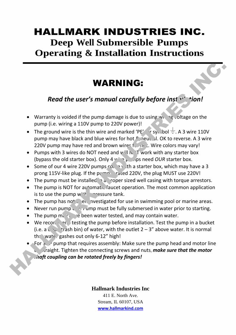
WARNING:
Read the user’s manual carefully before installation!
• Warranty is voided if the pump damage is due to using wrong voltage on the pump (i.e. wiring a 110V pump to 220V power)!
• The ground wire is the thin wire and marked ‘PE’, or symbol . A 3 wire 110V pump may have black and blue wires for hot & neutral. OK to reverse. A 3 wire 220V pump may have red and brown wires for hot. Wire colors may vary!
• Pumps with 3 wires do NOT need and will NOT work with any starter box (bypass the old starter box). Only 4 wire pumps need OUR starter box.
• Some of our 4 wire 220V pumps come with a starter box, which may have a 3 prong 115V-like plug. If the pump is rated 220V, the plug MUST use 220V!
• The pump must be installed in a proper sized well casing with torque arrestors.
• The pump is NOT for automatic faucet operation. The most common application is to use the pump with a pressure tank.
• The pump has not been investigated for use in swimming pool or marine areas.
• Never run pump dry! Pump must be fully submersed in water prior to starting.
• The pump may have been water tested, and may contain water.
• We recommend testing the pump before installation. Test the pump in a bucket (i.e. a clean trash bin) of water, with the outlet 2 – 3” above water. It is normal that water gashes out only 6-12” high!
• For 3HP pump that requires assembly: Make sure the pump head and motor line up straight. Tighten the connecting screws and nuts, make sure that the motor shaft coupling can be rotated freely by fingers!
Hallmark Industries Inc
411 E. North Ave.
Stream, IL 60107, USA
www.hallmarkind.com
HALLMARK IN
DUSTRIES IN
C.
Hallmark Industries Inc.
Deep Well Submersible Pumps - Operating & Installation Instructions Page 2
HALLMARK INDUSTRIES INC.
Deep Well Submersible Pumps
Operating & Installation Instructions
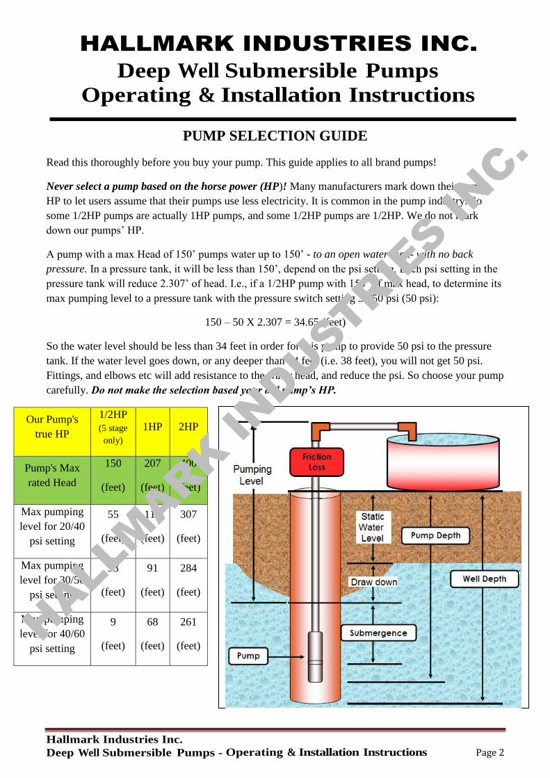
PUMP SELECTION GUIDE
Read this thoroughly before you buy your pump. This guide applies to all brand pumps!
Never select a pump based on the horse power (HP)! Many manufacturers mark down their pumps
HP to let users assume that their pumps use less electricity. It is common in the pump industry. So
some 1/2HP pumps are actually 1HP pumps, and some 1/2HP pumps are 1/2HP. We do not mark
down our pumps’ HP.
A pump with a max Head of 150’ pumps water up to 150’ - to an open water tank- with no back
pressure. In a pressure tank, it will be less than 150’, depend on the psi setting. Each psi setting in the
pressure tank will reduce 2.307’ of head. I.e., if a 1/2HP pump with 150’ of max head, to determine its
max pumping level to a pressure tank with the pressure switch setting 30/50 psi (50 psi):
150 – 50 X 2.307 = 34.65 (feet)
So the water level should be less than 34 feet in order for this pump to provide 50 psi to the pressure
tank. If the water level goes down, or any deeper than 34 feet (i.e. 38 feet), you will not get 50 psi.
Fittings, and elbows etc will add resistance to the water head, and reduce the psi. So choose your pump
carefully. Do not make the selection based your old pump’s HP.
Our Pump's
true HP
1/2HP
(5 stage
only)
1HP 2HP
Pump's Max
rated Head
150
(feet)
207
(feet)
400
(feet)
Max pumping
level for 20/40
psi setting
55
(feet)
114
(feet)
307
(feet)
Max pumping
level for 30/50
psi setting
33
(feet)
91
(feet)
284
(feet)
Max pumping
level for 40/60
psi setting
9
(feet)
68
(feet)
261
(feet)
HALLMARK IN
DUSTRIES IN
C.
Hallmark Industries Inc.
Deep Well Submersible Pumps - Operating & Installation Instructions Page 3
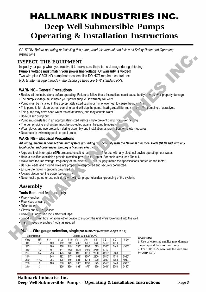
Motor Rating Copper Wire Size (AWG) Volts HP # 14 # 12 # 10 # 8 # 6 # 4 # 2 # 0 # 00 115 1/2 100’ 159’ 249’ 390’ 608’ 930’ 1410’ 1910’ 115 1 180’ 286’ 449’ 703’ 1096’ 1675’ 2550’ 3440’ 4300’ 230 1/2 404’ 641’ 1003’ 1575’ 2450’ 3750’ 5710’ 230 3/4 293’ 473’ 740’ 1161’ 1810’ 2760’ 4210’ 5680’ 230 1 248’ 392’ 617’ 968’ 1507’ 2300’ 3510’ 4730’ 5920’ 230 1-1/2 205’ 326’ 510’ 801’ 1248’ 1920’ 2930’ 3950’ 4940’ 230 2 180’ 286’ 449’ 703’ 1096’ 1675’ 2550’ 3440’ 4300’ 230 3 229’ 359’ 563’ 877’ 1339’ 2041’ 2750’ 3440’
HALLMARK INDUSTRIES INC.
Deep Well Submersible Pumps
Operating & Installation Instructions
CAUTION: Before operating or installing this pump, read this manual and follow all Safety Rules and Operating Instructions
INSPECT THE EQUIPMENT Inspect your pump when you receive it to make sure there is no damage during shipping.
Pump’s voltage must match your power line voltage! Or warranty is voided!
Two wire plus GROUND pump/motor assemblies DO NOT require a control box.
NOTE: Internal pipe threads in the discharge head are 1-¼" standard NPT.
WARNING - General Precautions • Review all the instructions before operating. Failure to follow these instructions could cause bodily injury and/or property damage.
• The pump’s voltage must match your power supply! Or warranty will void!
• Pump must be installed in the appropriately sized casing or it may overheat to cause the pump fail.
• This pump is for clean water, pumping sand will clog the pump. Installing a good filter may prevent the pumping of abrasives.
• This pump may have been water tested at factory, and may contain water.
• Do NOT run pump dry!
• Pump must installed in an appropriately sized well casing to prevent pump from over heating
• The pump, piping and system must be protected against freezing temperatures.
• Wear gloves and eye protection during assembly and installation as precautionary safety measures.
• Never use in swimming pools or pool areas.
WARNING - Electrical Precautions All wiring, electrical connections and system grounding must comply with the National Electrical Code (NEC) and with any
local codes and ordinances. Employ a licensed electrician.
• A ground fault interrupter (GFI) protected circuit is recommended for use with any electrical device operating near water.
• Have a qualified electrician provide electrical power to the motor. For cable sizes, see Table 1.
• Make sure the line voltage, frequency of the electrical current supply match the specifications printed on the motor.
• Be sure leads and ground wires are properly waterproofed and securely connected.
• Ensure the motor is properly grounded.
• Always disconnect the power before servicing.
• Never test a pump or use outside a well without proper electrical grounding of the system.
Assembly
Tools Required for Assembly • Pipe wrenches
• Pipe vises or clamps
• Teflon tape
• Gloves and safety glasses
• CSA or UL approved PVC electrical tape
• Tripod with chain hoist or some other device to support the unit while lowering it into the well
• Miscellaneous wrenches / tools as needed
Table 1 – Wire gauge selection, single phase motor (Max wire length in FT)
CAUTION:
1. Use of wire size smaller may damage
the pump and thus void warranty.
2. For 1HP 115V wire, use the wire size
for 2HP 230V.
HALLMARK IN
DUSTRIES IN
C.
Hallmark Industries Inc.
Deep Well Submersible Pumps - Operating & Installation Instructions Page 4
Installation
General Information The most important things you should know about your well are:
1. Well total depth - the distance from the ground level to the bottom of the well.
2. Head – A vertical distance from the water level to the ground where water is discharged or into a pressure tank. 3. GPM - the amount of water in GPM the pump produces.
Suitability of Well IMPORTANT: The well should be fully developed and must be pumped until all fines and foreign matter are removed before this pump is
installed. Make sure the well is large enough to allow the pump to be set at the required depth. Do not set the pump below the casing
perforations or well screen unless you are sure there is adequate flow of water around the motor for cooling. To determine the correct
pump setting use the driller’s records by taking into account the depth to water level and draw down at the proposed pumping rate. Always
keep the pump a minimum of five feet from the bottom of the drilled well.
Grounding All wiring, electrical connections and system grounding must comply with the National Electrical Code (NEC) and with any local
codes and ordinances. Employ a licensed electrician.
Permanently ground all electrical components in accordance with National Electrical Code and applicable local codes and ordinances.
DO NOT ground to a gas supply line.
DO NOT connect to electric power supply until unit is permanently grounded.
If a plastic well casing is used in your installation, ground the metal well cap or well seal, providing electrical leads to the pump motor go
through the well cap or well seal. Ensure correct wire size is used. Refer to local electrical code.
Cable Splicing Methods When the drop cable must be spliced or connected to the motor leads, it is necessary that the splice be water tight. The splice can be made
with commercially available potting or heat shrink splicing kits. Follow the kit instructions carefully.
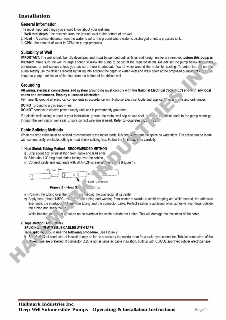
1. Heat Shrink Tubing Method - RECOMMENDED METHOD
i) Strip about 1/2” of installation from cable and lead ends.
ii) Slide about 3” long heat shrink tubing over the cables.
iii) Connect cable and lead ends with STA-KON or similar connectors (Figure 1).
1/2”
“STA-KON” Connector
Figure 1 - Heat Shrink Splicing
iv) Position the tubing over the connection keeping the connector at its center.
v) Apply heat (about 135°C) evenly on the tubing and working from center outwards to avoid trapping air. While heated, the adhesive
liner seals the interfaces between the tubing and the connector cable. Perfect sealing is achieved when adhesive liner flows outside
the tubing and seals the ends.
While heating, care must be taken not to overheat the cable outside the tubing. This will damage the insulation of the cable.
2. Tape Method (Alternative)
SPLICING SUBMERSIBLE CABLES WITH TAPE
Tape splicing should use the following procedure. See Figure 2.
i) Strip individual conductor of insulation only as far as necessary to provide room for a stake type connector. Tubular connectors of the
staked type are preferred. If connector O.D. is not as large as cable insulation, buildup with CSA/UL approved rubber electrical tape.
HALLMARK IN
DUSTRIES IN
C.
Hallmark Industries Inc.
Deep Well Submersible Pumps - Operating & Installation Instructions Page 5
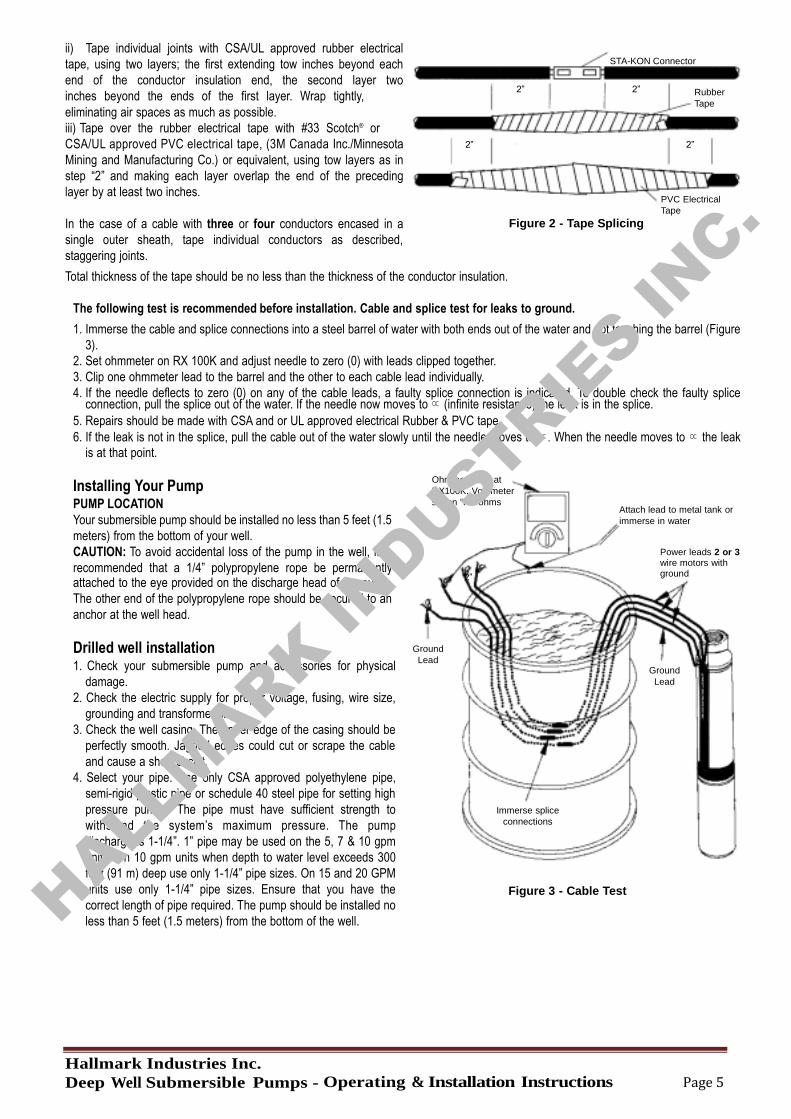
ii) Tape individual joints with CSA/UL approved rubber electrical
tape, using two layers; the first extending tow inches beyond each
end of the conductor insulation end, the second layer two
STA-KON Connector
inches beyond the ends of the first layer. Wrap tightly,
eliminating air spaces as much as possible.
iii) Tape over the rubber electrical tape with #33 Scotch® or
2” 2” Rubber
Tape
CSA/UL approved PVC electrical tape, (3M Canada Inc./Minnesota
Mining and Manufacturing Co.) or equivalent, using tow layers as in
step “2” and making each layer overlap the end of the preceding
layer by at least two inches.
2” 2”
PVC Electrical
Tape
In the case of a cable with three or four conductors encased in a
single outer sheath, tape individual conductors as described,
staggering joints.
Figure 2 - Tape Splicing
Total thickness of the tape should be no less than the thickness of the conductor insulation.
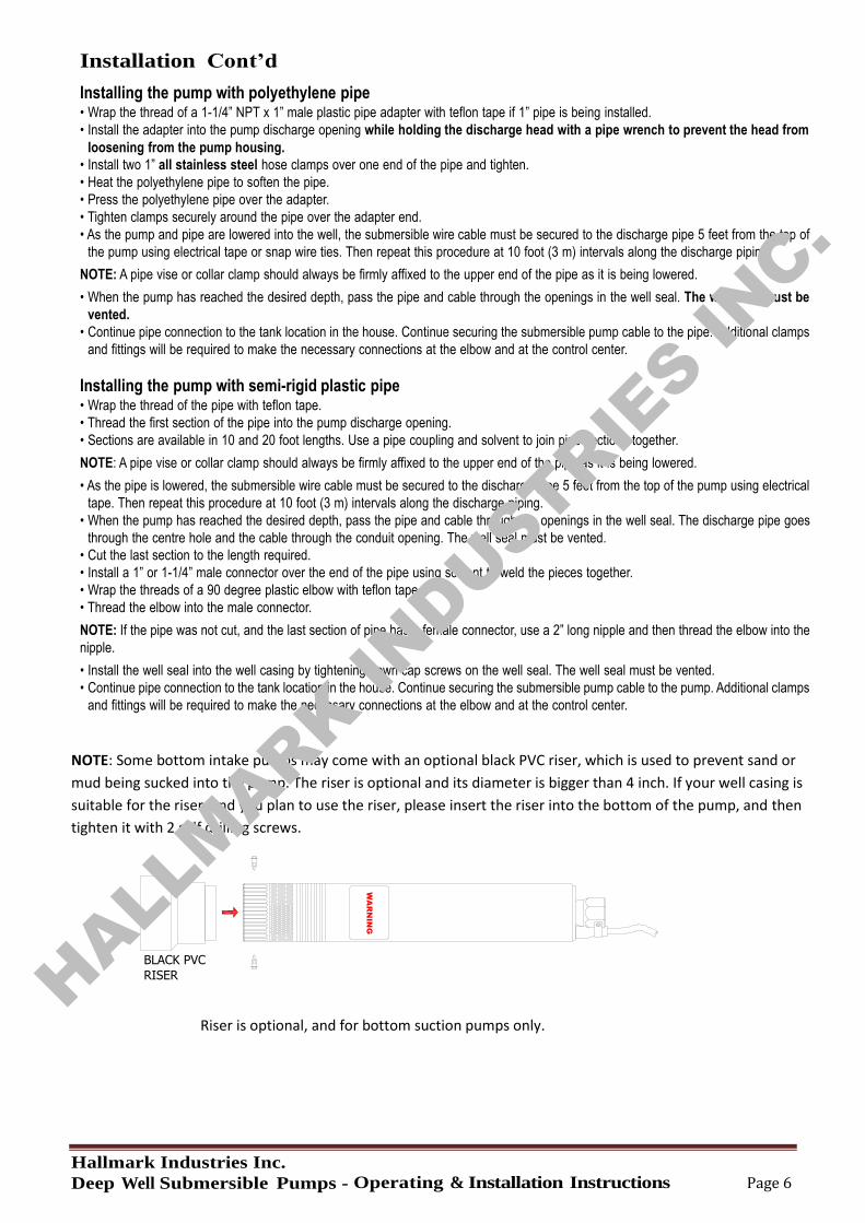
The following test is recommended before installation. Cable and splice test for leaks to ground.
1. Immerse the cable and splice connections into a steel barrel of water with both ends out of the water and not touching the barrel (Figure
3).
2. Set ohmmeter on RX 100K and adjust needle to zero (0) with leads clipped together.
3. Clip one ohmmeter lead to the barrel and the other to each cable lead individually.
4. If the needle deflects to zero (0) on any of the cable leads, a faulty splice connection is indicated. To double check the faulty splice connection, pull the splice out of the water. If the needle now moves to ∝ (infinite resistance) the leak is in the splice.
5. Repairs should be made with CSA and or UL approved electrical Rubber & PVC tape.
6. If the leak is not in the splice, pull the cable out of the water slowly until the needle moves to ∝. When the needle moves to ∝ the leak
is at that point.
Installing Your Pump PUMP LOCATION
Your submersible pump should be installed no less than 5 feet (1.5
meters) from the bottom of your well.
CAUTION: To avoid accidental loss of the pump in the well, it is
recommended that a 1/4” polypropylene rope be permanently
Ohmmeter set at
RX100K. Volt-meter
set on “HI” ohms Attach lead to metal tank or immerse in water
Power leads 2 or 3 wire motors with ground
attached to the eye provided on the discharge head of the pump. 2”
The other end of the polypropylene rope should be secured to an
anchor at the well head.
Drilled well installation 1. Check your submersible pump and accessories for physical
damage.
2. Check the electric supply for proper voltage, fusing, wire size,
grounding and transformer size.
3. Check the well casing. The upper edge of the casing should be
perfectly smooth. Jagged edges could cut or scrape the cable
and cause a short circuit.
4. Select your pipe. Use only CSA approved polyethylene pipe,
semi-rigid plastic pipe or schedule 40 steel pipe for setting high
pressure pumps. The pipe must have sufficient strength to
withstand the system’s maximum pressure. The pump
discharge is 1-1/4”. 1” pipe may be used on the 5, 7 & 10 gpm
units. On 10 gpm units when depth to water level exceeds 300
feet (91 m) deep use only 1-1/4” pipe sizes. On 15 and 20 GPM
units use only 1-1/4” pipe sizes. Ensure that you have the
correct length of pipe required. The pump should be installed no
less than 5 feet (1.5 meters) from the bottom of the well.
Ground
Lead
Immerse splice
connections
Figure 3 - Cable Test
Ground
Lead
HALLMARK IN
DUSTRIES IN
C.
Hallmark Industries Inc.
Deep Well Submersible Pumps - Operating & Installation Instructions Page 6
Installation Cont’d
Installing the pump with polyethylene pipe • Wrap the thread of a 1-1/4” NPT x 1” male plastic pipe adapter with teflon tape if 1” pipe is being installed.
• Install the adapter into the pump discharge opening while holding the discharge head with a pipe wrench to prevent the head from
loosening from the pump housing.
• Install two 1” all stainless steel hose clamps over one end of the pipe and tighten.
• Heat the polyethylene pipe to soften the pipe.
• Press the polyethylene pipe over the adapter.
• Tighten clamps securely around the pipe over the adapter end.
• As the pump and pipe are lowered into the well, the submersible wire cable must be secured to the discharge pipe 5 feet from the top of
the pump using electrical tape or snap wire ties. Then repeat this procedure at 10 foot (3 m) intervals along the discharge piping.
NOTE: A pipe vise or collar clamp should always be firmly affixed to the upper end of the pipe as it is being lowered.
• When the pump has reached the desired depth, pass the pipe and cable through the openings in the well seal. The well seal must be
vented.
• Continue pipe connection to the tank location in the house. Continue securing the submersible pump cable to the pipe. Additional clamps
and fittings will be required to make the necessary connections at the elbow and at the control center.
Installing the pump with semi-rigid plastic pipe • Wrap the thread of the pipe with teflon tape.
• Thread the first section of the pipe into the pump discharge opening.
• Sections are available in 10 and 20 foot lengths. Use a pipe coupling and solvent to join pipe sections together.
NOTE: A pipe vise or collar clamp should always be firmly affixed to the upper end of the pipe as it is being lowered.
• As the pipe is lowered, the submersible wire cable must be secured to the discharge pipe 5 feet from the top of the pump using electrical
tape. Then repeat this procedure at 10 foot (3 m) intervals along the discharge piping.
• When the pump has reached the desired depth, pass the pipe and cable through the openings in the well seal. The discharge pipe goes
through the centre hole and the cable through the conduit opening. The well seal must be vented.
• Cut the last section to the length required.
• Install a 1” or 1-1/4” male connector over the end of the pipe using solvent to weld the pieces together.
• Wrap the threads of a 90 degree plastic elbow with teflon tape.
• Thread the elbow into the male connector.
NOTE: If the pipe was not cut, and the last section of pipe has a female connector, use a 2” long nipple and then thread the elbow into the
nipple.
• Install the well seal into the well casing by tightening down cap screws on the well seal. The well seal must be vented.
• Continue pipe connection to the tank location in the house. Continue securing the submersible pump cable to the pump. Additional clamps
and fittings will be required to make the necessary connections at the elbow and at the control center.
NOTE: Some bottom intake pumps may come with an optional black PVC riser, which is used to prevent sand or
mud being sucked into the pump. The riser is optional and its diameter is bigger than 4 inch. If your well casing is
suitable for the riser, and you plan to use the riser, please insert the riser into the bottom of the pump, and then
tighten it with 2 self drilling screws.
WA
RN
ING
BLACK PVC
RISER
Riser is optional, and for bottom suction pumps only. HALL
MARK INDUSTRIE
S INC.
Hallmark Industries Inc.
Deep Well Submersible Pumps - Operating & Installation Instructions Page 7
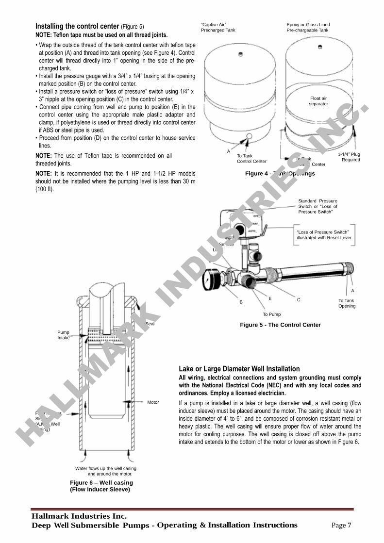
Installing the control center (Figure 5)
NOTE: Teflon tape must be used on all thread joints.
• Wrap the outside thread of the tank control center with teflon tape
at position (A) and thread into tank opening (see Figure 4). Control
center will thread directly into 1” opening in the side of the pre-
charged tank.
• Install the pressure gauge with a 3/4” x 1/4” busing at the opening
marked position (B) on the control center.
• Install a pressure switch or “loss of pressure” switch using 1/4” x
3” nipple at the opening position (C) in the control center.
• Connect pipe coming from well and pump to position (E) in the
control center using the appropriate male plastic adapter and
clamp, if polyethylene is used or thread directly into control center
if ABS or steel pipe is used.
• Proceed from position (D) on the control center to house service
lines.
NOTE: The use of Teflon tape is recommended on all
threaded joints.
“Captive Air”
Precharged Tank
A
To Tank
Control Center
Epoxy or Glass Lined
Pre-chargeable Tank
Float air
separator
To Tank
Control Center
1-1/4” Plug
Required
NOTE: It is recommended that the 1 HP and 1-1/2 HP models
should not be installed where the pumping level is less than 30 m
(100 ft).
Figure 4 - Tank Openings
Standard Pressure
Switch or “Loss of
Pressure Switch”
To Service
Line
“Loss of Pressure Switch”
illustrated with Reset Lever
D
B E C
To Pump
A To Tank
Opening
Pump
Intake
Flow Inducer
Sleeve
(A.K.A. Well casing)
Seal
Motor
Water flows up the well casing
and around the motor.
Figure 6 – Well casing (Flow Inducer Sleeve)
Figure 5 - The Control Center
Lake or Large Diameter Well Installation All wiring, electrical connections and system grounding must comply
with the National Electrical Code (NEC) and with any local codes and
ordinances. Employ a licensed electrician.
If a pump is installed in a lake or large diameter well, a well casing (flow
inducer sleeve) must be placed around the motor. The casing should have an
inside diameter of 4” to 6”, and be composed of corrosion resistant metal or
heavy plastic. The well casing will ensure proper flow of water around the
motor for cooling purposes. The well casing is closed off above the pump
intake and extends to the bottom of the motor or lower as shown in Figure 6. HALLMARK IN
DUSTRIES IN
C.
Hallmark Industries Inc.
Deep Well Submersible Pumps - Operating & Installation Instructions Page 8
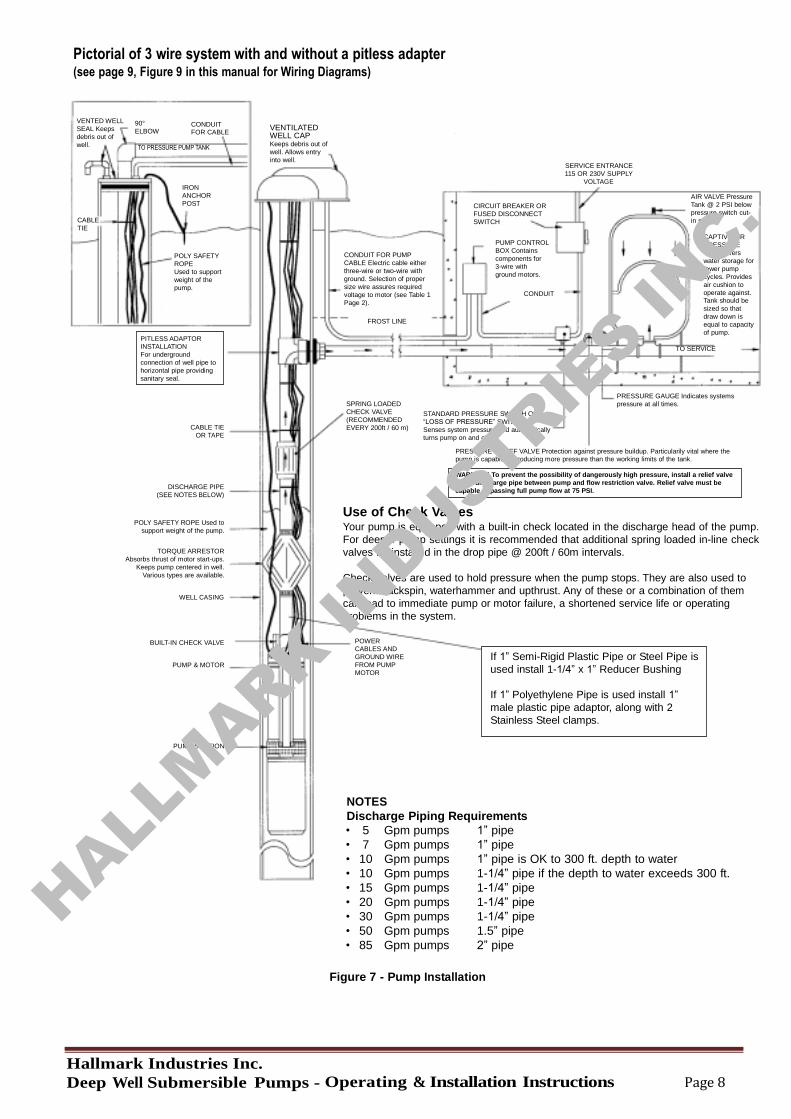
Pictorial of 3 wire system with and without a pitless adapter (see page 9, Figure 9 in this manual for Wiring Diagrams)
VENTED WELL
SEAL Keeps
debris out of
90°
ELBOW CONDUIT FOR CABLE
VENTILATED WELL CAP
well.
CABLE
TIE
TO PRESSURE PUMP TANK
IRON
ANCHOR
POST
POLY SAFETY
ROPE
Used to support
weight of the
pump.
PITLESS ADAPTOR
INSTALLATION
For underground
connection of well pipe to
horizontal pipe providing
sanitary seal.
Keeps debris out of
well. Allows entry
into well.
CONDUIT FOR PUMP
CABLE Electric cable either
three-wire or two-wire with
ground. Selection of proper
size wire assures required
voltage to motor (see Table 1
Page 2).
FROST LINE
CIRCUIT BREAKER OR
FUSED DISCONNECT
SWITCH
PUMP CONTROL
BOX Contains
components for
3-wire with
ground motors.
CONDUIT
SERVICE ENTRANCE
115 OR 230V SUPPLY
VOLTAGE
AIR VALVE Pressure
Tank @ 2 PSI below
pressure switch cut-
in setting.
CAPTIVE AIR
PRESSURE
TANK Offers
water storage for
fewer pump
cycles. Provides
air cushion to
operate against. Tank should be
sized so that
draw down is
equal to capacity
of pump.
TO SERVICE
CABLE TIE
OR TAPE
SPRING LOADED
CHECK VALVE
(RECOMMENDED
EVERY 200ft / 60 m)
STANDARD PRESSURE SWITCH OR
“LOSS OF PRESSURE” SWITCH
Senses system pressure and automatically
turns pump on and off.
PRESSURE GAUGE Indicates systems
pressure at all times.
PRESSURE RELIEF VALVE Protection against pressure buildup. Particularily vital where the pump is capable of producing more pressure than the working limits of the tank.
DISCHARGE PIPE
(SEE NOTES BELOW)
POLY SAFETY ROPE Used to
support weight of the pump.
TORQUE ARRESTOR
Absorbs thrust of motor start-ups.
Keeps pump centered in well.
Various types are available.
WELL CASING
WARNING! To prevent the possibility of dangerously high pressure, install a relief valve
in the discharge pipe between pump and flow restriction valve. Relief valve must be
capable of passing full pump flow at 75 PSI.
Use of Check Valves Your pump is equipped with a built-in check located in the discharge head of the pump.
For deeper pump settings it is recommended that additional spring loaded in-line check
valves be installed in the drop pipe @ 200ft / 60m intervals.
Check valves are used to hold pressure when the pump stops. They are also used to
prevent backspin, waterhammer and upthrust. Any of these or a combination of them
can lead to immediate pump or motor failure, a shortened service life or operating
problems in the system.
BUILT-IN CHECK VALVE
PUMP & MOTOR
PUMP SUCTION
POWER CABLES AND
GROUND WIRE
FROM PUMP
MOTOR
If 1” Semi-Rigid Plastic Pipe or Steel Pipe is
used install 1-1/4” x 1” Reducer Bushing
If 1” Polyethylene Pipe is used install 1”
male plastic pipe adaptor, along with 2
Stainless Steel clamps.
NOTES
Discharge Piping Requirements
• 5 Gpm pumps 1” pipe • 7 Gpm pumps 1” pipe • 10 Gpm pumps 1” pipe is OK to 300 ft. depth to water • 10 Gpm pumps 1-1/4” pipe if the depth to water exceeds 300 ft. • 15 Gpm pumps 1-1/4” pipe • 20 Gpm pumps 1-1/4” pipe • 30 Gpm pumps 1-1/4” pipe • 50 Gpm pumps 1.5” pipe • 85 Gpm pumps 2” pipe
Figure 7 - Pump Installation
HALLMARK IN
DUSTRIES IN
C.
Hallmark Industries Inc.
Deep Well Submersible Pumps - Operating & Installation Instructions Page 9
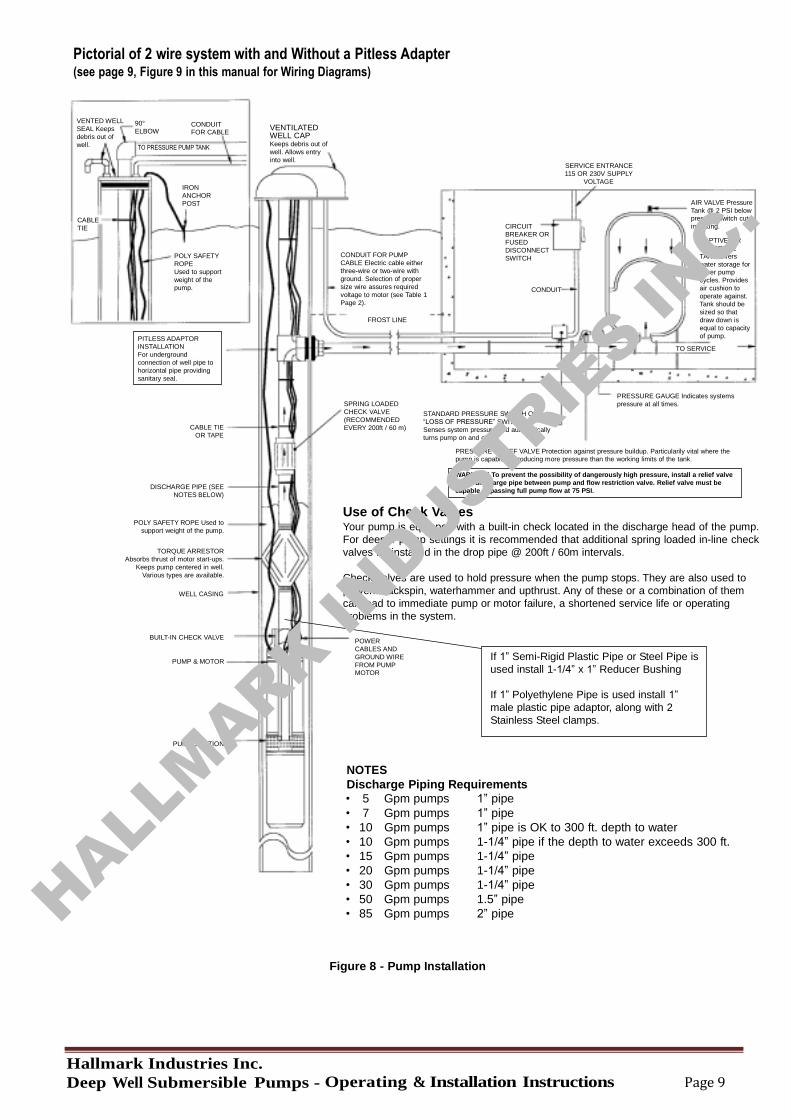
Pictorial of 2 wire system with and Without a Pitless Adapter (see page 9, Figure 9 in this manual for Wiring Diagrams)
VENTED WELL
SEAL Keeps
debris out of
90°
ELBOW CONDUIT FOR CABLE
VENTILATED WELL CAP
well.
CABLE
TIE
TO PRESSURE PUMP TANK
IRON
ANCHOR
POST
POLY SAFETY
ROPE
Used to support
weight of the
pump.
PITLESS ADAPTOR
INSTALLATION
For underground
connection of well pipe to
horizontal pipe providing
sanitary seal.
Keeps debris out of
well. Allows entry
into well.
CONDUIT FOR PUMP
CABLE Electric cable either
three-wire or two-wire with
ground. Selection of proper
size wire assures required
voltage to motor (see Table 1
Page 2).
FROST LINE
CIRCUIT
BREAKER OR
FUSED
DISCONNECT
SWITCH
CONDUIT
SERVICE ENTRANCE
115 OR 230V SUPPLY
VOLTAGE
AIR VALVE Pressure
Tank @ 2 PSI below pressure switch cut-
in setting.
CAPTIVE AIR
PRESSURE
TANK Offers
water storage for fewer pump
cycles. Provides
air cushion to
operate against.
Tank should be
sized so that
draw down is
equal to capacity
of pump.
TO SERVICE
CABLE TIE
OR TAPE
SPRING LOADED
CHECK VALVE
(RECOMMENDED
EVERY 200ft / 60 m)
STANDARD PRESSURE SWITCH OR
“LOSS OF PRESSURE” SWITCH
Senses system pressure and automatically
turns pump on and off.
PRESSURE GAUGE Indicates systems
pressure at all times.
PRESSURE RELIEF VALVE Protection against pressure buildup. Particularily vital where the pump is capable of producing more pressure than the working limits of the tank.
DISCHARGE PIPE (SEE
NOTES BELOW)
POLY SAFETY ROPE Used to
support weight of the pump.
TORQUE ARRESTOR
Absorbs thrust of motor start-ups.
Keeps pump centered in well.
Various types are available.
WELL CASING
WARNING! To prevent the possibility of dangerously high pressure, install a relief valve
in the discharge pipe between pump and flow restriction valve. Relief valve must be
capable of passing full pump flow at 75 PSI.
Use of Check Valves Your pump is equipped with a built-in check located in the discharge head of the pump.
For deeper pump settings it is recommended that additional spring loaded in-line check
valves be installed in the drop pipe @ 200ft / 60m intervals.
Check valves are used to hold pressure when the pump stops. They are also used to
prevent backspin, waterhammer and upthrust. Any of these or a combination of them
can lead to immediate pump or motor failure, a shortened service life or operating
problems in the system.
BUILT-IN CHECK VALVE
PUMP & MOTOR
PUMP SUCTION
POWER
CABLES AND
GROUND WIRE
FROM PUMP MOTOR
If 1” Semi-Rigid Plastic Pipe or Steel Pipe is
used install 1-1/4” x 1” Reducer Bushing
If 1” Polyethylene Pipe is used install 1”
male plastic pipe adaptor, along with 2
Stainless Steel clamps.
NOTES
Discharge Piping Requirements
• 5 Gpm pumps 1” pipe • 7 Gpm pumps 1” pipe • 10 Gpm pumps 1” pipe is OK to 300 ft. depth to water • 10 Gpm pumps 1-1/4” pipe if the depth to water exceeds 300 ft. • 15 Gpm pumps 1-1/4” pipe • 20 Gpm pumps 1-1/4” pipe • 30 Gpm pumps 1-1/4” pipe • 50 Gpm pumps 1.5” pipe • 85 Gpm pumps 2” pipe
Figure 8 - Pump Installation
HALLMARK IN
DUSTRIES IN
C.
Hallmark Industries Inc.
Deep Well Submersible Pumps - Operating & Installation Instructions Page 10
Installation Cont’d
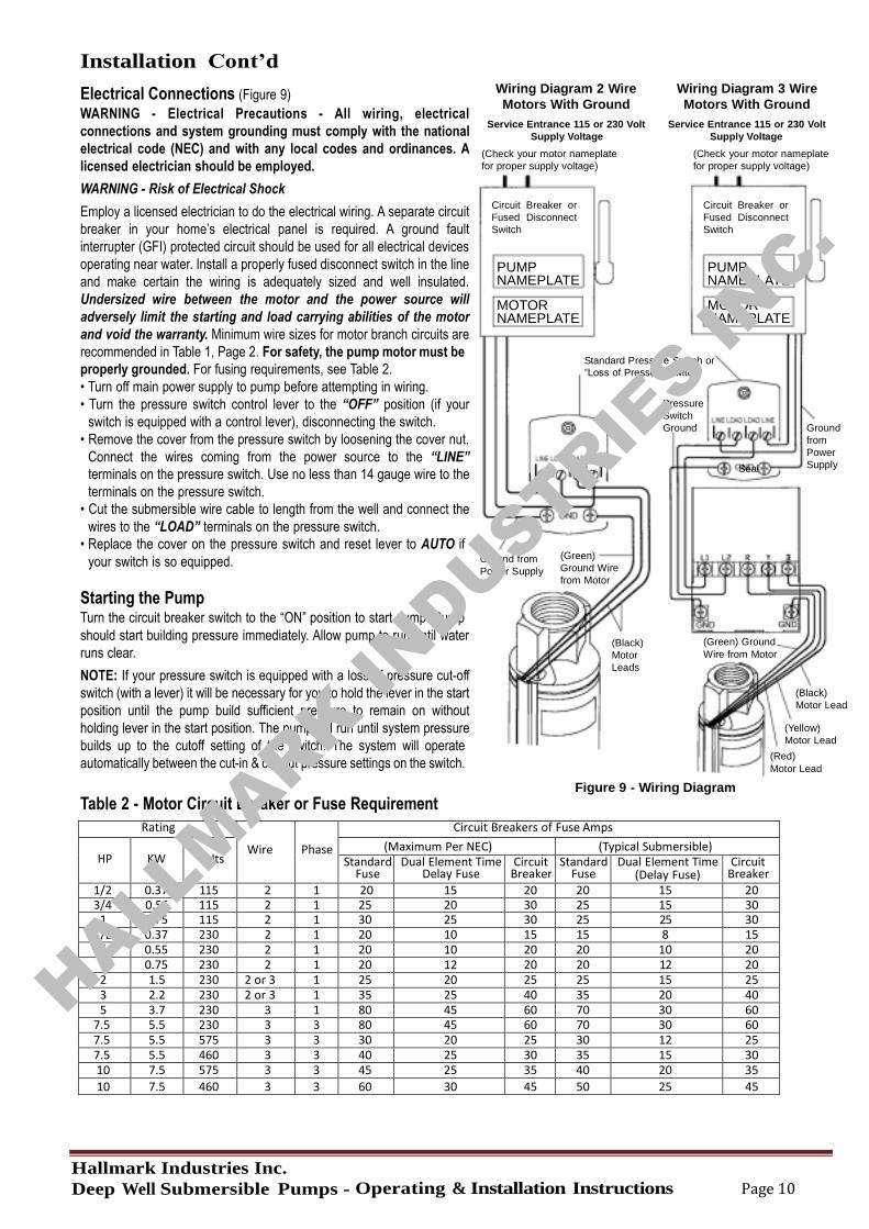
Electrical Connections (Figure 9)
WARNING - Electrical Precautions - All wiring, electrical
connections and system grounding must comply with the national
electrical code (NEC) and with any local codes and ordinances. A
licensed electrician should be employed.
WARNING - Risk of Electrical Shock
Employ a licensed electrician to do the electrical wiring. A separate circuit
breaker in your home’s electrical panel is required. A ground fault
interrupter (GFI) protected circuit should be used for all electrical devices
operating near water. Install a properly fused disconnect switch in the line
and make certain the wiring is adequately sized and well insulated.
Undersized wire between the motor and the power source will
adversely limit the starting and load carrying abilities of the motor
and void the warranty. Minimum wire sizes for motor branch circuits are
recommended in Table 1, Page 2. For safety, the pump motor must be
Wiring Diagram 2 Wire
Motors With Ground
Service Entrance 115 or 230 Volt
Supply Voltage
(Check your motor nameplate
for proper supply voltage)
Circuit Breaker or
Fused Disconnect
Switch
PUMP NAMEPLATE
MOTOR NAMEPLATE
Wiring Diagram 3 Wire
Motors With Ground
Service Entrance 115 or 230 Volt
Supply Voltage
(Check your motor nameplate
for proper supply voltage)
Circuit Breaker or
Fused Disconnect
Switch
PUMP NAMEPLATE
MOTOR NAMEPLATE
properly grounded. For fusing requirements, see Table 2.
• Turn off main power supply to pump before attempting in wiring.
• Turn the pressure switch control lever to the “OFF” position (if your
switch is equipped with a control lever), disconnecting the switch.
• Remove the cover from the pressure switch by loosening the cover nut.
Connect the wires coming from the power source to the “LINE”
terminals on the pressure switch. Use no less than 14 gauge wire to the
terminals on the pressure switch.
• Cut the submersible wire cable to length from the well and connect the
wires to the “LOAD” terminals on the pressure switch.
• Replace the cover on the pressure switch and reset lever to AUTO if
your switch is so equipped.
Starting the Pump Turn the circuit breaker switch to the “ON” position to start pump. Pump
Ground from
Power Supply
Standard Pressure Switch or “Loss of Pressure Switch”
Pressure
Switch
Ground
(Green)
Ground Wire
from Motor
Seal
Ground
from
Power
Supply
should start building pressure immediately. Allow pump to run until water
runs clear.
NOTE: If your pressure switch is equipped with a loss of pressure cut-off
switch (with a lever) it will be necessary for you to hold the lever in the start
position until the pump build sufficient pressure to remain on without
holding lever in the start position. The pump will run until system pressure
builds up to the cutoff setting of the switch. The system will operate
(Black)
Motor
Leads
(Green) Ground
Wire from Motor
(Black)
Motor Lead (Yellow)
Motor Lead
automatically between the cut-in & cut-out pressure settings on the switch.
Table 2 - Motor Circuit Breaker or Fuse Requirement
Figure 9 - Wiring Diagram
(Red) Motor Lead
Rating
Wire
Phase
Circuit Breakers of Fuse Amps
HP
KW
Volts
(Maximum Per NEC) (Typical Submersible) Standard
Fuse Dual Element Time
Delay Fuse Circuit
Breaker Standard
Fuse Dual Element Time
(Delay Fuse) Circuit
Breaker
1/2 0.37 115 2 1 20 15 20 20 15 20 3/4 0.55 115 2 1 25 20 30 25 15 30
1 0.75 115 2 1 30 25 30 25 25 30 1/2 0.37 230 2 1 20 10 15 15 8 15
3/4 0.55 230 2 1 20 10 20 20 10 20
1 0.75 230 2 1 20 12 20 20 12 20
2 1.5 230 2 or 3 1 25 20 25 25 15 25
3 2.2 230 2 or 3 1 35 25 40 35 20 40
5 3.7 230 3 1 80 45 60 70 30 60 7.5 5.5 230 3 3 80 45 60 70 30 60
7.5 5.5 575 3 3 30 20 25 30 12 25
7.5 5.5 460 3 3 40 25 30 35 15 30
10 7.5 575 3 3 45 25 35 40 20 35
10 7.5 460 3 3 60 30 45 50 25 45
HALLMARK IN
DUSTRIES IN
C.
Hallmark Industries Inc.
Deep Well Submersible Pumps - Operating & Installation Instructions Page 11
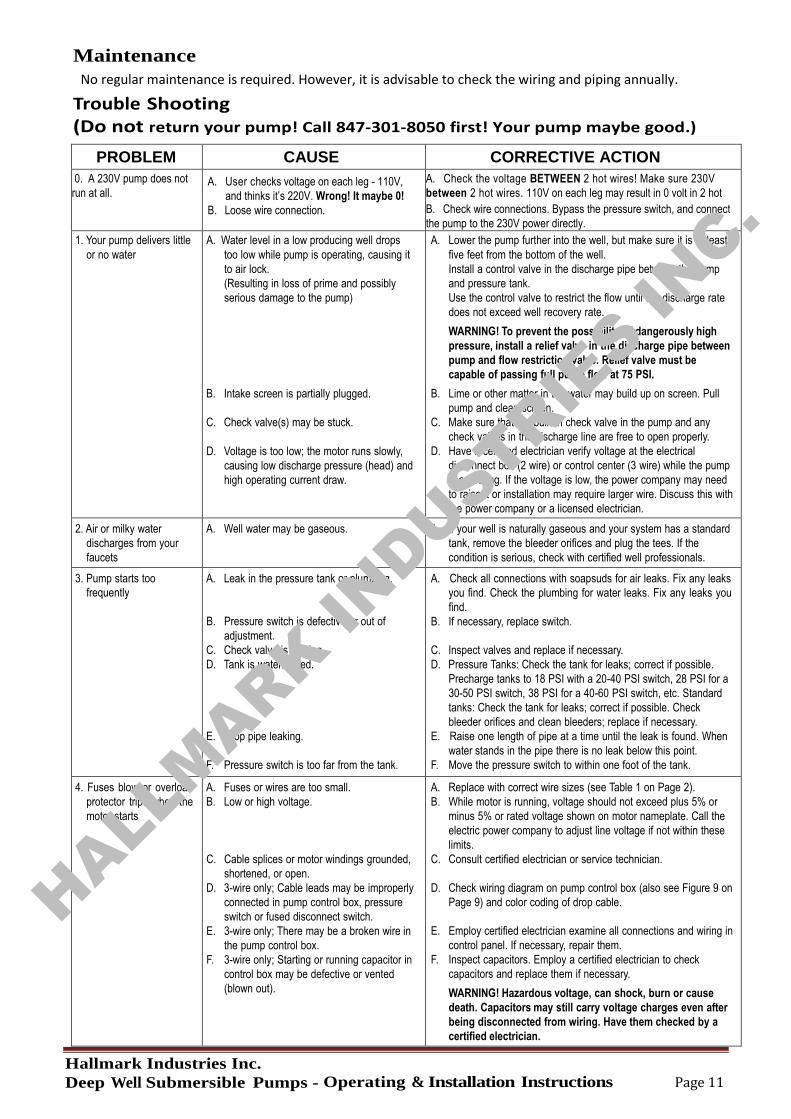
Maintenance
Trouble Shooting (Do not return your pump! Call 847-301-8050 first! Your pump maybe good.)
PROBLEM CAUSE CORRECTIVE ACTION
0. A 230V pump does not
run at all. A. User checks voltage on each leg - 110V,
and thinks it’s 220V. Wrong! It maybe 0!
B. Loose wire connection.
A. Check the voltage BETWEEN 2 hot wires! Make sure 230V
between 2 hot wires. 110V on each leg may result in 0 volt in 2 hot
B. Check wire connections. Bypass the pressure switch, and connect
the pump to the 230V power directly.
1. Your pump delivers little
or no water A. Water level in a low producing well drops
too low while pump is operating, causing it
to air lock.
(Resulting in loss of prime and possibly
serious damage to the pump) B. Intake screen is partially plugged.
C. Check valve(s) may be stuck.
D. Voltage is too low; the motor runs slowly,
causing low discharge pressure (head) and
high operating current draw.
A. Lower the pump further into the well, but make sure it is at least
five feet from the bottom of the well.
Install a control valve in the discharge pipe between the pump
and pressure tank.
Use the control valve to restrict the flow until the discharge rate
does not exceed well recovery rate.
WARNING! To prevent the possibility of dangerously high
pressure, install a relief valve in the discharge pipe between
pump and flow restriction valve. Relief valve must be
capable of passing full pump flow at 75 PSI.
B. Lime or other matter in the water may build up on screen. Pull
pump and clean screen.
C. Make sure that the built-in check valve in the pump and any
check valves in the discharge line are free to open properly.
D. Have a certified electrician verify voltage at the electrical
disconnect box (2 wire) or control center (3 wire) while the pump
is operating. If the voltage is low, the power company may need
to raise it or installation may require larger wire. Discuss this with
the power company or a licensed electrician.
2. Air or milky water
discharges from your
faucets
A. Well water may be gaseous. A. If your well is naturally gaseous and your system has a standard
tank, remove the bleeder orifices and plug the tees. If the
condition is serious, check with certified well professionals.
3. Pump starts too
frequently A. Leak in the pressure tank or plumbing.
B. Pressure switch is defective or out of
adjustment.
C. Check valve is leaking.
D. Tank is waterlogged.
E. Drop pipe leaking.
F. Pressure switch is too far from the tank.
A. Check all connections with soapsuds for air leaks. Fix any leaks
you find. Check the plumbing for water leaks. Fix any leaks you
find.
B. If necessary, replace switch.
C. Inspect valves and replace if necessary.
D. Pressure Tanks: Check the tank for leaks; correct if possible.
Precharge tanks to 18 PSI with a 20-40 PSI switch, 28 PSI for a
30-50 PSI switch, 38 PSI for a 40-60 PSI switch, etc. Standard
tanks: Check the tank for leaks; correct if possible. Check
bleeder orifices and clean bleeders; replace if necessary.
E. Raise one length of pipe at a time until the leak is found. When
water stands in the pipe there is no leak below this point.
F. Move the pressure switch to within one foot of the tank.
4. Fuses blow or overload
protector trips when the
motor starts
A. Fuses or wires are too small.
B. Low or high voltage.
C. Cable splices or motor windings grounded,
shortened, or open.
D. 3-wire only; Cable leads may be improperly
connected in pump control box, pressure
switch or fused disconnect switch.
E. 3-wire only; There may be a broken wire in
the pump control box.
F. 3-wire only; Starting or running capacitor in
control box may be defective or vented
(blown out).
A. Replace with correct wire sizes (see Table 1 on Page 2).
B. While motor is running, voltage should not exceed plus 5% or
minus 5% or rated voltage shown on motor nameplate. Call the
electric power company to adjust line voltage if not within these
limits.
C. Consult certified electrician or service technician.
D. Check wiring diagram on pump control box (also see Figure 9 on
Page 9) and color coding of drop cable.
E. Employ certified electrician examine all connections and wiring in
control panel. If necessary, repair them.
F. Inspect capacitors. Employ a certified electrician to check
capacitors and replace them if necessary.
WARNING! Hazardous voltage, can shock, burn or cause
death. Capacitors may still carry voltage charges even after
being disconnected from wiring. Have them checked by a
certified electrician.
No regular maintenance is required. However, it is advisable to check the wiring and piping annually.
HALLMARK IN
DUSTRIES IN
C.
Hallmark Industries Inc.
Deep Well Submersible Pumps - Operating & Installation Instructions Page 12
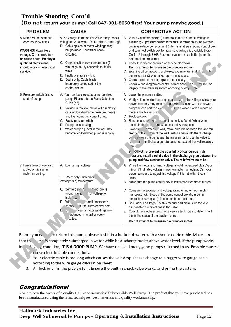
Trouble Shooting Cont’d
(Do not return your pump! Call 847-301-8050 first! Your pump maybe good.)
PROBLEM CAUSE CORRECTIVE ACTION
5. Motor will not start but
does not blow fuses.
WARNING! Hazardous
voltage. Can shock, burn
or cause death. Employ a
qualified electricians
should work on electrical
service.
A. A. No voltage to motor. For 230V pump, check voltage on 2 hot wires. Do not check ‘each leg’! B. Cable splices or motor windings may
be grounded, shorted or open-
circuited.
C. Open circuit in pump control box (3-
wire only); faulty connections; faulty
wires.
D. Faulty pressure switch.
E. 3-wire only; Cable leads
improperly connected in the
control center.
A. With a voltmeter check; 1) fuse box to make sure full voltage is
available; 2) pressure switch terminals, to make pressure switch is
passing voltage correctly; and 3) terminal strips in pump control box
or disconnect switch box to make sure voltage is available there.
On 1-1/2 through 3 HP: Push red overload reset button(s) on the
bottom of control center.
B. Consult certified electrician or service electrician.
Do not attempt to disassemble pump or motor.
C. Examine all connections and wires; examine terminal strips in the
control center (3-wire only); repair if necessary.
D. Check pressure switch; replace if necessary.
E. Check wiring diagram on control center panel (or see Figure 9 on
Page 9 of this manual) and color coding of drop cable.
6. Pressure switch fails to
shut off pump. A. You may have selected an undersized
pump. Please refer to Pump Selection
Guide (p2).
B. Voltage is too low; motor will run slowly,
causing low discharge pressure (head)
and high operating current draw.
C. Faulty pressure witch.
D. Drop pipe is leaking.
E. Water pumping level in the well may
become too low when pump is running.
A. Lower the pressure setting.
B. Verify voltage while the pump is operating. If the voltage is low, your
power company may require larger wire. Discuss with the power
company or a certified electrician. Check voltage with a recording
meter if trouble recurs.
C. Replace switch.
D. Raise one length at a time until the leak is found. When water
stands in the pipe, there is no leak below this point.
E. Lower pump further into well, make sure it is between five and ten
feet from the bottom of the well. Install a valve into the discharge
pipe between the pump and the pressure tank. Use the valve to
restrict flow until discharge rate does not exceed the well recovery
rate.
WARNING! To prevent the possibility of dangerous high
pressure, install a relief valve in the discharge pipe between the
pump and flow restriction valve. The relief valve must be
capable of passing full pump flow at 75 PSI. 7. Fuses blow or overload
protector trips when
motor is running.
A. Low or high voltage. B. 3-Wire only: High ambient (atmospheric) temperature.
C. 3-Wire only: Pump control box is
wrong horsepower or voltage for
installation.
D. Wire size is too small. Improperly
connected in the pump control box.
E. Cable splices or motor windings may
be grounded, shorted or open-
circuited.
A. While the motor is running, voltage should not exceed plus 5% or
minus 5% of rated voltage shown on motor nameplate. Call your
power company to adjust line voltage if it is not within these
limits.
B. Make sure the pump control box is installed out of direct sunlight.
C. Compare horsepower and voltage rating of motor (from motor
nameplate) with those of the pump control box (from pump
control box nameplate). These numbers must match.
D. See Table 1 on Page 2 of this manual and make sure the wire
sizes match specifications in the Table.
E. Consult certified electrician or a service technician to determine if
this is the cause of the problem or not.
Do not attempt to disassemble pump or motor.
Before you decide to return this pump, please test it in a bucket of water with a short electric cable. Make sure
that the pump is completely submerged in water while its discharge outlet above water level. If the pump works
in the testing condition, IT IS A GOOD PUMP. We have received many good pumps returned to us. Possible causes:
1. Loose electric cable connections. 2. Your electric cable is too long which causes the volt drop. Please change to a bigger wire gauge cable
according to the wire gauge calculation sheet. 3. Air lock or air in the pipe system. Ensure the built-in check valve works, and prime the system.
Congratulations! You are now the owner of a quality Hallmark Industries’ Submersible Well Pump. The product that you have purchased has
been manufactured using the latest techniques, best materials and quality workmanship.
HALLMARK IN
DUSTRIES IN
C.