Embed Size (px)
Citation preview
Presented to:
By:
Date:
Federal Aviation Administration Halon Replacement
Halon Replacement in
the Civil Transport
Aircraft Engine Nacelle
(2013)
Seventh Triennial International Fire & Cabin Safety Research Conference
Doug Ingerson, Testing Engineer
5 December 2013
2 Federal Aviation Administration
Seventh Triennial International Fire & Cabin Safety Research Conference
Philadelphia, PA, USA
2-5 December 2013
2
Presentation
Overview
• Encompassing conditions …who, how, why, the threat, threat mitigation, halon elimination
• A test process …a history, some existing outcomes, the future ?
• Overview of the current test process
• Description of the FAA test article
Use of trade and/or manufacturer product names or services does not constitute endorsement.
3 Federal Aviation Administration
Seventh Triennial International Fire & Cabin Safety Research Conference
Philadelphia, PA, USA
2-5 December 2013
3
Encompassing
Conditions
• Who is involved, why, and how…
– Who?
• Principally, large civil transport aircraft propulsion and
auxiliary power system (APS) interests
• Industry and government
– How?
• Task group(1) interaction within the FAA International
Aircraft Systems Fire Protection Working Group(2)
– Why?
• Providing assistance to satisfy FAA regulations requiring
adequate fire extinguishing systems for aircraft engine/APS
fire zones without using halon
4 Federal Aviation Administration
Seventh Triennial International Fire & Cabin Safety Research Conference
Philadelphia, PA, USA
2-5 December 2013
4
Encompassing
Conditions
• Circumstances in the real world...
– Circumstances in the turbine enclosure :
• Spatial volume of complex structure with forced ventilation
• Flowing flammable liquids normally contained in plumbing
• Resident ignition sources; electrical arc, “hot” surfaces
• Wide range of local conditions during operations
• Failure can create conditions resulting with undesired fire
– The mitigation of the fire threat
• Passive fire protection - component “fire worthiness”
• Active fire protection - ventilation, limited fuel/ignition source
elimination, fire detection & extinguishment systems
5 Federal Aviation Administration
Seventh Triennial International Fire & Cabin Safety Research Conference
Philadelphia, PA, USA
2-5 December 2013
5
Encompassing
Conditions
• Circumstances in the real world...
– Basis for the threat mitigation in the FAA regulations
• The broad foundation : 14 CFR §25.1181 – §25.1207
• The specific interest...
– 14 CFR §25.1195 Fire Extinguishing Systems
– Demonstrating acceptability for fire extinguishing systems
» FAA Advisory Circular (AC) 20-100(3)
» Acceptable performance at “worst”-case condition(s)
6 Federal Aviation Administration
Seventh Triennial International Fire & Cabin Safety Research Conference
Philadelphia, PA, USA
2-5 December 2013
6
Encompassing
Conditions
• Circumstances in the real world...
– State-of-the-art is roughly a 30 year evolution, where
it’s typically…
• Based on a pressure vessel :
– mounted in the engine pylon, wing or fuselage
– connected to the fire zone with plumbing
– manually discharged from the flight deck
– containing halon 1301 and nitrogen (N2)
– discharged through open-ended tubes and drilled holes
• Shown acceptable with a Statham-derivative gas analyzer
– Halon 1301 is being eliminated
• 1993, FAA halon replacement program officially announced(4)
7 Federal Aviation Administration
Seventh Triennial International Fire & Cabin Safety Research Conference
Philadelphia, PA, USA
2-5 December 2013
7
A Test
Process
• Revisional history/engine halon replacement…
– 1993, revision 1, FAA halon replacement program began
• Engine halon replacement to be handled by US Department of
Defense (DoD) in a 3-phase program
• Culminated with a design model for HFC-125(5)
• Civil interests wanted additional choices in FAA format
– 1996, revision 2, minimum performance standard, halon
replacement, engine nacelle (MPSe)
• Halon 1301 versus replacement candidate; extinguishant
injection into forced flow against the “robust fire”
• Much learned from this iteration plus that from the US DoD
• 2002, discontinued, “robust fire” too unreliable
8 Federal Aviation Administration
Seventh Triennial International Fire & Cabin Safety Research Conference
Philadelphia, PA, USA
2-5 December 2013
8
A Test
Process
• Revisional history/engine halon replacement…
– 2003, revision 3, MPSe
• Empirical basis; halon 1301 versus replacement candidate;
extinguishant injection into forced flow against forced reignition
• Experience with halon 1301 and 5 replacement candidates
– HFC-125, CF3I, 2-BTP, FK-5-1-12, and KSA(6)
– successful outcomes
» design concentration must reside in fire zone for ½ second
» 17.6%v/v HFC-125, 7.1%v/v CF3I or 6.1%v/v FK-5-1-12
• 2008, discontinued
– replacement candidates tending less halon-like; empiricism failing
– design concentrations shrinking to unreasonable values
9 Federal Aviation Administration
Seventh Triennial International Fire & Cabin Safety Research Conference
Philadelphia, PA, USA
2-5 December 2013
9
A Test
Process
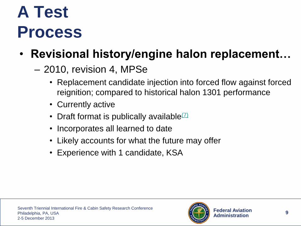
• Revisional history/engine halon replacement…
– 2010, revision 4, MPSe
• Replacement candidate injection into forced flow against forced
reignition; compared to historical halon 1301 performance
• Currently active
• Draft format is publically available(7)
• Incorporates all learned to date
• Likely accounts for what the future may offer
• Experience with 1 candidate, KSA
10 Federal Aviation Administration
Seventh Triennial International Fire & Cabin Safety Research Conference
Philadelphia, PA, USA
2-5 December 2013
10
A Test
Process
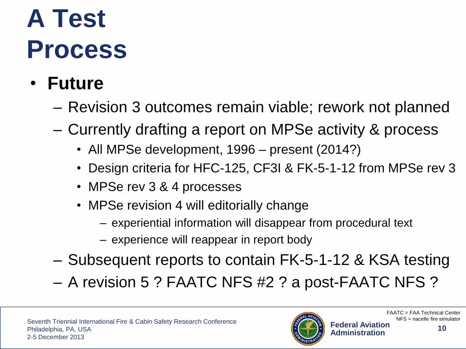
• Future
– Revision 3 outcomes remain viable; rework not planned
– Currently drafting a report on MPSe activity & process
• All MPSe development, 1996 – present (2014?)
• Design criteria for HFC-125, CF3I & FK-5-1-12 from MPSe rev 3
• MPSe rev 3 & 4 processes
• MPSe revision 4 will editorially change
– experiential information will disappear from procedural text
– experience will reappear in report body
– Subsequent reports to contain FK-5-1-12 & KSA testing
– A revision 5 ? FAATC NFS #2 ? a post-FAATC NFS ?
FAATC = FAA Technical Center
NFS = nacelle fire simulator
11 Federal Aviation Administration
Seventh Triennial International Fire & Cabin Safety Research Conference
Philadelphia, PA, USA
2-5 December 2013
11
Overview of the
Current Process
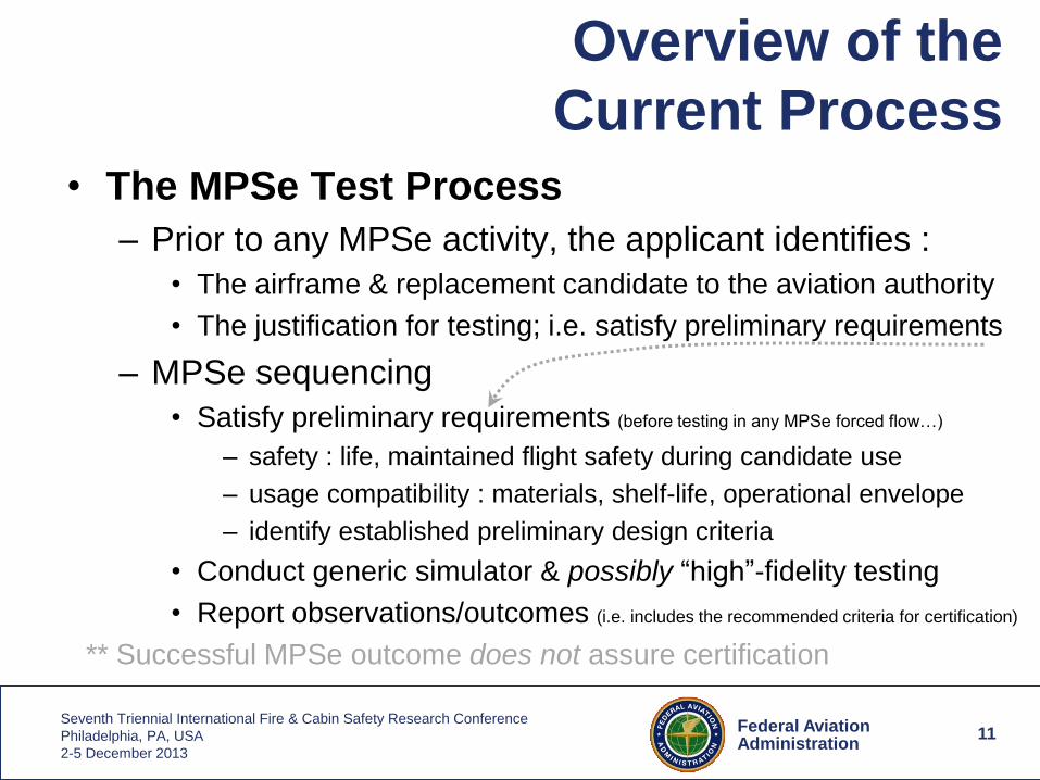
• The MPSe Test Process
– Prior to any MPSe activity, the applicant identifies :
• The airframe & replacement candidate to the aviation authority
• The justification for testing; i.e. satisfy preliminary requirements
– MPSe sequencing
• Satisfy preliminary requirements (before testing in any MPSe forced flow…)
– safety : life, maintained flight safety during candidate use
– usage compatibility : materials, shelf-life, operational envelope
– identify established preliminary design criteria
• Conduct generic simulator & possibly “high”-fidelity testing
• Report observations/outcomes (i.e. includes the recommended criteria for certification)
** Successful MPSe outcome does not assure certification
12 Federal Aviation Administration
Seventh Triennial International Fire & Cabin Safety Research Conference
Philadelphia, PA, USA
2-5 December 2013
12
Overview of the
Current Process
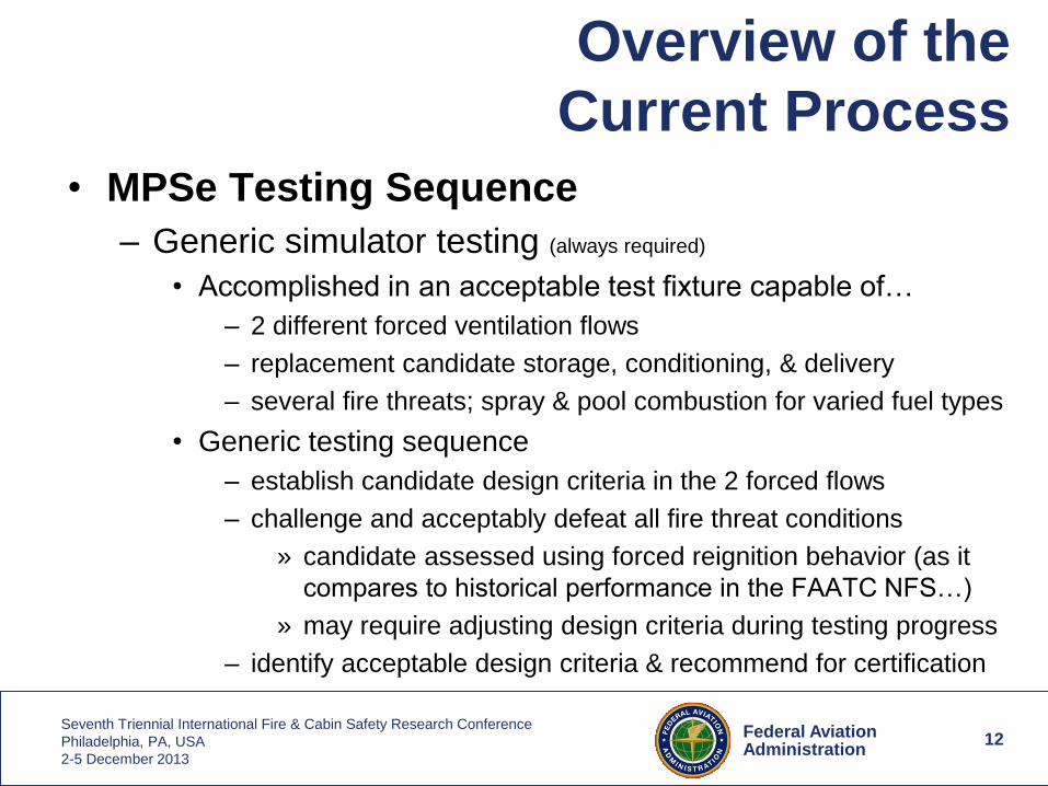
• MPSe Testing Sequence
– Generic simulator testing (always required)
• Accomplished in an acceptable test fixture capable of…
– 2 different forced ventilation flows
– replacement candidate storage, conditioning, & delivery
– several fire threats; spray & pool combustion for varied fuel types
• Generic testing sequence
– establish candidate design criteria in the 2 forced flows
– challenge and acceptably defeat all fire threat conditions
» candidate assessed using forced reignition behavior (as it
compares to historical performance in the FAATC NFS…)
» may require adjusting design criteria during testing progress
– identify acceptable design criteria & recommend for certification
13 Federal Aviation Administration
Seventh Triennial International Fire & Cabin Safety Research Conference
Philadelphia, PA, USA
2-5 December 2013
13
Overview of the
Current Process
• MPSe Testing Sequence
– “High”-fidelity testing (not always required)
• Analogous to testing in the fire zone of an actual engine
• Applicability
– decision to perform lies with aviation authority
– relates to the difference between the circumstances of the
candidate and the state-of-the-art
• A demonstration test
– a “go/no-go” test of the design criteria recommended for
certification; not a rework of the generic test phase…
– conversation occurs between applicant and aviation authority
– test conditions are defined as local circumstances dictate
14 Federal Aviation Administration
Seventh Triennial International Fire & Cabin Safety Research Conference
Philadelphia, PA, USA
2-5 December 2013
14
Description of the
FAA Test Article
• Multiple components
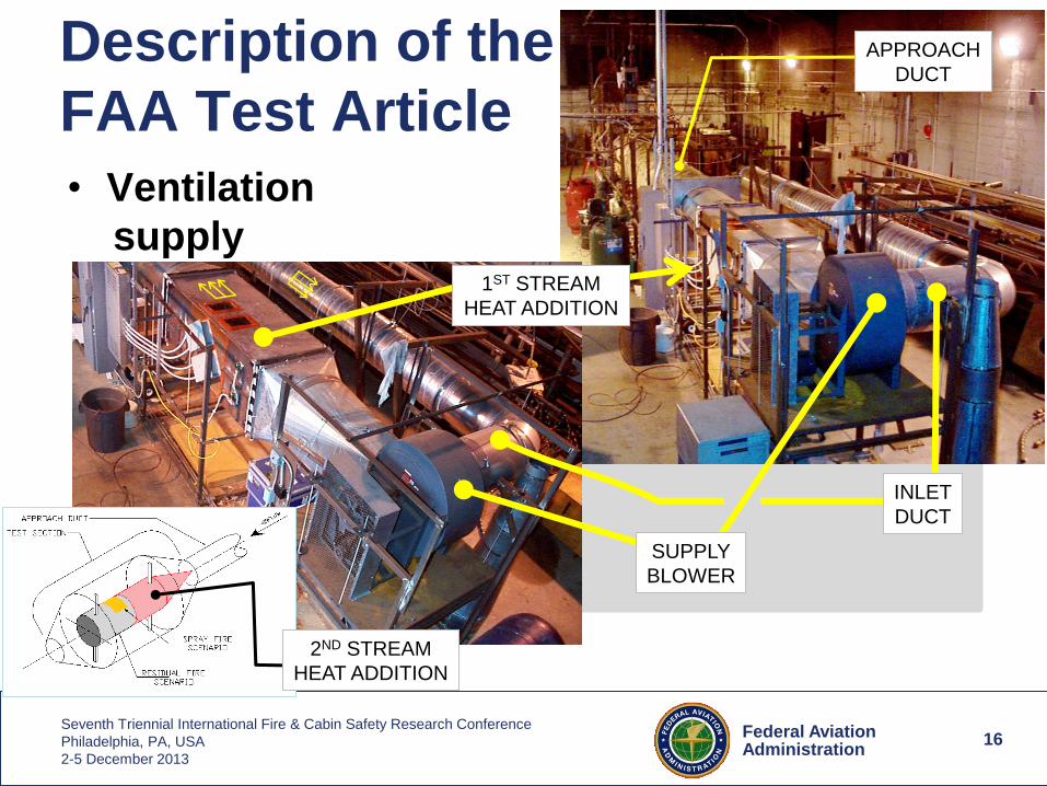
– Ventilation supply equipment; blower, 2 heat sources
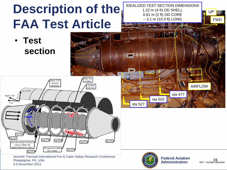
– Test section
• Receives ventilation flow & firex system injection
• Contains spray and pool fire threats
• Internal environment constantly monitored
– Fire extinguishing (firex) system
– Exhaust ducting
– Telemetry; visual and numerical data collection
• Controlled during test from adjacent space
15 Federal Aviation Administration
Seventh Triennial International Fire & Cabin Safety Research Conference
Philadelphia, PA, USA
2-5 December 2013
• Test
section
IDEALIZED TEST SECTION DIMENSIONS
1.22 m (4 ft) OD SHELL
0.61 m (2 ft) OD CORE
~ 3.1 m (10.3 ft) LONG
sta 502
sta 477
sta 527
15
Description of the
FAA Test Article
OD = outside diameter
16 Federal Aviation Administration
Seventh Triennial International Fire & Cabin Safety Research Conference
Philadelphia, PA, USA
2-5 December 2013
• Ventilation
supply
16
Description of the
FAA Test Article
INLET
DUCT
1ST STREAM
HEAT ADDITION
B
SUPPLY
BLOWER
2ND STREAM
HEAT ADDITION
APPROACH
DUCT
17 Federal Aviation Administration
Seventh Triennial International Fire & Cabin Safety Research Conference
Philadelphia, PA, USA
2-5 December 2013
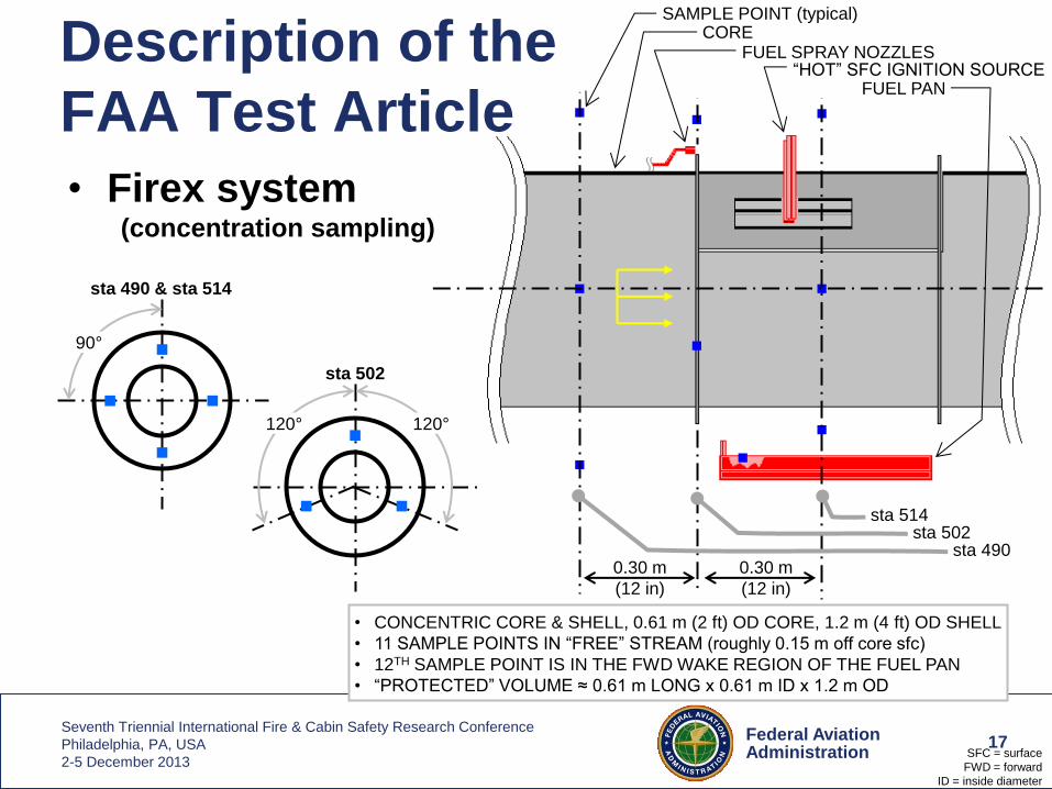
• Firex system (concentration sampling)
17
sta 490 & sta 514
90°
sta 502
120° 120°
• CONCENTRIC CORE & SHELL, 0.61 m (2 ft) OD CORE, 1.2 m (4 ft) OD SHELL
• 11 SAMPLE POINTS IN “FREE” STREAM (roughly 0.15 m off core sfc)
• 12TH SAMPLE POINT IS IN THE FWD WAKE REGION OF THE FUEL PAN
• “PROTECTED” VOLUME ≈ 0.61 m LONG x 0.61 m ID x 1.2 m OD
0.30 m
(12 in)
0.30 m
(12 in)
sta 514 sta 502
sta 490
SAMPLE POINT (typical) CORE
FUEL SPRAY NOZZLES “HOT” SFC IGNITION SOURCE
FUEL PAN
SFC = surface
FWD = forward
ID = inside diameter
Description of the
FAA Test Article
18 Federal Aviation Administration
Seventh Triennial International Fire & Cabin Safety Research Conference
Philadelphia, PA, USA
2-5 December 2013
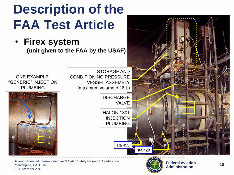
• Firex system (unit given to the FAA by the USAF)
18
Description of the
FAA Test Article
STORAGE AND
CONDITIONING PRESSURE
VESSEL ASSEMBLY
(maximum volume ≈ 18 L)
DISCHARGE
VALVE
HALON 1301
INJECTION
PLUMBING
sta 453
sta 428
ONE EXAMPLE,
“GENERIC” INJECTION
PLUMBING
19 Federal Aviation Administration
Seventh Triennial International Fire & Cabin Safety Research Conference
Philadelphia, PA, USA
2-5 December 2013
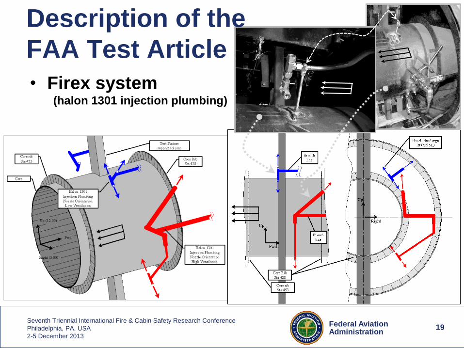
• Firex system (halon 1301 injection plumbing)
19
Description of the
FAA Test Article
20 Federal Aviation Administration
Seventh Triennial International Fire & Cabin Safety Research Conference
Philadelphia, PA, USA
2-5 December 2013
~ s
ta 5
14
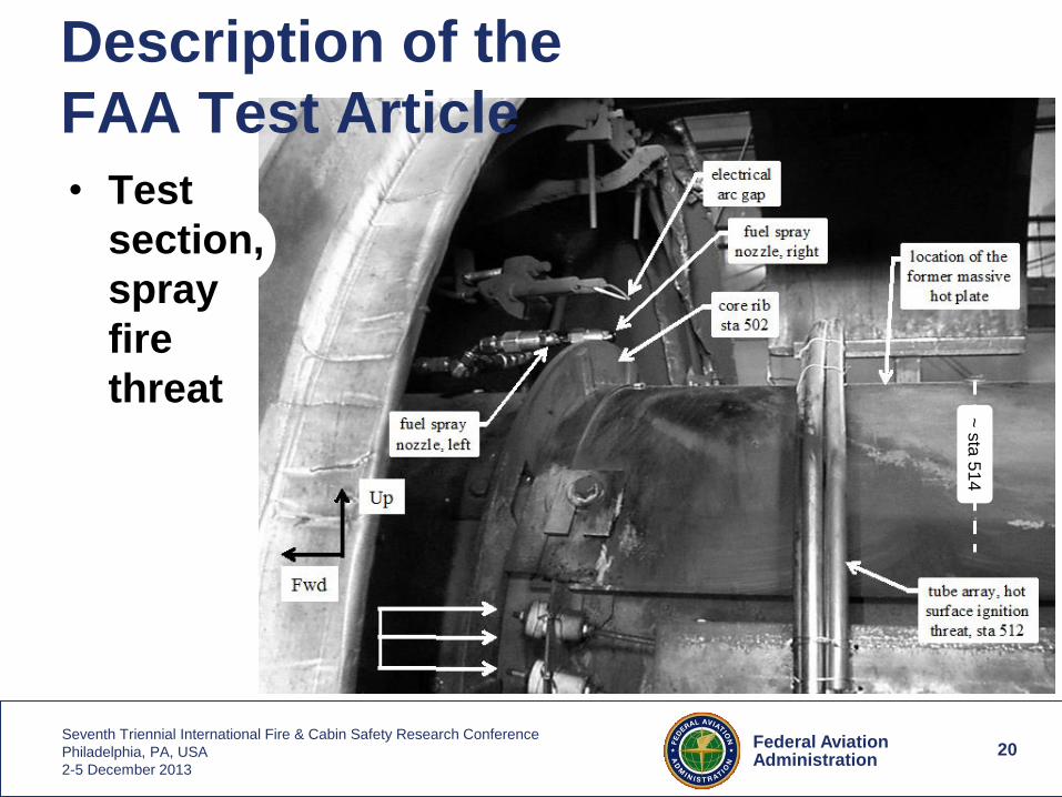
• Test
section,
spray
fire
threat
20
Description of the
FAA Test Article
21 Federal Aviation Administration
Seventh Triennial International Fire & Cabin Safety Research Conference
Philadelphia, PA, USA
2-5 December 2013
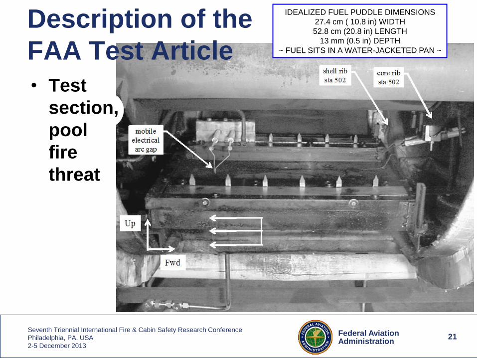
IDEALIZED FUEL PUDDLE DIMENSIONS
27.4 cm ( 10.8 in) WIDTH
52.8 cm (20.8 in) LENGTH
13 mm (0.5 in) DEPTH
~ FUEL SITS IN A WATER-JACKETED PAN ~
21
• Test
section,
pool
fire
threat
Description of the
FAA Test Article
22 Federal Aviation Administration
Seventh Triennial International Fire & Cabin Safety Research Conference
Philadelphia, PA, USA
2-5 December 2013
22
Referable
Information 1. http://www.fire.tc.faa.gov/systems/engine/engine.stm
2. http://www.fire.tc.faa.gov/systems.asp
3. http://www.faa.gov/regulations_policies/advisory_circulars/index.cfm/go/document.information/documentID/22046
4. FAA program, "Halon Replacement Performance Testing", Federal Register, June 17, 1993, pp. 33477-33481.
5. Bennett, J.M., Bennett, M.V., 1999, "Aircraft Engine/APU Fire Extinguishing System Design Model (HFC-125),"
Report No. AFRL-VA-WP-TR-1999-3068, Air Force Research Laboratory and Booz, Allen, and Hamilton,
Incorporated, Wright Patterson Air Force Base, OH; available from
http://www.fire.tc.faa.gov/pdf/systems/designguide.pdf
6. Further identifying the replacement candidates worked with
name in presentation : a chemical name, chemical formula, molecular weight, example of a product name
HFC-125 : pentafluoroethane, C2HF5, 120.02 g/mol, DuPont FE-25
CF3I : iodotrifluoromethane, CF3I, 195.91 g/mol, not known
2-BTP : 2-bromotrifluoropropene, C3H2BrF3, 174.95 g/mol, not known
FK-5-1-12 : dodecafluoro-2-methylpentan-3-one, C6F12O, 316.04 g/mol, 3M Novec 1230
KSA : sodium bicarbonate, NaHCO3, 84.007 g/mol, Kidde Aerospace KSA
7. http://www.fire.tc.faa.gov/pdf/systems/MPSErev04_MPSeRev04doc-02submtd.pdf
Use of trade and/or manufacturer product names or services does not constitute endorsement.


![AIRCRAFT GENERAL KNOWLEDGE 020 - Traficom · AIRCRAFT GENERAL KNOWLEDGE 020 . 1 A halon fire extinguisher: [A] Is only suitable for wood or fabric fires and is, therefore, of no use](https://img.pdfslide.net/doc/110x75/5e9aec71da8ac06d6b2fc205/aircraft-general-knowledge-020-traficom-aircraft-general-knowledge-020-1-a-halon.jpg)