Embed Size (px)
Citation preview
Industrial Energy, Technical Support - 1- Rev. 1, December 2003
Handbook for Gel-VRLA-Batteries
Part 1: Basic Principles, Design, Features
“Sonnenschein A 400” “Sonnenschein A 500” “Sonnenschein A 600” “Sonnenschein A 700” ./. „Sonnenschein SOLAR“ „Sonnenschein SOLAR BLOCK “Sonnenschein A 600 SOLAR“
Industrial Energy, Technical Support - 2- Rev. 1, December 2003
CONTENTS
Handbook for Gel-VRLA-Batteries
Part 1: Basic Principles, Design, Features Page
1. History of “SONNENSCHEIN” and Gel-Batteries 3 2. Function of VRLA-Batteries 4
2.1 Chemical Reactions 4 2.2 Gassing, Recombination 4
3. Design and Materials 8
3.1 Plate Construction and Alloys 9 3.2 Cell/Monobloc Containers 10 3.3 Terminal Posts 12 3.4 Valves 14
4. Special Features of Gel-Batteries 15
4.1 Capacity Range, Properties, Applications 15 4.2 Deep-Discharge 18 4.3 Heat Evolution and Dissipation 19 4.4 Acid Stratification 20
Industrial Energy, Technical Support - 3- Rev. 1, December 2003
1. HISTORY OF “SONNENSCHEIN” AND GEL-BATTERIES • 1910: Foundation of factory “Akkumulatorenfabrik Sonnenschein“ in
Berlin by Dr. Theodor Sonnenschein (former student of Max Planck); vented batteries (traction, automotive)
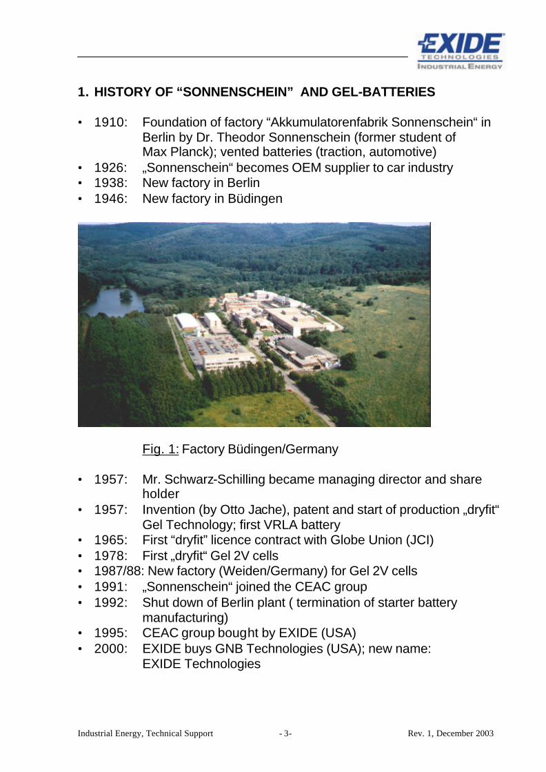
• 1926: „Sonnenschein“ becomes OEM supplier to car industry • 1938: New factory in Berlin • 1946: New factory in Büdingen Fig. 1: Factory Büdingen/Germany • 1957: Mr. Schwarz-Schilling became managing director and share
holder • 1957: Invention (by Otto Jache), patent and start of production „dryfit“
Gel Technology; first VRLA battery • 1965: First “dryfit” licence contract with Globe Union (JCI) • 1978: First „dryfit“ Gel 2V cells • 1987/88: New factory (Weiden/Germany) for Gel 2V cells • 1991: „Sonnenschein“ joined the CEAC group • 1992: Shut down of Berlin plant ( termination of starter battery
manufacturing) • 1995: CEAC group bought by EXIDE (USA) • 2000: EXIDE buys GNB Technologies (USA); new name:
EXIDE Technologies
Industrial Energy, Technical Support - 4- Rev. 1, December 2003
2. FUNCTION OF VRLA-GEL-BATTERIES 2.1 Chemical Reactions The following formula shows the chemical reactions as a so-called overall reaction for discharge and charge:
Pb + PbO2 + 2H2SO4 2PbSO4 + 2H2O During discharge (reaction from left to right side), the lead of the negative electrode (active material) and the lead dioxide of the positive electrode are transformed into lead sulphate. The sulphuric acid is transformed into sulphate (lead sulphate) and water. The formation of water shows that the acid concentration is decreased. On the other hand, the acid is diluted by the formed water. During charge (reactions from right to left), these processes take place in the reverse direction. 2.2 Gassing, Recombination
A special feature of VRLA-batteries consists in the recombination of oxygen during charge. The cycle starts at the positive electrode:
H2O ½ O2 + 2H+ + 2 e-
Water is decomposed and gaseous oxygen is formed. The hydrogen ions remain dissolved in the electrolyte and are not released as gas. The electrons move away via the positive electrode
What is happening now with the oxygen?
How does it make its way to the negative electrode?
In lead-acid batteries of the vented design with „free“ electrolyte, it is practically impossible for the oxygen to move to the negative electrode. Immediately after having „left“ the positive electrode, it bubbles up and escapes through the vent plug.
Discharge
Charge
Industrial Energy, Technical Support - 5- Rev. 1, December 2003
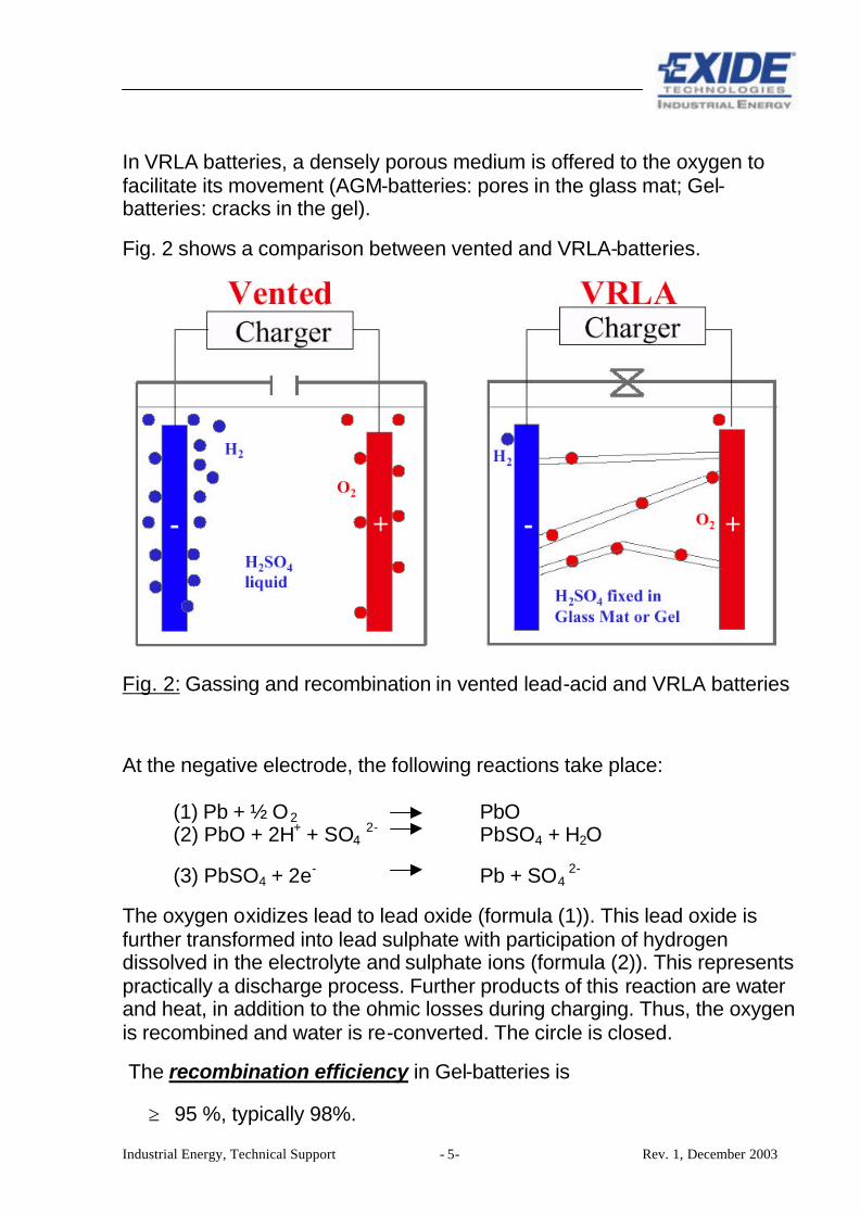
In VRLA batteries, a densely porous medium is offered to the oxygen to facilitate its movement (AGM-batteries: pores in the glass mat; Gel-batteries: cracks in the gel).
Fig. 2 shows a comparison between vented and VRLA-batteries.
Fig. 2: Gassing and recombination in vented lead-acid and VRLA batteries
At the negative electrode, the following reactions take place: (1) Pb + ½ O2 PbO (2) PbO + 2H+ + SO4
2- PbSO4 + H2O
(3) PbSO4 + 2e- Pb + SO4 2-
The oxygen oxidizes lead to lead oxide (formula (1)). This lead oxide is further transformed into lead sulphate with participation of hydrogen dissolved in the electrolyte and sulphate ions (formula (2)). This represents practically a discharge process. Further products of this reaction are water and heat, in addition to the ohmic losses during charging. Thus, the oxygen is recombined and water is re-converted. The circle is closed.
The recombination efficiency in Gel-batteries is
≥ 95 %, typically 98%.
Industrial Energy, Technical Support - 6- Rev. 1, December 2003
The continuous flowing current during charge reconverts the lead sulphate into lead (formula (3)). One could say that in this way the negative electrode is constantly acting with a charging process and therefore cannot produce hydrogen. Otherwise, hydrogen would be produced which could not be reconverted because recombination of hydrogen does not happen. The hydrogen would be lost by diffusion through the cell container (gas permeability of the plastic material!) and through the valve respectively. The consequences would be increased loss of water.
So the negative electrode is never fully charged. This is supported by over- dimensioning intentionally the negative active material. Naturally the hydrogen production cannot be fully suppressed due to electrochemical reasons. Especially unfavorable operating conditions (high charging voltages and temperatures for instance) can provoke hydrogen production. Anyway, hydrogen is also generated in small amounts during corrosion of the positive plates.
The oxygen produces a defined over-pressure within the cell. This is quite normal. The valve should not open at too low pressure because in that case too much oxygen would escape and get irretrievably lost.
If the defined opening pressure is achieved (see chapter 3.4), the valve opens for a short time and releases the accumulated gas. Under normal operating conditions this gas consists mainly of hydrogen. Under unfavorable conditions (high charge voltages at high temperatures, for instance) oxygen would also escape.
The quantity of electrolyte is dimensioned in such a way that the battery attains the expected design life under normal operating conditions, taking into account
- the rate of recombination,
- the corrosion of the positive electrode (oxygen consumption!) and
- the losses by diffusion through the cell container.
Gel-batteries have an electrolyte surplus anyway (see chapter 4.2).
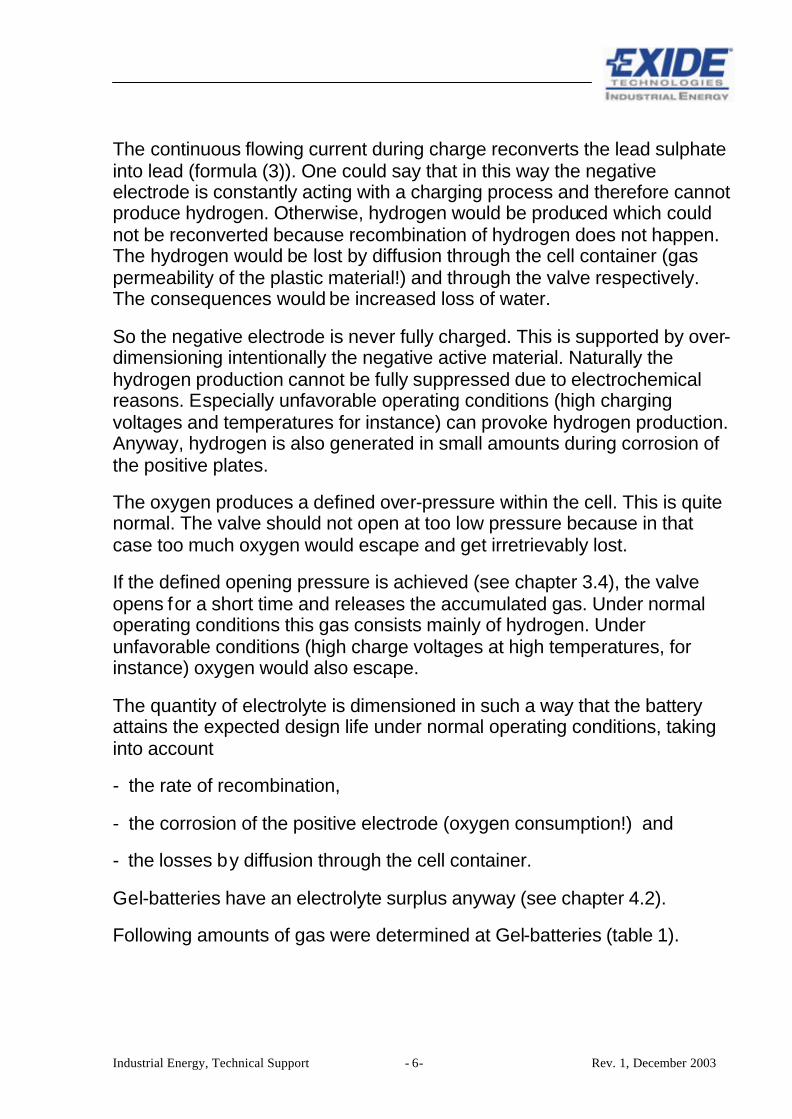
Following amounts of gas were determined at Gel-batteries (table 1).
Industrial Energy, Technical Support - 7- Rev. 1, December 2003
Charge conditions Measured [ml] Allowed [ml]
A 400
Float 2.3 Vpc 21.5 30
Over-charge 2.48 Vpc 94 300
A 500
Float 2.3 Vpc 5 30
Over-charge 2.48 Vpc 90 300
A 600
Float 2.23 Vpc 19 30
Float 2.25 Vpc 18.5 30
Over-charge 2.41 Vpc 300 300
A 700
Float 2.25 Vpc < 20 30
Over-charge 2.46 Vpc < 30 300 Table 1: Gassing acc. to IEC 896-2. Gassing rates measured per cell and per Ah within 30 days. Gas consists of (approx.) 2/3 hydrogen and 1/3 oxygen.
Over-charge voltage applied for tests only.
Industrial Energy, Technical Support - 8- Rev. 1, December 2003
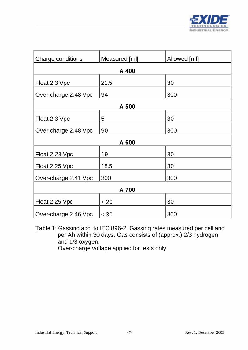
3. DESIGN AND MATERIALS
Fig. 3: Design of a Gel-Valve-Regulated-Lead-Acid cell (Type OPzV)
(Gel = with gelled electrolyte, is not visible in the picture. Other details are symbolical.)
Industrial Energy, Technical Support - 9- Rev. 1, December 2003
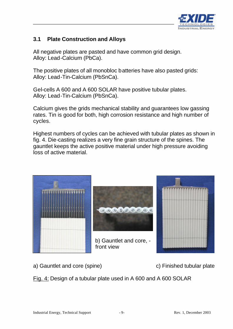
3.1 Plate Construction and Alloys All negative plates are pasted and have common grid design. Alloy: Lead-Calcium (PbCa). The positive plates of all monobloc batteries have also pasted grids: Alloy: Lead-Tin-Calcium (PbSnCa). Gel-cells A 600 and A 600 SOLAR have positive tubular plates. Alloy: Lead-Tin-Calcium (PbSnCa). Calcium gives the grids mechanical stability and guarantees low gassing rates. Tin is good for both, high corrosion resistance and high number of cycles. Highest numbers of cycles can be achieved with tubular plates as shown in fig. 4. Die-casting realizes a very fine grain structure of the spines. The gauntlet keeps the active positive material under high pressure avoiding loss of active material. b) Gauntlet and core, - front view a) Gauntlet and core (spine) c) Finished tubular plate Fig. 4: Design of a tubular plate used in A 600 and A 600 SOLAR
Industrial Energy, Technical Support - 10- Rev. 1, December 2003
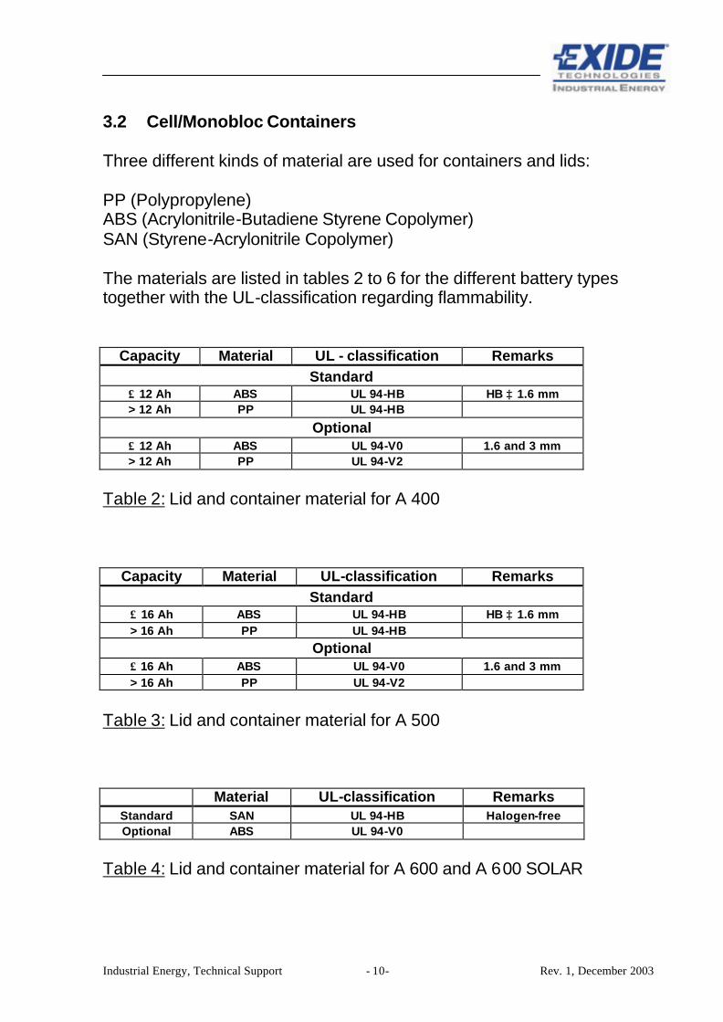
3.2 Cell/Monobloc Containers Three different kinds of material are used for containers and lids: PP (Polypropylene) ABS (Acrylonitrile-Butadiene Styrene Copolymer) SAN (Styrene-Acrylonitrile Copolymer) The materials are listed in tables 2 to 6 for the different battery types together with the UL-classification regarding flammability.
Capacity Material UL - classification Remarks Standard
≤ 12 Ah ABS UL 94-HB HB ≥ 1.6 mm > 12 Ah PP UL 94-HB
Optional ≤ 12 Ah ABS UL 94-V0 1.6 and 3 mm > 12 Ah PP UL 94-V2
Table 2: Lid and container material for A 400
Capacity Material UL-classification Remarks Standard
≤ 16 Ah ABS UL 94-HB HB ≥ 1.6 mm > 16 Ah PP UL 94-HB
Optional ≤ 16 Ah ABS UL 94-V0 1.6 and 3 mm > 16 Ah PP UL 94-V2
Table 3: Lid and container material for A 500
Material UL-classification Remarks Standard SAN UL 94-HB Halogen-free Optional ABS UL 94-V0
Table 4: Lid and container material for A 600 and A 600 SOLAR
Industrial Energy, Technical Support - 11- Rev. 1, December 2003
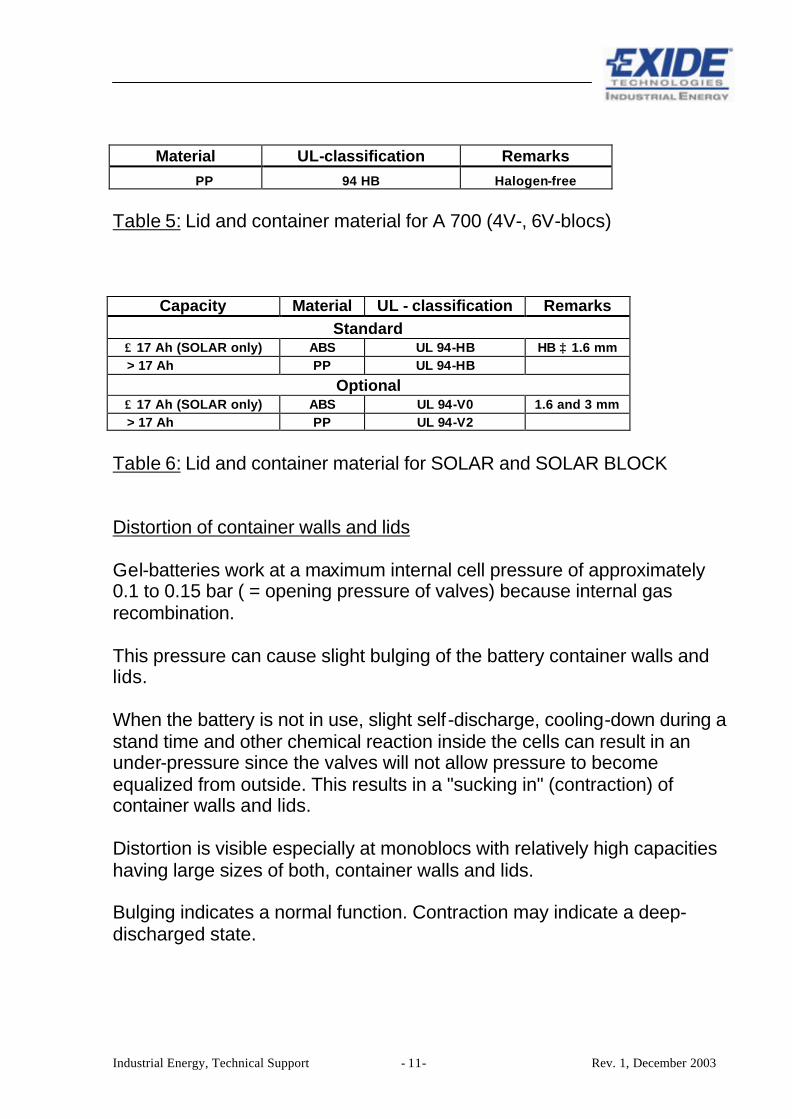
Material UL-classification Remarks PP 94 HB Halogen-free
Table 5: Lid and container material for A 700 (4V-, 6V-blocs)
Capacity Material UL - classification Remarks Standard
≤ 17 Ah (SOLAR only) ABS UL 94-HB HB ≥ 1.6 mm > 17 Ah PP UL 94-HB
Optional ≤ 17 Ah (SOLAR only) ABS UL 94-V0 1.6 and 3 mm
> 17 Ah PP UL 94-V2
Table 6: Lid and container material for SOLAR and SOLAR BLOCK Distortion of container walls and lids Gel-batteries work at a maximum internal cell pressure of approximately 0.1 to 0.15 bar ( = opening pressure of valves) because internal gas recombination. This pressure can cause slight bulging of the battery container walls and lids. When the battery is not in use, slight self -discharge, cooling-down during a stand time and other chemical reaction inside the cells can result in an under-pressure since the valves will not allow pressure to become equalized from outside. This results in a "sucking in" (contraction) of container walls and lids. Distortion is visible especially at monoblocs with relatively high capacities having large sizes of both, container walls and lids. Bulging indicates a normal function. Contraction may indicate a deep-discharged state.
Industrial Energy, Technical Support - 12- Rev. 1, December 2003
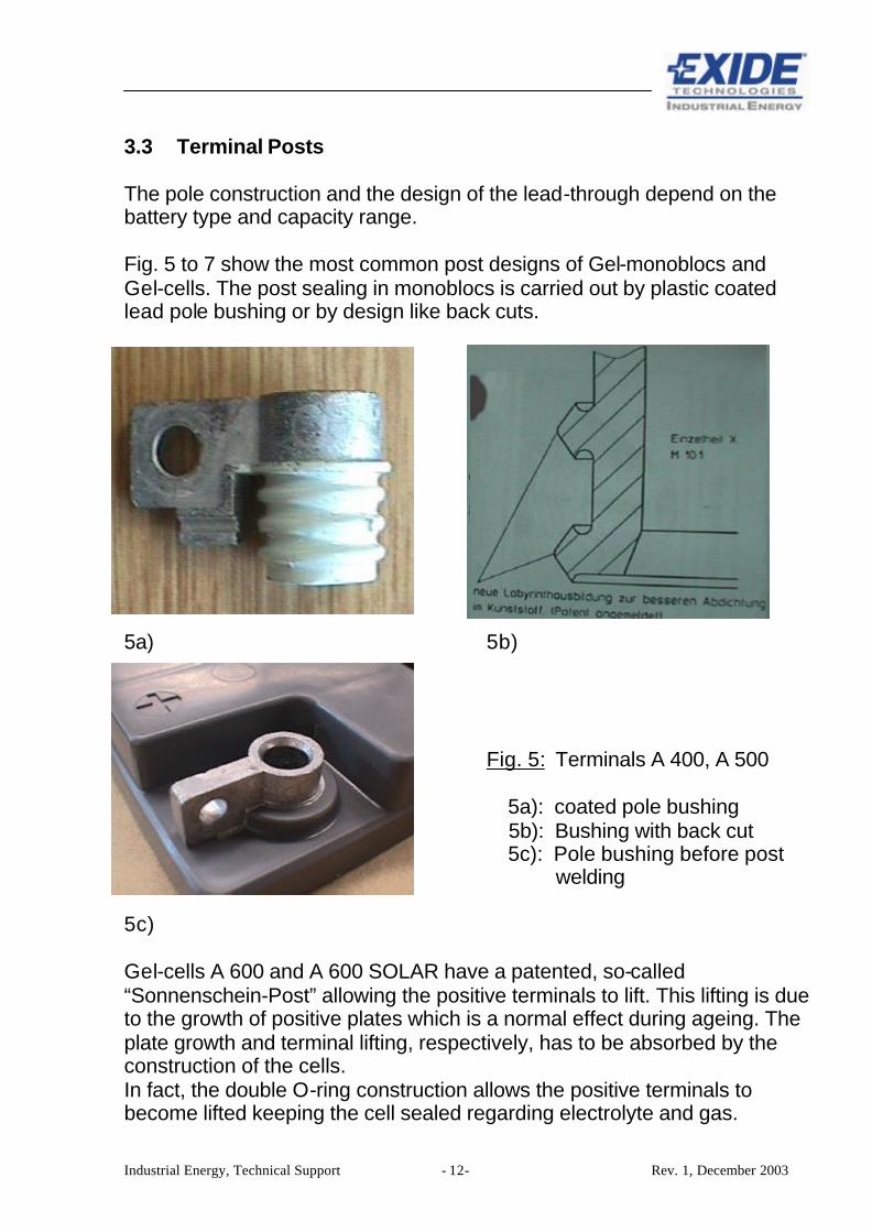
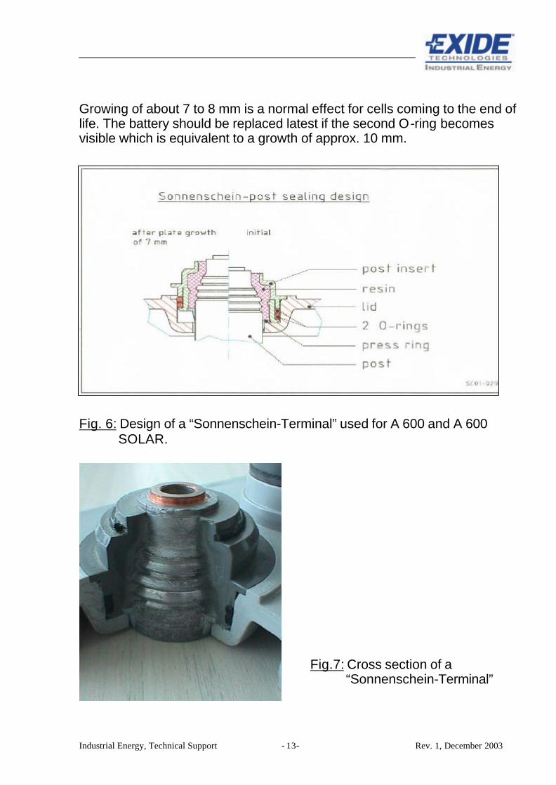
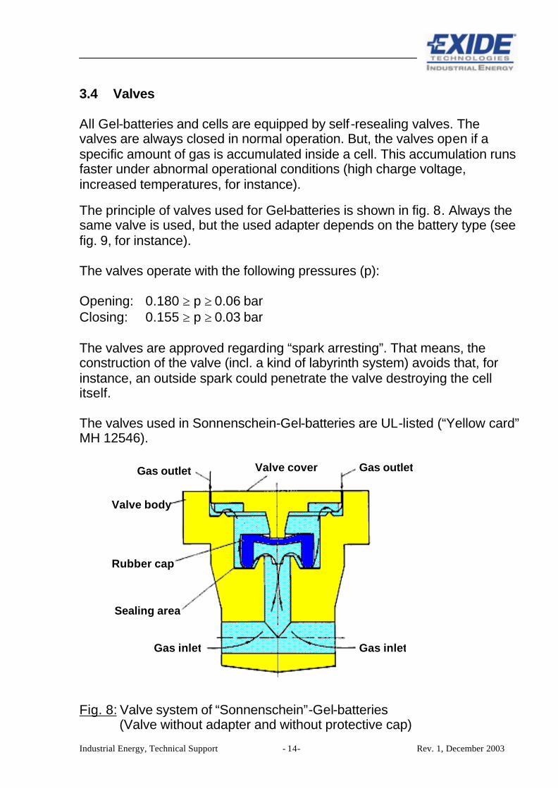
3.3 Terminal Posts The pole construction and the design of the lead-through depend on the battery type and capacity range. Fig. 5 to 7 show the most common post designs of Gel-monoblocs and Gel-cells. The post sealing in monoblocs is carried out by plastic coated lead pole bushing or by design like back cuts. 5a) 5b) Fig. 5: Terminals A 400, A 500 5a): coated pole bushing 5b): Bushing with back cut 5c): Pole bushing before post welding 5c) Gel-cells A 600 and A 600 SOLAR have a patented, so-called “Sonnenschein-Post” allowing the positive terminals to lift. This lifting is due to the growth of positive plates which is a normal effect during ageing. The plate growth and terminal lifting, respectively, has to be absorbed by the construction of the cells. In fact, the double O-ring construction allows the positive terminals to become lifted keeping the cell sealed regarding electrolyte and gas.
Industrial Energy, Technical Support - 13- Rev. 1, December 2003
Growing of about 7 to 8 mm is a normal effect for cells coming to the end of life. The battery should be replaced latest if the second O-ring becomes visible which is equivalent to a growth of approx. 10 mm. Fig. 6: Design of a “Sonnenschein-Terminal” used for A 600 and A 600 SOLAR.
Fig.7: Cross section of a “Sonnenschein-Terminal”
Industrial Energy, Technical Support - 14- Rev. 1, December 2003
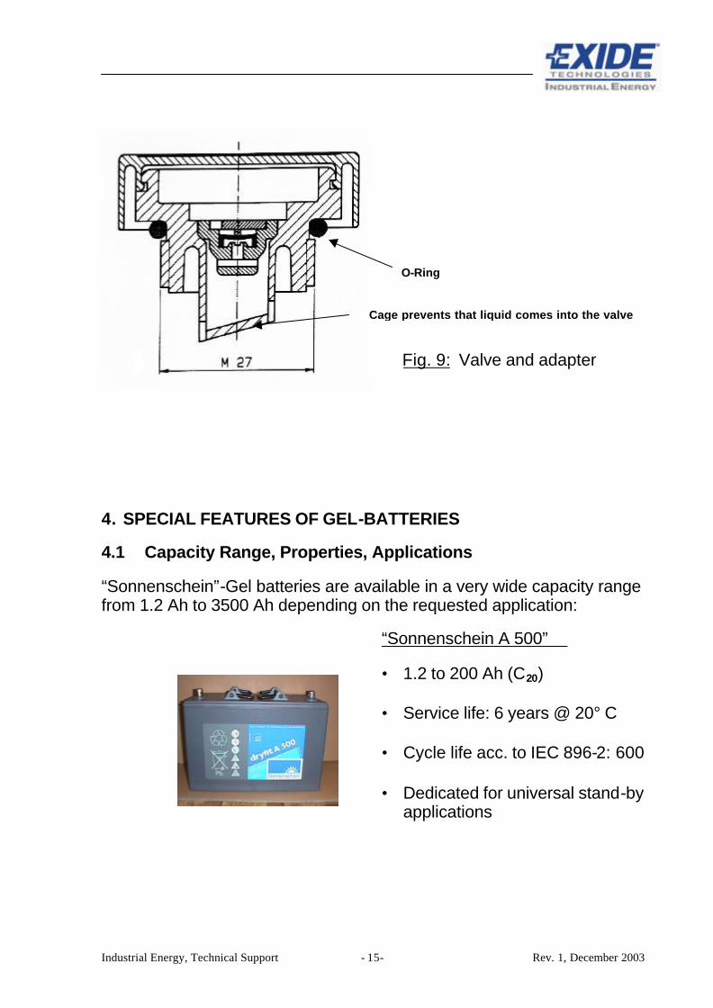
3.4 Valves All Gel-batteries and cells are equipped by self-resealing valves. The valves are always closed in normal operation. But, the valves open if a specific amount of gas is accumulated inside a cell. This accumulation runs faster under abnormal operational conditions (high charge voltage, increased temperatures, for instance).
The principle of valves used for Gel-batteries is shown in fig. 8. Always the same valve is used, but the used adapter depends on the battery type (see fig. 9, for instance). The valves operate with the following pressures (p): Opening: 0.180 ≥ p ≥ 0.06 bar Closing: 0.155 ≥ p ≥ 0.03 bar The valves are approved regarding “spark arresting”. That means, the construction of the valve (incl. a kind of labyrinth system) avoids that, for instance, an outside spark could penetrate the valve destroying the cell itself. The valves used in Sonnenschein-Gel-batteries are UL-listed (“Yellow card” MH 12546). Fig. 8: Valve system of “Sonnenschein”-Gel-batteries
(Valve without adapter and without protective cap)
Gas inlet Gas inlet
Sealing area
Rubber cap
Valve body
Gas outlet Gas outlet Valve cover
Industrial Energy, Technical Support - 15- Rev. 1, December 2003
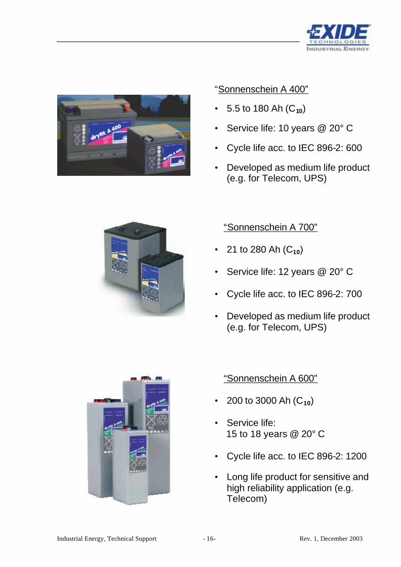
Fig. 9: Valve and adapter
4. SPECIAL FEATURES OF GEL-BATTERIES
4.1 Capacity Range, Properties, Applications
“Sonnenschein”-Gel batteries are available in a very wide capacity range from 1.2 Ah to 3500 Ah depending on the requested application:
“Sonnenschein A 500”
• 1.2 to 200 Ah (C20)
• Service life: 6 years @ 20° C
• Cycle life acc. to IEC 896-2: 600
• Dedicated for universal stand-by applications
O-Ring
Cage prevents that liquid comes into the valve
Industrial Energy, Technical Support - 16- Rev. 1, December 2003
“Sonnenschein A 400”
• 5.5 to 180 Ah (C10)
• Service life: 10 years @ 20° C
• Cycle life acc. to IEC 896-2: 600
• Developed as medium life product (e.g. for Telecom, UPS)
“Sonnenschein A 700”
• 21 to 280 Ah (C10)
• Service life: 12 years @ 20° C
• Cycle life acc. to IEC 896-2: 700
• Developed as medium life product (e.g. for Telecom, UPS)
“Sonnenschein A 600”
• 200 to 3000 Ah (C10)
• Service life: 15 to 18 years @ 20° C
• Cycle life acc. to IEC 896-2: 1200
• Long life product for sensitive and high reliability application (e.g. Telecom)
Industrial Energy, Technical Support - 17- Rev. 1, December 2003
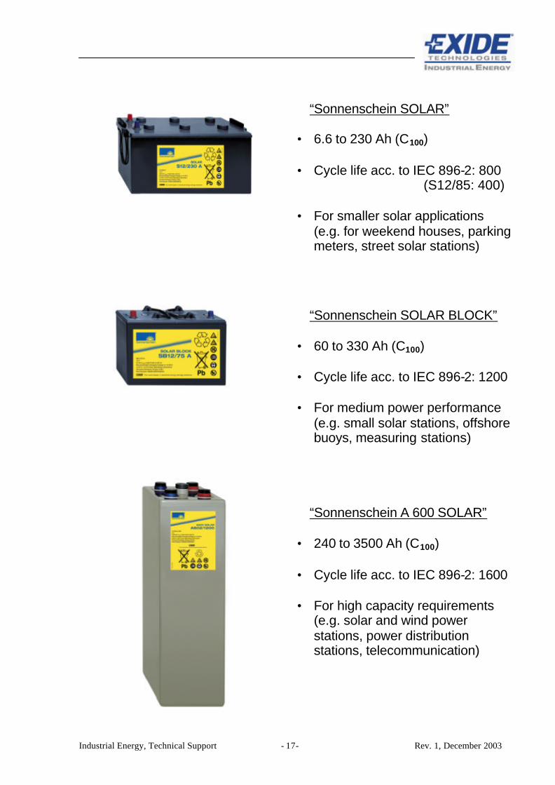
“Sonnenschein SOLAR”
• 6.6 to 230 Ah (C100)
• Cycle life acc. to IEC 896-2: 800 (S12/85: 400)
• For smaller solar applications
(e.g. for weekend houses, parking meters, street solar stations)
“Sonnenschein SOLAR BLOCK”
• 60 to 330 Ah (C100)
• Cycle life acc. to IEC 896-2: 1200
• For medium power performance
(e.g. small solar stations, offshore buoys, measuring stations)
“Sonnenschein A 600 SOLAR”
• 240 to 3500 Ah (C100) • Cycle life acc. to IEC 896-2: 1600
• For high capacity requirements
(e.g. solar and wind power stations, power distribution stations, telecommunication)
Industrial Energy, Technical Support - 18- Rev. 1, December 2003
4.2 Deep-Discharge Gel-batteries are proof against deep-discharge (acc. to DIN 43 539, part 5). That means the battery is connected to a load resistor equivalent to a discharge current of at least 2 * I20 and kept in this state for 30 days. After having disconnected the load and re-charged over 48 hours the battery a capacity of at least 75% has to be achieved. Gel-batteries withstand deep discharges much better than AGM-batteries due to
- surplus of electrolyte and - micro-porous separator used.
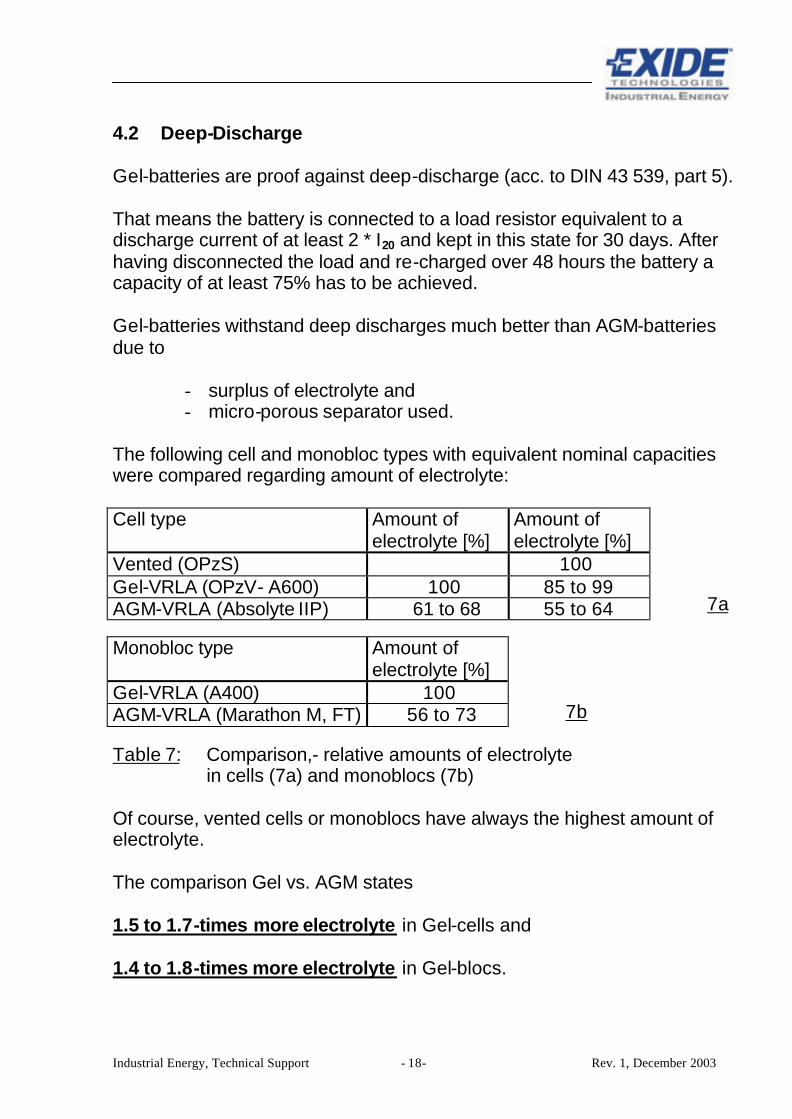
The following cell and monobloc types with equivalent nominal capacities were compared regarding amount of electrolyte:
7a
7b
Table 7: Comparison,- relative amounts of electrolyte
in cells (7a) and monoblocs (7b) Of course, vented cells or monoblocs have always the highest amount of electrolyte. The comparison Gel vs. AGM states 1.5 to 1.7-times more electrolyte in Gel-cells and 1.4 to 1.8-times more electrolyte in Gel-blocs.
Cell type Amount of electrolyte [%]
Amount of electrolyte [%]
Vented (OPzS) 100 Gel-VRLA (OPzV- A600) 100 85 to 99 AGM-VRLA (Absolyte IIP) 61 to 68 55 to 64
Monobloc type Amount of electrolyte [%]
Gel-VRLA (A400) 100 AGM-VRLA (Marathon M, FT) 56 to 73
Industrial Energy, Technical Support - 19- Rev. 1, December 2003
What happens during a discharge, especially during a deep- discharge?
- Sulphuric acid: Concentration decreases by conversion into lead sulphate
- Water is generated - The acid density comes closer to the density of water with
ongoing discharge - Solubility of lead sulphate (also pure lead) increases at lower
acid density ⇒ Soluble in water
⇒ Solved ions in the electrolyte - Lead ions re-convert to pure lead during a following re-charge
⇒ Re-converted lead growths as dendrites ⇒ Short circuits can be caused, - so-called “soft shorts” !
In Gel-batteries, the acid density does not decrease during a discharge, e.g. a deep discharge, as much as in AGM-batteries due to the surplus of electrolyte. Therefore, the tendency of generating short circuits is in Gel-batteries not as strong as in AGM-batteries (the generation of dendrites is supported in AGM-batteries due to the structure of the glass fiber mat). In addition, the used micro-porous separator in Gel-batteries prevents short circuits. 4.3 Heat Evolution and Dissipation Due to less void volume in the separator/electrolyte less heat evolution occurs in Gel-batteries compared to AGM-batteries by oxygen recombination. The heat dissipation in Gel-batteries is quite on the same level as in vented batteries and much better than in AGM, - once again due to the surplus of electrolyte. The electrolyte of Gel-batteries is not only inside and between the plates (AGM!). The Gel is filled completely to a level above the straps realizing a direct contact to the container walls. By this, excellent heat dissipation is guaranteed.
Industrial Energy, Technical Support - 20- Rev. 1, December 2003
Efficient heat dissipation is necessary in order to avoid “Thermal Runaway” in a VRLA-battery being operated under harsh conditions (e.g. high ambient temperature, missing or insufficient air-conditioning, missing or wrong temperature compensation of charge voltage). In fact, “Thermal Runaway” has not occurred in Gel-batteries till now. 4.4 Acid Stratification This term describes a non-homogeneous vertical acid distribution within a cell. Origins are insufficient charging and the gravity effect. Acid stratification occurs especially during cyclical applications. It causes shorter battery life by effects like stronger corrosion and sulphation. Therefore, acid stratification should be compensated during each re-charge process. Generation and compensation of acid stratification Concentrated sulphuric acid is generated during all re-charge processes. It has a higher specific weight compared to diluted acid. Therefore, it trends to deposit in the lower parts of the cell container directly after leaving the pores of the active material. One can measure, for instance, 1.10 kg/l in the upper part of a cell whilst the acid concentration may achieve 1.40 kg/l in the lower parts. 3 to 4% more Ampere hours than discharged have to be re-charged in order to re-convert all active material. This is due to different charging behavior of the positive and negative electrodes. Acid stratification can be prevented by:
- High absorption of the generated sulphuric acid (escaping from the pores of the active material) directly after leaving the pores
⇒Therefore, Gel-batteries show no stratification ⇒ Absorption by AGM is lower compared to Gel - In case of vented batteries (free flooded electrolyte) the
stratification cannot be prevented and has to be compensated
Industrial Energy, Technical Support - 21- Rev. 1, December 2003
at the end of charge by gas evolution. The gas bubbles mix the electrolyte. The same effect can be achieved by inserting air from outside.
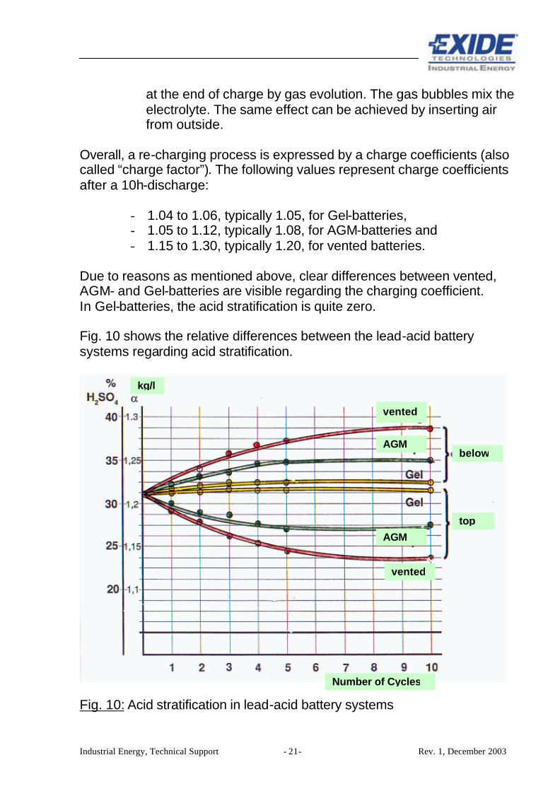
Overall, a re-charging process is expressed by a charge coefficients (also called “charge factor”). The following values represent charge coefficients after a 10h-discharge:
- 1.04 to 1.06, typically 1.05, for Gel-batteries, - 1.05 to 1.12, typically 1.08, for AGM-batteries and - 1.15 to 1.30, typically 1.20, for vented batteries.
Due to reasons as mentioned above, clear differences between vented, AGM- and Gel-batteries are visible regarding the charging coefficient. In Gel-batteries, the acid stratification is quite zero. Fig. 10 shows the relative differences between the lead-acid battery systems regarding acid stratification.
Fig. 10: Acid stratification in lead-acid battery systems
below
top
kg/l
vented
vented
AGM
AGM
Number of Cycles
Industrial Energy, Technical Support - 22- Rev. 1, December 2003
Important Notice: The manufacturer of batteries EXIDE Technologies do not take over responsibility for any loyalties resulting from this paper or resulting from changes in the mentioned standards, neither for any different national standards which may exist and has to be followed by the installer, planner or architect. EXIDE Technologies Network Power Im Thiergarten 63654 Büdingen (Hessen) Phone: + 49 60 42 81 70 Fax: + 49 60 42 81 233 www.exide.com State: Dec. 2003