Embed Size (px)
DESCRIPTION
www.psiconversion.com #efi #conversion #kits We specialize in the design and manufacture of Standalone Wiring Harnesses for GM Gen II, III, and IV LS based engines and transmissions. These harnesses include the Gen II LT1/LT4, Gen III (24x) LS1/LS6 and Vortec Truck Engines as well as Gen IV (58x) LS2, LS3 and LS7 Engines. In addition to wiring harnesses, you will find other components and kits for retrofitting older vehicles with these powertrains including PCM programming, Fuel Pump Kits, Engine Sensors, Extension Harnesses, Replacement GM connector pigtails and a complete line of hardware to complete your conversion needs!
Citation preview
PERFORMANCE SYSTEMS INTEGRATION
Manual P/N MAN-1016 Copyright 2014
1
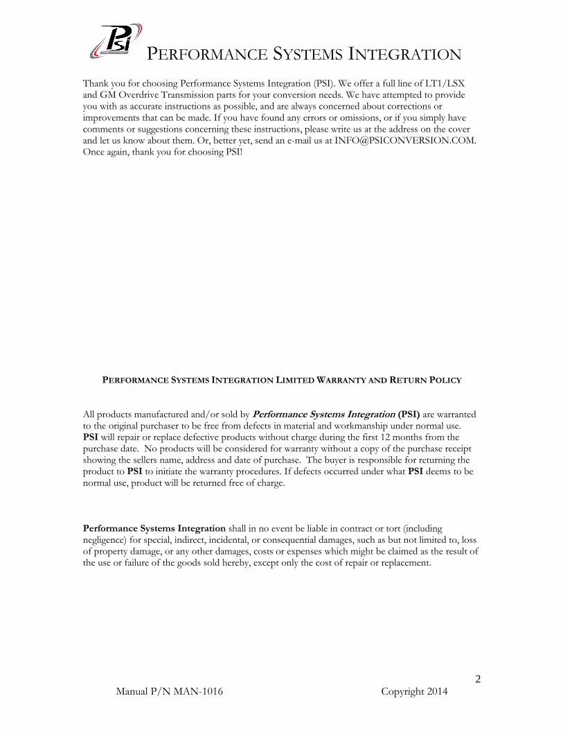
GM LS1 / LS6 Drive by Wire Electronic Fuel Injection Wiring Harness
PERFORMANCE SYSTEMS INTEGRATION 170 Oberlin Ave N Suite 13 – Lakewood NJ – 08701-4548 Ph: 732-444-3277 Email: [email protected]
www.PSIConversion.com
HAR-1016
PERFORMANCE SYSTEMS INTEGRATION
Manual P/N MAN-1016 Copyright 2014
2
Thank you for choosing Performance Systems Integration (PSI). We offer a full line of LT1/LSX and GM Overdrive Transmission parts for your conversion needs. We have attempted to provide you with as accurate instructions as possible, and are always concerned about corrections or improvements that can be made. If you have found any errors or omissions, or if you simply have comments or suggestions concerning these instructions, please write us at the address on the cover and let us know about them. Or, better yet, send an e-mail us at [email protected]. Once again, thank you for choosing PSI!
PERFORMANCE SYSTEMS INTEGRATION LIMITED WARRANTY AND RETURN POLICY All products manufactured and/or sold by Performance Systems Integration (PSI) are warranted to the original purchaser to be free from defects in material and workmanship under normal use. PSI will repair or replace defective products without charge during the first 12 months from the purchase date. No products will be considered for warranty without a copy of the purchase receipt showing the sellers name, address and date of purchase. The buyer is responsible for returning the product to PSI to initiate the warranty procedures. If defects occurred under what PSI deems to be normal use, product will be returned free of charge.
Performance Systems Integration shall in no event be liable in contract or tort (including negligence) for special, indirect, incidental, or consequential damages, such as but not limited to, loss of property damage, or any other damages, costs or expenses which might be claimed as the result of the use or failure of the goods sold hereby, except only the cost of repair or replacement.
PERFORMANCE SYSTEMS INTEGRATION
Manual P/N MAN-1016 Copyright 2014
3
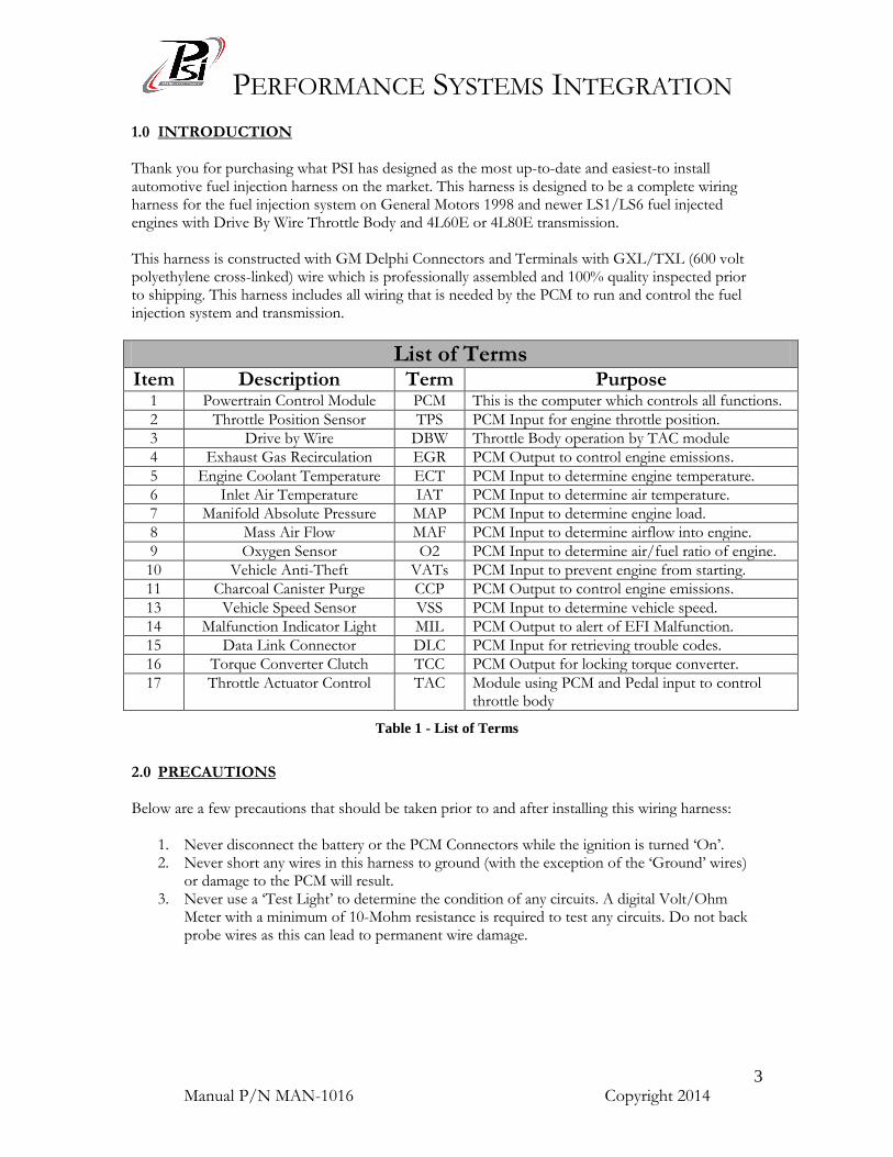
1.0 INTRODUCTION Thank you for purchasing what PSI has designed as the most up-to-date and easiest-to install automotive fuel injection harness on the market. This harness is designed to be a complete wiring harness for the fuel injection system on General Motors 1998 and newer LS1/LS6 fuel injected engines with Drive By Wire Throttle Body and 4L60E or 4L80E transmission. This harness is constructed with GM Delphi Connectors and Terminals with GXL/TXL (600 volt polyethylene cross-linked) wire which is professionally assembled and 100% quality inspected prior to shipping. This harness includes all wiring that is needed by the PCM to run and control the fuel injection system and transmission.
List of Terms Item Description Term Purpose
1 Powertrain Control Module PCM This is the computer which controls all functions.
2 Throttle Position Sensor TPS PCM Input for engine throttle position.
3 Drive by Wire DBW Throttle Body operation by TAC module
4 Exhaust Gas Recirculation EGR PCM Output to control engine emissions.
5 Engine Coolant Temperature ECT PCM Input to determine engine temperature.
6 Inlet Air Temperature IAT PCM Input to determine air temperature.
7 Manifold Absolute Pressure MAP PCM Input to determine engine load.
8 Mass Air Flow MAF PCM Input to determine airflow into engine.
9 Oxygen Sensor O2 PCM Input to determine air/fuel ratio of engine.
10 Vehicle Anti-Theft VATs PCM Input to prevent engine from starting.
11 Charcoal Canister Purge CCP PCM Output to control engine emissions.
13 Vehicle Speed Sensor VSS PCM Input to determine vehicle speed.
14 Malfunction Indicator Light MIL PCM Output to alert of EFI Malfunction.
15 Data Link Connector DLC PCM Input for retrieving trouble codes.
16 Torque Converter Clutch TCC PCM Output for locking torque converter.
17 Throttle Actuator Control TAC Module using PCM and Pedal input to control throttle body
Table 1 - List of Terms
2.0 PRECAUTIONS Below are a few precautions that should be taken prior to and after installing this wiring harness:
1. Never disconnect the battery or the PCM Connectors while the ignition is turned ‘On’. 2. Never short any wires in this harness to ground (with the exception of the ‘Ground’ wires)
or damage to the PCM will result. 3. Never use a ‘Test Light’ to determine the condition of any circuits. A digital Volt/Ohm
Meter with a minimum of 10-Mohm resistance is required to test any circuits. Do not back probe wires as this can lead to permanent wire damage.
PERFORMANCE SYSTEMS INTEGRATION
Manual P/N MAN-1016 Copyright 2014
4
3.0 PRE-INSTALLATION REQUIREMENTS The following information details some of the hardware and software requirements when installing this harness:
*(SEE TABLE 2 FOR COMPATIBLE REPLACEMENT SENSOR PART NUMBERS)*
1. All LS1 Engines will require the VATs System to be removed from the PCM. If the VATs is not removed from the PCM the engine will NOT start. Contact PSI for removal of this function.
2. Factory Stock LS1 Engines utilized four (4) O2 Sensors; two (2) Sensors on each side of the engine, one before and one after the catalytic converter. The rear O2 Sensors (after the catalytic converters) are not used with the PSI Harness. Provisions are provided for two oxygen sensors in the harness.
3. All LS1 Engines utilized an EGR, AIR Pump, and CCP features for emissions control. This harness does not include these provisions. EGR, Air Pump, and CCP are not necessary for engine operation. PCM reprogramming may be necessary to avoid storing a Diagnostic Trouble Code (DTC) for absence of emissions equipment.
4. If any sensors are missing or damaged, PSI recommends replacements listed in Table 2. Note that the PCM listed in Table 2 must be used.
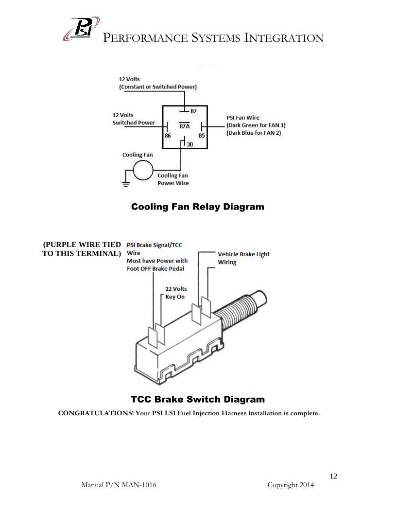
5. When using a 4L60E or 4L80E transmission you MUST have a two-position brake switch. These are necessary to allow proper function of the TCC. The brake switch should be closed (electrically connected) when the brakes ARE NOT being applied and open (not electrically connected) when the brakes ARE being applied. This is the opposite of a standard brake light switch. A TCC brake switch kit is available through PSI (p/n KIT-1002), contact us to order.
CAUTION: FAILURE TO WIRE THE TCC SWITCH CORRECTLY WILL RESULT IN A
DANGEROUS SITUATION IN THE VEHICLE WHERE THE TORQUE CONVERTER MAY NOT UNLOCK. ADDITIONALLY AN INOPERABLE THROTTLE BODY MAY RESULT!
PERFORMANCE SYSTEMS INTEGRATION
Manual P/N MAN-1016 Copyright 2014
5
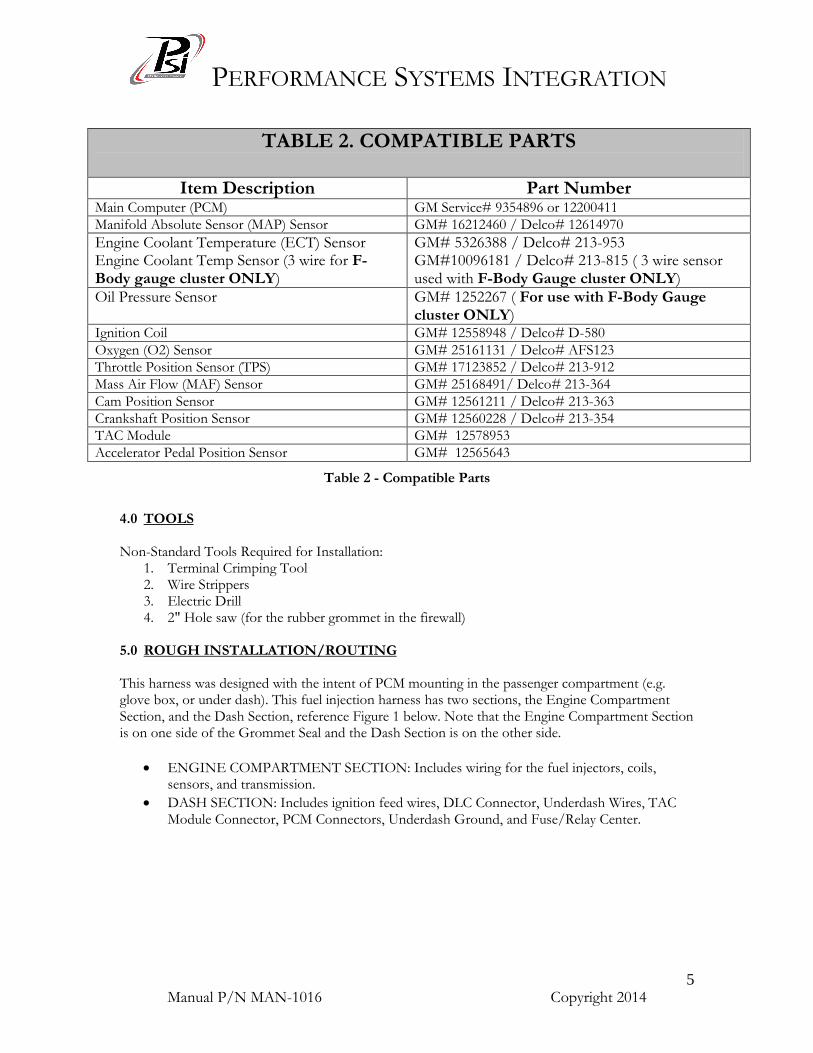
TABLE 2. COMPATIBLE PARTS
Item Description Part Number Main Computer (PCM) GM Service# 9354896 or 12200411
Manifold Absolute Sensor (MAP) Sensor GM# 16212460 / Delco# 12614970
Engine Coolant Temperature (ECT) Sensor Engine Coolant Temp Sensor (3 wire for F-Body gauge cluster ONLY)
GM# 5326388 / Delco# 213-953 GM#10096181 / Delco# 213-815 ( 3 wire sensor used with F-Body Gauge cluster ONLY)
Oil Pressure Sensor GM# 1252267 ( For use with F-Body Gauge cluster ONLY)
Ignition Coil GM# 12558948 / Delco# D-580
Oxygen (O2) Sensor GM# 25161131 / Delco# AFS123
Throttle Position Sensor (TPS) GM# 17123852 / Delco# 213-912
Mass Air Flow (MAF) Sensor GM# 25168491/ Delco# 213-364
Cam Position Sensor GM# 12561211 / Delco# 213-363
Crankshaft Position Sensor GM# 12560228 / Delco# 213-354
TAC Module GM# 12578953
Accelerator Pedal Position Sensor GM# 12565643
Table 2 - Compatible Parts
4.0 TOOLS Non-Standard Tools Required for Installation:
1. Terminal Crimping Tool 2. Wire Strippers 3. Electric Drill 4. 2" Hole saw (for the rubber grommet in the firewall)
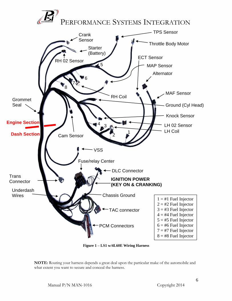
5.0 ROUGH INSTALLATION/ROUTING This harness was designed with the intent of PCM mounting in the passenger compartment (e.g. glove box, or under dash). This fuel injection harness has two sections, the Engine Compartment Section, and the Dash Section, reference Figure 1 below. Note that the Engine Compartment Section is on one side of the Grommet Seal and the Dash Section is on the other side.
ENGINE COMPARTMENT SECTION: Includes wiring for the fuel injectors, coils, sensors, and transmission.
DASH SECTION: Includes ignition feed wires, DLC Connector, Underdash Wires, TAC Module Connector, PCM Connectors, Underdash Ground, and Fuse/Relay Center.
PERFORMANCE SYSTEMS INTEGRATION
Manual P/N MAN-1016 Copyright 2014
6
Figure 1 – LS1 w/4L60E Wiring Harness
NOTE: Routing your harness depends a great deal upon the particular make of the automobile and what extent you want to secure and conceal the harness.
PCM Connectors
TAC connector
DLC Connector
Chassis Ground
VSS
Trans Connector
Fuse/relay Center
Underdash Wires
Cam Sensor
Grommet Seal
MAF Sensor
Alternator
ECT Sensor
1
LH 02 Sensor
2 LH Coil
3 4
Knock Sensor
Ground (Cyl Head)
MAP Sensor
8 7
RH Coil
6
5
Throttle Body Motor
TPS Sensor Crank Sensor
Starter (Battery)
RH 02 Sensor
1 = #1 Fuel Injector
2 = #2 Fuel Injector
3 = #3 Fuel Injector
4 = #4 Fuel Injector
5 = #5 Fuel Injector
6 = #6 Fuel Injector
7 = #7 Fuel Injector
8 = #8 Fuel Injector
Engine Section
Dash Section
IGNITION POWER
(KEY ON & CRANKING)
PERFORMANCE SYSTEMS INTEGRATION
Manual P/N MAN-1016 Copyright 2014
7
5.1 Decide where and how the PCM and Fuse/Relay Center will be mounted. PSI wiring harnesses are designed to mount either under the dash or in the kick panel on the right side. They must be no further apart than the wiring will allow.
5.2 A good exercise is to lay out the wire harness on the floor beside your vehicle and identify all
the connectors and wires. 5.3 You will want to route the harness through and around open areas. Inside edges provide
extra protection from hazards and also provide places for tie wraps, clips and other support. 5.4 Route the harness away from sharp edges, exhaust pipes, and the hood, trunk and door
hinges. 5.5 Allow enough slack in the harness at places where movement could possibly occur (body to
frame, frame to engine, etc.). 5.6 Familiarize yourself with the harness by locating each of the harness sections and by looking
at the connectors on the wire ends, reference Figure 1. As with all automotive wiring, the grounding circuit is critical for proper operation. Ensure that there is secure grounding of the following, battery to engine, battery to chassis, engine to chassis, harness to engine, and harness to chassis. NOTE: This harness is equipped with Ground Wiring on the rear portion of the driver side cylinder head and adjacent the fuse block supplied with the harness. 5.7 Connect a ground strap or cable (minimum of a 4 Ga. wire) from the negative battery
terminal to the chassis (frame). 5.8 Connect a ground strap (minimum of a 4 Ga. wire) from the engine to the chassis (frame).
DO NOT RELY UPON THE MOTOR MOUNTS TO MAKE THIS CONNECTION.
5.9 Connect a ground strap from the engine to the body.
6.0 HARNESS INSTALLATION CAUTION: BEFORE BEGINNING INSTALLATION, DISCONNECT THE POWER FROM YOUR VEHICLE BY REMOVING THE NEGATIVE BATTERY CABLE FROM THE BATTERY. Connecting the Wiring Harness is a simple process and is detailed in the following steps. 6.1 Mark the position where the wiring harness will come through the firewall with a metal
punch. Using a 2” hole saw, drill a hole in the firewall. Make sure to debur the hole with a file.
PERFORMANCE SYSTEMS INTEGRATION
Manual P/N MAN-1016 Copyright 2014
8
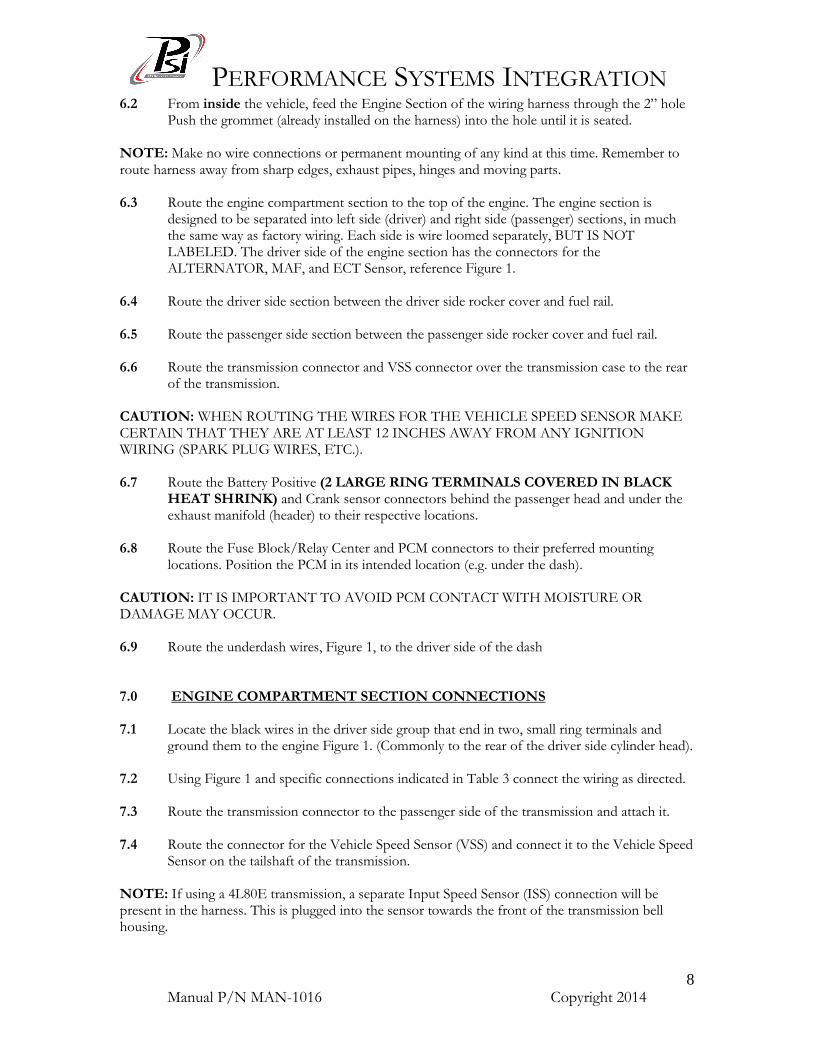
6.2 From inside the vehicle, feed the Engine Section of the wiring harness through the 2” hole Push the grommet (already installed on the harness) into the hole until it is seated.
NOTE: Make no wire connections or permanent mounting of any kind at this time. Remember to route harness away from sharp edges, exhaust pipes, hinges and moving parts. 6.3 Route the engine compartment section to the top of the engine. The engine section is
designed to be separated into left side (driver) and right side (passenger) sections, in much the same way as factory wiring. Each side is wire loomed separately, BUT IS NOT LABELED. The driver side of the engine section has the connectors for the ALTERNATOR, MAF, and ECT Sensor, reference Figure 1.
6.4 Route the driver side section between the driver side rocker cover and fuel rail. 6.5 Route the passenger side section between the passenger side rocker cover and fuel rail. 6.6 Route the transmission connector and VSS connector over the transmission case to the rear
of the transmission. CAUTION: WHEN ROUTING THE WIRES FOR THE VEHICLE SPEED SENSOR MAKE CERTAIN THAT THEY ARE AT LEAST 12 INCHES AWAY FROM ANY IGNITION WIRING (SPARK PLUG WIRES, ETC.). 6.7 Route the Battery Positive (2 LARGE RING TERMINALS COVERED IN BLACK
HEAT SHRINK) and Crank sensor connectors behind the passenger head and under the exhaust manifold (header) to their respective locations.
6.8 Route the Fuse Block/Relay Center and PCM connectors to their preferred mounting locations. Position the PCM in its intended location (e.g. under the dash). CAUTION: IT IS IMPORTANT TO AVOID PCM CONTACT WITH MOISTURE OR DAMAGE MAY OCCUR. 6.9 Route the underdash wires, Figure 1, to the driver side of the dash 7.0 ENGINE COMPARTMENT SECTION CONNECTIONS 7.1 Locate the black wires in the driver side group that end in two, small ring terminals and
ground them to the engine Figure 1. (Commonly to the rear of the driver side cylinder head). 7.2 Using Figure 1 and specific connections indicated in Table 3 connect the wiring as directed. 7.3 Route the transmission connector to the passenger side of the transmission and attach it. 7.4 Route the connector for the Vehicle Speed Sensor (VSS) and connect it to the Vehicle Speed
Sensor on the tailshaft of the transmission. NOTE: If using a 4L80E transmission, a separate Input Speed Sensor (ISS) connection will be present in the harness. This is plugged into the sensor towards the front of the transmission bell housing.
PERFORMANCE SYSTEMS INTEGRATION
Manual P/N MAN-1016 Copyright 2014
9
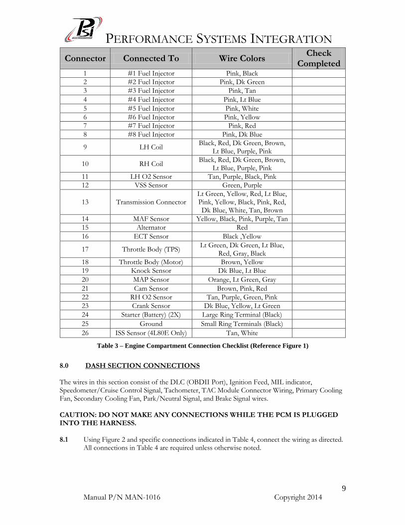
Connector Connected To Wire Colors Check
Completed 1 #1 Fuel Injector Pink, Black
2 #2 Fuel Injector Pink, Dk Green
3 #3 Fuel Injector Pink, Tan
4 #4 Fuel Injector Pink, Lt Blue
5 #5 Fuel Injector Pink, White
6 #6 Fuel Injector Pink, Yellow
7 #7 Fuel Injector Pink, Red
8 #8 Fuel Injector Pink, Dk Blue
9 LH Coil Black, Red, Dk Green, Brown,
Lt Blue, Purple, Pink
10 RH Coil Black, Red, Dk Green, Brown,
Lt Blue, Purple, Pink
11 LH O2 Sensor Tan, Purple, Black, Pink
12 VSS Sensor Green, Purple
13 Transmission Connector Lt Green, Yellow, Red, Lt Blue, Pink, Yellow, Black, Pink, Red, Dk Blue, White, Tan, Brown
14 MAF Sensor Yellow, Black, Pink, Purple, Tan
15 Alternator Red
16 ECT Sensor Black ,Yellow
17 Throttle Body (TPS) Lt Green, Dk Green, Lt Blue,
Red, Gray, Black
18 Throttle Body (Motor) Brown, Yellow
19 Knock Sensor Dk Blue, Lt Blue
20 MAP Sensor Orange, Lt Green, Gray
21 Cam Sensor Brown, Pink, Red
22 RH O2 Sensor Tan, Purple, Green, Pink
23 Crank Sensor Dk Blue, Yellow, Lt Green
24 Starter (Battery) (2X) Large Ring Terminal (Black)
25 Ground Small Ring Terminals (Black)
26 ISS Sensor (4L80E Only) Tan, White
Table 3 – Engine Compartment Connection Checklist (Reference Figure 1)
8.0 DASH SECTION CONNECTIONS The wires in this section consist of the DLC (OBDII Port), Ignition Feed, MIL indicator, Speedometer/Cruise Control Signal, Tachometer, TAC Module Connector Wiring, Primary Cooling Fan, Secondary Cooling Fan, Park/Neutral Signal, and Brake Signal wires. CAUTION: DO NOT MAKE ANY CONNECTIONS WHILE THE PCM IS PLUGGED INTO THE HARNESS. 8.1 Using Figure 2 and specific connections indicated in Table 4, connect the wiring as directed.
All connections in Table 4 are required unless otherwise noted.
PERFORMANCE SYSTEMS INTEGRATION
Manual P/N MAN-1016 Copyright 2014
10
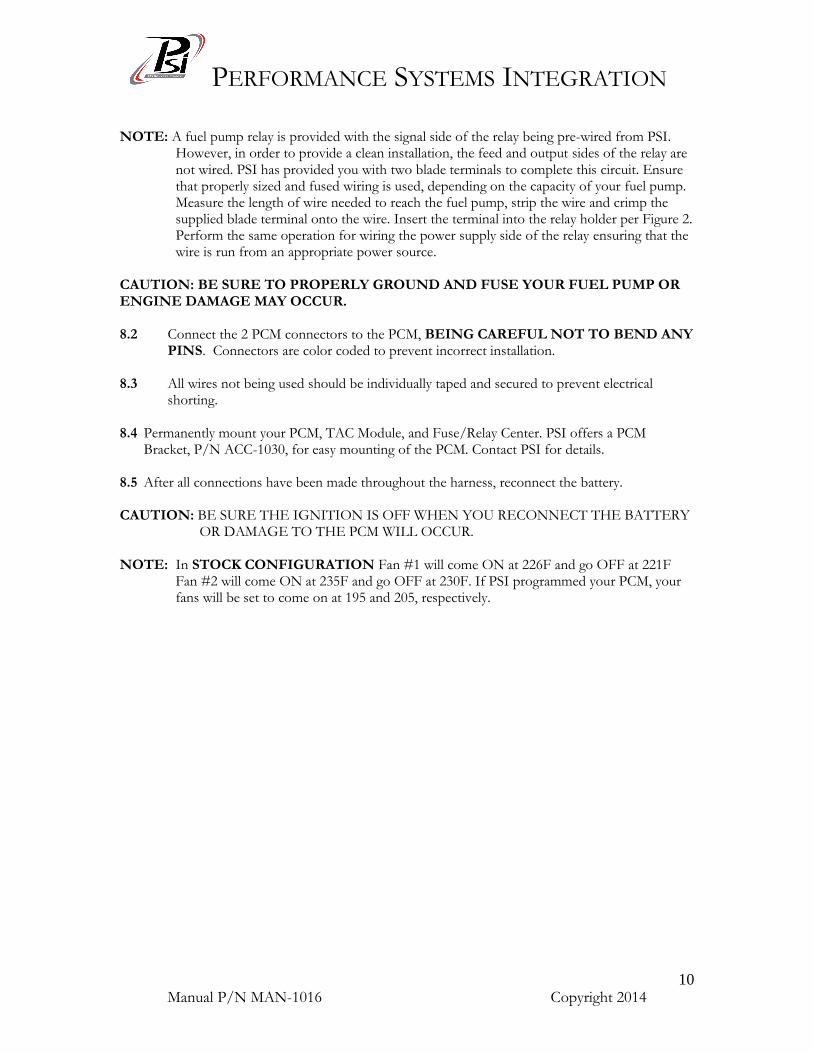
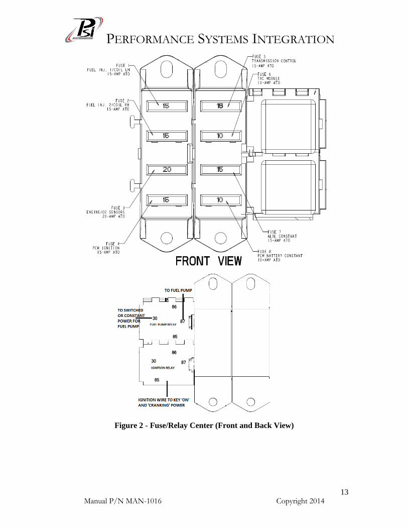
NOTE: A fuel pump relay is provided with the signal side of the relay being pre-wired from PSI.
However, in order to provide a clean installation, the feed and output sides of the relay are not wired. PSI has provided you with two blade terminals to complete this circuit. Ensure that properly sized and fused wiring is used, depending on the capacity of your fuel pump. Measure the length of wire needed to reach the fuel pump, strip the wire and crimp the supplied blade terminal onto the wire. Insert the terminal into the relay holder per Figure 2. Perform the same operation for wiring the power supply side of the relay ensuring that the wire is run from an appropriate power source.
CAUTION: BE SURE TO PROPERLY GROUND AND FUSE YOUR FUEL PUMP OR ENGINE DAMAGE MAY OCCUR. 8.2 Connect the 2 PCM connectors to the PCM, BEING CAREFUL NOT TO BEND ANY
PINS. Connectors are color coded to prevent incorrect installation. 8.3 All wires not being used should be individually taped and secured to prevent electrical
shorting. 8.4 Permanently mount your PCM, TAC Module, and Fuse/Relay Center. PSI offers a PCM
Bracket, P/N ACC-1030, for easy mounting of the PCM. Contact PSI for details. 8.5 After all connections have been made throughout the harness, reconnect the battery. CAUTION: BE SURE THE IGNITION IS OFF WHEN YOU RECONNECT THE BATTERY
OR DAMAGE TO THE PCM WILL OCCUR. NOTE: In STOCK CONFIGURATION Fan #1 will come ON at 226F and go OFF at 221F
Fan #2 will come ON at 235F and go OFF at 230F. If PSI programmed your PCM, your fans will be set to come on at 195 and 205, respectively.
PERFORMANCE SYSTEMS INTEGRATION
Manual P/N MAN-1016 Copyright 2014
11
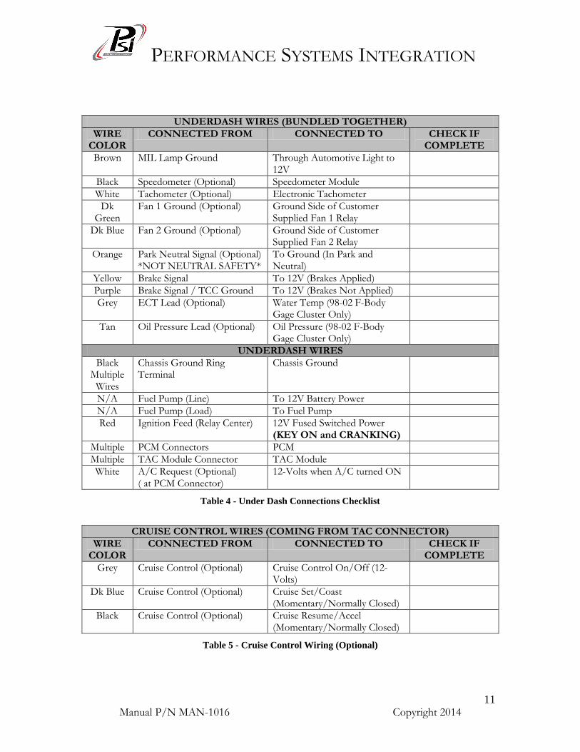
UNDERDASH WIRES (BUNDLED TOGETHER)
WIRE COLOR
CONNECTED FROM CONNECTED TO CHECK IF COMPLETE
Brown MIL Lamp Ground Through Automotive Light to 12V
Black Speedometer (Optional) Speedometer Module
White Tachometer (Optional) Electronic Tachometer
Dk Green
Fan 1 Ground (Optional) Ground Side of Customer Supplied Fan 1 Relay
Dk Blue Fan 2 Ground (Optional) Ground Side of Customer Supplied Fan 2 Relay
Orange Park Neutral Signal (Optional) *NOT NEUTRAL SAFETY*
To Ground (In Park and Neutral)
Yellow Brake Signal To 12V (Brakes Applied)
Purple Brake Signal / TCC Ground To 12V (Brakes Not Applied)
Grey ECT Lead (Optional) Water Temp (98-02 F-Body Gage Cluster Only)
Tan Oil Pressure Lead (Optional) Oil Pressure (98-02 F-Body Gage Cluster Only)
UNDERDASH WIRES
Black Multiple
Wires
Chassis Ground Ring Terminal
Chassis Ground
N/A Fuel Pump (Line) To 12V Battery Power
N/A Fuel Pump (Load) To Fuel Pump
Red Ignition Feed (Relay Center) 12V Fused Switched Power (KEY ON and CRANKING)
Multiple PCM Connectors PCM
Multiple TAC Module Connector TAC Module
White A/C Request (Optional) ( at PCM Connector)
12-Volts when A/C turned ON
Table 4 - Under Dash Connections Checklist
CRUISE CONTROL WIRES (COMING FROM TAC CONNECTOR)
WIRE COLOR
CONNECTED FROM CONNECTED TO CHECK IF COMPLETE
Grey Cruise Control (Optional) Cruise Control On/Off (12-Volts)
Dk Blue Cruise Control (Optional) Cruise Set/Coast (Momentary/Normally Closed)
Black Cruise Control (Optional) Cruise Resume/Accel (Momentary/Normally Closed)
Table 5 - Cruise Control Wiring (Optional)
PERFORMANCE SYSTEMS INTEGRATION
Manual P/N MAN-1016 Copyright 2014
12
Cooling Fan Relay Diagram
TCC Brake Switch Diagram
CONGRATULATIONS! Your PSI LS1 Fuel Injection Harness installation is complete.
(PURPLE WIRE TIED
TO THIS TERMINAL)
PERFORMANCE SYSTEMS INTEGRATION
Manual P/N MAN-1016 Copyright 2014
13
Figure 2 - Fuse/Relay Center (Front and Back View)
RED WIRE (KEY ON AND
CRANKING POWER)
PERFORMANCE SYSTEMS INTEGRATION
Manual P/N MAN-1016 Copyright 2014
14
9.0 TROUBLE SHOOTING INSTRUCTIONS If you are having trouble with your engine running poorly or not running at all, first perform basic trouble shooting (ensure that you are using the correct parts, see Table 2), check for faulty connections, 12V at starter, blown fuses, disabling of VATS in PCM, spark, timing, fuel pressure, etc., then see if the PCM has stored a trouble code in its memory. Check the following items prior to contacting PSI. NO-START
1. Red Ignition Wire (From back of Fuse/Relay Center) has 12-volts with the Key in the ON position and CRANKING position. This cannot be stressed enough, most NO-START conditions can be traced to this wiring issue.
2. Check Fuel Pressure for correct value (Approximately 58-psi). 3. Check that Fuel Injectors are firing. In many cases, engines which have been sitting for a few
months have old fuel which has turned to varnish and clogged the injectors. A simple way to check of the injectors are clogged is to place a NOID LIGHT (Available at most autoparts stores) in the injector plug while cranking the engine. If the plug lights up, then the injectors are being commanded to fire. If the spark plugs are firing, and the fuel pressure is correct, then the injectors are clogged and must be cleaned.
NO THROTTLE PEDAL
1. CHECK YOUR GROUNDS. This cannot be stressed enough. Most ‘Dead’ Throttle conditions are the result of a bad ground either under the dash or to the engine block. As a preliminary check run a temporary wire from the PSI grounds (under dash and cylinder head) directly back to the negative terminal of your battery. If this solves your throttle pedal issue then install new ground wires on your vehicle.
2. Ensure that both the Purple and Yellow Brake switch wires are connected properly. They must have power with the key on and foot OFF the brake pedal.
3. Make sure you are using the correct pedal, tac module, tac harness and TUNE for your application. Remember that Vortec/Truck Components and LS1/LS6 Corvette components do not interchange. The tune in the PCM must match the components as well.
COOLING FANS STAY RUNNING
1. Ensure that Check Engine Light is connected properly. 2. Trouble Codes exist.
PERFORMANCE SYSTEMS INTEGRATION
Manual P/N MAN-1016 Copyright 2014
15
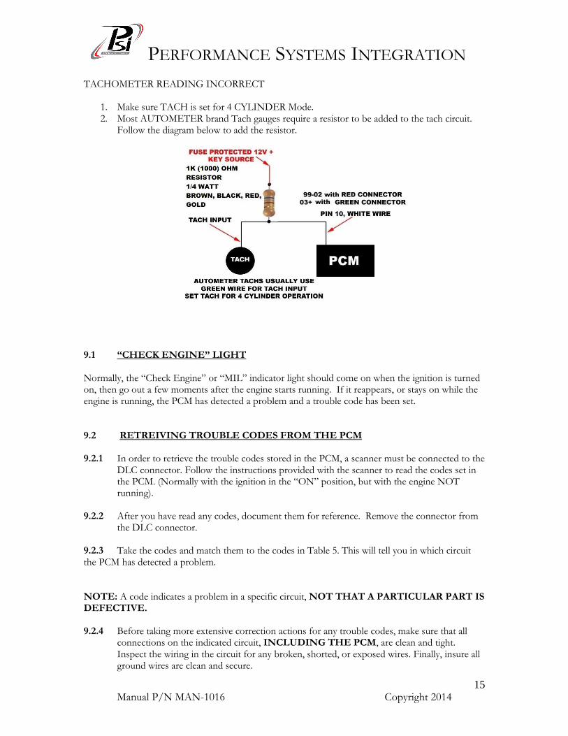
TACHOMETER READING INCORRECT
1. Make sure TACH is set for 4 CYLINDER Mode. 2. Most AUTOMETER brand Tach gauges require a resistor to be added to the tach circuit.
Follow the diagram below to add the resistor.
9.1 “CHECK ENGINE” LIGHT Normally, the “Check Engine” or “MIL” indicator light should come on when the ignition is turned on, then go out a few moments after the engine starts running. If it reappears, or stays on while the engine is running, the PCM has detected a problem and a trouble code has been set. 9.2 RETREIVING TROUBLE CODES FROM THE PCM 9.2.1 In order to retrieve the trouble codes stored in the PCM, a scanner must be connected to the
DLC connector. Follow the instructions provided with the scanner to read the codes set in the PCM. (Normally with the ignition in the “ON” position, but with the engine NOT running).
9.2.2 After you have read any codes, document them for reference. Remove the connector from
the DLC connector. 9.2.3 Take the codes and match them to the codes in Table 5. This will tell you in which circuit the PCM has detected a problem. NOTE: A code indicates a problem in a specific circuit, NOT THAT A PARTICULAR PART IS DEFECTIVE. 9.2.4 Before taking more extensive correction actions for any trouble codes, make sure that all
connections on the indicated circuit, INCLUDING THE PCM, are clean and tight. Inspect the wiring in the circuit for any broken, shorted, or exposed wires. Finally, insure all ground wires are clean and secure.
PERFORMANCE SYSTEMS INTEGRATION
Manual P/N MAN-1016 Copyright 2014
16
9.2.5 If a trouble code is detected and the problem has been fixed, clear the codes by first making
sure the ignition is off, then disconnecting the NEGATIVE battery cable for at least 3 minutes.
10.0 TECHNICAL SUPPORT PSI harnesses are built with the highest regard to quality control, and all products are 100% quality inspected. Before contacting us, please double check all connections and perform normal basic trouble shooting (fuel pressure, timing, ignition system, etc.).
*(SEE TABLE 2 FOR COMPATIBLE REPLACEMENT SENSOR PART NUMBERS)* If you have any questions concerning the installation of this harness, feel free to call Performance Systems Integration 732-444-3277. Email questions to [email protected]