Embed Size (px)
Citation preview
book.book Page 1 Tuesday, August 24, 2010 1:47 PM
Dell PowerEdge R515 Systems
Hardware Owner’sManual
Regulatory Model E12S Series and E13S SeriesRegulatory Type E12S002 and E13S002
book.book Page 2 Tuesday, August 24, 2010 1:47 PM
Notes, Cautions, and Warnings NOTE: A NOTE indicates important information that helps you make better use of
your computer.
CAUTION: A CAUTION indicates potential damage to hardware or loss of data if instructions are not followed.
WARNING: A WARNING indicates a potential for property damage, personal injury, or death.
____________________
Information in this publication is subject to change without notice.© 2010 Dell Inc. All rights reserved.
Reproduction of these materials in any manner whatsoever without the written permission of Dell Inc. is strictly forbidden.
Trademarks used in this text: Dell™, the DELL logo, and PowerEdge™ are trademarks of Dell Inc. Microsoft®, Windows®, MS-DOS®, and Windows Server® are either trademarks or registered trademarks of Microsoft Corporation in the United States and/or other countries.
Other trademarks and trade names may be used in this publication to refer to either the entities claiming the marks and names or their products. Dell Inc. disclaims any proprietary interest in trademarks and trade names other than its own.
Regulatory Model E12S Series and E13S SeriesRegulatory Type E12S002 and E13S002
August 2010 Rev. A00
book.book Page 3 Tuesday, August 24, 2010 1:47 PM
Contents
1 About Your System . . . . . . . . . . . . . . . . . . 11
Accessing System Features During Startup. . . . . . . 11
Front-Panel Features and Indicators . . . . . . . . . . 12
LCD Panel Features (Optional). . . . . . . . . . . . . . 16
Home Screen . . . . . . . . . . . . . . . . . . . . 17
Setup Menu . . . . . . . . . . . . . . . . . . . . . 18
View Menu . . . . . . . . . . . . . . . . . . . . . 18
Hard-Drive Indicator Patterns . . . . . . . . . . . . . . 19
Back-Panel Features and Indicators . . . . . . . . . . 20
Guidelines for Connecting Optional ExternalDevices. . . . . . . . . . . . . . . . . . . . . . . . . . 23
NIC Indicator Codes . . . . . . . . . . . . . . . . . . . 23
Power Indicator Codes . . . . . . . . . . . . . . . . . 24
Diagnostic Lights (Optional) . . . . . . . . . . . . . . . 25
LCD Status Messages (Optional) . . . . . . . . . . . . 27
Solving Problems Described by LCD Status Messages . . . . . . . . . . . . . . . 39
Removing LCD Status Messages . . . . . . . . . . 39
System Messages . . . . . . . . . . . . . . . . . . . . 40
Warning Messages . . . . . . . . . . . . . . . . . . . 55
Contents 3
book.book Page 4 Tuesday, August 24, 2010 1:47 PM
Diagnostics Messages. . . . . . . . . . . . . . . . . . 55
Alert Messages . . . . . . . . . . . . . . . . . . . . . 55
Other Information You May Need . . . . . . . . . . . . 56
2 Using the System Setup Program and UEFI Boot Manager . . . . . . . . . . . . . . . . . 57
Choosing the System Boot Mode . . . . . . . . . . . . 57
Entering the System Setup Program . . . . . . . . . . . 58
Responding to Error Messages . . . . . . . . . . . 58
Using the System Setup Program Navigation Keys . . . . . . . . . . . . . . . . . . . 58
System Setup Options . . . . . . . . . . . . . . . . . . 59
Main Screen. . . . . . . . . . . . . . . . . . . . . . . . . . . . . . . . . . . 59
Memory Settings Screen . . . . . . . . . . . . . . 61
Processor Settings Screen . . . . . . . . . . . . . 61
SATA Settings Screen (Optional) . . . . . . . . . . 62
Boot Settings Screen . . . . . . . . . . . . . . . . 63
Integrated Devices Screen . . . . . . . . . . . . . 64
PCI IRQ Assignments Screen . . . . . . . . . . . . 65
Serial Communication Screen . . . . . . . . . . . 65
Embedded Server Management Screen . . . . . . 66
Power Management Screen . . . . . . . . . . . . 67
System Security Screen . . . . . . . . . . . . . . 67
Exit Screen . . . . . . . . . . . . . . . . . . . . . 69
Entering the UEFI Boot Manager. . . . . . . . . . . . . 70
Using the UEFI Boot Manager Navigation Keys . . . . . . . . . . . . . . . . . . . 70
UEFI Boot Manager Screen. . . . . . . . . . . . . 71
UEFI Boot Settings Screen . . . . . . . . . . . . . 71
4 Contents
book.book Page 5 Tuesday, August 24, 2010 1:47 PM
System Utilities Screen . . . . . . . . . . . . . . . 72
System and Setup Password Features . . . . . . . . . 72
Using the System Password . . . . . . . . . . . . 72
Using the Setup Password . . . . . . . . . . . . . 75
Embedded System Management . . . . . . . . . . . . 76
Baseboard Management Controller Configuration . . . 77
Entering the BMC Setup Module . . . . . . . . . . 77
iDRAC6 Configuration Utility . . . . . . . . . . . . . . 78
Entering the iDRAC6 Configuration Utility . . . . . 78
3 Installing System Components . . . . . . . . 79
Recommended Tools. . . . . . . . . . . . . . . . . . . 79
Inside the System . . . . . . . . . . . . . . . . . . . . 79
Front Bezel (Optional) . . . . . . . . . . . . . . . . . . 82
Removing the Front Bezel . . . . . . . . . . . . . 82
Installing the Front Bezel . . . . . . . . . . . . . . 83
Opening and Closing the System . . . . . . . . . . . . 83
Opening the System . . . . . . . . . . . . . . . . 83
Closing the System . . . . . . . . . . . . . . . . . 85
Cooling Shroud. . . . . . . . . . . . . . . . . . . . . . 86
Removing the Cooling Shroud . . . . . . . . . . . 86
Installing the Cooling Shroud . . . . . . . . . . . . 87
Hard Drives. . . . . . . . . . . . . . . . . . . . . . . . 87
Removing a Hard-Drive Blank . . . . . . . . . . . 87
Installing a Hard-Drive Blank . . . . . . . . . . . . 88
Removing a Hard Drive . . . . . . . . . . . . . . . 88
Contents 5
book.book Page 6 Tuesday, August 24, 2010 1:47 PM
Installing a Hard Drive . . . . . . . . . . . . . . . 89
Removing a Hard Drive From a Hard-Drive Carrier . . . . . . . . . . . . . . . . . 90
Installing a Hard Drive Into a Hard-Drive Carrier . . . . . . . . . . . . . . . . . 91
Internal Hard Drives . . . . . . . . . . . . . . . . . . . 91
Removing an Internal Hard-Drive Bay . . . . . . . 91
Installing an Internal Hard-Drive Bay. . . . . . . . 93
Removing an Internal Hard Drive From the Internal Hard-Drive Bay. . . . . . . . . . . . . . . 93
Installing a Hard Drive Into a Hard-Drive Bay . . . . . . . . . . . . . . . . . . . 94
Optical Drive (Optional) . . . . . . . . . . . . . . . . . 95
Removing an Optical Drive . . . . . . . . . . . . . 95
Installing an Optical Drive . . . . . . . . . . . . . 96
Cooling Fans . . . . . . . . . . . . . . . . . . . . . . . 97
Removing a Cooling Fan . . . . . . . . . . . . . . 98
Installing a Cooling Fan . . . . . . . . . . . . . . 101
Power Supplies . . . . . . . . . . . . . . . . . . . . 102
Removing a Power Supply . . . . . . . . . . . . 102
Installing a Power Supply . . . . . . . . . . . . . 103
Removing the Power Supply Blank . . . . . . . . 104
Installing the Power Supply Blank . . . . . . . . 104
System Memory . . . . . . . . . . . . . . . . . . . . 104
General Memory Module InstallationGuidelines . . . . . . . . . . . . . . . . . . . . . 105
Mode-Specific Guidelines . . . . . . . . . . . . 106
Installing Memory Modules. . . . . . . . . . . . 108
Removing Memory Modules . . . . . . . . . . . 110
Expansion Cards and Expansion-Card Risers . . . . . 111
6 Contents
book.book Page 7 Tuesday, August 24, 2010 1:47 PM
Expansion Card Installation Guidelines . . . . . . 111
Installing an Expansion Card . . . . . . . . . . . . 113
Removing an Expansion Card . . . . . . . . . . . 115
Removing an Expansion-Card Riser . . . . . . . . 116
Installing an Expansion-Card Riser . . . . . . . . . 118
Integrated Storage Controller Card . . . . . . . . . . . 119
Removing the Storage Controller Card . . . . . . . 119
Installing the Storage Controller Card . . . . . . . 121
iDRAC6 Express Card (Optional). . . . . . . . . . . . . 122
Installing an iDRAC6 Express Card . . . . . . . . . 122
Removing an iDRAC6 Express Card . . . . . . . . 123
iDRAC6 Enterprise Card (Optional) . . . . . . . . . . . 124
Installing an iDRAC6 Enterprise Card . . . . . . . 124
Removing an iDRAC6 Enterprise Card . . . . . . . 126
VFlash Media (Optional) . . . . . . . . . . . . . . . . . 127
Installing a VFlash Media Card . . . . . . . . . . . 127
Removing a VFlash Media Card . . . . . . . . . . 127
Internal USB Memory Key . . . . . . . . . . . . . . . 127
Processors . . . . . . . . . . . . . . . . . . . . . . . . 128
Removing a Processor . . . . . . . . . . . . . . . 128
Installing a Processor . . . . . . . . . . . . . . . 132
System Battery . . . . . . . . . . . . . . . . . . . . . . 133
Replacing the System Battery . . . . . . . . . . . 133
RAID Battery (Optional) . . . . . . . . . . . . . . . . . 136
Removing the RAID Battery . . . . . . . . . . . . 136
Installing the RAID Battery . . . . . . . . . . . . . 137
Control Panel Assembly—LED . . . . . . . . . . . . . 137
Removing the Control-Panel Module–LED . . . . . 137
Contents 7
book.book Page 8 Tuesday, August 24, 2010 1:47 PM
Installing the Control-Panel Module–LED . . . . 139
Control Panel Assembly—LCD (Optional) . . . . . . . 140
Removing the Control Panel Display Module . . . . . . . . . . . . . . . . . . . . . . 140
Installing the Control Panel Display Module . . . . . . . . . . . . . . . . . . . . . . 141
Removing the Control Panel Assembly . . . . . . 141
Installing the Control Panel Assembly . . . . . . 143
SAS Backplane. . . . . . . . . . . . . . . . . . . . . 143
Removing the SAS Backplane . . . . . . . . . . 143
Installing the SAS Backplane . . . . . . . . . . . 147
Power Distribution Board . . . . . . . . . . . . . . . 148
Removing the Power Distribution Board . . . . . 148
Replacing the Power Distribution Board . . . . . 151
System Board. . . . . . . . . . . . . . . . . . . . . . 152
Removing the System Board . . . . . . . . . . . 152
Installing the System Board. . . . . . . . . . . . 154
4 Troubleshooting Your System . . . . . . . . 157
Safety First—For You and Your System . . . . . . . . 157
Troubleshooting System Startup Failure. . . . . . . . 157
Troubleshooting External Connections . . . . . . . . 157
Troubleshooting the Video Subsystem. . . . . . . . . 158
Troubleshooting a USB Device . . . . . . . . . . . . 158
Troubleshooting a Serial I/O Device. . . . . . . . . . 159
Troubleshooting a NIC . . . . . . . . . . . . . . . . . 159
8 Contents
book.book Page 9 Tuesday, August 24, 2010 1:47 PM
Troubleshooting a Wet System . . . . . . . . . . . . . 160
Troubleshooting a Damaged System . . . . . . . . . . 162
Troubleshooting the System Battery. . . . . . . . . . . 162
Troubleshooting Power Supplies . . . . . . . . . . . . 163
Troubleshooting System Cooling Problems . . . . . . . 163
Troubleshooting a Fan . . . . . . . . . . . . . . . . . . 164
Troubleshooting System Memory . . . . . . . . . . . . 165
Troubleshooting an Internal USB Key . . . . . . . . . . 167
Troubleshooting an Optical Drive . . . . . . . . . . . . 168
Troubleshooting a Hard Drive . . . . . . . . . . . . . . 169
Troubleshooting an Internal Hard Drive . . . . . . . . . 170
Troubleshooting a Storage Controller . . . . . . . . . . 171
Troubleshooting Expansion Cards. . . . . . . . . . . . 172
Troubleshooting Processors. . . . . . . . . . . . . . . 174
5 Running the System Diagnostics . . . . . . 177
Using Online Diagnostics . . . . . . . . . . . . . . . . 177
Embedded System Diagnostics Features . . . . . . . . 177
When to Use the Embedded System Diagnostics . . . . 178
Running the Embedded System Diagnostics . . . . . . 178
Embedded System Diagnostics Testing Options . . . . 179
Using the Custom Test Options . . . . . . . . . . . . . 179
Contents 9
book.book Page 10 Tuesday, August 24, 2010 1:47 PM
Selecting Devices for Testing . . . . . . . . . . . 179
Selecting Diagnostics Options . . . . . . . . . . 179
Viewing Information and Results . . . . . . . . . 180
6 Jumpers and Connectors . . . . . . . . . . . . 181
System Board Jumpers. . . . . . . . . . . . . . . . . 181
System Board Connectors . . . . . . . . . . . . . . . 182
Disabling a Forgotten Password. . . . . . . . . . . . 184
7 Getting Help . . . . . . . . . . . . . . . . . . . . . . 187
Contacting Dell . . . . . . . . . . . . . . . . . . . . . 187
Index . . . . . . . . . . . . . . . . . . . . . . . . . . . . . . 189
10 Contents
book.book Page 11 Tuesday, August 24, 2010 1:47 PM
1About Your System
Accessing System Features During StartupThe following keystrokes provide access to system features during startup.
Keystroke Description
<F2> Enters the System Setup program. See "Using the System Setup Program and UEFI Boot Manager" on page 57.
<F10> Enters System Services, which opens the Lifecycle Controller. The controller allows you to access utilities such as embedded system diagnostics. For information on Lifecycle Controller or any of the Lifecycle Controller software components, see the Lifecycle Controller documentation at support.dell.com/manuals.
<F11> Enters the BIOS Boot Manager or the Unified Extensible Firmware Interface (UEFI) Boot Manager, depending on the system’s boot configuration. See "Using the System Setup Program and UEFI Boot Manager" on page 57.
<F12> Starts Preboot eXecution Environment (PXE) boot.
<Ctrl><E> Enters the Baseboard Management Controller (BMC) or iDRAC6 Configuration Utility, which allows access to the system event log (SEL) and configuration of remote access to the system. For more information, see the BMC or iDRAC6 user documentation.
<Ctrl><C> Enters the SAS Configuration Utility. For more information, see the SAS adapter documentation.
<Ctrl><R> Enters the RAID configuration utility. For more information, see the documentation for your SAS RAID card.
<Ctrl><S> Enters the utility to configure NIC settings for PXE boot. For more information, see the documentation for your integrated NIC.
About Your System 11
book.book Page 12 Tuesday, August 24, 2010 1:47 PM
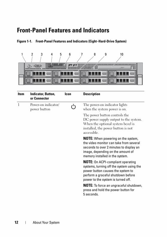
Front-Panel Features and Indicators
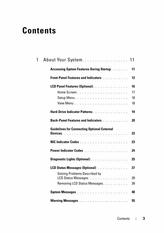
Figure 1-1. Front-Panel Features and Indicators (Eight–Hard-Drive System)
Item Indicator, Button, or Connector
Icon Description
1 Power-on indicator/ power button
The power-on indicator lights when the system power is on.
The power button controls the DC power supply output to the system. When the optional system bezel is installed, the power button is not accessible.
NOTE: When powering on the system, the video monitor can take from several seconds to over 2 minutes to display an image, depending on the amount of memory installed in the system.
NOTE: On ACPI-compliant operating systems, turning off the system using the power button causes the system to perform a graceful shutdown before power to the system is turned off.
NOTE: To force an ungraceful shutdown, press and hold the power button for 5 seconds.
1 4 5 7632 8 9 10
12 About Your System
book.book Page 13 Tuesday, August 24, 2010 1:47 PM
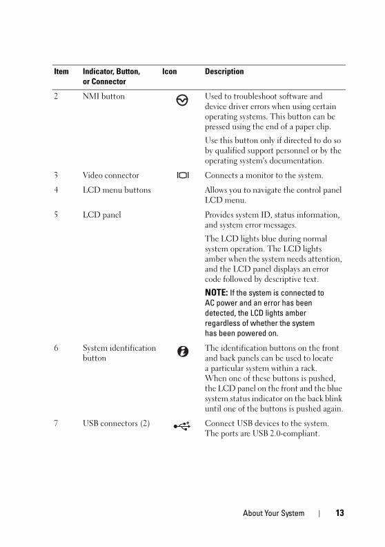
2 NMI button Used to troubleshoot software and device driver errors when using certain operating systems. This button can be pressed using the end of a paper clip.
Use this button only if directed to do so by qualified support personnel or by the operating system's documentation.
3 Video connector Connects a monitor to the system.
4 LCD menu buttons Allows you to navigate the control panel LCD menu.
5 LCD panel Provides system ID, status information, and system error messages.
The LCD lights blue during normal system operation. The LCD lights amber when the system needs attention, and the LCD panel displays an error code followed by descriptive text.
NOTE: If the system is connected to AC power and an error has been detected, the LCD lights amber regardless of whether the system has been powered on.
6 System identification button
The identification buttons on the front and back panels can be used to locate a particular system within a rack. When one of these buttons is pushed, the LCD panel on the front and the blue system status indicator on the back blink until one of the buttons is pushed again.
7 USB connectors (2) Connect USB devices to the system. The ports are USB 2.0-compliant.
Item Indicator, Button, or Connector
Icon Description
About Your System 13
book.book Page 14 Tuesday, August 24, 2010 1:47 PM
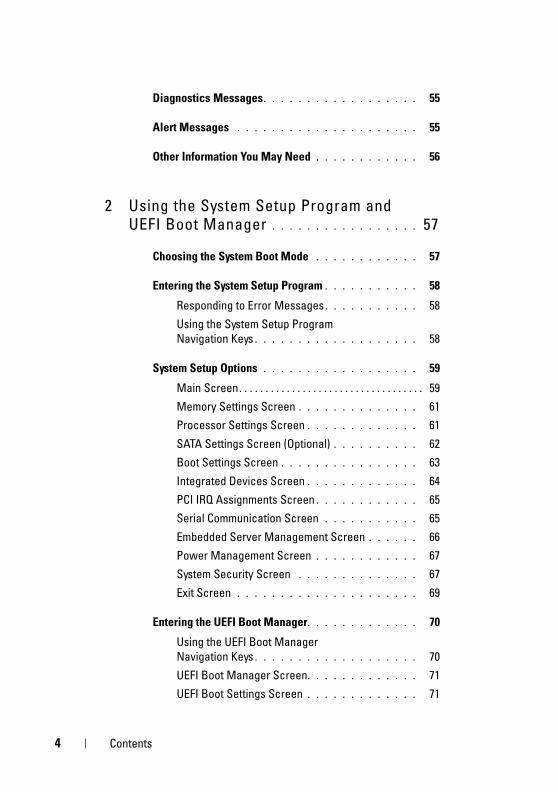
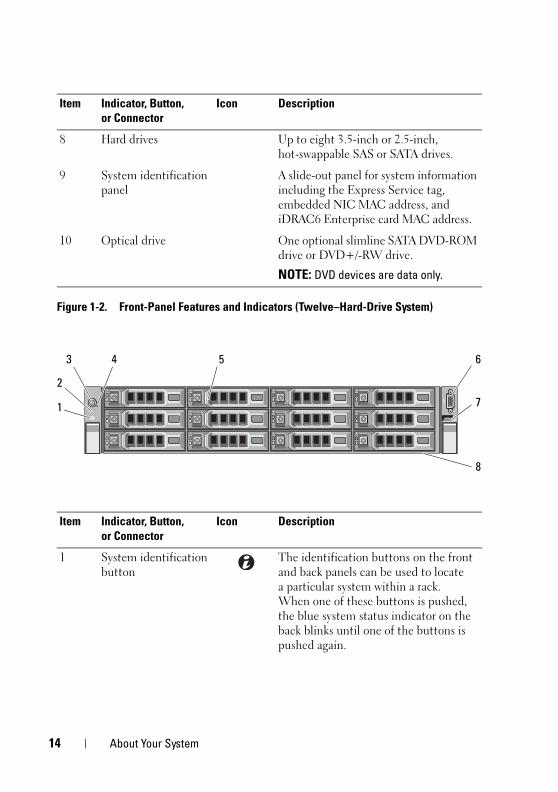
Figure 1-2. Front-Panel Features and Indicators (Twelve–Hard-Drive System)
8 Hard drives Up to eight 3.5-inch or 2.5-inch, hot-swappable SAS or SATA drives.
9 System identification panel
A slide-out panel for system information including the Express Service tag, embedded NIC MAC address, and iDRAC6 Enterprise card MAC address.
10 Optical drive One optional slimline SATA DVD-ROM drive or DVD+/-RW drive.
NOTE: DVD devices are data only.
Item Indicator, Button, or Connector
Icon Description
1 System identification button
The identification buttons on the front and back panels can be used to locate a particular system within a rack. When one of these buttons is pushed, the blue system status indicator on the back blinks until one of the buttons is pushed again.
Item Indicator, Button, or Connector
Icon Description
2
4
8
5
7
3
1
6
14 About Your System
book.book Page 15 Tuesday, August 24, 2010 1:47 PM
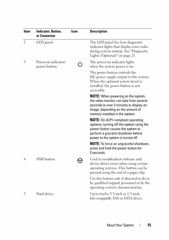
2 LED panel The LED panel has four diagnostic indicator lights that display error codes during system startup. See "Diagnostic Lights (Optional)" on page 25.
3 Power-on indicator/ power button
The power-on indicator lights when the system power is on.
The power button controls the DC power supply output to the system. When the optional system bezel is installed, the power button is not accessible.
NOTE: When powering on the system, the video monitor can take from several seconds to over 2 minutes to display an image, depending on the amount of memory installed in the system.
NOTE: On ACPI-compliant operating systems, turning off the system using the power button causes the system to perform a graceful shutdown before power to the system is turned off.
NOTE: To force an ungraceful shutdown, press and hold the power button for 5 seconds.
4 NMI button Used to troubleshoot software and device driver errors when using certain operating systems. This button can be pressed using the end of a paper clip.
Use this button only if directed to do so by qualified support personnel or by the operating system's documentation.
5 Hard drives Up to twelve 3.5-inch or 2.5-inch, hot-swappable SAS or SATA drives.
Item Indicator, Button, or Connector
Icon Description
About Your System 15
book.book Page 16 Tuesday, August 24, 2010 1:47 PM
LCD Panel Features (Optional) NOTE: This section is applicable only to eight–hard-drive systems.
The system's LCD panel provides system information and status and error messages to signify when the system is operating correctly or when the system needs attention. See "LCD Status Messages (Optional)" on page 27 for information on specific status codes.
The LCD backlight lights blue during normal operating conditions and lights amber to indicate an error condition. When the system is in standby mode, the LCD backlight switches off after five minutes of inactivity, and can be turned on by pressing the Select button on the LCD panel. The LCD backlight remains off if LCD messaging is turned off through the BMC or iDRAC6 utility, the LCD panel, or other tools.
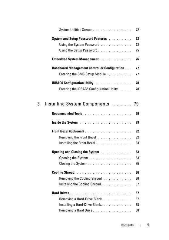
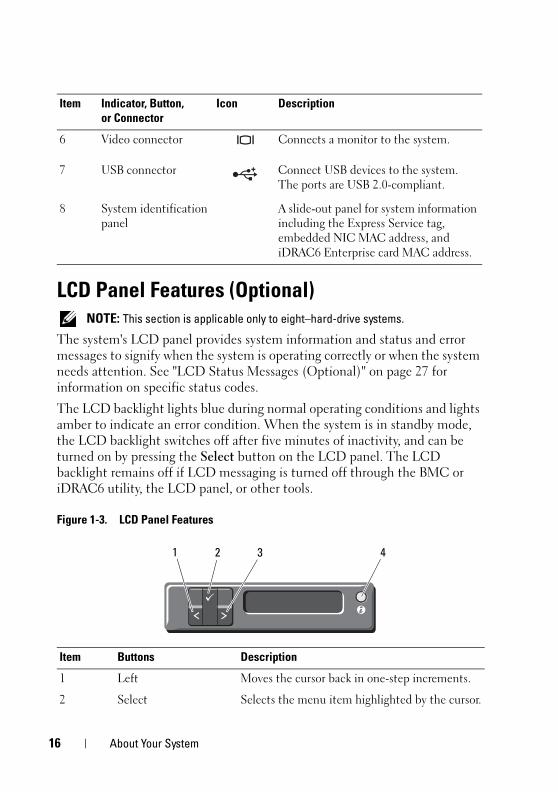
Figure 1-3. LCD Panel Features
6 Video connector Connects a monitor to the system.
7 USB connector Connect USB devices to the system. The ports are USB 2.0-compliant.
8 System identification panel
A slide-out panel for system information including the Express Service tag, embedded NIC MAC address, and iDRAC6 Enterprise card MAC address.
Item Buttons Description
1 Left Moves the cursor back in one-step increments.
2 Select Selects the menu item highlighted by the cursor.
Item Indicator, Button, or Connector
Icon Description
1 2 43
16 About Your System
book.book Page 17 Tuesday, August 24, 2010 1:47 PM
Home ScreenThe Home screen displays user-configurable information about the system. This screen is displayed during normal system operation when there are no status messages or errors present. When the system is in standby mode, the LCD backlight turns off after 5 minutes of inactivity if there are no error messages. Press one of the three navigation buttons (Select, Left, or Right) to view the Home screen.
To navigate to the Home screen from another menu, continue to select the up arrow until the Home icon is displayed, and then select the Home icon.
3 Right Moves the cursor forward in one-step increments.
During message scrolling:
• Press once to increase scrolling speed.
• Press again to stop.
• Press again to return to default scrolling.
• Press again to repeat the cycle.
4 System ID Turns the system ID mode on and off.
Press quickly to toggle the system ID on and off. If the system hangs during POST, press and hold the system ID button for more than 5 seconds to enter BIOS Progress mode.
Item Buttons Description
About Your System 17
book.book Page 18 Tuesday, August 24, 2010 1:47 PM
Setup Menu
View Menu
Option Description
BMC or DRAC
NOTE: If an iDRAC6 Express card is installed on the system, the BMC option is replaced by DRAC.
Select DHCP or Static IP to configure the network mode. If Static IP is selected, the available fields are IP, Subnet (Sub), and Gateway (Gtw). Select Setup DNS to enable DNS and to view domain addresses. Two separate DNS entries are available.
Set error Select SEL to display LCD error messages in a format that matches the IPMI description in the SEL. This can be useful when trying to match an LCD message with an SEL entry.
Select Simple to display LCD error messages in a more user-friendly description. See "LCD Status Messages (Optional)" on page 27 for a list of messages in this format.
Set home Select the default information to be displayed on the LCD Home screen. See "View Menu" on page 18 to see the options and option items that can be selected to display by default on the Home screen.
Option Description
BMC IP or DRAC IP
NOTE: If an iDRAC6 Express card is installed on the system, the BMC IP option is replaced by DRAC IP.
Displays the IPv4 or IPv6 addresses for the optional iDRAC6. Addresses include DNS (Primary and Secondary), Gateway, IP, and Subnet (IPv6 does not have Subnet).
NOTE: BMC IP supports only IPv4 addresses.
MAC Displays the MAC addresses for DRAC, iSCSIn, or NETn.
NOTE: If the iDRAC6 Express card is not installed on the system, the MAC option displays the MAC addresses for BMC, iSCSIn, or NETn.
Name Displays the name of the Host, Model, or User String for the system.
18 About Your System
book.book Page 19 Tuesday, August 24, 2010 1:47 PM
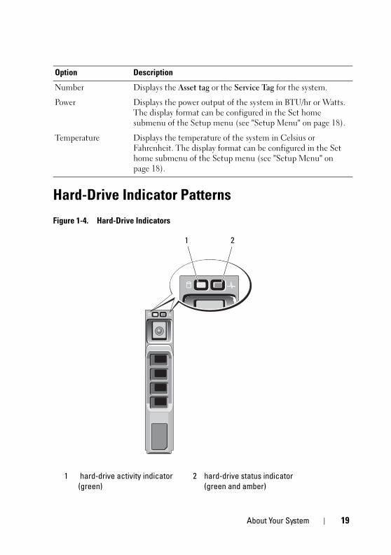
Hard-Drive Indicator Patterns
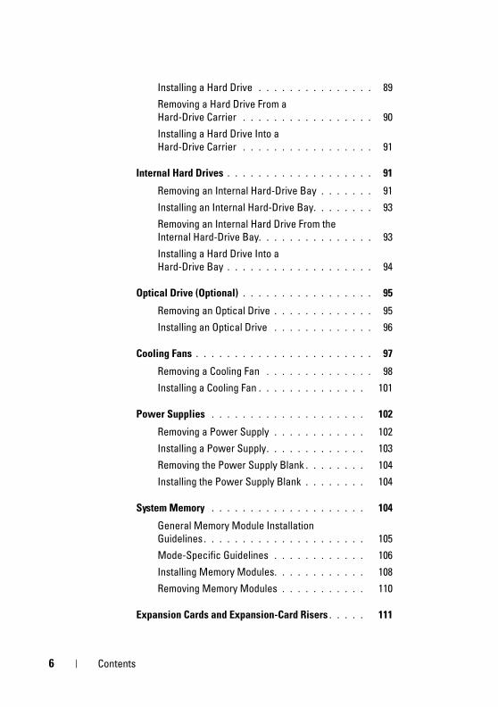
Figure 1-4. Hard-Drive Indicators
Number Displays the Asset tag or the Service Tag for the system.
Power Displays the power output of the system in BTU/hr or Watts. The display format can be configured in the Set home submenu of the Setup menu (see "Setup Menu" on page 18).
Temperature Displays the temperature of the system in Celsius or Fahrenheit. The display format can be configured in the Set home submenu of the Setup menu (see "Setup Menu" on page 18).
1 hard-drive activity indicator (green)
2 hard-drive status indicator (green and amber)
Option Description
1 2
About Your System 19
book.book Page 20 Tuesday, August 24, 2010 1:47 PM
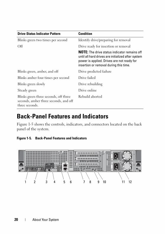
Back-Panel Features and IndicatorsFigure 1-5 shows the controls, indicators, and connectors located on the back panel of the system.
Figure 1-5. Back-Panel Features and Indicators
Drive-Status Indicator Pattern Condition
Blinks green two times per second Identify drive/preparing for removal
Off Drive ready for insertion or removal
NOTE: The drive status indicator remains off until all hard drives are initialized after system power is applied. Drives are not ready for insertion or removal during this time.
Blinks green, amber, and off Drive predicted failure
Blinks amber four times per second Drive failed
Blinks green slowly Drive rebuilding
Steady green Drive online
Blinks green three seconds, off three seconds, amber three seconds, and off three seconds.
Rebuild aborted
ST
1
3
2
1
2
Gb 2
Gb 1
21 3 4 6 9 10 11 12875
20 About Your System
book.book Page 21 Tuesday, August 24, 2010 1:47 PM
Item Indicator, Button, or Connector
Icon Description
1 Serial connector Connects a serial device to the system.
2 Video connector Connects a VGA display to the system.
3 iDRAC6 Enterprise port (optional)
Dedicated management port for the optional iDRAC6 Enterprise card.
4 VFlash media slot (optional)
Connects an external SD memory card for the optional iDRAC6 Enterprise card.
5 USB connectors (2) Connect USB devices to the system. The ports are USB 2.0-compliant.
6 Ethernet connectors (2) Embedded 10/100/1000 NIC connectors.
7 PCIe expansion card slots using riser card
Riser 1
OR
Riser 2
Depending on the configuration, your system may have either riser 1 or riser 2.
NOTE: See the Getting Started Guide that ships with your system for more information.
Connects four PCI Express Generation 2 expansion cards
NOTE: All four slots are x8 connectors.
Connects two PCI Express Generation 2 expansion cards.
NOTE: A General Purpose Computation on Graphics Processing Units (GPGPU) optimized configuration is available on Riser 2.
8 System identification connector
Connects the optional system status indicator assembly through the optional cable management arm.
About Your System 21
book.book Page 22 Tuesday, August 24, 2010 1:47 PM
9 System status indicator
Lights blue during normal system operation.
Both the systems management software and the identification buttons located on the front and back of the system can cause the indicator to flash blue to identify a particular system.
Lights amber when the system needs attention due to a problem.
10 System identification button
Turns the system ID modes on and off.
The identification buttons on the front and back panels can be used to locate a particular system within a rack. When one of these buttons is pushed, the LCD panel on the front and the system status indicator on the chassis back panel light blue until one of the buttons is pushed again.
11 Power supply 2 (PS2) 750 W redundant power supply
12 Power supply 1 (PS1) 750 W redundant power supply
Item Indicator, Button, or Connector
Icon Description
22 About Your System
book.book Page 23 Tuesday, August 24, 2010 1:47 PM
Guidelines for Connecting Optional External Devices• Turn off power to the system and external devices before attaching a new
external device. Turn on any external devices before turning on the system (unless the documentation for the device specifies otherwise).
• Ensure that the appropriate driver for the attached device has been installed on the system.
• If necessary to enable ports on your system, use the System Setup program. See "Using the System Setup Program and UEFI Boot Manager" on page 57.
NIC Indicator Codes
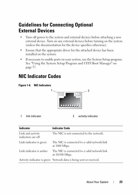
Figure 1-6. NIC Indicators
1 link indicator 2 activity indicator
Indicator Indicator Code
Link and activity indicators are off
The NIC is not connected to the network.
Link indicator is green The NIC is connected to a valid network link at 1000 Mbps.
Link indicator is amber The NIC is connected to a valid network link at 10/100 Mbps.
Activity indicator is green Network data is being sent or received.
1 2
About Your System 23
book.book Page 24 Tuesday, August 24, 2010 1:47 PM
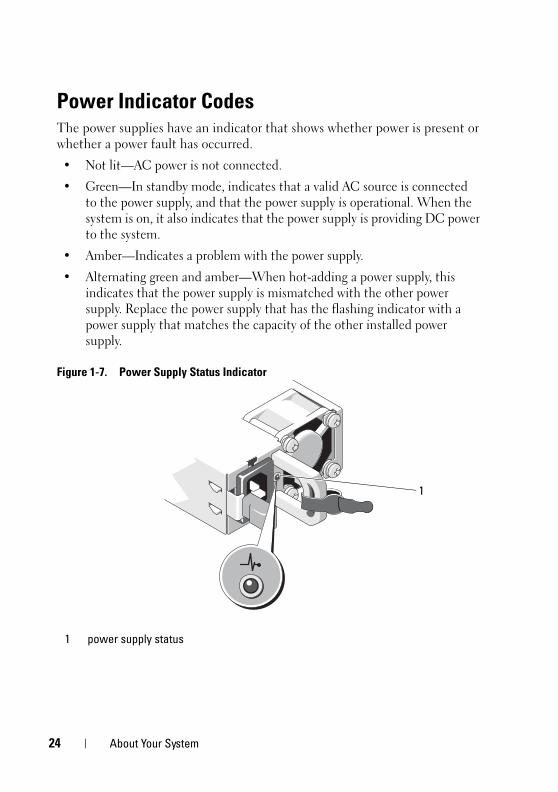
Power Indicator CodesThe power supplies have an indicator that shows whether power is present or whether a power fault has occurred.
• Not lit—AC power is not connected.
• Green—In standby mode, indicates that a valid AC source is connected to the power supply, and that the power supply is operational. When the system is on, it also indicates that the power supply is providing DC power to the system.
• Amber—Indicates a problem with the power supply.
• Alternating green and amber—When hot-adding a power supply, this indicates that the power supply is mismatched with the other power supply. Replace the power supply that has the flashing indicator with a power supply that matches the capacity of the other installed power supply.
Figure 1-7. Power Supply Status Indicator
1 power supply status
1
24 About Your System
book.book Page 25 Tuesday, August 24, 2010 1:47 PM
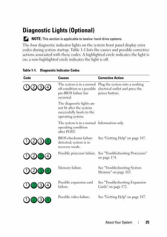
Diagnostic Lights (Optional) NOTE: This section is applicable to twelve–hard-drive systems.
The four diagnostic indicator lights on the system front panel display error codes during system startup. Table 1-1 lists the causes and possible corrective actions associated with these codes. A highlighted circle indicates the light is on; a non-highlighted circle indicates the light is off.
Table 1-1. Diagnostic Indicator Codes
Code Causes Corrective Action
The system is in a normal off condition or a possible pre-BIOS failure has occurred.
The diagnostic lights are not lit after the system successfully boots to the operating system.
Plug the system into a working electrical outlet and press the power button.
The system is in a normal operating condition after POST.
Information only.
BIOS checksum failure detected; system is in recovery mode.
See "Getting Help" on page 187.
Possible processor failure. See "Troubleshooting Processors" on page 174.
Memory failure. See "Troubleshooting System Memory" on page 165.
Possible expansion card failure.
See "Troubleshooting Expansion Cards" on page 172.
Possible video failure. See "Getting Help" on page 187.
About Your System 25
book.book Page 26 Tuesday, August 24, 2010 1:47 PM
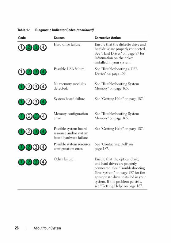
Hard drive failure. Ensure that the diskette drive and hard drive are properly connected. See "Hard Drives" on page 87 for information on the drives installed in your system.
Possible USB failure. See "Troubleshooting a USB Device" on page 158.
No memory modules detected.
See "Troubleshooting System Memory" on page 165.
System board failure. See "Getting Help" on page 187.
Memory configuration error.
See "Troubleshooting System Memory" on page 165.
Possible system board resource and/or system board hardware failure.
See "Getting Help" on page 187.
Possible system resource configuration error.
See "Contacting Dell" on page 187.
Other failure. Ensure that the optical drive, and hard drives are properly connected. See "Troubleshooting Your System" on page 157 for the appropriate drive installed in your system. If the problem persists, see "Getting Help" on page 187.
Table 1-1. Diagnostic Indicator Codes (continued)
Code Causes Corrective Action
26 About Your System
book.book Page 27 Tuesday, August 24, 2010 1:47 PM
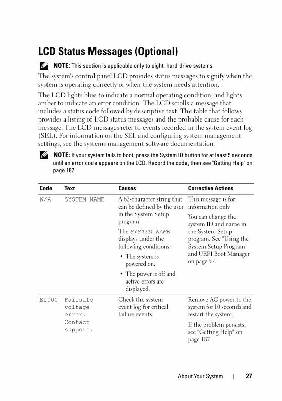
LCD Status Messages (Optional) NOTE: This section is applicable only to eight–hard-drive systems.
The system's control panel LCD provides status messages to signify when the system is operating correctly or when the system needs attention.
The LCD lights blue to indicate a normal operating condition, and lights amber to indicate an error condition. The LCD scrolls a message that includes a status code followed by descriptive text. The table that follows provides a listing of LCD status messages and the probable cause for each message. The LCD messages refer to events recorded in the system event log (SEL). For information on the SEL and configuring system management settings, see the systems management software documentation.
NOTE: If your system fails to boot, press the System ID button for at least 5 seconds until an error code appears on the LCD. Record the code, then see "Getting Help" on page 187.
Code Text Causes Corrective Actions
N/A SYSTEM NAME A 62-character string that can be defined by the user in the System Setup program.
The SYSTEM NAME displays under the following conditions:
• The system is powered on.
• The power is off and active errors are displayed.
This message is for information only.
You can change the system ID and name in the System Setup program. See "Using the System Setup Program and UEFI Boot Manager" on page 57.
E1000 Failsafe voltage error. Contact support.
Check the system event log for critical failure events.
Remove AC power to the system for 10 seconds and restart the system.
If the problem persists, see "Getting Help" on page 187.
About Your System 27
book.book Page 28 Tuesday, August 24, 2010 1:47 PM
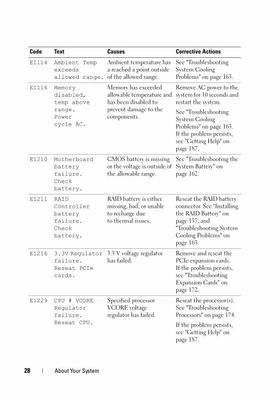
E1114 Ambient Temp exceeds allowed range.
Ambient temperature has a reached a point outside of the allowed range.
See "Troubleshooting System Cooling Problems" on page 163.
E1116 Memory disabled, temp above range. Powercycle AC.
Memory has exceeded allowable temperature and has been disabled to prevent damage to the components.
Remove AC power to the system for 10 seconds and restart the system.
See "Troubleshooting System Cooling Problems" on page 163. If the problem persists, see "Getting Help" on page 187.
E1210 Motherboard battery failure. Check battery.
CMOS battery is missing or the voltage is outside of the allowable range.
See "Troubleshooting the System Battery" on page 162.
E1211 RAID Controller battery failure. Check battery.
RAID battery is either missing, bad, or unable to recharge due to thermal issues.
Reseat the RAID battery connector. See "Installing the RAID Battery" on page 137, and "Troubleshooting System Cooling Problems" on page 163.
E1216 3.3V Regulator failure. Reseat PCIe cards.
3.3 V voltage regulator has failed.
Remove and reseat the PCIe expansion cards. If the problem persists, see "Troubleshooting Expansion Cards" on page 172.
E1229 CPU # VCORE Regulator failure. Reseat CPU.
Specified processor VCORE voltage regulator has failed.
Reseat the processor(s). See "Troubleshooting Processors" on page 174.
If the problem persists, see "Getting Help" on page 187.
Code Text Causes Corrective Actions
28 About Your System
book.book Page 29 Tuesday, August 24, 2010 1:47 PM
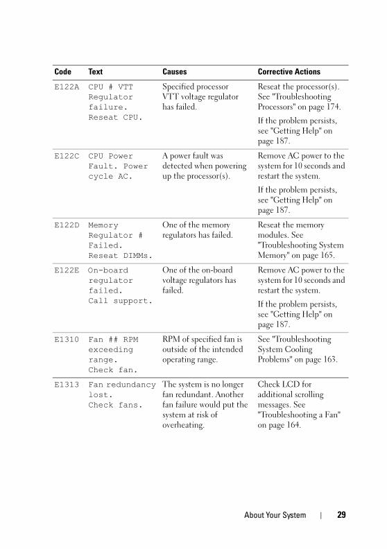
E122A CPU # VTT Regulator failure. Reseat CPU.
Specified processor VTT voltage regulator has failed.
Reseat the processor(s). See "Troubleshooting Processors" on page 174.
If the problem persists, see "Getting Help" on page 187.
E122C CPU Power Fault. Power cycle AC.
A power fault was detected when powering up the processor(s).
Remove AC power to the system for 10 seconds and restart the system.
If the problem persists, see "Getting Help" on page 187.
E122D Memory Regulator # Failed. Reseat DIMMs.
One of the memory regulators has failed.
Reseat the memory modules. See "Troubleshooting System Memory" on page 165.
E122E On-board regulator failed. Call support.
One of the on-board voltage regulators has failed.
Remove AC power to the system for 10 seconds and restart the system.
If the problem persists, see "Getting Help" on page 187.
E1310 Fan ## RPM exceeding range. Check fan.
RPM of specified fan is outside of the intended operating range.
See "Troubleshooting System Cooling Problems" on page 163.
E1313 Fan redundancy lost. Check fans.
The system is no longer fan redundant. Another fan failure would put the system at risk of overheating.
Check LCD for additional scrolling messages. See "Troubleshooting a Fan" on page 164.
Code Text Causes Corrective Actions
About Your System 29
book.book Page 30 Tuesday, August 24, 2010 1:47 PM
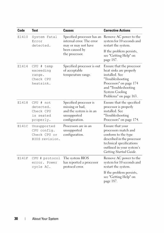
E1410 System Fatal Error detected.
Specified processor has an internal error. The error may or may not have been caused by the processor.
Remove AC power to the system for 10 seconds and restart the system.
If the problem persists, see "Getting Help" on page 187.
E1414 CPU # temp exceeding range. Check CPU heatsink.
Specified processor is out of acceptable temperature range.
Ensure that the processor heat sinks are properly installed. See "Troubleshooting Processors" on page 174 and "Troubleshooting System Cooling Problems" on page 163.
E1418 CPU # not detected. Check CPU is seated properly.
Specified processor is missing or bad, and the system is in an unsupported configuration.
Ensure that the specified processor is properly installed. See "Troubleshooting Processors" on page 174.
E141C Unsupported CPU config. Check CPU or BIOS revision.
Processors are in an unsupported configuration.
Ensure that your processors match and conform to the type described in the processor technical specifications outlined in your system’s Getting Started Guide.
E141F CPU # protocol error. Power cycle AC.
The system BIOS has reported a processor protocol error.
Remove AC power to the system for 10 seconds and restart the system.
If the problem persists, see "Getting Help" on page 187.
Code Text Causes Corrective Actions
30 About Your System
book.book Page 31 Tuesday, August 24, 2010 1:47 PM
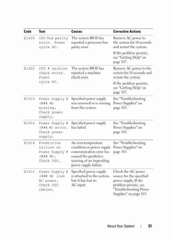
E1420 CPU Bus parity error. Power cycle AC.
The system BIOS has reported a processor bus parity error.
Remove AC power to the system for 10 seconds and restart the system.
If the problem persists, see "Getting Help" on page 187.
E1422 CPU # machine check error. Power cycle AC.
The system BIOS has reported a machine check error.
Remove AC power to the system for 10 seconds and restart the system.
If the problem persists, see "Getting Help" on page 187.
E1610 Power Supply # (### W) missing. Check power supply.
Specified power supply was removed or is missing from the system.
See "Troubleshooting Power Supplies" on page 163.
E1614 Power Supply # (### W) error. Check power supply.
Specified power supply has failed.
See "Troubleshooting Power Supplies" on page 163.
E1618 Predictive failure on Power Supply # (### W). Check PSU.
An over-temperature condition or power supply communication error has caused the predictive warning of an impending power supply failure.
See "Troubleshooting Power Supplies" on page 163.
E161C Power Supply # (### W) lost AC power. Check PSU cables.
Specified power supply is attached to the system, but it has lost its AC input.
Check the AC power source for the specified power supply. If the problem persists, see "Troubleshooting Power Supplies" on page 163.
Code Text Causes Corrective Actions
About Your System 31
book.book Page 32 Tuesday, August 24, 2010 1:47 PM
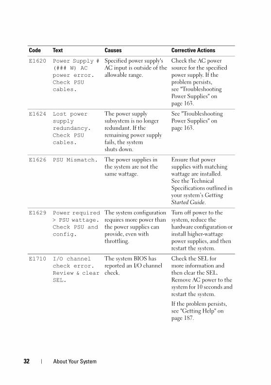
E1620 Power Supply # (### W) AC power error. Check PSU cables.
Specified power supply's AC input is outside of the allowable range.
Check the AC power source for the specified power supply. If the problem persists, see "Troubleshooting Power Supplies" on page 163.
E1624 Lost power supply redundancy. Check PSU cables.
The power supply subsystem is no longer redundant. If the remaining power supply fails, the system shuts down.
See "Troubleshooting Power Supplies" on page 163.
E1626 PSU Mismatch. The power supplies in the system are not the same wattage.
Ensure that power supplies with matching wattage are installed. See the Technical Specifications outlined in your system’s Getting Started Guide.
E1629 Power required > PSU wattage. Check PSU and config.
The system configuration requires more power than the power supplies can provide, even with throttling.
Turn off power to the system, reduce the hardware configuration or install higher-wattage power supplies, and then restart the system.
E1710 I/O channel check error. Review & clear SEL.
The system BIOS has reported an I/O channel check.
Check the SEL for more information and then clear the SEL. Remove AC power to the system for 10 seconds and restart the system.
If the problem persists, see "Getting Help" on page 187.
Code Text Causes Corrective Actions
32 About Your System
book.book Page 33 Tuesday, August 24, 2010 1:47 PM
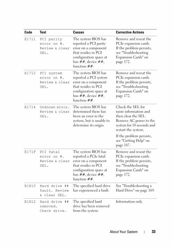
E1711 PCI parity error on #. Review & clear SEL.
The system BIOS has reported a PCI parity error on a component that resides in PCI configuration space at bus ##, device ##, function ##.
Remove and reseat the PCIe expansion cards. If the problem persists, see "Troubleshooting Expansion Cards" on page 172.
E1712 PCI system error on #. Review & clear SEL.
The system BIOS has reported a PCI system error on a component that resides in PCI configuration space at bus ##, device ##, function ##.
Remove and reseat the PCIe expansion cards. If the problem persists, see "Troubleshooting Expansion Cards" on page 172.
E1714 Unknown error. Review & clear SEL.
The system BIOS has determined there has been an error in the system, but is unable to determine its origin.
Check the SEL for more information and then clear the SEL. Remove AC power to the system for 10 seconds and restart the system.
If the problem persists, see "Getting Help" on page 187.
E171F PCI fatal error on #. Review & clear SEL.
The system BIOS has reported a PCIe fatal error on a component that resides in PCI configuration space at bus ##, device ##, function ##.
Remove and reseat the PCIe expansion cards. If the problem persists, see "Troubleshooting Expansion Cards" on page 172.
E1810 Hard drive ## fault. Review & clear SEL.
The specified hard drive has experienced a fault.
See "Troubleshooting a Hard Drive" on page 169.
E1812 Hard drive ## removed. Check drive.
The specified hard drive has been removed from the system.
Information only.
Code Text Causes Corrective Actions
About Your System 33
book.book Page 34 Tuesday, August 24, 2010 1:47 PM
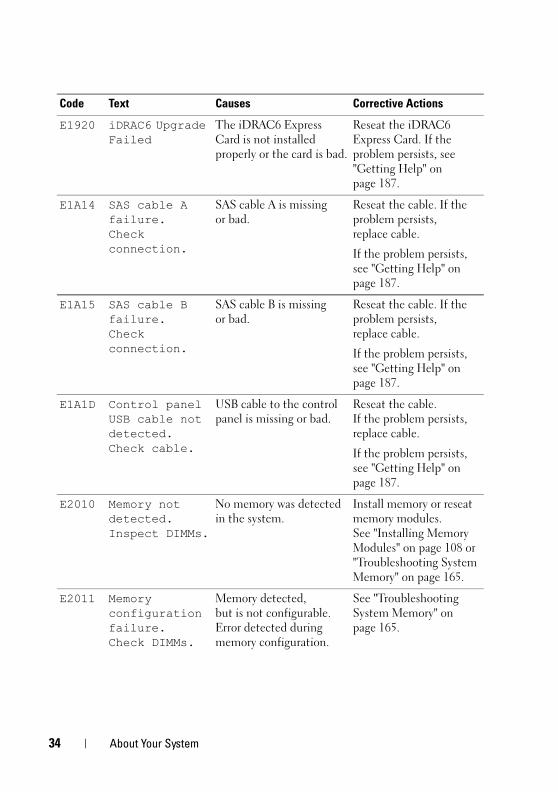
E1920 iDRAC6 Upgrade Failed
The iDRAC6 Express Card is not installed properly or the card is bad.
Reseat the iDRAC6 Express Card. If the problem persists, see "Getting Help" on page 187.
E1A14 SAS cable A failure. Check connection.
SAS cable A is missing or bad.
Reseat the cable. If the problem persists, replace cable.
If the problem persists, see "Getting Help" on page 187.
E1A15 SAS cable B failure. Check connection.
SAS cable B is missing or bad.
Reseat the cable. If the problem persists, replace cable.
If the problem persists, see "Getting Help" on page 187.
E1A1D Control panel USB cable not detected. Check cable.
USB cable to the control panel is missing or bad.
Reseat the cable. If the problem persists, replace cable.
If the problem persists, see "Getting Help" on page 187.
E2010 Memory not detected. Inspect DIMMs.
No memory was detected in the system.
Install memory or reseat memory modules. See "Installing Memory Modules" on page 108 or "Troubleshooting System Memory" on page 165.
E2011 Memory configuration failure. Check DIMMs.
Memory detected, but is not configurable. Error detected during memory configuration.
See "Troubleshooting System Memory" on page 165.
Code Text Causes Corrective Actions
34 About Your System
book.book Page 35 Tuesday, August 24, 2010 1:47 PM
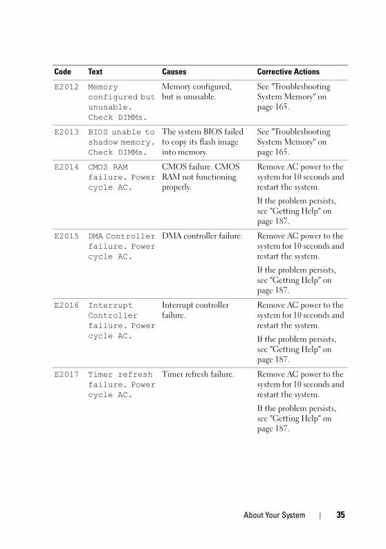
E2012 Memory configured but unusable. Check DIMMs.
Memory configured, but is unusable.
See "Troubleshooting System Memory" on page 165.
E2013 BIOS unable to shadow memory. Check DIMMs.
The system BIOS failed to copy its flash image into memory.
See "Troubleshooting System Memory" on page 165.
E2014 CMOS RAM failure. Power cycle AC.
CMOS failure. CMOS RAM not functioning properly.
Remove AC power to the system for 10 seconds and restart the system.
If the problem persists, see "Getting Help" on page 187.
E2015 DMA Controller failure. Power cycle AC.
DMA controller failure. Remove AC power to the system for 10 seconds and restart the system.
If the problem persists, see "Getting Help" on page 187.
E2016 Interrupt Controller failure. Power cycle AC.
Interrupt controller failure.
Remove AC power to the system for 10 seconds and restart the system.
If the problem persists, see "Getting Help" on page 187.
E2017 Timer refresh failure. Power cycle AC.
Timer refresh failure. Remove AC power to the system for 10 seconds and restart the system.
If the problem persists, see "Getting Help" on page 187.
Code Text Causes Corrective Actions
About Your System 35
book.book Page 36 Tuesday, August 24, 2010 1:47 PM
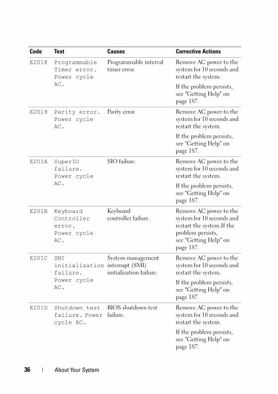
E2018 Programmable Timer error. Power cycle AC.
Programmable interval timer error.
Remove AC power to the system for 10 seconds and restart the system.
If the problem persists, see "Getting Help" on page 187.
E2019 Parity error. Power cycle AC.
Parity error. Remove AC power to the system for 10 seconds and restart the system.
If the problem persists, see "Getting Help" on page 187.
E201A SuperIO failure. Power cycle AC.
SIO failure. Remove AC power to the system for 10 seconds and restart the system.
If the problem persists, see "Getting Help" on page 187.
E201B Keyboard Controller error. Power cycle AC.
Keyboard controller failure.
Remove AC power to the system for 10 seconds and restart the system.If the problem persists, see "Getting Help" on page 187.
E201C SMI initialization failure. Power cycle AC.
System management interrupt (SMI) initialization failure.
Remove AC power to the system for 10 seconds and restart the system.
If the problem persists, see "Getting Help" on page 187.
E201D Shutdown test failure. Power cycle AC.
BIOS shutdown test failure.
Remove AC power to the system for 10 seconds and restart the system.
If the problem persists, see "Getting Help" on page 187.
Code Text Causes Corrective Actions
36 About Your System
book.book Page 37 Tuesday, August 24, 2010 1:47 PM
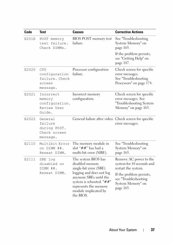
E201E POST memory test failure. Check DIMMs.
BIOS POST memory test failure.
See "Troubleshooting System Memory" on page 165.
If the problem persists, see "Getting Help" on page 187.
E2020 CPU configuration failure. Check screen message.
Processor configuration failure.
Check screen for specific error messages. See "Troubleshooting Processors" on page 174.
E2021 Incorrect memory configuration. Review User Guide.
Incorrect memory configuration.
Check screen for specific error messages. See "Troubleshooting System Memory" on page 165.
E2022 General failure during POST. Check screen message.
General failure after video. Check screen for specific error messages.
E2110 Multibit Error on DIMM ##. Reseat DIMM.
The memory module in slot “##” has had a multi-bit error (MBE).
See "Troubleshooting System Memory" on page 165.
E2111 SBE log disabled on DIMM ##. Reseat DIMM.
The system BIOS has disabled memory single-bit error (SBE) logging and does not log anymore SBEs until the system is rebooted. "##" represents the memory module implicated by the BIOS.
Remove AC power to the system for 10 seconds and restart the system.
If the problem persists, see "Troubleshooting System Memory" on page 165.
Code Text Causes Corrective Actions
About Your System 37
book.book Page 38 Tuesday, August 24, 2010 1:47 PM
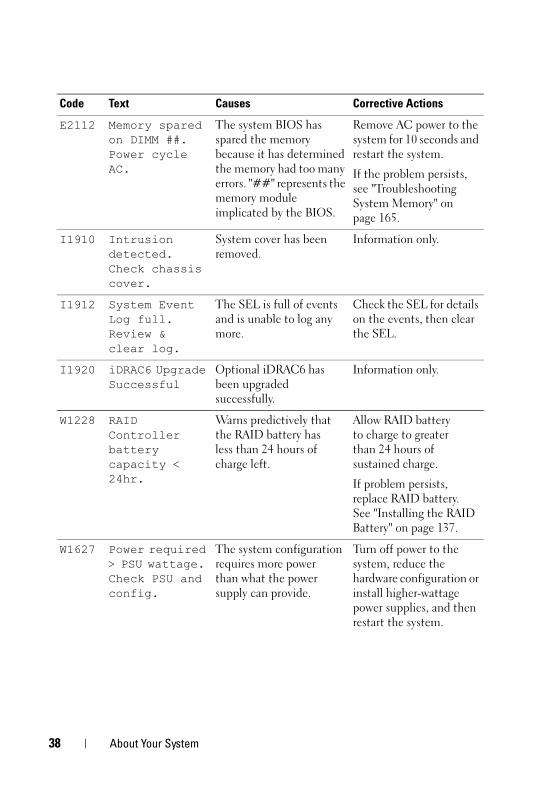
E2112 Memory spared on DIMM ##. Power cycle AC.
The system BIOS has spared the memory because it has determined the memory had too many errors. "##" represents the memory module implicated by the BIOS.
Remove AC power to the system for 10 seconds and restart the system.
If the problem persists, see "Troubleshooting System Memory" on page 165.
I1910 Intrusion detected. Check chassis cover.
System cover has been removed.
Information only.
I1912 System Event Log full. Review & clear log.
The SEL is full of events and is unable to log any more.
Check the SEL for details on the events, then clear the SEL.
I1920 iDRAC6 Upgrade Successful
Optional iDRAC6 has been upgraded successfully.
Information only.
W1228 RAID Controller battery capacity < 24hr.
Warns predictively that the RAID battery has less than 24 hours of charge left.
Allow RAID battery to charge to greater than 24 hours of sustained charge.
If problem persists, replace RAID battery. See "Installing the RAID Battery" on page 137.
W1627 Power required > PSU wattage. Check PSU and config.
The system configuration requires more power than what the power supply can provide.
Turn off power to the system, reduce the hardware configuration or install higher-wattage power supplies, and then restart the system.
Code Text Causes Corrective Actions
38 About Your System
book.book Page 39 Tuesday, August 24, 2010 1:47 PM
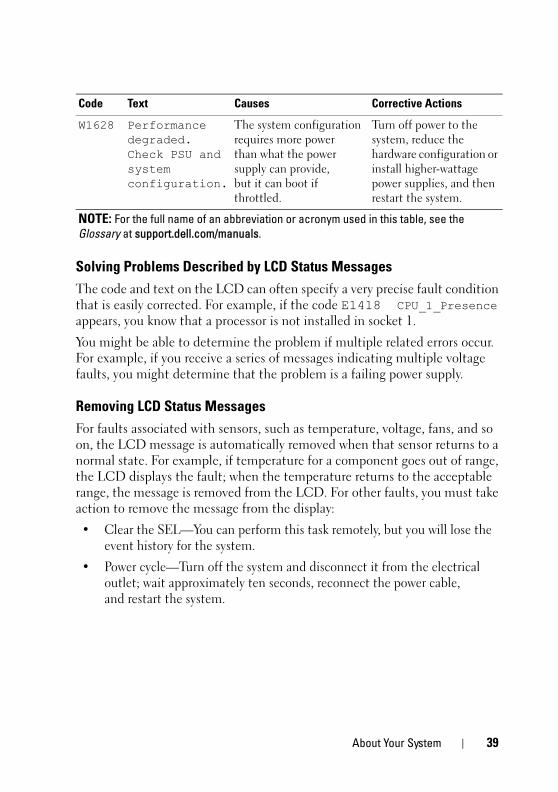
Solving Problems Described by LCD Status MessagesThe code and text on the LCD can often specify a very precise fault condition that is easily corrected. For example, if the code E1418 CPU_1_Presence appears, you know that a processor is not installed in socket 1.
You might be able to determine the problem if multiple related errors occur. For example, if you receive a series of messages indicating multiple voltage faults, you might determine that the problem is a failing power supply.
Removing LCD Status Messages For faults associated with sensors, such as temperature, voltage, fans, and so on, the LCD message is automatically removed when that sensor returns to a normal state. For example, if temperature for a component goes out of range, the LCD displays the fault; when the temperature returns to the acceptable range, the message is removed from the LCD. For other faults, you must take action to remove the message from the display:
• Clear the SEL—You can perform this task remotely, but you will lose the event history for the system.
• Power cycle—Turn off the system and disconnect it from the electrical outlet; wait approximately ten seconds, reconnect the power cable, and restart the system.
W1628 Performance degraded. Check PSU and system configuration.
The system configuration requires more power than what the power supply can provide, but it can boot if throttled.
Turn off power to the system, reduce the hardware configuration or install higher-wattage power supplies, and then restart the system.
NOTE: For the full name of an abbreviation or acronym used in this table, see the Glossary at support.dell.com/manuals.
Code Text Causes Corrective Actions
About Your System 39
book.book Page 40 Tuesday, August 24, 2010 1:47 PM
Any of these actions will remove fault messages, and return the status indicators and LCD colors to the normal state. Messages will reappear under the following conditions:
• The sensor returns to a normal state but fails again, resulting in a new SEL entry.
• The system is reset and new error events are detected.
• A failure is recorded from another source that maps to the same display entry.
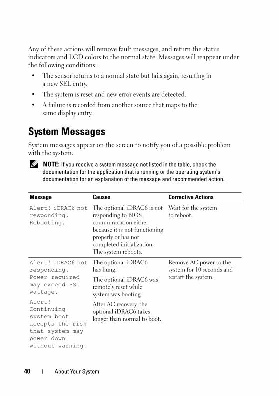
System MessagesSystem messages appear on the screen to notify you of a possible problem with the system.
NOTE: If you receive a system message not listed in the table, check the documentation for the application that is running or the operating system's documentation for an explanation of the message and recommended action.
Message Causes Corrective Actions
Alert! iDRAC6 not responding. Rebooting.
The optional iDRAC6 is not responding to BIOS communication either because it is not functioning properly or has not completed initialization. The system reboots.
Wait for the system to reboot.
Alert! iDRAC6 not responding. Power required may exceed PSU wattage.
Alert! Continuing system boot accepts the risk that system may power down without warning.
The optional iDRAC6 has hung.
The optional iDRAC6 was remotely reset while system was booting.
After AC recovery, the optional iDRAC6 takes longer than normal to boot.
Remove AC power to the system for 10 seconds and restart the system.
40 About Your System
book.book Page 41 Tuesday, August 24, 2010 1:47 PM
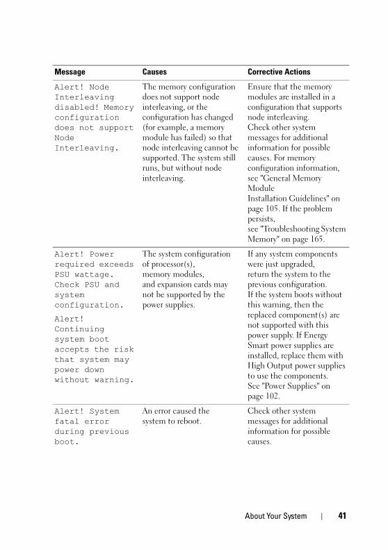
Alert! Node Interleaving disabled! Memory configuration does not support Node Interleaving.
The memory configuration does not support node interleaving, or the configuration has changed (for example, a memory module has failed) so that node interleaving cannot be supported. The system still runs, but without node interleaving.
Ensure that the memory modules are installed in a configuration that supports node interleaving. Check other system messages for additional information for possible causes. For memory configuration information, see "General Memory Module Installation Guidelines" on page 105. If the problem persists, see "Troubleshooting System Memory" on page 165.
Alert! Power required exceeds PSU wattage. Check PSU and system configuration.
Alert! Continuing system boot accepts the risk that system may power down without warning.
The system configuration of processor(s), memory modules, and expansion cards may not be supported by the power supplies.
If any system components were just upgraded, return the system to the previous configuration. If the system boots without this warning, then the replaced component(s) are not supported with this power supply. If Energy Smart power supplies are installed, replace them with High Output power supplies to use the components. See "Power Supplies" on page 102.
Alert! System fatal error during previous boot.
An error caused the system to reboot.
Check other system messages for additional information for possible causes.
Message Causes Corrective Actions
About Your System 41
book.book Page 42 Tuesday, August 24, 2010 1:47 PM
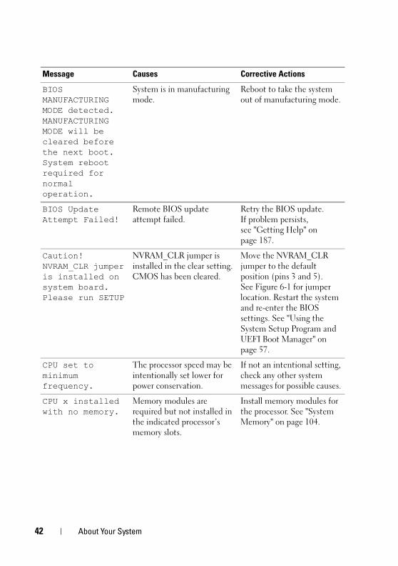
BIOS MANUFACTURING MODE detected. MANUFACTURING MODE will be cleared before the next boot. System reboot required for normal operation.
System is in manufacturing mode.
Reboot to take the system out of manufacturing mode.
BIOS Update Attempt Failed!
Remote BIOS update attempt failed.
Retry the BIOS update. If problem persists, see "Getting Help" on page 187.
Caution! NVRAM_CLR jumper is installed on system board. Please run SETUP
NVRAM_CLR jumper is installed in the clear setting. CMOS has been cleared.
Move the NVRAM_CLR jumper to the default position (pins 3 and 5). See Figure 6-1 for jumper location. Restart the system and re-enter the BIOS settings. See "Using the System Setup Program and UEFI Boot Manager" on page 57.
CPU set to minimum frequency.
The processor speed may be intentionally set lower for power conservation.
If not an intentional setting, check any other system messages for possible causes.
CPU x installed with no memory.
Memory modules are required but not installed in the indicated processor’s memory slots.
Install memory modules for the processor. See "System Memory" on page 104.
Message Causes Corrective Actions
42 About Your System
book.book Page 43 Tuesday, August 24, 2010 1:47 PM
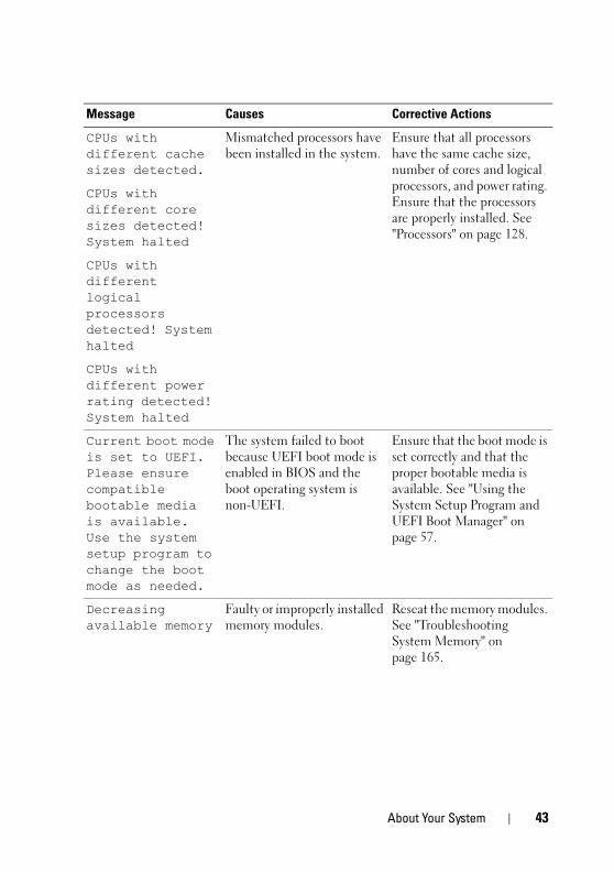
CPUs with different cache sizes detected.
Mismatched processors have been installed in the system.
Ensure that all processors have the same cache size, number of cores and logical processors, and power rating. Ensure that the processors are properly installed. See "Processors" on page 128.
CPUs with different core sizes detected! System halted
CPUs with different logical processors detected! System halted
CPUs with different power rating detected! System halted
Current boot mode is set to UEFI. Please ensure compatible bootable media is available. Use the system setup program to change the boot mode as needed.
The system failed to boot because UEFI boot mode is enabled in BIOS and the boot operating system is non-UEFI.
Ensure that the boot mode is set correctly and that the proper bootable media is available. See "Using the System Setup Program and UEFI Boot Manager" on page 57.
Decreasing available memory
Faulty or improperly installed memory modules.
Reseat the memory modules. See "Troubleshooting System Memory" on page 165.
Message Causes Corrective Actions
About Your System 43
book.book Page 44 Tuesday, August 24, 2010 1:47 PM
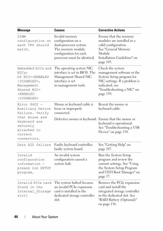
DIMM configuration on each CPU should match.
Invalid memory configuration on a dual-processor system. The memory module configuration for each processor must be identical.
Ensure that the memory modules are installed in a valid configuration. See "General Memory Module Installation Guidelines" on page 105.
Embedded NICx and NICy:OS NIC=<ENABLED |DISABLED>, Management Shared NIC=<ENABLED |DISABLED>
The operating system NIC interface is set in BIOS. The Management Shared NIC interface is set in management tools.
Check the system management software or the System Setup program for NIC settings. If a problem is indicated, see "Troubleshooting a NIC" on page 159.
Error 8602 - Auxiliary Device Failure. Verify that mouse and keyboard are securely attached to correct connectors.
Mouse or keyboard cable is loose or improperly connected.
Reseat the mouse or keyboard cable.
Defective mouse or keyboard. Ensure that the mouse or keyboard is operational. See "Troubleshooting a USB Device" on page 158.
Gate A20 failure Faulty keyboard controller; faulty system board.
See "Getting Help" on page 187.
Invalid configuration information - please run SETUP program.
An invalid system configuration caused a system halt.
Run the System Setup program and review the current settings. See "Using the System Setup Program and UEFI Boot Manager" on page 57.
Invalid PCIe card found in the Internal_Storage slot!
The system halted because an invalid PCIe expansion card is installed in the dedicated storage controller slot.
Remove the PCIe expansion card and install the integrated storage controller in the dedicated slot. See "RAID Battery (Optional)" on page 136.
Message Causes Corrective Actions
44 About Your System
book.book Page 45 Tuesday, August 24, 2010 1:47 PM
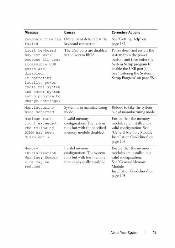
Keyboard fuse has failed
Overcurrent detected at the keyboard connector.
See "Getting Help" on page 187.
Local keyboard may not work because all user accessible USB ports are disabled. If operating locally, power cycle the system and enter system setup program to change settings.
The USB ports are disabled in the system BIOS.
Power down and restart the system from the power button, and then enter the System Setup program to enable the USB port(s). See "Entering the System Setup Program" on page 58.
Manufacturing mode detected
System is in manufacturing mode.
Reboot to take the system out of manufacturing mode.
Maximum rank count exceeded. The following DIMM has been disabled: x
Invalid memory configuration. The system runs but with the specified memory module disabled.
Ensure that the memory modules are installed in a valid configuration. See "General Memory Module Installation Guidelines" on page 105.
Memory Initialization Warning: Memory size may be reduced
Invalid memory configuration. The system runs but with less memory than is physically available.
Ensure that the memory modules are installed in a valid configuration. See "General Memory Module Installation Guidelines" on page 105.
Message Causes Corrective Actions
About Your System 45
book.book Page 46 Tuesday, August 24, 2010 1:47 PM
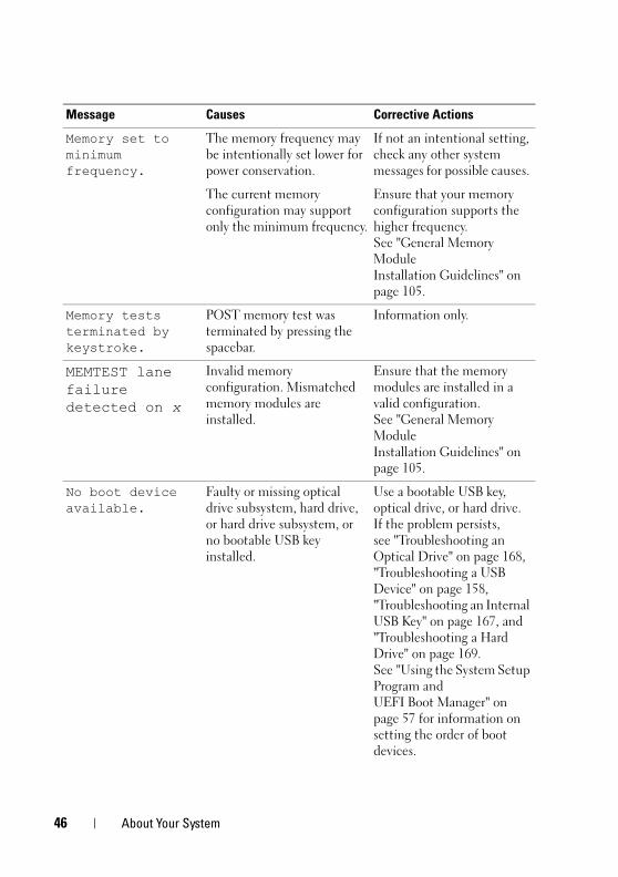
Memory set to minimum frequency.
The memory frequency may be intentionally set lower for power conservation.
If not an intentional setting, check any other system messages for possible causes.
The current memory configuration may support only the minimum frequency.
Ensure that your memory configuration supports the higher frequency. See "General Memory Module Installation Guidelines" on page 105.
Memory tests terminated by keystroke.
POST memory test was terminated by pressing the spacebar.
Information only.
MEMTEST lane failure detected on x
Invalid memory configuration. Mismatched memory modules are installed.
Ensure that the memory modules are installed in a valid configuration. See "General Memory Module Installation Guidelines" on page 105.
No boot device available.
Faulty or missing optical drive subsystem, hard drive, or hard drive subsystem, or no bootable USB key installed.
Use a bootable USB key, optical drive, or hard drive. If the problem persists, see "Troubleshooting an Optical Drive" on page 168, "Troubleshooting a USB Device" on page 158, "Troubleshooting an Internal USB Key" on page 167, and "Troubleshooting a Hard Drive" on page 169. See "Using the System Setup Program and UEFI Boot Manager" on page 57 for information on setting the order of boot devices.
Message Causes Corrective Actions
46 About Your System
book.book Page 47 Tuesday, August 24, 2010 1:47 PM
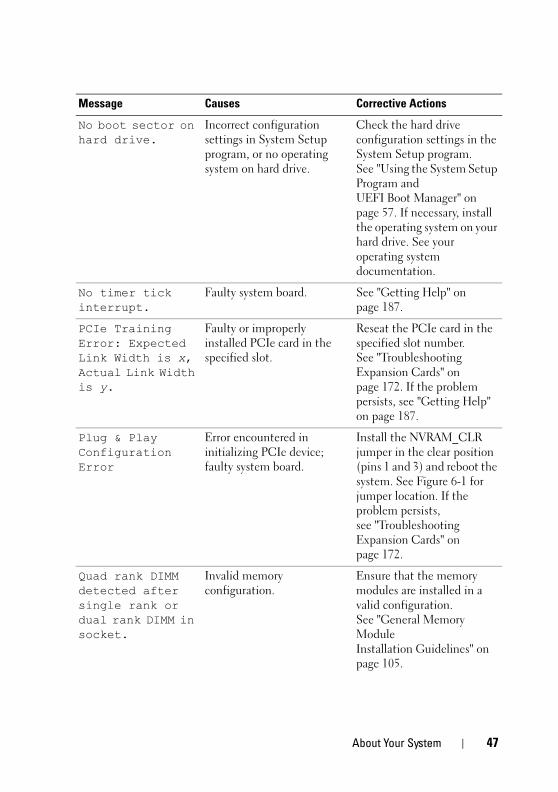
No boot sector on hard drive.
Incorrect configuration settings in System Setup program, or no operating system on hard drive.
Check the hard drive configuration settings in the System Setup program. See "Using the System Setup Program and UEFI Boot Manager" on page 57. If necessary, install the operating system on your hard drive. See your operating system documentation.
No timer tick interrupt.
Faulty system board. See "Getting Help" on page 187.
PCIe Training Error: Expected Link Width is x, Actual Link Width is y.
Faulty or improperly installed PCIe card in the specified slot.
Reseat the PCIe card in the specified slot number. See "Troubleshooting Expansion Cards" on page 172. If the problem persists, see "Getting Help" on page 187.
Plug & Play Configuration Error
Error encountered in initializing PCIe device; faulty system board.
Install the NVRAM_CLR jumper in the clear position (pins 1 and 3) and reboot the system. See Figure 6-1 for jumper location. If the problem persists, see "Troubleshooting Expansion Cards" on page 172.
Quad rank DIMM detected after single rank or dual rank DIMM in socket.
Invalid memory configuration.
Ensure that the memory modules are installed in a valid configuration. See "General Memory Module Installation Guidelines" on page 105.
Message Causes Corrective Actions
About Your System 47
book.book Page 48 Tuesday, August 24, 2010 1:47 PM
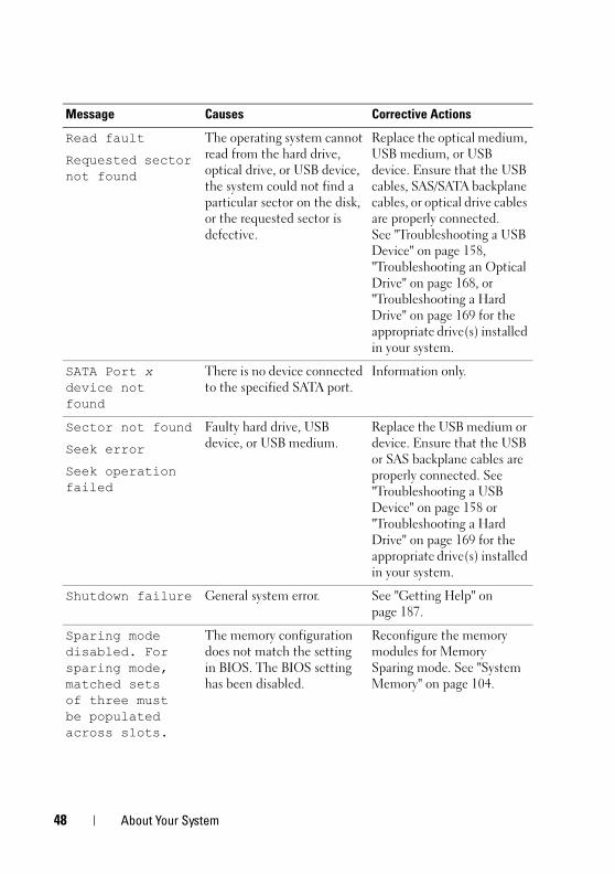
Read fault
Requested sector not found
The operating system cannot read from the hard drive, optical drive, or USB device, the system could not find a particular sector on the disk, or the requested sector is defective.
Replace the optical medium, USB medium, or USB device. Ensure that the USB cables, SAS/SATA backplane cables, or optical drive cables are properly connected. See "Troubleshooting a USB Device" on page 158, "Troubleshooting an Optical Drive" on page 168, or "Troubleshooting a Hard Drive" on page 169 for the appropriate drive(s) installed in your system.
SATA Port x device not found
There is no device connected to the specified SATA port.
Information only.
Sector not found
Seek error
Seek operation failed
Faulty hard drive, USB device, or USB medium.
Replace the USB medium or device. Ensure that the USB or SAS backplane cables are properly connected. See "Troubleshooting a USB Device" on page 158 or "Troubleshooting a Hard Drive" on page 169 for the appropriate drive(s) installed in your system.
Shutdown failure General system error. See "Getting Help" on page 187.
Sparing mode disabled. For sparing mode, matched sets of three must be populated across slots.
The memory configuration does not match the setting in BIOS. The BIOS setting has been disabled.
Reconfigure the memory modules for Memory Sparing mode. See "System Memory" on page 104.
Message Causes Corrective Actions
48 About Your System
book.book Page 49 Tuesday, August 24, 2010 1:47 PM
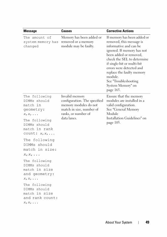
The amount of system memory has changed
Memory has been added or removed or a memory module may be faulty.
If memory has been added or removed, this message is informative and can be ignored. If memory has not been added or removed, check the SEL to determine if single-bit or multi-bit errors were detected and replace the faulty memory module. See "Troubleshooting System Memory" on page 165.
The following DIMMs should match in geometry: x,x,...
Invalid memory configuration. The specified memory modules do not match in size, number of ranks, or number of data lanes.
Ensure that the memory modules are installed in a valid configuration. See "General Memory Module Installation Guidelines" on page 105.
The following DIMMs should match in rank count: x,x,...
The following DIMMs should match in size: x,x,...
The following DIMMs should match in size and geometry: x,x,...
The following DIMMs should match in size and rank count: x,x,...
Message Causes Corrective Actions
About Your System 49
book.book Page 50 Tuesday, August 24, 2010 1:47 PM
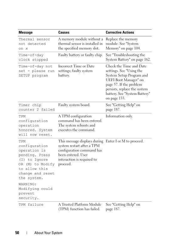
Thermal sensor not detected on x
A memory module without a thermal sensor is installed in the specified memory slot.
Replace the memory module. See "System Memory" on page 104.
Time-of-day clock stopped
Faulty battery or faulty chip. See "Troubleshooting the System Battery" on page 162.
Time-of-day not set - please run SETUP program
Incorrect Time or Date settings; faulty system battery.
Check the Time and Date settings. See "Using the System Setup Program and UEFI Boot Manager" on page 57. If the problem persists, replace the system battery. See "System Battery" on page 133.
Timer chip counter 2 failed
Faulty system board. See "Getting Help" on page 187.
TPM configuration operation honored. System will now reset.
A TPM configuration command has been entered. The system reboots and executes the command.
Information only.
TPM configuration operation is pending. Press (I) to Ignore OR (M) to Modify to allow this change and reset the system.
WARNING: Modifying could prevent security.
This message displays during system restart after a TPM configuration command has been entered. User interaction is required to proceed.
Enter I or M to proceed.
TPM failure A Trusted Platform Module (TPM) function has failed.
See "Getting Help" on page 187.
Message Causes Corrective Actions
50 About Your System
book.book Page 51 Tuesday, August 24, 2010 1:47 PM
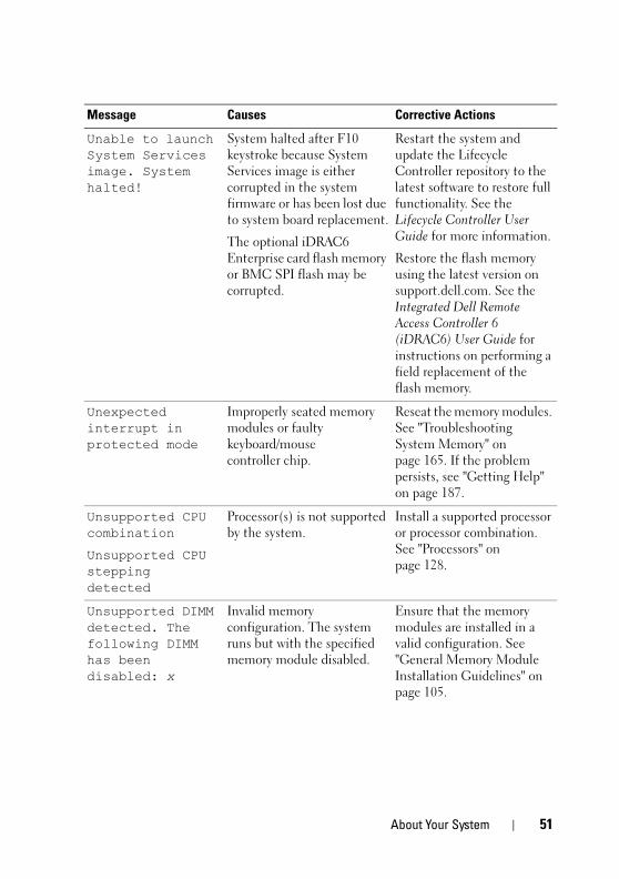
Unable to launch System Services image. System halted!
System halted after F10 keystroke because System Services image is either corrupted in the system firmware or has been lost due to system board replacement.
The optional iDRAC6 Enterprise card flash memory or BMC SPI flash may be corrupted.
Restart the system and update the Lifecycle Controller repository to the latest software to restore full functionality. See the Lifecycle Controller User Guide for more information.
Restore the flash memory using the latest version on support.dell.com. See the Integrated Dell Remote Access Controller 6 (iDRAC6) User Guide for instructions on performing a field replacement of the flash memory.
Unexpected interrupt in protected mode
Improperly seated memory modules or faulty keyboard/mouse controller chip.
Reseat the memory modules. See "Troubleshooting System Memory" on page 165. If the problem persists, see "Getting Help" on page 187.
Unsupported CPU combination
Unsupported CPU stepping detected
Processor(s) is not supported by the system.
Install a supported processor or processor combination. See "Processors" on page 128.
Unsupported DIMM detected. The following DIMM has been disabled: x
Invalid memory configuration. The system runs but with the specified memory module disabled.
Ensure that the memory modules are installed in a valid configuration. See "General Memory Module Installation Guidelines" on page 105.
Message Causes Corrective Actions
About Your System 51
book.book Page 52 Tuesday, August 24, 2010 1:47 PM
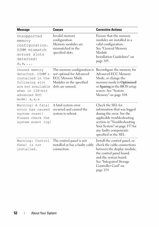
Unsupported memory configuration. DIMM mismatch across slots detected: x,x,...
Invalid memory configuration. Memory modules are mismatched in the specified slots.
Ensure that the memory modules are installed in a valid configuration. See "General Memory Module Installation Guidelines" on page 105.
Unused memory detected. DIMM’s installed in the following slot are not available when in 128-bit advanced ECC mode: x,x,x
The memory configuration is not optimal for Advanced ECC Memory Mode. Modules in the specified slots are unused.
Reconfigure the memory for Advanced ECC Memory Mode, or change the memory mode to Optimized or Sparing in the BIOS setup screen. See "System Memory" on page 104.
Warning: A fatal error has caused system reset! Please check the system event log!
A fatal system error occurred and caused the system to reboot.
Check the SEL for information that was logged during the error. See the applicable troubleshooting section in "Troubleshooting Your System" on page 157 for any faulty components specified in the SEL.
Warning: Control Panel is not installed.
The control panel is not installed or has a faulty cable connection.
Install the control panel, or check the cable connections between the display module, the control panel board, and the system board. See "Integrated Storage Controller Card" on page 119.
Message Causes Corrective Actions
52 About Your System
book.book Page 53 Tuesday, August 24, 2010 1:47 PM
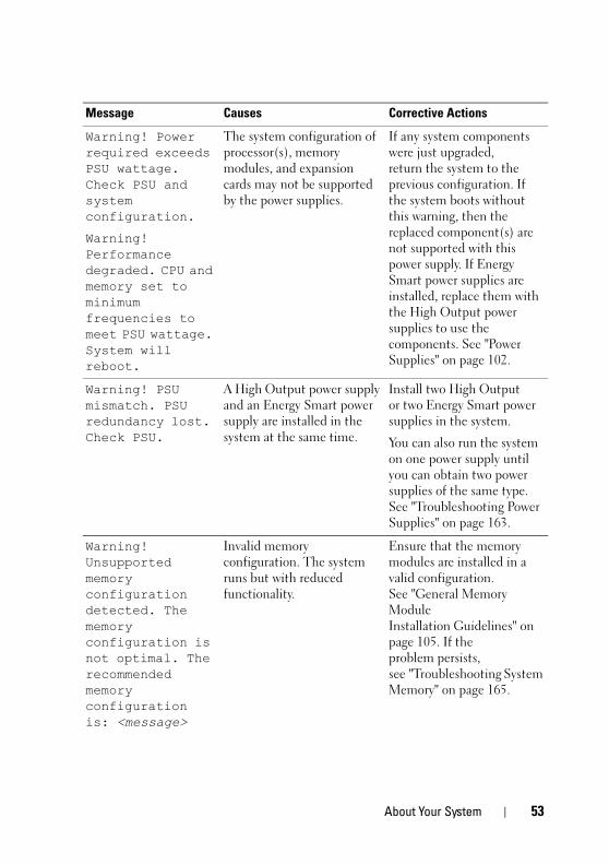
Warning! Power required exceeds PSU wattage. Check PSU and system configuration.
Warning! Performance degraded. CPU and memory set to minimum frequencies to meet PSU wattage. System will reboot.
The system configuration of processor(s), memory modules, and expansion cards may not be supported by the power supplies.
If any system components were just upgraded, return the system to the previous configuration. If the system boots without this warning, then the replaced component(s) are not supported with this power supply. If Energy Smart power supplies are installed, replace them with the High Output power supplies to use the components. See "Power Supplies" on page 102.
Warning! PSU mismatch. PSU redundancy lost. Check PSU.
A High Output power supply and an Energy Smart power supply are installed in the system at the same time.
Install two High Output or two Energy Smart power supplies in the system.
You can also run the system on one power supply until you can obtain two power supplies of the same type. See "Troubleshooting Power Supplies" on page 163.
Warning! Unsupported memory configuration detected. The memory configuration is not optimal. The recommended memory configuration is: <message>
Invalid memory configuration. The system runs but with reduced functionality.
Ensure that the memory modules are installed in a valid configuration. See "General Memory Module Installation Guidelines" on page 105. If the problem persists, see "Troubleshooting System Memory" on page 165.
Message Causes Corrective Actions
About Your System 53
book.book Page 54 Tuesday, August 24, 2010 1:47 PM
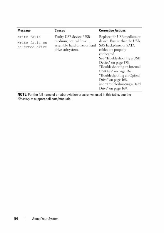
Write fault
Write fault on selected drive
Faulty USB device, USB medium, optical drive assembly, hard drive, or hard drive subsystem.
Replace the USB medium or device. Ensure that the USB, SAS backplane, or SATA cables are properly connected. See "Troubleshooting a USB Device" on page 158, "Troubleshooting an Internal USB Key" on page 167, "Troubleshooting an Optical Drive" on page 168, and "Troubleshooting a Hard Drive" on page 169.
NOTE: For the full name of an abbreviation or acronym used in this table, see the Glossary at support.dell.com/manuals.
Message Causes Corrective Actions
54 About Your System
book.book Page 55 Tuesday, August 24, 2010 1:47 PM
Warning MessagesA warning message alerts you to a possible problem and prompts you to respond before the system continues a task. For example, before you format a diskette, a message warns you that you may lose all data on the diskette. Warning messages usually interrupt the task and require you to respond by typing y (yes) or n (no).
NOTE: Warning messages are generated by either the application or the operating system. For more information, see the documentation that accompanied the application or operating system.
Diagnostics MessagesThe system diagnostic utilities may issue messages if you run diagnostic tests on your system. See "Running the Embedded System Diagnostics" on page 178 for more information about system diagnostics.
Alert MessagesSystems management software generates alert messages for your system. Alert messages include information, status, warning, and failure messages for drive, temperature, fan, and power conditions. For more information, see the systems management software documentation.
About Your System 55
book.book Page 56 Tuesday, August 24, 2010 1:47 PM
Other Information You May Need WARNING: See the safety and regulatory information that shipped with your
system. Warranty information may be included within this document or as a separate document.
• The rack documentation included with your rack solution describes how to install your system into a rack.
• The Getting Started Guide provides an overview of system features, setting up your system, and technical specifications.
• Any media that ships with your system that provides documentation and tools for configuring and managing your system, including those pertaining to the operating system, system management software, system updates, and system components that you purchased with your system.
• The Lifecycle Controller User Guide provides information about setting up the controller, configuring hardware and firmware, and deploying the operating system.
NOTE: Always check for updates on support.dell.com/manuals and read the updates first because they often supersede information in other documents.
56 About Your System
book.book Page 57 Tuesday, August 24, 2010 1:47 PM
2Using the System Setup Program and UEFI Boot ManagerThe System Setup program is the BIOS program that enables you to manage your system hardware and specify BIOS-level options. From the System Setup program, you can:
• Change the NVRAM settings after you add or remove hardware
• View the system hardware configuration
• Enable or disable integrated devices
• Set performance and power management thresholds
• Manage system security
Choosing the System Boot ModeThe System Setup program also enables you to specify the boot mode for installing your operating system:
• BIOS boot mode (the default) is the standard BIOS-level boot interface.
• Unified Extensible Firmware Interface (UEFI) boot mode is an enhanced 64-bit boot interface based on Unified Extensible Firmware Interface (UEFI) specifications that overlays the system BIOS. See "Entering the UEFI Boot Manager" on page 70 for more information on this interface.
You select the boot mode in the Boot Mode field of the Boot Settings screen of the System Setup program. After specifying the boot mode, proceed to install your operating system from that mode. Thereafter, you must boot the system to the same boot mode (BIOS or UEFI) to access the installed operating system. Trying to boot the operating system from the other boot mode causes the system to halt immediately at startup.
NOTE: Operating systems must be UEFI-compatible (for example, Microsoft Windows Server 2008 x64 version) to be installed from the UEFI boot mode. DOS and 32-bit operating systems do not support UEFI and can only be installed from the BIOS boot mode.
Using the System Setup Program and UEFI Boot Manager 57
book.book Page 58 Tuesday, August 24, 2010 1:47 PM
Entering the System Setup Program1 Turn on or restart your system.
2 Press <F2> after you see the following message:
<F2> = System Setup
NOTE: The system does not respond until the USB keyboard is active.
If your operating system begins to load before you press <F2>, allow the system to finish booting, and then restart your system and try again.
Responding to Error MessagesIf an error message appears while the system is booting, make a note of the message. See "System Messages" on page 40 for an explanation of the message and suggestions for correcting errors.
NOTE: After installing a memory upgrade, it is normal for your system to display a message that the system memory size has changed the first time you start your system.
Using the System Setup Program Navigation Keys
NOTE: For most of the options, any changes that you make are recorded but do not take effect until you restart the system.
Keys Action
Up arrow or <Shift><Tab> Moves to the previous field.
Down arrow or <Tab> Moves to the next field.
<Enter>, <Spacebar>, <+>, <–>, left and right arrows
Cycles through the settings in a field. In many fields, you can also type the appropriate value.
<Esc> Exits the System Setup program and restarts the system if any changes were made.
<F1> Displays the System Setup program's help file.
58 Using the System Setup Program and UEFI Boot Manager
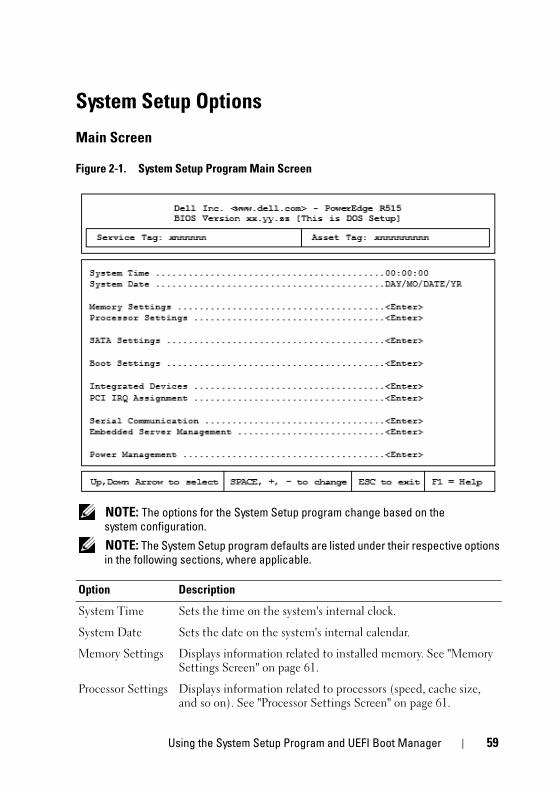
book.book Page 59 Tuesday, August 24, 2010 1:47 PM
System Setup Options
Main Screen
Figure 2-1. System Setup Program Main Screen
NOTE: The options for the System Setup program change based on the system configuration.
NOTE: The System Setup program defaults are listed under their respective options in the following sections, where applicable.
Option Description
System Time Sets the time on the system's internal clock.
System Date Sets the date on the system's internal calendar.
Memory Settings Displays information related to installed memory. See "Memory Settings Screen" on page 61.
Processor Settings Displays information related to processors (speed, cache size, and so on). See "Processor Settings Screen" on page 61.
Using the System Setup Program and UEFI Boot Manager 59
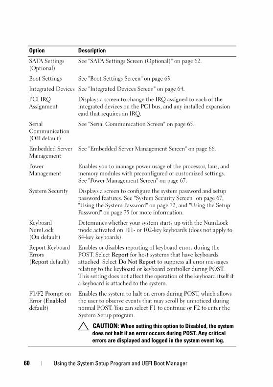
book.book Page 60 Tuesday, August 24, 2010 1:47 PM
SATA Settings (Optional)
See "SATA Settings Screen (Optional)" on page 62.
Boot Settings See "Boot Settings Screen" on page 63.
Integrated Devices See "Integrated Devices Screen" on page 64.
PCI IRQ Assignment
Displays a screen to change the IRQ assigned to each of the integrated devices on the PCI bus, and any installed expansion card that requires an IRQ.
Serial Communication(Off default)
See "Serial Communication Screen" on page 65.
Embedded Server Management
See "Embedded Server Management Screen" on page 66.
Power Management
Enables you to manage power usage of the processor, fans, and memory modules with preconfigured or customized settings. See "Power Management Screen" on page 67.
System Security Displays a screen to configure the system password and setup password features. See "System Security Screen" on page 67, "Using the System Password" on page 72, and "Using the Setup Password" on page 75 for more information.
Keyboard NumLock(On default)
Determines whether your system starts up with the NumLock mode activated on 101- or 102-key keyboards (does not apply to 84-key keyboards).
Report Keyboard Errors(Report default)
Enables or disables reporting of keyboard errors during the POST. Select Report for host systems that have keyboards attached. Select Do Not Report to suppress all error messages relating to the keyboard or keyboard controller during POST. This setting does not affect the operation of the keyboard itself if a keyboard is attached to the system.
F1/F2 Prompt on Error (Enabled default)
Enables the system to halt on errors during POST, which allows the user to observe events that may scroll by unnoticed during normal POST. You can select F1 to continue or F2 to enter the System Setup program.
CAUTION: When setting this option to Disabled, the system does not halt if an error occurs during POST. Any critical errors are displayed and logged in the system event log.
Option Description
60 Using the System Setup Program and UEFI Boot Manager
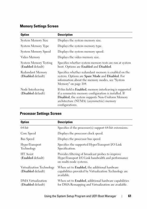
book.book Page 61 Tuesday, August 24, 2010 1:47 PM
Memory Settings Screen
Processor Settings Screen
Option Description
System Memory Size Displays the system memory size.
System Memory Type Displays the system memory type.
System Memory Speed Displays the system memory speed.
Video Memory Displays the video memory size.
System Memory Testing(Enabled default)
Specifies whether system memory tests are run at system boot. Options are Enabled and Disabled.
Redundant Memory(Disabled default)
Specifies whether redundant memory is enabled on the system. Options are Spare Mode and Disabled. For information about the memory modes, see "System Memory" on page 104.
Node Interleaving(Disabled default)
If this field is Enabled, memory interleaving is supported if a symmetric memory configuration is installed. If Disabled, the system supports Non-Uniform Memory architecture (NUMA) (asymmetric) memory configurations.
Option Description
64-bit Specifies if the processor(s) support 64-bit extensions.
Core Speed Displays the processor clock speed.
Bus Speed Displays the processor bus speed.
HyperTransport Technology
Specifies the supported HyperTransport I/O Link Specification.
HT Assist(Enabled default)
Provides filtering of broadcast probes to improve HyperTransport I/O Link bandwidth and performance on multi-node systems.
Virtualization Technology(Disabled default)
When set to Enabled, the additional hardware capabilities provided by Virtualization Technology are available.
DMA Virtualization(Disabled default)
When set to Enabled, additional hardware capabilities for DMA Remapping and Virtualization are available.
Using the System Setup Program and UEFI Boot Manager 61
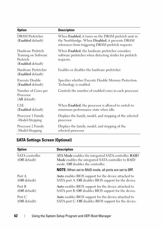
book.book Page 62 Tuesday, August 24, 2010 1:47 PM
SATA Settings Screen (Optional)
DRAM Prefetcher(Enabled default)
When Enabled, it turns on the DRAM prefetch unit in the Northbridge. When Disabled, it prevents DRAM references from triggering DRAM prefetch requests.
Hardware Prefetch Training on Software Prefetch(Enabled default)
When Enabled, the hardware prefetcher considers software prefetches when detecting strides for prefetch requests.
Hardware Prefetcher(Enabled default)
Enables or disables the hardware prefetcher.
Execute Disable(Enabled default)
Specifies whether Execute Disable Memory Protection Technology is enabled.
Number of Cores per Processor(All default)
Controls the number of enabled cores in each processor.
C1E(Enabled default)
When Enabled, the processor is allowed to switch to minimum performance state when idle.
Processor 1 Family -Model-Stepping
Displays the family, model, and stepping of the selected processor.
Processor 2 Family -Model-Stepping
Displays the family, model, and stepping of the selected processor.
Option Description
SATA controller(Off default)
ATA Mode enables the integrated SATA controller. RAID Mode enables the integrated SATA controller to RAID mode. Off disables the controller.
NOTE: When set to RAID mode, all ports are set to OFF.
Port A(Off default)
Auto enables BIOS support for the device attached to SATA port A. Off disables BIOS support for the device.
Port B(Off default)
Auto enables BIOS support for the device attached to SATA port B. Off disables BIOS support for the device.
Port C(Off default)
Auto enables BIOS support for the device attached to SATA port C. Off disables BIOS support for the device.
Option Description
62 Using the System Setup Program and UEFI Boot Manager
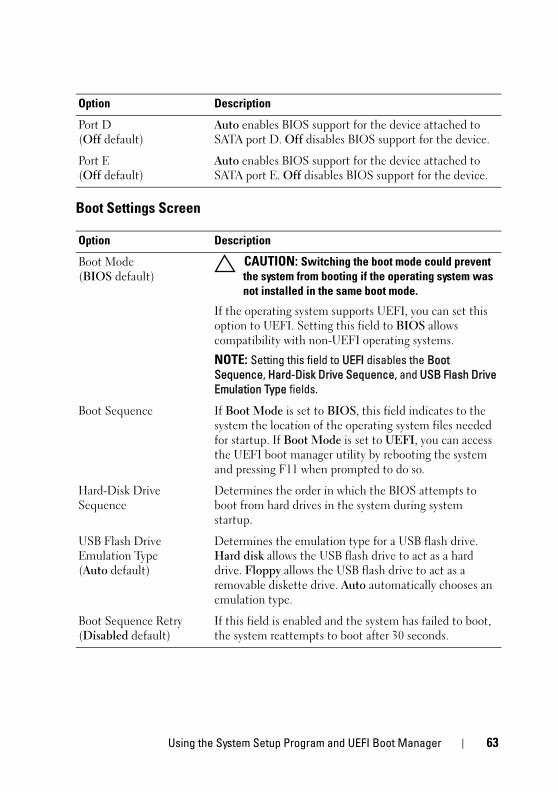
book.book Page 63 Tuesday, August 24, 2010 1:47 PM
Boot Settings Screen
Port D(Off default)
Auto enables BIOS support for the device attached to SATA port D. Off disables BIOS support for the device.
Port E(Off default)
Auto enables BIOS support for the device attached to SATA port E. Off disables BIOS support for the device.
Option Description
Boot Mode(BIOS default)
CAUTION: Switching the boot mode could prevent the system from booting if the operating system was not installed in the same boot mode.
If the operating system supports UEFI, you can set this option to UEFI. Setting this field to BIOS allows compatibility with non-UEFI operating systems.
NOTE: Setting this field to UEFI disables the Boot Sequence, Hard-Disk Drive Sequence, and USB Flash Drive Emulation Type fields.
Boot Sequence If Boot Mode is set to BIOS, this field indicates to the system the location of the operating system files needed for startup. If Boot Mode is set to UEFI, you can access the UEFI boot manager utility by rebooting the system and pressing F11 when prompted to do so.
Hard-Disk Drive Sequence
Determines the order in which the BIOS attempts to boot from hard drives in the system during system startup.
USB Flash Drive Emulation Type(Auto default)
Determines the emulation type for a USB flash drive. Hard disk allows the USB flash drive to act as a hard drive. Floppy allows the USB flash drive to act as a removable diskette drive. Auto automatically chooses an emulation type.
Boot Sequence Retry(Disabled default)
If this field is enabled and the system has failed to boot, the system reattempts to boot after 30 seconds.
Option Description
Using the System Setup Program and UEFI Boot Manager 63
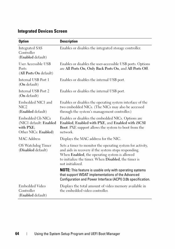
book.book Page 64 Tuesday, August 24, 2010 1:47 PM
Integrated Devices Screen
Option Description
Integrated SAS Controller(Enabled default)
Enables or disables the integrated storage controller.
User Accessible USB Ports(All Ports On default)
Enables or disables the user-accessible USB ports. Options are All Ports On, Only Back Ports On, and All Ports Off.
Internal USB Port 1 (On default)
Enables or disables the internal USB port.
Internal USB Port 2(On default)
Enables or disables the internal USB port.
Embedded NIC1 and NIC2(Enabled default)
Enables or disables the operating system interface of the two embedded NICs. (The NICs may also be accessed through the system’s management controller.)
Embedded Gb NICx(NIC1 default: Enabled with PXE; Other NICs: Enabled)
Enables or disables the embedded NICs. Options are Enabled, Enabled with PXE, and Enabled with iSCSI Boot. PXE support allows the system to boot from the network.
MAC Address Displays the MAC address for the NIC.
OS Watchdog Timer(Disabled default)
Sets a timer to monitor the operating system for activity, and aids in recovery if the system stops responding. When Enabled, the operating system is allowed to initialize the timer. When Disabled, the timer is not initialized.
NOTE: This feature is usable only with operating systems that support WDAT implementations of the Advanced Configuration and Power Interface (ACPI) 3.0b specification.
Embedded Video Controller(Enabled default)
Displays the total amount of video memory available in the embedded video controller.
64 Using the System Setup Program and UEFI Boot Manager
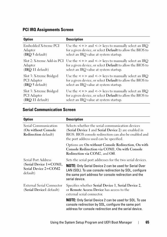
book.book Page 65 Tuesday, August 24, 2010 1:47 PM
PCI IRQ Assignments Screen
Serial Communication Screen
Option Description
Embedded X-treme PCI Adapter(IRQ 5 default)
Use the <+> and <-> keys to manually select an IRQ for a given device, or select Default to allow the BIOS to select an IRQ value at system startup.
Slot 2: X-treme Add-in PCI Adapter(IRQ 11 default)
Use the <+> and <-> keys to manually select an IRQ for a given device, or select Default to allow the BIOS to select an IRQ value at system startup.
Slot 3: X-treme Bridged PCI Adapter(IRQ 5 default)
Use the <+> and <-> keys to manually select an IRQ for a given device, or select Default to allow the BIOS to select an IRQ value at system startup.
Slot 3: X-treme Bridged PCI Adapter(IRQ 11 default)
Use the <+> and <-> keys to manually select an IRQ for a given device, or select Default to allow the BIOS to select an IRQ value at system startup.
Option Description
Serial Communication(On without Console Redirection default)
Selects whether the serial communication devices (Serial Device 1 and Serial Device 2) are enabled in BIOS. BIOS console redirection can also be enabled and the port address used can be specified.
Options are On without Console Redirection, On with Console Redirection via COM1, On with Console Redirection via COM2, and Off.
Serial Port Address(Serial Device 1=COM1, Serial Device 2=COM2 default)
Sets the serial port addresses for the two serial devices.
NOTE: Only Serial Device 2 can be used for Serial Over LAN (SOL). To use console redirection by SOL, configure the same port address for console redirection and the serial device.
External Serial Connector(Serial Device1 default)
Specifies whether Serial Device 1, Serial Device 2, or Remote Access Device has access to the external serial connector.
NOTE: Only Serial Device 2 can be used for SOL. To use console redirection by SOL, configure the same port address for console redirection and the serial device.
Using the System Setup Program and UEFI Boot Manager 65
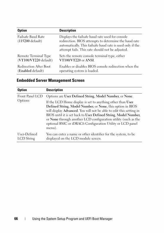
book.book Page 66 Tuesday, August 24, 2010 1:47 PM
Embedded Server Management Screen
Failsafe Baud Rate(115200 default)
Displays the failsafe baud rate used for console redirection. BIOS attempts to determine the baud rate automatically. This failsafe baud rate is used only if the attempt fails. This rate should not be adjusted.
Remote Terminal Type(VT100/VT220 default)
Sets the remote console terminal type, either VT100/VT220 or ANSI.
Redirection After Boot(Enabled default)
Enables or disables BIOS console redirection when the operating system is loaded.
Option Description
Front Panel LCD Options
Options are User Defined String, Model Number, or None.
If the LCD Home display is set to anything other than User Defined String, Model Number, or None, this option in BIOS will display Advanced. You will not be able to edit this setting in BIOS until it is set back to User Defined String, Model Number, or None through another LCD configuration utility (such as the optional BMC or iDRAC6 Configuration Utility or LCD panel menu).
User-Defined LCD String
You can enter a name or other identifier for the system, to be displayed on the LCD module screen.
Option Description
66 Using the System Setup Program and UEFI Boot Manager
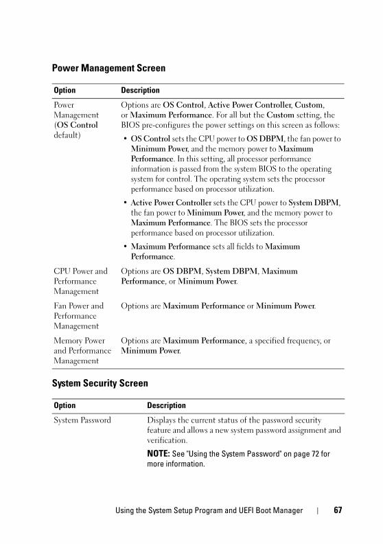
book.book Page 67 Tuesday, August 24, 2010 1:47 PM
Power Management Screen
System Security Screen
Option Description
Power Management(OS Control default)
Options are OS Control, Active Power Controller, Custom, or Maximum Performance. For all but the Custom setting, the BIOS pre-configures the power settings on this screen as follows:
• OS Control sets the CPU power to OS DBPM, the fan power to Minimum Power, and the memory power to Maximum Performance. In this setting, all processor performance information is passed from the system BIOS to the operating system for control. The operating system sets the processor performance based on processor utilization.
• Active Power Controller sets the CPU power to System DBPM, the fan power to Minimum Power, and the memory power to Maximum Performance. The BIOS sets the processor performance based on processor utilization.
• Maximum Performance sets all fields to Maximum Performance.
CPU Power and Performance Management
Options are OS DBPM, System DBPM, Maximum Performance, or Minimum Power.
Fan Power and Performance Management
Options are Maximum Performance or Minimum Power.
Memory Power and Performance Management
Options are Maximum Performance, a specified frequency, or Minimum Power.
Option Description
System Password Displays the current status of the password security feature and allows a new system password assignment and verification.
NOTE: See "Using the System Password" on page 72 for more information.
Using the System Setup Program and UEFI Boot Manager 67
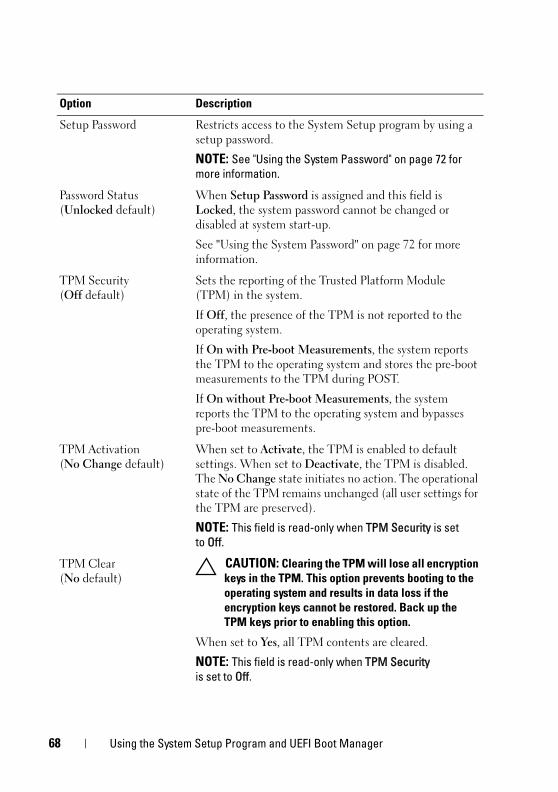
book.book Page 68 Tuesday, August 24, 2010 1:47 PM
Setup Password Restricts access to the System Setup program by using a setup password.
NOTE: See "Using the System Password" on page 72 for more information.
Password Status(Unlocked default)
When Setup Password is assigned and this field is Locked, the system password cannot be changed or disabled at system start-up.
See "Using the System Password" on page 72 for more information.
TPM Security(Off default)
Sets the reporting of the Trusted Platform Module (TPM) in the system.
If Off, the presence of the TPM is not reported to the operating system.
If On with Pre-boot Measurements, the system reports the TPM to the operating system and stores the pre-boot measurements to the TPM during POST.
If On without Pre-boot Measurements, the system reports the TPM to the operating system and bypasses pre-boot measurements.
TPM Activation(No Change default)
When set to Activate, the TPM is enabled to default settings. When set to Deactivate, the TPM is disabled. The No Change state initiates no action. The operational state of the TPM remains unchanged (all user settings for the TPM are preserved).
NOTE: This field is read-only when TPM Security is set to Off.
TPM Clear(No default)
CAUTION: Clearing the TPM will lose all encryption keys in the TPM. This option prevents booting to the operating system and results in data loss if the encryption keys cannot be restored. Back up the TPM keys prior to enabling this option.
When set to Yes, all TPM contents are cleared.
NOTE: This field is read-only when TPM Security is set to Off.
Option Description
68 Using the System Setup Program and UEFI Boot Manager
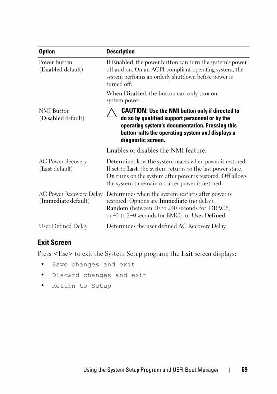
book.book Page 69 Tuesday, August 24, 2010 1:47 PM
Exit ScreenPress <Esc> to exit the System Setup program; the Exit screen displays:
• Save changes and exit
• Discard changes and exit
• Return to Setup
Power Button(Enabled default)
If Enabled, the power button can turn the system's power off and on. On an ACPI-compliant operating system, the system performs an orderly shutdown before power is turned off.
When Disabled, the button can only turn on system power.
NMI Button(Disabled default)
CAUTION: Use the NMI button only if directed to do so by qualified support personnel or by the operating system's documentation. Pressing this button halts the operating system and displays a diagnostic screen.
Enables or disables the NMI feature.
AC Power Recovery(Last default)
Determines how the system reacts when power is restored. If set to Last, the system returns to the last power state. On turns on the system after power is restored. Off allows the system to remain off after power is restored.
AC Power Recovery Delay(Immediate default)
Determines when the system restarts after power is restored. Options are Immediate (no delay), Random (between 30 to 240 seconds for iDRAC6, or 45 to 240 seconds for BMC), or User Defined.
User Defined Delay Determines the user defined AC Recovery Delay.
Option Description
Using the System Setup Program and UEFI Boot Manager 69
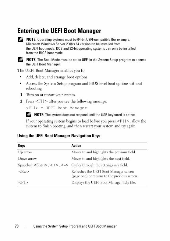
book.book Page 70 Tuesday, August 24, 2010 1:47 PM
Entering the UEFI Boot Manager NOTE: Operating systems must be 64-bit UEFI-compatible (for example,
Microsoft Windows Server 2008 x 64 version) to be installed from the UEFI boot mode. DOS and 32-bit operating systems can only be installed from the BIOS boot mode.
NOTE: The Boot Mode must be set to UEFI in the System Setup program to access the UEFI Boot Manager.
The UEFI Boot Manager enables you to:
• Add, delete, and arrange boot options
• Access the System Setup program and BIOS-level boot options without rebooting
1 Turn on or restart your system.
2 Press <F11> after you see the following message:
<F11> = UEFI Boot Manager
NOTE: The system does not respond until the USB keyboard is active.
If your operating system begins to load before you press <F11>, allow the system to finish booting, and then restart your system and try again.
Using the UEFI Boot Manager Navigation Keys
Keys Action
Up arrow Moves to and highlights the previous field.
Down arrow Moves to and highlights the next field.
Spacebar, <Enter>, <+>, <–> Cycles through the settings in a field.
<Esc> Refreshes the UEFI Boot Manager screen (page one) or returns to the previous screen.
<F1> Displays the UEFI Boot Manager help file.
70 Using the System Setup Program and UEFI Boot Manager
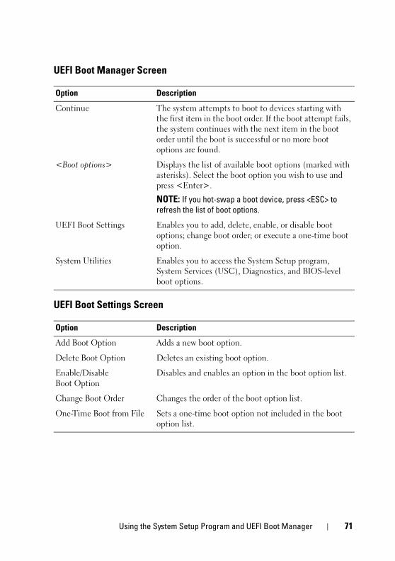
book.book Page 71 Tuesday, August 24, 2010 1:47 PM
UEFI Boot Manager Screen
UEFI Boot Settings Screen
Option Description
Continue The system attempts to boot to devices starting with the first item in the boot order. If the boot attempt fails, the system continues with the next item in the boot order until the boot is successful or no more boot options are found.
<Boot options> Displays the list of available boot options (marked with asterisks). Select the boot option you wish to use and press <Enter>.
NOTE: If you hot-swap a boot device, press <ESC> to refresh the list of boot options.
UEFI Boot Settings Enables you to add, delete, enable, or disable boot options; change boot order; or execute a one-time boot option.
System Utilities Enables you to access the System Setup program, System Services (USC), Diagnostics, and BIOS-level boot options.
Option Description
Add Boot Option Adds a new boot option.
Delete Boot Option Deletes an existing boot option.
Enable/Disable Boot Option
Disables and enables an option in the boot option list.
Change Boot Order Changes the order of the boot option list.
One-Time Boot from File Sets a one-time boot option not included in the boot option list.
Using the System Setup Program and UEFI Boot Manager 71
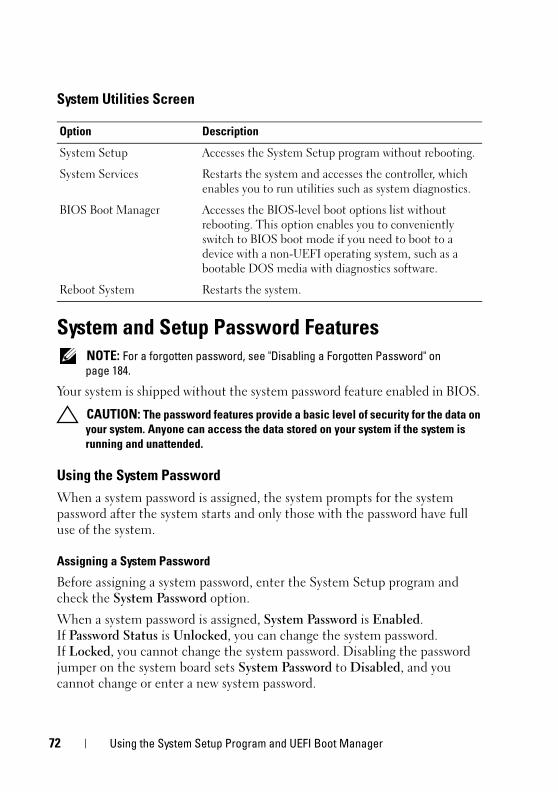
book.book Page 72 Tuesday, August 24, 2010 1:47 PM
System Utilities Screen
System and Setup Password Features NOTE: For a forgotten password, see "Disabling a Forgotten Password" on
page 184.
Your system is shipped without the system password feature enabled in BIOS.
CAUTION: The password features provide a basic level of security for the data on your system. Anyone can access the data stored on your system if the system is running and unattended.
Using the System PasswordWhen a system password is assigned, the system prompts for the system password after the system starts and only those with the password have full use of the system.
Assigning a System Password
Before assigning a system password, enter the System Setup program and check the System Password option.
When a system password is assigned, System Password is Enabled. If Password Status is Unlocked, you can change the system password. If Locked, you cannot change the system password. Disabling the password jumper on the system board sets System Password to Disabled, and you cannot change or enter a new system password.
Option Description
System Setup Accesses the System Setup program without rebooting.
System Services Restarts the system and accesses the controller, which enables you to run utilities such as system diagnostics.
BIOS Boot Manager Accesses the BIOS-level boot options list without rebooting. This option enables you to conveniently switch to BIOS boot mode if you need to boot to a device with a non-UEFI operating system, such as a bootable DOS media with diagnostics software.
Reboot System Restarts the system.
72 Using the System Setup Program and UEFI Boot Manager
book.book Page 73 Tuesday, August 24, 2010 1:47 PM
When a system password is not assigned and the password jumper on the system board is in the enabled position, System Password is Not Enabled and Password Status is Unlocked. To assign a system password:
1 Verify that Password Status is Unlocked.
2 Highlight the System Password option and press <Enter>.
3 Type your new system password.
You can use up to 32 characters in your password.
As you type, placeholders appear in the field.
The password assignment is not case-sensitive. To erase a character, press <Backspace> or the left-arrow key.
NOTE: To escape from the field without assigning a system password, press <Enter> to move to another field, or press <Esc> prior to completing step 5.
4 Press <Enter>.
5 To confirm your password, type it a second time and press <Enter>.
System Password changes to Enabled. Exit the System Setup program and begin using your system.
6 Either reboot the system now for the password protection to take effect or continue working.
NOTE: Password protection does not take effect until the system reboots.
Using Your System Password to Secure Your System
NOTE: If you have assigned a setup password (see "Using the Setup Password" on page 75), the system accepts your setup password as an alternate system password.
When Password Status is Unlocked, you have the option to leave the password security enabled or to disable password security.
To leave the password security enabled:
1 Turn on or reboot your system by pressing <Ctrl><Alt><Delete>.
2 Type your password and press <Enter>.
Using the System Setup Program and UEFI Boot Manager 73
book.book Page 74 Tuesday, August 24, 2010 1:47 PM
To disable the password security:
1 Turn on or reboot your system by pressing <Ctrl><Alt><Delete>.
2 Type your password and press <Ctrl><Enter>.
When Password Status is Locked, you must type the password and press <Enter> when prompted at reboot.
If an incorrect system password is entered, the system displays a message and prompts you to re-enter your password. You have three attempts to enter the correct password. After the third unsuccessful attempt, the system displays an error message that the system has halted and must be shut down manually using the power button.
Even after you shut down and restart the system, the error message continues to be displayed until the correct password is entered.
NOTE: You can use the Password Status option in conjunction with the System Password and Setup Password options to protect your system from unauthorized changes.
Disabling the System Password
If the system password is already set, you can disable it by typing the password during POST and pressing <Ctrl><Enter> or you can enter the system setup and press <Enter> twice when you are in the system password menu.
Changing an Existing System Password
1 Enter the System Setup program by pressing <F2> during POST.
2 Select the System Security screen.
3 Verify that the Password Status is Unlocked.
4 Type the new system password in the two password fields.
The System Password field changes to Not Enabled if the password was deleted.
74 Using the System Setup Program and UEFI Boot Manager
book.book Page 75 Tuesday, August 24, 2010 1:47 PM
Using the Setup Password
Assigning a Setup Password
You can assign a setup password only when the Setup Password is Not Enabled. To assign a setup password, highlight the Setup Password option and press the <+> or <–> key. The system prompts you to enter and verify the password.
NOTE: The setup password can be the same as the system password. If the two passwords are different, the setup password can be used as an alternate system password. The system password cannot be used in place of the setup password.
You can use up to 32 characters in your password.
As you type, placeholders appear in the field.
The password assignment is not case-sensitive. To erase a character, press <Backspace> or the left-arrow key.
When you verify the password, the Setup Password changes to Enabled. The next time you enter the System Setup program, the system prompts you for the setup password.
A change to the Setup Password option becomes effective immediately (restarting the system is not required).
Operating With a Setup Password Enabled
If Setup Password is Enabled, you must enter the correct setup password before modifying most of the System Setup options.
If you do not enter the correct password in three attempts, the system lets you view, but not modify, the System Setup screens. The following options are exceptions: If System Password is not Enabled and is not locked through the Password Status option, you can assign a system password. You cannot disable or change an existing system password.
NOTE: You can use the Password Status option in conjunction with the Setup Password option to protect the system password from unauthorized changes.
Using the System Setup Program and UEFI Boot Manager 75
book.book Page 76 Tuesday, August 24, 2010 1:47 PM
Deleting or Changing an Existing Setup Password
1 Enter the System Setup program and select System Security.
2 Highlight Setup Password, press <Enter> to access the setup password window. Press <Enter> twice to clear the existing setup password.
The setting changes to Not Enabled.
3 If you want to assign a new setup password, perform the steps in "Assigning a Setup Password" on page 75.
Embedded System ManagementThe Lifecycle Controller is an embedded utility that enables systems management tasks from an embedded environment throughout the server’s lifecycle.
The controller can be started during the boot sequence and can function independently of the operating system.
NOTE: Certain platform configurations may not support the full set of features provided by the controller.
The following features of the Lifecycle Controller are supported on systems with Baseboard Management Controller (BMC):
• Installing an operating system
• Running diagnostics to validate the memory, I/O devices, processors, physical disks, and other peripherals
When an optional iDRAC6 Express card is installed, the controller provides the following additional features:
• Downloading and applying firmware updates
• Configuring hardware and firmware
For more information about setting up the controller, configuring hardware and firmware, and deploying the operating system, see the Lifecycle Controller User Guide at support.dell.com/manuals.
76 Using the System Setup Program and UEFI Boot Manager
book.book Page 77 Tuesday, August 24, 2010 1:47 PM
Baseboard Management Controller Configuration NOTE: If an iDRAC6 Express card is installed on the system, the BMC utility is
replaced by the iDRAC6 utility.
The BMC enables configuring, monitoring, and recovery of systems remotely. BMC provides the following features:
• Uses the system’s integrated NIC
• Enables fault logging and SNMP alerting
• Provides access to system event log and sensor status
• Allows control of system functions including power on and off
• Functions independently of the system’s power state or the system’s operating system
• Provides text console redirection for system setup, text-based utilities, and operating system consoles
NOTE: To remotely access the BMC through the integrated NIC, you must connect the network connection to integrated NIC1.
For additional information on using BMC, see the documentation for the BMC and systems management applications.
Entering the BMC Setup Module1 Turn on or restart your system.
2 Press <Ctrl><E> when prompted after POST.
If your operating system begins to load before you press <Ctrl><E>, allow the system to finish booting, and then restart your system and try again.
Using the System Setup Program and UEFI Boot Manager 77
book.book Page 78 Tuesday, August 24, 2010 1:47 PM
iDRAC6 Configuration UtilityThe iDRAC6 Configuration Utility is a pre-boot configuration environment that allows you to view and set parameters for the optional iDRAC6 and for the managed server. The iDRAC6 Configuration Utility enables you to:
• Configure, enable, or disable the iDRAC6 local area network (LAN) through the dedicated iDRAC6 Enterprise card port or the embedded NICs.
• Enable or disable IPMI over LAN.
• Enable a LAN Platform Event Trap (PET) destination.
• Attach or detach the Virtual Media devices.
• Change the administrative username and password and manage user privileges.
• View System Event Log (SEL) messages or clear messages from the log.
For additional information on using iDRAC6, see the documentation for iDRAC6 and systems management applications.
Entering the iDRAC6 Configuration Utility1 Turn on or restart your system.
2 Press <Ctrl><E> when prompted during POST.
If your operating system begins to load before you press <Ctrl><E>, allow the system to finish booting, restart your system and try again.
78 Using the System Setup Program and UEFI Boot Manager
book.book Page 79 Tuesday, August 24, 2010 1:47 PM
3Installing System Components
Recommended Tools• Key to the system keylock
• #1 and #2 Phillips screwdrivers
• T10 Torx screwdriver
• Wrist grounding strap
Inside the System CAUTION: Many repairs may only be done by a certified service technician.
You should only perform troubleshooting and simple repairs as authorized in your product documentation, or as directed by the online or telephone service and support team. Damage due to servicing that is not authorized by Dell is not covered by your warranty. Read and follow the safety instructions that came with the product.
Installing System Components 79
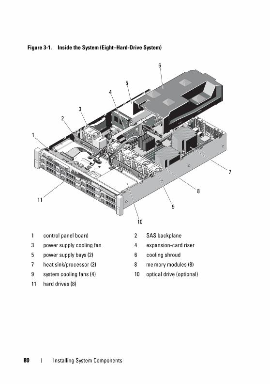
book.book Page 80 Tuesday, August 24, 2010 1:47 PM
Figure 3-1. Inside the System (Eight–Hard-Drive System)
1 control panel board 2 SAS backplane
3 power supply cooling fan 4 expansion-card riser
5 power supply bays (2) 6 cooling shroud
7 heat sink/processor (2) 8 me mory modules (8)
9 system cooling fans (4) 10 optical drive (optional)
11 hard drives (8)
6
5
8
911
1
2
7
3
4
10
80 Installing System Components
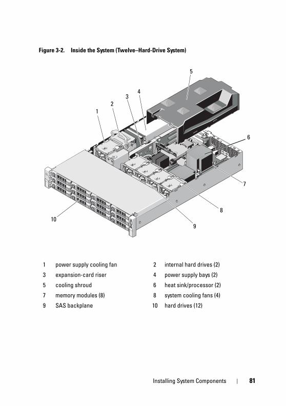
book.book Page 81 Tuesday, August 24, 2010 1:47 PM
Figure 3-2. Inside the System (Twelve–Hard-Drive System)
1 power supply cooling fan 2 internal hard drives (2)
3 expansion-card riser 4 power supply bays (2)
5 cooling shroud 6 heat sink/processor (2)
7 memory modules (8) 8 system cooling fans (4)
9 SAS backplane 10 hard drives (12)
5
4
8
910
7
1
3
6
2
Installing System Components 81
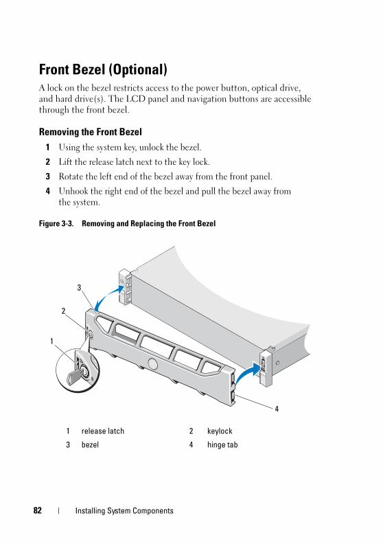
book.book Page 82 Tuesday, August 24, 2010 1:47 PM
Front Bezel (Optional) A lock on the bezel restricts access to the power button, optical drive, and hard drive(s). The LCD panel and navigation buttons are accessible through the front bezel.
Removing the Front Bezel1 Using the system key, unlock the bezel.
2 Lift the release latch next to the key lock.
3 Rotate the left end of the bezel away from the front panel.
4 Unhook the right end of the bezel and pull the bezel away from the system.
Figure 3-3. Removing and Replacing the Front Bezel
1 release latch 2 keylock
3 bezel 4 hinge tab
3
2
1
4
82 Installing System Components
book.book Page 83 Tuesday, August 24, 2010 1:47 PM
Installing the Front Bezel1 Hook the right end of the bezel onto the chassis.
2 Fit the free end of the bezel onto the system.
3 Secure the bezel with the keylock. See Figure 3-3.
Opening and Closing the System WARNING: Whenever you need to lift the system, get others to assist you.
To avoid injury, do not attempt to lift the system by yourself.
CAUTION: Many repairs may only be done by a certified service technician. You should only perform troubleshooting and simple repairs as authorized in your product documentation, or as directed by the online or telephone service and support team. Damage due to servicing that is not authorized by Dell is not covered by your warranty. Read and follow the safety instructions that came with the product.
Opening the System1 Turn off the system and attached peripherals, and disconnect the system
from the electrical outlet and peripherals.
2 If applicable, remove the front bezel. See "Removing the Front Bezel" on page 82.
3 Rotate the latch release lock on the system cover counter clockwise to the unlocked position. See Figure 3-4 and Figure 3-5.
4 Lift the latch on top of the system and slide the cover back.
5 Grasp the cover on both sides and lift the cover away from the system. See Figure 3-4 and Figure 3-5.
Installing System Components 83
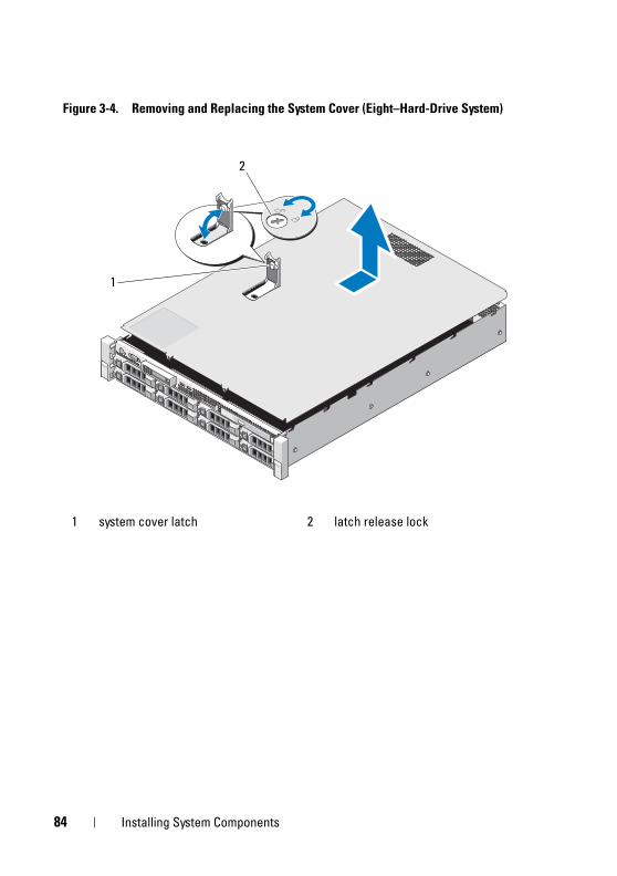
book.book Page 84 Tuesday, August 24, 2010 1:47 PM
Figure 3-4. Removing and Replacing the System Cover (Eight–Hard-Drive System)
1 system cover latch 2 latch release lock
1
2
84 Installing System Components
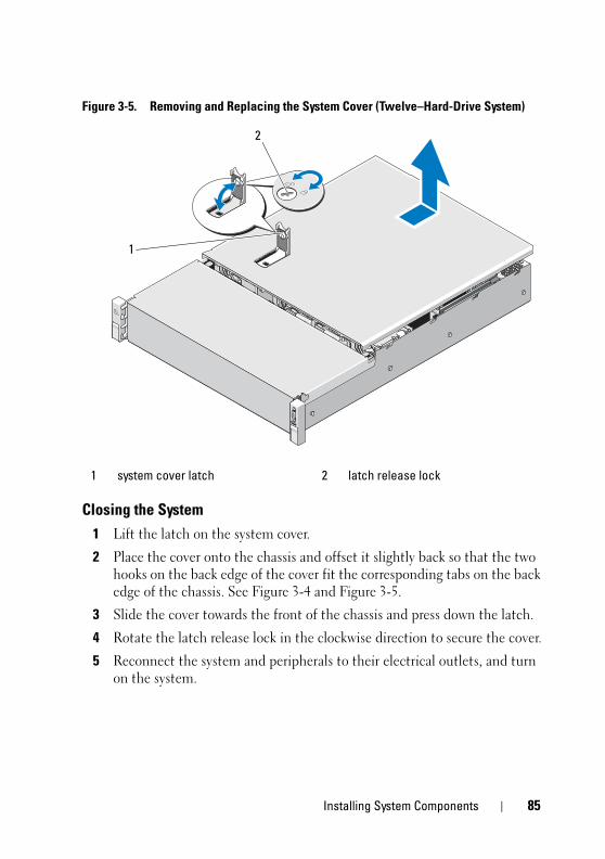
book.book Page 85 Tuesday, August 24, 2010 1:47 PM
Figure 3-5. Removing and Replacing the System Cover (Twelve–Hard-Drive System)
Closing the System1 Lift the latch on the system cover.
2 Place the cover onto the chassis and offset it slightly back so that the two hooks on the back edge of the cover fit the corresponding tabs on the back edge of the chassis. See Figure 3-4 and Figure 3-5.
3 Slide the cover towards the front of the chassis and press down the latch.
4 Rotate the latch release lock in the clockwise direction to secure the cover.
5 Reconnect the system and peripherals to their electrical outlets, and turn on the system.
1 system cover latch 2 latch release lock
1
2
Installing System Components 85
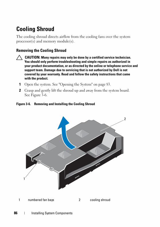
book.book Page 86 Tuesday, August 24, 2010 1:47 PM
Cooling ShroudThe cooling shroud directs airflow from the cooling fans over the system processor(s) and memory module(s).
Removing the Cooling Shroud
CAUTION: Many repairs may only be done by a certified service technician. You should only perform troubleshooting and simple repairs as authorized in your product documentation, or as directed by the online or telephone service and support team. Damage due to servicing that is not authorized by Dell is not covered by your warranty. Read and follow the safety instructions that came with the product.
1 Open the system. See "Opening the System" on page 83.
2 Grasp and gently lift the shroud up and away from the system board. See Figure 3-6.
Figure 3-6. Removing and Installing the Cooling Shroud
1 numbered fan bays 2 cooling shroud
2
1
86 Installing System Components
book.book Page 87 Tuesday, August 24, 2010 1:47 PM
Installing the Cooling Shroud
CAUTION: Many repairs may only be done by a certified service technician. You should only perform troubleshooting and simple repairs as authorized in your product documentation, or as directed by the online or telephone service and support team. Damage due to servicing that is not authorized by Dell is not covered by your warranty. Read and follow the safety instructions that came with the product.
1 Align the shroud using the center of the numbered fan bays as a guide.
2 Press the cooling shroud down into the chassis.
3 Close the system. See "Closing the System" on page 85.
4 Reconnect the system to its electrical outlet and turn the system on, including any attached peripherals.
Hard DrivesYour system supports 3.5-inch and 2.5-inch (SAS or SATA) hard drives in 3.5-inch hot-swap hard drive carrier or cabled internal drives. Depending on your chassis, the hard drives are installed internally or at the front of the system (see Figure 3-1). Front-mounted hard drives are connected to a SAS backplane through hard-drive carriers and can be configured as hot-swappable.
Removing a Hard-Drive Blank
CAUTION: To maintain proper system cooling, all empty hard-drive bays must have drive blanks installed.
1 If applicable, remove the front bezel. See "Removing the Front Bezel" on page 82.
2 Grasp the front of the hard-drive blank, press the release lever on the right side, and slide the blank out until it is free of the drive bay. See Figure 3-7.
Installing System Components 87
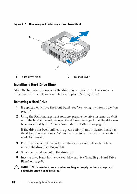
book.book Page 88 Tuesday, August 24, 2010 1:47 PM
Figure 3-7. Removing and Installing a Hard-Drive Blank
Installing a Hard-Drive Blank Align the hard-drive blank with the drive bay and insert the blank into the drive bay until the release lever clicks into place. See Figure 3-7.
Removing a Hard Drive1 If applicable, remove the front bezel. See "Removing the Front Bezel" on
page 82.
2 Using the RAID management software, prepare the drive for removal. Wait until the hard-drive indicators on the drive carrier signal that the drive can be removed safely. See "Hard-Drive Indicator Patterns" on page 19.
If the drive has been online, the green activity/fault indicator flashes as the drive is powered down. When the drive indicators are off, the drive is ready for removal.
3 Press the release button and open the drive carrier release handle to release the drive. See Figure 3-8.
4 Slide the hard drive out of the drive bay.
5 Insert a drive blank in the vacated drive bay. See "Installing a Hard-Drive Blank" on page 88.
CAUTION: To maintain proper system cooling, all empty hard-drive bays must have hard-drive blanks installed.
1 hard-drive blank 2 release lever
1
2
88 Installing System Components
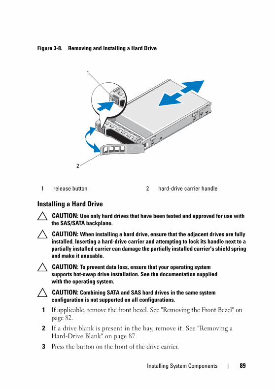
book.book Page 89 Tuesday, August 24, 2010 1:47 PM
Figure 3-8. Removing and Installing a Hard Drive
Installing a Hard Drive
CAUTION: Use only hard drives that have been tested and approved for use with the SAS/SATA backplane.
CAUTION: When installing a hard drive, ensure that the adjacent drives are fully installed. Inserting a hard-drive carrier and attempting to lock its handle next to a partially installed carrier can damage the partially installed carrier's shield spring and make it unusable.
CAUTION: To prevent data loss, ensure that your operating system supports hot-swap drive installation. See the documentation supplied with the operating system.
CAUTION: Combining SATA and SAS hard drives in the same system configuration is not supported on all configurations.
1 If applicable, remove the front bezel. See "Removing the Front Bezel" on page 82.
2 If a drive blank is present in the bay, remove it. See "Removing a Hard-Drive Blank" on page 87.
3 Press the button on the front of the drive carrier.
1 release button 2 hard-drive carrier handle
1
2
Installing System Components 89
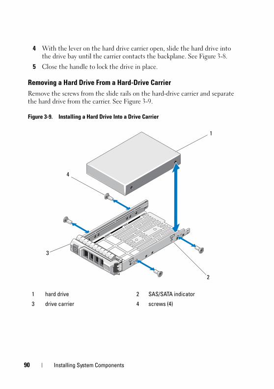
book.book Page 90 Tuesday, August 24, 2010 1:47 PM
4 With the lever on the hard drive carrier open, slide the hard drive into the drive bay until the carrier contacts the backplane. See Figure 3-8.
5 Close the handle to lock the drive in place.
Removing a Hard Drive From a Hard-Drive CarrierRemove the screws from the slide rails on the hard-drive carrier and separate the hard drive from the carrier. See Figure 3-9.
Figure 3-9. Installing a Hard Drive Into a Drive Carrier
1 hard drive 2 SAS/SATA indicator
3 drive carrier 4 screws (4)
2
1
3
4
90 Installing System Components
book.book Page 91 Tuesday, August 24, 2010 1:47 PM
Installing a Hard Drive Into a Hard-Drive Carrier1 Insert the hard drive into the hard-drive carrier with the connector end of
the drive at the back. See Figure 3-9.
2 Align the holes on the hard drive with the holes on the hard-drive carrier.
When aligned correctly, the back of the hard drive will be flush with the back of the hard-drive carrier.
3 Attach the four screws to secure the hard drive to the hard-drive carrier.
Internal Hard DrivesAll twelve–hard-drive systems support two cabled 2.5-inch (SAS or SATA) internal hard drives. Internal hard drives are connected to the SAS backplane. It is recommended that you install the operating system on the internal hard drives in a RAID 1 configuration. For information on RAID configuration, see the RAID documentation at support.dell.com/manuals.
Removing an Internal Hard-Drive Bay
CAUTION: Many repairs may only be done by a certified service technician. You should only perform troubleshooting and simple repairs as authorized in your product documentation, or as directed by the online or telephone service and support team. Damage due to servicing that is not authorized by Dell is not covered by your warranty. Read and follow the safety instructions that came with the product.
1 Turn off the system and attached peripherals, and disconnect the system from the electrical outlet and from the peripherals.
2 Open the system. See "Opening the System" on page 83.
3 Lift the latch on your internal hard drive bay and lift it out of the system. See Figure 3-10.
Installing System Components 91
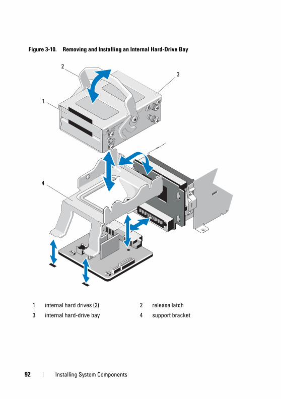
book.book Page 92 Tuesday, August 24, 2010 1:47 PM
Figure 3-10. Removing and Installing an Internal Hard-Drive Bay
1 internal hard drives (2) 2 release latch
3 internal hard-drive bay 4 support bracket
23
1
4
92 Installing System Components
book.book Page 93 Tuesday, August 24, 2010 1:47 PM
Installing an Internal Hard-Drive Bay
CAUTION: Many repairs may only be done by a certified service technician. You should only perform troubleshooting and simple repairs as authorized in your product documentation, or as directed by the online or telephone service and support team. Damage due to servicing that is not authorized by Dell is not covered by your warranty. Read and follow the safety instructions that came with the product.
1 Turn off the system and attached peripherals, and disconnect the system from the electrical outlet and from the peripherals.
2 Open the system. See "Opening the System" on page 83.
3 Lift the latch on your internal hard-drive bay and align the bay on the support bracket.
4 Rotate the latch to lock.
Removing an Internal Hard Drive From the Internal Hard-Drive BayRemove the screws on the sides of the internal hard-drive bay and slide out the hard drive. See Figure 3-11.
Installing System Components 93
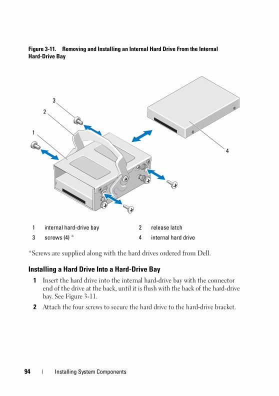
book.book Page 94 Tuesday, August 24, 2010 1:47 PM
Figure 3-11. Removing and Installing an Internal Hard Drive From the Internal Hard-Drive Bay
*Screws are supplied along with the hard drives ordered from Dell.
Installing a Hard Drive Into a Hard-Drive Bay 1 Insert the hard drive into the internal hard-drive bay with the connector
end of the drive at the back, until it is flush with the back of the hard-drive bay. See Figure 3-11.
2 Attach the four screws to secure the hard drive to the hard-drive bracket.
1 internal hard-drive bay 2 release latch
3 screws (4) * 4 internal hard drive
3
1
2
4
94 Installing System Components
book.book Page 95 Tuesday, August 24, 2010 1:47 PM
Optical Drive (Optional) An optional slimline SATA DVD-ROM or DVD+/-RW optical drive slides into the front panel and connects to the SATA controller on the system board.
NOTE: The twelve–hard-drive systems support only an external USB optical drive.
NOTE: DVD devices are data only.
Removing an Optical Drive
CAUTION: Many repairs may only be done by a certified service technician. You should only perform troubleshooting and simple repairs as authorized in your product documentation, or as directed by the online or telephone service and support team. Damage due to servicing that is not authorized by Dell is not covered by your warranty. Read and follow the safety instructions that came with the product.
1 If applicable, remove the front bezel. See "Removing the Front Bezel" on page 82.
2 Turn off the system, including any attached peripherals, and disconnect the system from its electrical outlet.
3 Open the system. See "Opening the System" on page 83.
4 Disconnect the optical drive cable from the back of the drive.
Note the routing of the optical drive cable underneath the tabs on the system chassis as you remove them from the system board and drive. You must route these cables properly when you replace them to prevent the cables from being pinched or crimped.
5 To remove the drive, press down the blue release tab at the back of the optical drive and gently push the drive out of the system. See Figure 3-12.
6 If you are not adding a new optical drive, replace the optical drive insert.
Installing System Components 95
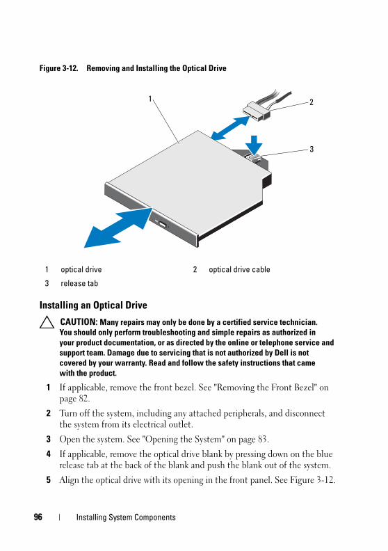
book.book Page 96 Tuesday, August 24, 2010 1:47 PM
Figure 3-12. Removing and Installing the Optical Drive
Installing an Optical Drive
CAUTION: Many repairs may only be done by a certified service technician. You should only perform troubleshooting and simple repairs as authorized in your product documentation, or as directed by the online or telephone service and support team. Damage due to servicing that is not authorized by Dell is not covered by your warranty. Read and follow the safety instructions that came with the product.
1 If applicable, remove the front bezel. See "Removing the Front Bezel" on page 82.
2 Turn off the system, including any attached peripherals, and disconnect the system from its electrical outlet.
3 Open the system. See "Opening the System" on page 83.
4 If applicable, remove the optical drive blank by pressing down on the blue release tab at the back of the blank and push the blank out of the system.
5 Align the optical drive with its opening in the front panel. See Figure 3-12.
1 optical drive 2 optical drive cable
3 release tab
2
3
1
96 Installing System Components
book.book Page 97 Tuesday, August 24, 2010 1:47 PM
6 Slide in the optical drive until the latch snaps into place.
7 Connect the optical drive cable to the back of the drive.
You must route these cables properly through the tabs on the system chassis to prevent them from being pinched or crimped. See Figure 3-1.
8 Connect the data cable to the system board and the interface cable to SAS_B on the backplane. See Figure 6-1.
9 Close the system. See "Closing the System" on page 85.
10 If applicable, replace the front bezel. See "Removing the Front Bezel" on page 82.
11 Reconnect the system and peripherals to their electrical outlets, and turn on the system.
Cooling FansYour system contains five cooling fans, single- or dual-motor depending on your system configuration. These provide cooling for the processor, PCI cards, memory modules, and power supplies.
NOTE: Hot-swap removal or installation of the cooling fans is not supported.
NOTE: In the event of a problem with a particular fan, the fan number is referenced by the system’s management software, allowing you to easily identify and replace the proper fan by noting the fan numbers on the fan assembly.
Installing System Components 97
book.book Page 98 Tuesday, August 24, 2010 1:47 PM
Removing a Cooling Fan
WARNING: The cooling fan can continue to spin for some time after the system has been powered down. Allow time for the fan to stop spinning before removing it from the system.
WARNING: Do not attempt to operate the system without the cooling fans.
CAUTION: Many repairs may only be done by a certified service technician. You should only perform troubleshooting and simple repairs as authorized in your product documentation, or as directed by the online or telephone service and support team. Damage due to servicing that is not authorized by Dell is not covered by your warranty. Read and follow the safety instructions that came with the product.
1 Turn off the system, including any attached peripherals, and disconnect the system from its electrical outlet.
2 Open the system. See "Opening the System" on page 83.
3 If applicable, remove the cooling shroud. See "Removing the Cooling Shroud" on page 86.
4 Disconnect the fan’s power cable from the system board or power distribution board as applicable. See Figure 3-14.
NOTE: To remove fans 3 and 4, remove the storage controller card first. See "Removing the Storage Controller Card" on page 119.
NOTE: To remove fan 5 in the twelve–hard-drive systems, remove the internal hard-drive bay and carrier. See "Removing an Internal Hard-Drive Bay" on page 91.
5 Press the release tab while grasping the ends of the fan and lift the fan straight up from the fan bracket. See Figure 3-13 and Figure 3-14.
98 Installing System Components
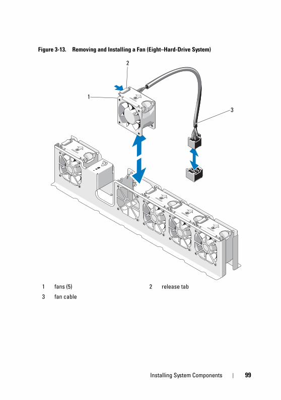
book.book Page 99 Tuesday, August 24, 2010 1:47 PM
Figure 3-13. Removing and Installing a Fan (Eight–Hard-Drive System)
1 fans (5) 2 release tab
3 fan cable
1
2
3
Installing System Components 99
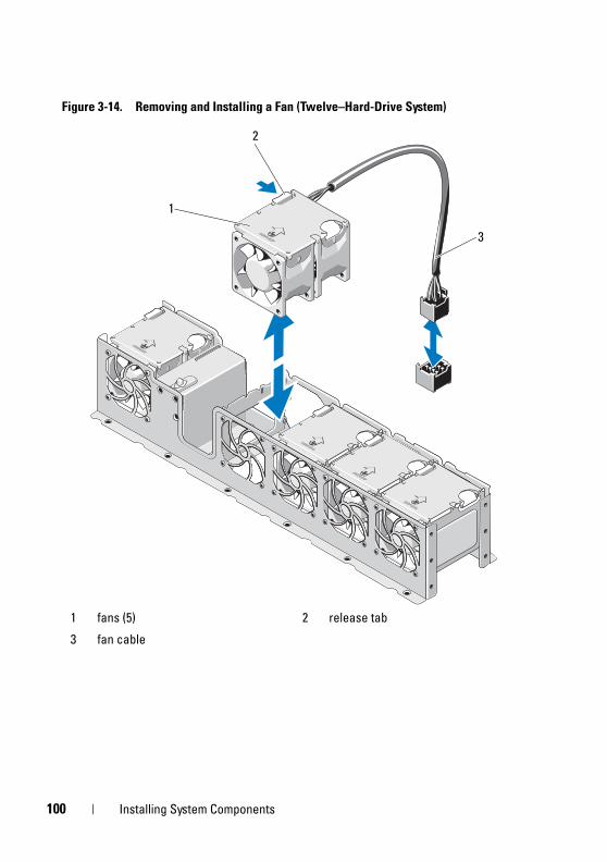
1
book.book Page 100 Tuesday, August 24, 2010 1:47 PM
Figure 3-14. Removing and Installing a Fan (Twelve–Hard-Drive System)
1 fans (5) 2 release tab
3 fan cable
1
2
3
00 Installing System Components
book.book Page 101 Tuesday, August 24, 2010 1:47 PM
Installing a Cooling Fan
CAUTION: Many repairs may only be done by a certified service technician. You should only perform troubleshooting and simple repairs as authorized in your product documentation, or as directed by the online or telephone service and support team. Damage due to servicing that is not authorized by Dell is not covered by your warranty. Read and follow the safety instructions that came with the product.
1 Align the fan module so that the side with the power cable faces toward the back of the system.
2 Slide the fan module into the fan assembly until the fan is fully seated. See Figure 3-13 and Figure 3-14.
3 Connect the fan’s power cable to the power connector on the system board or power distribution board as applicable.
4 Route the power cable through the guides on the chassis.
NOTE: For twelve–hard-drive systems, first replace the internal hard-drive carrier and bay. See "Installing an Internal Hard-Drive Bay" on page 93.
NOTE: After installing fans 3 and 4, replace the storage controller card. See "Installing the Storage Controller Card" on page 121.
5 Replace the cooling shroud. See "Installing the Cooling Shroud" on page 87.
6 Close the system. See "Closing the System" on page 85.
7 Reconnect the system to its electrical outlet and turn the system on, including any attached peripherals.
Installing System Components 101
1
book.book Page 102 Tuesday, August 24, 2010 1:47 PM
Power SuppliesYour system supports 750 W power supply.
NOTE: The maximum output power (shown in watts) is listed on the power supply label.
If two power supplies are installed, the second power supply provides hot-swappable, power redundancy. When a power supply is removed with the system powered on, the full power load is picked up by the remaining power supply.
CAUTION: To ensure proper system cooling, the power supply blank must be installed in the PS2 bay in a redundant configuration. See "Installing the Power Supply Blank" on page 104.
NOTE: If only one power supply is installed, it must be installed in the PS1 power supply bay.
Removing a Power Supply
CAUTION: Many repairs may only be done by a certified service technician. You should only perform troubleshooting and simple repairs as authorized in your product documentation, or as directed by the online or telephone service and support team. Damage due to servicing that is not authorized by Dell is not covered by your warranty. Read and follow the safety instructions that came with the product.
CAUTION: The system requires one power supply to operate the system normally. On power-redundant systems, remove and replace only one power supply at a time in a system that is powered on.
1 Disconnect the power cable from the power source.
2 Disconnect the power cable from the power supply and remove the system cables from the Velcro straps.
NOTE: You may have to unlatch and lift the optional cable management arm if it interferes with power-supply removal. For information about the cable management arm, see the system’s rack documentation.
3 Press the lever release latch and slide the power supply out of the chassis. See Figure 3-15.
NOTE: Install a power supply blank if you are not replacing the power supply. See "Installing the Power Supply Blank" on page 104.
02 Installing System Components
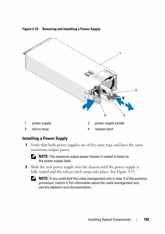
book.book Page 103 Tuesday, August 24, 2010 1:47 PM
Figure 3-15. Removing and Installing a Power Supply
Installing a Power Supply 1 Verify that both power supplies are of the same type and have the same
maximum output power.
NOTE: The maximum output power (shown in watts) is listed on the power supply label.
2 Slide the new power supply into the chassis until the power supply is fully seated and the release latch snaps into place. See Figure 3-15.
NOTE: If you unlatched the cable management arm in step 2 of the previous procedure, relatch it. For information about the cable management arm, see the system’s rack documentation.
1 power supply 2 power supply handle
3 velcro strap 4 release latch
1
3
2
4
Installing System Components 103
1
book.book Page 104 Tuesday, August 24, 2010 1:47 PM
3 Connect the power cable to the power supply and plug the cable into a power outlet.
CAUTION: When connecting the power cable, secure the cable with the Velcro strap.
NOTE: When installing, hot-swapping, or hot-adding a new power supply in a system with two power supplies, allow several seconds for the system to recognize the power supply and determine its status. The power-supply status indicator turns green to signify that the power supply is functioning properly (see Figure 1-7).
Removing the Power Supply BlankIf you are installing a second power supply, remove the power supply blank in bay PS2 by pulling outward on the blank.
CAUTION: To ensure proper system cooling, the power supply blank must be installed in power supply bay PS2 in a redundant configuration. Remove the power supply blank only if you are installing a second power supply.
Installing the Power Supply Blank
NOTE: Install the power supply blank only in power supply bay PS2.
To install the power supply blank, align the blank with the power supply bay and insert the blank into the chassis until it clicks into place.
System MemoryYour system supports standard (1.5 V) DDR3 and low voltage (1.35 V) DDR3L registered DIMMs (RDIMMs) or unbuffered ECC DIMMs (UDIMMs). Single and dual-rank DIMMs can be 1067 MHz or 1333 MHz, and quad-rank DIMMs can be 800 MHz or 1067 MHz.
The system contains eight memory sockets split into two sets of four sockets, one set per processor. Each four-socket set is organized into three channels. Two DIMMs for channel 0 and a single DIMM for channel 1 and 2. The first socket of each channel is marked with white release levers.
04 Installing System Components
book.book Page 105 Tuesday, August 24, 2010 1:47 PM
The maximum memory that is supported on your system varies according to the types and sizes of memory modules being used:
• Single-rank, dual-rank, and quad-rank RDIMMs of sizes 2 GB, 4 GB, 8 GB, and 16 GB are supported for a total of up to 128 GB.
• 1 GB, 2 GB, and 4 GB UDIMMs are supported for a total of up to 32 GB.
General Memory Module Installation GuidelinesTo ensure optimal performance of your system, observe the following general guidelines when configuring your system memory.
NOTE: Memory configurations that fail to observe these guidelines can prevent your system from starting and producing any video output.
• 1.35 V DDR3L memory operates the memory modules at 1.5 V, if any of the following conditions exist:
– Two 1333 MHz DIMMs per channel.
– A combination of both standard and low voltage memory modules.
• RDIMMs and UDIMMs cannot be mixed.
• Except for memory channels that are unused, all populated memory channels must have identical configurations.
• The memory configuration for each processor must be identical.
• Memory modules of different sizes can be mixed in A1-A4 or B1-B4 (for example, 2 GB and 4 GB), but all populated channels must have identical configurations.
• For Optimizer Mode, memory modules are installed in the numeric order of the sockets beginning with A1 or B1.
• The memory speed of each channel depends on the memory configuration:
– For single rank memory modules:
• One memory module per channel supports up to 1333 MHz.
• Two memory modules per channel support up to 1333 MHz.
Installing System Components 105
1
book.book Page 106 Tuesday, August 24, 2010 1:47 PM
– For dual-rank memory modules:
• One memory module per channel supports up to 1333 MHz.
• Two memory modules per channel support up to 1067 MHz.
– For quad-rank memory modules:
• One memory module per channel supports up to 1333 MHz.
• Two memory modules per channel are limited to 800 MHz, regardless of memory module speed.
• If quad-rank memory modules are mixed with single- or dual-rank modules, the quad-rank modules must be installed in the sockets with the white release levers.
• If memory modules with different speeds are installed, they operate at the speed of the slowest installed memory module(s).
Mode-Specific GuidelinesTwo memory channels are allocated to each processor. The number of channels used and the allowable configurations depend on the memory mode selected.
Optimizer (Independent Channel) Mode
In this mode, both the channels are populated with identical memory modules. This mode permits a larger total memory capacity but does not support SDDC with x8-based memory modules.
A minimal single-channel configuration of one 1 GB memory module per processor is also supported in this mode.
Table 3-1 and Table 3-2 show sample memory configurations that follow the appropriate memory guidelines stated in this section. The samples show identical memory-module configurations and their physical and available memory totals. The tables do not show mixed or quad-rank memory-module configurations, nor do they address the memory speed considerations of any configuration.
06 Installing System Components
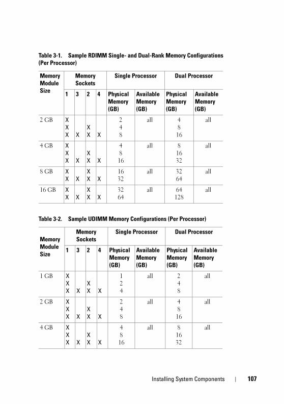
book.book Page 107 Tuesday, August 24, 2010 1:47 PM
Table 3-1. Sample RDIMM Single- and Dual-Rank Memory Configurations (Per Processor)
Memory Module Size
Memory Sockets
Single Processor Dual Processor
1 3 2 4 Physical Memory (GB)
Available Memory (GB)
Physical Memory (GB)
Available Memory (GB)
2 GB XXX X
XX X
24 8
all 4816
all
4 GB XXX X
XX X
48 16
all 81632
all
8 GB XX X
XX X
1632
all 3264
all
16 GB XX X
XX X
3264
all 64128
all
Table 3-2. Sample UDIMM Memory Configurations (Per Processor)
Memory Module Size
Memory Sockets
Single Processor Dual Processor
1 3 2 4 Physical Memory (GB)
Available Memory (GB)
Physical Memory (GB)
Available Memory (GB)
1 GB XXX X
XX X
124
all 24 8
all
2 GB XXX X
XX X
248
all 48
16
all
4 GB XXX X
XX X
4816
all 81632
all
Installing System Components 107
1
book.book Page 108 Tuesday, August 24, 2010 1:47 PM
Installing Memory Modules
WARNING: The memory modules are hot to the touch for some time after the system has been powered down. Allow time for the memory modules to cool before handling them. Handle the memory modules by the card edges and avoid touching the components on the memory module.
CAUTION: Many repairs may only be done by a certified service technician. You should only perform troubleshooting and simple repairs as authorized in your product documentation, or as directed by the online or telephone service and support team. Damage due to servicing that is not authorized by Dell is not covered by your warranty. Read and follow the safety instructions that came with the product.
1 Turn off the system, including any attached peripherals, and disconnect the system from the electrical outlet.
2 Open the system. See "Opening the System" on page 83.
3 Remove the cooling shroud. See "Removing the Cooling Shroud" on page 86.
4 Locate the memory module sockets. See Figure 6-1.
5 Press the ejectors on the memory module socket down and out, as shown in Figure 3-16, to allow the memory module to be inserted into the socket.
6 Handle each memory module only on either card edge, making sure not to touch the middle of the memory module.
08 Installing System Components
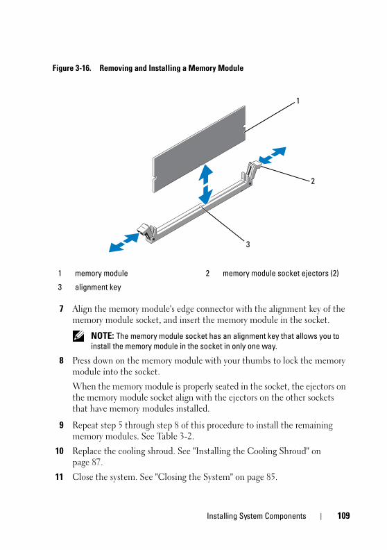
book.book Page 109 Tuesday, August 24, 2010 1:47 PM
Figure 3-16. Removing and Installing a Memory Module
7 Align the memory module's edge connector with the alignment key of the memory module socket, and insert the memory module in the socket.
NOTE: The memory module socket has an alignment key that allows you to install the memory module in the socket in only one way.
8 Press down on the memory module with your thumbs to lock the memory module into the socket.
When the memory module is properly seated in the socket, the ejectors on the memory module socket align with the ejectors on the other sockets that have memory modules installed.
9 Repeat step 5 through step 8 of this procedure to install the remaining memory modules. See Table 3-2.
10 Replace the cooling shroud. See "Installing the Cooling Shroud" on page 87.
11 Close the system. See "Closing the System" on page 85.
1 memory module 2 memory module socket ejectors (2)
3 alignment key
2
1
3
Installing System Components 109
1
book.book Page 110 Tuesday, August 24, 2010 1:47 PM
12 Reconnect the system to its electrical outlet and turn the system on, including any attached peripherals.
13 Start up the system, press <F2> to enter the System Setup program, and check the System Memory settings on the main System Setup screen.
The system should have already changed the value to reflect the newly installed memory.
14 If the value is incorrect, one or more of the memory modules may not be installed properly. Repeat step 2 through step 13 of this procedure, checking to ensure that the memory modules are firmly seated in their sockets.
15 Run the system memory test in the system diagnostics. See "Running the Embedded System Diagnostics" on page 178.
Removing Memory Modules
WARNING: The memory modules are hot to the touch for some time after the system has been powered down. Allow time for the memory modules to cool before handling them. Handle the memory modules by the card edges and avoid touching the components on the memory module.
CAUTION: Many repairs may only be done by a certified service technician. You should only perform troubleshooting and simple repairs as authorized in your product documentation, or as directed by the online or telephone service and support team. Damage due to servicing that is not authorized by Dell is not covered by your warranty. Read and follow the safety instructions that came with the product.
1 Turn off the system, including any attached peripherals, and disconnect the system from the electrical outlet.
2 Open the system. See "Opening the System" on page 83.
3 Remove the cooling shroud. See "Removing the Cooling Shroud" on page 86.
4 Locate the memory module sockets. See Figure 6-1.
5 Press down and out on the ejectors on each end of the socket until the memory module pops out of the socket. See Figure 3-16.
Handle each memory module only on either card edge, making sure not to touch the middle of the memory module.
10 Installing System Components
book.book Page 111 Tuesday, August 24, 2010 1:47 PM
6 Replace the cooling shroud. See "Installing the Cooling Shroud" on page 87.
7 Close the system. See "Closing the System" on page 85.
8 Reconnect the system and peripherals to their power sources, and turn them on.
Expansion Cards and Expansion-Card RisersYour system supports up to four PCI Express (PCIe) expansion cards installed in connectors on an expansion-card riser.
Depending on the configuration, your system may have either riser 1 or riser 2:
• Expansion-card riser 1 provides three x4 Generation 2 PCIe expansion-card slots and one x8 Generation 2 PCIe expansion-card slot.
• Expansion-card riser 2 provides one x4 Generation 2 PCIe expansion-card slot and one x16 Generation 2 PCIe expansion-card slot.
CAUTION: Expansion cards can only be installed in the slots on the expansion-card riser. Do not attempt to install expansion cards directly into the riser connector on the system board.
Expansion Card Installation Guidelines• The expansion-card slots support full-height, half-length cards.
• The expansion-card slots are hot-swappable.
• PCI Express Generation 2 expansion cards are supported in all the slots.
• All the slots are x8 connectors.
CAUTION: To ensure proper cooling, only one of the two expansion cards can have a power consumption of greater than 15 W (up to 25 W maximum), not including the integrated storage controller.
• Table 3-3 and Table 3-4 provide information about installing expansion cards to ensure proper cooling and mechanical fit. The expansion cards with the highest priority should be installed first using the slot priority indicated. All other expansion cards should be installed in card priority and slot priority order.
Installing System Components 111
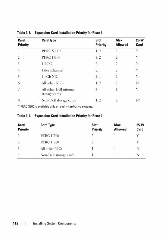
1
book.book Page 112 Tuesday, August 24, 2010 1:47 PM
Table 3-4. Expansion-Card Installation Priority for Riser 2
Table 3-3. Expansion-Card Installation Priority for Riser 1
Card Priority
Card Type Slot Priority
Max Allowed
25-W Card
1 PERC S300* 1, 2 2 Y
2 PERC H800 3, 2 2 Y
3 HPCC 2, 1 2 Y
4 Fibre Channel 2, 1 2 Y
5 10 Gb NIC 2, 1 2 Y
6 All other NICs 1, 2 2 N
7 All other Dell internal storage cards
4 1 Y
8 Non-Dell storage cards 1, 2 2 N*
* PERC S300 is available only on eight–hard-drive systems.
Card Priority
Card Type Slot Priority
Max Allowed
25-W Card
1 PERC H700 2 1 Y
2 PERC H200 2 1 Y
3 All other NICs 1 1 N
4 Non-Dell storage cards 1 1 N
12 Installing System Components
book.book Page 113 Tuesday, August 24, 2010 1:47 PM
Installing an Expansion Card
CAUTION: Many repairs may only be done by a certified service technician. You should only perform troubleshooting and simple repairs as authorized in your product documentation, or as directed by the online or telephone service and support team. Damage due to servicing that is not authorized by Dell is not covered by your warranty. Read and follow the safety instructions that came with the product.
1 Unpack the expansion card and prepare it for installation.
For instructions, see the documentation accompanying the card.
2 Turn off the system, including any attached peripherals, and disconnect the system from the electrical outlet.
3 Open the system. See "Opening the System" on page 83.
4 Remove the cooling shroud. See "Removing the Cooling Shroud" on page 86.
5 Open the expansion-card latch and remove the filler bracket. See Figure 3-17.
NOTE: Keep this bracket in case you need to remove the expansion card. Filler brackets must be installed over empty expansion-card slots to maintain FCC certification of the system. The brackets also keep dust and dirt out of the system and aid in proper cooling and airflow inside the system.
6 Holding the card by its edges, position the card so that the card-edge connector aligns with the expansion-card connector on the expansion-card riser.
7 Insert the card-edge connector firmly into the expansion-card connector until the card is fully seated.
8 Close the expansion-card latch. See Figure 3-17.
Installing System Components 113
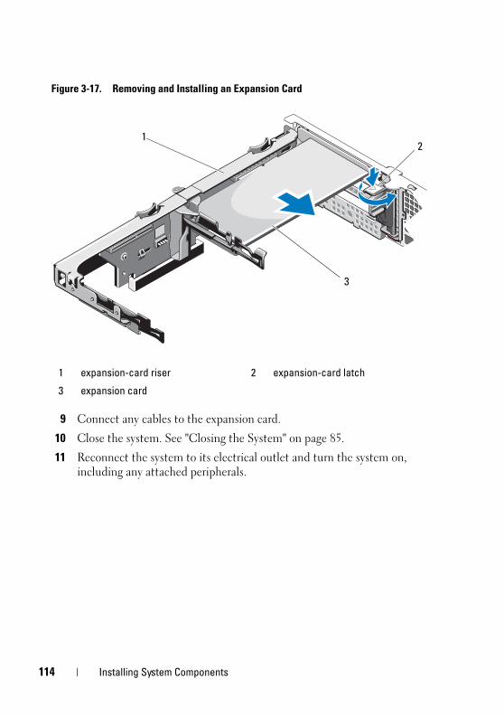
1
book.book Page 114 Tuesday, August 24, 2010 1:47 PM
Figure 3-17. Removing and Installing an Expansion Card
9 Connect any cables to the expansion card.
10 Close the system. See "Closing the System" on page 85.
11 Reconnect the system to its electrical outlet and turn the system on, including any attached peripherals.
1 expansion-card riser 2 expansion-card latch
3 expansion card
3
21
14 Installing System Components
book.book Page 115 Tuesday, August 24, 2010 1:47 PM
Removing an Expansion Card
CAUTION: Many repairs may only be done by a certified service technician. You should only perform troubleshooting and simple repairs as authorized in your product documentation, or as directed by the online or telephone service and support team. Damage due to servicing that is not authorized by Dell is not covered by your warranty. Read and follow the safety instructions that came with the product.
1 Turn off the system, including any attached peripherals, and disconnect the system from the electrical outlet.
2 Open the system. See "Opening the System" on page 83.
3 Remove the cooling shroud. See "Removing the Cooling Shroud" on page 86.
4 Disconnect all cables from the card.
5 Open the expansion-card latches. See Figure 3-17.
6 Grasp the expansion card by its edges, and carefully remove it from the expansion-card connector.
7 If you are removing the card permanently, install a metal filler bracket over the empty expansion slot opening and close the expansion-card latch.
NOTE: You must install a filler bracket over an empty expansion slot to maintain Federal Communications Commission (FCC) certification of the system. The brackets also keep dust and dirt out of the system and aid in proper cooling and airflow inside the system.
8 Close the system. See "Closing the System" on page 85.
9 Reconnect the system to its electrical outlet and turn the system on, including any attached peripherals.
Installing System Components 115
1
book.book Page 116 Tuesday, August 24, 2010 1:47 PM
Removing an Expansion-Card Riser
CAUTION: Many repairs may only be done by a certified service technician. You should only perform troubleshooting and simple repairs as authorized in your product documentation, or as directed by the online or telephone service and support team. Damage due to servicing that is not authorized by Dell is not covered by your warranty. Read and follow the safety instructions that came with the product.
1 Turn off the system, including any attached peripherals, and disconnect the system from the electrical outlet.
2 Open the system. See "Opening the System" on page 83.
3 Remove the cooling shroud. See "Removing the Cooling Shroud" on page 86.
4 If installed, remove the expansion card from the expansion-card slot. See "Removing an Expansion Card" on page 115.
5 If installed, remove the storage controller card. See "Removing the Storage Controller Card" on page 119.
6 Disconnect the cables connected to the riser card.
7 To remove the expansion-card riser, simultaneously press both the blue tabs on the expansion-card riser and lift it from the chassis. See Figure 3-18.
16 Installing System Components
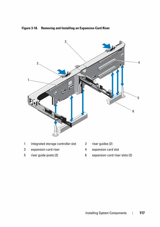
book.book Page 117 Tuesday, August 24, 2010 1:47 PM
Figure 3-18. Removing and Installing an Expansion-Card Riser
1 integrated storage controller slot 2 riser guides (2)
3 expansion-card riser 4 expansion card slot
5 riser guide posts (2) 6 expansion-card riser slots (2)
6
1
2
3
5
4
Installing System Components 117
1
book.book Page 118 Tuesday, August 24, 2010 1:47 PM
Installing an Expansion-Card Riser
CAUTION: Many repairs may only be done by a certified service technician. You should only perform troubleshooting and simple repairs as authorized in your product documentation, or as directed by the online or telephone service and support team. Damage due to servicing that is not authorized by Dell is not covered by your warranty. Read and follow the safety instructions that came with the product.
1 To install an expansion-card riser, align the riser guides with the riser guide posts on the system board. See Figure 3-18.
2 Lower the expansion-card riser into place until the expansion-card riser connector is fully seated.
3 If applicable, reinstall the expansion card. See "Installing an Expansion Card" on page 113.
4 Reinstall the storage controller card. See "Installing the Storage Controller Card" on page 121.
5 Reconnect all cables.
6 Replace the cooling shroud. See "Installing the Cooling Shroud" on page 87.
7 Close the system. See "Closing the System" on page 85.
8 Reconnect the system to its electrical outlet and turn the system on, including any attached peripherals.
18 Installing System Components
book.book Page 119 Tuesday, August 24, 2010 1:47 PM
Integrated Storage Controller CardYour system includes a dedicated expansion-card slot on the riser for an integrated SAS or RAID controller card that provides the integrated storage subsystem for your system’s hard drives. The controller supports SAS and SATA hard drives and also enables you to set up the hard drives in RAID configurations as supported by the version of the storage controller included with your system.
Removing the Storage Controller Card
CAUTION: Many repairs may only be done by a certified service technician. You should only perform troubleshooting and simple repairs as authorized in your product documentation, or as directed by the online or telephone service and support team. Damage due to servicing that is not authorized by Dell is not covered by your warranty. Read and follow the safety instructions that came with the product.
1 Turn off the system, including any attached peripherals, and disconnect the system from the electrical outlet.
2 Open the system. See "Opening the System" on page 83.
3 If installed, remove the expansion card. See "Removing an Expansion Card" on page 115.
4 Disconnect the SAS cables connected to the card.
5 Disconnect the cable connecting the card to the expansion-card riser.
6 For a battery-cached RAID controller, disconnect the cable connecting the card to the RAID battery.
7 Bend both the card-edge guides outward and pull the storage controller card out of the connector.
Installing System Components 119
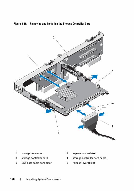
1
book.book Page 120 Tuesday, August 24, 2010 1:47 PM
Figure 3-19. Removing and Installing the Storage Controller Card
1 storage connector 2 expansion-card riser
3 storage controller card 4 storage controller card cable
5 SAS data cable connector 6 release lever (blue)
1
2
3
6
5
4
20 Installing System Components
book.book Page 121 Tuesday, August 24, 2010 1:47 PM
Installing the Storage Controller Card
CAUTION: Many repairs may only be done by a certified service technician. You should only perform troubleshooting and simple repairs as authorized in your product documentation, or as directed by the online or telephone service and support team. Damage due to servicing that is not authorized by Dell is not covered by your warranty. Read and follow the safety instructions that came with the product.
1 Turn off the system, including any attached peripherals, and disconnect the system from the electrical outlet.
2 Open the system. See "Opening the System" on page 83.
3 If installed, remove the expansion card. See "Removing an Expansion Card" on page 115.
4 Route the cables in the cable path under the storage controller card slot on the expansion card riser.
5 With the storage controller card edge facing the riser, insert one side of the card into the black card-edge guide.
NOTE: For expansion-card riser 1, the installation sequence must be slot 3, 2, 1, and 4. The storage controller card must be installed in slot 4 after the other expansion cards have been installed.
6 Bend outward on the blue card-edge guide, lower the card onto the blue card-edge guide, and release the guide. See Figure 3-19.
7 Slide the storage controller’s card edge connector into the card slot on the riser until the card is fully seated.
8 Connect the two SAS data cable connectors, CNTRL 0 and CNTRL 1, to the storage controller card. See Figure 3-19.
NOTE: Ensure that you connect the cables according to the connector labels on the cable. The cables do not function properly if reversed.
9 For a battery-cached RAID controller, connect the RAID battery cable to the controller card.
Installing System Components 121
1
book.book Page 122 Tuesday, August 24, 2010 1:47 PM
10 Replace the expansion card. See "Installing an Expansion Card" on page 113.
11 Close the system. See "Closing the System" on page 85.
12 Reconnect the system to its electrical outlet and turn the system on, including any attached peripherals.
iDRAC6 Express Card (Optional)
Installing an iDRAC6 Express Card
CAUTION: Many repairs may only be done by a certified service technician. You should only perform troubleshooting and simple repairs as authorized in your product documentation, or as directed by the online or telephone service and support team. Damage due to servicing that is not authorized by Dell is not covered by your warranty. Read and follow the safety instructions that came with the product.
1 Turn off the system, including any attached peripherals, and disconnect the system from the electrical outlet.
2 Open the system. See "Opening the System" on page 83.
3 If installed, remove all expansion cards from expansion-card riser. "Removing an Expansion Card" on page 115.
4 Insert the notch on the iDRAC6 Express card into the clip on the system board.
5 Align the front edge of the card with the connector on the system board. See Figure 6-1 for the location of the connector.
6 Press the card down until it is fully seated. See Figure 3-20.
When the front of the card is fully seated, the plastic standoff tab snaps over the edge of the holder.
22 Installing System Components
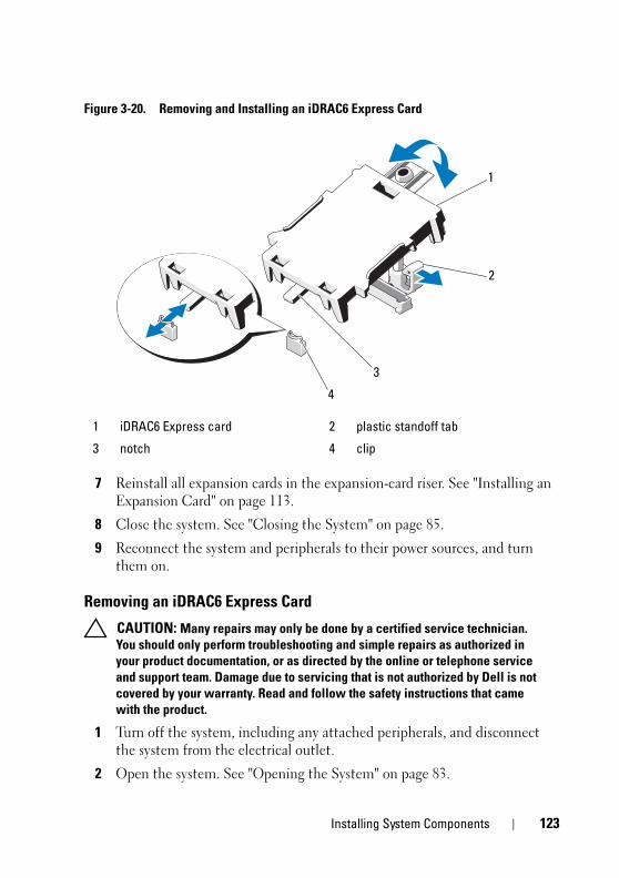
book.book Page 123 Tuesday, August 24, 2010 1:47 PM
Figure 3-20. Removing and Installing an iDRAC6 Express Card
7 Reinstall all expansion cards in the expansion-card riser. See "Installing an Expansion Card" on page 113.
8 Close the system. See "Closing the System" on page 85.
9 Reconnect the system and peripherals to their power sources, and turn them on.
Removing an iDRAC6 Express Card
CAUTION: Many repairs may only be done by a certified service technician. You should only perform troubleshooting and simple repairs as authorized in your product documentation, or as directed by the online or telephone service and support team. Damage due to servicing that is not authorized by Dell is not covered by your warranty. Read and follow the safety instructions that came with the product.
1 Turn off the system, including any attached peripherals, and disconnect the system from the electrical outlet.
2 Open the system. See "Opening the System" on page 83.
1 iDRAC6 Express card 2 plastic standoff tab
3 notch 4 clip
4
2
1
3
Installing System Components 123
1
book.book Page 124 Tuesday, August 24, 2010 1:47 PM
3 Pull back slightly on the retention standoff tab at the front edge of the card and gently lift the card off the retention standoff. See Figure 3-20.
As the holder releases from the standoff, the connector under the card disengages from the system board connector.
4 Angle the card so that the notch on the card slips through the clip on the system board.
5 Replace the expansion cards. See "Installing an Expansion Card" on page 113.
6 Close the system. See "Closing the System" on page 85.
7 Reconnect the system and peripherals to their power sources, and turn them on.
iDRAC6 Enterprise Card (Optional)
Installing an iDRAC6 Enterprise Card
CAUTION: Many repairs may only be done by a certified service technician. You should only perform troubleshooting and simple repairs as authorized in your product documentation, or as directed by the online or telephone service and support team. Damage due to servicing that is not authorized by Dell is not covered by your warranty. Read and follow the safety instructions that came with the product.
1 Turn off the system, including any attached peripherals, and disconnect the system from the electrical outlet.
2 Open the system. See "Opening the System" on page 83.
3 Remove the cooling shroud. See "Removing the Cooling Shroud" on page 86.
4 Remove the plastic filler plug of the iDRAC6 Enterprise port from the system back panel.
5 Angle the card so that the RJ-45 connector fits through the back-panel opening. See Figure 3-21.
6 Align the front edge of the card with the two front plastic retention standoffs next to the iDRAC6 connector on the system board, and lower the card into place. See Figure 3-21.
When the front of the card is fully seated, the plastic standoffs snap over the edge of the card.
24 Installing System Components
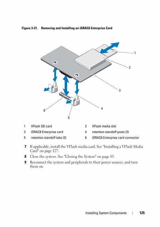
book.book Page 125 Tuesday, August 24, 2010 1:47 PM
Figure 3-21. Removing and Installing an iDRAC6 Enterprise Card
7 If applicable, install the VFlash media card. See "Installing a VFlash Media Card" on page 127.
8 Close the system. See "Closing the System" on page 85.9 Reconnect the system and peripherals to their power sources, and turn
them on.
1 VFlash SD card 2 VFlash media slot
3 iDRAC6 Enterprise card 4 retention standoff posts (2)
5 retention standoff tabs (2) 6 iDRAC6 Enterprise card connector
3
2
1
4
5
6
Installing System Components 125
1
book.book Page 126 Tuesday, August 24, 2010 1:47 PM
Removing an iDRAC6 Enterprise Card CAUTION: Many repairs may only be done by a certified service technician.
You should only perform troubleshooting and simple repairs as authorized in your product documentation, or as directed by the online or telephone service and support team. Damage due to servicing that is not authorized by Dell is not covered by your warranty. Read and follow the safety instructions that came with the product.
1 Turn off the system, including any attached peripherals, and disconnect the system from the electrical outlet.
2 If present, disconnect the Ethernet cable from the iDRAC6 enterprise card connector on the system back panel. See Figure 1-5.
3 Open the system. See "Opening the System" on page 83.
4 Remove the cooling shroud. See "Removing the Cooling Shroud" on page 86.
5 Remove the VFlash media card (if installed) from the iDRAC6 enterprise card. See "Removing a VFlash Media Card" on page 127.
6 Pull back slightly on the two tabs at the front edge of the card and gently lift the front edge of the card off of the retention standoffs.As the card releases from the standoffs, the connector under the card disengages from the system board connector.
7 Slide the card away from the back of the system until the RJ-45 connector is clear of the back panel, then lift the card out of the system.
8 Replace the plastic filler plug over the port at the system back panel. See "Back-Panel Features and Indicators" on page 20 for the location of the port.
9 Replace the cooling shroud. See "Installing the Cooling Shroud" on page 87.
10 Close the system. See "Closing the System" on page 85.
11 Reconnect the system and peripherals to their power sources, and turn them on.
26 Installing System Components
book.book Page 127 Tuesday, August 24, 2010 1:47 PM
VFlash Media (Optional)The VFlash media card is a Secure Digital (SD) card that plugs into the iDRAC6 Enterprise card at the back corner of the system.
Installing a VFlash Media Card1 Locate the VFlash media slot at the back of the system.
2 With the label side facing up, insert the contact-pin end of the SD card into the card slot on the module.
NOTE: The slot is keyed to ensure correct insertion of the card.
3 Press inward on the card to lock it into the slot.
Removing a VFlash Media CardTo remove the VFlash media, push inward on the card to release it, and pull the card from the card slot.
Internal USB Memory Key Optional USB memory keys installed inside your system can be used as a boot device, security key, or mass storage device. The USB connector must be enabled by the Internal USB Port option in the Integrated Devices screen of the System Setup program.
To boot from the USB memory key, configure the USB memory key with a boot image and then specify the USB memory key in the boot sequence in the System Setup program.
CAUTION: Many repairs may only be done by a certified service technician. You should only perform troubleshooting and simple repairs as authorized in your product documentation, or as directed by the online or telephone service and support team. Damage due to servicing that is not authorized by Dell is not covered by your warranty. Read and follow the safety instructions that came with the product.
1 Turn off the system, including any attached peripherals, and disconnect the system from the electrical outlet.
2 Open the system. See "Opening the System" on page 83.
3 Locate the USB connector on the control panel or SAS backplane, based on your system configuration. See Figure 3-28 or Figure 3-30.
Installing System Components 127
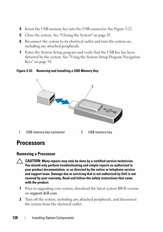
1
book.book Page 128 Tuesday, August 24, 2010 1:47 PM
4 Insert the USB memory key into the USB connector. See Figure 3-22.
5 Close the system. See "Closing the System" on page 85.
6 Reconnect the system to its electrical outlet and turn the system on, including any attached peripherals.
7 Enter the System Setup program and verify that the USB key has been detected by the system. See "Using the System Setup Program Navigation Keys" on page 58.
Figure 3-22. Removing and Installing a USB Memory Key
Processors
Removing a Processor
CAUTION: Many repairs may only be done by a certified service technician. You should only perform troubleshooting and simple repairs as authorized in your product documentation, or as directed by the online or telephone service and support team. Damage due to servicing that is not authorized by Dell is not covered by your warranty. Read and follow the safety instructions that came with the product.
1 Prior to upgrading your system, download the latest system BIOS version on support.dell.com.
2 Turn off the system, including any attached peripherals, and disconnect the system from the electrical outlet.
1 USB memory key connector 2 USB memory key
2
1
28 Installing System Components
book.book Page 129 Tuesday, August 24, 2010 1:47 PM
3 Open the system. See "Opening the System" on page 83.
4 Remove the cooling shroud. See "Removing the Cooling Shroud" on page 86.
WARNING: The heat sink and processor are hot to touch for some time after the system has been powered down. Allow the heat sink and processor to cool before handling them.
CAUTION: Never remove the heat sink from a processor unless you intend to remove the processor. The heat sink is necessary to maintain proper thermal conditions.
5 Using a #2 Phillips screwdriver, loosen one of the heat-sink retention screws. See Figure 3-23.
6 Wait 30 seconds for the heat sink to loosen from the processor.
7 Loosen the other three heat-sink retention screws.
8 Gently lift the heat sink off of the processor and set the heat sink aside with thermal grease side facing up.
CAUTION: The processor is held in its socket under strong pressure. Be aware that the release lever can spring up suddenly if not firmly grasped.
9 Position your thumb firmly over the processor socket-release lever and release the lever from the locked position. Rotate the lever 90 degrees upward until the processor is released from the socket. See Figure 3-24.
Installing System Components 129
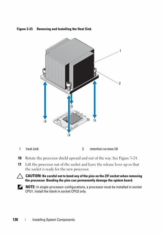
1
book.book Page 130 Tuesday, August 24, 2010 1:47 PM
Figure 3-23. Removing and Installing the Heat Sink
10 Rotate the processor shield upward and out of the way. See Figure 3-24.
11 Lift the processor out of the socket and leave the release lever up so that the socket is ready for the new processor.
CAUTION: Be careful not to bend any of the pins on the ZIF socket when removing the processor. Bending the pins can permanently damage the system board.
NOTE: In single-processor configurations, a processor must be installed in socket CPU1. Install the blank in socket CPU2 only.
1 heat sink 2 retention screws (4)
2
1
30 Installing System Components
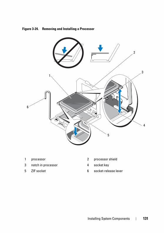
book.book Page 131 Tuesday, August 24, 2010 1:47 PM
Figure 3-24. Removing and Installing a Processor
1 processor 2 processor shield
3 notch in processor 4 socket key
5 ZIF socket 6 socket-release lever
2
1
6
3
4
5
Installing System Components 131
1
book.book Page 132 Tuesday, August 24, 2010 1:47 PM
Installing a Processor
CAUTION: Many repairs may only be done by a certified service technician. You should only perform troubleshooting and simple repairs as authorized in your product documentation, or as directed by the online or telephone service and support team. Damage due to servicing that is not authorized by Dell is not covered by your warranty. Read and follow the safety instructions that came with the product.
1 If you are upgrading your processors, prior to upgrading your system, download and install the latest system BIOS version from support.dell.com. Follow the instructions included in the file download to install the update on your system.
NOTE: In single-processor configurations, socket CPU1 must be used.
2 Unpack the processor if it has not been used previously.
If the processor has already been used, remove any thermal grease from the top of the processor using a lint-free cloth.
3 Align the processor with the socket keys on the ZIF socket. See Figure 3-24.
CAUTION: Positioning the processor incorrectly can permanently damage the system board or the processor. Be careful not to bend the pins in the ZIF socket.
4 With the release lever on the processor socket in the open position, align the processor with the socket keys and set the processor lightly in the socket.
CAUTION: Do not use force to seat the processor. When the processor is positioned correctly, it engages easily into the socket.
5 Close the processor shield.
6 Rotate the socket release lever down until it snaps into place.
7 Using a clean lint-free cloth, remove the thermal grease from the heat sink.
8 Open the grease packet included with your processor kit and apply thermal grease evenly to the center of the top of the new processor.
CAUTION: Using excess thermal grease can cause grease to contact the processor shield, which can cause contamination of the processor socket.
9 Place the heat sink on the processor. See Figure 3-23.
32 Installing System Components
book.book Page 133 Tuesday, August 24, 2010 1:47 PM
10 Using a #2 Phillips screwdriver, tighten the heat-sink retention screws. See Figure 3-23.
11 Replace the cooling shroud. See "Installing the Cooling Shroud" on page 87.
12 Close the system. See "Closing the System" on page 85.
13 Reconnect the system to its electrical outlet and turn the system on, including any attached peripherals.
14 Press <F2> to enter the System Setup program, and check that the processor information matches the new system configuration. See "Entering the System Setup Program" on page 58.
15 Run the system diagnostics to verify that the new processor operates correctly.
See "Running the Embedded System Diagnostics" on page 178 for information about running the diagnostics.
System Battery
Replacing the System Battery
WARNING: There is a danger of a new battery exploding if it is incorrectly installed. Replace the battery only with the same or equivalent type recommended by the manufacturer. See your safety information for additional info.
CAUTION: Many repairs may only be done by a certified service technician. You should only perform troubleshooting and simple repairs as authorized in your product documentation, or as directed by the online or telephone service and support team. Damage due to servicing that is not authorized by Dell is not covered by your warranty. Read and follow the safety instructions that came with the product.
1 Turn off the system, including any attached peripherals, and disconnect the system from the electrical outlet.
2 Open the system. See "Opening the System" on page 83.
3 Remove the cooling shroud. See "Removing the Cooling Shroud" on page 86.
Installing System Components 133
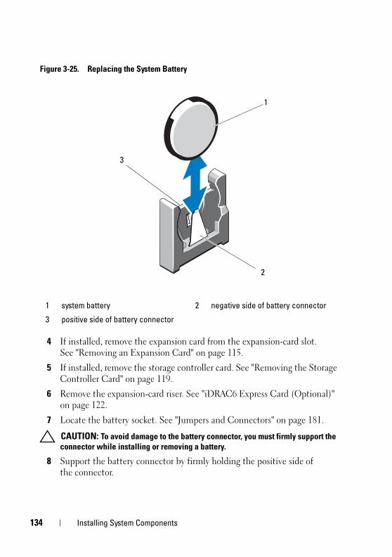
1
book.book Page 134 Tuesday, August 24, 2010 1:47 PM
Figure 3-25. Replacing the System Battery
4 If installed, remove the expansion card from the expansion-card slot. See "Removing an Expansion Card" on page 115.
5 If installed, remove the storage controller card. See "Removing the Storage Controller Card" on page 119.
6 Remove the expansion-card riser. See "iDRAC6 Express Card (Optional)" on page 122.
7 Locate the battery socket. See "Jumpers and Connectors" on page 181.
CAUTION: To avoid damage to the battery connector, you must firmly support the connector while installing or removing a battery.
8 Support the battery connector by firmly holding the positive side of the connector.
1 system battery 2 negative side of battery connector
3 positive side of battery connector
2
1
3
34 Installing System Components
book.book Page 135 Tuesday, August 24, 2010 1:47 PM
9 Press the battery toward the negative side of the connector and lift it out of the securing tab.
10 Support the battery connector by pressing down firmly on the positive side of the connector.
11 Hold the new battery with the "+" facing the plastic connector on the system board and slide it under the securing tabs.
12 Press the battery straight down into the connector until it snaps into place.
13 Replace the expansion-card riser. See "Installing an Expansion-Card Riser" on page 118.
14 Replace the storage controller card. See "Installing the Storage Controller Card" on page 121.
15 Replace the expansion card from the expansion-card slot. See "Installing an Expansion Card" on page 113.
16 Replace the cooling shroud. See "Installing the Cooling Shroud" on page 87.
17 Close the system. See "Closing the System" on page 85.
18 Reconnect the system to the electrical outlet and turn the system on, including any attached peripherals.
19 Enter the System Setup program to confirm that the battery is operating properly. See "Entering the System Setup Program" on page 58.
20 Enter the correct time and date in the System Setup program's Time and Date fields.
21 Exit the System Setup program.
Installing System Components 135
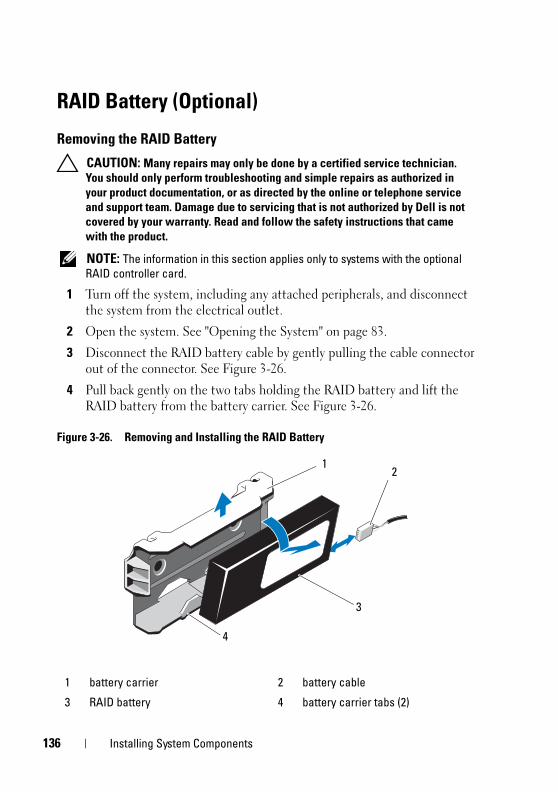
1
book.book Page 136 Tuesday, August 24, 2010 1:47 PM
RAID Battery (Optional)
Removing the RAID Battery
CAUTION: Many repairs may only be done by a certified service technician. You should only perform troubleshooting and simple repairs as authorized in your product documentation, or as directed by the online or telephone service and support team. Damage due to servicing that is not authorized by Dell is not covered by your warranty. Read and follow the safety instructions that came with the product.
NOTE: The information in this section applies only to systems with the optional RAID controller card.
1 Turn off the system, including any attached peripherals, and disconnect the system from the electrical outlet.
2 Open the system. See "Opening the System" on page 83.
3 Disconnect the RAID battery cable by gently pulling the cable connector out of the connector. See Figure 3-26.
4 Pull back gently on the two tabs holding the RAID battery and lift the RAID battery from the battery carrier. See Figure 3-26.
Figure 3-26. Removing and Installing the RAID Battery
1 battery carrier 2 battery cable
3 RAID battery 4 battery carrier tabs (2)
3
2
4
1
36 Installing System Components
book.book Page 137 Tuesday, August 24, 2010 1:47 PM
Installing the RAID Battery
CAUTION: Many repairs may only be done by a certified service technician. You should only perform troubleshooting and simple repairs as authorized in your product documentation, or as directed by the online or telephone service and support team. Damage due to servicing that is not authorized by Dell is not covered by your warranty. Read and follow the safety instructions that came with the product.
1 Insert the RAID battery into the battery carrier until it locks into place. See Figure 3-26.
2 Connect the cable to the battery. See Figure 3-26.
3 Close the system. See "Closing the System" on page 85.
4 Reconnect the system to its electrical outlet and turn the system on, including any attached peripherals.
Control Panel Assembly—LED NOTE: This section applies to twelve–hard-drive systems only.
Removing the Control-Panel Module–LED
CAUTION: Many repairs may only be done by a certified service technician. You should only perform troubleshooting and simple repairs as authorized in your product documentation, or as directed by the online or telephone service and support team. Damage due to servicing that is not authorized by Dell is not covered by your warranty. Read and follow the safety instructions that came with the product.
1 If applicable, remove the front bezel. See "Removing the Front Bezel" on page 82.
2 Turn off the system and attached peripherals, and disconnect the system from the electrical outlet and peripherals.
3 Remove the single screw securing the bracket to the module and remove the bracket.
4 Disconnect the control-panel cable at back of the module by using the pull tab. See Figure 3-27.
CAUTION: Do not pull on the cable to unseat the connector. Doing so can damage the cable.
Installing System Components 137
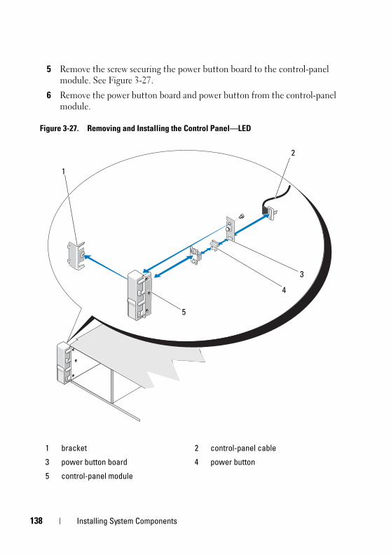
1
book.book Page 138 Tuesday, August 24, 2010 1:47 PM
5 Remove the screw securing the power button board to the control-panel module. See Figure 3-27.
6 Remove the power button board and power button from the control-panel module.
Figure 3-27. Removing and Installing the Control Panel—LED
1 bracket 2 control-panel cable
3 power button board 4 power button
5 control-panel module
1
2
4
3
5
38 Installing System Components
book.book Page 139 Tuesday, August 24, 2010 1:47 PM
Installing the Control-Panel Module–LED
CAUTION: Many repairs may only be done by a certified service technician. You should only perform troubleshooting and simple repairs as authorized in your product documentation, or as directed by the online or telephone service and support team. Damage due to servicing that is not authorized by Dell is not covered by your warranty. Read and follow the safety instructions that came with the product.
1 Assemble the power button and power button board in the control-panel module.
2 Tighten the screw to secure the power button board to the control-panel module. See Figure 3-27.
3 Connect the control-panel cable to the control-panel module.
4 Replace the bracket and tighten the single screw to secure the bracket to the back of the control-panel module.
5 Reconnect the system to the power source and turn on the system and attached peripherals.
6 If applicable, replace the front bezel. See "Installing the Front Bezel" on page 83.
Installing System Components 139
1
book.book Page 140 Tuesday, August 24, 2010 1:47 PM
Control Panel Assembly—LCD (Optional) NOTE: This section applies to eight–hard-drive systems only.
NOTE: The control panel assembly consists of two separate modules—the display module and the control panel circuit board. Use the following instructions to remove and install either module.
Removing the Control Panel Display Module
CAUTION: Many repairs may only be done by a certified service technician. You should only perform troubleshooting and simple repairs as authorized in your product documentation, or as directed by the online or telephone service and support team. Damage due to servicing that is not authorized by Dell is not covered by your warranty. Read and follow the safety instructions that came with the product.
1 Turn off the system and attached peripherals, and disconnect the system from the electrical outlet and peripherals.
2 If applicable, remove the front bezel. See "Removing the Front Bezel" on page 82.
3 Open the system. See "Opening the System" on page 83.
4 Disconnect the display module cable from the control panel board. See Figure 3-28.
5 Using a knife or a small flat-blade screwdriver, insert the blade beneath the front panel of the display and slide the blade across the bottom to lift the panel outward. See Figure 3-28.
6 Remove the front panel plate until it separates from the display module to allow access to the mounting screws.
7 Remove the two screws that secure the display module to the system chassis.
8 Remove the display module from the chassis cutout.
40 Installing System Components
book.book Page 141 Tuesday, August 24, 2010 1:47 PM
Installing the Control Panel Display Module
CAUTION: Many repairs may only be done by a certified service technician. You should only perform troubleshooting and simple repairs as authorized in your product documentation, or as directed by the online or telephone service and support team. Damage due to servicing that is not authorized by Dell is not covered by your warranty. Read and follow the safety instructions that came with the product.
1 Insert the display module into the chassis cutout and secure it with the Torx screw. See Figure 3-28.
2 Attach the replacement panel to the front of the display module.
3 Connect the display module cable to the control panel board.
4 Close the system. See "Closing the System" on page 85.
5 Reconnect the system to the power source and turn on the system and attached peripherals.
6 If applicable, install the front bezel. See "Installing the Front Bezel" on page 83.
Removing the Control Panel Assembly
CAUTION: Many repairs may only be done by a certified service technician. You should only perform troubleshooting and simple repairs as authorized in your product documentation, or as directed by the online or telephone service and support team. Damage due to servicing that is not authorized by Dell is not covered by your warranty. Read and follow the safety instructions that came with the product.
1 Turn off the system and attached peripherals, and disconnect the system from the electrical outlet and peripherals.
2 Open the system. See "Opening the System" on page 83.
3 Disconnect the control panel cable at the back of the control panel board by pressing the metal tabs on the ends of the cable connector and gently working the connector out of the socket.
CAUTION: Do not pull on the cable to unseat the connector. Doing so can damage the cable.
4 Disconnect the USB cable at the back of the control panel board. See Figure 3-28.
Installing System Components 141
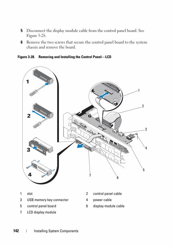
1
book.book Page 142 Tuesday, August 24, 2010 1:47 PM
5 Disconnect the display module cable from the control panel board. See Figure 3-28.
6 Remove the two screws that secure the control panel board to the system chassis and remove the board.
Figure 3-28. Removing and Installing the Control Panel—LCD
1 slot 2 control panel cable
3 USB memory key connector 4 power cable
5 control panel board 6 display module cable
7 LCD display module
1
6
5
2
7
4
3
42 Installing System Components
book.book Page 143 Tuesday, August 24, 2010 1:47 PM
Installing the Control Panel Assembly
CAUTION: Many repairs may only be done by a certified service technician. You should only perform troubleshooting and simple repairs as authorized in your product documentation, or as directed by the online or telephone service and support team. Damage due to servicing that is not authorized by Dell is not covered by your warranty. Read and follow the safety instructions that came with the product.
1 Install the control panel board in the system chassis and secure it with the two screws. See Figure 3-28.
2 Connect the display module cable to the control panel board. See Figure 3-28.
3 Connect the control panel cable to the control panel board. See Figure 3-28.
4 Connect the USB cable to the control panel board. See Figure 3-28.
5 Close the system. See "Closing the System" on page 85.
6 Reconnect the system to the power source and turn on the system and attached peripherals.
SAS Backplane
Removing the SAS Backplane
CAUTION: Many repairs may only be done by a certified service technician. You should only perform troubleshooting and simple repairs as authorized in your product documentation, or as directed by the online or telephone service and support team. Damage due to servicing that is not authorized by Dell is not covered by your warranty. Read and follow the safety instructions that came with the product.
1 If applicable, remove the front bezel. See "Removing the Front Bezel" on page 82.
2 Turn off the system and attached peripherals, and disconnect the system from the electrical outlet.
Installing System Components 143
1
book.book Page 144 Tuesday, August 24, 2010 1:47 PM
3 Open the system. See "Opening the System" on page 83.
CAUTION: To prevent damage to the drives and backplane, you must remove the hard drives from the system before removing the backplane.
CAUTION: You must note the number of each hard drive and temporarily label them before removal so that you can replace them in the same locations.
4 Remove all hard drives. See "Removing a Hard Drive" on page 88.
5 Disconnect the power cable from the end of the SAS backplane.
6 Disconnect the SAS data cables from the backplane.
7 Disconnect the optical-drive cable, USB cable, and the control-panel cable.
CAUTION: Handle the cables gently to prevent damage.
NOTE: In case of the twelve–hard-drive systems, disconnect the internal hard-drive cables.
8 While pressing the two blue latches toward each other, lift the backplane upward. See Figure 3-30.
9 When the backplane cannot slide upward any farther, pull the backplane toward the back of the system to remove it from the retention hooks.
10 Lift the board out of the system, being careful to avoid damaging components on the face of the board.
11 Place the SAS backplane face down on a work surface.
44 Installing System Components
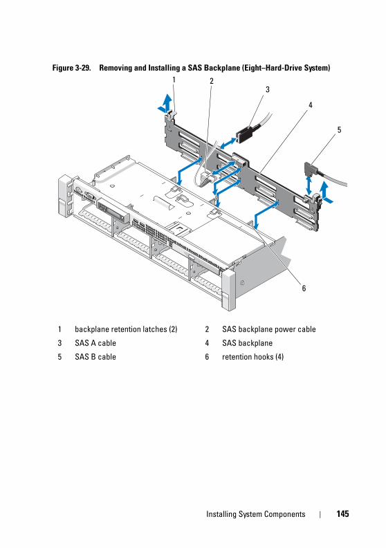
book.book Page 145 Tuesday, August 24, 2010 1:47 PM
Figure 3-29. Removing and Installing a SAS Backplane (Eight–Hard-Drive System)
1 backplane retention latches (2) 2 SAS backplane power cable
3 SAS A cable 4 SAS backplane
5 SAS B cable 6 retention hooks (4)
23
1
4
6
5
Installing System Components 145
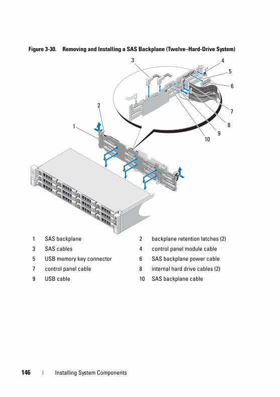
1
book.book Page 146 Tuesday, August 24, 2010 1:47 PM
Figure 3-30. Removing and Installing a SAS Backplane (Twelve–Hard-Drive System)
1 SAS backplane 2 backplane retention latches (2)
3 SAS cables 4 control panel module cable
5 USB memory key connector 6 SAS backplane power cable
7 control panel cable 8 internal hard drive cables (2)
9 USB cable 10 SAS backplane cable
1
3
72
89
6
4
10
5
46 Installing System Components
book.book Page 147 Tuesday, August 24, 2010 1:47 PM
Installing the SAS Backplane
CAUTION: Many repairs may only be done by a certified service technician. You should only perform troubleshooting and simple repairs as authorized in your product documentation, or as directed by the online or telephone service and support team. Damage due to servicing that is not authorized by Dell is not covered by your warranty. Read and follow the safety instructions that came with the product.
1 Lower the backplane into the system, being careful to avoid damaging components on the face of the board.
2 Align the slots in the backplane with the retention hooks on the back of the drive bays, then move the backplane forward until the retention hooks fit through the slots in the backplane. See Figure 3-30.
3 Slide the backplane downward until the two blue retention latches snap into place.
4 Connect the SAS data and power cables to the SAS backplane.
5 Install the hard drives in their original locations.
6 Connect the optical drive cable, USB cable, and the control panel cable to the system board.
CAUTION: Handle the cables gently to prevent damage.
NOTE: In case of the twelve–hard-drive systems, connect the internal hard-drive cables.
7 Close the system. See "Closing the System" on page 85.
8 Reconnect the system to its electrical outlet and turn the system on, including any attached peripherals.
9 If applicable, install the front bezel. See "Installing the Front Bezel" on page 83.
Installing System Components 147
1
book.book Page 148 Tuesday, August 24, 2010 1:47 PM
Power Distribution BoardThe power distribution board is located on your system directly behind the power supply fan module. See Figure 3-32.
Removing the Power Distribution Board
CAUTION: Many repairs may only be done by a certified service technician. You should only perform troubleshooting and simple repairs as authorized in your product documentation, or as directed by the online or telephone service and support team. Damage due to servicing that is not authorized by Dell is not covered by your warranty. Read and follow the safety instructions that came with the product.
1 Turn off the system and attached peripherals, and disconnect the system from the electrical outlet.
2 Open the system. See "Opening the System" on page 83.
3 If applicable, remove the internal hard drive bay and support carrier. See "Removing an Internal Hard-Drive Bay" on page 91.
4 If applicable, remove the thumb screw on the support bracket and lift it up and out of the system.
5 Remove the power supplies from the system. See "Removing a Power Supply" on page 102.
6 Remove the expansion cards. See "Removing an Expansion Card" on page 115.
7 Remove the expansion card riser. See "iDRAC6 Express Card (Optional)" on page 122.
8 Disconnect power distribution cables from the system board (see "System Board" on page 152).
9 Disconnect the fan cable.10 Remove the screws securing the power distribution board to the chassis.
See Figure 3-31 and Figure 3-32.
NOTE: The twelve–hard-drive systems have three screws securing the power distribution board to the chassis. The eight–hard-drive systems have four securing screws securing the power distribution board to the chassis.
48 Installing System Components
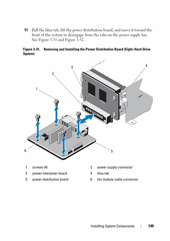
book.book Page 149 Tuesday, August 24, 2010 1:47 PM
11 Pull the blue tab, lift the power distribution board, and move it toward the front of the system to disengage from the tabs on the power supply bay. See Figure 3-31 and Figure 3-32.
Figure 3-31. Removing and Installing the Power Distribution Board (Eight–Hard-Drive System)
1 screws (4) 2 power supply connector
3 power-interposer board 4 blue tab
5 power-distribution board 6 fan module cable connector
6
2
1
5
43
Installing System Components 149
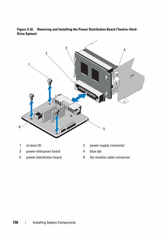
1
book.book Page 150 Tuesday, August 24, 2010 1:47 PM
Figure 3-32. Removing and Installing the Power Distribution Board (Twelve–Hard-Drive System)
1 screws (3) 2 power supply connector
3 power-interposer board 4 blue tab
5 power-distribution board 6 fan module cable connector
6
2
1
5
43
50 Installing System Components
book.book Page 151 Tuesday, August 24, 2010 1:47 PM
Replacing the Power Distribution Board
CAUTION: Many repairs may only be done by a certified service technician. You should only perform troubleshooting and simple repairs as authorized in your product documentation, or as directed by the online or telephone service and support team. Damage due to servicing that is not authorized by Dell is not covered by your warranty. Read and follow the safety instructions that came with the product.
1 Unpack the new power distribution board assembly.
2 Align the power distribution board with the tabs on the chassis and slide it in place until the blue tab snaps over the edge of the board. See Figure 3-32.
3 Install the four screws that secure the power distribution board to the chassis. See Figure 3-31 and Figure 3-32.
NOTE: The twelve–hard-drive systems have only three screws securing the power distribution board to the chassis.
4 Connect the power distribution cables to the system board (see "System Board" on page 152) and fan cable to the power distribution board as shown in Figure 3-31 and Figure 3-32.
5 If applicable, align the support bracket over the power distribution board and secure in place with the screw.
6 If applicable, install the internal hard-drive bay. See "Installing an Internal Hard-Drive Bay" on page 93.
7 Install the power supplies in the system. See "Installing a Power Supply" on page 103.
8 Replace the expansion-card riser. See "Installing an Expansion-Card Riser" on page 118.
9 Replace the expansion cards. See "Installing an Expansion Card" on page 113.
10 Close the system. See "Closing the System" on page 85.
11 Reconnect the system to its electrical outlet and turn the system on, including any attached peripherals.
Installing System Components 151
1
book.book Page 152 Tuesday, August 24, 2010 1:47 PM
System Board
Removing the System Board
CAUTION: Many repairs may only be done by a certified service technician. You should only perform troubleshooting and simple repairs as authorized in your product documentation, or as directed by the online or telephone service and support team. Damage due to servicing that is not authorized by Dell is not covered by your warranty. Read and follow the safety instructions that came with the product.
CAUTION: If you are using the Trusted Program Module (TPM) with an encryption key, you may be prompted to create a recovery key during program or system setup. Be sure to create and safely store this recovery key. If you replace this system board, you must supply the recovery key when you restart your system or program before you can access the encrypted data on your hard drives.
1 Turn off the system and attached peripherals, and disconnect the system from the electrical outlet.
2 Open the system. See "Opening the System" on page 83.
3 Remove the cooling shroud. See "Removing the Cooling Shroud" on page 86.
4 Remove the power supplies. See "Removing a Power Supply" on page 102 or "System Memory" on page 104.
5 Remove all expansion cards and, if applicable, the storage controller card. See "Removing an Expansion Card" on page 115 and "Removing the Storage Controller Card" on page 119.
6 Remove the expansion-card riser. See "iDRAC6 Express Card (Optional)" on page 122.
7 Remove the heat sinks, processors, and heat-sink blanks. See "Removing a Processor" on page 128.
8 If installed, remove the iDRAC6 Enterprise card. See "Removing an iDRAC6 Enterprise Card" on page 126.
9 If installed, remove the iDRAC6 Express card. See "Removing an iDRAC6 Express Card" on page 123.
10 Disconnect all cables from the system board.
52 Installing System Components
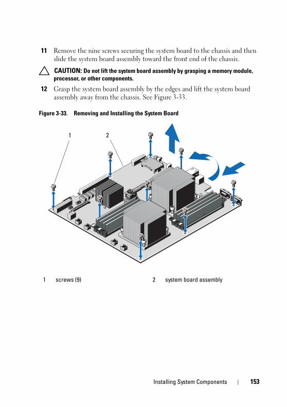
book.book Page 153 Tuesday, August 24, 2010 1:47 PM
11 Remove the nine screws securing the system board to the chassis and then slide the system board assembly toward the front end of the chassis.
CAUTION: Do not lift the system board assembly by grasping a memory module, processor, or other components.
12 Grasp the system board assembly by the edges and lift the system board assembly away from the chassis. See Figure 3-33.
Figure 3-33. Removing and Installing the System Board
1 screws (9) 2 system board assembly
1 2
Installing System Components 153
1
book.book Page 154 Tuesday, August 24, 2010 1:47 PM
Installing the System Board
CAUTION: Many repairs may only be done by a certified service technician. You should only perform troubleshooting and simple repairs as authorized in your product documentation, or as directed by the online or telephone service and support team. Damage due to servicing that is not authorized by Dell is not covered by your warranty. Read and follow the safety instructions that came with the product.
1 Unpack the new system board.
2 Remove the labels from the processor shield and affix them to the system identification panel on the front of the system. See Figure 1-1.
3 Holding the system board by the edges, lower it into the chassis.
CAUTION: Do not lift the system board assembly by grasping a memory module, processor, or other components.
4 Slightly lift up the front of the system board and maneuver the system board to the bottom of the chassis until it lays completely flat.
5 Push the system board toward the back of the chassis until the board is in place.
6 Tighten the nine screws that secure the system board to the chassis. See Figure 3-33.
7 Transfer the processors to the new system board. See "Removing a Processor" on page 128 and "Installing a Processor" on page 132.
8 Remove the memory modules and transfer them to the same locations on the new board. See "Removing Memory Modules" on page 110 and "Installing Memory Modules" on page 108.
9 Connect the cables to the system board. See Figure 6-1 for the locations of the connectors on the system board.
10 Replace the expansion-card riser. See "Installing an Expansion-Card Riser" on page 118.
11 Install all expansion cards. See "Installing an Expansion Card" on page 113.
12 If applicable, reinstall the storage controller card. See "Installing the Storage Controller Card" on page 121.
After connecting the SAS cables to the controller, ensure that you place the cables under the guide on the end of riser 1.
54 Installing System Components
book.book Page 155 Tuesday, August 24, 2010 1:47 PM
13 If applicable, install the iDRAC6 Enterprise card. See "Installing an iDRAC6 Enterprise Card" on page 124.
14 If applicable, install the iDRAC6 Express card. See "Installing an iDRAC6 Express Card" on page 122.
15 Replace the cooling shroud. See "Installing the Cooling Shroud" on page 87.
16 Close the system. See "Closing the System" on page 85.
17 Reconnect the system to its electrical outlet and turn the system on, including any attached peripherals.
Installing System Components 155

1
book.book Page 156 Tuesday, August 24, 2010 1:47 PM
56 Installing System Components
book.book Page 157 Tuesday, August 24, 2010 1:47 PM
4Troubleshooting Your System
Safety First—For You and Your System CAUTION: Many repairs may only be done by a certified service technician.
You should only perform troubleshooting and simple repairs as authorized in your product documentation, or as directed by the online or telephone service and support team. Damage due to servicing that is not authorized by Dell is not covered by your warranty. Read and follow the safety instructions that came with the product.
Troubleshooting System Startup FailureIf your system halts during startup prior to video imaging or LCD messaging, especially after installing an operating system or reconfiguring your system’s hardware, check for the following conditions.
• If you boot the system to the BIOS boot mode after installing an operating system from the UEFI Boot Manager, the system will hang. The reverse is also true. You must boot to the same boot mode in which you installed the operating system. See "Using the System Setup Program and UEFI Boot Manager" on page 57.
• Invalid memory configurations could cause the system to halt at startup without any video output. See "Expansion Cards and Expansion-Card Risers" on page 111.
For all other startup issues, note the LCD panel messages and any system messages that appear onscreen. See "LCD Status Messages (Optional)" on page 27 and "System Messages" on page 40 for more information.
Troubleshooting External ConnectionsEnsure that all external cables are securely attached to the external connectors on your system before troubleshooting any external devices. See Figure 1-1 and Figure 1-5 for the front- and back-panel connectors on your system.
Troubleshooting Your System 157
1
book.book Page 158 Tuesday, August 24, 2010 1:47 PM
Troubleshooting the Video Subsystem 1 Check the system and power connections to the monitor.
2 Check the video interface cabling from the system to the monitor.
3 Run the appropriate online diagnostic test. See "Using Online Diagnostics" on page 177.
If the tests run successfully, the problem is not related to video hardware.
If the tests fail, see "Getting Help" on page 187.
Troubleshooting a USB DeviceUse the following steps to troubleshoot a USB keyboard and/or mouse. For other USB devices, go to step 5.
1 Disconnect the keyboard and mouse cables from the system briefly and reconnect them.
2 Connect the keyboard/mouse to the USB port(s) on the opposite side of the system.
3 If the problem is resolved, restart the system, enter the System Setup program, and check if the nonfunctioning USB ports are enabled.
4 Replace the keyboard/mouse with another working keyboard/mouse.
If the problem is resolved, replace the faulty keyboard/mouse.
If the problem is not resolved, proceed to the next step to begin troubleshooting the other USB devices attached to the system.
5 Power down all attached USB devices and disconnect them from the system.
6 Restart the system and, if your keyboard is functioning, enter the system setup program. Verify that all USB ports are enabled. See "Integrated Devices Screen" on page 64.
If your keyboard is not functioning, you can also use remote access. If the system is not accessible, see "System Board Jumpers" on page 181 for instructions on setting the NVRAM_CLR jumper inside your system and restoring the BIOS to the default settings.
58 Troubleshooting Your System
book.book Page 159 Tuesday, August 24, 2010 1:47 PM
7 Reconnect and power on each USB device one at a time.
8 If a device causes the same problem, power down the device, replace the USB cable, and power up the device.
If the problem persists, replace the device.
If all troubleshooting fails, see "Getting Help" on page 187.
Troubleshooting a Serial I/O Device1 Turn off the system and any peripheral devices connected to the
serial port.
2 Swap the serial interface cable with another working cable, and turn on the system and the serial device.
If the problem is resolved, replace the interface cable.
3 Turn off the system and the serial device, and swap the device with a comparable device.
4 Turn on the system and the serial device.
If the problem is resolved, replace the serial device.
If the problem persists, see "Getting Help" on page 187.
Troubleshooting a NIC1 Run the appropriate online diagnostic test. See "Using Online Diagnostics"
on page 177.
2 Restart the system and check for any system messages pertaining to the NIC controller.
3 Check the appropriate indicator on the NIC connector. See "NIC Indicator Codes" on page 23.
• If the link indicator does not light, check all cable connections.
• If the activity indicator does not light, the network driver files might be damaged or missing.
Remove and reinstall the drivers if applicable. See the NIC's documentation.
Troubleshooting Your System 159
1
book.book Page 160 Tuesday, August 24, 2010 1:47 PM
• Change the auto-negotiation setting, if possible.
• Use another connector on the switch or hub.
If you are using a NIC card instead of an integrated NIC, see the documentation for the NIC card.
4 Ensure that the appropriate drivers are installed and the protocols are bound. See the NIC's documentation.
5 Enter the System Setup program and confirm that the NIC ports are enabled. See "Integrated Devices Screen" on page 64.
6 Ensure that the NICs, hubs, and switches on the network are all set to the same data transmission speed. See the documentation for each network device.
7 Ensure that all network cables are of the proper type and do not exceed the maximum length.
If all troubleshooting fails, see "Getting Help" on page 187.
Troubleshooting a Wet System CAUTION: Many repairs may only be done by a certified service technician.
You should only perform troubleshooting and simple repairs as authorized in your product documentation, or as directed by the online or telephone service and support team. Damage due to servicing that is not authorized by Dell is not covered by your warranty. Read and follow the safety instructions that came with the product.
1 Turn off the system and attached peripherals, and disconnect the system from the electrical outlet.
2 Open the system. See "Opening the System" on page 83.
3 Disassemble components from the system. See "Installing System Components" on page 79.
• Cooling shroud
• Hard drives
• SAS backplane
60 Troubleshooting Your System
book.book Page 161 Tuesday, August 24, 2010 1:47 PM
• VFlash media cards
• USB memory keys
• NIC hardware key
• Expansion-card riser
• Integrated storage controller card
• iDRAC6 Express card
• iDRAC6 Enterprise card
• Power supplies
• Fans
• Processors and heat sinks
• Memory modules
4 Let the system dry thoroughly for at least 24 hours.
5 Reinstall the components you removed in step 3.
6 Close the system. See "Closing the System" on page 85.
7 Reconnect the system to the electrical outlet, and turn on the system and attached peripherals.
If the system does not start properly, see "Getting Help" on page 187.
8 If the system starts properly, shut down the system and reinstall all of the expansion cards that you removed. See "Installing an Expansion Card" on page 113.
9 Run the appropriate online diagnostic test. See "Using Online Diagnostics" on page 177.
If the tests fail, see "Getting Help" on page 187.
Troubleshooting Your System 161
1
book.book Page 162 Tuesday, August 24, 2010 1:47 PM
Troubleshooting a Damaged System CAUTION: Many repairs may only be done by a certified service technician.
You should only perform troubleshooting and simple repairs as authorized in your product documentation, or as directed by the online or telephone service and support team. Damage due to servicing that is not authorized by Dell is not covered by your warranty. Read and follow the safety instructions that came with the product.
1 Turn off the system and attached peripherals, and disconnect the system from the electrical outlet.
2 Open the system. See "Opening the System" on page 83.
3 Ensure that the following components are properly installed:
• Expansion-card riser
• Power supplies
• Fans
• Processors and heat sinks
• Memory modules
• Hard-drive carriers
• Cooling shroud
4 Ensure that all cables are properly connected.
5 Close the system. See "Closing the System" on page 85.
6 Run the system board tests in the system diagnostics. See "Running the System Diagnostics" on page 177.
If the tests fail, see "Getting Help" on page 187.
Troubleshooting the System Battery NOTE: If the system is turned off for long periods of time (for weeks or months),
the NVRAM may lose its system configuration information. This situation is caused by a defective battery.
1 Re-enter the time and date through the System Setup program. See "System Setup Options" on page 59.
2 Turn off the system and disconnect it from the electrical outlet for at least one hour.
62 Troubleshooting Your System
book.book Page 163 Tuesday, August 24, 2010 1:47 PM
3 Reconnect the system to the electrical outlet and turn on the system.
4 Enter the System Setup program.
If the date and time are not correct in the System Setup program, replace the battery. See "Replacing the System Battery" on page 133.
If the problem is not resolved by replacing the battery, see "Getting Help" on page 187.
NOTE: Some software may cause the system time to speed up or slow down. If the system seems to operate normally except for the time kept in the System Setup program, the problem may be caused by software rather than by a defective battery.
Troubleshooting Power Supplies1 Identify the faulty power supply by the power supply's fault indicator.
See "Power Indicator Codes" on page 24.
CAUTION: At least one power supply must be installed for the system to operate. Operating the system with only one power supply installed for extended periods of time can cause the system to overheat.
2 Reseat the power supply by removing and reinstalling it. See "Power Supplies" on page 102.
NOTE: After installing a power supply, allow several seconds for the system to recognize the power supply and to determine if it is working properly. The power indicator turns green to signify that the power supply is functioning properly.
If the problem persists, replace the faulty power supply.
3 If all troubleshooting fails, see "Getting Help" on page 187.
Troubleshooting System Cooling Problems CAUTION: Many repairs may only be done by a certified service technician.
You should only perform troubleshooting and simple repairs as authorized in your product documentation, or as directed by the online or telephone service and support team. Damage due to servicing that is not authorized by Dell is not covered by your warranty. Read and follow the safety instructions that came with the product.
Troubleshooting Your System 163
1
book.book Page 164 Tuesday, August 24, 2010 1:47 PM
Ensure that none of the following conditions exist:
• System cover, cooling shroud, drive blank, power supply blank, or front or back filler panel is removed.
• Ambient temperature is too high.
• External airflow is obstructed.
• Cables inside the system obstruct airflow.
• An individual cooling fan is removed or has failed. See "Troubleshooting a Fan" on page 164.
• The expansion card installation guidelines have not been followed. See "Expansion Card Installation Guidelines" on page 111.
Troubleshooting a Fan CAUTION: Many repairs may only be done by a certified service technician.
You should only perform troubleshooting and simple repairs as authorized in your product documentation, or as directed by the online or telephone service and support team. Damage due to servicing that is not authorized by Dell is not covered by your warranty. Read and follow the safety instructions that came with the product.
1 Locate the faulty fan indicated by the LCD panel or the diagnostic software.
2 Turn off the system and all attached peripherals.
3 Open the system. See "Opening the System" on page 83.
4 Reseat the fan's power cable.
5 Restart the system.
If the fan functions properly, close the system. See "Closing the System" on page 85.
6 If the fan does not function, turn off the system and install a new fan. See "Installing a Cooling Fan" on page 101.
7 Restart the system.
If the problem is resolved, close the system. See "Closing the System" on page 85.
If the replacement fan does not operate, see "Getting Help" on page 187.
64 Troubleshooting Your System
book.book Page 165 Tuesday, August 24, 2010 1:47 PM
Troubleshooting System Memory CAUTION: Many repairs may only be done by a certified service technician.
You should only perform troubleshooting and simple repairs as authorized in your product documentation, or as directed by the online or telephone service and support team. Damage due to servicing that is not authorized by Dell is not covered by your warranty. Read and follow the safety instructions that came with the product.
NOTE: Invalid memory configurations can cause your system to halt at startup without video output. See "General Memory Module Installation Guidelines" on page 105 and verify that your memory configuration complies with all applicable guidelines.
1 If the system is operational, run the appropriate online diagnostic test. See "Using Online Diagnostics" on page 177.
If diagnostics indicates a fault, follow the corrective actions provided by the diagnostic program.
2 If the system is not operational, turn off the system and attached peripherals, and unplug the system from the power source. Wait at least 10 seconds and then reconnect the system to power.
3 Turn on the system and attached peripherals and note the messages on the screen.
Go to step 14 if an error message appears indicating a fault with a specific memory module.
4 Enter the System Setup program and check the system memory setting. See "Memory Settings Screen" on page 61. Make any changes to the memory settings, if needed.
If the memory settings match the installed memory but a problem is still indicated, go to step 14.
5 Turn off the system and attached peripherals, and disconnect the system from the electrical outlet.
6 Open the system. See "Opening the System" on page 83.
7 Remove the cooling shroud. See "Removing the Cooling Shroud" on page 86.
8 Check the memory channels and ensure that they are populated correctly. See "General Memory Module Installation Guidelines" on page 105.
Troubleshooting Your System 165
1
book.book Page 166 Tuesday, August 24, 2010 1:47 PM
9 Reseat the memory modules in their sockets. See "Installing Memory Modules" on page 108.
10 Replace the cooling shroud. See "Installing the Cooling Shroud" on page 87.
11 Close the system. See "Closing the System" on page 85.
12 Reconnect the system to its electrical outlet, and turn on the system and attached peripherals.
13 Enter the System Setup program and check the system memory setting. See "Memory Settings Screen" on page 61.
If the problem is not resolved, proceed with the next step.
14 Turn off the system and attached peripherals, and disconnect the system from the power source.
15 Open the system. See "Opening the System" on page 83.
16 If a diagnostic test or error message indicates a specific memory module as faulty, swap or replace the module.
17 To troubleshoot an unspecified faulty memory module, replace the memory module in the first DIMM socket with a module of the same type and capacity. See "Installing Memory Modules" on page 108.
18 Close the system. See "Closing the System" on page 85.
19 Reconnect the system to its electrical outlet, and turn on the system and attached peripherals.
20 As the system boots, observe any error message that appears and the diagnostic indicators on the front of the system.
21 If the memory problem is still indicated, repeat step 14 through step 20 for each memory module installed.
If the problem persists after all memory modules have been checked, see "Getting Help" on page 187.
66 Troubleshooting Your System
book.book Page 167 Tuesday, August 24, 2010 1:47 PM
Troubleshooting an Internal USB Key CAUTION: Many repairs may only be done by a certified service technician.
You should only perform troubleshooting and simple repairs as authorized in your product documentation, or as directed by the online or telephone service and support team. Damage due to servicing that is not authorized by Dell is not covered by your warranty. Read and follow the safety instructions that came with the product.
1 Enter the System Setup program and ensure that the USB key port is enabled. See "Integrated Devices Screen" on page 64.
2 Turn off the system and attached peripherals.
3 Open the system. See "Opening the System" on page 83.
4 Locate the USB key and reseat it. See "Internal USB Memory Key" on page 127.
5 Close the system. See "Closing the System" on page 85.
6 Turn on the system and attached peripherals and check if the USB key is functioning.
7 If the problem is not resolved, repeat step 2 and step 3.
8 Insert a different USB key that you know works properly.
9 Close the system. See "Closing the System" on page 85.
10 Turn on the system and attached peripherals and check if the USB key is functioning.
11 Reconnect the system to the electrical outlet, and turn on the system and attached peripherals.
If the problem is not resolved, see "Getting Help" on page 187.
Troubleshooting Your System 167
1
book.book Page 168 Tuesday, August 24, 2010 1:47 PM
Troubleshooting an Optical Drive CAUTION: Many repairs may only be done by a certified service technician.
You should only perform troubleshooting and simple repairs as authorized in your product documentation, or as directed by the online or telephone service and support team. Damage due to servicing that is not authorized by Dell is not covered by your warranty. Read and follow the safety instructions that came with the product.
1 If applicable, remove the front bezel. See "Removing the Front Bezel" on page 82.
2 Try using a different CD or DVD.
3 Enter the System Setup program and ensure that the integrated SATA controller and the drive's SATA port are enabled. See "Entering the System Setup Program" on page 58.
4 Run the appropriate online diagnostic test. See "Using Online Diagnostics" on page 177.
5 Turn off the system and attached peripherals, and disconnect the system from the electrical outlet.
6 Open the system. See "Opening the System" on page 83.
7 Ensure that the interface cable is securely connected to the optical drive and to the system board.
8 Ensure that a power cable is properly connected to the drive.
9 Close the system. See "Closing the System" on page 85.
10 Reconnect the system to the electrical outlet, and turn on the system and attached peripherals.
If the problem is not resolved, see "Getting Help" on page 187.
68 Troubleshooting Your System
book.book Page 169 Tuesday, August 24, 2010 1:47 PM
Troubleshooting a Hard Drive CAUTION: Many repairs may only be done by a certified service technician.
You should only perform troubleshooting and simple repairs as authorized in your product documentation, or as directed by the online or telephone service and support team. Damage due to servicing that is not authorized by Dell is not covered by your warranty. Read and follow the safety instructions that came with the product.
CAUTION: This troubleshooting procedure can destroy data stored on the hard drive. Before you proceed, back up all files on the hard drive.
1 Run the appropriate online diagnostics test. See "Using Online Diagnostics" on page 177.
Depending on the results of the diagnostics test, proceed as needed through the following steps.
2 If applicable, remove the front bezel. See "Removing the Front Bezel" on page 82.
3 If your system has a RAID controller and your hard drives are configured in a RAID array, perform the following steps:
a Restart the system and enter the host adapter configuration utility program by pressing <Ctrl><R> for a PERC controller or <Ctrl><C> for a SAS controller.
See the documentation supplied with the host adapter for information about the configuration utility.
b Ensure that the hard drive(s) have been configured correctly for the RAID array.
c Take the hard drive offline and reseat the drive. See "Removing a Hard Drive" on page 88
d Exit the configuration utility and allow the system to boot to the operating system.
4 Ensure that the required device drivers for your controller card are installed and are configured correctly. See the operating system documentation for more information.
Troubleshooting Your System 169
1
book.book Page 170 Tuesday, August 24, 2010 1:47 PM
5 Restart the system, enter the System Setup program, and verify that the controller is enabled and the drives appear in the System Setup program. See "Entering the System Setup Program" on page 58.
If the problem persists, see "Getting Help" on page 187.
6 Replace the front bezel. See "Installing the Front Bezel" on page 83.
Troubleshooting an Internal Hard Drive CAUTION: Many repairs may only be done by a certified service technician.
You should only perform troubleshooting and simple repairs as authorized in your product documentation, or as directed by the online or telephone service and support team. Damage due to servicing that is not authorized by Dell is not covered by your warranty. Read and follow the safety instructions that came with the product.
CAUTION: This troubleshooting procedure can destroy data stored on the hard drive. Before you proceed, back up all files on the hard drive.
1 Run the appropriate online diagnostics test. See "Using Online Diagnostics" on page 177.
Depending on the results of the diagnostics test, proceed as needed through the following steps.
2 If your system has a RAID controller and your hard drives are configured in a RAID array, perform the following steps:
a Restart the system and enter the host adapter configuration utility program by pressing <Ctrl><R> for a PERC controller or <Ctrl><C> for a SAS controller.
See the documentation supplied with the host adapter for information about the configuration utility.
b Ensure that the hard drive(s) have been configured correctly for the RAID array.
c Take the hard drive offline and reseat the drive. See "Removing an Internal Hard-Drive Bay" on page 91.
d Exit the configuration utility and allow the system to boot to the operating system.
70 Troubleshooting Your System
book.book Page 171 Tuesday, August 24, 2010 1:47 PM
3 Ensure that the required device drivers for your controller card are installed and are configured correctly. See the operating system documentation for more information.
4 Restart the system, enter the System Setup program, and verify that the controller is enabled and the drives appear in the System Setup program. See "Entering the System Setup Program" on page 58.
If the problem persists, see "Getting Help" on page 187.
Troubleshooting a Storage Controller NOTE: When troubleshooting a SAS or SAS RAID controller, also see the
documentation for your operating system and the controller.
1 Run the appropriate online diagnostic test. See "Using Online Diagnostics" on page 177.
2 Enter the System Setup program and ensure that the SAS or PERC controller is enabled. See "Entering the System Setup Program" on page 58.
3 Restart the system and press the applicable key sequence to enter the configuration utility program.
• <Ctrl><C> for a SAS controller
• <Ctrl><R> for a PERC controller
See the controller's documentation for information about configuration settings.
4 Check the configuration settings, make any necessary corrections, and restart the system.
CAUTION: Many repairs may only be done by a certified service technician. You should only perform troubleshooting and simple repairs as authorized in your product documentation, or as directed by the online or telephone service and support team. Damage due to servicing that is not authorized by Dell is not covered by your warranty. Read and follow the safety instructions that came with the product.
5 If applicable, remove the front bezel. See "Removing the Front Bezel" on page 82.
6 Turn off the system and attached peripherals, and disconnect the system from its electrical outlet.
Troubleshooting Your System 171
1
book.book Page 172 Tuesday, August 24, 2010 1:47 PM
7 Open the system. See "Opening the System" on page 83.
8 Ensure that the controller card is firmly seated into the system board connector. See "Installing an Expansion Card" on page 113.
9 If you have a battery-cached PERC controller, ensure that the RAID battery is properly connected and, if applicable, the memory module on the PERC card is properly seated.
10 Verify that the cable connections between the SAS backplane(s) and the integrated storage controller are correct. See "Installing the Storage Controller Card" on page 121 and Figure 3-19.
Ensure that the cables are firmly connected to the storage controller and the SAS backplane board.
11 Close the system. See "Closing the System" on page 85.
12 Reconnect the system to its electrical outlet, and turn on the system and attached peripherals.
If the problem persists, see "Getting Help" on page 187.
13 If applicable, replace the front bezel. See "Installing the Front Bezel" on page 83.
Troubleshooting Expansion Cards CAUTION: Many repairs may only be done by a certified service technician.
You should only perform troubleshooting and simple repairs as authorized in your product documentation, or as directed by the online or telephone service and support team. Damage due to servicing that is not authorized by Dell is not covered by your warranty. Read and follow the safety instructions that came with the product.
NOTE: When troubleshooting an expansion card, see the documentation for your operating system and the expansion card.
1 Run the appropriate online diagnostic test. See "Using Online Diagnostics" on page 177.
2 If applicable, remove the front bezel. See "Removing the Front Bezel" on page 82.
3 Turn off the system and attached peripherals, and disconnect the system from the electrical outlet.
72 Troubleshooting Your System
book.book Page 173 Tuesday, August 24, 2010 1:47 PM
4 Open the system. See "Opening the System" on page 83.
5 Ensure that each expansion card is firmly seated in its connector. See "Installing an Expansion Card" on page 113.
6 Ensure that each expansion-card riser is firmly seated in its connector. See "Installing an Expansion-Card Riser" on page 118.
7 Close the system. See "Closing the System" on page 85.
8 Reconnect the system to the electrical outlet, and turn on the system and attached peripherals.
9 If problem is not resolved, turn off the system and attached peripherals, and disconnect the system from the electrical outlet.
10 Open the system. See "Opening the System" on page 83.
11 Remove all expansion cards installed in the system. See "Removing an Expansion Card" on page 115.
12 Close the system. See "Closing the System" on page 85.
13 Reconnect the system to the electrical outlet, and turn on the system and attached peripherals.
14 Run the appropriate online diagnostic test. See "Running the System Diagnostics" on page 177.
If the tests fail, see "Getting Help" on page 187.
15 For each expansion card you removed in step 11, perform the following steps:
a Turn off the system and attached peripherals, and disconnect the system from the electrical outlet.
b Open the system. See "Opening the System" on page 83.
c Reinstall one of the expansion cards.
d Close the system. See "Closing the System" on page 85.
e Run the appropriate diagnostic test.
If the tests fail, see "Getting Help" on page 187.
Troubleshooting Your System 173
1
book.book Page 174 Tuesday, August 24, 2010 1:47 PM
Troubleshooting Processors CAUTION: Many repairs may only be done by a certified service technician.
You should only perform troubleshooting and simple repairs as authorized in your product documentation, or as directed by the online or telephone service and support team. Damage due to servicing that is not authorized by Dell is not covered by your warranty. Read and follow the safety instructions that came with the product.
1 Run the appropriate online diagnostics test. See "Using Online Diagnostics" on page 177.
2 Turn off the system and attached peripherals, and disconnect the system from the electrical outlet.
3 Open the system. See "Opening the System" on page 83.
4 Ensure that each processor and heat sink are properly installed. See "Installing a Processor" on page 132.
5 Close the system. See "Closing the System" on page 85.
6 Reconnect the system to the electrical outlet, and turn on the system and attached peripherals.
7 Run the appropriate online diagnostic test. See "Running the System Diagnostics" on page 177.
8 Turn off the system and attached peripherals, and disconnect the system from the electrical outlet.
9 Open the system. See "Opening the System" on page 83.
10 Remove processor 2. See "Removing a Processor" on page 128.
11 Close the system. See "Closing the System" on page 85.
12 Reconnect the system to the electrical outlet, and turn on the system and attached peripherals.
13 Run the appropriate online diagnostic test. See "Running the System Diagnostics" on page 177.
If the test fails, the processor is faulty. See "Getting Help" on page 187.
14 Turn off the system and attached peripherals, and disconnect the system from the electrical outlet.
15 Open the system. See "Opening the System" on page 83.
74 Troubleshooting Your System
book.book Page 175 Tuesday, August 24, 2010 1:47 PM
16 Replace processor 1 with processor 2. See "Installing a Processor" on page 132.
17 Repeat step 11 through step 13.
If you have tested both the processors and the problem persists, the system board is faulty. See "Getting Help" on page 187.
Troubleshooting Your System 175

1
book.book Page 176 Tuesday, August 24, 2010 1:47 PM
76 Troubleshooting Your System
book.book Page 177 Tuesday, August 24, 2010 1:47 PM
5Running the System DiagnosticsIf you experience a problem with your system, run the diagnostics before calling for technical assistance. The purpose of the diagnostics is to test your system's hardware without requiring additional equipment or risking data loss. If you are unable to fix the problem yourself, service and support personnel can use diagnostics test results to help you solve the problem.
Using Online DiagnosticsTo assess a system problem, first use the Online Diagnostics. Dell Online Diagnostics is a suite of diagnostic programs, or test modules, that include diagnostic tests on chassis and storage components such as hard drives, physical memory, communications and printer ports, NICs, CMOS, and more. If you are unable to identify the problem using the Online Diagnostics, then use the embedded system diagnostics.
The files required to run Online Diagnostics for systems running supported Microsoft Windows and Linux operating systems are available at support.dell.com and on the DVDs that came with your system. For information about using diagnostics, see the Dell Online Diagnostics User's Guide.
The embedded system diagnostics can be launched using Lifecycle Controller. For more information about using the controller, see Lifecycle Controller documentation at support.dell.com/manuals.
Embedded System Diagnostics FeaturesThe embedded system diagnostics provides a series of menus and options for particular device groups or devices. The system diagnostics menus and options allow you to:
• Run tests individually or collectively
• Control the sequence of tests
• Repeat tests
• Display, print, or save test results
Running the System Diagnostics 177
1
book.book Page 178 Tuesday, August 24, 2010 1:47 PM
• Temporarily suspend testing if an error is detected or terminate testing when a user-defined error limit is reached
• View help messages that briefly describe each test and its parameters
• View status messages that inform you if tests are completed successfully
• View error messages that inform you of problems encountered during testing
When to Use the Embedded System DiagnosticsIf a major component or device in the system does not operate properly, component failure may be indicated. As long as the processor and the system's input/output devices are functioning, you can use the system diagnostics to help identify the problem.
Running the Embedded System DiagnosticsYou can run the embedded system diagnostics program from the USC main screen.
CAUTION: Use the system diagnostics to test only your system. Using this program with other systems may cause invalid results or error messages.
1 As the system boots, press <F10> to start the controller.
2 Click Diagnostics in the left pane and click Launch Diagnostics in the right pane.
The Diagnostics menu allows you to run all or specific diagnostics tests or to exit.
78 Running the System Diagnostics
book.book Page 179 Tuesday, August 24, 2010 1:47 PM
Embedded System Diagnostics Testing OptionsClick the testing option in the Main Menu window.
Using the Custom Test OptionsWhen you select Custom Test in the Main Menu window, the Customize window allows you to select the device(s) to be tested, select specific options for testing, and view the test results.
Selecting Devices for TestingThe left side of the Customize window lists devices that can be tested. Click the (+) next to a device or module to view its components. Click (+) on any component to view the tests that are available. Clicking a device, rather than its components, selects all of the components of the device for testing.
NOTE: After you select all the devices and components that you want to test, highlight All Devices and then click Run Tests.
Selecting Diagnostics OptionsFrom the Diagnostics Options area, select the test(s) you want to run on a device:
• Non-Interactive Tests Only—Runs only tests that require no user intervention.
• Quick Tests Only—Runs only the quick tests on the device.
• Show Ending Timestamp—Time stamps the test log.
Testing Option Function
Express Test Performs a quick check of the system. This option runs device tests that do not require user interaction.
Extended Test Performs a more thorough check of the system. This test can take an hour or longer.
Custom Test Tests a particular device.
Information Displays test results.
Running the System Diagnostics 179
1
book.book Page 180 Tuesday, August 24, 2010 1:47 PM
• Test Iterations—Selects the number of times the test is run.
• Log output file pathname—Enables you to specify the diskette drive or USB memory key where the test log file is saved. You cannot save the file to a hard drive.
Viewing Information and ResultsThe following tabs in the Customize window provide information about the test and the test results:
• Results—Displays the test that ran and the result.
• Errors—Displays any errors that occurred during the test.
• Help—Displays information about the currently selected device, component, or test.
• Configuration—Displays basic configuration information about the currently selected device.
• Parameters—Displays parameters that you can set for the test.
80 Running the System Diagnostics
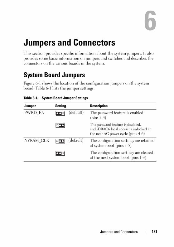
book.book Page 181 Tuesday, August 24, 2010 1:47 PM
6Jumpers and ConnectorsThis section provides specific information about the system jumpers. It also provides some basic information on jumpers and switches and describes the connectors on the various boards in the system.
System Board JumpersFigure 6-1 shows the location of the configuration jumpers on the system board. Table 6-1 lists the jumper settings.
Table 6-1. System Board Jumper Settings
Jumper Setting Description
PWRD_EN (default) The password feature is enabled (pins 2-4)
The password feature is disabled, and iDRAC6 local access is unlocked at the next AC power cycle (pins 4-6)
NVRAM_CLR (default) The configuration settings are retained at system boot (pins 3-5)
The configuration settings are cleared at the next system boot (pins 1-3)
Jumpers and Connectors 181
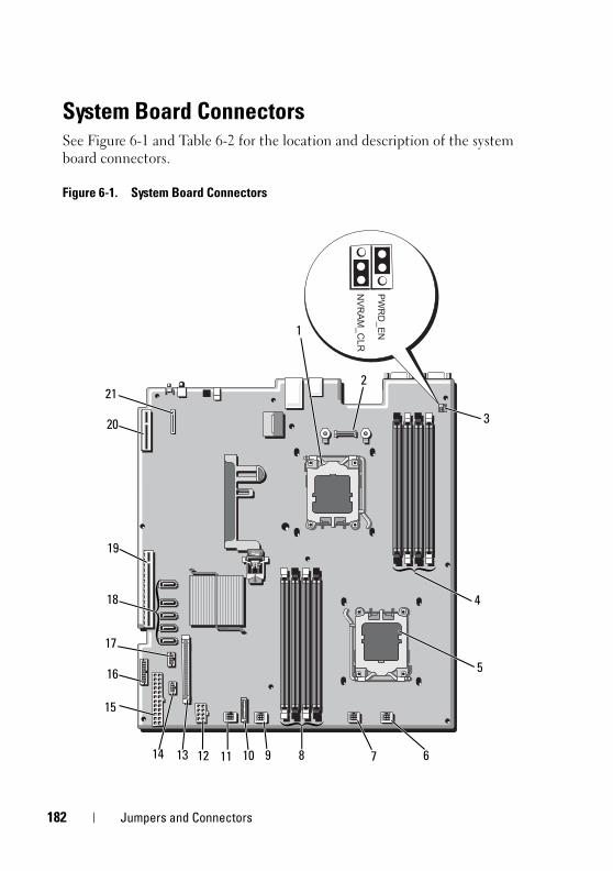
1
book.book Page 182 Tuesday, August 24, 2010 1:47 PM
System Board ConnectorsSee Figure 6-1 and Table 6-2 for the location and description of the system board connectors.
Figure 6-1. System Board Connectors
1
2
19
20
18
17
16
15
14 13 12 11 10 9 8 7 6
5
4
3
21
82 Jumpers and Connectors
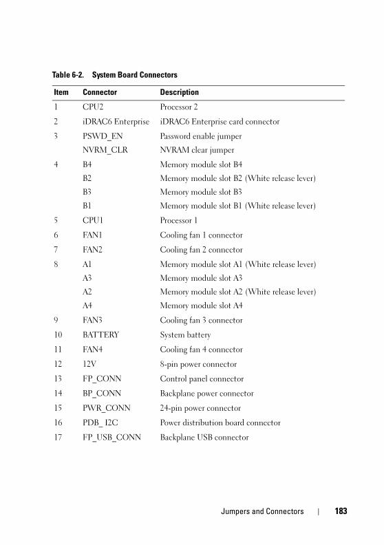
book.book Page 183 Tuesday, August 24, 2010 1:47 PM
Table 6-2. System Board Connectors
Item Connector Description
1 CPU2 Processor 2
2 iDRAC6 Enterprise iDRAC6 Enterprise card connector
3 PSWD_EN
NVRM_CLR
Password enable jumper
NVRAM clear jumper
4 B4
B2
B3
B1
Memory module slot B4
Memory module slot B2 (White release lever)
Memory module slot B3
Memory module slot B1 (White release lever)
5 CPU1 Processor 1
6 FAN1 Cooling fan 1 connector
7 FAN2 Cooling fan 2 connector
8 A1
A3
A2
A4
Memory module slot A1 (White release lever)
Memory module slot A3
Memory module slot A2 (White release lever)
Memory module slot A4
9 FAN3 Cooling fan 3 connector
10 BATTERY System battery
11 FAN4 Cooling fan 4 connector
12 12V 8-pin power connector
13 FP_CONN Control panel connector
14 BP_CONN Backplane power connector
15 PWR_CONN 24-pin power connector
16 PDB_ I2C Power distribution board connector
17 FP_USB_CONN Backplane USB connector
Jumpers and Connectors 183
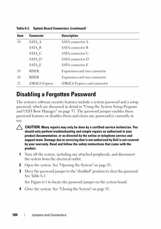
1
book.book Page 184 Tuesday, August 24, 2010 1:47 PM
Disabling a Forgotten PasswordThe system's software security features include a system password and a setup password, which are discussed in detail in "Using the System Setup Program and UEFI Boot Manager" on page 57. The password jumper enables these password features or disables them and clears any password(s) currently in use.
CAUTION: Many repairs may only be done by a certified service technician. You should only perform troubleshooting and simple repairs as authorized in your product documentation, or as directed by the online or telephone service and support team. Damage due to servicing that is not authorized by Dell is not covered by your warranty. Read and follow the safety instructions that came with the product.
1 Turn off the system, including any attached peripherals, and disconnect the system from the electrical outlet.
2 Open the system. See "Opening the System" on page 83.
3 Move the password jumper to the "disabled" position to clear the password. See Table 6-1.
See Figure 6-1 to locate the password jumper on the system board.
4 Close the system. See "Closing the System" on page 85.
18 SATA_A
SATA_B
SATA_C
SATA_D
SATA_E
SATA connector A
SATA connector B
SATA connector C
SATA connector D
SATA connector E
19 RISER Expansion-card riser connector
20 RISER Expansion-card riser connector
21 iDRAC6 Express iDRAC6 Express card connector
Table 6-2. System Board Connectors (continued)
Item Connector Description
84 Jumpers and Connectors
book.book Page 185 Tuesday, August 24, 2010 1:47 PM
5 Reconnect your system and peripherals to their electrical outlets, and turn on the system.
The existing passwords are not disabled (erased) until the system boots with the password jumper plug in the "disabled" position. However, before you assign a new system and/or setup password, you must return the jumper plug to the enabled position.
NOTE: If you assign a new system and/or setup password with the jumper plug still in the "disabled" position, the system disables the new password(s) the next time it boots.
6 Turn off the system, including any attached peripherals, and disconnect the system from the electrical outlet.
7 Open the system. See "Opening the System" on page 83.
8 Move the password jumper back to the enabled position to restore the password function. See Table 6-1.
9 Close the system. See "Closing the System" on page 85.
10 Reconnect your system and peripherals to their electrical outlets, and turn on the system.
11 Assign a new system and/or setup password.
To assign a new password using the System Setup program, see "System and Setup Password Features" on page 72.
Jumpers and Connectors 185

1
book.book Page 186 Tuesday, August 24, 2010 1:47 PM
86 Jumpers and Connectors

book.book Page 187 Tuesday, August 24, 2010 1:47 PM
7Getting Help
Contacting DellFor customers in the United States, call 800-WWW-DELL (800-999-3355).
NOTE: If you do not have an active Internet connection, you can find contact information on your purchase invoice, packing slip, bill, or Dell product catalog.
Dell provides several online and telephone-based support and service options. Availability varies by country and product, and some services may not be available in your area. To contact Dell for sales, technical support, or customer service issues:
1 Visit support.dell.com.
2 Verify your country or region in the Choose A Country/Region drop-down menu at the bottom of the page.
3 Click Contact Us on the left side of the page.
4 Select the appropriate service or support link based on your need.
5 Choose the method of contacting Dell that is convenient for you.
Getting Help 187

1
book.book Page 188 Tuesday, August 24, 2010 1:47 PM
88 Getting Help
book.book Page 189 Tuesday, August 24, 2010 1:47 PM
Index
BBack-Panel Features and
Indicators, 20
batteriestroubleshooting, 160
batterytroubleshooting the RAID card
battery, 169
battery (system)replacing, 132
bezel, 82
blankhard drive, 87power supply, 104
BMCconfiguring, 77
Ccabling
optical drive, 95
CD drivetroubleshooting, 166
connectorssystem board, 180USB, 12video, 12
contacting Dell, 185
control panel assemblyfeatures, 12installing, 138, 142LCD panel features, 16removing, 136, 140
cooling fanreplacing, 101
cooling fanstroubleshooting, 162
cooling shroudinstalling, 87removing, 86
coverclosing, 85opening, 83
Ddamaged systems
troubleshooting, 160
Dellcontacting, 185
Dell PowerEdge Diagnosticsusing, 175
diagnosticsadvanced testing options, 177testing options, 177using Dell PowerEdge
Diagnostics, 175
Index 189
1
book.book Page 190 Tuesday, August 24, 2010 1:47 PM
when to use, 176
DIMMsSee memory modules (DIMMs).
drive blankinstalling, 88removing, 87
EEmbedded System
Management, 76
error messages, 58
expansion cardtroubleshooting, 170
expansion cardsinstalling, 113removing, 115SAS controller, 116
expansion slots, 111
Ffront-panel features, 12
Gguidelines
connecting external devices, 23expansion card installation, 111memory installation, 105
Hhard drive
troubleshooting, 167-168
hard drives (hot-swappable)installing, 89
heat sink, 129
IiDRAC6 Configuration
Utility, 78
iDRAC6 Enterprise Card (Optional), 123
iDRAC6 Express Card (Optional), 121
indicatorsfront-panel, 12NIC, 23power, 12, 24
installingcontrol panel assembly, 138, 142cooling shroud, 87expansion card, 113hard drive (hot-swappable), 89hard drive blank, 88memory modules, 108power supply blank, 104processor, 131SAS backplane board, 146SAS controller, 118
90 Index
book.book Page 191 Tuesday, August 24, 2010 1:47 PM
Jjumpers (system board), 179
Kkeyboards
troubleshooting, 156
LLCD panel
features, 16menus, 17
Lifecyle Controller, 76
Mmemory
troubleshooting, 163
memory key connector (USB), 126
memory modeOptimizer, 106
memory modules (DIMMs)configuring, 105installing, 108removing, 110UDIMM configurations, 112
messageserror messages, 58status LCD, 27system, 40
warning, 55
NNIC
indicators, 23
NICstroubleshooting, 157
OOptimizer memory mode, 106
Ppassword
setup, 75system, 72
passwordsdisabling, 182
phone numbers, 185
POSTaccessing system features, 11
power indicators, 12, 24
power suppliesindicators, 24removing, 102replacing, 103
power supply blank, 104
processorinstalling, 131removing, 127
Index 191
1
book.book Page 192 Tuesday, August 24, 2010 1:47 PM
See processor.upgrades, 127
processorstroubleshooting, 172
Rremoving
bezel, 82control panel assembly, 136, 140cooling shroud, 86cover, 83expansion card, 115hard drive blank, 87memory modules, 110power supply, 102power supply blank, 104processor, 127SAS backplane board, 142SAS controller, 116system board, 151
replacingcooling fan, 101power supply, 103system battery, 132
Ssafety, 155
SAS backplane boardinstalling, 146removing, 142
SAS controller card
installing, 118removing, 116
SAS controller daughter cardtroubleshooting, 169
SAS hard drive. See hard drive.
SAS RAID controller daughter card
troubleshooting, 169
SATA hard drive. See hard drive.
SD cardtroubleshooting, 165
securing your system, 67, 73
setup password, 75
slotsSee expansion slots.
startupaccessing system features, 11
supportcontacting Dell, 185
systemclosing, 85opening, 83
system boardconnectors, 180installing, 153jumpers, 179removing, 151
system coolingtroubleshooting, 161
system featuresaccessing, 11
92 Index
book.book Page 193 Tuesday, August 24, 2010 1:47 PM
system messages, 40
system password, 72
system setup programboot settings, 63embedded server management
options, 66integrated devices options, 64keystroke to enter, 58memory settings, 61PCI IRQ assignments, 65power management options, 67processor settings, 61SATA settings, 62serial communications
options, 65system security options, 67
system setup screensmain, 59
Ttelephone numbers, 185
TPM security, 67
troubleshootingbattery, 160CD drive, 166cooling fans, 162damaged system, 160expansion card, 170external connections, 155hard drive, 167-168internal hard drive, 168internal USB key, 165keyboard, 156
memory, 163NIC, 157processors, 172SAS RAID controller daughter
card, 169SD card, 165system cooling, 161video, 156wet system, 158
UUEFI Boot Manager
entering, 70main screen, 71System Utilities screen, 72UEFI Boot Settings screen, 71
upgradesprocessor, 127
USBfront-panel connectors, 12internal connector for memory
key, 126
USB keytroubleshooting, 165
Vvideo
front-panel connectors, 12troubleshooting, 156
Index 193

1
book.book Page 194 Tuesday, August 24, 2010 1:47 PM
Wwarning messages, 55
warranty, 56
wet systemtroubleshooting, 158
94 Index