Embed Size (px)
Citation preview

Single Source Machine Control ……………………………………………..…...………………. Power // Flexibility // Ease of Use
21314 Lassen St. Chatsworth, CA 91311 // Tel. (818) 998-2095 Fax. (818) 998-7807 // www.deltatau.com
^1 HARDWARE REFERENCE MANUAL
^2 Turbo PMAC Clipper
^3Turbo PMAC Clipper
^4 4xx-603871-xAxx
^5October 17, 2018
DELTA TAU Data Systems, Inc.
NEW IDEAS IN MOTION …

Turbo PMAC Clipper
Copyright Information © 2018 Delta Tau Data Systems, Inc. All rights reserved.
This document is furnished for the customers of Delta Tau Data Systems, Inc. Other uses
are unauthorized without written permission of Delta Tau Data Systems, Inc. Information
contained in this manual may be updated from time-to-time due to product improvements,
etc., and may not conform in every respect to former issues.
To report errors or inconsistencies, call or email:
Delta Tau Data Systems, Inc. Technical Support
Phone: (818) 717-5656
Fax: (818) 998-7807
Email: [email protected]
Website: http://www.deltatau.com
Operating Conditions
All Delta Tau Data Systems, Inc. motion controller products, accessories, and amplifiers
contain static sensitive components that can be damaged by incorrect handling. When
installing or handling Delta Tau Data Systems, Inc. products, avoid contact with highly
insulated materials. Only qualified personnel should be allowed to handle this equipment.
In the case of industrial applications, we expect our products to be protected from
hazardous or conductive materials and/or environments that could cause harm to the
controller by damaging components or causing electrical shorts. When our products are
used in an industrial environment, install them into an industrial electrical cabinet or
industrial PC to protect them from excessive or corrosive moisture, abnormal ambient
temperatures, and conductive materials. If Delta Tau Data Systems, Inc. products are
directly exposed to hazardous or conductive materials and/or environments, we cannot
guarantee their operation.

Turbo PMAC Clipper
Safety Instructions
Qualified personnel must transport, assemble, install, and maintain this equipment. Properly qualified
personnel are persons who are familiar with the transport, assembly, installation, and operation of
equipment. The qualified personnel must know and observe the following standards and regulations:
IEC364resp.CENELEC HD 384 or DIN VDE 0100
IEC report 664 or DIN VDE 0110
National regulations for safety and accident prevention or VBG 4
Incorrect handling of products can result in injury and damage to persons and machinery. Strictly adhere
to the installation instructions. Electrical safety is provided through a low-resistance earth connection. It
is vital to ensure that all system components are connected to earth ground.
This product contains components that are sensitive to static electricity and can be damaged by incorrect
handling. Avoid contact with high insulating materials (artificial fabrics, plastic film, etc.). Place the
product on a conductive surface. Discharge any possible static electricity build-up by touching an
unpainted, metal, grounded surface before touching the equipment.
Keep all covers and cabinet doors shut during operation. Be aware that during operation, the product has
electrically charged components and hot surfaces. Control and power cables can carry a high voltage,
even when the motor is not rotating. Never disconnect or connect the product while the power source is
energized to avoid electric arcing.
A Warning identifies hazards that could result in personal injury or
death. It precedes the discussion of interest.
Warning
Caution
A Caution identifies hazards that could result in equipment damage. It
precedes the discussion of interest.
Note
A Note identifies information critical to the understanding or use of
the equipment. It follows the discussion of interest.
Turbo PMAC Clipper
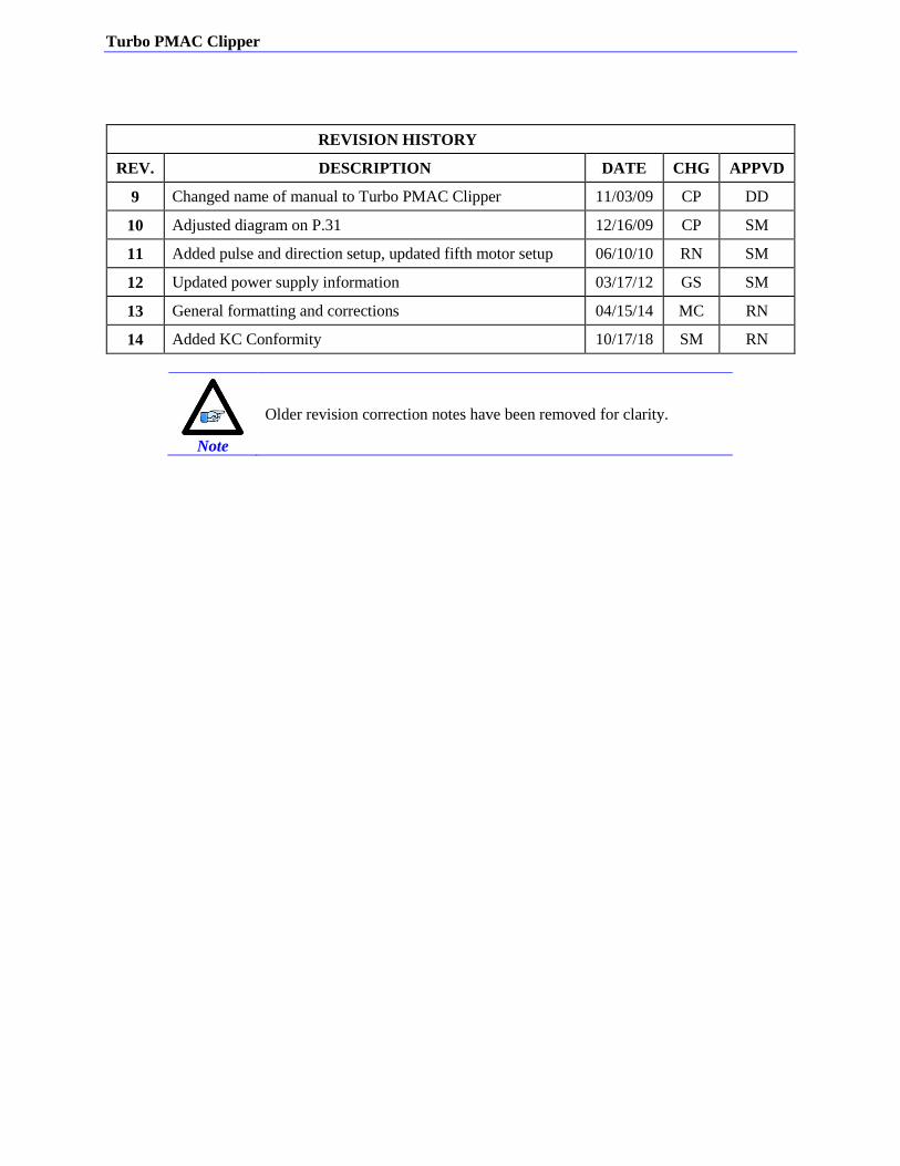
REVISION HISTORY
REV. DESCRIPTION DATE CHG APPVD
9 Changed name of manual to Turbo PMAC Clipper 11/03/09 CP DD
10 Adjusted diagram on P.31 12/16/09 CP SM
11 Added pulse and direction setup, updated fifth motor setup 06/10/10 RN SM
12 Updated power supply information 03/17/12 GS SM
13 General formatting and corrections 04/15/14 MC RN
14 Added KC Conformity 10/17/18 SM RN
Note
Older revision correction notes have been removed for clarity.

Turbo PMAC Clipper
Table of Contents vi
Table of Contents
INTRODUCTION ....................................................................................................................................... 9
Documentation .............................................................................................................................................. 9
Downloadable Turbo PMAC Script ............................................................................................................ 10
SPECIFICATIONS ................................................................................................................................... 11
Part Number ................................................................................................................................................ 11
Options ........................................................................................................................................................ 12
Environmental Specifications ..................................................................................................................... 13
Electrical Specifications .............................................................................................................................. 13 Digital Power Supply ............................................................................................................................. 13 DAC Outputs Power Supply .................................................................................................................. 13 Flags Power Supply ............................................................................................................................... 13
Agency Approval and Safety ...................................................................................................................... 14
RECEIVING AND UNPACKING .......................................................................................................... 15
Use of Equipment ....................................................................................................................................... 15
MOUNTING .............................................................................................................................................. 16
Physical Specifications ............................................................................................................................... 17 Board Dimensions and Layout .............................................................................................................. 17
CONNECTIONS AND SOFTWARE SETUP ....................................................................................... 18
TB1: Power Supply Input ........................................................................................................................... 18
J2: Serial Port .............................................................................................................................................. 19
J3: Machine Connector (JMACH1 Port) .................................................................................................... 20 Setting up Quadrature Encoders ........................................................................................................... 23 Setting up Sinusoidal Encoders ............................................................................................................. 23 Counts per User Units ........................................................................................................................... 25 Wiring the DAC Output ......................................................................................................................... 26 Amplifier Enable Signal (AENAn/DIRn) ............................................................................................... 27 Amplifier Fault Signal (FAULT-) .......................................................................................................... 28 Optional Analog Inputs .......................................................................................................................... 29 Analog Inputs Setup ............................................................................................................................... 29
J4: Machine Connector (JMACH2 Port) .................................................................................................... 30 Overtravel Limits and Home Switches ................................................................................................... 31
Wiring the Limits and Flags .................................................................................................................. 31 Limits and Flags [Axis 1- 4] Suggested M-Variables ............................................................................ 34 Step and Direction PFM Output (To External Stepper Amplifier) ........................................................ 35 Compare Equal Outputs ........................................................................................................................ 36
J7: Machine Connector (JMACH3 Port) .................................................................................................... 37
J8: Thumbwheel Multiplexer Port (JTHW Port) ........................................................................................ 38 Thumbwheel Port Digital Inputs and Outputs ....................................................................................... 39
J9: General-Purpose Digital Inputs and Outputs (JOPT Port) .................................................................... 40 General Purpose I/Os (J6) Suggested M-Variables .............................................................................. 42
Turbo PMAC Clipper
Table of Contents vii
J10: Handwheel and Pulse/Dir Connector (JHW/PD Port) ......................................................................... 43
J12: Ethernet Communications Port ........................................................................................................... 44
J13: USB Communications Port ................................................................................................................. 44
JP11: OPT-11 Shunt ................................................................................................................................... 44
LED Indicators ............................................................................................................................................ 44
DRIVE - MOTOR SETUP ....................................................................................................................... 45
Filtered PWM Output (Analog ±10V) ........................................................................................................ 46 Clock Settings, Output Mode, Command Limit ..................................................................................... 47 Flag Control, Ixx24 ............................................................................................................................... 47 I2T Protection: Ixx57, Ixx58 .................................................................................................................. 48 Open Loop Test: Encoder/Decode ......................................................................................................... 48 Position-Loop PID Gains: Ixx30…Ixx39 ............................................................................................... 50
True DAC Output (±10V) ........................................................................................................................... 51 Clock Settings, Output Mode ................................................................................................................. 51 Flag Control, Ixx24 ............................................................................................................................... 51 I2T Protection: Ixx57, Ixx58 .................................................................................................................. 51 Open Loop Test: Encoder/Decode ......................................................................................................... 52 Position-Loop PID Gains: Ixx30…Ixx39 ............................................................................................... 53
Pulse and Direction Output (PFM) ............................................................................................................. 55 PFM Clock Settings Example ................................................................................................................ 55 PFM Setup Example .............................................................................................................................. 56 Writing directly to the PFM register ..................................................................................................... 56 Issuing Open-Loop Commands .............................................................................................................. 57 Issuing Closed-Loop Commands ........................................................................................................... 57
Setup of a Fifth Motor Using Opt-12 on the Clipper Board ....................................................................... 60
LASER CONTROL OUTPUT ................................................................................................................ 62
Understanding Option-11A Capabilities ..................................................................................................... 63
Clock Settings ............................................................................................................................................. 64
Controlling the output ................................................................................................................................. 65
TROUBLESHOOTING ........................................................................................................................... 67
Serial Number and Board Revisions Identification .................................................................................... 67
Write-Protect Disable – E8 Jumper ............................................................................................................ 68 Changing IP Address, Gateway IP, Gateway Mask .............................................................................. 69 Enabling ModBus .................................................................................................................................. 70 Reloading Boot and Communication Firmware .................................................................................... 71 Reloading PMAC firmware – E13 Jumper ............................................................................................ 72 Re-initialization jumper (Factory Reset) ............................................................................................... 74
Watchdog Timer ......................................................................................................................................... 74
APPENDIX A: E-POINT JUMPERS ..................................................................................................... 75
E0: Forced Reset Control ........................................................................................................................... 75
E1 – E2: Serial Port Selection (rev 102 and below only) .......................................................................... 75
E3: Normal/Re-Initializing Power-Up/Reset ............................................................................................. 75

Turbo PMAC Clipper
Table of Contents viii
E4: Watchdog Disable Jumper ................................................................................................................... 75
E5: Reserved for factory use only .............................................................................................................. 75
E6: ADC Inputs Enable ............................................................................................................................. 76
E7 – E8: USB/Ethernet Reset Jumpers ...................................................................................................... 76
E10 – E12: Flash IC Jumpers ..................................................................................................................... 76
E13: Power-Up/Reset Load Source ........................................................................................................... 77
E14- E17: Ports Direction Control .............................................................................................................. 77
APPENDIX B: SCHEMATICS ............................................................................................................... 78
Turbo PMAC Clipper
Introduction 9
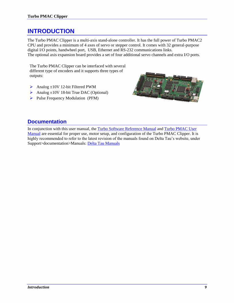
INTRODUCTION
The Turbo PMAC Clipper is a multi-axis stand-alone controller. It has the full power of Turbo PMAC2
CPU and provides a minimum of 4 axes of servo or stepper control. It comes with 32 general-purpose
digital I/O points, handwheel port, USB, Ethernet and RS-232 communications links.
The optional axis expansion board provides a set of four additional servo channels and extra I/O ports.
The Turbo PMAC Clipper can be interfaced with several
different type of encoders and it supports three types of
outputs:
Analog ±10V 12-bit Filtered PWM
Analog ±10V 18-bit True DAC (Optional)
Pulse Frequency Modulation (PFM)
Documentation
In conjunction with this user manual, the Turbo Software Reference Manual and Turbo PMAC User
Manual are essential for proper use, motor setup, and configuration of the Turbo PMAC Clipper. It is
highly recommended to refer to the latest revision of the manuals found on Delta Tau’s website, under
Support>documentation>Manuals: Delta Tau Manuals
Turbo PMAC Clipper
Introduction 10
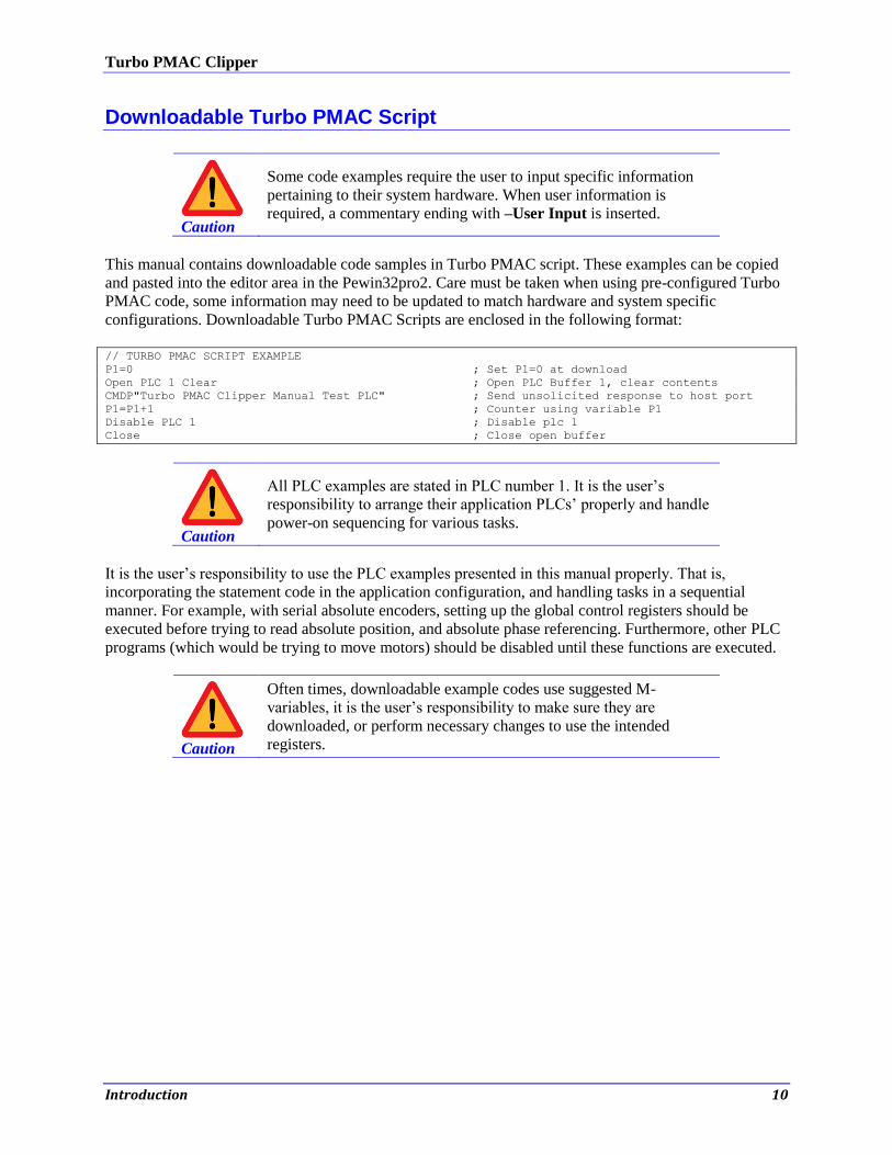
Downloadable Turbo PMAC Script
Caution
Some code examples require the user to input specific information
pertaining to their system hardware. When user information is
required, a commentary ending with –User Input is inserted.
This manual contains downloadable code samples in Turbo PMAC script. These examples can be copied
and pasted into the editor area in the Pewin32pro2. Care must be taken when using pre-configured Turbo
PMAC code, some information may need to be updated to match hardware and system specific
configurations. Downloadable Turbo PMAC Scripts are enclosed in the following format:
// TURBO PMAC SCRIPT EXAMPLE
P1=0 ; Set P1=0 at download
Open PLC 1 Clear ; Open PLC Buffer 1, clear contents
CMDP"Turbo PMAC Clipper Manual Test PLC" ; Send unsolicited response to host port
P1=P1+1 ; Counter using variable P1
Disable PLC 1 ; Disable plc 1
Close ; Close open buffer
Caution
All PLC examples are stated in PLC number 1. It is the user’s
responsibility to arrange their application PLCs’ properly and handle
power-on sequencing for various tasks.
It is the user’s responsibility to use the PLC examples presented in this manual properly. That is,
incorporating the statement code in the application configuration, and handling tasks in a sequential
manner. For example, with serial absolute encoders, setting up the global control registers should be
executed before trying to read absolute position, and absolute phase referencing. Furthermore, other PLC
programs (which would be trying to move motors) should be disabled until these functions are executed.
Caution
Often times, downloadable example codes use suggested M-
variables, it is the user’s responsibility to make sure they are
downloaded, or perform necessary changes to use the intended
registers.
Turbo PMAC Clipper
Connections and Software Setup 11
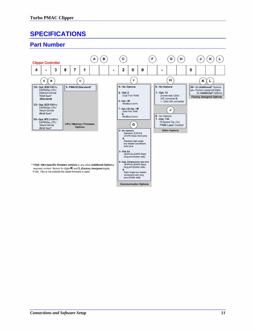
SPECIFICATIONS
Part Number
Turbo PMAC Clipper
Connections and Software Setup 12
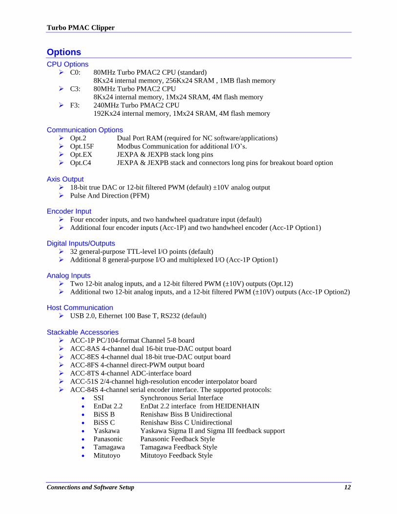
Options
CPU Options C0: 80MHz Turbo PMAC2 CPU (standard)
8Kx24 internal memory, 256Kx24 SRAM , 1MB flash memory
C3: 80MHz Turbo PMAC2 CPU
8Kx24 internal memory, 1Mx24 SRAM, 4M flash memory
F3: 240MHz Turbo PMAC2 CPU
192Kx24 internal memory, 1Mx24 SRAM, 4M flash memory
Communication Options Opt.2 Dual Port RAM (required for NC software/applications)
Opt.15F Modbus Communication for additional I/O’s.
Opt.EX JEXPA & JEXPB stack long pins
Opt.C4 JEXPA & JEXPB stack and connectors long pins for breakout board option
Axis Output
18-bit true DAC or 12-bit filtered PWM (default) ±10V analog output
Pulse And Direction (PFM)
Encoder Input Four encoder inputs, and two handwheel quadrature input (default)
Additional four encoder inputs (Acc-1P) and two handwheel encoder (Acc-1P Option1)
Digital Inputs/Outputs 32 general-purpose TTL-level I/O points (default)
Additional 8 general-purpose I/O and multiplexed I/O (Acc-1P Option1)
Analog Inputs Two 12-bit analog inputs, and a 12-bit filtered PWM (±10V) outputs (Opt.12)
Additional two 12-bit analog inputs, and a 12-bit filtered PWM (±10V) outputs (Acc-1P Option2)
Host Communication USB 2.0, Ethernet 100 Base T, RS232 (default)
Stackable Accessories
ACC-1P PC/104-format Channel 5-8 board
ACC-8AS 4-channel dual 16-bit true-DAC output board
ACC-8ES 4-channel dual 18-bit true-DAC output board
ACC-8FS 4-channel direct-PWM output board
ACC-8TS 4-channel ADC-interface board
ACC-51S 2/4-channel high-resolution encoder interpolator board
ACC-84S 4-channel serial encoder interface. The supported protocols:
SSI Synchronous Serial Interface
EnDat 2.2 EnDat 2.2 interface from HEIDENHAIN
BiSS B Renishaw Biss B Unidirectional
BiSS C Renishaw Biss C Unidirectional
Yaskawa Yaskawa Sigma II and Sigma III feedback support
Panasonic Panasonic Feedback Style
Tamagawa Tamagawa Feedback Style
Mitutoyo Mitutoyo Feedback Style

Turbo PMAC Clipper
Connections and Software Setup 13
Environmental Specifications
Description Specification Notes
Operating Temperature 0°C to 45°C
Storage Temperature -25°C to 70°C
Humidity 10% to 95 % Non-Condensing
Electrical Specifications
Digital Power Supply
The +5V and ground reference lines from the power supply should be connected to TB1 terminal block of
the Turbo PMAC Clipper board using 18 AWG stranded wire. The power requirement (± 5%) is:
+5 V (20W) @ 4 A (Eight-channel configuration with a typical load of encoders)
WARNING
Boards with revisions 103 and below have the following
requirement:
Mininumum 10 msec rise time
6A @ +5V (±5%) (30 W)
The Clipper Board and other stackable accessories each require
a 1A @ 5VDC power supply for normal operation; however, the
Clipper board has an in-rush current requirement that can reach
3A, so a 6A @ 5VDC power supply is recommended.
DAC Outputs Power Supply
The ±12V lines from the supply, including the ground reference, can be brought in either from the TB1
terminal block or from the JMACH1 connector.
+12 to +15 V (4.5W) @ 0.30 A (Eight-channel configuration with a typical load of encoders)
-12 to -15 V (3.8W) @ 0.25 A (Eight-channel configuration with a typical load of encoders)
Flags Power Supply
Each channel of PMAC has five dedicated digital inputs on the machine connector: PLIMn, MLIMn
(overtravel limits), HOMEn (home flag), FAULTn (amplifier fault), and USERn. A power supply from 5
to 24V must be used to power the circuits related to these inputs. This power supply can be the same
used to Turbo PMAC Clipper and can be connected from the TB1 terminal block or the J3 (JMACH1)
connector.
Turbo PMAC Clipper
Connections and Software Setup 14
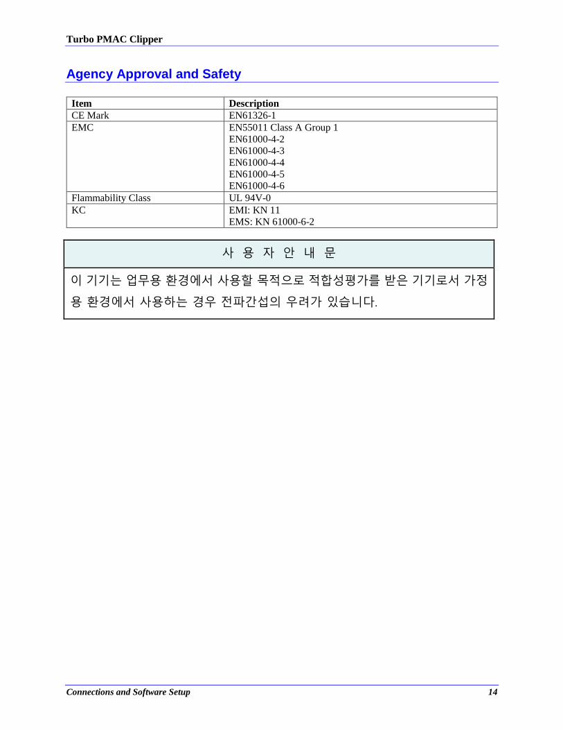
Agency Approval and Safety
Item Description
CE Mark EN61326-1
EMC EN55011 Class A Group 1
EN61000-4-2
EN61000-4-3
EN61000-4-4
EN61000-4-5
EN61000-4-6
Flammability Class UL 94V-0
KC EMI: KN 11
EMS: KN 61000-6-2
사 용 자 안 내 문
이 기기는 업무용 환경에서 사용할 목적으로 적합성평가를 받은 기기로서 가정
용 환경에서 사용하는 경우 전파간섭의 우려가 있습니다.

Turbo PMAC Clipper
Connections and Software Setup 15
RECEIVING AND UNPACKING
Delta Tau products are thoroughly tested at the factory and carefully packaged for shipment. When the
Turbo PMAC Clipper is received, there are several things to be done immediately:
Observe the condition of the shipping container and report any damage immediately to the
commercial carrier that delivered the board.
Remove the Turbo PMAC Clipper from the shipping container and remove all packing materials.
Check all shipping material for connector kits, documentation, or other small pieces of
equipment. Be aware that some connector kits and other equipment pieces may be quite small
and can be accidentally discarded if care is not used when unpacking the equipment. The
container and packing materials may be retained for future shipment.
Verify that the part number of the board received is the same as the part number listed on the
purchase order.
Inspect for external physical damage that may have been sustained during shipment and report
any damage immediately to the commercial carrier that delivered the board.
Electronic components in this product are design-hardened to reduce static sensitivity. However,
use proper procedures when handling the equipment.
If the Turbo PMAC Clipper is to be stored for several weeks before use, be sure that it is stored in
a location that conforms to published storage humidity and temperature specifications.
Use of Equipment
The following restrictions will ensure the proper use of the Turbo PMAC Clipper:
The components built into electrical equipment or machines can be used only as integral
components of such equipment.
The Turbo PMAC Clipper must not be operated on power supply networks without a ground or
with an asymmetrical ground.
If the Turbo PMAC Clipper is used in residential areas, or in business or commercial premises,
implement additional filtering measures.
The Turbo PMAC Clipper may be operated only in a closed switchgear cabinet, taking into
account the ambient conditions defined in the environmental specifications.
Delta Tau guarantees the conformance of the Turbo PMAC Clippers with the standards for industrial
areas stated in this manual, only if Delta Tau components (cables, controllers, etc.) are used.

Turbo PMAC Clipper
Connections and Software Setup 16
MOUNTING
The location of the Turbo PMAC Clipper is important. Installation should be in an area that is protected
from direct sunlight, corrosives, harmful gases or liquids, dust, metallic particles, and other contaminants.
Exposure to these can reduce the operating life and degrade performance of the board.
Several other factors should be carefully evaluated when selecting a location for installation:
For effective cooling and maintenance, the Turbo PMAC Clipper should be mounted on a smooth,
non- flammable vertical or horizontal surface.
At least 100 mm (0.4 inches) top and bottom clearance must be provided for air flow.
Temperature, humidity and Vibration specifications should also be taken in account.
Caution
Unit must be installed in an enclosure that meets the environmental
IP rating of the end product (ventilation or cooling may be necessary
to prevent enclosure ambient from exceeding 45° C [113° F]).
The Turbo PMAC Clipper can be mounted as a stand-alone controller using standoffs. At each of the
four corners of the board and at the center edges, there are mounting holes that can be used for this.
The order of the Acc-1P or other stacked accessories with respect to the Clipper Board does not matter.
If the Turbo PMAC Clipper is mounted to a back panel, the back panel should be unpainted and
electrically conductive to allow for reduced electrical noise interference. The back panel should be
machined to accept the standoffs pattern of the board.
The board can be mounted to the back panel using four standoffs and internal-tooth lock washers. It is
important that the teeth break through any anodization on the board’s mounting gears to provide a good
electrically conductive path in as many places as possible. Mount the board on the back panel so there is
airflow at both the top and bottom areas of the board (at least 0.4 inches).
Turbo PMAC Clipper
Connections and Software Setup 17
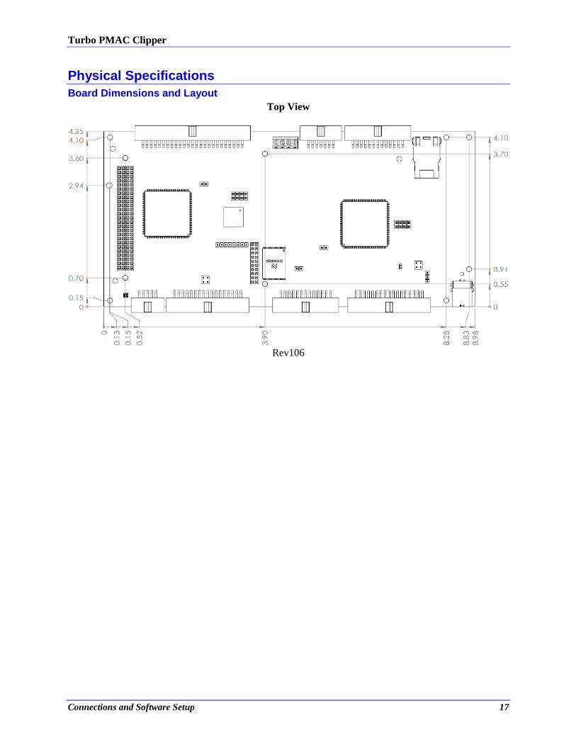
Physical Specifications
Board Dimensions and Layout
Top View
Rev106
Turbo PMAC Clipper Hardware Reference Manual
Connections and Software Setup 18
CONNECTIONS AND SOFTWARE SETUP
WARNING
Installation of electrical equipment is subject to many
regulations including national, state, local, and industry
guidelines and rules. The following are general
recommendations but it is important that the integration be
carried out in accordance with all regulations pertaining to the
installation.
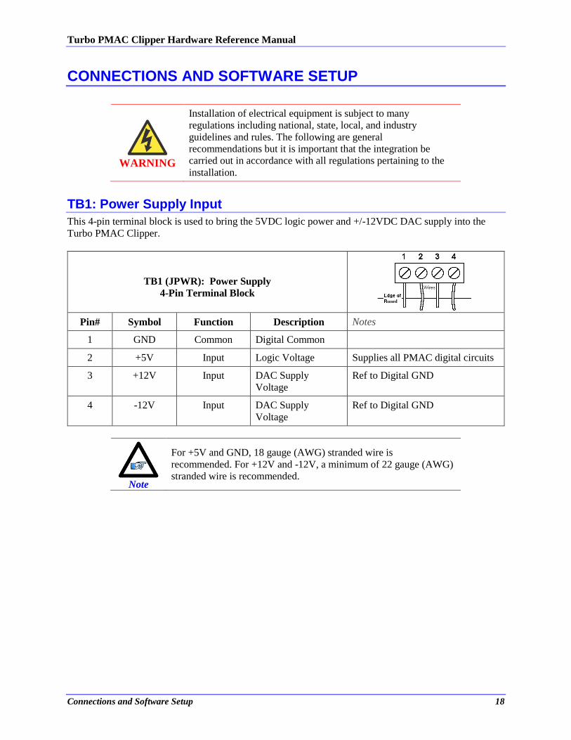
TB1: Power Supply Input
This 4-pin terminal block is used to bring the 5VDC logic power and +/-12VDC DAC supply into the
Turbo PMAC Clipper.
TB1 (JPWR): Power Supply
4-Pin Terminal Block
Pin# Symbol Function Description Notes
1 GND Common Digital Common
2 +5V Input Logic Voltage Supplies all PMAC digital circuits
3 +12V Input DAC Supply
Voltage
Ref to Digital GND
4 -12V Input DAC Supply
Voltage
Ref to Digital GND
Note
For +5V and GND, 18 gauge (AWG) stranded wire is
recommended. For +12V and -12V, a minimum of 22 gauge (AWG)
stranded wire is recommended.
Turbo PMAC Clipper Hardware Reference Manual
Connections and Software Setup 19
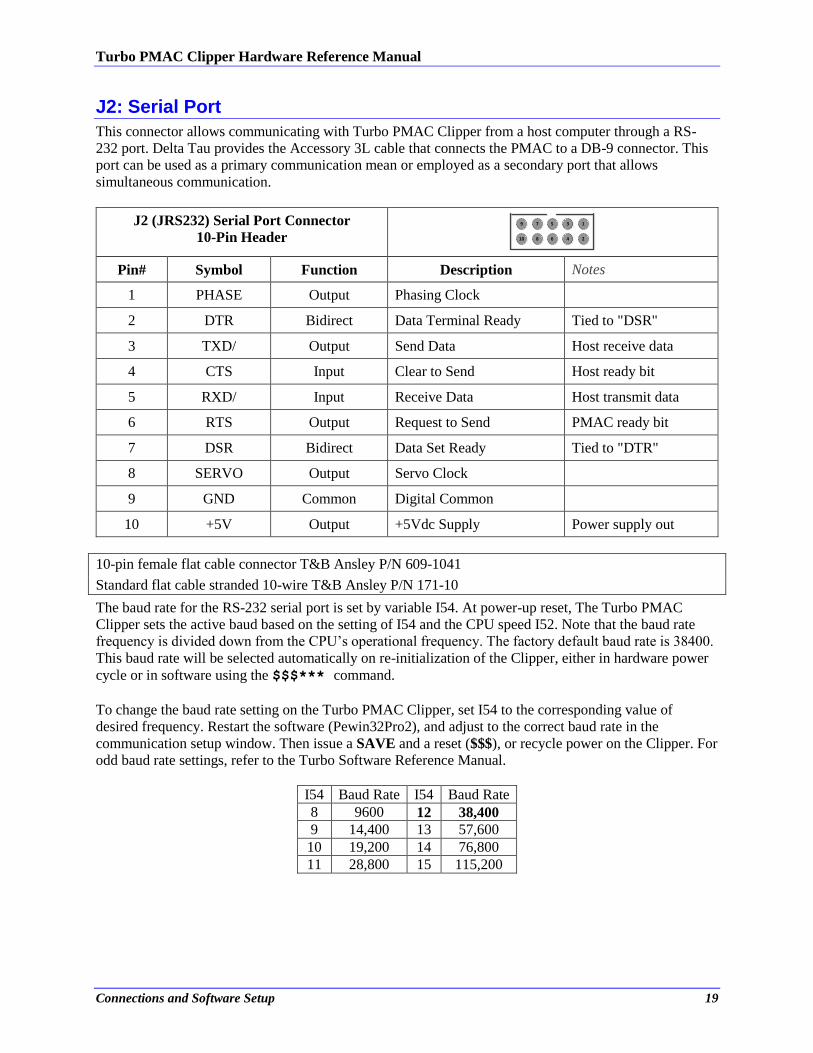
J2: Serial Port
This connector allows communicating with Turbo PMAC Clipper from a host computer through a RS-
232 port. Delta Tau provides the Accessory 3L cable that connects the PMAC to a DB-9 connector. This
port can be used as a primary communication mean or employed as a secondary port that allows
simultaneous communication.
J2 (JRS232) Serial Port Connector
10-Pin Header
5
6
3
4
1
2
9
10
7
8
Pin# Symbol Function Description Notes
1 PHASE Output Phasing Clock
2 DTR Bidirect Data Terminal Ready Tied to "DSR"
3 TXD/ Output Send Data Host receive data
4 CTS Input Clear to Send Host ready bit
5 RXD/ Input Receive Data Host transmit data
6 RTS Output Request to Send PMAC ready bit
7 DSR Bidirect Data Set Ready Tied to "DTR"
8 SERVO Output Servo Clock
9 GND Common Digital Common
10 +5V Output +5Vdc Supply Power supply out
10-pin female flat cable connector T&B Ansley P/N 609-1041
Standard flat cable stranded 10-wire T&B Ansley P/N 171-10
The baud rate for the RS-232 serial port is set by variable I54. At power-up reset, The Turbo PMAC
Clipper sets the active baud based on the setting of I54 and the CPU speed I52. Note that the baud rate
frequency is divided down from the CPU’s operational frequency. The factory default baud rate is 38400.
This baud rate will be selected automatically on re-initialization of the Clipper, either in hardware power
cycle or in software using the $$$*** command.
To change the baud rate setting on the Turbo PMAC Clipper, set I54 to the corresponding value of
desired frequency. Restart the software (Pewin32Pro2), and adjust to the correct baud rate in the
communication setup window. Then issue a SAVE and a reset ($$$), or recycle power on the Clipper. For
odd baud rate settings, refer to the Turbo Software Reference Manual.
I54 Baud Rate I54 Baud Rate
8 9600 12 38,400
9 14,400 13 57,600
10 19,200 14 76,800
11 28,800 15 115,200
Turbo PMAC Clipper Hardware Reference Manual
Connections and Software Setup 20
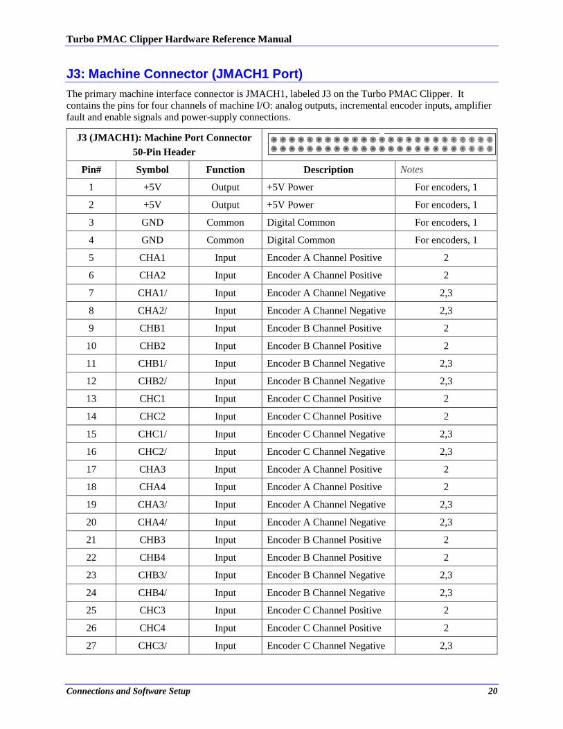
J3: Machine Connector (JMACH1 Port)
The primary machine interface connector is JMACH1, labeled J3 on the Turbo PMAC Clipper. It
contains the pins for four channels of machine I/O: analog outputs, incremental encoder inputs, amplifier
fault and enable signals and power-supply connections.
J3 (JMACH1): Machine Port Connector
50-Pin Header
49
50
47
48
45
46
43
44
41
42
39
40
37
38
35
36
33
34
31
32
29
30
27
28
25
26
23
24
21
22
19
20
17
18
15
16
13
14
11
12
9
10
7
8
5
6
3
4
1
2
Pin# Symbol Function Description Notes
1 +5V Output +5V Power For encoders, 1
2 +5V Output +5V Power For encoders, 1
3 GND Common Digital Common For encoders, 1
4 GND Common Digital Common For encoders, 1
5 CHA1 Input Encoder A Channel Positive 2
6 CHA2 Input Encoder A Channel Positive 2
7 CHA1/ Input Encoder A Channel Negative 2,3
8 CHA2/ Input Encoder A Channel Negative 2,3
9 CHB1 Input Encoder B Channel Positive 2
10 CHB2 Input Encoder B Channel Positive 2
11 CHB1/ Input Encoder B Channel Negative 2,3
12 CHB2/ Input Encoder B Channel Negative 2,3
13 CHC1 Input Encoder C Channel Positive 2
14 CHC2 Input Encoder C Channel Positive 2
15 CHC1/ Input Encoder C Channel Negative 2,3
16 CHC2/ Input Encoder C Channel Negative 2,3
17 CHA3 Input Encoder A Channel Positive 2
18 CHA4 Input Encoder A Channel Positive 2
19 CHA3/ Input Encoder A Channel Negative 2,3
20 CHA4/ Input Encoder A Channel Negative 2,3
21 CHB3 Input Encoder B Channel Positive 2
22 CHB4 Input Encoder B Channel Positive 2
23 CHB3/ Input Encoder B Channel Negative 2,3
24 CHB4/ Input Encoder B Channel Negative 2,3
25 CHC3 Input Encoder C Channel Positive 2
26 CHC4 Input Encoder C Channel Positive 2
27 CHC3/ Input Encoder C Channel Negative 2,3

Turbo PMAC Clipper Hardware Reference Manual
Connections and Software Setup 21
28 CHC4/ Input Encoder C Channel Negative 2,3
29 DAC1 Output Analog Output Positive 1 4
30 DAC2 Output Analog Output Positive 2 4
31 DAC1/ Output Analog Output Negative 1 4,5
32 DAC2/ Output Analog Output Negative 2 4,5
33 AENA1/ Output Amplifier-Enable 1
34 AENA2/ Output Amplifier -Enable 2
35 FAULT1/ Input Amplifier -Fault 1 6
36 FAULT2/ Input Amplifier -Fault 2 6
37 DAC3 Output Analog Output Positive 3 4
38 DAC4 Output Analog Output Positive 4 4
39 DAC3/ Output Analog Output Negative 3 4,5
40 DAC4/ Output Analog Output Negative 4 4,5
41 AENA3/ Output Amplifier -Enable 3
42 AENA4/ Output Amplifier -Enable 4
43 FAULT3/ Input Amplifier -Fault 3 6
44 FAULT4/ Input Amplifier -Fault 4 6
45 ADCIN_1 Input Analog Input 1 Option-12 required
46 ADCIN_2 Input Analog Input 2 Option-12 required
47 FLT_FLG_V Input Amplifier Fault pull-up V+
48 GND Common Digital Common
49 +12V Input DAC Supply Voltage 7
50 -12V Input DAC Supply Voltage 7
Note
Note 1: These lines can be used as +5V power supply inputs to power
PMAC’s digital circuitry.
Note 2: Referenced to digital common (GND). Maximum of ±12V
permitted between this signal and its complement.
Note 3: Leave this input floating if not used (i.e. digital single-ended
encoders).
Note 4: ±10V, 10 mA max, referenced to common ground (GND).
Note 5: Leave floating if not used. Do not tie to GND.
Note 6: Functional polarity controlled by variable Ixx24. Must be
conducting to 0V (usually GND) to produce a 0 in PMAC software.
Automatic fault function can be disabled with Ixx24.
Note 7: Can be used to provide input power when the TB1 connector is
not being used.
Turbo PMAC Clipper Hardware Reference Manual
Connections and Software Setup 22
50-pin female flat cable connector T&B Ansley P/N 609-5041
Standard flat cable stranded 50-wire T&B Ansley P/N 171-50
Phoenix varioface module type FLKM 50 (male pins) P/N 22 81 08 9
Note
Use an encoder cable with high quality shield.
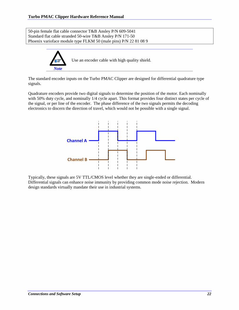
The standard encoder inputs on the Turbo PMAC Clipper are designed for differential quadrature type
signals.
Quadrature encoders provide two digital signals to determine the position of the motor. Each nominally
with 50% duty cycle, and nominally 1/4 cycle apart. This format provides four distinct states per cycle of
the signal, or per line of the encoder. The phase difference of the two signals permits the decoding
electronics to discern the direction of travel, which would not be possible with a single signal.
Channel A
Channel B
Typically, these signals are 5V TTL/CMOS level whether they are single-ended or differential.
Differential signals can enhance noise immunity by providing common mode noise rejection. Modern
design standards virtually mandate their use in industrial systems.
Turbo PMAC Clipper Hardware Reference Manual
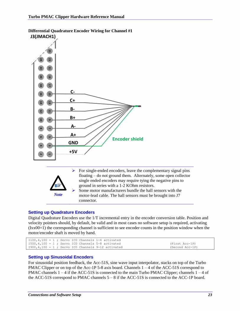
Connections and Software Setup 23
Differential Quadrature Encoder Wiring for Channel #1
Encoder shield
25
23
24
21
22
19
20
17
18
15
16
13
14
11
12
910
78
56
34
12
B-
C-
C+
B+
A-
A+
GND
+5V
J3(JMACH1)
Note
For single-ended encoders, leave the complementary signal pins
floating – do not ground them. Alternately, some open collector
single ended encoders may require tying the negative pins to
ground in series with a 1-2 KOhm resistors.
Some motor manufacturers bundle the hall sensors with the
motor-lead cable. The hall sensors must be brought into J7
connector.
Setting up Quadrature Encoders
Digital Quadrature Encoders use the 1/T incremental entry in the encoder conversion table. Position and
velocity pointers should, by default, be valid and in most cases no software setup is required, activating
(Ixx00=1) the corresponding channel is sufficient to see encoder counts in the position window when the
motor/encoder shaft is moved by hand. I100,4,100 = 1 ; Servo IC0 Channels 1-4 activated
I500,4,100 = 1 ; Servo IC0 Channels 5-8 activated (First Acc-1P)
I900,4,100 = 1 ; Servo IC0 Channels 9-12 activated (Second Acc-1P)
Setting up Sinusoidal Encoders
For sinusoidal position feedback, the Acc-51S, sine wave input interpolator, stacks on top of the Turbo
PMAC Clipper or on top of the Acc-1P 5-8 axis board. Channels 1 – 4 of the ACC-51S correspond to
PMAC channels 1 – 4 if the ACC-51S is connected to the main Turbo PMAC Clipper; channels 1 – 4 of
the ACC-51S correspond to PMAC channels 5 – 8 if the ACC-51S is connected to the ACC-1P board.
Turbo PMAC Clipper Hardware Reference Manual
Connections and Software Setup 24
Note
ACC-51S channels 1 – 4 become PMAC channels 1 – 4 if ACC-
51S jumper E1 connects pins 2 and 3.
ACC-51S channels 1 – 4 become PMAC channels 5 – 8 if ACC
51S jumper E1 connects pins 1 and 2.
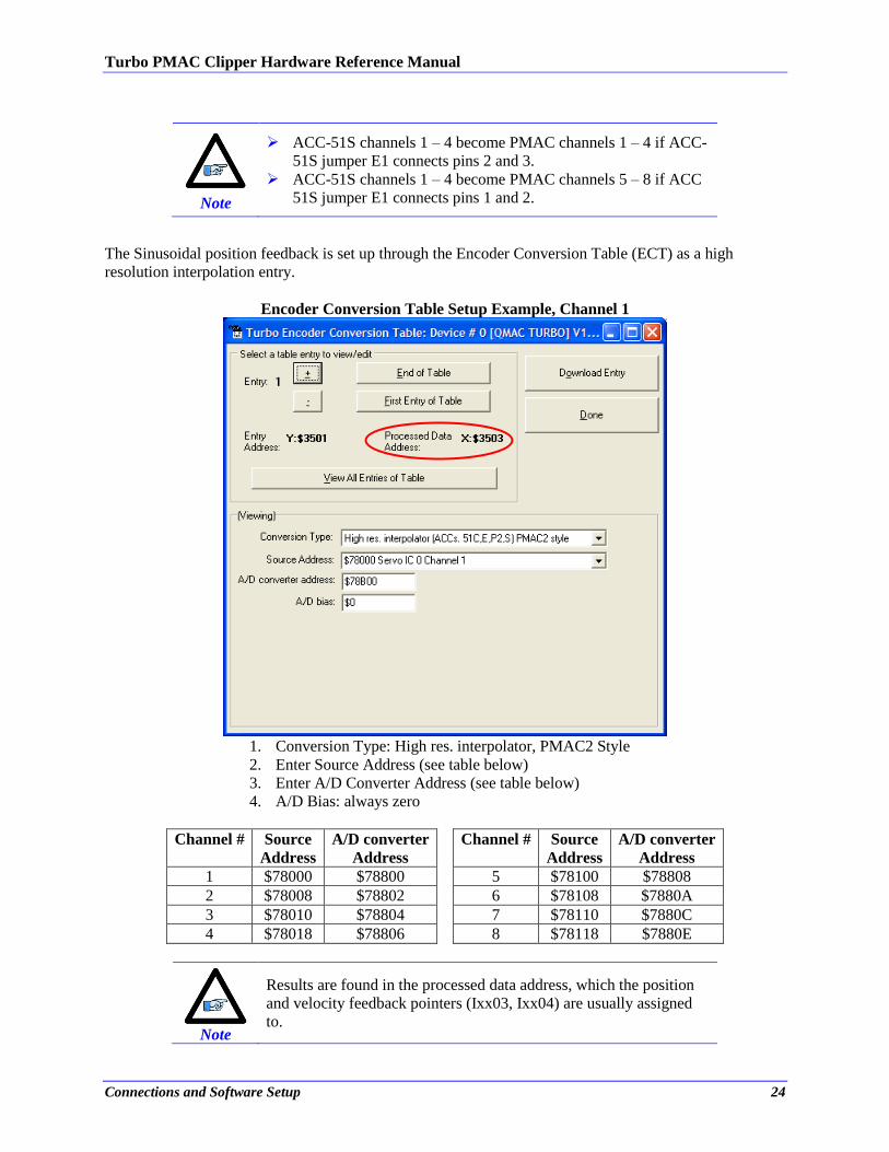
The Sinusoidal position feedback is set up through the Encoder Conversion Table (ECT) as a high
resolution interpolation entry.
Encoder Conversion Table Setup Example, Channel 1
1. Conversion Type: High res. interpolator, PMAC2 Style
2. Enter Source Address (see table below)
3. Enter A/D Converter Address (see table below)
4. A/D Bias: always zero
Channel # Source
Address
A/D converter
Address
Channel # Source
Address
A/D converter
Address
1 $78000 $78800 5 $78100 $78808
2 $78008 $78802 6 $78108 $7880A
3 $78010 $78804 7 $78110 $7880C
4 $78018 $78806 8 $78118 $7880E
Note
Results are found in the processed data address, which the position
and velocity feedback pointers (Ixx03, Ixx04) are usually assigned
to.
Turbo PMAC Clipper Hardware Reference Manual
Connections and Software Setup 25
The equivalent Turbo PMAC script code for 8-channel entries // Channel 1
I8000=$FF8000 ; High resolution interpolator (Clipper & Acc-51S)
I8001=$078800 ; A/D converter address (Clipper & Acc-51S)
I8002=$000000 ; Bias Term and Entry result (Clipper & Acc-51S)
// Channel 2
I8003=$FF8008 ; High resolution interpolator (Clipper & Acc-51S)
I8004=$078802 ; A/D converter address (Clipper & Acc-51S)
I8005=$000000 ; Bias Term and Entry result (Clipper & Acc-51S)
// Channel 3
I8006=$FF8010 ; High resolution interpolator (Clipper & Acc-51S)
I8007=$078804 ; A/D converter address (Clipper & Acc-51S)
I8008=$000000 ; Bias Term and Entry result (Clipper & Acc-51S)
// Channel 4
I8009=$FF8018 ; High resolution interpolator (Clipper & Acc-51S)
I8010=$078806 ; A/D converter address (Clipper & Acc-51S)
I8011=$000000 ; Bias Term and Entry result (Clipper & Acc-51S)
// Channel 5
I8012=$FF8100 ; High resolution interpolator (Acc-1P & Acc-51S)
I8013=$078808 ; A/D converter address (Acc-1P & Acc-51S)
I8014=$000000 ; Bias Term and Entry result (Acc-1P & Acc-51S)
// Channel 6
I8015=$FF8108 ; High resolution interpolator (Acc-1P & Acc-51S)
I8016=$07880A ; A/D converter address (Acc-1P & Acc-51S)
I8017=$000000 ; Bias Term and Entry result (Acc-1P & Acc-51S)
// Channel 7
I8018=$FF8110 ; High resolution interpolator (Acc-1P & Acc-51S)
I8019=$07880C ; A/D converter address (Acc-1P & Acc-51S)
I8020=$000000 ; Bias Term and Entry result (Acc-1P & Acc-51S)
// Channel 8
I8021=$FF8118 ; High resolution interpolator (Acc-1P & Acc-51S)
I8022=$07880E ; A/D converter address (Acc-1P & Acc-51S)
I8023=$000000 ; Bias Term and Entry result (Acc-1P & Acc-51S)
Position and Velocity feedback pointers should now be set to the corresponding ECT result: I103=$3503 I104=$3503 ; (Clipper & Acc-51S)
I203=$3506 I204=$3506 ; (Clipper & Acc-51S)
I303=$3509 I304=$3509 ; (Clipper & Acc-51S)
I403=$350C I404=$350C ; (Clipper & Acc-51S)
I503=$350F I504=$350F ; (Acc-1P & Acc-51S)
I603=$3512 I604=$3512 ; (Acc-1P & Acc-51S)
I703=$3515 I704=$3515 ; (Acc-1P & Acc-51S)
I803=$3518 I804=$3518 ; (Acc-1P & Acc-51S)
Note
At this point of the setup, you should be able to move the
motor/encoder shaft by hand and see ‘motor’ counts in the position
window.
Counts per User Units
With the interpolation of x 4096 in Turbo PMAC, there are 128 (4096/32) motor counts per sine/cosine
cycles. Motor counts can be monitored in the motor position window upon moving the motor by hand.
Examples:
A 1024 Sine/Cosine periods per revolution of a rotary encoder produces 1024 x 128 = 131,072 cts/rev.
A 20 μm linear encoder resolution produces 128/0.02 = 6400 cts/mm.
Turbo PMAC Clipper Hardware Reference Manual
Connections and Software Setup 26
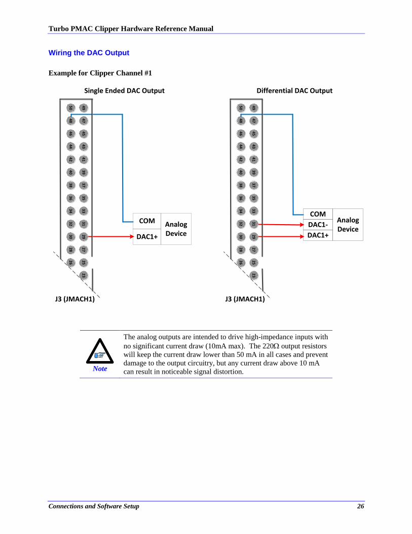
Wiring the DAC Output
Example for Clipper Channel #1
25
23
Analog Device
COM
DAC1+
49
50
47
48
45
46
43
44
41
42
39
40
37
38
35
36
33
34
31
32
29
30
27
28
26
Single Ended DAC Output
J3 (JMACH1)
Analog Device
COM
DAC1-
DAC1+
25
23
49
50
47
48
45
46
43
44
41
42
39
40
37
38
35
36
33
34
31
32
29
30
27
28
26
Differential DAC Output
J3 (JMACH1)
Note
The analog outputs are intended to drive high-impedance inputs with
no significant current draw (10mA max). The 220 output resistors
will keep the current draw lower than 50 mA in all cases and prevent
damage to the output circuitry, but any current draw above 10 mA
can result in noticeable signal distortion.
Turbo PMAC Clipper Hardware Reference Manual
Connections and Software Setup 27
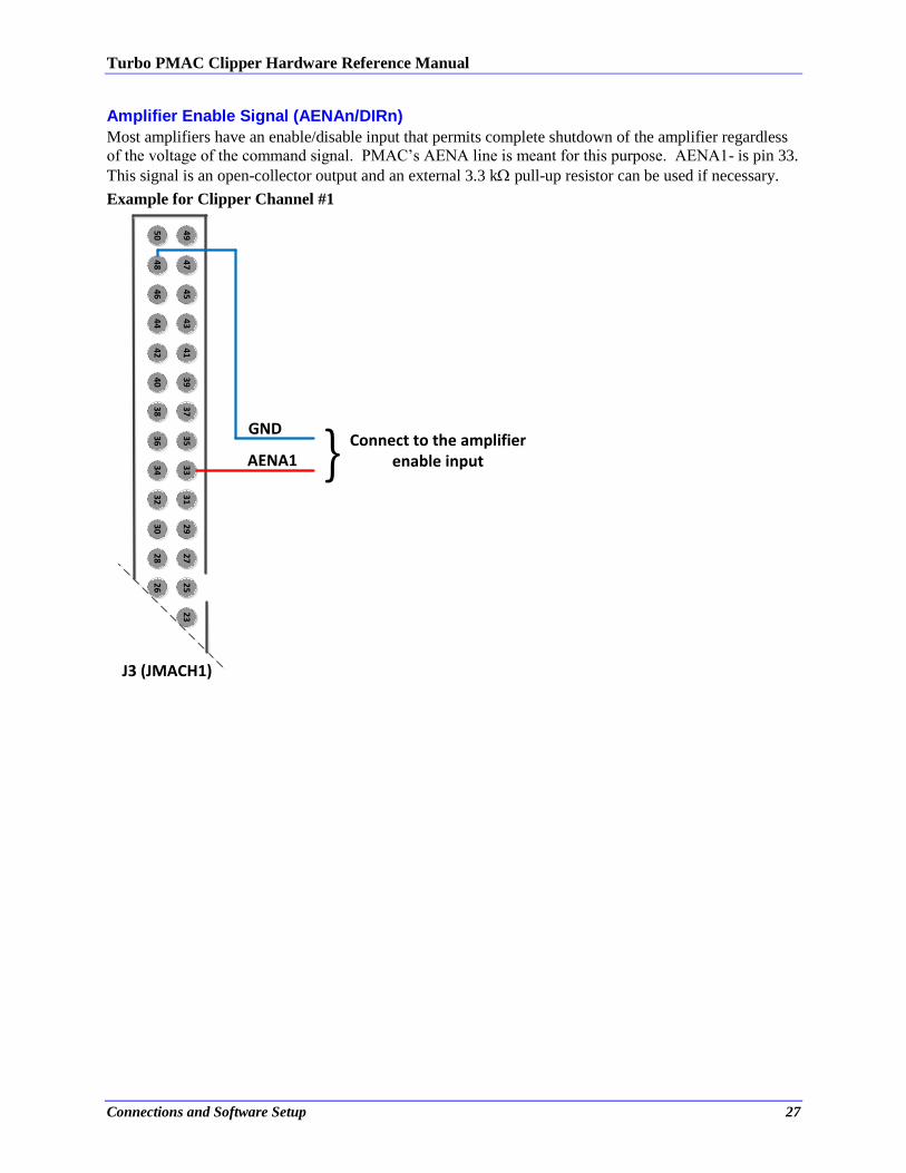
Amplifier Enable Signal (AENAn/DIRn)
Most amplifiers have an enable/disable input that permits complete shutdown of the amplifier regardless
of the voltage of the command signal. PMAC’s AENA line is meant for this purpose. AENA1- is pin 33.
This signal is an open-collector output and an external 3.3 k pull-up resistor can be used if necessary.
Example for Clipper Channel #1
25
23
49
50
47
48
45
46
43
44
41
42
39
40
37
38
35
36
33
34
31
32
29
30
27
28
26
J3 (JMACH1)
AENA1
GND
} Connect to the amplifierenable input
Turbo PMAC Clipper Hardware Reference Manual
Connections and Software Setup 28
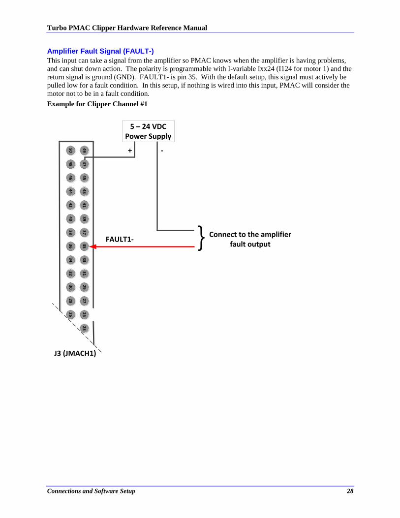
Amplifier Fault Signal (FAULT-)
This input can take a signal from the amplifier so PMAC knows when the amplifier is having problems,
and can shut down action. The polarity is programmable with I-variable Ixx24 (I124 for motor 1) and the
return signal is ground (GND). FAULT1- is pin 35. With the default setup, this signal must actively be
pulled low for a fault condition. In this setup, if nothing is wired into this input, PMAC will consider the
motor not to be in a fault condition.
Example for Clipper Channel #1
J3 (JMACH1)
5 – 24 VDCPower Supply
25
23
49
50
47
48
45
46
43
44
41
42
39
40
37
38
35
36
33
34
31
32
29
30
27
28
26
FAULT1- } Connect to the amplifierfault output
+ -
Turbo PMAC Clipper Hardware Reference Manual
Connections and Software Setup 29
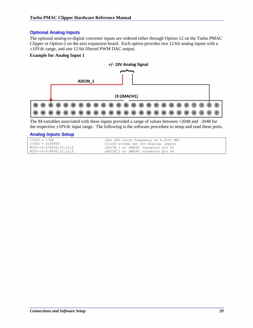
Optional Analog Inputs
The optional analog-to-digital converter inputs are ordered either through Option-12 on the Turbo PMAC
Clipper or Option-2 on the axis expansion board. Each option provides two 12-bit analog inputs with a
±10Vdc range, and one 12-bit filtered PWM DAC output.
Example for Analog Input 1
} +/- 10V Analog Signal
ADCIN_1
J3 (JMACH1)
49
50
47
48
45
46
43
44
41
42
39
40
37
38
35
36
33
34
31
32
29
30
27
28
25
26
23
24
21
22
19
20
17
18
15
16
13
14
11
12
9
10
7
8
5
6
3
4
1
2
The M-variables associated with these inputs provided a range of values between +2048 and –2048 for
the respective ±10Vdc input range. The following is the software procedure to setup and read these ports.
Analog Inputs Setup I7003 = 1746 ;Set ADC clock frequency at 4.9152 MHz
I7006 = $1FFFFF ;Clock strobe set for bipolar inputs
M105->Y:$78005,12,12,S ;ADCIN_1 on JMACH1 connector pin 45
M205->Y:$7800D,12,12,S ;ADCIN_2 on JMACH1 connector pin 46
Turbo PMAC Clipper Hardware Reference Manual
Connections and Software Setup 30
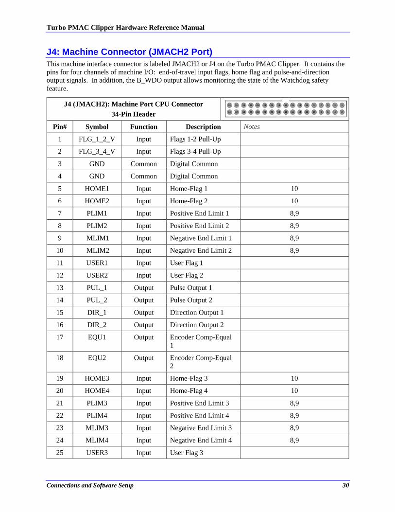
J4: Machine Connector (JMACH2 Port)
This machine interface connector is labeled JMACH2 or J4 on the Turbo PMAC Clipper. It contains the
pins for four channels of machine I/O: end-of-travel input flags, home flag and pulse-and-direction
output signals. In addition, the B_WDO output allows monitoring the state of the Watchdog safety
feature.
J4 (JMACH2): Machine Port CPU Connector
34-Pin Header
5
6
3
4
1
2
9
10
7
8
15
16
13
14
11
12
19
20
17
18
25
26
23
24
21
22
29
30
27
28
33
34
31
32
Pin# Symbol Function Description Notes
1 FLG_1_2_V Input Flags 1-2 Pull-Up
2 FLG_3_4_V Input Flags 3-4 Pull-Up
3 GND Common Digital Common
4 GND Common Digital Common
5 HOME1 Input Home-Flag 1 10
6 HOME2 Input Home-Flag 2 10
7 PLIM1 Input Positive End Limit 1 8,9
8 PLIM2 Input Positive End Limit 2 8,9
9 MLIM1 Input Negative End Limit 1 8,9
10 MLIM2 Input Negative End Limit 2 8,9
11 USER1 Input User Flag 1
12 USER2 Input User Flag 2
13 PUL_1 Output Pulse Output 1
14 PUL_2 Output Pulse Output 2
15 DIR_1 Output Direction Output 1
16 DIR_2 Output Direction Output 2
17 EQU1 Output Encoder Comp-Equal
1
18 EQU2 Output Encoder Comp-Equal
2
19 HOME3 Input Home-Flag 3 10
20 HOME4 Input Home-Flag 4 10
21 PLIM3 Input Positive End Limit 3 8,9
22 PLIM4 Input Positive End Limit 4 8,9
23 MLIM3 Input Negative End Limit 3 8,9
24 MLIM4 Input Negative End Limit 4 8,9
25 USER3 Input User Flag 3
Turbo PMAC Clipper Hardware Reference Manual
Connections and Software Setup 31
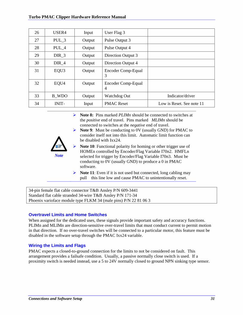
26 USER4 Input User Flag 3
27 PUL_3 Output Pulse Output 3
28 PUL_4 Output Pulse Output 4
29 DIR_3 Output Direction Output 3
30 DIR_4 Output Direction Output 4
31 EQU3 Output Encoder Comp-Equal
3
32 EQU4 Output Encoder Comp-Equal
4
33 B_WDO Output Watchdog Out Indicator/driver
34 INIT- Input PMAC Reset Low is Reset. See note 11
Note
Note 8: Pins marked PLIMn should be connected to switches at
the positive end of travel. Pins marked MLIMn should be
connected to switches at the negative end of travel.
Note 9: Must be conducting to 0V (usually GND) for PMAC to
consider itself not into this limit. Automatic limit function can
be disabled with Ixx24.
Note 10: Functional polarity for homing or other trigger use of
HOMEn controlled by Encoder/Flag Variable I70n2. HMFLn
selected for trigger by Encoder/Flag Variable I70n3. Must be
conducting to 0V (usually GND) to produce a 0 in PMAC
software.
Note 11: Even if it is not used but connected, long cabling may
pull this line low and cause PMAC to unintentionally reset.
34-pin female flat cable connector T&B Ansley P/N 609-3441
Standard flat cable stranded 34-wire T&B Ansley P/N 171-34
Phoenix varioface module type FLKM 34 (male pins) P/N 22 81 06 3
Overtravel Limits and Home Switches
When assigned for the dedicated uses, these signals provide important safety and accuracy functions.
PLIMn and MLIMn are direction-sensitive over-travel limits that must conduct current to permit motion
in that direction. If no over-travel switches will be connected to a particular motor, this feature must be
disabled in the software setup through the PMAC Ixx24 variable.
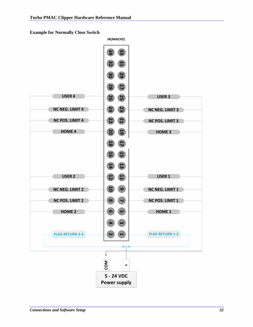
Wiring the Limits and Flags
PMAC expects a closed-to-ground connection for the limits to not be considered on fault. This
arrangement provides a failsafe condition. Usually, a passive normally close switch is used. If a
proximity switch is needed instead, use a 5 to 24V normally closed to ground NPN sinking type sensor.
Turbo PMAC Clipper Hardware Reference Manual
Connections and Software Setup 32
Example for Normally Close Switch
56
34
12
910
78
15
16
13
14
11
12
19
20
17
18
25
26
23
24
21
22
29
30
27
28
33
34
31
32
5 - 24 VDCPower supply
USER 1
NC POS. LIMIT 1
NC NEG. LIMIT 1
HOME 1
CO
M +
FLAG RETURN 3-4 FLAG RETURN 1-2
USER 2
NC POS. LIMIT 2
NC NEG. LIMIT 2
HOME 2
USER 3
NC POS. LIMIT 3
NC NEG. LIMIT 3
HOME 3
USER 4
NC POS. LIMIT 4
NC NEG. LIMIT 4
HOME 4
J4(JMACH2)
Turbo PMAC Clipper Hardware Reference Manual
Connections and Software Setup 33
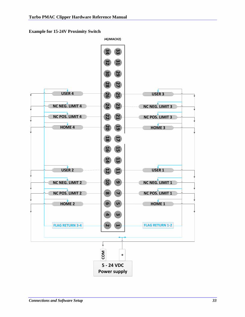
Example for 15-24V Proximity Switch
56
34
12
910
78
15
16
13
14
11
12
19
20
17
18
25
26
23
24
21
22
29
30
27
28
33
34
31
32
5 - 24 VDCPower supply
USER 1
NC POS. LIMIT 1
NC NEG. LIMIT 1
HOME 1
CO
M +
FLAG RETURN 3-4 FLAG RETURN 1-2
USER 2
NC POS. LIMIT 2
NC NEG. LIMIT 2
HOME 2
USER 3
NC POS. LIMIT 3
NC NEG. LIMIT 3
HOME 3
USER 4
NC POS. LIMIT 4
NC NEG. LIMIT 4
HOME 4
J4(JMACH2)
Turbo PMAC Clipper Hardware Reference Manual
Connections and Software Setup 34
Note
While normally closed-to-ground switches are required for the
overtravel limits inputs, the home switches could be either
normally close or normally open types. The polarity is
determined by the home sequence setup, through the I-variables
I7mn2.
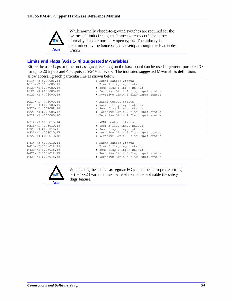
Limits and Flags [Axis 1- 4] Suggested M-Variables
Either the user flags or other not assigned axes flag on the base board can be used as general-purpose I/O
for up to 20 inputs and 4 outputs at 5-24Vdc levels. The indicated suggested M-variables definitions
allow accessing each particular line as shown below: M114->X:$078005,14 ; AENA1 output status
M115->X:$078000,19 ; User 1 flag input status
M120->X:$078000,16 ; Home flag 1 input status
M121->X:$078000,17 ; Positive Limit 1 flag input status
M122->X:$078000,18 ; Negative Limit 1 flag input status
M214->X:$07800D,14 ; AENA2 output status
M215->X:$078008,19 ; User 2 flag input status
M220->X:$078008,16 ; Home flag 2 input status
M221->X:$078008,17 ; Positive Limit 2 flag input status
M222->X:$078008,18 ; Negative Limit 2 flag input status
M314->X:$078015,14 ; AENA3 output status
M315->X:$078010,19 ; User 3 flag input status
M320->X:$078010,16 ; Home flag 3 input status
M321->X:$078010,17 ; Positive Limit 3 flag input status
M322->X:$078010,18 ; Negative Limit 3 flag input status
M414->X:$07801D,14 ; AENA4 output status
M415->X:$078018,19 ; User 4 flag input status
M420->X:$078018,16 ; Home flag 4 input status
M421->X:$078018,17 ; Positive Limit 4 flag input status
M422->X:$078018,18 ; Negative Limit 4 flag input status
Note
When using these lines as regular I/O points the appropriate setting
of the Ixx24 variable must be used to enable or disable the safety
flags feature.
Turbo PMAC Clipper Hardware Reference Manual
Connections and Software Setup 35
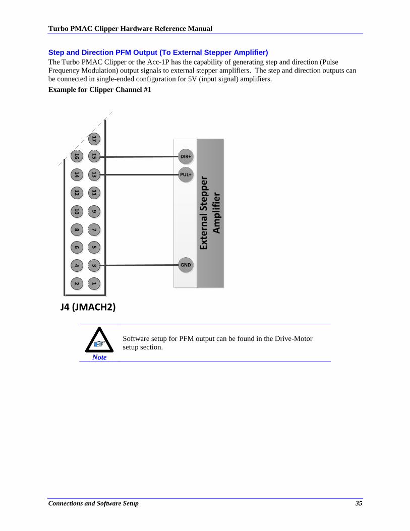
Step and Direction PFM Output (To External Stepper Amplifier)
The Turbo PMAC Clipper or the Acc-1P has the capability of generating step and direction (Pulse
Frequency Modulation) output signals to external stepper amplifiers. The step and direction outputs can
be connected in single-ended configuration for 5V (input signal) amplifiers.
Example for Clipper Channel #1
56
34
12
910
78
15
16
13
14
11
12
17
Exte
rnal
Ste
pp
er
Am
plif
ier
DIR+
PUL+
GND
J4 (JMACH2)
Note
Software setup for PFM output can be found in the Drive-Motor
setup section.
Turbo PMAC Clipper Hardware Reference Manual
Connections and Software Setup 36
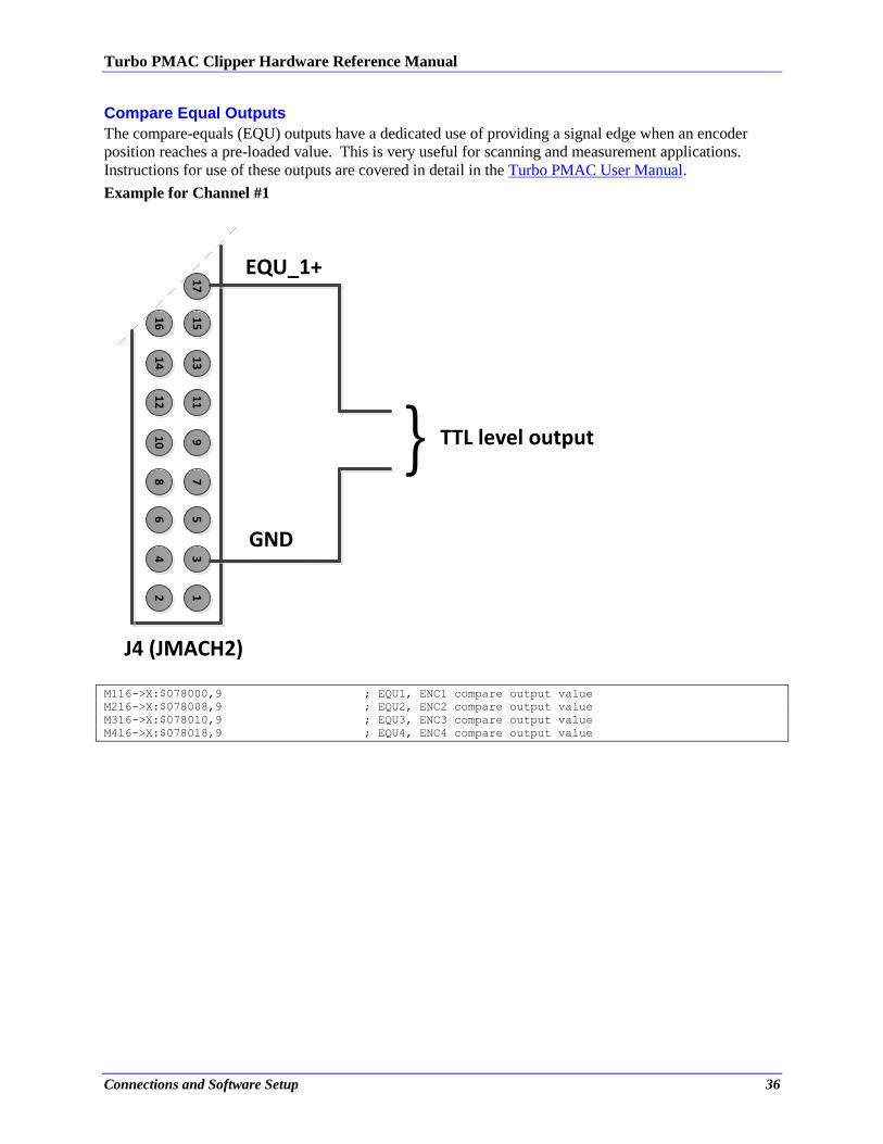
Compare Equal Outputs
The compare-equals (EQU) outputs have a dedicated use of providing a signal edge when an encoder
position reaches a pre-loaded value. This is very useful for scanning and measurement applications.
Instructions for use of these outputs are covered in detail in the Turbo PMAC User Manual.
Example for Channel #1
56
34
12
910
78
15
16
13
14
11
12
17
J4 (JMACH2)
} TTL level output
EQU_1+
GND
M116->X:$078000,9 ; EQU1, ENC1 compare output value
M216->X:$078008,9 ; EQU2, ENC2 compare output value
M316->X:$078010,9 ; EQU3, ENC3 compare output value
M416->X:$078018,9 ; EQU4, ENC4 compare output value
Turbo PMAC Clipper Hardware Reference Manual
Connections and Software Setup 37
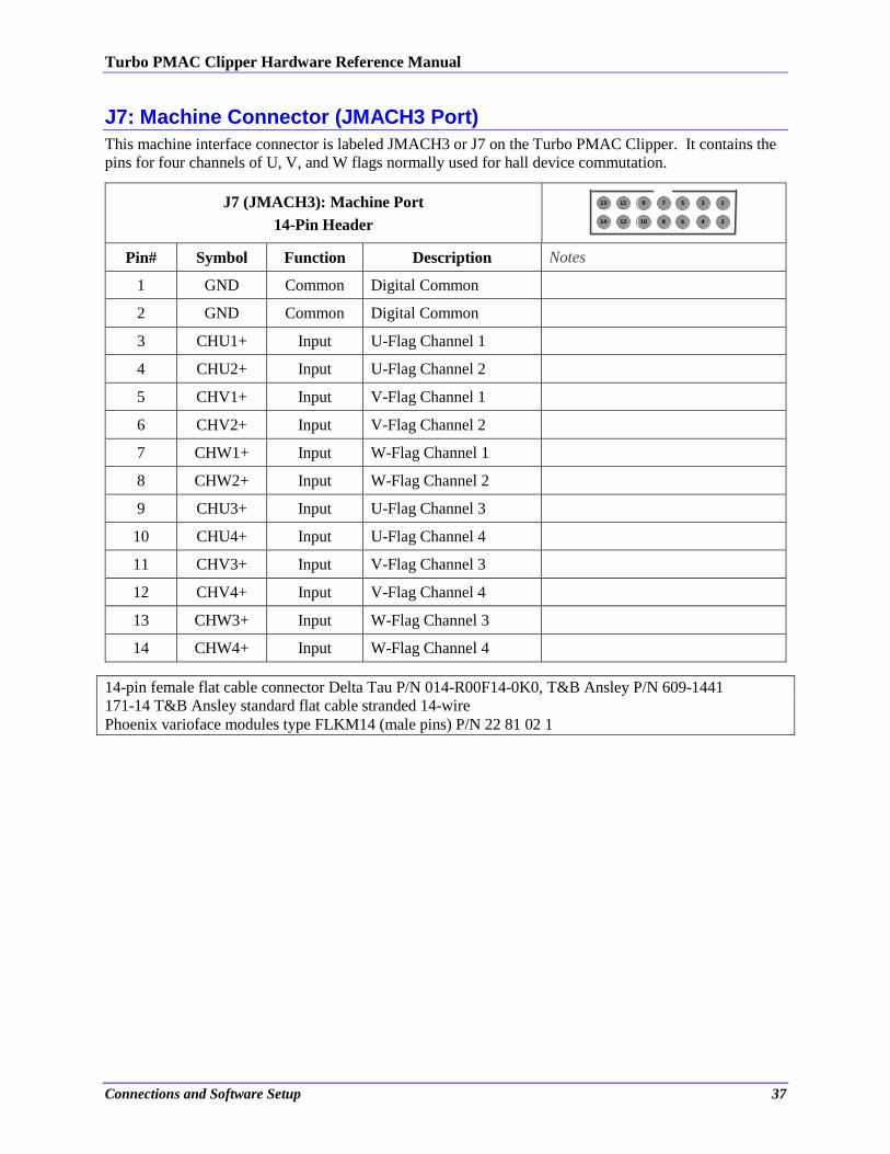
J7: Machine Connector (JMACH3 Port)
This machine interface connector is labeled JMACH3 or J7 on the Turbo PMAC Clipper. It contains the
pins for four channels of U, V, and W flags normally used for hall device commutation.
J7 (JMACH3): Machine Port
14-Pin Header
5
6
3
4
1
2
9
10
7
8
13
14
11
12
Pin# Symbol Function Description Notes
1 GND Common Digital Common
2 GND Common Digital Common
3 CHU1+ Input U-Flag Channel 1
4 CHU2+ Input U-Flag Channel 2
5 CHV1+ Input V-Flag Channel 1
6 CHV2+ Input V-Flag Channel 2
7 CHW1+ Input W-Flag Channel 1
8 CHW2+ Input W-Flag Channel 2
9 CHU3+ Input U-Flag Channel 3
10 CHU4+ Input U-Flag Channel 4
11 CHV3+ Input V-Flag Channel 3
12 CHV4+ Input V-Flag Channel 4
13 CHW3+ Input W-Flag Channel 3
14 CHW4+ Input W-Flag Channel 4
14-pin female flat cable connector Delta Tau P/N 014-R00F14-0K0, T&B Ansley P/N 609-1441
171-14 T&B Ansley standard flat cable stranded 14-wire
Phoenix varioface modules type FLKM14 (male pins) P/N 22 81 02 1
Turbo PMAC Clipper Hardware Reference Manual
Connections and Software Setup 38
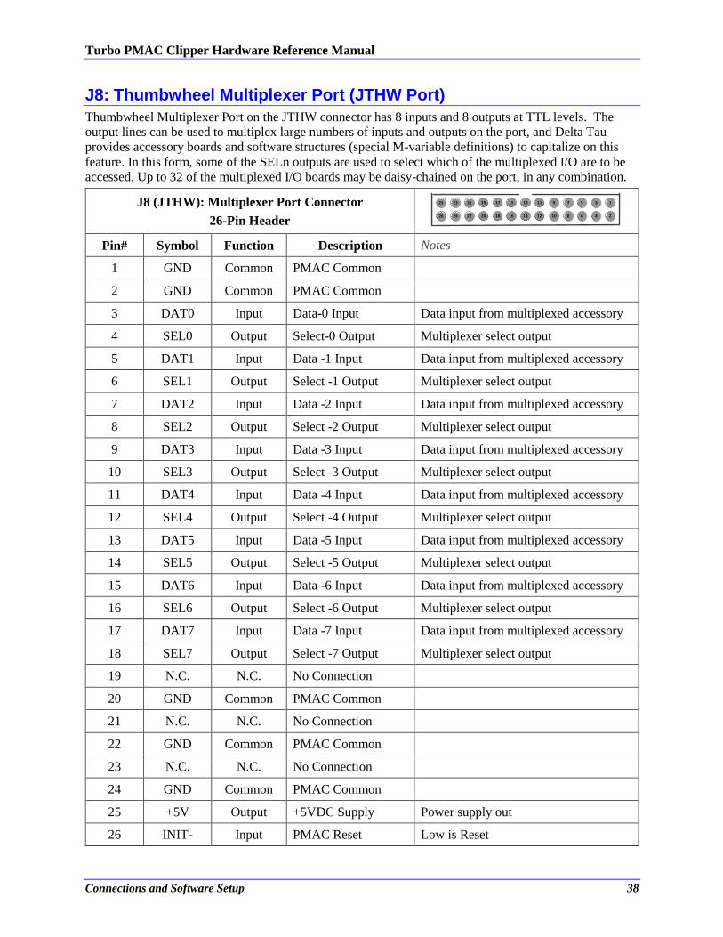
J8: Thumbwheel Multiplexer Port (JTHW Port)
Thumbwheel Multiplexer Port on the JTHW connector has 8 inputs and 8 outputs at TTL levels. The
output lines can be used to multiplex large numbers of inputs and outputs on the port, and Delta Tau
provides accessory boards and software structures (special M-variable definitions) to capitalize on this
feature. In this form, some of the SELn outputs are used to select which of the multiplexed I/O are to be
accessed. Up to 32 of the multiplexed I/O boards may be daisy-chained on the port, in any combination.
J8 (JTHW): Multiplexer Port Connector
26-Pin Header
5
6
3
4
1
2
9
10
7
8
15
16
13
14
11
12
19
20
17
18
25
26
23
24
21
22
Pin# Symbol Function Description Notes
1 GND Common PMAC Common
2 GND Common PMAC Common
3 DAT0 Input Data-0 Input Data input from multiplexed accessory
4 SEL0 Output Select-0 Output Multiplexer select output
5 DAT1 Input Data -1 Input Data input from multiplexed accessory
6 SEL1 Output Select -1 Output Multiplexer select output
7 DAT2 Input Data -2 Input Data input from multiplexed accessory
8 SEL2 Output Select -2 Output Multiplexer select output
9 DAT3 Input Data -3 Input Data input from multiplexed accessory
10 SEL3 Output Select -3 Output Multiplexer select output
11 DAT4 Input Data -4 Input Data input from multiplexed accessory
12 SEL4 Output Select -4 Output Multiplexer select output
13 DAT5 Input Data -5 Input Data input from multiplexed accessory
14 SEL5 Output Select -5 Output Multiplexer select output
15 DAT6 Input Data -6 Input Data input from multiplexed accessory
16 SEL6 Output Select -6 Output Multiplexer select output
17 DAT7 Input Data -7 Input Data input from multiplexed accessory
18 SEL7 Output Select -7 Output Multiplexer select output
19 N.C. N.C. No Connection
20 GND Common PMAC Common
21 N.C. N.C. No Connection
22 GND Common PMAC Common
23 N.C. N.C. No Connection
24 GND Common PMAC Common
25 +5V Output +5VDC Supply Power supply out
26 INIT- Input PMAC Reset Low is Reset
Turbo PMAC Clipper Hardware Reference Manual
Connections and Software Setup 39
Note
The direction of the input and output lines on this connector are
set by jumpers E14 and E15.
If E14 is removed or E15 is installed then the multiplexing
feature of the JTHW port cannot be used.
26-pin female flat cable connector T&B Ansley P/N 609-2641
Standard flat cable stranded 26-wire T&B Ansley P/N 171.26
Phoenix varioface module type FLKM 26 (male pins) P/N 22 81 05 0
Thumbwheel Port Digital Inputs and Outputs
The inputs and outputs on the thumbwheel multiplexer port J8 may be used as discrete, non-multiplexed
I/O. In this case, these I/O lines can be accessed through M-variables: M40->Y:$78402,8,1 ; SEL0 Output
M41->Y:$78402,9,1 ; SEL1 Output
M42->Y:$78402,10,1 ; SEL2 Output
M43->Y:$78402,11,1 ; SEL3 Output
M44->Y:$78402,12,1 ; SEL4 Output
M45->Y:$78402,13,1 ; SEL5 Output
M46->Y:$78402,14,1 ; SEL6 Output
M47->Y:$78402,15,1 ; SEL7 Output
M48->Y:$78402,8,8,U ; SEL0-7 Outputs treated as a byte
M50->Y:$78402,0,1 ; DAT0 Input
M51->Y:$78402,1,1 ; DAT1 Input
M52->Y:$78402,2,1 ; DAT2 Input
M53->Y:$78402,3,1 ; DAT3 Input
M54->Y:$78402,4,1 ; DAT4 Input
M55->Y:$78402,5,1 ; DAT5 Input
M56->Y:$78402,6,1 ; DAT6 Input
M57->Y:$78402,7,1 ; DAT7 Input
M58->Y:$78402,0,8,U ; DAT0-7 Inputs treated as a byte
Turbo PMAC Clipper Hardware Reference Manual
Connections and Software Setup 40
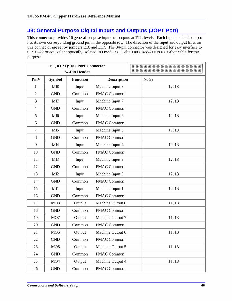
J9: General-Purpose Digital Inputs and Outputs (JOPT Port)
This connector provides 16 general-purpose inputs or outputs at TTL levels. Each input and each output
has its own corresponding ground pin in the opposite row. The direction of the input and output lines on
this connector are set by jumpers E16 and E17. The 34-pin connector was designed for easy interface to
OPTO-22 or equivalent optically isolated I/O modules. Delta Tau's Acc-21F is a six-foot cable for this
purpose.
J9 (JOPT): I/O Port Connector
34-Pin Header
5
6
3
4
1
2
9
10
7
8
15
16
13
14
11
12
19
20
17
18
25
26
23
24
21
22
29
30
27
28
33
34
31
32
Pin# Symbol Function Description Notes
1 MI8 Input Machine Input 8 12, 13
2 GND Common PMAC Common
3 MI7 Input Machine Input 7 12, 13
4 GND Common PMAC Common
5 MI6 Input Machine Input 6 12, 13
6 GND Common PMAC Common
7 MI5 Input Machine Input 5 12, 13
8 GND Common PMAC Common
9 MI4 Input Machine Input 4 12, 13
10 GND Common PMAC Common
11 MI3 Input Machine Input 3 12, 13
12 GND Common PMAC Common
13 MI2 Input Machine Input 2 12, 13
14 GND Common PMAC Common
15 MI1 Input Machine Input 1 12, 13
16 GND Common PMAC Common
17 MO8 Output Machine Output 8 11, 13
18 GND Common PMAC Common
19 MO7 Output Machine Output 7 11, 13
20 GND Common PMAC Common
21 MO6 Output Machine Output 6 11, 13
22 GND Common PMAC Common
23 MO5 Output Machine Output 5 11, 13
24 GND Common PMAC Common
25 MO4 Output Machine Output 4 11, 13
26 GND Common PMAC Common
Turbo PMAC Clipper Hardware Reference Manual
Connections and Software Setup 41
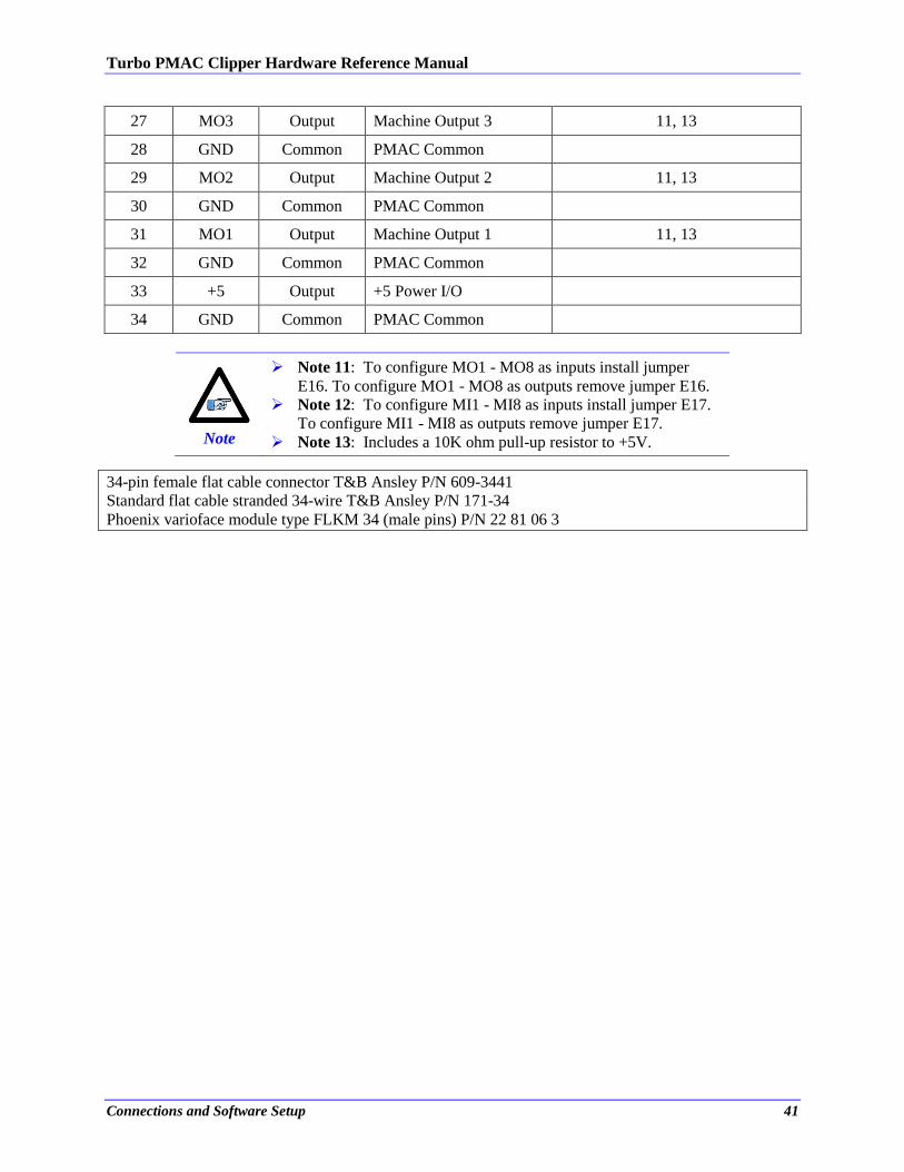
27 MO3 Output Machine Output 3 11, 13
28 GND Common PMAC Common
29 MO2 Output Machine Output 2 11, 13
30 GND Common PMAC Common
31 MO1 Output Machine Output 1 11, 13
32 GND Common PMAC Common
33 +5 Output +5 Power I/O
34 GND Common PMAC Common
Note
Note 11: To configure MO1 - MO8 as inputs install jumper
E16. To configure MO1 - MO8 as outputs remove jumper E16.
Note 12: To configure MI1 - MI8 as inputs install jumper E17.
To configure MI1 - MI8 as outputs remove jumper E17.
Note 13: Includes a 10K ohm pull-up resistor to +5V.
34-pin female flat cable connector T&B Ansley P/N 609-3441
Standard flat cable stranded 34-wire T&B Ansley P/N 171-34
Phoenix varioface module type FLKM 34 (male pins) P/N 22 81 06 3
Turbo PMAC Clipper Hardware Reference Manual
Connections and Software Setup 42
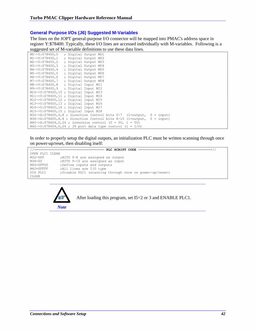
General Purpose I/Os (J6) Suggested M-Variables
The lines on the JOPT general-purpose I/O connector will be mapped into PMAC's address space in
register Y:$78400. Typically, these I/O lines are accessed individually with M-variables. Following is a
suggested set of M-variable definitions to use these data lines. M0->Y:$78400,0 ; Digital Output M01
M1->Y:$78400,1 ; Digital Output M02
M2->Y:$78400,2 ; Digital Output M03
M3->Y:$78400,3 ; Digital Output M04
M4->Y:$78400,4 ; Digital Output M05
M5->Y:$78400,5 ; Digital Output M06
M6->Y:$78400,6 ; Digital Output M07
M7->Y:$78400,7 ; Digital Output M08
M8->Y:$78400,8 ; Digital Input MI1
M9->Y:$78400,9 ; Digital Input MI2
M10->Y:$78400,10 ; Digital Input MI3
M11->Y:$78400,11 ; Digital Input MI4
M12->Y:$78400,12 ; Digital Input MI5
M13->Y:$78400,13 ; Digital Input MI6
M14->Y:$78400,14 ; Digital Input MI7
M15->Y:$78400,15 ; Digital Input MI8
M32->X:$78400,0,8 ; Direction Control bits 0-7 (1=output, 0 = input)
M34->X:$78400,8,8 ; Direction Control bits 8-15 (1=output, 0 = input)
M40->X:$78404,0,24 ; Inversion control (0 = 0V, 1 = 5V)
M42->Y:$78404,0,24 ; J9 port data type control (1 = I/O)
In order to properly setup the digital outputs, an initialization PLC must be written scanning through once
on power-up/reset, then disabling itself:
//=================================== PLC SCRIPT CODE =====================================//
OPEN PLC1 CLEAR
M32=$FF ;BITS 0-8 are assigned as output
M34=$0 ;BITS 9-16 are assigned as input
M40=$FF00 ;Define inputs and outputs
M42=$FFFF ;All lines are I/O type
DIS PLC1 ;Disable PLC1 (scanning through once on power-up/reset)
CLOSE
Note
After loading this program, set I5=2 or 3 and ENABLE PLC1.
Turbo PMAC Clipper Hardware Reference Manual
Connections and Software Setup 43
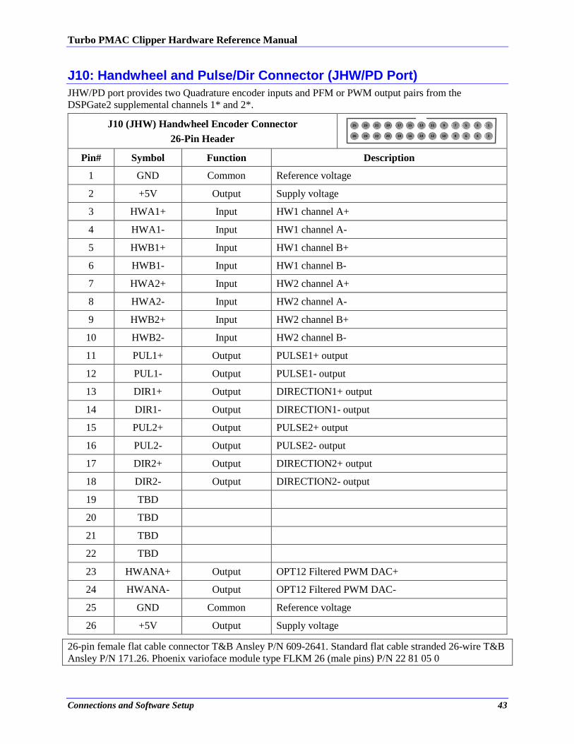
J10: Handwheel and Pulse/Dir Connector (JHW/PD Port)
JHW/PD port provides two Quadrature encoder inputs and PFM or PWM output pairs from the
DSPGate2 supplemental channels 1* and 2*.
J10 (JHW) Handwheel Encoder Connector
26-Pin Header
5
6
3
4
1
2
9
10
7
8
15
16
13
14
11
12
19
20
17
18
25
26
23
24
21
22
Pin# Symbol Function Description
1 GND Common Reference voltage
2 +5V Output Supply voltage
3 HWA1+ Input HW1 channel A+
4 HWA1- Input HW1 channel A-
5 HWB1+ Input HW1 channel B+
6 HWB1- Input HW1 channel B-
7 HWA2+ Input HW2 channel A+
8 HWA2- Input HW2 channel A-
9 HWB2+ Input HW2 channel B+
10 HWB2- Input HW2 channel B-
11 PUL1+ Output PULSE1+ output
12 PUL1- Output PULSE1- output
13 DIR1+ Output DIRECTION1+ output
14 DIR1- Output DIRECTION1- output
15 PUL2+ Output PULSE2+ output
16 PUL2- Output PULSE2- output
17 DIR2+ Output DIRECTION2+ output
18 DIR2- Output DIRECTION2- output
19 TBD
20 TBD
21 TBD
22 TBD
23 HWANA+ Output OPT12 Filtered PWM DAC+
24 HWANA- Output OPT12 Filtered PWM DAC-
25 GND Common Reference voltage
26 +5V Output Supply voltage
26-pin female flat cable connector T&B Ansley P/N 609-2641. Standard flat cable stranded 26-wire T&B
Ansley P/N 171.26. Phoenix varioface module type FLKM 26 (male pins) P/N 22 81 05 0
Turbo PMAC Clipper Hardware Reference Manual
Connections and Software Setup 44
J12: Ethernet Communications Port
This connector is used to establish communication over Ethernet between the PC and the Turbo PMAC
Clipper. A crossover cable is required if you are going directly to the Clipper from the PC Ethernet card,
and not through a hub.
Delta Tau strongly recommends the use of RJ45 CAT5e or better shielded cable. Newer network cards
have the Auto-MDIX feature that eliminates the need for crossover cabling by performing an internal
crossover when a straight cable is detected during the auto-negotiation process. For older network cards,
one end of the link must perform media dependent interface (MDI) crossover (MDIX), so that the
transmitter on one end of the data link is connected to the receiver on the other end of the data link (a
crossover/patch cable is typically used). If an RJ45 hub is used, then a regular straight cable must be
implemented. Maximum length for Ethernet cable should not exceed 100m (330ft).
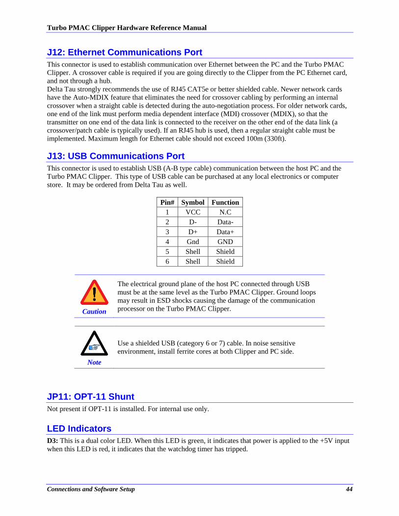
J13: USB Communications Port
This connector is used to establish USB (A-B type cable) communication between the host PC and the
Turbo PMAC Clipper. This type of USB cable can be purchased at any local electronics or computer
store. It may be ordered from Delta Tau as well.
Pin# Symbol Function
1 VCC N.C
2 D- Data-
3 D+ Data+
4 Gnd GND
5 Shell Shield
6 Shell Shield
Caution
The electrical ground plane of the host PC connected through USB
must be at the same level as the Turbo PMAC Clipper. Ground loops
may result in ESD shocks causing the damage of the communication
processor on the Turbo PMAC Clipper.
Note
Use a shielded USB (category 6 or 7) cable. In noise sensitive
environment, install ferrite cores at both Clipper and PC side.
JP11: OPT-11 Shunt
Not present if OPT-11 is installed. For internal use only.
LED Indicators
D3: This is a dual color LED. When this LED is green, it indicates that power is applied to the +5V input
when this LED is red, it indicates that the watchdog timer has tripped.
Turbo PMAC Clipper Hardware Reference Manual
Drive – Motor Setup 45
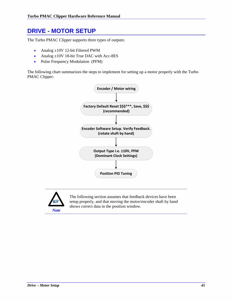
DRIVE - MOTOR SETUP
The Turbo PMAC Clipper supports three types of outputs:
Analog ±10V 12-bit Filtered PWM
Analog ±10V 18-bit True DAC with Acc-8ES
Pulse Frequency Modulation (PFM)
The following chart summarizes the steps to implement for setting up a motor properly with the Turbo
PMAC Clipper:
Factory Default Reset $$$***, Save, $$$(recommended)
Encoder Software Setup. Verify Feedback.(rotate shaft by hand)
Position PID Tuning
Output Type i.e. ±10V, PFM(Dominant Clock Settings)
Encoder / Motor wiring
Note
The following section assumes that feedback devices have been
setup properly, and that moving the motor/encoder shaft by hand
shows correct data in the position window.

Turbo PMAC Clipper Hardware Reference Manual
Drive – Motor Setup 46
Filtered PWM Output (Analog ±10V)
In this mode, the ±10V analog output is obtained by passing the digital PWM signal through a 10 KHz
low pass filter. This technique, although not as performing as a true digital to analog converter, is more
than adequate for most servo applications.
The duty cycle of the PWM signal controls the magnitude of the voltage output. This is handled internally
by the PMAC, the user needs not to change any settings.
However, the frequency of the PWM signal determines the output resolution and ripple magnitude
(disturbance). The trade-off is as follows:
The higher the PWM frequency, the lower is the resolution with a low-ripple signal output.
The lower the PWM frequency, the higher is the resolution with a high-ripple signal output.
Note
Some amplifiers operate in the ±5V range; this can be regulated
using the motor command output limit, parameter Ixx69.
Both the resolution and the frequency of the Filtered PWM outputs are configured in software on the
Turbo PMAC Clipper through the variable I7000. This variable also effects the phase and servo
interrupts. Therefore as we change I7000 we will also have to change I7001 (phase clock divider), I7002
(servo clock divider), and I10 (servo interrupt time). These four variables are all related and must be
understood before adjusting parameters. The detailed information for these parameters can be found in
the Turbo Software Reference Manual.
Note
Filtered PWM Output Configuration sets the Max PWM
frequency very high (29KHz). This setting can be problematic
with Direct PWM commutation on the same servo IC.
The ACC-28A and ACC-28B cannot be used on the same servo
IC since the PWM frequency settings are out of range for these
products.
PWM Frequency Resolution Ripple
Turbo PMAC Clipper Hardware Reference Manual
Drive – Motor Setup 47
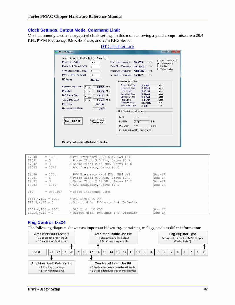
Clock Settings, Output Mode, Command Limit
Most commonly used and suggested clock settings in this mode allowing a good compromise are a 29.4
KHz PWM Frequency, 9.8 KHz Phase, and 2.45 KHZ Servo.
DT Calculator Link
I7000 = 1001 ; PWM Frequency 29.4 KHz, PWM 1-4
I7001 = 5 ; Phase Clock 9.8 KHz, Servo IC 0
I7002 = 3 ; Servo Clock 2.45 KHz, Servo IC 0
I7003 = 1746 ; ADC frequency, Servo IC 0
I7100 = 1001 ; PWM Frequency 29.4 KHz, PWM 5-8 (Acc-1P)
I7101 = 5 ; Phase Clock 9.8 KHz, Servo IC 1 (Acc-1P)
I7102 = 3 ; Servo Clock 2.45 KHz, Servo IC 1 (Acc-1P)
I7103 = 1746 ; ADC frequency, Servo IC 1 (Acc-1P)
I10 = 3421867 ; Servo Interrupt Time
I169,4,100 = 1001 ; DAC Limit 10 VDC
I7016,4,10 = 0 ; Output Mode, PWM axis 1-4 (Default)
I569,4,100 = 1001 ; DAC Limit 10 VDC (Acc-1P)
I7116,4,10 = 0 ; Output Mode, PWM axis 5-8 (Default) (Acc-1P)
Flag Control, Ixx24
The following diagram showcases important bit settings pertaining to flags, and amplifier information:
23 22 21 20 19 18 17 16 15 14 13 12 11 10 9 8 7 6 5 4 3 2 1 0
Amplifier Enable Use Bit= 0 Use amp enable output= 1 Don’t use amp enable
Amplifier Fault Use Bit= 0 Enable amp fault input= 1 Disable amp fault input
Overtravel Limit Use Bit= 0 Enable hardware over-travel limits= 1 Disable hardware over-travel limits
Amplifier Fault Polarity Bit= 0 For low true amp= 1 For high true amp
Bit #:
Flag Register TypeAlways =1 for Turbo PMAC Clipper
(Turbo PMAC)
Turbo PMAC Clipper Hardware Reference Manual
Drive – Motor Setup 48
Example: Setting Ixx24 for a low true amplifier and disabling the over-travel limit switches yields $20001. I124,4,100 = $20001
I2T Protection: Ixx57, Ixx58
I2T is a software thermal model (PMAC internal calculation) used to protect motor and drive from
exceeding current specifications. For a safe setup, the lower limit of continuous and peak current
specifications between the motor and drive should be selected.
Example:
A Turbo PMAC Clipper driving a torque-mode amplifier that has a gain of 3 amperes/volt and a
continuous current rating of 10 amperes, with a motor rated to 12 amperes continuous.
Using the amplifier’s continuous current rating of 10 Amps: #define ContCurrent 10 ; Continuous Current Limit [Amps] –User Input
#define MaxADC 30 ; full range ADC reading, Amplifier Spec. –User Input
#define I2TOnTime 2 ; Time allowed at peak Current, Amp/motor spec [sec] –User Input
#define ServoClk 2.45 ; Servo Clock, pre-defined in suggested clocks [Khz]
I157 = INT(I7000*ContCurrent/MaxADC)
I158 = INT((I7000*I7000-I157*I157)*ServoClk*1000*I2TOnTime/(I7000*I7000))
I257=I157 I357=I157 I457=I157 I557=I157
I657=I157 I757=I157 I857=I157
I258=I158 I358=I158 I458=I158 I558=I158
I657=I158 I757=I158 I857=I158
Open Loop Test: Encoder/Decode
The open-loop test is critical to verify the direction sense of the encoder counting versus the command
output. A positive command should create a positive velocity and a position counting in the positive
direction; a negative command should create a negative velocity and a position counting in the negative
direction. The Open Loop test utility in the PMACTuningPro2 Software can be used to execute and open
loop test. It can also be carried manually from the terminal window while gathering position, velocity data
or simply monitoring the motor velocity in the position window.
Satisfactory Open-Loop Test Result
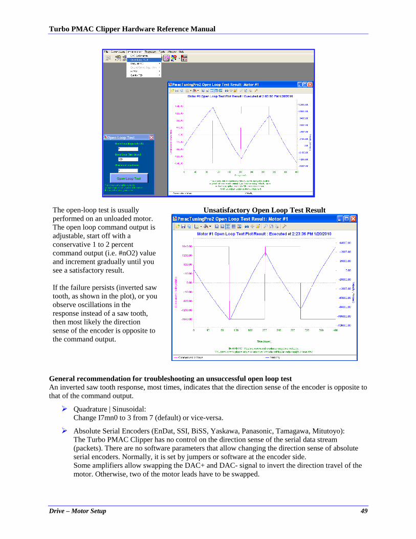
Turbo PMAC Clipper Hardware Reference Manual
Drive – Motor Setup 49
The open-loop test is usually
performed on an unloaded motor.
The open loop command output is
adjustable, start off with a
conservative 1 to 2 percent
command output (i.e. #nO2) value
and increment gradually until you
see a satisfactory result.
If the failure persists (inverted saw
tooth, as shown in the plot), or you
observe oscillations in the
response instead of a saw tooth,
then most likely the direction
sense of the encoder is opposite to
the command output.
Unsatisfactory Open Loop Test Result
General recommendation for troubleshooting an unsuccessful open loop test
An inverted saw tooth response, most times, indicates that the direction sense of the encoder is opposite to
that of the command output.
Quadrature | Sinusoidal:
Change I7mn0 to 3 from 7 (default) or vice-versa. Absolute Serial Encoders (EnDat, SSI, BiSS, Yaskawa, Panasonic, Tamagawa, Mitutoyo):
The Turbo PMAC Clipper has no control on the direction sense of the serial data stream
(packets). There are no software parameters that allow changing the direction sense of absolute
serial encoders. Normally, it is set by jumpers or software at the encoder side.
Some amplifiers allow swapping the DAC+ and DAC- signal to invert the direction travel of the
motor. Otherwise, two of the motor leads have to be swapped.
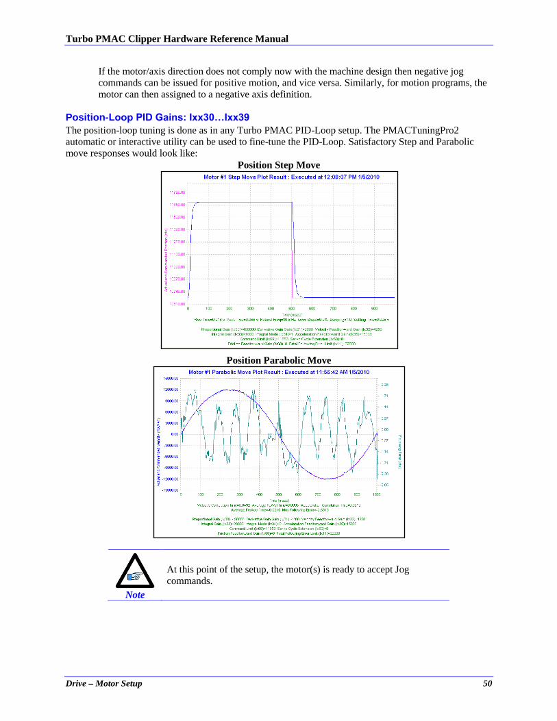
Turbo PMAC Clipper Hardware Reference Manual
Drive – Motor Setup 50
If the motor/axis direction does not comply now with the machine design then negative jog
commands can be issued for positive motion, and vice versa. Similarly, for motion programs, the
motor can then assigned to a negative axis definition.
Position-Loop PID Gains: Ixx30…Ixx39
The position-loop tuning is done as in any Turbo PMAC PID-Loop setup. The PMACTuningPro2
automatic or interactive utility can be used to fine-tune the PID-Loop. Satisfactory Step and Parabolic
move responses would look like:
Position Step Move
Position Parabolic Move
Note
At this point of the setup, the motor(s) is ready to accept Jog
commands.
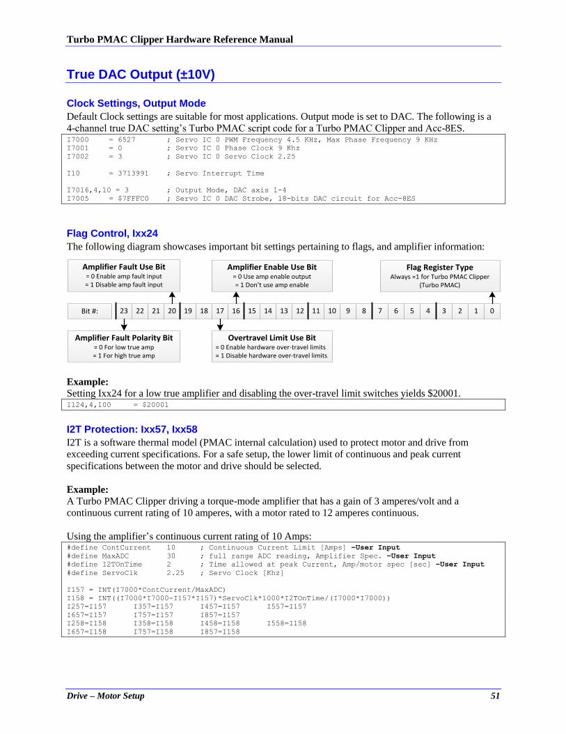
Turbo PMAC Clipper Hardware Reference Manual
Drive – Motor Setup 51
True DAC Output (±10V)
Clock Settings, Output Mode
Default Clock settings are suitable for most applications. Output mode is set to DAC. The following is a
4-channel true DAC setting’s Turbo PMAC script code for a Turbo PMAC Clipper and Acc-8ES. I7000 = 6527 ; Servo IC 0 PWM Frequency 4.5 KHz, Max Phase Frequency 9 KHz
I7001 = 0 ; Servo IC 0 Phase Clock 9 Khz
I7002 = 3 ; Servo IC 0 Servo Clock 2.25
I10 = 3713991 ; Servo Interrupt Time
I7016,4,10 = 3 ; Output Mode, DAC axis 1-4
I7005 = $7FFFC0 ; Servo IC 0 DAC Strobe, 18-bits DAC circuit for Acc-8ES
Flag Control, Ixx24
The following diagram showcases important bit settings pertaining to flags, and amplifier information:
23 22 21 20 19 18 17 16 15 14 13 12 11 10 9 8 7 6 5 4 3 2 1 0
Amplifier Enable Use Bit= 0 Use amp enable output= 1 Don’t use amp enable
Amplifier Fault Use Bit= 0 Enable amp fault input= 1 Disable amp fault input
Overtravel Limit Use Bit= 0 Enable hardware over-travel limits= 1 Disable hardware over-travel limits
Amplifier Fault Polarity Bit= 0 For low true amp= 1 For high true amp
Bit #:
Flag Register TypeAlways =1 for Turbo PMAC Clipper
(Turbo PMAC)
Example: Setting Ixx24 for a low true amplifier and disabling the over-travel limit switches yields $20001. I124,4,100 = $20001
I2T Protection: Ixx57, Ixx58
I2T is a software thermal model (PMAC internal calculation) used to protect motor and drive from
exceeding current specifications. For a safe setup, the lower limit of continuous and peak current
specifications between the motor and drive should be selected.
Example:
A Turbo PMAC Clipper driving a torque-mode amplifier that has a gain of 3 amperes/volt and a
continuous current rating of 10 amperes, with a motor rated to 12 amperes continuous.
Using the amplifier’s continuous current rating of 10 Amps: #define ContCurrent 10 ; Continuous Current Limit [Amps] –User Input
#define MaxADC 30 ; full range ADC reading, Amplifier Spec. –User Input
#define I2TOnTime 2 ; Time allowed at peak Current, Amp/motor spec [sec] –User Input
#define ServoClk 2.25 ; Servo Clock [Khz]
I157 = INT(I7000*ContCurrent/MaxADC)
I158 = INT((I7000*I7000-I157*I157)*ServoClk*1000*I2TOnTime/(I7000*I7000))
I257=I157 I357=I157 I457=I157 I557=I157
I657=I157 I757=I157 I857=I157
I258=I158 I358=I158 I458=I158 I558=I158
I657=I158 I757=I158 I857=I158
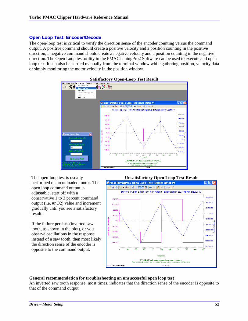
Turbo PMAC Clipper Hardware Reference Manual
Drive – Motor Setup 52
Open Loop Test: Encoder/Decode
The open-loop test is critical to verify the direction sense of the encoder counting versus the command
output. A positive command should create a positive velocity and a position counting in the positive
direction; a negative command should create a negative velocity and a position counting in the negative
direction. The Open Loop test utility in the PMACTuningPro2 Software can be used to execute and open
loop test. It can also be carried manually from the terminal window while gathering position, velocity data
or simply monitoring the motor velocity in the position window.
Satisfactory Open-Loop Test Result
The open-loop test is usually
performed on an unloaded motor. The
open loop command output is
adjustable, start off with a
conservative 1 to 2 percent command
output (i.e. #nO2) value and increment
gradually until you see a satisfactory
result.
If the failure persists (inverted saw
tooth, as shown in the plot), or you
observe oscillations in the response
instead of a saw tooth, then most likely
the direction sense of the encoder is
opposite to the command output.
Unsatisfactory Open Loop Test Result
General recommendation for troubleshooting an unsuccessful open loop test
An inverted saw tooth response, most times, indicates that the direction sense of the encoder is opposite to
that of the command output.
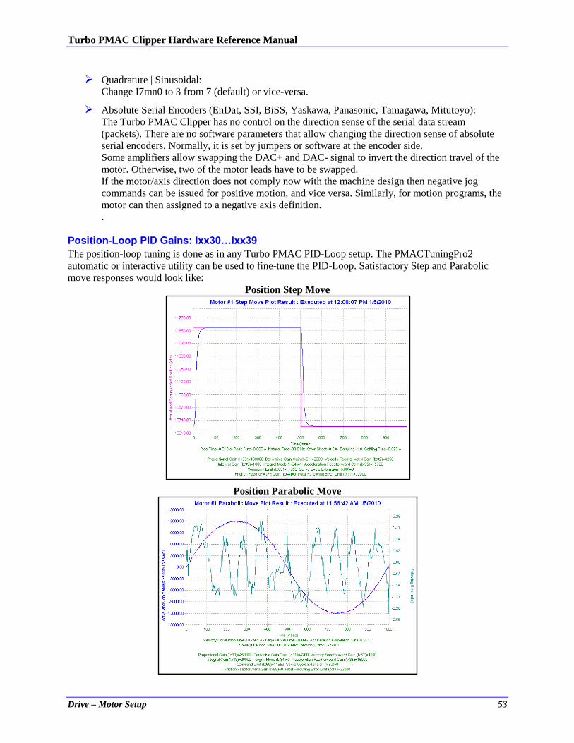
Turbo PMAC Clipper Hardware Reference Manual
Drive – Motor Setup 53
Quadrature | Sinusoidal:
Change I7mn0 to 3 from 7 (default) or vice-versa. Absolute Serial Encoders (EnDat, SSI, BiSS, Yaskawa, Panasonic, Tamagawa, Mitutoyo):
The Turbo PMAC Clipper has no control on the direction sense of the serial data stream
(packets). There are no software parameters that allow changing the direction sense of absolute
serial encoders. Normally, it is set by jumpers or software at the encoder side.
Some amplifiers allow swapping the DAC+ and DAC- signal to invert the direction travel of the
motor. Otherwise, two of the motor leads have to be swapped.
If the motor/axis direction does not comply now with the machine design then negative jog
commands can be issued for positive motion, and vice versa. Similarly, for motion programs, the
motor can then assigned to a negative axis definition.
.
Position-Loop PID Gains: Ixx30…Ixx39
The position-loop tuning is done as in any Turbo PMAC PID-Loop setup. The PMACTuningPro2
automatic or interactive utility can be used to fine-tune the PID-Loop. Satisfactory Step and Parabolic
move responses would look like:
Position Step Move
Position Parabolic Move

Turbo PMAC Clipper Hardware Reference Manual
Drive – Motor Setup 54
Note
At this point of the setup, the motor(s) is ready to accept Jog
commands.
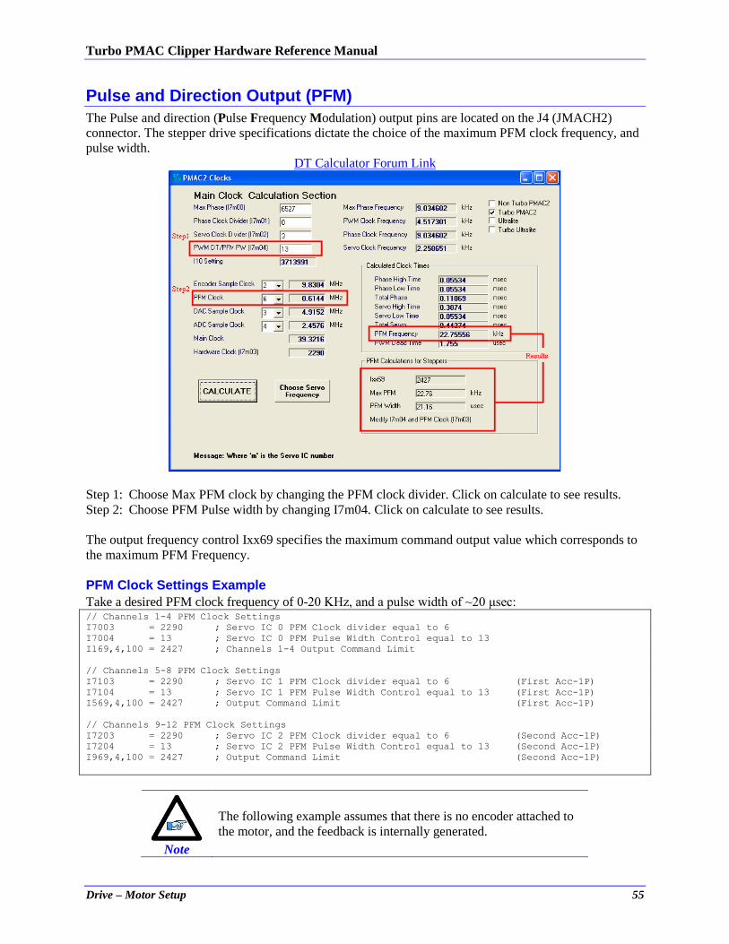
Turbo PMAC Clipper Hardware Reference Manual
Drive – Motor Setup 55
Pulse and Direction Output (PFM)
The Pulse and direction (Pulse Frequency Modulation) output pins are located on the J4 (JMACH2)
connector. The stepper drive specifications dictate the choice of the maximum PFM clock frequency, and
pulse width.
DT Calculator Forum Link
Step 1: Choose Max PFM clock by changing the PFM clock divider. Click on calculate to see results.
Step 2: Choose PFM Pulse width by changing I7m04. Click on calculate to see results.
The output frequency control Ixx69 specifies the maximum command output value which corresponds to
the maximum PFM Frequency.
PFM Clock Settings Example
Take a desired PFM clock frequency of 0-20 KHz, and a pulse width of ~20 μsec: // Channels 1-4 PFM Clock Settings
I7003 = 2290 ; Servo IC 0 PFM Clock divider equal to 6
I7004 = 13 ; Servo IC 0 PFM Pulse Width Control equal to 13
I169,4,100 = 2427 ; Channels 1-4 Output Command Limit
// Channels 5-8 PFM Clock Settings
I7103 = 2290 ; Servo IC 1 PFM Clock divider equal to 6 (First Acc-1P)
I7104 = 13 ; Servo IC 1 PFM Pulse Width Control equal to 13 (First Acc-1P)
I569,4,100 = 2427 ; Output Command Limit (First Acc-1P)
// Channels 9-12 PFM Clock Settings
I7203 = 2290 ; Servo IC 2 PFM Clock divider equal to 6 (Second Acc-1P)
I7204 = 13 ; Servo IC 2 PFM Pulse Width Control equal to 13 (Second Acc-1P)
I969,4,100 = 2427 ; Output Command Limit (Second Acc-1P)
Note
The following example assumes that there is no encoder attached to
the motor, and the feedback is internally generated.
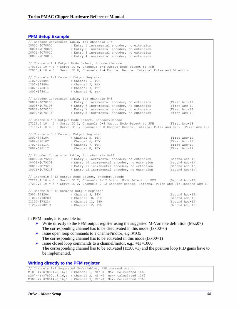
Turbo PMAC Clipper Hardware Reference Manual
Drive – Motor Setup 56
PFM Setup Example // Encoder Conversion Table, for channels 1-4
I8000=$C78000 ; Entry 1 incremental encoder, no extension
I8001=$C78008 ; Entry 2 incremental encoder, no extension
I8002=$C78010 ; Entry 3 incremental encoder, no extension
I8003=$C78018 ; Entry 4 incremental encoder, no extension
// Channels 1-4 Output Mode Select, Encoder/Decode
I7016,4,10 = 3 ; Servo IC 0, Channels 1-4 Output Mode Select to PFM
I7010,4,10 = 8 ; Servo IC 0, Channels 1-4 Encoder Decode, Internal Pulse and Direction
// Channels 1-4 Command Output Register
I102=$78004 ; Channel 1, PFM
I202=$7800c ; Channel 2, PFM
I302=$78014 ; Channel 3, PFM
I402=$7801C ; Channel 4, PFM
// Encoder Conversion Table, for channels 5-8
I8004=$C78100 ; Entry 5 incremental encoder, no extension (First Acc-1P)
I8005=$C78108 ; Entry 6 incremental encoder, no extension (First Acc-1P)
I8006=$C78110 ; Entry 7 incremental encoder, no extension (First Acc-1P)
I8007=$C78118 ; Entry 8 incremental encoder, no extension (First Acc-1P)
// Channels 5-8 Output Mode Select, Encoder/Decode
I7116,4,10 = 3 ; Servo IC 1, Channels 5-8 Output Mode Select to PFM (First Acc-1P)
I7110,4,10 = 8 ; Servo IC 1, Channels 5-8 Encoder Decode, Internal Pulse and Dir. (First Acc-1P)
// Channels 5-8 Command Output Register
I502=$78104 ; Channel 5, PFM (First Acc-1P)
I602=$7810C ; Channel 6, PFM (First Acc-1P)
I702=$78114 ; Channel 7, PFM (First Acc-1P)
I802=$7811C ; Channel 8, PFM (First Acc-1P)
// Encoder Conversion Table, for channels 9-12
I8008=$C79200 ; Entry 9 incremental encoder, no extension (Second Acc-1P)
I8009=$C79208 ; Entry 10 incremental encoder, no extension (Second Acc-1P)
I8010=$C79210 ; Entry 11 incremental encoder, no extension (Second Acc-1P)
I8011=$C79218 ; Entry 12 incremental encoder, no extension (Second Acc-1P)
// Channels 9-12 Output Mode Select, Encoder/Decode
I7216,4,10 = 3 ; Servo IC 2, Channels 9-12 Output Mode Select to PFM (Second Acc-1P)
I7210,4,10 = 8 ; Servo IC 2, Channels 9-12 Encoder Decode, Internal Pulse and Dir.(Second Acc-1P)
// Channels 9-12 Command Output Register
I902=$78204 ; Channel 9, PFM (Second Acc-1P)
I1002=$7820C ; Channel 10, PFM (Second Acc-1P)
I1102=$78214 ; Channel 11, PFM (Second Acc-1P)
I1202=$7821C ; Channel 12, PFM (Second Acc-1P)
In PFM mode, it is possible to:
Write directly to the PFM output register using the suggested M-Variable definition (Mxx07)
The corresponding channel has to be deactivated in this mode (Ixx00=0)
Issue open loop commands to a channel/motor, e.g.:#1O5
The corresponding channel has to be activated in this mode (Ixx00=1)
Issue closed loop commands to a channel/motor, e.g.: #1J=1000
The corresponding channel has to be activated (Ixx00=1) and the position loop PID gains have to
be implemented.
Writing directly to the PFM register // Channels 1-4 Suggested M-Variables, PFM command output
M107->Y:$78004,8,16,S ; Channel 1, Min=0, Max= Calculated I169
M207->Y:$7800C,8,16,S ; Channel 2, Min=0, Max= Calculated I269
M307->Y:$78014,8,16,S ; Channel 3, Min=0, Max= Calculated I369
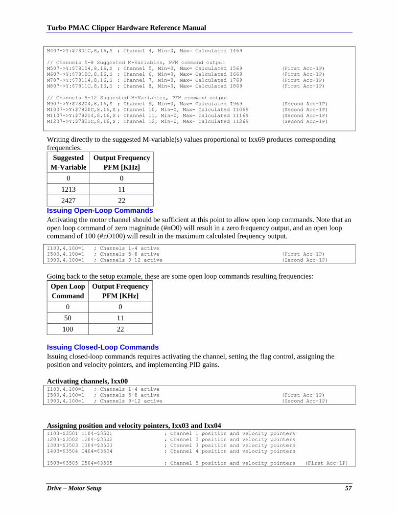
Turbo PMAC Clipper Hardware Reference Manual
Drive – Motor Setup 57
M407->Y:$7801C,8,16,S ; Channel 4, Min=0, Max= Calculated I469
// Channels 5-8 Suggested M-Variables, PFM command output
M507->Y:$78104,8,16,S ; Channel 5, Min=0, Max= Calculated I569 (First Acc-1P)
M607->Y:$7810C,8,16,S ; Channel 6, Min=0, Max= Calculated I669 (First Acc-1P)
M707->Y:$78114,8,16,S ; Channel 7, Min=0, Max= Calculated I769 (First Acc-1P)
M807->Y:$7811C,8,16,S ; Channel 8, Min=0, Max= Calculated I869 (First Acc-1P)
// Channels 9-12 Suggested M-Variables, PFM command output
M907->Y:$78204,8,16,S ; Channel 9, Min=0, Max= Calculated I969 (Second Acc-1P)
M1007->Y:$7820C,8,16,S ; Channel 10, Min=0, Max= Calculated I1069 (Second Acc-1P)
M1107->Y:$78214,8,16,S ; Channel 11, Min=0, Max= Calculated I1169 (Second Acc-1P)
M1207->Y:$7821C,8,16,S ; Channel 12, Min=0, Max= Calculated I1269 (Second Acc-1P)
Writing directly to the suggested M-variable(s) values proportional to Ixx69 produces corresponding
frequencies:
Suggested
M-Variable
Output Frequency
PFM [KHz]
0 0
1213 11
2427 22
Issuing Open-Loop Commands
Activating the motor channel should be sufficient at this point to allow open loop commands. Note that an
open loop command of zero magnitude (#nO0) will result in a zero frequency output, and an open loop
command of 100 (#nO100) will result in the maximum calculated frequency output. I100,4,100=1 ; Channels 1-4 active
I500,4,100=1 ; Channels 5-8 active (First Acc-1P)
I900,4,100=1 ; Channels 9-12 active (Second Acc-1P)
Going back to the setup example, these are some open loop commands resulting frequencies:
Open Loop
Command
Output Frequency
PFM [KHz]
0 0
50 11
100 22
Issuing Closed-Loop Commands
Issuing closed-loop commands requires activating the channel, setting the flag control, assigning the
position and velocity pointers, and implementing PID gains.
Activating channels, Ixx00 I100,4,100=1 ; Channels 1-4 active
I500,4,100=1 ; Channels 5-8 active (First Acc-1P)
I900,4,100=1 ; Channels 9-12 active (Second Acc-1P)
Assigning position and velocity pointers, Ixx03 and Ixx04 I103=$3501 I104=$3501 ; Channel 1 position and velocity pointers
I203=$3502 I204=$3502 ; Channel 2 position and velocity pointers
I303=$3503 I304=$3503 ; Channel 3 position and velocity pointers
I403=$3504 I404=$3504 ; Channel 4 position and velocity pointers
I503=$3505 I504=$3505 ; Channel 5 position and velocity pointers (First Acc-1P)
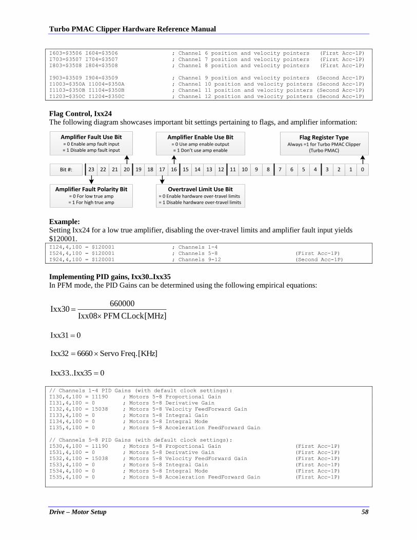
Turbo PMAC Clipper Hardware Reference Manual
Drive – Motor Setup 58
I603=$3506 I604=$3506 ; Channel 6 position and velocity pointers (First Acc-1P)
I703=$3507 I704=$3507 ; Channel 7 position and velocity pointers (First Acc-1P)
I803=$3508 I804=$3508 ; Channel 8 position and velocity pointers (First Acc-1P)
I903=$3509 I904=$3509 ; Channel 9 position and velocity pointers (Second Acc-1P)
I1003=$350A I1004=$350A ; Channel 10 position and velocity pointers (Second Acc-1P)
I1103=$350B I1104=$350B ; Channel 11 position and velocity pointers (Second Acc-1P)
I1203=$350C I1204=$350C ; Channel 12 position and velocity pointers (Second Acc-1P)
Flag Control, Ixx24
The following diagram showcases important bit settings pertaining to flags, and amplifier information:
23 22 21 20 19 18 17 16 15 14 13 12 11 10 9 8 7 6 5 4 3 2 1 0
Amplifier Enable Use Bit= 0 Use amp enable output= 1 Don’t use amp enable
Amplifier Fault Use Bit= 0 Enable amp fault input= 1 Disable amp fault input
Overtravel Limit Use Bit= 0 Enable hardware over-travel limits= 1 Disable hardware over-travel limits
Amplifier Fault Polarity Bit= 0 For low true amp= 1 For high true amp
Bit #:
Flag Register TypeAlways =1 for Turbo PMAC Clipper
(Turbo PMAC)
Example: Setting Ixx24 for a low true amplifier, disabling the over-travel limits and amplifier fault input yields
$120001. I124,4,100 = $120001 ; Channels 1-4
I524,4,100 = $120001 ; Channels 5-8 (First Acc-1P)
I924,4,100 = $120001 ; Channels 9-12 (Second Acc-1P)
Implementing PID gains, Ixx30..Ixx35
In PFM mode, the PID Gains can be determined using the following empirical equations:
[MHz]CLock PFMIxx08
660000 Ixx30
// Channels 1-4 PID Gains (with default clock settings):
I130,4,100 = 11190 ; Motors 5-8 Proportional Gain
I131,4,100 = 0 ; Motors 5-8 Derivative Gain
I132,4,100 = 15038 ; Motors 5-8 Velocity FeedForward Gain
I133,4,100 = 0 ; Motors 5-8 Integral Gain
I134,4,100 = 0 ; Motors 5-8 Integral Mode
I135,4,100 = 0 ; Motors 5-8 Acceleration FeedForward Gain
// Channels 5-8 PID Gains (with default clock settings):
I530,4,100 = 11190 ; Motors 5-8 Proportional Gain (First Acc-1P)
I531,4,100 = 0 ; Motors 5-8 Derivative Gain (First Acc-1P)
I532,4,100 = 15038 ; Motors 5-8 Velocity FeedForward Gain (First Acc-1P)
I533,4,100 = 0 ; Motors 5-8 Integral Gain (First Acc-1P)
I534,4,100 = 0 ; Motors 5-8 Integral Mode (First Acc-1P)
I535,4,100 = 0 ; Motors 5-8 Acceleration FeedForward Gain (First Acc-1P)
0 Ixx31
[KHz] Freq. Servo 6660 Ixx32
0..Ixx353Ixx3
Turbo PMAC Clipper Hardware Reference Manual
Drive – Motor Setup 59
// Channels 9-12 PID Gains (with default clock settings):
I930,4,100 = 11190 ; Motors 9-12 Proportional Gain (Second Acc-1P)
I931,4,100 = 0 ; Motors 9-12 Derivative Gain (Second Acc-1P)
I932,4,100 = 15038 ; Motors 9-12 Velocity FeedForward Gain (Second Acc-1P)
I933,4,100 = 0 ; Motors 9-12 Integral Gain (Second Acc-1P)
I934,4,100 = 0 ; Motors 9-12 Integral Mode (Second Acc-1P)
I935,4,100 = 0 ; Motors 9-12 Acceleration FeedForward Gain (Second Acc-1P)
Note
At this point of the setup, the drive-motor(s) is ready to accept Jog
commands.
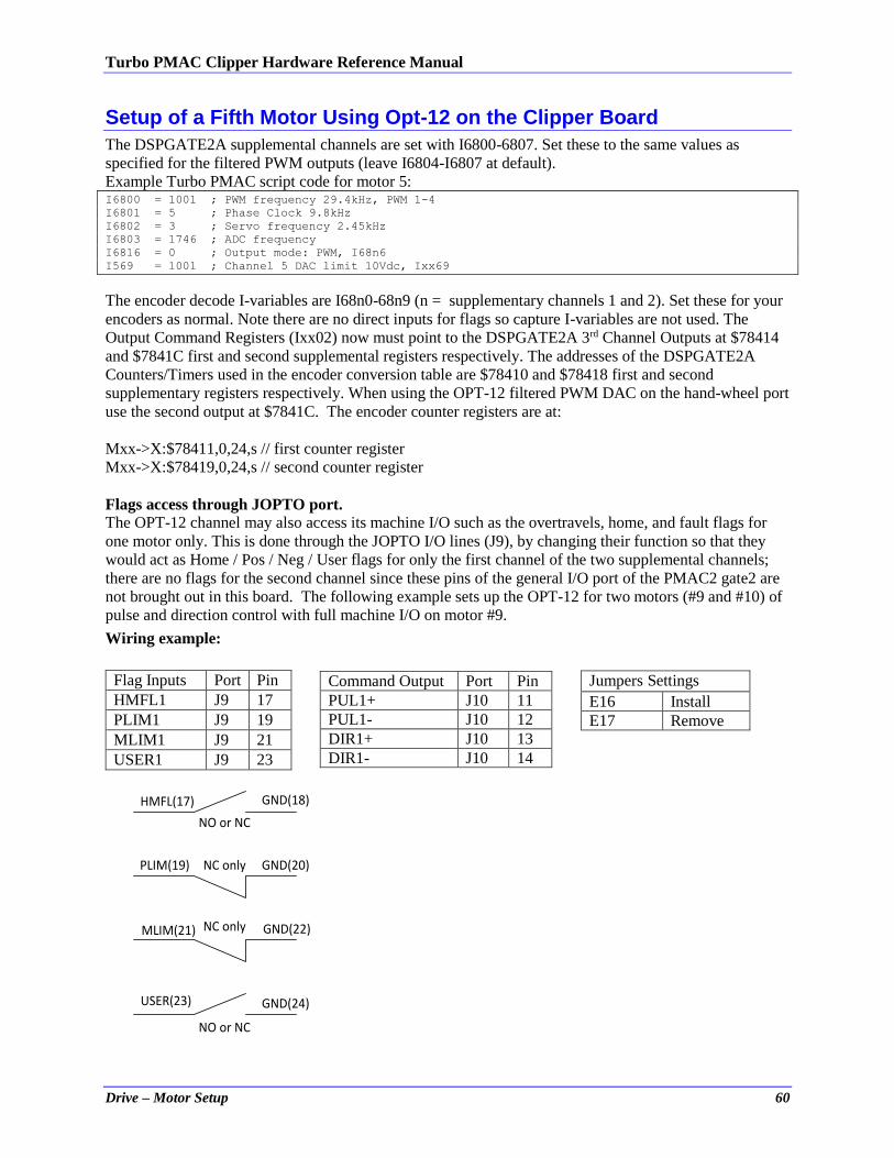
Turbo PMAC Clipper Hardware Reference Manual
Drive – Motor Setup 60
Setup of a Fifth Motor Using Opt-12 on the Clipper Board
The DSPGATE2A supplemental channels are set with I6800-6807. Set these to the same values as
specified for the filtered PWM outputs (leave I6804-I6807 at default).
Example Turbo PMAC script code for motor 5: I6800 = 1001 ; PWM frequency 29.4kHz, PWM 1-4
I6801 = 5 ; Phase Clock 9.8kHz
I6802 = 3 ; Servo frequency 2.45kHz
I6803 = 1746 ; ADC frequency
I6816 = 0 ; Output mode: PWM, I68n6
I569 = 1001 ; Channel 5 DAC limit 10Vdc, Ixx69
The encoder decode I-variables are I68n0-68n9 (n = supplementary channels 1 and 2). Set these for your
encoders as normal. Note there are no direct inputs for flags so capture I-variables are not used. The
Output Command Registers (Ixx02) now must point to the DSPGATE2A 3rd Channel Outputs at $78414
and $7841C first and second supplemental registers respectively. The addresses of the DSPGATE2A
Counters/Timers used in the encoder conversion table are $78410 and $78418 first and second
supplementary registers respectively. When using the OPT-12 filtered PWM DAC on the hand-wheel port
use the second output at $7841C. The encoder counter registers are at:
Mxx->X:$78411,0,24,s // first counter register
Mxx->X:$78419,0,24,s // second counter register
Flags access through JOPTO port.
The OPT-12 channel may also access its machine I/O such as the overtravels, home, and fault flags for
one motor only. This is done through the JOPTO I/O lines (J9), by changing their function so that they
would act as Home / Pos / Neg / User flags for only the first channel of the two supplemental channels;
there are no flags for the second channel since these pins of the general I/O port of the PMAC2 gate2 are
not brought out in this board. The following example sets up the OPT-12 for two motors (#9 and #10) of
pulse and direction control with full machine I/O on motor #9.
Wiring example:
Flag Inputs Port Pin HMFL1 J9 17 PLIM1 J9 19
MLIM1 J9 21 USER1 J9 23
HMFL(17)
PLIM(19)
MLIM(21)
USER(23)
GND(18)
GND(20)
GND(22)
GND(24)
NO or NC
NC only
NC only
NO or NC
Command Output Port Pin PUL1+ J10 11 PUL1- J10 12 DIR1+ J10 13 DIR1- J10 14
Jumpers Settings
E16 Install E17 Remove
Turbo PMAC Clipper Hardware Reference Manual
Drive – Motor Setup 61
The equivalent Turbo PMAC script code Settings: M32->X:$78400,0,8 ; Direction Control bits 0-7 (1=output, 0 = input)
M34->X:$78400,8,8 ; Direction Control bits 8-15 (1=output, 0 = input)
M40->X:$78404,0,24 ; Inversion control (0 = 0V, 1 = 5V)
M42->Y:$78404,0,24 ; J9 port data type control (1 = I/O)
//Power-up PLC:
Open plc 1 clear
M32 = $00 ; IO 1/8 inputs
M34 = $FF ; IO 9/16 Outputs
M40 = $0 ; Do not invert anything
M42 = $FF0F ; 1~4 GP I/O 5~8 flags 9~16 GP I/O
Disable plc 1
Close
I925=$78410 ; mot #9
I1025=$78418 ; mot #10 for this motor use I1024=$520001 to disable amp
; fault and overtravel limits
I902 = $78414 ; mot #9
I1002 = $7841C ; mot #10
I6810 = 8 ; Internal pulse and direction ;mot #9
I6816 = 3 ; PFM on C
I6820 = 8 ; Internal pulse and direction ;mot #10
I6826 = 3 ; PFM on C
For motor #9 use I903 and I904 appropriate ECT entry performing a “No extension of quadrature
encoder” pointing to $78410. For motor #10 use I1003 and I1004 appropriate ECT entry performing a
“No extension of quadrature encoder” pointing to $78418.
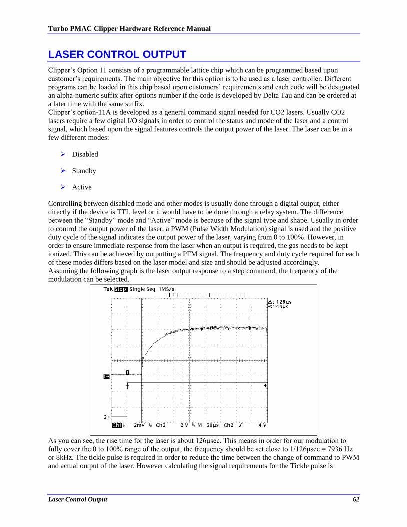
Turbo PMAC Clipper Hardware Reference Manual
Laser Control Output 62
LASER CONTROL OUTPUT
Clipper’s Option 11 consists of a programmable lattice chip which can be programmed based upon
customer’s requirements. The main objective for this option is to be used as a laser controller. Different
programs can be loaded in this chip based upon customers’ requirements and each code will be designated
an alpha-numeric suffix after options number if the code is developed by Delta Tau and can be ordered at
a later time with the same suffix.
Clipper’s option-11A is developed as a general command signal needed for CO2 lasers. Usually CO2
lasers require a few digital I/O signals in order to control the status and mode of the laser and a control
signal, which based upon the signal features controls the output power of the laser. The laser can be in a
few different modes:
Disabled
Standby
Active
Controlling between disabled mode and other modes is usually done through a digital output, either
directly if the device is TTL level or it would have to be done through a relay system. The difference
between the “Standby” mode and “Active” mode is because of the signal type and shape. Usually in order
to control the output power of the laser, a PWM (Pulse Width Modulation) signal is used and the positive
duty cycle of the signal indicates the output power of the laser, varying from 0 to 100%. However, in
order to ensure immediate response from the laser when an output is required, the gas needs to be kept
ionized. This can be achieved by outputting a PFM signal. The frequency and duty cycle required for each
of these modes differs based on the laser model and size and should be adjusted accordingly.
Assuming the following graph is the laser output response to a step command, the frequency of the
modulation can be selected.
As you can see, the rise time for the laser is about 126μsec. This means in order for our modulation to
fully cover the 0 to 100% range of the output, the frequency should be set close to 1/126μsec = 7936 Hz
or 8kHz. The tickle pulse is required in order to reduce the time between the change of command to PWM
and actual output of the laser. However calculating the signal requirements for the Tickle pulse is
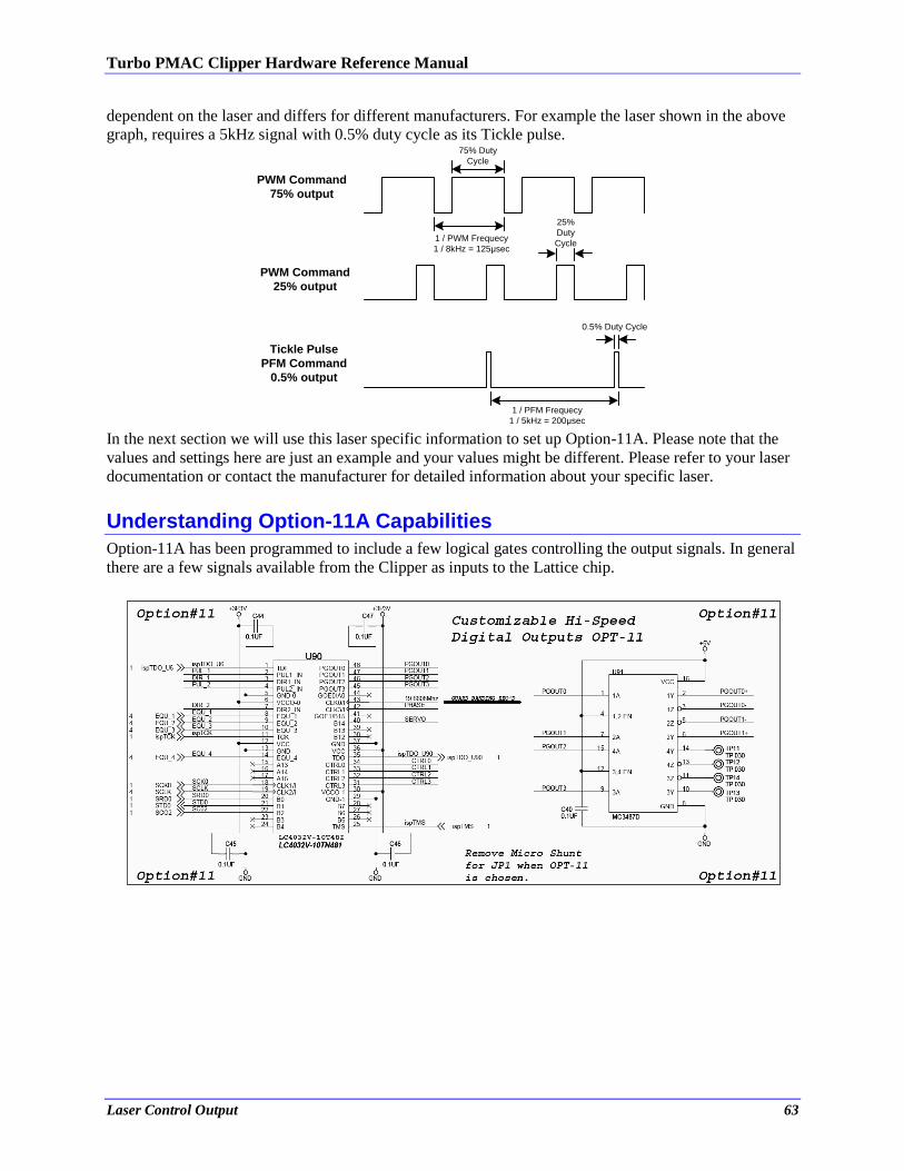
Turbo PMAC Clipper Hardware Reference Manual
Laser Control Output 63
dependent on the laser and differs for different manufacturers. For example the laser shown in the above
graph, requires a 5kHz signal with 0.5% duty cycle as its Tickle pulse.
1 / PWM Frequecy
1 / 8kHz = 125μsec
75% Duty
Cycle
25%
Duty
Cycle
PWM Command
75% output
PWM Command
25% output
1 / PFM Frequecy
1 / 5kHz = 200μsec
0.5% Duty Cycle
Tickle Pulse
PFM Command
0.5% output
In the next section we will use this laser specific information to set up Option-11A. Please note that the
values and settings here are just an example and your values might be different. Please refer to your laser
documentation or contact the manufacturer for detailed information about your specific laser.
Understanding Option-11A Capabilities
Option-11A has been programmed to include a few logical gates controlling the output signals. In general
there are a few signals available from the Clipper as inputs to the Lattice chip.
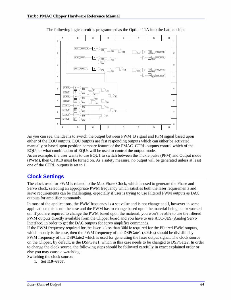
Turbo PMAC Clipper Hardware Reference Manual
Laser Control Output 64
The following logic circuit is programmed as the Option-11A into the Lattice chip:
As you can see, the idea is to switch the output between PWM_B signal and PFM signal based upon
either of the EQU outputs. EQU outputs are fast responding outputs which can either be activated
manually or based upon position compare feature of the PMAC. CTRL outputs control which of the
EQUs or what combination of EQUs will be used to control the output mode.
As an example, if a user wants to use EQU1 to switch between the Tickle pulse (PFM) and Output mode
(PWM), then CTRL0 must be turned on. As a safety measure, no output will be generated unless at least
one of the CTRL outputs is set to 1.
Clock Settings
The clock used for PWM is related to the Max Phase Clock, which is used to generate the Phase and
Servo clock, selecting an appropriate PWM frequency which satisfies both the laser requirements and
servo requirements can be challenging, especially if user is trying to use Filtered PWM outputs as DAC
outputs for amplifier commands.
In most of the applications, the PWM frequency is a set value and is not change at all, however in some
applications this is not the case and the PWM has to change based upon the material being cut or worked
on. If you are required to change the PWM based upon the material, you won’t be able to use the filtered
PWM outputs directly available from the Clipper board and you have to use ACC-8ES (Analog Servo
Interface) in order to get the DAC outputs for servo amplifier commands.
If the PWM frequency required for the laser is less than 30kHz required for the Filtered PWM outputs,
which mostly is the case, then the PWM frequency of the DSPGate1 (30kHz) should be divisible by
PWM frequency of the DSPGate2 which is used for generating the laser output signal. The clock source
on the Clipper, by default, is the DSPGate1, which in this case needs to be changed to DSPGate2. In order
to change the clock source, the following steps should be followed carefully in exact explained order or
else you may cause a watchdog.
Switching the clock source:
1. Set I19=6807.
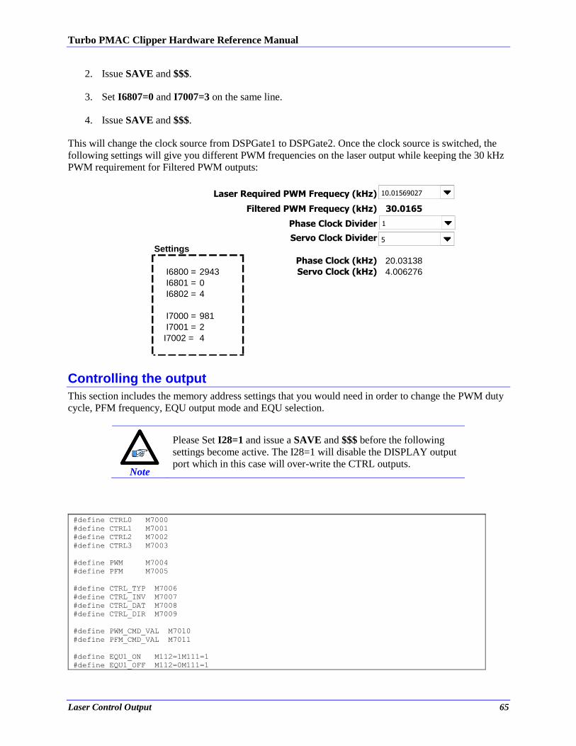
Turbo PMAC Clipper Hardware Reference Manual
Laser Control Output 65
2. Issue SAVE and $$$.
3. Set I6807=0 and I7007=3 on the same line.
4. Issue SAVE and $$$.
This will change the clock source from DSPGate1 to DSPGate2. Once the clock source is switched, the
following settings will give you different PWM frequencies on the laser output while keeping the 30 kHz
PWM requirement for Filtered PWM outputs:
Laser Required PWM Frequecy (kHz)
Filtered PWM Frequecy (kHz) 30.0165
Phase Clock Divider
Servo Clock Divider
Settings
Phase Clock (kHz) 20.03138
I6800 = 2943 Servo Clock (kHz) 4.006276
I6801 = 0
I6802 = 4
I7000 = 981
I7001 = 2
I7002 = 4
10.01569027
1
5
Controlling the output
This section includes the memory address settings that you would need in order to change the PWM duty
cycle, PFM frequency, EQU output mode and EQU selection.
Note
Please Set I28=1 and issue a SAVE and $$$ before the following
settings become active. The I28=1 will disable the DISPLAY output
port which in this case will over-write the CTRL outputs.
#define CTRL0 M7000
#define CTRL1 M7001
#define CTRL2 M7002
#define CTRL3 M7003
#define PWM M7004
#define PFM M7005
#define CTRL_TYP M7006
#define CTRL_INV M7007
#define CTRL_DAT M7008
#define CTRL_DIR M7009
#define PWM_CMD_VAL M7010
#define PFM_CMD_VAL M7011
#define EQU1_ON M112=1M111=1
#define EQU1_OFF M112=0M111=1
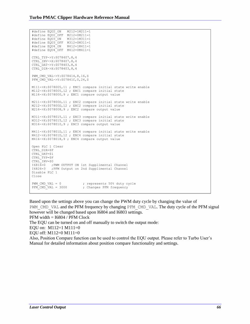
Turbo PMAC Clipper Hardware Reference Manual
Laser Control Output 66
#define EQU2_ON M212=1M211=1
#define EQU2_OFF M212=0M211=1
#define EQU3_ON M312=1M311=1
#define EQU3_OFF M312=0M311=1
#define EQU4_ON M412=1M411=1
#define EQU4_OFF M412=0M411=1
CTRL_TYP->Y:$078407,8,4
CTRL_INV->X:$078407,8,4
CTRL_DAT->Y:$078403,8,4
CTRL_DIR->X:$078403,8,4
PWM_CMD_VAL->Y:$078414,8,16,S
PFM_CMD_VAL->Y:$07841C,0,24,S
M111->X:$078005,11 ; ENC1 compare initial state write enable
M112->X:$078005,12 ; ENC1 compare initial state
M116->X:$078000,9 ; ENC1 compare output value
M211->X:$07800D,11 ; ENC2 compare initial state write enable
M212->X:$07800D,12 ; ENC2 compare initial state
M216->X:$078008,9 ; ENC2 compare output value
M311->X:$078015,11 ; ENC3 compare initial state write enable
M312->X:$078015,12 ; ENC3 compare initial state
M316->X:$078010,9 ; ENC3 compare output value
M411->X:$07801D,11 ; ENC4 compare initial state write enable
M412->X:$07801D,12 ; ENC4 compare initial state
M416->X:$078018,9 ; ENC4 compare output value
Open PLC 1 Clear
CTRL_DIR=$F
CTRL_DAT=$1
CTRL_TYP=$F
CTRL_INV=$0
I6816=0 ;PWM OUTPUT ON 1st Supplimental Channel
I6826=3 ;PFM Output on 2nd Supplimental Channel
Disable PLC 1
Close
PWM_CMD_VAL = 0 ; represents 50% duty cycle
PFM_CMD_VAL = 3000 ; Changes PFM frequency
Based upon the settings above you can change the PWM duty cycle by changing the value of
PWM_CMD_VAL and the PFM frequency by changing PFM_CMD_VAL. The duty cycle of the PFM signal
however will be changed based upon I6804 and I6803 settings.
PFM width = I6804 / PFM Clock
The EQU can be turned on and off manually to switch the output mode:
EQU on: M112=1 M111=0
EQU off: M112=0 M111=0
Also, Position Compare function can be used to control the EQU output. Please refer to Turbo User’s
Manual for detailed information about position compare functionality and settings.
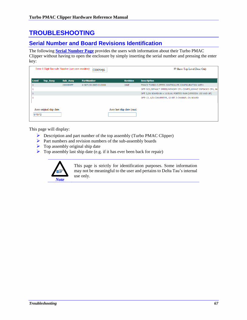
Turbo PMAC Clipper Hardware Reference Manual
Troubleshooting 67
TROUBLESHOOTING
Serial Number and Board Revisions Identification
The following Serial Number Page provides the users with information about their Turbo PMAC
Clipper without having to open the enclosure by simply inserting the serial number and pressing the enter
key:
This page will display:
Description and part number of the top assembly (Turbo PMAC Clipper)
Part numbers and revision numbers of the sub-assembly boards
Top assembly original ship date
Top assembly last ship date (e.g. if it has ever been back for repair)
Note
This page is strictly for identification purposes. Some information
may not be meaningful to the user and pertains to Delta Tau’s internal
use only.
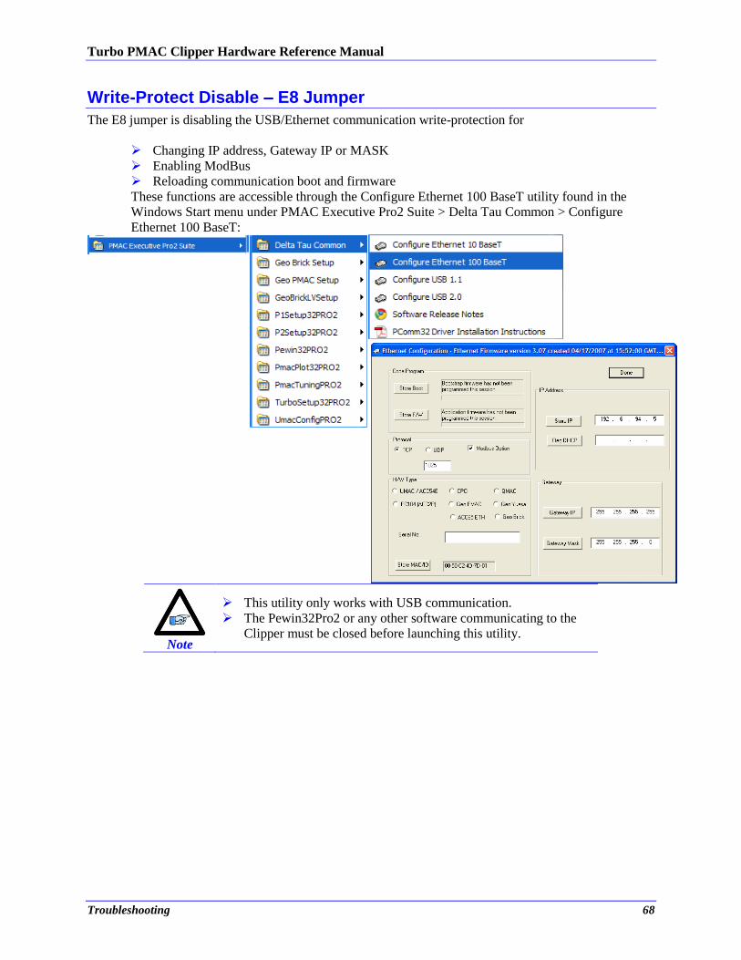
Turbo PMAC Clipper Hardware Reference Manual
Troubleshooting 68
Write-Protect Disable – E8 Jumper
The E8 jumper is disabling the USB/Ethernet communication write-protection for
Changing IP address, Gateway IP or MASK
Enabling ModBus
Reloading communication boot and firmware
These functions are accessible through the Configure Ethernet 100 BaseT utility found in the
Windows Start menu under PMAC Executive Pro2 Suite > Delta Tau Common > Configure
Ethernet 100 BaseT:
Note
This utility only works with USB communication.
The Pewin32Pro2 or any other software communicating to the
Clipper must be closed before launching this utility.
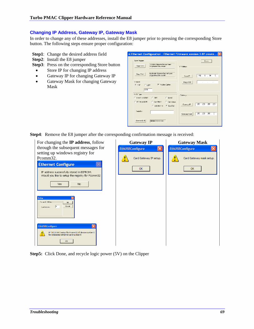
Turbo PMAC Clipper Hardware Reference Manual
Troubleshooting 69
Changing IP Address, Gateway IP, Gateway Mask
In order to change any of these addresses, install the E8 jumper prior to pressing the corresponding Store
button. The following steps ensure proper configuration:
Step1: Change the desired address field
Step2: Install the E8 jumper
Step3: Press on the corresponding Store button
Store IP for changing IP address
Gateway IP for changing Gateway IP
Gateway Mask for changing Gateway
Mask
Step4: Remove the E8 jumper after the corresponding confirmation message is received:
For changing the IP address, follow
through the subsequent messages for
setting up windows registry for
Pcomm32.
Gateway IP
Gateway Mask
Step5: Click Done, and recycle logic power (5V) on the Clipper
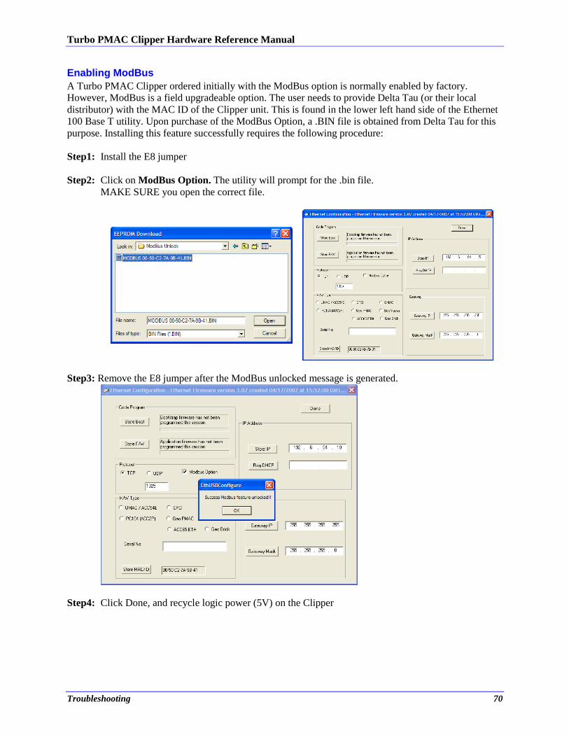
Turbo PMAC Clipper Hardware Reference Manual
Troubleshooting 70
Enabling ModBus
A Turbo PMAC Clipper ordered initially with the ModBus option is normally enabled by factory.
However, ModBus is a field upgradeable option. The user needs to provide Delta Tau (or their local
distributor) with the MAC ID of the Clipper unit. This is found in the lower left hand side of the Ethernet
100 Base T utility. Upon purchase of the ModBus Option, a .BIN file is obtained from Delta Tau for this
purpose. Installing this feature successfully requires the following procedure:
Step1: Install the E8 jumper
Step2: Click on ModBus Option. The utility will prompt for the .bin file.
MAKE SURE you open the correct file.
Step3: Remove the E8 jumper after the ModBus unlocked message is generated.
Step4: Click Done, and recycle logic power (5V) on the Clipper
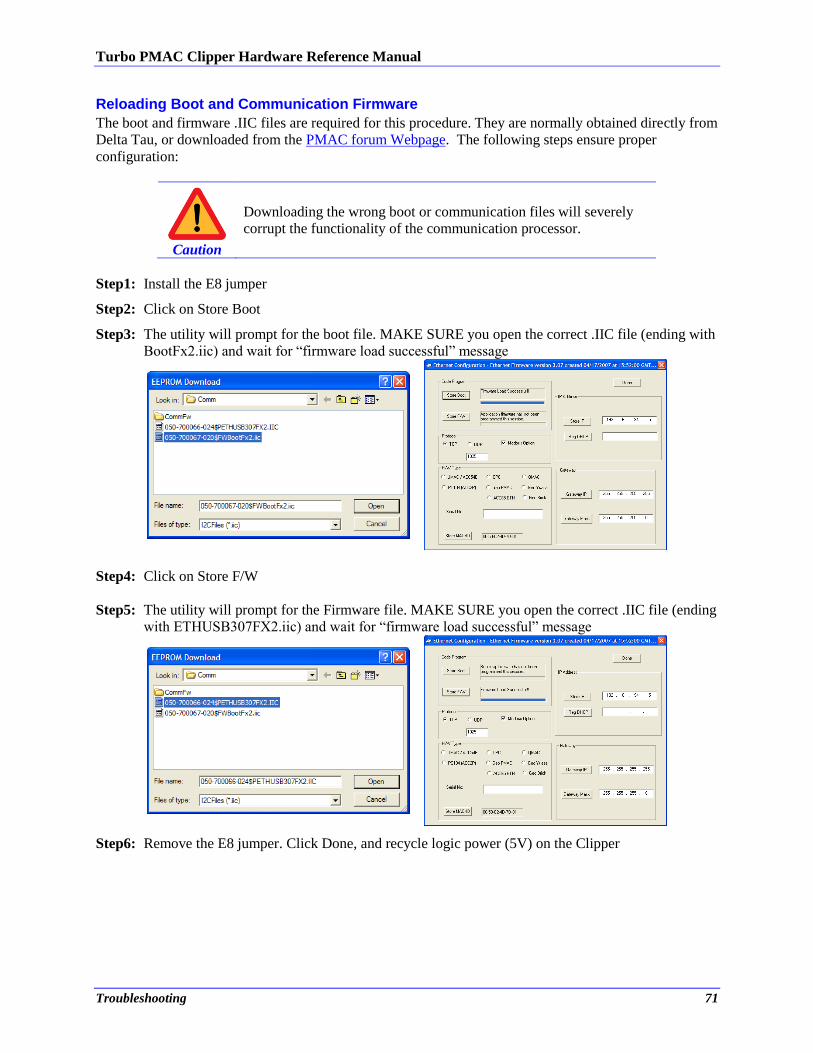
Turbo PMAC Clipper Hardware Reference Manual
Troubleshooting 71
Reloading Boot and Communication Firmware
The boot and firmware .IIC files are required for this procedure. They are normally obtained directly from
Delta Tau, or downloaded from the PMAC forum Webpage. The following steps ensure proper
configuration:
Caution
Downloading the wrong boot or communication files will severely
corrupt the functionality of the communication processor.
Step1: Install the E8 jumper Step2: Click on Store Boot Step3: The utility will prompt for the boot file. MAKE SURE you open the correct .IIC file (ending with
BootFx2.iic) and wait for “firmware load successful” message
Step4: Click on Store F/W
Step5: The utility will prompt for the Firmware file. MAKE SURE you open the correct .IIC file (ending
with ETHUSB307FX2.iic) and wait for “firmware load successful” message
Step6: Remove the E8 jumper. Click Done, and recycle logic power (5V) on the Clipper
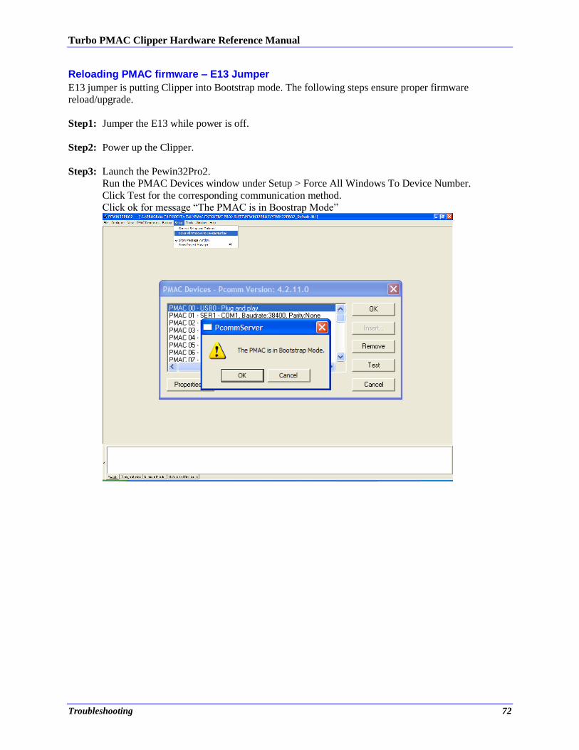
Turbo PMAC Clipper Hardware Reference Manual
Troubleshooting 72
Reloading PMAC firmware – E13 Jumper
E13 jumper is putting Clipper into Bootstrap mode. The following steps ensure proper firmware
reload/upgrade.
Step1: Jumper the E13 while power is off.
Step2: Power up the Clipper.
Step3: Launch the Pewin32Pro2.
Run the PMAC Devices window under Setup > Force All Windows To Device Number.
Click Test for the corresponding communication method.
Click ok for message “The PMAC is in Boostrap Mode”
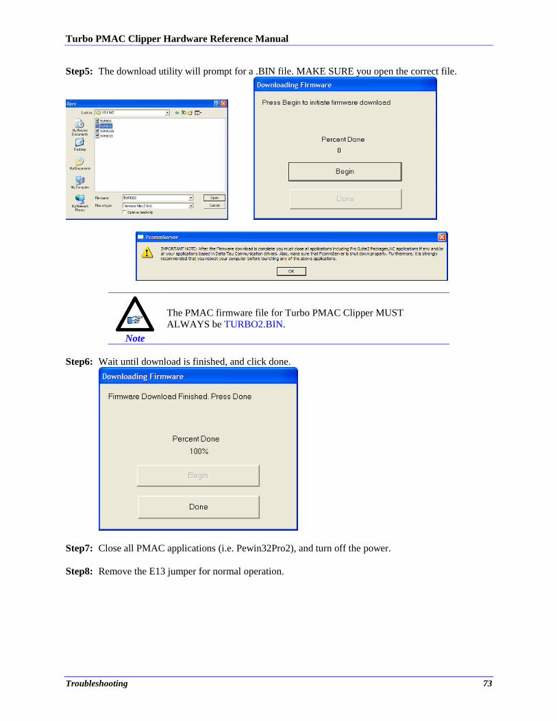
Turbo PMAC Clipper Hardware Reference Manual
Troubleshooting 73
Step5: The download utility will prompt for a .BIN file. MAKE SURE you open the correct file.
Note
The PMAC firmware file for Turbo PMAC Clipper MUST
ALWAYS be TURBO2.BIN.
Step6: Wait until download is finished, and click done.
Step7: Close all PMAC applications (i.e. Pewin32Pro2), and turn off the power.
Step8: Remove the E13 jumper for normal operation.
Turbo PMAC Clipper Hardware Reference Manual
Troubleshooting 74
Re-initialization jumper (Factory Reset)
The E3 jumper is used to reset the Turbo PMAC Clipper back to factory default settings, global reset.
Caution
Issuing a SAVE after power up (with the E3 jumper) will
permanently erase any user configured parameters.
Re-initialization instructions: Power down the unit. Install the E3 jumper, then power back up. The
factory default parameters are now restored from the firmware EEPROM into the active memory. Issue a
SAVE and a $$$ to maintain this configuration.
Watchdog Timer
On a Turbo PMAC Clipper, the watchdog timer trigger illuminates the red WD LED and interrupts
communication. It occurs if any of the following applies:
PMAC CPU over-clocked:
In this mode, the CPU signals that is has been overloaded with computation and cannot
accomplish tasks in a timely manner. e.g. bad programming such as an infinite loop, or too much
computation (Kinematics) requiring faster CPU option.
Wrong clock settings:
In this mode, the user has downloaded or written bad values to clock setting parameters.
Logic power supply +5V failure:
In this mode, the 5V logic power supply has failed. Check and monitor the 5VDC power.
Downloading wrong configuration file (I4900):
In this mode, the user has reloaded a configuration file uploaded from a 4-axis unit (Servo IC 1
parameters set to zero) into an 8-axis unit, thus writing zero to the second Servo IC clock
parameters. Commenting out variables I7100…7106 (or forcing them to hold the same values as
I7000…I7106) eliminates the watchdog problem.
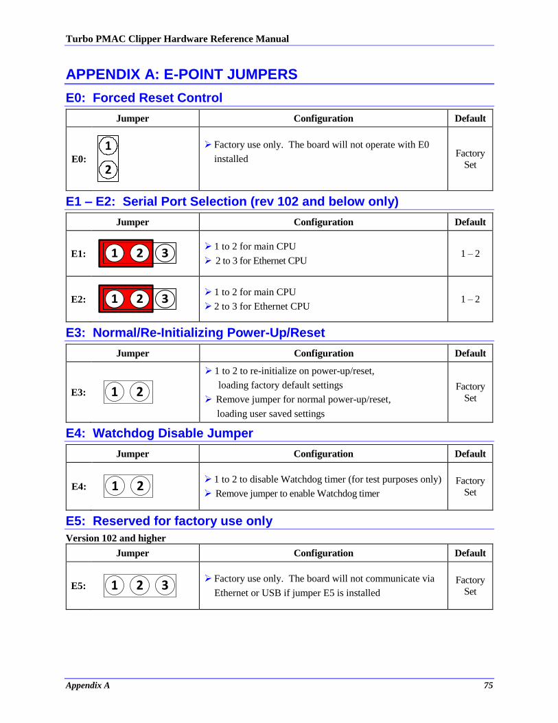
Turbo PMAC Clipper Hardware Reference Manual
Appendix A 75
APPENDIX A: E-POINT JUMPERS
E0: Forced Reset Control
Jumper Configuration Default
E0:
2
1
Factory use only. The board will not operate with E0
installed
Factory
Set
E1 – E2: Serial Port Selection (rev 102 and below only)
Jumper Configuration Default
E1: 1 2 3
1 to 2 for main CPU
2 to 3 for Ethernet CPU 1 – 2
E2: 1 2 3
1 to 2 for main CPU
2 to 3 for Ethernet CPU 1 – 2
E3: Normal/Re-Initializing Power-Up/Reset
Jumper Configuration Default
E3: 1 2
1 to 2 to re-initialize on power-up/reset,
loading factory default settings
Remove jumper for normal power-up/reset,
loading user saved settings
Factory
Set
E4: Watchdog Disable Jumper
Jumper Configuration Default
E4: 1 2
1 to 2 to disable Watchdog timer (for test purposes only)
Remove jumper to enable Watchdog timer
Factory
Set
E5: Reserved for factory use only
Version 102 and higher
Jumper Configuration Default
E5: 1 2 3
Factory use only. The board will not communicate via
Ethernet or USB if jumper E5 is installed
Factory
Set
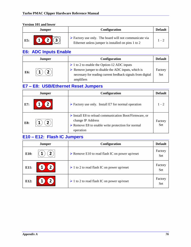
Turbo PMAC Clipper Hardware Reference Manual
Appendix A 76
Version 101 and lower
Jumper Configuration Default
E5: 1 2 3
Factory use only. The board will not communicate via
Ethernet unless jumper is installed on pins 1 to 2 1 – 2
E6: ADC Inputs Enable
Jumper Configuration Default
E6: 1 2
1 to 2 to enable the Option-12 ADC inputs
Remove jumper to disable the ADC inputs, which is
necessary for reading current feedback signals from digital
amplifiers
Factory
Set
E7 – E8: USB/Ethernet Reset Jumpers
Jumper Configuration Default
E7: 1 2
Factory use only. Install E7 for normal operation 1 – 2
E8: 1 2
Install E8 to reload communication Boot/Firmware, or
change IP Address
Remove E8 to enable write protection for normal
operation
Factory
Set
E10 – E12: Flash IC Jumpers
Jumper Configuration Default
E10: 1 2
Remove E10 to read flash IC on power up/reset Factory
Set
E11: 1 2
1 to 2 to read flash IC on power up/reset Factory
Set
E12: 1 2
1 to 2 to read flash IC on power up/reset Factory
Set
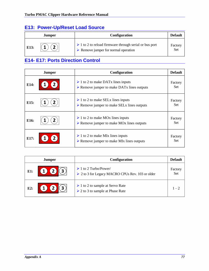
Turbo PMAC Clipper Hardware Reference Manual
Appendix A 77
E13: Power-Up/Reset Load Source
Jumper Configuration Default
E13: 1 2
1 to 2 to reload firmware through serial or bus port
Remove jumper for normal operation
Factory
Set
E14- E17: Ports Direction Control
Jumper Configuration Default
E14: 1 2
1 to 2 to make DATx lines inputs
Remove jumper to make DATx lines outputs
Factory
Set
E15: 1 2
1 to 2 to make SELx lines inputs
Remove jumper to make SELx lines outputs
Factory
Set
E16: 1 2
1 to 2 to make MOx lines inputs
Remove jumper to make MOx lines outputs
Factory
Set
E17: 1 2
1 to 2 to make MIx lines inputs
Remove jumper to make MIx lines outputs
Factory
Set
Jumper Configuration Default
E1: 1 2 3
1 to 2 Turbo/Power/
2 to 3 for Legacy MACRO CPUs Rev. 103 or older
Factory
Set
E2: 1 2 3
1 to 2 to sample at Servo Rate
2 to 3 to sample at Phase Rate 1 – 2
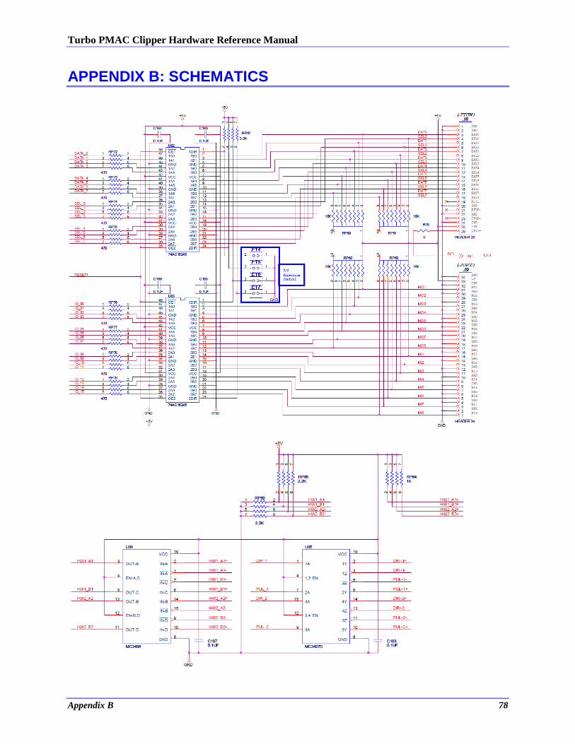
Turbo PMAC Clipper Hardware Reference Manual
Appendix B 78
APPENDIX B: SCHEMATICS
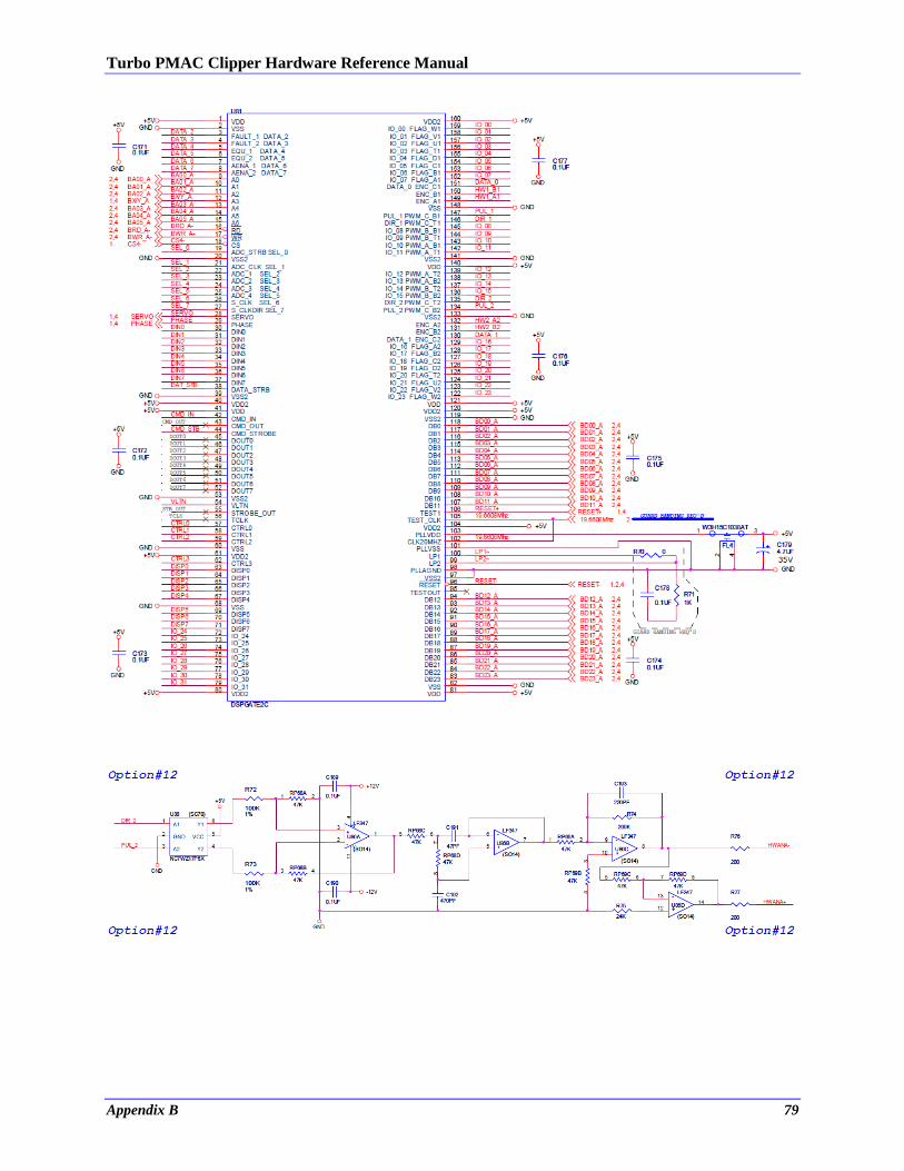
Turbo PMAC Clipper Hardware Reference Manual
Appendix B 79
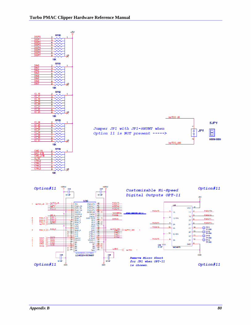
Turbo PMAC Clipper Hardware Reference Manual
Appendix B 80
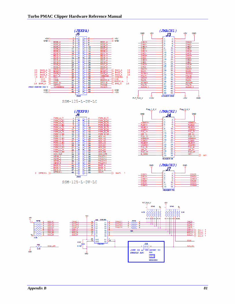
Turbo PMAC Clipper Hardware Reference Manual
Appendix B 81
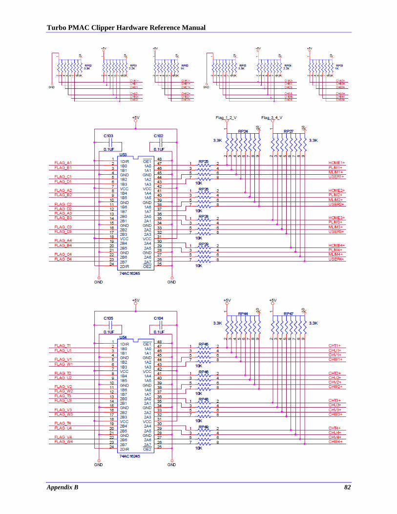
Turbo PMAC Clipper Hardware Reference Manual
Appendix B 82
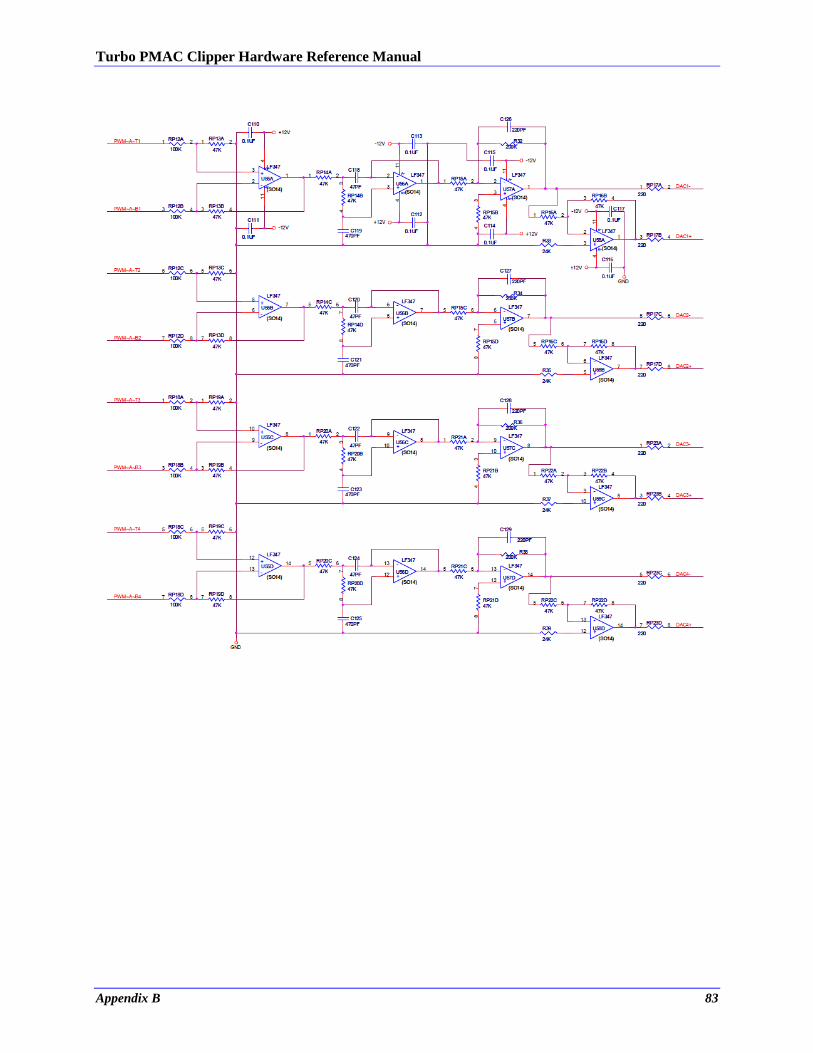
Turbo PMAC Clipper Hardware Reference Manual
Appendix B 83
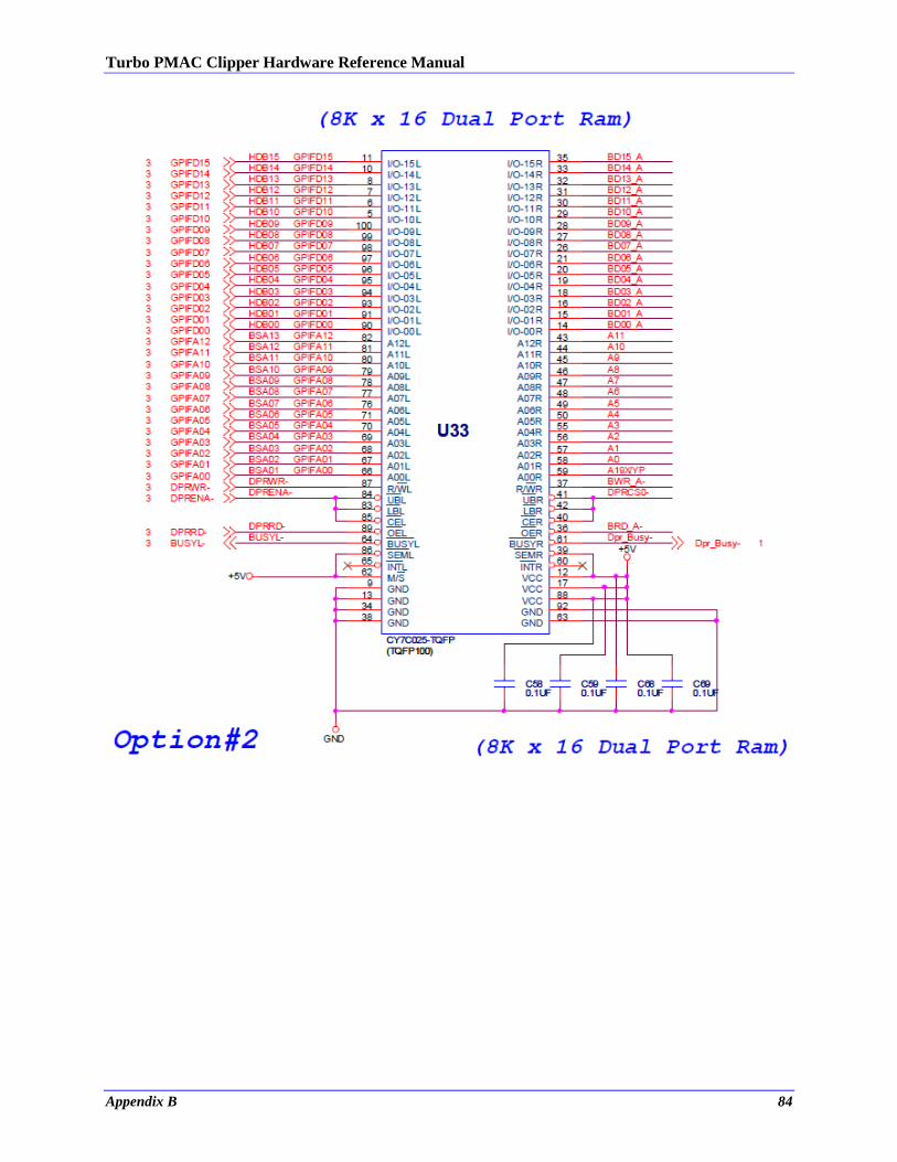
Turbo PMAC Clipper Hardware Reference Manual
Appendix B 84