Embed Size (px)
Citation preview
MODULES FOR STEPPER MOTORS MODULES
TRINAMIC Motion Control GmbH & Co. KG Hamburg, Germany www.trinamic.com
Hardware Version V 1.10
HARDWARE MANUAL
+ + TMCM-6212
TMCM-6213
6-Axes Stepper
Controller / Driver
Up-to 1.1A RMS / 24V DC
Encoder / HOME / STOP
4x analog / digital inputs
4x digital outputs
Brake chopper support
CAN, RS485, USB (TMCM-6212)
EtherCAT™, USB (TMCM-6213) + +
TMCM-6212, TMCM-6213 Hardware Manual (V0.91 / 2017-MAR-01) 2
Copyright © 2016, 2017 TRINAMIC Motion Control GmbH & Co. KG
Table of contents 1 Life support policy ....................................................................................................................................................... 3 2 Features ........................................................................................................................................................................... 4 3 Order codes .................................................................................................................................................................... 5 4 Mechanical and Electrical Interfacing ..................................................................................................................... 6
4.1 Dimensions and Mounting Holes ................................................................................................................... 6 4.2 Board mounting considerations ...................................................................................................................... 7
5 Connectors of TMCM-6212 and TMCM-6213 ........................................................................................................... 8 5.1 TMCM-6212 Interface Brick ................................................................................................................................ 8
5.1.1 RS485 connector ............................................................................................................................................ 9 5.1.2 CAN connector ................................................................................................................................................ 9 5.1.3 USB connector .............................................................................................................................................. 10 5.1.4 Input connector ........................................................................................................................................... 10 5.1.5 Output connector ......................................................................................................................................... 11
5.2 TMCM-6213 Interface Brick .............................................................................................................................. 11 5.2.1 EtherCAT™ connector ................................................................................................................................. 12 5.2.2 USB connector .............................................................................................................................................. 12 5.2.3 Input connector ........................................................................................................................................... 12 5.2.4 Output connector ......................................................................................................................................... 13
5.3 TMCM-6212 + TMCM-6213 Driver Brick .......................................................................................................... 14 5.3.1 Motor connector........................................................................................................................................... 14 5.3.2 REF / HOME connector ................................................................................................................................ 15 5.3.3 Encoder connector....................................................................................................................................... 15
5.4 TMCM-6212 + TMCM-6213 Power supply Brick ........................................................................................... 16 5.4.1 Power connector .......................................................................................................................................... 17 5.4.2 Control connector ........................................................................................................................................ 17 5.4.3 Resistor connector ....................................................................................................................................... 18
5.5 Power supply ...................................................................................................................................................... 18 5.6 RS485 ..................................................................................................................................................................... 18 5.7 CAN ........................................................................................................................................................................ 20
5.7.1 CAN adapter .................................................................................................................................................. 21 5.8 General purpose outputs OUT0..3 ................................................................................................................. 22
6 Motor driver current .................................................................................................................................................. 23 7 On Board LEDs............................................................................................................................................................. 24
7.1 Power supply brick ............................................................................................................................................ 24 7.2 TMCM-6212 Interface Brick .............................................................................................................................. 24 7.3 TMCM-6213 Interface Brick .............................................................................................................................. 25
8 Reset to Factory Default ........................................................................................................................................... 25 9 Operational ratings .................................................................................................................................................... 26 10 TMCM-6212 Functional Description ........................................................................................................................ 27 11 TMCM-6213 Functional Description ........................................................................................................................ 28 12 Revision History .......................................................................................................................................................... 29
12.1 Document revision ............................................................................................................................................ 29 12.2 Hardware revision ............................................................................................................................................. 29
13 References..................................................................................................................................................................... 29
TMCM-6212, TMCM-6213 Hardware Manual (V0.91 / 2017-MAR-01) 3
Copyright © 2016, 2017 TRINAMIC Motion Control GmbH & Co. KG
1 Life support policy TRINAMIC Motion Control GmbH & Co. KG does not authorize or warrant any of its products for use in life support systems, without the specific written consent of TRINAMIC Motion Control GmbH & Co. KG. Life support systems are equipment intended to support or sustain life, and whose failure to perform, when properly used in accordance with instructions provided, can be reasonably expected to result in personal injury or death. © TRINAMIC Motion Control GmbH & Co. KG 2016, 2017 Information given in this data sheet is believed to be accurate and reliable. However neither responsibility is assumed for the consequences of its use nor for any infringement of patents or other rights of third parties, which may result from its use. Specifications are subject to change without notice.
TMCM-6212, TMCM-6213 Hardware Manual (V0.91 / 2017-MAR-01) 4
Copyright © 2016, 2017 TRINAMIC Motion Control GmbH & Co. KG
2 Features The TMCM-6212 / TMCM-6213 is a six axes controller/driver module for 2-phase bipolar stepper motors with separate encoder (differential) and HOME / STOP switch inputs for each axis. CAN, RS485 and USB (Micro-USB) interfaces are available on the TMCM-6212 and EtherCAT™ together with USB (Micro-USB) on the TMCM-6213 for communication. Furthermore the modules offer four analog / digital inputs and four digital outputs together with a brake chopper unit (supporting an external brake resistor) for supply voltage limitation when energy is fed back into the supply rail.
MAIN CHARACTERISTICS
Motion controller
Motion profile calculation in real-time (supporting linear and sixPoint™ ramps)
On the fly alteration of motor parameters (e.g. position, velocity, acceleration)
Dedicated HOME + STOP switch inputs (internal pull-ups)
High performance microcontroller for overall system control and communication protocol handling Bipolar stepper motor driver
Up to 256 microsteps per full step
High-efficient operation, low power dissipation
Dynamic current control
Integrated protection
stealthChop™ for quiet operation and smooth motion
dcStep™ feature for load dependent speed control
stallGuard2™ feature for stall detection
coolStep™ feature for reduced power consumption and heat dissipation Interfaces
TMCM-6212: CAN + RS485
TMCM-6213: EtherCAT™
USB full speed (12Mbit/s) device interface (Micro-USB)
Differential encoder input per motor axis (6x)
HOME, STOP_L, STOP_R switch inputs with internal pull-ups per motor axis (6x)
4 general purpose analog inputs (0..10V) or digital inputs (accept +24V signals)
4 general purpose digital outputs (open-drain) Software
TMCL™ remote (direct mode) and standalone operation with memory for up to 1024 TMCL commands
TMCM-6212: CANopen firmware available
TMCM-6213: CoE (CANopen over EtherCAT™) firmware available Electrical data
Supply voltage: nom. +12V and +24V with +11V … +35V supply voltage operating range
Motor current: up to 1.1A RMS (programmable) Mechanical data
Board size: 215mm x 100mm, overall height 21mm max. (incl. pcb but, without mating connectors and cables)
12x M3 mounting holes (optional) Please see separate TMCM-6212 / TMCM-6213 Software / Firmware documentation for additional information regarding programming and communication protocol.
TMCM-6212, TMCM-6213 Hardware Manual (V0.91 / 2017-MAR-01) 5
Copyright © 2016, 2017 TRINAMIC Motion Control GmbH & Co. KG
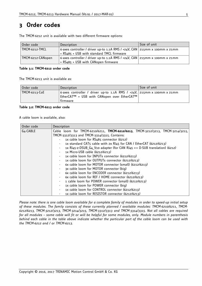
3 Order codes The TMCM-6212 unit is available with two different firmware options:
Order code Description Size of unit
TMCM-6212-TMCL 6-axes controller / driver up-to 1.1A RMS / +24V, CAN + RS485 + USB with standard TMCL firmware
215mm x 100mm x 21mm
TMCM-6212-CANopen 6-axes controller / driver up-to 1.1A RMS / +24V, CAN + RS485 + USB with CANopen firmware
215mm x 100mm x 21mm
Table 3.1: TMCM-6212 order code
The TMCM-6213 unit is available as:
Order code Description Size of unit
TMCM-6213-CoE 6-axes controller / driver up-to 1.1A RMS / +24V, EtherCAT™ + USB with CANopen over EtherCAT™ firmware
215mm x 100mm x 21mm
Table 3.2: TMCM-6213 order code
A cable loom is available, also:
Order code Description
G4-CABLE Cable loom for TMCM-6210/6211, TMCM-6212/6213, TMCM-3212/3213, TMCM-3214/3215, TMCM-3312/3313 and TMCM-3314/3315. Contains:
- 1x cable loom for RS485 connector (6212) - 1x standard CAT5 cable with 2x RJ45 for CAN / EtherCAT (6212/6213) - 1x RJ45-2-DSUB_G4_V10 adapter (for CAN RJ45 <-> D-SUB translation) (6212) - 1x Micro-USB cable (6212/6213) - 1x cable loom for INPUTs connector (6212/6213) - 1x cable loom for OUTPUTs connector (6212/6213) - 6x cable loom for MOTOR connector (small) (6212/6213) - 3x cable loom for MOTOR connector (big) - 6x cable loom for ENCODER connector (6212/6213) - 6x cable loom for REF / HOME connector (6212/6213) - 1 cable loom for POWER connector (small) (6212/6213) - 1x cable loom for POWER connector (big) - 1x cable loom for CONTROL connector (6212/6213) - 1x cable loom for RESISTOR connector (6212/6213)
Please note: there is one cable loom available for a complete family of modules in order to speed-up initial setup of these modules. The family consists of these currently planned / available modules: TMCM-6210/6211, TMCM-6212/6213, TMCM-3212/3213, TMCM-3214/3215, TMCM-3312/3313 and TMCM-3314/3315. Not all cables are required for all modules – some cable will fit or will be helpful for some modules, only. Module numbers in parenthesis behind each cable in the table above indicate whether the particular part of the cable loom can be used with the TMCM-6212 and / or TMCM-6213.
TMCM-6212, TMCM-6213 Hardware Manual (V0.91 / 2017-MAR-01) 6
Copyright © 2016, 2017 TRINAMIC Motion Control GmbH & Co. KG
4 Mechanical and Electrical Interfacing
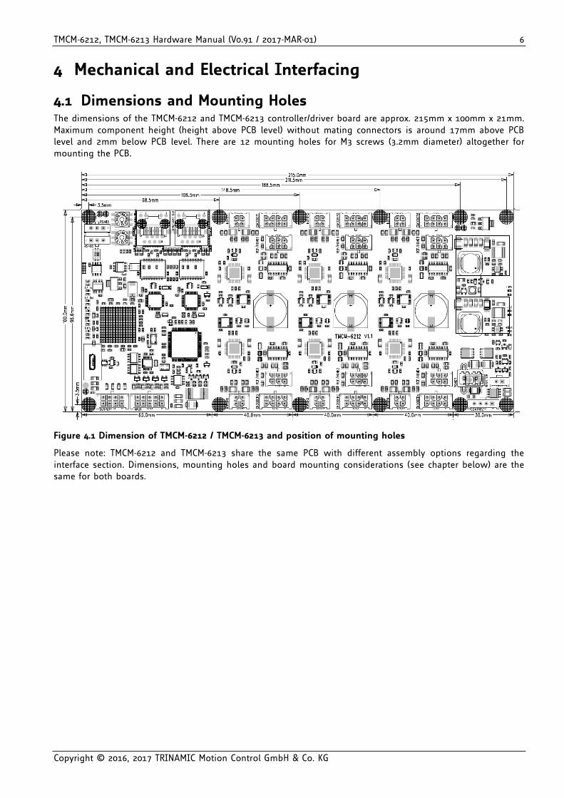
4.1 Dimensions and Mounting Holes The dimensions of the TMCM-6212 and TMCM-6213 controller/driver board are approx. 215mm x 100mm x 21mm. Maximum component height (height above PCB level) without mating connectors is around 17mm above PCB level and 2mm below PCB level. There are 12 mounting holes for M3 screws (3.2mm diameter) altogether for mounting the PCB.
Figure 4.1 Dimension of TMCM-6212 / TMCM-6213 and position of mounting holes
Please note: TMCM-6212 and TMCM-6213 share the same PCB with different assembly options regarding the interface section. Dimensions, mounting holes and board mounting considerations (see chapter below) are the same for both boards.
TMCM-6212, TMCM-6213 Hardware Manual (V0.91 / 2017-MAR-01) 7
Copyright © 2016, 2017 TRINAMIC Motion Control GmbH & Co. KG
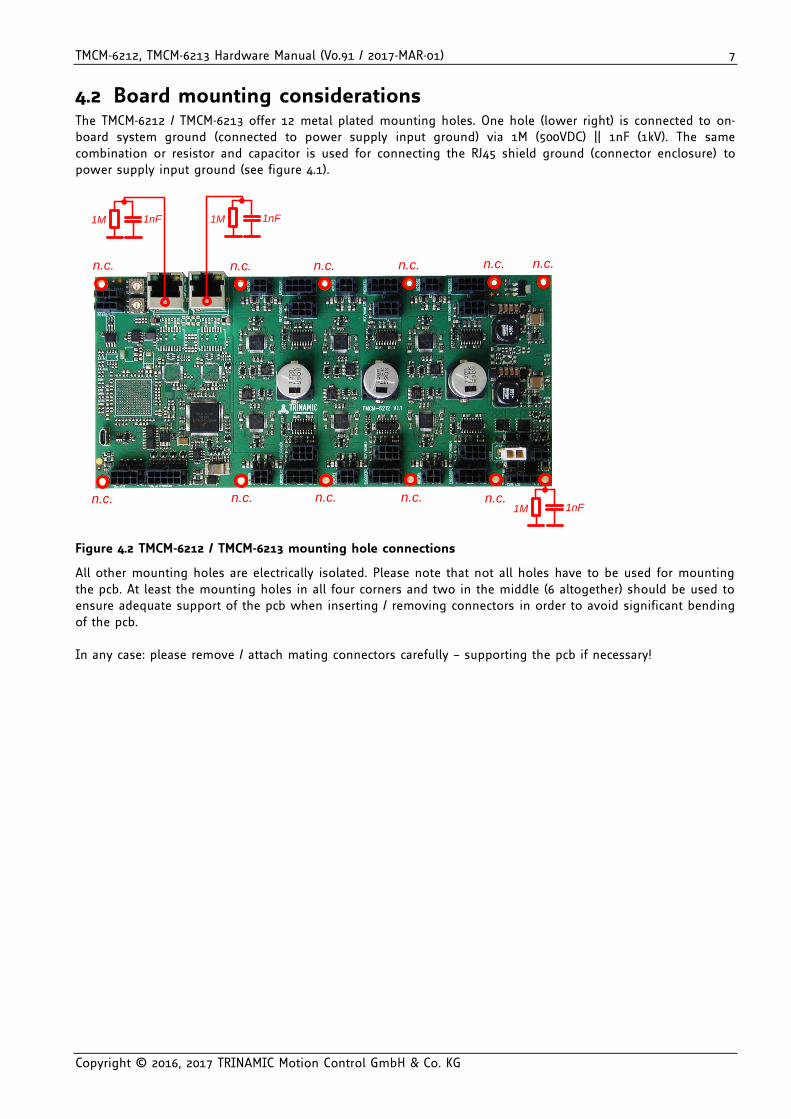
4.2 Board mounting considerations The TMCM-6212 / TMCM-6213 offer 12 metal plated mounting holes. One hole (lower right) is connected to on-board system ground (connected to power supply input ground) via 1M (500VDC) || 1nF (1kV). The same combination or resistor and capacitor is used for connecting the RJ45 shield ground (connector enclosure) to power supply input ground (see figure 4.1).
n.c.n.c.n.c.n.c.n.c.
n.c. n.c. n.c. n.c. n.c.n.c.
1M 1nF
1M 1M 1nF1nF
Figure 4.2 TMCM-6212 / TMCM-6213 mounting hole connections
All other mounting holes are electrically isolated. Please note that not all holes have to be used for mounting the pcb. At least the mounting holes in all four corners and two in the middle (6 altogether) should be used to ensure adequate support of the pcb when inserting / removing connectors in order to avoid significant bending of the pcb. In any case: please remove / attach mating connectors carefully – supporting the pcb if necessary!
TMCM-6212, TMCM-6213 Hardware Manual (V0.91 / 2017-MAR-01) 8
Copyright © 2016, 2017 TRINAMIC Motion Control GmbH & Co. KG
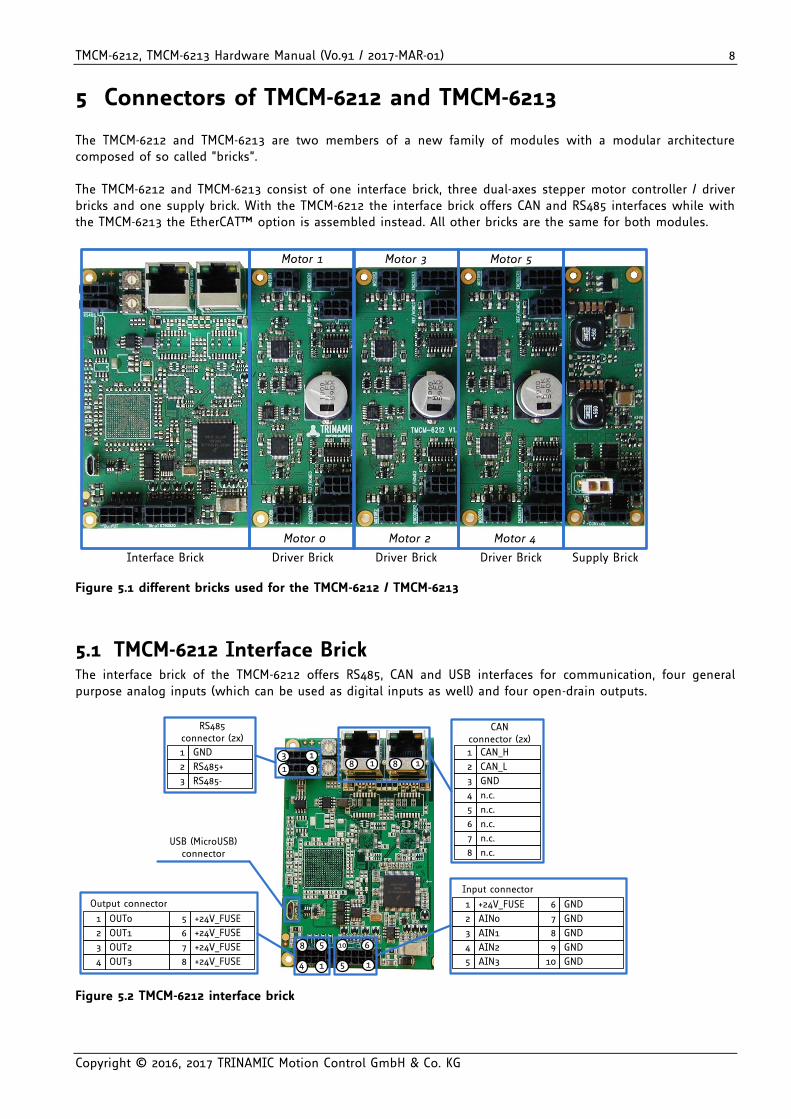
5 Connectors of TMCM-6212 and TMCM-6213 The TMCM-6212 and TMCM-6213 are two members of a new family of modules with a modular architecture composed of so called “bricks”. The TMCM-6212 and TMCM-6213 consist of one interface brick, three dual-axes stepper motor controller / driver bricks and one supply brick. With the TMCM-6212 the interface brick offers CAN and RS485 interfaces while with the TMCM-6213 the EtherCAT™ option is assembled instead. All other bricks are the same for both modules.
Interface Brick Driver Brick Driver Brick Driver Brick Supply Brick
Motor 0
Motor 1
Motor 2 Motor 4
Motor 3 Motor 5
Figure 5.1 different bricks used for the TMCM-6212 / TMCM-6213
5.1 TMCM-6212 Interface Brick The interface brick of the TMCM-6212 offers RS485, CAN and USB interfaces for communication, four general purpose analog inputs (which can be used as digital inputs as well) and four open-drain outputs.
13
31
14
58
15
610
RS485 connector (2x)
RS485-3
RS485+
GND1
2
CANconnector (2x)
GND3
CAN_L
CAN_H1
2
n.c.6
n.c.
n.c.4
5
n.c.8
n.c.7
Output connector
OUT3
OUT23
4
OUT1
OUT01
2
+24V_FUSE
+24V_FUSE7
8
+24V_FUSE
+24V_FUSE5
6
Input connector
AIN2
AIN13
4
AIN0
+24V_FUSE1
2
GND
GND8
9
GND
GND6
7
AIN35 GND10
USB (MicroUSB)connector
1818
Figure 5.2 TMCM-6212 interface brick
TMCM-6212, TMCM-6213 Hardware Manual (V0.91 / 2017-MAR-01) 9
Copyright © 2016, 2017 TRINAMIC Motion Control GmbH & Co. KG
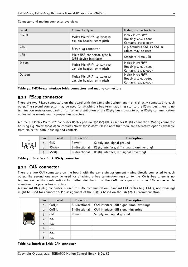
Connector and mating connector overview:
Label Connector type Mating connector type
RS485 Molex MicroFit™, 436500315 1x4 pin header, 3mm pitch
Molex MicroFit™, Housing: 43645-0300 Contacts: 43030-0007
CAN RJ45 plug connector
e.g. Standard CAT 5 / CAT 5e cables may be used
USB Micro-USB connector, type B (USB device interface)
Standard Micro-USB
Inputs Molex MicroFit™, 430451012 2x5 pin header, 3mm pitch
Molex MicroFit™, Housing: 43025-1000 Contacts: 43030-0007
Outputs Molex MicroFit™, 430450812 2x4 pin header, 3mm pitch
Molex MicroFit™, Housing: 43025-0800 Contacts: 43030-0007
Table 5.1 TMCM-6212 interface brick: connectors and mating connectors
5.1.1 RS485 connector There are two RS485 connectors on the board with the same pin assignment – pins directly connected to each other. The second connector may be used for attaching a bus termination resistor to the RS485 bus (there is no termination resistor on-board) or for further distribution of the RS485 bus signals to other RS485 communication nodes while maintaining a proper bus structure. A three pin Molex MicroFit™ connector (Molex part no. 436500315) is used for RS485 connection. Mating connector housing e.g. Molex 43645-0300, contacts Molex 43030-0007. Please note that there are alternative options available from Molex for both, housing and contacts.
13
Pin Label Direction Description
1 GND Power Supply and signal ground
2 RS485+ Bi-directional RS485 interface, diff. signal (non-inverting)
3 RS485- Bi-directional RS485 interface, diff signal (inverting)
Table 5.1: Interface Brick: RS485 connector
5.1.2 CAN connector There are two CAN connectors on the board with the same pin assignment – pins directly connected to each other. The second one may be used for attaching a bus termination resistor to the RS485 bus (there is no termination resistor on-board) or for further distribution of the CAN bus signals to other CAN nodes while maintaining a proper bus structure. A standard RJ45 plug connector is used for CAN communication. Standard CAT cables (e.g. CAT 5, non-crossing) might be used for connection. Pin assignment of the RJ45 is based on the CiA 303-1 recommendation.
18
Pin Label Direction Description
1 CAN_H Bi-Directional CAN interface, diff signal (non-inverting)
2 CAN_L Bi-directional CAN interface, diff signal (inverting)
3 GND Power Supply and signal ground
4 n.c.
5 n.c.
6 n.c.
7 n.c.
8 n.c.
Table 5.2 Interface Brick: CAN connector
TMCM-6212, TMCM-6213 Hardware Manual (V0.91 / 2017-MAR-01) 10
Copyright © 2016, 2017 TRINAMIC Motion Control GmbH & Co. KG
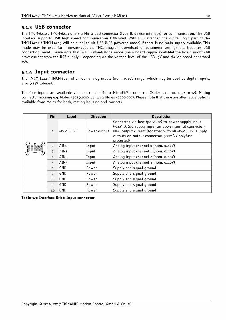
5.1.3 USB connector The TMCM-6212 / TMCM-6213 offers a Micro USB connector (Type B, device interface) for communication. The USB interface supports USB high speed communication (12Mbit/s). With USB attached the digital logic part of the TMCM-6212 / TMCM-6213 will be supplied via USB (USB powered mode) if there is no main supply available. This mode may be used for firmware-updates, TMCL-program download or parameter settings etc. (requires USB connection, only). Please note that in USB stand-alone mode (main board supply available) the board might still draw current from the USB supply – depending on the voltage level of the USB +5V and the on-board generated +5V.
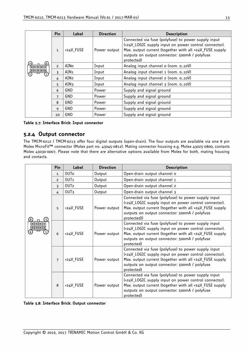
5.1.4 Input connector The TMCM-6212 / TMCM-6213 offer four analog inputs (nom. 0..10V range) which may be used as digital inputs, also (+24V tolerant). The four inputs are available via one 10 pin Molex MicroFit™ connector (Molex part no. 430451012). Mating connector housing e.g. Molex 43025-1000, contacts Molex 43030-0007. Please note that there are alternative options available from Molex for both, mating housing and contacts.
15
610
Pin Label Direction Description
1 +24V_FUSE Power output
Connected via fuse (polyfuse) to power supply input (+24V_LOGIC supply input on power control connector). Max. output current (together with all +24V_FUSE supply outputs on output connector: 500mA / polyfuse protected)
2 AIN0 Input Analog input channel 0 (nom. 0..10V)
3 AIN1 Input Analog input channel 1 (nom. 0..10V)
4 AIN2 Input Analog input channel 2 (nom. 0..10V)
5 AIN3 Input Analog input channel 3 (nom. 0..10V)
6 GND Power Supply and signal ground
7 GND Power Supply and signal ground
8 GND Power Supply and signal ground
9 GND Power Supply and signal ground
10 GND Power Supply and signal ground
Table 5.3: Interface Brick: Input connector
TMCM-6212, TMCM-6213 Hardware Manual (V0.91 / 2017-MAR-01) 11
Copyright © 2016, 2017 TRINAMIC Motion Control GmbH & Co. KG
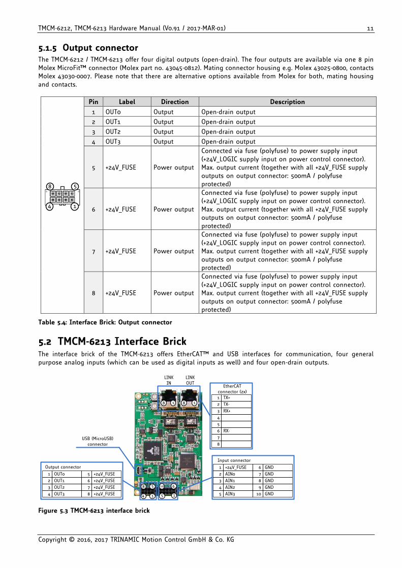
5.1.5 Output connector The TMCM-6212 / TMCM-6213 offer four digital outputs (open-drain). The four outputs are available via one 8 pin Molex MicroFit™ connector (Molex part no. 43045-0812). Mating connector housing e.g. Molex 43025-0800, contacts Molex 43030-0007. Please note that there are alternative options available from Molex for both, mating housing and contacts.
14
58
Pin Label Direction Description
1 OUT0 Output Open-drain output
2 OUT1 Output Open-drain output
3 OUT2 Output Open-drain output
4 OUT3 Output Open-drain output
5 +24V_FUSE Power output
Connected via fuse (polyfuse) to power supply input (+24V_LOGIC supply input on power control connector). Max. output current (together with all +24V_FUSE supply outputs on output connector: 500mA / polyfuse protected)
6 +24V_FUSE Power output
Connected via fuse (polyfuse) to power supply input (+24V_LOGIC supply input on power control connector). Max. output current (together with all +24V_FUSE supply outputs on output connector: 500mA / polyfuse protected)
7 +24V_FUSE Power output
Connected via fuse (polyfuse) to power supply input (+24V_LOGIC supply input on power control connector). Max. output current (together with all +24V_FUSE supply outputs on output connector: 500mA / polyfuse protected)
8 +24V_FUSE Power output
Connected via fuse (polyfuse) to power supply input (+24V_LOGIC supply input on power control connector). Max. output current (together with all +24V_FUSE supply outputs on output connector: 500mA / polyfuse protected)
Table 5.4: Interface Brick: Output connector
5.2 TMCM-6213 Interface Brick The interface brick of the TMCM-6213 offers EtherCAT™ and USB interfaces for communication, four general purpose analog inputs (which can be used as digital inputs as well) and four open-drain outputs.
14
58
15
610
Output connector
OUT3
OUT23
4
OUT1
OUT01
2
+24V_FUSE
+24V_FUSE7
8
+24V_FUSE
+24V_FUSE5
6
Input connector
AIN2
AIN13
4
AIN0
+24V_FUSE1
2
GND
GND8
9
GND
GND6
7
AIN35 GND10
USB (MicroUSB)connector
EtherCATconnector (2x)
RX+3
TX-
TX+1
2
RX-6
4
5
8
7
1818
LINKIN
LINKOUT
Figure 5.3 TMCM-6213 interface brick
TMCM-6212, TMCM-6213 Hardware Manual (V0.91 / 2017-MAR-01) 12
Copyright © 2016, 2017 TRINAMIC Motion Control GmbH & Co. KG
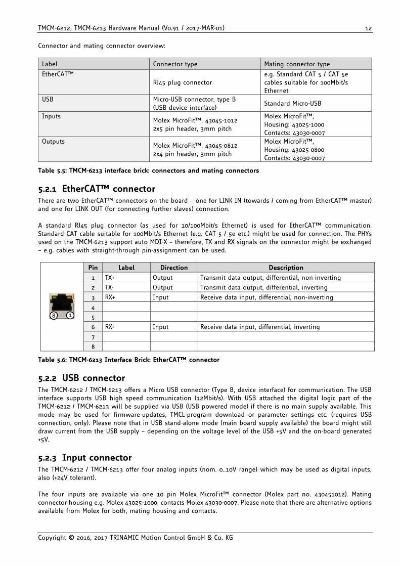
Connector and mating connector overview:
Label Connector type Mating connector type
EtherCAT™ RJ45 plug connector
e.g. Standard CAT 5 / CAT 5e cables suitable for 100Mbit/s Ethernet
USB Micro-USB connector, type B (USB device interface)
Standard Micro-USB
Inputs Molex MicroFit™, 43045-1012 2x5 pin header, 3mm pitch
Molex MicroFit™, Housing: 43025-1000 Contacts: 43030-0007
Outputs Molex MicroFit™, 43045-0812 2x4 pin header, 3mm pitch
Molex MicroFit™, Housing: 43025-0800 Contacts: 43030-0007
Table 5.5: TMCM-6213 interface brick: connectors and mating connectors
5.2.1 EtherCAT™ connector There are two EtherCAT™ connectors on the board – one for LINK IN (towards / coming from EtherCAT™ master) and one for LINK OUT (for connecting further slaves) connection. A standard RJ45 plug connector (as used for 10/100Mbit/s Ethernet) is used for EtherCAT™ communication. Standard CAT cable suitable for 100Mbit/s Ethernet (e.g. CAT 5 / 5e etc.) might be used for connection. The PHYs used on the TMCM-6213 support auto MDI-X – therefore, TX and RX signals on the connector might be exchanged – e.g. cables with straight-through pin-assignment can be used.
18
Pin Label Direction Description
1 TX+ Output Transmit data output, differential, non-inverting
2 TX- Output Transmit data output, differential, inverting
3 RX+ Input Receive data input, differential, non-inverting
4
5
6 RX- Input Receive data input, differential, inverting
7
8
Table 5.6: TMCM-6213 Interface Brick: EtherCAT™ connector
5.2.2 USB connector The TMCM-6212 / TMCM-6213 offers a Micro USB connector (Type B, device interface) for communication. The USB interface supports USB high speed communication (12Mbit/s). With USB attached the digital logic part of the TMCM-6212 / TMCM-6213 will be supplied via USB (USB powered mode) if there is no main supply available. This mode may be used for firmware-updates, TMCL-program download or parameter settings etc. (requires USB connection, only). Please note that in USB stand-alone mode (main board supply available) the board might still draw current from the USB supply – depending on the voltage level of the USB +5V and the on-board generated +5V.
5.2.3 Input connector The TMCM-6212 / TMCM-6213 offer four analog inputs (nom. 0..10V range) which may be used as digital inputs, also (+24V tolerant). The four inputs are available via one 10 pin Molex MicroFit™ connector (Molex part no. 430451012). Mating connector housing e.g. Molex 43025-1000, contacts Molex 43030-0007. Please note that there are alternative options available from Molex for both, mating housing and contacts.
TMCM-6212, TMCM-6213 Hardware Manual (V0.91 / 2017-MAR-01) 13
Copyright © 2016, 2017 TRINAMIC Motion Control GmbH & Co. KG
15
610
Pin Label Direction Description
1 +24V_FUSE Power output
Connected via fuse (polyfuse) to power supply input (+24V_LOGIC supply input on power control connector). Max. output current (together with all +24V_FUSE supply outputs on output connector: 500mA / polyfuse protected)
2 AIN0 Input Analog input channel 0 (nom. 0..10V)
3 AIN1 Input Analog input channel 1 (nom. 0..10V)
4 AIN2 Input Analog input channel 2 (nom. 0..10V)
5 AIN3 Input Analog input channel 3 (nom. 0..10V)
6 GND Power Supply and signal ground
7 GND Power Supply and signal ground
8 GND Power Supply and signal ground
9 GND Power Supply and signal ground
10 GND Power Supply and signal ground
Table 5.7: Interface Brick: Input connector
5.2.4 Output connector The TMCM-6212 / TMCM-6213 offer four digital outputs (open-drain). The four outputs are available via one 8 pin Molex MicroFit™ connector (Molex part no. 43045-0812). Mating connector housing e.g. Molex 43025-0800, contacts Molex 43030-0007. Please note that there are alternative options available from Molex for both, mating housing and contacts.
14
58
Pin Label Direction Description
1 OUT0 Output Open-drain output channel 0
2 OUT1 Output Open-drain output channel 1
3 OUT2 Output Open-drain output channel 2
4 OUT3 Output Open-drain output channel 3
5 +24V_FUSE Power output
Connected via fuse (polyfuse) to power supply input (+24V_LOGIC supply input on power control connector). Max. output current (together with all +24V_FUSE supply outputs on output connector: 500mA / polyfuse protected))
6 +24V_FUSE Power output
Connected via fuse (polyfuse) to power supply input (+24V_LOGIC supply input on power control connector). Max. output current (together with all +24V_FUSE supply outputs on output connector: 500mA / polyfuse protected)
7 +24V_FUSE Power output
Connected via fuse (polyfuse) to power supply input (+24V_LOGIC supply input on power control connector). Max. output current (together with all +24V_FUSE supply outputs on output connector: 500mA / polyfuse protected)
8 +24V_FUSE Power output
Connected via fuse (polyfuse) to power supply input (+24V_LOGIC supply input on power control connector). Max. output current (together with all +24V_FUSE supply outputs on output connector: 500mA / polyfuse protected)
Table 5.8: Interface Brick: Output connector
TMCM-6212, TMCM-6213 Hardware Manual (V0.91 / 2017-MAR-01) 14
Copyright © 2016, 2017 TRINAMIC Motion Control GmbH & Co. KG
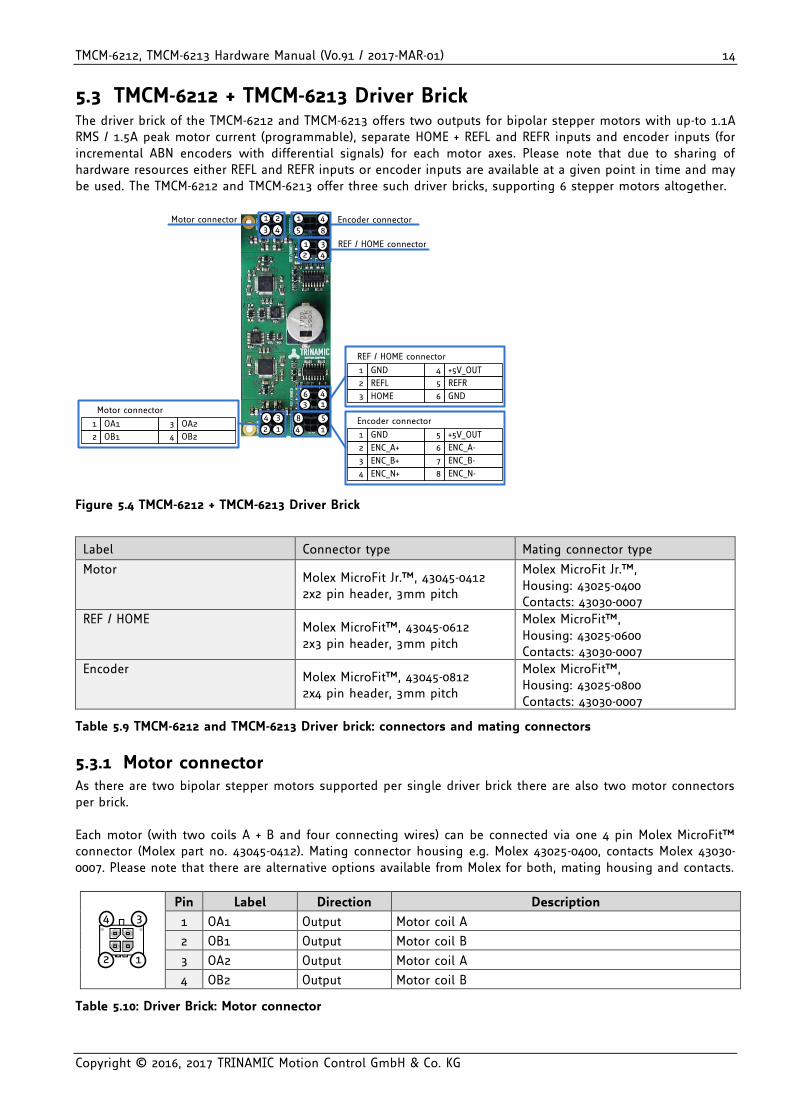
5.3 TMCM-6212 + TMCM-6213 Driver Brick The driver brick of the TMCM-6212 and TMCM-6213 offers two outputs for bipolar stepper motors with up-to 1.1A RMS / 1.5A peak motor current (programmable), separate HOME + REFL and REFR inputs and encoder inputs (for incremental ABN encoders with differential signals) for each motor axes. Please note that due to sharing of hardware resources either REFL and REFR inputs or encoder inputs are available at a given point in time and may be used. The TMCM-6212 and TMCM-6213 offer three such driver bricks, supporting 6 stepper motors altogether.
12
34
14
58
1346
Motor connector
OB1
OA11
2 OB2
OA23
4
Encoder connector
ENC_N+
ENC_B+3
4
ENC_A+
GND1
2
ENC_N-
ENC_B-7
8
ENC_A-
+5V_OUT5
6
REF / HOME connector
HOME3
REFL
GND1
2
GND6
REFR
+5V_OUT4
5
4321
8541Motor connector Encoder connector
4231 REF / HOME connector
Figure 5.4 TMCM-6212 + TMCM-6213 Driver Brick
Label Connector type Mating connector type
Motor Molex MicroFit Jr.™, 43045-0412 2x2 pin header, 3mm pitch
Molex MicroFit Jr.™, Housing: 43025-0400 Contacts: 43030-0007
REF / HOME Molex MicroFit™, 43045-0612 2x3 pin header, 3mm pitch
Molex MicroFit™, Housing: 43025-0600 Contacts: 43030-0007
Encoder Molex MicroFit™, 43045-0812 2x4 pin header, 3mm pitch
Molex MicroFit™, Housing: 43025-0800 Contacts: 43030-0007
Table 5.9 TMCM-6212 and TMCM-6213 Driver brick: connectors and mating connectors
5.3.1 Motor connector As there are two bipolar stepper motors supported per single driver brick there are also two motor connectors per brick. Each motor (with two coils A + B and four connecting wires) can be connected via one 4 pin Molex MicroFit™ connector (Molex part no. 43045-0412). Mating connector housing e.g. Molex 43025-0400, contacts Molex 43030-0007. Please note that there are alternative options available from Molex for both, mating housing and contacts.
1
3
2
4
Pin Label Direction Description
1 OA1 Output Motor coil A
2 OB1 Output Motor coil B
3 OA2 Output Motor coil A
4 OB2 Output Motor coil B
Table 5.10: Driver Brick: Motor connector
TMCM-6212, TMCM-6213 Hardware Manual (V0.91 / 2017-MAR-01) 15
Copyright © 2016, 2017 TRINAMIC Motion Control GmbH & Co. KG
CAUTION
Do not connect or disconnect motor during operation!
Motor cable and motor inductivity might lead to voltage spikes when the motor is disconnected / connected while energized. These voltage spikes might exceed voltage limits of the driver MOSFETs and might permanently damage them. Therefore, always switch off and / or disconnect power supply before connecting / disconnecting the motor.
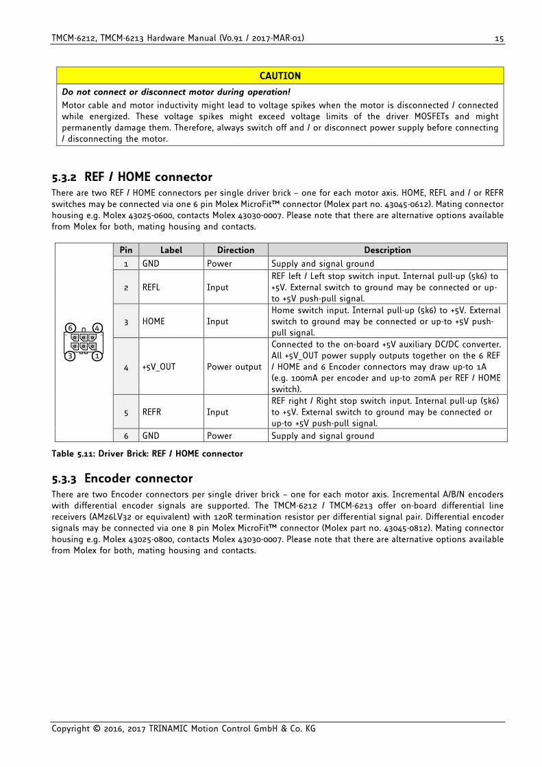
5.3.2 REF / HOME connector There are two REF / HOME connectors per single driver brick – one for each motor axis. HOME, REFL and / or REFR switches may be connected via one 6 pin Molex MicroFit™ connector (Molex part no. 43045-0612). Mating connector housing e.g. Molex 43025-0600, contacts Molex 43030-0007. Please note that there are alternative options available from Molex for both, mating housing and contacts.
13
46
Pin Label Direction Description
1 GND Power Supply and signal ground
2 REFL Input REF left / Left stop switch input. Internal pull-up (5k6) to +5V. External switch to ground may be connected or up-to +5V push-pull signal.
3 HOME Input Home switch input. Internal pull-up (5k6) to +5V. External switch to ground may be connected or up-to +5V push-pull signal.
4 +5V_OUT Power output
Connected to the on-board +5V auxiliary DC/DC converter. All +5V_OUT power supply outputs together on the 6 REF / HOME and 6 Encoder connectors may draw up-to 1A (e.g. 100mA per encoder and up-to 20mA per REF / HOME switch).
5 REFR Input REF right / Right stop switch input. Internal pull-up (5k6) to +5V. External switch to ground may be connected or up-to +5V push-pull signal.
6 GND Power Supply and signal ground
Table 5.11: Driver Brick: REF / HOME connector
5.3.3 Encoder connector There are two Encoder connectors per single driver brick – one for each motor axis. Incremental A/B/N encoders with differential encoder signals are supported. The TMCM-6212 / TMCM-6213 offer on-board differential line receivers (AM26LV32 or equivalent) with 120R termination resistor per differential signal pair. Differential encoder signals may be connected via one 8 pin Molex MicroFit™ connector (Molex part no. 43045-0812). Mating connector housing e.g. Molex 43025-0800, contacts Molex 43030-0007. Please note that there are alternative options available from Molex for both, mating housing and contacts.
TMCM-6212, TMCM-6213 Hardware Manual (V0.91 / 2017-MAR-01) 16
Copyright © 2016, 2017 TRINAMIC Motion Control GmbH & Co. KG
14
58
Pin Label Direction Description
1 GND Power Supply and signal ground
2 ENC_A+ Input Differential input of encoder channel A, non-inverting input
3 ENC_B+ Input Differential input of encoder channel B, non-inverting input
4 ENC_N+ Input Differential input of encoder null / zero channel, non-inverting input
5 +5V_OUT Power output
Connected to the on-board +5V auxiliary DC/DC converter. All +5V_OUT power supply outputs together on the 6 REF / HOME and 6 Encoder connectors may draw up-to 1A (e.g. 100mA per encoder and up-to 20mA per REF / HOME switch).
6 ENC_A- Input Differential input of encoder channel A, inverting input
7 ENC_B- Input Differential input of encoder channel B, inverting input
8 ENC_N- Input Differential input of encoder null / zero channel, inverting input
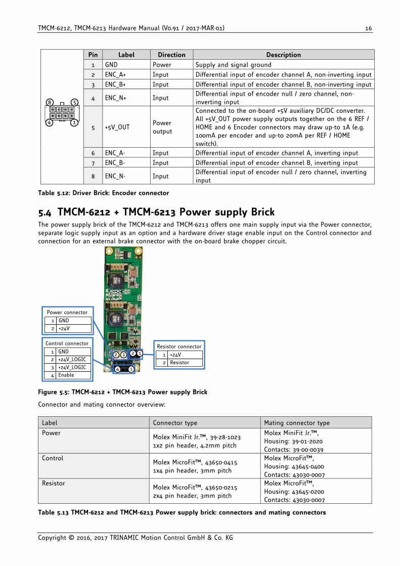
Table 5.12: Driver Brick: Encoder connector
5.4 TMCM-6212 + TMCM-6213 Power supply Brick The power supply brick of the TMCM-6212 and TMCM-6213 offers one main supply input via the Power connector, separate logic supply input as an option and a hardware driver stage enable input on the Control connector and connection for an external brake connector with the on-board brake chopper circuit.
14
212
Control connector
+24V_LOGIC
GND1
2
Enable
+24V_LOGIC3
4
Power connector
+24V
GND1
2
Resistor connector
Resistor
+24V1
2
1
Figure 5.5: TMCM-6212 + TMCM-6213 Power supply Brick
Connector and mating connector overview:
Label Connector type Mating connector type
Power Molex MiniFit Jr.™, 39-28-1023 1x2 pin header, 4.2mm pitch
Molex MiniFit Jr.™, Housing: 39-01-2020 Contacts: 39-00-0039
Control Molex MicroFit™, 43650-0415 1x4 pin header, 3mm pitch
Molex MicroFit™, Housing: 43645-0400 Contacts: 43030-0007
Resistor Molex MicroFit™, 43650-0215 2x4 pin header, 3mm pitch
Molex MicroFit™, Housing: 43645-0200 Contacts: 43030-0007
Table 5.13 TMCM-6212 and TMCM-6213 Power supply brick: connectors and mating connectors
TMCM-6212, TMCM-6213 Hardware Manual (V0.91 / 2017-MAR-01) 17
Copyright © 2016, 2017 TRINAMIC Motion Control GmbH & Co. KG
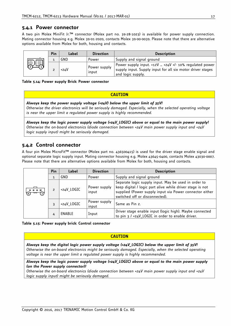
5.4.1 Power connector A two pin Molex MiniFit Jr.™ connector (Molex part no. 39-28-1023) is available for power supply connection. Mating connector housing e.g. Molex 39-01-2020, contacts Molex 39-00-0039. Please note that there are alternative options available from Molex for both, housing and contacts.
12
Pin Label Direction Description
1 GND Power Supply and signal ground
2 +24V Power supply input
Power supply input. +12V … +24V +/- 10% regulated power supply input. Supply input for all six motor driver stages and logic supply.
Table 5.14: Power supply Brick: Power connector
CAUTION
Always keep the power supply voltage (+24V) below the upper limit of 35V!
Otherwise the driver electronics will be seriously damaged. Especially, when the selected operating voltage is near the upper limit a regulated power supply is highly recommended.
Always keep the logic power supply voltage (+24V_LOGIC) above or equal to the main power supply! Otherwise the on-board electronics (diode connection between +24V main power supply input and +24V logic supply input) might be seriously damaged.
5.4.2 Control connector A four pin Molex MicroFit™ connector (Molex part no. 436500415) is used for the driver stage enable signal and optional separate logic supply input. Mating connector housing e.g. Molex 43645-0400, contacts Molex 43030-0007. Please note that there are alternative options available from Molex for both, housing and contacts.
14
Pin Label Direction Description
1 GND Power Supply and signal ground
2 +24V_LOGIC Power supply input
Separate logic supply input. May be used in order to keep digital / logic part alive while driver stage is not supplied (Power supply input via Power connector either switched off or disconnected).
3 +24V_LOGIC Power supply input
Same as Pin 2.
4 ENABLE Input Driver stage enable input (logic high). Maybe connected to pin 3 / +24V_LOGIC in order to enable driver.
Table 5.15: Power supply brick: Control connector
CAUTION
Always keep the digital logic power supply voltage (+24V_LOGIC) below the upper limit of 35V! Otherwise the on-board electronics might be seriously damaged. Especially, when the selected operating voltage is near the upper limit a regulated power supply is highly recommended.
Always keep the logic power supply voltage (+24V_LOGIC) above or equal to the main power supply (on the Power supply connector)! Otherwise the on-board electronics (diode connection between +24V main power supply input and +24V logic supply input) might be seriously damaged.
TMCM-6212, TMCM-6213 Hardware Manual (V0.91 / 2017-MAR-01) 18
Copyright © 2016, 2017 TRINAMIC Motion Control GmbH & Co. KG
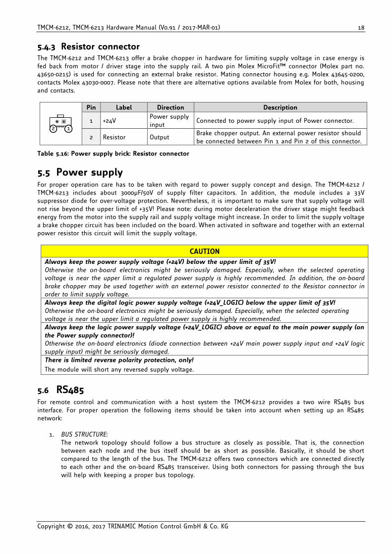
5.4.3 Resistor connector The TMCM-6212 and TMCM-6213 offer a brake chopper in hardware for limiting supply voltage in case energy is fed back from motor / driver stage into the supply rail. A two pin Molex MicroFit™ connector (Molex part no. 43650-0215) is used for connecting an external brake resistor. Mating connector housing e.g. Molex 43645-0200, contacts Molex 43030-0007. Please note that there are alternative options available from Molex for both, housing and contacts.
12
Pin Label Direction Description
1 +24V Power supply input
Connected to power supply input of Power connector.
2 Resistor Output Brake chopper output. An external power resistor should be connected between Pin 1 and Pin 2 of this connector.
Table 5.16: Power supply brick: Resistor connector
5.5 Power supply For proper operation care has to be taken with regard to power supply concept and design. The TMCM-6212 / TMCM-6213 includes about 3000µF/50V of supply filter capacitors. In addition, the module includes a 33V suppressor diode for over-voltage protection. Nevertheless, it is important to make sure that supply voltage will not rise beyond the upper limit of +35V! Please note: during motor deceleration the driver stage might feedback energy from the motor into the supply rail and supply voltage might increase. In order to limit the supply voltage a brake chopper circuit has been included on the board. When activated in software and together with an external power resistor this circuit will limit the supply voltage.
CAUTION
Always keep the power supply voltage (+24V) below the upper limit of 35V!
Otherwise the on-board electronics might be seriously damaged. Especially, when the selected operating voltage is near the upper limit a regulated power supply is highly recommended. In addition, the on-board brake chopper may be used together with an external power resistor connected to the Resistor connector in order to limit supply voltage.
Always keep the digital logic power supply voltage (+24V_LOGIC) below the upper limit of 35V! Otherwise the on-board electronics might be seriously damaged. Especially, when the selected operating voltage is near the upper limit a regulated power supply is highly recommended.
Always keep the logic power supply voltage (+24V_LOGIC) above or equal to the main power supply (on the Power supply connector)! Otherwise the on-board electronics (diode connection between +24V main power supply input and +24V logic supply input) might be seriously damaged.
There is limited reverse polarity protection, only!
The module will short any reversed supply voltage.
5.6 RS485 For remote control and communication with a host system the TMCM-6212 provides a two wire RS485 bus interface. For proper operation the following items should be taken into account when setting up an RS485 network:
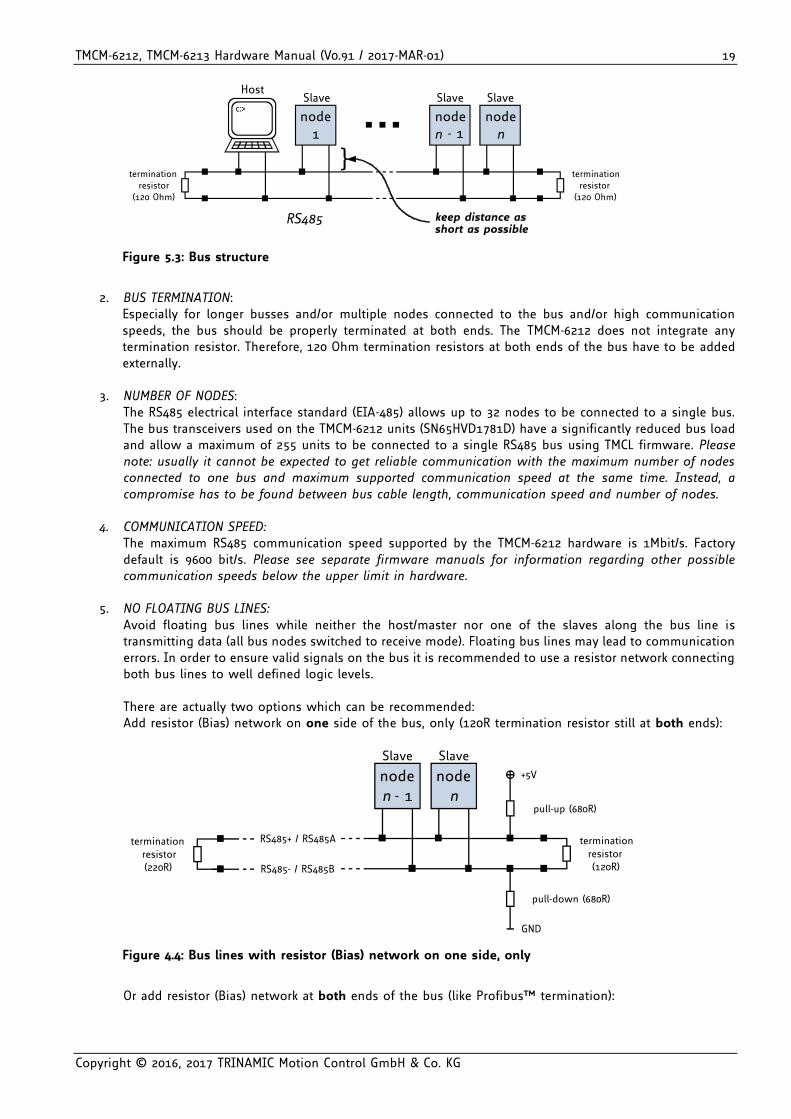
1. BUS STRUCTURE: The network topology should follow a bus structure as closely as possible. That is, the connection between each node and the bus itself should be as short as possible. Basically, it should be short compared to the length of the bus. The TMCM-6212 offers two connectors which are connected directly to each other and the on-board RS485 transceiver. Using both connectors for passing through the bus will help with keeping a proper bus topology.
TMCM-6212, TMCM-6213 Hardware Manual (V0.91 / 2017-MAR-01) 19
Copyright © 2016, 2017 TRINAMIC Motion Control GmbH & Co. KG
c:>node
1noden - 1
noden
HostSlave Slave Slave
RS485
terminationresistor
(120 Ohm)
terminationresistor
(120 Ohm)
}
keep distance asshort as possible
Figure 5.3: Bus structure
2. BUS TERMINATION:
Especially for longer busses and/or multiple nodes connected to the bus and/or high communication speeds, the bus should be properly terminated at both ends. The TMCM-6212 does not integrate any termination resistor. Therefore, 120 Ohm termination resistors at both ends of the bus have to be added externally.
3. NUMBER OF NODES:
The RS485 electrical interface standard (EIA-485) allows up to 32 nodes to be connected to a single bus. The bus transceivers used on the TMCM-6212 units (SN65HVD1781D) have a significantly reduced bus load and allow a maximum of 255 units to be connected to a single RS485 bus using TMCL firmware. Please note: usually it cannot be expected to get reliable communication with the maximum number of nodes connected to one bus and maximum supported communication speed at the same time. Instead, a compromise has to be found between bus cable length, communication speed and number of nodes.
4. COMMUNICATION SPEED: The maximum RS485 communication speed supported by the TMCM-6212 hardware is 1Mbit/s. Factory default is 9600 bit/s. Please see separate firmware manuals for information regarding other possible communication speeds below the upper limit in hardware.
5. NO FLOATING BUS LINES:
Avoid floating bus lines while neither the host/master nor one of the slaves along the bus line is transmitting data (all bus nodes switched to receive mode). Floating bus lines may lead to communication errors. In order to ensure valid signals on the bus it is recommended to use a resistor network connecting both bus lines to well defined logic levels. There are actually two options which can be recommended: Add resistor (Bias) network on one side of the bus, only (120R termination resistor still at both ends):
noden - 1
noden
Slave Slave
terminationresistor(120R)
+5V
GND
pull-up (680R)
pull-down (680R)
RS485- / RS485B
terminationresistor(220R)
RS485+ / RS485A
Figure 4.4: Bus lines with resistor (Bias) network on one side, only
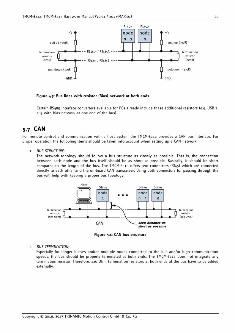
Or add resistor (Bias) network at both ends of the bus (like Profibus™ termination):
TMCM-6212, TMCM-6213 Hardware Manual (V0.91 / 2017-MAR-01) 20
Copyright © 2016, 2017 TRINAMIC Motion Control GmbH & Co. KG
noden - 1
noden
Slave Slave
terminationresistor(220R)
+5V
GND
pull-up (390R)
pull-down (390R)
RS485- / RS485B
RS485+ / RS485Aterminationresistor(220R)
+5V
GND
pull-up (390R)
pull-down (390R)
Figure 4.5: Bus lines with resistor (Bias) network at both ends
Certain RS485 interface converters available for PCs already include these additional resistors (e.g. USB-2-485 with bias network at one end of the bus).
5.7 CAN For remote control and communication with a host system the TMCM-6212 provides a CAN bus interface. For proper operation the following items should be taken into account when setting up a CAN network:
1. BUS STRUCTURE: The network topology should follow a bus structure as closely as possible. That is, the connection between each node and the bus itself should be as short as possible. Basically, it should be short compared to the length of the bus. The TMCM-6212 offers two connectors (RJ45) which are connected directly to each other and the on-board CAN transceiver. Using both connectors for passing through the bus will help with keeping a proper bus topology.
c:>node
1noden - 1
noden
HostSlave Slave Slave
CAN
terminationresistor
(120 Ohm)
terminationresistor
(120 Ohm)
}
keep distance asshort as possible
Figure 5.6: CAN bus structure
2. BUS TERMINATION:
Especially for longer busses and/or multiple nodes connected to the bus and/or high communication speeds, the bus should be properly terminated at both ends. The TMCM-6212 does not integrate any termination resistor. Therefore, 120 Ohm termination resistors at both ends of the bus have to be added externally.
TMCM-6212, TMCM-6213 Hardware Manual (V0.91 / 2017-MAR-01) 21
Copyright © 2016, 2017 TRINAMIC Motion Control GmbH & Co. KG
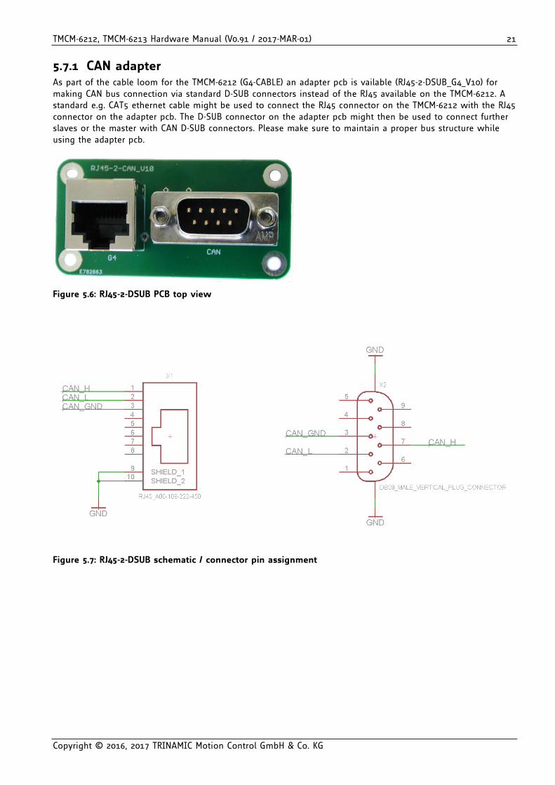
5.7.1 CAN adapter As part of the cable loom for the TMCM-6212 (G4-CABLE) an adapter pcb is vailable (RJ45-2-DSUB_G4_V10) for making CAN bus connection via standard D-SUB connectors instead of the RJ45 available on the TMCM-6212. A standard e.g. CAT5 ethernet cable might be used to connect the RJ45 connector on the TMCM-6212 with the RJ45 connector on the adapter pcb. The D-SUB connector on the adapter pcb might then be used to connect further slaves or the master with CAN D-SUB connectors. Please make sure to maintain a proper bus structure while using the adapter pcb.
Figure 5.6: RJ45-2-DSUB PCB top view
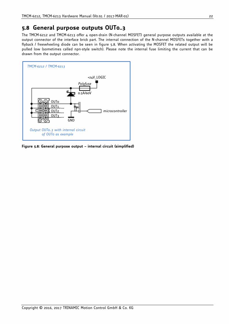
Figure 5.7: RJ45-2-DSUB schematic / connector pin assignment
TMCM-6212, TMCM-6213 Hardware Manual (V0.91 / 2017-MAR-01) 22
Copyright © 2016, 2017 TRINAMIC Motion Control GmbH & Co. KG
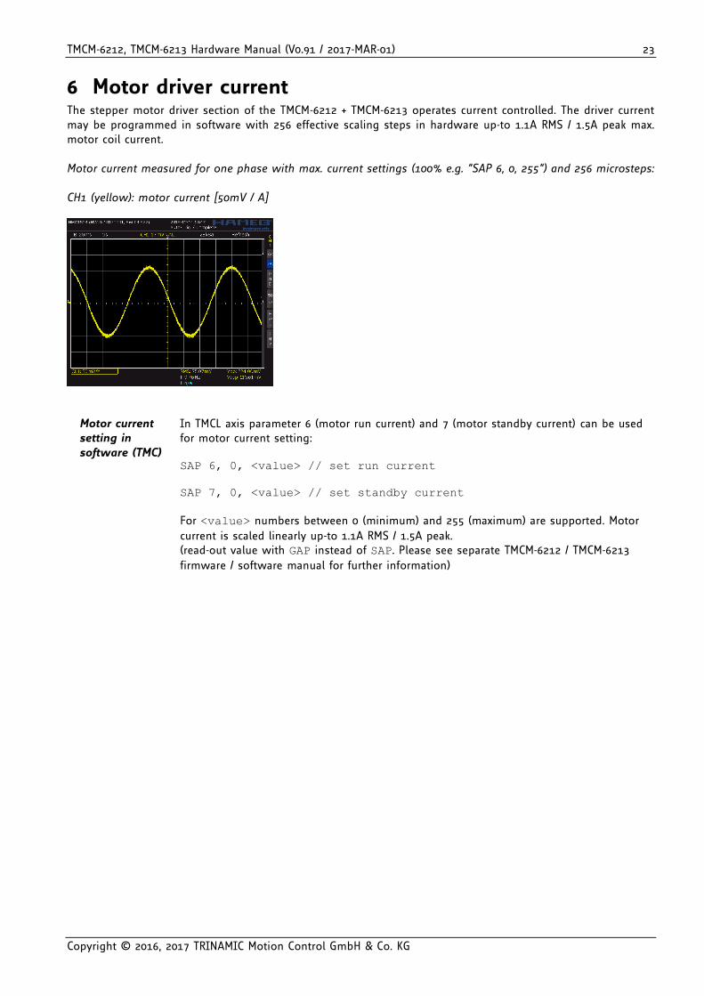
5.8 General purpose outputs OUT0..3 The TMCM-6212 and TMCM-6213 offer 4 open-drain (N-channel MOSFET) general purpose outputs available at the output connector of the interface brick part. The internal connection of the N-channel MOSFETs together with a flyback / freewheeling diode can be seen in figure 5.8. When activating the MOSFET the related output will be pulled low (sometimes called npn-style switch). Please note the internal fuse limiting the current that can be drawn from the output connector.
+24V_LOGIC
microcontroller
GND
1 OUT05
48
OUT1
OUT2
OUT3
TMCM-6212 / TMCM-6213
Output OUT0..3 with internal circuit of OUT0 as example
0.5A/60V
Polyfuse
Figure 5.8: General purpose output – internal circuit (simplified)
TMCM-6212, TMCM-6213 Hardware Manual (V0.91 / 2017-MAR-01) 23
Copyright © 2016, 2017 TRINAMIC Motion Control GmbH & Co. KG
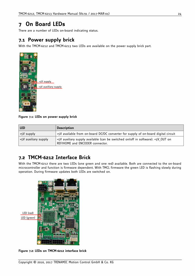
6 Motor driver current The stepper motor driver section of the TMCM-6212 + TMCM-6213 operates current controlled. The driver current may be programmed in software with 256 effective scaling steps in hardware up-to 1.1A RMS / 1.5A peak max. motor coil current. Motor current measured for one phase with max. current settings (100% e.g. “SAP 6, 0, 255”) and 256 microsteps: CH1 (yellow): motor current [50mV / A]
Motor current setting in software (TMC)
In TMCL axis parameter 6 (motor run current) and 7 (motor standby current) can be used for motor current setting: SAP 6, 0, <value> // set run current
SAP 7, 0, <value> // set standby current
For <value> numbers between 0 (minimum) and 255 (maximum) are supported. Motor
current is scaled linearly up-to 1.1A RMS / 1.5A peak. (read-out value with GAP instead of SAP. Please see separate TMCM-6212 / TMCM-6213
firmware / software manual for further information)
TMCM-6212, TMCM-6213 Hardware Manual (V0.91 / 2017-MAR-01) 24
Copyright © 2016, 2017 TRINAMIC Motion Control GmbH & Co. KG
7 On Board LEDs There are a number of LEDs on-board indicating status.
7.1 Power supply brick With the TMCM-6212 and TMCM-6213 two LEDs are available on the power supply brick part.
+5V auxilliary supply
+5V supply
Figure 7.1: LEDs on power supply brick
LED Description
+5V supply +5V available from on-board DC/DC converter for supply of on-board digital circuit
+5V auxiliary supply +5V auxiliary supply available (can be switched on/off in software). +5V_OUT on REF/HOME and ENCODER connector.
7.2 TMCM-6212 Interface Brick With the TMCM-6212 there are two LEDs (one green and one red) available. Both are connected to the on-board microcontroller and function is firmware dependent. With TMCL firmware the green LED is flashing slowly during operation. During firmware updates both LEDs are switched on.
LED (green)
LED (red)
Figure 7.2: LEDs on TMCM-6212 interface brick
TMCM-6212, TMCM-6213 Hardware Manual (V0.91 / 2017-MAR-01) 25
Copyright © 2016, 2017 TRINAMIC Motion Control GmbH & Co. KG
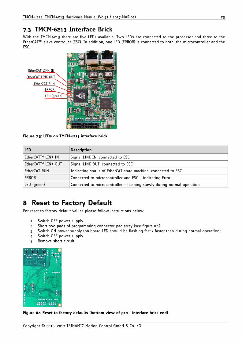
7.3 TMCM-6213 Interface Brick With the TMCM-6213 there are five LEDs available. Two LEDs are connected to the processor and three to the EtherCAT™ slave controller (ESC). In addition, one LED (ERROR) is connected to both, the microcontroller and the ESC.
LED (green)
EtherCAT LINK IN
EtherCAT LINK OUT
EtherCAT RUN
ERROR
Figure 7.3: LEDs on TMCM-6213 interface brick
LED Description
EtherCAT™ LINK IN Signal LINK IN, connected to ESC
EtherCAT™ LINK OUT Signal LINK OUT, connected to ESC
EtherCAT RUN Indicating status of EtherCAT state machine, connected to ESC
ERROR Connected to microcontroller and ESC – indicating Error
LED (green) Connected to microcontroller – flashing slowly during normal operation
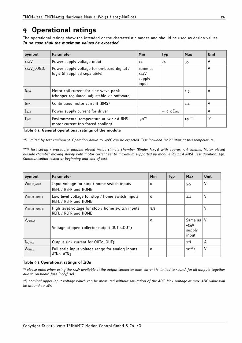
8 Reset to Factory Default For reset to factory default values please follow instructions below:
1. Switch OFF power supply. 2. Short two pads of programming connector pad-array (see figure 8.1). 3. Switch ON power supply (on-board LED should be flashing fast / faster than during normal operation). 4. Switch OFF power supply. 5. Remove short circuit.
Figure 8.1 Reset to factory defaults (bottom view of pcb - interface brick end)
TMCM-6212, TMCM-6213 Hardware Manual (V0.91 / 2017-MAR-01) 26
Copyright © 2016, 2017 TRINAMIC Motion Control GmbH & Co. KG
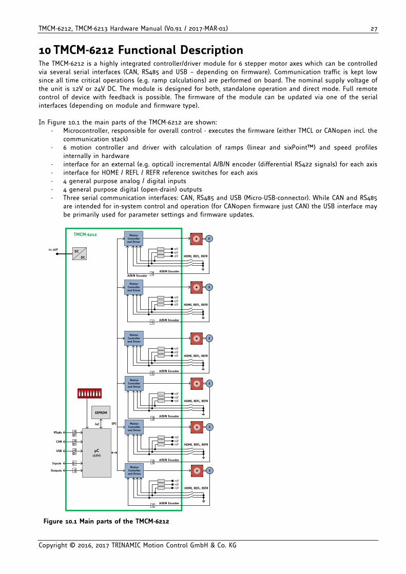
9 Operational ratings The operational ratings show the intended or the characteristic ranges and should be used as design values. In no case shall the maximum values be exceeded.
Symbol Parameter Min Typ Max Unit
+24V Power supply voltage input 11 24 35 V
+24V_LOGIC Power supply voltage for on-board digital / logic (if supplied separately)
Same as +24V supply input
V
IPEAK Motor coil current for sine wave peak (chopper regulated, adjustable via software)
1.5 A
IRMS Continuous motor current (RMS) 1.1 A
I+24V Power supply current for driver << 6 x IRMS A
TENV Environmental temperature at 6x 1.1A RMS motor current (no forced cooling)
-30**) +40***) °C
Table 9.1: General operational ratings of the module **) limited by test equipment. Operation down to -40°C can be expected. Test included “cold” start at this temperature.
***) Test set-up / procedure: module placed inside climate chamber (Binder MK53) with approx. 53l volume. Motor placed outside chamber moving slowly with motor current set to maximum supported by module (6x 1.1A RMS). Test duration: 24h. Communication tested at beginning and end of test.
Symbol Parameter Min Typ Max Unit
VREFL/R_HOME Input voltage for stop / home switch inputs
REFL / REFR and HOME
0 5.5 V
VREFL/R_HOME_L Low level voltage for stop / home switch inputs REFL / REFR and HOME
0 1.1 V
VREFL/R_HOME_H High level voltage for stop / home switch inputs REFL / REFR and HOME
3.3 V
VOUT0…3
Voltage at open collector output OUT0…OUT3
0 Same as +24V supply input
V
IOUT0…3 Output sink current for OUT0…OUT3 1*) A
VAIN0…3 Full scale input voltage range for analog inputs AIN0…AIN3
0 10**) V
Table 9.2 Operational ratings of I/Os
*) please note: when using the +24V available at the output connector max. current is limited to 500mA for all outputs together due to on-board fuse (polyfuse)
**) nominal upper input voltage which can be measured without saturation of the ADC. Max. voltage at max. ADC value will be around 10.56V.
TMCM-6212, TMCM-6213 Hardware Manual (V0.91 / 2017-MAR-01) 27
Copyright © 2016, 2017 TRINAMIC Motion Control GmbH & Co. KG
10 TMCM-6212 Functional Description The TMCM-6212 is a highly integrated controller/driver module for 6 stepper motor axes which can be controlled via several serial interfaces (CAN, RS485 and USB – depending on firmware). Communication traffic is kept low since all time critical operations (e.g. ramp calculations) are performed on board. The nominal supply voltage of the unit is 12V or 24V DC. The module is designed for both, standalone operation and direct mode. Full remote control of device with feedback is possible. The firmware of the module can be updated via one of the serial interfaces (depending on module and firmware type). In Figure 10.1 the main parts of the TMCM-6212 are shown:
- Microcontroller, responsible for overall control - executes the firmware (either TMCL or CANopen incl. the communication stack)
- 6 motion controller and driver with calculation of ramps (linear and sixPoint™) and speed profiles internally in hardware
- interface for an external (e.g. optical) incremental A/B/N encoder (differential RS422 signals) for each axis - interface for HOME / REFL / REFR reference switches for each axis - 4 general purpose analog / digital inputs - 4 general purpose digital (open-drain) outputs - Three serial communication interfaces: CAN, RS485 and USB (Micro-USB-connector). While CAN and RS485
are intended for in-system control and operation (for CANopen firmware just CAN) the USB interface may be primarily used for parameter settings and firmware updates.
µC(ARM)
CAN
USB
RS485
Inputs
Outputs
11..35V
DC
DC
EEPROM
I2C SPI
TMCM-6212
Motion Controller and Driver
+5V+5V
+5V
HOME, REFL, REFR
A/B/N Encoder
E
Motion Controller and Driver
+5V+5V
+5V
HOME, REFL, REFR
E
Motion Contorller and Driver
+5V+5V
+5V
HOME, REFL, REFR
E
Motion Controller and Driver
+5V+5V
+5V
HOME, REFL, REFR
A/B/N Encoder
E
Motion Controller and Driver
+5V+5V
+5V
HOME, REFL, REFR
E
Motion Controller and Driver
+5V+5V
+5V
HOME, REFL, REFR
E
A/B/N Encoder
A/B/N Encoder
A/B/N Encoder
A/B/N Encoder
A/B/N Encoder
Figure 10.1 Main parts of the TMCM-6212
TMCM-6212, TMCM-6213 Hardware Manual (V0.91 / 2017-MAR-01) 28
Copyright © 2016, 2017 TRINAMIC Motion Control GmbH & Co. KG
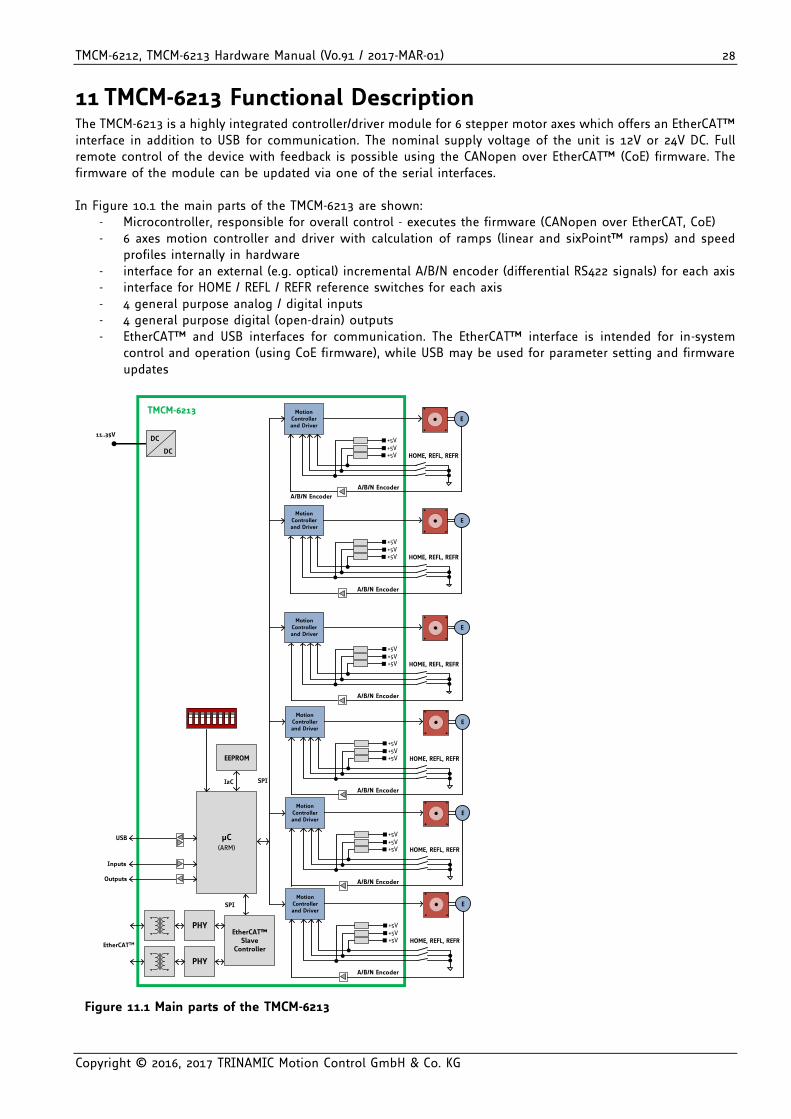
11 TMCM-6213 Functional Description The TMCM-6213 is a highly integrated controller/driver module for 6 stepper motor axes which offers an EtherCAT™ interface in addition to USB for communication. The nominal supply voltage of the unit is 12V or 24V DC. Full remote control of the device with feedback is possible using the CANopen over EtherCAT™ (CoE) firmware. The firmware of the module can be updated via one of the serial interfaces. In Figure 10.1 the main parts of the TMCM-6213 are shown:
- Microcontroller, responsible for overall control - executes the firmware (CANopen over EtherCAT, CoE) - 6 axes motion controller and driver with calculation of ramps (linear and sixPoint™ ramps) and speed
profiles internally in hardware - interface for an external (e.g. optical) incremental A/B/N encoder (differential RS422 signals) for each axis - interface for HOME / REFL / REFR reference switches for each axis - 4 general purpose analog / digital inputs - 4 general purpose digital (open-drain) outputs - EtherCAT™ and USB interfaces for communication. The EtherCAT™ interface is intended for in-system
control and operation (using CoE firmware), while USB may be used for parameter setting and firmware updates
µC(ARM)
USB
Inputs
Outputs
EEPROM
I2C SPI
EtherCAT™ Slave
Controller
SPI
PHY
PHY
EtherCATTM
TMCM-6213
11..35V
DC
DC
Motion Controller and Driver
+5V+5V
+5V
HOME, REFL, REFR
A/B/N Encoder
E
Motion Controller and Driver
+5V+5V
+5V
HOME, REFL, REFR
E
Motion Controller and Driver
+5V+5V
+5V
HOME, REFL, REFR
E
Motion Controller and Driver
+5V+5V
+5V
HOME, REFL, REFR
A/B/N Encoder
E
Motion Controller and Driver
+5V+5V
+5V
HOME, REFL, REFR
E
Motion Controller and Driver
+5V+5V
+5V
HOME, REFL, REFR
E
A/B/N Encoder
A/B/N Encoder
A/B/N Encoder
A/B/N Encoder
A/B/N Encoder
Figure 11.1 Main parts of the TMCM-6213
TMCM-6212, TMCM-6213 Hardware Manual (V0.91 / 2017-MAR-01) 29
Copyright © 2016, 2017 TRINAMIC Motion Control GmbH & Co. KG
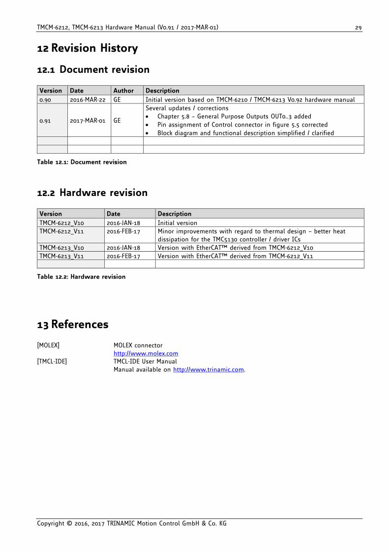
12 Revision History
12.1 Document revision
Version Date Author Description
0.90 2016-MAR-22 GE Initial version based on TMCM-6210 / TMCM-6213 V0.92 hardware manual
0.91 2017-MAR-01 GE
Several updates / corrections
Chapter 5.8 – General Purpose Outputs OUT0..3 added
Pin assignment of Control connector in figure 5.5 corrected
Block diagram and functional description simplified / clarified
Table 12.1: Document revision
12.2 Hardware revision
Version Date Description
TMCM-6212_V10 2016-JAN-18 Initial version
TMCM-6212_V11 2016-FEB-17 Minor improvements with regard to thermal design – better heat dissipation for the TMC5130 controller / driver ICs
TMCM-6213_V10 2016-JAN-18 Version with EtherCAT™ derived from TMCM-6212_V10
TMCM-6213_V11 2016-FEB-17 Version with EtherCAT™ derived from TMCM-6212_V11
Table 12.2: Hardware revision
13 References [MOLEX] MOLEX connector http://www.molex.com [TMCL-IDE] TMCL-IDE User Manual Manual available on http://www.trinamic.com.