Embed Size (px)
Citation preview
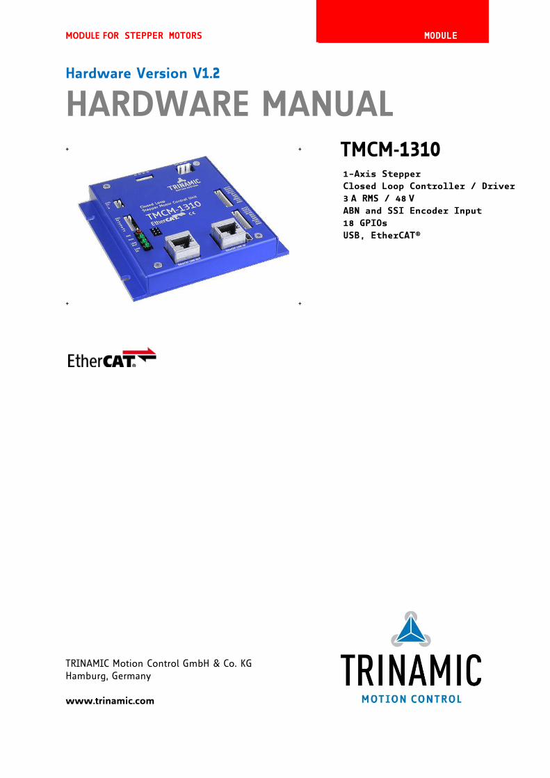
MODULE FOR STEPPER MOTORS MODULE
TRINAMIC Motion Control GmbH & Co. KG Hamburg, Germany www.trinamic.com
Hardware Version V1.2
HARDWARE MANUAL
+ + TMCM-1310
+ +
1-Axis Stepper
Closed Loop Controller / Driver
3 A RMS / 48 V
ABN and SSI Encoder Input
18 GPIOs
USB, EtherCAT®
TMCM-1310 V1.2 Hardware Manual (Rev. 1.12 / 2013-JUL-05) 2
www.trinamic.com
Table of Contents 1 Features ........................................................................................................................................................................... 3 2 Order Codes ................................................................................................................................................................... 5 3 Mechanical and Electrical Interfacing ..................................................................................................................... 6
3.1 Dimensions ........................................................................................................................................................... 6 3.2 Connectors ............................................................................................................................................................. 7
3.2.1 Power Connector ........................................................................................................................................... 8 3.2.2 Motor Connector ............................................................................................................................................ 8 3.2.3 Encoder Connector ........................................................................................................................................ 9 3.2.4 Reference Switch Connector .................................................................................................................... 11 3.2.5 I/O Connectors 0 and 1 ............................................................................................................................. 11 3.2.6 USB Connector ............................................................................................................................................. 12 3.2.7 EtherCAT LINK IN / LINK OUT Connectors ............................................................................................ 13
3.3 Power Supply ..................................................................................................................................................... 14 3.3.1 Adding an Electrolytic Capacitor ............................................................................................................. 14
3.4 Communication .................................................................................................................................................. 15 3.4.1 USB .................................................................................................................................................................. 15
3.5 Inputs and Outputs .......................................................................................................................................... 15 3.5.1 Encoder Input ............................................................................................................................................... 15 3.5.2 Reference Switch Inputs ........................................................................................................................... 16 3.5.3 General Purpose Inputs............................................................................................................................. 16 3.5.4 General Purpose Outputs .......................................................................................................................... 17
4 On-Board LEDs............................................................................................................................................................. 18 5 Operational Ratings ................................................................................................................................................... 19 6 Functional Description .............................................................................................................................................. 20 7 Life Support Policy ..................................................................................................................................................... 21 8 Revision History .......................................................................................................................................................... 22
8.1 Document Revision ........................................................................................................................................... 22 8.2 Hardware Revision ............................................................................................................................................ 22
9 References .................................................................................................................................................................... 22
TMCM-1310 V1.2 Hardware Manual (Rev. 1.12 / 2013-JUL-05) 3
www.trinamic.com
1 Features The TMCM-1310 is a single axis stepper motor controller/driver standalone board with closed loop support. For communication an USB interface and EtherCAT®* are provided. The module supports motor currents up to 3A RMS and supply voltages up to 48V nominal. The module offers inputs for one incremental a/b/n (TTL, open-collector and differential inputs) or absolute SSI encoders (selectable in software). There are dedicated stop switch inputs, 8 general purpose inputs, and 8 general purpose outputs.
MAIN CHARACTERISTICS
Bipolar stepper motor driver Up to 256 microsteps per full step High-efficient operation, low power dissipation Dynamic current control Integrated protection: overtemperature and undervoltage stallGuard2™ feature for stall detection ( for open loop operation) Encoder Encoder input for incremental a/b/n (TTL, open-collector and differential inputs) and absolute SSI
encoders (selectable in software) Interfaces USB 2.0 full-speed (12Mbit/s) communication interface (mini-USB connector) EtherCAT LINK IN and LINK OUT (RJ45) Dedicated STOP_L / STOP_R inputs Up to 8 multi-purpose inputs (+24V compatible, incl. 2 dedicated analog inputs) Up to 8 multi-purpose outputs (open-drain, incl. 2 outputs for currents up to 1A) Software TMCL™ remote (direct mode) and standalone operation with memory for up to 1024 TMCL commands Closed-loop support Fully supported by TMCL-IDE (PC based integrated development environment)
Electrical data Supply voltage: +12V… +48V DC Motor current: up to 3A RMS (programmable) Mechanical data Size: 110mm x 110mm, height 26.3mm
Please refer to separate TMCM-1310 TMCL Firmware Manual for additional information.
* EtherCAT® is registered trademark and patented technology, licensed by Beckhoff Automation GmbH, Germany.
TMCM-1310 V1.2 Hardware Manual (Rev. 1.12 / 2013-JUL-05) 4
www.trinamic.com
TRINAMICS UNIQUE FEATURES – CLOSED LOOP MODE
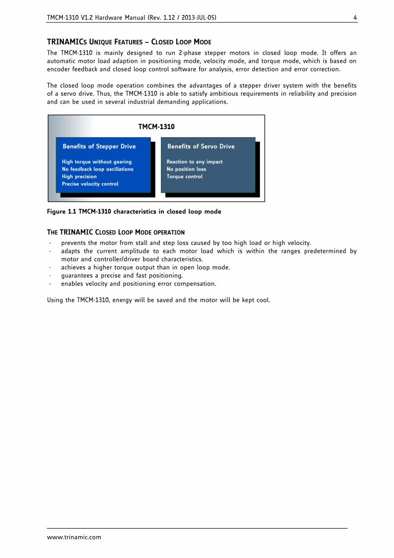
The TMCM-1310 is mainly designed to run 2-phase stepper motors in closed loop mode. It offers an automatic motor load adaption in positioning mode, velocity mode, and torque mode, which is based on encoder feedback and closed loop control software for analysis, error detection and error correction. The closed loop mode operation combines the advantages of a stepper driver system with the benefits of a servo drive. Thus, the TMCM-1310 is able to satisfy ambitious requirements in reliability and precision and can be used in several industrial demanding applications.
Benefits of Stepper Drive
High torque without gearing
No feedback loop oscillations
High precision
Precise velocity control
Benefits of Servo Drive
Reaction to any impact
No position loss
Torque control
TMCM-1310
Figure 1.1 TMCM-1310 characteristics in closed loop mode
THE TRINAMIC CLOSED LOOP MODE OPERATION
prevents the motor from stall and step loss caused by too high load or high velocity. adapts the current amplitude to each motor load which is within the ranges predetermined by
motor and controller/driver board characteristics. achieves a higher torque output than in open loop mode. guarantees a precise and fast positioning. enables velocity and positioning error compensation. Using the TMCM-1310, energy will be saved and the motor will be kept cool.
TMCM-1310 V1.2 Hardware Manual (Rev. 1.12 / 2013-JUL-05) 5
www.trinamic.com
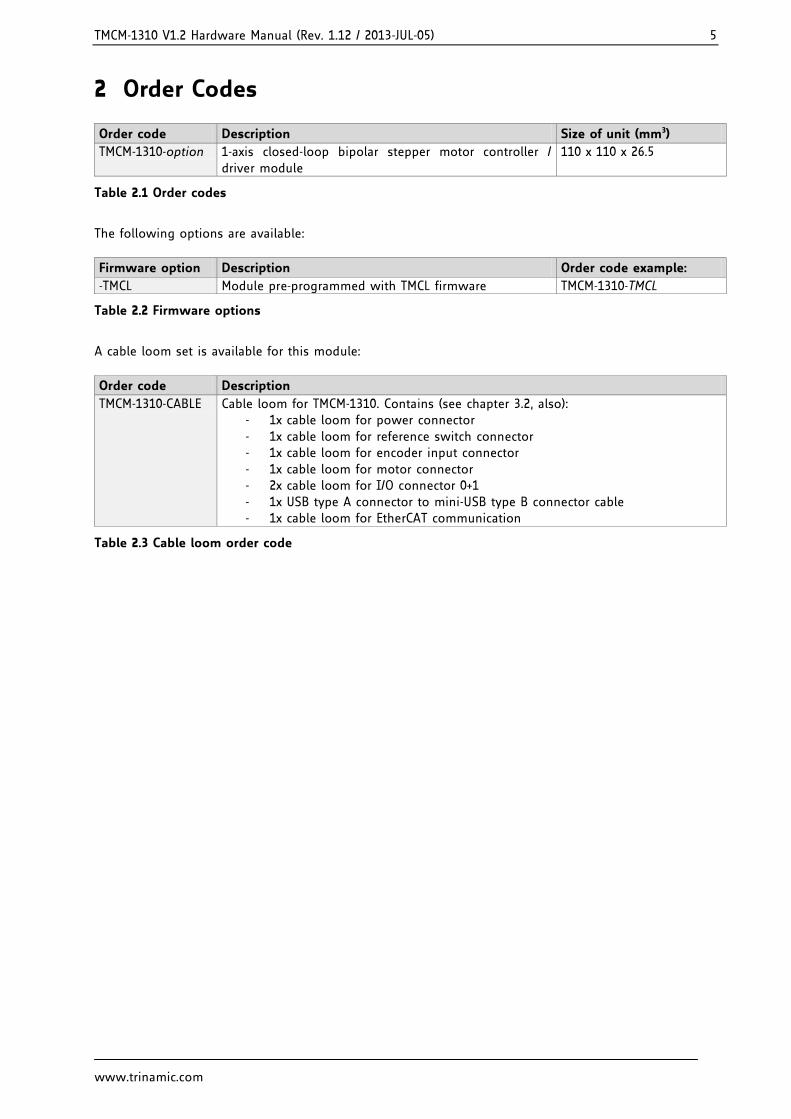
2 Order Codes
Order code Description Size of unit (mm3)
TMCM-1310-option 1-axis closed-loop bipolar stepper motor controller / driver module
110 x 110 x 26.5
Table 2.1 Order codes
The following options are available:
Firmware option Description Order code example:
-TMCL Module pre-programmed with TMCL firmware TMCM-1310-TMCL
Table 2.2 Firmware options
A cable loom set is available for this module:
Order code Description
TMCM-1310-CABLE Cable loom for TMCM-1310. Contains (see chapter 3.2, also): - 1x cable loom for power connector - 1x cable loom for reference switch connector - 1x cable loom for encoder input connector - 1x cable loom for motor connector - 2x cable loom for I/O connector 0+1 - 1x USB type A connector to mini-USB type B connector cable - 1x cable loom for EtherCAT communication
Table 2.3 Cable loom order code
TMCM-1310 V1.2 Hardware Manual (Rev. 1.12 / 2013-JUL-05) 6
www.trinamic.com
3 Mechanical and Electrical Interfacing
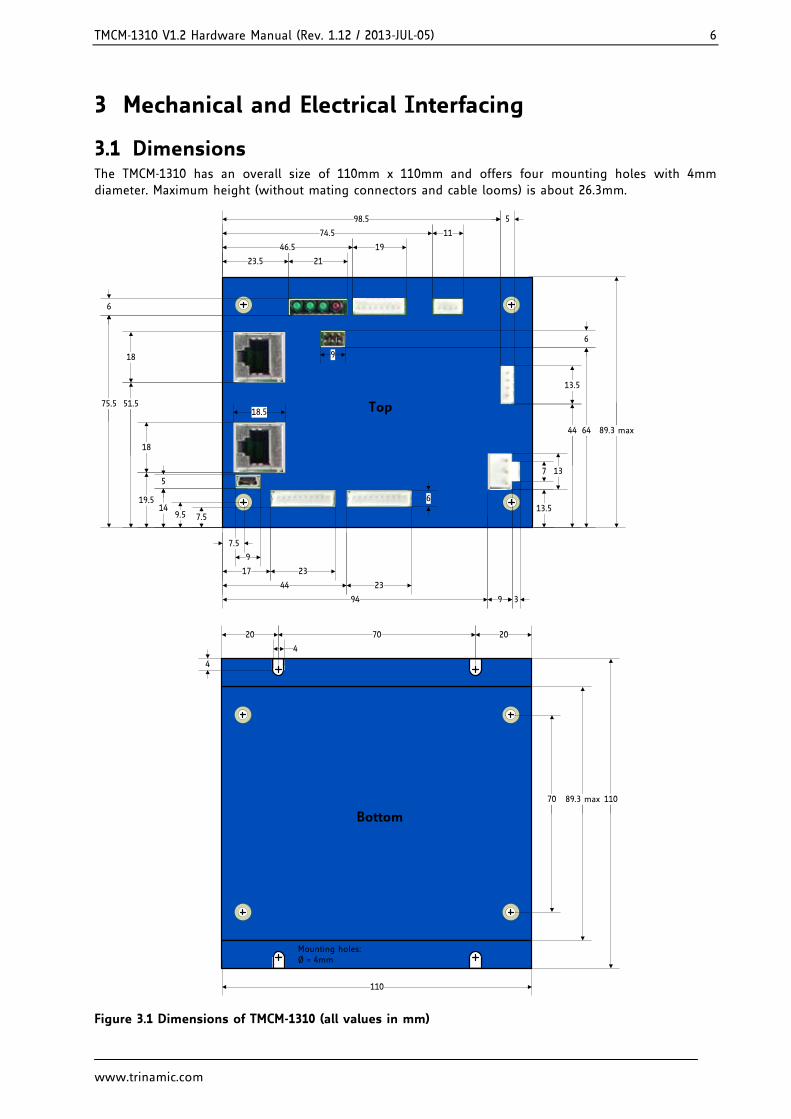
3.1 Dimensions The TMCM-1310 has an overall size of 110mm x 110mm and offers four mounting holes with 4mm diameter. Maximum height (without mating connectors and cable looms) is about 26.3mm.
Top
89.3 max
18.5
18
9
9.5 7.5
9
14
7.5
19.5
51.5
18
75.5
6
5
23.5 21
1946.5
74.5 11
98.5 5
17 23
44 23
6
94 9 3
137
13.5
13.5
44 64
6
Bottom
Mounting holes: Ø = 4mm
20 2070
4
4
70 110
110
89.3 max
Figure 3.1 Dimensions of TMCM-1310 (all values in mm)
TMCM-1310 V1.2 Hardware Manual (Rev. 1.12 / 2013-JUL-05) 7
www.trinamic.com
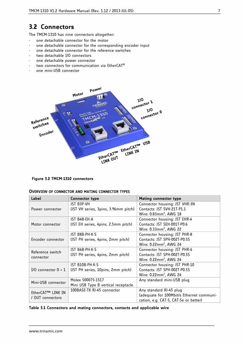
3.2 Connectors The TMCM-1310 has nine connectors altogether:
one detachable connector for the motor one detachable connector for the corresponding encoder input one detachable connector for the reference switches two detachable I/O connectors one detachable power connector two connectors for communication via EtherCAT© one mini-USB connector
Encoder
Reference
switches
MotorPower
I/O
connector 1
I/O
connector 0
EtherCAT™
LINK IN
EtherCAT™
LINK OUT
USB
Figure 3.2 TMCM-1310 connectors
OVERVIEW OF CONNECTOR AND MATING CONNECTOR TYPES
Label Connector type Mating connector type
Power connector JST B3P-VH (JST VH series, 3pins, 3.96mm pitch)
Connector housing: JST VHR-3N Contacts: JST SVH-21T-P1.1 Wire: 0.83mm2, AWG 18
Motor connector JST B4B-EH-A (JST EH series, 4pins, 2.5mm pitch)
Connector housing: JST EHR-4 Contacts: JST SEH-001T-P0.6 Wire: 0.33mm2, AWG 22
Encoder connector JST B8B-PH-K-S (JST PH series, 4pins, 2mm pitch)
Connector housing: JST PHR-8 Contacts: JST SPH-002T-P0.5S Wire: 0.22mm2, AWG 24
Reference switch connector
JST B4B-PH-K-S (JST PH series, 4pins, 2mm pitch)
Connector housing: JST PHR-4 Contacts: JST SPH-002T-P0.5S Wire: 0.22mm2, AWG 24
I/O connector 0 + 1 JST B10B-PH-K-S (JST PH series, 10pins, 2mm pitch)
Connector housing: JST PHR-10 Contacts: JST SPH-002T-P0.5S Wire: 0.22mm2, AWG 24
Mini-USB connector Molex 500075-1517 Mini USB Type B vertical receptacle
Any standard mini-USB plug
EtherCAT™ LINK IN / OUT connectors
100BASE-TX RJ-45 connector
Any standard RJ-45 plug (adequate for 100Mbit/s Ethernet communi-cation, e.g. CAT-5, CAT-5e or better)
Table 3.1 Connectors and mating connectors, contacts and applicable wire
TMCM-1310 V1.2 Hardware Manual (Rev. 1.12 / 2013-JUL-05) 8
www.trinamic.com
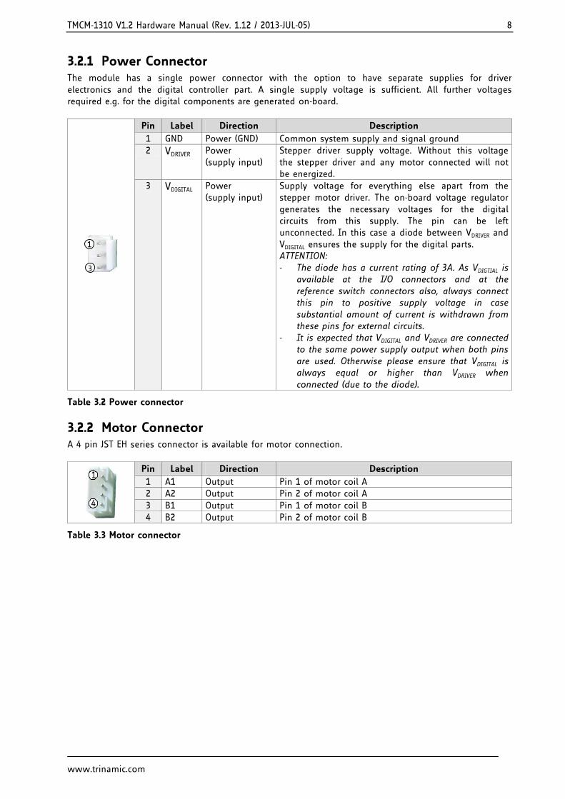
3.2.1 Power Connector The module has a single power connector with the option to have separate supplies for driver electronics and the digital controller part. A single supply voltage is sufficient. All further voltages required e.g. for the digital components are generated on-board.
1
3
Pin Label Direction Description
1 GND Power (GND) Common system supply and signal ground
2 VDRIVER Power (supply input)
Stepper driver supply voltage. Without this voltage the stepper driver and any motor connected will not be energized.
3 VDIGITAL Power (supply input)
Supply voltage for everything else apart from the stepper motor driver. The on-board voltage regulator generates the necessary voltages for the digital circuits from this supply. The pin can be left unconnected. In this case a diode between VDRIVER and VDIGITAL ensures the supply for the digital parts. ATTENTION: The diode has a current rating of 3A. As VDIGTIAL is
available at the I/O connectors and at the reference switch connectors also, always connect this pin to positive supply voltage in case substantial amount of current is withdrawn from these pins for external circuits.
It is expected that VDIGITAL and VDRIVER are connected to the same power supply output when both pins are used. Otherwise please ensure that VDIGITAL is always equal or higher than VDRIVER when connected (due to the diode).
Table 3.2 Power connector
3.2.2 Motor Connector A 4 pin JST EH series connector is available for motor connection.
1
4
Pin Label Direction Description
1 A1 Output Pin 1 of motor coil A
2 A2 Output Pin 2 of motor coil A
3 B1 Output Pin 1 of motor coil B
4 B2 Output Pin 2 of motor coil B
Table 3.3 Motor connector
TMCM-1310 V1.2 Hardware Manual (Rev. 1.12 / 2013-JUL-05) 9
www.trinamic.com
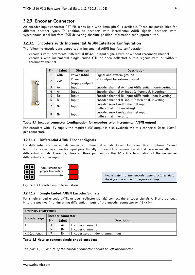
3.2.3 Encoder Connector An encoder input connector (JST PH series 8pin with 2mm pitch) is available. There are possibilities for different encoder types. In addition to encoders with incremental A/B/N signals, encoders with synchronous serial interface (SSI) delivering absolute position information are supported, too.
3.2.3.1 Encoders with Incremental A/B/N Interface Configuration
The following encoders are supported in incremental A/B/N interface configuration:
encoders with incremental differential (RS422) output signals with or without zero/index channel encoders with incremental single ended (TTL or open collector) output signals with or without
zero/index channel
8
1
Pin Label Direction Description
1 GND Power (GND) Signal and system ground
2 +5V Power (supply output)
+5V output for external circuit
3 A+ Input Encoder channel A+ input (differential, non-inverting)
4 A- Input Encoder channel A- input (differential, inverting)
5 B+ Input Encoder channel B+ input (differential, non-inverting)
6 B- Input Encoder channel B- input (differential, inverting)
7 N+ Input Encoder zero / index channel input (differential, non-inverting)
8 N- Input Encoder zero / index channel input (differential, inverting)
Table 3.4 Encoder connector (configuration for encoders with incremental A/B/N output)
For encoders with +5V supply the required +5V output is also available via this connector (max. 100mA per connector).
3.2.3.1.1 Differential A/B/N Encoder Signals
For differential encoder signals connect all differential signals (A+ and A-, B+ and B- and optional N+ and N-) to the respective connector input pins. Usually on-board line termination should be also installed for differential signals. Therefore, close all three jumpers for the 120R line termination of the respective differential encoder input.
Place jumpers for proper temrination
Figure 3.3 Encoder input termination
3.2.3.1.2 Single Ended A/B/N Encoder Signals
For single ended encoders (TTL or open collector signals) connect the encoder signals A, B and optional N to the positive / non-inverting differential inputs of the encoder connector A+ / B+ / N+.
NECESSARY CONNECTIONS
Encoder sign. Encoder connector
Pin Label Description
A 3 A+ Encoder channel A
B 5 B+ Encoder channel B
N/I (optional) 7 N+ Encoder zero / index channel input
Table 3.5 How to connect single ended encoders
The pins A-, B-, and N- of the encoder connector should be left unconnected.
Please refer to the encoder manufacturer data sheet for the correct interface settings.
TMCM-1310 V1.2 Hardware Manual (Rev. 1.12 / 2013-JUL-05) 10
www.trinamic.com
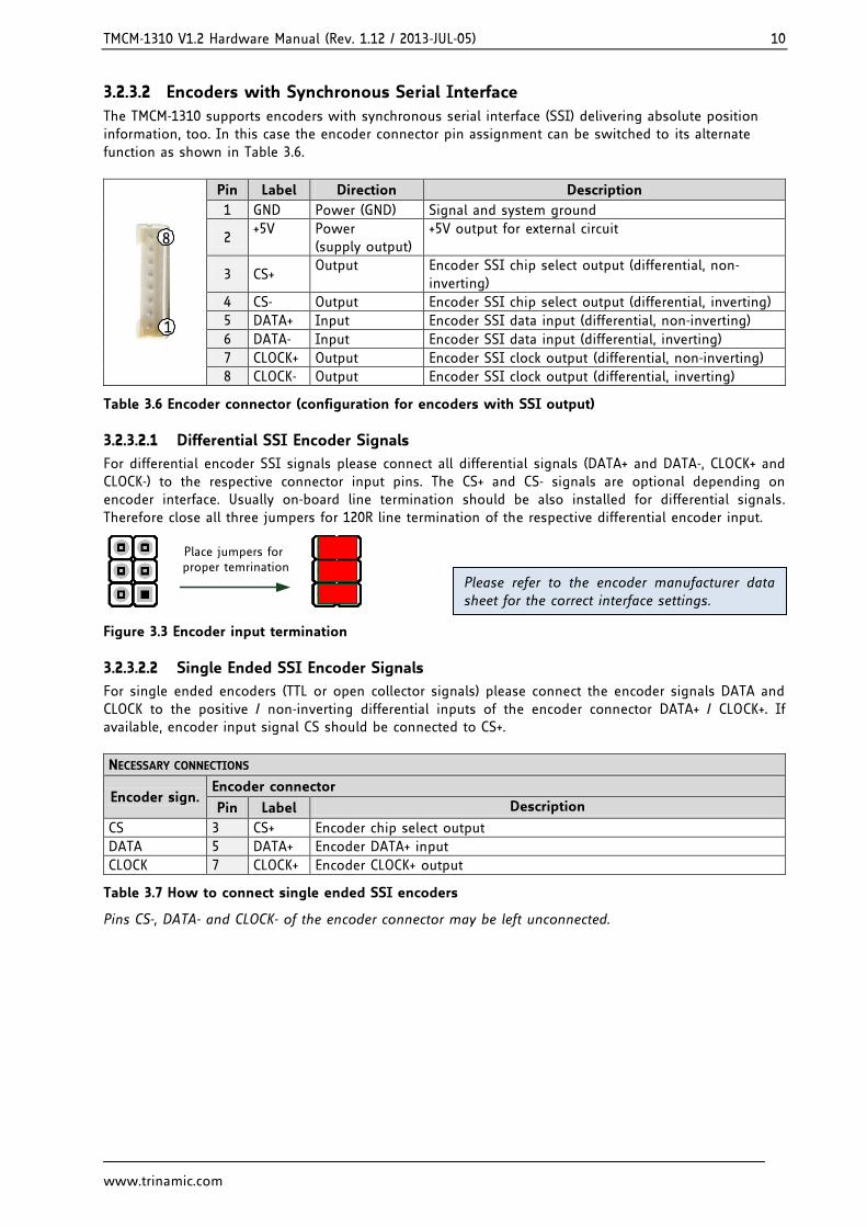
3.2.3.2 Encoders with Synchronous Serial Interface
The TMCM-1310 supports encoders with synchronous serial interface (SSI) delivering absolute position information, too. In this case the encoder connector pin assignment can be switched to its alternate function as shown in Table 3.6.
8
1
Pin Label Direction Description
1 GND Power (GND) Signal and system ground
2 +5V Power
(supply output) +5V output for external circuit
3 CS+ Output Encoder SSI chip select output (differential, non-
inverting)
4 CS- Output Encoder SSI chip select output (differential, inverting)
5 DATA+ Input Encoder SSI data input (differential, non-inverting)
6 DATA- Input Encoder SSI data input (differential, inverting)
7 CLOCK+ Output Encoder SSI clock output (differential, non-inverting)
8 CLOCK- Output Encoder SSI clock output (differential, inverting)
Table 3.6 Encoder connector (configuration for encoders with SSI output)
3.2.3.2.1 Differential SSI Encoder Signals
For differential encoder SSI signals please connect all differential signals (DATA+ and DATA-, CLOCK+ and CLOCK-) to the respective connector input pins. The CS+ and CS- signals are optional depending on encoder interface. Usually on-board line termination should be also installed for differential signals. Therefore close all three jumpers for 120R line termination of the respective differential encoder input.
Place jumpers for proper temrination
Figure 3.3 Encoder input termination
3.2.3.2.2 Single Ended SSI Encoder Signals
For single ended encoders (TTL or open collector signals) please connect the encoder signals DATA and CLOCK to the positive / non-inverting differential inputs of the encoder connector DATA+ / CLOCK+. If available, encoder input signal CS should be connected to CS+.
NECESSARY CONNECTIONS
Encoder sign. Encoder connector
Pin Label Description
CS 3 CS+ Encoder chip select output
DATA 5 DATA+ Encoder DATA+ input
CLOCK 7 CLOCK+ Encoder CLOCK+ output
Table 3.7 How to connect single ended SSI encoders
Pins CS-, DATA- and CLOCK- of the encoder connector may be left unconnected.
Please refer to the encoder manufacturer data sheet for the correct interface settings.
TMCM-1310 V1.2 Hardware Manual (Rev. 1.12 / 2013-JUL-05) 11
www.trinamic.com
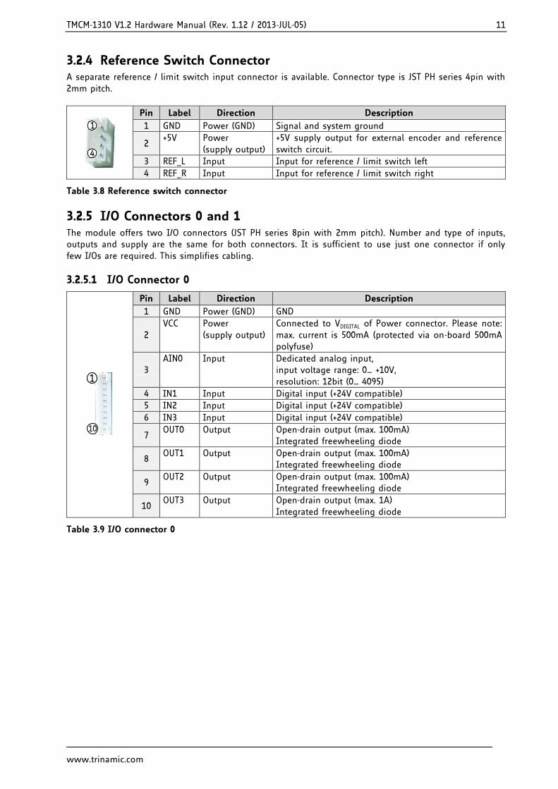
3.2.4 Reference Switch Connector A separate reference / limit switch input connector is available. Connector type is JST PH series 4pin with 2mm pitch.
1
4
Pin Label Direction Description
1 GND Power (GND) Signal and system ground
2 +5V Power
(supply output) +5V supply output for external encoder and reference switch circuit.
3 REF_L Input Input for reference / limit switch left
4 REF_R Input Input for reference / limit switch right
Table 3.8 Reference switch connector
3.2.5 I/O Connectors 0 and 1 The module offers two I/O connectors (JST PH series 8pin with 2mm pitch). Number and type of inputs, outputs and supply are the same for both connectors. It is sufficient to use just one connector if only few I/Os are required. This simplifies cabling.
3.2.5.1 I/O Connector 0
1
10
Pin Label Direction Description
1 GND Power (GND) GND
2 VCC Power
(supply output)
Connected to VDIGITAL of Power connector. Please note: max. current is 500mA (protected via on-board 500mA polyfuse)
3 AIN0 Input Dedicated analog input,
input voltage range: 0… +10V, resolution: 12bit (0… 4095)
4 IN1 Input Digital input (+24V compatible)
5 IN2 Input Digital input (+24V compatible)
6 IN3 Input Digital input (+24V compatible)
7 OUT0 Output Open-drain output (max. 100mA)
Integrated freewheeling diode
8 OUT1 Output Open-drain output (max. 100mA)
Integrated freewheeling diode
9 OUT2 Output Open-drain output (max. 100mA)
Integrated freewheeling diode
10 OUT3 Output Open-drain output (max. 1A)
Integrated freewheeling diode
Table 3.9 I/O connector 0
TMCM-1310 V1.2 Hardware Manual (Rev. 1.12 / 2013-JUL-05) 12
www.trinamic.com
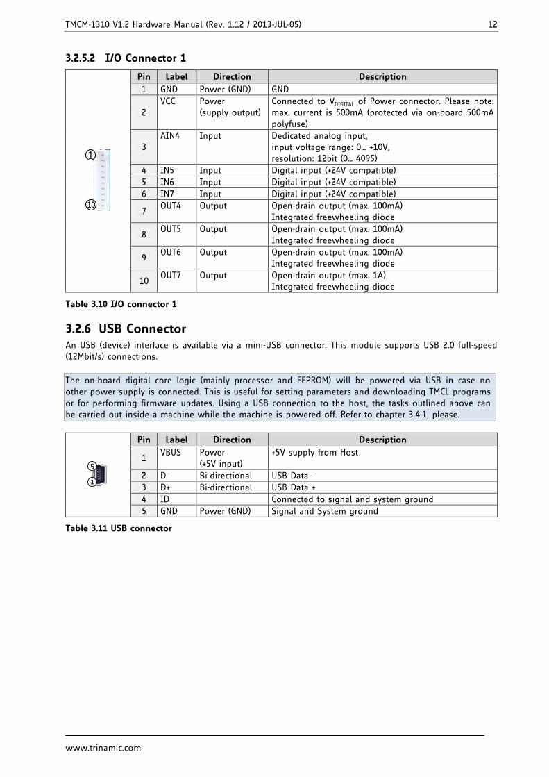
3.2.5.2 I/O Connector 1
1
10
Pin Label Direction Description
1 GND Power (GND) GND
2 VCC Power
(supply output)
Connected to VDIGITAL of Power connector. Please note: max. current is 500mA (protected via on-board 500mA polyfuse)
3 AIN4 Input Dedicated analog input,
input voltage range: 0… +10V, resolution: 12bit (0… 4095)
4 IN5 Input Digital input (+24V compatible)
5 IN6 Input Digital input (+24V compatible)
6 IN7 Input Digital input (+24V compatible)
7 OUT4 Output Open-drain output (max. 100mA)
Integrated freewheeling diode
8 OUT5 Output Open-drain output (max. 100mA)
Integrated freewheeling diode
9 OUT6 Output Open-drain output (max. 100mA)
Integrated freewheeling diode
10 OUT7 Output Open-drain output (max. 1A)
Integrated freewheeling diode
Table 3.10 I/O connector 1
3.2.6 USB Connector An USB (device) interface is available via a mini-USB connector. This module supports USB 2.0 full-speed (12Mbit/s) connections.
The on-board digital core logic (mainly processor and EEPROM) will be powered via USB in case no other power supply is connected. This is useful for setting parameters and downloading TMCL programs or for performing firmware updates. Using a USB connection to the host, the tasks outlined above can be carried out inside a machine while the machine is powered off. Refer to chapter 3.4.1, please.
1
5
Pin Label Direction Description
1 VBUS Power
(+5V input) +5V supply from Host
2 D- Bi-directional USB Data -
3 D+ Bi-directional USB Data +
4 ID Connected to signal and system ground
5 GND Power (GND) Signal and System ground
Table 3.11 USB connector
TMCM-1310 V1.2 Hardware Manual (Rev. 1.12 / 2013-JUL-05) 13
www.trinamic.com
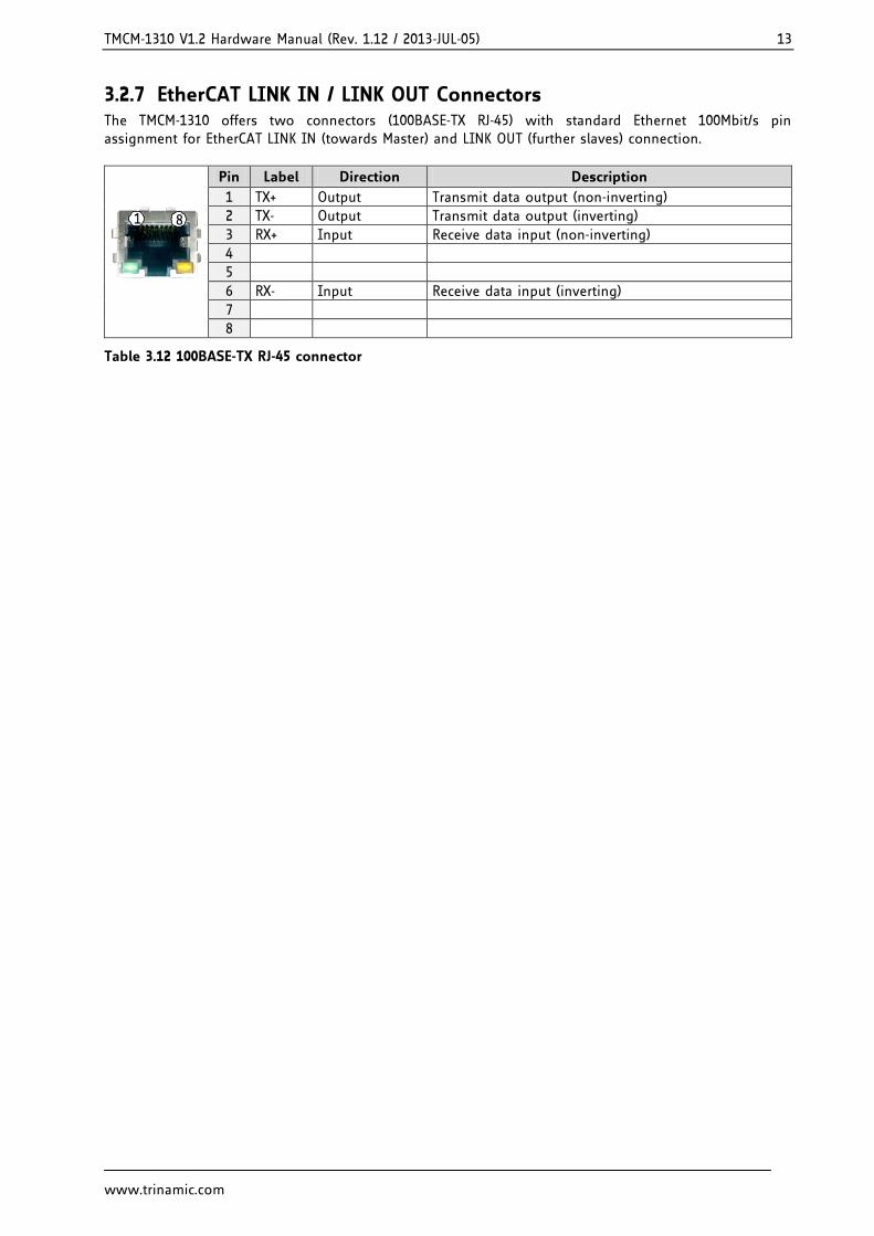
3.2.7 EtherCAT LINK IN / LINK OUT Connectors The TMCM-1310 offers two connectors (100BASE-TX RJ-45) with standard Ethernet 100Mbit/s pin assignment for EtherCAT LINK IN (towards Master) and LINK OUT (further slaves) connection.
1 8
Pin Label Direction Description
1 TX+ Output Transmit data output (non-inverting)
2 TX- Output Transmit data output (inverting)
3 RX+ Input Receive data input (non-inverting)
4
5
6 RX- Input Receive data input (inverting)
7
8
Table 3.12 100BASE-TX RJ-45 connector
TMCM-1310 V1.2 Hardware Manual (Rev. 1.12 / 2013-JUL-05) 14
www.trinamic.com
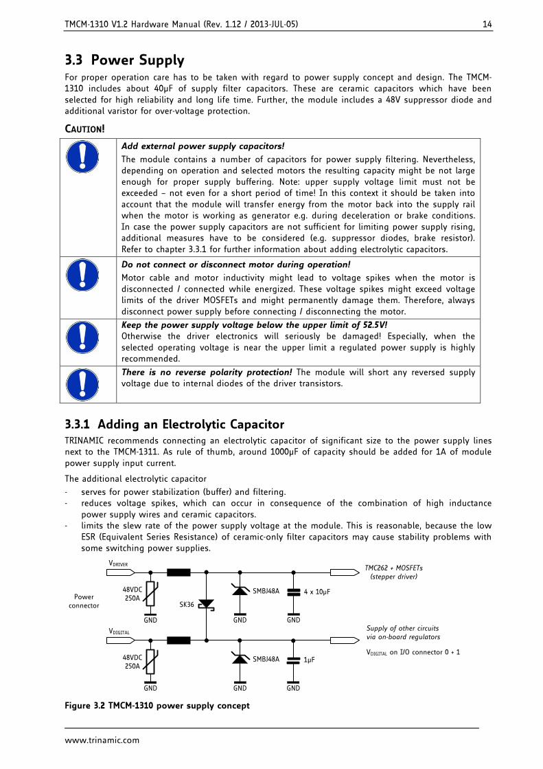
3.3 Power Supply For proper operation care has to be taken with regard to power supply concept and design. The TMCM-1310 includes about 40µF of supply filter capacitors. These are ceramic capacitors which have been selected for high reliability and long life time. Further, the module includes a 48V suppressor diode and additional varistor for over-voltage protection.
CAUTION!
Add external power supply capacitors!
The module contains a number of capacitors for power supply filtering. Nevertheless, depending on operation and selected motors the resulting capacity might be not large enough for proper supply buffering. Note: upper supply voltage limit must not be exceeded – not even for a short period of time! In this context it should be taken into account that the module will transfer energy from the motor back into the supply rail when the motor is working as generator e.g. during deceleration or brake conditions. In case the power supply capacitors are not sufficient for limiting power supply rising, additional measures have to be considered (e.g. suppressor diodes, brake resistor). Refer to chapter 3.3.1 for further information about adding electrolytic capacitors.
Do not connect or disconnect motor during operation!
Motor cable and motor inductivity might lead to voltage spikes when the motor is disconnected / connected while energized. These voltage spikes might exceed voltage limits of the driver MOSFETs and might permanently damage them. Therefore, always disconnect power supply before connecting / disconnecting the motor.
Keep the power supply voltage below the upper limit of 52.5V! Otherwise the driver electronics will seriously be damaged! Especially, when the selected operating voltage is near the upper limit a regulated power supply is highly recommended.
There is no reverse polarity protection! The module will short any reversed supply voltage due to internal diodes of the driver transistors.
3.3.1 Adding an Electrolytic Capacitor TRINAMIC recommends connecting an electrolytic capacitor of significant size to the power supply lines next to the TMCM-1311. As rule of thumb, around 1000µF of capacity should be added for 1A of module power supply input current.
The additional electrolytic capacitor
serves for power stabilization (buffer) and filtering. reduces voltage spikes, which can occur in consequence of the combination of high inductance
power supply wires and ceramic capacitors. limits the slew rate of the power supply voltage at the module. This is reasonable, because the low
ESR (Equivalent Series Resistance) of ceramic-only filter capacitors may cause stability problems with some switching power supplies.
Powerconnector
VDIGITAL
VDRIVER
SMBJ48A 4 x 10µF
GND
TMC262 + MOSFETs(stepper driver)
GND
SK36
SMBJ48A 1µF
GND
Supply of other circuits via on-board regulators
GND
VDIGITAL on I/O connector 0 + 1
GND
48VDC250A
GND
48VDC250A
Figure 3.2 TMCM-1310 power supply concept
TMCM-1310 V1.2 Hardware Manual (Rev. 1.12 / 2013-JUL-05) 15
www.trinamic.com
3.4 Communication
3.4.1 USB For remote control and communication with a host system the TMCM-1310 provides a USB 2.0 full-speed (12Mbit/s) interface. As soon as the USB-host is connected the module accepts commands via the USB interface. The TMCM-1310 supports USB self powered operation with external power supply via the power supply connector and USB bus powered operation without this external power supply.
USB BUS POWERED OPERATION
During USB bus powered operation only the core digital circuit parts - microcontroller and EEPROM - are operational. Motor movements are not possible. This mode has been implemented in order to enable configuration, parameter setting, read-out, firmware updates, etc. by connecting an USB cable between the module and an USB-host. No additional cabling or external devices (e.g. power supply) are required.
Please note that the module might draw current from the USB +5V bus supply even in USB self powered operation. This depends on the voltage level of this supply.
3.5 Inputs and Outputs
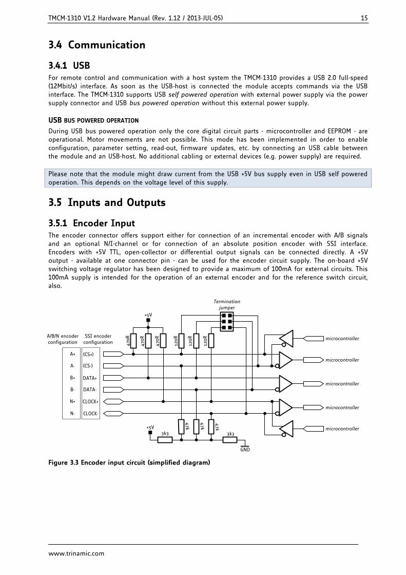
3.5.1 Encoder Input The encoder connector offers support either for connection of an incremental encoder with A/B signals and an optional N/I-channel or for connection of an absolute position encoder with SSI interface. Encoders with +5V TTL, open-collector or differential output signals can be connected directly. A +5V output - available at one connector pin - can be used for the encoder circuit supply. The on-board +5V switching voltage regulator has been designed to provide a maximum of 100mA for external circuits. This 100mA supply is intended for the operation of an external encoder and for the reference switch circuit, also.
A+microcontroller
470R
+5V
A-
B+
470R
470R
B-
N+
N-
47k
47k
47k
3k3 3k3
+5V
GND
120R
120R
120R
Termination jumper
microcontroller
microcontrollerCLOCK+
CLOCK-
DATA-
DATA+
SSI encoder configuration
A/B/N encoder configuration
microcontroller
microcontroller
(CS-)
(CS+)
Figure 3.3 Encoder input circuit (simplified diagram)
TMCM-1310 V1.2 Hardware Manual (Rev. 1.12 / 2013-JUL-05) 16
www.trinamic.com
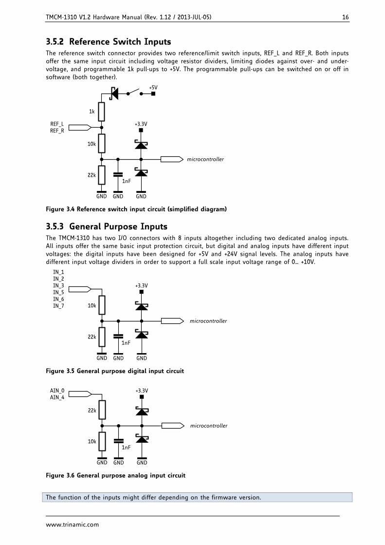
3.5.2 Reference Switch Inputs The reference switch connector provides two reference/limit switch inputs, REF_L and REF_R. Both inputs offer the same input circuit including voltage resistor dividers, limiting diodes against over- and under-voltage, and programmable 1k pull-ups to +5V. The programmable pull-ups can be switched on or off in software (both together).
+3.3VREF_LREF_R
10k
22k1nF
GND GND GND
1k
+5V
microcontroller
Figure 3.4 Reference switch input circuit (simplified diagram)
3.5.3 General Purpose Inputs The TMCM-1310 has two I/O connectors with 8 inputs altogether including two dedicated analog inputs. All inputs offer the same basic input protection circuit, but digital and analog inputs have different input voltages: the digital inputs have been designed for +5V and +24V signal levels. The analog inputs have different input voltage dividers in order to support a full scale input voltage range of 0… +10V.
+3.3V
IN_1IN_2IN_3IN_5IN_6IN_7
microcontroller
10k
22k1nF
GND GND GND
Figure 3.5 General purpose digital input circuit
+3.3VAIN_0
AIN_4
microcontroller
22k
10k1nF
GND GND GND
Figure 3.6 General purpose analog input circuit
The function of the inputs might differ depending on the firmware version.
TMCM-1310 V1.2 Hardware Manual (Rev. 1.12 / 2013-JUL-05) 17
www.trinamic.com
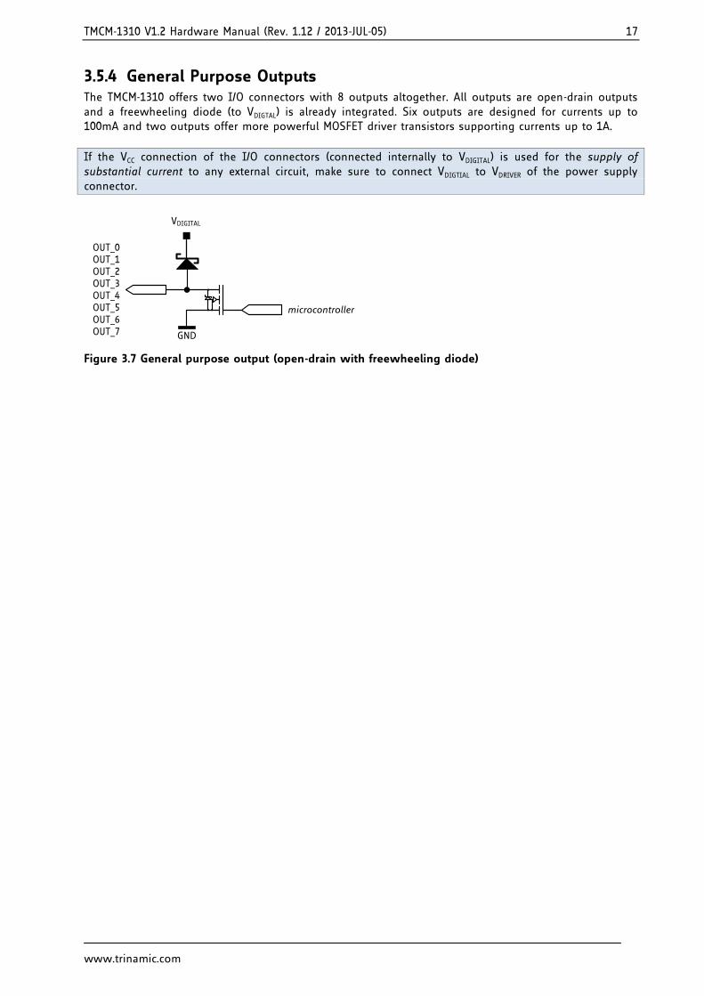
3.5.4 General Purpose Outputs The TMCM-1310 offers two I/O connectors with 8 outputs altogether. All outputs are open-drain outputs and a freewheeling diode (to VDIGTAL) is already integrated. Six outputs are designed for currents up to 100mA and two outputs offer more powerful MOSFET driver transistors supporting currents up to 1A.
If the VCC connection of the I/O connectors (connected internally to VDIGITAL) is used for the supply of substantial current to any external circuit, make sure to connect VDIGTIAL to VDRIVER of the power supply connector.
VDIGITAL
OUT_0OUT_1OUT_2OUT_3OUT_4OUT_5OUT_6OUT_7
microcontroller
GND
Figure 3.7 General purpose output (open-drain with freewheeling diode)
TMCM-1310 V1.2 Hardware Manual (Rev. 1.12 / 2013-JUL-05) 18
www.trinamic.com
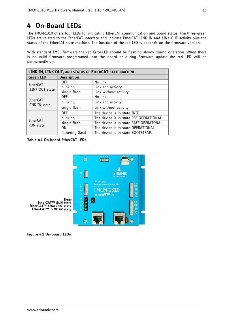
4 On-Board LEDs The TMCM-1310 offers four LEDs for indicating EtherCAT communication and board status. The three green LEDs are related to the EtherCAT interface and indicate EtherCAT LINK IN and LINK OUT activity plus the status of the EtherCAT state machine. The function of the red LED is depends on the firmware version. With standard TMCL firmware the red Error-LED should be flashing slowly during operation. When there is no valid firmware programmed into the board or during firmware update the red LED will be permanently on.
LINK IN, LINK OUT, AND STATUS OF ETHERCAT STATE MACHINE
Green LED Description
EtherCAT LINK OUT state
OFF No link.
blinking Link and activity.
single flash Link without activity.
EtherCAT LINK IN state
OFF No link.
blinking Link and activity.
single flash Link without activity.
EtherCAT RUN state
OFF The device is in state INIT.
blinking The device is in state PRE-OPERATIONAL.
single flash The device is in state SAFE-OPERATONAL.
ON The device is in state OPERATIONAL.
flickering (fast) The device is in state BOOTSTRAP.
Table 4.1 On-board EtherCAT LEDs
EtherCAT™ LINK IN stateEtherCAT™ LINK OUT state
EtherCAT™ RUN stateError
Figure 4.1 On-board LEDs
TMCM-1310 V1.2 Hardware Manual (Rev. 1.12 / 2013-JUL-05) 19
www.trinamic.com
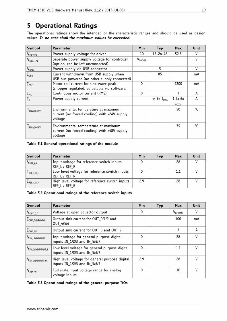
5 Operational Ratings The operational ratings show the intended or the characteristic ranges and should be used as design values. In no case shall the maximum values be exceeded.
Symbol Parameter Min Typ Max Unit
VDRIVER Power supply voltage for driver 10 12..24..48 52.5 V
VDIGITAL Separate power supply voltage for controller (option, can be left unconnected)
VDRIVER V
VUSB Power supply via USB connector 5 V
IUSB Current withdrawn from USB supply when USB bus powered (no other supply connected)
85 mA
ICOIL Motor coil current for sine wave peak (chopper regulated, adjustable via software)
0 4200 mA
IMC Continuous motor current (RMS) 0 3 A
IS Power supply current << 6x ICOIL 1.4x 6x ICOIL
A
TENV@+24V Environmental temperature at maximum current (no forced cooling) with +24V supply voltage
50 °C
TENV@+48V Environmental temperature at maximum current (no forced cooling) with +48V supply voltage
35 °C
Table 5.1 General operational ratings of the module
Symbol Parameter Min Typ Max Unit
VREF_L/R Input voltage for reference switch inputs REF_L / REF_R
0 28 V
IREF_L/R_L Low level voltage for reference switch inputs REF_L / REF_R
0 1.1 V
IREF_L/R_H High level voltage for reference switch inputs REF_L / REF_R
2.9 28 V
Table 5.2 Operational ratings of the reference switch inputs
Symbol Parameter Min Typ Max Unit
VOUT_0..7 Voltage at open collector output 0 VDIGITAL V
IOUT_0/1/2/4/5/6 Output sink current for OUT_0/1/2 and OUT_4/5/6
100 mA
IOUT_3/7 Output sink current for OUT_3 and OUT_7 1 A
VIN_ 1/2/3/5/6/7 Input voltage for general purpose digital inputs IN_1/2/3 and IN_5/6/7
0 28 V
VIN_1/1/2/3/5/6/7_L Low level voltage for general purpose digital inputs IN_1/2/3 and IN_5/6/7
0 1.1 V
VIN_1/2/3/5/6/7_H High level voltage for general purpose digital inputs IN_1/2/3 and IN_5/6/7
2.9 28 V
VAIN_0!4 Full scale input voltage range for analog voltage inputs
0 10 V
Table 5.3 Operational ratings of the general purpose I/Os
TMCM-1310 V1.2 Hardware Manual (Rev. 1.12 / 2013-JUL-05) 20
www.trinamic.com
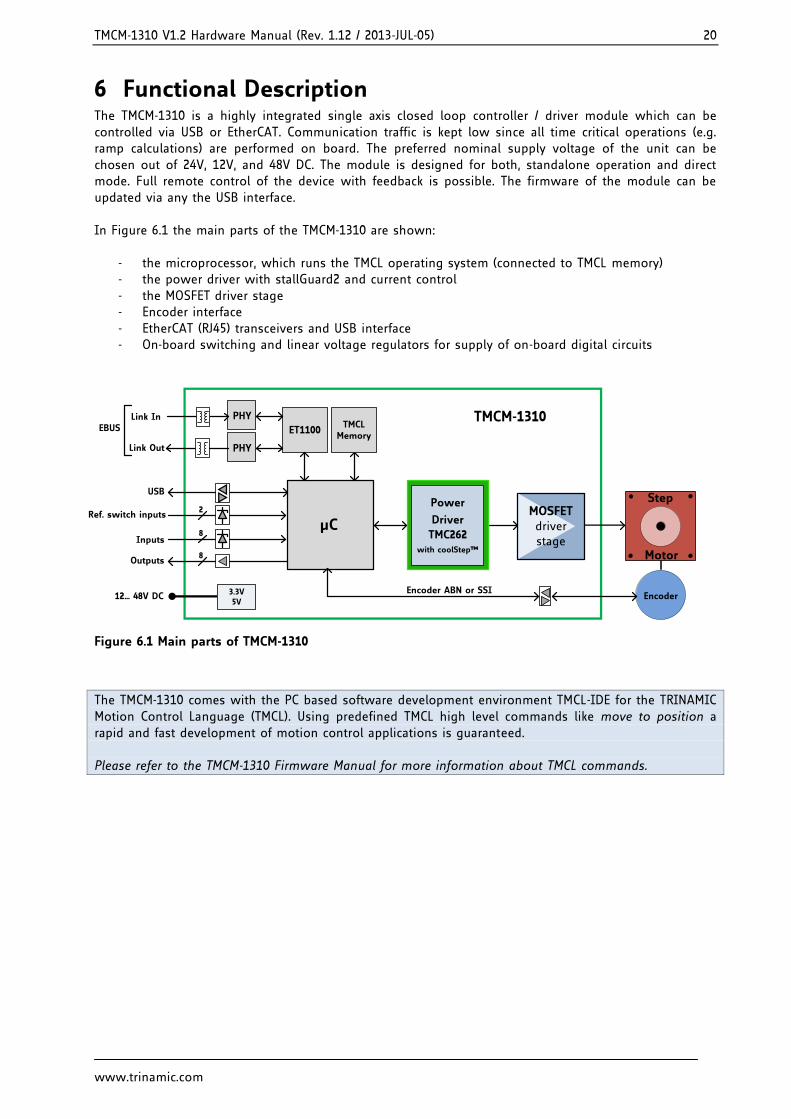
6 Functional Description The TMCM-1310 is a highly integrated single axis closed loop controller / driver module which can be controlled via USB or EtherCAT. Communication traffic is kept low since all time critical operations (e.g. ramp calculations) are performed on board. The preferred nominal supply voltage of the unit can be chosen out of 24V, 12V, and 48V DC. The module is designed for both, standalone operation and direct mode. Full remote control of the device with feedback is possible. The firmware of the module can be updated via any the USB interface. In Figure 6.1 the main parts of the TMCM-1310 are shown:
- the microprocessor, which runs the TMCL operating system (connected to TMCL memory) - the power driver with stallGuard2 and current control - the MOSFET driver stage - Encoder interface - EtherCAT (RJ45) transceivers and USB interface - On-board switching and linear voltage regulators for supply of on-board digital circuits
Step
Motor
12… 48V DC
TMCM-1310
MOSFETdriverstage
µC
Encoder
ET1100
Link In
Link Out
EBUS TMCL Memory
Encoder ABN or SSI
Energy Efficient
DriverTMC262
Power
Driver
TMC262with coolStep™
PHY
PHY
USB
8Inputs
8Outputs
2Ref. switch inputs
3.3V 5V
Figure 6.1 Main parts of TMCM-1310
The TMCM-1310 comes with the PC based software development environment TMCL-IDE for the TRINAMIC Motion Control Language (TMCL). Using predefined TMCL high level commands like move to position a rapid and fast development of motion control applications is guaranteed. Please refer to the TMCM-1310 Firmware Manual for more information about TMCL commands.

TMCM-1310 V1.2 Hardware Manual (Rev. 1.12 / 2013-JUL-05) 21
www.trinamic.com
7 Life Support Policy TRINAMIC Motion Control GmbH & Co. KG does not authorize or warrant any of its products for use in life support systems, without the specific written consent of TRINAMIC Motion Control GmbH & Co. KG. Life support systems are equipment intended to support or sustain life, and whose failure to perform, when properly used in accordance with instructions provided, can be reasonably expected to result in personal injury or death. © TRINAMIC Motion Control GmbH & Co. KG 2013 Information given in this data sheet is believed to be accurate and reliable. However neither responsibility is assumed for the consequences of its use nor for any infringement of patents or other rights of third parties, which may result from its use. Specifications are subject to change without notice. All trademarks used are property of their respective owners.
TMCM-1310 V1.2 Hardware Manual (Rev. 1.12 / 2013-JUL-05) 22
www.trinamic.com
8 Revision History
8.1 Document Revision Version Date Author Description
0.90 2012-OCT-25 GE Preliminary version
1.00 2012-DEC-06 SD First complete version
1.10 2013-MAY-23 GE Adapted to latest hardware version V1.2
1.11 2013-JUL-03 SD Changes related to the design
1.12 2013-JUL-05 SD New front picture
Table 8.1 Document revision
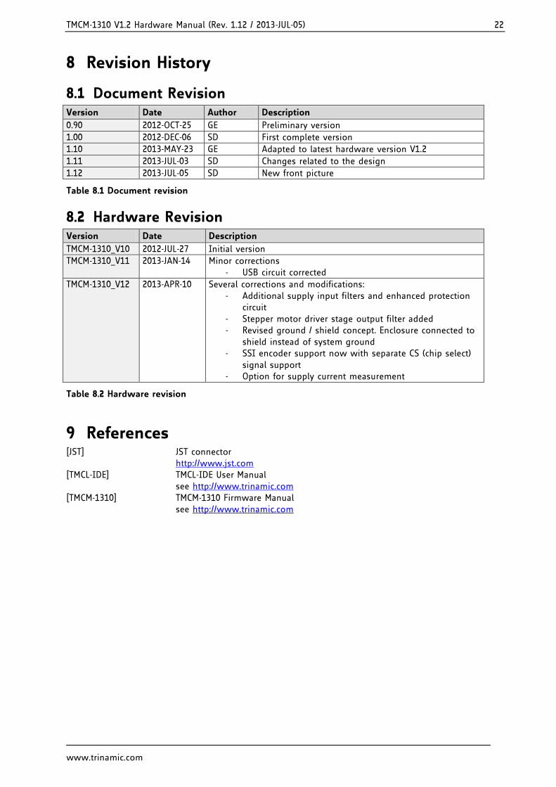
8.2 Hardware Revision Version Date Description
TMCM-1310_V10 2012-JUL-27 Initial version
TMCM-1310_V11 2013-JAN-14 Minor corrections - USB circuit corrected
TMCM-1310_V12 2013-APR-10 Several corrections and modifications: - Additional supply input filters and enhanced protection
circuit - Stepper motor driver stage output filter added - Revised ground / shield concept. Enclosure connected to
shield instead of system ground - SSI encoder support now with separate CS (chip select)
signal support - Option for supply current measurement
Table 8.2 Hardware revision
9 References [JST] JST connector http://www.jst.com [TMCL-IDE] TMCL-IDE User Manual see http://www.trinamic.com [TMCM-1310] TMCM-1310 Firmware Manual see http://www.trinamic.com