Embed Size (px)
Citation preview
© 2005 Eaton Corporation. All rights reserved.
Applying Harmonic Solutions to Commercial and
Industrial Power Systems
David G. Loucks, [email protected]
Moon Township, PA
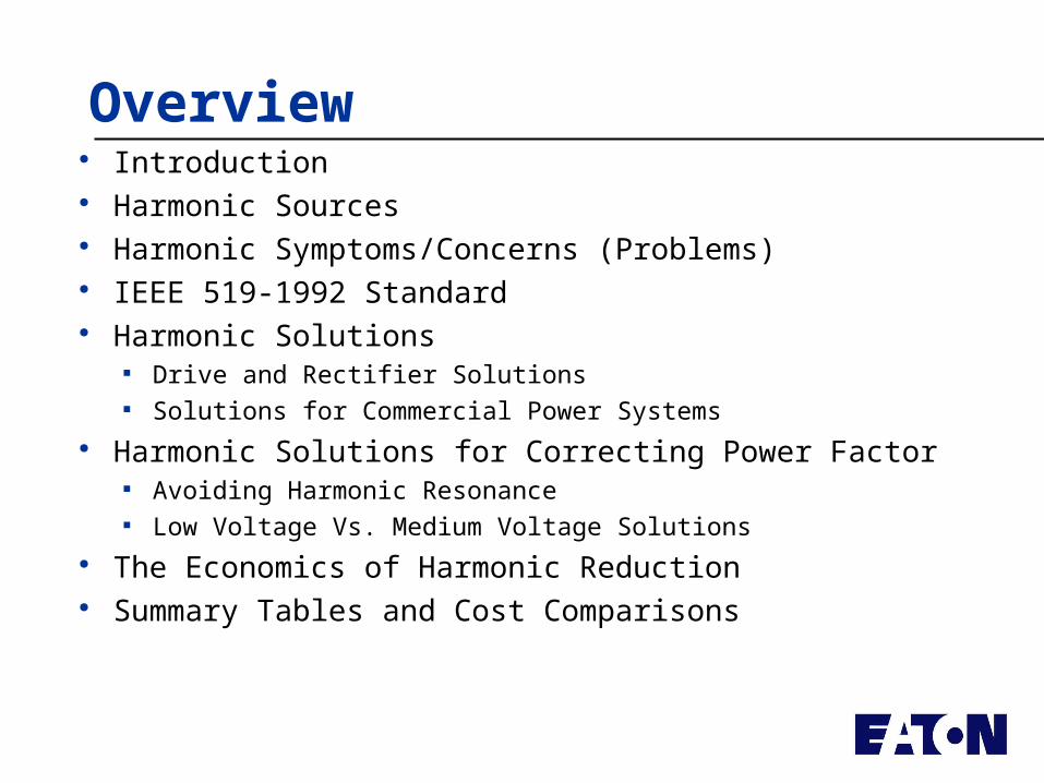
Overview Introduction Harmonic Sources Harmonic Symptoms/Concerns (Problems) IEEE 519-1992 Standard Harmonic Solutions
Drive and Rectifier Solutions Solutions for Commercial Power Systems
Harmonic Solutions for Correcting Power Factor Avoiding Harmonic Resonance Low Voltage Vs. Medium Voltage Solutions
The Economics of Harmonic Reduction Summary Tables and Cost Comparisons
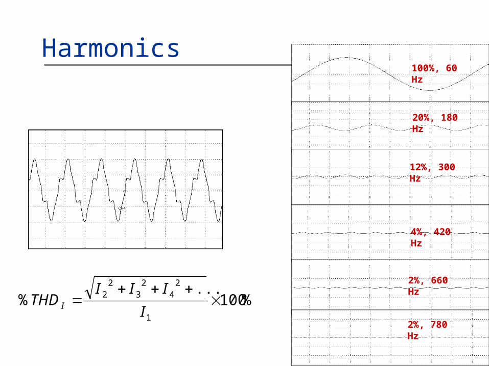
Harmonics 100%, 60 Hz
2%, 780 Hz
20%, 180 Hz
12%, 300 Hz
4%, 420 Hz
2%, 660 Hz
%100...
%1
24
23
22
I
IIITHDI
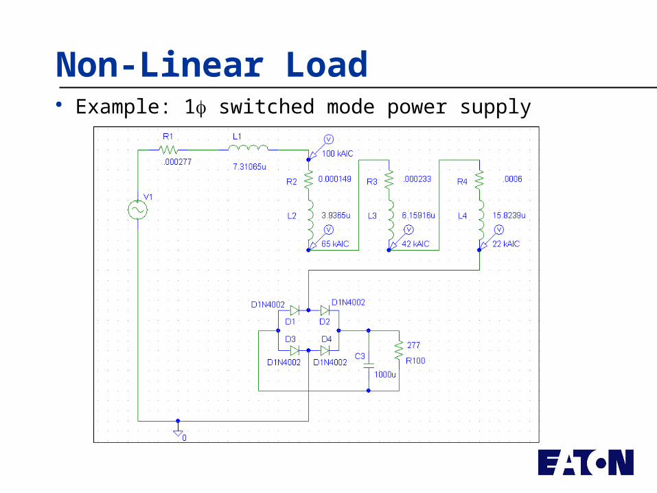
Harmonic Sources
Harmonic Sources Power Electronic
Equipment (drives, rectifiers (UPS), computers, etc.)
Arcing Devices (welders, arc furnaces, fluorescent lights, etc.)
Rotating Machines (generators)
Most Common Variable Frequency
Drives UPS Computer Power Supplies Fluorescent Lighting
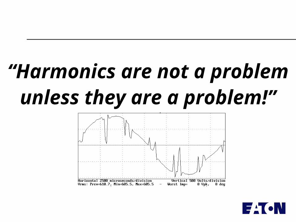
Voltage Distortion
When current flows from other than an infinite source, the source voltage drops
The higher the source impedance or the higher the load current, the greater the drop
Time
0s 0.1s 0.2s 0.3s 0.4s 0.5s 0.6s 0.7s 0.8s 0.9s 1.0sRMS(I(L4)) I(L4)
-40A
0A
40A
Frequency
0Hz 0.2KHz 0.4KHz 0.6KHz 0.8KHz 1.0KHz 1.2KHzI(L4)
0A
2.0A
4.0A
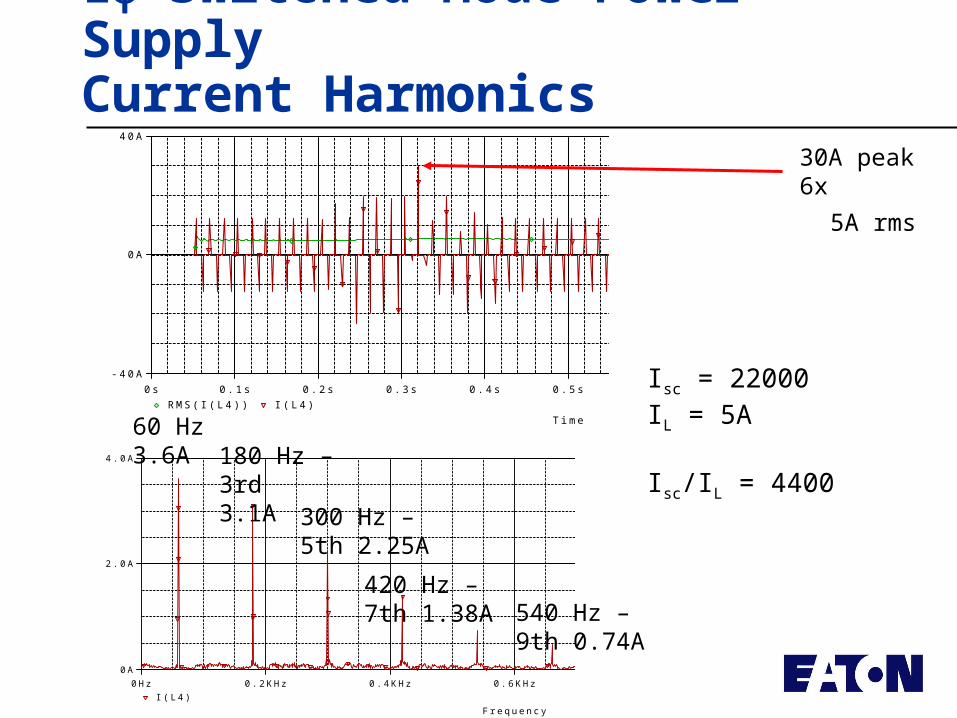
1 Switched Mode Power SupplyCurrent Harmonics
5A rms
30A peak6x
60 Hz3.6A 180 Hz – 3rd
3.1A300 Hz – 5th 2.25A
420 Hz – 7th 1.38A 540 Hz – 9th
0.74A
Isc = 22000IL = 5A
Isc/IL = 4400
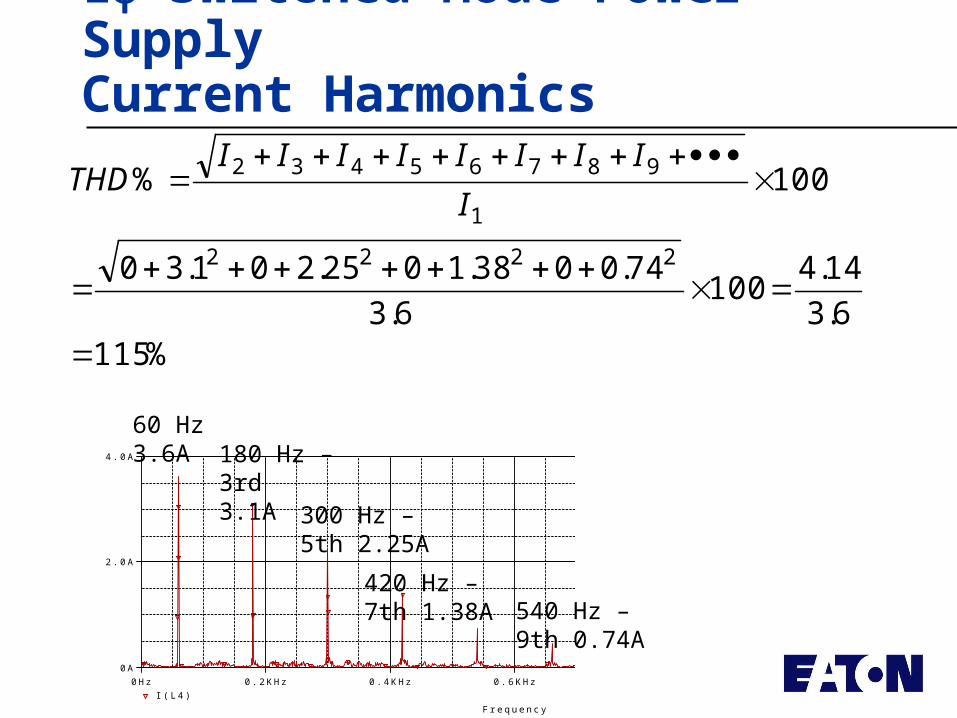
1 Switched Mode Power SupplyCurrent Harmonics
%.
.
.
....
%
11563
144100
63
740038102520130
100
2222
1
98765432
I
IIIIIIIITHD
Frequency
0Hz 0.2KHz 0.4KHz 0.6KHz 0.8KHz 1.0KHz 1.2KHzI(L4)
0A
2.0A
4.0A
60 Hz3.6A 180 Hz – 3rd
3.1A300 Hz – 5th 2.25A
420 Hz – 7th 1.38A 540 Hz – 9th
0.74A
Frequency
0Hz 0.2KHz 0.4KHz 0.6KHz 0.8KHz 1.0KHz 1.2KHzI(L4)
0A
2.0A
4.0A
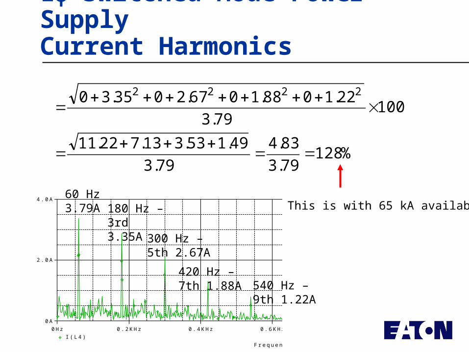
1 Switched Mode Power SupplyCurrent Harmonics
60 Hz3.79A 180 Hz – 3rd
3.35A300 Hz – 5th 2.67A
420 Hz – 7th 1.88A 540 Hz – 9th
1.22A
%.
.
.
....
.
....
128793
834
793
4915331372211
100793
2210881067203530 2222
This is with 65 kA available
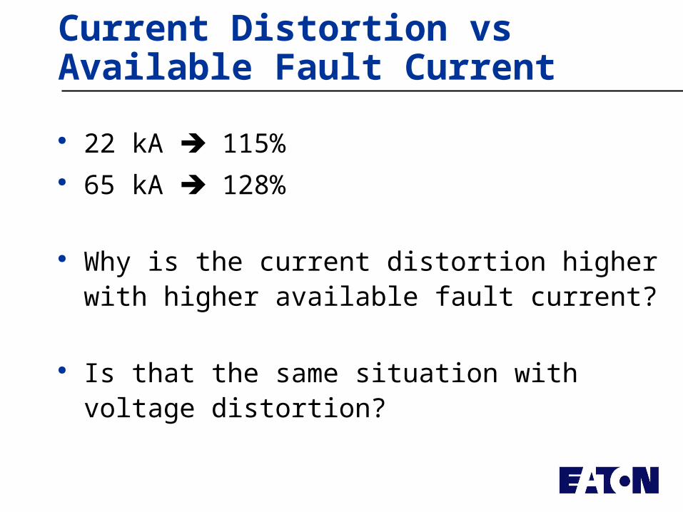
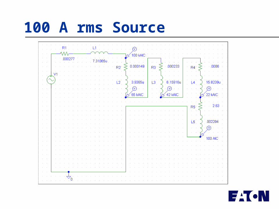
Current Distortion vs Available Fault Current
22 kA 115% 65 kA 128%
Why is the current distortion higher with higher available fault current?
Is that the same situation with voltage distortion?
Let’s increase the source impedance
Remember, our power supply was drawing 5A rms
On a 22 kA source, the ratio of Isc/IL= 4400…
essentially an infinite source
Keeping the same load impedance, let’s drop the source short current down (Isc/IL= 20)
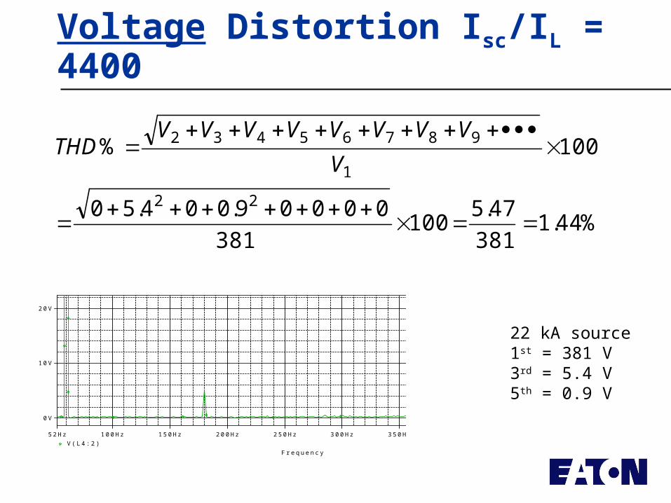
Voltage Distortion Isc/IL = 4400
%....
%
441381
475100
381
0000900450
100
22
1
98765432
V
VVVVVVVVTHD
Frequency
100Hz 150Hz 200Hz 250Hz 300Hz 350Hz 400Hz 450Hz52HzV(L4:2)
0V
10V
20V
22 kA source1st = 381 V3rd = 5.4 V5th = 0.9 V
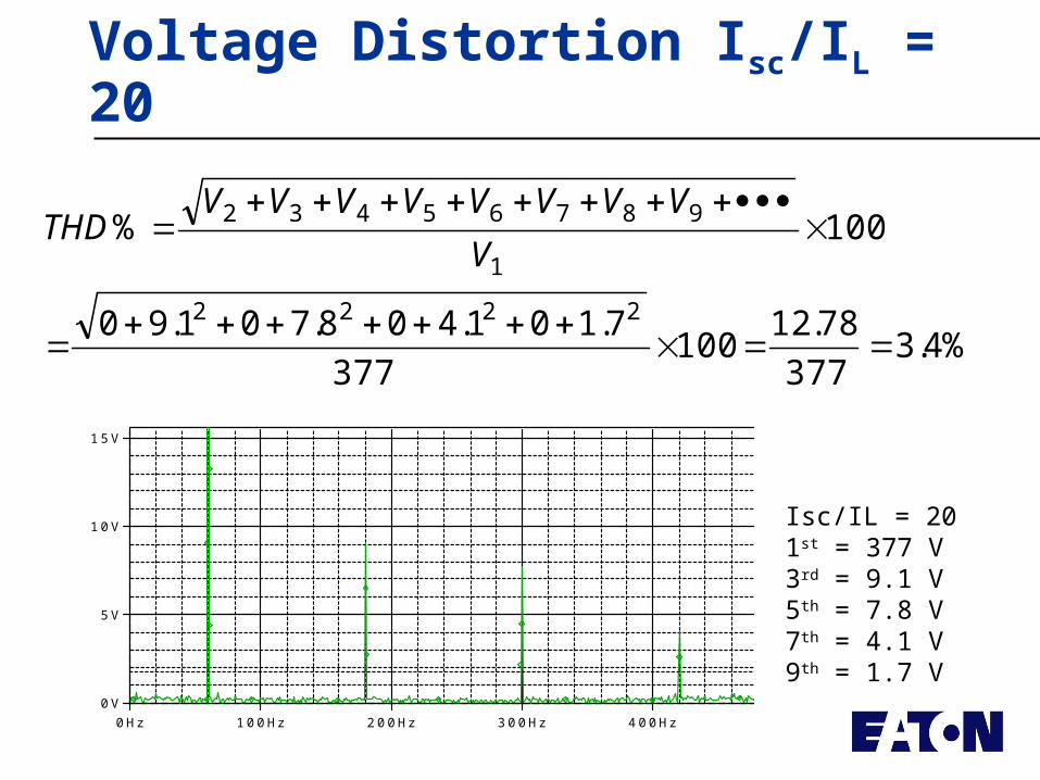
Voltage Distortion Isc/IL = 20
%......
%
43377
7812100
377
710140870190
100
2222
1
98765432
V
VVVVVVVVTHD
Isc/IL = 201st = 377 V3rd = 9.1 V5th = 7.8 V7th = 4.1 V9th = 1.7 V
Frequency
0Hz 100Hz 200Hz 300Hz 400Hz 500Hz 600Hz 700Hz 791HzV(L5:2)
0V
5V
10V
15V
Harmonic Distortion Standards
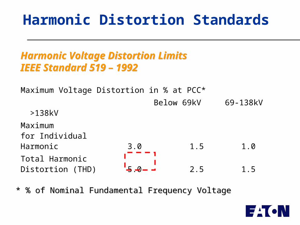
Maximum Voltage Distortion in % at PCC*
Below 69kV 69-138kV >138kV
Maximum for Individual Harmonic 3.0 1.5 1.0
Total Harmonic Distortion (THD) 5.0 2.5 1.5
Harmonic Voltage Distortion LimitsIEEE Standard 519 – 1992Harmonic Voltage Distortion LimitsIEEE Standard 519 – 1992
* % of Nominal Fundamental Frequency Voltage* % of Nominal Fundamental Frequency Voltage
Harmonic Distortion Standards
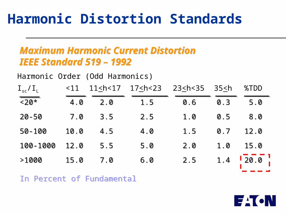
Harmonic Order (Odd Harmonics)
Isc/IL <11 11<h<17 17<h<23 23<h<35 35<h %TDD
Maximum Harmonic Current DistortionIEEE Standard 519 – 1992Maximum Harmonic Current DistortionIEEE Standard 519 – 1992
In Percent of FundamentalIn Percent of Fundamental
<20* 4.0 2.0 1.5 0.6 0.3 5.0
20-50 7.0 3.5 2.5 1.0 0.5 8.0
50-100 10.0 4.5 4.0 1.5 0.7 12.0
100-1000 12.0 5.5 5.0 2.0 1.0 15.0
>1000 15.0 7.0 6.0 2.5 1.4 20.0
<20* 4.0 2.0 1.5 0.6 0.3 5.0
20-50 7.0 3.5 2.5 1.0 0.5 8.0
50-100 10.0 4.5 4.0 1.5 0.7 12.0
100-1000 12.0 5.5 5.0 2.0 1.0 15.0
>1000 15.0 7.0 6.0 2.5 1.4 20.0
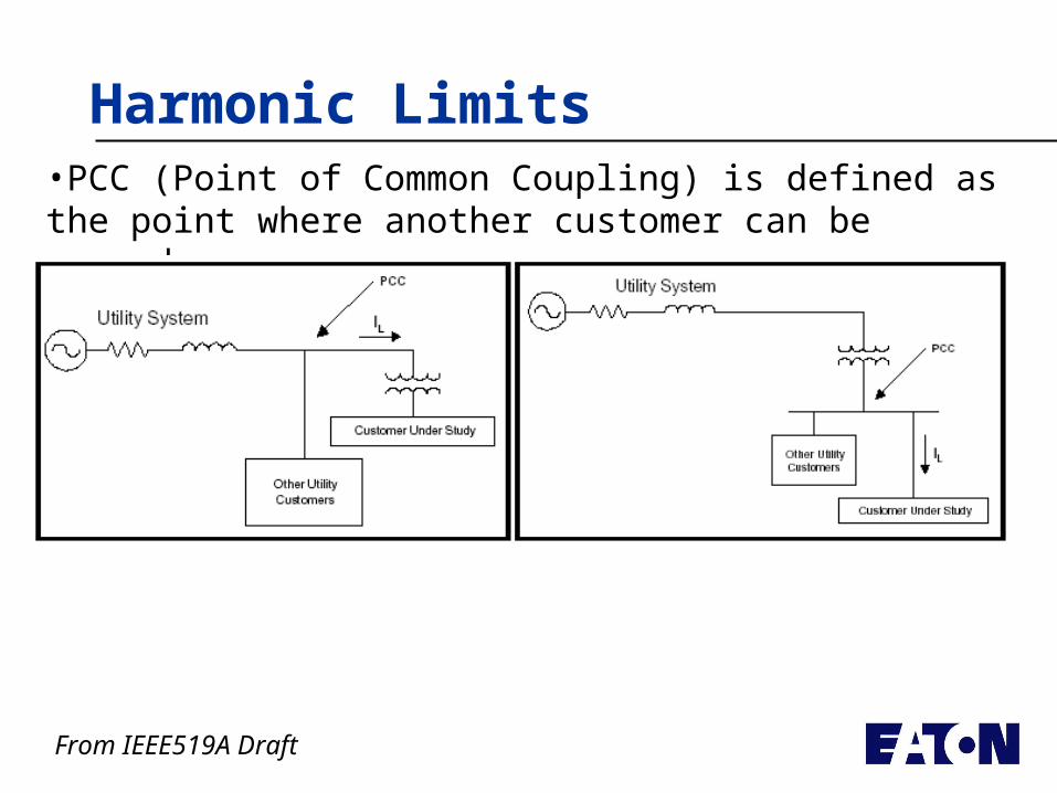
Harmonic Limits•PCC (Point of Common Coupling) is defined as the point where another customer can be served
From IEEE519A Draft
Harmonic Limits
From IEEE519A Draft
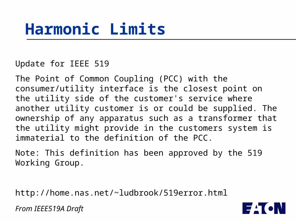
Update for IEEE 519
The Point of Common Coupling (PCC) with the consumer/utility interface is the closest point on the utility side of the customer's service where another utility customer is or could be supplied. The ownership of any apparatus such as a transformer that the utility might provide in the customers system is immaterial to the definition of the PCC.
Note: This definition has been approved by the 519 Working Group.
http://home.nas.net/~ludbrook/519error.html
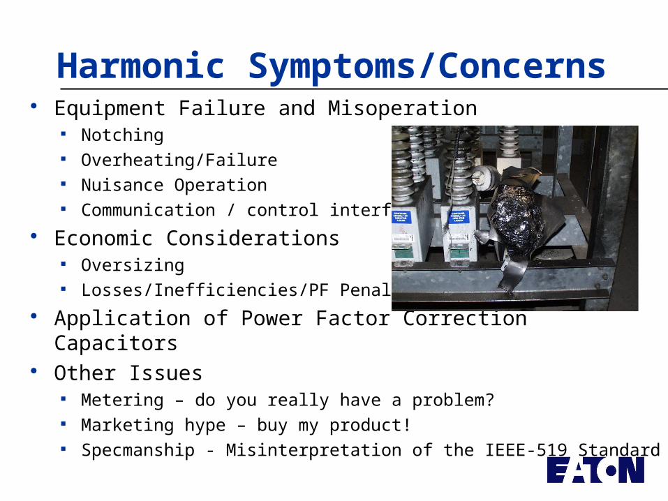
Harmonic Symptoms/Concerns Equipment Failure and Misoperation
Notching Overheating/Failure Nuisance Operation Communication / control interference
Economic Considerations Oversizing Losses/Inefficiencies/PF Penalties
Application of Power Factor Correction Capacitors Other Issues
Metering – do you really have a problem? Marketing hype – buy my product! Specmanship - Misinterpretation of the IEEE-519 Standard
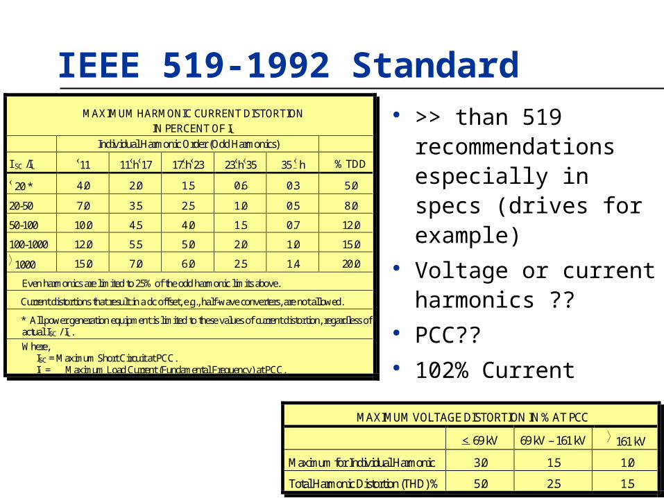
IEEE 519-1992 Standard
MAXIMUM VOLTAGE DISTORTION IN % AT PCC
< 69 kV 69 kV – 161 kV 161 kV
Maximum for Individual Harmonic 3.0 1.5 1.0
Total Harmonic Distortion (THD) % 5.0 2.5 1.5
MAXIMUM HARMONIC CURRENT DISTORTION IN PERCENT OF IL
Individual Harmonic Order (Odd Harmonics)
I SC /IL 11 11h17 17h23 23h35 35 h % TDD
20 * 4.0 2.0 1.5 0.6 0.3 5.0
20-50 7.0 3.5 2.5 1.0 0.5 8.0
50-100 10.0 4.5 4.0 1.5 0.7 12.0
100-1000 12.0 5.5 5.0 2.0 1.0 15.0
1000 15.0 7.0 6.0 2.5 1.4 20.0
Even harmonics are limited to 25% of the odd harmonic limits above.
Current distortions that result in a dc offset, e.g., half-wave converters, are not allowed.
* All power generation equipment is limited to these values of current distortion, regardless of actual ISC / IL.
Where, ISC = Maximum Short Circuit at PCC. IL = Maximum Load Current (Fundamental Frequency) at PCC.
>> than 519 recommendations especially in specs (drives for example)
Voltage or current harmonics ??
PCC?? 102% Current
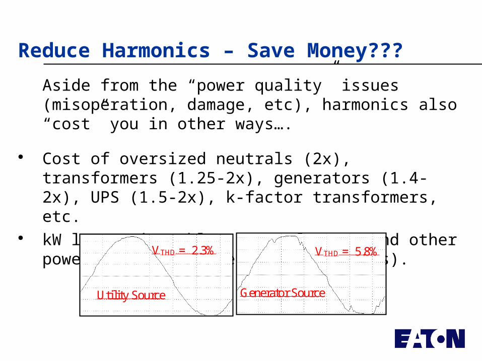
Reduce Harmonics – Save Money???
Aside from the “power quality” issues (misoperation, damage, etc), harmonics also “cost” you in other ways….
Cost of oversized neutrals (2x), transformers (1.25-2x), generators (1.4-2x), UPS (1.5-2x), k-factor transformers, etc.
kW losses in cables, transformers and other power system components (1-8% losses).
VTHD = 2.3% VTHD = 5.8%
Utility Source Generator Source
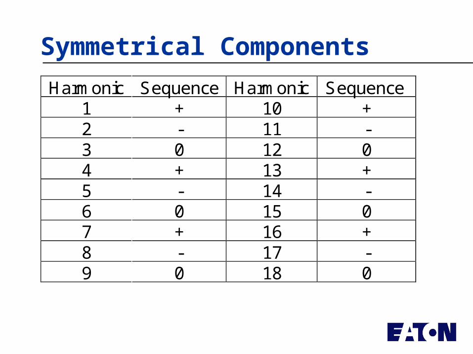
Symmetrical Components
Harmonic Sequence Harmonic Sequence1 + 10 +2 - 11 -3 0 12 04 + 13 +5 - 14 -6 0 15 07 + 16 +8 - 17 -9 0 18 0
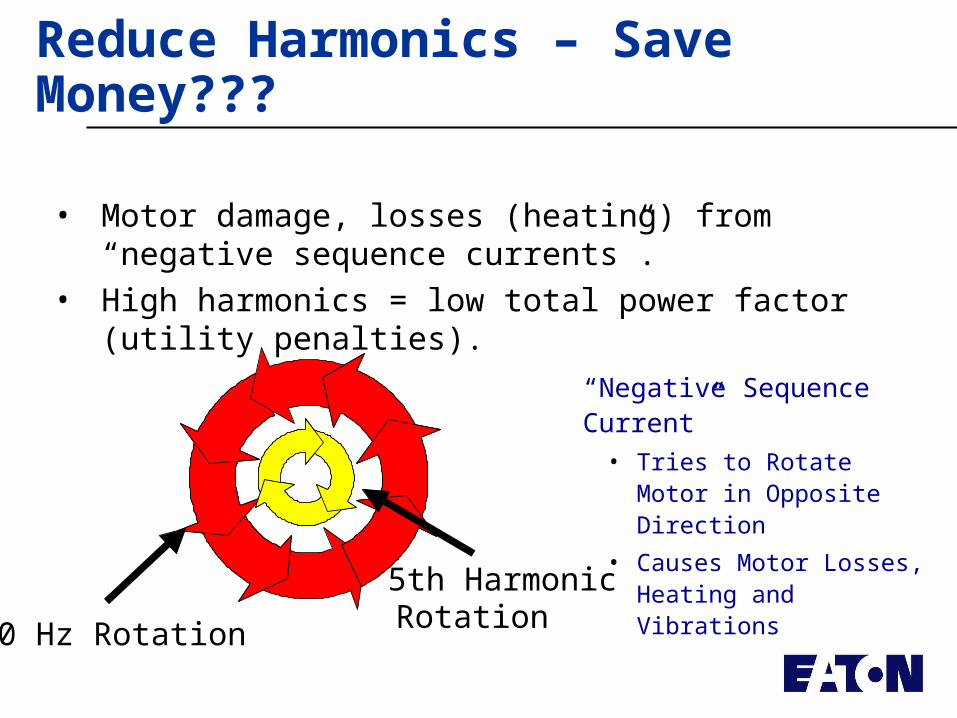
Reduce Harmonics – Save Money???
• Motor damage, losses (heating) from “negative sequence currents”.
• High harmonics = low total power factor (utility penalties).
60 Hz Rotation
5th Harmonic Rotation
“Negative Sequence Current” • Tries to Rotate Motor in
Opposite Direction
• Causes Motor Losses, Heating and Vibrations
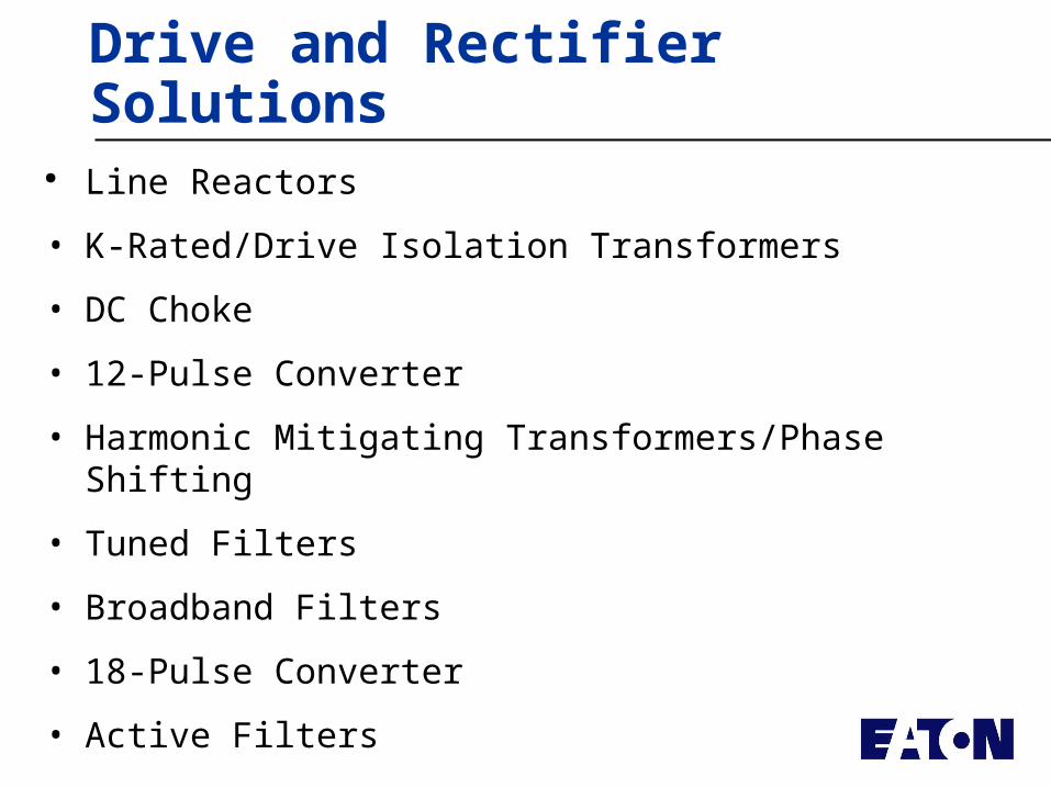
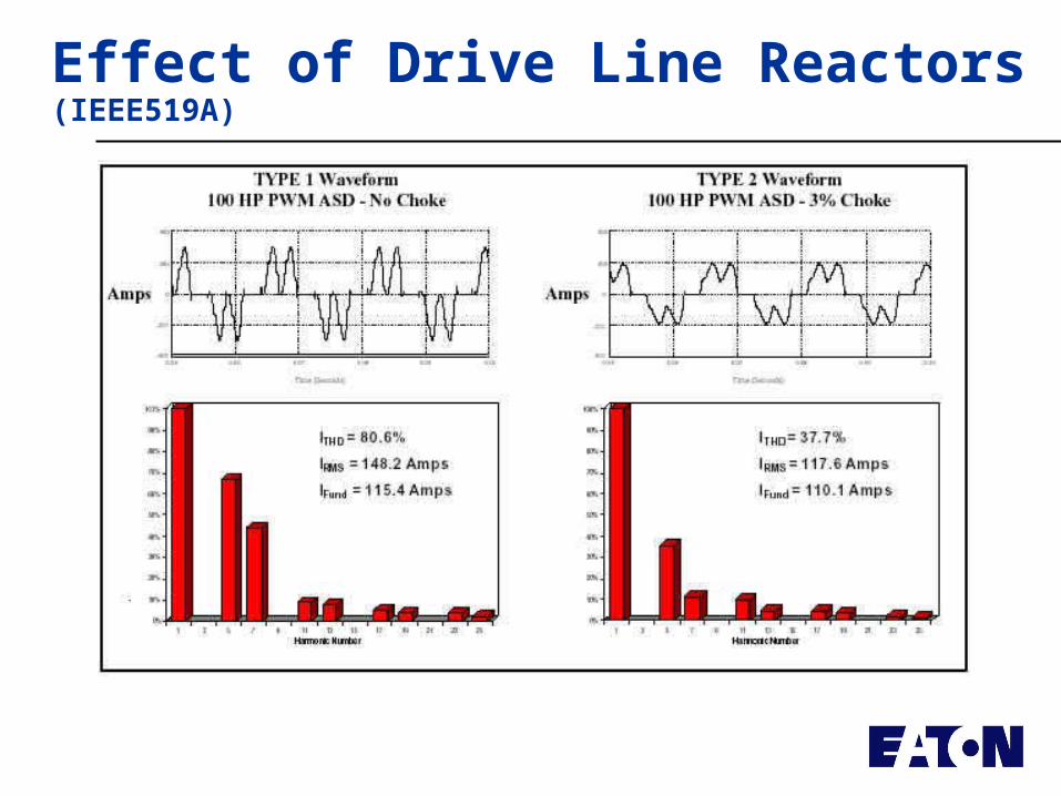
Drive and Rectifier Solutions Line Reactors
• K-Rated/Drive Isolation Transformers
• DC Choke
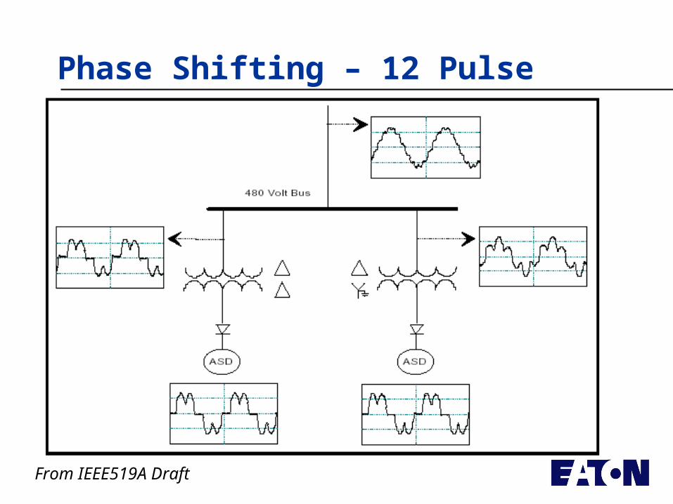
• 12-Pulse Converter
• Harmonic Mitigating Transformers/Phase Shifting
• Tuned Filters
• Broadband Filters
• 18-Pulse Converter
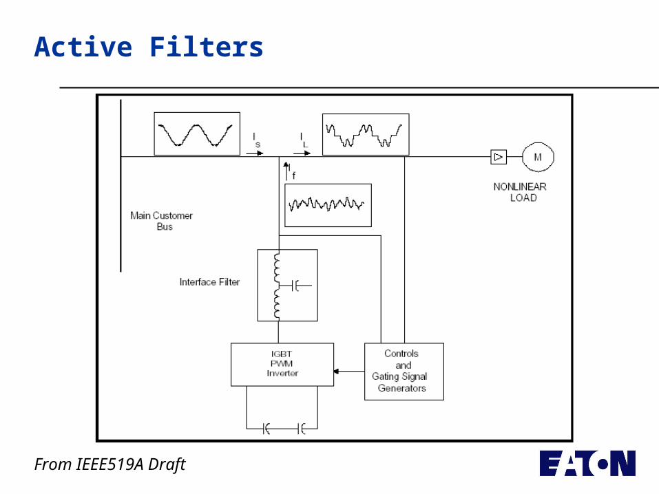
• Active Filters
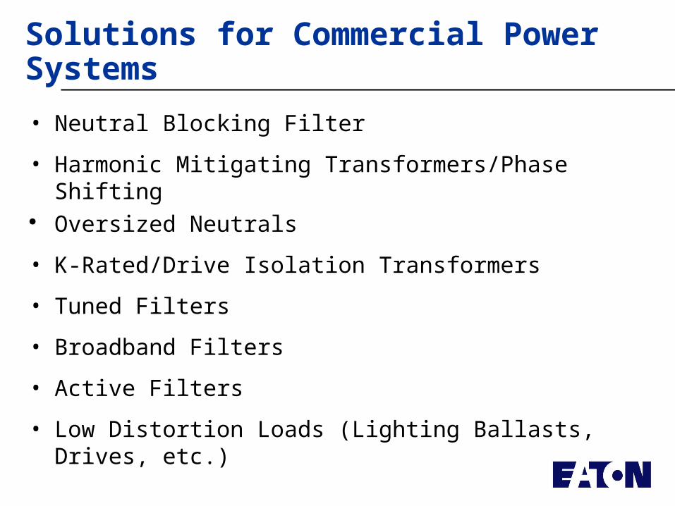
Solutions for Commercial Power Systems
• Neutral Blocking Filter
• Harmonic Mitigating Transformers/Phase Shifting Oversized Neutrals
• K-Rated/Drive Isolation Transformers
• Tuned Filters
• Broadband Filters
• Active Filters
• Low Distortion Loads (Lighting Ballasts, Drives, etc.)
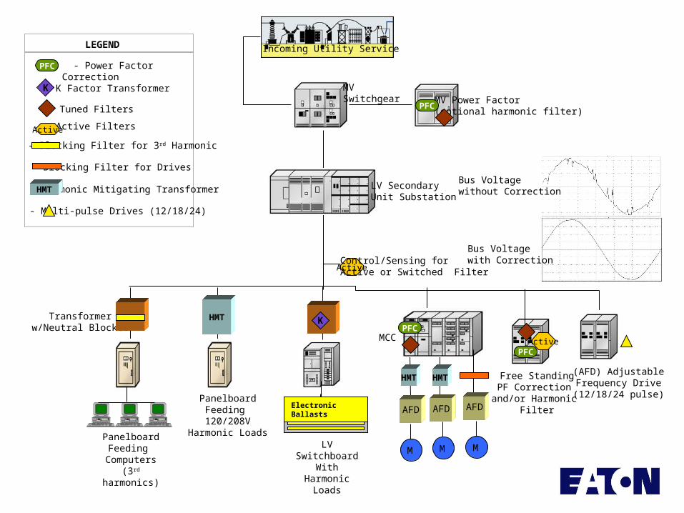
MV Power Factor (optional harmonic filter)
MVSwitchgear
Incoming Utility Service
LV SecondaryUnit Substation
Transformerw/Neutral Blocker
LV SwitchboardWith Harmonic
Loads
MCC
(AFD) AdjustableFrequency Drive(12/18/24 pulse)
PanelboardFeeding
Computers(3rd harmonics)
PFC
PFC
Active
HMT HMT
AFD
M M M
PFC
Free StandingPF Correction
and/or Harmonic Filter
K
AFD AFD
HMT
PanelboardFeeding 120/208V
Harmonic Loads
- Power Factor Correction
- Tuned Filters
PFC
- Active Filters
- Harmonic Mitigating Transformer
- Blocking Filter for 3rd Harmonic
- Multi-pulse Drives (12/18/24)
Active
HMT
- Blocking Filter for Drives
- K Factor TransformerK
LEGEND
Electronic Ballasts
Active
Control/Sensing for Active or Switched Filter
Bus Voltage without Correction
Bus Voltage with Correction
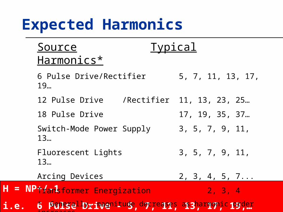
Expected Harmonics
H = NP+/-1
i.e. 6 Pulse Drive - 5, 7, 11, 13, 17, 19,…
Source Typical Harmonics*6 Pulse Drive/Rectifier 5, 7, 11, 13, 17, 19…
12 Pulse Drive /Rectifier 11, 13, 23, 25…
18 Pulse Drive 17, 19, 35, 37…
Switch-Mode Power Supply 3, 5, 7, 9, 11, 13…
Fluorescent Lights 3, 5, 7, 9, 11, 13…
Arcing Devices 2, 3, 4, 5, 7...
Transformer Energization 2, 3, 4
* Generally, magnitude decreases as harmonic order increases
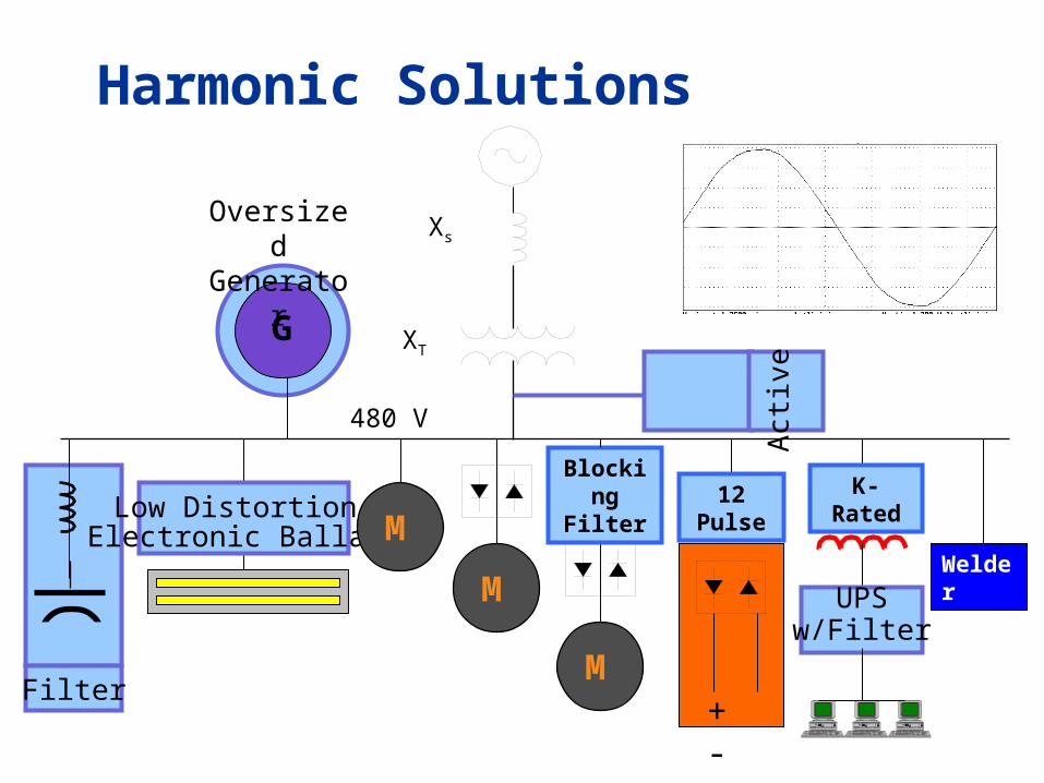
Filter
Harmonic Solutions
480 V
Xs
M
XT
+ -M
Blocking Filter
G
UPSw/Filter
Welder
Low Distortion Electronic Ballast
Oversized Generator
K-Rated
Act
ive
Filt
er
12 Pulse
M
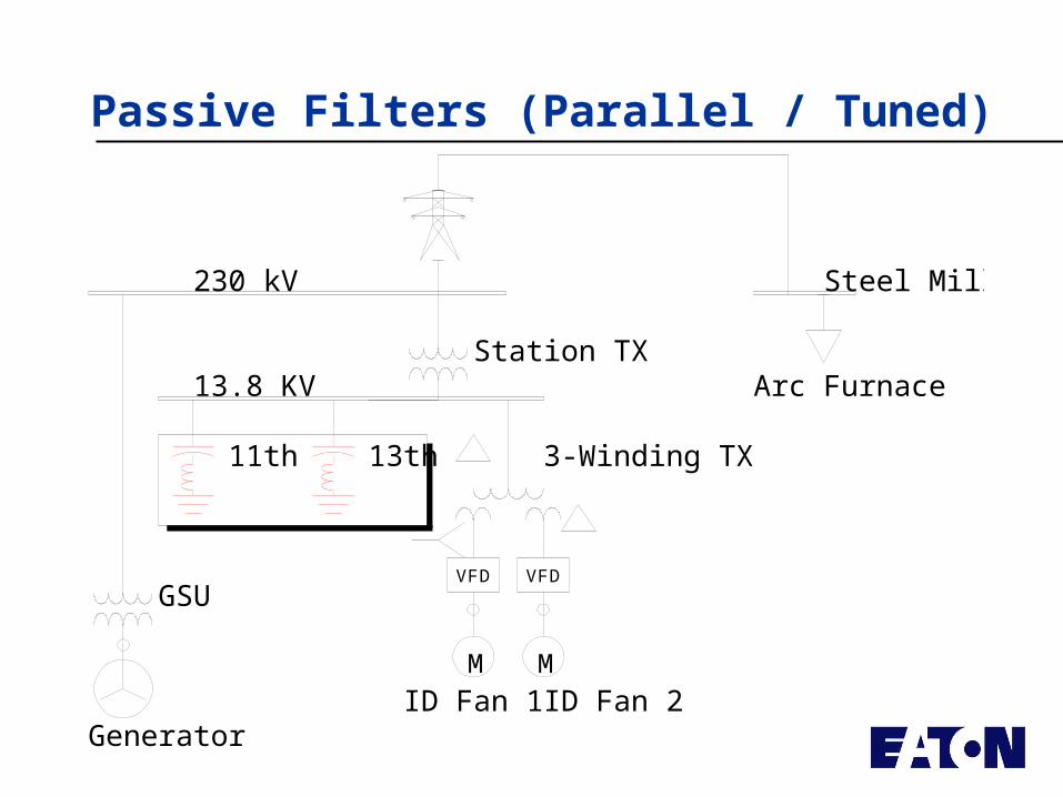
Passive Filters (Parallel / Tuned)
3-Winding TX
VFD VFD
ID Fan 1M
ID Fan 2M
13.8 KV
11th 13th
230 kV
Generator
GSU
Station TX
Steel Mill Sub
Arc Furnace
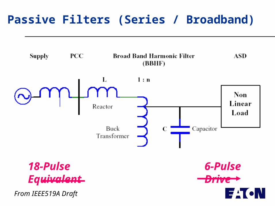
Passive Filters (Series / Broadband)
From IEEE519A Draft
6-Pulse Drive18-Pulse Equivalent
Harmonic Solutions for PF
Application of Harmonic Solutions for PF Correction
• Reduce Utility Penalties – Most Common Reason Today
• Resonance Issues
• Reduce Harmonic = Reduce Vars
• LV/MV?
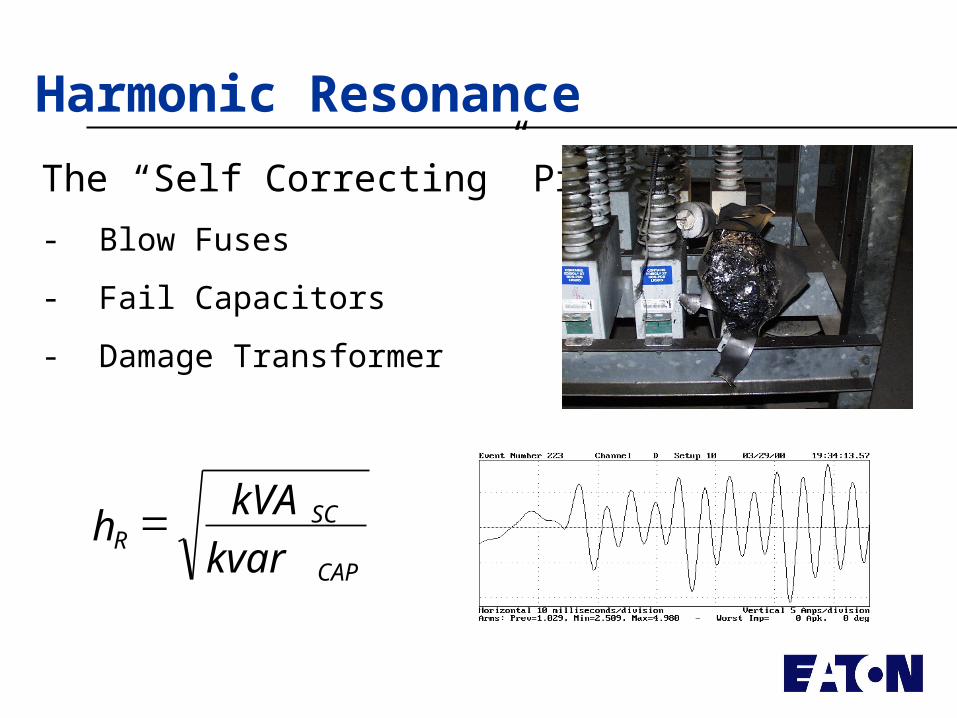
Harmonic Resonance
The “Self Correcting” Problem
- Blow Fuses
- Fail Capacitors
- Damage Transformer
CAP
SCR
kvar
kVAh
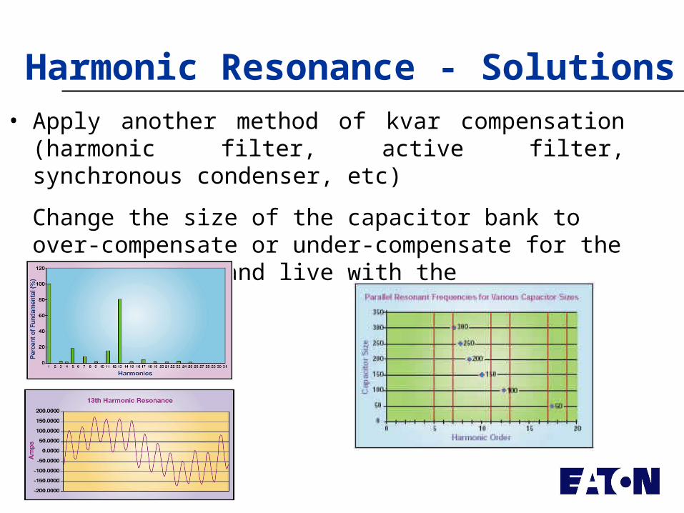
Harmonic Resonance - Solutions• Apply another method of kvar compensation (harmonic
filter, active filter, synchronous condenser, etc)
Change the size of the capacitor bank to over-compensate or under-compensate for the required kvar and live with the ramifications.
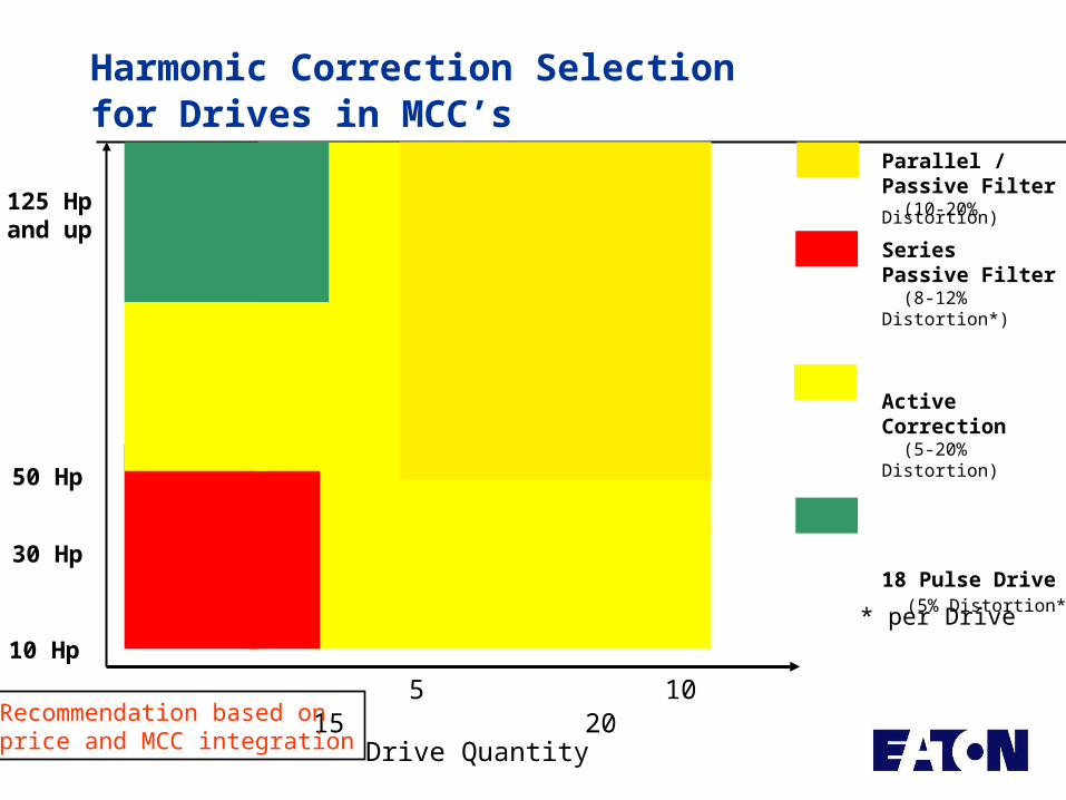
Harmonic Correction Selectionfor Drives in MCC’s
Drive Quantity
5 10 15 20
10 Hp
50 Hp
125 Hpand up
Parallel / Passive Filter (10-20% Distortion)
SeriesPassive Filter (8-12% Distortion*)
Active Correction (5-20% Distortion)
18 Pulse Drive (5% Distortion*) 30 Hp
* per Drive
Recommendation based on price and MCC integration
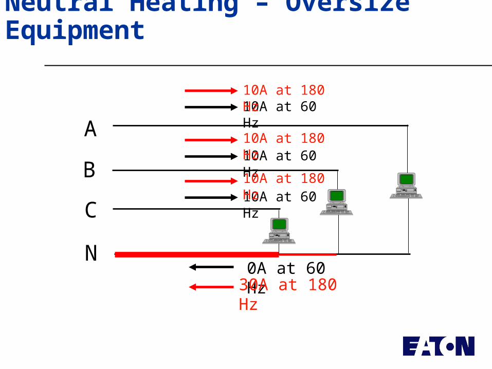
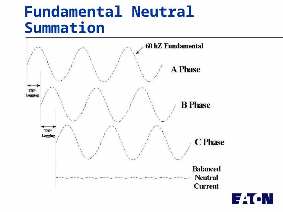
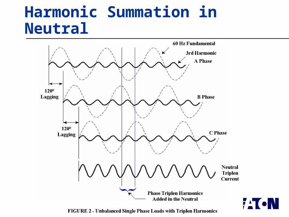
Neutral Heating – Oversize Equipment
C
B
A
N0A at 60 Hz
10A at 60 Hz
10A at 60 Hz
10A at 60 Hz
30A at 180 Hz
10A at 180 Hz
10A at 180 Hz
10A at 180 Hz
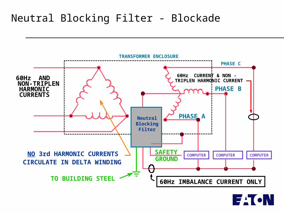
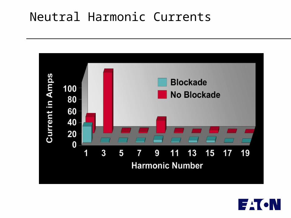
Neutral Blocking Filter - Blockade
TRANSFORMER ENCLOSURE
PHASE C
PHASE A
PHASE B
SAFETYGROUND
60Hz ANDNON-TRIPLENHARMONICCURRENTS
TO BUILDING STEEL
COMPUTER COMPUTER COMPUTER
NeutralBlocking
Filter
NO 3rd HARMONIC CURRENTSCIRCULATE IN DELTA WINDING
60Hz CURRENT & NON -TRIPLEN HARMONIC CURRENT
60Hz IMBALANCE CURRENT ONLY
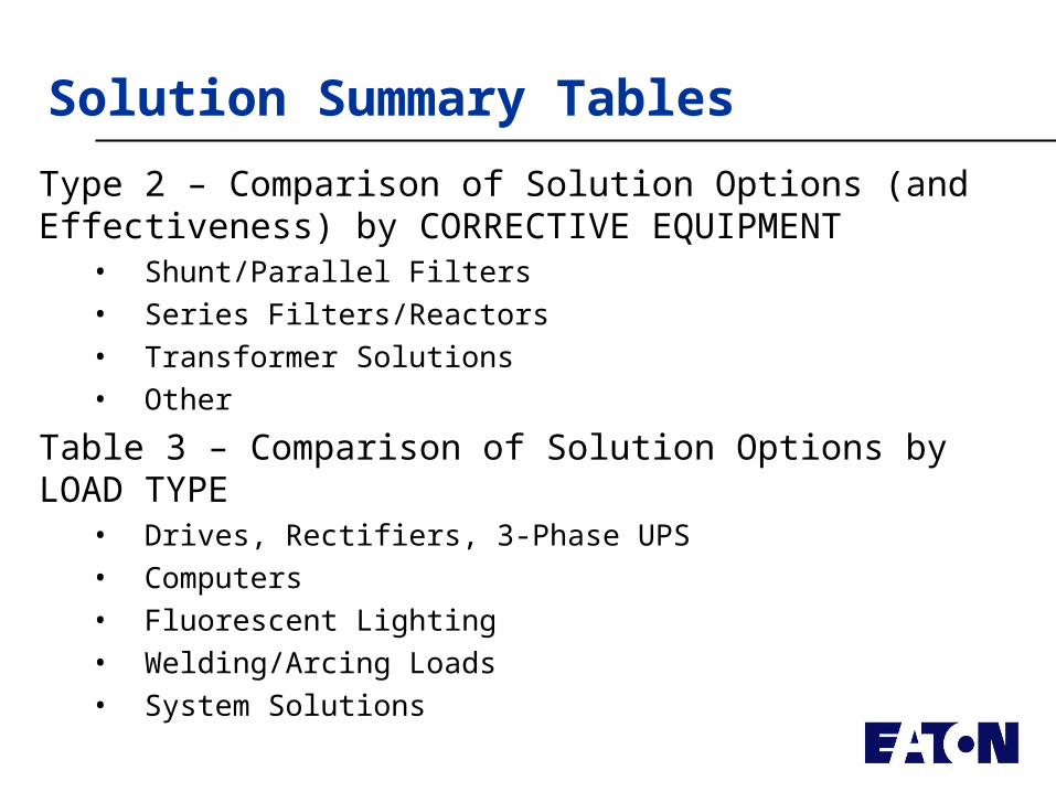
Solution Summary Tables
Type 2 – Comparison of Solution Options (and Effectiveness) by CORRECTIVE EQUIPMENT
• Shunt/Parallel Filters• Series Filters/Reactors• Transformer Solutions• Other
Table 3 – Comparison of Solution Options by LOAD TYPE• Drives, Rectifiers, 3-Phase UPS• Computers• Fluorescent Lighting• Welding/Arcing Loads• System Solutions
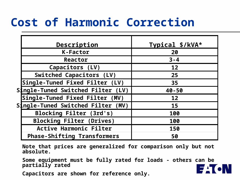
Cost of Harmonic Correction
Description Typical $/kVA*K-Factor 20Reactor 3-4
Capacitors (LV) 12Switched Capacitors (LV) 25
Single-Tuned Fixed Filter (LV) 35Single-Tuned Switched Filter (LV) 40-50
Single-Tuned Fixed Filter (MV) 12Single-Tuned Switched Filter (MV) 15
Blocking Filter (3rd's) 100Blocking Filter (Drives) 100Active Harmonic Filter 150
Phase-Shifting Transformers 50
Note that prices are generalized for comparison only but not absolute.
Some equipment must be fully rated for loads - others can be partially rated
Capacitors are shown for reference only.
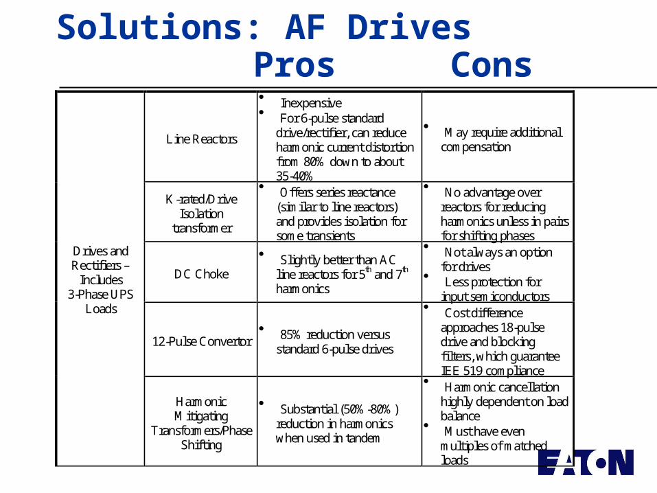
Solutions: AF DrivesPros Cons
Line Reactors
Inexpensive For 6-pulse standard
drive/rectifier, can reduce harmonic current distortion from 80% down to about 35-40%
May require additional compensation
K-rated/Drive Isolation
transformer
Offers series reactance (similar to line reactors) and provides isolation for some transients
No advantage over reactors for reducing harmonics unless in pairs for shifting phases
DC Choke
Slightly better than AC line reactors for 5th and 7th harmonics
Not always an option for drives
Less protection for input semiconductors
12-Pulse Convertor 85% reduction versus
standard 6-pulse drives
Cost difference approaches 18-pulse drive and blocking filters, which guarantee IEE 519 compliance
Drives and Rectifiers –
Includes 3-Phase UPS
Loads
Harmonic Mitigating
Transformers/Phase Shifting
Substantial (50%-80%) reduction in harmonics when used in tandem
Harmonic cancellation highly dependent on load balance
Must have even multiples of matched loads
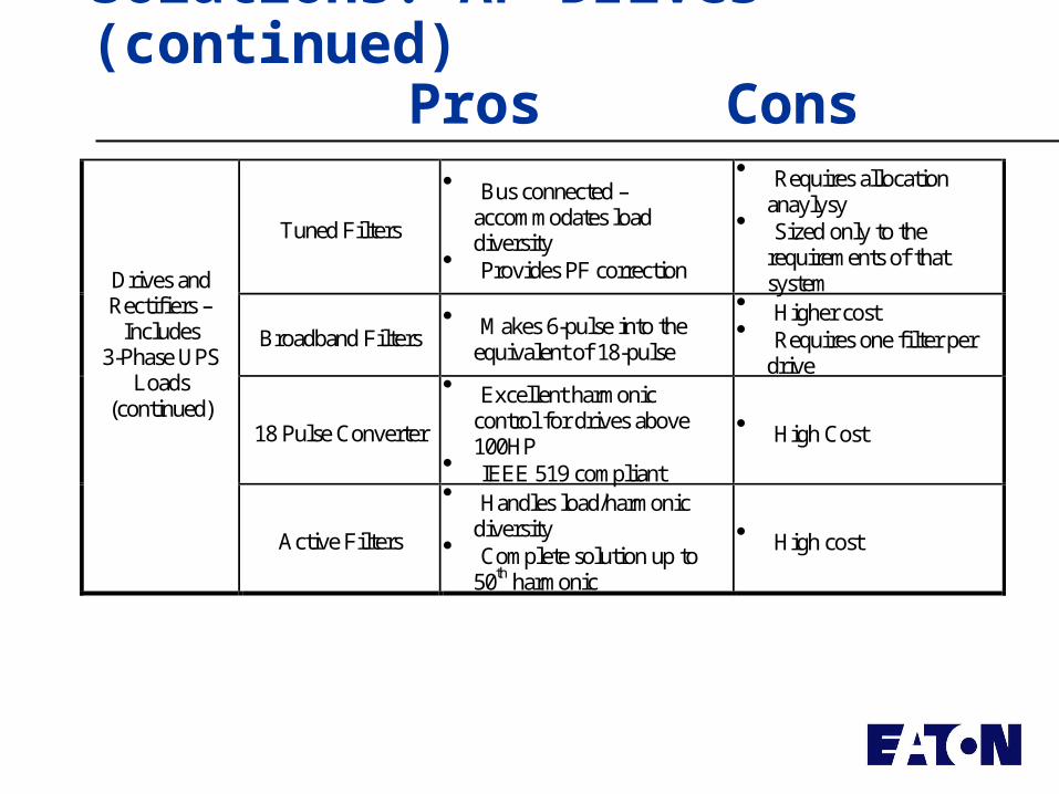
Solutions: AF Drives (continued)Pros Cons
Tuned Filters
Bus connected – accommodates load diversity
Provides PF correction
Requires allocation anaylysy
Sized only to the requirements of that system
Broadband Filters Makes 6-pulse into the
equivalent of 18-pulse
Higher cost Requires one filter per
drive
18 Pulse Converter
Excellent harmonic control for drives above 100HP
IEEE 519 compliant
High Cost
Drives and Rectifiers –
Includes 3-Phase UPS
Loads (continued)
Active Filters
Handles load/harmonic diversity
Complete solution up to 50th harmonic
High cost
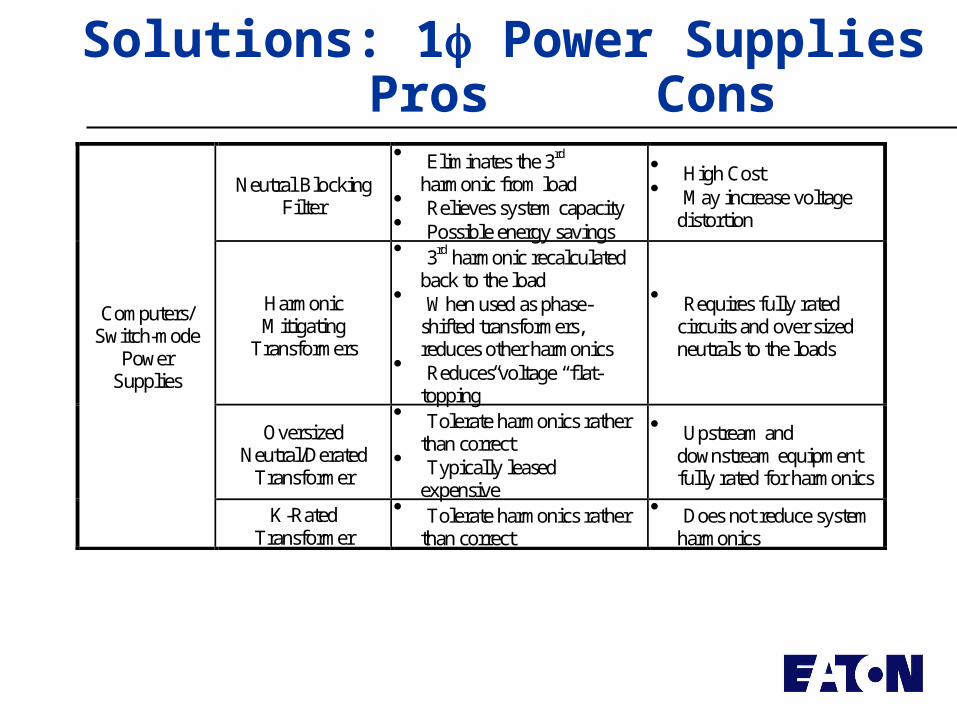
Solutions: 1 Power SuppliesPros Cons
Neutral Blocking Filter
Eliminates the 3rd harmonic from load
Relieves system capacity Possible energy savings
High Cost May increase voltage
distortion
Harmonic Mitigating
Transformers
3rd harmonic recalculated back to the load
When used as phase-shifted transformers, reduces other harmonics
Reduces voltage “flat-topping”
Requires fully rated circuits and over sized neutrals to the loads
Oversized Neutral/Derated
Transformer
Tolerate harmonics rather than correct
Typically leased expensive
Upstream and downstream equipment fully rated for harmonics
Computers/ Switch-mode
Power Supplies
K-Rated Transformer
Tolerate harmonics rather than correct
Does not reduce system harmonics
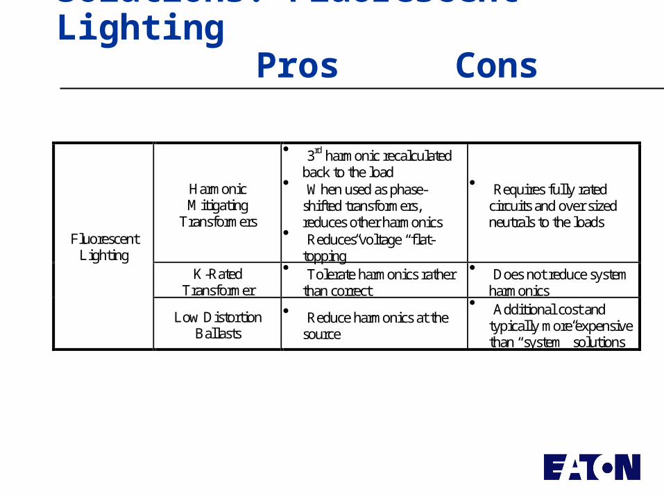
Solutions: Fluorescent LightingPros Cons
Harmonic Mitigating
Transformers
3rd harmonic recalculated back to the load
When used as phase-shifted transformers, reduces other harmonics
Reduces voltage “flat-topping”
Requires fully rated circuits and over sized neutrals to the loads
K-Rated Transformer
Tolerate harmonics rather than correct
Does not reduce system harmonics
Fluorescent Lighting
Low Distortion Ballasts
Reduce harmonics at the source
Additional cost and typically more expensive than “system” solutions
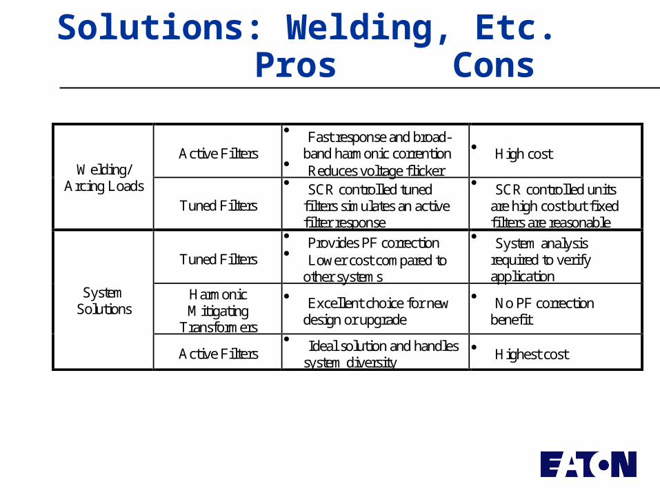
Solutions: Welding, Etc.Pros Cons
Active Filters
Fast response and broad-band harmonic corrention
Reduces voltage flicker
High cost Welding/
Arcing Loads Tuned Filters
SCR controlled tuned filters simulates an active filter response
SCR controlled units are high cost but fixed filters are reasonable
Tuned Filters
Provides PF correction Lower cost compared to
other systems
System analysis required to verify application
Harmonic Mitigating
Transformers
Excellent choice for new design or upgrade
No PF correction benefit
System Solutions
Active Filters Ideal solution and handles
system diversity Highest cost
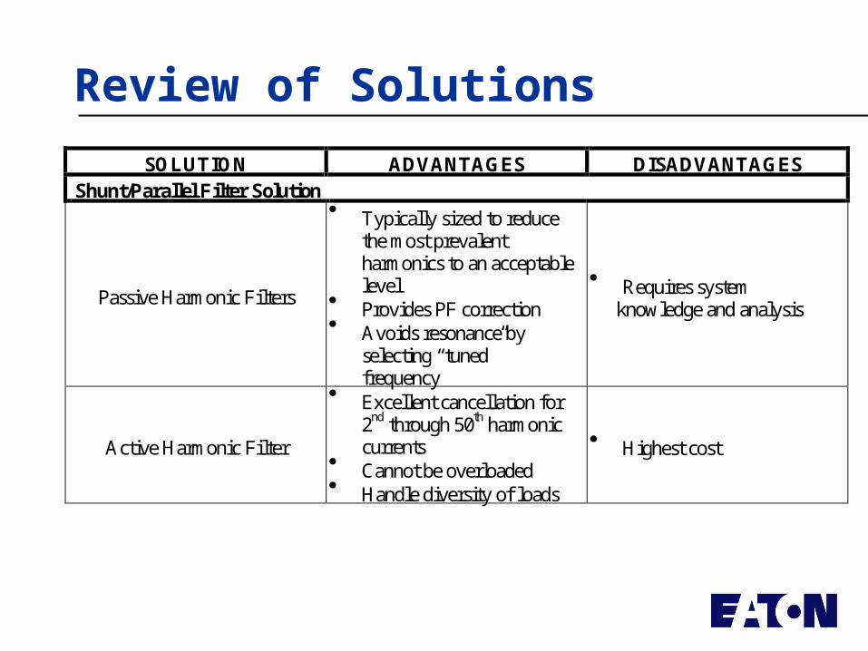
Review of Solutions
SOLUTION ADVANTAGES DISADVANTAGES Shunt/Parallel Filter Solution
Passive Harmonic Filters
Typically sized to reduce the most prevalent harmonics to an acceptable level
Provides PF correction Avoids resonance by
selecting “tuned” frequency
Requires system knowledge and analysis
Active Harmonic Filter
Excellent cancellation for 2nd through 50th harmonic currents
Cannot be overloaded Handle diversity of loads
Highest cost
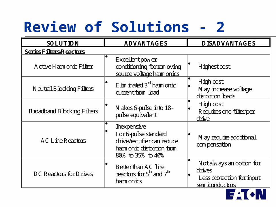
Review of Solutions - 2SOLUTION ADVANTAGES DISADVANTAGES
Series Filters/Reactors
Active Harmonic Filter
Excellent power conditioning for removing source voltage harmonics
Highest cost
Neutral Blocking Filters Eliminated 3rd harmonic
current from load
High cost May increase voltage
distortion loads
Broadband Blocking Filters Makes 6-pulse into 18-
pulse equivalent
High cost Requires one filter per
drive
AC Line Reactors
Inexpensive For 6-pulse standard
drive/rectifier can reduce harmonic distortion from 80% to 35% to 40%
May require additional compensation
DC Reactors for Drives
Better than AC line reactors for 5th and 7th harmonics
Not always an option for drives
Less protection for input semiconductors
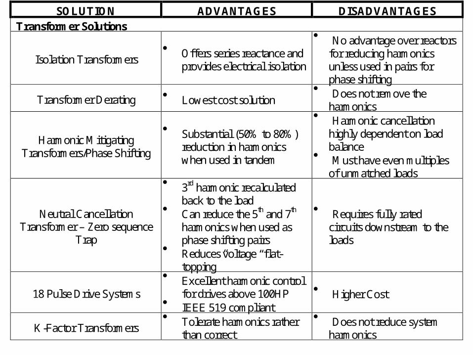
SOLUTION ADVANTAGES DISADVANTAGES Transformer Solutions
Isolation Transformers Offers series reactance and
provides electrical isolation
No advantage over reactors for reducing harmonics unless used in pairs for phase shifting
Transformer Derating Lowest cost solution Does not remove the
harmonics
Harmonic Mitigating Transformers/Phase Shifting
Substantial (50% to 80%) reduction in harmonics when used in tandem
Harmonic cancellation highly dependent on load balance
Must have even multiples of unmatched loads
Neutral Cancellation Transformer – Zero sequence
Trap
3rd harmonic recalculated back to the load
Can reduce the 5th and 7th harmonics when used as phase shifting pairs
Reduces voltage “flat-topping”
Requires fully rated circuits downstream to the loads
18 Pulse Drive Systems
Excellent harmonic control for drives above 100HP
IEEE 519 compliant
Higher Cost
K-Factor Transformers Tolerate harmonics rather
than correct
Does not reduce system harmonics
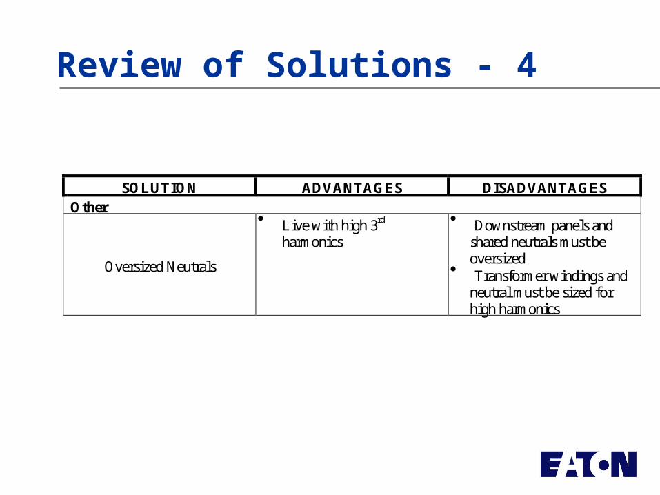
SOLUTION ADVANTAGES DISADVANTAGES Other
Oversized Neutrals
Live with high 3rd harmonics
Downstream panels and shared neutrals must be oversized
Transformer windings and neutral must be sized for high harmonics
Review of Solutions - 4
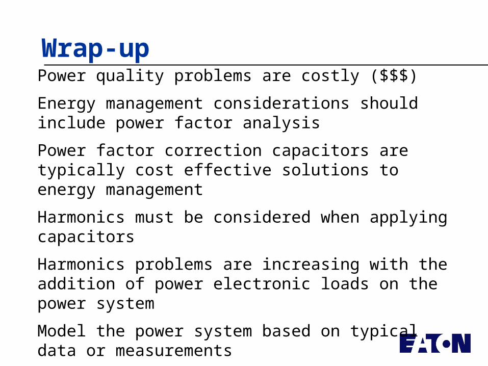
Wrap-upPower quality problems are costly ($$$)
Energy management considerations should include power factor analysis
Power factor correction capacitors are typically cost effective solutions to energy management
Harmonics must be considered when applying capacitors
Harmonics problems are increasing with the addition of power electronic loads on the power system
Model the power system based on typical data or measurements
Verify computer model with measurements


![DGL 5HWQR 'ZL 6DUL (UYRQ 9HUL]D](https://img.pdfslide.net/doc/110x75/626c4890a910dd2a14425e26/dgl-5hwqr-zl-6dul-uyrq-9huld.jpg)


![DGL - loreti.it · y ] # ~ < ¤ TW_ ~ z¤ / # ~](https://img.pdfslide.net/doc/110x75/5ea47ed8eaee5b4404066d84/dgl-y-tw-z-.jpg)