Embed Size (px)
Citation preview

Scan User Guide
Legal Notices
Published by Toon Boom Animation Inc.Corporate Headquarters 7 Laurier Avenue East Montreal, Quebec Canada H2T 1E4 Tel: (514) 278-8666 Fax: (514) 278-2666
toonboom.com
DisclaimerThe content of this manual is covered by a specific limited warranty and exclusions and limit of liability under the applicable License Agreement as supplemented by the special terms and conditions for Adobe® Flash® File Format (SWF). Please refer to the License Agreement and to those special terms and conditions for details.
The content of this manual is the property of Toon Boom Animation Inc. and is copyrighted. Any reproduction in whole or in part is strictly prohibited. For additional copies of this manual, please contact Toon Boom Animation Inc. at the Corporate Headquarters address.
Copyright © 2009 by Toon Boom Animation Inc. All rights reserved.
TrademarksToon Boom Harmony is a trademark owned by Toon Boom Animation Inc. All other trademarks are the property of their respective owners.
CreditsDocumentation Development: Toon Boom Animation Inc.
Content Development: Marie-Eve Chartrand, Anouk Whissell
Publication DateOctober 2009
Contents
Chapter 1: Introduction ............................................................................................................................................ 3Scan Module .............................................................................................................................................................. 4Scanners and SCSI Adapters ..................................................................................................................................... 4
Chapter 2: Interface ................................................................................................................................................... 5Interface Highlights ..................................................................................................................................................... 6
Top Menu .............................................................................................................................................................. 6Control Panel ......................................................................................................................................................... 7
Checkboxes ........................................................................................................................................................ 8Scan Options ..................................................................................................................................................... 8
Drawing List ........................................................................................................................................................... 8Frame Preview Panel ............................................................................................................................................. 8Image Panel ........................................................................................................................................................... 8
Chapter 3: How to Scan ........................................................................................................................................... 9Scanning with the Harmony Scan Module ................................................................................................................. 9
Launching the Harmony Scan Module and Loading Drawings ........................................................................... 10Creating Scenes, Elements and Drawing Lists .................................................................................................... 12
Creating a Scene from the Scan Module ......................................................................................................... 12Creating Elements from the Scan Module ...................................................................................................... 13Creating and Editing a Drawing List ................................................................................................................ 15
Setting up the Scanner ........................................................................................................................................ 16Scanner Information ........................................................................................................................................ 17
Performing a Trial Scan ........................................................................................................................................ 17Scanning Drawings .............................................................................................................................................. 19
Scanning with the Automatic Document Feeder ............................................................................................ 19Scanning by Placing the Drawings Manually ................................................................................................... 21Pegging and Scanning a Pan Cel .................................................................................................................... 22Stopping the Scanning Process ....................................................................................................................... 23
Advanced Scanning Techniques .......................................................................................................................... 23Scanning Drawings without Matching Frames ................................................................................................ 23Loading Previously Scanned Drawings ............................................................................................................. 25Setting the Vectorization Style ........................................................................................................................ 26
Chapter 4: Scan Menu Commands................................................................................................................... 27Scan Commands ...................................................................................................................................................... 28
About Toon Boom Scan ....................................................................................................................................... 28Quit Toon Boom Scan ......................................................................................................................................... 28
File Commands ......................................................................................................................................................... 28Build Manual List ................................................................................................................................................... 28Exit ....................................................................................................................................................................... 28Load From File ...................................................................................................................................................... 28Open Drawings ..................................................................................................................................................... 28
Edit Commands ........................................................................................................................................................ 29Drawing List .......................................................................................................................................................... 29Create ScanInfo File ........................................................................................................................................... 29Reverse Drawing List ........................................................................................................................................... 29Vectorize Style ..................................................................................................................................................... 29
Scanner Commands .................................................................................................................................................. 29EjectPage .............................................................................................................................................................. 29Info ........................................................................................................................................................................ 29
Help Commands ....................................................................................................................................................... 30About ................................................................................................................................................................... 30Debug Mode ....................................................................................................................................................... 30Help ..................................................................................................................................................................... 30
Index............................................................................................................................................................................... 31
1

Harmony Scan User Guide
2
Chapter 1 Introduction
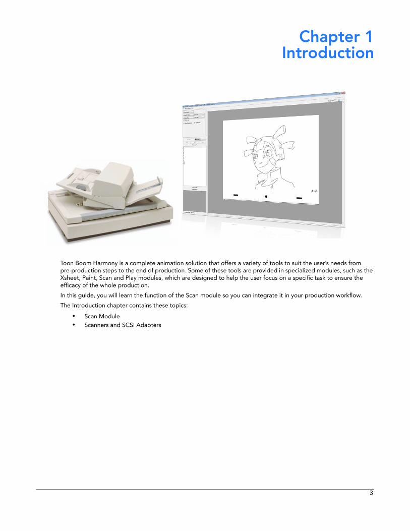
Toon Boom Harmony is a complete animation solution that offers a variety of tools to suit the user’s needs from pre-production steps to the end of production. Some of these tools are provided in specialized modules, such as the Xsheet, Paint, Scan and Play modules, which are designed to help the user focus on a specific task to ensure the efficacy of the whole production.
In this guide, you will learn the function of the Scan module so you can integrate it in your production workflow.
The Introduction chapter contains these topics:
• Scan Module• Scanners and SCSI Adapters
3
Harmony Scan User Guide
Scan Module
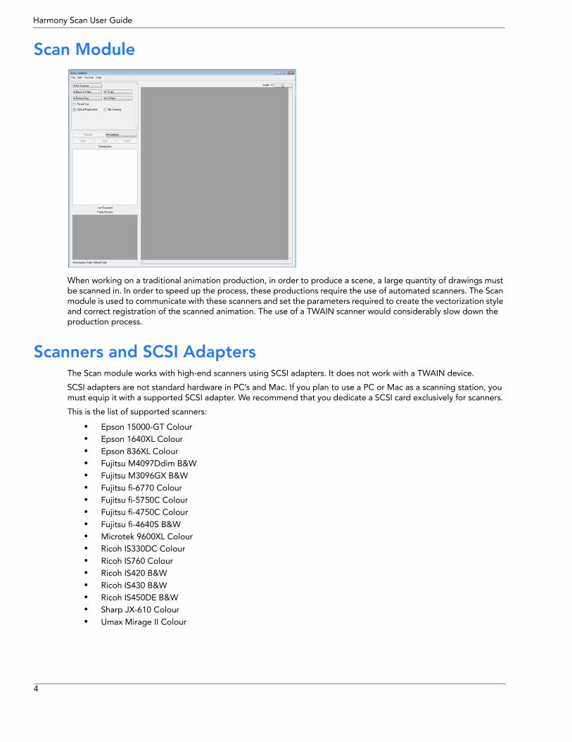
When working on a traditional animation production, in order to produce a scene, a large quantity of drawings must be scanned in. In order to speed up the process, these productions require the use of automated scanners. The Scan module is used to communicate with these scanners and set the parameters required to create the vectorization style and correct registration of the scanned animation. The use of a TWAIN scanner would considerably slow down the production process.
Scanners and SCSI Adapters The Scan module works with high-end scanners using SCSI adapters. It does not work with a TWAIN device.
SCSI adapters are not standard hardware in PC’s and Mac. If you plan to use a PC or Mac as a scanning station, you must equip it with a supported SCSI adapter. We recommend that you dedicate a SCSI card exclusively for scanners.
This is the list of supported scanners:
• Epson 15000-GT Colour • Epson 1640XL Colour • Epson 836XL Colour • Fujitsu M4097Ddim B&W • Fujitsu M3096GX B&W • Fujitsu fi-6770 Colour • Fujitsu fi-5750C Colour • Fujitsu fi-4750C Colour • Fujitsu fi-4640S B&W • Microtek 9600XL Colour • Ricoh IS330DC Colour • Ricoh IS760 Colour • Ricoh IS420 B&W • Ricoh IS430 B&W • Ricoh IS450DE B&W • Sharp JX-610 Colour • Umax Mirage II Colour
4
Chapter 2 Interface
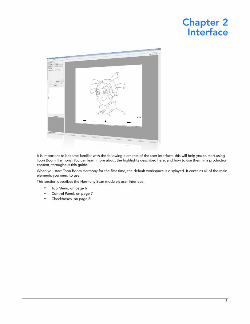
It is important to become familiar with the following elements of the user interface, this will help you to start using Toon Boom Harmony. You can learn more about the highlights described here, and how to use them in a production context, throughout this guide.
When you start Toon Boom Harmony for the first time, the default workspace is displayed. It contains all of the main elements you need to use.
This section describes the Harmony Scan module’s user interface:
• Top Menu, on page 6• Control Panel, on page 7• Checkboxes, on page 8
5
Harmony Scan User Guide
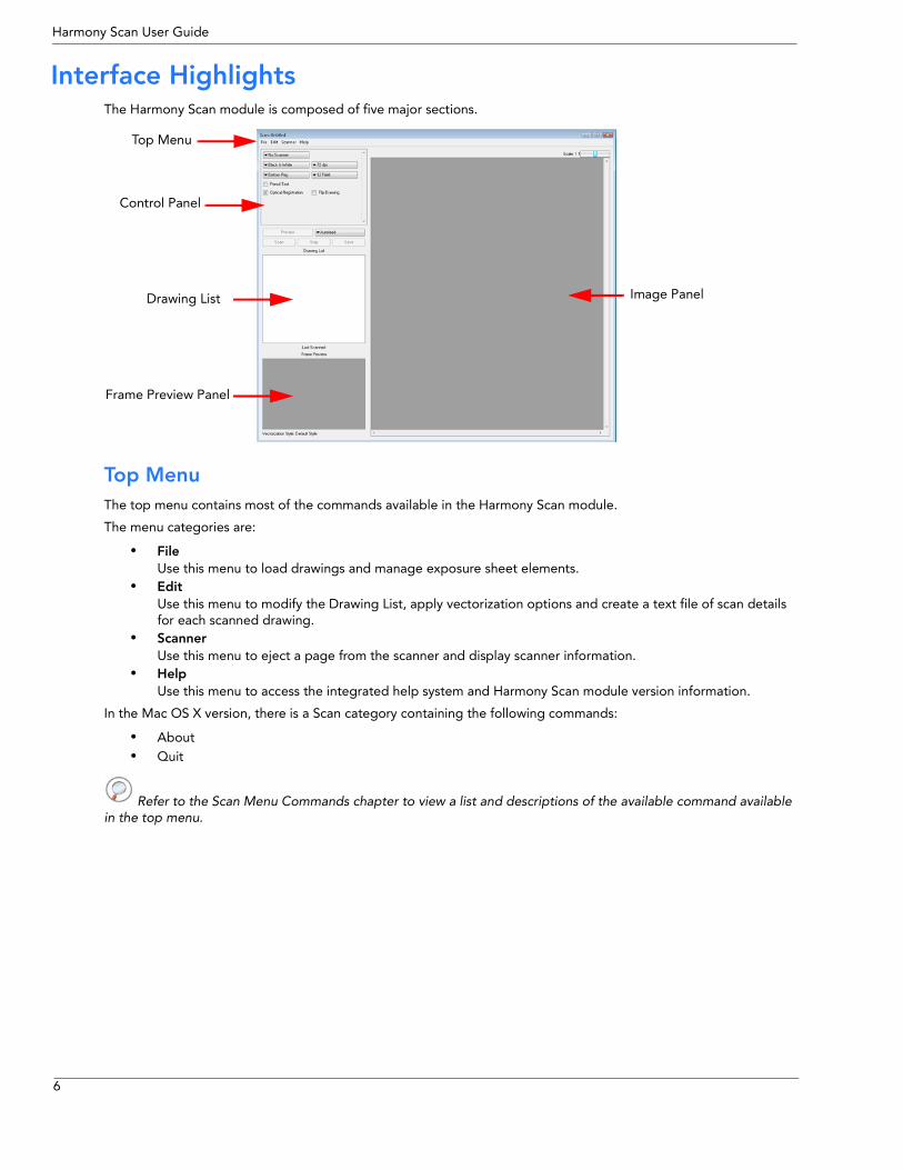
Interface HighlightsThe Harmony Scan module is composed of five major sections.
Top Menu The top menu contains most of the commands available in the Harmony Scan module.
The menu categories are:
• FileUse this menu to load drawings and manage exposure sheet elements.
• EditUse this menu to modify the Drawing List, apply vectorization options and create a text file of scan details for each scanned drawing.
• ScannerUse this menu to eject a page from the scanner and display scanner information.
• HelpUse this menu to access the integrated help system and Harmony Scan module version information.
In the Mac OS X version, there is a Scan category containing the following commands:
• About• Quit
Refer to the Scan Menu Commands chapter to view a list and descriptions of the available command available in the top menu.
Top Menu
Control Panel
Drawing List
Frame Preview Panel
Image Panel
6
Chapter 2: Interface
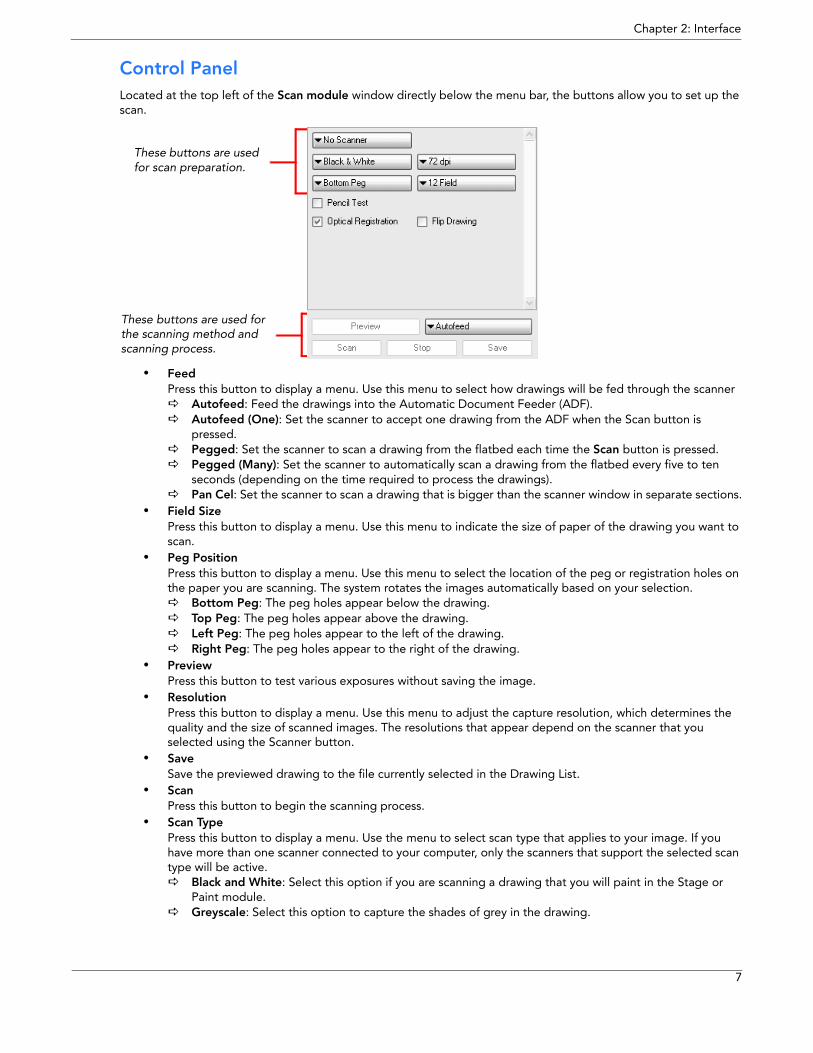
Control Panel Located at the top left of the Scan module window directly below the menu bar, the buttons allow you to set up the scan.
• FeedPress this button to display a menu. Use this menu to select how drawings will be fed through the scanner
Autofeed: Feed the drawings into the Automatic Document Feeder (ADF).Autofeed (One): Set the scanner to accept one drawing from the ADF when the Scan button is pressed.Pegged: Set the scanner to scan a drawing from the flatbed each time the Scan button is pressed.Pegged (Many): Set the scanner to automatically scan a drawing from the flatbed every five to ten seconds (depending on the time required to process the drawings).Pan Cel: Set the scanner to scan a drawing that is bigger than the scanner window in separate sections.
• Field SizePress this button to display a menu. Use this menu to indicate the size of paper of the drawing you want to scan.
• Peg PositionPress this button to display a menu. Use this menu to select the location of the peg or registration holes on the paper you are scanning. The system rotates the images automatically based on your selection.
Bottom Peg: The peg holes appear below the drawing.Top Peg: The peg holes appear above the drawing.Left Peg: The peg holes appear to the left of the drawing.Right Peg: The peg holes appear to the right of the drawing.
• PreviewPress this button to test various exposures without saving the image.
• ResolutionPress this button to display a menu. Use this menu to adjust the capture resolution, which determines the quality and the size of scanned images. The resolutions that appear depend on the scanner that you selected using the Scanner button.
• SaveSave the previewed drawing to the file currently selected in the Drawing List.
• ScanPress this button to begin the scanning process.
• Scan TypePress this button to display a menu. Use the menu to select scan type that applies to your image. If you have more than one scanner connected to your computer, only the scanners that support the selected scan type will be active.
Black and White: Select this option if you are scanning a drawing that you will paint in the Stage or Paint module.Greyscale: Select this option to capture the shades of grey in the drawing.
These buttons are used for scan preparation.
These buttons are used for the scanning method and scanning process.
7
Harmony Scan User Guide
Colour: Select this option to scan a pre-coloured drawing, such as a background or an overlay.• Scanner
Press this button to display a menu. Use the menu to select one of the scanners that is connected to the host machine. The default model is the one that appears first in your scanner configuration file, scan.conf.
• StopPress this button to interrupt a scan that is in progress.
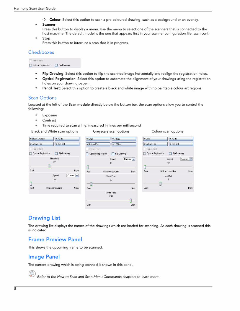
Checkboxes
• Flip Drawing: Select this option to flip the scanned image horizontally and realign the registration holes.• Optical Registration: Select this option to automate the alignment of your drawings using the registration
holes on your drawing paper.• Pencil Test: Select this option to create a black and white image with no paintable colour art regions.
Scan Options Located at the left of the Scan module directly below the button bar, the scan options allow you to control the following:
• Exposure• Contrast• Time required to scan a line, measured in lines per millisecond
Drawing List The drawing list displays the names of the drawings which are loaded for scanning. As each drawing is scanned this is indicated.
Frame Preview Panel This shows the upcoming frame to be scanned.
Image Panel The current drawing which is being scanned is shown in this panel.
Refer to the How to Scan and Scan Menu Commands chapters to learn more.
Black and White scan options Greyscale scan options Colour scan options
8
Chapter 3 How to Scan
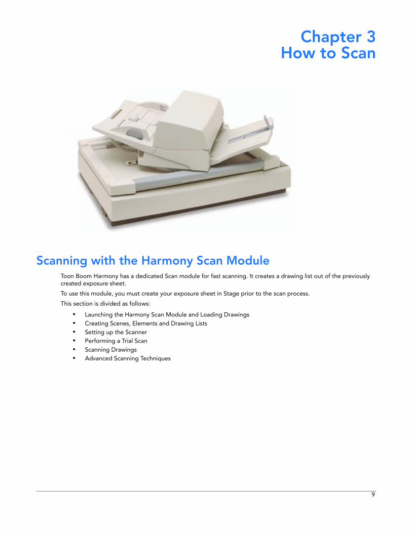
Scanning with the Harmony Scan Module Toon Boom Harmony has a dedicated Scan module for fast scanning. It creates a drawing list out of the previously created exposure sheet.
To use this module, you must create your exposure sheet in Stage prior to the scan process.
This section is divided as follows:
• Launching the Harmony Scan Module and Loading Drawings• Creating Scenes, Elements and Drawing Lists• Setting up the Scanner• Performing a Trial Scan• Scanning Drawings• Advanced Scanning Techniques
9
Harmony Scan User Guide
Launching the Harmony Scan Module and Loading Drawings Usually when you are ready for the scanning process, a scene have been created containing the elements to be scanned and the exposure sheet has been filled.
If you did not previously prepare your scene’s exposure sheet, create your elements or even create your scene, you can always create drawing lists, elements or scenes directly from the scan module without having to go through the Control Centre. Refer to the Creating Scenes, Elements and Drawing Lists topic to learn how.
To launch the Scan module and load your scene:
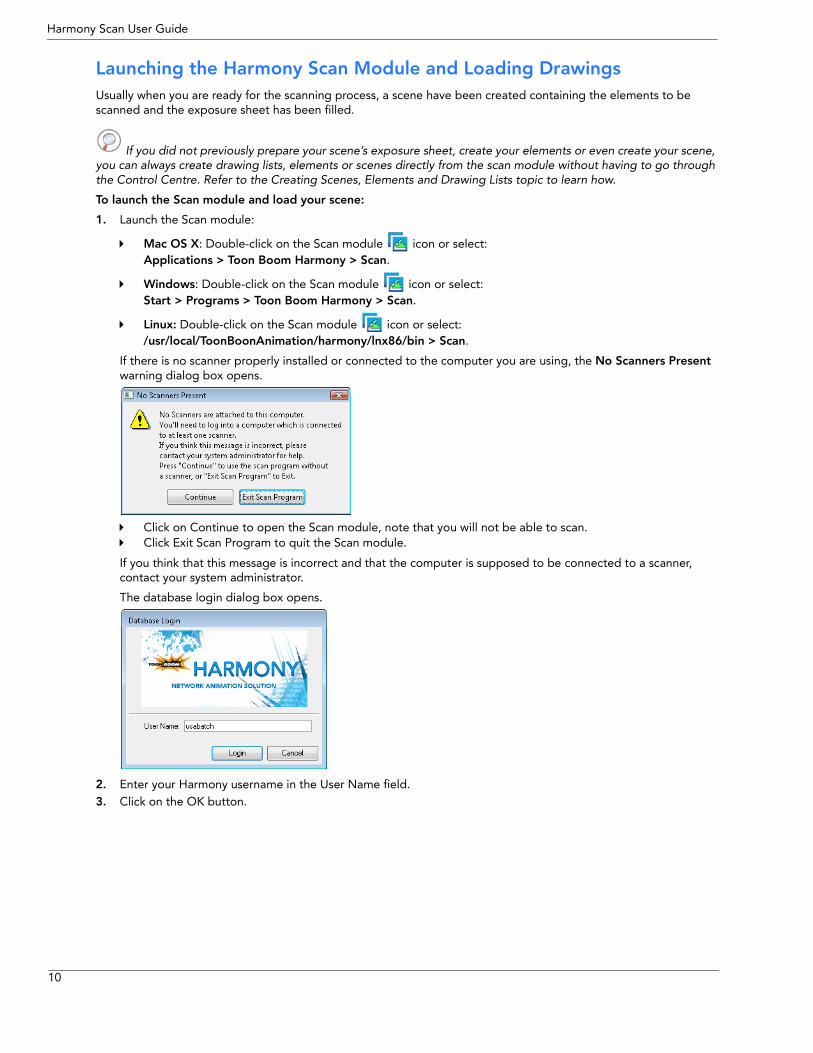
1. Launch the Scan module:
Mac OS X: Double-click on the Scan module icon or select: Applications > Toon Boom Harmony > Scan.
Windows: Double-click on the Scan module icon or select: Start > Programs > Toon Boom Harmony > Scan.
Linux: Double-click on the Scan module icon or select: /usr/local/ToonBoonAnimation/harmony/lnx86/bin > Scan.
If there is no scanner properly installed or connected to the computer you are using, the No Scanners Present warning dialog box opens.
Click on Continue to open the Scan module, note that you will not be able to scan.Click Exit Scan Program to quit the Scan module.
If you think that this message is incorrect and that the computer is supposed to be connected to a scanner, contact your system administrator.
The database login dialog box opens.
2. Enter your Harmony username in the User Name field.3. Click on the OK button.
10
Chapter 3: How to Scan Scanning with the Harmony Scan Module
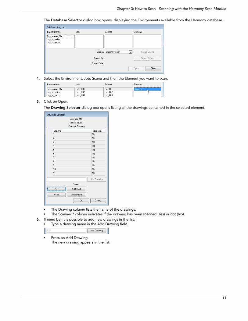
The Database Selector dialog box opens, displaying the Environments available from the Harmony database.
4. Select the Environment, Job, Scene and then the Element you want to scan.
5. Click on Open.
The Drawing Selector dialog box opens listing all the drawings contained in the selected element.
The Drawing column lists the name of the drawings.The Scanned? column indicates if the drawing has been scanned (Yes) or not (No).
6. If need be, it is possible to add new drawings in the list:Type a drawing name in the Add Drawing field.
Press on Add Drawing.The new drawing appears in the list.
11
Harmony Scan User Guide
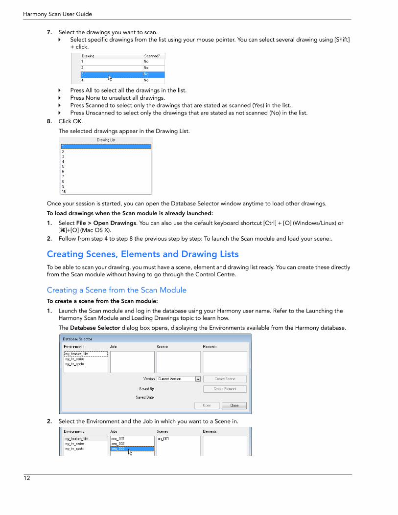
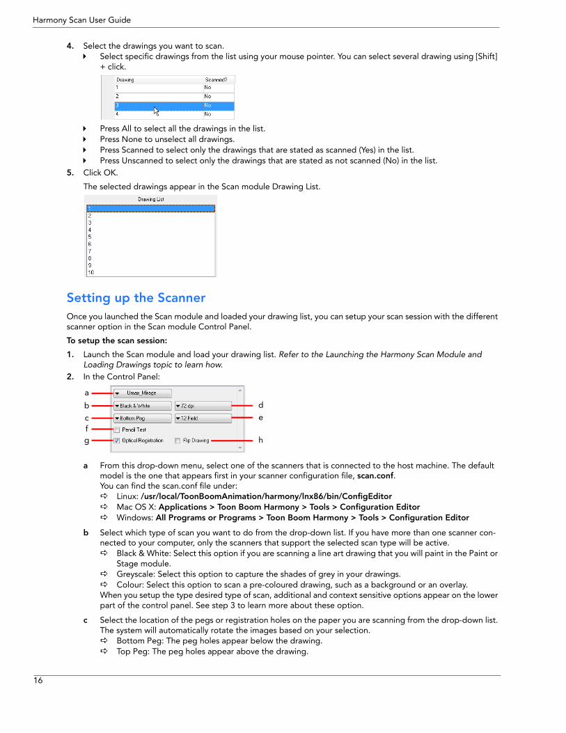
7. Select the drawings you want to scan.Select specific drawings from the list using your mouse pointer. You can select several drawing using [Shift] + click.
Press All to select all the drawings in the list.Press None to unselect all drawings.Press Scanned to select only the drawings that are stated as scanned (Yes) in the list.Press Unscanned to select only the drawings that are stated as not scanned (No) in the list.
8. Click OK.
The selected drawings appear in the Drawing List.
Once your session is started, you can open the Database Selector window anytime to load other drawings.
To load drawings when the Scan module is already launched:
1. Select File > Open Drawings. You can also use the default keyboard shortcut [Ctrl] + [O] (Windows/Linux) or [ ]+[O] (Mac OS X).
2. Follow from step 4 to step 8 the previous step by step: To launch the Scan module and load your scene:.
Creating Scenes, Elements and Drawing Lists To be able to scan your drawing, you must have a scene, element and drawing list ready. You can create these directly from the Scan module without having to go through the Control Centre.
Creating a Scene from the Scan Module To create a scene from the Scan module:
1. Launch the Scan module and log in the database using your Harmony user name. Refer to the Launching the Harmony Scan Module and Loading Drawings topic to learn how.
The Database Selector dialog box opens, displaying the Environments available from the Harmony database.
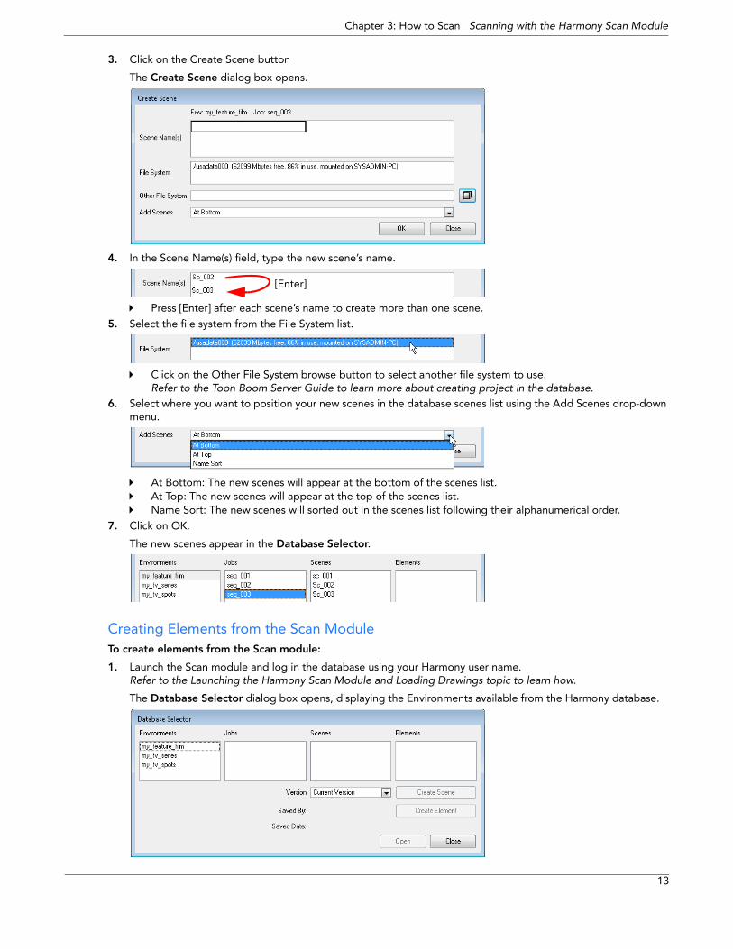
2. Select the Environment and the Job in which you want to a Scene in.
12
Chapter 3: How to Scan Scanning with the Harmony Scan Module
3. Click on the Create Scene button
The Create Scene dialog box opens.
4. In the Scene Name(s) field, type the new scene’s name.
Press [Enter] after each scene’s name to create more than one scene.5. Select the file system from the File System list.
Click on the Other File System browse button to select another file system to use.Refer to the Toon Boom Server Guide to learn more about creating project in the database.
6. Select where you want to position your new scenes in the database scenes list using the Add Scenes drop-down menu.
At Bottom: The new scenes will appear at the bottom of the scenes list.At Top: The new scenes will appear at the top of the scenes list.Name Sort: The new scenes will sorted out in the scenes list following their alphanumerical order.
7. Click on OK.
The new scenes appear in the Database Selector.
Creating Elements from the Scan Module To create elements from the Scan module:
1. Launch the Scan module and log in the database using your Harmony user name. Refer to the Launching the Harmony Scan Module and Loading Drawings topic to learn how.
The Database Selector dialog box opens, displaying the Environments available from the Harmony database.
[Enter]
13
Harmony Scan User Guide
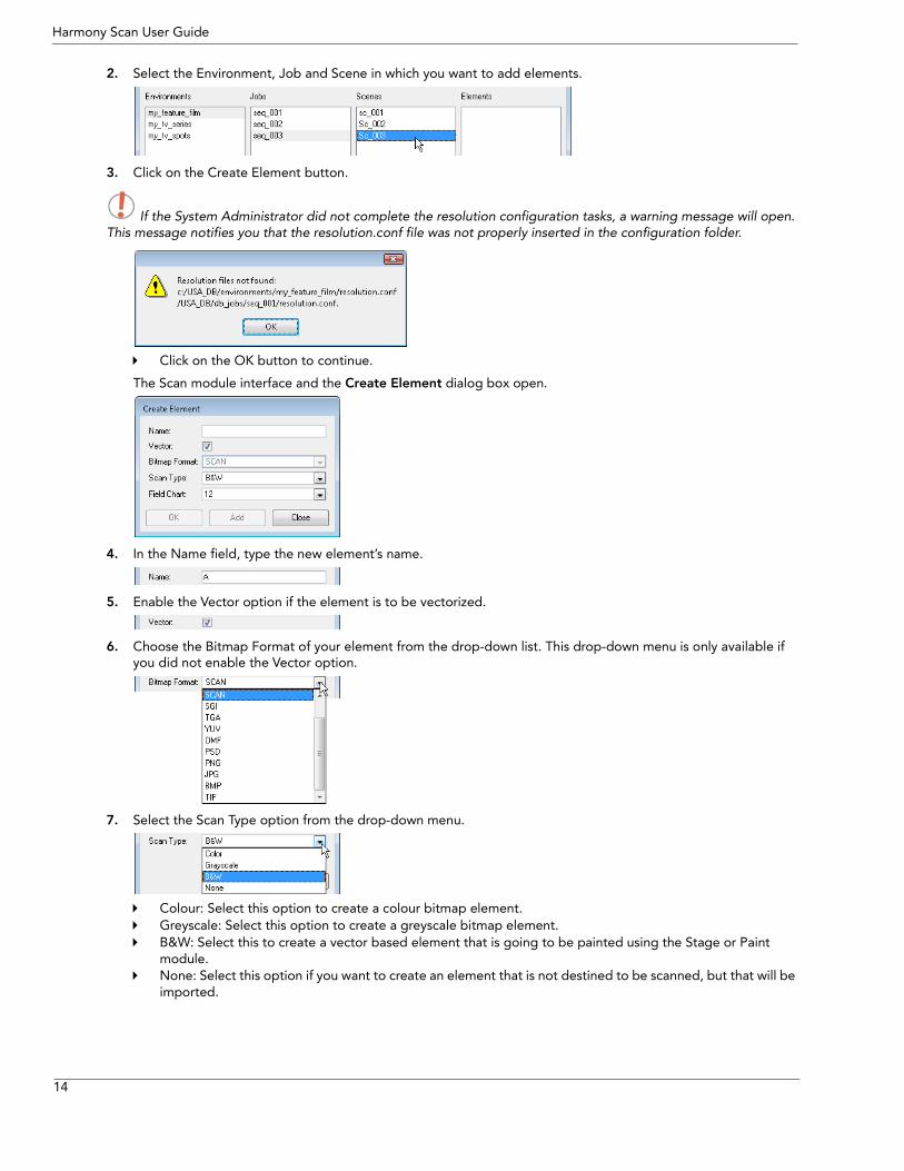
2. Select the Environment, Job and Scene in which you want to add elements.
3. Click on the Create Element button.
If the System Administrator did not complete the resolution configuration tasks, a warning message will open. This message notifies you that the resolution.conf file was not properly inserted in the configuration folder.
Click on the OK button to continue.
The Scan module interface and the Create Element dialog box open.
4. In the Name field, type the new element’s name.
5. Enable the Vector option if the element is to be vectorized.
6. Choose the Bitmap Format of your element from the drop-down list. This drop-down menu is only available if you did not enable the Vector option.
7. Select the Scan Type option from the drop-down menu.
Colour: Select this option to create a colour bitmap element.Greyscale: Select this option to create a greyscale bitmap element.B&W: Select this to create a vector based element that is going to be painted using the Stage or Paint module.None: Select this option if you want to create an element that is not destined to be scanned, but that will be imported.
14
Chapter 3: How to Scan Scanning with the Harmony Scan Module
8. Select the field chart size of your element from the drop-down list.
9. When you are done:Click OK to add the element and return to the Database Selector.Click Add to add the element and keep the dialog box open to add more.Click Close to cancel and return to the Database Selector without adding an element.
Creating and Editing a Drawing List There are two ways you can create and edit a drawing list from the Scan module.
• Creating or Editing a Drawing List When Loading your Element. Refer to the Launching the Harmony Scan Module and Loading Drawings topic to learn how to do this.
• Creating or Editing a Drawing List When your Element is Already Loaded.
To create or edit a drawing list when your element is already loaded:
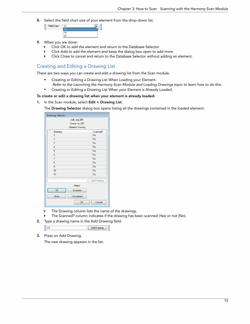
1. In the Scan module, select Edit > Drawing List.
The Drawing Selector dialog box opens listing all the drawings contained in the loaded element.
The Drawing column lists the name of the drawings.The Scanned? column indicates if the drawing has been scanned (Yes) or not (No).
2. Type a drawing name in the Add Drawing field.
3. Press on Add Drawing.
The new drawing appears in the list.
15
Harmony Scan User Guide
4. Select the drawings you want to scan.Select specific drawings from the list using your mouse pointer. You can select several drawing using [Shift] + click.
Press All to select all the drawings in the list.Press None to unselect all drawings.Press Scanned to select only the drawings that are stated as scanned (Yes) in the list.Press Unscanned to select only the drawings that are stated as not scanned (No) in the list.
5. Click OK.
The selected drawings appear in the Scan module Drawing List.
Setting up the Scanner Once you launched the Scan module and loaded your drawing list, you can setup your scan session with the different scanner option in the Scan module Control Panel.
To setup the scan session:
1. Launch the Scan module and load your drawing list. Refer to the Launching the Harmony Scan Module and Loading Drawings topic to learn how.
2. In the Control Panel:
a From this drop-down menu, select one of the scanners that is connected to the host machine. The default model is the one that appears first in your scanner configuration file, scan.conf. You can find the scan.conf file under:
Linux: /usr/local/ToonBoomAnimation/harmony/lnx86/bin/ConfigEditorMac OS X: Applications > Toon Boom Harmony > Tools > Configuration EditorWindows: All Programs or Programs > Toon Boom Harmony > Tools > Configuration Editor
b Select which type of scan you want to do from the drop-down list. If you have more than one scanner con-nected to your computer, only the scanners that support the selected scan type will be active.
Black & White: Select this option if you are scanning a line art drawing that you will paint in the Paint or Stage module.Greyscale: Select this option to capture the shades of grey in your drawings.Colour: Select this option to scan a pre-coloured drawing, such as a background or an overlay.
When you setup the type desired type of scan, additional and context sensitive options appear on the lower part of the control panel. See step 3 to learn more about these option.
c Select the location of the pegs or registration holes on the paper you are scanning from the drop-down list. The system will automatically rotate the images based on your selection.
Bottom Peg: The peg holes appear below the drawing.Top Peg: The peg holes appear above the drawing.
a
b
cfg
d
e
h
16
Chapter 3: How to Scan Scanning with the Harmony Scan Module
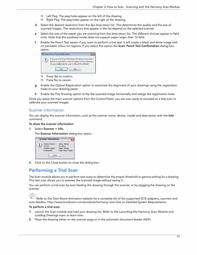
Left Peg: The peg holes appear on the left of the drawing.Right Peg: The peg holes appear on the right of the drawing.
d Select the desired resolution from the dpi drop-down list. This determines the quality and the size of scanned images. The resolutions that appear in the list depend on the selected scanner.
e Select the size of the paper you are scanning from the drop-down list. The different choices appear in field units. Note that the autofeed mode does not support paper larger than 12 field.
f Enable the Pencil Test option if you want to perform a line test. It will create a black and white image with no paintable colour art regions. If you select this option the Scan: Pencil Test Confirmation dialog box opens.
Press Yes to confirm.Press No to cancel.
g Enable the Optical Registration option to automate the alignment of your drawings using the registration holes on your drawing paper.
h Enable the Flip Drawing option to flip the scanned image horizontally and realign the registration holes.
Once you setup the main scanner options from the Control Panel, you are now ready to proceed to a test scan to calibrate your scanned images.
Scanner Information You can display the scanner information, such as the scanner name, device, model and description with the Info command.
To show the scanner information:
1. Select Scanner > Info.
The Scanner Information dialog box opens.
2. Click on the Close button to close the dialog box.
Performing a Trial Scan The Scan module allows you to perform test scans to determine the proper threshold or gamma setting for a drawing. This test scan allows you to preview the scanned image without saving it.
You can perform a trial scan by auto feeding the drawing through the scanner, or by pegging the drawing on the scanner.
Refer to the Toon Boom Animation website for a complete list of the supported SCSI adapters, scanners and auto-feeders. http://www.toonboom.com/products/harmony/ and click on Detailed System Requirements.
To perform a trial scan:
1. Launch the Scan module and load your drawing list. Refer to the Launching the Harmony Scan Module and Loading Drawings topic to learn how.
2. Place the drawing either on the scanner pegs or in the automatic document feeder (ADF).
17
Harmony Scan User Guide
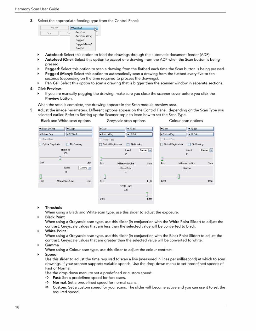
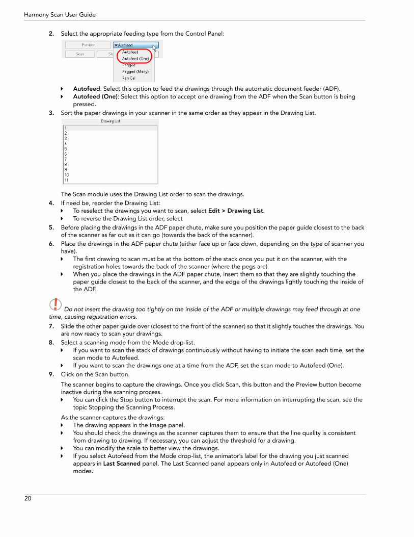
3. Select the appropriate feeding type from the Control Panel:
Autofeed: Select this option to feed the drawings through the automatic document feeder (ADF).Autofeed (One): Select this option to accept one drawing from the ADF when the Scan button is being pressed.Pegged: Select this option to scan a drawing from the flatbed each time the Scan button is being pressed.Pegged (Many): Select this option to automatically scan a drawing from the flatbed every five to ten seconds (depending on the time required to process the drawings).Pan Cel: Select this option to scan a drawing that is bigger than the scanner window in separate sections.
4. Click Preview.If you are manually pegging the drawing, make sure you close the scanner cover before you click the Preview button.
When the scan is complete, the drawing appears in the Scan module preview area.5. Adjust the image parameters. Different options appear on the Control Panel, depending on the Scan Type you
selected earlier. Refer to Setting up the Scanner topic to learn how to set the Scan Type.
Threshold When using a Black and White scan type, use this slider to adjust the exposure.Black Point When using a Greyscale scan type, use this slider (in conjunction with the White Point Slider) to adjust the contrast. Greyscale values that are less than the selected value will be converted to black.White Point When using a Greyscale scan type, use this slider (in conjunction with the Black Point Slider) to adjust the contrast. Greyscale values that are greater than the selected value will be converted to white.Gamma When using a Colour scan type, use this slider to adjust the colour contrast.Speed Use this slider to adjust the time required to scan a line (measured in lines per millisecond) at which to scan drawings, if your scanner supports variable speeds. Use the drop-down menu to set predefined speeds of Fast or Normal. Use the drop-down menu to set a predefined or custom speed:
Fast: Set a predefined speed for fast scans.Normal: Set a predefined speed for normal scans.Custom: Set a custom speed for your scans. The slider will become active and you can use it to set the required speed.
Black and White scan options Greyscale scan options Colour scan options
18
Chapter 3: How to Scan Scanning with the Harmony Scan Module
6. Click Preview to view the changes.7. Keep adjusting these values until you get the effect you want. These values will be applied to all the subsequent
drawings you scan.
NOTE:
To keep the image from a trial scan without having to re-scan the drawing, press the Save button. This assigns the image to the currently selected drawing name in the Drawing List and marks it as Scanned.
Scanning Drawings After building your exposure sheet, opening the cells in the Scan module, configuring your scanner, fine tuning your scan settings and previewing your scanned drawings, you are now ready to begin the final scanning process.
There are five ways in which you can feed your drawings through the scanner:
• Autofeed: Scan the drawings in the automatic document feeder (ADF).• Autofeed (One): Scan the drawings in the ADF one at a time, and click Scan for each drawing.• Pegged: Scan a drawing on the scanner, and click Scan each time you change the drawing on the scanner. • Pegged (Many): Automatically scan the drawing in the scanner every five to ten seconds (depending on the
time required to process the drawings).
However, this mode does not scan each drawing automatically when you click the Preview button.• Pan Cel: Scan a drawing into the system in separate sections, because the drawing is bigger than the scan
window.
You may find that the Autofeed option is not available on your system, since your scanner may not support it. The field size you select can also determine which mode is available.
• All scanning modes support 12 field.• The Autofeed modes do not support 16 field or higher.
When you start scanning your drawings, the Scan module scans the drawings in the order in which they appear in the Drawing List. After setting these options, you may only need to perform Previewing Scanned Drawings and Scanning Drawings for future scans.
NOTE: • If you want to reverse the order of these drawings, select Edit > Reverse List Order.• If you want to make any other sorting changes, you can reselect the drawings from the Drawing Selector
dialog box. For more information about the Drawing Selector, refer to the Creating Scenes, Elements and Drawing Lists topic.
• You may need to re-enter your list of drawings using the File > Build Manual List command. Refer to Advanced Scanning Techniques topic to learn more about manual drawing list.
Scanning with the Automatic Document Feeder If the selected scanner supports an automatic document feeder (ADF), you can select Autofeed or Autofeed (One) to scan the drawings.
• Autofeed: Scans all the drawings in the ADF.• Autofeed (One): Scan the drawings in the ADF one at a time, and click Scan for each drawing.
You can use the ADF to scan a stack of drawings continuously on a black and white scanner. Many scanner models support up to A3-sized paper in the ADF (15 field). If you are scanning a 16 field drawing, you may have to manually peg it on the scanner.
Since you must splice the multiple drawings in a pan cel together once you’ve scanned them all, you cannot feed pan drawings through the ADF. When you use the black and white scanner’s ADF to scan a stack of drawings, the scanner optically detects the peg holes on the drawing and registers the image accordingly.
To scan your drawing using the automatic document feeder (ADF):
1. Launch the Scan module and load your drawing list. Refer to the Launching the Harmony Scan Module and Loading Drawings topic to learn how.
19
Harmony Scan User Guide
2. Select the appropriate feeding type from the Control Panel:
Autofeed: Select this option to feed the drawings through the automatic document feeder (ADF).Autofeed (One): Select this option to accept one drawing from the ADF when the Scan button is being pressed.
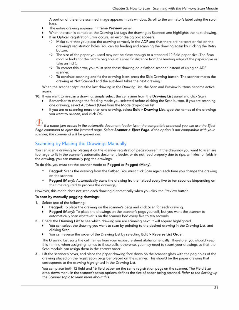
3. Sort the paper drawings in your scanner in the same order as they appear in the Drawing List.
The Scan module uses the Drawing List order to scan the drawings. 4. If need be, reorder the Drawing List:
To reselect the drawings you want to scan, select Edit > Drawing List.To reverse the Drawing List order, select
5. Before placing the drawings in the ADF paper chute, make sure you position the paper guide closest to the back of the scanner as far out as it can go (towards the back of the scanner).
6. Place the drawings in the ADF paper chute (either face up or face down, depending on the type of scanner you have).
The first drawing to scan must be at the bottom of the stack once you put it on the scanner, with the registration holes towards the back of the scanner (where the pegs are).When you place the drawings in the ADF paper chute, insert them so that they are slightly touching the paper guide closest to the back of the scanner, and the edge of the drawings lightly touching the inside of the ADF.
Do not insert the drawing too tightly on the inside of the ADF or multiple drawings may feed through at one time, causing registration errors.
7. Slide the other paper guide over (closest to the front of the scanner) so that it slightly touches the drawings. You are now ready to scan your drawings.
8. Select a scanning mode from the Mode drop-list.If you want to scan the stack of drawings continuously without having to initiate the scan each time, set the scan mode to Autofeed.If you want to scan the drawings one at a time from the ADF, set the scan mode to Autofeed (One).
9. Click on the Scan button.
The scanner begins to capture the drawings. Once you click Scan, this button and the Preview button become inactive during the scanning process.
You can click the Stop button to interrupt the scan. For more information on interrupting the scan, see the topic Stopping the Scanning Process.
As the scanner captures the drawings:The drawing appears in the Image panel.You should check the drawings as the scanner captures them to ensure that the line quality is consistent from drawing to drawing. If necessary, you can adjust the threshold for a drawing.You can modify the scale to better view the drawings.If you select Autofeed from the Mode drop-list, the animator’s label for the drawing you just scanned appears in Last Scanned panel. The Last Scanned panel appears only in Autofeed or Autofeed (One) modes.
20
Chapter 3: How to Scan Scanning with the Harmony Scan Module
A portion of the entire scanned image appears in this window. Scroll to the animator’s label using the scroll bars.The entire drawing appears in Frame Preview panel.When the scan is complete, the Drawing List tags the drawing as Scanned and highlights the next drawing. If an Optical Registration Error occurs, an error dialog box appears.
Make sure that you place the drawing correctly in the ADF and that there are no tears or rips on the drawing’s registration holes. You can try feeding and scanning the drawing again by clicking the Retry button.The size of the paper you used may not be close enough to a standard 12 field paper size. The Scan module looks for the centre peg hole at a specific distance from the leading edge of the paper (give or take an inch).To correct this error, you must scan these drawing on a flatbed scanner instead of using an ADF scanner.To continue scanning and fix the drawing later, press the Skip Drawing button. The scanner marks the drawing as Not Scanned and the autofeed takes the next drawing.
When the scanner captures the last drawing in the Drawing List, the Scan and Preview buttons become active again.
10. If you want to re-scan a drawing, simply select the cell name from the Drawing List panel and click Scan. Remember to change the feeding mode you selected before clicking the Scan button. If you are scanning one drawing, select Autofeed (One) from the Mode drop-down list.If you are re-scanning more than one drawing, select Edit > Drawing List, type the names of the drawings you want to re-scan, and click OK.
If a paper jam occurs in the automatic document feeder (with the compatible scanners) you can use the Eject Page command to eject the jammed page. Select Scanner > Eject Page. If the option is not compatible with your scanner, the command will be greyed out.
Scanning by Placing the Drawings Manually You can scan a drawing by placing it on the scanner registration pegs yourself. If the drawings you want to scan are too large to fit in the scanner’s automatic document feeder, or do not feed properly due to rips, wrinkles, or folds in the drawing, you can manually peg the drawings.
To do this, you must set the scanner mode to Pegged or Pegged (Many).
• Pegged: Scans the drawing from the flatbed. You must click Scan again each time you change the drawing on the scanner.
• Pegged (Many): Automatically scans the drawing fro the flatbed every five to ten seconds (depending on the time required to process the drawings).
However, this mode does not scan each drawing automatically when you click the Preview button.
To scan by manually pegging drawings:
1. Select one of the following:Pegged: To place the drawing on the scanner’s pegs and click Scan for each drawing.Pegged (Many): To place the drawings on the scanner’s pegs yourself, but you want the scanner to automatically scan whatever is on the scanner bed every five to ten seconds.
2. Check the Drawing List to see which drawing you are scanning next. It will appear highlighted.You can select the drawing you want to scan by pointing to the desired drawing in the Drawing List, and clicking Scan.You can reverse the order of the Drawing List by selecting Edit > Reverse List Order.
The Drawing List sorts the cell names from your exposure sheet alphanumerically. Therefore, you should keep this in mind when assigning names to these cells, otherwise, you may need to resort your drawings so that the Scan module can assign them in the correct order.
3. Lift the scanner’s cover, and place the paper drawing face down on the scanner glass with the peg holes of the drawing placed on the registration pegs bar placed on the scanner. This should be the paper drawing that corresponds to the drawing highlighted in the Drawing List.
You can place both 12 field and 16 field paper on the same registration pegs on the scanner. The Field Size drop-down menu in the scanner’s setup options defines the size of paper being scanned. Refer to the Setting up the Scanner topic to learn more about this.
21
Harmony Scan User Guide
4. Close the scanner cover, making sure the paper is laying flat against the glass, free of wrinkles and folds. You are now ready to scan the drawing.
Never scan a drawing while the scanner cover is open. If you do, large black areas can appear around the edges (similar to a photocopier with the lid open). The scanner interprets this extra black area as part of the drawing, which drastically slows the vectorization process. If by mistake you do scan a drawing with the cover open, you can go to the vectorize queue and delete the entry before it starts processing. Refer to the Toon Boom Server Guide to learn more about this.
5. Click Scan.If you set the scan mode to Pegged, the scanner scans the drawing, then stops and waits for you to change the drawing and click the Scan button again. If you set the scan mode to Pegged (Many), the scanner continues to capture a drawing every five to ten seconds (depending on how long it takes to process each drawing).
While the scanner captures the drawing, the Scan button becomes inactive.
You can use the Stop button to interrupt scanning at any time. For more information on interrupting the scanning process, see Stopping the Scanning Process.
When the scan is complete, the captured image appears in the Scan module. The Drawing List marks the drawing as Scanned and the next drawing to scan appears highlighted.
6. If you set the scan mode to Pegged (Many), you must wait for the scanner to stop after each drawing and place the next one before it starts again.
Pegging and Scanning a Pan Cel Pan cels are drawings that contain more than one set of registration holes. Because pan cels are large, you cannot scan the entire image with one pass on the scanner.
Therefore, you must scan pan cels one section at a time (one set of registration holes at a time). After you scan each section of the pan cel, the application splices the sections together to create the original pan cel image.
There must be exactly eight inches between the centre peg holes (the round holes) for each pan cel and the peg holes must all align exactly. This is important if the Scan module must make slight seaming adjustments to compensate for angle differences when it joins all the pan cels to form one drawing.
To scan a pan:
1. Launch the Scan module and load your drawing. Refer to the Launching the Harmony Scan Module and Loading Drawings topic to learn how.
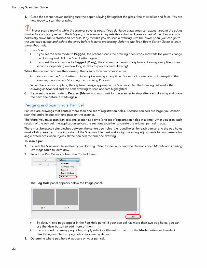
2. Select the Pan Cel mode from the Control Panel:
The Peg Hole panel appears below the Image panel.
By default, two pegs appear in the Peg Hole panel. If your pan cel has more than two peg holes, you can use the New button to add more of them.If you added too many peg holes, simply select a different format from the Mode button and reselect Pan Cel again. The two peg holes reappear by default.
3. Determine where peg hole A appears on your pan cel.
22
Chapter 3: How to Scan Scanning with the Harmony Scan Module
The Scan module considers peg hole A to be the leftmost peg position on horizontal pan cels, and the topmost peg position for vertical pan cels.
4. Place the pan cel face down on the scanner glass with the round A peg hole placed on the round registration peg on the scanner or position it in the optical registration search area as defined earlier. Close the scanner cover.
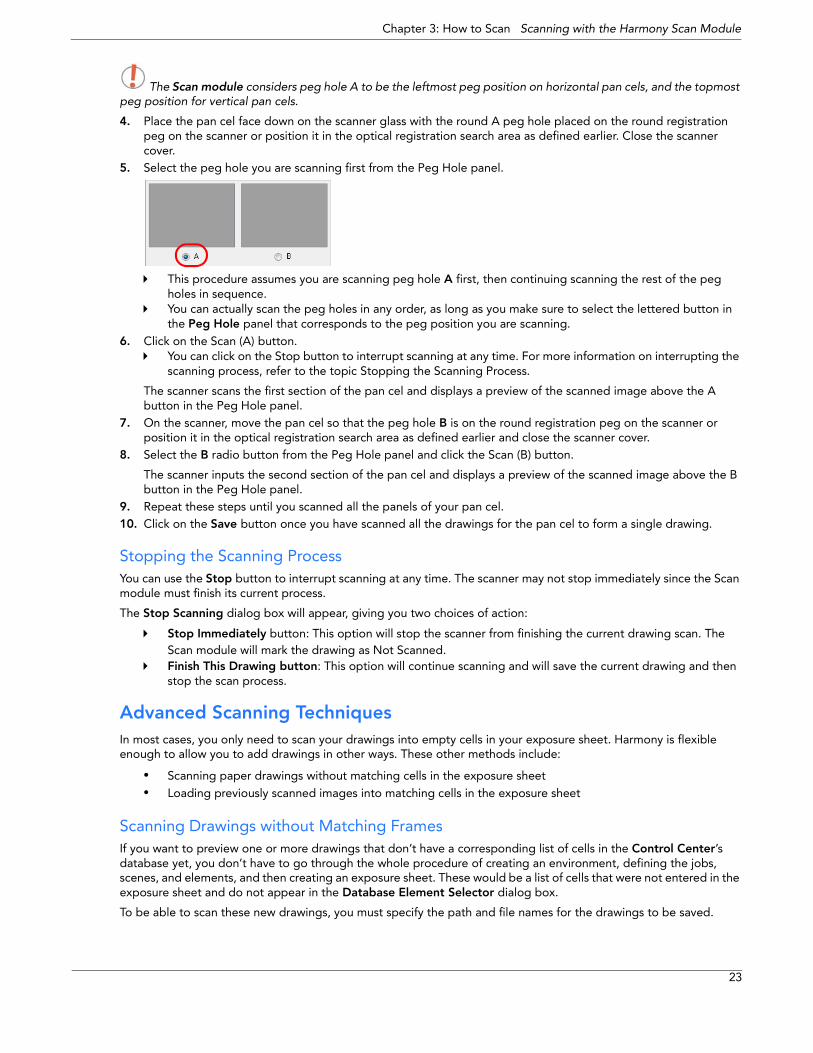
5. Select the peg hole you are scanning first from the Peg Hole panel.
This procedure assumes you are scanning peg hole A first, then continuing scanning the rest of the peg holes in sequence. You can actually scan the peg holes in any order, as long as you make sure to select the lettered button in the Peg Hole panel that corresponds to the peg position you are scanning.
6. Click on the Scan (A) button.You can click on the Stop button to interrupt scanning at any time. For more information on interrupting the scanning process, refer to the topic Stopping the Scanning Process.
The scanner scans the first section of the pan cel and displays a preview of the scanned image above the A button in the Peg Hole panel.
7. On the scanner, move the pan cel so that the peg hole B is on the round registration peg on the scanner or position it in the optical registration search area as defined earlier and close the scanner cover.
8. Select the B radio button from the Peg Hole panel and click the Scan (B) button.
The scanner inputs the second section of the pan cel and displays a preview of the scanned image above the B button in the Peg Hole panel.
9. Repeat these steps until you scanned all the panels of your pan cel.10. Click on the Save button once you have scanned all the drawings for the pan cel to form a single drawing.
Stopping the Scanning Process You can use the Stop button to interrupt scanning at any time. The scanner may not stop immediately since the Scan module must finish its current process.
The Stop Scanning dialog box will appear, giving you two choices of action:
Stop Immediately button: This option will stop the scanner from finishing the current drawing scan. The Scan module will mark the drawing as Not Scanned.Finish This Drawing button: This option will continue scanning and will save the current drawing and then stop the scan process.
Advanced Scanning Techniques In most cases, you only need to scan your drawings into empty cells in your exposure sheet. Harmony is flexible enough to allow you to add drawings in other ways. These other methods include:
• Scanning paper drawings without matching cells in the exposure sheet• Loading previously scanned images into matching cells in the exposure sheet
Scanning Drawings without Matching Frames If you want to preview one or more drawings that don’t have a corresponding list of cells in the Control Center’s database yet, you don’t have to go through the whole procedure of creating an environment, defining the jobs, scenes, and elements, and then creating an exposure sheet. These would be a list of cells that were not entered in the exposure sheet and do not appear in the Database Element Selector dialog box.
To be able to scan these new drawings, you must specify the path and file names for the drawings to be saved.
23

Harmony Scan User Guide
The Scan module does not vectorize these types of digital drawings and you cannot view them in the Control Center. If you do decide to use these drawings, you must follow the standard procedure for scanning drawings for a regular scene (with the Control Center and Stage Modules).
To manually build a list of drawings to Scan:
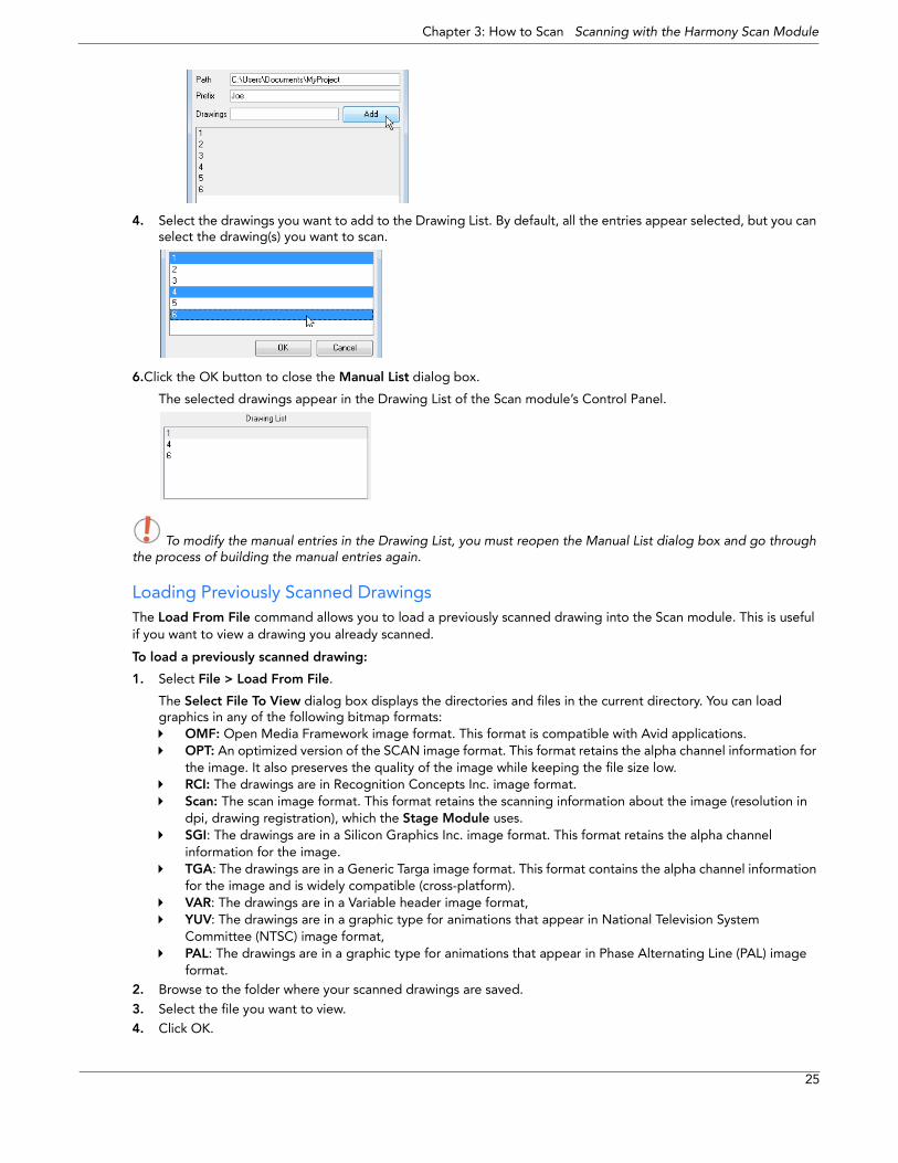
1. Select File > Build Manual List.
The Manual List dialog box appears.
2. In the Path field, type an existing directory path where you want to store the scanned drawings in the Path field.
3. You can type a name in the Prefix field that appears at the beginning of the scanned files that correspond to the drawing names you subsequently add to the manual list.
For example, if you enter the name of the character joe in the Prefix field, then add the drawing names 01 and 02, the Drawing List would display 01 and 02, but once you scan the drawings, the files would appear as follows:
joe-01joe-02
The prefix and a dash automatically appear in front of the drawing names you add when the Scan module creates the files of the scanned drawings.
4.Type the name of the drawing you want to scan in the Drawings field and click the Add button. The name of your drawing appears in the Drawings panel. Repeat for every drawings you must add.
For a quick way to create a series of drawings, you can type the first number and the last number with a colon symbol (:) in between.
For example, if you want to create a series of drawings number one to six, you would type the following in the Drawings field and click on the Add button:
1:6
24
Chapter 3: How to Scan Scanning with the Harmony Scan Module
4. Select the drawings you want to add to the Drawing List. By default, all the entries appear selected, but you can select the drawing(s) you want to scan.
6.Click the OK button to close the Manual List dialog box.
The selected drawings appear in the Drawing List of the Scan module’s Control Panel.
To modify the manual entries in the Drawing List, you must reopen the Manual List dialog box and go through the process of building the manual entries again.
Loading Previously Scanned DrawingsThe Load From File command allows you to load a previously scanned drawing into the Scan module. This is useful if you want to view a drawing you already scanned.
To load a previously scanned drawing:
1. Select File > Load From File.
The Select File To View dialog box displays the directories and files in the current directory. You can load graphics in any of the following bitmap formats:
OMF: Open Media Framework image format. This format is compatible with Avid applications.OPT: An optimized version of the SCAN image format. This format retains the alpha channel information for the image. It also preserves the quality of the image while keeping the file size low.RCI: The drawings are in Recognition Concepts Inc. image format.Scan: The scan image format. This format retains the scanning information about the image (resolution in dpi, drawing registration), which the Stage Module uses.SGI: The drawings are in a Silicon Graphics Inc. image format. This format retains the alpha channel information for the image.TGA: The drawings are in a Generic Targa image format. This format contains the alpha channel information for the image and is widely compatible (cross-platform).VAR: The drawings are in a Variable header image format,YUV: The drawings are in a graphic type for animations that appear in National Television System Committee (NTSC) image format,PAL: The drawings are in a graphic type for animations that appear in Phase Alternating Line (PAL) image format.
2. Browse to the folder where your scanned drawings are saved.
3. Select the file you want to view. 4. Click OK.
25

Harmony Scan User Guide
Setting the Vectorization Style You can set the vectorization style you want to apply to the subsequent drawings that will be sent to the Vectorize Queue in the Control Centre, using the Vectorize Style command.
To set the vectorization style:
1. Select Edit >Vectorize Style.
The Vectorization Styles dialog box opens.
2. Select the desired vectorization style from the list.3. Click on the OK button.
Refer to the Harmony Stage User Guide to learn how to edit and setup the vectorization styles.
Refer to the Harmony Server User Guide to learn more about the Vectorize Queue and the Control Centre.
26
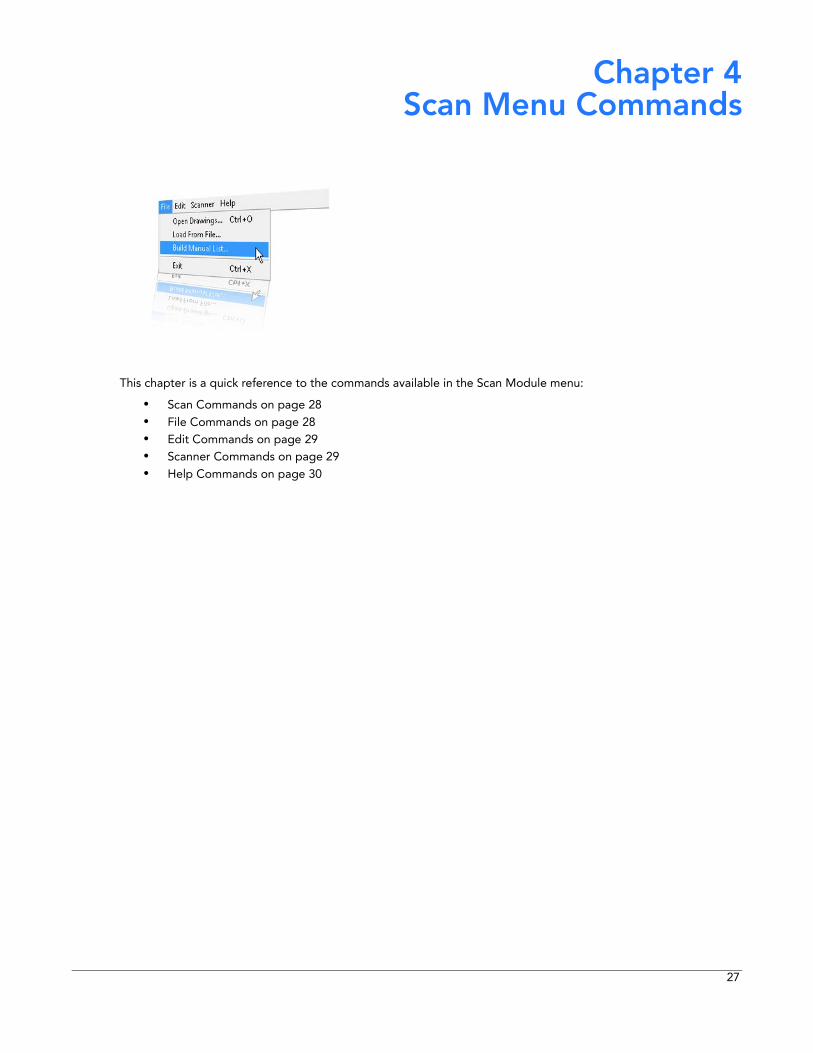
Chapter 4 Scan Menu Commands
This chapter is a quick reference to the commands available in the Scan Module menu:
• Scan Commands on page 28• File Commands on page 28• Edit Commands on page 29• Scanner Commands on page 29• Help Commands on page 30
27
Harmony Scan User Guide
Scan Commands
About Toon Boom Scan If you are using Mac OS X, use the About Toon Boom Scan command to display product and version information.
To activate this command:
Select Scan > About Toon Boom Scan
Quit Toon Boom Scan
If you are using Mac OS X, use the Quit Toon Boom Scan command to close the Scan module window and end the current session.
Use one of the following methods to activate this command:
Select Scan > Quit Toon Boom ScanPress [ ] + [Q], the default keyboard shortcut
File Commands
Build Manual List Use the Build Manual List command to open the Manual List dialog box and create a list of labeled cells.
To activate this command:
Select File > Build Manual List
Exit If you are using Windows or Linux, use this command to close the Scan Module and end your session.
Use one of the following methods to activate this command:
Select File > ExitPress [Ctrl] + [X], the default keyboard shortcut
Load From FileUse the command to open the dialog box and select a previously scanned drawing that you want to load into the Scan Module.
To activate this command:
Select File > Load From File
Open DrawingsUse the command to open the Database Selector dialog box and add new scenes and elements to a job.
Use one of the following methods to activate this command:
Select File > Open DrawingsIf you are using Windows or Linux, press [Ctrl] + [O] (Windows/Linux) or [ ] + [O] (Mac OS X)
28
Chapter 4: Scan Menu Commands Edit Commands
Edit Commands
Drawing ListUse the command to open the Drawings Selector dialog box and label cells to accept drawings.
To activate this command:
Select Edit > Drawing List
Create ScanInfo File
Use the Create ScanInfo File command to create a plaintext file for each subsequent scan, such as the image’s resolution and aspect ratio. Each plaintext file is located in the same directory and has the same filename as that of the scanned image with the file extension SI.
To activate this command:
Select Edit > Create ScanInfo File
Reverse Drawing List Use the Reverse Drawing List command to reverse the sequence of drawings in the Drawing List.
To activate this command:
Select Edit > Reverse Drawing List
Vectorize Style Use the Vectorize Style command to open the Vectorization Styles dialog box and select the vectorization style you want to apply when you scan drawings.
To activate this command:
Select Edit > Vectorize Style
Scanner Commands
EjectPage Use the EjectPage command to eject a page from a scanner’s automatic document feeder (ADF). This command is only activated when a paper jam occurs.
This option is not available on all the scanners. If this option is not compatible with your scanner, the option will be greyed out.
To activate this command:
Select Scanner > EjectPage
Info Use the command to open the Scanner Information dialog box to view scanner name, device, model and description information.
To activate this command:
Select Scanner > Info
29
Harmony Scan User Guide
Help Commands
About If you are using Windows or Linux, use the About command to display product and version information.
To activate this command:
Select Help > About
Debug Mode Use the Debug Mode command to access the Debug window which helps to identify a problem encountered in the software.
To activate this command:
Select Help > Debug Mode
Help Use the Help command to view the integrated help system.
To activate this command:
Select Help > Help
30
Index
Index
AAbout 30
Scan ModuleHelp Command 30
scan module 4About Scan command 28
Scan Module 28
ADFusing 19
Automatic Document Feederusing 19
BBuild Manual List 28
Scan ModuleFile Command 28
Ccheckboxes 8commands
Scan 28
control panel 8checkboxes 8interface
scan module 7scan options 8
Create ScanInfo File 29Scan Module
Edit Command 29
creating scenesscanner 12
DDebug Mode 30Debug mode
Scan ModuleHelp Command 30
Drawing List 29Scan Module
Edit Command 29
drawing listcreate from scan module 15editing scan module 15interface
scan module 8
drawing listsscanner 12
drawingsloading 10loading previously scanned 25scanning 19
without matching frames 23
scanning manually 21
EEdit Commands
Create ScanInfo File 29Drawing List 29Reverse Drawing List 29Vectorize Style 29
EjectPage 29
Scan ModuleScanner Command 29
elementscreate from scan module 13scanner 12
Epsonsupported scanners
colour 4
Exit 28Scan Module
File Command 28
FFile Commands
Build Manual List 28Exit 28Load From File 28Open Drawings 28
frame previewinterface
scan module 8
Fujitsusupported scanners
B&W 4colour 4
HHelp 30
Scan ModuleHelp Command 30
Help CommandsAbout 30Debug Mode 30Help 30
How toscan 9
Iimage panel
interfacescan module 8
Info 29Scan Module
Scanner Command 29
informationscanner
displaying 17
interfacescan module 5, 6
Llaunching
scanner 10
list ofscanners 4
Load From File 28Scan Module
File Command 28
loadingdrawings 10
Mmanual
scanning of drawings 21
matching framesscanning without 23
31
Harmony Scan User Guide
Microteksupported scanners
colour 4
OOpen Drawings 28
Scan ModuleFile Command 28
Ppan cel
pegging 22scanning 22
peggingpan cels 22
QQuit command 28
Scan Module 28
RReverse Drawing List 29
Scan ModuleEdit Command 29
Ricohsupported scanners
B&W 4colour 4
SScan Commands
About Scan 28Quit 28
Scan commands 28Scan Module 28, 29, 30
create drawing list from 15create elements from 13create scene from 12editing drawing list 15interface 5, 6
control panel 7drawing list 8frame preview 8image panel 8top menu 6
Scan moduleabout 4
scannercreating drawing lists 12creating elements 12creating scenes 12information
displaying 17
loading drawings 10setup 16testing 17
Scanner CommandsEjectPage 29Info 29
scannersB&W
Fujitsu 4Ricoh 4
colourEpson 4Fujitsu 4Microtek 4
Ricoh 4Sharp 4Umax 4
list of 4scanning
ADFusing 19
Automatic Document Feederusing 19
drawings 19manually 21
how to 9launching 10loading previously scanned drawings 25pan cels 22stop process 23techniques
advanced 23
vectorization stylesetting of 26
without matching frames 23
scan options 8scene
create from scan module 12
SCSI Adapters 4setting
vectorization style 26
setting upscanner 16
Sharpsupported scanners
colour 4
stopscanning process 23
Ttest scan
perfoming 17
top menuinterface
scan module 6
UUmax
supported scannerscolour 4
Vvectorization style
setting 26
Vectorize Style 29Scan Module
Edit Command 29
32