Embed Size (px)
DESCRIPTION
Hazardous Waste Management Hierarchy. SECURED LANDFILL. A controlled site for disposal of wastes on land , run in accordance with safety and environmental requirements laid down by a regulatory authority. A FACILITY WHERE. WASTES ARE PLACED PERMANENTLY IN SECURED MANNER - PowerPoint PPT Presentation
Citation preview
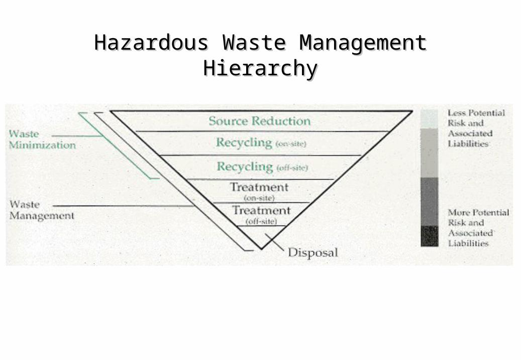
Hazardous Waste Management HierarchyHazardous Waste Management Hierarchy
A controlled site for disposal of wastes on
land, run in accordance with safety and
environmental requirements laid down by a
regulatory authority
SECURED LANDFILL
WASTES ARE PLACED PERMANENTLY IN SECURED MANNER
WASTE IS ENCAPSULATED FROM THE ENVIRONMENT BY IMPERMEABLE BARRIERS/ LINERS
LEACHATE IS COLLECTED, REMOVED & TREATED THROUGHOUT ITS LIFE.
A FACILITY WHERE
All hazardous waste treatment options
result in residues and One of the safer
methods for disposal of them
Best techno-economic option for some
wastes.
WHY LANDFILL ?
SECURED LANDFILL FACILITY
• Last Option
• Primarily Containment of contaminants
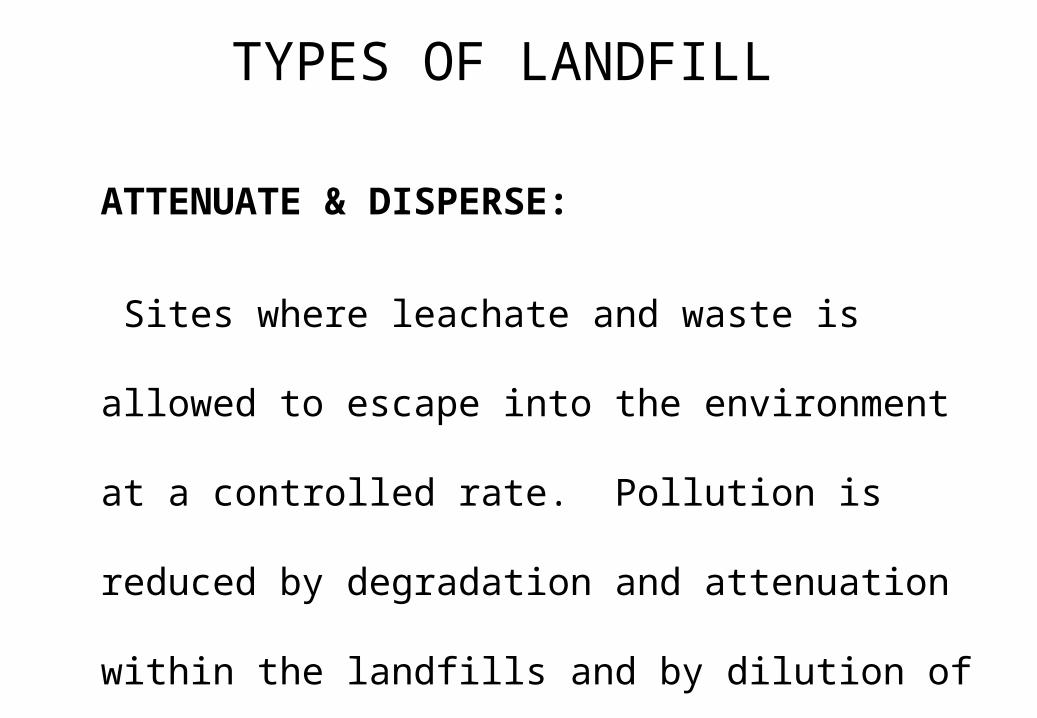
ATTENUATE & DISPERSE:
Sites where leachate and waste is allowed to
escape into the environment at a controlled rate.
Pollution is reduced by degradation and attenuation
within the landfills and by dilution of the leachate in
the aquifer
TYPES OF LANDFILL
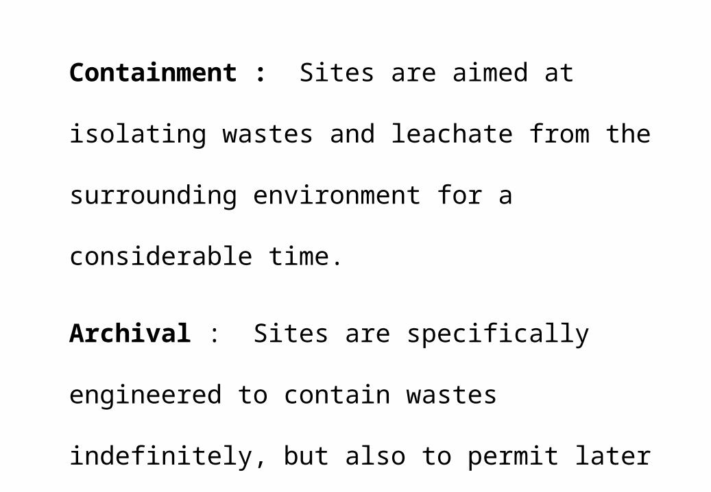
Containment : Sites are aimed at isolating wastes
and leachate from the surrounding environment for a
considerable time.
Archival : Sites are specifically engineered to
contain wastes indefinitely, but also to permit later
identification and retrieval.
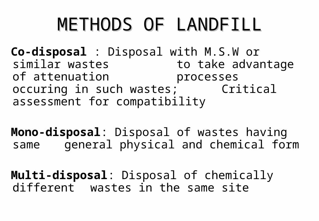
METHODS OF LANDFILLMETHODS OF LANDFILL
Co-disposal : Disposal with M.S.W or similar wastes to take advantage of attenuation processes occuring in such wastes; Critical assessment for compatibility
Mono-disposal: Disposal of wastes having same general physical and chemical form
Multi-disposal: Disposal of chemically different wastes in the same site
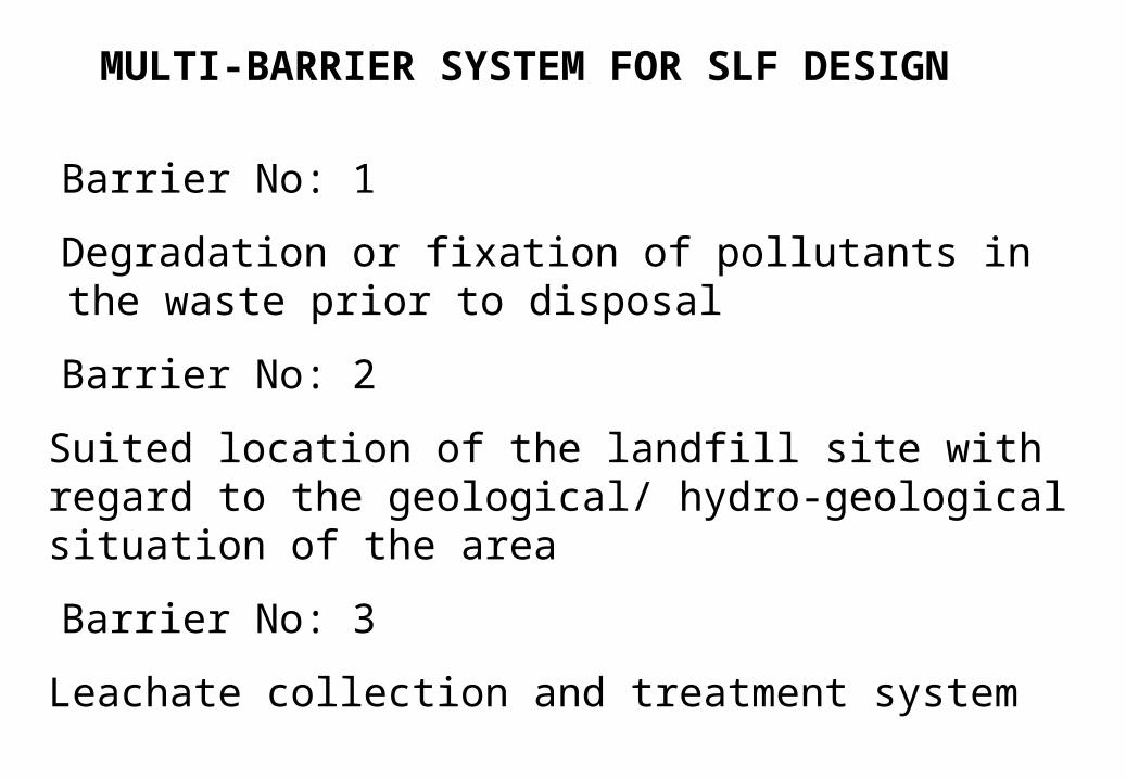
Barrier No: 1
Degradation or fixation of pollutants in the waste prior to disposal
Barrier No: 2
Suited location of the landfill site with regard to the geological/ hydro-geological situation of the area
Barrier No: 3
Leachate collection and treatment system
MULTI-BARRIER SYSTEM FOR SLF DESIGN
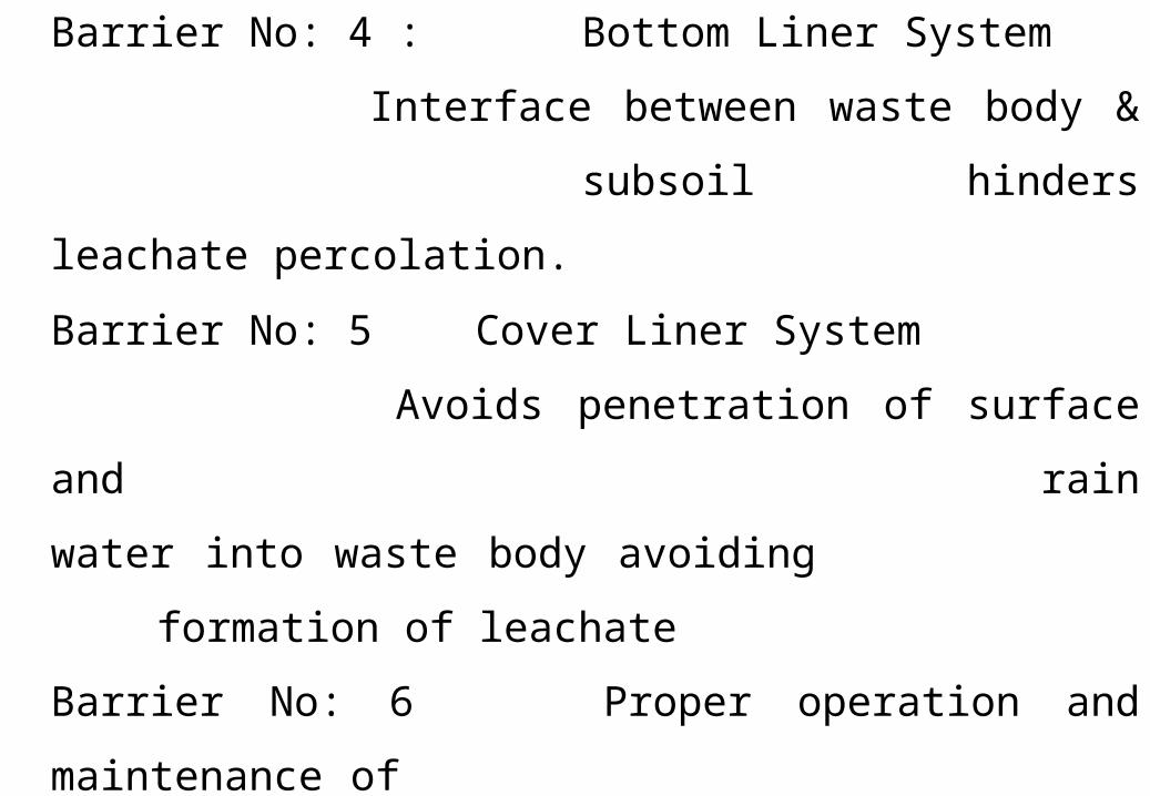
Barrier No: 4 : Bottom Liner System
Interface between waste body &
subsoil hinders leachate percolation.
Barrier No: 5 Cover Liner System
Avoids penetration of surface and
rain water into waste body avoiding
formation of leachate
Barrier No: 6 Proper operation and maintenance of
SLF
Barrier No: 7 Post Closure measures & Repairability of barriers
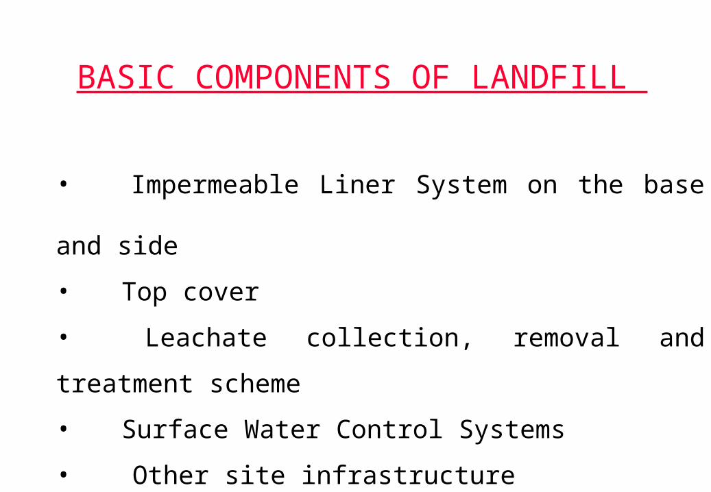
BASIC COMPONENTS OF LANDFILL
• Impermeable Liner System on the base and side
• Top cover
• Leachate collection, removal and treatment
scheme
• Surface Water Control Systems
• Other site infrastructure
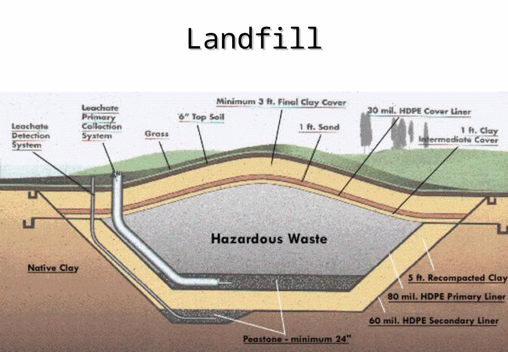
LandfillLandfill
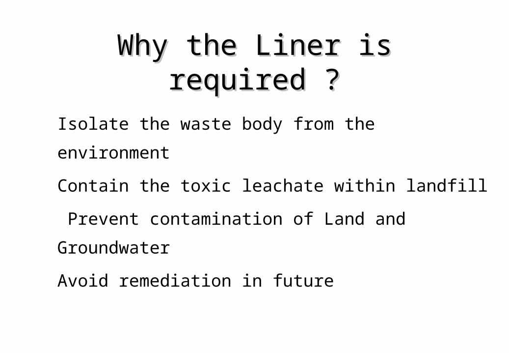
Why the Liner is required ?Why the Liner is required ?
Isolate the waste body from the environment
Contain the toxic leachate within landfill
Prevent contamination of Land and Groundwater
Avoid remediation in future
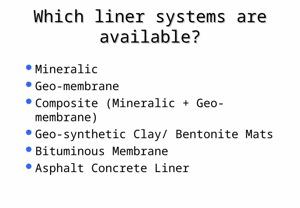
Which liner systems are Which liner systems are available?available?
MineralicGeo-membraneComposite (Mineralic + Geo-membrane)Geo-synthetic Clay/ Bentonite MatsBituminous MembraneAsphalt Concrete Liner
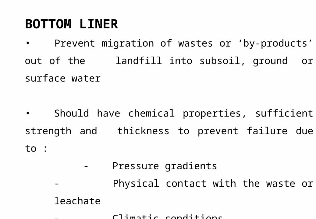
BOTTOM LINER • Prevent migration of wastes or ‘by-products’ out of the
landfill into subsoil, ground or surface water
• Should have chemical properties, sufficient strength and
thickness to prevent failure due to :
- Pressure gradients
- Physical contact with the waste or leachate
- Climatic conditions
- Stress of installation and
- Stress of daily operation
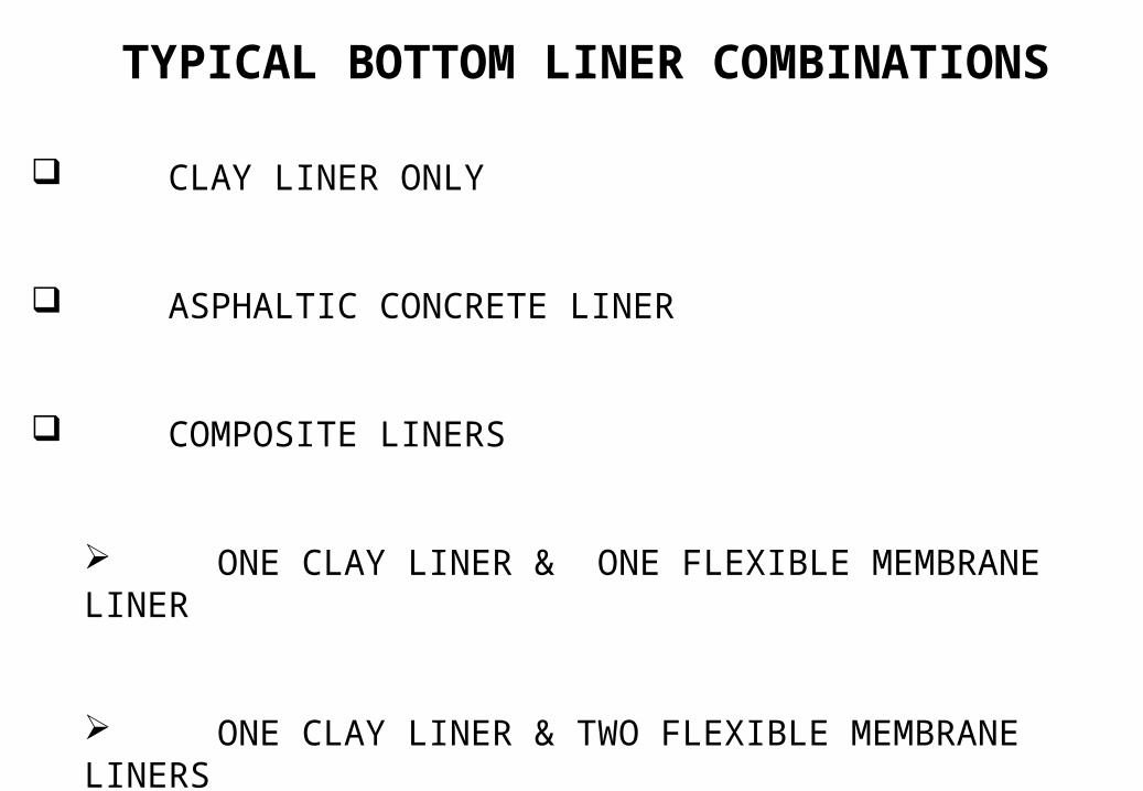
TYPICAL BOTTOM LINER COMBINATIONS
CLAY LINER ONLY
ASPHALTIC CONCRETE LINER
COMPOSITE LINERS
ONE CLAY LINER & ONE FLEXIBLE MEMBRANE LINER
ONE CLAY LINER & TWO FLEXIBLE MEMBRANE LINERS
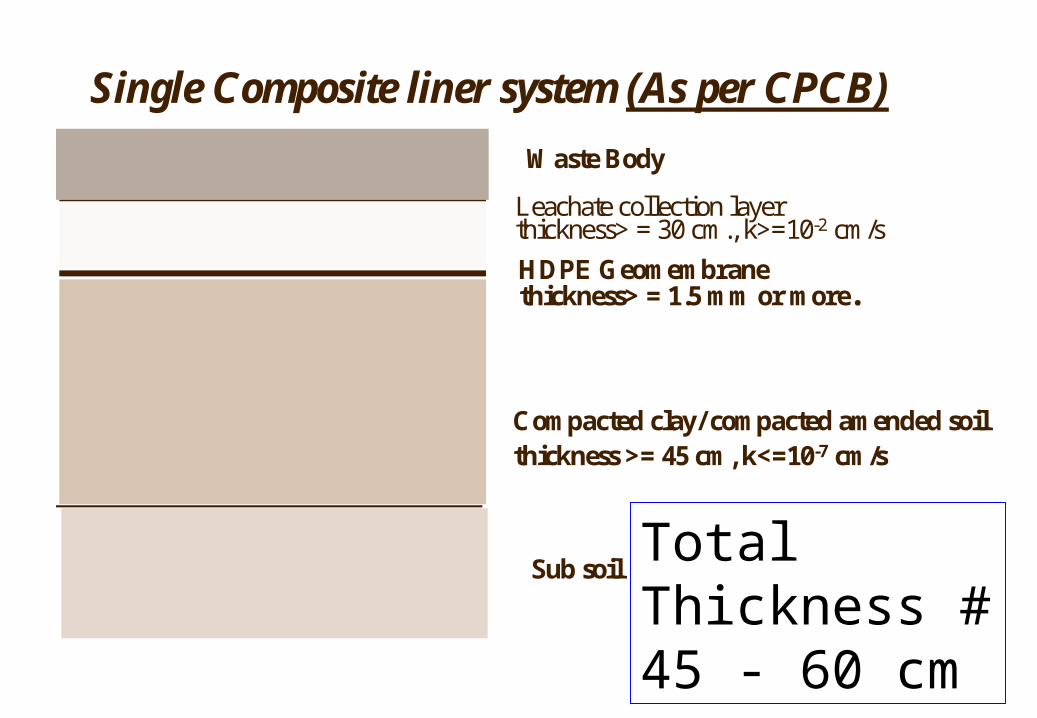
Compacted clay/ compacted amended soilthickness >= 45 cm, k<=10-7 cm/s
Waste Body
Leachate collection layerthickness> = 30 cm., k>=10-2 cm/s
Sub soil
HDPE Geomembranethickness> = 1.5 mm or more.
Single Composite liner system (As per CPCB)
Total Thickness # 45 - 60 cm
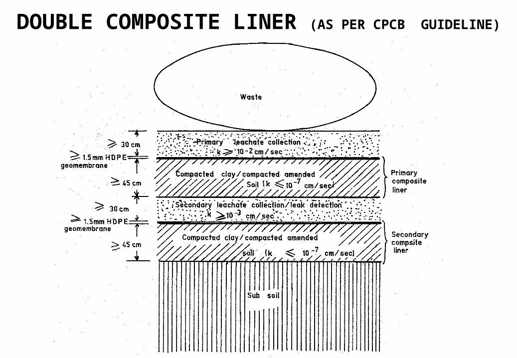
DOUBLE COMPOSITE LINER (AS PER CPCB GUIDELINE)
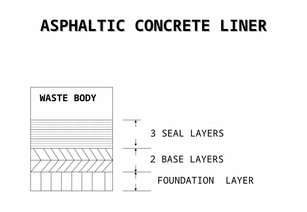
ASPHALTIC CONCRETE LINERASPHALTIC CONCRETE LINER
2 BASE LAYERS
3 SEAL LAYERS
FOUNDATION LAYER
WASTE BODY
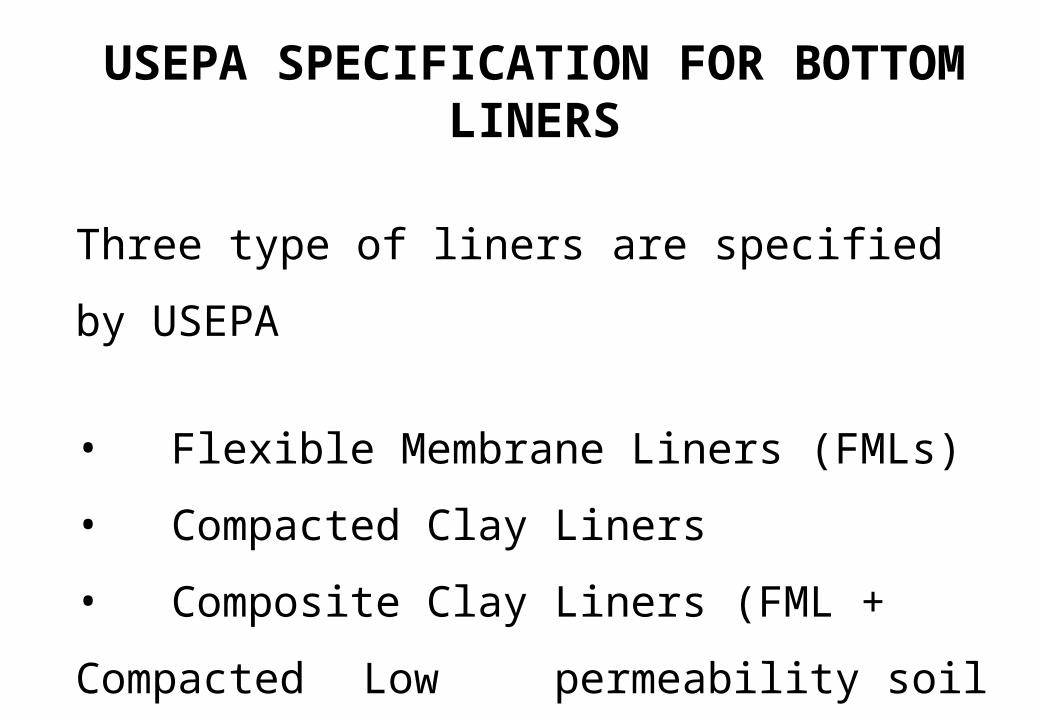
USEPA SPECIFICATION FOR BOTTOM LINERS
Three type of liners are specified by USEPA
• Flexible Membrane Liners (FMLs)
• Compacted Clay Liners
• Composite Clay Liners (FML + Compacted
Low permeability soil liners)
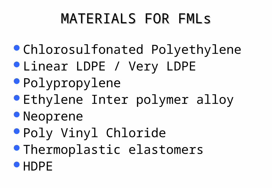
MATERIALS FOR FMLsMATERIALS FOR FMLs
Chlorosulfonated PolyethyleneLinear LDPE / Very LDPEPolypropyleneEthylene Inter polymer alloyNeoprenePoly Vinyl ChlorideThermoplastic elastomersHDPE
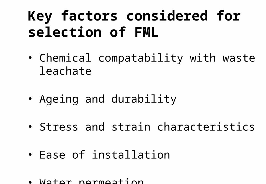
• Chemical compatability with waste leachate
• Ageing and durability
• Stress and strain characteristics
• Ease of installation
• Water permeation
Key factors considered for selection of FML
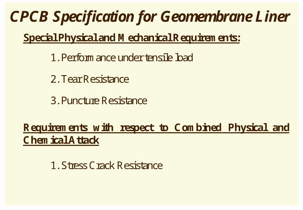
CPCB Specification for Geomembrane Liner Special Physical and Mechanical Requirements:
1. Performance under tensile load
2. Tear Resistance
3. Puncture Resistance
Requirements with respect to Combined Physical and Chemical Attack
1. Stress Crack Resistance
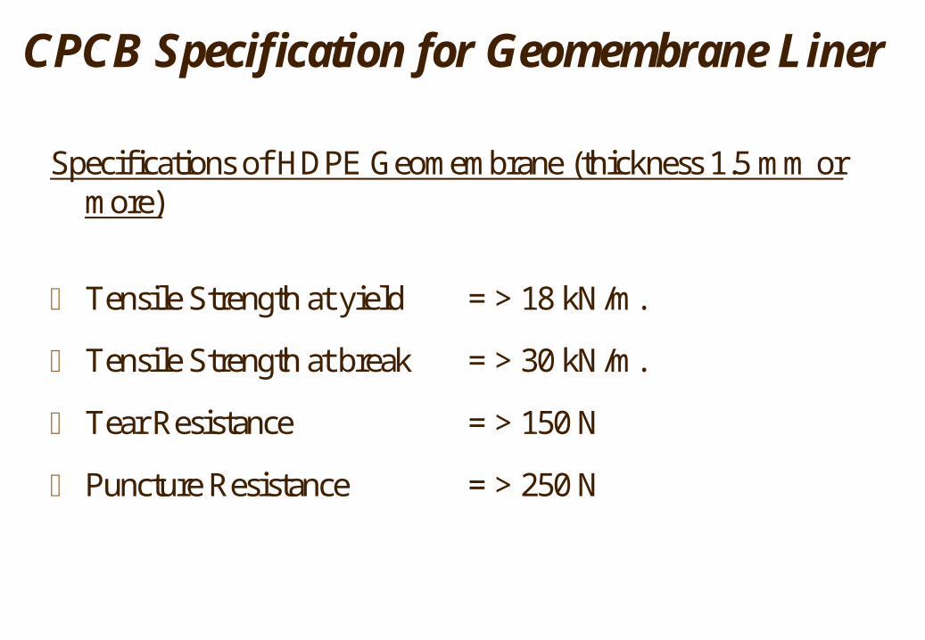
Specifications of HDPE Geomembrane (thickness 1.5 mm or more)
Tensile Strength at yield = > 18 kN/m.
Tensile Strength at break = > 30 kN/m.
Tear Resistance = > 150 N
Puncture Resistance = > 250 N
CPCB Specification for Geomembrane Liner
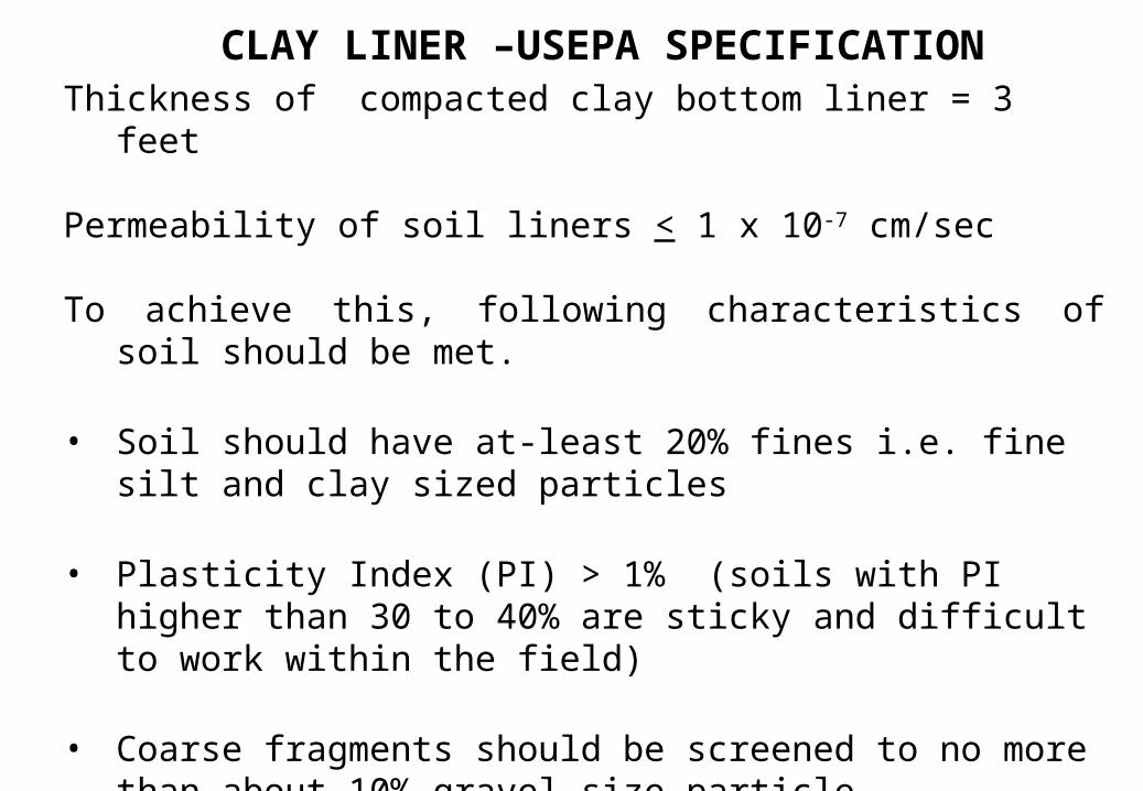
CLAY LINER –USEPA SPECIFICATIONThickness of compacted clay bottom liner = 3 feet
Permeability of soil liners < 1 x 10⁻⁷ cm/sec
To achieve this, following characteristics of soil should be met.
• Soil should have at-least 20% fines i.e. fine silt and clay sized particles
• Plasticity Index (PI) > 1% (soils with PI higher than 30 to 40% are sticky and difficult to work within the field)
• Coarse fragments should be screened to no more than about 10% gravel size particle.
• No soil particles or chunks of rock larger than 1 – 2 inches in diameter.
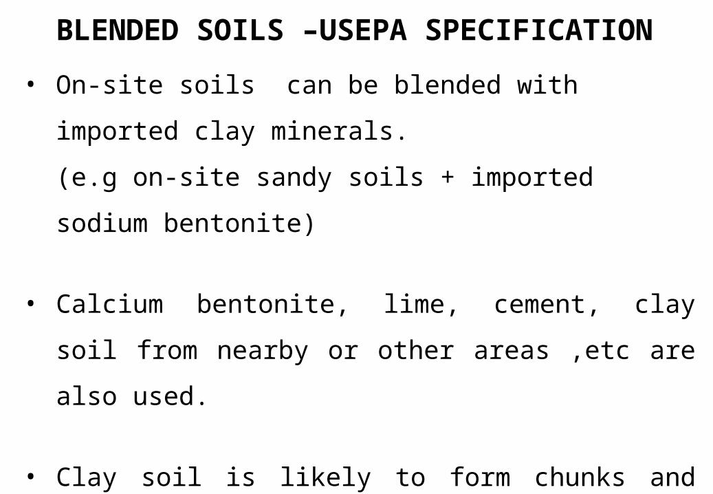
• On-site soils can be blended with imported clay
minerals.
(e.g on-site sandy soils + imported sodium bentonite)
• Calcium bentonite, lime, cement, clay soil from nearby
or other areas ,etc are also used.
• Clay soil is likely to form chunks and difficult and hence
easier to blend on-site sandy soils with dry bentonite
powder.
BLENDED SOILS –USEPA SPECIFICATION
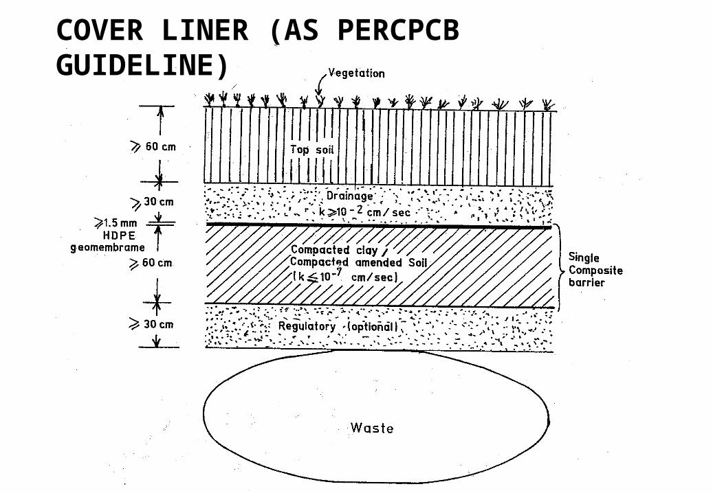
COVER LINER (AS PERCPCB GUIDELINE)
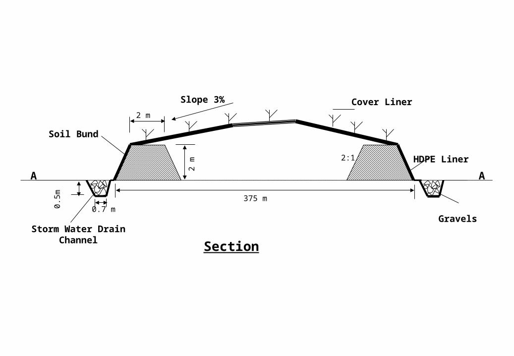
HDPE Liner
Gravels
Section
A A
Cover Liner
Soil Bund
Storm Water Drain Channel
375 m2
m
2 m
0.7 m0.5
m
2:1
Slope 3%
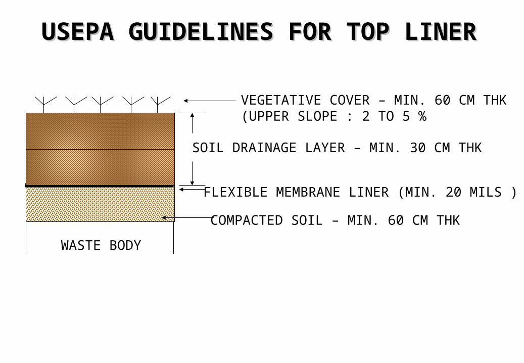
USEPA GUIDELINES FOR TOP LINERUSEPA GUIDELINES FOR TOP LINER
FLEXIBLE MEMBRANE LINER (MIN. 20 MILS )
COMPACTED SOIL – MIN. 60 CM THK
SOIL DRAINAGE LAYER – MIN. 30 CM THK
VEGETATIVE COVER – MIN. 60 CM THK(UPPER SLOPE : 2 TO 5 %
WASTE BODY
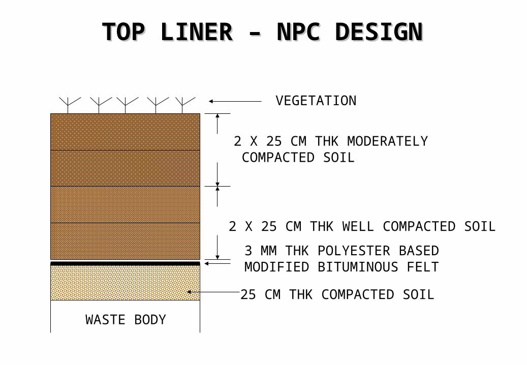
TOP LINER – NPC DESIGNTOP LINER – NPC DESIGN
3 MM THK POLYESTER BASEDMODIFIED BITUMINOUS FELT
25 CM THK COMPACTED SOIL
2 X 25 CM THK WELL COMPACTED SOIL
2 X 25 CM THK MODERATELY COMPACTED SOIL
VEGETATION
WASTE BODY
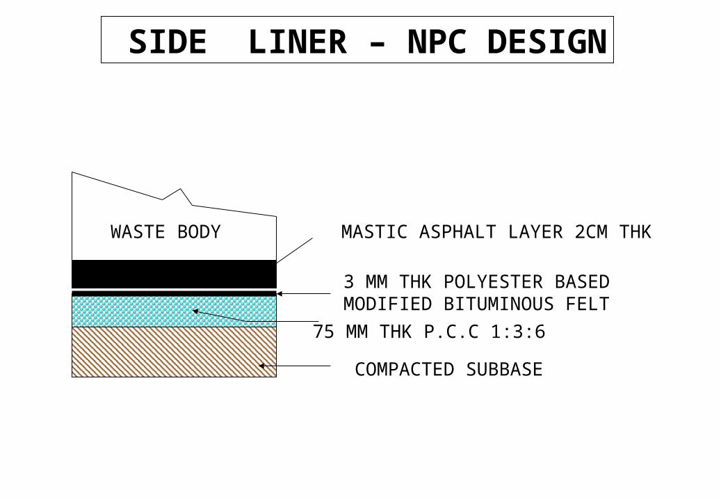
COMPACTED SUBBASE
75 MM THK P.C.C 1:3:6
MASTIC ASPHALT LAYER 2CM THK
3 MM THK POLYESTER BASEDMODIFIED BITUMINOUS FELT
WASTE BODY
SIDE LINER – NPC DESIGN
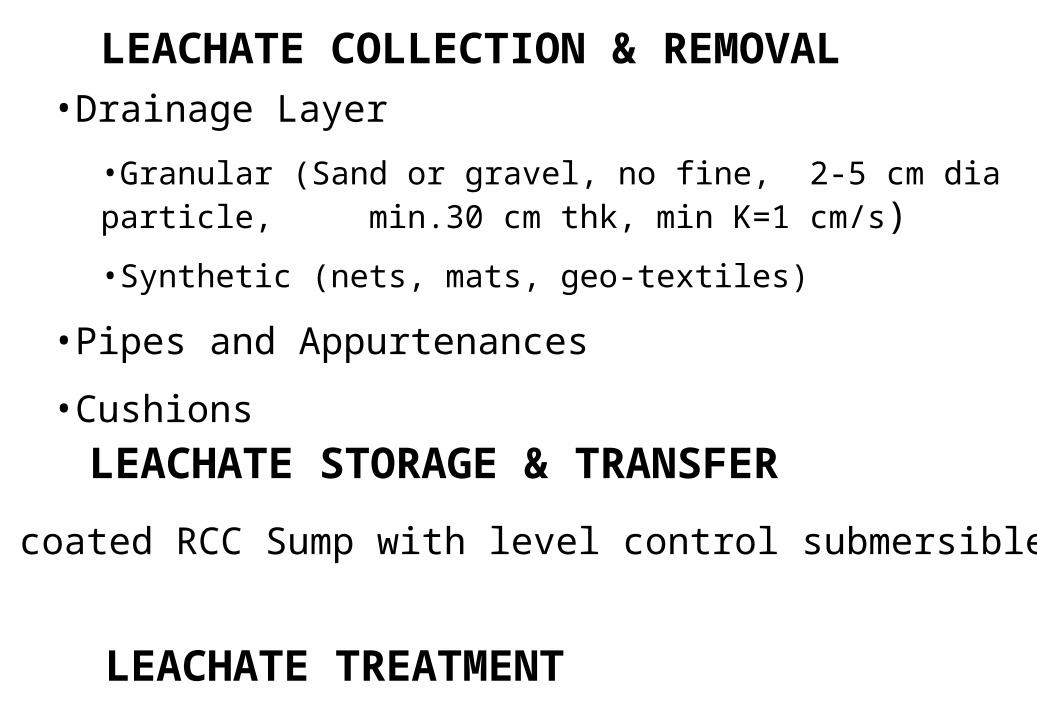
LEACHATE COLLECTION & REMOVAL•Drainage Layer
•Granular (Sand or gravel, no fine, 2-5 cm dia particle, min.30 cm thk, min K=1 cm/s)
•Synthetic (nets, mats, geo-textiles)
•Pipes and Appurtenances
•Cushions
LEACHATE TREATMENT
LEACHATE STORAGE & TRANSFER
Epoxy coated RCC Sump with level control submersible pump
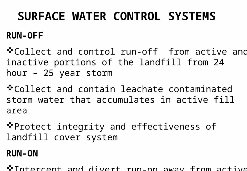
SURFACE WATER CONTROL SYSTEMS
RUN-OFF
Collect and control run-off from active and inactive portions of the landfill from 24 hour – 25 year storm
Collect and contain leachate contaminated storm water that accumulates in active fill area
Protect integrity and effectiveness of landfill cover system
RUN-ON
Intercept and divert run-on away from active and closed land fill cells from peak discharge of 25 year storm
Minimise site erosion
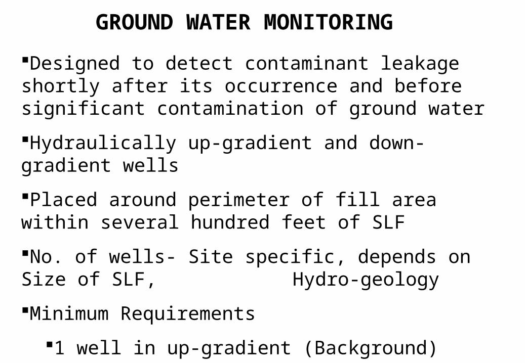
GROUND WATER MONITORING
Designed to detect contaminant leakage shortly after its occurrence and before significant contamination of ground water
Hydraulically up-gradient and down-gradient wells
Placed around perimeter of fill area within several hundred feet of SLF
No. of wells- Site specific, depends on Size of SLF, Hydro-geology
Minimum Requirements
1 well in up-gradient (Background)
3 wells in down-gradient
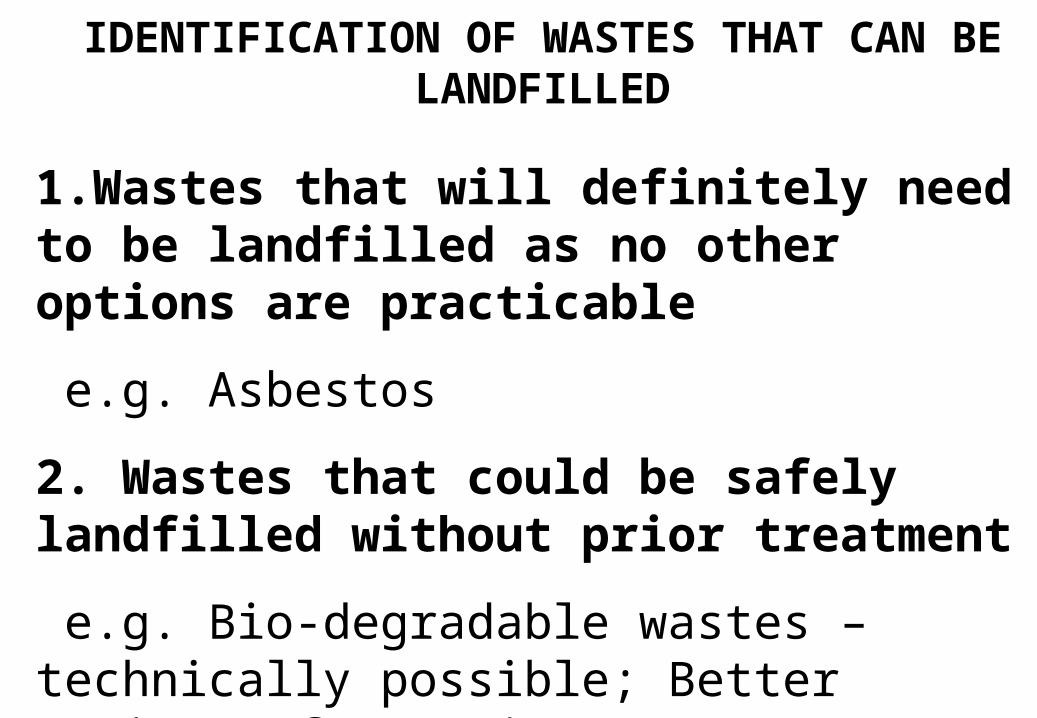
IDENTIFICATION OF WASTES THAT CAN BE LANDFILLED
1.Wastes that will definitely need to be landfilled as no other options are practicable
e.g. Asbestos
2. Wastes that could be safely landfilled without prior treatment
e.g. Bio-degradable wastes – technically possible; Better options often exist.
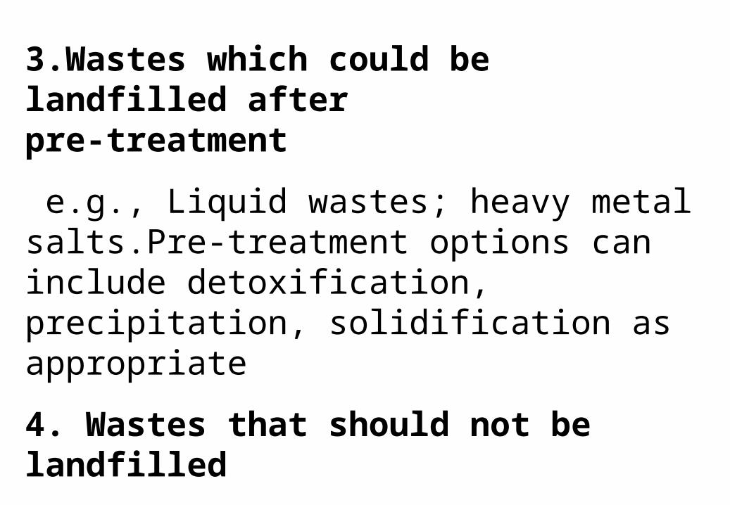
3.Wastes which could be landfilled after pre-treatment
e.g., Liquid wastes; heavy metal salts.Pre-treatment options can include detoxification, precipitation, solidification as appropriate
4. Wastes that should not be landfilled
e.g., Explosives, Compressed toxic gases, Liquid PCBs for technical reasons
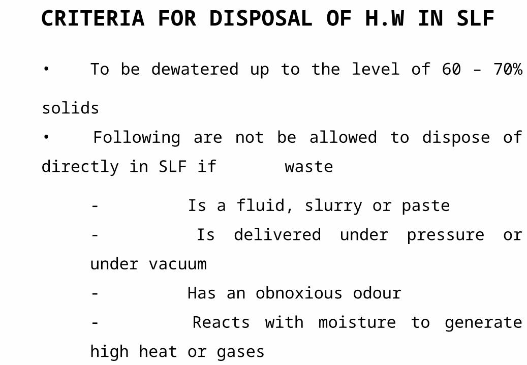
CRITERIA FOR DISPOSAL OF H.W IN SLF
• To be dewatered up to the level of 60 – 70% solids
• Following are not be allowed to dispose of directly in SLF if
waste
- Is a fluid, slurry or paste
- Is delivered under pressure or under vacuum
- Has an obnoxious odour
- Reacts with moisture to generate high heat or
gases
- Is highly inflammable (flash point < 40oC)
- Contains very strong oxidising agents
- Contains volatile substances of significant
toxicity
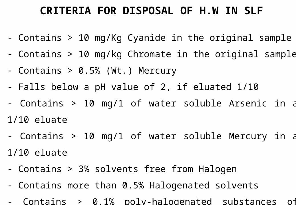
CRITERIA FOR DISPOSAL OF H.W IN SLF
- Contains > 10 mg/Kg Cyanide in the original sample
- Contains > 10 mg/kg Chromate in the original sample
- Contains > 0.5% (Wt.) Mercury
- Falls below a pH value of 2, if eluated 1/10
- Contains > 10 mg/1 of water soluble Arsenic in a 1/10 eluate
- Contains > 10 mg/1 of water soluble Mercury in a 1/10 eluate
- Contains > 3% solvents free from Halogen
- Contains more than 0.5% Halogenated solvents
- Contains > 0.1% poly-halogenated substances of Significant toxicity
(PCBs)
Criteria for Hazardous Waste Criteria for Hazardous Waste Landfilling in Germany due to Landfilling in Germany due to
“Technical Instructions for HWM” “Technical Instructions for HWM” 19911991
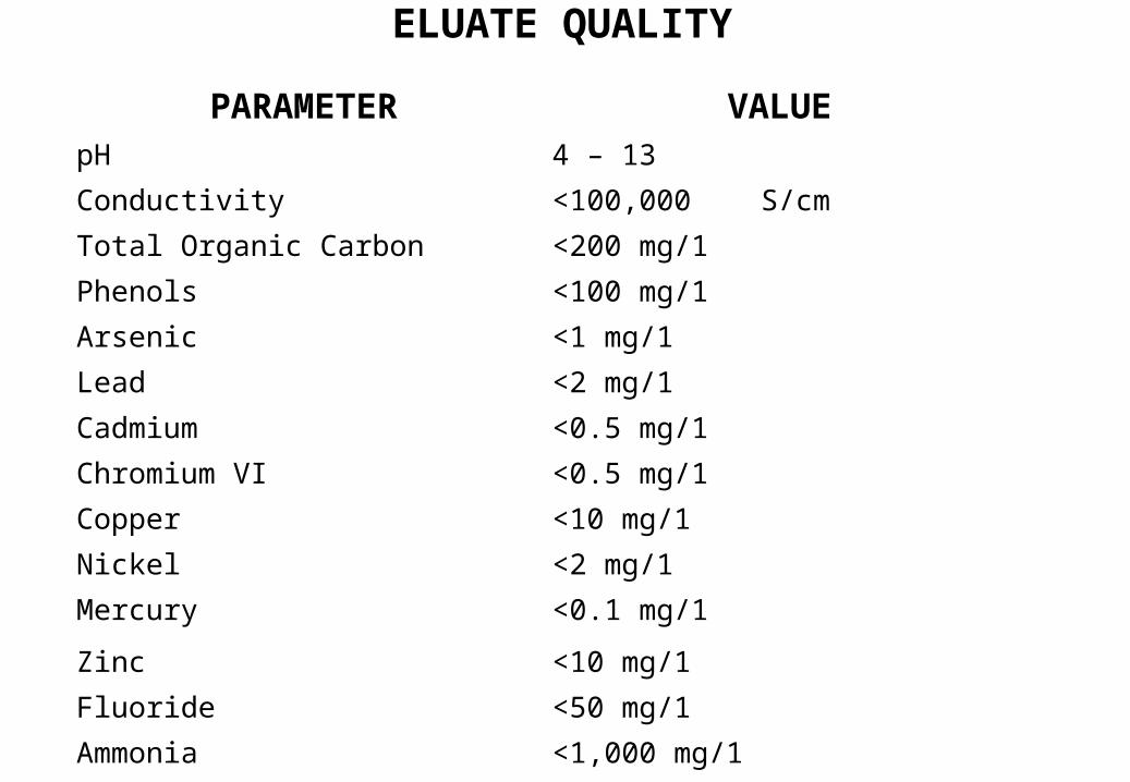
PARAMETER VALUEpH 4 – 13
Conductivity <100,000 S/cm
Total Organic Carbon <200 mg/1
Phenols <100 mg/1
Arsenic <1 mg/1
Lead <2 mg/1
Cadmium <0.5 mg/1
Chromium VI <0.5 mg/1
Copper <10 mg/1
Nickel <2 mg/1
Mercury <0.1 mg/1
Zinc <10 mg/1
Fluoride <50 mg/1
Ammonia <1,000 mg/1
ELUATE QUALITY
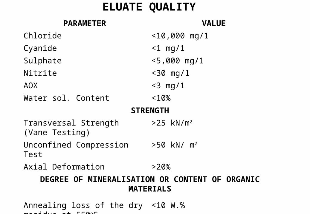
PARAMETER VALUE
Chloride <10,000 mg/1
Cyanide <1 mg/1
Sulphate <5,000 mg/1
Nitrite <30 mg/1
AOX <3 mg/1
Water sol. Content <10%
STRENGTH
Transversal Strength (Vane Testing)
>25 kN/m2
Unconfined Compression Test >50 kN/ m2
Axial Deformation >20%
DEGREE OF MINERALISATION OR CONTENT OF ORGANIC MATERIALS
Annealing loss of the dry residue at 550oC
<10 W.%
ELUATE QUALITY
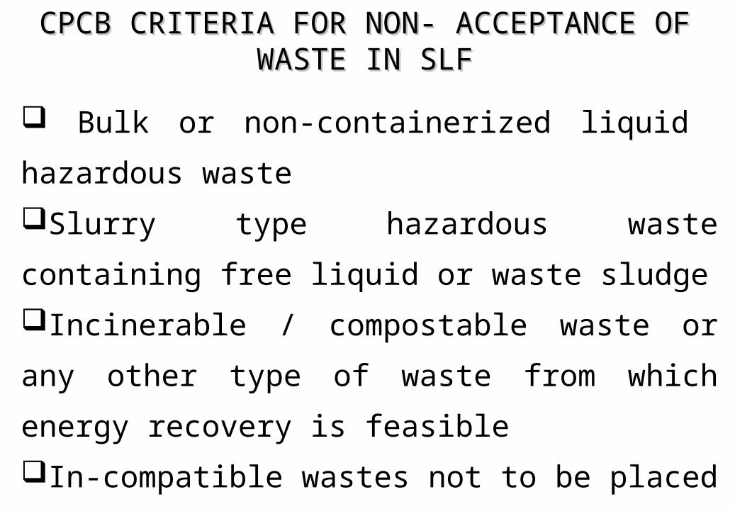
CPCB CRITERIA FOR NON- ACCEPTANCE OF CPCB CRITERIA FOR NON- ACCEPTANCE OF WASTE IN SLFWASTE IN SLF
Bulk or non-containerized liquid hazardous
waste
Slurry type hazardous waste containing free liquid
or waste sludge
Incinerable / compostable waste or any other type
of waste from which energy recovery is feasible
In-compatible wastes not to be placed in same
landfills
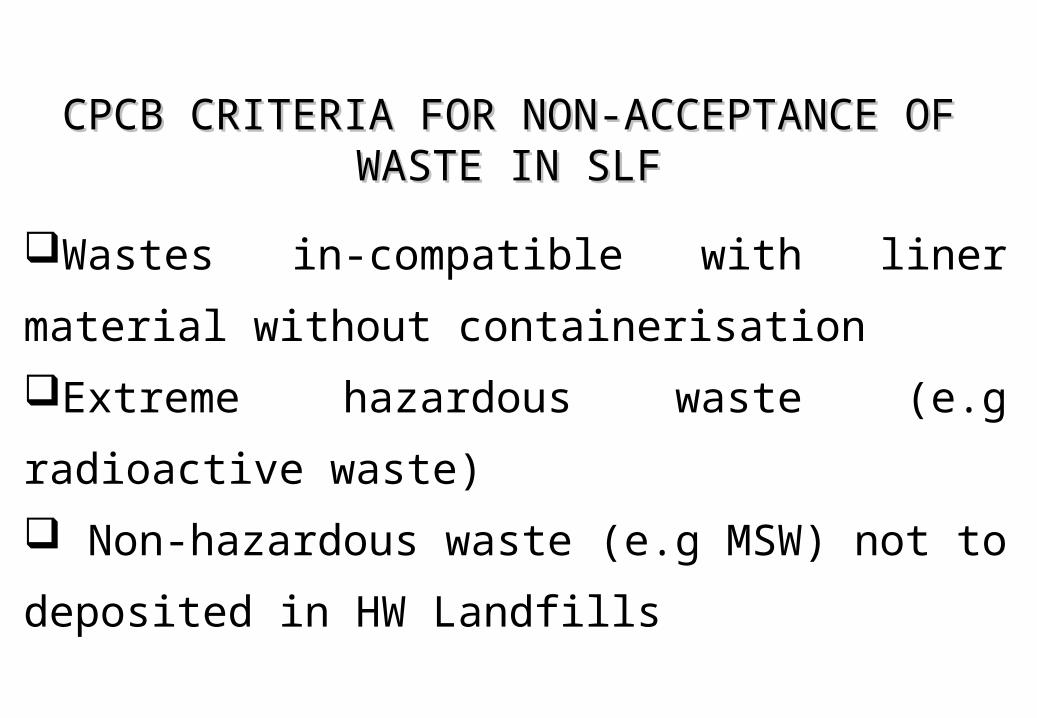
CPCB CRITERIA FOR NON-ACCEPTANCE OF CPCB CRITERIA FOR NON-ACCEPTANCE OF WASTE IN SLFWASTE IN SLF
Wastes in-compatible with liner material without
containerisation
Extreme hazardous waste (e.g radioactive waste)
Non-hazardous waste (e.g MSW) not to
deposited in HW Landfills
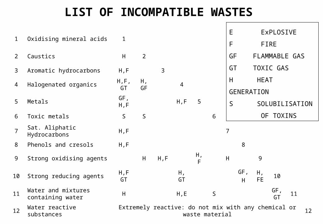
1 Oxidising mineral acids 1
2 Caustics H 2
3 Aromatic hydrocarbons H,F 3
4 Halogenated organicsH,F, GT
H, GF
4
5 MetalsGF, H,F
H,F 5
6 Toxic metals S S 6
7 Sat. Aliphatic Hydrocarbons H,F 7
8 Phenols and cresols H,F 8
9 Strong oxidising agents H H,F H,F H 9
10 Strong reducing agentsH,F GT
H, GT
GF,
HH,FE
10
11Water and mixtures containing water
H H,E SGF, GT
11
12 Water reactive substances Extremely reactive: do not mix with any chemical or waste material 12
E ExPLOSIVE
F FIRE
GF FLAMMABLE GAS
GT TOXIC GAS
H HEAT GENERATION
S SOLUBILISATION
OF TOXINS
LIST OF INCOMPATIBLE WASTES
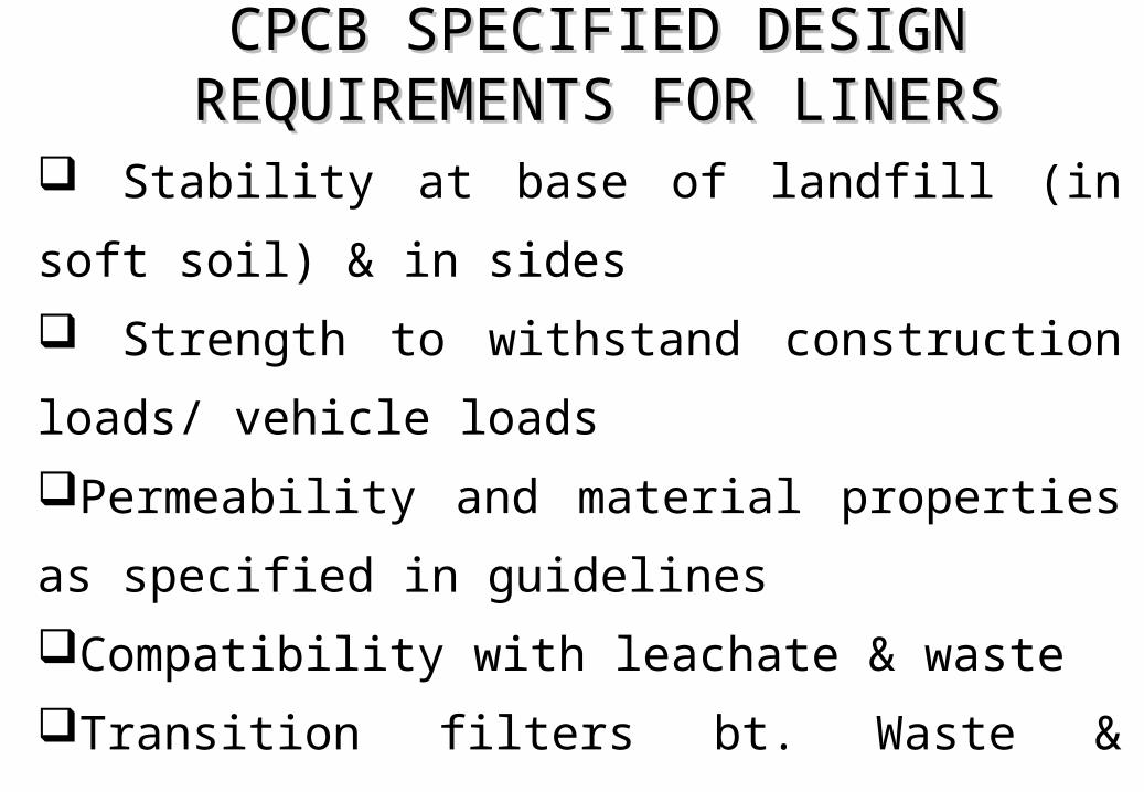
CPCB SPECIFIED DESIGN CPCB SPECIFIED DESIGN REQUIREMENTS FOR LINERSREQUIREMENTS FOR LINERS
Stability at base of landfill (in soft soil) & in sides
Strength to withstand construction loads/ vehicle
loads
Permeability and material properties as specified
in guidelines
Compatibility with leachate & waste
Transition filters bt. Waste & leachate collection
layer to prevent clogging of leachate collection layer
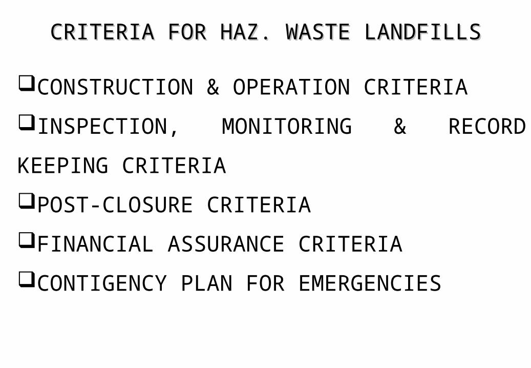
CRITERIA FOR HAZ. WASTE LANDFILLSCRITERIA FOR HAZ. WASTE LANDFILLS
CONSTRUCTION & OPERATION CRITERIA
INSPECTION, MONITORING & RECORD
KEEPING CRITERIA
POST-CLOSURE CRITERIA
FINANCIAL ASSURANCE CRITERIA
CONTIGENCY PLAN FOR EMERGENCIES
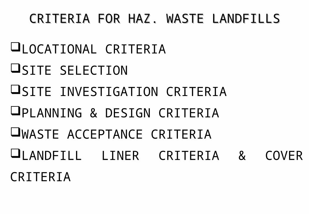
CRITERIA FOR HAZ. WASTE LANDFILLSCRITERIA FOR HAZ. WASTE LANDFILLS
LOCATIONAL CRITERIA
SITE SELECTION
SITE INVESTIGATION CRITERIA
PLANNING & DESIGN CRITERIA
WASTE ACCEPTANCE CRITERIA
LANDFILL LINER CRITERIA & COVER
CRITERIA
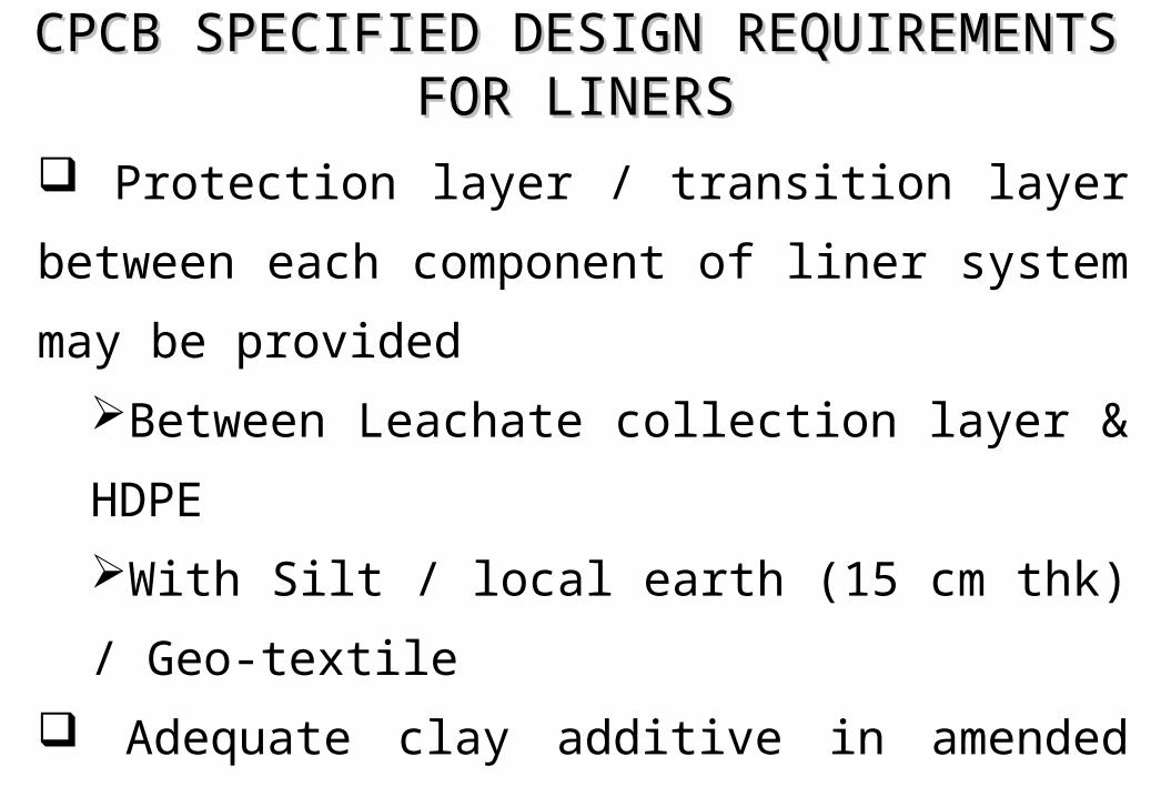
CPCB SPECIFIED DESIGN REQUIREMENTS CPCB SPECIFIED DESIGN REQUIREMENTS FOR LINERSFOR LINERS
Protection layer / transition layer between each
component of liner system may be provided
Between Leachate collection layer & HDPE
With Silt / local earth (15 cm thk) / Geo-textile
Adequate clay additive in amended soils
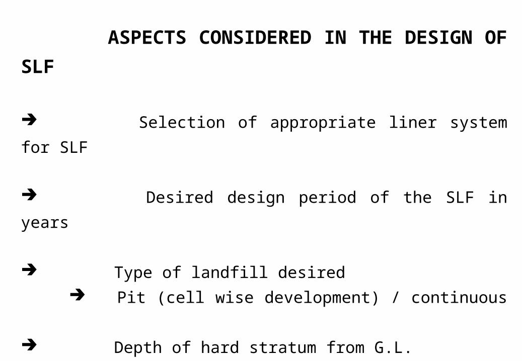
ASPECTS CONSIDERED IN THE DESIGN OF SLF
Selection of appropriate liner system for SLF
Desired design period of the SLF in years
Type of landfill desired
Pit (cell wise development) / continuous
Depth of hard stratum from G.L.
Total lay out size & total area of the SLF
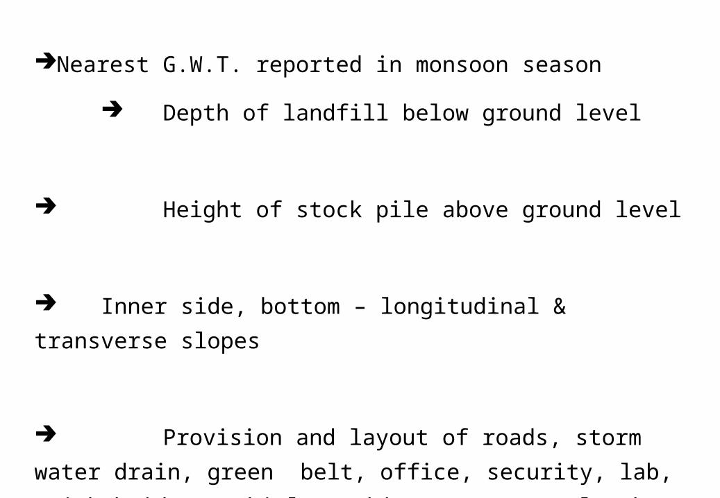
Nearest G.W.T. reported in monsoon season
Depth of landfill below ground level
Height of stock pile above ground level
Inner side, bottom – longitudinal & transverse slopes
Provision and layout of roads, storm water drain, green
belt, office, security, lab, weigh bridge, Vehicle washing
area, leachate sumps, etc around the SLF
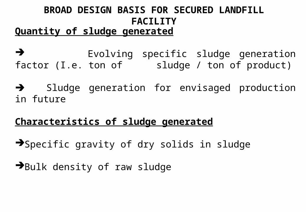
BROAD DESIGN BASIS FOR SECURED LANDFILL FACILITY
Quantity of sludge generated
Evolving specific sludge generation factor (I.e. ton of sludge / ton of product)
Sludge generation for envisaged production in future
Characteristics of sludge generated
Specific gravity of dry solids in sludge
Bulk density of raw sludge
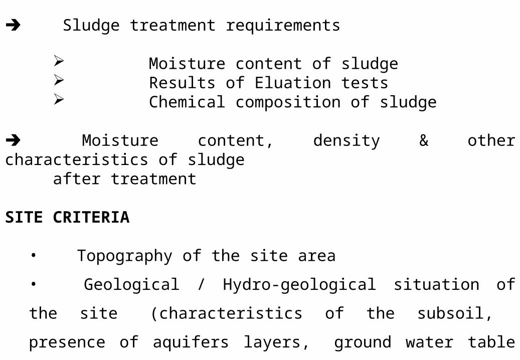
Sludge treatment requirements
Moisture content of sludge Results of Eluation tests Chemical composition of sludge
Moisture content, density & other characteristics of sludge after treatment
SITE CRITERIA
• Topography of the site area
• Geological / Hydro-geological situation of the site
(characteristics of the subsoil, presence of aquifers layers, ground
water table etc.)
• Rainfall situation in the region of the site area
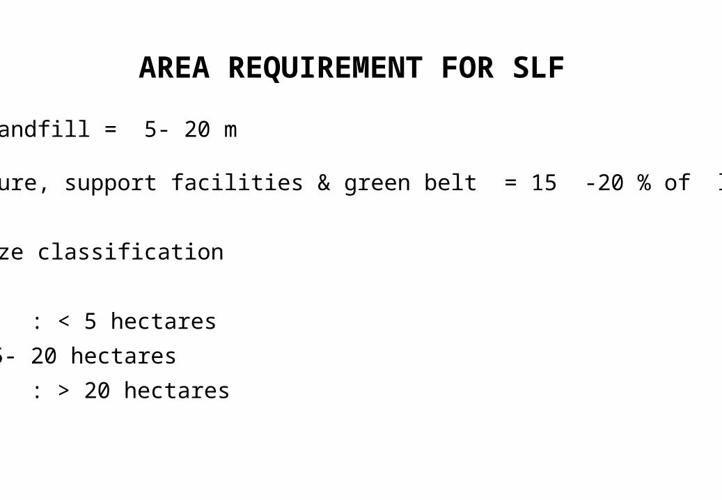
AREA REQUIREMENT FOR SLF
Height of Landfill = 5- 20 m
Infrastructure, support facilities & green belt = 15 -20 % of landfill
Landfill size classification
Small : < 5 hectares
Medium : 5- 20 hectares
Large : > 20 hectares
QA/QC Plan during construction of SLF
Permeability check of Mineralic Liner
Material Testing as per specifications
Compaction, Moisture content of Mineralic Liner
Vacuum Testing for HDPE Joints
Why does well designed SLF fail ?Why does well designed SLF fail ?
Improper operating practices
Allowed too much liquid to enter into the landfill
Cracks, punctures and physical failure of liners
Clogging of leachate collection systems
Consolidation may result in breaks in the liner or the
cover material
Disposal of solvents which affects the liner
Improper Joints


![A Strategy for Hazardous Waste Management in England1].pdf · a. Hazardous waste should be managed by waste producers and waste managers in accordance with the EU waste hierarchy](https://img.pdfslide.net/doc/110x75/5e15c5b17883c13f891096d6/a-strategy-for-hazardous-waste-management-in-england-1pdf-a-hazardous-waste.jpg)