Embed Size (px)
Citation preview
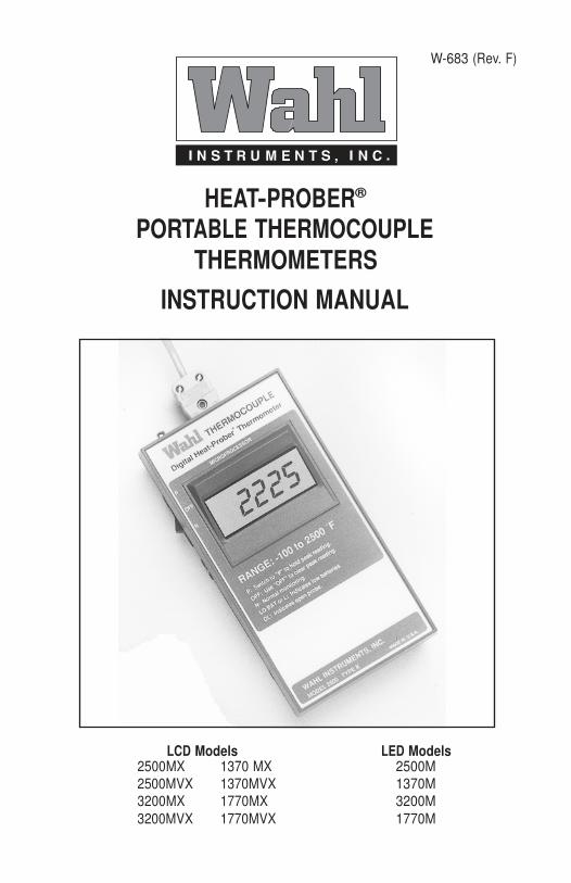
W-683 (Rev. F)
HEAT-PROBER®
PORTABLE THERMOCOUPLE THERMOMETERS
INSTRUCTION MANUAL
LCD Models LED Models 2500MX 1370 MX 2500M 2500MVX 1370MVX 1370M 3200MX 1770MX 3200M 3200MVX 1770MVX 1770M
RECEIVING INSPECTION
Check your new Wahl Portable Thermocouple Heat-Prober Thermometer upon Receiving to assure that:
1. It has not been physically damaged in transit.
2. All parts are included.
Then, plug in the probe at top and turn it on to see that it reads room temperature.
If a fault is determined, take the following steps:
1. Notify the Wahl factory of the difficulty. Give model number and description.
Wahl will authorize return, and notify our service department to receive the
unit.
2. Return the instrument in its shipping container to the factory, freight pre-
paid. Repairs will be made under warranty or at regular service cost.
3. Prepare a “Repair Information Form” as shown in Section 12.0 and return
with the instrument. This is very important. We need the information to diagnose the problem. If there is no information returned with the unit, it
will slow up the repair process.
© Copyright 1999 Wahl Instruments, Inc. Printed in USA
ii
TABLE OF CONTENTS Page
RECEIVING INSPECTION . . . . . . . . . . . . . . . . . . . . . . .ii
1.0 INTRODUCTION . . . . . . . . . . . . . . . . . . . . . . . . . . . .1
2.0 OPERATION . . . . . . . . . . . . . . . . . . . . . . . . . . . . . . .3
2.1 Meter Operation . . . . . . . . . . . . . . . . . . . . . . . . . . . . . . . . .5
2.2 Peak Hold (MAXI-TEMP) . . . . . . . . . . . . . . . . . . . . . . . . . .5
2.3 Batteries . . . . . . . . . . . . . . . . . . . . . . . . . . . . . . . . . . . . . . .5 2.3.1 Recharging . . . . . . . . . . . . . . . . . . . . . . . . . . . . . . . . . . . . .7
2.3.2 Low Battery . . . . . . . . . . . . . . . . . . . . . . . . . . . . . . . . . . . .7
2.3.3 Continuous Operation . . . . . . . . . . . . . . . . . . . . . . . . . . . . .7
3.0 PROBES . . . . . . . . . . . . . . . . . . . . . . . . . . . . . . . . . .8
3.1 Open Probe . . . . . . . . . . . . . . . . . . . . . . . . . . . . . . . . . . . .11
3.2 Temperature Sensors in use . . . . . . . . . . . . . . . . . . . . . . .11
4.0 SPECIFICATIONS . . . . . . . . . . . . . . . . . . . . . . . . . . .14
5.0 CALIBRATION . . . . . . . . . . . . . . . . . . . . . . . . . . . . .17
5.1 Voltage Regulator Adjustment . . . . . . . . . . . . . . . . . . . . . 17 5.2 Low Battery Adjustment . . . . . . . . . . . . . . . . . . . . . . . . . .17
5.3 Calibration Using Wahl Calibrator . . . . . . . . . . . . . . . . . . .18
5.3.1 Zero Adjustment Using Wahl Calibrator . . . . . . . . . . . . . . 18 5.3.2 Span Adjustment Using Wahl Calibrator . . . . . . . . . . . . . .18
5.4 Calibration With a Millivolt Source . . . . . . . . . . . . . . . . . .18
5.4.1 Zero Adjustment with Millivolt Source . . . . . . . . . . . . . . .18 5.4.2 Span Adjustment with Millivolt Source . . . . . . . . . . . . . . .20
5.5 Thermal Calibration . . . . . . . . . . . . . . . . . . . . . . . . . . . . . .21
5.6 Calibration with Thermocouple Simulator . . . . . . . . . . . . .22 5.7 TA-70 Thermocouple Calibrator . . . . . . . . . . . . . . . . . . . .22
6.0 THEORY OF OPERATION . . . . . . . . . . . . . . . . . . . . . .27
6.1 Voltage Regulation Circuitry . . . . . . . . . . . . . . . . . . . . . . .29 6.2 Voltage Reference Circuitry . . . . . . . . . . . . . . . . . . . . . . .29
6.3 Front End Circuitry . . . . . . . . . . . . . . . . . . . . . . . . . . . . . . 29
6.4 Cold Junction Compensation . . . . . . . . . . . . . . . . . . . . . .30 6.5 Dual Slope A/D Converter . . . . . . . . . . . . . . . . . . . . . . . . .30
6.6 8048 Microprocessor . . . . . . . . . . . . . . . . . . . . . . . . . . . . 31 6.7 Waveforms and Timing Diagrams . . . . . . . . . . . . . . . . . . .31
6.8 Low Battery Indication . . . . . . . . . . . . . . . . . . . . . . . . . . . 32
iii
7.0 BASIC TROUBLESHOOTING . . . . . . . . . . . . . . . . . . . .33
8.0 MAINTENANCE AND REPAIR . . . . . . . . . . . . . . . . . . .36
8.1 LED and LCD Diagnostics . . . . . . . . . . . . . . . . . . . . . . . . .36
9.0 APPENDIX IPTS-86 AND IPTS-90 . . . . . . . . . . . . . . . .42
10.0 ADDITIONAL PROBES AND ACCESSORIES . . . . . . . . .51
11.0 WARRANTY REGISTRATION . . . . . . . . . . . . . . . . . . . .52
12.0 RETURN FOR REPAIR/CALIBRATION . . . . . . . . . . . . . .52
FIGURES Page
Figure 1-1 Microprocessor Based Thermocouple Digital Therm. . . . . .2
Figure 2-1 Digital Heat Prober Major Features . . . . . . . . . . . . . . . . . . .4
Figure 2-2 Rechargeable Battery Pack Compartment . . . . . . . . . . . . . .6
Figure 3-1 Heat Prober Thermocouple Types, Model Numbers . . . . . .8
Figure 3-2 Standard Wahl Probes . . . . . . . . . . . . . . . . . . . . . . . . . . . .10
Figure 3-3 Extension Probe Handle . . . . . . . . . . . . . . . . . . . . . . . . . . .10
Figure 3-4 Molten Metal Dip Stick . . . . . . . . . . . . . . . . . . . . . . . . . . . .12
Figure 5-1 Wahl Calibrator Types . . . . . . . . . . . . . . . . . . . . . . . . . . . .21
Figure 5-2 Heat Prober With Wahl Calibrator . . . . . . . . . . . . . . . . . . .24
Figure 5-3 LED Adjustment Points . . . . . . . . . . . . . . . . . . . . . . . . . . .25
Figure 5-4 LCD Adjustment Points . . . . . . . . . . . . . . . . . . . . . . . . . . .26
Figure 6-1 Program Flow . . . . . . . . . . . . . . . . . . . . . . . . . . . . . . . . . .28
Figure 6-2 Microprocessor Control Functions . . . . . . . . . . . . . . . . . . .32
Figure 7-1 Wiring Diagram . . . . . . . . . . . . . . . . . . . . . . . . . . . . . . . . .35
Figure 8-1 Block Diagram . . . . . . . . . . . . . . . . . . . . . . . . . . . . . . . . . .39
Figure 8-2 LED Component Layout . . . . . . . . . . . . . . . . . . . . . . . . . . .40
Figure 8-3 LCD Component Layout . . . . . . . . . . . . . . . . . . . . . . . . . . .41
Figure 11-1 Additional Probes and Accessories . . . . . . . . . . . . . . . . . .50
iv
1
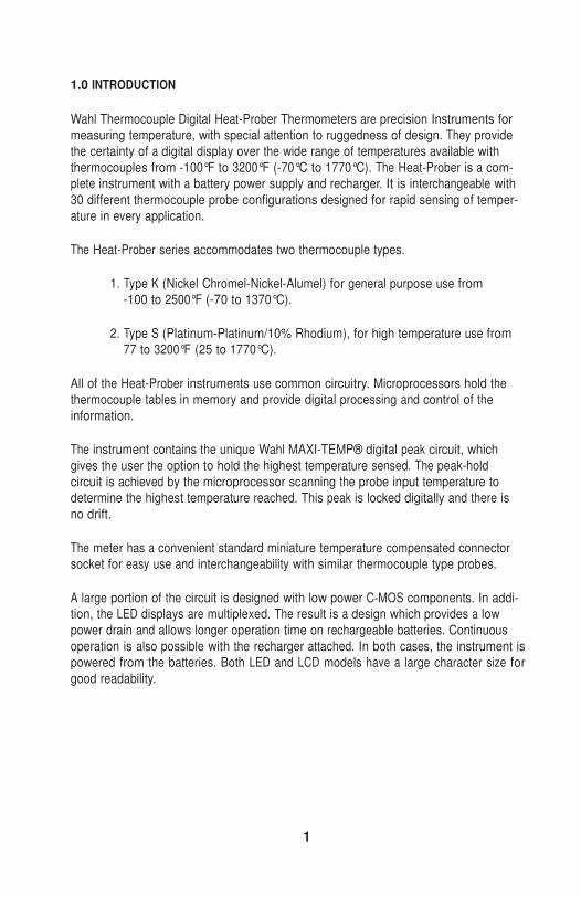
1.0 INTRODUCTION
Wahl Thermocouple Digital Heat-Prober Thermometers are precision Instruments for measuring temperature, with special attention to ruggedness of design. They provide
the certainty of a digital display over the wide range of temperatures available with
thermocouples from -100°F to 3200°F (-70°C to 1770°C). The Heat-Prober is a com- plete instrument with a battery power supply and recharger. It is interchangeable with
30 different thermocouple probe configurations designed for rapid sensing of temper-
ature in every application.
The Heat-Prober series accommodates two thermocouple types.
1. Type K (Nickel Chromel-Nickel-Alumel) for general purpose use from
-100 to 2500°F (-70 to 1370°C).
2. Type S (Platinum-Platinum/10% Rhodium), for high temperature use from
77 to 3200°F (25 to 1770°C).
All of the Heat-Prober instruments use common circuitry. Microprocessors hold the thermocouple tables in memory and provide digital processing and control of the
information.
The instrument contains the unique Wahl MAXI-TEMP® digital peak circuit, which
gives the user the option to hold the highest temperature sensed. The peak-hold
circuit is achieved by the microprocessor scanning the probe input temperature to determine the highest temperature reached. This peak is locked digitally and there is
no drift.
The meter has a convenient standard miniature temperature compensated connector socket for easy use and interchangeability with similar thermocouple type probes.
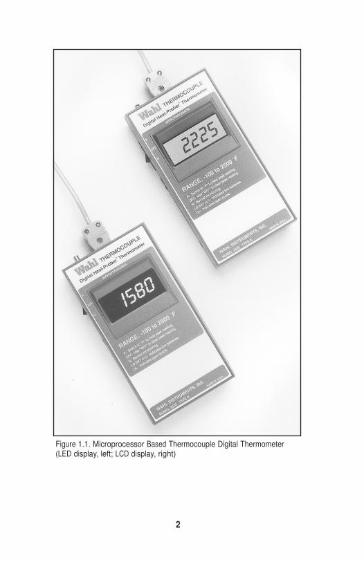
A large portion of the circuit is designed with low power C-MOS components. In addi- tion, the LED displays are multiplexed. The result is a design which provides a low
power drain and allows longer operation time on rechargeable batteries. Continuous
operation is also possible with the recharger attached. In both cases, the instrument is powered from the batteries. Both LED and LCD models have a large character size for
good readability.
2
Figure 1.1. Microprocessor Based Thermocouple Digital Thermometer (LED display, left; LCD display, right)
3
All Heat-Prober instruments are extensively tested in environments from
-20°F to 140°F for specification compliance and reliability determination. In addition, durability testing includes impact, vibration, battery life and running life tests. Mean
time between failure is based on using preburned-in C-MOS electronic components
and is rated at 16,000 hours.
The 9-volt LCD models with 50-hour standard alkaline batteries, replaceable from the
back cover, are designated models 1370MVX, 1770MVX, 2500MVX and 3200MVX.
They have the same specifications as the rechargeable LCD models.
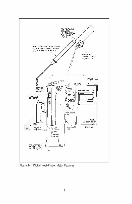
2.0 OPERATION (See Figure 2-1)
Insert probe into socket at the top of the instrument. Turn on the switch at the left. The
switch is 3-position; the lower detent is marked “N” for normal temperature monitor- ing, the middle detent is “OFF’ and the upper detent is marked “P” for use with Wahl
Maxi-Temp peak hold circuit. This tracks the temperature and holds the highest attained reading. If “L” appears or if there is no reading, this indicates the battery is
discharged. For models MVX, change the 9-volt battery. Recharge the unit by inserting
the recharger in a 110 VAC, 50-60 Hz wall outlet and plug in the recharger jack to the instrument socket on the left. (Turn the instrument switch OFF during recharging, to
maximize recharge rate. Charge for 10-12 hours)*. Turn on instrument again.
Make measurements with sensor probe as required. Turn off switch when measure- ments are complete to preserve battery life.
*Special Note on Care of Rechargeable Batteries, See Paragraph 2.3
4
Figure 2-1. Digital Heat-Prober Major Features
5
2.1 Meter Operation
The Heat-Prober instrument has an accurate measuring range as stated on the front label. When the temperature is below zero, a minus sign will automatically show on
digital display. Absence of a sign indicates positive temperature.
2.2 Peak Hold (MAXI-TEMP)
MAXI-TEMP peak hold is a standard feature on all models. With the switch in “P” or
peak hold position, it will sense positive increases in temperature and hold the highest
reading. This is convenient in making measurements where attention to the probe or to the area being measured occupies the operator. The peak reading is held digitally by
the microprocessor and will not drift. To remove the peak reading, switch to “OFF”, or
to “N”.
2.3 Batteries (Figures 2-2)
The Heat-Prober is powered with five size AA rechargeable nickel-cadmium batteries,
1.25 volts each. The total capacity is 450 milliampere hours at 6.0 volts. The LED display demands the largest power drain. Depending on the number of digits being
displayed, the batteries can power the instrument for a minimum of 5 hours or for as long as 6 hours (with LCD display, the life is approximately 12 hours).
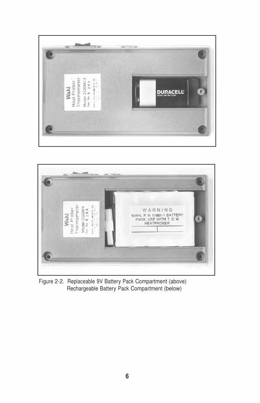
An alternate replaceable 9-volt alkaline transistor radio-type battery powers meters
with “V” designations in their part number. The instrument has a voltage regulation which will accept and control the power from the 9-volt battery. These instruments do
not allow for recharging. Under special circumstances LED models 2500M, 1370M
and 1770M may be operated with disposable 9-volt alkaline batteries with an approxi- mate 3 hour battery Iifespan. (Figure 2.2)
SPECIAL NOTE: Rechargeable batteries should be kept at full charge. On the shelf,
they will gradually discharge, losing about 10% charge per week. If the battery fails to respond to recharge, provisions have been made for ease of replacement. Open the
back cover and disconnect from the instrument by means of the Molex connector. Replace with Wahl P/N 11681 (See Figure 2-2).
6
Figure 2-2. Replaceable 9V Battery Pack Compartment (above) Rechargeable Battery Pack Compartment (below)
7
2.3.1 Recharging
To recharge the batteries, use the recharger supplied. Plug in directly to a 120-volt, 60-cycle wall plug and insert the jack into the socket on the left side of the Heat-
Prober. (For overseas 220-volt lines, use a Franzus converter adapter with the recharg- er supplied or request a 220-volt recharger).
2.3.2 Low Battery
Ni-Cad batteries have a stable voltage throughout their charge life. Near the end of the
power cycle the voltage will drop abruptly. This voltage is sensed by the meter.
Low-battery indication is registered on the display by “L” on LED models and “LO
BATT” on LCD models. This indicates that you have approximately two minutes to
complete your measurement. After that, the falling battery voltage may cause erro- neous readings. Continued use of the meter will result in total loss of display. The
recharger should be put on immediately after the low battery light comes on. Recharge
time is 10 to 12 hours, but a partial charge can be obtained in 1 hour or less.
2.3.3 Continuous Operation
The Heat-Prober can be continuously operated by using a battery recharger to restore
or recharge the batteries as they are depleted. The instrument operates from the bat- teries only. The recharger will charge the batteries with the switch “OFF”, or make-up
battery power when the instrument is operating. The recharger supplied with the instrument will enable continuous operation. It the battery pack is in an extremely low
charge condition, it may take two to three minutes before the display will function.
NOTE: The instrument cannot rectify AC current. A DC charger with open circuit volt-
age of 9 volts and approximately 120 milliamperes will maintain the battery charge.
This occurs when the switch is on and the instrument is operating. Do not connect a
voltage source to the batteries unless its current is limited to 120 milliamperes.
8
3.0 PROBES
One of the key features of the Wahl Thermocouple Heat-Prober is a standard miniature thermocouple connector used in the meter. Thermocouple connections are color
coded by type. Use probes with the same color male plug as the female. Each Heat-
Prober is designed for use with a specific thermocouple Type K or S. A thermocouple of the same type with a standard male thermocouple connector will fit the meter. No
adapters are needed. The thermocouple is compensated where the cold junction is
made and cold junction compensation occurs automatically.
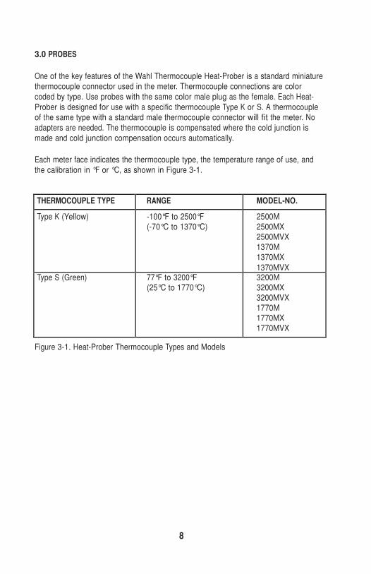
Each meter face indicates the thermocouple type, the temperature range of use, and
the calibration in °F or °C, as shown in Figure 3-1.
THERMOCOUPLE TYPE RANGE MODEL-NO.
Type K (Yellow) -100°F to 2500°F (-70°C to 1370°C)
2500M 2500MX 2500MVX 1370M 1370MX
1370MVX Type S (Green) 77°F to 3200°F
(25°C to 1770°C) 3200M 3200MX 3200MVX 1770M 1770MX 1770MVX
Figure 3-1. Heat-Prober Thermocouple Types and Models
9
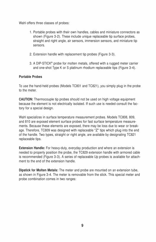
Wahl offers three classes of probes:
1. Portable probes with their own handles, cables and miniature connectors as
shown (Figure 3-2). These include unique replaceable tip surface probes,
straight and right angle, air sensors, immersion sensors, and miniature tip
sensors.
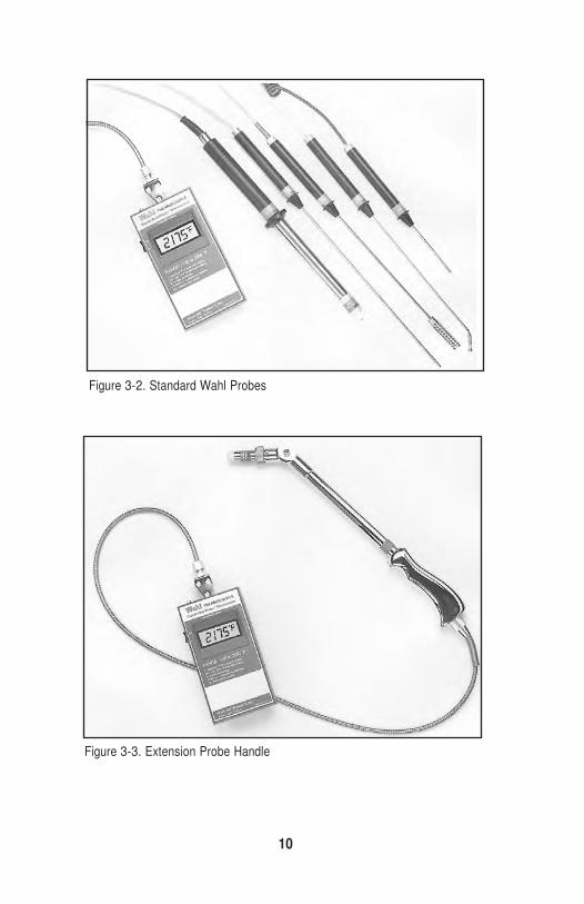
2. Extension handle with replacement tip probes (Figure 3-3).
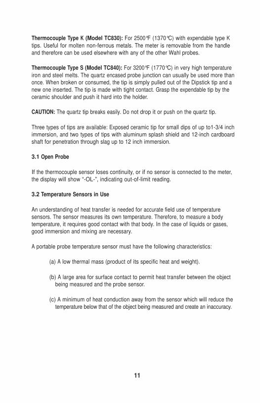
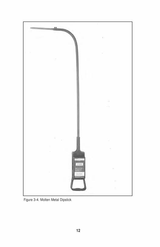
3. A DIP-STICK® probe for molten metals, offered with a rugged meter carrier
and one-shot Type K or S platinum rhodium replaceable tips (Figure 3-4).
Portable Probes
To use the hand-held probes (Models TC801 and TC821), you simply plug in the probe to the meter.
CAUTION: Thermocouple tip probes should not be used on high voltage equipment
because the element is not electrically isolated. If such use is needed consult the fac-
tory for a special design.
Wahl specializes in surface temperature measurement probes. Models TC808, 809,
and 810 are exposed element surface probes for fast surface temperature measure- ments. Because these elements are exposed, there may be loss due to wear or break-
age. Therefore, TC809 was designed with replaceable “Z” tips which plug into the end
of the handle. Two types, straight or right angle, are available by designating TC821 replaceable tips.
Extension Handle: For heavy-duty, everyday production and where an extension is
needed to properly position the probe, the TC829 extension handle with armored cable is recommended (Figure 3-3). A series of replaceable Up probes is available for attach-
ment to the end of the extension handle.
Dipstick for Molten Metals: The meter and probe are mounted on an extension tube,
as shown in Figure 3-4. The meter is removable from the stick. This special meter and probe combination comes in two ranges:
10
Figure 3-2. Standard Wahl Probes
Figure 3-3. Extension Probe Handle
11
Thermocouple Type K (Model TC830): For 2500°F (1370°C) with expendable type K
tips. Useful for molten non-ferrous metals. The meter is removable from the handle and therefore can be used elsewhere with any of the other Wahl probes.
Thermocouple Type S (Model TC840): For 3200°F (1770°C) in very high temperature
iron and steel melts. The quartz encased probe junction can usually be used more than once. When broken or consumed, the tip is simply pulled out of the Dipstick tip and a
new one inserted. The tip is made with tight contact. Grasp the expendable tip by the
ceramic shoulder and push it hard into the holder.
CAUTION: The quartz tip breaks easily. Do not drop it or push on the quartz tip.
Three types of tips are available: Exposed ceramic tip for small dips of up to1-3/4 inch
immersion, and two types of tips with aluminum splash shield and 12-inch cardboard shaft for penetration through slag up to 12 inch immersion.
3.1 Open Probe
If the thermocouple sensor loses continuity, or if no sensor is connected to the meter,
the display will show “-OL-”, indicating out-of-limit reading.
3.2 Temperature Sensors in Use
An understanding of heat transfer is needed for accurate field use of temperature
sensors. The sensor measures its own temperature. Therefore, to measure a body
temperature, it requires good contact with that body. In the case of liquids or gases, good immersion and mixing are necessary.
A portable probe temperature sensor must have the following characteristics:
(a) A low thermal mass (product of its specific heat and weight).
(b) A large area for surface contact to permit heat transfer between the object being measured and the probe sensor.
(c) A minimum of heat conduction away from the sensor which will reduce the
temperature below that of the object being measured and create an inaccuracy.
12
Figure 3-4. Molten Metal Dipstick
13
Wahl’s surface probes are designed with the above conditions as criteria. They also
include an insulating handle for your safety and convenience. Each probe is assembled with a plastic handle made of high-quality Delrin which:
a) Thermally isolates the hand from the probe, preventing hand heat from
reaching the sensor, and sensor heat, in the case of high temperature meas- urement, from burning the hand.
b) Electrically isolates the hand from the metal probes and therefore, potentially,
from a voltage on the surface to be measured.
To obtain best time responses and accuracy of surface measurements, two conditions
are necessary:
a) Good surface contact with all of the probe surface. Ensure this by holding it
squarely on the surface. The TC868 and TC869 surface probes are specially
designed with a spring loaded tip to provide compliance with the surface.
b) Good heat conductance to the measuring probe. A rough surface can be
overcome by applying a thin layer of heat-conducting silicone paste between
the measuring point and the probe tip. The paste shortens indicating time up to 50%.
In liquids, move the immersion probe around and mix to get good contact. In air, put
the probe in the vicinity of a stream to get good velocity, or move the probe back and forth to induce velocity across the tip.
For bolt-on or stick-on probe/sensors, it is recommended that an insulating layer of cement be placed over the unit after installation to prevent heat loss to the surroundings.
14
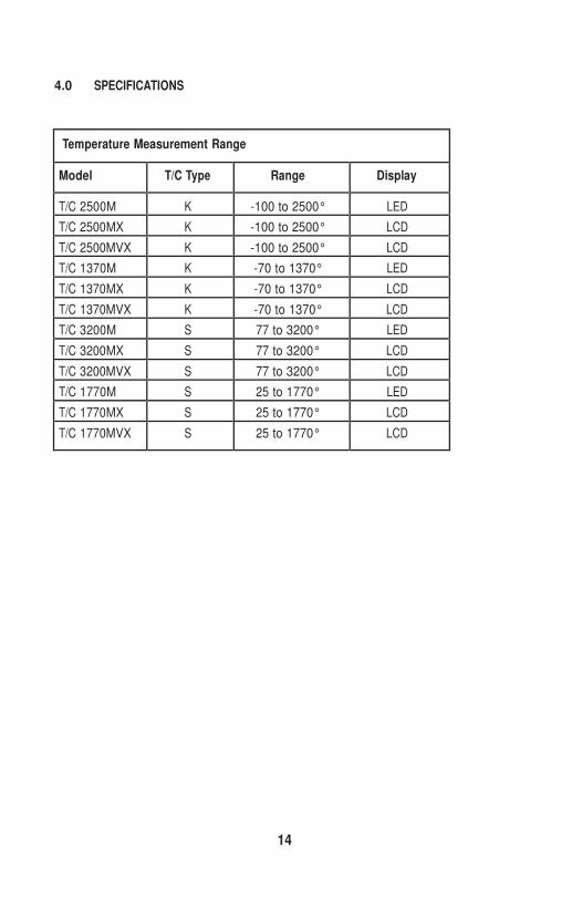
4.0 SPECIFICATIONS
Temperature Measurement Range
Model T/C Type Range Display
T/C 2500M K -100 to 2500° LED T/C 2500MX K -100 to 2500° LCD T/C 2500MVX K -100 to 2500° LCD T/C 1370M K -70 to 1370° LED T/C 1370MX K -70 to 1370° LCD T/C 1370MVX K -70 to 1370° LCD T/C 3200M S 77 to 3200° LED T/C 3200MX S 77 to 3200° LCD T/C 3200MVX S 77 to 3200° LCD T/C 1770M S 25 to 1770° LED T/C 1770MX S 25 to 1770° LCD T/C 1770MVX S 25 to 1770° LCD
15
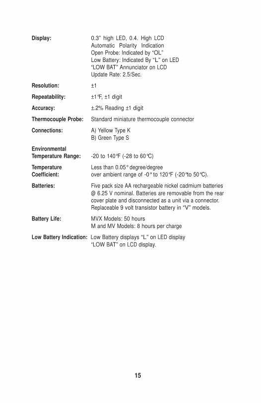
Display: 0.3” high LED, 0.4. High LCD
Automatic Polarity Indication Open Probe: Indicated by “OL”
Low Battery: Indicated By “L” on LED
“LOW BAT” Annunciator on LCD Update Rate: 2.5/Sec.
Resolution: ±1
Repeatability: ±1°F, ±1 digit
Accuracy: ±.2% Reading ±1 digit
Thermocouple Probe: Standard miniature thermocouple connector
Connections: A) Yellow Type K
B) Green Type S
Environmental Temperature Range: -20 to 140°F (-28 to 60°C)
Temperature Less than 0.05° degree/degree Coefficient: over ambient range of -0° to 120°F (-20°to 50°C).
Batteries: Five pack size AA rechargeable nickel cadmium batteries
@ 6.25 V nominal. Batteries are removable from the rear cover plate and disconnected as a unit via a connector. Replaceable 9 volt transistor battery in “V” models.
Battery Life: MVX Models: 50 hours
M and MV Models: 8 hours per charge
Low Battery Indication: Low Battery displays “L” on LED display
“LOW BAT” on LCD display.
16
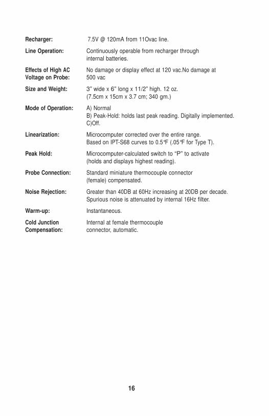
Recharger: 7.5V @ 120mA from 11Ovac line.
Line Operation: Continuously operable from recharger through
internal batteries.
Effects of High AC No damage or display effect at 120 vac.No damage at Voltage on Probe: 500 vac
Size and Weight: 3” wide x 6” long x 11/2” high. 12 oz.
(7.5cm x 15cm x 3.7 cm; 340 gm.)
Mode of Operation: A) Normal
B) Peak-Hold: holds last peak reading. Digitally implemented. C)Off.
Linearization: Microcomputer corrected over the entire range.
Based on IPT-S68 curves to 0.5°F (.05°F for Type T).
Peak Hold: Microcomputer-calculated switch to “P” to activate
(holds and displays highest reading).
Probe Connection: Standard miniature thermocouple connector
(female) compensated.
Noise Rejection: Greater than 40DB at 60Hz increasing at 20DB per decade.
Spurious noise is attenuated by internal 16Hz filter.
Warm-up: Instantaneous.
Cold Junction Internal at female thermocouple Compensation: connector, automatic.
17
5.0 CALIBRATION
Be sure to allow the Heat-Prober to stabilize to room temperature for at least
30 minutes before calibration procedure is begun. It is important that all the compo- nents be stabilized to room temperature, especially those involved with cold junction
compensation.
5.1 Voltage Regulator Adjustment
1) Equipment Needed:
a. Digital voltmeter: Fluke 44/2 digit Model 8600A or equivalent.
2) Be sure the battery pack is fully charged, and if not, be sure the recharger is
attached to the Heat-Prober.
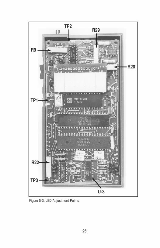
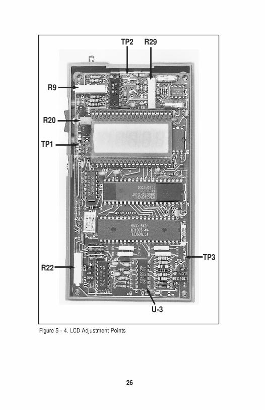
3) Remove the four screws from the bottom of the case and remove the top
cover. You will note the adjustment points as shown in Fig. 5-3 for LED
Heat-Probers and Fig. 5-4 for LCD Heat-Probers. Turn the Heat-Prober to the
“N” position. Connect DVM(-) lead to TP1. Connect DVM(+) lead to U1/1. DVM should read battery voltage between 5.5 volts and 6.2 volts. If the bat-
tery voltage is lower than this range, this means that the batteries are not fully charged or are defective.
4) Connect DVM(+) lead to TP3. Adjust R20 unit DVM reads 5.000 volts. This
completes the adjustment of the voltage regulation circuit.
5.2 Low Battery Adjustment
1) Equipment Needed:
a. Digital voltmeter, Fluke 41/2 digit Model 8600A or equivalent.
2) See Figure 5-3 for LED and Figure 5-4 for LCD Adjustment Points Connect
DVM(+) leads to TP2. Connect DVM(-) leads to TP1. Adjust R29 until DVM
reads 2.000 volts. When this adjustment is completed, a low battery indica- tion will appear on the display when the voltage falls below approximately
5.5 volts.
18
5.3 Calibration Using Wahl Calibrator
5.3.1 Zero Adjustment Using Wahl Calibrator
1) Equipment needed:
a. Wahl Thermocouple Calibrator Part No. TA70 or TA70S
(see Figure 5-2 for calibrator type).
b. An accurate thermometer to measure room temperature ±0.5°F.
2) Insert the Wahl calibrator and adjust the calibrator to the “OFF/R.T.” position
(Figure 5-2). Apply power to the Heat Prober by turning to the “N” position and make the zero adjustment with R9 so that the instrument reads “ROOM
TEMPERATURE”, as indicated by the glass thermometer.
5.3.2 Span Adjustment Using Wahl Calibrator
1 ) Set the Wahl calibrator to its maximum temperature setting. Adjust the
span with resistor R22. The display should read the highest temperature
indication on the Wahl calibrator (to which it has just been set), plus the room temperature.
2) Repeat the zero (section 5.3.1) and span adjustment until the Heat-Prober
reads room temperature correctly and room temperature plus Wahl calibra-
tor temperature without the necessity of further adjustments on R9 or R22.
5.4 Calibration with a Millivolt Source
5.4.1 Zero Adjustment with a Millivolt Source
1 ) Equipment Needed:
a. A millivolt source accurate to within .01millivolt and internal resistance of
50 ohms,or less.
b. An accurate thermometer to measure room temperature 10.5°F.
19
2) See Figure 5-3 for LED and Figure 5-4 for LCD adjustment points. Short the
thermocouple connector with a copper wire. With the input shorted, the input voltage to the electronics is zero, and only the reference junction
compensation circuit contributes to the signal used to compute tempera-
ture. This signal is the room temperature. Therefore, with the input short- ed, the Heat-Prober display when properly calibrated will read “ROOM
TEMPERATURE”. This room temperature must be accurately determined
from a secondary thermometer. Adjust R9 until the display reads “ROOM TEMPERATURE” as measured by the glass thermometer.
3) Alternate Method Using a Millivolt Source:
The room temperature from your secondary thermometer needs to be known and recorded. Look up the equivalent millivolt signal for this recorded room temperature
for your thermocouple type in the tables provided in the appendix of this manual. Insert copper wires into the thermocouple plug and apply the negative of the millivolt
value found in the tables equivalent to the measured room temperature. This will have
the effect of exactly compensating for the signal from the compensating circuit, and should result in the “Ice Point” reading (32°F/ 0°C). Therefore, R9 should be adjusted
so that the display reads either 32°F or 0°C (according to your type of instrument).
This completes the zero adjustment.
Example: Room temperature = 25°C, millivolt = 1,000,
input = 1,000mV reading = 0°C, or 32°F.
20
5.4.2 Span Adjustment with Millivolt Source
1) Insert copper wires into the thermocouple probe socket to apply the milli-
volt signal. A calibration temperature should be chosen so that it is at the
high end of the temperature range of the instrument (within about 10% of
the upper limit of the range). Look up this temperature that you have chosen
in the millivolt tables in the appendix of this manual for your thermocouple type. Now, look up the millivolt value for the recorded room temperature.
Subtract the millivolt value equivalent to room temperature from the millivolt value equivalent to your chosen calibration temperature. This calculated
value is the signal that must be applied to the Heat-Prober, adjust span
compensation with R22 so that the chosen calibration point appears on the display. This will complete the span adjustment
Example: Type K thermocouple calibration point chosen is 1300°C (mV 52.398).
Room temperature = 25°C (mV = 1.000). The input signal is then 52.398 - 1.000 =
51.398mV. R22 is adjusted so that the display reads 1300°C with an input signal of 51.398mV.
NOTE: For Type S, the instrument has been programmed to read accurately between
55°F (13°C) and 95°F (35°C) and at 32°F (0°C) to accommodate these standard cali- bration procedures, even though the stated range does not go below 200°F (90°C).
21
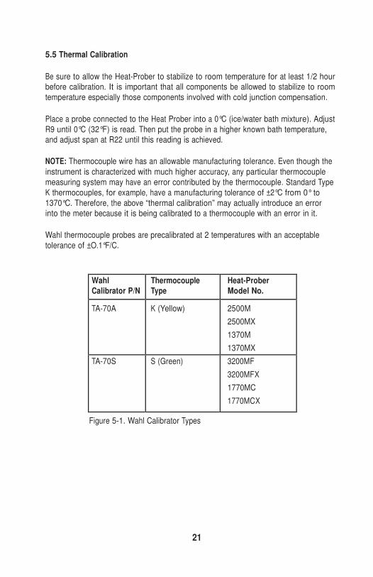
5.5 Thermal Calibration
Be sure to allow the Heat-Prober to stabilize to room temperature for at least 1/2 hour before calibration. It is important that all components be allowed to stabilize to room
temperature especially those components involved with cold junction compensation.
Place a probe connected to the Heat Prober into a 0°C (ice/water bath mixture). Adjust
R9 until 0°C (32°F) is read. Then put the probe in a higher known bath temperature, and adjust span at R22 until this reading is achieved.
NOTE: Thermocouple wire has an allowable manufacturing tolerance. Even though the
instrument is characterized with much higher accuracy, any particular thermocouple
measuring system may have an error contributed by the thermocouple. Standard Type
K thermocouples, for example, have a manufacturing tolerance of ±2°C from 0° to
1370°C. Therefore, the above “thermal calibration” may actually introduce an error into the meter because it is being calibrated to a thermocouple with an error in it.
Wahl thermocouple probes are precalibrated at 2 temperatures with an acceptable
tolerance of ±O.1°F/C.
Wahl Calibrator P/N
Thermocouple Type
Heat-Prober Model No.
TA-70A K (Yellow) 2500M
2500MX
1370M
1370MX TA-70S S (Green) 3200MF
3200MFX
1770MC
1770MCX
Figure 5-1. Wahl Calibrator Types
22
5.6 Calibration with Thermocouple Simulator
The Wahl Instruments thermocouple calibrator Model C65 may be utilized to calibrate the Thermocouple Heat-Prober.
NOTE: Allow the temperature of the meter to stabilize to the ambient temperature to
the environment. Typically, this will be 30 minutes.
1. Using the correct thermocouple wire (either “K” or “S” type), connect the
calibrator output to the Heat-Prober input terminals.
2. Set the C65 calibrator to the applicable TC mode, either “K” or “S”.
3. Set the C65 calibrator to output 3 2°F (0°C). Adjust R9 on the Heat-Prober
PC board for a display indication of 32°F (0°C).
4. Set the C65 calibrator to output to within 10% of the upper limit of the
Heat-Prober range. Adjust R22 on the Heat-Prober PC to display the same temperature.
5. If interaction of adjustments are experienced, repeat steps 3 and 4 until no
further adjustment is required.
5.7 TA-70 Thermocouple Calibrator
The TA-70 Calibrator is a battery-operated, self-contained millivolt source which may
be conveniently utilized to calibrate and verify thermocouple-based temperature meas- uring instruments such as Wahl Instruments’ Heat-Prober line.
Since the TA-70 is a millivolt-based instrument, the cold junction compensation is not
included. This requires that the ambient, or instrument temperature must be added to
the indicated temperature on the TA-70 selector switch.
For example: if the ambient temperature is 70°F and the TA-70-selected calibration
temperature is 32°F, the actual output temperature of the TA-70 will be 70° + 32° = 102°F.
For the most accurate calibration of ambient temperature, utilize a thermometer with accuracy of 0.5° traceable to NIST. Wahl’s 392M Platinum RTD meter with a 202
23
Probe is one example. A glass thermometer with 0.01 °C resolution is another. The
thermometer should be placed in close proximity to the TA-70 calibrator and Heat- Prober under calibration to determine the correction temperature. Cover the three
units with a cloth cover to prevent drafts from affecting readings and allow to stabilize
for 30 minutes.
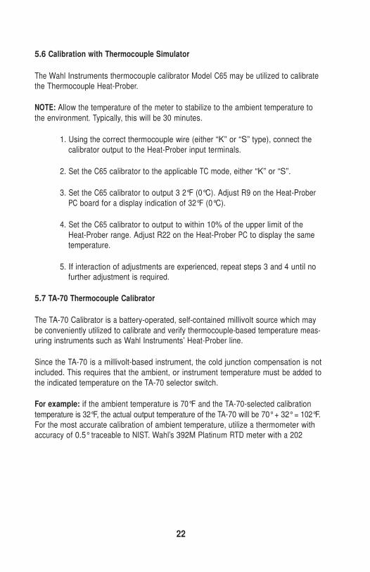
Always position the selector switch to the OFF position when not in use to prevent bat-
tery drain. A LOW battery indication is displayed by a rapidly changing display on the
thermocouple Heat-Prober under calibration. If in doubt as to battery condition, meas- ure the battery voltage with a DVM. Battery voltage should be 6.75 volts +0.1 volt. Battery
life is at least one year for normal utilization.
Batteries may be replaced or measured by removing the four cover retaining screws
and carefully lifting off the cover. The battery may be removed from the holder and
replaced with a Wahl Instruments battery, part number 9782-9.
TA70 ACCURACY SPECIFICATIONS
Switch Pos Accuracy 130° F
650
1300
1900
0.2°F
1.0
2.0
3.0
24
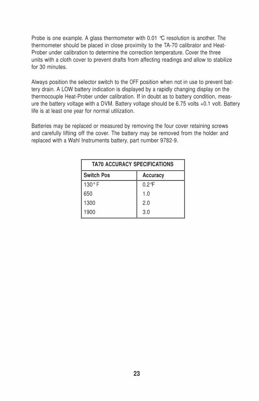
Figure 5-2. Heat-Prober with Wahl Calibrator
25
TP2 R29
R9
R20
TP1
R22
TP3
U-3
Figure 5-3. LED Adjustment Points
26
TP2 R29
R9
R20
TP1
R22
TP3
U-3
Figure 5 - 4. LCD Adjustment Points
27
6.0 THEORY OF OPERATION
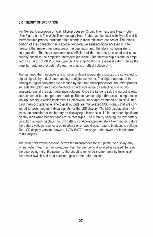
For General Description of Wahl Microprocessor Circuit Thermocouple Heat-Prober
(See Figure 6-1). The Wahl Thermocouple Heat-Prober can be used with Type K and S thermocouple probes terminated in a standard male miniature connector. The female
portion of the connector has a special temperature sensing diode encased in it to measure the ambient temperature of the connector and, therefore, compensate for
cold junction. The linear temperature coefficient of the diode is processed and subse-
quently added to the amplified thermocouple signal. The thermocouple signal is ampli- fied by a factor of 60 (180 for Type S). The amplification is essentially drift free as the
amplifier auto-zero circuit nulls out the effects of offset voltage drift.
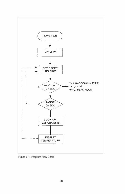
The summed thermocouple and junction ambient temperature signals are converted to digital signals by a dual slope analog-to-digital converter. The digital outputs of the
analog-to-digital converter are scanned by the 8048 microprocessor. The microproces- sor sets the optimum analog-to-digital conversion range by selecting one of two
analog-to-digital precision reference voltages. Once the range is set, the output is read
and converted to a temperature reading. The conversion algorithm uses a simple table lookup technique which implements a piecewise linear approximation of an NIST stan-
dard thermocouple table. The digital outputs are multiplexed BCD signals that are con-
verted to seven segment drive signals for the LED display. The LED display also indi- cates the condition of the battery by displaying a lower case “L” in the most significant
display digit when battery needs to be recharged. The circuitry sensing the low battery condition actually displays the low battery condition approximately five minutes before
the battery voltage reaches a point where error would occur due to inadequate voltage.
The LCD display version shows a “LOW BATT” message in the lower left hand corner of the display.
The peak hold switch position allows the microprocessor to update the display only
when higher “warmer” temperatures than the one being displayed is sensed. To reset the peak being held, the power to the circuit is removed momentarily by turning off
the power switch and then back on again to the hold position.
28
Figure 6-1. Program Flow Chart
29
6.1 Voltage Regulation Circuitry
The battery voltage of approximately 6.5 volts is regulated down to 5 volts by Q1 and U2 in conjunction with U1 which is used for its internal zener. When power is first
applied, the PNP transistor (Q1) turns on sourcing current into the system load con-
sisting in part of R19, R20, and R21. When the voltage reaches 2.5 volts on the wiper
of R20, the output voltage stabilizes with U2 sinking the required Q1 base drive, adjusted for 5.000 volts from TP3.
U4, the negative regulator IC connected directly between the battery and digital
ground, supplies the V-system voltage rail of approximately -6 volts. The board has a dual ground system such that analog and digital return currents are kept separate.
6.2 Voltage Reference Circuitry
Along with supplying a precision reference voltage for the +V rail, U1 also provides the
analog-to-digital converter with its precision voltage reference. Two such references are obtained using R22, R23, R24, R25, and U6. The derived voltages which drive U5 pin
36 are either 1.703 volts or .2458 volts. The absolute values may vary in order to
compensate for the gain of U3. However, the ratio is exactly 7:1 due to the 0.1% resis- tors used. The actual gain compensation is obtained by adjusting R22 with a known
calibrated input.
6.3 Front End Circuitry
A Type K or S thermocouple is connected to the Heat-Prober at J1. The voltage output
of the thermocouple is conditioned by a protective limiting network consisting of R4,
C1, and CR2 through CR5. The network’s output is applied to a non-inverting amplifier, U3. U3 is an integrated chopper stabilized amplifier with a gain of 60 VN (180 for Type
S). The gain was chosen to give a .05°C/bit resolution for Type K thermocouple at the
analog- to-digital converter input with the selected analog-to-digital sensitivity of 120 uV/bit at the lower precision reference voltage (.24576V). C2 and C3 are the offset and
drift holding capacitors and are high quality polycarbonate. The output of the amplifier is filtered by R5 and R6 prior to sensing by the inverting input of the analog-to-digital
converter, U5.
30
6.4 Cold Junction Compensation
The thermocouple output is a function of the difference in temperature between its probe and end copper connection junction (cold junction). In case of Type K material,
the output is 40 microvolts per degree C. Since the microprocessor’s temperature con-
version tables contain reference thermocouple values to ice point and the actual con- nection is at ambient temperature, the temperature difference must be accounted for
by a compensation circuit. The output of the thermocouple must be summed with the
cold junction temperature compensation in order to display the actual temperature to the probe end of the thermocouple. This is accomplished by sensing the temperature
of the connector with a temperature sensitive diode, CR1, and summing its negative
temperature coefficient (-2.40 mVPC) at the analog-to-digHal convertor non-inverting input. The initial ambient temperature (25°C) compensation voltage offset is deter-
mined by R12, R13, and U2. This posHive voltage of approximately 60 millivolts can be adjusted by R9 to conform to the range of the actual ambient temperature encoun-
tered in final test. R11 will determine the diode temperature characteristic curve and is
set to bias the diode at 35 microamps which gives the desired coefficient.
6.5 Dual Slope A/D Converter
The A/D converter, U5, is a commercially available type. The theory of operation of
these devices will not be covered here.
31
6.6 8048 Microprocessor
The 8 bit signal chip 8048 microprocessor is configured with P1 as the analog-to-digi- tal input port, P2 as a control/status port, and the b-directional data port, DB, as the
display driver output port. Test ports T1 and T2 are used to sense the LED/LCD config-
uration flag and the peak hold request respectively. Figure 6-2 (Microprocessor Control Functions) contains the software design specification which gives a more
detailed description of the port pin allocations and the general flow of the micro-
processor control function.
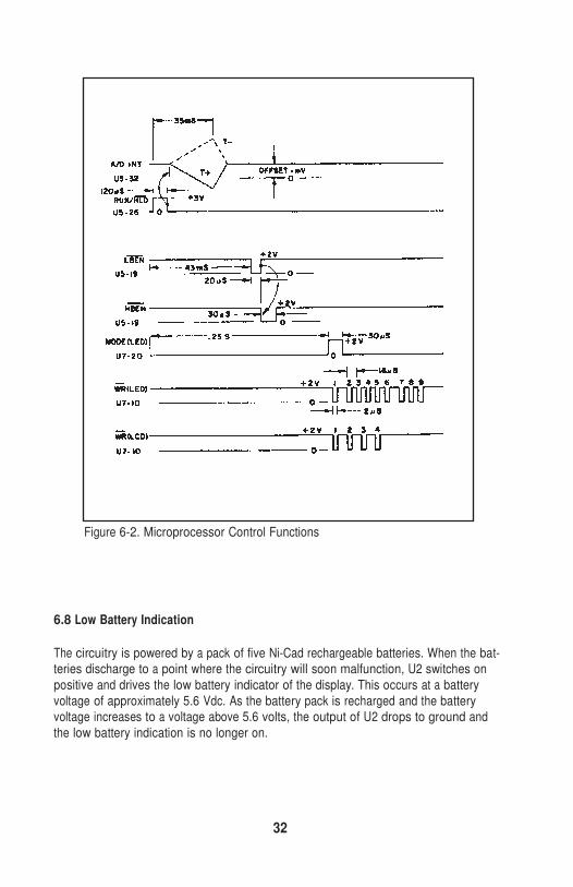
6.7 Waveforms and Timing Diagrams
The Intersil 7109 has an internal clock working with a firmware delay loop such that
the display updates at approximately three times per second.
The cycle begins when the microprocessor raises RUN, U5-26. After the analog-to-
digital converter initialization sequence, the integrator begins ramping up U5-32, the ramp rate determined by the input voltage, VIN. After 2048 clock counts, it begins to
ramp down, the ramp rate portional to VIN. The number of counts to zero crossing is
a measure of VIN. The STATUS flag (U5-2) is now dropped informing the micro- processor of conversion completion. The 8048 drops RUN, alternately dropping and
rising HBEN (U5-18) and LBEN (U5-19) to read the high and low bytes of the 12 bit
digital count. Once processed and ready for display, the microprocessor, U7, raises MODE (U7-21) and writes a control word to the LED display driver. MODE is then
dropped and write pulses (U7-10) load the 5 display digits sequentially (MSD-LSD). Four more dummy writes occur to clear the driver, U8, control logic. The LCD display
sequence is similar and presented at the bottom of Figure 6-2.
32
Figure 6-2. Microprocessor Control Functions
6.8 Low Battery Indication
The circuitry is powered by a pack of five Ni-Cad rechargeable batteries. When the bat- teries discharge to a point where the circuitry will soon malfunction, U2 switches on
positive and drives the low battery indicator of the display. This occurs at a battery
voltage of approximately 5.6 Vdc. As the battery pack is recharged and the battery voltage increases to a voltage above 5.6 volts, the output of U2 drops to ground and
the low battery indication is no longer on.
33
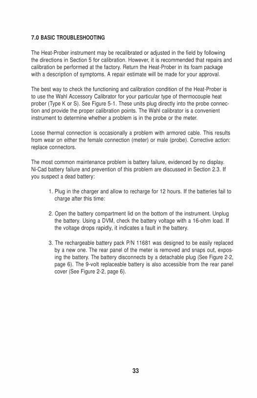
7.0 BASIC TROUBLESHOOTING
The Heat-Prober instrument may be recalibrated or adjusted in the field by following
the directions in Section 5 for calibration. However, it is recommended that repairs and calibration be performed at the factory. Return the Heat-Prober in its foam package
with a description of symptoms. A repair estimate will be made for your approval.
The best way to check the functioning and calibration condition of the Heat-Prober is
to use the Wahl Accessory Calibrator for your particular type of thermocouple heat prober (Type K or S). See Figure 5-1. These units plug directly into the probe connec- tion and provide the proper calibration points. The Wahl calibrator is a convenient
instrument to determine whether a problem is in the probe or the meter.
Loose thermal connection is occasionally a problem with armored cable. This results from wear on either the female connection (meter) or male (probe). Corrective action:
replace connectors.
The most common maintenance problem is battery failure, evidenced by no display.
Ni-Cad battery failure and prevention of this problem are discussed in Section 2.3. If you suspect a dead battery:
1. Plug in the charger and allow to recharge for 12 hours. If the batteries fail to
charge after this time:
2. Open the battery compartment lid on the bottom of the instrument. Unplug
the battery. Using a DVM, check the battery voltage with a 16-ohm load. If
the voltage drops rapidly, it indicates a fault in the battery.
3. The rechargeable battery pack P/N 11681 was designed to be easily replaced
by a new one. The rear panel of the meter is removed and snaps out, expos-
ing the battery. The battery disconnects by a detachable plug (See Figure 2-2, page 6). The 9-volt replaceable battery is also accessible from the rear panel
cover (See Figure 2-2, page 6).
34
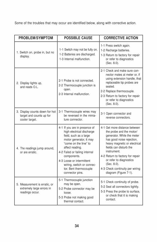
Some of the troubles that may occur are identified below, along with corrective action.
PROBLEM/SYMPTOM POSSIBLE CAUSE CORRECTIVE ACTION
1. Switch on, probe in, but no
display.
1-1 Switch may not be fully on.
1-2 Batteries are discharged.
1-3 Internal malfunction.
1-1 Press switch again.
1-2 Recharge batteries.
1-3 Return to factory for repair
or refer to diagnostics
(Sec. 8.0).
2. Display lights up,
and reads O.L.
2-1 Probe is not connected.
2-2 Thermocouple junction is
open.
2-3 Internal malfunction.
2-1 Check and make sure con-
nector mates at meter or, if
using extension handle, that
replaceable tip probes are
seated.
2-2 Replace thermocouple.
2-3 Return to factory for repair
or refer to diagnostics
(Sec. 8.0).
3. Display counts down for hot
target and counts up for
cooler target.
3-1 Thermocouple wires may
be reversed in the minia-
ture connector.
3-1 Open connector and
reverse connectors.
4. The readings jump around,
or are erratic.
4-1 If you are in presence of
high electrical discharge
field, such as a large
motor generator, it may
“come on the line” to
affect reading.
4-2 Failed or failing internal
components.
4-3 Loose or intermittent
wiring, switch or connec-
tor. Bent thermocouple
connector pins.
4-1 Get more distance between
the probe and the motor/
generator. While the meter
has good noise rejection,
heavy magnetic or electrical
fields can disturb the
instrument.
4-2 Return to factory for repair
or refer to diagnostics
(Sec. 8.0).
4-3 Check continuity per wiring
diagram (Figure 7-1).
5. Measurement is erratic, or
extremely large errors in
readings occur.
5-1 Thermocouple junction
may be open.
5-2 Probe connector may be
loose.
5-3 Probe not making good
thermal contact.
5-1 Check continuity of probe.
5-2 Seat all connectors tightly.
5-3 Press the probe to surface,
or check that it is making
contact.
35
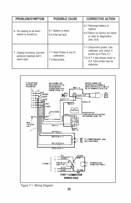
PROBLEM/SYMPTOM POSSIBLE CAUSE CORRECTIVE ACTION
6. No reading at all when
switch is turned on.
6-1 Battery is dead.
6-2 Internal fault.
6-1 Recharge battery or
replace.
6-2 Return to factory for repair
or refer to diagnostics
(Sec. 8.0).
7. Display functions, but tem-
perature readings don’t
seem right.
7-1 Heat-Prober is out of
calibration.
7-2 Bad probe.
7-1 Disconnect probe. Use
calibrator and check 4
points as in Para. 5.1.
7-2 If 7-1 test shows meter is
O.K. then probe may be
defective.
Figure 7-1. Wiring Diagram
36
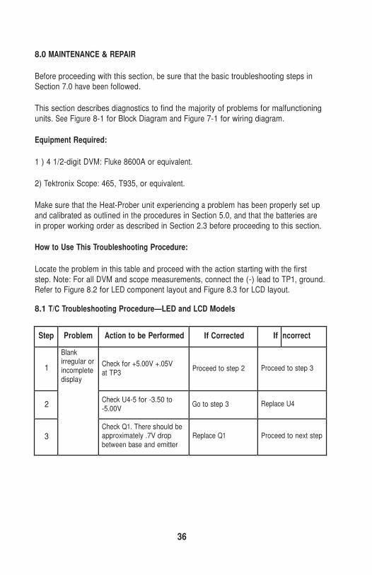
8.0 MAINTENANCE & REPAIR
Before proceeding with this section, be sure that the basic troubleshooting steps in Section 7.0 have been followed.
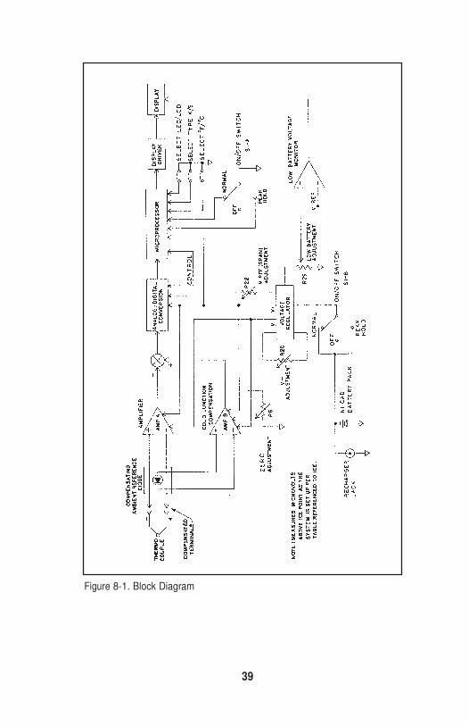
This section describes diagnostics to find the majority of problems for malfunctioning
units. See Figure 8-1 for Block Diagram and Figure 7-1 for wiring diagram.
Equipment Required:
1 ) 4 1/2-digit DVM: Fluke 8600A or equivalent.
2) Tektronix Scope: 465, T935, or equivalent.
Make sure that the Heat-Prober unit experiencing a problem has been properly set up
and calibrated as outlined in the procedures in Section 5.0, and that the batteries are
in proper working order as described in Section 2.3 before proceeding to this section.
How to Use This Troubleshooting Procedure:
Locate the problem in this table and proceed with the action starting with the first
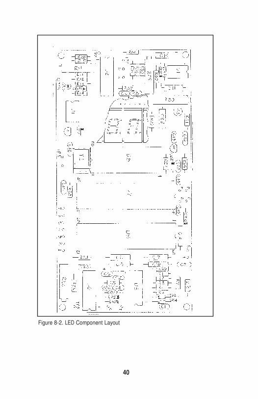
step. Note: For all DVM and scope measurements, connect the (-) lead to TP1, ground. Refer to Figure 8.2 for LED component layout and Figure 8.3 for LCD layout.
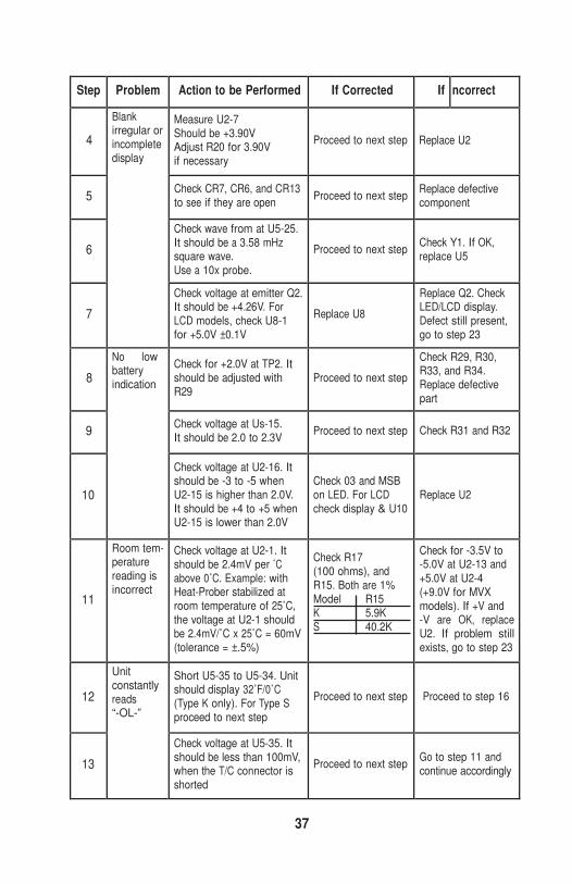
8.1 T/C Troubleshooting Procedure—LED and LCD Models
Step Problem Action to be Performed If Corrected If Incorrect
1
Check for +5.00V +.05V at TP3
Proceed to step 2
Proceed to step 3
2 Check U4-5 for -3.50 to -5.00V
Go to step 3
Replace U4
3
Blank irregular or incomplete display
Check Q1. There should be approximately .7V drop between base and emitter
Replace Q1
Proceed to next step
37
Step Problem Action to be Performed If Corrected If Incorrect
4
Measure U2-7 Should be +3.90V Adjust R20 for 3.90V if necessary
Proceed to next step
Replace U2
5 Check CR7, CR6, and CR13
to see if they are open Proceed to next step Replace defective
component
6
Check wave from at U5-25. It should be a 3.58 mHz square wave. Use a 10x probe.
Proceed to next step
Check Y1. If OK, replace U5
7
Blank irregular or incomplete display
Check voltage at emitter Q2. It should be +4.26V. For LCD models, check U8-1 for +5.0V ±0.1V
Replace U8
Replace Q2. Check LED/LCD display. Defect still present, go to step 23
8
Check for +2.0V at TP2. It should be adjusted with R29
Proceed to next step
Check R29, R30, R33, and R34. Replace defective part
9 Check voltage at Us-15. It should be 2.0 to 2.3V
Proceed to next step
Check R31 and R32
10
No low battery indication
Check voltage at U2-16. It should be -3 to -5 when U2-15 is higher than 2.0V. It should be +4 to +5 when U2-15 is lower than 2.0V
Check 03 and MSB on LED. For LCD check display & U10
Replace U2
11
Room tem- perature reading is incorrect
Check voltage at U2-1. It should be 2.4mV per ˚C above 0˚C. Example: with Heat-Prober stabilized at room temperature of 25˚C, the voltage at U2-1 should be 2.4mV/˚C x 25˚C = 60mV (tolerance = ±.5%)
Check R17 (100 ohms), and R15. Both are 1% Model R15 K 5.9K S 40.2K
Check for -3.5V to -5.0V at U2-13 and +5.0V at U2-4 (+9.0V for MVX models). If +V and -V are OK, replace U2. If problem still exists, go to step 23
12
Short U5-35 to U5-34. Unit should display 32˚F/0˚C (Type K only). For Type S proceed to next step
Proceed to next step
Proceed to step 16
13
Unit constantly reads “-OL-”
Check voltage at U5-35. It should be less than 100mV, when the T/C connector is shorted
Proceed to next step
Go to step 11 and continue accordingly
38
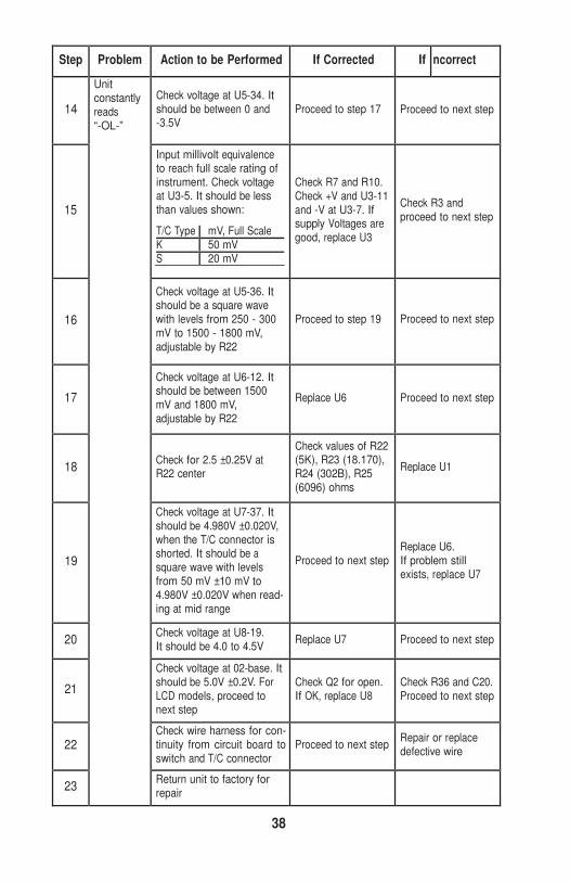
T/C Type mV, Full Scale K 50 mV S 20 mV
Step Problem Action to be Performed If Corrected If Incorrect
14
Check voltage at U5-34. It should be between 0 and -3.5V
Proceed to step 17
Proceed to next step
15
Input millivolt equivalence to reach full scale rating of instrument. Check voltage at U3-5. It should be less than values shown:
Check R7 and R10. Check +V and U3-11 and -V at U3-7. If supply Voltages are good, replace U3
Check R3 and proceed to next step
16
Check voltage at U5-36. It should be a square wave with levels from 250 - 300 mV to 1500 - 1800 mV, adjustable by R22
Proceed to step 19
Proceed to next step
17
Check voltage at U6-12. It should be between 1500 mV and 1800 mV, adjustable by R22
Replace U6
Proceed to next step
18
Check for 2.5 ±0.25V at R22 center
Check values of R22 (5K), R23 (18.170), R24 (302B), R25 (6096) ohms
Replace U1
19
Check voltage at U7-37. It should be 4.980V ±0.020V, when the T/C connector is shorted. It should be a square wave with levels from 50 mV ±10 mV to 4.980V ±0.020V when read- ing at mid range
Proceed to next step
Replace U6. If problem still exists, replace U7
20 Check voltage at U8-19. It should be 4.0 to 4.5V
Replace U7
Proceed to next step
21
Check voltage at 02-base. It should be 5.0V ±0.2V. For LCD models, proceed to next step
Check Q2 for open. If OK, replace U8
Check R36 and C20. Proceed to next step
22
Check wire harness for con- tinuity from circuit board to switch and T/C connector
Proceed to next step
Repair or replace defective wire
23
Unit constantly reads “-OL-”
Return unit to factory for repair
39
Figure 8-1. Block Diagram
40
Figure 8-2. LED Component Layout
41
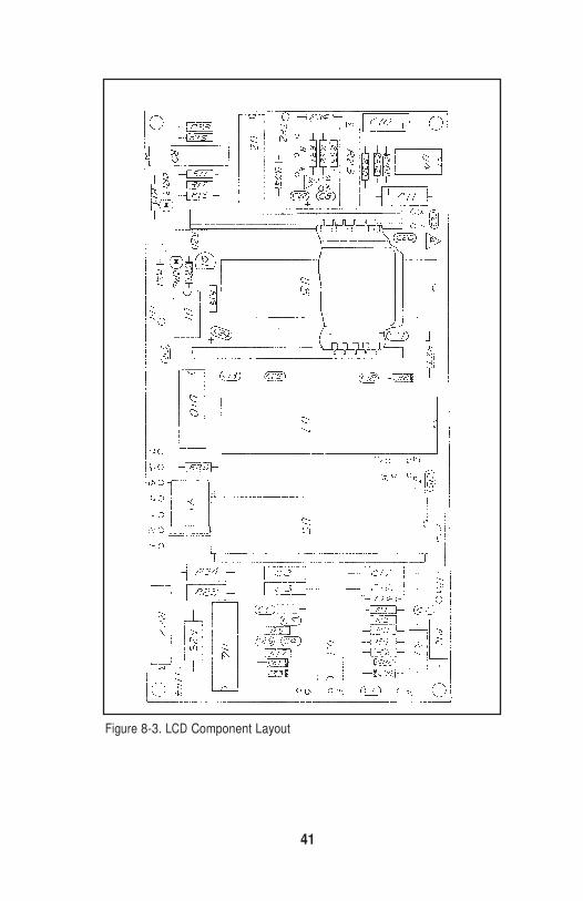
Figure 8-3. LCD Component Layout
42
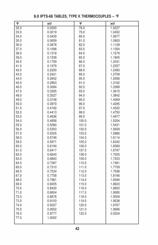
9.0 IPTS-68 TABLES, TYPE K THERMOCOUPLES – °F
°F mV °F mV 32.0 33.0
34.0
35.0
36.0
37.0
38.0
39.0
40.0
41.0
42.0
43.0
44.0
45.0
46.0
47.0
48.0
49.0
50.0
51.0
52.0
53.0
54.0
55.0
56.0
57.0
58.0
59.0
60.0
61.0
62.0
63.0
64.0
65.0
66.0
67.0
68.0
69.0
70.0
71.0
72.0
73.0
74.0
75.0
76.0
77.0
0.0000 0.0219
0.0439
0.0659
0.0878
0.1098
0.1318
0.1539
0.1759
0.1979
0.2200
0.2421
0.2642
0.2863
0.3084
0.3305
0.3527
0.3748
0.3970
0.4192
0.4413
0.4636
0.4858
0.5080
0.5303
0.5525
0.5748
0.5971
0.6194
0.6417
0.6640
0.6863
0.7087
0.7310
0.7534
0.7758
0.7981
0.8205
0.8430
0.8654
0.8878
0.9103
0.9327
0.9552
0.9777
1.0002
78.0 79.0
80.0
81.0
82.0
83.0
84.0
85.0
86.0
87.0
88.0
89.0
90.0
91.0
92.0
93.0
94.0
95.0
96.0
97.0
98.0
99.0
100.0
101.0
102.0
103.0
104.0
105.0
106.0
107.0
108.0
109.0
110.0
111.0
112.0
113.0
114.0
115.0
116.0
117.0
118.0
119.0
120.0
121.0
122.0
1.0227 1.0452
1.0677
1.0903
1.1128
1.1354
1.1579
1.1805
1.2031
1.2257
1.2483
1.2709
1.2936
1.3162
1.3389
1.3615
1.3842
1.4069
1.4295
1.4522
1.4750
1.4977
1.5204
1.5431
1.5659
1.5886
1.6114
1.6342
1.6569
1.6797
1.7025
1.7253
1.7481
1.7709
1.7938
1.8166
1.8394
1.8623
1.8852
1.9080
1.9309
1.9538
1.9767
1.9996
2.0224
43
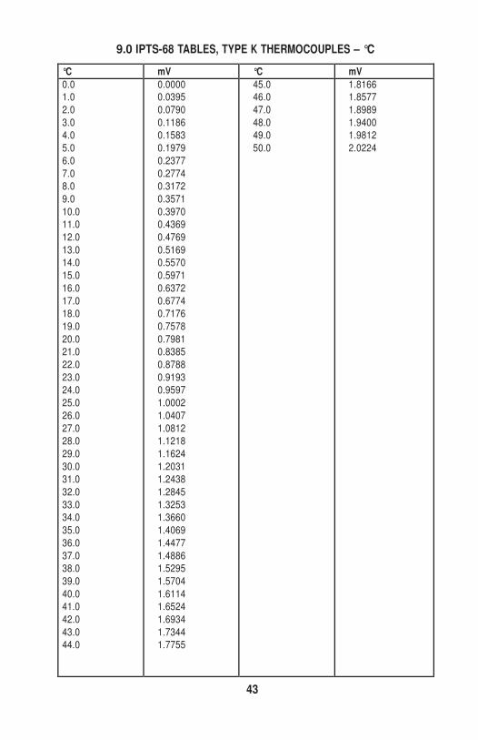
9.0 IPTS-68 TABLES, TYPE K THERMOCOUPLES – °C
°C mV °C mV 0.0 1.0
2.0
3.0
4.0
5.0
6.0
7.0
8.0
9.0
10.0
11.0
12.0
13.0
14.0
15.0
16.0
17.0
18.0
19.0
20.0
21.0
22.0
23.0
24.0
25.0
26.0
27.0
28.0
29.0
30.0
31.0
32.0
33.0
34.0
35.0
36.0
37.0
38.0
39.0
40.0
41.0
42.0
43.0
44.0
0.0000 0.0395
0.0790
0.1186
0.1583
0.1979
0.2377
0.2774
0.3172
0.3571
0.3970
0.4369
0.4769
0.5169
0.5570
0.5971
0.6372
0.6774
0.7176
0.7578
0.7981
0.8385
0.8788
0.9193
0.9597
1.0002
1.0407
1.0812
1.1218
1.1624
1.2031
1.2438
1.2845
1.3253
1.3660
1.4069
1.4477
1.4886
1.5295
1.5704
1.6114
1.6524
1.6934
1.7344
1.7755
45.0 46.0
47.0
48.0
49.0
50.0
1.8166 1.8577
1.8989
1.9400
1.9812
2.0224
44
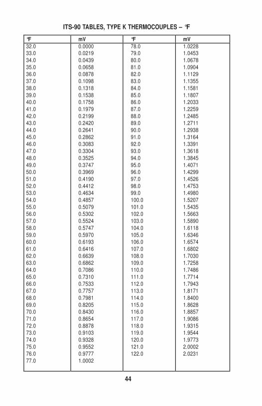
ITS-90 TABLES, TYPE K THERMOCOUPLES – °F
°F mV °F mV 32.0 33.0
34.0
35.0
36.0
37.0
38.0
39.0
40.0
41.0
42.0
43.0
44.0
45.0
46.0
47.0
48.0
49.0
50.0
51.0
52.0
53.0
54.0
55.0
56.0
57.0
58.0
59.0
60.0
61.0
62.0
63.0
64.0
65.0
66.0
67.0
68.0
69.0
70.0
71.0
72.0
73.0
74.0
75.0
76.0
77.0
0.0000 0.0219
0.0439
0.0658
0.0878
0.1098
0.1318
0.1538
0.1758
0.1979
0.2199
0.2420
0.2641
0.2862
0.3083
0.3304
0.3525
0.3747
0.3969
0.4190
0.4412
0.4634
0.4857
0.5079
0.5302
0.5524
0.5747
0.5970
0.6193
0.6416
0.6639
0.6862
0.7086
0.7310
0.7533
0.7757
0.7981
0.8205
0.8430
0.8654
0.8878
0.9103
0.9328
0.9552
0.9777
1.0002
78.0 79.0
80.0
81.0
82.0
83.0
84.0
85.0
86.0
87.0
88.0
89.0
90.0
91.0
92.0
93.0
94.0
95.0
96.0
97.0
98.0
99.0
100.0
101.0
102.0
103.0
104.0
105.0
106.0
107.0
108.0
109.0
110.0
111.0
112.0
113.0
114.0
115.0
116.0
117.0
118.0
119.0
120.0
121.0
122.0
1.0228 1.0453
1.0678
1.0904
1.1129
1.1355
1.1581
1.1807
1.2033
1.2259
1.2485
1.2711
1.2938
1.3164
1.3391
1.3618
1.3845
1.4071
1.4299
1.4526
1.4753
1.4980
1.5207
1.5435
1.5663
1.5890
1.6118
1.6346
1.6574
1.6802
1.7030
1.7258
1.7486
1.7714
1.7943
1.8171
1.8400
1.8628
1.8857
1.9086
1.9315
1.9544
1.9773
2.0002
2.0231

45
ITS-90 TABLES, TYPE K THERMOCOUPLES – °C
°C mV °C mV 0.0 1.0
2.0
3.0
4.0
5.0
6.0
7.0
8.0
9.0
10.0
11.0
12.0
13.0
14.0
15.0
16.0
17.0
18.0
19.0
20.0
21.0
22.0
23.0
24.0
25.0
26.0
27.0
28.0
29.0
30.0
31.0
32.0
33.0
34.0
35.0
36.0
37.0
38.0
39.0
40.0
41.0
42.0
43.0
44.0
0.0000 0.0395
0.0790
0.1186
0.1582
0.1979
0.2376
0.2773
0.3171
0.3570
0.3969
0.4368
0.4768
0.5168
0.5569
0.5970
0.6371
0.6773
0.7175
0.7578
0.7981
0.8385
0.8789
0.9193
0.9597
1.0002
1.0408
1.0813
1.1220
1.1626
1.2033
1.2440
1.2847
1.3255
1.3663
1.4071
1.4480
1.4889
1.5298
1.5708
1.6118
1.6528
1.6938
1.7349
1.7760
45.0 46.0
47.0
48.0
49.0
50.0
1.8171 1.8583
1.8994
1.9406
1.9818
2.0231
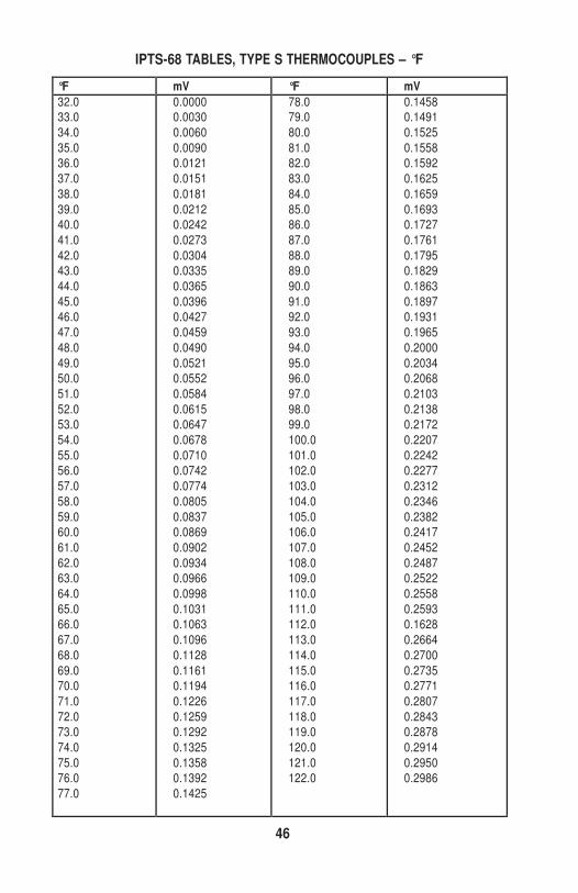
46
IPTS-68 TABLES, TYPE S THERMOCOUPLES – °F
°F mV °F mV 32.0 33.0
34.0
35.0
36.0
37.0
38.0
39.0
40.0
41.0
42.0
43.0
44.0
45.0
46.0
47.0
48.0
49.0
50.0
51.0
52.0
53.0
54.0
55.0
56.0
57.0
58.0
59.0
60.0
61.0
62.0
63.0
64.0
65.0
66.0
67.0
68.0
69.0
70.0
71.0
72.0
73.0
74.0
75.0
76.0
77.0
0.0000 0.0030
0.0060
0.0090
0.0121
0.0151
0.0181
0.0212
0.0242
0.0273
0.0304
0.0335
0.0365
0.0396
0.0427
0.0459
0.0490
0.0521
0.0552
0.0584
0.0615
0.0647
0.0678
0.0710
0.0742
0.0774
0.0805
0.0837
0.0869
0.0902
0.0934
0.0966
0.0998
0.1031
0.1063
0.1096
0.1128
0.1161
0.1194
0.1226
0.1259
0.1292
0.1325
0.1358
0.1392
0.1425
78.0 79.0
80.0
81.0
82.0
83.0
84.0
85.0
86.0
87.0
88.0
89.0
90.0
91.0
92.0
93.0
94.0
95.0
96.0
97.0
98.0
99.0
100.0
101.0
102.0
103.0
104.0
105.0
106.0
107.0
108.0
109.0
110.0
111.0
112.0
113.0
114.0
115.0
116.0
117.0
118.0
119.0
120.0
121.0
122.0
0.1458 0.1491
0.1525
0.1558
0.1592
0.1625
0.1659
0.1693
0.1727
0.1761
0.1795
0.1829
0.1863
0.1897
0.1931
0.1965
0.2000
0.2034
0.2068
0.2103
0.2138
0.2172
0.2207
0.2242
0.2277
0.2312
0.2346
0.2382
0.2417
0.2452
0.2487
0.2522
0.2558
0.2593
0.1628
0.2664
0.2700
0.2735
0.2771
0.2807
0.2843
0.2878
0.2914
0.2950
0.2986
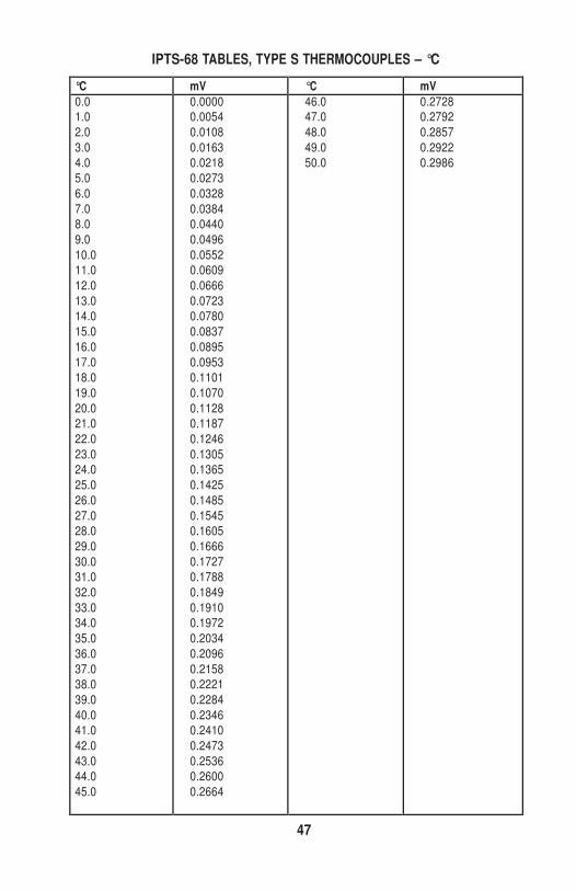
47
IPTS-68 TABLES, TYPE S THERMOCOUPLES – °C
°C mV °C mV 0.0 1.0
2.0
3.0
4.0
5.0
6.0
7.0
8.0
9.0
10.0
11.0
12.0
13.0
14.0
15.0
16.0
17.0
18.0
19.0
20.0
21.0
22.0
23.0
24.0
25.0
26.0
27.0
28.0
29.0
30.0
31.0
32.0
33.0
34.0
35.0
36.0
37.0
38.0
39.0
40.0
41.0
42.0
43.0
44.0
45.0
0.0000 0.0054
0.0108
0.0163
0.0218
0.0273
0.0328
0.0384
0.0440
0.0496
0.0552
0.0609
0.0666
0.0723
0.0780
0.0837
0.0895
0.0953
0.1101
0.1070
0.1128
0.1187
0.1246
0.1305
0.1365
0.1425
0.1485
0.1545
0.1605
0.1666
0.1727
0.1788
0.1849
0.1910
0.1972
0.2034
0.2096
0.2158
0.2221
0.2284
0.2346
0.2410
0.2473
0.2536
0.2600
0.2664
46.0 47.0
48.0
49.0
50.0
0.2728 0.2792
0.2857
0.2922
0.2986
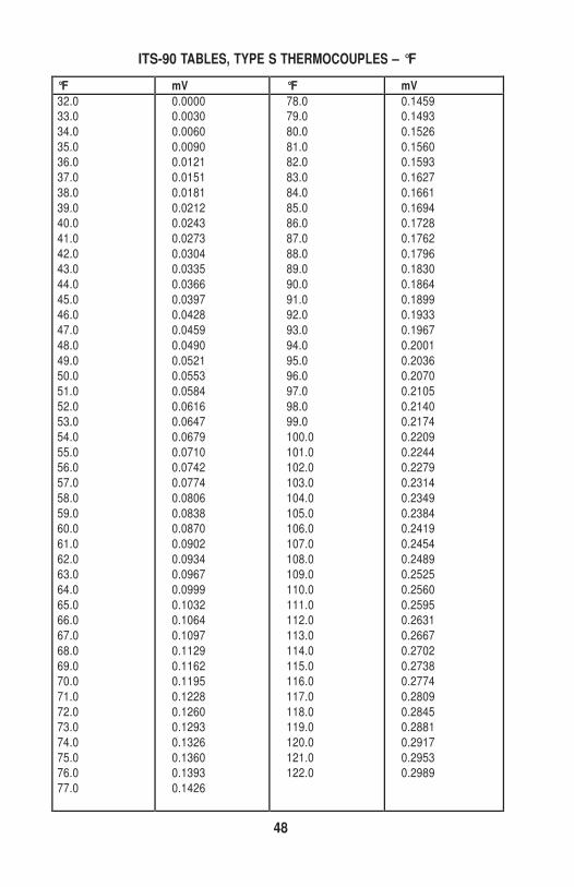
48
ITS-90 TABLES, TYPE S THERMOCOUPLES – °F
°F mV °F mV 32.0 33.0
34.0
35.0
36.0
37.0
38.0
39.0
40.0
41.0
42.0
43.0
44.0
45.0
46.0
47.0
48.0
49.0
50.0
51.0
52.0
53.0
54.0
55.0
56.0
57.0
58.0
59.0
60.0
61.0
62.0
63.0
64.0
65.0
66.0
67.0
68.0
69.0
70.0
71.0
72.0
73.0
74.0
75.0
76.0
77.0
0.0000 0.0030
0.0060
0.0090
0.0121
0.0151
0.0181
0.0212
0.0243
0.0273
0.0304
0.0335
0.0366
0.0397
0.0428
0.0459
0.0490
0.0521
0.0553
0.0584
0.0616
0.0647
0.0679
0.0710
0.0742
0.0774
0.0806
0.0838
0.0870
0.0902
0.0934
0.0967
0.0999
0.1032
0.1064
0.1097
0.1129
0.1162
0.1195
0.1228
0.1260
0.1293
0.1326
0.1360
0.1393
0.1426
78.0 79.0
80.0
81.0
82.0
83.0
84.0
85.0
86.0
87.0
88.0
89.0
90.0
91.0
92.0
93.0
94.0
95.0
96.0
97.0
98.0
99.0
100.0
101.0
102.0
103.0
104.0
105.0
106.0
107.0
108.0
109.0
110.0
111.0
112.0
113.0
114.0
115.0
116.0
117.0
118.0
119.0
120.0
121.0
122.0
0.1459 0.1493
0.1526
0.1560
0.1593
0.1627
0.1661
0.1694
0.1728
0.1762
0.1796
0.1830
0.1864
0.1899
0.1933
0.1967
0.2001
0.2036
0.2070
0.2105
0.2140
0.2174
0.2209
0.2244
0.2279
0.2314
0.2349
0.2384
0.2419
0.2454
0.2489
0.2525
0.2560
0.2595
0.2631
0.2667
0.2702
0.2738
0.2774
0.2809
0.2845
0.2881
0.2917
0.2953
0.2989
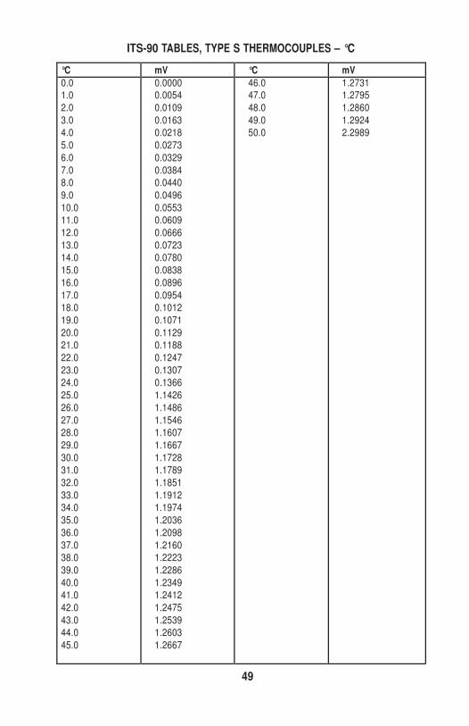
49
ITS-90 TABLES, TYPE S THERMOCOUPLES – °C
°C mV °C mV 0.0 1.0
2.0
3.0
4.0
5.0
6.0
7.0
8.0
9.0
10.0
11.0
12.0
13.0
14.0
15.0
16.0
17.0
18.0
19.0
20.0
21.0
22.0
23.0
24.0
25.0
26.0
27.0
28.0
29.0
30.0
31.0
32.0
33.0
34.0
35.0
36.0
37.0
38.0
39.0
40.0
41.0
42.0
43.0
44.0
45.0
0.0000 0.0054
0.0109
0.0163
0.0218
0.0273
0.0329
0.0384
0.0440
0.0496
0.0553
0.0609
0.0666
0.0723
0.0780
0.0838
0.0896
0.0954
0.1012
0.1071
0.1129
0.1188
0.1247
0.1307
0.1366
1.1426
1.1486
1.1546
1.1607
1.1667
1.1728
1.1789
1.1851
1.1912
1.1974
1.2036
1.2098
1.2160
1.2223
1.2286
1.2349
1.2412
1.2475
1.2539
1.2603
1.2667
46.0 47.0
48.0
49.0
50.0
1.2731 1.2795
1.2860
1.2924
2.2989
50
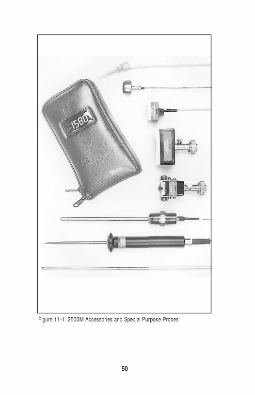
Figure 11-1. 2500M Accessories and Special Purpose Probes
51
10.0 ADDITIONAL PROBES AND ACCESSORIES
Wahl offers a complete line of probes and accessories to complement the 2500M meter, including:
Probes:
TC804 Miniature Spring Loaded J-Probe
TC812 Ferrous Magnetic Surface Probe, 450°F
TC886 Magnetic Surface Probe, Ferrous surfaces
RTC877 Moving Surface Probe, 450°F max
RTC824 Roll Surface Probe, 450°F max
TC881 Spring Loaded Thermowell Probe
TC817 Penetration Probe, 1000°F max
TC874 Fully Immersible Probe Without Handle, 1000°F
Accessory:
TA6M Meter Carrying Case
Request Wahl’s Heat-Prober® Catalog PW1155, for our complete offering of meters, probes, cost-saving kits and accessories.
52
11.0 WARRANTY REGISTRATION
Fill out the Warranty Registration Form packed on the back cover of this manual and return to Wahl. It is helpful to do this to put the three-year warranty in force. We will
send you follow-up reminders about recalibration dates.
12.0 RETURN FOR REPAIR/CALIBRATION SERVICE Warranty Repair Information Form
Please contact Wahl Heat Prober Service at (800) 421-2853 or
e-mail: [email protected] before returning your instrument to the fac- tory. Send your instrument prepaid. To insure a fast turnaround time, fill out a copy of
the form on page 53 with as much detail as possible, and attach it to the instrument.
Shipping
Material being returned should be packed well, preferably in the original foam
shipping container.
Ship to:
WAHL INSTRUMENTS, INC.
234 OLD WEAVERVILLE ROAD
ASHEVILLE, NC 28804-1228
53
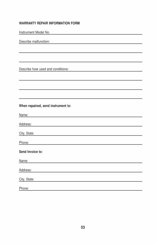
WARRANTY REPAIR INFORMATION FORM
Instrument Model No.
Describe malfunction:
Describe how used and conditions:
When repaired, send instrument to:
Name:
Address:
City, State:
Phone:
Send Invoice to:
Name:
Address:
City, State:
Phone:
54
WARRANTY
Wahl Instruments, Inc., hereinafter referred to as Wahl, warrants each instru- ment of its manufacture to be free from defects in material and workmanship
under normal use and service for one year from the date of shipment. If our
examination discloses that malfunction was caused by either poor workmanship or defective material, Wahl will repair or replace the components accordingly,
providing these are forwarded to the factory within three years from the date of
shipment, properly packaged, and with prepaid transportation. Wahl assumes no liability for damages of any kind, direct or indirect, as a result of the installa-
tion and/or use of the equipment. The purchaser, by accepting the equipment,
will assume all liability for any damages, direct or consequential to himself, his employees, agents or others, which may result from use or misuse of this
equipment.
The above warranty also applies to instrument accessories manufactured by
Wahl except probes, which, due to the environmental nature of their use, can-
not be replaced unless returned unused. In addition, Wahl assumes no liability for any costs resulting from removing and reinstalling any of its prod-
ucts for replacement under the terms of the above warranty.
Please complete and return the enclosed Warranty Form.

55

Palmer Wahl Instrumentation Group
234 Old Weaverville Road Asheville, North Carolina 28804-1228 (800) 421-2853 • Fax (828) 658-0728
email: [email protected] www.palmerwahl.com