Embed Size (px)
Citation preview
P r o d u c t G u i d e
H e a t S h r i n k a b l e M o u l d e d S h a p e s

10
1.0
10/2
016
031
-933
86M
ould
ed S
hape
s BR
O
InsulationSelection Guide
This selection guide will help you to find the correct moulded shape for your application:
Step 1. Product Style
Use the Selection Guide Overview on page 12 to quickly select a suitable product profile.
Step 2. Product Size
Choose the correct dimensions to meet your application from our sizes and types table which appears on the relevant product profile page.
An example of these tables is shown below:
TYPE
ØHmin.
a
ØHmax.
b
ØJmin.
a
ØJmax.
b P ±
10% R ±
15% T ±0.8
JO ±10%
HW ±1.5
JW ±0.8
S ±1.5
313F322 23.8(.93“)
9.9(.39“)
17.2(.67“)
6.6(.26“)
105.9(4.13“)
11.6(.45“)
1.3(.05“)
86.3(3.37“)
1.5(.06“)
1.5(.06“)
1.5(.06“)
313F332 27.1(1.06“)
13.2(.51“)
20.8(.81“)
7.6(.30“)
121.1(4.72“)
12.1(.47“)
1.3(.05“)
98.5(3.84“)
1.5(.06“)
1.5(.06“)
1.5(.06“)
Combinations "On request"
Adhesive Material
9 8 6TSA-200 • • •
-450 • - •
-250 • - •
W24 • - •
V9500 • • •
HMT200A • • •
Without Adhesive • • •
Step 3. Material/ Adhesive
Choose a material and adhesive to meet your application requirements from the tables on page 14/15.
Further combinations are available.
Here is an example:
These symbols denote the material or adhesive availability for each profile type. In this example the adhesive W24 is not available with the material 8 because of the ”-”.
But it is available with the material 9 and 6 because of the ”•”.
3.1 Material
Parts can be supplied in a choice of materials. The ″combinations″ table on each product page provides a quick and easy material recognition guide for the product profiled.
On page 14 you will find detailed information on our range of materials.
11
1.010
/201
6 0
31-9
3386
Mou
lded
Sha
pes
BRO
InsulationSelection Guide
3.2 Adhesive
To maximise environmental protection and strain relief we recommend the use of an adhesive from our range below.
Pre-lined hot melt adhesive: Component adhesive:
• WM250
• W
• W2
• W8
• W21
• HMT200A
• W24
• V9500
• TSA-200
For further information on adhesives please refer to page 15.
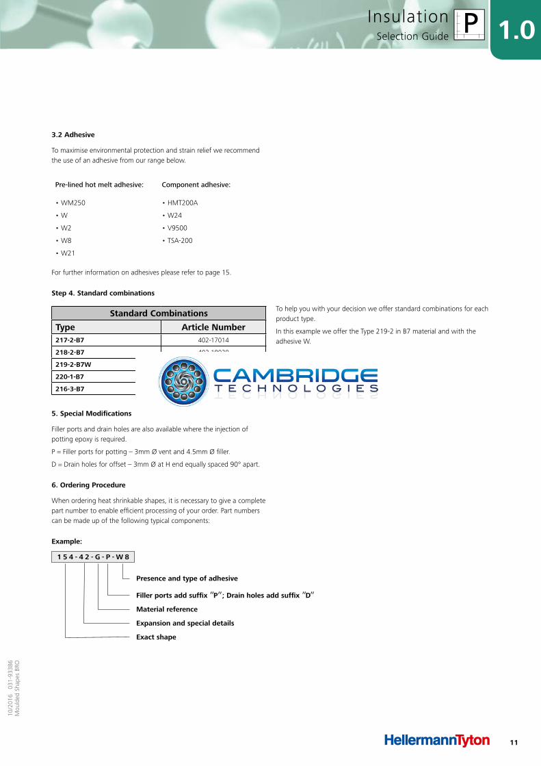
Step 4. Standard combinations
To help you with your decision we offer standard combinations for each product type.
In this example we offer the Type 219-2 in B7 material and with the adhesive W.
5. Special Modifications
Filler ports and drain holes are also available where the injection of potting epoxy is required.
P = Filler ports for potting – 3mm Ø vent and 4.5mm Ø filler.
D = Drain holes for offset – 3mm Ø at H end equally spaced 90° apart.
6. Ordering Procedure
When ordering heat shrinkable shapes, it is necessary to give a complete part number to enable efficient processing of your order. Part numbers can be made up of the following typical components:
1 5 4 - 4 2 - G - P - W 8
Example:
Presence and type of adhesive
Filler ports add suffix ”P”; Drain holes add suffix ”D”Material reference
Expansion and special details
Exact shape
Standard Combinations
Type Article Number217-2-B7 402-17014
218-2-B7 402-18020
219-2-B7W 402-19039
220-1-B7 402-20008
216-3-B7 402-16057
12
1.0
10/2
016
031
-933
86M
ould
ed S
hape
s BR
O
InsulationSelection Guide Overview
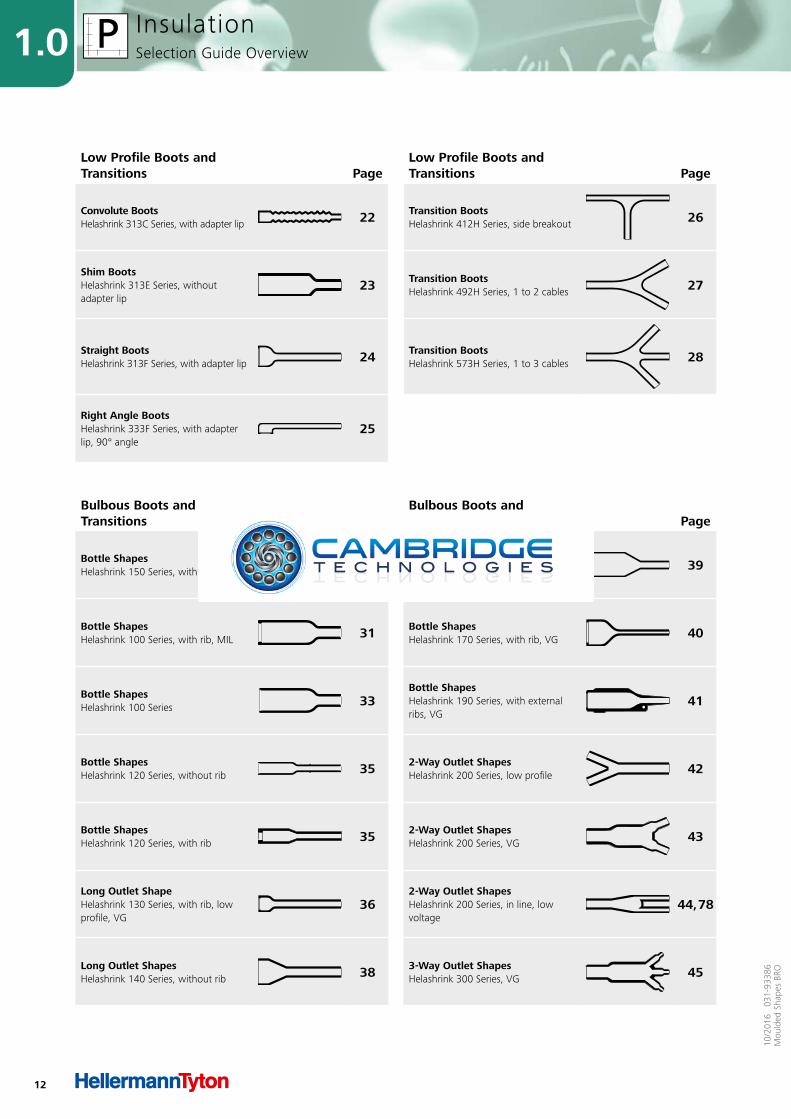
Bulbous Boots and Transitions Page
Bulbous Boots and Transitions Page
Bottle ShapesHelashrink 150 Series, with rib, VG 29 Bottle Shapes
Helashrink 160 Series, without rib 39
Bottle ShapesHelashrink 100 Series, with rib, MIL 31 Bottle Shapes
Helashrink 170 Series, with rib, VG 40
Bottle ShapesHelashrink 100 Series 33
Bottle ShapesHelashrink 190 Series, with external ribs, VG
41
Bottle ShapesHelashrink 120 Series, without rib 35 2-Way Outlet Shapes
Helashrink 200 Series, low profile 42
Bottle ShapesHelashrink 120 Series, with rib 35 2-Way Outlet Shapes
Helashrink 200 Series, VG 43
Long Outlet ShapeHelashrink 130 Series, with rib, low profile, VG
362-Way Outlet ShapesHelashrink 200 Series, in line, low voltage
44, 78
Long Outlet ShapesHelashrink 140 Series, without rib 38 3-Way Outlet Shapes
Helashrink 300 Series, VG 45
Low Profile Boots and Transitions Page
Low Profile Boots and Transitions Page
Convolute BootsHelashrink 313C Series, with adapter lip 22 Transition Boots
Helashrink 412H Series, side breakout 26
Shim BootsHelashrink 313E Series, without adapter lip
23 Transition BootsHelashrink 492H Series, 1 to 2 cables 27
Straight BootsHelashrink 313F Series, with adapter lip 24 Transition Boots
Helashrink 573H Series, 1 to 3 cables 28
Right Angle BootsHelashrink 333F Series, with adapter lip, 90° angle
25
13
1.010
/201
6 0
31-9
3386
Mou
lded
Sha
pes
BRO
InsulationSelection Guide Overview
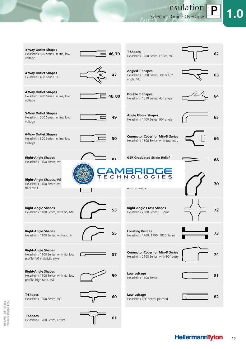
3-Way Outlet ShapesHelashrink 300 Series, in line, low voltage
46, 79 T-ShapesHelashrink 1200 Series, Offset, VG 62
4-Way Outlet ShapesHelashrink 400 Series, VG 47
Angled T-ShapesHelashrink 1300 Series, 30° & 45° angle, VG
63
4-Way Outlet ShapesHelashrink 400 Series, in line, low voltage
48, 80 Double T-ShapesHelashrink 1310 Series, 45° angle 64
5-Way Outlet ShapesHelashrink 500 Series, in line, low voltage
49 Angle Elbow ShapesHelashrink 1400 Series, 90° angle 65
6-Way Outlet ShapesHelashrink 600 Series, in line, low voltage
50 Connector Cover for Min-D SeriesHelashrink 1500 Series, with top entry 66
Right-Angle ShapesHelashrink 1100 Series, with rib, VG 51 GSR Graduated Strain Relief
Helashrink 1750 Series, with rib 68
Right-Angle Shapes, VG styleHelashrink 1100 Series, without rib, thick wall
52Angle ShapesHelashrink 1800 Series, with rib, 30°, 45°, 60° angle
70
Right-Angle ShapesHelashrink 1100 Series, with rib, MIL 53 Right Angle Cross Shapes
Helashrink 2000 Series - T-Joint 72
Right-Angle ShapesHelashrink 1100 Series, without rib 55 Locating Bushes
Helashrink 1760, 1790, 1820 Series 73
Right-Angle ShapesHelashrink 1100 Series, with rib, low profile, VG style/MIL style
57 Connector Cover for Min-D SeriesHelashrink 2100 Series, with 90° entry 74
Right-Angle ShapesHelashrink 1100 Series, with rib, low profile, high ratio, VG
59 Low voltageHelashrink 1600 Series 81
T-ShapesHelashrink 1200 Series, VG 60 Low voltage
Helashrink PEC Series, pinched 82
T-ShapesHelashrink 1200 Series, Offset 61

14
1.0
10/2
016
031
-933
86M
ould
ed S
hape
s BR
O
InsulationMaterial Specifications
Materials for Heat Shrinkable Moulded Shapes
Material Specifications
L H G B7
MaterialFlexible flame retarded fluoroelastomer
Flexible limited fire hazard material
Fluid resistant elastomerSemi-rigid flame retarded polyolefin
Operating Temperature-67°F to +392°F (-55°C to +200°C)
-67°F to +221°F (-55°C to +105°C)
-103°F to +302°F (-75°C to +150°C)
-67°F to +275°F (-55°C to +135°C)
Min. Shrink Temperature +347 °F (+175 °C) +275 °F (+135 °C) +275 °F (+135 °C) +275 °F (+135 °C)
SpecificationsDEF STAN 59-97, BSG198 Part 5, Type DD, MIL-81765/4
DEF STAN 59-97, BSG198 Part 5, Type DF, VG95343 pt 29, NAVSEA 5617649
DEF STAN 59-97, BSG198 Part 5, Type DE, VG 95343 Part 6, 18
MIL-I-81765/1 Type 1, DEF STAN 59-97, BSG198 Part 5, Type DA
Tensile Strength 12 MPa 10 MPa 15 MPa 13 MPa
Elongation at break
300 % 450 % 580 % 500 %
Dielectric Strength 8 kV/mm 15 kV/mm 14 kV/mm 14 kV/mm
Flammability for Material Excellent Excellent Excellent Excellent
FeaturesHigh temperature excellent chemical resistance
Low smokeHalogen free
Excellent resistance to fuels
Good physical and chemical resistance
Typical ApplicationMilitary and high performance harnessing
Ships, submarines and railways
Military and general high performance harnessing
Military and general high performance harnessing
Material Specifications
J B8 -8 -9 -6
Material Flexible polyolefinSemi-rigid flame retarded polyolefin
Modified fluoroelastomer
Modified elastomer blend
Flexible flame retarded polyolefin
Operating Temperature-67°F to +275°F (-55°C to +135°C)
-67°F to +212°F (-55°C to +100°C)
-67°F to +302°F (-55°C to +150°C)
-67°F to +248°F (-55°C to +120°C)
-67°F to +248°F (-55°C to +120°C)
Min. Shrink Temperature +275 °F (+135 °C) +275 °F (+135 °C) +275 °F (+135 °C) +275 °F (+135 °C) +275 °F (+135 °C)
SpecificationsMIL-I-81765/1 Type 2, DEF STAN 59-97, BSG198 Part 5, Type DB
EA-TS 09-11 SCX15111 SCX15112MIL-I-81765/1 Type 1, MIL-I-81765/1 Type 2
Tensile Strength 14 MPa 15 MPa 15 MPa 12 MPa 12 MPa
Elongation at break
610 % 500 % 450 % 500 % 500 %
Dielectric Strength 12 kV/mm 15 kV/mm 20 kV/mm 20 kV/mm 20 kV/mm
Flammability for Material excellent good <25mm excellent excellent
Features FlexibleGood physical and reasonable chemical resistance
Good physical and reasonable chemical resistance
Good physical and reasonable chemical resistance
Good physical and reasonable chemical resistance
Typical ApplicationMilitary and high performance harnessing
Power/utility shapesMilitary and general high performance harnessing
Military and general high performance harnessing
Military and general high performance harnessing

15
1.010
/201
6 0
31-9
3386
Mou
lded
Sha
pes
BRO
InsulationAdhesive Specifications
Adhesive Specifications
450 TSA200 WM250 V9500 HMT200A
AdhesiveEVA hot melt adhesive
Thermoset +125° C Hot melt adhesive Two part, black, epoxy adhesive
Hot melt adhesive tape
Operating Temperature-67°F to +221°F (-55°C to +105°C)
-67°F to +257°F (-55°C to +125°C)
-67°F to +176°F (-55°C to +80°C)
-103°F to +302°F (-75°C to +150°C)
-67°F to +221°F (-55°C to +105°C)
Softening Point Adhesive +230°F (+110°C) +203°F (+95°C) +203°F (+95°C) +230°F (+110°C)
Supplied Form Pre-applied Tape Pre-applied Cardridge Tape
Shelf life 5 years 5 years 5 years 18 months 5 years
Solvent ResistanceFair under splash conditions
Fair under splash conditions
Fair under splash conditions
De-icing fluid: Excellent, Petrol: Excellent, Lubricating Oil: Excellent, Hydraulic Oil: Excellent
Fair under splash conditions
Adhesive for Heat Shrinkable Moulded Shapes
Adhesive Specifications
W / W2 W8 W21 W24
AdhesiveGeneral purpose hot melt adhesive
High performance EVA hot melt adhesive
Modified polyamide hot melt adhesive
High performance, pre-coat, 1 part epoxy
Operating Temperature-67°F to +176°F (-55°C to +80°C)
-67°F to +221°F (-55°C to +105°C)
-67°F to +248°F (-55°C to +120°C)
-94°F to +428°F (-75°C to +200°C)
Softening Point Adhesive +203°F (+95°C) +230°F (+110°C) +248°F (+120°C)
Supplied Form Pre-applied Pre-applied Pre-applied Pre-applied
Shelf life 5 years 5 years 5 years 5 years
Solvent ResistanceFair under splash conditions
Fair under splash conditions
Saline: Very goodDe-icing fluid: GoodDiesel: ExcellentLubricating Oil: GoodHydraulic Oil: ExcellentAviation Fuel: GoodAutomotive Fuel: Good
De-icing fluid: ExcellentPetrol: ExcellentLubricating Oil: ExcellentHydraulic Oil: Excellent
16
1.0
10/2
016
031
-933
86M
ould
ed S
hape
s BR
O
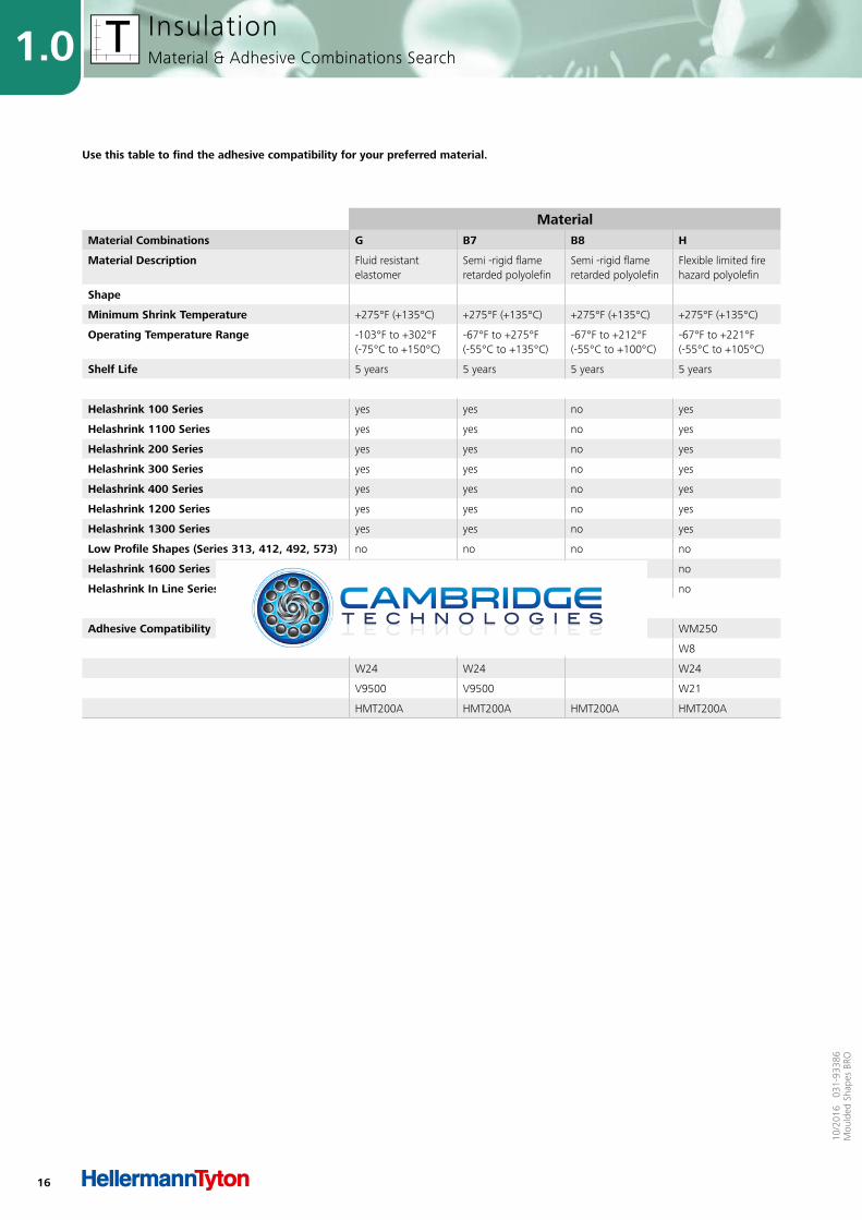
InsulationMaterial & Adhesive Combinations Search
MaterialMaterial Combinations G B7 B8 H
Material Description Fluid resistant elastomer
Semi -rigid flameretarded polyolefin
Semi -rigid flameretarded polyolefin
Flexible limited firehazard polyolefin
Shape
Minimum Shrink Temperature +275°F (+135°C) +275°F (+135°C) +275°F (+135°C) +275°F (+135°C)
Operating Temperature Range -103°F to +302°F (-75°C to +150°C)
-67°F to +275°F (-55°C to +135°C)
-67°F to +212°F (-55°C to +100°C)
-67°F to +221°F (-55°C to +105°C)
Shelf Life 5 years 5 years 5 years 5 years
Helashrink 100 Series yes yes no yes
Helashrink 1100 Series yes yes no yes
Helashrink 200 Series yes yes no yes
Helashrink 300 Series yes yes no yes
Helashrink 400 Series yes yes no yes
Helashrink 1200 Series yes yes no yes
Helashrink 1300 Series yes yes no yes
Low Profile Shapes (Series 313, 412, 492, 573) no no no no
Helashrink 1600 Series no no yes no
Helashrink In Line Series, low voltage no no yes no
Adhesive Compatibility WM250 WM250 WM250 WM250
W8 W8 W8 W8
W24 W24 W24
V9500 V9500 W21
HMT200A HMT200A HMT200A HMT200A
Use this table to find the adhesive compatibility for your preferred material.
17
1.010
/201
6 0
31-9
3386
Mou
lded
Sha
pes
BRO
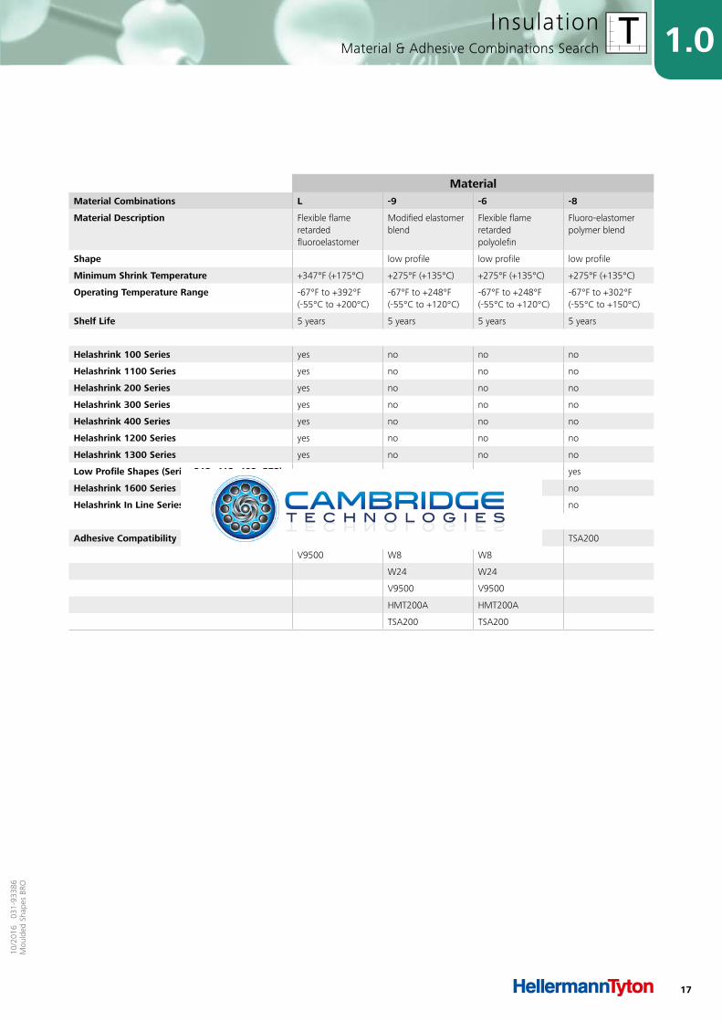
InsulationMaterial & Adhesive Combinations Search
MaterialMaterial Combinations L -9 -6 -8
Material Description Flexible flame retardedfluoroelastomer
Modified elastomerblend
Flexible flame retardedpolyolefin
Fluoro-elastomerpolymer blend
Shape low profile low profile low profile
Minimum Shrink Temperature +347°F (+175°C) +275°F (+135°C) +275°F (+135°C) +275°F (+135°C)
Operating Temperature Range -67°F to +392°F (-55°C to +200°C)
-67°F to +248°F (-55°C to +120°C)
-67°F to +248°F (-55°C to +120°C)
-67°F to +302°F (-55°C to +150°C)
Shelf Life 5 years 5 years 5 years 5 years
Helashrink 100 Series yes no no no
Helashrink 1100 Series yes no no no
Helashrink 200 Series yes no no no
Helashrink 300 Series yes no no no
Helashrink 400 Series yes no no no
Helashrink 1200 Series yes no no no
Helashrink 1300 Series yes no no no
Low Profile Shapes (Series 313, 412, 492, 573) no yes yes yes
Helashrink 1600 Series no no no no
Helashrink In Line Series, low voltage no no no no
Adhesive Compatibility W24 WM250 WM250 TSA200
V9500 W8 W8
W24 W24
V9500 V9500
HMT200A HMT200A
TSA200 TSA200

18
1.0
10/2
016
031
-933
86M
ould
ed S
hape
s BR
O
InsulationMaterial & Adhesive Combinations Search
MaterialAdhesive Combinations W / W2 WM250 W8 W21
Adhesive Description General purposehot melt adhesive
General purposehot melt adhesive
EVA, high performance,hot melt adhesive
Modified polyamidehot melt adhesive
Operating Temperature Range -67°F to +176°F (-55°C to +80°C)
-67°F to +176°F (-55°C to +80°C)
-67°F to +221°F (-55°C to +105°C)
-67°F to +248°F (-55°C to +120°C)
Softening Point +203°F (+95°C) +203°F (+95°C) +230°F (+110°C) -
Supplied Form pre-applied pre-applied pre-applied pre-applied
Shelf Life 5 years 5 years 5 years 5 years
Solvent Resistance Fair undersplash conditions
Fair undersplash conditions
Fair undersplash conditions
Saline: Very goodDe-icing fluid: GoodDiesel: ExcellentLubricating Oil: GoodHydraulic Oil: GoodAviation Fuel: GoodAutomotive Fuel: Good
Helashrink 100 Series no yes yes yes
Helashrink 1100 Series no yes yes yes
Helashrink 200 Series no yes yes yes
Helashrink 300 Series no yes yes yes
Helashrink 400 Series no yes yes yes
Helashrink 1200 Series no yes yes yes
Helashrink 1300 Series no yes yes yes
Low Profile Shapes (Series 313, 412, 492, 573) no yes yes yes
Helashrink 1600 Series yes yes no no
Helashrink In Line Series, low voltage yes yes no no
Material Compatibility B8 G G G
B7 B7 B7
B8 H B8
H 6 H
6 9
9
Use this table to find the material compatibility for your preferred adhesive.
19
1.010
/201
6 0
31-9
3386
Mou
lded
Sha
pes
BRO
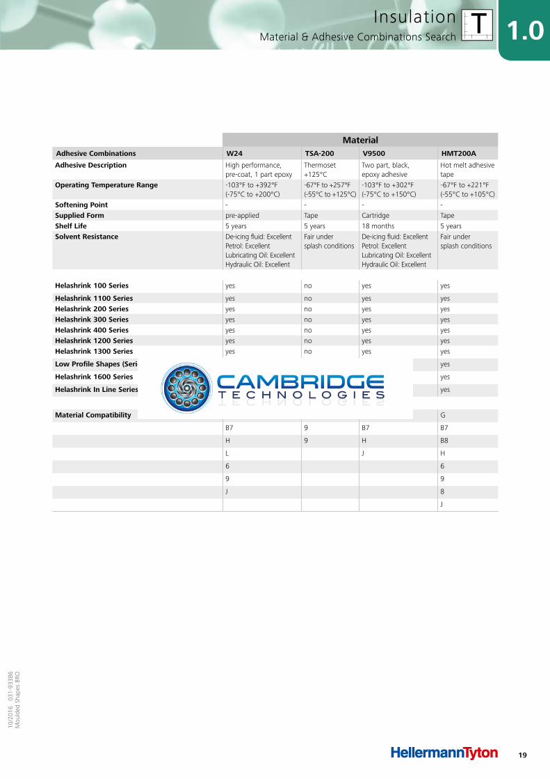
InsulationMaterial & Adhesive Combinations Search
MaterialAdhesive Combinations W24 TSA-200 V9500 HMT200A
Adhesive Description High performance,pre-coat, 1 part epoxy
Thermoset +125°C
Two part, black,epoxy adhesive
Hot melt adhesive tape
Operating Temperature Range -103°F to +392°F (-75°C to +200°C)
-67°F to +257°F (-55°C to +125°C)
-103°F to +302°F (-75°C to +150°C)
-67°F to +221°F (-55°C to +105°C)
Softening Point - - - -
Supplied Form pre-applied Tape Cartridge Tape
Shelf Life 5 years 5 years 18 months 5 years
Solvent Resistance De-icing fluid: ExcellentPetrol: ExcellentLubricating Oil: ExcellentHydraulic Oil: Excellent
Fair undersplash conditions
De-icing fluid: ExcellentPetrol: ExcellentLubricating Oil: ExcellentHydraulic Oil: Excellent
Fair undersplash conditions
Helashrink 100 Series yes no yes yes
Helashrink 1100 Series yes no yes yes
Helashrink 200 Series yes no yes yes
Helashrink 300 Series yes no yes yes
Helashrink 400 Series yes no yes yes
Helashrink 1200 Series yes no yes yes
Helashrink 1300 Series yes no yes yes
Low Profile Shapes (Series 313, 412, 492, 573) yes yes yes yes
Helashrink 1600 Series no no no yes
Helashrink In Line Series, low voltage no no no yes
Material Compatibility G 6 G G
B7 9 B7 B7
H 9 H B8
L J H
6 6
9 9
J 8
J

20
10/2
016
031
-933
86M
ould
ed S
hape
s BR
O
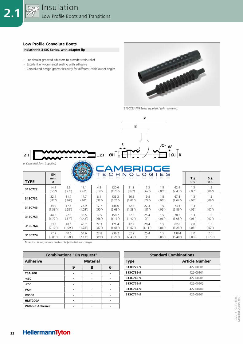
2.1 Low Profile Boots and Transitions
Convolute BootsHelashrink 313C Series, with adapter lip 22
Shim BootsHelashrink 313E Series, without adapter lip 23
Straight BootsHelashrink 313F Series, with adapter lip 24
Right Angle BootsHelashrink 333F Series, with adapter lip, 90° angle 25
Transition Boots
Helashrink 412H Series, side breakout 26
Helashrink 492H Series, 1 to 2 cables 27
Helashrink 573H Series, 1 to 3 cables 28
2.2 Bulbous Boots and Transitions
Bottle Shapes
Helashrink 150 Series, with rib, VG 29
Helashrink 100 Series, with rib, MIL 31
Helashrink 100 Series, without rib 33
Helashrink 120 Series, without rib 35
Helashrink 120 Series, with rib 35
Long Outlet ShapeHelashrink 130 Series, with rib, low profile, VG 36
Long Outlet Shapes Helashrink 140 Series, without rib 38
Bottle Shapes
Helashrink 160 Series, without rib 39
Helashrink 170 Series, with rib, VG 40
Helashrink 190 Series, with external ribs, VG 41
2-Way Outlet Shapes
Helashrink 200 Series, low profile 42
Helashrink 200 Series, VG 43
Helashrink 200 Series, in line, low voltage 44
3-Way Outlet ShapesHelashrink 300 Series, VG 45
Helashrink 300 Series, in line, low voltage 46
4-Way Outlet ShapesHelashrink 400 Series, VG 47
Helashrink 400 Series, in line, low voltage 48
5-Way Outlet Shapes Helashrink 500 Series, in line, low voltage 49
6-Way Outlet Shapes Helashrink 600 Series, in line, low voltage 50

21
210
/201
6 0
31-9
3386
Mou
lded
Sha
pes
BRO
Heat Shrinkable Moulded Shapes
Right-Angle Shapes
Helashrink 1100 Series, with rib, VG 51
Helashrink 1100 Series, without rib, thick wall, VG 52
Helashrink 1100 Series, with rib, MIL 53
Helashrink 1100 Series, without rib 55
Helashrink 1100 Series, with rib, low profile, VG style/MIL style 57
Helashrink 1100 Series, with rib, low profile, high ratio, VG 59
T-Shapes
Helashrink 1200 Series, VG/MIL 60
Helashrink 1200 Series, Offset 61
Helashrink 1200 Series, Offset, VG 62
Angled T-ShapesHelashrink 1300 Series, 30° & 45° angle, VG 63
Double T-Shapes Helashrink 1310 Series, 30° angle 64
Angle Elbow Shapes Helashrink 1400 Series, 90° angle 65
Connector Cover for Min-D Series Helashrink 1500 Series, with top entry 66
GSR Graduated Strain Relief Helashrink 1750 Series, with rib 68
Angle ShapesHelashrink 1800 Series, with rib, 30°, 45°, 60° angle 70
Right Angle Cross Shapes Helashrink 2000 Series - T-Joint 72
Locating Bushes Helashrink 1760, 1790, 1820 Series 73
Connector Cover for Min-D Series Helashrink 2100 Series, with 90° entry 74
22
2.1
10/2
016
031
-933
86M
ould
ed S
hape
s BR
O
TYPE
ØHmin.
a
ØHmax.
b
ØJmin.
a
ØJmax.
b P ±
10% R
max. JO ±10%
Wmin.
Bnom.
T ±0.5
S ± 0.5
313C722 14.2(.55“)
6.9(.27“)
11.1(.43“)
4.8(.19“)
120.6(4.70“)
21.1(.82“)
17.3(.67“)
1.5(.06“)
62.4(2.43“)
1.3(.05“)
1.5(.06“)
313C732 22.4(.87“)
11.7(.46“)
17.7(.69“)
8.1(.32“)
133.3(5.20“)
26.5(1.03“)
19.8(.77“)
1.5(.06“)
67.8(2.64“)
1.3(.05“)
1.5(.06“)
313C743 34.0(1.33“)
17.5(.68“)
26.9(1.05“)
12.7(.50“)
146.0(5.69“)
32.7(1.28“)
22.3(.87“)
1.5(.06“)
73.4(2.86“)
1.3(.05“)
1.8(.07“)
313C753 44.2(1.72“)
22.3(.87“)
36.5(1.42“)
17.5(.68“)
158.7(6.19“)
37.8(1.47“)
25.4(1“)
1.5(.06“)
78.2(3.05“)
1.3(.05“)
1.8(.07“)
313C764 53.8(2.10“)
40.6(1.09“)
45.7(1.78“)
22.3(.87“)
171.4(6.68“)
42.9(1.67“)
28.4(1.11“)
1.5(.06“)
82.8(3.23“)
2.0(.08“)
1.8(.07“)
313C774 77.2(3.01“)
40.6(1.58“)
54.6(2.13“)
22.8(.89“)
236.2(9.21“)
62.2(2.43“)
25.4(1“)
1.5(.06“)
138.4(5.40“)
2.0(.08“)
2.0(.078“)
Dimensions in mm, inches in brackets. Subject to technical changes.
a: Expanded form (supplied)
ØH ØJ
b: Fully recovered form (after heating)
P
B
JO-
ØJ
W
ØH RT
S
• For circular grooved adapters to provide strain relief • Excellent environmental sealing with adhesive• Convoluted design grants flexibility for different cable outlet angles
InsulationLow Profile Boots and Transitions
Low Profile Convolute Boots
313C722-774 Series supplied / fully recovered.
Helashrink 313C Series, with adapter lip
Combinations "On request"
Adhesive Material
9 8 6TSA-200 • • •
-450 • - •
-250 • - •
W24 • - •
V9500 • - •
HMT200A • - •
Without Adhesive • • •
Standard Combinations
Type Article Number313C722-9 422-00001
313C732-9 422-00101
313C743-9 422-00201
313C753-9 422-00302
313C764-9 422-00400
313C774-9 422-00501
23
2.110
/201
6 0
31-9
3386
Mou
lded
Sha
pes
BRO
TYPE
ØHmin.
a
ØHmax.
b
ØJmin.
a
ØJmax.
b P ±
10% HO ±10%
HW ± 25%
JW ±25%
JO ±10%
313E445 12.7(.50“)
12.7(.50“)
11.1(.43“)
3.3(.13“)
63.5(2.48“)
41.1(1.6“)
1.5(.06“)
1.5(.06“)
15.7(.61“)
313E447 20.8(.81“)
14.7(.57“)
20.6(.80“)
9.9(.39“)
63.5(2.48“)
41.1(1.6“)
1.5(.06“)
1.5(.06“)
16.5(.64“)
313E455 22.1(.86“)
22.1(.86“)
11.2(.44“)
3.3(.13“)
53.3(2.08“)
27.9(1.09“)
2.3(.089“)
1.5(.06“)
15.7(.61“)
313E457 22.1(.86“)
22.1(.86“)
20.6(.80“)
9.9(.39“)
53.3(2.08“)
27.9(1.09“)
2.3(.089“)
1.5(.06“)
14.0(.54“)
Dimensions in mm, inches in brackets. Subject to technical changes.
a: Expanded form (supplied)
ØJØH
b: Fully recovered form (after heating)
P
HO JOHW
ØH ØJ
JW
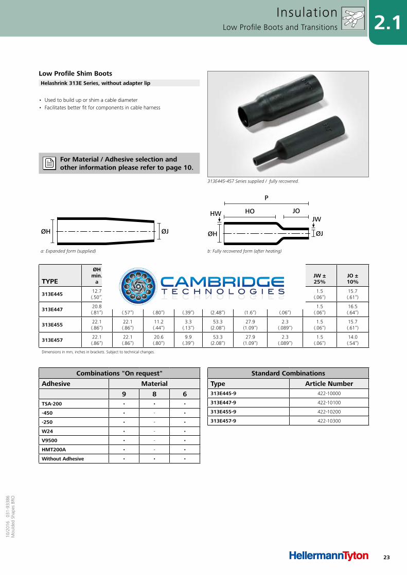
• Used to build up or shim a cable diameter • Facilitates better fit for components in cable harness
InsulationLow Profile Boots and Transitions
Low Profile Shim Boots
313E445-457 Series supplied / fully recovered.
Helashrink 313E Series, without adapter lip
Combinations "On request"
Adhesive Material
9 8 6TSA-200 • • •
-450 • - •
-250 • - •
W24 • - •
V9500 • - •
HMT200A • - •
Without Adhesive • • •
Standard Combinations
Type Article Number313E445-9 422-10000
313E447-9 422-10100
313E455-9 422-10200
313E457-9 422-10300
For Material / Adhesive selection and other information please refer to page 10.
24
2.1
10/2
016
031
-933
86M
ould
ed S
hape
s BR
O
TYPE
ØHmin.
a
ØHmax.
b
ØJmin.
a
ØJmax.
b P ±
10% R ±
15% T ±0.8
JO ±10%
HW ±1.5
JW ±0.8
S ±1.5
313F322 23.8(.93“)
9.9(.39“)
17.2(.67“)
6.6(.26“)
105.9(4.13“)
11.6(.45“)
1.3(.05“)
86.3(3.37“)
1.5(.06“)
1.5(.06“)
1.5(.06“)
313F332 27.1(1.06“)
13.2(.51“)
20.8(.81“)
7.6(.30“)
121.1(4.72“)
12.1(.47“)
1.3(.05“)
98.5(3.84“)
1.5(.06“)
1.5(.06“)
1.5(.06“)
313F343 30.9(1.21“)
18.5(.72“)
24.3(.95“)
8.9(.35“)
138.6(5.41“)
12.1(.47“)
1.3(.05“)
112.7(4.4“)
1.7(.066“)
1.5(.06“)
1.7(.066“)
313F353 35.6(1.39“)
22.1(.86“)
28.7(1.12“)
10.1(.39“)
159.5(6.22“)
12.1(.47“)
1.3(.05“)
13.8(5.1“)
1.7(.066“)
1.5(.06“)
1.7(.066“)
313F364 38.8(1.51“)
28.2(1.10“)
31.4(1.22“)
10.9(.43“)
177.8(6.93“)
13.9(.54“)
1.8(.07“)
142.2(5.54“)
1.7(.066“)
1.5(.06“)
1.7(.066“)
313F374 42.2(1.65“)
32.2(1.26“)
38.3(1.49“)
12.7(.50“)
203.2(7.92“)
15.2(.59“)
1.8(.07“)
163.0(6.36“)
1.7(.066“)
1.5(.06“)
1.7(.066“)
313F385 51.5(2.01“)
45.4(1.77“)
45.4(1.77“)
14.9(.58“)
203.2(7.92“)
15.2(.59“)
1.8(.07“)
157.7(6.15“)
1.7(.066“)
1.7(.066“)
1.7(.066“)
313F396 62.7(2.45“)
45.4(1.77“)
53.3(2.08“)
16.7(.65“)
228.6(8.92“)
16.0(.62“)
1.8(.07“)
153.1(5.97“)
1.7(.066“)
1.7(.066“)
1.7(.066“)
Dimensions in mm, inches in brackets. Subject to technical changes.
a: Expanded form (supplied)
ØJØH
b: Fully recovered form (after heating)
P
R
S
JO
ØJØH
JWHW
T
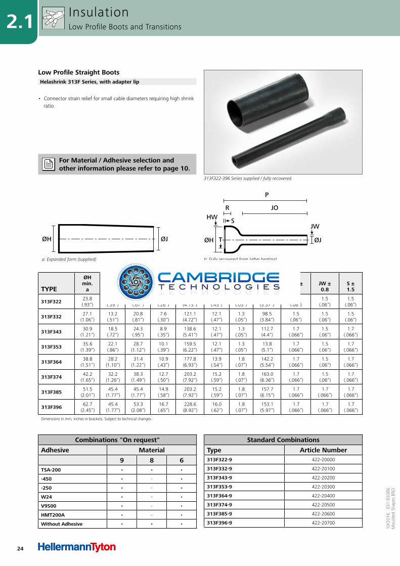
• Connector strain relief for small cable diameters requiring high shrink ratio
InsulationLow Profile Boots and Transitions
Low Profile Straight Boots
313F322-396 Series supplied / fully recovered.
Helashrink 313F Series, with adapter lip
Combinations "On request"
Adhesive Material
9 8 6TSA-200 • • •
-450 • - •
-250 • - •
W24 • - •
V9500 • - •
HMT200A • - •
Without Adhesive • • •
Standard Combinations
Type Article Number313F322-9 422-20000
313F332-9 422-20100
313F343-9 422-20200
313F353-9 422-20300
313F364-9 422-20400
313F374-9 422-20500
313F385-9 422-20600
313F396-9 422-20700
For Material / Adhesive selection and other information please refer to page 10.
25
2.110
/201
6 0
31-9
3386
Mou
lded
Sha
pes
BRO
TYPE
ØHmin.
a
ØHmax.
b
ØJmin.
a
ØJmax.
b P ±
10% R ±
15% T ±0.8
HW ±1.5
JW ±0.8
S ±1.5
333F322 23.8(.93“)
9.9(.39“)
17.2(.67“)
6.6(.26“)
105.1(4.10“)
18.5(.72“)
1.3(.05“)
1.5(.06“)
1.5(.06“)
1.5(.06“)
333F332 27.1(1.06“)
13.2(.51“)
20.8(.81“)
7.6(.30“)
115.8(4.52“)
19.8(.77“)
1.3(.05“)
1.5(.06“)
1.5(.06“)
1.5(.06“)
333F343 30.9(1.21“)
18.5(.72“)
24.3(.95“)
8.9(.35“)
146.3(5.71“)
20.8(.81“)
1.3(.05“)
1.7(.066“)
1.5(.06“)
1.7(.066“)
333F353 35.3(1.38“)
21.6(.84“)
28.7(1.12“)
10.1(.39“)
172.2(6.72“)
21.8(.85“)
1.3(.05“)
1.7(.066“)
1.5(.06“)
1.7(.066“)
333F364 38.8(1.51“)
27.9(1.09“)
31.4(1.22“)
10.9(.43“)
185.1(7.22“)
24.1(.94“)
1.8(.07“)
1.7(.066“)
1.5(.06“)
1.7(.066“)
333F374 45.2(1.76“)
34.0(1.33“)
38.3(1.49“)
12.1(.47“)
213.6(8.33“)
27.4(1.06“)
1.8(.07“)
1.7(.066“)
1.5(.06“)
1.7(.066“)
333F385 51.5(2.01“)
41.1(1.60“)
44.4(1.73“)
15.0(.59“)
224.5(8.76“)
29.4(1.15“)
1.7(.045“)
1.7(.066“)
1.7(.066“)
1.7(.066“)
Dimensions in mm, inches in brackets. Subject to technical changes.
Fully recovered form (after heating)
JO
a: Expanded form (supplied)
ØJØH
b: Fully recovered form (after heating)
P
ØH
T
HWS
R ØJ
JW
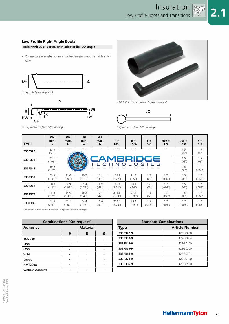
• Connector strain relief for small cable diameters requiring high shrink ratio
InsulationLow Profile Boots and Transitions
Low Profile Right Angle Boots
333F322-385 Series supplied / fully recovered.
Helashrink 333F Series, with adapter lip, 90° angle
Combinations "On request"
Adhesive Material
9 8 6TSA-200 • • •
-450 • - •
-250 • - •
W24 • - •
V9500 • - •
HMT200A • - •
Without Adhesive • • •
Standard Combinations
Type Article Number333F322-9 422-30000
333F332-9 422-30004
333F343-9 422-30100
333F353-9 422-30200
333F364-9 422-30301
333F374-9 422-30400
333F385-9 422-30500
26
2.1
10/2
016
031
-933
86M
ould
ed S
hape
s BR
O
TYPE
ØHmin.
a
ØHmax.
b
ØJ/Kmin.
a
ØJ/Kmax.
b HO/JO/KO
± 10% P
nom. W
nom. R/S
nom.
412H622 19.8(.77“)
6.6(.26“)
13.2(.51“)
6.6(.25“)
25.4(1“)
80.7(3.15“)
1.0(.039“)
40.3(1.57“)
412H623 34.2(1.33“)
11.4(.44“)
22.8(.88“)
6.6(.25“)
41.1(1.6“)
12.3(4.69“)
1.3(.05“)
60.1(2.34“)
412H624 60.1(2.34“)
20.0(.78“)
40.1(1.56“)
20(.78“)
63.5(2.47“)
175.7(6.85“)
1.5(.06“)
87.8(3.42“)
412H625 83.3(3.25“)
33.2(1.29“)
54.8(2.13“)
33.2(1.29“)
88.9(3.46“)
242.3(9.45“)
1.7(.066“)
121.1(4.72“)
Dimensions in mm, inches in brackets. Subject to technical changes.
a: Expanded form (supplied)
ØH
ØK
ØJ
b: Fully recovered form (after heating)
P
R
HO JO
W
ØJ
ØK
KOS
ØH
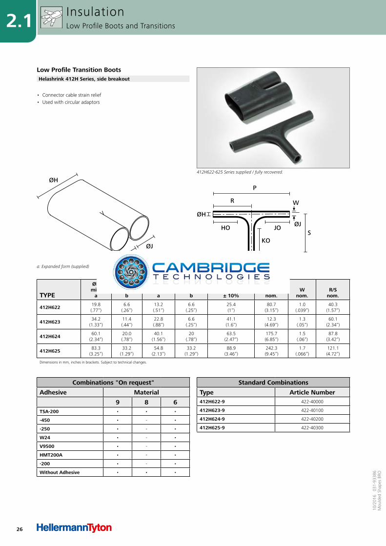
• Connector cable strain relief • Used with circular adaptors
InsulationLow Profile Boots and Transitions
Low Profile Transition Boots
412H622-625 Series supplied / fully recovered.
Helashrink 412H Series, side breakout
Combinations "On request"
Adhesive Material
9 8 6TSA-200 • • •
-450 • - •
-250 • - •
W24 • - •
V9500 • - •
HMT200A • - •
-200 • - •
Without Adhesive • • •
Standard Combinations
Type Article Number412H622-9 422-40000
412H623-9 422-40100
412H624-9 422-40200
412H625-9 422-40300

27
2.110
/201
6 0
31-9
3386
Mou
lded
Sha
pes
BRO
TYPE
ØHmin.
a
ØHmax.
b
ØJ/Kmin.
a
ØJ/Kmax.
b HO/JO/KO
± 15% W
nom. P/R/Snom.
492H412 19.8(.77“)
6.6(.26“)
13.2(.51“)
6.6(.25“)
25.4(1“)
1.0(.039“)
40.6(1.58“)
492H413 34.2(1.33“)
11.4(.44“)
22.8(.88“)
11.4(.44“)
41.1(1.6“)
1.3(.05“)
62.9(2.45“)
492H414 60.1(2.34“)
20.0(.78“)
40.1(1.56“)
20.0(.78“)
63.5(2.48“)
1.5(0.06“)
94.7(3.69“)
492H415 83.3(3.25“)
33.2(1.29“)
54.8(2.14“)
33.2(1.29“)
49.7(1.94“)
1.7(.066“)
133.8(5.22“)
Dimensions in mm, inches in brackets. Subject to technical changes.
a: Expanded form (supplied)
ØH
ØK
ØJ
b: Fully recovered form (after heating)
ØH
ØJ
ØKKO
HO
P
W
R
JO
S
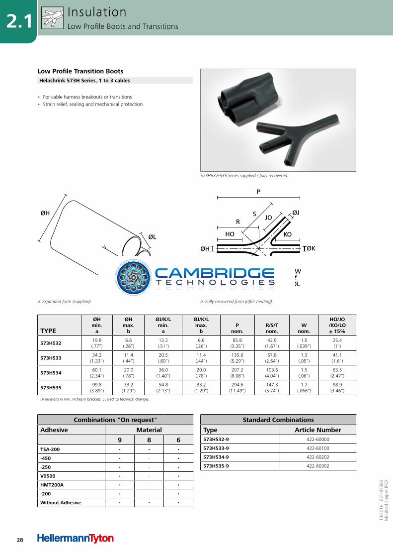
• For cable harness breakouts or transitions• Strain relief, sealing and mechanical protection
InsulationLow Profile Boots and Transitions
Low Profile Transition Boots
492H412-415 Series supplied / fully recovered.
Helashrink 492H Series, 1 to 2 cables
Combinations "On request"
Adhesive Material
9 8 6TSA-200 • • •
-450 • - •
-250 • - •
W24 • - •
V9500 • - •
HMT200A • - •
-200 • - •
Without Adhesive • • •
Standard Combinations
Type Article Number492H412-9 422-50000
492H413-9 422-50101
492H414-9 422-50202
492H415-9 422-50302
For Material / Adhesive selection and other information please refer to page 10.
28
2.1
10/2
016
031
-933
86M
ould
ed S
hape
s BR
O
TYPE
ØHmin.
a
ØHmax.
b
ØJ/K/Lmin.
a
ØJ/K/Lmax.
b P
nom. R/S/Tnom.
Wnom.
HO/JO/KO/LO± 15%
573H532 19.8(.77“)
6.6(.26“)
13.2(.51“)
6.6(.26“)
85.8(3.35“)
42.9(1.67“)
1.0(.039“)
25.4(1“)
573H533 34.2(1.33“)
11.4(.44“)
20.5(.80“)
11.4(.44“)
135.6(5.29“)
67.8(2.64“)
1.3(.05“)
41.1(1.6“)
573H534 60.1(2.34“)
20.0(.78“)
36.0(1.40“)
20.0(.78“)
207.2(8.08“)
103.6(4.04“)
1.5(.06“)
63.5(2.47“)
573H535 99.8(3.89“)
33.2(1.29“)
54.8(2.13“)
33.2(1.29“)
294.6(11.49“)
147.3(5.74“)
1.7(.066“)
88.9(3.46“)
Dimensions in mm, inches in brackets. Subject to technical changes.
a: Expanded form (supplied)
ØH
ØK
ØJ
ØL
b: Fully recovered form (after heating)
ØH ØK
ØJ
ØL
HO KO
RS
T
JO
LOW
P
• For cable harness breakouts or transitions• Strain relief, sealing and mechanical protection
InsulationLow Profile Boots and Transitions
Low Profile Transition Boots
573H532-535 Series supplied / fully recovered.
Helashrink 573H Series, 1 to 3 cables
Combinations "On request"
Adhesive Material
9 8 6TSA-200 • • •
-450 • - •
-250 • - •
V9500 • - •
HMT200A • - •
-200 • - •
Without Adhesive • • •
Standard Combinations
Type Article Number573H532-9 422-60000
573H533-9 422-60100
573H534-9 422-60202
573H535-9 422-60302
29
2.210
/201
6 0
31-9
3386
Mou
lded
Sha
pes
BRO
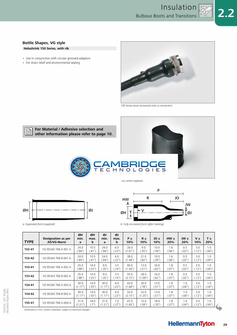
• Use in conjunction with circular grooved adaptors • For strain relief and environmental sealing
InsulationBulbous Boots and Transitions
Bottle Shapes, VG style
150 Series boot recovered onto a connectors.
Helashrink 150 Series, with rib
TYPEDesignation as per
AS/VG-Norm
ØHmin.
a
ØHmax.
b
ØJmin.
a
ØJmax.
b P ±
10% R ±10%
JO ±10%
HW ±20%
JW ±20%
V ± 10%
T ±20%
152-41 VG 95343 T06 A 001 A24.0(.94“)
10.5(.41“)
24.0(.94“)
6.0(.23“)
26.0(1.01“)
9.0(.35“)
10.0(.39“)
1.6(.06“)
0.5(.02“)
3.0(.12“)
1.0(.04“)
152-42 VG 95343 T06 B 001 A24.0(.94“)
10.5(.41“)
24.0(.94“)
6.0(.23“)
38.0(1.48“)
21.0(.82“)
10.0(.39“)
1.6(.06“)
0.5(.02“)
3.0(.12“)
1.0(.04“)
153-41 VG 95343 T06 A 002 A25.0(.98“)
14.0(.55“)
9.0(.35“)
3.5(.14“)
40.0(1.56“)
13.0(.51“)
16.0(.62“)
1.8(.07“)
0.5(.02“)
3.0(.12“)
1.0(.04“)
153-42 VG 95343 T06 B 002 A25.0(.98“)
14.0(.55“)
9.0(.35“)
3.5(.14“)
55.0(2.15“)
28.0(1.09“)
16.0(.62“)
1.8(.07“)
0.5(.02“)
3.0(.12“)
1.0(.04“)
154-41 VG 95343 T06 A 003 A30.0
(1.17“)14.0(.55“)
30.0(1.17“)
6.0(.23“)
43.0(1.68“)
20.0(.78“)
13.0(.51“)
1.8(.07“)
1.0(.04“)
3.0(.12“)
1.0(.04“)
154-42 VG 95343 T06 B 003 A30.0
(1.17“)14.0(.55“)
30.0(1.17“)
6.0(.23“)
55.0(2.15“)
32.0(1.25“)
13.0(.51“)
1.8(.07“)
1.0(.04“)
3.0(.12“)
1.0(.04“)
155-41 VG 95343 T06 A 004 A31.0
(1.21“)18.0(.7“)
31.0(1.21“)
7.0(.27“)
47.0(1.83“)
15.0(.59“)
18.0(.70“)
1.8(.07“)
1.0(.04“)
3.0(.12“)
1.0(.04“)
Dimensions in mm, inches in brackets. Subject to technical changes.
a: Expanded form (supplied)
ØJØH
b: Fully recovered form (after heating)
TØH
HW
V
R JO
P
ØJ
JW
150 Series supplied.
For Material / Adhesive selection and other information please refer to page 10.
30
2.2
10/2
016
031
-933
86M
ould
ed S
hape
s BR
O
Combinations "On request"
Adhesive Material
B7 G J H LWM250 • • • • -
W8 • • • • -
W24 • • • • •
W21 • • • • -
HMT200A • • • • -
V9500 • • • • •
Without Adhesive • • • • •
Standard Combinations
Type Article Number152-41-G 401-52780
152-42-G 401-52880
153-41-G 401-53780
153-42-G 401-53880
154-41-G 401-54780
154-42-G 401-54880
155-41-G 401-55780
155-42-G 401-55880
156-41-G 401-56780
156-42-G 401-56880
157-42-G 401-57880
157-43-G 401-57980
158-41-G 401-58780
158-43-G 401-58980
159-41-G 401-59780
159-42-G 401-59880
159-43-G 401-59980
160-41-G 401-60780
160-42-G 401-60880
160-43-G 401-60980
TYPEDesignation as per
AS/VG-Norm
ØHmin.
a
ØHmax.
b
ØJmin.
a
ØJmax.
b P ±
10% R ±10%
JO ±10%
HW ±20%
JW ±20%
V ± 10%
T ±20%
155-42 VG 95343 T06 B 004 A31.0
(1.21“)18.0(.7“)
31.0(1.21“)
7.0(.27“)
67.0(2.61“)
35.0(1.37“)
18.0(.7“)
1.8(.07“)
1.0(.04“)
3.0(.12“)
1.0(.04“)
156-41 VG 95343 T06 A 005 A36.0(1.4“)
22.5(.88“)
36.0(1.4“)
8.5(.33“)
60.0(2.34“)
22.0(.86“)
20.0(.78“)
2.0(.08“)
1.0(.04“)
3.0(.12“)
1.0(.04“)
156-42 VG 95343 T06 B 005 A36.0(1.4“)
22.5(.88“)
36.0(1.4“)
8.5(.33“)
80.0(3.12“)
42.0(1.64“)
20.0(.78“)
2.0(.08“)
1.0(.04“)
3.0(.12“)
1.0(.04“)
157-42 VG 95343 T06 B 006 A43.0
(1.68“)28.0
(1.09“)43.0
(1.68“)10.0(.39“)
79.0(3.08“)
41.0(1.6“)
20.0(.78“)
2.2(.09“)
1.0(.04“)
3.0(.12“)
1.7(.07“)
157-43 VG 95343 T06 C 001 A43.0
(1.68“)28.0
(1.09“)43.0
(1.68“)10.0(.39“)
99.0(3.86“)
61.0(2.38“)
20.0(.78“)
2.2(.09“)
1.0(.04“)
3.0(.12“)
1.7(.07“)
158-41 VG 95343 T06 A 007 A60.0
(2.34“)35.0
(1.37“)60.0
(2.34“)16.0(.62“)
90.0(3.51“)
32.0(1.25“)
38.0(1.48“)
3.2(.12“)
1.5(.06“)
3.0(.12“)
1.7(.07“)
158-43 VG 95343 T06 C 002 A60.0
(2.34“)35.0
(1.37“)60.0
(2.34“)16.0(.62“)
130.0(5.07“)
72.0(2.81“)
38.0(1.48“)
3.2(.12“)
1.5(.06“)
3.0(.12“)
1.7(.07“)
159-41 VG 95343 T06 A 008 A66.0
(2.57“)45.0
(1.76“)66.0
(2.57“)17.0(.66“)
130.0(5.07“)
50.0(1.95“)
50.0(1.95“)
3.8(.15“)
2.0(.08“)
3.0(.12“)
2.0(.08“)
159-42 VG 95343 T06 B 008 A66.0
(2.57“)45.0
(1.76“)66.0
(2.57“)17.0(.66“)
150.0(5.85“)
70.0(2.73“)
50.0(1.95“)
3.8(.15“)
2.0(.08“)
3.0(.12“)
2.0(.08“)
159-43 VG 95343 T06 C 003 A66.0
(2.57“)45.0
(1.76“)66.0
(2.57“)17.0(.66“)
171.0(6.67“)
90.0(3.51“)
50.0(1.95“)
3.8(.15“)
2.0(.08“)
3.0(.12“)
2.0(.08“)
160-41 VG 95343 T06 A 009 A82.0(3.2“)
58.0(2.26“)
82.0(3.2“)
27.0(1.05“)
137.0(5.34“)
37.0(1.44“)
62.0(2.42“)
3.8(.15“)
3.8(.15“)
3.0(.12“)
2.0(.08“)
160-42 VG 95343 T06 B 009 A82.0(3.2“)
58.0(2.26“)
82.0(3.2“)
27.0(1.05“)
158.0(6.16“)
58.0(2.26“)
62.0(2.42“)
3.8(.15“)
3.8(.15“)
3.0(.12“)
2.0(.08“)
160-43 VG 95343 T06 C 004 A82.0(3.2“)
58.0(2.26“)
82.0(3.2“)
27.0(1.05“)
213.0(8.31“)
113.0(4.41“)
62.0(2.42“)
3.8(.15“)
3.8(.15“)
3.0(.12“)
2.0(.08“)
Dimensions in mm, inches in brackets. Subject to technical changes.
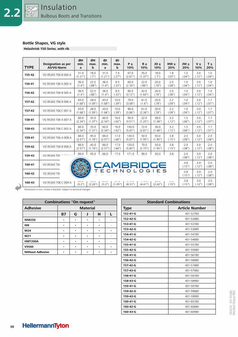
Bottle Shapes, VG styleHelashrink 150 Series, with rib
InsulationBulbous Boots and Transitions
31
2.210
/201
6 0
31-9
3386
Mou
lded
Sha
pes
BRO
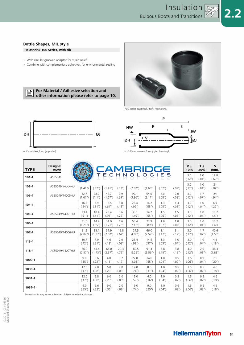
• With circular grooved adaptor for strain relief • Combine with complementary adhesives for environmental sealing
InsulationBulbous Boots and Transitions
Bottle Shapes, MIL style
100 series supplied / fully recovered.
Helashrink 100 Series, with rib
For Material / Adhesive selection and other information please refer to page 10.
TYPEDesignation as per
AS/VG-Norm
ØHmin.
a
ØHmax.
b
ØJmin.
a
ØJmax.
b P ±
10% R ±
10% HW ±20%
JW ±20%
V ± 10%
T ±20%
Snom.
101-4 AS85049/14003HU31.0
(1.21“)17.8(.69“)
31.0(1.21“)
7.1(.28“)
67.0(2.61“)
38.1(1.49“)
2.0(.08“)
2.0(.08“)
3.0(.12“)
1.0(.04“)
17.8(.69“)
102-4 AS85049/14004HU36.1
(1.41“)22.4(.87“)
36.1(1.41“)
8.4(.33“)
73.7(2.87“)
43.2(1.68“)
1.8(.07“)
1.8(.07“)
3.0(.12“)
1.0(.04“)
21(.82“)
103-4 AS85049/14005HU42.7
(1.67“)28.2(1.1“)
42.7(1.67“)
9.9(.39“)
99.1(3.86“)
54.0(2.11“)
2.0(.08“)
2.0(.08“)
3.0(.12“)
1.7(.07“)
24(.94“)
104-4 16.5(.64“)
7.9(.31“)
16.5(.64“)
3.8(.15“)
25.4(.99“)
14.2(.55“)
1.3(.05“)
1.3(.05“)
3.0(.12“)
1.0(.04“)
6.9(.27“)
105-4 AS85049/14001HU23.4(.91“)
10.4(.41“)
23.4(.91“)
5.6(.22“)
38.1(1.49“)
14.2(.55“)
1.5(.06“)
1.5(.06“)
3.0(.12“)
1.0(.04“)
10.2(.4“)
106-4 31.0(1.21“)
14.2(.55“)
31.0(1.21“)
6.6(.26“)
55.4(2.16“)
22.9(.89“)
1.8(.07“)
1.8(.07“)
3.0(.12“)
1.0(.04“)
10.2(.4“)
107-4 AS85049/14006HU51.9
(2.02“)35.1
(1.37“)51.9
(2.02“)15.8(.62“)
124.5(4.86“)
66.0(2.57“)
3.1(.12“)
3.1(.12“)
3.0(.12“)
1.7(.07“)
40.6(1.58“)
113-4 10.7(.42“)
7.9(.31“)
4.6(.18“)
2.0(.08“)
25.4(.99“)
14.5(.57“)
1.3(.05“)
1.0(.04“)
3.0(.12“)
1.0(.04“)
4.6(.18“)
118-4 AS85049/14007HU66.0
(2.57“)44.4
(1.73“)66.0
(2.57“)20.3(.79“)
160.5(6.26“)
91.4(3.56“)
3.8(.15“)
3.8(.15“)
3.0(.12“)
2.0(.08“)
48.3(1.88“)
1009-1 9.0(.35“)
5.6(.22“)
4.0(.16“)
3.2(.12“)
27.0(1.05“)
14.0(.55“)
1.0(.04“)
0.5(.02“)
1.6(.06“)
0.9(.04“)
7.5(.29“)
1030-4 12.0(.47“)
9.8(.38“)
6.0(.23“)
2.0(.08“)
19.0(.74“)
8.0(.31“)
1.0(.04“)
0.5(.02“)
1.5(.06“)
0.5(.02“)
4.6(.18“)
1031-4 12.0(.47“)
9.8(.38“)
6.0(.23“)
2.0(.08“)
15.0(.59“)
4.0(.16“)
1.0(.04“)
0.5(.02“)
1.5(.06“)
0.5(.02“)
4.6(.18“)
1037-4 9.0 (.35")
5.6 (.22")
9.0 (.35")
2.0 (.08")
19.0 (.74")
9.0 (.35")
1.0 (.04")
0.6 (.02")
1.5 (.06")
0.6 (.02")
4.5 (.18")
Dimensions in mm, inches in brackets. Subject to technical changes.
a: Expanded form (supplied)
ØJØH
b: Fully recovered form (after heating)
R
P
S
T VØH ØJ
JWHW

32
2.2
10/2
016
031
-933
86M
ould
ed S
hape
s BR
O
Combinations "On request"
Adhesive Material
B7 G J H LWM250 • • • • -
W8 • • • • -
W24 • • • • •
W21 • • • • -
HMT200A • • • • -
V9500 • • • • •
Without Adhesive • • • • •
Standard Combinations
Type Article Number101-4-G 401-01037
102-4-G 401-02031
103-4-G 401-03041
104-4-G 401-04024
105-4-G 401-05034
106-4-G 401-06036
107-4-G 401-07030
113-4-G 401-13480
118-4-B7 401-18018
1009-1-G 410-09001
1030-4-G 410-30480
1031-4-G 410-31001
1037-4-G 410-37001
InsulationBulbous Boots and Transitions
Bottle Shapes, MIL styleHelashrink 100 Series, with rib
33
2.210
/201
6 0
31-9
3386
Mou
lded
Sha
pes
BRO
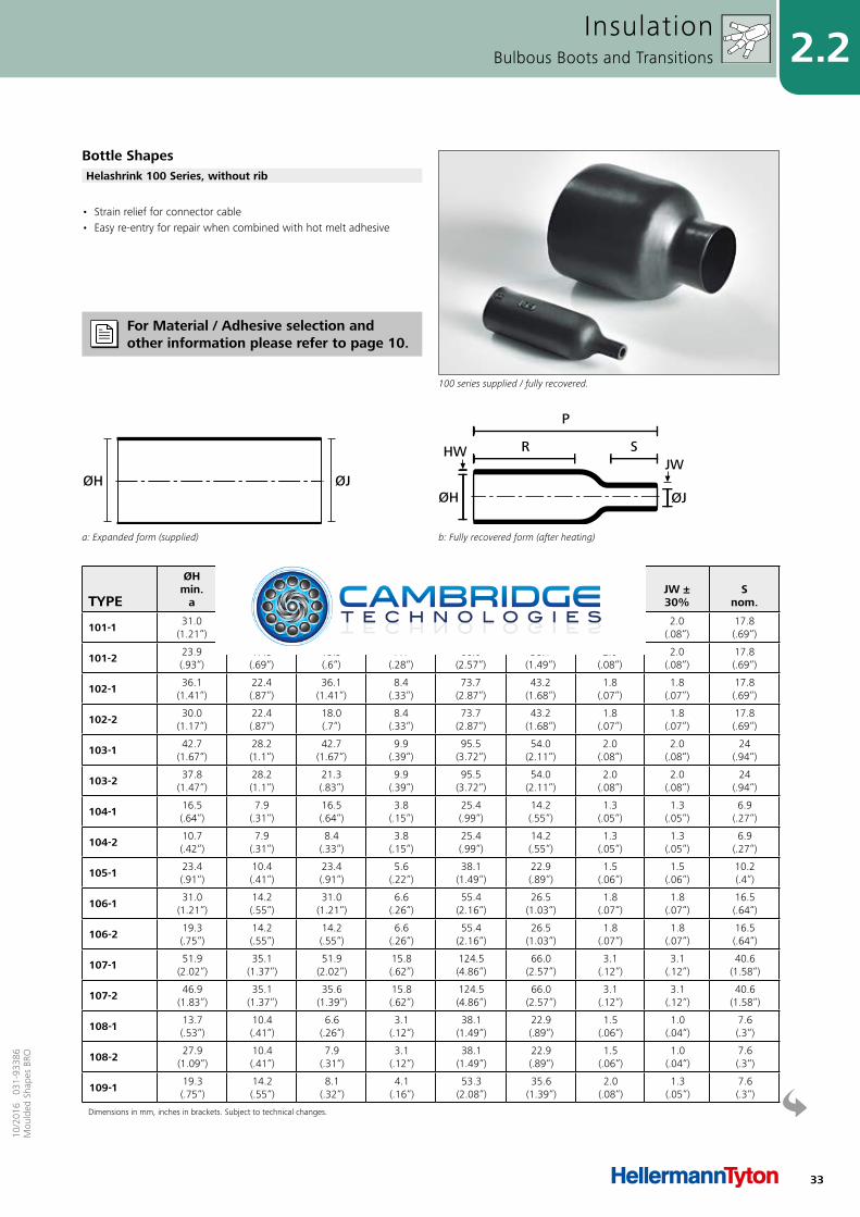
• Strain relief for connector cable • Easy re-entry for repair when combined with hot melt adhesive
InsulationBulbous Boots and Transitions
Bottle Shapes
100 series supplied / fully recovered.
Helashrink 100 Series, without rib
TYPE
ØHmin.
a
ØHmax.
b
ØJmin.
a
ØJmax.
b P ±
10% R
max. HW ±20%
JW ±30%
Snom.
101-1 31.0(1.21“)
17.8(.69“)
31.0(1.21“)
7.1(.28“)
66.0(2.57“)
38.1(1.49“)
2.0(.08“)
2.0(.08“)
17.8(.69“)
101-2 23.9(.93“)
17.8(.69“)
15.5(.6“)
7.1(.28“)
66.0(2.57“)
38.1(1.49“)
2.0(.08“)
2.0(.08“)
17.8(.69“)
102-1 36.1(1.41“)
22.4(.87“)
36.1(1.41“)
8.4(.33“)
73.7(2.87“)
43.2(1.68“)
1.8(.07“)
1.8(.07“)
17.8(.69“)
102-2 30.0(1.17“)
22.4(.87“)
18.0(.7“)
8.4(.33“)
73.7(2.87“)
43.2(1.68“)
1.8(.07“)
1.8(.07“)
17.8(.69“)
103-1 42.7(1.67“)
28.2(1.1“)
42.7(1.67“)
9.9(.39“)
95.5(3.72“)
54.0(2.11“)
2.0(.08“)
2.0(.08“)
24(.94“)
103-2 37.8(1.47“)
28.2(1.1“)
21.3(.83“)
9.9(.39“)
95.5(3.72“)
54.0(2.11“)
2.0(.08“)
2.0(.08“)
24(.94“)
104-1 16.5(.64“)
7.9(.31“)
16.5(.64“)
3.8(.15“)
25.4(.99“)
14.2(.55“)
1.3(.05“)
1.3(.05“)
6.9(.27“)
104-2 10.7(.42“)
7.9(.31“)
8.4(.33“)
3.8(.15“)
25.4(.99“)
14.2(.55“)
1.3(.05“)
1.3(.05“)
6.9(.27“)
105-1 23.4(.91“)
10.4(.41“)
23.4(.91“)
5.6(.22“)
38.1(1.49“)
22.9(.89“)
1.5(.06“)
1.5(.06“)
10.2(.4“)
106-1 31.0(1.21“)
14.2(.55“)
31.0(1.21“)
6.6(.26“)
55.4(2.16“)
26.5(1.03“)
1.8(.07“)
1.8(.07“)
16.5(.64“)
106-2 19.3(.75“)
14.2(.55“)
14.2(.55“)
6.6(.26“)
55.4(2.16“)
26.5(1.03“)
1.8(.07“)
1.8(.07“)
16.5(.64“)
107-1 51.9(2.02“)
35.1(1.37“)
51.9(2.02“)
15.8(.62“)
124.5(4.86“)
66.0(2.57“)
3.1(.12“)
3.1(.12“)
40.6(1.58“)
107-2 46.9(1.83“)
35.1(1.37“)
35.6(1.39“)
15.8(.62“)
124.5(4.86“)
66.0(2.57“)
3.1(.12“)
3.1(.12“)
40.6(1.58“)
108-1 13.7(.53“)
10.4(.41“)
6.6(.26“)
3.1(.12“)
38.1(1.49“)
22.9(.89“)
1.5(.06“)
1.0(.04“)
7.6(.3“)
108-2 27.9(1.09“)
10.4(.41“)
7.9(.31“)
3.1(.12“)
38.1(1.49“)
22.9(.89“)
1.5(.06“)
1.0(.04“)
7.6(.3“)
109-1 19.3(.75“)
14.2(.55“)
8.1(.32“)
4.1(.16“)
53.3(2.08“)
35.6(1.39“)
2.0(.08“)
1.3(.05“)
7.6(.3“)
Dimensions in mm, inches in brackets. Subject to technical changes.
a: Expanded form (supplied)
ØJØH
b: Fully recovered form (after heating)
R S
P
HW
ØJ
JW
ØH
For Material / Adhesive selection and other information please refer to page 10.
34
2.2
10/2
016
031
-933
86M
ould
ed S
hape
s BR
O
Combinations "On request"
Adhesive Material
B7 G J H LWM250 • • • • -
W8 • • • • -
W24 • • • • •
W21 - - - • -
HMT200A • • • • -
V9500 • • • • •
Without Adhesive • • • • -
Standard Combinations
Type Article Number101-1-G 401-01006
101-2-G 401-01026
102-1-G 401-02005
102-2-G 401-02020
103-1-G 401-03006
103-2-B7 401-03024
104-1-G 401-04006
104-2-G 401-04017
105-1-G 401-05005
106-1-G 401-06005
106-2-G 401-06023
107-1-G 401-07006
107-2-B7 401-07016
108-1-B7 401-08001
108-2-G 401-08016
109-1-B7 401-09002
109-2-G 401-09011
110-1-G 401-10005
110-2-G 401-10011
111-1-J 401-11003
111-2-G 401-11011
118-1-G 401-18005
119-1-B7 401-19001
1006-1-B7 410-06006
116-1-B7. 401-16007
InsulationBulbous Boots and Transitions
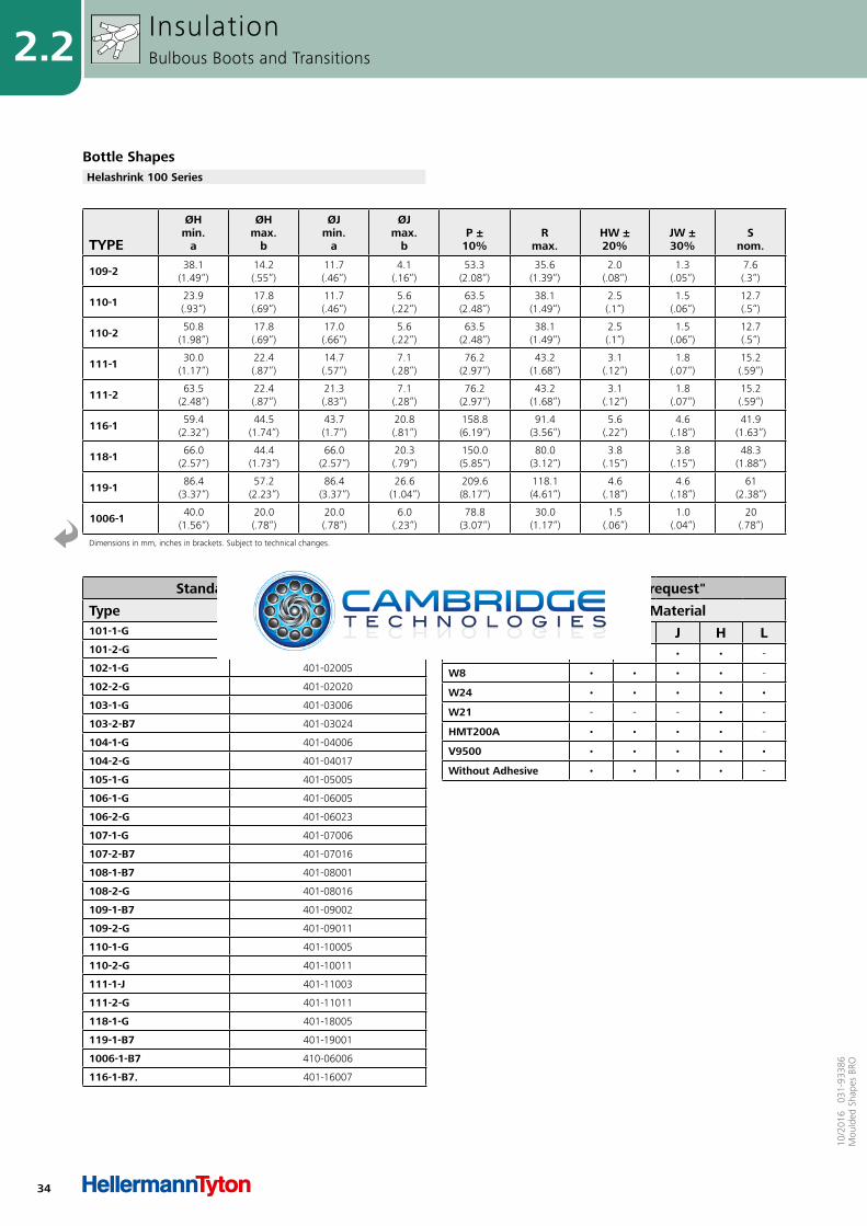
Bottle ShapesHelashrink 100 Series
TYPE
ØHmin.
a
ØHmax.
b
ØJmin.
a
ØJmax.
b P ±
10% R
max. HW ±20%
JW ±30%
Snom.
109-2 38.1(1.49“)
14.2(.55“)
11.7(.46“)
4.1(.16“)
53.3(2.08“)
35.6(1.39“)
2.0(.08“)
1.3(.05“)
7.6(.3“)
110-1 23.9(.93“)
17.8(.69“)
11.7(.46“)
5.6(.22“)
63.5(2.48“)
38.1(1.49“)
2.5(.1“)
1.5(.06“)
12.7(.5“)
110-2 50.8(1.98“)
17.8(.69“)
17.0(.66“)
5.6(.22“)
63.5(2.48“)
38.1(1.49“)
2.5(.1“)
1.5(.06“)
12.7(.5“)
111-1 30.0(1.17“)
22.4(.87“)
14.7(.57“)
7.1(.28“)
76.2(2.97“)
43.2(1.68“)
3.1(.12“)
1.8(.07“)
15.2(.59“)
111-2 63.5(2.48“)
22.4(.87“)
21.3(.83“)
7.1(.28“)
76.2(2.97“)
43.2(1.68“)
3.1(.12“)
1.8(.07“)
15.2(.59“)
116-1 59.4(2.32“)
44.5(1.74“)
43.7(1.7“)
20.8(.81“)
158.8(6.19“)
91.4(3.56“)
5.6(.22“)
4.6(.18“)
41.9(1.63“)
118-1 66.0(2.57“)
44.4(1.73“)
66.0(2.57“)
20.3(.79“)
150.0(5.85“)
80.0(3.12“)
3.8(.15“)
3.8(.15“)
48.3(1.88“)
119-1 86.4(3.37“)
57.2(2.23“)
86.4(3.37“)
26.6(1.04“)
209.6(8.17“)
118.1(4.61“)
4.6(.18“)
4.6(.18“)
61(2.38“)
1006-1 40.0(1.56“)
20.0(.78“)
20.0(.78“)
6.0(.23“)
78.8(3.07“)
30.0(1.17“)
1.5(.06“)
1.0(.04“)
20(.78“)
Dimensions in mm, inches in brackets. Subject to technical changes.
35
2.210
/201
6 0
31-9
3386
Mou
lded
Sha
pes
BRO
TYPE
ØHmin.
a
ØHmax.
b
ØJmin.
a
ØJmax.
b P ±
10% R ±
10% W ±20%
HW ±20%
JW ±20%
Snom.
120-1 16.5(.64“)
7.0(.27“)
10.2(.4“)
3.0(.12“)
60.9(2.38“)
24.0(.94“)
1.3(.05“)
1.3(.05“)
1.3(.05“)
32.0(1.25“)
120-2 20.3(.79“)
7.0(.27“)
10.2(.4“)
3.0(.12“)
60.9(2.38“)
24.0(.94“)
1.3(.05“)
1.3(.05“)
1.3(.05“)
32.0(1.25“)
120-3 16.5(.64“)
7.0(.27“)
10.7(.42“)
3.0(.12“)
38.0(1.48“)
24.0(.94“)
1.3(.05“)
1.3(.05“)
1.3(.05“)
9.1(.35“)
Dimensions in mm, inches in brackets. Subject to technical changes.
Fully recovered form without end ribs (after heating)
R S
P
ØJ
JWHW
ØH
a: Expanded form (supplied)
ØH ØJ
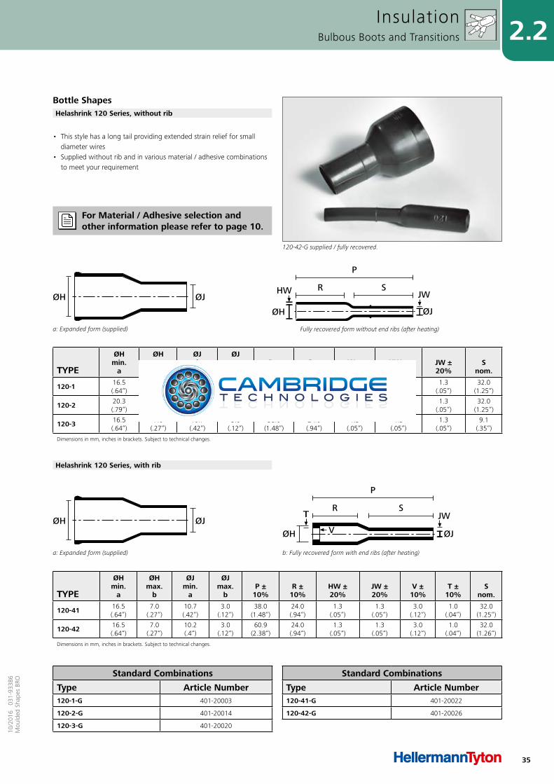
• This style has a long tail providing extended strain relief for small diameter wires
• Supplied without rib and in various material / adhesive combinations to meet your requirement
InsulationBulbous Boots and Transitions
Bottle Shapes
120-42-G supplied / fully recovered.
Helashrink 120 Series, without rib
TYPE
ØHmin.
a
ØHmax.
b
ØJmin.
a
ØJmax.
b P ±
10% R ±
10% HW ±20%
JW ±20%
V ± 10%
T ±10%
Snom.
120-41 16.5(.64“)
7.0(.27“)
10.7(.42“)
3.0(.12“)
38.0(1.48“)
24.0(.94“)
1.3(.05“)
1.3(.05“)
3.0(.12“)
1.0(.04“)
32.0(1.25“)
120-42 16.5(.64“)
7.0(.27“)
10.2(.4“)
3.0(.12“)
60.9(2.38“)
24.0(.94“)
1.3(.05“)
1.3(.05“)
3.0(.12“)
1.0(.04“)
32.0(1.26“)
Dimensions in mm, inches in brackets. Subject to technical changes.
a: Expanded form (supplied)
ØH ØJ
b: Fully recovered form with end ribs (after heating)
R
P
S
V ØJ
JWT
ØH
Helashrink 120 Series, with rib
Standard Combinations
Type Article Number120-41-G 401-20022
120-42-G 401-20026
Standard Combinations
Type Article Number120-1-G 401-20003
120-2-G 401-20014
120-3-G 401-20020
For Material / Adhesive selection and other information please refer to page 10.
36
2.2
10/2
016
031
-933
86M
ould
ed S
hape
s BR
O
TYPEDesignation as per
AS/VG-Norm
ØHmin.
a
ØHmax.
b
ØJmin.
a
ØJmax.
b P ±
10% R ±
10% HW ±20%
JW ±20%
V ± 10%
T ±10%
129-1 VG 95343 T06 D 001 A22.0(.86“)
12.0(.47“)
22.0(.86“)
6.5(.25“)
76.0(2.96“)
12.0(.47“)
1.5(.06“)
1.1(.04“)
3.0(.12“)
1.0(.04“)
129-4 AS85049/14009HU22.3(.87“)
11.4(.44“)
22.3(.87“)
6.5(.25“)
105.9(4.13“)
11.7(.46“)
1.5(.06“)
1.1(.04“)
3.0(.12“)
1.0(.04“)
130-1 VG 95343 T06 D 002 A25.5(.99“)
15.0(.59“)
25.5(.99“)
7.5(.29“)
83.0(3.24“)
12.0(.47“)
1.5(.06“)
1.1(.04“)
3.0(.12“)
1.0(.04“)
130-4 AS85049/14010HU25.6(1“)
15.0(.59“)
25.6(1“)
7.4(.29“)
121.2(4.73“)
12.2(.48“)
1.5(.06“)
1.1(.04“)
3.0(.12“)
1.0(.04“)
131-1 VG 95343 T06 D 003 A29.0
(1.13“)19.0(.74“)
29.0(1.13“)
8.5(.33“)
89.0(3.47“)
12.0(.47“)
1.8(.07“)
1.1(.04“)
3.0(.12“)
1.0(.04“)
131-4 AS85049/14011HU29.4
(1.15“)18.8(.73“)
29.4(1.15“)
8.4(.33“)
138.7(5.41“)
12.2(.48“)
1.8(.07“)
1.1(.04“)
1.0(.04“)
1.0(.04“)
132-1 VG 95343 T06 D 004 A34.0
(1.33“)23.0(.9“)
34.0(1.33“)
10.0(.39“)
102.0(3.98“)
12.0(.47“)
1.8(.07“)
1.1(.04“)
3.0(.12“)
1.0(0.39“)
132-2 34.0(1.33“)
22.9(.89“)
34.0(1.33“)
9.7(.38“)
35.0(1.37“)
12.2(.48“)
1.8(.07“)
1.1(.04“)
3.0(.12“)
1.0(.04“)
132-4 AS85049/14012HU34.0
(1.33“)22.9(.89“)
34.0(1.33“)
9.7(.38“)
159.5(6.22“)
12.2(.48“)
1.8(.07“)
1.1(.04“)
3.0(.12“)
1.0(.04“)
133-1 VG 95343 T06 D 005 A37.0
(1.44“)30.0
(1.17“)37.0
(1.44“)11.0(.43“)
108.0(4.21“)
14.0(.55“)
2.0(.08“)
1.1(.04“)
3.0(.12“)
1.7(.07“)
133-2 37.3(1.45“)
26.9(1.05“)
37.3(1.45“)
10.4(.41“)
47.0(1.83“)
14.0(.55“)
2.0(.08“)
1.1(.04“)
3.0(.12“)
1.7(.07“)
133-3 37.3(1.45“)
29.5(1.15“)
37.3(1.45“)
10.4(.41“)
60.0(2.34“)
14.0(.55“)
2.0(.08“)
1.1(.04“)
3.0(.12“)
1.7(.07“)
133-4 AS85049/14013HU37.3
(1.45“)26.9
(1.05“)37.3
(1.45“)10.4(.41“)
177.8(6.93“)
14.0(.55“)
2.0(.08“)
1.1(.04“)
3.0(.12“)
1.7(.07“)
134-1 VG 95343 T06 D 006 A43.5(1.7“)
34.0(1.33“)
43.5(1.7“)
12.0(.47“)
114.0(4.45“)
15.0(.59“)
2.0(.08“)
1.1(.04“)
3.0(.12“)
1.7(.07“)
134-4 AS85049/14014HU43.7(1.7“)
34.0(1.33“)
43.7(1.7“)
12.2(.48“)
203.2(7.92“)
15.2(.59“)
2.0(.08“)
1.1(.04“)
3.0(.12“)
1.7(.07“)
135-1 VG 95343 T06 D 007 A50.0
(1.95“)41.0(1.6“)
50.0(1.95“)
14.5(.57“)
118.0(4.6“)
15.0(.59“)
2.3(.09“)
1.4(.05“)
3.0(.12“)
1.7(.07“)
135-4 AS85049/14015HU50.0
(1.95“)41.2
(1.61“)50.0
(1.95“)14.2(.55“)
203.2(7.92“)
15.2(.59“)
2.3(.09“)
1.4(.05“)
3.0(.12“)
1.7(.07“)
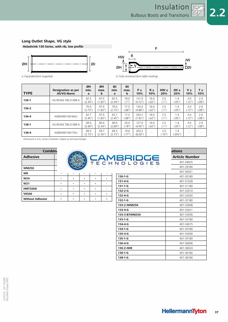
Dimensions in mm, inches in brackets. Subject to technical changes.
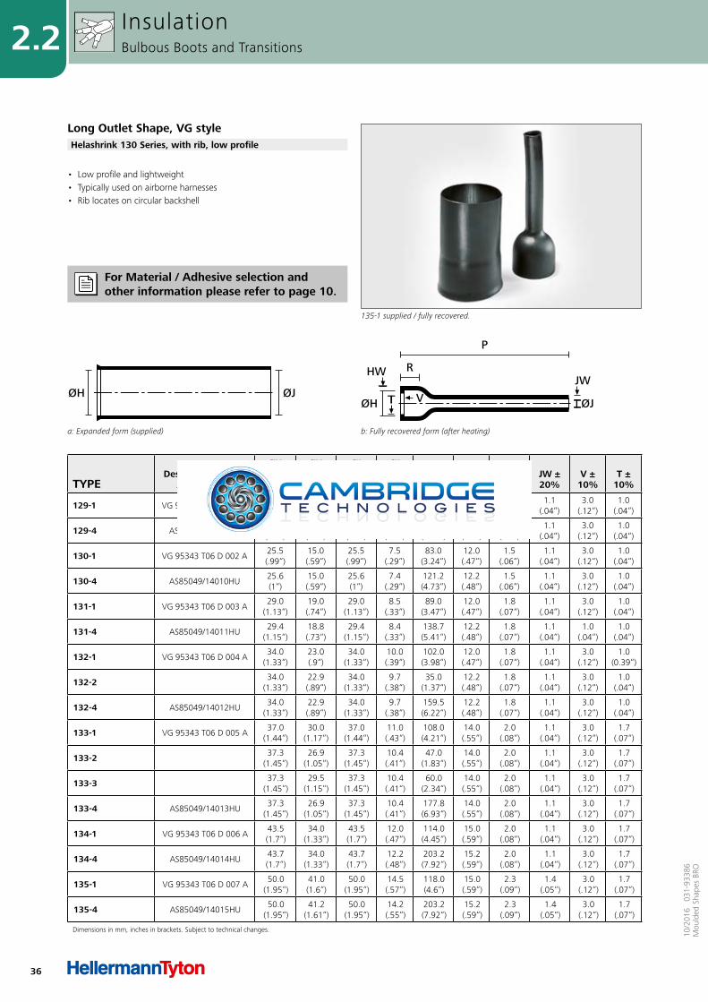
a: Expanded form (supplied)
ØJØH
b: Fully recovered form (after heating)
R
P
V ØJ
JW
TØH
HW
• Low profile and lightweight• Typically used on airborne harnesses• Rib locates on circular backshell
InsulationBulbous Boots and Transitions
Long Outlet Shape, VG style
135-1 supplied / fully recovered.
Helashrink 130 Series, with rib, low profile
For Material / Adhesive selection and other information please refer to page 10.
37
2.210
/201
6 0
31-9
3386
Mou
lded
Sha
pes
BRO
a: Expanded form (supplied)
ØJØH
b: Fully recovered form (after heating)
R
P
V ØJ
JW
TØH
HW
TYPEDesignation as per
AS/VG-Norm
ØHmin.
a
ØHmax.
b
ØJmin.
a
ØJmax.
b P ±
10% R ±
10% HW ±20%
JW ±20%
V ± 10%
T ±10%
136-1 VG 95343 T06 D 008 A62.5
(2.44“)47.0
(1.83“)62.5
(2.44“)18.0(.7“)
121.0(4.72“)
16.0(.62“)
2.5(.1“)
1.4(.05“)
3.0(.12“)
2.0(.08“)
136-2 70.0(2.73“)
47.0(1.83“)
70.0(2.73“)
17.5(.68“)
125.0(4.88“)
16.0(.62“)
2.5(.1“)
1.4(.05“)
3.0(.12“)
2.0(.08“)
136-4 AS85049/14016HU62.7
(2.45“)47.0
(1.83“)62.7
(2.45“)17.5(.68“)
203.2(7.92“)
16.0(.62“)
2.5(.1“)
1.4(.05“)
3.0(.12“)
2.0(.08“)
138-1 VG 95343 T06 D 009 A69.0
(2.69“)60.0
(2.34“)69.0
(2.69“)20.0(.78“)
127.0(4.95“)
16.0(.62“)
2.5(.1“)
1.4(.05“)
3.0(.12“)
2.0(.08“)
138-4 AS85049/14017HU69.3
(2.73“)59.7
(2.35“)69.3
(2.73“)19.6(.77“)
203.2(8.00“)
-2.5
(.10“)1.4
(.055“)- -
Dimensions in mm, inches in brackets. Subject to technical changes.
Combinations "On request"
Adhesive Material
B7 G J H LWM250 • • • • -
W8 • • • • -
W24 • • • • •
W21 • • • • -
HMT200A • • • • -
V9500 • • • • •
Without Adhesive • • • • •
Standard Combinations
Type Article Number129-4-G 401-29025
129-1-G 401-29180
130-4-G 401-30021
130-1-G 401-30180
131-4-G 401-31028
131-1-G 401-31180
132-2-G 401-32014
132-4-G 401-32030
132-1-G 401-32180
133-2-JWM250 401-33008
133-4-G 401-33021
133-3-B7WM250 401-33036
133-1-G 401-33180
134-4-G 401-34015
134-1-G 401-34180
135-4-G 401-35009
135-1-G 401-35180
136-4-G 401-36006
136-2-JW8 401-36024
136-1-G 401-36180
138-1-G 401-38180
InsulationBulbous Boots and Transitions
Long Outlet Shape, VG styleHelashrink 130 Series, with rib, low profile
38
2.2
10/2
016
031
-933
86M
ould
ed S
hape
s BR
O
TYPE
ØHmin.
a
ØHmax.
b
ØJmin.
a
ØJmax.
b P ±
10% R ±
10% HW ±20%
JW ±30%
Snom.
146-1 20.1(.78“)
14.5(.57“)
20.1(.78“)
5.3(.21“)
127.0(4.95“)
15.7(.61“)
2.0(.08“)
2.0(.08“)
97.0(3.78“)
146-2 22.3(.87“)
14.5(.57“)
10.2(.4“)
5.3(.21“)
127.0(4.95“)
15.7(.61“)
2.0(.08“)
2.0(.08“)
97.0(3.78“)
148-1 30.5(1.19“)
18.0(.7“)
30.5(1.19“)
7.9(.31“)
146.0(5.69“)
15.7(.61“)
2.0(.08“)
2.0(.08“)
125.0(4.88“)
148-2 30.5(1.19“)
18.0(.7“)
15.2(.59“)
7.9(.31“)
146.0(5.69“)
15.7(.61“)
2.3(.09“)
2.3(.09“)
125.0(4.88“)
149-1 41.2(1.61“)
21.8(.85“)
41.2(1.61“)
10.2(.4“)
162.1(6.32“)
22.4(.87“)
2.3(.09“)
2.3(.09“)
127.0(4.95“)
Dimensions in mm, inches in brackets. Subject to technical changes.
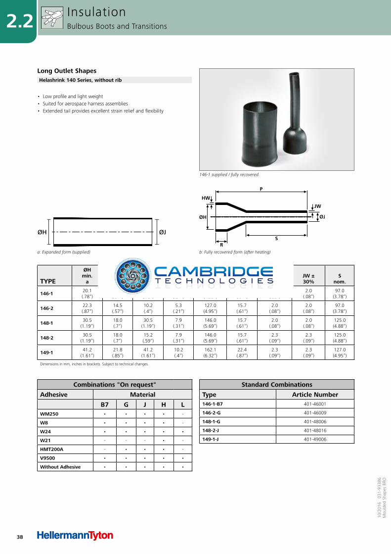
a: Expanded form (supplied)
ØJØH
b: Fully recovered form (after heating)
• Low profile and light weight• Suited for aerospace harness assemblies• Extended tail provides excellent strain relief and flexibility
InsulationBulbous Boots and Transitions
Long Outlet Shapes
146-1 supplied / fully recovered.
Helashrink 140 Series, without rib
Combinations "On request"
Adhesive Material
B7 G J H LWM250 • • • • -
W8 • • • • -
W24 • • • • •
W21 - - - • -
HMT200A - • • • -
V9500 • • • • •
Without Adhesive • • • • •
Standard Combinations
Type Article Number146-1-B7 401-46001
146-2-G 401-46009
148-1-G 401-48006
148-2-J 401-48016
149-1-J 401-49006
39
2.210
/201
6 0
31-9
3386
Mou
lded
Sha
pes
BRO
TYPE
ØHmin.
a
ØHmax.
b
ØJmin.
a
ØJmax.
b P ±
10% R ±
10% HW ±20%
JW ±20%
Snom.
162-1 22.0(.86“)
14.2(.55“)
9.0(.35“)
4.1(.16“)
44.0(1.72“)
15.7(.61“)
1.8(.07“)
1.8(.07“)
16.0(.62“)
Dimensions in mm, inches in brackets. Subject to technical changes.
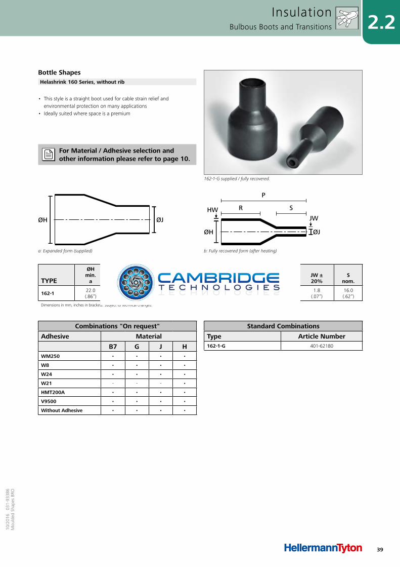
a: Expanded form (supplied)
ØJØH
b: Fully recovered form (after heating)
HW
ØH
R S
P
ØJ
JW
• This style is a straight boot used for cable strain relief and environmental protection on many applications
• Ideally suited where space is a premium
InsulationBulbous Boots and Transitions
Bottle Shapes
162-1-G supplied / fully recovered.
Helashrink 160 Series, without rib
Combinations "On request"
Adhesive Material
B7 G J HWM250 • • • •
W8 • • • •
W24 • • • •
W21 - - - •
HMT200A • • • •
V9500 • • • •
Without Adhesive • • • •
Standard Combinations
Type Article Number162-1-G 401-62180
For Material / Adhesive selection and other information please refer to page 10.
40
2.2
10/2
016
031
-933
86M
ould
ed S
hape
s BR
O
TYPEDesignation as per
AS/VG-Norm
ØHmin.
a
ØHmax.
b
ØJmin.
a
ØJmax.
b P ±
10% R ±
10% T ±
20% JW
nom. HW ±20%
Vmax.
Snom.
176-1 VG 95343 T06 D 011 A19.3(.75“)
13.0(.51“)
6.3(.25“)
2.1(.08“)
60.0(2.34“)
11.7(.46“)
1.0(.04“)
1.1(.04“)
1.5(.06“)
3.3(.13“)
38.0(1.48“)
176-2 19.0(.74“)
13.0(.51“)
6.0(.23“)
2.0(.08“)
30.0(1.17“)
11.7(.46“)
1.0(.04“)
1.1(.04“)
1.5(.06“)
3.3(.13“)
8.0(.31“)
176-3 25.0(.98“)
13.0(.51“)
4.0(.16“)
2.0(.08“)
45.0(1.76“)
11.7(.46“)
1.0(.04“)
1.1(.04“)
1.5(.06“)
3.3(.13“)
23.0(.9“)
176-4 AS85049/14019HU19.0(.74“)
13.0(.51“)
6.0(.23“)
2.0(.08“)
60.0(2.34“)
11.7(.46“)
1.0(.04“)
1.1(.04“)
1.5(.06“)
3.3(.13“)
38.0(1.48“)
177-1 AS85049/14020HU26.1
(1.02“)19.1(.75“)
7.6(.30“)
2.6(.10“)
74.2(2.91“)
12.2(.48“)
1.0(.04“)
1.1(.04“)
1.8(.07“)
3.3(.13“)
45.0(1.77“)
178-1AS85049/14021HU 34.2
(1.33“)26.0
(1.01“)9.6
(.37“)3.1
(.12“)84.0
(3.28“)12.2(.48“)
1.0(.04“)
1.1(.04“)
1.8(.07“)
3.3(.13“)
51.0(1.99“)VG 95343 T06 D 013 A
179-1AS85049/14022HU 43.6
(1.7“)34.1
(1.33“)11.4(.44“)
3.6(.14“)
100.0(3.9“)
12.2(.48“)
1.7(.07“)
1.1(.04“)
1.8(.07“)
3.3(.13“)
58.0(2.26“)VG 95343 T06 D 014 A
Dimensions in mm, inches in brackets. Subject to technical changes.
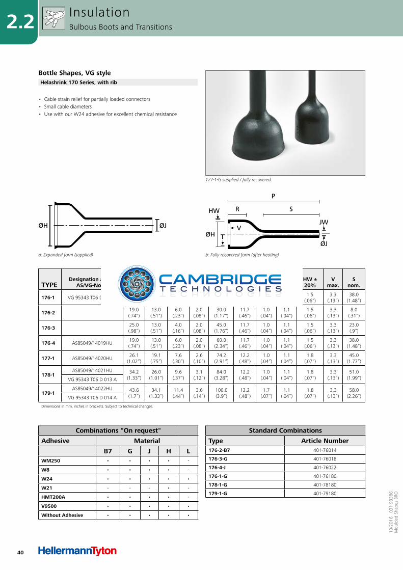
a: Expanded form (supplied)
ØJØH
b: Fully recovered form (after heating)
TØH
HW
ØJ
JW
R S
P
V
• Cable strain relief for partially loaded connectors• Small cable diameters• Use with our W24 adhesive for excellent chemical resistance
InsulationBulbous Boots and Transitions
Bottle Shapes, VG style
177-1-G supplied / fully recovered.
Helashrink 170 Series, with rib
Combinations "On request"
Adhesive Material
B7 G J H LWM250 • • • • -
W8 • • • • -
W24 • • • • •
W21 - - - • -
HMT200A • • • • -
V9500 • • • • •
Without Adhesive • • • • •
Standard Combinations
Type Article Number176-2-B7 401-76014
176-3-G 401-76018
176-4-J 401-76022
176-1-G 401-76180
178-1-G 401-78180
179-1-G 401-79180
41
2.210
/201
6 0
31-9
3386
Mou
lded
Sha
pes
BRO
TYPEDesignation as per
AS/VG-Norm
ØHmin.
a
ØHmax.
b
ØJmin.
a
ØJmax.
b P ±
10% R ±
10% HW ±20%
JW ±20%
V ± 10%
T ±10%
T ±20%
Snom.
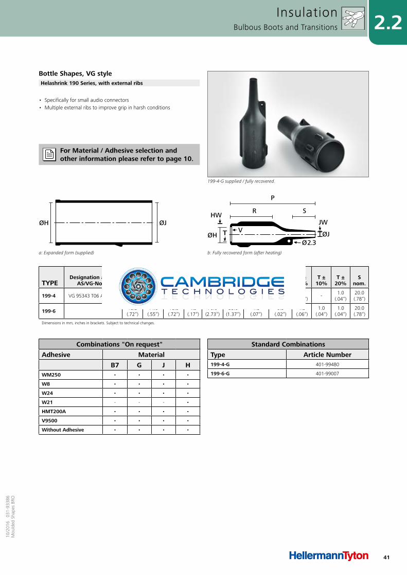
199-4 VG 95343 T06 A 010 A17.5(.68“)
14.0(.55“)
7.0(.27“)
4.3(.17“)
70.0(2.73“)
35.0(1.37“)
1.8(.07“)
0.5(.02“)
1.5(.06“)
-1.0
(.04“)20.0(.78“)
199-6 18.5(.72“)
14.0(.55“)
18.5(.72“)
4.3(.17“)
70.0(2.73“)
35.0(1.37“)
1.8(.07“)
0.5(.02“)
1.5(.06“)
1.0(.04“)
1.0(.04“)
20.0(.78“)
Dimensions in mm, inches in brackets. Subject to technical changes.
a: Expanded form (supplied)
ØJØH
b: Fully recovered form (after heating)
R S
P
ØJØ2.3
JW
TØH
HW
V
• Specifically for small audio connectors • Multiple external ribs to improve grip in harsh conditions
InsulationBulbous Boots and Transitions
Bottle Shapes, VG style
199-4-G supplied / fully recovered.
Helashrink 190 Series, with external ribs
Combinations "On request"
Adhesive Material
B7 G J HWM250 • • • •
W8 • • • •
W24 • • • •
W21 - - - •
HMT200A • • • •
V9500 • • • •
Without Adhesive • • • •
Standard Combinations
Type Article Number199-4-G 401-99480
199-6-G 401-99007
For Material / Adhesive selection and other information please refer to page 10.
42
2.2
10/2
016
031
-933
86M
ould
ed S
hape
s BR
O
TYPE
ØHmin.
a
ØHmax.
b
ØJmin.
a
ØJmax.
b
ØKmin.
a
ØKmax.
b P ±
10% R ±
10% W ±20%
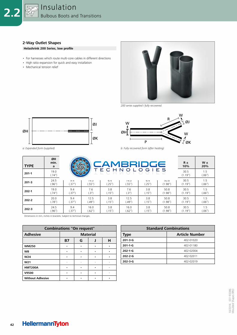
201-1 19.0(.74“)
9.4(.37“)
6.4(.25“)
14.0(.55“)
6.4(.25“)
14.0(.55“)
50.8(1.98“)
30.5(1.19“)
1.5(.06“)
201-3 24.5(.96“)
9.4(.37“)
14.0(.55“)
6.4(.25“)
14.0(.55“)
6.4(.25“)
50.8(1.98“)
30.5(1.19“)
1.5(.06“)
202-1 19.0(.74“)
9.4(.37“)
7.6(.3“)
3.8(.15“)
7.6(.3“)
3.8(.15“)
50.8(1.98“)
30.5(1.19“)
1.5(.06“)
202-2 20.0(.78“)
9.4(.37“)
12.5(.49“)
3.8(.15“)
12.5(.49“)
3.8(.15“)
50.8(1.98“)
30.5(1.19“)
1.5(.06“)
202-3 24.5(.96“)
9.4(.37“)
16.0(.62“)
3.8(.15“)
16.0(.62“)
3.8(.15“)
50.8(1.98“)
30.5(1.19“)
1.5(.06“)
Dimensions in mm, inches in brackets. Subject to technical changes.
a: Expanded form (supplied)
ØJ
ØK
ØH
b: Fully recovered form (after heating)
ØH
W
P
WR
ØJ
ØK
W
• For harnesses which route multi-core cables in different directions• High ratio expansion for quick and easy installation• Mechanical tension relief
InsulationBulbous Boots and Transitions
2-Way Outlet Shapes
200 series supplied / fully recovered.
Helashrink 200 Series, low profile
Combinations "On request"
Adhesive Material
B7 G J HWM250 • • • •
W8 • • • •
W24 • • • •
W21 - - - -
HMT200A • • • -
V9500 • • • -
Without Adhesive • • • •
Standard Combinations
Type Article Number201-3-G 402-01020
201-1-G 402-01180
202-1-G 402-02004
202-2-G 402-02011
202-3-G 402-02019

43
2.210
/201
6 0
31-9
3386
Mou
lded
Sha
pes
BRO
TYPEDesignation as per
AS/VG-Norm
ØHmin.
a
ØHmax.
b
ØJmin.
a
ØJmax.
b P ±
10% R ±
10% HW ±20%
JW nom.
Snom.
203-1AS85049/14206HU 27.0
(1.05“)12.0(.47“)
13.0(.51“)
6.0(.23“)
80.0(3.15“)
43.0(1.68“)
2.5(.1“)
1.5(.06“)
43.0(1.68“)VG 95343 T08 C 002 A
204-1AS85049/14207HU 39.0
(1.52“)18.0(.7“)
27.0(1.05“)
12.0(.47“)
66.0(2.57“)
81.0(3.16“)
3.1(.12“)
2.0(.08“)
81.0(3.16“)VG 95343 T08 C 003 A
206-1AS85049/14205HU 13.0
(.51“)6.0
(.23“)7.0
(.27“)3.0
(.12“)41.0
(1.62“)19.0(.74“)
1.5(.06“)
1.0(.04“)
19.0(.74“)VG 95343 T08 C 001 A
212-1 VG 95343 T08 C 005 A14.5(.57“)
8.0(.31“)
8.5(.33“)
5.5(.21“)
82.6(3.22“)
83.0(3.24“)
2.3(.09“)
2.0(.08“)
63.0(2.46“)
213-1 17.3(.67“)
7.9(.31“)
11.1(.43“)
7.9(.31“)
140.0(5.46“)
83.1(3.24“)
2.3(.09“)
1.0(.04“)
64.0(2.5“)
213-2 40.0(1.56“)
8.5(.33“)
31.8(1.24“)
7.9(.31“)
140.0(5.46“)
83.1(3.24“)
2.3(.09“)
2.3(.09“)
64.0(2.5“)
Dimensions in mm, inches in brackets. Subject to technical changes.
a: Expanded form (supplied)
ØJØH
b: Fully recovered form (after heating)
HW
ØH
P
R
S
JW
ØJ
• Mechanical tension relief in cable harnesses
InsulationBulbous Boots and Transitions
2-Way Outlet Shapes, VG style
203-1 supplied / fully recovered.
Helashrink 200 Series
Combinations "On request"
Adhesive Material
B7 G J H LWM250 • • • • -
W8 • • • • -
W24 • • • • •
W21 - - - • -
HMT200A • • • - -
V9500 • • • - •
Without Adhesive • • • • •
Standard Combinations
Type Article Number203-1-G 402-03180
204-1-G 402-04180
206-1-G 402-06180
212-1-G 402-12180
213-1-G 402-13180
213-2-G 402-13021
For Material / Adhesive selection and other information please refer to page 10.
44
2.2
10/2
016
031
-933
86M
ould
ed S
hape
s BR
O
TYPE
ØHmin.
a
ØHmax.
b
ØJmin.
a
ØJmax.
b P ±
10% R ±
10% HW ±20%
JW ±20%
Snom.
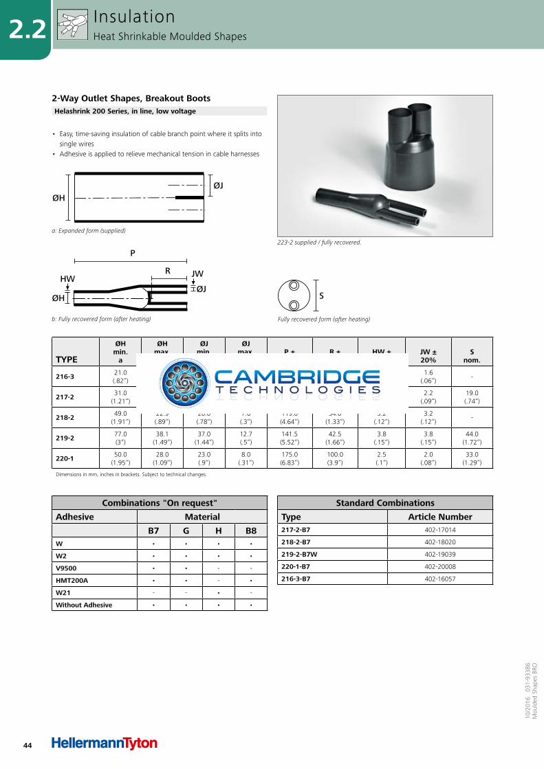
216-3 21.0 (.82“)
9.4 (.37“)
9.0 (.35“)
2.8 (.11“)
76.5 (2.98“)
20.0 (.78“)
1.6 (.06“)
1.6 (.06“)
-
217-2 31.0 (1.21“)
15.2 (.59“)
13.0 (.51“)
4.3 (.17“)
99.5 (3.88“)
28.5 (1.11“)
2.2 (.09“)
2.2 (.09“)
19.0 (.74“)
218-2 49.0 (1.91“)
22.9 (.89“)
20.0 (.78“)
7.6 (.3“)
119.0 (4.64“)
34.0 (1.33“)
3.2 (.12“)
3.2 (.12“)
-
219-2 77.0 (3“)
38.1 (1.49“)
37.0 (1.44“)
12.7 (.5“)
141.5 (5.52“)
42.5 (1.66“)
3.8 (.15“)
3.8 (.15“)
44.0 (1.72“)
220-1 50.0 (1.95“)
28.0 (1.09“)
23.0 (.9“)
8.0 (.31“)
175.0 (6.83“)
100.0 (3.9“)
2.5 (.1“)
2.0 (.08“)
33.0 (1.29“)
Dimensions in mm, inches in brackets. Subject to technical changes.
Combinations "On request"
Adhesive Material
B7 G H B8W • • • •
W2 • • • •
V9500 • • - -
HMT200A • • - •
W21 - - • -
Without Adhesive • • • •
Standard Combinations
Type Article Number217-2-B7 402-17014
218-2-B7 402-18020
219-2-B7W 402-19039
220-1-B7 402-20008
216-3-B7 402-16057
223-2 supplied / fully recovered.
• Easy, time-saving insulation of cable branch point where it splits into single wires
• Adhesive is applied to relieve mechanical tension in cable harnesses
InsulationHeat Shrinkable Moulded Shapes
2-Way Outlet Shapes, Breakout BootsHelashrink 200 Series, in line, low voltage
a: Expanded form (supplied)
ØJØH
b: Fully recovered form (after heating)
P
R
ØJØH
JWHW
Fully recovered form (after heating)
S
45
2.210
/201
6 0
31-9
3386
Mou
lded
Sha
pes
BRO
TYPEDesignation as per
AS/VG-Norm
ØHmin.
a
ØHmax.
b
ØJ/K/Lmin.
a
ØJ/K/Lmax.
b P ±
10% R ±
10% HW ±20%
W ±20%
T ±10%
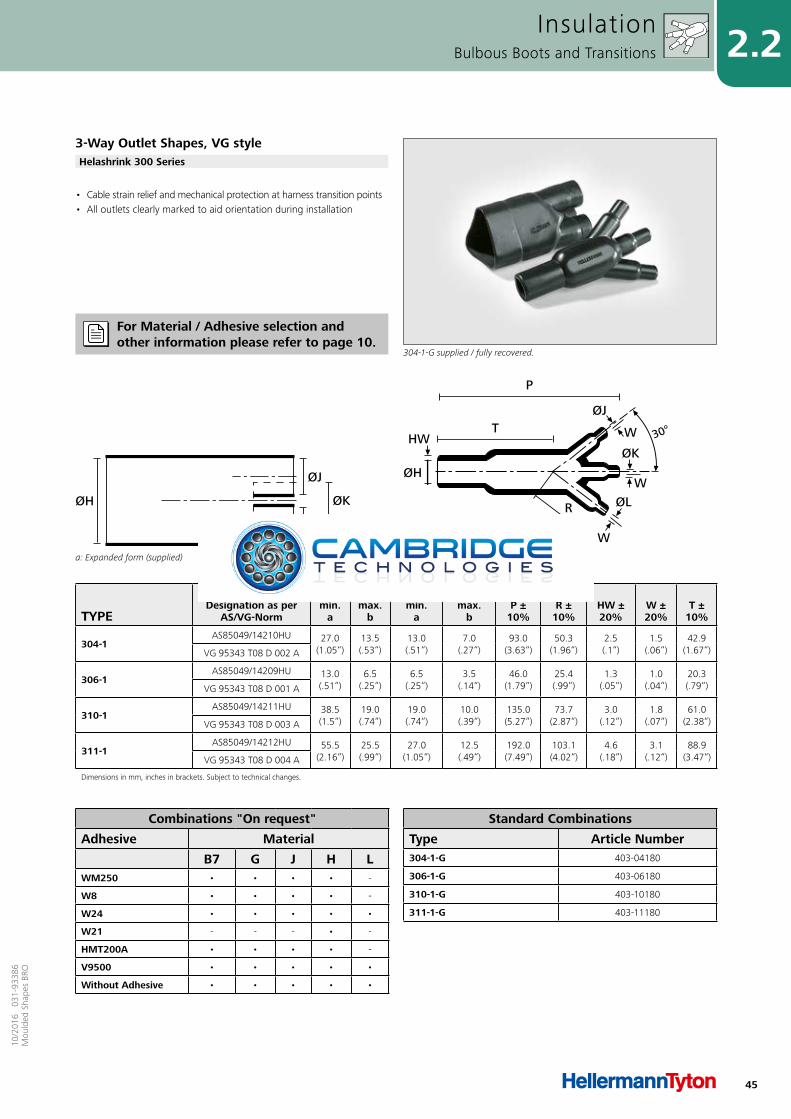
304-1AS85049/14210HU 27.0
(1.05“)13.5(.53“)
13.0(.51“)
7.0(.27“)
93.0(3.63“)
50.3(1.96“)
2.5(.1“)
1.5(.06“)
42.9(1.67“)VG 95343 T08 D 002 A
306-1AS85049/14209HU 13.0
(.51“)6.5
(.25“)6.5
(.25“)3.5
(.14“)46.0
(1.79“)25.4(.99“)
1.3(.05“)
1.0(.04“)
20.3(.79“)VG 95343 T08 D 001 A
310-1AS85049/14211HU 38.5
(1.5“)19.0(.74“)
19.0(.74“)
10.0(.39“)
135.0(5.27“)
73.7(2.87“)
3.0(.12“)
1.8(.07“)
61.0(2.38“)VG 95343 T08 D 003 A
311-1AS85049/14212HU 55.5
(2.16“)25.5(.99“)
27.0(1.05“)
12.5(.49“)
192.0(7.49“)
103.1(4.02“)
4.6(.18“)
3.1(.12“)
88.9(3.47“)VG 95343 T08 D 004 A
Dimensions in mm, inches in brackets. Subject to technical changes.
a: Expanded form (supplied)
ØH
ØJ
ØL
ØK
b: Fully recovered form (after heating)
HW
ØH
ØJ
ØK
W
W
W
R
30°T
P
ØL
• Cable strain relief and mechanical protection at harness transition points• All outlets clearly marked to aid orientation during installation
InsulationBulbous Boots and Transitions
3-Way Outlet Shapes, VG style
304-1-G supplied / fully recovered.
Helashrink 300 Series
Combinations "On request"
Adhesive Material
B7 G J H LWM250 • • • • -
W8 • • • • -
W24 • • • • •
W21 - - - • -
HMT200A • • • • -
V9500 • • • • •
Without Adhesive • • • • •
Standard Combinations
Type Article Number304-1-G 403-04180
306-1-G 403-06180
310-1-G 403-10180
311-1-G 403-11180
For Material / Adhesive selection and other information please refer to page 10.

46
2.2
10/2
016
031
-933
86M
ould
ed S
hape
s BR
O
TYPE
ØHmin.
a
ØHmax.
b
ØJmin.
a
ØJmax.
b P ±
10% R ±
10% HW ±20%
JW ±20%
Snom.
318-1 23.0 (.9“)
9.1 (.35“)
9.0 (.35“)
3.0 (.12“)
76.5 (2.98“)
20.0 (.78“)
2.5 (.1“)
2.5 (.1“)
16.0 (.62“)
319-1 31.0 (1.21“)
17.5 (.68“)
13.0 (.51“)
4.6 (.18“)
93.5 (3.65“)
28.5 (1.11“)
2.9 (.11“)
2.9 (.11“)
23.0 (.9“)
328-2 44.0 (1.72“)
22.8 (.89“)
21.0 (.82“)
7.6 (.3“)
99.0 (3.86“)
34.0 (1.33“)
3.8 (.15“)
3.8 (.15“)
-
330-2 61.0 (2.38“)
35.5 (1.38“)
32.0 (1.25“)
12.7 (.5“)
144.5 (5.64“)
45.5 (1.77“)
3.8 (.15“)
3.8 (.15“)
47.0 (1.83“)
339-2 39.0 (1.52“)
12.7 (.5“)
17.0 (.66“)
4.1 (.16“)
102.0 (3.98“)
56.0 (2.18“)
2.9 (.11“)
2.9 (.11“)
26.0 (1.01“)
Dimensions in mm, inches in brackets. Subject to technical changes.
Fully recovered form (after heating)
S
a: Expanded form (supplied)
ØJ
ØH
b: Fully recovered form (after heating)
P
R
ØJØH
JWHW
• Easy, time-saving insulation of cable branch point where it splits into single wires
• Adhesive is applied to relieve mechanical tension in cable harnesses
InsulationHeat Shrinkable Moulded Shapes
3-Way Outlet Shapes, Breakout Boots
300 Series supplied / fully recovered.
Helashrink 300 Series, in line, low voltage
Combinations "On request"
Adhesive Material
B7 G H B8 JW • • • • •
W2 • • • • -
WM250 • • • • •
V9500 • • - - •
HMT200A • • - • •
W21 - - • - -
Without Adhesive • • • • •
Standard Combinations
Type Article Number319-1-G 403-19022
328-2-J 403-28015
330-2-B7WM250 403-30014
339-2-G 403-39017
318-1-G 403-18018
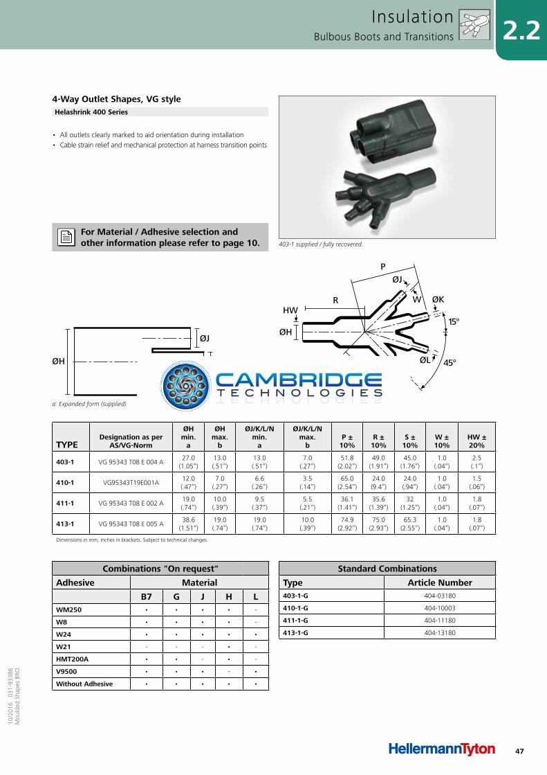
47
2.210
/201
6 0
31-9
3386
Mou
lded
Sha
pes
BRO
TYPEDesignation as per
AS/VG-Norm
ØHmin.
a
ØHmax.
b
ØJ/K/L/Nmin.
a
ØJ/K/L/Nmax.
b P ±
10% R ±
10% S ±
10% W ±10%
HW ±20%
403-1 VG 95343 T08 E 004 A27.0
(1.05“)13.0(.51“)
13.0(.51“)
7.0(.27“)
51.8(2.02“)
49.0(1.91“)
45.0(1.76“)
1.0(.04“)
2.5(.1“)
410-1 VG95343T19E001A12.0(.47“)
7.0(.27“)
6.6(.26“)
3.5(.14“)
65.0(2.54“)
24.0(9.4“)
24.0(.94“)
1.0(.04“)
1.5(.06“)
411-1 VG 95343 T08 E 002 A19.0(.74“)
10.0(.39“)
9.5(.37“)
5.5(.21“)
36.1(1.41“)
35.6(1.39“)
32(1.25“)
1.0(.04“)
1.8(.07“)
413-1 VG 95343 T08 E 005 A38.6
(1.51“)19.0(.74“)
19.0(.74“)
10.0(.39“)
74.9(2.92“)
75.0(2.93“)
65.3(2.55“)
1.0(.04“)
1.8(.07“)
Dimensions in mm, inches in brackets. Subject to technical changes.
a: Expanded form (supplied)
ØH
ØJ
ØN
ØK/ØL
b: Fully recovered form (after heating)
R
S
P
HW
ØH
ØK
15°
45°
ØJ
W
ØL
ØN
• All outlets clearly marked to aid orientation during installation• Cable strain relief and mechanical protection at harness transition points
InsulationBulbous Boots and Transitions
4-Way Outlet Shapes, VG style
403-1 supplied / fully recovered.
Helashrink 400 Series
Combinations "On request"
Adhesive Material
B7 G J H LWM250 • • • • -
W8 • • • • -
W24 • • • • •
W21 - - - • -
HMT200A • • - • -
V9500 • • • - •
Without Adhesive • • • • •
Standard Combinations
Type Article Number403-1-G 404-03180
410-1-G 404-10003
411-1-G 404-11180
413-1-G 404-13180
For Material / Adhesive selection and other information please refer to page 10.
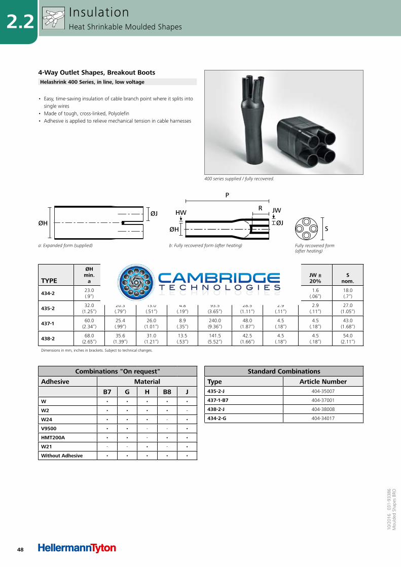
48
2.2
10/2
016
031
-933
86M
ould
ed S
hape
s BR
O
TYPE
ØHmin.
a
ØHmax.
b
ØJmin.
a
ØJmax.
b P ±
10% R ±
10% HW ±20%
JW ±20%
Snom.
434-2 23.0 (.9“)
11.0 (.43“)
8.0 (.31“)
2.8 (.11“)
78.0 (3.04“)
22.0 (.86“)
1.6 (.06“)
1.6 (.06“)
18.0 (.7“)
435-2 32.0 (1.25“)
20.3 (.79“)
13.0 (.51“)
4.8 (.19“)
93.5 (3.65“)
28.5 (1.11“)
2.9 (.11“)
2.9 (.11“)
27.0 (1.05“)
437-1 60.0 (2.34“)
25.4 (.99“)
26.0 (1.01“)
8.9 (.35“)
240.0 (9.36“)
48.0 (1.87“)
4.5 (.18“)
4.5 (.18“)
43.0 (1.68“)
438-2 68.0 (2.65“)
35.6 (1.39“)
31.0 (1.21“)
13.5 (.53“)
141.5 (5.52“)
42.5 (1.66“)
4.5 (.18“)
4.5 (.18“)
54.0 (2.11“)
Dimensions in mm, inches in brackets. Subject to technical changes.
Fully recovered form (after heating)
S
a: Expanded form (supplied)
ØJØH
b: Fully recovered form (after heating)
P
R
ØJØH
JWHW
• Easy, time-saving insulation of cable branch point where it splits into single wires
• Made of tough, cross-linked, Polyolefin• Adhesive is applied to relieve mechanical tension in cable harnesses
InsulationHeat Shrinkable Moulded Shapes
4-Way Outlet Shapes, Breakout Boots
400 series supplied / fully recovered.
Helashrink 400 Series, in line, low voltage
Combinations "On request"
Adhesive Material
B7 G H B8 JW • • • • •
W2 • • • • -
W24 • • • - •
V9500 • • - - •
HMT200A • • - • •
W21 - - • - •
Without Adhesive • • • • •
Standard Combinations
Type Article Number435-2-J 404-35007
437-1-B7 404-37001
438-2-J 404-38008
434-2-G 404-34017
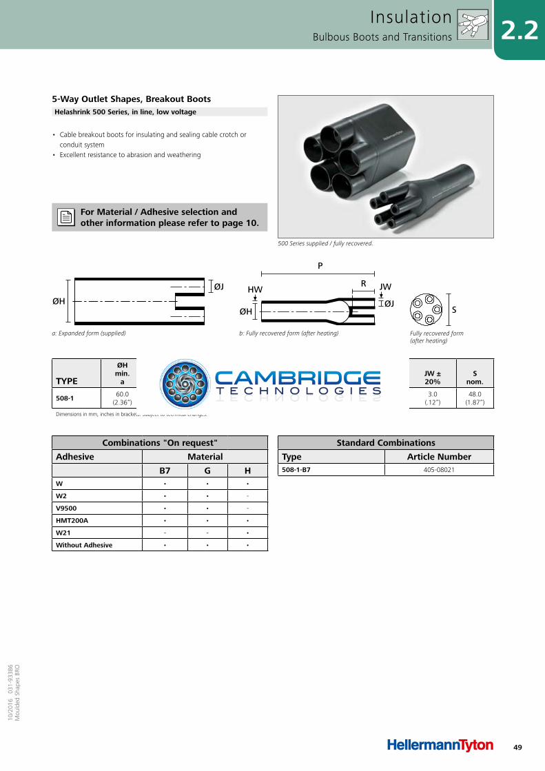
49
2.210
/201
6 0
31-9
3386
Mou
lded
Sha
pes
BRO
TYPE
ØHmin.
a
ØHmax.
b
ØJmin.
a
ØJmax.
b P ±
10% R ±
10% HW ±20%
JW ±20%
Snom.
508-1 60.0(2.36“)
24.5(.96“)
30.0(1.17“)
7.5(.29“)
180.0(7.02“)
30.0(1.17“)
3.5(.14“)
3.0(.12“)
48.0(1.87“)
Dimensions in mm, inches in brackets. Subject to technical changes.
Fully recovered form (after heating)
S
a: Expanded form (supplied)
ØJ
ØH
b: Fully recovered form (after heating)
P
R
ØJØH
JWHW
• Cable breakout boots for insulating and sealing cable crotch or conduit system
• Excellent resistance to abrasion and weathering
InsulationBulbous Boots and Transitions
5-Way Outlet Shapes, Breakout Boots
500 Series supplied / fully recovered.
Helashrink 500 Series, in line, low voltage
Combinations "On request"
Adhesive Material
B7 G HW • • •
W2 • • -
V9500 • • -
HMT200A • • •
W21 - - •
Without Adhesive • • •
Standard Combinations
Type Article Number508-1-B7 405-08021
For Material / Adhesive selection and other information please refer to page 10.
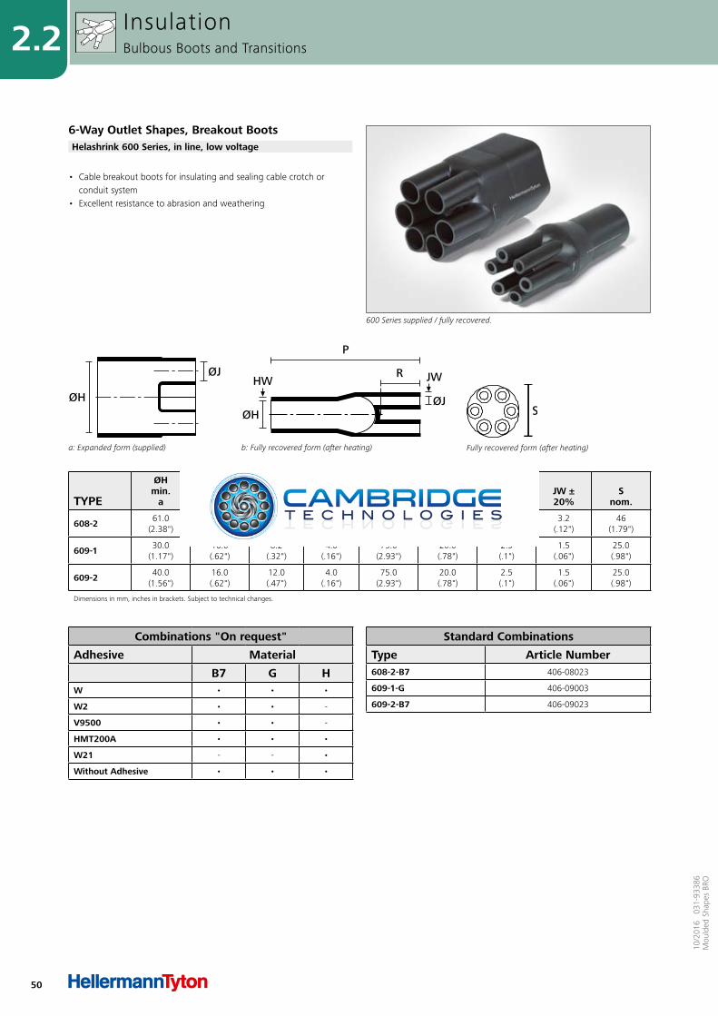
50
2.2
10/2
016
031
-933
86M
ould
ed S
hape
s BR
O
TYPE
ØHmin.
a
ØHmax.
b
ØJmin.
a
ØJmax.
b P ±
10% R ±
10% HW ±20%
JW ±20%
Snom.
608-2 61.0 (2.38")
37.0 (1.44")
21.0 (.82")
9.0 (.35")
152.0 (5.93")
56.0 (2.18")
3.2 (.12")
3.2 (.12")
46 (1.79")
609-1 30.0 (1.17")
16.0 (.62")
8.2 (.32")
4.0 (.16")
75.0 (2.93")
20.0 (.78")
2.5 (.1")
1.5 (.06")
25.0 (.98")
609-2 40.0 (1.56")
16.0 (.62")
12.0 (.47")
4.0 (.16")
75.0 (2.93")
20.0 (.78")
2.5 (.1")
1.5 (.06")
25.0 (.98")
Dimensions in mm, inches in brackets. Subject to technical changes.
Fully recovered form (after heating)a: Expanded form (supplied)
ØJ
ØH
b: Fully recovered form (after heating)
P
R
ØJØH
JWHW
• Cable breakout boots for insulating and sealing cable crotch or conduit system
• Excellent resistance to abrasion and weathering
InsulationBulbous Boots and Transitions
6-Way Outlet Shapes, Breakout Boots
600 Series supplied / fully recovered.
Helashrink 600 Series, in line, low voltage
Combinations "On request"
Adhesive Material
B7 G HW • • •
W2 • • -
V9500 • • -
HMT200A • • •
W21 - - •
Without Adhesive • • •
Standard Combinations
Type Article Number608-2-B7 406-08023
609-1-G 406-09003
609-2-B7 406-09023

51
2.210
/201
6 0
31-9
3386
Mou
lded
Sha
pes
BRO
TYPEDesignation as per
AS/VG-Norm
ØHmin.
a
ØHmax.
b
ØJmin.
a
ØJmax.
b P ±
10% R ±
10% HW ±20%
JW ±20%
V ± 10%
T ±20%
M nom.
Snom.
1152-4 VG 95343 T06 E 001 A24.0(.94“)
10.5(.41“)
24.0(.94“)
6.0(.23“)
26.0(1.01“)
25.0(.98“)
1.3(.05“)
0.5(.02“)
3.0(.12“)
1.0(.04“)
19.0(.74“)
10.0(.39“)
1154-4 VG 95343 T06 E 002 A30.0
(1.17“)15.5(.6“)
30.0(1.17“)
6.0(.23“)
32.0(1.25“)
27.0(1.05“)
1.5(.06“)
0.8(.03“)
3.0(.12“)
1.0(.04“)
19.0(.74“)
12.0(.47“)
1155-4 VG 95343 T06 E 003 A31.0
(1.21“)18.0(.7“)
31.0(1.21“)
7.0(.27“)
40.0(1.56“)
31.0(1.21“)
1.8(.07“)
1.0(.04“)
3.0(.12“)
1.0(.04“)
21.0(.82“)
15.0(.59“)
1156-4 VG 95343 T06 E 004 A36.0(1.4“)
22.5(.88“)
36.0(1.4“)
8.5(.33“)
46.0(1.79“)
38.0(1.48“)
1.8(.07“)
1.0(.04“)
3.0(.12“)
1.0(.04“)
26.0(1.01“)
15.0(.59“)
1157-4 VG 95343 T06 E 005 A43.0
(1.68“)28.5
(1.11“)43.0
(1.68“)10.0(.39“)
55.0(2.15“)
45.0(1.76“)
2.0(.08“)
1.0(.04“)
3.0(.12“)
1.7(.07“)
30.0(1.17“)
16.0(.62“)
1158-4 VG 95343 T06 E 006 A60.0
(2.34“)35.0
(1.37“)60.0
(2.34“)16.0(.62“)
80.0(3.12“)
54.0(2.11“)
3.3(.13“)
1.5(.06“)
3.0(.12“)
1.7(.07“)
35.0(1.37“)
30.0(1.17“)
1159-4 VG 95343 T06 E 007 A66.0
(2.57“)45.0
(1.76“)66.0
(2.57“)17.0(.66“)
108.0(4.21“)
68.0(2.65“)
3.8(.15“)
2.0(.08“)
3.0(.12“)
2.0(.08“)
42.0(1.64“)
51.0(1.99“)
1160-4 VG 95343 T06 E 008 A82.0(3.2“)
61.0(2.38“)
82.0(3.2“)
25.0(.98“)
118.0(4.6“)
84.0(3.28“)
4.0(.16“)
4.0(.16“)
3.0(.12“)
2.0(.08“)
52.0(2.03“)
39.0(1.52“)
Dimensions in mm, inches in brackets. Subject to technical changes.
a: Expanded form (supplied)
ØJØH
b: Fully recovered form (after heating)
V
R
ØHHW
T
S
P
ØJ
MJW
• Used in conjunction with a circular grooved adaptor• Provides strain relief and an environmental seal
InsulationBulbous Boots and Transitions
Right-Angle Shapes, VG style
1152-4-G recovered onto a connector.
Helashrink 1100 Series, with rib
For Material / Adhesive selection and other information please refer to page 10.
Combinations "On request"
Adhesive Material
B7 G J H LWM250 • • • • -
W8 • • • • -
W24 • • • • •
W21 - - • • -
HMT200A • • • • -
V9500 • • • - -
Without Adhesive • • • • •
Standard Combinations
Type Article Number1152-4-G 411-52480
1154-4-G 411-54480
1155-4-G 411-55480
1156-4-G 411-56480
1157-4-G 411-57480
1158-4-G 411-58480
1159-4-G 411-59480
1160-4-G 411-60480

52
2.2
10/2
016
031
-933
86M
ould
ed S
hape
s BR
O
TYPEDesignation as per
AS/VG-Norm
ØHmin.
a
ØHmax.
b
ØJmin.
a
ØJmax.
b P ±
20% R ±
10% HW ±30%
JW ±30%
M nom.
Snom.
1113-1 VG 95343 T06 J 003 A19.0(.74“)
14.5(.57“)
8.0(.31“)
4.5(.18“)
39(1.52“)
26.0(1.01“)
2.5(.1“)
1.8(.07“)
19.0(.74“)
8.0(.31“)
1114-1 VG 95343 T06 J 004 A23.5(.92“)
18.0(.7“)
11.5(.45“)
5.5(.21“)
51(1.99“)
33.0(1.29“)
3.0(.12“)
1.0(.04“)
22.0(.86“)
9.5(.37“)
Dimensions in mm, inches in brackets. Subject to technical changes.
a: Expanded form (supplied)
ØJØH
b: Fully recovered form (after heating)
ØHHW
R
P
S
ØJ
MJW
• Provides connector cable strain relief• Can be installed on the connector rear thread or plain shaft• Allows easy re-entry for repair when combined with a hot melt
adhesive
InsulationBulbous Boots and Transitions
Right-Angle Shapes, VG style
1114-1 supplied / fully recovered.
Helashrink 1100 Series, without rib, thick wall
Combinations "On request"
Adhesive Material
B7 G J HWM250 • • • •
W8 • • • •
W24 • • • •
W21 - - - •
HMT200A • • • •
V9500 • • • -
Without Adhesive • • • •
Standard Combinations
Type Article Number1113-1-G 411-13002
1114-1-G 411-14004
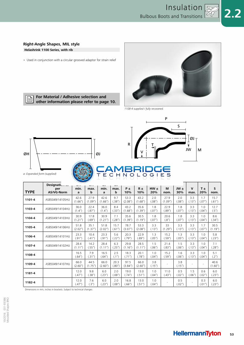
53
2.210
/201
6 0
31-9
3386
Mou
lded
Sha
pes
BRO
• Used in conjunction with a circular grooved adaptor for strain relief
InsulationBulbous Boots and Transitions
Right-Angle Shapes, MIL style
1108-4 supplied / fully recovered.
Helashrink 1100 Series, with rib
For Material / Adhesive selection and other information please refer to page 10.
TYPE
Designation as per
AS/VG-Norm
ØHmin.
a
ØHmax.
b
ØJmin.
a
ØJmax.
b P ±
10% R ±
10% HW ±20%
M nom.
JW ±30%
Vmax.
T ±20%
Snom.
1101-4 AS85049/14105HU42.6
(1.66“)27.9
(1.09“)42.6
(1.66“)9.7
(.38“)53.3
(2.08“)43.2
(1.68“)2.0
(.08“)27.9
(1.09“)2.0
(.08“)3.3
(.13“)1.7
(.07“)15.7(.61“)
1103-4 AS85049/14104HU36.0(1.4“)
22.4(.87“)
36.0(1.4“)
8.4(.33“)
43.2(1.68“)
35.6(1.39“)
1.8(.07“)
22.9(.89“)
1.8(.07“)
3.3(.13“)
1.0(.04“)
12.7(.5“)
1104-4 AS85049/14103HU30.9
(1.21“)17.8(.69“)
30.9(1.21“)
7.1(.28“)
35.6(1.39“)
30.5(1.19“)
1.8(.07“)
20.6(.8“)
1.8(.07“)
3.3(.13“)
1.0(.04“)
8.6(.34“)
1105-4 AS85049/14106HU51.8
(2.02“)35.1
(1.37“)51.8
(2.02“)15.7(.61“)
78.7(3.07“)
53.3(2.08“)
3.3(.13“)
33(1.29“)
3.3(.13“)
3.3(.13“)
1.7(.07“)
30.5(1.19“)
1106-4 AS85049/14101HU23.3(.91“)
10.4(.41“)
23.3(.91“)
5.6(.22“)
20.3(.79“)
22.9(.89“)
1.3(.05“)
15.2(.59“)
1.3(.05“)
3.3(.13“)
1.0(.04“)
5.8(.23“)
1107-4 AS85049/14102HU28.4
(1.11“)14.2(.55“)
28.4(1.11“)
6.3(.25“)
29.8(1.16“)
28.5(1.11“)
1.5(.06“)
21.4(.83“)
1.5(.06“)
3.3(.13“)
1.0(.04“)
7.1(.28“)
1108-4 16.5(.64“)
7.9(.31“)
16.5(.64“)
2.5(.1“)
18.3(.71“)
20.1(.78“)
1.0(.04“)
15.2(.59“)
1.6(.06“)
3.3(.13“)
1.0(.04“)
5.1(.2“)
1109-4 AS85049/14107HU66.0
(2.60“)44.5
(1.75“)66.0
(2.60“)20.3(.80“)
97.5(3.84“)
66.0(2.60“)
3.8(.15“)
-3.8
(.15“)- -
40.6(1.60“)
1181-4 12.0(.47“)
9.8(.38“)
6.0(.23“)
2.0(.08“)
19.0(.74“)
13.0(.51“)
1.0(.04“)
11.0(.43“)
0.5(.02“)
1.5(.06“)
0.6(.02“)
6.0(.23“)
1182-4 12.0(.47“)
7.6(.3“)
6.0(.23“)
2.0(.08“)
16.8(.66“)
13.0(.51“)
1.0(.04“)
-0.5
(.02“)-
0.3(.01“)
6.0(.23“)
Dimensions in mm, inches in brackets. Subject to technical changes.
a: Expanded form (supplied)
ØJØH
b: Fully recovered form (after heating)
V
R
ØHHW
S
P
T
ØJ
MJW
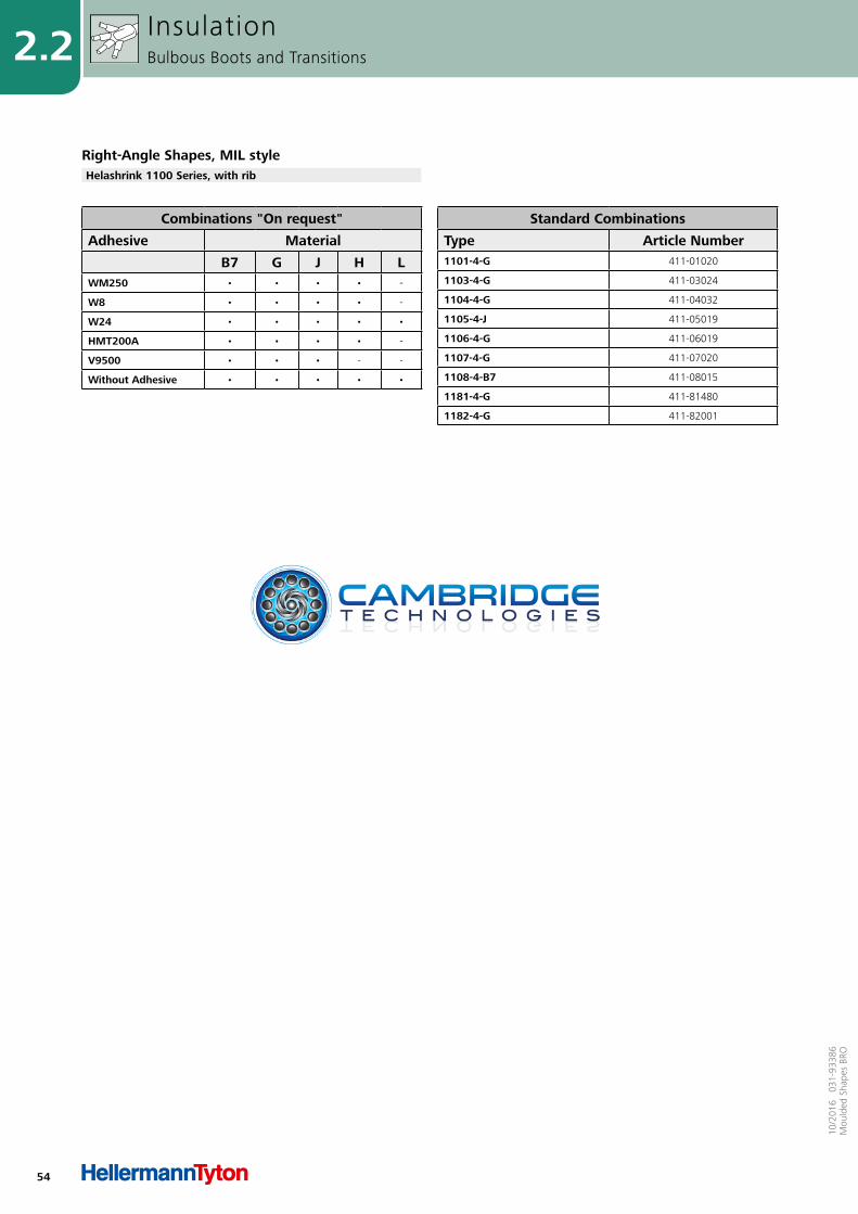
54
2.2
10/2
016
031
-933
86M
ould
ed S
hape
s BR
O
Combinations "On request"
Adhesive Material
B7 G J H LWM250 • • • • -
W8 • • • • -
W24 • • • • •
HMT200A • • • • -
V9500 • • • - -
Without Adhesive • • • • •
Standard Combinations
Type Article Number1101-4-G 411-01020
1103-4-G 411-03024
1104-4-G 411-04032
1105-4-J 411-05019
1106-4-G 411-06019
1107-4-G 411-07020
1108-4-B7 411-08015
1181-4-G 411-81480
1182-4-G 411-82001
Right-Angle Shapes, MIL styleHelashrink 1100 Series, with rib
InsulationBulbous Boots and Transitions
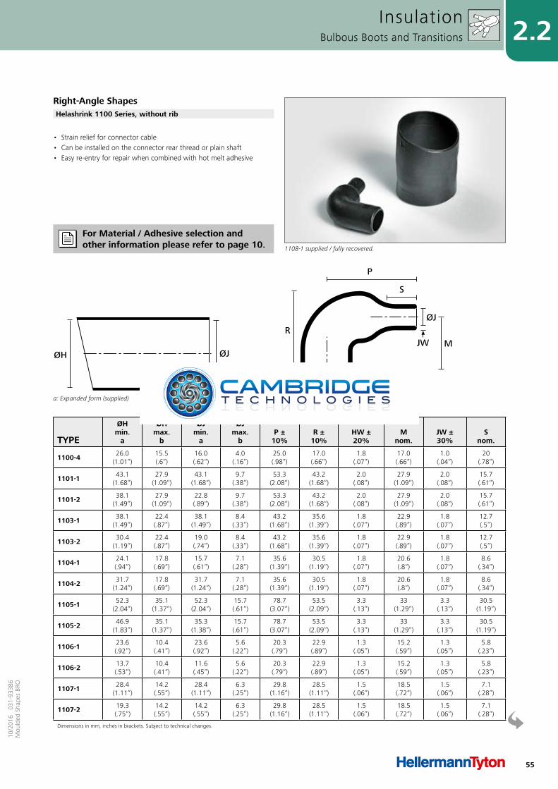
55
2.210
/201
6 0
31-9
3386
Mou
lded
Sha
pes
BRO
• Strain relief for connector cable• Can be installed on the connector rear thread or plain shaft• Easy re-entry for repair when combined with hot melt adhesive
InsulationBulbous Boots and Transitions
Right-Angle Shapes
1108-1 supplied / fully recovered.
Helashrink 1100 Series, without rib
For Material / Adhesive selection and other information please refer to page 10.
TYPE
ØHmin.
a
ØHmax.
b
ØJmin.
a
ØJmax.
b P ±
10% R ±
10% HW ±20%
M nom.
JW ±30%
Snom.
1100-4 26.0(1.01“)
15.5(.6“)
16.0(.62“)
4.0(.16“)
25.0(.98“)
17.0(.66“)
1.8(.07“)
17.0(.66“)
1.0(.04“)
20(.78“)
1101-1 43.1(1.68“)
27.9(1.09“)
43.1(1.68“)
9.7(.38“)
53.3(2.08“)
43.2(1.68“)
2.0(.08“)
27.9(1.09“)
2.0(.08“)
15.7(.61“)
1101-2 38.1(1.49“)
27.9(1.09“)
22.8(.89“)
9.7(.38“)
53.3(2.08“)
43.2(1.68“)
2.0(.08“)
27.9(1.09“)
2.0(.08“)
15.7(.61“)
1103-1 38.1(1.49“)
22.4(.87“)
38.1(1.49“)
8.4(.33“)
43.2(1.68“)
35.6(1.39“)
1.8(.07“)
22.9(.89“)
1.8(.07“)
12.7(.5“)
1103-2 30.4(1.19“)
22.4(.87“)
19.0(.74“)
8.4(.33“)
43.2(1.68“)
35.6(1.39“)
1.8(.07“)
22.9(.89“)
1.8(.07“)
12.7(.5“)
1104-1 24.1(.94“)
17.8(.69“)
15.7(.61“)
7.1(.28“)
35.6(1.39“)
30.5(1.19“)
1.8(.07“)
20.6(.8“)
1.8(.07“)
8.6(.34“)
1104-2 31.7(1.24“)
17.8(.69“)
31.7(1.24“)
7.1(.28“)
35.6(1.39“)
30.5(1.19“)
1.8(.07“)
20.6(.8“)
1.8(.07“)
8.6(.34“)
1105-1 52.3(2.04“)
35.1(1.37“)
52.3(2.04“)
15.7(.61“)
78.7(3.07“)
53.5(2.09“)
3.3(.13“)
33(1.29“)
3.3(.13“)
30.5(1.19“)
1105-2 46.9(1.83“)
35.1(1.37“)
35.3(1.38“)
15.7(.61“)
78.7(3.07“)
53.5(2.09“)
3.3(.13“)
33(1.29“)
3.3(.13“)
30.5(1.19“)
1106-1 23.6(.92“)
10.4(.41“)
23.6(.92“)
5.6(.22“)
20.3(.79“)
22.9(.89“)
1.3(.05“)
15.2(.59“)
1.3(.05“)
5.8(.23“)
1106-2 13.7(.53“)
10.4(.41“)
11.6(.45“)
5.6(.22“)
20.3(.79“)
22.9(.89“)
1.3(.05“)
15.2(.59“)
1.3(.05“)
5.8(.23“)
1107-1 28.4(1.11“)
14.2(.55“)
28.4(1.11“)
6.3(.25“)
29.8(1.16“)
28.5(1.11“)
1.5(.06“)
18.5(.72“)
1.5(.06“)
7.1(.28“)
1107-2 19.3(.75“)
14.2(.55“)
14.2(.55“)
6.3(.25“)
29.8(1.16“)
28.5(1.11“)
1.5(.06“)
18.5(.72“)
1.5(.06“)
7.1(.28“)
Dimensions in mm, inches in brackets. Subject to technical changes.
a: Expanded form (supplied)
ØJØH
b: Fully recovered form (after heating)
ØJ
M
ØH
RJW
P
S
HW
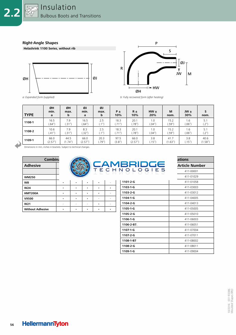
56
2.2
10/2
016
031
-933
86M
ould
ed S
hape
s BR
O
InsulationBulbous Boots and Transitions
Right-Angle ShapesHelashrink 1100 Series, without rib
Combinations "On request"
Adhesive Material
B7 G J H LWM250 • • • • -
W8 • • • • -
W24 • • • • •
HMT200A • • • • -
V9500 • • • - -
W21 - - - • -
Without Adhesive • • • • •
Standard Combinations
Type Article Number1100-4-G 411-00001
1101-1-GW8 411-01029
1101-2-G 411-01058
1103-1-G 411-03003
1103-2-G 411-03012
1104-1-G 411-04005
1104-2-G 411-04013
1105-1-G 411-05005
1105-2-G 411-05010
1106-1-G 411-06003
1106-2-B7. 411-06051
1107-1-G 411-07004
1107-2-G 411-07011
1108-1-B7 411-08002
1108-2-G 411-08011
1109-1-G 411-09004
TYPE
ØHmin.
a
ØHmax.
b
ØJmin.
a
ØJmax.
b P ±
10% R ±
10% HW ±20%
M nom.
JW ±30%
Snom.
1108-1 16.5(.64“)
7.9(.31“)
16.5(.64“)
2.5(.1“)
18.3(.71“)
20.1(.78“)
1.0(.04“)
15.2(.59“)
1.6(.06“)
5.1(.2“)
1108-2 10.6(.41“)
7.9(.31“)
8.3(.32“)
2.5(.1“)
18.3(.71“)
20.1(.78“)
1.0(.04“)
15.2(.59“)
1.6(.06“)
5.1(.2“)
1109-1 66.0(2.57“)
44.5(1.74“)
66.0(2.57“)
20.3(.79“)
97.5(3.8“)
66.0(2.57“)
3.8(.15“)
41.7(1.63“)
3.8(.15“)
40.6(1.58“)
Dimensions in mm, inches in brackets. Subject to technical changes.
a: Expanded form (supplied)
ØJØH
b: Fully recovered form (after heating)
ØJ
M
ØH
RJW
P
S
HW
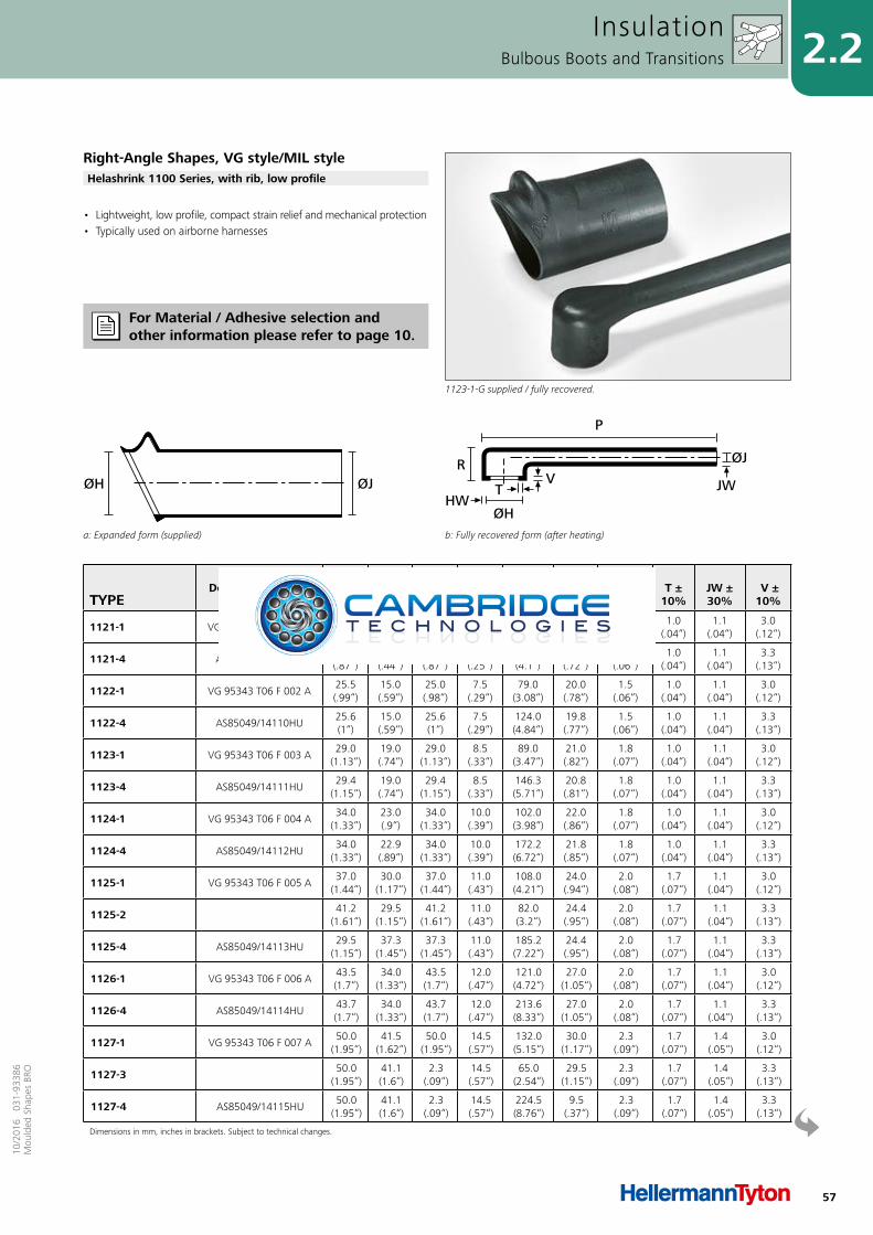
57
2.210
/201
6 0
31-9
3386
Mou
lded
Sha
pes
BRO
• Lightweight, low profile, compact strain relief and mechanical protection• Typically used on airborne harnesses
InsulationBulbous Boots and Transitions
Right-Angle Shapes, VG style/MIL style
1123-1-G supplied / fully recovered.
Helashrink 1100 Series, with rib, low profile
For Material / Adhesive selection and other information please refer to page 10.
TYPEDesignation as per
AS/VG-Norm
ØHmin.
a
ØHmax.
b
ØJmin.
a
ØJmax.
b P ±
10% R ±
10% HW ±20%
T ±10%
JW ±30%
V ± 10%
1121-1 VG 95343 T06 F 001 A22.0(.86“)
12.0(.47“)
22.0(.86“)
6.5(.25“)
70.0(2.73“)
19.0(.74“)
1.5(.06“)
1.0(.04“)
1.1(.04“)
3.0(.12“)
1121-4 AS85049/14109HU22.3(.87“)
11.4(.44“)
22.3(.87“)
6.4(.25“)
105.2(4.1“)
18.5(.72“)
1.5(.06“)
1.0(.04“)
1.1(.04“)
3.3(.13“)
1122-1 VG 95343 T06 F 002 A25.5(.99“)
15.0(.59“)
25.0(.98“)
7.5(.29“)
79.0(3.08“)
20.0(.78“)
1.5(.06“)
1.0(.04“)
1.1(.04“)
3.0(.12“)
1122-4 AS85049/14110HU25.6(1“)
15.0(.59“)
25.6(1“)
7.5(.29“)
124.0(4.84“)
19.8(.77“)
1.5(.06“)
1.0(.04“)
1.1(.04“)
3.3(.13“)
1123-1 VG 95343 T06 F 003 A29.0
(1.13“)19.0(.74“)
29.0(1.13“)
8.5(.33“)
89.0(3.47“)
21.0(.82“)
1.8(.07“)
1.0(.04“)
1.1(.04“)
3.0(.12“)
1123-4 AS85049/14111HU29.4
(1.15“)19.0(.74“)
29.4(1.15“)
8.5(.33“)
146.3(5.71“)
20.8(.81“)
1.8(.07“)
1.0(.04“)
1.1(.04“)
3.3(.13“)
1124-1 VG 95343 T06 F 004 A34.0
(1.33“)23.0(.9“)
34.0(1.33“)
10.0(.39“)
102.0(3.98“)
22.0(.86“)
1.8(.07“)
1.0(.04“)
1.1(.04“)
3.0(.12“)
1124-4 AS85049/14112HU34.0
(1.33“)22.9(.89“)
34.0(1.33“)
10.0(.39“)
172.2(6.72“)
21.8(.85“)
1.8(.07“)
1.0(.04“)
1.1(.04“)
3.3(.13“)
1125-1 VG 95343 T06 F 005 A37.0
(1.44“)30.0
(1.17“)37.0
(1.44“)11.0(.43“)
108.0(4.21“)
24.0(.94“)
2.0(.08“)
1.7(.07“)
1.1(.04“)
3.0(.12“)
1125-2 41.2(1.61“)
29.5(1.15“)
41.2(1.61“)
11.0(.43“)
82.0(3.2“)
24.4(.95“)
2.0(.08“)
1.7(.07“)
1.1(.04“)
3.3(.13“)
1125-4 AS85049/14113HU29.5
(1.15“)37.3
(1.45“)37.3
(1.45“)11.0(.43“)
185.2(7.22“)
24.4(.95“)
2.0(.08“)
1.7(.07“)
1.1(.04“)
3.3(.13“)
1126-1 VG 95343 T06 F 006 A43.5(1.7“)
34.0(1.33“)
43.5(1.7“)
12.0(.47“)
121.0(4.72“)
27.0(1.05“)
2.0(.08“)
1.7(.07“)
1.1(.04“)
3.0(.12“)
1126-4 AS85049/14114HU43.7(1.7“)
34.0(1.33“)
43.7(1.7“)
12.0(.47“)
213.6(8.33“)
27.0(1.05“)
2.0(.08“)
1.7(.07“)
1.1(.04“)
3.3(.13“)
1127-1 VG 95343 T06 F 007 A50.0
(1.95“)41.5
(1.62“)50.0
(1.95“)14.5(.57“)
132.0(5.15“)
30.0(1.17“)
2.3(.09“)
1.7(.07“)
1.4(.05“)
3.0(.12“)
1127-3 50.0(1.95“)
41.1(1.6“)
2.3(.09“)
14.5(.57“)
65.0(2.54“)
29.5(1.15“)
2.3(.09“)
1.7(.07“)
1.4(.05“)
3.3(.13“)
1127-4 AS85049/14115HU50.0
(1.95“)41.1(1.6“)
2.3(.09“)
14.5(.57“)
224.5(8.76“)
9.5(.37“)
2.3(.09“)
1.7(.07“)
1.4(.05“)
3.3(.13“)
Dimensions in mm, inches in brackets. Subject to technical changes.
a: Expanded form (supplied)
ØJØH
b: Fully recovered form (after heating)
P
R
ØHHW
TV
ØJ
JW
58
2.2
10/2
016
031
-933
86M
ould
ed S
hape
s BR
O
Combinations "On request"
Adhesive Material
B7 G J H LWM250 • • • • -
W8 • • • • -
W24 • • • • •
HMT200A • • • • -
V9500 • • • - -
W21 - - - • -
Without Adhesive • • • • •
Standard Combinations
Type Article Number1121-4-G 411-21007
1121-1-G 411-21180
1122-4-G 411-22015
1122-1-G 411-22180
1123-4-G 411-23013
1123-1-G 411-23180
1124-4-G 411-24009
1124-1-G 411-24180
1125-4-G 411-25008
1125-2-G 411-25027
1125-1-G 411-25180
1126-4-G 411-26008
1126-1-G 411-26180
1127-3-B7 411-27005
1127-4-G 411-27008
1127-1-G 411-27180
1128-4-G 411-28002
1128-1-G 411-28180
1129-1-G 411-29180
1129-4-J 411-29001
InsulationBulbous Boots and Transitions
Right-Angle Shapes, VG style/MIL styleHelashrink 1100 Series, with rib, low profile
TYPEDesignation as per
AS/VG-Norm
ØHmin.
a
ØHmax.
b
ØJmin.
a
ØJmax.
b P ±
10% R ±
10% HW ±20%
T ±10%
JW ±30%
V ± 10%
1128-1 VG 95343 T06 F 008 A62.5
(2.44“)47.0
(1.83“)62.5
(2.44“)18.0(.7“)
133.0(5.19“)
33.0(1.29“)
2.5(.1“)
2.0(.08“)
1.4(.05“)
3.0(.12“)
1128-4 AS85049/14116HU62.7
(2.45“)47.0
(1.83“)62.7
(2.45“)18.0(.7“)
227.3(8.86“)
33.3(1.3“)
2.5(.1“)
2.0(.08“)
1.4(.05“)
3.3(.13“)
1129-1 VG 95343 T06 F 009 A69.0
(2.69“)60.0
(2.34“)69.0
(2.69“)20.0(.78“)
137.0(5.34“)
35.0(1.37“)
2.5(.1“)
2.0(.08“)
1.4(.05“)
3.0(.12“)
1129-4 AS85049/14117HU69.3(2.7“)
59.7(2.33“)
69.3(2.7“)
20.0(.78“)
233.4(9.1“)
35.1(1.37“)
2.5(.1“)
2.0(.08“)
1.4(.05“)
3.3(.13“)
Dimensions in mm, inches in brackets. Subject to technical changes.
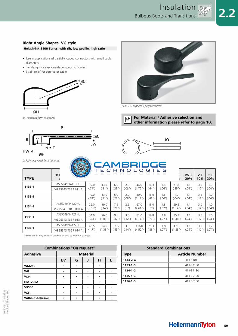
59
2.210
/201
6 0
31-9
3386
Mou
lded
Sha
pes
BRO
TYPEDesignation as per
AS/VG-Norm
ØHmin.
a
ØHmax.
b
ØJmin.
a
ØJmax.
b P ±
10% R ±
10% HW ±20%
JO ±10%
JW ±20%
V ± 10%
T ±20%
1133-1AS85049/14119HU 19.0
(.74“)13.0(.51“)
6.0(.23“)
2.0(.08“)
44.0(1.72“)
16.3(.64“)
1.5(.06“)
21.8(.85“)
1.1(.04“)
3.0(.12“)
1.0(.04“)VG 95343 T06 F 011 A
1133-2 19.0(.74“)
13.0(.51“)
6.0(.23“)
2.0(.08“)
30.0(1.17“)
16.0(.62“)
1.5(.06“)
1.0(.04“)
1.1(.04“)
3.3(.13“)
1.0(.04“)
1134-1AS85049/14120HU 26.0
(1.01“)19.0(.74“)
7.5(.29“)
2.5(.1“)
67.0(2.61“)
18.0(.7“)
1.8(.07“)
29.2(1.14“)
1.1(.04“)
3.0(.12“)
1.0(.04“)VG 95343 T18 H 001 A
1135-1AS85049/14121HU 34.0
(1.33“)26.0
(1.01“)9.5
(.37“)3.0
(.12“)81.0
(3.16“)18.8(.73“)
1.8(.07“)
35.3(1.38“)
1.1(.04“)
3.0(.12“)
1.0(.04“)VG 95343 T06 F 013 A
1136-1AS85049/14122HU 43.5
(1.7“)34.0
(1.33“)11.5(.45“)
3.5(.14“)
116.0(4.52“)
21.3(.83“)
1.8(.07“)
47.0(1.83“)
1.1(.04“)
3.0(.12“)
1.7(.07“)VG 95343 T06 F 014 A
Dimensions in mm, inches in brackets. Subject to technical changes.
Fully recovered form (after heating)
JO
a: Expanded form (supplied)
ØH
ØJ
b: Fully recovered form (after heating)
P
ØH
THW
VRØJ
JW
• Use in applications of partially loaded connectors with small cable diameters
• Tail design for easy orientation prior to cooling• Strain relief for connector cable
InsulationBulbous Boots and Transitions
Right-Angle Shapes, VG style
1135-1-G supplied / fully recovered.
Helashrink 1100 Series, with rib, low profile, high ratio
For Material / Adhesive selection and other information please refer to page 10.
Combinations "On request"
Adhesive Material
B7 G J H LWM250 • • • • -
W8 • • • • -
W24 • • • • •
HMT200A • • • • -
V9500 • • • - -
W21 - - - • -
Without Adhesive • • • • •
Standard Combinations
Type Article Number1133-2-G 411-33011
1133-1-G 411-33180
1134-1-G 411-34180
1135-1-G 411-35180
1136-1-G 411-36180
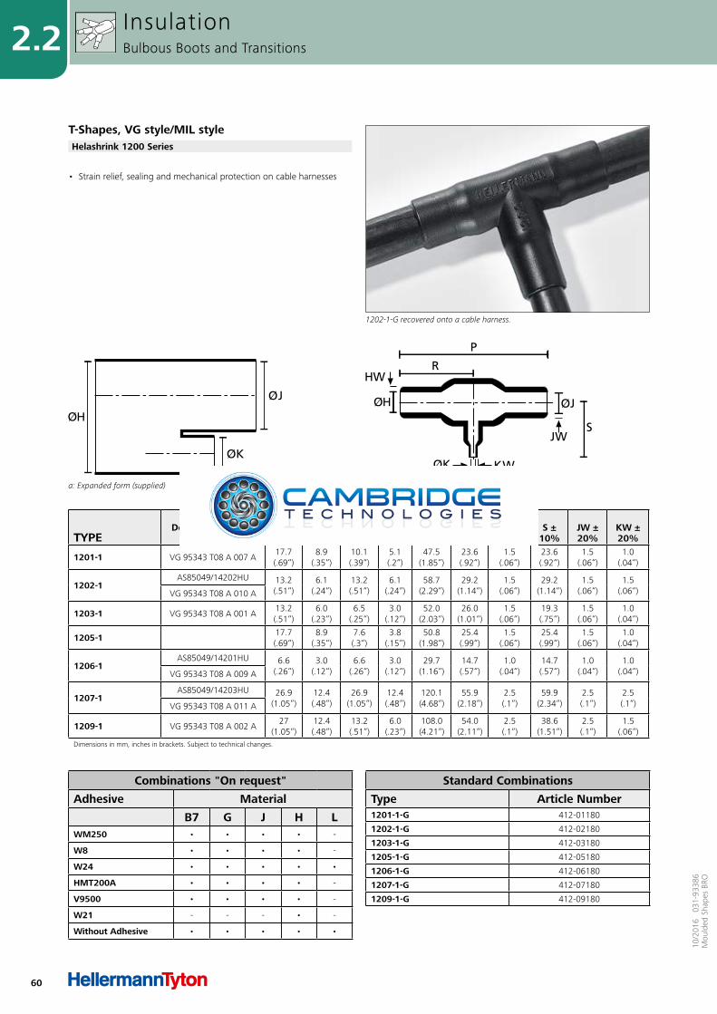
60
2.2
10/2
016
031
-933
86M
ould
ed S
hape
s BR
O
TYPEDesignation as per
AS/VG-Norm
ØH/Jmin.
a
ØH/Jmax.
b
ØKmin.
a
ØKmax.
b P ±
10% R ±
10% HW ±20%
S ±10%
JW ±20%
KW ±20%
1201-1 VG 95343 T08 A 007 A17.7(.69“)
8.9(.35“)
10.1(.39“)
5.1(.2“)
47.5(1.85“)
23.6(.92“)
1.5(.06“)
23.6(.92“)
1.5(.06“)
1.0(.04“)
1202-1AS85049/14202HU 13.2
(.51“)6.1
(.24“)13.2(.51“)
6.1(.24“)
58.7(2.29“)
29.2(1.14“)
1.5(.06“)
29.2(1.14“)
1.5(.06“)
1.5(.06“)VG 95343 T08 A 010 A
1203-1 VG 95343 T08 A 001 A13.2(.51“)
6.0(.23“)
6.5(.25“)
3.0(.12“)
52.0(2.03“)
26.0(1.01“)
1.5(.06“)
19.3(.75“)
1.5(.06“)
1.0(.04“)
1205-1 17.7(.69“)
8.9(.35“)
7.6(.3“)
3.8(.15“)
50.8(1.98“)
25.4(.99“)
1.5(.06“)
25.4(.99“)
1.5(.06“)
1.0(.04“)
1206-1AS85049/14201HU 6.6
(.26“)3.0
(.12“)6.6
(.26“)3.0
(.12“)29.7
(1.16“)14.7(.57“)
1.0(.04“)
14.7(.57“)
1.0(.04“)
1.0(.04“)VG 95343 T08 A 009 A
1207-1AS85049/14203HU 26.9
(1.05“)12.4(.48“)
26.9(1.05“)
12.4(.48“)
120.1(4.68“)
55.9(2.18“)
2.5(.1“)
59.9(2.34“)
2.5(.1“)
2.5(.1“)VG 95343 T08 A 011 A
1209-1 VG 95343 T08 A 002 A27
(1.05“)12.4(.48“)
13.2(.51“)
6.0(.23“)
108.0(4.21“)
54.0(2.11“)
2.5(.1“)
38.6(1.51“)
2.5(.1“)
1.5(.06“)
Dimensions in mm, inches in brackets. Subject to technical changes.
a: Expanded form (supplied) b: Fully recovered form (after heating)
• Strain relief, sealing and mechanical protection on cable harnesses
InsulationBulbous Boots and Transitions
T-Shapes, VG style/MIL style
1202-1-G recovered onto a cable harness.
Helashrink 1200 Series
Combinations "On request"
Adhesive Material
B7 G J H LWM250 • • • • -
W8 • • • • -
W24 • • • • •
HMT200A • • • • -
V9500 • • • • -
W21 - - - • -
Without Adhesive • • • • •
Standard Combinations
Type Article Number1201-1-G 412-01180
1202-1-G 412-02180
1203-1-G 412-03180
1205-1-G 412-05180
1206-1-G 412-06180
1207-1-G 412-07180
1209-1-G 412-09180
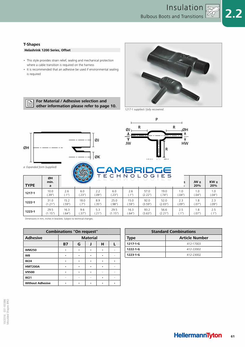
61
2.210
/201
6 0
31-9
3386
Mou
lded
Sha
pes
BRO
TYPE
ØHmin.
a
ØHmax.
b
ØJmin.
a
ØJmax.
b
ØKmin.
a
ØKmax.
b P ±
10% R ±
10% HW ±20%
JW ±20%
KW ±20%
1217-1 10.0 (.39")
2.6 (.1")
6.0 (.23")
2.2 (.09")
6.0 (.23")
2.6 (.1")
57.0 (2.22")
19.0 (.74")
1.0 (.04")
1.0 (.04")
1.0 (.04")
1222-1 31.0 (1.21")
15.2 (.59")
18.0 (.7")
8.9 (.35")
25.0 (.98")
15.0 (.59")
92.0 (3.59")
52.0 (2.03")
2.3 (.09")
1.8 (.07")
2.3 (.09")
1223-1 29.5 (1.15")
16.3 (.64")
9.6 (.37")
5.3 (.21")
29.5 (1.15")
16.3 (.64")
93.2 (3.63")
56.6 (2.21")
2.5 (.1")
1.8 (.07")
2.5 (.1")
Dimensions in mm, inches in brackets. Subject to technical changes.
a: Expanded form (supplied)
ØH
ØJ
ØK
b: Fully recovered form (after heating)
JW
ØJ
P
R RØH
HWR
KW ØK
• This style provides strain relief, sealing and mechanical protection where a cable transition is required on the harness
• It is recommended that an adhesive be used if environmental sealing is required
InsulationBulbous Boots and Transitions
T-Shapes
1217-1 supplied / fully recovered.
Helashrink 1200 Series, Offset
Combinations "On request"
Adhesive Material
B7 G J H LWM250 • • • • -
W8 • • • • -
W24 • • • • •
HMT200A • • • • -
V9500 • • • - -
W21 - - - • -
Without Adhesive • • • • •
Standard Combinations
Type Article Number1217-1-G 412-17003
1222-1-G 412-22002
1223-1-G 412-23002
For Material / Adhesive selection and other information please refer to page 10.
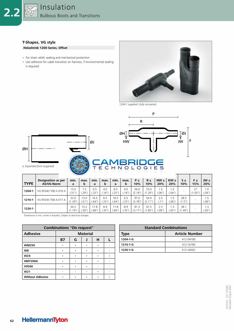
62
2.2
10/2
016
031
-933
86M
ould
ed S
hape
s BR
O
TYPEDesignation as per
AS/VG-Norm
ØHmin.
a
ØHmax.
b
ØJmin.
a
ØJmax.
b
ØKmin.
a
ØKmax.
b P ±
10% R ±
10% HW ±20%
KW ±20%
S ±10%
F ±15%
JW ±20%
1204-1 VG 95343 T08 A 016 A13.0 (.51")
7.5 (.29")
6.5 (.25")
4.0 (.16")
6.5 (.25")
4.0 (.16")
56.0 (2.18")
33.0 (1.29")
1.5 (.06")
1.0 (.04")
-27
(1.05")1.0
(.04")
1216-1 VG 95343 T08 A 017 A33.0
(1.29")13.0 (.51")
16.5 (.64")
6.5 (.25")
16.5 (.64")
6.5 (.25")
97.0 (3.78")
54.0 (2.11")
2.5 (.1")
1.5 (.06")
38.5 (1.5")
-1.5
(.06")
1226-1 30.5 (1.19")
15.2 (.59")
17.8 (.69")
8.9 (.35")
17.8 (.69")
8.9 (.35")
81.3 (3.17")
47.5 (1.85")
2.3 (.09")
1.3 (.05")
38.1 (1.49")
-1.3
(.05")
Dimensions in mm, inches in brackets. Subject to technical changes.
a: Expanded form (supplied)
ØH
ØJ
ØK
b: Fully recovered form (after heating)
HW
ØH
JW
ØJ
F
P
KW ØK
R
• For strain relief, sealing and mechanical protection• Use adhesive for cable transition on harness, if environmental sealing
is required
InsulationBulbous Boots and Transitions
T-Shapes, VG style
1204-1 supplied / fully recovered.
Helashrink 1200 Series, Offset
Combinations "On request"
Adhesive Material
B7 G J H LWM250 • • • • -
W8 • • • • -
W24 • • • • •
HMT200A • • • • -
V9500 • • • - -
W21 - - - • -
Without Adhesive • • • • •
Standard Combinations
Type Article Number1204-1-G 412-04180
1216-1-G 412-16180
1226-1-G 412-26002
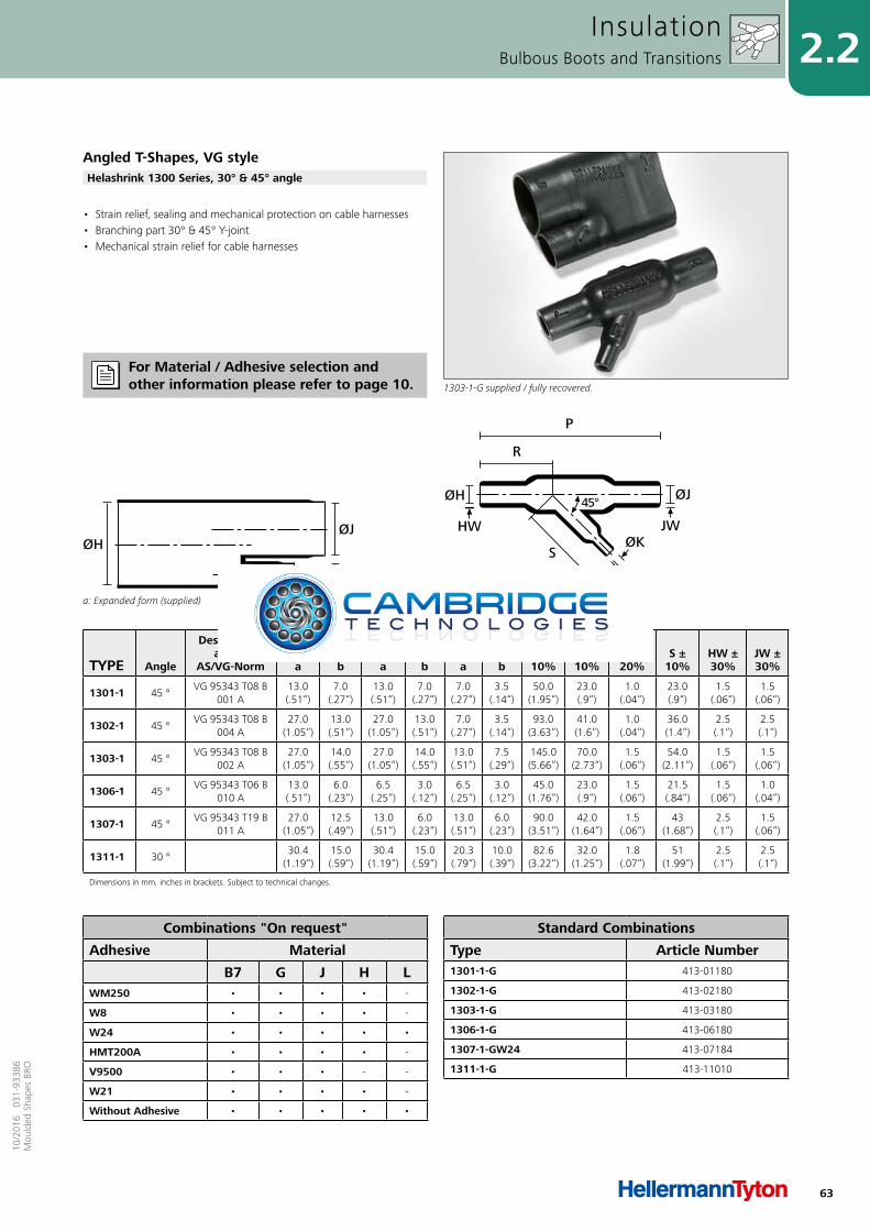
63
2.210
/201
6 0
31-9
3386
Mou
lded
Sha
pes
BRO
TYPE Angle
Designation as per
AS/VG-Norm
ØHmin.
a
ØHmax.
b
ØJmin.
a
ØJmax.
b
ØKmin.
a
ØKmax.
b P ±
10% R ±
10% KW ±20%
S ±10%
HW ±30%
JW ±30%
1301-1 45 °VG 95343 T08 B
001 A13.0(.51“)
7.0(.27“)
13.0(.51“)
7.0(.27“)
7.0(.27“)
3.5(.14“)
50.0(1.95“)
23.0(.9“)
1.0(.04“)
23.0(.9“)
1.5(.06“)
1.5(.06“)
1302-1 45 °VG 95343 T08 B
004 A27.0
(1.05“)13.0(.51“)
27.0(1.05“)
13.0(.51“)
7.0(.27“)
3.5(.14“)
93.0(3.63“)
41.0(1.6“)
1.0(.04“)
36.0(1.4“)
2.5(.1“)
2.5(.1“)
1303-1 45 °VG 95343 T08 B
002 A27.0
(1.05“)14.0(.55“)
27.0(1.05“)
14.0(.55“)
13.0(.51“)
7.5(.29“)
145.0(5.66“)
70.0(2.73“)
1.5(.06“)
54.0(2.11“)
1.5(.06“)
1.5(.06“)
1306-1 45 °VG 95343 T06 B
010 A13.0(.51“)
6.0(.23“)
6.5(.25“)
3.0(.12“)
6.5(.25“)
3.0(.12“)
45.0(1.76“)
23.0(.9“)
1.5(.06“)
21.5(.84“)
1.5(.06“)
1.0(.04“)
1307-1 45 °VG 95343 T19 B
011 A27.0
(1.05“)12.5(.49“)
13.0(.51“)
6.0(.23“)
13.0(.51“)
6.0(.23“)
90.0(3.51“)
42.0(1.64“)
1.5(.06“)
43(1.68“)
2.5(.1“)
1.5(.06“)
1311-1 30 °30.4
(1.19“)15.0(.59“)
30.4(1.19“)
15.0(.59“)
20.3(.79“)
10.0(.39“)
82.6(3.22“)
32.0(1.25“)
1.8(.07“)
51(1.99“)
2.5(.1“)
2.5(.1“)
Dimensions in mm, inches in brackets. Subject to technical changes.
a: Expanded form (supplied)
ØHØJ
ØK
b: Fully recovered form (after heating)
P
R
HW
S
ØH 45°
ØKJW
KW
ØJ
• Strain relief, sealing and mechanical protection on cable harnesses• Branching part 30° & 45° Y-joint• Mechanical strain relief for cable harnesses
InsulationBulbous Boots and Transitions
Angled T-Shapes, VG style
1303-1-G supplied / fully recovered.
Helashrink 1300 Series, 30° & 45° angle
For Material / Adhesive selection and other information please refer to page 10.
Combinations "On request"
Adhesive Material
B7 G J H LWM250 • • • • -
W8 • • • • -
W24 • • • • •
HMT200A • • • • -
V9500 • • • - -
W21 • • • • -
Without Adhesive • • • • •
Standard Combinations
Type Article Number1301-1-G 413-01180
1302-1-G 413-02180
1303-1-G 413-03180
1306-1-G 413-06180
1307-1-GW24 413-07184
1311-1-G 413-11010
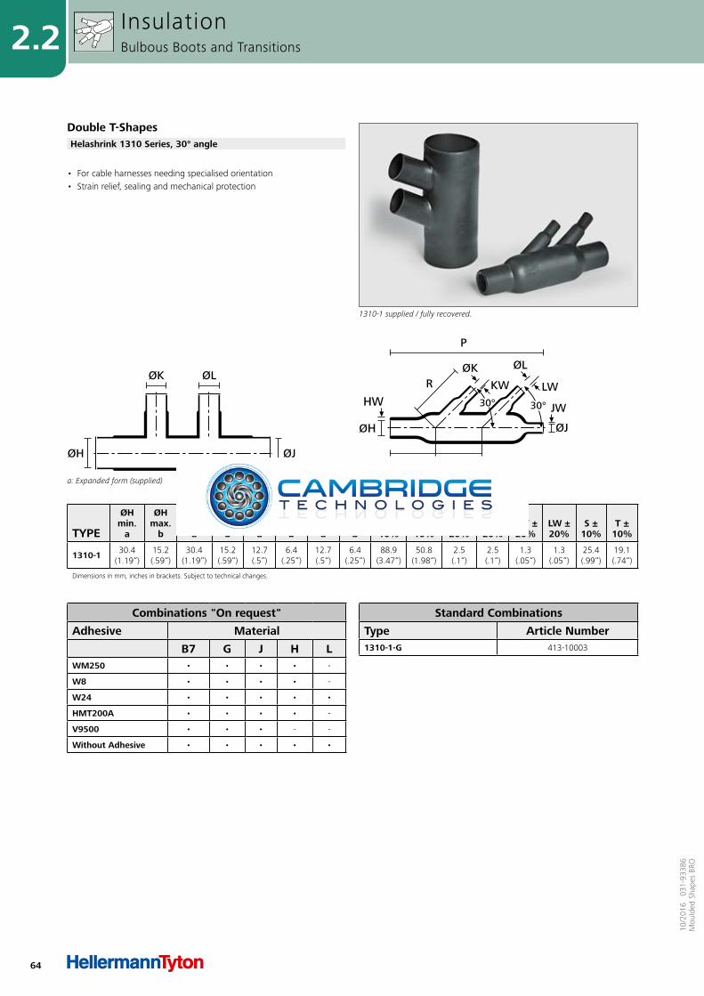
64
2.2
10/2
016
031
-933
86M
ould
ed S
hape
s BR
O
TYPE
ØHmin.
a
ØHmax.
b
ØJmin.
a
ØJmax.
b
ØKmin.
a
ØKmax.
b
ØLmin.
a
ØLmax.
b P ±
10% R ±
10% HW ±20%
JW ±20%
KW ±20%
LW ±20%
S ±10%
T ±10%
1310-1 30.4(1.19“)
15.2(.59“)
30.4(1.19“)
15.2(.59“)
12.7(.5“)
6.4(.25“)
12.7(.5“)
6.4(.25“)
88.9(3.47“)
50.8(1.98“)
2.5(.1“)
2.5(.1“)
1.3(.05“)
1.3(.05“)
25.4(.99“)
19.1(.74“)
Dimensions in mm, inches in brackets. Subject to technical changes.
a: Expanded form (supplied)
ØJØH
ØK ØL
b: Fully recovered form (after heating)
HW
ØH
ØKKW
ØJ
JW
P
T
R
S
ØL
LW
30°30°
• For cable harnesses needing specialised orientation• Strain relief, sealing and mechanical protection
InsulationBulbous Boots and Transitions
Double T-Shapes
1310-1 supplied / fully recovered.
Helashrink 1310 Series, 30° angle
Combinations "On request"
Adhesive Material
B7 G J H LWM250 • • • • -
W8 • • • • -
W24 • • • • •
HMT200A • • • • -
V9500 • • • - -
Without Adhesive • • • • •
Standard Combinations
Type Article Number1310-1-G 413-10003
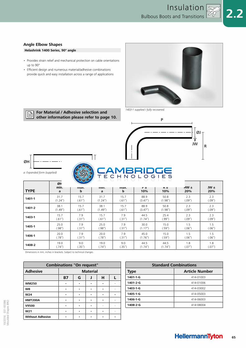
65
2.210
/201
6 0
31-9
3386
Mou
lded
Sha
pes
BRO
TYPE
ØHmin.
a
ØHmax.
b
ØJmin.
a
ØJmax.
b P ±
10% R ±
10% HW ±20%
JW ±20%
1401-1 31.7(1.24“)
15.7(.61“)
31.7(1.24“)
15.7(.61“)
88.9(3.47“)
50.8(1.98“)
2.3(.09“)
2.3(.09“)
1401-2 38.1(1.49“)
15.7(.61“)
38.1(1.49“)
15.7(.61“)
88.9(3.47“)
50.8(1.98“)
2.3(.09“)
2.3(.09“)
1403-1 15.7(.61“)
7.9(.31“)
15.7(.61“)
7.9(.31“)
44.5(1.74“)
25.4(.99“)
2.3(.09“)
2.3(.09“)
1405-1 25.0(.98“)
7.9(.31“)
25.0(.98“)
7.9(.31“)
30.0(1.17“)
15.0(.59“)
1.5(.06“)
1.5(.06“)
1406-1 20.0(.78“)
7.9(.31“)
20.0(.78“)
7.9(.31“)
45.0(1.76“)
15.0(.59“)
1.5(.06“)
1.5(.06“)
1408-2 19.0(.74“)
9.0(.35“)
19.0(.74“)
9.0(.35“)
44.5(1.74“)
44.5(1.74“)
1.8(.07“)
1.8(.07“)
Dimensions in mm, inches in brackets. Subject to technical changes.
a: Expanded form (supplied)
ØJØH
b: Fully recovered form (after heating)
P
HWØH
RJW
ØJ
• Provides strain relief and mechanical protection on cable orientations up to 90°
• Efficient design and numerous material/adhesive combinations provide quick and easy installation across a range of applications
InsulationBulbous Boots and Transitions
Angle Elbow Shapes
1403-1 supplied / fully recovered.
Helashrink 1400 Series, 90° angle
For Material / Adhesive selection and other information please refer to page 10.
Combinations "On request"
Adhesive Material
B7 G J H LWM250 • • • • -
W8 • • • • -
W24 • • • • •
HMT200A • • • • -
V9500 • • • - -
W21 • • • • -
Without Adhesive • • • • •
Standard Combinations
Type Article Number1401-1-G 414-01003
1401-2-G 414-01006
1403-1-G 414-03002
1405-1-G 414-05003
1406-1-G 414-06003
1408-2-G 414-08004
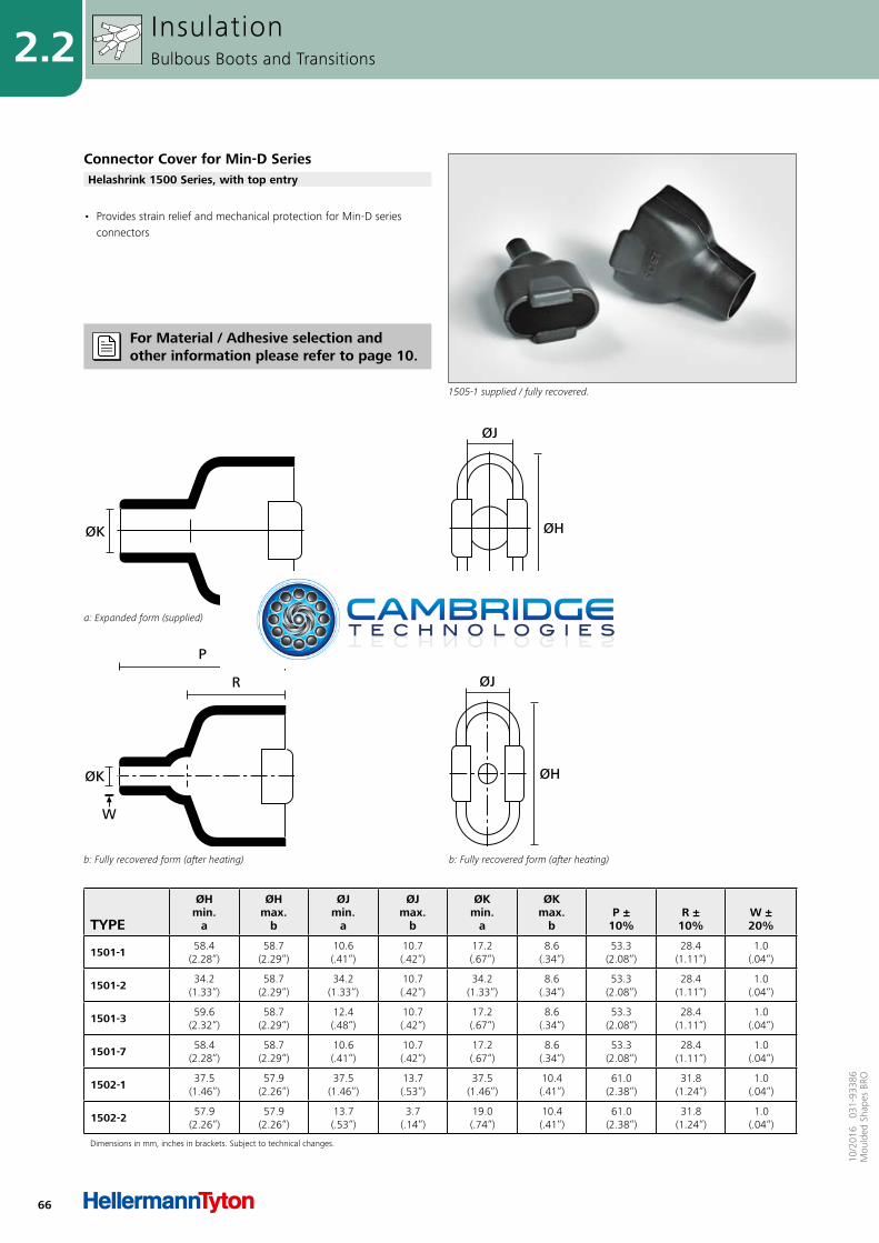
66
2.2
10/2
016
031
-933
86M
ould
ed S
hape
s BR
O
TYPE
ØHmin.
a
ØHmax.
b
ØJmin.
a
ØJmax.
b
ØKmin.
a
ØKmax.
b P ±
10% R ±
10% W ±20%
1501-1 58.4(2.28“)
58.7(2.29“)
10.6(.41“)
10.7(.42“)
17.2(.67“)
8.6(.34“)
53.3(2.08“)
28.4(1.11“)
1.0(.04“)
1501-2 34.2(1.33“)
58.7(2.29“)
34.2(1.33“)
10.7(.42“)
34.2(1.33“)
8.6(.34“)
53.3(2.08“)
28.4(1.11“)
1.0(.04“)
1501-3 59.6(2.32“)
58.7(2.29“)
12.4(.48“)
10.7(.42“)
17.2(.67“)
8.6(.34“)
53.3(2.08“)
28.4(1.11“)
1.0(.04“)
1501-7 58.4(2.28“)
58.7(2.29“)
10.6(.41“)
10.7(.42“)
17.2(.67“)
8.6(.34“)
53.3(2.08“)
28.4(1.11“)
1.0(.04“)
1502-1 37.5(1.46“)
57.9(2.26“)
37.5(1.46“)
13.7(.53“)
37.5(1.46“)
10.4(.41“)
61.0(2.38“)
31.8(1.24“)
1.0(.04“)
1502-2 57.9(2.26“)
57.9(2.26“)
13.7(.53“)
3.7(.14“)
19.0(.74“)
10.4(.41“)
61.0(2.38“)
31.8(1.24“)
1.0(.04“)
Dimensions in mm, inches in brackets. Subject to technical changes.
ØH
ØJ
b: Fully recovered form (after heating)b: Fully recovered form (after heating)
R
P
W
ØK
a: Expanded form (supplied)
ØK
a: Expanded form (supplied)
ØH
ØJ
• Provides strain relief and mechanical protection for Min-D series connectors
InsulationBulbous Boots and Transitions
Connector Cover for Min-D Series
1505-1 supplied / fully recovered.
Helashrink 1500 Series, with top entry
For Material / Adhesive selection and other information please refer to page 10.
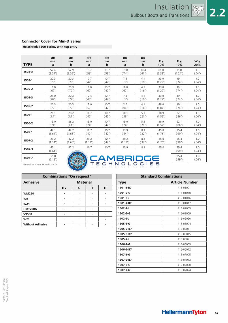
67
2.210
/201
6 0
31-9
3386
Mou
lded
Sha
pes
BRO
Combinations "On request"
Adhesive Material
B7 G J HWM250 • • • •
W8 • • • •
W24 • • • •
HMT200A • • • •
V9500 • • • -
W21 - - - •
Without Adhesive • • • •
Standard Combinations
Type Article Number1501-1-B7 415-01001
1501-2-G 415-01010
1501-3-J 415-01016
1501-7-B7 415-01017
1502-1-J 415-02005
1502-2-G 415-02009
1502-3-J 415-02020
1505-1-G 415-05004
1505-2-B7 415-05011
1505-3-B7 415-05015
1505-7-J 415-05021
1506-1-G 415-06005
1506-2-B7 415-06012
1507-1-G 415-07005
1507-2-B7 415-07013
1507-3-G 415-07030
1507-7-G 415-07024
TYPE
ØHmin.
a
ØHmax.
b
ØJmin.
a
ØJmax.
b
ØKmin.
a
ØKmax.
b P ±
10% R ±
10% W ±20%
1502-3 57.4(2.24“)
57.9(2.26“)
13.7(.53“)
13.7(.53“)
19.0(.74“)
10.4(.41“)
61.0(2.38“)
31.8(1.24“)
1.0(.04“)
1505-1 20.3(.79“)
20.3(.79“)
10.7(.42“)
10.7(.42“)
7.8(.3“)
4.1(.16“)
33.0(1.29“)
19.1(.74“)
1.0(.04“)
1505-2 16.0(.62“)
20.3(.79“)
16.0(.62“)
10.7(.42“)
16.0(.62“)
4.1(.16“)
33.0(1.29“)
19.1(.74“)
1.0(.04“)
1505-3 21.0(.82“)
20.3(.79“)
12.4(.48“)
10.7(.42“)
7.8(.3“)
4.1(.16“)
33.0(1.29“)
19.1(.74“)
1.0(.04“)
1505-7 20.3(.79“)
20.3(.79“)
15.0(.59“)
10.7(.42“)
2.0(.08“)
4.1(.16“)
48.0(1.87“)
19.1(.74“)
1.0(.04“)
1506-1 28.1(1.1“)
28.2(1.1“)
10.7(.42“)
10.7(.42“)
10.1(.39“)
5.3(.21“)
38.9(1.52“)
22.1(.86“)
1.0(.04“)
1506-2 19.0(.74“)
28.2(1.1“)
19.0(.74“)
10.7(.42“)
19.0(.74“)
5.3(.21“)
38.9(1.52“)
22.1(.86“)
1.0(.04“)
1507-1 42.1(1.64“)
42.2(1.65“)
10.7(.42“)
10.7(.42“)
13.9(.54“)
8.1(.32“)
45.0(1.76“)
25.4(.99“)
1.0(.04“)
1507-2 29.2(1.14“)
42.2(1.65“)
29.2(1.14“)
10.7(.42“)
29.2(1.14“)
8.1(.32“)
45.0(1.76“)
25.4(.99“)
1.0(.04“)
1507-3 42.1(1.64“)
42.2(1.65“)
10.7(.42“)
10.7(.42“)
13.9(.54“)
8.1(.32“)
45.0(1.76“)
25.4(.99“)
1.0(.04“)
1507-7 55.0(2.15“)
42.2(1.65“)
13.9(.54“)
10.7(.42“)
25.0(.98“)
8.1(.32“)
45.0(1.76“)
25.4(.99“)
1.0(.04“)
Dimensions in mm, inches in brackets. Subject to technical changes.
InsulationBulbous Boots and Transitions
Connector Cover for Min-D SeriesHelashrink 1500 Series, with top entry
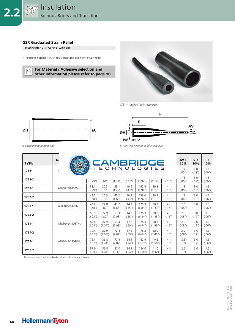
68
2.2
10/2
016
031
-933
86M
ould
ed S
hape
s BR
O
TYPEDesignation as per
AS/VG-Norm
ØHmin.
a
ØHmax.
b
ØJmin.
a
ØJmax.
b P ±
10% R ±
10% HW ±20%
JW ±20%
V ± 10%
T ±10%
1751-1 AS85049/14024HU25.4(.99“)
16.5(.64“)
25.4(.99“)
8.3(.32“)
152.4(5.94“)
30.5(1.19“)
4.1(.16“)
1.5(.06“)
3.0(.12“)
1.5(.06“)
1751-2 33.0(1.29“)
16.5(.64“)
33.0(1.29“)
8.4(.33“)
153.0(5.97“)
30.5(1.19“)
4.1(.16“)
1.5(.06“)
3.0(.12“)
1.5(.06“)
1752-1 AS85049/14025HU33.1
(1.29“)20.3(.79“)
33.1(1.29“)
10.9(.43“)
152.4(5.94“)
30.5(1.19“)
4.1(.16“)
1.5(.06“)
3.0(.12“)
1.5(.06“)
1752-2 43.2(1.68“)
20.3(.79“)
43.2(1.68“)
10.9(.43“)
153.0(5.97“)
30.5(1.19“)
4.1(.16“)
1.5(.06“)
3.0(.12“)
1.5(.06“)
1753-1 AS85049/14026HU43.2
(1.68“)22.8(.89“)
43.2(1.68“)
14.2(.55“)
175.3(6.84“)
38.1(1.49“)
4.1(.16“)
2.0(.08“)
3.0(.12“)
1.5(.06“)
1753-2 53.3(2.08“)
22.9(.89“)
53.3(2.08“)
14.2(.55“)
175.3(6.84“)
38.0(1.48“)
4.1(.16“)
2.0(.08“)
3.0(.12“)
1.5(.06“)
1754-1 AS85049/14027HU53.4
(2.08“)27.9
(1.09“)53.4
(2.08“)17.7(.69“)
175.3(6.84“)
38.1(1.49“)
4.1(.16“)
2.0(.08“)
3.0(.12“)
1.5(.06“)
1754-2 72.4(2.82“)
27.9(1.09“)
72.4(2.82“)
17.8(.69“)
175.3(6.84“)
38.0(1.48“)
4.1(.16“)
2.0(.08“)
3.0(.12“)
1.5(.06“)
1755-1 AS85049/14028HU72.4
(2.82“)36.8
(1.44“)72.4
(2.82“)24.1(.94“)
182.9(7.13“)
40.6(1.58“)
4.1(.16“)
2.5(.1“)
3.0(.12“)
1.5(.06“)
1755-2 87.0(3.39“)
36.8(1.44“)
87.0(3.39“)
24.1(.94“)
184.0(7.18“)
41.0(1.6“)
4.1(.16“)
2.5(.1“)
3.0(.12“)
1.5(.06“)
Dimensions in mm, inches in brackets. Subject to technical changes.
a: Expanded form (supplied)
ØJØH
b: Fully recovered form (after heating)
P
RT
ØH
HW V
ØJ
JW
• Features superior crush resistance and excellent strain relief
InsulationBulbous Boots and Transitions
GSR Graduated Strain Relief
1751-1 supplied / fully recovered.
Helashrink 1750 Series, with rib
For Material / Adhesive selection and other information please refer to page 10.
69
2.210
/201
6 0
31-9
3386
Mou
lded
Sha
pes
BRO
Combinations "On request"
Adhesive Material
B7 G J HWM250 • • • •
W8 • • • •
W24 • • • •
HMT200A • • • •
V9500 • • • -
W21 - - - •
Without Adhesive • • • •
Standard Combinations
Type Article Number1751-1-H 417-51001
1751-2-H 417-51009
1752-1-H 417-52001
1752-2-H 417-52005
1753-1-H 417-53001
1753-2-H 417-53005
1754-1-H 417-54001
1754-2-H 417-54005
1755-1-H 417-55001
1755-2-H 417-55005
GSR Graduated Strain ReliefHelashrink 1750 Series, with rib
InsulationBulbous Boots and Transitions
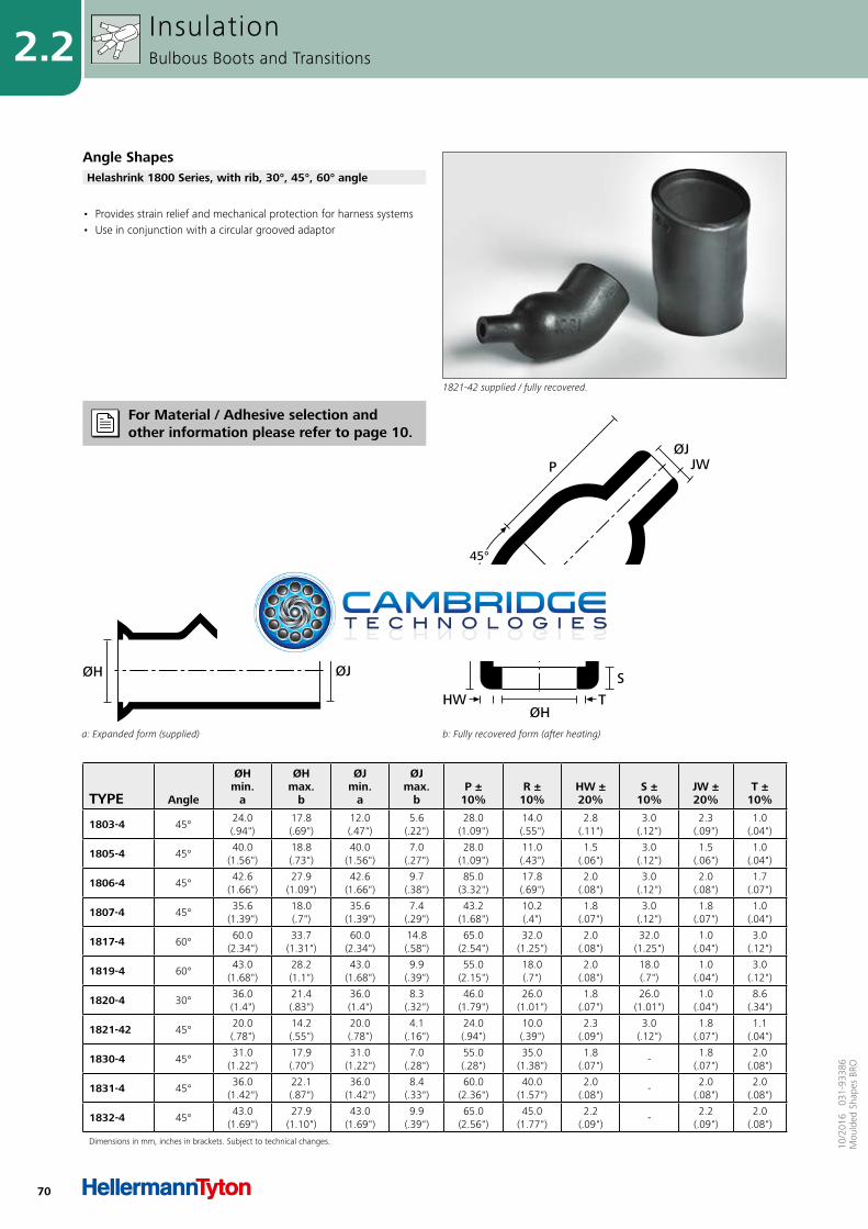
70
2.2
10/2
016
031
-933
86M
ould
ed S
hape
s BR
O
TYPE Angle
ØHmin.
a
ØHmax.
b
ØJmin.
a
ØJmax.
b P ±
10% R ±
10% HW ±20%
S ±10%
JW ±20%
T ±10%
1803-4 45°24.0 (.94")
17.8 (.69")
12.0 (.47")
5.6 (.22")
28.0 (1.09")
14.0 (.55")
2.8 (.11")
3.0 (.12")
2.3 (.09")
1.0 (.04")
1805-4 45°40.0
(1.56")18.8 (.73")
40.0 (1.56")
7.0 (.27")
28.0 (1.09")
11.0 (.43")
1.5 (.06")
3.0 (.12")
1.5 (.06")
1.0 (.04")
1806-4 45°42.6
(1.66")27.9
(1.09")42.6
(1.66")9.7
(.38")85.0
(3.32")17.8 (.69")
2.0 (.08")
3.0 (.12")
2.0 (.08")
1.7 (.07")
1807-4 45°35.6
(1.39")18.0 (.7")
35.6 (1.39")
7.4 (.29")
43.2 (1.68")
10.2 (.4")
1.8 (.07")
3.0 (.12")
1.8 (.07")
1.0 (.04")
1817-4 60°60.0
(2.34")33.7
(1.31")60.0
(2.34")14.8 (.58")
65.0 (2.54")
32.0 (1.25")
2.0 (.08")
32.0 (1.25")
1.0 (.04")
3.0 (.12")
1819-4 60°43.0
(1.68")28.2 (1.1")
43.0 (1.68")
9.9 (.39")
55.0 (2.15")
18.0 (.7")
2.0 (.08")
18.0 (.7")
1.0 (.04")
3.0 (.12")
1820-4 30°36.0 (1.4")
21.4 (.83")
36.0 (1.4")
8.3 (.32")
46.0 (1.79")
26.0 (1.01")
1.8 (.07")
26.0 (1.01")
1.0 (.04")
8.6 (.34")
1821-42 45°20.0 (.78")
14.2 (.55")
20.0 (.78")
4.1 (.16")
24.0 (.94")
10.0 (.39")
2.3 (.09")
3.0 (.12")
1.8 (.07")
1.1 (.04")
1830-4 45°31.0
(1.22")17.9 (.70")
31.0 (1.22")
7.0 (.28")
55.0 (.28")
35.0 (1.38")
1.8 (.07")
-1.8
(.07")2.0
(.08")
1831-4 45°36.0
(1.42")22.1 (.87")
36.0 (1.42")
8.4 (.33")
60.0 (2.36")
40.0 (1.57")
2.0 (.08")
-2.0
(.08")2.0
(.08")
1832-4 45°43.0
(1.69")27.9
(1.10")43.0
(1.69")9.9
(.39")65.0
(2.56")45.0
(1.77")2.2
(.09")-
2.2 (.09")
2.0 (.08")
Dimensions in mm, inches in brackets. Subject to technical changes.
a: Expanded form (supplied)
ØJØH
b: Fully recovered form (after heating)
T
JWP
45°
ØH
ØJ
HWS
R
• Provides strain relief and mechanical protection for harness systems• Use in conjunction with a circular grooved adaptor
InsulationBulbous Boots and Transitions
Angle Shapes
1821-42 supplied / fully recovered.
Helashrink 1800 Series, with rib, 30°, 45°, 60° angle
For Material / Adhesive selection and other information please refer to page 10.

71
2.210
/201
6 0
31-9
3386
Mou
lded
Sha
pes
BRO
Combinations "On request"
Adhesive Material
B7 G J H LWM250 • • • • -
W8 • • • • -
W24 • • • • •
HMT200A • • • - -
V9500 • • • • -
W21 - - - • -
Without Adhesive • • • • •
Standard Combinations
Type Article Number1803-4-G 418-03005
1805-4-G 418-05003
1806-4-G 418-06002
1807-4-G 418-07003
1817-4-G 418-17001
1819-4-G 418-19001
1820-4-G 418-20001
1821-42-G 418-21013
1830-4-G 418-30003
1831-4-G 418-31001
1832-4-G 418-32000
Angle ShapesHelashrink 1800 Series, with rib, 30°, 45°, 60° angle
InsulationBulbous Boots and Transitions
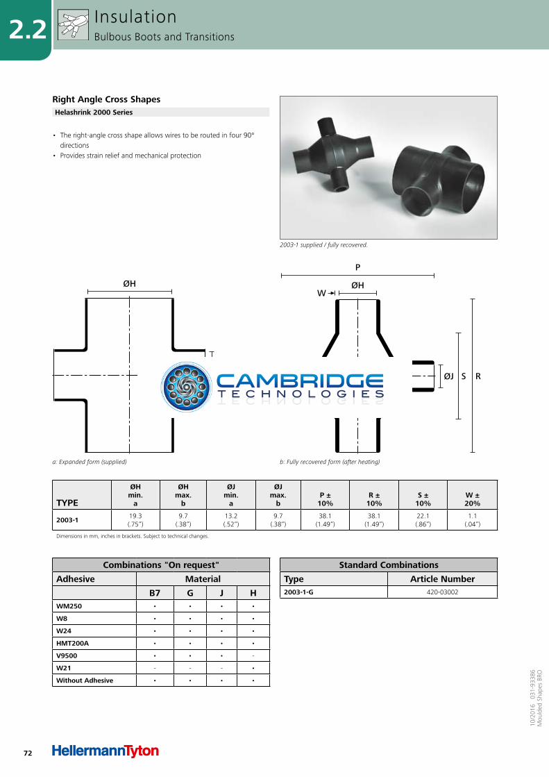
72
2.2
10/2
016
031
-933
86M
ould
ed S
hape
s BR
O
TYPE
ØHmin.
a
ØHmax.
b
ØJmin.
a
ØJmax.
b P ±
10% R ±
10% S ±
10% W ±20%
2003-1 19.3(.75“)
9.7(.38“)
13.2(.52“)
9.7(.38“)
38.1(1.49“)
38.1(1.49“)
22.1(.86“)
1.1(.04“)
Dimensions in mm, inches in brackets. Subject to technical changes.
a: Expanded form (supplied)
ØJ
ØH
b: Fully recovered form (after heating)
P
S RØJ
ØHW
• The right-angle cross shape allows wires to be routed in four 90° directions
• Provides strain relief and mechanical protection
InsulationBulbous Boots and Transitions
Right Angle Cross Shapes
2003-1 supplied / fully recovered.
Helashrink 2000 Series
Combinations "On request"
Adhesive Material
B7 G J HWM250 • • • •
W8 • • • •
W24 • • • •
HMT200A • • • •
V9500 • • • -
W21 - - - •
Without Adhesive • • • •
Standard Combinations
Type Article Number2003-1-G 420-03002
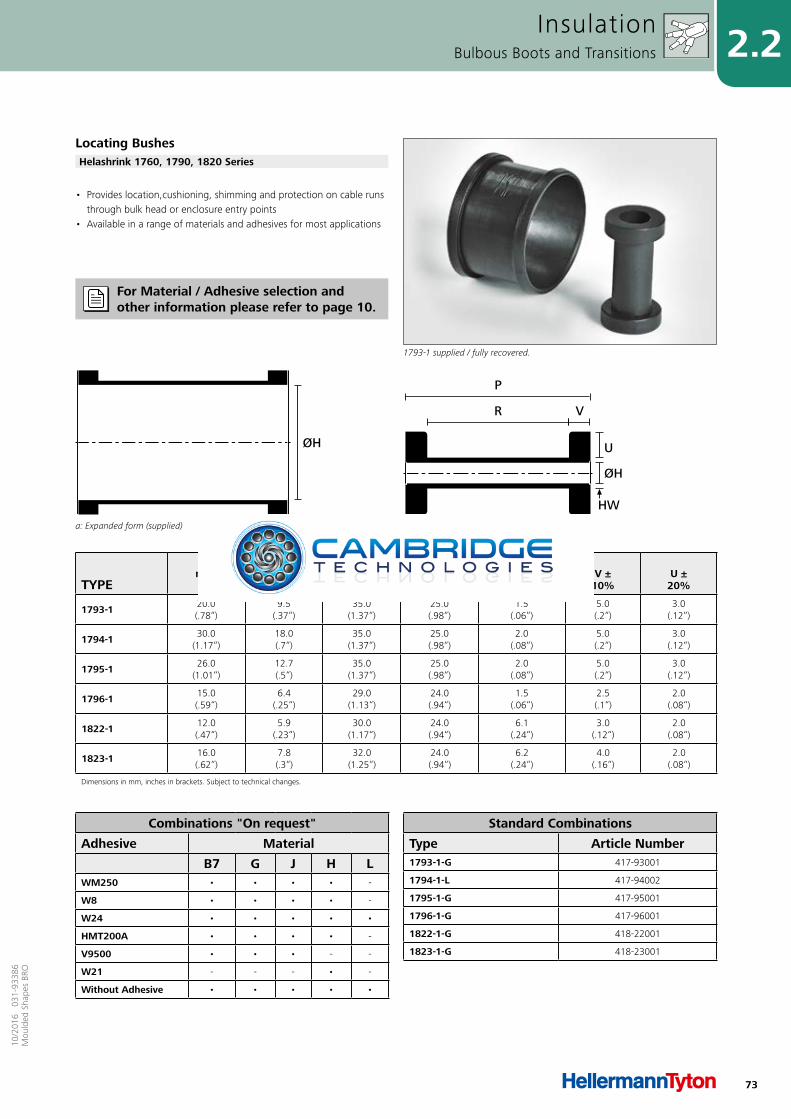
73
2.210
/201
6 0
31-9
3386
Mou
lded
Sha
pes
BRO
TYPE
ØHmin.
a
ØHmax.
b P ±
10% R ±
10% HW ±20%
V ± 10%
U ±20%
1793-1 20.0(.78“)
9.5(.37“)
35.0(1.37“)
25.0(.98“)
1.5(.06“)
5.0(.2“)
3.0(.12“)
1794-1 30.0(1.17“)
18.0(.7“)
35.0(1.37“)
25.0(.98“)
2.0(.08“)
5.0(.2“)
3.0(.12“)
1795-1 26.0(1.01“)
12.7(.5“)
35.0(1.37“)
25.0(.98“)
2.0(.08“)
5.0(.2“)
3.0(.12“)
1796-1 15.0(.59“)
6.4(.25“)
29.0(1.13“)
24.0(.94“)
1.5(.06“)
2.5(.1“)
2.0(.08“)
1822-1 12.0(.47“)
5.9(.23“)
30.0(1.17“)
24.0(.94“)
6.1(.24“)
3.0(.12“)
2.0(.08“)
1823-1 16.0(.62“)
7.8(.3“)
32.0(1.25“)
24.0(.94“)
6.2(.24“)
4.0(.16“)
2.0(.08“)
Dimensions in mm, inches in brackets. Subject to technical changes.
a: Expanded form (supplied)
ØH
b: Fully recovered form (after heating)
P
ØH
U
R V
HW
• Provides location,cushioning, shimming and protection on cable runs through bulk head or enclosure entry points
• Available in a range of materials and adhesives for most applications
InsulationBulbous Boots and Transitions
Locating Bushes
1793-1 supplied / fully recovered.
Helashrink 1760, 1790, 1820 Series
Combinations "On request"
Adhesive Material
B7 G J H LWM250 • • • • -
W8 • • • • -
W24 • • • • •
HMT200A • • • • -
V9500 • • • - -
W21 - - - • -
Without Adhesive • • • • •
Standard Combinations
Type Article Number1793-1-G 417-93001
1794-1-L 417-94002
1795-1-G 417-95001
1796-1-G 417-96001
1822-1-G 418-22001
1823-1-G 418-23001
For Material / Adhesive selection and other information please refer to page 10.
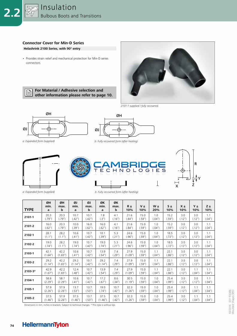
74
2.2
10/2
016
031
-933
86M
ould
ed S
hape
s BR
O
TYPE
ØHmin.
a
ØHmax.
b
ØJmin.
a
ØJmax.
b
ØKmin.
a
ØKmax.
b R ±
10% V ±
10% W ±20%
S ±10%
X ±10%
Y ±10%
Z ±10%
2101-1 20.3(.79“)
20.3(.79“)
10.7(.42“)
10.7(.42“)
7.8(.3“)
4.1(.16“)
21.6(.84“)
15.0(.59“)
1.0(.04“)
15.2(.59“)
3.0(.12“)
3.0(.12“)
1.1(.04“)
2101-2 16.0(.62“)
20.3(.79“)
10.0(.39“)
16.0(.62“)
16.0(.62“)
4.1(.16“)
21.6(.84“)
15.0(.59“)
1.0(.04“)
15.2(.59“)
3.0(.12“)
3.0(.12“)
1.1(.04“)
2102-1 28.1(1.1“)
28.2(1.1“)
10.6(.41“)
10.7(.42“)
10.1(.39“)
5.3(.21“)
24.6(.96“)
15.0(.59“)
1.0(.04“)
18.5(.72“)
3.0(.12“)
3.0(.12“)
1.1(.04“)
2102-2 19.0(.74“)
28.2(1.1“)
19.0(.74“)
10.7(.42“)
19.0(.74“)
5.3(.21“)
24.6(.96“)
15.0(.59“)
1.0(.04“)
18.5(.72“)
3.0(.12“)
3.0(.12“)
1.1(.04“)
2103-1 42.1(1.64“)
42.2(1.65“)
10.6(.41“)
10.7(.42“)
13.9(.54“)
7.4(.29“)
27.9(1.09“)
15.0(.59“)
1.1(.04“)
22.1(.86“)
3.0(.12“)
3.0(.12“)
1.1(.04“)
2103-2 29.2(1.14“)
42.2(1.65“)
29.2(1.14“)
10.7(.42“)
29.2(1.14“)
7.4(.29“)
27.9(1.09“)
15.0(.59“)
1.1(.04“)
22.1(.86“)
3.0(.12“)
3.0(.12“)
1.1(.04“)
2103-3* 42.9(1.67“)
42.2(1.65“)
12.4(.48“)
10.7(.42“)
13.9(.54“)
7.4(.29“)
27.9(1.09“)
15.0(.59“)
1.1(.04“)
22.1(.86“)
3.0(.12“)
1.1(.04“)
1.1(.04“)
2104-1 58.6(2.29“)
58.7(2.29“)
10.6(.41“)
10.7(.42“)
17.2(.67“)
8.6(.34“)
30.5(1.19“)
15.0(.59“)
1.0(.04“)
25.4(.99“)
3.0(.12“)
3.0(.12“)
1.1(.04“)
2105-1 57.9(2.26“)
57.9(2.26“)
13.7(.53“)
13.7(.53“)
19.0(.74“)
10.7(.42“)
32.3(1.26“)
15.0(.59“)
1.0(.04“)
25.4(.99“)
3.0(.12“)
1.1(.04“)
1.1(.04“)
2105-2 37.5(1.46“)
57.9(2.26“)
37.5(1.46“)
13.7(.53“)
37.5(1.46“)
10.7(.42“)
32.3(1.26“)
15.0(.59“)
1.0(.04“)
25.4(.99“)
3.0(.12“)
1.1(.04“)
1.1(.04“)
Dimensions in mm, inches in brackets. Subject to technical changes. * This style is without lips.
• Provides strain relief and mechanical protection for Min-D series connectors
InsulationBulbous Boots and Transitions
Connector Cover for Min-D Series
2101-1 supplied / fully recovered.
Helashrink 2100 Series, with 90° entry
For Material / Adhesive selection and other information please refer to page 10.
b: Fully recovered form (after heating)
ØJ
ØH
a: Expanded form (supplied)
ØJ
ØH
ØK
W S
b: Fully recovered form (after heating)a: Expanded form (supplied)
ØK R
VY
ZX

75
2.210
/201
6 0
31-9
3386
Mou
lded
Sha
pes
BRO
Combinations "On request"
Adhesive Material
B7 G J HWM250 • • • •
W8 • • • •
W24 • • • •
HMT200A • • • •
V9500 • • • -
W21 - - - •
Without Adhesive • • • •
Standard Combinations
Type Article Number2101-1-G 421-01004
2101-2-G 421-01010
2102-1-G 421-02004
2102-2-B7 421-02009
2103-1-G 421-03004
2103-2-G 421-03014
2103-3-J 421-03019
2104-1-G 421-04005
2105-1-G 421-05003
2105-2-J 421-05010
Connector Cover for Min-D SeriesHelashrink 2100 Series, with 90° entry
InsulationBulbous Boots and Transitions
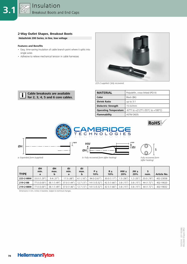
78
3.1
10/2
016
031
-933
86M
ould
ed S
hape
s BR
O
TYPE
ØHmin.
a
ØHmax.
b
ØJmin.
a
ØJmax.
bP ±
10%R ±
10%HW ±20%
JW ±20%
Snom. Article No.
223-2-B8W 33.0 (1.29“) 9.4 (.37“) 17.5 (.68“) 4.1 (.16“) 94.0 (3.67“) 30.0 (1.17“) 1.5 (.06“) 1.2 (.05“) 20.0 (.78“) 402-23058
219-2-B8 77.0 (3.00") 38.1 (1.49“) 37.0 (1.44“) 12.7 (.5“) 141.5 (5.52“) 42.5 (1.66“) 3.8 (.15“) 3.8 (.15“) 44 (1.72“) 402-19020
219-2-B8W 77.0 (3.00“) 38.1 (1.49“) 37.0 (1.46“) 12.7 (.5“) 141.5 (5.52“) 42.5 (1.66“) 3.8 (.15“) 3.8 (.15“) 44 (1.72“) 402-19032
Dimensions in mm, inches in brackets. Subject to technical changes.
MATERIAL Polyolefin, cross-linked (PO-X)
Color Black (BK)
Shrink Ratio up to 3:1
Dielectric Strength 15 kV/mm
Operating Temperature -67°F to +212°F (-55°C to +100°C)
Flammability ASTM D635
Features and Benefits• Easy, time-saving insulation of cable branch point where it splits into
single wires• Adhesive to relieve mechanical tension in cable harnesses
InsulationBreakout Boots and End Caps
2-Way Outlet Shapes, Breakout Boots
223-2 supplied / fully recovered.
Helashrink 200 Series, in line, low voltage
Cable breakouts are available for 2, 3, 4, 5 and 6 core cables.
Fully recovered form (after heating)
S
a: Expanded form (supplied)
ØJØH
b: Fully recovered form (after heating)
P
R
ØJØH
JWHW
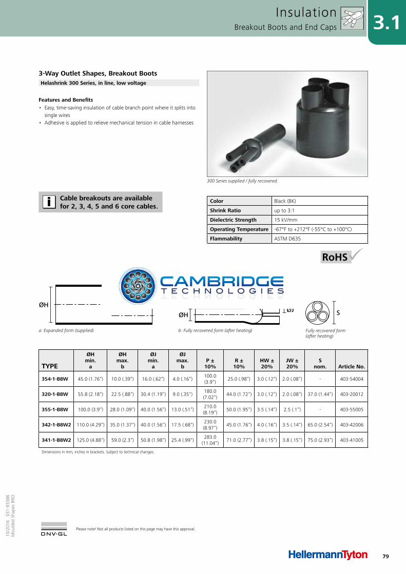
79
3.110
/201
6 0
31-9
3386
Mou
lded
Sha
pes
BRO
Please note! Not all products listed on this page may have this approval.
TYPE
ØHmin.
a
ØHmax.
b
ØJmin.
a
ØJmax.
bP ±
10%R ±
10%HW ±20%
JW ±20%
Snom. Article No.
354-1-B8W 45.0 (1.76“) 10.0 (.39“) 16.0 (.62“) 4.0 (.16“)100.0 (3.9“)
25.0 (.98“) 3.0 (.12“) 2.0 (.08“) - 403-54004
320-1-B8W 55.8 (2.18“) 22.5 (.88“) 30.4 (1.19“) 9.0 (.35“)180.0 (7.02“)
44.0 (1.72“) 3.0 (.12“) 2.0 (.08“) 37.0 (1.44“) 403-20012
355-1-B8W 100.0 (3.9“) 28.0 (1.09“) 40.0 (1.56“) 13.0 (.51“)210.0 (8.19“)
50.0 (1.95“) 3.5 (.14“) 2.5 (.1“) - 403-55005
342-1-B8W2 110.0 (4.29“) 35.0 (1.37“) 40.0 (1.56“) 17.5 (.68“)230.0 (8.97“)
45.0 (1.76“) 4.0 (.16“) 3.5 (.14“) 65.0 (2.54“) 403-42006
341-1-B8W2 125.0 (4.88“) 59.0 (2.3“) 50.8 (1.98“) 25.4 (.99“)283.0
(11.04“)71.0 (2.77“) 3.8 (.15“) 3.8 (.15“) 75.0 (2.93“) 403-41005
Dimensions in mm, inches in brackets. Subject to technical changes.
Color Black (BK)
Shrink Ratio up to 3:1
Dielectric Strength 15 kV/mm
Operating Temperature -67°F to +212°F (-55°C to +100°C)
Flammability ASTM D635
Fully recovered form (after heating)
S
a: Expanded form (supplied)
ØJ
ØH
b: Fully recovered form (after heating)
P
R
ØJØH
JWHW
Features and Benefits• Easy, time-saving insulation of cable branch point where it splits into
single wires• Adhesive is applied to relieve mechanical tension in cable harnesses
InsulationBreakout Boots and End Caps
3-Way Outlet Shapes, Breakout Boots
300 Series supplied / fully recovered.
Helashrink 300 Series, in line, low voltage
Cable breakouts are available for 2, 3, 4, 5 and 6 core cables.
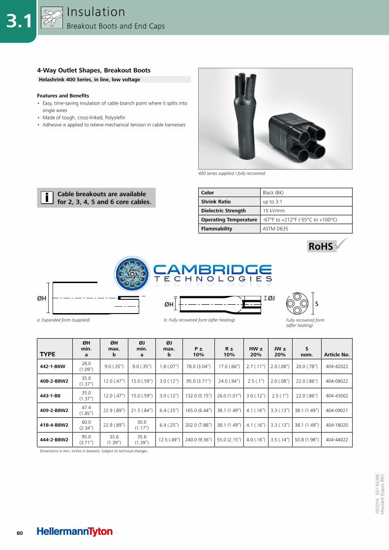
80
3.1
10/2
016
031
-933
86M
ould
ed S
hape
s BR
O
TYPE
ØHmin.
a
ØHmax.
b
ØJmin.
a
ØJmax.
bP ±
10%R ±
10%HW ±20%
JW ±20%
Snom. Article No.
442-1-B8W 28.0 (1.09“)
9.0 (.35“) 9.0 (.35“) 1.8 (.07“) 78.0 (3.04“) 17.0 (.66“) 2.7 (.11“) 2.0 (.08“) 20.0 (.78“) 404-42022
408-2-B8W2 35.0 (1.37“)
12.0 (.47“) 15.0 (.59“) 3.0 (.12“) 95.0 (3.71“) 24.0 (.94“) 2.5 (.1“) 2.0 (.08“) 22.0 (.86“) 404-08022
443-1-B8 35.0 (1.37“)
12.0 (.47“) 15.0 (.59“) 3.0 (.12“) 132.0 (5.15“) 26.0 (1.01“) 3.0 (.12“) 2.5 (.1“) 22.0 (.86“) 404-43002
409-2-B8W2 47.4 (1.85“)
22.9 (.89“) 21.5 (.84“) 6.4 (.25“) 165.0 (6.44“) 38.1 (1.49“) 4.1 (.16“) 3.3 (.13“) 38.1 (1.49“) 404-09021
418-4-B8W2 60.0 (2.34“)
22.9 (.89“)30.0
(1.17“)6.4 (.25“) 202.0 (7.88“) 38.1 (1.49“) 4.1 (.16“) 3.3 (.13“) 38.1 (1.49“) 404-18020
444-2-B8W2 95.0 (3.71“)
35.6 (1.39“)
35.6 (1.39“)
12.5 (.49“) 240.0 (9.36“) 55.0 (2.15“) 4.0 (.16“) 3.5 (.14“) 50.8 (1.98“) 404-44022
Dimensions in mm, inches in brackets. Subject to technical changes.
Color Black (BK)
Shrink Ratio up to 3:1
Dielectric Strength 15 kV/mm
Operating Temperature -67°F to +212°F (-55°C to +100°C)
Flammability ASTM D635
Fully recovered form (after heating)
S
a: Expanded form (supplied)
ØJØH
b: Fully recovered form (after heating)
P
R
ØJØH
JWHW
Features and Benefits• Easy, time-saving insulation of cable branch point where it splits into
single wires• Made of tough, cross-linked, Polyolefin• Adhesive is applied to relieve mechanical tension in cable harnesses
InsulationBreakout Boots and End Caps
4-Way Outlet Shapes, Breakout Boots
400 series supplied / fully recovered.
Helashrink 400 Series, in line, low voltage
Cable breakouts are available for 2, 3, 4, 5 and 6 core cables.
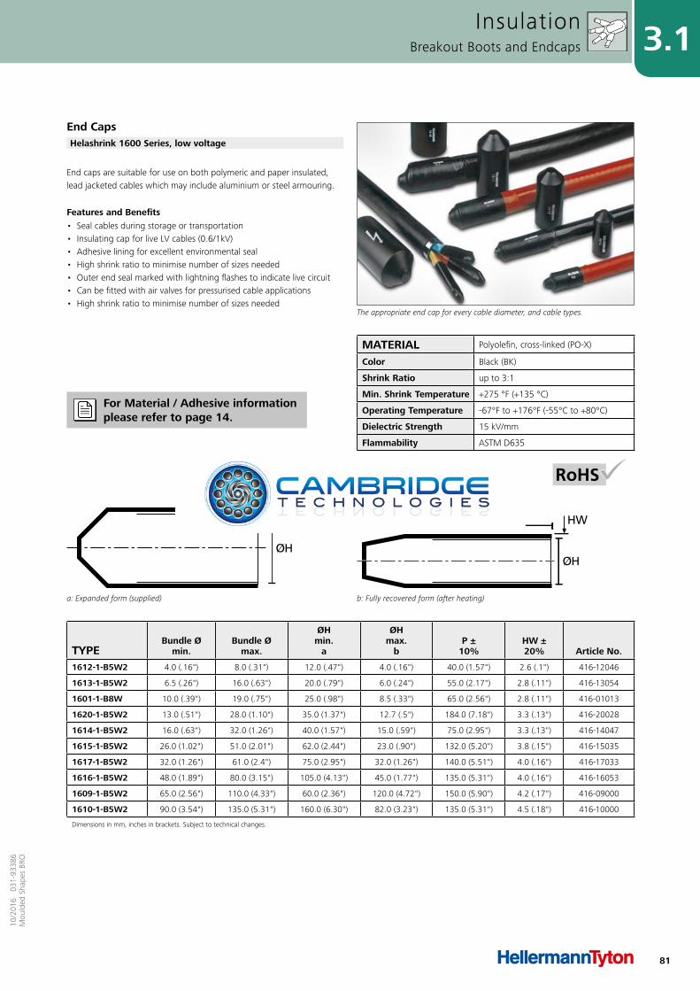
81
3.110
/201
6 0
31-9
3386
Mou
lded
Sha
pes
BRO
TYPEBundle Ø
min.Bundle Ø
max.
ØHmin.
a
ØHmax.
bP ±
10%HW ±20% Article No.
1612-1-B5W2 4.0 (.16") 8.0 (.31") 12.0 (.47") 4.0 (.16") 40.0 (1.57") 2.6 (.1") 416-12046
1613-1-B5W2 6.5 (.26") 16.0 (.63") 20.0 (.79") 6.0 (.24") 55.0 (2.17") 2.8 (.11") 416-13054
1601-1-B8W 10.0 (.39") 19.0 (.75") 25.0 (.98") 8.5 (.33") 65.0 (2.56") 2.8 (.11") 416-01013
1620-1-B5W2 13.0 (.51") 28.0 (1.10") 35.0 (1.37") 12.7 (.5") 184.0 (7.18") 3.3 (.13") 416-20028
1614-1-B5W2 16.0 (.63") 32.0 (1.26") 40.0 (1.57") 15.0 (.59") 75.0 (2.95") 3.3 (.13") 416-14047
1615-1-B5W2 26.0 (1.02") 51.0 (2.01") 62.0 (2.44") 23.0 (.90") 132.0 (5.20") 3.8 (.15") 416-15035
1617-1-B5W2 32.0 (1.26") 61.0 (2.4") 75.0 (2.95") 32.0 (1.26") 140.0 (5.51") 4.0 (.16") 416-17033
1616-1-B5W2 48.0 (1.89") 80.0 (3.15") 105.0 (4.13") 45.0 (1.77") 135.0 (5.31") 4.0 (.16") 416-16053
1609-1-B5W2 65.0 (2.56") 110.0 (4.33") 60.0 (2.36") 120.0 (4.72") 150.0 (5.90") 4.2 (.17") 416-09000
1610-1-B5W2 90.0 (3.54") 135.0 (5.31") 160.0 (6.30") 82.0 (3.23") 135.0 (5.31") 4.5 (.18") 416-10000
Dimensions in mm, inches in brackets. Subject to technical changes.
a: Expanded form (supplied) b: Fully recovered form (after heating)
End caps are suitable for use on both polymeric and paper insulated, lead jacketed cables which may include aluminium or steel armouring.
Features and Benefits• Seal cables during storage or transportation• Insulating cap for live LV cables (0.6/1kV)• Adhesive lining for excellent environmental seal• High shrink ratio to minimise number of sizes needed• Outer end seal marked with lightning flashes to indicate live circuit• Can be fitted with air valves for pressurised cable applications• High shrink ratio to minimise number of sizes needed
InsulationBreakout Boots and Endcaps
End Caps
The appropriate end cap for every cable diameter, and cable types.
Helashrink 1600 Series, low voltage
For Material / Adhesive information please refer to page 14.
MATERIAL Polyolefin, cross-linked (PO-X)
Color Black (BK)
Shrink Ratio up to 3:1
Min. Shrink Temperature +275 °F (+135 °C)
Operating Temperature -67°F to +176°F (-55°C to +80°C)
Dielectric Strength 15 kV/mm
Flammability ASTM D635
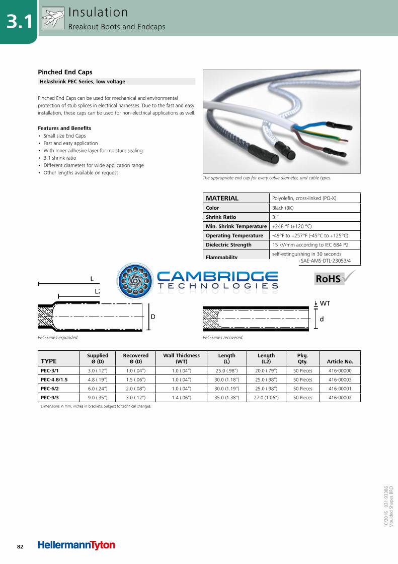
82
3.1
10/2
016
031
-933
86M
ould
ed S
hape
s BR
O
TYPESupplied
Ø (D)Recovered
Ø (D)Wall Thickness
(WT)Length
(L)Length
(L2)Pkg.Qty. Article No.
PEC-3/1 3.0 (.12“) 1.0 (.04“) 1.0 (.04“) 25.0 (.98“) 20.0 (.79“) 50 Pieces 416-00000
PEC-4.8/1.5 4.8 (.19“) 1.5 (.06“) 1.0 (.04“) 30.0 (1.18“) 25.0 (.98“) 50 Pieces 416-00003
PEC-6/2 6.0 (.24“) 2.0 (.08“) 1.0 (.04“) 30.0 (1.19“) 25.0 (.98“) 50 Pieces 416-00001
PEC-9/3 9.0 (.35“) 3.0 (.12“) 1.4 (.06“) 35.0 (1.38“) 27.0 (1.06“) 50 Pieces 416-00002
Dimensions in mm, inches in brackets. Subject to technical changes.
PEC-Series expanded.
L2
PEC-Series recovered.
Pinched End Caps can be used for mechanical and environmental protection of stub splices in electrical harnesses. Due to the fast and easy installation, these caps can be used for non-electrical applications as well.
Features and Benefits• Small size End Caps• Fast and easy application• With Inner adhesive layer for moisture sealing • 3:1 shrink ratio• Different diameters for wide application range• Other lengths available on request
InsulationBreakout Boots and Endcaps
Pinched End Caps
The appropriate end cap for every cable diameter, and cable types.
Helashrink PEC Series, low voltage
MATERIAL Polyolefin, cross-linked (PO-X)
Color Black (BK)
Shrink Ratio 3:1
Min. Shrink Temperature +248 °F (+120 °C)
Operating Temperature -49°F to +257°F (-45°C to +125°C)
Dielectric Strength 15 kV/mm according to IEC 684 P2
Flammabilityself-extinguishing in 30 seconds according to SAE-AMS-DTL-23053/4

84
3.3
10/2
016
031
-933
86M
ould
ed S
hape
s BR
O
MATERIAL Epoxy resins (EP)
Color Black (BK)
Curing Temperature +275°F (+135°C)
Curing Time24 hours at +77°F (+25°C), 2 hours at +185°F (+85°C)
Operating Temperature -103°F to +302°F (-75°C to +150°C)
Specifications VG 95343
Features and Benefits• High performance, two-part epoxy adhesive • Very resistant to most solvents and fuels, even at elevated
temperatures• Two different packages available• V9500 available in 10g sachets for manual mixing• Processing set: emery paper, small mixing bowl and wooden spatula• High performance bonding• Meets military requirements for heat shrinkable components for
harnesses• VG-approved
InsulationAdhesives
The V9500 applicator gun guarantees the clean and precise coating of special fittings.
Two-Component Adhesive for Heat Shrinkable Tubing and Shapes
Two-component epoxy adhesive V9500.
V9500
Please note! Not all products listed on this page may have this approval.
TYPE DescriptionDesignation as per
AS/VG-Norm Article No.
V9500 Epoxy Kit5 x 10g sachets (50g), 5 x mixing pots, 5 x mixing sticks, 5 x emery papers VG 95343 T15 A 001 A 627-95000
1 x dual cartridge, 5 x mixing pots, 5 x mixing sticks, 5 x emery papers VG 95343 T15 A 002 B 627-95001
V9500 Epoxy Cartridge Two-component adhesive cartridge VG 95343 T15 A 627-95002
V9500 Applicator Gun Applicator gun VG 95343 T15 DA 627-95003
V9500 Applicator Nozzle Mixing nozzle VG 95343 T15 MA 627-95004
Dimensions in mm, inches in brackets. Subject to technical changes.
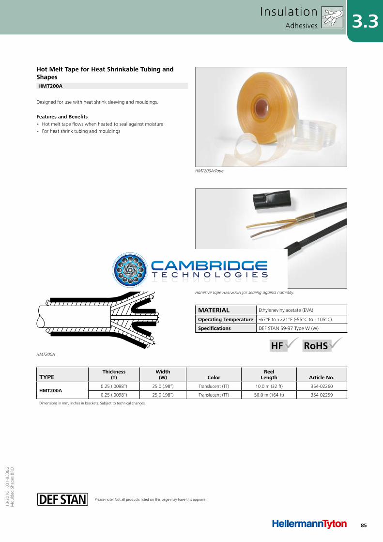
85
3.310
/201
6 0
31-9
3386
Mou
lded
Sha
pes
BRO
Please note! Not all products listed on this page may have this approval.
TYPEThickness
(T)Width
(W) ColorReel
Length Article No.
HMT200A0.25 (.0098“) 25.0 (.98“) Translucent (TT) 10.0 m (32 ft) 354-02260
0.25 (.0098“) 25.0 (.98“) Translucent (TT) 50.0 m (164 ft) 354-02259
Dimensions in mm, inches in brackets. Subject to technical changes.
MATERIAL Ethylenevinylacetate (EVA)
Operating Temperature -67°F to +221°F (-55°C to +105°C)
Specifications DEF STAN 59-97 Type W (W)
HMT200A
Designed for use with heat shrink sleeving and mouldings.
Features and Benefits• Hot melt tape flows when heated to seal against moisture• For heat shrink tubing and mouldings
InsulationAdhesives
Adhesive tape HMT200A for sealing against humidity.
Hot Melt Tape for Heat Shrinkable Tubing and Shapes
HMT200A-Tape.
HMT200A
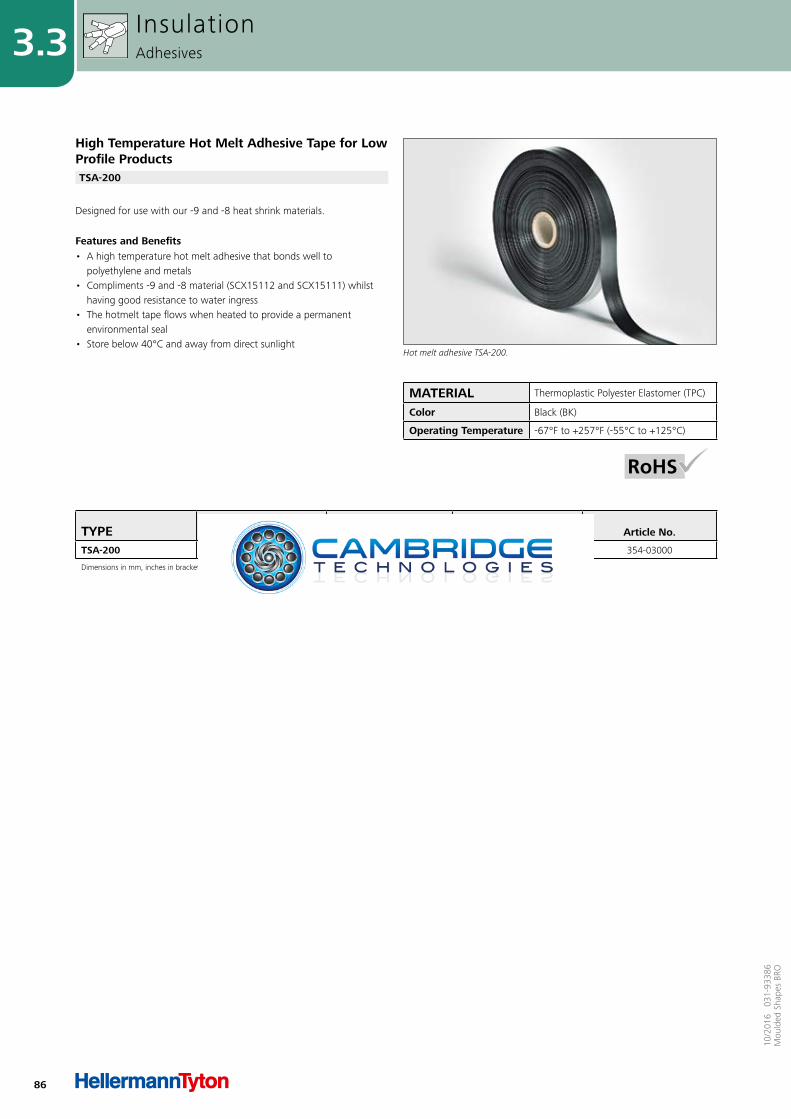
86
3.3
10/2
016
031
-933
86M
ould
ed S
hape
s BR
O
TYPEThickness
(T)Width
(W)Reel
Length Article No.
TSA-200 0.6 (.024“) 22.0 (.87“) 25 m (83 ft) 354-03000
Dimensions in mm, inches in brackets. Subject to technical changes.
MATERIAL Thermoplastic Polyester Elastomer (TPC)
Color Black (BK)
Operating Temperature -67°F to +257°F (-55°C to +125°C)
Designed for use with our -9 and -8 heat shrink materials.
Features and Benefits• A high temperature hot melt adhesive that bonds well to
polyethylene and metals• Compliments -9 and -8 material (SCX15112 and SCX15111) whilst
having good resistance to water ingress• The hotmelt tape flows when heated to provide a permanent
environmental seal • Store below 40°C and away from direct sunlight
InsulationAdhesives
High Temperature Hot Melt Adhesive Tape for Low Profile Products
Hot melt adhesive TSA-200.
TSA-200

87
410
/201
6 0
31-9
3386
Mou
lded
Sha
pes
BRO
4.1 HellermannTyton Product StandardsStandards for HellermannTyton Heat Shrinkable Moulded Shapes according to VG Norm
88
VG/MIL Specification Cross Reference 90
HellermannTyton Shapes for use with MIL Connectors 91
MIL Specification Slash Sheet Cross Reference 92
AS85049 Qualification 93
Appendix

88
4.1
10/2
016
031
-933
86M
ould
ed S
hape
s BR
O
AppendixHellermannTyton Product Standards
DescriptionVG-Norm
DescriptionHellermannTyton
VG 95343 T06 A 001 A 152-41-G
VG 95343 T06 A 002 A 153-41-G
VG 95343 T06 A 003 A 154-41-G
VG 95343 T06 A 004 A 155-41-G
VG 95343 T06 A 005 A 156-41-G
VG 95343 T06 A 006 A 157-41-G
VG 95343 T06 A 007 A 158-41-G
VG 95343 T06 A 008 A 159-41-G
VG 95343 T06 A 009 A 160-41-G
VG 95343 T06 A 010 A 199-4-G
VG 95343 T06 B 001 A 152-42-G
VG 95343 T06 B 002 A 153-42-G
VG 95343 T06 B 003 A 154-42-G
VG 95343 T06 B 004 A 155-42-G
VG 95343 T06 B 005 A 156-42-G
VG 95343 T06 B 006 A 157-42-G
VG 95343 T06 B 007 A 158-42-G
VG 95343 T06 B 008 A 159-42-G
VG 95343 T06 B 009 A 160-42-G
VG 95343 T06 C 001 A 157-43-G
VG 95343 T06 C 002 A 158-43-G
VG 95343 T06 C 003 A 159-43-G
VG 95343 T06 C 004 A 160-43-G
VG 95343 T06 D 001 A 129-1-G
VG 95343 T06 D 002 A 130-1-G
VG 95343 T06 D 003 A 131-1-G
VG 95343 T06 D 004 A 132-1-G
VG 95343 T06 D 005 A 133-1-G
VG 95343 T06 D 006 A 134-1-G
VG 95343 T06 D 007 A 135-1-G
VG 95343 T06 D 008 A 136-1-G
VG 95343 T06 D 009 A 138-1-G
VG 95343 T06 D 011 A 176-1-G
VG 95343 T06 D 012 A 177-1-G
VG 95343 T06 D 013 A 178-1-G
VG 95343 T06 D 014 A 179-1-G
VG 95343 T06 E 001 A 1152-4-G
VG 95343 T06 E 002 A 1154-4-G
VG 95343 T06 E 003 A 1155-4-G
VG 95343 T06 E 004 A 1156-4-G
VG 95343 T06 E 005 A 1157-4-G
VG 95343 T06 E 006 A 1158-4-G
VG 95343 T06 E 007 A 1159-4-G
VG 95343 T06 E 008 A 1160-4-G
VG 95343 T06 F 001 A 1121-1-G
VG 95343 T06 F 002 A 1122-1-G
VG 95343 T06 F 003 A 1123-1-G
VG 95343 T06 F 004 A 1124-1-G
VG 95343 T06 F 005 A 1125-1-G
VG 95343 T06 F 006 A 1126-1-G
VG 95343 T06 F 007 A 1127-1-G
VG 95343 T06 F 008 A 1128-1-G
VG 95343 T06 F 009 A 1129-1-G
VG 95343 T06 F 010 A 1141-1-G
VG 95343 T06 F 011 A 1133-1-G
DescriptionVG-Norm
DescriptionHellermannTyton
VG 95343 T06 F 012 A 1134-1-G
VG 95343 T06 F 013 A 1135-1-G
VG 95343 T06 F 014 A 1136-1-G
VG 95343 T06 J 001 A 1111-1-G
VG 95343 T06 J 002 A 1112-1-G
VG 95343 T06 J 003 A 1113-1-G
VG 95343 T06 J 004 A 1114-1-G
VG 95343 T06 J 006 A 1116-1-G
VG 95343 T06 J 007 A 1117-1-G
VG 95343 T06 J 008 A 1118-1-G
VG 95343 T06 K 001 A 1505-1-G
VG 95343 T06 K 002 A 1506-1-G
VG 95343 T06 K 003 A 1507-1-G
VG 95343 T06 K 004 A 1501-1-G
VG 95343 T06 K 005 A 1502-2-G
VG 95343 T06 K 006 A 1502-2-G
VG 95343 T06 K 007 A 1506-2-G
VG 95343 T06 K 008 A 1507-2-G
VG 95343 T06 K 009 A 1501-2-G
VG 95343 T06 K 010 A 1502-1-G
VG 95343 T06 L 001 A 2101-1-G
VG 95343 T06 L 002 A 2102-1-G
VG 95343 T06 L 003 A 2103-1-G
VG 95343 T06 L 004 A 2104-1-G
VG 95343 T06 L 005 A 2105-1-G
VG 95343 T06 L 006 A 2101-2-G
VG 95343 T06 L 007 A 2102-2-G
VG 95343 T06 L 008 A 2103-2-G
VG 95343 T06 L 009 A 2105-2-G
VG 95343 T07 A 001 A 152-41-GP
VG 95343 T07 A 002 A 153-41-GP
VG 95343 T07 A 003 A 154-41-GP
VG 95343 T07 A 004 A 155-41-GP
VG 95343 T07 A 005 A 156-41-GP
VG 95343 T07 A 006 A 157-41-GP
VG 95343 T07 A 007 A 158-41-GP
VG 95343 T07 A 008 A 159-41-GP
VG 95343 T07 A 009 A 160-41-GP
VG 95343 T07 B 001 A 152-42-GP
VG 95343 T07 B 002 A 153-42-GP
VG 95343 T07 B 003 A 154-42-GP
VG 95343 T07 B 004 A 155-42-GP
VG 95343 T07 B 005 A 156-42-GP
VG 95343 T07 B 006 A 157-42-GP
VG 95343 T07 B 007 A 158-42-GP
VG 95343 T07 B 008 A 159-42-GP
VG 95343 T07 B 009 A 160-42-GP
VG 95343 T07 C 001 A 157-43-GP
VG 95343 T07 C 002 A 158-43-GP
VG 95343 T07 C 003 A 159-43-GP
VG 95343 T07 C 004 A 160-43-GP
VG 95343 T07 D 001 A 129-1-GP
VG 95343 T07 D 002 A 130-1-GP
VG 95343 T07 D 003 A 131-1-GP
VG 95343 T07 D 004 A 132-1-GP
DescriptionVG-Norm
DescriptionHellermannTyton
VG 95343 T07 D 005 A 133-1-GP
VG 95343 T07 D 006 A 134-1-GP
VG 95343 T07 D 007 A 135-1-GP
VG 95343 T07 D 008 A 136-1-GP
VG 95343 T07 D 009 A 138-1-GP
VG 95343 T07 D 010 A 187-1-GP
VG 95343 T07 E 001 A 1152-4-GP
VG 95343 T07 E 002 A 1154-4-GP
VG 95343 T07 E 003 A 1155-4-GP
VG 95343 T07 E 004 A 1156-4-GP
VG 95343 T07 E 005 A 1157-4-GP
VG 95343 T07 E 006 A 1158-4-GP
VG 95343 T07 E 007 A 1159-4-GP
VG 95343 T07 E 008 A 1160-4-GP
VG 95343 T07 F 002 A 1122-1-GP
VG 95343 T07 F 003 A 1123-1-GP
VG 95343 T07 F 004 A 1124-1-GP
VG 95343 T07 F 005 A 1125-1-GP
VG 95343 T07 F 006 A 1126-1-GP
VG 95343 T07 F 007 A 1127-1-GP
VG 95343 T07 F 008 A 1128-1-GP
VG 95343 T07 F 009 A 1129-1-GP
VG 95343 T07 F 010 A 1141-1-GP
VG 95343 T08 A 001 A 1203-1-G
VG 95343 T08 A 002 A 1209-1-G
VG 95343 T08 A 007 A 1201-1-G
VG 95343 T08 A 009 A 1206-1-G
VG 95343 T08 A 010 A 1202-1-G
VG 95343 T08 A 011 A 1207-1-G
VG 95343 T08 A 016 A 1204-1-G
VG 95343 T08 A 017 A 1216-1-G
VG 95343 T08 B 001 A 1301-1-G
VG 95343 T08 B 002 A 1303-1-G
VG 95343 T08 B 003 A 1311-1-G
VG 95343 T08 B 004 A 1302-1-G
VG 95343 T08 B 005 A 1304-1-G
VG 95343 T08 B 006 A 1305-1-G
VG 95343 T08 B 007 A 1312-1-G
VG 95343 T08 B 008 A 1316-1-G
VG 95343 T08 B 009 A 1313-1-G
VG 95343 T08 B 010 A 1306-1-G
VG 95343 T08 B 011 A 1307-1-G
VG 95343 T08 B 012 A 1308-1-G
VG 95343 T08 C 001 A 206-1-G
VG 95343 T08 C 002 A 203-1-G
VG 95343 T08 C 003 A 204-1-G
VG 95343 T08 C 004 A 211-1-G
VG 95343 T08 C 005 A 212-1-G
VG 95343 T08 D 001 A 306-1-G
VG 95343 T08 D 002 A 304-1-G
VG 95343 T08 D 003 A 310-1-G
VG 95343 T08 D 004 A 311-1-G
VG 95343 T08 E 002 A 411-1-G
VG 95343 T08 E 004 A 403-1-G
VG 95343 T08 E 005 A 413-1-G
Standards for HellermannTyton Heat Shrinkable Moulded Shapes according to VG Norm
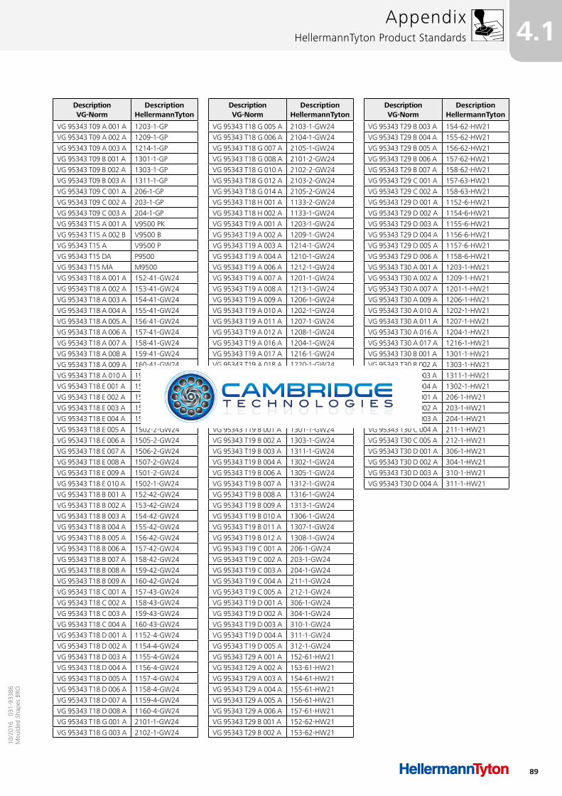
89
4.110
/201
6 0
31-9
3386
Mou
lded
Sha
pes
BRO
AppendixHellermannTyton Product Standards
DescriptionVG-Norm
DescriptionHellermannTyton
VG 95343 T09 A 001 A 1203-1-GP
VG 95343 T09 A 002 A 1209-1-GP
VG 95343 T09 A 003 A 1214-1-GP
VG 95343 T09 B 001 A 1301-1-GP
VG 95343 T09 B 002 A 1303-1-GP
VG 95343 T09 B 003 A 1311-1-GP
VG 95343 T09 C 001 A 206-1-GP
VG 95343 T09 C 002 A 203-1-GP
VG 95343 T09 C 003 A 204-1-GP
VG 95343 T15 A 001 A V9500 PK
VG 95343 T15 A 002 B V9500 B
VG 95343 T15 A V9500 P
VG 95343 T15 DA P9500
VG 95343 T15 MA M9500
VG 95343 T18 A 001 A 152-41-GW24
VG 95343 T18 A 002 A 153-41-GW24
VG 95343 T18 A 003 A 154-41-GW24
VG 95343 T18 A 004 A 155-41-GW24
VG 95343 T18 A 005 A 156-41-GW24
VG 95343 T18 A 006 A 157-41-GW24
VG 95343 T18 A 007 A 158-41-GW24
VG 95343 T18 A 008 A 159-41-GW24
VG 95343 T18 A 009 A 160-41-GW24
VG 95343 T18 A 010 A 199-41-GW24
VG 95343 T18 E 001 A 1505-1-GW24
VG 95343 T18 E 002 A 1506-1-GW24
VG 95343 T18 E 003 A 1507-1-GW24
VG 95343 T18 E 004 A 1501-1-GW24
VG 95343 T18 E 005 A 1502-2-GW24
VG 95343 T18 E 006 A 1505-2-GW24
VG 95343 T18 E 007 A 1506-2-GW24
VG 95343 T18 E 008 A 1507-2-GW24
VG 95343 T18 E 009 A 1501-2-GW24
VG 95343 T18 E 010 A 1502-1-GW24
VG 95343 T18 B 001 A 152-42-GW24
VG 95343 T18 B 002 A 153-42-GW24
VG 95343 T18 B 003 A 154-42-GW24
VG 95343 T18 B 004 A 155-42-GW24
VG 95343 T18 B 005 A 156-42-GW24
VG 95343 T18 B 006 A 157-42-GW24
VG 95343 T18 B 007 A 158-42-GW24
VG 95343 T18 B 008 A 159-42-GW24
VG 95343 T18 B 009 A 160-42-GW24
VG 95343 T18 C 001 A 157-43-GW24
VG 95343 T18 C 002 A 158-43-GW24
VG 95343 T18 C 003 A 159-43-GW24
VG 95343 T18 C 004 A 160-43-GW24
VG 95343 T18 D 001 A 1152-4-GW24
VG 95343 T18 D 002 A 1154-4-GW24
VG 95343 T18 D 003 A 1155-4-GW24
VG 95343 T18 D 004 A 1156-4-GW24
VG 95343 T18 D 005 A 1157-4-GW24
VG 95343 T18 D 006 A 1158-4-GW24
VG 95343 T18 D 007 A 1159-4-GW24
VG 95343 T18 D 008 A 1160-4-GW24
VG 95343 T18 G 001 A 2101-1-GW24
VG 95343 T18 G 003 A 2102-1-GW24
DescriptionVG-Norm
DescriptionHellermannTyton
VG 95343 T18 G 005 A 2103-1-GW24
VG 95343 T18 G 006 A 2104-1-GW24
VG 95343 T18 G 007 A 2105-1-GW24
VG 95343 T18 G 008 A 2101-2-GW24
VG 95343 T18 G 010 A 2102-2-GW24
VG 95343 T18 G 012 A 2103-2-GW24
VG 95343 T18 G 014 A 2105-2-GW24
VG 95343 T18 H 001 A 1133-2-GW24
VG 95343 T18 H 002 A 1133-1-GW24
VG 95343 T19 A 001 A 1203-1-GW24
VG 95343 T19 A 002 A 1209-1-GW24
VG 95343 T19 A 003 A 1214-1-GW24
VG 95343 T19 A 004 A 1210-1-GW24
VG 95343 T19 A 006 A 1212-1-GW24
VG 95343 T19 A 007 A 1201-1-GW24
VG 95343 T19 A 008 A 1213-1-GW24
VG 95343 T19 A 009 A 1206-1-GW24
VG 95343 T19 A 010 A 1202-1-GW24
VG 95343 T19 A 011 A 1207-1-GW24
VG 95343 T19 A 012 A 1208-1-GW24
VG 95343 T19 A 016 A 1204-1-GW24
VG 95343 T19 A 017 A 1216-1-GW24
VG 95343 T19 A 018 A 1220-1-GW24
VG 95343 T19 E 002 A 411-1-GW24
VG 95343 T19 E 003 A 412-1-GW24
VG 95343 T19 E 004 A 403-1-GW24
VG 95343 T19 E 005 A 413-1-GW24
VG 95343 T19 E 009 A 414-1-GW24
VG 95343 T19 B 001 A 1301-1-GW24
VG 95343 T19 B 002 A 1303-1-GW24
VG 95343 T19 B 003 A 1311-1-GW24
VG 95343 T19 B 004 A 1302-1-GW24
VG 95343 T19 B 006 A 1305-1-GW24
VG 95343 T19 B 007 A 1312-1-GW24
VG 95343 T19 B 008 A 1316-1-GW24
VG 95343 T19 B 009 A 1313-1-GW24
VG 95343 T19 B 010 A 1306-1-GW24
VG 95343 T19 B 011 A 1307-1-GW24
VG 95343 T19 B 012 A 1308-1-GW24
VG 95343 T19 C 001 A 206-1-GW24
VG 95343 T19 C 002 A 203-1-GW24
VG 95343 T19 C 003 A 204-1-GW24
VG 95343 T19 C 004 A 211-1-GW24
VG 95343 T19 C 005 A 212-1-GW24
VG 95343 T19 D 001 A 306-1-GW24
VG 95343 T19 D 002 A 304-1-GW24
VG 95343 T19 D 003 A 310-1-GW24
VG 95343 T19 D 004 A 311-1-GW24
VG 95343 T19 D 005 A 312-1-GW24
VG 95343 T29 A 001 A 152-61-HW21
VG 95343 T29 A 002 A 153-61-HW21
VG 95343 T29 A 003 A 154-61-HW21
VG 95343 T29 A 004 A 155-61-HW21
VG 95343 T29 A 005 A 156-61-HW21
VG 95343 T29 A 006 A 157-61-HW21
VG 95343 T29 B 001 A 152-62-HW21
VG 95343 T29 B 002 A 153-62-HW21
DescriptionVG-Norm
DescriptionHellermannTyton
VG 95343 T29 B 003 A 154-62-HW21
VG 95343 T29 B 004 A 155-62-HW21
VG 95343 T29 B 005 A 156-62-HW21
VG 95343 T29 B 006 A 157-62-HW21
VG 95343 T29 B 007 A 158-62-HW21
VG 95343 T29 C 001 A 157-63-HW21
VG 95343 T29 C 002 A 158-63-HW21
VG 95343 T29 D 001 A 1152-6-HW21
VG 95343 T29 D 002 A 1154-6-HW21
VG 95343 T29 D 003 A 1155-6-HW21
VG 95343 T29 D 004 A 1156-6-HW21
VG 95343 T29 D 005 A 1157-6-HW21
VG 95343 T29 D 006 A 1158-6-HW21
VG 95343 T30 A 001 A 1203-1-HW21
VG 95343 T30 A 002 A 1209-1-HW21
VG 95343 T30 A 007 A 1201-1-HW21
VG 95343 T30 A 009 A 1206-1-HW21
VG 95343 T30 A 010 A 1202-1-HW21
VG 95343 T30 A 011 A 1207-1-HW21
VG 95343 T30 A 016 A 1204-1-HW21
VG 95343 T30 A 017 A 1216-1-HW21
VG 95343 T30 B 001 A 1301-1-HW21
VG 95343 T30 B 002 A 1303-1-HW21
VG 95343 T30 B 003 A 1311-1-HW21
VG 95343 T30 B 004 A 1302-1-HW21
VG 95343 T30 C 001 A 206-1-HW21
VG 95343 T30 C 002 A 203-1-HW21
VG 95343 T30 C 003 A 204-1-HW21
VG 95343 T30 C 004 A 211-1-HW21
VG 95343 T30 C 005 A 212-1-HW21
VG 95343 T30 D 001 A 306-1-HW21
VG 95343 T30 D 002 A 304-1-HW21
VG 95343 T30 D 003 A 310-1-HW21
VG 95343 T30 D 004 A 311-1-HW21
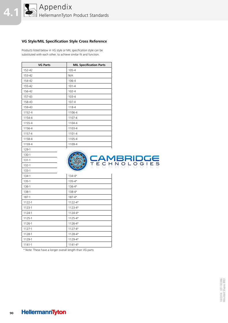
90
4.1
10/2
016
031
-933
86M
ould
ed S
hape
s BR
O
VG Style/MIL Specification Style Cross Reference
Products listed below in VG style or MIL specification style can be substituted with each other, to achieve similar fit and function.
VG Parts MIL Specification Parts
152-42 105-4
153-42 N/A
154-42 106-4
155-42 101-4
156-42 102-4
157-43 103-4
158-43 107-4
159-43 118-4
1152-4 1106-4
1154-4 1107-4
1155-4 1104-4
1156-4 1103-4
1157-4 1101-4
1158-4 1105-4
1159-4 1109-4
129-1 129-4*
130-1 130-4*
131-1 131-4*
132-1 132-4*
133-1 133-4*
134-1 134-4*
135-1 135-4*
136-1 136-4*
138-1 138-4*
187-1 187-4*
1122-1 1122-4*
1123-1 1123-4*
1124-1 1124-4*
1125-1 1125-4*
1126-1 1126-4*
1127-1 1127-4*
1128-1 1128-4*
1129-1 1129-4*
1141-1 1141-4*
* Note: These have a longer overall length than VG parts
AppendixHellermannTyton Product Standards
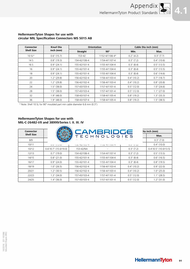
91
4.110
/201
6 0
31-9
3386
Mou
lded
Sha
pes
BRO
HellermannTyton Shapes for use with circular MIL Specification Connectors MS 5015 AB
HellermannTyton Shapes for use with MIL-C-26482-I/II and 38999/Series I, II, III, IV
ConnectorShell Size
Knurl Dia inch (mm)
Orientation Cable Dia inch (mm)
Straight 90° Min. Max.
10 SL* 0.6“ (15.7) 153-42 1152-4/1106-4* 0.2“ (4.2) 0.3“ (7.7)
14 S 0.8“ (19.3) 154-42/106-4 1154-4/1107-4 0.3“ (7.2) 0.4“ (10.6)
16 S 0.9“ (24.1) 155-42/101-4 1155-4/1104-4 0.3“ (8.4) 0.5“ (13.5)
16 0.9“ (24.1) 155-42/101-4 1155-4/1104-4 0.3“ (8.4) 0.5“ (13.5)
18 0.9“ (24.1) 155-42/101-4 1155-4/1104-4 0.3“ (8.4) 0.6“ (14.6)
20 1.2“ (29.8) 156-42/102-4 1156-4/1103-4 0.4“ (10.2) 0.7“ (18.7)
22 1.2“ (29.8) 156-42/102-4 1156-4/1103-4 0.4“ (10.2) 0.8“ (20.8)
24 1.5“ (38.0) 157-43/103-4 1157-4/1101-4 0.5“ (12.0) 1.0“ (24.6)
28 1.5“ (38.0) 157-43/103-4 1157-4/1101-4 0.5“ (12.0) 1.1“ (27.0)
32 1.9“ (48.0) 158-43/107-4 1158-4/1105-4 0.8“ (19.2) 1.3“ (33.3)
36 1.9“ (48.0) 158-43/107-4 1158-4/1105-4 0.8“ (19.2) 1.5“ (38.5)
* Note: Shell 10 SL for 90° moulded part min cable diameter 6.6 mm (0.3")
ConnectorShell Size
Knurl Dia inch (mm)
Orientation Cable Dia inch (mm)
Straight 90° Min. Max.
8/9 0.5“ (13.0) 152-42/105-4 1152-4/1106-4 0.3“ (7.2) 0.3“ (7.0)
10/11 0.6“ (15.0) 152-42/105-4 1152-4/1106-4 0.3“ (7.2) 0.4“ (10.0)
10/12 0.6“/0.7“ (15.0/19.0) 153-42/NA - 0.3“ (7.2) 0.4“/0.5“ (10.0/13.5)
12/13 0.7“ (19.0) 154-42/106-4 1154-4/1107-4 0.3“ (7.2) 0.5“ (13.5)
14/15 0.8“ (21.0) 155-42/101-4 1155-4/1104-4 0.3“ (8.4) 0.6“ (16.5)
16/17 0.9“ (24.0) 155-42/101-4 1155-4/1104-4 0.3“ (8.4) 0.8“ (19.5)
18/19 1.0“ (26.5) 156-42/102-4 1156-4/1103-4 0.4“ (10.2) 0.9“ (22.0)
20/21 1.2“ (30.5) 156-42/102-4 1156-4/1103-4 0.4“ (10.2) 1.0“ (25.0)
22/23 1.3“ (34.0) 157-43/103-4 1157-4/1101-4 0.5“ (12.0) 1.1“ (28.5)
24/25 1.4“ (36.0) 157-43/103-4 1157-4/1101-4 0.5“ (12.0) 1.2“ (31.0)
AppendixHellermannTyton Product Standards
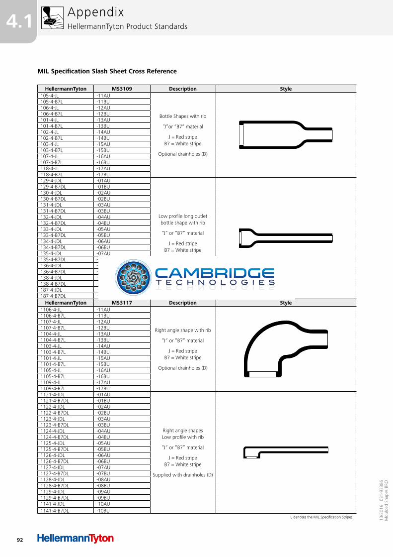
92
4.1
10/2
016
031
-933
86M
ould
ed S
hape
s BR
O
MIL Specification Slash Sheet Cross Reference
HellermannTyton MS3109 Description Style105-4-JL -11AU
Bottle Shapes with rib
”J”or ”B7” material
J = Red stripe B7 = White stripe
Optional drainholes (D)
105-4-B7L -11BU106-4-JL -12AU106-4-B7L -12BU101-4-JL -13AU101-4-B7L -13BU102-4-JL -14AU102-4-B7L -14BU103-4-JL -15AU103-4-B7L -15BU107-4-JL -16AU107-4-B7L -16BU118-4-JL -17AU118-4-B7L -17BU129-4-JDL -01AU
Low profile long outlet bottle shape with rib
”J” or ”B7” material
J = Red stripe B7 = White stripe
Supplied with drainholes (D)
129-4-B7DL -01BU130-4-JDL -02AU130-4-B7DL -02BU131-4-JDL -03AU131-4-B7DL -03BU132-4-JDL -04AU132-4-B7DL -04BU133-4-JDL -05AU133-4-B7DL -05BU134-4-JDL -06AU134-4-B7DL -06BU135-4-JDL -07AU135-4-B7DL -07BU136-4-JDL -08AU136-4-B7DL -08BU138-4-JDL -09AU138-4-B7DL -09BU187-4-JDL -10AU187-4-B7DL -10BU
HellermannTyton MS3117 Description Style1106-4-JL -11AU
Right angle shape with rib
”J” or ”B7” material
J = Red stripe B7 = White stripe
Optional drainholes (D)
1106-4-B7L -11BU1107-4-JL -12AU1107-4-B7L -12BU1104-4-JL -13AU1104-4-B7L -13BU1103-4-JL -14AU1103-4-B7L -14BU1101-4-JL -15AU1101-4-B7L -15BU1105-4-JL -16AU1105-4-B7L -16BU1109-4-JL -17AU1109-4-B7L -17BU1121-4-JDL -01AU
Right angle shapes Low profile with rib
”J” or ”B7” material
J = Red stripe B7 = White stripe
Supplied with drainholes (D)
1121-4-B7DL -01BU1122-4-JDL -02AU1122-4-B7DL -02BU1123-4-JDL -03AU1123-4-B7DL -03BU1124-4-JDL -04AU1124-4-B7DL -04BU1125-4-JDL -05AU1125-4-B7DL -05BU1126-4-JDL -06AU1126-4-B7DL -06BU1127-4-JDL -07AU1127-4-B7DL -07BU1128-4-JDL -08AU1128-4-B7DL -08BU1129-4-JDL -09AU1129-4-B7DL -09BU1141-4-JDL -10AU1141-4-B7DL -10BU
L denotes the MIL Specification Stripes.
AppendixHellermannTyton Product Standards
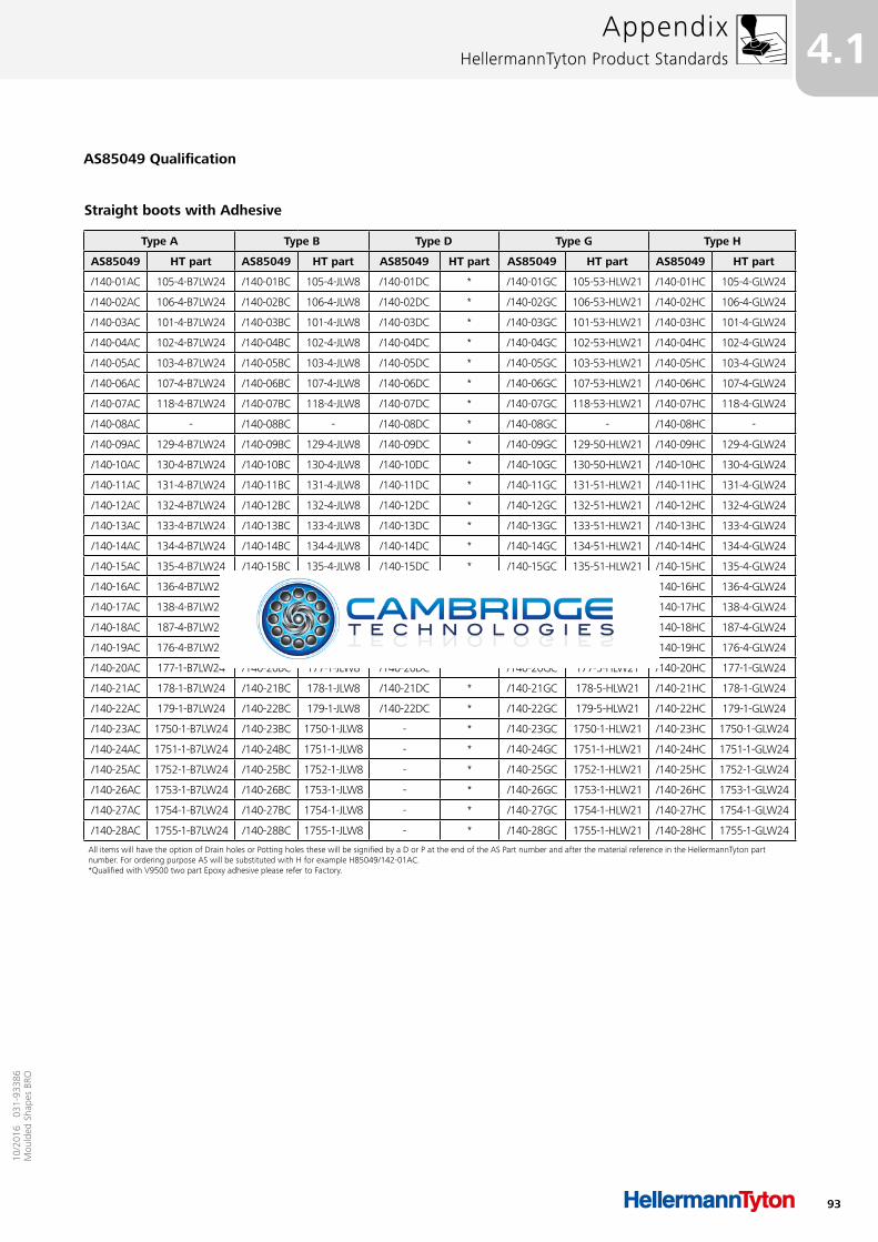
93
4.110
/201
6 0
31-9
3386
Mou
lded
Sha
pes
BRO
AppendixHellermannTyton Product Standards
Straight boots with Adhesive
Type A Type B Type D Type G Type H
AS85049 HT part AS85049 HT part AS85049 HT part AS85049 HT part AS85049 HT part
/140-01AC 105-4-B7LW24 /140-01BC 105-4-JLW8 /140-01DC * /140-01GC 105-53-HLW21 /140-01HC 105-4-GLW24
/140-02AC 106-4-B7LW24 /140-02BC 106-4-JLW8 /140-02DC * /140-02GC 106-53-HLW21 /140-02HC 106-4-GLW24
/140-03AC 101-4-B7LW24 /140-03BC 101-4-JLW8 /140-03DC * /140-03GC 101-53-HLW21 /140-03HC 101-4-GLW24
/140-04AC 102-4-B7LW24 /140-04BC 102-4-JLW8 /140-04DC * /140-04GC 102-53-HLW21 /140-04HC 102-4-GLW24
/140-05AC 103-4-B7LW24 /140-05BC 103-4-JLW8 /140-05DC * /140-05GC 103-53-HLW21 /140-05HC 103-4-GLW24
/140-06AC 107-4-B7LW24 /140-06BC 107-4-JLW8 /140-06DC * /140-06GC 107-53-HLW21 /140-06HC 107-4-GLW24
/140-07AC 118-4-B7LW24 /140-07BC 118-4-JLW8 /140-07DC * /140-07GC 118-53-HLW21 /140-07HC 118-4-GLW24
/140-08AC - /140-08BC - /140-08DC * /140-08GC - /140-08HC -
/140-09AC 129-4-B7LW24 /140-09BC 129-4-JLW8 /140-09DC * /140-09GC 129-50-HLW21 /140-09HC 129-4-GLW24
/140-10AC 130-4-B7LW24 /140-10BC 130-4-JLW8 /140-10DC * /140-10GC 130-50-HLW21 /140-10HC 130-4-GLW24
/140-11AC 131-4-B7LW24 /140-11BC 131-4-JLW8 /140-11DC * /140-11GC 131-51-HLW21 /140-11HC 131-4-GLW24
/140-12AC 132-4-B7LW24 /140-12BC 132-4-JLW8 /140-12DC * /140-12GC 132-51-HLW21 /140-12HC 132-4-GLW24
/140-13AC 133-4-B7LW24 /140-13BC 133-4-JLW8 /140-13DC * /140-13GC 133-51-HLW21 /140-13HC 133-4-GLW24
/140-14AC 134-4-B7LW24 /140-14BC 134-4-JLW8 /140-14DC * /140-14GC 134-51-HLW21 /140-14HC 134-4-GLW24
/140-15AC 135-4-B7LW24 /140-15BC 135-4-JLW8 /140-15DC * /140-15GC 135-51-HLW21 /140-15HC 135-4-GLW24
/140-16AC 136-4-B7LW24 /140-16BC 136-4-JLW8 /140-16DC * /140-16GC 136-51-HLW24 /140-16HC 136-4-GLW24
/140-17AC 138-4-B7LW24 /140-17BC 138-4-JLW8 /140-17DC * /140-17GC 138-51-HLW21 /140-17HC 138-4-GLW24
/140-18AC 187-4-B7LW24 /140-18BC 187-4-JLW8 /140-18DC * /140-18GC 187-51-HLW21 /140-18HC 187-4-GLW24
/140-19AC 176-4-B7LW24 /140-19BC 176-4-JLW8 /140-19DC * /140-19GC 176-50-HLW21 /140-19HC 176-4-GLW24
/140-20AC 177-1-B7LW24 /140-20BC 177-1-JLW8 /140-20DC * /140-20GC 177-5-HLW21 /140-20HC 177-1-GLW24
/140-21AC 178-1-B7LW24 /140-21BC 178-1-JLW8 /140-21DC * /140-21GC 178-5-HLW21 /140-21HC 178-1-GLW24
/140-22AC 179-1-B7LW24 /140-22BC 179-1-JLW8 /140-22DC * /140-22GC 179-5-HLW21 /140-22HC 179-1-GLW24
/140-23AC 1750-1-B7LW24 /140-23BC 1750-1-JLW8 - * /140-23GC 1750-1-HLW21 /140-23HC 1750-1-GLW24
/140-24AC 1751-1-B7LW24 /140-24BC 1751-1-JLW8 - * /140-24GC 1751-1-HLW21 /140-24HC 1751-1-GLW24
/140-25AC 1752-1-B7LW24 /140-25BC 1752-1-JLW8 - * /140-25GC 1752-1-HLW21 /140-25HC 1752-1-GLW24
/140-26AC 1753-1-B7LW24 /140-26BC 1753-1-JLW8 - * /140-26GC 1753-1-HLW21 /140-26HC 1753-1-GLW24
/140-27AC 1754-1-B7LW24 /140-27BC 1754-1-JLW8 - * /140-27GC 1754-1-HLW21 /140-27HC 1754-1-GLW24
/140-28AC 1755-1-B7LW24 /140-28BC 1755-1-JLW8 - * /140-28GC 1755-1-HLW21 /140-28HC 1755-1-GLW24
All items will have the option of Drain holes or Potting holes these will be signified by a D or P at the end of the AS Part number and after the material reference in the HellermannTyton part number. For ordering purpose AS will be substituted with H for example H85049/142-01AC.*Qualified with V9500 two part Epoxy adhesive please refer to Factory.
AS85049 Qualification

94
4.1
10/2
016
031
-933
86M
ould
ed S
hape
s BR
O
AppendixHellermannTyton Product Standards
Straight boots with No Adhesive
Type A Type B Type D Type G Type H
AS85049 HT part AS85049 HT part AS85049 HT part AS85049 HT part AS85049 HT part
/140-01AU 105-4-B7L /140-01BU 105-4-JL /140-01DU 105-53-LL /140-01GU 105-53-HL /140-01HU 105-4-GL
/140-02AU 106-4-B7L /140-02BU 106-4-JL /140-02DU 106-53-LL /140-02GU 106-53-HL /140-02HU 106-4-GL
/140-03AU 101-4-B7L /140-03BU 101-4-JL /140-03DU 101-53-LL /140-03GU 101-53-HL /140-03HU 101-4-GL
/140-04AU 102-4-B7L /140-04BU 102-4-JL /140-04DU 102-53-LL /140-04GU 102-53-HL /140-04HU 102-4-GL
/140-05AU 103-4-B7L /140-05BU 103-4-JL /140-05DU 103-53-LL /140-05GU 103-53-HL /140-05HU 103-4-GL
/140-06AU 107-4-B7L /140-06BU 107-4-JL /140-06DU 107-53-LL /140-06GU 107-53-HL /140-06HU 107-4-GL
/140-07AU 118-4-B7L /140-07BU 118-4-JL /140-07DU 118-53-LL /140-07GU 118-53-HL /140-07HU 118-4-GL
/140-08AU - /140-08BU - /140-08DU - /140-08GU - /140-08HU -
/140-09AU 129-4-B7L /140-09BU 129-4-JL /140-09DU 129-50-LL /140-09GU 129-50-HL /140-09HU 129-4-GL
/140-10AU 130-4-B7L /140-10BU 130-4-JL /140-10DU 130-50-LL /140-10GU 130-50-HL /140-10HU 130-4-GL
/140-11AU 131-4-B7L /140-11BU 131-4-JL /140-11DU 131-51-LL /140-11GU 131-51-HL /140-11HU 131-4-GL
/140-12AU 132-4-B7L /140-12BU 132-4-JL /140-12DU 132-51-LL /140-12GU 132-51-HL /140-12HU 132-4-GL
/140-13AU 133-4-B7L /140-13BU 133-4-JL /140-13DU 133-51-LL /140-13GU 133-51-HL /140-13HU 133-4-GL
/140-14AU 134-4-B7L /140-14BU 134-4-JL /140-14DU 134-51-LL /140-14GU 134-51-HL /140-14HU 134-4-GL
/140-15AU 135-4-B7L /140-15BU 135-4-JL /140-15DU 135-51-LL /140-15GU 135-51-HL /140-15HU 135-4-GL
/140-16AU 136-4-B7L /140-16BU 136-4-JL /140-16DU 136-51-LL /140-16GU 136-51-HL /140-16HU 136-4-GL
/140-17AU 138-4-B7L /140-17BU 138-4-JL /140-17DU 138-51-LL /140-17GU 138-51-HL /140-17HU 138-4-GL
/140-18AU 187-4-B7L /140-18BU 187-4-JL /140-18DU 187-51-LL /140-18GU 187-51-HL /140-18HU 187-4-GL
/140-19AU 176-4-B7L /140-19BU 176-4-JL /140-19DU 176-4-LL /140-19GU 176-50-HL /140-19HU 176-4-GL
/140-20AU 177-1-B7L /140-20BU 177-1-JL /140-20DU 177-1-LL /140-20GU 177-5-HL /140-20HU 177-1-GL
/140-21AU 178-1-B7L /140-21BU 178-1-JL /140-21DU 178-1-LL /140-21GU 178-5-HL /140-21HU 178-1-GL
/140-22AU 179-1-B7L /140-22BU 179-1-JL /140-22DU 179-1-LL /140-22GU 179-5-HL /140-22HU 179-1-GL
/140-23AU 1750-1-B7L /140-23BU 1750-1-JL - - /140-23GU 1750-1-HL /140-23HU 1750-1-GL
/140-24AU 1751-1-B7L /140-24BU 1751-1-JL - - /140-24GU 1751-1-HL /140-24HU 1751-1-GL
/140-25AU 1752-1-B7L /140-25BU 1752-1-JL - - /140-25GU 1752-1-HL /140-25HU 1752-1-GL
/140-26AU 1753-1-B7L /140-26BU 1753-1-JL - - /140-26GU 1753-1-HL /140-26HU 1753-1-GL
/140-27AU 1754-1-B7L /140-27BU 1754-1-JL - - /140-27GU 1754-1-HL /140-27HU 1754-1-GL
/140-28AU 1755-1-B7L /140-28BU 1755-1-JL - - /140-28GU 1755-1-HL /140-28HU 1755-1-GL
All items will have the option of Drain holes or Potting holes these will be signified by a D or P at the end of the AS Part number and after the material reference in the HellermannTyton part number. For ordering purpose AS will be substituted with H for example H85049/142-01AC.

95
4.110
/201
6 0
31-9
3386
Mou
lded
Sha
pes
BRO
AppendixHellermannTyton Product Standards
90 Degree boots with Adhesive
Type A Type B Type D Type G Type H
AS85049 HT part AS85049 HT part AS85049 HT part AS85049 HT part AS85049 HT part
/141-01AC 1106-4-B7LW24 /141-01BC 1106-4-JLW8 /141-01DC * /141-01GC 1106-50-HLW21 /141-01HC 1106-4-GLW24
/141-02AC 1107-4-B7LW24 /141-02BC 1107-4-JLW8 /141-02DC * /141-02GC 1107-50-HLW21 /141-02HC 1107-4-GLW24
/141-03AC 1104-4-B7LW24 /141-03BC 1104-4-JLW8 /141-03DC * /141-03GC 1104-50-HLW21 /141-03HC 1104-4-GLW24
/141-04AC 1103-4-B7LW24 /141-04BC 1103-4-JLW8 /141-04DC * /141-04GC 1103-50-HLW21 /141-04HC 1103-4-GLW24
/141-05AC 1101-4-B7LW24 /141-05BC 1101-4-JLW8 /141-05DC * /141-05GC 1101-52-HLW21 /141-05HC 1101-4-GLW24
/141-06AC 1105-4-B7LW24 /141-06BC 1105-4-JLW8 /141-06DC * /141-06GC 1105-50-HLW21 /141-06HC 1105-4-GLW24
/141-07AC 1109-4-B7LW24 /141-07BC 1109-4-JLW8 /141-07DC * /141-07GC 1109-50-HLW21 /141-07HC 1109-4-GLW24
/141-08AC - /141-08BC - /141-08DC * /141-08GC - /141-08HC -
/141-09AC 1121-4-B7LW24 /141-09BC 1121-4-JLW8 /141-09DC * /141-09GC 1121-50-HLW21 /141-09HC 1121-4-GLW24
/141-10AC 1122-4-B7LW24 /141-10BC 1122-4-JLW8 /141-10DC * /141-10GC 1122-50-HLW21 /141-10HC 1122-4-GLW24
/141-11AC 1123-4-B7LW24 /141-11BC 1123-4-JLW8 /141-11DC * /141-11GC 1123-50-HLW21 /141-11HC 1123-4-GLW24
/141-12AC 1124-4-B7LW24 /141-12BC 1124-4-JLW8 /141-12DC * /141-12GC 1124-50-HLW21 /141-12HC 1124-4-GLW24
/141-13AC 1125-4-B7LW24 /141-13BC 1125-4-JLW8 /141-13DC * /141-13GC 1125-50-HLW21 /141-13HC 1125-4-GLW24
/141-14AC 1126-4-B7LW24 /141-14BC 1126-4-JLW8 /141-14DC * /141-14GC 1126-50-HLW21 /141-14HC 1126-4-GLW24
/141-15AC 1127-4-B7LW24 /141-15BC 1127-4-JLW8 /141-15DC * /141-15GC 1127-50-HLW21 /141-15HC 1127-4-GLW24
/141-16AC 1128-4-B7LW24 /141-16BC 1128-4-JLW8 /141-16DC * /141-16GC 1128-50-HLW21 /141-16HC 1128-4-GLW24
/141-17AC 1129-4-B7LW24 /141-17BC 1129-4-JLW8 /141-17DC * /141-17GC 1129-50-HLW21 /141-17HC 1129-4-GLW24
/141-18AC 1141-4-B7LW24 /141-18BC 1141-4-JLW8 /141-18DC * /141-18GC 1141-50-HLW21 /141-18HC 1141-4-GLW24
/141-19AC 1133-1-B7LW24 /141-19BC 1133-1-JLW8 /141-19DC * /141-19GC 1133-4-HLW21 /141-19HC 1133-1-GLW24
/141-20AC 1134-1-B7LW24 /141-20BC 1134-1-JLW8 /141-20DC * /141-20GC 1134-5-HLW21 /141-20HC 1134-1-GLW24
/141-21AC 1135-1-B7LW24 /141-21BC 1135-1-JLW8 /141-21DC * /141-21GC 1135-4-HLW21 /141-21HC 1135-1-GLW24
/141-22AC 1136-1-B7LW24 /141-22BC 1136-1-JLW8 /141-22DC * /141-22GC 1136-4-HLW21 /141-22HC 1136-1-GLW24
All items will have the option of Drain holes or Potting holes these will be signified by a D or P at the end of the AS Part number and after the material reference in the HellermannTyton part number. For ordering purpose AS will be substituted with H for example H85049/142-01AC.*Qualified with V9500 two part Epoxy adhesive please refer to Factory.
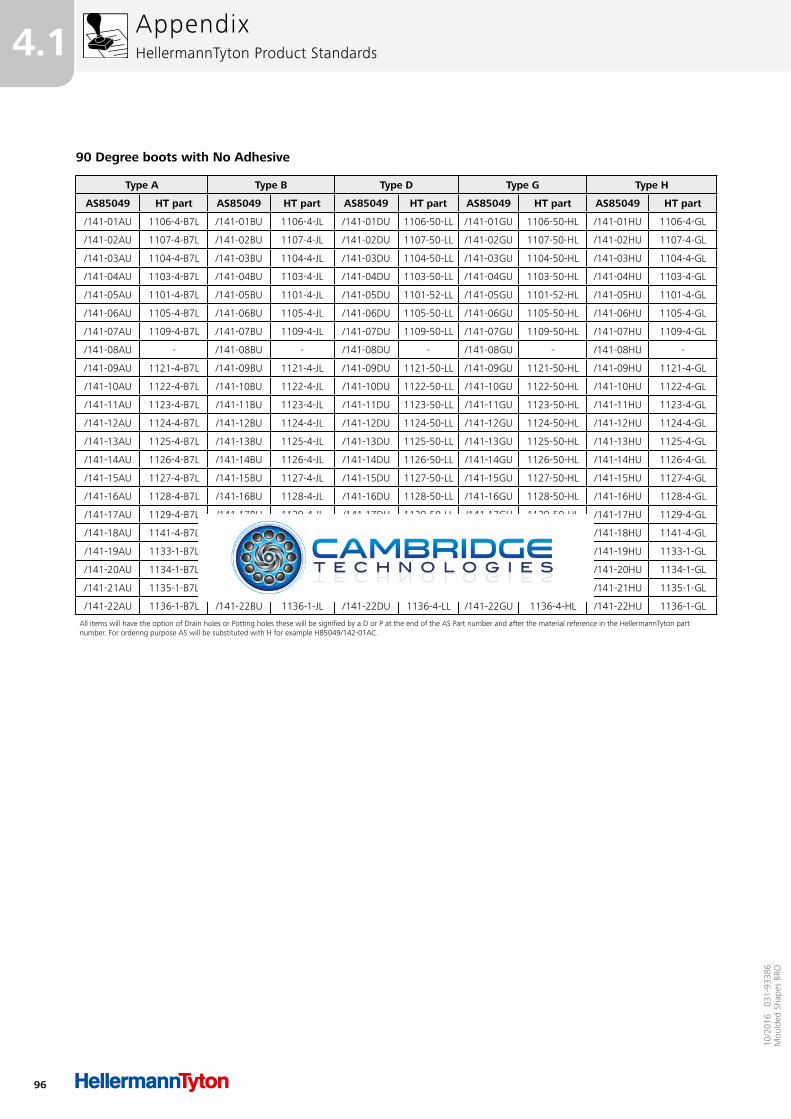
96
4.1
10/2
016
031
-933
86M
ould
ed S
hape
s BR
O
AppendixHellermannTyton Product Standards
90 Degree boots with No Adhesive
Type A Type B Type D Type G Type H
AS85049 HT part AS85049 HT part AS85049 HT part AS85049 HT part AS85049 HT part
/141-01AU 1106-4-B7L /141-01BU 1106-4-JL /141-01DU 1106-50-LL /141-01GU 1106-50-HL /141-01HU 1106-4-GL
/141-02AU 1107-4-B7L /141-02BU 1107-4-JL /141-02DU 1107-50-LL /141-02GU 1107-50-HL /141-02HU 1107-4-GL
/141-03AU 1104-4-B7L /141-03BU 1104-4-JL /141-03DU 1104-50-LL /141-03GU 1104-50-HL /141-03HU 1104-4-GL
/141-04AU 1103-4-B7L /141-04BU 1103-4-JL /141-04DU 1103-50-LL /141-04GU 1103-50-HL /141-04HU 1103-4-GL
/141-05AU 1101-4-B7L /141-05BU 1101-4-JL /141-05DU 1101-52-LL /141-05GU 1101-52-HL /141-05HU 1101-4-GL
/141-06AU 1105-4-B7L /141-06BU 1105-4-JL /141-06DU 1105-50-LL /141-06GU 1105-50-HL /141-06HU 1105-4-GL
/141-07AU 1109-4-B7L /141-07BU 1109-4-JL /141-07DU 1109-50-LL /141-07GU 1109-50-HL /141-07HU 1109-4-GL
/141-08AU - /141-08BU - /141-08DU - /141-08GU - /141-08HU -
/141-09AU 1121-4-B7L /141-09BU 1121-4-JL /141-09DU 1121-50-LL /141-09GU 1121-50-HL /141-09HU 1121-4-GL
/141-10AU 1122-4-B7L /141-10BU 1122-4-JL /141-10DU 1122-50-LL /141-10GU 1122-50-HL /141-10HU 1122-4-GL
/141-11AU 1123-4-B7L /141-11BU 1123-4-JL /141-11DU 1123-50-LL /141-11GU 1123-50-HL /141-11HU 1123-4-GL
/141-12AU 1124-4-B7L /141-12BU 1124-4-JL /141-12DU 1124-50-LL /141-12GU 1124-50-HL /141-12HU 1124-4-GL
/141-13AU 1125-4-B7L /141-13BU 1125-4-JL /141-13DU 1125-50-LL /141-13GU 1125-50-HL /141-13HU 1125-4-GL
/141-14AU 1126-4-B7L /141-14BU 1126-4-JL /141-14DU 1126-50-LL /141-14GU 1126-50-HL /141-14HU 1126-4-GL
/141-15AU 1127-4-B7L /141-15BU 1127-4-JL /141-15DU 1127-50-LL /141-15GU 1127-50-HL /141-15HU 1127-4-GL
/141-16AU 1128-4-B7L /141-16BU 1128-4-JL /141-16DU 1128-50-LL /141-16GU 1128-50-HL /141-16HU 1128-4-GL
/141-17AU 1129-4-B7L /141-17BU 1129-4-JL /141-17DU 1129-50-LL /141-17GU 1129-50-HL /141-17HU 1129-4-GL
/141-18AU 1141-4-B7L /141-18BU 1141-4-JL /141-18DU 1141-50-LL /141-18GU 1141-50-HL /141-18HU 1141-4-GL
/141-19AU 1133-1-B7L /141-19BU 1133-1-JL /141-19DU 1133-4-LL /141-19GU 1133-4-HL /141-19HU 1133-1-GL
/141-20AU 1134-1-B7L /141-20BU 1134-1-JL /141-20DU 1134-5-LL /141-20GU 1134-5-HL /141-20HU 1134-1-GL
/141-21AU 1135-1-B7L /141-21BU 1135-1-JL /141-21DU 1135-4-LL /141-21GU 1135-4-HL /141-21HU 1135-1-GL
/141-22AU 1136-1-B7L /141-22BU 1136-1-JL /141-22DU 1136-4-LL /141-22GU 1136-4-HL /141-22HU 1136-1-GL
All items will have the option of Drain holes or Potting holes these will be signified by a D or P at the end of the AS Part number and after the material reference in the HellermannTyton part number. For ordering purpose AS will be substituted with H for example H85049/142-01AC.
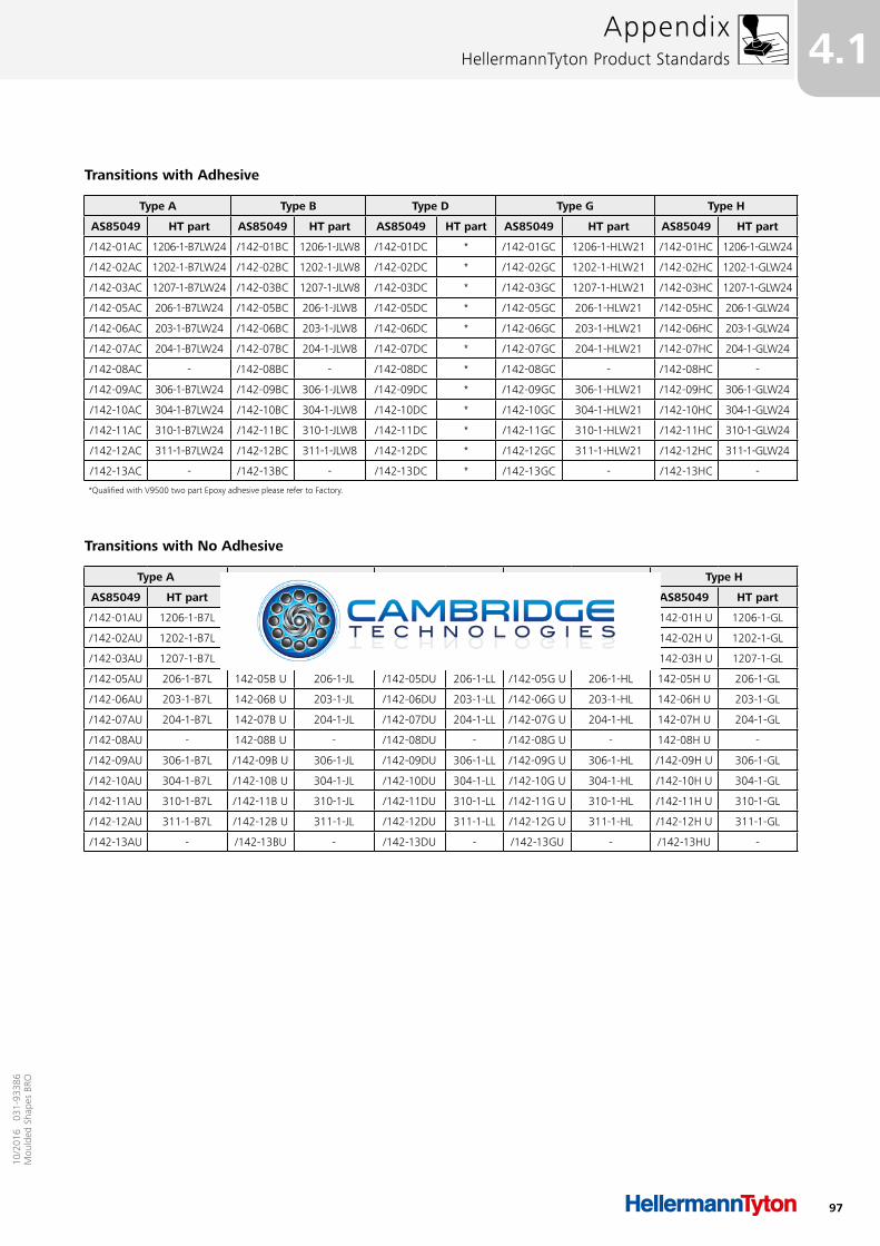
97
4.110
/201
6 0
31-9
3386
Mou
lded
Sha
pes
BRO
AppendixHellermannTyton Product Standards
Transitions with Adhesive
Type A Type B Type D Type G Type H
AS85049 HT part AS85049 HT part AS85049 HT part AS85049 HT part AS85049 HT part
/142-01AC 1206-1-B7LW24 /142-01BC 1206-1-JLW8 /142-01DC * /142-01GC 1206-1-HLW21 /142-01HC 1206-1-GLW24
/142-02AC 1202-1-B7LW24 /142-02BC 1202-1-JLW8 /142-02DC * /142-02GC 1202-1-HLW21 /142-02HC 1202-1-GLW24
/142-03AC 1207-1-B7LW24 /142-03BC 1207-1-JLW8 /142-03DC * /142-03GC 1207-1-HLW21 /142-03HC 1207-1-GLW24
/142-05AC 206-1-B7LW24 /142-05BC 206-1-JLW8 /142-05DC * /142-05GC 206-1-HLW21 /142-05HC 206-1-GLW24
/142-06AC 203-1-B7LW24 /142-06BC 203-1-JLW8 /142-06DC * /142-06GC 203-1-HLW21 /142-06HC 203-1-GLW24
/142-07AC 204-1-B7LW24 /142-07BC 204-1-JLW8 /142-07DC * /142-07GC 204-1-HLW21 /142-07HC 204-1-GLW24
/142-08AC - /142-08BC - /142-08DC * /142-08GC - /142-08HC -
/142-09AC 306-1-B7LW24 /142-09BC 306-1-JLW8 /142-09DC * /142-09GC 306-1-HLW21 /142-09HC 306-1-GLW24
/142-10AC 304-1-B7LW24 /142-10BC 304-1-JLW8 /142-10DC * /142-10GC 304-1-HLW21 /142-10HC 304-1-GLW24
/142-11AC 310-1-B7LW24 /142-11BC 310-1-JLW8 /142-11DC * /142-11GC 310-1-HLW21 /142-11HC 310-1-GLW24
/142-12AC 311-1-B7LW24 /142-12BC 311-1-JLW8 /142-12DC * /142-12GC 311-1-HLW21 /142-12HC 311-1-GLW24
/142-13AC - /142-13BC - /142-13DC * /142-13GC - /142-13HC -
*Qualified with V9500 two part Epoxy adhesive please refer to Factory.
Transitions with No Adhesive
Type A Type B Type D Type G Type H
AS85049 HT part AS85049 HT part AS85049 HT part AS85049 HT part AS85049 HT part
/142-01AU 1206-1-B7L /142-01B U 1206-1-JL /142-01DU 1206-1-LL /142-01G U 1206-1-HL /142-01H U 1206-1-GL
/142-02AU 1202-1-B7L /142-02B U 1202-1-JL /142-02DU 1202-1-LL /142-02G U 1202-1-HL /142-02H U 1202-1-GL
/142-03AU 1207-1-B7L /142-03B U 1207-1-JL /142-03DU 1207-1-LL /142-03G U 1207-1-HL /142-03H U 1207-1-GL
/142-05AU 206-1-B7L 142-05B U 206-1-JL /142-05DU 206-1-LL /142-05G U 206-1-HL 142-05H U 206-1-GL
/142-06AU 203-1-B7L 142-06B U 203-1-JL /142-06DU 203-1-LL /142-06G U 203-1-HL 142-06H U 203-1-GL
/142-07AU 204-1-B7L 142-07B U 204-1-JL /142-07DU 204-1-LL /142-07G U 204-1-HL 142-07H U 204-1-GL
/142-08AU - 142-08B U - /142-08DU - /142-08G U - 142-08H U -
/142-09AU 306-1-B7L /142-09B U 306-1-JL /142-09DU 306-1-LL /142-09G U 306-1-HL /142-09H U 306-1-GL
/142-10AU 304-1-B7L /142-10B U 304-1-JL /142-10DU 304-1-LL /142-10G U 304-1-HL /142-10H U 304-1-GL
/142-11AU 310-1-B7L /142-11B U 310-1-JL /142-11DU 310-1-LL /142-11G U 310-1-HL /142-11H U 310-1-GL
/142-12AU 311-1-B7L /142-12B U 311-1-JL /142-12DU 311-1-LL /142-12G U 311-1-HL /142-12H U 311-1-GL
/142-13AU - /142-13BU - /142-13DU - /142-13GU - /142-13HU -

10/2
016
031
-934
38M
ould
ed S
hape
s BR
O