Embed Size (px)
Citation preview
Heat Transfer to a Plastic Tape Traveling Over Heated Rolls
I . BRAZINSKY* and H. L. DAVIS
Celanese Research Company SLmrnif, New Jersey OBO1
Temperature was calculated as a function of lateral and axial position within a thin poly(ethy1ene terephthalate) (PET) tape traveling alternately over a heated roll and through air. The system consists ofapair of rolls which are internally heated and located in an oven. The centers of the rolls are ten inches apart and the tape makes eight wraps around the roll pair. Three sources of heat transfer to the tape are considered: convection and radiation from the heated rolls, convection from the air, and radiation from the hot oven walls. Calculations were carried out for oven wall temperatures of 100 and 1000°C, air tempera- tures of 100 and 205”C, and roll surface temperatures of 180 and 235°C. The computations generally indicate that after several wraps the temperature of the outside surface of the tape (i.e., the surface that does not contact the rolls) is essentially the same each time the tape leaves the roll. However, this tempera- ture changes as the tape then travels through the adjacent, downstream air space. Although there is a temperature gra- dient across the tape, the temperature ofthe inside surface(i.e., the side that contacts the rolls) exhibits behavior similar to that of the outside surface.
INTRODUCTION he drawing ofpolymeric materials (fibers, tapes, etc.) T has been an industrially important process for the last
35 years. Despite the many improvements to the tech- nique during this period very few attempts have actually been made to understand the underlying mechanisms of the process. Until recently, even an aspect of the proc- ess such as the heat transfer to the polymeric material had not been properly evaluated. For example, in indus- trial’ practice one often hears reference to a “draw tem- perature.” Clearly there is no unique temperature to which a polymer undergoing drawing is subjected, but rather there exists significant axial and lateral tempera- ture gradients within the material. It would appear im- portant to know these gradients, since localized temper- atures can significantly influence the properties of the drawn polymeric material.
Phenomenologically, drawing is quite complicated, and the present authors are not aware of any com- prehensive mathematical descriptions of the process. Attempts, however, have been made (1, 2) to model the heat transfer aspects of the process. Both Grant and Krieger (l), and Pai and Hyman (2) treat the case of a bundle of filaments traveling alternately over heated rolls and through air. Since the mathematical treatment of this geometrical configuration is complex, simplifying assumptions were made. Pai and Hyman (2) postulated
* Prfsent addrfss: Halcnn RbrD COT., Two Park AW , New York, New Ynrk 10016.
that the filament bundle assumed the configuration of a thin band (with large aspect ratio and constant cross sectional area) as it traveled alternately over rolls and through air. On the other hand, Grant and Krieger (1) treated each fiber separately. They assumed that each filament possessed a constant, square cross sectional area while on a roll but retained its circular shape while traveling through air.
Grant and Krieger (1) postulated that the surface of the square filament in contact with the roll was at the roll temperature. The other three surfaces were assumed to be insulated, i.e., the temperature gradient at these surfaces was assumed equal to zero. It was further postu- lated (1) that heat was transferred between the ambient and the circular filament surface by the normal convec- tive processes as the fiber traveled through the air. Furthermore, Grant and Krieger assumed a flat temper- ature profile with respect to filament cross sectional position as the fiber entered either into an air space or onto a roll.
As previously mentioned, Pai and Hyman (2) , in con- trast to Grant and Krieger (l), did not treat the fibers individually, but postulated that the filament bundle was sufficiently splayed to assume a film-like configura- tion. However, Pai and Hyman assumed, as did Grant and Krieger, that the lateral temperature profile was flat as the film entered either into an air space or onto a roll. In addition, Pai and Hyman postulated that the temper- ature of the film surface in contact with the roll was equivalent to that of the roll. They did not, however,
POLYMER ENGINEERING AND SCIENCE, SEPTEMBER, 1978, Vol. 18, No. 12 955
1. Brazinsky and H . L. Davis
assume that while the film was in contact with the roll the surface exposed to the air was perfectly insulated.
Utilizing the above assumptions both Pai and Hyman (2), and Grant and Krieger (1) were able to obtain analyt- ical solutions to the energy balance equation. Calculated temperatures, along with some experimental data are presented in their papers.
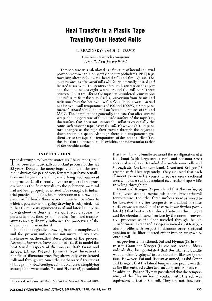
In the present work many calculations were per- formed for the roll system shown in F i g . 1 . A po- ly(ethy1ene terephthalate) (PET) tape makes eight wraps around the roll pair, and both rolls, which are internally heated, are located in an oven. Temperatures within the thin polymeric tape were calculated at various axial and lateral positions. These calculations are obviously more rigorously applicable to a traveling polymer tape, which incidentally is also an important industrial process, than to a band of fibers traveling over rolls. However, the computations may be applied to fiber processing if we postulate, as did Pai and Hyman (2), that a moving filament bundle may be modeled as a thin tape with large aspect ratio.
In order to obtain more realistic results, some of the assumptions made by both Grant and Krieger (l), and Pai and Hyman (2) were eliminated. An analytical solu- tion of the energy balance equation could therefore not be obtained and numerical techniques had to be re- sorted to. Instead of postulating as did Grant and Krieger (l), that the air-polymer interfaces were per- fectly insulated while the film was on a roll, it was assumed that there always existed normal convective heat transfer from the air and radiative transfer from the oven walls to the exposed tape surfaces. Generally, heat transfer by radiation is not important in industrial fiber processes. However, in certain specific applications it is being proposed as a supplementary source of energy.
In addition, it was not assumed that the lateral tem- perature profile was uniform as the film entered any particular stage. (A stage is defined as either a roll sur- face or an air space. For example, roll stage 1-2 is im- mediately upstream of air stage 3-4.) The temperature
Fig. 1 . Tape traveling over pair of heated rolls contained in oven.
profile possessed by the tape upon entering each new stage was chosen as the profile possessed by the tape leaving the previous, adjacent stage.
Finally, the assumption that the temperature of the inside tape surface (the surface which contacts the roll) was equivalent to the roll temperature, while the tape resided on the roll, was eliminated. The temperature of the inside tape surface was calculated using the specified value of roll temperature, the appropriate value of the polymer thermal conductivity, and the values of the interfacial and radiative coefficients of heat transfer be- tween the roll and tape surfaces.
As previously indicated, elimination of the above cited assumptions allows a more realistic description of the heat transfer occurring in the process. Although based on specific numerical computations, the calcu- lated trends presented later in the article should be of general industrial applicability as the values of the inde- pendent operating parameters chosen for the calcula- tions are typical of commercial processes.
MATHEMATICAL MODEL The mathematical model used to calculate the axial
and lateral temperature distribution in the tape is essen- tially a solution of the well known differential energy balance (3) shown below.
(For all symbol identification see Nomenclature). The assumptions utilized in reducing the general dif-
ferential energy balance to the form shown above, and in its solution are:
1) The system is at steady state. 2) The polymeric tape is PET. The density, thermal
conductivity, and specific heat are assumed constant and equal to 1.35 gm/cc, 0.00037 (cal-cm)/(s-cm2-"C), and 0.3 cal/(gm-"C) respectively.
3) The cross-sectional area of the traveling tape does not vary with axial position.
4) There is no temperature variation in the I direc- tion, i.e., along the width of the film (see F i g . 1) .
5) Heat generation due to friction between the tape and roll is negligible.
6) The tape is in plug flow, i.e., there is no velocity gradient in either the I, y or z directions.
7) The infrared radiation striking the tape surface is partly absorbed at the interface with the remainder being completely transmitted through the film.
Postulate 7 is tantamount to assuming that no thermal radiation is absorbed in the interior as the ray travels through the film. Actually, if allowance had been made for the absorption of radiation within the tape's interior, then E q 1 would have had to contain an additional term to account for added internal energy input.
Equation 1 has to be solved with two separate sets of boundary conditions. One set applies when the tape is traveling through the air, and the other set is applicable when the tape contacts the roll. When the PET is travel- ing through the air the following boundary conditions apply.
956 POLYMER ENGINEERING AND SCIENCE, SEPTEMBER, 1978, Vol. 18, No. I2
Heat Transfer to a Plastic Tape Traveling Over Heated Rolls
(1) at Z , = 0 (i.e., when the tape first contacts any air space), T = fb). The variation of temperature, T , with lateral position, y, as the tape enters the air space is equivalent to the temperature distribution in the tape as it leaves the preceding, adjacent roll surface.
(2) at y = 6, all Z , dT
hutr(T&,u - T m r ) + hrw/ . o ( T y . o - Tu) = - k - It a l l dY
(3) at y = 0, all Z,
When the tape resides on the roll the boundary condi- tions are:
(1) at Z, = 0 (i.e., when the tape initidly contacts the roll), T = g(y). The temperature variation with lateral position (T = g(y)) within the tape as the tape initially contacts the roll is equivalent to the lateral temperature distribution in the material leaving the preceding, adja- c m t air space.
(2) at y = 6, all Z r
(3) at y = 0, all Z,
The convective heat transfer coefficient at the air-tape interface, hui,, was assumed not to vary with axial posi- tion. This coefficient, which is dependent on film speed, however, was calculated from the usual heat transfer correlations to he 0.0041 cal/(s-cm2-"C) at a film speed of 4064 cmis, the velocity employed in the present calcula- tions. This value of the coefficient was considered appli- cabltx regardless ofwhether the tape was in contact with a roll or traveling through the air.
The value of hroa, the interfacial coefficient of heat transfer between the roll surface and the film in contact with it, was found to be about 0.4065 cal/(s-cm2-"C) (4). This value was obtained by passing a known heat flux through a PET film in contact with an internally heated roll. The surface temperatures of the metallic roll and of the outside of the film were measured. hroll was deter- mined from these measurements and the known ther- mal conductivity of PET.
The effective radiative heat transfer coefficient be- tween the tape and roll surfaces, brad, was evaluated
from the roll temperature, and the absorptivity, emis- sivity and interface temperature of the polymeric film. Since the emissivity and the absorptivity of the tape surface contacting the roll were found to be essentially equal, the net interchange (per unit area) of radiant energy between the tape and roll surfaces was expressed as the product of a radiative heat transfer coefficient and a temperature difference driving force. Tape absorptiv- ity at any given roll temperature was calculated by inte- grating the experimentally determined infrared spectra over the range of intensities (a function of temperature and wave length) characteristic of the infrared radiation the tape was receiving from the hot roll surface, which was assumed to be a black body. The infrared spectra,
roll
i.e., the transmissivity \IS wave length curve, was mea- sured using a 0.92 mil thick PET fiIm, the same thick- ness employed for the calculations presented in this paper.
Tape emissivity, a function of film surface tempera- ture, was calculated in an analogous manner, i.e., by integrating the infrared spectra over the range of inten- sities characteristic of the IR radiation being emitted from the polymer surface. For the range of tape and roll surface temperatures encountered in these computa- tions, both tape emissivity and tape absorptivity were calculated to be about 0.5.
In formulating the expression for the net interchange of radiative energy, it was assumed that the tape-roll view factor was unity. This view factor is defined as the fraction of radiant energy emanating from the tape sur- face in contact with the roll and subsequently received by the roll surface. For all cases presented in this paper brad was calculated to be negligible compared with hrall.
The effective radiative heat transfer coefficient be- tween a tape surface and the enclosing oven wall, which is assumed to be a black body, was evaluated from the wall temperature and the emissivity, absorptivity, and surface temperature of the polymer film. The radiative coefficients of the inner and outer tape surfaces, brad ,i and
brad ,o were respectively evaluated from the temperatures
of the inner and outer film surfaces. For all cases con- sidered, the inner and outer radiative coefficients are essentially equal.
In formulating the coefficient of radiant heat exchange between each tape surface and the enclosing oven wall, the tape surface-wall view factor was taken as unity. This view factor is defined as the fraction of radiation emanat- ing from the tape surface which is received by the wall. The methods for calculating polymer emissivity and ab- sorptivity have been previously described.
For the 100°C wall case, both tape emissivity and tape absorptivity were found to be essentially equal to 0.5, as in the computation of hr(l,,. Thus the formula-
tion of the wall-tape surface radiative heat transfer coefficient is essentially identical to that for hr,l+ For
these low wall temperature runs, the wall-tape surface radiative coefficient is quite small compared with h(iir, generally ranging about 2 percent of the convective coefficient. It is interesting to note that for the 100°C wall temperature runs the film is actually losing radiant energy to the oven walls.
For the 1OOO"C wall case, tape emissivity is still about 0.5, but the value of the absorptivity is 0.25. However, since the radiant energy emitted by the film is a very small percentage (about 5 percent) of the radiation the tape receives from the hot, 1000°C wall, the net inter- change (per unit area of tape surface) of radiant energy between the hot wall and the polymer interface could still be expressed as the product of a radiative heat transfer coefficient and a temperature difference driving force. Generally, the radiative coefficient for the 1O()o0c wall case is about 25 percent of the convective coefficient. This value is significant, and as the calcula-
roll
wall
wall
roll
roll
POLYMER ENGINEERING AND SCIENCE, SEPTEMBER, 1978, Vol. 18, No. I2 957
I . Bruzinsky and H . L . Davis
tions will later show, radiation from the 1000°C walls affects the polymer surface temperature appreciably.
As previously mentioned, the differential energy bal- ance, Ey l , and the associated boundary conditions could not be solved analytically. An analytical solution could not be obtained primarily for two reasons. These are: (1) the existence of a lateral temperature gradient across the film at t h e 2 = 0 position, and (2) the inclusion of a radiation term in the boundary condition. The Dufort-Frank1 method (5) was thus used to obtain a numerical solution. This particular method was chosen bccause i t is explicitly stable, i .e. , it is stable regardless of the ratio of the sides of the finite difference increment. (This ratio is denoted as r and is equal to (AZ/Atj)).
The lateral dimension of each finite difference incre- ment, Ay, was obtained by dividing the film thickness, 0.00234 cm, by 16. The length of each air stage is 25.4 cm, whereas that of a roll stage (i.e., when the film is in contact with a roll) is 30.5 cm. There are eight wraps around the pair of rolls and each wrap consists of two air stages and two roll stages. Thus, unless large values of T
had lieen chosen, an unreasonably large number of in- cremcnts wwuld have bevn necessary and the cost of the computation would have \wen txorhitant.
The reliability of the numerical computation was checked by repeating the calculation at a value of &j equal to one quarter the value originally chosen but with the same valuc. of the ratio (AZ/(Az/)'). Thc, calculated temperati1rc.s werv esscwtially the same as those ob- tained with thc original value of hy (i.e., 0.0001463 em). The agreement between the temperatures calculated using the smaller and larger increments indicates the reliability of the numerical schcrne in representing the solution to the partial differential equation.
Calculations were made for the 8 wrap system using the mathematical model described above. Several trends c~mc~rgt~ which are of apparent general applicabil- ity to industrial processcs.
RESULTS AND DISCUSSION A factorial series of runs was carried out on the com-
puter. The independent variables studied were air tem- peraturr, wall tcsrnpr.rature, and roll temperature. Each of these factors w a s studied at two levels; the wall tcm- perature at 100 and 1OOO"C, the air temperature at 100 and 205"C, and the roll temperature at 180 and 235°C. The complete factorial design is shown in Table 1.
The results of these calculations are shown in'Figs. 2-12. ,411 ofthe calculations shown in these figures are for
Table 1. Factoral Design of Computer Runs
Wall Air Roll Run No. temperature temperature temperature
1A 100 100 1 80 2A 100 100 235 3A 100 205 1 80 4A 100 205 235 1B 1000 100 1 80 28 1000 100 235 38 1000 205 180 48 1000 205 235
a tape velocity of4064 cmls. The roll centers were taken to be 25.4 em. apart and each roll diameter was assumed to be equal to 19.4 cm. For all runs the temperature of the tape was taken as 100°C as it initially contacted roll A during the first wrap. For convenience the values of the independent variables maintained constant during the study are listed in T u b k 2 .
As previously indicated, the computer program calcu- lates temperatures at various lateral and axial positions within the tape for all of the air and roll stages constitut- ing the eight wrap system. Figures 2 , 3 and4 show tape temperature profiles for the first wrap of Run 2A. Analogous results were obtained for all of the runs,
Figures 5-12 show the temperatures of the inner and outer surfaces as the tape leaves each stage of the eight wrap system. Position 1 corresponds to the tape leaving stage 1, i.e., air space A between the rolls during the initial wrap, whereas position 2 corresponds to the tape leaving roll B during the initial wrap. Position 3 corre- sponds to the tape leaving air space B during the initial wrap, and position 4 to the tape leaving roll A at the end of the first wrap. In general, therefore, ail even num- bered position indicates that the film is leaving a roll, whereas an add numbered position indicates that the tape is leaving an air space.
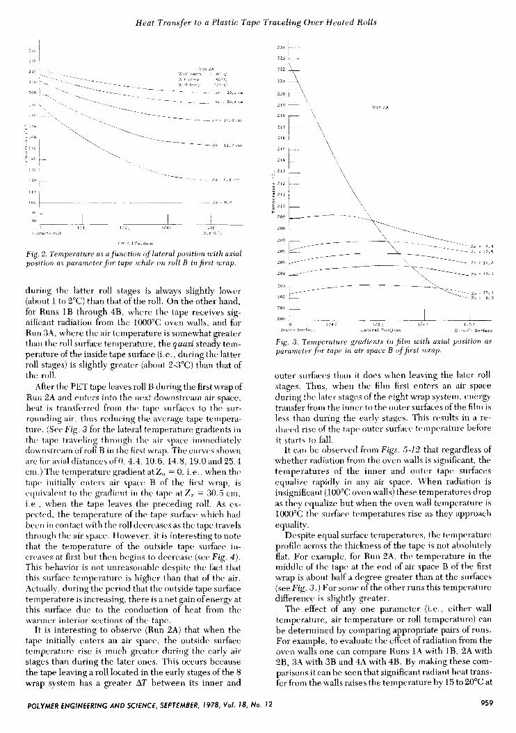
A yuusi steady state is generally attained after one or two complete wraps, i.e., the temperature-position re- lationship within each wrap does not change with ad- ditional wraps. At the beginning of the first wrap of any run, the tape makes only line contact with roll A, and it is therefore assumed that no heat is transferred between this roll and the tape. Thus, for those runs in which the air and ovvn wall temperatures arc' 100°C, i.e., 1A and 2A, the tcmpcmture of the tape, a s it contacts roll B during the first wrap, is still 100°C. (Obviously, for runs in which either the air or oven wall temperatures differ from 1OO"C, the temperature of the tape will rise above 100°C as the tape enters onto roll B during the first wrap.) Immediately upon contact with roll B a tempera- ture gradient begins to develop through the thickness of the tape. (The lateral temperature gradients for Run 2A at axial distances of 0, 6.5, 12.7, 19.0, 25.2 and 30.5 cm are shown in Fig. 2 . ) As expected, temperature at any lateral position in the tape increases with increasing axial position. Figure 2 also reveals that for this particular roll stage, the inside surface of the tape never attains the temperature of the roll. Roll temperature is 235°C for this run, but the inside tape surface temperature only reaches 223°C as the tape leaves the roll.
In fact, for a roll stage of any run, the temperature of the inner tape surface generally differs from that of the roll. For Runs l A , 2A and 4 A , where the air and wall temperatures are lower than the roll temperature, the steady temperature attained by the inner film surface
Table 2. Independent Variables Maintained Constant
Tape velocity 4064 cm/s Distance between roll centers 25.4 cm Diameter of rolls 19.4 cm Initial temperature of PET tape 100°C No. of wraps 8
958 POLYMER ENGINEERING AND SCIENCE, SEPTEMBER, 1978, Vol . 18, No. 12
Heat Transfer to a Plastic Tape Traveling Over Heated Rolls
, ?L
1 l l f 1
1 1 , ) I
( (10 I-. ~ ~ -
1 I - 4 - p rt----- Air 5 I
1 a1 - -~
1 4
1 %I ' 8 1 l o i l * l O n
Fig 2 Temperature as a fumt ion of lateral pontzon zozth axzal posztzon as parameter f o r tape while on roll B i n first wrap
during the latter roll stages is always slightly lower (about 1 to 2°C) than that of the roll. On the other hand, for Runs 1B through 4B, where the tape receives sig- nificant radiation from the 1000°C oven walls, and for Run 3A, where the air temperature is somewhat greater than the roll surface temperature, the quasi steady tem- perature of the inside tape surface (i.e., during the latter roll stages) is slightly greater (about 2-3°C) than that of the roll.
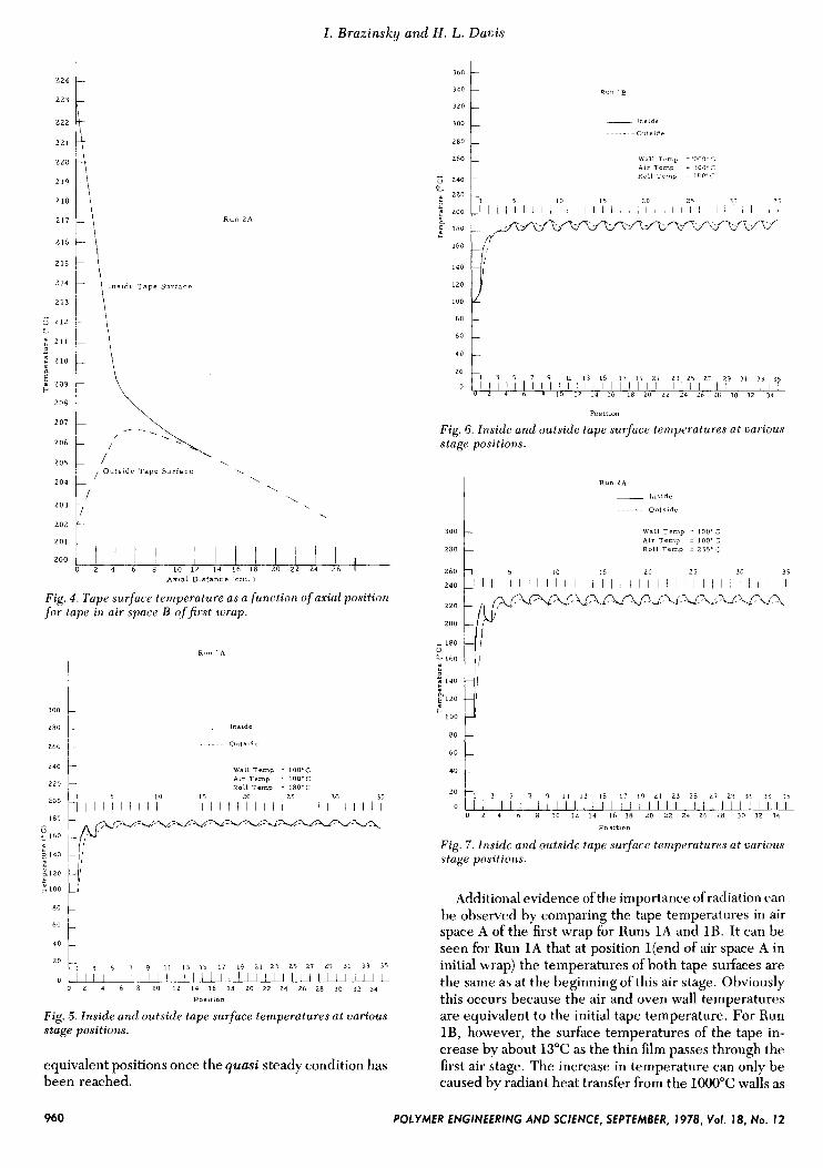
After the PET tape leaves roll B during the first wrap of Run 2A and enters into the next downstream air space, heat is transferred from the tape surfaces to the sur- rounding air, thus reducing the average tape tempera- turt,. (SCC Fig. 3 for the lateral temperature gradients in the tape traveling through thr air space immediatt,ly clounstream of roll B in the first wrap. The curves shown are for axial distances ofO, 4.4, 10.6, 14.8, 19.0 and 25.4 cm.) The temperaturc. gradient at Z,, = 0, i tapr initially enters air space B of the first wrap, is rquivalent to the gradient in thr tape at Z,. = 30.S cm, i .e. , when the tape leaves the preceding roll. As ex- pecttd, the temperature of the tape surface which had been in contact with the roll decreases as the tape travels through the air space. However, it is interesting to note that the temperature of the outside tape surface in- creases at first but then begins to decrease (see Fig. 4 ) . This behavior is not unreasonable despite the fact that this surface temperature is higher than that of the air. Actually, during the period that the outside tape surface temperature is increasing, there is a net gain ofenergy at this surface due to the conduction of heat from the warmer interior sections of the, tape.
It is interesting to observe (Run 2A) that when the tape initially enters an air space, the outside surface temperature rise is much greater during the early air stages than during the later ones. This occurs because the tape leaving a roll located in the early stages of the 8 wrap system has a greater AT between its inner and
2 2 4 b- 2 2 3 i
d 2'2 t- : 211 +
209
208 j
R u n LA
I 2 0 1 t
I I I
I -L 0 1 / 4 6 1 / 2 5 3 1 4 1 1 . 0 1
200 I I I I n s l d r s u r i a c - Lateral Pos?tlon O u t s i d - Surface
Fig 3. Tempcroftire grudients a n film wi th axial position as parurrwtrr f o r tape 111 air space B of first imzp.
outer surfaces than it does when leaving the later roll stages. Thus, when the film first enters an air space during the later stages of the eight wrap system, energy transfer from the inner to the outer surfaces of the film is less than during the early stages. This results in a re- tluced risc of the tape outrr surfacc ternperaturc before i t starts to fall.
It can be observed from Figs. 5-12 that regardless of whether radiation from the oven walls is significant, the temperatures of the inner and outer tape surfaces equalize rapidly in any air space. When radiation is insignificant (100°C oven walls) these temperatures drop as they equalize but when the oven wall temperature is 1000°C the surface temperatures rise as they approach equality.
Despite equal surface temperatures, the temperature profile across the thickness of the tape is not absolutely flat. For example, for Run 2A, the temperature in the middle of the tape at the end of air space B of the first wrap is about half a degree greater than at the surfaces (see Fig . 3 . ) For some of the other runs this temperature difference is slightly greater.
The effect of any one parameter (i.e., either wall temperature, air temperature or roll temperature) can be determined by comparing appropriate pairs of runs. For example, to evaluate the effect of radiation from the oven walls one can compare Runs 1A with 1B, 2A with 2B, 3A with 3B and 4A with 4B. By making these com- parisons it can be seen that significant radiant heat trans- fer from the walls raises the temperature by 15 to 20°C at
959 POLYMER ENGINEERING AND SCIENCE, SEPTEMBER, 1978, Vof. 18, No. I2
I . Brazinsky and H . L.
- 1 5 LO 15 20 2 5
_I I I I I 1 1 I 1 I 1 1 1 I 1 I 1 1 I I I 1 I 1 1 I I I 'P I I I lJli
Davis
-
- -
~
224 1
260
2 4 0 - 1
221
220
1:: E\ 217
216
2 1 5
214
2 1 3
" 212 I
- : 211
2 210 I
a
209
208
207
206
205
204
2 0 3
202
1 5 10 15 20 2 5 30 35
I I I I I I I I I I I I I I I I I I I I I I I I I I I I l l / I I I
R u n 2 A
- 1 8 0 u
160 e
140
2 1 2 0
c 100
\ \
\ \ \ , ,
- I - I
-I - 1
-
A x i a l Diatance ( c m . )
Fig. 4 . Tape surface temperature as a function of axial position for tape in air space B of first wrap.
I R u n I A
280
260
__ Inside
.~.... Outside
13 15 17 ~9 2 1 2 3 25 27 29 31 33 35 20
I I 1 I l I 1 1 0 2 4 6 8 10 I 2 14 16 18 20 22 24 26 28 30 32 34
P O l l l t i O "
: l ; ; I 9 I , , I I I I I I , I
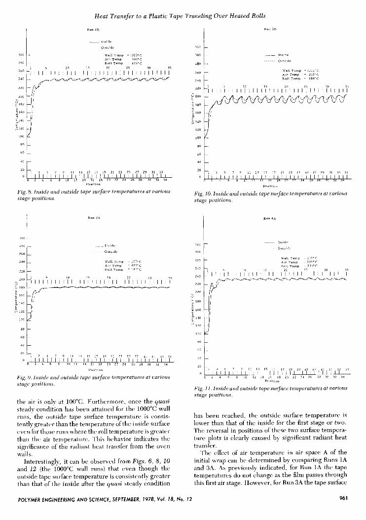
Fig. -5. Inside and outside tape surface temperatures at uarious stage positions.
equivalent positions once the quasi steady condition has been reached.
360
340
320
300
280
260
240 OI
~ 220 2 ., 200
; 180 w
160
140
120
100
8 0
60
40
20
0
Run 1B
~ I n s i d e
O u t s i d e . . . . . . .
W a l l Temp = 100"-" A i r Temp = 100' R o l l Temp = 18o'i:
Positlo"
F i g . 6 . Inside and outside tape surface temperatures at carious stage positions.
Run 2A
__ I n r i d e
...... Outside
W a l l Temp = I O O ' C A i r Temp = 100.3 R o l l Temp = 2 3 5 Y
8o t *O ! 2o I 3 5 7 9 11 13 15 I 7 I 9 2 1 23 25 27 29 31
0 2 4 6 8 10 12 14 16 18 20 22 24 26 i.8 30 32 34
Poaltlo"
Fig. 7 . Inside and outside tape surface temperaturi's at carious stage positions.
Additional evidence of the importance of radiation can be observed by comparing the tape temperatures in air space A of the first wrap for Runs 1A and 1B. It can be seen for Run 1 A that at position l(end of air space A in initial wrap) the temperatures of both tape surfaces are the same as at the beginning of this air stage. Obviously this occurs because the air and oven wall temperatures are equivalent to the initial tape temperature. For Run 1B, however, the surface temperatures of the tape in- crease by about 13°C as the thin film passes through the first air stage. The increase in temperature can only be caused by radiant heat transfer from the 1ooo"C walls as
960 POLYMER ENGINEERING AND SCIENCE, SEPTEMBER, 1978, Vol. 18, No. 12
Heat Transfer to a Plastic Tape Traveling Over Heated Rolls
c120
LOO
__ Inside
..... Outside
- t
300 W a l l T e m p = IOOO~C A i r T e m p = I O O ~ C
280 R o l l T e m p = 2 3 5 ~ C
10 15 20 25 30 35
240 220 260 zoo 11 - - I I 1 1 ' 1 I l l l l l l I I I I I I I I I I I I I I I I I I I I I I
- E l 8 0
2 160
320
300
280
260
240
~ Inside
...... O u t s r d e
- -
W a l l T e m p = LOO*C A i r T e m p = 205'C
-
ROII ~ e m p = 235'C
- 1 I I 1 ' 1 I I I 1 ' 7 1 I I 1 '7 I I I ~ I ' I I I 1 ' 5 1 I I 1'7 I I 131i
1 3 5 7 9 1 1 13 15 17 19 2 1 23 25 27 29 31 33
I ! ' I 6 8 LO 12 14 16 18 20 22 24 26 28 30 32 34 0 2 4
20
I l l l l l l l / / l l l l l l l l l l l l l l l l l l l
u - 180
160
2 1 4 0
I 2 0
100
80
60
40
P o * l t l o n
Fig. 8 . Znside and outside tape surface temperatures at various stage positions.
I
I
~
- I -
- -
- -
-
300 1
240
220
R u n 3A
~ I n ~ i d c
...... Outside
W a l l T e m p = I O O ~ C A i r l e m p = 205'C R o l l T e m p = 18O'C
e 180 c 160 If
40 6o 1
1 3 5 7 9 11 13 15 17 19 2 1 23 25 27 29 31 33 35 20
0 I I I I I l l l l l l l l l l l l l l l l l l l l l l l l l l l I 0 2 4 6 8 10 12 14 16 18 20 22 24 Z b 28 30 32 34
Pos1t1on
Fig. 9. Inside ancl outside tape surface temperaturm at various stage positions.
the air is only at 100°C. Furthermore, once the quasi steady condition ha5 been attained for the 1000°C wall runs, the outside tape surface temperature is consis- tently greater than the temperature of the inside surface even for those runs where the roll temperature is greater than the air temperature. This behavior indicates the significance of the radiant heat transfer from the oven walls.
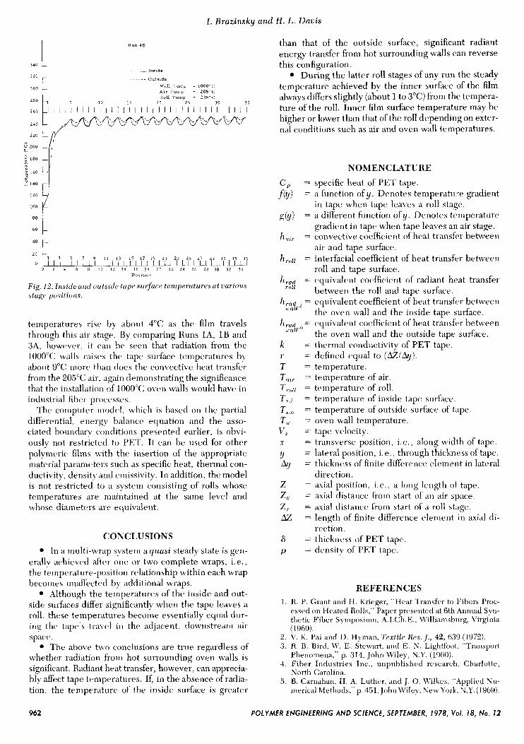
Interestingly, it can be observed from Figs. 6, 8, 10 ancl 12 (the 1OOO"C wall runs) that even though the out side tape surface temperature is consistently greater than that of the inside after the quasi steady condition
320
300
280
260
240
220
3 200 5 1*0
E"
- -
160
140
1 2 0
100
80
60
40
20
0
R u n 3 5
-Inside
....~. Outside
W a l l T e m p - 1 O O O ' C A i r Temp = 2 0 5 ' C R o l l T a m p = 180'C
-1 3 5 7 9 I 1 13 15 17 19 21 2 3 25 27 29 31 33 35
I ! l l l r l ~ l l l l l l l l l l l l l l l ~ l l l l l l l ~ I l l 8 10 12 14 16 18 20 Z2 24 Zb L8 30 3L 34
Poalt lon
Fig, 10. Inside and outside tape surface temperatures at various stage positions.
0
20
~ I l l I l j I 1 1 1 1 ' / I 1 1 l l l l l l l l l l I 'I' 1 j l I 'i I j15 I 3 5 7 9 I 1 1 3 15 17 19 21 23 2 5 27
0 2 4 6 8 LO 12 14 16 18 20 22 24 26 2R 30 3 2 34 P o s i t i o n
Fig. 11. Inside and outside tape surface temperatures at various stage positions.
has been reached, the outside surface temperature is lower than that of the inside for the first stage or two. The reversal in positions of these two surface tempera- ture plots is clearly caused by significant radiant heat transfer.
The effect of air temperature in air space A of the initial wrap can be determined by comparing Runs 1A and 3A. As previously indicated, for Run 1A the tape temperatures do not change as the film passes through this first air stage. However, for Run 3A the tape surface
POLYMER ENGlNEERlNG AND SCIENCE, SEPTEMBER, 1978, Vol. 18, No. 12 96 1
I . Brazinsky and H . L. Davis
I Run 4B
t
1 3 5 7 9 11 13 15 17 I 2 1 23 25 27 9 31 3 3 20
0 l ~ l l ~ l ~ ~ l l l / / I I l I I l l l ~ ~ l ~ ~ l 1 1 1 I 0 2 4 6 8 10 I 2 14 16 I 8 2 0 2 2 24 2 6 28 30 3 2 34
Poslilo”
Fig . 12. Insidc>urid o w t s i t l c tupcl surfuca taniperutures ut various s tagc por i tion F
temperatures rise by about 4°C as the film travels through this air stage. By comparing Runs l A , 1B and 3A, however, it c a ~ i he seen that radiation from the 1000°C ~ l l s raises the tape surface temperatures by about Y°C inorc than t l o ~ s thtr convective heat transfer from the 205°C air. again demonstrating the significance that the installation of 1000°C oven walls would have in industrial fiber processcs.
The computer model, which is based on the partial differential. vnergy balancc. equation and the asso- ciated houndarp conditions presented earlier, is obvi- ously not restricted to PET. It can he used for other polymeric films with the insertion of the appropriate material parameters such as specific heat, thermal con- ductivity, density arid einissivity. In addition, the model is not restricted to a system consisting of rolls whose temperatures are maintained at the same level and whose diameters are equivalent.
CONCLUSIONS In a multi-wrap system a yuasi steady state is gcn-
erally achieved after one or two complete wraps, i.e., the temperature-positioii relationship within each wrap becomes unafhcted by additional wraps.
Although the temperatures of the inside and out- side surfaces differ significantly when the tape leaves a roll, these temperatures become essentially equal dur- ing the tape’s travc.1 i t 1 the acljaceiit, downstream air spacv.
?’he above two conclusions are true regardless of whether radiation from hot surrounding oven walls is significant. Radiant heat transfer, however, can apprecia- bly d e c t tape temperatures. If, in the absence of radia- tion, the temperature of the inside surface is greater
than that of the outside surface, significant radiant energy transfer from hot surrounding walls can reverse this configuration.
During the latter roll stages of any run the steady temperature achieved by the inner surface of the film always differs slightly (about 1 to 3°C) from the tempera- ture of the roll. Inner film surface temperature may be higher or lower than that of the roll depending on exter- nal conditions such as air and oven wall temperatures.
NOMENCLATURE specific heat of PET tape. a function of y. Denotes temperature gradient in tape when tape leaves a roll stage. a diEerent function of y. Denotes tcmperature gradient in tape when tape leaves an air stage. convective coefficient of heat transfer between air and tape surfacc. interfacial coefficient of heat transfer between roll and tape surface. equivalent coefficient of radiant heat transfer between the roll and tape surface. equivalent coefficient of heat transfer between the oven wall and the inside tape surface. equivalent coefficient of heat transfer between the oven wall and the outside tape surface. thermal conductivity of PET tap<%. defined equal to (Az lh j ) . temperature. temperature of air. temperature of roll. temperature of inside tape surface. temperature of outside surface of tape. oven wall temperature. tape velocity. transverse position, i.e., along width of tape. lateral position, i . e . , through thickness of tape. thickness of finite difference elenieiit in lateral direction. axial position, i.e., a long length of tape. axial distance from start of an air space. axial distance from start of a roll stage. length of finite difrerence element in axial di- rection. thickness of PET tape. density of PET tape.
R E F E R E N C E S 1. R. P. Grant and H. Krieger, “Heat Transfer to Fibers Proc-
essed on Heated Rolls,” Paper presented at 6th Annual Syn- thetic Fiber Syinposinrn, A.I.Ch.E., Willianisburg, Virginia (1969).
2 . V. K. Pai and D. Hyman, Textile Res. I . , 42, 639 (1972). 3. R. B. Bird, M‘. E. Stewart, and E. N. Lightfoot. “Transport
Phenomena,” p. 314, John Wiley, N.Y. (1960). 4. Fiber Industries Inc., unpublished rcscxarch, Charlotte,
North Carolina. 5 . B. Carriahati, H. A. Luther, and J. 0. Wilkes. “Applied Nu-
merical hlethods,” p. 451, John Wile!?. Ke\trYork, N.Y. (1969).
962 POLYMER ENGINEERING AND SCIENCE, SEPTEMBER, 1978, Vol. 18, No. 12