Embed Size (px)
Citation preview
Page 1
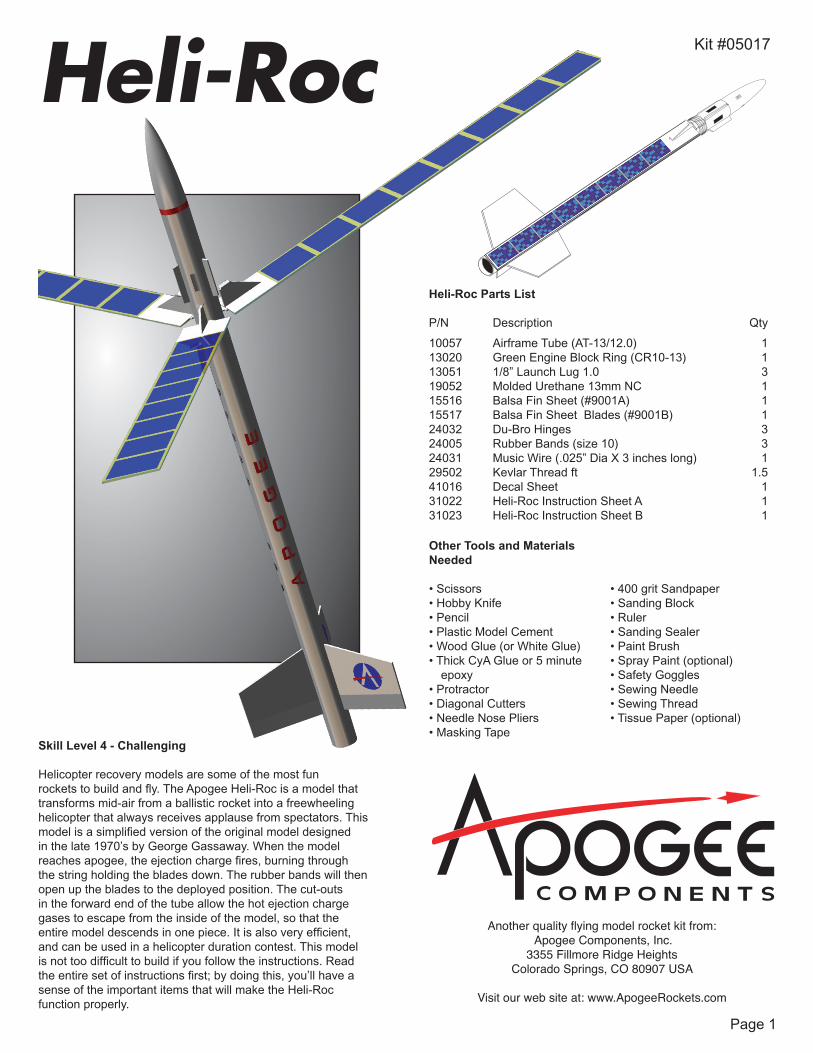
Heli-Roc Parts List
P/N Description Qty
10057 Airframe Tube (AT-13/12.0) 113020 Green Engine Block Ring (CR10-13) 113051 1/8” Launch Lug 1.0 319052 Molded Urethane 13mm NC 115516 Balsa Fin Sheet (#9001A) 115517 Balsa Fin Sheet Blades (#9001B) 124032 Du-Bro Hinges 324005 Rubber Bands (size 10) 324031 Music Wire (.025” Dia X 3 inches long) 129502 Kevlar Thread ft 1.541016 Decal Sheet 131022 Heli-Roc Instruction Sheet A 131023 Heli-Roc Instruction Sheet B 1
Skill Level 4 - Challenging
Helicopter recovery models are some of the most fun rockets to build and fly. The Apogee Heli-Roc is a model that transforms mid-air from a ballistic rocket into a freewheeling helicopter that always receives applause from spectators. This model is a simplified version of the original model designed in the late 1970’s by George Gassaway. When the model reaches apogee, the ejection charge fires, burning through the string holding the blades down. The rubber bands will then open up the blades to the deployed position. The cut-outs in the forward end of the tube allow the hot ejection charge gases to escape from the inside of the model, so that the entire model descends in one piece. It is also very efficient, and can be used in a helicopter duration contest. This model is not too difficult to build if you follow the instructions. Read the entire set of instructions first; by doing this, you’ll have a sense of the important items that will make the Heli-Roc function properly.
Another quality flying model rocket kit from: Apogee Components, Inc.
3355 Fillmore Ridge HeightsColorado Springs, CO 80907 USA
Visit our web site at: www.ApogeeRockets.com
Other Tools and Materials Needed
• Scissors• Hobby Knife• Pencil• Plastic Model Cement• Wood Glue (or White Glue)• Thick CyA Glue or 5 minute
epoxy• Protractor• Diagonal Cutters• Needle Nose Pliers• Masking Tape
• 400 grit Sandpaper• Sanding Block• Ruler• Sanding Sealer• Paint Brush• Spray Paint (optional)• Safety Goggles• Sewing Needle• Sewing Thread• Tissue Paper (optional)
Heli-Roc Kit #05017
Page 2
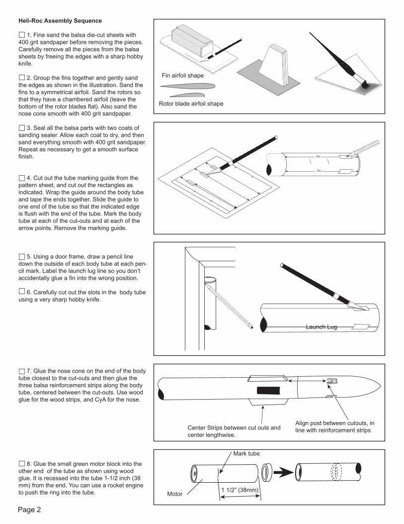
Heli-Roc Assembly Sequence
1. Fine sand the balsa die-cut sheets with 400 grit sandpaper before removing the pieces. Carefully remove all the pieces from the balsa sheets by freeing the edges with a sharp hobby knife.
2. Group the fins together and gently sand the edges as shown in the illustration. Sand the fins to a symmetrical airfoil. Sand the rotors so that they have a chambered airfoil (leave the bottom of the rotor blades flat). Also sand the nose cone smooth with 400 grit sandpaper.
3. Seal all the balsa parts with two coats of sanding sealer. Allow each coat to dry, and then sand everything smooth with 400 grit sandpaper. Repeat as necessary to get a smooth surface finish.
4. Cut out the tube marking guide from the pattern sheet, and cut out the rectangles as indicated. Wrap the guide around the body tube and tape the ends together. Slide the guide to one end of the tube so that the indicated edge is flush with the end of the tube. Mark the body tube at each of the cut-outs and at each of the arrow points. Remove the marking guide.
5. Using a door frame, draw a pencil line down the outside of each body tube at each pen-cil mark. Label the launch lug line so you don’t accidentally glue a fin into the wrong position.
6. Carefully cut out the slots in the body tube using a very sharp hobby knife.
7. Glue the nose cone on the end of the body tube closest to the cut-outs and then glue the three balsa reinforcement strips along the body tube, centered between the cut-outs. Use wood glue for the wood strips, and CyA for the nose.
8. Glue the small green motor block into the other end of the tube as shown using wood glue. It is recessed into the tube 1-1/2 inch (38 mm) from the end. You can use a rocket engine to push the ring into the tube.
Fin
Fin
Fin airfoil shape
Rotor blade airfoil shape
Launch Lug
Center Strips between cut outs and center lengthwise.
Align post between cutouts, in line with reinforcement strips
Mark tube
Motor1 1/2” (38mm)
Page 3
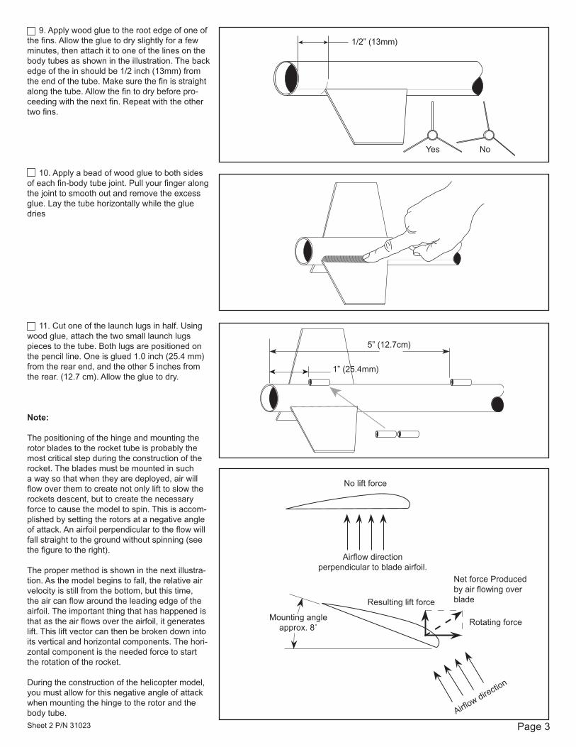
9. Apply wood glue to the root edge of one of the fins. Allow the glue to dry slightly for a few minutes, then attach it to one of the lines on the body tubes as shown in the illustration. The back edge of the in should be 1/2 inch (13mm) from the end of the tube. Make sure the fin is straight along the tube. Allow the fin to dry before pro-ceeding with the next fin. Repeat with the other two fins.
10. Apply a bead of wood glue to both sides of each fin-body tube joint. Pull your finger along the joint to smooth out and remove the excess glue. Lay the tube horizontally while the glue dries
11. Cut one of the launch lugs in half. Using wood glue, attach the two small launch lugs pieces to the tube. Both lugs are positioned on the pencil line. One is glued 1.0 inch (25.4 mm) from the rear end, and the other 5 inches from the rear. (12.7 cm). Allow the glue to dry.
Note:
The positioning of the hinge and mounting the rotor blades to the rocket tube is probably the most critical step during the construction of the rocket. The blades must be mounted in such a way so that when they are deployed, air will flow over them to create not only lift to slow the rockets descent, but to create the necessary force to cause the model to spin. This is accom-plished by setting the rotors at a negative angle of attack. An airfoil perpendicular to the flow will fall straight to the ground without spinning (see the figure to the right).
The proper method is shown in the next illustra-tion. As the model begins to fall, the relative air velocity is still from the bottom, but this time, the air can flow around the leading edge of the airfoil. The important thing that has happened is that as the air flows over the airfoil, it generates lift. This lift vector can then be broken down into its vertical and horizontal components. The hori-zontal component is the needed force to start the rotation of the rocket.
During the construction of the helicopter model, you must allow for this negative angle of attack when mounting the hinge to the rotor and the body tube.
1/2” (13mm)
Yes No
5” (12.7cm)
1” (25.4mm)
No lift force
Airflow directionperpendicular to blade airfoil.
Mounting angleapprox. 8˚
Resulting lift force
Net force Produced by air flowing over blade
Rotating force
Airflow direction
Sheet 2 P/N 31023
Page 4
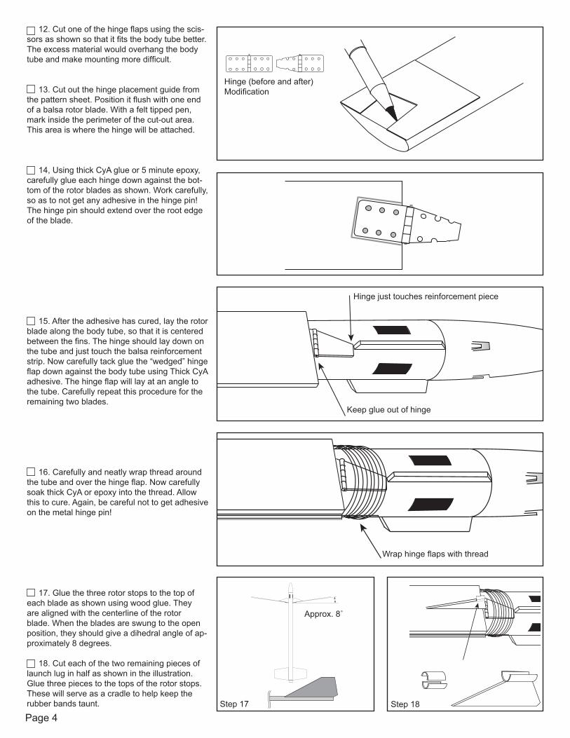
12. Cut one of the hinge flaps using the scis-sors as shown so that it fits the body tube better. The excess material would overhang the body tube and make mounting more difficult.
13. Cut out the hinge placement guide from the pattern sheet. Position it flush with one end of a balsa rotor blade. With a felt tipped pen, mark inside the perimeter of the cut-out area. This area is where the hinge will be attached.
14, Using thick CyA glue or 5 minute epoxy, carefully glue each hinge down against the bot-tom of the rotor blades as shown. Work carefully, so as to not get any adhesive in the hinge pin! The hinge pin should extend over the root edge of the blade.
15. After the adhesive has cured, lay the rotor blade along the body tube, so that it is centered between the fins. The hinge should lay down on the tube and just touch the balsa reinforcement strip. Now carefully tack glue the “wedged” hinge flap down against the body tube using Thick CyA adhesive. The hinge flap will lay at an angle to the tube. Carefully repeat this procedure for the remaining two blades.
16. Carefully and neatly wrap thread around the tube and over the hinge flap. Now carefully soak thick CyA or epoxy into the thread. Allow this to cure. Again, be careful not to get adhesive on the metal hinge pin!
17. Glue the three rotor stops to the top of each blade as shown using wood glue. They are aligned with the centerline of the rotor blade. When the blades are swung to the open position, they should give a dihedral angle of ap-proximately 8 degrees.
18. Cut each of the two remaining pieces of launch lug in half as shown in the illustration. Glue three pieces to the tops of the rotor stops. These will serve as a cradle to help keep the rubber bands taunt.
Hinge (before and after) Modification
Hinge just touches reinforcement piece
Keep glue out of hinge
Wrap hinge flaps with thread
Approx. 8˚
Step 17 Step 18
Page 5
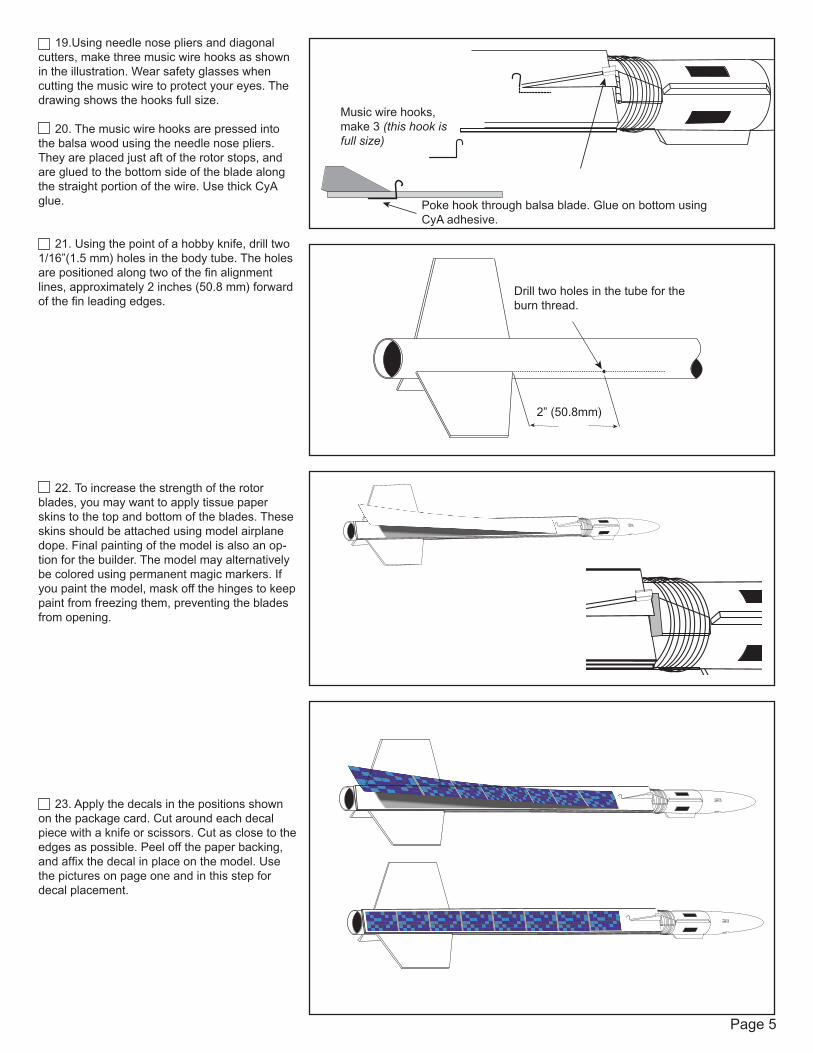
19.Using needle nose pliers and diagonal cutters, make three music wire hooks as shown in the illustration. Wear safety glasses when cutting the music wire to protect your eyes. The drawing shows the hooks full size.
20. The music wire hooks are pressed into the balsa wood using the needle nose pliers. They are placed just aft of the rotor stops, and are glued to the bottom side of the blade along the straight portion of the wire. Use thick CyA glue.
21. Using the point of a hobby knife, drill two 1/16”(1.5 mm) holes in the body tube. The holes are positioned along two of the fin alignment lines, approximately 2 inches (50.8 mm) forward of the fin leading edges.
22. To increase the strength of the rotor blades, you may want to apply tissue paper skins to the top and bottom of the blades. These skins should be attached using model airplane dope. Final painting of the model is also an op-tion for the builder. The model may alternatively be colored using permanent magic markers. If you paint the model, mask off the hinges to keep paint from freezing them, preventing the blades from opening.
23. Apply the decals in the positions shown on the package card. Cut around each decal piece with a knife or scissors. Cut as close to the edges as possible. Peel off the paper backing, and affix the decal in place on the model. Use the pictures on page one and in this step for decal placement.
Poke hook through balsa blade. Glue on bottom usingCyA adhesive.
Music wire hooks, make 3 (this hook is full size)
2” (50.8mm)
Drill two holes in the tube for the burn thread.
Page 6
Launch Supplies Needed
To launch your rocket you will need the following supplies:A model rocket launching systemRecommended Rocket Motors:
1/2A3-2T (first flight)A3-4TA10-3TB7-6 (Apogee Components)
Rocket Preflight Instructions
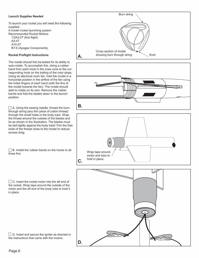
The model should first be tested for its ability to auto-rotate. To accomplish this, string a rubber band from each hook in the nose cone to the cor-responding hook on the trailing of the rotor stops. Using an electrical room fan, hold the model in a horizontal position in the airflow of the fan using the index fingers of each hand (with the fins of the model towards the fan). The model should start to rotate on its own. Remove the rubber bands and fold the blades down to the launch position.
A. Using the sewing needle, thread the burn-through string (any thin piece of cotton thread) through the small holes in the body tube. Wrap the thread around the outside of the blades and tie as shown in the illustration. The blades must be tied tightly against the body tube! Trim the free ends of the thread close to the model to reduce excess drag.
B. Install the rubber bands on the hooks to all three fins.
C. Insert the rocket motor into the aft end of the rocket. Wrap tape around the outside of the motor and the aft end of the body tube to hold it in place.
D. Insert and secure the igniter as directed in the instructions that came with the motors.
Burn string
KnotCross section of modelshowing burn through stringA.
B.
Wrap tape around motor and tube to hold in place.
C.
D.
Page 7
Countdown and Launch Procedure
WARNING: This model should not be launched in strong breezes. The model will weathercock and will pass apogee when the ejection charge burns through the string holding the rotors down. Since the model will be descending nose-first, it is not likely that the rubber bands will be able to open the blades against the airflow that is now holding the rotors down. The result will be a model streamlining into the ground.
Fly your rocket on a large field that isn’t near any power lines, trees, or low flying aircraft. The larger the field, the greater your chances of recovering your rocket. The launch area around the pad must be free of dry weeds and brown grass. Launch only during calm weather with very little or no wind and good visibility.
10. Remove the safety key from the launch controller.9. Slide the launch lugs over the launch rod to place the rocket on the pad. The rocket should slide freely over the rod.8. Attach the micro-clips to the igniter wires. The clips or the wires must not touch each other or the metal blast deflector.7. Stand back from your rocket as far as the launch wire allows (at least 5 meters or 15 feet).6. Insert the safety key to arm the launch system. The light (or buzzer) on the controller should come on.
Give a loud countdown 5 ... 4 ... 3 ... 2 ... 1 ... LAUNCH!
Push and hold the button until the motor ignites. Then remove the safety key and place the safety cap on the launch rod.
Misfire Procedure
Occasionally the igniter will burn, but the motor will fail to ignite. If this happens, the cause is that the pyrogen on the igniter was not in contact with the motor’s propellant. When an ignition failure occurs, remove the safety key from the launch controller and wait 60 seconds before approaching the rocket. Remove the old igniter from the motor and install a new one. Make sure the igniter is insert fully into the mo-tor and touches the propellant. Secure the igniter as directed on the motor package and repeat the countdown and launch procedure.
Always follow the NAR* Model Rocket Safety Code when launching model rockets.
*National Association of Rocketry
**Kevlar® is a brand name of E.I. DuPont for their selection of aramid fibers. Only DuPont makes Kevlar®
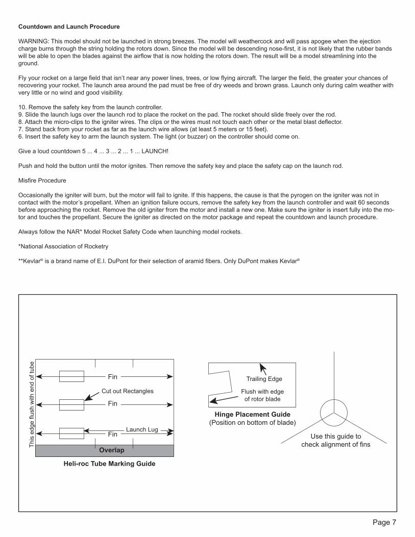
Use this guide tocheck alignment of fins
Hinge Placement Guide(Position on bottom of blade)
Flush with edgeof rotor blade
Trailing EdgeFin
Fin
FinLaunch Lug
Cut out Rectangles
Overlap
Heli-roc Tube Marking Guide
Thi
s ed
ge fl
ush
with
end
of t
ube

Page 8 Sheet 1 P/N 31022