Embed Size (px)
Citation preview
1
EBU – TECH 3299
High Definition (HD) Image Formats for Television Production
Status: Specification
Geneva January 2010

Page intentionally left blank. This document is paginated for two sided printing
Tech 3299 HD Image Formats for TV Production
3
Contents
1. Introduction ..................................................................................... 5
2. Normative references.......................................................................... 5
3. Other References............................................................................... 6
4. Nomenclatures and Image Sampling Systems .............................................. 7
5. System compliance............................................................................. 7
6. System colorimetry and opto-electrical conversion for System S1 to S4............... 7
7. Signal Formats for Systems S1 to S4 ......................................................... 8
8. Raster structure, digital picture representation and timing reference ................ 8
9. Digital Signal Formats for System S1 to S4 ................................................. 8
10. Digital Interfaces and their constraints ..................................................... 9
10.1 1.5 Gbit/s HD-SDI .....................................................................................9
10.2 3 Gbit/s HD-SDI........................................................................................9
10.3 Coaxial cable length..................................................................................9
10.4 3G-SDI mapping Levels ...............................................................................9
11. General remarks concerning 3G SDI ........................................................ 10
12. System S4 infrastructure (informative note) .............................................. 10
HD Image Formats for TV Production Tech 3299
4
Page intentionally left blank. This document is paginated for two sided printing
Tech 3299 HD Image Formats for TV Production
5
High Definition (HD) Image Formats for Television Production
EBU Committee First Issued Revised Re-issued
PMC 2010
Keywords: High Definition Television, HDTV, Image Format, Progressive, Interlace
1. Introduction This document specifies the basic image formats and digital sampling systems for High Definition Television (HDTV) production in the European 50 Hz environment. It is intended to meet the demands of EBU Members for interoperability and implementation stability in their HDTV production systems. The application of this specification is intended for, but not limited to, the television production environment.
Four HDTV production systems are recognised for use in Europe:
System 1 (S1) with 1280 horizontal samples and 720 active lines in progressive scan with a frame rate of 50 Hz, 16:9 aspect ratio. Abbreviated 720p/50.
System 2 (S2) with 1920 horizontal samples and 1080 active lines in interlaced scan with a frame rate of 25 Hz, 16:9 aspect ratio. Abbreviated 1080i/25.
System 3 (S3) with 1920 horizontal samples and 1080 active lines in progressive scan and a frame rate of 25 Hz, 16:9 aspect ratio. Abbreviated 1080p/25.
System 4 (S4) with 1920 horizontal samples and 1080 active lines in progressive scan at a frame rate of 50 Hz, 16:9 aspect ratio. Abbreviated 1080p/50.
In order to transport these signals around a production site, variants of the HD-SDI (High Definition Serial Digital Interface) are typically used. Designers of HD-SDI infrastructures should carefully study whether to apply the 1.485 Gbit/s single link HD-SDI (specified in SMPTE 292M) for Systems S1, S2 and S3 only, or an advanced 2.97 Gbit/s single link HD-SDI (specified in SMPTE 424M) for Systems S1 to S4 inclusive, but with some additional constraints. Section 10 of this document discusses these interfaces and their practical constraints in more detail.
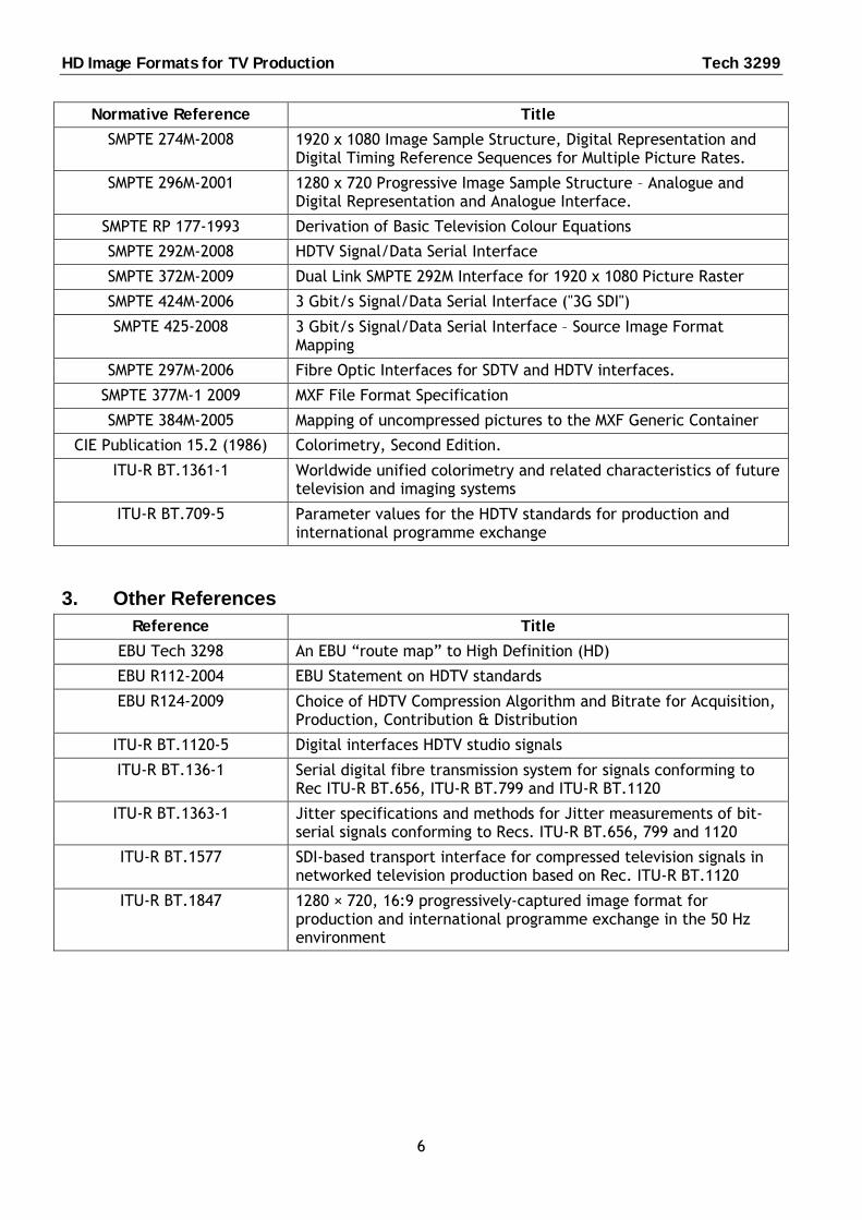
2. Normative references This specification depends upon the following external specifications, which define in detail:
◦ R’G’B’ colour encoding;
◦ R’G’B’ analogue and digital representation;
◦ Y’P’BP’R colour encoding, analogue representation and analogue interface; and
◦ Y’C’BC’R colour encoding and digital representation.
Note that the apostrophe, ‘, in the above means that the signal has been gamma corrected.
HD Image Formats for TV Production Tech 3299
6
Normative Reference Title
SMPTE 274M-2008 1920 x 1080 Image Sample Structure, Digital Representation and Digital Timing Reference Sequences for Multiple Picture Rates.
SMPTE 296M-2001 1280 x 720 Progressive Image Sample Structure – Analogue and Digital Representation and Analogue Interface.
SMPTE RP 177-1993 Derivation of Basic Television Colour Equations
SMPTE 292M-2008 HDTV Signal/Data Serial Interface
SMPTE 372M-2009 Dual Link SMPTE 292M Interface for 1920 x 1080 Picture Raster
SMPTE 424M-2006 3 Gbit/s Signal/Data Serial Interface ("3G SDI")
SMPTE 425-2008 3 Gbit/s Signal/Data Serial Interface – Source Image Format Mapping
SMPTE 297M-2006 Fibre Optic Interfaces for SDTV and HDTV interfaces.
SMPTE 377M-1 2009 MXF File Format Specification
SMPTE 384M-2005 Mapping of uncompressed pictures to the MXF Generic Container
CIE Publication 15.2 (1986) Colorimetry, Second Edition.
ITU-R BT.1361-1 Worldwide unified colorimetry and related characteristics of future television and imaging systems
ITU-R BT.709-5 Parameter values for the HDTV standards for production and international programme exchange
3. Other References Reference Title
EBU Tech 3298 An EBU “route map” to High Definition (HD)
EBU R112-2004 EBU Statement on HDTV standards
EBU R124-2009 Choice of HDTV Compression Algorithm and Bitrate for Acquisition, Production, Contribution & Distribution
ITU-R BT.1120-5 Digital interfaces HDTV studio signals
ITU-R BT.136-1 Serial digital fibre transmission system for signals conforming to Rec ITU-R BT.656, ITU-R BT.799 and ITU-R BT.1120
ITU-R BT.1363-1 Jitter specifications and methods for Jitter measurements of bit-serial signals conforming to Recs. ITU-R BT.656, 799 and 1120
ITU-R BT.1577 SDI-based transport interface for compressed television signals in networked television production based on Rec. ITU-R BT.1120
ITU-R BT.1847 1280 × 720, 16:9 progressively-captured image format for production and international programme exchange in the 50 Hz environment
Tech 3299 HD Image Formats for TV Production
7
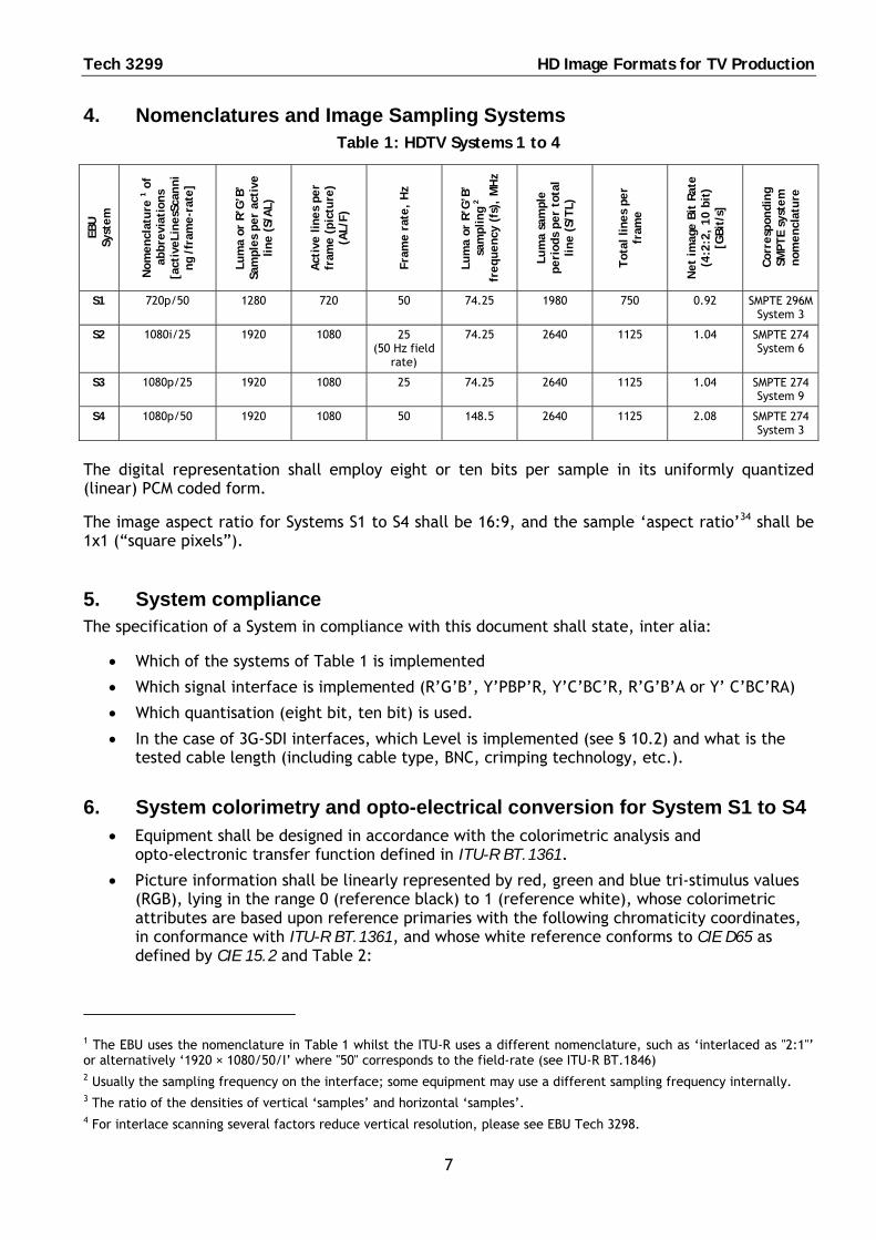
4. Nomenclatures and Image Sampling Systems Table 1: HDTV Systems 1 to 4
EBU
Sy
stem
Nom
encl
ature
1 o
f ab
bre
viat
ions
[act
iveLi
nes
Scan
ni
ng
/fra
me-r
ate]
Lum
a or
R’G
’B’
Sam
ples
per
act
ive
line (
S/A
L)
Act
ive lin
es
per
fram
e (p
ictu
re)
(AL/
F)
Fra
me r
ate,
Hz
Lum
a or
R’G
’B’
sam
pling
2
freq
uen
cy (
fs),
MH
z
Lum
a sa
mpl
e
peri
ods
per
tota
l line (
S/T
L)
Tot
al lin
es
per
fram
e
Net
im
age B
it R
ate
(4:2
:2,
10 b
it)
[GBit
/s]
Cor
resp
ondin
g SM
PT
E sy
stem
nom
encl
ature
S1 720p/50 1280 720 50 74.25 1980 750 0.92 SMPTE 296M System 3
S2 1080i/25 1920 1080 25 (50 Hz field
rate)
74.25 2640 1125 1.04 SMPTE 274 System 6
S3 1080p/25 1920 1080 25 74.25 2640 1125 1.04 SMPTE 274 System 9
S4 1080p/50 1920 1080 50 148.5 2640 1125 2.08 SMPTE 274 System 3
The digital representation shall employ eight or ten bits per sample in its uniformly quantized (linear) PCM coded form.
The image aspect ratio for Systems S1 to S4 shall be 16:9, and the sample ‘aspect ratio’34 shall be 1x1 (“square pixels”).
5. System compliance The specification of a System in compliance with this document shall state, inter alia:
Which of the systems of Table 1 is implemented
Which signal interface is implemented (R’G’B’, Y’PBP’R, Y’C’BC’R, R’G’B’A or Y’ C’BC’RA)
Which quantisation (eight bit, ten bit) is used.
In the case of 3G-SDI interfaces, which Level is implemented (see § 10.2) and what is the tested cable length (including cable type, BNC, crimping technology, etc.).
6. System colorimetry and opto-electrical conversion for System S1 to S4 Equipment shall be designed in accordance with the colorimetric analysis and
opto-electronic transfer function defined in ITU-R BT.1361.
Picture information shall be linearly represented by red, green and blue tri-stimulus values (RGB), lying in the range 0 (reference black) to 1 (reference white), whose colorimetric attributes are based upon reference primaries with the following chromaticity coordinates, in conformance with ITU-R BT.1361, and whose white reference conforms to CIE D65 as defined by CIE 15.2 and Table 2:
1 The EBU uses the nomenclature in Table 1 whilst the ITU-R uses a different nomenclature, such as ‘interlaced as "2:1"’ or alternatively ‘1920 × 1080/50/I’ where "50" corresponds to the field-rate (see ITU-R BT.1846) 2 Usually the sampling frequency on the interface; some equipment may use a different sampling frequency internally. 3 The ratio of the densities of vertical ‘samples’ and horizontal ‘samples’. 4 For interlace scanning several factors reduce vertical resolution, please see EBU Tech 3298.
HD Image Formats for TV Production Tech 3299
8
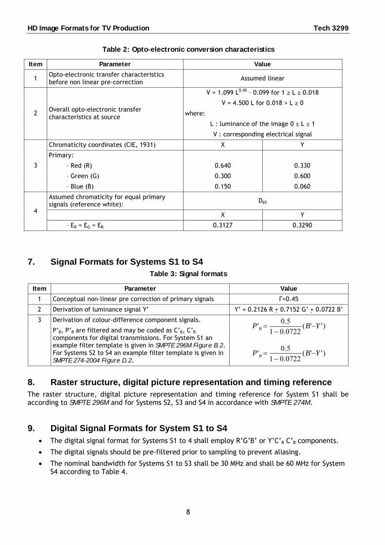
Table 2: Opto-electronic conversion characteristics
Item Parameter Value
1 Opto-electronic transfer characteristics before non linear pre-correction
Assumed linear
V = 1.099 L0.45 – 0.099 for 1 ≥ L ≥ 0.018
V = 4.500 L for 0.018 > L ≥ 0
where:
L : luminance of the image 0 ≤ L ≤ 1
2 Overall opto-electronic transfer characteristics at source
V : corresponding electrical signal
Chromaticity coordinates (CIE, 1931) X Y
Primary:
– Red (R) 0.640 0.330
– Green (G) 0.300 0.600
3
– Blue (B) 0.150 0.060
Assumed chromaticity for equal primary signals (reference white): D65
X Y 4
– ER = EG = EB 0.3127 0.3290
7. Signal Formats for Systems S1 to S4 Table 3: Signal formats
Item Parameter Value
1 Conceptual non-linear pre correction of primary signals Γ=0.45
2 Derivation of luminance signal Y’ Y’ = 0.2126 R + 0.7152 G’ + 0.0722 B’
Derivation of colour-difference component signals. 3
P’B, P’R are filtered and may be coded as C’B, C’R components for digital transmissions. For System S1 an example filter template is given in SMPTE 296M Figure B.2. For Systems S2 to S4 an example filter template is given in SMPTE 274-2004 Figure D.2.
)''(
0722.015.0
' YBP B
)''(0722.015.0
' YBP B
8. Raster structure, digital picture representation and timing reference The raster structure, digital picture representation and timing reference for System S1 shall be according to SMPTE 296M and for Systems S2, S3 and S4 in accordance with SMPTE 274M.
9. Digital Signal Formats for System S1 to S4 The digital signal format for Systems S1 to 4 shall employ R’G’B’ or Y’C’R C’B components.
The digital signals should be pre-filtered prior to sampling to prevent aliasing.
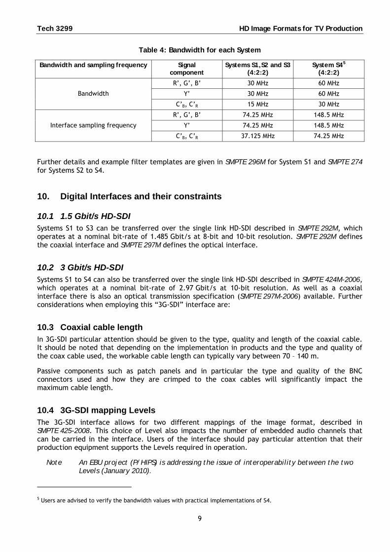
The nominal bandwidth for Systems S1 to S3 shall be 30 MHz and shall be 60 MHz for System S4 according to Table 4.
Tech 3299 HD Image Formats for TV Production
9
Table 4: Bandwidth for each System
Bandwidth and sampling frequency Signal component
Systems S1,S2 and S3 (4:2:2)
System S45 (4:2:2)
R’, G’, B’ 30 MHz 60 MHz
Y’ 30 MHz 60 MHz Bandwidth
C’B, C’R 15 MHz 30 MHz
R’, G’, B’ 74.25 MHz 148.5 MHz
Y’ 74.25 MHz 148.5 MHz Interface sampling frequency
C’B, C’R 37.125 MHz 74.25 MHz
Further details and example filter templates are given in SMPTE 296M for System S1 and SMPTE 274 for Systems S2 to S4.
10. Digital Interfaces and their constraints
10.1 1.5 Gbit/s HD-SDI Systems S1 to S3 can be transferred over the single link HD-SDI described in SMPTE 292M, which operates at a nominal bit-rate of 1.485 Gbit/s at 8-bit and 10-bit resolution. SMPTE 292M defines the coaxial interface and SMPTE 297M defines the optical interface.
10.2 3 Gbit/s HD-SDI Systems S1 to S4 can also be transferred over the single link HD-SDI described in SMPTE 424M-2006, which operates at a nominal bit-rate of 2.97 Gbit/s at 10-bit resolution. As well as a coaxial interface there is also an optical transmission specification (SMPTE 297M-2006) available. Further considerations when employing this “3G-SDI” interface are:
10.3 Coaxial cable length In 3G-SDI particular attention should be given to the type, quality and length of the coaxial cable. It should be noted that depending on the implementation in products and the type and quality of the coax cable used, the workable cable length can typically vary between 70 – 140 m.
Passive components such as patch panels and in particular the type and quality of the BNC connectors used and how they are crimped to the coax cables will significantly impact the maximum cable length.
10.4 3G-SDI mapping Levels The 3G-SDI interface allows for two different mappings of the image format, described in SMPTE 425-2008. This choice of Level also impacts the number of embedded audio channels that can be carried in the interface. Users of the interface should pay particular attention that their production equipment supports the Levels required in operation.
Note An EBU project (P/HIPS) is addressing the issue of interoperability between the two Levels (January 2010).
5 Users are advised to verify the bandwidth values with practical implementations of S4.
HD Image Formats for TV Production Tech 3299
10
11. General remarks concerning 3G SDI It is suggested that users should investigate the possible implementation of the 3G-SDI
interface in their HDTV installations. For existing HDTV installations, users should investigate whether they can upgrade their interfaces to 3G-SDI.
Conversion from 8-bit to 10-bit shall be performed by adding two padding bits.
R'G'B' encoding for Systems S2 and S3, and Y'C’B, C’R for System S4, require using either the dual link bit serial interface version of SMPTE 292M as specified in SMPTE 372M, or preferably, the single link 3G-SDI (SMPTE 424M) interface described above.
For file format transport of Systems S1 to S4, the Material Exchange Format (MXF), described in SMPTE 377M, should be used. The mapping of uncompressed pictures in MXF, including Systems S1 to S4, is defined in SMPTE 384M.
12. System S4 infrastructure (informative note) Users should be aware that whereas an increasing number of dedicated production systems are available today to support 1080p/50, complex IT-based studio production systems are not yet available for System S4.