Embed Size (px)
Citation preview
American-Eurasian Journal of Scientific Research 11 (5): 381-389, 2016ISSN 1818-6785© IDOSI Publications, 2016DOI: 10.5829/idosi.aejsr.2016.11.5.22957
Corresponding Author: S. Vigneshwaran, Department of Electrical Engineering, Nandha Engineering College, (Autonomous),Erode-52, Tamilnadu, India.
381
High Efficiency DC/DC Buck-Boost Converters forHigh Power DC System Using Adaptive Control
S. Vigneshwaran and R. Vijayalakshmi
Department of Electrical Engineering, Nandha Engineering College,(Autonomous), Erode-52, Tamilnadu, India
Abstract: In this paper presents new topologies Multilevel DC-DC buck-boost converter which consists of aninductor based boost circuit and a switched capacitor circuit has high voltage gain and flexible output voltage.Operation of these switching devices causes inherently nonlinear characteristic to the DC-DC Convertersinclude buck-boost converter. It is suitable for a low voltage power source such as fuel cells. However, in highswitching frequency, multilevel DC-DC buck-boost converter's power conversion efficiency is reduced byswitching loss. Against the problem, this paper proposes an five level soft-switching multilevel DC-DCconverter. Proposed system consists of development of fuzzy logic controller for generating control PWMpulses of required duty cycle foe MOSFET of the buck-boost converter to maintain the constant outputvoltage. Duty cycle of the converter is adjusted continuously to obtain required output voltage. However,implementations of this control method to nonlinear system like buck-boost converters will suffer from dynamicresponse for the converter output. To achieve a stable and fast response, nonlinear controller were applied tocontrol buck-boost converters. The efficiency of the proposed converter is improved compared with theconventional soft switching converter in high boost ratio. The operation of the proposed converter has beenconfirmed by circuit experiments and simulations by using MATLAB Simulink.
Key words: Five-level DC/DC Converters Buck-Boost Operation Adaptive control (FUZZY) Closedloop system Pulse width modulation (PWM) MATLAB-Simulink
INTRODUCTION Modular Multilevel Converters: Modular multilevel
DC-DC converters are basically used for generating electronics appliances. They can be found in almost everyan output voltage at desired level and when a control electronic appliance nowadays, since all semiconductortechnique is used in a dc-dc converter, it produces the components are powered by DC sources. DC-DCoutput more efficiently as compared to the converter converters are basically used for stabilizing a given dcwhen used in open loop. Control systems are designed voltage to a desired value. This is generally achieve byand implemented to accomplish the requirements by using chopping and filtering of input voltage throughproviding specified voltage level irrespective of suitable switching action, generally implemented by usinguncertainties and disturbances occurred in power pulse width modulation. The buck-boost is a popular non-semiconductors. And therefore proper and more efficient isolated, inverting power stage topology, sometimestechnique is used to design control system. When non called a step-up/down converter. Power supply designerslinear phenomenon characteristics occur in DC-DC choose the buck-boost converter because the outputconverters, they make their control and analysis very voltage is inverted from the input voltage and the outputdifficult. There are many control techniques used to voltage can be either higher or lower than the inputcontrol these converters for example PI controller, PD voltage. The topology gets its name from producing ancontroller, PID controller and Fuzzy Logic Controller. Here output voltage that can be higher or lower in magnitudePI, PD, PID controllers are linear controllers and Fuzzy than the input voltage. Buck-boost converter is anLogic Controller is a non linear controller [1]. intriguing subject from the control point of view, due to
DC-DC converters are the mostly used circuits in power
Am-Euras. J. Sci. Res., 11 (5): 381-389, 2016
382
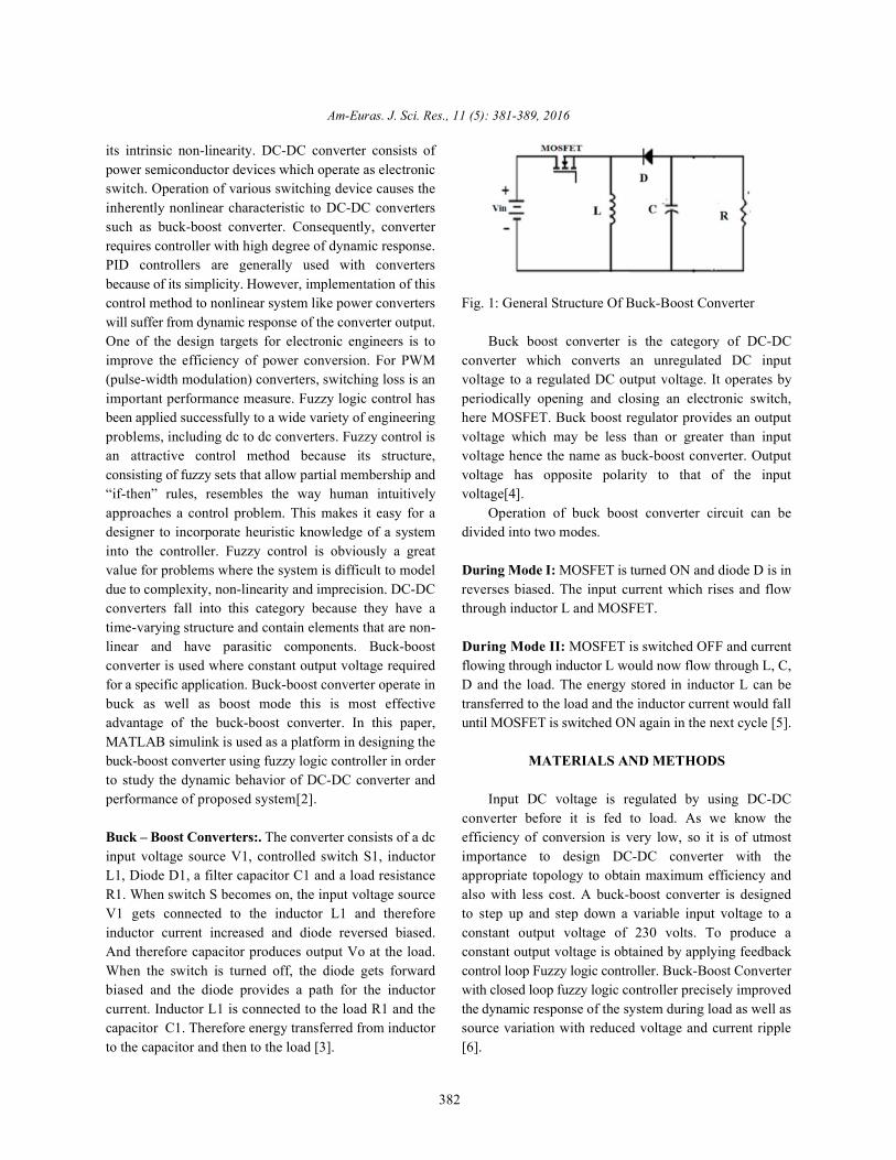
its intrinsic non-linearity. DC-DC converter consists ofpower semiconductor devices which operate as electronicswitch. Operation of various switching device causes theinherently nonlinear characteristic to DC-DC converterssuch as buck-boost converter. Consequently, converterrequires controller with high degree of dynamic response.PID controllers are generally used with convertersbecause of its simplicity. However, implementation of thiscontrol method to nonlinear system like power converters Fig. 1: General Structure Of Buck-Boost Converterwill suffer from dynamic response of the converter output.One of the design targets for electronic engineers is to Buck boost converter is the category of DC-DCimprove the efficiency of power conversion. For PWM converter which converts an unregulated DC input(pulse-width modulation) converters, switching loss is an voltage to a regulated DC output voltage. It operates byimportant performance measure. Fuzzy logic control has periodically opening and closing an electronic switch,been applied successfully to a wide variety of engineering here MOSFET. Buck boost regulator provides an outputproblems, including dc to dc converters. Fuzzy control is voltage which may be less than or greater than inputan attractive control method because its structure, voltage hence the name as buck-boost converter. Outputconsisting of fuzzy sets that allow partial membership and voltage has opposite polarity to that of the input“if-then” rules, resembles the way human intuitively voltage[4].approaches a control problem. This makes it easy for a Operation of buck boost converter circuit can bedesigner to incorporate heuristic knowledge of a system divided into two modes.into the controller. Fuzzy control is obviously a greatvalue for problems where the system is difficult to model During Mode I: MOSFET is turned ON and diode D is indue to complexity, non-linearity and imprecision. DC-DC reverses biased. The input current which rises and flowconverters fall into this category because they have a through inductor L and MOSFET. time-varying structure and contain elements that are non-linear and have parasitic components. Buck-boost During Mode II: MOSFET is switched OFF and currentconverter is used where constant output voltage required flowing through inductor L would now flow through L, C,for a specific application. Buck-boost converter operate in D and the load. The energy stored in inductor L can bebuck as well as boost mode this is most effective transferred to the load and the inductor current would falladvantage of the buck-boost converter. In this paper, until MOSFET is switched ON again in the next cycle [5].MATLAB simulink is used as a platform in designing thebuck-boost converter using fuzzy logic controller in order MATERIALS AND METHODSto study the dynamic behavior of DC-DC converter andperformance of proposed system[2]. Input DC voltage is regulated by using DC-DC
Buck – Boost Converters:. The converter consists of a dc efficiency of conversion is very low, so it is of utmostinput voltage source V1, controlled switch S1, inductor importance to design DC-DC converter with theL1, Diode D1, a filter capacitor C1 and a load resistance appropriate topology to obtain maximum efficiency andR1. When switch S becomes on, the input voltage source also with less cost. A buck-boost converter is designedV1 gets connected to the inductor L1 and therefore to step up and step down a variable input voltage to ainductor current increased and diode reversed biased. constant output voltage of 230 volts. To produce aAnd therefore capacitor produces output Vo at the load. constant output voltage is obtained by applying feedbackWhen the switch is turned off, the diode gets forward control loop Fuzzy logic controller. Buck-Boost Converterbiased and the diode provides a path for the inductor with closed loop fuzzy logic controller precisely improvedcurrent. Inductor L1 is connected to the load R1 and the the dynamic response of the system during load as well ascapacitor C1. Therefore energy transferred from inductor source variation with reduced voltage and current rippleto the capacitor and then to the load [3]. [6].
converter before it is fed to load. As we know the
Am-Euras. J. Sci. Res., 11 (5): 381-389, 2016
383
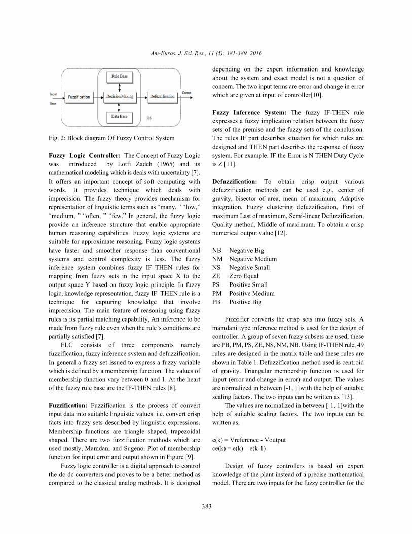
Fig. 2: Block diagram Of Fuzzy Control System The rules IF part describes situation for which rules are
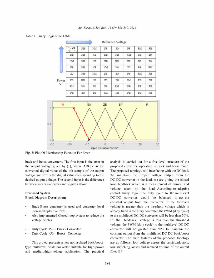
Fuzzy Logic Controller: The Concept of Fuzzy Logic system. For example. IF the Error is N THEN Duty Cyclewas introduced by Lotfi Zadeh (1965) and its is Z [11].mathematical modeling which is deals with uncertainty [7].It offers an important concept of soft computing with Defuzzification: To obtain crisp output variouswords. It provides technique which deals with defuzzification methods can be used e.g., center ofimprecision. The fuzzy theory provides mechanism for gravity, bisector of area, mean of maximum, Adaptiverepresentation of linguistic terms such as “many, ” “low,” integration, Fuzzy clustering defuzzification, First of“medium, ” “often, ” “few.” In general, the fuzzy logic maximum Last of maximum, Semi-linear Defuzzification,provide an inference structure that enable appropriate Quality method, Middle of maximum. To obtain a crisphuman reasoning capabilities. Fuzzy logic systems are numerical output value [12].suitable for approximate reasoning. Fuzzy logic systemshave faster and smoother response than conventional NB Negative Bigsystems and control complexity is less. The fuzzy NM Negative Mediuminference system combines fuzzy IF–THEN rules for NS Negative Smallmapping from fuzzy sets in the input space X to the ZE Zero Equaloutput space Y based on fuzzy logic principle. In fuzzy PS Positive Smalllogic, knowledge representation, fuzzy IF–THEN rule is a PM Positive Mediumtechnique for capturing knowledge that involve PB Positive Bigimprecision. The main feature of reasoning using fuzzyrules is its partial matching capability, An inference to be Fuzzifier converts the crisp sets into fuzzy sets. Amade from fuzzy rule even when the rule’s conditions are mamdani type inference method is used for the design ofpartially satisfied [7]. controller. A group of seven fuzzy subsets are used, these
FLC consists of three components namely are PB, PM, PS, ZE, NS, NM, NB. Using IF-THEN rule, 49fuzzification, fuzzy inference system and defuzzification. rules are designed in the matrix table and these rules areIn general a fuzzy set issued to express a fuzzy variable shown in Table 1. Defuzzification method used is centroidwhich is defined by a membership function. The values of of gravity. Triangular membership function is used formembership function vary between 0 and 1. At the heart input (error and change in error) and output. The valuesof the fuzzy rule base are the IF-THEN rules [8]. are normalized in between [-1, 1]with the help of suitable
Fuzzification: Fuzzification is the process of convert The values are normalized in between [-1, 1]with theinput data into suitable linguistic values. i.e. convert crisp help of suitable scaling factors. The two inputs can befacts into fuzzy sets described by linguistic expressions. written as, Membership functions are triangle shaped, trapezoidalshaped. There are two fuzzification methods which are e(k) = Vreference - Voutputused mostly, Mamdani and Sugeno. Plot of membership ce(k) = e(k) – e(k-1)function for input error and output shown in Figure [9].
Fuzzy logic controller is a digital approach to control Design of fuzzy controllers is based on expertthe dc-dc converters and proves to be a better method as knowledge of the plant instead of a precise mathematicalcompared to the classical analog methods. It is designed model. There are two inputs for the fuzzy controller for the
depending on the expert information and knowledgeabout the system and exact model is not a question ofconcern. The two input terms are error and change in errorwhich are given at input of controller[10].
Fuzzy Inference System: The fuzzy IF-THEN ruleexpresses a fuzzy implication relation between the fuzzysets of the premise and the fuzzy sets of the conclusion.
designed and THEN part describes the response of fuzzy
scaling factors. The two inputs can be written as [13].
Am-Euras. J. Sci. Res., 11 (5): 381-389, 2016
384
Table 1: Fuzzy Logic Rule Table
Fig. 3: Plot Of Membership Function For Error
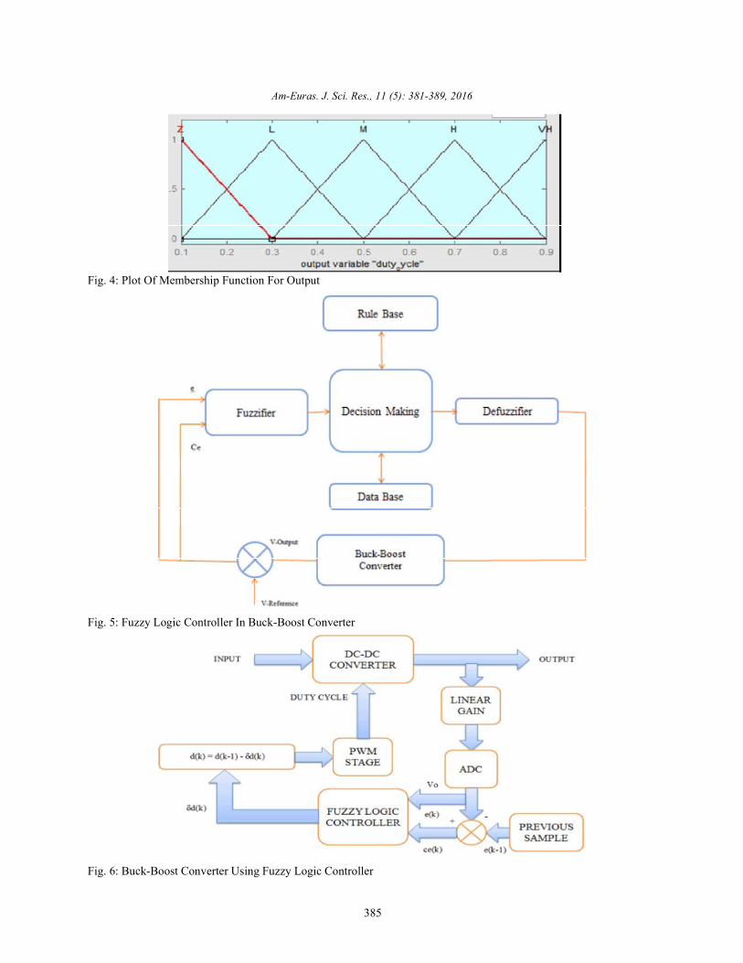
buck and boost converters. The first input is the error in analysis is carried out for a five-level structure of thethe output voltage given by (1), where ADC[k] is the proposed converter, operating in Buck and boost mode.converted digital value of the kth sample of the output The proposed topology will interfacing with the DC load.voltage and Ref is the digital value corresponding to the To maintain the proper voltage output from thedesired output voltage. The second input is the difference DC-DC converter to the load, we are giving the closedbetween successive errors and is given above. loop feedback which is a measurement of current and
Proposed System control fuzzy logic, the duty cycle to the multilevelBlock Diagram Description: DC-DC converter would be balanced to get the
Buck-Boost converter is used and converter level voltage is greater than the threshold voltage which isincreased upto five level. already fixed in the fuzzy controller, the PWM (duty cycle)Also implemented Closed loop system to reduce the to the multilevel DC-DC converter will be less than 50%.voltage ripples If the feedback voltage is less than the threshold
Duty Cycle <50 = Buck - Converter converter will be greater than 50% to maintain theDuty Cycle >50 = Boost - Converter constant output from the multilevel DC-DC buck/boost
This project presents a new non isolated buck/boost- are as follows: low voltage across the semiconductors,type multilevel dc-dc converter suitable for high-power low switching losses and reduced volume of the outputand medium/high-voltage application. The practical filter [14].
voltage taken by the load. According to adaptive
constant output from the Converter. If the feedback
voltage, the PWM (duty cycle) to the multilevel DC-DC
converter. The main features of the proposed topology
Am-Euras. J. Sci. Res., 11 (5): 381-389, 2016
385
Fig. 4: Plot Of Membership Function For Output
Fig. 5: Fuzzy Logic Controller In Buck-Boost Converter
Fig. 6: Buck-Boost Converter Using Fuzzy Logic Controller
Am-Euras. J. Sci. Res., 11 (5): 381-389, 2016
386
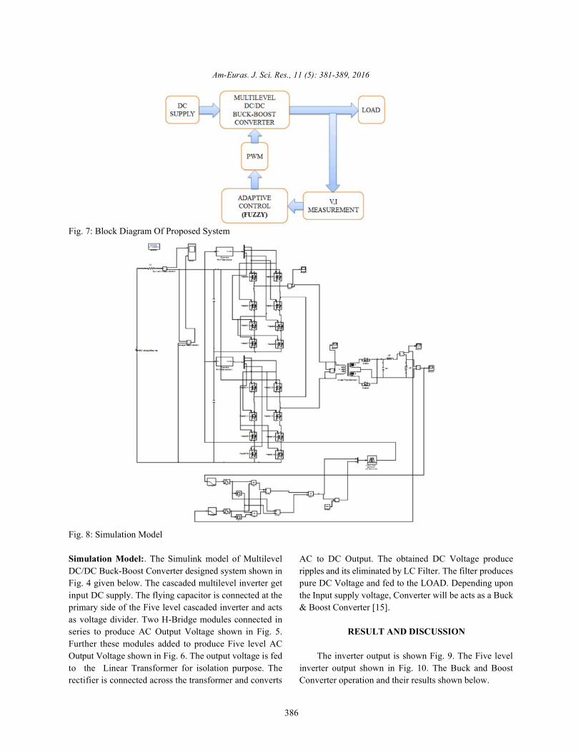
Fig. 7: Block Diagram Of Proposed System
Fig. 8: Simulation Model
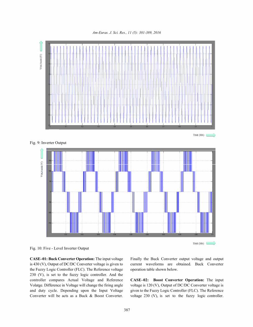
Simulation Model:. The Simulink model of Multilevel AC to DC Output. The obtained DC Voltage produceDC/DC Buck-Boost Converter designed system shown in ripples and its eliminated by LC Filter. The filter producesFig. 4 given below. The cascaded multilevel inverter get pure DC Voltage and fed to the LOAD. Depending uponinput DC supply. The flying capacitor is connected at the the Input supply voltage, Converter will be acts as a Buckprimary side of the Five level cascaded inverter and acts & Boost Converter [15].as voltage divider. Two H-Bridge modules connected inseries to produce AC Output Voltage shown in Fig. 5. RESULT AND DISCUSSIONFurther these modules added to produce Five level ACOutput Voltage shown in Fig. 6. The output voltage is fed The inverter output is shown Fig. 9. The Five levelto the Linear Transformer for isolation purpose. The inverter output shown in Fig. 10. The Buck and Boostrectifier is connected across the transformer and converts Converter operation and their results shown below.
Am-Euras. J. Sci. Res., 11 (5): 381-389, 2016
387
Fig. 9: Inverter Output
Fig. 10: Five - Level Inverter Output
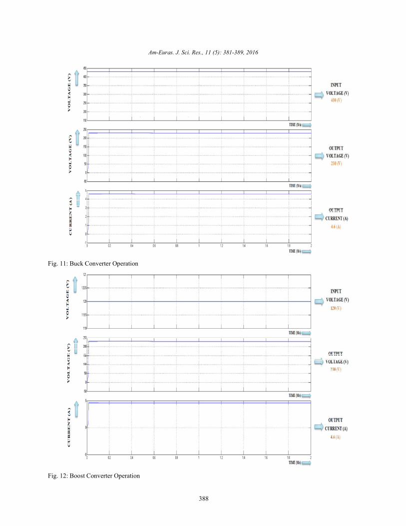
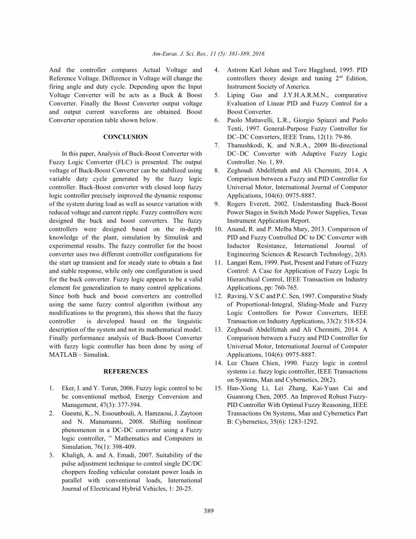
CASE–01: Buck Converter Operation: The input voltage Finally the Buck Converter output voltage and outputis 430 (V), Output of DC/DC Converter voltage is given to current waveforms are obtained. Buck Converterthe Fuzzy Logic Controller (FLC). The Reference voltage operation table shown below.230 (V), is set to the fuzzy logic controller. And thecontroller compares Actual Voltage and Reference CASE–02: Boost Converter Operation: The inputVolatge. Difference in Voltage will change the firing angle voltage is 120 (V), Output of DC/DC Converter voltage isand duty cycle. Depending upon the Input Voltage given to the Fuzzy Logic Controller (FLC). The ReferenceConverter will be acts as a Buck & Boost Converter. voltage 230 (V), is set to the fuzzy logic controller.
Am-Euras. J. Sci. Res., 11 (5): 381-389, 2016
388
Fig. 11: Buck Converter Operation
Fig. 12: Boost Converter Operation
Am-Euras. J. Sci. Res., 11 (5): 381-389, 2016
389
And the controller compares Actual Voltage and 4. Astrom Karl Johan and Tore Hagglund, 1995. PIDReference Voltage. Difference in Voltage will change the controllers theory design and tuning 2 Edition,firing angle and duty cycle. Depending upon the Input Instrument Society of America.Voltage Converter will be acts as a Buck & Boost 5. Liping Guo and J.Y.H.A.R.M.N., comparativeConverter. Finally the Boost Converter output voltage Evaluation of Linear PID and Fuzzy Control for aand output current waveforms are obtained. Boost Boost Converter. Converter operation table shown below. 6. Paolo Mattavelli, L.R., Giorgio Spiazzi and Paolo
CONCLUSION DC–DC Converters, IEEE Trans, 12(1): 79-86.
In this paper, Analysis of Buck-Boost Converter with DC–DC Converter with Adaptive Fuzzy LogicFuzzy Logic Converter (FLC) is presented. The output Controller. No. 1, 89.voltage of Buck-Boost Converter can be stabilized using 8. Zeghoudi Abdelfettah and Ali Chermitti, 2014. Avariable duty cycle generated by the fuzzy logic Comparison between a Fuzzy and PID Controller forcontroller. Buck-Boost converter with closed loop fuzzy Universal Motor, International Journal of Computerlogic controller precisely improved the dynamic response Applications, 104(6): 0975-8887.of the system during load as well as source variation with 9. Rogers Everett, 2002. Understanding Buck-Boostreduced voltage and current ripple. Fuzzy controllers were Power Stages in Switch Mode Power Supplies, Texasdesigned the buck and boost converters. The fuzzy Instrument Application Report.controllers were designed based on the in-depth 10. Anand, R. and P. Melba Mary, 2013. Comparison ofknowledge of the plant, simulation by Simulink and PID and Fuzzy Controlled DC to DC Converter withexperimental results. The fuzzy controller for the boost Inductor Resistance, International Journal ofconverter uses two different controller configurations for Engineering Sciences & Research Technology, 2(8).the start up transient and for steady state to obtain a fast 11. Langari Rem, 1999. Past, Present and Future of Fuzzyand stable response, while only one configuration is used Control: A Case for Application of Fuzzy Logic Infor the buck converter. Fuzzy logic appears to be a valid Hierarchical Control, IEEE Transaction on Industryelement for generalization to many control applications. Applications, pp: 760-765.Since both buck and boost converters are controlled 12. Raviraj, V.S.C and P.C. Sen, 1997. Comparative Studyusing the same fuzzy control algorithm (without any of Proportional-Integral, Sliding-Mode and Fuzzymodifications to the program), this shows that the fuzzy Logic Controllers for Power Converters, IEEEcontroller is developed based on the linguistic Transaction on Industry Applications, 33(2): 518-524.description of the system and not its mathematical model. 13. Zeghoudi Abdelfettah and Ali Chermitti, 2014. AFinally performance analysis of Buck-Boost Converter Comparison between a Fuzzy and PID Controller forwith fuzzy logic controller has been done by using of Universal Motor, International Journal of ComputerMATLAB – Simulink. Applications, 104(6): 0975-8887.
REFERENCES systems i.e. fuzzy logic controller, IEEE Transactions
1. Eker, I. and Y. Torun, 2006. Fuzzy logic control to be 15. Han-Xiong Li, Lei Zhang, Kai-Yuan Cai andbe conventional method, Energy Conversion and Guanrong Chen, 2005. An Improved Robust Fuzzy-Management, 47(3): 377-394. PID Controller With Optimal Fuzzy Reasoning, IEEE
2. Guesmi, K., N. Essounbouli, A. Hamzaoui, J. Zaytoon Transactions On Systems, Man and Cybernetics Partand N. Manamanni, 2008. Shifting nonlinear B: Cybernetics, 35(6): 1283-1292.phenomenon in a DC-DC converter using a Fuzzylogic controller, ” Mathematics and Computers inSimulation, 76(1): 398-409.
3. Khaligh, A. and A. Emadi, 2007. Suitability of thepulse adjustment technique to control single DC/DCchoppers feeding vehicular constant power loads inparallel with conventional loads, InternationalJournal of Electricand Hybrid Vehicles, 1: 20-25.
nd
Tenti, 1997. General-Purpose Fuzzy Controller for
7. Thanushkodi, K. and N.R.A., 2009 Bi-directional
14. Lee Chuen Chien, 1990. Fuzzy logic in control
on Systems, Man and Cybernetics, 20(2).