Embed Size (px)
Citation preview
HighG accelerometer dynamic calibration by a laser differential Doppler techniqueShengyou Wang, Caizhi Cao, Peiduan Fei, and Aihua Zhang Citation: Review of Scientific Instruments 67, 2022 (1996); doi: 10.1063/1.1146963 View online: http://dx.doi.org/10.1063/1.1146963 View Table of Contents: http://scitation.aip.org/content/aip/journal/rsi/67/5?ver=pdfcov Published by the AIP Publishing Articles you may be interested in Dopplerfree saturated absorption: Laser spectroscopy Am. J. Phys. 64, 1432 (1996); 10.1119/1.18457 Characterization of laserdriven shocks of high intensity using piezoelectric polymers J. Appl. Phys. 80, 3656 (1996); 10.1063/1.363312 The angular dependence of the absorption of 0.35 μm laser light by highZ, laserproduced plasmas Phys. Fluids B 3, 3477 (1991); 10.1063/1.859776 Dynamics of the ultraviolet laser ablation of corneal tissue AIP Conf. Proc. 160, 703 (1987); 10.1063/1.36805 Laser Doppler retinal blood flow measurements AIP Conf. Proc. 65, 213 (1980); 10.1063/1.32272
This article is copyrighted as indicated in the article. Reuse of AIP content is subject to the terms at: http://scitationnew.aip.org/termsconditions. Downloaded to IP:
128.83.63.20 On: Wed, 26 Nov 2014 02:15:51
High-G accelerometer dynamic calibration by a laser differential Dopplertechnique
Shengyou Wang, Caizhi Cao, Peiduan Fei, and Aihua ZhangNorth China Institute of Technology, P.O. Box 13, Taiyuan, Shanxi, People’s Republic of China
~Received 21 June 1995; accepted for publication 3 January 1996!
An operational system was developed for dynamic and absolute calibration of the high-Gaccelerometers. A test accelerometer, mounted on the end of an anvil which can be moved along asliding guideway, experiences a high-G acceleration when a hammer impacts the anvil. Its half-sineacceleration pulse can be obtained by itself. At the same time, using the differential Dopplertechnique, the velocity change during the period of impacting can be independently measured.Comparing both, the calibrated sensitivity of the test accelerometer can be obtained. The workingsystem and its principle are described. Experimental results are given, which verify the validity ofthe principle and the method. The maximum acceleration calibrated is now up to 100 000 G, limitedby the test accelerometer, with a total uncertainty of65%. © 1996 American Institute of Physics.@S0034-6748~96!00404-4#
I. INTRODUCTION
The calibration of an accelerometer is primarily based onobtaining the accelerometer sensitivity. Because the chargesensitivity is independent of the length of the cables, peoplealways use charge sensitivity rather than voltage sensitivity.The unit of the charge sensitivity is pC/ms22 ~pico-Coulombper meter per second squared! or pC/G ~1 G59.81 ms22!.Some of the more commonly used calibration methods aredescribed as follows.
A. Comparison method
A test accelerometer is mounted as close as possible to areference standard accelerometer on a vibration generator.Comparing the outputs of the two accelerometers, the sensi-tivity of the test accelerometer can be obtained. This methodis a relative calibration, and the upper acceleration limit is15 000 G.
Usually the charge sensitivity of an accelerometer iscalibrated by a manufacturer using this method at 50 or 160Hz. The given charge sensitivity is obtained at low accelera-tion, only a few tens of G’s. When using an accelerometer inshock, it experiences a highG acceleration. So the acceler-ometer should be dynamically calibrated at highG accelera-tion.
B. Absolute method
Usually, dynamic calibration would be done by an abso-lute method. The shock absolute calibration system of theaccelerometers works in the ‘‘velocity change’’ method.
In the absolute method, use is made of only one accel-erometer, whose sensitivity needs to be calibrated. The blockdiagram in Fig. 1 shows the typical instrumentation systemused for absolute calibration. The test accelerometer ismounted on the end of an anvil, shown at the right-hand sideof Fig. 2, and an impact is given to them by a hammer. Theanvil with the test accelerometer can move along a slidingguideway, and experiences a high-G acceleration. Its shockacceleration signal is amplified by a conditioning amplifier~e.g., BK2626!, and recorded on the transient recorder~e.g.,
DL1080!. Shown as the top trace in Fig. 3, it resembles ahalf-sine curve. TheX axis is the time,t, in ms ~microsec-onds!. TheY axis is the accelerometer voltageU(t), in V,which is equal to the product of the applied accelerationa(t)the sensitivityS, and the amplifier gainK,
U~ t !5SKa~ t !. ~1!
If we adjust the amplifier gainK, we can get a normalizedoutput, e.g., 1 V output makes 10 000 G~1 V represents10 000 G!. The velocity at the end of the impact is equal tothe time integral of the acceleration over the duration of theacceleration pulse. The integral of the pulse is performed asa sum of the digitized data by the DL1080 software. Theintegration is equal toU, the sum over theN data pointswhich comprise the acceleration pulse, multiplied by thetime-between-samplesTa . At the end of the impact, the ac-celerometer velocityva is
va5E0
t
a~ t !dt5E0
t
@U~ t !/SK#dt5TaU/SK, ~2!
U5 (k51
N
U~k!, ~3!
wheret is the time interval during the whole width of theacceleration pulse.
At the same time, the velocity change during the periodof impacting can be independently and absolutely obtainedin many ways. For example, by light beam cutting,1,2 thevelocity of the anvil after impact can be measured by twolight sensors~or photodetectors!, placed at a known distanceapart. Or, by measuring the compression wave in a Hopkin-son bar. Strain gauges on the surface of the bar measure thestrain ratee, then the velocity changev of the accelerometerat the end of the bar is related to the strain ratee,
v52ce, ~4!
wherec is the propagation velocity of the compression wavein the bar. The calibrations can now be done at 100 000 Gwith an estimated RSS uncertainty of 6%.3
2022 Rev. Sci. Instrum. 67 (5), May 1996 0034-6748/96/67(5)/2022/4/$10.00 © 1996 American Institute of Physics This article is copyrighted as indicated in the article. Reuse of AIP content is subject to the terms at: http://scitationnew.aip.org/termsconditions. Downloaded to IP:
128.83.63.20 On: Wed, 26 Nov 2014 02:15:51
In this article, the velocity change is measured by thelaser differential Doppler technique. The basic theory and thecalibration system are described. The test results whichverify the capabilities of the system are presented. Themethod is more advanced and the measurement is more pre-cise.
II. PRINCIPLE OF LASER DIFFERENTIAL DOPPLERTECHNIQUE AND EXPERIMENTAL EQUIPMENT
The velocity of a moving object can be measured bydetecting the Doppler shift of the light scattered from it. Inthe optical differential technique, when light waves with twofrequencies are superposed on the photodetector surface, themixing process in the photodetector will give their differencefrequency since all other frequencies are too high to detect.
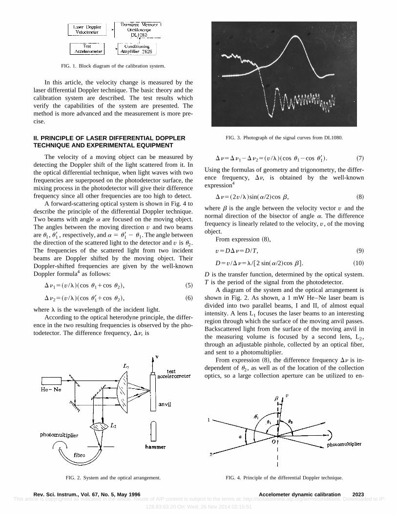
A forward-scattering optical system is shown in Fig. 4 todescribe the principle of the differential Doppler technique.Two beams with anglea are focused on the moving object.The angles between the moving directionv and two beamsareu1, u18 , respectively, anda 5 u18 2 u1. The angle betweenthe direction of the scattered light to the detector andv is u2.The frequencies of the scattered light from two incidentbeams are Doppler shifted by the moving object. TheirDoppler-shifted frequencies are given by the well-knownDoppler formula4 as follows:
Dn15~v/l!~cosu11cosu2!, ~5!
Dn25~v/l!~cosu181cosu2!, ~6!
wherel is the wavelength of the incident light.According to the optical heterodyne principle, the differ-
ence in the two resulting frequencies is observed by the pho-todetector. The difference frequency,Dn, is
Dn5Dn12Dn25~v/l!~cosu12cosu18!. ~7!
Using the formulas of geometry and trigonometry, the differ-ence frequency,Dn, is obtained by the well-knownexpression4
Dn5~2v/l!sin~a/2!cosb, ~8!
whereb is the angle between the velocity vectorv and thenormal direction of the bisector of anglea. The differencefrequency is linearly related to the velocity,v, of the movingobject.
From expression~8!,
v5DDn5D/T, ~9!
D5v/Dn5l/@2 sin~a/2!cosb#. ~10!
D is the transfer function, determined by the optical system.T is the period of the signal from the photodetector.
A diagram of the system and the optical arrangement isshown in Fig. 2. As shown, a 1 mW He–Nelaser beam isdivided into two parallel beams, I and II, of almost equalintensity. A lens L1 focuses the laser beams to an interestingregion through which the surface of the moving anvil passes.Backscattered light from the surface of the moving anvil inthe measuring volume is focused by a second lens, L2,through an adjustable pinhole, collected by an optical fiber,and sent to a photomultiplier.
From expression~8!, the difference frequencyDn is in-dependent ofu2, as well as of the location of the collectionoptics, so a large collection aperture can be utilized to en-
FIG. 2. System and the optical arrangement.
FIG. 3. Photograph of the signal curves from DL1080.
FIG. 4. Principle of the differential Doppler technique.
FIG. 1. Block diagram of the calibration system.
2023Rev. Sci. Instrum., Vol. 67, No. 5, May 1996 Accelometer dynamic calibration This article is copyrighted as indicated in the article. Reuse of AIP content is subject to the terms at: http://scitationnew.aip.org/termsconditions. Downloaded to IP:
128.83.63.20 On: Wed, 26 Nov 2014 02:15:51
hance the signal-to-noise ratio. Using an optical fiber tomake adjustment easy simplifies the equipment. Sticking aScotchlite tape on the surface of the moving anvil makes thescattered light stronger.
The block diagram in Fig. 1 shows the instrumentationsystem used for the calibration. The signal from the photo-multiplier was amplified before recording and storage on thetransient recorder ~Transient Memory OscilloscopeDL1080!. A permanent copy was subsequently obtained~shown as the bottom trace in Fig. 3!, and the period of theindividual Doppler cycles was evaluated to obtain the fre-quency and, from Eq.~9!, the anvil velocity. It is evident thatthe photomultiplier output shows the frequency varying withthe anvil’s velocity. At the beginning of the impact, the fre-quency is lower, the velocity is lower, and at the end of theimpact, the frequency is the highest and the velocity is themaximumvD .
At the same time, the shock acceleration was directlymeasured by the test accelerometer, which was mounted onthe end of the moving anvil. The signal from the test accel-erometer was amplified by a conditioning amplifier~BK2626! and recorded on the same transient recorder~DL1080!, shown as the top trace in Fig. 3. TheX axis istime, inms, and theY axis is the accelerometer voltageU(t),in V.
Comparing Eq.~2! to the maximumvD , the calibratedsensitivity,S, of the test accelerometer is
S5UTa /KvD . ~11!
III. EXPERIMENTAL RESULTS AND CALIBRATIONACCURACY
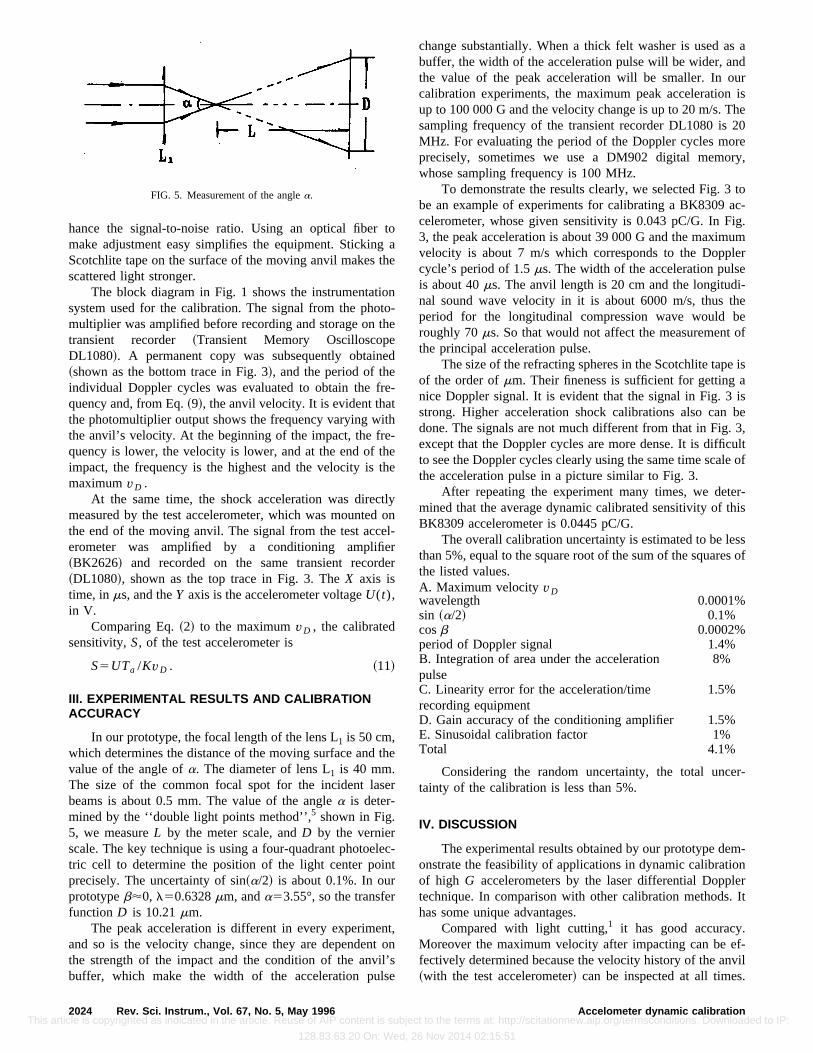
In our prototype, the focal length of the lens L1 is 50 cm,which determines the distance of the moving surface and thevalue of the angle ofa. The diameter of lens L1 is 40 mm.The size of the common focal spot for the incident laserbeams is about 0.5 mm. The value of the anglea is deter-mined by the ‘‘double light points method’’,5 shown in Fig.5, we measureL by the meter scale, andD by the vernierscale. The key technique is using a four-quadrant photoelec-tric cell to determine the position of the light center pointprecisely. The uncertainty of sin~a/2! is about 0.1%. In ourprototypeb'0, l50.6328mm, anda53.55°, so the transferfunctionD is 10.21mm.
The peak acceleration is different in every experiment,and so is the velocity change, since they are dependent onthe strength of the impact and the condition of the anvil’sbuffer, which make the width of the acceleration pulse
change substantially. When a thick felt washer is used as abuffer, the width of the acceleration pulse will be wider, andthe value of the peak acceleration will be smaller. In ourcalibration experiments, the maximum peak acceleration isup to 100 000 G and the velocity change is up to 20 m/s. Thesampling frequency of the transient recorder DL1080 is 20MHz. For evaluating the period of the Doppler cycles moreprecisely, sometimes we use a DM902 digital memory,whose sampling frequency is 100 MHz.
To demonstrate the results clearly, we selected Fig. 3 tobe an example of experiments for calibrating a BK8309 ac-celerometer, whose given sensitivity is 0.043 pC/G. In Fig.3, the peak acceleration is about 39 000 G and the maximumvelocity is about 7 m/s which corresponds to the Dopplercycle’s period of 1.5ms. The width of the acceleration pulseis about 40ms. The anvil length is 20 cm and the longitudi-nal sound wave velocity in it is about 6000 m/s, thus theperiod for the longitudinal compression wave would beroughly 70ms. So that would not affect the measurement ofthe principal acceleration pulse.
The size of the refracting spheres in the Scotchlite tape isof the order ofmm. Their fineness is sufficient for getting anice Doppler signal. It is evident that the signal in Fig. 3 isstrong. Higher acceleration shock calibrations also can bedone. The signals are not much different from that in Fig. 3,except that the Doppler cycles are more dense. It is difficultto see the Doppler cycles clearly using the same time scale ofthe acceleration pulse in a picture similar to Fig. 3.
After repeating the experiment many times, we deter-mined that the average dynamic calibrated sensitivity of thisBK8309 accelerometer is 0.0445 pC/G.
The overall calibration uncertainty is estimated to be lessthan 5%, equal to the square root of the sum of the squares ofthe listed values.A. Maximum velocityvDwavelength 0.0001%sin ~a/2! 0.1%cosb 0.0002%period of Doppler signal 1.4%B. Integration of area under the accelerationpulse
8%
C. Linearity error for the acceleration/timerecording equipment
1.5%
D. Gain accuracy of the conditioning amplifier 1.5%E. Sinusoidal calibration factor 1%Total 4.1%
Considering the random uncertainty, the total uncer-tainty of the calibration is less than 5%.
IV. DISCUSSION
The experimental results obtained by our prototype dem-onstrate the feasibility of applications in dynamic calibrationof high G accelerometers by the laser differential Dopplertechnique. In comparison with other calibration methods. Ithas some unique advantages.
Compared with light cutting,1 it has good accuracy.Moreover the maximum velocity after impacting can be ef-fectively determined because the velocity history of the anvil~with the test accelerometer! can be inspected at all times.
FIG. 5. Measurement of the anglea.
2024 Rev. Sci. Instrum., Vol. 67, No. 5, May 1996 Accelometer dynamic calibration This article is copyrighted as indicated in the article. Reuse of AIP content is subject to the terms at: http://scitationnew.aip.org/termsconditions. Downloaded to IP:
128.83.63.20 On: Wed, 26 Nov 2014 02:15:51
However by the light cutting, the average velocity in a dis-tance can be measured. When the intensity of the impactchanges, the width of the acceleration pulse changes too, andthe positions of the targets for the two beams should bechanged in a corresponding way. This is difficultexperimentally.5
Laser Doppler velocity measurement is an absolute cali-bration, however the Hopkinson bar method using straingauges to calibrate an accelerometer is not. Strictly speakingit is a relative calibration. There are some difficult techniquesrequired, for example, the attachment technique for the straingauges, measurement of the acoustic velocity in the bar, etc.
For highG accelerometer absolute and dynamic calibra-tion by the Doppler technique, further improvements canmake the calibration more accurate and practical, for ex-ample, using the high resolution velocity interferometer~VISAR!6 to measure the anvil velocity after impacting. Be-cause it obtains the anvil velocity by integration with theinterference fringes, it can measure the instantaneous veloc-ity at any moment more accurately. It provides for a newapproach to get the dynamic sensitivity of the test acceler-
ometer with only one impact, and the linearity of the ampli-tude. Because, using VISAR, the anvil velocity history canbe inspected easily. The anvil velocities corresponding to thepoints on the signal curve of the accelerometer can be ob-tained with high accuracy. The sensitivities of the test accel-erometer for differentG values also can be obtained. It isdifficult to do so by the laser differential Doppler technique,because the velocity is obtained by differentiation with re-spect to the interference fringes. It is difficult to obtain thevelocity history accurately when the velocity changes veryquickly.
1R. R. Bouche,Calibration of Shock and Vibration Measuring Transduc-ers, The Shock and Vibration Information Center~U.S. GPO, Washington,DC, 1979!.
2Draft International Standard ISO/DIS 5347/2, 1987.3Robert D. Sill, The 29th International Instrumentation Symposium, Instru-ment Society of America, Albuquerque, NM, May 1983~unpublished!.
4L. E. Drain,The Laser Doppler Technique~Wiley, New York, 1980!.5T. Kallard,Exploring Laser Light, Laboratory Exercises and Lecture byDemonstrations Performed with Low-Power Helium–Neon Laser~Op-tosonic, 1977!.
6S. Wang, C. Cao, and J. Sun, Rev. Sci. Instrum.62, 2944~1991!.
2025Rev. Sci. Instrum., Vol. 67, No. 5, May 1996 Accelometer dynamic calibration This article is copyrighted as indicated in the article. Reuse of AIP content is subject to the terms at: http://scitationnew.aip.org/termsconditions. Downloaded to IP:
128.83.63.20 On: Wed, 26 Nov 2014 02:15:51