Embed Size (px)
Citation preview
High PressureDiaphragm Pumps
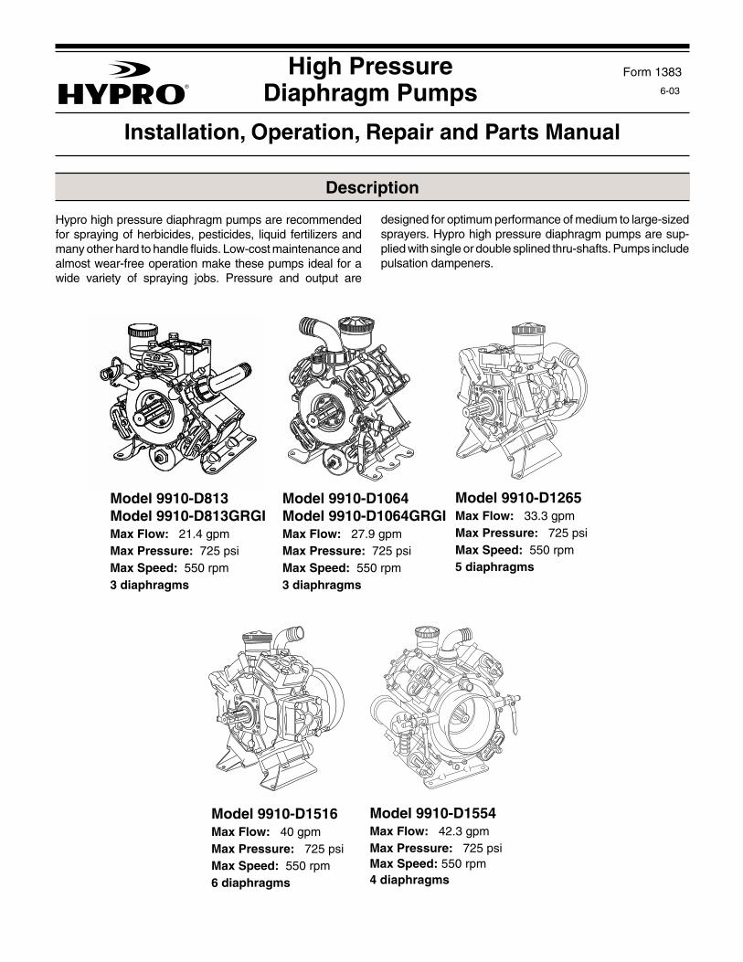
Hypro high pressure diaphragm pumps are recommendedfor spraying of herbicides, pesticides, liquid fertilizers andmany other hard to handle fluids. Low-cost maintenance andalmost wear-free operation make these pumps ideal for awide variety of spraying jobs. Pressure and output are
6-03
Form 1383
Description
Model 9910-D1265Max Flow: 33.3 gpmMax Pressure: 725 psiMax Speed: 550 rpm5 diaphragms
Model 9910-D813Model 9910-D813GRGIMax Flow: 21.4 gpmMax Pressure: 725 psiMax Speed: 550 rpm3 diaphragms
Model 9910-D1064Model 9910-D1064GRGIMax Flow: 27.9 gpmMax Pressure: 725 psiMax Speed: 550 rpm3 diaphragms
Model 9910-D1516Max Flow: 40 gpmMax Pressure: 725 psiMax Speed: 550 rpm6 diaphragms
Model 9910-D1554Max Flow: 42.3 gpmMax Pressure: 725 psiMax Speed: 550 rpm4 diaphragms
Installation, Operation, Repair and Parts Manual
designed for optimum performance of medium to large-sizedsprayers. Hypro high pressure diaphragm pumps are sup-plied with single or double splined thru-shafts. Pumps includepulsation dampeners.
- 2 -
CONTROL MAX MAX PUMPUNIT MODEL GPM PSI MODEL
9910-GS50GI 48 725 ALL MODELS
9910-VDR50 35 725 -D813, -D1064,and -D1265
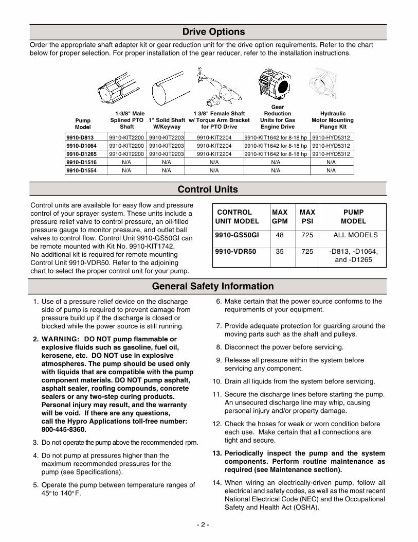
Order the appropriate shaft adapter kit or gear reduction unit for the drive option requirements. Refer to the chartbelow for proper selection. For proper installation of the gear reducer, refer to the installation instructions.
9910-D813 9910-KIT2200 9910-KIT2203 9910-KIT2204 9910-KIT1642 for 8-18 hp 9910-HYD5312
9910-D1064 9910-KIT2200 9910-KIT2203 9910-KIT2204 9910-KIT1642 for 8-18 hp 9910-HYD5312
9910-D1265 9910-KIT2200 9910-KIT2203 9910-KIT2204 9910-KIT1642 for 8-18 hp 9910-HYD5312
9910-D1516 N/A N/A N/A N/A N/A
9910-D1554 N/A N/A N/A N/A N/A
PumpModel
Gear1-3/8" Male 1 3/8" Female Shaft Reduction Hydraulic
Splined PTO 1" Solid Shaft w/ Torque Arm Bracket Units for Gas Motor MountingShaft W/Keyway for PTO Drive Engine Drive Flange KIt
Drive Options
Control Units
Control units are available for easy flow and pressurecontrol of your sprayer system. These units include apressure relief valve to control pressure, an oil-filledpressure gauge to monitor pressure, and outlet ballvalves to control flow. Control Unit 9910-GS50GI canbe remote mounted with Kit No. 9910-KIT1742.No additional kit is required for remote mountingControl Unit 9910-VDR50. Refer to the adjoiningchart to select the proper control unit for your pump.
6. Make certain that the power source conforms to therequirements of your equipment.
7. Provide adequate protection for guarding around themoving parts such as the shaft and pulleys.
8. Disconnect the power before servicing.
9. Release all pressure within the system beforeservicing any component.
10. Drain all liquids from the system before servicing.
11. Secure the discharge lines before starting the pump.An unsecured discharge line may whip, causingpersonal injury and/or property damage.
12. Check the hoses for weak or worn condition beforeeach use. Make certain that all connections aretight and secure.
13. Periodically inspect the pump and the systemcomponents. Perform routine maintenance asrequired (see Maintenance section).
14. When wiring an electrically-driven pump, follow allelectrical and safety codes, as well as the most recentNational Electrical Code (NEC) and the OccupationalSafety and Health Act (OSHA).
1. Use of a pressure relief device on the dischargeside of pump is required to prevent damage frompressure build up if the discharge is closed orblocked while the power source is still running.
2. WARNING: DO NOT pump flammable orexplosive fluids such as gasoline, fuel oil,kerosene, etc. DO NOT use in explosiveatmospheres. The pump should be used onlywith liquids that are compatible with the pumpcomponent materials. DO NOT pump asphalt,asphalt sealer, roofing compounds, concretesealers or any two-step curing products.Personal injury may result, and the warrantywill be void. If there are any questions,call the Hypro Applications toll-free number:800-445-8360.
3. Do not operate the pump above the recommended rpm.
4. Do not pump at pressures higher than themaximum recommended pressures for thepump (see Specifications).
5. Operate the pump between temperature ranges of45o to 140o F.
General Safety Information
- 3 -
General Safety Information Continued
15. WARNING: Because of the risk of electrical shock,all wiring should be done by a qualified electrician.
WARNING: DO NOT handle a pump or pump motorwith wet hands or when standing on a wet or dampsurface, or while standing in water.
16. Do not operate a gasoline engine in an enclosed area.Be sure the area is well ventilated.
17. Use only pipe, hose and fittings rated for the maximumrated pressure of the pump or pressure that the pressurerelief valve is set. Check with a local supplier for theproper pressure rating. Do not use used pipe!
18. Do not use these pumps for pumping water or otherliquids for human or animal consumption.
19. Do not pressure feed pump inlet.
1. Always mount the pump with oil sight tube in theupright position.
2. The correct type and size of hose are vital to goodperformance:
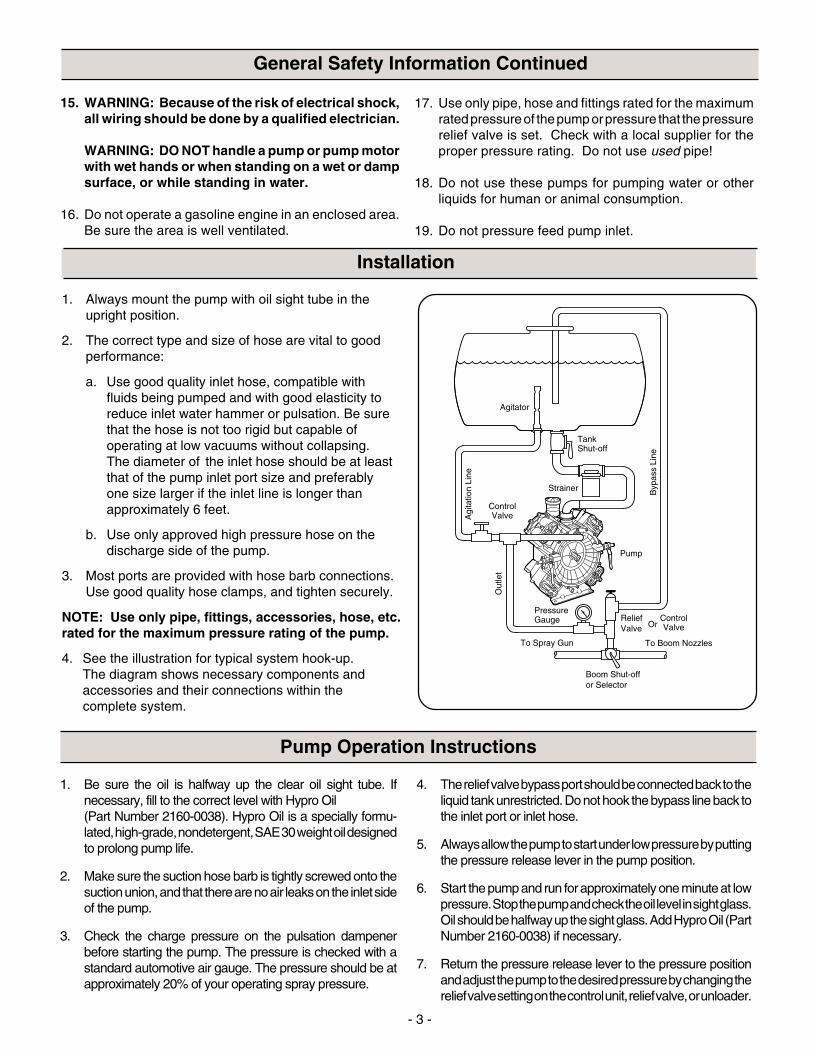
a. Use good quality inlet hose, compatible withfluids being pumped and with good elasticity toreduce inlet water hammer or pulsation. Be surethat the hose is not too rigid but capable ofoperating at low vacuums without collapsing.The diameter of the inlet hose should be at leastthat of the pump inlet port size and preferablyone size larger if the inlet line is longer thanapproximately 6 feet.
b. Use only approved high pressure hose on thedischarge side of the pump.
3. Most ports are provided with hose barb connections.Use good quality hose clamps, and tighten securely.
NOTE: Use only pipe, fittings, accessories, hose, etc.rated for the maximum pressure rating of the pump.
4. See the illustration for typical system hook-up.The diagram shows necessary components andaccessories and their connections within thecomplete system.
Agi
tatio
n Li
ne
Out
let
ControlValve
ControlValve
Or
PressureGauge
To Spray Gun
To Boom NozzlesB
ypas
s Li
ne
TankShut-off
Strainer
Relief Valve
Pump
Boom Shut-offor Selector
Agitator
1. Be sure the oil is halfway up the clear oil sight tube. Ifnecessary, fill to the correct level with Hypro Oil(Part Number 2160-0038). Hypro Oil is a specially formu-lated, high-grade, nondetergent, SAE 30 weight oil designedto prolong pump life.
2. Make sure the suction hose barb is tightly screwed onto thesuction union, and that there are no air leaks on the inlet sideof the pump.
3. Check the charge pressure on the pulsation dampenerbefore starting the pump. The pressure is checked with astandard automotive air gauge. The pressure should be atapproximately 20% of your operating spray pressure.
4. The relief valve bypass port should be connected back to theliquid tank unrestricted. Do not hook the bypass line back tothe inlet port or inlet hose.
5. Always allow the pump to start under low pressure by puttingthe pressure release lever in the pump position.
6. Start the pump and run for approximately one minute at lowpressure. Stop the pump and check the oil level in sight glass.Oil should be halfway up the sight glass. Add Hypro Oil (PartNumber 2160-0038) if necessary.
7. Return the pressure release lever to the pressure positionand adjust the pump to the desired pressure by changing therelief valve setting on the control unit, relief valve, or unloader.
Pump Operation Instructions
Installation
- 4 -
Hazardous Substance Alert
1. Always drain and flush the pump before servicing or disassembling for any reason (see instructions).
2. Always drain and flush pumps prior to returning unit for repair.
3. Never store pumps containing hazardous chemicals.
4. Before returning pump for service/repair, drain out all liquids and flush unit with neutralizing liquid. Then, drainthe pump. Attach tag or include written notice certifying that this has been done. Please note that it is illegal toship or transport any hazardous chemicals without United States Environmental Protection Agency Licensing.
¤OIL THE ULTIMATE PUMP LUBRICANT
Specifically formulated SAE 30 weight high-grade, non-detergent pump oil with special agents for the prevent
¥ Scuff and wear¥ Moisture¥ Oxidation¥ Foaming ¥ Rust �
1. After use, flush the pump with clean water.
2. Hypro diaphragm pumps come withoil in the crankcase. Hypro recom-mends changing oil after 40 hours ofbreak-in operation and every threemonths or 500 hours, whichevercomes first. Use Hypro Oil (partnumber 2160-0038). Hypro Oil is aspecially formulated, high-grade,nondetergent, SAE 30 weight oildesigned to prolong pump life.
To drain the oil from the pump, remove the oil drainplug and rotate the shaft until the oil stops flowingout. To fill the pump with oil, slowly pour the oil intosight tube while turning the pump shaft. Turning thepump shaft purges all the air out of the crankcase.Always change oil when replacing diaphragms.
3. For winter storage or if a freezing condition will beencountered, flush pump with a 50/50 mixture ofwater and antifreeze.
SYMPTOM PROBABLE CAUSE(S) CORRECTIVE ACTION
The pump does not draw water. One or more valves are seating improperly. Remove valve and check for debris.
Suction line is plugged or collapsed. Clogged strainer. Examine suction line. Clean strainer.
The liquid flow is The charge in the pulsation Check pressure in pulsation damperirregular. damper is incorrect. (approximately 20% of operating pressure).
One or more valves are seating improperly. Remove valve and check for debris. Examinethe valve seatings and clean them.
Output drops and the Oil level is too low. Add oil to correct level (halfway up the sight tube).pump is noisy.
Oil comes out of the One or more diaphragms split. Remove manifold and heads. Drain oil and cleandischarge port or oil is crankcase of water. Replace diaphragms, heads anda milky color. manifold. Refill with Hypro Oil (Part No. 2160-0038).
Troubleshooting
Valve ReplacementOccasionally debris can cause the valves to not seatproperly or damage the o-rings. To check for thisproblem, follow these steps.
1. Remove valve retainers and valve holders.With holders removed, the valves can readilybe removed and checked for debris or wear.Check o-rings as well. See the parts list forappropriate valve and o-ring kits.
2. Replace the necessary parts and reassemble.
Maintenance
- 5 -
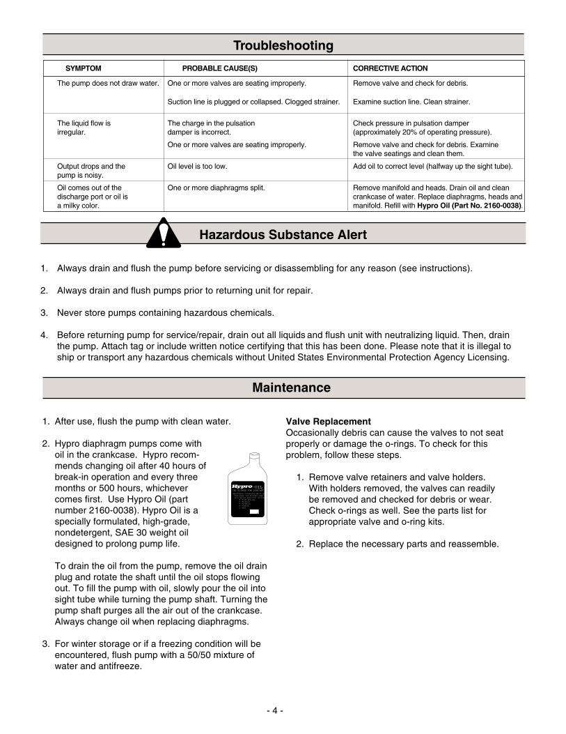
Diaphragm Replacement
5
3
4
2
4
3
5
1
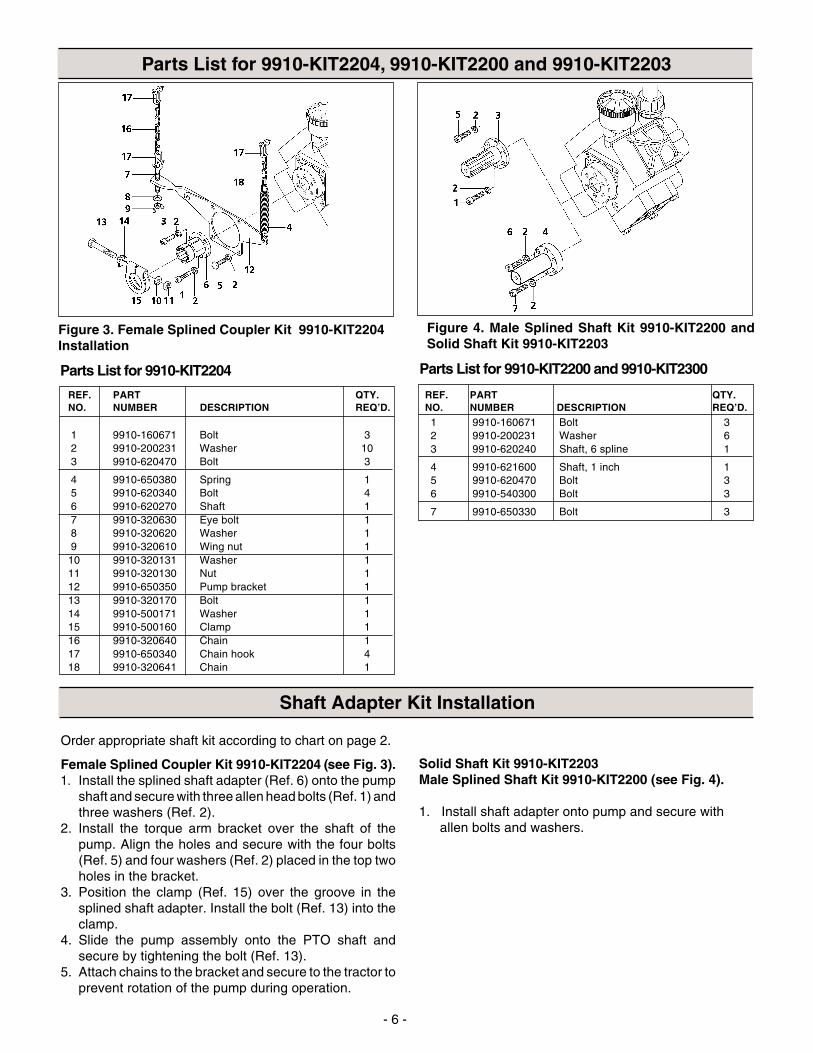
Parts List for Flange Kit 9910-HYD5312
NOTE: When ordering parts, give QUANTITY, PART NUMBER, DESCRIPTION,and COMPLETE MODEL NUMBER. Reference numbers are used ONLY toidentify parts in the drawing and are NOT to be used as order numbers.
Diaphragm Replacement: D813, D1064, D1265, D1516
Change diaphragms every 500 hours or three months,whichever comes first.
1. Drain oil from crankcase (refer to Maintenance, p.4).
2. Remove pump head bolts and heads.
3. Remove the bolt securing the diaphragm (seeFigure 1).
4. Remove the old diaphragm and the washer (seeFigure 1).
5. Install a new diaphragm; then, turn the crankshaft tobring the piston to its down-stroke and seat thediaphragm into the sleeve groove.
6. Install the washer and bolts removed in steps 3 and 4.Refer to parts breakdown for proper torque.
7. Replace the pulsation dampener diaphragm by firstbleeding the air from the dampener. Remove the boltsfrom the dampener cover and replace the diaphragm.Reassemble the cover in place and charge thedampener to 20% of the operating pressure.
8. Refill the crankcase with Hypro Oil (part number 2160-0038). Rotate the shaft to distribute the oil, and fill toproper level.
Figure 1
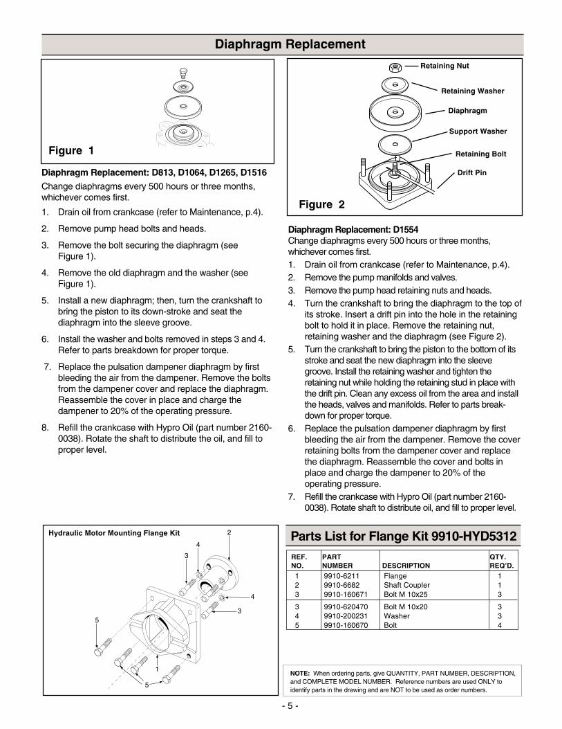
Diaphragm Replacement: D1554Change diaphragms every 500 hours or three months,whichever comes first.1. Drain oil from crankcase (refer to Maintenance, p.4).2. Remove the pump manifolds and valves.3. Remove the pump head retaining nuts and heads.4. Turn the crankshaft to bring the diaphragm to the top of
its stroke. Insert a drift pin into the hole in the retainingbolt to hold it in place. Remove the retaining nut,retaining washer and the diaphragm (see Figure 2).
5. Turn the crankshaft to bring the piston to the bottom of itsstroke and seat the new diaphragm into the sleevegroove. Install the retaining washer and tighten theretaining nut while holding the retaining stud in place withthe drift pin. Clean any excess oil from the area and installthe heads, valves and manifolds. Refer to parts break-down for proper torque.
6. Replace the pulsation dampener diaphragm by firstbleeding the air from the dampener. Remove the coverretaining bolts from the dampener cover and replacethe diaphragm. Reassemble the cover and bolts inplace and charge the dampener to 20% of theoperating pressure.
7. Refill the crankcase with Hypro Oil (part number 2160-0038). Rotate shaft to distribute oil, and fill to proper level.
Drift Pin
Retaining Nut
Retaining Washer
Diaphragm
Support Washer
Retaining Bolt
Figure 2
Hydraulic Motor Mounting Flange Kit
REF. PART QTY.NO. NUMBER DESCRIPTION REQ’D.
1 9910-6211 Flange 12 9910-6682 Shaft Coupler 13 9910-160671 Bolt M 10x25 3
3 9910-620470 Bolt M 10x20 34 9910-200231 Washer 35 9910-160670 Bolt 4
- 6 -
Order appropriate shaft kit according to chart on page 2.
Female Splined Coupler Kit 9910-KIT2204 (see Fig. 3).1. Install the splined shaft adapter (Ref. 6) onto the pump
shaft and secure with three allen head bolts (Ref. 1) andthree washers (Ref. 2).
2. Install the torque arm bracket over the shaft of thepump. Align the holes and secure with the four bolts(Ref. 5) and four washers (Ref. 2) placed in the top twoholes in the bracket.
3. Position the clamp (Ref. 15) over the groove in thesplined shaft adapter. Install the bolt (Ref. 13) into theclamp.
4. Slide the pump assembly onto the PTO shaft andsecure by tightening the bolt (Ref. 13).
5. Attach chains to the bracket and secure to the tractor toprevent rotation of the pump during operation.
Solid Shaft Kit 9910-KIT2203Male Splined Shaft Kit 9910-KIT2200 (see Fig. 4).
1. Install shaft adapter onto pump and secure withallen bolts and washers.
Figure 3. Female Splined Coupler Kit 9910-KIT2204Installation
Parts List for 9910-KIT2204, 9910-KIT2200 and 9910-KIT2203
Figure 4. Male Splined Shaft Kit 9910-KIT2200 andSolid Shaft Kit 9910-KIT2203
REF. PART QTY.NO. NUMBER DESCRIPTION REQ’D.
Parts List for 9910-KIT2204
1 9910-160671 Bolt 32 9910-200231 Washer 103 9910-620470 Bolt 3
4 9910-650380 Spring 15 9910-620340 Bolt 46 9910-620270 Shaft 17 9910-320630 Eye bolt 18 9910-320620 Washer 19 9910-320610 Wing nut 110 9910-320131 Washer 111 9910-320130 Nut 112 9910-650350 Pump bracket 113 9910-320170 Bolt 114 9910-500171 Washer 115 9910-500160 Clamp 116 9910-320640 Chain 117 9910-650340 Chain hook 418 9910-320641 Chain 1
Shaft Adapter Kit Installation
Parts List for 9910-KIT2200 and 9910-KIT2300
REF. PART QTY.NO. NUMBER DESCRIPTION REQ’D.
1 9910-160671 Bolt 32 9910-200231 Washer 63 9910-620240 Shaft, 6 spline 1
4 9910-621600 Shaft, 1 inch 15 9910-620470 Bolt 36 9910-540300 Bolt 3
7 9910-650330 Bolt 3
- 7 -
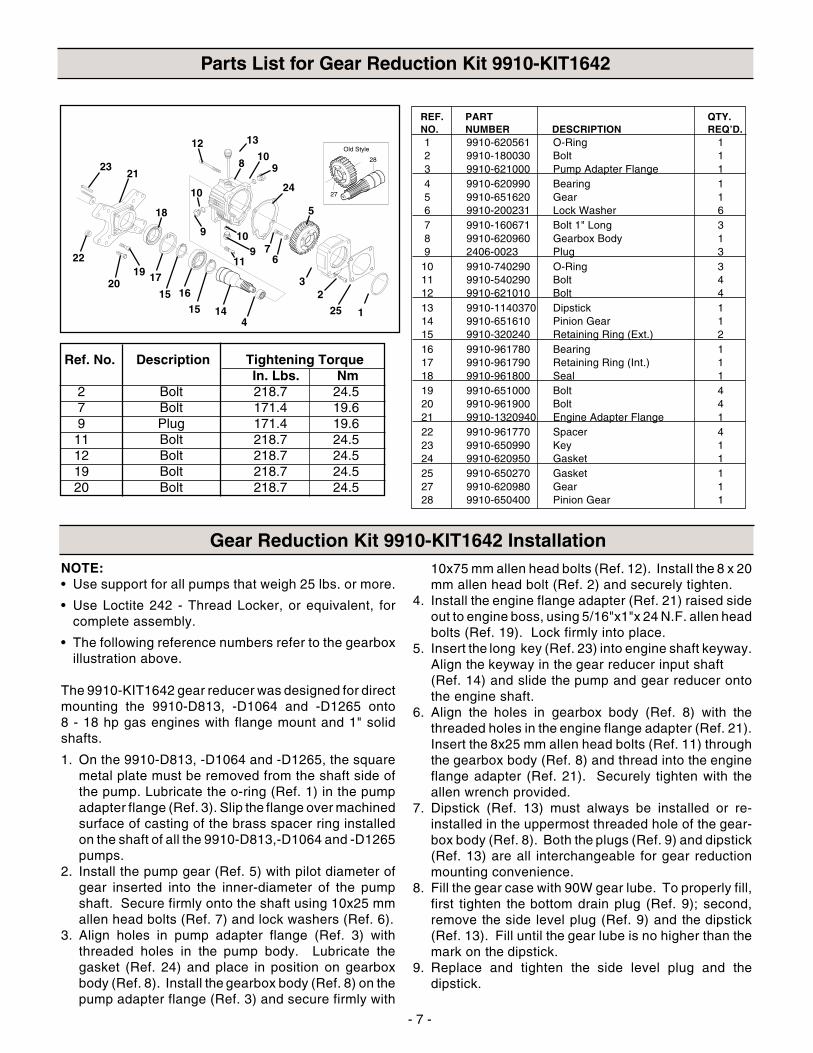
Parts List for Gear Reduction Kit 9910-KIT1642
NOTE:• Use support for all pumps that weigh 25 lbs. or more.
• Use Loctite 242 - Thread Locker, or equivalent, forcomplete assembly.
• The following reference numbers refer to the gearboxillustration above.
The 9910-KIT1642 gear reducer was designed for directmounting the 9910-D813, -D1064 and -D1265 onto8 - 18 hp gas engines with flange mount and 1" solidshafts.
1. On the 9910-D813, -D1064 and -D1265, the squaremetal plate must be removed from the shaft side ofthe pump. Lubricate the o-ring (Ref. 1) in the pumpadapter flange (Ref. 3). Slip the flange over machinedsurface of casting of the brass spacer ring installedon the shaft of all the 9910-D813,-D1064 and -D1265pumps.
2. Install the pump gear (Ref. 5) with pilot diameter ofgear inserted into the inner-diameter of the pumpshaft. Secure firmly onto the shaft using 10x25 mmallen head bolts (Ref. 7) and lock washers (Ref. 6).
3. Align holes in pump adapter flange (Ref. 3) withthreaded holes in the pump body. Lubricate thegasket (Ref. 24) and place in position on gearboxbody (Ref. 8). Install the gearbox body (Ref. 8) on thepump adapter flange (Ref. 3) and secure firmly with
10x75 mm allen head bolts (Ref. 12). Install the 8 x 20mm allen head bolt (Ref. 2) and securely tighten.
4. Install the engine flange adapter (Ref. 21) raised sideout to engine boss, using 5/16"x1"x 24 N.F. allen headbolts (Ref. 19). Lock firmly into place.
5. Insert the long key (Ref. 23) into engine shaft keyway.Align the keyway in the gear reducer input shaft(Ref. 14) and slide the pump and gear reducer ontothe engine shaft.
6. Align the holes in gearbox body (Ref. 8) with thethreaded holes in the engine flange adapter (Ref. 21).Insert the 8x25 mm allen head bolts (Ref. 11) throughthe gearbox body (Ref. 8) and thread into the engineflange adapter (Ref. 21). Securely tighten with theallen wrench provided.
7. Dipstick (Ref. 13) must always be installed or re-installed in the uppermost threaded hole of the gear-box body (Ref. 8). Both the plugs (Ref. 9) and dipstick(Ref. 13) are all interchangeable for gear reductionmounting convenience.
8. Fill the gear case with 90W gear lube. To properly fill,first tighten the bottom drain plug (Ref. 9); second,remove the side level plug (Ref. 9) and the dipstick(Ref. 13). Fill until the gear lube is no higher than themark on the dipstick.
9. Replace and tighten the side level plug and thedipstick.
Gear Reduction Kit 9910-KIT1642 Installation
Ref. No. Description Tightening TorqueIn. Lbs. Nm
2 Bolt 218.7 24.57 Bolt 171.4 19.69 Plug 171.4 19.611 Bolt 218.7 24.512 Bolt 218.7 24.519 Bolt 218.7 24.520 Bolt 218.7 24.5
REF. PART QTY.NO. NUMBER DESCRIPTION REQ’D.1 9910-620561 O-Ring 12 9910-180030 Bolt 13 9910-621000 Pump Adapter Flange 14 9910-620990 Bearing 15 9910-651620 Gear 16 9910-200231 Lock Washer 67 9910-160671 Bolt 1" Long 38 9910-620960 Gearbox Body 19 2406-0023 Plug 3
10 9910-740290 O-Ring 311 9910-540290 Bolt 412 9910-621010 Bolt 413 9910-1140370 Dipstick 114 9910-651610 Pinion Gear 115 9910-320240 Retaining Ring (Ext.) 216 9910-961780 Bearing 117 9910-961790 Retaining Ring (Int.) 118 9910-961800 Seal 119 9910-651000 Bolt 420 9910-961900 Bolt 421 9910-1320940 Engine Adapter Flange 122 9910-961770 Spacer 423 9910-650990 Key 124 9910-620950 Gasket 125 9910-650270 Gasket 127 9910-620980 Gear 128 9910-650400 Pinion Gear 1
4
2
1
3
5
67
109
11
24
910
8
1312
23
22
21
10
9
1415
1615
17
18
1920
25
- 8 -
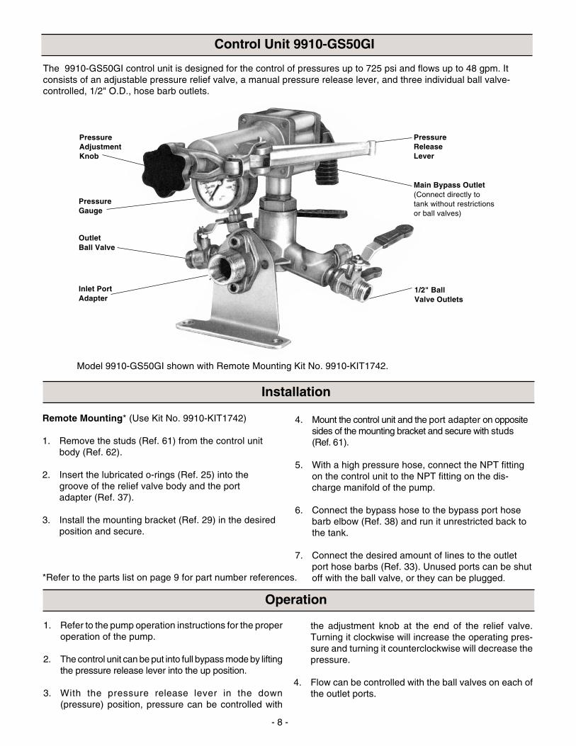
The 9910-GS50GI control unit is designed for the control of pressures up to 725 psi and flows up to 48 gpm. Itconsists of an adjustable pressure relief valve, a manual pressure release lever, and three individual ball valve-controlled, 1/2" O.D., hose barb outlets.
1. Refer to the pump operation instructions for the properoperation of the pump.
2. The control unit can be put into full bypass mode by liftingthe pressure release lever into the up position.
3. With the pressure release lever in the down(pressure) position, pressure can be controlled with
Control Unit 9910-GS50GI
Main Bypass Outlet(Connect directly totank without restrictionsor ball valves)
Installation
Operation
the adjustment knob at the end of the relief valve.Turning it clockwise will increase the operating pres-sure and turning it counterclockwise will decrease thepressure.
4. Flow can be controlled with the ball valves on each ofthe outlet ports.
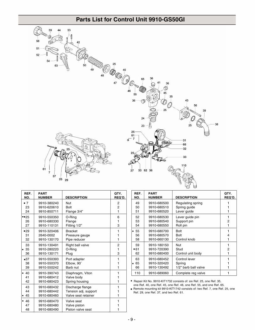
Remote Mounting* (Use Kit No. 9910-KIT1742)
1. Remove the studs (Ref. 61) from the control unitbody (Ref. 62).
2. Insert the lubricated o-rings (Ref. 25) into thegroove of the relief valve body and the portadapter (Ref. 37).
3. Install the mounting bracket (Ref. 29) in the desiredposition and secure.
4. Mount the control unit and the port adapter on oppositesides of the mounting bracket and secure with studs(Ref. 61).
5. With a high pressure hose, connect the NPT fittingon the control unit to the NPT fitting on the dis-charge manifold of the pump.
6. Connect the bypass hose to the bypass port hosebarb elbow (Ref. 38) and run it unrestricted back tothe tank.
7. Connect the desired amount of lines to the outletport hose barbs (Ref. 33). Unused ports can be shutoff with the ball valve, or they can be plugged.*Refer to the parts list on page 9 for part number references.
PressureReleaseLever
Inlet PortAdapter
OutletBall Valve
PressureGauge
PressureAdjustmentKnob
Model 9910-GS50GI shown with Remote Mounting Kit No. 9910-KIT1742.
1/2" BallValve Outlets
- 9 -
7 9910-380240 Nut 223 9910-620610 Bolt 224 9910-850711 Flange 3/4” 1
25 9910-550350 O-Ring 626 9910-680330 Flange 127 9910-110131 Fitting 1/2" 3
29 9910-320406 Bracket 131 2640-0002 Pressure gauge 132 9910-130170 Pipe reducer 1
33 9910-130491 Right ball valve 235 9910-280220 O-Ring 136 9910-130171 Plug 3
37 9910-550393 Port adapter 138 9910-550370 Elbow, 90˚ 139 9910-550242 Barb nut 1
40 9910-390743 Diaphragm, Viton 141 9910-680412 Valve body 142 9910-680423 Spring housing 1
43 9910-680432 Discharge flange 144 9910-680442 Tension adj. support 145 9910-680460 Valve seat retainer 1
46 9910-680470 Valve seat 147 9910-680480 Valve piston 148 9910-680490 Piston valve seat 1
Parts List for Control Unit 9910-GS50GI
49 9910-680500 Regulating spring 150 9910-680510 Spring guide 151 9910-680520 Lever guide 1
52 9910-680530 Lever guide pin 153 9910-680540 Support pin 254 9910-680550 Roll pin 1
55 9910-680700 Bolt 156 9910-680570 Bolt 458 9910-660130 Control knob 1
59 9910-180150 Nut 161 9910-720390 Stud 262 9910-680400 Control unit body 1
63 9910-680452 Control lever 165 9910-320420 Spring 166 9910-130492 1/2" barb ball valve 1
110 9910-689060 Complete reg valve 1
REF. PART QTY.NO. NUMBER DESCRIPTION REQ’D.
REF. PART QTY.NO. NUMBER DESCRIPTION REQ’D.
• Repair Kit No. 9910-KIT1732 consists of: six Ref. 25, one Ref. 35,one Ref. 40, one Ref. 45, one Ref. 46, one Ref. 55, and one Ref. 65.
� Remote mounting kit 9910-KIT1742 consists of: two Ref. 7, one Ref. 25, oneRef. 29, one Ref. 37, and two Ref. 61.
�
�
•
• �
�
�
•
••
•
•
- 10 -
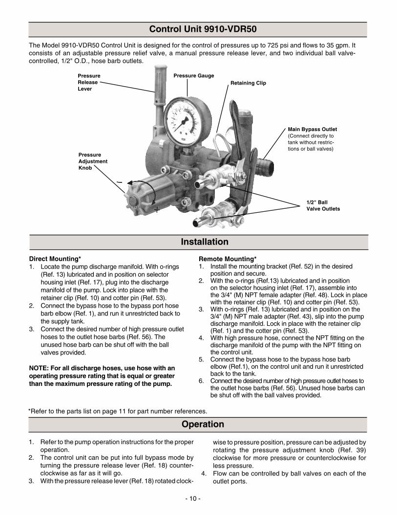
Control Unit 9910-VDR50
The Model 9910-VDR50 Control Unit is designed for the control of pressures up to 725 psi and flows to 35 gpm. Itconsists of an adjustable pressure relief valve, a manual pressure release lever, and two individual ball valve-controlled, 1/2" O.D., hose barb outlets.
Pressure Gauge
Main Bypass Outlet(Connect directly totank without restric-tions or ball valves)
PressureReleaseLever
PressureAdjustmentKnob
Retaining Clip
1/2" BallValve Outlets
*Refer to the parts list on page 11 for part number references.
Remote Mounting*1. Install the mounting bracket (Ref. 52) in the desired
position and secure.2. With the o-rings (Ref.13) lubricated and in position
on the selector housing inlet (Ref. 17), assemble intothe 3/4" (M) NPT female adapter (Ref. 48). Lock in placewith the retainer clip (Ref. 10) and cotter pin (Ref. 53).
3. With o-rings (Ref. 13) lubricated and in position on the3/4" (M) NPT male adapter (Ref. 43), slip into the pumpdischarge manifold. Lock in place with the retainer clip(Ref. 1) and the cotter pin (Ref. 53).
4. With high pressure hose, connect the NPT fitting on thedischarge manifold of the pump with the NPT fitting onthe control unit.
5. Connect the bypass hose to the bypass hose barbelbow (Ref.1), on the control unit and run it unrestrictedback to the tank.
6. Connect the desired number of high pressure outlet hoses tothe outlet hose barbs (Ref. 56). Unused hose barbs canbe shut off with the ball valves provided.
Direct Mounting*1. Locate the pump discharge manifold. With o-rings
(Ref. 13) lubricated and in position on selectorhousing inlet (Ref. 17), plug into the dischargemanifold of the pump. Lock into place with theretainer clip (Ref. 10) and cotter pin (Ref. 53).
2. Connect the bypass hose to the bypass port hosebarb elbow (Ref. 1), and run it unrestricted back tothe supply tank.
3. Connect the desired number of high pressure outlethoses to the outlet hose barbs (Ref. 56). Theunused hose barb can be shut off with the ballvalves provided.
NOTE: For all discharge hoses, use hose with anoperating pressure rating that is equal or greaterthan the maximum pressure rating of the pump.
Installation
1. Refer to the pump operation instructions for the properoperation.
2. The control unit can be put into full bypass mode byturning the pressure release lever (Ref. 18) counter-clockwise as far as it will go.
3. With the pressure release lever (Ref. 18) rotated clock-
Operation
wise to pressure position, pressure can be adjusted byrotating the pressure adjustment knob (Ref. 39)clockwise for more pressure or counterclockwise forless pressure.
4. Flow can be controlled by ball valves on each of theoutlet ports.

- 11 -
Parts List for Control Unit 9910-VDR50
NOTE: When ordering parts, giveQUANTITY, PART NUMBER,DESCRIPTION, and COMPLETEMODEL NUMBER. Referencenumbers are used ONLY to identifyparts in the drawing and are NOT tobe used as order numbers.
REF. PART QTY.NO. NUMBER DESCRIPTION REQ’D.
1 9910-550370 Hose Barb 12 9910-550242 Nut 13 9910-550350 O-ring 2
4 9910-1040780 Port Adapter 15 9910-550040 O-ring 16 9910-1040670 Spacer 1
8 9910-1040660 Valve Seat 19 9910-130491 Ball Valve w/o hose barb assy. 2
10 9910-1040690 Retainer Clip 2
11 9910-550545 Gauge 112 9910-1040680 Outlet Manifold 113 9910-390180 O-ring 8
14 9910-130171 Plug 215 9910-1040820 Pin 116 9910-180030 Bolt 4
17 9910-1040720 Selector Housing 118 9910-1040730 Pressure Release Lever 119 9910-1080200 O-ring 1
20 9910-1040700 Selector Body 121 9910-850680 Spring 122 9910-850660 Ball 1
23 9910-850650 Seat 224 9910-740290 O-ring 225 9910-1040710 O-ring 1
26 9910-1040600 Main Body 1
REF. PART QTY.NO. NUMBER DESCRIPTION REQ’D.
27 9910-680560 Bolt 128 9910-1040650 Spring 129 9910-1040640 Valve Cap 1
30 9910-1040630 Diaphragm 131 9910-880830 O-ring 132 9910-1040620 Piston 1
33 9910-850440 Spacer 134 9910-1040830 Spring 135 9910-394770 Spring Guide 1
36 9910-1040610 Spring Guide Body 137 9910-550331 Washer 438 9910-780330 Bolt 4
39 9910-394790 Knob 140 9910-480550 Snap Ring 443 9910-1040761 3/4" (M) NPT Male Adapter 1
48 9910-1040771 3/4" (M) NPT Female Adapter 149 9910-550210 1" Straight Hose Barb 150 9910-390270 Nut 2
51 9910-180370 Bolt 252 9910-850690 Mounting Bracket 153 9910-1040950 Cotter Pin 2
54 9910-1150650 Bolt 155 9910-770130 O-ring 156 9910-110130 Hose barb assembly 1/2" 2
- 12 -
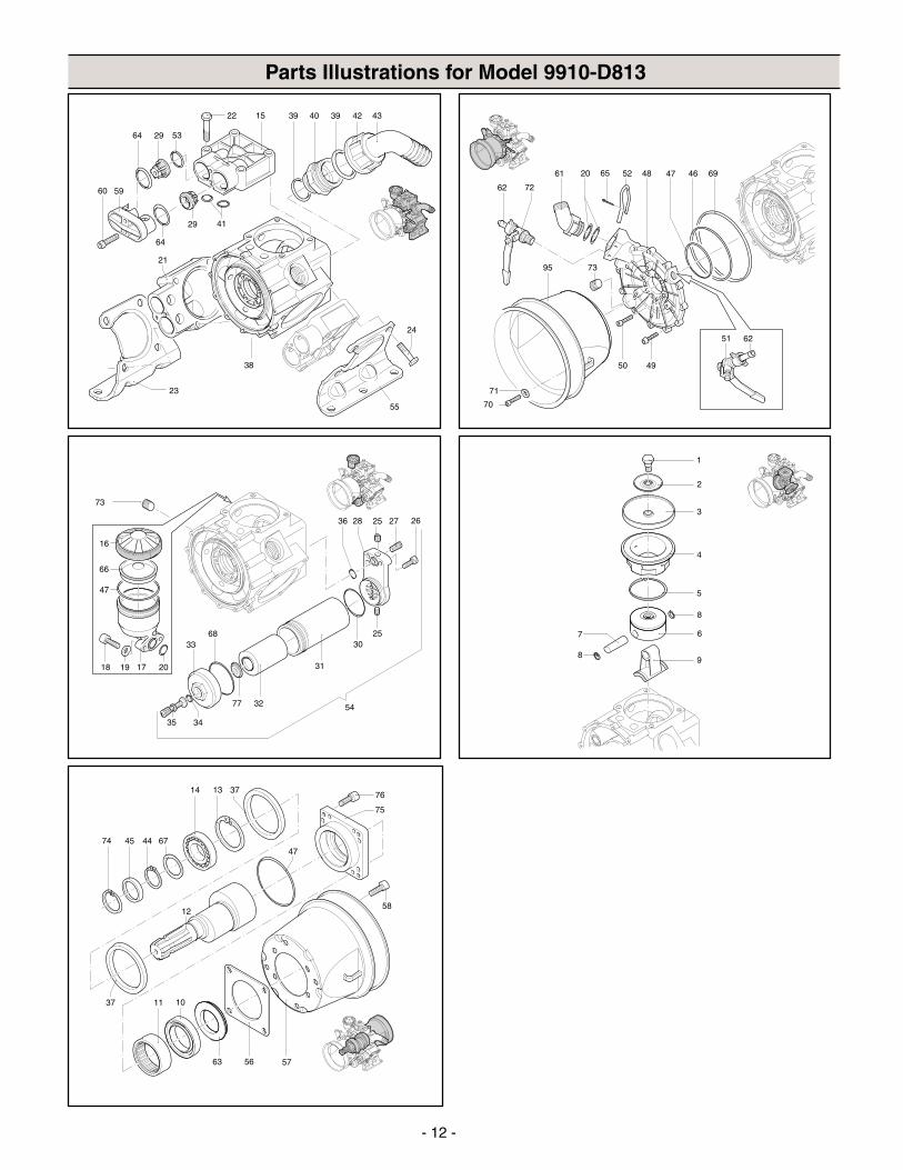
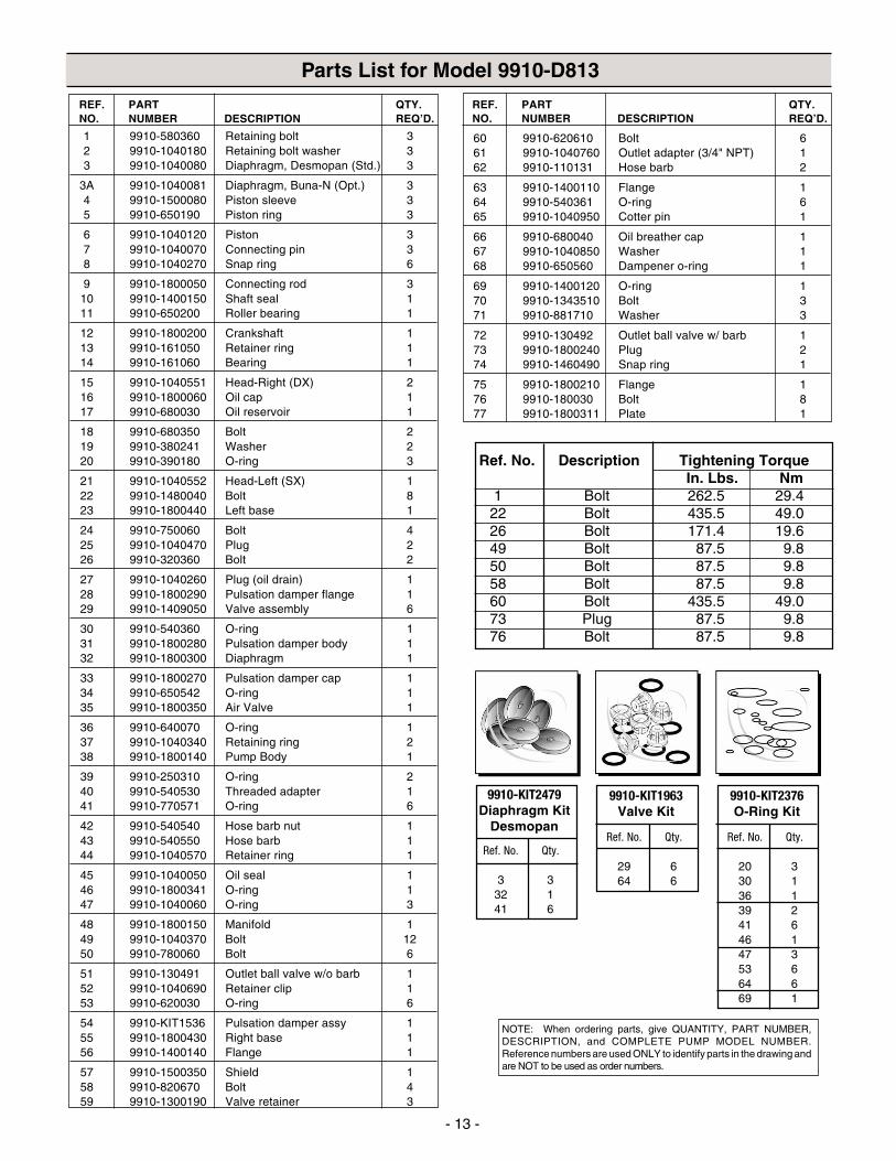
Parts Illustrations for Model 9910-D813
- 13 -
1 9910-580360 Retaining bolt 32 9910-1040180 Retaining bolt washer 33 9910-1040080 Diaphragm, Desmopan (Std.) 3
3A 9910-1040081 Diaphragm, Buna-N (Opt.) 34 9910-1500080 Piston sleeve 35 9910-650190 Piston ring 3
6 9910-1040120 Piston 37 9910-1040070 Connecting pin 38 9910-1040270 Snap ring 6
9 9910-1800050 Connecting rod 310 9910-1400150 Shaft seal 111 9910-650200 Roller bearing 1
12 9910-1800200 Crankshaft 113 9910-161050 Retainer ring 114 9910-161060 Bearing 1
15 9910-1040551 Head-Right (DX) 216 9910-1800060 Oil cap 117 9910-680030 Oil reservoir 1
18 9910-680350 Bolt 219 9910-380241 Washer 220 9910-390180 O-ring 3
21 9910-1040552 Head-Left (SX) 122 9910-1480040 Bolt 823 9910-1800440 Left base 1
24 9910-750060 Bolt 425 9910-1040470 Plug 226 9910-320360 Bolt 2
27 9910-1040260 Plug (oil drain) 128 9910-1800290 Pulsation damper flange 129 9910-1409050 Valve assembly 6
30 9910-540360 O-ring 131 9910-1800280 Pulsation damper body 132 9910-1800300 Diaphragm 1
33 9910-1800270 Pulsation damper cap 134 9910-650542 O-ring 135 9910-1800350 Air Valve 1
36 9910-640070 O-ring 137 9910-1040340 Retaining ring 238 9910-1800140 Pump Body 1
39 9910-250310 O-ring 240 9910-540530 Threaded adapter 141 9910-770571 O-ring 6
42 9910-540540 Hose barb nut 143 9910-540550 Hose barb 144 9910-1040570 Retainer ring 1
45 9910-1040050 Oil seal 146 9910-1800341 O-ring 147 9910-1040060 O-ring 3
48 9910-1800150 Manifold 149 9910-1040370 Bolt 1250 9910-780060 Bolt 6
51 9910-130491 Outlet ball valve w/o barb 152 9910-1040690 Retainer clip 153 9910-620030 O-ring 6
54 9910-KIT1536 Pulsation damper assy 155 9910-1800430 Right base 156 9910-1400140 Flange 1
57 9910-1500350 Shield 158 9910-820670 Bolt 459 9910-1300190 Valve retainer 3
Parts List for Model 9910-D813
REF. PART QTY.NO. NUMBER DESCRIPTION REQ’D.
Ref. No. Qty.
20 330 136 139 241 646 147 353 664 669 1
9910-KIT2376O-Ring Kit
Ref. No. Qty.
3 332 141 6
9910-KIT2479Diaphragm Kit
Desmopan
NOTE: When ordering parts, give QUANTITY, PART NUMBER,DESCRIPTION, and COMPLETE PUMP MODEL NUMBER.Reference numbers are used ONLY to identify parts in the drawing andare NOT to be used as order numbers.
Ref. No. Description Tightening TorqueIn. Lbs. Nm
1 Bolt 262.5 29.422 Bolt 435.5 49.026 Bolt 171.4 19.649 Bolt 87.5 9.850 Bolt 87.5 9.858 Bolt 87.5 9.860 Bolt 435.5 49.073 Plug 87.5 9.876 Bolt 87.5 9.8
60 9910-620610 Bolt 661 9910-1040760 Outlet adapter (3/4" NPT) 162 9910-110131 Hose barb 2
63 9910-1400110 Flange 164 9910-540361 O-ring 665 9910-1040950 Cotter pin 1
66 9910-680040 Oil breather cap 167 9910-1040850 Washer 168 9910-650560 Dampener o-ring 1
69 9910-1400120 O-ring 170 9910-1343510 Bolt 371 9910-881710 Washer 3
72 9910-130492 Outlet ball valve w/ barb 173 9910-1800240 Plug 274 9910-1460490 Snap ring 1
75 9910-1800210 Flange 176 9910-180030 Bolt 877 9910-1800311 Plate 1
REF. PART QTY.NO. NUMBER DESCRIPTION REQ’D.
Ref. No. Qty.
29 664 6
9910-KIT1963Valve Kit
- 14 -
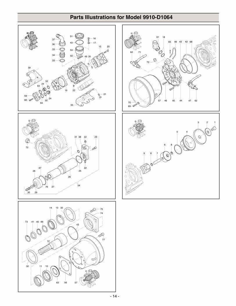
Parts Illustrations for Model 9910-D1064
39
55
21
52
37
33
34
33
36
51
50
53
43
16
17
15 20
49 35
19
2464
59
60 5224
64
22
4457
61 18
4865
45 47 62
6842
69
70
43
46
72
62 71
13 2
4
8
5
6
9 8 7
77
63 56
1011
1314 32
57
73 41
75
74
43
12
32
40 66
- 15 -
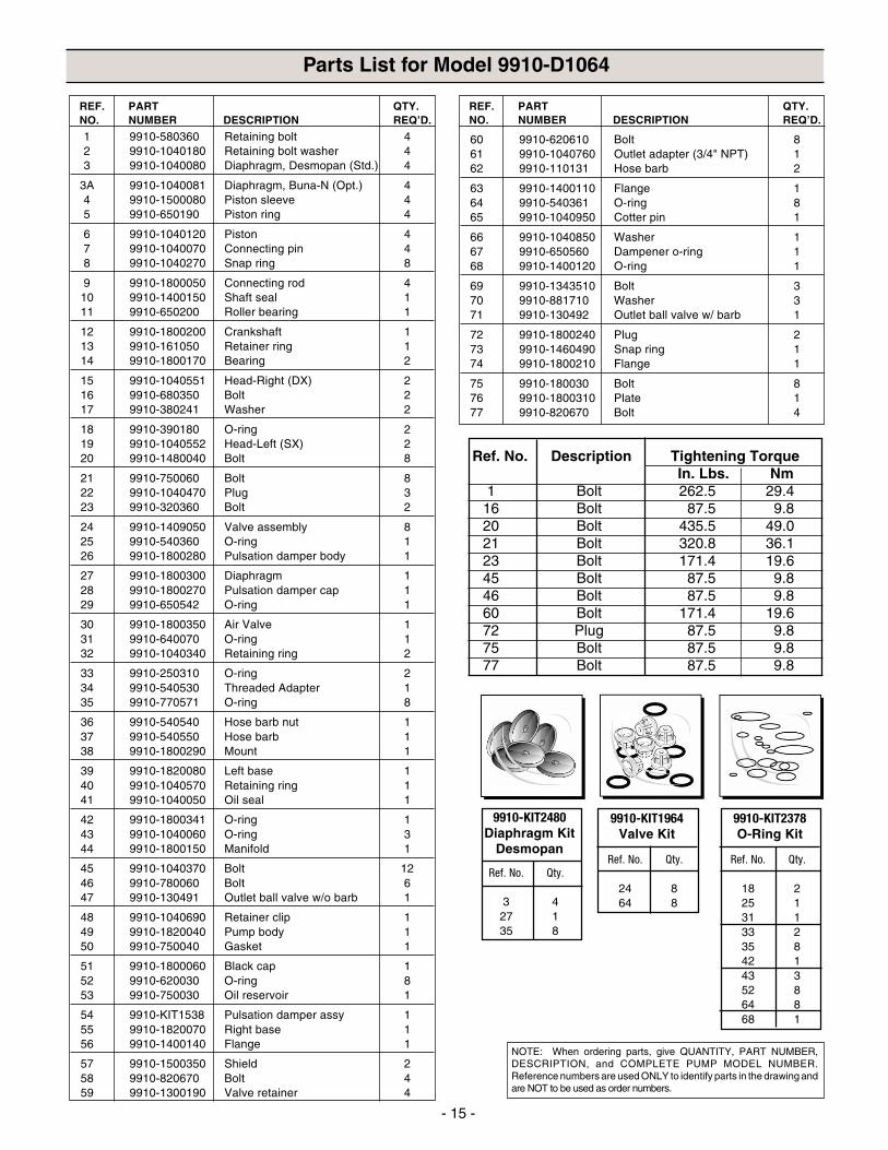
Parts List for Model 9910-D1064
60 9910-620610 Bolt 861 9910-1040760 Outlet adapter (3/4" NPT) 162 9910-110131 Hose barb 2
63 9910-1400110 Flange 164 9910-540361 O-ring 865 9910-1040950 Cotter pin 1
66 9910-1040850 Washer 167 9910-650560 Dampener o-ring 168 9910-1400120 O-ring 1
69 9910-1343510 Bolt 370 9910-881710 Washer 371 9910-130492 Outlet ball valve w/ barb 1
72 9910-1800240 Plug 273 9910-1460490 Snap ring 174 9910-1800210 Flange 1
75 9910-180030 Bolt 876 9910-1800310 Plate 177 9910-820670 Bolt 4
REF. PART QTY.NO. NUMBER DESCRIPTION REQ’D.
1 9910-580360 Retaining bolt 42 9910-1040180 Retaining bolt washer 43 9910-1040080 Diaphragm, Desmopan (Std.) 4
3A 9910-1040081 Diaphragm, Buna-N (Opt.) 44 9910-1500080 Piston sleeve 45 9910-650190 Piston ring 4
6 9910-1040120 Piston 47 9910-1040070 Connecting pin 48 9910-1040270 Snap ring 8
9 9910-1800050 Connecting rod 410 9910-1400150 Shaft seal 111 9910-650200 Roller bearing 1
12 9910-1800200 Crankshaft 113 9910-161050 Retainer ring 114 9910-1800170 Bearing 2
15 9910-1040551 Head-Right (DX) 216 9910-680350 Bolt 217 9910-380241 Washer 2
18 9910-390180 O-ring 219 9910-1040552 Head-Left (SX) 220 9910-1480040 Bolt 8
21 9910-750060 Bolt 822 9910-1040470 Plug 323 9910-320360 Bolt 2
24 9910-1409050 Valve assembly 825 9910-540360 O-ring 126 9910-1800280 Pulsation damper body 1
27 9910-1800300 Diaphragm 128 9910-1800270 Pulsation damper cap 129 9910-650542 O-ring 1
30 9910-1800350 Air Valve 131 9910-640070 O-ring 132 9910-1040340 Retaining ring 2
33 9910-250310 O-ring 234 9910-540530 Threaded Adapter 135 9910-770571 O-ring 8
36 9910-540540 Hose barb nut 137 9910-540550 Hose barb 138 9910-1800290 Mount 1
39 9910-1820080 Left base 140 9910-1040570 Retaining ring 141 9910-1040050 Oil seal 1
42 9910-1800341 O-ring 143 9910-1040060 O-ring 344 9910-1800150 Manifold 1
45 9910-1040370 Bolt 1246 9910-780060 Bolt 647 9910-130491 Outlet ball valve w/o barb 1
48 9910-1040690 Retainer clip 149 9910-1820040 Pump body 150 9910-750040 Gasket 1
51 9910-1800060 Black cap 152 9910-620030 O-ring 853 9910-750030 Oil reservoir 1
54 9910-KIT1538 Pulsation damper assy 155 9910-1820070 Right base 156 9910-1400140 Flange 1
57 9910-1500350 Shield 258 9910-820670 Bolt 459 9910-1300190 Valve retainer 4
REF. PART QTY.NO. NUMBER DESCRIPTION REQ’D.
NOTE: When ordering parts, give QUANTITY, PART NUMBER,DESCRIPTION, and COMPLETE PUMP MODEL NUMBER.Reference numbers are used ONLY to identify parts in the drawing andare NOT to be used as order numbers.
Ref. No. Description Tightening TorqueIn. Lbs. Nm
1 Bolt 262.5 29.416 Bolt 87.5 9.820 Bolt 435.5 49.021 Bolt 320.8 36.123 Bolt 171.4 19.645 Bolt 87.5 9.846 Bolt 87.5 9.860 Bolt 171.4 19.672 Plug 87.5 9.875 Bolt 87.5 9.877 Bolt 87.5 9.8
Ref. No. Qty.
18 225 131 133 235 842 143 352 864 868 1
9910-KIT2378O-Ring Kit
Ref. No. Qty.
24 864 8
9910-KIT1964Valve Kit
Ref. No. Qty.
3 427 135 8
9910-KIT2480Diaphragm Kit
Desmopan
- 16 -
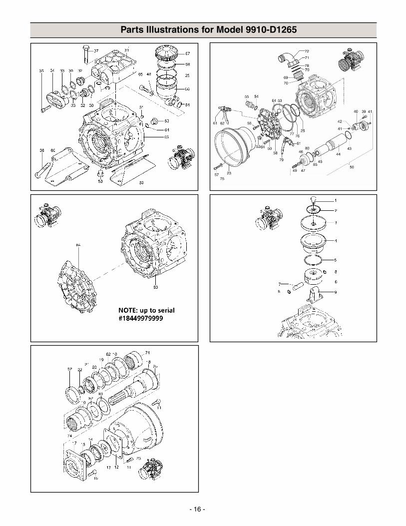
Parts Illustrations for Model 9910-D1265
- 17 -
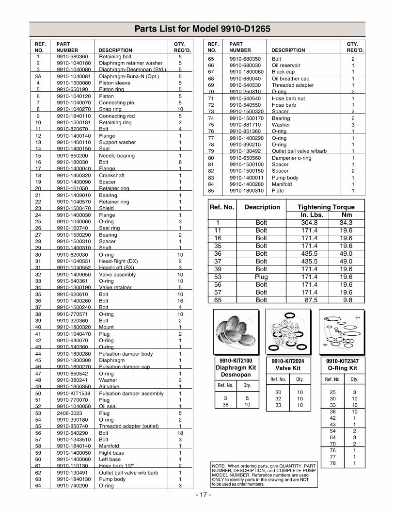
Parts List for Model 9910-D1265
1 9910-580360 Retaining bolt 52 9910-1040180 Diaphragm retainer washer 53 9910-1040080 Diaphragm-Desmopan (Std.) 5
3A 9910-1040081 Diaphragm-Buna-N (Opt.) 54 9910-1500080 Piston sleeve 55 9910-650190 Piston ring 56 9910-1040120 Piston 57 9910-1040070 Connecting pin 58 9910-1040270 Snap ring 109 9910-1840110 Connecting rod 5
10 9910-1500181 Retaining ring 211 9910-820670 Bolt 412 9910-1400140 Flange 113 9910-1400110 Support washer 114 9910-1400150 Seal 115 9910-650200 Needle bearing 116 9910-180030 Bolt 817 9910-1400040 Flange 118 9910-1400320 Crankshaft 119 9910-1400090 Spacer 120 9910-161050 Retainer ring 121 9910-1409010 Bearing 122 9910-1040570 Retainer ring 123 9910-1500470 Shield 124 9910-1400030 Flange 125 9910-1040060 O-ring 326 9910-160740 Seal ring 127 9910-1500290 Bearing 228 9910-1500310 Spacer 129 9910-1400310 Shaft 130 9910-620030 O-ring 1031 9910-1040551 Head-Right (DX) 231 9910-1040552 Head-Left (SX) 332 9910-1409050 Valve assembly 1033 9910-540361 O-ring 1034 9910-1300190 Valve retainer 535 9910-620610 Bolt 1036 9910-1400260 Bolt 1637 9910-1500240 Bolt 438 9910-770571 O-ring 1039 9910-320360 Bolt 240 9910-1800320 Mount 141 9910-1040470 Plug 242 9910-640070 O-ring 143 9910-540360 O-ring 144 9910-1800280 Pulsation damper body 145 9910-1800300 Diaphragm 146 9910-1800270 Pulsation damper cap 147 9910-650542 O-ring 148 9910-380241 Washer 249 9910-1800350 Air valve 150 9910-KIT1538 Pulsation damper assembly 151 9910-770070 Plug 152 9910-1040050 Oil seal 153 2406-0023 Plug 554 9910-390180 O-ring 255 9910-850740 Threaded adapter (outlet) 156 9910-540290 Bolt 1857 9910-1343510 Bolt 358 9910-1840140 Manifold 159 9910-1400050 Right base 160 9910-1400060 Left base 161 9910-110130 Hose barb 1/2" 262 9910-130491 Outlet ball valve w/o barb 163 9910-1840130 Pump body 164 9910-740290 O-ring 3
REF. PART QTY.NO. NUMBER DESCRIPTION REQ’D.
65 9910-680350 Bolt 266 9910-680030 Oil reservoir 167 9910-1800060 Black cap 168 9910-680040 Oil breather cap 169 9910-540530 Threaded adapter 170 9910-250310 O-ring 271 9910-540540 Hose barb nut 172 9910-540550 Hose barb 173 9910-1500320 Spacer 274 9910-1500170 Bearing 275 9910-881710 Washer 376 9910-851360 O-ring 177 9910-1400290 O-ring 178 9910-390210 O-ring 179 9910-130492 Outlet ball valve w/barb 180 9910-650560 Dampener o-ring 181 9910-1500100 Spacer 182 9910-1500150 Spacer 283 9910-1400011 Pump body 184 9910-1400280 Manifold 185 9910-1800310 Plate 1
REF. PART QTY.NO. NUMBER DESCRIPTION REQ’D.
Ref. No. Qty.
25 330 1033 1038 1042 143 154 264 370 276 177 178 1
9910-KIT2347O-Ring Kit
Ref. No. Qty.
30 1032 1033 10
9910-KIT2024Valve Kit
Ref. No. Qty.
3 538 10
9910-KIT2100Diaphragm Kit
Desmopan
NOTE: When ordering parts, give QUANTITY, PARTNUMBER, DESCRIPTION, and COMPLETE PUMPMODEL NUMBER. Reference numbers are usedONLY to identify parts in the drawing and are NOTto be used as order numbers.
Ref. No. Description Tightening TorqueIn. Lbs. Nm
1 Bolt 304.8 34.311 Bolt 171.4 19.616 Bolt 171.4 19.635 Bolt 171.4 19.636 Bolt 435.5 49.037 Bolt 435.5 49.039 Bolt 171.4 19.653 Plug 171.4 19.656 Bolt 171.4 19.657 Bolt 171.4 19.665 Bolt 87.5 9.8
- 18 -
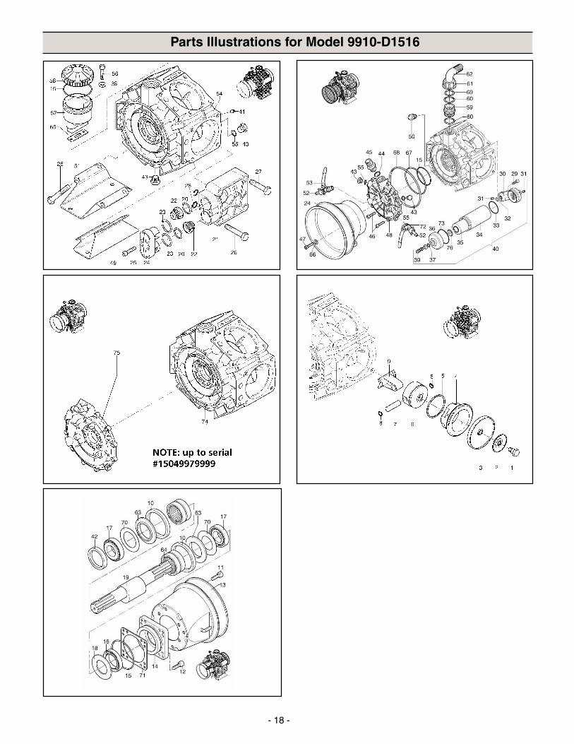
Parts Illustrations for Model 9910-D1516
- 19 -
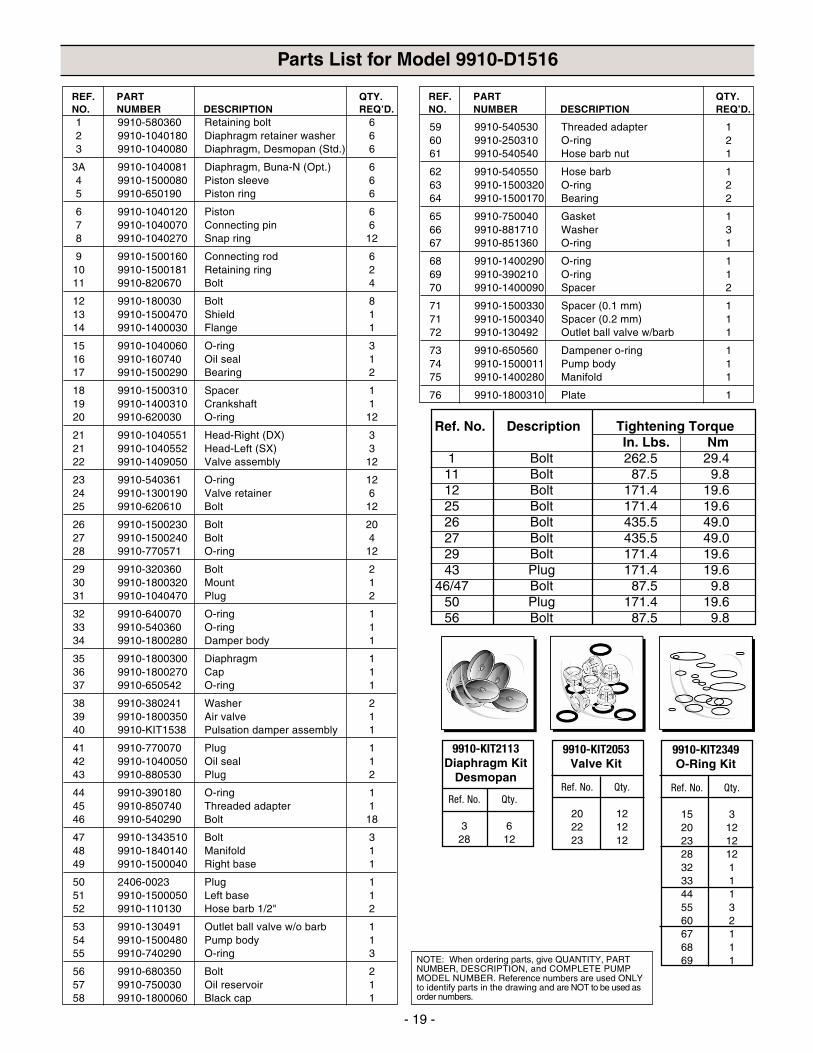
Parts List for Model 9910-D1516
59 9910-540530 Threaded adapter 160 9910-250310 O-ring 261 9910-540540 Hose barb nut 1
62 9910-540550 Hose barb 163 9910-1500320 O-ring 264 9910-1500170 Bearing 2
65 9910-750040 Gasket 166 9910-881710 Washer 367 9910-851360 O-ring 1
68 9910-1400290 O-ring 169 9910-390210 O-ring 170 9910-1400090 Spacer 2
71 9910-1500330 Spacer (0.1 mm) 171 9910-1500340 Spacer (0.2 mm) 172 9910-130492 Outlet ball valve w/barb 1
73 9910-650560 Dampener o-ring 174 9910-1500011 Pump body 175 9910-1400280 Manifold 1
76 9910-1800310 Plate 1
REF. PART QTY.NO. NUMBER DESCRIPTION REQ’D.
1 9910-580360 Retaining bolt 62 9910-1040180 Diaphragm retainer washer 63 9910-1040080 Diaphragm, Desmopan (Std.) 6
3A 9910-1040081 Diaphragm, Buna-N (Opt.) 64 9910-1500080 Piston sleeve 65 9910-650190 Piston ring 6
6 9910-1040120 Piston 67 9910-1040070 Connecting pin 68 9910-1040270 Snap ring 12
9 9910-1500160 Connecting rod 610 9910-1500181 Retaining ring 211 9910-820670 Bolt 4
12 9910-180030 Bolt 813 9910-1500470 Shield 114 9910-1400030 Flange 1
15 9910-1040060 O-ring 316 9910-160740 Oil seal 117 9910-1500290 Bearing 2
18 9910-1500310 Spacer 119 9910-1400310 Crankshaft 120 9910-620030 O-ring 12
21 9910-1040551 Head-Right (DX) 321 9910-1040552 Head-Left (SX) 322 9910-1409050 Valve assembly 12
23 9910-540361 O-ring 1224 9910-1300190 Valve retainer 625 9910-620610 Bolt 12
26 9910-1500230 Bolt 2027 9910-1500240 Bolt 428 9910-770571 O-ring 12
29 9910-320360 Bolt 230 9910-1800320 Mount 131 9910-1040470 Plug 2
32 9910-640070 O-ring 133 9910-540360 O-ring 134 9910-1800280 Damper body 1
35 9910-1800300 Diaphragm 136 9910-1800270 Cap 137 9910-650542 O-ring 1
38 9910-380241 Washer 239 9910-1800350 Air valve 140 9910-KIT1538 Pulsation damper assembly 1
41 9910-770070 Plug 142 9910-1040050 Oil seal 143 9910-880530 Plug 2
44 9910-390180 O-ring 145 9910-850740 Threaded adapter 146 9910-540290 Bolt 18
47 9910-1343510 Bolt 348 9910-1840140 Manifold 149 9910-1500040 Right base 1
50 2406-0023 Plug 151 9910-1500050 Left base 152 9910-110130 Hose barb 1/2" 2
53 9910-130491 Outlet ball valve w/o barb 154 9910-1500480 Pump body 155 9910-740290 O-ring 3
56 9910-680350 Bolt 257 9910-750030 Oil reservoir 158 9910-1800060 Black cap 1
REF. PART QTY.NO. NUMBER DESCRIPTION REQ’D.
NOTE: When ordering parts, give QUANTITY, PARTNUMBER, DESCRIPTION, and COMPLETE PUMPMODEL NUMBER. Reference numbers are used ONLYto identify parts in the drawing and are NOT to be used asorder numbers.
Ref. No. Description Tightening TorqueIn. Lbs. Nm
1 Bolt 262.5 29.411 Bolt 87.5 9.812 Bolt 171.4 19.625 Bolt 171.4 19.626 Bolt 435.5 49.027 Bolt 435.5 49.029 Bolt 171.4 19.643 Plug 171.4 19.6
46/47 Bolt 87.5 9.850 Plug 171.4 19.656 Bolt 87.5 9.8
Ref. No. Qty.
15 320 1223 1228 1232 133 144 155 360 267 168 169 1
9910-KIT2349O-Ring Kit
Ref. No. Qty.
3 628 12
9910-KIT2113Diaphragm Kit
DesmopanRef. No. Qty.
20 1222 1223 12
9910-KIT2053Valve Kit
- 20 -
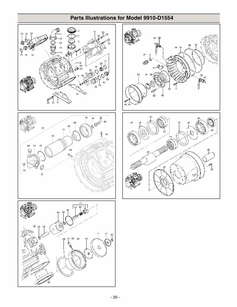
Parts Illustrations for Model 9910-D1554
- 21 -
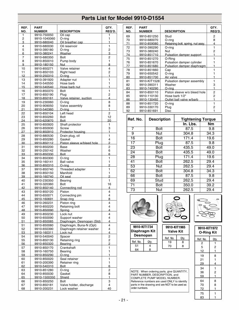
Parts List for Model 9910-D1554
69 9910-851250 Stud 270 9910-680070 O-ring 871 9910-859080 Retaining bolt, spring, nut assy. 472 9910-390290 O-ring 173 9910-380240 Nut 274 9910-851710 Pulsation damper support 175 9910-851270 O-Ring 176 9910-851670 Pulsation damper cylinder 177 9910-851680 Pulsation damper diaphragm 178 9910-851660 Cap 179 9910-650542 O-ring 180 9910-851700 Air valve 181 9910-KIT1528 Pulsation damper assembly 182 9910-390311 Washer 383 9910-740290 O-ring 184 9910-850110 Piston sleeve w/o bleed hole 285 9910-110130 Hose barb 1/2" 286 9910-130492 Outlet ball valve w/barb 188 9910-851720 O-ring 189 9910-330170 Plug 292 9910-851691 Disc 1
REF. PART QTY.NO. NUMBER DESCRIPTION REQ’D.
1 9910-750050 Oil cap 12 9910-1040060 O-ring 13 9910-680040 Oil breather cap 14 9910-680030 Oil reservoir 15 9910-390180 O-ring 26 9910-380241 Washer 37 9910-680350 Bolt 28 9910-850010 Pump body 19 9910-180150 Nut 8
10 9910-850271 Valve retainer 411 9910-850103 Right head 212 9910-250310 O-ring 113 9910-391920 Adapter nut 114 9910-540550 Hose barb 115 9910-540540 Hose barb nut 116 9910-850370 Bolt 117 9910-850190 Plug 218 9910-850161 Valve retainer, suction 419 9910-230060 O-ring 820 9910-909050 Valve assembly 821 9910-540360 O-ring 122 9910-850104 Left head 223 9910-850260 Bolt 1224 9910-620870 Bolt 2025 9910-850920 Shaft protector 126 9910-850930 Screw 327 9910-850910 Protector housing 128 9910-880530 Drain plug, oil 129 9910-850280 Gasket 430 9910-850112 Piston sleeve w/bleed hole 231 9910-850200 Base 232 9910-250142 Washer 633 9910-850330 Bolt 634 9910-850300 O-ring 135 9910-160141 Ball valve 136 9910-850310 O-ring 237 9910-850740 Threaded adapter 138 9910-850150 Manifold 139 9910-160740 Oil seal 240 9910-230350 Bearing 141 9910-320360 Bolt 1642 9910-850140 Connecting rod 443 9910-850120 Piston 444 9910-650071 Connecting pin 445 9910-160691 Snap ring 846 9910-260231 Piston ring 447 9910-850220 Retaining bolt 448 9910-850090 Spring 449 9910-850230 Lock nut 450 9910-650090 Support washer 451 9910-850085 Diaphragm, Desmopan (Std) 451 9910-850080 Diaphragm, Buna-N (Opt) 452 9910-650390 Diaphragm retainer washer 453 9910-160311 Lock nut 454 9910-540040 Spacer 255 9910-850130 Retaining ring 256 9910-850320 Bearing 257 9910-850170 Crankshaft 158 9910-160750 Bearing 159 9910-850290 O-ring 160 9910-850020 Seal retainer 161 9910-200390 Retainer ring 162 9910-540310 Bolt 663 9910-851280 O-ring 264 9910-850030 Gasket 865 9910-1500350 Shield 166 9910-850250 Bolt 367 9910-850181 Valve holder, discharge 468 9910-200231 Lock washer 40
REF. PART QTY.NO. NUMBER DESCRIPTION REQ’D.
NOTE: When ordering parts, give QUANTITY,PART NUMBER, DESCRIPTION, andCOMPLETE PUMP MODEL NUMBER.Reference numbers are used ONLY to identifyparts in the drawing and are NOT to be used asorder numbers.
Ref. No. Qty.2 15 2
12 1
19 821 129 4
34 136 259 1
64 870 872 1
75 183 1
9910-KIT1972O-Ring Kit
Ref. No. Qty.19 870 8
9910-KIT1965Valve Kit
Ref. No. Qty.51 464 8
9910-KIT1734Diaphragm Kit
Desmopan
Ref. No. Description Tightening TorqueIn. Lbs. Nm
7 Bolt 87.5 9.89 Nut 304.8 34.316 Bolt 171.4 19.617 Plug 87.5 9.823 Bolt 435.5 49.024 Bolt 435.5 49.028 Plug 171.4 19.641 Bolt 262.5 29.453 Nut 262.5 29.462 Bolt 304.8 34.366 Bolt 87.5 9.869 Stud 262.5 29.471 Bolt 350.0 39.273 Nut 262.5 29.4
- 22 -
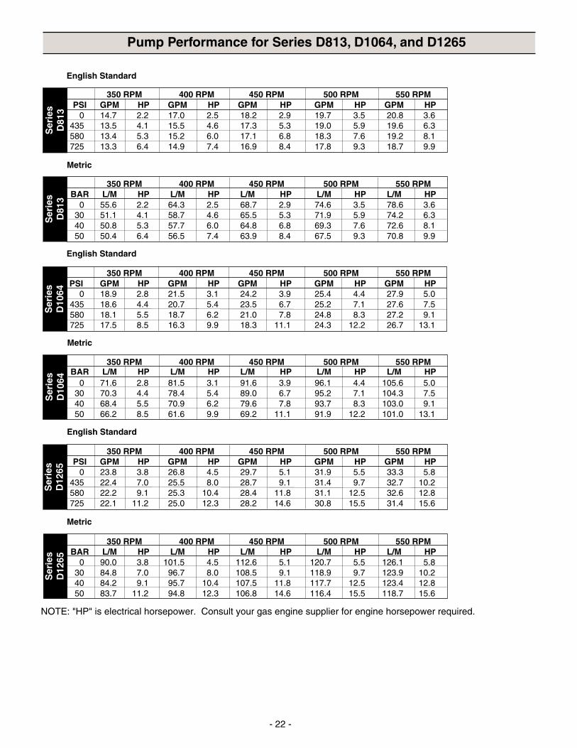
Pump Performance for Series D813, D1064, and D1265
NOTE: "HP" is electrical horsepower. Consult your gas engine supplier for engine horsepower required.
Ser
ies
D12
65
350 RPM 400 RPM 450 RPM 500 RPM 550 RPM
0 71.6 2.8 81.5 3.1 91.6 3.9 96.1 4.4 105.6 5.030 70.3 4.4 78.4 5.4 89.0 6.7 95.2 7.1 104.3 7.540 68.4 5.5 70.9 6.2 79.6 7.8 93.7 8.3 103.0 9.150 66.2 8.5 61.6 9.9 69.2 11.1 91.9 12.2 101.0 13.1
English Standard
350 RPM 400 RPM 450 RPM 500 RPM 550 RPMPSI GPM HP GPM HP GPM HP GPM HP GPM HP
0 23.8 3.8 26.8 4.5 29.7 5.1 31.9 5.5 33.3 5.8435 22.4 7.0 25.5 8.0 28.7 9.1 31.4 9.7 32.7 10.2580 22.2 9.1 25.3 10.4 28.4 11.8 31.1 12.5 32.6 12.8725 22.1 11.2 25.0 12.3 28.2 14.6 30.8 15.5 31.4 15.6
Metric
Ser
ies
D12
65
350 RPM 400 RPM 450 RPM 500 RPM 550 RPM
0 90.0 3.8 101.5 4.5 112.6 5.1 120.7 5.5 126.1 5.830 84.8 7.0 96.7 8.0 108.5 9.1 118.9 9.7 123.9 10.240 84.2 9.1 95.7 10.4 107.5 11.8 117.7 12.5 123.4 12.850 83.7 11.2 94.8 12.3 106.8 14.6 116.4 15.5 118.7 15.6
BAR L/M HP L/M HP L/M HP L/M HP L/M HP
English Standard
Ser
ies
D81
3S
erie
sD
1064
Ser
ies
D10
64
Metric
350 RPM 400 RPM 450 RPM 500 RPM 550 RPMPSI GPM HP GPM HP GPM HP GPM HP GPM HP
0 14.7 2.2 17.0 2.5 18.2 2.9 19.7 3.5 20.8 3.6435 13.5 4.1 15.5 4.6 17.3 5.3 19.0 5.9 19.6 6.3580 13.4 5.3 15.2 6.0 17.1 6.8 18.3 7.6 19.2 8.1725 13.3 6.4 14.9 7.4 16.9 8.4 17.8 9.3 18.7 9.9
Metric
English Standard
350 RPM 400 RPM 450 RPM 500 RPM 550 RPM PSI GPM HP GPM HP GPM HP GPM HP GPM HP
0 18.9 2.8 21.5 3.1 24.2 3.9 25.4 4.4 27.9 5.0435 18.6 4.4 20.7 5.4 23.5 6.7 25.2 7.1 27.6 7.5580 18.1 5.5 18.7 6.2 21.0 7.8 24.8 8.3 27.2 9.1725 17.5 8.5 16.3 9.9 18.3 11.1 24.3 12.2 26.7 13.1
BAR L/M HP L/M HP L/M HP L/M HP L/M HP
Ser
ies
D81
3
350 RPM 400 RPM 450 RPM 500 RPM 550 RPM
0 55.6 2.2 64.3 2.5 68.7 2.9 74.6 3.5 78.6 3.630 51.1 4.1 58.7 4.6 65.5 5.3 71.9 5.9 74.2 6.340 50.8 5.3 57.7 6.0 64.8 6.8 69.3 7.6 72.6 8.150 50.4 6.4 56.5 7.4 63.9 8.4 67.5 9.3 70.8 9.9
BAR L/M HP L/M HP L/M HP L/M HP L/M HP
- 23 -
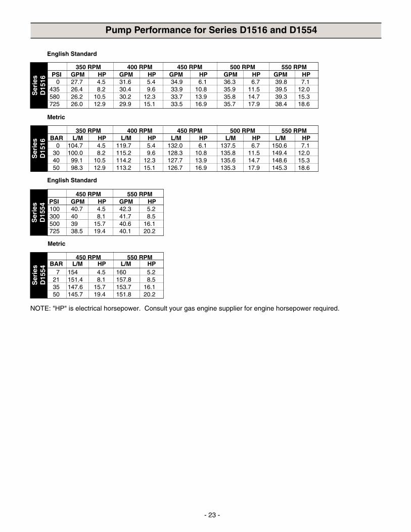
Pump Performance for Series D1516 and D1554
NOTE: "HP" is electrical horsepower. Consult your gas engine supplier for engine horsepower required.
450 RPM 550 RPM
7 154 4.5 160 5.221 151.4 8.1 157.8 8.535 147.6 15.7 153.7 16.150 145.7 19.4 151.8 20.2
English Standard
Ser
ies
D15
16
350 RPM 400 RPM 450 RPM 500 RPM 550 RPMPSI GPM HP GPM HP GPM HP GPM HP GPM HP
0 27.7 4.5 31.6 5.4 34.9 6.1 36.3 6.7 39.8 7.1435 26.4 8.2 30.4 9.6 33.9 10.8 35.9 11.5 39.5 12.0580 26.2 10.5 30.2 12.3 33.7 13.9 35.8 14.7 39.3 15.3725 26.0 12.9 29.9 15.1 33.5 16.9 35.7 17.9 38.4 18.6
Metric
450 RPM 550 RPM PSI GPM HP GPM HP100 40.7 4.5 42.3 5.2300 40 8.1 41.7 8.5500 39 15.7 40.6 16.1725 38.5 19.4 40.1 20.2
Ser
ies
D15
16
350 RPM 400 RPM 450 RPM 500 RPM 550 RPM
0 104.7 4.5 119.7 5.4 132.0 6.1 137.5 6.7 150.6 7.130 100.0 8.2 115.2 9.6 128.3 10.8 135.8 11.5 149.4 12.040 99.1 10.5 114.2 12.3 127.7 13.9 135.6 14.7 148.6 15.350 98.3 12.9 113.2 15.1 126.7 16.9 135.3 17.9 145.3 18.6
BAR L/M HP L/M HP L/M HP L/M HP L/M HP
Ser
ies
D15
54
English Standard
Ser
ies
D15
54
Metric
BAR L/M HP L/M HP
Hypro Corporation 2003Printed in the USA
Hypro Corporation (“Hypro”) warrants to the original purchaser of its products (the “Purchaser”) that such products will befree from defects in material and workmanship under normal use for the period of one (1) year for all products except: oilcrankcase plunger pumps will be free from defects in material and workmanship under normal use for the period of five(5) years, and accessories will be free from defects in material and workmanship under normal use for the period ofninety (90) days. In addition, Hypro warrants to the purchaser all forged brass pump manifolds will be free from defects inmaterial and workmanship under normal use and from damage resulting from environmental conditions for the life of the pump.
“Normal use” does not include use in excess of recommended maximum speeds, pressures, vacuums and temperatures,or use requiring handling of fluids not compatible with component materials, as noted in Hypro product catalogs, technicalliterature, and instructions. This warranty does not cover freight damage, freezing damage, normal wear and tear, ordamage caused by misapplication, fault, negligence, alterations, or repair that affects the performance or reliability of theproduct.
THIS WARRANTY IS EXCLUSIVE. HYPRO MAKES NO OTHER WARRANTY, EXPRESS OR IMPLIED, INCLUDINGBUT NOT LIMITED TO ANY WARRANTY OF MERCHANTABILITY OR FITNESS FOR A PARTICULAR PURPOSE.
Hypro’s obligation under this warranty is, at Hypro’s option, to either repair or replace the product upon return of the entireproduct to the Hypro factory in accordance with the return procedures set forth below. THIS IS THE EXCLUSIVE REM-EDY FOR ANY BREACH OF WARRANTY.
IN NO EVENT SHALL HYPRO BE LIABLE FOR ANY INCIDENTAL OR CONSEQUENTIAL DAMAGES OF ANY KIND,WHETHER FOR BREACH OF ANY WARRANTY, FOR NEGLIGENCE, ON THE BASIS OF STRICT LIABILITY, OROTHERWISE.
Return Procedures-All pumps or products must be flushed of any chemical (ref. OSHA Section 0910.1200 (d)(e)(f)(g)(h)) and hazard-ous chemicals must be labeled before being shipped* to Hypro for service or warranty consideration. Hyproreserves the right to request a Material Safety Data sheet from the Purchaser for any pump or product Hypro deemsnecessary. Hypro reserves the right to “disposition as scrap” pumps or products returned which contain unknown sub-stances, or to charge for any and all costs incurred for chemical testing and proper disposal of components containingunknown substances. Hypro requests this in order to protect the environment and personnel from the hazards of han-dling unknown substances.
For technical or application assistance, call the Hypro Technical/Application number: 1-800-445-8360.To obtain service or warranty assistance, call the Hypro Service and Warranty number: 1-800-468-3428;or call the Hypro Service and Warranty FAX: (651) 766-6618.Be prepared to give Hypro full details of the problem, including the following information:1. Model number and the date and from whom you purchased your pump.2. A brief description of the pump problem, including the following:
• Liquid pumped. State the pH and any non-soluble • Drive type (gas engine/electric motor; direct/belt drive;materials, and give the generic or trade name. tractor PTO) and rpm of pump.
• Temperature of the liquid and ambient environment. • Viscosity (of oil, or other than water weight liquid).• Suction lift or vacuum (measured at the pump). • Elevation from the pump to the discharge point.• Discharge pressure. • Size and material of suction and discharge line.• Size, type, and mesh of the suction strainer. • Type of spray gun, orifice size, unloader/relief valve.
Hypro may request additional information, and may require a sketch to illustrate the problem.Contact the factory to receive a return material authorization before sending the product. All pumps returned for warrantywork should be sent shipping charges prepaid to:
HYPRO CORPORATIONAttention: Service Department375 Fifth Avenue NWNew Brighton, Minnesota 55112-3288
* Carriers, including U.S.P.S., airlines, UPS, ground freight, etc., require specific identification of any hazardous materials being shipped. Failure to do so may result in a substantial fine and/or prison term. Check with your shipping company for specific instructions.
Limited Warranty on Hypro Pumps and Other Hypro Products