Embed Size (px)
Citation preview

Manuale d'uso SALPA ANCORA ORIZZONTALI
User's Manual HORIZONTAL WINDLASSES
Manuel de l'utilisateur GUINDEAUX HORIZONTAL
Benutzerhandbuch HORIZONTAL ANKERWINDEN
Manual del usuario MOLINETES HORIZONTALES
GP2 GENIUS SERIES 500/1200 GP2 500 GP2 1200 GP2 1200 D GP2 1200 F
REV 000a
High Quality Nautical Equipment
CIMA E CATENA SU UN UNICO BARBOTINROPE AND CHAIN ON A SINGLE GYPSY
CORDAGE ET CHÂINE SUR LE MÊME BARBOTIN KETTE AUF EINER KOMBINIERTEN KETTENNUSS
CABO Y CADENA EN UN ÚNICO BARBOTEN
IT
GB
FR
DE
ES

3GP2 SERIES GENIUS 500/1200 - REV000A
Pag. 4 Caratteristiche tecnichePag. 5 InstallazionePag. 6 Schema di collegamentoPag. 7 Uso - Avvertenze importanti
Pag. 8/9 Manutenzione - GP2 500Pag. 10/11 Manutenzione - GP2 1200Pag. 12/13 Manutenzione - GP2 Free FallPag. 14/15 Set
Pag. 16 Technical dataPag. 17 InstallationPag. 18 Connection diagramPag. 19 Usage - warning
Pag. 20/21 Maintenance - GP2 500Pag. 22/23 Maintenance - GP2 1200Pag. 24/25 Maintenance - GP2 Free FallPag. 26/27 Set
Pag. 28 Caractéristiques techniquesPag. 29 InstallationPag. 30 Schema de cablagePag. 31 Utilisation - Avvertissements importants
Pag. 32/33 Entretien - GP2 500Pag. 34/34 Entretien - GP2 1200Pag. 35/36 Entretien - GP2 Free FallPag. 37/38 Groupes
Seite 39 Technische EigenschaftenSeite 40 MontageSeite 41 AnschlussplanSeite 42 Gebrauch - Wichtige hinweise
Seite 43/44 Wartung - GP2 500Seite 45/46 Wartung - GP2 1200Seite 47/48 Wartung - GP2 Free FallSeite 49/50 Gruppen
Pág. 51 Características técnicasPág. 52 InstalaciónPág. 53 Esquema de montagePág. 54 Uso - Advertencias importantes
Pág. 55/56 Mantenimiento - GP2 500Pág. 57/58 Mantenimiento - GP2 1200Pág. 59/60 Mantenimiento - GP2 Free FallPág. 61/62 Grupos
INDICE
INDEX
SOMMAIRE
INHALTSANGABE
INDICE
IT
GB
FR
DE
ES
16
TECHNICAL DATAGB
GP2 SERIES GENIUS 500/1200 - REV000A
GB
Quick® reserves the right to introduce changes to the equipment and the contents of this manual without prior notice.In case of discordance or errors in translation between the translated version and the original text in the Italian language, reference will be made to the Italian or English text.F
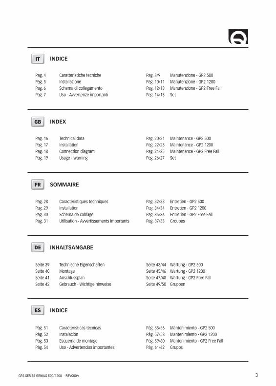
DIMENSIONS OF MODELS mm ( inch )
213 (8 23/64)
129 (5 3/32)184 (7 17/64)
GP2 500
213 (8 23/64)
129 (5 3/32)184 (7 17/64)
197 (7 49/64)
GP2 1200 - / D
213 (8 23/64)
129 (5 3/32)184 (7 17/64)
GP2 1200 FF
(1) After an initial period of use. (2) Measurements taken with a gypsy for a 8 mm chain. (3) Minimum allowable value for a total length L< 20m (see pag. 18). Determine the cable size according to the length of the wiring. (4) With circuit breaker designed for direct currents (DC) and delayed-action (thermal-magnetic or hydraulic-magnetic).(5) On request, studs can be supplied for greater deck thicknesses.
(*) The values in the table regard a three-strand polyester rope with the “Quick®” system rope/chain joint.(**) ISO EN 818-3.
MODELS GP2 500 GP2 1200 / D - GP2 1200 FF
MOTOR OUTPUT 150W 250W
Motor supply voltage 12V 12V
Maximum pull 220 Kg (485,0 lb) 550 Kg (1212,5 lb)
Maximum working load 70 Kg (154,3 lb) 170 Kg (374,8 lb)
Working load 35 Kg (77,2 lb) 50 Kg (110,2 lb)
Current absorption @ working load (1) 29 A 35 A
Maximum chain speed (2) 38,9 mm (83,7 ft/min) 31,2 mm (102,4 ft/min)
Maximum chain speed @ working load (2) 28,5 mm (33,8 ft/min) 25,1 mm (82,3 ft/min)
Motor cable size (3) 4 mm2 (AWG 12) 10 mm2 (AWG 7)
Protection circuit breaker (4) 40 A 40 A
Deck thickness (5) 20 ÷ 40 mm (3/4” ÷ 1” 9/16)
Weight mod. without drum 6 kg (22,4 lb) 8 kg (22,4 lb)
Weight mod. with drum - 9 kg (25,3 lb)
Weight mod. Free Fall - 10,9 kg (24,0 lb)
GYPSY 6 mm 7 mm - 1/4” 8 mm 5/16”
Chain size6 mm 6 mm 7 mm 7 mm 1/4” 1/4” 8 mm 8 mm 5/16”
DIN 766 ISO** DIN 766 ISO** G4 BBB DIN 766 ISO** G4
Rope size * 1/2” (12,7 mm) 1/2” (12,7 mm) 1/2” (12,7 mm) 1/2” (12,7 mm) 1/2” (12,7 mm)
17
INSTALLATION GB
GP2 SERIES GENIUS 500/1200 - REV000A
GB
WARNING: before wiring up, be sure the electrical cables are not live.
BEFORE USING THE WINDLASS READ THESE INSTRUCTIONS CAREFULLY.IF IN DOUBT, CONTACT YOUR NEAREST “QUICK®” DEALER.
WARNING: the Quick® windlasses are designed to weigh the anchor. Do not use the equipment for other purposes. Quick® shall not be held responsible for damage to equipment and/or personal injury, caused by a faulty use
of the equipment. The windlass is not designed for the loads that might occur in extreme weather conditions (storms). Always deactivate the windlass when not in use. Check that there are no swimmers nearby before dropping anchor. The splice between the rope and the chain must be tightly woven for the rope to slide easily into the gypsy shape. For any
problem or request, feel free to contact Quick® Technical Service. For improved safety we recommend installing at least two anchor windlass controls in case one is accidentally damaged. We recommend the use of the Quick® hydraulic-ma-gnetic switch as the motor safety switch. Secure the chain with a further device before starting the navigation.
The contactor unit or reversing contactor unit must be installed in a point protected from accidental water contact. After completing the anchorage, secure the chain or rope to fixed points such as chain stopper or bollard. To prevent accidental releases, the anchor must be secured. The windlass shall not be used as the only securing device. Isolate the windlass from the power system during navigation (switch the circuit breaker off) and lock the chain securing it to
a fixed point of the boat.
THE PACKAGE CONTAINS: windlass - reversing contactor unit - base gasket - drill template - handle - bolts and screws (for assem-bly) - user’s manual - conditions of warranty.
TOOLS REQUIRED FOR INSTALLATION: drill and drill bits: Ø 9 mm (23/64") and Ø 11 mm (7/16”) - Ø 40 (1” 9/16) hollow mill; hexag-onal wrenche: 13 mm.
“QUICK®”ACCESSORIES RECOMMENDED: anchoring RL control board (mod. 800) - Waterproof hand helds R/C (mod. HRC 1002) - Foot switch (mod. 900) - Hydraulic-magnetic circuit breaker - Anchor chain counter (mod. CHC 1102M and CHC1202M) - Radio control RRC (mod. R02, P02, H02).
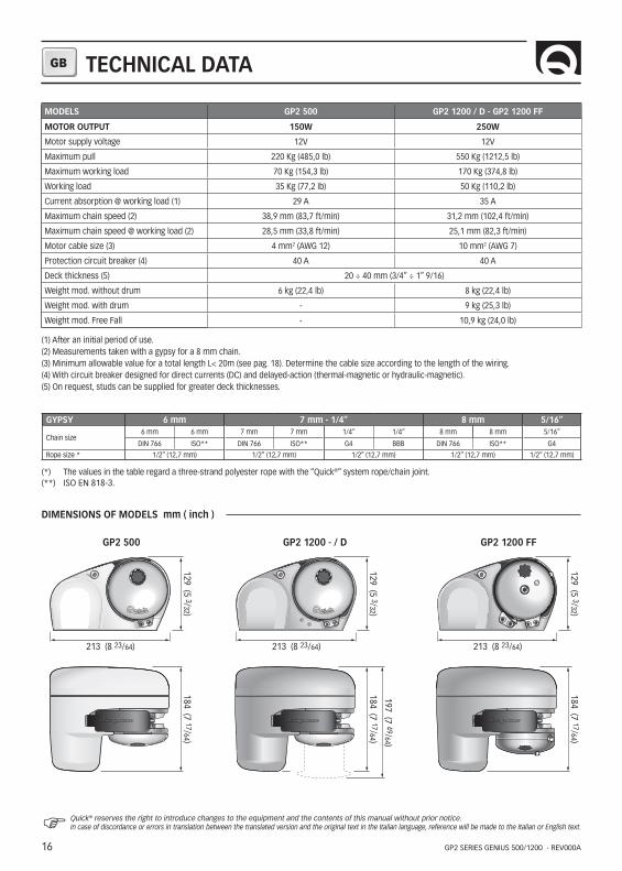
INSTALLATION REQUIREMENTS: the windlass must be positioned with the gypsy aligned with the bow roller. Ensure that the upper and lower surfaces of the deck are as parallel as possible. If this is not the case, compensate the difference appropriately (a lack of parallelism could result in a loss of motor power). The deck thickness must be included among the figures listed in the table. In cases of other thicknesses it is necessary to consult a Quick® retailer. There must be no obstacles under deck to the passage of cables, rope and chain; lack of depth of the peak could cause jamming.
FITTING PROCEDURE: when the ideal position has been established, drill four holes using the drilling template provided.Remove excess material from the chain through hole, ensuring the free passage of the chain or rope. Position the windlass lowering it from above deck and inserting the gasket between the deck and the base. Screw the stud bolts, using the short threaded end, onto the base. Apply a medium grade locking product onto the thread. Fix the windlass by screwing the nuts onto the fixing studs. Connect the supply cables from the windlass to the reversing contactor unit.
max 5 mm(3/16”)
40 cm(16”)
45°
18
GB
GP2 SERIES GENIUS 500/1200 - REV000A
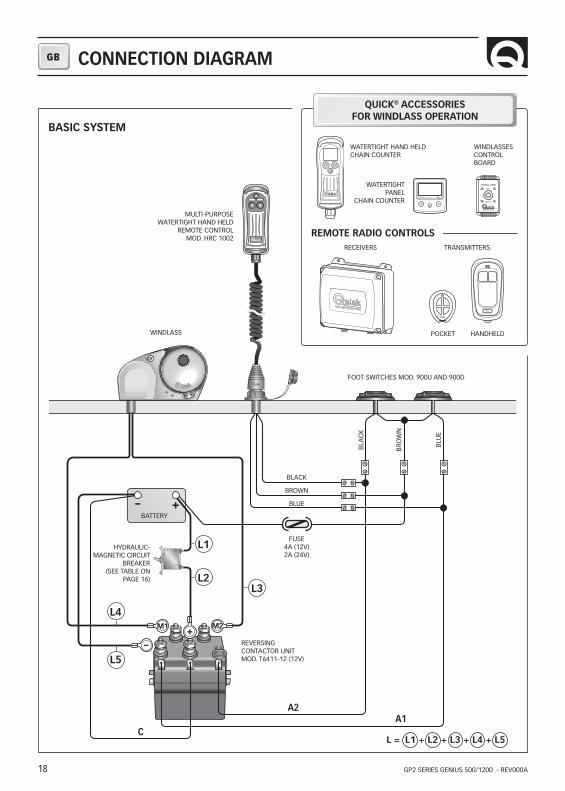
- +
M1 M2
MULTI-PURPOSEWATERTIGHT HAND HELD
REMOTE CONTROLMOD. HRC 1002
WINDLASS
BATTERY
HYDRAULIC-MAGNETIC CIRCUIT
BREAKER(SEE TABLE ON
PAGE 16)
REVERSING CONTACTOR UNITMOD. T6411-12 (12V)
FOOT SWITCHES MOD. 900U AND 900D
BLACK
BROWN
BLUE
BRO
WN
BLA
CK
BLU
E
FUSE4A (12V)2A (24V)
BASIC SYSTEM
WATERTIGHTPANEL
CHAIN COUNTER
WINDLASSESCONTROLBOARD
WATERTIGHT HAND HELDCHAIN COUNTER
QUICK® ACCESSORIESFOR WINDLASS OPERATION
REMOTE RADIO CONTROLS
L = L1 + L2 + L3 + L4 + L5
CONNECTION DIAGRAM
RECEIVERS TRANSMITTERS
HANDHELD
C
A2A1
L3L2
L1
L4
L5
19
GB
GP2 SERIES GENIUS 500/1200 - REV000A
WARNING: stay clear of the chains, ropes and gypsy. Make sure the electric motor is off when windlass is used manually (even when using the handle to disengage the clutch). In fact people with windlass remote controls (hand-held remote control or radio-controlled systems) might accidentally operate it.
WARNING: secure the chain with a device before starting the navigation.
WARNING: do not operate the windlass by using the electrical power when the handle is inserted in the drum or into the gypsy cover.
WARNING: Quick® recommend using a circuit breaker designed for direct current (DC) with delayed-action (thermal-magnetic or hydraulic-magnetic) to protect the motor supply line from overheating or short circuits. The circuit breaker can be used to cut off power to the windlass control circuit and so avoid accidental activation.
CLUTCH USE
MOD. FF (see drawing on page 21)The clutch (N) provides a link between the gypsy and the main shaft (A). The clutch can be released (disengagement) by using the handle (1) which, when inserted into the gypsy cover (N), must be turned counter-clockwise. The clutch will be re-engaged by turning it clockwise.
MOD. 500/1200 (see drawings on pages 22 and 24)The clutch (3) provides a link between the gypsy and the main shaft (mod.500 = 19 - mod.1200 = 21 or 23). The clutch can be released (disengagement) by using the handle (1) which, when inserted in the bush (8) of the drum or into the gypsy cover (2), must be turned counter-clockwise. The clutch will be re-engaged by turning it clockwise.
WEIGHING THE ANCHOR Turn on the engine. Make sure the clutch is engaged and remove the handle. Press the UP button on the control pro-vided. If the windlass stops and the hydraulic magnetic switch (or thermal cutout) has not tripped, wait a few seconds and try again (avoid keeping the button pressed). If the hydraulic magnetic switch, has tripped, reset it and wait a few minutes before weighing anchor once again. If, after a number of attempts, the windlass is still blocked, we suggest to move the boat to release the anchor. Check the upward movement of the chain for the last few meters in order to avoid damages to the bow.
CASTING THE ANCHOR The anchor can be cast by using the electrical control or manually. To operate manually, the clutch must be disengaged allowing the gypsy to revolve and letting the rope or chain fall into the water. To slow down the chain, the handle must be turned clockwise. To cast the anchor by using the electrical power, press the DOWN button on the control provided. In this manner, anchor casting is under control and the chain and rope unwind evenly. In order to avoid any stress on the windlass -once the boat is anchored- fasten the chain or secure it in place with a rope.
DRUM USE MOD. 1200 D (see drawing on page 24)
WARNING: before carrying out warping operations, check that the anchor and relative rope or chain are solidly fixed to a bitt or another strong point on the boat.
For the independent use of the drum (9) release the clutch with the handle (1), (at least 2 turns of the bush anticlock-wise). Remove the handle from the bush (8) on the gypsy, wrap the rope around the drum (at least 3 turns). Activate the windlass control, keeping the rope under tension during take up. By varying the tension during take up it is possible to modify the rope winding speed.
WARNING: during take up maintain a safe distance between hands and windlass drum.
Once take up is complete, screw up the clutch by tightening the drum bush clockwise and secure the rope to a bitt or other strong point on the boat.
USAGE - WARNING
20
GB
GP2 SERIES GENIUS 500/1200 - REV000A20
MAINTENANCE
2930
31
3021
22
2223
22
18
17
27
38
39
40
36
22
41
14
13
12
11
16
10
9 42
3233
3435
33
37
28
15
25
26
17
7
3
8
4
3
2
15
6
20
2019
22
24
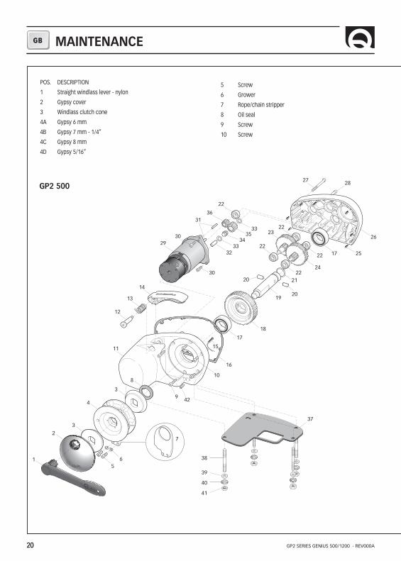
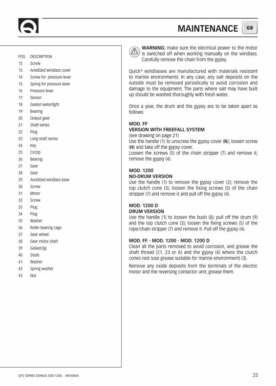
POS. DESCRIPTION
1 Straight windlass lever - nylon
2 Gypsy cover
3 Windlass clutch cone
4A Gypsy 6 mm
4B Gypsy 7 mm - 1/4”
4C Gypsy 8 mm
4D Gypsy 5/16”
5 Screw
6 Grower
7 Rope/chain stripper
8 Oil seal
9 Screw
10 Screw
GP2 500

21
GB
GP2 SERIES GENIUS 500/1200 - REV000A 21
MAINTENANCE
WARNING: make sure the electrical power to the motor is switched off when working manually on the windlass. Carefully remove the chain from the gypsy.
Quick® windlasses are manufactured with materials resistant to marine environments. In any case, any salt deposits on the outside must be removed periodically to avoid corrosion and damage to the equipment. The parts where salt may have built up should be washed thoroughly with fresh water.
Once a year, the drum and the gypsy are to be taken apart as follows:
MOD. 500Use the handle (1) to remove the gypsy cover (2); remove the top clutch cone (3); loosen the fixing screws (5) of the chain stripper (7) and remove it and pull off the gypsy (4).
Clean all the parts removed to avoid corrosion, and grease the shaft thread (19) and the gypsy (4) where the clutch cones (3) rest (use grease suitable for marine environment) .
Remove any oxide deposits from the terminals of the electric motor and the reversing contactor unit; grease them.
POS. DESCRIPTION
11 White plastic 150 windlass cover
12 Screw for pressure lever
13 Spring for pressure lever
14 Pressure lever
15 Sensor
16 Gasket watertight
17 Bearing
18 Output gear
19 Shaft series
20 Plug
21 Circlip
22 Bearing
23 Gear
24 Gear
25 Plug
26 White plastic 150 windlass base
27 Screw
28 Screw
29 Motor
30 Screw
31 Mooring rope puller pin
32 Plug
33 Washer
34 Roller bearing cage
35 Gear wheel
36 Gear motor shaft
37 Gasket/jig
38 Studs
39 Washer
40 Spring washer
41 Nut
42 Hexagonal cheese-headed screw
22
GB
GP2 SERIES GENIUS 500/1200 - REV000A
MAINTENANCE
2627
26
20
19
30
40
41
42
31
38
32
33
26
43
22
16
15
14
13
18
12 11
32
3334
3536
3735
39
17
22
29
19
7
3
10
4
3
2
98
1
56
22
24
22
22
25
22
25
23
21
26
26
28
GP2 1200GP2 1200 D
POS. DESCRIPTION
1 Windlass lever - Nylon
2 Gypsy cove
3 Windlass clutch cone
4A Gypsy 6 mm
4B Gypsy 7 mm - 1/4”
4C Gypsy 8 mm
4D Gypsy 5/16”
5 Screw
6 Grower
7 Rope/chain stripper
8 Bush
9 Drum
10 Oil seal
11 Screw
23
GB
GP2 SERIES GENIUS 500/1200 - REV000A
MAINTENANCE
POS. DESCRIPTION
12 Screw
13 Anodized windlass cover
14 Screw for pressure lever
15 Spring for pressure lever
16 Pressure lever
17 Sensor
18 Gasket watertight
19 Bearing
20 Output gear
21 Shaft series
22 Plug
23 Long shaft series
24 Key
25 Circlip
26 Bearing
27 Gear
28 Gear
29 Anodized windlass base
30 Screw
31 Motor
32 Screw
33 Plug
34 Plug
35 Washer
36 Roller bearing cage
37 Gear wheel
38 Gear motor shaft
39 Gasket/jig
40 Studs
41 Washer
42 Spring washer
43 Nut
WARNING: make sure the electrical power to the motor is switched off when working manually on the windlass. Carefully remove the chain from the gypsy.
Quick® windlasses are manufactured with materials resistant to marine environments. In any case, any salt deposits on the outside must be removed periodically to avoid corrosion and damage to the equipment. The parts where salt may have built up should be washed thoroughly with fresh water.
Once a year, the drum and the gypsy are to be taken apart as follows:
MOD. FF VERSION WITH FREEFALL SYSTEM (see drawing on page 21)Use the handle (1) to unscrew the gypsy cover (N); loosen screw (H) and take off the gypsy cover. Loosen the screws (5) of the chain stripper (7) and remove it; remove the gypsy (4).
MOD. 1200 NO-DRUM VERSIONUse the handle (1) to remove the gypsy cover (2); remove the top clutch cone (3); loosen the fixing screws (5) of the chain stripper (7) and remove it and pull off the gypsy (4).
MOD. 1200 DDRUM VERSIONUse the handle (1) to loosen the bush (8); pull off the drum (9) and the top clutch cone (3); loosen the fixing screws (5) of the rope/chain stripper (7) and remove it. Pull off the gypsy (4).
MOD. FF - MOD. 1200 - MOD. 1200 DClean all the parts removed to avoid corrosion, and grease the shaft thread (21, 23 or A) and the gypsy (4) where the clutch cones rest (use grease suitable for marine environment) (3).
Remove any oxide deposits from the terminals of the electric motor and the reversing contactor unit; grease them.
24
GB
GP2 SERIES GENIUS 500/1200 - REV000A
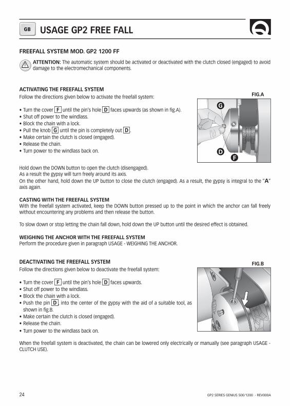
FREEFALL SYSTEM MOD. GP2 1200 FF
ATTENTION: The automatic system should be activated or deactivated with the clutch closed (engaged) to avoid damage to the electromechanical components.
ACTIVATING THE FREEFALL SYSTEM Follow the directions given below to activate the freefall system:
• Turn the cover F until the pin’s hole D faces upwards (as shown in fig.A).• Shut off power to the windlass. • Block the chain with a lock. • Pull the knob G until the pin is completely out D . • Make certain the clutch is closed (engaged). • Release the chain.• Turn power to the windlass back on.
Hold down the DOWN button to open the clutch (disengaged). As a result the gypsy will turn freely around its axis.On the other hand, hold down the UP button to close the clutch (engaged). As a result, the gypsy is integral to the “A” axis again.
CASTING WITH THE FREEFALL SYSTEM With the freefall system activated, keep the DOWN button pressed up to the point in which the anchor can fall freely without encountering any problems and then release the button.
To slow down or stop letting the chain fall down, hold down the UP button until the desired effect is obtained.
WEIGHING THE ANCHOR WITH THE FREEFALL SYSTEM Perform the procedure given in paragraph USAGE - WEIGHING THE ANCHOR.
DEACTIVATING THE FREEFALL SYSTEM Follow the directions given below to deactivate the freefall system:
• Turn the cover F until the pin’s hole D faces upwards.• Shut off power to the windlass. • Block the chain with a lock. • Push the pin D , into the center of the gypsy with the aid of a suitable tool, as
shown in fig.B.• Make certain the clutch is closed (engaged). • Release the chain.• Turn power to the windlass back on.
When the freefall system is deactivated, the chain can be lowered only electrically or manually (see paragraph USAGE - CLUTCH USE).
FIG.B
FIG.A
USAGE GP2 FREE FALL
G
DF
25
GB
GP2 SERIES GENIUS 500/1200 - REV000A
MAINTENANCE
3022
2919
A
2627
26
2019
40
41
42
31
38
32
33
26
43
16
15
14
13
18
6
11
32
3334
3536
3735
39
17
22
10
22
22
25
26
2628
7
3
4
1
5
B
C
LI
M
N
H
F
G
E
D
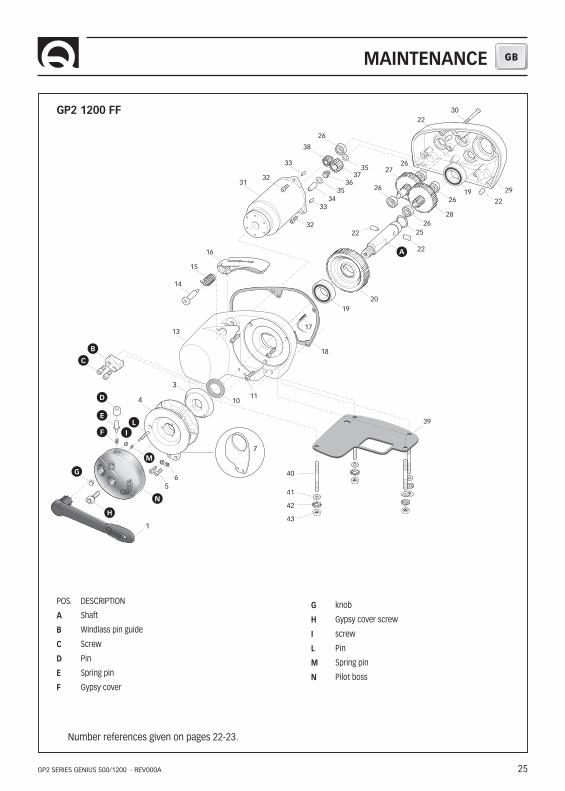
GP2 1200 FF
Number references given on pages 22-23.
POS. DESCRIPTION
A Shaft
B Windlass pin guide
C Screw
D Pin
E Spring pin
F Gypsy cover
G knob
H Gypsy cover screw
I screw
L Pin
M Spring pin
N Pilot boss
26
GB
GP2 SERIES GENIUS 500/1200 - REV000A
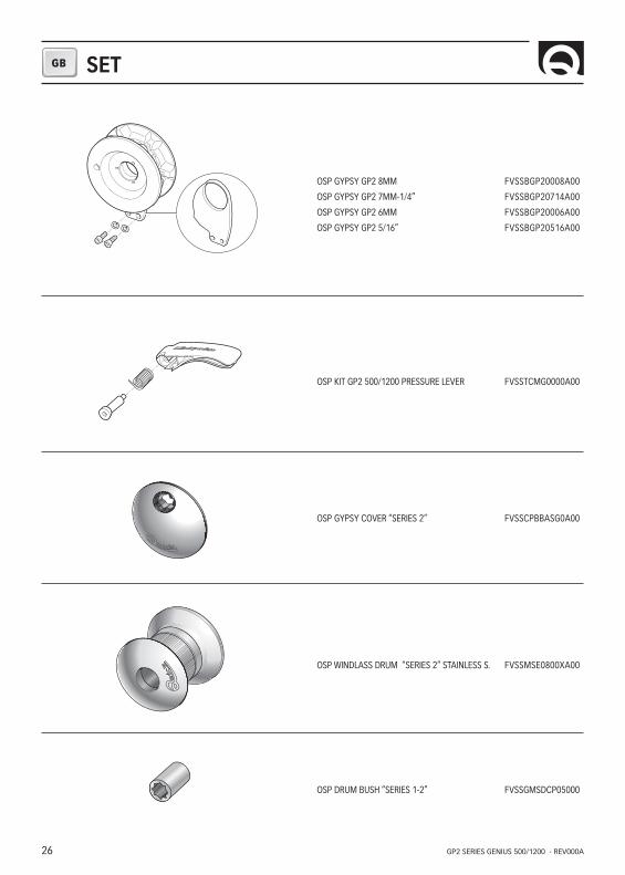
SET
OSP GYPSY GP2 8MM FVSSBGP20008A00
OSP GYPSY GP2 7MM-1/4” FVSSBGP20714A00
OSP GYPSY GP2 6MM FVSSBGP20006A00
OSP GYPSY GP2 5/16” FVSSBGP20516A00
OSP KIT GP2 500/1200 PRESSURE LEVER FVSSTCMG0000A00
OSP GYPSY COVER “SERIES 2” FVSSCPBBASG0A00
OSP WINDLASS DRUM “SERIES 2” STAINLESS S. FVSSMSE0800XA00
OSP DRUM BUSH “SERIES 1-2” FVSSGMSDCP05000
27
GB
GP2 SERIES GENIUS 500/1200 - REV000A
SET
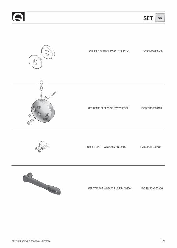
OSP STRAIGHT WINDLASS LEVER - NYLON FVSSLVSDN000A00
OSP KIT GP2 WINDLASS CLUTCH CONE FVSSCFG00000A00
OSP COMPLET FF “GP2” GYPSY COVER FVSSCPBBGFF0A00
OSP KIT GP2 FF WINDLASS PIN GUIDE FVSSGPGFF000A00

QUICK® S.P.A. - Via Piangipane, 120/A - 48124 Piangipane (RAVENNA) - ITALYTel. +39.0544.415061 - Fax +39.0544.415047 www.quickitaly.com - E-mail: [email protected]
Codice e numero seriale del prodotto
Product code and serial number
Code et numéro de série du produit
Code- und Seriennummer des Produkts
Código y número de serie del producto
GB
FR
DE
IT
ES
GP2 GENIUS SERIES500 / 1200
R000a