Embed Size (px)
Citation preview
Journal The Prankiin Institute
Devoted to Science and the Mechanic Arts
Vol. 194 DECEMBER, 1922 No. 6
HIGH-SPEED PHOTOGRAPHY OF VIBRATIONS (SOUND, MECHANICAL, ELECTRICAL, ETC.).*
BY
AUGUSTUS TROWBRIDGE, Ph.D., D.S.M., D.S.O., Chev.L.H. Professor of physics. Princeton University, Princeton. New Jersey.
Member of the Institute.
UP to within a few years ago I shared what I believe to be the general feeling amon g technical scientific men that photo- graphic methods of recording experimental data such as pressure- volume changes in engine cylinders, motion or timing of valves, vibrations of sonorous bodies, motions of optical images or the interference fringes obtained with visible or ultra-violet light, etc., etc., could not be rendered sufficiently simple to be reliable in the hands of the ordinary intelligent mechanic. Nearly two years’ experience in France during the war convinced me that photo- graphic recording is the quickest, cheapest, most simple and clean- est method there is. In the American Army I was in charge of the sound-ranging service, the object of which was to locate the positions of the enemy large calibre guns by recording the time of arrival of their sound at known positions near our own trenches. An accuracy of about fifty feet in five miles was required and a delay of more than four or five minutes in record- ing, calculating and reporting to our own artillery headquarters was considered excessive. Th e work was carried on by the ordi- nary enlisted man who had been given but a few weeks’ special
*Presented at a meeting of the Section of Physics and Chemistry of The Franklin Institute held Thursday, October 26, 1922.
(No&--The Franklin Institute is not responsible for the statements and opinions advanced by contributors to the JOURNAL)
COPYRIGHT, was. by THE FRANKLIN INSTITUTE. VOL. 194, No. 1164-50 713
714 AUGUSTUS TROWBRIDGE. [J. F. I.
training; and it was always conducted under rather unfavorable conditions in cellars of ruined houses or in crowded dugouts. I believe that photographic methods which stood this test contin- ually for months without a breakdown are suitable for use under almost any conditions.
Success was chiefly due to the fact that all operations were made strictly automatic. The camera was designed to use a cheap sensitized paper which was fed from a zoo-foot roll past a stationary lens through which the exposure was made. The paper was automatically developed and fixed before it left the camera, so that there was no chance whatever of confusion of records when a great many were being taken in rapid succession, since the operator could inspect and mark with a pencil each record as it issued from the camera. In the case of the camera originally designed for field use, the speed of taking the photo- graph was slow, so that the paper could be run through the developer and fixer at the same speed at which exposure was made, without danger that the development might not be long enough for the most satisfactory contrast between light and shadow. For laboratory purposes, however, it is desirable that very rapid exposures may be taken in some instances and there- fore the camera was re-designed by Mr. William Duryea, head mechanician of the Physical Laboratory of Princeton University, whose great experience in the design and construction of the field instrument enabled him to retain the excellent simple automatic features which had been thoroughly tested, and, at the same time, introduce modifications which permit much greater flexibility in use. One of these is a simple mechanism which allows the record to be taken at one speed and developed at a slower speed so as to give sharp contrast. Exposure speeds up to about four feet per second, using an ordinary automobile electric-light bulb as a source of light, can be used and the _automatically developed records show entirely satisfactory contrast.
A series of fine lines reaching clear across the paper is photo- graphed at the same time as the record. These lines are spaced 0.01 second apart, even if the speed of the paper should vary slightly, and serve as time-lines to time accurately an event shown on the record; for example, the opening and closing of an exhaust- valve of a running automobile engine.
Dec., Igzz.] HIGH-SPEED PHOTOGRAPHY. 715
An automatic recording camera can be used to trace the motion of any moving part of a mechanism and, owing to the high speed at which a record can be taken, it is possible to study variations which occur in time-intervals as short as 0.001 second. It is more convenient to transmit electrically to the camera the motion that actually takes place in the mechanism than to attempt to set up the camera itself close to the mechanism. A special form of simple string galvanometer is very convenient and meets satisfactorily the necessary condition that its moving part shall move synchronously with the motion of the mechanism. The moving part of the galvanometer is practically weightless, as it is a short piece of wire 0.0004 inch in diameter, and its motion is strongly damped by the magnetic field in which it is placed. When a current is sent through this wire it moves in the magnetic field and a shadow of this motion is photographed by the auto- matic camera.
In practice, almost any slight motion can be converted into a flow of electricity, so that the applications of photographic record- ing to the study of vibrations in running machinery are very numerous.
CAXERA.
The essential features in the design of a suitable photographic recorder for the experimental purposes of a laboratory are some- what similar to those embodied in the moving picture machine, in that a sensitized tape must be moved rapidly behind a suitable lens which brings an image of the moving object on the sensitized tape. In the moving picture camera an extended image of a variety of objects must be formed and a series of such extended images is obtained by the use of a shutter which revolves at suitable speed. The problem is somewhat simpler in the design of photographic recorder since the moving object which is to be photographed is, in general, very small compared to the moving objects photographed by the moving picture camera. It is, in fact, generally possible to arrange that the moving object shall be a point of light, or, at least, a fine line of light, whose long dimensions may be brought parallel to the direction of motion of the sensitized tape in the camera. Instead of a line or point of light, a sharply defined moving shadow caused by the motion of a very fine wire may be the object to be photographed. Under
716 AUGUSTUS TROWBRIDGE. [J. F. I.
these conditions there is not the possibility of overlapping of portions of the images on the sensitized tape that there would be in the moving picture camera and hence the usual shutter of such cameras may be dispensed with and an actual continuous record of the motion of the small body may be made instead of a series of instantaneous photographs of its position as would be the case were a shutter used. The possibility of doing away with the shutter greatly simplifies the design and permits the attainment of very rapid exposure without any serious mechanical difficulty.
If it is desired to record the motion of a spot of light which moves, say, in a horizontal plane, an ordinary lens may be used to bring an image of the spot on the moving sensitized tape and the tape is run rapidly behind the lens in a vertical plane. This gives a photographic trace of the position of the spot in the form of a line. If a bright flash or a dense shadow is thrown across the tape every hundredth of a second, for example, it will be pos- sible to tell from the developed record just what the position of the spot of light was at any given instant of time. If, instead of a spot of light, the moving object is a fine line of light or a sharply defined shadow in a vertical plane, it is necessary to substitute for the ordinary lens, to bring the image on the tape, a cylindrical lens whose axis (the axis of the cylinder from which the lens is cut) lies in a horizontal plane. The action of such a lens is to gather all of the light from a vertical line and focus it into a very bright and tiny spot and the lens has no condensing action in the direction of its own axis; therefore, the line of light is imaged as a spot of light whose diameter is the correct image of the diameter of the line of light. If there is no motion of the line the photographic record is a straight line which is the correct image of the stationary line. If the line moves rapidly the record shows a curve any point on which is the image of the position of the moving line at the corresponding time. If a sharp shadow is cast by an opaque narrow wire which moves, the motion of that shadow gives a curve on the record which is a faithful represen- tation of the motion of the wire which casts the shadow.
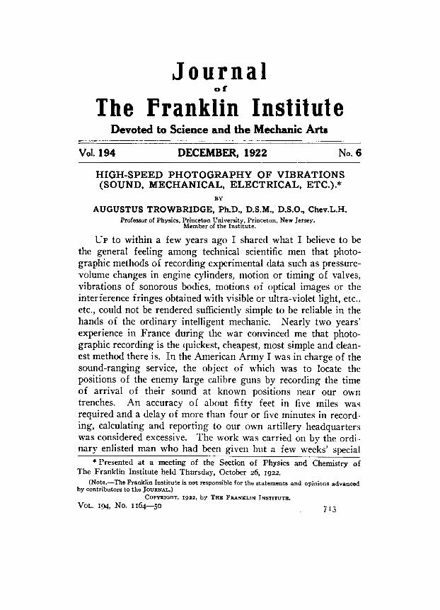
Figs. I, 2, and 3 show some of the especial features of a recording camera.
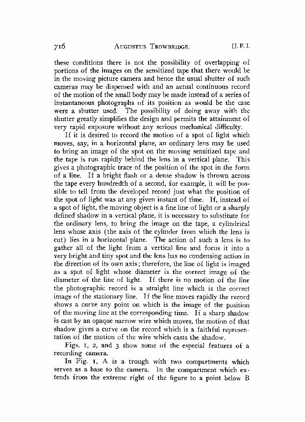
In Fig. I, A is a trough with two compartments which serves as a base to the camera. In the compartment which ex- tends from the extreme right of the figure to a point below I?
Dec., Igm.] HIGH-SPEED PHOTOGRAPHY. 717
the developer is placed. B is a roller which transfers the devel- oped film into the second portion of the tank to the left of the figure in which the fixing bath is. The developed side of the film is the under side as it comes through the baths, and, for this reason, is sufficiently protected from daylight so that the fixing may be done outside the camera proper. The unexposed film is stored in the upper cylindrical portion of the camera (shown in
FIG. I.
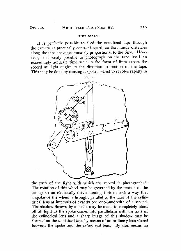
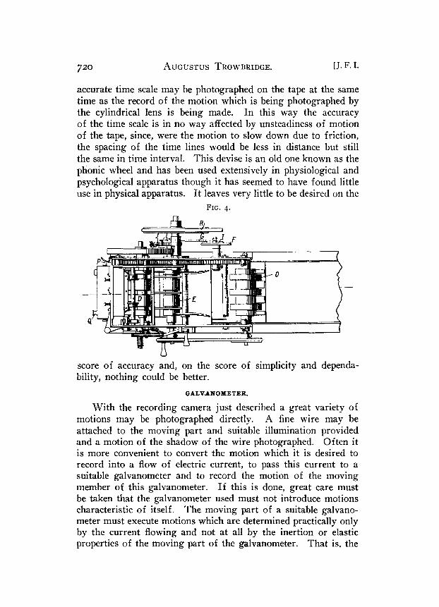
part near C) and is fed down in a vertical plane at the right of Fig. I, being caught by the rollers D shown in Fig. 4 (in plan). If the speed of exposure is rapid, the rollers D are driven more rapidly than the rollers E by the mechanism shown at F to R/I inclusive in Fig. I, which allows of any practical ratio of speeds. When the sensitized tape is started it immediately commences to be fed into the developer at the slower speed and the excess of tape is stored up in a storage space near the top of the camera. The tape passes between the blades of a knife operated by the lever N of Fig. 3, which cuts off the tape when the operator
718
has finished an Fig. 4, cease to 0 continue to
AUGUSTUS TROWBRIDGE. [J. F. I.
exposure. When this happens the rollers D, feed the unexposed tape, but the rollers E and feed the exposed tape through the solutions
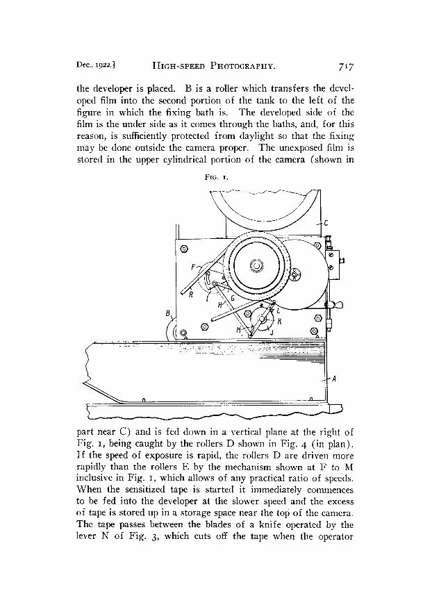
until all has passed through. The mechanism, shown enlarged in Fig. 3, serves to guide the tape into the storage space and prevent its entanglement with a new length of tape in case it is desired to expose a second tape before the first one has passed through the camera. The face of the camera is closed by a hinged
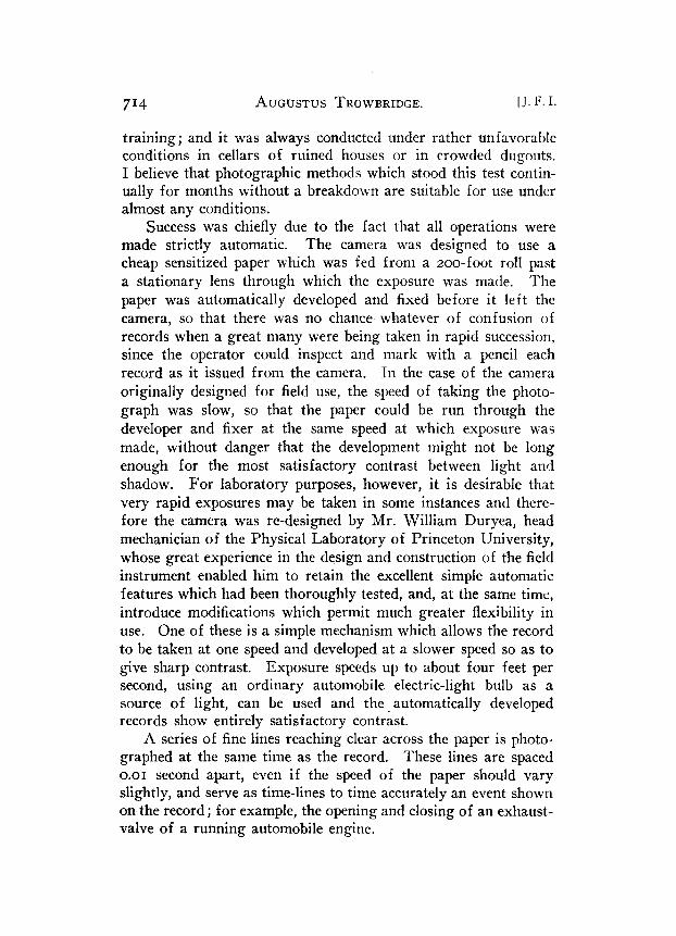
FIG. 2.
door-P, Fig. 4-which carries the cylindrical lens with its axis in a horizontal plane. The amount of light admitted to the lens is regulated by a horizontal aperture of variable width which can be opened or closed by a knurled screw Q, Figs. 2 and 4. The power necessary to drive the mechanism is supplied by a motor (not shown) which may be started or stopped by a foot switch controlled by the operator. This motor drives the mechan- ism by means of a belt R. Suitable gears, shown in Fig. 4, are used to drive the roller D at any desired speed.
Dec., 1922.1 HIGII-SPEED PHOTOGRAPHY. 719
TIME SCALE.
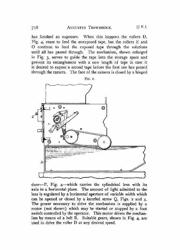
It is perfectly possible to feed the sensitized tape through the camera at practically constant speed, so that linear distances along the tape are approximately proportional to the time. How- ever, it is easily possible to photograph on the tape itself an exceedingly accurate time scale in the form of lines across the record at right angles to the direction of motion of the tape. This may be done by causing a spoked wheel to revolve rapidly in
FIG. 3.
the path of the light with which the record is photographed. The rotation of this wheel may be governed by the motion of the prongs of an electrically driven tuning fork in such a way that a spoke of the wheel is brought parallel to the axis of the cylin- drical lens at intervals of exactly one one-hundredth of a second. The shadow thrown by a spoke may be made to completely block off all light as the spoke comes into parallelism with the axis of the cylindrical lens and a sharp image of this shadow may be formed on the sensitized tape by means of an ordinary lens placed between the spoke and the cylindrical lens. By this means an
720 AUGUSTUS TROWBRIDGE. [J.F. I.
accurate time scale may be photographed on the tape at the same time as the record of the motion which is being photographed by the cylindrical lens is being made. In this way the accuracy of the time scale is in no way affected by unsteadiness of motion of the tape, since, were the motion to slow down due to friction, the spacing of the time lines would be less in distance but still the same in time interval. This devise is an old one known as the phonic wheel and has been used extensively in physiological and psychological apparatus though it has seemed to have found little use in physical apparatus. It leaves very little to be desired on the
FIG. 4.
- -
score of accuracy and, on the score of simplicity and dependa- bility, nothing could be better.
GALVANOPBTER.
With the recording camera just described a great variety of motions may be photographed directly. A fine wire may be attached to the moving part and suitable illumination provided and a motion of the shadow of the wire photographed. Often it is more convenient to convert the motion which it is desired to record into a flow of electric current, to pass this current to a suitable galvanometer and to record the motion of the moving member of this galvanometer. If this is done, great care must be taken that the galvanometer used must not introduce motions characteristic of itself. The moving part of a suitable galvano- meter must execute motions which are determined practically only by the current flowing and not at all by the inertion or elastic properties of the moving part of the galvanometer. That is, the
Dec., 1922.1 HIGH-SPEED PHOTOGRAPHY. 721
moving part must be practically without weight, it must have a restoring force acting on it which will make it return quickly to its position of rest, and its motion must be sufficiently damped so that it will not tend to overshoot its position of deflection as it takes up this position. In addition, it must be moderately sensi- tive so that small currents may produce appreciable motions.
It is impossible to fulfill all of these conditions absolutely, but they have been practically met in the design of the string galvano- meter by the Dutch physiologist, Einthofen, and described by him in P&iiger’s Arch. f. d. Gesmnte. Physiol. (9% p. 372, 1903).
FIG. 5.
The full theory of the design and performance of the string gal- vanometer is also given in Ann. der Phys. (21, 1906, p. 433).
The instrument which I have used in connection with the recording camera is a simple modification of the Einthofen instru- ment. One or more very fine wires are mounted vertically between the poles of an electromagnet whose magnetic field is horizontal. The pole pieces of the magnet are bored out and each is fitted to carry a small microscope objective lens of about s-inch focus, each lens being about s inch from the plane of the fine vertical wires. Light passing through the lenses travels at right angles to the plane of the vertical wires and along the lines of force of the magnetic field.
As a source of light a small nitrogen filled tungsten filament automobile head-light bulb is used. A small lens forms a real image of the filament at 5 inch from the first microscope objec- tive mentioned above. Between the bulb and the small lens a spoked wheel is mounted so that the spokes, as they revolve, cut off the light. The spoked wheel is rotated at constant speed, SO that a spoke comes into a horizontal position every hundredth of a second. The constancy of rotation of the wheel is secured by VOL. 194, No. 1164-51
722 AUGUSTUS TROWBRIDGE. [J. F. I.
governing its motion by current impulses from an accurate tuning fork, itself electrically driven. The light from the real image of the tungsten filament is rendered parallel by the first microscope objective and this narrow parallel beam of light illuminates uni- formly the vertical fine wires of the galvanometer. These wires cast shadows which may be focussed by the second microscope objective so as to be sharp black lines in the plane of the photo- graphic tape of the camera. A cylindrical lens is mounted in the converging beam of light so as to render the sharp shadow lines sharp shadow points as mentioned above.
FIG. 6.
When a current flows in one of the galvanometer wires, the wire moves at right angles both to its own length and to the direction of the magnetic field in which it stands, and since the beam of light is.in the direction of the magnetic field, the motion of the wire is in a vertical plane and across the beam of light. The shadow of the wire will thus move across the axis of the beam of light or will move in the plane of the sensitized tape of the camera. For small currents the amount of motion of the point image of the shadow on the tape will be proportional to the current and a reversal of the direction of flow of current in the wire will produce a reversal of the motion of the shadow. It is possible to adjust the position of the wire in the magnetic field of the galvanometer so that the deflection of the shadow to the right and left of the zero position is accurately the same when a given current is sent, first in one direction and then in the other, through the galvanometer wire.
DAMPING.
If a small current be sent through the wire and a permanent deflection of the shadow image obtained, and then the circuit be
Dec.. 1922.] HIGH-SPEED PHOTOGRAPHS. 7’3
suddenly broken, the record of the motion of the wire as it returns to its zero position is a wave motion whose period is determined by the tension to which the wire is subjected and by the mass of the moving wire. The successive excursions of the wire about its zero position grow gradually less because of air friction, stiffness of the wire, e$. The motion of the wire on open circuit is only very slightly damped and the instrument would be wholly unre- liable if used under these conditions, for the motions of the wire would be more characteristic of the tension and mass of the wire itself than they would be of the current flowing in the wire. The
FIG. 7.
behavior of the wire will be quite different, however, if it is always shunted with a resistance comparable to its own resistance, for then, as the wire moves in the magnetic field it acts as a tiny dynamo and sends current through the shunting resistance, and the energy of this induced current must come from the motion of the wire. To the small air friction damping .which exists when the wire is on open circuit, is added a large electromagnetic damping when the wire is shunted with a resistance comparable to its own resistance and the amount of this electromagnetic damping may be increased by reducing the resistance of the shunt. In practice it is possible to render the motion of the galvanometer wire practically aperiodic by the use of a shunt whose resistance is about one-third of that of the wire itself. This has the dis- advantage of reducing the sensitivity of the galvanometer to about one-third of what it would be were no shunt used, but the gain in having a practically dead-beat instrument whose motion depends solely on the instantaneous value of the current flowing in it, more than offsets this sacrifice in sensitivity.
If one wishes to record very rapid variations in current, one must put the wire under rather strong tension so that its free
724 AUGUSTUS TROWBRIDGE. [J. F. I.
period (undamped) shall be less than the period of the current variations one wishes to record; at the same time one must shunt the wire with small resistance in order that the motion of the wire may be sufficiently damped so as to be practically aperiodic. Under these conditions the sensitivity of the instrument (deflec- tion for a given current in the wire) will be r$atively small, both because of the large tension and because of the low shunt.
If one has to record slow variations in current, one may relax the tension and secure adequate damping by the use of a higher
FIG. 8.
resistance shunt and the sensitivity under these conditions may be relatively very large.
It follows from these considerations that the electromagnet of the galvanometer should be designed to give as strong (and uniform) magnetic field as possible in the region where the wire (or wires) stands since both the sensitivity and the damping increase with increasing field strength. In the instrument con- structed in this laboratory, great care has been given to this element in design and the results are very satisfactory since it. is possible to obtain a sensitivity of about one one-hundred thou- sandth of an ampere per millimetre deflection af the shadow of the wire and still preserve sufficient quickness of response and damping to faithfully record small current variations as rapid as a few hundred per second.
So great a sensitivity as this is not needed for most laboratory purposes. When it is not needed a faithful record of current variations taking place in less than a thousandth of a second may be easily secured by increasing the tension and damping of the wire.
Examples of Use of Recorder.-
Dec., Igz2.1 HIGH-WEED PHOTOGRAPHY. 725
(a) As an oscillograph for current and voltage measurement with alternating currents.
If two wires are used, one may serve to record variations in electromotive force and the other to record current variations.
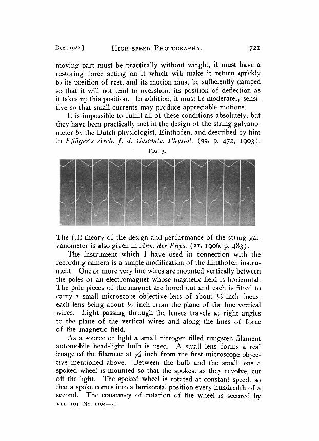
Fig. 5 shows a record of the voltage over the primary of small, cheap transformers with an iron core, and the current in the primary when the secondary is on open circuit. (In the following figures the voltage record is at the top and the current record near the middle of the tape and the beginning of the record is at the left-hand edge, so that each line on the time scale as one counts
FIG. g.
towards the right, is one one-hundredth of a second later than the line to its immediate left.)
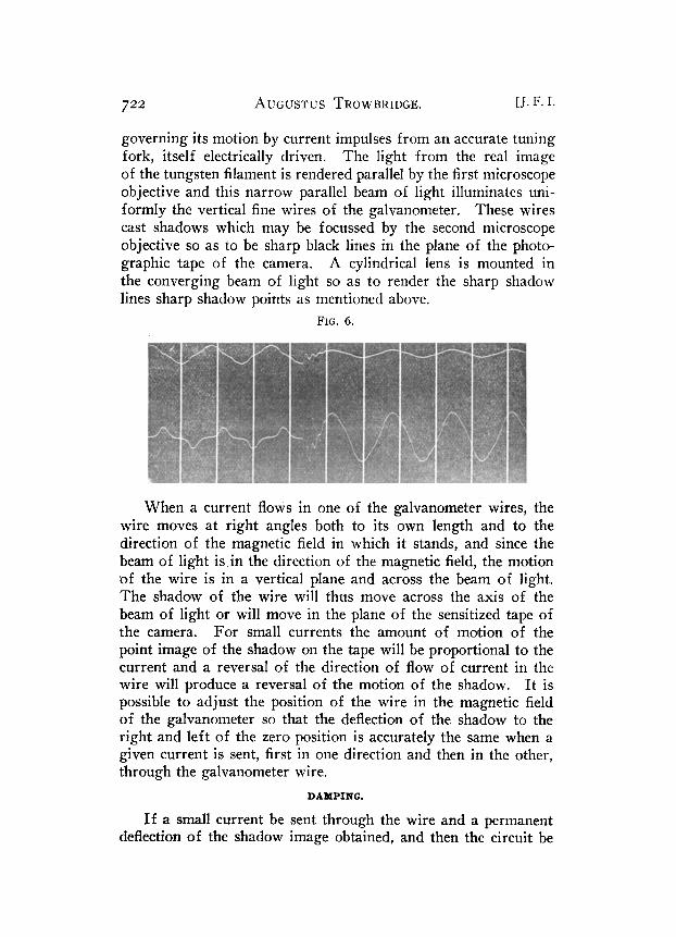
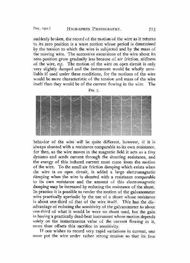
In this figure it will be noted that the current attains its maximum later than the voltage attains its maximum (i.e., the current lags on the e.m. f. in the inductive circuit) and on measure- ment it will be seen that the lag is very nearly one-quarter of a period. It will be further noted that the current does not follow a simple sine law but shows evidences of hysteresis losses in the iron core of the transformer. Fig. 6 shows the effect of suddenly short-circuiting the secondary of the little transformer by placing a knife blade across its terminals (contact not very abrupt !) . The effect is to reduce the impedance of the primary which is shown as an increase in the current and a decrease in the voltage, and to bring the phase of the current into practical agreement with that of the e.m.f. (i.e., to reduce the angle of lag to zero), and also to make the current nearly a sine wave. Fig. 7 is the record of voltage over, and current through, a small telephone condenser of about two microfarads capacity, and the current will be seen to lead on the e.m.f. by about a quarter of a period ; also the dis- torsions of the current wave from the sine form owing to har-
726 AUGUSTUS TROWBRIDGE.
manic components for which the reactance of than for the fundamental are easily noticed.
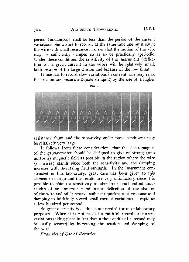
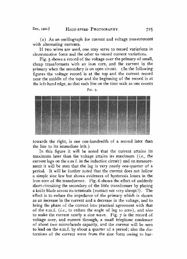
(b) Records of Musical Notes.
[J. F. I.
the capacity is less
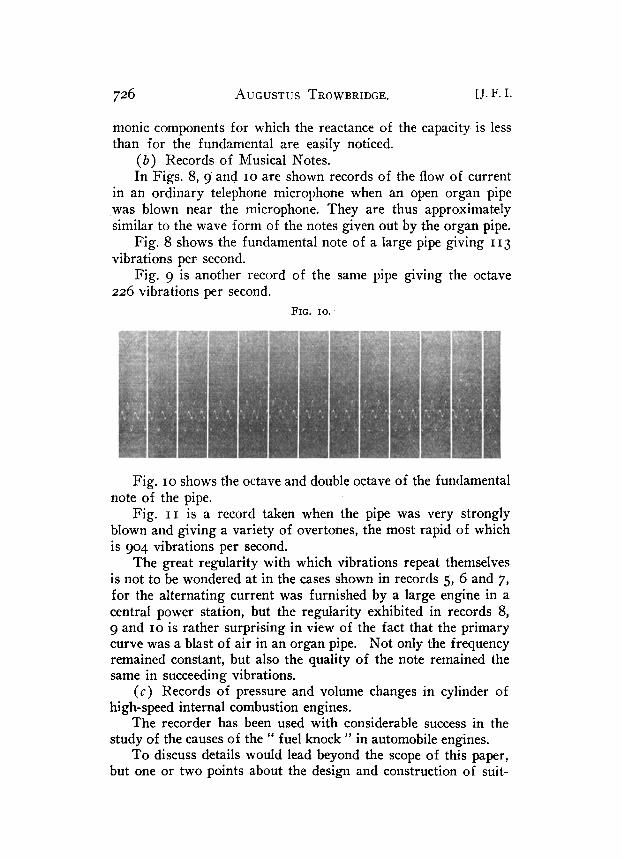
In Figs. 8, 9. and IO are shown records of the flow of current in an ordinary telephone microphone when an open organ pipe was blown near the microphone. They are thus approximately similar to the wave form of the notes given out by the organ pipe.
Fig. 8 shows the fundamental note of a large pipe giving I I 3 vibrations per second.
Fig. 9 is another record of the same pipe giving the octave 226 vibrations per second.
FIG. IO.
Fig. IO shows the octave and double octave of the fundamental note of the pipe.
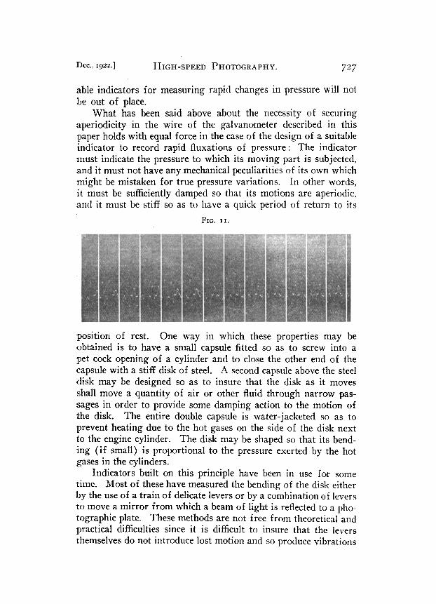
Fig. II is a record taken when the pipe was very strongly blown and giving a variety of overtones, the most rapid of which is 904 vibrations per second.
The great regularity with which vibrations repeat themselves is not to be wondered at in the cases shown in records 5, 6 and 7, for the alternating current was furnished by a large engine in a central power station, but the regularity exhibited in records 8, 9 and IO is rather surprising in view of the fact that the primary curve was a blast of air in an organ pipe. Not only the frequency remained constant, but also the quality of the note remained the same in succeeding vibrations.
(c) Records of pressure and volume changes in cylinder of high-speed internal combustion engines.
The recorder has been used with considerable success in the study of the causes of the “ fuel knock ” in automobile engines.
To discuss details would lead beyond the scope of this paper, but one or two points about the design and construction of suit-
Dec., Igzz.] HIGH-SPEED PHOTOGRAPHY. 727
able indicators for measuring rapid changes in pressure will not be out of place.
What has been said above about the necessity of securing aperiodicity in the wire of the galvanometer described in this paper holds with equal force in the case of the design of a suitable indicator to record rapid fluxations of pressure : The indicator must indicate the pressure to which its moving part is subjected, and it must not have any mechanical peculiarities of its own which might be mistaken for true pressure variations. In other words, it must be sufficiently damped so that its motions are aperiodic, and it must be stiff so as to have a quick period of return to its
FIG. II.
position of rest. One way in which these properties may be obtained is to have a small capsule fitted so as to screw into a pet cock opening of a cylinder and to close the other end of the capsule with a stiff disk of steel. A second capsule above the steel disk may be designed so as to insure that the disk as it moves shall move a quantity of air or other fluid through narrow pas- sages in order to provide some damping action to the motion of the disk. The entire double capsule is water-jacketed so as to prevent heating due to the hot gases on the side of the disk next to the engine cylinder. The disk may be shaped so that its bend- ing (if small) is proportional to the pressure exerted by the hot gases in the cylinders.
Indicators built on this principle have been in use for some time. Most of these have measured the bending of the disk either by the use of a train of delicate levers or by a combination of levers to move a mirror from which a beam of light is reflected to a pho- tographic plate. These methods are not free from theoretical and practical difficulties since it is difficult to insure that the levers themselves do not introduce lost motion and so produce vibrations
728 AUGUSTUS TROWBRIDGE. [J. F. I.
in the record which are not due to pressure changes in the cylin- der, and moreover, any recording mechanical indicator attached directly to a running engine shares the not inconsiderable vibration of the engine itself and, unless it is very massive and rigid, is likely to give a record on which the mechanical vibrations are impressed on the pressure changes it is designed to record. Xlas- sive construction of the recording indicator is an undesirable feature for the reason that quick changes from one cylinder to another of a running engine are rendered difficult.
It seemed to me, therefore, desirable to retain the disk form of indicator and eliminate the objectionable lever feature and, naturally, I thought of converting the motion of the moving disk into the flow of electric current and recording this current flow with the recording galvanometer described above. This would allow the indicator proper to be small and easily screwed into a pet cock opening and it would allow the recording part of the apparatus to be set up at a distance from the noisy running engine. To secure this, all that was necessary was to fasten a very small coil of fine wire to the disk and into the coil to place one pole of an electromagnet, the other pole of which was a ring which surrounded the outer circumference of the coil of fine wire. In this way, when the disk moved, it moved all the turns of the fine wire coil across a radial field of magnetic force and an electro- motive force was generated proportional to the velocity with which the disk moved. If the coil of fine wire was connected so as to send current through the wire of the galvanometer, this current, and hence the motion of the galvanometer wire, was pro- portional to the velocity of motion of the indicator disk, but the velocity of this disk is proportional to the rate of change of pre.s- sure occurring in the cylinder, so the final result was that the photographic record obtained gave the time rate of change of the pressure in a cylinder at every instant of time. A conveniently placed make-and-break key, placed on the crank shaft of the engine, could be used to send a small current to a second wire in the galvanometer and thus the times at which the cylinder was at any part of its stroke (say in-centre) could be recorded at the same time that the pressure variations were recorded. From these data the pressure corresponding to any given volume of gas in the cylinder can be calculated. However, in a study of changes brought about by changed mixture-strength, changed engine
Dec., ~gzz.] HIGH-SPEED PHOTOGRAPHY. 729
speed, changed temperature or the like, it is not necessary to convert the observed data into the well-known pressure-volume diagram, for one soon becomes expert in interpreting the observed diagram which gives time rate of variation of pressure as a function of time. In fact, such an indicator diagram shows far more of what is going on in an engine cylinder than the corre- sponding pressure-volume diagram with which engineers are more familiar. One reason for this is that the most interesting part of the cycle of an internal combustion engine is near the in-centre and out-centre positions, for near the former the ignition takes place and near the latter the exhaust valve opens. The standard pressure-volume diagram is most crowded together at these very points, whereas a pressure-change-time diagram is per- fectly uniformly spaced. The pressure-volume diagram is widely spaced in the very region where one could stand crowding without sacrificing accuracy and is so crowded together as to be inaccu- rate at the very places where the most important changes are going on in the cylinder. The pressure-volume diagram was designed for use with slow-speed steam engines and has certain obvious advantages, but it should be discarded when one wishes to represent what goes on in a high-speed internal combus- tion engine.
In the interests of fuel economy, it is very desirable that far- reaching studies be made looking towards increasing the efficiency of the automobile engine. Automobile engineers should not over- look the fact that the design of efficient steam engines was greatly aided by the perfection of a suitable indicator and that, while the problem of design of an indicator suitable for the high speeds of the internal combustion engine is difficult, it is by no means impossible.
Short Electric Waves. E. F. NICHOLS and J. D. TEAR. (Phys. Rev., July, 1922).-By using the famous Hertzian oscillator with the addition of certain new features it has become possible to produce at will waves of length 1.8 mm. The shortest obtained was .8 mm. in length, but this was not reproducible. It is interesting to note that in two cases Nichols, in collaboration with another physicist, has expanded and perfected the work of Peter Lebedew, viz., in the measurement of the pressure of light and now in the production of short electric waves. G. F. S.


![L 21 – Vibrations and Sound [1]](https://img.pdfslide.net/doc/110x75/56815b1f550346895dc8d79a/l-21-vibrations-and-sound-1.jpg)