Embed Size (px)
Citation preview
1
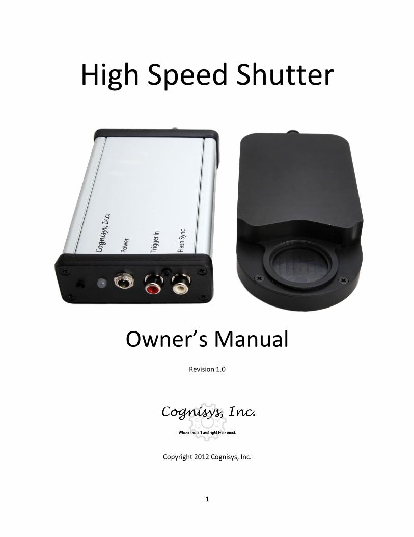
High Speed Shutter
Owner’s Manual Revision 1.0
Copyright 2012 Cognisys, Inc.
2
Table of Contents
1. SAFETY INSTRUCTIONS .................................................................................................................................. 3
2. GETTING STARTED ......................................................................................................................................... 4
2.1 PACKAGE CONTENTS .......................................................................................................................................... 4 2.2 CONNECTIONS .................................................................................................................................................. 5
3. OPERATION ................................................................................................................................................... 6
3.1 OVERVIEW ....................................................................................................................................................... 6 3.2 MANUAL BUTTON ............................................................................................................................................. 6 3.3 LED INDICATOR ................................................................................................................................................ 7 3.4 STOPSHOT CONFIGURATION ................................................................................................................................ 7
3.4.1 Overview .................................................................................................................................................. 7 3.4.2 Sequential Mode ...................................................................................................................................... 7 3.4.3 Trigger 1: Delay ........................................................................................................................................ 8 3.4.4 Trigger 2: XBS A&B ................................................................................................................................... 9 3.4.5 Trigger 3: Delay ...................................................................................................................................... 10
3.5 CAMERA SETTINGS ........................................................................................................................................... 10 3.6 FLASH SETTINGS .............................................................................................................................................. 10
4. TROUBLESHOOTING .................................................................................................................................... 11
5. SPECIFICATIONS .......................................................................................................................................... 12
6. WARRANTY ................................................................................................................................................. 13
7. GLOSSARY ................................................................................................................................................... 14
8. REVISION HISTORY ...................................................................................................................................... 16
Table of Figures
Figure 1 - Typical Connection Diagram ......................................................................................................... 5
3
1. Safety Instructions WARNING indicates a potentially hazardous situation which, if not avoided, could result in death or serious injury. Follow all CAUTION notices to reduce the risk of personal injury, prevent damage to the HSS, StopShot module, accessories, and devices (cameras, flashes, etc). Failure to follow all CAUTION notices may void your warranty. CAUTION may also indicate a potentially hazardous situation which, if not avoided, may result in personal injury.
The safety alert symbol precedes a general CAUTION or WARNING statement.
The electrical hazard symbol precedes an electric shock hazard CAUTION or WARNING statement.
CAUTION: Do not insert any object or finger(s) into the shutter opening. This may result in damage to the shutter or personal injury.
CAUTION: Only use the recommended battery pack for powering the HSS and StopShot. Use of other power sources may damage the controller(s).
CAUTION: Do not use “Y” adapters for the trigger outputs to connect more than three devices. Some devices generate significant transients (like solenoids) that may damage sensitive equipment such as cameras and flashes. StopShot is protected from these transients but other electronics (such as flashes and cameras) may not be. It is acceptable to use a “Y” adapter to connect more than one device to a trigger output as long as the devices are similar. If you have any questions or concerns about device compatibility, please contact us at: [email protected].
WARNING: There are no user-serviceable parts inside the shutter or controller. Under no circumstances open the devices.
WARNING: Do not expose the shutter or controller to wet environments.
WARNING: High voltage flashes should NOT be connected to the StopShot module or any of its associated adapters/connectors/cables. Doing so could expose you to dangerously high voltages resulting in serious injury or death. All new flashes on the market do not expose high voltage on the hot-shoe. These are the flashes intended for use with the StopShot module. Please visit our web-site at http://www.cognisys-inc.com for a list of low-voltage flashes, or contact us via e-mail at: [email protected].
4
2. Getting Started
2.1 Package contents
The latest version of this manual is available at http://www.cognisys-inc.com.
The High Speed Shutter kit contains the following:
1. High Speed Shutter (1) 2. High Speed Shutter controller (1) 3. Operation Manual CD (1) 4. 18” right-angle twist-lock shutter cable (1) 5. Clamp ring (1) 6. 37mm adapter ring (1) 7. Mounting hole plug (4) 8. Allen wrench (1)
Note: There is no power source included with the shutter.
Required accessories:
1. StopShot controller 2. Li-Ion 14.8V battery kit or 2A 12VDC power adapter 3. Ring adapter for your lens size to 37mm female 4. Camera shutter cable 5. PC->RCA cable (or hot shoe kit) for flash control
5
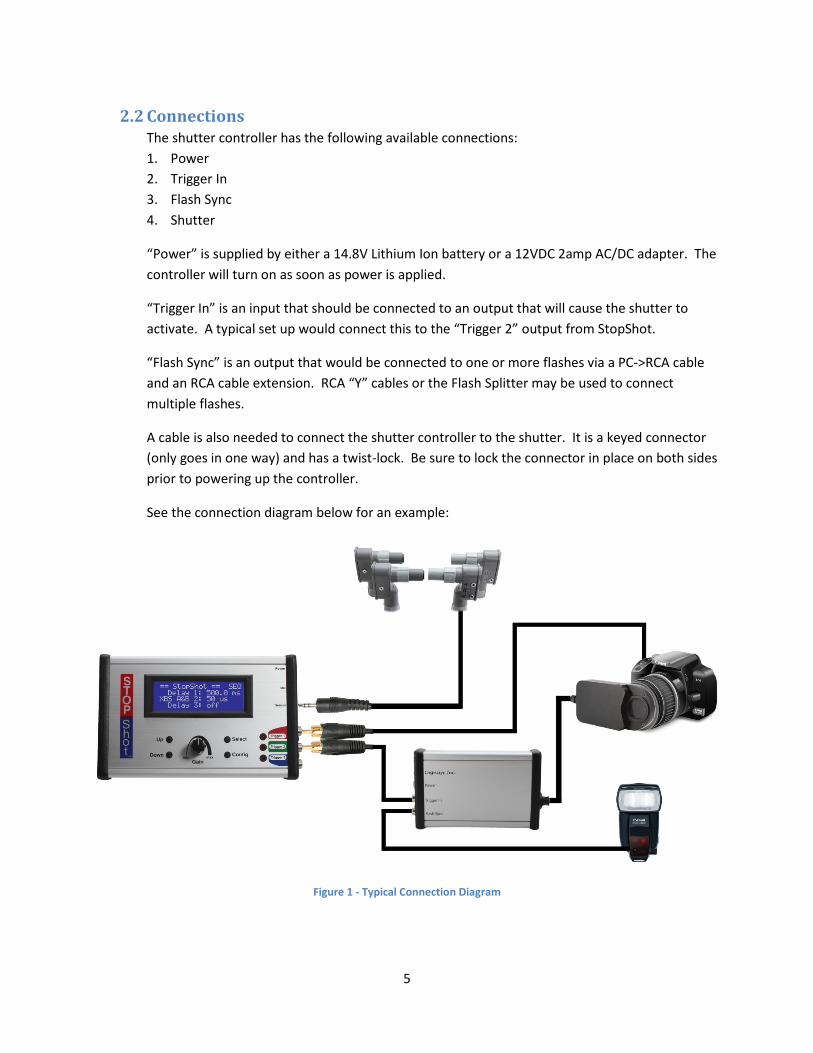
2.2 Connections The shutter controller has the following available connections: 1. Power 2. Trigger In 3. Flash Sync 4. Shutter
“Power” is supplied by either a 14.8V Lithium Ion battery or a 12VDC 2amp AC/DC adapter. The controller will turn on as soon as power is applied.
“Trigger In” is an input that should be connected to an output that will cause the shutter to activate. A typical set up would connect this to the “Trigger 2” output from StopShot.
“Flash Sync” is an output that would be connected to one or more flashes via a PC->RCA cable and an RCA cable extension. RCA “Y” cables or the Flash Splitter may be used to connect multiple flashes.
A cable is also needed to connect the shutter controller to the shutter. It is a keyed connector (only goes in one way) and has a twist-lock. Be sure to lock the connector in place on both sides prior to powering up the controller.
See the connection diagram below for an example:
Figure 1 - Typical Connection Diagram
6
3. Operation
3.1 Overview The High Speed Shutter (subsequently referred to as HSS) virtually eliminates the shutter lag associated with all modern DSLR cameras. While it may be used stand-alone it was designed to work in conjunction with StopShot. StopShot’s significant selection of sensor technologies coupled with its incredible flexibility brings your photography to the next level with the HSS. The simple to use single-button interface provides manual control while the two RCA connections allow a complete interface with StopShot and your flash. The included mounting hole plugs should be inserted into the unused mounting holes to prevent debris from entering the shutter housing.
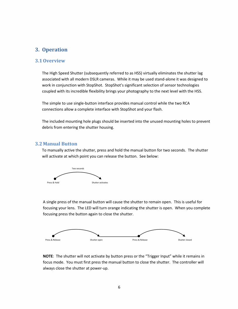
3.2 Manual Button To manually active the shutter, press and hold the manual button for two seconds. The shutter will activate at which point you can release the button. See below:
A single press of the manual button will cause the shutter to remain open. This is useful for focusing your lens. The LED will turn orange indicating the shutter is open. When you complete focusing press the button again to close the shutter. NOTE: The shutter will not activate by button press or the “Trigger Input” while it remains in focus mode. You must first press the manual button to close the shutter. The controller will always close the shutter at power-up.
Press & Hold
Two seconds
Shutter activates
Press & Release Shutter open Press & Release Shutter closed
7
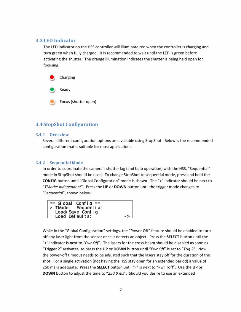
3.3 LED Indicator The LED indicator on the HSS controller will illuminate red when the controller is charging and turn green when fully charged. It is recommended to wait until the LED is green before activating the shutter. The orange illumination indicates the shutter is being held open for focusing.
Charging Ready Focus (shutter open)
3.4 StopShot Configuration
3.4.1 Overview Several different configuration options are available using StopShot. Below is the recommended configuration that is suitable for most applications.
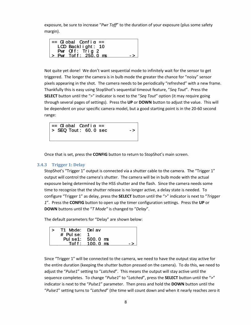
3.4.2 Sequential Mode In order to coordinate the camera’s shutter lag (and bulb operation) with the HSS, “Sequential” mode in StopShot should be used. To change StopShot to sequential mode, press and hold the CONFIG button until “Global Configuration” mode is shown. The “>” indicator should be next to “TMode: Independent”. Press the UP or DOWN button until the trigger mode changes to “Sequential”, shown below:
== Global Config == > TMode: Sequential
Load/Save Config Load Defaults: ->
While in the “Global Configuration” settings, the “Power Off” feature should be enabled to turn off any laser light from the sensor once it detects an object. Press the SELECT button until the “>” indicator is next to “Pwr Off”. The lasers for the cross-beam should be disabled as soon as “Trigger 2” activates, so press the UP or DOWN button until “Pwr Off” is set to “Trig 2”. Now the power-off timeout needs to be adjusted such that the lasers stay off for the duration of the shot. For a single activation (not having the HSS stay open for an extended period) a value of 250 ms is adequate. Press the SELECT button until “>” is next to “Pwr Toff”. Use the UP or DOWN button to adjust the time to “250.0 ms”. Should you desire to use an extended
8
exposure, be sure to increase “Pwr Toff” to the duration of your exposure (plus some safety margin).
== Global Config == LCD Backlight: 10
Pwr Off: Trig 2 Pwr Toff: 250.0 ms ->
>
Not quite yet done! We don’t want sequential mode to infinitely wait for the sensor to get triggered. The longer the camera is in bulb mode the greater the chance for “noisy” sensor pixels appearing in the shot. The camera needs to be periodically “refreshed” with a new frame. Thankfully this is easy using StopShot’s sequential timeout feature, “Seq Tout”. Press the SELECT button until the “>” indicator is next to the “Seq Tout” option (it may require going through several pages of settings). Press the UP or DOWN button to adjust the value. This will be dependent on your specific camera model, but a good starting point is in the 20-60 second range:
== Global Config == > SEQ Tout: 60.0 sec ->
Once that is set, press the CONFIG button to return to StopShot’s main screen.
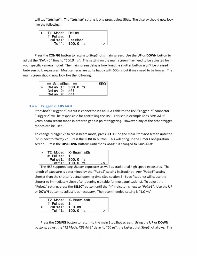
3.4.3 Trigger 1: Delay StopShot’s “Trigger 1” output is connected via a shutter cable to the camera. The “Trigger 1” output will control the camera’s shutter. The camera will be in bulb mode with the actual exposure being determined by the HSS shutter and the flash. Since the camera needs some time to recognize that the shutter release is no longer active, a delay state is needed. To configure “Trigger 1” as delay, press the SELECT button until the “>” indicator is next to “Trigger 1”. Press the CONFIG button to open up the timer configuration settings. Press the UP or DOWN buttons until the “T Mode” is changed to “Delay”.
The default parameters for “Delay” are shown below:
> T1 Mode: Delay # Pulse: 1 Pulse1: 500.0 ms Toff: 100.0 ms ->
Since “Trigger 1” will be connected to the camera, we need to have the output stay active for the entire duration (keeping the shutter button pressed on the camera). To do this, we need to adjust the “Pulse1” setting to “Latched”. This means the output will stay active until the sequence completes. To change “Pulse1” to “Latched”, press the SELECT button until the “>” indicator is next to the “Pulse1” parameter. Then press and hold the DOWN button until the “Pulse1” setting turns to “Latched” (the time will count down and when it nearly reaches zero it
9
will say “Latched”). The “Latched” setting is one press below 50us. The display should now look like the following:
> T1 Mode: Delay # Pulse: 1 Pulse1: Latched Toff: 100.0 ms ->
Press the CONFIG button to return to StopShot’s main screen. Use the UP or DOWN button to adjust the “Delay 1” time to “500.0 ms”. This setting on the main screen may need to be adjusted for your specific camera model. The main screen delay is how long the shutter button won’t be pressed in between bulb exposures. Most cameras are quite happy with 500ms but it may need to be longer. The main screen should now look like the following:
== StopShot == SEQ > Delay 1: 500.0 ms Delay 2: off Delay 3: off
3.4.4 Trigger 2: XBS A&B StopShot’s “Trigger 2” output is connected via an RCA cable to the HSS “Trigger In” connector. “Trigger 2” will be responsible for controlling the HSS. This setup example uses “XBS A&B” Cross-beam sensor mode in order to get pin point triggering. However, any of the other trigger modes can be used.
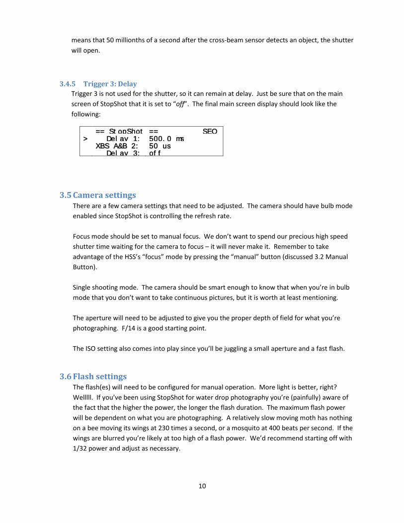
To change “Trigger 2” to cross-beam mode, press SELECT on the main StopShot screen until the “>” is next to “Delay 2”. Press the CONFIG button. This will bring up the Timer Configuration screen. Press the UP/DOWN buttons until the “T Mode” is changed to “XBS A&B”.
> T2 Mode: X-Beam a&b # Pulse: 1 Pulse1: 500.0 ms Toff1: 100.0 ms -> The HSS supports long shutter exposures as well as traditional high speed exposures. The
length of exposure is determined by the “Pulse1” setting in StopShot. Any “Pulse1” setting shorter than the shutter’s actual opening time (See section 5 - Specifications) will cause the shutter to immediately close after opening (suitable for most applications). To adjust the “Pulse1” setting, press the SELECT button until the “>” indicator is next to “Pulse1”. Use the UP or DOWN button to adjust it as necessary. The recommended setting is “1.0 ms”.
T2 Mode: X-Beam a&b # Pulse: 1 > Pulse1: 1.0 ms Toff1: 100.0 ms ->
Press the CONFIG button to return to the main StopShot screen. Using the UP or DOWN buttons, adjust the “T2 Mode: XBS A&B” delay to “50 us”, the fastest that StopShot allows. This
10
means that 50 millionths of a second after the cross-beam sensor detects an object, the shutter will open.
3.4.5 Trigger 3: Delay Trigger 3 is not used for the shutter, so it can remain at delay. Just be sure that on the main screen of StopShot that it is set to “off”. The final main screen display should look like the following:
== StopShot == SEQ > Delay 1: 500.0 ms XBS A&B 2: 50 us Delay 3: off
3.5 Camera settings There are a few camera settings that need to be adjusted. The camera should have bulb mode enabled since StopShot is controlling the refresh rate. Focus mode should be set to manual focus. We don’t want to spend our precious high speed shutter time waiting for the camera to focus – it will never make it. Remember to take advantage of the HSS’s “focus” mode by pressing the “manual” button (discussed 3.2 Manual Button). Single shooting mode. The camera should be smart enough to know that when you’re in bulb mode that you don’t want to take continuous pictures, but it is worth at least mentioning. The aperture will need to be adjusted to give you the proper depth of field for what you’re photographing. F/14 is a good starting point. The ISO setting also comes into play since you’ll be juggling a small aperture and a fast flash.
3.6 Flash settings The flash(es) will need to be configured for manual operation. More light is better, right? Welllll. If you’ve been using StopShot for water drop photography you’re (painfully) aware of the fact that the higher the power, the longer the flash duration. The maximum flash power will be dependent on what you are photographing. A relatively slow moving moth has nothing on a bee moving its wings at 230 times a second, or a mosquito at 400 beats per second. If the wings are blurred you’re likely at too high of a flash power. We’d recommend starting off with 1/32 power and adjust as necessary.
11
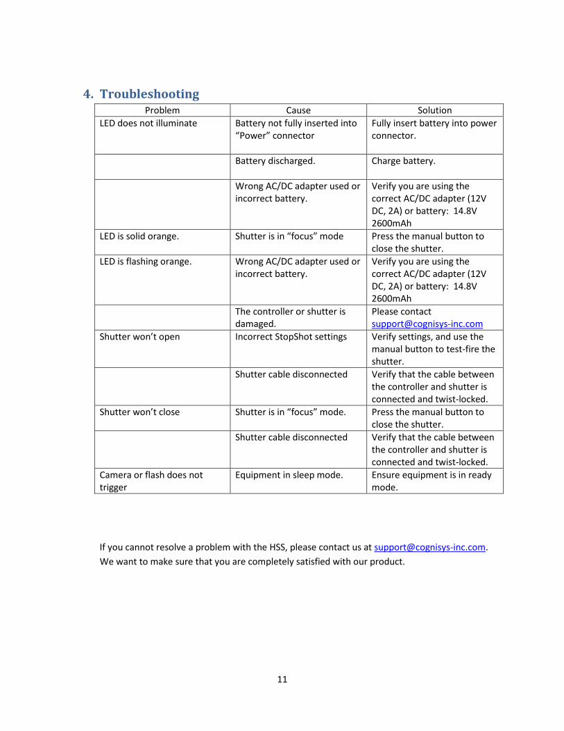
4. Troubleshooting Problem Cause Solution
LED does not illuminate Battery not fully inserted into “Power” connector
Fully insert battery into power connector.
Battery discharged. Charge battery.
Wrong AC/DC adapter used or incorrect battery.
Verify you are using the correct AC/DC adapter (12V DC, 2A) or battery: 14.8V 2600mAh
LED is solid orange. Shutter is in “focus” mode Press the manual button to close the shutter.
LED is flashing orange. Wrong AC/DC adapter used or incorrect battery.
Verify you are using the correct AC/DC adapter (12V DC, 2A) or battery: 14.8V 2600mAh
The controller or shutter is damaged.
Please contact [email protected]
Shutter won’t open Incorrect StopShot settings Verify settings, and use the manual button to test-fire the shutter.
Shutter cable disconnected Verify that the cable between the controller and shutter is connected and twist-locked.
Shutter won’t close Shutter is in “focus” mode. Press the manual button to close the shutter.
Shutter cable disconnected Verify that the cable between the controller and shutter is connected and twist-locked.
Camera or flash does not trigger
Equipment in sleep mode. Ensure equipment is in ready mode.
If you cannot resolve a problem with the HSS, please contact us at [email protected]. We want to make sure that you are completely satisfied with our product.
12
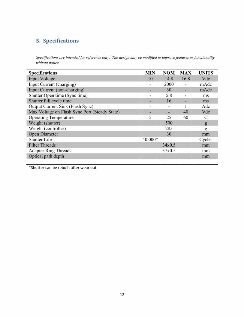
5. Specifications
Specifications are intended for reference only. The design may be modified to improve features or functionality without notice.
Specifications MIN NOM MAX UNITS Input Voltage 10 14.8 16.8 Vdc Input Current (charging) - 2000 - mAdc Input Current (non-charging) - 30 - mAdc Shutter Open time (Sync time) - 5.8 - ms Shutter full cycle time - 16 - ms Output Current Sink (Flash Sync) - - 1 Adc Max Voltage on Flash Sync Port (Steady State) - - 40 Vdc Operating Temperature 5 25 60 C Weight (shutter) 500 g Weight (controller) 285 g Open Diameter 30 mm Shutter Life 40,000* Cycles Filter Threads 34x0.5 mm Adapter Ring Threads 37x0.5 mm Optical path depth mm *Shutter can be rebuilt after wear out.
13
6. Warranty
Limited Warranty
The High Speed Shutter is warranted to be free from defects in materials or workmanship for one (1) year from the date of purchase or up to 40,000 shutter cycles, whichever comes first. Within this period, Cognisys Inc. will, at its sole option, repair or replace any components which fail in normal use. Such repairs or replacement will be made at no charge to the customer for parts or labor, provided that the customer shall be responsible for any transportation cost. This warranty does not cover failures due to abuse, misuse, accident or unauthorized alterations or repairs.
THE WARRANTIES AND REMEDIES CONTAINED HEREIN ARE EXCLUSIVE AND IN LIEU OF ALL OTHER WARRANTIES, WHETHER EXPRESS, IMPLIED OR STATUTORY, INCLUDING ANY LIABILITY ARISING UNDER ANY WARRANTY OF MERCHANTABILITY OR FITNESS FOR A PARTICULAR PURPOSE, STATUTORY OR OTHERWISE. THIS WARRANTY GIVES YOU SPECIFIC LEGAL RIGHTS, WHICH MAY VARY FROM STATE TO STATE.
IN NO EVENT SHALL COGNISYS BE LIABLE FOR ANY INCIDENTAL, SPECIAL, INDIRECT OR CONSEQUENTIAL DAMAGES, WHETHER RESULTING FROM THE USE, MISUSE OR INABILITY TO USE THE PRODUCT OR FROM DEFECTS IN THE PRODUCT. SOME STATES DO NOT ALLOW THE EXCLUSION OF INCIDENTAL OR CONSEQUENTIAL DAMAGES, SO THE ABOVE LIMITATIONS MAY NOT APPLY TO YOU.
Cognisys retains the exclusive right to repair or replace the product or offer a full refund of the purchase price at its sole discretion. SUCH REMEDY SHALL BE YOUR SOLE AND EXCLUSIVE REMEDY FOR ANY BREACH OF WARRANTY.
14
7. Glossary
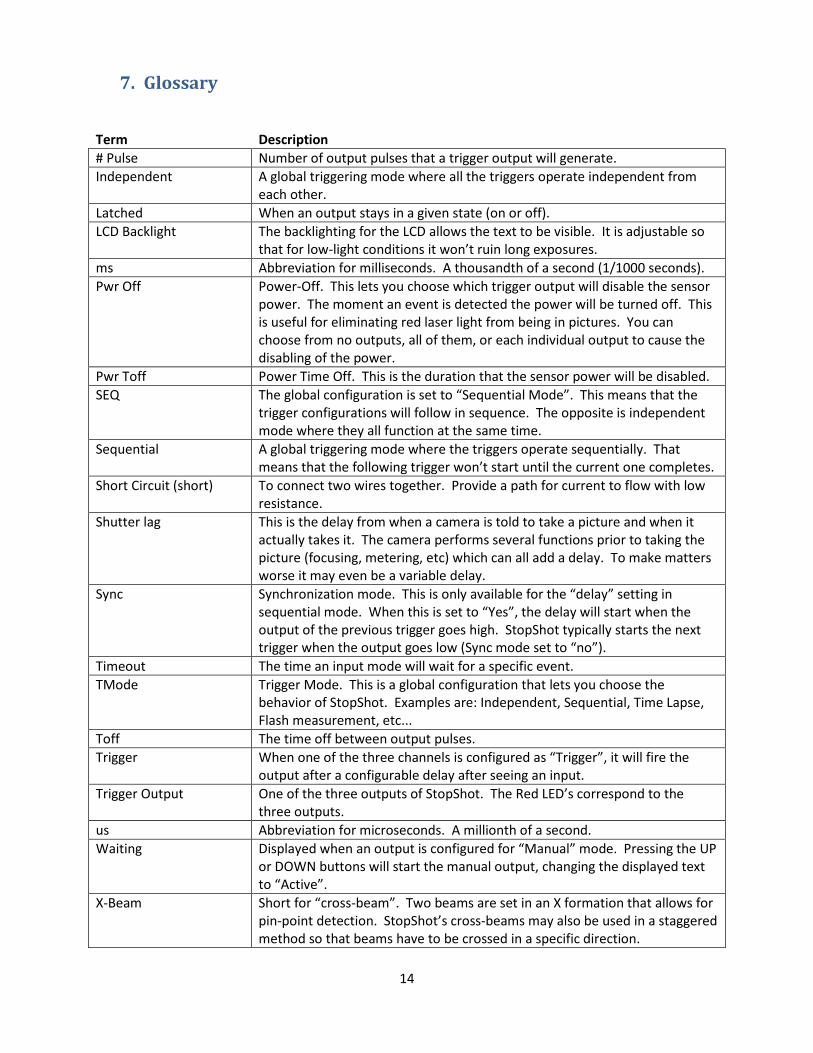
Term Description # Pulse Number of output pulses that a trigger output will generate. Independent A global triggering mode where all the triggers operate independent from
each other. Latched When an output stays in a given state (on or off). LCD Backlight The backlighting for the LCD allows the text to be visible. It is adjustable so
that for low-light conditions it won’t ruin long exposures. ms Abbreviation for milliseconds. A thousandth of a second (1/1000 seconds). Pwr Off Power-Off. This lets you choose which trigger output will disable the sensor
power. The moment an event is detected the power will be turned off. This is useful for eliminating red laser light from being in pictures. You can choose from no outputs, all of them, or each individual output to cause the disabling of the power.
Pwr Toff Power Time Off. This is the duration that the sensor power will be disabled. SEQ The global configuration is set to “Sequential Mode”. This means that the
trigger configurations will follow in sequence. The opposite is independent mode where they all function at the same time.
Sequential A global triggering mode where the triggers operate sequentially. That means that the following trigger won’t start until the current one completes.
Short Circuit (short) To connect two wires together. Provide a path for current to flow with low resistance.
Shutter lag This is the delay from when a camera is told to take a picture and when it actually takes it. The camera performs several functions prior to taking the picture (focusing, metering, etc) which can all add a delay. To make matters worse it may even be a variable delay.
Sync Synchronization mode. This is only available for the “delay” setting in sequential mode. When this is set to “Yes”, the delay will start when the output of the previous trigger goes high. StopShot typically starts the next trigger when the output goes low (Sync mode set to “no”).
Timeout The time an input mode will wait for a specific event. TMode Trigger Mode. This is a global configuration that lets you choose the
behavior of StopShot. Examples are: Independent, Sequential, Time Lapse, Flash measurement, etc...
Toff The time off between output pulses. Trigger When one of the three channels is configured as “Trigger”, it will fire the
output after a configurable delay after seeing an input. Trigger Output One of the three outputs of StopShot. The Red LED’s correspond to the
three outputs. us Abbreviation for microseconds. A millionth of a second. Waiting Displayed when an output is configured for “Manual” mode. Pressing the UP
or DOWN buttons will start the manual output, changing the displayed text to “Active”.
X-Beam Short for “cross-beam”. Two beams are set in an X formation that allows for pin-point detection. StopShot’s cross-beams may also be used in a staggered method so that beams have to be crossed in a specific direction.
15
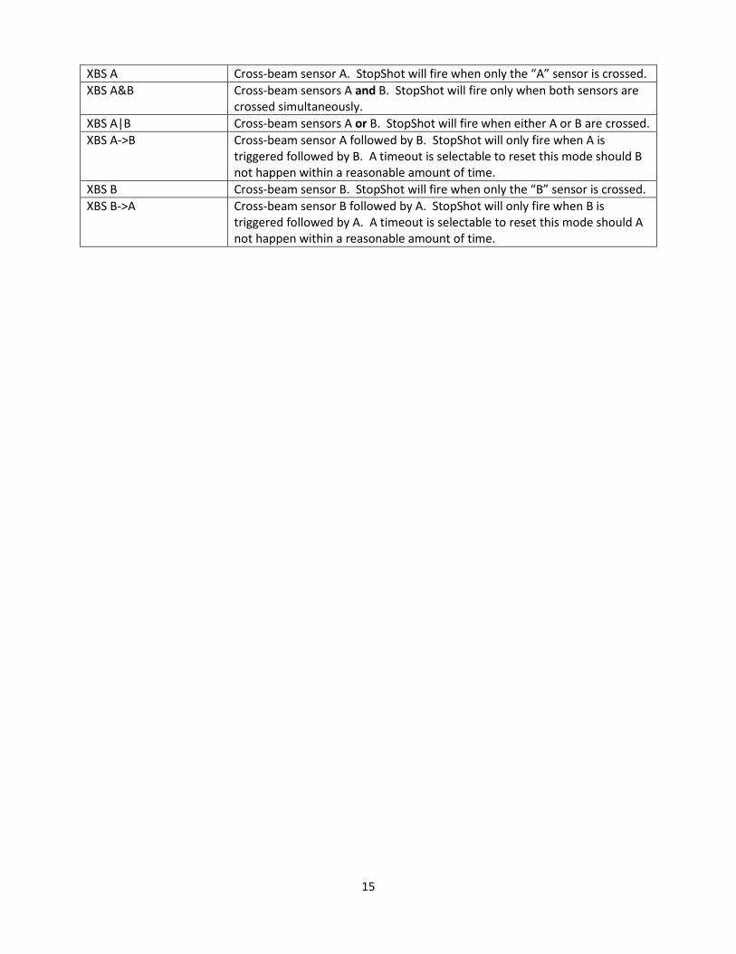
XBS A Cross-beam sensor A. StopShot will fire when only the “A” sensor is crossed. XBS A&B Cross-beam sensors A and B. StopShot will fire only when both sensors are
crossed simultaneously. XBS A|B Cross-beam sensors A or B. StopShot will fire when either A or B are crossed. XBS A->B Cross-beam sensor A followed by B. StopShot will only fire when A is
triggered followed by B. A timeout is selectable to reset this mode should B not happen within a reasonable amount of time.
XBS B Cross-beam sensor B. StopShot will fire when only the “B” sensor is crossed. XBS B->A Cross-beam sensor B followed by A. StopShot will only fire when B is
triggered followed by A. A timeout is selectable to reset this mode should A not happen within a reasonable amount of time.

16
8. Revision History
Revision Date Change 1.0 08/06/12 Initial Release