Embed Size (px)
Citation preview
2016-17
HIGHER NOTES
Higher GraphicsCourse Notes
HIGHER NOTES 2
Graphic Types
A ll graphic forms can be classified by the following terms: Preliminary, Production and Promotionalgraphics. It is important you are familiar with each term and how they are applied across all features of the
graphics industry. You shall have used many within several aspects of your school work to date, including withinother subjects.
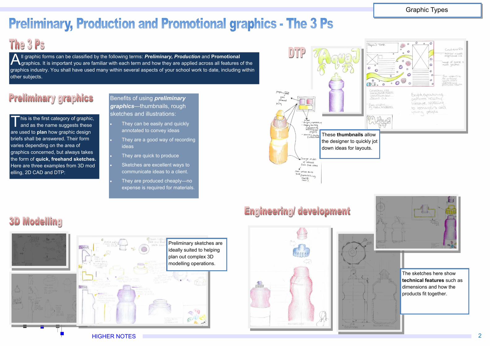
This is the first category of graphic,and as the name suggests these
are used to plan how graphic designbriefs shall be answered. Their formvaries depending on the area ofgraphics concerned, but always takesthe form of quick, freehand sketches.Here are three examples from 3D modelling, 2D CAD and DTP:
Benefits of using preliminarygraphics—thumbnails, roughsketches and illustrations:· They can be easily and quickly
annotated to convey ideas
· They are a good way of recordingideas
· They are quick to produce
· Sketches are excellent ways tocommunicate ideas to a client.
· They are produced cheaply—noexpense is required for materials.
These thumbnails allowthe designer to quickly jotdown ideas for layouts.
The sketches here showtechnical features such asdimensions and how theproducts fit together.
Preliminary sketches areideally suited to helpingplan out complex 3Dmodelling operations.
HIGHER NOTES 3
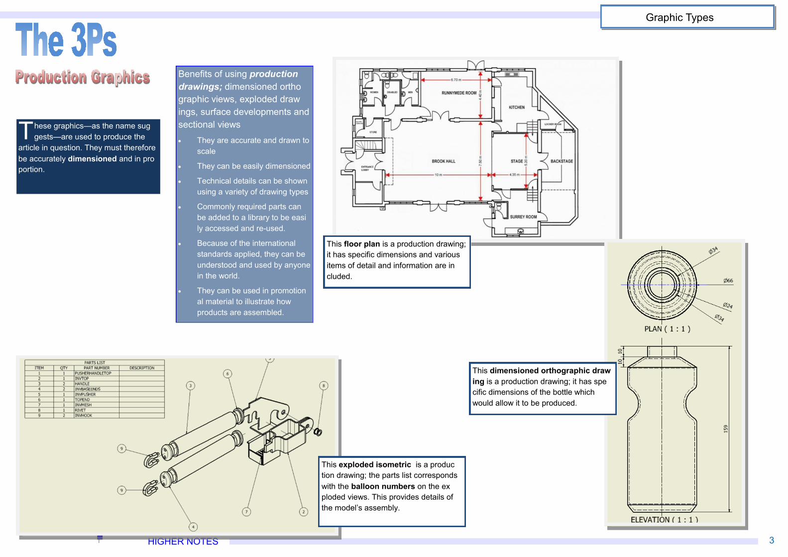
These graphics—as the name suggests—are used to produce the
article in question. They must thereforebe accurately dimensioned and in proportion.
Benefits of using productiondrawings; dimensioned orthographic views, exploded drawings, surface developments andsectional views· They are accurate and drawn to
scale
· They can be easily dimensioned
· Technical details can be shownusing a variety of drawing types
· Commonly required parts canbe added to a library to be easily accessed and re-used.
· Because of the internationalstandards applied, they can beunderstood and used by anyonein the world.
· They can be used in promotional material to illustrate howproducts are assembled.
This floor plan is a production drawing;it has specific dimensions and variousitems of detail and information are included.
This exploded isometric is a production drawing; the parts list correspondswith the balloon numbers on the exploded views. This provides details ofthe model’s assembly.
This dimensioned orthographic drawing is a production drawing; it has specific dimensions of the bottle whichwould allow it to be produced.
Graphic Types
HIGHER NOTES 4
Graphic Types
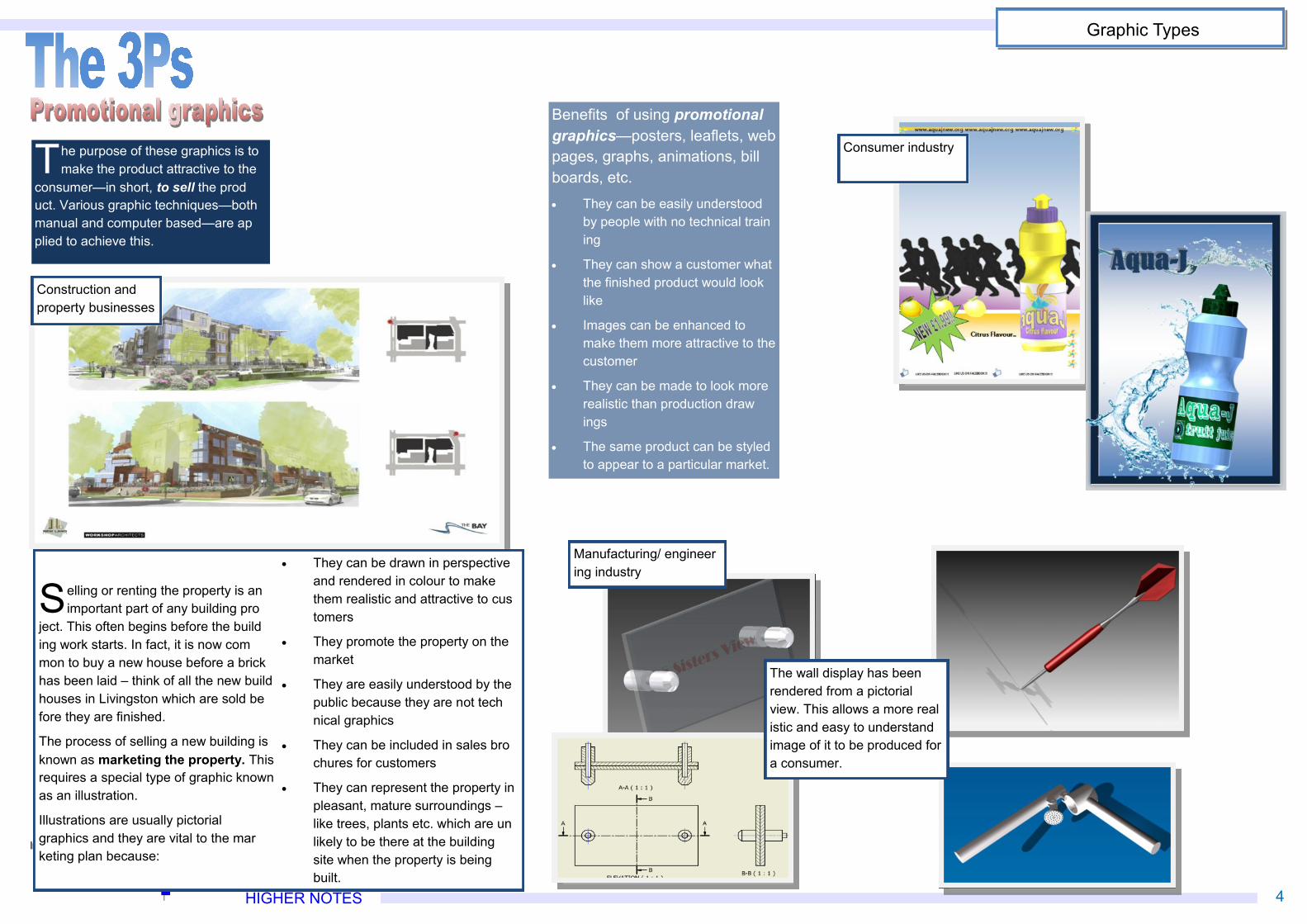
Selling or renting the property is animportant part of any building pro
ject. This often begins before the building work starts. In fact, it is now common to buy a new house before a brickhas been laid – think of all the new buildhouses in Livingston which are sold before they are finished.
The process of selling a new building isknown as marketing the property. Thisrequires a special type of graphic knownas an illustration.
Illustrations are usually pictorialgraphics and they are vital to the marketing plan because:
· They can be drawn in perspectiveand rendered in colour to makethem realistic and attractive to customers
· They promote the property on themarket
· They are easily understood by thepublic because they are not technical graphics
· They can be included in sales brochures for customers
· They can represent the property inpleasant, mature surroundings –like trees, plants etc. which are unlikely to be there at the buildingsite when the property is beingbuilt.
Benefits of using promotionalgraphics—posters, leaflets, webpages, graphs, animations, billboards, etc.· They can be easily understood
by people with no technical training
· They can show a customer whatthe finished product would looklike
· Images can be enhanced tomake them more attractive to thecustomer
· They can be made to look morerealistic than production drawings
· The same product can be styledto appear to a particular market.
Construction andproperty businesses
The purpose of these graphics is tomake the product attractive to the
consumer—in short, to sell the product. Various graphic techniques—bothmanual and computer based—are applied to achieve this.
Consumer industry
Manufacturing/ engineering industry
The wall display has beenrendered from a pictorialview. This allows a more realistic and easy to understandimage of it to be produced fora consumer.
HIGHER NOTES 5
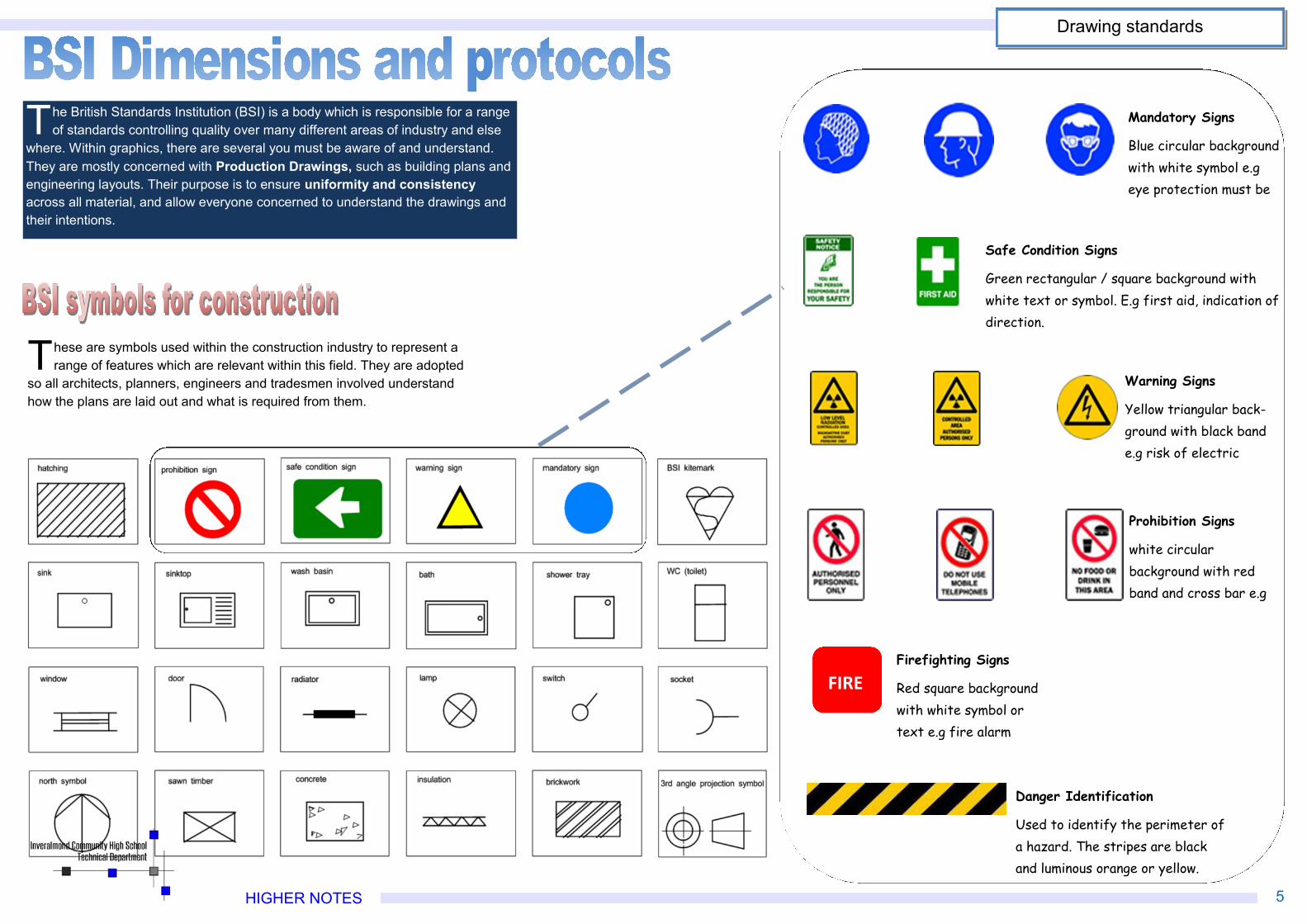
Mandatory Signs
Blue circular backgroundwith white symbol e.geye protection must be
Safe Condition Signs
Green rectangular / square background withwhite text or symbol. E.g first aid, indication ofdirection.
Warning Signs
Yellow triangular back-ground with black bande.g risk of electric
Prohibition Signs
white circularbackground with redband and cross bar e.g
FIREFirefighting Signs
Red square backgroundwith white symbol ortext e.g fire alarm
Danger Identification
Used to identify the perimeter ofa hazard. The stripes are blackand luminous orange or yellow.
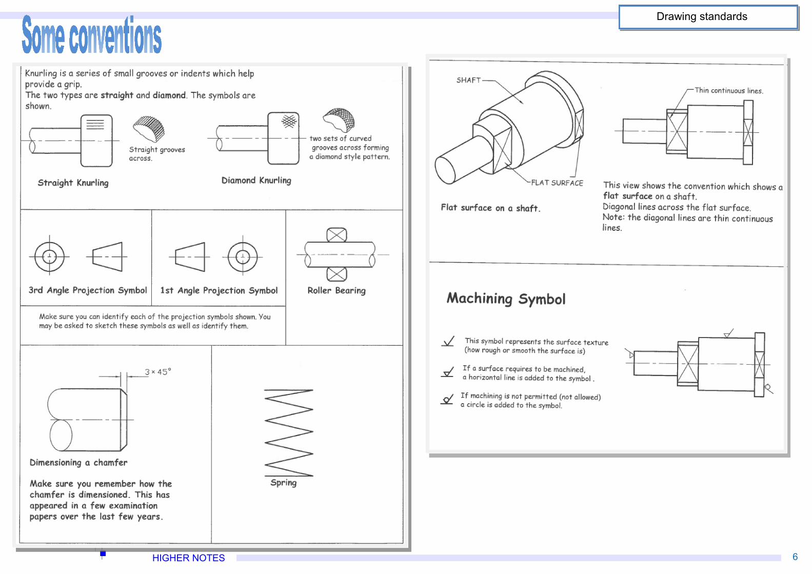
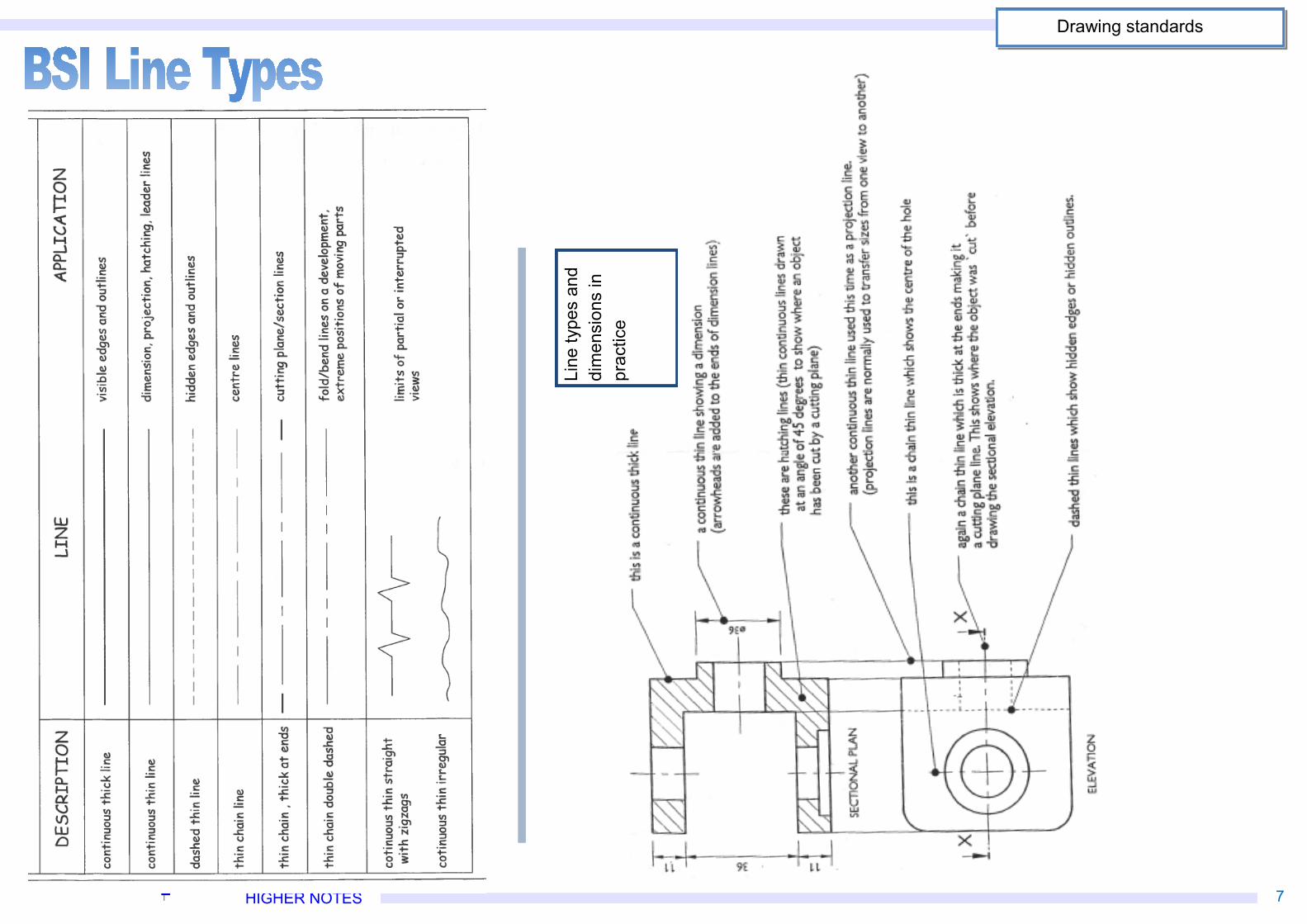
The British Standards Institution (BSI) is a body which is responsible for a rangeof standards controlling quality over many different areas of industry and else
where. Within graphics, there are several you must be aware of and understand.They are mostly concerned with Production Drawings, such as building plans andengineering layouts. Their purpose is to ensure uniformity and consistencyacross all material, and allow everyone concerned to understand the drawings andtheir intentions.
These are symbols used within the construction industry to represent arange of features which are relevant within this field. They are adopted
so all architects, planners, engineers and tradesmen involved understandhow the plans are laid out and what is required from them.
Drawing standards
HIGHER NOTES 6
Drawing standards
HIGHER NOTES 7
Line
type
s an
ddi
men
sion
s in
prac
tice
Drawing standards
HIGHER NOTES 8
Drawing standards
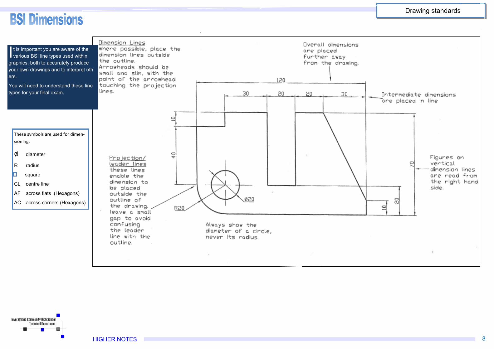
It is important you are aware of thevarious BSI line types used within
graphics; both to accurately produceyour own drawings and to interpret others.
You will need to understand these linetypes for your final exam.
These symbols are used for dimen‐sioning:
ø diameter
R radius
square
CL centre line
AF across flats (Hexagons)
AC across corners (Hexagons)
HIGHER NOTES 9
Drawing standards
HIGHER NOTES 10
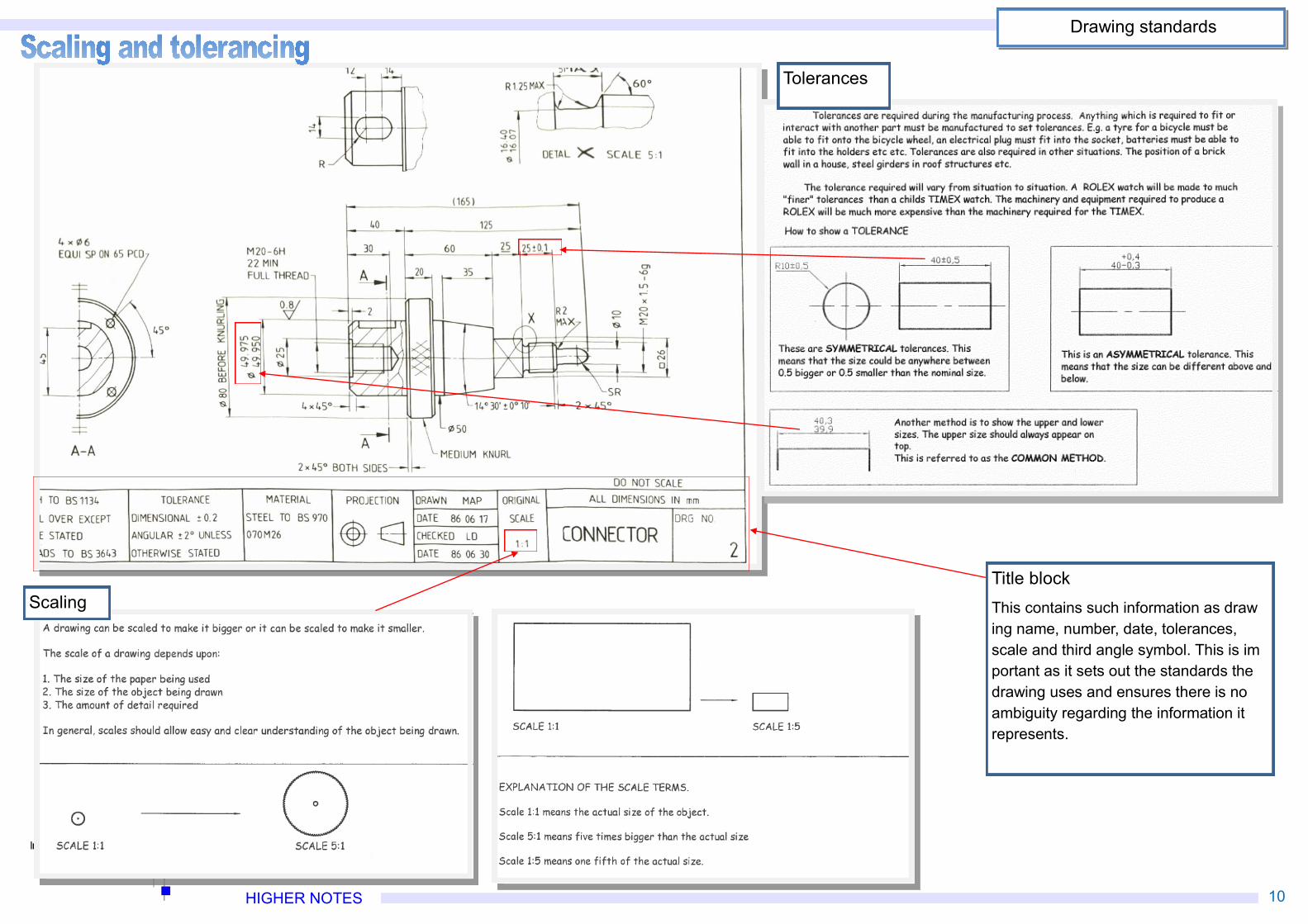
Tolerances
Drawing standards
ScalingTitle blockThis contains such information as drawing name, number, date, tolerances,scale and third angle symbol. This is important as it sets out the standards thedrawing uses and ensures there is noambiguity regarding the information itrepresents.
HIGHER NOTES 11
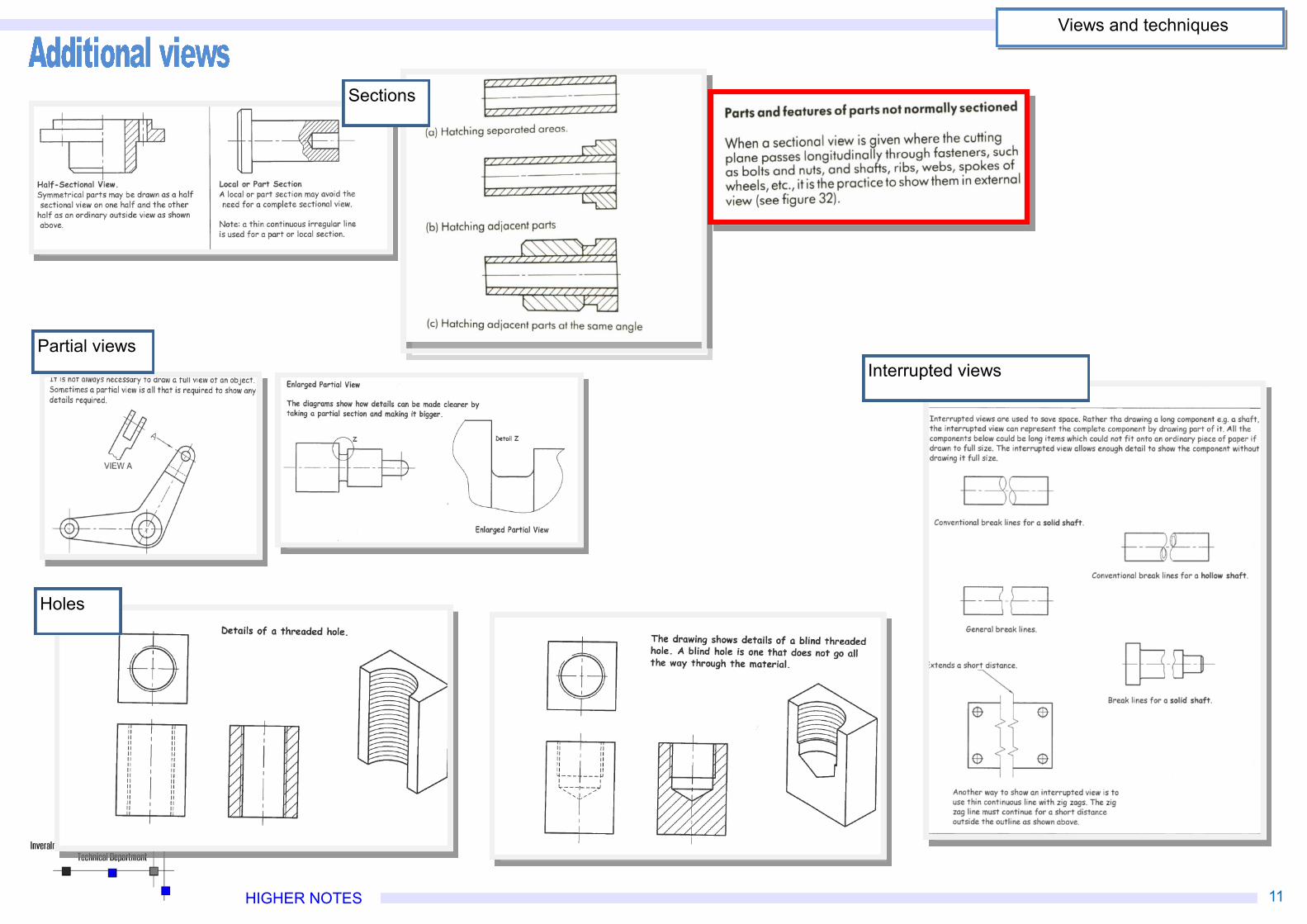
Partial viewsInterrupted views
Holes
Sections
Views and techniques
HIGHER NOTES 12
Views and techniques
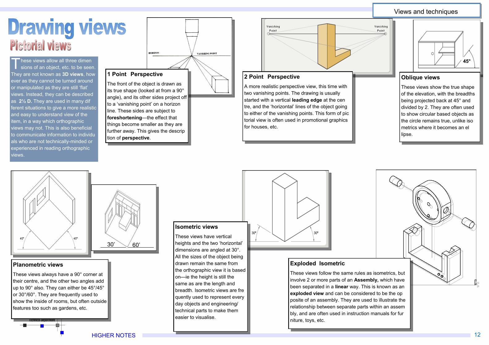
30’
Isometric viewsThese views have verticalheights and the two ‘horizontal’dimensions are angled at 30°.All the sizes of the object beingdrawn remain the same fromthe orthographic view it is basedon—ie the height is still thesame as are the length andbreadth. Isometric views are frequently used to represent everyday objects and engineering/technical parts to make themeasier to visualise.
1 Point PerspectiveThe front of the object is drawn asits true shape (looked at from a 90°angle), and its other sides project offto a ‘vanishing point’ on a horizonline. These sides are subject toforeshortening—the effect thatthings become smaller as they arefurther away. This gives the description of perspective.
2 Point PerspectiveA more realistic perspective view, this time withtwo vanishing points. The drawing is usuallystarted with a vertical leading edge at the centre, and the ‘horizontal’ lines of the object goingto either of the vanishing points. This form of pictorial view is often used in promotional graphicsfor houses, etc.
Exploded IsometricThese views follow the same rules as isometrics, butinvolve 2 or more parts of an Assembly, which havebeen separated in a linear way. This is known as anexploded view and can be considered to be the opposite of an assembly. They are used to illustrate therelationship between separate parts within an assembly, and are often used in instruction manuals for furniture, toys, etc.
These views allow all three dimensions of an object, etc. to be seen.
They are not known as 3D views, however as they cannot be turned aroundor manipulated as they are still ‘flat’views. Instead, they can be describedas 2½ D. They are used in many different situations to give a more realisticand easy to understand view of theitem, in a way which orthographicviews may not. This is also beneficialto communicate information to individuals who are not technically-minded orexperienced in reading orthographicviews.
45°
Oblique viewsThese views show the true shapeof the elevation, with the breadthsbeing projected back at 45° anddivided by 2. They are often usedto show circular based objects asthe circle remains true, unlike isometrics where it becomes an ellipse.
Planometric viewsThese views always have a 90° corner attheir centre, and the other two angles addup to 90° also. They can either be 45°/45°or 30°/60°. They are frequently used toshow the inside of rooms, but often outsidefeatures too such as gardens, etc.
60’30’
HIGHER NOTES 13
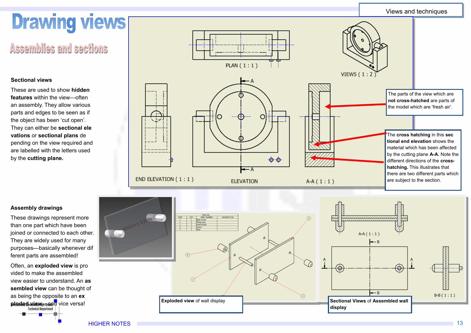
Sectional views
These are used to show hiddenfeatures within the view—oftenan assembly. They allow variousparts and edges to be seen as ifthe object has been ‘cut open’.They can either be sectional elevations or sectional plans depending on the view required andare labelled with the letters usedby the cutting plane.
Assembly drawings
These drawings represent morethan one part which have beenjoined or connected to each other.They are widely used for manypurposes—basically whenever different parts are assembled!
Often, an exploded view is provided to make the assembledview easier to understand. An assembled view can be thought ofas being the opposite to an exploded view—and vice versa!
The cross hatching in this sectional end elevation shows thematerial which has been affectedby the cutting plane A-A. Note thedifferent directions of the cross-hatching. This illustrates thatthere are two different parts whichare subject to the section.
The parts of the view which arenot cross-hatched are parts ofthe model which are ‘fresh air’.
Exploded view of wall display Sectional Views of Assembled walldisplay
Views and techniques
HIGHER NOTES 14
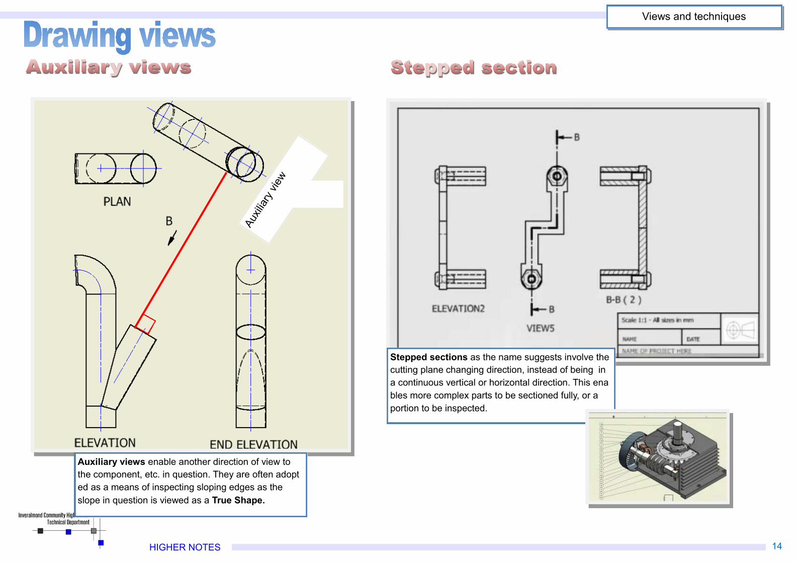
Auxil
iary v
iew
Auxiliary views enable another direction of view tothe component, etc. in question. They are often adopted as a means of inspecting sloping edges as theslope in question is viewed as a True Shape.
Views and techniques
Stepped sections as the name suggests involve thecutting plane changing direction, instead of being ina continuous vertical or horizontal direction. This enables more complex parts to be sectioned fully, or aportion to be inspected.
HIGHER NOTES 15
Geometric shapes and forms
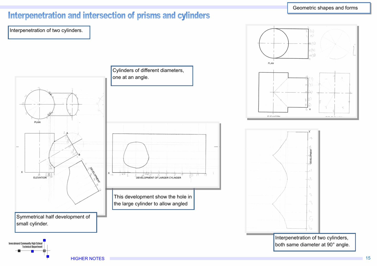
Interpenetration of two cylinders.
Cylinders of different diameters,one at an angle.
This development show the hole inthe large cylinder to allow angled
Symmetrical half development ofsmall cylinder.
Interpenetration of two cylinders,both same diameter at 90° angle.
HIGHER NOTES 16
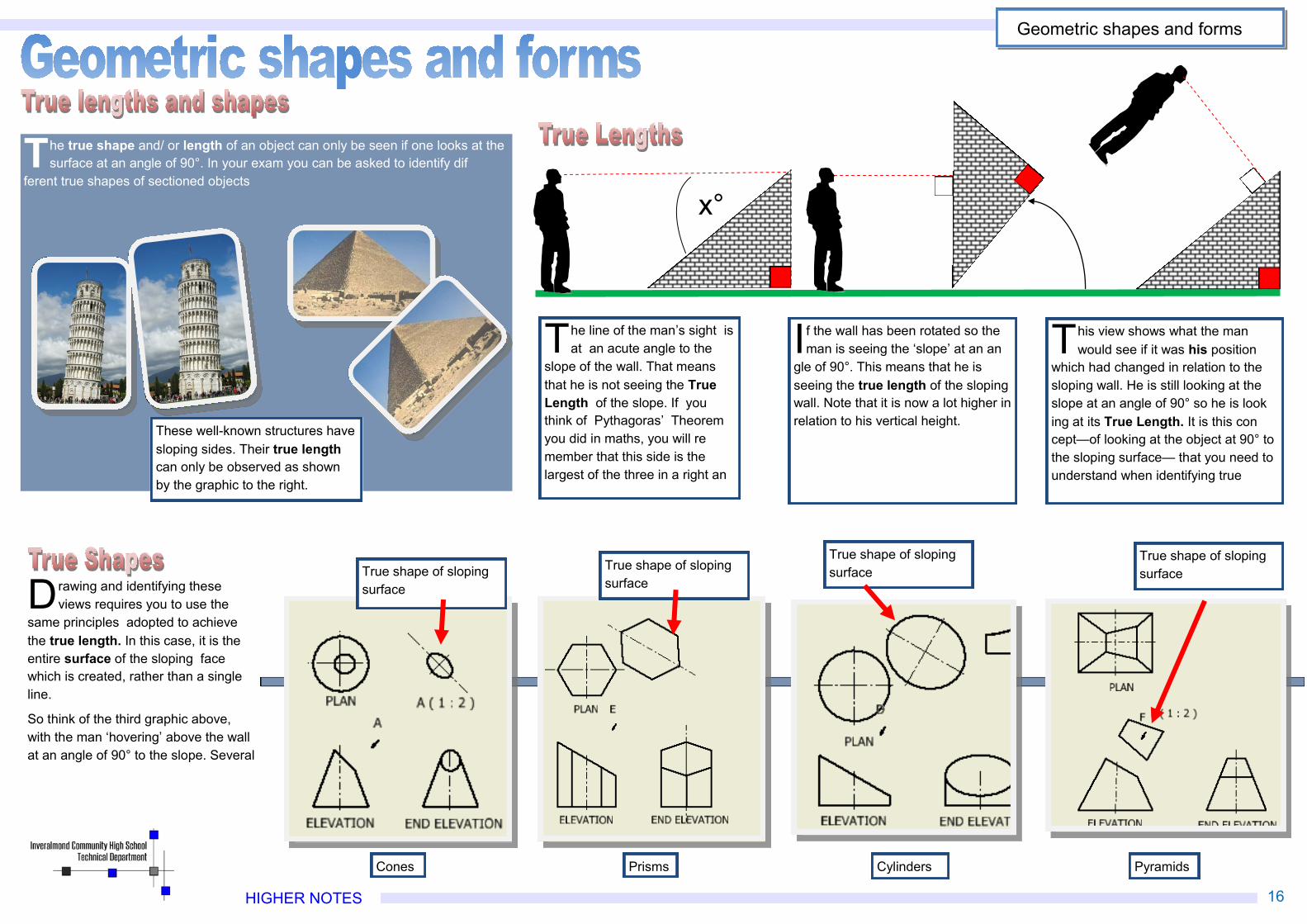
The true shape and/ or length of an object can only be seen if one looks at thesurface at an angle of 90°. In your exam you can be asked to identify dif
ferent true shapes of sectioned objects
x°
The line of the man’s sight isat an acute angle to the
slope of the wall. That meansthat he is not seeing the TrueLength of the slope. If youthink of Pythagoras’ Theoremyou did in maths, you will remember that this side is thelargest of the three in a right an
If the wall has been rotated so theman is seeing the ‘slope’ at an an
gle of 90°. This means that he isseeing the true length of the slopingwall. Note that it is now a lot higher inrelation to his vertical height.
This view shows what the manwould see if it was his position
which had changed in relation to thesloping wall. He is still looking at theslope at an angle of 90° so he is looking at its True Length. It is this concept—of looking at the object at 90° tothe sloping surface— that you need tounderstand when identifying true
Drawing and identifying theseviews requires you to use the
same principles adopted to achievethe true length. In this case, it is theentire surface of the sloping facewhich is created, rather than a singleline.
So think of the third graphic above,with the man ‘hovering’ above the wallat an angle of 90° to the slope. Several
True shape of slopingsurface
True shape of slopingsurface
True shape of slopingsurface
True shape of slopingsurface
Cones Prisms Cylinders Pyramids
These well-known structures havesloping sides. Their true lengthcan only be observed as shownby the graphic to the right.
Geometric shapes and forms
HIGHER NOTES 29
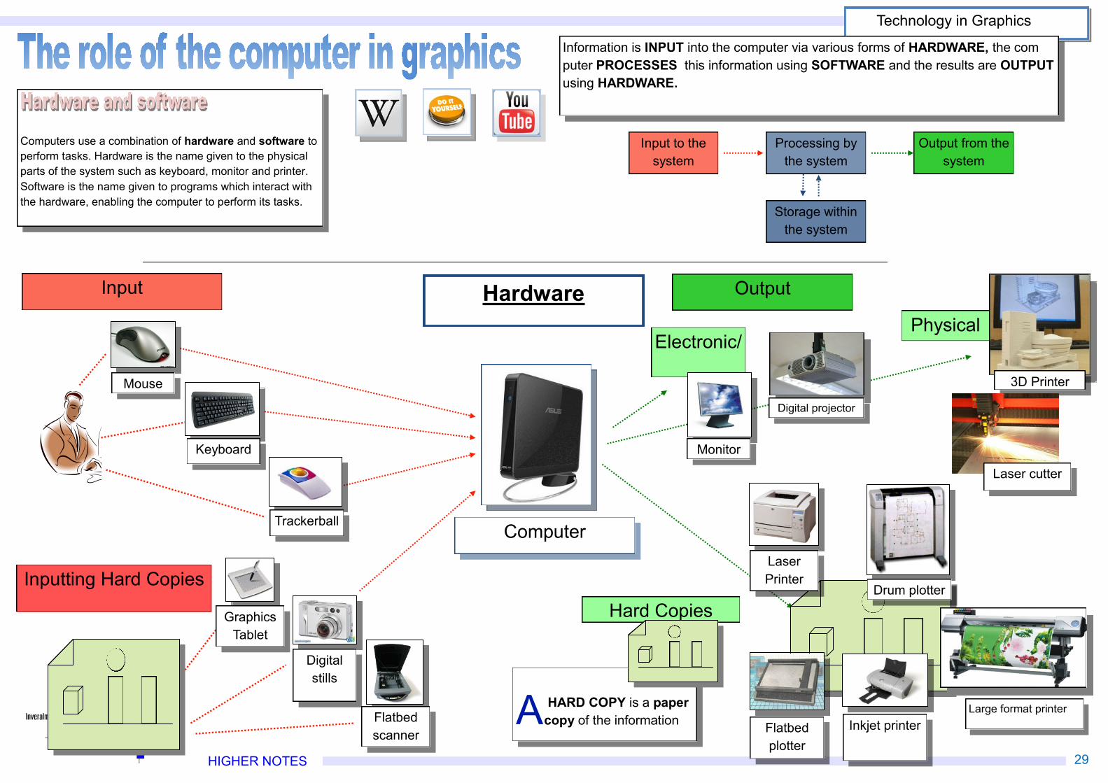
Input Hardware Output
Inputting Hard Copies
Information is INPUT into the computer via various forms of HARDWARE, the computer PROCESSES this information using SOFTWARE and the results are OUTPUTusing HARDWARE.
Computer
Electronic/
Hard Copies
Physical
Mouse
Keyboard
Flatbedscanner
Digitalstills
Trackerball
Monitor
GraphicsTablet
Flatbedplotter
Inkjet printer
LaserPrinter
Drum plotter
A HARD COPY is a papercopy of the information
Input to thesystem
Processing bythe system
Output from thesystem
Storage withinthe system
Digital projector
3D Printer
Laser cutter
Computers use a combination of hardware and software toperform tasks. Hardware is the name given to the physicalparts of the system such as keyboard, monitor and printer.Software is the name given to programs which interact withthe hardware, enabling the computer to perform its tasks.
Large format printer
Technology in Graphics
HIGHER NOTES 30
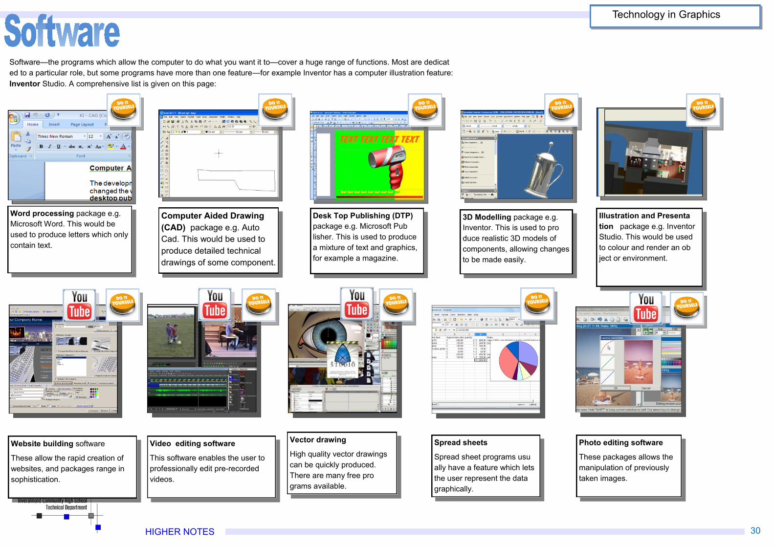
Photo editing software
These packages allows themanipulation of previouslytaken images.
Vector drawing
High quality vector drawingscan be quickly produced.There are many free programs available.
Video editing software
This software enables the user toprofessionally edit pre-recordedvideos.
Website building software
These allow the rapid creation ofwebsites, and packages range insophistication.
Spread sheets
Spread sheet programs usually have a feature which letsthe user represent the datagraphically.
Software—the programs which allow the computer to do what you want it to—cover a huge range of functions. Most are dedicated to a particular role, but some programs have more than one feature—for example Inventor has a computer illustration feature:Inventor Studio. A comprehensive list is given on this page:
Illustration and Presentation package e.g. InventorStudio. This would be usedto colour and render an object or environment.
Word processing package e.g.Microsoft Word. This would beused to produce letters which onlycontain text.
Computer Aided Drawing(CAD) package e.g. AutoCad. This would be used toproduce detailed technicaldrawings of some component.
Desk Top Publishing (DTP)package e.g. Microsoft Publisher. This is used to producea mixture of text and graphics,for example a magazine.
3D Modelling package e.g.Inventor. This is used to produce realistic 3D models ofcomponents, allowing changesto be made easily.
Technology in Graphics


![EFFECT OF SINGLE LIGHT ORIENTATION ON LANDING GEAR WAKE · Figure 2.9: Two cylinders in the tandem arrangement [41]. L is the distance between the centers of the two cylinders (same](https://img.pdfslide.net/doc/110x75/5e83a8a52036f560143b12a4/effect-of-single-light-orientation-on-landing-gear-wake-figure-29-two-cylinders.jpg)