Embed Size (px)
Citation preview
Highly nonlinear Ablative Rayleigh-Taylor Instabilityon NIF
Highly nonlinear Ablative Rayleigh-Taylor Instabilityon NIF
Presentation toNIF User Group Meeting
February 13th, 2012
Alexis Casner and Abl RT teamCEA, DAM, DIF, F-91297 Arpajon , FRANCE
Ablative Rayleigh-Taylor Instability (Abl RT) Collaboration
• PI name and institution: A. Casner (CEA DAM DIF, France)• CEA Collaborators• L. Masse (ablative RTI), O. Poujade (RTI turbulence), D. Galmiche, S. Liberatore (hohlraum designers), B. Delorme (PhD student) • P. Loiseau (LPI), F. Girard, L. Jacquet (backlighters), L. Videau (shrapnel)
• LLNL Collaborators• V. Smalyuk (co-PI), H.S. Park, D. Martinez, D. Bradley, B. Remington• J. Kane (Eagle nebula proposal designer)• AWE Collaborator: A. Moore (RadT platform expert)
• I. Igumenshev in charge of Direct Drive design(Laboratory of Laser Energetics, Rochester)
• Prof. P. Clavin (Institut de Recherche PhénomènesHors équilibre, Aix-Marseille University)
• M. Olazabal-Loumé (CELIA, University of Bordeaux)• S. Abarzhi (U. Chicago)• Prof. S. Sarkar (Department of Mechanical and Aerospace Enginneering,
UCSD) 2Casner Abl RT—NIF User group meeting , February 13th, 2012
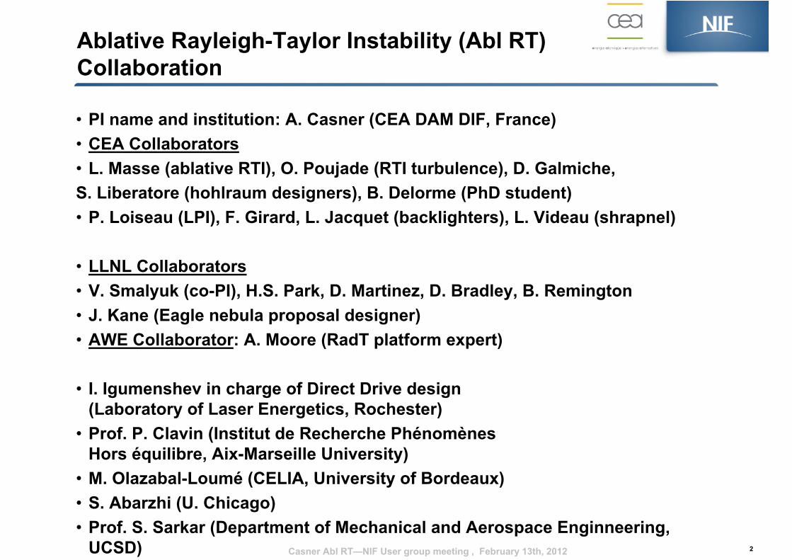
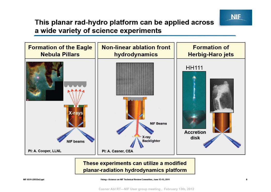
Ablative RT proposal objectives• The effect of ablation on RTI growth rate depends on the irradiating scheme: direct versus indirect drive.
• Multimode ablative Rayleigh Taylor Instability is not well understood, as well as turbulent front hydrodynamics.
• NIF will accelerate targets over much larger distances (x6) and over longer time periods than ever achieved.
• In one shot, growth of RT modulations can be measured from the weakly nonlinear stage near nonlinear saturation levels to the highly nonlinear bubble-competition, bubble-merger regimes and perhaps into a turbulent-like regime.
• The result of the first DD planar RT shot on NIF will lead the way for academic IFE studies (Polar Direct Drive, Shock Ignition).
• We can perform these experiments right now, without any new diagnostics.
• We are developping a gas-filled hydrodynamics platform usefull for future experiments (Eagle nebula, ….)33
t = 18 ns
Casner Abl RT—NIF User group meeting , February 13th, 2012
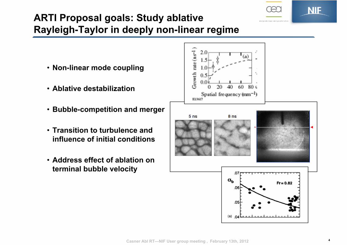
ARTI Proposal goals: Study ablative Rayleigh-Taylor in deeply non-linear regime
• Non-linear mode coupling
• Ablative destabilization
• Bubble-competition and merger
• Transition to turbulence andinfluence of initial conditions
• Address effect of ablation onterminal bubble velocity
4Casner Abl RT—NIF User group meeting , February 13th, 2012
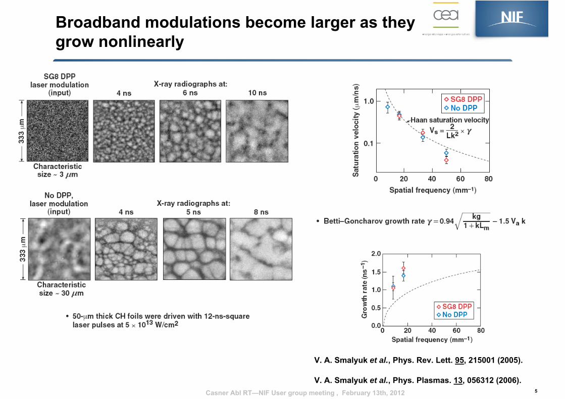
Broadband modulations become larger as they grow nonlinearly
5
V. A. Smalyuk et al., Phys. Rev. Lett. 95, 215001 (2005).
V. A. Smalyuk et al., Phys. Plasmas. 13, 056312 (2006). Casner Abl RT—NIF User group meeting , February 13th, 2012
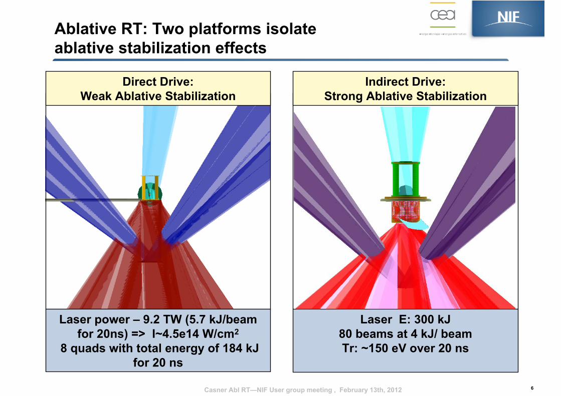
Ablative RT: Two platforms isolate ablative stabilization effects
6
Laser E: 300 kJ80 beams at 4 kJ/ beamTr: ~150 eV over 20 ns
Indirect Drive: Strong Ablative Stabilization
Laser power – 9.2 TW (5.7 kJ/beam for 20ns) => I~4.5e14 W/cm2
8 quads with total energy of 184 kJ for 20 ns
Direct Drive: Weak Ablative Stabilization
Casner Abl RT—NIF User group meeting , February 13th, 2012
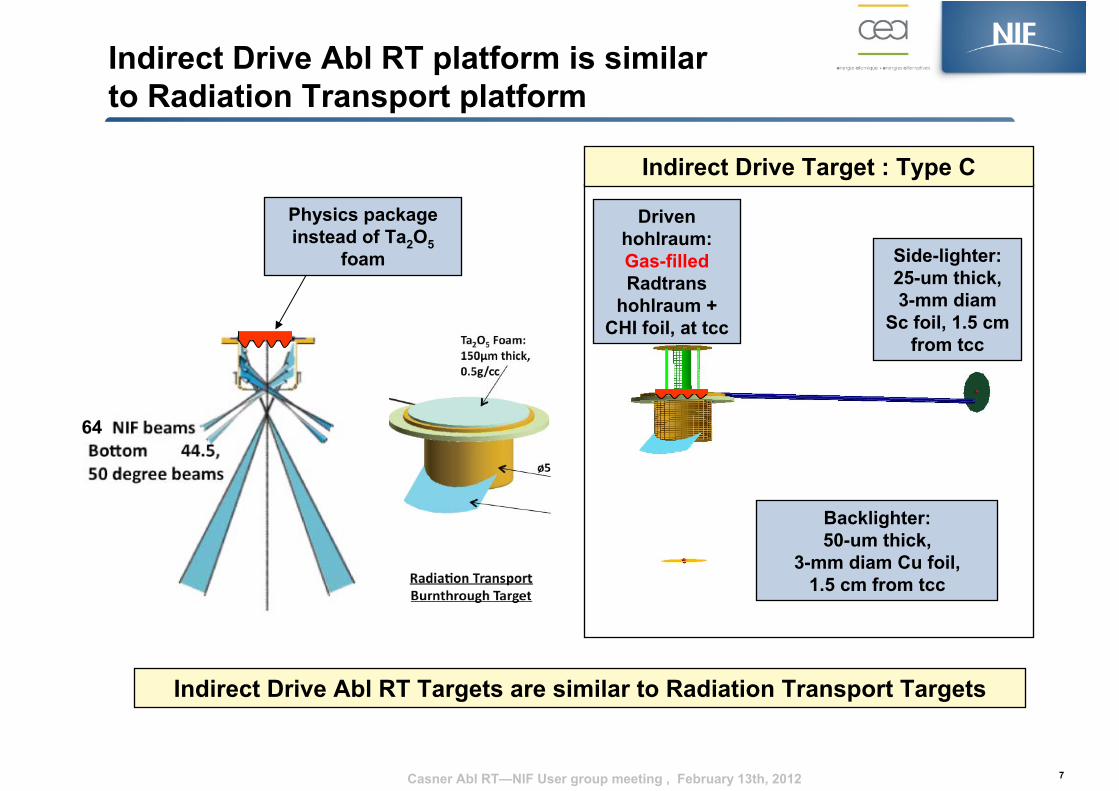
Indirect Drive Abl RT platform is similar to Radiation Transport platform
7
Indirect Drive Abl RT Targets are similar to Radiation Transport Targets
Indirect Drive Target : Type C
Side-lighter:25-um thick, 3-mm diam
Sc foil, 1.5 cm from tcc
Backlighter:50-um thick,
3-mm diam Cu foil, 1.5 cm from tcc
Driven hohlraum:Gas-filledRadtrans
hohlraum + CHI foil, at tcc
64
Physics package instead of Ta2O5
foam
Casner Abl RT—NIF User group meeting , February 13th, 2012
Casner Abl RT—NIF User group meeting , February 13th, 2012
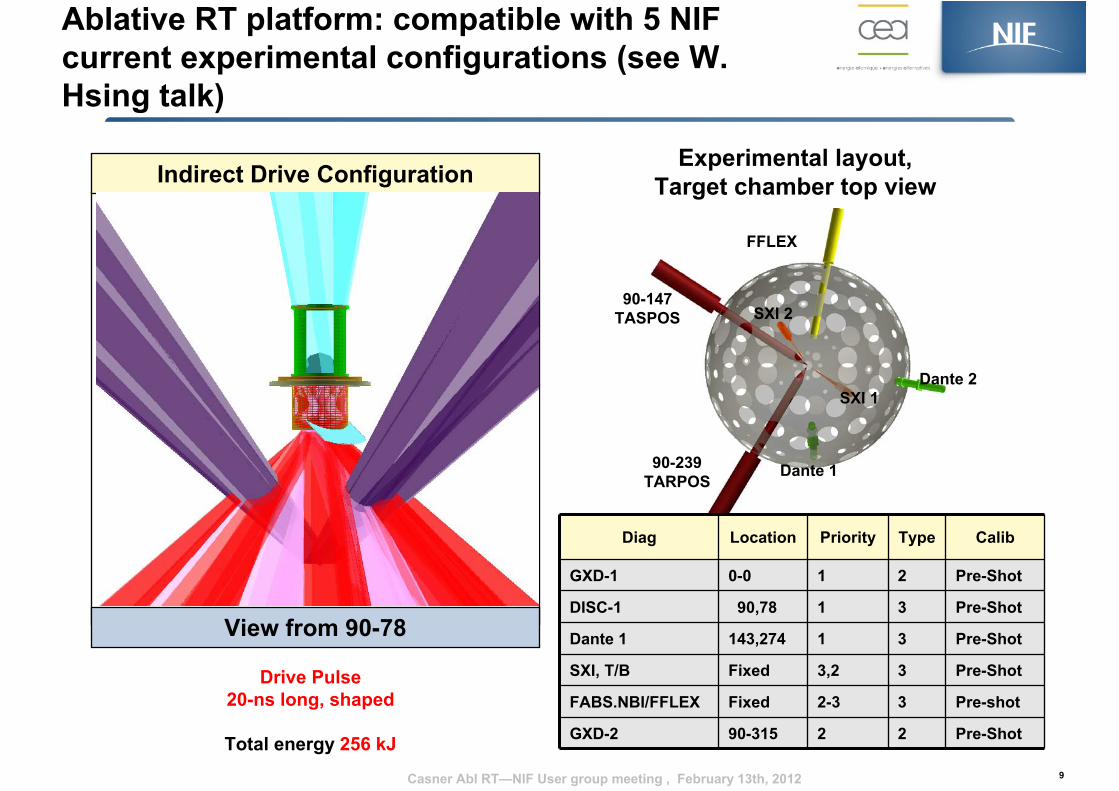
Ablative RT platform: compatible with 5 NIF current experimental configurations (see W. Hsing talk)
9
View from 90-78
Indirect Drive Configuration
Dante 2
Dante 190-239TARPOS
90-147TASPOS
FFLEX
Diag Location Priority Type Calib
GXD-1 0-0 1 2 Pre-Shot
DISC-1 90,78 1 3 Pre-Shot
Dante 1 143,274 1 3 Pre-Shot
SXI, T/B Fixed 3,2 3 Pre-Shot
FABS.NBI/FFLEX Fixed 2-3 3 Pre-shot
GXD-2 90-315 2 2 Pre-Shot
SXI 1
SXI 2
Drive Pulse20-ns long, shaped
Total energy 256 kJ
Experimental layout, Target chamber top view
Casner Abl RT—NIF User group meeting , February 13th, 2012
Laser Parameter Drive Value Face-on BL Value SidelighterValue
Tolerance
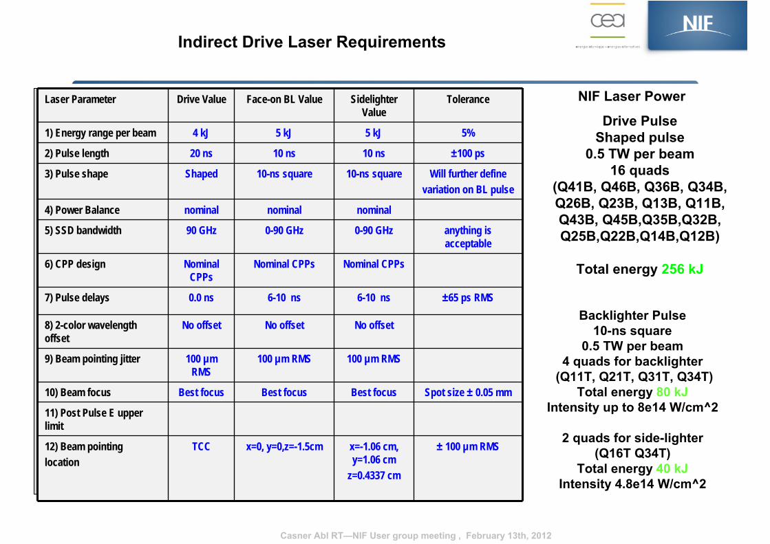
1) Energy range per beam 4 kJ 5 kJ 5 kJ 5%
2) Pulse length 20 ns 10 ns 10 ns ±100 ps
3) Pulse shape Shaped 10-ns square 10-ns square Will further define variation on BL pulse
4) Power Balance nominal nominal nominal
5) SSD bandwidth 90 GHz 0-90 GHz 0-90 GHz anything is acceptable
6) CPP design Nominal CPPs
Nominal CPPs Nominal CPPs
7) Pulse delays 0.0 ns 6-10 ns 6-10 ns ±65 ps RMS
8) 2-color wavelength offset
No offset No offset No offset
9) Beam pointing jitter 100 µm RMS
100 µm RMS 100 µm RMS
10) Beam focus Best focus Best focus Best focus Spot size ± 0.05 mm
11) Post Pulse E upper limit
12) Beam pointing location
TCC x=0, y=0,z=-1.5cm x=-1.06 cm, y=1.06 cm
z=0.4337 cm
± 100 µm RMS
Indirect Drive Laser Requirements
NIF Laser Power
Drive PulseShaped pulse
0.5 TW per beam16 quads
(Q41B, Q46B, Q36B, Q34B,Q26B, Q23B, Q13B, Q11B,Q43B, Q45B,Q35B,Q32B,Q25B,Q22B,Q14B,Q12B)
Total energy 256 kJ
Backlighter Pulse10-ns square
0.5 TW per beam4 quads for backlighter
(Q11T, Q21T, Q31T, Q34T)Total energy 80 kJ
Intensity up to 8e14 W/cm^2
2 quads for side-lighter(Q16T Q34T)
Total energy 40 kJIntensity 4.8e14 W/cm^2
Casner Abl RT—NIF User group meeting , February 13th, 2012
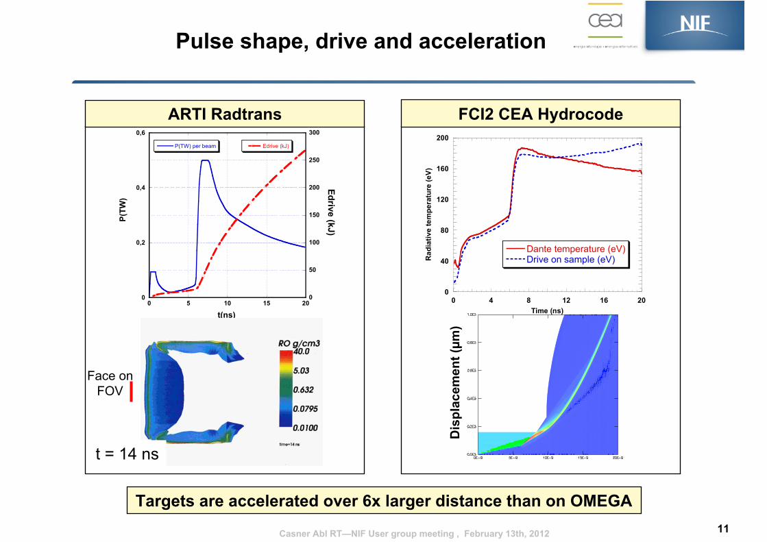
Pulse shape, drive and acceleration
11
FCI2 CEA HydrocodeARTI Radtrans
Targets are accelerated over 6x larger distance than on OMEGA
0
40
80
120
160
200
0 4 8 12 16 20
Dante temperature (eV)Drive on sample (eV)R
adia
tive
tem
pera
ture
(eV)
Time (ns)
0
0,2
0,4
0,6
0
50
100
150
200
250
300
0 5 10 15 20
P(TW) per beam Edrive (kJ)
P(TW
)
Edrive (kJ)
t(ns)
Dis
plac
emen
t(µm
)
Face onFOV
Casner Abl RT—NIF User group meeting , February 13th, 2012
t = 14 ns
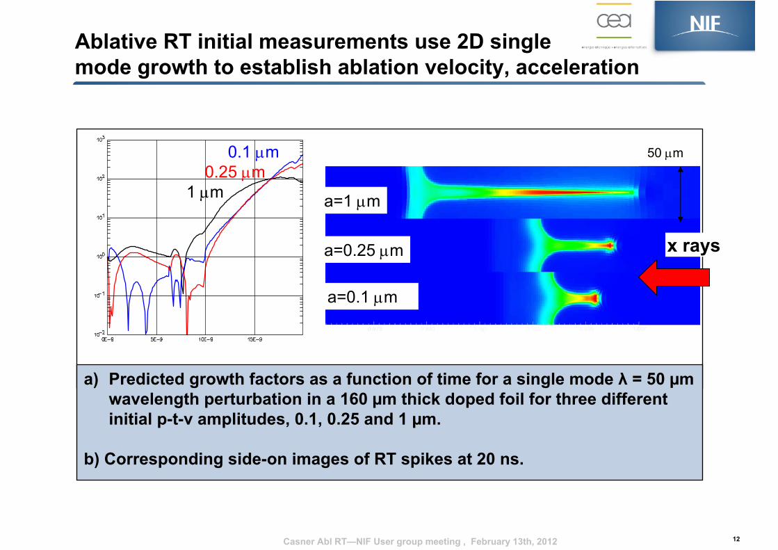
Ablative RT initial measurements use 2D single mode growth to establish ablation velocity, acceleration
12
a) Predicted growth factors as a function of time for a single mode λ = 50 µm wavelength perturbation in a 160 µm thick doped foil for three different initial p-t-v amplitudes, 0.1, 0.25 and 1 µm.
b) Corresponding side-on images of RT spikes at 20 ns.
a=1 µm
a=0.25 µm
a=0.1 µm
50 µm0.1 µm0.25 µm
1 µm
x rays
Casner Abl RT—NIF User group meeting , February 13th, 2012
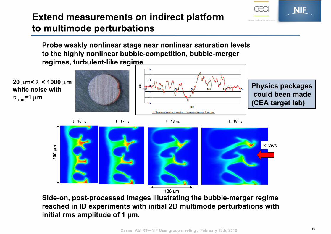
Extend measurements on indirect platform to multimode perturbations
13
Probe weakly nonlinear stage near nonlinear saturation levels to the highly nonlinear bubble-competition, bubble-merger regimes, turbulent-like regime
Side-on, post-processed images illustrating the bubble-merger regime reached in ID experiments with initial 2D multimode perturbations with initial rms amplitude of 1 µm.
Physics packagescould been made(CEA target lab)
200
µm
138 µm
x-rays
t =16 ns t =17 ns t =18 ns t =19 ns
200
µm
138 µm
200
µm
138 µm
x-rays
t =16 ns t =17 ns t =18 ns t =19 ns
20 µm< λ < 1000 µmwhite noise withσrms=1 µm
Casner Abl RT—NIF User group meeting , February 13th, 2012
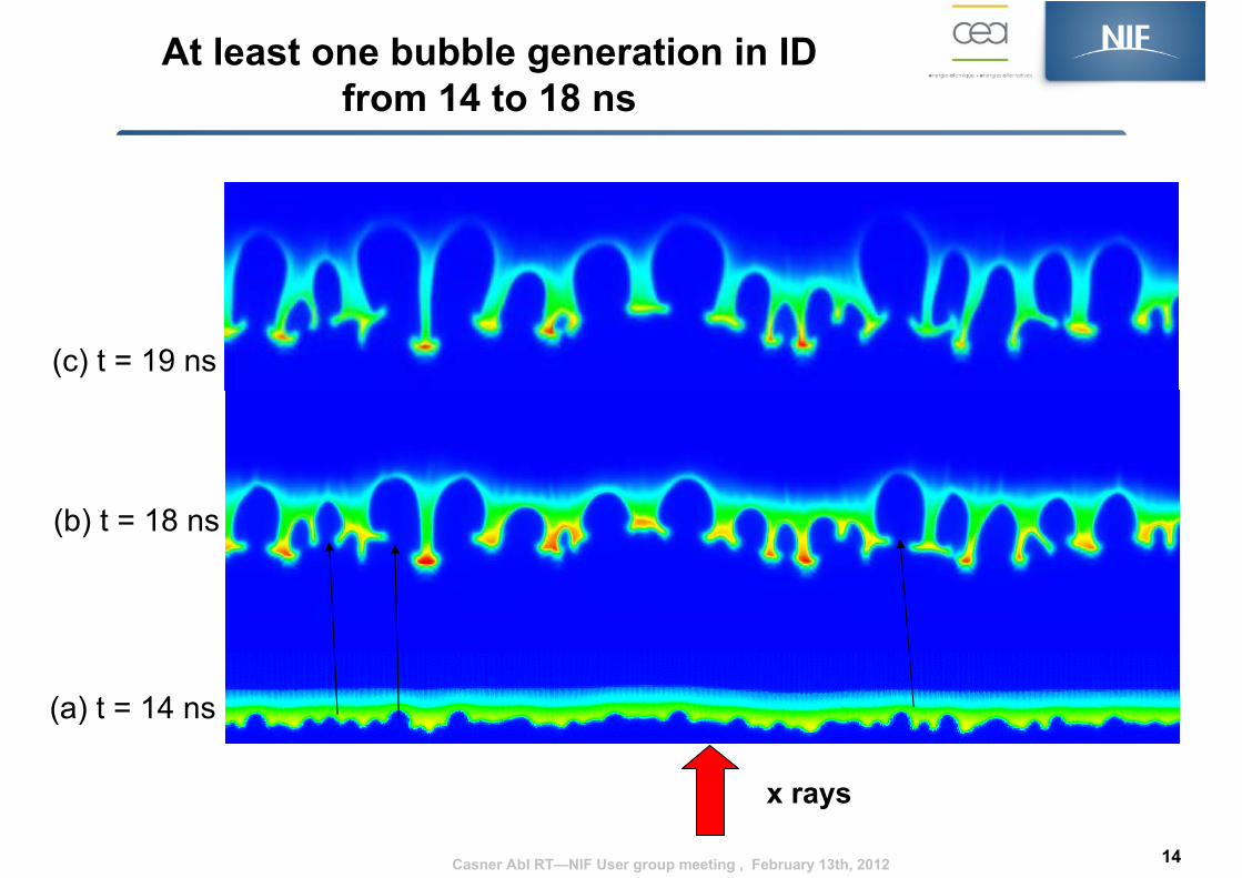
(c) t = 19 ns
(a) t = 14 ns
(b) t = 18 ns
At least one bubble generation in ID from 14 to 18 ns
14
x rays
Casner Abl RT—NIF User group meeting , February 13th, 2012
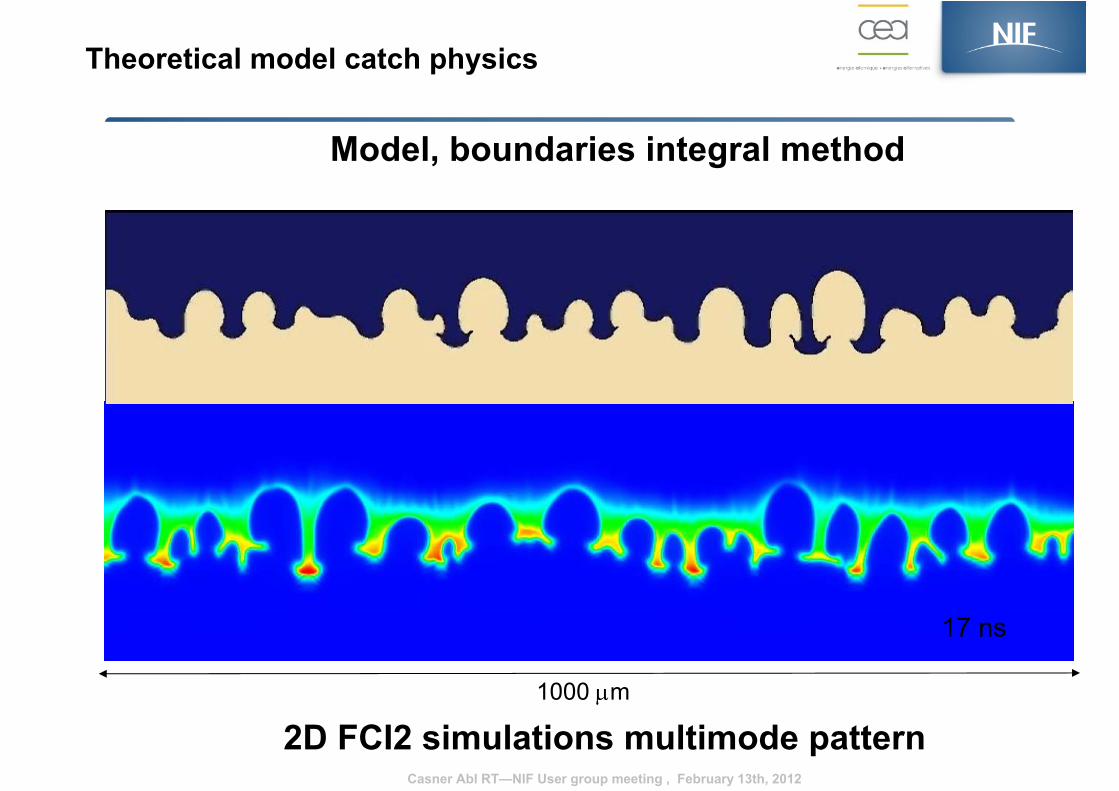
Model, boundaries integral method
2D FCI2 simulations multimode pattern
17 ns
Theoretical model catch physics
1000 µm
Casner Abl RT—NIF User group meeting , February 13th, 2012
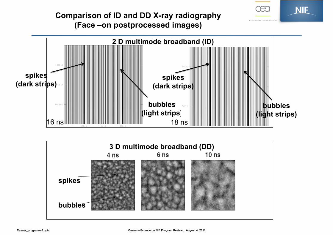
spikes(dark strips)
bubbles(light strips)
spikes(dark strips)
bubbles(light strips)
2 D multimode broadband (ID)
Comparison of ID and DD X-ray radiography(Face –on postprocessed images)
16 ns 18 ns
3 D multimode broadband (DD)
spikes
bubbles
Casner—Science on NIF Program Review , August 4, 2011Casner_program-v0.pptx
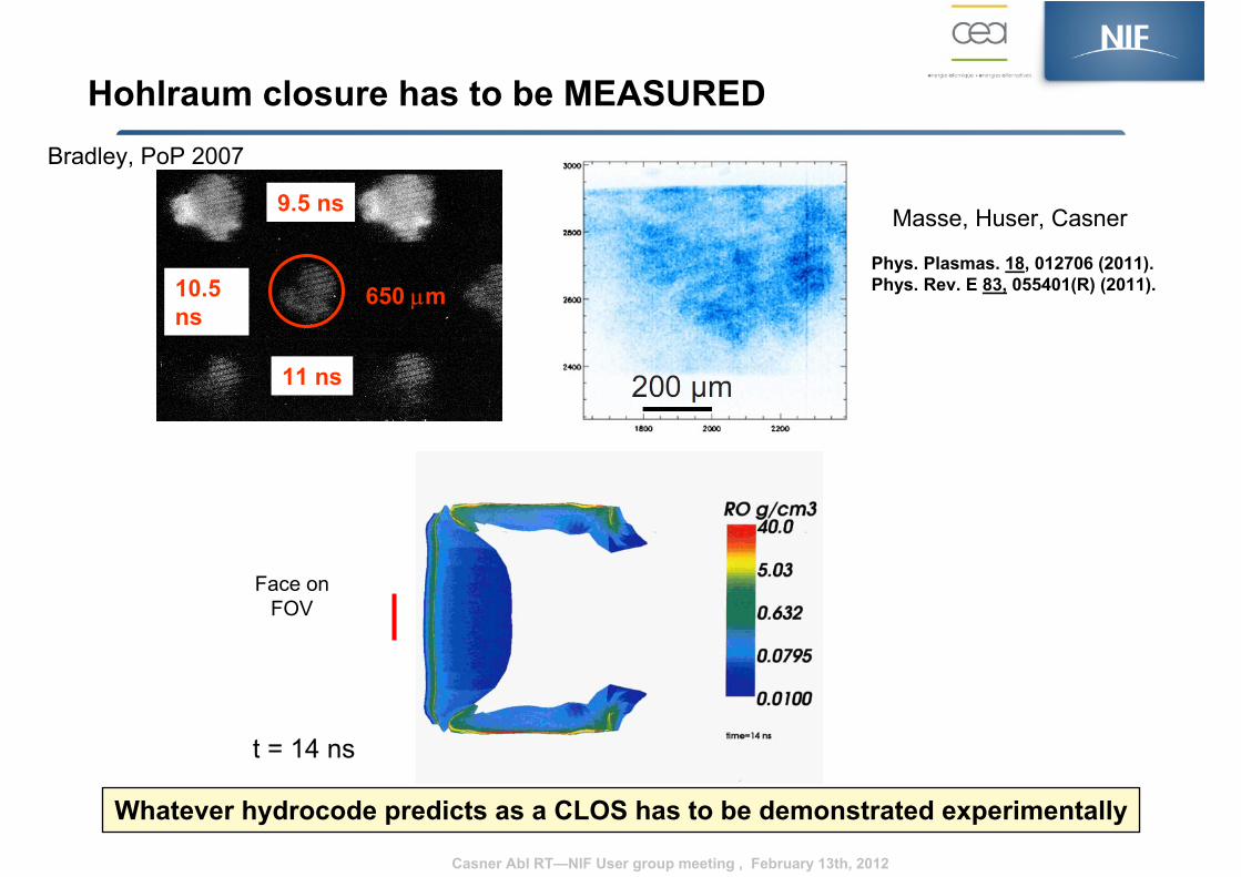
9.5 ns
10.5 ns
11 ns
650 µm
Hohlraum closure has to be MEASUREDBradley, PoP 2007
Masse, Huser, Casner
Phys. Plasmas. 18, 012706 (2011).Phys. Rev. E 83, 055401(R) (2011).
Casner Abl RT—NIF User group meeting , February 13th, 2012
Whatever hydrocode predicts as a CLOS has to be demonstrated experimentally
Face onFOV
t = 14 ns

Back-lighter foil
Side-lighter foil
Shield
Abl RT: Backlighter Performance Qualification shot (Tier 1 FY12) followed by Hohlraum PQ shot (Tier 2)
Casner Abl RT—NIF User group meeting , February 13th, 2012
Final design review this week.Target support is needed to finalize the drawings
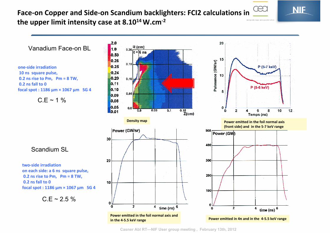
Face‐on Copper and Side‐on Scandium backlighters: FCI2 calculations in the upper limit intensity case at 8.1014 W.cm‐2
two‐side irradiationon each side: a 6 ns square pulse,0.2 ns rise to Pm, Pm = 8 TW, 0.2 ns fall to 0focal spot : 1186 μm × 1067 μm SG 4
Power emitted in the foil normal axis andin the 4‐5.5 keV range Power emitted in 4π and in the 4‐5.5 keV range
one‐side irradiation10 ns square pulse,0.2 ns rise to Pm, Pm = 8 TW, 0.2 ns fall to 0focal spot : 1186 μm × 1067 μm SG 4
Power emitted in the foil normal axis (front side) and in the 5‐7 keV range
Density map
Vanadium Face-on BL
Scandium SL
C.E ~ 2.5 %
C.E ~ 1 %
Casner Abl RT—NIF User group meeting , February 13th, 2012
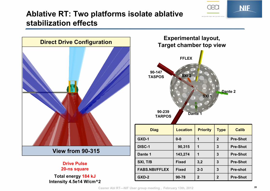
Ablative RT: Two platforms isolate ablative stabilization effects
20
Direct Drive Configuration
Dante 2
Dante 190-239TARPOS
90-147TASPOS
FFLEX
Experimental layout, Target chamber top view
Diag Location Priority Type Calib
GXD-1 0-0 1 2 Pre-Shot
DISC-1 90,315 1 3 Pre-Shot
Dante 1 143,274 1 3 Pre-Shot
SXI, T/B Fixed 3,2 3 Pre-Shot
FABS.NBI/FFLEX Fixed 2-3 3 Pre-shot
GXD-2 90-78 2 2 Pre-Shot
SXI 1
SXI 2
Drive Pulse20-ns square
Total energy 184 kJIntensity 4.5e14 W/cm^2
View from 90-315
Casner Abl RT—NIF User group meeting , February 13th, 2012
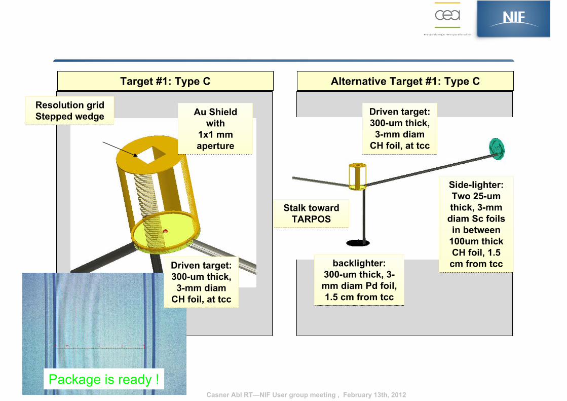
Target #1: Type C Alternative Target #1: Type C
Driven target:300-um thick, 3-mm diam
CH foil, at tcc
Driven target:300-um thick, 3-mm diam
CH foil, at tcc
Side-lighter:Two 25-um thick, 3-mm
diam Sc foils in between
100um thick CH foil, 1.5 cm from tcc
Side-lighter:Two 25-um thick, 3-mm
diam Sc foils in between
100um thick CH foil, 1.5 cm from tcc
Stalk toward TARPOS
Stalk toward TARPOS
backlighter:300-um thick, 3-mm diam Pd foil, 1.5 cm from tcc
backlighter:300-um thick, 3-mm diam Pd foil, 1.5 cm from tcc
Au Shield with
1x1 mm aperture
Au Shield with
1x1 mm aperture
Package is ready !
Driven target:300-um thick, 3-mm diam
CH foil, at tcc
Driven target:300-um thick, 3-mm diam
CH foil, at tcc
Resolution gridStepped wedgeResolution gridStepped wedge
Casner Abl RT—NIF User group meeting , February 13th, 2012
Laser Parameter Drive Value Face-on BL Value SidelighterValue
Tolerance
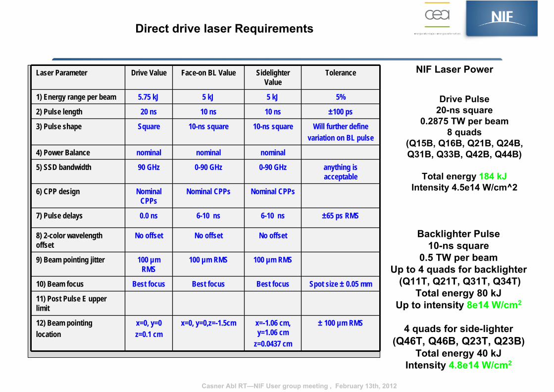
1) Energy range per beam 5.75 kJ 5 kJ 5 kJ 5%
2) Pulse length 20 ns 10 ns 10 ns ±100 ps
3) Pulse shape Square 10-ns square 10-ns square Will further define variation on BL pulse
4) Power Balance nominal nominal nominal
5) SSD bandwidth 90 GHz 0-90 GHz 0-90 GHz anything is acceptable
6) CPP design Nominal CPPs
Nominal CPPs Nominal CPPs
7) Pulse delays 0.0 ns 6-10 ns 6-10 ns ±65 ps RMS
8) 2-color wavelength offset
No offset No offset No offset
9) Beam pointing jitter 100 µm RMS
100 µm RMS 100 µm RMS
10) Beam focus Best focus Best focus Best focus Spot size ± 0.05 mm
11) Post Pulse E upper limit
12) Beam pointing location
x=0, y=0z=0.1 cm
x=0, y=0,z=-1.5cm x=-1.06 cm, y=1.06 cm
z=0.0437 cm
± 100 µm RMS
Direct drive laser Requirements
NIF Laser Power
Backlighter Pulse10-ns square
0.5 TW per beamUp to 4 quads for backlighter
(Q11T, Q21T, Q31T, Q34T)Total energy 80 kJ
Up to intensity 8e14 W/cm2
4 quads for side-lighter(Q46T, Q46B, Q23T, Q23B)
Total energy 40 kJIntensity 4.8e14 W/cm2
Drive Pulse20-ns square
0.2875 TW per beam8 quads
(Q15B, Q16B, Q21B, Q24B,Q31B, Q33B, Q42B, Q44B)
Total energy 184 kJIntensity 4.5e14 W/cm^2
Casner Abl RT—NIF User group meeting , February 13th, 2012
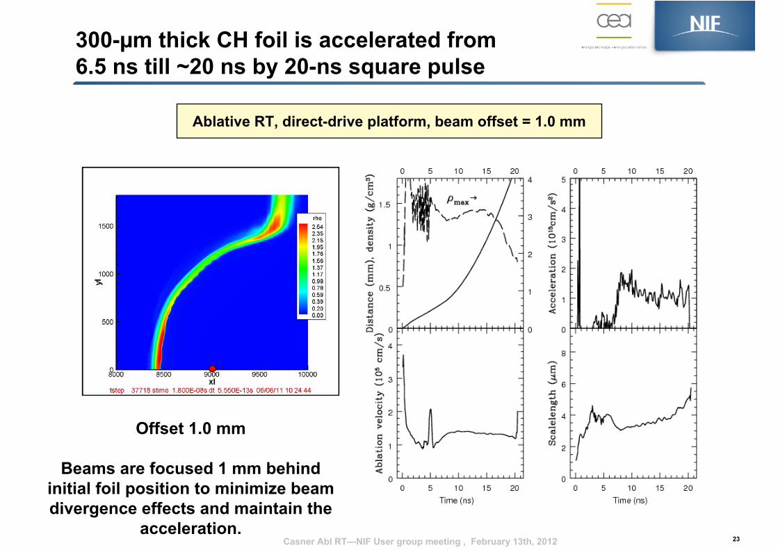
300-µm thick CH foil is accelerated from 6.5 ns till ~20 ns by 20-ns square pulse
23
Ablative RT, direct-drive platform, beam offset = 1.0 mm
Offset 1.0 mm
Beams are focused 1 mm behind initial foil position to minimize beam divergence effects and maintain the
acceleration.Casner Abl RT—NIF User group meeting , February 13th, 2012
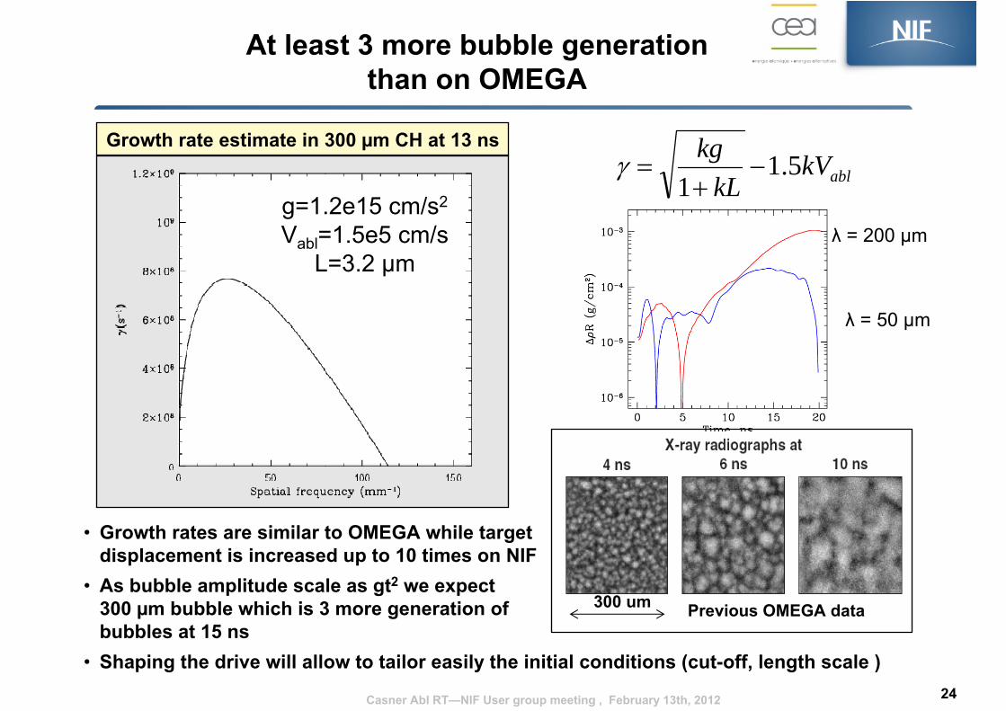
At least 3 more bubble generation than on OMEGA
• Growth rates are similar to OMEGA while target displacement is increased up to 10 times on NIF
• As bubble amplitude scale as gt2 we expect 300 µm bubble which is 3 more generation of bubbles at 15 ns
• Shaping the drive will allow to tailor easily the initial conditions (cut-off, length scale ) 24
ablkVkL
kg 5.11
−+
=γ
λ = 200 µm
Growth rate estimate in 300 µm CH at 13 ns
g=1.2e15 cm/s2
Vabl=1.5e5 cm/sL=3.2 µm
300 um Previous OMEGA data
λ = 50 µm
Casner Abl RT—NIF User group meeting , February 13th, 2012
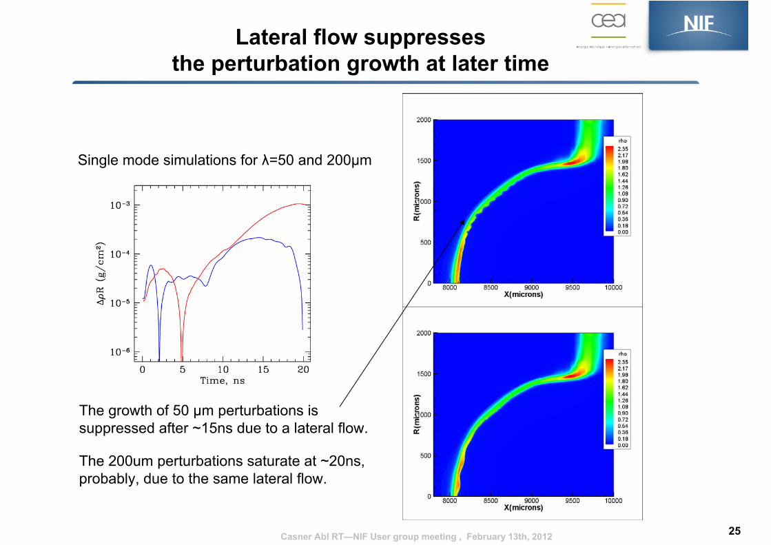
Lateral flow suppresses the perturbation growth at later time
The growth of 50 µm perturbations is suppressed after ~15ns due to a lateral flow.
The 200um perturbations saturate at ~20ns,probably, due to the same lateral flow.
Single mode simulations for λ=50 and 200µm
25Casner Abl RT—NIF User group meeting , February 13th, 2012
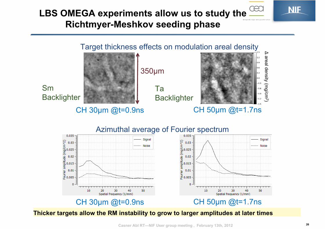
Thicker targets allow the RM instability to grow to larger amplitudes at later times26
SmBacklighter
Ta Backlighter
CH 30µm @t=0.9ns CH 50µm @t=1.7ns
∆areal density (m
g/cm2)
350µm
Azimuthal average of Fourier spectrum
Target thickness effects on modulation areal density
CH 30µm @t=0.9ns CH 50µm @t=1.7ns
Casner Abl RT—NIF User group meeting , February 13th, 2012
LBS OMEGA experiments allow us to study the Richtmyer-Meshkov seeding phase
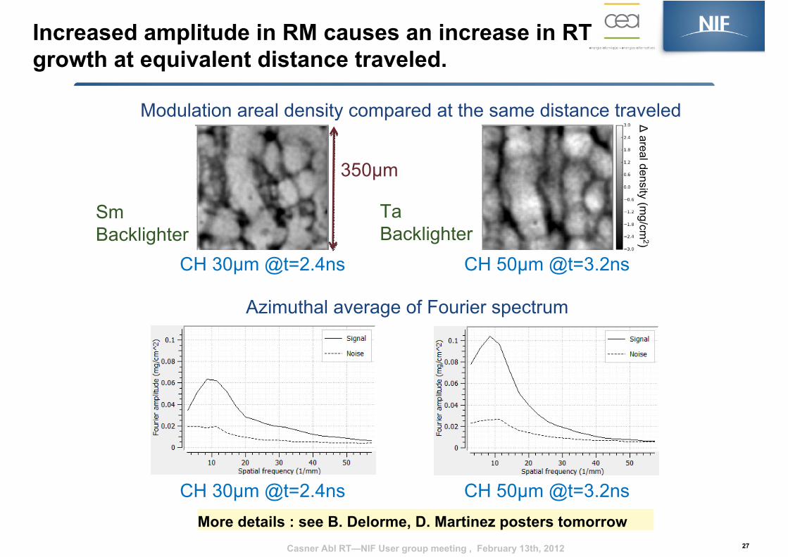
Increased amplitude in RM causes an increase in RT growth at equivalent distance traveled.
27
Modulation areal density compared at the same distance traveled
SmBacklighter
Ta Backlighter
Azimuthal average of Fourier spectrum
∆areal density (m
g/cm2)
CH 30µm @t=2.4ns CH 50µm @t=3.2ns
350µm
CH 30µm @t=2.4ns CH 50µm @t=3.2ns
Casner Abl RT—NIF User group meeting , February 13th, 2012
More details : see B. Delorme, D. Martinez posters tomorrow

Ablative RT proposal objectives• The effect of ablation on RTI growth rate depends on the irradiating scheme: direct versus indirect drive.
• Multimode ablative Rayleigh Taylor Instability is not well understood, as well as turbulent front hydrodynamics.
• NIF will accelerate targets over much larger distances (x6) and over longer time periods than ever achieved.
• In one shot, growth of RT modulations can be measured from the weakly nonlinear stage near nonlinear saturation levels to the highly nonlinear bubble-competition, bubble-merger regimes and perhaps into a turbulent-like regime.
• The result of the first DD planar RT shot on NIF will lead the way for academic IFE studies (Polar Direct Drive, Shock Ignition).
• We can perform these experiments right now, without any new diagnostics.
• We are developping a gas-filled hydrodynamics platform usefull for future experiments (Eagle nebula, ….)2828
t = 18 ns
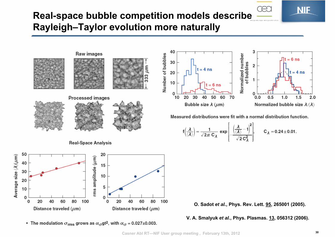
Real-space bubble competition models describe Rayleigh–Taylor evolution more naturally
30
O. Sadot et al., Phys. Rev. Lett. 95, 265001 (2005).
V. A. Smalyuk et al., Phys. Plasmas. 13, 056312 (2006).
Casner Abl RT—NIF User group meeting , February 13th, 2012
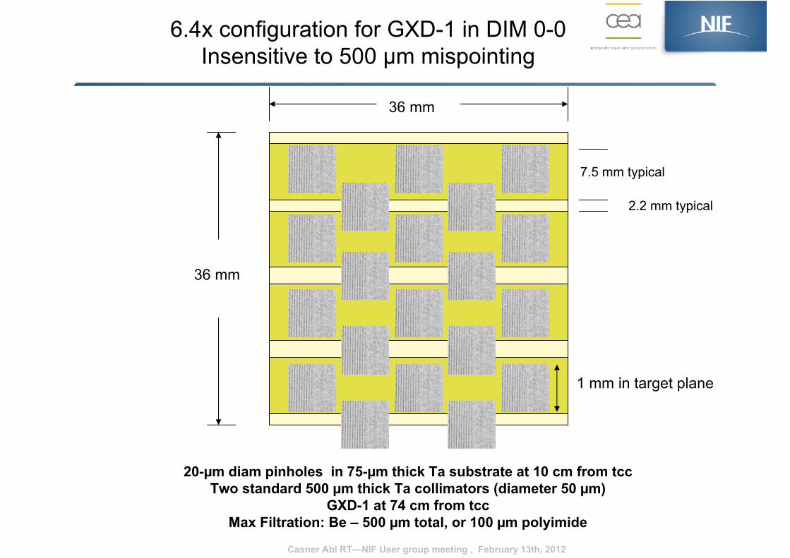
20-µm diam pinholes in 75-µm thick Ta substrate at 10 cm from tccTwo standard 500 µm thick Ta collimators (diameter 50 µm)
GXD-1 at 74 cm from tccMax Filtration: Be – 500 µm total, or 100 µm polyimide
36 mm
36 mm
7.5 mm typical
2.2 mm typical
6.4x configuration for GXD-1 in DIM 0-0Insensitive to 500 µm mispointing
1 mm in target plane
Casner Abl RT—NIF User group meeting , February 13th, 2012
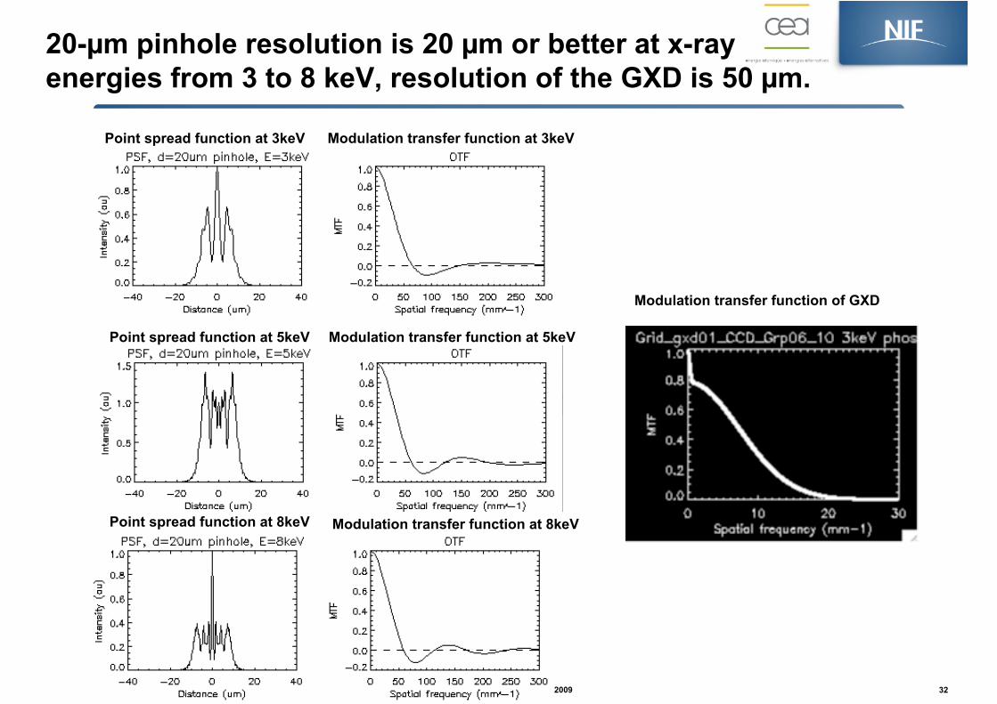
20-µm pinhole resolution is 20 µm or better at x-ray energies from 3 to 8 keV, resolution of the GXD is 50 µm.
Author—NIC Review, December 2009 32
Point spread function at 3keV Modulation transfer function at 3keV
Point spread function at 5keV
Point spread function at 8keV
Modulation transfer function at 5keV
Modulation transfer function at 8keV
Modulation transfer function of GXD