Embed Size (px)
Citation preview
Highly sensitive fiber Bragg grating-basedpressure sensor using side-hole packagingSUNEETHA SEBASTIAN,1,† S. SRIDHAR,1,† P. SHIVA PRASAD,2 AND S. ASOKAN1,*1Department of Instrumentation and Applied Physics, Indian Institute of Science, Bangalore, India2Research Center Imarat, DRDO, Hyderabad, India*Corresponding author: [email protected]
Received 6 September 2018; revised 7 November 2018; accepted 7 November 2018; posted 8 November 2018 (Doc. ID 343102);published 20 December 2018
In this work, an analysis of pressure response of a fiber Bragg grating (FBG) sensor in a side-hole package ispresented using the finite element method. Various parameters of the side-hole packaging such as hole radius,the distance of separation between them, the radius and length of the package, and the choice of the packagematerial are considered and optimized in order to promote maximum pressure sensitivity of the FBG sensor. Thisinvestigation on optimization of the side-hole package parameters gives rise to pressure sensitivity of nearly105 times as compared with the bare FBG sensor, with the numerical values of 3 pm/MPa for a bare FBG sensorto ∼280,000 pm∕MPa for an optimized side-hole package FBG sensor. Such high-pressure sensitivity of an FBGsensor is being reported for the very first time in this work, to the best of our knowledge, and can be considered asthe initial step toward the realization of a highly sensitive hydrophone based on FBG for sensing underwateracoustic signals. © 2018 Optical Society of America
https://doi.org/10.1364/AO.58.000115
1. INTRODUCTION
Optical fiber-based hydrophones, an acoustic signal detector,have been widely studied for their extensive uses in various fieldssuch as military sonars [1], geophysical [2], and marine monitor-ing [3]. To compare with conventional piezo-based sensors,fiber-based hydrophones inherit the advantages of more flexibil-ity, light weight, low cost, and complete immunity to electro-magnetic interference. Further, optical fiber-based hydrophonesrequire no electrical components in the sensing area, whichprovides a completely passive network of sensors. However, inordinary optical fiber sensors, the measured phase/amplitude/wavelength shift of transmitting optical signal gives the informa-tion about various measurands. On the other hand, an FBG sen-sor uses the reflection of narrow wavelength bandwidth in itsprocess of measurement of various measurand [4], which is amore direct and unwavering measurement than that of phaseshift. FBG sensors also possess several added advantages such asreliability and stability in severe environments, smaller size, andmultiplexing capability over conventional sensors. Wheneveracoustic pressure is imposed on an FBG sensor, the resultantstrain is induced in the core of the fiber, which ultimately altersthe grating pitch and yields a shift in Bragg wavelength. Becausethe optical fiber material possesses high Young’s modulus (nearly72 GPa), the deformations due to the applied pressure on thegrating are feeble. Previous studies measure 3 pm of shifts inthe Bragg wavelength when a pressure of 1 MPa is appliedon a bare FBG sensor [5]. This prevents the FBG sensors from
large deformation under acoustic pressure [6]. This eventuallyresults in the low sensitivity of the FBG-based sensors in theiruse in underwater applications.
To extend the application of FBG sensors for deep sea appli-cations such as underwater acoustic sensing, it demands the en-hancement of pressure sensitivity of FBG by several orders ofmagnitude (such that FBG can detect acoustic signal in mParange). The resolution of the FBG interrogator (wavelengthdemodulator) is the central unit, which defines the pressure sen-sitivity of the FBG sensor. But the typical resolution of the com-mercially available FBG sensor systems is ≅1 pm∕με, which ispossible to detect the pressure of, is in the range of MPa.Hence, the appropriate development of interrogator sensitivityand/or amplification of the FBG sensor’s pressure sensitivity haveto be achieved to suit underwater acoustic pressure sensing. Inconsideration of improvement of the FBG sensor’s pressure sen-sitivity, a number of efforts have been taken such as by coatingFBG sensors with polymeric material [6], using phase-shiftedFBGs [7,8], using a distributed feedback (DFB) fiber laser[9,10], using photonic crystal fiber [11], etc. Apart from thosetechniques, Xie et al. [12] have proposed side-hole fibers as a fea-sible hydrostatic or acoustic pressure sensor. In the side-holefibers, due to the introduction of holes in the fiber, which breaksthe mechanical symmetry of the fiber, the symmetrical stress/pressure induced by hydrostatic pressure on the surface of thefiber is transferred as an amplified asymmetrical stress distributionin the fiber core [13]. Further, the applied pressure is measured
Research Article Vol. 58, No. 1 / 1 January 2019 / Applied Optics 115
1559-128X/19/010115-07 Journal © 2019 Optical Society of America
from the birefringence in the core, which is governed by thephoto-elastic property of the fiber, induced by the applied asym-metrical stress distribution [14–16]. Considering this concept,researchers developed the novel side-hole package [17–19] forFBG-based hydrostatic pressure sensors. However, in the previousstudies, a systematic study on a side-hole package for maximumpressure amplification in FBG sensor has not been reported.
The present work deals with a systematic approach on aside-hole packaged FBG sensor to achieve maximum pressureamplification in the fiber core. Different parameters, involvingthe determination of the pressure sensitivity enhancement of anFBG sensor such as package dimensions and its materials, havebeen optimized theoretically using COMSOL Multiphysicssoftware. In this cautious, systematic study, by the preciseinvestigation of all the parameters of the side-hole package,the highest ever reported sensitivity pressure enhancement ofthe order of 105 times, to compare with the typical bareFBG sensor, has been achieved. Apart from enormous pressureamplification on FBG sensors, this package also offers an addi-tional advantage by providing more mechanical stability to thefiber. Because the package emanates with additional featuressuch as mechanical stability, the possibility of incorporating dif-ferent types of sensors, such as etched FBGs, etched FBGscoated with nanomaterials, etc., which has improved pressuresensitivity over that of the typical bare FBG sensor, can beconsidered in the future.
2. SIMULATION METHOD AND THEORY
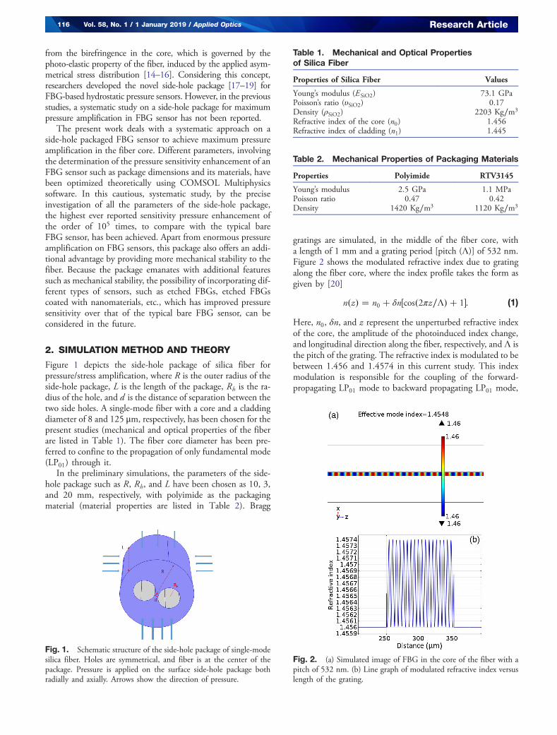
Figure 1 depicts the side-hole package of silica fiber forpressure/stress amplification, where R is the outer radius of theside-hole package, L is the length of the package, Rh is the ra-dius of the hole, and d is the distance of separation between thetwo side holes. A single-mode fiber with a core and a claddingdiameter of 8 and 125 μm, respectively, has been chosen for thepresent studies (mechanical and optical properties of the fiberare listed in Table 1). The fiber core diameter has been pre-ferred to confine to the propagation of only fundamental mode(LP01) through it.
In the preliminary simulations, the parameters of the side-hole package such as R, Rh, and L have been chosen as 10, 3,and 20 mm, respectively, with polyimide as the packagingmaterial (material properties are listed in Table 2). Bragg
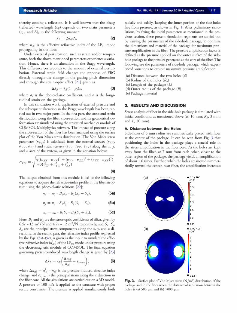
gratings are simulated, in the middle of the fiber core, witha length of 1 mm and a grating period [pitch (Λ)] of 532 nm.Figure 2 shows the modulated refractive index due to gratingalong the fiber core, where the index profile takes the form asgiven by [20]
n�z� � n0 � δn�cos�2πz∕Λ� � 1�: (1)
Here, n0, δn, and z represent the unperturbed refractive indexof the core, the amplitude of the photoinduced index change,and longitudinal direction along the fiber, respectively, and Λ isthe pitch of the grating. The refractive index is modulated to bebetween 1.456 and 1.4574 in this current study. This indexmodulation is responsible for the coupling of the forward-propagating LP01 mode to backward propagating LP01 mode,
Fig. 1. Schematic structure of the side-hole package of single-modesilica fiber. Holes are symmetrical, and fiber is at the center of thepackage. Pressure is applied on the surface side-hole package bothradially and axially. Arrows show the direction of pressure.
Table 1. Mechanical and Optical Propertiesof Silica Fiber
Properties of Silica Fiber Values
Young’s modulus (ESiO2) 73.1 GPaPoisson’s ratio (υSiO2) 0.17Density (ρSiO2) 2203 Kg∕m3
Refractive index of the core (n0) 1.456Refractive index of cladding (n1) 1.445
Table 2. Mechanical Properties of Packaging Materials
Properties Polyimide RTV3145
Young’s modulus 2.5 GPa 1.1 MPaPoisson ratio 0.47 0.42Density 1420 Kg∕m3 1120 Kg∕m3
Fig. 2. (a) Simulated image of FBG in the core of the fiber with apitch of 532 nm. (b) Line graph of modulated refractive index versuslength of the grating.
116 Vol. 58, No. 1 / 1 January 2019 / Applied Optics Research Article
thereby causing a reflection. It is well known that the Bragg(reflected) wavelength (λB) depends on two main parameters(neff and Λ), in the following manner:
λB � 2neffΛ, (2)
where neff is the effective refractive index of the LP01 modepropagating in the fiber.
Under external perturbation, such as strain and/or temper-ature, both the above-mentioned parameters experience a varia-tion. Hence, there is an alteration in the Bragg wavelength.This difference corresponds to the amount of external pertur-bation. External strain field changes the response of FBGdirectly through the change in the grating pitch dimensionand through the strain-optic effect [21] given as
ΔλB � λB�1 − ρe�ε, (3)
where ρe is the photo-elastic coefficient, and ε is the longi-tudinal strain on the gratings.
In this simulation work, application of external pressure andthe subsequent alteration in the Bragg wavelength has been car-ried out in two major parts. In the first part, the stress and straindistribution along the fiber cross-section and its geometrical de-formation are simulated using the structural mechanics module ofCOMSOL Multiphysics software. The impact of pressure alongthe cross-section of the fiber has been analyzed using the surfaceplot of the Von Mises stress distribution. The Von Mises stressparameter (σVM ) is calculated from the normal stresses (σXX ,σY Y , σZZ ) and shear stresses (τXY , τY Z , τZX ) along the x, y,and z axes of the system, as given in the equation below:
σVM �ffiffiffiffiffiffiffiffiffiffiffiffiffiffiffiffiffiffiffiffiffiffiffiffiffiffiffiffiffiffiffiffiffiffiffiffiffiffiffiffiffiffiffiffiffiffiffiffiffiffiffiffiffiffiffiffiffiffiffiffiffiffiffiffiffiffiffiffiffiffiffiffiffiffiffiffiffiffiffiffiffiffiffiffiffiffiffiffiffiffiffiffiffiffi12 ��σXX − σY Y �2 � �σY Y − σZZ �2 � �σZZ − σXX �2��3�τ2XY � τ2Y Z � τ2ZX �
s:
(4)
The output obtained from this module is fed to the followingequations to acquire the refractive-index profile in the fiber struc-ture using the photo-elastic relations [22]:
nx � n0 − B1Sx − B2�Sy � Sz�, (5a)
ny � n0 − B1Sy − B2�Sx � Sz�, (5b)
nz � n0 − B1Sz − B2�Sx � Sy�: (5c)
Here, B1 and B2 are the stress-optic coefficients of silica, given by6.5e − 13 m2∕N and 4.2e − 12 m2∕N respectively, and Sx , Sy,Sz are the principal stress components along the x, y, and z di-rections. In the second part, the refractive-index profile, expressedby the Eqs. (5a)–(5c), is given as the input to simulate the effec-tive refractive index (n†eff ) of the LP01 mode under pressure usingthe electromagnetic module of COMSOL. The final equationgoverning pressure-induced wavelength change is given by [23]
ΔλB � λB
�Δneffneff
� εz,core
�, (6)
where Δneff � n†eff − neff is the pressure-induced effective indexchange, and εz,core is the principal strain along the z direction inthe fiber core. All the simulations are carried out on a 3D model.A pressure of 100 hPa is applied to the structure with propersecure constraints. The pressure is applied simultaneously both
radially and axially, keeping the inner portion of the side-holesfree from pressure, as shown in Fig. 1. After preliminary simu-lations, by fixing the initial parameters as mentioned in the pre-vious section, these present simulation segments are carried outby varying the parameters of the side-hole package, to optimizethe dimensions and material of the package for maximum pres-sure amplification in the fiber. The pressure amplification factor isdefined as the pressure applied on the outer surface of the side-hole package to the pressure generated at the core of the fiber. Thefollowing are the parameters of side-hole package, which experi-enced variations to exhibit maximum pressure amplification:
(a) Distance between the two holes (d )(b) Radius of the holes (Rh)(c) Length of the package (L)(d) Outer radius of the package (R)(e) Package material
3. RESULTS AND DISCUSSION
Stress analysis of fiber in the side-hole package is simulated withinitial conditions, as mentioned above (R, 10 mm; Rh, 3 mm;and L, 20 mm).
A. Distance between the HolesSide-holes of 3 mm radius are symmetrically placed with fiberat the center of the package. It can be seen from Fig. 3 thatpositioning the holes in the package plays a crucial role inthe stress amplification in the fiber core. As the holes are keptaway from the fiber, at 7 mm from each other, closer to theouter region of the package, the package yields an amplificationof about 1.6 times. Further, when the holes are moved symmet-rically toward the center, near fiber, the amplification increases
Fig. 3. Surface plot of Von Mises stress (N∕m2) distribution of thepackage and in the fiber when the distance of separation between theholes is (a) 500 μm and (b) 7000 μm.
Research Article Vol. 58, No. 1 / 1 January 2019 / Applied Optics 117
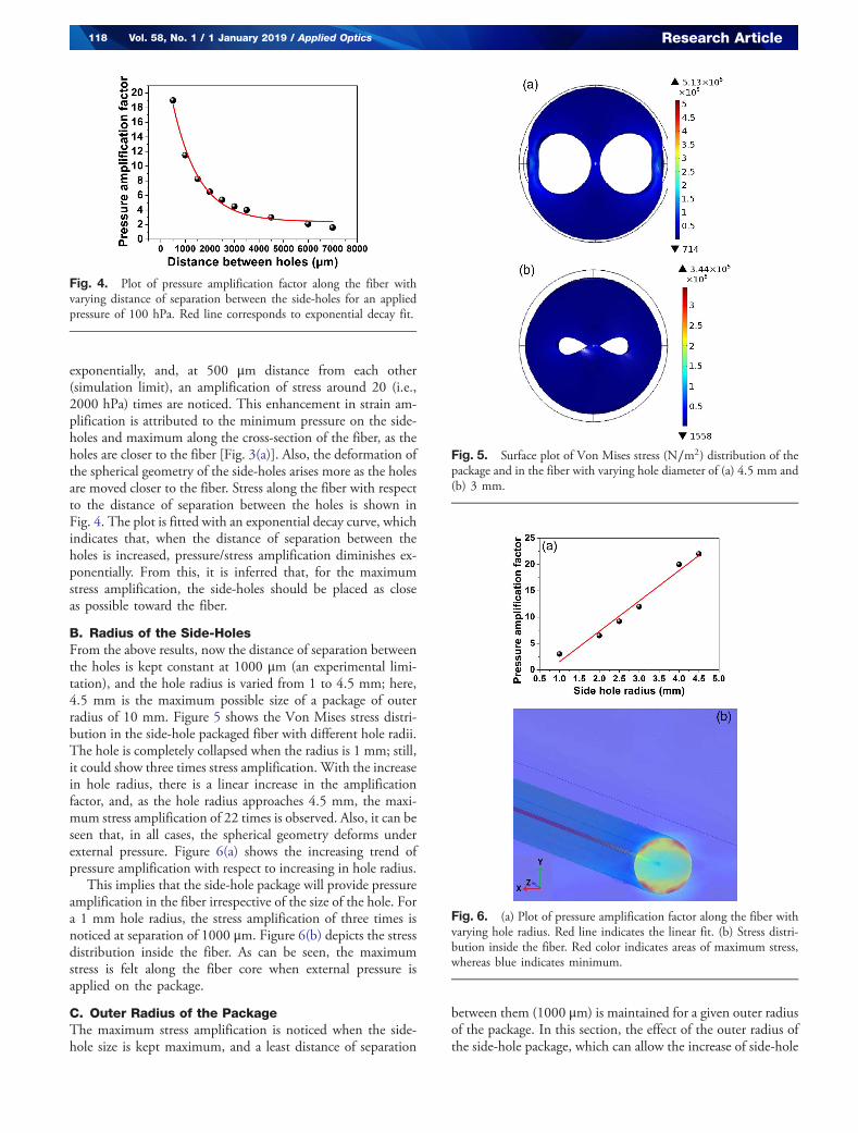
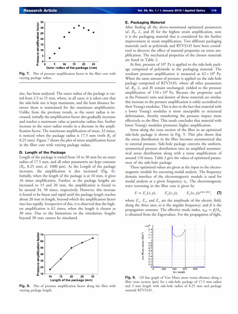
exponentially, and, at 500 μm distance from each other(simulation limit), an amplification of stress around 20 (i.e.,2000 hPa) times are noticed. This enhancement in strain am-plification is attributed to the minimum pressure on the side-holes and maximum along the cross-section of the fiber, as theholes are closer to the fiber [Fig. 3(a)]. Also, the deformation ofthe spherical geometry of the side-holes arises more as the holesare moved closer to the fiber. Stress along the fiber with respectto the distance of separation between the holes is shown inFig. 4. The plot is fitted with an exponential decay curve, whichindicates that, when the distance of separation between theholes is increased, pressure/stress amplification diminishes ex-ponentially. From this, it is inferred that, for the maximumstress amplification, the side-holes should be placed as closeas possible toward the fiber.
B. Radius of the Side-HolesFrom the above results, now the distance of separation betweenthe holes is kept constant at 1000 μm (an experimental limi-tation), and the hole radius is varied from 1 to 4.5 mm; here,4.5 mm is the maximum possible size of a package of outerradius of 10 mm. Figure 5 shows the Von Mises stress distri-bution in the side-hole packaged fiber with different hole radii.The hole is completely collapsed when the radius is 1 mm; still,it could show three times stress amplification. With the increasein hole radius, there is a linear increase in the amplificationfactor, and, as the hole radius approaches 4.5 mm, the maxi-mum stress amplification of 22 times is observed. Also, it can beseen that, in all cases, the spherical geometry deforms underexternal pressure. Figure 6(a) shows the increasing trend ofpressure amplification with respect to increasing in hole radius.
This implies that the side-hole package will provide pressureamplification in the fiber irrespective of the size of the hole. Fora 1 mm hole radius, the stress amplification of three times isnoticed at separation of 1000 μm. Figure 6(b) depicts the stressdistribution inside the fiber. As can be seen, the maximumstress is felt along the fiber core when external pressure isapplied on the package.
C. Outer Radius of the PackageThe maximum stress amplification is noticed when the side-hole size is kept maximum, and a least distance of separation
between them (1000 μm) is maintained for a given outer radiusof the package. In this section, the effect of the outer radius ofthe side-hole package, which can allow the increase of side-hole
Fig. 4. Plot of pressure amplification factor along the fiber withvarying distance of separation between the side-holes for an appliedpressure of 100 hPa. Red line corresponds to exponential decay fit.
Fig. 5. Surface plot of Von Mises stress (N∕m2) distribution of thepackage and in the fiber with varying hole diameter of (a) 4.5 mm and(b) 3 mm.
Fig. 6. (a) Plot of pressure amplification factor along the fiber withvarying hole radius. Red line indicates the linear fit. (b) Stress distri-bution inside the fiber. Red color indicates areas of maximum stress,whereas blue indicates minimum.
118 Vol. 58, No. 1 / 1 January 2019 / Applied Optics Research Article
size, has been analyzed. The outer radius of the package is var-ied from 2.5 to 25 mm, where, in all cases, it is taken care thatthe side-hole size is kept maximum, and the least distance be-tween them is maintained for the maximum amplification.Unlike from the previous trends, as the outer radius is in-creased, initially the amplification factor also gradually increasesand reaches a maximum value at particular radius; but, furtherincrease in the outer radius results in a decrease in the ampli-fication factor. The maximum amplification of stress, 32 times,is noticed when the package radius is 17.5 mm (with Rh of8.25 mm). Figure 7 shows the plot of stress amplification factorin the fiber core with varying package radius.
D. Length of the PackageLength of the package is varied from 10 to 30 mm for an outerradius of 17.5 mm, and all other parameters are kept constant(Rh, 8.25 mm; d , 1000 μm). As the Length of the packageincreases, the amplification is also increased (Fig. 8).Initially, when the length of the package is at 10 mm, it gives16 times amplification. Further, as the package lengths areincreased to 15 and 20 mm, the amplification is found tobe around 34, 50 times, respectively. However, this increaseis found to be linear and rapid until the package length reachesabout 20 mm in length, beyond which the amplification factorrises less rapidly. Irrespective of this, it is observed that the high-est amplification is 62 times, when the length is chosen as30 mm. Due to the limitations in the simulation, lengthsbeyond 30 mm cannot be simulated.
E. Packaging MaterialAfter finding all the above-mentioned optimized parameters(d , Rh, L, and R) for the highest strain amplification, nowit is the packaging material that is considered for the furtherimprovement in strain amplification. Two different packagingmaterials such as polyimide and RTV3145 have been consid-ered to discover the effect of material properties on stress am-plification. The mechanical properties of the chosen materialsare listed in Table 2.
At first, pressure of 104 Pa is applied to the side-hole pack-age comprised of polyimide as the packaging material. Theresultant pressure amplification is measured as 62 × 104 Pa.When the same amount of pressure is applied on the side-holepackage comprised of RTV3145, where all other parameters(d , Rh, L, and R) remain unchanged, yielded to the pressureamplification of 110 × 104 Pa. Because the properties suchas the Poisson’s ratio and density of those materials are similar,this increase in the pressure amplification is solely accredited totheir Young’s modulus. This is due to the fact that material witha lower Young’s modulus is more susceptible to structuraldeformation, thereby transferring the pressure impact moreeffectively to the fiber. This result concludes that material withlower Young’s modulus promotes higher amplification.
Stress along the cross section of the fiber in an optimizedside-hole package is shown in Fig. 9. This plot shows thatthe stress distribution in the fiber becomes asymmetrical dueto external pressure. Side-hole package converts the uniform,symmetrical pressure distribution into an amplified asymmet-rical stress distribution along with a stress amplification ofaround 110 times. Table 3 give the values of optimized param-eters of the side-hole package.
These optimized values are given as the input to the electro-magnetic module for executing modal analysis. The frequencydomain interface of the electromagnetic module is used formodal analysis at a given frequency, υo. The electromagneticwave traversing in the fiber core is given by
E � Ex�x, y�, Ey�x, y�, Ez�x, y�ei�ωt−βz�, (7)
where Ex , Ey, and Ez are the amplitude of the electric field,along the three axes; ω is the angular frequency; and β is thepropagation constant. The effective mode index, neff � β∕ko,is obtained from the Eigenvalues. For the propagation of light,
Fig. 7. Plot of pressure amplification factor in the fiber core withvarying package radius.
Fig. 8. Plot of pressure amplification factor along the fiber withvarying package length.
Fig. 9. 1D line graph of Von Mises stress versus distance along afiber cross section (μm) for a side-hole package of 17.5 mm radiusand 3 mm length with side-hole radius of 8.25 mm and packagematerial RTV3145.
Research Article Vol. 58, No. 1 / 1 January 2019 / Applied Optics 119
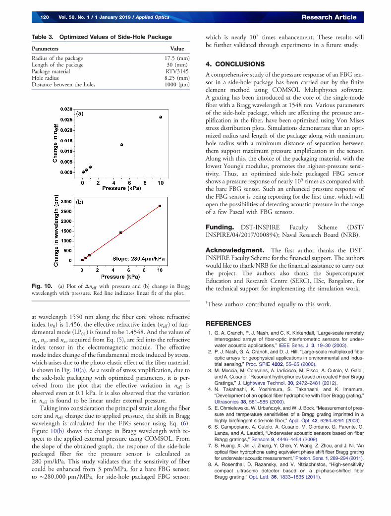
at wavelength 1550 nm along the fiber core whose refractiveindex (n0) is 1.456, the effective refractive index (neff ) of fun-damental mode (LP01) is found to be 1.4548. And the values ofnx , ny, and nz , acquired from Eq. (5), are fed into the refractiveindex tensor in the electromagnetic module. The effectivemode index change of the fundamental mode induced by stress,which arises due to the photo-elastic effect of the fiber material,is shown in Fig. 10(a). As a result of stress amplification, due tothe side-hole packaging with optimized parameters, it is per-ceived from the plot that the effective variation in neff isobserved even at 0.1 kPa. It is also observed that the variationin neff is found to be linear under external pressure.
Taking into consideration the principal strain along the fibercore and neff change due to applied pressure, the shift in Braggwavelength is calculated for the FBG sensor using Eq. (6).Figure 10(b) shows the change in Bragg wavelength with re-spect to the applied external pressure using COMSOL. Fromthe slope of the obtained graph, the response of the side-holepackaged fiber for the pressure sensor is calculated as280 pm/kPa. This study validates that the sensitivity of fibercould be enhanced from 3 pm/MPa, for a bare FBG sensor,to ∼280,000 pm∕MPa, for side-hole packaged FBG sensor,
which is nearly 105 times enhancement. These results willbe further validated through experiments in a future study.
4. CONCLUSIONS
A comprehensive study of the pressure response of an FBG sen-sor in a side-hole package has been carried out by the finiteelement method using COMSOL Multiphysics software.A grating has been introduced at the core of the single-modefiber with a Bragg wavelength at 1548 nm. Various parametersof the side-hole package, which are affecting the pressure am-plification in the fiber, have been optimized using Von Misesstress distribution plots. Simulations demonstrate that an opti-mized radius and length of the package along with maximumhole radius with a minimum distance of separation betweenthem support maximum pressure amplification in the sensor.Along with this, the choice of the packaging material, with thelowest Young’s modulus, promotes the highest-pressure sensi-tivity. Thus, an optimized side-hole packaged FBG sensorshows a pressure response of nearly 105 times as compared withthe bare FBG sensor. Such an enhanced pressure response ofthe FBG sensor is being reporting for the first time, which willopen the possibilities of detecting acoustic pressure in the rangeof a few Pascal with FBG sensors.
Funding. DST-INSPIRE Faculty Scheme (DST/INSPIRE/04/2017/000894); Naval Research Board (NRB).
Acknowledgment. The first author thanks the DST-INSPIRE Faculty Scheme for the financial support. The authorswould like to thank NRB for the financial assistance to carry outthe project. The authors also thank the SupercomputerEducation and Research Centre (SERC), IISc, Bangalore, forthe technical support for implementing the simulation work.
†These authors contributed equally to this work.
REFERENCES1. G. A. Cranch, P. J. Nash, and C. K. Kirkendall, “Large-scale remotely
interrogated arrays of fiber-optic interferometric sensors for under-water acoustic applications,” IEEE Sens. J. 3, 19–30 (2003).
2. P. J. Nash, G. A. Cranch, and D. J. Hill, “Large-scale multiplexed fiberoptic arrays for geophysical applications in environmental and indus-trial sensing,” Proc. SPIE 4202, 55–65 (2000).
3. M. Moccia, M. Consales, A. Iadicicco, M. Pisco, A. Cutolo, V. Galdi,and A. Cusano, “Resonant hydrophones based on coated Fiber BraggGratings,” J. Lightwave Technol. 30, 2472–2481 (2012).
4. N. Takahashi, K. Yoshimura, S. Takahashi, and K. Imamura,“Development of an optical fiber hydrophone with fiber Bragg grating,”Ultrasonics 38, 581–585 (2000).
5. E. Chmielewska,W. Urbanczyk, andW. J. Bock, “Measurement of pres-sure and temperature sensitivities of a Bragg grating imprinted in ahighly birefringent side-hole fiber,” Appl. Opt. 42, 6284–6291 (2003).
6. S. Campopiano, A. Cutolo, A. Cusano, M. Giordano, G. Parente, G.Lanza, and A. Laudati, “Underwater acoustic sensors based on fiberBragg gratings,” Sensors 9, 4446–4454 (2009).
7. S. Huang, X. Jin, J. Zhang, Y. Chen, Y. Wang, Z. Zhou, and J. Ni, “Anoptical fiber hydrophone using equivalent phase shift fiber Bragg gratingfor underwater acoustic measurement,”Photon. Sens. 1, 289–294 (2011).
8. A. Rosenthal, D. Razansky, and V. Ntziachristos, “High-sensitivitycompact ultrasonic detector based on a pi-phase-shifted fiberBragg grating,” Opt. Lett. 36, 1833–1835 (2011).
Fig. 10. (a) Plot of Δneff with pressure and (b) change in Braggwavelength with pressure. Red line indicates linear fit of the plot.
Table 3. Optimized Values of Side-Hole Package
Parameters Value
Radius of the package 17.5 (mm)Length of the package 30 (mm)Package material RTV3145Hole radius 8.25 (mm)Distance between the holes 1000 (μm)
120 Vol. 58, No. 1 / 1 January 2019 / Applied Optics Research Article
9. L.-Y. Shao, S.-T. Lau, X. Dong, A. P. Zhang, H. L. W. Chan, H. Y. Tam,and S. He, “High-frequency ultrasonic hydrophone based on a cladding-etched DBR fiber laser,” IEEE Photon. Technol. Lett. 20, 548–550 (2008).
10. Y. Liu, W. Zhang, T. Xu, J. He, F. Zhang, and F. Li, “Fiber laser sensingsystem and its applications,” Photon. Sens. 1, 43–53 (2011).
11. D. Pawar, C. N. Rao, R. K. Choubey, and S. N. Kale, “Mach-Zehnderinterferometric photonic crystal fiber for low acoustic frequency detec-tions,” Appl. Phys. Lett. 108, 041912 (2016).
12. H. M. Xie, P. Dabkiewicz, and R. Ulrich, “Side-hole fiber for fiber-opticpressure sensing,” Opt. Lett. 11, 333–335 (1986).
13. J. R. Clowes, S. Syngellakis, and M. N. Zervas, “Pressure sensitivityof side-hole optical fiber sensors,” IEEE Photon. Technol. Lett. 10,857–859 (1998).
14. Y. Xin, X. Dong, J. Yuan, Y. Li, S. Jin, and S. Zhang, “Sensing char-acteristics of side-hole fiber-based long-period grating,” Adv. Mater.Sci. Eng. 2013, 850293 (2013).
15. S. H. Lee, B. H. Kim, and W.-T. Han, “Effect of filler metals on thetemperature sensitivity of side-hole fiber,” Opt. Express 17, 9712–9717 (2009).
16. M. S. Alam and M. A. Islam, “Birefringence properties of side-hole op-tical fibers,” in International Conference on Communication Technology(2006).
17. S. Qiufeng and L. Binghua, “Simulation and analysis on hydrostatic pres-sure sensor using fiber Bragg grating,” in International Conference onMeasuring Technology and Mechatronics Automation (2010).
18. C.-F. Sun, Z.-H. Li, S.-M. Jiao, X.-G. Xu, X.-M. Wang, C.-H. Wang,G.-F. Jin, and S.-X. Wang, “Research on pressure and temperaturesensitivities of FBG embedded in novel side-hole package,” Proc.SPIE 8192, 81924K (2011).
19. Z. Li, H. Zhu, Z. Tang, and Y. Hu, “Research on fiber Bragg gratingside-hole package technology,” Acta Opt. Sinica 27, 993–998 (2007).
20. S. Udoh, J. Njuguma, and R. Prabhu, “Modelling and simulation offiber Bragg grating characterization for oil and gas sensing applica-tions,” Int. J. Simul. Syst. Sci. Technol. 15, 213–218 (2014).
21. Y. Wang, X. Qiao, H. Yang, D. Su, L. Li, and T. Guo, “Sensitivity-improved strain sensor over a large range of temperatures using anetched and regenerated fiber Bragg grating,” Sensors 14, 18575–18582 (2014).
22. C. Wu, J. Li, X. Feng, B.-O. Guan, and H.-Y. Tam, “Side-hole photoniccrystal fiber with ultrahigh polarimetric pressure sensitivity,” J. LightwaveTechnol. 29, 943–948 (2011).
23. C. Wu, B.-O. Guan, Z. Wang, and X. Feng, “Characterization of pres-sure response of Bragg gratings in grapefruit microstructured fibers,”J. Lightwave Technol. 28, 1392–1397 (2010).
Research Article Vol. 58, No. 1 / 1 January 2019 / Applied Optics 121


![Fiber Bragg Grating Sensors - Optical Sensing · Fiber Bragg Grating Sensors. ... Bragg grating production Commercial phase mask [Ibsen] with central pitch of 1061.27 nm and operating](https://img.pdfslide.net/doc/110x75/5eb72771ad990c1bc0201c29/fiber-bragg-grating-sensors-optical-fiber-bragg-grating-sensors-bragg-grating.jpg)