Embed Size (px)
Citation preview

Hippocampal slice electrophysiology
1. Purpose
This protocol outlines our approach to phenotypic characterisation of mutant mouse strains with respect to putative effects of mutations on synaptic transmission in synapses between Schäffer collateral/commissural fibres and apical dendrites of CA1 pyramidal neurones. We describe acute preparation of mouse hippocampal slices and methodology of recording field excitatory post-synaptic potentials (fEPSPs) in CA1 area of the hippocampus by means of multi-electrode arrays (MEAs). Standardised procedures utilised to evoke basal synaptic responses and to observe such plastic phenomena as paired-pulse facilitation (PPF) and long-term potentiation (LTP) of fEPSPs are considered. Collectively, these measurements demonstrate if mutation affects basal synaptic strength, short-term and long-term plasticity of the synaptic transmission in the hippocampus. 2. Procedure
2.1. Preparation of hippocampal slices
We use hippocampal slices prepared from litter-matched wild type and mutant mice that are at least 3 months old. Animals are killed by cervical dislocation in accordance with Schedule 1 to the U.K. Animals (Scientific Procedures) Act 1986. Brain is immediately immersed in an ice-cold “cutting” solution of the following composition (in mM):
sucrose 110
NaCl 60
NaHCO3 28
NaH2PO4 1.25
KCl 3
MgSO4 7
CaCl2 0.5
glucose 5
sodium ascorbate 0.6
phenol red 0.015 (bubbled with a gas mixture of 95%O2/5%CO2 to maintain pH levels at 7.2-7.3 ).
Whole brain slices are cut at 350 µm thickness by a Vibroslice MA752 (Campden Instruments, Loughborough, UK) in such a way, so that the blade cuts through hemispheres at an angle of 20-30o to their horizontal planes (http://www.med64.com/resources/pdf/acutesliceprotocol_4.pdf). “Cutting” solution in the temperature-controlled Peltier bath is maintained at 0-3 oC and constantly saturated with a mixture of 95% O2 and 5% CO2 . Up to eight slices containing medial segments of both hippocampi with overlaying cortical areas are trimmed of the remaining tissue, placed into a well of a slice chamber (Fine Science Tools, Foster City, CA) and kept in the interface between moist air and subfused fresh artificial cerebrospinal fluid (ACSF) containing (in mM):
NaCl 124
NaHCO3 25
NaH2PO4 1
KCl 4.4, MgSO4 1.2
CaCl2 2
glucose 10
phenol red 0.015 (bubbled with a gas mixture of 95%O2/5%CO2 to maintain pH levels at 7.3-7.4 ).
Flow rate of ACSF is 2 ml/min and its temperature in the chamber is maintained at 30 oC. Slices are kept in these conditions for at least two to three hours before experiments commence.
2.2 Electrophysiological recording
Field excitatory postsynaptic potentials (fEPSPs) are recorded by the MEA60 electrophysiological suite (Multi Channel Systems, Reutlingen, FRG). Up to four set-ups consisting of a MEA1060-BC pre-amplifier and a filter amplifier (gain 550x) are run simultaneously by a data acquisition card operated by MC_Rack software. A maximum of eight set-ups connected to two PCs are used at any given time. Raw electrode data are digitised at 10 kHz and stored on a PC hard disk for subsequent analysis. To record fEPSPs, we place a hippocampal slice into the well of a 5x13 3D MEA biochip (Ayanda Biosystems, Lausanne, Switzerland). The slice is guided to a desired position in relation to MEA electrodes with a fine paintbrush. It is gently immobilised by a silver ring with attached nylon mesh (e.g. CMN-0165-C 165 micron mesh from Small Parts, Inc.) lowered vertically by a one-dimensional U-1C micromanipulator (You Ltd, Tokyo, Japan). MEA biochips are fitted into the pre-amplifier case and fresh ACSF of the above-mentioned composition is delivered to MEA well through a temperature-controlled perfusion cannula (Multi Channel Systems, Reutlingen, FRG) that warms ACSF to 32 oC. Monopolar stimulation of Schäffer collateral/commissural fibres through array electrodes is performed by STG2008 stimulus generator (Multi Channel Systems, Reutlingen, FRG). Biphasic (positive/negative or negative/positive, depending on the size of the artefact, 100 µs/a phase) voltage pulses are used. Amplitude, duration and frequency of stimulation are controlled by MC_Stimulus II software (Multi Channel Systems, Reutlingen, FRG). As our data acquisition cards have capacity for 128 channels each, we record from only 30 electrodes per chip (out of possible 60) and thereby test up to four slices per animal. We perform all LTP experiments using two-pathway stimulation of Schäffer collateral/commissural fibres (Schwartzkroin and Wester, 1975; Andersen et al., 1977). Our previous experiments that utilised MEAs, demonstrated that largest LTP is recorded in proximal parts of the CA1 stratum radiatum (Kopanitsa et al., 2006). We therefore select a
single principal recording electrode in the middle of proximal part of CA1 (within 25-75 m from stratum pyramidale) and assign two electrodes for stimulation of the control and test pathways on the subicular side and on the CA3 side of stratum radiatum respectively. The distance from the recording electrode to the test stimulation electrode is 400-510 µm and to the control stimulation electrode 316-510 µm. To evoke orthodromic fEPSPs, stimulation electrodes are activated at a frequency of 0.02 Hz. Following at least 15-30 min of equilibration period inside an MEA well, input-output relationships are obtained by consecutive stimulation of control and test pathways with a
series of increasing voltage pulses as follows: 0.1; 0.5; 1; 1.5; 2; 2.5; 3; 3.5; 4; 4.2 V. Stronger stimulation usually leads to large Faradaic effects on electrodes causing artefacts. Baseline stimulation strength is set to evoke a response that corresponds to 40% of the maximal attainable fEPSP at the principal recording electrode. To investigate short-term plasticity, we use paired-pulse stimulation of the test pathway with an inter-pulse interval of 50 ms. Paired-pulse ratio is calculated by dividing the amplitude (peak-to-baseline) of the second fEPSP in a pair by the amplitude of the first one. Averaged data from five paired-pulse stimulations are used for each slice. LTP is induced after 30 min period of stable baseline responses by applying theta-burst stimulation (TBS) train consisting of 10 bursts given at 5 Hz with 4 pulses evoked at 100 Hz per burst. Stimulus strength is not altered during TBS.
2.3. Data analysis
Amplitude of the negative part of fEPSPs are used as a measure of the synaptic strength. Input-output relationships are compared by GraphPad (GraphPad Software, Inc., San Diego, CA) using repeated-measures ANOVA. Bonferroni post hoc test is used when the ANOVA F-value indicated significant differences (α = 0.05). Baseline synaptic transmission is deemed to be different between mutant and wild type mice if Bonferroni test reports a significant difference of fEPSP amplitudes for at least one stimulus strength point. LTP plots are scaled to the average of the first five baseline points. To account for possible drift of baseline conditions, amplitude values in the test pathway are normalised by respective amplitudes in the control pathway prior to statistical comparison. LTP magnitude is assessed by averaging normalised fEPSPs in the test pathway 60-65 min after TBS episode. Unpaired Student’s t-test is used to examine differences in paired-pulse ratios and LTP levels between wild-type and mutant mice. Graph plots, normalisation and unpaired Student’s t-test analysis are performed using OriginPro 7.5. 3. Materials 3.1. Brain slice preparation To dissect mouse brain we use the following surgical instruments:
Large 12 cm straight scissors (FST 14001-18);
Delicate iris scissors (FST 14060-10);
Fine curved points stainless steel forceps with guide pin (VWR 232-0037);
Chattaway Medium size spatula (for scooping the brain) (Fisher FB65033);
Chattaway micro nickel 150 mm spatula (Fisher FB65057);
Standard polystyrene Cell Culture dishes 100 x 20 mm (for brain dissection and trimming) (Corning, Inc. 430167);
Winsor & Newton Cotman Brush, Series 111 Size 0 (for gentle manipulations with slices)
VWR Filter paper grade 413 (for quick drying of the brain before gluing it to the steel platform inside the slicer) (VWR 516-0053);
Trimming of brain slices is done by Swann-Morton scalpels (handle 3) equipped by carbon steel blades (No. 10, code 0101, Swann-Morton)

Slicing is performed using MA752 Vibroslice MA752 (Campden Instruments, Loughborough, UK). Temperature inside the chamber is maintained at 0 oC by 7600 Camden Bath Cooler (model 7600). We use fresh stainless steel blades daily (Cat. 7550/1/SS, Campden Instruments). Slices are transferred into the interface slice chamber (Fine Science Tools, Foster City, CA) connected to a temperature controller TR-200 (Cat. 21052-00; Fine Science Tools, Foster City, CA) ACSF solutions are prepared using Sigma reagents (SigmaUltra grade). We utilise Watson Marlow peristaltic pumps (models Q401U/DM3; 323DU and 403/VM4) compatible with PVC tubing (Cat. 981.0129.000 and 980.0165.00, Watson Marlow). Tygon microbore tubing (0.040" x 0.070"OD) is used to deliver solutions into the slice chamber and to MEA biochip wells (Cole Palmer, cat. 06418-04). 3.2. Recording equipment. To record fEPSP, we use MEA120-4-System (Multi Channel Systems, Reutlingen, FRG).
5x13 3D MEA biochips manufactured by Ayanda Biosystems (Lausanne, Switzerland) are used for fEPSP recordings.
Stimulation of 8 channels (test and control pathways for each of the 4 slices) is provided by STG2008 Stimulus Generator governed by MC_Stimulus II software (v. 1.0.1.0).
Visualisation and primary analysis of fEPSPs is done using MC_Rack (v. 3.5.0). Available 120 channels are distributed between the four set-ups by MEA_Switch (v.1.0.1.0, Multi Channel Systems, Reutlingen, FRG). Assignment of test and control pathway stimulation electrodes is provided by MEA_Select.
Before entering MEA well, ACSF is pre-heated to 32 0C by PH01 heating cannula (Multi Channel Systems, Reutlingen, FRG).
Immobilisation of slices is performed by a flattened silver wire (Cat. AGW 1530, WPI) attached to micromanipulator assembled from the following parts manufactured by You Ltd (Japan) and distributed in UK by Intracel: SMALL MANIPULATOR (U-1C); X-BLOCK FOR 6MM STAND/6MM BAR (UX-6-6); PIPETTE HOLDER (UPN-20); MAGNETIC STAND (USM-6).
Below is a picture of the assembled device positioned on the ALA MMP - MEA MOUNTING PLATE (Multi Channel Systems, Reutlingen, FRG):
4. Quality Control Several criteria are used to ensure consistency of measurements of fEPSPs. 4.1. Response size A typical hippocampal slice prepared from a 3-6 months wild type mouse should generate maximum fEPSPs of about 2-3 mV in proximal part of apical dendrites of CA1 area, when stimulated through an MEA electrode located 400-510 µm from the recording site. Therefore, we generally discard slices that generate maximum fEPSPs lower than 1.5 mV if other slices from the same animal produce larger responses. However, since some mutant strains may have impaired synaptic transmission, this criterion is exercised with caution. 4.2. Recording location We have outlined in Procedures section relative positioning of the principal recording electrode in proximal region of CA1 apical dendrites as well as its distance from electrodes employed to stimulate independent test and control pathways. Most commonly, an electrode that stimulates test pathway is located in the middle/lower third of stratum radiatum on the border between CA3 and CA1 areas 447 µm from principal recording electrode and at least 707 µm away from another electrode that stimulates control pathway located from the opposite side of the hippocampal slice. This arrangement ensures recruitment of independent sets of fibres by these two electrodes as was confirmed by the absence of paired-pulse facilitation in pilot experiments when the two pathways were stimulated in close succession. The correct positioning of the principal recording electrode is also verified by the shapes of fEPSPs in more distal regions of stratum radiatum. In particular, electrodes located 200 µm more distally than principal recording electrode should still demonstrate large, broad negative-going fEPSPs. If this is not observed, it may mean that principal recording electrode is too far away from the stratum pyramidale that would result in lower LTP estimates (Kopanitsa et al., 2006). Alternatively, chosen slice might have a very narrow stratum radiatum and should also be avoided. 4.3. Stability of baseline recording We do not induce LTP in slices that have not been able to maintain stable fEPSP amplitudes for at least 30 min. Variations within 15% of the average of first five responses are tolerated although in case of stable slow increase of fEPSPs in both control and test pathways it is routine practice to wait until full stabilisation. Larger variable changes of baseline synaptic fEPSPs may indicate an extreme closeness to stratum pyramidale and contamination by population spikes initiated in axons of CA1 pyramidal neurones. Spiky fEPSPs may also be observed in compromised slices that underwent putative damage during their preparation and storage. In both cases, such recordings are excluded from analysis.

Shortly after LTP induction in the test pathway it is common to observe a transient heterosynaptic depression of responses in control pathway. Thereafter, control pathway fEPSPs recover and are generally stable throughout an hour following LTP induction. Changes of up to 15% in control pathway fEPSPs compared to the level of the first 5 baseline recordings are tolerated.
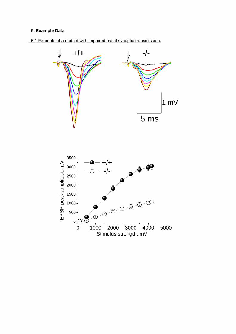
5. Example Data 5.1 Example of a mutant with impaired basal synaptic transmission.
1 mV
-/-
5 ms
+/+
0 1000 2000 3000 4000 5000
0
500
1000
1500
2000
2500
3000
3500
+/+
-/-
fEP
SP
pe
ak a
mplit
ude
. V
Stimulus strength, mV
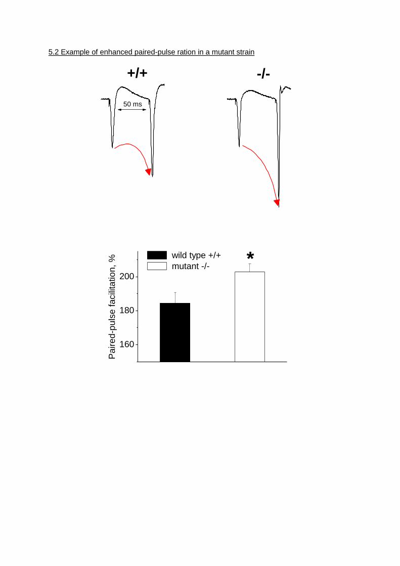
5.2 Example of enhanced paired-pulse ration in a mutant strain
50 ms
+/+ -/-
160
180
200
Pa
ire
d-p
uls
e fa
cili
tatio
n, % wild type +/+
mutant -/- *
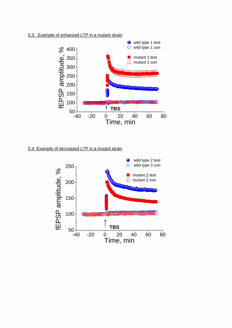
5.3 Example of enhanced LTP in a mutant strain
-40 -20 0 20 40 60 8050
100
150
200
250
300
350
400
wild type 1 test
wild type 1 con
mutant 1 test
mutant 1 confE
PS
P a
mp
litu
de
, %
Time, min
TBS
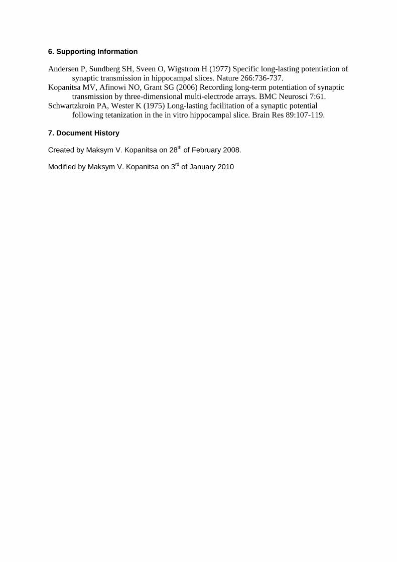
5.4 Example of decreased LTP in a mutant strain
-40 -20 0 20 40 60 8050
100
150
200
250
wild type 2 test
wild type 2 con
mutant 2 test
mutant 2 con
fEP
SP
am
plit
ud
e, %
Time, min
TBS
6. Supporting Information
Andersen P, Sundberg SH, Sveen O, Wigstrom H (1977) Specific long-lasting potentiation of
synaptic transmission in hippocampal slices. Nature 266:736-737.
Kopanitsa MV, Afinowi NO, Grant SG (2006) Recording long-term potentiation of synaptic
transmission by three-dimensional multi-electrode arrays. BMC Neurosci 7:61.
Schwartzkroin PA, Wester K (1975) Long-lasting facilitation of a synaptic potential
following tetanization in the in vitro hippocampal slice. Brain Res 89:107-119.
7. Document History Created by Maksym V. Kopanitsa on 28th of February 2008. Modified by Maksym V. Kopanitsa on 3rd of January 2010