Embed Size (px)
Citation preview
MK-08HC157-04
Hitachi Device Manager Software Server Configuration and Operation Guide
FASTFIND LINKS
Document Organization
Software Version
Getting Help
Contents
ii
Hitachi Device Manager Server Configuration and Operation Guide
Copyright © 2010 Hitachi, Ltd., Hitachi Data Systems Corporation, ALL RIGHTS RESERVED
No part of this publication may be reproduced or transmitted in any form or by any means, electronic
or mechanical, including photocopying and recording, or stored in a database or retrieval system for any purpose without the express written permission of
Hitachi, Ltd. (hereinafter referred to as “Hitachi”) and Hitachi Data Systems Corporation (hereinafter
referred to as “Hitachi Data Systems”).
Hitachi and Hitachi Data Systems reserve the right to make changes to this document at any time without notice and assume no responsibility for its use. This
document contains the most current information available at the time of publication. When new and/or
revised information becomes available, this entire document will be updated and distributed to all
registered users.
All of the features described in this document may not be currently available. Refer to the most recent product announcement or contact your local Hitachi Data Systems sales office for information on feature
and product availability.
Notice: Hitachi Data Systems products and services can be ordered only under the terms and conditions
of Hitachi Data Systems’ applicable agreement(s). The use of Hitachi Data Systems products is governed
by the terms of your agreement(s) with Hitachi Data Systems.
By using this software, you agree that you are responsible for:
a) Acquiring the relevant consents as may be required under local privacy laws or otherwise from employees and other individuals to access relevant
data; and
b) Ensuring that data continues to be held, retrieved, deleted or otherwise processed in accordance with
relevant laws.
Hitachi is a registered trademark of Hitachi, Ltd. in the United States and other countries. Hitachi Data
Systems is a registered trademark and service mark of Hitachi in the United States and other countries.
All other trademarks, service marks, and company names are properties of their respective owners.
Microsoft product screen shot(s) reprinted with permission from Microsoft Corporation.names are
properties of their respective owners.
Microsoft product screen shot(s) reprinted with
Contents iii
Hitachi Device Manager Server Configuration and Operation Guide
Contents
Preface ................................................................................................ xv
Intended Audience .............................................................................................. xvi Software Version ................................................................................................. xvi Release Notes ..................................................................................................... xvi Document Revision Level .................................................................................... xvii Document Organization ...................................................................................... xvii Referenced Documents ...................................................................................... xviii Document Conventions ...................................................................................... xviii Conventions for Storage Capacity Values .............................................................. xix Getting Help........................................................................................................ xxi Comments .......................................................................................................... xxi
Overview .............................................................................................1-1
System Configuration ......................................................................................... 1-2 Network Configuration ........................................................................................ 1-6
Common Security Risks ................................................................................ 1-7 Most Secure Configuration: Separate Management LAN Plus Firewall .............. 1-8 Second-Most Secure Configuration: Separate Management LAN Plus Firewalled
Devices Under Management .................................................................. 1-9 Third-Most Secure Configuration: Dual-Homed Management Servers Plus
Separate Management LAN.................................................................. 1-11 Least Secure Configuration: Flat Network .................................................... 1-12
Management Server Requirements .................................................................... 1-14 Computer Requirements............................................................................. 1-14
Requirements When Using Windows as the Management Server OS ...... 1-14 Requirements When Using Solaris as the Management Server OS .......... 1-22 Requirements When Using Linux as the Management Server OS ............ 1-26
Setting the Memory Heap Size According to the Number of Managed Resources 1-30 Setting the Memory Heap Size of HBase Storage Mgmt Web Service ...... 1-30
iv Contents
Hitachi Device Manager Server Configuration and Operation Guide
Setting the Memory Heap Size of the Device Manager Server ................. 1-32 Setting the Memory Heap Size When Using the CIM/WBEM Function ...... 1-33
System Requirements for Storage Subsystems ................................................... 1-35 System Requirements for Universal Storage Platform V/VM........................... 1-36 System Requirements for Hitachi USP.......................................................... 1-38 System Requirements for Lightning 9900V ................................................... 1-40 System Requirements for Lightning 9900 ..................................................... 1-41 System Requirements for Hitachi AMS 2000 ................................................. 1-41 System Requirements for Hitachi SMS ......................................................... 1-44 System Requirements for Hitachi AMS/WMS ................................................ 1-45 System Requirements for Thunder 9500V .................................................... 1-47 System Requirements for Thunder 9200 ...................................................... 1-49 System Requirements for SUN T3 ............................................................... 1-50 System Requirements for Other Storage Subsystems ................................... 1-50
Host Requirements ........................................................................................... 1-53 System Requirements for Hosts on Which No Virtualization Software Product Is
Installed ............................................................................................. 1-53 System Requirements for Hosts on Which a Virtualization Software Product Is
Installed ............................................................................................. 1-54 Virtual Machine Requirements .............................................................. 1-54 Virtualization Server Requirements ....................................................... 1-56
Mainframe Host Requirements .................................................................... 1-63 File Server Requirements ............................................................................ 1-64
Products Related to Device Manager .................................................................. 1-66 Tiered Storage Manager ............................................................................. 1-66 Replication Manager ................................................................................... 1-66 Tuning Manager ......................................................................................... 1-67 Dynamic Link Manager ............................................................................... 1-67 Global Link Manager ................................................................................... 1-67 Protection Manager .................................................................................... 1-68 Hitachi Essential NAS Platform Manager ...................................................... 1-68 Hitachi Storage Services Manager ............................................................... 1-69 Hitachi Content Archive Platform ................................................................. 1-69
System Requirements for Managing Copy Pairs .................................................. 1-70 Device Manager Server Requirements for Managing Copy Pairs..................... 1-70 Host Requirements for Managing Copy Pairs ................................................ 1-70
Managing Copy Pairs by Using Local Management ................................. 1-71 Managing Copy Pairs by Using Central Management .............................. 1-73 Device Manager Agent Requirements for Managing Copy Pairs ............... 1-74
Storage Subsystem Requirements for Managing Copy Pairs .......................... 1-75 Notes on Using Device Manager When CCI or Protection Manager Is Already
Managing Copy Pairs ........................................................................... 1-78
Contents v
Hitachi Device Manager Server Configuration and Operation Guide
Settings for Various Network Configurations ...........................................2-1
Port Settings ...................................................................................................... 2-2 Ports Used by Device Manager ..................................................................... 2-2
Ports Used by Common Component ....................................................... 2-2 Ports Used by Device Manager Server .................................................... 2-3 Ports Used by Device Manager Agent ..................................................... 2-4 Ports Used by Storage Subsystems ........................................................ 2-5
Changing Ports Used by Common Component ............................................... 2-5 23015/tcp (Used for Accessing HBase Storage Mgmt Web Service) .......... 2-6 23016/tcp (Used for Accessing SSL HBase Storage Mgmt Web Service) .... 2-7 23017/tcp (Used for HBase Storage Mgmt Common Service through an AJP
Connection) ................................................................................... 2-7 23018/tcp (Used for Stop Requests to HBase Storage Mgmt Common
Service) ......................................................................................... 2-8 23032/tcp (Used for HiRDB) .................................................................. 2-8
Settings Required for Operation in a Firewall Environment ............................. 2-9 Registering Firewall Exceptions in a Linux Environment ................................ 2-16
In Red Hat Enterprise Linux ................................................................. 2-16 In SUSE Linux Enterprise Server .......................................................... 2-17
Settings Required to Use a Management Server That Has Multiple NICs .............. 2-18 Network Settings ....................................................................................... 2-18 Settings for the Device Manager Server....................................................... 2-19 Settings for Storage Navigator Modular 2 or Storage Navigator Modular (for Web)
.......................................................................................................... 2-19 Settings Required to Operate in an IPv6 Environment ......................................... 2-21
Limitations on Operations in an IPv6 Environment ....................................... 2-21 Settings for Linking with Storage Subsystems That Support IPv6 .................. 2-21 Settings Required to Migrate Device Manager to an IPv6 Environment .......... 2-22
Settings for IPv6 ................................................................................. 2-22 Settings When Establishing SSL Communication .................................... 2-23
Changing the IP Address or Host Name of the Management Server ..................... 2-24 Changing the IP Address of the Management Server .................................... 2-24 Changing the Host Name of the Management Server ................................... 2-26 Settings Required After Changing the IP Address or Host Name of the
Management Server ............................................................................ 2-29 Changing the URLs for Accessing Hitachi Storage Command Suite Products ......... 2-31 Settings Required When Disconnecting the Management Server Network ............ 2-34
Settings Required for Managing User Accounts........................................3-1
Setting Password Conditions for User Accounts .................................................... 3-2 Settings for Locking User Accounts ...................................................................... 3-4
Settings for Automatic Locking ..................................................................... 3-4 Settings for Automatic Locking of the System Account ................................... 3-5
vi Contents
Hitachi Device Manager Server Configuration and Operation Guide
Settings Required to Authenticate Users by Using an External Authentication Server 3-7 Settings Required When Using an LDAP Directory Server for Authentication... 3-10
Checking the Data Structure and Authentication Method ........................ 3-12 Setting the exauth.properties File (When the Authentication Method Is
LDAP) .......................................................................................... 3-15 Registering a User Account Used to Search for LDAP User Information
(When the Authentication Method Is LDAP) .................................... 3-21 Checking the Connection Status of the External Authentication Server and
the External Authorization Server (When the Authentication Method Is LDAP) .......................................................................................... 3-24
Settings Required When Using a RADIUS Server for Authentication ............... 3-26 Setting the exauth.properties File (When the Authentication Method Is
RADIUS) ...................................................................................... 3-27 Registering a User Account Used to Search for LDAP User Information
(When the Authentication Method Is RADIUS) ................................ 3-34 Setting a Shared Secret ....................................................................... 3-37 Checking the Connection Status of then External Authentication Server and
the External Authorization Server (When the Authentication Method Is RADIUS) ...................................................................................... 3-38
Settings Required When Using a Kerberos Server for Authentication ............. 3-39 Setting the exauth.properties File (When the Authentication Method Is
Kerberos) ..................................................................................... 3-41 Registering a User Account Used to Search for LDAP User Information
(When the Authentication Method Is Kerberos) .............................. 3-46 Checking the Connection Status of then External Authentication Server and
the External Authorization Server (When the Authentication Method Is Kerberos) ..................................................................................... 3-48
Encryption Types That Can Be Used For Kerberos Authentication ........... 3-50
Security Settings for Device Manager ..................................................... 4-1
Warning Banner Settings ..................................................................................... 4-2 Editing the Message ..................................................................................... 4-2 Registering the Message ............................................................................... 4-4 Deleting the Message ................................................................................... 4-5
Security Settings Related to Communication ......................................................... 4-6 Security Settings for the Device Manager Server (Communication with Web Client
or CLI) ................................................................................................ 4-10 Creating a Keypair ............................................................................... 4-10 Enabling TLS/SSL Server Security ......................................................... 4-13 Creating a Certificate Signing Request (CSR) (Security Settings for the
Device Manager Server) ................................................................ 4-14
Contents vii
Hitachi Device Manager Server Configuration and Operation Guide
Importing a Digitally-signed Certificate into the Device Manager Server Keystore ...................................................................................... 4-15
Displaying the Contents of the Device Manager Keystore (Regular Mode)4-16 Displaying the Contents of the Device Manager Keystore (Verbose Mode) .. 4-
17 Deleting an Entry from the Device Manager Server Keystore.................. 4-17 Changing the Device Manager Server Private Key Password................... 4-18 Changing the Device Manager Server Keystore Password ...................... 4-18 Importing a Digitally-signed Certificate into the Device Manager Truststore 4-
19 Displaying Contents of the Device Manager Server Truststore (Regular
Mode) .......................................................................................... 4-19 Displaying Contents of the Device Manager Server Truststore (Verbose
Mode) .......................................................................................... 4-20 Deleting a Digitally-signed Certificate Entry from the Device Manager Server
Truststore .................................................................................... 4-21 Changing the Device Manager Server Truststore Password .................... 4-21
Security Settings for Common Component (Communication with Web Client) 4-22 Generating a Private Key ..................................................................... 4-22 Creating a Certificate Signing Request (CSR) (Security Settings for Common
Component) ................................................................................. 4-23 Creating a Self-Signed Certificate ......................................................... 4-25 Enabling SSL....................................................................................... 4-26 Disabling SSL ...................................................................................... 4-29 Changing a Port Assigned to SSL.......................................................... 4-31
Security Settings for the Device Manager Server (Communication with a CIM Client) ................................................................................................ 4-31 Modifying the Keystore File for Object Operations ................................. 4-32 Specifying Two-way Authentication for Object Operations ..................... 4-35 Specifying Two-way Authentication for Event Indications....................... 4-38 Disabling Two-way Authentication ........................................................ 4-43
Security Settings for a CIM Client (Communication with the Device Manager Server) ............................................................................................... 4-44 Creating a Keystore File ....................................................................... 4-45 Exporting a Certificate from a Keystore File .......................................... 4-45 Creating a Truststore File and Importing Certificate............................... 4-46
Security Settings for the Common Component (Communication with an LDAP Directory Server)................................................................................. 4-46 Obtaining a Certificate for the LDAP Directory Server ............................ 4-47 Importing the Certificate to the Truststore File ...................................... 4-48
Security Settings for the Device Manager Server (Communication with SMI-S Provider) ............................................................................................ 4-50
Specifying Which Device Manager Clients Can Access the Device Manager Server 4-51
viii Contents
Hitachi Device Manager Server Configuration and Operation Guide
Changing the Password-Encoding Level in CLI of Device Manager or Tiered Storage Manager .................................................................................................... 4-53
Advanced Security Mode ................................................................................... 4-53 Settings Required to Communicate with Management Clients (Settings for
Common Component) .......................................................................... 4-54 Creating a Private Key and Certificate Signing Request .......................... 4-54 Configuring the httpsd.conf File ............................................................ 4-56
Settings Required to Communicate with Management Clients (Settings for the Device Manager Server) ....................................................................... 4-56
Settings Required to Communicate with an LDAP Directory Server ................ 4-56 Setting User Passwords .............................................................................. 4-57 Notes on System Configuration ................................................................... 4-57
Settings Required for Linking with Related Products ................................ 5-1
Settings for Linking with Storage Navigator Modular 2 .......................................... 5-2 Prerequisites for Linking with Storage Navigator Modular 2 ............................. 5-2
Prerequisites for Using Storage Navigator Modular 2 ................................ 5-2 Note on Linking with Storage Navigator Modular 2 .................................. 5-4
Launch Settings for Storage Navigator Modular 2 ........................................... 5-4 Deleting Launch Settings for Storage Navigator Modular 2 .............................. 5-6
Settings for Linking with Storage Navigator Modular (for Web) .............................. 5-8 Prerequisites for Linking with Storage Navigator Modular (for Web) ................ 5-8
Prerequisites for Using Storage Navigator Modular (for Web) ................... 5-8 Note on Linking with Storage Navigator Modular (for Web) ...................... 5-9
Launch Settings for Storage Navigator Modular (for Web)............................... 5-9 Deleting Launch Settings for Storage Navigator Modular (for Web) ............... 5-12
Settings for Linking with DAMP (for Web) ........................................................... 5-14 Prerequisites for Linking with DAMP (for Web) ............................................. 5-14
Prerequisites for Using DAMP (for Web) ................................................ 5-14 Note on Linking with DAMP (for Web) ................................................... 5-15
Launch Settings for DAMP (for Web) ........................................................... 5-16 Registering Storage Subsystem Information with DAMP (for Web) ................ 5-18
Settings for Linking with Tuning Manager ........................................................... 5-19 Settings in a Non-cluster Environment ......................................................... 5-19 Settings in a Cluster Environment ................................................................ 5-20
For Microsoft Cluster Service ................................................................ 5-20 For Microsoft Failover Cluster ............................................................... 5-22 For Veritas Cluster Server .................................................................... 5-23 For Sun Cluster ................................................................................... 5-25
htmsetup Command ................................................................................... 5-27 Settings for Starting HSSM from the Dashboard .................................................. 5-29 Settings for Starting Applications from Web Client .............................................. 5-30
Contents ix
Hitachi Device Manager Server Configuration and Operation Guide
Settings for Logs and Alerts ..................................................................6-1
Settings for Integrated Logs................................................................................ 6-2 Setting the Number of Common Component Trace Log Files .......................... 6-2
In Windows .......................................................................................... 6-2 In Solaris or Linux ................................................................................. 6-2
Setting the Size of Common Component Trace Log Files ................................ 6-3 In Windows .......................................................................................... 6-3 In Solaris or Linux ................................................................................. 6-3
Settings Required for Generating Audit Logs ........................................................ 6-5 Audit Events and Categories of Information Output to Audit Logs ................... 6-6 Editing the Audit Log Environment Settings File ........................................... 6-11
Settings Required for Centrally Managing Storage Subsystem Alerts .................... 6-15 Settings for Receiving SNMP Traps.............................................................. 6-15 Settings for Recording the Received SNMP Traps in Log Files ....................... 6-16
Data Items to Be Output to Log Files ................................................... 6-16 Setting the Data to Be Output to Log Files ............................................ 6-17
Settings Required for Email Notification ............................................................. 6-19 Settings on the SMTP Server ...................................................................... 6-19 Settings for Users Who Receive Emails by Using Web Client ......................... 6-19 Settings on the Device Manager Server ....................................................... 6-20
Settings for an SMTP Authentication User ............................................. 6-21 Customizing the Template File ............................................................. 6-22
Settings for CIM/WBEM ........................................................................7-1
Device Manager and CIM/WBEM ......................................................................... 7-2 CIM/WBEM Features of Device Manager .............................................................. 7-5 Basic Settings Required to Use the CIM/WBEM Features ....................................... 7-7 Settings for Ports Used by CIM/WBEM Features ................................................... 7-9
Opening and Closing Ports According to the Communication Type .................. 7-9 Changing the Port Number ......................................................................... 7-10
Properties File Settings for Executing CIM .......................................................... 7-11 Settings for the Service Discovery Feature ......................................................... 7-12
Setting Up the Service Discovery Feature .................................................... 7-12 In Windows ........................................................................................ 7-12 In Solaris ............................................................................................ 7-13 In Red Hat Enterprise Linux ................................................................. 7-13 In SUSE Linux Enterprise Server .......................................................... 7-14
Starting and Stopping the Service Discovery Feature.................................... 7-14 In Windows ........................................................................................ 7-14 In Solaris ............................................................................................ 7-14 In Red Hat Enterprise Linux ................................................................. 7-15 In SUSE Linux Enterprise Server .......................................................... 7-15
Notes on Using OpenSLP ............................................................................ 7-15
x Contents
Hitachi Device Manager Server Configuration and Operation Guide
The Performance Information Acquisition Feature ............................................... 7-17 System Configuration Required to Use the Performance Information Acquisition
Feature ............................................................................................... 7-18 Settings Required to Acquire Performance Information of Universal Storage
Platform V/VM or Hitachi USP ............................................................... 7-20 Preparations in Storage Subsystems ..................................................... 7-20 Preparations in the Host That Acquires Performance Information ........... 7-20 Preparations in the Device Manager Server ........................................... 7-21 Settings in the perf_cmddev.properties File ........................................... 7-21 Format of the perf_findcmddev Command ............................................ 7-23
Settings Required to Acquire Performance Information of Hitachi AMS 2000, Hitachi SMS, Hitachi AMS/WMS, Thunder 9500, or Thunder 9200 ........... 7-24 Preparations in Storage Subsystems ..................................................... 7-25 Setting Up a User to Acquire Performance Information .......................... 7-25 Format of the hdvmmodpolluser Command ........................................... 7-25
User Permissions for Using CIM/WBEM Features ................................................. 7-27
Starting and Stopping the Device Manager Server ................................... 8-1
Before Controlling the Device Manager Server ...................................................... 8-2 Starting the Device Manager Server ..................................................................... 8-4 Stopping the Device Manager Server.................................................................... 8-5 Checking the Operating Status of the Device Manager Server ................................ 8-6 Starting the Device Manager Server and Common Component .............................. 8-7 Stopping the Device Manager Server and Common Component ............................. 8-8 Checking the Operating Status of the Device Manager Server and Common
Component .................................................................................................. 8-9
Managing the Database ........................................................................ 9-1
Before Managing the Database ............................................................................ 9-2 Backing Up the Database .................................................................................... 9-3 Restoring the Database ....................................................................................... 9-5 Migrating the Databases...................................................................................... 9-7
Notes on Migrating Databases....................................................................... 9-7 Procedure for Migrating Databases ................................................................ 9-8
On the Migration Destination Server, Install the Hitachi Storage Command Suite Products ................................................................................ 9-9
Exporting the Databases from the Migration Source Server ...................... 9-9 Importing the Databases to the Migration Destination Server ................. 9-10
Initializing the Database .................................................................................... 9-13
Troubleshooting ................................................................................. 10-1
Common Problems and Solutions ....................................................................... 10-2
Contents xi
Hitachi Device Manager Server Configuration and Operation Guide
Obtaining Maintenance Information of Device Manager ...................................... 10-7 Obtaining the Java VM Thread Dump............................................................... 10-11
Obtaining the Java VM Thread Dump in a Windows Environment ................ 10-11 Obtaining the Java VM Thread Dump in a Solaris or Linux Environment ...... 10-11
Checking Audit Log Data ................................................................................. 10-12 Message Text in Audit Log Data................................................................ 10-14
Message Text Output for Common Component Processing .................. 10-14 Message Text Output for Device Manager Server Processing ............... 10-14 Message Text Output for Launches of Related Products....................... 10-15 Message Text Output for Device Manager Server Processing via CIM ... 10-17 Message Text Output for Provisioning Manager Server Processing........ 10-18
Detail Message Output for a Request to a Device Manager Server .............. 10-20 Requests and Parameters Output as Provisioning Manager Audit Log Data .. 10-39
Contacting the Hitachi Data Systems Support Center ........................................ 10-50
Overview and Setup of VDS .....................................................................1
Overview and Functions of Device Manager VDS Provider ........................................ 2 Overview of Device Manager VDS Provider ....................................................... 2 Functions of Device Manager VDS Provider....................................................... 2 Available Functions in Storage Manager for SANs for Windows Server 2003 R2... 3
Installing Device Manager VDS Provider .................................................................. 4 New Installation ............................................................................................. 5 Upgrade Installation (to Update an Earlier Version)........................................... 7 Re-installation (to Correct the Same Version) ................................................... 7
Uninstalling Device Manager VDS Provider .............................................................. 9 Starting and Stopping Device Manager VDS Provider ............................................. 10
Starting the Service ...................................................................................... 10 Stopping the Service ..................................................................................... 10 Notes on Starting and Stopping the Service .................................................... 10
Device Manager VDS Provider Property Files ......................................................... 12 vds.properties File ........................................................................................ 12 logger.properties File .................................................................................... 13
Setting up Device Manager VDS Provider .............................................................. 14 Creating a User Account Used by Device Manager VDS Provider ...................... 14 Specifying Information in the vds.properties File ............................................. 14
Device Manager VDS Provider Log Files ................................................................ 16
Specifying Properties ...............................................................................1
Properties Overview .............................................................................................. 2 Device Manager Server Configuration Properties ..................................................... 5
server.http.host .............................................................................................. 5 server.http.port .............................................................................................. 6 server.https.port ............................................................................................. 6
xii Contents
Hitachi Device Manager Server Configuration and Operation Guide
server.http.default........................................................................................... 6 server.http.request.timeout ............................................................................. 6 server.http.connection.priority ......................................................................... 7 server.http.connection.bufSize ......................................................................... 7 server.http.socket.backlog ............................................................................... 7 server.http.socket.maxThreads ........................................................................ 8 server.http.socket.linger .................................................................................. 8 server.http.socket.noDelay .............................................................................. 8 server.http.headers.maxNumber ...................................................................... 8 server.http.headers.maxLength ........................................................................ 9 server.http.entity.maxLength ........................................................................... 9 server.http.log.reverseDNS .............................................................................. 9 server.http.cache.size .................................................................................... 10 server.http.cache.maxFileSize ........................................................................ 10 server.http.fileTypes.noLog ............................................................................ 10 server.http.mode .......................................................................................... 10 server.installTime .......................................................................................... 11 server.base.home.......................................................................................... 11 server.horcmconfigfile.hostname .................................................................... 11 server.base.initialsynchro............................................................................... 11 server.cim.agent ........................................................................................... 12 server.cim.support ........................................................................................ 12 server.cim.support.job ................................................................................... 12 server.cim.support.protocol ........................................................................... 12 server.cim.http.port....................................................................................... 12 server.cim.https.port ..................................................................................... 13 server.configchange.enabled.......................................................................... 13 server.configchange.autorefresh.lastrefreshed ................................................ 13 server.mail.enabled ....................................................................................... 14 server.mail.from ............................................................................................ 14 server.mail.smtp.host .................................................................................... 14 server.mail.smtp.port .................................................................................... 14 server.mail.smtp.auth .................................................................................... 15 server.mail.alert.type..................................................................................... 15 server.mail.alert.status .................................................................................. 15 server.subsystem.ssid.availableValues ............................................................ 15 server.smisclient.indication.port ..................................................................... 16
Device Manager Database Properties .................................................................... 17 dbm.traceSQL ............................................................................................... 17 dbm.startingCheck.retryCount ........................................................................ 17 dbm.startingCheck.retryPeriod ....................................................................... 17
Device Manager Logger Properties ........................................................................ 18 logger.loglevel .............................................................................................. 18 logger.MaxBackupIndex................................................................................. 19
Contents xiii
Hitachi Device Manager Server Configuration and Operation Guide
logger.MaxFileSize ........................................................................................ 19 logger.hicommandbase.loglevel ..................................................................... 19 logger.hicommandbase.sysloglevel ................................................................ 20 logger.hicommandbase.MaxBackupIndex ....................................................... 20 logger.hicommandbase.MaxFileSize ............................................................... 20
Device Manager Dispatcher Properties .................................................................. 21 server.dispatcher.agent.priority ..................................................................... 21 server.dispatcher.message.timeout ................................................................ 21 server.dispatcher.message.timeout.in.processing ............................................ 21 server.dispatcher.daemon.pollingPeriod ......................................................... 22 server.dispatcher.traps.purgePeriod ............................................................... 22 server.dispatcher.startTimeOfIgnoringConnectionAlert .................................... 22 server.dispatcher.endTimeOfIgnoringConnectionAlert ..................................... 22 server.dispatcher.daemon.receiveTrap ........................................................... 22 server.dispatcher.snm2.configchange.pollingPeriod ......................................... 23 server.dispatcher.configchange.pollingPeriod .................................................. 23 server.dispatcher.daemon.configUpdate.detection.interval .............................. 23 server.dispatcher.daemon.autoSynchro.doRefresh .......................................... 24 server.dispatcher.daemon.autoSynchro.type................................................... 25 server.dispatcher.daemon.autoSynchro.dayOfWeek ........................................ 25 server.dispatcher.daemon.autoSynchro.startTime ........................................... 26 server.dispatcher.daemon.autoSynchro.interval .............................................. 26 server.dispatcher.daemon.autoSynchro.refresh.interval ................................... 26 server.dispatcher.daemon.autoSynchro.refresh.timeout .................................. 26
Device Manager MIME Properties ......................................................................... 28 Device Manager Client Properties ......................................................................... 29
client.logger.trace ......................................................................................... 29 client.message.timeout ................................................................................. 29 client.outputhorcmfunction.enabled ............................................................... 30 table.ldev.rowsperpage ................................................................................. 30 client.assignlun.upperlimit.enabled................................................................. 30 client.report.csv.format.escaped .................................................................... 31 client.addstorage.block.per.storage ................................................................ 31 client.ldev.rowsperpage.retain.enabled .......................................................... 31
Device Manager Security Properties ...................................................................... 33 server.http.secure ......................................................................................... 33 server.http.security.realm.............................................................................. 34 server.http.security.clientIP ........................................................................... 34 server.http.security.clientIPv6........................................................................ 35 server.https.security.keystore ........................................................................ 36 server.http.security.unprotected .................................................................... 36 server.https.security.truststore ...................................................................... 36
Device Manager SNMP Trap Log Output Function Properties .................................. 38 customizedsnmptrap.customizedSNMPTrapEnable .......................................... 38
xiv Contents
Hitachi Device Manager Server Configuration and Operation Guide
customizedsnmptrap.customizelist.................................................................. 38 Device Manager Launchable Applications Properties ............................................... 39
launchapp.snm2.url ....................................................................................... 39 launchapp.damp.url....................................................................................... 39 launchapp.snm2.rmi.port ............................................................................... 40 launchapp.snm.rmi.port ................................................................................. 41
Device Manager Mainframe Host Agent Properties ................................................. 42 host.mf.agent.connection.timeout .................................................................. 42
Device Manager Report Function Properties........................................................... 43 DetailedArrayReport.outputPath ..................................................................... 43
Provisioning Manager Server Configuration Information Properties.......................... 44 server.operation.abortTimeout ....................................................................... 44 server.operation.eventTimeout ...................................................................... 44 server.rmiapi.port ......................................................................................... 44 server.history.maxNumber ............................................................................. 45 server.history.maxDays ................................................................................. 45 server.installTime .......................................................................................... 45
Provisioning Manager Logger Properties ................................................................ 46 Logger.loglevel ............................................................................................. 46 Logger.sysloglevel ......................................................................................... 46 Logger.MaxBackupIndex ................................................................................ 47 Logger.MaxFileSize ........................................................................................ 47
Provisioning Manager Client Properties .................................................................. 48 client.ldev.rowsperpage.retain.enabled ........................................................... 48
Acronyms and Abbreviations .................................................................... 1
Index ..................................................................................................... 1
Preface xv
Hitachi Device Manager Server Configuration and Operation Guide
Preface
This manual describes system requirements for Hitachi Device Manager (abbreviated hereafter to Device Manager), Hitachi Provisioning Manager (abbreviated hereafter to Provisioning Manager), and Hitachi Storage Command Suite Common Component (abbreviated hereafter to Common Component), and also describes environment setup and troubleshooting on the management server.
This preface includes the following information:
Intended Audience
Software Version
Release Notes
Document Revision Level
Document Organization
Referenced Documents
Document Conventions
Conventions for Storage Capacity Values
Getting Help
Notice: The use of Hitachi Device Manager and all other Hitachi Data Systems products is governed by the terms of your agreement(s) with Hitachi Data Systems.
Comments
xvi Preface
Hitachi Device Manager Server Configuration and Operation Guide
Intended Audience
This guide assumes that its audience has a basic knowledge of the following:
• Management tools appropriate to the individual storage subsystem
• Storage Area Networks (SANs)
• OSs supported for Device Manager
• Cluster software supported for Device Manager
Please contact your Hitachi Data Systems account team or see the Hitachi Data Systems worldwide Web site (http://www.hds.com) for additional information on subsystem features and functions.
Software Version
This document revision applies to Hitachi Device Manager software and Hitachi Provisioning Manager software version 6.4.
Release Notes
Release notes can be found on the documentation CD. Release notes contain requirements and more recent product information that may not be fully described in this manual. Be sure to review the release notes before installation.
Preface xvii
Hitachi Device Manager Server Configuration and Operation Guide
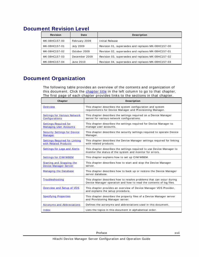
Document Revision Level Revision Date Description
MK-08HC157-00 February 2009 Initial Release
MK-08HC157-01 July 2009 Revision 01, supersedes and replaces MK-08HC157-00
MK-08HC157-02 October 2009 Revision 02, supersedes and replaces MK-08HC157-01
MK-08HC157-03 December 2009 Revision 03, supersedes and replaces MK-08HC157-02
MK-08HC157-04 June 2010 Revision 04, supersedes and replaces MK-08HC157-03
Document Organization
The following table provides an overview of the contents and organization of this document. Click the chapter title in the left column to go to that chapter. The first page of each chapter provides links to the sections in that chapter.
Chapter Description
This chapter describes the system configuration and system requirements for Device Manager and Provisioning Manager.
Overview
This chapter describes the settings required on a Device Manager server for various network configurations.
Settings for Various Network Configurations
This chapter describes the settings required for Device Manager to manage user accounts.
Settings Required for Managing User Accounts
This chapter describes the security settings required to operate Device Manager.
Security Settings for Device Manager
This chapter describes the Device Manager settings required for linking with related products.
Settings Required for Linking with Related Products
This chapter describes the settings required to use Device Manager to monitor the status of the system and monitor for errors.
Settings for Logs and Alerts
This chapter explains how to set up CIM/WBEM. Settings for CIM/WBEM
This chapter describes how to start and stop the Device Manager server.
Starting and Stopping the Device Manager Server
This chapter describes how to back up or restore the Device Manager server database.
Managing the Database
This chapter describes how to resolve problems that can occur during Device Manager operation and how to read the contents of log files.
Troubleshooting
This chapter provides an overview of Device Manager VDS Provider, and explains the setup procedure.
Overview and Setup of VDS
This chapter describes the property files of a Device Manager server and Provisioning Manager server.
Specifying Properties
Defines the acronyms and abbreviations used in this document. Acronyms and Abbreviations
Lists the topics in this document in alphabetical order. Index
xviii Preface
Hitachi Device Manager Server Configuration and Operation Guide
Referenced Documents
The following Hitachi referenced documents can be found on the applicable Hitachi documentation CD:
Hitachi Storage Command Suite documents:
• Hitachi Storage Command Suite Server Installation Guide, MK-98HC150
• Hitachi Device Manager Command Line Interface (CLI) User’s Guide, MK-91HC007
• Hitachi Device Manager Agent Installation Guide, MK-92HC019
• Hitachi Tuning Manager Server Administration Guide, MK-92HC02
• Hitachi Tuning Manager User’s Guide, MK-92HC022
• Hitachi Tuning Manager Installation Guide, MK-96HC14
Hitachi Enterprise Storage Systems documents:
• Hitachi Storage Navigator User’s Guide, MK-96RD621
• Hitachi TagmaStore Universal Storage Platform and Hitachi TagmaStore Network Storage Controller Storage Navigator Users Guide, MK-94RD206
Hitachi Modular Storage Systems document:
• Account Authentication User’s Guide, MK-96DF797
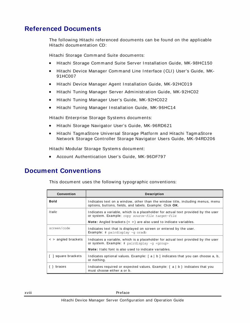
Document Conventions
This document uses the following typographic conventions:
Convention Description
Bold Indicates text on a window, other than the window title, including menus, menu options, buttons, fields, and labels. Example: Click OK.
Italic Indicates a variable, which is a placeholder for actual text provided by the user or system. Example: copy source-file target-file
Note: Angled brackets (< >) are also used to indicate variables.
screen/code Indicates text that is displayed on screen or entered by the user. Example: # pairdisplay -g oradb
< > angled brackets Indicates a variable, which is a placeholder for actual text provided by the user or system. Example: # pairdisplay -g <group>
Note: Italic font is also used to indicate variables.
[ ] square brackets Indicates optional values. Example: [ a | b ] indicates that you can choose a, b, or nothing.
{ } braces Indicates required or expected values. Example: { a | b } indicates that you must choose either a or b.
Preface xix
Hitachi Device Manager Server Configuration and Operation Guide
Convention Description
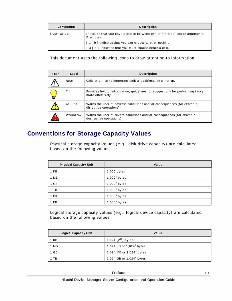
| vertical bar Indicates that you have a choice between two or more options or arguments. Examples:
[ a | b ] indicates that you can choose a, b, or nothing.
{ a | b } indicates that you must choose either a or b.
This document uses the following icons to draw attention to information:
Icon Label Description
Note Calls attention to important and/or additional information.
Tip Provides helpful information, guidelines, or suggestions for performing tasks more effectively.
Caution Warns the user of adverse conditions and/or consequences (for example, disruptive operations).
WARNING Warns the user of severe conditions and/or consequences (for example, destructive operations).
Conventions for Storage Capacity Values
Physical storage capacity values (e.g., disk drive capacity) are calculated based on the following values:
Physical Capacity Unit Value
1 KB 1,000 bytes
1 MB 1,0002 bytes
1 GB 1,0003 bytes
1 TB 1,0004 bytes
1 PB 1,0005 bytes
1 EB 1,0006 bytes
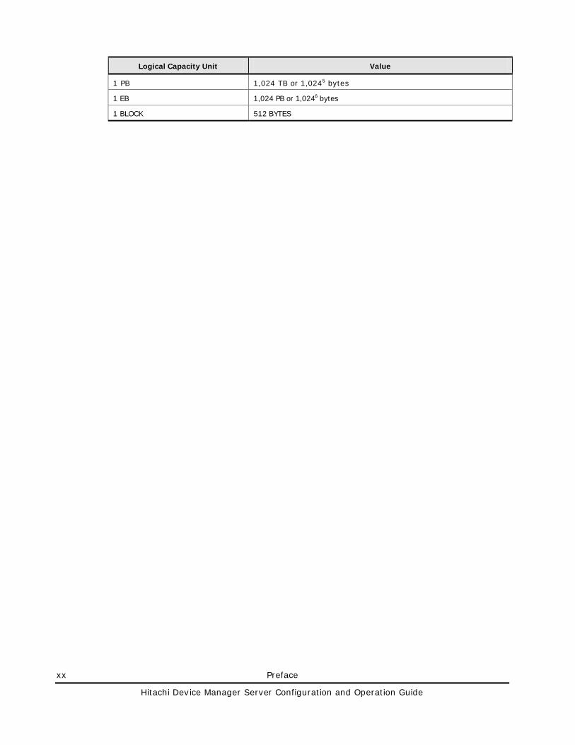
Logical storage capacity values (e.g., logical device capacity) are calculated based on the following values:
Logical Capacity Unit Value
1 KB 1,024 (210) bytes
1 MB 1,024 KB or 1,0242 bytes
1 GB 1,024 MB or 1,0243 bytes
1 TB 1,024 GB or 1,0244 bytes
xx Preface
Hitachi Device Manager Server Configuration and Operation Guide
Logical Capacity Unit Value
1 PB 1,024 TB or 1,0245 bytes
1 EB 1,024 PB or 1,0246 bytes
1 BLOCK 512 BYTES
Preface xxi
Hitachi Device Manager Server Configuration and Operation Guide
Getting Help
The Hitachi Data Systems Support Center staff is available 24 hours a day, seven days a week. To reach us, please visit the support Web site for current telephone numbers and other contact information: http://www.hds.com/services/support/. If you purchased this product from an authorized HDS reseller, contact that reseller for support.
Before calling the Hitachi Data Systems Support Center, please provide as much information about the problem as possible, including:
• The circumstances surrounding the error or failure.
• The exact content of any error message(s) displayed on the host system(s).
Comments
Please send us your comments on this document: [email protected]. Include the document title, number, and revision, and refer to specific section(s) and paragraph(s) whenever possible.
Thank you! (All comments become the property of Hitachi Data Systems Corporation.)

1
Overview 1-1
Hitachi Device Manager Server Configuration and Operation Guide
Overview
This chapter describes the system configuration and system requirements for Device Manager and Provisioning Manager.
System Configuration
Network Configuration
Management Server Requirements
System Requirements for Storage Subsystems
Host Requirements
Products Related to Device Manager
System Requirements for Managing Copy Pairs
1-2 Overview
Hitachi Device Manager Server Configuration and Operation Guide
System Configuration
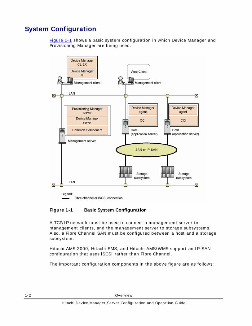
Figure 1-1 shows a basic system configuration in which Device Manager and Provisioning Manager are being used.
Figure 1-1 Basic System Configuration
A TCP/IP network must be used to connect a management server to management clients, and the management server to storage subsystems. Also, a Fibre Channel SAN must be configured between a host and a storage subsystem.
Hitachi AMS 2000, Hitachi SMS, and Hitachi AMS/WMS support an IP-SAN configuration that uses iSCSI rather than Fibre Channel.
The important configuration components in the above figure are as follows:
Overview 1-3
Hitachi Device Manager Server Configuration and Operation Guide
Management server
A management server is a computer on which the Device Manager server and the Provisioning Manager server are running. The management server also supports active-standby clustering using two computers. For details about the requirements for a management server computer, see Management Server Requirements.
Device Manager server
A Device Manager server is a program that controls storage subsystems and hosts based on requests from management clients (Web Client and CLI).
Provisioning Manager server
A Provisioning Manager server is a program that controls storage subsystems and hosts based on requests from management clients (Web Client). This program is automatically installed when you install the Device Manager server.
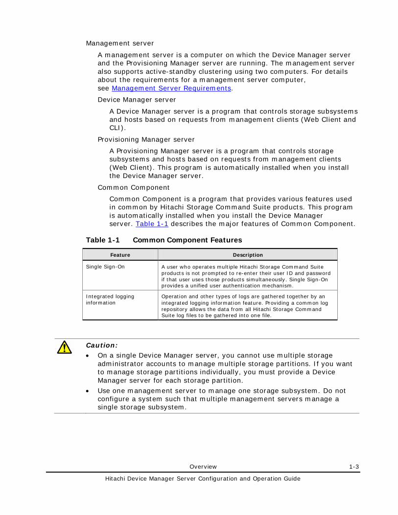
Common Component
Common Component is a program that provides various features used in common by Hitachi Storage Command Suite products. This program is automatically installed when you install the Device Manager server. Table 1-1 describes the major features of Common Component.
Table 1-1 Common Component Features
Feature Description
Single Sign-On A user who operates multiple Hitachi Storage Command Suite products is not prompted to re-enter their user ID and password if that user uses those products simultaneously. Single Sign-On provides a unified user authentication mechanism.
Integrated logging information
Operation and other types of logs are gathered together by an integrated logging information feature. Providing a common log repository allows the data from all Hitachi Storage Command Suite log files to be gathered into one file.
Caution: • On a single Device Manager server, you cannot use multiple storage
administrator accounts to manage multiple storage partitions. If you want to manage storage partitions individually, you must provide a Device Manager server for each storage partition.
• Use one management server to manage one storage subsystem. Do not configure a system such that multiple management servers manage a single storage subsystem.
1-4 Overview
Hitachi Device Manager Server Configuration and Operation Guide
Management client
A management client is a computer used to operate Device Manager and Provisioning Manager. A management client and a management server can be the same computer.
Web Client
Web Client is a Web-based graphical interface supported by Device Manager and Provisioning Manager. For details on computer requirements for using Device Manager Web Client and how to use it, see the Device Manager online Help. For details on the computer requirements for using Provisioning Manager Web Client and how to use it, see the Provisioning Manager online Help.
CLI and CLIEX
CLI and CLIEX are text-based interfaces supported by Device Manager. Using CLI and CLIEX enables you to perform certain tasks (such as the initial installation of a system or applying the same changes to settings in many locations) more efficiently. For details on the computer requirements for using CLI or CLIEX and how to use them, see the Hitachi Device Manager Software Command Line Interface (CLI) User’s Guide.
Host (application server)
A host (application server) is a computer that uses the volumes in a storage subsystem.
Device Manager agent
A Device Manager agent is a program that collects information about hosts and storage subsystems, and reports that information to the Device Manager server. This program must be installed if you use Device Manager to manage host information and the volume usage states on each host, or if you use Provisioning Manager. For details on the computer requirements for using the Device Manager agent and how to use it, see the Hitachi Device Manager Agent Installation Guide.
CCI
CCI is a program that controls copy pairs on a storage subsystem.
This program must be installed to use Device Manager to provide consolidated management of copy-pair configurations and statuses. For details about how to install the CCI, see the CCI documentation.
Storage subsystem
The storage subsystems (shown in the figure) are managed by Device Manager and Provisioning Manager. For details on the system requirements for storage subsystems, see System Requirements for Storage Subsystems.
Overview 1-5
Hitachi Device Manager Server Configuration and Operation Guide
Note: • Windows Server® 2003 environments support Device Manager VDS
Provider, which is a program that provides storage subsystem information in response to requests from VDS (Virtual Disk Service) and that can also change the storage subsystem configuration. For details about how to install and set up Device Manager VDS Provider, see Overview and Setup of VDS.
1-6 Overview
Hitachi Device Manager Server Configuration and Operation Guide
Network Configuration
Universal Storage Platform V/VM, Hitachi USP, Lightning 9900V, and Lightning 9900 come equipped with a service processor, or SVP. The SVP has two Ethernet adapters. The first adapter is for a private (internal) Ethernet LAN, which is only intended for intra-array communications. There are two devices that can access the internal LAN:
• The Service Processor (SVP)
• The remote Console for Lightning 9900
The second adapter is used for other applications to communicate with the SVP, and it is called the public LAN, because it is visible to other computers outside the array. Device Manager uses the public LAN to communicate with a storage subsystem and with an SVP used to make configuration changes to a storage subsystem.
While Universal Storage Platform V/VM, Hitachi USP, Lightning 9900V, and Lightning 9900 are managed through their SVP interfaces, other managed storage subsystems (such as Hitachi AMS 2000, Hitachi SMS, Hitachi AMS/WMS, Thunder 9500V, and Thunder 9200) do not have private LANs. Instead, they have Ethernet network interfaces that are intended to be directly attached to a public LAN. Once attached, each has its own remote management API, which can be accessed by a variety of management applications.
WARNING: Universal Storage Platform V/VM, Hitachi USP, Lightning 9900V, and Lightning 9900 have a public LAN and a private LAN. Device Manager uses the public LAN to communicate with the SVP about the array and configuration changes. Do not ever attach the private LAN to an external network because this can cause serious problems on the array.
Overview 1-7
Hitachi Device Manager Server Configuration and Operation Guide
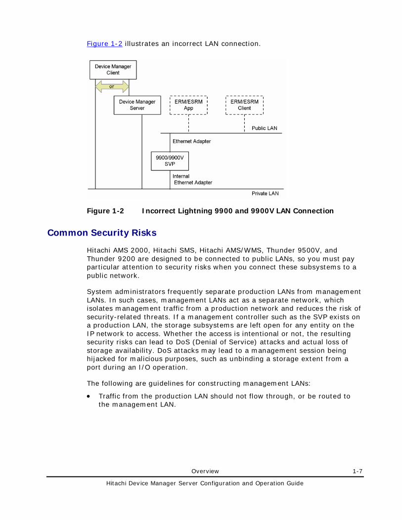
Figure 1-2 illustrates an incorrect LAN connection.
Figure 1-2 Incorrect Lightning 9900 and 9900V LAN Connection
Common Security Risks
Hitachi AMS 2000, Hitachi SMS, Hitachi AMS/WMS, Thunder 9500V, and Thunder 9200 are designed to be connected to public LANs, so you must pay particular attention to security risks when you connect these subsystems to a public network.
System administrators frequently separate production LANs from management LANs. In such cases, management LANs act as a separate network, which isolates management traffic from a production network and reduces the risk of security-related threats. If a management controller such as the SVP exists on a production LAN, the storage subsystems are left open for any entity on the IP network to access. Whether the access is intentional or not, the resulting security risks can lead to DoS (Denial of Service) attacks and actual loss of storage availability. DoS attacks may lead to a management session being hijacked for malicious purposes, such as unbinding a storage extent from a port during an I/O operation.
The following are guidelines for constructing management LANs:
• Traffic from the production LAN should not flow through, or be routed to the management LAN.
1-8 Overview
Hitachi Device Manager Server Configuration and Operation Guide
• If possible, all hosts with management interfaces or controllers on the management LAN should be hardened to their maximum level to reduce the potential that software other than the management interface will not lead to an exploit of the entire station or device. (In this case hardening should include removal of unnecessary software, shutting down nonessential services, and updating to the latest patches.)
• The management LAN should only intersect a production LAN on those computers acting as an interface between the management LAN and the production LAN (for example, the Device Manager server).
• If possible, those computers intersecting both private LAN and management LAN should be behind a firewall of some kind, further inhibiting unintended access.
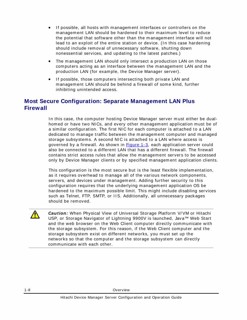
Most Secure Configuration: Separate Management LAN Plus Firewall
In this case, the computer hosting Device Manager server must either be dual-homed or have two NICs, and every other management application must be of a similar configuration. The first NIC for each computer is attached to a LAN dedicated to manage traffic between the management computer and managed storage subsystems. A second NIC is attached to a LAN where access is governed by a firewall. As shown in Figure 1-3, each application server could also be connected to a different LAN that has a different firewall. The firewall contains strict access rules that allow the management servers to be accessed only by Device Manager clients or by specified management application clients.
This configuration is the most secure but is the least flexible implementation, as it requires overhead to manage all of the various network components, servers, and devices under management. Adding further security to this configuration requires that the underlying management application OS be hardened to the maximum possible limit. This might include disabling services such as Telnet, FTP, SMTP, or IIS. Additionally, all unnecessary packages should be removed.
Caution: When Physical View of Universal Storage Platform V/VM or Hitachi USP, or Storage Navigator of Lightning 9900V is launched, Java™ Web Start and the web browser on the Web Client computer directly communicate with the storage subsystem. For this reason, if the Web Client computer and the storage subsystem exist on different networks, you must set up the networks so that the computer and the storage subsystem can directly communicate with each other.
Overview 1-9
Hitachi Device Manager Server Configuration and Operation Guide
Figure 1-3 illustrates a separate management LAN with a firewall configuration.
Figure 1-3 Most Secure Configuration: Separate Management LAN Plus Firewall
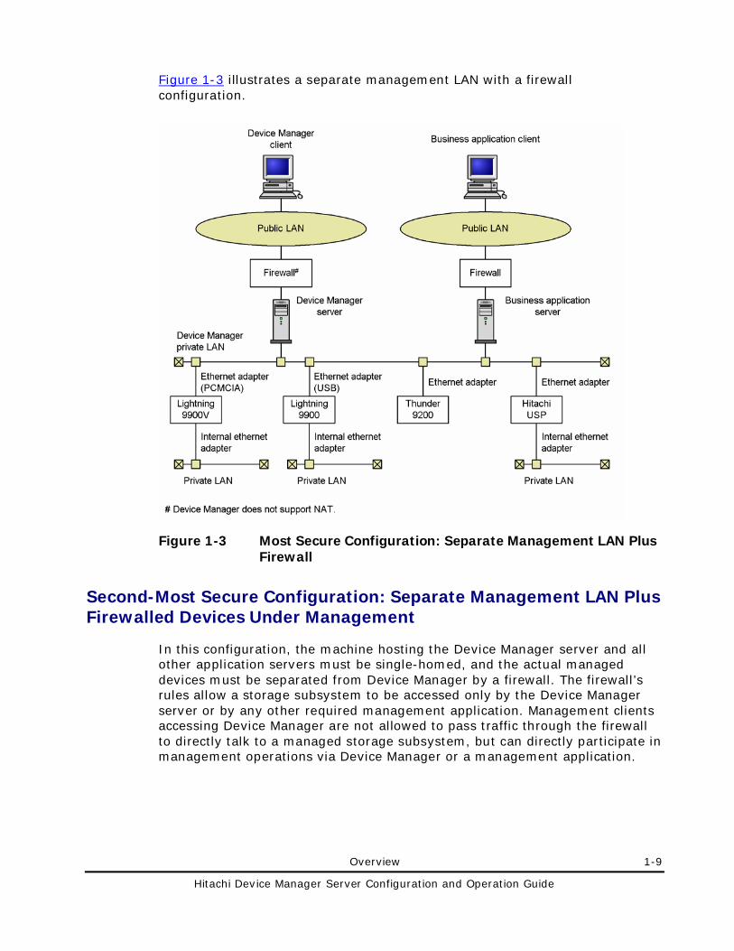
Second-Most Secure Configuration: Separate Management LAN Plus Firewalled Devices Under Management
In this configuration, the machine hosting the Device Manager server and all other application servers must be single-homed, and the actual managed devices must be separated from Device Manager by a firewall. The firewall’s rules allow a storage subsystem to be accessed only by the Device Manager server or by any other required management application. Management clients accessing Device Manager are not allowed to pass traffic through the firewall to directly talk to a managed storage subsystem, but can directly participate in management operations via Device Manager or a management application.
1-10 Overview
Hitachi Device Manager Server Configuration and Operation Guide
This configuration is the second most secure, and is more flexible than the most secure option. While this configuration protects the devices under management, it does not protect the management application servers themselves. Therefore, all management application servers should be hardened to the maximum possible extent.
Caution: When Physical View of Universal Storage Platform V/VM or Hitachi USP, or Storage Navigator of Lightning 9900V is launched, Java Web Start and the web browser on the Web Client computer directly communicate with the storage subsystem. For this reason, if the Web Client computer and the storage subsystem exist on different networks, you must set up the networks so that the computer and the storage subsystem can directly communicate with each other.
Figure 1-4 illustrates a separate management LAN plus firewalled devices under management.
Figure 1-4 Second-Most Secure Configuration: Separate Management LAN Plus Firewalled Devices
Overview 1-11
Hitachi Device Manager Server Configuration and Operation Guide
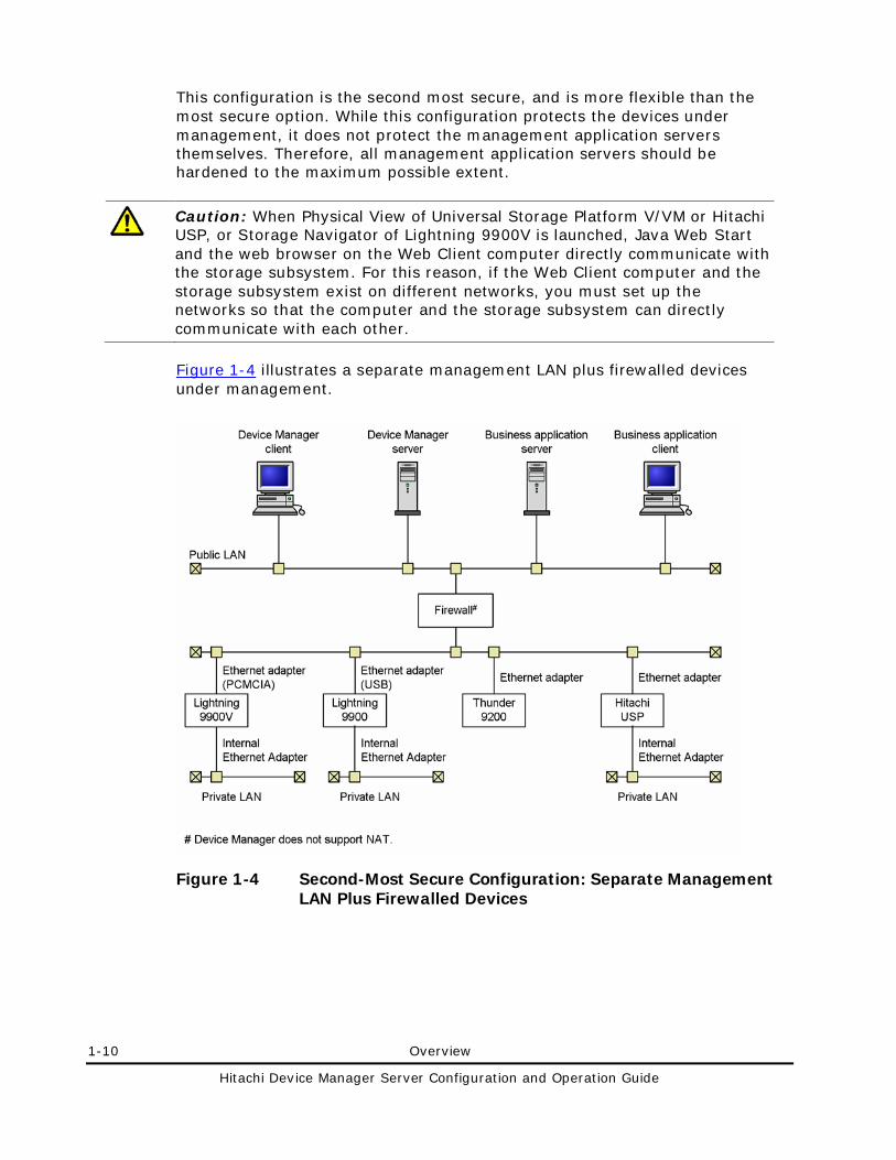
Third-Most Secure Configuration: Dual-Homed Management Servers Plus Separate Management LAN
In this configuration, the management servers themselves act as the intersection point between the management LAN and a production LAN. The server running Device Manager or management applications is dual-homed. One NIC is attached to the management LAN along with the devices under management, and the second NIC is attached to a production LAN along with the management clients (for example, the Device Manager GUI). Because the management application servers actually act as the gateway between the production LAN and the management LAN, and there is no additional firewall, you must be very sure that the server itself will not route traffic between the two networks.
This configuration is the third most secure, and is more flexible than either the most or second-most secure configurations. While it protects the devices under management, it does not protect the management application servers themselves. Therefore, all management application servers should be hardened to the maximum possible extent. Additionally, because the management application servers themselves act as gateways between the two LANs, OS hardening is very important.
Caution: When Physical View of Universal Storage Platform V/VM or Hitachi USP, or Storage Navigator of Lightning 9900V is launched, Java Web Start and the web browser on the Web Client computer directly communicate with the storage subsystem. For this reason, if the Web Client computer and the storage subsystem exist on different networks, you must set up the networks so that the computer and the storage subsystem can directly communicate with each other.
1-12 Overview
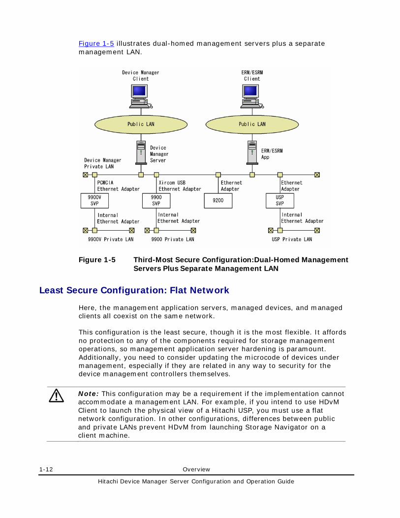
Hitachi Device Manager Server Configuration and Operation Guide
Figure 1-5 illustrates dual-homed management servers plus a separate management LAN.
Figure 1-5 Third-Most Secure Configuration:Dual-Homed Management Servers Plus Separate Management LAN
Least Secure Configuration: Flat Network
Here, the management application servers, managed devices, and managed clients all coexist on the same network.
This configuration is the least secure, though it is the most flexible. It affords no protection to any of the components required for storage management operations, so management application server hardening is paramount. Additionally, you need to consider updating the microcode of devices under management, especially if they are related in any way to security for the device management controllers themselves.
Note: This configuration may be a requirement if the implementation cannot accommodate a management LAN. For example, if you intend to use HDvM Client to launch the physical view of a Hitachi USP, you must use a flat network configuration. In other configurations, differences between public and private LANs prevent HDvM from launching Storage Navigator on a client machine.
Overview 1-13
Hitachi Device Manager Server Configuration and Operation Guide
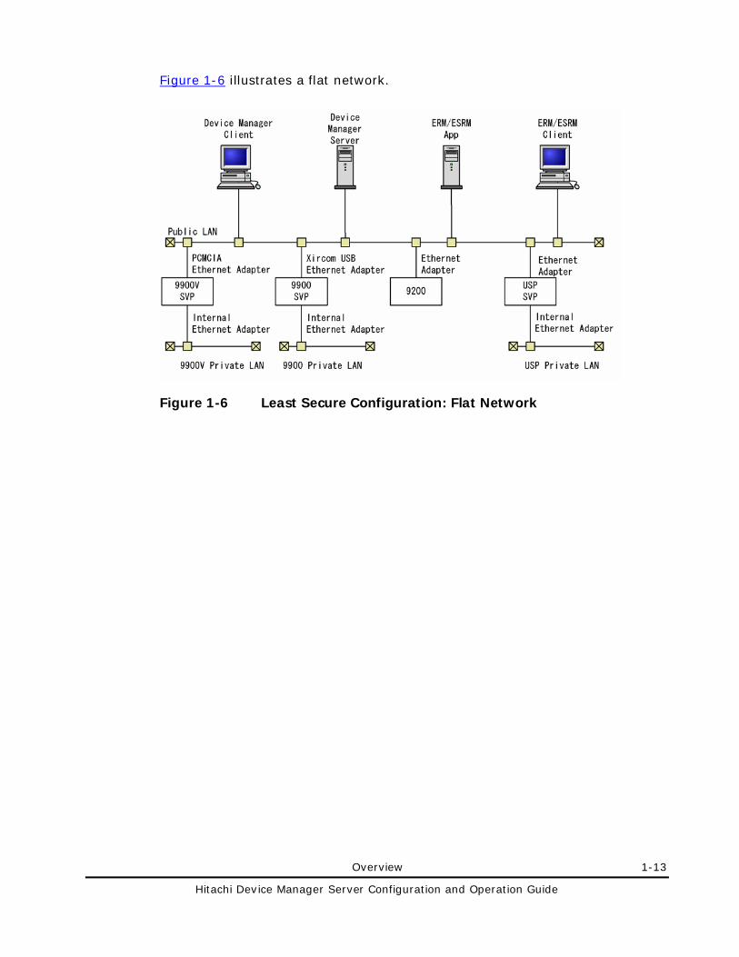
Figure 1-6 illustrates a flat network.
Figure 1-6 Least Secure Configuration: Flat Network
1-14 Overview
Hitachi Device Manager Server Configuration and Operation Guide
Management Server Requirements
This section describes the management server requirements.
Computer Requirements
The Device Manager server and Provisioning Manager server can be used in the following OS environments:
• Windows®
• Solaris
• Linux®
The following sections describe the computer requirements for each OS. For details about the installation, see the Hitachi Storage Command Suite Server Installation Guide.
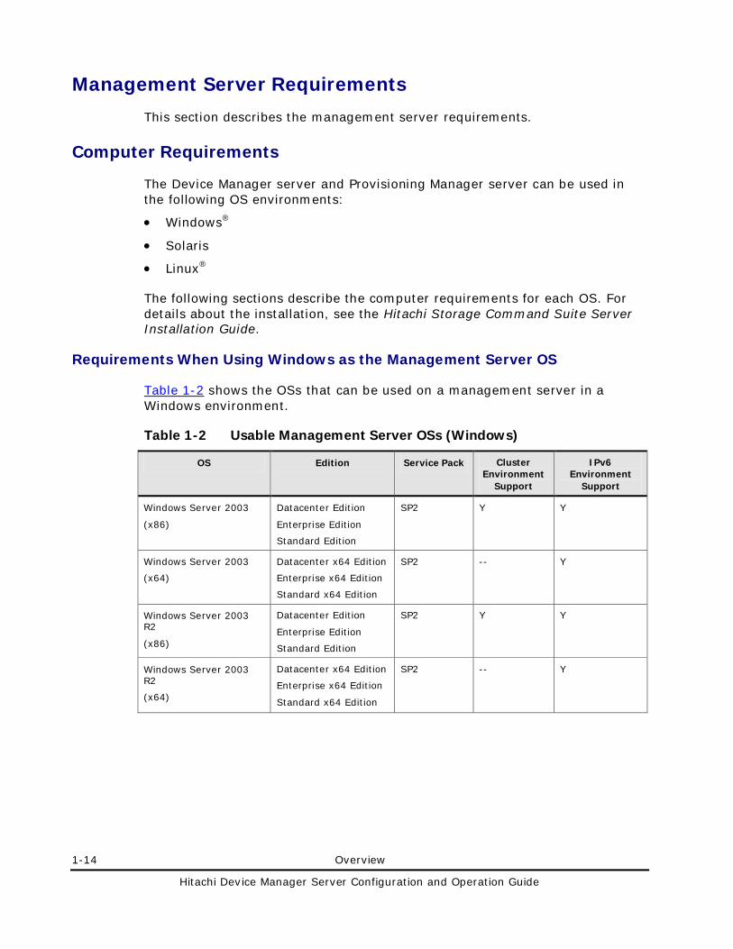
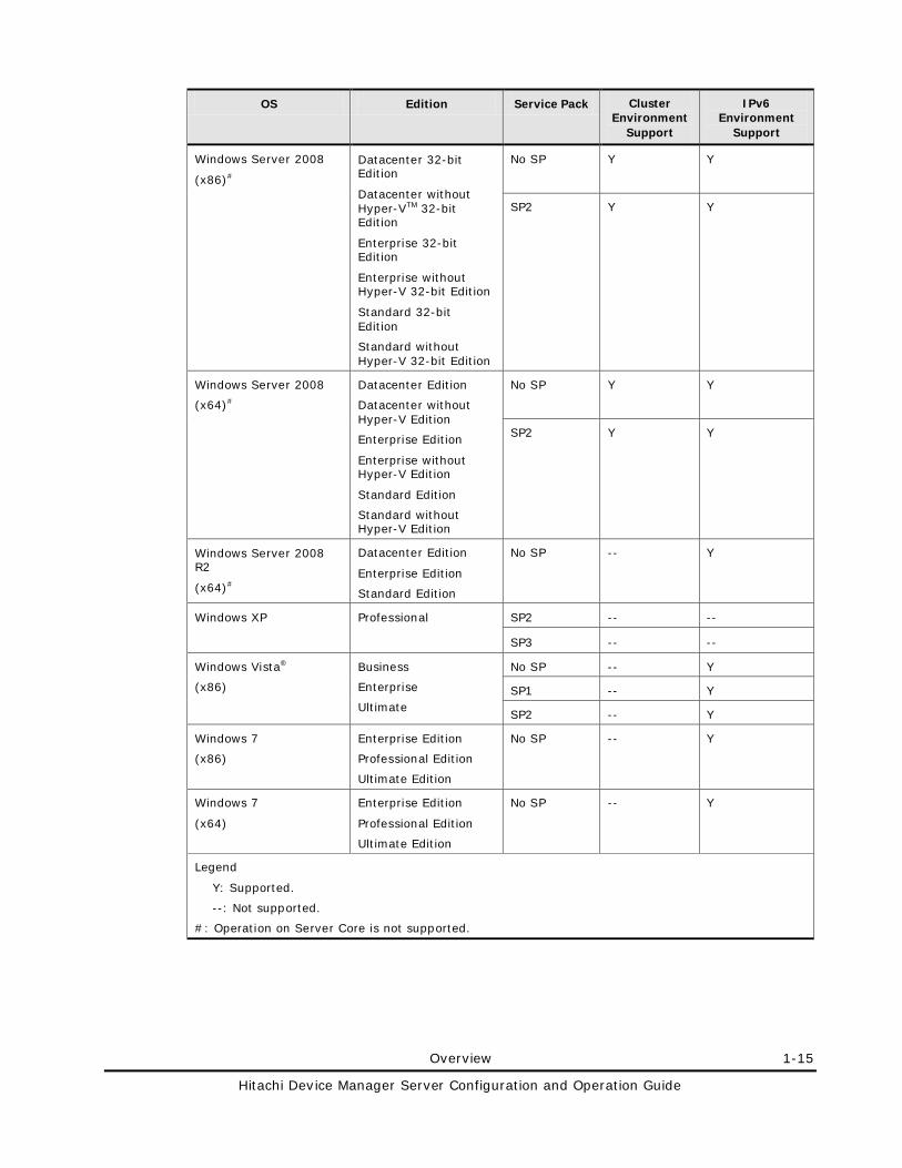
Requirements When Using Windows as the Management Server OS
Table 1-2 shows the OSs that can be used on a management server in a Windows environment.
Table 1-2 Usable Management Server OSs (Windows)
OS Edition Service Pack Cluster Environment
Support
IPv6 Environment
Support
Windows Server 2003
(x86)
Datacenter Edition
Enterprise Edition
Standard Edition
SP2 Y Y
Windows Server 2003
(x64)
Datacenter x64 Edition
Enterprise x64 Edition
Standard x64 Edition
SP2 -- Y
Windows Server 2003 R2
(x86)
Datacenter Edition
Enterprise Edition
Standard Edition
SP2 Y Y
Windows Server 2003 R2
(x64)
Datacenter x64 Edition
Enterprise x64 Edition
Standard x64 Edition
SP2 -- Y
Overview 1-15
Hitachi Device Manager Server Configuration and Operation Guide
OS Edition Service Pack Cluster Environment
Support
IPv6 Environment
Support
Windows Server 2008
(x86)#
Datacenter 32-bit Edition
Datacenter without Hyper-VTM 32-bit Edition
Enterprise 32-bit Edition
Enterprise without Hyper-V 32-bit Edition
Standard 32-bit Edition
Standard without Hyper-V 32-bit Edition
No SP Y Y
SP2 Y Y
Windows Server 2008
(x64)#
Datacenter Edition
Datacenter without Hyper-V Edition
Enterprise Edition
Enterprise without Hyper-V Edition
Standard Edition
Standard without Hyper-V Edition
No SP Y Y
SP2 Y Y
Windows Server 2008 R2
(x64)#
Datacenter Edition
Enterprise Edition
Standard Edition
No SP -- Y
Windows XP Professional SP2 -- --
SP3 -- --
Windows Vista®
(x86)
Business
Enterprise
Ultimate
No SP -- Y
SP1 -- Y
SP2 -- Y
Windows 7
(x86)
Enterprise Edition
Professional Edition
Ultimate Edition
No SP -- Y
Windows 7
(x64)
Enterprise Edition
Professional Edition
Ultimate Edition
No SP -- Y
Legend
Y: Supported.
--: Not supported.
#: Operation on Server Core is not supported.
1-16 Overview
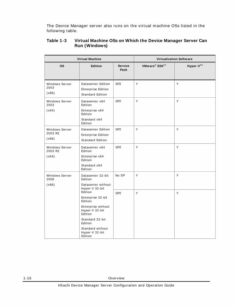
Hitachi Device Manager Server Configuration and Operation Guide
The Device Manager server also runs on the virtual machine OSs listed in the following table.
Table 1-3 Virtual Machine OSs on Which the Device Manager Server Can Run (Windows)
Virtual Machine Virtualization Software
OS Edition Service Pack
VMware® ESX#1 Hyper-V#2
Windows Server 2003
(x86)
Datacenter Edition
Enterprise Edition
Standard Edition
SP2 Y Y
Windows Server 2003
(x64)
Datacenter x64 Edition
Enterprise x64 Edition
Standard x64 Edition
SP2 Y Y
Windows Server 2003 R2
(x86)
Datacenter Edition
Enterprise Edition
Standard Edition
SP2 Y Y
Windows Server 2003 R2
(x64)
Datacenter x64 Edition
Enterprise x64 Edition
Standard x64 Edition
SP2 Y Y
Windows Server 2008
(x86)
Datacenter 32-bit Edition
Datacenter without Hyper-V 32-bit Edition
Enterprise 32-bit Edition
Enterprise without Hyper-V 32-bit Edition
Standard 32-bit Edition
Standard without Hyper-V 32-bit Edition
No SP Y Y
SP2 Y Y
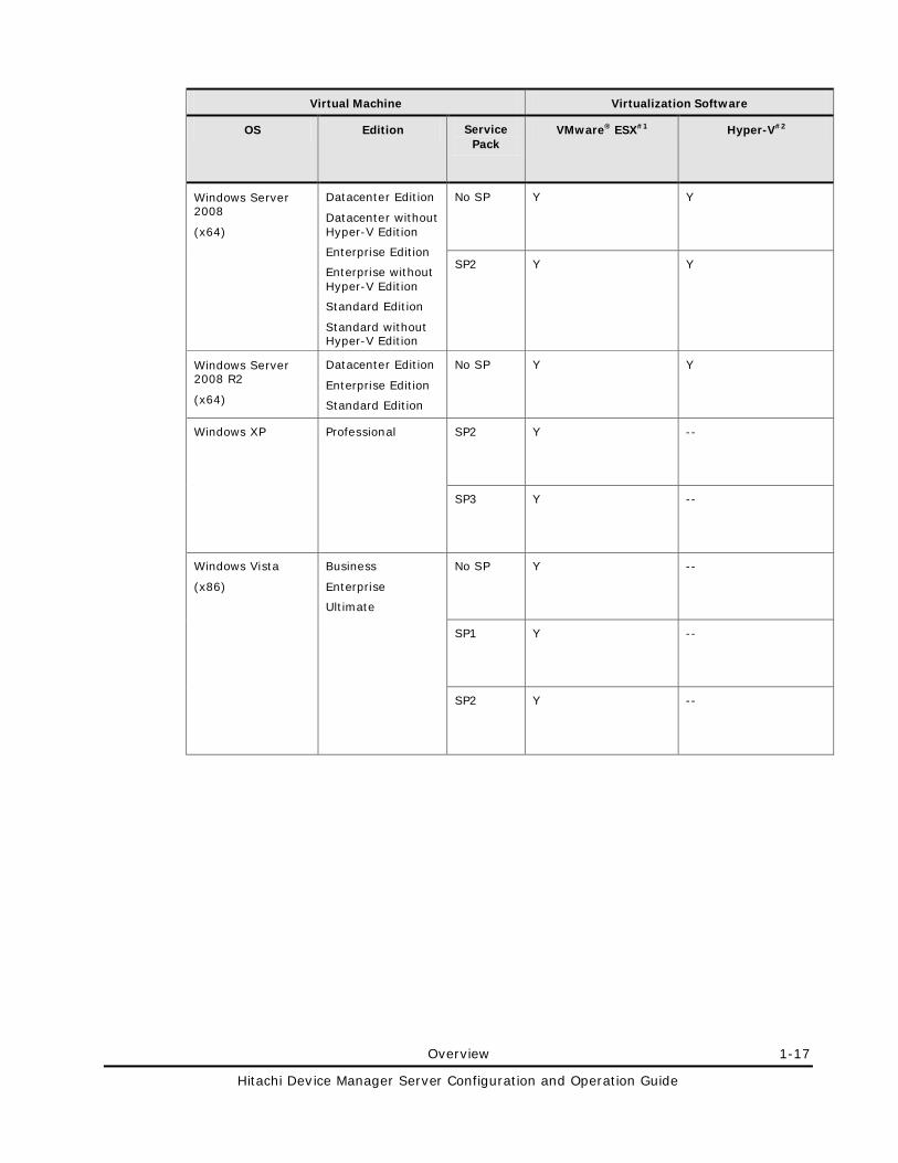
Overview 1-17
Hitachi Device Manager Server Configuration and Operation Guide
Virtual Machine Virtualization Software
OS Edition Service Pack
VMware® ESX#1 Hyper-V#2
Windows Server 2008
(x64)
Datacenter Edition
Datacenter without Hyper-V Edition
Enterprise Edition
Enterprise without Hyper-V Edition
Standard Edition
Standard without Hyper-V Edition
No SP Y Y
SP2 Y Y
Windows Server 2008 R2
(x64)
Datacenter Edition
Enterprise Edition
Standard Edition
No SP Y Y
Windows XP Professional SP2 Y --
SP3 Y --
Windows Vista
(x86)
Business
Enterprise
Ultimate
No SP Y --
SP1 Y --
SP2 Y --
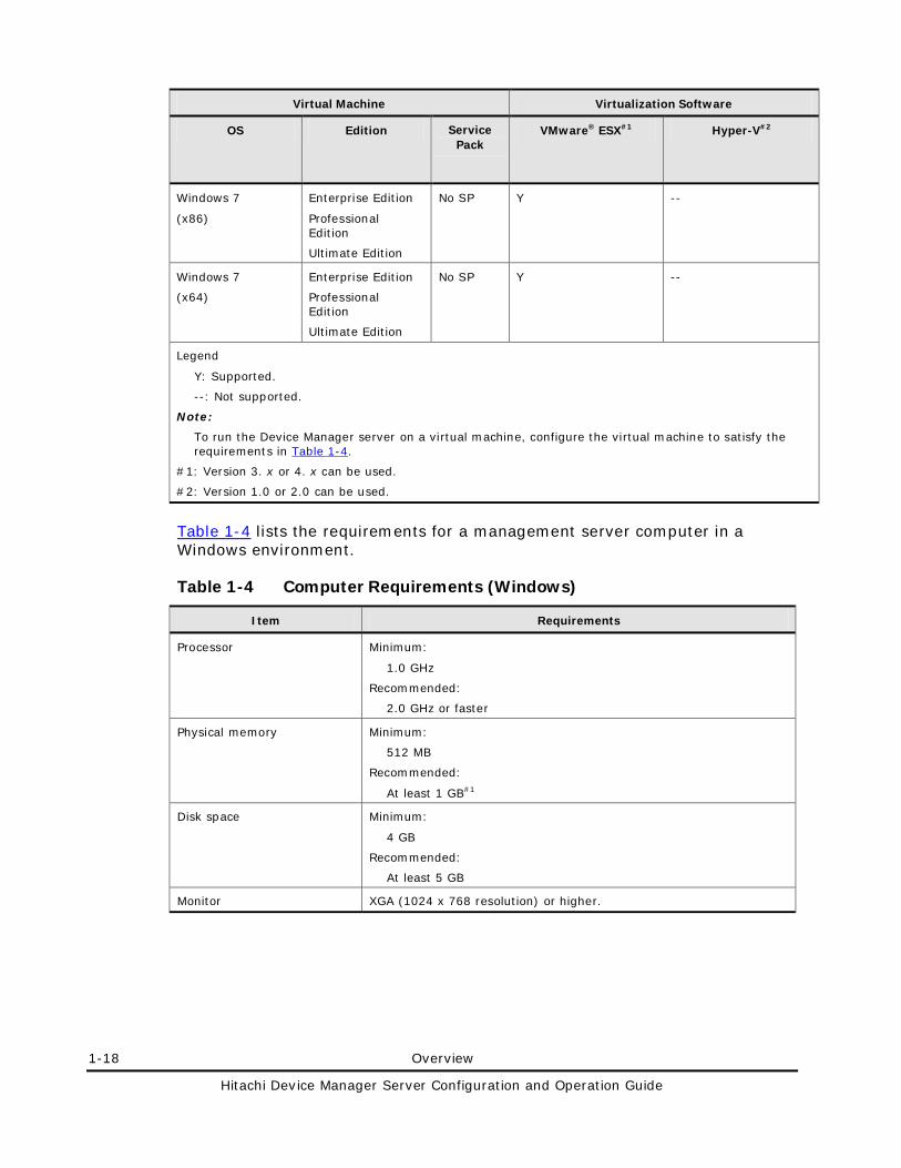
1-18 Overview
Hitachi Device Manager Server Configuration and Operation Guide
Virtual Machine Virtualization Software
OS Edition Service Pack
VMware® ESX#1 Hyper-V#2
Windows 7
(x86)
Enterprise Edition
Professional Edition
Ultimate Edition
No SP Y --
Windows 7
(x64)
Enterprise Edition
Professional Edition
Ultimate Edition
No SP Y --
Legend
Y: Supported.
--: Not supported.
Note:
To run the Device Manager server on a virtual machine, configure the virtual machine to satisfy the requirements in Table 1-4.
#1: Version 3. x or 4. x can be used.
#2: Version 1.0 or 2.0 can be used.
Table 1-4 lists the requirements for a management server computer in a Windows environment.
Table 1-4 Computer Requirements (Windows)
Item Requirements
Processor Minimum:
1.0 GHz
Recommended:
2.0 GHz or faster
Physical memory Minimum:
512 MB
Recommended:
At least 1 GB#1
Disk space Minimum:
4 GB
Recommended:
At least 5 GB
Monitor XGA (1024 x 768 resolution) or higher.
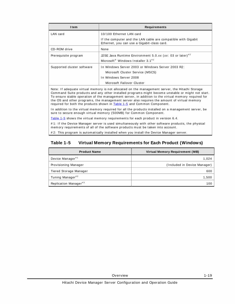
Overview 1-19
Hitachi Device Manager Server Configuration and Operation Guide
Item Requirements
LAN card 10/100 Ethernet LAN card
If the computer and the LAN cable are compatible with Gigabit Ethernet, you can use a Gigabit-class card.
CD-ROM drive None
Prerequisite program J2SE Java Runtime Environment 5.0.xx (xx: 03 or later)#2
Microsoft® Windows Installer 3.1#2
Supported cluster software In Windows Server 2003 or Windows Server 2003 R2:
Microsoft Cluster Service (MSCS)
In Windows Server 2008
Microsoft Failover Cluster
Note: If adequate virtual memory is not allocated on the management server, the Hitachi Storage Command Suite products and any other installed programs might become unstable or might not start. To ensure stable operation of the management server, in addition to the virtual memory required for the OS and other programs, the management server also requires the amount of virtual memory required for both the products shown in Table 1-5 and Common Component.
In addition to the virtual memory required for all the products installed on a management server, be sure to secure enough virtual memory (500MB) for Common Component.
Table 1-5 shows the virtual memory requirements for each product in version 6.4.
#1: If the Device Manager server is used simultaneously with other software products, the physical memory requirements of all of the software products must be taken into account.
#2: This program is automatically installed when you install the Device Manager server.
Table 1-5 Virtual Memory Requirements for Each Product (Windows)
Product Name Virtual Memory Requirement (MB)
Device Manager#1 1,024
Provisioning Manager (Included in Device Manager)
Tiered Storage Manager 600
Tuning Manager#2 1,500
Replication Manager#3 100
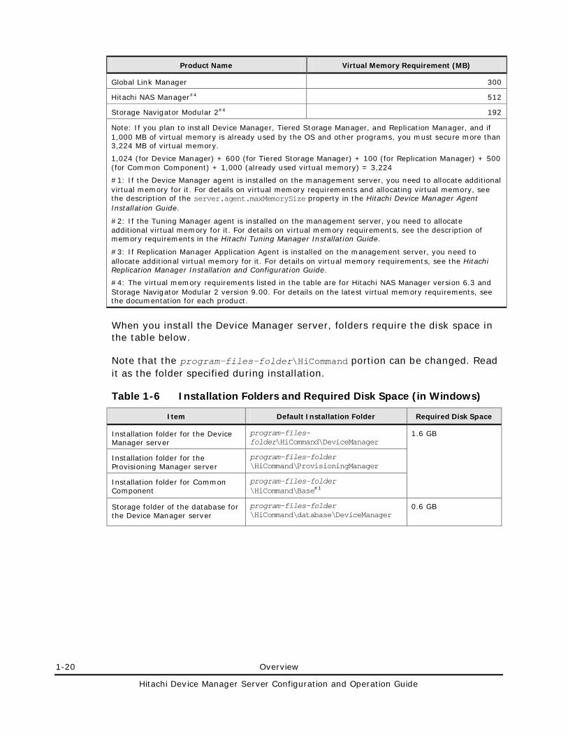
1-20 Overview
Hitachi Device Manager Server Configuration and Operation Guide
Product Name Virtual Memory Requirement (MB)
Global Link Manager 300
Hitachi NAS Manager#4 512
Storage Navigator Modular 2#4 192
Note: If you plan to install Device Manager, Tiered Storage Manager, and Replication Manager, and if 1,000 MB of virtual memory is already used by the OS and other programs, you must secure more than 3,224 MB of virtual memory.
1,024 (for Device Manager) + 600 (for Tiered Storage Manager) + 100 (for Replication Manager) + 500 (for Common Component) + 1,000 (already used virtual memory) = 3,224
#1: If the Device Manager agent is installed on the management server, you need to allocate additional virtual memory for it. For details on virtual memory requirements and allocating virtual memory, see the description of the server.agent.maxMemorySize property in the Hitachi Device Manager Agent Installation Guide.
#2: If the Tuning Manager agent is installed on the management server, you need to allocate additional virtual memory for it. For details on virtual memory requirements, see the description of memory requirements in the Hitachi Tuning Manager Installation Guide.
#3: If Replication Manager Application Agent is installed on the management server, you need to allocate additional virtual memory for it. For details on virtual memory requirements, see the Hitachi Replication Manager Installation and Configuration Guide.
#4: The virtual memory requirements listed in the table are for Hitachi NAS Manager version 6.3 and Storage Navigator Modular 2 version 9.00. For details on the latest virtual memory requirements, see the documentation for each product.
When you install the Device Manager server, folders require the disk space in the table below.
Note that the program-files-folder\HiCommand portion can be changed. Read it as the folder specified during installation.
Table 1-6 Installation Folders and Required Disk Space (in Windows)
Item Default Installation Folder Required Disk Space
Installation folder for the Device Manager server
program-files-folder\HiCommand\DeviceManager
1.6 GB
Installation folder for the Provisioning Manager server
program-files-folder \HiCommand\ProvisioningManager
Installation folder for Common Component
program-files-folder \HiCommand\Base#1
Storage folder of the database for the Device Manager server
program-files-folder \HiCommand\database\DeviceManager
0.6 GB
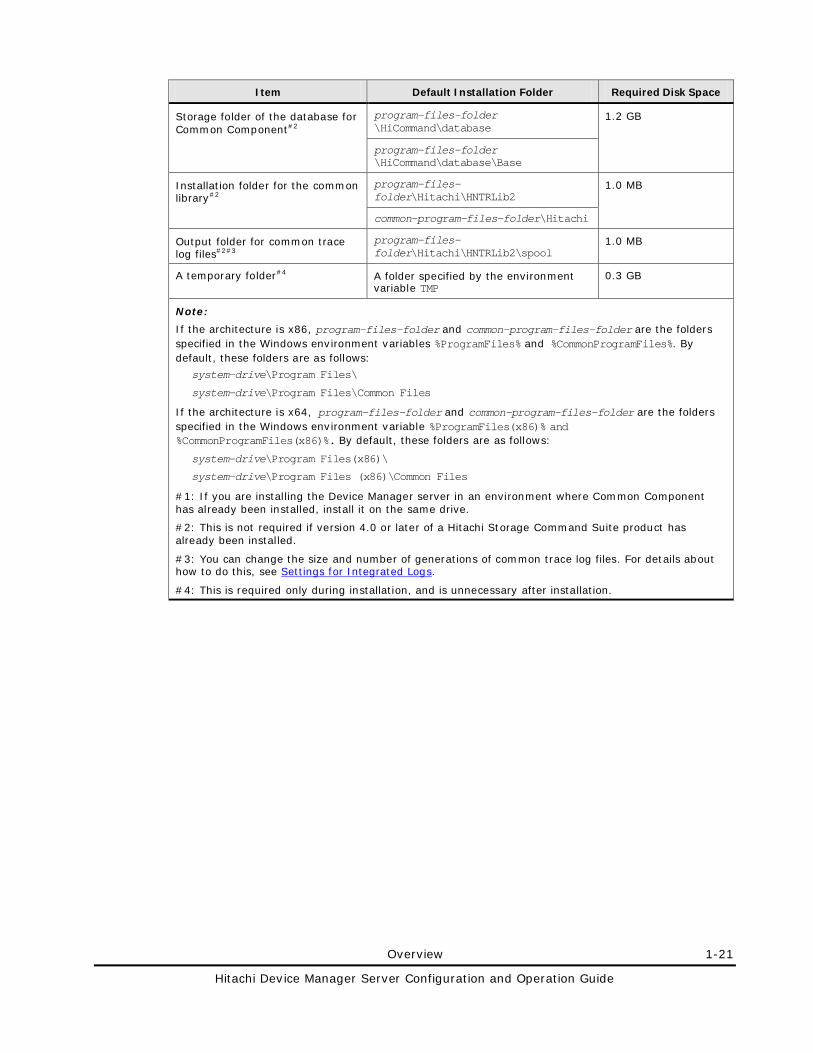
Overview 1-21
Hitachi Device Manager Server Configuration and Operation Guide
Item Default Installation Folder Required Disk Space
Storage folder of the database for Common Component#2
program-files-folder \HiCommand\database
1.2 GB
program-files-folder \HiCommand\database\Base
Installation folder for the common library#2
program-files-folder\Hitachi\HNTRLib2
1.0 MB
common-program-files-folder\Hitachi
Output folder for common trace log files#2#3
program-files-folder\Hitachi\HNTRLib2\spool
1.0 MB
A temporary folder#4 A folder specified by the environment variable TMP
0.3 GB
Note:
If the architecture is x86, program-files-folder and common-program-files-folder are the folders specified in the Windows environment variables %ProgramFiles% and %CommonProgramFiles%. By default, these folders are as follows:
system-drive\Program Files\
system-drive\Program Files\Common Files
If the architecture is x64, program-files-folder and common-program-files-folder are the folders specified in the Windows environment variable %ProgramFiles(x86)% and %CommonProgramFiles(x86)%. By default, these folders are as follows:
system-drive\Program Files(x86)\
system-drive\Program Files (x86)\Common Files
#1: If you are installing the Device Manager server in an environment where Common Component has already been installed, install it on the same drive.
#2: This is not required if version 4.0 or later of a Hitachi Storage Command Suite product has already been installed.
#3: You can change the size and number of generations of common trace log files. For details about how to do this, see Settings for Integrated Logs.
#4: This is required only during installation, and is unnecessary after installation.
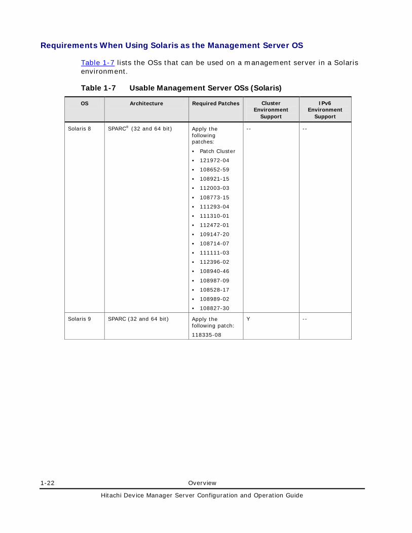
1-22 Overview
Hitachi Device Manager Server Configuration and Operation Guide
Requirements When Using Solaris as the Management Server OS
Table 1-7 lists the OSs that can be used on a management server in a Solaris environment.
Table 1-7 Usable Management Server OSs (Solaris)
OS Architecture Required Patches Cluster Environment
Support
IPv6 Environment
Support
Solaris 8 SPARC® (32 and 64 bit) Apply the following patches:
Patch Cluster
121972-04
108652-59
108921-15
112003-03
108773-15
111293-04
111310-01
112472-01
109147-20
108714-07
111111-03
112396-02
108940-46
108987-09
108528-17
108989-02
108827-30
-- --
Solaris 9 SPARC (32 and 64 bit) Apply the following patch:
118335-08
Y --
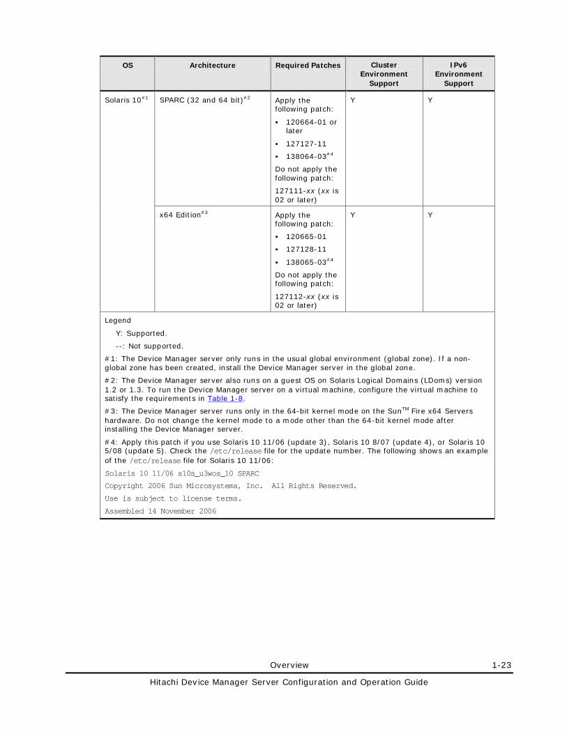
Overview 1-23
Hitachi Device Manager Server Configuration and Operation Guide
OS Architecture Required Patches Cluster Environment
Support
IPv6 Environment
Support
Solaris 10#1 SPARC (32 and 64 bit)#2 Apply the following patch:
120664-01 or later
127127-11
138064-03#4
Do not apply the following patch:
127111-xx (xx is 02 or later)
Y Y
x64 Edition#3 Apply the following patch:
120665-01
127128-11
138065-03#4
Do not apply the following patch:
127112-xx (xx is 02 or later)
Y Y
Legend
Y: Supported.
--: Not supported.
#1: The Device Manager server only runs in the usual global environment (global zone). If a non-global zone has been created, install the Device Manager server in the global zone.
#2: The Device Manager server also runs on a guest OS on Solaris Logical Domains (LDoms) version 1.2 or 1.3. To run the Device Manager server on a virtual machine, configure the virtual machine to satisfy the requirements in Table 1-8.
#3: The Device Manager server runs only in the 64-bit kernel mode on the SunTM Fire x64 Servers hardware. Do not change the kernel mode to a mode other than the 64-bit kernel mode after installing the Device Manager server.
#4: Apply this patch if you use Solaris 10 11/06 (update 3), Solaris 10 8/07 (update 4), or Solaris 10 5/08 (update 5). Check the /etc/release file for the update number. The following shows an example of the /etc/release file for Solaris 10 11/06:
Solaris 10 11/06 s10s_u3wos_10 SPARC
Copyright 2006 Sun Microsystems, Inc. All Rights Reserved.
Use is subject to license terms.
Assembled 14 November 2006
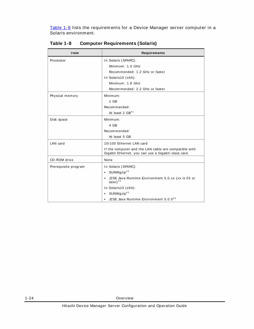
1-24 Overview
Hitachi Device Manager Server Configuration and Operation Guide
Table 1-8 lists the requirements for a Device Manager server computer in a Solaris environment.
Table 1-8 Computer Requirements (Solaris)
Item Requirements
Processor In Solaris (SPARC):
Minimum: 1.0 GHz
Recommended: 1.2 GHz or faster
In Solaris10 (x64):
Minimum: 1.8 GHz
Recommended: 2.2 GHz or faster
Physical memory Minimum:
1 GB
Recommended:
At least 2 GB#1
Disk space Minimum:
4 GB
Recommended:
At least 5 GB
LAN card 10/100 Ethernet LAN card
If the computer and the LAN cable are compatible with Gigabit Ethernet, you can use a Gigabit-class card.
CD-ROM drive None
Prerequisite program In Solaris (SPARC):
SUNWgzip#2
J2SE Java Runtime Environment 5.0.xx (xx is 03 or later)#3
In Solaris10 (x64):
SUNWgzip#2
J2SE Java Runtime Environment 5.0.0#4
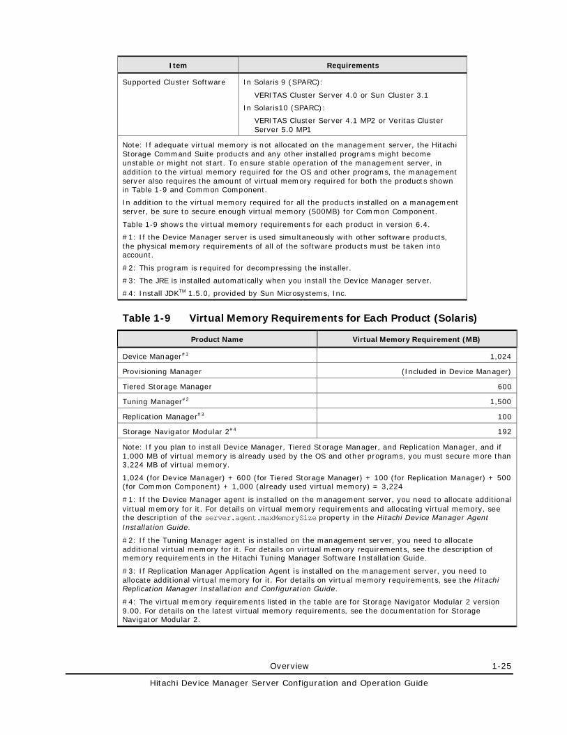
Overview 1-25
Hitachi Device Manager Server Configuration and Operation Guide
Item Requirements
Supported Cluster Software In Solaris 9 (SPARC):
VERITAS Cluster Server 4.0 or Sun Cluster 3.1
In Solaris10 (SPARC):
VERITAS Cluster Server 4.1 MP2 or Veritas Cluster Server 5.0 MP1
Note: If adequate virtual memory is not allocated on the management server, the Hitachi Storage Command Suite products and any other installed programs might become unstable or might not start. To ensure stable operation of the management server, in addition to the virtual memory required for the OS and other programs, the management server also requires the amount of virtual memory required for both the products shown in Table 1-9 and Common Component.
In addition to the virtual memory required for all the products installed on a management server, be sure to secure enough virtual memory (500MB) for Common Component.
Table 1-9 shows the virtual memory requirements for each product in version 6.4.
#1: If the Device Manager server is used simultaneously with other software products, the physical memory requirements of all of the software products must be taken into account.
#2: This program is required for decompressing the installer.
#3: The JRE is installed automatically when you install the Device Manager server.
#4: Install JDKTM 1.5.0, provided by Sun Microsystems, Inc.
Table 1-9 Virtual Memory Requirements for Each Product (Solaris)
Product Name Virtual Memory Requirement (MB)
Device Manager#1 1,024
Provisioning Manager (Included in Device Manager)
Tiered Storage Manager 600
Tuning Manager#2 1,500
Replication Manager#3 100
Storage Navigator Modular 2#4 192
Note: If you plan to install Device Manager, Tiered Storage Manager, and Replication Manager, and if 1,000 MB of virtual memory is already used by the OS and other programs, you must secure more than 3,224 MB of virtual memory.
1,024 (for Device Manager) + 600 (for Tiered Storage Manager) + 100 (for Replication Manager) + 500 (for Common Component) + 1,000 (already used virtual memory) = 3,224
#1: If the Device Manager agent is installed on the management server, you need to allocate additional virtual memory for it. For details on virtual memory requirements and allocating virtual memory, see the description of the server.agent.maxMemorySize property in the Hitachi Device Manager Agent Installation Guide.
#2: If the Tuning Manager agent is installed on the management server, you need to allocate additional virtual memory for it. For details on virtual memory requirements, see the description of memory requirements in the Hitachi Tuning Manager Software Installation Guide.
#3: If Replication Manager Application Agent is installed on the management server, you need to allocate additional virtual memory for it. For details on virtual memory requirements, see the Hitachi Replication Manager Installation and Configuration Guide.
#4: The virtual memory requirements listed in the table are for Storage Navigator Modular 2 version 9.00. For details on the latest virtual memory requirements, see the documentation for Storage Navigator Modular 2.
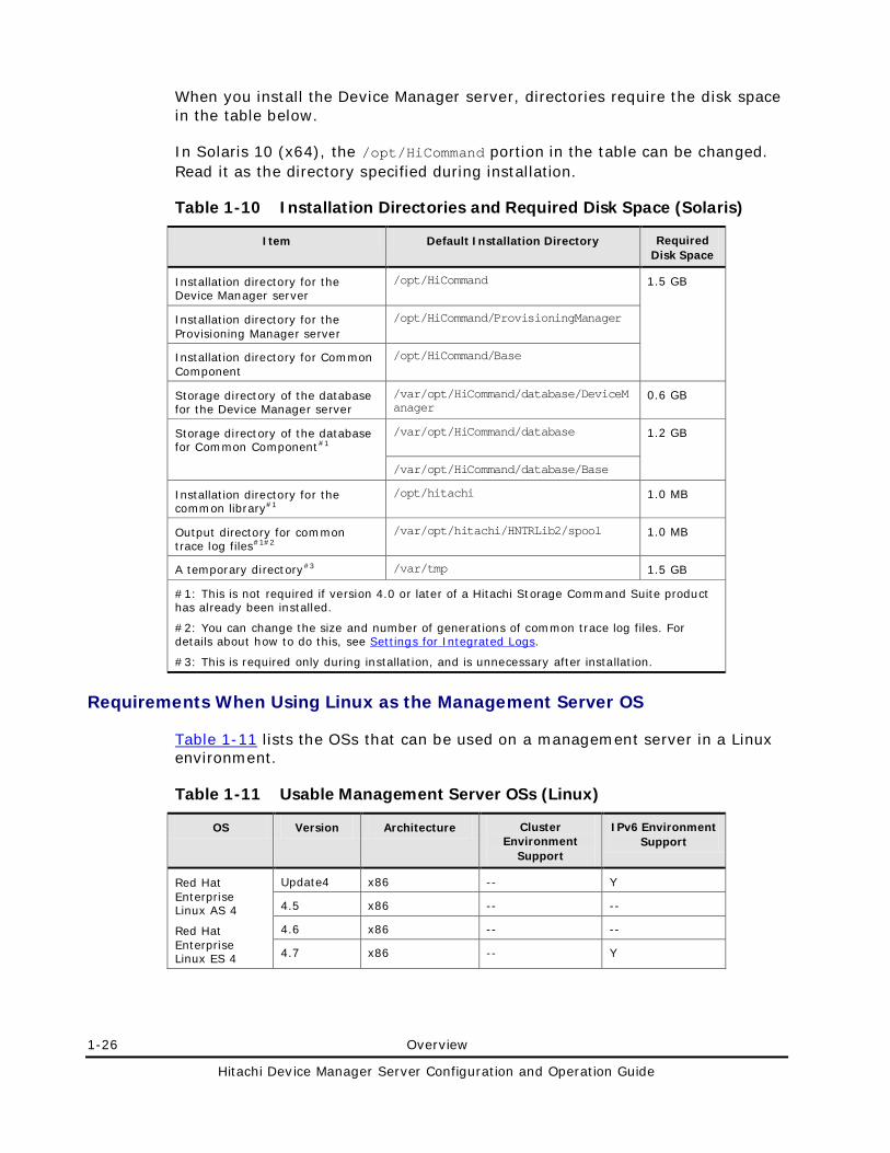
1-26 Overview
Hitachi Device Manager Server Configuration and Operation Guide
When you install the Device Manager server, directories require the disk space in the table below.
In Solaris 10 (x64), the /opt/HiCommand portion in the table can be changed. Read it as the directory specified during installation.
Table 1-10 Installation Directories and Required Disk Space (Solaris)
Item Default Installation Directory Required Disk Space
Installation directory for the Device Manager server
/opt/HiCommand 1.5 GB
Installation directory for the Provisioning Manager server
/opt/HiCommand/ProvisioningManager
Installation directory for Common Component
/opt/HiCommand/Base
Storage directory of the database for the Device Manager server
/var/opt/HiCommand/database/DeviceManager
0.6 GB
Storage directory of the database for Common Component#1
/var/opt/HiCommand/database 1.2 GB
/var/opt/HiCommand/database/Base
Installation directory for the common library#1
/opt/hitachi 1.0 MB
Output directory for common trace log files#1#2
/var/opt/hitachi/HNTRLib2/spool 1.0 MB
A temporary directory#3 /var/tmp 1.5 GB
#1: This is not required if version 4.0 or later of a Hitachi Storage Command Suite product has already been installed.
#2: You can change the size and number of generations of common trace log files. For details about how to do this, see Settings for Integrated Logs.
#3: This is required only during installation, and is unnecessary after installation.
Requirements When Using Linux as the Management Server OS
Table 1-11 lists the OSs that can be used on a management server in a Linux environment.
Table 1-11 Usable Management Server OSs (Linux)
OS Version Architecture Cluster Environment
Support
IPv6 Environment Support
Red Hat Enterprise Linux AS 4
Red Hat Enterprise Linux ES 4
Update4 x86 -- Y
4.5 x86 -- --
4.6 x86 -- --
4.7 x86 -- Y
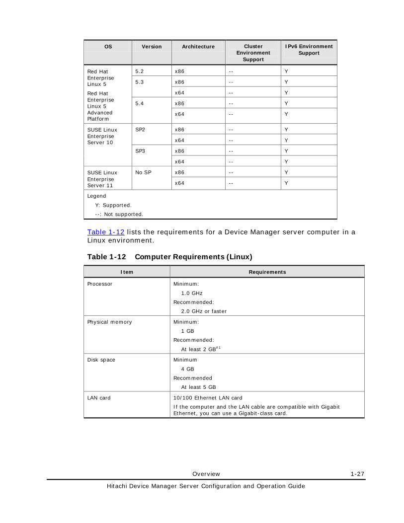
Overview 1-27
Hitachi Device Manager Server Configuration and Operation Guide
OS Version Architecture Cluster Environment
Support
IPv6 Environment Support
Red Hat Enterprise Linux 5
Red Hat Enterprise Linux 5 Advanced Platform
5.2 x86 -- Y
5.3 x86 -- Y
x64 -- Y
5.4 x86 -- Y
x64 -- Y
SUSE Linux Enterprise Server 10
SP2 x86 -- Y
x64 -- Y
SP3 x86 -- Y
x64 -- Y
SUSE Linux Enterprise Server 11
No SP x86 -- Y
x64 -- Y
Legend
Y: Supported.
--: Not supported.
Table 1-12 lists the requirements for a Device Manager server computer in a Linux environment.
Table 1-12 Computer Requirements (Linux)
Item Requirements Processor Minimum:
1.0 GHz
Recommended:
2.0 GHz or faster
Physical memory Minimum:
1 GB
Recommended:
At least 2 GB#1
Disk space Minimum
4 GB
Recommended
At least 5 GB
LAN card 10/100 Ethernet LAN card
If the computer and the LAN cable are compatible with Gigabit Ethernet, you can use a Gigabit-class card.
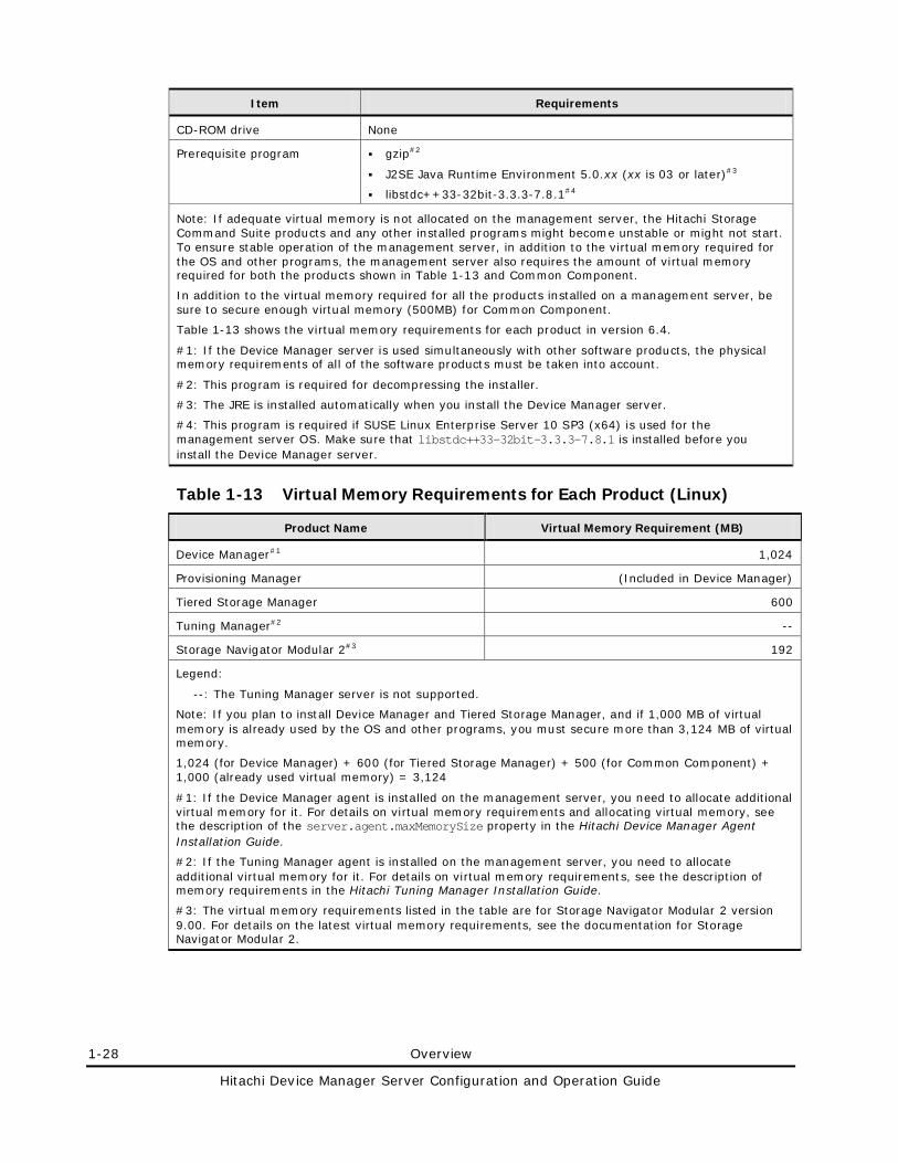
1-28 Overview
Hitachi Device Manager Server Configuration and Operation Guide
Item Requirements CD-ROM drive None
Prerequisite program gzip#2
J2SE Java Runtime Environment 5.0.xx (xx is 03 or later)#3
libstdc++33-32bit-3.3.3-7.8.1#4
Note: If adequate virtual memory is not allocated on the management server, the Hitachi Storage Command Suite products and any other installed programs might become unstable or might not start. To ensure stable operation of the management server, in addition to the virtual memory required for the OS and other programs, the management server also requires the amount of virtual memory required for both the products shown in Table 1-13 and Common Component.
In addition to the virtual memory required for all the products installed on a management server, be sure to secure enough virtual memory (500MB) for Common Component.
Table 1-13 shows the virtual memory requirements for each product in version 6.4.
#1: If the Device Manager server is used simultaneously with other software products, the physical memory requirements of all of the software products must be taken into account.
#2: This program is required for decompressing the installer.
#3: The JRE is installed automatically when you install the Device Manager server.
#4: This program is required if SUSE Linux Enterprise Server 10 SP3 (x64) is used for the management server OS. Make sure that libstdc++33-32bit-3.3.3-7.8.1 is installed before you install the Device Manager server.
Table 1-13 Virtual Memory Requirements for Each Product (Linux)
Product Name Virtual Memory Requirement (MB)
Device Manager#1 1,024
Provisioning Manager (Included in Device Manager)
Tiered Storage Manager 600
Tuning Manager#2 --
Storage Navigator Modular 2#3 192
Legend:
--: The Tuning Manager server is not supported.
Note: If you plan to install Device Manager and Tiered Storage Manager, and if 1,000 MB of virtual memory is already used by the OS and other programs, you must secure more than 3,124 MB of virtual memory.
1,024 (for Device Manager) + 600 (for Tiered Storage Manager) + 500 (for Common Component) + 1,000 (already used virtual memory) = 3,124
#1: If the Device Manager agent is installed on the management server, you need to allocate additional virtual memory for it. For details on virtual memory requirements and allocating virtual memory, see the description of the server.agent.maxMemorySize property in the Hitachi Device Manager Agent Installation Guide.
#2: If the Tuning Manager agent is installed on the management server, you need to allocate additional virtual memory for it. For details on virtual memory requirements, see the description of memory requirements in the Hitachi Tuning Manager Installation Guide.
#3: The virtual memory requirements listed in the table are for Storage Navigator Modular 2 version 9.00. For details on the latest virtual memory requirements, see the documentation for Storage Navigator Modular 2.
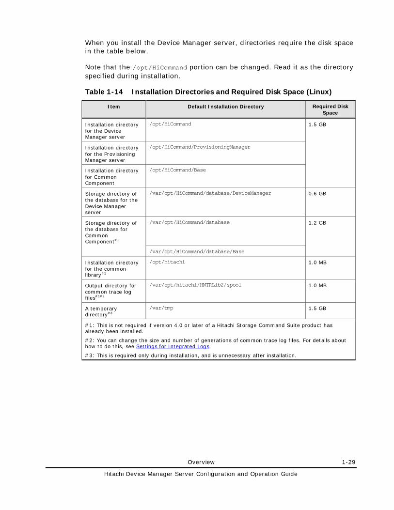
Overview 1-29
Hitachi Device Manager Server Configuration and Operation Guide
When you install the Device Manager server, directories require the disk space in the table below.
Note that the /opt/HiCommand portion can be changed. Read it as the directory specified during installation.
Table 1-14 Installation Directories and Required Disk Space (Linux)
Item Default Installation Directory Required Disk Space
Installation directory for the Device Manager server
/opt/HiCommand 1.5 GB
Installation directory for the Provisioning Manager server
/opt/HiCommand/ProvisioningManager
Installation directory for Common Component
/opt/HiCommand/Base
Storage directory of the database for the Device Manager server
/var/opt/HiCommand/database/DeviceManager 0.6 GB
Storage directory of the database for Common Component#1
/var/opt/HiCommand/database 1.2 GB
/var/opt/HiCommand/database/Base
Installation directory for the common library#1
/opt/hitachi 1.0 MB
Output directory for common trace log files#1#2
/var/opt/hitachi/HNTRLib2/spool 1.0 MB
A temporary directory#3
/var/tmp 1.5 GB
#1: This is not required if version 4.0 or later of a Hitachi Storage Command Suite product has already been installed.
#2: You can change the size and number of generations of common trace log files. For details about how to do this, see Settings for Integrated Logs.
#3: This is required only during installation, and is unnecessary after installation.
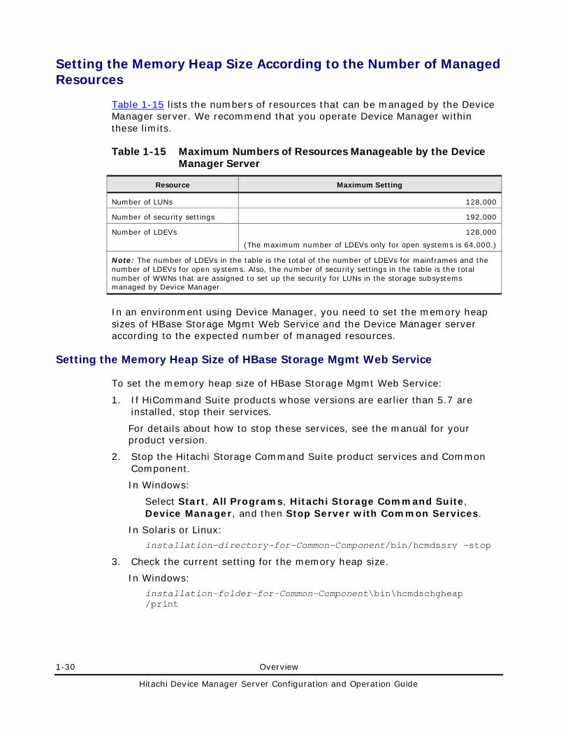
1-30 Overview
Hitachi Device Manager Server Configuration and Operation Guide
Setting the Memory Heap Size According to the Number of Managed Resources
Table 1-15 lists the numbers of resources that can be managed by the Device Manager server. We recommend that you operate Device Manager within these limits.
Table 1-15 Maximum Numbers of Resources Manageable by the Device Manager Server
Resource Maximum Setting
Number of LUNs 128,000
Number of security settings 192,000
Number of LDEVs 128,000
(The maximum number of LDEVs only for open systems is 64,000.)
Note: The number of LDEVs in the table is the total of the number of LDEVs for mainframes and the number of LDEVs for open systems. Also, the number of security settings in the table is the total number of WWNs that are assigned to set up the security for LUNs in the storage subsystems managed by Device Manager.
In an environment using Device Manager, you need to set the memory heap sizes of HBase Storage Mgmt Web Service and the Device Manager server according to the expected number of managed resources.
Setting the Memory Heap Size of HBase Storage Mgmt Web Service
To set the memory heap size of HBase Storage Mgmt Web Service:
1. If HiCommand Suite products whose versions are earlier than 5.7 are installed, stop their services.
For details about how to stop these services, see the manual for your product version.
2. Stop the Hitachi Storage Command Suite product services and Common Component.
In Windows:
Select Start, All Programs, Hitachi Storage Command Suite, Device Manager, and then Stop Server with Common Services.
In Solaris or Linux:
installation-directory-for-Common-Component/bin/hcmdssrv -stop
3. Check the current setting for the memory heap size.
In Windows:
installation-folder-for-Common-Component\bin\hcmdschgheap /print
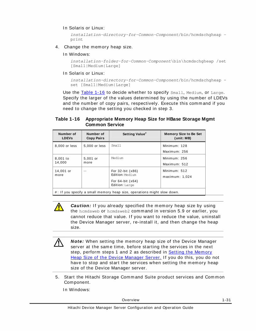
Overview 1-31
Hitachi Device Manager Server Configuration and Operation Guide
In Solaris or Linux: installation-directory-for-Common-Component/bin/hcmdschgheap -print
4. Change the memory heap size.
In Windows:
installation-folder-for-Common-Component\bin\hcmdschgheap /set [Small|Medium|Large]
In Solaris or Linux:
installation-directory-for-Common-Component/bin/hcmdschgheap -set [Small|Medium|Large]
Use the Table 1-16 to decide whether to specify Small, Medium, or Large. Specify the larger of the values determined by using the number of LDEVs and the number of copy pairs, respectively. Execute this command if you need to change the setting you checked in step 3.
Table 1-16 Appropriate Memory Heap Size for HBase Storage Mgmt Common Service
Number of LDEVs
Number of Copy Pairs
Setting Value# Memory Size to Be Set (unit: MB)
8,000 or less 5,000 or less Small Minimum: 128
Maximum: 256
8,001 to 14,000
5,001 or more
Medium Minimum: 256
Maximum: 512
14,001 or more
-- For 32-bit (x86) Edition:Medium
For 64-bit (x64) Edition:Large
Minimum: 512
maximum: 1,024
#: If you specify a small memory heap size, operations might slow down.
Caution: If you already specified the memory heap size by using the hcmdsweb or hcmdsweb2 command in version 5.9 or earlier, you cannot reduce that value. If you want to reduce the value, uninstall the Device Manager server, re-install it, and then change the heap size.
Note: When setting the memory heap size of the Device Manager server at the same time, before starting the services in the next step, perform steps 1 and 2 as described in Setting the Memory Heap Size of the Device Manager Server. If you do this, you do not have to stop and start the services when setting the memory heap size of the Device Manager server.
5. Start the Hitachi Storage Command Suite product services and Common Component.
In Windows:
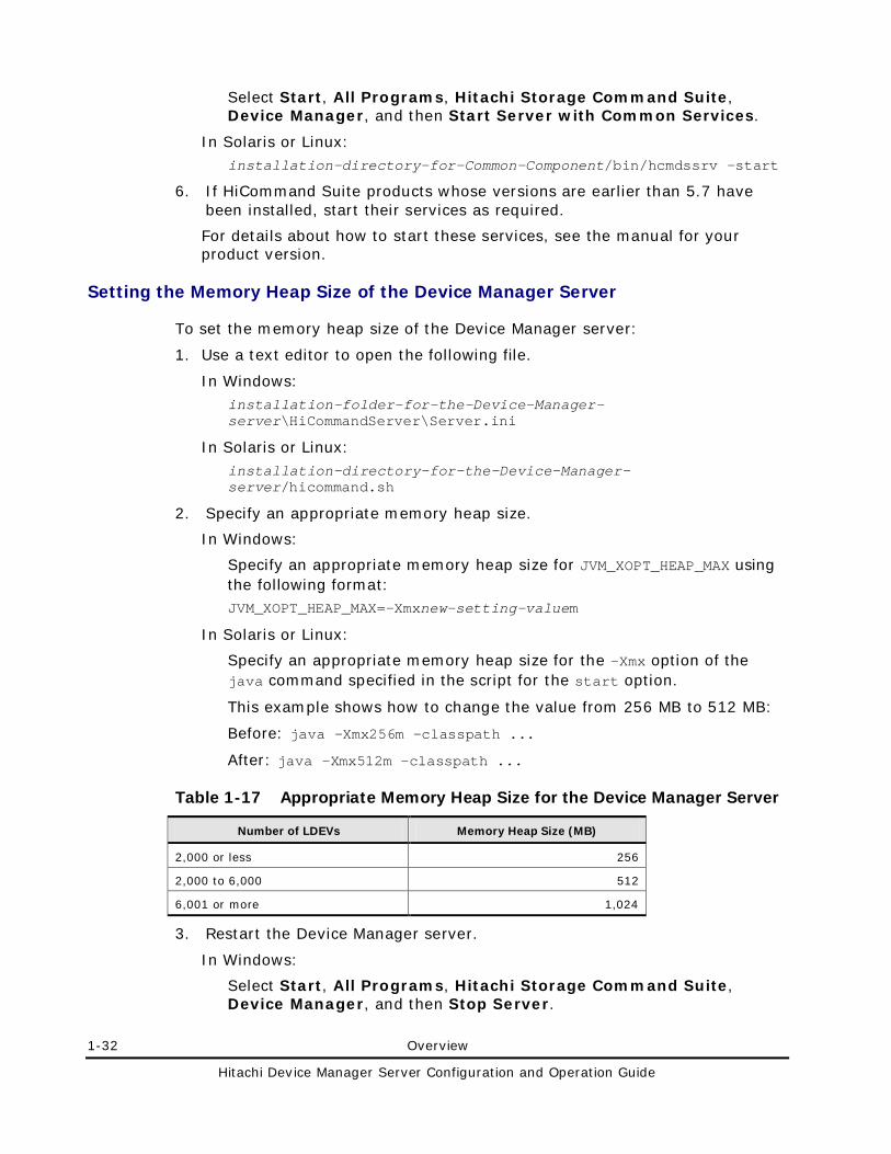
1-32 Overview
Hitachi Device Manager Server Configuration and Operation Guide
Select Start, All Programs, Hitachi Storage Command Suite, Device Manager, and then Start Server with Common Services.
In Solaris or Linux: installation-directory-for-Common-Component/bin/hcmdssrv -start
6. If HiCommand Suite products whose versions are earlier than 5.7 have been installed, start their services as required.
For details about how to start these services, see the manual for your product version.
Setting the Memory Heap Size of the Device Manager Server
To set the memory heap size of the Device Manager server:
1. Use a text editor to open the following file.
In Windows: installation-folder-for-the-Device-Manager-server\HiCommandServer\Server.ini
In Solaris or Linux: installation-directory-for-the-Device-Manager-server/hicommand.sh
2. Specify an appropriate memory heap size.
In Windows:
Specify an appropriate memory heap size for JVM_XOPT_HEAP_MAX using the following format: JVM_XOPT_HEAP_MAX=-Xmxnew-setting-valuem
In Solaris or Linux:
Specify an appropriate memory heap size for the -Xmx option of the java command specified in the script for the start option.
This example shows how to change the value from 256 MB to 512 MB:
Before: java -Xmx256m -classpath ...
After: java -Xmx512m -classpath ...
Table 1-17 Appropriate Memory Heap Size for the Device Manager Server
Number of LDEVs Memory Heap Size (MB)
2,000 or less 256
2,000 to 6,000 512
6,001 or more 1,024
3. Restart the Device Manager server.
In Windows:
Select Start, All Programs, Hitachi Storage Command Suite, Device Manager, and then Stop Server.
Overview 1-33
Hitachi Device Manager Server Configuration and Operation Guide
After the Device Manager server stops, select Start, All Programs, Hitachi Storage Command Suite, Device Manager, and then Start Server.
In Solaris or Linux: installation-directory-for-the-Device-Manager-server/suitesrvcntl -stop_hdvm
installation-directory-for-the-Device-Manager-server/suitesrvcntl -start_hdvm
Caution: If you overwrite or upgrade the Device Manager server from the following version, the memory heap size setting is retained.
If the management server OS is Windows:
Version 5.9 or later
If the management server OS is Solaris or Linux:
Version 6.2 or later
If you upgrade the Device Manager server from a version earlier than those listed above, the memory heap size setting is initialized to the value listed in Table 1-17 and will need to be specified again.
Setting the Memory Heap Size When Using the CIM/WBEM Function
If CIM/WBEM functions are being used, you might have to increase the memory heap size of the Device Manager server, depending on the conditions. Note that the required memory heap size differs depending on the CIM client you are using.
To change the memory heap size:
1. Use a text editor to open the following file.
In Windows:
installation-folder-for-the-Device-Manager-server\HiCommandServer\Server.ini
In Solaris or Linux:
installation-directory-for-the-Device-Manager-server/hicommand.sh
2. Specify an appropriate memory heap size.
In Windows:
Specify an appropriate memory heap size for JVM_XOPT_HEAP_MAX using the following format: JVM_XOPT_HEAP_MAX = -Xmxnew-setting-valuem
In Solaris or Linux:
Change the value of the -Xmx option of the java command specified in the script for the start option.
This example shows how to change the value from 256 MB to 512 MB:
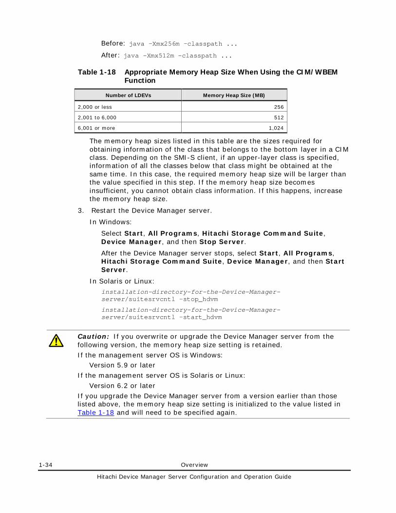
1-34 Overview
Hitachi Device Manager Server Configuration and Operation Guide
Before: java -Xmx256m -classpath ...
After: java -Xmx512m -classpath ...
Table 1-18 Appropriate Memory Heap Size When Using the CIM/WBEM Function
Number of LDEVs Memory Heap Size (MB)
2,000 or less 256
2,001 to 6,000 512
6,001 or more 1,024
The memory heap sizes listed in this table are the sizes required for obtaining information of the class that belongs to the bottom layer in a CIM class. Depending on the SMI-S client, if an upper-layer class is specified, information of all the classes below that class might be obtained at the same time. In this case, the required memory heap size will be larger than the value specified in this step. If the memory heap size becomes insufficient, you cannot obtain class information. If this happens, increase the memory heap size.
3. Restart the Device Manager server.
In Windows:
Select Start, All Programs, Hitachi Storage Command Suite, Device Manager, and then Stop Server.
After the Device Manager server stops, select Start, All Programs, Hitachi Storage Command Suite, Device Manager, and then Start Server.
In Solaris or Linux:
installation-directory-for-the-Device-Manager-server/suitesrvcntl -stop_hdvm
installation-directory-for-the-Device-Manager-server/suitesrvcntl -start_hdvm
Caution: If you overwrite or upgrade the Device Manager server from the following version, the memory heap size setting is retained.
If the management server OS is Windows: Version 5.9 or later
If the management server OS is Solaris or Linux:
Version 6.2 or later
If you upgrade the Device Manager server from a version earlier than those listed above, the memory heap size setting is initialized to the value listed in Table 1-18 and will need to be specified again.
Overview 1-35
Hitachi Device Manager Server Configuration and Operation Guide
System Requirements for Storage Subsystems
To use Device Manager to manage storage subsystems, you need storage subsystem management tools and software in addition to Device Manager. This section describes these requirements.
Caution: If you want to update the microcode or firmware of a storage subsystem, follow the procedure below. While the microcode or firmware is being updated, do not change the configuration by, for example, refreshing the storage subsystem or performing path operations.
To update the microcode or firmware:
1. Make sure that no Device Manager refresh or setup operations are being executed on the target storage subsystem. You need to ensure that operations such as adding or removing storage, creating or deleting LDEVs, and setting the host mode have finished. Note: You do not need to stop the Device Manager server.
2. Temporarily change the settings in the property file so that the Device Manager database is not updated while the microcode or firmware is being updated. Change the property settings in the server.properties file as follows: – Change the setting for the
server.dispatcher.daemon.configUpdate.detection.interval property to 0.
– Change the setting for the server.dispatcher.daemon.autoSynchro.doRefresh property to false.
3. Update the microcode or firmware. During the update, an error might be output to the trace log or error log because of storage subsystem polling. This error will not be output after the microcode is changed successfully.
4. Set the SVP tuning parameters, and then restart the SVP. 5. For Universal Storage Platform V/VM, restart the Device Manager server. 6. Manually refresh the storage subsystem. 7. Restore the property settings that you changed in step 2.
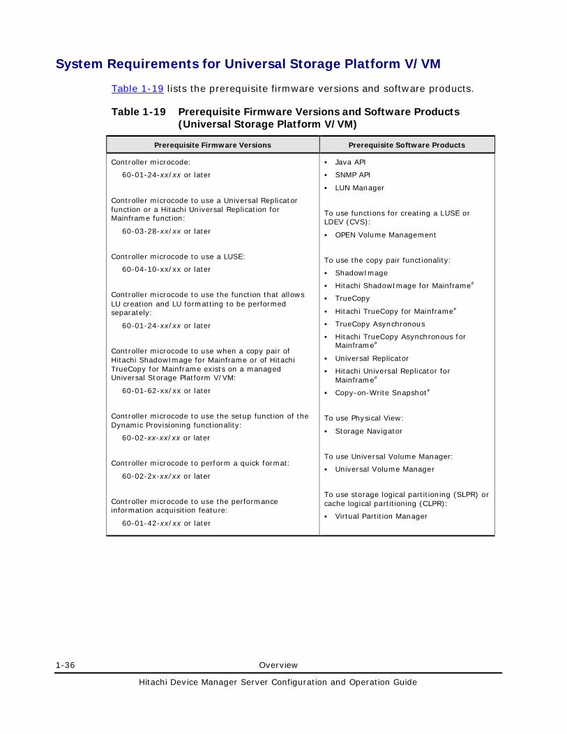
1-36 Overview
Hitachi Device Manager Server Configuration and Operation Guide
System Requirements for Universal Storage Platform V/VM
Table 1-19 lists the prerequisite firmware versions and software products.
Table 1-19 Prerequisite Firmware Versions and Software Products (Universal Storage Platform V/VM)
Prerequisite Firmware Versions Prerequisite Software Products
Controller microcode:
60-01-24-xx/xx or later
Controller microcode to use a Universal Replicator function or a Hitachi Universal Replication for Mainframe function:
60-03-28-xx/xx or later
Controller microcode to use a LUSE:
60-04-10-xx/xx or later
Controller microcode to use the function that allows LU creation and LU formatting to be performed separately:
60-01-24-xx/xx or later
Controller microcode to use when a copy pair of Hitachi ShadowImage for Mainframe or of Hitachi TrueCopy for Mainframe exists on a managed Universal Storage Platform V/VM:
60-01-62-xx/xx or later
Controller microcode to use the setup function of the Dynamic Provisioning functionality:
60-02-xx-xx/xx or later
Controller microcode to perform a quick format:
60-02-2x-xx/xx or later
Controller microcode to use the performance information acquisition feature:
60-01-42-xx/xx or later
Java API
SNMP API
LUN Manager
To use functions for creating a LUSE or LDEV (CVS):
OPEN Volume Management
To use the copy pair functionality:
ShadowImage
Hitachi ShadowImage for Mainframe#
TrueCopy
Hitachi TrueCopy for Mainframe#
TrueCopy Asynchronous
Hitachi TrueCopy Asynchronous for Mainframe#
Universal Replicator
Hitachi Universal Replicator for Mainframe#
Copy-on-Write Snapshot#
To use Physical View:
Storage Navigator
To use Universal Volume Manager:
Universal Volume Manager
To use storage logical partitioning (SLPR) or cache logical partitioning (CLPR):
Virtual Partition Manager
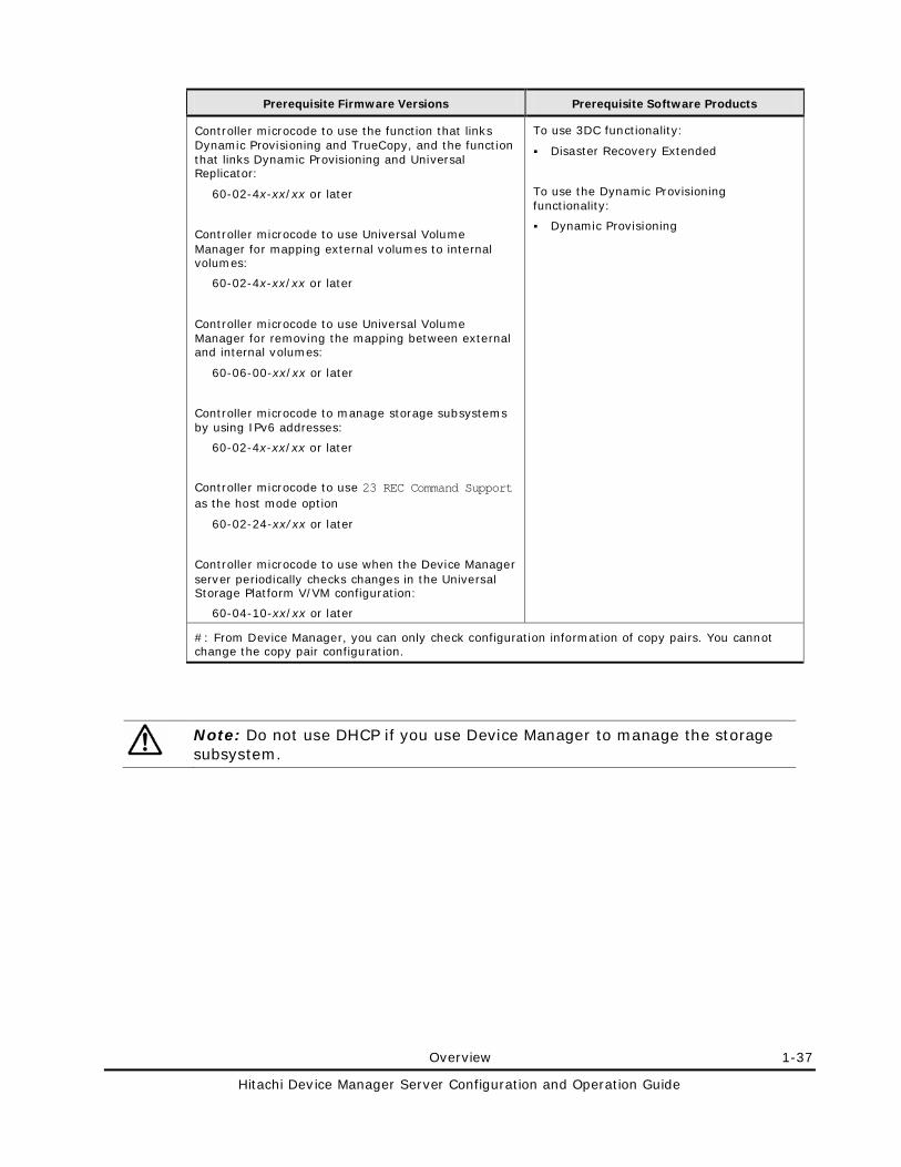
Overview 1-37
Hitachi Device Manager Server Configuration and Operation Guide
Prerequisite Firmware Versions Prerequisite Software Products
Controller microcode to use the function that links Dynamic Provisioning and TrueCopy, and the function that links Dynamic Provisioning and Universal Replicator:
60-02-4x-xx/xx or later
Controller microcode to use Universal Volume Manager for mapping external volumes to internal volumes:
60-02-4x-xx/xx or later
Controller microcode to use Universal Volume Manager for removing the mapping between external and internal volumes:
60-06-00-xx/xx or later
Controller microcode to manage storage subsystems by using IPv6 addresses:
60-02-4x-xx/xx or later
Controller microcode to use 23 REC Command Support as the host mode option
60-02-24-xx/xx or later
Controller microcode to use when the Device Manager server periodically checks changes in the Universal Storage Platform V/VM configuration:
60-04-10-xx/xx or later
To use 3DC functionality:
Disaster Recovery Extended
To use the Dynamic Provisioning functionality:
Dynamic Provisioning
#: From Device Manager, you can only check configuration information of copy pairs. You cannot change the copy pair configuration.
Note: Do not use DHCP if you use Device Manager to manage the storage subsystem.
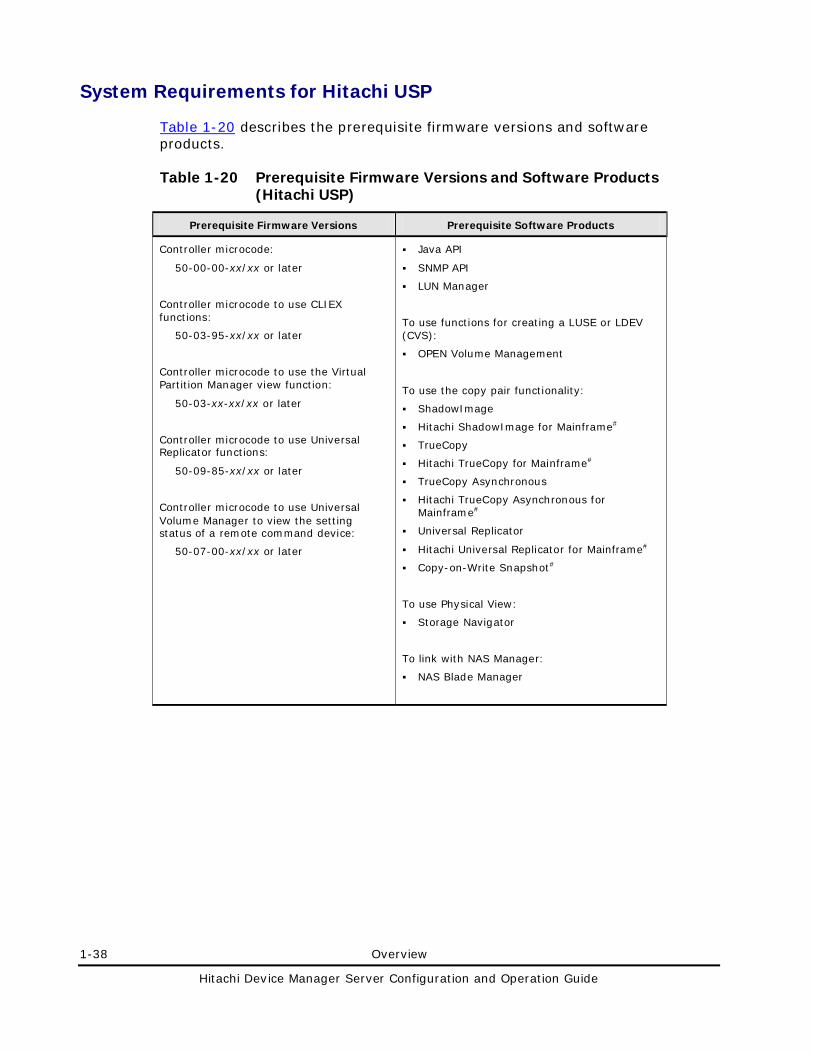
1-38 Overview
Hitachi Device Manager Server Configuration and Operation Guide
System Requirements for Hitachi USP
Table 1-20 describes the prerequisite firmware versions and software products.
Table 1-20 Prerequisite Firmware Versions and Software Products (Hitachi USP)
Prerequisite Firmware Versions Prerequisite Software Products
Controller microcode:
50-00-00-xx/xx or later
Controller microcode to use CLIEX functions:
50-03-95-xx/xx or later
Controller microcode to use the Virtual Partition Manager view function:
50-03-xx-xx/xx or later
Controller microcode to use Universal Replicator functions:
50-09-85-xx/xx or later
Controller microcode to use Universal Volume Manager to view the setting status of a remote command device:
50-07-00-xx/xx or later
Java API
SNMP API
LUN Manager
To use functions for creating a LUSE or LDEV (CVS):
OPEN Volume Management
To use the copy pair functionality:
ShadowImage
Hitachi ShadowImage for Mainframe#
TrueCopy
Hitachi TrueCopy for Mainframe#
TrueCopy Asynchronous
Hitachi TrueCopy Asynchronous for Mainframe#
Universal Replicator
Hitachi Universal Replicator for Mainframe#
Copy-on-Write Snapshot#
To use Physical View:
Storage Navigator
To link with NAS Manager:
NAS Blade Manager
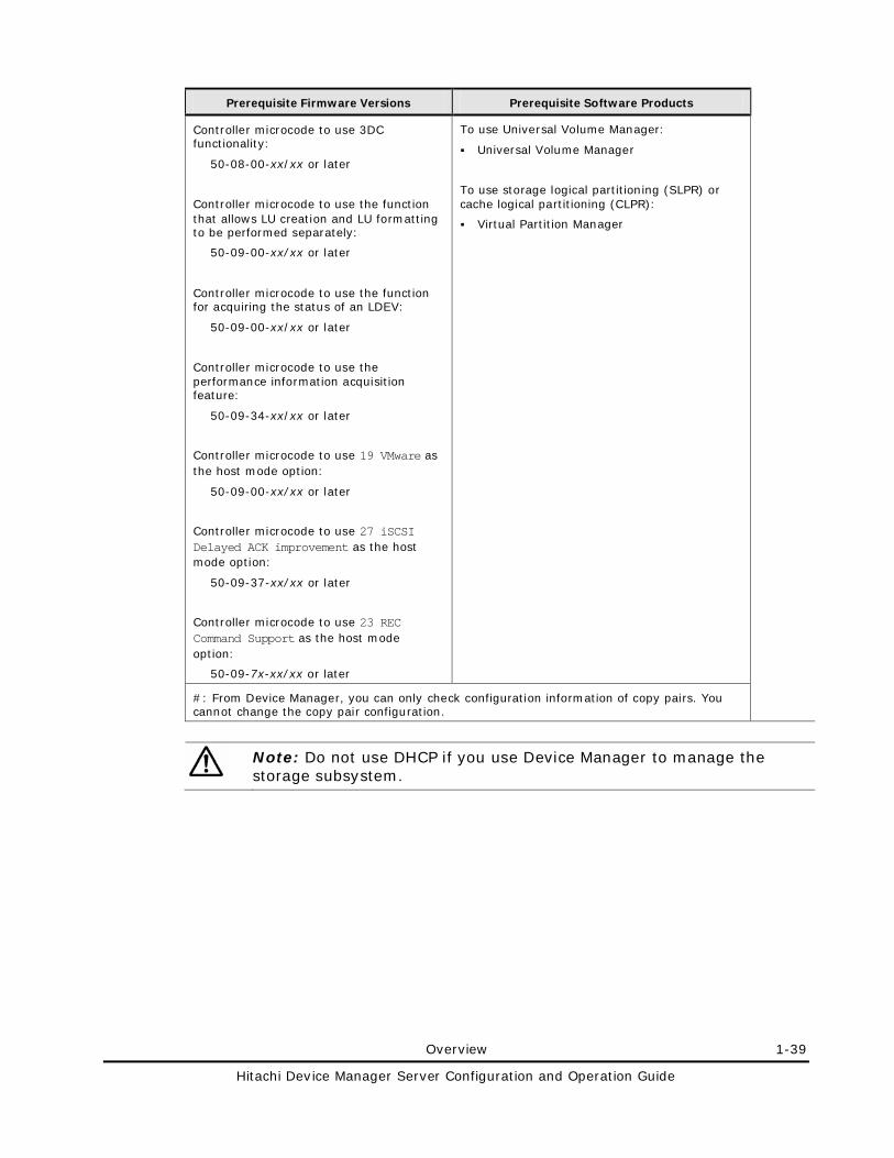
Overview 1-39
Hitachi Device Manager Server Configuration and Operation Guide
Prerequisite Firmware Versions Prerequisite Software Products
Controller microcode to use 3DC functionality:
50-08-00-xx/xx or later
Controller microcode to use the function that allows LU creation and LU formatting to be performed separately:
50-09-00-xx/xx or later
Controller microcode to use the function for acquiring the status of an LDEV:
50-09-00-xx/xx or later
Controller microcode to use the performance information acquisition feature:
50-09-34-xx/xx or later
Controller microcode to use 19 VMware as the host mode option:
50-09-00-xx/xx or later
Controller microcode to use 27 iSCSI Delayed ACK improvement as the host mode option:
50-09-37-xx/xx or later
Controller microcode to use 23 REC Command Support as the host mode option:
50-09-7x-xx/xx or later
To use Universal Volume Manager:
Universal Volume Manager
To use storage logical partitioning (SLPR) or cache logical partitioning (CLPR):
Virtual Partition Manager
#: From Device Manager, you can only check configuration information of copy pairs. You cannot change the copy pair configuration.
Note: Do not use DHCP if you use Device Manager to manage the storage subsystem.
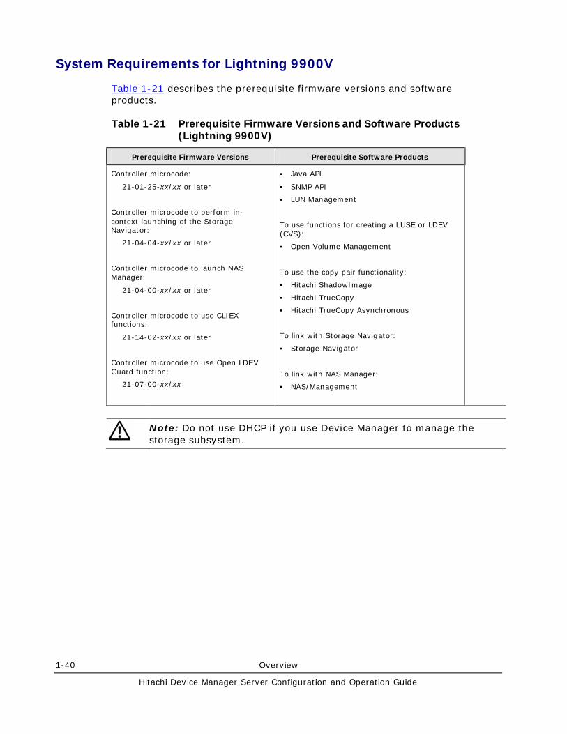
1-40 Overview
Hitachi Device Manager Server Configuration and Operation Guide
System Requirements for Lightning 9900V
Table 1-21 describes the prerequisite firmware versions and software products.
Table 1-21 Prerequisite Firmware Versions and Software Products (Lightning 9900V)
Prerequisite Firmware Versions Prerequisite Software Products
Controller microcode:
21-01-25-xx/xx or later
Controller microcode to perform in-context launching of the Storage Navigator:
21-04-04-xx/xx or later
Controller microcode to launch NAS Manager:
21-04-00-xx/xx or later
Controller microcode to use CLIEX functions:
21-14-02-xx/xx or later
Controller microcode to use Open LDEV Guard function:
21-07-00-xx/xx
Java API
SNMP API
LUN Management
To use functions for creating a LUSE or LDEV (CVS):
Open Volume Management
To use the copy pair functionality:
Hitachi ShadowImage
Hitachi TrueCopy
Hitachi TrueCopy Asynchronous
To link with Storage Navigator:
Storage Navigator
To link with NAS Manager:
NAS/Management
Note: Do not use DHCP if you use Device Manager to manage the storage subsystem.
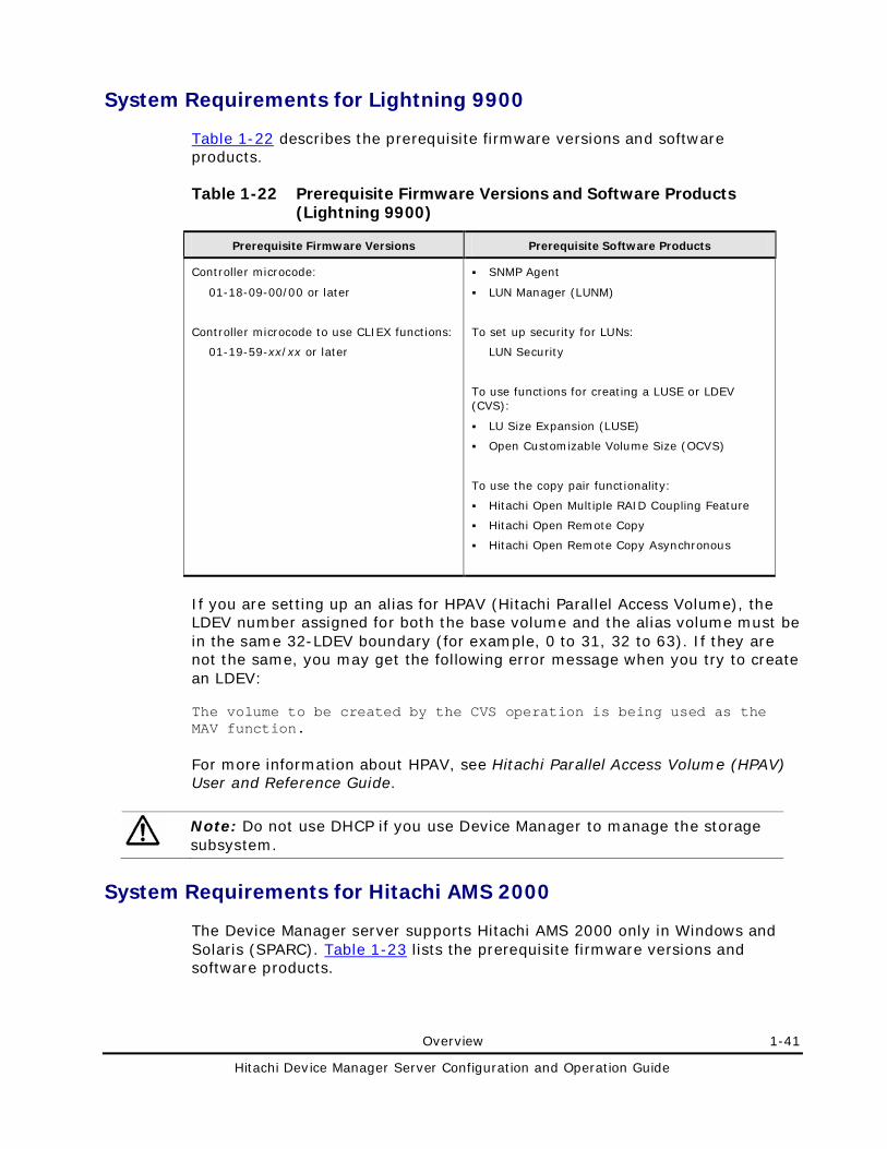
Overview 1-41
Hitachi Device Manager Server Configuration and Operation Guide
System Requirements for Lightning 9900
Table 1-22 describes the prerequisite firmware versions and software products.
Table 1-22 Prerequisite Firmware Versions and Software Products (Lightning 9900)
Prerequisite Firmware Versions Prerequisite Software Products
Controller microcode:
01-18-09-00/00 or later
Controller microcode to use CLIEX functions:
01-19-59-xx/xx or later
SNMP Agent
LUN Manager (LUNM)
To set up security for LUNs:
LUN Security
To use functions for creating a LUSE or LDEV (CVS):
LU Size Expansion (LUSE)
Open Customizable Volume Size (OCVS)
To use the copy pair functionality:
Hitachi Open Multiple RAID Coupling Feature
Hitachi Open Remote Copy
Hitachi Open Remote Copy Asynchronous
If you are setting up an alias for HPAV (Hitachi Parallel Access Volume), the LDEV number assigned for both the base volume and the alias volume must be in the same 32-LDEV boundary (for example, 0 to 31, 32 to 63). If they are not the same, you may get the following error message when you try to create an LDEV:
The volume to be created by the CVS operation is being used as the MAV function.
For more information about HPAV, see Hitachi Parallel Access Volume (HPAV) User and Reference Guide.
Note: Do not use DHCP if you use Device Manager to manage the storage subsystem.
System Requirements for Hitachi AMS 2000
The Device Manager server supports Hitachi AMS 2000 only in Windows and Solaris (SPARC). Table 1-23 lists the prerequisite firmware versions and software products.
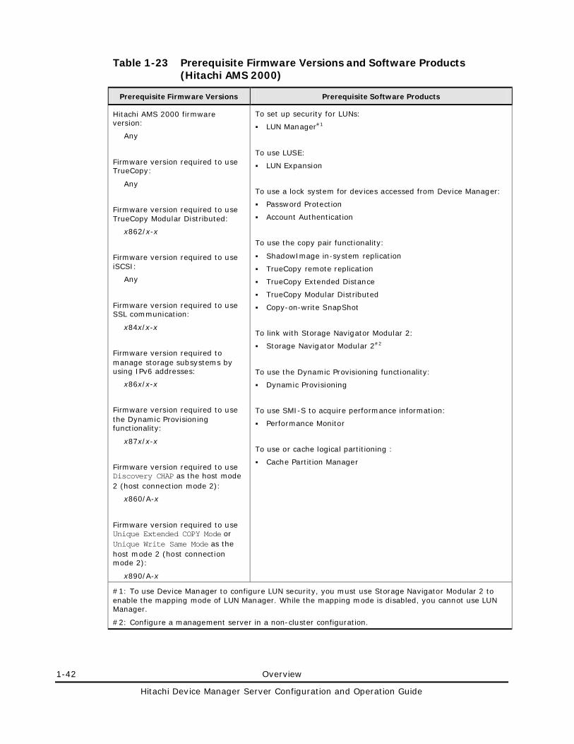
1-42 Overview
Hitachi Device Manager Server Configuration and Operation Guide
Table 1-23 Prerequisite Firmware Versions and Software Products (Hitachi AMS 2000)
Prerequisite Firmware Versions Prerequisite Software Products
Hitachi AMS 2000 firmware version:
Any
Firmware version required to use TrueCopy:
Any
Firmware version required to use TrueCopy Modular Distributed:
x862/x-x
Firmware version required to use iSCSI:
Any
Firmware version required to use SSL communication:
x84x/x-x
Firmware version required to manage storage subsystems by using IPv6 addresses:
x86x/x-x
Firmware version required to use the Dynamic Provisioning functionality:
x87x/x-x
Firmware version required to use Discovery CHAP as the host mode 2 (host connection mode 2):
x860/A-x
Firmware version required to use Unique Extended COPY Mode or Unique Write Same Mode as the host mode 2 (host connection mode 2):
x890/A-x
To set up security for LUNs:
LUN Manager#1
To use LUSE:
LUN Expansion
To use a lock system for devices accessed from Device Manager:
Password Protection
Account Authentication
To use the copy pair functionality:
ShadowImage in-system replication
TrueCopy remote replication
TrueCopy Extended Distance
TrueCopy Modular Distributed
Copy-on-write SnapShot
To link with Storage Navigator Modular 2:
Storage Navigator Modular 2#2
To use the Dynamic Provisioning functionality:
Dynamic Provisioning
To use SMI-S to acquire performance information:
Performance Monitor
To use or cache logical partitioning :
Cache Partition Manager
#1: To use Device Manager to configure LUN security, you must use Storage Navigator Modular 2 to enable the mapping mode of LUN Manager. While the mapping mode is disabled, you cannot use LUN Manager.
#2: Configure a management server in a non-cluster configuration.
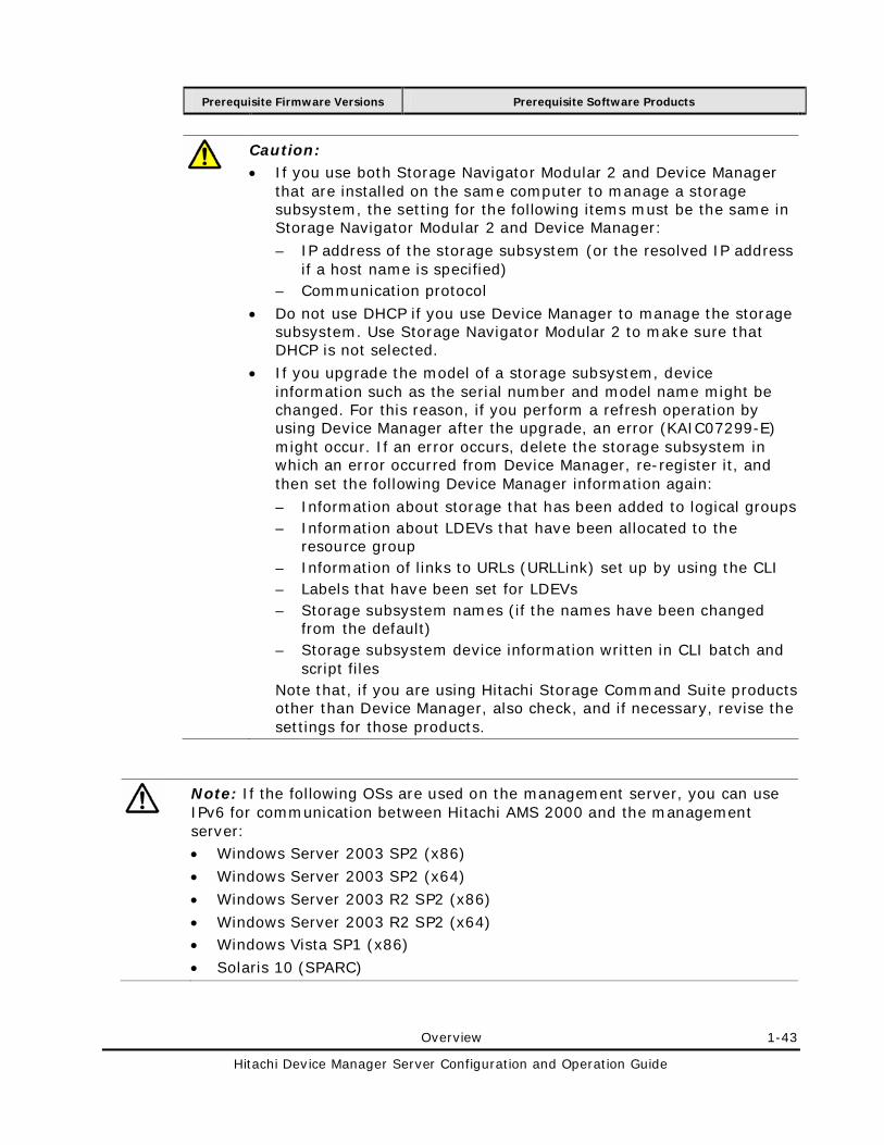
Overview 1-43
Hitachi Device Manager Server Configuration and Operation Guide
Prerequisite Firmware Versions Prerequisite Software Products
Caution: • If you use both Storage Navigator Modular 2 and Device Manager
that are installed on the same computer to manage a storage subsystem, the setting for the following items must be the same in Storage Navigator Modular 2 and Device Manager:
– IP address of the storage subsystem (or the resolved IP address if a host name is specified)
– Communication protocol
• Do not use DHCP if you use Device Manager to manage the storage subsystem. Use Storage Navigator Modular 2 to make sure that DHCP is not selected.
• If you upgrade the model of a storage subsystem, device information such as the serial number and model name might be changed. For this reason, if you perform a refresh operation by using Device Manager after the upgrade, an error (KAIC07299-E) might occur. If an error occurs, delete the storage subsystem in which an error occurred from Device Manager, re-register it, and then set the following Device Manager information again:
– Information about storage that has been added to logical groups – Information about LDEVs that have been allocated to the
resource group – Information of links to URLs (URLLink) set up by using the CLI – Labels that have been set for LDEVs – Storage subsystem names (if the names have been changed
from the default) – Storage subsystem device information written in CLI batch and
script files Note that, if you are using Hitachi Storage Command Suite products other than Device Manager, also check, and if necessary, revise the settings for those products.
Note: If the following OSs are used on the management server, you can use IPv6 for communication between Hitachi AMS 2000 and the management server: • Windows Server 2003 SP2 (x86)
• Windows Server 2003 SP2 (x64)
• Windows Server 2003 R2 SP2 (x86)
• Windows Server 2003 R2 SP2 (x64) • Windows Vista SP1 (x86)
• Solaris 10 (SPARC)

1-44 Overview
Hitachi Device Manager Server Configuration and Operation Guide
System Requirements for Hitachi SMS
The Device Manager server supports Hitachi SMS only in Windows and Solaris (SPARC). Table 1-24 lists the prerequisite firmware versions and software products.
Table 1-24 Prerequisite Firmware Versions and Software Products (Hitachi SMS)
Prerequisite Firmware Versions Prerequisite Software Products
Hitachi SMS firmware version:
Any
Firmware version required to use SSL communication:
x84x/x-x
Firmware version required to manage storage subsystems by using IPv6 addresses:
x86x/x-x
Firmware version required to use Discovery CHAP as the host mode 2 (host connection mode 2):
x860x/A-x
To set up security for LUNs:
LUN Manager#1
To use LUSE:
LUN Expansion
To use a lock system for devices accessed from Device Manager:
Password Protection
Account Authentication
To use the copy pair functionality:
ShadowImage in-system replication
TrueCopy remote replication#2
Copy-on-write SnapShot
Simple Data Recovery#2
To link with Storage Navigator Modular 2:
Storage Navigator Modular 2#3
To use SMI-S to acquire performance information:
Performance Monitor
#1: To use Device Manager to configure LUN security, you must use Storage Navigator Modular 2 to enable the mapping mode of LUN Manager. While the mapping mode is disabled, you cannot use LUN Manager.
#2: From Device Manager, you can only check configuration information of copy pairs. You cannot change the copy pair configuration.
#3: Configure a management server in a non-cluster configuration.
Overview 1-45
Hitachi Device Manager Server Configuration and Operation Guide
Caution: • If you use both Storage Navigator Modular 2 and Device Manager that
are installed on the same computer to manage a storage subsystem, the setting for the following items must be the same in Storage Navigator Modular 2 and Device Manager:
– IP address of the storage subsystem (or the resolved IP address if a host name is specified)
– Communication protocol
• Do not use DHCP if you use Device Manager to manage the storage subsystem. Use Storage Navigator Modular 2 to make sure that DHCP is not selected.
Note: For IP-SAN configurations, if the following OSs are used on the management server, you can use IPv6 for communication between Hitachi SMS and the management server:
• Windows Server 2003 SP2 (x86) • Windows Server 2003 SP2 (x64)
• Windows Server 2003 R2 SP2 (x86)
• Windows Server 2003 R2 SP2 (x64)
• Windows Vista SP1 (x86)
• Solaris 10 (SPARC)
System Requirements for Hitachi AMS/WMS
The Device Manager server supports Hitachi AMS/WMS only when the Windows or Solaris (SPARC) version is being used. Table 1-25 describes the prerequisite firmware versions and software products.
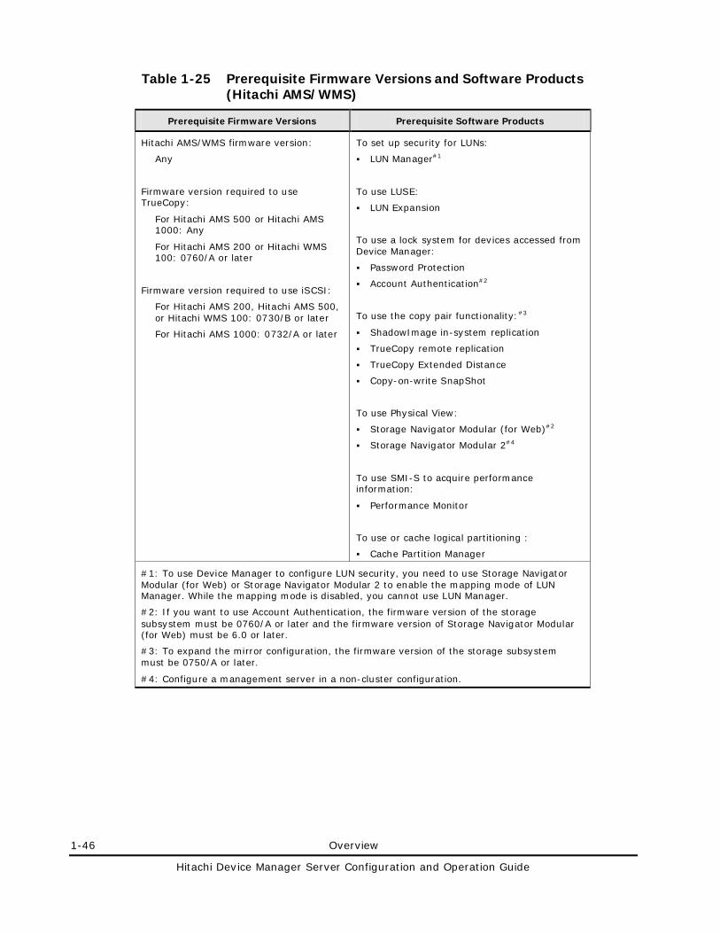
1-46 Overview
Hitachi Device Manager Server Configuration and Operation Guide
Table 1-25 Prerequisite Firmware Versions and Software Products (Hitachi AMS/WMS)
Prerequisite Firmware Versions Prerequisite Software Products
Hitachi AMS/WMS firmware version:
Any
Firmware version required to use TrueCopy:
For Hitachi AMS 500 or Hitachi AMS 1000: Any
For Hitachi AMS 200 or Hitachi WMS 100: 0760/A or later
Firmware version required to use iSCSI:
For Hitachi AMS 200, Hitachi AMS 500, or Hitachi WMS 100: 0730/B or later
For Hitachi AMS 1000: 0732/A or later
To set up security for LUNs:
LUN Manager#1
To use LUSE:
LUN Expansion
To use a lock system for devices accessed from Device Manager:
Password Protection
Account Authentication#2
To use the copy pair functionality:#3
ShadowImage in-system replication
TrueCopy remote replication
TrueCopy Extended Distance
Copy-on-write SnapShot
To use Physical View:
Storage Navigator Modular (for Web)#2
Storage Navigator Modular 2#4
To use SMI-S to acquire performance information:
Performance Monitor
To use or cache logical partitioning :
Cache Partition Manager
#1: To use Device Manager to configure LUN security, you need to use Storage Navigator Modular (for Web) or Storage Navigator Modular 2 to enable the mapping mode of LUN Manager. While the mapping mode is disabled, you cannot use LUN Manager.
#2: If you want to use Account Authentication, the firmware version of the storage subsystem must be 0760/A or later and the firmware version of Storage Navigator Modular (for Web) must be 6.0 or later.
#3: To expand the mirror configuration, the firmware version of the storage subsystem must be 0750/A or later.
#4: Configure a management server in a non-cluster configuration.
Overview 1-47
Hitachi Device Manager Server Configuration and Operation Guide
Prerequisite Firmware Versions Prerequisite Software Products
Caution: • If you use both Storage Navigator Modular 2 and Device Manager
that are installed on the same computer to manage a storage subsystem, the setting for the IP address of the storage subsystem (or the resolved IP address if a host name is specified) must be the same in Storage Navigator Modular 2 and Device Manager.
• Do not use DHCP if you are using Device Manager to manage the storage subsystems. Use Storage Navigator Modular (for Web) or Storage Navigator Modular 2 to make sure that DHCP is not selected.
Notes: • IPv6 is not supported for IP-SAN configurations.
• For a NAS Modular system of Hitachi AMS/WMS, Device Manager only allows you to add storage subsystems and to launch Storage Navigator Modular or Storage Navigator Modular 2. To operate a NAS Modular subsystem, perform the operations from Storage Navigator Modular.
System Requirements for Thunder 9500V
The Device Manager server supports Thunder 9500V only when the Windows or Solaris (SPARC) version is used. Table 1-26 describes the prerequisite firmware versions and software products.
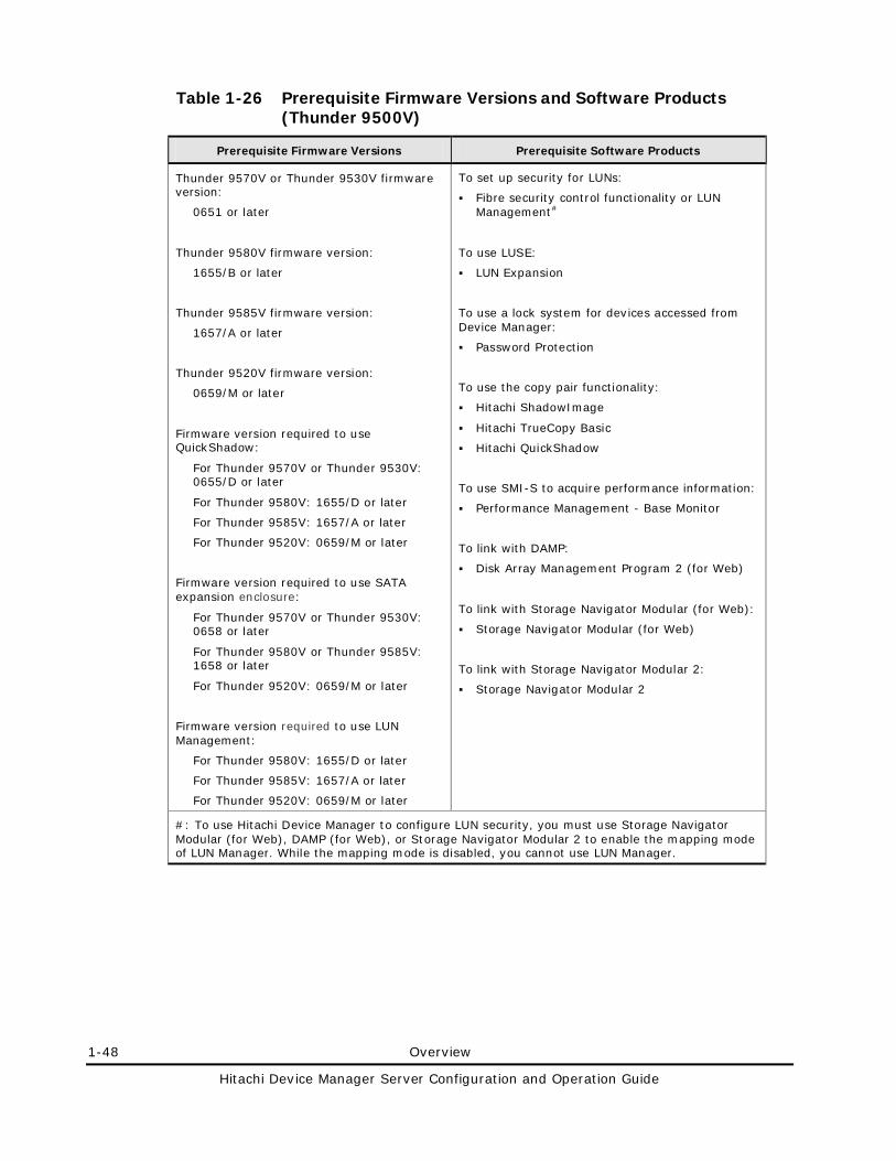
1-48 Overview
Hitachi Device Manager Server Configuration and Operation Guide
Table 1-26 Prerequisite Firmware Versions and Software Products (Thunder 9500V)
Prerequisite Firmware Versions Prerequisite Software Products
Thunder 9570V or Thunder 9530V firmware version:
0651 or later
Thunder 9580V firmware version:
1655/B or later
Thunder 9585V firmware version:
1657/A or later
Thunder 9520V firmware version:
0659/M or later
Firmware version required to use QuickShadow:
For Thunder 9570V or Thunder 9530V: 0655/D or later
For Thunder 9580V: 1655/D or later
For Thunder 9585V: 1657/A or later
For Thunder 9520V: 0659/M or later
Firmware version required to use SATA expansion enclosure:
For Thunder 9570V or Thunder 9530V: 0658 or later
For Thunder 9580V or Thunder 9585V: 1658 or later
For Thunder 9520V: 0659/M or later
Firmware version required to use LUN Management:
For Thunder 9580V: 1655/D or later
For Thunder 9585V: 1657/A or later
For Thunder 9520V: 0659/M or later
To set up security for LUNs:
Fibre security control functionality or LUN Management#
To use LUSE:
LUN Expansion
To use a lock system for devices accessed from Device Manager:
Password Protection
To use the copy pair functionality:
Hitachi ShadowImage
Hitachi TrueCopy Basic
Hitachi QuickShadow
To use SMI-S to acquire performance information:
Performance Management - Base Monitor
To link with DAMP:
Disk Array Management Program 2 (for Web)
To link with Storage Navigator Modular (for Web):
Storage Navigator Modular (for Web)
To link with Storage Navigator Modular 2:
Storage Navigator Modular 2
#: To use Hitachi Device Manager to configure LUN security, you must use Storage Navigator Modular (for Web), DAMP (for Web), or Storage Navigator Modular 2 to enable the mapping mode of LUN Manager. While the mapping mode is disabled, you cannot use LUN Manager.
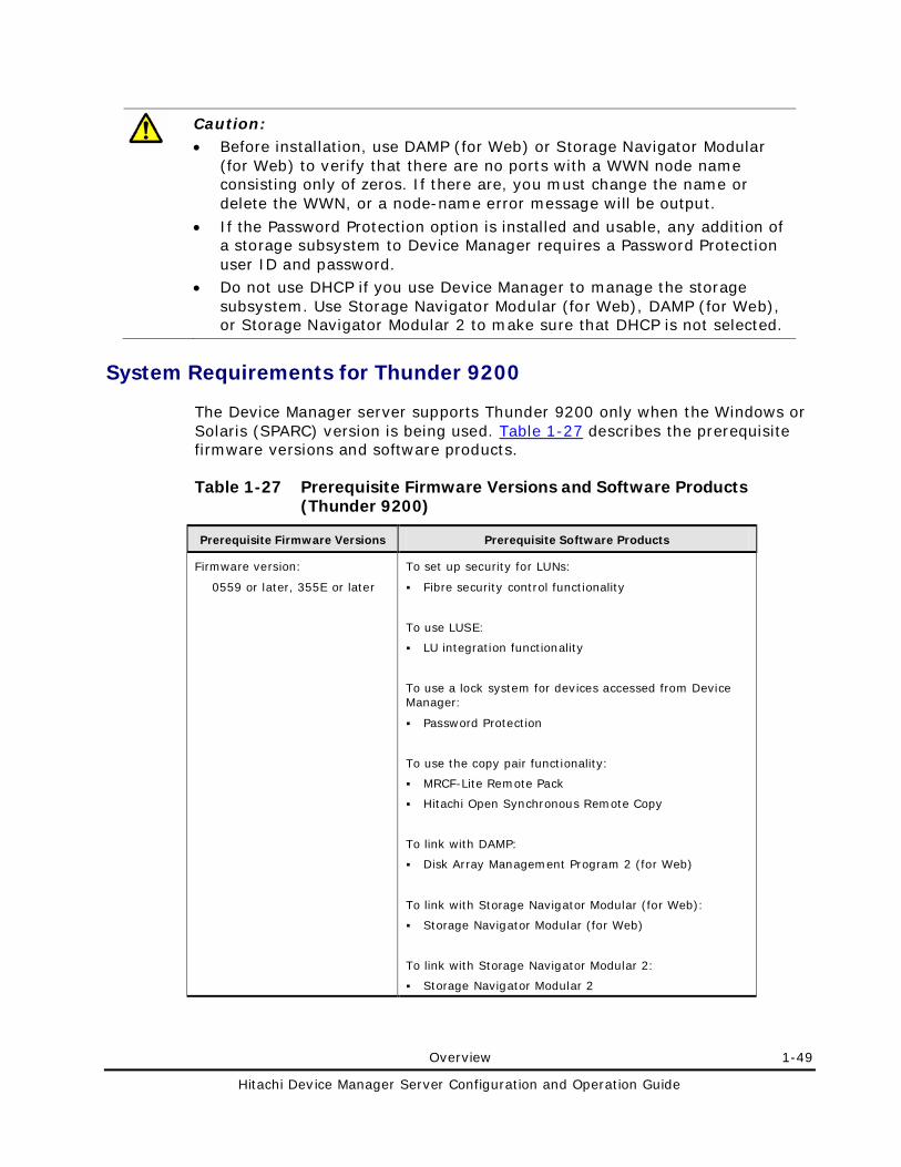
Overview 1-49
Hitachi Device Manager Server Configuration and Operation Guide
Caution: • Before installation, use DAMP (for Web) or Storage Navigator Modular
(for Web) to verify that there are no ports with a WWN node name consisting only of zeros. If there are, you must change the name or delete the WWN, or a node-name error message will be output.
• If the Password Protection option is installed and usable, any addition of a storage subsystem to Device Manager requires a Password Protection user ID and password.
• Do not use DHCP if you use Device Manager to manage the storage subsystem. Use Storage Navigator Modular (for Web), DAMP (for Web), or Storage Navigator Modular 2 to make sure that DHCP is not selected.
System Requirements for Thunder 9200
The Device Manager server supports Thunder 9200 only when the Windows or Solaris (SPARC) version is being used. Table 1-27 describes the prerequisite firmware versions and software products.
Table 1-27 Prerequisite Firmware Versions and Software Products (Thunder 9200)
Prerequisite Firmware Versions Prerequisite Software Products
Firmware version:
0559 or later, 355E or later
To set up security for LUNs:
Fibre security control functionality
To use LUSE:
LU integration functionality
To use a lock system for devices accessed from Device Manager:
Password Protection
To use the copy pair functionality:
MRCF-Lite Remote Pack
Hitachi Open Synchronous Remote Copy
To link with DAMP:
Disk Array Management Program 2 (for Web)
To link with Storage Navigator Modular (for Web):
Storage Navigator Modular (for Web)
To link with Storage Navigator Modular 2:
Storage Navigator Modular 2
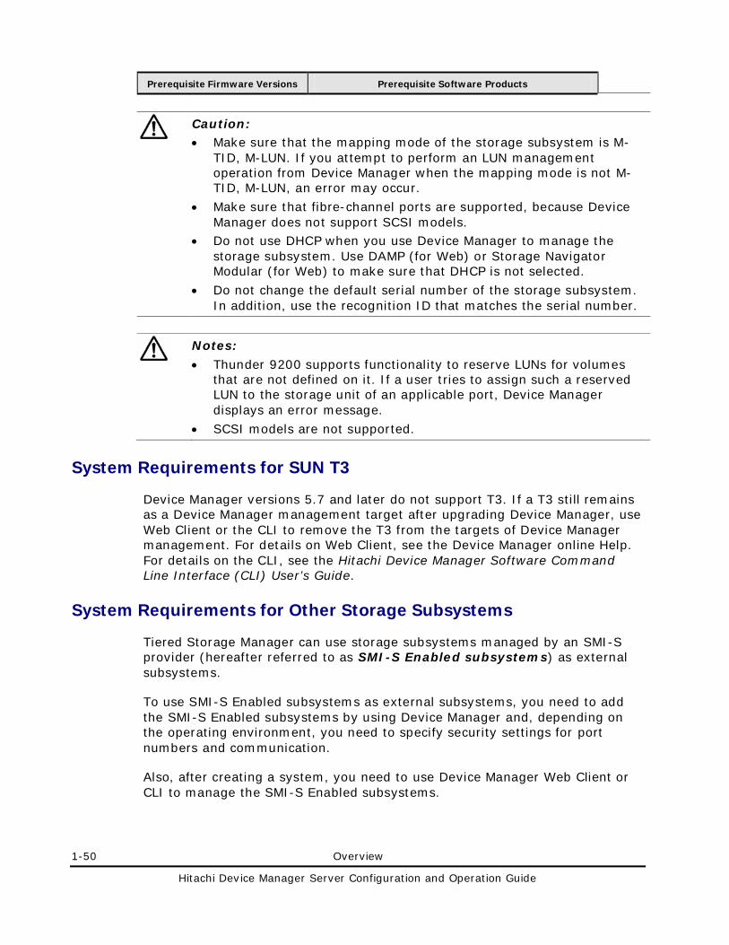
1-50 Overview
Hitachi Device Manager Server Configuration and Operation Guide
Prerequisite Firmware Versions Prerequisite Software Products
Caution: • Make sure that the mapping mode of the storage subsystem is M-
TID, M-LUN. If you attempt to perform an LUN management operation from Device Manager when the mapping mode is not M-TID, M-LUN, an error may occur.
• Make sure that fibre-channel ports are supported, because Device Manager does not support SCSI models.
• Do not use DHCP when you use Device Manager to manage the storage subsystem. Use DAMP (for Web) or Storage Navigator Modular (for Web) to make sure that DHCP is not selected.
• Do not change the default serial number of the storage subsystem. In addition, use the recognition ID that matches the serial number.
Notes:
• Thunder 9200 supports functionality to reserve LUNs for volumes that are not defined on it. If a user tries to assign such a reserved LUN to the storage unit of an applicable port, Device Manager displays an error message.
• SCSI models are not supported.
System Requirements for SUN T3
Device Manager versions 5.7 and later do not support T3. If a T3 still remains as a Device Manager management target after upgrading Device Manager, use Web Client or the CLI to remove the T3 from the targets of Device Manager management. For details on Web Client, see the Device Manager online Help. For details on the CLI, see the Hitachi Device Manager Software Command Line Interface (CLI) User’s Guide.
System Requirements for Other Storage Subsystems
Tiered Storage Manager can use storage subsystems managed by an SMI-S provider (hereafter referred to as SMI-S Enabled subsystems) as external subsystems.
To use SMI-S Enabled subsystems as external subsystems, you need to add the SMI-S Enabled subsystems by using Device Manager and, depending on the operating environment, you need to specify security settings for port numbers and communication.
Also, after creating a system, you need to use Device Manager Web Client or CLI to manage the SMI-S Enabled subsystems.
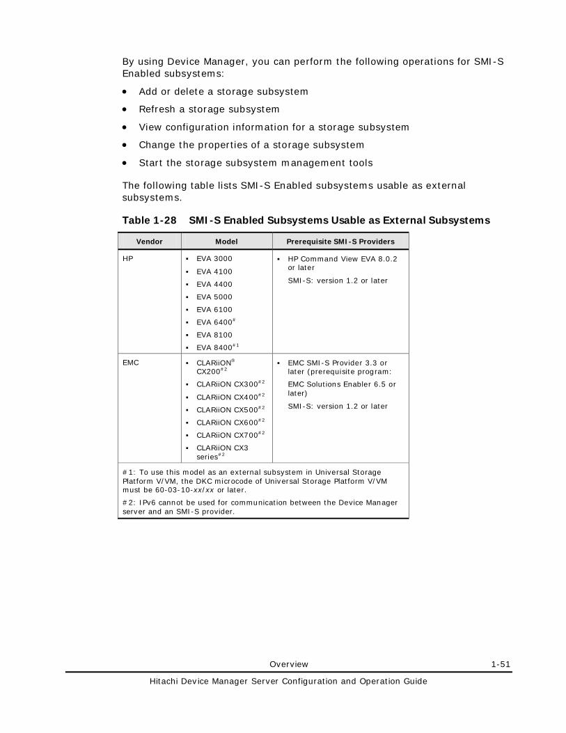
Overview 1-51
Hitachi Device Manager Server Configuration and Operation Guide
By using Device Manager, you can perform the following operations for SMI-S Enabled subsystems:
• Add or delete a storage subsystem
• Refresh a storage subsystem
• View configuration information for a storage subsystem
• Change the properties of a storage subsystem
• Start the storage subsystem management tools
The following table lists SMI-S Enabled subsystems usable as external subsystems.
Table 1-28 SMI-S Enabled Subsystems Usable as External Subsystems
Vendor Model Prerequisite SMI-S Providers
HP EVA 3000
EVA 4100
EVA 4400
EVA 5000
EVA 6100
EVA 6400#
EVA 8100
EVA 8400#1
HP Command View EVA 8.0.2 or later
SMI-S: version 1.2 or later
EMC CLARiiON® CX200#2
CLARiiON CX300#2
CLARiiON CX400#2
CLARiiON CX500#2
CLARiiON CX600#2
CLARiiON CX700#2
CLARiiON CX3 series#2
EMC SMI-S Provider 3.3 or later (prerequisite program:
EMC Solutions Enabler 6.5 or later)
SMI-S: version 1.2 or later
#1: To use this model as an external subsystem in Universal Storage Platform V/VM, the DKC microcode of Universal Storage Platform V/VM must be 60-03-10-xx/xx or later.
#2: IPv6 cannot be used for communication between the Device Manager server and an SMI-S provider.
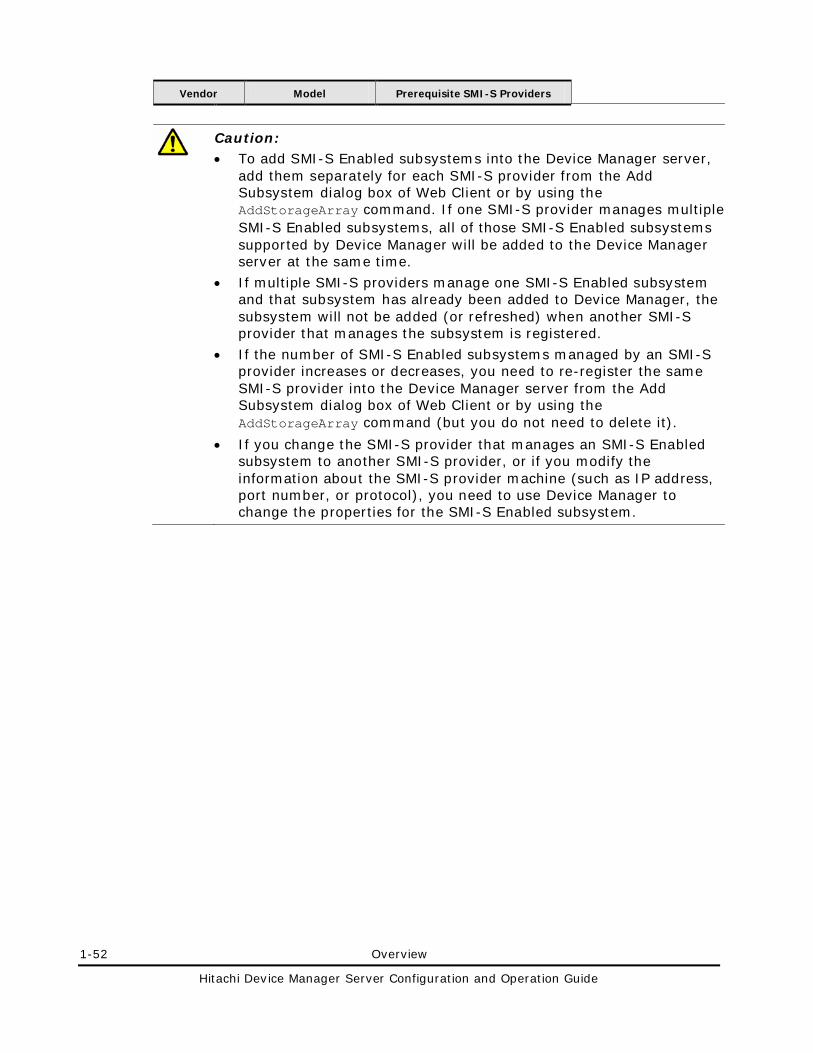
1-52 Overview
Hitachi Device Manager Server Configuration and Operation Guide
Vendor Model Prerequisite SMI-S Providers
Caution: • To add SMI-S Enabled subsystems into the Device Manager server,
add them separately for each SMI-S provider from the Add Subsystem dialog box of Web Client or by using the AddStorageArray command. If one SMI-S provider manages multiple SMI-S Enabled subsystems, all of those SMI-S Enabled subsystems supported by Device Manager will be added to the Device Manager server at the same time.
• If multiple SMI-S providers manage one SMI-S Enabled subsystem and that subsystem has already been added to Device Manager, the subsystem will not be added (or refreshed) when another SMI-S provider that manages the subsystem is registered.
• If the number of SMI-S Enabled subsystems managed by an SMI-S provider increases or decreases, you need to re-register the same SMI-S provider into the Device Manager server from the Add Subsystem dialog box of Web Client or by using the AddStorageArray command (but you do not need to delete it).
• If you change the SMI-S provider that manages an SMI-S Enabled subsystem to another SMI-S provider, or if you modify the information about the SMI-S provider machine (such as IP address, port number, or protocol), you need to use Device Manager to change the properties for the SMI-S Enabled subsystem.
Overview 1-53
Hitachi Device Manager Server Configuration and Operation Guide
Host Requirements
Device Manager can manage, as hosts, computers that use volumes on managed storage subsystems. By assigning the most appropriate volume based on usage, you can centrally manage the disk resources for individual hosts by using Device Manager.
Device Manager can manage the following computers as hosts:
• Open hosts
A computer that uses open volumes
– If no virtualization software product is installed on the host
In Device Manager, an environment in which no virtualization software product is installed is called a normal host.
– If a virtualization software product is installed on the host
In Device Manager, a physical host on which a virtualization software product is installed is called a virtualization server, and a virtual environment created by using the virtualization software product is called a virtual machine.
• Mainframe hosts
A computer that uses mainframe volumes
• File servers
A computer that is used to share the files in a storage subsystem with multiple clients in the network by using the NAS functionality.
The following sections describe system requirements for using Device Manager to manage the above types of hosts. For details on how to register hosts and assign volumes, see the Device Manager online Help.
System Requirements for Hosts on Which No Virtualization Software Product Is Installed
If you want to assign volumes to a host, register it in Device Manager as a normal host. In addition, if you want to perform the following operations, you need to install a Device Manager agent on the host:
• Automatically register and update information of the host
• Check the volume usage by using Device Manager
• Centrally manage copy pairs by using Device Manager or Replication Manager
• Centrally manage file systems and device files on the host by using Provisioning Manager
1-54 Overview
Hitachi Device Manager Server Configuration and Operation Guide
For details on how to install and operate a Device Manager agent, see the Hitachi Device Manager Agent Installation Guide.
System Requirements for Hosts on Which a Virtualization Software Product Is Installed
System requirements depend on whether a virtual machine or virtualization server will be managed by Device Manager.
Virtual Machine Requirements
If you want to perform the following operations, you need to install a Device Manager agent on the host:
• Automatically register and update information of the host
• Check the volume usage by using Device Manager
• Centrally manage copy pairs by using Device Manager or Replication Manager
• Centrally manage file systems and device files on the virtual machine by using Provisioning Manager
For details on how to install and operate a Device Manager agent, see the Hitachi Device Manager Agent Installation Guide.
In addition, the management method of Device Manager depends on the configuration of virtual machines and HBAs. The following figure shows the system configuration of virtual machines supported by Device Manager.
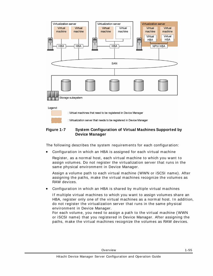
Overview 1-55
Hitachi Device Manager Server Configuration and Operation Guide
Figure 1-7 System Configuration of Virtual Machines Supported by Device Manager
The following describes the system requirements for each configuration:
• Configuration in which an HBA is assigned for each virtual machine
Register, as a normal host, each virtual machine to which you want to assign volumes. Do not register the virtualization server that runs in the same physical environment in Device Manager.
Assign a volume path to each virtual machine (WWN or iSCSI name). After assigning the paths, make the virtual machines recognize the volumes as RAW devices.
• Configuration in which an HBA is shared by multiple virtual machines
If multiple virtual machines to which you want to assign volumes share an HBA, register only one of the virtual machines as a normal host. In addition, do not register the virtualization server that runs in the same physical environment in Device Manager. For each volume, you need to assign a path to the virtual machine (WWN or iSCSI name) that you registered in Device Manager. After assigning the paths, make the virtual machines recognize the volumes as RAW devices.
1-56 Overview
Hitachi Device Manager Server Configuration and Operation Guide
Note: If multiple virtual machines share the same HBA, regardless of which virtual machine you assign a volume to, you need to assign all paths for that HBA to the virtual machine that is managed by Device Manager. Therefore, after assigning a path, we recommend that you label each volume so that you can identify, in Device Manager, which virtual machine the volume is actually assigned to.
• Configuration in which a virtual HBA is assigned to each virtual machine (when NPIV HBA is used)
Register, as a normal host, each virtual machine to which you want to assign volumes. In addition, register the virtualization server that runs in the same physical environment in Device Manager.
For each volume, you must assign a path to the virtualization server (physical WWN) and a path to the virtual machine (virtual WWN). After assigning the paths, make the virtual machine recognize the volumes as a RAW device.
For details on the system requirements for virtualization servers, see Virtualization Server Requirements.
Caution: If you move a virtual machine from one virtualization server to another, you need to update (refresh) the information of the source and destination virtualization servers in Device Manager. After moving a virtual machine, if there are no volumes assigned to the source virtualization server, manually delete the information about the source virtualization server from Device Manager.
Virtualization Server Requirements
To use Device Manager to manage virtualization servers, the following requirements must be satisfied.
Table 1-29 System Requirements for Using Device Manager to Manage Virtualization Servers
Virtualization Software Prerequisite Software Connection Type Between Virtualization Servers and
Storage Subsystems
VMware ESX 3.5
(Upgrade 2 or later)
None#1 FC
VMware ESXi 3.5 vMA#2 FC
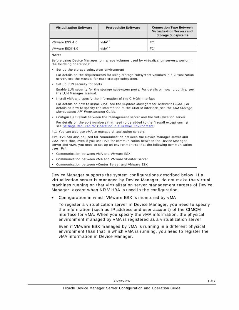
Overview 1-57
Hitachi Device Manager Server Configuration and Operation Guide
Virtualization Software Prerequisite Software Connection Type Between Virtualization Servers and
Storage Subsystems
VMware ESX 4.0 vMA#2 FC
VMware ESXi 4.0 vMA#2 FC
Note:
Before using Device Manager to manage volumes used by virtualization servers, perform the following operations:
Set up the storage subsystem environment
For details on the requirements for using storage subsystem volumes in a virtualization server, see the manual for each storage subsystem.
Set up LUN security for ports
Enable LUN security for the storage subsystem ports. For details on how to do this, see the LUN Manager manual.
Install vMA and specify the information of the CIMOM interface
For details on how to install vMA, see the vSphere Management Assistant Guide. For details on how to specify the information of the CIMOM interface, see the CIM Storage Management API Programming Guide.
Configure a firewall between the management server and the virtualization server
For details on the port numbers that need to be added to the firewall exceptions list, see Settings Required for Operation in a Firewall Environment.
#1: You can also use vMA to manage virtualization servers.
#2: IPv6 can also be used for communication between the Device Manager server and vMA. Note that, even if you use IPv6 for communication between the Device Manager server and vMA, you need to set up an environment so that the following communication uses IPv4:
Communication between vMA and VMware ESX
Communication between vMA and VMware vCenter Server
Communication between vCenter Server and VMware ESX
Device Manager supports the system configurations described below. If a virtualization server is managed by Device Manager, do not make the virtual machines running on that virtualization server management targets of Device Manager, except when NPIV HBA is used in the configuration.
• Configuration in which VMware ESX is monitored by vMA
To register a virtualization server in Device Manager, you need to specify the information (such as IP address and user account) of the CIMOM interface for vMA. When you specify the vMA information, the physical environment managed by vMA is registered as a virtualization server.
Even if VMware ESX managed by vMA is running in a different physical environment than that in which vMA is running, you need to register the vMA information in Device Manager.
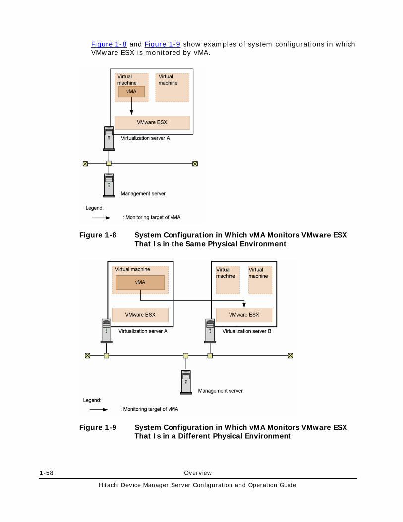
1-58 Overview
Hitachi Device Manager Server Configuration and Operation Guide
Figure 1-8 and Figure 1-9 show examples of system configurations in which VMware ESX is monitored by vMA.
Figure 1-8 System Configuration in Which vMA Monitors VMware ESX That Is in the Same Physical Environment
Figure 1-9 System Configuration in Which vMA Monitors VMware ESX That Is in a Different Physical Environment
Overview 1-59
Hitachi Device Manager Server Configuration and Operation Guide
In Figure 1-8, when you specify the vMA information, virtualization server A is registered in Device Manager. In Figure 1-9, when you specify the vMA information, virtualization server B is registered in Device Manager.
Caution: • If you change the information (such as IP address and user account) of
the CIMOM interface for vMA, you must re-register the vMA in Device Manager (but you do not need to delete it).
• If you change which instance of vMA manages a virtualization server, first re-register the instance of vMA that previously managed the virtualization server, and then re-register the instance of vMA that now manages the virtualization server (but you do not need to delete it).
• Configuration in which VMware vCenter Server is monitored by vMA
To register virtualization servers in Device Manager, you need to specify the information (such as IP address and user account) about the CIMOM interface for vMA. When you specify the vMA information, the physical environments managed by VMware vCenter Server are registered as virtualization servers.
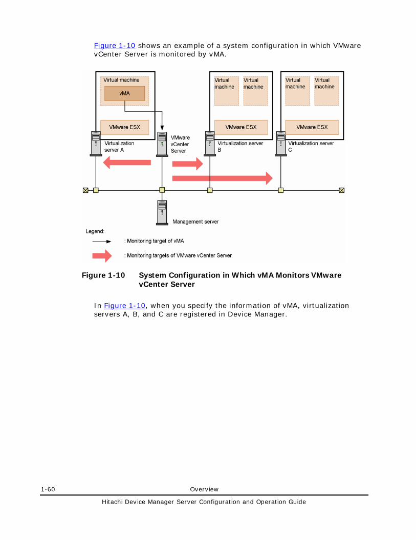
1-60 Overview
Hitachi Device Manager Server Configuration and Operation Guide
Figure 1-10 shows an example of a system configuration in which VMware vCenter Server is monitored by vMA.
Figure 1-10 System Configuration in Which vMA Monitors VMware vCenter Server
In Figure 1-10, when you specify the information of vMA, virtualization servers A, B, and C are registered in Device Manager.
Overview 1-61
Hitachi Device Manager Server Configuration and Operation Guide
Caution: • If you change the information (such as IP address and user account) of
the CIMOM interface for vMA, you must re-register the vMA in Device Manager (but you do not need to delete it).
• If you add virtualization servers to or delete virtualization servers from VMware vCenter Server management, you must re-register, in Device Manager, the instance of vMA that monitors that instance of VMware vCenter Server (but you do not need to delete it).
• If you change which instance of VMware vCenter Server manages virtualization servers, you must perform the following operations from Device Manager:
1. Change the communication parameter setting for the virtualization server to the information of the instance of vMA that monitors the instance of VMware vCenter Server that now manages the virtualization server. 2. Update (refresh) the virtualization server information.
• Configuration in which vMA is not used
In Device Manager, this configuration of virtualization server can be used only if the virtualization software is VMware ESX 3.5.
To register a virtualization server in Device Manager, specify the information (such as IP address and user account) about the CIMOM interface for VMware ESX.
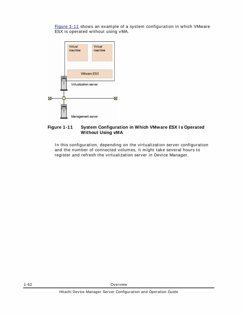
1-62 Overview
Hitachi Device Manager Server Configuration and Operation Guide
Figure 1-11 shows an example of a system configuration in which VMware ESX is operated without using vMA.
Figure 1-11 System Configuration in Which VMware ESX Is Operated Without Using vMA
In this configuration, depending on the virtualization server configuration and the number of connected volumes, it might take several hours to register and refresh the virtualization server in Device Manager.
Overview 1-63
Hitachi Device Manager Server Configuration and Operation Guide
Notes: • To check the most recent information about virtualization server
volumes, perform either of the following operations from Device Manager:
– Manually refresh each virtualization server. – Re-register the vMA that manages the virtualization servers in Device
Manager (but you do not need to delete it). Note that, if you change the hardware configuration of a virtualization server, after the configuration information of the monitored virtualization server is applied to vMA and VMware vCenter Server, you need to update (refresh) the Device Manager information. If the configuration information of virtualization servers is set to be automatically applied to vMA and VMware vCenter Server, a time lag might occur from the time the configuration is changed until the information is applied to vMA and VMware vCenter Server. For details on how to apply the configuration information of virtualization servers to vMA and VMware vCenter Server and how to adjust the interval for applying information, see the VMware documentation.
• You cannot use Provisioning Manager to check information about file systems and device files on a virtualization server.
Mainframe Host Requirements
To use Device Manager Web Client to check the information about volumes assigned to a mainframe host, you need to install Mainframe Agent on the mainframe host. The following table lists the versions of Mainframe Agent supported by Device Manager.
Table 1-30 Versions of Mainframe Agent Supported by Device Manager
Mainframe Host Platform Platform Version Mainframe Agent Version
OS/390 2.10 5.1 or later
z/OS 1.1 to 1.11 5.1 or later
For details about how to install Mainframe Agent, see the Hitachi Device Manager Mainframe Agent User's Guide. For details about the environment settings required for linking the Device Manager server to Mainframe Agent, see the Hitachi Device Manager Software Command Line Interface (CLI) User’s Guide.
1-64 Overview
Hitachi Device Manager Server Configuration and Operation Guide
File Server Requirements
Device Manager can manage the following file server.
Table 1-31 File Server That Can Be Managed by Device Manager
Vendor File Server
Hitachi Hitachi NAS and High-performance NAS platform
Before you can allocate a volume to a Hitachi NAS and High-performance NAS platform or view its volume information, you need to specify the following environment settings.
1. Use Device Manager to register storage subsystems used by the target file server.
2. Use the management program of the Hitachi NAS and High-performance NAS platform to register the file server on the Device Manager server.
3. Use Device Manager to make sure that the file server is registered.
Overview 1-65
Hitachi Device Manager Server Configuration and Operation Guide
Caution: • If you upgrade Device Manager from version 6.3 or earlier and you want to
manage Hitachi NAS and High-performance NAS platform as a file server, we recommend that you change the value for the server.http.entity.maxLength property of the server.properties file to 1310720 or more. After changing the value, restart the Device Manager server.
• You cannot update (refresh) the file server information from Device Manager. To apply the latest file server information to the Device Manager database, re-register the file server by using the management program of the Hitachi NAS and High-performance NAS platform. (You do not need to delete the file server.)
• To re-register, as a file server, the Hitachi NAS and High-performance NAS platform that has been registered in Device Manager as a normal host, perform the following procedure:
1. Use Web Client or CLI of Device Manager to delete the Hitachi NAS and High-performance NAS platform information. 2. Use the management program of the Hitachi NAS and High-performance NAS platform to register the Hitachi NAS and High-performance NAS platform on the Device Manager server. 3. Use Device Manager Web Client to add the Hitachi NAS and High-performance NAS platform registered in step 2 to the resource group. This step is required when you have registered, in a resource group, the Hitachi NAS and High-performance NAS platform that is managed as a normal host. Note that, if the host name (the file server name) of the Hitachi NAS and High-performance NAS platform matches the host name of a file server or a normal host that has already been registered in Device Manager, the Hitachi NAS and High-performance NAS platform will be registered as a file server. (The information of the database will be overwritten.)
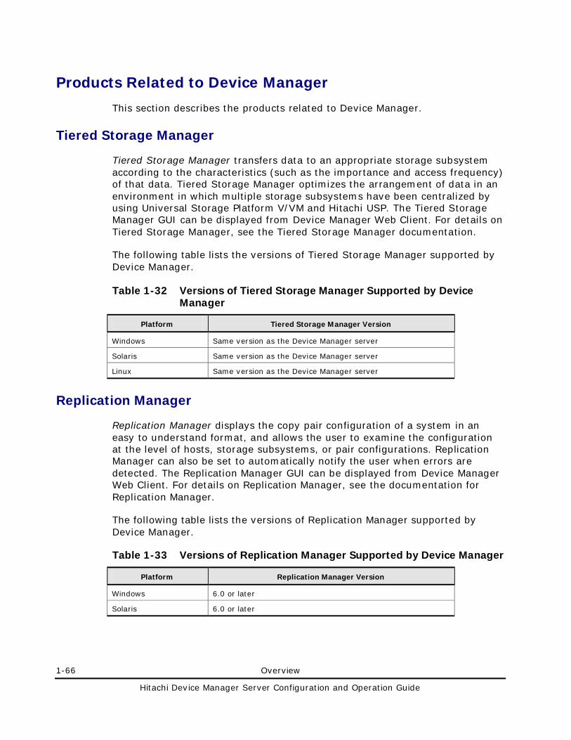
1-66 Overview
Hitachi Device Manager Server Configuration and Operation Guide
Products Related to Device Manager
This section describes the products related to Device Manager.
Tiered Storage Manager
Tiered Storage Manager transfers data to an appropriate storage subsystem according to the characteristics (such as the importance and access frequency) of that data. Tiered Storage Manager optimizes the arrangement of data in an environment in which multiple storage subsystems have been centralized by using Universal Storage Platform V/VM and Hitachi USP. The Tiered Storage Manager GUI can be displayed from Device Manager Web Client. For details on Tiered Storage Manager, see the Tiered Storage Manager documentation.
The following table lists the versions of Tiered Storage Manager supported by Device Manager.
Table 1-32 Versions of Tiered Storage Manager Supported by Device Manager
Platform Tiered Storage Manager Version
Windows Same version as the Device Manager server
Solaris Same version as the Device Manager server
Linux Same version as the Device Manager server
Replication Manager
Replication Manager displays the copy pair configuration of a system in an easy to understand format, and allows the user to examine the configuration at the level of hosts, storage subsystems, or pair configurations. Replication Manager can also be set to automatically notify the user when errors are detected. The Replication Manager GUI can be displayed from Device Manager Web Client. For details on Replication Manager, see the documentation for Replication Manager.
The following table lists the versions of Replication Manager supported by Device Manager.
Table 1-33 Versions of Replication Manager Supported by Device Manager
Platform Replication Manager Version
Windows 6.0 or later
Solaris 6.0 or later
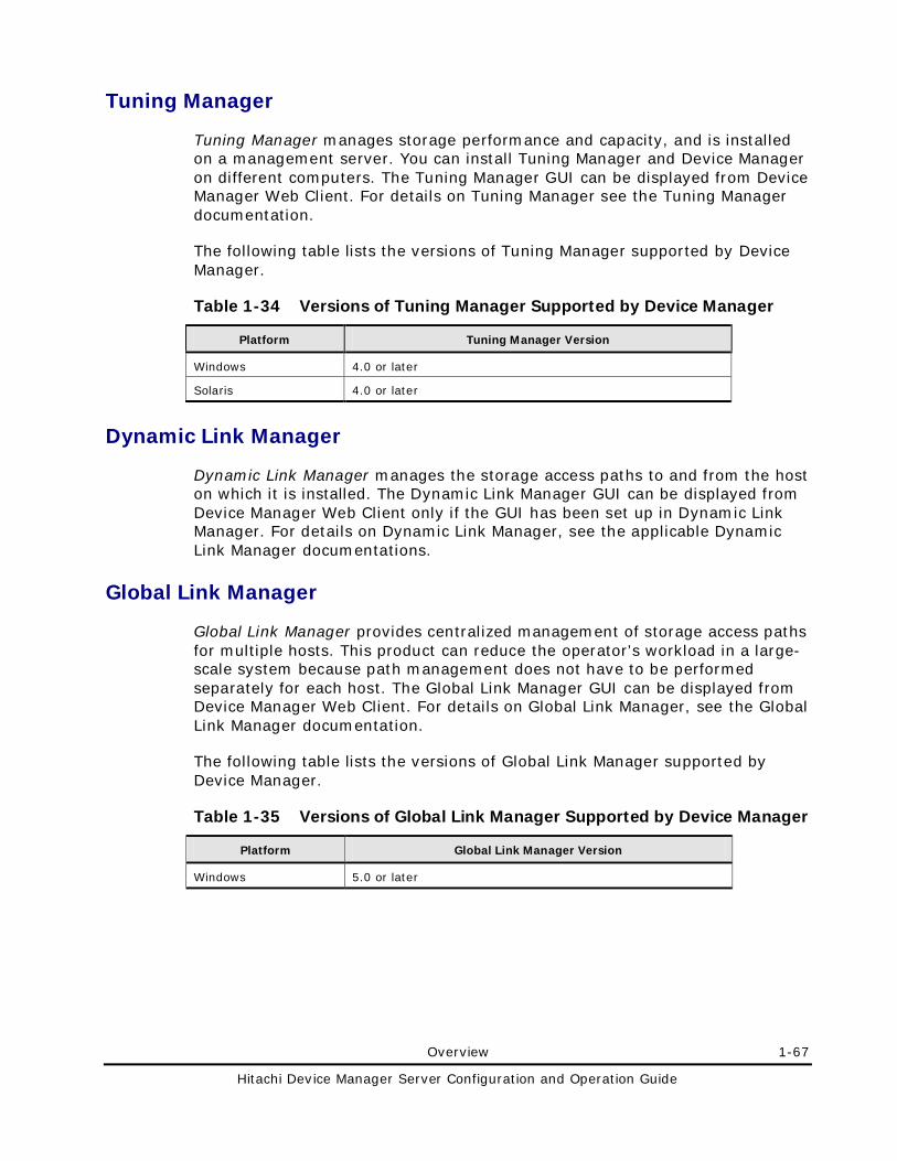
Overview 1-67
Hitachi Device Manager Server Configuration and Operation Guide
Tuning Manager
Tuning Manager manages storage performance and capacity, and is installed on a management server. You can install Tuning Manager and Device Manager on different computers. The Tuning Manager GUI can be displayed from Device Manager Web Client. For details on Tuning Manager see the Tuning Manager documentation.
The following table lists the versions of Tuning Manager supported by Device Manager.
Table 1-34 Versions of Tuning Manager Supported by Device Manager
Platform Tuning Manager Version
Windows 4.0 or later
Solaris 4.0 or later
Dynamic Link Manager
Dynamic Link Manager manages the storage access paths to and from the host on which it is installed. The Dynamic Link Manager GUI can be displayed from Device Manager Web Client only if the GUI has been set up in Dynamic Link Manager. For details on Dynamic Link Manager, see the applicable Dynamic Link Manager documentations.
Global Link Manager
Global Link Manager provides centralized management of storage access paths for multiple hosts. This product can reduce the operator’s workload in a large-scale system because path management does not have to be performed separately for each host. The Global Link Manager GUI can be displayed from Device Manager Web Client. For details on Global Link Manager, see the Global Link Manager documentation.
The following table lists the versions of Global Link Manager supported by Device Manager.
Table 1-35 Versions of Global Link Manager Supported by Device Manager
Platform Global Link Manager Version
Windows 5.0 or later
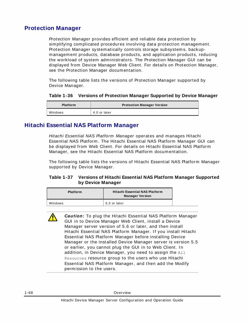
1-68 Overview
Hitachi Device Manager Server Configuration and Operation Guide
Protection Manager
Protection Manager provides efficient and reliable data protection by simplifying complicated procedures involving data protection management. Protection Manager systematically controls storage subsystems, backup-management products, database products, and application products, reducing the workload of system administrators. The Protection Manager GUI can be displayed from Device Manager Web Client. For details on Protection Manager, see the Protection Manager documentation.
The following table lists the versions of Protection Manager supported by Device Manager.
Table 1-36 Versions of Protection Manager Supported by Device Manager
Platform Protection Manager Version
Windows 4.0 or later
Hitachi Essential NAS Platform Manager
Hitachi Essential NAS Platform Manager operates and manages Hitachi Essential NAS Platform. The Hitachi Essential NAS Platform Manager GUI can be displayed from Web Client. For details on Hitachi Essential NAS Platform Manager, see the Hitachi Essential NAS Platform documentation.
The following table lists the versions of Hitachi Essential NAS Platform Manager supported by Device Manager.
Table 1-37 Versions of Hitachi Essential NAS Platform Manager Supported by Device Manager
Platform Hitachi Essential NAS Platform Manager Version
Windows 5.0 or later
Caution: To plug the Hitachi Essential NAS Platform Manager GUI in to Device Manager Web Client, install a Device Manager server version of 5.6 or later, and then install Hitachi Essential NAS Platform Manager. If you install Hitachi Essential NAS Platform Manager before installing Device Manager or the installed Device Manager server is version 5.5 or earlier, you cannot plug the GUI in to Web Client. In addition, in Device Manager, you need to assign the All Resources resource group to the users who use Hitachi Essential NAS Platform Manager, and then add the Modify permission to the users.
Overview 1-69
Hitachi Device Manager Server Configuration and Operation Guide
Hitachi Storage Services Manager
Hitachi Storage Services Manager acts as the main console for heterogeneous storage infrastructure management software, providing SAN visualization and reporting, asset management, performance and capacity monitoring and planning, and policy-driven event management.
WARNING: Do not install HSSM on the same server as Device Manager.
Hitachi Content Archive Platform
Hitachi Content Archive Platform is an appliance product that is intended for long-term data storage, and it integrates software and hardware for a managing content archive. For details on Hitachi Content Archive Platform, see the Hitachi Content Archive Platform documentation.
1-70 Overview
Hitachi Device Manager Server Configuration and Operation Guide
System Requirements for Managing Copy Pairs
In Device Manager, you can manage copy pairs by using either of the following methods:
Local management
This method manages copy pairs for each host individually.
Central management
This method centrally manages copy pairs by using one host (the pair management server).
The following sections describe the requirements for Device Manager to manage copy pairs.
Device Manager Server Requirements for Managing Copy Pairs
This section describes the requirements necessary for the Device Manager server to manage copy pairs.
• The subsystems that are candidates for P-VOL or S-VOL must be managed by a single Device Manager server.
• The hosts that manage copy pairs must have been added to the Device Manager server.
Host Requirements for Managing Copy Pairs
This section describes the host requirements for performing copy pair operations when local management is used and when central management is used. If you have not yet created a copy pair, in the following explanation you must read P-VOL as P-VOL candidate and S-VOL as S-VOL candidate.
Caution: If you use the Remote Console for Lightning 9900, Storage Navigator (for Universal Storage Platform V/VM, Hitachi USP, and Lightning 9900V), SVP, or CCI/LIB, you can create or manage a copy pair without using CCI. However, a copy pair created by such tools cannot be controlled from Device Manager (for example, you cannot delete the copy pair or change its status), because there is no configuration definition file that is controlled by CCI to perform such copy pair operations. If you have an existing copy pair that was not created using CCI, first release the copy pair (using the same tool that created it), and then use Device Manager to recreate the volume pairs. You can also manually create a configuration definition file to control the existing copy pairs.
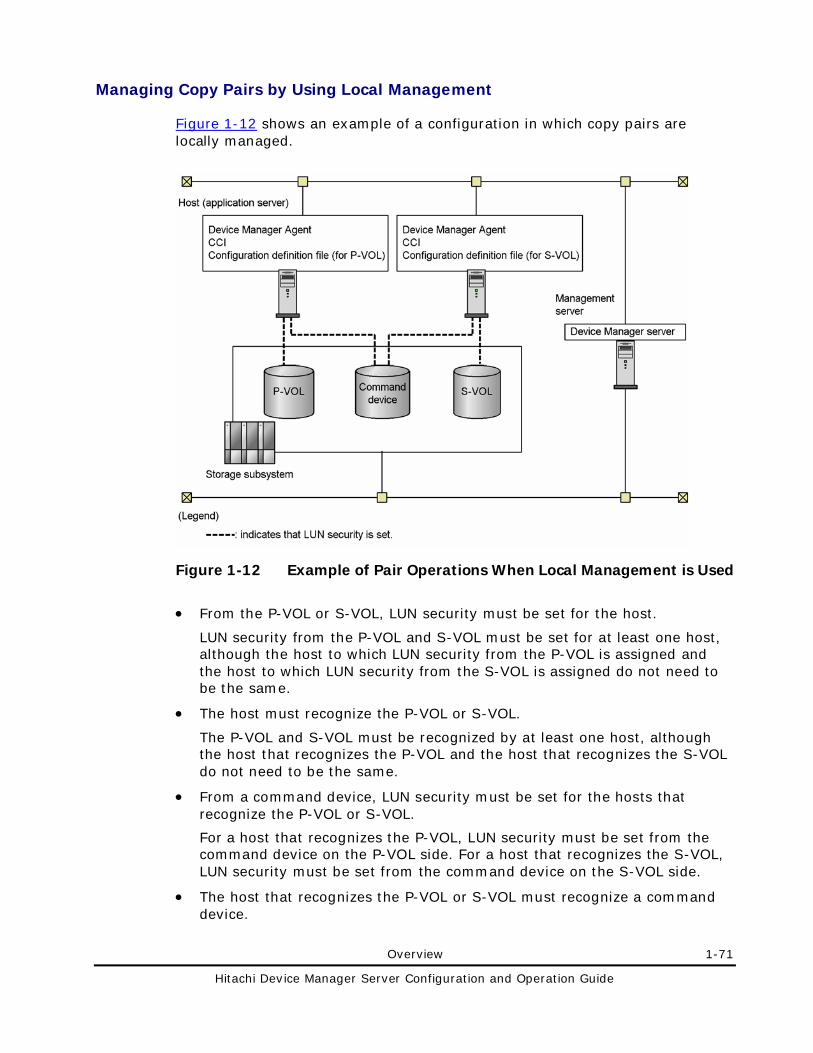
Overview 1-71
Hitachi Device Manager Server Configuration and Operation Guide
Managing Copy Pairs by Using Local Management
Figure 1-12 shows an example of a configuration in which copy pairs are locally managed.
Figure 1-12 Example of Pair Operations When Local Management is Used
• From the P-VOL or S-VOL, LUN security must be set for the host.
LUN security from the P-VOL and S-VOL must be set for at least one host, although the host to which LUN security from the P-VOL is assigned and the host to which LUN security from the S-VOL is assigned do not need to be the same.
• The host must recognize the P-VOL or S-VOL.
The P-VOL and S-VOL must be recognized by at least one host, although the host that recognizes the P-VOL and the host that recognizes the S-VOL do not need to be the same.
• From a command device, LUN security must be set for the hosts that recognize the P-VOL or S-VOL.
For a host that recognizes the P-VOL, LUN security must be set from the command device on the P-VOL side. For a host that recognizes the S-VOL, LUN security must be set from the command device on the S-VOL side.
• The host that recognizes the P-VOL or S-VOL must recognize a command device.
1-72 Overview
Hitachi Device Manager Server Configuration and Operation Guide
• Device Manager agent must be installed on hosts as follows:
If there is one host that recognizes the P-VOL and one host that recognizes the S-VOL:
Install a Device Manager agent on each of the hosts.
If there are multiple hosts that recognize the P-VOL and multiple hosts that recognize the S-VOL:
Install a Device Manager agent on one of the hosts that recognize the P-VOL and one of the hosts that recognize the S-VOL.
For details on the correspondence between copy pair operations and required Device Manager agent versions, see Device Manager Agent Requirements for Managing Copy Pairs.
Caution: To create a configuration definition file by using Web Client, you need to install the Device Manager agent version 3.1 or later on each host.
• CCI must be installed on hosts as follows:
If there are multiple hosts that recognize the P-VOL and multiple hosts that recognize the S-VOL, install CCI on one of the hosts that recognize the P-VOL and one of the hosts that recognize the S-VOL.
For details on how to install CCI, see the relevant manual for CCI.
• If there are multiple NICs on the host, the Device Manager agent and CCI must use the same IP address.
• There must be fewer than 32 running instances of CCI.
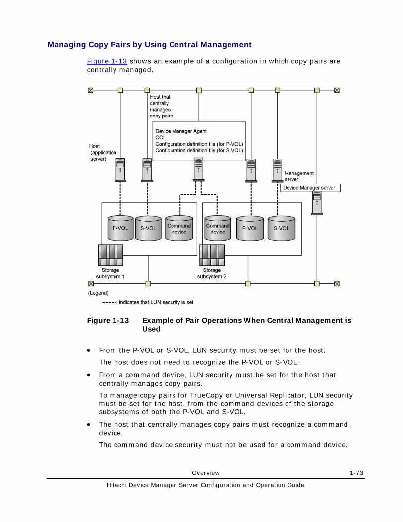
Overview 1-73
Hitachi Device Manager Server Configuration and Operation Guide
Managing Copy Pairs by Using Central Management
Figure 1-13 shows an example of a configuration in which copy pairs are centrally managed.
Figure 1-13 Example of Pair Operations When Central Management is Used
• From the P-VOL or S-VOL, LUN security must be set for the host.
The host does not need to recognize the P-VOL or S-VOL.
• From a command device, LUN security must be set for the host that centrally manages copy pairs.
To manage copy pairs for TrueCopy or Universal Replicator, LUN security must be set for the host, from the command devices of the storage subsystems of both the P-VOL and S-VOL.
• The host that centrally manages copy pairs must recognize a command device.
The command device security must not be used for a command device.
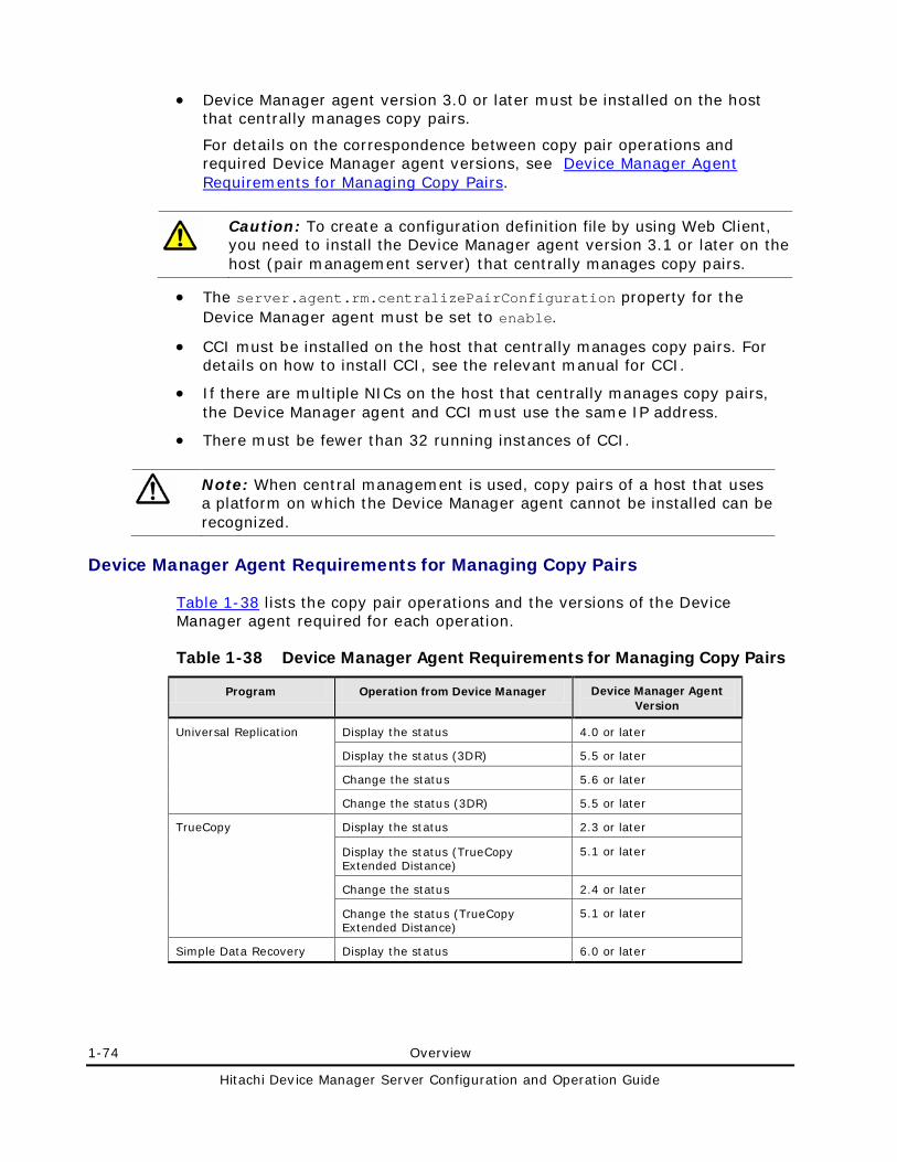
1-74 Overview
Hitachi Device Manager Server Configuration and Operation Guide
• Device Manager agent version 3.0 or later must be installed on the host that centrally manages copy pairs.
For details on the correspondence between copy pair operations and required Device Manager agent versions, see Device Manager Agent Requirements for Managing Copy Pairs.
Caution: To create a configuration definition file by using Web Client, you need to install the Device Manager agent version 3.1 or later on the host (pair management server) that centrally manages copy pairs.
• The server.agent.rm.centralizePairConfiguration property for the Device Manager agent must be set to enable.
• CCI must be installed on the host that centrally manages copy pairs. For details on how to install CCI, see the relevant manual for CCI.
• If there are multiple NICs on the host that centrally manages copy pairs, the Device Manager agent and CCI must use the same IP address.
• There must be fewer than 32 running instances of CCI.
Note: When central management is used, copy pairs of a host that uses a platform on which the Device Manager agent cannot be installed can be recognized.
Device Manager Agent Requirements for Managing Copy Pairs
Table 1-38 lists the copy pair operations and the versions of the Device Manager agent required for each operation.
Table 1-38 Device Manager Agent Requirements for Managing Copy Pairs
Program Operation from Device Manager Device Manager Agent Version
Universal Replication Display the status 4.0 or later
Display the status (3DR) 5.5 or later
Change the status 5.6 or later
Change the status (3DR) 5.5 or later
TrueCopy Display the status 2.3 or later
Display the status (TrueCopy Extended Distance)
5.1 or later
Change the status 2.4 or later
Change the status (TrueCopy Extended Distance)
5.1 or later
Simple Data Recovery Display the status 6.0 or later
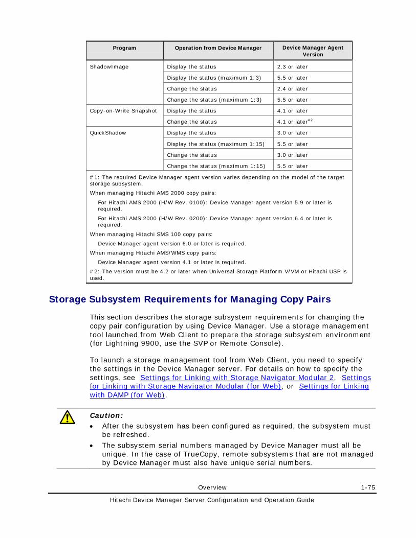
Overview 1-75
Hitachi Device Manager Server Configuration and Operation Guide
Program Operation from Device Manager Device Manager Agent Version
ShadowImage Display the status 2.3 or later
Display the status (maximum 1:3) 5.5 or later
Change the status 2.4 or later
Change the status (maximum 1:3) 5.5 or later
Copy-on-Write Snapshot Display the status 4.1 or later
Change the status 4.1 or later#2
QuickShadow Display the status 3.0 or later
Display the status (maximum 1:15) 5.5 or later
Change the status 3.0 or later
Change the status (maximum 1:15) 5.5 or later
#1: The required Device Manager agent version varies depending on the model of the target storage subsystem.
When managing Hitachi AMS 2000 copy pairs:
For Hitachi AMS 2000 (H/W Rev. 0100): Device Manager agent version 5.9 or later is required.
For Hitachi AMS 2000 (H/W Rev. 0200): Device Manager agent version 6.4 or later is required.
When managing Hitachi SMS 100 copy pairs:
Device Manager agent version 6.0 or later is required.
When managing Hitachi AMS/WMS copy pairs:
Device Manager agent version 4.1 or later is required.
#2: The version must be 4.2 or later when Universal Storage Platform V/VM or Hitachi USP is used.
Storage Subsystem Requirements for Managing Copy Pairs
This section describes the storage subsystem requirements for changing the copy pair configuration by using Device Manager. Use a storage management tool launched from Web Client to prepare the storage subsystem environment (for Lightning 9900, use the SVP or Remote Console).
To launch a storage management tool from Web Client, you need to specify the settings in the Device Manager server. For details on how to specify the settings, see Settings for Linking with Storage Navigator Modular 2, Settings for Linking with Storage Navigator Modular (for Web), or Settings for Linking with DAMP (for Web).
Caution: • After the subsystem has been configured as required, the subsystem must
be refreshed.
• The subsystem serial numbers managed by Device Manager must all be unique. In the case of TrueCopy, remote subsystems that are not managed by Device Manager must also have unique serial numbers.
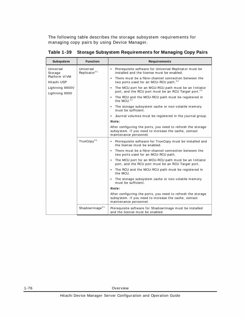
1-76 Overview
Hitachi Device Manager Server Configuration and Operation Guide
The following table describes the storage subsystem requirements for managing copy pairs by using Device Manager.
Table 1-39 Storage Subsystem Requirements for Managing Copy Pairs
Subsystem Function Requirements
Universal Storage Platform V/VM
Hitachi USP
Lightning 9900V
Lightning 9900
Universal Replicator#1
Prerequisite software for Universal Replicator must be installed and the license must be enabled.
There must be a fibre-channel connection between the two ports used for an MCU-RCU path.#2
The MCU port for an MCU-RCU path must be an Initiator port, and the RCU port must be an RCU Target port.#2
The RCU and the MCU-RCU path must be registered in the MCU.#2
The storage subsystem cache or non-volatile memory must be sufficient.
Journal volumes must be registered in the journal group.
Note:
After configuring the ports, you need to refresh the storage subsystem. If you need to increase the cache, contact maintenance personnel.
TrueCopy#1 Prerequisite software for TrueCopy must be installed and the license must be enabled.
There must be a fibre-channel connection between the two ports used for an MCU-RCU path.
The MCU port for an MCU-RCU path must be an Initiator port, and the RCU port must be an RCU Target port.
The RCU and the MCU-RCU path must be registered in the MCU.
The storage subsystem cache or non-volatile memory must be sufficient.
Note:
After configuring the ports, you need to refresh the storage subsystem. If you need to increase the cache, contact maintenance personnel.
ShadowImage#1 Prerequisite software for ShadowImage must be installed and the license must be enabled.
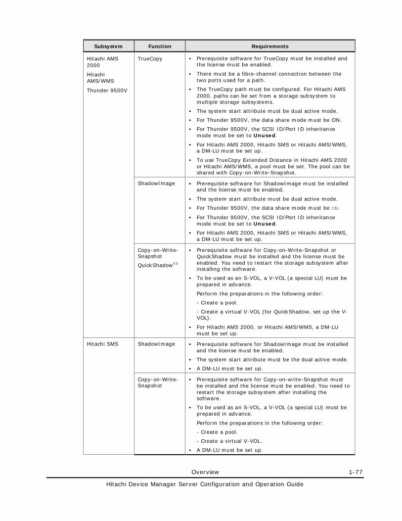
Overview 1-77
Hitachi Device Manager Server Configuration and Operation Guide
Subsystem Function Requirements
Hitachi AMS 2000
Hitachi AMS/WMS
Thunder 9500V
TrueCopy Prerequisite software for TrueCopy must be installed and the license must be enabled.
There must be a fibre-channel connection between the two ports used for a path.
The TrueCopy path must be configured. For Hitachi AMS 2000, paths can be set from a storage subsystem to multiple storage subsystems.
The system start attribute must be dual active mode.
For Thunder 9500V, the data share mode must be ON.
For Thunder 9500V, the SCSI ID/Port ID inheritance mode must be set to Unused.
For Hitachi AMS 2000, Hitachi SMS or Hitachi AMS/WMS, a DM-LU must be set up.
To use TrueCopy Extended Distance in Hitachi AMS 2000 or Hitachi AMS/WMS, a pool must be set. The pool can be shared with Copy-on-Write-Snapshot.
ShadowImage Prerequisite software for ShadowImage must be installed and the license must be enabled.
The system start attribute must be dual active mode.
For Thunder 9500V, the data share mode must be ON.
For Thunder 9500V, the SCSI ID/Port ID inheritance mode must be set to Unused.
For Hitachi AMS 2000, Hitachi SMS or Hitachi AMS/WMS, a DM-LU must be set up.
Copy-on-Write-Snapshot
QuickShadow#3
Prerequisite software for Copy-on-Write-Snapshot or QuickShadow must be installed and the license must be enabled. You need to restart the storage subsystem after installing the software.
To be used as an S-VOL, a V-VOL (a special LU) must be prepared in advance.
Perform the preparations in the following order:
- Create a pool.
- Create a virtual V-VOL (for QuickShadow, set up the V-VOL).
For Hitachi AMS 2000, or Hitachi AMS/WMS, a DM-LU must be set up.
Hitachi SMS ShadowImage Prerequisite software for ShadowImage must be installed and the license must be enabled.
The system start attribute must be the dual active mode.
A DM-LU must be set up.
Copy-on-Write-Snapshot
Prerequisite software for Copy-on-write-Snapshot must be installed and the license must be enabled. You need to restart the storage subsystem after installing the software.
To be used as an S-VOL, a V-VOL (a special LU) must be prepared in advance.
Perform the preparations in the following order:
- Create a pool.
- Create a virtual V-VOL.
A DM-LU must be set up.
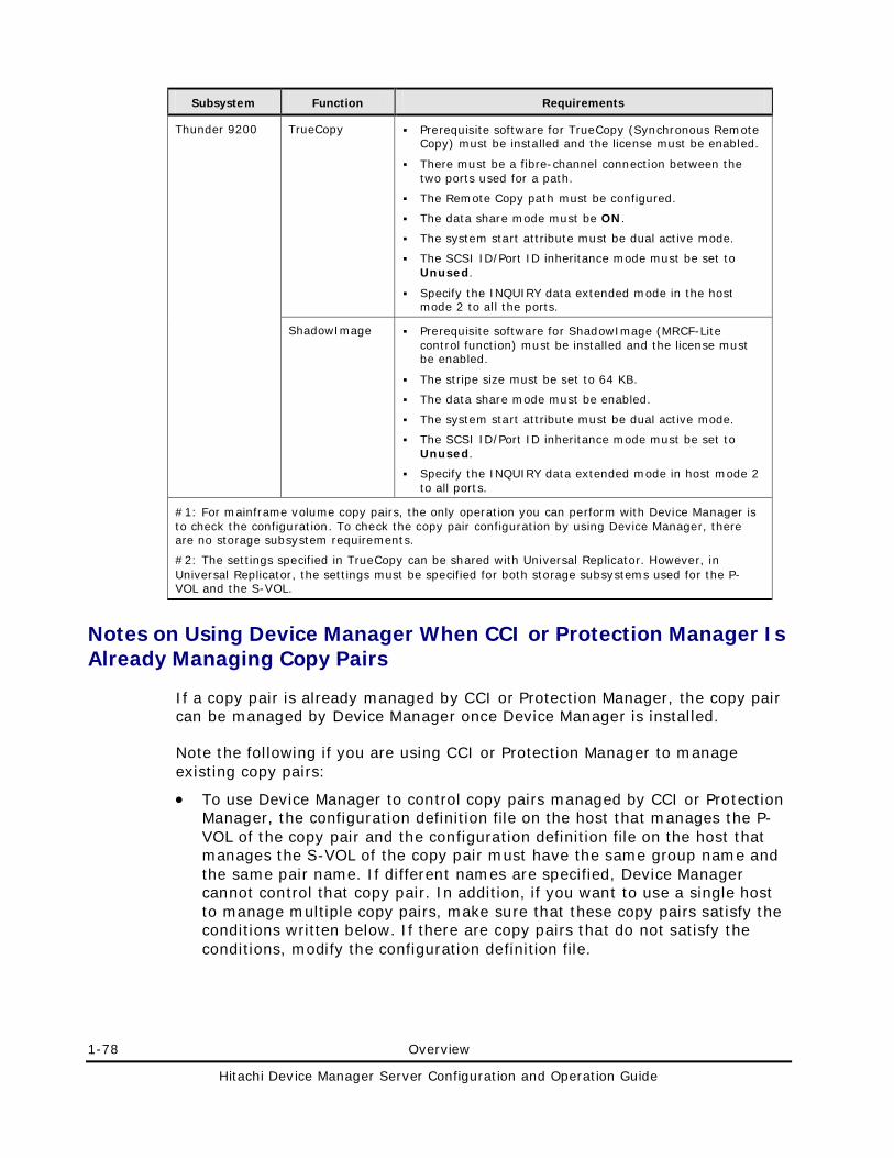
1-78 Overview
Hitachi Device Manager Server Configuration and Operation Guide
Subsystem Function Requirements
Thunder 9200 TrueCopy Prerequisite software for TrueCopy (Synchronous Remote Copy) must be installed and the license must be enabled.
There must be a fibre-channel connection between the two ports used for a path.
The Remote Copy path must be configured.
The data share mode must be ON.
The system start attribute must be dual active mode.
The SCSI ID/Port ID inheritance mode must be set to Unused.
Specify the INQUIRY data extended mode in the host mode 2 to all the ports.
ShadowImage Prerequisite software for ShadowImage (MRCF-Lite control function) must be installed and the license must be enabled.
The stripe size must be set to 64 KB.
The data share mode must be enabled.
The system start attribute must be dual active mode.
The SCSI ID/Port ID inheritance mode must be set to Unused.
Specify the INQUIRY data extended mode in host mode 2 to all ports.
#1: For mainframe volume copy pairs, the only operation you can perform with Device Manager is to check the configuration. To check the copy pair configuration by using Device Manager, there are no storage subsystem requirements.
#2: The settings specified in TrueCopy can be shared with Universal Replicator. However, in Universal Replicator, the settings must be specified for both storage subsystems used for the P-VOL and the S-VOL.
Notes on Using Device Manager When CCI or Protection Manager Is Already Managing Copy Pairs
If a copy pair is already managed by CCI or Protection Manager, the copy pair can be managed by Device Manager once Device Manager is installed.
Note the following if you are using CCI or Protection Manager to manage existing copy pairs:
• To use Device Manager to control copy pairs managed by CCI or Protection Manager, the configuration definition file on the host that manages the P-VOL of the copy pair and the configuration definition file on the host that manages the S-VOL of the copy pair must have the same group name and the same pair name. If different names are specified, Device Manager cannot control that copy pair. In addition, if you want to use a single host to manage multiple copy pairs, make sure that these copy pairs satisfy the conditions written below. If there are copy pairs that do not satisfy the conditions, modify the configuration definition file.
Overview 1-79
Hitachi Device Manager Server Configuration and Operation Guide
– If the version of the Device Manager agent installed on the host is 05-60 or earlier:
Each copy pair on the host must have a unique combination of the following items:
• Group name
• Pair name
– If the version of the Device Manager agent installed on the host is 05-70 or later:
Each copy pair on the host must have a unique combination of the following items:
• Port number
• Group name
• Pair name
• If you want to use CCI to create a copy pair or are already using CCI to manage copy pairs, you can create a configuration definition file by using the Create Pair wizard of Device Manager Web Client. To create a configuration definition file by using Web Client, you need to stop HBase Storage Mgmt Common Service, and then change the value of the client.outputhorcmfunction.enabled property in the client.properties file to true. For details about this property, see client.outputhorcmfunction.enabled.
– You cannot create a copy pair from the Device Manager server by using a configuration definition file created using Web Client.
– If you create an invalid configuration definition file by using Web Client, you need to delete or edit the file on the host that manages copy pairs because the Device Manager server cannot be used to delete configuration definition files. An invalid configuration file or a configuration file that is not used for performing copy pair operations might affect system performance (for example, when adding or refreshing a storage subsystem). Delete such configuration files from the host that manages copy pairs.
1-80 Overview
Hitachi Device Manager Server Configuration and Operation Guide
Note: • In the step performed in the Define Pair(s) dialog box, you do not need
to specify the fence level and copy pace. Even if you specify these items, they are not applied to the configuration definition file.
• In the View Pair Information dialog box, you can view the HORCM instance number, pair group name, and pair name of the created configuration definition file.
• For a Shadow Image copy pair and a QuickShadow or Copy-on-Write Snapshot copy pair, the Device Manager server sets 0 as the MU number in the configuration definition file. For TrueCopy, the MU number is not set because this number is not necessary. The Device Manager server also sets 1 as the MU number in the configuration definition file for Universal Replicator copy pairs. When you use a configuration definition file, created by the Device Manager server, to create a copy pair, make sure that you change these values into appropriate values.
• When you install the Device Manager agent, the Device Manager agent properties must be configured if the installation drive of CCI in Windows is different from the installation drive of the Device Manager agent. For details about the Device Manager agent properties to be configured, see the Hitachi Device Manager Agent Installation Guide.
To avoid malfunctions and to shorten the processing time of Device Manager, exclude (from Device Manager operations) copy pairs that you do not plan to control from Device Manager. To do this:
1. Check the number of the CCI HORCM instance that is managing the copy pair.
2. In the following property in the Device Manager agent property file, enter the HORCM instances that you want to exclude from Device Manager operations. If you enter multiple HORCM instances, separate them by a comma: Property file name: server.properties
Property name: server.agent.rm.exclusion.instance Example: server.agent.rm.exclusion.instance=0,1,2
3. Restart the Device Manager agent service (daemon).
Settings for Various Network Configurations 2-1
Hitachi Device Manager Server Configuration and Operation Guide
Settings for Various Network Configurations
This chapter describes the settings required on a Device Manager server for various network configurations.
Port Settings
Settings Required to Use a Management Server That Has Multiple NICs
Settings Required to Operate in an IPv6 Environment
Changing the IP Address or Host Name of the Management Server
Changing the URLs for Accessing Hitachi Storage Command Suite Products
Settings Required When Disconnecting the Management Server Network
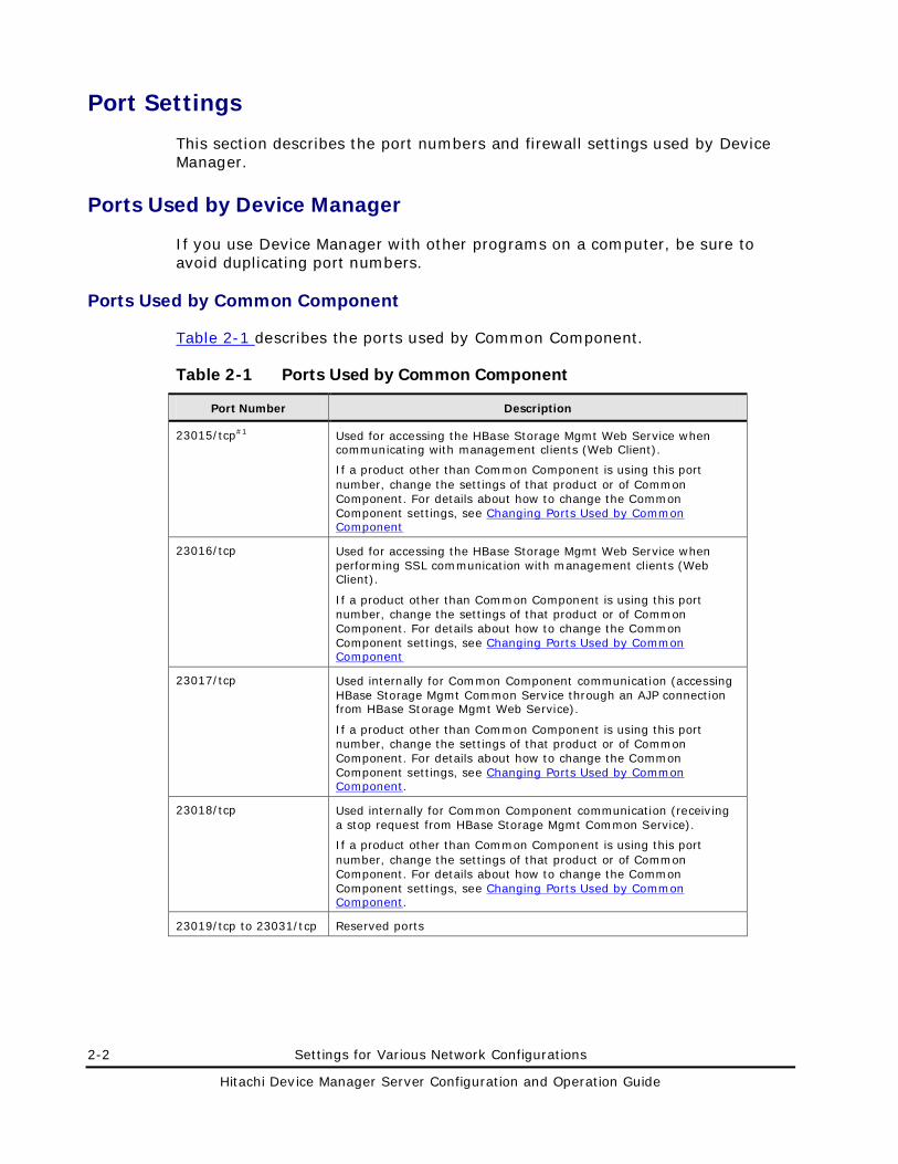
2-2 Settings for Various Network Configurations
Hitachi Device Manager Server Configuration and Operation Guide
Port Settings
This section describes the port numbers and firewall settings used by Device Manager.
Ports Used by Device Manager
If you use Device Manager with other programs on a computer, be sure to avoid duplicating port numbers.
Ports Used by Common Component
Table 2-1 describes the ports used by Common Component.
Table 2-1 Ports Used by Common Component
Port Number Description
23015/tcp#1 Used for accessing the HBase Storage Mgmt Web Service when communicating with management clients (Web Client).
If a product other than Common Component is using this port number, change the settings of that product or of Common Component. For details about how to change the Common Component settings, see Changing Ports Used by Common Component
23016/tcp Used for accessing the HBase Storage Mgmt Web Service when performing SSL communication with management clients (Web Client).
If a product other than Common Component is using this port number, change the settings of that product or of Common Component. For details about how to change the Common Component settings, see Changing Ports Used by Common Component
23017/tcp Used internally for Common Component communication (accessing HBase Storage Mgmt Common Service through an AJP connection from HBase Storage Mgmt Web Service).
If a product other than Common Component is using this port number, change the settings of that product or of Common Component. For details about how to change the Common Component settings, see Changing Ports Used by Common Component.
23018/tcp Used internally for Common Component communication (receiving a stop request from HBase Storage Mgmt Common Service).
If a product other than Common Component is using this port number, change the settings of that product or of Common Component. For details about how to change the Common Component settings, see Changing Ports Used by Common Component.
23019/tcp to 23031/tcp Reserved ports
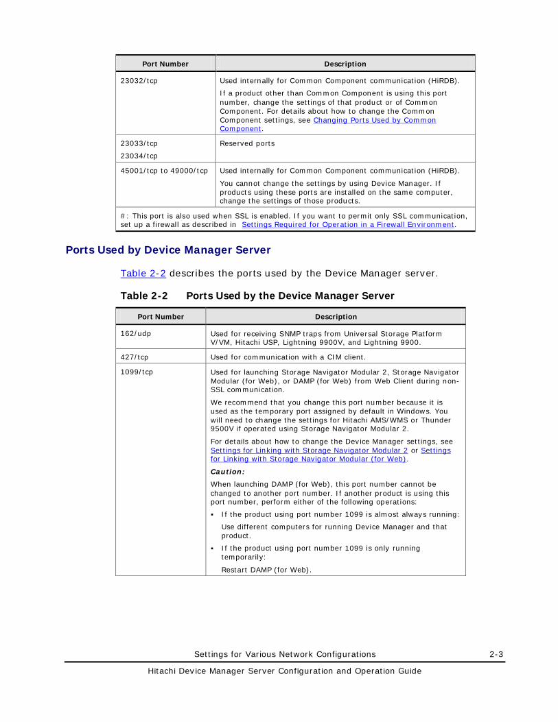
Settings for Various Network Configurations 2-3
Hitachi Device Manager Server Configuration and Operation Guide
Port Number Description
23032/tcp Used internally for Common Component communication (HiRDB).
If a product other than Common Component is using this port number, change the settings of that product or of Common Component. For details about how to change the Common Component settings, see Changing Ports Used by Common Component.
23033/tcp
23034/tcp
Reserved ports
45001/tcp to 49000/tcp Used internally for Common Component communication (HiRDB).
You cannot change the settings by using Device Manager. If products using these ports are installed on the same computer, change the settings of those products.
#: This port is also used when SSL is enabled. If you want to permit only SSL communication, set up a firewall as described in Settings Required for Operation in a Firewall Environment.
Ports Used by Device Manager Server
Table 2-2 describes the ports used by the Device Manager server.
Table 2-2 Ports Used by the Device Manager Server
Port Number Description
162/udp Used for receiving SNMP traps from Universal Storage Platform V/VM, Hitachi USP, Lightning 9900V, and Lightning 9900.
427/tcp Used for communication with a CIM client.
1099/tcp Used for launching Storage Navigator Modular 2, Storage Navigator Modular (for Web), or DAMP (for Web) from Web Client during non-SSL communication.
We recommend that you change this port number because it is used as the temporary port assigned by default in Windows. You will need to change the settings for Hitachi AMS/WMS or Thunder 9500V if operated using Storage Navigator Modular 2.
For details about how to change the Device Manager settings, see Settings for Linking with Storage Navigator Modular 2 or Settings for Linking with Storage Navigator Modular (for Web).
Caution:
When launching DAMP (for Web), this port number cannot be changed to another port number. If another product is using this port number, perform either of the following operations:
If the product using port number 1099 is almost always running:
Use different computers for running Device Manager and that product.
If the product using port number 1099 is only running temporarily:
Restart DAMP (for Web).
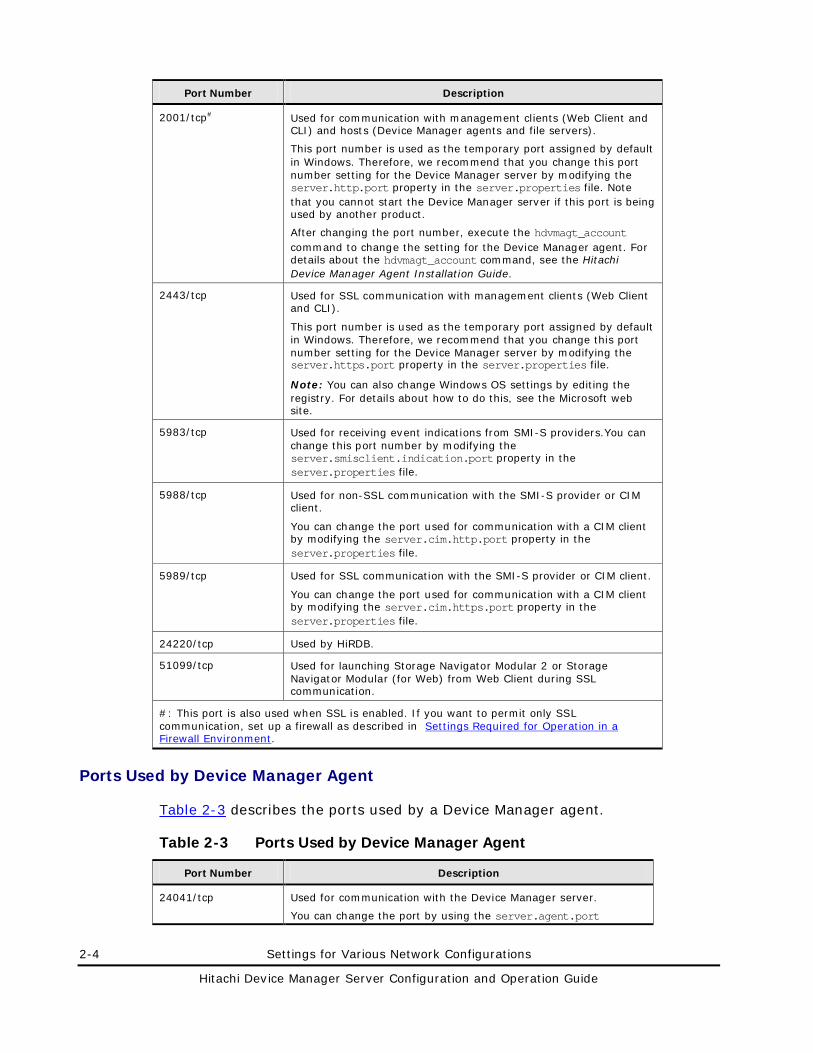
2-4 Settings for Various Network Configurations
Hitachi Device Manager Server Configuration and Operation Guide
Port Number Description
2001/tcp# Used for communication with management clients (Web Client and CLI) and hosts (Device Manager agents and file servers).
This port number is used as the temporary port assigned by default in Windows. Therefore, we recommend that you change this port number setting for the Device Manager server by modifying the server.http.port property in the server.properties file. Note that you cannot start the Device Manager server if this port is being used by another product.
After changing the port number, execute the hdvmagt_account command to change the setting for the Device Manager agent. For details about the hdvmagt_account command, see the Hitachi Device Manager Agent Installation Guide.
2443/tcp Used for SSL communication with management clients (Web Client and CLI).
This port number is used as the temporary port assigned by default in Windows. Therefore, we recommend that you change this port number setting for the Device Manager server by modifying the server.https.port property in the server.properties file.
Note: You can also change Windows OS settings by editing the registry. For details about how to do this, see the Microsoft web site.
5983/tcp Used for receiving event indications from SMI-S providers.You can change this port number by modifying the server.smisclient.indication.port property in the server.properties file.
5988/tcp Used for non-SSL communication with the SMI-S provider or CIM client.
You can change the port used for communication with a CIM client by modifying the server.cim.http.port property in the server.properties file.
5989/tcp Used for SSL communication with the SMI-S provider or CIM client.
You can change the port used for communication with a CIM client by modifying the server.cim.https.port property in the server.properties file.
24220/tcp Used by HiRDB.
51099/tcp Used for launching Storage Navigator Modular 2 or Storage Navigator Modular (for Web) from Web Client during SSL communication.
#: This port is also used when SSL is enabled. If you want to permit only SSL communication, set up a firewall as described in Settings Required for Operation in a Firewall Environment.
Ports Used by Device Manager Agent
Table 2-3 describes the ports used by a Device Manager agent.
Table 2-3 Ports Used by Device Manager Agent
Port Number Description
24041/tcp Used for communication with the Device Manager server.
You can change the port by using the server.agent.port
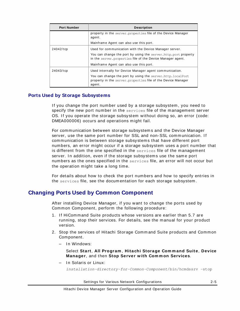
Settings for Various Network Configurations 2-5
Hitachi Device Manager Server Configuration and Operation Guide
Port Number Description
property in the server.properties file of the Device Manager agent.
Mainframe Agent can also use this port.
24042/tcp Used for communication with the Device Manager server.
You can change the port by using the server.http.port property in the server.properties file of the Device Manager agent.
Mainframe Agent can also use this port.
24043/tcp Used internally for Device Manager agent communication.
You can change the port by using the server.http.localPort property in the server.properties file of the Device Manager agent.
Ports Used by Storage Subsystems
If you change the port number used by a storage subsystem, you need to specify the new port number in the services file of the management server OS. If you operate the storage subsystem without doing so, an error (code: DMEA000006) occurs and operations might fail.
For communication between storage subsystems and the Device Manager server, use the same port number for SSL and non-SSL communication. If communication is between storage subsystems that have different port numbers, an error might occur if a storage subsystem uses a port number that is different from the one specified in the services file of the management server. In addition, even if the storage subsystems use the same port numbers as the ones specified in the services file, an error will not occur but the operation might take a long time.
For details about how to check the port numbers and how to specify entries in the services file, see the documentation for each storage subsystem.
Changing Ports Used by Common Component
After installing Device Manager, if you want to change the ports used by Common Component, perform the following procedure:
1. If HiCommand Suite products whose versions are earlier than 5.7 are running, stop their services. For details, see the manual for your product version.
2. Stop the services of Hitachi Storage Command Suite products and Common Component.
– In Windows:
Select Start, All Program, Hitachi Storage Command Suite, Device Manager, and then Stop Server with Common Services.
– In Solaris or Linux:
installation-directory-for-Common-Component/bin/hcmdssrv -stop
2-6 Settings for Various Network Configurations
Hitachi Device Manager Server Configuration and Operation Guide
3. Edit the Common Component settings files and change the port number.
For details about each port’s setup file, see 23015/tcp (Used for Accessing HBase Storage Mgmt Web Service) to 23032/tcp (Used for HiRDB).
4. Start the services of the Device Manager server, other Hitachi Storage Command Suite products, and Common Component.
– In Windows:
Select Start, All Program, Hitachi Storage Command Suite, Device Manager, and then Start Server with Common Services.
– In Solaris or Linux:
installation-directory-for-Common-Component/bin/hcmdssrv -start
5. If HiCommand Suite products whose versions are earlier than 5.7 have been installed, start their services as required. For details, see the manual for your product version.
6. If you change the following port numbers, you need to change the URLs used for accessing Hitachi Storage Command Suite products:
– 23015/tcp (used for accessing HBase Storage Mgmt Web Service)
You need to change the URLs if you use non-SSL for communication between the management server and management clients.
– 23016/tcp (used for accessing SSL HBase Storage Mgmt Web Service)
You need to change the URLs if you use SSL for communication between the management server and management clients.
For details about how to change the URLs, see Settings Required When Disconnecting the Management Server Network.
Note that you might not need to change the URLs depending on the network environment between the management server and management clients, such as an environment that has a firewall configured.
Note: If storage management tools are configured to be launched from Web Client, you need to use launchapptool to change the launch settings for the storage management tools (Storage Navigator Modular 2, Storage Navigator Modular, or DAMP (for Web)). For details on how to do this, see Launch Settings for Storage Navigator Modular 2, Launch Settings for Storage Navigator Modular (for Web), or Launch Settings for DAMP (for Web).
23015/tcp (Used for Accessing HBase Storage Mgmt Web Service)
To change the port used for accessing the HBase Storage Mgmt Web Service, change the port number written in the following files:
In Windows:
– The Listen directive in
Settings for Various Network Configurations 2-7
Hitachi Device Manager Server Configuration and Operation Guide
installation-folder-for-Common-Component\httpsd\conf\httpsd.conf
– hsso.hostport in
installation-folder-for-Common-Component\conf\hsso.conf
In Solaris or Linux:
– The Listen directive in
installation-directory-for-Common-Component/httpsd/conf/httpsd.conf
– hsso.hostport in
installation-directory-for-Common-Component/conf/hsso.conf
23016/tcp (Used for Accessing SSL HBase Storage Mgmt Web Service)
To change the port used for accessing SSL HBase Storage Mgmt Web Service, you must change the port numbers written in the following file:
In Windows:
– <VirtualHost host-name:port-number> and also the Listen directive in
installation-folder-for-Common-Component\httpsd\conf\httpsd.conf
In Solaris or Linux:
– <VirtualHost host-name:port-number> and also the Listen directive in
installation-directory-for-Common-Component/httpsd/conf/httpsd.conf
23017/tcp (Used for HBase Storage Mgmt Common Service through an AJP Connection)
To change the port used for the HBase Storage Mgmt Common Service through an AJP connection, change the port number written in the following files:
In Windows:
– worker.worker1.port in
installation-folder-for-Common-Component\CC\web\redirector\workers.properties
– webserver.connector.ajp13.port in
installation-folder-for-Common-Component\CC\web\containers\HiCommand\usrconf\usrconf.properties
In Solaris or Linux:
– worker.worker1.port in
installation-directory-for-Common-Component/CC/web/redirector/workers.properties
2-8 Settings for Various Network Configurations
Hitachi Device Manager Server Configuration and Operation Guide
– webserver.connector.ajp13.port in
installation-directory-for-Common-Component/CC/web/containers/HiCommand/usrconf/usrconf.properties
23018/tcp (Used for Stop Requests to HBase Storage Mgmt Common Service)
To change the port through which the HBase Storage Mgmt Common Service Service receives a stop request, change the port number written in the following file:
In Windows:
– webserver.shutdown.port in
installation-folder-for-Common-Component\CC\web\containers\HiCommand\usrconf\usrconf.properties
In Solaris or Linux:
– webserver.shutdown.port in
installation-directory-for-Common-Component/CC/web/containers/HiCommand/usrconf/usrconf.properties
23032/tcp (Used for HiRDB)
To change the port used by HiRDB, you must change the port number written in the following files:
In Windows:
– PDNAMEPORT in
installation-folder-for-Common-Component\HDB\CONF\emb\HiRDB.ini
– pd_name_port in
installation-folder-for-Common-Component\HDB\CONF\pdsys
– pd_name_port in
installation-folder-for-Common-Component\database\work\def_pdsys
Settings for Various Network Configurations 2-9
Hitachi Device Manager Server Configuration and Operation Guide
In Solaris or Linux:
– PDNAMEPORT in
installation-directory-for-Common-Component/HDB/conf/emb/HiRDB.ini
– pd_name_port in
installation-directory-for-Common-Component/HDB/conf/pdsys
– pd_name_port in
installation-directory-for-Common-Component/database/work/def_pdsys
Settings Required for Operation in a Firewall Environment
In an environment where firewalls are set up in the following locations, you need to register port numbers as firewall exceptions to permit communication between ports:
• Between the management server and management clients
• Between the management server and storage subsystems
• Between the management client and storage subsystems
• Between the management server and a normal host
• Between the management server and a virtualization server
• Between the management server and a mainframe host
• Between the management server and a file serer
• Between the management server of Device Manager and the management server of Tuning Manager
• Between the management server and an SMI-S provider
• Between the management server and a CIM client
• Between the management server and a mail server
• Between the management server and an external authentication server
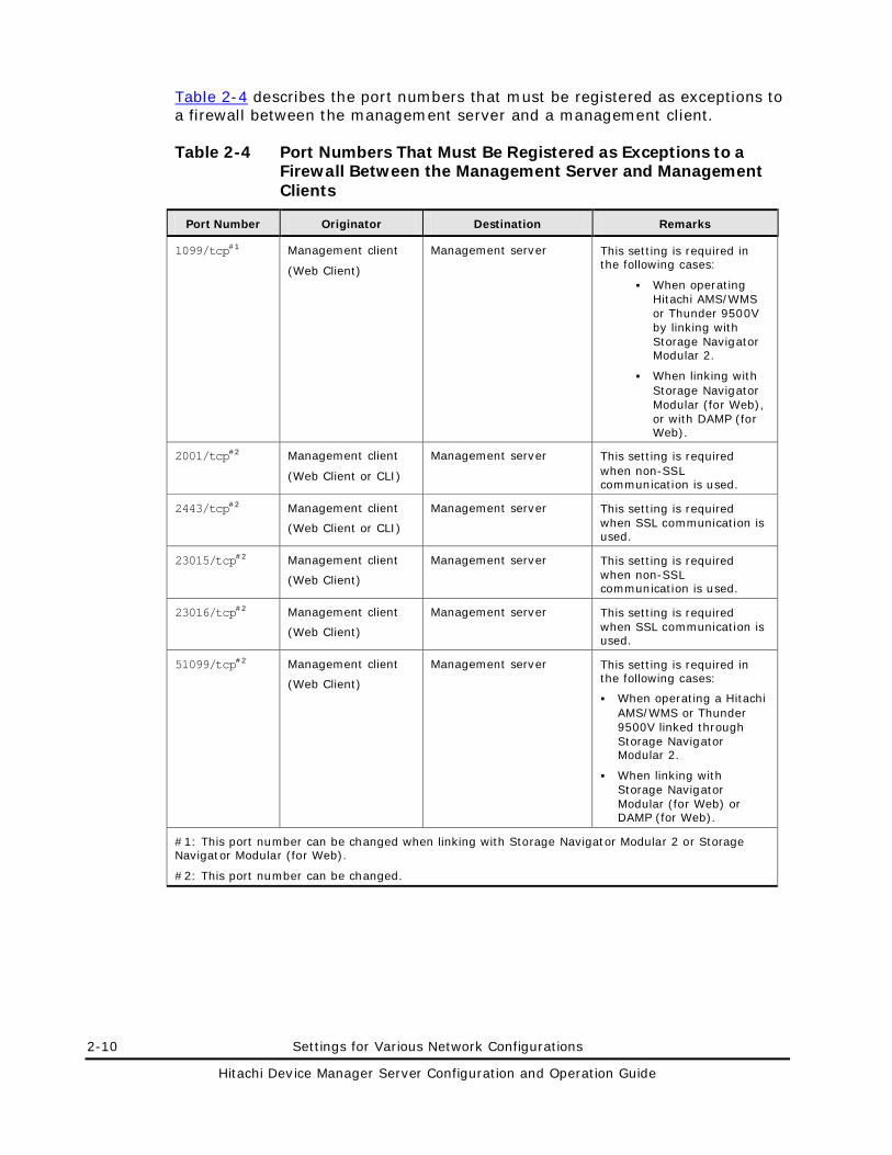
2-10 Settings for Various Network Configurations
Hitachi Device Manager Server Configuration and Operation Guide
Table 2-4 describes the port numbers that must be registered as exceptions to a firewall between the management server and a management client.
Table 2-4 Port Numbers That Must Be Registered as Exceptions to a Firewall Between the Management Server and Management Clients
Port Number Originator Destination Remarks
1099/tcp#1 Management client
(Web Client)
Management server This setting is required in the following cases:
When operating Hitachi AMS/WMS or Thunder 9500V by linking with Storage Navigator Modular 2.
When linking with Storage Navigator Modular (for Web), or with DAMP (for Web).
2001/tcp#2 Management client
(Web Client or CLI)
Management server This setting is required when non-SSL communication is used.
2443/tcp#2 Management client
(Web Client or CLI)
Management server This setting is required when SSL communication is used.
23015/tcp#2 Management client
(Web Client)
Management server This setting is required when non-SSL communication is used.
23016/tcp#2 Management client
(Web Client)
Management server This setting is required when SSL communication is used.
51099/tcp#2 Management client
(Web Client)
Management server This setting is required in the following cases:
When operating a Hitachi AMS/WMS or Thunder 9500V linked through Storage Navigator Modular 2.
When linking with Storage Navigator Modular (for Web) or DAMP (for Web).
#1: This port number can be changed when linking with Storage Navigator Modular 2 or Storage Navigator Modular (for Web).
#2: This port number can be changed.
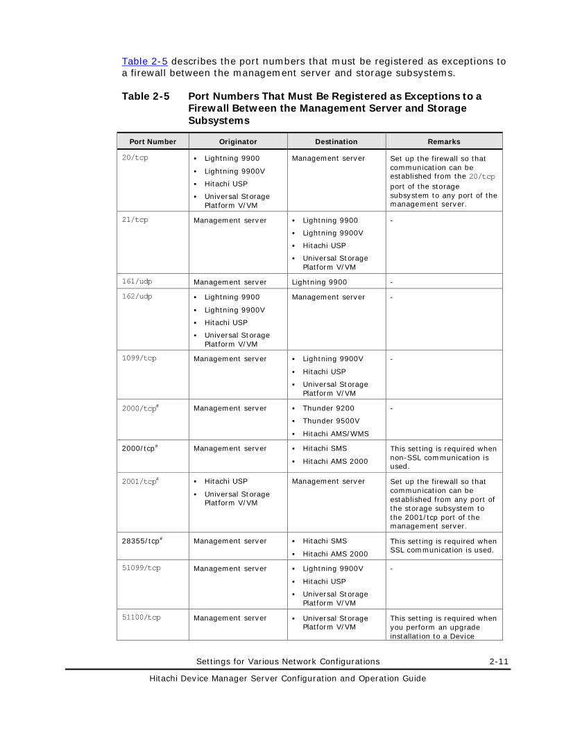
Settings for Various Network Configurations 2-11
Hitachi Device Manager Server Configuration and Operation Guide
Table 2-5 describes the port numbers that must be registered as exceptions to a firewall between the management server and storage subsystems.
Table 2-5 Port Numbers That Must Be Registered as Exceptions to a Firewall Between the Management Server and Storage Subsystems
Port Number Originator Destination Remarks
20/tcp Lightning 9900
Lightning 9900V
Hitachi USP
Universal Storage Platform V/VM
Management server Set up the firewall so that communication can be established from the 20/tcp port of the storage subsystem to any port of the management server.
21/tcp Management server Lightning 9900
Lightning 9900V
Hitachi USP
Universal Storage Platform V/VM
-
161/udp Management server Lightning 9900 -
162/udp Lightning 9900
Lightning 9900V
Hitachi USP
Universal Storage Platform V/VM
Management server -
1099/tcp Management server Lightning 9900V
Hitachi USP
Universal Storage Platform V/VM
-
2000/tcp# Management server Thunder 9200
Thunder 9500V
Hitachi AMS/WMS
-
2000/tcp# Management server Hitachi SMS
Hitachi AMS 2000
This setting is required when non-SSL communication is used.
2001/tcp# Hitachi USP
Universal Storage Platform V/VM
Management server Set up the firewall so that communication can be established from any port of the storage subsystem to the 2001/tcp port of the management server.
28355/tcp# Management server Hitachi SMS
Hitachi AMS 2000
This setting is required when SSL communication is used.
51099/tcp Management server Lightning 9900V
Hitachi USP
Universal Storage Platform V/VM
-
51100/tcp Management server Universal Storage Platform V/VM
This setting is required when you perform an upgrade installation to a Device
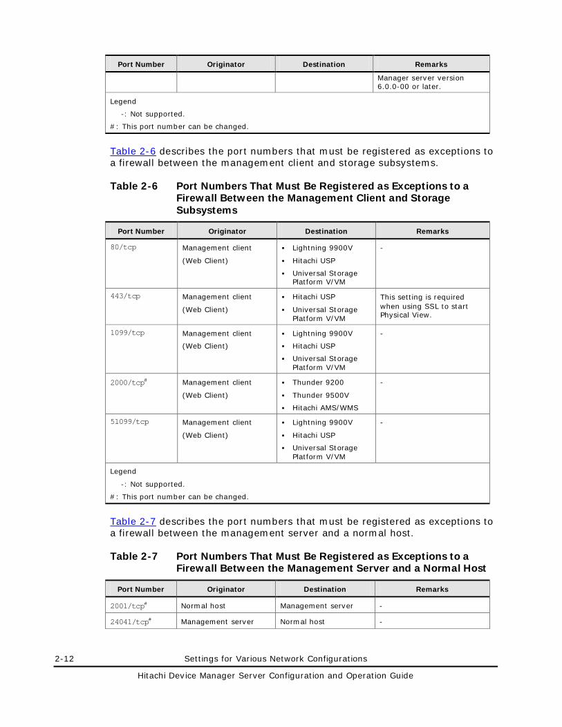
2-12 Settings for Various Network Configurations
Hitachi Device Manager Server Configuration and Operation Guide
Port Number Originator Destination Remarks
Manager server version 6.0.0-00 or later.
Legend
-: Not supported.
#: This port number can be changed.
Table 2-6 describes the port numbers that must be registered as exceptions to a firewall between the management client and storage subsystems.
Table 2-6 Port Numbers That Must Be Registered as Exceptions to a Firewall Between the Management Client and Storage Subsystems
Port Number Originator Destination Remarks
80/tcp Management client
(Web Client)
Lightning 9900V
Hitachi USP
Universal Storage Platform V/VM
-
443/tcp Management client
(Web Client)
Hitachi USP
Universal Storage Platform V/VM
This setting is required when using SSL to start Physical View.
1099/tcp Management client
(Web Client)
Lightning 9900V
Hitachi USP
Universal Storage Platform V/VM
-
2000/tcp# Management client
(Web Client)
Thunder 9200
Thunder 9500V
Hitachi AMS/WMS
-
51099/tcp Management client
(Web Client)
Lightning 9900V
Hitachi USP
Universal Storage Platform V/VM
-
Legend
-: Not supported.
#: This port number can be changed.
Table 2-7 describes the port numbers that must be registered as exceptions to a firewall between the management server and a normal host.
Table 2-7 Port Numbers That Must Be Registered as Exceptions to a Firewall Between the Management Server and a Normal Host
Port Number Originator Destination Remarks
2001/tcp# Normal host Management server -
24041/tcp# Management server Normal host -
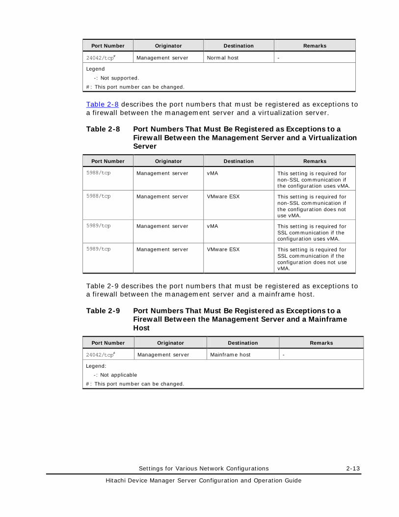
Settings for Various Network Configurations 2-13
Hitachi Device Manager Server Configuration and Operation Guide
Port Number Originator Destination Remarks
24042/tcp# Management server Normal host -
Legend
-: Not supported.
#: This port number can be changed.
Table 2-8 describes the port numbers that must be registered as exceptions to a firewall between the management server and a virtualization server.
Table 2-8 Port Numbers That Must Be Registered as Exceptions to a Firewall Between the Management Server and a Virtualization Server
Port Number Originator Destination Remarks
5988/tcp Management server vMA This setting is required for non-SSL communication if the configuration uses vMA.
5988/tcp Management server VMware ESX This setting is required for non-SSL communication if the configuration does not use vMA.
5989/tcp Management server vMA This setting is required for SSL communication if the configuration uses vMA.
5989/tcp Management server VMware ESX This setting is required for SSL communication if the configuration does not use vMA.
Table 2-9 describes the port numbers that must be registered as exceptions to a firewall between the management server and a mainframe host.
Table 2-9 Port Numbers That Must Be Registered as Exceptions to a Firewall Between the Management Server and a Mainframe Host
Port Number Originator Destination Remarks
24042/tcp# Management server Mainframe host -
Legend:
-: Not applicable
#: This port number can be changed.
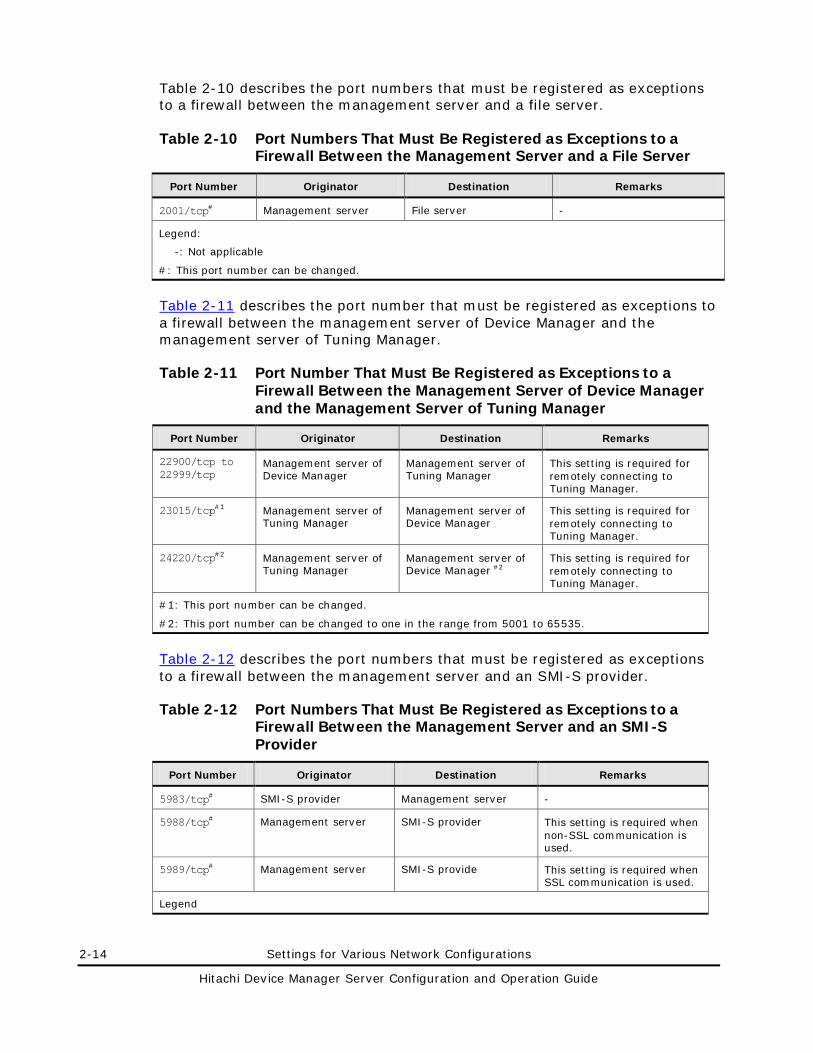
2-14 Settings for Various Network Configurations
Hitachi Device Manager Server Configuration and Operation Guide
Table 2-10 describes the port numbers that must be registered as exceptions to a firewall between the management server and a file server.
Table 2-10 Port Numbers That Must Be Registered as Exceptions to a Firewall Between the Management Server and a File Server
Port Number Originator Destination Remarks
2001/tcp# Management server File server -
Legend:
-: Not applicable
#: This port number can be changed.
Table 2-11 describes the port number that must be registered as exceptions to a firewall between the management server of Device Manager and the management server of Tuning Manager.
Table 2-11 Port Number That Must Be Registered as Exceptions to a Firewall Between the Management Server of Device Manager and the Management Server of Tuning Manager
Port Number Originator Destination Remarks
22900/tcp to 22999/tcp
Management server of Device Manager
Management server of Tuning Manager
This setting is required for remotely connecting to Tuning Manager.
23015/tcp#1 Management server of Tuning Manager
Management server of Device Manager
This setting is required for remotely connecting to Tuning Manager.
24220/tcp#2 Management server of Tuning Manager
Management server of Device Manager #2
This setting is required for remotely connecting to Tuning Manager.
#1: This port number can be changed.
#2: This port number can be changed to one in the range from 5001 to 65535.
Table 2-12 describes the port numbers that must be registered as exceptions to a firewall between the management server and an SMI-S provider.
Table 2-12 Port Numbers That Must Be Registered as Exceptions to a Firewall Between the Management Server and an SMI-S Provider
Port Number Originator Destination Remarks
5983/tcp# SMI-S provider Management server -
5988/tcp# Management server SMI-S provider This setting is required when non-SSL communication is used.
5989/tcp# Management server SMI-S provide This setting is required when SSL communication is used.
Legend
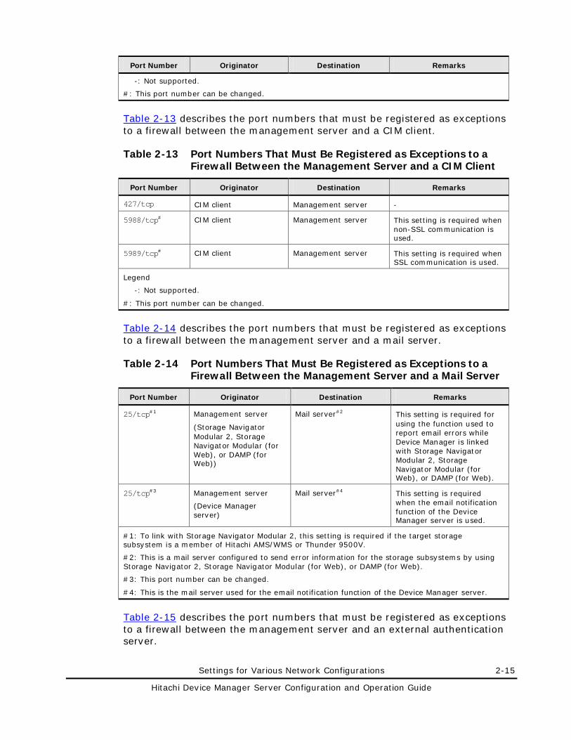
Settings for Various Network Configurations 2-15
Hitachi Device Manager Server Configuration and Operation Guide
Port Number Originator Destination Remarks
-: Not supported.
#: This port number can be changed.
Table 2-13 describes the port numbers that must be registered as exceptions to a firewall between the management server and a CIM client.
Table 2-13 Port Numbers That Must Be Registered as Exceptions to a Firewall Between the Management Server and a CIM Client
Port Number Originator Destination Remarks
427/tcp CIM client Management server -
5988/tcp# CIM client Management server This setting is required when non-SSL communication is used.
5989/tcp# CIM client Management server This setting is required when SSL communication is used.
Legend
-: Not supported.
#: This port number can be changed.
Table 2-14 describes the port numbers that must be registered as exceptions to a firewall between the management server and a mail server.
Table 2-14 Port Numbers That Must Be Registered as Exceptions to a Firewall Between the Management Server and a Mail Server
Port Number Originator Destination Remarks
25/tcp#1 Management server
(Storage Navigator Modular 2, Storage Navigator Modular (for Web), or DAMP (for Web))
Mail server#2 This setting is required for using the function used to report email errors while Device Manager is linked with Storage Navigator Modular 2, Storage Navigator Modular (for Web), or DAMP (for Web).
25/tcp#3 Management server
(Device Manager server)
Mail server#4 This setting is required when the email notification function of the Device Manager server is used.
#1: To link with Storage Navigator Modular 2, this setting is required if the target storage subsystem is a member of Hitachi AMS/WMS or Thunder 9500V.
#2: This is a mail server configured to send error information for the storage subsystems by using Storage Navigator 2, Storage Navigator Modular (for Web), or DAMP (for Web).
#3: This port number can be changed.
#4: This is the mail server used for the email notification function of the Device Manager server.
Table 2-15 describes the port numbers that must be registered as exceptions to a firewall between the management server and an external authentication server.
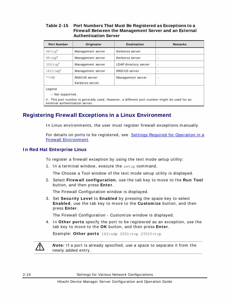
2-16 Settings for Various Network Configurations
Hitachi Device Manager Server Configuration and Operation Guide
Table 2-15 Port Numbers That Must Be Registered as Exceptions to a Firewall Between the Management Server and an External Authentication Server
Port Number Originator Destination Remarks
88/tcp# Management server Kerberos server -
88/udp# Management server Kerberos server -
359/tcp# Management server LDAP directory server -
1812/udp# Management server RADIUS server -
*/udp RADIUS server
Kerberos server
Management server -
Legend
-: Not supported.
#: This port number is generally used. However, a different port number might be used for an external authentication server.
Registering Firewall Exceptions in a Linux Environment
In Linux environments, the user must register firewall exceptions manually.
For details on ports to be registered, see Settings Required for Operation in a Firewall Environment.
In Red Hat Enterprise Linux
To register a firewall exception by using the text mode setup utility:
1. In a terminal window, execute the setup command.
The Choose a Tool window of the text mode setup utility is displayed.
2. Select Firewall configuration, use the tab key to move to the Run Tool button, and then press Enter.
The Firewall Configuration window is displayed.
3. Set Security Level to Enabled by pressing the space key to select Enabled, use the tab key to move to the Customize button, and then press Enter.
The Firewall Configuration - Customize window is displayed.
4. In Other ports specify the port to be registered as an exception, use the tab key to move to the OK button, and then press Enter.
Example: Other ports 162:udp 2001:tcp 23015:tcp
Note: If a port is already specified, use a space to separate it from the newly added entry.
Settings for Various Network Configurations 2-17
Hitachi Device Manager Server Configuration and Operation Guide
5. After returning to the Firewall Configuration window, check that Security Level is Enabled, use the tab key to move to the OK button, and then press Enter.
In SUSE Linux Enterprise Server
To register a firewall exception by using SuSEFirewall2:
1. Edit the /etc/sysconfig/SuSEfirewall2 file to specify the port to be registered as an exception.
Specify the port numbers to be registered as exceptions, in the following format:
– FW_SERVICES_EXT_TCP="TCP-port-number"
– FW_SERVICES_EXT_UDP="UDP-port-number"
Example: In this example, 2001, 23015, 23016, 23017, 23018, 161, and 162 are registered as exceptions.
FW_SERVICES_EXT_TCP="2001 23015:23018" FW_SERVICES_EXT_UDP="161 162"
2. Execute /sbin/SuSEfirewall2.
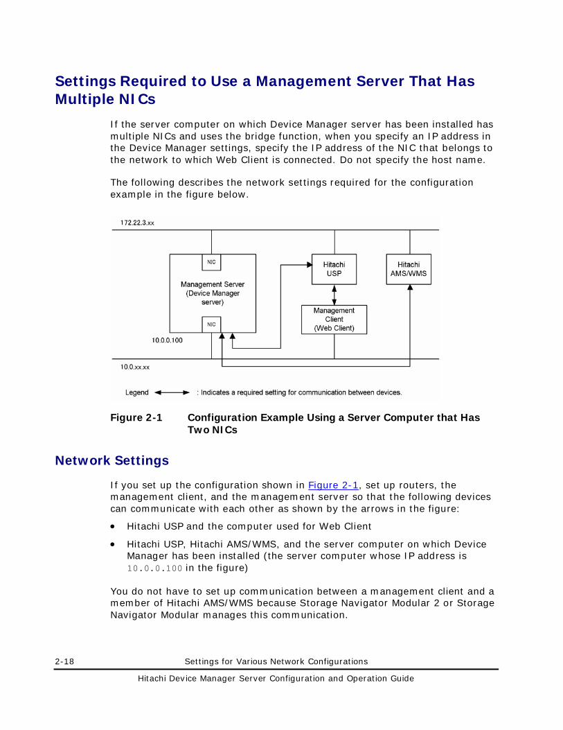
2-18 Settings for Various Network Configurations
Hitachi Device Manager Server Configuration and Operation Guide
Settings Required to Use a Management Server That Has Multiple NICs
If the server computer on which Device Manager server has been installed has multiple NICs and uses the bridge function, when you specify an IP address in the Device Manager settings, specify the IP address of the NIC that belongs to the network to which Web Client is connected. Do not specify the host name.
The following describes the network settings required for the configuration example in the figure below.
Figure 2-1 Configuration Example Using a Server Computer that Has Two NICs
Network Settings
If you set up the configuration shown in Figure 2-1, set up routers, the management client, and the management server so that the following devices can communicate with each other as shown by the arrows in the figure:
• Hitachi USP and the computer used for Web Client
• Hitachi USP, Hitachi AMS/WMS, and the server computer on which Device Manager has been installed (the server computer whose IP address is 10.0.0.100 in the figure)
You do not have to set up communication between a management client and a member of Hitachi AMS/WMS because Storage Navigator Modular 2 or Storage Navigator Modular manages this communication.
Settings for Various Network Configurations 2-19
Hitachi Device Manager Server Configuration and Operation Guide
Settings for the Device Manager Server
When you use a Device Manager property to specify an IP address, specify the IP address of the NIC that belongs to the network to which the management client connects.
The settings required for the configuration in Figure 2-1 are as follows:
• Specifying the property for the Device Manager server:
For the server.http.host property, specify the IP address of the computer on which the web server function of Device Manager is used. server.http.host=10.0.0.100
• Specifying the property for launchable applications:
As shown in Figure 2-1, if the management target is a member of Hitachi AMS/WMS, necessary settings vary depending on the application to be executed.
– If the application to be executed is DAMP or Storage Navigator Modular (for Web):
For the launchapp.damp.url property, specify the URL of the web server for Storage Navigator Modular (for Web) to be launched from the web browser of a management client.
launchapp.damp.url=http://10.0.0.100:23015/program/DeviceManager/snm
– If the application to be executed is Storage Navigator Modular 2:
For the launchapp.snm2.url property, specify the URL of the web server for Storage Navigator Modular 2 to be executed from a management client web browser.
launchapp.snm2.url=http://10.0.0.100:23015/program/StorageNavigatorModular/applet
Note: If the storage subsystem to be managed is a member of Hitachi AMS 2000 and Hitachi SMS, settings for Storage Navigator Modular 2 are not required.
For details about the Device Manager properties, see Specifying Properties.
Settings for Storage Navigator Modular 2 or Storage Navigator Modular (for Web)
In the configuration example in Figure 2-1, if you use the simple setup tool (launchapptool) to set the IP address to be specified for the web server’s URL, specify 10.0.0.100 for the IP address.
For details on how to set up the environment when Storage Navigator Modular 2 or Storage Navigator Modular (for Web) is to be launched and executed, see Settings for Linking with Storage Navigator Modular 2 or Settings for Linking with Storage Navigator Modular (for Web).
2-20 Settings for Various Network Configurations
Hitachi Device Manager Server Configuration and Operation Guide
Note: If the storage subsystem to be managed is a member of Hitachi AMS 2000 and Hitachi SMS, settings for Storage Navigator Modular 2 are not required.
For details on Storage Navigator Modular 2 and Storage Navigator Modular (for Web), see the manual for Storage Navigator Modular 2 or the Storage Navigator Modular (for Web) User’s Guide.

Settings for Various Network Configurations 2-21
Hitachi Device Manager Server Configuration and Operation Guide
Settings Required to Operate in an IPv6 Environment
This section describes the settings required to use Device Manager in an IPv6 environment. For details about the OSs that support Device Manager server operations in IPv6 environments, see Management Server Requirements.
Limitations on Operations in an IPv6 Environment
Note the following limitations when you use Device Manager in an IPv6 environment:
• Set up the OS so that both IPv6 and IPv4 can be used because, even if IPv6 is being used, IPv4 is also required for processing in the product.
• You can only use global addresses as IPv6 addresses. Global-unique local addresses, (site-local addresses, )and link-local addresses cannot be used.
• When specifying the IP address or host name of the Device Manager server, we recommend that you use the host name. If you specify an IPv6 address, in Internet Explorer® 6 you might not be able to connect to the Device Manager server or move among windows.
• If you specify a URL when setting up Storage Navigator Modular 2, Storage Navigator Modular (for Web), or DAMP (for Web), you cannot use IPv6 addresses. Use a host name for these settings.
Settings for Linking with Storage Subsystems That Support IPv6
If you use Physical View of Universal Storage Platform V/VM managed by using IPv6 addresses, set either of the following values for the server.http.host property in the server.properties file:
• The IPv6 address of the computer on which the Device Manager server is installed
• The host name of the computer on which the Device Manager server is installed#
#:
The host name must be resolvable to the IPv6 address.
For details on how to set the server.http.host property, see server.http.host.
Caution: If a storage subsystem that supports IPv6 is used with a Universal Storage Platform V/VM or Hitachi USP that is managed by using IPv4 addresses, in the server.http.host property you need to set an IPv4 address for any NIC for which an IPv6 address is specified.
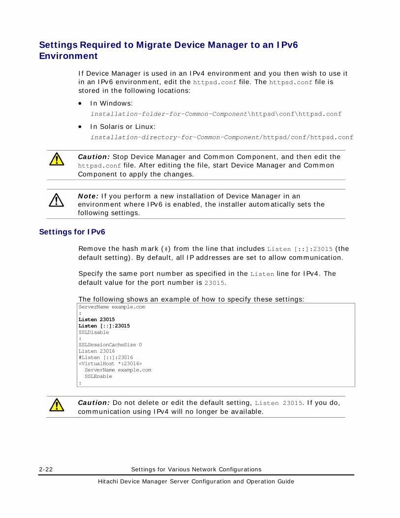
2-22 Settings for Various Network Configurations
Hitachi Device Manager Server Configuration and Operation Guide
Settings Required to Migrate Device Manager to an IPv6 Environment
If Device Manager is used in an IPv4 environment and you then wish to use it in an IPv6 environment, edit the httpsd.conf file. The httpsd.conf file is stored in the following locations:
• In Windows: installation-folder-for-Common-Component\httpsd\conf\httpsd.conf
• In Solaris or Linux: installation-directory-for-Common-Component/httpsd/conf/httpsd.conf
Caution: Stop Device Manager and Common Component, and then edit the httpsd.conf file. After editing the file, start Device Manager and Common Component to apply the changes.
Note: If you perform a new installation of Device Manager in an environment where IPv6 is enabled, the installer automatically sets the following settings.
Settings for IPv6
Remove the hash mark (#) from the line that includes Listen [::]:23015 (the default setting). By default, all IP addresses are set to allow communication.
Specify the same port number as specified in the Listen line for IPv4. The default value for the port number is 23015.
The following shows an example of how to specify these settings: ServerName example.com : Listen 23015 Listen [::]:23015 SSLDisable : SSLSessionCacheSize 0 Listen 23016 #Listen [::]:23016 <VirtualHost *:23016> ServerName example.com SSLEnable :
Caution: Do not delete or edit the default setting, Listen 23015. If you do, communication using IPv4 will no longer be available.
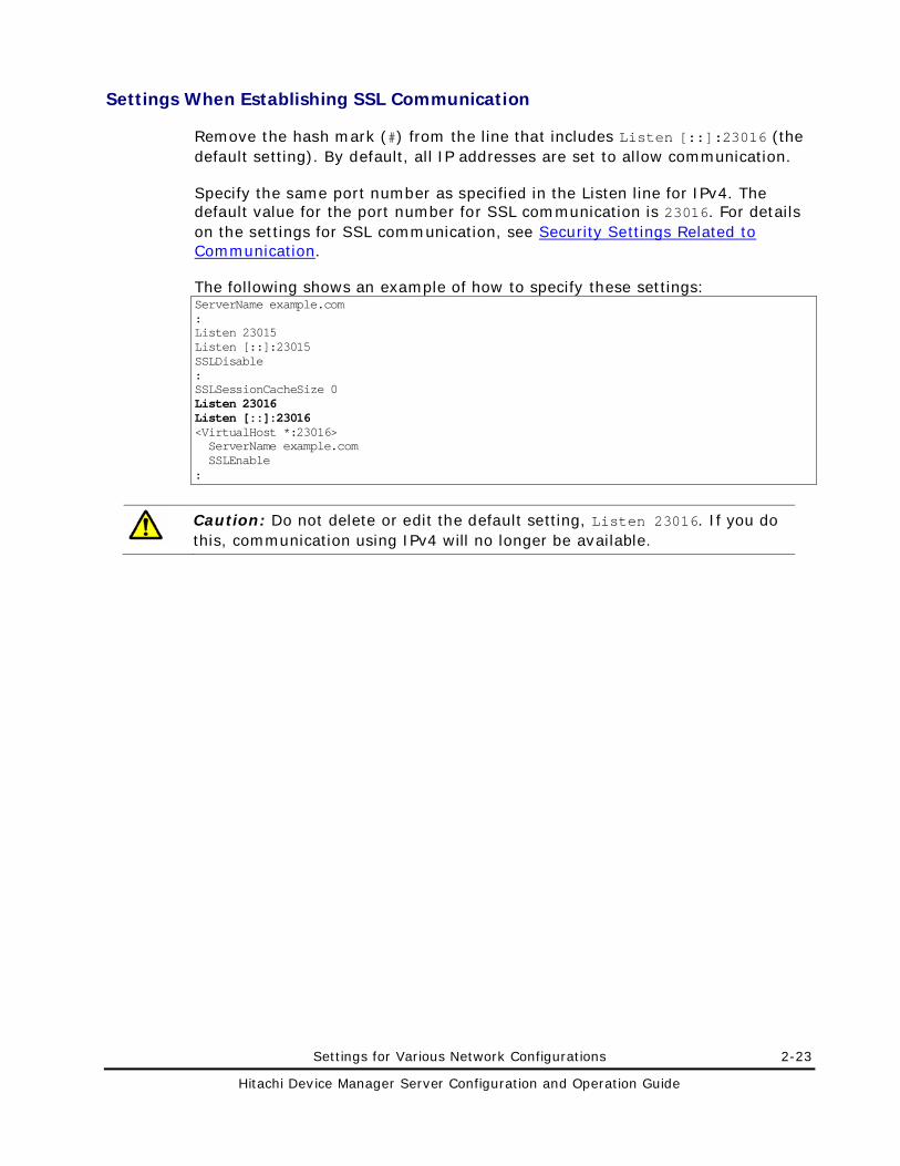
Settings for Various Network Configurations 2-23
Hitachi Device Manager Server Configuration and Operation Guide
Settings When Establishing SSL Communication
Remove the hash mark (#) from the line that includes Listen [::]:23016 (the default setting). By default, all IP addresses are set to allow communication.
Specify the same port number as specified in the Listen line for IPv4. The default value for the port number for SSL communication is 23016. For details on the settings for SSL communication, see Security Settings Related to Communication.
The following shows an example of how to specify these settings: ServerName example.com : Listen 23015 Listen [::]:23015 SSLDisable : SSLSessionCacheSize 0 Listen 23016 Listen [::]:23016 <VirtualHost *:23016> ServerName example.com SSLEnable :
Caution: Do not delete or edit the default setting, Listen 23016. If you do this, communication using IPv4 will no longer be available.
2-24 Settings for Various Network Configurations
Hitachi Device Manager Server Configuration and Operation Guide
Changing the IP Address or Host Name of the Management Server
If you change the IP address or host name of the management server, you also need to change the settings files of Hitachi Storage Command Suite products.
Changing the IP Address of the Management Server
This section describes how to change the IP address of the management server.
Caution: • If you have changed the IP address of the management server before
changing the settings files of Hitachi Storage Command Suite products, write down the new IP address.
• Do not change the settings in the cluster configuration file (the cluster.conf file).
To change the IP address of the management server:
1. If HiCommand Suite products whose versions are earlier than 5.7 are running, stop their services.
For details about how to stop these services, see the manual for your product version.
2. Stop the services of Hitachi Storage Command Suite products and Common Component.
– In Windows:
Select Start, All Programs, Hitachi Storage Command Suite, Device Manager, and then Stop Server with Common Services.
– In Solaris or Linux:
Execute the following command: installation-directory-for-Common-Component/bin/hcmdssrv -stop
3. Edit the httpsd.conf file.
If the old IP address is specified in the httpsd.conf file, change the IP address to the host name or the new IP address.
The httpsd.conf file is stored in the following locations:
– In Windows:
installation-folder-for-Common-Component\httpsd\conf\httpsd.conf
– In Solaris or Linux:
Settings for Various Network Configurations 2-25
Hitachi Device Manager Server Configuration and Operation Guide
installation-directory-for-Common-Component/httpsd/conf/httpsd.conf
Note: We recommend that you specify the host name in the httpsd.conf file.
4. Edit the pdsys file and the def_pdsys file.
If the old IP address is specified in the pdsys file and the def_pdsys file, change the IP address to the loopback address 127.0.0.1.
The pdsys and def_pdsys files are stored in the following locations:
– In Windows:
installation-folder-for-Common-Component\HDB\CONF\pdsys
installation-folder-for-Common-Component\database\work\def_pdsys
– In Solaris or Linux:
installation-directory-for-Common-Component/HDB/conf/pdsys
installation-directory-for-Common-Component/database/work/def_pdsys
5. Edit the pdutsys file and the def_pdutsys file.
If the old IP address is specified in the pdutsys file and the def_pdutsys file, change the IP address to the loopback address 127.0.0.1.
The pdutsys and def_pdutsys files are stored in the following locations:
– In Windows:
installation-folder-for-Common-Component\HDB\CONF\pdutsys
installation-folder-for-Common-Component\database\work\def_pdutsys
– In Solaris or Linux:
installation-directory-for-Common-Component/HDB/conf/pdutsys
installation-directory-for-Common-Component/database/work/def_pdutsys
Note: If the management server is running in a cluster configuration, you also need to change the IP address specified in the pdutsys file and the def_pdutsys file to the loopback address 127.0.0.1 on the standby node .
6. Edit the HiRDB.ini file.
If the old IP address is specified in the HiRDB.ini file, change the IP address to the loopback address 127.0.0.1.
The HiRDB.ini file is stored in the following locations:
– In Windows:
installation-folder-for-Common-Component\HDB\CONF\emb\HiRDB.ini
– In Solaris or Linux:
2-26 Settings for Various Network Configurations
Hitachi Device Manager Server Configuration and Operation Guide
installation-directory-for-Common-Component/HDB/conf/emb/HiRDB.ini
7. Change the IP address of the management server, and then restart the computer.
If the IP address of the management server has already been changed before you change the Common Component settings files, just restart the computer.
8. Make sure that the Common Component services are running.
– In Windows:
Select Start, All Programs, Hitachi Storage Command Suite, Device Manager, and then Server and Common Services Status.
– In Solaris or Linux:
Execute the following command: installation-directory-for-Common-Component/bin/hcmdssrv -status
– If the IP address is used in the URLs for accessing Hitachi Storage Command Suite products, change the setting.
For details on how to change the URLs, see Changing the URLs for Accessing Hitachi Storage Command Suite Products.
Note that, if you change the IP address of the management server, you need to check and, if necessary, revise the settings for each Hitachi Storage Command Suite product. For details about the settings that need to be changed, see Settings Required After Changing the IP Address or Host Name of the Management Server.
Changing the Host Name of the Management Server
This section describes how to change the host name of the management server.
Caution: • The host name must be no more than 32 bytes. You can use the
following characters:
A to Z a to z 0 to 9 and - Note that the host name cannot start or end with a hyphen (-).
• If you have changed the host name of the management server before changing the settings files of Hitachi Storage Command Suite products, use the hostname command to display the new host name and write it down (for Windows, the ipconfig /ALL command can also be used to display host names). For the host name in the Device Manager settings file, specify the name you recorded earlier. Note that this name is case-sensitive.
To change the host name of the management server:
Settings for Various Network Configurations 2-27
Hitachi Device Manager Server Configuration and Operation Guide
1. If HiCommand Suite products whose versions are earlier than 5.7 are running, stop their services. For details, see the manual for your product version.
2. Stop the services of Hitachi Storage Command Suite products and Common Component.
– In Windows:
Choose Start, All Program, Hitachi Storage Command Suite, Device Manager, and then Stop Server with Common Services
– In Solaris or Linux:
Execute the following command: installation-directory-for-Common-Component/bin/hcmdssrv -stop
3. If TLS/SSL is used for communication between the management server and management clients or an SMI-S provider, re-create a server certificate of the management server by using the new host name. For details on how to configure SSL settings, see Security Settings Related to Communication.
4. If the OS is Solaris or Linux, edit the /etc/hosts file.
Change the host name of the management server to the new host name. For Linux, write the new host name into the line above the localhost line.
5. Edit the httpsd.conf file.
Change the value for the ServerName parameter to the new host name.
The httpsd.conf file is stored in the following locations:
– In Windows:
installation-folder-for-Common-Component\httpsd\conf\httpsd.conf
– In Solaris or Linux:
installation-directory-for-Common-Component/httpsd/conf/httpsd.conf
If TLS/SSL is used for communication between the management server and management clients, you also need to change the following settings:
– If a host name has been specified for the <VirtualHost> tag, change the host name to an asterisk (*).
– Change the value for the ServerName parameter in the <VirtualHost> tag to the new host name.
6. Edit the pdsys file and def_pdsys file. Change the value for the -x option for the pdunit parameter to the loopback address 127.0.0.1.
The pdsys and def_pdsys files are stored in the following locations:
– In Windows:
installation-folder-for-Common-Component\HDB\CONF\pdsys
installation-folder-for-Common-Component\database\work\def_pdsys
– In Solaris or Linux:
installation-directory-for-Common-Component/HDB/conf/pdsys
2-28 Settings for Various Network Configurations
Hitachi Device Manager Server Configuration and Operation Guide
installation-directory-for-Common-Component/database/work/def_pdsys
7. Edit the pdutsys file and the def_pdutsys file.
Change the value for the pd_hostname parameter to the loopback address 127.0.0.1. If the pd_hostname parameter does not exist, add the pd_hostname parameter, specifying the loopback address.
The pdutsys and def_pdutsys files are stored in the following locations:
– In Windows:
installation-folder-for-Common-Component\HDB\CONF\pdutsys
installation-folder-for-Common-Component\database\work\def_pdutsys
– In Solaris or Linux:
installation-directory-for-Common-Component/HDB/conf/pdutsys
installation-directory-for-Common-Component/database/work/def_pdutsys
Note: If the management server is running in a cluster configuration, you also need to change the settings in the pdutsys file and the def_pdutsys file on the standby node. For the pd_hostname parameter on the standby node, specify the loopback address 127.0.0.1 or the host name of the executing node.
8. Edit the HiRDB.ini file. Change the value for the PDHOST parameter to the
loopback address 127.0.0.1.
The HiRDB.ini file is stored in the following locations:
– In Windows:
installation-folder-for-Common-Component\HDB\CONF\emb\HiRDB.ini
– In Solaris or Linux:
installation-directory-for-Common-Component/HDB/conf/emb/HiRDB.ini
9. Edit the cluster.conf file (applicable only for a cluster configuration). Change the corresponding logical host name, executing node’s host name, and standby node’s host name to the new host names.
The cluster.conf file is stored in the following location:
– In Windows:
installation-folder-for-Common-Component\conf\cluster.conf
– In Solaris:
installation-directory-for-Common-Component/conf/cluster.conf
10. Change the host name for the management server, and then restart the computer.
Settings for Various Network Configurations 2-29
Hitachi Device Manager Server Configuration and Operation Guide
If you have changed the host name for the management server before changing the Common Component settings files, just restart the computer.
11. Make sure that the Common Component services are running.
– In Windows:
Select Start, All Programs, Hitachi Storage Command Suite, Device Manager, and then Server and Common Services Status.
– In Solaris or Linux:
Execute the following command: installation-directory-for-Common-Component/bin/hcmdssrv -status
12. If the host name is used in the URLs for accessing Hitachi Storage Command Suite products, change the setting.
For details on how to change the URLs, see Changing the URLs for Accessing Hitachi Storage Command Suite Products.
Note that, if you change the host name of the management server, you need to check and, if necessary, revise the settings for each Hitachi Storage Command Suite product. For details about the settings that need to be changed, see Settings Required After Changing the IP Address or Host Name of the Management Server.
Settings Required After Changing the IP Address or Host Name of the Management Server
This section describes the settings required in Device Manager after you change the IP address or host name of the management server. For details about the settings for other Hitachi Storage Command Suite products, see the manual for each product.
In Device Manager, check and revise the following settings:
• Settings in the Device Manager server property files
If the old host name or IP address is specified for the server.http.host property in the server.properties file, you need to specify the new host name or IP address, and then restart the Device Manager server.
• Settings in the Device Manager agent property files
You need to execute the hdvmagt_account command to change the settings for the Device Manager server information (the server.server.authorization property). For details on how to do this, see the Hitachi Device Manager Agent Installation Guide.
Also, depending on the operating environment, you might need to check and revise the following settings:
2-30 Settings for Various Network Configurations
Hitachi Device Manager Server Configuration and Operation Guide
• If storage management tools are configured to be launched from Web Client, you need to use launchapptool to change the launch settings for the storage management tools (Storage Navigator Modular 2, Storage Navigator Modular, or DAMP (for Web)). For details on how to do this, see Launch Settings for Storage Navigator Modular 2, Launch Settings for Storage Navigator Modular (for Web), or Launch Settings for DAMP (for Web).
• If a RADIUS server is used to authenticate accounts
Check the settings in the exauth.properties file. For details on how to specify settings in the exauth.properties file, see Setting the exauth.properties File (When the Authentication Method Is RADIUS).
• If the Device Manager server and the Tuning Manager server are remotely connected
If all the following conditions are satisfied, change the registration of repository location.
– The IP address of the computer on which the Device Manager server is installed was changed.
– The IP address of the computer on which the Device Manager server is installed is set in the hsso.conf file of the computer on which the Tuning Manager server is installed.
For details on how to change the registration of repository location, see the Hitachi Tuning Manager Server Administration Guide.
• If VDS Provider is used to manage network resources
Use the hdvmconfig command to change the IP address of the Device Manager server specified for the server.ipaddress property in the vds.properties file. For details on how to do this, see Specifying Information in the vds.properties File.
Settings for Various Network Configurations 2-31
Hitachi Device Manager Server Configuration and Operation Guide
Changing the URLs for Accessing Hitachi Storage Command Suite Products
If any of the following configuration changes are made after you begin using Device Manager, you must also change the URLs for accessing Hitachi Storage Command Suite products:
• Changing the IP address or host name of a computer on which the Device Manager server is installed
• Changing to a port used by HBase Storage Mgmt Web Service
• Changing to the settings of the Device Manager system in order to use or stop using SSL
• Migrating to a cluster environment
Use the hcmdschgurl command to change the URLs for accessing Hitachi Storage Command Suite products.
Format:
In Windows:
installation-folder-for-Common-Component\bin\hcmdschgurl {/print | /list | /change old-URL new-URL | /change new-URL /type Hitachi-Storage-Command-Suite-product-name}
In Solaris or Linux:
installation-folder-for-Common-Component\bin\hcmdschgurl {-print | -list | -change old-URL new-URL | -change new-URL -type Hitachi-Storage-Command-Suite-product-name}
Options:
print: Specify this option to display a list of URLs and programs that are currently registered.
list: Specify this option to display the same information as the print option in a different format.
change: Specify this option to change a currently registered URL.
2-32 Settings for Various Network Configurations
Hitachi Device Manager Server Configuration and Operation Guide
Caution: • The specified URL must be a complete URL that contains protocols
and a port number. You cannot use an IPv6 address. You must use a host name to specify the URL in an IPv6 environment, as shown in the following example: http://127.0.0.1:23015 http://hostname:23015
• When changing the URL during migration to a cluster environment, use the following format to specify new-URL: http://logical-host-name:port-number
type: If you want to change the URL for a specific Hitachi Storage Command Suite product only, use this option to specify the name of that product. If you omit the type option, the URLs for all Hitachi Storage Command Suite products that are installed in the same management server will be changed. To change only the Device Manager URL, specify DeviceManager. To change only the Provisioning Manager URL, specify ProvisioningManager. For details on the names of other Hitachi Storage Command Suite products, see the documentation for each product.
Return values:
0: Normal
1: Argument error
2: URL does not exist
253: Restoration failure
254: Backup failure
255: Abnormal termination
For details about the errors, check a following log file:
– In Windows:
installation-folder-for-Common-Component\log\hcmdsChangeURLn.log
– In Solaris or Linux:
/var/installation-directory-for-Common-Component/log/hcmdsChangeURLn.log
To change the URLs for accessing Hitachi Storage Command Suite products:
1. Make sure that the Common Component services are running.
– In Windows:
Select Start, All Programs, Hitachi Storage Command Suite, Device Manager, and then Server and Common Services Status.
– In Solaris or Linux:
Execute the following command: installation-directory-for-Common-Component/bin/hcmdssrv -status
Settings for Various Network Configurations 2-33
Hitachi Device Manager Server Configuration and Operation Guide
2. Execute the command with the list option to check the current URL registered in the database.
– In Windows: C:\Program Files\HiCommand\Base\bin\hcmdschgurl /list http://192.168.11.33:23015 Hitachi DeviceManager Hitachi Provisioning Manager
– In Solaris or Linux: # /opt/HiCommand/Base/bin/hcmdschgurl -list http://192.168.11.33:23015 Hitachi DeviceManager Hitachi Provisioning Manager
3. Execute the command with the change option to change the URL information.
In the following example, the URL is changed from http://192.168.11.33:23015 to http://192.168.11.55:23015.
– In Windows: C:\Program Files\HiCommand\Base\bin\hcmdschgurl /change “http://192.168.11.33:23015” “http://192.168.11.55:23015” The URL was changed from “http://192.168.11.33:23015” to “http://192.168.11.55:23015”.
– In Solaris or Linux: # /opt/HiCommand/Base/bin/hcmdschgurl -change “http://192.168.11.33:23015” “http://192.168.11.55:23015” The URL was changed from “http://192.168.11.33:23015” to “http://192.168.11.55:23015”.
4. To confirm the results, execute the command with the list option specified.
– In Windows: C:\Program Files\HiCommand\Base\bin\hcmdschgurl /list http://192.168.11.55:23015 Hitachi DeviceManager Hitachi Provisioning Manager
– In Solaris or Linux: # /opt/HiCommand/Base/bin/hcmdschgurl -list http://192.168.11.55:23015 Hitachi DeviceManager Hitachi Provisioning Manager
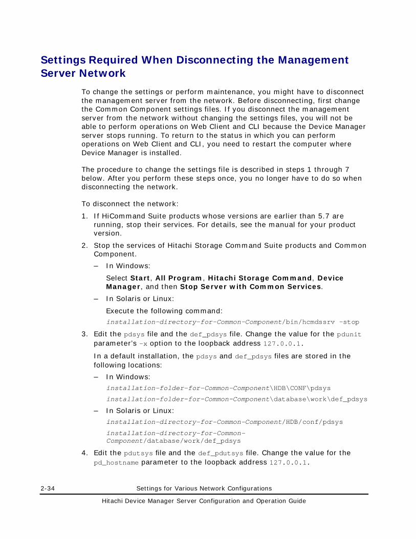
2-34 Settings for Various Network Configurations
Hitachi Device Manager Server Configuration and Operation Guide
Settings Required When Disconnecting the Management Server Network
To change the settings or perform maintenance, you might have to disconnect the management server from the network. Before disconnecting, first change the Common Component settings files. If you disconnect the management server from the network without changing the settings files, you will not be able to perform operations on Web Client and CLI because the Device Manager server stops running. To return to the status in which you can perform operations on Web Client and CLI, you need to restart the computer where Device Manager is installed.
The procedure to change the settings file is described in steps 1 through 7 below. After you perform these steps once, you no longer have to do so when disconnecting the network.
To disconnect the network:
1. If HiCommand Suite products whose versions are earlier than 5.7 are running, stop their services. For details, see the manual for your product version.
2. Stop the services of Hitachi Storage Command Suite products and Common Component.
– In Windows:
Select Start, All Program, Hitachi Storage Command, Device Manager, and then Stop Server with Common Services.
– In Solaris or Linux:
Execute the following command: installation-directory-for-Common-Component/bin/hcmdssrv -stop
3. Edit the pdsys file and the def_pdsys file. Change the value for the pdunit parameter’s -x option to the loopback address 127.0.0.1.
In a default installation, the pdsys and def_pdsys files are stored in the following locations:
– In Windows:
installation-folder-for-Common-Component\HDB\CONF\pdsys
installation-folder-for-Common-Component\database\work\def_pdsys
– In Solaris or Linux:
installation-directory-for-Common-Component/HDB/conf/pdsys
installation-directory-for-Common-Component/database/work/def_pdsys
4. Edit the pdutsys file and the def_pdutsys file. Change the value for the pd_hostname parameter to the loopback address 127.0.0.1.
Settings for Various Network Configurations 2-35
Hitachi Device Manager Server Configuration and Operation Guide
If the pd_hostname parameter does not exist, add the pd_hostname parameter to set a loopback address.
In a default installation, the pdutsys and def_pdutsys files are stored in the following locations:
– In Windows:
installation-folder-for-Common-Component\HDB\CONF\pdutsys
installation-folder-for-Common-Component\database\work\def_pdutsys
– In Solaris or Linux:
installation-directory-for-Common-Component/HDB/conf/pdutsys
installation-directory-for-Common-Component/database/work/def_pdutsys
5. Edit the HiRDB.ini file. Change the value for the PDHOST parameter to the loopback address 127.0.0.1.
In a default installation, the HiRDB.ini file is stored in the following location:
– In Windows:
installation-folder-for-Common-Component\HDB\CONF\emb\HiRDB.ini
– In Solaris or Linux: installation-directory-for-Common-Component/HDB/conf/emb/HiRDB.ini
6. Restart the computer.
7. Make sure that the Common Component services are running.
– In Windows:
Select Start, All Program, Hitachi Storage Command Suite, Device Manager, and then Server and Common Services Status.
– In Solaris or Linux:
Execute the following command:
installation-directory-for-Common-Component/bin/hcmdssrv -status
8. Disconnect the network, and then change the settings or perform maintenance.
9. After the network becomes available, start the service of the Device Manager server, the services of other Hitachi Storage Command Suite products, and Hitachi Storage Command Suite Common Component.
– In Windows:
Select Start, All Program, Hitachi Storage Command Suite, Device Manager, and then Start Server with Common Services.
– In Solaris or Linux, execute the following command:
installation-directory-for-Common-Component/bin/hcmdssrv -start
2-36 Settings for Various Network Configurations
Hitachi Device Manager Server Configuration and Operation Guide
10. If Hitachi Storage Command Suite products have been installed, start their services as required. For details, see the manual for your product.
Settings Required for Managing User Accounts 3-1
Hitachi Device Manager Server Configuration and Operation Guide
Settings Required for Managing User Accounts
This chapter describes the settings required for Device Manager to manage user accounts.
Setting Password Conditions for User Accounts
Settings for Locking User Accounts
Settings Required to Authenticate Users by Using an External Authentication Server
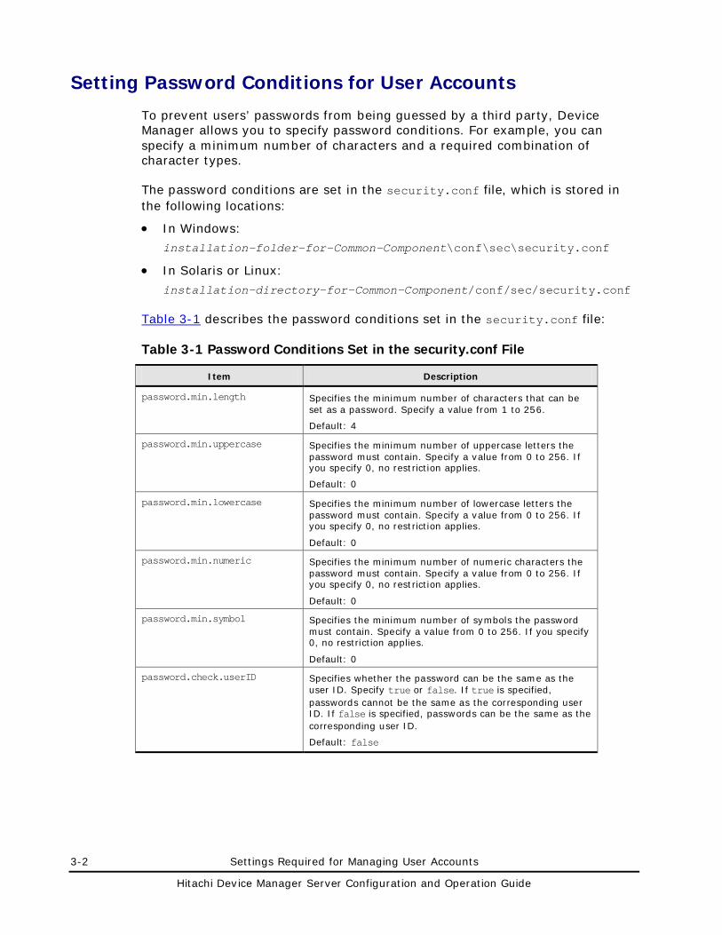
3-2 Settings Required for Managing User Accounts
Hitachi Device Manager Server Configuration and Operation Guide
Setting Password Conditions for User Accounts
To prevent users’ passwords from being guessed by a third party, Device Manager allows you to specify password conditions. For example, you can specify a minimum number of characters and a required combination of character types.
The password conditions are set in the security.conf file, which is stored in the following locations:
• In Windows:
installation-folder-for-Common-Component\conf\sec\security.conf
• In Solaris or Linux:
installation-directory-for-Common-Component/conf/sec/security.conf
Table 3-1 describes the password conditions set in the security.conf file:
Table 3-1 Password Conditions Set in the security.conf File
Item Description
password.min.length Specifies the minimum number of characters that can be set as a password. Specify a value from 1 to 256.
Default: 4
password.min.uppercase Specifies the minimum number of uppercase letters the password must contain. Specify a value from 0 to 256. If you specify 0, no restriction applies.
Default: 0
password.min.lowercase Specifies the minimum number of lowercase letters the password must contain. Specify a value from 0 to 256. If you specify 0, no restriction applies.
Default: 0
password.min.numeric Specifies the minimum number of numeric characters the password must contain. Specify a value from 0 to 256. If you specify 0, no restriction applies.
Default: 0
password.min.symbol Specifies the minimum number of symbols the password must contain. Specify a value from 0 to 256. If you specify 0, no restriction applies.
Default: 0
password.check.userID Specifies whether the password can be the same as the user ID. Specify true or false. If true is specified, passwords cannot be the same as the corresponding user ID. If false is specified, passwords can be the same as the corresponding user ID.
Default: false
Settings Required for Managing User Accounts 3-3
Hitachi Device Manager Server Configuration and Operation Guide
When you change a setting in the security.conf file, the change takes effect immediately. The password conditions that you set in the security.conf file are applied when a user account is created or when a password is changed, and are not applied to passwords of existing user accounts. As a result, even if an existing password does not satisfy the password conditions, a user can continue to use the password to log in to the system.
Caution: • Password conditions can also be set from Web Client. However, if the
system is in a cluster configuration, the settings from Web Client are only applied to the executing node. To apply the settings to the standby node, switch the nodes, and then specify the same settings. For details on how to use Web Client, see the Device Manager online Help.
• If Hitachi Storage Command Suite product versions 5.1 or later are installed, password conditions can be set. The password conditions are applied to all users registered in Hitachi Storage Command Suite products. Therefore, if you are unable to change a password or add a user account while using HiCommand Suite product versions 5.0 or earlier, the reason might be that the specified character string does not satisfy the password conditions. Follow the output message and specify an appropriate password.
• If an external authentication server is used to authenticate users, passwords are checked by using a combination of character types specified on the external authentication server. However, if you register a password for a Hitachi Storage Command Suite product user, you need to use character types specified in the Hitachi Storage Command Suite products.
3-4 Settings Required for Managing User Accounts
Hitachi Device Manager Server Configuration and Operation Guide
Settings for Locking User Accounts
This section describes the settings related to locking user accounts.
Settings for Automatic Locking
Device Manager provides settings by which a user account is automatically locked after repeated unsuccessful login attempts to Web Client. Such automatic locking reduces the risk of unauthorized access to Web Client.
The settings related to automatic locking are set using the account.lock.num property in the security.conf file, which is stored in the following locations:
• In Windows: installation-folder-for-Common-Component\conf\sec\security.conf
• In Solaris or Linux:
installation-directory-for-Common-Component/conf/sec/security.conf
Specify a value from 0 to 10 (default: 0). If a user makes the specified number of unsuccessful logon attempts, his or her user account will be locked. If you specify 0, any number of unsuccessful logon attempts is allowed. When you change a setting in the security.conf file, the change takes effect immediately.
Unsuccessful attempts to log on to other products in the Hitachi Storage Command Suite that use the Single Sign-On feature count towards the number of unsuccessful logon attempts. For example, if the number of unsuccessful attempts is set to 3, and a user fails to log on to Device Manager once, fails to log on to Provisioning Manager once, and then fails to log on to Tiered Storage Manager once, his or her user account will be automatically locked.
If the number of unsuccessful logon attempts is changed, the new number will be applied the next time an attempt to log on fails. If a user is currently logged on and you attempt to log on using his or her account, but you fail the specified number of times, his or her user account will be locked. However, the user can continue to perform operations while still logged on.
You can unlock user accounts from Web Client. You must have the User Management permission to unlock a user account. For details about unlocking user accounts, see the Device Manager online Help.
Settings Required for Managing User Accounts 3-5
Hitachi Device Manager Server Configuration and Operation Guide
Caution: • Settings related to locking can also be specified from Web Client.
However, if the system is in a cluster configuration, the settings from Web Client are only applied to the executing node. To apply the settings to the standby node, switch the nodes, and then specify the same settings. For details on how to use Web Client, see the Device Manager online Help.
• You can specify settings for automatic locking if Hitachi Storage Command Suite product versions 5.1 or later are installed.
These settings are applied to all Hitachi Storage Command Suite product versions, so there is a risk of login failure if versions 5.0 or earlier (which do not support automatic locking) are being used. If login fails despite a correctly specified user ID and password, take appropriate action, such as unlocking the relevant user account and registering a new user account.
• If an external authentication server is used to authenticate users, the settings on the external authentication server are used to control automatic locking.
Settings for Automatic Locking of the System Account
The System account is not subject to automatic or manual locking during the initial installation of Device Manager. If you want to also make the System account subject to locking, specify this setting in the account.lock.system property in the user.conf file, which is stored in the following locations:
• In Windows: installation-folder-for-Common-Component\conf\user.conf
• In Solaris or Linux: installation-directory-for-Common-Component/conf/user.conf
If the user.conf file does not exist, create it.
Specify the account.lock.system property in the following format: account.lock.system=value
For value, specify true or false. If you specify true, the System account is subject to automatic and manual locking. If you specify false, the System account is not subject to automatic or manual locking.
Note that you need to restart Common Component for the value set in the user.conf file to take effect. For details about how to restart Common Component, see Stopping the Device Manager Server and Common Component and Starting the Device Manager Server and Common Component.
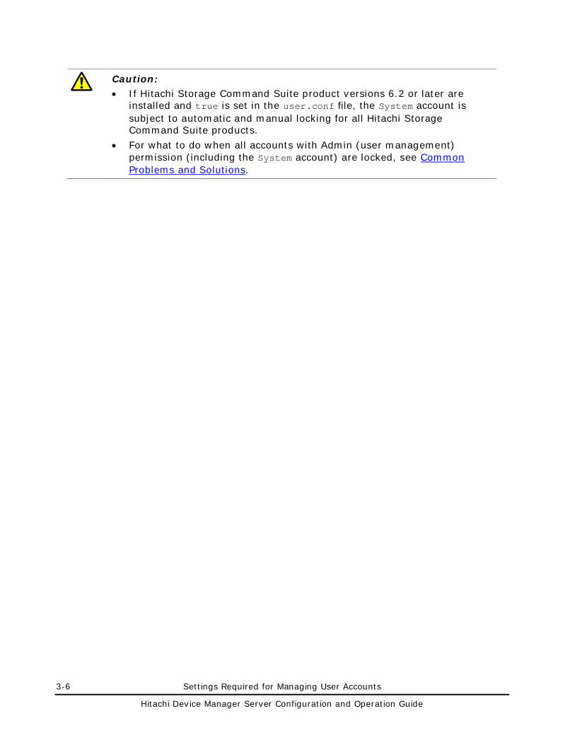
3-6 Settings Required for Managing User Accounts
Hitachi Device Manager Server Configuration and Operation Guide
Caution: • If Hitachi Storage Command Suite product versions 6.2 or later are
installed and true is set in the user.conf file, the System account is subject to automatic and manual locking for all Hitachi Storage Command Suite products.
• For what to do when all accounts with Admin (user management) permission (including the System account) are locked, see Common Problems and Solutions.
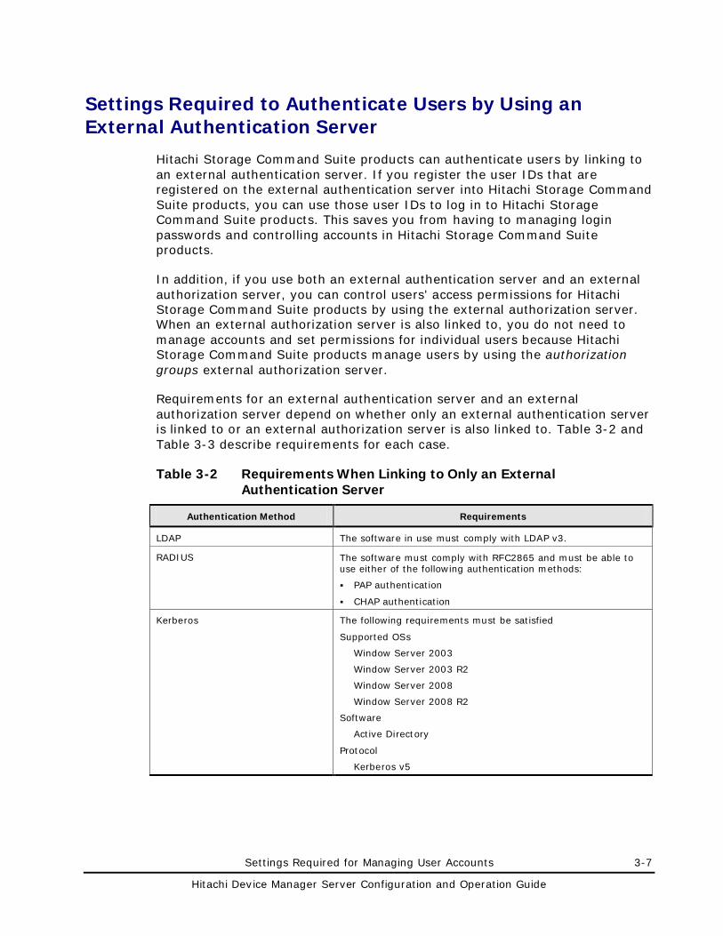
Settings Required for Managing User Accounts 3-7
Hitachi Device Manager Server Configuration and Operation Guide
Settings Required to Authenticate Users by Using an External Authentication Server
Hitachi Storage Command Suite products can authenticate users by linking to an external authentication server. If you register the user IDs that are registered on the external authentication server into Hitachi Storage Command Suite products, you can use those user IDs to log in to Hitachi Storage Command Suite products. This saves you from having to managing login passwords and controlling accounts in Hitachi Storage Command Suite products.
In addition, if you use both an external authentication server and an external authorization server, you can control users' access permissions for Hitachi Storage Command Suite products by using the external authorization server. When an external authorization server is also linked to, you do not need to manage accounts and set permissions for individual users because Hitachi Storage Command Suite products manage users by using the authorization groups external authorization server.
Requirements for an external authentication server and an external authorization server depend on whether only an external authentication server is linked to or an external authorization server is also linked to. Table 3-2 and Table 3-3 describe requirements for each case.
Table 3-2 Requirements When Linking to Only an External Authentication Server
Authentication Method Requirements
LDAP The software in use must comply with LDAP v3.
RADIUS The software must comply with RFC2865 and must be able to use either of the following authentication methods:
PAP authentication
CHAP authentication
Kerberos The following requirements must be satisfied
Supported OSs
Window Server 2003
Window Server 2003 R2
Window Server 2008
Window Server 2008 R2
Software
Active Directory
Protocol
Kerberos v5
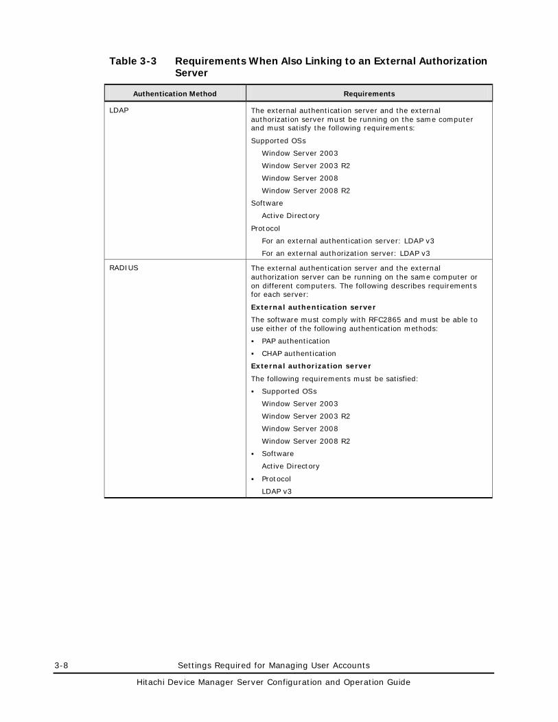
3-8 Settings Required for Managing User Accounts
Hitachi Device Manager Server Configuration and Operation Guide
Table 3-3 Requirements When Also Linking to an External Authorization Server
Authentication Method Requirements
LDAP The external authentication server and the external authorization server must be running on the same computer and must satisfy the following requirements:
Supported OSs
Window Server 2003
Window Server 2003 R2
Window Server 2008
Window Server 2008 R2
Software
Active Directory
Protocol
For an external authentication server: LDAP v3
For an external authorization server: LDAP v3
RADIUS The external authentication server and the external authorization server can be running on the same computer or on different computers. The following describes requirements for each server:
External authentication server
The software must comply with RFC2865 and must be able to use either of the following authentication methods:
PAP authentication
CHAP authentication
External authorization server
The following requirements must be satisfied:
Supported OSs
Window Server 2003
Window Server 2003 R2
Window Server 2008
Window Server 2008 R2
Software
Active Directory
Protocol
LDAP v3
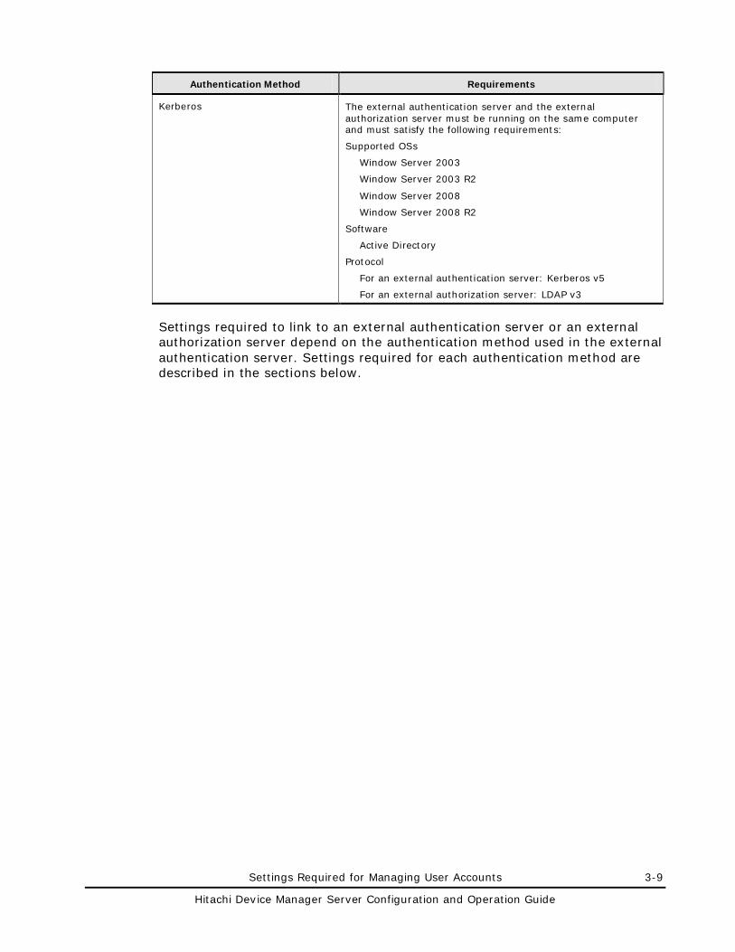
Settings Required for Managing User Accounts 3-9
Hitachi Device Manager Server Configuration and Operation Guide
Authentication Method Requirements
Kerberos The external authentication server and the external authorization server must be running on the same computer and must satisfy the following requirements:
Supported OSs
Window Server 2003
Window Server 2003 R2
Window Server 2008
Window Server 2008 R2
Software
Active Directory
Protocol
For an external authentication server: Kerberos v5
For an external authorization server: LDAP v3
Settings required to link to an external authentication server or an external authorization server depend on the authentication method used in the external authentication server. Settings required for each authentication method are described in the sections below.
3-10 Settings Required for Managing User Accounts
Hitachi Device Manager Server Configuration and Operation Guide
Caution: If command line control characters are included in the arguments of commands that will be executed when specifying the settings to link to an external authentication server, escape the characters correctly according to the specifications of the command line.
Also, you need to pay attention to backslashes (\) included in the arguments because they are treated specially in the command line.
– In Windows: If the following characters are included in an argument, enclose the argument in double quotation marks (") or use a caret (^) to escape each character: Spaces & | ^ < > ( ) A backslash might be treated as an escape character depending on the character that follows it. Therefore, if a backslash and any of the above characters are included in an argument, use a caret to escape each character rather than enclose the argument in double quotation marks. Also, if there is a backslash at the end of an argument, escape it by using another backslash.
– In Solaris or Linux: If the following characters are included in an argument, enclose the argument in double quotation marks or use a backslash to escape each character: Spaces # & ' ( ) ~ \ ` < > ; | Note that a backslash in an argument is treated as an escape character even if the argument is enclosed in double quotation marks. If a backslash is included in an argument, escape it by using another backslash.
For example, if a shared secret to be registered by the hcmdsradiussecret command is secret01\, escape it as follows:
– In Windows: hcmdsradiussecret /set secret01\\ /name ServerName
– In Solaris or Linux: Use either of the following formats: hcmdsradiussecret -set secret01\\ -name ServerName hcmdsradiussecret -set "secret01\\" -name ServerName
Settings Required When Using an LDAP Directory Server for Authentication
To authenticate users by using an LDAP directory server, specify the following settings in Hitachi Storage Command Suite products.
1. Check the data structure of the LDAP directory server to determine the method for linking with Hitachi Storage Command Suite products and for authentication.
Settings Required for Managing User Accounts 3-11
Hitachi Device Manager Server Configuration and Operation Guide
2. In the exauth.properties file on the management server, specify necessary information.
Necessary settings depend on whether only an external authentication server is linked to or an external authorization server is also linked to.
You can use either of the following methods to define the LDAP directory server:
– In the exauth.properties file, directly specify information about the LDAP directory server to connect to.
Specify information such as IP address and port number in the exauth.properties file for each LDAP directory server.
– Use the DNS server to look up the LDAP directory server to connect to.
Before using this method, you need to set up the DNS server environment on the OS of the LDAP directory server. In addition, you need to register the host name, port number, and domain name of the LDAP directory server in the SRV records of the DNS server.
Note: To use StartTLS for communication between the management server and the LDAP directory server, you need to directly specify information about the LDAP directory server to connect to in the exauth.properties file.
If you use the DNS server to look up the LDAP directory server to connect to, it might take longer for users to log in.
3. In the following cases, on the management server, register a user account used to search for user information on the LDAP directory server.
– When the data structure is the hierarchical structure model
– When the data structure is the flat model and an external authorization server is also linked to#
#:
When registering an authorization group in Hitachi Storage Command Suite products by using Web Client (For details on the procedure, see step 5), if you want to check whether the distinguished name of the authorization group is registered on the external authorization server by using a user ID such as the System account registered in Hitachi Storage Command Suite products, you need to register a user account used to search for LDAP user information on the management server.
4. On the LDAP directory server, register the accounts of users that will use Hitachi Storage Command Suite products.
User IDs and passwords must consist of characters that can be used in Hitachi Storage Command Suite products. Specify 1 to 256 bytes of the following characters:
0 to 9 A to Z a to z ! # $ % & ' ( ) * + - . = @ \ ^ _ |
3-12 Settings Required for Managing User Accounts
Hitachi Device Manager Server Configuration and Operation Guide
In Hitachi Storage Command Suite products, user IDs are not case-sensitive. The combination of character types for passwords must follow the settings in the external authentication server.
5. Register accounts and set permissions by using Web Client.
When linking to only an external authentication server
• Register users.
• Change the authentication method of users.#
• Set permissions for users.
• Assign resource groups to users.
#: This operation is required if you want to change the authentication method of existing users.
When also linking to an external authorization server
• Register authorization groups.
• Set permissions for authorization groups.
You do not need to assign resource groups to authorization groups. All Resources will be automatically assigned to users who belong to authorization groups.
6. Use the hcmdscheckauth command to make sure that the external authentication server and the external authorization server can be properly connected to.
The following sections describe operations you need to perform on the management server. For details on how to use Web Client, see the Device Manager online Help.
Checking the Data Structure and Authentication Method
The LDAP directory server has the following two data structure models.
• Hierarchical structure model
• Flat model
You must first determine which data structure model is being used, because the information you need to set in the exauth.properties file and the operations you need to perform on the management server depend on the data structure.
In addition, check BaseDN, which is the entry that will be the start point for searching for LDAP user information during authentication. BaseDN must be specified in the exauth.properties file. Only the user entries that are in the hierarchy below BaseDN can be authenticated. Make sure that all users you want to authenticate for Hitachi Storage Command Suite products are in this hierarchy.
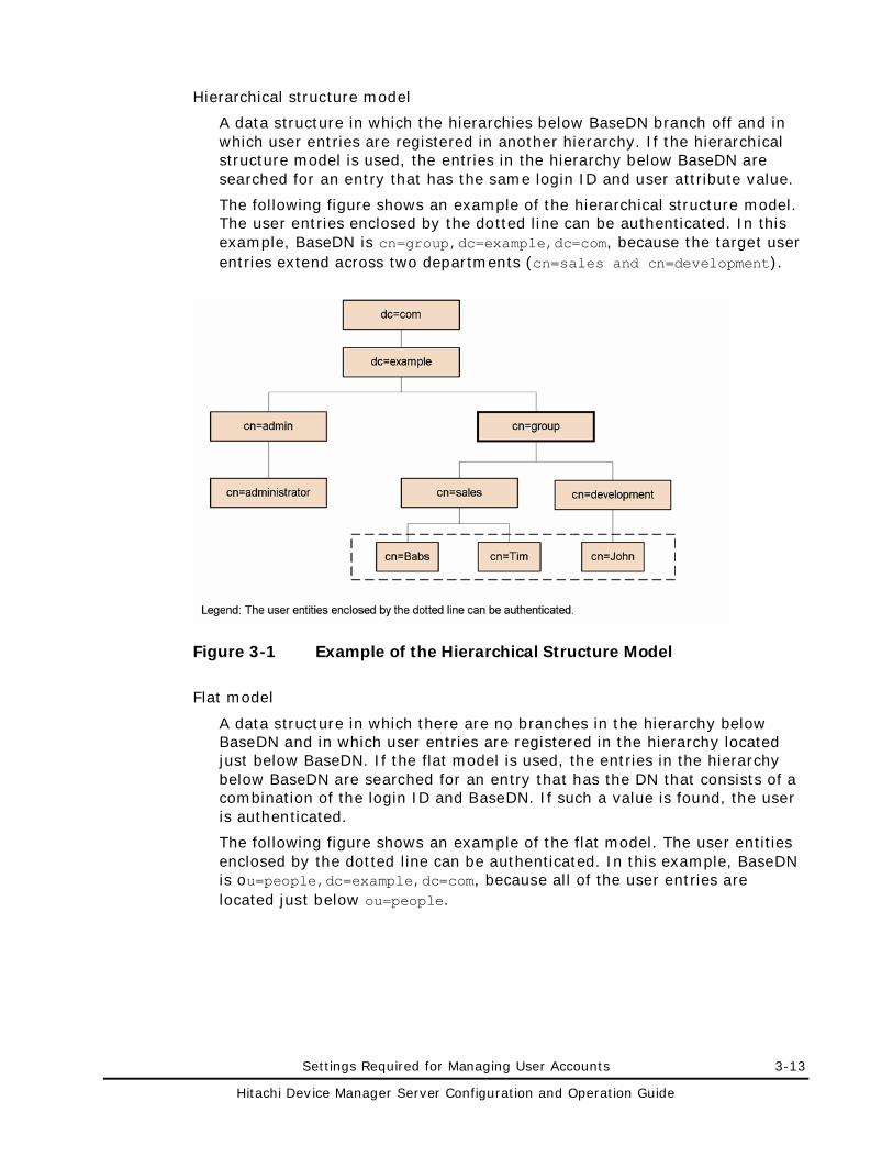
Settings Required for Managing User Accounts 3-13
Hitachi Device Manager Server Configuration and Operation Guide
Hierarchical structure model
A data structure in which the hierarchies below BaseDN branch off and in which user entries are registered in another hierarchy. If the hierarchical structure model is used, the entries in the hierarchy below BaseDN are searched for an entry that has the same login ID and user attribute value.
The following figure shows an example of the hierarchical structure model. The user entries enclosed by the dotted line can be authenticated. In this example, BaseDN is cn=group,dc=example,dc=com, because the target user entries extend across two departments (cn=sales and cn=development).
Figure 3-1 Example of the Hierarchical Structure Model
Flat model
A data structure in which there are no branches in the hierarchy below BaseDN and in which user entries are registered in the hierarchy located just below BaseDN. If the flat model is used, the entries in the hierarchy below BaseDN are searched for an entry that has the DN that consists of a combination of the login ID and BaseDN. If such a value is found, the user is authenticated.
The following figure shows an example of the flat model. The user entities enclosed by the dotted line can be authenticated. In this example, BaseDN is ou=people,dc=example,dc=com, because all of the user entries are located just below ou=people.
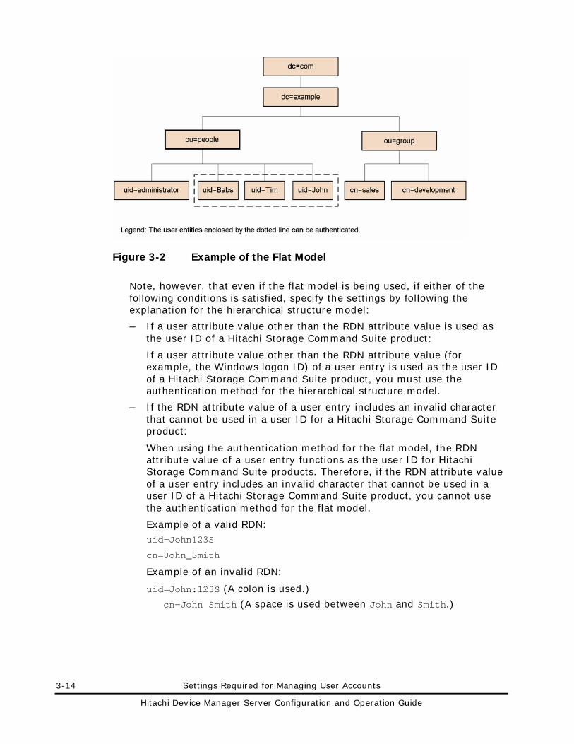
3-14 Settings Required for Managing User Accounts
Hitachi Device Manager Server Configuration and Operation Guide
Figure 3-2 Example of the Flat Model
Note, however, that even if the flat model is being used, if either of the following conditions is satisfied, specify the settings by following the explanation for the hierarchical structure model:
– If a user attribute value other than the RDN attribute value is used as the user ID of a Hitachi Storage Command Suite product:
If a user attribute value other than the RDN attribute value (for example, the Windows logon ID) of a user entry is used as the user ID of a Hitachi Storage Command Suite product, you must use the authentication method for the hierarchical structure model.
– If the RDN attribute value of a user entry includes an invalid character that cannot be used in a user ID for a Hitachi Storage Command Suite product:
When using the authentication method for the flat model, the RDN attribute value of a user entry functions as the user ID for Hitachi Storage Command Suite products. Therefore, if the RDN attribute value of a user entry includes an invalid character that cannot be used in a user ID of a Hitachi Storage Command Suite product, you cannot use the authentication method for the flat model.
Example of a valid RDN: uid=John123S
cn=John_Smith
Example of an invalid RDN:
uid=John:123S (A colon is used.)
cn=John Smith (A space is used between John and Smith.)
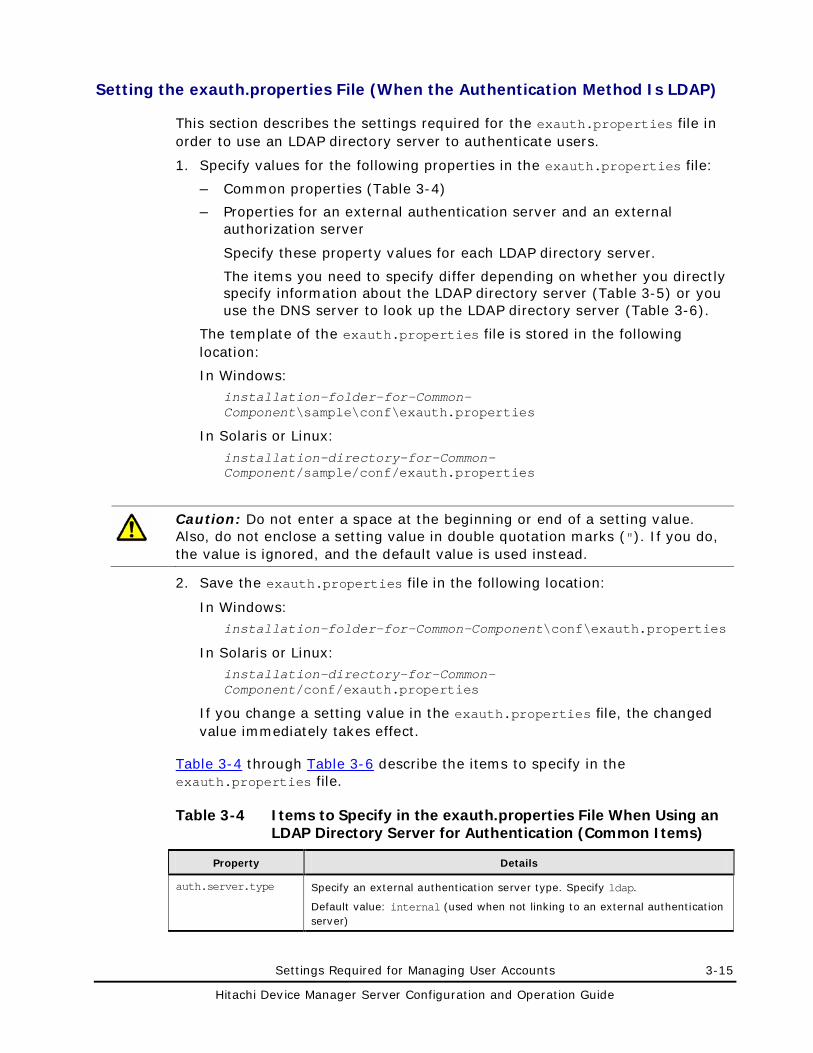
Settings Required for Managing User Accounts 3-15
Hitachi Device Manager Server Configuration and Operation Guide
Setting the exauth.properties File (When the Authentication Method Is LDAP)
This section describes the settings required for the exauth.properties file in order to use an LDAP directory server to authenticate users.
1. Specify values for the following properties in the exauth.properties file:
– Common properties (Table 3-4)
– Properties for an external authentication server and an external authorization server
Specify these property values for each LDAP directory server.
The items you need to specify differ depending on whether you directly specify information about the LDAP directory server (Table 3-5) or you use the DNS server to look up the LDAP directory server (Table 3-6).
The template of the exauth.properties file is stored in the following location:
In Windows: installation-folder-for-Common-Component\sample\conf\exauth.properties
In Solaris or Linux:
installation-directory-for-Common-Component/sample/conf/exauth.properties
Caution: Do not enter a space at the beginning or end of a setting value. Also, do not enclose a setting value in double quotation marks ("). If you do, the value is ignored, and the default value is used instead.
2. Save the exauth.properties file in the following location:
In Windows: installation-folder-for-Common-Component\conf\exauth.properties
In Solaris or Linux: installation-directory-for-Common-Component/conf/exauth.properties
If you change a setting value in the exauth.properties file, the changed value immediately takes effect.
Table 3-4 through Table 3-6 describe the items to specify in the exauth.properties file.
Table 3-4 Items to Specify in the exauth.properties File When Using an LDAP Directory Server for Authentication (Common Items)
Property Details
auth.server.type Specify an external authentication server type. Specify ldap.
Default value: internal (used when not linking to an external authentication server)
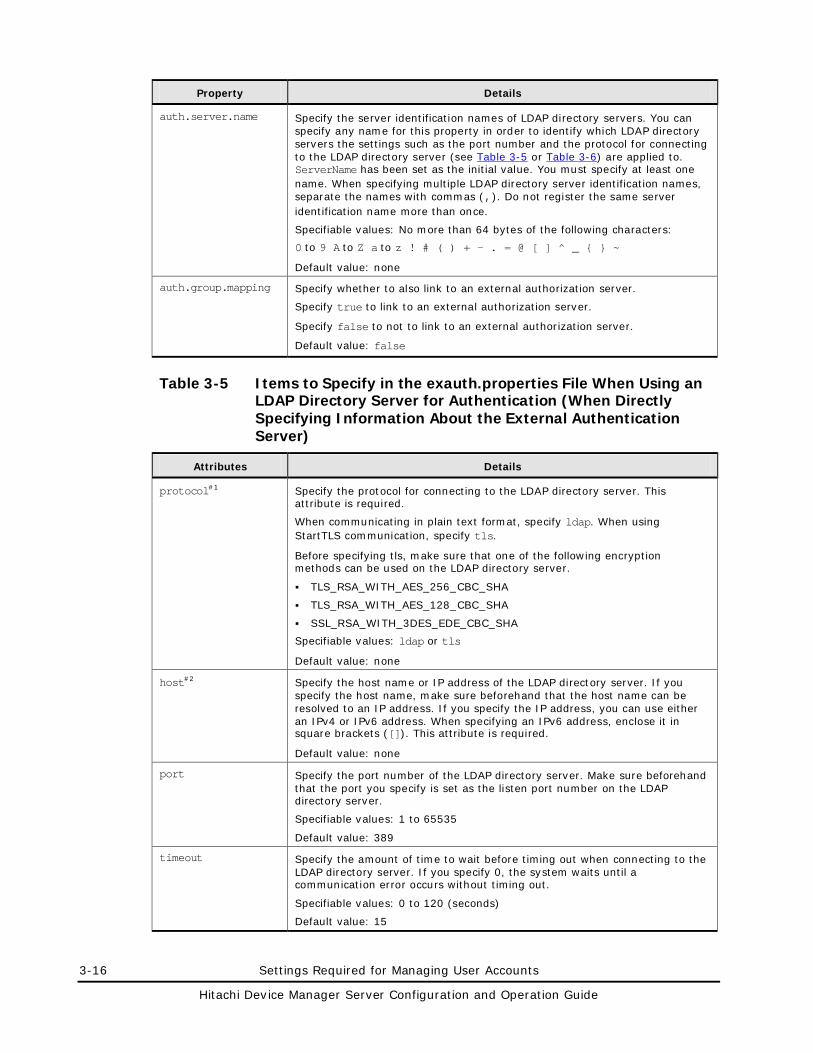
3-16 Settings Required for Managing User Accounts
Hitachi Device Manager Server Configuration and Operation Guide
Property Details
auth.server.name Specify the server identification names of LDAP directory servers. You can specify any name for this property in order to identify which LDAP directory servers the settings such as the port number and the protocol for connecting to the LDAP directory server (see Table 3-5 or Table 3-6) are applied to. ServerName has been set as the initial value. You must specify at least one name. When specifying multiple LDAP directory server identification names, separate the names with commas (,). Do not register the same server identification name more than once.
Specifiable values: No more than 64 bytes of the following characters:
0 to 9 A to Z a to z ! # ( ) + - . = @ [ ] ̂ _ { } ~
Default value: none
auth.group.mapping Specify whether to also link to an external authorization server.
Specify true to link to an external authorization server.
Specify false to not to link to an external authorization server.
Default value: false
Table 3-5 Items to Specify in the exauth.properties File When Using an LDAP Directory Server for Authentication (When Directly Specifying Information About the External Authentication Server)
Attributes Details
protocol#1 Specify the protocol for connecting to the LDAP directory server. This attribute is required.
When communicating in plain text format, specify ldap. When using StartTLS communication, specify tls.
Before specifying tls, make sure that one of the following encryption methods can be used on the LDAP directory server.
TLS_RSA_WITH_AES_256_CBC_SHA
TLS_RSA_WITH_AES_128_CBC_SHA
SSL_RSA_WITH_3DES_EDE_CBC_SHA
Specifiable values: ldap or tls
Default value: none
host#2 Specify the host name or IP address of the LDAP directory server. If you specify the host name, make sure beforehand that the host name can be resolved to an IP address. If you specify the IP address, you can use either an IPv4 or IPv6 address. When specifying an IPv6 address, enclose it in square brackets ([]). This attribute is required.
Default value: none
port Specify the port number of the LDAP directory server. Make sure beforehand that the port you specify is set as the listen port number on the LDAP directory server.
Specifiable values: 1 to 65535
Default value: 389
timeout Specify the amount of time to wait before timing out when connecting to the LDAP directory server. If you specify 0, the system waits until a communication error occurs without timing out.
Specifiable values: 0 to 120 (seconds)
Default value: 15
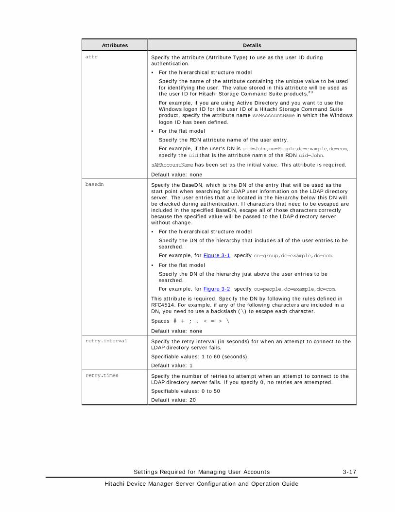
Settings Required for Managing User Accounts 3-17
Hitachi Device Manager Server Configuration and Operation Guide
Attributes Details
attr Specify the attribute (Attribute Type) to use as the user ID during authentication.
For the hierarchical structure model
Specify the name of the attribute containing the unique value to be used for identifying the user. The value stored in this attribute will be used as the user ID for Hitachi Storage Command Suite products.#3
For example, if you are using Active Directory and you want to use the Windows logon ID for the user ID of a Hitachi Storage Command Suite product, specify the attribute name sAMAccountName in which the Windows logon ID has been defined.
For the flat model
Specify the RDN attribute name of the user entry.
For example, if the user's DN is uid=John,ou=People,dc=example,dc=com, specify the uid that is the attribute name of the RDN uid=John.
sAMAccountName has been set as the initial value. This attribute is required.
Default value: none
basedn Specify the BaseDN, which is the DN of the entry that will be used as the start point when searching for LDAP user information on the LDAP directory server. The user entries that are located in the hierarchy below this DN will be checked during authentication. If characters that need to be escaped are included in the specified BaseDN, escape all of those characters correctly because the specified value will be passed to the LDAP directory server without change.
For the hierarchical structure model
Specify the DN of the hierarchy that includes all of the user entries to be searched.
For example, for Figure 3-1, specify cn=group,dc=example,dc=com.
For the flat model
Specify the DN of the hierarchy just above the user entries to be searched.
For example, for Figure 3-2, specify ou=people,dc=example,dc=com.
This attribute is required. Specify the DN by following the rules defined in RFC4514. For example, if any of the following characters are included in a DN, you need to use a backslash (\) to escape each character.
Spaces # + ; , < = > \
Default value: none
retry.interval Specify the retry interval (in seconds) for when an attempt to connect to the LDAP directory server fails.
Specifiable values: 1 to 60 (seconds)
Default value: 1
retry.times Specify the number of retries to attempt when an attempt to connect to the LDAP directory server fails. If you specify 0, no retries are attempted.
Specifiable values: 0 to 50
Default value: 20
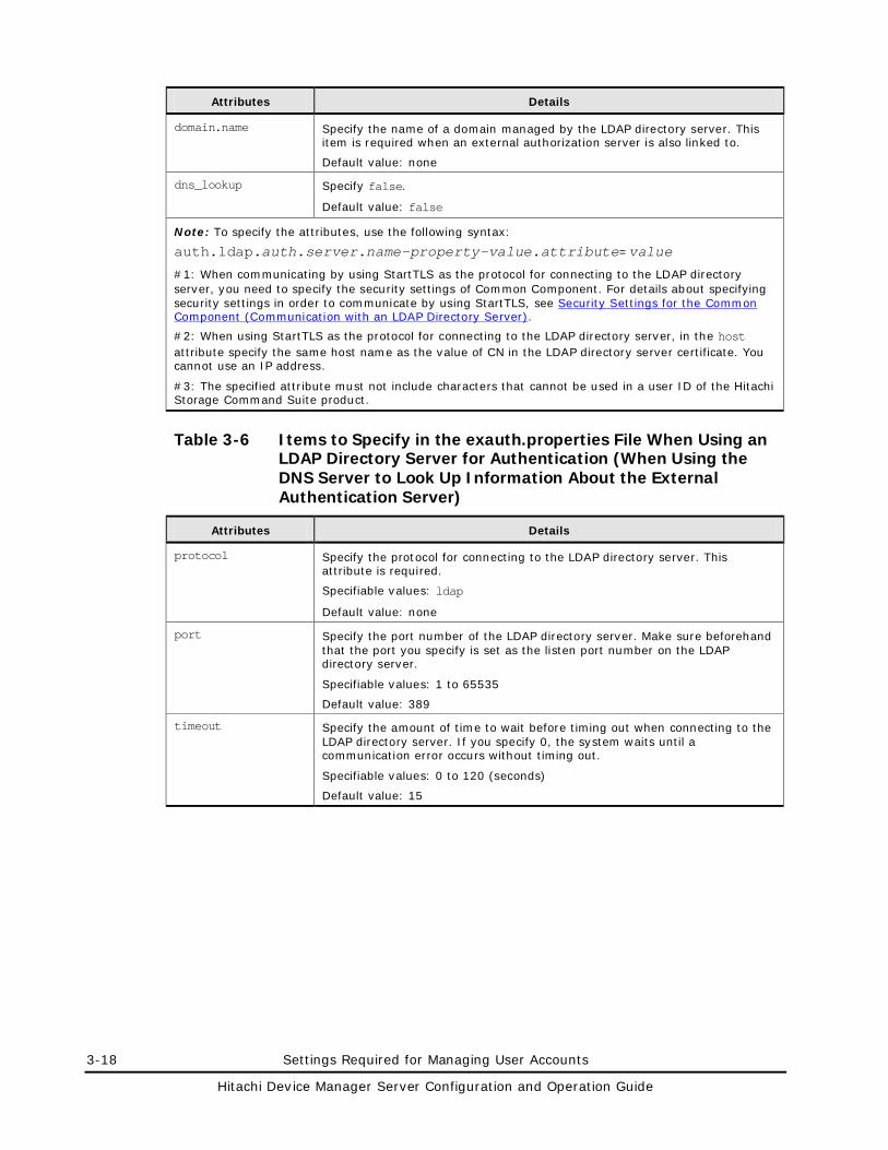
3-18 Settings Required for Managing User Accounts
Hitachi Device Manager Server Configuration and Operation Guide
Attributes Details
domain.name Specify the name of a domain managed by the LDAP directory server. This item is required when an external authorization server is also linked to.
Default value: none
dns_lookup Specify false.
Default value: false
Note: To specify the attributes, use the following syntax:
auth.ldap.auth.server.name-property-value.attribute=value
#1: When communicating by using StartTLS as the protocol for connecting to the LDAP directory server, you need to specify the security settings of Common Component. For details about specifying security settings in order to communicate by using StartTLS, see Security Settings for the Common Component (Communication with an LDAP Directory Server).
#2: When using StartTLS as the protocol for connecting to the LDAP directory server, in the host attribute specify the same host name as the value of CN in the LDAP directory server certificate. You cannot use an IP address.
#3: The specified attribute must not include characters that cannot be used in a user ID of the Hitachi Storage Command Suite product.
Table 3-6 Items to Specify in the exauth.properties File When Using an LDAP Directory Server for Authentication (When Using the DNS Server to Look Up Information About the External Authentication Server)
Attributes Details
protocol Specify the protocol for connecting to the LDAP directory server. This attribute is required.
Specifiable values: ldap
Default value: none
port Specify the port number of the LDAP directory server. Make sure beforehand that the port you specify is set as the listen port number on the LDAP directory server.
Specifiable values: 1 to 65535
Default value: 389
timeout Specify the amount of time to wait before timing out when connecting to the LDAP directory server. If you specify 0, the system waits until a communication error occurs without timing out.
Specifiable values: 0 to 120 (seconds)
Default value: 15
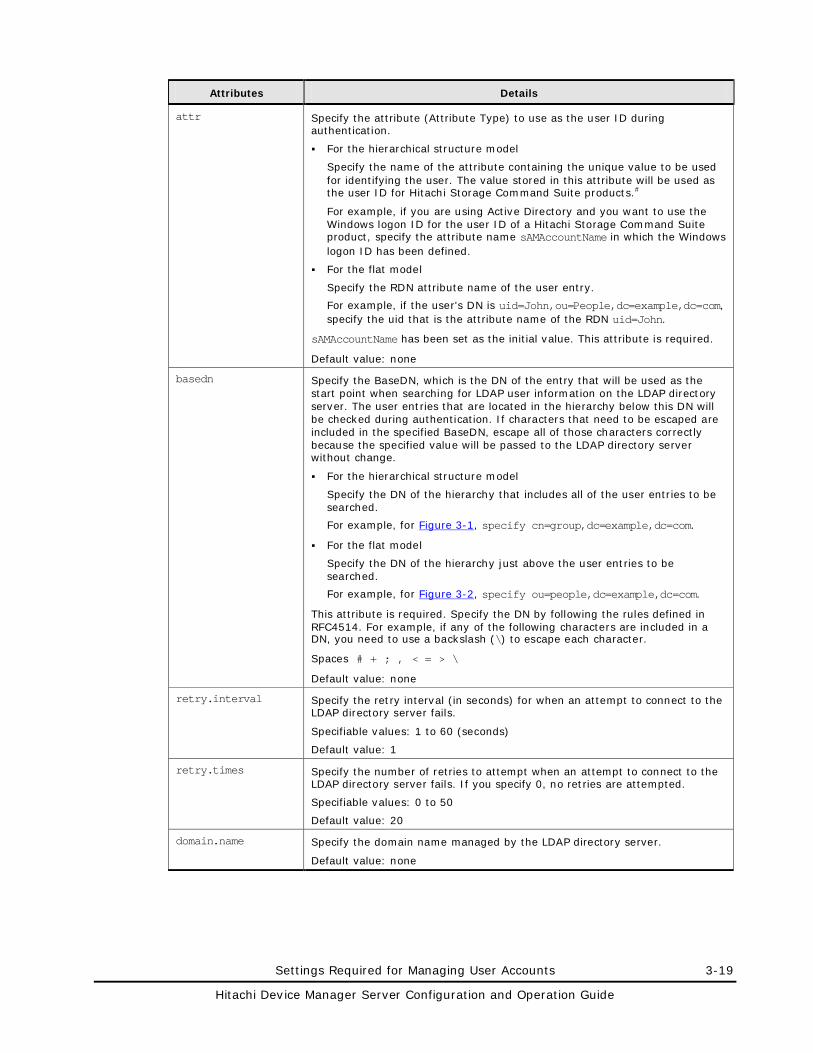
Settings Required for Managing User Accounts 3-19
Hitachi Device Manager Server Configuration and Operation Guide
Attributes Details
attr Specify the attribute (Attribute Type) to use as the user ID during authentication.
For the hierarchical structure model
Specify the name of the attribute containing the unique value to be used for identifying the user. The value stored in this attribute will be used as the user ID for Hitachi Storage Command Suite products.#
For example, if you are using Active Directory and you want to use the Windows logon ID for the user ID of a Hitachi Storage Command Suite product, specify the attribute name sAMAccountName in which the Windows logon ID has been defined.
For the flat model
Specify the RDN attribute name of the user entry.
For example, if the user's DN is uid=John,ou=People,dc=example,dc=com, specify the uid that is the attribute name of the RDN uid=John.
sAMAccountName has been set as the initial value. This attribute is required.
Default value: none
basedn Specify the BaseDN, which is the DN of the entry that will be used as the start point when searching for LDAP user information on the LDAP directory server. The user entries that are located in the hierarchy below this DN will be checked during authentication. If characters that need to be escaped are included in the specified BaseDN, escape all of those characters correctly because the specified value will be passed to the LDAP directory server without change.
For the hierarchical structure model
Specify the DN of the hierarchy that includes all of the user entries to be searched.
For example, for Figure 3-1, specify cn=group,dc=example,dc=com.
For the flat model
Specify the DN of the hierarchy just above the user entries to be searched.
For example, for Figure 3-2, specify ou=people,dc=example,dc=com.
This attribute is required. Specify the DN by following the rules defined in RFC4514. For example, if any of the following characters are included in a DN, you need to use a backslash (\) to escape each character.
Spaces # + ; , < = > \
Default value: none
retry.interval Specify the retry interval (in seconds) for when an attempt to connect to the LDAP directory server fails.
Specifiable values: 1 to 60 (seconds)
Default value: 1
retry.times Specify the number of retries to attempt when an attempt to connect to the LDAP directory server fails. If you specify 0, no retries are attempted.
Specifiable values: 0 to 50
Default value: 20
domain.name Specify the domain name managed by the LDAP directory server.
Default value: none
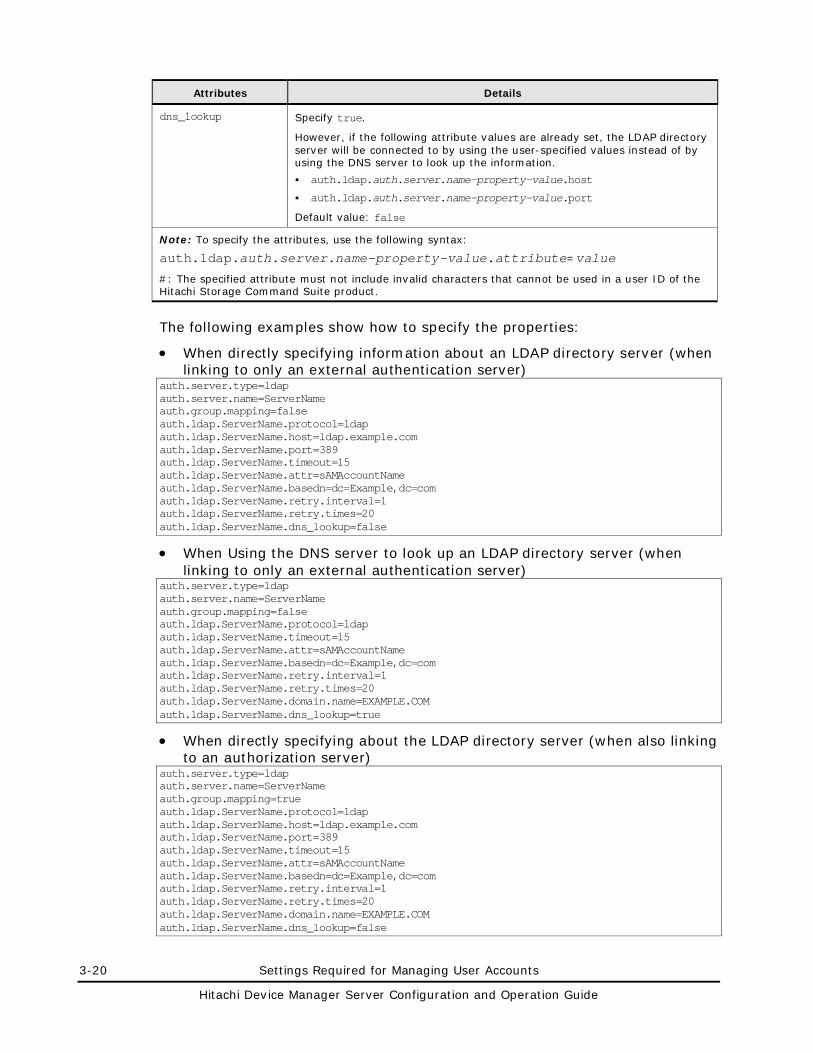
3-20 Settings Required for Managing User Accounts
Hitachi Device Manager Server Configuration and Operation Guide
Attributes Details
dns_lookup Specify true.
However, if the following attribute values are already set, the LDAP directory server will be connected to by using the user-specified values instead of by using the DNS server to look up the information.
auth.ldap.auth.server.name-property-value.host
auth.ldap.auth.server.name-property-value.port
Default value: false
Note: To specify the attributes, use the following syntax:
auth.ldap.auth.server.name-property-value.attribute=value
#: The specified attribute must not include invalid characters that cannot be used in a user ID of the Hitachi Storage Command Suite product.
The following examples show how to specify the properties:
• When directly specifying information about an LDAP directory server (when linking to only an external authentication server)
auth.server.type=ldap auth.server.name=ServerName auth.group.mapping=false auth.ldap.ServerName.protocol=ldap auth.ldap.ServerName.host=ldap.example.com auth.ldap.ServerName.port=389 auth.ldap.ServerName.timeout=15 auth.ldap.ServerName.attr=sAMAccountName auth.ldap.ServerName.basedn=dc=Example,dc=com auth.ldap.ServerName.retry.interval=1 auth.ldap.ServerName.retry.times=20 auth.ldap.ServerName.dns_lookup=false
• When Using the DNS server to look up an LDAP directory server (when linking to only an external authentication server)
auth.server.type=ldap auth.server.name=ServerName auth.group.mapping=false auth.ldap.ServerName.protocol=ldap auth.ldap.ServerName.timeout=15 auth.ldap.ServerName.attr=sAMAccountName auth.ldap.ServerName.basedn=dc=Example,dc=com auth.ldap.ServerName.retry.interval=1 auth.ldap.ServerName.retry.times=20 auth.ldap.ServerName.domain.name=EXAMPLE.COM auth.ldap.ServerName.dns_lookup=true
• When directly specifying about the LDAP directory server (when also linking to an authorization server)
auth.server.type=ldap auth.server.name=ServerName auth.group.mapping=true auth.ldap.ServerName.protocol=ldap auth.ldap.ServerName.host=ldap.example.com auth.ldap.ServerName.port=389 auth.ldap.ServerName.timeout=15 auth.ldap.ServerName.attr=sAMAccountName auth.ldap.ServerName.basedn=dc=Example,dc=com auth.ldap.ServerName.retry.interval=1 auth.ldap.ServerName.retry.times=20 auth.ldap.ServerName.domain.name=EXAMPLE.COM auth.ldap.ServerName.dns_lookup=false
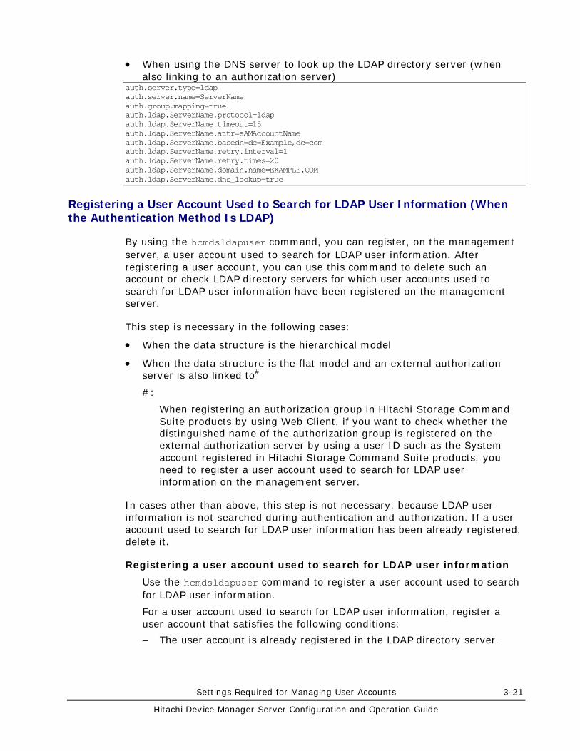
Settings Required for Managing User Accounts 3-21
Hitachi Device Manager Server Configuration and Operation Guide
• When using the DNS server to look up the LDAP directory server (when also linking to an authorization server)
auth.server.type=ldap auth.server.name=ServerName auth.group.mapping=true auth.ldap.ServerName.protocol=ldap auth.ldap.ServerName.timeout=15 auth.ldap.ServerName.attr=sAMAccountName auth.ldap.ServerName.basedn=dc=Example,dc=com auth.ldap.ServerName.retry.interval=1 auth.ldap.ServerName.retry.times=20 auth.ldap.ServerName.domain.name=EXAMPLE.COM auth.ldap.ServerName.dns_lookup=true
Registering a User Account Used to Search for LDAP User Information (When the Authentication Method Is LDAP)
By using the hcmdsldapuser command, you can register, on the management server, a user account used to search for LDAP user information. After registering a user account, you can use this command to delete such an account or check LDAP directory servers for which user accounts used to search for LDAP user information have been registered on the management server.
This step is necessary in the following cases:
• When the data structure is the hierarchical model
• When the data structure is the flat model and an external authorization server is also linked to#
#:
When registering an authorization group in Hitachi Storage Command Suite products by using Web Client, if you want to check whether the distinguished name of the authorization group is registered on the external authorization server by using a user ID such as the System account registered in Hitachi Storage Command Suite products, you need to register a user account used to search for LDAP user information on the management server.
In cases other than above, this step is not necessary, because LDAP user information is not searched during authentication and authorization. If a user account used to search for LDAP user information has been already registered, delete it.
Registering a user account used to search for LDAP user information
Use the hcmdsldapuser command to register a user account used to search for LDAP user information.
For a user account used to search for LDAP user information, register a user account that satisfies the following conditions:
– The user account is already registered in the LDAP directory server.
3-22 Settings Required for Managing User Accounts
Hitachi Device Manager Server Configuration and Operation Guide
– The user account can bind to the DN specified for auth.ldap.auth.server.name-property-value.basedn in the exauth.properties file
– The user account can search the attributes for all entries below the DN specified for auth.ldap.auth.server.name-property-value.basedn in the exauth.properties file
– The user account can reference the DN specified for auth.ldap.auth.server.name-property-value.basedn in the exauth.properties file
The format of the hcmdsldapuser command is as follows:
In Windows:
installation-folder-for-Common-Component\bin\hcmdsldapuser /set /dn DN-of-user-account-used-to-search-for-LDAP-user-info /pass password-of-user-account-used-to-search-for-LDAP-user-info /name server-identification-name
In Solaris or Linux:
installation-directory-for-Common-Component/bin/hcmdsldapuser -set -dn DN-of-user-account-used-to-search-for-LDAP-user-info -pass password-of-user-account-used-to-search-for-LDAP-user-info -name server-identification-name
– DN-of-user-account-used-to-search-for-LDAP-user-info
Specify a DN by following the rules defined in RFC4514. For example, if the following characters are included in a DN, you need to use a backslash (\) to escape each character.
Spaces # + , ; < = > \
– password-of-user-account-used-to-search-for-LDAP-user-info
This is case-sensitive and must exactly match the password registered in the LDAP directory server.
– server-identification-name
Specify the server identification name that was specified for the auth.server.name property in the exauth.properties file.
Caution: In the LDAP directory server, you can use double quotation marks (") for the DN and password. In the management server, however, you need to register a user account whose DN and password do not include double quotation marks.
The following describes an example of execution using the data structure shown in Figure 3-1. In this data structure, the DN of the entry used as the start point for searching is specified as cn=group,dc=example,dc=com. If a user searching the attribute values of all users (Babs, Tim, and John) below the DN has the administrator privilege, specify the dn option as the DN of administrator (cn=administrator,cn=admin,dc=example,dc=com). The following is an example of executing the command. The password of administrator is administrator_pass:
Settings Required for Managing User Accounts 3-23
Hitachi Device Manager Server Configuration and Operation Guide
– In Windows:
hcmdsldapuser /set /dn "cn=administrator,cn=admin,dc=example,dc=com" /pass administrator_pass /name ServerName
– In Solaris or Linux:
hcmdsldapuser -set -dn "cn=administrator,cn=admin,dc=example,dc=com" -pass administrator_pass -name ServerName
Note: • If you are using Active Directory, you can use the dsquery command
provided by Active Directory to check the DN of a user. The following example shows how to use the dsquery command to check the DN of the user administrator, and also shows the execution results: dsquery user -name administrator "CN=administrator,CN=admin,DC=example,DC=com"
• If the DN includes commas such as cn=administrator,cn=admin,dc=example,com, specify as follows:
In Windows: hcmdsldapuser /set /dn "cn=administrator,cn=admin,dc=example\,com" /pass administrator_pass /name ServerName
In Solaris or Linux: hcmdsldapuser -set -dn "cn=administrator,cn=admin,dc=example\\,com" -pass administrator_pass -name ServerName
Deleting a user account used to search for LDAP user information
To delete a user account used to search for LDAP user information, execute the following command.
– In Windows:
installation-folder-for-Common-Component\bin\hcmdsldapuser /delete /name server-identification-name
– In Solaris or Linux:
installation-directory-for-Common-Component/bin/hcmdsldapuser -delete -name server-identification-name
Checking LDAP directory servers for which a user account used to search for LDAP user information has been registered
To check the names of LDAP directory servers for which a user account used to search for LDAP user information has been registered on the management server, execute the following command.
– In Windows:
installation-folder-for-Common-Component\bin\hcmdsldapuser /list
– In Solaris or Linux:
3-24 Settings Required for Managing User Accounts
Hitachi Device Manager Server Configuration and Operation Guide
installation-directory-for-Common-Component/bin/hcmdsldapuser –list
Checking the Connection Status of the External Authentication Server and the External Authorization Server (When the Authentication Method Is LDAP)
By using the hcmdscheckauth command, you can make sure that the external authentication server and the external authorization server can properly be connected to.
If Tuning Manager is remotely connected, perform this operation on the computer on which the Device Manager server is installed.
In Windows:
installation-folder-for-Common-Component\bin\hcmdscheckauth /user user-ID /pass password [/summary]
In Solaris or Linux:
installation-directory-for-Common-Component/bin/hcmdscheckauth -user user-ID -pass password [-summary]
If you execute the command with the summary option specified, the confirmation message is displayed in summary format.
user-ID and password must match those of the user account that has been registered in the LDAP directory server. user-ID must be the same value as the one specified for the attribute auth.ldap.auth.server.name-property-value.attr in the exauth.properties file. However, you cannot specify a user account whose user-ID or password begins with a forward slash (/) in Windows or a hyphen (-) in Solaris or Linux.
If you execute the hcmdscheckauth command, the settings in the exauth.properties file, and the connection status of the external authentication server and the external authorization server are checked in the four phases described below. Check results are displayed for each phase.
Phase 1
The command verifies that common properties (Table 3-4) have been correctly specified in the exauth.properties file.
Phase 2
The command verifies that the properties for the external authentication server and the external authorization server (Table 3-5 or Table 3-6) have been correctly specified in the exauth.properties file.
Phase 3
The command verifies that the external authentication server can be connected to.
Settings Required for Managing User Accounts 3-25
Hitachi Device Manager Server Configuration and Operation Guide
Phase 4
If an external authorization server is also linked to, the command verifies that the external authorization server can be connected to and authorization groups can be searched.
When a phase finishes normally, the following message is displayed: KAPM15004-I The result of the configuration check of Phase X was normal.
Note: X is the phase number.
If an error occurs, find the output message ID in the Hitachi Device Manager Error Codes, and check the cause and action to take for the error.
• Example of executing the hcmdscheckauth command when the hierarchical structure model is used:
The following example shows how to execute the hcmdscheckauth command, using the user account John shown in Figure 3-1.
This example assumes that sAMAccountName has been specified in auth.ldap.auth.server.name-property-value.attr in the exauth.properties file. If the sAMAccountName attribute value of John is John_Smith, specify John_Smith in user-ID. If the password of John to be used on the LDAP directory server is John_pass, specify John_pass in password.
– In Windows:
hcmdscheckauth /user John_Smith /pass John_pass
– In Solaris or Linux:
hcmdscheckauth -user John_Smith -pass John_pass
• Example of executing the hcmdscheckauth command when the flat model is used:
The following example shows how to execute the hcmdscheckauth command, using the user account John shown in Figure 3-2.
This example assumes that uid has been specified in auth.ldap.auth.server.name-property-value.attr in the exauth.properties file. As the RDN of John is given by uid=John, specify the RDN attribute value John in user-ID. If the password of John to be used on the LDAP directory server is John_pass, specify John_pass in password.
– In Windows:
hcmdscheckauth /user John /pass John_pass
– In Solaris or Linux:
hcmdscheckauth -user John -pass John_pass
3-26 Settings Required for Managing User Accounts
Hitachi Device Manager Server Configuration and Operation Guide
Settings Required When Using a RADIUS Server for Authentication
To authenticate users by using a RADIUS server, specify the following settings in Hitachi Storage Command Suite products.
1. In the exauth.properties file on the management server, specify necessary information.
Necessary settings depend on whether only an external authentication server is linked to or an external authorization server is also linked to.
You can use either of the following methods to define the LDAP directory server to be used as an external authorization server:
– In the exauth.properties file, directly specify information about the LDAP directory server to connect to.
Specify information such as IP address and port number in the exauth.properties file for each LDAP directory server.
– Use the DNS server to look up the LDAP directory server to connect to.
Before using this method, you need to set up the DNS server environment on the OS of the LDAP directory server. In addition, you need to register the host name, port number, and domain name of the LDAP directory server in the SRV records of the DNS server.
Note: To use StartTLS for communication between the management server and the LDAP directory server, you need to directly specify information about the LDAP directory server to connect to in the exauth.properties file.
When using the DNS server to look up the LDAP directory server to connect to, it might take longer for users to log in.
2. When also linking to an external authorization server, on the management server, register a user account used to search for user information on the LDAP directory server.
3. On the RADIUS server, register the accounts of user that will use Hitachi Storage Command Suite products.
User IDs and passwords must consist of characters that can be used in Hitachi Storage Command Suite products. Specify 1 to 256 bytes of the following characters:
0 to 9 A to Z a to z ! # $ % & ' ( ) * + - . = @ \ ^ _ |
In Hitachi Storage Command Suite products, user IDs are not case-sensitive. The combination of character types for passwords must follow the settings in the external authentication server.
4. Specify a shared secret on the management server for communicating with the RADIUS server.
Settings Required for Managing User Accounts 3-27
Hitachi Device Manager Server Configuration and Operation Guide
5. Register accounts and set permissions by using Web Client.
When linking to only an external authentication server
• Register users.
• Change the authentication method of users.#
• Set permissions for users.
• Assign resource groups to users.
#: This operation is required if you want to change the authentication method of existing users.
When also linking to an external authorization server
• Register authorization groups.
• Set permissions for authorization groups.
You do not need to assign resource groups to authorization groups. All Resources will be automatically assigned to users who belong to authorization groups.
6. Use the hcmdscheckauth command to make sure that the external authentication server and the external authorization server can be properly connected to.
The following sections describe operations you need to perform on the management server. For details on how to use Web Client, see the Device Manager online Help.
Setting the exauth.properties File (When the Authentication Method Is RADIUS)
This section describes the settings required for the exauth.properties file in order to use a RADIUS server to authenticate users.
1. Specify values for the following properties in the exauth.properties file:
– Common properties (Table 3-7)
– Properties for an external authentication server (Table 3-8)
Specify these property values for each RADIUS server.
– Properties for an external authorization server
These properties need to be set when an external authorization server is also linked to. Specify information about the LDAP directory server for each domain.
The items you need to specify differ depending on whether you directly specify information about the LDAP directory server (Table 3-9 and Table 3-10) or you use the DNS server to look up the LDAP directory server (Table 3-9 and Table 3-11).
The template of the exauth.properties file is stored in the following location:
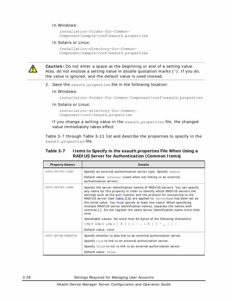
3-28 Settings Required for Managing User Accounts
Hitachi Device Manager Server Configuration and Operation Guide
In Windows: installation-folder-for-Common-Component\sample\conf\exauth.properties
In Solaris or Linux:
installation-directory-for-Common-Component/sample/conf/exauth.properties
Caution: Do not enter a space at the beginning or end of a setting value. Also, do not enclose a setting value in double quotation marks ("). If you do, the value is ignored, and the default value is used instead.
2. Save the exauth.properties file in the following location:
In Windows: installation-folder-for-Common-Component\conf\exauth.properties
In Solaris or Linux: installation-directory-for-Common-Component/conf/exauth.properties
If you change a setting value in the exauth.properties file, the changed value immediately takes effect.
Table 3-7 through Table 3-11 list and describe the properties to specify in the exauth.properties file.
Table 3-7 Items to Specify in the exauth.properties File When Using a RADIUS Server for Authentication (Common Items)
Property Names Details
auth.server.type Specify an external authentication server type. Specify radius.
Default value: internal (used when not linking to an external authentication server)
auth.server.name Specify the server identification names of RADIUS servers. You can specify any name for this property in order to identify which RADIUS servers the settings such as the port number and the protocol for connecting to the RADIUS server (see Table 3-8) are applied to. ServerName has been set as the initial value. You must specify at least one name. When specifying multiple RADIUS server identification names, separate the names with commas (,). Do not register the same server identification name more than once.
Specifiable values: No more than 64 bytes of the following characters:
0 to 9 A to Z a to z ! # ( ) + - . = @ [ ] ̂ _ { } ~
Default value: none
auth.group.mapping Specify whether to also link to an external authorization server.
Specify true to link to an external authorization server.
Specify false to not to link to an external authorization server.
Default value: false
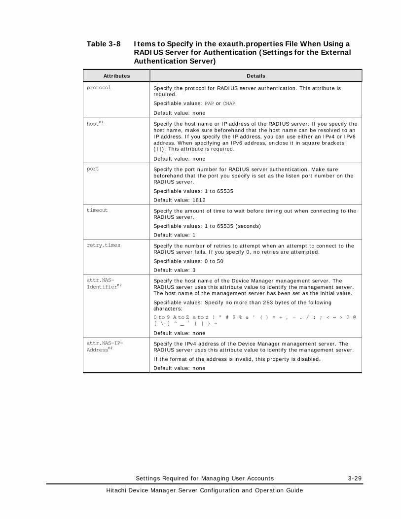
Settings Required for Managing User Accounts 3-29
Hitachi Device Manager Server Configuration and Operation Guide
Table 3-8 Items to Specify in the exauth.properties File When Using a RADIUS Server for Authentication (Settings for the External Authentication Server)
Attributes Details
protocol Specify the protocol for RADIUS server authentication. This attribute is required.
Specifiable values: PAP or CHAP
Default value: none
host#1 Specify the host name or IP address of the RADIUS server. If you specify the host name, make sure beforehand that the host name can be resolved to an IP address. If you specify the IP address, you can use either an IPv4 or IPv6 address. When specifying an IPv6 address, enclose it in square brackets ([]). This attribute is required.
Default value: none
port Specify the port number for RADIUS server authentication. Make sure beforehand that the port you specify is set as the listen port number on the RADIUS server.
Specifiable values: 1 to 65535
Default value: 1812
timeout Specify the amount of time to wait before timing out when connecting to the RADIUS server.
Specifiable values: 1 to 65535 (seconds)
Default value: 1
retry.times Specify the number of retries to attempt when an attempt to connect to the RADIUS server fails. If you specify 0, no retries are attempted.
Specifiable values: 0 to 50
Default value: 3
attr.NAS-Identifier#2
Specify the host name of the Device Manager management server. The RADIUS server uses this attribute value to identify the management server. The host name of the management server has been set as the initial value.
Specifiable values: Specify no more than 253 bytes of the following characters:
0 to 9 A to Z a to z ! " # $ % & ' ( ) * + , - . / : ; < = > ? @ [ \ ] ̂ _ ̀ { | } ~
Default value: none
attr.NAS-IP-Address#2
Specify the IPv4 address of the Device Manager management server. The RADIUS server uses this attribute value to identify the management server.
If the format of the address is invalid, this property is disabled.
Default value: none
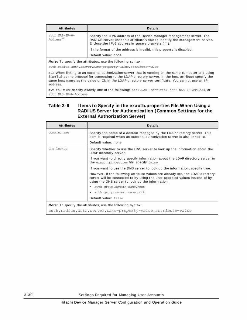
3-30 Settings Required for Managing User Accounts
Hitachi Device Manager Server Configuration and Operation Guide
Attributes Details
attr.NAS-IPv6-Address#2
Specify the IPv6 address of the Device Manager management server. The RADIUS server uses this attribute value to identify the management server. Enclose the IPv6 address in square brackets ([]).
If the format of the address is invalid, this property is disabled.
Default value: none
Note: To specify the attributes, use the following syntax:
auth.radius.auth.server.name-property-value.attribute=value
#1: When linking to an external authorization server that is running on the same computer and using StartTLS as the protocol for connecting to the LDAP directory server, in the host attribute specify the same host name as the value of CN in the LDAP directory server certificate. You cannot use an IP address.
#2: You must specify exactly one of the following: attr.NAS-Identifier, attr.NAS-IP-Address, or attr.NAS-IPv6-Address.
Table 3-9 Items to Specify in the exauth.properties File When Using a RADIUS Server for Authentication (Common Settings for the External Authorization Server)
Attributes Details
domain.name Specify the name of a domain managed by the LDAP directory server. This item is required when an external authorization server is also linked to.
Default value: none
dns_lookup Specify whether to use the DNS server to look up the information about the LDAP directory server.
If you want to directly specify information about the LDAP directory server in the exauth.properties file, specify false.
If you want to use the DNS server to look up the information, specify true.
However, if the following attribute values are already set, the LDAP directory server will be connected to by using the user-specified values instead of by using the DNS server to look up the information.
auth.group.domain-name.host
auth.group.domain-name.port
Default value: false
Note: To specify the attributes, use the following syntax:
auth.radius.auth.server.name-property-value.attribute=value
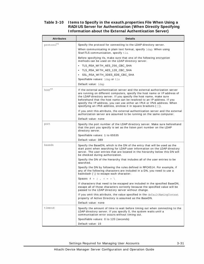
Settings Required for Managing User Accounts 3-31
Hitachi Device Manager Server Configuration and Operation Guide
Table 3-10 Items to Specify in the exauth.properties File When Using a RADIUS Server for Authentication (When Directly Specifying Information about the External Authentication Server)
Attributes Details
protocol#1 Specify the protocol for connecting to the LDAP directory server.
When communicating in plain text format, specify ldap. When using StartTLS communication, specify tls.
Before specifying tls, make sure that one of the following encryption methods can be used on the LDAP directory server.
TLS_RSA_WITH_AES_256_CBC_SHA
TLS_RSA_WITH_AES_128_CBC_SHA
SSL_RSA_WITH_3DES_EDE_CBC_SHA
Specifiable values: ldap or tls
Default value: ldap
host#2 If the external authentication server and the external authorization server are running on different computers, specify the host name or IP address of the LDAP directory server. If you specify the host name, make sure beforehand that the host name can be resolved to an IP address. If you specify the IP address, you can use either an IPv4 or IPv6 address. When specifying an IPv6 address, enclose it in square brackets ([]).
If you omit this attribute, the external authentication server and the external authorization server are assumed to be running on the same computer.
Default value: none
port Specify the port number of the LDAP directory server. Make sure beforehand that the port you specify is set as the listen port number on the LDAP directory server.
Specifiable values: 1 to 65535
Default value: 389
basedn Specify the BaseDN, which is the DN of the entry that will be used as the start point when searching for LDAP user information on the LDAP directory server. The user entries that are located in the hierarchy below this DN will be checked during authorization.
Specify the DN of the hierarchy that includes all of the user entries to be searched.
Specify the DN by following the rules defined in RFC4514. For example, if any of the following characters are included in a DN, you need to use a backslash (\) to escape each character.
Spaces # + ; , < = > \
If characters that need to be escaped are included in the specified BaseDN, escape all of those characters correctly because the specified value will be passed to the LDAP directory server without change.
If you omit this attribute, the value specified in the defaultNamingContext property of Active Directory is assumed as the BaseDN.
Default value: none
timeout Specify the amount of time to wait before timing out when connecting to the LDAP directory server. If you specify 0, the system waits until a communication error occurs without timing out.
Specifiable values: 0 to 120 (seconds)
Default value: 15
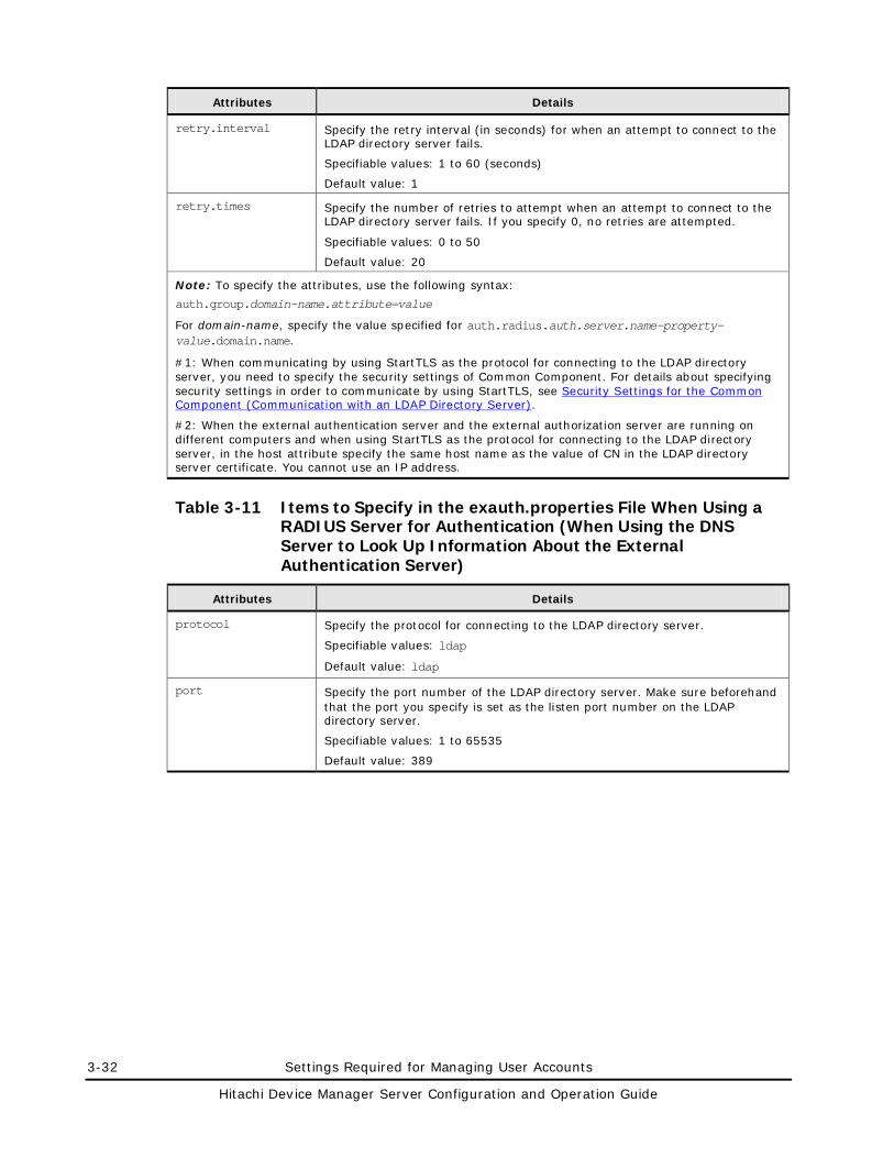
3-32 Settings Required for Managing User Accounts
Hitachi Device Manager Server Configuration and Operation Guide
Attributes Details
retry.interval Specify the retry interval (in seconds) for when an attempt to connect to the LDAP directory server fails.
Specifiable values: 1 to 60 (seconds)
Default value: 1
retry.times Specify the number of retries to attempt when an attempt to connect to the LDAP directory server fails. If you specify 0, no retries are attempted.
Specifiable values: 0 to 50
Default value: 20
Note: To specify the attributes, use the following syntax:
auth.group.domain-name.attribute=value
For domain-name, specify the value specified for auth.radius.auth.server.name-property-value.domain.name.
#1: When communicating by using StartTLS as the protocol for connecting to the LDAP directory server, you need to specify the security settings of Common Component. For details about specifying security settings in order to communicate by using StartTLS, see Security Settings for the Common Component (Communication with an LDAP Directory Server).
#2: When the external authentication server and the external authorization server are running on different computers and when using StartTLS as the protocol for connecting to the LDAP directory server, in the host attribute specify the same host name as the value of CN in the LDAP directory server certificate. You cannot use an IP address.
Table 3-11 Items to Specify in the exauth.properties File When Using a RADIUS Server for Authentication (When Using the DNS Server to Look Up Information About the External Authentication Server)
Attributes Details
protocol Specify the protocol for connecting to the LDAP directory server.
Specifiable values: ldap
Default value: ldap
port Specify the port number of the LDAP directory server. Make sure beforehand that the port you specify is set as the listen port number on the LDAP directory server.
Specifiable values: 1 to 65535
Default value: 389
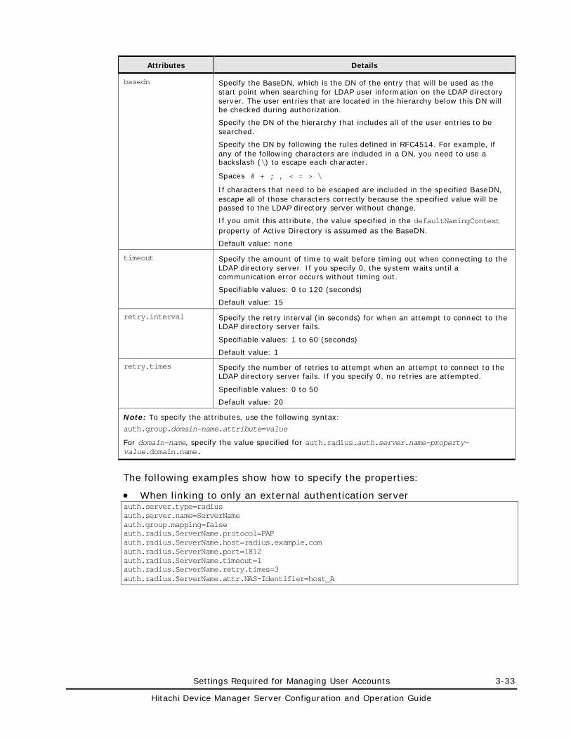
Settings Required for Managing User Accounts 3-33
Hitachi Device Manager Server Configuration and Operation Guide
Attributes Details
basedn Specify the BaseDN, which is the DN of the entry that will be used as the start point when searching for LDAP user information on the LDAP directory server. The user entries that are located in the hierarchy below this DN will be checked during authorization.
Specify the DN of the hierarchy that includes all of the user entries to be searched.
Specify the DN by following the rules defined in RFC4514. For example, if any of the following characters are included in a DN, you need to use a backslash (\) to escape each character.
Spaces # + ; , < = > \
If characters that need to be escaped are included in the specified BaseDN, escape all of those characters correctly because the specified value will be passed to the LDAP directory server without change.
If you omit this attribute, the value specified in the defaultNamingContext property of Active Directory is assumed as the BaseDN.
Default value: none
timeout Specify the amount of time to wait before timing out when connecting to the LDAP directory server. If you specify 0, the system waits until a communication error occurs without timing out.
Specifiable values: 0 to 120 (seconds)
Default value: 15
retry.interval Specify the retry interval (in seconds) for when an attempt to connect to the LDAP directory server fails.
Specifiable values: 1 to 60 (seconds)
Default value: 1
retry.times Specify the number of retries to attempt when an attempt to connect to the LDAP directory server fails. If you specify 0, no retries are attempted.
Specifiable values: 0 to 50
Default value: 20
Note: To specify the attributes, use the following syntax:
auth.group.domain-name.attribute=value
For domain-name, specify the value specified for auth.radius.auth.server.name-property-value.domain.name.
The following examples show how to specify the properties:
• When linking to only an external authentication server auth.server.type=radius auth.server.name=ServerName auth.group.mapping=false auth.radius.ServerName.protocol=PAP auth.radius.ServerName.host=radius.example.com auth.radius.ServerName.port=1812 auth.radius.ServerName.timeout=1 auth.radius.ServerName.retry.times=3 auth.radius.ServerName.attr.NAS-Identifier=host_A
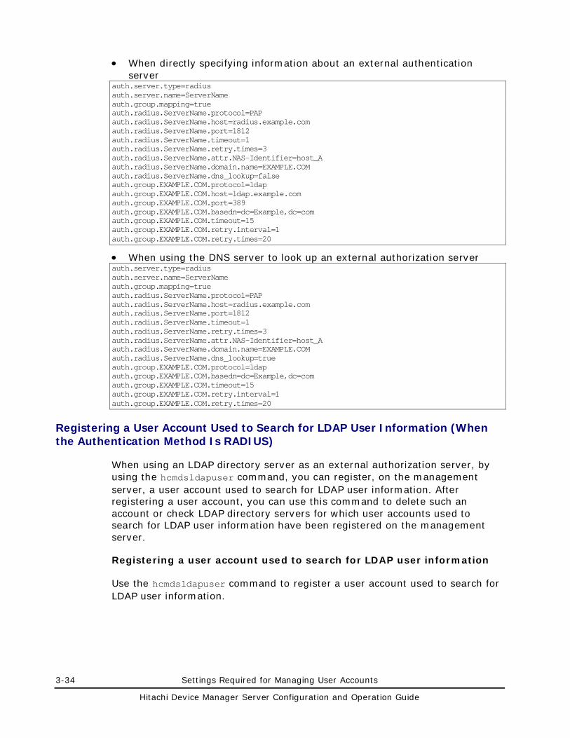
3-34 Settings Required for Managing User Accounts
Hitachi Device Manager Server Configuration and Operation Guide
• When directly specifying information about an external authentication server
auth.server.type=radius auth.server.name=ServerName auth.group.mapping=true auth.radius.ServerName.protocol=PAP auth.radius.ServerName.host=radius.example.com auth.radius.ServerName.port=1812 auth.radius.ServerName.timeout=1 auth.radius.ServerName.retry.times=3 auth.radius.ServerName.attr.NAS-Identifier=host_A auth.radius.ServerName.domain.name=EXAMPLE.COM auth.radius.ServerName.dns_lookup=false auth.group.EXAMPLE.COM.protocol=ldap auth.group.EXAMPLE.COM.host=ldap.example.com auth.group.EXAMPLE.COM.port=389 auth.group.EXAMPLE.COM.basedn=dc=Example,dc=com auth.group.EXAMPLE.COM.timeout=15 auth.group.EXAMPLE.COM.retry.interval=1 auth.group.EXAMPLE.COM.retry.times=20
• When using the DNS server to look up an external authorization server auth.server.type=radius auth.server.name=ServerName auth.group.mapping=true auth.radius.ServerName.protocol=PAP auth.radius.ServerName.host=radius.example.com auth.radius.ServerName.port=1812 auth.radius.ServerName.timeout=1 auth.radius.ServerName.retry.times=3 auth.radius.ServerName.attr.NAS-Identifier=host_A auth.radius.ServerName.domain.name=EXAMPLE.COM auth.radius.ServerName.dns_lookup=true auth.group.EXAMPLE.COM.protocol=ldap auth.group.EXAMPLE.COM.basedn=dc=Example,dc=com auth.group.EXAMPLE.COM.timeout=15 auth.group.EXAMPLE.COM.retry.interval=1 auth.group.EXAMPLE.COM.retry.times=20
Registering a User Account Used to Search for LDAP User Information (When the Authentication Method Is RADIUS)
When using an LDAP directory server as an external authorization server, by using the hcmdsldapuser command, you can register, on the management server, a user account used to search for LDAP user information. After registering a user account, you can use this command to delete such an account or check LDAP directory servers for which user accounts used to search for LDAP user information have been registered on the management server.
Registering a user account used to search for LDAP user information
Use the hcmdsldapuser command to register a user account used to search for LDAP user information.
Settings Required for Managing User Accounts 3-35
Hitachi Device Manager Server Configuration and Operation Guide
For a user account used to search for LDAP user information, register a user account that satisfies the following conditions:
• The user account is already registered in the LDAP directory server.
• The user account can bind to the DN specified for auth.group.domain-name.basedn in the exauth.properties file
• The user account can search the attributes for all entries below the DN specified for auth.group.domain-name.basedn in the exauth.properties file
• The user account can reference the DN specified for auth.group.domain-name.basedn in the exauth.properties file
The format of the hcmdsldapuser command is as follows:
In Windows:
installation-folder-for-Common-Component\bin\hcmdsldapuser /set /dn DN-of-user-account-used-to-search-for-LDAP-user-info /pass password-of-user-account-used-to-search-for-LDAP-user-info /name domain-name
In Solaris or Linux:
installation-directory-for-Common-Component/bin/hcmdsldapuser -set -dn DN-of-user-account-used-to-search-for-LDAP-user-info -pass password-of-user-account-used-to-search-for-LDAP-user-info -name domain-name
• DN-of-user-account-used-to-search-for-LDAP-user-info
Specify a DN by following the rules defined in RFC4514. For example, if the following characters are included in a DN, you need to use a backslash (\) to escape each character.
Spaces # + , ; < = > \
• password-of-user-account-used-to-search-for-LDAP-user-info
This is case-sensitive and must exactly match the password registered in the LDAP directory server.
• domain-name
Specify the domain name specified for auth.radius.auth.server.name-property-value.domain.name in the exauth.properties file.
Caution: In the LDAP directory server, you can use double quotation marks (") for the DN and password. In the management server, however, you need to register a user account whose DN and password do not include double quotation marks.
3-36 Settings Required for Managing User Accounts
Hitachi Device Manager Server Configuration and Operation Guide
Note:
• You can use the dsquery command provided by Active Directory to check the DN of a user. The following example shows how to use the dsquery command to check the DN of the user administrator, and also shows the execution results: dsquery user -name administrator "CN=administrator,CN=admin,DC=example,DC=com"
• If the DN includes commas such as cn=administrator,cn=admin,dc=example,com, specify as follows:
In Windows: hcmdsldapuser /set /dn "cn=administrator,cn=admin,dc=example\,com" /pass administrator_pass /name ServerName
In Solaris or Linux: hcmdsldapuser -set -dn "cn=administrator,cn=admin,dc=example\\,com" -pass administrator_pass -name ServerName
Deleting a user account used to search for LDAP user information
To delete a user account used to search for LDAP user information, execute the following command.
In Windows:
installation-folder-for-Common-Component\bin\hcmdsldapuser /delete /name domain-name
In Solaris or Linux:
installation-directory-for-Common-Component/bin/hcmdsldapuser -delete -name domain-name
Checking LDAP directory servers for which a user account used to search for LDAP user information has been registered
To check the names of LDAP directory servers for which a user account used to search for LDAP user information has been registered on the management server, execute the following command:
In Windows:
installation-folder-for-Common-Component\bin\hcmdsldapuser /list
In Solaris or Linux:
installation-directory-for-Common-Component/bin/hcmdsldapuser -list
Settings Required for Managing User Accounts 3-37
Hitachi Device Manager Server Configuration and Operation Guide
Setting a Shared Secret
By using the hcmdsradiussecret command, you can specify a shared secret on the management server to communicate with the RADIUS server. After specifying a shared secret, you can use this command to delete a shared secret or to list the server identification names of external authentication servers in which a shared secret has been registered.
Specifying a shared secret
To specify a shared secret by using the hcmdsradiussecret command, execute the following command.
– In Windows:
installation-folder-for-Common-Component\bin\hcmdsradiussecret /set shared-secret /name RADIUS-server-indication-name
– In Solaris or Linux:
installation-directory-for-Common-Component/bin/hcmdsradiussecret -set shared-secret -name RADIUS-server-indication-name
RADIUS-server-indication-name must match a server indication name specified for the auth.server.name property in the exauth.properties file.
The following example shows how to execute the hcmdsradiussecret command when the shared secret is secret01 and the server identification name of the RADIUS server is ServerName.
– In Windows: hcmdsradiussecret /set secret01 /name ServerName
– In Solaris or Linux:
hcmdsradiussecret -set secret01\\ -name ServerName
Deleting a shared secret
To delete a shared secret, execute the following command.
– In Windows:
installation-folder-for-Common-Component\bin\hcmdsradiussecret /delete /name RADIUS-server-indication-name
– In Solaris or Linux:
installation-directory-for-Common-Component/bin/hcmdsradiussecret -delete -name RADIUS-server-indication-name
Listing the server identification names of RADIUS servers in which a shared secret has been registered
To list the server identification names of RADIUS servers in which a shared secret has been registered, execute the following command:
– In Windows:
installation-folder-for-Common-Component\bin\hcmdsradiussecret /list
3-38 Settings Required for Managing User Accounts
Hitachi Device Manager Server Configuration and Operation Guide
– In Solaris or Linux:
installation-directory-for-Common-Component/bin/hcmdsradiussecret -list
Checking the Connection Status of then External Authentication Server and the External Authorization Server (When the Authentication Method Is RADIUS)
By using the hcmdscheckauth command, you can make sure that the external authentication server and the external authorization server can be properly connected to.
If Tuning Manager is remotely connected, perform this operation on the computer on which the Device Manager server is installed.
In Windows: installation-folder-for-Common-Component\bin\hcmdscheckauth /user user-ID /pass password [/summary]
In Solaris or Linux:
installation-directory-for-Common-Component/bin/hcmdscheckauth -user user-ID -pass password [-summary]
If you specify a user who belongs to a realm different from the realm name specified for default_realm in the exauth.properties file, specify a character string that contains the realm name for user-ID. If you specify a user who belongs to the realm specified for default_realm in the exauth.properties file, you can omit the realm name. However, you cannot specify a user account whose user-ID or password begins with a forward slash (/) in Windows, or a hyphen (-) in Solaris or Linux.
If you execute the command with the summary option specified, the confirmation message is displayed in summary format.
If you execute the hcmdscheckauth command, the settings in the exauth.properties file, and the connection status of the external authentication server and the external authorization server are checked in the four phases described below. Check results are displayed for each phase.
Phase 1
The command verifies that common properties (Table 3-7) have been correctly specified in the exauth.properties file.
Phase 2
The command verifies that the properties for the external authentication server (Table 3-8) and properties for the external authorization server (Table 3-9 through Table 3-11) have been correctly specified in the exauth.properties file.
Settings Required for Managing User Accounts 3-39
Hitachi Device Manager Server Configuration and Operation Guide
Phase 3
The command verifies that the external authentication server can be connected to.
Phase 4
If an external authorization server is also linked to, the command verifies that the external authorization server can be connected to and authorization groups can be searched.
When a phase finishes normally, the following message is displayed: KAPM15004-I The result of the configuration check of Phase X was normal.
Note: X is the phase number.
If an error occurs, find the output message ID in the Hitachi Device Manager Error Codes, and check the cause and action to take for the error.
Settings Required When Using a Kerberos Server for Authentication
To authenticate users by using a Kerberos server, specify the following settings in Hitachi Storage Command Suite products.
1. In the exauth.properties file on the management server, specify necessary information.
Necessary settings depend on whether only an external authentication server is linked to or an external authorization server is also linked to.
You can use either of the following methods to define the Kerberos server to be used as an external authorization server:
– In the exauth.properties file, directly specify information about the Kerberos server to connect to.
Specify information about the Kerberos server, such as the IP address and port number, in the exauth.properties file for each realm.
– Use the DNS server to look up the Kerberos server to connect to.
Specify information about the DNS server that manages Kerberos servers in the exauth.properties file.
In addition, before using this method, you need to register the host name, port number, and realm name of the Kerberos server in the SRV records of the DNS server.
3-40 Settings Required for Managing User Accounts
Hitachi Device Manager Server Configuration and Operation Guide
Note: To use StartTLS for communication between the management server and the LDAP directory server, you need to directly specify information about the Kerberos server to connect to in the exauth.properties file.
When using the DNS server to look up the Kerberos server to connect to, it might take longer for users to log in.
2. When also linking to an external authorization server, on the management server, register a user account used to search for user information on the LDAP directory server.
3. On the Kerberos server, register accounts of users that will use Hitachi Storage Command Suite products.
User IDs and passwords must consist of characters that can be used in Hitachi Storage Command Suite products. Specify 1 to 256 bytes of the following characters:
0 to 9 A to Z a to z ! # $ % & ' ( ) * + - . = @ \ ^ _ |
In Hitachi Storage Command Suite products, user IDs are not case-sensitive. The combination of character types for passwords must follow the settings in the external authentication server.
4. Register accounts and set permissions by using Web Client.
When linking to only an external authentication server
• Register users.
• Change the authentication method of users.#
• Set permissions for users.
• Assign resource groups to users.
#: This operation is required if you want to change the authentication method of existing users.
When also linking to an external authorization server
• Register authorization groups.
• Set permissions for authorization groups.
You do not need to assign resource groups to authorization groups. All Resources will be automatically assigned to users who belong to authorization groups.
5. On the management server, use the hcmdscheckauth command to make sure that the external authentication server and the external authorization server can be properly connected to.
The following sections describe operations you need to perform on the management server. For details on how to use Web Client, see the Device Manager online Help.
Settings Required for Managing User Accounts 3-41
Hitachi Device Manager Server Configuration and Operation Guide
Setting the exauth.properties File (When the Authentication Method Is Kerberos)
This section describes the settings required for the exauth.properties file in order to use a Kerberos server to authenticate users.
1. Specify values for the necessary properties in the exauth.properties file:
– Common properties (Table 3-12)
– Properties for an external authentication server
Specify these property values for each Kerberos server.
The items you need to specify differ depending on whether you directly specify information about the Kerberos server (Table 3-13) or you use the DNS server to look up the Kerberos server (Table 3-14).
– Properties for an external authorization server (Table 3-15)
These properties need to be set if you directly specify information about the Kerberos server and an external authorization server is also linked. Specify the properties for each realm.
The template of the exauth.properties file is stored in the following location:
In Windows: installation-folder-for-Common-Component\sample\conf\exauth.properties
In Solaris or Linux:
installation-directory-for-Common-Component/sample/conf/exauth.properties
Caution: Do not enter a space at the beginning or end of a setting value. Also, do not enclose a setting value in double quotation marks ("). If you do, the value is ignored, and the default value is used instead.
2. Save the exauth.properties file in the following location:
In Windows: installation-folder-for-Common-Component\conf\exauth.properties
In Solaris or Linux: installation-directory-for-Common-Component/conf/exauth.properties
If you change a setting value in the exauth.properties file, the changed value immediately takes effect.
Table 3-12 through Table 3-15 list and describe the properties to specify in the exauth.properties file.
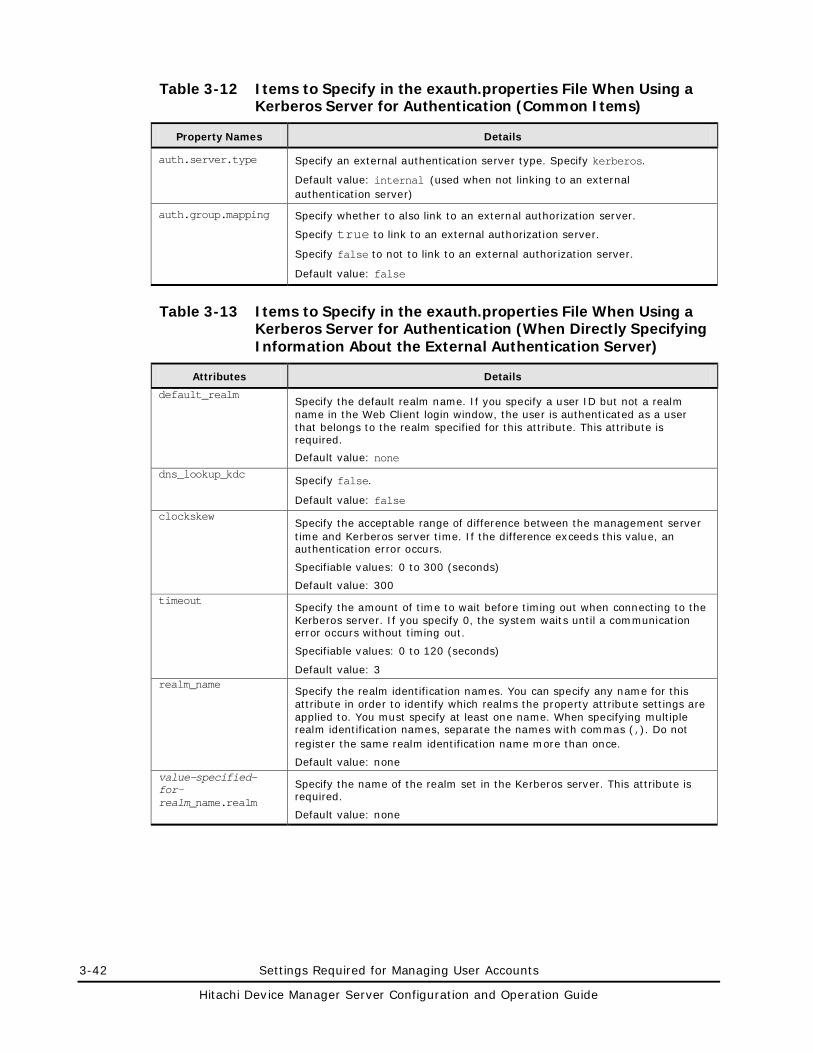
3-42 Settings Required for Managing User Accounts
Hitachi Device Manager Server Configuration and Operation Guide
Table 3-12 Items to Specify in the exauth.properties File When Using a Kerberos Server for Authentication (Common Items)
Property Names Details
auth.server.type Specify an external authentication server type. Specify kerberos.
Default value: internal (used when not linking to an external authentication server)
auth.group.mapping Specify whether to also link to an external authorization server.
Specify true to link to an external authorization server.
Specify false to not to link to an external authorization server.
Default value: false
Table 3-13 Items to Specify in the exauth.properties File When Using a Kerberos Server for Authentication (When Directly Specifying Information About the External Authentication Server)
Attributes Details
default_realm Specify the default realm name. If you specify a user ID but not a realm name in the Web Client login window, the user is authenticated as a user that belongs to the realm specified for this attribute. This attribute is required.
Default value: none dns_lookup_kdc
Specify false.
Default value: false clockskew
Specify the acceptable range of difference between the management server time and Kerberos server time. If the difference exceeds this value, an authentication error occurs.
Specifiable values: 0 to 300 (seconds)
Default value: 300 timeout
Specify the amount of time to wait before timing out when connecting to the Kerberos server. If you specify 0, the system waits until a communication error occurs without timing out.
Specifiable values: 0 to 120 (seconds)
Default value: 3 realm_name
Specify the realm identification names. You can specify any name for this attribute in order to identify which realms the property attribute settings are applied to. You must specify at least one name. When specifying multiple realm identification names, separate the names with commas (,). Do not register the same realm identification name more than once.
Default value: none value-specified-for-realm_name.realm
Specify the name of the realm set in the Kerberos server. This attribute is required.
Default value: none
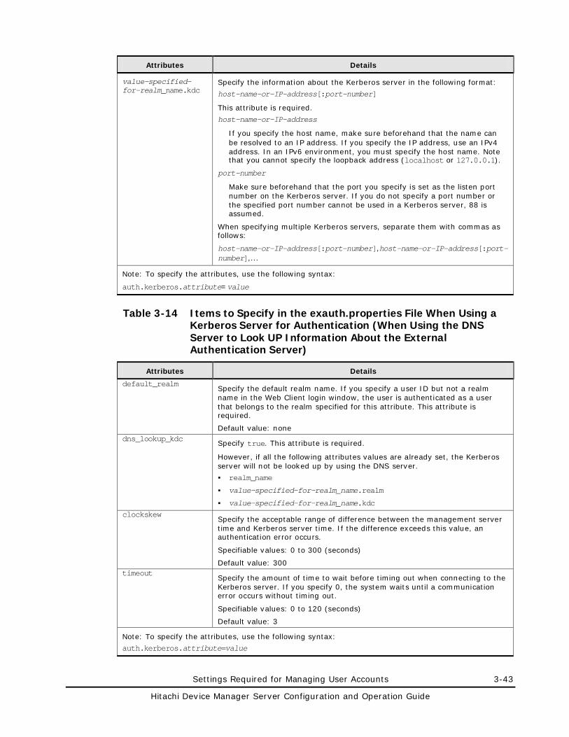
Settings Required for Managing User Accounts 3-43
Hitachi Device Manager Server Configuration and Operation Guide
Attributes Details
value-specified-for-realm_name.kdc
Specify the information about the Kerberos server in the following format:
host-name-or-IP-address[:port-number]
This attribute is required.
host-name-or-IP-address
If you specify the host name, make sure beforehand that the name can be resolved to an IP address. If you specify the IP address, use an IPv4 address. In an IPv6 environment, you must specify the host name. Note that you cannot specify the loopback address (localhost or 127.0.0.1).
port-number
Make sure beforehand that the port you specify is set as the listen port number on the Kerberos server. If you do not specify a port number or the specified port number cannot be used in a Kerberos server, 88 is assumed.
When specifying multiple Kerberos servers, separate them with commas as follows:
host-name-or-IP-address[:port-number],host-name-or-IP-address[:port-number],...
Note: To specify the attributes, use the following syntax:
auth.kerberos.attribute=value
Table 3-14 Items to Specify in the exauth.properties File When Using a Kerberos Server for Authentication (When Using the DNS Server to Look UP Information About the External Authentication Server)
Attributes Details
default_realm Specify the default realm name. If you specify a user ID but not a realm name in the Web Client login window, the user is authenticated as a user that belongs to the realm specified for this attribute. This attribute is required.
Default value: none dns_lookup_kdc
Specify true. This attribute is required.
However, if all the following attributes values are already set, the Kerberos server will not be looked up by using the DNS server.
realm_name
value-specified-for-realm_name.realm
value-specified-for-realm_name.kdc clockskew
Specify the acceptable range of difference between the management server time and Kerberos server time. If the difference exceeds this value, an authentication error occurs.
Specifiable values: 0 to 300 (seconds)
Default value: 300 timeout
Specify the amount of time to wait before timing out when connecting to the Kerberos server. If you specify 0, the system waits until a communication error occurs without timing out.
Specifiable values: 0 to 120 (seconds)
Default value: 3
Note: To specify the attributes, use the following syntax:
auth.kerberos.attribute=value
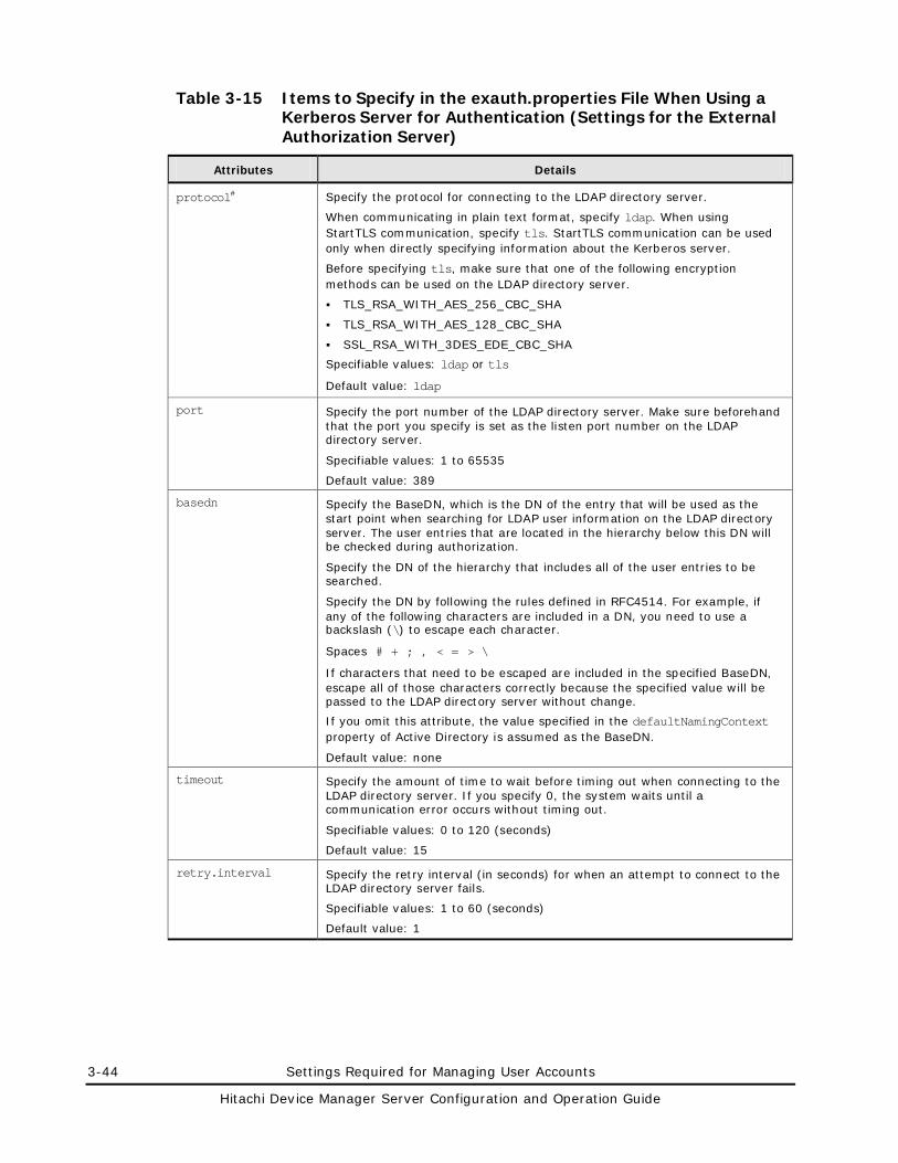
3-44 Settings Required for Managing User Accounts
Hitachi Device Manager Server Configuration and Operation Guide
Table 3-15 Items to Specify in the exauth.properties File When Using a Kerberos Server for Authentication (Settings for the External Authorization Server)
Attributes Details
protocol# Specify the protocol for connecting to the LDAP directory server.
When communicating in plain text format, specify ldap. When using StartTLS communication, specify tls. StartTLS communication can be used only when directly specifying information about the Kerberos server.
Before specifying tls, make sure that one of the following encryption methods can be used on the LDAP directory server.
TLS_RSA_WITH_AES_256_CBC_SHA
TLS_RSA_WITH_AES_128_CBC_SHA
SSL_RSA_WITH_3DES_EDE_CBC_SHA
Specifiable values: ldap or tls
Default value: ldap
port Specify the port number of the LDAP directory server. Make sure beforehand that the port you specify is set as the listen port number on the LDAP directory server.
Specifiable values: 1 to 65535
Default value: 389
basedn Specify the BaseDN, which is the DN of the entry that will be used as the start point when searching for LDAP user information on the LDAP directory server. The user entries that are located in the hierarchy below this DN will be checked during authorization.
Specify the DN of the hierarchy that includes all of the user entries to be searched.
Specify the DN by following the rules defined in RFC4514. For example, if any of the following characters are included in a DN, you need to use a backslash (\) to escape each character.
Spaces # + ; , < = > \
If characters that need to be escaped are included in the specified BaseDN, escape all of those characters correctly because the specified value will be passed to the LDAP directory server without change.
If you omit this attribute, the value specified in the defaultNamingContext property of Active Directory is assumed as the BaseDN.
Default value: none
timeout Specify the amount of time to wait before timing out when connecting to the LDAP directory server. If you specify 0, the system waits until a communication error occurs without timing out.
Specifiable values: 0 to 120 (seconds)
Default value: 15
retry.interval Specify the retry interval (in seconds) for when an attempt to connect to the LDAP directory server fails.
Specifiable values: 1 to 60 (seconds)
Default value: 1
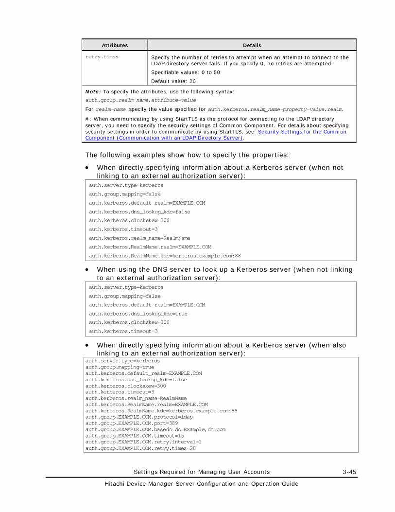
Settings Required for Managing User Accounts 3-45
Hitachi Device Manager Server Configuration and Operation Guide
Attributes Details
retry.times Specify the number of retries to attempt when an attempt to connect to the LDAP directory server fails. If you specify 0, no retries are attempted.
Specifiable values: 0 to 50
Default value: 20
Note: To specify the attributes, use the following syntax:
auth.group.realm-name.attribute=value
For realm-name, specify the value specified for auth.kerberos.realm_name-property-value.realm.
#: When communicating by using StartTLS as the protocol for connecting to the LDAP directory server, you need to specify the security settings of Common Component. For details about specifying security settings in order to communicate by using StartTLS, see Security Settings for the Common Component (Communication with an LDAP Directory Server).
The following examples show how to specify the properties:
• When directly specifying information about a Kerberos server (when not linking to an external authorization server):
auth.server.type=kerberos
auth.group.mapping=false
auth.kerberos.default_realm=EXAMPLE.COM
auth.kerberos.dns_lookup_kdc=false
auth.kerberos.clockskew=300
auth.kerberos.timeout=3
auth.kerberos.realm_name=RealmName
auth.kerberos.RealmName.realm=EXAMPLE.COM
auth.kerberos.RealmName.kdc=kerberos.example.com:88
• When using the DNS server to look up a Kerberos server (when not linking to an external authorization server):
auth.server.type=kerberos
auth.group.mapping=false
auth.kerberos.default_realm=EXAMPLE.COM
auth.kerberos.dns_lookup_kdc=true
auth.kerberos.clockskew=300
auth.kerberos.timeout=3
• When directly specifying information about a Kerberos server (when also linking to an external authorization server):
auth.server.type=kerberos auth.group.mapping=true auth.kerberos.default_realm=EXAMPLE.COM auth.kerberos.dns_lookup_kdc=false auth.kerberos.clockskew=300 auth.kerberos.timeout=3 auth.kerberos.realm_name=RealmName auth.kerberos.RealmName.realm=EXAMPLE.COM auth.kerberos.RealmName.kdc=kerberos.example.com:88 auth.group.EXAMPLE.COM.protocol=ldap auth.group.EXAMPLE.COM.port=389 auth.group.EXAMPLE.COM.basedn=dc=Example,dc=com auth.group.EXAMPLE.COM.timeout=15 auth.group.EXAMPLE.COM.retry.interval=1 auth.group.EXAMPLE.COM.retry.times=20
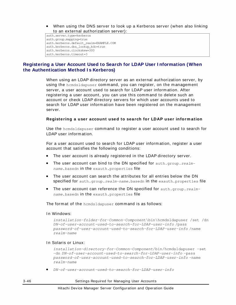
3-46 Settings Required for Managing User Accounts
Hitachi Device Manager Server Configuration and Operation Guide
• When using the DNS server to look up a Kerberos server (when also linking to an external authorization server):
auth.server.type=kerberos auth.group.mapping=true auth.kerberos.default_realm=EXAMPLE.COM auth.kerberos.dns_lookup_kdc=true auth.kerberos.clockskew=300 auth.kerberos.timeout=3
Registering a User Account Used to Search for LDAP User Information (When the Authentication Method Is Kerberos)
When using an LDAP directory server as an external authorization server, by using the hcmdsldapuser command, you can register, on the management server, a user account used to search for LDAP user information. After registering a user account, you can use this command to delete such an account or check LDAP directory servers for which user accounts used to search for LDAP user information have been registered on the management server.
Registering a user account used to search for LDAP user information
Use the hcmdsldapuser command to register a user account used to search for LDAP user information.
For a user account used to search for LDAP user information, register a user account that satisfies the following conditions:
• The user account is already registered in the LDAP directory server.
• The user account can bind to the DN specified for auth.group.realm-name.basedn in the exauth.properties file
• The user account can search the attributes for all entries below the DN specified for auth.group.realm-name.basedn in the exauth.properties file
• The user account can reference the DN specified for auth.group.realm-name.basedn in the exauth.properties file
The format of the hcmdsldapuser command is as follows:
In Windows:
installation-folder-for-Common-Component\bin\hcmdsldapuser /set /dn DN-of-user-account-used-to-search-for-LDAP-user-info /pass password-of-user-account-used-to-search-for-LDAP-user-info /name realm-name
In Solaris or Linux:
installation-directory-for-Common-Component/bin/hcmdsldapuser -set -dn DN-of-user-account-used-to-search-for-LDAP-user-info -pass password-of-user-account-used-to-search-for-LDAP-user-info -name realm-name
• DN-of-user-account-used-to-search-for-LDAP-user-info
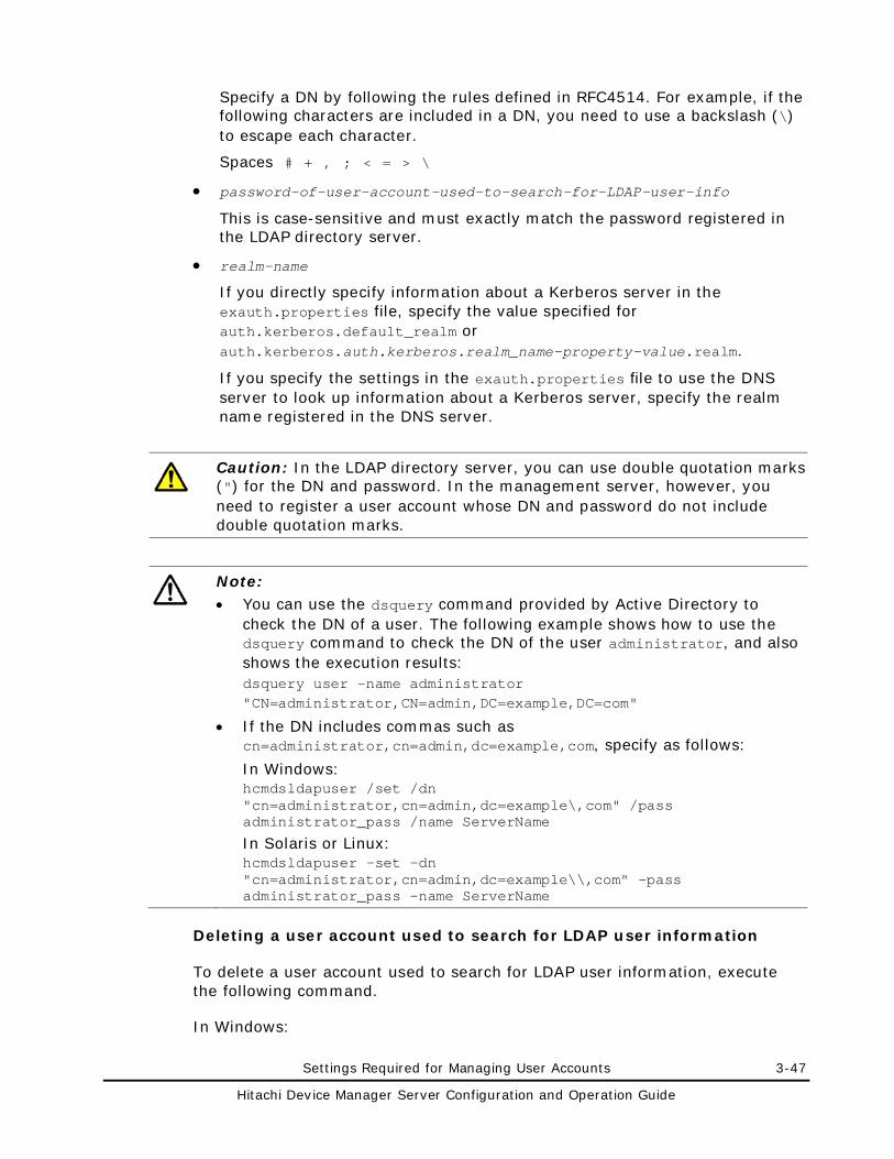
Settings Required for Managing User Accounts 3-47
Hitachi Device Manager Server Configuration and Operation Guide
Specify a DN by following the rules defined in RFC4514. For example, if the following characters are included in a DN, you need to use a backslash (\) to escape each character.
Spaces # + , ; < = > \
• password-of-user-account-used-to-search-for-LDAP-user-info
This is case-sensitive and must exactly match the password registered in the LDAP directory server.
• realm-name
If you directly specify information about a Kerberos server in the exauth.properties file, specify the value specified for auth.kerberos.default_realm or auth.kerberos.auth.kerberos.realm_name-property-value.realm.
If you specify the settings in the exauth.properties file to use the DNS server to look up information about a Kerberos server, specify the realm name registered in the DNS server.
Caution: In the LDAP directory server, you can use double quotation marks (") for the DN and password. In the management server, however, you need to register a user account whose DN and password do not include double quotation marks.
Note: • You can use the dsquery command provided by Active Directory to
check the DN of a user. The following example shows how to use the dsquery command to check the DN of the user administrator, and also shows the execution results: dsquery user -name administrator "CN=administrator,CN=admin,DC=example,DC=com"
• If the DN includes commas such as cn=administrator,cn=admin,dc=example,com, specify as follows:
In Windows: hcmdsldapuser /set /dn "cn=administrator,cn=admin,dc=example\,com" /pass administrator_pass /name ServerName
In Solaris or Linux: hcmdsldapuser -set -dn "cn=administrator,cn=admin,dc=example\\,com" -pass administrator_pass -name ServerName
Deleting a user account used to search for LDAP user information
To delete a user account used to search for LDAP user information, execute the following command.
In Windows:
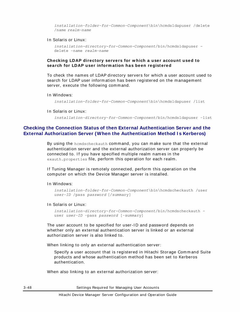
3-48 Settings Required for Managing User Accounts
Hitachi Device Manager Server Configuration and Operation Guide
installation-folder-for-Common-Component\bin\hcmdsldapuser /delete /name realm-name
In Solaris or Linux:
installation-directory-for-Common-Component/bin/hcmdsldapuser -delete -name realm-name
Checking LDAP directory servers for which a user account used to search for LDAP user information has been registered
To check the names of LDAP directory servers for which a user account used to search for LDAP user information has been registered on the management server, execute the following command.
In Windows:
installation-folder-for-Common-Component\bin\hcmdsldapuser /list
In Solaris or Linux: installation-directory-for-Common-Component/bin/hcmdsldapuser -list
Checking the Connection Status of then External Authentication Server and the External Authorization Server (When the Authentication Method Is Kerberos)
By using the hcmdscheckauth command, you can make sure that the external authentication server and the external authorization server can properly be connected to. If you have specified multiple realm names in the exauth.properties file, perform this operation for each realm.
If Tuning Manager is remotely connected, perform this operation on the computer on which the Device Manager server is installed.
In Windows:
installation-folder-for-Common-Component\bin\hcmdscheckauth /user user-ID /pass password [/summary]
In Solaris or Linux:
installation-directory-for-Common-Component/bin/hcmdscheckauth -user user-ID -pass password [-summary]
The user account to be specified for user-ID and password depends on whether only an external authentication server is linked or an external authorization server is also linked to.
When linking to only an external authentication server:
Specify a user account that is registered in Hitachi Storage Command Suite products and whose authentication method has been set to Kerberos authentication.
When also linking to an external authorization server:
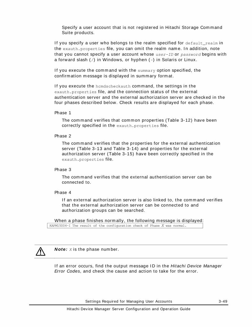
Settings Required for Managing User Accounts 3-49
Hitachi Device Manager Server Configuration and Operation Guide
Specify a user account that is not registered in Hitachi Storage Command Suite products.
If you specify a user who belongs to the realm specified for default_realm in the exauth.properties file, you can omit the realm name. In addition, note that you cannot specify a user account whose user-ID or password begins with a forward slash (/) in Windows, or hyphen (-) in Solaris or Linux.
If you execute the command with the summary option specified, the confirmation message is displayed in summary format.
If you execute the hcmdscheckauth command, the settings in the exauth.properties file, and the connection status of the external authentication server and the external authorization server are checked in the four phases described below. Check results are displayed for each phase.
Phase 1
The command verifies that common properties (Table 3-12) have been correctly specified in the exauth.properties file.
Phase 2
The command verifies that the properties for the external authentication server (Table 3-13 and Table 3-14) and properties for the external authorization server (Table 3-15) have been correctly specified in the exauth.properties file.
Phase 3
The command verifies that the external authentication server can be connected to.
Phase 4
If an external authorization server is also linked to, the command verifies that the external authorization server can be connected to and authorization groups can be searched.
When a phase finishes normally, the following message is displayed: KAPM15004-I The result of the configuration check of Phase X was normal.
Note: X is the phase number.
If an error occurs, find the output message ID in the Hitachi Device Manager Error Codes, and check the cause and action to take for the error.
3-50 Settings Required for Managing User Accounts
Hitachi Device Manager Server Configuration and Operation Guide
Encryption Types That Can Be Used For Kerberos Authentication
In Hitachi Storage Command Suite products, the encryption types listed below can be used for Kerberos authentication. Configure the Kerberos server so that one of the following encryption types can be used.
If the management server OS is Windows:
AES128-CTS-HMAC-SHA1-96
RC4-HMAC
DES3-CBC-SHA1
DES-CBC-CRC
DES-CBC-MD5
If the management server OS is Solaris or Linux:
DES-CBC-MD5
For example, if the management server OS is Solaris or Linux and you use Windows Server 2008 R2 Active Directory for the Kerberos server, you need to enable DES-CBC-MD5 in the Windows security policy settings.
Security Settings for Device Manager 4-1
Hitachi Device Manager Server Configuration and Operation Guide
Security Settings for Device Manager
This chapter describes the security settings required to operate Device Manager.
Warning Banner Settings
Security Settings Related to Communication
Specifying Which Device Manager Clients Can Access the Device Manager Server
Changing the Password-Encoding Level in CLI of Device Manager or Tiered Storage Manager
Advanced Security Mode
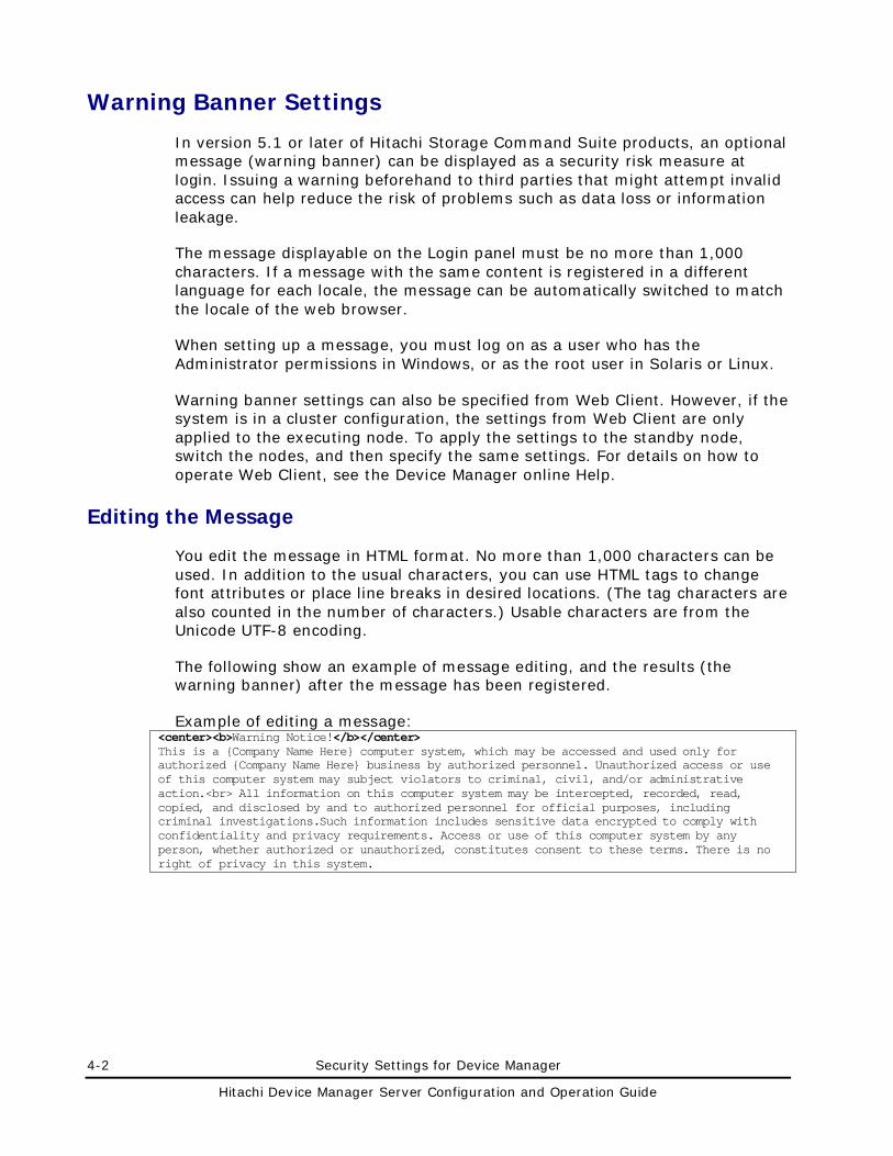
4-2 Security Settings for Device Manager
Hitachi Device Manager Server Configuration and Operation Guide
Warning Banner Settings
In version 5.1 or later of Hitachi Storage Command Suite products, an optional message (warning banner) can be displayed as a security risk measure at login. Issuing a warning beforehand to third parties that might attempt invalid access can help reduce the risk of problems such as data loss or information leakage.
The message displayable on the Login panel must be no more than 1,000 characters. If a message with the same content is registered in a different language for each locale, the message can be automatically switched to match the locale of the web browser.
When setting up a message, you must log on as a user who has the Administrator permissions in Windows, or as the root user in Solaris or Linux.
Warning banner settings can also be specified from Web Client. However, if the system is in a cluster configuration, the settings from Web Client are only applied to the executing node. To apply the settings to the standby node, switch the nodes, and then specify the same settings. For details on how to operate Web Client, see the Device Manager online Help.
Editing the Message
You edit the message in HTML format. No more than 1,000 characters can be used. In addition to the usual characters, you can use HTML tags to change font attributes or place line breaks in desired locations. (The tag characters are also counted in the number of characters.) Usable characters are from the Unicode UTF-8 encoding.
The following show an example of message editing, and the results (the warning banner) after the message has been registered.
Example of editing a message: <center><b>Warning Notice!</b></center> This is a {Company Name Here} computer system, which may be accessed and used only for authorized {Company Name Here} business by authorized personnel. Unauthorized access or use of this computer system may subject violators to criminal, civil, and/or administrative action.<br> All information on this computer system may be intercepted, recorded, read, copied, and disclosed by and to authorized personnel for official purposes, including criminal investigations.Such information includes sensitive data encrypted to comply with confidentiality and privacy requirements. Access or use of this computer system by any person, whether authorized or unauthorized, constitutes consent to these terms. There is no right of privacy in this system.
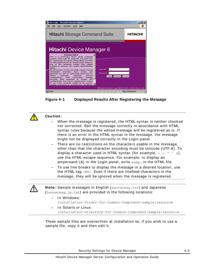
Security Settings for Device Manager 4-3
Hitachi Device Manager Server Configuration and Operation Guide
Figure 4-1 Displayed Results After Registering the Message
Caution:
– When the message is registered, the HTML syntax is neither checked nor corrected. Edit the message correctly in accordance with HTML syntax rules because the edited message will be registered as is. If there is an error in the HTML syntax in the message, the message might not be displayed correctly in the Login panel.
– There are no restrictions on the characters usable in the message, other than that the character encoding must be Unicode (UTF-8). To display a character used in HTML syntax (for example, < > “ ‘ &), use the HTML escape sequence. For example, to display an ampersand (&) in the Login panel, write & in the HTML file.
– To use line breaks to display the message in a desired location, use the HTML tag <BR>. Even if there are linefeed characters in the message, they will be ignored when the message is registered.
Note: Sample messages in English (bannermsg.txt) and Japanese (bannermsg_ja.txt) are provided in the following locations:
– In Windows: installation-folder-for-Common-Component\sample\resource
– In Solaris or Linux: installation-directory-for-Common-Component/sample/resource
These sample files are overwritten at installation so, if you wish to use a sample file, copy it and then edit it.
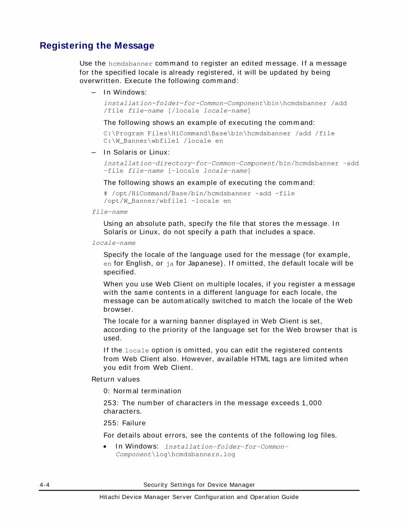
4-4 Security Settings for Device Manager
Hitachi Device Manager Server Configuration and Operation Guide
Registering the Message
Use the hcmdsbanner command to register an edited message. If a message for the specified locale is already registered, it will be updated by being overwritten. Execute the following command:
– In Windows:
installation-folder-for-Common-Component\bin\hcmdsbanner /add /file file-name [/locale locale-name]
The following shows an example of executing the command: C:\Program Files\HiCommand\Base\bin\hcmdsbanner /add /file C:\W_Banner\wbfile1 /locale en
– In Solaris or Linux:
installation-directory-for-Common-Component/bin/hcmdsbanner -add -file file-name [-locale locale-name]
The following shows an example of executing the command: # /opt/HiCommand/Base/bin/hcmdsbanner -add -file /opt/W_Banner/wbfile1 -locale en
file-name
Using an absolute path, specify the file that stores the message. In Solaris or Linux, do not specify a path that includes a space.
locale-name
Specify the locale of the language used for the message (for example, en for English, or ja for Japanese). If omitted, the default locale will be specified.
When you use Web Client on multiple locales, if you register a message with the same contents in a different language for each locale, the message can be automatically switched to match the locale of the Web browser.
The locale for a warning banner displayed in Web Client is set, according to the priority of the language set for the Web browser that is used.
If the locale option is omitted, you can edit the registered contents from Web Client also. However, available HTML tags are limited when you edit from Web Client.
Return values
0: Normal termination
253: The number of characters in the message exceeds 1,000 characters.
255: Failure
For details about errors, see the contents of the following log files.
• In Windows: installation-folder-for-Common-Component\log\hcmdsbannern.log
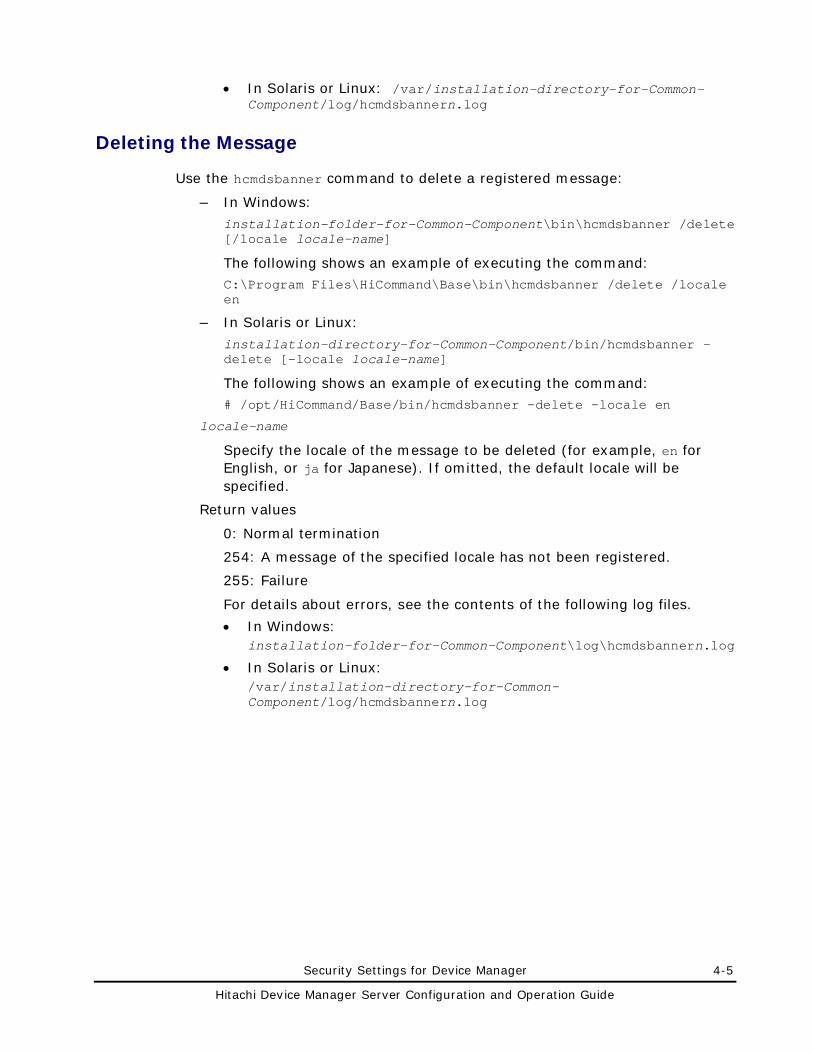
Security Settings for Device Manager 4-5
Hitachi Device Manager Server Configuration and Operation Guide
• In Solaris or Linux: /var/installation-directory-for-Common-Component/log/hcmdsbannern.log
Deleting the Message
Use the hcmdsbanner command to delete a registered message:
– In Windows:
installation-folder-for-Common-Component\bin\hcmdsbanner /delete [/locale locale-name]
The following shows an example of executing the command: C:\Program Files\HiCommand\Base\bin\hcmdsbanner /delete /locale en
– In Solaris or Linux:
installation-directory-for-Common-Component/bin/hcmdsbanner -delete [-locale locale-name]
The following shows an example of executing the command: # /opt/HiCommand/Base/bin/hcmdsbanner -delete -locale en
locale-name
Specify the locale of the message to be deleted (for example, en for English, or ja for Japanese). If omitted, the default locale will be specified.
Return values
0: Normal termination
254: A message of the specified locale has not been registered.
255: Failure
For details about errors, see the contents of the following log files.
• In Windows: installation-folder-for-Common-Component\log\hcmdsbannern.log
• In Solaris or Linux: /var/installation-directory-for-Common-Component/log/hcmdsbannern.log
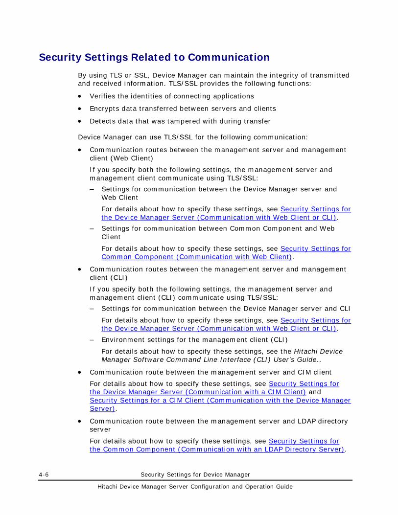
4-6 Security Settings for Device Manager
Hitachi Device Manager Server Configuration and Operation Guide
Security Settings Related to Communication
By using TLS or SSL, Device Manager can maintain the integrity of transmitted and received information. TLS/SSL provides the following functions:
• Verifies the identities of connecting applications
• Encrypts data transferred between servers and clients
• Detects data that was tampered with during transfer
Device Manager can use TLS/SSL for the following communication:
• Communication routes between the management server and management client (Web Client)
If you specify both the following settings, the management server and management client communicate using TLS/SSL:
– Settings for communication between the Device Manager server and Web Client
For details about how to specify these settings, see Security Settings for the Device Manager Server (Communication with Web Client or CLI).
– Settings for communication between Common Component and Web Client
For details about how to specify these settings, see Security Settings for Common Component (Communication with Web Client).
• Communication routes between the management server and management client (CLI)
If you specify both the following settings, the management server and management client (CLI) communicate using TLS/SSL:
– Settings for communication between the Device Manager server and CLI
For details about how to specify these settings, see Security Settings for the Device Manager Server (Communication with Web Client or CLI).
– Environment settings for the management client (CLI)
For details about how to specify these settings, see the Hitachi Device Manager Software Command Line Interface (CLI) User’s Guide..
• Communication route between the management server and CIM client
For details about how to specify these settings, see Security Settings for the Device Manager Server (Communication with a CIM Client) and Security Settings for a CIM Client (Communication with the Device Manager Server).
• Communication route between the management server and LDAP directory server
For details about how to specify these settings, see Security Settings for the Common Component (Communication with an LDAP Directory Server).
Security Settings for Device Manager 4-7
Hitachi Device Manager Server Configuration and Operation Guide
• Communication routes between the management server and storage subsystems
TLS/SSL can be used for communication with the following storage subsystems:
– Universal Storage Platform V/VM
– Hitachi USP
– Hitachi AMS 2000
– Hitachi SMS
– SMI-S Enabled subsystem (SMI-S provider)#
#: TLS/SSL can be used to receive event indications from an SMI-S provider.
You do not need to set up a Device Manager environment for communication with Universal Storage Platform V/VM or Hitachi USP because such communication always uses SSL.
To use SSL for communication with Hitachi AMS 2000 or Hitachi SMS, you need to specify the settings for Web Client or CLI. For details about how to specify the settings, see the Device Manager online Help or the Hitachi Device Manager Software Command Line Interface (CLI) User’s Guide.
For details about how to specify settings to use TLS/SSL for event indications, see Security Settings for the Device Manager Server (Communication with SMI-S Provider).
This section describes how to configure Device Manager to enable secure communications over the Internet or an intranet by using TLS/SSL. For details about the SSL settings for linked applications, see the documentation for the relevant application.
Note: If you enable security on Device Manager, you must make sure that the key pair and associated server certificate do not expire. If either the key pair or the server certificate expires, users might not be able to connect to the Device Manager server or Common Component (HBase Storage Mgmt Web Service) with Web Client. For details, see Creating a Keypair, Creating a Certificate Signing Request (CSR) (Security Settings for Common Component)and Creating a Self-Signed Certificate.
This section includes the following terms:
• host-name indicates the name of the host that is running the Device Manager server or HBase Storage Mgmt Web Service, unless otherwise specified.
• installation-directory-for-Java-Web-Start indicates the default Java Web Start installation directory on a client computer. If a client's Java Web Start directory is not located in the default location, adjust commands or paths accordingly. The default directories are as follows:
– In Windows: program-files-folder\Java\version-of-JRE\bin
4-8 Security Settings for Device Manager
Hitachi Device Manager Server Configuration and Operation Guide
– In Solaris: /usr/j2se/jre/javaws
– In Linux: /usr/Java/version-of-JRE/javaws
– In HP-UX®: /opt/version-of-JRE/jre/javaws
• Public Key Infrastructure (PKI) is a cryptographic technology developed under the guidance of the Internet Engineering Task Force (IETF) to create a secure networking system that can have interoperative characteristics between multiple vendors.
• Secure Sockets Layer (SSL) is a protocol first developed by Netscape® to securely transmit data over the Internet. Two SSL-enabled peers use their private and public keys to establish a secure communication session, with each peer encrypting transmitted data with a randomly generated and agreed-upon symmetric key.
• Transport Layer Security (TLS) is the successor protocol to SSL. For more information, see the RFC, The TLS Protocol (version 1.0) at:
http://www.ietf.org/rfc/rfc2246.txt
• A keypair is two mathematically-related cryptographic keys consisting of a private key and its associated public key.
• A keystore is a file that contains the keypair, which is used for TLS/SSL connections and the corresponding server certificate.
• A private key password is a password for restoring the keypair used to encrypt TLS/SSL connections and the corresponding server certificate.
• A truststore is a file containing a signed and trusted server certificate.
• A server certificate (digitally-signed certificate) forms an association between an ID (the Device Manager server or HBase Storage Mgmt Web Service of Common Component) and a specific keypair. A server certificate is used to identify the Device Manager server or HBase Storage Mgmt Web Service to a client so that the server and client can communicate using TLS/SSL. Server certificates used in Device Manager are X.509 certificates in DER or PEM format (Device Manager server) or X.509 certificates in PEM format (HBase Storage Mgmt Web Service). Server certificates come in two basic types:
– Self-signed: This is a certificate self-signed by the issuer of the certificate. Users can create certificates of this type by themselves. For example, if you use HiKeytool to create a keypair, you will have a keypair and an associated self-signed certificate. Although you can use a self-signed certificate to establish encrypted communications, a warning message might be output depending on the browser because the security level of self-signed certificates is low. Therefore, we recommend that you use a self-signed certificate only to test encrypted communications.
Security Settings for Device Manager 4-9
Hitachi Device Manager Server Configuration and Operation Guide
– Signed and trusted: This is a certificate signed by a trusted certificate authority (CA). To obtain a signed certificate from a certificate authority, generate a certificate signing request (CSR), send it to a certificate authority (the root certificate authority or other certificate authorities trusted by different certificate authorities), and then have it returned from the certificate authority. A well-known and trusted certificate authority meets the following requirements:
4. A certificate for that certificate authority is located inside the Device Manager server truststore.
5. A certificate for that certificate authority is located in the database of trusted certificate authorities within browsers supported by Device Manager.
6. A certificate for that certificate authority is located within the truststore distributed with Java Web Start.
7. A certificate for that certificate authority is located within the truststore used by Common Component.
8. A certificate for that certificate authority is located within the truststore used by SMI-S clients and SMI-S Indication clients. SMI-S Indication clients.
Note: • The locations of the truststore for the Device Manager server and the
default truststore for Java Web Start are as follows: Truststore for the Device Manager server:
installation-directory-for-Common-Component/jdk/jre/lib/security/cacerts
Default truststore for Java Web Start: Java-Web-Start-installation-directory/cacerts
The default location of the truststore for the Device Manager server can be changed by using the server.https.security.truststore property.
• The truststore for Common Component is in the following location: installation-directory-for-Common-Component/jdk/jre/lib/security/jssecacerts
• The default truststore for the CIM/WBEM server is in the following location: installation-directory-for-the-Device-Manager-server/HiCommandServer/wsi/server/jserver/bin
• Unless otherwise noted, the following description uses examples displayed in a Windows environment.
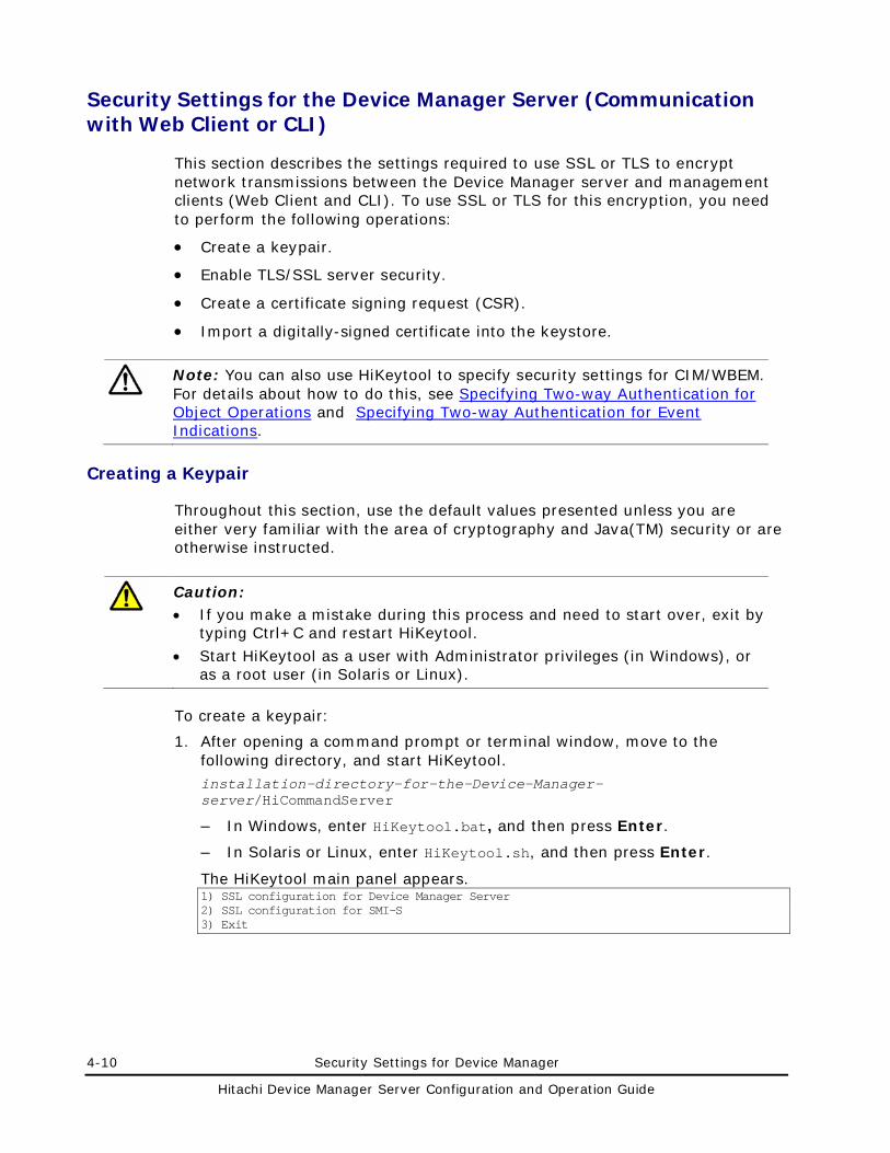
4-10 Security Settings for Device Manager
Hitachi Device Manager Server Configuration and Operation Guide
Security Settings for the Device Manager Server (Communication with Web Client or CLI)
This section describes the settings required to use SSL or TLS to encrypt network transmissions between the Device Manager server and management clients (Web Client and CLI). To use SSL or TLS for this encryption, you need to perform the following operations:
• Create a keypair.
• Enable TLS/SSL server security.
• Create a certificate signing request (CSR).
• Import a digitally-signed certificate into the keystore.
Note: You can also use HiKeytool to specify security settings for CIM/WBEM. For details about how to do this, see Specifying Two-way Authentication for Object Operations and Specifying Two-way Authentication for Event Indications.
Creating a Keypair
Throughout this section, use the default values presented unless you are either very familiar with the area of cryptography and Java(TM) security or are otherwise instructed.
Caution: • If you make a mistake during this process and need to start over, exit by
typing Ctrl+C and restart HiKeytool.
• Start HiKeytool as a user with Administrator privileges (in Windows), or as a root user (in Solaris or Linux).
To create a keypair:
1. After opening a command prompt or terminal window, move to the following directory, and start HiKeytool. installation-directory-for-the-Device-Manager-server/HiCommandServer
– In Windows, enter HiKeytool.bat, and then press Enter.
– In Solaris or Linux, enter HiKeytool.sh, and then press Enter.
The HiKeytool main panel appears. 1) SSL configuration for Device Manager Server 2) SSL configuration for SMI-S 3) Exit
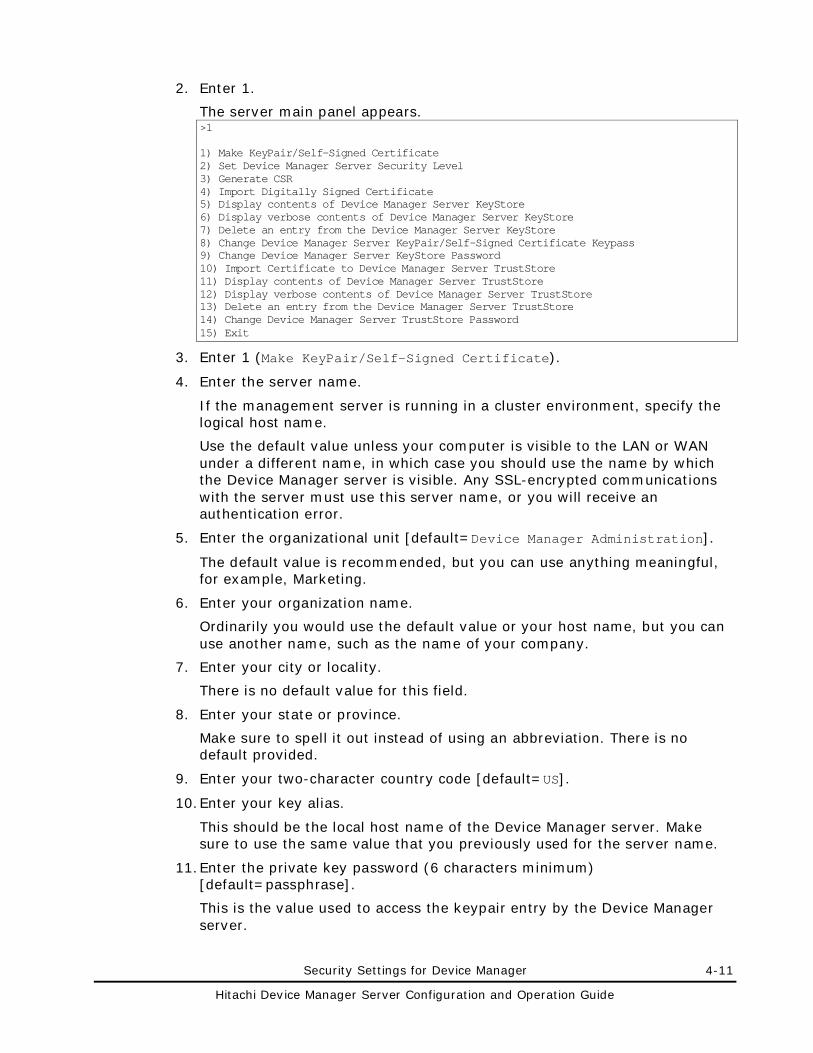
Security Settings for Device Manager 4-11
Hitachi Device Manager Server Configuration and Operation Guide
2. Enter 1.
The server main panel appears. >1 1) Make KeyPair/Self-Signed Certificate 2) Set Device Manager Server Security Level 3) Generate CSR 4) Import Digitally Signed Certificate 5) Display contents of Device Manager Server KeyStore 6) Display verbose contents of Device Manager Server KeyStore 7) Delete an entry from the Device Manager Server KeyStore 8) Change Device Manager Server KeyPair/Self-Signed Certificate Keypass 9) Change Device Manager Server KeyStore Password 10) Import Certificate to Device Manager Server TrustStore 11) Display contents of Device Manager Server TrustStore 12) Display verbose contents of Device Manager Server TrustStore 13) Delete an entry from the Device Manager Server TrustStore 14) Change Device Manager Server TrustStore Password 15) Exit
3. Enter 1 (Make KeyPair/Self-Signed Certificate).
4. Enter the server name.
If the management server is running in a cluster environment, specify the logical host name.
Use the default value unless your computer is visible to the LAN or WAN under a different name, in which case you should use the name by which the Device Manager server is visible. Any SSL-encrypted communications with the server must use this server name, or you will receive an authentication error.
5. Enter the organizational unit [default=Device Manager Administration].
The default value is recommended, but you can use anything meaningful, for example, Marketing.
6. Enter your organization name.
Ordinarily you would use the default value or your host name, but you can use another name, such as the name of your company.
7. Enter your city or locality.
There is no default value for this field.
8. Enter your state or province.
Make sure to spell it out instead of using an abbreviation. There is no default provided.
9. Enter your two-character country code [default=US].
10. Enter your key alias.
This should be the local host name of the Device Manager server. Make sure to use the same value that you previously used for the server name.
11. Enter the private key password (6 characters minimum) [default=passphrase].
This is the value used to access the keypair entry by the Device Manager server.
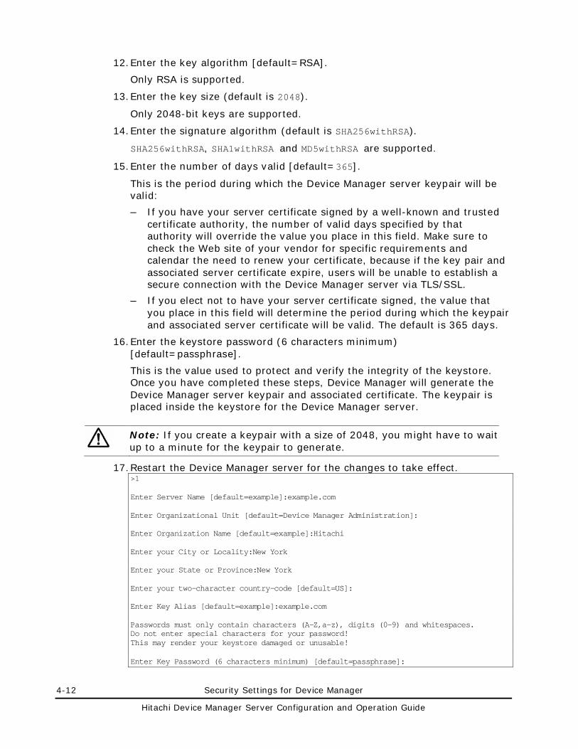
4-12 Security Settings for Device Manager
Hitachi Device Manager Server Configuration and Operation Guide
12. Enter the key algorithm [default=RSA].
Only RSA is supported.
13. Enter the key size (default is 2048).
Only 2048-bit keys are supported.
14. Enter the signature algorithm (default is SHA256withRSA).
SHA256withRSA, SHA1withRSA and MD5withRSA are supported.
15. Enter the number of days valid [default=365].
This is the period during which the Device Manager server keypair will be valid:
– If you have your server certificate signed by a well-known and trusted certificate authority, the number of valid days specified by that authority will override the value you place in this field. Make sure to check the Web site of your vendor for specific requirements and calendar the need to renew your certificate, because if the key pair and associated server certificate expire, users will be unable to establish a secure connection with the Device Manager server via TLS/SSL.
– If you elect not to have your server certificate signed, the value that you place in this field will determine the period during which the keypair and associated server certificate will be valid. The default is 365 days.
16. Enter the keystore password (6 characters minimum) [default=passphrase].
This is the value used to protect and verify the integrity of the keystore. Once you have completed these steps, Device Manager will generate the Device Manager server keypair and associated certificate. The keypair is placed inside the keystore for the Device Manager server.
Note: If you create a keypair with a size of 2048, you might have to wait up to a minute for the keypair to generate.
17. Restart the Device Manager server for the changes to take effect. >1 Enter Server Name [default=example]:example.com Enter Organizational Unit [default=Device Manager Administration]: Enter Organization Name [default=example]:Hitachi Enter your City or Locality:New York Enter your State or Province:New York Enter your two-character country-code [default=US]: Enter Key Alias [default=example]:example.com Passwords must only contain characters (A-Z,a-z), digits (0-9) and whitespaces. Do not enter special characters for your password! This may render your keystore damaged or unusable! Enter Key Password (6 characters minimum) [default=passphrase]:

Security Settings for Device Manager 4-13
Hitachi Device Manager Server Configuration and Operation Guide
Enter Key Algorithm [default=RSA]: Enter Key Size [default=2048]: Enter Signature Algorithm [default=SHA256withRSA]: Enter number of days valid [default=365]: Passwords must only contain characters (A-Z,a-z), digits (0-9) and whitespaces. Do not enter special characters for your password! This may render your keystore damaged or unusable! Enter KeyStore Password (6 characters minimum) [default=passphrase]: Creating new X500Name for example.com... Creating the Device Manager Server KeyPair for example.com at: C:\Program Files\HiCommand\DeviceManager\HiCommandServer\keystore <this can take up to a minute> Updating KeyStore password in server.properties... Saving new KeyStore password to disk... Updating keypass in server properties... Saving new keypass to disk... All done.
Enabling TLS/SSL Server Security
Caution: If the Device Manager server manages SMI-S Enabled subsystems, the setting specified below will also be used when Device Manager receives event indications from an SMI-S provider.
To enable TLS/SSL server security:
1. Open the server main screen.
For details, see steps 1 and 2 in Creating a Keypair.
2. In the server main panel, enter 2 (Set Device Manager Server Security Level).
The current security level and two available levels of security are displayed:
– 1:Basic authentication, which requires a valid username and password.
Note: This is the default. Information will be base64 encoded, but it might be unencoded if the communications were intercepted.
– 2:Encrypted using TLS/SSL, which is discussed in this section.
3. To enable TLS/SSL (Secure Sockets), enter 2 and then press Enter.
The display will confirm that you have selected TLS/SSL.
4. Restart the Device Manager server for these changes to take effect. >2 Current Device Manager Server Security Level = User Logon (Basic Authentication)
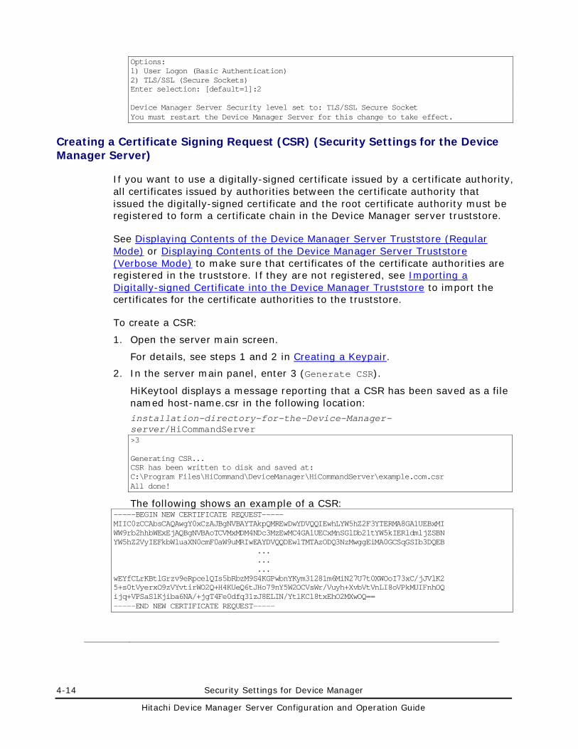
4-14 Security Settings for Device Manager
Hitachi Device Manager Server Configuration and Operation Guide
Options: 1) User Logon (Basic Authentication) 2) TLS/SSL (Secure Sockets) Enter selection: [default=1]:2 Device Manager Server Security level set to: TLS/SSL Secure Socket You must restart the Device Manager Server for this change to take effect.
Creating a Certificate Signing Request (CSR) (Security Settings for the Device Manager Server)
If you want to use a digitally-signed certificate issued by a certificate authority, all certificates issued by authorities between the certificate authority that issued the digitally-signed certificate and the root certificate authority must be registered to form a certificate chain in the Device Manager server truststore.
See Displaying Contents of the Device Manager Server Truststore (Regular Mode) or Displaying Contents of the Device Manager Server Truststore (Verbose Mode) to make sure that certificates of the certificate authorities are registered in the truststore. If they are not registered, see Importing a Digitally-signed Certificate into the Device Manager Truststore to import the certificates for the certificate authorities to the truststore.
To create a CSR:
1. Open the server main screen.
For details, see steps 1 and 2 in Creating a Keypair.
2. In the server main panel, enter 3 (Generate CSR).
HiKeytool displays a message reporting that a CSR has been saved as a file named host-name.csr in the following location: installation-directory-for-the-Device-Manager-server/HiCommandServer >3 Generating CSR... CSR has been written to disk and saved at: C:\Program Files\HiCommand\DeviceManager\HiCommandServer\example.com.csr All done!
The following shows an example of a CSR: -----BEGIN NEW CERTIFICATE REQUEST----- MIIC0zCCAbsCAQAwgY0xCzAJBgNVBAYTAkpQMREwDwYDVQQIEwhLYW5hZ2F3YTERMA8GA1UEBxMI WW9rb2hhbWExEjAQBgNVBAoTCVMxMDM4NDc3MzEwMC4GA1UECxMnSGlDb21tYW5kIERldmljZSBN YW5hZ2VyIEFkbWluaXN0cmF0aW9uMRIwEAYDVQQDEwlTMTAzODQ3NzMwggEiMA0GCSqGSIb3DQEB ... ... ... wEYfCLrKBtlGrzv9eRpcelQIs5bRbzM9S4KGPwbnYKym31281m6MiN27U7t0XWOoI73xC/jJVlK2 5+s0tVyerxO9zVYvtirWO2Q+H4KUeQ6tJHo79nY5W2OCVsWr/Vuyh+XvbVtVnLI8oVPkMUIFnhOQ ijq+VPSaSlKjiba6NA/+jgT4Fe0dfq31zJ8ELIN/YtlKCl8txEhO2MXwOQ== -----END NEW CERTIFICATE REQUEST-----
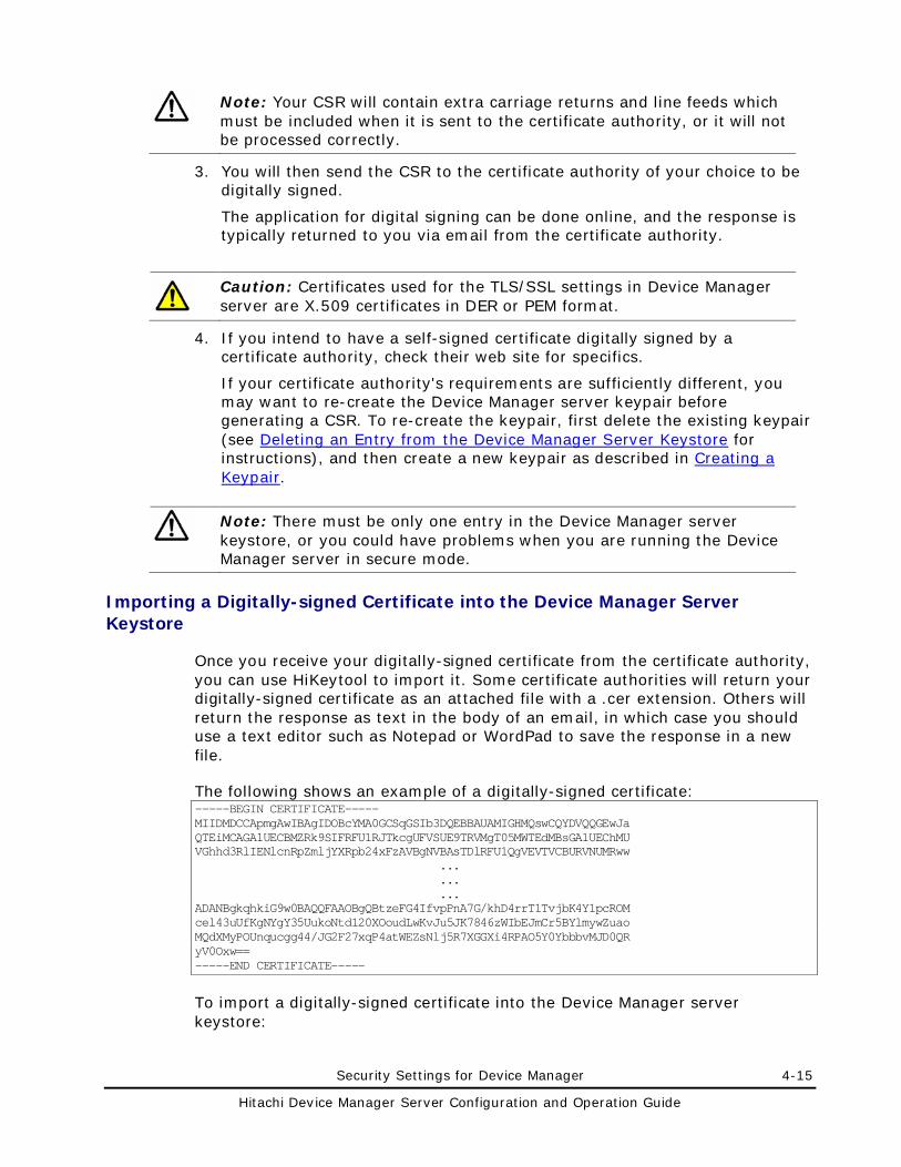
Security Settings for Device Manager 4-15
Hitachi Device Manager Server Configuration and Operation Guide
Note: Your CSR will contain extra carriage returns and line feeds which must be included when it is sent to the certificate authority, or it will not be processed correctly.
3. You will then send the CSR to the certificate authority of your choice to be digitally signed.
The application for digital signing can be done online, and the response is typically returned to you via email from the certificate authority.
Caution: Certificates used for the TLS/SSL settings in Device Manager server are X.509 certificates in DER or PEM format.
4. If you intend to have a self-signed certificate digitally signed by a certificate authority, check their web site for specifics.
If your certificate authority's requirements are sufficiently different, you may want to re-create the Device Manager server keypair before generating a CSR. To re-create the keypair, first delete the existing keypair (see Deleting an Entry from the Device Manager Server Keystore for instructions), and then create a new keypair as described in Creating a Keypair.
Note: There must be only one entry in the Device Manager server keystore, or you could have problems when you are running the Device Manager server in secure mode.
Importing a Digitally-signed Certificate into the Device Manager Server Keystore
Once you receive your digitally-signed certificate from the certificate authority, you can use HiKeytool to import it. Some certificate authorities will return your digitally-signed certificate as an attached file with a .cer extension. Others will return the response as text in the body of an email, in which case you should use a text editor such as Notepad or WordPad to save the response in a new file.
The following shows an example of a digitally-signed certificate: -----BEGIN CERTIFICATE----- MIIDMDCCApmgAwIBAgIDOBcYMA0GCSqGSIb3DQEBBAUAMIGHMQswCQYDVQQGEwJa QTEiMCAGA1UECBMZRk9SIFRFU1RJTkcgUFVSUE9TRVMgT05MWTEdMBsGA1UEChMU VGhhd3RlIENlcnRpZmljYXRpb24xFzAVBgNVBAsTDlRFU1QgVEVTVCBURVNUMRww ... ... ... ADANBgkqhkiG9w0BAQQFAAOBgQBtzeFG4IfvpPnA7G/khD4rrT1TvjbK4Y1pcROM cel43uUfKgNYgY35UukoNtd120XOoudLwKvJu5JK7846zWIbEJmCr5BYlmywZuao MQdXMyPOUnqucgg44/JG2F27xqP4atWEZsNlj5R7XGGXi4RPAO5Y0YbbbvMJD0QR yV0Oxw== -----END CERTIFICATE-----
To import a digitally-signed certificate into the Device Manager server keystore:
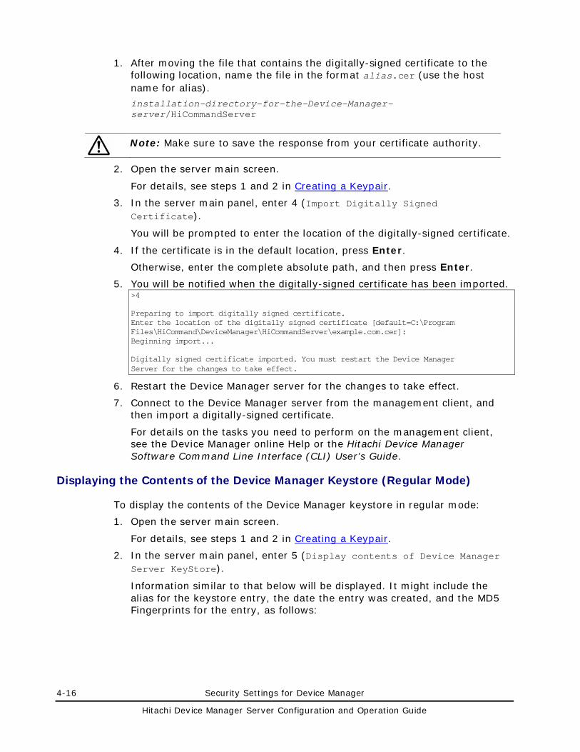
4-16 Security Settings for Device Manager
Hitachi Device Manager Server Configuration and Operation Guide
1. After moving the file that contains the digitally-signed certificate to the following location, name the file in the format alias.cer (use the host name for alias).
installation-directory-for-the-Device-Manager-server/HiCommandServer
Note: Make sure to save the response from your certificate authority.
2. Open the server main screen.
For details, see steps 1 and 2 in Creating a Keypair.
3. In the server main panel, enter 4 (Import Digitally Signed Certificate).
You will be prompted to enter the location of the digitally-signed certificate.
4. If the certificate is in the default location, press Enter.
Otherwise, enter the complete absolute path, and then press Enter.
5. You will be notified when the digitally-signed certificate has been imported. >4 Preparing to import digitally signed certificate. Enter the location of the digitally signed certificate [default=C:\Program Files\HiCommand\DeviceManager\HiCommandServer\example.com.cer]: Beginning import... Digitally signed certificate imported. You must restart the Device Manager Server for the changes to take effect.
6. Restart the Device Manager server for the changes to take effect.
7. Connect to the Device Manager server from the management client, and then import a digitally-signed certificate.
For details on the tasks you need to perform on the management client, see the Device Manager online Help or the Hitachi Device Manager Software Command Line Interface (CLI) User’s Guide.
Displaying the Contents of the Device Manager Keystore (Regular Mode)
To display the contents of the Device Manager keystore in regular mode:
1. Open the server main screen.
For details, see steps 1 and 2 in Creating a Keypair.
2. In the server main panel, enter 5 (Display contents of Device Manager Server KeyStore).
Information similar to that below will be displayed. It might include the alias for the keystore entry, the date the entry was created, and the MD5 Fingerprints for the entry, as follows:
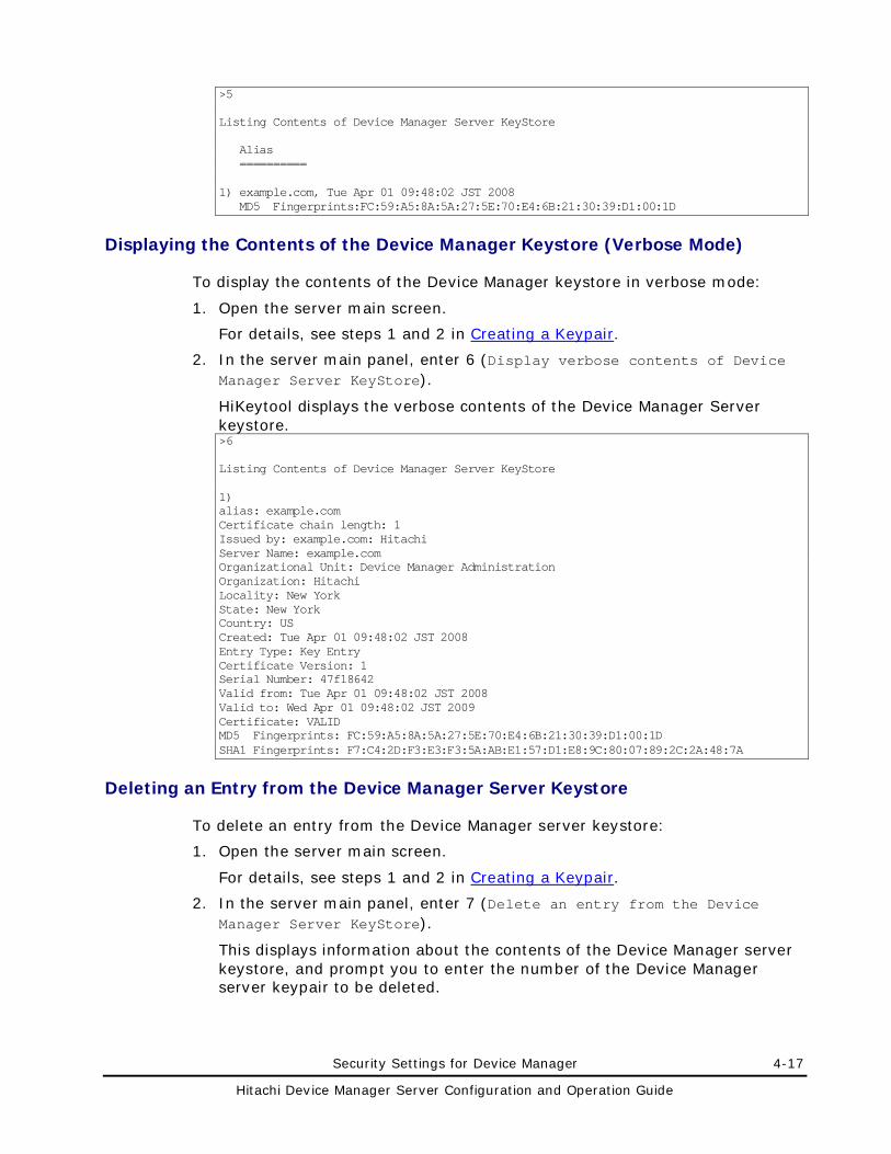
Security Settings for Device Manager 4-17
Hitachi Device Manager Server Configuration and Operation Guide
>5 Listing Contents of Device Manager Server KeyStore Alias ========== 1) example.com, Tue Apr 01 09:48:02 JST 2008 MD5 Fingerprints:FC:59:A5:8A:5A:27:5E:70:E4:6B:21:30:39:D1:00:1D
Displaying the Contents of the Device Manager Keystore (Verbose Mode)
To display the contents of the Device Manager keystore in verbose mode:
1. Open the server main screen.
For details, see steps 1 and 2 in Creating a Keypair.
2. In the server main panel, enter 6 (Display verbose contents of Device Manager Server KeyStore).
HiKeytool displays the verbose contents of the Device Manager Server keystore. >6 Listing Contents of Device Manager Server KeyStore 1) alias: example.com Certificate chain length: 1 Issued by: example.com: Hitachi Server Name: example.com Organizational Unit: Device Manager Administration Organization: Hitachi Locality: New York State: New York Country: US Created: Tue Apr 01 09:48:02 JST 2008 Entry Type: Key Entry Certificate Version: 1 Serial Number: 47f18642 Valid from: Tue Apr 01 09:48:02 JST 2008 Valid to: Wed Apr 01 09:48:02 JST 2009 Certificate: VALID MD5 Fingerprints: FC:59:A5:8A:5A:27:5E:70:E4:6B:21:30:39:D1:00:1D SHA1 Fingerprints: F7:C4:2D:F3:E3:F3:5A:AB:E1:57:D1:E8:9C:80:07:89:2C:2A:48:7A
Deleting an Entry from the Device Manager Server Keystore
To delete an entry from the Device Manager server keystore:
1. Open the server main screen.
For details, see steps 1 and 2 in Creating a Keypair.
2. In the server main panel, enter 7 (Delete an entry from the Device Manager Server KeyStore).
This displays information about the contents of the Device Manager server keystore, and prompt you to enter the number of the Device Manager server keypair to be deleted.
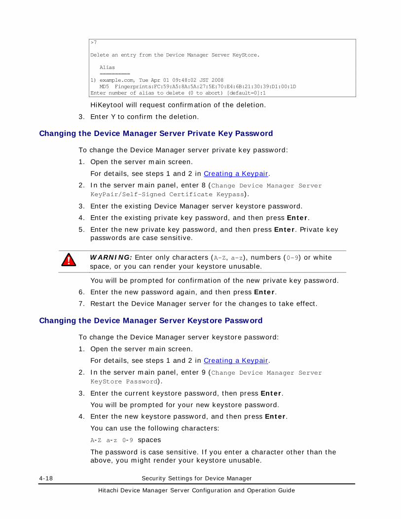
4-18 Security Settings for Device Manager
Hitachi Device Manager Server Configuration and Operation Guide
>7 Delete an entry from the Device Manager Server KeyStore. Alias ========== 1) example.com, Tue Apr 01 09:48:02 JST 2008 MD5 Fingerprints:FC:59:A5:8A:5A:27:5E:70:E4:6B:21:30:39:D1:00:1D Enter number of alias to delete (0 to abort) [default=0]:1
HiKeytool will request confirmation of the deletion.
3. Enter Y to confirm the deletion.
Changing the Device Manager Server Private Key Password
To change the Device Manager server private key password:
1. Open the server main screen.
For details, see steps 1 and 2 in Creating a Keypair.
2. In the server main panel, enter 8 (Change Device Manager Server KeyPair/Self-Signed Certificate Keypass).
3. Enter the existing Device Manager server keystore password.
4. Enter the existing private key password, and then press Enter.
5. Enter the new private key password, and then press Enter. Private key passwords are case sensitive.
WARNING: Enter only characters (A-Z, a-z), numbers (0-9) or white space, or you can render your keystore unusable.
You will be prompted for confirmation of the new private key password.
6. Enter the new password again, and then press Enter.
7. Restart the Device Manager server for the changes to take effect.
Changing the Device Manager Server Keystore Password
To change the Device Manager server keystore password:
1. Open the server main screen.
For details, see steps 1 and 2 in Creating a Keypair.
2. In the server main panel, enter 9 (Change Device Manager Server KeyStore Password).
3. Enter the current keystore password, then press Enter.
You will be prompted for your new keystore password.
4. Enter the new keystore password, and then press Enter.
You can use the following characters:
A-Z a-z 0-9 spaces
The password is case sensitive. If you enter a character other than the above, you might render your keystore unusable.
Security Settings for Device Manager 4-19
Hitachi Device Manager Server Configuration and Operation Guide
5. Confirm the new password.
6. Restart the Device Manager server for the changes to take effect.
Importing a Digitally-signed Certificate into the Device Manager Truststore
To import a digitally-signed certificate, the certificate authority that issued the certificate must already be registered in the truststore. If that certificate authority is not registered, import the certificate for the certificate authority to the truststore by following the procedure below. Note that, if one or more intermediate certificate authorities exist between the certificate authority that issued the certificate and the root certificate authority, all of them must be also registered in the truststore.
To import a digitally-signed certificate into the Device Manager server truststore:
1. Obtain the certificates for all the necessary certificate authorities including intermediate certificate authorities.
Device Manager supports X.509-formatted certificates. For details on how to obtain certificates, contact each certificate authority.
2. Open the server main screen.
For details, see steps 1 and 2 in Creating a Keypair.
3. In the server main panel, enter 10 (Import Certificate Device Manager Server TrustStore).
You will be prompted to enter the alias of the certificate to be imported.
4. Enter the alias, and then press Enter.
You will be prompted to enter the location of the certificate to be imported.
5. Enter the absolute path of the certificate, and then press Enter.
You will be notified when the certificate has been imported.
6. Repeat steps 3 through 5 if you import more than one certificate.
Displaying Contents of the Device Manager Server Truststore (Regular Mode)
To display contents of the Device Manager server truststore in regular mode:
1. Open the server main screen.
For details, see steps 1 and 2 in Creating a Keypair.
2. In the server main panel, enter 11 (Display contents of Device Manager Server TrustStore).
The display will include the entry alias, the date the certificate was created, and the MD5 Fingerprints for that entry.
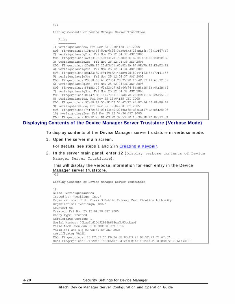
4-20 Security Settings for Device Manager
Hitachi Device Manager Server Configuration and Operation Guide
>11 Listing Contents of Device Manager Server TrustStore Alias ========== 1) verisignclass3ca, Fri Nov 25 12:04:38 JST 2005 MD5 Fingerprints:10:FC:63:5D:F6:26:3E:0D:F3:25:BE:5F:79:CD:67:67 2) verisignclass3g2ca, Fri Nov 25 12:04:37 JST 2005 MD5 Fingerprints:A2:33:9B:4C:74:78:73:D4:6C:E7:C1:F3:8D:CB:5C:E9 3) verisignclass2g2ca, Fri Nov 25 12:04:35 JST 2005 MD5 Fingerprints:2D:BB:E5:25:D3:D1:65:82:3A:B7:0E:FA:E6:EB:E2:E1 4) verisignclass1g2ca, Fri Nov 25 12:04:34 JST 2005 MD5 Fingerprints:DB:23:3D:F9:69:FA:4B:B9:95:80:44:73:5E:7D:41:83 5) verisignclass3g3ca, Fri Nov 25 12:04:37 JST 2005 MD5 Fingerprints:CD:68:B6:A7:C7:C4:CE:75:E0:1D:4F:57:44:61:92:09 6) verisignclass2g3ca, Fri Nov 25 12:04:36 JST 2005 MD5 Fingerprints:F8:BE:C4:63:22:C9:A8:46:74:8B:B8:1D:1E:4A:2B:F6 7) verisignclass1g3ca, Fri Nov 25 12:04:34 JST 2005 MD5 Fingerprints:B1:47:BC:18:57:D1:18:A0:78:2D:EC:71:E8:2A:95:73 8) verisignclass1ca, Fri Nov 25 12:04:35 JST 2005 MD5 Fingerprints:97:60:E8:57:5F:D3:50:47:E5:43:0C:94:36:8A:B0:62 9) verisignserverca, Fri Nov 25 12:04:38 JST 2005 MD5 Fingerprints:74:7B:82:03:43:F0:00:9E:6B:B3:EC:47:BF:85:A5:93 10) verisignclass2ca, Fri Nov 25 12:04:36 JST 2005 MD5 Fingerprints:B3:9C:25:B1:C3:2E:32:53:80:15:30:9D:4D:02:77:3E
Displaying Contents of the Device Manager Server Truststore (Verbose Mode)
To display contents of the Device Manager server truststore in verbose mode:
1. Open the server main screen.
For details, see steps 1 and 2 in Creating a Keypair.
2. In the server main panel, enter 12 (Display verbose contents of Device Manager Server TrustStore).
This will display the verbose information for each entry in the Device Manager server truststore. >12 Listing Contents of Device Manager Server TrustStore 1) alias: verisignclass3ca Issued by: "VeriSign, Inc." Organizational Unit: Class 3 Public Primary Certification Authority Organization: "VeriSign, Inc." Country: US Created: Fri Nov 25 12:04:38 JST 2005 Entry Type: Trusted Certificate Version: 1 Serial Number: 70bae41d10d92934b638ca7b03ccbabf Valid from: Mon Jan 29 09:00:00 JST 1996 Valid to: Wed Aug 02 08:59:59 JST 2028 Certificate: VALID MD5 Fingerprints: 10:FC:63:5D:F6:26:3E:0D:F3:25:BE:5F:79:CD:67:67 SHA1 Fingerprints: 74:2C:31:92:E6:07:E4:24:EB:45:49:54:2B:E1:BB:C5:3E:61:74:E2
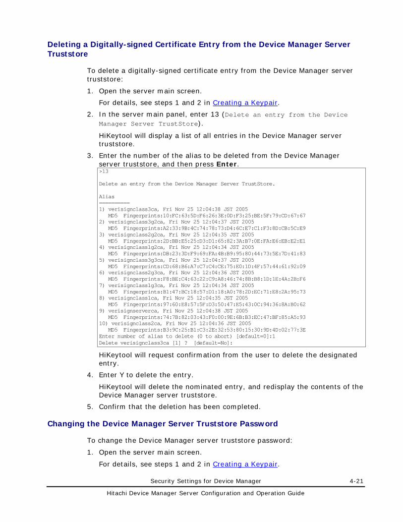
Security Settings for Device Manager 4-21
Hitachi Device Manager Server Configuration and Operation Guide
Deleting a Digitally-signed Certificate Entry from the Device Manager Server Truststore
To delete a digitally-signed certificate entry from the Device Manager server truststore:
1. Open the server main screen.
For details, see steps 1 and 2 in Creating a Keypair.
2. In the server main panel, enter 13 (Delete an entry from the Device Manager Server TrustStore).
HiKeytool will display a list of all entries in the Device Manager server truststore.
3. Enter the number of the alias to be deleted from the Device Manager server truststore, and then press Enter. >13 Delete an entry from the Device Manager Server TrustStore. Alias ========== 1) verisignclass3ca, Fri Nov 25 12:04:38 JST 2005 MD5 Fingerprints:10:FC:63:5D:F6:26:3E:0D:F3:25:BE:5F:79:CD:67:67 2) verisignclass3g2ca, Fri Nov 25 12:04:37 JST 2005 MD5 Fingerprints:A2:33:9B:4C:74:78:73:D4:6C:E7:C1:F3:8D:CB:5C:E9 3) verisignclass2g2ca, Fri Nov 25 12:04:35 JST 2005 MD5 Fingerprints:2D:BB:E5:25:D3:D1:65:82:3A:B7:0E:FA:E6:EB:E2:E1 4) verisignclass1g2ca, Fri Nov 25 12:04:34 JST 2005 MD5 Fingerprints:DB:23:3D:F9:69:FA:4B:B9:95:80:44:73:5E:7D:41:83 5) verisignclass3g3ca, Fri Nov 25 12:04:37 JST 2005 MD5 Fingerprints:CD:68:B6:A7:C7:C4:CE:75:E0:1D:4F:57:44:61:92:09 6) verisignclass2g3ca, Fri Nov 25 12:04:36 JST 2005 MD5 Fingerprints:F8:BE:C4:63:22:C9:A8:46:74:8B:B8:1D:1E:4A:2B:F6 7) verisignclass1g3ca, Fri Nov 25 12:04:34 JST 2005 MD5 Fingerprints:B1:47:BC:18:57:D1:18:A0:78:2D:EC:71:E8:2A:95:73 8) verisignclass1ca, Fri Nov 25 12:04:35 JST 2005 MD5 Fingerprints:97:60:E8:57:5F:D3:50:47:E5:43:0C:94:36:8A:B0:62 9) verisignserverca, Fri Nov 25 12:04:38 JST 2005 MD5 Fingerprints:74:7B:82:03:43:F0:00:9E:6B:B3:EC:47:BF:85:A5:93 10) verisignclass2ca, Fri Nov 25 12:04:36 JST 2005 MD5 Fingerprints:B3:9C:25:B1:C3:2E:32:53:80:15:30:9D:4D:02:77:3E Enter number of alias to delete (0 to abort) [default=0]:1 Delete verisignclass3ca [1] ? [default=No]:
HiKeytool will request confirmation from the user to delete the designated entry.
4. Enter Y to delete the entry.
HiKeytool will delete the nominated entry, and redisplay the contents of the Device Manager server truststore.
5. Confirm that the deletion has been completed.
Changing the Device Manager Server Truststore Password
To change the Device Manager server truststore password:
1. Open the server main screen.
For details, see steps 1 and 2 in Creating a Keypair.
4-22 Security Settings for Device Manager
Hitachi Device Manager Server Configuration and Operation Guide
2. In the server main panel, enter 14 (Change Device Manager Server TrustStore Password).
3. Enter the existing truststore password, and then press Enter.
The default password is changeit.
4. Enter the new truststore password, and then press Enter.
You can use the following characters:
A-Z a-z 0-9 spaces
The password is case sensitive. If you enter a character other than the above, you might render your keystore unusable.
5. Enter the new password again, and then press Enter.
6. Restart the Device Manager server for the changes to take effect.
Security Settings for Common Component (Communication with Web Client)
This section describes the settings required to encrypt network transmissions between Common Component and Web Client by using SSL (version 3) or TLS (version 1.0). To encrypt network transmissions by using SSL or TLS, you need to perform the following operations:
• Generate a private key.
• Create a certificate signing request (CSR).
• Enable SSL.
Note: If you use TLS/SSL-encrypted communication, you need to change the URLs used for accessing Hitachi Storage Command Suite products. For details on how to do this, see Changing the URLs for Accessing Hitachi Storage Command Suite Products. You also need to enter https:// for the URLs when accessing Hitachi Storage Command Suite products.
Generating a Private Key
To create a private key, use the hcmdssslc genrsa utility (for Windows) or the sslc genrsa utility (for Solaris or Linux). You can either use the private key as the basis for a certificate signing request (see Creating a Certificate Signing Request (CSR) (Security Settings for Common Component)), or you can use it as a self-signed certificate to test the web server. The installation locations of the hcmdssslc genrsa utility and the sslc genrsa utility are as follows:
For hcmdssslc genrsa:
installation-folder-for-Common-Component\Base\bin
For sslc genrsa:
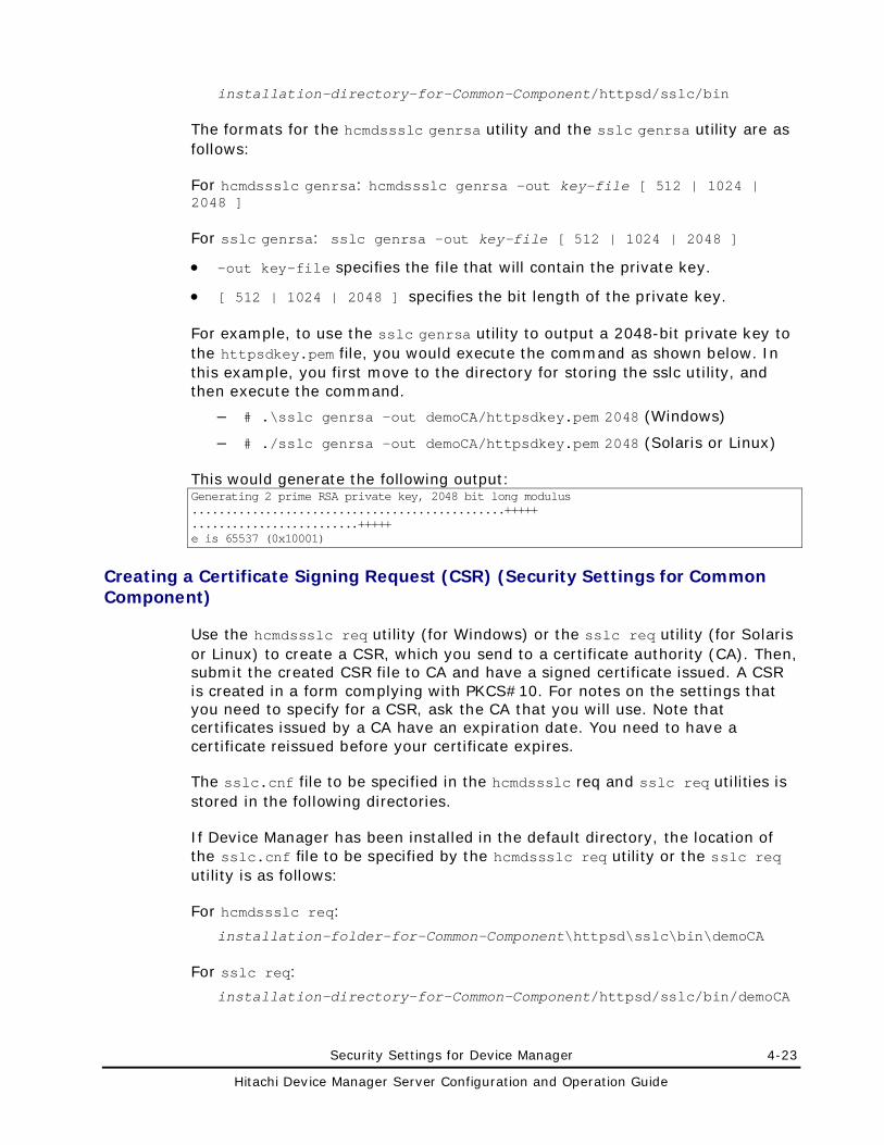
Security Settings for Device Manager 4-23
Hitachi Device Manager Server Configuration and Operation Guide
installation-directory-for-Common-Component/httpsd/sslc/bin
The formats for the hcmdssslc genrsa utility and the sslc genrsa utility are as follows:
For hcmdssslc genrsa: hcmdssslc genrsa -out key-file [ 512 | 1024 | 2048 ]
For sslc genrsa: sslc genrsa -out key-file [ 512 | 1024 | 2048 ]
• -out key-file specifies the file that will contain the private key.
• [ 512 | 1024 | 2048 ] specifies the bit length of the private key.
For example, to use the sslc genrsa utility to output a 2048-bit private key to the httpsdkey.pem file, you would execute the command as shown below. In this example, you first move to the directory for storing the sslc utility, and then execute the command.
– # .\sslc genrsa -out demoCA/httpsdkey.pem 2048 (Windows)
– # ./sslc genrsa -out demoCA/httpsdkey.pem 2048 (Solaris or Linux)
This would generate the following output: Generating 2 prime RSA private key, 2048 bit long modulus ...............................................+++++ .........................+++++ e is 65537 (0x10001)
Creating a Certificate Signing Request (CSR) (Security Settings for Common Component)
Use the hcmdssslc req utility (for Windows) or the sslc req utility (for Solaris or Linux) to create a CSR, which you send to a certificate authority (CA). Then, submit the created CSR file to CA and have a signed certificate issued. A CSR is created in a form complying with PKCS#10. For notes on the settings that you need to specify for a CSR, ask the CA that you will use. Note that certificates issued by a CA have an expiration date. You need to have a certificate reissued before your certificate expires.
The sslc.cnf file to be specified in the hcmdssslc req and sslc req utilities is stored in the following directories.
If Device Manager has been installed in the default directory, the location of the sslc.cnf file to be specified by the hcmdssslc req utility or the sslc req utility is as follows:
For hcmdssslc req:
installation-folder-for-Common-Component\httpsd\sslc\bin\demoCA
For sslc req:
installation-directory-for-Common-Component/httpsd/sslc/bin/demoCA
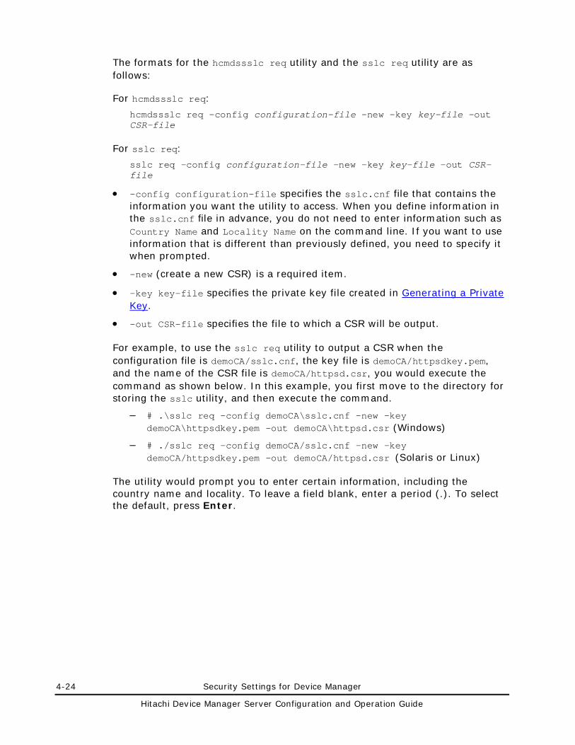
4-24 Security Settings for Device Manager
Hitachi Device Manager Server Configuration and Operation Guide
The formats for the hcmdssslc req utility and the sslc req utility are as follows:
For hcmdssslc req:
hcmdssslc req -config configuration-file -new -key key-file -out CSR-file
For sslc req:
sslc req -config configuration-file -new -key key-file -out CSR-file
• -config configuration-file specifies the sslc.cnf file that contains the information you want the utility to access. When you define information in the sslc.cnf file in advance, you do not need to enter information such as Country Name and Locality Name on the command line. If you want to use information that is different than previously defined, you need to specify it when prompted.
• -new (create a new CSR) is a required item.
• -key key-file specifies the private key file created in Generating a Private Key.
• -out CSR-file specifies the file to which a CSR will be output.
For example, to use the sslc req utility to output a CSR when the configuration file is demoCA/sslc.cnf, the key file is demoCA/httpsdkey.pem, and the name of the CSR file is demoCA/httpsd.csr, you would execute the command as shown below. In this example, you first move to the directory for storing the sslc utility, and then execute the command.
– # .\sslc req -config demoCA\sslc.cnf -new -key demoCA\httpsdkey.pem -out demoCA\httpsd.csr (Windows)
– # ./sslc req -config demoCA/sslc.cnf -new -key demoCA/httpsdkey.pem -out demoCA/httpsd.csr (Solaris or Linux)
The utility would prompt you to enter certain information, including the country name and locality. To leave a field blank, enter a period (.). To select the default, press Enter.
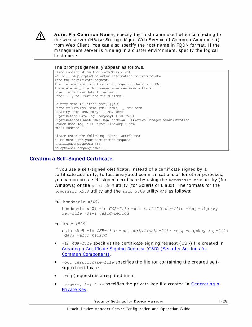
Security Settings for Device Manager 4-25
Hitachi Device Manager Server Configuration and Operation Guide
Note: For Common Name, specify the host name used when connecting to the web server (HBase Storage Mgmt Web Service of Common Component) from Web Client. You can also specify the host name in FQDN format. If the management server is running in a cluster environment, specify the logical host name.
The prompts generally appear as follows. Using configuration from demoCA/sslc.cnf You will be prompted to enter information to incorporate into the certificate request. This information is called a Distinguished Name or a DN. There are many fields however some can remain blank. Some fields have default values. Enter '.', to leave the field blank. ----- Country Name (2 letter code) []:US State or Province Name (full name) []:New York Locality Name (eg, city) []:New York Organization Name (eg, company) []:HITACHI Organizational Unit Name (eg, section) []:Device Manager Administration Common Name (eg, YOUR name) []:example.com Email Address []: Please enter the following 'extra' attributes to be sent with your certificate request A challenge password []: An optional company name []:
Creating a Self-Signed Certificate
If you use a self-signed certificate, instead of a certificate signed by a certificate authority, to test encrypted communications or for other purposes, you can create a self-signed certificate by using the hcmdssslc x509 utility (for Windows) or the sslc x509 utility (for Solaris or Linux). The formats for the hcmdssslc x509 utility and the sslc x509 utility are as follows:
For hcmdssslc x509:
hcmdssslc x509 -in CSR-file -out certificate-file -req -signkey key-file -days valid-period
For sslc x509:
sslc x509 -in CSR-file -out certificate-file -req -signkey key-file -days valid-period
• -in CSR-file specifies the certificate signing request (CSR) file created in Creating a Certificate Signing Request (CSR) (Security Settings for Common Component).
• -out certificate-file specifies the file for containing the created self-signed certificate.
• -req (request) is a required item.
• -signkey key-file specifies the private key file created in Generating a Private Key.
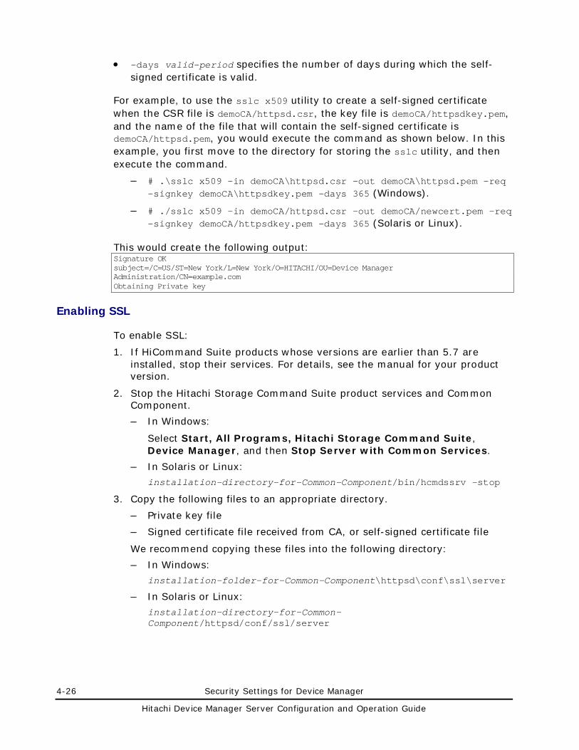
4-26 Security Settings for Device Manager
Hitachi Device Manager Server Configuration and Operation Guide
• -days valid-period specifies the number of days during which the self-signed certificate is valid.
For example, to use the sslc x509 utility to create a self-signed certificate when the CSR file is demoCA/httpsd.csr, the key file is demoCA/httpsdkey.pem, and the name of the file that will contain the self-signed certificate is demoCA/httpsd.pem, you would execute the command as shown below. In this example, you first move to the directory for storing the sslc utility, and then execute the command.
– # .\sslc x509 -in demoCA\httpsd.csr -out demoCA\httpsd.pem -req -signkey demoCA\httpsdkey.pem -days 365 (Windows).
– # ./sslc x509 -in demoCA/httpsd.csr -out demoCA/newcert.pem -req -signkey demoCA/httpsdkey.pem -days 365 (Solaris or Linux).
This would create the following output: Signature OK subject=/C=US/ST=New York/L=New York/O=HITACHI/OU=Device Manager Administration/CN=example.com Obtaining Private key
Enabling SSL
To enable SSL:
1. If HiCommand Suite products whose versions are earlier than 5.7 are installed, stop their services. For details, see the manual for your product version.
2. Stop the Hitachi Storage Command Suite product services and Common Component.
– In Windows:
Select Start, All Programs, Hitachi Storage Command Suite, Device Manager, and then Stop Server with Common Services.
– In Solaris or Linux:
installation-directory-for-Common-Component/bin/hcmdssrv -stop
3. Copy the following files to an appropriate directory.
– Private key file
– Signed certificate file received from CA, or self-signed certificate file
We recommend copying these files into the following directory:
– In Windows:
installation-folder-for-Common-Component\httpsd\conf\ssl\server
– In Solaris or Linux:
installation-directory-for-Common-Component/httpsd/conf/ssl/server
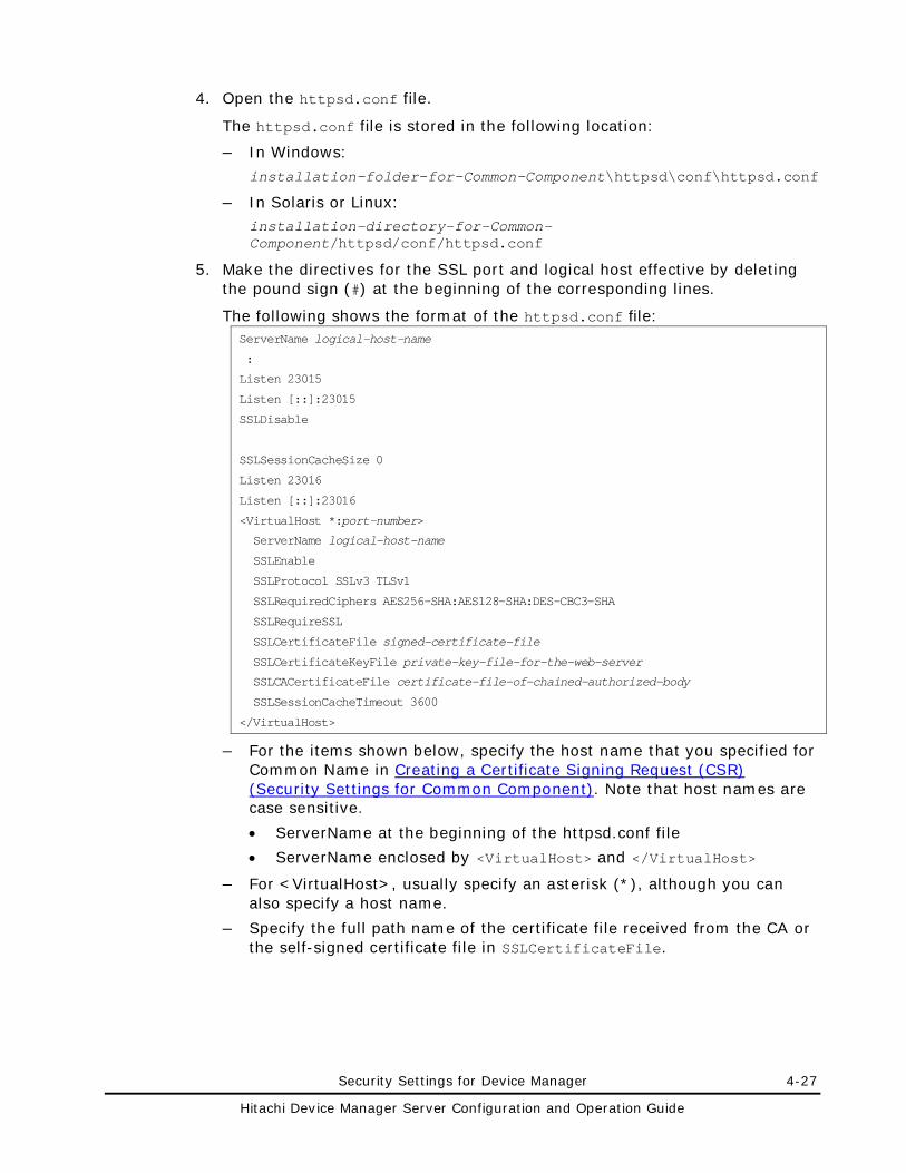
Security Settings for Device Manager 4-27
Hitachi Device Manager Server Configuration and Operation Guide
4. Open the httpsd.conf file.
The httpsd.conf file is stored in the following location:
– In Windows:
installation-folder-for-Common-Component\httpsd\conf\httpsd.conf
– In Solaris or Linux: installation-directory-for-Common-Component/httpsd/conf/httpsd.conf
5. Make the directives for the SSL port and logical host effective by deleting the pound sign (#) at the beginning of the corresponding lines.
The following shows the format of the httpsd.conf file: ServerName logical-host-name
:
Listen 23015
Listen [::]:23015
SSLDisable
SSLSessionCacheSize 0
Listen 23016
Listen [::]:23016
<VirtualHost *:port-number>
ServerName logical-host-name
SSLEnable
SSLProtocol SSLv3 TLSv1
SSLRequiredCiphers AES256-SHA:AES128-SHA:DES-CBC3-SHA
SSLRequireSSL
SSLCertificateFile signed-certificate-file
SSLCertificateKeyFile private-key-file-for-the-web-server
SSLCACertificateFile certificate-file-of-chained-authorized-body
SSLSessionCacheTimeout 3600
</VirtualHost>
– For the items shown below, specify the host name that you specified for Common Name in Creating a Certificate Signing Request (CSR) (Security Settings for Common Component). Note that host names are case sensitive.
• ServerName at the beginning of the httpsd.conf file
• ServerName enclosed by <VirtualHost> and </VirtualHost>
– For <VirtualHost>, usually specify an asterisk (*), although you can also specify a host name.
– Specify the full path name of the certificate file received from the CA or the self-signed certificate file in SSLCertificateFile.
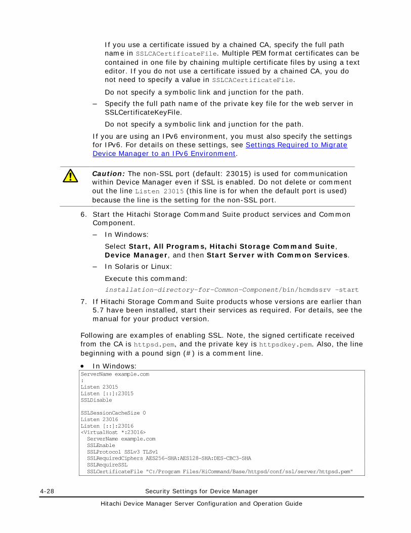
4-28 Security Settings for Device Manager
Hitachi Device Manager Server Configuration and Operation Guide
If you use a certificate issued by a chained CA, specify the full path name in SSLCACertificateFile. Multiple PEM format certificates can be contained in one file by chaining multiple certificate files by using a text editor. If you do not use a certificate issued by a chained CA, you do not need to specify a value in SSLCACertificateFile.
Do not specify a symbolic link and junction for the path.
– Specify the full path name of the private key file for the web server in SSLCertificateKeyFile.
Do not specify a symbolic link and junction for the path.
If you are using an IPv6 environment, you must also specify the settings for IPv6. For details on these settings, see Settings Required to Migrate Device Manager to an IPv6 Environment.
Caution: The non-SSL port (default: 23015) is used for communication within Device Manager even if SSL is enabled. Do not delete or comment out the line Listen 23015 (this line is for when the default port is used) because the line is the setting for the non-SSL port.
6. Start the Hitachi Storage Command Suite product services and Common Component.
– In Windows:
Select Start, All Programs, Hitachi Storage Command Suite, Device Manager, and then Start Server with Common Services.
– In Solaris or Linux:
Execute this command:
installation-directory-for-Common-Component/bin/hcmdssrv -start
7. If Hitachi Storage Command Suite products whose versions are earlier than 5.7 have been installed, start their services as required. For details, see the manual for your product version.
Following are examples of enabling SSL. Note, the signed certificate received from the CA is httpsd.pem, and the private key is httpsdkey.pem. Also, the line beginning with a pound sign (#) is a comment line.
• In Windows: ServerName example.com : Listen 23015 Listen [::]:23015 SSLDisable SSLSessionCacheSize 0 Listen 23016 Listen [::]:23016 <VirtualHost *:23016> ServerName example.com SSLEnable SSLProtocol SSLv3 TLSv1 SSLRequiredCiphers AES256-SHA:AES128-SHA:DES-CBC3-SHA SSLRequireSSL SSLCertificateFile "C:/Program Files/HiCommand/Base/httpsd/conf/ssl/server/httpsd.pem"
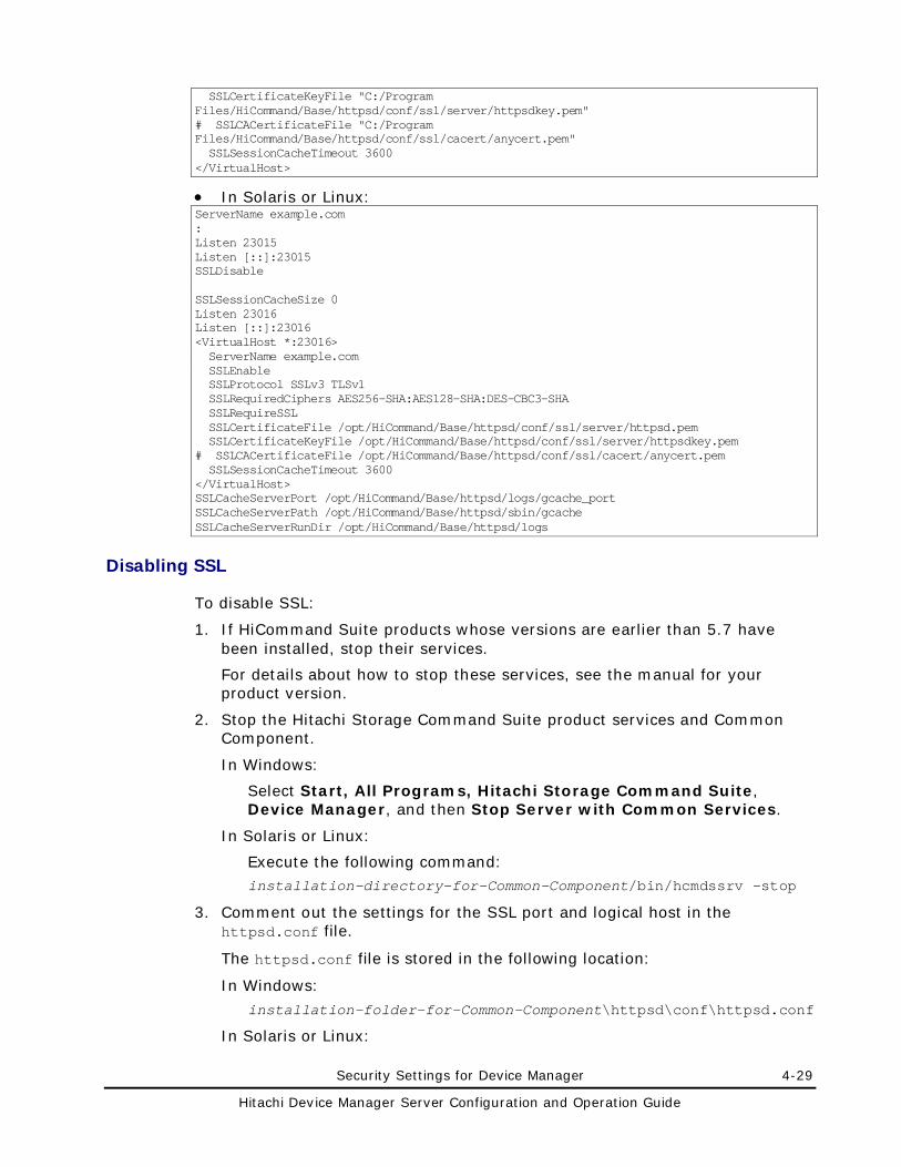
Security Settings for Device Manager 4-29
Hitachi Device Manager Server Configuration and Operation Guide
SSLCertificateKeyFile "C:/Program Files/HiCommand/Base/httpsd/conf/ssl/server/httpsdkey.pem" # SSLCACertificateFile "C:/Program Files/HiCommand/Base/httpsd/conf/ssl/cacert/anycert.pem" SSLSessionCacheTimeout 3600 </VirtualHost>
• In Solaris or Linux: ServerName example.com : Listen 23015 Listen [::]:23015 SSLDisable SSLSessionCacheSize 0 Listen 23016 Listen [::]:23016 <VirtualHost *:23016> ServerName example.com SSLEnable SSLProtocol SSLv3 TLSv1 SSLRequiredCiphers AES256-SHA:AES128-SHA:DES-CBC3-SHA SSLRequireSSL SSLCertificateFile /opt/HiCommand/Base/httpsd/conf/ssl/server/httpsd.pem SSLCertificateKeyFile /opt/HiCommand/Base/httpsd/conf/ssl/server/httpsdkey.pem # SSLCACertificateFile /opt/HiCommand/Base/httpsd/conf/ssl/cacert/anycert.pem SSLSessionCacheTimeout 3600 </VirtualHost> SSLCacheServerPort /opt/HiCommand/Base/httpsd/logs/gcache_port SSLCacheServerPath /opt/HiCommand/Base/httpsd/sbin/gcache SSLCacheServerRunDir /opt/HiCommand/Base/httpsd/logs
Disabling SSL
To disable SSL:
1. If HiCommand Suite products whose versions are earlier than 5.7 have been installed, stop their services.
For details about how to stop these services, see the manual for your product version.
2. Stop the Hitachi Storage Command Suite product services and Common Component.
In Windows:
Select Start, All Programs, Hitachi Storage Command Suite, Device Manager, and then Stop Server with Common Services.
In Solaris or Linux:
Execute the following command: installation-directory-for-Common-Component/bin/hcmdssrv -stop
3. Comment out the settings for the SSL port and logical host in the httpsd.conf file.
The httpsd.conf file is stored in the following location:
In Windows:
installation-folder-for-Common-Component\httpsd\conf\httpsd.conf
In Solaris or Linux:
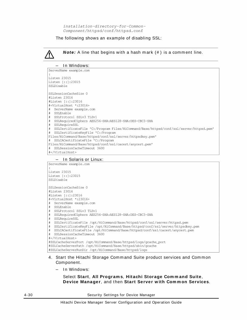
4-30 Security Settings for Device Manager
Hitachi Device Manager Server Configuration and Operation Guide
installation-directory-for-Common-Component/httpsd/conf/httpsd.conf
The following shows an example of disabling SSL:
Note: A line that begins with a hash mark (#) is a comment line.
– In Windows: ServerName example.com : Listen 23015 Listen [::]:23015 SSLDisable SSLSessionCacheSize 0 #Listen 23016 #Listen [::]:23016 #<VirtualHost *:23016> # ServerName example.com # SSLEnable # SSLProtocol SSLv3 TLSv1 # SSLRequiredCiphers AES256-SHA:AES128-SHA:DES-CBC3-SHA # SSLRequireSSL # SSLCertificateFile "C:/Program Files/HiCommand/Base/httpsd/conf/ssl/server/httpsd.pem" # SSLCertificateKeyFile "C:/Program Files/HiCommand/Base/httpsd/conf/ssl/server/httpsdkey.pem" # SSLCACertificateFile "C:/Program Files/HiCommand/Base/httpsd/conf/ssl/cacert/anycert.pem" # SSLSessionCacheTimeout 3600 #</VirtualHost>
– In Solaris or Linux: ServerName example.com : Listen 23015 Listen [::]:23015 SSLDisable SSLSessionCacheSize 0 #Listen 23016 #Listen [::]:23016 #<VirtualHost *:23016> # ServerName example.com # SSLEnable # SSLProtocol SSLv3 TLSv1 # SSLRequiredCiphers AES256-SHA:AES128-SHA:DES-CBC3-SHA # SSLRequireSSL # SSLCertificateFile /opt/HiCommand/Base/httpsd/conf/ssl/server/httpsd.pem # SSLCertificateKeyFile /opt/HiCommand/Base/httpsd/conf/ssl/server/httpsdkey.pem # SSLCACertificateFile /opt/HiCommand/Base/httpsd/conf/ssl/cacert/anycert.pem # SSLSessionCacheTimeout 3600 #</VirtualHost> #SSLCacheServerPort /opt/HiCommand/Base/httpsd/logs/gcache_port #SSLCacheServerPath /opt/HiCommand/Base/httpsd/sbin/gcache #SSLCacheServerRunDir /opt/HiCommand/Base/httpsd/logs
4. Start the Hitachi Storage Command Suite product services and Common Component.
– In Windows:
Select Start, All Programs, Hitachi Storage Command Suite, Device Manager, and then Start Server with Common Services.
Security Settings for Device Manager 4-31
Hitachi Device Manager Server Configuration and Operation Guide
– In Solaris or Linux:
Execute the following command: installation-directory-for-Common-Component/bin/hcmdssrv -start
5. If HiCommand Suite products whose versions are earlier than 5.7 have been installed, start their services as required.
For details about how to start these services, see the manual for your product version.
Changing a Port Assigned to SSL
The default port of SSL for HBase Storage Mgmt Web Service is 23016. To change the port, edit the httpsd.conf file. The httpsd.conf file is stored in the following location:
• In Windows: installation-folder-for-Common-Component\httpsd\conf\httpsd.conf
• In Solaris or Linux:
installation-directory-for-Common-Component/httpsd/conf/httpsd.conf
Stop the Device Manager server and Common Component, and then edit the httpsd.conf file. After editing these files, start the Device Manager server and Common Component to apply the changes.
Security Settings for the Device Manager Server (Communication with a CIM Client)
CIM/WBEM functions supported in SSL communications include the following:
• Object operations
In the object operation feature, a CIM client acts as an SSL client and the Device Manager server acts as an SSL server. By default, you can perform SSL communication in object operations. If you want to modify the Device Manager server keystore file used for SSL, see Modifying the Keystore File for Object Operations.
• Event indications
During the sending/receiving of CIM event indications, the Device Manager server acts as an SSL client and a CIM client (Indication Listener) acts as an SSL server. By default, the Device Manager server can use SSL communication to receive event indications by following the CIM client requests. In this case, settings must be specified beforehand to enable SSL communication between the CIM clients.
4-32 Security Settings for Device Manager
Hitachi Device Manager Server Configuration and Operation Guide
You can also strengthen security by applying two-way authentication for object operations and event indications. Two-way authentication enables communications between pre-specified trusted users. In this way, users can accept object operations from specific CIM clients only, and send event indications to specific CIM clients only. For details on the setting procedures, see Specifying Two-way Authentication for Object Operations and Specifying Two-way Authentication for Event Indications.
Caution: Use a Java tool to set up SSL. For details on how to use the commands, see section, see Security Settings for a CIM Client (Communication with the Device Manager Server).
Modifying the Keystore File for Object Operations
To use a self-signed certificate other than the default, re-create a keystore file. The Device Manager server self-signed certificate used for CIMOM object operations is stored in the keystore file shown below. The signature algorithm of the default self-signed certificate is SHA256withRSA, and the key size is 2,048 bits.
In Windows: installation-folder-for-the-Device-Manager-server\HiCommandServer\wsi\server\jserver\bin\.keystore
In Solaris or Linux: installation-directory-for-the-Device-Manager-server/HiCommandServer/wsi/server/jserver/bin/.keystore
To modify the keystore file:
1. Delete the existing keystore file for object operations (.keystore).
2. Create a keystore file.
Create a Device Manager server keystore file by using the hcmdskeytool utility in Windows, or the keytool utility in Solaris or Linux. These tools are installed in the following locations:
The hcmdskeytool utility:
installation-folder-for-Common-Component\bin
The keytool utility:
installation-directory-for-Common-Component/jdk/bin
To create a keystore file, execute the following commands:
For the hcmdskeytool utility:
keytool -genkey -keystore keystore-file-name -storepass keystore-password -alias alias -dname entity-distinguished-name -validity validity-of-certificate -keypass private-key-password -keyalg key-algorithm -sigalg signature-algorithm -keysize key-size
Security Settings for Device Manager 4-33
Hitachi Device Manager Server Configuration and Operation Guide
For the keytool utility:
hcmdskeytool -genkey -keystore keystore-file-name -storepass keystore-password -alias alias -dname entity-distinguished-name -validity validity-of-certificate -keypass private-key-password -keyalg key-algorithm -sigalg signature-algorithm -keysize key-size
– For keystore-file-name, specify .keystore to change from the default keystore file.
– Specify the same password for -storepass option and -keypass option.
You can check the contents of the self-signed certificate created in the keystore file by using the following commands:
For the hcmdskeytool utility:
hcmdskeytool -list -keystore keystore-file-name -storepass keystore-password
For the keytool utility:
keytool -list -keystore keystore-file-name -storepass keystore-password
3. Use WSIEncryptString.jar to encrypt the keystore password that was specified during creation of the keystore file in step 2. WSIEncryptString.jar is stored in the following location:
– In Windows:
installation-folder-for-the-Device-Manager-server\HiCommandServer\wsi\server\jserver\lib
– In Solaris or Linux:
installation-directory-for-the-Device-Manager-server/HiCommandServer/wsi/server/jserver/lib/
After executing the command, the encrypted character string of the keystore password is displayed. This character string is used in a later step.
4. Stop the Device Manager server.
– In Windows:
Select Start, All Programs, Hitachi Storage Command Suite, Device Manager, and then Stop Server.
– In Solaris or Linux:
installation-directory-for-the-Device-Manager-server/suitesrvcntl -stop_hdvm
5. Modify the MOF file (CIMXMLSCOMATLSSettingData_instances.mof).
In the MOF file, specify the keystore password that was encrypted in step 3 of this procedure. The MOF file is stored in the following location:
– In Windows:
installation-folder-for-the-Device-Manager-server\HiCommandServer\wsi\server\jserver\mof\wbemserver
– In Solaris or Linux:
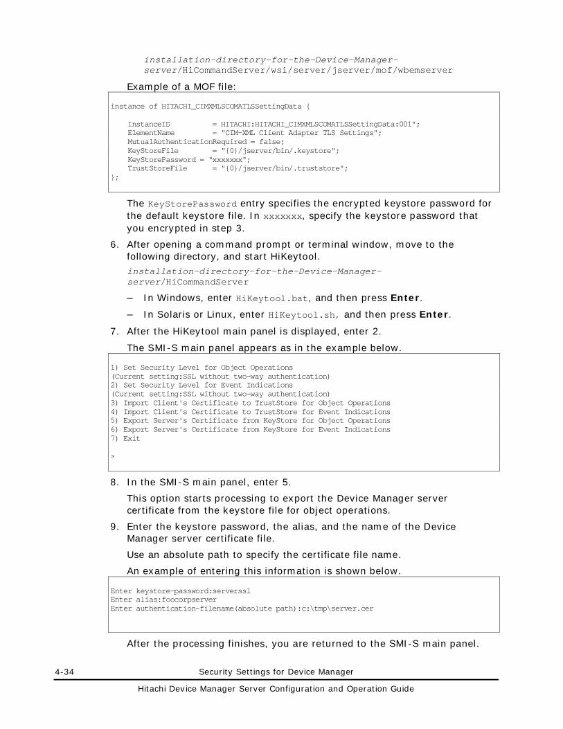
4-34 Security Settings for Device Manager
Hitachi Device Manager Server Configuration and Operation Guide
installation-directory-for-the-Device-Manager-server/HiCommandServer/wsi/server/jserver/mof/wbemserver
Example of a MOF file: instance of HITACHI_CIMXMLSCOMATLSSettingData { InstanceID = HITACHI:HITACHI_CIMXMLSCOMATLSSettingData:001"; ElementName = "CIM-XML Client Adapter TLS Settings"; MutualAuthenticationRequired = false; KeyStoreFile = "{0}/jserver/bin/.keystore"; KeyStorePassword = "xxxxxxx"; TrustStoreFile = "{0}/jserver/bin/.truststore"; };
The KeyStorePassword entry specifies the encrypted keystore password for the default keystore file. In xxxxxxx, specify the keystore password that you encrypted in step 3.
6. After opening a command prompt or terminal window, move to the following directory, and start HiKeytool. installation-directory-for-the-Device-Manager-server/HiCommandServer
– In Windows, enter HiKeytool.bat, and then press Enter.
– In Solaris or Linux, enter HiKeytool.sh, and then press Enter.
7. After the HiKeytool main panel is displayed, enter 2.
The SMI-S main panel appears as in the example below. 1) Set Security Level for Object Operations (Current setting:SSL without two-way authentication) 2) Set Security Level for Event Indications (Current setting:SSL without two-way authentication) 3) Import Client's Certificate to TrustStore for Object Operations 4) Import Client's Certificate to TrustStore for Event Indications 5) Export Server's Certificate from KeyStore for Object Operations 6) Export Server's Certificate from KeyStore for Event Indications 7) Exit >
8. In the SMI-S main panel, enter 5.
This option starts processing to export the Device Manager server certificate from the keystore file for object operations.
9. Enter the keystore password, the alias, and the name of the Device Manager server certificate file.
Use an absolute path to specify the certificate file name.
An example of entering this information is shown below. Enter keystore-password:serverssl Enter alias:foocorpserver Enter authentication-filename(absolute path):c:\tmp\server.cer
After the processing finishes, you are returned to the SMI-S main panel.
Security Settings for Device Manager 4-35
Hitachi Device Manager Server Configuration and Operation Guide
10. Compile the MOF file.
Use the mofcomp command to compile the MOF file. The command is stored in the following location:
– In Windows:
installation-folder-for-the-Device-Manager-server\HiCommandServer\wsi\bin\mofcomp.bat
– In Solaris or Linux:
installation-directory-for-the-Device-Manager-server/HiCommandServer/wsi/bin/mofcomp
Example of executing the command: > mofcomp -m -o ..\server\jserver\logr ..\server\jserver\mof\wbemserver\CIMXMLSCOMATLSSettingData_instances.mof
11. Start the Device Manager server.
– In Windows:
Select Start, All Programs, Hitachi Storage Command Suite, Device Manager, and then Start Server.
– In Solaris or Linux:
Execute the following command: installation-directory-for-the-Device-Manager-server/suitesrvcntl -start_hdvm
After you have completed the settings on the Device Manager server, import the Device Manager server certificate specified in step 9 into the truststore file on the CIM client. For details on how to create a truststore file and import the certificate, see Creating a Truststore File and Importing Certificate.
Specifying Two-way Authentication for Object Operations
This section describes how to specify the settings for using two-way authentication for object operations.
Before specifying the settings on the Device Manager server, you must perform the following operations in the CIM client:
• Create a keystore file
For details on how to create a keystore file, see Creating a Keystore File.
• Export the CIM client server certificate
For details on how to export the CIM client server certificate, see Exporting a Certificate from a Keystore File.
After finishing the preparations in the CIM client, perform the following operations on the Device Manager server by using HiKeytool.
• Set up two-way authentication
• Import the CIM client server certificate
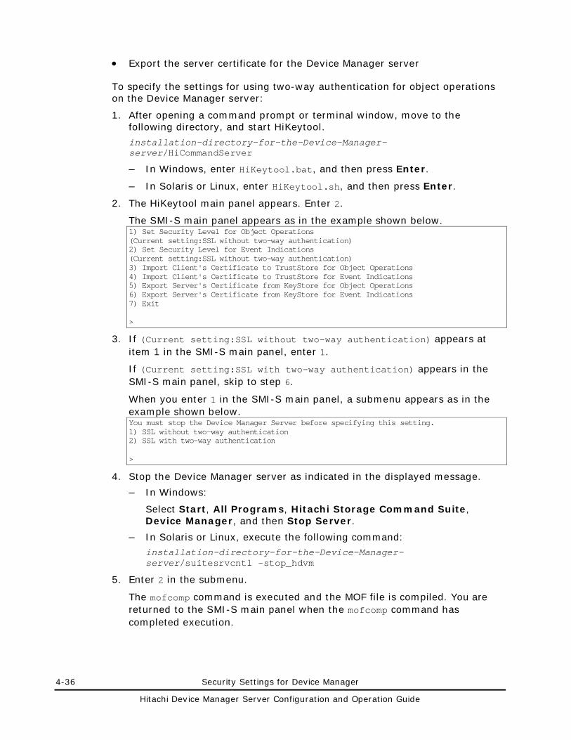
4-36 Security Settings for Device Manager
Hitachi Device Manager Server Configuration and Operation Guide
• Export the server certificate for the Device Manager server
To specify the settings for using two-way authentication for object operations on the Device Manager server:
1. After opening a command prompt or terminal window, move to the following directory, and start HiKeytool.
installation-directory-for-the-Device-Manager-server/HiCommandServer
– In Windows, enter HiKeytool.bat, and then press Enter.
– In Solaris or Linux, enter HiKeytool.sh, and then press Enter.
2. The HiKeytool main panel appears. Enter 2.
The SMI-S main panel appears as in the example shown below. 1) Set Security Level for Object Operations (Current setting:SSL without two-way authentication) 2) Set Security Level for Event Indications (Current setting:SSL without two-way authentication) 3) Import Client's Certificate to TrustStore for Object Operations 4) Import Client's Certificate to TrustStore for Event Indications 5) Export Server's Certificate from KeyStore for Object Operations 6) Export Server's Certificate from KeyStore for Event Indications 7) Exit >
3. If (Current setting:SSL without two-way authentication) appears at item 1 in the SMI-S main panel, enter 1.
If (Current setting:SSL with two-way authentication) appears in the SMI-S main panel, skip to step 6.
When you enter 1 in the SMI-S main panel, a submenu appears as in the example shown below. You must stop the Device Manager Server before specifying this setting. 1) SSL without two-way authentication 2) SSL with two-way authentication >
4. Stop the Device Manager server as indicated in the displayed message.
– In Windows:
Select Start, All Programs, Hitachi Storage Command Suite, Device Manager, and then Stop Server.
– In Solaris or Linux, execute the following command: installation-directory-for-the-Device-Manager-server/suitesrvcntl -stop_hdvm
5. Enter 2 in the submenu.
The mofcomp command is executed and the MOF file is compiled. You are returned to the SMI-S main panel when the mofcomp command has completed execution.
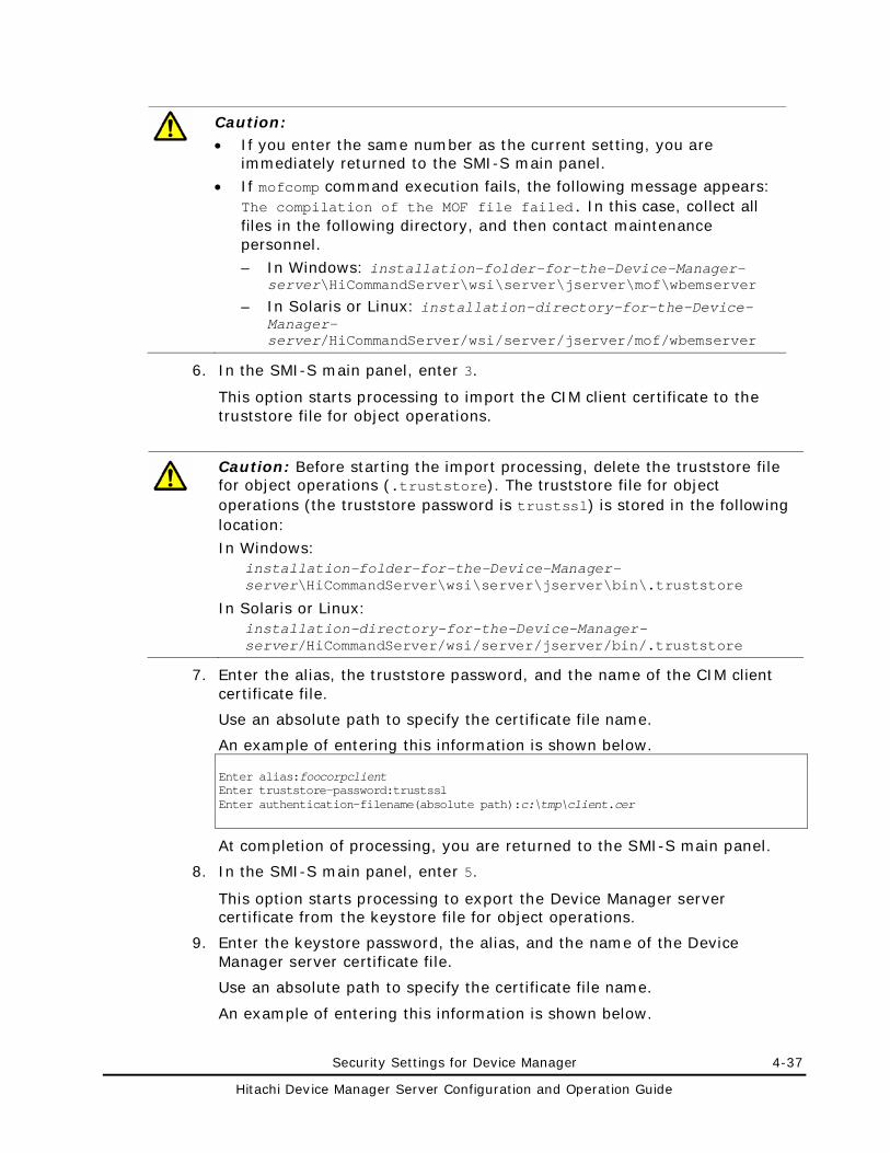
Security Settings for Device Manager 4-37
Hitachi Device Manager Server Configuration and Operation Guide
Caution: • If you enter the same number as the current setting, you are
immediately returned to the SMI-S main panel.
• If mofcomp command execution fails, the following message appears: The compilation of the MOF file failed. In this case, collect all files in the following directory, and then contact maintenance personnel.
– In Windows: installation-folder-for-the-Device-Manager-server\HiCommandServer\wsi\server\jserver\mof\wbemserver
– In Solaris or Linux: installation-directory-for-the-Device-Manager-server/HiCommandServer/wsi/server/jserver/mof/wbemserver
6. In the SMI-S main panel, enter 3.
This option starts processing to import the CIM client certificate to the truststore file for object operations.
Caution: Before starting the import processing, delete the truststore file for object operations (.truststore). The truststore file for object operations (the truststore password is trustssl) is stored in the following location:
In Windows: installation-folder-for-the-Device-Manager-server\HiCommandServer\wsi\server\jserver\bin\.truststore
In Solaris or Linux: installation-directory-for-the-Device-Manager-server/HiCommandServer/wsi/server/jserver/bin/.truststore
7. Enter the alias, the truststore password, and the name of the CIM client certificate file.
Use an absolute path to specify the certificate file name.
An example of entering this information is shown below. Enter alias:foocorpclient Enter truststore-password:trustssl Enter authentication-filename(absolute path):c:\tmp\client.cer
At completion of processing, you are returned to the SMI-S main panel.
8. In the SMI-S main panel, enter 5.
This option starts processing to export the Device Manager server certificate from the keystore file for object operations.
9. Enter the keystore password, the alias, and the name of the Device Manager server certificate file.
Use an absolute path to specify the certificate file name.
An example of entering this information is shown below.
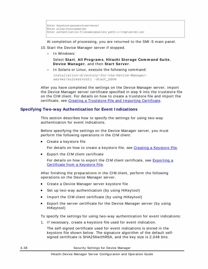
4-38 Security Settings for Device Manager
Hitachi Device Manager Server Configuration and Operation Guide
Enter keystore-password:serverssl Enter alias:foocorpserver Enter authentication-filename(absolute path):c:\tmp\server.cer
At completion of processing, you are returned to the SMI-S main panel.
10. Start the Device Manager server if stopped.
– In Windows:
Select Start, All Programs, Hitachi Storage Command Suite, Device Manager, and then Start Server.
– In Solaris or Linux, execute the following command:
installation-directory-for-the-Device-Manager-server/suitesrvcntl -start_hdvm
After you have completed the settings on the Device Manager server, import the Device Manager server certificate specified in step 9 into the truststore file on the CIM client. For details on how to create a truststore file and import the certificate, see Creating a Truststore File and Importing Certificate.
Specifying Two-way Authentication for Event Indications
This section describes how to specify the settings for using two-way authentication for event indications.
Before specifying the settings on the Device Manager server, you must perform the following operations in the CIM client:
• Create a keystore file
For details on how to create a keystore file, see Creating a Keystore File.
• Export the CIM client certificate
For details on how to export the CIM client certificate, see Exporting a Certificate from a Keystore File.
After finishing the preparations in the CIM client, perform the following operations on the Device Manager server.
• Create a Device Manager server keystore file
• Set up two-way authentication (by using HiKeytool)
• Import the CIM client certificate (by using HiKeytool)
• Export the server certificate for the Device Manager server (by using HiKeytool)
To specify the settings for using two-way authentication for event indications:
1. If necessary, create a keystore file used for event indication.
The self-signed certificate used for event indications is stored in the keystore file shown below. The signature algorithm of the default self-signed certificate is SHA256withRSA, and the key size is 2,048 bits.
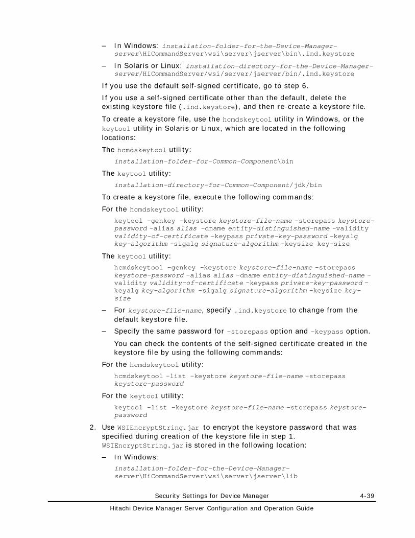
Security Settings for Device Manager 4-39
Hitachi Device Manager Server Configuration and Operation Guide
– In Windows: installation-folder-for-the-Device-Manager-server\HiCommandServer\wsi\server\jserver\bin\.ind.keystore
– In Solaris or Linux: installation-directory-for-the-Device-Manager-server/HiCommandServer/wsi/server/jserver/bin/.ind.keystore
If you use the default self-signed certificate, go to step 6.
If you use a self-signed certificate other than the default, delete the existing keystore file (.ind.keystore), and then re-create a keystore file.
To create a keystore file, use the hcmdskeytool utility in Windows, or the keytool utility in Solaris or Linux, which are located in the following locations:
The hcmdskeytool utility:
installation-folder-for-Common-Component\bin
The keytool utility:
installation-directory-for-Common-Component/jdk/bin
To create a keystore file, execute the following commands:
For the hcmdskeytool utility:
keytool -genkey -keystore keystore-file-name -storepass keystore-password -alias alias -dname entity-distinguished-name -validity validity-of-certificate -keypass private-key-password -keyalg key-algorithm -sigalg signature-algorithm -keysize key-size
The keytool utility:
hcmdskeytool -genkey -keystore keystore-file-name -storepass keystore-password -alias alias -dname entity-distinguished-name -validity validity-of-certificate -keypass private-key-password -keyalg key-algorithm -sigalg signature-algorithm -keysize key-size
– For keystore-file-name, specify .ind.keystore to change from the default keystore file.
– Specify the same password for -storepass option and -keypass option.
You can check the contents of the self-signed certificate created in the keystore file by using the following commands:
For the hcmdskeytool utility:
hcmdskeytool -list -keystore keystore-file-name -storepass keystore-password
For the keytool utility:
keytool -list -keystore keystore-file-name -storepass keystore-password
2. Use WSIEncryptString.jar to encrypt the keystore password that was specified during creation of the keystore file in step 1. WSIEncryptString.jar is stored in the following location:
– In Windows:
installation-folder-for-the-Device-Manager-server\HiCommandServer\wsi\server\jserver\lib
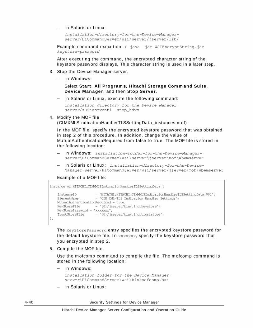
4-40 Security Settings for Device Manager
Hitachi Device Manager Server Configuration and Operation Guide
– In Solaris or Linux:
installation-directory-for-the-Device-Manager-server/HiCommandServer/wsi/server/jserver/lib/
Example command execution: > java -jar WSIEncryptString.jar keystore-password
After executing the command, the encrypted character string of the keystore password displays. This character string is used in a later step.
3. Stop the Device Manager server.
– In Windows:
Select Start, All Programs, Hitachi Storage Command Suite, Device Manager, and then Stop Server.
– In Solaris or Linux, execute the following command: installation-directory-for-the-Device-Manager-server/suitesrvcntl -stop_hdvm
4. Modify the MOF file (CIMXMLSIndicationHandlerTLSSettingData_instances.mof).
In the MOF file, specify the encrypted keystore password that was obtained in step 2 of this procedure. In addition, change the value of MutualAuthenticationRequired from false to true. The MOF file is stored in the following location:
– In Windows: installation-folder-for-the-Device-Manager-server\HiCommandServer\wsi\server\jserver\mof\wbemserver
– In Solaris or Linux: installation-directory-for-the-Device-Manager-server/HiCommandServer/wsi/server/jserver/mof/wbemserver
Example of a MOF file: instance of HITACHI_CIMXMLSIndicationHandlerTLSSettingData { InstanceID = "HITACHI:HITACHI_CIMXMLSIndicationHandlerTLSSettingData:001"; ElementName = "CIM_XML-TLS Indication Handler Settings"; MutualAuthenticationRequired = true; KeyStoreFile = "{0}/jserver/bin/.ind.keystore"; KeyStorePassword = "xxxxxxx"; TrustStoreFile = "{0}/jserver/bin/.ind.truststore"; };
The KeyStorePassword entry specifies the encrypted keystore password for the default keystore file. In xxxxxxx, specify the keystore password that you encrypted in step 2.
5. Compile the MOF file.
Use the mofcomp command to compile the file. The mofcomp command is stored in the following location:
– In Windows:
installation-folder-for-the-Device-Manager-server\HiCommandServer\wsi\bin\mofcomp.bat
– In Solaris or Linux:
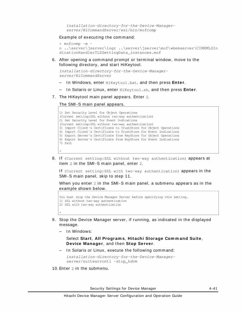
Security Settings for Device Manager 4-41
Hitachi Device Manager Server Configuration and Operation Guide
installation-directory-for-the-Device-Manager-server/HiCommandServer/wsi/bin/mofcomp
Example of executing the command: > mofcomp -m -o ..\server\jserver\logr ..\server\jserver\mof\wbemserver\CIMXMLSIndicationHandlerTLSSettingData_instances.mof
6. After opening a command prompt or terminal window, move to the following directory, and start HiKeytool. installation-directory-for-the-Device-Manager-server/HiCommandServer
– In Windows, enter HiKeytool.bat, and then press Enter.
– In Solaris or Linux, enter HiKeytool.sh, and then press Enter.
7. The HiKeytool main panel appears. Enter 2.
The SMI-S main panel appears. 1) Set Security Level for Object Operations (Current setting:SSL without two-way authentication) 2) Set Security Level for Event Indications (Current setting:SSL without two-way authentication) 3) Import Client's Certificate to TrustStore for Object Operations 4) Import Client's Certificate to TrustStore for Event Indications 5) Export Server's Certificate from KeyStore for Object Operations 6) Export Server's Certificate from KeyStore for Event Indications 7) Exit >
8. If (Current setting:SSL without two-way authentication) appears at item 2 in the SMI-S main panel, enter 2.
If (Current setting:SSL with two-way authentication) appears in the SMI-S main panel, skip to step 11.
When you enter 2 in the SMI-S main panel, a submenu appears as in the example shown below. You must stop the Device Manager Server before specifying this setting. 1) SSL without two-way authentication 2) SSL with two-way authentication >
9. Stop the Device Manager server, if running, as indicated in the displayed message.
– In Windows:
Select Start, All Programs, Hitachi Storage Command Suite, Device Manager, and then Stop Server.
– In Solaris or Linux, execute the following command:
installation-directory-for-the-Device-Manager-server/suitesrvcntl -stop_hdvm
10. Enter 2 in the submenu.
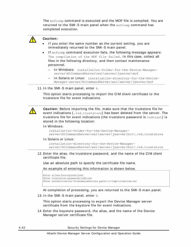
4-42 Security Settings for Device Manager
Hitachi Device Manager Server Configuration and Operation Guide
The mofcomp command is executed and the MOF file is compiled. You are returned to the SMI-S main panel when the mofcomp command has completed execution.
Caution:
• If you enter the same number as the current setting, you are immediately returned to the SMI-S main panel.
• If mofcomp command execution fails, the following message appears: The compilation of the MOF file failed. In this case, collect all files in the following directory, and then contact maintenance personnel. – In Windows: installation-folder-for-the-Device-Manager-
server\HiCommandServer\wsi\server\jserver\mof
– In Solaris or Linux: installation-directory-for-the-Device-Manager-server/HiCommandServer/wsi/server/jserver/mof
11. In the SMI-S main panel, enter 4.
This option starts processing to import the CIM client certificate to the truststore file for event indications.
Caution: Before importing the file, make sure that the truststore file for event indications (.ind.truststore) has been deleted from the server. The truststore file for event indications (the truststore password is indtrust) is stored in the following location:
In Windows: installation-folder-for-the-Device-Manager-server\HiCommandServer\wsi\server\jserver\bin\.ind.truststore
In Solaris or Linux: installation-directory-for-the-Device-Manager-server/HiCommandServer/wsi/server/jserver/bin/.ind.truststore
12. Enter the alias, the truststore password, and the name of the CIM client certificate file.
Use an absolute path to specify the certificate file name.
An example of entering this information is shown below. Enter alias:foocorpindclient Enter truststore-password:indtrust Enter authentication-filename(absolute path):c:\tmp\clientind.cer
At completion of processing, you are returned to the SMI-S main panel.
13. In the SMI-S main panel, enter 6.
This option starts processing to export the Device Manager server certificate from the keystore file for event indications.
14. Enter the keystore password, the alias, and the name of the Device Manager server certificate file.
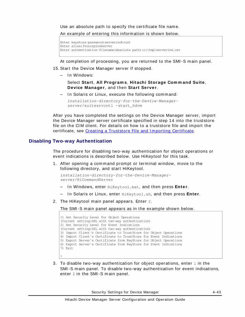
Security Settings for Device Manager 4-43
Hitachi Device Manager Server Configuration and Operation Guide
Use an absolute path to specify the certificate file name.
An example of entering this information is shown below. Enter keystore-password:serverindtrust Enter alias:foocorpindserver Enter authentication-filename(absolute path):c:\tmp\serverind.cer
At completion of processing, you are returned to the SMI-S main panel.
15. Start the Device Manager server if stopped.
– In Windows:
Select Start, All Programs, Hitachi Storage Command Suite, Device Manager, and then Start Server.
– In Solaris or Linux, execute the following command:
installation-directory-for-the-Device-Manager-server/suitesrvcntl -start_hdvm
After you have completed the settings on the Device Manager server, import the Device Manager server certificate specified in step 14 into the truststore file on the CIM client. For details on how to a truststore file and import the certificate, see Creating a Truststore File and Importing Certificate.
Disabling Two-way Authentication
The procedure for disabling two-way authentication for object operations or event indications is described below. Use HiKeytool for this task.
1. After opening a command prompt or terminal window, move to the following directory, and start HiKeytool.
installation-directory-for-the-Device-Manager-server/HiCommandServer
– In Windows, enter HiKeytool.bat, and then press Enter.
– In Solaris or Linux, enter HiKeytool.sh, and then press Enter.
2. The HiKeytool main panel appears. Enter 2.
The SMI-S main panel appears as in the example shown below. 1) Set Security Level for Object Operations (Current setting:SSL with two-way authentication) 2) Set Security Level for Event Indications (Current setting:SSL with two-way authentication) 3) Import Client's Certificate to TrustStore for Object Operations 4) Import Client's Certificate to TrustStore for Event Indications 5) Export Server's Certificate from KeyStore for Object Operations 6) Export Server's Certificate from KeyStore for Event Indications 7) Exit >
3. To disable two-way authentication for object operations, enter 1 in the SMI-S main panel. To disable two-way authentication for event indications, enter 2 in the SMI-S main panel.
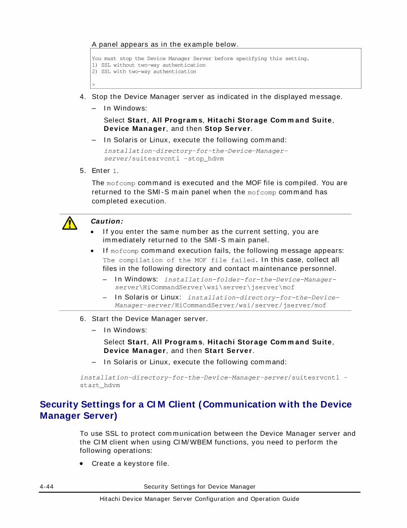
4-44 Security Settings for Device Manager
Hitachi Device Manager Server Configuration and Operation Guide
A panel appears as in the example below. You must stop the Device Manager Server before specifying this setting. 1) SSL without two-way authentication 2) SSL with two-way authentication >
4. Stop the Device Manager server as indicated in the displayed message.
– In Windows:
Select Start, All Programs, Hitachi Storage Command Suite, Device Manager, and then Stop Server.
– In Solaris or Linux, execute the following command:
installation-directory-for-the-Device-Manager-server/suitesrvcntl -stop_hdvm
5. Enter 1.
The mofcomp command is executed and the MOF file is compiled. You are returned to the SMI-S main panel when the mofcomp command has completed execution.
Caution: • If you enter the same number as the current setting, you are
immediately returned to the SMI-S main panel.
• If mofcomp command execution fails, the following message appears: The compilation of the MOF file failed. In this case, collect all files in the following directory and contact maintenance personnel.
– In Windows: installation-folder-for-the-Device-Manager-server\HiCommandServer\wsi\server\jserver\mof
– In Solaris or Linux: installation-directory-for-the-Device-Manager-server/HiCommandServer/wsi/server/jserver/mof
6. Start the Device Manager server.
– In Windows:
Select Start, All Programs, Hitachi Storage Command Suite, Device Manager, and then Start Server.
– In Solaris or Linux, execute the following command:
installation-directory-for-the-Device-Manager-server/suitesrvcntl -start_hdvm
Security Settings for a CIM Client (Communication with the Device Manager Server)
To use SSL to protect communication between the Device Manager server and the CIM client when using CIM/WBEM functions, you need to perform the following operations:
• Create a keystore file.
Security Settings for Device Manager 4-45
Hitachi Device Manager Server Configuration and Operation Guide
• Export a certificate from a keystore file.
• Create a truststore file and importing a certificate.
You use the keytool utility for these operations. To use the keytool utility in a CIM client, install Java (JDK1.5) on the CIM client machine.
Note the following when using the keytool utility to specify the file name, the alias, and the password for the keystore file or the truststore file:
• Do not use the following symbols in the file name: : , ; * ? " < > |
• Specify the file name as a character string of no more than 255 bytes.
• Do not include double quotation marks (") in the alias or password.
Note: This section assumes that a path to the keytool utility has been added to the environment variable PATH.
Creating a Keystore File
To create a keystore file:
1. Execute the following command:
keytool -genkey -keystore keystore-file-name -storepass keystore-password -alias alias -dname entity-distinguished-name -validity validity-of-certificate -keypass private-key-password -keyalg key-algorithm -sigalg signature-algorithm -keysize key-size
Caution: Specify the same password for the -storepass option and the -keypass option.
2. Check the created keystore file.
Execute the following command: keytool -list -keystore keystore-file-name -storepass keystore-password
Exporting a Certificate from a Keystore File
To export a certificate:
1. Export the certificate.
Execute the following command:
keytool -export -keystore keystore-file-name -storepass keystore-password -alias alias -file certificate-file-name
2. Check the exported certificate.
Execute the following command: keytool -printcert -v -file certificate-file-name
4-46 Security Settings for Device Manager
Hitachi Device Manager Server Configuration and Operation Guide
Creating a Truststore File and Importing Certificate
To create a truststore file and import the certificate:
1. Create the truststore file and import the certificate.
Execute the following command:
keytool -import -alias alias -keystore truststore-file-name -storepass truststore-password -trustcacerts -file certificate-file-name
2. Check the created truststore file.
Execute the following command:
keytool -list -keystore truststore-file-name -storepass truststore-password
Security Settings for the Common Component (Communication with an LDAP Directory Server)
In Hitachi Storage Command Suite products, when performing user authentication or authorization by linking with an LDAP directory server, you can encrypt network transmissions between Common Component and the LDAP directory server by using StartTLS. To use StartTLS to protect communications between the management server and LDAP directory server, you need to perform the following operations:
• Obtain a certificate for the LDAP directory server
• Import the certificate into the truststore file
To encrypt network transmissions between Common Component and an LDAP directory server, you also need to set up the exauth.properties file. For details on how to do this, see REF _Ref256668853 \h \* MERGEFORMAT Settings Required to Authenticate Users by Using an External Authentication Server.
Security Settings for Device Manager 4-47
Hitachi Device Manager Server Configuration and Operation Guide
Caution: The CN of the certificate for the LDAP directory server must be the same as the value specified for the following attribute in the exauth.properties file.
If the authentication method is LDAP: auth.ldap.value-specified-for-auth.server.name.host
If the authentication method is RADIUS and an external authorization server is also linked to:
If the external authentication server and the external authorization server are running on the same computer: auth.radius.value-specified-for-auth.server.name.host If the external authentication server and the external authorization server are running on different computers: auth.group.domain-name.host
If the authentication method is Kerberos and an external authorization server is also linked to:
auth.kerberos.value-specified-for-auth.kerberos.realm_name.kdc
Obtaining a Certificate for the LDAP Directory Server
Obtain a server certificate for the LDAP directory server that communicates with the management server. For details, see the documentation for the LDAP directory server you use.
If you have obtained a certificate for the LDAP directory server from a well-known CA, the CA certificate might already be set up in the standard truststore referenced by Common Component. Execute the command below to check this. If the certificate for the LDAP directory server is authenticated by the already-registered CA certificate, you do not need to set up the truststore jssecacerts explained in Importing the Certificate to the Truststore File.
In Windows: hcmdskeytool -list -v -keystore truststore-file-name -storepass password-to-access-the-truststore
In Solaris or Linux:
keytool -list -v -keystore truststore-file-name -storepass password-to-access-the-truststore
• -keystore truststore-file-name specifies the truststore file to be referenced.
In Windows: installation-folder-for-Common-Component\jdk\jre\lib\security\cacerts
In Solaris or Linux: installation-directory-for-Common-Component/jdk/jre/lib/security/cacerts
4-48 Security Settings for Device Manager
Hitachi Device Manager Server Configuration and Operation Guide
• -storepass password-to-access-the-truststore specifies the password used to reference the truststore cacerts. The default is changeit.
The following shows an example of executing the command:
# /opt/HiCommand/Base/jdk/bin/keytool -list -v -keystore /opt/HiCommand/Base/jdk/jre/lib/security/cacerts -storepass changeit
Caution: Do not import and use your own certificate into the truststore cacerts because that truststore is updated when Common Component is upgraded.
Importing the Certificate to the Truststore File
Import the certificate for the LDAP directory server into the truststore used by Common Component. Store that truststore (jssecacerts) in the following locations. If no truststore file exists, create a truststore file.
In Windows:
installation-folder-for-Common-Component\jdk\jre\lib\security\jssecacerts
In Solaris or Linux:
installation-directory-for-Common-Component/jdk/jre/lib/security/jssecacerts
To create a truststore file, import a certificate, and check the contents, use the hcmdskeytool utility (for Windows) or the Keytool utility (for Solaris or Linux). These utilities are stored in the following locations:
For hcmdskeytool:
installation-folder-for-Common-Component\bin\hcmdskeytool.exe
For keytool:
installation-directory-for-Common-Component/jdk/bin/keytool
To create a truststore file and import a certificate, execute the following command:
In Windows: hcmdskeytool -import -alias unique-name-in-the-truststore -file certificate-file-name -keystore truststore-file-name -storepass password-to-access-the-truststore
In Solaris or Linux:
keytool -import -alias unique-name-in-the-truststore -file certificate-file-name -keystore truststore-file-name -storepass password-to-access-the-truststore
Security Settings for Device Manager 4-49
Hitachi Device Manager Server Configuration and Operation Guide
• -alias unique-name-in-the-truststore specifies the name used to identify the certificate in the truststore
• -file certificate-file-name specifies the certificate file.
• -keystore truststore-file-name specifies jssecacerts, which is the truststore file to be registered and created.
• -storepass password-to-access-the-truststore specifies the password used to access the truststore (jssecacerts).
For example, to use the keytool utility to import a certificate file when the certificate file is /tmp/ldapcert.der, the password to access the truststore is changeit, and the unique name in the truststore is ldaphost, you would execute the command as shown below.
# /opt/HiCommand/Base/jdk/bin/keytool -import -alias ldaphost -file /tmp/ldapcert.der -keystore /opt/HiCommand/Base/jdk/jre/lib/security/jssecacerts -storepass changeit
To view the contents of the truststore, execute the following command:
In Windows:
hcmdskeytool -list -v -keystore truststore-file-name -storepass password-to-access-the-truststore
In Solaris or Linux:
keytool -list -v -keystore truststore-file-name -storepass password-to-access-the-truststore
• -keystore truststore-file-name specifies jssecacerts, which is the truststore file to be registered and created.
• -storepass password-to-access-the-truststore specifies the password used to update the truststore jssecacerts.
# /opt/HiCommand/Base/jdk/bin/keytool -list -v -keystore /opt/HiCommand/Base/jdk/jre/lib/security/jssecacerts -storepass changeit
Note that, to apply the truststore, you need to restart the Hitachi Storage Command Suite product services and Common Component.
In Windows:
Select Start, All Programs, Hitachi Storage Command Suite, Device Manager, and then Stop Server.
After the Device Manager server stops, select Start, All Programs, Hitachi Storage Command Suite, Device Manager, and then Start Server.
4-50 Security Settings for Device Manager
Hitachi Device Manager Server Configuration and Operation Guide
In Solaris or Linux: installation-directory-for-the-Device-Manager-server/suitesrvcntl -stop_hdvm
installation-directory-for-the-Device-Manager-server/suitesrvcntl -start_hdvm
Caution: • If there is more than one certificate file, import a certificate file by
specifying an alias name that is not used in jssecacerts.
• Note the following when you use the hcmdskeytool or keytool utility to specify a unique name in the truststore, the truststore file name, and the password:
– Do not use the following symbols in the file name: : , ; * ? " < > |
– Specify the file name as a character string of no more than 255 bytes. – Do not include double quotation marks (") in the unique name in the
truststore or the password.
Security Settings for the Device Manager Server (Communication with SMI-S Provider)
If Device Manager manages SMI-S Enabled subsystems, Device Manager can use TLS/SSL to receive event indications from an SMI-S provider.
Caution: • These security settings will also be used for communication between the
Device Manager server and Web Client.
• If you want to use TLS/SSL for event indications, you need to specify the settings for an SMI-S provider. For details, see the documentation for your SMI-S provider.
To use TLS/SSL for event indications:
1. Create a keypair used for communication between the Device Manager server and SMI-S provider.
For details on how to create a keypair, see Creating a Keypair.
2. Enable TLS/SSL server security for the Device Manager server.
For details on how to do this, see Enabling TLS/SSL Server Security.
3. If there is a possibility that you will change the settings for an SMI-S Enabled subsystem from Tiered Storage Manager, refresh the target SMI-S Enabled subsystem.
Security Settings for Device Manager 4-51
Hitachi Device Manager Server Configuration and Operation Guide
Specifying Which Device Manager Clients Can Access the Device Manager Server
To control which Web Clients are able to connect to the Device Manager server:
1. If HiCommand Suite products whose versions are earlier than 5.7 are installed, stop their services. For details, see the manual for your product version.
2. Stop the Hitachi Storage Command Suite product services and Common Component.
– In Windows, select Start, All Program, Hitachi Storage Command Suite, Device Manager, and then Stop Server with Common Services.
– In Solaris or Linux, execute the following command:
installation-directory-for-Common-Component/bin/hcmdssrv -stop
3. Open the httpsd.conf file, located in the following directory:
The httpsd.conf file is stored in the following location:
– In Windows: installation-folder-for-Common-Component\httpsd\conf\httpsd.conf
– In Solaris or Linux: installation-directory-for-Common-Component/httpsd/conf/httpsd.conf
4. In the last line of the httpsd.conf file, register information about management clients that can be connected to the Device Manager server.
The following shows how to specify the httpsd.conf file: <Location /DeviceManager> order allow,deny allow from management-client [management-client...] </Location>
Hosts can be written in the following formats:
– The domain name (example: hitachi.datasystem.com)
– Part of the domain name (example: hitachi)
– The whole IPv4 and IPv6 address (example: 10.1.2.3 127.0.0.1 2001::123:4567:89ab:cdef)
– Part of the IPv4 address (example: 10.1 which, in this case, means 10.1.0.0/16)
– IPv4 Network/Netmask format (dot notation) (example: 10.1.0.0/255.255.0.0)
– IPv4 and IPv6 Network/c (CIDR notation: c is a decimal integer that indicates the number of bits for identifying a network) (example: 10.1.0.0/16 2001:0:0:1230::/64)
4-52 Security Settings for Device Manager
Hitachi Device Manager Server Configuration and Operation Guide
If you want to specify multiple management clients in a command line for allow from, delimit the hosts with a space.
Multiple lines can be used to specify hosts for allow from.
If you attempt to connect from a computer which has Device Manager installed, you must also specify the local loop-back address (127.0.0.1 or localhost).
Be sure to specify order in accordance with the specified format. If extra spaces or tabs are inserted, the operation will fail.
The following example shows how to register management clients in the httpsd.conf file:
<Location /DeviceManager> order allow,deny allow from 127.0.0.1 10.0.0.1 2001::123:4567:89ab:cdef allow from 10.1.0.0/16 2001:0:0:1230::/64 </Location>
5. Register information about the management clients in the server.http.security.clientIP or server.http.security.clientIPv6 property.
For details on how to specify the server.http.security.clientIP property, see server.http.security.clientIP. For details on how to specify the server.http.security.clientIPv6 property, see server.http.security.clientIPv6.
6. Start the Hitachi Storage Command Suite product services and Common Component.
– In Windows, select Start-All Programs-Hitachi Storage Command Suite-Device Manager-Start Server with Common Services.
– In Solaris or Linux, execute the following command:
installation-directory-for-Common-Component/bin/hcmdssrv -start
7. If HiCommand Suite products whose versions are earlier than 5.7 is installed, start their services as required. For details, see the manual for your product version.
Caution: If you log on to a Hitachi Storage Command Suite product from a management client that is not registered in the httpsd.conf file, the Device Manager server cannot be started from that Hitachi Storage Command Suite product.
Security Settings for Device Manager 4-53
Hitachi Device Manager Server Configuration and Operation Guide
Changing the Password-Encoding Level in CLI of Device Manager or Tiered Storage Manager
In Device Manager CLI or Tiered Storage Manager CLI, you can preset a password in the properties file or password file. By specifying this setting, you can omit specifying the password when executing commands.
We recommend that you specify the character string of the encoded password in the properties file or password file. This section explains how to change the level (complexity) used when encoding the password. For details about how to encode a password, see the Hitachi Device Manager Software Command Line Interface (CLI) User's Guide and the Hitachi Tiered Storage Manager Software CLI Reference Guide.
There are two levels for encoding passwords, NORMAL and HIGH. In the NORMAL level, a password is encoded with a 128-bit key length. In the HIGH level, it is encoded with a 256-bit key length. If you want to change the encoding level to HIGH, you need to download and install the Java Cryptography Extension (JCE) Unlimited Strength Jurisdiction Policy Files for the JRE version you are using. Download the Jurisdiction Policy files from the Sun Microsystems website (if the management client OS is Windows, Solaris, HP-UX, or Linux) or the IBM website (if the management client OS is AIX®). For details about how to install the files, see the documentation provided with the Jurisdiction Policy files.
Advanced Security Mode
To use Device Manager in a configuration that satisfies the following security requirements, you need to specify the settings for SSL/TLS communications and set user passwords.
Digital signature hash algorithm
SHA-256 or higher
Cryptographic algorithms
RSA (whose key size is 2,048 bits or more)
AES (whose key size is 128 bits or more)
3KeyTDES
This section describes the tasks required to run Device Manager in the advanced security mode.
4-54 Security Settings for Device Manager
Hitachi Device Manager Server Configuration and Operation Guide
Settings Required to Communicate with Management Clients (Settings for Common Component)
To enable communication between the management server and management clients (Web Client) in the advanced security mode, you need to perform the tasks described below in Common Component.
Creating a Private Key and Certificate Signing Request
Create a private key, certificate signing request (CSR) to be sent to a certificate authority (CA), and self-signed certificate by using the hcmdsssltool command. Executing this command creates a CSR and self-signed certificate whose private key size is 2,048 bits and whose signature algorithm is SHA256withRSA.
Then, submit the created CSR file to CA and have a signed certificate issued. A CSR is created in a form complying with PEM. For notes on the settings that you need to specify for a CSR, ask the CA that you will use. Note that certificates issued by a CA have an expiration date. You need to have a certificate reissued before your certificate expires.
Caution: • If you want to use an external CA, make sure that the CA supports
signatures using SHA256withRSA. • Although you can use the hcmdsssltool command to create a self-signed
certificate, we recommend that you use the command only to test encrypted communications.
The hcmdsssltool command is installed in the following location:
In Windows: installation-folder-for-Common-Component\bin
In Solaris or Linux: installation-folder-for-Common-Component/bin
The following shows the format of the hcmdsssltool command:
In Windows:
hcmdsssltool /key key-file /csr CSR-file /cert certificate-file /certtext file-for-displaying-the-contents-of-the-certificate [/validity number-of-valid-days] [/dname DN]
In Solaris or Linux:
hcmdsssltool -key key-file -csr CSR-file -cert certificate-file -certtext file-for-displaying-the-contents-of-the-certificate [-validity number-of-valid-days] [-dname DN]
Security Settings for Device Manager 4-55
Hitachi Device Manager Server Configuration and Operation Guide
• key-file specifies the absolute path of a file to which a private key will be output. The size of a private key is 2,048 bits.
• csr CSR-file specifies the absolute path of a file to which a certificate signing request (CSR) will be output.
• cert certificate-file specifies the absolute path of a file to which a self-signed certificate will be output.
• certtext file-for-displaying-the-contents-of-the-certificate specifies the absolute path of a file to which the contents of a self-signed certificate will be output in text format.
• validity number-of-valid-days specifies the number of days during which the self-signed certificate is valid.
• dname DN specifies the DN to be included in the self-signed certificate and CSR. If you execute the command without this option, you can specify the DN interactively.
To specify the DN, combine each attribute type with the corresponding attribute value into one attribute by using an equal sign (=), and then specify the attributes by separating each by a comma. For the DN, you cannot specify a double quotation mark (") or backslash (\). In addition, specify each attribute value as defined by RFC2253. For example, if the specified DN includes any of the following characters, escape each of them by using a backslash (\).
– A space at the beginning of or at the end of the DN
– A hash mark (#) at the beginning of the DN
– A plus sign (+), comma (,), semicolon (;), left angle bracket (<), equal sign (=), or right angle bracket (>)
The following table lists and describes the attribute types and values specified for the DN.
Table 4-1 Attribute Types and Values Specified for the DN
Attribute Type Full Name of Attribute Type Attribute Value
CN Common Name Specify the host name of the management server (HBase Storage Mgmt Web Service). This attribute is required.
Specify the host name used when connecting to the web server (HBase Storage Mgmt Web Service of Common Component) from Web Client. You can also specify the host name in FQDN format. If the management server is running in a cluster environment, specify the logical host name.
OU Organizational Unit Name Specify the name of the organizational unit.
O Organization Name Specify the organizational name. This attribute is required.
L Locality Name Specify the name of the city, town, or other locality.
4-56 Security Settings for Device Manager
Hitachi Device Manager Server Configuration and Operation Guide
Attribute Type Full Name of Attribute Type Attribute Value
ST State or Province Name Specify the name of the state or province.
C Country Name Specify the two-letter country code.
Configuring the httpsd.conf File
In addition to the settings described in Enabling SSL , to limit the cipher strength, specify the SSLProtocol and SSLRequiredCiphers directives between the SSLEnable and SSLRequireSSL directives as shown in the following example. : SSLEnable SSLProtocol SSLv3 TLSv1 SSLRequiredCiphers AES256-SHA:AES128-SHA:DES-CBC3-SHA SSLRequireSSL :
Settings Required to Communicate with Management Clients (Settings for the Device Manager Server)
To enable communication between the management server and management clients (Web Client and CLI) in the advanced security mode, you need to perform the tasks described below in the Device Manager server.
• To use a self-signed certificate in order to use SSL/TLS communication, specify SHA256withRSA for the signature algorithm when you create a keypair by using HiKeytool.
For details on how to create a keypair, see Creating a Keypair.
• To use a digitally-signed certificate issued by an external certificate authority (CA), make sure that the CA supports SHA256withRSA signatures.
For details on how to create a certificate signing request, see Creating a Certificate Signing Request (CSR) (Security Settings for the Device Manager Server). For details on how to import a digitally-signed certificate into the Device Manager server keystore, see Importing a Digitally-signed Certificate into the Device Manager Server Keystore.
Settings Required to Communicate with an LDAP Directory Server
To enable StartTLS communication between the management server and an LDAP directory server in the advanced security mode, you need to import a certificate signed with SHA256withRSA to the truststore for Common Component.
For details on how to check and import server certificates, see Security Settings for the Common Component (Communication with an LDAP Directory Server).
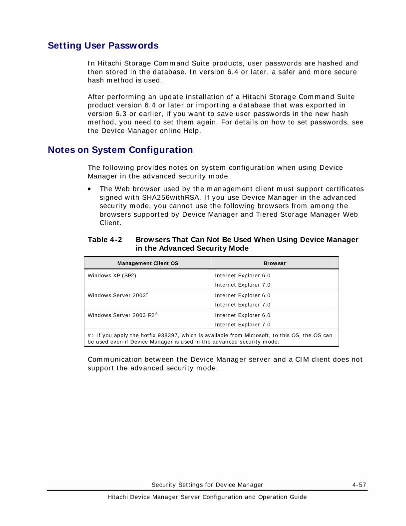
Security Settings for Device Manager 4-57
Hitachi Device Manager Server Configuration and Operation Guide
Setting User Passwords
In Hitachi Storage Command Suite products, user passwords are hashed and then stored in the database. In version 6.4 or later, a safer and more secure hash method is used.
After performing an update installation of a Hitachi Storage Command Suite product version 6.4 or later or importing a database that was exported in version 6.3 or earlier, if you want to save user passwords in the new hash method, you need to set them again. For details on how to set passwords, see the Device Manager online Help.
Notes on System Configuration
The following provides notes on system configuration when using Device Manager in the advanced security mode.
• The Web browser used by the management client must support certificates signed with SHA256withRSA. If you use Device Manager in the advanced security mode, you cannot use the following browsers from among the browsers supported by Device Manager and Tiered Storage Manager Web Client.
Table 4-2 Browsers That Can Not Be Used When Using Device Manager in the Advanced Security Mode
Management Client OS Browser
Windows XP (SP2) Internet Explorer 6.0
Internet Explorer 7.0
Windows Server 2003# Internet Explorer 6.0
Internet Explorer 7.0
Windows Server 2003 R2# Internet Explorer 6.0
Internet Explorer 7.0
#: If you apply the hotfix 938397, which is available from Microsoft, to this OS, the OS can be used even if Device Manager is used in the advanced security mode.
Communication between the Device Manager server and a CIM client does not support the advanced security mode.

4-58 Security Settings for Device Manager
Hitachi Device Manager Server Configuration and Operation Guide
Settings Required for Linking with Related Products 5-1
Hitachi Device Manager Server Configuration and Operation Guide
Settings Required for Linking with Related Products
This chapter describes the Device Manager settings required for linking with related products.
Settings for Linking with Storage Navigator Modular 2
Settings for Linking with Storage Navigator Modular (for Web)
Settings for Linking with DAMP (for Web)
Settings for Linking with Tuning Manager
Settings for Starting HSSM from the Dashboard
Settings for Starting Applications from Web Client
5-2 Settings Required for Linking with Related Products
Hitachi Device Manager Server Configuration and Operation Guide
Settings for Linking with Storage Navigator Modular 2
By linking Device Manager with Storage Navigator Modular 2, you can view details about the following storage subsystems and change their configuration.
• Hitachi AMS 2000 or Hitachi SMS
If you register a Hitachi AMS 2000 or Hitachi SMS, the settings are automatically configured so that the Storage Navigator Modular 2 window can be displayed. Therefore, you do not need to specify the launch environment settings.
In the navigation area of Web Client, if you choose the Storage Navigator Modular 2 object from the storage subsystems object tree, the Storage Navigator Modular 2 window is displayed in the application area.
• Hitachi AMS/WMS or Thunder 9500V
On the management server, specify the launch environment settings for Storage Navigator Modular 2.
After specifying the launch environment settings, you can launch the Storage Navigator Modular 2 window by clicking the Physical View button in the subsystem-name subwindow of Web Client.
This section describes prerequisites and environment settings for linking with Storage Navigator Modular 2.
Prerequisites for Linking with Storage Navigator Modular 2
The prerequisites and notes for using Storage Navigator Modular 2 are as follows:
Prerequisites for Using Storage Navigator Modular 2
• Device Manager supports linkage with Storage Navigator Modular 2 only if the management server is in a non-cluster configuration and its OS is Windows or Solaris.
• Use Common Component for the web server that runs Storage Navigator Modular 2.
• Install Storage Navigator Modular 2 on the computer where the Device Manager server is installed.
• If you operate Storage Navigator Modular (for Web) and Storage Navigator Modular 2 on the same computer, do not use the same port number for RMI communication between Storage Navigator Modular (for Web) and Storage Navigator Modular 2. For details on how to change the port number for RMI communication, see the documentation for Storage Navigator Modular 2 or Storage Navigator Modular (for Web).
Settings Required for Linking with Related Products 5-3
Hitachi Device Manager Server Configuration and Operation Guide
• The web server for Storage Navigator Modular 2 can be accessed via only one NIC even if multiple NICs are installed on the computer. To link with Storage Navigator Modular 2 in a computer environment where multiple NICs are installed, you need to specify the NIC to be used to access the web server for Storage Navigator Modular 2. The IP address specified for this setting must be the same as that specified during installation of the Device Manager server. For details on how to specify the settings, see the documentation for Storage Navigator Modular 2.
• Make sure that Storage Navigator Modular 2 works properly by itself. You need to set up the Java Plug-in in Storage Navigator Modular 2. For details about how to specify environment settings and how to start Storage Navigator Modular 2, see the documentation for Storage Navigator Modular 2.
• In Storage Navigator Modular 2, you can register only storage subsystems that are supported by Device Manager.
• To manage Hitachi AMS 2000 and Hitachi SMS, register a user who satisfies all of the following conditions:
– The Modify permission of Storage Navigator Modular 2 has been set.
– The Modify permission of Device Manager has been set.
– All Resources has been assigned as a resource group.
To register a user who has both the Modify permission of Storage Navigator Modular 2 and the Modify permission of Device Manager, you need to use Storage Navigator Modular 2. For details on how to do this, see the documentation for Storage Navigator Modular 2.
For details on how to assign a resource group, see the Device Manager online Help.
• For storage subsystems for which password protection or account authentication is enabled, do not use a user ID that starts with HDvM.
If you launch Storage Navigator Modular 2 while password protection or account authentication is enabled, the system creates a temporary user account for Storage Navigator Modular 2 to access the storage subsystem. This user account is automatically registered into the system with a user ID that starts with HDvM, and is automatically deleted after you exit Storage Navigator Modular 2. Therefore, manually registering a user account that starts with HDvM or changing the registration details might cause the launch to fail.
• When you enable or disable the advanced security mode in a Hitachi AMS 2000 or Hitachi SMS storage subsystem, user accounts registered in that storage subsystem will be deleted. To re-register them, use Storage Navigator Modular 2.
• To manage Hitachi AMS 2000 and Hitachi SMS, match the communication protocol setting in Storage Navigator Modular 2 to the setting in Device Manager Web Client or CLI.
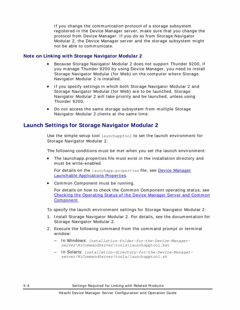
5-4 Settings Required for Linking with Related Products
Hitachi Device Manager Server Configuration and Operation Guide
If you change the communication protocol of a storage subsystem registered in the Device Manager server, make sure that you change the protocol from Device Manager. If you do so from Storage Navigator Modular 2, the Device Manager server and the storage subsystem might not be able to communicate.
Note on Linking with Storage Navigator Modular 2
• Because Storage Navigator Modular 2 does not support Thunder 9200, if you manage Thunder 9200 by using Device Manager, you need to install Storage Navigator Modular (for Web) on the computer where Storage Navigator Modular 2 is installed.
• If you specify settings in which both Storage Navigator Modular 2 and Storage Navigator Modular (for Web) are to be launched, Storage Navigator Modular 2 will take priority and be launched, unless using Thunder 9200.
• Do not access the same storage subsystem from multiple Storage Navigator Modular 2 clients at the same time.
Launch Settings for Storage Navigator Modular 2
Use the simple setup tool launchapptool to set the launch environment for Storage Navigator Modular 2.
The following conditions must be met when you set the launch environment:
• The launchapp.properties file must exist in the installation directory and must be write-enabled.
For details on the launchapp.properties file, see Device Manager Launchable Applications Properties.
• Common Component must be running.
For details on how to check the Common Component operating status, see Checking the Operating Status of the Device Manager Server and Common Component.
To specify the launch environment settings for Storage Navigator Modular 2:
1. Install Storage Navigator Modular 2. For details, see the documentation for Storage Navigator Modular 2.
2. Execute the following command from the command prompt or terminal window:
– In Windows: installation-folder-for-the-Device-Manager-server\HiCommandServer\tools\launchapptool.bat
– In Solaris: installation-directory-for-the-Device-Manager-server/HiCommandServer/tools/launchapptool.sh
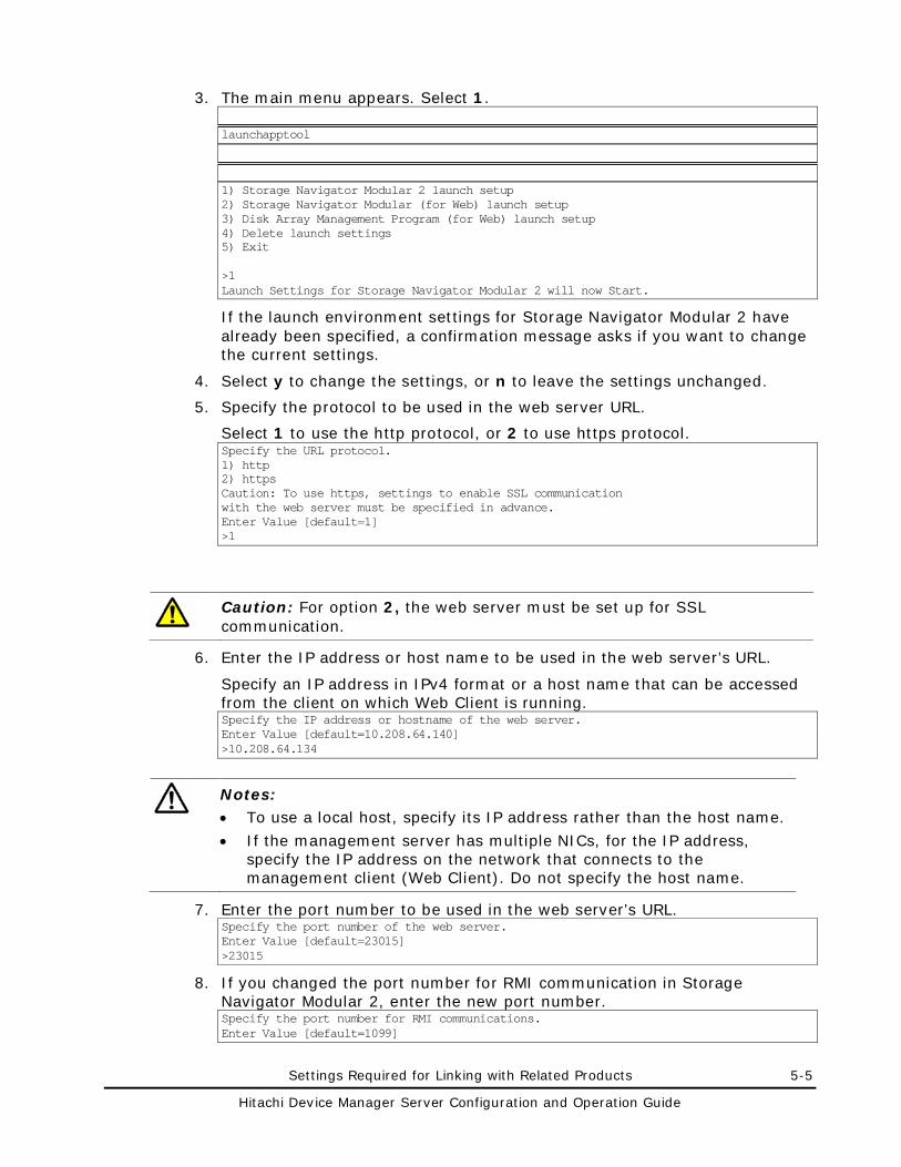
Settings Required for Linking with Related Products 5-5
Hitachi Device Manager Server Configuration and Operation Guide
3. The main menu appears. Select 1.
launchapptool
1) Storage Navigator Modular 2 launch setup 2) Storage Navigator Modular (for Web) launch setup 3) Disk Array Management Program (for Web) launch setup 4) Delete launch settings 5) Exit >1 Launch Settings for Storage Navigator Modular 2 will now Start.
If the launch environment settings for Storage Navigator Modular 2 have already been specified, a confirmation message asks if you want to change the current settings.
4. Select y to change the settings, or n to leave the settings unchanged.
5. Specify the protocol to be used in the web server URL.
Select 1 to use the http protocol, or 2 to use https protocol. Specify the URL protocol. 1) http 2) https Caution: To use https, settings to enable SSL communication with the web server must be specified in advance. Enter Value [default=1] >1
Caution: For option 2, the web server must be set up for SSL communication.
6. Enter the IP address or host name to be used in the web server’s URL.
Specify an IP address in IPv4 format or a host name that can be accessed from the client on which Web Client is running. Specify the IP address or hostname of the web server. Enter Value [default=10.208.64.140] >10.208.64.134
Notes: • To use a local host, specify its IP address rather than the host name.
• If the management server has multiple NICs, for the IP address, specify the IP address on the network that connects to the management client (Web Client). Do not specify the host name.
7. Enter the port number to be used in the web server’s URL. Specify the port number of the web server. Enter Value [default=23015] >23015
8. If you changed the port number for RMI communication in Storage Navigator Modular 2, enter the new port number. Specify the port number for RMI communications. Enter Value [default=1099]
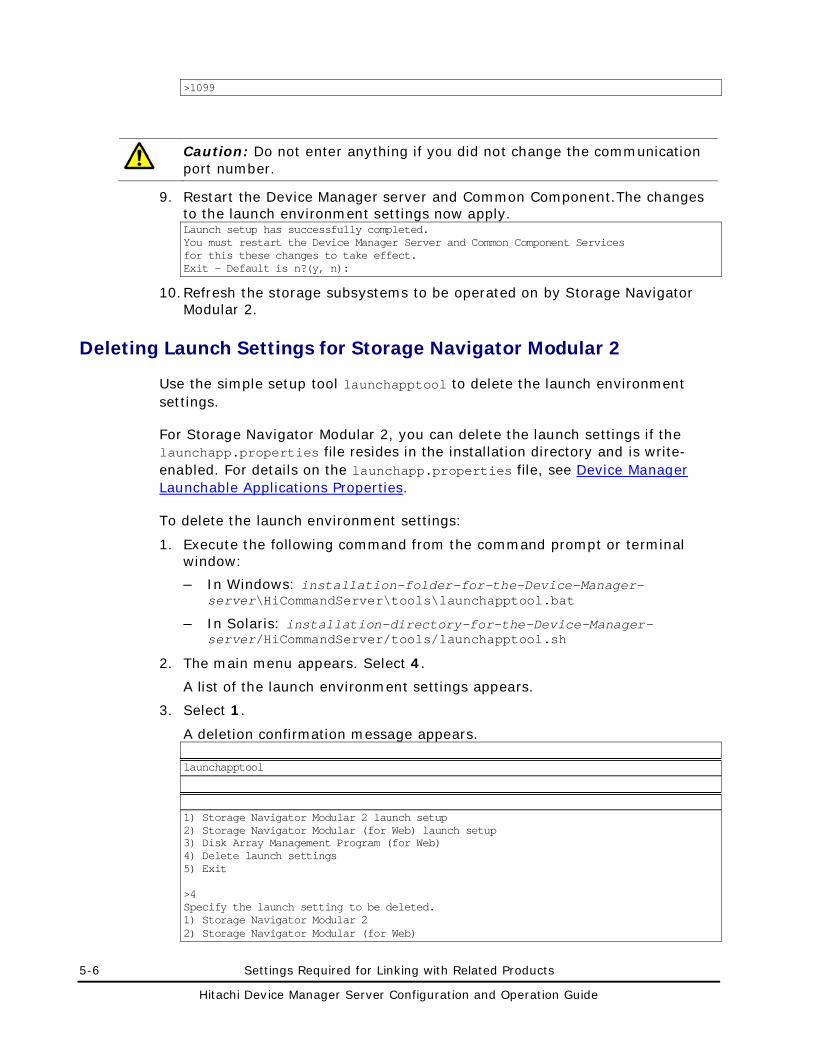
5-6 Settings Required for Linking with Related Products
Hitachi Device Manager Server Configuration and Operation Guide
>1099
Caution: Do not enter anything if you did not change the communication port number.
9. Restart the Device Manager server and Common Component.The changes to the launch environment settings now apply. Launch setup has successfully completed. You must restart the Device Manager Server and Common Component Services for this these changes to take effect. Exit - Default is n?(y, n):
10. Refresh the storage subsystems to be operated on by Storage Navigator Modular 2.
Deleting Launch Settings for Storage Navigator Modular 2
Use the simple setup tool launchapptool to delete the launch environment settings.
For Storage Navigator Modular 2, you can delete the launch settings if the launchapp.properties file resides in the installation directory and is write-enabled. For details on the launchapp.properties file, see Device Manager Launchable Applications Properties.
To delete the launch environment settings:
1. Execute the following command from the command prompt or terminal window:
– In Windows: installation-folder-for-the-Device-Manager-server\HiCommandServer\tools\launchapptool.bat
– In Solaris: installation-directory-for-the-Device-Manager-server/HiCommandServer/tools/launchapptool.sh
2. The main menu appears. Select 4.
A list of the launch environment settings appears.
3. Select 1.
A deletion confirmation message appears.
launchapptool
1) Storage Navigator Modular 2 launch setup 2) Storage Navigator Modular (for Web) launch setup 3) Disk Array Management Program (for Web) 4) Delete launch settings 5) Exit >4 Specify the launch setting to be deleted. 1) Storage Navigator Modular 2 2) Storage Navigator Modular (for Web)
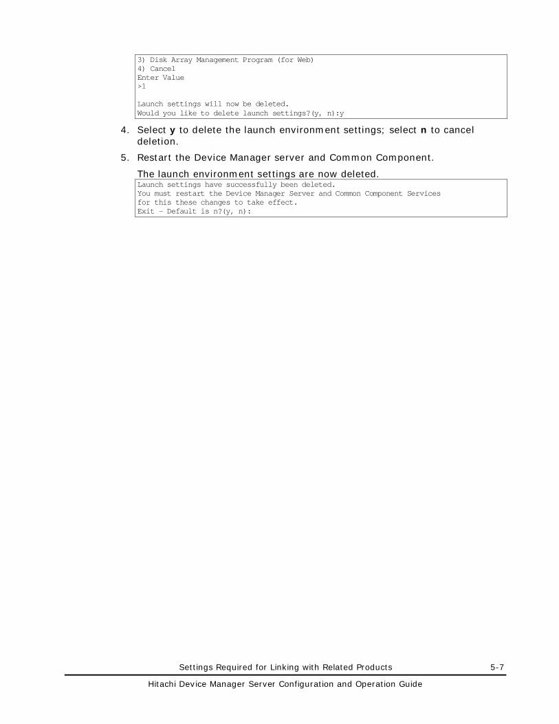
Settings Required for Linking with Related Products 5-7
Hitachi Device Manager Server Configuration and Operation Guide
3) Disk Array Management Program (for Web) 4) Cancel Enter Value >1 Launch settings will now be deleted. Would you like to delete launch settings?(y, n):y
4. Select y to delete the launch environment settings; select n to cancel deletion.
5. Restart the Device Manager server and Common Component.
The launch environment settings are now deleted. Launch settings have successfully been deleted. You must restart the Device Manager Server and Common Component Services for this these changes to take effect. Exit - Default is n?(y, n):
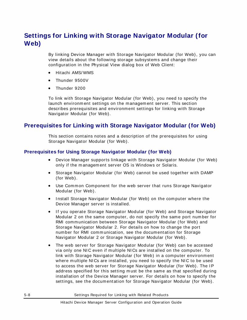
5-8 Settings Required for Linking with Related Products
Hitachi Device Manager Server Configuration and Operation Guide
Settings for Linking with Storage Navigator Modular (for Web)
By linking Device Manager with Storage Navigator Modular (for Web), you can view details about the following storage subsystems and change their configuration in the Physical View dialog box of Web Client:
• Hitachi AMS/WMS
• Thunder 9500V
• Thunder 9200
To link with Storage Navigator Modular (for Web), you need to specify the launch environment settings on the management server. This section describes prerequisites and environment settings for linking with Storage Navigator Modular (for Web).
Prerequisites for Linking with Storage Navigator Modular (for Web)
This section contains notes and a description of the prerequisites for using Storage Navigator Modular (for Web).
Prerequisites for Using Storage Navigator Modular (for Web)
• Device Manager supports linkage with Storage Navigator Modular (for Web) only if the management server OS is Windows or Solaris.
• Storage Navigator Modular (for Web) cannot be used together with DAMP (for Web).
• Use Common Component for the web server that runs Storage Navigator Modular (for Web).
• Install Storage Navigator Modular (for Web) on the computer where the Device Manager server is installed.
• If you operate Storage Navigator Modular (for Web) and Storage Navigator Modular 2 on the same computer, do not specify the same port number for RMI communication between Storage Navigator Modular (for Web) and Storage Navigator Modular 2. For details on how to change the port number for RMI communication, see the documentation for Storage Navigator Modular 2 or Storage Navigator Modular (for Web).
• The web server for Storage Navigator Modular (for Web) can be accessed via only one NIC even if multiple NICs are installed on the computer. To link with Storage Navigator Modular (for Web) in a computer environment where multiple NICs are installed, you need to specify the NIC to be used to access the web server for Storage Navigator Modular (for Web). The IP address specified for this setting must be the same as that specified during installation of the Device Manager server. For details on how to specify the settings, see the documentation for Storage Navigator Modular (for Web).
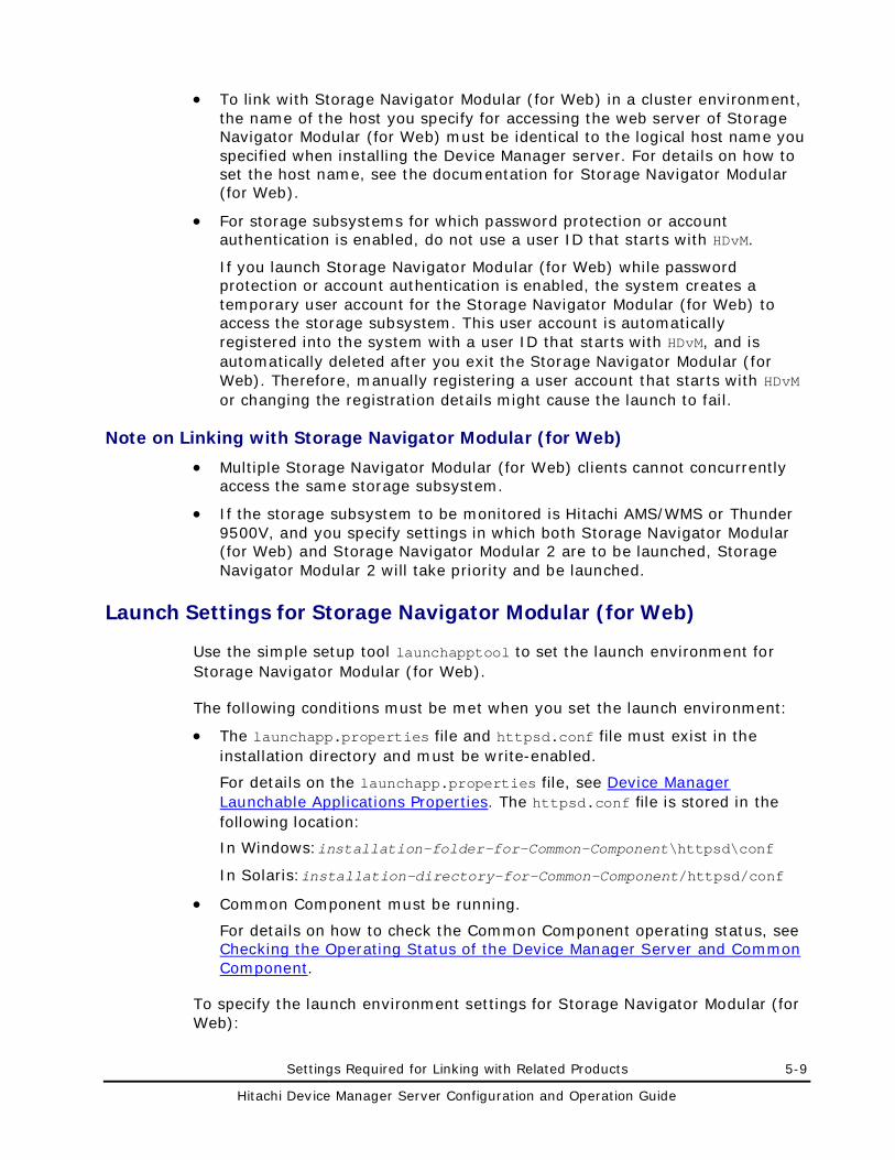
Settings Required for Linking with Related Products 5-9
Hitachi Device Manager Server Configuration and Operation Guide
• To link with Storage Navigator Modular (for Web) in a cluster environment, the name of the host you specify for accessing the web server of Storage Navigator Modular (for Web) must be identical to the logical host name you specified when installing the Device Manager server. For details on how to set the host name, see the documentation for Storage Navigator Modular (for Web).
• For storage subsystems for which password protection or account authentication is enabled, do not use a user ID that starts with HDvM.
If you launch Storage Navigator Modular (for Web) while password protection or account authentication is enabled, the system creates a temporary user account for the Storage Navigator Modular (for Web) to access the storage subsystem. This user account is automatically registered into the system with a user ID that starts with HDvM, and is automatically deleted after you exit the Storage Navigator Modular (for Web). Therefore, manually registering a user account that starts with HDvM or changing the registration details might cause the launch to fail.
Note on Linking with Storage Navigator Modular (for Web)
• Multiple Storage Navigator Modular (for Web) clients cannot concurrently access the same storage subsystem.
• If the storage subsystem to be monitored is Hitachi AMS/WMS or Thunder 9500V, and you specify settings in which both Storage Navigator Modular (for Web) and Storage Navigator Modular 2 are to be launched, Storage Navigator Modular 2 will take priority and be launched.
Launch Settings for Storage Navigator Modular (for Web)
Use the simple setup tool launchapptool to set the launch environment for Storage Navigator Modular (for Web).
The following conditions must be met when you set the launch environment:
• The launchapp.properties file and httpsd.conf file must exist in the installation directory and must be write-enabled.
For details on the launchapp.properties file, see Device Manager Launchable Applications Properties. The httpsd.conf file is stored in the following location:
In Windows:installation-folder-for-Common-Component\httpsd\conf
In Solaris:installation-directory-for-Common-Component/httpsd/conf
• Common Component must be running.
For details on how to check the Common Component operating status, see Checking the Operating Status of the Device Manager Server and Common Component.
To specify the launch environment settings for Storage Navigator Modular (for Web):
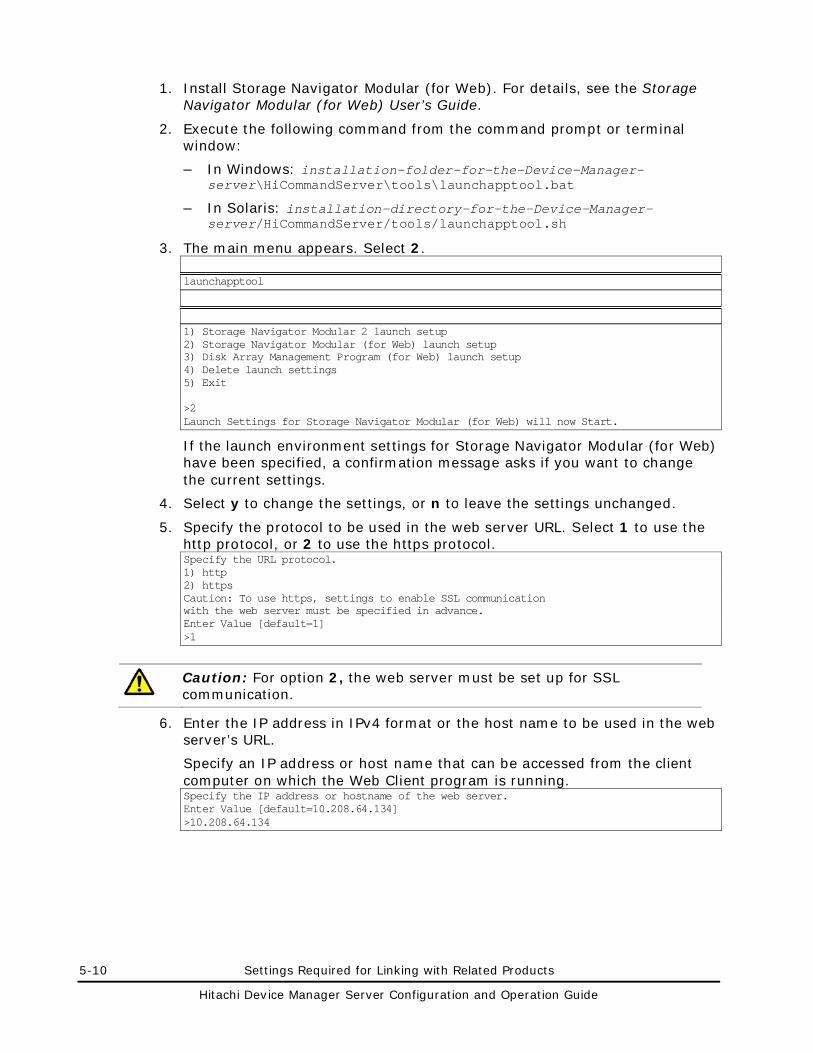
5-10 Settings Required for Linking with Related Products
Hitachi Device Manager Server Configuration and Operation Guide
1. Install Storage Navigator Modular (for Web). For details, see the Storage Navigator Modular (for Web) User’s Guide.
2. Execute the following command from the command prompt or terminal window:
– In Windows: installation-folder-for-the-Device-Manager-server\HiCommandServer\tools\launchapptool.bat
– In Solaris: installation-directory-for-the-Device-Manager-server/HiCommandServer/tools/launchapptool.sh
3. The main menu appears. Select 2.
launchapptool
1) Storage Navigator Modular 2 launch setup 2) Storage Navigator Modular (for Web) launch setup 3) Disk Array Management Program (for Web) launch setup 4) Delete launch settings 5) Exit >2 Launch Settings for Storage Navigator Modular (for Web) will now Start.
If the launch environment settings for Storage Navigator Modular (for Web) have been specified, a confirmation message asks if you want to change the current settings.
4. Select y to change the settings, or n to leave the settings unchanged.
5. Specify the protocol to be used in the web server URL. Select 1 to use the http protocol, or 2 to use the https protocol. Specify the URL protocol. 1) http 2) https Caution: To use https, settings to enable SSL communication with the web server must be specified in advance. Enter Value [default=1] >1
Caution: For option 2, the web server must be set up for SSL communication.
6. Enter the IP address in IPv4 format or the host name to be used in the web server’s URL.
Specify an IP address or host name that can be accessed from the client computer on which the Web Client program is running. Specify the IP address or hostname of the web server. Enter Value [default=10.208.64.134] >10.208.64.134
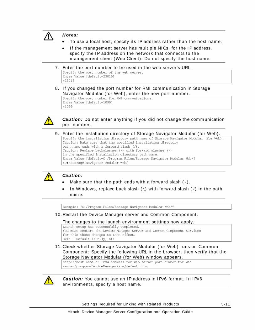
Settings Required for Linking with Related Products 5-11
Hitachi Device Manager Server Configuration and Operation Guide
Notes: • To use a local host, specify its IP address rather than the host name.
• If the management server has multiple NICs, for the IP address, specify the IP address on the network that connects to the management client (Web Client). Do not specify the host name.
7. Enter the port number to be used in the web server’s URL. Specify the port number of the web server. Enter Value [default=23015] >23015
8. If you changed the port number for RMI communication in Storage Navigator Modular (for Web), enter the new port number. Specify the port number for RMI communications. Enter Value [default=1099] >1099
Caution: Do not enter anything if you did not change the communication port number.
9. Enter the installation directory of Storage Navigator Modular (for Web). Specify the installation directory path name of Storage Navigator Modular (for Web). Caution: Make sure that the specified installation directory path name ends with a forward slash (/). Caution: Replace backslashes (\) with forward slashes (/) in the specified installation directory path name. Enter Value [default=C:/Program Files/Storage Navigator Modular Web/] >D:/Storage Navigator Modular Web/
Caution: • Make sure that the path ends with a forward slash (/).
• In Windows, replace back slash (\) with forward slash (/) in the path name.
Example: “C:/Program Files/Storage Navigator Modular Web/”
10. Restart the Device Manager server and Common Component.
The changes to the launch environment settings now apply. Launch setup has successfully completed. You must restart the Device Manager Server and Common Component Services for this these changes to take effect. Exit - Default is n?(y, n):
11. Check whether Storage Navigator Modular (for Web) runs on Common Component: Specify the following URL in the browser, then verify that the Storage Navigator Modular (for Web) window appears. http://host-name-or-IPv4-address-for-web-server:port-number-for-web-server/program/DeviceManager/snm/default.htm
Caution: You cannot use an IP address in IPv6 format. In IPv6 environments, specify a host name.
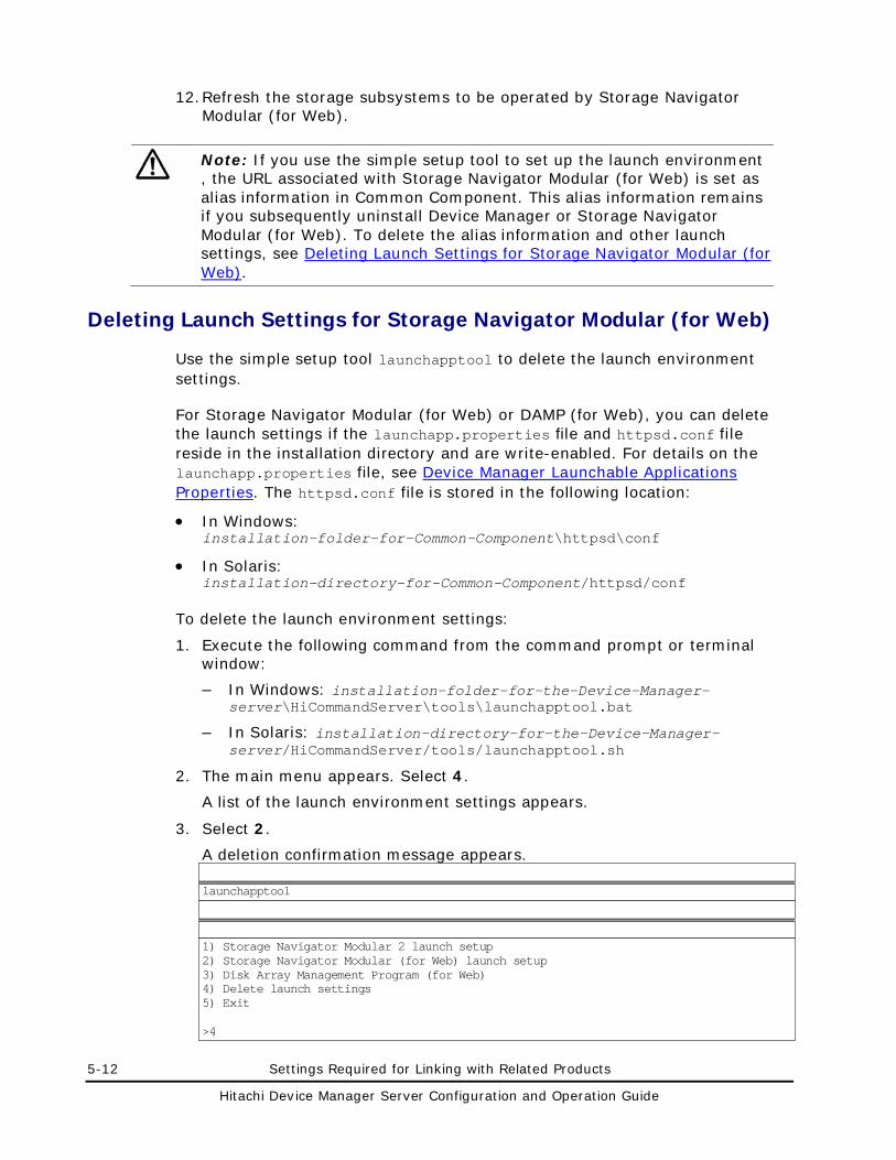
5-12 Settings Required for Linking with Related Products
Hitachi Device Manager Server Configuration and Operation Guide
12. Refresh the storage subsystems to be operated by Storage Navigator Modular (for Web).
Note: If you use the simple setup tool to set up the launch environment , the URL associated with Storage Navigator Modular (for Web) is set as alias information in Common Component. This alias information remains if you subsequently uninstall Device Manager or Storage Navigator Modular (for Web). To delete the alias information and other launch settings, see Deleting Launch Settings for Storage Navigator Modular (for Web).
Deleting Launch Settings for Storage Navigator Modular (for Web)
Use the simple setup tool launchapptool to delete the launch environment settings.
For Storage Navigator Modular (for Web) or DAMP (for Web), you can delete the launch settings if the launchapp.properties file and httpsd.conf file reside in the installation directory and are write-enabled. For details on the launchapp.properties file, see Device Manager Launchable Applications Properties. The httpsd.conf file is stored in the following location:
• In Windows: installation-folder-for-Common-Component\httpsd\conf
• In Solaris: installation-directory-for-Common-Component/httpsd/conf
To delete the launch environment settings:
1. Execute the following command from the command prompt or terminal window:
– In Windows: installation-folder-for-the-Device-Manager-server\HiCommandServer\tools\launchapptool.bat
– In Solaris: installation-directory-for-the-Device-Manager-server/HiCommandServer/tools/launchapptool.sh
2. The main menu appears. Select 4.
A list of the launch environment settings appears.
3. Select 2.
A deletion confirmation message appears.
launchapptool
1) Storage Navigator Modular 2 launch setup 2) Storage Navigator Modular (for Web) launch setup 3) Disk Array Management Program (for Web) 4) Delete launch settings 5) Exit >4
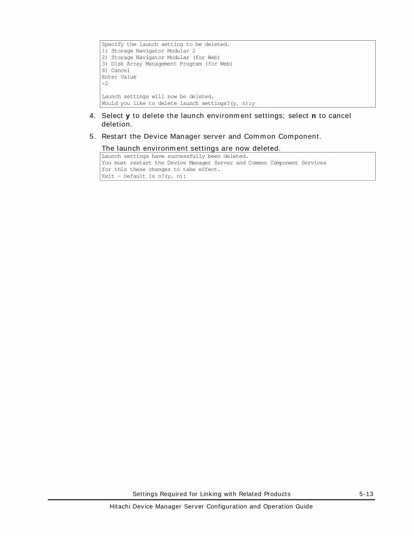
Settings Required for Linking with Related Products 5-13
Hitachi Device Manager Server Configuration and Operation Guide
Specify the launch setting to be deleted. 1) Storage Navigator Modular 2 2) Storage Navigator Modular (for Web) 3) Disk Array Management Program (for Web) 4) Cancel Enter Value >2 Launch settings will now be deleted. Would you like to delete launch settings?(y, n):y
4. Select y to delete the launch environment settings; select n to cancel deletion.
5. Restart the Device Manager server and Common Component.
The launch environment settings are now deleted. Launch settings have successfully been deleted. You must restart the Device Manager Server and Common Component Services for this these changes to take effect. Exit - Default is n?(y, n):
5-14 Settings Required for Linking with Related Products
Hitachi Device Manager Server Configuration and Operation Guide
Settings for Linking with DAMP (for Web)
By linking Device Manager with DAMP (for Web), you can view details about the following storage subsystems and change their configuration in the Physical View dialog box of Web Client:
• Thunder 9500V
• Thunder 9200
To link with DAMP (for Web), you need to specify the launch environment settings on the management server. This section describes prerequisites and environment settings for linking with DAMP (for Web). This section also describes storage subsystem information to be registered into DAMP (for Web).
Prerequisites for Linking with DAMP (for Web)
This section contains notes and a description of the prerequisites for using DAMP (for Web).
Prerequisites for Using DAMP (for Web)
• Device Manager supports linkage with DAMP (for Web) only if the management server OS is Windows or Solaris.
• To perform DAMP launching, the DAMP (for Web) version must be 10.00 or later.
• DAMP (for Web) cannot be used together with Storage Navigator Modular (for Web) or Storage Navigator Modular 2, and cannot be used while Hitachi AMS 2000, Hitachi SMS or Hitachi AMS/WMS is in use.
• Use Common Component for the web server that runs DAMP (for Web).
• Install DAMP (for Web) on the computer where the Device Manager server is installed.
• The web server for DAMP (for Web) can be accessed via only one NIC even if multiple NICs are installed on the computer. To link with DAMP (for Web) in a computer environment where multiple NICs are installed, you need to specify the NIC to be used to access the web server for DAMP (for Web). The IP address specified for this setting must be the same as that specified during installation of the Device Manager server. For details on how to specify the settings, see the document for DAMP (for Web) or Disk Array Management Program 3 (for Web).
• To link with DAMP (for Web) in a cluster environment, the name of the host you specify for accessing DAMP’s web server must be identical to the logical host name you specified when installing the Device Manager server. For details on setting the host name, see the document for DAMP (for Web) or Disk Array Management Program 3 (for Web).
Settings Required for Linking with Related Products 5-15
Hitachi Device Manager Server Configuration and Operation Guide
Note on Linking with DAMP (for Web)
If the storage subsystem to be monitored is the Thunder 9500V, and you specify settings in which both DAMP (for Web) and Storage Navigator Modular 2 are to be launched, Storage Navigator Modular 2 will take priority and be launched.
In addition, If password protection is enabled on Thunder 9200 or Thunder 9500V, DAMP (for Web) operations launched from Physical View might fail, or Web Client operations# or CLI operations# might fail. The following are ways to avoid this problem:
• Change the application you use from DAMP (for Web) to Storage Navigator Modular (for Web).
• Use DAMP (for Web) by directly connecting to it from the browser.
When you connect to DAMP (for Web), you must use a user ID different from the one you used when you registered Thunder 9200 or Thunder 9500V in Device Manager.
In this case, you cannot perform DAMP (for Web) operations and operations for Web Client or CLI# at the same time for the same storage subsystem (Thunder 9200 or Thunder 9500V). This however is the normal situation when password protection is enabled.
• Stop the polling of the Device Manager server, and try not to perform DAMP (for Web) operations and operations for Web Client or CLI# at the same time for the same storage subsystem (Thunder 9200 or Thunder 9500V).
To stop the polling of the Device Manager server:
1. Specify 0 for the server.dispatcher.daemon.pollingPeriod property in the dispatcher.properties file.
For details about this property, see server.dispatcher.daemon.pollingPeriod.
2. To enable the property settings, restart the Device Manager server. This operation disables the alert detection performed by polling. However, for the following storage subsystems, you can detect alerts by using SNMP traps:
– Universal Storage Platform V/VM
– Hitachi USP
– Lightning 9900V
– Lightning 9900
#:
Includes such operations as changing the configuration of, or refreshing the storage subsystem, by using Web Client or CLI
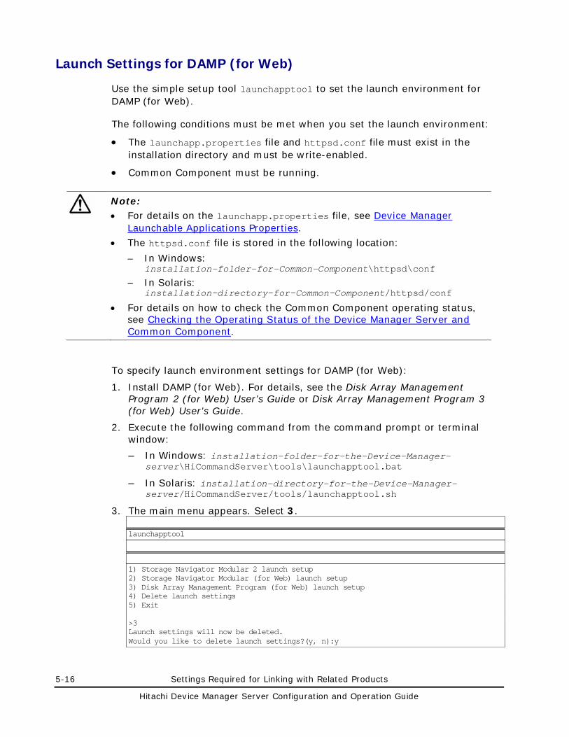
5-16 Settings Required for Linking with Related Products
Hitachi Device Manager Server Configuration and Operation Guide
Launch Settings for DAMP (for Web)
Use the simple setup tool launchapptool to set the launch environment for DAMP (for Web).
The following conditions must be met when you set the launch environment:
• The launchapp.properties file and httpsd.conf file must exist in the installation directory and must be write-enabled.
• Common Component must be running.
Note: • For details on the launchapp.properties file, see Device Manager
Launchable Applications Properties.
• The httpsd.conf file is stored in the following location:
– In Windows: installation-folder-for-Common-Component\httpsd\conf
– In Solaris: installation-directory-for-Common-Component/httpsd/conf
• For details on how to check the Common Component operating status, see Checking the Operating Status of the Device Manager Server and Common Component.
To specify launch environment settings for DAMP (for Web):
1. Install DAMP (for Web). For details, see the Disk Array Management Program 2 (for Web) User’s Guide or Disk Array Management Program 3 (for Web) User’s Guide.
2. Execute the following command from the command prompt or terminal window:
– In Windows: installation-folder-for-the-Device-Manager-server\HiCommandServer\tools\launchapptool.bat
– In Solaris: installation-directory-for-the-Device-Manager-server/HiCommandServer/tools/launchapptool.sh
3. The main menu appears. Select 3.
launchapptool
1) Storage Navigator Modular 2 launch setup 2) Storage Navigator Modular (for Web) launch setup 3) Disk Array Management Program (for Web) launch setup 4) Delete launch settings 5) Exit >3 Launch settings will now be deleted. Would you like to delete launch settings?(y, n):y
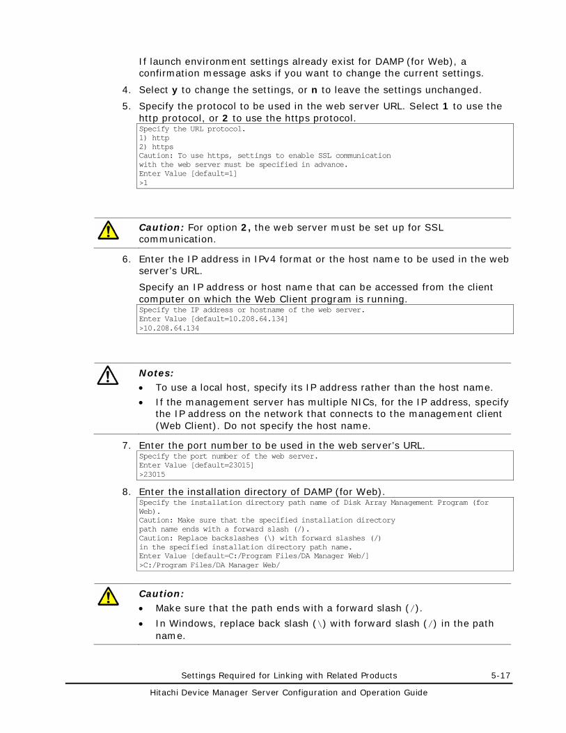
Settings Required for Linking with Related Products 5-17
Hitachi Device Manager Server Configuration and Operation Guide
If launch environment settings already exist for DAMP (for Web), a confirmation message asks if you want to change the current settings.
4. Select y to change the settings, or n to leave the settings unchanged.
5. Specify the protocol to be used in the web server URL. Select 1 to use the http protocol, or 2 to use the https protocol. Specify the URL protocol. 1) http 2) https Caution: To use https, settings to enable SSL communication with the web server must be specified in advance. Enter Value [default=1] >1
Caution: For option 2, the web server must be set up for SSL communication.
6. Enter the IP address in IPv4 format or the host name to be used in the web server’s URL.
Specify an IP address or host name that can be accessed from the client computer on which the Web Client program is running. Specify the IP address or hostname of the web server. Enter Value [default=10.208.64.134] >10.208.64.134
Notes: • To use a local host, specify its IP address rather than the host name.
• If the management server has multiple NICs, for the IP address, specify the IP address on the network that connects to the management client (Web Client). Do not specify the host name.
7. Enter the port number to be used in the web server’s URL. Specify the port number of the web server. Enter Value [default=23015] >23015
8. Enter the installation directory of DAMP (for Web). Specify the installation directory path name of Disk Array Management Program (for Web). Caution: Make sure that the specified installation directory path name ends with a forward slash (/). Caution: Replace backslashes (\) with forward slashes (/) in the specified installation directory path name. Enter Value [default=C:/Program Files/DA Manager Web/] >C:/Program Files/DA Manager Web/
Caution: • Make sure that the path ends with a forward slash (/).
• In Windows, replace back slash (\) with forward slash (/) in the path name.
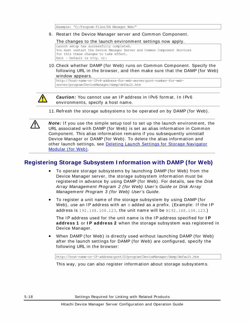
5-18 Settings Required for Linking with Related Products
Hitachi Device Manager Server Configuration and Operation Guide
Example: “C:/Program Files/DA Manager Web/”
9. Restart the Device Manager server and Common Component.
The changes to the launch environment settings now apply. Launch setup has successfully completed. You must restart the Device Manager Server and Common Component Services for this these changes to take effect. Exit - Default is n?(y, n):
10. Check whether DAMP (for Web) runs on Common Component. Specify the following URL in the browser, and then make sure that the DAMP (for Web) window appears. http://host-name-or-IPv4-address-for-web-server:port-number-for-web-server/program/DeviceManager/damp/default.htm
Caution: You cannot use an IP address in IPv6 format. In IPv6 environments, specify a host name.
11. Refresh the storage subsystems to be operated on by DAMP (for Web).
Note: If you use the simple setup tool to set up the launch environment, the URL associated with DAMP (for Web) is set as alias information in Common Component. This alias information remains if you subsequently uninstall Device Manager or DAMP (for Web). To delete the alias information and other launch settings, see Deleting Launch Settings for Storage Navigator Modular (for Web).
Registering Storage Subsystem Information with DAMP (for Web) • To operate storage subsystems by launching DAMP (for Web) from the
Device Manager server, the storage subsystem information must be registered in advance by using DAMP (for Web). For details, see the Disk Array Management Program 2 (for Web) User’s Guide or Disk Array Management Program 3 (for Web) User’s Guide.
• To register a unit name of the storage subsystem by using DAMP (for Web), use an IP address with an H added as a prefix. (Example: If the IP address is 192.168.108.123, the unit name will be H192.168.108.123.)
The IP address used for the unit name is the IP address specified for IP address 1 or IP address 2 when the storage subsystem was registered in Device Manager.
• When DAMP (for Web) is directly used without launching DAMP (for Web) after the launch settings for DAMP (for Web) are configured, specify the following URL in the browser: http://host-name-or-IP-address:portID/program/DeviceManager/damp/default.htm
This way, you can also register information about storage subsystems.
Settings Required for Linking with Related Products 5-19
Hitachi Device Manager Server Configuration and Operation Guide
Settings for Linking with Tuning Manager
This section describes the settings required for linking with Tuning Manager whose version is 6.0 or later. If you want to link Device Manager with an instance of Tuning Manager installed on a different computer from the computer on which Device Manager is installed, you must specify the following settings in Device Manager. Specifying these settings is not required when Device Manager and Tuning Manager are installed on the same computer.
• Enabling remote connection with Tuning Manager
• Specifying the remote connection port
• Changing the OS firewall settings
Note: • When Tuning Manager and Device Manager are installed on different
computers, the following restrictions apply to communication with Tuning Manager:
– Communication using IPv6 is not supported. – Communication encrypted by SSL or TLS is not supported.
• Some database operation commands might initialize the settings for remote connection with Tuning Manager. If you execute either of the following commands, re-specify the settings:
– hcmdsdbclustersetup (cluster setup) – hcmdsdbremake (database re-creation)
• If you execute any of the following commands or the following combination of commands to perform database migration, you must re-specify the settings for remote connection with Tuning Manager on the destination computer: – hcmdsdbtrans – hcmdsdbmove
– hcmdsbackups and hcmdsdb -restore
Settings in a Non-cluster Environment
In a non-cluster environment, to enable or disable remote connection with Tuning Manager, or to change the connection port that will be used:
1. Make sure that the host name and IP address of the local computer are registered in the host settings file.
The host settings file is typically stored in the following location:
– In Windows: Windows-system-folder\system32\drivers\etc\hosts
– In Solaris or Linux: /etc/hosts
2. If Common Component is running, stop it.
5-20 Settings Required for Linking with Related Products
Hitachi Device Manager Server Configuration and Operation Guide
For details on how to check the Common Component operating status, see Checking the Operating Status of the Device Manager Server and Common Component.
3. In Linux, if the firewall function is enabled, make sure that the remote connection port is set correctly.
If Windows Firewall is used, this step is unnecessary.
For details on the port numbers that must be registered as firewall exceptions, see Settings Required for Operation in a Firewall Environment.
4. Execute the htmsetup command.
For details on how to use the htmsetup command, see htmsetup Command.
5. When an interactive menu appears, use it to specify settings.
When you complete specifying the settings, HiRDB starts.
Settings in a Cluster Environment
In a cluster environment, to enable or disable a remote connection with Tuning Manager or to change the connection port that will be used, follow the procedure shown below:
For Microsoft Cluster Service
To specify settings when using Microsoft Cluster Service as the cluster software:
1. On the executing and standby nodes, if the physical host name and IP address of the local computer are not registered in the host settings file, register them.
The host settings file is typically stored in the following location: Windows-system-folder\system32\drivers\etc\hosts
2. Remove the services and cluster groups of Hitachi Storage Command Suite products from cluster management.
Steps 3 to 6 describe how to do this.
Note: For details about the services and resource groups that need to be removed from cluster management, see the documentation for the corresponding Hitachi Storage Command Suite product.
3. In the cluster application, take the following services offline:
– HiCommandServer
– HBase Storage Mgmt Web Service
– Hbase Storage Mgmt Common Service
– Hitachi Storage Command Suite product resources other than the above
Each resource name is the name you registered.
Settings Required for Linking with Related Products 5-21
Hitachi Device Manager Server Configuration and Operation Guide
4. Execute the following command to stop the Common Component and Hitachi Storage Command Suite product services:
installation-folder-for-Common-Component\bin\hcmdssrv /stop
5. In the cluster application, take the following service offline:
HiRDB/ClusterService _HD0
6. In the cluster application, disable the failover of resource groups.
Right-click the following services, select Properties, the Advanced tab, Do not restart, and then click OK:
– Hbase Storage Mgmt Common Service
– HBase Storage Mgmt Web Service
– HiCommandServer
– HiRDB/ClusterService _HD0
– Services that were taken offline in step 3
Each resource name is the name you registered.
7. Execute the htmsetup command.
For details on how to use the htmsetup command, see htmsetup Command.
8. Execute the following command to stop the Common Component and Hitachi Storage Command Suite product services:
installation-folder-for-Common-Component\bin\hcmdssrv /stop
9. Move the group in which the Hitachi Storage Command Suite product services have been registered to the standby node.
10. On the standby node, execute the htmsetup command. Specify the same settings as those on the executing node.
11. Execute the following command to stop the Common Component and Hitachi Storage Command Suite product services:
installation-folder-for-Common-Component\bin\hcmdssrv /stop
12. Place the services and cluster groups of Hitachi Storage Command Suite products under cluster management.
Steps 13 to 14 describe how to do this.
13. In the Services window, open the properties for the following services, and then change Startup Type from Automatic to Manual:
– HBase Storage Mgmt Common Service
– HBase Storage Mgmt Web Service
– HiCommandServer
14. In the cluster application, enable the failover of resource groups.
Right-click the following services, select Properties, the Advanced tab, Restart, and then click OK:
– Hbase Storage Mgmt Common Service
– HBase Storage Mgmt Web Service
5-22 Settings Required for Linking with Related Products
Hitachi Device Manager Server Configuration and Operation Guide
– HiCommandServer
– HiRDB/ClusterService _HD0
– Hitachi Storage Command Suite product resources other than the above
Each resource name is the name you registered.
15. In the cluster application, bring online the group in which the Hitachi Storage Command Suite product services have been registered.
For Microsoft Failover Cluster
To specify settings when using Microsoft Failover Cluster as the cluster software:
1. On the executing and standby nodes, if the physical host name and IP address of the local computer are not registered in the host settings file, register them.
The host settings file is typically stored in the following location: Windows-system-folder\system32\drivers\etc\hosts
2. Remove the services and resource groups of Hitachi Storage Command Suite products from cluster management.
Steps 3 to 6 describe how to do this.
Note: For details about the services and resource groups that need to be removed from cluster management, see the documentation for the corresponding Hitachi Storage Command Suite product.
3. In the cluster application, take the following services offline:HiCommandServer
– HBase Storage Mgmt Web Service
– Hbase Storage Mgmt Common Service
Each resource name is the name you registered.
4. Execute the following command to stop the Common Component and Hitachi Storage Command Suite product services:
installation-folder-for-Common-Component\bin\hcmdssrv /stop
5. In the cluster application, take the following service offline:
HiRDB/ClusterService _HD0
6. In the cluster application, disable the failover of resource groups.
Right-click the following services, select Properties, the Policies tab, If resource fails, do not restart, and then click OK:
– Hbase Storage Mgmt Common Service
– HBase Storage Mgmt Web Service
– HiCommandServer
– HiRDB/ClusterService _HD0
Each resource name is the name you registered.
Settings Required for Linking with Related Products 5-23
Hitachi Device Manager Server Configuration and Operation Guide
7. Execute the htmsetup command.
For details on how to use the htmsetup command, see htmsetup Command.
8. Execute the following command to stop the Common Component and Hitachi Storage Command Suite product services:
installation-folder-for-Common-Component\bin\hcmdssrv /stop
9. Move the group in which the Hitachi Storage Command Suite product services have been registered to the standby node.
10. On the standby node, execute the htmsetup command. Specify the same settings as those on the executing node.
11. Execute the following command to stop the Common Component and Hitachi Storage Command Suite product services:
installation-folder-for-Common-Component\bin\hcmdssrv /stop
12. Place the services and resource groups of Hitachi Storage Command Suite products under cluster management.
Steps 13 to 14 describe how to do this.
13. In the Services window, open the properties for the following services, and then change Startup Type from Automatic to Manual:
– HBase Storage Mgmt Common Service
– HBase Storage Mgmt Web Service
– HiCommandServer
14. In the cluster application, enable the failover of resource groups.
Right-click the following services, from the Policies tab under Properties, select If resource fails. Attempt restart on current node and If restart is unsuccessful, fail over all resources in this service or application, and then click OK:
– Hbase Storage Mgmt Common Service
– HBase Storage Mgmt Web Service
– HiCommandServer
– HiRDB/ClusterService _HD0
– Hitachi Storage Command Suite product resources other than the above
Each resource name is the name you registered.
15. In the cluster application, bring online the group in which the Hitachi Storage Command Suite product services have been registered.
For Veritas Cluster Server
To specify settings when using Veritas Cluster Service as the cluster software:
1. On the executing and standby nodes, if the physical host name and IP address of the local computer are not registered in the host settings file, register them.
The host settings file is typically stored in the following location:
5-24 Settings Required for Linking with Related Products
Hitachi Device Manager Server Configuration and Operation Guide
/etc/hosts
2. Remove the services and resource groups of Hitachi Storage Command Suite products from cluster management.
Steps 3 to 10 describe how to do this.
Note: For details about the services and resource groups that need to be removed from cluster management, see the documentation for the corresponding Hitachi Storage Command Suite product.
3. On the executing node, start Cluster Manager in Java Console.
4. Take the following services offline:
– HiCommandServer
– HBase Storage Mgmt Web Service
– Hbase Storage Mgmt Common Service
– Hitachi Storage Command Suite product resources other than the above
Each resource name is the name you registered.
5. Select and right-click each service described in step 4, and then clear Enabled.
6. Execute the following command to stop the Common Component and Hitachi Storage Command Suite product services:
installation-directory-for-Common-Component/bin/hcmdssrv -stop
7. Take the HiRDB service offline:
8. Select and right-click the HiRDB service, and then clear Enabled from the displayed context menu.
9. In the Cluster Explorer window, select the Service Groups tab.
10. Select and right-click the group in which the Hitachi Storage Command Suite product services have been registered, and then select Freeze and then Temporary from the displayed context menu.
11. Execute the htmsetup command.
For details on how to use the htmsetup command, see htmsetup Command.
12. Execute the following command to stop the Common Component and Hitachi Storage Command Suite product services:
installation-directory-for-Common-Component/bin/hcmdssrv -stop
13. Move the group in which the Hitachi Storage Command Suite product services have been registered to the standby node.
Steps 14 to 15 describe how to do this.
14. In the Cluster Explorer window, select the Service Groups tab.
15. Select and right-click the group in which the Hitachi Storage Command Suite product services have been registered, and then, from the displayed context menu, execute the following three operations in order:
– Select Unfreeze.
Settings Required for Linking with Related Products 5-25
Hitachi Device Manager Server Configuration and Operation Guide
– Select Switch To and then the host name of the standby node.
– Select Freeze and then Temporary.
16. On the standby node, execute the htmsetup command.
Specify the same settings as those on the executing node.
17. Execute the following command to stop the Common Component and Hitachi Storage Command Suite product services:
installation-directory-for-Common-Component/bin/hcmdssrv -stop
18. Place the services and resource groups of Hitachi Storage Command Suite products under cluster management.
Steps 19 to 24 describe how to do this.
19. Start Cluster Manager in Java Console.
20. In the Cluster Explorer window, select the Service Groups tab. Select and right-click the group in which the Hitachi Storage Command Suite product services have been registered, and then select Unfreeze from the displayed context menu.
21. Select and right-click the group in which the Hitachi Storage Command Suite product services have been registered, and then select Enable Resources from the displayed context menu.
22. Save the changes in the Veritas Cluster Server configuration file.
From the File menu, select Save Configuration.
23. Close the Veritas Cluster Server configuration file.
From the File menu, select Close Configuration.
24. On the executing node, bring online the group in which the Hitachi Storage Command Suite product services have been registered.
For Sun Cluster
To specify settings when using Sun Cluster as the cluster software:
1. On the executing and standby nodes, if the physical host name and IP address of the local computer are not registered in the host settings file, register them.
The host settings file is typically stored in the following location: /etc/hosts
2. Remove the services and resource groups of Hitachi Storage Command Suite products from cluster management.
Steps 3 to 7 describe how to do this.
5-26 Settings Required for Linking with Related Products
Hitachi Device Manager Server Configuration and Operation Guide
Note: For details about the services and resource groups that need to be removed from cluster management, see the documentation for the corresponding Hitachi Storage Command Suite product.
3. On the executing node, execute the following commands to disable monitoring of the resources of Common Component (except HiRDB) and Device Manager:
# /usr/cluster/bin/scswitch -n -M -j CommonWebService # /usr/cluster/bin/scswitch -n -M -j HiCommandServer # /usr/cluster/bin/scswitch -n -M -j SingleSignOnService
Each resource name is the name you registered.
You also need to disable monitoring of any other Hitachi Storage Command Suite product resources.
4. Execute the following commands to disable the resources of Common Component (except HiRDB) and Device Manager:
# /usr/cluster/bin/scswitch -n -j CommonWebService # /usr/cluster/bin/scswitch -n -j HiCommandServer # /usr/cluster/bin/scswitch -n -j SingleSignOnService
Each resource name is the name you registered.
You also need to disable any other Hitachi Storage Command Suite product resources.
5. Execute the following command to stop the Common Component and Hitachi Storage Command Suite product services:
installation-directory-for-Common-Component/bin/hcmdssrv -stop
6. Execute the following command to disable monitoring of the HiRDB resource:
# /usr/cluster/bin/scswitch -n -M -j HiRDB
The resource name is the name you registered.
7. Execute the following command to disable the HiRDB resource: # /usr/cluster/bin/scswitch -n -j HiRDB
The resource name is the name you registered.
8. Execute the htmsetup command. For details on how to use the htmsetup command, see htmsetup Command.
9. Execute the following command to stop the Common Component and Hitachi Storage Command Suite product services:
installation-directory-for-Common-Component/bin/hcmdssrv -stop
10. Execute the following command to move the group in which the Hitachi Storage Command Suite product services have been registered to the standby node:
# /usr/cluster/bin/scswitch -z -g group-name -h host-name
11. On the standby node, execute the htmsetup command. Specify the same settings as those on the executing node.
12. Execute the following command to stop the Common Component and Hitachi Storage Command Suite product services:
Settings Required for Linking with Related Products 5-27
Hitachi Device Manager Server Configuration and Operation Guide
installation-directory-for-Common-Component/bin/hcmdssrv -stop
13. Place the services and resource groups of Hitachi Storage Command Suite products under cluster management.
Steps 14 to 17 describe how to this.
14. Execute the following commands to enable the services of Common Component and Device Manager:
# /usr/cluster/bin/scswitch -e -j HiRDB # /usr/cluster/bin/scswitch -e -j SingleSignOnService # /usr/cluster/bin/scswitch -e -j CommonWebService # /usr/cluster/bin/scswitch -e -j HiCommandServer
Each resource name is the name you registered.
You also need to enable any other Hitachi Storage Command Suite product resources you have disabled.
15. Execute the following commands to enable monitoring of the services of Common Component and Device Manager:
# /usr/cluster/bin/scswitch -e -M -j HiRDB # /usr/cluster/bin/scswitch -e -M -j SingleSignOnService # /usr/cluster/bin/scswitch -e -M -j CommonWebService # /usr/cluster/bin/scswitch -e -M -j HiCommandServer
Each resource name is the name you registered.
You also need to enable monitoring of any other Hitachi Storage Command Suite product resources you have disabled monitoring of.
16. Start Cluster Manager in Java Console.
17. On the executing node, bring online the group in which the Hitachi Storage Command Suite product services have been registered.
htmsetup Command
To change the settings for remote connection with Tuning Manager, use the htmsetup command. To execute the htmsetup command, you must be a member of the Administrators group or a root user. This section describes how to use the htmsetup command.
Conditions for executing the htmsetup command:
– When a remote connection is to be enabled, the host name and IP address of the local computer must be registered in the host settings file.
– Common Component must be stopped.
– Other commands that change the Common Component settings must not be running.
– The htmsetup command must not already be running.
– In a cluster environment, the services and resource groups of Hitachi Storage Command Suite products must not be registered as cluster monitoring targets on both the executing and standby nodes.
Location of the htmsetup command:
5-28 Settings Required for Linking with Related Products
Hitachi Device Manager Server Configuration and Operation Guide
– In Windows:
installation-folder-for-the-Device-Manager-server\HiCommandServer\tools\htmsetup.bat
– In Solaris or Linux:
installation-directory-for-the-Device-Manager-server/HiCommandServer/tools/htmsetup.sh
Description:
The htmsetup command lets you interactively change the settings for remotely connecting HiRDB with Tuning Manager. You can use the htmsetup command for the following operations:
– Enabling or disabling remote connection (default: disabling)
– Specifying the port number used when remote connection is enabled (range of specifiable values: 5001 to 65535, default: 24220)
In an OS in which Windows Firewall has been installed, the command also performs registration in the Windows Firewall exception list when remote connection is enabled, and performs unregistration when remote connection is disabled. When the settings have been completed, HiRDB is activated.
Options:
None
Settings Required for Linking with Related Products 5-29
Hitachi Device Manager Server Configuration and Operation Guide
Settings for Starting HSSM from the Dashboard
To link with HSSM and start HSSM from the Dashboard menu, create the StorageServicesManager.conf file in the following directory if the file has not been created yet. This file is stored in the following location:
In Windows: installation-folder-for-Common-Component\common
In Solaris or Linux: installation-directory-for-Common-Component/common
In the StorageServicesManager.conf file, specify the LaunchURL parameter in the following format:
LaunchURL=HSSM-URL
In HSSM-URL, specify the URL used to start HSSM. For details about this URL, see the HSSM documentation.
For example, if the name of the HSSM management server is computer-name, configure the StorageServicesManager.conf as follows:
For Secure Connections: LaunchURL=https://computer-name
For Nonsecure Connections: LaunchURL=http://computer-name
5-30 Settings Required for Linking with Related Products
Hitachi Device Manager Server Configuration and Operation Guide
Settings for Starting Applications from Web Client
When you select Go and then Links in the global tasks bar area of Web Client, a dialog box is displayed with links for starting applications for which the user is registered. By registering the web applications that you often use or the information that you want to reference (such as a device installation chart) to this window, you can easily call a desired application from Web Client. To register a desired application or cancel the registration, you use the hcmdslink command. This section describes how to use the hcmdslink command.
Format:
In Windows:
installation-folder-for-Common-Component\bin\hcmdslink {/add | /delete } /file user-defined-application-file [/nolog] /user user-identifier /pass password
In Solaris or Linux:
installation-directory-for-Common-Component/bin/hcmdslink {-add | -delete } -file user-defined-application-file [-nolog] -user user-identifier -pass password
Function:
The hcmdslink command registers a Web application to allow you to start the desired application from Web Client, or cancels the registration.
In the user-defined application file, you specify a desired application name, URL, and name to be displayed. Then, use the hcmdslink command to register that information. The link to the registered application will be displayed in the link dialog box that appears when you select Go and then Links in the global tasks bar area of Web Client.
Note: Once you register a link for starting an application, do not delete the user-defined application file used in the hcmdslink command. If you do, you cannot delete the link for the registered application.
Options:
add: Registers an application.
delete: Deletes an application.
file: Specifies the name of the user-defined application file. In Solaris or Linux, do not specify a path that includes a space.
user: Specifies a user ID used to register or delete the user-defined application link. Specify the user ID of a user who has the Admin permission.
Settings Required for Linking with Related Products 5-31
Hitachi Device Manager Server Configuration and Operation Guide
pass: Specifies the password for the user ID used to register or delete the user-defined application link.
nolog: Suppresses outputting messages to the command line. However, even when this option is specified, messages for option errors are displayed.
User-defined application file:
The following shows a coding example in the user-defined application file.
Caution: To code the user-defined application file, use ASCII characters only. Also note that you cannot use the control code other than the CR and LF control code. @TOOL-LINK @NAME SampleApp @URL http://SampleApp/index.html @DISPLAYNAME SampleApplication @DISPLAYORDER 1 @ICONURL http://SampleApp/graphic/icon.gif @TOOL-END
The items to be specified in the user-defined application file are as follows:
@TOOL-LINK: The start key. The information between the start key and the end key is the setting information. This item is required.
@NAME: Information used as the key for registration. Specify a unique name. This item is required. The maximum length of the name is 256 bytes. Use alphanumeric characters only.
@URL: The URL of the target of the link from Web Client. The maximum length of the URL is 256 bytes. You cannot use an IPv6 address. You must use a host name to specify the URL in an IPv6 environment.
@DISPLAYNAME: The name displayed in the link dialog box that appears when you select Go and then Links in the global tasks bar area of Web Client. If no information is specified, the name specified in @NAME is displayed. You can specify a Unicode code point in the range from U+10000 to U+10FFFF. The maximum length of the name is 80 characters.
@DISPLAYORDER: The order of the applications displayed in the link dialog box that appears when you select Go and then Links in the global tasks bar area of Web Client. The applications are displayed in ascending order of this value. You can specify a value in the range from -2147483648 to 2147483647.
@ICONURL: The URL of the icon displayed beside the link. The maximum length of the URL is 256 bytes. You cannot use an IPv6 address. You must use a host name to specify the URL in an IPv6 environment.
@TOOL-END: The end key. This item is required.
Return values:
0: Normal termination
5-32 Settings Required for Linking with Related Products
Hitachi Device Manager Server Configuration and Operation Guide
255: Failure
If you do not specify the nolog option, you can determine whether the command was successful from the output message. If you specify the nolog option, no message is output. Therefore, you need to use the return value of the command to determine whether the command was successful.
For details about errors, see the following log files.
– In Windows:
installation-folder-for-Common-Component\log\hcmdslinkn.log
– In Solaris or Linux:
/var/installation-directory-for-Common-Component/log/hcmdslinkn.log
Command execution examples (in Windows)
The following command adds a link for an application (note that this command is entered on one line): C:\Program Files\HiCommand\Base\bin\hcmdslink /add /file C:\SampleLink.txt /user system /pass manager
The following command deletes a link for an application (note that this command is entered on one line): C:\Program Files\HiCommand\Base\bin\hcmdslink /delete /file C:\SampleLink.txt /user system /pass manager
Command execution examples (in Solaris or Linux)
The following command adds a link for an application (note that this command is entered on one line): # /opt/HiCommand/Base/bin/hcmdslink -add -file /opt/SampleLink.txt -user system -pass manager
The following command deletes a link for an application (note that this command is entered on one line): # /opt/HiCommand/Base/bin/hcmdslink -delete -file /opt/SampleLink.txt -user system -pass manager
Settings for Logs and Alerts 6-1
Hitachi Device Manager Server Configuration and Operation Guide
Settings for Logs and Alerts
This chapter describes the settings required to use Device Manager to monitor the status of the system and monitor for errors.
Settings for Integrated Logs
Settings Required for Generating Audit Logs
Settings Required for Centrally Managing Storage Subsystem Alerts
Settings Required for Email Notification
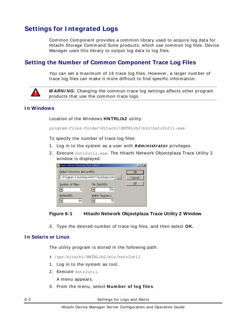
6-2 Settings for Logs and Alerts
Hitachi Device Manager Server Configuration and Operation Guide
Settings for Integrated Logs
Common Component provides a common library used to acquire log data for Hitachi Storage Command Suite products, which use common log files. Device Manager uses this library to output log data to log files.
Setting the Number of Common Component Trace Log Files
You can set a maximum of 16 trace log files. However, a larger number of trace log files can make it more difficult to find specific information.
WARNING: Changing the common trace log settings affects other program products that use the common trace logs.
In Windows
Location of the Windows HNTRLib2 utility:
program-files-folder\Hitachi\HNTRLib2\bin\hntr2util.exe
To specify the number of trace log files:
1. Log in to the system as a user with Administrator privileges.
2. Execute hntr2util.exe. The Hitachi Network Objectplaza Trace Utility 2 window is displayed.
Figure 6-1 Hitachi Network Objectplaza Trace Utility 2 Window
3. Type the desired number of trace log files, and then select OK.
In Solaris or Linux
The utility program is stored in the following path:
# /opt/hitachi/HNTRLib2/bin/hntr2util
1. Log in to the system as root.
2. Execute hntr2util.
A menu appears.
3. From the menu, select Number of log files.
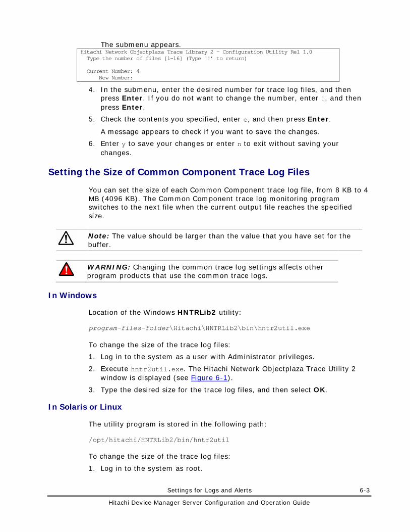
Settings for Logs and Alerts 6-3
Hitachi Device Manager Server Configuration and Operation Guide
The submenu appears. Hitachi Network Objectplaza Trace Library 2 - Configuration Utility Rel 1.0 Type the number of files [1-16] (Type ‘!’ to return) Current Number: 4 New Number:
4. In the submenu, enter the desired number for trace log files, and then press Enter. If you do not want to change the number, enter !, and then press Enter.
5. Check the contents you specified, enter e, and then press Enter.
A message appears to check if you want to save the changes.
6. Enter y to save your changes or enter n to exit without saving your changes.
Setting the Size of Common Component Trace Log Files
You can set the size of each Common Component trace log file, from 8 KB to 4 MB (4096 KB). The Common Component trace log monitoring program switches to the next file when the current output file reaches the specified size.
Note: The value should be larger than the value that you have set for the buffer.
WARNING: Changing the common trace log settings affects other program products that use the common trace logs.
In Windows
Location of the Windows HNTRLib2 utility:
program-files-folder\Hitachi\HNTRLib2\bin\hntr2util.exe
To change the size of the trace log files:
1. Log in to the system as a user with Administrator privileges.
2. Execute hntr2util.exe. The Hitachi Network Objectplaza Trace Utility 2 window is displayed (see Figure 6-1).
3. Type the desired size for the trace log files, and then select OK.
In Solaris or Linux
The utility program is stored in the following path:
/opt/hitachi/HNTRLib2/bin/hntr2util
To change the size of the trace log files:
1. Log in to the system as root.
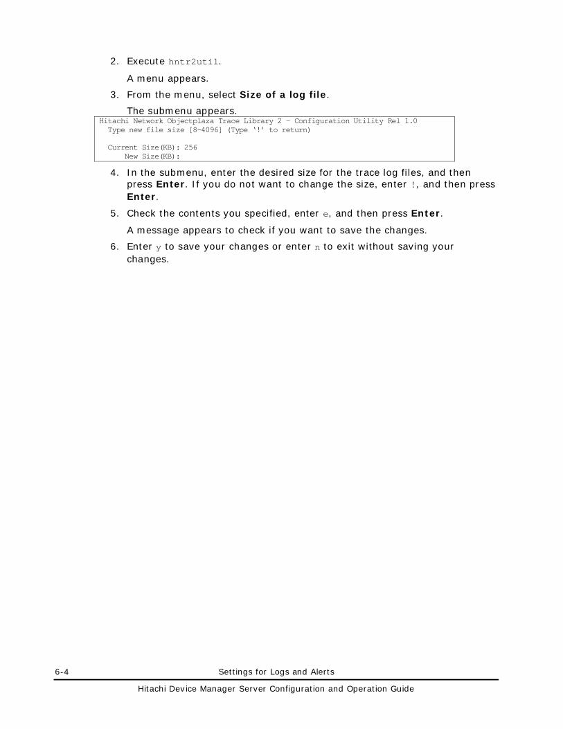
6-4 Settings for Logs and Alerts
Hitachi Device Manager Server Configuration and Operation Guide
2. Execute hntr2util.
A menu appears.
3. From the menu, select Size of a log file.
The submenu appears. Hitachi Network Objectplaza Trace Library 2 - Configuration Utility Rel 1.0 Type new file size [8-4096] (Type ‘!’ to return) Current Size(KB): 256 New Size(KB):
4. In the submenu, enter the desired size for the trace log files, and then press Enter. If you do not want to change the size, enter !, and then press Enter.
5. Check the contents you specified, enter e, and then press Enter.
A message appears to check if you want to save the changes.
6. Enter y to save your changes or enter n to exit without saving your changes.
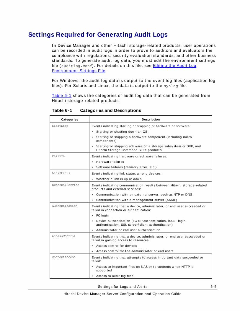
Settings for Logs and Alerts 6-5
Hitachi Device Manager Server Configuration and Operation Guide
Settings Required for Generating Audit Logs
In Device Manager and other Hitachi storage-related products, user operations can be recorded in audit logs in order to prove to auditors and evaluators the compliance with regulations, security evaluation standards, and other business standards. To generate audit log data, you must edit the environment settings file (auditlog.conf). For details on this file, see Editing the Audit Log Environment Settings File.
For Windows, the audit log data is output to the event log files (application log files). For Solaris and Linux, the data is output to the syslog file.
Table 6-1 shows the categories of audit log data that can be generated from Hitachi storage-related products.
Table 6-1 Categories and Descriptions
Categories Description
StartStop Events indicating starting or stopping of hardware or software:
Starting or shutting down an OS
Starting or stopping a hardware component (including micro components)
Starting or stopping software on a storage subsystem or SVP, and Hitachi Storage Command Suite products
Failure Events indicating hardware or software failures:
Hardware failures
Software failures (memory error, etc.)
LinkStatus Events indicating link status among devices:
Whether a link is up or down
ExternalService Events indicating communication results between Hitachi storage-related products and external services:
Communication with an external server, such as NTP or DNS
Communication with a management server (SNMP)
Authentication Events indicating that a device, administrator, or end user succeeded or failed in connection or authentication:
FC login
Device authentication (FC-SP authentication, iSCSI login authentication, SSL server/client authentication)
Administrator or end user authentication
AccessControl Events indicating that a device, administrator, or end user succeeded or failed in gaining access to resources:
Access control for devices
Access control for the administrator or end users
ContentAccess
Events indicating that attempts to access important data succeeded or failed:
Access to important files on NAS or to contents when HTTP is supported
Access to audit log files
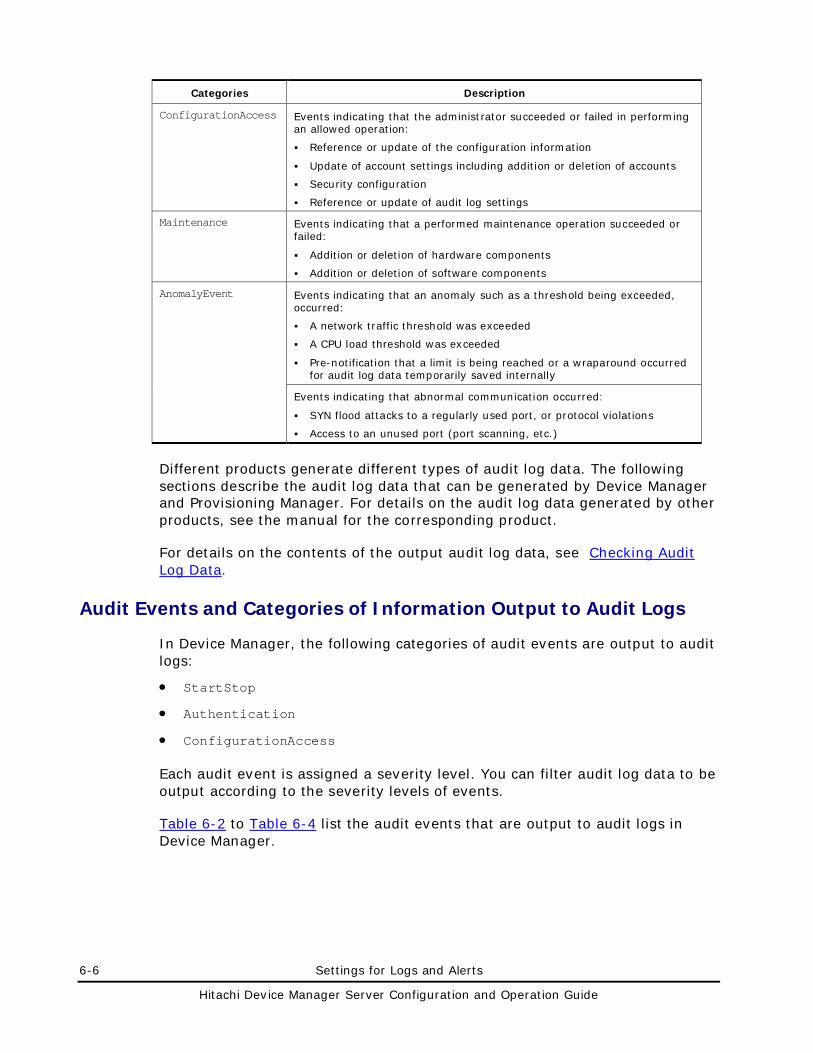
6-6 Settings for Logs and Alerts
Hitachi Device Manager Server Configuration and Operation Guide
Categories Description
ConfigurationAccess Events indicating that the administrator succeeded or failed in performing an allowed operation:
Reference or update of the configuration information
Update of account settings including addition or deletion of accounts
Security configuration
Reference or update of audit log settings
Maintenance Events indicating that a performed maintenance operation succeeded or failed:
Addition or deletion of hardware components
Addition or deletion of software components
AnomalyEvent Events indicating that an anomaly such as a threshold being exceeded, occurred:
A network traffic threshold was exceeded
A CPU load threshold was exceeded
Pre-notification that a limit is being reached or a wraparound occurred for audit log data temporarily saved internally
Events indicating that abnormal communication occurred:
SYN flood attacks to a regularly used port, or protocol violations
Access to an unused port (port scanning, etc.)
Different products generate different types of audit log data. The following sections describe the audit log data that can be generated by Device Manager and Provisioning Manager. For details on the audit log data generated by other products, see the manual for the corresponding product.
For details on the contents of the output audit log data, see Checking Audit Log Data.
Audit Events and Categories of Information Output to Audit Logs
In Device Manager, the following categories of audit events are output to audit logs:
• StartStop
• Authentication
• ConfigurationAccess
Each audit event is assigned a severity level. You can filter audit log data to be output according to the severity levels of events.
Table 6-2 to Table 6-4 list the audit events that are output to audit logs in Device Manager.
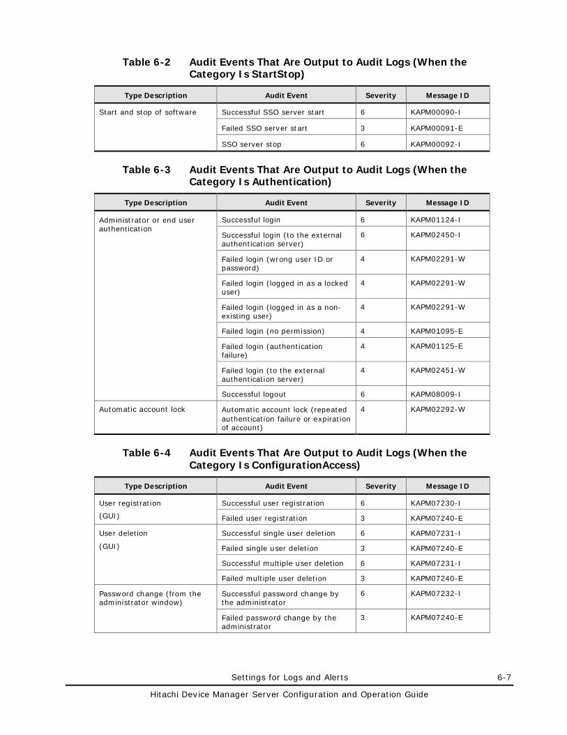
Settings for Logs and Alerts 6-7
Hitachi Device Manager Server Configuration and Operation Guide
Table 6-2 Audit Events That Are Output to Audit Logs (When the Category Is StartStop)
Type Description Audit Event Severity Message ID
Start and stop of software Successful SSO server start 6 KAPM00090-I
Failed SSO server start 3 KAPM00091-E
SSO server stop 6 KAPM00092-I
Table 6-3 Audit Events That Are Output to Audit Logs (When the Category Is Authentication)
Type Description Audit Event Severity Message ID
Administrator or end user authentication
Successful login 6 KAPM01124-I
Successful login (to the external authentication server)
6 KAPM02450-I
Failed login (wrong user ID or password)
4 KAPM02291-W
Failed login (logged in as a locked user)
4 KAPM02291-W
Failed login (logged in as a non-existing user)
4 KAPM02291-W
Failed login (no permission) 4 KAPM01095-E
Failed login (authentication failure)
4 KAPM01125-E
Failed login (to the external authentication server)
4 KAPM02451-W
Successful logout 6 KAPM08009-I
Automatic account lock Automatic account lock (repeated authentication failure or expiration of account)
4 KAPM02292-W
Table 6-4 Audit Events That Are Output to Audit Logs (When the Category Is ConfigurationAccess)
Type Description Audit Event Severity Message ID
User registration
(GUI)
Successful user registration 6 KAPM07230-I
Failed user registration 3 KAPM07240-E
User deletion
(GUI)
Successful single user deletion 6 KAPM07231-I
Failed single user deletion 3 KAPM07240-E
Successful multiple user deletion 6 KAPM07231-I
Failed multiple user deletion 3 KAPM07240-E
Password change (from the administrator window)
Successful password change by the administrator
6 KAPM07232-I
Failed password change by the administrator
3 KAPM07240-E
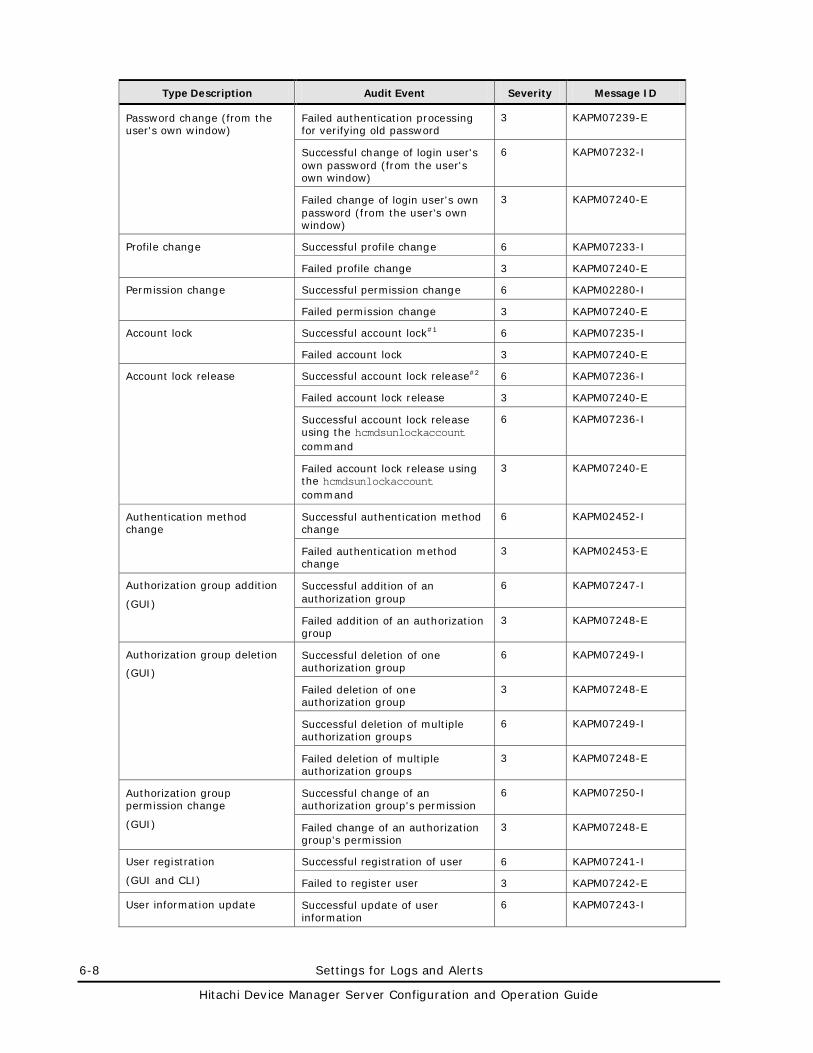
6-8 Settings for Logs and Alerts
Hitachi Device Manager Server Configuration and Operation Guide
Type Description Audit Event Severity Message ID
Password change (from the user's own window)
Failed authentication processing for verifying old password
3 KAPM07239-E
Successful change of login user's own password (from the user's own window)
6 KAPM07232-I
Failed change of login user's own password (from the user's own window)
3 KAPM07240-E
Profile change Successful profile change 6 KAPM07233-I
Failed profile change 3 KAPM07240-E
Permission change Successful permission change 6 KAPM02280-I
Failed permission change 3 KAPM07240-E
Account lock Successful account lock#1 6 KAPM07235-I
Failed account lock 3 KAPM07240-E
Account lock release Successful account lock release#2 6 KAPM07236-I
Failed account lock release 3 KAPM07240-E
Successful account lock release using the hcmdsunlockaccount command
6 KAPM07236-I
Failed account lock release using the hcmdsunlockaccount command
3 KAPM07240-E
Authentication method change
Successful authentication method change
6 KAPM02452-I
Failed authentication method change
3 KAPM02453-E
Authorization group addition
(GUI)
Successful addition of an authorization group
6 KAPM07247-I
Failed addition of an authorization group
3 KAPM07248-E
Authorization group deletion
(GUI)
Successful deletion of one authorization group
6 KAPM07249-I
Failed deletion of one authorization group
3 KAPM07248-E
Successful deletion of multiple authorization groups
6 KAPM07249-I
Failed deletion of multiple authorization groups
3 KAPM07248-E
Authorization group permission change
(GUI)
Successful change of an authorization group's permission
6 KAPM07250-I
Failed change of an authorization group's permission
3 KAPM07248-E
User registration
(GUI and CLI)
Successful registration of user 6 KAPM07241-I
Failed to register user 3 KAPM07242-E
User information update Successful update of user information
6 KAPM07243-I
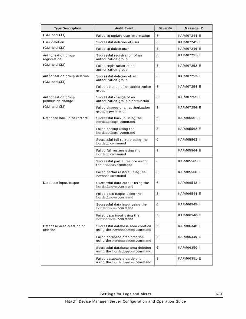
Settings for Logs and Alerts 6-9
Hitachi Device Manager Server Configuration and Operation Guide
Type Description Audit Event Severity Message ID
(GUI and CLI) Failed to update user information 3 KAPM07244-E
User deletion
(GUI and CLI)
Successful deletion of user 6 KAPM07245-I
Failed to delete user 3 KAPM07246-E
Authorization group registration
(GUI and CLI)
Successful registration of an authorization group
6 KAPM07251-I
Failed registration of an authorization group
3 KAPM07252-E
Authorization group deletion
(GUI and CLI)
Successful deletion of an authorization group
6 KAPM07253-I
Failed deletion of an authorization group
3 KAPM07254-E
Authorization group permission change
(GUI and CLI)
Successful change of an authorization group's permission
6 KAPM07255-I
Failed change of an authorization group's permission
3 KAPM07256-E
Database backup or restore Successful backup using the hcmdsbackups command
6 KAPM05561-I
Failed backup using the hcmdsbackups command
3 KAPM05562-E
Successful full restore using the hcmdsdb command
6 KAPM05563-I
Failed full restore using the hcmdsdb command
3 KAPM05564-E
Successful partial restore using the hcmdsdb command
6 KAPM05565-I
Failed partial restore using the hcmdsdb command
3 KAPM05566-E
Database input/output Successful data output using the hcmdsdbmove command
6 KAPM06543-I
Failed data output using the hcmdsdbmove command
3 KAPM06544-E
Successful data input using the hcmdsdbmove command
6 KAPM06545-I
Failed data input using the hcmdsdbmove command
3 KAPM06546-E
Database area creation or deletion
Successful database area creation using the hcmdsdbsetup command
6 KAPM06348-I
Failed database area creation using the hcmdsdbsetup command
3 KAPM06349-E
Successful database area deletion using the hcmdsdbsetup command
6 KAPM06350-I
Failed database area deletion using the hcmdsdbsetup command
3 KAPM06351-E
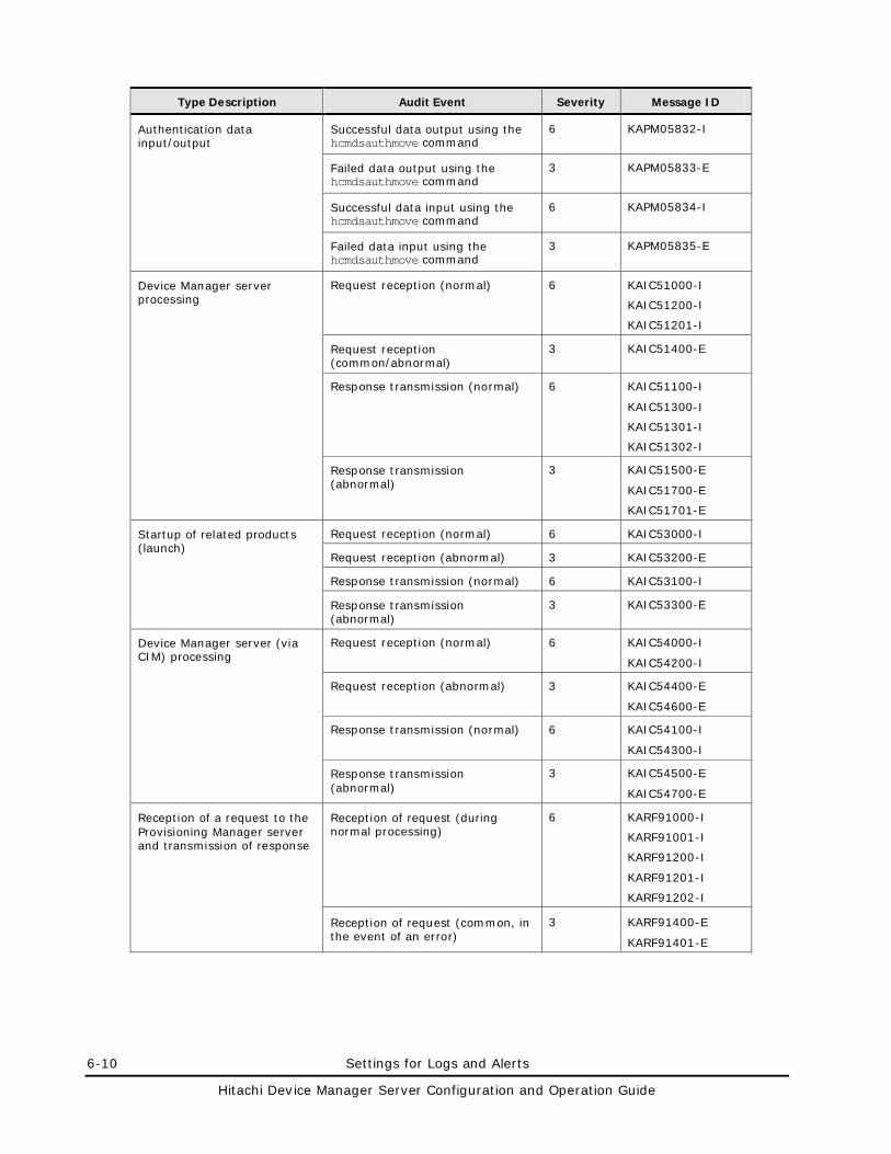
6-10 Settings for Logs and Alerts
Hitachi Device Manager Server Configuration and Operation Guide
Type Description Audit Event Severity Message ID
Authentication data input/output
Successful data output using the hcmdsauthmove command
6 KAPM05832-I
Failed data output using the hcmdsauthmove command
3 KAPM05833-E
Successful data input using the hcmdsauthmove command
6 KAPM05834-I
Failed data input using the hcmdsauthmove command
3 KAPM05835-E
Device Manager server processing
Request reception (normal) 6 KAIC51000-I
KAIC51200-I
KAIC51201-I
Request reception (common/abnormal)
3 KAIC51400-E
Response transmission (normal) 6 KAIC51100-I
KAIC51300-I
KAIC51301-I
KAIC51302-I
Response transmission (abnormal)
3 KAIC51500-E
KAIC51700-E
KAIC51701-E
Startup of related products (launch)
Request reception (normal) 6 KAIC53000-I
Request reception (abnormal) 3 KAIC53200-E
Response transmission (normal) 6 KAIC53100-I
Response transmission (abnormal)
3 KAIC53300-E
Device Manager server (via CIM) processing
Request reception (normal) 6 KAIC54000-I
KAIC54200-I
Request reception (abnormal) 3 KAIC54400-E
KAIC54600-E
Response transmission (normal) 6 KAIC54100-I
KAIC54300-I
Response transmission (abnormal)
3 KAIC54500-E
KAIC54700-E
Reception of a request to the Provisioning Manager server and transmission of response
Reception of request (during normal processing)
6 KARF91000-I
KARF91001-I
KARF91200-I
KARF91201-I
KARF91202-I
Reception of request (common, in the event of an error)
3 KARF91400-E
KARF91401-E
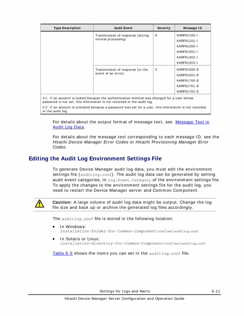
Settings for Logs and Alerts 6-11
Hitachi Device Manager Server Configuration and Operation Guide
Type Description Audit Event Severity Message ID
Transmission of response (during normal processing)
6 KARF91100-I
KARF91101-I
KARF91300-I
KARF91301-I
KARF91302-I
KARF91303-I
Transmission of response (in the event of an error)
3 KARF91500-E
KARF91501-E
KARF91700-E
KARF91701-E
KARF91702-E
#1: If an account is locked because the authentication method was changed for a user whose password is not set, this information is not recorded in the audit log.
#2: If an account is unlocked because a password was set for a user, this information is not recorded in the audit log.
For details about the output format of message text, see Message Text in Audit Log Data.
For details about the message text corresponding to each message ID, see the Hitachi Device Manager Error Codes or Hitachi Provisioning Manager Error Codes.
Editing the Audit Log Environment Settings File
To generate Device Manager audit log data, you must edit the environment settings file (auditlog.conf). The audit log data can be generated by setting audit event categories, in Log.Event.Category of the environment settings file. To apply the changes to the environment settings file for the audit log, you need to restart the Device Manager server and Common Component.
Caution: A large volume of audit log data might be output. Change the log file size and back up or archive the generated log files accordingly.
The auditlog.conf file is stored in the following location:
• In Windows: installation-folder-for-Common-Component\conf\sec\auditlog.conf
• In Solaris or Linux: installation-directory-for-Common-Component/conf/sec/auditlog.conf
Table 6-5 shows the items you can set in the auditlog.conf file.
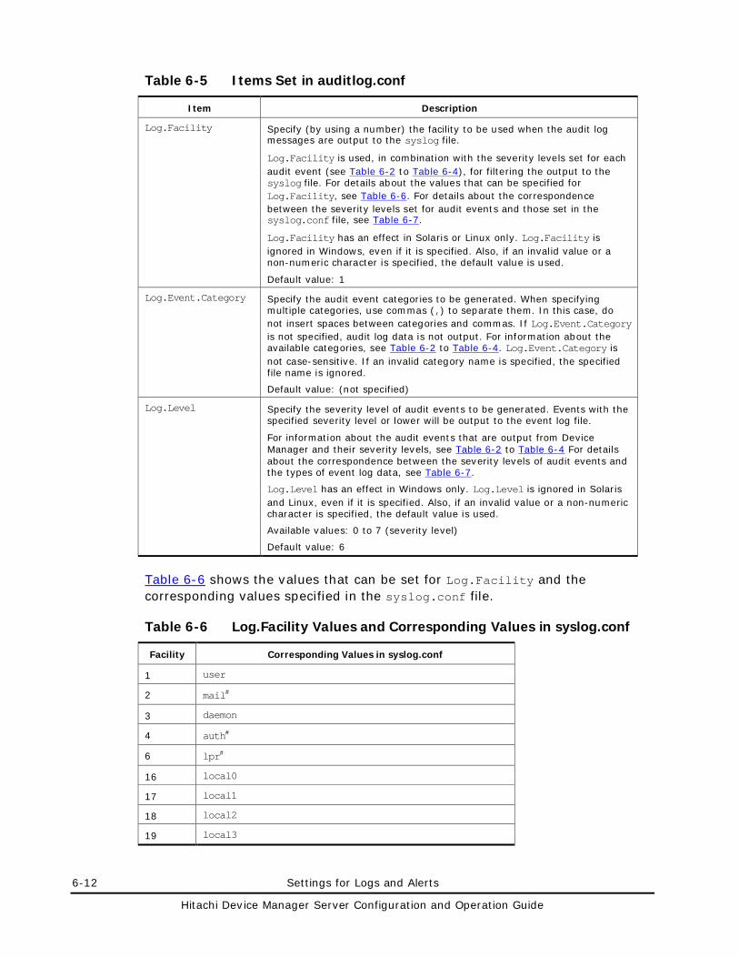
6-12 Settings for Logs and Alerts
Hitachi Device Manager Server Configuration and Operation Guide
Table 6-5 Items Set in auditlog.conf
Item Description
Log.Facility Specify (by using a number) the facility to be used when the audit log messages are output to the syslog file.
Log.Facility is used, in combination with the severity levels set for each audit event (see Table 6-2 to Table 6-4), for filtering the output to the syslog file. For details about the values that can be specified for Log.Facility, see Table 6-6. For details about the correspondence between the severity levels set for audit events and those set in the syslog.conf file, see Table 6-7.
Log.Facility has an effect in Solaris or Linux only. Log.Facility is ignored in Windows, even if it is specified. Also, if an invalid value or a non-numeric character is specified, the default value is used.
Default value: 1
Log.Event.Category Specify the audit event categories to be generated. When specifying multiple categories, use commas (,) to separate them. In this case, do not insert spaces between categories and commas. If Log.Event.Category is not specified, audit log data is not output. For information about the available categories, see Table 6-2 to Table 6-4. Log.Event.Category is not case-sensitive. If an invalid category name is specified, the specified file name is ignored.
Default value: (not specified)
Log.Level Specify the severity level of audit events to be generated. Events with the specified severity level or lower will be output to the event log file.
For information about the audit events that are output from Device Manager and their severity levels, see Table 6-2 to Table 6-4 For details about the correspondence between the severity levels of audit events and the types of event log data, see Table 6-7.
Log.Level has an effect in Windows only. Log.Level is ignored in Solaris and Linux, even if it is specified. Also, if an invalid value or a non-numeric character is specified, the default value is used.
Available values: 0 to 7 (severity level)
Default value: 6
Table 6-6 shows the values that can be set for Log.Facility and the corresponding values specified in the syslog.conf file.
Table 6-6 Log.Facility Values and Corresponding Values in syslog.conf
Facility Corresponding Values in syslog.conf
1 user
2 mail#
3 daemon
4 auth#
6 lpr#
16 local0
17 local1
18 local2
19 local3
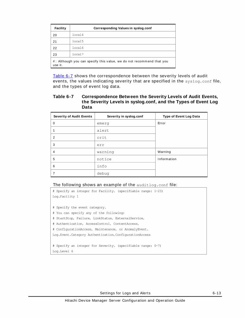
Settings for Logs and Alerts 6-13
Hitachi Device Manager Server Configuration and Operation Guide
Facility Corresponding Values in syslog.conf
20 local4
21 local5
22 local6
23 local7
#: Although you can specify this value, we do not recommend that you use it.
Table 6-7 shows the correspondence between the severity levels of audit events, the values indicating severity that are specified in the syslog.conf file, and the types of event log data.
Table 6-7 Correspondence Between the Severity Levels of Audit Events, the Severity Levels in syslog.conf, and the Types of Event Log Data
Severity of Audit Events Severity in syslog.conf Type of Event Log Data
0 emerg Error
1 alert
2 crit
3 err
4 warning Warning
5 notice Information
6 info
7 debug
The following shows an example of the auditlog.conf file: # Specify an integer for Facility. (specifiable range: 1-23)
Log.Facility 1
# Specify the event category.
# You can specify any of the following:
# StartStop, Failure, LinkStatus, ExternalService,
# Authentication, AccessControl, ContentAccess,
# ConfigurationAccess, Maintenance, or AnomalyEvent.
Log.Event.Category Authentication,ConfigurationAccess
# Specify an integer for Severity. (specifiable range: 0-7)
Log.Level 6
6-14 Settings for Logs and Alerts
Hitachi Device Manager Server Configuration and Operation Guide
In this example, the audit events related to Authentication or ConfigurationAccess are output. In Windows, Log.Level 6 outputs audit log data corresponding to the Error, Warning, and Information levels. In Solaris or Linux, Log.Facility 1 outputs the audit log data to the syslog file that is defined as the user facility in the syslog.conf file.
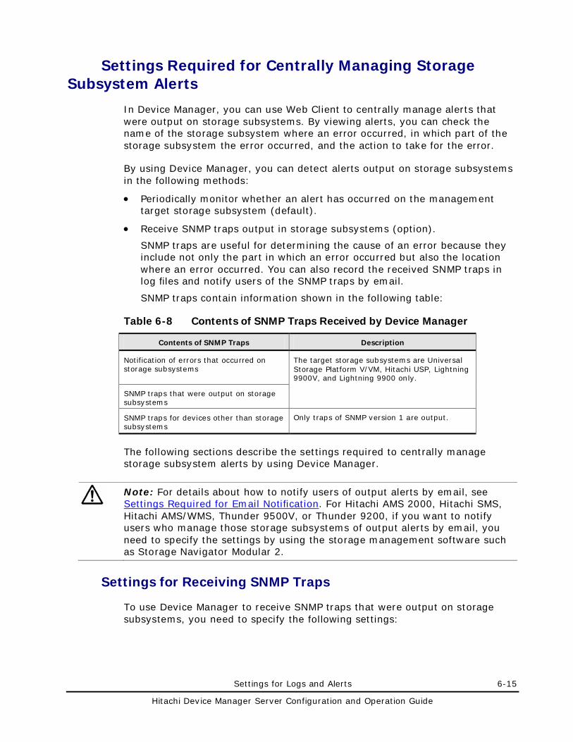
Settings for Logs and Alerts 6-15
Hitachi Device Manager Server Configuration and Operation Guide
Settings Required for Centrally Managing Storage Subsystem Alerts
In Device Manager, you can use Web Client to centrally manage alerts that were output on storage subsystems. By viewing alerts, you can check the name of the storage subsystem where an error occurred, in which part of the storage subsystem the error occurred, and the action to take for the error.
By using Device Manager, you can detect alerts output on storage subsystems in the following methods:
• Periodically monitor whether an alert has occurred on the management target storage subsystem (default).
• Receive SNMP traps output in storage subsystems (option).
SNMP traps are useful for determining the cause of an error because they include not only the part in which an error occurred but also the location where an error occurred. You can also record the received SNMP traps in log files and notify users of the SNMP traps by email.
SNMP traps contain information shown in the following table:
Table 6-8 Contents of SNMP Traps Received by Device Manager
Contents of SNMP Traps Description
Notification of errors that occurred on storage subsystems
The target storage subsystems are Universal Storage Platform V/VM, Hitachi USP, Lightning 9900V, and Lightning 9900 only.
SNMP traps that were output on storage subsystems
SNMP traps for devices other than storage subsystems
Only traps of SNMP version 1 are output.
The following sections describe the settings required to centrally manage storage subsystem alerts by using Device Manager.
Note: For details about how to notify users of output alerts by email, see Settings Required for Email Notification. For Hitachi AMS 2000, Hitachi SMS, Hitachi AMS/WMS, Thunder 9500V, or Thunder 9200, if you want to notify users who manage those storage subsystems of output alerts by email, you need to specify the settings by using the storage management software such as Storage Navigator Modular 2.
Settings for Receiving SNMP Traps
To use Device Manager to receive SNMP traps that were output on storage subsystems, you need to specify the following settings:
6-16 Settings for Logs and Alerts
Hitachi Device Manager Server Configuration and Operation Guide
• In the SNMP agent settings of the storage subsystem, register the IP address of the Device Manager server in the trap notification target machines.
• Specify true for the server.dispatcher.daemon.receiveTrap property of the Device Manager server.
Settings for Recording the Received SNMP Traps in Log Files
By recording the received SNMP traps in the Device Manager log files, you can use integrated management software to centrally monitor the operating status of all the network resources including storage resources managed by Device Manager.
To record the received SNMP traps in log files, you need to specify the following settings:
• Specify true for the customizedsnmptrap.customizedSNMPTrapEnable property of the Device Manager server.
• Specify the data to be output to log files in the customizedsnmptrap.customizelist property of the Device Manager server.
Data Items to Be Output to Log Files
The following data items from among the SNMP trap data are output to the log files:
• Message ID indicating that a trap has been received
• Sender (agent)
• Enterprise ID (enterprise)
• Generic trap number (generic)
• Specific trap number (specific)
In addition, the data of the received SNMP traps are recorded in the following log files:
• Hitachi Storage Command Suite common trace log file (hntr2n.log)
• Device Manager trace log file (HDvMtracen.log)
• Event log file or syslog file
• Trace log file (trace.log.n)
• Error log file (error.log.n)#
#: The data is output to this file only when the severity is Error, Critical, or Alert. For details on the severity, see Table 6-9.
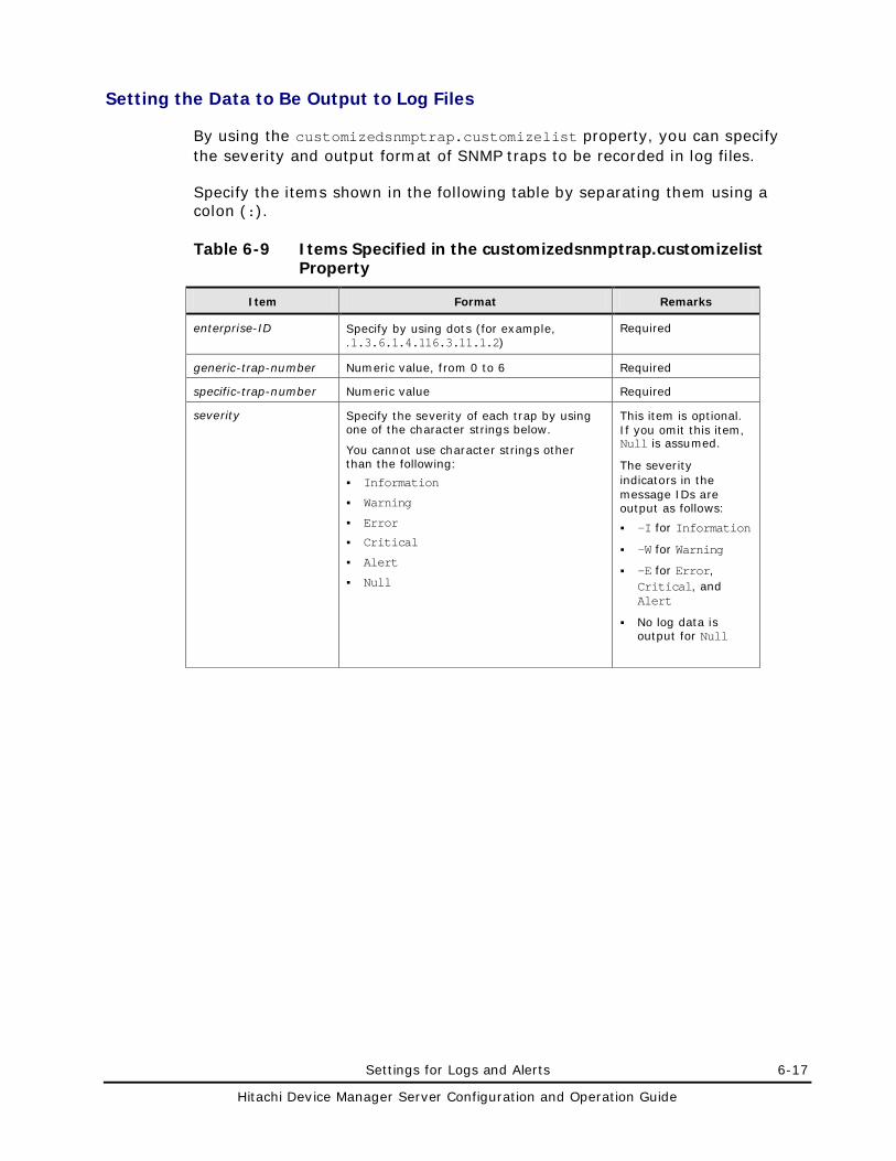
Settings for Logs and Alerts 6-17
Hitachi Device Manager Server Configuration and Operation Guide
Setting the Data to Be Output to Log Files
By using the customizedsnmptrap.customizelist property, you can specify the severity and output format of SNMP traps to be recorded in log files.
Specify the items shown in the following table by separating them using a colon (:).
Table 6-9 Items Specified in the customizedsnmptrap.customizelist Property
Item Format Remarks
enterprise-ID Specify by using dots (for example, .1.3.6.1.4.116.3.11.1.2)
Required
generic-trap-number Numeric value, from 0 to 6 Required
specific-trap-number Numeric value Required
severity Specify the severity of each trap by using one of the character strings below.
You cannot use character strings other than the following:
Information
Warning
Error
Critical
Alert
Null
This item is optional. If you omit this item, Null is assumed.
The severity indicators in the message IDs are output as follows:
-I for Information
-W for Warning
-E for Error, Critical, and Alert
No log data is output for Null
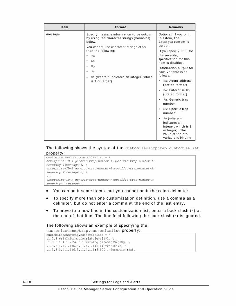
6-18 Settings for Logs and Alerts
Hitachi Device Manager Server Configuration and Operation Guide
Item Format Remarks
message Specify message information to be output by using the character strings (variables) below.
You cannot use character strings other than the following:
$a
$e
$g
$s
$n (where n indicates an integer, which is 1 or larger)
Optional. If you omit this item, the $a$e$g$s content is output.
If you specify Null for the severity, specification for this item is disabled.
Information output for each variable is as follows:
$a: Agent address (dotted format)
$e: Enterprise ID (dotted format)
$g: Generic trap number
$s: Specific trap number
$n (where n indicates an integer, which is 1 or larger): The value of the nth variable is binding
The following shows the syntax of the customizedsnmptrap.customizelist property: customizedsnmptrap.customizelist = \ enterprise-ID-1:generic-trap-number-1:specific-trap-number-1: severity-1:message-1, \ enterprise-ID-2:generic-trap-number-2:specific-trap-number-2: severity-2:message-2, \ ... enterprise-ID-n:generic-trap-number-n:specific-trap-number-n: severity-n:message-n
• You can omit some items, but you cannot omit the colon delimiter.
• To specify more than one customization definition, use a comma as a delimiter, but do not enter a comma at the end of the last entry.
• To move to a new line in the customization list, enter a back slash (\) at the end of that line. The line feed following the back slash (\) is ignored.
The following shows an example of specifying the customizedsnmptrap.customizelist property: customizedsnmptrap.customizelist = \ .1.2.3:6:1:Information:$a$e$g$s$1$2, \ .1.3.6.1.4.1.2854:6:1:Warning:$e$a$s$3$2$1$g, \ .1.3.6.1.4.1.116.3.11.4.1.1:6:1:Error:$a$s, \ .1.3.6.1.4.1.116.3.11.4.1.1:6:100:Information:$a$s
Settings for Logs and Alerts 6-19
Hitachi Device Manager Server Configuration and Operation Guide
Settings Required for Email Notification
The email notification function notifies users, by email, of the contents of alerts that occurred in the storage subsystem and were detected by the Device Manager server. To use this function, you need to specify settings at the SMTP server, for the Device Manager users, and at the Device Manager server.
For the email notification function, the Device Manager server notifies users of an alert only once when the Device Manager server detects the alert. If the Device Manager server fails to send an email, the same email will not be sent again. Information on an alert for which the Device Manager server fails to send an email, as well as the email address of the intended destination of this email, are output to the Device Manager trace log file. For details about the Device Manager trace log file, see Obtaining Maintenance Information of Device Manager. Also, if the Device Manager server service stops before the Device Manager server sends an email about an alert, the email will not be sent. In this case, even if the Device Manager server service is started again, the Device Manager server will not send the email that has not been sent. Start the Device Manager server service, and then execute the GetAlerts command from the CLI or use the alert management function of Web Client, to make sure that actions have been taken for every alert.
If you set up an environment or perform maintenance for a storage subsystem that has already been registered in the Device Manager server, the storage subsystem might generate many alerts. As such, we recommend that you disable the email notification function during such tasks.
The users who receive emails need to use email software that supports Unicode (UTF-8) encoding because, when sending an email, the Device Manager server sets the character encoding of the email to Unicode (UTF-8).
Settings on the SMTP Server
Following the setup procedure for the SMTP server being used, set it up so that the Device Manager server can connect to the SMTP server. The Device Manager server supports the following SMTP authentication methods: LOGIN or PLAIN. Make sure that you specify one of these authentication methods in the SMTP server that you use.
Settings for Users Who Receive Emails by Using Web Client
When using the email notification function, use Web Client to specify the settings below for a Device Manager users who receive emails. For details on how to specify the settings, see the Device Manager online Help.
An email that contains the same contents will be sent to the users for whom the settings below are specified. Each email is addressed to one recipient, and is sent to the users individually.
6-20 Settings for Logs and Alerts
Hitachi Device Manager Server Configuration and Operation Guide
• Set the Device Manager’s modify permission for the user.
• Assign All Resources as a resource group to the user.
• Specify the user’s email address by editing the profile.
Settings on the Device Manager Server
To configure the Device Manager server when using the email notification function:
1. Stop the Device Manager server service.
For details about how to do this, see Stopping the Device Manager Server.
2. Specify the Device Manager server properties related to the email notification function. The following properties are related:
– server.mail.enabled
– server.mail.from
– server.mail.smtp.host
– server.mail.smtp.port
– server.mail.smtp.auth
– server.mail.alert.type
– server.mail.alert.status
Note: • When the SMTP authentication setting is enabled on the Device
Manager server and there are multiple SMTP authentication methods that the SMTP server specifies, the Device Manager server selects an authentication method (LOGIN or PLAIN in that priority order), and then sends an email. If LOGIN or PLAIN is not specified, the Device Manager server will send an email without using the SMTP authentication.
• If SMTP authentication setting is disabled on the SMTP server, even if the setting is enabled on the Device Manager server, the Device Manager server will send an email without using SMTP authentication.
3. If you want to use SMTP authentication for the SMTP server, set the SMTP authentication user information.
To set SMTP authentication user information, execute the SMTP authentication user information setting command. Even if SMTP authentication is enabled in the Device Manager server, if SMTP authentication user information is not registered, the Device Manager server will send emails without using SMTP authentication.
For details about how to set up SMTP authentication users, see Settings for an SMTP Authentication User.
4. If necessary, edit the template file of the email used by the email notification function.
Settings for Logs and Alerts 6-21
Hitachi Device Manager Server Configuration and Operation Guide
For details about how to do this, see Customizing the Template File.
5. Start the Device Manager server service.
For details about how to do this, see Starting the Device Manager Server.
Settings for an SMTP Authentication User
To use the email notification function, you need to connect to the SMTP server. To use SMTP authentication for the SMTP server, you need to set the SMTP authentication user information on the Device Manager server.
To register or modify the SMTP authentication user information on the Device Manager server, execute the hdvmmodmailuser command. The settings will go into effect when you start the Device Manager server service after executing this command.
You can set only one piece of SMTP authentication user information on the Device Manager server. The set SMTP authentication user information will be updated each time you execute the command. If the currently set SMTP authentication user information is unknown, re-execute the command to set SMTP authentication user information.
Note: • Even if the SMTP authentication setting is enabled on the Device
Manager server, the Device Manager server sends an email without using SMTP authentication if the connection target SMTP server has not enabled the SMTP authentication setting.
• You cannot delete the SMTP authentication user information that you set on the Device Manager server.
To execute the hdvmmodmailuser command, the following conditions must be satisfied:
• The user who executes the hdvmmodmailuser command has the Administrator permission for Windows, or the root permission for Solaris or Linux
• The user specified when executing the hdvmmodmailuser command has the Admin permission of Device Manager
• The Device Manager server service is stopped.
• The Common Component services are running.
The following shows the installation location and format of the hdvmmodmailuser command:
In Windows:
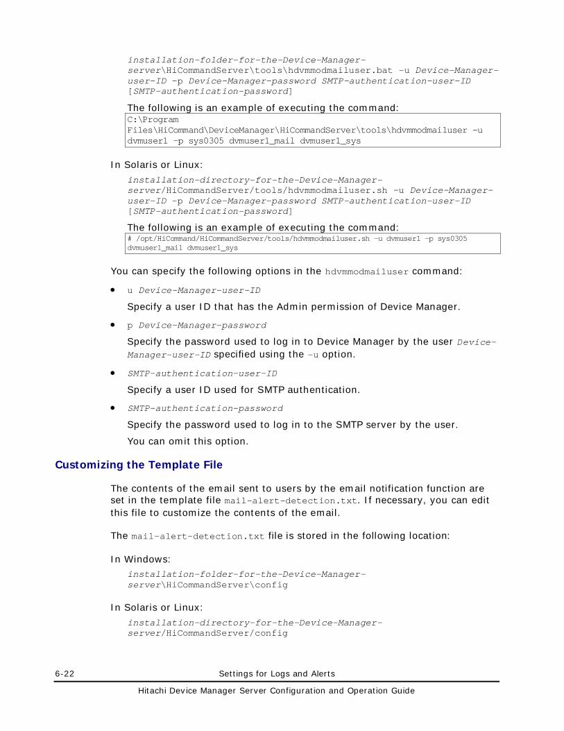
6-22 Settings for Logs and Alerts
Hitachi Device Manager Server Configuration and Operation Guide
installation-folder-for-the-Device-Manager-server\HiCommandServer\tools\hdvmmodmailuser.bat -u Device-Manager-user-ID -p Device-Manager-password SMTP-authentication-user-ID [SMTP-authentication-password]
The following is an example of executing the command: C:\Program Files\HiCommand\DeviceManager\HiCommandServer\tools\hdvmmodmailuser -u dvmuser1 -p sys0305 dvmuser1_mail dvmuser1_sys
In Solaris or Linux:
installation-directory-for-the-Device-Manager-server/HiCommandServer/tools/hdvmmodmailuser.sh -u Device-Manager-user-ID -p Device-Manager-password SMTP-authentication-user-ID [SMTP-authentication-password]
The following is an example of executing the command: # /opt/HiCommand/HiCommandServer/tools/hdvmmodmailuser.sh -u dvmuser1 -p sys0305 dvmuser1_mail dvmuser1_sys
You can specify the following options in the hdvmmodmailuser command:
• u Device-Manager-user-ID
Specify a user ID that has the Admin permission of Device Manager.
• p Device-Manager-password
Specify the password used to log in to Device Manager by the user Device-Manager-user-ID specified using the -u option.
• SMTP-authentication-user-ID
Specify a user ID used for SMTP authentication.
• SMTP-authentication-password
Specify the password used to log in to the SMTP server by the user.
You can omit this option.
Customizing the Template File
The contents of the email sent to users by the email notification function are set in the template file mail-alert-detection.txt. If necessary, you can edit this file to customize the contents of the email.
The mail-alert-detection.txt file is stored in the following location:
In Windows: installation-folder-for-the-Device-Manager-server\HiCommandServer\config
In Solaris or Linux:
installation-directory-for-the-Device-Manager-server/HiCommandServer/config
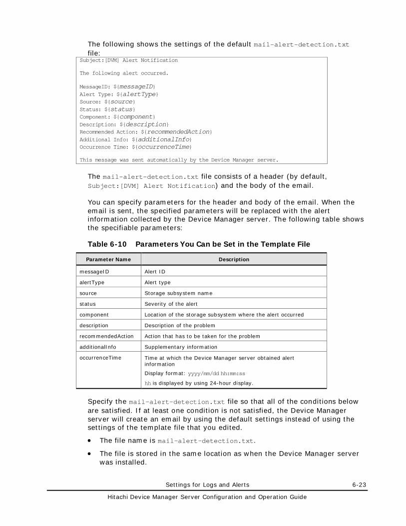
Settings for Logs and Alerts 6-23
Hitachi Device Manager Server Configuration and Operation Guide
The following shows the settings of the default mail-alert-detection.txt file:
Subject:[DVM] Alert Notification The following alert occurred. MessageID: ${messageID} Alert Type: ${alertType} Source: ${source} Status: ${status} Component: ${component} Description: ${description} Recommended Action: ${recommendedAction} Additional Info: ${additionalInfo} Occurrence Time: ${occurrenceTime} This message was sent automatically by the Device Manager server.
The mail-alert-detection.txt file consists of a header (by default, Subject:[DVM] Alert Notification) and the body of the email.
You can specify parameters for the header and body of the email. When the email is sent, the specified parameters will be replaced with the alert information collected by the Device Manager server. The following table shows the specifiable parameters:
Table 6-10 Parameters You Can be Set in the Template File
Parameter Name Description
messageID Alert ID
alertType Alert type
source Storage subsystem name
status Severity of the alert
component Location of the storage subsystem where the alert occurred
description Description of the problem
recommendedAction Action that has to be taken for the problem
additionalInfo Supplementary information
occurrenceTime Time at which the Device Manager server obtained alert information
Display format: yyyy/mm/dd hh:mm:ss
hh is displayed by using 24-hour display.
Specify the mail-alert-detection.txt file so that all of the conditions below are satisfied. If at least one condition is not satisfied, the Device Manager server will create an email by using the default settings instead of using the settings of the template file that you edited.
• The file name is mail-alert-detection.txt.
• The file is stored in the same location as when the Device Manager server was installed.
6-24 Settings for Logs and Alerts
Hitachi Device Manager Server Configuration and Operation Guide
• The file size is no more than 64 KB.
• Unicode (UTF-8) can be used as the character encoding.
• Each line of the template file is no more than 1024 bytes in length, excluding the line feed character.
• In the top line, the header is specified in the following format:
Subject:email-title
Only one header is specified.
• In the second line from the top, a blank line is specified.
• In the third line from the top until the bottom line, the contents are specified.
• Parameters are specified in the following format: ${parameter-name}
The parameter name is case sensitive.
Note: The settings of this template file will go into effect when the Device Manager service starts.
Settings for CIM/WBEM 7-1
Hitachi Device Manager Server Configuration and Operation Guide
Settings for CIM/WBEM
This chapter explains how to set up CIM/WBEM.
Device Manager and CIM/WBEM
CIM/WBEM Features of Device Manager
Basic Settings Required to Use the CIM/WBEM Features
Settings for Ports Used by CIM/WBEM Features
Properties File Settings for Executing CIM
Settings for the Service Discovery Feature
The Performance Information Acquisition Feature
User Permissions for Using CIM/WBEM Features
7-2 Settings for CIM/WBEM
Hitachi Device Manager Server Configuration and Operation Guide
Device Manager and CIM/WBEM
Device Manager supports WBEM, which is defined by the standards-setting organization DMTF. WBEM is a standard proposed by the DMTF for managing networked devices, including hosts and storage subsystems, over the Internet. WBEM enables you to share data about devices in different environments (such as environments with different vendors, operating systems, or protocols) without considering the differences. WBEM is based on CIM, an object-oriented information model.
CIM, defined by DMTF, is a standardized approach for managing systems in network environments. CIM provides a framework for expressing the data to be managed. Applying CIM to storage subsystems enables you to use standardized methods to manage the configuration and status of storage subsystems in networks.
Caution: In Device Manager, when registering a storage subsystem that is to be managed, use the account of an administrator for the entire storage subsystem. Do not use the account of an administrator who only has permissions for part of the storage subsystem.
The CIM models provided by Device Manager conform to the SMI-S specifications (SNIA-CTP) endorsed by SNIA. The CIM models of the Device Manager server are defined in MOF (Managed Object Format) files provided by Device Manager.
CIM clients can access Device Manager by using the CIM XML/HTTP interface defined by WBEM.
The following figure shows the CIM components for Device Manager.
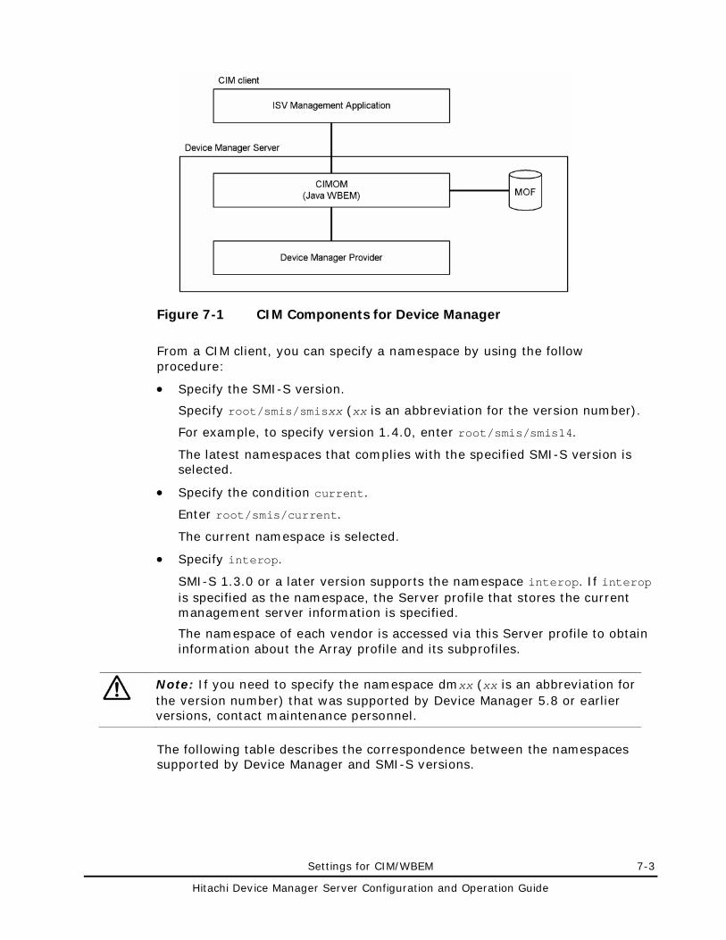
Settings for CIM/WBEM 7-3
Hitachi Device Manager Server Configuration and Operation Guide
Figure 7-1 CIM Components for Device Manager
From a CIM client, you can specify a namespace by using the follow procedure:
• Specify the SMI-S version.
Specify root/smis/smisxx (xx is an abbreviation for the version number).
For example, to specify version 1.4.0, enter root/smis/smis14.
The latest namespaces that complies with the specified SMI-S version is selected.
• Specify the condition current.
Enter root/smis/current.
The current namespace is selected.
• Specify interop.
SMI-S 1.3.0 or a later version supports the namespace interop. If interop is specified as the namespace, the Server profile that stores the current management server information is specified.
The namespace of each vendor is accessed via this Server profile to obtain information about the Array profile and its subprofiles.
Note: If you need to specify the namespace dmxx (xx is an abbreviation for the version number) that was supported by Device Manager 5.8 or earlier versions, contact maintenance personnel.
The following table describes the correspondence between the namespaces supported by Device Manager and SMI-S versions.
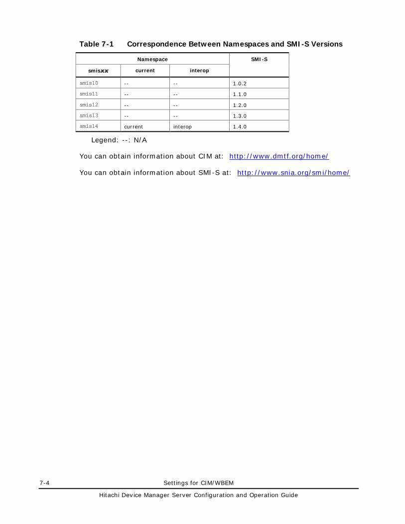
7-4 Settings for CIM/WBEM
Hitachi Device Manager Server Configuration and Operation Guide
Table 7-1 Correspondence Between Namespaces and SMI-S Versions
Namespace SMI-S
smisxx current interop
smis10 -- -- 1.0.2
smis11 -- -- 1.1.0
smis12 -- -- 1.2.0
smis13 -- -- 1.3.0
smis14 current interop 1.4.0
Legend: --: N/A
You can obtain information about CIM at: http://www.dmtf.org/home/
You can obtain information about SMI-S at: http://www.snia.org/smi/home/
Settings for CIM/WBEM 7-5
Hitachi Device Manager Server Configuration and Operation Guide
CIM/WBEM Features of Device Manager
CIM/WBEM of Device Manager provides the four features specified in SMI-S:
• Objection operation feature
• Indication feature
• Service discovery feature
• Performance information acquisition feature
These features are described below:
Object operation feature
The SMI-S specifications, which Device Manager conforms to, define the interfaces for devices that make up a storage network, such as storage subsystems, virtual storage systems, switches, and hosts. The features that need to be provided by the management service to manage the devices are grouped in a profile for each device.
The profiles used by the CIM/WBEM features of Device Manager are the Array profile and its subprofiles. The Array profile defines the interfaces for storage subsystems.
Indication feature
The indication feature is the event notification feature defined by CIM. When an event occurs in a CIM server, the CIM server reports the indication instance, which shows the information about the event (such as generation or deletion of a CIM instance), to CIM clients. For a CIM client to receive indications, its location and transmission conditions for indications must be registered in the CIM server beforehand. For details on how to register them, see the SNIA website.
Device Manager reports the occurrence of the following events:
– Generation of a volume
– Deletion of a volume
– Allocation of a path
– Cancellation of a path
Service discovery feature
Device Manager provides the service discovery feature based on the Service Location Protocol (SLP).
The SLP is undergoing standardization by IETF and provides a way to discover desired services available in a network. For details on the SLP, see RFC2608.
Just by specifying the type of service, SLP clients can obtain information (such as URLs) about how to access the available services, and information about service attributes.
7-6 Settings for CIM/WBEM
Hitachi Device Manager Server Configuration and Operation Guide
In Device Manager, the Device Manager server uses the SLP to report information about the WBEM Service.
Performance information acquisition feature
Using the CIM interface, Device Manager acquires information about I/Os to ports and LDEVs as performance information of the storage subsystem.
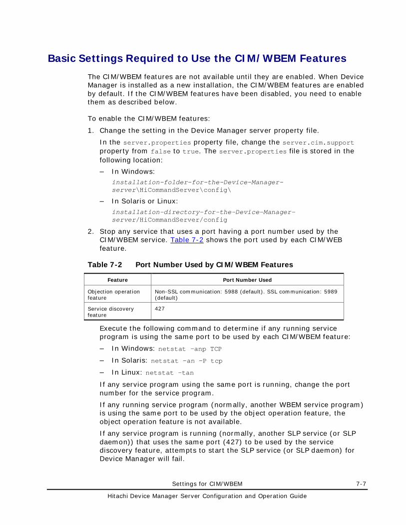
Settings for CIM/WBEM 7-7
Hitachi Device Manager Server Configuration and Operation Guide
Basic Settings Required to Use the CIM/WBEM Features
The CIM/WBEM features are not available until they are enabled. When Device Manager is installed as a new installation, the CIM/WBEM features are enabled by default. If the CIM/WBEM features have been disabled, you need to enable them as described below.
To enable the CIM/WBEM features:
1. Change the setting in the Device Manager server property file.
In the server.properties property file, change the server.cim.support property from false to true. The server.properties file is stored in the following location:
– In Windows: installation-folder-for-the-Device-Manager-server\HiCommandServer\config\
– In Solaris or Linux:
installation-directory-for-the-Device-Manager-server/HiCommandServer/config
2. Stop any service that uses a port having a port number used by the CIM/WBEM service. Table 7-2 shows the port used by each CIM/WEB feature.
Table 7-2 Port Number Used by CIM/WBEM Features
Feature Port Number Used
Objection operation feature
Non-SSL communication: 5988 (default). SSL communication: 5989 (default)
Service discovery feature
427
Execute the following command to determine if any running service program is using the same port to be used by each CIM/WBEM feature:
– In Windows: netstat -anp TCP
– In Solaris: netstat -an -P tcp
– In Linux: netstat -tan
If any service program using the same port is running, change the port number for the service program.
If any running service program (normally, another WBEM service program) is using the same port to be used by the object operation feature, the object operation feature is not available.
If any service program is running (normally, another SLP service (or SLP daemon)) that uses the same port (427) to be used by the service discovery feature, attempts to start the SLP service (or SLP daemon) for Device Manager will fail.
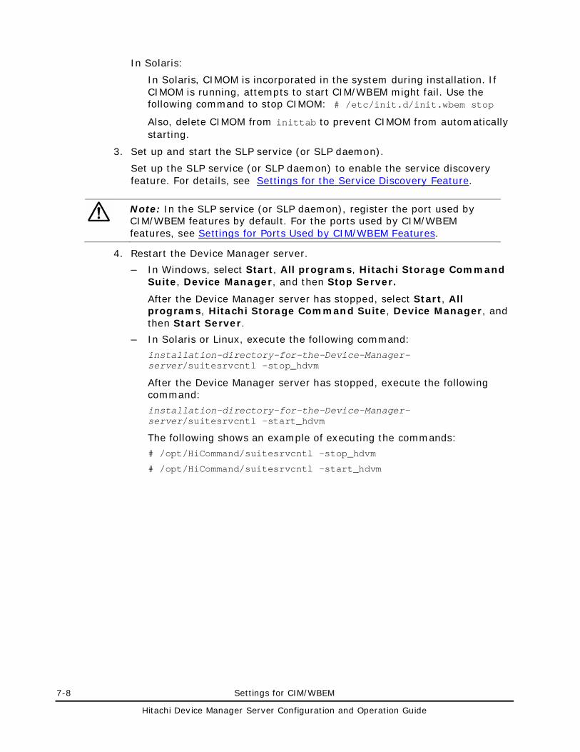
7-8 Settings for CIM/WBEM
Hitachi Device Manager Server Configuration and Operation Guide
In Solaris:
In Solaris, CIMOM is incorporated in the system during installation. If CIMOM is running, attempts to start CIM/WBEM might fail. Use the following command to stop CIMOM: # /etc/init.d/init.wbem stop
Also, delete CIMOM from inittab to prevent CIMOM from automatically starting.
3. Set up and start the SLP service (or SLP daemon).
Set up the SLP service (or SLP daemon) to enable the service discovery feature. For details, see Settings for the Service Discovery Feature.
Note: In the SLP service (or SLP daemon), register the port used by CIM/WBEM features by default. For the ports used by CIM/WBEM features, see Settings for Ports Used by CIM/WBEM Features.
4. Restart the Device Manager server.
– In Windows, select Start, All programs, Hitachi Storage Command Suite, Device Manager, and then Stop Server.
After the Device Manager server has stopped, select Start, All programs, Hitachi Storage Command Suite, Device Manager, and then Start Server.
– In Solaris or Linux, execute the following command:
installation-directory-for-the-Device-Manager-server/suitesrvcntl -stop_hdvm
After the Device Manager server has stopped, execute the following command:
installation-directory-for-the-Device-Manager-server/suitesrvcntl -start_hdvm
The following shows an example of executing the commands:
# /opt/HiCommand/suitesrvcntl -stop_hdvm
# /opt/HiCommand/suitesrvcntl -start_hdvm
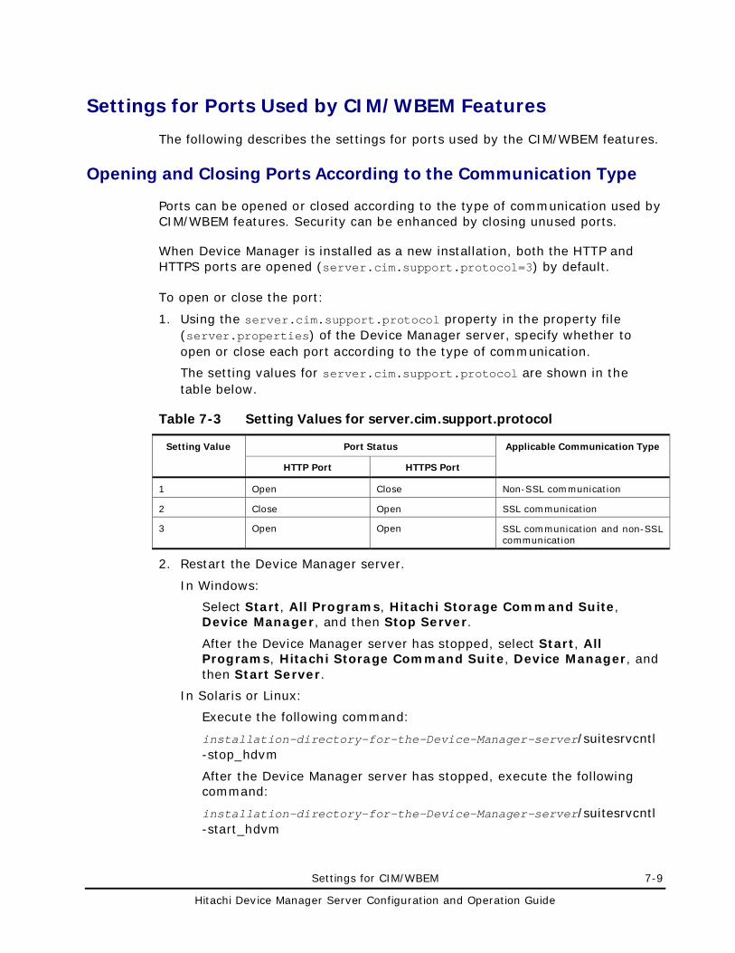
Settings for CIM/WBEM 7-9
Hitachi Device Manager Server Configuration and Operation Guide
Settings for Ports Used by CIM/WBEM Features
The following describes the settings for ports used by the CIM/WBEM features.
Opening and Closing Ports According to the Communication Type
Ports can be opened or closed according to the type of communication used by CIM/WBEM features. Security can be enhanced by closing unused ports.
When Device Manager is installed as a new installation, both the HTTP and HTTPS ports are opened (server.cim.support.protocol=3) by default.
To open or close the port:
1. Using the server.cim.support.protocol property in the property file (server.properties) of the Device Manager server, specify whether to open or close each port according to the type of communication.
The setting values for server.cim.support.protocol are shown in the table below.
Table 7-3 Setting Values for server.cim.support.protocol
Setting Value Port Status Applicable Communication Type
HTTP Port HTTPS Port
1 Open Close Non-SSL communication
2 Close Open SSL communication
3 Open Open SSL communication and non-SSL communication
2. Restart the Device Manager server.
In Windows:
Select Start, All Programs, Hitachi Storage Command Suite, Device Manager, and then Stop Server.
After the Device Manager server has stopped, select Start, All Programs, Hitachi Storage Command Suite, Device Manager, and then Start Server.
In Solaris or Linux:
Execute the following command:
installation-directory-for-the-Device-Manager-server/suitesrvcntl -stop_hdvm
After the Device Manager server has stopped, execute the following command:
installation-directory-for-the-Device-Manager-server/suitesrvcntl -start_hdvm
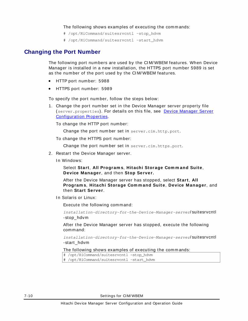
7-10 Settings for CIM/WBEM
Hitachi Device Manager Server Configuration and Operation Guide
The following shows examples of executing the commands: # /opt/HiCommand/suitesrvcntl -stop_hdvm
# /opt/HiCommand/suitesrvcntl -start_hdvm
Changing the Port Number
The following port numbers are used by the CIM/WBEM features. When Device Manager is installed in a new installation, the HTTPS port number 5989 is set as the number of the port used by the CIM/WBEM features.
• HTTP port number: 5988
• HTTPS port number: 5989
To specify the port number, follow the steps below:
1. Change the port number set in the Device Manager server property file (server.properties). For details on this file, see Device Manager Server Configuration Properties.
To change the HTTP port number:
Change the port number set in server.cim.http.port.
To change the HTTPS port number:
Change the port number set in server.cim.https.port.
2. Restart the Device Manager server.
In Windows:
Select Start, All Programs, Hitachi Storage Command Suite, Device Manager, and then Stop Server.
After the Device Manager server has stopped, select Start, All Programs, Hitachi Storage Command Suite, Device Manager, and then Start Server.
In Solaris or Linux:
Execute the following command:
installation-directory-for-the-Device-Manager-server/suitesrvcntl -stop_hdvm
After the Device Manager server has stopped, execute the following command:
installation-directory-for-the-Device-Manager-server/suitesrvcntl -start_hdvm
The following shows examples of executing the commands: # /opt/HiCommand/suitesrvcntl -stop_hdvm # /opt/HiCommand/suitesrvcntl -start_hdvm
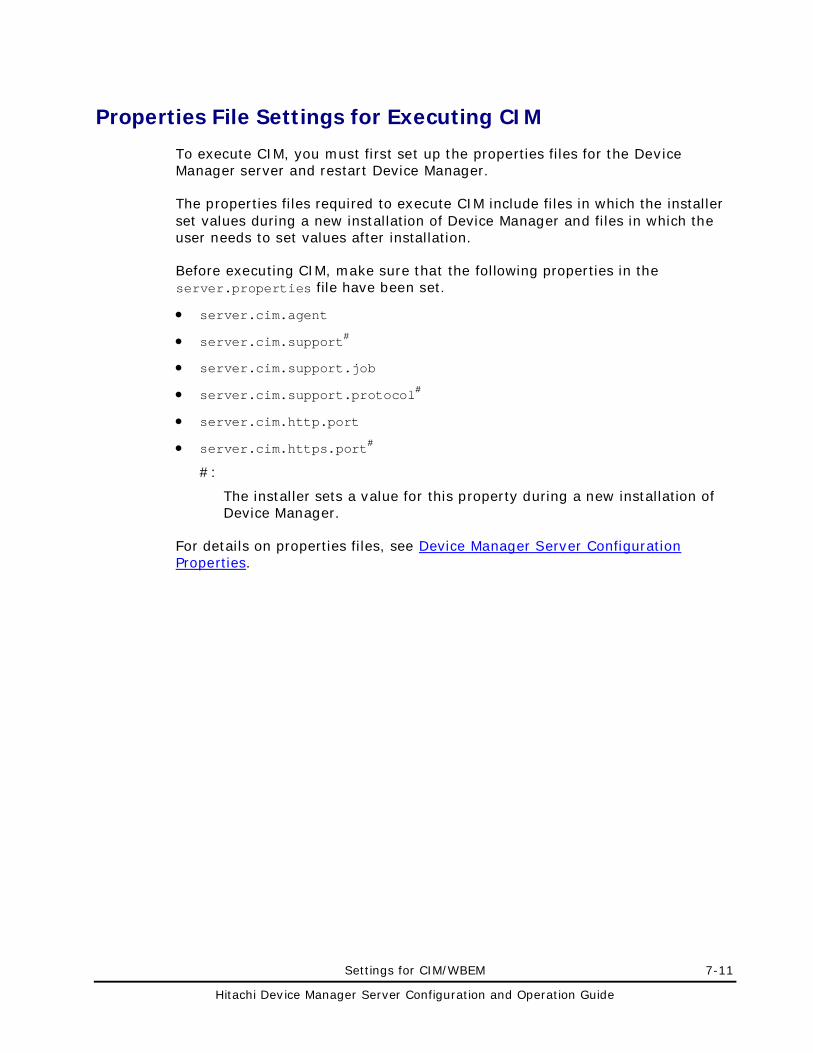
Settings for CIM/WBEM 7-11
Hitachi Device Manager Server Configuration and Operation Guide
Properties File Settings for Executing CIM
To execute CIM, you must first set up the properties files for the Device Manager server and restart Device Manager.
The properties files required to execute CIM include files in which the installer set values during a new installation of Device Manager and files in which the user needs to set values after installation.
Before executing CIM, make sure that the following properties in the server.properties file have been set.
• server.cim.agent
• server.cim.support#
• server.cim.support.job
• server.cim.support.protocol#
• server.cim.http.port
• server.cim.https.port#
#:
The installer sets a value for this property during a new installation of Device Manager.
For details on properties files, see Device Manager Server Configuration Properties.
7-12 Settings for CIM/WBEM
Hitachi Device Manager Server Configuration and Operation Guide
Settings for the Service Discovery Feature
This section describes how to specify settings for the service discovery feature of Device Manager. To use the service discovery feature of Device Manager, the following software is required:
• In Windows or Red Hat Enterprise Linux:
OpenSLP 1.0.11
OpenSLP is provided with Device Manager. When you install Device Manager, the required file is copied. For details on OpenSLP, see the OpenSLP website (http://www.openslp.org/).
• In Solaris:
SUNWslpr package and SUNWslpu package
These packages are provided with the Solaris system. For details on the packages, see the Sun Microsystems (http://docs.sun.com/).
• In SUSE Linux Enterprise Server:
OpenSLP 1.2.0
OpenSLP is provided with the SUSE Linux Enterprise Server system. For details on OpenSLP, see the Novell website(http://www.novell.com/).
OpenSLP, the SUNWslpr package, and the SUNWslpu package need to be set up separately. For the setup procedure, see Setting Up the Service Discovery Feature.
When starting the CIM client, set the language tag (locale) for the service discovery feature to English (en).
Setting Up the Service Discovery Feature
This section describes how to specify the settings for using the service discovery feature.
In Windows
When you install Device Manager, the OpenSLP file is copied simultaneously. You do not need to specify any settings after installation, and can use the service discovery feature immediately after installation.
If the following message is displayed when Device Manager is uninstalled, release the SLP service manually from the Windows services.
An attempt to release the SLP service has failed. After uninstallation, release the SLP service manually. Uninstallation continues.
To release the SLP service:
1. Log on as a member of the Administrator group.
Settings for CIM/WBEM 7-13
Hitachi Device Manager Server Configuration and Operation Guide
2. Show the command prompt and move to the folder containing the OpenSLP executable file.
3. Release the SLP service from Windows services. Execute the following command: • slpd -remove
In Solaris
In Solaris, the SLP daemon is installed in the standard configuration. However, the SLP daemon does not become active with the default settings. Perform the following procedure to automatically start the SLP daemon when the system starts.
To automatically start the SLP daemon:
1. Log on as the root user.
2. Check that the SLP daemon is installed.
Use the pkginfo command or the graphical user interface of Solaris to check that the SUNWslpr package and the SUNWslpu package are installed. If they are not installed, install them.
3. Change the name of the configuration file of the SLP daemon.
Change the file name as follows:
Before change: /etc/inet/slp.conf.example
After change: /etc/inet/slp.conf
4. Start the SLP daemon.
Restart Solaris or execute the following command: # /etc/init.d/slpd start
If Device Manager is uninstalled, stop or cancel the SLP daemon, as required. You can cancel the SLP daemon by using either of the following methods:
• Delete /etc/init.d/slpd or rename it.
• Delete /etc/inet/slp.conf or rename it.
In Red Hat Enterprise Linux
When Device Manager is installed, the OpenSLP file is copied at the same time. Settings do not need to be specified after installation, and the service discovery feature can be used as is.
If the following message is displayed when Device Manager is uninstalled, release the SLP daemon manually from the Linux daemons.
WARNING: An attempt to release the SLP daemon has failed. After uninstallation, release the SLP daemon manually. Uninstallation continues.
To release the SLP daemon:
7-14 Settings for CIM/WBEM
Hitachi Device Manager Server Configuration and Operation Guide
1. Log on as the root user.
2. Stop the SLP daemon.
Execute the following command: installation-directory-for-the-Device-Manager-server/HiCommandServer/wsi/bin/slpd.sh stop
The following shows an example of executing the command: #/opt/HiCommand/HiCommandServer/wsi/bin/slpd.sh stop
3. If /etc/init.d/slpd exists, delete it.
Execute the following commands: # chkconfig—level 01345 slpd off # chkconfig—del slpd # rm -f /etc/init.d/slpd
In SUSE Linux Enterprise Server
OpenSLP is provided with the standard configuration. No settings are required to use the service discovery feature after installing SUSE Linux Enterprise Server. You can use the service discovery feature as is.
Starting and Stopping the Service Discovery Feature
This section describes how to start and stop the SLP service.
In Windows
To manually start the SLP service, perform either of the following procedures:
• From Administrative Tools, select Services and then Service Location Protocol to start the SLP service.
• Show the command prompt, move to the folder containing the OpenSLP executable file, and execute the following command: • slpd -start
To stop the SLP service, perform either of the following:
• From Administrative Tools, select Services and then Service Location Protocol.
• Display the command prompt, move to the folder containing the OpenSLP executable file, and execute the following command: • slpd -stop
In Solaris
To manually start the SLP daemon, execute this command:
# /etc/init.d/slpd start
To stop the SLP daemon, execute this command:
Settings for CIM/WBEM 7-15
Hitachi Device Manager Server Configuration and Operation Guide
# /etc/init.d/slpd stop
Note: Sometimes, the /etc/init.d/slpd stop command might not successfully stop the SLP daemon. In that case, perform the following procedure to stop it: • Return the name of the /etc/inet/slp.conf file to
/etc/inet/slp.conf.example.
You must delete the /etc/inet/slp.conf file at this point.
• Restart Solaris.
In Red Hat Enterprise Linux
To manually start the SLP daemon, execute the following command: installation-directory-for-the-Device-Manager-server/HiCommandServer/wsi/bin/slpd.sh start
To stop the SLP daemon, execute the following command: installation-directory-for-the-Device-Manager-server/HiCommandServer/wsi/bin/slpd.sh stop
The following shows an example of executing the commands: # /opt/HiCommand/HiCommandServer/wsi/bin/slpd.sh start # /opt/HiCommand/HiCommandServer/wsi/bin/slpd.sh stop
In SUSE Linux Enterprise Server
To manually start or stop the SLP daemon, you need to log in to the system as the superuser.
To manually start the SLP daemon, execute the following command:
# /usr/sbin/rcslpd start
To stop the SLP daemon, execute the following command:
# /usr/sbin/rcslpd stop
Notes on Using OpenSLP
The SLP service (or SLP daemon) of OpenSLP outputs operation logs to the following file:
In Windows: %WINDIR%slpd.log#
#:
%WINDIR% is replaced by the value of the environment variable WINDIR in Windows. Normally, the value is C:\WINNT\.
7-16 Settings for CIM/WBEM
Hitachi Device Manager Server Configuration and Operation Guide
In Linux: installation-directory-for-the-Device-Manager-server/HiCommandServer/wsi/cfg/slp.log
By default, only the start message at SLP service startup is output to the log file. Since the SLP service log output (or SLP daemon) accumulates as time elapses, if you use the SLP service (or SLP daemon) for an extended period of time, the log output might eventually use up a lot of disk space. To prevent this, you need to periodically back up the log file and clear the disk space.
Settings for CIM/WBEM 7-17
Hitachi Device Manager Server Configuration and Operation Guide
The Performance Information Acquisition Feature
Device Manager can obtain performance information of a storage subsystem using the CIM interface. It acquires the following information for any or all ports (except Thunder 9200, which does not support this feature):
• Total I/O count
• Data traffic
Device Manager acquires the following information for open or mainframe volumes:
• Total I/O count
• Data traffic
• Number of read I/Os (and number of read I/Os that hit the cache)
• Number of write I/Os (and number of write I/Os that hit the cache)
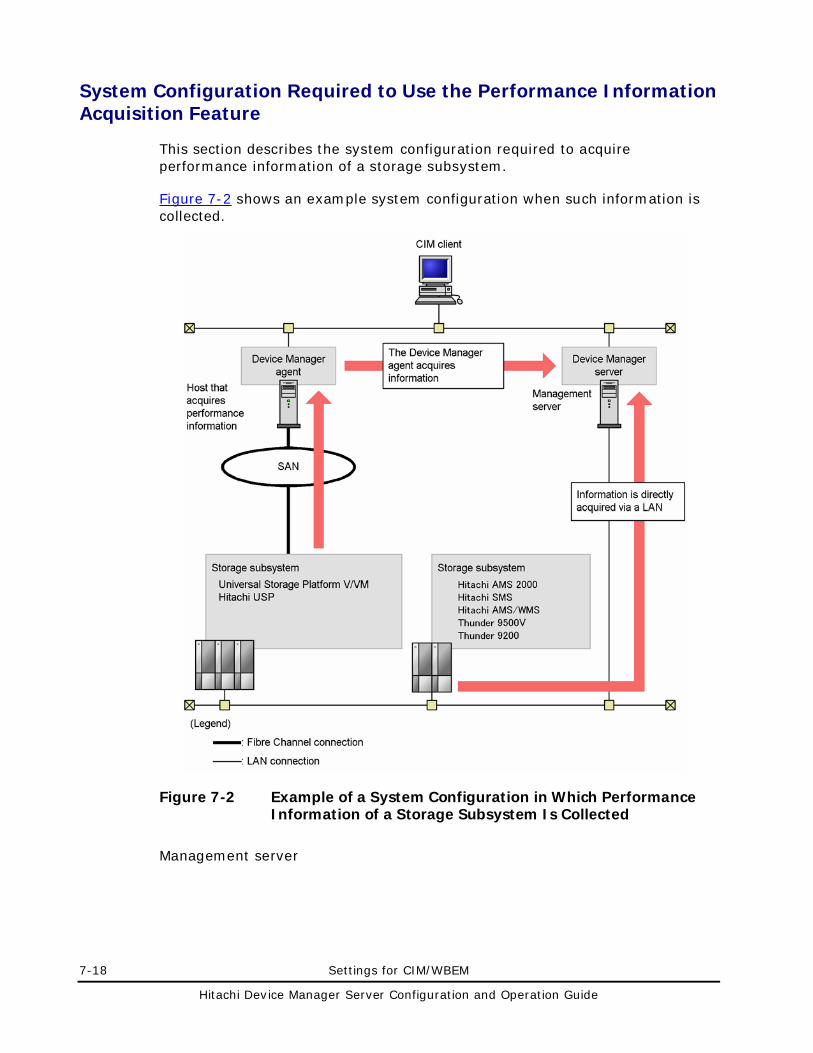
7-18 Settings for CIM/WBEM
Hitachi Device Manager Server Configuration and Operation Guide
System Configuration Required to Use the Performance Information Acquisition Feature
This section describes the system configuration required to acquire performance information of a storage subsystem.
Figure 7-2 shows an example system configuration when such information is collected.
Figure 7-2 Example of a System Configuration in Which Performance Information of a Storage Subsystem Is Collected
Management server
Settings for CIM/WBEM 7-19
Hitachi Device Manager Server Configuration and Operation Guide
A management server is a server in which Device Manager server version 5.9 or later is installed. You must set the management server so that CIM/WBEM can be used. For details on how to set up CIM/WBEM, see Basic Settings Required to Use the CIM/WBEM Features and Settings for Ports Used by CIM/WBEM Features.
Host that acquires performance information
This host is required when acquiring performance information of Universal Storage Platform V/VM or Hitachi USP. You must install Device Manager agent version 5.9 or later on this host.
We recommend that use the same computer for the management server and for the host to acquire performance information In this case, the OS for the host that acquires performance information must be able to support both Device Manager server and the Device Manager agent.
For example, if the OS for the management server is Windows XP, you cannot install the Device Manager agent, so you cannot use this computer as the host that acquires performance information.
Even if you use different computers for the management server and for the host to acquire performance information, the OS for the host that acquires performance information must be Windows, Solaris, or Linux. The host that acquires performance information cannot run HP-UX or AIX. For details about the OSs (Windows, Solaris, and Linux) supported by the Device Manager agent, see the Hitachi Device Manager Agent Installation Guide.
We recommend that you set the central management method of the Device Manager agent installed on the host that acquires performance information. For details on how to set the central management method, see the Hitachi Device Manager Agent Installation Guide.
Storage subsystem
This is a storage subsystem whose performance information is to be acquired. For details on the microcode versions that can use the performance information acquisition feature, see System Requirements for Storage Subsystems.
The host that acquires performance information (the Device Manager agent) acquires the information of Universal Storage Platform V/VM and Hitachi USP by using the command device within the storage subsystem, and then reports it to the Device Manager server.
In Hitachi AMS 2000, Hitachi SMS, Hitachi AMS/WMS, Thunder 9500V or Thunder 9200, the Device Manager server acquires performance information directly from a storage subsystem.
7-20 Settings for CIM/WBEM
Hitachi Device Manager Server Configuration and Operation Guide
The system configuration that is required to acquire performance information of a storage subsystem differs depending on the storage subsystem model. For information on Universal Storage Platform V/VM or Hitachi USP, see Settings Required to Acquire Performance Information of Universal Storage Platform V/VM or Hitachi USP. For information on Hitachi AMS 2000, Hitachi AMS/WMS, Thunder 9500V, or Thunder 9200, see Settings Required to Acquire Performance Information of Hitachi AMS 2000, Hitachi SMS, Hitachi AMS/WMS, Thunder 9500, or Thunder 9200.
Settings Required to Acquire Performance Information of Universal Storage Platform V/VM or Hitachi USP
This section describes the settings required to acquire performance information of Universal Storage Platform V/VM or Hitachi USP.
Preparations in Storage Subsystems
Prepare a command device for each storage subsystem from which you want to acquire performance information, and then assign the path to the host that acquires performance information so that the host can recognize the command device.
Preparations in the Host That Acquires Performance Information
Configure the settings shown below for the host that acquires performance information:
To configure the settings:
1. Install the Device Manager agent.
To acquire performance information, a CCI/LIB is necessary. If you install the Device Manager agent on a host, the necessary CCI/LIB is installed. However, if a CCI/LIB is already installed on the host, it is not overwritten. In this case, install a CCI/LIB that satisfies the following requirements:
A CCI/LIB whose version is 01-12-03/03 or later
2. Specify settings for central management. (This is recommended.)
3. Write the command device settings into the perf_cmddev.properties file.
To write the settings into the file, execute the perf_findcmddev command or edit the file directly. For details about the settings in the file, see Settings in the perf_cmddev.properties File. For details about the perf_findcmddev command, see Format of the perf_findcmddev Command.
Settings for CIM/WBEM 7-21
Hitachi Device Manager Server Configuration and Operation Guide
Note: • If you are using the Device Manager agent version 6.3 or earlier and you
want to use a storage subsystem in an SLPR environment, directly edit the perf_cmddev.properties file to define command devices for SLPRs.
• If you upgrade the Device Manager agent from version 6.3 or earlier to version 6.4 or later, the settings in the perf_cmddev.properties file remain unchanged. If you are using a storage subsystem in an SLPR environment, after the upgrade installation finishes, refresh the information of SLPR command devices defined in the perf_cmddev.properties file.
Preparations in the Device Manager Server
For the Device Manager server property, specify the name of the host that acquires performance information.
Specify the name of the host on which the Device Manager agent is installed by directly editing the server.cim.agent property in the server.properties file on the Device Manager server. For details on setting this property, see server.cim.agent.
After the property is set, restart the Device Manager server.
Note: Verify that the host name specified for the server.cim.agent property matches the host name registered in Device Manager for the host that acquires performance information. If these host names are different, you cannot acquire performance information.
Settings in the perf_cmddev.properties File
Edit the perf_cmddev.properties file to define the command device of the target storage subsystem. The perf_cmddev.properties file is stored in the following location:
• In Windows:
installation-folder-for-the-Device-Manager-agent\mod\hdvm\config\perf_cmddev.properties
• In Solaris or Linux:
/opt/HDVM/HBaseAgent/mod/hdvm/config/perf_cmddev.properties
Use the following format to define the command device in the perf_cmddev.properties file. Define one command device per line. When using the Device Manager agent version 6.3 or earlier: RAID-ID.serial-number.LDEV-number: deviceFileName
When using the Device Manager agent version 6.4 or later: RAID-ID.serial-number.[SLPR-number.]LDEV-number: deviceFileName
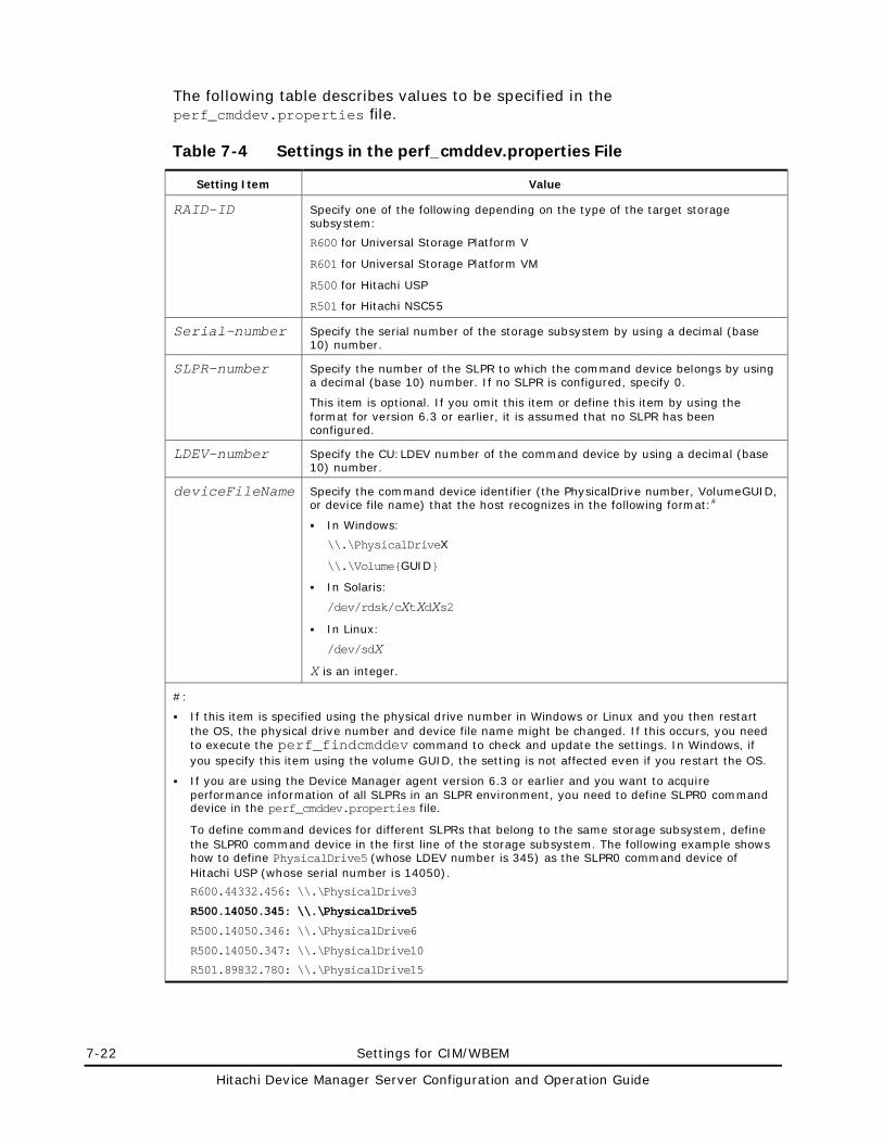
7-22 Settings for CIM/WBEM
Hitachi Device Manager Server Configuration and Operation Guide
The following table describes values to be specified in the perf_cmddev.properties file.
Table 7-4 Settings in the perf_cmddev.properties File
Setting Item Value
RAID-ID Specify one of the following depending on the type of the target storage subsystem:
R600 for Universal Storage Platform V
R601 for Universal Storage Platform VM
R500 for Hitachi USP
R501 for Hitachi NSC55
Serial-number Specify the serial number of the storage subsystem by using a decimal (base 10) number.
SLPR-number Specify the number of the SLPR to which the command device belongs by using a decimal (base 10) number. If no SLPR is configured, specify 0.
This item is optional. If you omit this item or define this item by using the format for version 6.3 or earlier, it is assumed that no SLPR has been configured.
LDEV-number Specify the CU:LDEV number of the command device by using a decimal (base 10) number.
deviceFileName Specify the command device identifier (the PhysicalDrive number, VolumeGUID, or device file name) that the host recognizes in the following format:#
In Windows:
\\.\PhysicalDriveX
\\.\Volume{GUID}
In Solaris:
/dev/rdsk/cXtXdXs2
In Linux:
/dev/sdX
X is an integer.
#:
If this item is specified using the physical drive number in Windows or Linux and you then restart the OS, the physical drive number and device file name might be changed. If this occurs, you need to execute the perf_findcmddev command to check and update the settings. In Windows, if you specify this item using the volume GUID, the setting is not affected even if you restart the OS.
If you are using the Device Manager agent version 6.3 or earlier and you want to acquire performance information of all SLPRs in an SLPR environment, you need to define SLPR0 command device in the perf_cmddev.properties file.
To define command devices for different SLPRs that belong to the same storage subsystem, define the SLPR0 command device in the first line of the storage subsystem. The following example shows how to define PhysicalDrive5 (whose LDEV number is 345) as the SLPR0 command device of Hitachi USP (whose serial number is 14050).
R600.44332.456: \\.\PhysicalDrive3
R500.14050.345: \\.\PhysicalDrive5
R500.14050.346: \\.\PhysicalDrive6
R500.14050.347: \\.\PhysicalDrive10
R501.89832.780: \\.\PhysicalDrive15
Settings for CIM/WBEM 7-23
Hitachi Device Manager Server Configuration and Operation Guide
Format of the perf_findcmddev Command
The perf_findcmddev command allows you to specify a command device in the perf_cmddev.properties file. To execute this command, you must have Administrator permissions (for Windows) or root permissions (for Solaris or Linux). Following is the command format:
• In Windows: installation-folder-for-the-Device-Manager-agent\bin\perf_findcmddev { view | verify | write [-file file-name] }
• In Solaris or Linux:
installation-directory-for-the-Device-Manager-agent/bin/perf_findcmddev { view | verify | write [-file file-name] }
The parameters for the perf_findcmddev command are described below. If you specify no parameter, multiple parameters, or upper-case parameters, the method for specifying the command is displayed.
view
This parameter displays the settings for the command devices defined in the perf_cmddev.properties file. The following table describes the command device settings displayed by the perf_findcmddev command.
Table 7-5 Command Device Settings Displayed by the perf_findcmddev Command
Item Description
Raid ID Displays the RAID ID.
R600 for Universal Storage Platform V
R601 for Universal Storage Platform VM
R500 for Hitachi USP
R501 for Hitachi NSC 55
Serial# Displays the serial number of the storage subsystem by using a decimal (base 10) number.
SLPR# Displays the number of the SLPR to which the command device belongs by using a decimal (base 10) number.
If no number is defined for the SLPR, a hyphen (-) is displayed.
LDEV# Displays the CU:LDEV number of the command device by using a decimal (base 10) number.
Device file name Displays the command device identifier (the physical drive number, VolumeGUID, or device file name) recognized by the host.
If an unrecognizable value is defined in the perf_cmddev.properties file, that value is displayed as UNKNOWN. On lines where the definition does not follow the proper format, all information is displayed as UNKNOWN. Comment lines and blank lines are not displayed. In addition, if no value is specified in the perf_cmddev.properties file, only the header is displayed. The following is an example of output from the command.
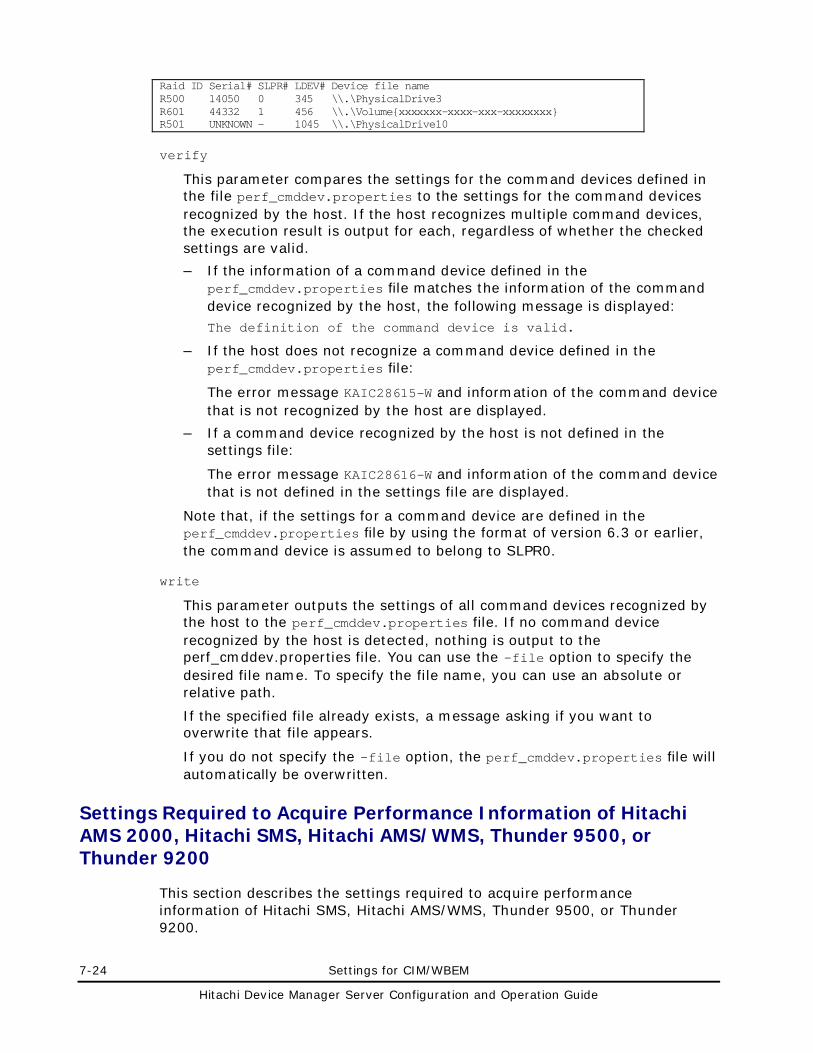
7-24 Settings for CIM/WBEM
Hitachi Device Manager Server Configuration and Operation Guide
Raid ID Serial# SLPR# LDEV# Device file name R500 14050 0 345 \\.\PhysicalDrive3 R601 44332 1 456 \\.\Volume{xxxxxxx-xxxx-xxx-xxxxxxxx} R501 UNKNOWN - 1045 \\.\PhysicalDrive10
verify
This parameter compares the settings for the command devices defined in the file perf_cmddev.properties to the settings for the command devices recognized by the host. If the host recognizes multiple command devices, the execution result is output for each, regardless of whether the checked settings are valid.
– If the information of a command device defined in the perf_cmddev.properties file matches the information of the command device recognized by the host, the following message is displayed: The definition of the command device is valid.
– If the host does not recognize a command device defined in the perf_cmddev.properties file:
The error message KAIC28615-W and information of the command device that is not recognized by the host are displayed.
– If a command device recognized by the host is not defined in the settings file:
The error message KAIC28616-W and information of the command device that is not defined in the settings file are displayed.
Note that, if the settings for a command device are defined in the perf_cmddev.properties file by using the format of version 6.3 or earlier, the command device is assumed to belong to SLPR0.
write
This parameter outputs the settings of all command devices recognized by the host to the perf_cmddev.properties file. If no command device recognized by the host is detected, nothing is output to the perf_cmddev.properties file. You can use the -file option to specify the desired file name. To specify the file name, you can use an absolute or relative path.
If the specified file already exists, a message asking if you want to overwrite that file appears.
If you do not specify the -file option, the perf_cmddev.properties file will automatically be overwritten.
Settings Required to Acquire Performance Information of Hitachi AMS 2000, Hitachi SMS, Hitachi AMS/WMS, Thunder 9500, or Thunder 9200
This section describes the settings required to acquire performance information of Hitachi SMS, Hitachi AMS/WMS, Thunder 9500, or Thunder 9200.
Settings for CIM/WBEM 7-25
Hitachi Device Manager Server Configuration and Operation Guide
Preparations in Storage Subsystems
Before you use the feature for acquiring performance information, you need to use the Physical View of Device Manager Web Client, Storage Navigator Modular, or Storage Navigator Modular 2 to specify settings for acquiring performance statistics for each relevant storage subsystem. For details, see the manuals for each storage subsystem.
Setting Up a User to Acquire Performance Information
When performance information is acquired from a storage subsystem, that storage subsystem might be locked depending on whether the Password Protection function or the Account Authentication function is enabled for it. In this case, you might be unable to acquire performance information from any storage subsystem that Device Manager, Storage Navigator Modular, or Storage Navigator Modular 2 is accessing.
• If the Password Protection function is enabled: The storage subsystem is always locked when you acquire performance information from it.
• If both the Password Protection function and the Account Authentication function are disabled: The storage subsystem is not locked when you acquire performance information from it.
• If the Password Protection function is disabled and the Account Authentication function is enabled: You can acquire performance information without locking the storage subsystem by creating a user account dedicated to acquiring performance information.
To set up this account on storage subsystems and the Device Manager server:
1. Register a user account that has only the View permission for each storage subsystem from which performance information is to be acquired. To acquire performance information from multiple storage subsystems, the user account registered for each of those storage subsystems must have the same user ID and password.
2. Execute the hdvmmodpolluser command to register this user in Device Manager. For details about the hdvmmodpolluser command, see Format of the hdvmmodpolluser Command.
Format of the hdvmmodpolluser Command
The hdvmmodpolluser command is stored in the following location:
• In Windows:
installation-folder-for-the-Device-Manager-server\HiCommandServer\tools\hdvmmodpolluser.bat
• In Solaris or Linux:
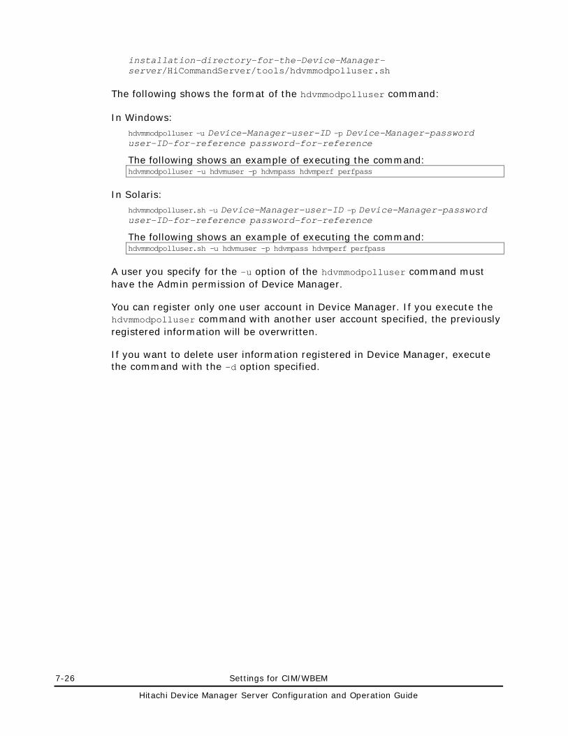
7-26 Settings for CIM/WBEM
Hitachi Device Manager Server Configuration and Operation Guide
installation-directory-for-the-Device-Manager-server/HiCommandServer/tools/hdvmmodpolluser.sh
The following shows the format of the hdvmmodpolluser command:
In Windows:
hdvmmodpolluser -u Device-Manager-user-ID -p Device-Manager-password user-ID-for-reference password-for-reference
The following shows an example of executing the command: hdvmmodpolluser -u hdvmuser -p hdvmpass hdvmperf perfpass
In Solaris:
hdvmmodpolluser.sh -u Device-Manager-user-ID -p Device-Manager-password user-ID-for-reference password-for-reference
The following shows an example of executing the command: hdvmmodpolluser.sh -u hdvmuser -p hdvmpass hdvmperf perfpass
A user you specify for the -u option of the hdvmmodpolluser command must have the Admin permission of Device Manager.
You can register only one user account in Device Manager. If you execute the hdvmmodpolluser command with another user account specified, the previously registered information will be overwritten.
If you want to delete user information registered in Device Manager, execute the command with the -d option specified.
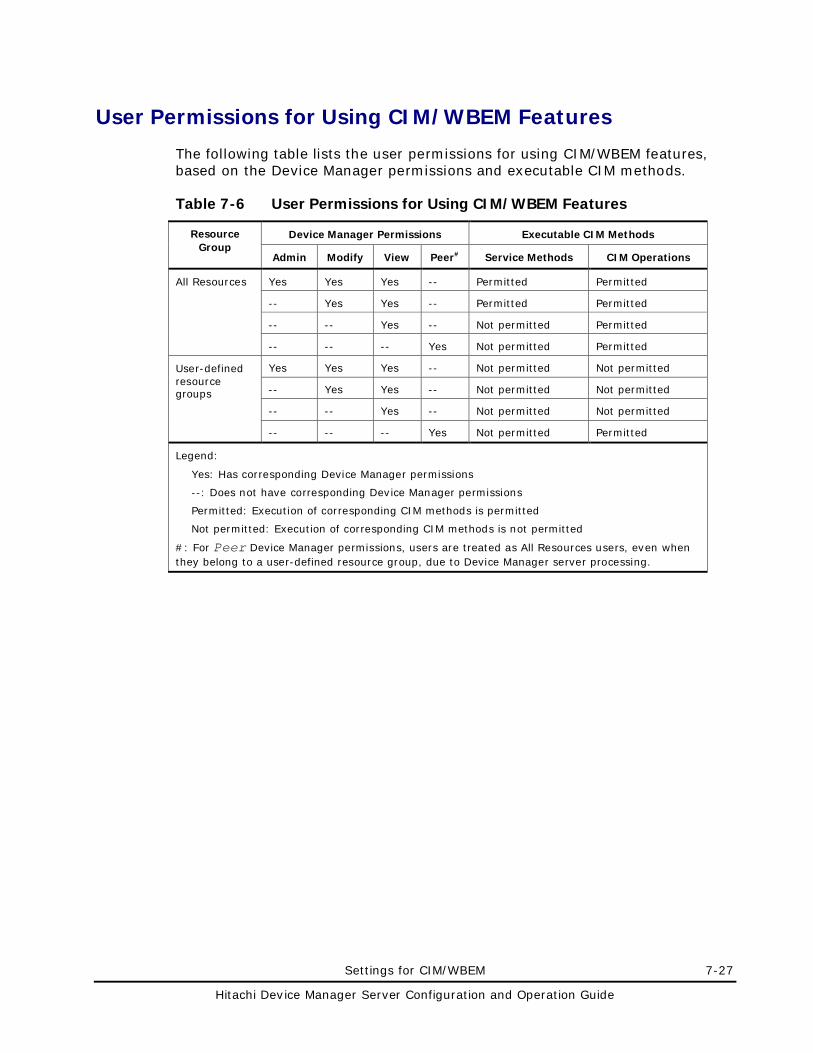
Settings for CIM/WBEM 7-27
Hitachi Device Manager Server Configuration and Operation Guide
User Permissions for Using CIM/WBEM Features
The following table lists the user permissions for using CIM/WBEM features, based on the Device Manager permissions and executable CIM methods.
Table 7-6 User Permissions for Using CIM/WBEM Features
Resource Group
Device Manager Permissions Executable CIM Methods
Admin Modify View Peer# Service Methods CIM Operations
All Resources Yes Yes Yes -- Permitted Permitted
-- Yes Yes -- Permitted Permitted
-- -- Yes -- Not permitted Permitted
-- -- -- Yes Not permitted Permitted
User-defined resource groups
Yes Yes Yes -- Not permitted Not permitted
-- Yes Yes -- Not permitted Not permitted
-- -- Yes -- Not permitted Not permitted
-- -- -- Yes Not permitted Permitted
Legend:
Yes: Has corresponding Device Manager permissions
--: Does not have corresponding Device Manager permissions
Permitted: Execution of corresponding CIM methods is permitted
Not permitted: Execution of corresponding CIM methods is not permitted
#: For Peer Device Manager permissions, users are treated as All Resources users, even when they belong to a user-defined resource group, due to Device Manager server processing.

Starting and Stopping the Device Manager Server 8-1
Hitachi Device Manager Server Configuration and Operation Guide
Starting and Stopping the Device Manager Server
This chapter describes how to start and stop the Device Manager server.
Before Controlling the Device Manager Server
Starting the Device Manager Server
Stopping the Device Manager Server
Checking the Operating Status of the Device Manager Server
Starting the Device Manager Server and Common Component
Stopping the Device Manager Server and Common Component
Checking the Operating Status of the Device Manager Server and Common Component
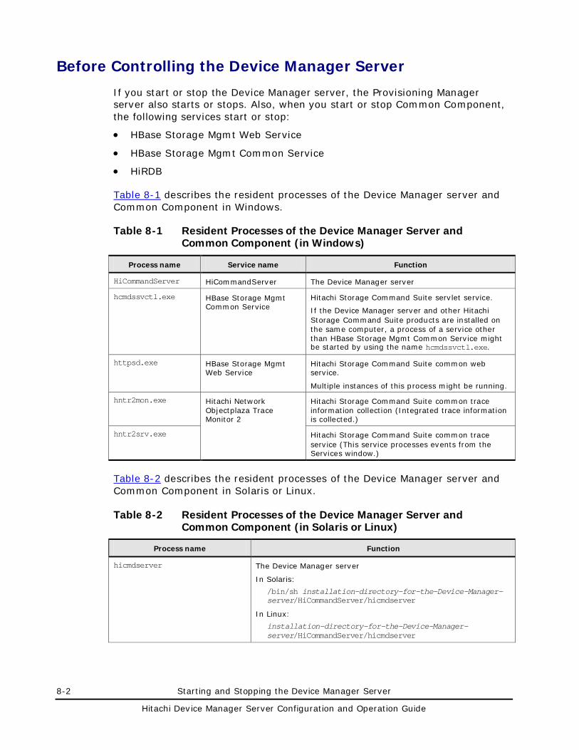
8-2 Starting and Stopping the Device Manager Server
Hitachi Device Manager Server Configuration and Operation Guide
Before Controlling the Device Manager Server
If you start or stop the Device Manager server, the Provisioning Manager server also starts or stops. Also, when you start or stop Common Component, the following services start or stop:
• HBase Storage Mgmt Web Service
• HBase Storage Mgmt Common Service
• HiRDB
Table 8-1 describes the resident processes of the Device Manager server and Common Component in Windows.
Table 8-1 Resident Processes of the Device Manager Server and Common Component (in Windows)
Process name Service name Function
HiCommandServer HiCommandServer The Device Manager server
hcmdssvctl.exe HBase Storage Mgmt Common Service
Hitachi Storage Command Suite servlet service.
If the Device Manager server and other Hitachi Storage Command Suite products are installed on the same computer, a process of a service other than HBase Storage Mgmt Common Service might be started by using the name hcmdssvctl.exe.
httpsd.exe HBase Storage Mgmt Web Service
Hitachi Storage Command Suite common web service.
Multiple instances of this process might be running.
hntr2mon.exe Hitachi Network Objectplaza Trace Monitor 2
Hitachi Storage Command Suite common trace information collection (Integrated trace information is collected.)
hntr2srv.exe Hitachi Storage Command Suite common trace service (This service processes events from the Services window.)
Table 8-2 describes the resident processes of the Device Manager server and Common Component in Solaris or Linux.
Table 8-2 Resident Processes of the Device Manager Server and Common Component (in Solaris or Linux)
Process name Function
hicmdserver The Device Manager server
In Solaris:
/bin/sh installation-directory-for-the-Device-Manager-server/HiCommandServer/hicmdserver
In Linux:
installation-directory-for-the-Device-Manager-server/HiCommandServer/hicmdserver
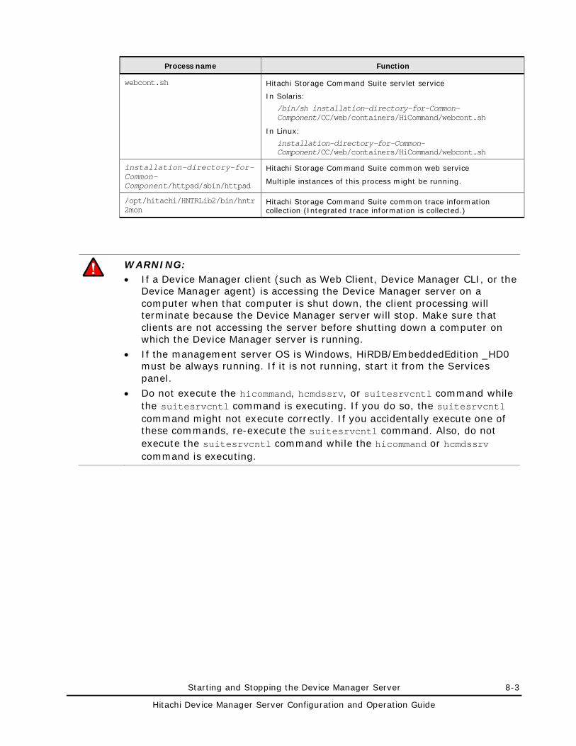
Starting and Stopping the Device Manager Server 8-3
Hitachi Device Manager Server Configuration and Operation Guide
Process name Function
webcont.sh Hitachi Storage Command Suite servlet service
In Solaris:
/bin/sh installation-directory-for-Common-Component/CC/web/containers/HiCommand/webcont.sh
In Linux:
installation-directory-for-Common-Component/CC/web/containers/HiCommand/webcont.sh
installation-directory-for-Common-Component/httpsd/sbin/httpsd
Hitachi Storage Command Suite common web service
Multiple instances of this process might be running.
/opt/hitachi/HNTRLib2/bin/hntr2mon
Hitachi Storage Command Suite common trace information collection (Integrated trace information is collected.)
WARNING: • If a Device Manager client (such as Web Client, Device Manager CLI, or the
Device Manager agent) is accessing the Device Manager server on a computer when that computer is shut down, the client processing will terminate because the Device Manager server will stop. Make sure that clients are not accessing the server before shutting down a computer on which the Device Manager server is running.
• If the management server OS is Windows, HiRDB/EmbeddedEdition _HD0 must be always running. If it is not running, start it from the Services panel.
• Do not execute the hicommand, hcmdssrv, or suitesrvcntl command while the suitesrvcntl command is executing. If you do so, the suitesrvcntl command might not execute correctly. If you accidentally execute one of these commands, re-execute the suitesrvcntl command. Also, do not execute the suitesrvcntl command while the hicommand or hcmdssrv command is executing.
8-4 Starting and Stopping the Device Manager Server
Hitachi Device Manager Server Configuration and Operation Guide
Starting the Device Manager Server
To start the Device Manager server:
In Windows:
Log in as a user with Administrator permissions, and then start the Device Manager server in either of the following ways:
By using Windows functions:
Select Start, All Programs, Hitachi Storage Command Suite, Device Manager, and then Start Server.
By using the following command: installation-folder-for-the-Device-Manager-server\suitesrvcntl /start_hdvm
In Solaris or Linux:
Log in as a root user, and then execute the following command: installation-directory-for-the-Device-Manager-server/suitesrvcntl -start_hdvm
Starting and Stopping the Device Manager Server 8-5
Hitachi Device Manager Server Configuration and Operation Guide
Stopping the Device Manager Server
To stop the Device Manager server:
In Windows:
Log in as a user with Administrator permissions, and then stop the Device Manager server in either of the following ways:
By using Windows functions:
Select Start, All Programs, Hitachi Storage Command Suite, Device Manager, and then Stop Server.
By using the following command: installation-folder-for-the-Device-Manager-server\suitesrvcntl /stop_hdvm
In Solaris or Linux:
Log in as a root user, and then execute the following command: installation-directory-for-the-Device-Manager-server/suitesrvcntl -stop_hdvm
8-6 Starting and Stopping the Device Manager Server
Hitachi Device Manager Server Configuration and Operation Guide
Checking the Operating Status of the Device Manager Server
To check the operating status of the Device Manager server:
In Windows:
Log in as a user with Administrator permissions, and then check the operating status of the Device Manager server in either of the following ways:
By using Windows functions:
Select Start, All Programs, Hitachi Storage Command Suite, Device Manager, and then Server Status.
By using the following command:
installation-folder-for-the-Device-Manager-server\suitesrvcntl /status_hdvm
In Solaris or Linux:
Log in as a root user, and then execute the following command: installation-directory-for-the-Device-Manager-server/suitesrvcntl -status_hdvm
Starting and Stopping the Device Manager Server 8-7
Hitachi Device Manager Server Configuration and Operation Guide
Starting the Device Manager Server and Common Component
To start the Device Manager server and Common Component:
In Windows:
Log in as a user with Administrator permissions, and then start the Device Manager server and Common Component in either of the following ways:
By using Windows functions:
Select Start, All Programs, Hitachi Storage Command Suite, Device Manager, and then Start Server with Common Services.
By using the following command: installation-folder-for-Common-Component\bin\hcmdssrv /start
In Solaris or Linux:
Log in as a root user, and then execute the following command:
installation-directory-for-Common-Component/bin/hcmdssrv -start
Caution: Services of other Hitachi Storage Command Suite products whose versions are 5.7 or later are started at the same time.
• If you start the Device Manager server and Common Component at the same time, services of other Hitachi Storage Command Suite products whose versions are 5.7 or later also start. For details about how to start services of HiCommand Suite products whose versions are earlier than 5.7, see the manual for your product version.
• If the Common Component services are already running when you use the above methods, the Device Manager server and the Tiered Storage Manager server will not start. In this case, start the Device Manager server or the Tiered Storage Manager server independently of Common Component.
8-8 Starting and Stopping the Device Manager Server
Hitachi Device Manager Server Configuration and Operation Guide
Stopping the Device Manager Server and Common Component
To stop the Device Manager server and Common Component:
In Windows:
Log in as a user with Administrator permissions, and then stop the Device Manager server and Common Component in either of the following ways:
By using Windows functions:
Select Start, All Programs, Hitachi Storage Command Suite, Device Manager, and then Stop Server with Common Services.
By using the following command: installation-folder-for-Common-Component\bin\hcmdssrv /stop
In Solaris or Linux:
Log in as a root user, and then execute the following command:
installation-directory-for-Common-Component/bin/hcmdssrv -stop
Caution: • Services of other Hitachi Storage Command Suite products whose versions
are 5.7 or later stop at the same time. If you stop the Device Manager server and Common Component at the same time, services of other Hitachi Storage Command Suite products whose versions are 5.7 or later also stop. For details about how to stop services of HiCommand Suite products whose versions are earlier than 5.7, see the manual for your product version.
• In Solaris or Linux, do not stop Common Component before it has completed startup. If you do so, the service status might indicate that the service has stopped even though a resident process for the service is running, or you might be unable to stop the service. In such cases, restart the computer.
Starting and Stopping the Device Manager Server 8-9
Hitachi Device Manager Server Configuration and Operation Guide
Checking the Operating Status of the Device Manager Server and Common Component
To check the operating status of the Device Manager server and Common Component:
In Windows:
Log in as a user with Administrator permissions, and then check the operating status of the Device Manager server and Common Component in either of the following ways:
By using Windows functions:
Select Start, All Programs, Hitachi Storage Command Suite, Device Manager, and then Server and Common Services Status.
By using the following command: installation-folder-for-Common-Component\bin\hcmdssrv /statusall
In Solaris or Linux:
Log in as a root user, and then execute the following command: installation-directory-for-Common-Component/bin/hcmdssrv -statusall

8-10 Starting and Stopping the Device Manager Server
Hitachi Device Manager Server Configuration and Operation Guide
Managing the Database 9-1
Hitachi Device Manager Server Configuration and Operation Guide
Managing the Database
This chapter describes how to back up or restore the Device Manager server database.
Before Managing the Database
Backing Up the Database
Restoring the Database
Migrating the Databases
Initializing the Database
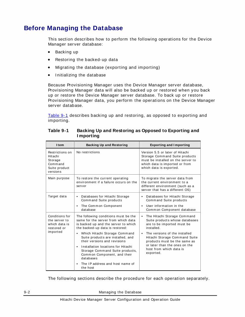
9-2 Managing the Database
Hitachi Device Manager Server Configuration and Operation Guide
Before Managing the Database
This section describes how to perform the following operations for the Device Manager server database:
• Backing up
• Restoring the backed-up data
• Migrating the database (exporting and importing)
• Initializing the database
Because Provisioning Manager uses the Device Manager server database, Provisioning Manager data will also be backed up or restored when you back up or restore the Device Manager server database. To back up or restore Provisioning Manager data, you perform the operations on the Device Manager server database.
Table 9-1 describes backing up and restoring, as opposed to exporting and importing.
Table 9-1 Backing Up and Restoring as Opposed to Exporting and Importing
Item Backing Up and Restoring Exporting and Importing
Restrictions on Hitachi Storage Command Suite product versions
No restrictions Version 5.5 or later of Hitachi Storage Command Suite products must be installed on the server to which data is imported or from which data is exported.
Main purpose To restore the current operating environment if a failure occurs on the server
To migrate the server data from the current environment to a different environment (such as a server that has a different OS)
Target data Databases for Hitachi Storage Command Suite products
The Common Component database
Databases for Hitachi Storage Command Suite products
User information in the Common Component database
Conditions for the server to which data is restored or imported
The following conditions must be the same for the server from which data is backed up and the server to which the backed-up data is restored:
Which Hitachi Storage Command Suite products are installed, and their versions and revisions
Installation locations for Hitachi Storage Command Suite products, Common Component, and their databases
The IP address and host name of the host
The Hitachi Storage Command Suite products whose databases are to be imported must be installed.
The versions of the installed Hitachi Storage Command Suite products must be the same as or later than the ones on the host from which data is exported.
The following sections describe the procedure for each operation separately.
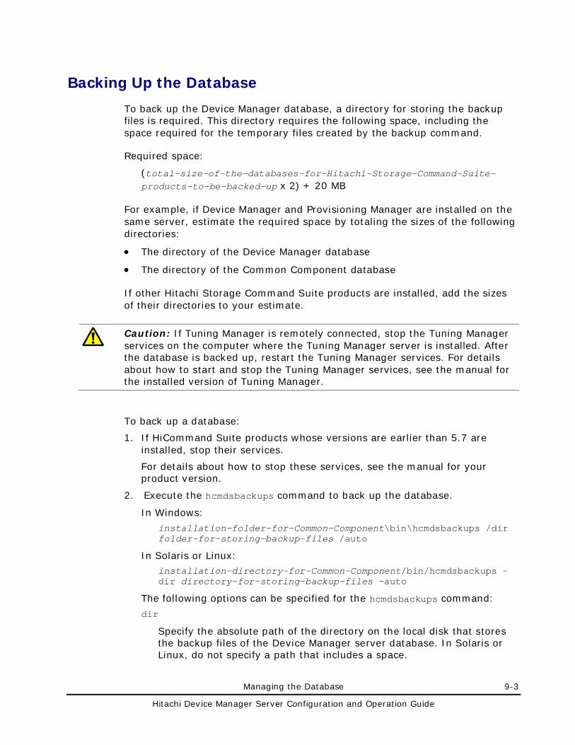
Managing the Database 9-3
Hitachi Device Manager Server Configuration and Operation Guide
Backing Up the Database
To back up the Device Manager database, a directory for storing the backup files is required. This directory requires the following space, including the space required for the temporary files created by the backup command.
Required space:
(total-size-of-the-databases-for-Hitachi-Storage-Command-Suite-products-to-be-backed-up x 2) + 20 MB
For example, if Device Manager and Provisioning Manager are installed on the same server, estimate the required space by totaling the sizes of the following directories:
• The directory of the Device Manager database
• The directory of the Common Component database
If other Hitachi Storage Command Suite products are installed, add the sizes of their directories to your estimate.
Caution: If Tuning Manager is remotely connected, stop the Tuning Manager services on the computer where the Tuning Manager server is installed. After the database is backed up, restart the Tuning Manager services. For details about how to start and stop the Tuning Manager services, see the manual for the installed version of Tuning Manager.
To back up a database:
1. If HiCommand Suite products whose versions are earlier than 5.7 are installed, stop their services.
For details about how to stop these services, see the manual for your product version.
2. Execute the hcmdsbackups command to back up the database.
In Windows:
installation-folder-for-Common-Component\bin\hcmdsbackups /dir folder-for-storing-backup-files /auto
In Solaris or Linux: installation-directory-for-Common-Component/bin/hcmdsbackups -dir directory-for-storing-backup-files -auto
The following options can be specified for the hcmdsbackups command:
dir
Specify the absolute path of the directory on the local disk that stores the backup files of the Device Manager server database. In Solaris or Linux, do not specify a path that includes a space.
9-4 Managing the Database
Hitachi Device Manager Server Configuration and Operation Guide
Caution: Make sure that no files or subdirectories are in the directory specified for the dir option. If any are, the backup will be aborted. In this case, delete the files or subdirectories in that directory, and then re-execute the hcmdsbackups command.
auto
This option automatically changes the Hitachi Storage Command Suite product services and the HiRDB service that are on the same computer to the statuses required for backing up the database. After the command finishes, the Hitachi Storage Command Suite product services and the HiRDB service will be active.
When you execute the hcmdsbackups command, the directory database will be created in the directory for storing backup files, specified with the dir option, and these files will be combined and stored as the file backup.hdb.
Note: The setting files for Hitachi Storage Command Suite products are backed up in locations other than the database directory created in the directory for storing backup files, specified with the dir option. If an error occurs in the management server and you need to re-install Hitachi Storage Command Suite products, you can use the backed up setting files to check the previous settings.
3. If HiCommand Suite products whose versions are earlier than 5.7 are installed, start their services as needed.
For details about how to start these services, see the manual for your product version.
Managing the Database 9-5
Hitachi Device Manager Server Configuration and Operation Guide
Restoring the Database
Before restoring the database, make sure that the items below are the same on the server from which the Device Manager server database was backed up and on the server to which the backed-up database is to be restored. If the following differ, the database cannot be restored:
• The installed Hitachi Storage Command Suite products, and their versions and revisions
• Installation locations for Hitachi Storage Command Suite products, Common Component, and their databases
• The IP address and host name of the host
Caution: • The hcmdsdb command, which is used in the procedure below, creates
temporary files during execution. Make sure that you have write permission for the directory that contains backup files, and that the directory has enough space. The required space can be estimated as follows: total-size-of-the-databases-for-Hitachi-Storage-Command-Suite-products-to-be-backed-up + 20 MB
• If Tuning Manager is remotely connected, stop the Tuning Manager services on the computer where the Tuning Manager server is installed. After the database is restored, restart the Tuning Manager services. For details about how to start and stop the Tuning Manager services, see the manual for the installed version of Tuning Manager.
To restore a database:
1. If HiCommand Suite products whose versions are earlier than 5.7 are installed, stop their services.
For details about how to stop these services, see the manual for your product version.
2. Execute the hcmdsdb command to restore the database.
In Windows: installation-folder-for-Common-Component\bin\hcmdsdb.bat /restore backup-file /type name-of-the-Hitachi-Storage-Command-Suite-product-to-be-restored /auto
In Solaris or Linux:
installation-directory-for-Common-Component/bin/hcmdsdb -restore backup-file -type name-of-the-Hitachi-Storage-Command-Suite-product-to-be-restored -auto
You can specify the following options for the hcmdsdb command:
restore
9-6 Managing the Database
Hitachi Device Manager Server Configuration and Operation Guide
Specify the absolute path to the Device Manager server database backup file (backup.hdb) created by using the hcmdsbackups command. In Solaris or Linux, do not specify a path that includes a space.
type
Specify the name of the Hitachi Storage Command Suite product to be restored.
To restore only the Device Manager database, specify DeviceManager.
To restore all the Hitachi Storage Command Suite product databases at once, specify ALL.
If you uninstalled all the Hitachi Storage Command Suite products and then reinstalled them, specify ALL to restore their databases.
WARNING: If you do not want to restore the databases for Hitachi Storage Command Suite products other than Device Manager, specify DeviceManager.
auto
This option automatically changes the Hitachi Storage Command Suite product services and the HiRDB service that are on the same computer to the statuses required for restoring the database. After the command finishes, the Hitachi Storage Command Suite product services and the HiRDB service will remain stopped.
3. If DeviceManager is specified for the type option, specify true for the server.base.initialsynchro property in the server.properties file.
For details about this property, see server.base.initialsynchro.
4. To remotely connect to Tuning Manager, execute the htmsetup command. For details, see htmsetup Command.
5. Start the services of Hitachi Storage Command Suite products and Common Component as follows.
In Windows:
Select Start, All Programs, Hitachi Storage Command Suite, Device Manager, and then Start Server with Common Services.
In Solaris or Linux, execute the following command:
installation-directory-for-Common-Component/bin/hcmdssrv -start
Caution: The services of HiCommand Suite products whose versions are earlier than 5.7 do not start automatically. If such products are installed, start their services manually as needed. For details about how to start these services, see the manual for your product version.
6. Change the value of the server.base.initialsynchro property in the server.properties file back to false.
Managing the Database 9-7
Hitachi Device Manager Server Configuration and Operation Guide
Migrating the Databases
If you use Hitachi Storage Command Suite products for an extended period of time, you might need a higher performance computer to run an upgraded product or to handle an increased number of managed objects. In such a case, you have to migrate the current databases to your new computer. You can migrate Hitachi Storage Command Suite product databases by using the hcmdsdbtrans command. This command migrates both the data stored in the databases of Hitachi Storage Command Suite products and the user information managed by Common Component.
You can also use the hcmdsdbtrans command to migrate the Device Manager database to a server whose environment differs from the current one in any of the following ways:
• Migration to a server of a different platform
• Migration to a server on which installation locations for Hitachi Storage Command Suite products differ from the ones on the migration source server
• Migration to a server on which versions of Hitachi Storage Command Suite products are later than the ones on the migration source server
Notes on Migrating Databases
The following are notes on the databases, product types, versions, and user information of Hitachi Storage Command Suite products on the migration source and destination servers.
Notes on databases, product types, and versions of Hitachi Storage Command Suite products:
– Databases of Hitachi Storage Command Suite products that do not exist on the migration destination server cannot be migrated. Install necessary products on the migration destination server before migration.
– If a storage subsystem that is not supported on the migration destination server is registered in the Device Manager database on the migration source server, delete that storage subsystem from the database before migration.
– If any of the versions of the Hitachi Storage Command Suite products installed on the migration destination server are earlier than the ones on the migration source server, no databases can be migrated. On the migration destination server, install Hitachi Storage Command Suite products whose versions are the same as or later than the ones on the migration source server.
– If you want to migrate the database of Replication Monitor 4.2 or earlier, upgrade Replication Monitor on the migration source and
9-8 Managing the Database
Hitachi Device Manager Server Configuration and Operation Guide
destination servers to version 5.0 or later in advance. If you cannot upgrade Replication Monitor to version 5.0 or later, or the Replication Monitor database does not need to be migrated, use the type option to specify all products other than Replication Monitor when you execute the command.
– If you want to migrate the data in the Replication Monitor database to a Replication Manager database, upgrade Replication Monitor on the migration source server to Replication Manager, and then migrate the database.
– The following restrictions apply when migrating the Tuning Manager database.
If the version of Tuning Manager is earlier than 6.0, first upgrade Tuning Manager to version 6.0 or later on both the migration source and destination servers.
Specify the same capacity for the Tuning Manager database on these servers. For details about how to change the capacity of the database, see the Hitachi Tuning Manager Server Administration Guide.
The database can be migrated if the database configuration (Small or Medium) is the same on both the migration source and destination servers, or if the database configuration on the migration destination server is larger than that on the source server.
On the migration source server, if the number of managed resources exceeds 70% of the number of manageable resources, the database data cannot be migrated to a database that has the same configuration.
Notes on user information:
– If there is user information on the migration destination server, this user information will be replaced with the user information from the migration source server. Therefore, do not perform a migration to a server on which user information for Hitachi Storage Command Suite products already exists.
– Do not migrate the databases of Hitachi Storage Command Suite products that were running on different management servers to one management server because user information will be overwritten.
Procedure for Migrating Databases
To migrate databases:
1. On the migration destination server, install the Hitachi Storage Command Suite products whose databases will be migrated.
2. Export the databases from the migration source server by using the hcmdsdbtrans command.
3. Transfer the archive file from the source server to the destination server.
4. Import the databases into the destination server by using the hcmdsdbtrans command.
Managing the Database 9-9
Hitachi Device Manager Server Configuration and Operation Guide
The following sections describe each step.
On the Migration Destination Server, Install the Hitachi Storage Command Suite Products
On the migration source server, install the Hitachi Storage Command Suite products whose databases will be migrated. The versions of the Hitachi Storage Command Suite products installed on the migration destination server must be the same as or later than the ones on the migration source server.
Exporting the Databases from the Migration Source Server
To export the Device Manager database, a directory for temporarily storing the database data and a directory for storing the archive file are required. These directories require as much capacity as the total size of the following two directories:
• The directory of the Device Manager database
• The directory of the Common Component database (other than the SYS directory and its subdirectories)
The above estimate applies if only Device Manager is installed. If other Hitachi Storage Command Suite products are installed, add the capacities of their databases to your estimate.
Caution: • Databases are exported as archive files. If the total capacity of databases
exceeds 2 GB, creation of the archive file fails when the database data is exported. In this case, instead of using the archive file, transfer the exported database data to the migration destination.
• If Tuning Manager is remotely connected, stop the Tuning Manager services on the computer where the Tuning Manager server is installed. After the database is exported, restart the Tuning Manager services. For details about how to start and stop the Tuning Manager services, see the manual for the installed version of Tuning Manager.
To export the databases from the migration source server:
1. If HiCommand Suite products whose versions are earlier than 5.7 are installed, stop their services.
For details about how to stop these services, see the manual for your product version.
2. Execute the hcmdsdbtrans command to export the databases.
In Windows:
installation-folder-for-Common-Component\bin\hcmdsdbtrans /export /workpath working-folder /file archive-file /auto
In Solaris or Linux:
9-10 Managing the Database
Hitachi Device Manager Server Configuration and Operation Guide
installation-directory-for-Common-Component/bin/hcmdsdbtrans -export -workpath working-directory -file archive-file -auto
The following options can be specified for the hcmdsdbtrans command:
workpath
Specify the absolute path to the working directory where you want to temporarily store database data. In Solaris or Linux, do not specify a path that includes a space. Specify a directory on your local disk.
Caution: Make sure that no files or subdirectories are in the directory specified for the workpath option. If any are, the export will be aborted. In this case, delete the files and subdirectories in that directory, and then re-execute the hcmdsdbtrans command.
file
Using an absolute path, specify the name of the archive file to be output. In Solaris or Linux, do not include a space in this path.
auto
This option automatically changes the Hitachi Storage Command Suite product services and the HiRDB service that are on the same computer to the statuses required for exporting the databases. After the command finishes, the Hitachi Storage Command Suite product services and the HiRDB service will be active.
3. Transfer the exported files to the migration destination server.
If the archive file cannot be created, transfer all the files created in the directory specified by the workpath option. In this case, do not change the structure of the files.
Importing the Databases to the Migration Destination Server
To import the databases to the migration destination server:
Caution: If Tuning Manager is remotely connected, stop the Tuning Manager services on the computer where the Tuning Manager server is installed. After the database is imported, restart the Tuning Manager services. For details about how to start and stop the Tuning Manager services, see the manual for the installed version of Tuning Manager.
1. If HiCommand Suite products whose versions are earlier than 5.7 are
installed, stop their services.
For details about how to stop these services, see the manual for your product version.
2. Execute the hcmdsdbtrans command to import the databases.
In Windows:
Managing the Database 9-11
Hitachi Device Manager Server Configuration and Operation Guide
installation-folder-for-Common-Component\bin\hcmdsdbtrans /import /workpath working-folder [/file archive-file] /type {ALL|Hitachi-Storage-Command-Suite-products-whose-databases-will-be-migrated} /auto
In Solaris or Linux: installation-directory-for-Common-Component/bin/hcmdsdbtrans -import -workpath working-directory [-file archive-file] -type {ALL|Hitachi- Storage-Command-Suite-products-whose-databases-will-be-migrated} -auto
The following options can be specified for the hcmdsdbtrans command:
workpath
When using the archive file for the import:
Specify the absolute path to the directory used to extract the archive file. In Solaris or Linux, do not specify a path that includes a space. Specify a directory on your local disk. If you want to use the archive file, the file option must be specified.
Caution: Make sure that no files or subdirectories are in the directory specified for the workpath option. If any are, the import will be aborted. In this case, delete the files or subdirectories in that directory, and then re-execute the hcmdsdbtrans command.
When not using the archive file for the import:
Specify the directory that stores the database data files transferred from the migration source server. Do not change the structure of those files in the transferred directory. Also, do not specify the file option.
file
Specify the absolute path to the archive file of the databases transferred from the migration source server. In Solaris or Linux, do not specify a path that includes a space. If the database data files transferred from the migration source server are stored in the directory specified by workpath, you do not need to specify this option.
type
Specify the names of the Hitachi Storage Command Suite products whose databases will be migrated. Only the databases of the specified products will be migrated.
To migrate the Device Manager database, specify DeviceManager. For details about the names to specify when you migrate databases of other products, see the manuals for those products. If you specify multiple product names, use a comma to separate the names.
To migrate the databases of all the installed Hitachi Storage Command Suite products at once, specify ALL. The databases of the Hitachi Storage Command Suite products installed on the migration destination server are automatically migrated.
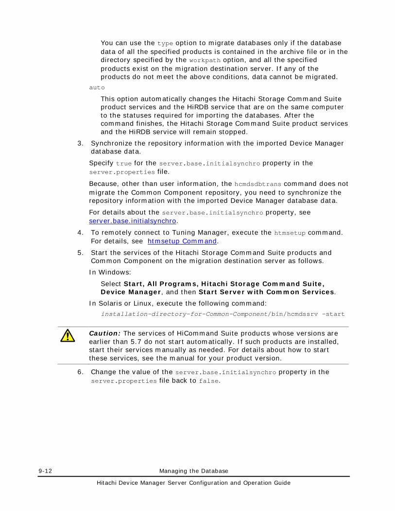
9-12 Managing the Database
Hitachi Device Manager Server Configuration and Operation Guide
You can use the type option to migrate databases only if the database data of all the specified products is contained in the archive file or in the directory specified by the workpath option, and all the specified products exist on the migration destination server. If any of the products do not meet the above conditions, data cannot be migrated.
auto
This option automatically changes the Hitachi Storage Command Suite product services and the HiRDB service that are on the same computer to the statuses required for importing the databases. After the command finishes, the Hitachi Storage Command Suite product services and the HiRDB service will remain stopped.
3. Synchronize the repository information with the imported Device Manager database data.
Specify true for the server.base.initialsynchro property in the server.properties file.
Because, other than user information, the hcmdsdbtrans command does not migrate the Common Component repository, you need to synchronize the repository information with the imported Device Manager database data.
For details about the server.base.initialsynchro property, see server.base.initialsynchro.
4. To remotely connect to Tuning Manager, execute the htmsetup command. For details, see htmsetup Command.
5. Start the services of the Hitachi Storage Command Suite products and Common Component on the migration destination server as follows.
In Windows:
Select Start, All Programs, Hitachi Storage Command Suite, Device Manager, and then Start Server with Common Services.
In Solaris or Linux, execute the following command:
installation-directory-for-Common-Component/bin/hcmdssrv -start
Caution: The services of HiCommand Suite products whose versions are earlier than 5.7 do not start automatically. If such products are installed, start their services manually as needed. For details about how to start these services, see the manual for your product version.
6. Change the value of the server.base.initialsynchro property in the server.properties file back to false.
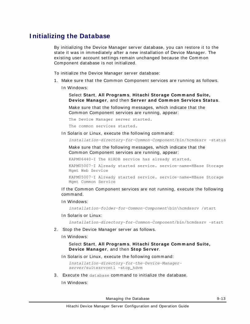
Managing the Database 9-13
Hitachi Device Manager Server Configuration and Operation Guide
Initializing the Database
By initializing the Device Manager server database, you can restore it to the state it was in immediately after a new installation of Device Manager. The existing user account settings remain unchanged because the Common Component database is not initialized.
To initialize the Device Manager server database:
1. Make sure that the Common Component services are running as follows.
In Windows:
Select Start, All Programs, Hitachi Storage Command Suite, Device Manager, and then Server and Common Services Status.
Make sure that the following messages, which indicate that the Common Component services are running, appear:
The Device Manager server started.
The common services started.
In Solaris or Linux, execute the following command:
installation-directory-for-Common-Component/bin/hcmdssrv -status
Make sure that the following messages, which indicate that the Common Component services are running, appear:
KAPM06440-I The HiRDB service has already started.
KAPM05007-I Already started service. service-name=HBase Storage Mgmt Web Service
KAPM05007-I Already started service. service-name=HBase Storage Mgmt Common Service
If the Common Component services are not running, execute the following command.
In Windows: installation-folder-for-Common-Component\bin\hcmdssrv /start
In Solaris or Linux:
installation-directory-for-Common-Component/bin/hcmdssrv -start
2. Stop the Device Manager server as follows.
In Windows:
Select Start, All Programs, Hitachi Storage Command Suite, Device Manager, and then Stop Server.
In Solaris or Linux, execute the following command: installation-directory-for-the-Device-Manager-server/suitesrvcntl -stop_hdvm
3. Execute the database command to initialize the database.
In Windows:
9-14 Managing the Database
Hitachi Device Manager Server Configuration and Operation Guide
installation-folder-for-the-Device-Manager-server\database.bat initialize
In Solaris or Linux: installation-directory-for-the-Device-Manager-server/database.sh initialize
4. Specify true for the server.base.initialsynchro property in the server.properties file.
For details about this property, see server.base.initialsynchro.
5. Start the Device Manager server as follows.
In Windows:
Select Start, All Programs, Hitachi Storage Command Suite, Device Manager, and then Start Server.
In Solaris or Linux, execute the following command: installation-directory-for-the-Device-Manager-server/suitesrvcntl -start_hdvm
6. Change the value of the server.base.initialsynchro property in the server.properties file back to false.
Troubleshooting 10-1
Hitachi Device Manager Server Configuration and Operation Guide
Troubleshooting
This chapter describes how to resolve problems that can occur during Device Manager operation and how to read the contents of log files.
Common Problems and Solutions
Obtaining Maintenance Information of Device Manager
Obtaining the Java VM Thread Dump
Checking Audit Log Data
Contacting the Hitachi Data Systems Support Center
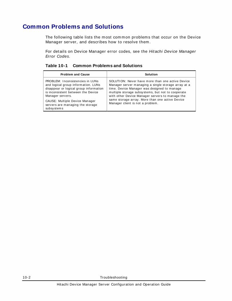
10-2 Troubleshooting
Hitachi Device Manager Server Configuration and Operation Guide
Common Problems and Solutions
The following table lists the most common problems that occur on the Device Manager server, and describes how to resolve them.
For details on Device Manager error codes, see the Hitachi Device Manager Error Codes.
Table 10-1 Common Problems and Solutions
Problem and Cause Solution
PROBLEM: Inconsistencies in LUNs and logical group information. LUNs disappear or logical group information is inconsistent between the Device Manager servers.
CAUSE: Multiple Device Manager servers are managing the storage subsystems
SOLUTION: Never have more than one active Device Manager server managing a single storage array at a time. Device Manager was designed to manage multiple storage subsystems, but not to cooperate with other Device Manager servers to manage the same storage array. More than one active Device Manager client is not a problem.
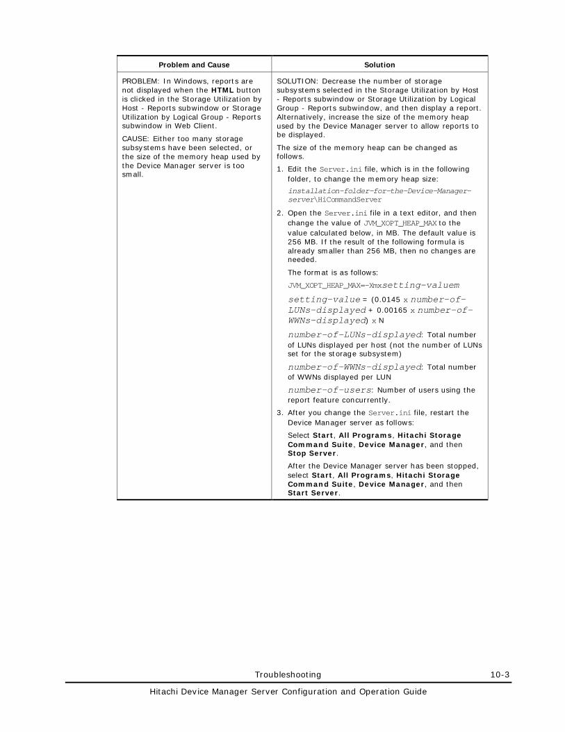
Troubleshooting 10-3
Hitachi Device Manager Server Configuration and Operation Guide
Problem and Cause Solution
PROBLEM: In Windows, reports are not displayed when the HTML button is clicked in the Storage Utilization by Host - Reports subwindow or Storage Utilization by Logical Group - Reports subwindow in Web Client.
CAUSE: Either too many storage subsystems have been selected, or the size of the memory heap used by the Device Manager server is too small.
SOLUTION: Decrease the number of storage subsystems selected in the Storage Utilization by Host - Reports subwindow or Storage Utilization by Logical Group - Reports subwindow, and then display a report. Alternatively, increase the size of the memory heap used by the Device Manager server to allow reports to be displayed.
The size of the memory heap can be changed as follows.
1. Edit the Server.ini file, which is in the following folder, to change the memory heap size:
installation-folder-for-the-Device-Manager-server\HiCommandServer
2. Open the Server.ini file in a text editor, and then change the value of JVM_XOPT_HEAP_MAX to the value calculated below, in MB. The default value is 256 MB. If the result of the following formula is already smaller than 256 MB, then no changes are needed.
The format is as follows:
JVM_XOPT_HEAP_MAX=-Xmxsetting-valuem
setting-value = (0.0145 x number-of-LUNs-displayed + 0.00165 x number-of-WWNs-displayed) x N
number-of-LUNs-displayed: Total number of LUNs displayed per host (not the number of LUNs set for the storage subsystem)
number-of-WWNs-displayed: Total number of WWNs displayed per LUN
number-of-users: Number of users using the report feature concurrently.
3. After you change the Server.ini file, restart the Device Manager server as follows:
Select Start, All Programs, Hitachi Storage Command Suite, Device Manager, and then Stop Server.
After the Device Manager server has been stopped, select Start, All Programs, Hitachi Storage Command Suite, Device Manager, and then Start Server.
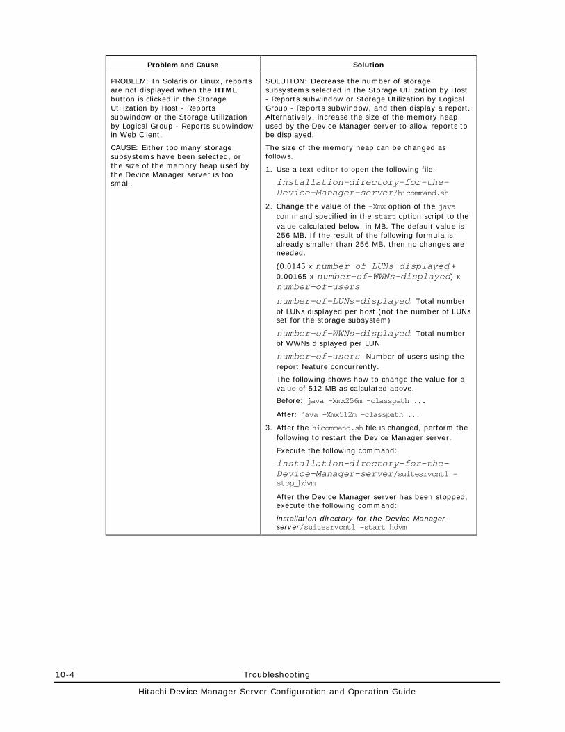
10-4 Troubleshooting
Hitachi Device Manager Server Configuration and Operation Guide
Problem and Cause Solution
PROBLEM: In Solaris or Linux, reports are not displayed when the HTML button is clicked in the Storage Utilization by Host - Reports subwindow or the Storage Utilization by Logical Group - Reports subwindow in Web Client.
CAUSE: Either too many storage subsystems have been selected, or the size of the memory heap used by the Device Manager server is too small.
SOLUTION: Decrease the number of storage subsystems selected in the Storage Utilization by Host - Reports subwindow or Storage Utilization by Logical Group - Reports subwindow, and then display a report. Alternatively, increase the size of the memory heap used by the Device Manager server to allow reports to be displayed.
The size of the memory heap can be changed as follows.
1. Use a text editor to open the following file:
installation-directory-for-the-Device-Manager-server/hicommand.sh
2. Change the value of the -Xmx option of the java command specified in the start option script to the value calculated below, in MB. The default value is 256 MB. If the result of the following formula is already smaller than 256 MB, then no changes are needed.
(0.0145 x number-of-LUNs-displayed + 0.00165 x number-of-WWNs-displayed) x number-of-users
number-of-LUNs-displayed: Total number of LUNs displayed per host (not the number of LUNs set for the storage subsystem)
number-of-WWNs-displayed: Total number of WWNs displayed per LUN
number-of-users: Number of users using the report feature concurrently.
The following shows how to change the value for a value of 512 MB as calculated above.
Before: java -Xmx256m -classpath ...
After: java -Xmx512m -classpath ...
3. After the hicommand.sh file is changed, perform the following to restart the Device Manager server.
Execute the following command:
installation-directory-for-the-Device-Manager-server/suitesrvcntl -stop_hdvm
After the Device Manager server has been stopped, execute the following command:
installation-directory-for-the-Device-Manager-server/suitesrvcntl -start_hdvm
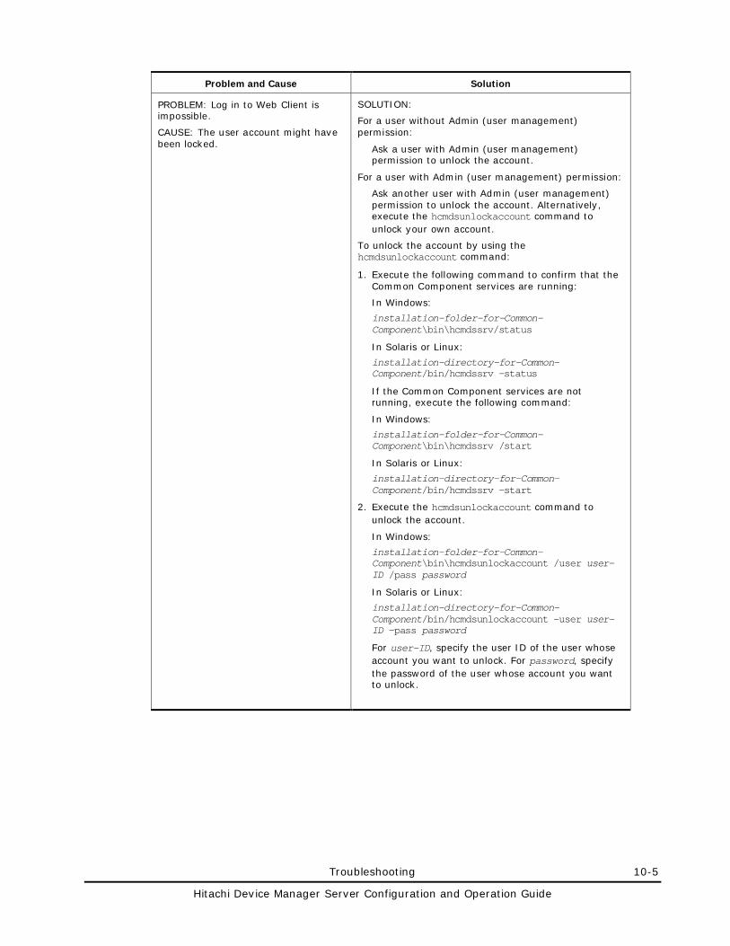
Troubleshooting 10-5
Hitachi Device Manager Server Configuration and Operation Guide
Problem and Cause Solution
PROBLEM: Log in to Web Client is impossible.
CAUSE: The user account might have been locked.
SOLUTION:
For a user without Admin (user management) permission:
Ask a user with Admin (user management) permission to unlock the account.
For a user with Admin (user management) permission:
Ask another user with Admin (user management) permission to unlock the account. Alternatively, execute the hcmdsunlockaccount command to unlock your own account.
To unlock the account by using the hcmdsunlockaccount command:
1. Execute the following command to confirm that the Common Component services are running:
In Windows:
installation-folder-for-Common-Component\bin\hcmdssrv/status
In Solaris or Linux:
installation-directory-for-Common-Component/bin/hcmdssrv -status
If the Common Component services are not running, execute the following command:
In Windows:
installation-folder-for-Common-Component\bin\hcmdssrv /start
In Solaris or Linux:
installation-directory-for-Common-Component/bin/hcmdssrv -start
2. Execute the hcmdsunlockaccount command to unlock the account.
In Windows:
installation-folder-for-Common-Component\bin\hcmdsunlockaccount /user user-ID /pass password
In Solaris or Linux:
installation-directory-for-Common-Component/bin/hcmdsunlockaccount -user user-ID -pass password
For user-ID, specify the user ID of the user whose account you want to unlock. For password, specify the password of the user whose account you want to unlock.
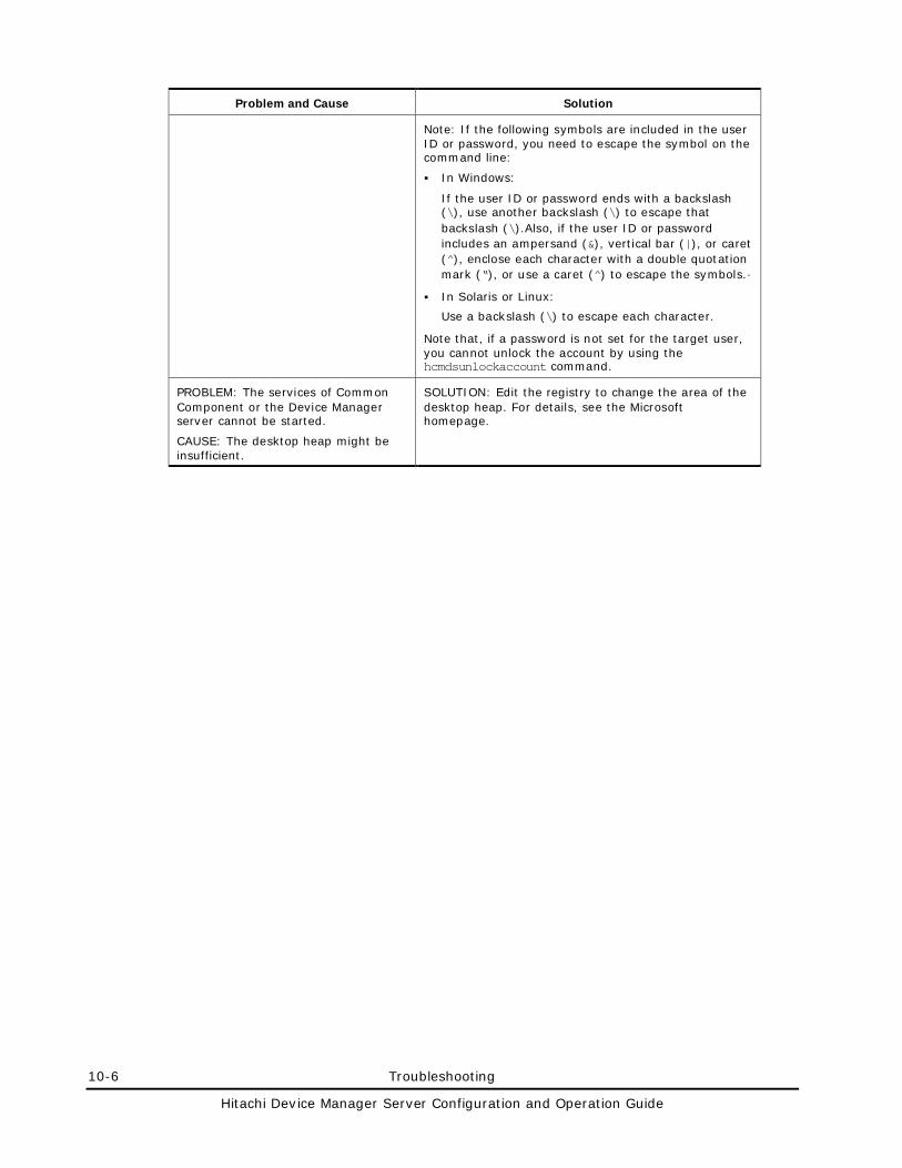
10-6 Troubleshooting
Hitachi Device Manager Server Configuration and Operation Guide
Problem and Cause Solution
Note: If the following symbols are included in the user ID or password, you need to escape the symbol on the command line:
In Windows:
If the user ID or password ends with a backslash (\), use another backslash (\) to escape that backslash (\).Also, if the user ID or password includes an ampersand (&), vertical bar (|), or caret (^), enclose each character with a double quotation mark (“), or use a caret (^) to escape the symbols.·
In Solaris or Linux:
Use a backslash (\) to escape each character.
Note that, if a password is not set for the target user, you cannot unlock the account by using the hcmdsunlockaccount command.
PROBLEM: The services of Common Component or the Device Manager server cannot be started.
CAUSE: The desktop heap might be insufficient.
SOLUTION: Edit the registry to change the area of the desktop heap. For details, see the Microsoft homepage.
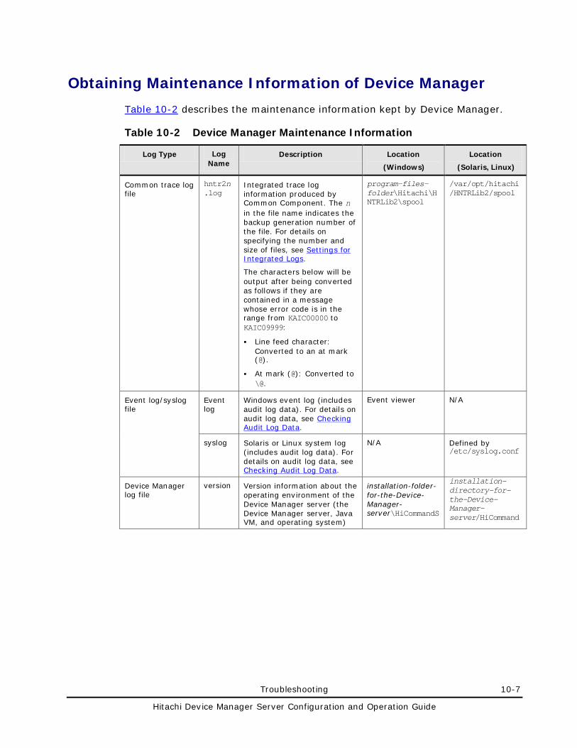
Troubleshooting 10-7
Hitachi Device Manager Server Configuration and Operation Guide
Obtaining Maintenance Information of Device Manager
Table 10-2 describes the maintenance information kept by Device Manager.
Table 10-2 Device Manager Maintenance Information
Log Type Log Name
Description Location
(Windows)
Location
(Solaris, Linux)
Common trace log file
hntr2n.log
Integrated trace log information produced by Common Component. The n in the file name indicates the backup generation number of the file. For details on specifying the number and size of files, see Settings for Integrated Logs.
The characters below will be output after being converted as follows if they are contained in a message whose error code is in the range from KAIC00000 to KAIC09999:
Line feed character: Converted to an at mark (@).
At mark (@): Converted to \@.
program-files-folder\Hitachi\HNTRLib2\spool
/var/opt/hitachi/HNTRLib2/spool
Event log/syslog file
Event log
Windows event log (includes audit log data). For details on audit log data, see Checking Audit Log Data.
Event viewer N/A
syslog Solaris or Linux system log (includes audit log data). For details on audit log data, see Checking Audit Log Data.
N/A Defined by /etc/syslog.conf
Device Manager log file
version Version information about the operating environment of the Device Manager server (the Device Manager server, Java VM, and operating system)
installation-folder-for-the-Device-Manager-server\HiCommandS
installation-directory-for-the-Device-Manager-server/HiCommand
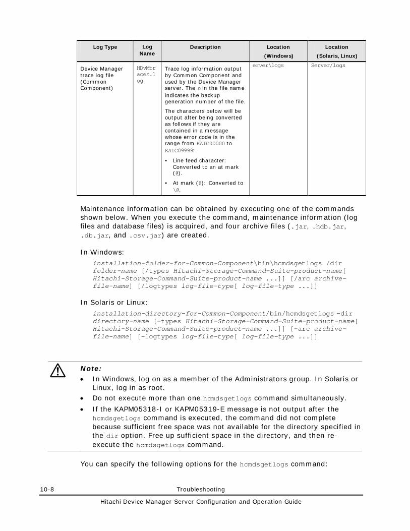
10-8 Troubleshooting
Hitachi Device Manager Server Configuration and Operation Guide
Log Type Log Name
Description Location
(Windows)
Location
(Solaris, Linux)
Device Manager trace log file (Common Component)
HDvMtracen.log
Trace log information output by Common Component and used by the Device Manager server. The n in the file name indicates the backup generation number of the file.
The characters below will be output after being converted as follows if they are contained in a message whose error code is in the range from KAIC00000 to KAIC09999:
Line feed character: Converted to an at mark (@).
At mark (@): Converted to \@.
erver\logs Server/logs
Maintenance information can be obtained by executing one of the commands shown below. When you execute the command, maintenance information (log files and database files) is acquired, and four archive files (.jar, .hdb.jar, .db.jar, and .csv.jar) are created.
In Windows:
installation-folder-for-Common-Component\bin\hcmdsgetlogs /dir folder-name [/types Hitachi-Storage-Command-Suite-product-name[ Hitachi-Storage-Command-Suite-product-name ...]] [/arc archive-file-name] [/logtypes log-file-type[ log-file-type ...]]
In Solaris or Linux:
installation-directory-for-Common-Component/bin/hcmdsgetlogs -dir directory-name [-types Hitachi-Storage-Command-Suite-product-name[ Hitachi-Storage-Command-Suite-product-name ...]] [-arc archive-file-name] [-logtypes log-file-type[ log-file-type ...]]
Note: • In Windows, log on as a member of the Administrators group. In Solaris or
Linux, log in as root. • Do not execute more than one hcmdsgetlogs command simultaneously.
• If the KAPM05318-I or KAPM05319-E message is not output after the hcmdsgetlogs command is executed, the command did not complete because sufficient free space was not available for the directory specified in the dir option. Free up sufficient space in the directory, and then re-execute the hcmdsgetlogs command.
You can specify the following options for the hcmdsgetlogs command:
Troubleshooting 10-9
Hitachi Device Manager Server Configuration and Operation Guide
dir
– Specify the name of the directory on a local disk that stores maintenance information. If the directory has already been created, empty the directory.
The maximum length of a path name that can be specified is 41 bytes. For details about the maximum length of a path name when an application name other than DeviceManager is specified in the type option, see the manual for each product.
You can specify any printable ASCII character excluding certain special characters. You cannot specify the following characters:
\ / : , ; * ? “ < > | $ % & ‘ ‘
However, you can specify backslashes (\), colons (:), and slashes (/) in Windows, or slashes (/) in Solaris or Linux as a path delimiter. Do not specify a path delimiter at the end of a path name.
In Windows, to specify a space character in a path name, enclose the path name in double quotation marks (“). In Solaris or Linux, you cannot specify a space character in a path name.
types
If you want to obtain only maintenance information for specific Hitachi Storage Command Suite products for a reason such as a failure, specify the name of the products from which you want to obtain maintenance information. To obtain maintenance information for Device Manager, specify DeviceManager. To obtain maintenance information for Provisioning Manager, specify ProvisioningManager. For details on the other Hitachi Storage Command Suite product names, see the documentation for each product. To specify multiple product names, separate them by a space.
When specifying this option, also specify the log file type log for the logtypes option.
If you omit the types option, maintenance information for all Hitachi Storage Command Suite products installed on the management server is obtained.
arc
Specify the name of the archive files to be created. If you do not specify this option, the default file name is HiCommand_log. When the archive files are output, each of them will have an extension corresponding to the type of each archive file (.jar, .hdb.jar, .db.jar, or .csv.jar). The archive files are output under the directory specified in the dir option.
For the file name, you can specify any printable ASCII character excluding certain special characters. You cannot specify the following characters:
\ / : , ; * ? “ < > | $ % & ‘ ‘
In Solaris or Linux, you cannot specify a space character in a file name.
10-10 Troubleshooting
Hitachi Device Manager Server Configuration and Operation Guide
logtypes
If you want to obtain only specific log files for a reason such as a failure, specify the type of log files that you want to obtain.
log: Specify this to obtain .jar files and .hdb.jar files only.
db: Specify this to obtain .db.jar files only.
csv: Specify this to obtain .csv.jar files only.
To specify multiple types, separate them by a space.
If you omit this option, all log files will be obtained.
Return values
0: Normal termination
1: Parameter error
2: Abnormal termination
An example of obtaining maintenance information for Hitachi Storage Command Suite products is shown below. In this example, the archive file named hicmd_log is created under the logs_work directory.
In Windows:
C:\Program Files\HiCommand\Base\bin\hcmdsgetlogs /dir C:\logs_work /arc hicmd_log
In Solaris or Linux:
# /opt/HiCommand/Base/bin/hcmdsgetlogs -dir /opt/logs_work -arc hicmd_log
Note: If virtualization servers are managed by Device Manager, you also need to collect the log files for the virtualization software, vMA, and VMware vCenter Server. For details about how to collect the log files, see the VMware documentation.
Troubleshooting 10-11
Hitachi Device Manager Server Configuration and Operation Guide
Obtaining the Java VM Thread Dump
If the following problem occurs, obtain a Java VM thread dump to locate the cause of the problem.
• The Device Manager logon window is not displayed when you start Web Client.
• The Device Manager main window is not displayed after logging on to Device Manager.
• The Device Manager main window is not displayed when you start a Device Manager server from Tuning Manager.
Obtaining the Java VM Thread Dump in a Windows Environment
To obtain a Java VM thread dump:
1. In installation-folder-for-Common-Component\CC\web\containers\HiCommand, create a file called dump.
2. Access the Windows Services window.
3. Stop the HBase Storage Mgmt Common Service.
The javacorexxx.xxxx.txt file is output to installation-folder-for-Common-Component\CC\web\containers\HiCommand.
4. From the Services window, start the HBase Storage Mgmt Common Service.
Obtaining the Java VM Thread Dump in a Solaris or Linux Environment
To obtain a Java VM thread dump:
1. Execute the following command: # kill -3 PID
PID is a process ID written in the installation-directory-for-Common-Component/CC/web/containers/HiCommand/logs/cjstdout.log file.
The javacorexxx.xxxx.txt file is output to installation-directory-for-Common-Component/CC/web/containers/HiCommand.
2. Execute the following command to stop the HBase Storage Mgmt Common Service and the Device Manager server:
installation-directory-for-Common-Component/bin/hcmdssrv -stop
3. Execute the following command to start the HBase Storage Mgmt Common Service and the Device Manager server:
installation-directory-for-Common-Component/bin/hcmdssrv -start
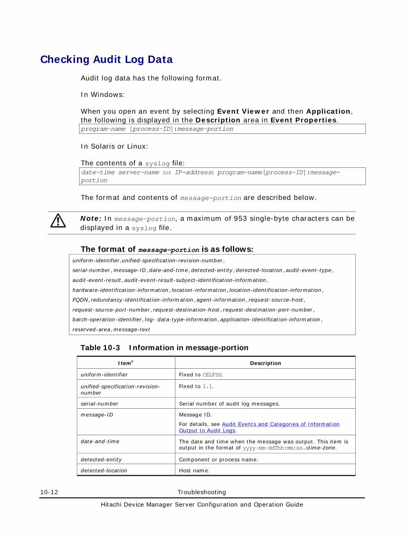
10-12 Troubleshooting
Hitachi Device Manager Server Configuration and Operation Guide
Checking Audit Log Data
Audit log data has the following format.
In Windows:
When you open an event by selecting Event Viewer and then Application, the following is displayed in the Description area in Event Properties. program-name [process-ID]:message-portion
In Solaris or Linux:
The contents of a syslog file: date-time server-name (or IP-address) program-name[process-ID]:message-portion
The format and contents of message-portion are described below.
Note: In message-portion, a maximum of 953 single-byte characters can be displayed in a syslog file.
The format of message-portion is as follows: uniform-identifier,unified-specification-revision-number,
serial-number,message-ID,date-and-time,detected-entity,detected-location,audit-event-type,
audit-event-result,audit-event-result-subject-identification-information,
hardware-identification-information,location-information,location-identification-information,
FQDN,redundancy-identification-information,agent-information,request-source-host,
request-source-port-number,request-destination-host,request-destination-port-number,
batch-operation-identifier,log- data-type-information,application-identification-information,
reserved-area,message-text
Table 10-3 Information in message-portion
Item# Description
uniform-identifier Fixed to CELFSS.
unified-specification-revision-number
Fixed to 1.1.
serial-number Serial number of audit log messages.
message-ID Message ID.
For details, see Audit Events and Categories of Information Output to Audit Logs.
date-and-time The date and time when the message was output. This item is output in the format of yyyy-mm-ddThh:mm:ss.stime-zone.
detected-entity Component or process name.
detected-location Host name.
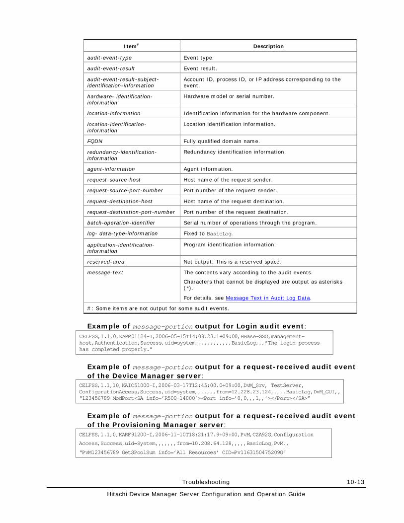
Troubleshooting 10-13
Hitachi Device Manager Server Configuration and Operation Guide
Item# Description
audit-event-type Event type.
audit-event-result Event result.
audit-event-result-subject-identification-information
Account ID, process ID, or IP address corresponding to the event.
hardware- identification-information
Hardware model or serial number.
location-information Identification information for the hardware component.
location-identification-information
Location identification information.
FQDN Fully qualified domain name.
redundancy-identification-information
Redundancy identification information.
agent-information Agent information.
request-source-host Host name of the request sender.
request-source-port-number Port number of the request sender.
request-destination-host Host name of the request destination.
request-destination-port-number Port number of the request destination.
batch-operation-identifier Serial number of operations through the program.
log- data-type-information Fixed to BasicLog.
application-identification-information
Program identification information.
reserved-area Not output. This is a reserved space.
message-text The contents vary according to the audit events.
Characters that cannot be displayed are output as asterisks (*).
For details, see Message Text in Audit Log Data.
#: Some items are not output for some audit events.
Example of message-portion output for Login audit event: CELFSS,1.1,0,KAPM01124-I,2006-05-15T14:08:23.1+09:00,HBase-SSO,management-host,Authentication,Success,uid=system,,,,,,,,,,,,BasicLog,,,”The login process has completed properly.”
Example of message-portion output for a request-received audit event of the Device Manager server:
CELFSS,1.1,10,KAIC51000-I,2006-03-17T12:45:00.0+09:00,DvM_Srv, TestServer, ConfigurationAccess,Success,uid=system,,,,,,,from=12.228.23.124,,,,,BasicLog,DvM_GUI,, “123456789 ModPort<SA info=’R500-14000’><Port info=’0,0,,,1,,’></Port></SA>”
Example of message-portion output for a request-received audit event of the Provisioning Manager server:
CELFSS,1.1,0,KARF91200-I,2006-11-10T18:21:17.9+09:00,PvM,CZA92G,Configuration
Access,Success,uid=System,,,,,,,from=10.208.64.128,,,,,BasicLog,PvM,,
“PvM123456789 GetSPoolSum info=’All Resources’ CID=Pv1163150475209G”
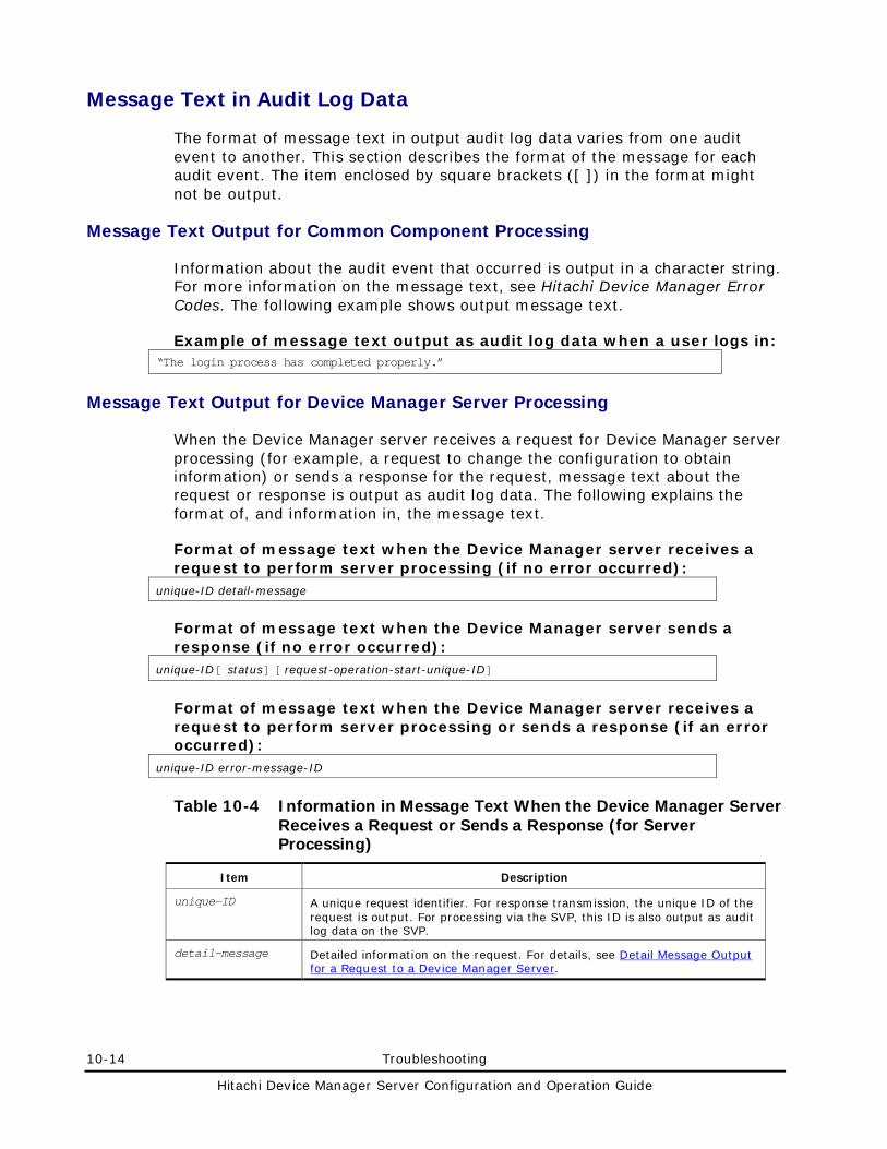
10-14 Troubleshooting
Hitachi Device Manager Server Configuration and Operation Guide
Message Text in Audit Log Data
The format of message text in output audit log data varies from one audit event to another. This section describes the format of the message for each audit event. The item enclosed by square brackets ([ ]) in the format might not be output.
Message Text Output for Common Component Processing
Information about the audit event that occurred is output in a character string. For more information on the message text, see Hitachi Device Manager Error Codes. The following example shows output message text.
Example of message text output as audit log data when a user logs in: “The login process has completed properly.”
Message Text Output for Device Manager Server Processing
When the Device Manager server receives a request for Device Manager server processing (for example, a request to change the configuration to obtain information) or sends a response for the request, message text about the request or response is output as audit log data. The following explains the format of, and information in, the message text.
Format of message text when the Device Manager server receives a request to perform server processing (if no error occurred):
unique-ID detail-message
Format of message text when the Device Manager server sends a response (if no error occurred):
unique-ID[ status] [ request-operation-start-unique-ID]
Format of message text when the Device Manager server receives a request to perform server processing or sends a response (if an error occurred):
unique-ID error-message-ID
Table 10-4 Information in Message Text When the Device Manager Server Receives a Request or Sends a Response (for Server Processing)
Item Description
unique-ID A unique request identifier. For response transmission, the unique ID of the request is output. For processing via the SVP, this ID is also output as audit log data on the SVP.
detail-message Detailed information on the request. For details, see Detail Message Output for a Request to a Device Manager Server.
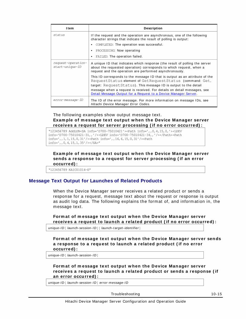
Troubleshooting 10-15
Hitachi Device Manager Server Configuration and Operation Guide
Item Description
status If the request and the operation are asynchronous, one of the following character strings that indicate the result of polling is output:
COMPLETED: The operation was successful.
PROCESSING: Now operating
FAILED: The operation failed.
request-operation-start-unique-ID
A unique ID that indicates which response (the result of polling the server about the requested operation) corresponds to which request, when a request and the operation are performed asynchronously.
This ID corresponds to the message ID that is output as an attribute of the RequestStatus element of GetRequestStatus (command: Get, target: RequestStatus). This message ID is output to the detail message when a request is received. For details on detail messages, see Detail Message Output for a Request to a Device Manager Server.
error-message-ID The ID of the error message. For more information on message IDs, see Hitachi Device Manager Error Codes.
The following examples show output message text. Example of message text output when the Device Manager server receives a request for server processing (if no error occurred):
“123456789 AddLUN<SA info=’D700-75010421’><Path info=’,,0,4,15,0,’><LDEV info=’D700-75010421-31,,’/><LDEV info=’D700-75010421-34,,’/></Path><Path info=’,,1,1,15,0,31’/><Path info=’,,16,6,15,0,31’/><Path info=’,,0,4,15,1,35’/></SA>”
Example of message text output when the Device Manager server sends a response to a request for server processing (if an error occurred):
“123456789 KAIC01014-E”
Message Text Output for Launches of Related Products
When the Device Manager server receives a related product or sends a response for a request, message text about the request or response is output as audit log data. The following explains the format of, and information in, the message text.
Format of message text output when the Device Manager server receives a request to launch a related product (if no error occurred):
unique-ID[ launch-session-ID][ launch-target-identifier]
Format of message text output when the Device Manager server sends a response to a request to launch a related product (if no error occurred):
unique-ID[ launch-session-ID]
Format of message text output when the Device Manager server receives a request to launch a related product or sends a response (if an error occurred):
unique-ID[ launch-session-ID] error-message-ID
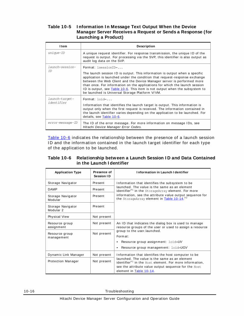
10-16 Troubleshooting
Hitachi Device Manager Server Configuration and Operation Guide
Table 10-5 Information In Message Text Output When the Device Manager Server Receives a Request or Sends a Response (for Launching a Product)
Item Description
unique-ID A unique request identifier. For response transmission, the unique ID of the request is output. For processing via the SVP, this identifier is also output as audit log data on the SVP.
launch-session-ID
Format: lsessionID=...
The launch session ID is output. This information is output when a specific application is launched under the condition that request-response exchange between the Web Client and the Device Manager server is performed more than once. For information on the applications for which the launch session ID is output, see Table 10-6. This item is not output when the subsystem to be launched is Universal Storage Platform V/VM.
launch-target-identifier
Format: loid=...
Information that identifies the launch target is output. This information is output only when the first request is received. The information contained in the launch identifier varies depending on the application to be launched. For details, see Table 10-6.
error-message-ID The ID of the error message. For more information on message IDs, see Hitachi Device Manager Error Codes.
Table 10-6 indicates the relationship between the presence of a launch session ID and the information contained in the launch target identifier for each type of the application to be launched.
Table 10-6 Relationship between a Launch Session ID and Data Contained in the Launch Identifier
Application Type Presence of Session ID
Information in Launch Identifier
Storage Navigator Present Information that identifies the subsystem to be launched. The value is the same as an element identifier#1 in the StorageArray element. For more information, see the attribute value output sequence for the StorageArray element in Table 10-14.#2
DAMP Present
Storage Navigator Modular
Present
Storage Navigator Modular 2
Present
Physical View Not present
Resource group assignment
Not present An ID that indicates the dialog box is used to manage resource groups of the user or used to assign a resource group to the user.launched.
Format:
Resource group assignment: loid=UV
Resource group management: loid=UGV
Resource group management
Not present
Dynamic Link Manager Not present Information that identifies the host computer to be launched. The value is the same as an element identifier#1 in the Host element. For more information, see the attribute value output sequence for the Host element in Table 10-14.
Protection Manager Not present
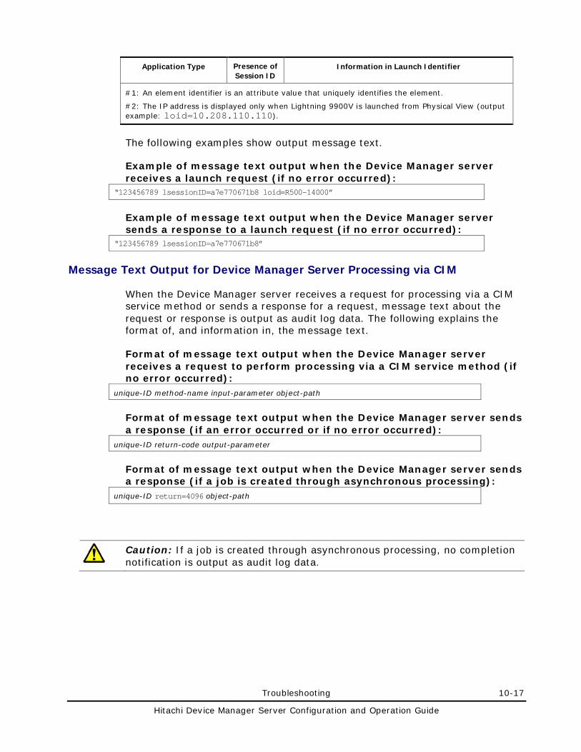
Troubleshooting 10-17
Hitachi Device Manager Server Configuration and Operation Guide
Application Type Presence of Session ID
Information in Launch Identifier
#1: An element identifier is an attribute value that uniquely identifies the element.
#2: The IP address is displayed only when Lightning 9900V is launched from Physical View (output example: loid=10.208.110.110).
The following examples show output message text.
Example of message text output when the Device Manager server receives a launch request (if no error occurred):
“123456789 lsessionID=a7e770671b8 loid=R500-14000”
Example of message text output when the Device Manager server sends a response to a launch request (if no error occurred):
“123456789 lsessionID=a7e770671b8”
Message Text Output for Device Manager Server Processing via CIM
When the Device Manager server receives a request for processing via a CIM service method or sends a response for a request, message text about the request or response is output as audit log data. The following explains the format of, and information in, the message text.
Format of message text output when the Device Manager server receives a request to perform processing via a CIM service method (if no error occurred):
unique-ID method-name input-parameter object-path
Format of message text output when the Device Manager server sends a response (if an error occurred or if no error occurred):
unique-ID return-code output-parameter
Format of message text output when the Device Manager server sends a response (if a job is created through asynchronous processing):
unique-ID return=4096 object-path
Caution: If a job is created through asynchronous processing, no completion notification is output as audit log data.
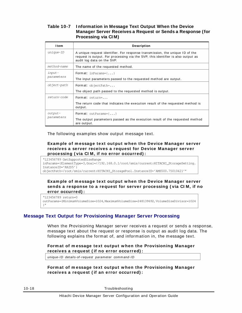
10-18 Troubleshooting
Hitachi Device Manager Server Configuration and Operation Guide
Table 10-7 Information in Message Text Output When the Device Manager Server Receives a Request or Sends a Response (for Processing via CIM)
Item Description
unique-ID A unique request identifier. For response transmission, the unique ID of the request is output. For processing via the SVP, this identifier is also output as audit log data on the SVP.
method-name The name of the requested method.
input-parameters
Format: inParams={...}
The input parameters passed to the requested method are output.
object-path Format: objectPath=...
The object path passed to the requested method is output.
return-code Format: return=...
The return code that indicates the execution result of the requested method is output.
output-parameters
Format: outParams={...}
The output parameters passed as the execution result of the requested method are output.
The following examples show output message text.
Example of message text output when the Device Manager server receives a server receives a request for Device Manager server processing (via CIM, if no error occurred):
“123456789 GetSupportedSizeRange inParams={ElementType=3,Goal=//192.168.0.1/root/smis/current:HITACHI_StorageSetting.InstanceID=’RAID5’} objectPath=/root/smis/current:HITACHI_StoragePool.InstanceID=’AMS500.75010421’”
Example of message text output when the Device Manager server sends a response to a request for server processing (via CIM, if no error occurred):
“123456789 return=0 outParams={MinimumVolumeSize=1024,MaximumVolumeSize=248139692,VolumeSizeDivisor=1024}”
Message Text Output for Provisioning Manager Server Processing
When the Provisioning Manager server receives a request or sends a response, message text about the request or response is output as audit log data. The following explains the format of, and information in, the message text.
Format of message text output when the Provisioning Manager receives a request (if no error occurred): unique-ID details-of-request parameter command-ID
Format of message text output when the Provisioning Manager receives a request (if an error occurred):
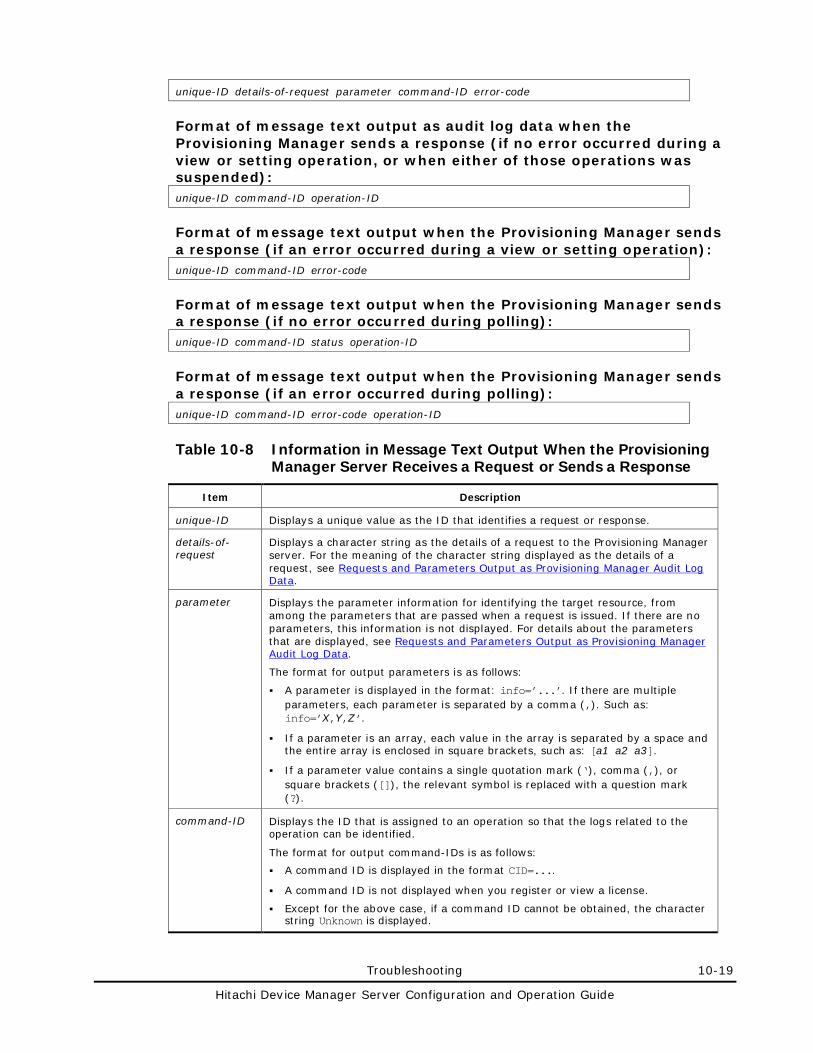
Troubleshooting 10-19
Hitachi Device Manager Server Configuration and Operation Guide
unique-ID details-of-request parameter command-ID error-code
Format of message text output as audit log data when the Provisioning Manager sends a response (if no error occurred during a view or setting operation, or when either of those operations was suspended): unique-ID command-ID operation-ID
Format of message text output when the Provisioning Manager sends a response (if an error occurred during a view or setting operation): unique-ID command-ID error-code
Format of message text output when the Provisioning Manager sends a response (if no error occurred during polling): unique-ID command-ID status operation-ID
Format of message text output when the Provisioning Manager sends a response (if an error occurred during polling): unique-ID command-ID error-code operation-ID
Table 10-8 Information in Message Text Output When the Provisioning Manager Server Receives a Request or Sends a Response
Item Description
unique-ID Displays a unique value as the ID that identifies a request or response.
details-of-request
Displays a character string as the details of a request to the Provisioning Manager server. For the meaning of the character string displayed as the details of a request, see Requests and Parameters Output as Provisioning Manager Audit Log Data.
parameter Displays the parameter information for identifying the target resource, from among the parameters that are passed when a request is issued. If there are no parameters, this information is not displayed. For details about the parameters that are displayed, see Requests and Parameters Output as Provisioning Manager Audit Log Data.
The format for output parameters is as follows:
A parameter is displayed in the format: info=’...’. If there are multiple parameters, each parameter is separated by a comma (,). Such as: info=’X,Y,Z’.
If a parameter is an array, each value in the array is separated by a space and the entire array is enclosed in square brackets, such as: [a1 a2 a3].
If a parameter value contains a single quotation mark (‘), comma (,), or square brackets ([]), the relevant symbol is replaced with a question mark (?).
command-ID Displays the ID that is assigned to an operation so that the logs related to the operation can be identified.
The format for output command-IDs is as follows:
A command ID is displayed in the format CID=....
A command ID is not displayed when you register or view a license.
Except for the above case, if a command ID cannot be obtained, the character string Unknown is displayed.
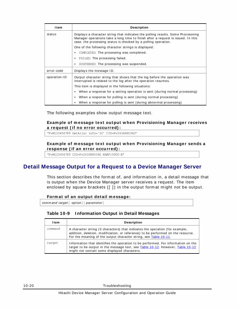
10-20 Troubleshooting
Hitachi Device Manager Server Configuration and Operation Guide
Item Description
status Displays a character string that indicates the polling results. Some Provisioning Manager operations take a long time to finish after a request is issued. In this case, the processing status is checked by a polling operation.
One of the following character strings is displayed:
COMPLETED: The processing was completed.
FAILED: The processing failed.
SUSPENDED: The processing was suspended.
error-code Displays the message ID.
operation-ID Output character string that shows that the log before the operation was interrupted is related to the log after the operation resumes.
This item is displayed in the following situations:
When a response for a setting operation is sent (during normal processing)
When a response for polling is sent (during normal processing)
When a response for polling is sent (during abnormal processing)
The following examples show output message text.
Example of message text output when Provisioning Manager receives a request (if no error occurred): “PvM123456789 GetAlloc info=’32’ CID=Pv243488034G”
Example of message text output when Provisioning Manager sends a response (if an error occurred): “PvM123456789 CID=Pv243488034G KARF15000-E”
Detail Message Output for a Request to a Device Manager Server
This section describes the format of, and information in, a detail message that is output when the Device Manager server receives a request. The item enclosed by square brackets ([ ]) in the output format might not be output.
Format of an output detail message: command target[ option][ parameter]
Table 10-9 Information Output in Detail Messages
Item Description
command A character string (3 characters) that indicates the operation (for example, addition, deletion, modification, or reference) to be performed on the resource. For the meaning of the output character string, see Table 10-11.
target Information that identifies the operation to be performed. For information on the target to be output in the message text, see Table 10-12. However, Table 10-12 might not contain some displayed characters.
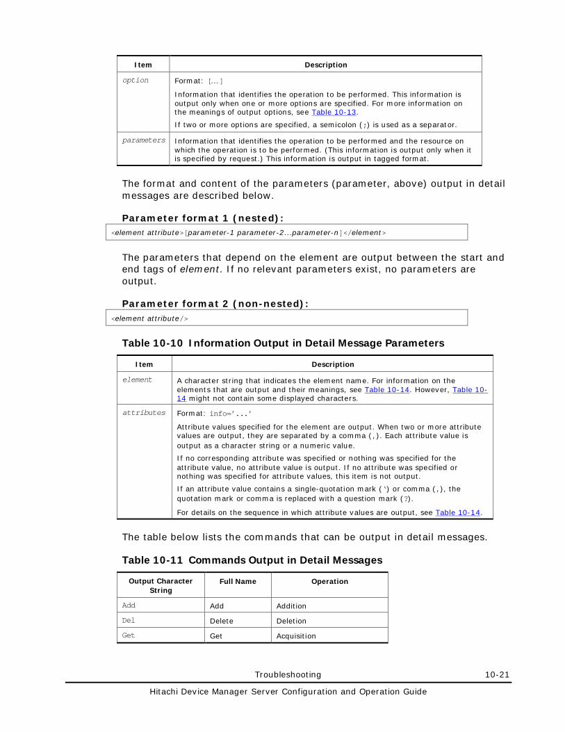
Troubleshooting 10-21
Hitachi Device Manager Server Configuration and Operation Guide
Item Description
option Format: [...]
Information that identifies the operation to be performed. This information is output only when one or more options are specified. For more information on the meanings of output options, see Table 10-13.
If two or more options are specified, a semicolon (;) is used as a separator.
parameters Information that identifies the operation to be performed and the resource on which the operation is to be performed. (This information is output only when it is specified by request.) This information is output in tagged format.
The format and content of the parameters (parameter, above) output in detail messages are described below.
Parameter format 1 (nested): <element attribute>[parameter-1 parameter-2...parameter-n]</element>
The parameters that depend on the element are output between the start and end tags of element. If no relevant parameters exist, no parameters are output.
Parameter format 2 (non-nested): <element attribute/>
Table 10-10 Information Output in Detail Message Parameters
Item Description
element A character string that indicates the element name. For information on the elements that are output and their meanings, see Table 10-14. However, Table 10-14 might not contain some displayed characters.
attributes Format: info=’...’
Attribute values specified for the element are output. When two or more attribute values are output, they are separated by a comma (,). Each attribute value is output as a character string or a numeric value.
If no corresponding attribute was specified or nothing was specified for the attribute value, no attribute value is output. If no attribute was specified or nothing was specified for attribute values, this item is not output.
If an attribute value contains a single-quotation mark (‘) or comma (,), the quotation mark or comma is replaced with a question mark (?).
For details on the sequence in which attribute values are output, see Table 10-14.
The table below lists the commands that can be output in detail messages.
Table 10-11 Commands Output in Detail Messages
Output Character String
Full Name Operation
Add Add Addition
Del Delete Deletion
Get Get Acquisition
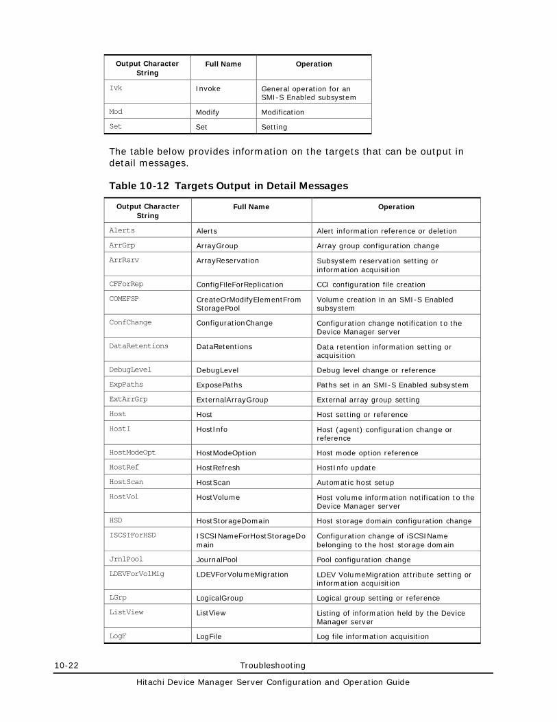
10-22 Troubleshooting
Hitachi Device Manager Server Configuration and Operation Guide
Output Character String
Full Name Operation
Ivk Invoke General operation for an SMI-S Enabled subsystem
Mod Modify Modification
Set Set Setting
The table below provides information on the targets that can be output in detail messages.
Table 10-12 Targets Output in Detail Messages
Output Character String
Full Name Operation
Alerts Alerts Alert information reference or deletion
ArrGrp ArrayGroup Array group configuration change
ArrRsrv ArrayReservation Subsystem reservation setting or information acquisition
CFForRep ConfigFileForReplication CCI configuration file creation
COMEFSP CreateOrModifyElementFromStoragePool
Volume creation in an SMI-S Enabled subsystem
ConfChange ConfigurationChange Configuration change notification to the Device Manager server
DataRetentions DataRetentions Data retention information setting or acquisition
DebugLevel DebugLevel Debug level change or reference
ExpPaths ExposePaths Paths set in an SMI-S Enabled subsystem
ExtArrGrp ExternalArrayGroup External array group setting
Host Host Host setting or reference
HostI HostInfo Host (agent) configuration change or reference
HostModeOpt HostModeOption Host mode option reference
HostRef HostRefresh HostInfo update
HostScan HostScan Automatic host setup
HostVol HostVolume Host volume information notification to the Device Manager server
HSD HostStorageDomain Host storage domain configuration change
ISCSIForHSD ISCSINameForHostStorageDomain
Configuration change of iSCSIName belonging to the host storage domain
JrnlPool JournalPool Pool configuration change
LDEVForVolMig LDEVForVolumeMigration LDEV VolumeMigration attribute setting or information acquisition
LGrp LogicalGroup Logical group setting or reference
ListView ListView Listing of information held by the Device Manager server
LogF LogFile Log file information acquisition
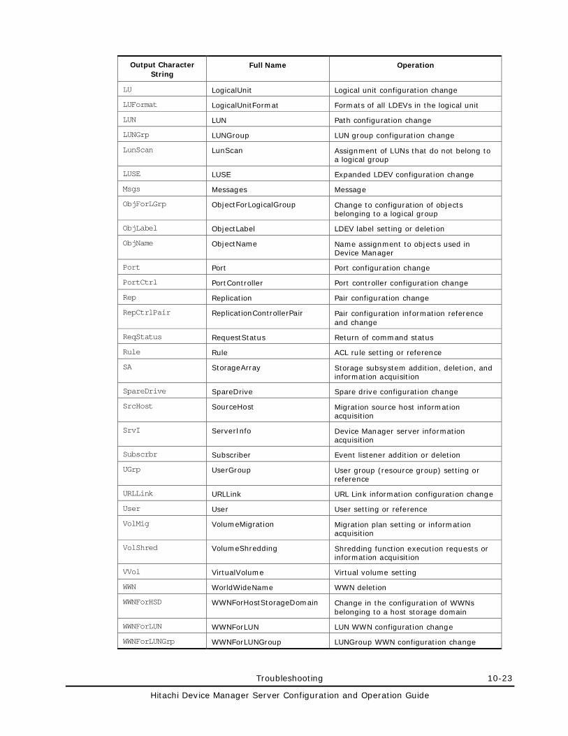
Troubleshooting 10-23
Hitachi Device Manager Server Configuration and Operation Guide
Output Character String
Full Name Operation
LU LogicalUnit Logical unit configuration change
LUFormat LogicalUnitFormat Formats of all LDEVs in the logical unit
LUN LUN Path configuration change
LUNGrp LUNGroup LUN group configuration change
LunScan LunScan Assignment of LUNs that do not belong to a logical group
LUSE LUSE Expanded LDEV configuration change
Msgs Messages Message
ObjForLGrp ObjectForLogicalGroup Change to configuration of objects belonging to a logical group
ObjLabel ObjectLabel LDEV label setting or deletion
ObjName ObjectName Name assignment to objects used in Device Manager
Port Port Port configuration change
PortCtrl PortController Port controller configuration change
Rep Replication Pair configuration change
RepCtrlPair ReplicationControllerPair Pair configuration information reference and change
ReqStatus RequestStatus Return of command status
Rule Rule ACL rule setting or reference
SA StorageArray Storage subsystem addition, deletion, and information acquisition
SpareDrive SpareDrive Spare drive configuration change
SrcHost SourceHost Migration source host information acquisition
SrvI ServerInfo Device Manager server information acquisition
Subscrbr Subscriber Event listener addition or deletion
UGrp UserGroup User group (resource group) setting or reference
URLLink URLLink URL Link information configuration change
User User User setting or reference
VolMig VolumeMigration Migration plan setting or information acquisition
VolShred VolumeShredding Shredding function execution requests or information acquisition
VVol VirtualVolume Virtual volume setting
WWN WorldWideName WWN deletion
WWNForHSD WWNForHostStorageDomain Change in the configuration of WWNs belonging to a host storage domain
WWNForLUN WWNForLUN LUN WWN configuration change
WWNForLUNGrp WWNForLUNGroup LUNGroup WWN configuration change
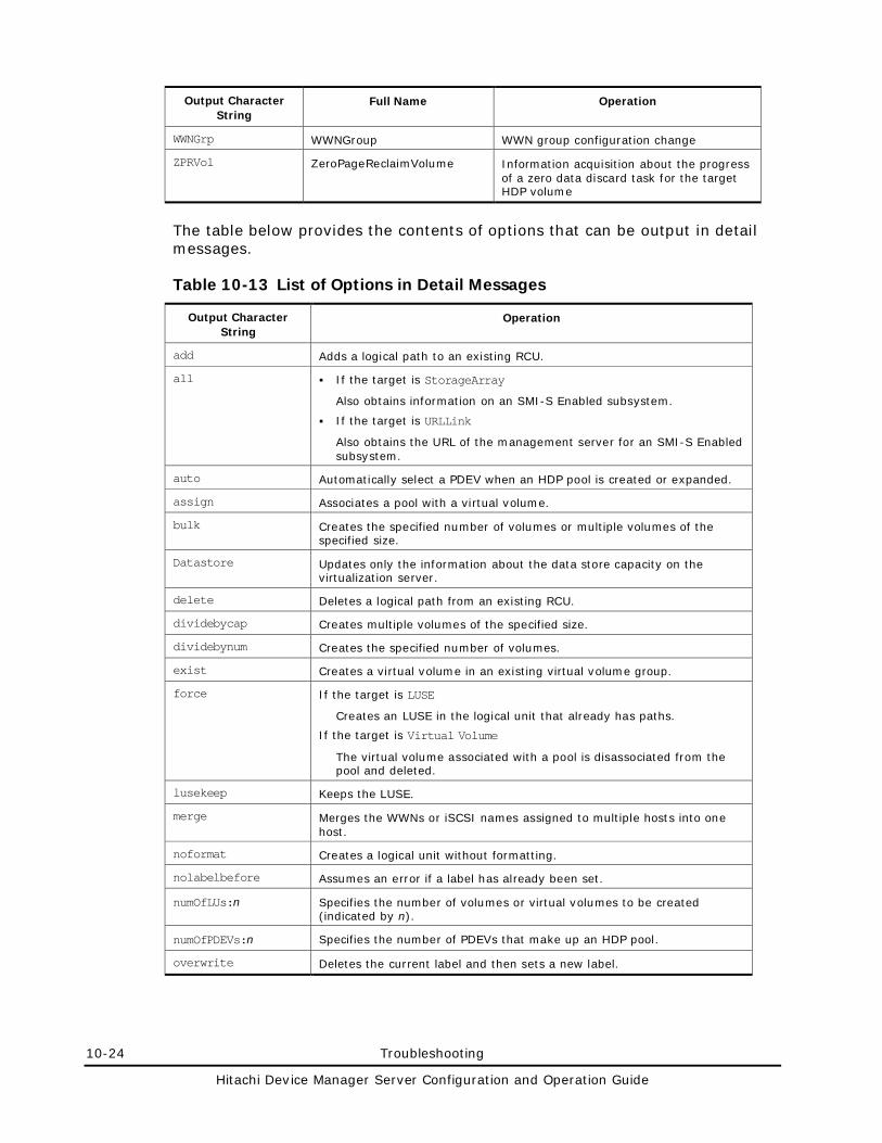
10-24 Troubleshooting
Hitachi Device Manager Server Configuration and Operation Guide
Output Character String
Full Name Operation
WWNGrp WWNGroup WWN group configuration change
ZPRVol ZeroPageReclaimVolume Information acquisition about the progress of a zero data discard task for the target HDP volume
The table below provides the contents of options that can be output in detail messages.
Table 10-13 List of Options in Detail Messages
Output Character String
Operation
add Adds a logical path to an existing RCU.
all If the target is StorageArray
Also obtains information on an SMI-S Enabled subsystem.
If the target is URLLink
Also obtains the URL of the management server for an SMI-S Enabled subsystem.
auto Automatically select a PDEV when an HDP pool is created or expanded.
assign Associates a pool with a virtual volume.
bulk Creates the specified number of volumes or multiple volumes of the specified size.
Datastore Updates only the information about the data store capacity on the virtualization server.
delete Deletes a logical path from an existing RCU.
dividebycap Creates multiple volumes of the specified size.
dividebynum Creates the specified number of volumes.
exist Creates a virtual volume in an existing virtual volume group.
force If the target is LUSE
Creates an LUSE in the logical unit that already has paths.
If the target is Virtual Volume
The virtual volume associated with a pool is disassociated from the pool and deleted.
lusekeep Keeps the LUSE.
merge Merges the WWNs or iSCSI names assigned to multiple hosts into one host.
noformat Creates a logical unit without formatting.
nolabelbefore Assumes an error if a label has already been set.
numOfLUs:n Specifies the number of volumes or virtual volumes to be created (indicated by n).
numOfPDEVs:n Specifies the number of PDEVs that make up an HDP pool.
overwrite Deletes the current label and then sets a new label.
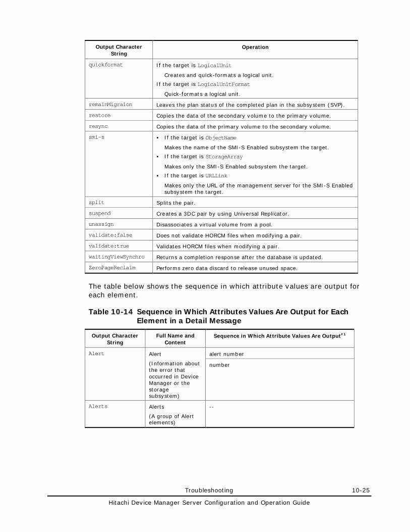
Troubleshooting 10-25
Hitachi Device Manager Server Configuration and Operation Guide
Output Character String
Operation
quickformat If the target is LogicalUnit
Creates and quick-formats a logical unit.
If the target is LogicalUnitFormat
Quick-formats a logical unit.
remainMigraion Leaves the plan status of the completed plan in the subsystem (SVP).
restore Copies the data of the secondary volume to the primary volume.
resync Copies the data of the primary volume to the secondary volume.
smi-s If the target is ObjectName
Makes the name of the SMI-S Enabled subsystem the target.
If the target is StorageArray
Makes only the SMI-S Enabled subsystem the target.
If the target is URLLink
Makes only the URL of the management server for the SMI-S Enabled subsystem the target.
split Splits the pair.
suspend Creates a 3DC pair by using Universal Replicator.
unassign Disassociates a virtual volume from a pool.
validate:false Does not validate HORCM files when modifying a pair.
validate:true Validates HORCM files when modifying a pair.
waitingViewSynchro Returns a completion response after the database is updated.
ZeroPageReclaim Performs zero data discard to release unused space.
The table below shows the sequence in which attribute values are output for each element.
Table 10-14 Sequence in Which Attributes Values Are Output for Each Element in a Detail Message
Output Character String
Full Name and Content
Sequence in Which Attribute Values Are Output#1
Alert Alert
(Information about the error that occurred in Device Manager or the storage subsystem)
alert number
number
Alerts Alerts
(A group of Alert elements)
--
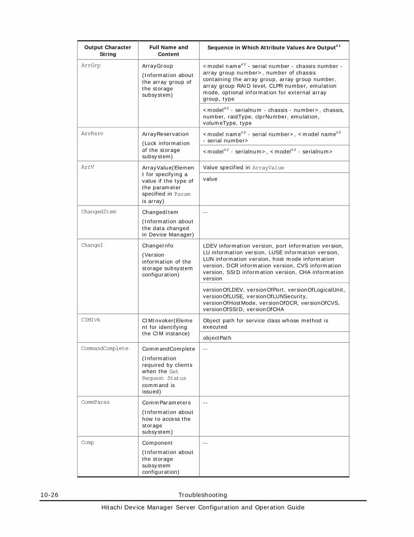
10-26 Troubleshooting
Hitachi Device Manager Server Configuration and Operation Guide
Output Character String
Full Name and Content
Sequence in Which Attribute Values Are Output#1
ArrGrp ArrayGroup
(Information about the array group of the storage subsystem)
<model name#2 - serial number - chassis number - array group number>, number of chassis containing the array group, array group number, array group RAID level, CLPR number, emulation mode, optional information for external array group, type
<model#2 - serialnum - chassis - number>, chassis, number, raidType, clprNumber, emulation, volumeType, type
ArrRsrv ArrayReservation
(Lock information of the storage subsystem)
<model name#2 - serial number>, <model name#2 - serial number>
<model#2 - serialnum>, <model#2 - serialnum>
ArrV ArrayValue(Element for specifying a value if the type of the parameter specified in Param is array)
Value specified in ArrayValue
value
ChangedItem ChangedItem
(Information about the data changed in Device Manager)
--
ChangeI ChangeInfo
(Version information of the storage subsystem configuration)
LDEV information version, port information version, LU information version, LUSE information version, LUN information version, host mode information version, DCR information version, CVS information version, SSID information version, CHA information version
versionOfLDEV, versionOfPort, versionOfLogicalUnit, versionOfLUSE, versionOfLUNSecurity, versionOfHostMode, versionOfDCR, versionOfCVS, versionOfSSID, versionOfCHA
CIMIvk CIMInvoker(Element for identifying the CIM instance)
Object path for service class whose method is executed
objectPath
CommandComplete CommandComplete
(Information required by clients when the Get Request Status command is issued)
--
CommParas CommParameters
(Information about how to access the storage subsystem)
--
Comp Component
(Information about the storage subsystem configuration)
--
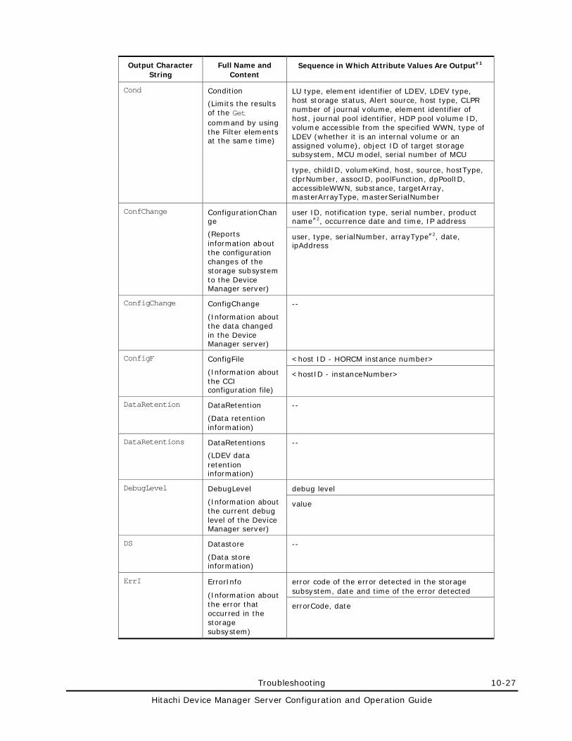
Troubleshooting 10-27
Hitachi Device Manager Server Configuration and Operation Guide
Output Character String
Full Name and Content
Sequence in Which Attribute Values Are Output#1
Cond Condition
(Limits the results of the Get command by using the Filter elements at the same time)
LU type, element identifier of LDEV, LDEV type, host storage status, Alert source, host type, CLPR number of journal volume, element identifier of host, journal pool identifier, HDP pool volume ID, volume accessible from the specified WWN, type of LDEV (whether it is an internal volume or an assigned volume), object ID of target storage subsystem, MCU model, serial number of MCU
type, childID, volumeKind, host, source, hostType, clprNumber, assocID, poolFunction, dpPoolID, accessibleWWN, substance, targetArray, masterArrayType, masterSerialNumber
ConfChange ConfigurationChange
(Reports information about the configuration changes of the storage subsystem to the Device Manager server)
user ID, notification type, serial number, product name#2, occurrence date and time, IP address
user, type, serialNumber, arrayType#2, date, ipAddress
ConfigChange ConfigChange
(Information about the data changed in the Device Manager server)
--
ConfigF ConfigFile
(Information about the CCI configuration file)
<host ID - HORCM instance number>
<hostID - instanceNumber>
DataRetention DataRetention
(Data retention information)
--
DataRetentions DataRetentions
(LDEV data retention information)
--
DebugLevel DebugLevel
(Information about the current debug level of the Device Manager server)
debug level
value
DS Datastore
(Data store information)
--
ErrI ErrorInfo
(Information about the error that occurred in the storage subsystem)
error code of the error detected in the storage subsystem, date and time of the error detected
errorCode, date
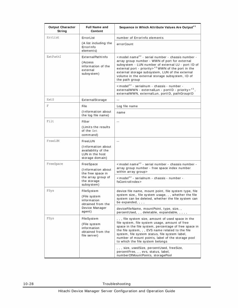
10-28 Troubleshooting
Hitachi Device Manager Server Configuration and Operation Guide
Output Character String
Full Name and Content
Sequence in Which Attribute Values Are Output#1
ErrList ErrorList
(A list including the ErrorInfo elements)
number of ErrorInfo elements
errorCount
ExtPathI ExternalPathInfo
(Access information of the external subsystem)
<model name#2 - serial number - chassis number - array group number - WWN of port for external subsystem - LUN number of external LU - port ID of external port - priority>#3 WWN of the port in the external storage subsystem, LUN of the external volume in the external storage subsystem, ID of the path group
<model#2 - serialnum - chassis - number - externalWWN - externalLun - portID - priority>#3 , externalWWN, externalLun, portID, pathGroupID
ExtS ExternalStorage --
F File
(Information about the log file name)
Log file name
name
Filt Filter
(Limits the results of the Get command)
--
FreeLUN FreeLUN
(Information about availability of the LUN in the host storage domain)
--
FreeSpace FreeSpace
(Information about the free space in the array group of the storage subsystem)
<model name#2 - serial number - chassis number - array group number - free space index number within array group>
<model#2 - serialnum - chassis - number - fsControlIndex>
FSys FileSystem
(File system information obtained from the Device Manager agent)
device file name, mount point, file system type, file system size,, file system usage, , , whether the file system can be deleted, whether the file system can be expanded, , , ,
deviceFileName, mountPoint, type, size, , percentUsed, , , deletable, expandable, , , , ,
FSys FileSystem
(File system information obtained from the file server)
, , , file system size, amount of used space in the file system, file system usage, amount of free space in the file system, percentage of free space in the file system, , , EVS name related to the file system, file system status, file system label, number of mount points, label of the storage pool to which the file system belongs
, , , size, usedSize, percentUsed, freeSize, percentFree, , , evs, status, label, numberOfMountPoints, storagePool
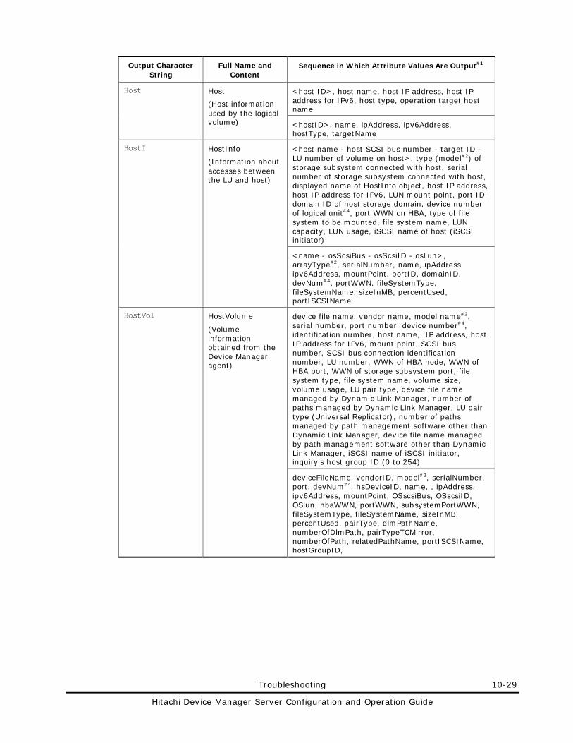
Troubleshooting 10-29
Hitachi Device Manager Server Configuration and Operation Guide
Output Character String
Full Name and Content
Sequence in Which Attribute Values Are Output#1
Host Host
(Host information used by the logical volume)
<host ID>, host name, host IP address, host IP address for IPv6, host type, operation target host name
<hostID>, name, ipAddress, ipv6Address, hostType, targetName
HostI HostInfo
(Information about accesses between the LU and host)
<host name - host SCSI bus number - target ID - LU number of volume on host>, type (model#2) of storage subsystem connected with host, serial number of storage subsystem connected with host, displayed name of HostInfo object, host IP address, host IP address for IPv6, LUN mount point, port ID, domain ID of host storage domain, device number of logical unit#4, port WWN on HBA, type of file system to be mounted, file system name, LUN capacity, LUN usage, iSCSI name of host (iSCSI initiator)
<name - osScsiBus - osScsiID - osLun>, arrayType#2, serialNumber, name, ipAddress, ipv6Address, mountPoint, portID, domainID, devNum#4, portWWN, fileSystemType, fileSystemName, sizeInMB, percentUsed, portISCSIName
HostVol HostVolume
(Volume information obtained from the Device Manager agent)
device file name, vendor name, model name#2, serial number, port number, device number#4, identification number, host name,, IP address, host IP address for IPv6, mount point, SCSI bus number, SCSI bus connection identification number, LU number, WWN of HBA node, WWN of HBA port, WWN of storage subsystem port, file system type, file system name, volume size, volume usage, LU pair type, device file name managed by Dynamic Link Manager, number of paths managed by Dynamic Link Manager, LU pair type (Universal Replicator), number of paths managed by path management software other than Dynamic Link Manager, device file name managed by path management software other than Dynamic Link Manager, iSCSI name of iSCSI initiator, inquiry's host group ID (0 to 254)
deviceFileName, vendorID, model#2, serialNumber, port, devNum#4, hsDeviceID, name, , ipAddress, ipv6Address, mountPoint, OSscsiBus, OSscsiID, OSlun, hbaWWN, portWWN, subsystemPortWWN, fileSystemType, fileSystemName, sizeInMB, percentUsed, pairType, dlmPathName, numberOfDlmPath, pairTypeTCMirror, numberOfPath, relatedPathName, portISCSIName, hostGroupID,
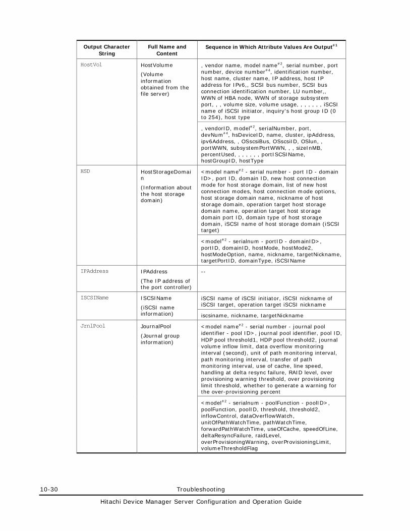
10-30 Troubleshooting
Hitachi Device Manager Server Configuration and Operation Guide
Output Character String
Full Name and Content
Sequence in Which Attribute Values Are Output#1
HostVol HostVolume
(Volume information obtained from the file server)
, vendor name, model name#2, serial number, port number, device number#4, identification number, host name, cluster name, IP address, host IP address for IPv6,, SCSI bus number, SCSI bus connection identification number, LU number,, WWN of HBA node, WWN of storage subsystem port, , , volume size, volume usage, , , , , , , iSCSI name of iSCSI initiator, inquiry's host group ID (0 to 254), host type
, vendorID, model#2, serialNumber, port, devNum#4, hsDeviceID, name, cluster, ipAddress, ipv6Address, , OSscsiBus, OSscsiID, OSlun, , portWWN, subsystemPortWWN, , , sizeInMB, percentUsed, , , , , , , portISCSIName, hostGroupID, hostType
HSD HostStorageDomain
(Information about the host storage domain)
<model name#2 - serial number - port ID - domain ID>, port ID, domain ID, new host connection mode for host storage domain, list of new host connection modes, host connection mode options, host storage domain name, nickname of host storage domain, operation target host storage domain name, operation target host storage domain port ID, domain type of host storage domain, iSCSI name of host storage domain (iSCSI target)
<model#2 - serialnum - portID - domainID>, portID, domainID, hostMode, hostMode2, hostModeOption, name, nickname, targetNickname, targetPortID, domainType, iSCSIName
IPAddress IPAddress
(The IP address of the port controller)
--
ISCSIName ISCSIName
(iSCSI name information)
iSCSI name of iSCSI initiator, iSCSI nickname of iSCSI target, operation target iSCSI nickname
iscsiname, nickname, targetNickname
JrnlPool JournalPool
(Journal group information)
<model name#2 - serial number - journal pool identifier - pool ID>, journal pool identifier, pool ID, HDP pool threshold1, HDP pool threshold2, journal volume inflow limit, data overflow monitoring interval (second), unit of path monitoring interval, path monitoring interval, transfer of path monitoring interval, use of cache, line speed, handling at delta resync failure, RAID level, over provisioning warning threshold, over provisioning limit threshold, whether to generate a warning for the over-provisioning percent
<model#2 - serialnum - poolFunction - poolID>, poolFunction, poolID, threshold, threshold2, inflowControl, dataOverflowWatch, unitOfPathWatchTime, pathWatchTime, forwardPathWatchTime, useOfCache, speedOfLine, deltaResyncFailure, raidLevel, overProvisioningWarning, overProvisioningLimit, volumeThresholdFlag
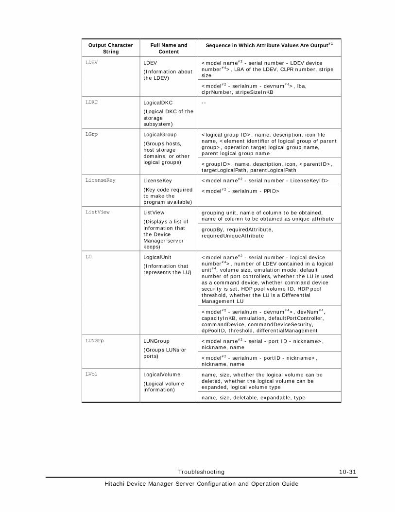
Troubleshooting 10-31
Hitachi Device Manager Server Configuration and Operation Guide
Output Character String
Full Name and Content
Sequence in Which Attribute Values Are Output#1
LDEV LDEV
(Information about the LDEV)
<model name#2 - serial number - LDEV device number#4>, LBA of the LDEV, CLPR number, stripe size
<model#2 - serialnum - devnum#4>, lba, clprNumber, stripeSizeInKB
LDKC LogicalDKC
(Logical DKC of the storage subsystem)
--
LGrp LogicalGroup
(Groups hosts, host storage domains, or other logical groups)
<logical group ID>, name, description, icon file name, <element identifier of logical group of parent group>, operation target logical group name, parent logical group name
<groupID>, name, description, icon, <parentID>, targetLogicalPath, parentLogicalPath
LicenseKey LicenseKey
(Key code required to make the program available)
<model name#2 - serial number - LicenseKeyID>
<model#2 - serialnum - PPID>
ListView ListView
(Displays a list of information that the Device Manager server keeps)
grouping unit, name of column to be obtained, name of column to be obtained as unique attribute
groupBy, requiredAttribute, requiredUniqueAttribute
LU LogicalUnit
(Information that represents the LU)
<model name#2 - serial number - logical device number#4>, number of LDEV contained in a logical unit#4, volume size, emulation mode, default number of port controllers, whether the LU is used as a command device, whether command device security is set, HDP pool volume ID, HDP pool threshold, whether the LU is a Differential Management LU
<model#2 - serialnum - devnum#4>, devNum#4, capacityInKB, emulation, defaultPortController, commandDevice, commandDeviceSecurity, dpPoolID, threshold, differentialManagement
LUNGrp LUNGroup
(Groups LUNs or ports)
<model name#2 - serial - port ID - nickname>, nickname, name
<model#2 - serialnum - portID - nickname>, nickname, name
LVol LogicalVolume
(Logical volume information)
name, size, whether the logical volume can be deleted, whether the logical volume can be expanded, logical volume type
name, size, deletable, expandable, type
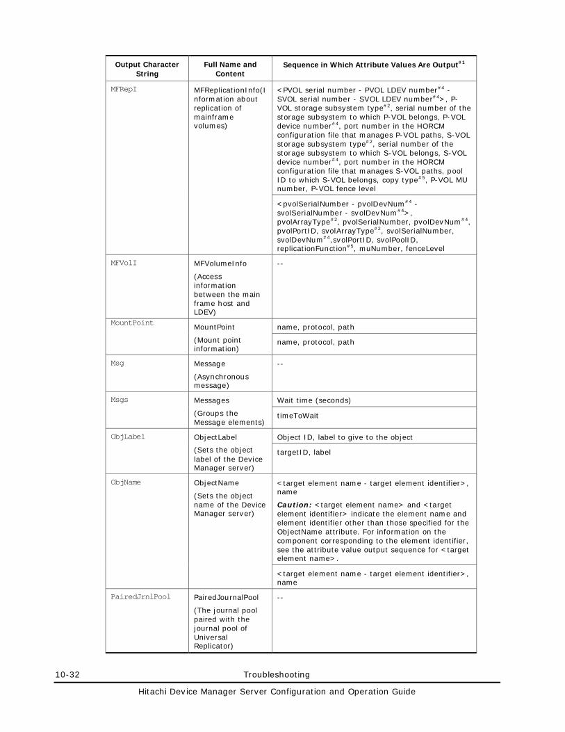
10-32 Troubleshooting
Hitachi Device Manager Server Configuration and Operation Guide
Output Character String
Full Name and Content
Sequence in Which Attribute Values Are Output#1
MFRepI MFReplicationInfo(Information about replication of mainframe volumes)
<PVOL serial number - PVOL LDEV number#4 - SVOL serial number - SVOL LDEV number#4>, P-VOL storage subsystem type#2, serial number of the storage subsystem to which P-VOL belongs, P-VOL device number#4, port number in the HORCM configuration file that manages P-VOL paths, S-VOL storage subsystem type#2, serial number of the storage subsystem to which S-VOL belongs, S-VOL device number#4, port number in the HORCM configuration file that manages S-VOL paths, pool ID to which S-VOL belongs, copy type#5, P-VOL MU number, P-VOL fence level
<pvolSerialNumber - pvolDevNum#4 - svolSerialNumber - svolDevNum#4>, pvolArrayType#2, pvolSerialNumber, pvolDevNum#4, pvolPortID, svolArrayType#2, svolSerialNumber, svolDevNum#4,svolPortID, svolPoolID, replicationFunction#5, muNumber, fenceLevel
MFVolI MFVolumeInfo
(Access information between the main frame host and LDEV)
--
MountPoint MountPoint
(Mount point information)
name, protocol, path
name, protocol, path
Msg Message
(Asynchronous message)
--
Msgs Messages
(Groups the Message elements)
Wait time (seconds)
timeToWait
ObjLabel ObjectLabel
(Sets the object label of the Device Manager server)
Object ID, label to give to the object
targetID, label
ObjName ObjectName
(Sets the object name of the Device Manager server)
<target element name - target element identifier>, name
Caution: <target element name> and <target element identifier> indicate the element name and element identifier other than those specified for the ObjectName attribute. For information on the component corresponding to the element identifier, see the attribute value output sequence for <target element name>.
<target element name - target element identifier>, name
PairedJrnlPool PairedJournalPool
(The journal pool paired with the journal pool of Universal Replicator)
--
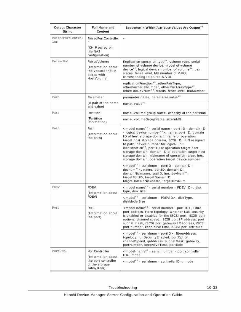
Troubleshooting 10-33
Hitachi Device Manager Server Configuration and Operation Guide
Output Character String
Full Name and Content
Sequence in Which Attribute Values Are Output#1
PairedPortController
PairedPortController
(CHIP paired on the NAS configuration)
--
PairedVol PairedVolume
(Information about the volume that is paired with HostVolume)
Replication operation type#5, volume type, serial number of volume device, model of volume device#2, logical device number of volume#4, pair status, fence level, MU number of P-VOL corresponding to paired S-VOL
replicationFunction#5, otherPairType, otherPairSerialNumber, otherPairArrayType#2, otherPairDevNum#4, status, fenceLevel, muNumber
Para Parameter
(A pair of the name and value)
parameter name, parameter value#2
name, value#2
Part Partition
(Partition information)
name, volume group name, capacity of the partition
name, volumeGroupName, sizeInMB
Path Path
(Information about the path)
<model name#2 - serial name - port ID - domain ID - logical device number#4>, name, port ID, domain ID of host storage domain, name of operation target host storage domain, SCSI ID, LUN assigned to path, device number for logical unit identification#4, port ID of operation target host storage domain, domain ID of operation target host storage domain, nickname of operation target host storage domain, operation target device number
<model#2 - serialnum - portID - domainID - devnum#4>, name, portID, domainID, domainNickname, scsiID, lun, devNum#4, targetPortID, targetDomainID, targetDomainNickname, targetDevNum
PDEV PDEV
(Information about PDEV)
<model name#2 - serial number - PDEV ID>, disk type, disk size
<model#2 - serialnum - PDEVID>, diskType, diskModelSize
Port Port
(Information about the port)
<model name#2 - serial number - port ID>, Fibre port address, Fibre topology, whether LUN security is enabled or disabled for the iSCSI port, iSCSI port options, channel speed, iSCSI port IP address, port subnet mask, iSCSI port gateway IP address, iSCSI port number, keep alive time, iSCSI port attribute
<model#2 - serialnum - portID>, fibreAddress, topology, lunSecurityEnabled, portOption, channelSpeed, ipAddress, subnetMask, gateway, portNumber, keepAliveTime, portRole
PortCtrl PortController
(Information about the port controller of the storage subsystem)
<model-name#2 - serial number - port controller ID>, mode
<model#2 - serialnum - controllerID>, mode
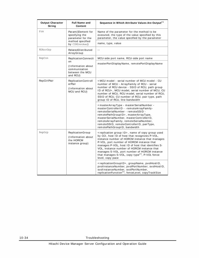
10-34 Troubleshooting
Hitachi Device Manager Server Configuration and Operation Guide
Output Character String
Full Name and Content
Sequence in Which Attribute Values Are Output#1
Prm Param(Element for specifying the parameter for the method specified by CIMInvoker)
Name of the parameter for the method to be executed, the type of the value specified by this parameter, the value specified by the parameter
name, type, value
RDArrGrp RelatedDistributedArrayGroup
--
RepCon ReplicationConnection
(Information about communication between the MCU and RCU)
MCU-side port name, RCU-side port name
masterPortDisplayName, remotePortDisplayName
RepCtrlPair ReplicationControllerPair
(Information about MCU and RCU)
<MCU model - serial number of MCU model - CU number of MCU - ArrayFamily of RCU - serial number of RCU device - SSID of RCU, path group ID of RCU>, MCU model, serial number of MCU, CU number of MCU, RCU model, serial number of RCU, SSID of RCU, CU number of RCU, pair type, path group ID of RCU, line bandwidth
<masterArrayType - masterSerialNumber - masterControllerID - -remoteArrayFamily- remoteSerialNumber - remoteSSID -remotePathGroupID>, masterArrayType, masterSerialNumber, masterControllerID, remoteArrayFamily, remoteSerialNumber, remoteSSID, remoteControllerID, pairType, remotePathGroupID, bandwidth
RepGrp ReplicationGroup
(Information about the HORCM instance group)
<replication group ID>, name of copy group used by CCI, host ID of host that recognizes P-VOL, instance number of HORCM instance that manages P-VOL, port number of HORCM instance that manages P-VOL, host ID of host that identifies S-VOL, instance number of HORCM instance that manages S-VOL, port number of HORCM instance that manages S-VOL, copy type#5, P-VOL fence level, copy pace
<replicationGroupID>, groupName, pvolHostID, pvolInstanceNumber, pvolPortNumber, svolHostID, svolInstanceNumber, svolPortNumber, replicationFunction#5, fenceLevel, copyTrackSize
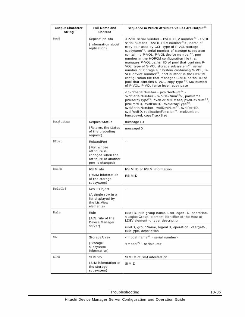
Troubleshooting 10-35
Hitachi Device Manager Server Configuration and Operation Guide
Output Character String
Full Name and Content
Sequence in Which Attribute Values Are Output#1
RepI ReplicationInfo
(Information about replication)
<PVOL serial number - PVOLLDEV number#4 - SVOL serial number - SVOLLDEV number#4>, name of copy pair used by CCI, type of P-VOL storage subsystem#2, serial number of storage subsystem containing P-VOL, P-VOL device number#4, port number in the HORCM configuration file that manages P-VOL paths, ID of pool that contains P-VOL, type of S-VOL storage subsystem#2, serial number of storage subsystem containing S-VOL, S-VOL device number#4, port number in the HORCM configuration file that manages S-VOL paths, ID of pool that contains S-VOL, copy type #5, MU number of P-VOL, P-VOL fence level, copy pace
<pvolSerialNumber - pvolDevNum#4 - svolSerialNumber - svolDevNum#4>, pairName, pvolArrayType#2, pvolSerialNumber, pvolDevNum#4, pvolPortID, pvolPoolID, svolArrayType#2, svolSerialNumber, svolDevNum#4, svolPortID, svolPoolID, replicationFunction#5, muNumber, fenceLevel, copyTrackSize
ReqStatus RequestStatus
(Returns the status of the preceding request)
message ID
messageID
RPort RelatedPort
(Port whose attribute is changed when the attribute of another port is changed)
--
RSIMI RSIMInfo
(RSIM information of the storage subsystem)
RSIM ID of RSIM information
RSIMID
RsltObj ResultObject
(A single row in a list displayed by the ListView elements)
--
Rule Rule
(ACL rule of the Device Manager server)
rule ID, rule group name, user logon ID, operation, <LogicalGroup, element identifier of the Host or LDEV element>, type, description
ruleID, groupName, logonID, operation, <target>, ruleType, description
SA StorageArray
(Storage subsystem information)
<model name#2 - serial number>
<model#2 - serialnum>
SIMI SIMInfo
(SIM information of the storage subsystem)
SIM ID of SIM information
SIMID
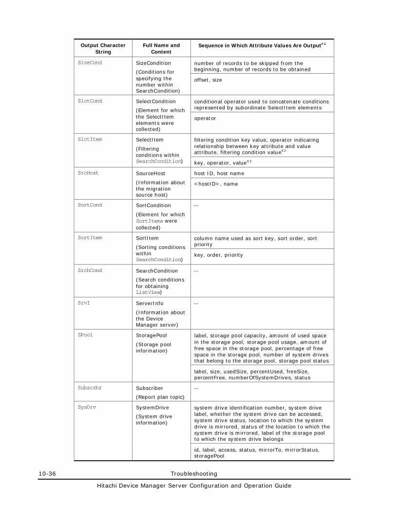
10-36 Troubleshooting
Hitachi Device Manager Server Configuration and Operation Guide
Output Character String
Full Name and Content
Sequence in Which Attribute Values Are Output#1
SizeCond SizeCondition
(Conditions for specifying the number within SearchCondition)
number of records to be skipped from the beginning, number of records to be obtained
offset, size
SlctCond SelectCondition
(Element for which the SelectItem elements were collected)
conditional operator used to concatenate conditions represented by subordinate SelectItem elements
operator
SlctItem SelectItem
(Filtering conditions within SearchCondition)
filtering condition key value, operator indicating relationship between key attribute and value attribute, filtering condition value#2
key, operator, value#2
SrcHost SourceHost
(Information about the migration source host)
host ID, host name
<hostID>, name
SortCond SortCondition
(Element for which SortItems were collected)
--
SortItem SortItem
(Sorting conditions within SearchCondition)
column name used as sort key, sort order, sort priority
key, order, priority
SrchCond SearchCondition
(Search conditions for obtaining ListView)
--
SrvI ServerInfo
(Information about the Device Manager server)
--
SPool StoragePool
(Storage pool information)
label, storage pool capacity, amount of used space in the storage pool, storage pool usage, amount of free space in the storage pool, percentage of free space in the storage pool, number of system drives that belong to the storage pool, storage pool status
label, size, usedSize, percentUsed, freeSize, percentFree, numberOfSystemDrives, status
Subscrbr Subscriber
(Report plan topic)
--
SysDrv SystemDrive
(System drive information)
system drive identification number, system drive label, whether the system drive can be accessed, system drive status, location to which the system drive is mirrored, status of the location to which the system drive is mirrored, label of the storage pool to which the system drive belongs
id, label, access, status, mirrorTo, mirrorStatus, storagePool
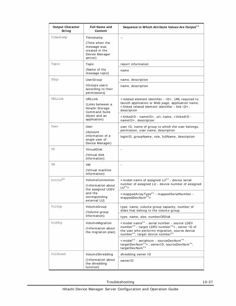
Troubleshooting 10-37
Hitachi Device Manager Server Configuration and Operation Guide
Output Character String
Full Name and Content
Sequence in Which Attribute Values Are Output#1
Timestamp Timestamp
(Time when the message was created in the Device Manager server)
--
Topic Topic
(Name of the message topic)
report information
name
UGrp UserGroup
(Groups users according to their permissions)
name, description
name, description
URLLink URLLink
(Links between a Hitachi Storage Command Suite object and an application)
<related element identifier - ID>, URL required to launch application or Web page, application name, <linked related element identifier - link ID>, description
<linkedID - nameID>, url, name, <linkedID - nameID>, description
User User
(Account information of a single user of Device Manager)
user ID, name of group to which the user belongs, permission, user name, description
loginID, groupName, role, fullName, description
VD VirtualDisk
(Virtual disk information)
-
VM VM
(Virtual machine information)
-
VolCon#3 VolumeConnection
(Information about the assigned LDEV and the corresponding external LU)
<model name of assigned LU#2 - device serial number of assigned LU - device number of assigned LU#4>
<mappedArrayType#2 - mappedSerialNumber - mappedDevNum#4>
VolGrp VolumeGroup
(Volume group information)
type, name, volume group capacity, number of disks that belong to the volume group
type, name, size, numberOfDisk
VolMig VolumeMigration
(Information about the migration plan)
<model name#2 - serial number - source LDEV number#4 - target LDEV number#4>, owner ID of the user who performs migration, source device number#4, target device number#4
<model#2 - serialnum - sourceDevNum#4 - targetDevNum#4>, ownerID, sourceDevNum#4, targetDevNum#4
VolShred VolumeShredding
(Information about the shredding function)
shredding owner ID
ownerID
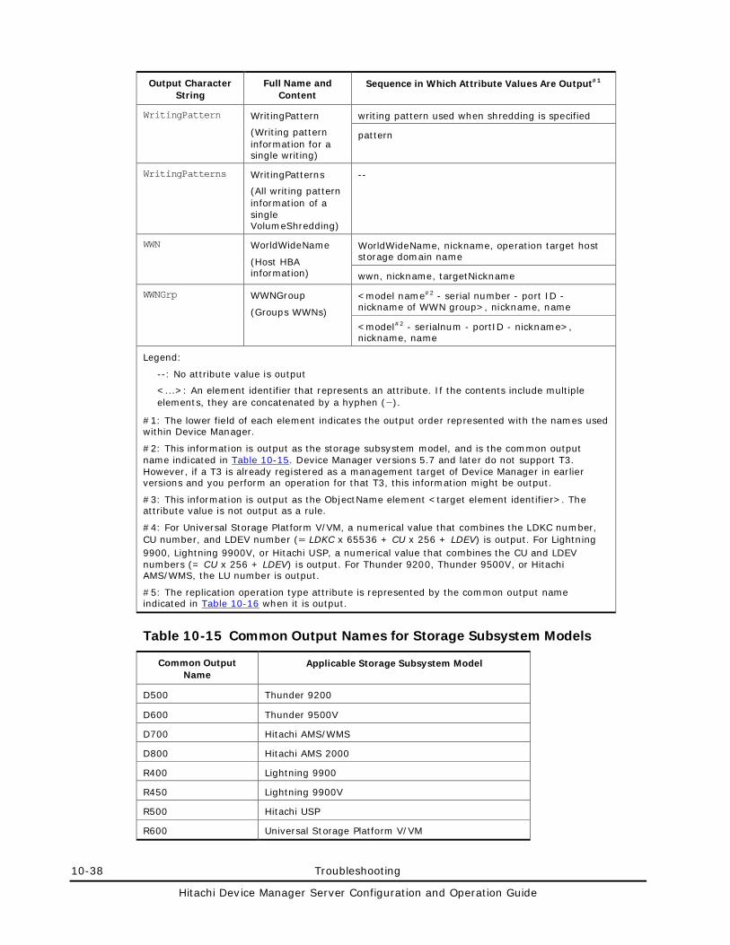
10-38 Troubleshooting
Hitachi Device Manager Server Configuration and Operation Guide
Output Character String
Full Name and Content
Sequence in Which Attribute Values Are Output#1
WritingPattern WritingPattern
(Writing pattern information for a single writing)
writing pattern used when shredding is specified
pattern
WritingPatterns WritingPatterns
(All writing pattern information of a single VolumeShredding)
--
WWN WorldWideName
(Host HBA information)
WorldWideName, nickname, operation target host storage domain name
wwn, nickname, targetNickname
WWNGrp WWNGroup
(Groups WWNs)
<model name#2 - serial number - port ID - nickname of WWN group>, nickname, name
<model#2 - serialnum - portID - nickname>, nickname, name
Legend:
--: No attribute value is output
<...>: An element identifier that represents an attribute. If the contents include multiple elements, they are concatenated by a hyphen (-).
#1: The lower field of each element indicates the output order represented with the names used within Device Manager.
#2: This information is output as the storage subsystem model, and is the common output name indicated in Table 10-15. Device Manager versions 5.7 and later do not support T3. However, if a T3 is already registered as a management target of Device Manager in earlier versions and you perform an operation for that T3, this information might be output.
#3: This information is output as the ObjectName element <target element identifier>. The attribute value is not output as a rule.
#4: For Universal Storage Platform V/VM, a numerical value that combines the LDKC number, CU number, and LDEV number (= LDKC x 65536 + CU x 256 + LDEV) is output. For Lightning 9900, Lightning 9900V, or Hitachi USP, a numerical value that combines the CU and LDEV numbers (= CU x 256 + LDEV) is output. For Thunder 9200, Thunder 9500V, or Hitachi AMS/WMS, the LU number is output.
#5: The replication operation type attribute is represented by the common output name indicated in Table 10-16 when it is output.
Table 10-15 Common Output Names for Storage Subsystem Models
Common Output Name
Applicable Storage Subsystem Model
D500 Thunder 9200
D600 Thunder 9500V
D700 Hitachi AMS/WMS
D800 Hitachi AMS 2000
R400 Lightning 9900
R450 Lightning 9900V
R500 Hitachi USP
R600 Universal Storage Platform V/VM
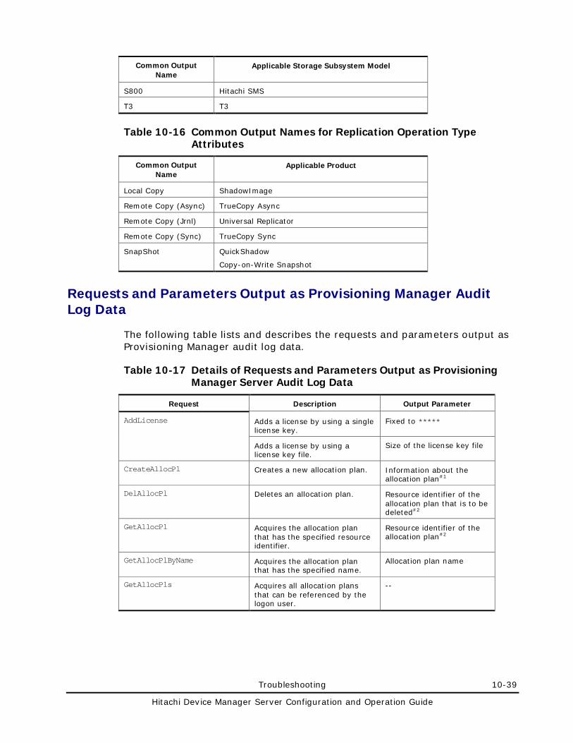
Troubleshooting 10-39
Hitachi Device Manager Server Configuration and Operation Guide
Common Output Name
Applicable Storage Subsystem Model
S800 Hitachi SMS
T3 T3
Table 10-16 Common Output Names for Replication Operation Type Attributes
Common Output Name
Applicable Product
Local Copy ShadowImage
Remote Copy (Async) TrueCopy Async
Remote Copy (Jrnl) Universal Replicator
Remote Copy (Sync) TrueCopy Sync
SnapShot QuickShadow
Copy-on-Write Snapshot
Requests and Parameters Output as Provisioning Manager Audit Log Data
The following table lists and describes the requests and parameters output as Provisioning Manager audit log data.
Table 10-17 Details of Requests and Parameters Output as Provisioning Manager Server Audit Log Data
Request Description Output Parameter
AddLicense Adds a license by using a single license key.
Fixed to *****
Adds a license by using a license key file.
Size of the license key file
CreateAllocPl Creates a new allocation plan. Information about the allocation plan#1
DelAllocPl Deletes an allocation plan. Resource identifier of the allocation plan that is to be deleted#2
GetAllocPl Acquires the allocation plan that has the specified resource identifier.
Resource identifier of the allocation plan#2
GetAllocPlByName Acquires the allocation plan that has the specified name.
Allocation plan name
GetAllocPls Acquires all allocation plans that can be referenced by the logon user.
--
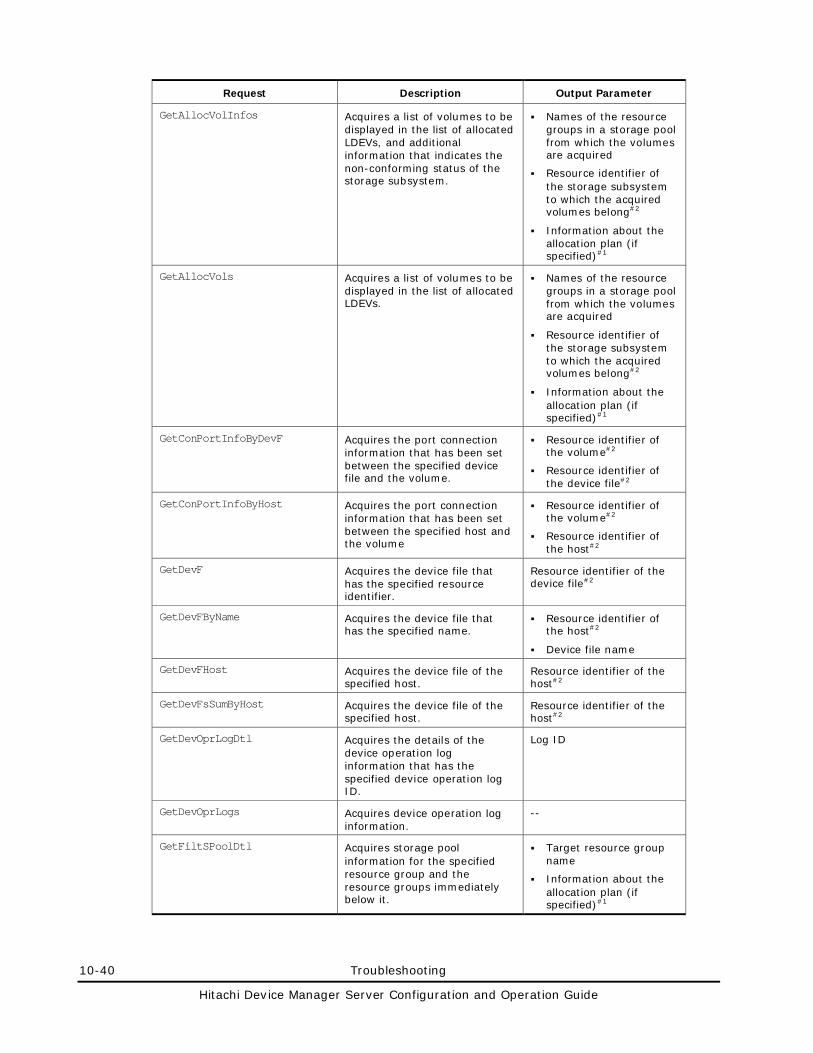
10-40 Troubleshooting
Hitachi Device Manager Server Configuration and Operation Guide
Request Description Output Parameter
GetAllocVolInfos Acquires a list of volumes to be displayed in the list of allocated LDEVs, and additional information that indicates the non-conforming status of the storage subsystem.
Names of the resource groups in a storage pool from which the volumes are acquired
Resource identifier of the storage subsystem to which the acquired volumes belong#2
Information about the allocation plan (if specified)#1
GetAllocVols Acquires a list of volumes to be displayed in the list of allocated LDEVs.
Names of the resource groups in a storage pool from which the volumes are acquired
Resource identifier of the storage subsystem to which the acquired volumes belong#2
Information about the allocation plan (if specified)#1
GetConPortInfoByDevF Acquires the port connection information that has been set between the specified device file and the volume.
Resource identifier of the volume#2
Resource identifier of the device file#2
GetConPortInfoByHost Acquires the port connection information that has been set between the specified host and the volume
Resource identifier of the volume#2
Resource identifier of the host#2
GetDevF Acquires the device file that has the specified resource identifier.
Resource identifier of the device file#2
GetDevFByName Acquires the device file that has the specified name.
Resource identifier of the host#2
Device file name
GetDevFHost Acquires the device file of the specified host.
Resource identifier of the host#2
GetDevFsSumByHost Acquires the device file of the specified host.
Resource identifier of the host#2
GetDevOprLogDtl Acquires the details of the device operation log information that has the specified device operation log ID.
Log ID
GetDevOprLogs Acquires device operation log information.
--
GetFiltSPoolDtl Acquires storage pool information for the specified resource group and the resource groups immediately below it.
Target resource group name
Information about the allocation plan (if specified)#1
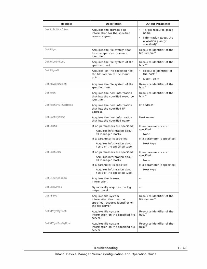
Troubleshooting 10-41
Hitachi Device Manager Server Configuration and Operation Guide
Request Description Output Parameter
GetFiltSPoolSum Acquires the storage pool information for the specified resource group
Target resource group name
Information about the allocation plan (if specified)#1
GetFSys Acquires the file system that has the specified resource identifier.
Resource identifier of the file system#2
GetFSysByHost Acquires the file system of the specified host.
Resource identifier of the host#2
GetFSysMP Acquires, on the specified host, the file system at the mount point.
Resource identifier of the host#2
Mount point
GetFSysSumHost Acquires the file system of the specified host.
Resource identifier of the host#2
GetHost Acquires the host information that has the specified resource identifier.
Resource identifier of the host#2
GetHostByIPAddress Acquires the host information that has the specified IP address.
IP address
GetHostByName Acquires the host information that has the specified name.
Host name
GetHosts If no parameters are specified:
Acquires information about all managed hosts.
If a parameter is specified:
Acquires information about hosts of the specified type.
If no parameters are specified:
None
If a parameter is specified:
Host type
GetHostSum If no parameters are specified:
Acquires information about all managed hosts.
If a parameter is specified:
Acquires information about hosts of the specified type.
If no parameters are specified:
None
If a parameter is specified:
Host type
GetLicenseInfo Acquires the license information.
--
GetLogLevel Dynamically acquires the log output level.
--
GetNFSys Acquires file system information that has the specified resource identifier on the file server.
Resource identifier of the file system#2
GetNFSysByHost Acquires file system information on the specified file server.
Resource identifier of the host#2
GetNFSysSumByHost Acquires file system information on the specified file server.
Resource identifier of the host#2
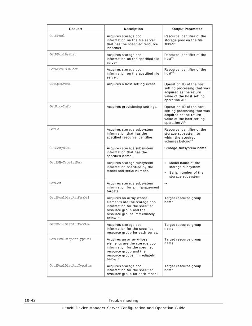
10-42 Troubleshooting
Hitachi Device Manager Server Configuration and Operation Guide
Request Description Output Parameter
GetNPool Acquires storage pool information on the file server that has the specified resource identifier.
Resource identifier of the storage pool on the file server
GetNPoolByHost Acquires storage pool information on the specified file server
Resource identifier of the host#2
GetNPoolSumHost Acquires storage pool information on the specified file server.
Resource identifier of the host#2
GetOprEvent Acquires a host setting event. Operation ID of the host setting processing that was acquired as the return value of the host setting operation API
GetProvInfo Acquires provisioning settings. Operation ID of the host setting processing that was acquired as the return value of the host setting operation API
GetSA Acquires storage subsystem information that has the specified resource identifier.
Resource identifier of the storage subsystem to which the acquired volumes belong#2
GetSAByName Acquires storage subsystem information that has the specified name.
Storage subsystem name
GetSAByTypeSrlNum Acquires storage subsystem information specified by the model and serial number.
Model name of the storage subsystem
Serial number of the storage subsystem
GetSAs Acquires storage subsystem information for all management targets.
--
GetSPoolDispArrFamDtl Acquires an array whose elements are the storage pool information for the specified resource group and the resource groups immediately below it.
Target resource group name
GetSPoolDispArrFamSum Acquires storage pool information for the specified resource group for each series.
Target resource group name
GetSPoolDispArrTypeDtl Acquires an array whose elements are the storage pool information for the specified resource group and the resource groups immediately below it.
Target resource group name
GetSPoolDispArrTypeSum Acquires storage pool information for the specified resource group for each model.
Target resource group name
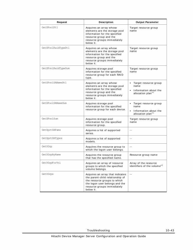
Troubleshooting 10-43
Hitachi Device Manager Server Configuration and Operation Guide
Request Description Output Parameter
GetSPoolDtl Acquires an array whose elements are the storage pool information for the specified resource group and the resource groups immediately below it.
Target resource group name
GetSPoolRaidTypeDtl Acquires an array whose elements are the storage pool information for the specified resource group and the resource groups immediately below it.
Target resource group name
GetSPoolRaidTypeSum Acquires storage pool information for the specified resource group for each RAID type.
Target resource group name
GetSPoolSANameDtl Acquires an array whose elements are the storage pool information for the specified resource group and the resource groups immediately below it.
Target resource group name
Information about the allocation plan#1
GetSPoolSANameSum Acquires storage pool information for the specified resource group for each device.
Target resource group name
Information about the allocation plan#1
GetSPoolSum Acquires storage pool information for the specified resource group.
Target resource group name
GetSprtSAFams Acquires a list of supported series.
--
GetSprtSATypes Acquires a list of supported models.
--
GetUGrp Acquires the resource group to which the logon user belongs.
--
GetUGrpByName Acquires the resource group that has the specified name.
Resource group name
GetUGrpForVol Acquires an array of resource groups to which the specified volume belongs.
Array of the resource identifiers of the volume#2
GetUGrps Acquires an array that indicates the parent-child relationship of the resource groups to which the logon user belongs and the resource groups immediately below it.
--
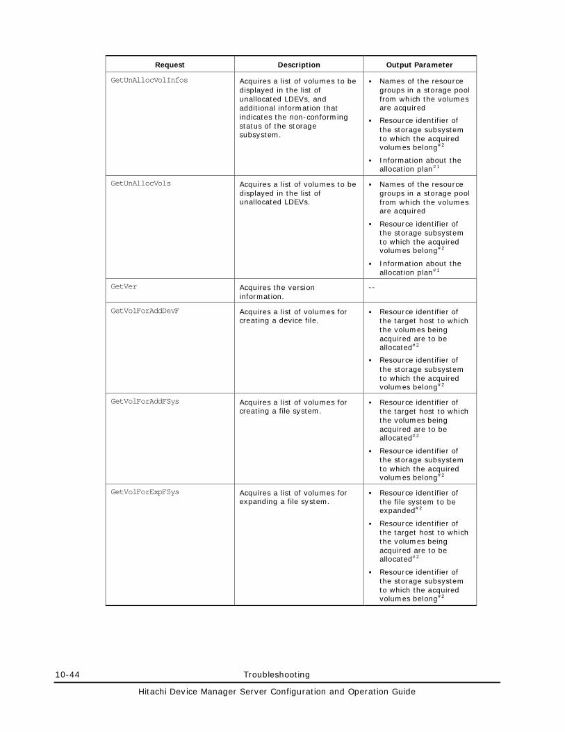
10-44 Troubleshooting
Hitachi Device Manager Server Configuration and Operation Guide
Request Description Output Parameter
GetUnAllocVolInfos Acquires a list of volumes to be displayed in the list of unallocated LDEVs, and additional information that indicates the non-conforming status of the storage subsystem.
Names of the resource groups in a storage pool from which the volumes are acquired
Resource identifier of the storage subsystem to which the acquired volumes belong#2
Information about the allocation plan#1
GetUnAllocVols Acquires a list of volumes to be displayed in the list of unallocated LDEVs.
Names of the resource groups in a storage pool from which the volumes are acquired
Resource identifier of the storage subsystem to which the acquired volumes belong#2
Information about the allocation plan#1
GetVer Acquires the version information.
--
GetVolForAddDevF Acquires a list of volumes for creating a device file.
Resource identifier of the target host to which the volumes being acquired are to be allocated#2
Resource identifier of the storage subsystem to which the acquired volumes belong#2
GetVolForAddFSys Acquires a list of volumes for creating a file system.
Resource identifier of the target host to which the volumes being acquired are to be allocated#2
Resource identifier of the storage subsystem to which the acquired volumes belong#2
GetVolForExpFSys Acquires a list of volumes for expanding a file system.
Resource identifier of the file system to be expanded#2
Resource identifier of the target host to which the volumes being acquired are to be allocated#2
Resource identifier of the storage subsystem to which the acquired volumes belong#2
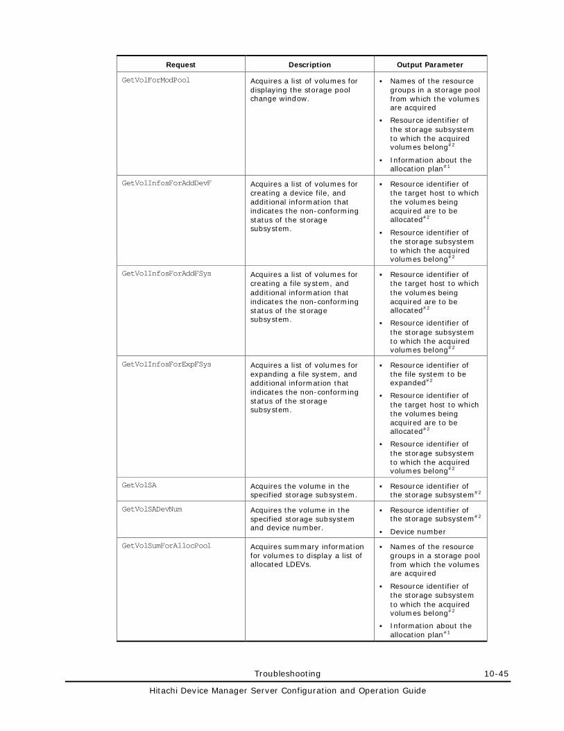
Troubleshooting 10-45
Hitachi Device Manager Server Configuration and Operation Guide
Request Description Output Parameter
GetVolForModPool Acquires a list of volumes for displaying the storage pool change window.
Names of the resource groups in a storage pool from which the volumes are acquired
Resource identifier of the storage subsystem to which the acquired volumes belong#2
Information about the allocation plan#1
GetVolInfosForAddDevF Acquires a list of volumes for creating a device file, and additional information that indicates the non-conforming status of the storage subsystem.
Resource identifier of the target host to which the volumes being acquired are to be allocated#2
Resource identifier of the storage subsystem to which the acquired volumes belong#2
GetVolInfosForAddFSys Acquires a list of volumes for creating a file system, and additional information that indicates the non-conforming status of the storage subsystem.
Resource identifier of the target host to which the volumes being acquired are to be allocated#2
Resource identifier of the storage subsystem to which the acquired volumes belong#2
GetVolInfosForExpFSys Acquires a list of volumes for expanding a file system, and additional information that indicates the non-conforming status of the storage subsystem.
Resource identifier of the file system to be expanded#2
Resource identifier of the target host to which the volumes being acquired are to be allocated#2
Resource identifier of the storage subsystem to which the acquired volumes belong#2
GetVolSA Acquires the volume in the specified storage subsystem.
Resource identifier of the storage subsystem#2
GetVolSADevNum Acquires the volume in the specified storage subsystem and device number.
Resource identifier of the storage subsystem#2
Device number
GetVolSumForAllocPool Acquires summary information for volumes to display a list of allocated LDEVs.
Names of the resource groups in a storage pool from which the volumes are acquired
Resource identifier of the storage subsystem to which the acquired volumes belong#2
Information about the allocation plan#1
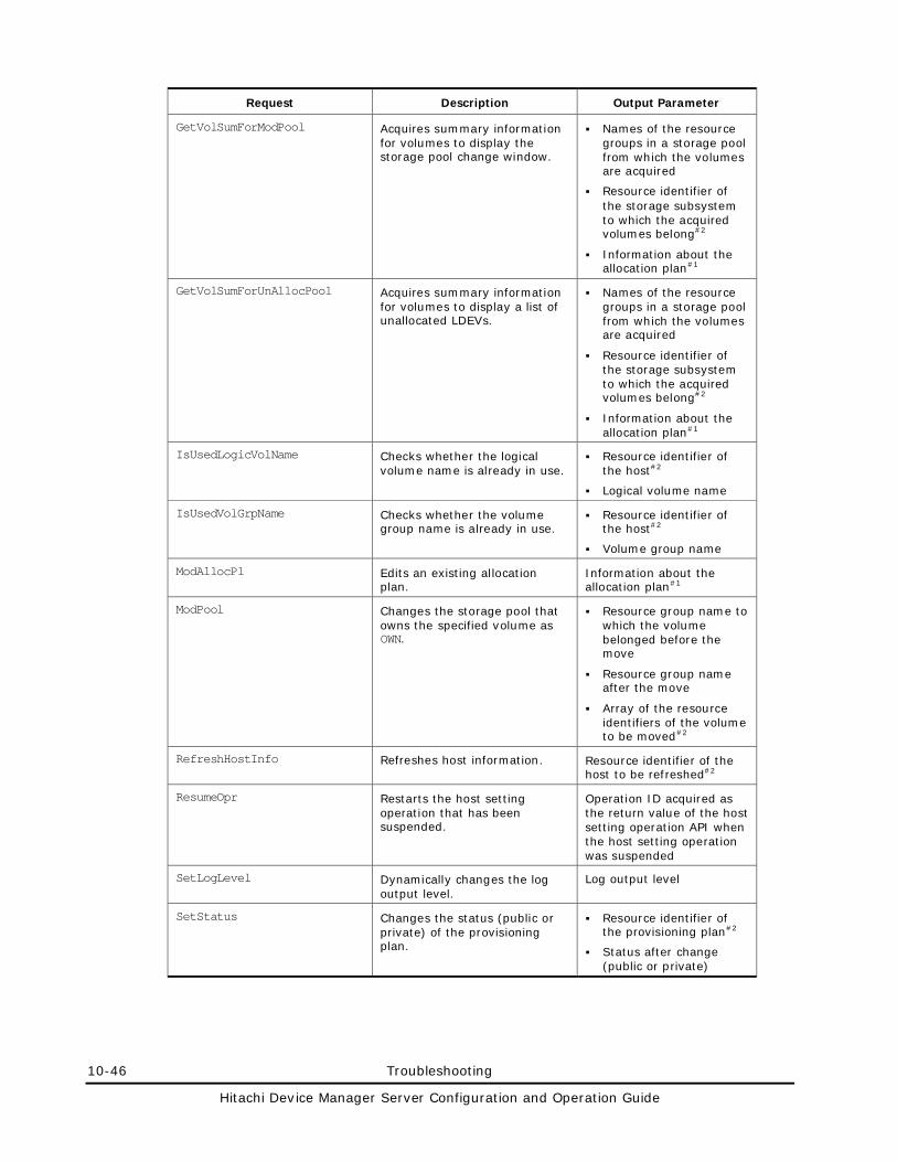
10-46 Troubleshooting
Hitachi Device Manager Server Configuration and Operation Guide
Request Description Output Parameter
GetVolSumForModPool Acquires summary information for volumes to display the storage pool change window.
Names of the resource groups in a storage pool from which the volumes are acquired
Resource identifier of the storage subsystem to which the acquired volumes belong#2
Information about the allocation plan#1
GetVolSumForUnAllocPool Acquires summary information for volumes to display a list of unallocated LDEVs.
Names of the resource groups in a storage pool from which the volumes are acquired
Resource identifier of the storage subsystem to which the acquired volumes belong#2
Information about the allocation plan#1
IsUsedLogicVolName Checks whether the logical volume name is already in use.
Resource identifier of the host#2
Logical volume name
IsUsedVolGrpName Checks whether the volume group name is already in use.
Resource identifier of the host#2
Volume group name
ModAllocPl Edits an existing allocation plan.
Information about the allocation plan#1
ModPool Changes the storage pool that owns the specified volume as OWN.
Resource group name to which the volume belonged before the move
Resource group name after the move
Array of the resource identifiers of the volume to be moved#2
RefreshHostInfo Refreshes host information. Resource identifier of the host to be refreshed#2
ResumeOpr Restarts the host setting operation that has been suspended.
Operation ID acquired as the return value of the host setting operation API when the host setting operation was suspended
SetLogLevel Dynamically changes the log output level.
Log output level
SetStatus Changes the status (public or private) of the provisioning plan.
Resource identifier of the provisioning plan#2
Status after change (public or private)
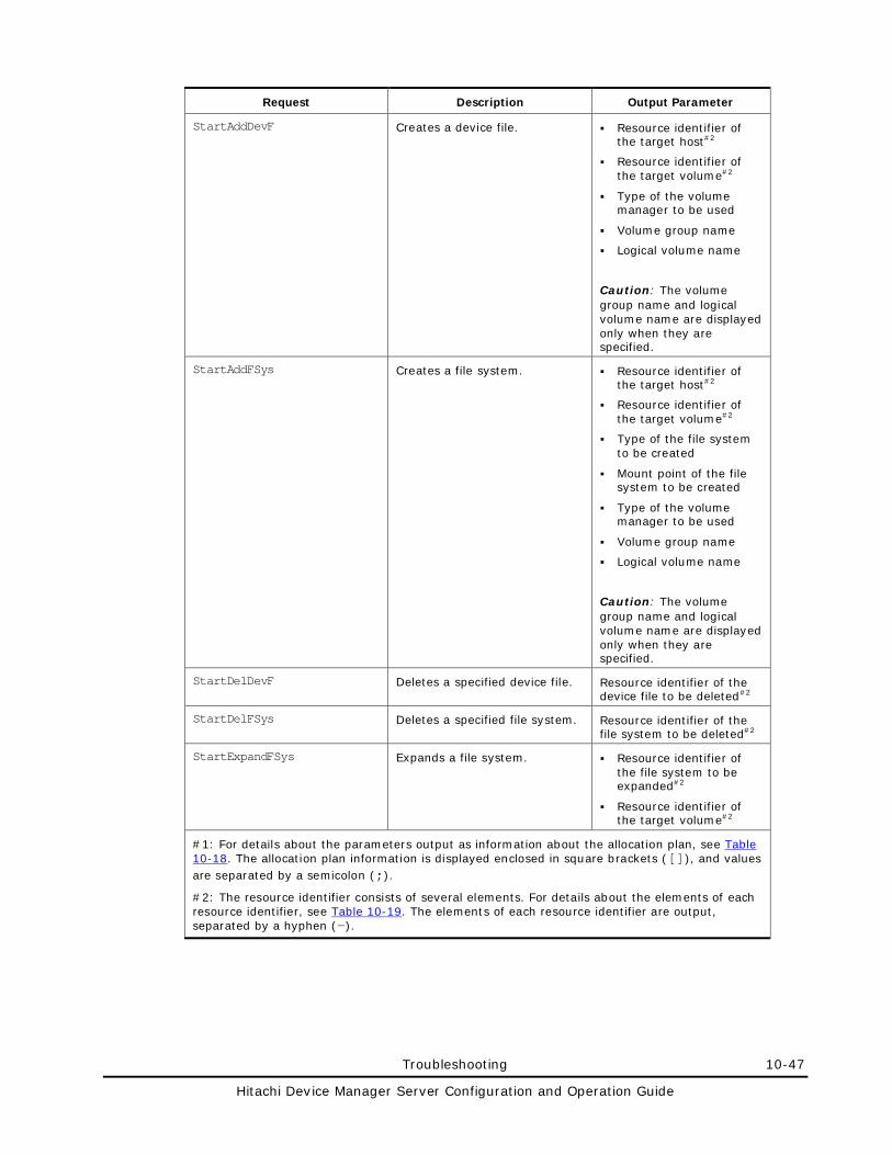
Troubleshooting 10-47
Hitachi Device Manager Server Configuration and Operation Guide
Request Description Output Parameter
StartAddDevF Creates a device file. Resource identifier of the target host#2
Resource identifier of the target volume#2
Type of the volume manager to be used
Volume group name
Logical volume name
Caution: The volume group name and logical volume name are displayed only when they are specified.
StartAddFSys Creates a file system. Resource identifier of the target host#2
Resource identifier of the target volume#2
Type of the file system to be created
Mount point of the file system to be created
Type of the volume manager to be used
Volume group name
Logical volume name
Caution: The volume group name and logical volume name are displayed only when they are specified.
StartDelDevF Deletes a specified device file. Resource identifier of the device file to be deleted#2
StartDelFSys Deletes a specified file system. Resource identifier of the file system to be deleted#2
StartExpandFSys Expands a file system. Resource identifier of the file system to be expanded#2
Resource identifier of the target volume#2
#1: For details about the parameters output as information about the allocation plan, see Table 10-18. The allocation plan information is displayed enclosed in square brackets ([]), and values are separated by a semicolon (;).
#2: The resource identifier consists of several elements. For details about the elements of each resource identifier, see Table 10-19. The elements of each resource identifier are output, separated by a hyphen (-).
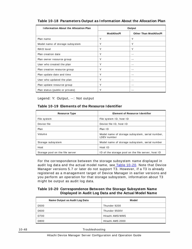
10-48 Troubleshooting
Hitachi Device Manager Server Configuration and Operation Guide
Table 10-18 Parameters Output as Information About the Allocation Plan
Information About the Allocation Plan Output
ModAllocPl Other Than ModAllocPl
Plan name Y Y
Model name of storage subsystem Y Y
RAID level Y Y
Plan creation date Y --
Plan owner resource group Y --
User who created the plan Y --
Plan creation resource group Y --
Plan update date and time Y --
User who updated the plan Y --
Plan update resource group Y --
Plan status (public or private) Y --
Legend: Y: Output, --: Not output
Table 10-19 Elements of the Resource Identifier
Resource Type Element of Resource Identifier
File system File system ID, host ID
Device file Device file ID, host ID
Plan Plan ID
Volume Model name of storage subsystem, serial number, LDEV number
Storage subsystem Model name of storage subsystem, serial number
Host Host ID
Storage pool on the file server ID of the storage pool on the file server, host ID
For the correspondence between the storage subsystem name displayed in audit log data and the actual model name, see Table 10-20. Note that Device Manager versions 5.7 or later do not support T3. However, if a T3 is already registered as a management target of Device Manager in earlier versions and you perform an operation for that storage subsystem, information about T3 might be output as audit log data.
Table 10-20 Correspondence Between the Storage Subsystem Name Displayed in Audit Log Data and the Actual Model Name
Name Output as Audit Log Data Model
D500 Thunder 9200
D600 Thunder 9500V
D700 Hitachi AMS/WMS
D800 Hitachi AMS 2000
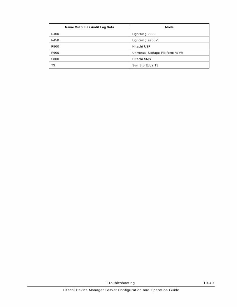
Troubleshooting 10-49
Hitachi Device Manager Server Configuration and Operation Guide
Name Output as Audit Log Data Model
R400 Lightning 2000
R450 Lightning 9900V
R500 Hitachi USP
R600 Universal Storage Platform V/VM
S800 Hitachi SMS
T3 Sun StorEdge T3
10-50 Troubleshooting
Hitachi Device Manager Server Configuration and Operation Guide
Contacting the Hitachi Data Systems Support Center
If you need to contact the Hitachi Data Systems Support Center, make sure that you provide as much information as possible about the problem, including the circumstances surrounding the error or failure, and the exact content of any error messages.
The Hitachi Data Systems customer support staff is available 24 hours a day, seven days a week. If you need technical support, please call:
• United States:
(800) 446-0744
• Outside the United States:
(858) 547-4526
Overview and Setup of VDS A-1
Hitachi Device Manager Server Configuration and Operation Guide
Overview and Setup of VDS
This chapter provides an overview of Device Manager VDS Provider, and explains the setup procedure.
Overview and Functions of Device Manager VDS Provider
Installing Device Manager VDS Provider
Uninstalling Device Manager VDS Provider
Starting and Stopping Device Manager VDS Provider
Device Manager VDS Provider Property Files
Setting up Device Manager VDS Provider
Device Manager VDS Provider Log Files
A-2 Overview and Setup of VDS
Hitachi Device Manager Server Configuration and Operation Guide
Overview and Functions of Device Manager VDS Provider
This section describes the functions of Device Manager VDS Provider. It also describes functions that are available in Storage Manager for SANs for Windows Server 2003 R2.
Overview of Device Manager VDS Provider
Windows Server 2003 provides Virtual Disk Service (VDS), which is a virtual disk system designed to manage storage subsystem devices via standardized interfaces.
Device Manager VDS Provider is a Device Manager software product that provides and configures storage subsystem information for VDS. Device Manager VDS Provider supports the following OSs:
• Windows Server 2003 SP2 (x86)
• Windows Server 2003 SP2 (x64)
• Windows Server 2003 R2 SP2 (x86)
• Windows Server 2003 R2 SP2 (x64)
Functions of Device Manager VDS Provider
Device Manager VDS Provider is a hardware provider that is resident on a Windows host and replies to VDS requests. It provides functions for:
• Obtaining the following storage subsystem related configuration information:
– Subsystem
– LUN
– LUN replication information
– Path information
– Port information
If you specify a user assigned to a user-defined resource group as a user account used by VDS Provider, only the resources that have been defined in the resource group can be displayed when configuration information is acquired. This is called the filtering function.
• Performing the following storage subsystem related configuration tasks:
– Creating LUNs
– Expanding LUNs
– Deleting LUNs
– Mapping LUNs
– Masking LUNs
Overview and Setup of VDS A-3
Hitachi Device Manager Server Configuration and Operation Guide
Before you can use the DISKRAID command provided by Microsoft, you must perform the following installation tasks:
• Install Device Manager VDS Provider.
Note: To use Device Manager VDS Provider, you need to change the value of the Device Manager server property server.cim.support to true in the server.properties file, and then restart the Device Manager server.
• If your host computer OS is not Windows Server 2003 R2, download VDS SDK from the Microsoft web site (http://www.microsoftstoragepartners.com) and then install it.
Available Functions in Storage Manager for SANs for Windows Server 2003 R2
When using Storage Manager for SANs provided by Windows Server 2003 R2, you can perform storage subsystem operations via the VDS Provider function of Device Manager.
Functionality the following functions are available:
• Creating LUNs
• Deleting LUNs
• Extending LUNs
• Renaming LUNs
• Assigning LUNs
• Unassigning LUNs
• Managing server connections
• Renaming storage subsystems
• Refreshing
Functionality for the following is not available:
• Blinking of drive lights
• Managing iSCSI targets
• Managing iSCSI security
• Logging on to iSCSI targets
A-4 Overview and Setup of VDS
Hitachi Device Manager Server Configuration and Operation Guide
Installing Device Manager VDS Provider
The following describes how to install Device Manager VDS Provider:
• New installation
Use this installation method to install Device Manager VDS Provider in a host in which Device Manager VDS Provider does not exist.
• Upgrade installation (to update an earlier version)
Use this installation method to install Device Manager VDS Provider on a host in which an older version of Device Manager VDS Provider has been installed.
• Re-installation (to correct the same version)
Use this installation method to install Device Manager VDS Provider on a host in which the same version of Device Manager VDS Provider has been installed.
You can obtain the version of an installed Device Manager VDS Provider by executing the following command: installation-folder-for-Device-Manager-VDS-Provider\bin\hdvminfo.exe
The following shows an example of executing the command: C:\Program Files\HITACHI\HDvM_VDS\bin\hdvminfo.exe
Overview and Setup of VDS A-5
Hitachi Device Manager Server Configuration and Operation Guide
Notes: Note the following when installing Device Manager VDS Provider: • At least 5 MB of free space is required on the hard disk. Also, an
additional 5 MB of free space is required on the system drive to create temporary files during installation.
• Before starting the installation, cancel any programs that might be running.
• After installation, you will need to set up access permission for the Device Manager VDS Provider installation folder. Since access permission cannot be set for FAT or FAT32 formatted drives, be sure to install Device Manager VDS Provider installation on an NTFS formatted drive.
• Do not execute the DISKRAID command provided by Microsoft or the hdvmconfig command during an upgrade installation of Device Manager VDS Provider. In addition, do not install Device Manager VDS Provider when the DISKRAID or hdvmconfig command is being executed. If you execute the above command during an upgrade installation, the installation might end before completion. Make sure that you restart the system after installation
• Version 4.1 or earlier of Device Manager VDS Provider is automatically installed or uninstalled when Device Manager Agent is installed. If you want to use version 4.1 or earlier of Device Manager VDS Provider, install Device Manager Agent. For details on how to install Device Manager Agent, see the manual for the installed version of Device Manager Agent.
• Version 4.1 or earlier of Device Manager VDS Provider cannot be used at the same time as version 4.2 or later. Stop the service of the version that will not be unused. For details, see Starting and Stopping Device Manager VDS Provider. The service names are:
– In version 4.1 or earlier: Hitachi RAID Provider – In version 4.2 or later: Device Manager VDS Provider
• If the Hitachi RAID Provider service is running, version 4.3 or later of Device Manager VDS Provider cannot be installed. If you attempt to install it, the following message appears. Hitachi RAID Provider is running. Re-install after stopping this service.
• Overwrite installation (an update installation or a fixed version) might fail, in which case cancellation of the overwrite installation is reported. Overwrite installation (update or fixed) might also fail when the startup status of the Device Manager VDS Provider service is disabled. In this case, reboot the system, and then perform installation again.
New Installation
Note: Before starting the installation, cancel any programs that might be running.
To perform a new installation:
A-6 Overview and Setup of VDS
Hitachi Device Manager Server Configuration and Operation Guide
1. Log on to Windows using an Administrators-group user ID.
2. Insert the Device Manager VDS Provider CD-ROM.
3. Select Start, and then Run. In the displayed window, click Browse. In the displayed tree view, select setup.exe (in the \VDS folder on the CD-ROM). Then, click OK.
The Welcome to the InstallShield® Wizard for Device Manager VDS Provider window appears.
4. Click the Next button.
The Device Manager VDS Provider License Agreement window appears.
5. Click the Next button.
The Choose Destination Location window appears.
6. Specify the installation folder of Device Manager VDS Provider, and then click the Next button.
The installation folder displayed by default differs for x86 and x64.
– For x86
Windows-system-drive\Program Files\HITACHI\HDvM_VDS
– For x64
Windows-system-drive\Program Files (x86)\HITACHI\HDvM_VDS
Caution: Do not select the installation folder for Device Manager VDS Provider version 4.1 or earlier.
The IP Address of the Device Manager server window appears.
7. Specify the IP address of the Device Manager server, and then click the Next button.
Caution: Device Manager VDS Provider only supports IPv4 (IPv6 is not supported).
The Installation Confirmation window appears.
8. Click the Install button.
The Progress window appears. When installation is complete, a window indicating the completion of installation appears.
9. Click the Finish button.
10. Set up access permissions for the Device Manager VDS Provider installation folder.
Using the appropriate OS function, set up read/write access permissions for the Administrators group and SYSTEM group. Do not set up access permissions for groups other than the Administrators group and SYSTEM group.
Overview and Setup of VDS A-7
Hitachi Device Manager Server Configuration and Operation Guide
If your installation has ended normally, specify your user ID and password for connection to the Device Manager server. For details on how to specify your user ID and password, see Setting up Device Manager VDS Provider.
Upgrade Installation (to Update an Earlier Version)
Note: Before starting the installation, cancel any programs that might be running.
To perform an upgrade installation:
1. Log on to Windows using an Administrators-group user ID.
2. Insert the Device Manager VDS Provider CD-ROM.
3. Select Start, and then Run. In the displayed window, click Browse. In the displayed tree view, select setup.exe (in the \VDS folder on the CD-ROM). The Welcome to the InstallShield Wizard for Device Manager VDS Provider window appears.
4. Click the Next button.
The Progress window appears. When installation is complete, a window indicating the completion of installation appears.
5. Click the Finish button.
6. Set up access permissions for the Device Manager VDS Provider installation folder.
Using the appropriate OS function, set up read/write access permissions for the Administrators group and SYSTEM group. Do not set up access permissions for groups other than the Administrators group and SYSTEM group.
Note: Upgrade installation relies on the already specified Device Manager server IP address, user ID, and password as they are inherited from the original system. To change the IP address, user ID, or password, see Setting up Device Manager VDS Provider.
Re-installation (to Correct the Same Version)
To perform an upgrade installation:
1. Log on to Windows using an Administrators-group user ID.
2. Insert the Device Manager VDS Provider CD-ROM, and then select Start, Run. In the displayed window, click Browse. In the displayed tree view, select setup.exe (in the \VDS folder on the CD-ROM), and then click OK.
The Welcome window appears.
A-8 Overview and Setup of VDS
Hitachi Device Manager Server Configuration and Operation Guide
Note: You can also perform the above operation by selecting Start, Settings, Control Panel, and then Add or Remove Programs. In the displayed window, select Device Manager - VDS Provider and then click the Change/Remove button.
3. Select Repair, and then click the Next button.
The Welcome to the InstallShield Wizard for Device Manager VDS Provider window appears.
4. Click the Next button.
A dialog box indicating that preparations for setup have finished is displayed.
Note: Up until this step, you can select Cancel to cancel installation of Device Manager VDS Provider.
5. Click the Next button.
A dialog box appears, indicating that Device Manager VDS Provider is being installed, and then a window indicating the completion of installation appears.
6. Click the Finish button.
7. Set up access permissions for the Device Manager VDS Provider installation folder.
Using the appropriate OS function, set up the read/write access permissions for the Administrators group and SYSTEM group.
Do not set up access permissions for groups other than the Administrators group and SYSTEM group.
Overview and Setup of VDS A-9
Hitachi Device Manager Server Configuration and Operation Guide
Uninstalling Device Manager VDS Provider
This section describes how to uninstall Device Manager VDS Provider.
Uninstalling Device Manager VDS Provider stops service programs and deletes all the folders, files, and registry information that were registered during installation. The system returns to the status before installation.
Note: When you perform an uninstallation when the following conditions are satisfied, a message prompting you to restart the OS is displayed after the uninstallation. Even though this message appears, you do not have to restart the OS. Take the appropriate action by following the relevant instructions.
• If the exe file or bat file corresponding to Device Manager VDS Provider is being executed:
Stop the exe file or bat file (or both) that is being executed.
• If the command prompt window is open and its current folder is the same as the installation folder for Device Manager VDS Provider:
Close the command prompt window.
To uninstall Device Manager VDS Provider (method 1):
1. Select Start, Settings, Control Panel, and then Add or Remove Programs.
2. Click the Remove button for Device Manager VDS Provider.
To uninstall Device Manager VDS Provider (method 2):
1. Select Start, Settings, Control Panel, and then Add or Remove Programs.
2. Click the Change button for Device Manager VDS Provider.
The Device Manager - VDS Provider maintenance menu is displayed.
3. Click the Remove button.
Caution: When changes or deletions are performed from Add or Remove Programs, an error might occur, in which case the following message is displayed. If an error occurs, use setup.exe in the \VDS folder on the CD-ROM to perform any changes or deletions.
An error occurred during reading C:\Program Files\Common Files\InstallShield\Professional\RunTime\10\50\Intel32\Ctor.dll. The specified module cannot be found.
A-10 Overview and Setup of VDS
Hitachi Device Manager Server Configuration and Operation Guide
Starting and Stopping Device Manager VDS Provider
The following describes how to start and stop Device Manager VDS Provider.
Starting the Service
Open the Services window by selecting Start, Settings, Control Panel, Administrative Tools, and then Services. Then, start the Device Manager VDS Provider service.
Note: After the service starts, the message KAIC24804-I is output to the log file: KAIC24804-I Acquiring storage subsystem information from the Device Manager server has finished.
The log file is stored in the following path: installation-folder-for-Device-Manager-VDS-Provider\logs\hdvmcomm.log
Caution: Do not connect from the VDS client to the VDS Provider until the Device Manager VDS Provider service starts.
Stopping the Service
Open the Services window by selecting Start, Settings, Control Panel, Administrative Tools, and then Services. Then, stop the Device Manager VDS Provider service.
Notes on Starting and Stopping the Service
After stopping or restarting Device Manager VDS Provider while the DISKRAID command is running, if the subcommand of the DISKRAID command is executed, an error occurs. In this case, finish the DISKRAID command by executing the QUIT command, and then restart the DISKRAID command.
Device Manager VDS Provider acquires information about the storage subsystems from the Device Manager server when Device Manager VDS Provider starts, or the REFRESH subcommand of the DISKRAID command is executed.
It might take a long time to acquire this information, so follow the directions below:
• Restarting Device Manager VDS Provider
Until Device Manager VDS Provider completes processing to acquire configuration information about the storage subsystems, note that:
– If you execute a DISKRAID command to display information about the storage subsystems, the information is not displayed.
Overview and Setup of VDS A-11
Hitachi Device Manager Server Configuration and Operation Guide
– If you execute the REFRESH subcommand of the DISKRAID command, an error occurs.
• Executing the REFRESH subcommand of the DISKRAID command
Until Device Manager VDS Provider completes processing to acquire configuration information about the storage subsystem, note that:
– If you execute a DISKRAID command to display information about the storage subsystems, the information before the refresh operation is displayed.
– If you re-execute the REFRESH subcommand of the DISKRAID command, an error occurs.
Caution: If the REFRESH subcommand is executed, while the storage subsystem deleted from the Device Manager server is selected by executing the SELECT subcommand, the LIST subcommand might display incorrect information. In such a case, select another storage subsystem by executing the SELECT subcommand, and then re-execute the REFRESH subcommand, or restart the DISKRAID command.
A-12 Overview and Setup of VDS
Hitachi Device Manager Server Configuration and Operation Guide
Device Manager VDS Provider Property Files
Device Manager VDS Provider uses two property files:
• vds.properties file
This file is used to configure the Device Manager VDS Provider environment.
• logger.properties file
This file is used to configure the Device Manager VDS Provider logging function.
These files are stored in the following locations:
vds.properties file:
installation-folder-for-Device-Manager-VDS-Provider\config\vds.properties
logger.properties file:
installation-folder-for-Device-Manager-VDS-Provider\config\logger.properties
Caution: If you change the contents of the Device Manager VDS Provider property files (vds.properties and logger.properties), you must restart the service.
vds.properties File
The vds.properties file contains the following information:
• IP address of the Device Manager server
• Port number of the Device Manager server
• Account (user name and password) used for Device Manager VDS Provider
• Device Manager VDS Provider account (user name and password) used for the filtering function
Note: • This information will be specified in the vds.properties file only when
the filtering function is used. • Because the data of the Device Manager VDS Provider user account is
encrypted, execute the hdvmconfig command to edit the data.
You can change the above information after installing Device Manager VDS Provider. For details on how to change the information, see Setting up Device Manager VDS Provider.
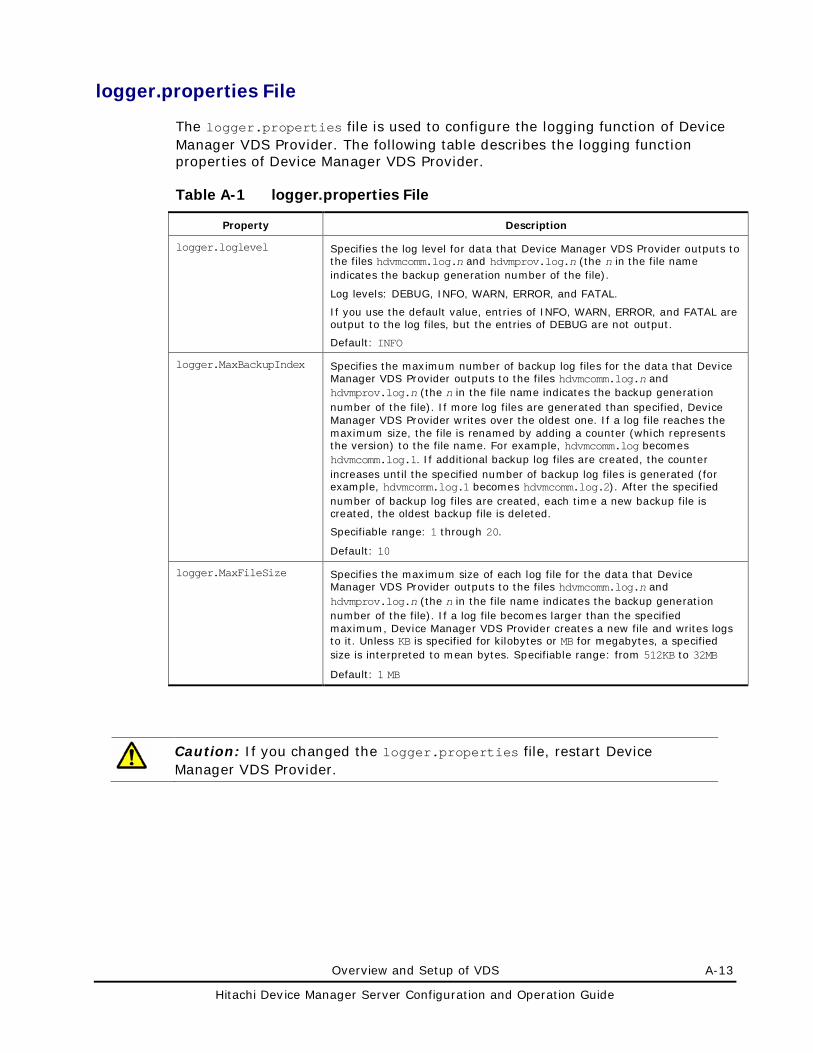
Overview and Setup of VDS A-13
Hitachi Device Manager Server Configuration and Operation Guide
logger.properties File
The logger.properties file is used to configure the logging function of Device Manager VDS Provider. The following table describes the logging function properties of Device Manager VDS Provider.
Table A-1 logger.properties File
Property Description
logger.loglevel Specifies the log level for data that Device Manager VDS Provider outputs to the files hdvmcomm.log.n and hdvmprov.log.n (the n in the file name indicates the backup generation number of the file).
Log levels: DEBUG, INFO, WARN, ERROR, and FATAL.
If you use the default value, entries of INFO, WARN, ERROR, and FATAL are output to the log files, but the entries of DEBUG are not output.
Default: INFO
logger.MaxBackupIndex Specifies the maximum number of backup log files for the data that Device Manager VDS Provider outputs to the files hdvmcomm.log.n and hdvmprov.log.n (the n in the file name indicates the backup generation number of the file). If more log files are generated than specified, Device Manager VDS Provider writes over the oldest one. If a log file reaches the maximum size, the file is renamed by adding a counter (which represents the version) to the file name. For example, hdvmcomm.log becomes hdvmcomm.log.1. If additional backup log files are created, the counter increases until the specified number of backup log files is generated (for example, hdvmcomm.log.1 becomes hdvmcomm.log.2). After the specified number of backup log files are created, each time a new backup file is created, the oldest backup file is deleted.
Specifiable range: 1 through 20.
Default: 10
logger.MaxFileSize Specifies the maximum size of each log file for the data that Device Manager VDS Provider outputs to the files hdvmcomm.log.n and hdvmprov.log.n (the n in the file name indicates the backup generation number of the file). If a log file becomes larger than the specified maximum, Device Manager VDS Provider creates a new file and writes logs to it. Unless KB is specified for kilobytes or MB for megabytes, a specified size is interpreted to mean bytes. Specifiable range: from 512KB to 32MB
Default: 1 MB
Caution: If you changed the logger.properties file, restart Device Manager VDS Provider.
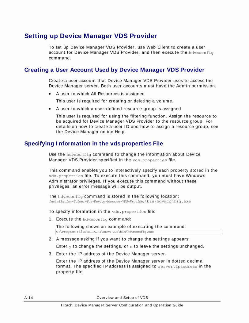
A-14 Overview and Setup of VDS
Hitachi Device Manager Server Configuration and Operation Guide
Setting up Device Manager VDS Provider
To set up Device Manager VDS Provider, use Web Client to create a user account for Device Manager VDS Provider, and then execute the hdvmconfig command.
Creating a User Account Used by Device Manager VDS Provider
Create a user account that Device Manager VDS Provider uses to access the Device Manager server. Both user accounts must have the Admin permission.
• A user to which All Resources is assigned
This user is required for creating or deleting a volume.
• A user to which a user-defined resource group is assigned
This user is required for using the filtering function. Assign the resource to be acquired for Device Manager VDS Provider to the resource group. For details on how to create a user ID and how to assign a resource group, see the Device Manager online Help.
Specifying Information in the vds.properties File
Use the hdvmconfig command to change the information about Device Manager VDS Provider specified in the vds.properties file.
This command enables you to interactively specify each property stored in the vds.properties file. To execute this command, you must have Windows Administrator privileges. If you execute this command without these privileges, an error message will be output.
The hdvmconfig command is stored in the following location: installation-folder-for-Device-Manager-VDS-Provider\bin\hdvmconfig.exe
To specify information in the vds.properties file:
1. Execute the hdvmconfig command:
The following shows an example of executing the command: C:\Program Files\HITACHI\HDvM_VDS\bin\hdvmconfig.exe
2. A message asking if you want to change the settings appears.
Enter y to change the settings, or n to leave the settings unchanged.
3. Enter the IP address of the Device Manager server.
Enter the IP address of the Device Manager server in dotted decimal format. The specified IP address is assigned to server.ipaddress in the property file.
Overview and Setup of VDS A-15
Hitachi Device Manager Server Configuration and Operation Guide
Caution: Device Manager VDS Provider only supports IPv4 (IPv6 is not supported).
4. Enter the port number of the Device Manager server.
If you do not enter a port number, the default 5988 is specified. The specified port number is assigned to server.port in the property file.
Caution: Specify the port number assigned to server.cim.http.port in the server.properties file used by the Device Manager server.
5. Enter the type of user to be registered.
When 1 is entered:
You need to specify a user to which All Resources is assigned. This user acquires configuration information of all resources. This user can create and delete a volume.
When 2 is entered:
You need to specify a user to which a user-defined resource group is assigned. This user acquires configuration information within the resource group that is assigned to this user. This user cannot create or delete a volume.
When 3 is entered:
This user acquires configuration information within the resource group that is assigned to this user. This user can create and delete a volume.
To use the filtering function, enter 2 or 3.
6. By following the selection in step 5, enter the user ID and password.
You can use the following characters for the user ID:
a to z A to Z 0 to 9 ! # $ % & ( ) * + - . = @ \ ^ _ | ‘
Note: For overwrite installations, if you do not enter a user ID, the currently set user ID will be inherited.
You can use the following characters for the password:
a to z A to Z 0 to 9 ! # $ % & ( ) * + - . = @ \ ^ _ | ‘
The user ID and password are encrypted by the hdvmconfig command and assigned to server.authorization and server.authorizationforresourcegroup in the property file.
7. A message appears asking if you want to save the entered information into the vds.properties file.
Enter y to save the information, or n to leave the information unchanged.
8. Restart Device Manager VDS Provider.
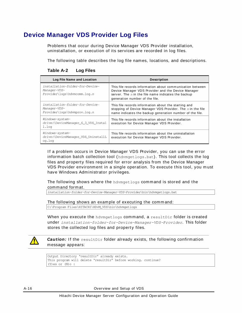
A-16 Overview and Setup of VDS
Hitachi Device Manager Server Configuration and Operation Guide
Device Manager VDS Provider Log Files
Problems that occur during Device Manager VDS Provider installation, uninstallation, or execution of its services are recorded in log files.
The following table describes the log file names, locations, and descriptions.
Table A-2 Log Files
Log File Name and Location Description
installation-folder-for-Device-Manager-VDS-Provider\logs\hdvmcomm.log.n
This file records information about communication between Device Manager VDS Provider and the Device Manager server. The n in the file name indicates the backup generation number of the file.
installation-folder-for-Device-Manager-VDS-Provider\logs\hdvmprov.log.n
This file records information about the starting and stopping of Device Manager VDS Provider. The n in the file name indicates the backup generation number of the file.
Windows-system-drive:\DeviceManager_6_3_VDS_Install.log
This file records information about the installation execution for Device Manager VDS Provider.
Windows-system-drive:\DeviceManager_VDS_UninstallLog.log
This file records information about the uninstallation execution for Device Manager VDS Provider.
If a problem occurs in Device Manager VDS Provider, you can use the error information batch collection tool (hdvmgetlogs.bat). This tool collects the log files and property files required for error analysis from the Device Manager VDS Provider environment in a single operation. To execute this tool, you must have Windows Administrator privileges.
The following shows where the hdvmgetlogs command is stored and the command format. installation-folder-for-Device-Manager-VDS-Provider\bin\hdvmgetlogs.bat
The following shows an example of executing the command: C:\Program Files\HITACHI\HDvM_VDS\bin\hdvmgetlogs
When you execute the hdvmgetlogs command, a resultDir folder is created under installation-folder-for-Device-Manager-VDS-Provider. This folder stores the collected log files and property files.
Caution: If the resultDir folder already exists, the following confirmation message appears:
Output Directory “resultDir” already exists. This program will delete “resultDir” before working. continue? (Y)es or (N)o :
Overview and Setup of VDS A-17
Hitachi Device Manager Server Configuration and Operation Guide
If you enter y, the command deletes the resultDir folder, and stores the acquired error information files in a new resultDir folder. If you enter n, processing is cancelled.

A-18 Overview and Setup of VDS
Hitachi Device Manager Server Configuration and Operation Guide
Specifying Properties B-1
Hitachi Device Manager Server Configuration and Operation Guide
Specifying Properties
This Chapter describes the property files of a Device Manager server and Provisioning Manager server.
Properties Overview
Device Manager Server Configuration Properties
Device Manager Database Properties
Device Manager Logger Properties
Device Manager Dispatcher Properties
Device Manager MIME Properties
Device Manager Client Properties
Device Manager Security Properties
Device Manager SNMP Trap Log Output Function Properties
Device Manager Launchable Applications Properties
Device Manager Mainframe Host Agent Properties
Device Manager Report Function Properties
Provisioning Manager Server Configuration Information Properties
Provisioning Manager Logger Properties
Provisioning Manager Client Properties
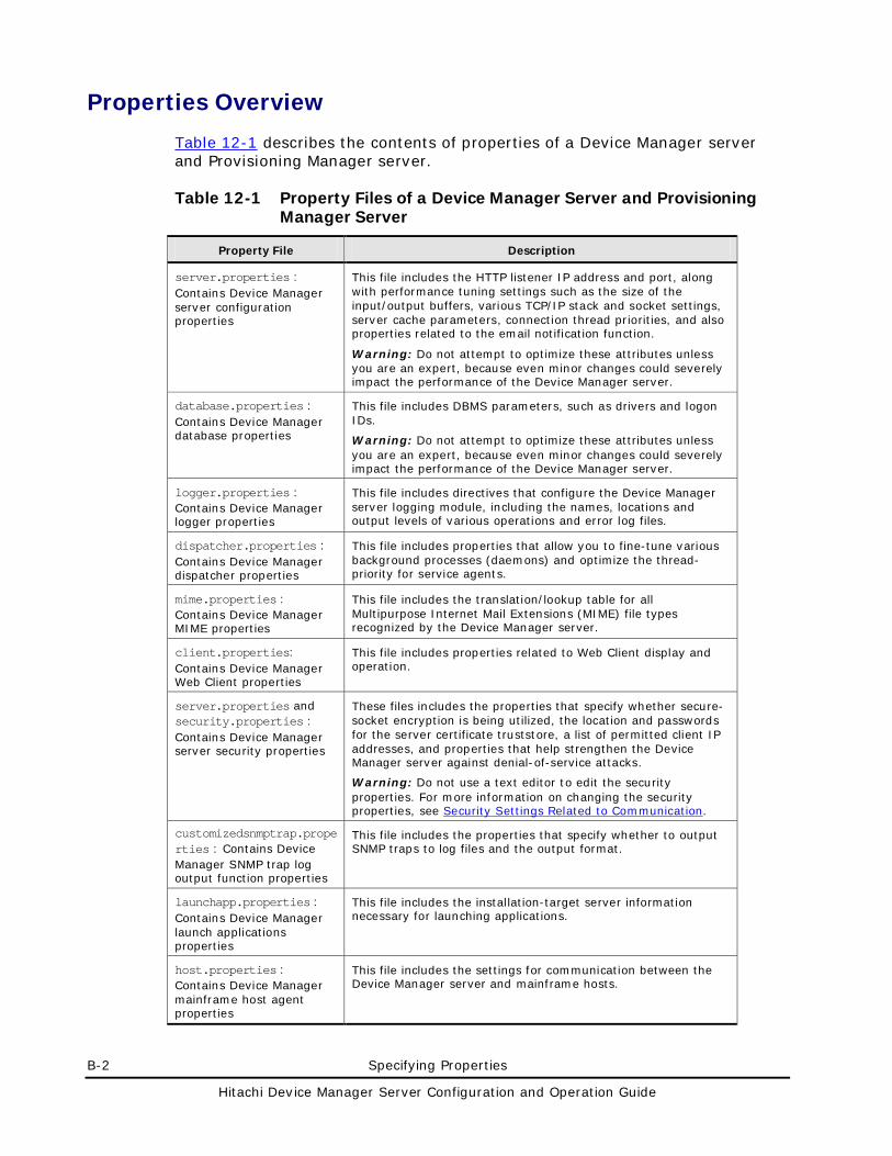
B-2 Specifying Properties
Hitachi Device Manager Server Configuration and Operation Guide
Properties Overview
Table 12-1 describes the contents of properties of a Device Manager server and Provisioning Manager server.
Table 12-1 Property Files of a Device Manager Server and Provisioning Manager Server
Property File Description
server.properties : Contains Device Manager server configuration properties
This file includes the HTTP listener IP address and port, along with performance tuning settings such as the size of the input/output buffers, various TCP/IP stack and socket settings, server cache parameters, connection thread priorities, and also properties related to the email notification function.
Warning: Do not attempt to optimize these attributes unless you are an expert, because even minor changes could severely impact the performance of the Device Manager server.
database.properties : Contains Device Manager database properties
This file includes DBMS parameters, such as drivers and logon IDs.
Warning: Do not attempt to optimize these attributes unless you are an expert, because even minor changes could severely impact the performance of the Device Manager server.
logger.properties : Contains Device Manager logger properties
This file includes directives that configure the Device Manager server logging module, including the names, locations and output levels of various operations and error log files.
dispatcher.properties : Contains Device Manager dispatcher properties
This file includes properties that allow you to fine-tune various background processes (daemons) and optimize the thread-priority for service agents.
mime.properties : Contains Device Manager MIME properties
This file includes the translation/lookup table for all Multipurpose Internet Mail Extensions (MIME) file types recognized by the Device Manager server.
client.properties: Contains Device Manager Web Client properties
This file includes properties related to Web Client display and operation.
server.properties and security.properties : Contains Device Manager server security properties
These files includes the properties that specify whether secure-socket encryption is being utilized, the location and passwords for the server certificate truststore, a list of permitted client IP addresses, and properties that help strengthen the Device Manager server against denial-of-service attacks.
Warning: Do not use a text editor to edit the security properties. For more information on changing the security properties, see Security Settings Related to Communication.
customizedsnmptrap.properties : Contains Device Manager SNMP trap log output function properties
This file includes the properties that specify whether to output SNMP traps to log files and the output format.
launchapp.properties : Contains Device Manager launch applications properties
This file includes the installation-target server information necessary for launching applications.
host.properties : Contains Device Manager mainframe host agent properties
This file includes the settings for communication between the Device Manager server and mainframe hosts.
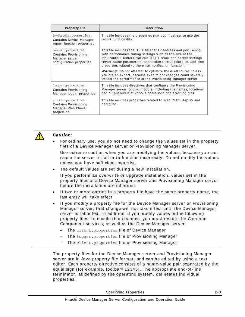
Specifying Properties B-3
Hitachi Device Manager Server Configuration and Operation Guide
Property File Description
DvMReport.properties : Contains Device Manager report function properties
This file includes the properties that you must set to use the report functionality.
server.properties : Contains Provisioning Manager server configuration properties
This file includes the HTTP listener IP address and port, along with performance tuning settings such as the size of the input/output buffers, various TCP/IP stack and socket settings, server cache parameters, connection thread priorities, and also properties related to the email notification function.
Warning: Do not attempt to optimize these attributes unless you are an expert, because even minor changes could severely impact the performance of the Provisioning Manager server.
logger.properties : Contains Provisioning Manager logger properties
This file includes directives that configure the Provisioning Manager server logging module, including the names, locations and output levels of various operations and error log files.
client.properties: Contains Provisioning Manager Web Client properties
This file includes properties related to Web Client display and operation.
Caution: • For ordinary use, you do not need to change the values set in the property
files of a Device Manager server or Provisioning Manager server.
Use extreme caution when you are modifying the values, because you can cause the server to fail or to function incorrectly. Do not modify the values unless you have sufficient expertise.
• The default values are set during a new installation. If you perform an overwrite or upgrade installation, values set in the property files of a Device Manager server and Provisioning Manager server before the installation are inherited.
• If two or more entries in a property file have the same property name, the last entry will take effect.
• If you modify a property file for the Device Manager server or Provisioning Manager server, that change will not take effect until the Device Manager server is rebooted. In addition, if you modify values in the following property files, to enable that changes, you must restart the Common Component services, as well as the Device Manager server:
– The client.properties file of Device Manager – The logger.properties file of Provisioning Manager – The client.properties file of Provisioning Manager
The property files for the Device Manager server and Provisioning Manager server are in Java property file format, and can be edited by using a text editor. Each property directive consists of a name-value pair separated by the equal sign (for example, foo.bar=12345). The appropriate end-of-line terminator, as defined by the operating system, delineates individual properties.
B-4 Specifying Properties
Hitachi Device Manager Server Configuration and Operation Guide
Comments in Device Manager or Provisioning Manager property files are tagged using a hash mark (#) at the start of a line. Literals (text strings or numeric values) do not need to be quoted. Boolean values can be either true or false (case-insensitive). Any other setting (for example, yes) is interpreted as false.
The backslash (\) is a reserved character in Java property files, and is used for escaping various control characters such as tabs, line-feeds, etc. On Windows platforms, absolute pathnames typically contain backslash characters, and must be backslash-escaped. For example, the file pathname c:\HiCommand\docroot\foo.bar should be entered as c:\\HiCommand\\docroot\\foo.bar. There is generally no need to backslash-escape any other characters in the property directives.
Specifying Properties B-5
Hitachi Device Manager Server Configuration and Operation Guide
Device Manager Server Configuration Properties
The server.properties file contains properties related to the server configuration.
• In Windows:
installation-folder-for-the-Device-Manager-server\HiCommandServer\config\server.properties
• In Solaris or Linux:
installation-directory-for-the-Device-Manager-server/HiCommandServer/config/server.properties
server.http.host
This property designates either the host name or IP address for the host on which the web server function of Device Manager operates. To specify the IP address, use one of the following formats:
IPv4 format:
x.x.x.x (x: integer from 0 to 255)
IPv6 format:
Specify hexadecimal numbers by using colons (:). You can also use a short format. You can only use global IPv6 addresses.
– If you specify a host name, make sure to use a value that a DNS can resolve on the Web Client, CLI, and the subsystem.
– If you specify an IP address, specify a value to which Web Client, CLI, and the subsystem can connect.
– In a cluster environment, specify the IP address of the cluster manager.
– If multiple NICs are installed on the server computer on which Device Manager is installed, specify the IP address of the NIC that belongs to the network to which the clients (Web Client, CLI, and storage subsystems) connect. Do not specify the host name.
– If you have changed the value of the server.http.host property and wish to specify settings for an SMI-S Enabled subsystem from Tiered Storage Manager, you first need to refresh the target SMI-S Enabled subsystem.
Default: The host name or IP address of the management server specified during installation (if an error occurs when registering the URL, localhost is set).
B-6 Specifying Properties
Hitachi Device Manager Server Configuration and Operation Guide
server.http.port
This property assigns the port used for the Device Manager HTTP (Web) server. The conventional port number used for a standard web server is 80, but there might already be an intranet server running on this port. Moreover, you should avoid low-numbered ports because these could conflict with other services installed on the server. As a general rule, you can pick any port between 1024 and 49151.
Caution: Use 80 for the port number when this property is set to a space character.
Default: 2001
server.https.port
This property assigns the port used for the Device Manager secure HTTP web server. The conventional port number for a secure web server is 443, but there might already be a secure intranet server running on this port. As noted above, it is better practice to utilize a port number between 1024 and 49151 for a specialized (middleware) HTTP server. Make sure that it has a different value than the port designated for the HTTP listener.
Default: 2443
server.http.default
If the Device Manager web server receives an HTTP request in which only a directory name is specified but not a file name, the server searches within the directory for the file name specified in this property. Under normal conditions, you do not need to change the default value of this property.
Default: index.html
server.http.request.timeout
This property sets the read-blocking timeout of the HTTP socket connection (in milliseconds). It can be used to enable or disable the SO_TIMEOUT setting for client-connection sockets. Reading from the input stream associated with a socket will block for only this amount of time before the socket expires. Its default value is 5000 (5 seconds). A value of 0 is interpreted as an infinite timeout, meaning that SO_TIMEOUT is disabled for client connections. You should only modify this property if you are an expert system administrator seeking to fine-tune the server’s performance.
Default: 5000 (5 seconds)
Specifying Properties B-7
Hitachi Device Manager Server Configuration and Operation Guide
server.http.connection.priority
This property sets the priority for all client-connection threads spawned by HTTP requests made against the Device Manager server. Valid values are from 1 to 10 (1 = minimum priority; 5 = normal priority; 10 = maximum priority). You should only modify this property if you are an expert system administrator seeking to fine-tune the server’s performance. Recommended values are from 5 to 8.
Note: If the connection thread priority is set to 10 (maximum), any simultaneous request connections are queued for sequential processing, which defeats the purpose of a multi-threaded server. This setting would actually adversely affect server performance, particularly when you are loading complex HTML pages (for example, those containing many images).
Default: 7
server.http.connection.bufSize
This property sets the size in bytes for all of the server’s input/output (I/O) buffers. Increased buffer size might improve request/response network performance for high-volume connections, while decreasing it can help reduce the backlog of incoming data. Do not set the default value smaller than 1024 bytes, or it can cause failure. You should only modify this property if you are an expert system administrator seeking to fine-tune the server’s performance.
Default: 8192 bytes
server.http.socket.backlog
This property assigns the maximum queue length for incoming connection indications (a request to connect), such as setting the SO_MAX_CONN attribute of the server socket. If a connection indication arrives when the queue is already full, the Device Manager server will refuse the new connection. You should only modify this property if you are an expert system administrator seeking to fine-tune the server’s performance.
Default: 50
B-8 Specifying Properties
Hitachi Device Manager Server Configuration and Operation Guide
server.http.socket.maxThreads
When a request has been issued and is being processed on the Device Manager server, a client has an active connection on the server. This property specifies the number of active requests that can be processed at one time on Device Manager server, not the maximum number of clients. Once this limit is reached, the next request will be dropped. You should only modify this property if you are an expert system administrator seeking to fine-tune the server’s performance.
Default: 50
server.http.socket.linger
This property determines whether the SO_LINGER socket attribute is enabled for client connections with the Device Manager server. Setting this flag to its default value means a linger-On-close timeout of 60 seconds is applied to socket connections. You should only modify this property if you are an expert system administrator seeking to fine-tune the server’s performance.
Default: true
server.http.socket.noDelay
This property determines whether the TCP_NODELAY socket attribute is enabled for connections to the Device Manager server. Setting this flag at its default value disables the Nagle algorithm for TCP/IP packets. If the Nagle algorithm is disabled, packets will be sent without delay. You should only modify this property if you are an expert system administrator seeking to fine-tune the server’s performance.
Default: true
server.http.headers.maxNumber
This property sets the maximum number of HTTP headers permitted for any request submitted to the Device Manager web server, and helps prevent certain types of denial of service and attempted buffer overflow attacks by restricting the effect of malicious requests containing a large number of headers. Under normal conditions, you do not need to change the default value of this property. The Device Manager server silently ignores any HTTP headers in excess of this number. Runtime errors are not automatically generated under such circumstances.
Default: 20
Specifying Properties B-9
Hitachi Device Manager Server Configuration and Operation Guide
server.http.headers.maxLength
This property sets the maximum length permitted for any HTTP header in bytes. Under normal conditions, you do not need to change the default value of this property. It helps prevent certain types of denial of service and attempted buffer-overflow attacks by restricting the effect of malicious requests that contain unusually large header fields. Headers longer than the specified length will be truncated by the Device Manager server without automatically generating runtime errors.
Default: 1024
server.http.entity.maxLength
This property sets the maximum length of an HTTP request entity in bytes. Under normal conditions, you do not need to change the default value of this property. It helps prevent certain types of denial of service and attempted buffer overflow attacks by restricting the effect of malicious requests that contain unusually large payload entities. If the server detects a posted request longer than this value, it sends an error response to the client and logs details of the attempted request.
Default: 1310720
Note: If you register a file server that has many file systems and storage pools into Device Manager, information sent from the file server might not be applied to Device Manager properly. In this case, change the property value to a value greater than the default.
server.http.log.reverseDNS
This property determines whether the Device Manager server performs reverse-DNS (Domain Name Server) lookup for its access logging. If this property is set to true, the host name is determined from a given IP address. If DNS can find the name of the host associated with the IP address, the host name is also written into the access log. If DNS cannot find the name or this property is set to false, the IP address is written into the access log.
Note: While translation of the IP address to a domain name can assist analysis of the server’s access logs, reverse-DNS lookups are expensive in terms of resources, and this feature may significantly degrade the server’s performance, especially on a slow network. You should keep the setting at the default value for better performance.
Default: false
B-10 Specifying Properties
Hitachi Device Manager Server Configuration and Operation Guide
server.http.cache.size
This property sets the upper-limit size of the Device Manager server’s internal file cache in bytes. A value of 0 turns file caching off, which may adversely affect server performance when delivering complex static files (HTML pages containing images, etc).
This setting can be increased on a host computer with sufficient RAM installed. However, since the number of static files being served by Device Manager is only in the order of a few pages, performance gains would most likely be quite trivial. Under normal conditions, you do not need to change the default value of this property.
Default: 10000000 bytes
server.http.cache.maxFileSize
This property specifies the maximum size (in bytes) of a file to be stored in the Device Manager internal cache. If a file larger than the specified size is requested, the Device Manager server reads the data from disk without using the cache. If this property is set to 0, performance might be degraded because the cache is not used. Under normal conditions, you do not need to change the default value of this property.
Default: 100000 bytes
server.http.fileTypes.noLog
This property specifies the file types that are not logged in log files. If you specify multiple types, separate them with commas. Spaces are ignored. This property prevents the access log from overflow with entries related to files such as graphic files, JavaScripts, or cascading style sheets (CSS). If you specify the default value for this property, only the HTML pages requested by a browser or other clients are logged. If you specify nothing for this property, all files are logged.
Default: gif, jpg, jpeg, png, css, js
server.http.mode
This property sets whether the server is running in real mode or simulation mode. This property is only used for development of the application that is connected to Device Manager. Under normal conditions, you do not need to change the default value of this property.
Default: real
Specifying Properties B-11
Hitachi Device Manager Server Configuration and Operation Guide
server.installTime
This property contains the Device Manager installation date.
Format : dd/mm/yyyy:HH:MM:SS ZZZZ (dd: day, mm: month, yyyy: year, HH: hour, MM: minute, SS: second, ZZZZ: time zone)
Default: install date
server.base.home
This property contains the installation directory of Common Component, which is set by the Device Manager installer. Under normal conditions, you do not need to change the default value of this property.
Default: Value set by the installer
server.horcmconfigfile.hostname
This property allows you to specify whether to use the host name (hostname) or the IP address (ipaddress) when Device Manager edits the configuration definition file.
Caution:
• Changing a host name or an IP address that was specified when a copy pair was created disables operations on the copy pair. In such a case, refresh the subsystem information.
• The setting for this property is ignored in Replication Manager. If you edit the configuration definition file in Replication Manager, the host name is always used.
Default: ipaddress
server.base.initialsynchro
This property allows you to specify whether to synchronize the management information database and the displayed information (Hitachi Storage Command Suite Common Repository) when you start Device Manager. A setting of true will synchronize the information. A setting of false will not synchronize the information.
Caution: If this property is set to true, synchronization of the information will take several minutes. If you change the property and then log in to Device Manager right away, an error might occur. If that occurs, wait until the synchronization has finished, and then log in.
Default: false
B-12 Specifying Properties
Hitachi Device Manager Server Configuration and Operation Guide
server.cim.agent
This property allows you to specify the name of the host on which the Device Manager agent is installed when the function for collecting storage subsystem performance information is used.
Performance information can be collected only when this property is specified.
Default: None
server.cim.support
This property determines whether CIM support is enabled. If you want to use a VDS service provider or execute CIM, you must set this property to true.
This property is set to true during a new installation of Device Manager.
Default: true
server.cim.support.job
This property specifies whether a method for creating or deleting a volume, setting or releasing a path, setting or cancelling security for a LUN, or creating or deleting a LUSE volume is executed asynchronously or synchronously. If you set this property to true, the method is executed asynchronously. If you set this property to false, the method is executed synchronously. If the CIM client does not support the job control subprofile, specify false.
If you specify any values other than true or false, or if this property does not exist, the method is executed asynchronously.
Default: true
server.cim.support.protocol
This property sets whether to open or close the ports used by the CIM function. A value of 1 to 3 can be specified. When 1 is specified, the port for non-SSL transmission is opened and the port for SSL transmission is closed. When 2 is specified, the port for non-SSL transmission is closed and the port for SSL transmission is opened. When 3 is specified, both ports are opened.
This property is set to 3 during a new installation of Device Manager.
Default: 3
server.cim.http.port
This property specifies the port for non- SSL transmission for the CIM function.
Specifying Properties B-13
Hitachi Device Manager Server Configuration and Operation Guide
Default: 5988
server.cim.https.port
This property specifies the port for SSL transmission, for the CIM function.
Default: 5989
server.configchange.enabled
This property specifies whether to automatically update (refresh) storage subsystem information in the database when the configuration of storage subsystems is changed by a storage management tool (Storage Navigator, Storage Navigator Modular 2, or Storage Navigator Modular (for Web)) launched from Web Client.
For Universal Storage Platform V/VM, Hitachi USP, Lightning 9900V, or Lightning 9900, if you specify true, storage subsystem information in the database is automatically refreshed immediately after the configuration change. For Hitachi AMS 2000, Hitachi SMS, Hitachi AMS/WMS, Thunder 9500V, or Thunder 9200, if you specify true, whether the configuration has been changed is checked at the interval specified in the following properties, and storage subsystem information in the database is automatically refreshed if the configuration has been changed:
For Hitachi AMS 2000 or Hitachi SMS
server.dispatcher.snm2.configchange.pollingPeriod property
For Hitachi AMS/WMS, Thunder 9500V, or Thunder 9200
server.dispatcher.configchange.pollingPeriod property
If you specify false, storage subsystem information in the database is not automatically refreshed.
Default: true
server.configchange.autorefresh.lastrefreshed
This property specifies whether the time of the last refresh is to be updated when storage subsystem information in the database is automatically refreshed (that is, when storage subsystems are automatically refreshed). If you specify true for this property, the time of the last refresh is also updated when the database is automatically refreshed. If you specify false, it is not updated even if the database is automatically refreshed (from Web Client and CLI, you will be unable to check whether an automatic refresh is performed).
If a storage subsystem is manually refreshed, the time of the last refresh is updated regardless of the value specified for this property.
B-14 Specifying Properties
Hitachi Device Manager Server Configuration and Operation Guide
Under normal conditions, you do not need to change the default values in this file.
Default: true
server.mail.enabled
This property determines whether to report an alert that has occurred in a storage subsystem to the user by email. To enable the email notification function, set this property to true.
Default: true
server.mail.from
This property changes the mail address of the notification source (sender). If no value is specified or the specified value is invalid, the default value is set.
Default: hdvmserver
server.mail.smtp.host
This property specifies the host name or IP address of the SMTP server to be accessed when an email is sent by the email notification function of the Device Manager server. The IP address can be specified in IPv4 or IPv6 format. You must specify this property.
Caution: If you do not specify this property, the email notification function will not be enabled even if you specify true for the server.mail.enabled property.
Default: None
server.mail.smtp.port
This property specifies the port number of the SMTP server to be accessed when an email is sent by the email notification function of the Device Manager server. You must specify this property.
Specifiable range: 0 to 65535.
Default: 25
Specifying Properties B-15
Hitachi Device Manager Server Configuration and Operation Guide
server.mail.smtp.auth
This property specifies whether to use SMTP authentication when an email is sent by the email notification function of the Device Manager server. To use SMTP authentication, set this property to true. To not use SMTP authentication, set this property to false. Specifying this property is optional.
Default: false
server.mail.alert.type
This property specifies the type of alerts to be reported by the email notification function of the Device Manager server. The following values can be specified:
Trap: Reports only SNMP trap alerts.
Server: Reports only the alerts detected by the background threads responsible for checking component status and the configuration version.
All: Reports both SNMP trap alerts and the alerts detected by the background threads responsible for checking component status and the configuration version.
Note: If All is set, alerts are reported from both SNMP and the server even if these alerts refer to the same error information.
Default: Trap
server.mail.alert.status
This property specifies the severity of alerts to be reported by the email notification function of the Device Manager server. The Device Manager server reports alerts whose severity is higher than the severity specified for this property. The following values (listed in ascending order of importance) can be specified:
Normal, Service, Moderate, Serious, Acute
Default: Moderate
server.subsystem.ssid.availableValues
This property specifies the range of the SSIDs that can be assigned automatically to storage subsystems registered in Device Manager. It is valid for Lightning 9900V, Hitachi USP, and Universal Storage Platform V/VM.
The values that can be specified for this property are as follows:
B-16 Specifying Properties
Hitachi Device Manager Server Configuration and Operation Guide
Hexadecimal numbers in the range from 4 to FFFD: To specify consecutive numbers, use a hyphen (-) to specify the range. To specify non-consecutive numbers, use commas as separators. The values are not case sensitive. If multiple values and ranges that include duplicated numbers are specified, the logical union of all specified values is used.
All: The string All specifies that the entire range of values can be specified. This value is not case sensitive.
Automatic SSID assignment can be performed only when a value or values are specified in this property.
Default: All
server.smisclient.indication.port
This property specifies the port number used to receive event indications from SMI-S providers.
Specifiable range: 1024 to 49151.
Default: 5983
If you have changed the value of the server.smisclient.indication.port property and wish to specify settings for an SMI-S Enabled subsystem from Tiered Storage Manager, you first need to refresh the target SMI-S subsystem.
Specifying Properties B-17
Hitachi Device Manager Server Configuration and Operation Guide
Device Manager Database Properties
The database.properties file contains the database properties.
• In Windows: installation-folder-for-the-Device-Manager-server\HiCommandServer\config\database.properties
• In Solaris or Linux: installation-directory-for-the-Device-Manager-server/HiCommandServer/config/database.properties
This property file contains the set of directives that pertain to establishing a connection with the Device Manager server’s database. Before the Device Manager server will run you need to correctly enter these settings and start the Database Management System (DBMS). If the server cannot connect to its DBMS, an entry is written to the error log (the default location is in the logs directory). This information can help considerably when you are troubleshooting a new installation.
dbm.traceSQL
This property designates whether the output to trace.log is SQL. Set true to output to SQL. Set false not to output SQL.
Default: false
dbm.startingCheck.retryCount
This property specifies the number of times that the Device Manager server (at startup) retries checking of whether the DBMS has started when the server is launched. The specifiable values are from 0 to 100. Under normal conditions, you do not need to change the default value of this property.
Default: 18
dbm.startingCheck.retryPeriod
This property specifies the interval (in seconds) that the Device Manager server (at startup) retries checking of whether the DBMS has started when the server is launched. The specifiable values are from 0 to 60 (seconds). Under normal conditions, you do not need to change the default value of this property.
Default: 10 seconds
B-18 Specifying Properties
Hitachi Device Manager Server Configuration and Operation Guide
Device Manager Logger Properties
The logger.properties file contains the logger properties.
• In Windows: installation-folder-for-the-Device-Manager-server\HiCommandServer\config\logger.properties
• In Solaris or Linux: installation-directory-for-the-Device-Manager-server/HiCommandServer/config/logger.properties
This properties file contains a set of directives that configure Device Manager server’s logging module, including the names, locations and verbosity level of the various operation and error log files. You can also use this file to configure trace logging for debugging and diagnostic purposes.
The properties logger.loglevel, logger.MaxBackupIndex, and logger.MaxFileSize are applied to the following files: access.log.n, cim_access.log.n, error.log.n, service.log.n, stdout.log.n, stderr.log.n, statuscheck.log.n, trace.log.n, CIMOMTracen.log, and SMISClientTracen.log.
The properties logger.hicommandbase.loglevel, logger.hicommandbase.MaxBackupIndex, and logger.hicommandbase.MaxFileSize are applied to the following files: HDvMtracen.log, HDvMGuiTracen.log, and HDvMGuiMessagen.log.
The n in the file name indicates the backup generation number of the file.
The Windows event log is viewable in the Event Viewer. The default syslog is specified in /etc/syslog.conf
logger.loglevel
In this property, you can specify the verbosity level for the trace.log.n, error.log.n, CIMOMTracen.log, and SMISClientTracen.log (the n in the file name indicates the backup generation number of the file). The values accepted in this field are (in decreasing order of detail): DEBUG, INFO, WARN, ERROR, and FATAL. If this property is set to the default, entries whose verbosity level is either INFO, WARN, ERROR, or FATAL are written into the trace.log.n. In this case, entries whose verbosity level is DEBUG are not written into the logs.
Default: INFO
Specifying Properties B-19
Hitachi Device Manager Server Configuration and Operation Guide
logger.MaxBackupIndex
In this property, you can specify the maximum number of backups for the access.log.n, cim_access.log.n, error.log.n, service.log.n, stdout.log.n, stderr.log.n, statuscheck.log.n, trace.log.n, CIMOMTracen.log, and SMISClientTracen.log.
The n in the file name indicates the backup generation number of the file. When a log file reaches its maximum length its file name is modified by appending a counter, for example, access.log.1. As more backup log files are created, their counter or version suffix is incremented (for example, access.log.1 becomes access.log.2), until the specified number of rolling backups have been created. After that, the oldest backup log file is deleted each time a new backup is created. Specifiable values are from 1 to 20.
Default: 10
logger.MaxFileSize
In this property, you can specify the maximum size for the access.log.n, cim_access.log.n, error.log.n, service.log.n, stdout.log.n, stderr.log.n, statuscheck.log.n, trace.log.n, CIMOMTracen.log, and SMISClientTracen.log (the n in the file name indicates the backup generation number of the file). If the maximum size is exceeded, a new log file is created. Unless KB is specified for kilobytes or MB for megabytes, the specified size is interpreted to mean bytes.
Specifiable range: from 512 KB to 32 MB
Default: 1 MB
logger.hicommandbase.loglevel
In this property, you can specify the verbosity level for each operation (trace) log file and error log file written by Common Component. The log files are HDvMtracen.log, HDvMGuiTracen.log, and HDvMGuiMessagen.log, where n is an integer that represents the backup number for the file. Each logging event has its own importance level independent from its type (error, warning, and information). The levels, in increasing order of importance, are: 30, 20, 10, and 0. The default logging level for production systems is 20, which means that messages for logging event levels 20, 10, and 0 are written into the HDvMtrace1.log, but messages for logging event level 30 are not.
Default: 20
B-20 Specifying Properties
Hitachi Device Manager Server Configuration and Operation Guide
logger.hicommandbase.sysloglevel
In this property, you can specify the verbosity level for the operation (trace) log data and error log data written to the event log (in Windows) or to syslog (in Solaris or Linux) by Common Component. Each logging event has its own importance level independent from its type (error, warning, and information). The levels, in increasing order of importance, are: 30, 20, 10 and 0. The default logging level for production systems is 0, which means that messages for only the logging event leveled 0 are written into the EventLog (Windows) or the syslog (Solaris or Linux), but messages for the logging event leveled 30, 20, and 10 are not. The default value is recommended.
Default: 0
logger.hicommandbase.MaxBackupIndex
In this property, you can specify the maximum number of backups for each trace and error log file that is written by Common Component. The log files are HDvMtracen.log, HDvMGuiTracen.log, and HDvMGuiMessagen.log (the n in the file name indicates the backup generation number of the file). Valid values are from 1 to 16.
When a log file reaches its maximum length, its file name is modified by increasing a counter (for example, HDvMtrace2). As more backup log files are created, their counter or version suffix is incremented (for example, HDvMtrace2.log becomes HDvMtrace3.log), until the specified number of rolling backups have been created. After that, the oldest backup log file is deleted each time a new backup is created.
Default: 10
logger.hicommandbase.MaxFileSize
In this property, you can specify the maximum size of each operation (trace) log file and error log file that is written by Common Component. The log files are HDvMtracen.log, HDvMGuiTracen.log, and HDvMGuiMessagen.log (the n in the file name indicates the backup generation number of the file). The specified size is assumed to be in bytes unless you specify KB for kilobytes, MB for megabytes or GB for gigabytes. Valid values are from 4096 to 2147483647(less than 2 GB).
Default: 5 MB
Specifying Properties B-21
Hitachi Device Manager Server Configuration and Operation Guide
Device Manager Dispatcher Properties
The dispatcher.properties file contains the dispatcher properties.
• In Windows: installation-folder-for-the-Device-Manager-server\HiCommandServer\config\dispatcher.properties
• In Solaris or Linux: installation-directory-for-the-Device-Manager-server/HiCommandServer/config/dispatcher.properties
This property file contains a set of configurable directives pertaining to the operation of Device Manager server’s dispatcher layer, including properties that allow the fine-tuning of various background processes (daemons) and the optimization of the thread-priority for service agents.
server.dispatcher.agent.priority
This property assigns the priority for Device Manager Agent threads. Valid values are from 1 to 10 (1 = minimum priority; 5 = normal priority; 10 = maximum priority). You should change the default value only if you need to fine-tune the agent dispatcher’s performance. The recommended values are from 5 to 8, and you should not set it to the maximum thread priority (9-10), because while that might cause individual requests to execute faster, it is likely to cause an overall degradation in performance when multiple users are sending concurrent requests.
Default: 5
server.dispatcher.message.timeout
This property sets the timeout (in minutes) for pending response messages before they are expired (purged). A pending message contains a response from a process that has been running for a long time (such as the addition of a storage subsystem) but has not yet been polled by the client or has not yet been sent to the client via the Device Manager notification service.
Default: 15 minutes
server.dispatcher.message.timeout.in.processing
This property sets the timeout period (in minutes) for Web Client processing and CLI processing that does not completed for some reason.
Default: 720 minutes
B-22 Specifying Properties
Hitachi Device Manager Server Configuration and Operation Guide
server.dispatcher.daemon.pollingPeriod
This property defines the polling interval (in minutes) for the background agents responsible for checking component status and configuration version. A value of 0 will disable these polling agents.
Default: 5 minutes
server.dispatcher.traps.purgePeriod
This property defines the purging interval for stale SNMP traps or alerts (in minutes). A value of 0 will disable the purging of traps from the server.
Default: 5 minutes
server.dispatcher.startTimeOfIgnoringConnectionAlert
This property defines the start time of the interval for stopping SNMP communication alert. Accessing a storage subsystem that is in regular reboot will incur this alert.
Default: 2:45
server.dispatcher.endTimeOfIgnoringConnectionAlert
This property defines the end time of the interval for stopping SNMP communication alert. If you access a storage subsystem that is in regular reboot, that will cause this alert.
Default: 3:15
server.dispatcher.daemon.receiveTrap
This property determines whether to use the SNMP trap reception function.
To use the SNMP trap reception function, specify true. To not use the function, specify false.
The SNMP trap reception function uses port 162.
If port 162 is not used by another product when you perform a new installation of Device Manager, this property is automatically set to true. If the port is used by another product, you need to change the setting for that product or disable this setting in the window for setting up the SNMP trap reception function, which is displayed during installation of Device Manager.
Specifying Properties B-23
Hitachi Device Manager Server Configuration and Operation Guide
If this property is set to true, the SNMP trap information for storage subsystems will be output to the log messages, regardless of the settings for the SNMP trap log output function. For details about how to specify settings for the SNMP trap log output function, see Device Manager SNMP Trap Log Output Function Properties.
Default: true
server.dispatcher.snm2.configchange.pollingPeriod
This property specifies the interval (in seconds) at which the Device Manager server checks whether the configuration of Hitachi AMS 2000 or Hitachi SMS is changed by Storage Navigator Modular 2 launched from Web Client. If the server.configchange.enabled property is set to true and the Device Manager server detects changes in the storage subsystem configuration, storage subsystem information in the database is automatically updated (refreshed).
You can specify a value from 0 to 3600. If you specify 0, storage subsystem information in the database is not refreshed when the storage subsystem configuration is changed because the Device Manager server does not detect the change.
Default: 300 (seconds)
server.dispatcher.configchange.pollingPeriod
This property specifies the interval (in seconds) at which the Device Manager server checks whether the configuration of Thunder 9200, Thunder 9500V, or Hitachi AMS/WMS subsystems is changed by Storage Navigator Modular (for Web) or Storage Navigator Modular 2 launched from Web Client. If the server.configchange.enabled property is set to true and the Device Manager server detects changes in the storage subsystem configuration, storage subsystem information in the database is automatically updated (refreshed).
You can specify a value from 0 to 3600. If you specify 0, storage subsystem information in the database is not updated when the storage subsystem configuration is changed because the Device Manager server does not detect the change.
Default: 60 (seconds)
server.dispatcher.daemon.configUpdate.detection.interval
This property specifies the interval (in minutes) at which the Device Manager server checks whether the configuration of Universal Storage Platform V/VM is changed by a storage management tool other than Device Manager (such as CCI or SVP) or Device Manager CLIEX. If the Device Manager server detects changes in the Universal Storage Platform V/VM configuration, a warning message is displayed in Device Manager Web Client.
B-24 Specifying Properties
Hitachi Device Manager Server Configuration and Operation Guide
You can specify a value from 0 to 1440. If you specify 0, the Device Manager server does not check whether the configuration of Universal Storage Platform V/VM is changed.
Default: 10 (minutes)
Caution: • If a warning message is displayed in Web Client, manually refresh the
corresponding storage subsystem information.
You can also specify the settings so that information in the database is automatically updated in case a user forgets to perform a manual refresh after changing the storage subsystem configuration. To do so, set up the following properties: – server.dispatcher.daemon.autoSynchro.doRefresh property – server.dispatcher.daemon.autoSynchro.type property
• The Device Manager server cannot detect the following configuration change performed on Universal Storage Platform V/VM: – Creating, changing, or deleting copy pairs – Changing the status of an LDEV (such as Normal, Blocked, or Copying) – Changing the access attribute of an LDEV (such as Read/Write, Read
Only, or Protect)
• The Device Manager server treats the following operations as configuration changes of Universal Storage Platform V/VM:
– Restarting SVP – Refreshing the configuration information of Universal Storage Platform
V/VM displayed in Storage Navigator. – Switching the SVP in a cluster configuration from the executing node to
the standby node, or vice versa. – Turning on the DKC
server.dispatcher.daemon.autoSynchro.doRefresh
This property specifies whether to automatically refresh the Universal Storage Platform V/VM information in the database if the Device Manager server detects that the configuration of the Universal Storage Platform V/VM has changed.
When true is specified for this property, if a user does not perform a manual refresh after the Device Manager server detects a change, the Universal Storage Platform V/VM information in the database is automatically refreshed at the interval specified in the server.dispatcher.daemon.autoSynchro.type property. If false is specified, the database is not automatically refreshed.
Default: true
Specifying Properties B-25
Hitachi Device Manager Server Configuration and Operation Guide
Caution: If you specify true, only the information about the Universal Storage Platform V/VM is updated in the database. The information in the configuration file of a host that recognizes the Universal Storage Platform V/VM command device is not updated in the database.
server.dispatcher.daemon.autoSynchro.type
This property specifies the interval at which storage subsystem information in the database is automatically updated (refreshed) using one of the following values:
H: Specify this format to automatically refresh the information at regular intervals. Specify the interval in the server.dispatcher.daemon.autoSynchro.interval property.
D: Specify this format to automatically refresh the information once a day at a specific time. Specify the time in the server.dispatcher.daemon.autoSynchro.startTime property.
W: Specify this format to automatically refresh the information once a week at a specific time on a specific day. Specify the day in the server.dispatcher.daemon.autoSynchro.dayOfWeek property, and the time in the server.dispatcher.daemon.autoSynchro.startTime property.
This property is enabled only if the server.dispatcher.daemon.autoSynchro.doRefresh property is set to true.
Default: D
server.dispatcher.daemon.autoSynchro.dayOfWeek
This property specifies the day on which storage subsystem information in the database is automatically updated (refreshed) using one of the following values:
Sun Mon Tue Wed Thu Fri Sat
This property is enabled only if the server.dispatcher.daemon.autoSynchro.type property is set to W. In addition, storage subsystem information is automatically refreshed (updated) according to the time zone setting for the management server.
Default: Sat
B-26 Specifying Properties
Hitachi Device Manager Server Configuration and Operation Guide
server.dispatcher.daemon.autoSynchro.startTime
This property specifies the time at which storage subsystem information is automatically refreshed (updated) in the database starts in the format hh:mm. Specify a value from 00 to 23 for hh, and 00 to 59 for mm.
This property is enabled only if the server.dispatcher.daemon.autoSynchro.type property is set to D or W. In addition, storage subsystem information is automatically refreshed (updated) according to the time zone setting for the management server.
Default: 23:00
server.dispatcher.daemon.autoSynchro.interval
This property specifies the interval (in hours) at which storage subsystem information in the database is automatically updated (refreshed).
You can specify a value from 1 to 24.
This property is enabled only if the server.dispatcher.daemon.autoSynchro.type property is set to H.
Default: 24 (hours)
server.dispatcher.daemon.autoSynchro.refresh.interval
This property specifies the interval (in minutes) between the time when the Universal Storage Platform V/VM information in the database is automatically refreshed and the time when the next refresh starts.
This property is enabled only if the server.dispatcher.daemon.autoSynchro.doRefresh property is set to true.
You can specify a value from 0 to 120. If you specify 0, storage subsystem information is automatically refreshed continuously without an interval.
Under normal conditions, you do not need to change the default values in this file.
Default: 5 (minutes)
server.dispatcher.daemon.autoSynchro.refresh.timeout
This property specifies the timeout period (in minutes) for automatic refresh processing. This property is enabled if the server.dispatcher.daemon.autoSynchro.doRefresh property is set to true.
Specifying Properties B-27
Hitachi Device Manager Server Configuration and Operation Guide
If a refresh of Universal Storage Platform V/VM does not finish even if the time period specified in this property has elapsed, the next refresh starts without waiting for the preceding refresh operation to finish (refresh operations are performed in parallel).
You can specify a value from 0 to 1440. If you specify 0, the next refresh starts after the active refresh operation finishes.
Under normal conditions, you do not need to change the default values in this file.
Default: 720 (minutes)
B-28 Specifying Properties
Hitachi Device Manager Server Configuration and Operation Guide
Device Manager MIME Properties
The mime.properties file contains the MIME properties.
• In Windows: installation-folder-for-the-Device-Manager-server\HiCommandServer\config\mime.properties
• In Solaris or Linux: installation-directory-for-the-Device-Manager-server/HiCommandServer/config/mime.properties
This property file contains the translation/lookup table for all Multipurpose Internet Mail Extensions (MIME) file types recognized by the Device Manager web server. Each property in this lookup table maps a particular extension suffix to the MIME type for that file. Under normal conditions, you do not need to change the default values in this file. In any event, only expert system administrators should make any additions to this file.
Specifying Properties B-29
Hitachi Device Manager Server Configuration and Operation Guide
Device Manager Client Properties
The client.properties file contains the client properties.
• In Windows: installation-folder-for-the-Device-Manager-server\HiCommandServer\config\client.properties
• In Solaris or Linux: installation-directory-for-the-Device-Manager-server/HiCommandServer/config/client.properties
This property file contains the settings related to display and operation of Device Manager Web Client.
client.logger.trace
This property defines whether to output the trace information or not by applying Java Web Start’s log output function. Set this property to true to output trace information. Set this property to false to not output trace information.
Note: In order to output trace information, Java Web Start’s log output function must be activated. For more information about Java Web Start’s log output function, see the Device Manager online Help.
Default: false
client.message.timeout
This property defines the maximum wait time for the Device Manager server response (timeout of connection) in seconds. Web Client sends the notification messages to the server, and the server sends the notification of the task completion or the alert in response. The connection between the client and the server is on while waiting the response of the notification from the server. This property sets the timeout of this waiting time. The client sends the notification message again after the timeout. This timeout will be applied each time Web Client accesses the server.
Note: When the client is accessing the server through a proxy server and the connection timeout of the proxy is shorter than the timeout of this property, the notification message might be lost, because the timeout of the proxy server cuts the connection before the Device Manager server can send the response to the Web Client. If this is the case, please set the timeout for this property to a time shorter than the timeout of the proxy.
Default: 300 seconds
B-30 Specifying Properties
Hitachi Device Manager Server Configuration and Operation Guide
client.outputhorcmfunction.enabled
This property specifies whether Web Client is able to use the CCI functionality for creating a configuration definition file. Set this property to true to enable Web Client to use this function.
Before changing this property, stop HBase Storage Mgmt Common Service. After changing this property, restart HBase Storage Mgmt Common Service. For details about how to start and stop HBase Storage Mgmt Common Service, see Starting the Device Manager Server and Common Component and Stopping the Device Manager Server and Common Component.
Default: false
table.ldev.rowsperpage
This property specifies the values displayed in the drop-down list used for setting the number of lines displayed per page on a window using a Web Client sortable table. The values set by this property appear in a Web Client drop-down list. Up to two choices for the number of lines can be included in the drop-down list. To set two choices, specify the two values separated by a comma. The minimum number of lines that can be specified is 1. The maximum number of lines that can be specified depends on the environment: for example, on the web browser the client uses and the CPU performance and memory capacity of the client computer. The maximum number of lines (standard) for each Web browser is as follows:
• Firefox® 2.0.0.x: 100
• Firefox 3.0.x or Firefox 3.5: 300
• Internet Explorer 6.0, Internet Explorer 7.0 or Internet Explorer 8.0: 1000
• Mozilla 1.4: 2000
• Mozilla 1.7: 300
If you specify a value larger than the maximum (standard) value, a warning dialog box might appear indicating that the computer might be unable to respond. If this occurs, decrease the value of the property and restart HBase Storage Mgmt Common Service. For details about how to start and stop HBase Storage Mgmt Common Service, see Starting the Device Manager Server and Common Component and Stopping the Device Manager Server and Common Component.
Default: 25, 300
client.assignlun.upperlimit.enabled
This property enables or disables the upper limit check on the number of LUNs that are assigned when storage is added.
Specifying Properties B-31
Hitachi Device Manager Server Configuration and Operation Guide
If LUN assignment, which is the procedure for adding storage, is performed in a state where many volume paths have already been determined, HBase Storage Mgmt Common Service might stop running. This problem occurs when the size of the memory required to display the information for LUN assignment and the log output information exceeds the upper limit of the Java heap size for HBase Storage Mgmt Common Service. Therefore, to prevent HBase Storage Mgmt Common Service from stopping, set and check the upper limit for the number of LUNs that can be assigned in a single operation. The upper limit of the number of LUNs, which is used for the check, is 100. To enable the check, specify true, and to disable the check, specify false.
Before changing this property, stop HBase Storage Mgmt Common Service. After changing this property, restart HBase Storage Mgmt Common Service. For details about how to start and stop HBase Storage Mgmt Common Service, see Starting the Device Manager Server and Common Component and Stopping the Device Manager Server and Common Component.
Default: true
client.report.csv.format.escaped
This property switches the format of the CSV report for information of the storages and users that are managed by Device Manager. If this property is set to true, each value is output enclosed by double quotation marks (“). For details on the report function, see the Device Manager online Help.
Default: true
client.addstorage.block.per.storage
This property specifies whether multiple users are prohibited from simultaneously assigning a path to one LDEV. If this property is set to true, simultaneous path assignment is prohibited. If this property is set to false, simultaneous path assignment is permitted.
Default: true
client.ldev.rowsperpage.retain.enabled
This property specifies whether to keep the setting when the number of lines displayed per page for a sortable table is changed.
If this property is set to true, after a user changes the number of displayed lines for a sortable table, that table is initially displayed using the new setting the next time the same user views the same sortable table. The number of displayed lines that you specify is kept for each user account and for each sortable table.
B-32 Specifying Properties
Hitachi Device Manager Server Configuration and Operation Guide
If this property is set to false, the new value is not kept. The sortable table is displayed by using the smaller value specified for the table.ldev.rowsperpage property in the client.properties file.
If this property is set to false, the sortable table is initially displayed using the smaller number of displayed lines specified for the table.ldev.rowsperpage property in the Device Manager server client.properties file.
Default: true
Note: Even if the property value is changed from true to false, the setting for the number of displayed lines changed by each user is saved in the Device Manager server. Therefore, if this property is set to true again, then each sortable table will be initially displayed using the setting that each user previously set.
Specifying Properties B-33
Hitachi Device Manager Server Configuration and Operation Guide
Device Manager Security Properties
The server.properties and security.properties files contain server security properties.
• In Windows:
installation-folder-for-the-Device-Manager-server\HiCommandServer\config\server.properties
installation-folder-for-the-Device-Manager-server\HiCommandServer\config\security.properties
• In Solaris or Linux:
installation-directory-for-the-Device-Manager-server/HiCommandServer/config/server.properties
installation-directory-for-the-Device-Manager-server/HiCommandServer/config/security.properties
WARNING: Do not use a text editor to edit these properties. For more information on changing the security properties, see Security Settings Related to Communication.
server.http.secure
This property sets the security level of the Device Manager server. This setting is used for communication in the following routes:
• Between the Device Manager server and Web Client
For details on how to use HiKeytool to set the security level, see Enabling TLS/SSL Server Security.
• Between the Device Manager server and SMI-S provider
For details on how to use HiKeytool to set the security level, see Security Settings for the Device Manager Server (Communication with SMI-S Provider).
Specifiable values are as follows:
• 1 = Basic Authentication. The Device Manager server operates in protected mode, and client applications attempting to connect with the server must submit an authorized user's logon ID and password and be authenticated against the Access Control List (ACL).
Note: These requirements do not apply to requests for files that are intentionally designated as being excluded from ACL security protection (see the server.http.security.unprotected property in server.http.security.unprotected).
B-34 Specifying Properties
Hitachi Device Manager Server Configuration and Operation Guide
• 2 = Secure Socket (TLS/SSL). In this security mode, the server opens an additional secure HTTP listener on a port designated by the server.https.port property. All communications via this port are strongly encrypted using Secure Socket Layer (SSL) or Transport Layer Security (TLS). For further information on SSL and TLS, see \* MERGEFORMATSecurity Settings Related to Communication. In order for a server to use the secure HTTP protocol, a keypair and associated server certificate must be present in the Device Manager server keystore. We strongly recommend this setting if the Device Manager server is exposed to any public network or Internet.
Default: 1
server.http.security.realm
This property sets the security realm message for the Device Manager server's authentication challenge. This text is usually displayed in a browser's logon dialog box.
Default: Device Manager Security
server.http.security.clientIP
This property specifies IP addresses, in IPv4 format, that can be used to connect to the Device Manager server. This setting limits the IP addresses permitted for connection, thus preventing denial-of-service attacks or other attacks that intend to overflow buffers. The following shows a specification example when the Device Manager server accepts connections from 172.16.0.1 and IP addresses in the range from 192.168.0.0 to 192.168.255.255:
server.http.security.clientIP=172.16.0.1,192.168.*.*
You can use asterisks as a wildcard character when specifying multiple connection sources by using a single IP address. To specify multiple IP addresses, separate them with commas. Invalid IP addresses and spaces are ignored.
Specifying Properties B-35
Hitachi Device Manager Server Configuration and Operation Guide
Caution: • You do not need to specify the IP address (the local loopback address) of
the computer on which the Device Manager server is installed. In this property, it is assumed that the Device Manager server can always be connected to using the local loopback address.
• You also need to register the IP addresses to the environment definition file httpsd.conf for Common Component. For details, see \* MERGEFORMATSpecifying Which Device Manager Clients Can Access the Device Manager Server.
Default: *.*.*.* (Any IP address can be used to connect to the Device Manager server.)
server.http.security.clientIPv6
This property specifies IP addresses, in IPv6 format, that can be used to connect to the Device Manager server. This setting limits the IP addresses permitted for connection, thus preventing denial-of-service attacks or other attacks that intend to overflow buffers. The following shows a specification example when the Device Manager server accepts connections from IP addresses in the range from 12AB:0:0:CD30:: to 12AB:0:0:CD3F:FFFF:FFFF:FFFF:FFFF.
server.http.security.clientIPv6=12AB:0:0:CD30::/60
You can specify a range of IP addresses in CIDR format. To specify multiple IP addresses, separate them with commas. Invalid IP addresses and spaces are ignored.
Caution: • You do not need to specify the IP address (the local loopback address) of
the computer on which the Device Manager server is installed. In this property, it is assumed that the Device Manager server can always be connected to using the local loopback address.
• You also need to register the IP addresses to the environment definition file httpsd.conf for Common Component. For details, see \* MERGEFORMATSpecifying Which Device Manager Clients Can Access the Device Manager Server.
Default: :: (Any IP address can be used to connect to the Device Manager server.)
B-36 Specifying Properties
Hitachi Device Manager Server Configuration and Operation Guide
server.https.security.keystore
This property assigns the name of the Keystore file that contains the keypair and associated server certificate used for establishing an encrypted communication via Secure Sockets Layer(SSL) or Transport Layer Security. The default setting is keystore.
The keystore file shipped with a Device Manager server is an empty placeholder file that does not contain the required keypair and associated server certificate needed to run the Device Manager server in secure mode. If you attempt to start the server in secure mode with an empty keystore file, the server will log a fatal error and terminate abnormally. A keypair and associated self-signed or trusted certificate must first be installed into the keystore before encrypted communications can be started. For more information about server certificates, see Creating a Certificate Signing Request (CSR) (Security Settings for the Device Manager Server) and Importing a Digitally-signed Certificate into the Device Manager Server Keystore.
Default: keystore
server.http.security.unprotected
This property designates a comma-delimited list of any non-protected file resources under the server's document root. To specify multiple file resources, separate them with commas. Spaces are ignored. When files or directories are designated as unprotected, they are not subject to Access Control List checks (user authentication), regardless of the security mode setting for the server. Entire directories (including nested sub-directories) can be flagged as unprotected by using an asterisk as a wildcard character. If you specify a space, all resources are protected, so that every request to the Device Manager server will require user authentication.
This property allows anyone to view the index.html front page via a browser, without user authentication being required. More importantly, it allows the Java Web Start application to update its JAR file and deploy (via the HiCommand.jnlp file) to the end-user's system without raising a series of logon dialogs. Similarly, the GUI's help files (and certain client installation information) can be viewed via a Web browser without separate authentication being required at each step. Under normal conditions, you do not need to change the default value of this property.
Default: index.html, HiCommand/*, webstart/*, images/*, style/*, docs/*, favicon/ico
server.https.security.truststore
This property assigns the name and location of the truststore file that contains the server certificates. The Device Manager server uses the default truststore distributed with the JRE named "cacerts".
Specifying Properties B-37
Hitachi Device Manager Server Configuration and Operation Guide
Default: {java.home}/lib/security/cacerts
Note: • This property cannot be modified with HiKeytool. If you want to change
the value, you must do so by editing the value in the server.properties file.
• {java.home} means installation-directory-for-Common-Component/jdk/jre.
B-38 Specifying Properties
Hitachi Device Manager Server Configuration and Operation Guide
Device Manager SNMP Trap Log Output Function Properties
The customizedsnmptrap.properties file contains the properties of the SNMP trap log output function.
• In Windows:
installation-folder-for-the-Device-Manager-server\HiCommandServer\config\customizedsnmptrap.properties
• In Solaris or Linux:
installation-directory-for-the-Device-Manager-server/HiCommandServer/config/customizedsnmptrap.properties
customizedsnmptrap.customizedSNMPTrapEnable
This property allows you to enable the SNMP trap log output function. Specify true to use the log output function, or false to not to use the function.
Default: false
customizedsnmptrap.customizelist
This property allows you to specify how to customize the SNMP trap log output. For details, see Settings for Recording the Received SNMP Traps in Log Files.
Caution: If you do not specify this property, the SNMP trap data will not be output to the log even if you specify true for the customizedsnmptrap.customizedSNMPTrapEnable property.
Default: None
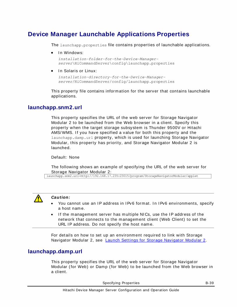
Specifying Properties B-39
Hitachi Device Manager Server Configuration and Operation Guide
Device Manager Launchable Applications Properties
The launchapp.properties file contains properties of launchable applications.
• In Windows: installation-folder-for-the-Device-Manager-server\HiCommandServer\config\launchapp.properties
• In Solaris or Linux: installation-directory-for-the-Device-Manager-server/HiCommandServer/config/launchapp.properties
This property file contains information for the server that contains launchable applications.
launchapp.snm2.url
This property specifies the URL of the web server for Storage Navigator Modular 2 to be launched from the Web browser in a client. Specify this property when the target storage subsystem is Thunder 9500V or Hitachi AMS/WMS. If you have specified a value for both this property and the launchapp.damp.url property, which is used for launching Storage Navigator Modular, this property has priority, and Storage Navigator Modular 2 is launched.
Default: None
The following shows an example of specifying the URL of the web server for Storage Navigator Modular 2:
launchapp.snm2.url=http://192.168.17.235:23015/program/StorageNavigatorModular/applet
Caution: • You cannot use an IP address in IPv6 format. In IPv6 environments, specify
a host name. • If the management server has multiple NICs, use the IP address of the
network that connects to the management client (Web Client) to set the URL IP address. Do not specify the host name.
For details on how to set up an environment required to link with Storage Navigator Modular 2, see Launch Settings for Storage Navigator Modular 2.
launchapp.damp.url
This property specifies the URL of the web server for Storage Navigator Modular (for Web) or Damp (for Web) to be launched from the Web browser in a client.
B-40 Specifying Properties
Hitachi Device Manager Server Configuration and Operation Guide
When the target storage subsystem is Thunder 9500V or Hitachi AMS/WMS, and you have specified a value for both this property and the launchapp.snm2.url property, which is used for launching Storage Navigator Modular 2, the setting of launchapp.snm2.url has priority, and Storage Navigator Modular 2 is launched.
Default: None
The following example shows how to specify the URL of the web server for Storage Navigator Modular (for Web):
launchapp.damp.url=http://192.168.17.235:23015/program/DeviceManager/snm
The following example shows how to specify the URL of the web server for DAMP (for Web):
launchapp.damp.url=http://192.168.17.235:23015/program/DeviceManager/damp
Caution: • You cannot use an IP address in IPv6 format. In IPv6 environments,
specify a host name. • Setting up alias information is necessary in order to use Storage
Navigator Modular (for Web) or DAMP (for Web). For details on setting the environment information in one operation, see Launch Settings for Storage Navigator Modular (for Web) or Launch Settings for DAMP (for Web).
• If the management server has multiple NICs, use the IP address of the network that connects to the management client (Web Client) to set the URL IP address. Do not specify the host name.
launchapp.snm2.rmi.port
If you change the port number used for RMI communication in Storage Navigator Modular 2, you need to specify the new port number in this property. If you do not do this, Device Manager cannot link with Storage Navigator Modular 2. Valid values are from 1 to 65535.
Specify this property when the target storage subsystem is Thunder 9500V or Hitachi AMS/WMS.
If you want to run Storage Navigator Modular 2 on a computer also running Storage Navigator Modular (for Web), do not specify the same number for the port numbers that are used for RMI communication in Storage Navigator Modular (for Web) and Storage Navigator Modular 2.
Specifying Properties B-41
Hitachi Device Manager Server Configuration and Operation Guide
If you have specified a value for both this property and the launchapp.snm.rmi.port property, which is used to specify the port number used for RMI communication in Storage Navigator Modular (for Web), the setting of this property has priority, and Storage Navigator Modular 2 is launched.
For details on how to view and change the communication port number specified in Storage Navigator Modular 2, see the manual for Storage Navigator Modular 2.
Default: None
launchapp.snm.rmi.port
If you have changed the port number used for RMI communication in Storage Navigator Modular (for Web), you need to specify the new port number in this property. If you do not do this, Device Manager cannot link with Storage Navigator Modular (for Web). Valid values are from 1 to 65535.
If you want to run Storage Navigator Modular (for Web) on a computer also running Storage Navigator Modular 2, do not specify the same number for the port numbers used for RMI communication in Storage Navigator Modular (for Web) and Storage Navigator Modular 2.
If the target storage subsystem is Thunder 9500V or Hitachi AMS/WMS and you have specified a value for both this property and the launchapp.snm2.rmi.port property, which is used to specify the port number used for RMI communication in Storage Navigator Modular 2, the setting of launchapp.snm2.rmi.port has priority, and Storage Navigator Modular 2 is launched.
For details on how to view and change the communication port number specified in Storage Navigator Modular (for Web), see the Storage Navigator Modular (for Web) User’s Guide.
Default: None
B-42 Specifying Properties
Hitachi Device Manager Server Configuration and Operation Guide
Device Manager Mainframe Host Agent Properties
The host.properties file contains properties of the mainframe host agent.
• In Windows: installation-folder-for-the-Device-Manager-server\HiCommandServer\config\host.properties
• In Solaris or Linux: installation-directory-for-the-Device-Manager-server/HiCommandServer/config/host.properties
This property file contains settings for communication between the Device Manager server and mainframe hosts.
host.mf.agent.connection.timeout
This property specifies the timeout (in seconds) for communication processing between the Device Manager server and a mainframe host agent. Valid values are 0 and from 30 to 3600 (seconds). If you specify 0, no timeout applies. You should only modify this property if you are an expert system administrator seeking to fine-tune performance of the mainframe host agent.
Default: 300
Specifying Properties B-43
Hitachi Device Manager Server Configuration and Operation Guide
Device Manager Report Function Properties
The DvMReport.properties file contains report function properties.
• In Windows: installation-folder-for-the-Device-Manager-server\HiCommandServer\config\DvMReport.properties
• In Solaris or Linux: installation-directory-for-the-Device-Manager-server/HiCommandServer/config/DvMReport.properties
DetailedArrayReport.outputPath
This property specifies the storage location of the CSV file that can be generated from the Detailed Array Reports window in Web Client.
Note: The value specified for the storage location of the CSV file is enabled when the Detailed Array Reports - Reports subwindow is first displayed on Web Client after the Device Manager server service is restarted.
Default: installation-directory-for-the-Device-Manager-server/DvMReport/CSV
B-44 Specifying Properties
Hitachi Device Manager Server Configuration and Operation Guide
Provisioning Manager Server Configuration Information Properties
The server.properties file contains properties related to the server configuration information.
• In Windows: installation-folder-for-the-Provisioning-Manager-server\conf\server.properties
• In Solaris or Linux:
installation-directory-for-the-Provisioning-Manager-server/conf/server.properties
server.operation.abortTimeout
This property specifies the amount of time (timeout period) from when suspension of a host setting operation begins, until the time the operation is to be stopped automatically.
You can specify a value (in hours) from 0 to 10000. If 0 is specified, a suspended operation is not stopped automatically.
Default: 24
server.operation.eventTimeout
This property specifies the amount of time (timeout period) from when Provisioning Manager begins holding the transaction logs for a host setting operation that has either completed successfully or has failed, until it purges the logs automatically.
You can specify a value (in hours) from 0 to 10000. If 0 is specified, the operation history is not purged automatically.
Default: 24
server.rmiapi.port
This property specifies the port number of the management server.
You can specify a value from 1 to 65535.
Default: 20333
Specifying Properties B-45
Hitachi Device Manager Server Configuration and Operation Guide
server.history.maxNumber
This property specifies the maximum number of items to be recorded in the transaction logs (recorded in the database file that records log information).
You can specify a value from 1 to 100000.
Default: 10000
server.history.maxDays
This property specifies the number of days for which the transaction log data is to be retained. The number of days set here is used as a reference for automatically deleting logs. Any log data that exceeds the specified number of days is deleted.
You can specify a value from 1 to 100000 (days). If no value is specified, transaction log data is not automatically deleted after a number of days elapse.
Default: None
server.installTime
The date, time, and time zone of the completed installation are written into this property.
B-46 Specifying Properties
Hitachi Device Manager Server Configuration and Operation Guide
Provisioning Manager Logger Properties
The logger.properties file contains the logger properties.
• In Windows: installation-folder-for-the-Provisioning-Manager-server\conf\logger.properties
• In Solaris or Linux: installation-directory-for-the-Provisioning-Manager-server/conf/logger.properties
Logger.loglevel
This property specifies the output level threshold for trace logs and message logs output by the Provisioning Manager log output functionality.
This property is used for the trace logs and message logs of the Provisioning Manager server and GUI listed below. The n in the file name indicates the backup generation number of the file.
• HPvMGuiTracen.log
• HPvMGuiMessagen.log
• HPvMServerTracen.log
• HPvMServerMessagen.log
In Provisioning Manager, the output level is specified for all message types (error, warning, and information). There are four levels (0, 10, 20, and 30), which indicate the level of importance. The smaller number indicates a higher level of importance. Only messages with an output level that is less than or equal to the value set in this field are output to the trace log or message log.
Although this field will accept 0, 10, 20, and 30 as values, use of the default output level of 20 is recommended.
Default: 20
Logger.sysloglevel
This property specifies the output level threshold for logs output to the OS (event log in Windows, syslog in Solaris or Linux) by the log output functionality of Common Component.
Specifying Properties B-47
Hitachi Device Manager Server Configuration and Operation Guide
In Provisioning Manager, the output level is specified for all message types (error, warning, and information). There are four levels (0, 10, 20, and 30), which indicate the level of importance. The smaller number indicates a higher level of importance. Only messages with an output level that is less than or equal to the value set in this field are output to the event log or syslog.
Although this field will accept 0, 10, 20, and 30 as values, use of the default output level of 0 is recommended.
Default: 0
Logger.MaxBackupIndex
This property specifies the maximum number of trace log files and message log files that can be output by the Provisioning Manager log output functionality.
Caution: This property is applied to the Provisioning Manager server and GUI trace log files and message log files.
A log file is created with a size as specified in Logger.MaxFileSize, and is assigned a file name with a version number added (for example, HPvMServerTrace1.log and HPvMServerTrace2.log). Log files are used in the order of their numbers, and trace information is written into them. When the last file becomes full, the first file is overwritten.
You can specify a value from 1 to 16.
Default: 10
Logger.MaxFileSize
This property specifies the maximum size of a trace log file or message log file output by the Provisioning Manager log output functionality. This property is applied to the Provisioning Manager server, GUI trace log files, and message log files. If you do not specify KB (for kilobytes), MB (for megabytes), or GB (for gigabytes), the specified value is assumed to be in bytes.
You can specify a value from 4096 bytes to 2147483647 bytes (up to but not including 2 GB).
Default: 1 MB
B-48 Specifying Properties
Hitachi Device Manager Server Configuration and Operation Guide
Provisioning Manager Client Properties
The client.properties file contains the client properties.
• In Windows: installation-folder-for-the-Provisioning-Manager-server\conf\client.properties
• In Solaris or Linux: installation-directory-for-the-Provisioning-Manager-server/conf/client.properties
This property file contains the settings related to display and operation of Provisioning Manager Web Client.
client.ldev.rowsperpage.retain.enabled
This property specifies whether to keep the setting when the number of lines displayed per page for a sortable table is changed.
If this property is set to true, when a user changes the number of displayed lines for a sortable table, that table is initially displayed using the new setting the next time the same user views the same sortable table. The number of displayed lines that you specify is kept for each user account and for each sortable table.
If this property is set to false, the sortable table is set to the initial display of 25 lines per page.
Default: true
Note: Even if the property value is changed from true to false, the setting for the number of displayed lines changed by each user is kept in the Provisioning Manager server. Therefore, if this property is set to true again, then each sortable table will be set to the initial display using the previous user-specified setting.
Acronyms and Abbreviations Acronyms-1
Hitachi Device Manager Server Configuration and Operation Guide
Acronyms and Abbreviations
ACL Access Control List AJP Apache JServ Protocol AMS Adaptable Modular Storage API application program interfaces
CA Certification Authority CCI Command Control Interface CD-ROM Compact Disk - Read Only Memory CHA Channel Adapter CHAP Challenge Handshake Authentication Protocol CIDR Classless Inter-Domain Routing CLI Command Line Interface CLPR Cache Logical PaRtition CN Common Name CPU Central Processing Unit CSR Certificate Signing Request CSS Cascading Style Sheet CU Control Unit CVS Custom Volume Size
DASD direct access storage device DER Distinguished Encoding Rules DHCP Dynamic Host Configuration Protocol DIT Directory Information Tree DN Distinguished Name DNS Domain Name System DoS Denial of Services DST Daylight Saving Time
FAT File Allocation Tables FC Fibre Channel FTP File Transfer Protocol
GB gigabyte(s) GUI Graphical User Interface
HSD Host Storage Domain HTTPS HyperText Transfer Protocol Secure
I/O Input/Output
Acronyms-2 Acronyms and Abbreviations
Hitachi Device Manager Server Configuration and Operation Guide
ID IDentifier IEEE Institute of Electrical and Electronics Engineers IETF Internet Engineering Task Force IIS Internet Information Services IP-SAN Internet Protocol Storage Area Network IPv4 Internet Protocol Version 4 IPv6 Internet Protocol Version 6 iSCSI Internet Small Computer System Interface
JWS Java WE
KB kilobyte(s)
LAN local-area network LBA Logical Block Addressing LDAP Lightweight Directory Access Protocol LDEV logical device LDKC Logical DisK Controller LUN Logical unit number LUSE Logical Unit Size Expansion
MOF Managed Object Format
NAS Network Attached Storage NAT Network Address Translation NPIV N Port ID Virtualization NSC Network Storage Controller NTFS NT File System NTP Network Time Protocol
OS Operating System
P-VOL Primary VOLume PAP Password Authentication Protocol PEM Privacy Enhanced Mail PID Process ID PKI Public Key Infrastructure
RADIUS Remote Authentication Dial-In User Service RAID Redundant Array of Independent Disks RCU Remote Control Unit RDN Relative Distinguished Name RFC Request For Comments
S-ATA Serial ATA S-VOL Secondary VOLume SIM Service Information Message SLPR Storage Logical PaRtition SNMP Simple network management Protocol SSID Storage Subsystem ID SSL Secure Sockets Layer SSO Single Sign - On SVP Service Processor
TCP/IP transmission control protocol/internet protocol TLS Transport Layer Security
Acronyms and Abbreviations Acronyms-3
Hitachi Device Manager Server Configuration and Operation Guide
URL Uniform Resource Locator
VCS VERITAS Cluster Server VDS Virtual Disk Service V-VOL Virtual VOLume
WBEM Web - Based Enterprise Management WWN Worldwide name
XGA eXtended Graphics Array

Acronyms-4 Acronyms and Abbreviations
Hitachi Device Manager Server Configuration and Operation Guide
Index Index-1
Hitachi Device Manager Server Configuration and Operation Guide
Index
* */udp, 2-16
1 1099/tcp, 2-3, 2-10, 2-11, 2-12 161/udp, 2-11 162/udp, 2-3, 2-11 1812/udp, 2-16
2 20/tcp, 2-11 2000/tcp, 2-11, 2-12 2001/tcp, 2-4, 2-10, 2-11, 2-12, 2-14 21/tcp, 2-11 22900/tcp, 2-14 23015/tcp, 2-2, 2-7, 2-10, 2-14 23016/tcp, 2-2, 2-7, 2-10 23017/tcp, 2-2, 2-8 23018/tcp, 2-2, 2-8 23019/tcp to 23031/tcp, 2-2 23032/tcp, 2-3, 2-8 23033/tcp, 2-3 23034/tcp, 2-3 24041/tcp, 2-5, 2-12 24042/tcp, 2-5, 2-13 24043/tcp, 2-5 24220/tcp, 2-5, 2-14 2443/tcp, 2-4, 2-10 25/tcp, 2-15 28355/tcp, 2-11
3 359/tcp, 2-16
4 427/tcp, 2-3, 2-15 443/tcp, 2-12 45001/tcp to 49000/tcp, 2-3
5 51099/tcp, 2-5, 2-10, 2-11, 2-12 51100/tcp, 2-11 5983/tcp, 2-4, 2-14 5988/tcp, 2-4, 2-13, 2-14, 2-15 5989/tcp, 2-4, 2-13, 2-14, 2-15
8 80/tcp, 2-12 88/tcp, 2-16 88/udp, 2-16
A account.lock.num, 3-4 account.lock.system, 3-5 advanced security mode, 4-53 audit log data
checking, 10-12 Common Component, 10-14 detail message (Device Manager), 10-20 Device Manager server, 10-14 Device Manager server via CIM, 10-17 log in Solaris or Linux, 10-7 log in Windows, 10-7 message text, 10-14 Provisioning Manager parameters and
requests, 10-39 Provisioning Manager server, 10-18 related products, 10-15
auditlog.conf, 6-11 authentication
Kerberos server, 3-39 LDAP directory server, 3-10 RADIUS server, 3-26
authentication method directory server, 3-12
authorization groups, 3-7
B backing up
Index-2 Index
Hitachi Device Manager Server Configuration and Operation Guide
database, 9-3
C CA, 4-9 CCI, 1-4 certificate
for LDAP directory server, 4-47 importing, 4-48
certificate authority, 4-9 certificate signing request
creating (Common Component), 4-23 creating (Device Manager server), 4-14 creating in advanced security mode, 4-54
changing Device Manager server keystore password, 4-
18 host name of management server, 2-26 IP address of management server, 2-24 password-encoding level, 4-53 port assigned to SSL, 4-31 ports used by Common Component, 2-6 private key password, 4-18 truststore password, 4-21 URLs for accessing Hitachi Storage Command
Suite products, 2-31 checking
audit log, 10-12 operating status of Common Component, 8-9 operating status of Device Manager server, 8-
6, 8-9 checking connection status
Kerberos, 3-48 LDAP, 3-24 RADIUS, 3-38
CIM/WBEM, 7-2 basic settings, 7-7 Device Manager, 7-5 event indication, 4-31 object operations, 4-31 overview, 7-2 required user permissions, 7-27 setting for ports, 7-9 user permissions, 7-27
CLI, 1-4 client.addstorage.block.per.storage, 31 client.assignlun.upperlimit.enabled, 30 client.ldev.rowsperpage.retain.enabled, 31, 47 client.logger.trace, 29 client.message.timeout, 29 client.outputhorcmfunction.enabled, 30 client.properties, 29, 47 client.report.csv.format.escaped, 31 CLIEX, 1-4 Common Component, 1-3
changing ports, 2-6 checking operating status, 8-9 installation directory (Linux), 1-29 installation directory (Solaris), 1-26 installation folder (Windows), 1-20
log output, 6-2 ports, 2-2 security settings (communication with LDAP
directory server), 4-46 security settings (communication with Web
Client), 4-22 security settings (creating signing request),
4-23 Single Sign-On, 1-3 starting, 8-7 stopping, 8-8
configuring httpsd.conf file in advanced security mode, 4-
56 launch settings for DAMP (for Web), 5-16 launch settings for Storage Navigator Modular
(for Web), 5-9 launch settings for Storage Navigator Modular
2, 5-4 configuring networks
common security risks, 1-7 dual-homed management servers plus
separate management LAN, 1-11 flat network, 1-12 separate management LAN plus firewall, 1-8 separate management LAN plus firewalled
devices, 1-9 contacting
Hitachi Data Systems, 10-50 copy pairs
central management, 1-70 local management, 1-70
creating certificate signing request (Common
Component), 4-23 certificate signing request (Device Manager
server), 4-14 certificate signing request in advanced
security mode, 4-54 keypair, 4-10 keystore file (CIM client), 4-45 private key in advanced security mode, 4-54 self-signed certificate, 4-25 truststore file, 4-46
customizedsnmptrap.customizedSNMPTrapEnable, 37
customizedsnmptrap.customizelist, 37 customizedsnmptrap.properties, 37
D DAMP (for Web)
configuring launch settings, 5-16 linking, 5-14
database backing up, 9-3 exporting, 9-9 importing, 9-10 initializing, 9-13 migrating, 9-7
Index Index-3
Hitachi Device Manager Server Configuration and Operation Guide
restoring, 9-5 database.properties file, 17 dbm.startingCheck.retryCount, 17 dbm.startingCheck.retryPeriod, 17 dbm.traceSQL, 17 deleting
digitally-signed certificate entry from Device Manager server truststore, 4-21
keystore entry from Device Manager server, 4-17
launch settings for Storage Navigator Modular (for Web), 5-12
launch settings for Storage Navigator Modular 2, 5-6
warning banner message, 4-5 DetailedArrayReport.outputPath, 42 Device Manager
obtaining maintenance information, 10-7 Device Manager agent, 1-4
ports, 2-5 Device Manager CLI
changing password-encoding level, 4-53 Device Manager server, 1-3
changing keystore password, 4-18 changing truststore password, 4-21 checking operating status, 8-6, 8-9 displaying contents of truststore (regular
mode), 4-19 displaying contents of truststore (verbose
mode), 4-20 installation directory (Linux), 1-29 installation directory (Solaris), 1-26 installation folder (Windows), 1-20 ports, 2-3 requirements for managing copy pairs, 1-70 security settings (communication with CIM
client), 4-31 security settings (communication with Web
Client or CLI), 4-10 security settings (creating signing request
(CSR)), 4-14 starting, 8-4, 8-7 stopping, 8-5, 8-8
Device Manager Server security settings (communication with SMI-S
Provider), 4-50 digitally-signed certificate, 4-8
deleting entry from Device Manager server truststore, 4-21
importing into Device Manager server keystore, 4-15
importing into Device Manager truststore, 4-19
directory server authentication method, 3-12
disabling SSL, 4-29 two-way authentication, 4-43
disconnecting
management server network, 2-34 dispatcher.properties, 21 displaying
contents of Device Manager keystore (regular mode), 4-16
contents of Device Manager keystore (verbose mode), 4-17
contents of Device Manager server truststore (regular mode), 4-19
contents of Device Manager server truststore (verbose mode), 4-20
DvMReport.properties, 42 Dynamic Link Manager, 1-67
E editing
audit log environment settings file, 6-11 warning banner message, 4-2
enabling SSL, 4-26 TLS/SSL server security, 4-13
error information hdvmgetlogs.bat, 16
event indications specifying two-way authentication, 4-38
event log, 45 logs, 10-7
exauth.properties file Kerberos server, 3-41 LDAP directory server, 3-15 RADIUS server, 3-27
exporting certificate from keystore file, 4-45 databases, 9-9
external authentication server, 3-7 external authorization server, 3-7
F file server, 1-53
system requirements, 1-64 filtering function(VDS), 2 firewall
registering exception, 2-16 settings, 2-9
flat model, 3-13
G generating
private key, 4-22 Global Link Manager, 1-67
H hcmdscheckauth command
when authentication method is Kerberos, 3-48
when authentication method is LDAP, 3-24 when authentication method is RADIUS, 3-38
hcmdschgurl command, 2-31
Index-4 Index
Hitachi Device Manager Server Configuration and Operation Guide
hcmdsldapuser command when authentication method is Kerberos, 3-
46 when authentication method is LDAP, 3-21 when authentication method is RADIUS, 3-34
hcmdslink command, 5-30 hcmdsradiussecret command, 3-37 hcmdsunlockaccount command, 10-5 hdvmmodmailuser command, 6-21 hdvmmodpolluser, 7-25 hierarchical structure model, 3-13 Hitachi Content Archive Platform, 1-69 Hitachi Data Systems
contacting, 10-50 Hitachi Essential NAS Platform Manager, 1-68 Hitachi Storage Services Manager, 1-69 host, 1-4
requirements for managing copy pairs, 1-70 host.mf.agent.connection.timeout, 41 host.properties, 41 hosts
system requirements, 1-53 htmsetup command, 5-27 httpsd.conf file
configuring in advanced security mode, 4-56 Hyper-V, 1-16
I IETF, 4-8 importing
certificate, 4-46, 4-48 databases, 9-10 digitally-signed certificate into Device
Manager server keystore, 4-15 digitally-signed certificate into Device
Manager truststore, 4-19 initializing
database, 9-13 installation directory
Common Component (Linux), 1-29 Common Component (Solaris), 1-26 Device Manager server (Linux), 1-29 Device Manager server (Solaris), 1-26 Provisioning Manager server (Linux), 1-29 Provisioning Manager server (Solaris), 1-26
installation folder Common Component (Windows), 1-20 Device Manager server (Windows), 1-20 Provisioning Manager server (Windows), 1-20
IPv6 limitations on operations, 2-21 linking with storage subsystems, 2-21 migrating Device Manger server, 2-22
J Java VM
obtaining, 10-11
K Kerberos server
authentication, 3-39 checking connection status, 3-48 exauth.properties file, 3-41 hcmdscheckauth command, 3-48 hcmdsldapuser command, 3-46 user account used to search for LDAP user
information, 3-46 keypair
creating, 4-10 keystore
deleting entry from Device Manager server, 4-17
displaying (regular mode), 4-16 displaying (verbose mode), 4-17
keystore file creating (CIM client), 4-45 exporting certificate, 4-45 modifying for object operations, 4-32
L launchapp.damp.url, 38 launchapp.properties, 38 launchapp.snm.rmi.port, 40 launchapp.snm2.rmi.port, 39 launchapp.snm2.url, 38 LDAP directory server
authentication, 3-10 certificate, 4-47 checking connection status, 3-24 exauth.properties file, 3-15 hcmdscheckauth command, 3-24 hcmdsldapuser command, 3-21 settings required for advanced security mode,
4-56 user account used to search for LDAP user
information, 3-21 limitation
in IPv6 environment, 2-21 linking
DAMP (for Web), 5-14 prerequisites for DAMP (for Web), 5-14 prerequisites for Storage Navigator Modular
(for Web), 5-8 prerequisites for Storage Navigator Modular
2, 5-2 Storage Navigator Modular (for Web), 5-8 Storage Navigator Modular 2, 5-2 Tuning Manager, 5-19 with storage subsystem that support IPv6, 2-
21 locking
automatic locking, 3-4 System account, 3-5
logger.hicommandbase.loglevel, 19 logger.hicommandbase.MaxBackupIndex, 20 logger.hicommandbase.MaxFileSize, 20 logger.hicommandbase.sysloglevel, 20
Index Index-5
Hitachi Device Manager Server Configuration and Operation Guide
logger.loglevel, 18 Logger.loglevel, 45 logger.MaxBackupIndex, 19 Logger.MaxBackupIndex, 46 logger.MaxFileSize, 19 Logger.MaxFileSize, 46 logger.properties, 18, 45 Logger.sysloglevel, 45 logs
audit log data, 10-12 HDvMtrace* .log, 10-8 hntr2*.log, 10-7 Java VM thread dump, 10-11 syslog, 10-7 version, 10-7
M mainframe host
system requirements, 1-63 management client, 1-4 management server, 1-3
changing host name, 2-26 changing IP address, 2-24 computer requirements, 1-14 system requirements, 1-14
maximum number of log files, 46 maximum size of a log file, 46 memory heap size
settings, 1-30 migrating
databases, 9-7 to IPv6 environment, 2-22
mime.properties, 28 modifying
keystore file for object operations, 4-32
N network
least secure configuration, 1-12 most secure configuration, 1-8 second-most secure configuration, 1-9 settings required when disconnecting
management server, 2-34 third-most secure configuration, 1-11
network configuration, 1-6 NICs
settings, 2-18 normal host, 1-53 notes on
using Device Manager when copy pairs are already managed, 1-78
O object operations
specifying two-way authentication, 4-35 obtaining
Java VM thread dump, 10-11
maintenance information of Device Manager, 10-7
P password
setting for advanced security mode, 4-57 password.check.userID, 3-2 password.min.length, 3-2 password.min.lowercase, 3-2 password.min.numeric, 3-2 password.min.symbol, 3-2 password.min.uppercase, 3-2 performance information
required system configuration, 7-18 setting for Hitachi AMS 2000, Hitachi SMS,
Hitachi AMS/WMS, Thunder 9500, or Thunder 9200, 7-24
settings for Universal Storage Platform V/VM or Hitachi USP, 7-20
port number of the management server, 43 ports
changing, 2-6 CIM/WBEM, 7-9 settings, 2-2 used by Common Component, 2-2 used by Device Manager agent, 2-5 used by Device Manager server, 2-3 used by storage subsystems, 2-5
prerequisites linking with DAMP (for Web), 5-14 linking with Storage Navigator Modular (for
Web), 5-8 linking with Storage Navigator Modular 2, 5-2
private key generating, 4-22
private key creating in advanced security mode, 4-54
private key password, 4-8 changing, 4-18
property files client.properties, 29, 47 customaizedsnmptrap.properties, 37 database.properties, 17 dispatcher.properties, 21 DVMReport.properties, 42 host.properties, 41 launchapp.properties, 38 list of, 2 logger.properties, 18 logger.properties (Provisioning Manager), 45 logger.properties (VDS Provider), 13 mime.properties, 28 perf_cmddev.properties, 7-21 server.properties, 5, 33 server.properties (Provisioning Manager), 43 server.properties for CIM, 7-11 vds.properties (VDS Provider), 12
Protection Manager, 1-68 Provisioning Manager server, 1-3
Index-6 Index
Hitachi Device Manager Server Configuration and Operation Guide
installation directory (Linux), 1-29 installation directory (Solaris), 1-26 installation folder (Windows), 1-20
public LAN, 1-6
R RADIUS server
authentication, 3-26 checking connection status, 3-38 exauth.properties file, 3-27 hcmdscheckauth command, 3-38 hcmdsldapuser command, 3-34 user account used to search for LDAP user
information, 3-34 receiving
SNMP traps, 6-15 recording
SNMP trap in log files, 6-16 registering
firewall exceptions in Linux environment, 2-16
warning banner message, 4-4 Replication Manager, 1-66 requirements
Device Manager server for managing copy pairs, 1-70
host for managing copy pairs, 1-70 storage subsystem for managing copy pairs,
1-75 resident processes, 8-2 restoring
database, 9-5
S security
configuring networks (common security risks), 1-7
security properties server.https.security.truststore, 36
security settings Common Component (communication with
LDAP directory server), 4-46 Common Component (communication with
Web Client), 4-22 Device Manager server (communication with
CIM client), 4-31 for CIM Client (communication with Device
Manager server), 4-44 for Common Component (creating certificate
signing request), 4-23 for Device Manager server (communication
with SMI-S Provider), 4-50 for Device Manager server (communication
with Web Client or CLI), 4-10 for Device Manager server (creating
certificate signing request (CSR)), 4-14 security.conf, 3-2 security.conf file, 3-4 security.properties, 33
self-signed certificate creating, 4-25
server certificate, 4-8 server.base.home, 11 server.base.initialsynchro, 11 server.cim.agent, 12 server.cim.http.port, 12 server.cim.https.port, 13 server.cim.support, 12 server.cim.support.job, 12 server.cim.support.protocol, 12 server.configchange.autorefresh.lastrefreshed,
13 server.configchange.enabled, 13 server.dispatcher.agent.priority, 21 server.dispatcher.configchange.pollingPeriod, 23 server.dispatcher.daemon.autoSynchro.dayOfW
eek, 25 server.dispatcher.daemon.autoSynchro.doRefres
h, 24 server.dispatcher.daemon.autoSynchro.interval,
26 server.dispatcher.daemon.autoSynchro.refresh.i
nterval, 26 server.dispatcher.daemon.autoSynchro.refresh.t
imeout, 26 server.dispatcher.daemon.autoSynchro.startTim
e, 26 server.dispatcher.daemon.autoSynchro.type, 25 server.dispatcher.daemon.configUpdate.detectio
n.interval, 23 server.dispatcher.daemon.pollingPeriod, 22 server.dispatcher.daemon.receiveTrap, 22 server.dispatcher.endTimeOfIgnoringConnection
Alert, 22 server.dispatcher.message.timeout, 21 server.dispatcher.message.timeout.in.processin
g, 21 server.dispatcher.snm2.configchange.pollingPeri
od, 23 server.dispatcher.startTimeOfIgnoringConnectio
nAlert, 22 server.dispatcher.traps.purgePeriod, 22 server.history.maxDays, 44 server.history.maxNumber, 44 server.horcmconfigfile.hostname, 11 server.http.cache.maxFileSize, 10 server.http.cache.size, 10 server.http.connection.bufSize, 7 server.http.connection.priority, 7 server.http.default, 6 server.http.entity.maxLength, 9 server.http.fileTypes.noLog, 10 server.http.headers.maxLength, 9 server.http.headers.maxNumber, 8 server.http.host, 5 server.http.log.reverseDNS, 9 server.http.mode, 10 server.http.port, 6
Index Index-7
Hitachi Device Manager Server Configuration and Operation Guide
server.http.request.timeout, 6 server.http.secure, 33 server.http.security.clientIP, 34 server.http.security.clientIPv6, 35 server.http.security.realm, 34 server.http.security.unprotected, 36 server.http.socket.backlog, 7 server.http.socket.linger, 8 server.http.socket.maxThreads, 8 server.http.socket.noDelay, 8 server.https.port, 6 server.https.security.keystore, 35 server.installTime, 11, 44 server.mail.alert.status, 15 server.mail.alert.type, 15 server.mail.enabled, 14 server.mail.from, 14 server.mail.smtp.auth, 15 server.mail.smtp.host, 14 server.mail.smtp.port, 14 server.operation.abortTimeout, 43 server.operation.eventTimeout, 43 server.properties, 5, 33, 43 server.rmiapi.port, 43 server.smisclient.indication.port, 16 server.subsystem.ssid.availableValues, 15 service discovery feature
setting up, 7-12 starting and stopping, 7-14
service processor, 1-6 setting
for linking with Tuning Manager, 5-19 user password for advanced security mode,
4-57 settings
automatic locking, 3-4 for centrally managing storage subsystem
alerts, 6-15 for Common Component for using advanced
security mode, 4-54 for communicating with LDAP directory server
in advanced security mode, 4-56 for Device Manager server for using advanced
security mode, 4-56 for generating audit logs, 6-5 for generating integrated logs, 6-2 for IPv6 support, 2-21 for service discovery, 7-12 for using email notification, 6-19 in firewall environment, 2-9 locking user accounts, 3-4 memory heap size, 1-30 number of trace log files of Common
Component, 6-2 password conditions, 3-2 port, 2-2 required to use management server that has
multiple NICs, 2-18 shared secret, 3-37
size of trace log files of Common Component, 6-3
starting applications from Web Client, 5-30 warning banner, 4-2
settings for advanced security mode Common Component, 4-54 Device Manager server, 4-56
shared secret settings, 3-37
single home, 1-9 Single Sign-On
Common Component, 1-3 SMI-S Enabled subsystems, 1-50 SNMP traps
receiving, 6-15 recording in log files, 6-16
SSL changing port, 4-31 disabling, 4-29 enabling, 4-26
starting application from Web Client, 5-30 Common Component, 8-7 Device Manager server, 8-4, 8-7 VDS Provider, 10
stopping Common Component, 8-8 Device Manager server, 8-5, 8-8 VDS Provider, 10
Storage Navigator Modular (for Web) configuring launch settings, 5-9 deleting launch settings, 5-12 linking, 5-8
Storage Navigator Modular 2, 38 configuring launch settings, 5-4 deleting launch settings, 5-6 linking, 5-2
storage subsystem, 1-4 setting for centrally manager alerts, 6-15
storage subsystems ports, 2-5 requirements for managing copy pairs, 1-75 system requirements, 1-35
SVP, 1-6 syslog, 45 System account
settings for locking, 3-5 system configuration, 1-2
notes on advanced security mode, 4-57 required to use performance information
acquisition feature, 7-18 system requirements
file server, 1-64 Hitachi AMS 2000, 1-41 Hitachi AMS/WMS, 1-45 Hitachi SMS, 1-44 Hitachi USP, 1-38 hosts, 1-53 Lightning 9900, 1-41
Index-8 Index
Hitachi Device Manager Server Configuration and Operation Guide
Lightning 9900V, 1-40 mainframe host, 1-63 management server, 1-14 other storage subsystems, 1-50 storage subsystems, 1-35 SUN T3, 1-50 Thunder 9200, 1-49 Thunder 9500V, 1-47 Universal Storage Platform V/VM, 1-36 virtual machines, 1-54 virtualization servers, 1-56
T table.ldev.rowsperpage, 30 threshold, 45 Tiered Storage Manager, 1-66 Tiered Storage Manager CLI
changing password-encoding level, 4-53 timeout period, 43 TLS/SSL
enabling server security, 4-13 transaction logs, 43 troubleshooting
common problems and solutions, 10-2 truststore file
creating, 4-46 importing certificate, 4-46
Tuning Manager, 1-67 settings for linking with, 5-19
two-way authentication disabling, 4-43 event indications, 4-38 object operations, 4-35
U URL
changing, 2-31 user account used to search for LDAP user
information Kerberos server, 3-46 LDAP directory server, 3-21 RADIUS server, 3-34
user accounts setting locking, 3-4 setting password conditions, 3-2
user.conf file, 3-5
V VDS Provider
filtering function, 2 functions, 2 installing, 4 log files, 16 new installation, 5 overview, 2 property file logger.properties, 13 property files, 12 re-installation for correcting same version, 7
setting up, 14 starting, 10 stopping, 10 uninstalling, 9 upgrading (installation for updating earlier
version), 7 vds.properties property file, 12
virtual machine, 1-53 virtual machines
system requirements, 1-54 virtualization server, 1-53 virtualization servers
system requirements, 1-56 VMware ESX, 1-16
W warning banner
deleting message, 4-5 editing message, 4-2 registering message, 4-4 settings, 4-2
Web Client, 1-4
X X.509 certificate, 4-8

Hitachi Device Manager Server Configuration and Operation Guide
MK-08HC157-04
Hitachi Data Systems
Corporate Headquarters 750 Central Expressway Santa Clara, California 95050-2627 U.S.A. Phone: 1 408 970 1000 www.hds.com [email protected]
Asia Pacific and Americas 750 Central Expressway Santa Clara, California 95050-2627 U.S.A. Phone: 1 408 970 1000 [email protected]
Europe Headquarters Sefton Park Stoke Poges Buckinghamshire SL2 4HD United Kingdom Phone: + 44 (0)1753 618000 [email protected]