Embed Size (px)
Citation preview
Product version
Document conventions
Getting help
Contents
FASTFIND LINKS
MK-09RM6745-08
Hitachi Storage Replication Adapter 2.1for VMware® vCenter Site Recovery Manager™ 5.1/5.5
Deployment Guide
ii
Hitachi Storage Replication Adapter 2.1 for VMware® vCenter Site Recovery Manager™ 5.1/5.5 Deployment Guide
© 2009-2014 Hitachi Ltd. All Rights Reserved.
No part of this publication may be reproduced or transmitted in any form or by any means, electronic or mechanical, including photocopying and recording, or stored in a database or retrieval system for any purpose without the express written permission of Hitachi, Ltd. (hereinafter referred to as “Hitachi”) and Hitachi Data Systems Corporation (hereinafter referred to as “Hitachi Data Systems”).
Hitachi and Hitachi Data Systems reserve the right to make changes to this document at any time without notice and assume no responsibility for its use. This document contains the most current information available at the time of publication. When new and/or revised information becomes available, this entire document will be updated and distributed to all registered users.
Some of the features described in this document may not be currently available. Refer to the most recent product announcement or contact your local Hitachi Data Systems sales office for information about feature and product availability.
Notice: Hitachi Data Systems products and services can be ordered only under the terms and conditions of the applicable Hitachi Data Systems agreements. The use of Hitachi Data Systems products is governed by the terms of your agreements with Hitachi Data Systems.
Hitachi is a registered trademark of Hitachi, Ltd. in the United States and other countries. Hitachi Data Systems is a registered trademark and service mark of Hitachi, Ltd. in the United States and other countries.
Shadowimage and TrueCopy are registered trademarks of Hitachi Data Systems.
AIX, ESCON, FICON, FlashCopy, IBM, MVS/ESA, MVS/XA, OS/390, S/390, VM/ESA, VSE/ESA, z/OS, zSeries, z/VM, and zVSE are registered trademarks or trademarks of International Business Machines Corporation.
All other trademarks, service marks, and company names are properties of their respective owners.
Microsoft product screen shots reprinted with permission from Microsoft Corporation.

Contents iii
Hitachi Storage Replication Adapter 2.1 for VMware® vCenter Site Recovery Manager™ 5.1/5.5 Deployment Guide
Contents
Preface . . . . . . . . . . . . . . . . . . . . . . . . . . . . . . . . . . . . . . . . . . . . . vIntended audience. . . . . . . . . . . . . . . . . . . . . . . . . . . . . . . . . . . . . . . . . . . . . viProduct version . . . . . . . . . . . . . . . . . . . . . . . . . . . . . . . . . . . . . . . . . . . . . . . viDocument revision level . . . . . . . . . . . . . . . . . . . . . . . . . . . . . . . . . . . . . . . . . viChanges in this release . . . . . . . . . . . . . . . . . . . . . . . . . . . . . . . . . . . . . . . . . viDocument conventions. . . . . . . . . . . . . . . . . . . . . . . . . . . . . . . . . . . . . . . . . . viiConvention for storage capacity values . . . . . . . . . . . . . . . . . . . . . . . . . . . . . . viiGetting help . . . . . . . . . . . . . . . . . . . . . . . . . . . . . . . . . . . . . . . . . . . . . . . . . viiComments . . . . . . . . . . . . . . . . . . . . . . . . . . . . . . . . . . . . . . . . . . . . . . . . . . vii
1 Overview. . . . . . . . . . . . . . . . . . . . . . . . . . . . . . . . . . . . . . . . . . 1-1About Hitachi Storage Replication Adapter and Site Recovery Manager . . . . . . 1-2
VMware vCenter infrastructure . . . . . . . . . . . . . . . . . . . . . . . . . . . . . . . . 1-2Hitachi storage and replication software products . . . . . . . . . . . . . . . . . . 1-2
Hitachi Command Control Interface (CCI) . . . . . . . . . . . . . . . . . . . . . . . . . . . 1-5How the VMware® vCenter SRM™/SRA solution works . . . . . . . . . . . . . . . . . 1-5
2 Requirements, planning, and prerequisites . . . . . . . . . . . . . . . . . . 2-1Requirements . . . . . . . . . . . . . . . . . . . . . . . . . . . . . . . . . . . . . . . . . . . . . . . 2-2SRA/VMware® vCenter SRM™/CCI location options . . . . . . . . . . . . . . . . . . . . 2-4Test options . . . . . . . . . . . . . . . . . . . . . . . . . . . . . . . . . . . . . . . . . . . . . . . . 2-4
Using the S-VOL for testing . . . . . . . . . . . . . . . . . . . . . . . . . . . . . . . . . . 2-4Required configuration for testing with S-VOL. . . . . . . . . . . . . . . . . . . . 2-4
Using a copy of the S-VOL for testing . . . . . . . . . . . . . . . . . . . . . . . . . . . 2-5Required configuration for testing with a copy of S-VOL . . . . . . . . . . . . 2-5ShadowImage port requirement . . . . . . . . . . . . . . . . . . . . . . . . . . . . . 2-6
Configurations with protected and recovery VMs on the same site . . . . . . . . . . 2-6Consistency groups and VM failover groups . . . . . . . . . . . . . . . . . . . . . . . . . . 2-6Consistency groups and same-time split operations . . . . . . . . . . . . . . . . . . . . 2-7About the TrueCopy fence level, “Never” . . . . . . . . . . . . . . . . . . . . . . . . . . . . 2-7AMS 2000 host group options . . . . . . . . . . . . . . . . . . . . . . . . . . . . . . . . . . . 2-7
iv Contents
Hitachi Storage Replication Adapter 2.1 for VMware® vCenter Site Recovery Manager™ 5.1/5.5 Deployment Guide
3 Deployment . . . . . . . . . . . . . . . . . . . . . . . . . . . . . . . . . . . . . . . . 3-1Deployment workflow . . . . . . . . . . . . . . . . . . . . . . . . . . . . . . . . . . . . . . . . . 3-2Installing CCI . . . . . . . . . . . . . . . . . . . . . . . . . . . . . . . . . . . . . . . . . . . . . . . 3-2Creating and configuring a command device . . . . . . . . . . . . . . . . . . . . . . . . . 3-3Setting up HORCM configuration definition files . . . . . . . . . . . . . . . . . . . . . . . 3-6
Editing HORCM.conf files . . . . . . . . . . . . . . . . . . . . . . . . . . . . . . . . . . . . 3-6Primary HORCM file . . . . . . . . . . . . . . . . . . . . . . . . . . . . . . . . . . . . . 3-8Secondary HORCM file . . . . . . . . . . . . . . . . . . . . . . . . . . . . . . . . . . . . 3-9In-system test copy HORCM file . . . . . . . . . . . . . . . . . . . . . . . . . . . . 3-10
Starting HORCM instances, creating pairs . . . . . . . . . . . . . . . . . . . . . . . . . . 3-11Creating a copy for testing on the recovery site . . . . . . . . . . . . . . . . . . . 3-11
Setting environment variables. . . . . . . . . . . . . . . . . . . . . . . . . . . . . . . . . . . 3-12Defining environment variables using the GUI . . . . . . . . . . . . . . . . . . . . 3-13About SSH . . . . . . . . . . . . . . . . . . . . . . . . . . . . . . . . . . . . . . . . . . . . . 3-13
Configuring SRA for testing . . . . . . . . . . . . . . . . . . . . . . . . . . . . . . . . . . . . 3-14SRA installation . . . . . . . . . . . . . . . . . . . . . . . . . . . . . . . . . . . . . . . . . . . . 3-15
Installing SRA 2.0 or SRA 2.1 . . . . . . . . . . . . . . . . . . . . . . . . . . . . . . . . 3-15Removing an earlier version of SRA. . . . . . . . . . . . . . . . . . . . . . . . . . . . 3-16Checking the SRA version . . . . . . . . . . . . . . . . . . . . . . . . . . . . . . . . . . 3-16
Configuring array managers . . . . . . . . . . . . . . . . . . . . . . . . . . . . . . . . . . . 3-18Enabling array managers . . . . . . . . . . . . . . . . . . . . . . . . . . . . . . . . . . . 3-21Verifying devices . . . . . . . . . . . . . . . . . . . . . . . . . . . . . . . . . . . . . . . . 3-22
Performing reprotect and failback . . . . . . . . . . . . . . . . . . . . . . . . . . . . . . . 3-23
4 Troubleshooting . . . . . . . . . . . . . . . . . . . . . . . . . . . . . . . . . . . . . 4-1Error messages on VMware® vCenter SRM™ log files . . . . . . . . . . . . . . . . . . 4-2
XML errors received from VMware® vCenter SRM™ . . . . . . . . . . . . . . . . 4-2RAID Manager command errors in rmsra20.exe . . . . . . . . . . . . . . . . . . 4-4Configuration and status errors. . . . . . . . . . . . . . . . . . . . . . . . . . . . . . 4-5Error codes for multiple errors . . . . . . . . . . . . . . . . . . . . . . . . . . . . . . 4-7
Failure to launch scripts . . . . . . . . . . . . . . . . . . . . . . . . . . . . . . . . . . . . . 4-8Correcting UNIX CCI server problems . . . . . . . . . . . . . . . . . . . . . . . . . 4-8Correcting Windows CCI server problems. . . . . . . . . . . . . . . . . . . . . . . 4-8
Test failover errors. . . . . . . . . . . . . . . . . . . . . . . . . . . . . . . . . . . . . . . . . 4-9Collecting information before contacting customer support . . . . . . . . . . . . . . 4-12
VMware® vCenter SRM™/SRA local configuration . . . . . . . . . . . . . . . 4-12VMware® vCenter SRM™/SRA remote configuration. . . . . . . . . . . . . . 4-12
A Configurations with both sites active . . . . . . . . . . . . . . . . . . . . . . A-1Protecting both sites . . . . . . . . . . . . . . . . . . . . . . . . . . . . . . . . . . . . . . . . . . A-2HORCM definition file setup . . . . . . . . . . . . . . . . . . . . . . . . . . . . . . . . . . . . . A-2
Index
Preface v
Hitachi Storage Replication Adapter 2.1 for VMware® vCenter Site Recovery Manager™ 5.1/5.5 Deployment Guide
Preface
This document provides deployment and implementation information for VMware® vCenter Site Recovery Manager™ 5.1/5.5 using Hitachi Storage Replication Adapter 2.1.
Please read this document carefully to understand the deployment requirements for the VMware vCenter Site Recovery Manager, and maintain a copy for reference.
This preface includes the following information:• Intended audience• Product version• Document revision level• Changes in this release• Document conventions• Document conventions• Convention for storage capacity values• Getting help• Comments
vi Preface
Hitachi Storage Replication Adapter 2.1 for VMware® vCenter Site Recovery Manager™ 5.1/5.5 Deployment Guide
Intended audienceThis document is intended for VMware and Hitachi Data Systems (HDS) storage administrators who are involved in the deployment of the VMware vCenter Site Recovery Manager.
This document assumes the following:• The user has a working knowledge of Hitachi Data Systems storage
management tools including Hitachi Command Control Interface (CCI)software.
• The user has an understanding of Windows systems, and if a Linuxserver is intended for use as a CCI server, working knowledge of Linuxsystem administration.
Product versionThis document applies to the Storage Replication Adapter version 2.1, which has a subcomponent, RAID Manager Storage Replication Adapter (RMSRA20) versions 02.01.0, 02.01.03, and 02.01.04.
Document revision level•
Changes in this release• Support for Hitachi Virtual Storage Platform G1000 (VSP G1000) is
added in the following:• Hitachi storage and replication software products on page 1-2• Requirements on page 2-2• Test options on page 2-4• Using the S-VOL for testing on page 2-4• Using a copy of the S-VOL for testing on page 2-5
• Support for Hitachi Thin Image is included in Configuring SRA fortesting on page 3-14.
• Support for SSH secure protocol is included in Setting environmentvariables on page 3-12 and About SSH on page 3-13.
Revision Date Description
MK-09RM6745-00 April 2009 Initial release
MK-09RM6745-01 May 2009 Supersedes and replaces revision 00.
MK-09RM6745-02 September 2011 Supersedes and replaces revision 01.
MK-09RM6745-03 October 2011 Supersedes and replaces revision 02.
MK-09RM6745-04 September 2012 Supersedes and replaces revision 03.
MK-09RM6745-05 November 2012 Supersedes and replaces revision 04.
MK-09RM6745-06 February 2013 Supersedes and replaces revision 05.
MK-09RM6745-07 September 2013 Supersedes and replaces revision 06.
MK-09RM6745-08 April 2014 Supersedes and replaces revision 07.
Preface vii
Hitachi Storage Replication Adapter 2.1 for VMware® vCenter Site Recovery Manager™ 5.1/5.5 Deployment Guide
Document conventionsThis document uses the following icons to draw attention to information:•
Convention for storage capacity valuesPhysical storage capacity values (e.g., disk drive capacity) are calculated based on the following values:
1 KB = 1,000 bytes 1 MB = 1,0002 bytes 1 GB = 1,0003 bytes 1 TB = 1,0004 bytes 1 PB = 1,0005 bytes
Logical storage capacity values (e.g., logical device capacity) are calculated based on the following values:
1 KB = 1,024 bytes 1 MB = 1,024 KB or 1,0242 bytes 1 GB = 1,024 MB or 1,0243 bytes 1 TB = 1,024 GB or 1,0244 bytes 1 PB = 1,024 TB or 1,0245 bytes 1 block = 512 bytes
Getting helpIf you need to call the Hitachi Data Systems Support Center, make sure to provide as much information about the problem as possible, including:• The circumstances surrounding the error or failure.• The exact content of any messages displayed on the host or Storage
Navigator.• Service information messages (SIMs), including reference codes and
severity levels, displayed by Storage Navigator.
See Collecting information before contacting customer support on page 4-12 for more information.
The Hitachi Data Systems customer support staff is available 24 hours a day, seven days a week. If you need technical support, please call:• United States: +1 (800) 446-0744• Outside the United States: +1 (858) 547-4526
CommentsPlease send us your comments on this document:
Icon Meaning Description
•
Note Calls attention to important and/or additional information.
viii Preface
Hitachi Storage Replication Adapter 2.1 for VMware® vCenter Site Recovery Manager™ 5.1/5.5 Deployment Guide
Include the document title, number, and revision, and refer to specific sections and paragraphs whenever possible.
Thank you! (All comments become the property of Hitachi Data Systems Corporation.)
Overview 1–1
Hitachi Storage Replication Adapter 2.1 for VMware® vCenter Site Recovery Manager™ 5.1/5.5 Deployment Guide
1Overview
This chapter describes Hitachi Storage Replication Adapter (SRA) 2.1 and the VMware® vCenter Site Recovery Manager™ 5.1/5.5 disaster recovery solution when used with Hitachi storage. The following topics are discussed:
About Hitachi Storage Replication Adapter and Site Recovery Manager
Hitachi Command Control Interface (CCI)
How the VMware® vCenter SRM™/SRA solution works
1–2 Overview
Hitachi Storage Replication Adapter 2.1 for VMware® vCenter Site Recovery Manager™ 5.1/5.5 Deployment Guide
About Hitachi Storage Replication Adapter and Site Recovery Manager
VMware® vCenter Site Recovery Manager™ 5.1/5.5 (VMware® vCenter SRM™) is a VMware application that automates the disaster recovery process using storage-based replication.
Storage Replication Adapter 2.1 (SRA) is the Hitachi interface that integrates Hitachi storage systems and replication software with VMware® vCenter SRM™ processes.
Used together, VMware® vCenter SRM™ and Hitachi storage and software provide an automated and seamless disaster recovery solution within the VMware vCenter infrastructure.
VMware vCenter infrastructure The VMware® vCenter SRM™/Hitachi SRA solution on the VMware side consists of the following: • VMware vSphere, the virtualization platform with data center
infrastructure. vSphere consists of:• VMware ESX/ESXi host, which is a virtualization platform that
provides a data center infrastructure in which many virtual machines share hardware resources from a single physical machine. The ESX/ESXi host loads directly on a physical server.
• vCenter Server, which provides management of one or multiple vSphere environments.
These vSphere elements are used on the protected and recovery sites.• VMware® vCenter SRM™, which provides a disaster recovery solution
that reduces planned and unplanned downtime of the vSphere infrastructure.
Hitachi storage and replication software products The Storage Replication Adapter (SRA) links VMware® vCenter SRM™ and Hitachi storage and replication software. The SRA/VMware® vCenter SRM™ solution supports:• Hitachi Virtual Storage Platform G1000 (VSP G1000)• Hitachi Virtual Storage Platform (VSP)• Hitachi Unified Storage (HUS)• Hitachi Unified Storage VM (HUS VM)• Universal Storage Platform V/VM (USP V/VM)• Adaptable Modular Storage 2000 Family (AMS). •
NOTE: A separate Hitachi NAS SRA is available for environments using NFS datastores. View related documentation by clicking: http://www.hds.com/assets/pdf/hitachi-storage-replication-adapter-for-hitachi-nas-platform.pdf
Overview 1–3
Hitachi Storage Replication Adapter 2.1 for VMware® vCenter Site Recovery Manager™ 5.1/5.5 Deployment Guide
Hitachi remote and in-system replication are key features of the solution. Remote replication is used to backup protected site data at the recovery site in a remote location. In-system replication is used on the remote site to create a clone volume for testing the VMware® vCenter SRM™-SRA solution.
The following remote replication products are supported: • Hitachi Universal Replicator, which provides long distance asynchronous
replication across any distance without significant impact on host performance.Universal Replicator is used with VSP G1000, VSP, HUS VM, and USP V/VM.
• Hitachi TrueCopy Remote Replication, which provides synchronous remote replication. TrueCopy Synchronous is used with VSP G1000, VSP, HUS, HUS VM, USP V/VM, and AMS.
• Hitachi TrueCopy Extended Distance (TCE), which provides asynchronous remote replication.TCE is used with HUS.
•
The following in-system replication products are supported for creating a clone of the recovery site volume for testing.• Hitachi ShadowImage In-System Replication, which creates RAID-
protected duplicate volumes within VSP G1000, VSP, HUS, HUS VM, USP V/VM, and AMS systems. With ShadowImage, you create a clone of the remote backup volume in the remote storage system.
• Hitachi Thin Image, which creates a virtual backup of a production volume from a point in time “snapshot”. Thin Image is used on the VSP G1000, VSP and HUS VM remote systema.
Hitachi users manage storage and data replication operations using Hitachi Command Control Interface (CCI), a command line interface.
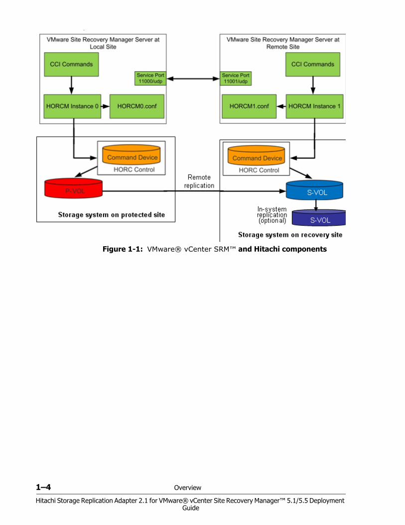
The following figure shows basic VMware® vCenter SRM™/SRA components.
1–4 Overview
Hitachi Storage Replication Adapter 2.1 for VMware® vCenter Site Recovery Manager™ 5.1/5.5 Deployment Guide
•
Figure 1-1: VMware® vCenter SRM™ and Hitachi components
Overview 1–5
Hitachi Storage Replication Adapter 2.1 for VMware® vCenter Site Recovery Manager™ 5.1/5.5 Deployment Guide
Hitachi Command Control Interface (CCI) Hitachi’s remote and in-system replication software require CCI to manage the pairs. The adapter plug-in links CCI with Site Recovery Manager.
There are two CCI components:• Command devices, which reside on the storage systems. CCI uses the
command device as the interface to the storage system from the host. The command device accepts commands from the host and executes them on the storage system. The command device is a dedicated logical volume.
• Hitachi Open Remote Copy Manager (HORCM), which resides on the CCI server. HORCM operates as a daemon process. When activated, HORCM refers to CCI configuration definition files, also located on the server. The HORCM instance communicates with the storage system and remote servers.HORCM definition files describe the storage systems, pair volumes, and data paths. When a user issues a command, CCI uses the information in the HORCM files to identify which volumes are the targets of the command.Two HORCM files are needed for each pair. One file describes the primary volumes (P-VOLs), which are also referred to as “protected volumes”, and the other describes the secondary volumes (S-VOLs), which are also referred to as “recovery volumes”.
Figure 1-1 on page 1-4 shows a two-server, two-HORCM instance setup with optional in-system test copy.
How the VMware® vCenter SRM™/SRA solution works VMware® vCenter SRM™ coordinates process with Hitachi storage and replication so that in a recovery condition, the virtual machines at the protected site are shut down and the replicated virtual machines are powered up. Recovery is guided by a recovery plan in which you have specified an order that virtual machines are to be started up.
After a recovery is performed, the running virtual machines are no longer protected. VMware® vCenter SRM™ provides a reprotect operation, which runs after the original protected site is back up. Reprotect activates CCI operations that reverse-synchronize data in the storage systems from recovery site to protected site.
Finally, VMware® vCenter SRM™-supported failback (VSP G1000, VSP, HUS VM, and USP V/VM only) and reprotect operations allow you to restore protection back to the original configuration, with data flow from the protected site to the recovery site.
VMware® vCenter SRM™ lets you test recovery plans using an in-system copy of the replicated data without disrupting ongoing operations at either site.

1–6 Overview
Hitachi Storage Replication Adapter 2.1 for VMware® vCenter Site Recovery Manager™ 5.1/5.5 Deployment Guide
Requirements, planning, and prerequisites 2–1Hitachi Storage Replication Adapter 2.1 for VMware® vCenter Site Recovery Manager™ 5.1/5.5 Deployment
Guide
2Requirements, planning,
and prerequisites
You share responsibilities for planning and deploying Hitachi SRA 2.1 with the Hitachi Data Systems account team, which will assist you as needed throughout the process. The account team coordinates Hitachi Data Systems resources to ensure a successful installation and deployment. Before you begin planning, it might be useful to review the deployment workflow in Chapter 3, Deployment.
This chapter provides requirements and planning information in the following topics:
Requirements
SRA/VMware® vCenter SRM™/CCI location options
Test options
Configurations with protected and recovery VMs on the same site
Consistency groups and VM failover groups
Consistency groups and same-time split operations
About the TrueCopy fence level, “Never”
AMS 2000 host group options

2–2 Requirements, planning, and prerequisites
Hitachi Storage Replication Adapter 2.1 for VMware® vCenter Site Recovery Manager™ 5.1/5.5 Deployment Guide
Requirements This section lists hardware and software requirements.
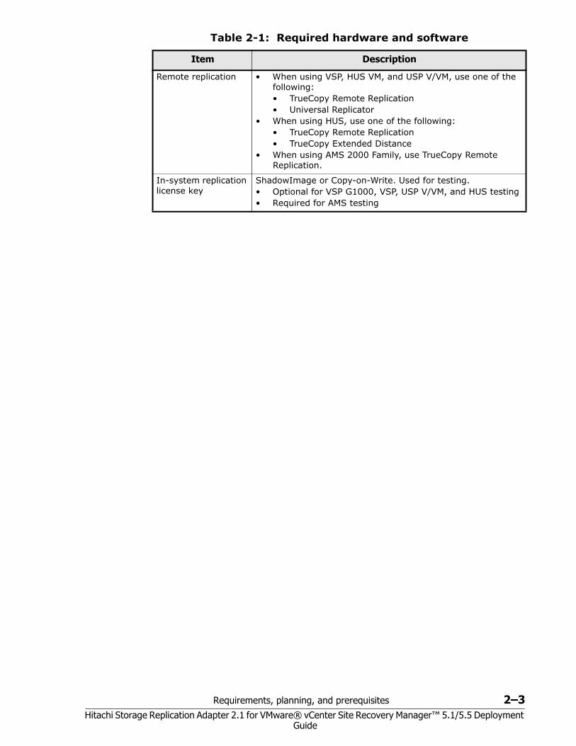
Table 2-1: Required hardware and software
Item Description
Storage Replication Adapter version
• SRA 02.01.04—VMware® vCenter SRM™ 5.1/5.5. • Supports SSH connections • Supports VMware® vCenter SRM™ on one array in
loopback mode, for testing only in non-production environments.
• Requires HITACHI_RMHTCSRA_X64-02.01.4.exe.
Supported Hitachi storage systems and microcode levels
• SRA 02.01.04—VMware® vCenter SRM™ 5.1/5.5• VSP G1000 microcode 80-00-xx or later• VSP microcode 70-05-xx or later• USP-VM microcode 60-07-xx or later• TagmaStore USP/NSC: 50-09-xx or later• HUS microcode 0930/A-H or later• HUS VM microcode 73-01-xx• AMS microcode 08C3/E or later
Supported operating systems
• Windows 2003 or later• Linux• Solaris• Solaris/x86• HP-UX • AIX
VMware infrastructure
• Protected site:• VMware vCenter Server • ESX/ESXi host • Datastore on the ESX/ESXi host• Site Recovery Manager*• Recovery site:• VMware vCenter Server • ESX/ESXi host • No datastore required. • However, two volumes with the same capacity as the
datastore of the primary ESX/ESXi host are required. The volumes must be mapped to the recovery ESX/ESXi host only. Do not install datastores on these volumes.
• Site Recovery Manager** Can also be installed on a physical server.
CCI • Version: 01-27-03/04. Supported for all Hitachi storage systems.
• CCI must be installed on protected and recovery sites on Windows or UNIX systems. If Windows is used, CCI and VMware® vCenter SRM™ must be installed on the same server. For more information, see SRA/VMware® vCenter SRM™/CCI location options on page 2-4.
Requirements, planning, and prerequisites 2–3Hitachi Storage Replication Adapter 2.1 for VMware® vCenter Site Recovery Manager™ 5.1/5.5 Deployment
Guide
Remote replication • When using VSP, HUS VM, and USP V/VM, use one of the following:• TrueCopy Remote Replication• Universal Replicator
• When using HUS, use one of the following:• TrueCopy Remote Replication• TrueCopy Extended Distance
• When using AMS 2000 Family, use TrueCopy Remote Replication.
In-system replication license key
ShadowImage or Copy-on-Write. Used for testing. • Optional for VSP G1000, VSP, USP V/VM, and HUS testing• Required for AMS testing
Table 2-1: Required hardware and software
Item Description
2–4 Requirements, planning, and prerequisites
Hitachi Storage Replication Adapter 2.1 for VMware® vCenter Site Recovery Manager™ 5.1/5.5 Deployment Guide
SRA/VMware® vCenter SRM™/CCI location options The VMware® vCenter SRM™ array manager configuration for SRA 2.0 or SRA 2.1 varies depending on the location of CCI.• If the Windows version of CCI is used, CCI must be installed on both
protection and recovery sites. This means that CCI, VMware® vCenter SRM™, and SRA 2.0 or SRA 2.1 must be installed on the same servers. SRA 2.0 or SRA 2.1 will communicate locally with CCI.
• If the UNIX version of CCI is used, VMware® vCenter SRM™ array managers can be configured using telnet to remotely communicate with CCI instances. VMware® vCenter SRM™ and SRA must be installed on the same server, and CCI can run on separate (remote) UNIX hosts. This allows you to run a centralized UNIX CCI host instead of running UNIX CCI hosts for each site (protection and recovery). Hitachi Data Systems does not recommend running a centralized CCI host for redundancy reasons.
Test optionsSRA/VMware® vCenter SRM™ recovery takes place automatically. To ensure that recovery occurs as expected, the recovery processes must be tested manually. • For VSP G1000, VSP, USP V/VM, and HUS, testing is done using either
the remote S-VOL, or using a copy of the S-VOL (recommended). • For AMS, testing can only be done using a copy of the S-VOL.
Using the S-VOL for testingIf your storage system is a VSP G1000, VSP, USP V/VM, or HUS, VMware® vCenter SRM™ can use the S-VOL on the remote site for test failover. However, note the following important restrictions: • Testing with the S-VOL disrupts replication from the primary to the
secondary volumes. You can avoid disruption to replication if you test during planned outages.
• The S-VOL is not available for an actual failover should the need arise. • After testing, the pair is resynchronized with data that was stored in a
bitmap. The updates are out of order, rendering the S-VOL unavailable for an actual failover should the need arise, until resynchronization is completed.
Required configuration for testing with S-VOL
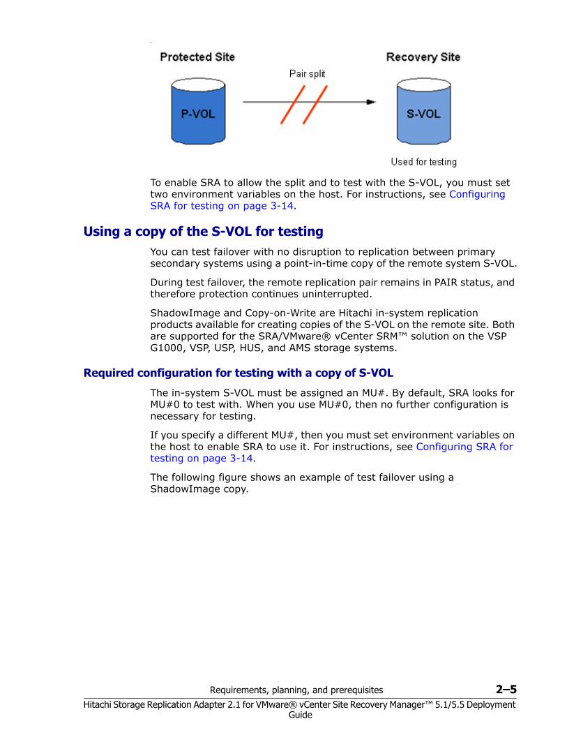
The TrueCopy or Universal Replicator pair must be split in order to test using the S-VOL. The following figure shows the VMware® vCenter SRM™ configuration during test failover using the S-VOL.
Requirements, planning, and prerequisites 2–5Hitachi Storage Replication Adapter 2.1 for VMware® vCenter Site Recovery Manager™ 5.1/5.5 Deployment
Guide
•
To enable SRA to allow the split and to test with the S-VOL, you must set two environment variables on the host. For instructions, see Configuring SRA for testing on page 3-14.
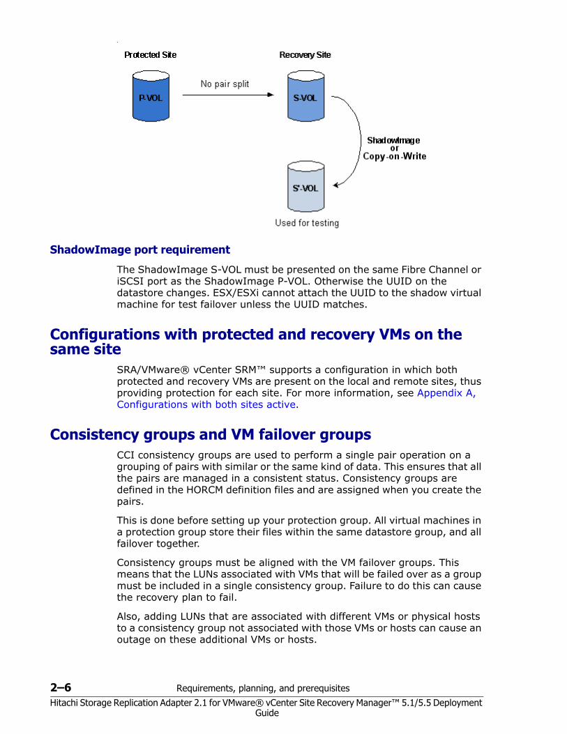
Using a copy of the S-VOL for testing You can test failover with no disruption to replication between primary secondary systems using a point-in-time copy of the remote system S-VOL.
During test failover, the remote replication pair remains in PAIR status, and therefore protection continues uninterrupted.
ShadowImage and Copy-on-Write are Hitachi in-system replication products available for creating copies of the S-VOL on the remote site. Both are supported for the SRA/VMware® vCenter SRM™ solution on the VSP G1000, VSP, USP, HUS, and AMS storage systems.
Required configuration for testing with a copy of S-VOL
The in-system S-VOL must be assigned an MU#. By default, SRA looks for MU#0 to test with. When you use MU#0, then no further configuration is necessary for testing.
If you specify a different MU#, then you must set environment variables on the host to enable SRA to use it. For instructions, see Configuring SRA for testing on page 3-14.
The following figure shows an example of test failover using a ShadowImage copy.
2–6 Requirements, planning, and prerequisites
Hitachi Storage Replication Adapter 2.1 for VMware® vCenter Site Recovery Manager™ 5.1/5.5 Deployment Guide
•
ShadowImage port requirement
The ShadowImage S-VOL must be presented on the same Fibre Channel or iSCSI port as the ShadowImage P-VOL. Otherwise the UUID on the datastore changes. ESX/ESXi cannot attach the UUID to the shadow virtual machine for test failover unless the UUID matches.
Configurations with protected and recovery VMs on the same site
SRA/VMware® vCenter SRM™ supports a configuration in which both protected and recovery VMs are present on the local and remote sites, thus providing protection for each site. For more information, see Appendix A, Configurations with both sites active.
Consistency groups and VM failover groupsCCI consistency groups are used to perform a single pair operation on a grouping of pairs with similar or the same kind of data. This ensures that all the pairs are managed in a consistent status. Consistency groups are defined in the HORCM definition files and are assigned when you create the pairs.
This is done before setting up your protection group. All virtual machines in a protection group store their files within the same datastore group, and all failover together.
Consistency groups must be aligned with the VM failover groups. This means that the LUNs associated with VMs that will be failed over as a group must be included in a single consistency group. Failure to do this can cause the recovery plan to fail.
Also, adding LUNs that are associated with different VMs or physical hosts to a consistency group not associated with those VMs or hosts can cause an outage on these additional VMs or hosts.
Requirements, planning, and prerequisites 2–7Hitachi Storage Replication Adapter 2.1 for VMware® vCenter Site Recovery Manager™ 5.1/5.5 Deployment
Guide
Consistency groups and same-time split operationsP-VOLs in the same CCI consistency group are split at the same time. In addition, you can specify a time that a split operation is to be performed on the consistency group. This CCI operation is called At-Time Split. Data consistency is guaranteed across the consistency group when you perform the At-Time Split operation.
The At-Time Split can only be performed on the pairs in a CCI consistency group.
Hitachi recommends assigning P-VOLs in a protected group to the same CCI consistency group, and warns against placing a protected group’s P-VOLs in multiple consistency groups.
See the TrueCopy or Universal Replicator user guide for your storage system for information about using consistency groups and the At-Time Split operation.
About the TrueCopy fence level, “Never” Using “Never” for the fence level for TrueCopy pairs causes the internal horctakeover to fail; the command returns with EX_VOLCUR. This occurs because “Never” cannot completely guarantee data consistency.
However, the VMware® vCenter SRM™/VMware goal of Failover/testFailover is booting the VM’s. This makes the fence level “Never” acceptable despite the horctakeover return of EX_VOLCUR.
If you use “Never”, remember that the recovery will be on APP (SQL/Exchange/Oracle/..).
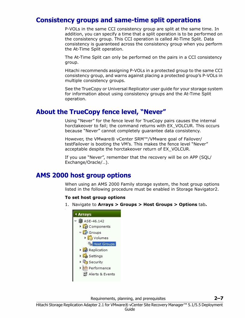
AMS 2000 host group options When using an AMS 2000 Family storage system, the host group options listed in the following procedure must be enabled in Storage Navigator2.
To set host group options1. Navigate to Arrays > Groups > Host Groups > Options tab.•
2–8 Requirements, planning, and prerequisites
Hitachi Storage Replication Adapter 2.1 for VMware® vCenter Site Recovery Manager™ 5.1/5.5 Deployment Guide
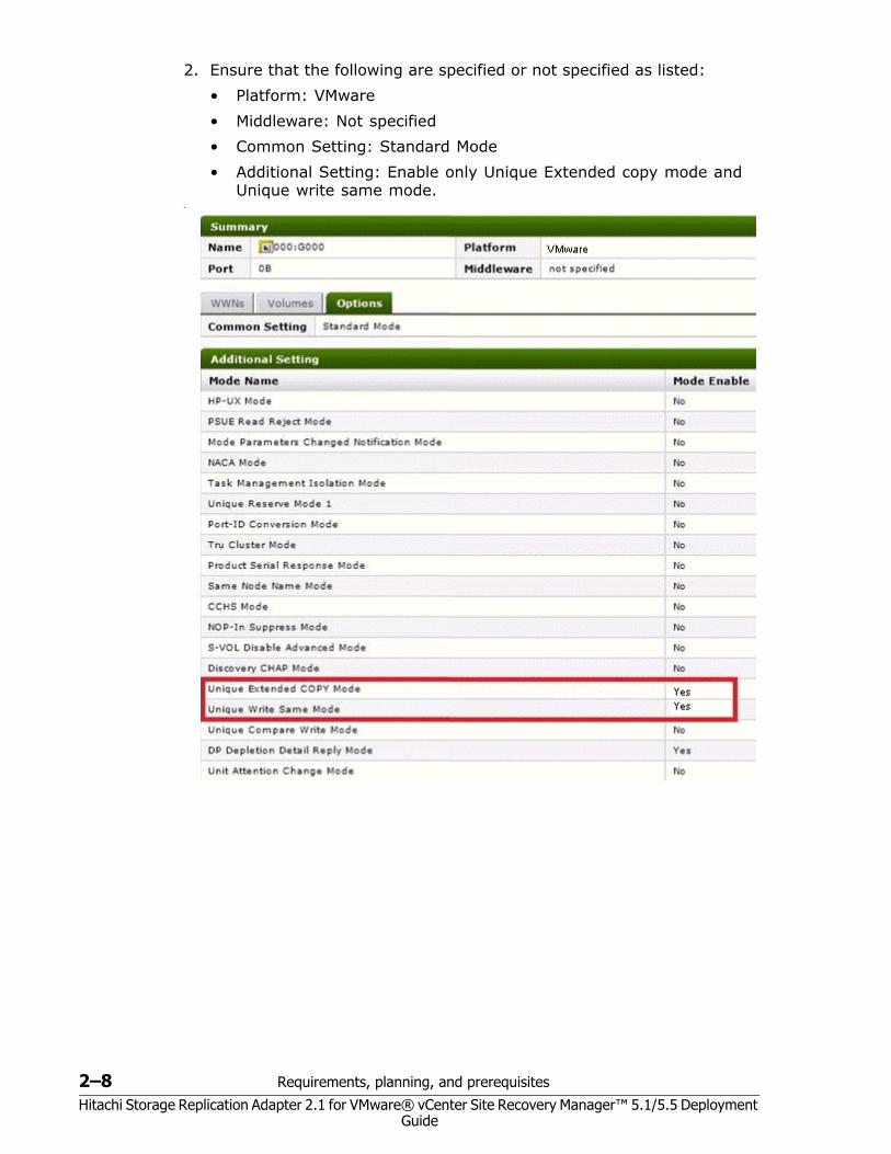
2. Ensure that the following are specified or not specified as listed:• Platform: VMware• Middleware: Not specified• Common Setting: Standard Mode• Additional Setting: Enable only Unique Extended copy mode and
Unique write same mode.•
Deployment 3–1Hitachi Storage Replication Adapter 2.1 for VMware® vCenter Site Recovery Manager™ 5.1/5.5 Deployment
Guide
3Deployment
This chapter provides instructions for deploying Hitachi Storage Replication Adapter 2.0. The following topics are discussed:
Deployment workflow
Installing CCI
Creating and configuring a command device
Setting up HORCM configuration definition files
Starting HORCM instances, creating pairs
Setting environment variables
Configuring SRA for testing
SRA installation
Configuring array managers
Performing reprotect and failback
3–2 Deployment
Hitachi Storage Replication Adapter 2.1 for VMware® vCenter Site Recovery Manager™ 5.1/5.5 Deployment Guide
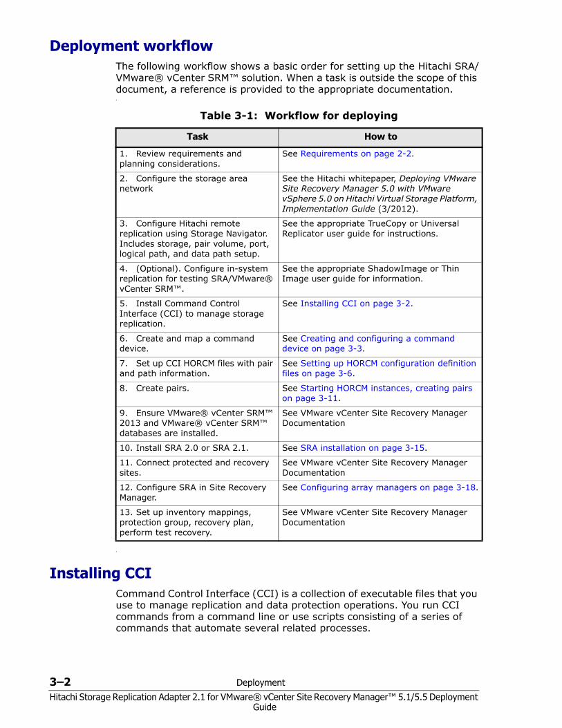
Deployment workflow The following workflow shows a basic order for setting up the Hitachi SRA/VMware® vCenter SRM™ solution. When a task is outside the scope of this document, a reference is provided to the appropriate documentation.•
•
Installing CCI Command Control Interface (CCI) is a collection of executable files that you use to manage replication and data protection operations. You run CCI commands from a command line or use scripts consisting of a series of commands that automate several related processes.
Table 3-1: Workflow for deploying
Task How to
1. Review requirements and planning considerations.
See Requirements on page 2-2.
2. Configure the storage area network
See the Hitachi whitepaper, Deploying VMware Site Recovery Manager 5.0 with VMware vSphere 5.0 on Hitachi Virtual Storage Platform, Implementation Guide (3/2012).
3. Configure Hitachi remote replication using Storage Navigator. Includes storage, pair volume, port, logical path, and data path setup.
See the appropriate TrueCopy or Universal Replicator user guide for instructions.
4. (Optional). Configure in-system replication for testing SRA/VMware® vCenter SRM™.
See the appropriate ShadowImage or Thin Image user guide for information.
5. Install Command Control Interface (CCI) to manage storage replication.
See Installing CCI on page 3-2.
6. Create and map a command device.
See Creating and configuring a command device on page 3-3.
7. Set up CCI HORCM files with pair and path information.
See Setting up HORCM configuration definition files on page 3-6.
8. Create pairs. See Starting HORCM instances, creating pairs on page 3-11.
9. Ensure VMware® vCenter SRM™ 2013 and VMware® vCenter SRM™ databases are installed.
See VMware vCenter Site Recovery Manager Documentation
10. Install SRA 2.0 or SRA 2.1. See SRA installation on page 3-15.
11. Connect protected and recovery sites.
See VMware vCenter Site Recovery Manager Documentation
12. Configure SRA in Site Recovery Manager.
See Configuring array managers on page 3-18.
13. Set up inventory mappings, protection group, recovery plan, perform test recovery.
See VMware vCenter Site Recovery Manager Documentation
Deployment 3–3Hitachi Storage Replication Adapter 2.1 for VMware® vCenter Site Recovery Manager™ 5.1/5.5 Deployment
Guide
SRA 2.0/2.1 requires CCI version 01-24-03/13 or later. See the Hitachi Command Control Interface Installation Guide for your storage system for installation or upgrade instructions.
If CCI is installed on the VMware® vCenter SRM™ host, Hitachi Data Systems recommends that you run HORCM as a service. (HORCM is described in Setting up HORCM configuration definition files on page 3-6.)
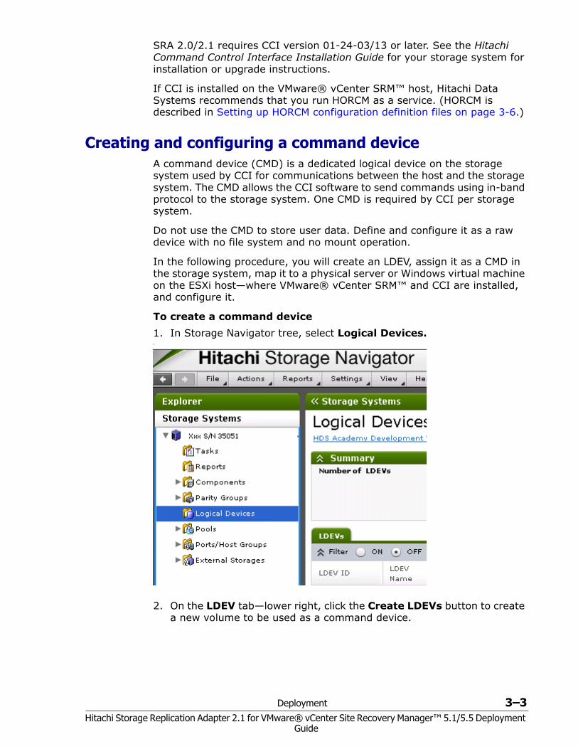
Creating and configuring a command device A command device (CMD) is a dedicated logical device on the storage system used by CCI for communications between the host and the storage system. The CMD allows the CCI software to send commands using in-band protocol to the storage system. One CMD is required by CCI per storage system.
Do not use the CMD to store user data. Define and configure it as a raw device with no file system and no mount operation.
In the following procedure, you will create an LDEV, assign it as a CMD in the storage system, map it to a physical server or Windows virtual machine on the ESXi host—where VMware® vCenter SRM™ and CCI are installed, and configure it.
To create a command device1. In Storage Navigator tree, select Logical Devices.•
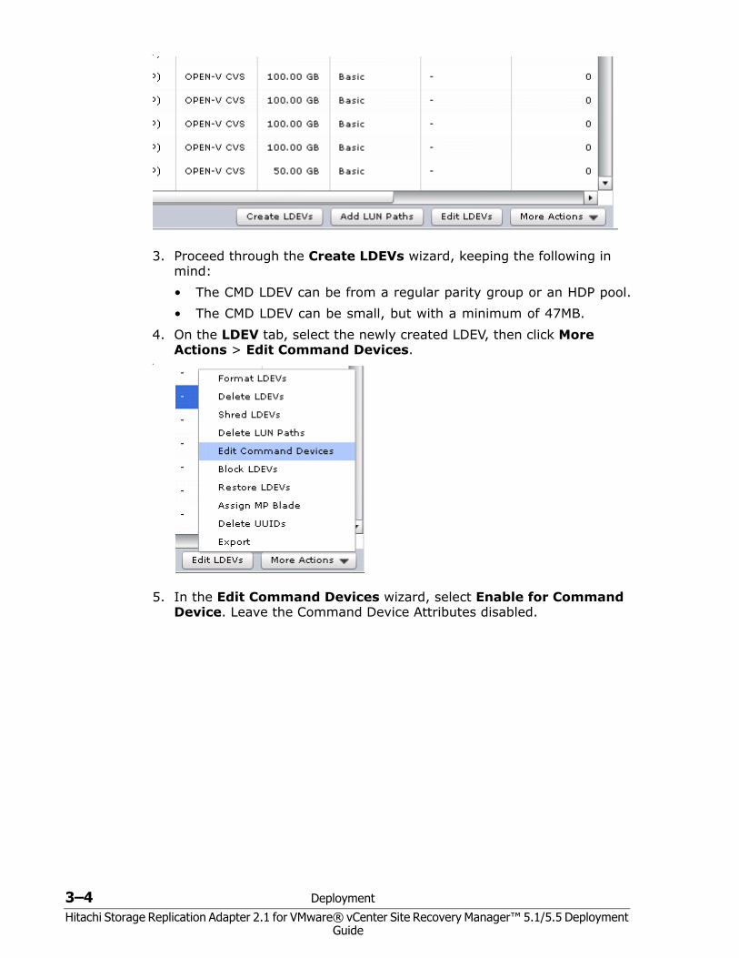
2. On the LDEV tab—lower right, click the Create LDEVs button to create a new volume to be used as a command device.
3–4 Deployment
Hitachi Storage Replication Adapter 2.1 for VMware® vCenter Site Recovery Manager™ 5.1/5.5 Deployment Guide
•
3. Proceed through the Create LDEVs wizard, keeping the following in mind:• The CMD LDEV can be from a regular parity group or an HDP pool.• The CMD LDEV can be small, but with a minimum of 47MB.
4. On the LDEV tab, select the newly created LDEV, then click More Actions > Edit Command Devices.
•
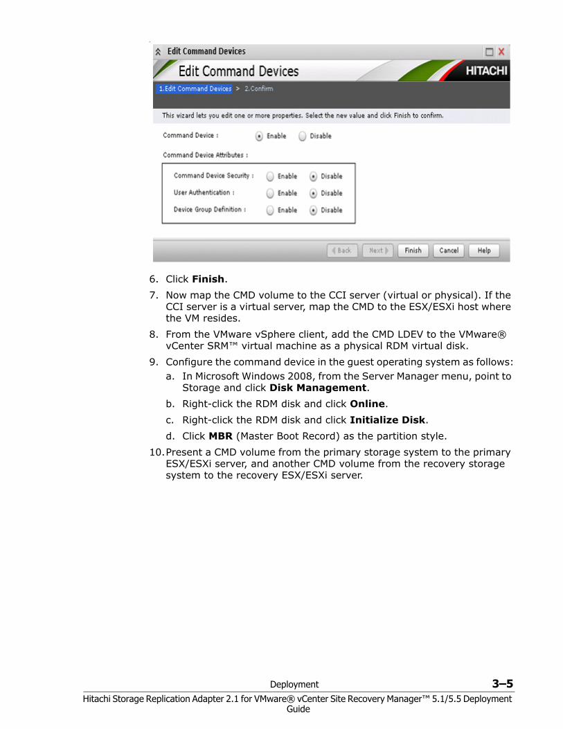
5. In the Edit Command Devices wizard, select Enable for Command Device. Leave the Command Device Attributes disabled.
Deployment 3–5Hitachi Storage Replication Adapter 2.1 for VMware® vCenter Site Recovery Manager™ 5.1/5.5 Deployment
Guide
•
6. Click Finish.7. Now map the CMD volume to the CCI server (virtual or physical). If the
CCI server is a virtual server, map the CMD to the ESX/ESXi host where the VM resides.
8. From the VMware vSphere client, add the CMD LDEV to the VMware® vCenter SRM™ virtual machine as a physical RDM virtual disk.
9. Configure the command device in the guest operating system as follows:a. In Microsoft Windows 2008, from the Server Manager menu, point to
Storage and click Disk Management.b. Right-click the RDM disk and click Online.c. Right-click the RDM disk and click Initialize Disk.d. Click MBR (Master Boot Record) as the partition style.
10.Present a CMD volume from the primary storage system to the primary ESX/ESXi server, and another CMD volume from the recovery storage system to the recovery ESX/ESXi server.
3–6 Deployment
Hitachi Storage Replication Adapter 2.1 for VMware® vCenter Site Recovery Manager™ 5.1/5.5 Deployment Guide
Setting up HORCM configuration definition files You will need two HORCM definition files to define the pair relationship: one file describes the primary volumes (P-VOLs), the other describes the secondary volumes (S-VOLs).
A third HORCM file is required if you use a ShadowImage or Copy-on-Write copy of the remote site S-VOL for testing.
Figure 1-1 on page 1-4 provides a configuration example that shows HORCM files on the local and remote servers.
Editing HORCM.conf files HORCM files are used to identify the target volumes of a CCI command. You can copy and modify the HORCM files included with the remote replication bundle. You will identify your pair volumes and data paths in the these files.
Note the following when editing HORCM.conf files:• Use a text editor to edit HORCM files. Default HORCM.conf files are
located in:• Hitachi TrueCopy Remote Replication bundle files• Hitachi Universal Replicator files• (Optional) Hitachi ShadowImage Heterogeneous Replication files
• Save a copy of the HORCM.conf files on the local and remote CCI servers in the C:\Windows folder.
• HORCM files must be named horcm#.conf, where “#” represents the HORCM instance. • The instance on the primary site is usually 0. In this case, the
HORCM file on the primary site would be named, horcm0.conf. • The # of the secondary instance must be the primary instance
number plus 1. Thus, if the primary instance is 0, the HORCM file on the secondary site would be named, horcm1.conf.
• Likewise, the # of ShadowImage or Copy-on-Write S-VOL instance must be the secondary instance number plus 1. Thus, if the secondary instance is 1, the HORCM file for the in-system S-VOL would be named horcm2.conf.
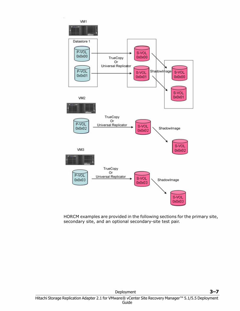
• It is best practice to name devices the same as the datastore contained in the LU. The following figure shows example device naming schemes.
Deployment 3–7Hitachi Storage Replication Adapter 2.1 for VMware® vCenter Site Recovery Manager™ 5.1/5.5 Deployment
Guide
•
HORCM examples are provided in the following sections for the primary site, secondary site, and an optional secondary-site test pair.
3–8 Deployment
Hitachi Storage Replication Adapter 2.1 for VMware® vCenter Site Recovery Manager™ 5.1/5.5 Deployment Guide
Primary HORCM file
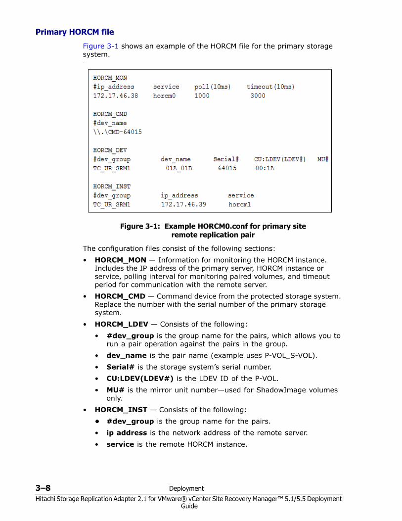
Figure 3-1 shows an example of the HORCM file for the primary storage system.•
Figure 3-1: Example HORCM0.conf for primary site remote replication pair
The configuration files consist of the following sections:• HORCM_MON — Information for monitoring the HORCM instance.
Includes the IP address of the primary server, HORCM instance or service, polling interval for monitoring paired volumes, and timeout period for communication with the remote server.
• HORCM_CMD — Command device from the protected storage system. Replace the number with the serial number of the primary storage system.
• HORCM_LDEV — Consists of the following:• #dev_group is the group name for the pairs, which allows you to
run a pair operation against the pairs in the group.• dev_name is the pair name (example uses P-VOL_S-VOL).• Serial# is the storage system’s serial number.• CU:LDEV(LDEV#) is the LDEV ID of the P-VOL.• MU# is the mirror unit number—used for ShadowImage volumes
only.• HORCM_INST — Consists of the following:
• #dev_group is the group name for the pairs.• ip address is the network address of the remote server.• service is the remote HORCM instance.
Deployment 3–9Hitachi Storage Replication Adapter 2.1 for VMware® vCenter Site Recovery Manager™ 5.1/5.5 Deployment
Guide
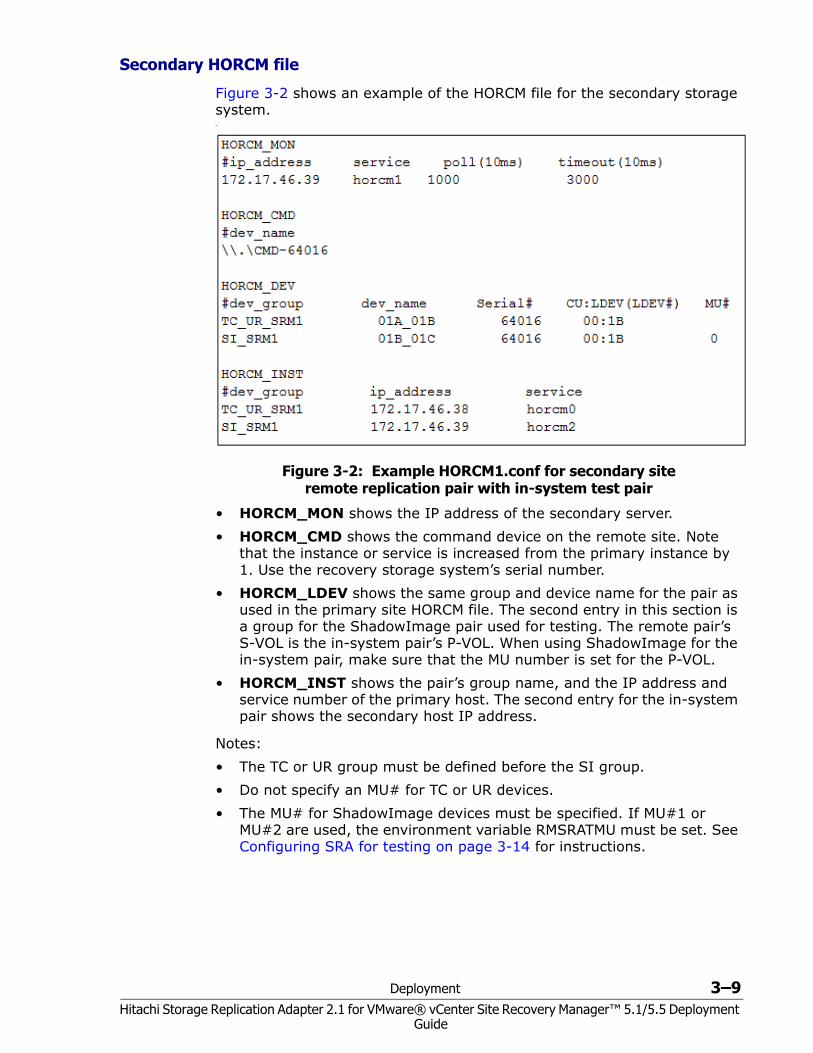
Secondary HORCM file
Figure 3-2 shows an example of the HORCM file for the secondary storage system.•
Figure 3-2: Example HORCM1.conf for secondary site remote replication pair with in-system test pair
• HORCM_MON shows the IP address of the secondary server.• HORCM_CMD shows the command device on the remote site. Note
that the instance or service is increased from the primary instance by 1. Use the recovery storage system’s serial number.
• HORCM_LDEV shows the same group and device name for the pair as used in the primary site HORCM file. The second entry in this section is a group for the ShadowImage pair used for testing. The remote pair’s S-VOL is the in-system pair’s P-VOL. When using ShadowImage for the in-system pair, make sure that the MU number is set for the P-VOL.
• HORCM_INST shows the pair’s group name, and the IP address and service number of the primary host. The second entry for the in-system pair shows the secondary host IP address.
Notes:• The TC or UR group must be defined before the SI group.• Do not specify an MU# for TC or UR devices.• The MU# for ShadowImage devices must be specified. If MU#1 or
MU#2 are used, the environment variable RMSRATMU must be set. See Configuring SRA for testing on page 3-14 for instructions.
3–10 Deployment
Hitachi Storage Replication Adapter 2.1 for VMware® vCenter Site Recovery Manager™ 5.1/5.5 Deployment Guide
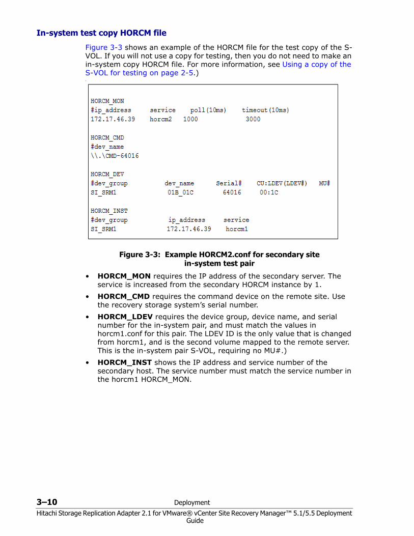
In-system test copy HORCM file
Figure 3-3 shows an example of the HORCM file for the test copy of the S-VOL. If you will not use a copy for testing, then you do not need to make an in-system copy HORCM file. For more information, see Using a copy of the S-VOL for testing on page 2-5.)•
Figure 3-3: Example HORCM2.conf for secondary site in-system test pair
• HORCM_MON requires the IP address of the secondary server. The service is increased from the secondary HORCM instance by 1.
• HORCM_CMD requires the command device on the remote site. Use the recovery storage system’s serial number.
• HORCM_LDEV requires the device group, device name, and serial number for the in-system pair, and must match the values in horcm1.conf for this pair. The LDEV ID is the only value that is changed from horcm1, and is the second volume mapped to the remote server. This is the in-system pair S-VOL, requiring no MU#.)
• HORCM_INST shows the IP address and service number of the secondary host. The service number must match the service number in the horcm1 HORCM_MON.
Deployment 3–11Hitachi Storage Replication Adapter 2.1 for VMware® vCenter Site Recovery Manager™ 5.1/5.5 Deployment
Guide
Starting HORCM instances, creating pairs When the necessary HORCM files are edited and saved on the local and remote servers, start the HORCM instance on both servers and create the pair or pairs. (For additional information on CCI commands and expected output, see the Hitachi Command Control Interface User Guide.)
To start the HORCM instance and create pairs1. On the primary and secondary vCenter servers, open a command
prompt and enter the following:
cd c:\HORCM\etchorcmstart.exe *Substitute the HORCM instance number for the asterisk (*); for example, 0.
2. Verify the status of the pair volumes and systems. Initially, the volumes are in simplex (SMPL) status. Run the pairdisplay command on the primary server.
pairdisplay.exe -g <grp> -IH<HORCM instance #> -fcx3. On the primary server, create the TrueCopy (TC) or Universal Replicator
(UR) pair using the paircreate command:• For TC, use: paircreate.exe –g <grp> -vl –fg <fence> <CTGID>
–IH<HORCM instance #>• For UR, use: paircreate.exe –g <grp> -vl –f async –jp <journal id> –js
<journal id> –IH<HORCM instance #>4. Use the pairdisplay command to check pair status. When status is PAIR,
the data on the primary site is copied to the recovery site. If the P-VOL contains a large amount of data, completion may take longer than expected (the pairdisplay command shows the copy percentage).
5. Shut down the HORCM instance on both sites. VMware® vCenter SRM™ will start the instances again, but HORCM processes must be stopped for this. • On the primary server, run horcmshutdown.exe 0. • On the recovery server, run horcmshutdown.exe 1.
Creating a copy for testing on the recovery site If you are using a copy of the remote replication S-VOL for testing, use the following procedure to start the HORCM instance and create the pair. If you are not using a copy for testing, skip this section.
Prerequisites• For ShadowImage, assign the pair to a consistency group using the
-m grp option.• Split mode must be set to quick using the command option -fq quick.• ShadowImage S-VOLs and P-VOLs must be mapped on the same Fibre
Channel or iSCSI port.
3–12 Deployment
Hitachi Storage Replication Adapter 2.1 for VMware® vCenter Site Recovery Manager™ 5.1/5.5 Deployment Guide
To create the in-system test pair1. On the remote site vCenter server, open a command prompt and enter
the following to start the in-system HORCM instance:
cd c:\HORCM\etchorcmstart.exe *Substitute the HORCM instance number for the asterisk (*); for example, 2.
2. Verify the status of the pair volume and system using the pairdisplay command.
pairdisplay.exe -g <grp> -IM<HORCM instance #> -fcxInitially, the volumes are in simplex (SMPL) status.
3. Create the pair using the following:
paircreate -g <grp> -vl -m grp -fq quick• -m grp creates a consistency group for all LUNs in the pair group.• -fq quick allows for ShadowImage quick split.• For Copy-on-Write, do not use the -fq quick option.
4. Use the pairdisplay command to check the in-system pair’s status. When status is PAIR, the data in the P-VOL (remote S-VOL) is copied to the in-system S-VOL.
5. Shut down the HORCM instance. VMware® vCenter SRM™ will start the instance at a later time, but HORCM processes must be stopped for this. Run horcmshutdown.exe 1 2.
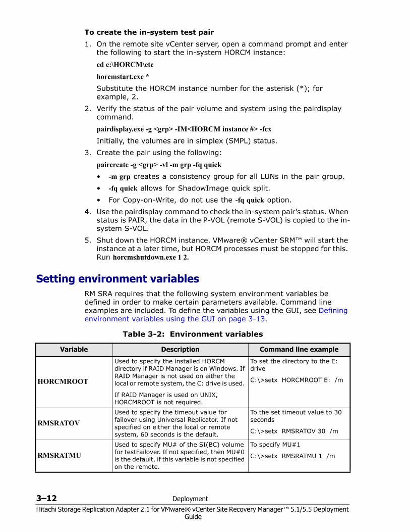
Setting environment variablesRM SRA requires that the following system environment variables be defined in order to make certain parameters available. Command line examples are included. To define the variables using the GUI, see Defining environment variables using the GUI on page 3-13.•
Table 3-2: Environment variables
Variable Description Command line example
HORCMROOT
Used to specify the installed HORCM directory if RAID Manager is on Windows. If RAID Manager is not used on either the local or remote system, the C: drive is used.
If RAID Manager is used on UNIX, HORCMROOT is not required.
To set the directory to the E: drive
C:\>setx HORCMROOT E: /m
RMSRATOVUsed to specify the timeout value for failover using Universal Replicator. If not specified on either the local or remote system, 60 seconds is the default.
To the set timeout value to 30 seconds
C:\>setx RMSRATOV 30 /m
RMSRATMUUsed to specify MU# of the SI(BC) volume for testFailover. If not specified, then MU#0 is the default, if this variable is not specified on the remote.
To specify MU#1
C:\>setx RMSRATMU 1 /m
Deployment 3–13Hitachi Storage Replication Adapter 2.1 for VMware® vCenter Site Recovery Manager™ 5.1/5.5 Deployment
Guide
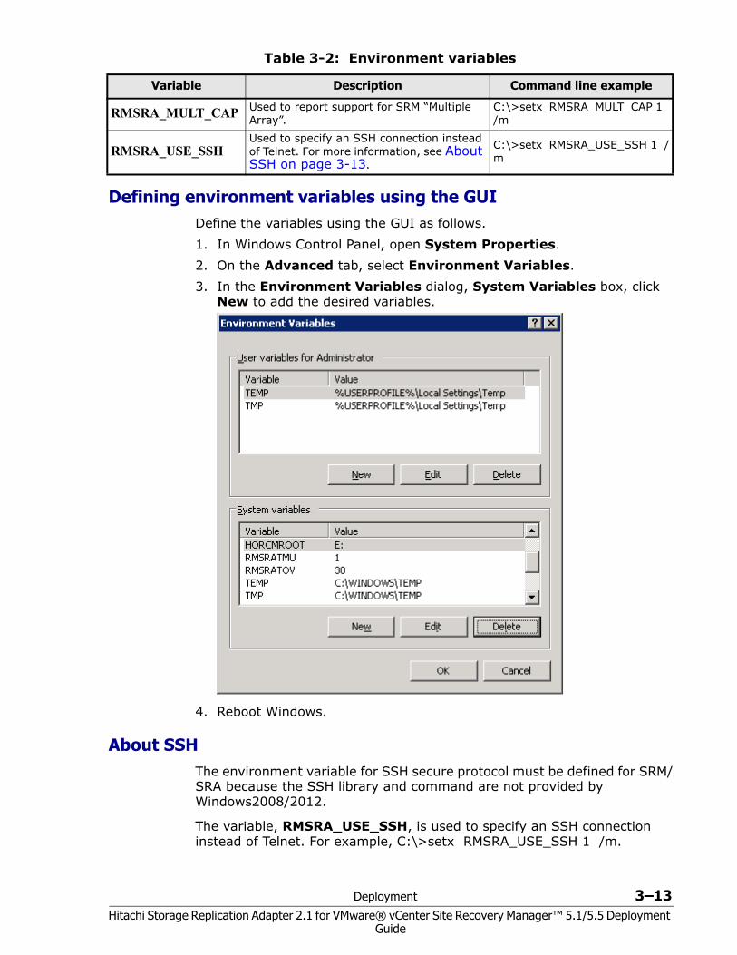
Defining environment variables using the GUIDefine the variables using the GUI as follows.1. In Windows Control Panel, open System Properties.2. On the Advanced tab, select Environment Variables.3. In the Environment Variables dialog, System Variables box, click
New to add the desired variables.
4. Reboot Windows.
About SSHThe environment variable for SSH secure protocol must be defined for SRM/SRA because the SSH library and command are not provided by Windows2008/2012.
The variable, RMSRA_USE_SSH, is used to specify an SSH connection instead of Telnet. For example, C:\>setx RMSRA_USE_SSH 1 /m.
RMSRA_MULT_CAP Used to report support for SRM “Multiple Array”.
C:\>setx RMSRA_MULT_CAP 1 /m
RMSRA_USE_SSHUsed to specify an SSH connection instead of Telnet. For more information, see About SSH on page 3-13.
C:\>setx RMSRA_USE_SSH 1 /m
Table 3-2: Environment variables
Variable Description Command line example
3–14 Deployment
Hitachi Storage Replication Adapter 2.1 for VMware® vCenter Site Recovery Manager™ 5.1/5.5 Deployment Guide
You can install using \Program Files (x86)\PuTTY\plink.exe, or, putty-0.62-installer.exe, which is available at http://www.chiark.greenend.org.uk/~sgtatham/putty/download.html.
You can register using the fingerprint for executing the SSH command with the remote host, or by executing the following command one time for authentication: SRA install drive: \Program Files (x86)\PuTTY\plink.exe -ssh –l root –pw PASS HOST ls. (PASS : password, HOST : hostname for HORCM server).
Configuring SRA for testing Testing requires an S-VOL on which to perform testFailover. The S-VOL used for testing is set up as follows. ShadowImage (SI), Hitachi Thin Image (HTI), and Copy-on-Write (COW) are supported on the respective HDS Storage platform for this use case.
• SRA automatically searches MU#0 to test with. If you have created the SI, HTI, or COW pair and set the S-VOL at MU#0, no further configuration is necessary.
• If you test using the remote replication pair, the pair must be split first. This requires the following environment variables on the host to be set:• SplitReplication=True (gives permission to use TC/HUR S-VOL)• RMSRATMU=MUx, where x is an unused MU number other than
0.With these variables set, SRA would search for the SI, HTI, or COW S-VOL at MU#0, fail, and then continue the operation using the TC or UR S-VOL.
The CCI location determines where you set the environment variable when you have an MU# other than 0:• If CCI is installed on the VMware® vCenter SRM™ host, then you set
the environment variables on the VMware® vCenter SRM™ host.• If CCI is installed on a UNIX host, then you set the environment
variables on the UNIX host.
To set environment variables on the VMware® vCenter SRM™ host 1. On the VMware® vCenter SRM™ host, issue the following command to
set the SplitReplication parameter to true:
setx SplitReplication true /m2. Issue the following command to set the RMSRATMU parameter to 1:
setx RMSRATMU 1 /m3. Reboot the VMware® vCenter SRM™ host.4. Verify that the variables are set correctly using the Set command.5. Optional: If CCI is installed on another drive (e.g. E:), then use the
HORCMROOTD variable:
setx HORCMROOT E: /m
Deployment 3–15Hitachi Storage Replication Adapter 2.1 for VMware® vCenter Site Recovery Manager™ 5.1/5.5 Deployment
Guide
6. Optional: The default timeout value for failover using UR/Async is 60sec. This can be changed using RMSRATOV variable:
setx RMSRATOV 120 /m
To set environment variables on a UNIX Host
VMware® vCenter SRM™ will telnet as root to the UNIX host to execute RMSRA (Hitachi SRA) commands. Use the root user profile to set these variables; that is, /root/.bash_profile for Linux or /.profile for HP-UX. Use the appropriate root user profile for your default shell. Insert the following lines in this file.
• SplitReplication=true• export SplitReplication• RMSRATMU=1• export RMSRATMU
Log out and back in and use the env command to verify that these variables are set correctly.
Configuration is now complete. When testFailover is executed on virtual machine 1, the TrueCopy pairs are suspended and utilized for testing. When testFailover is done on virtual machine 2, the ShadowImage pairs at MU#1 are suspended and used for testing.
SRA installation You can perform a new installation of Hitachi SRA 2.0 or SRA 2.1 or upgrade an existing version. This section discusses both options.• If you are installing a new version of SRA 2.0 or SRA 2.1, continue to
Installing SRA 2.0 or SRA 2.1.• If you are upgrading an existing version of SRA 2.0 or SRA 2.1, you
must remove it before continuing. See Removing an earlier version of SRA on page 3-16 for instructions.
• To check your SRA version, see Checking the SRA version on page 3-16.
Installing SRA 2.0 or SRA 2.1Note the following before performing installation:• Site Recovery Manager 2013 must be installed on both protected and
recovery sites.• Download one of the following versions of SRA 2.0 or SRA 2.1 from the
VMware website:• If using VMware® vCenter SRM™ 5.1/5.5, download
HITACHI_RMHTCSRA_X64-02.01.4.exe.• If a previous version of SRA is installed, it must be removed before
installing SRA 2.0 or SRA 2.1. See Removing an earlier version of SRA on page 3-16 for instructions.
3–16 Deployment
Hitachi Storage Replication Adapter 2.1 for VMware® vCenter Site Recovery Manager™ 5.1/5.5 Deployment Guide
• Install SRA on the VMware® vCenter SRM™ servers on the protected and recovery sites.
• Make sure the RMSRA executable in the CCI installation is the latest version.
To install SRA 2.0 or SRA 2.11. Double-click RMHTCSRA.exe in the download folder. 2. Accept the terms of the license agreement and click Next.3. Either accept or change the default installation path. The default location
is C:\Program Files\VMware\VMware vCenter Site Recovery Manager.4. Click Install and proceed through the wizard.5. After SRA installation, restart the VMware® vCenter SRM™ service.
a. Right click on My Computer and select Manage.b. Click on Services and Application, then select Services.c. Locate VMware Site Recover Manager, then click Restart.
Removing an earlier version of SRAIf an earlier version of SRA is installed, it must be removed in order to upgrade to SRA 2.0 or SRA 2.1. If you are not sure, you can check the installed version; see Checking the SRA version on page 3-16.
To remove SRA 1.01. Open Windows Control Panel.2. Click Add or Remove Programs.3. Select Hitachi Storage Replication Adapter from the list of currently
installed programs.4. Click Remove.5. Open an Explorer window.6. Navigate to C:\Program Files\VMware\VMware vCenter Site Recovery
Manager\storage\sra\RMHTC7. Right-click on the Hitachi Storage Replication Adapter folder and click
Delete.
SRA is removed.
Checking the SRA version You can check your existing version of the Hitachi SRA on the following operating system servers:• Windows server• Linux server
To check the SRA version on a Windows server1. On the Windows server that is running VMware® vCenter SRM™ and
CCI, log in as an administrator.2. Open a command prompt window.
Deployment 3–17Hitachi Storage Replication Adapter 2.1 for VMware® vCenter Site Recovery Manager™ 5.1/5.5 Deployment
Guide
3. Navigate to C:\Program Files\VMware\VMware vCenter Site Recovery Manager\storage\sra\RMHT.
4. Issue the following command:rmsra20 -hNote the version number information that is displayed. For example:Ver&rev: 02.01.03
5. To display the RMSRA version number that was installed with SRA, issue the following command:
./rmsra20 -h
To check the SRA version on a Linux server1. On the Linux CCI server, log in as root.2. Navigate to the /HORCM/usr/bin directory.3. Using FTP, copy the rmsra20.linux file from the SRA installation folder on
the Windows VMware® vCenter SRM™ server to the /HORCM/usr/bin directory on the Linux server that is running CCI.
4. Issue the following commands to make the rmsra20.linux file executable:
chmod +x rmsra20.linux
mv rmsra20.linux rmsra20
5. Issue the following command to display the version number of RMSRA that was installed with the SRA:
./rmsra20 -h
Note the version number information that is displayed; for example:Ver&Rev: 02.01.03
If the RMSRA version is newer than the rmsra20.linux version, no action is needed.
3–18 Deployment
Hitachi Storage Replication Adapter 2.1 for VMware® vCenter Site Recovery Manager™ 5.1/5.5 Deployment Guide
Configuring array managers After the remote replication pair is created, SRA is installed, and the protected and recovery sites are connected, you configure VMware® vCenter SRM™ to discover the replicated volumes and to manage recovery and testing. This is done by configuring the array managers on the local and remote sites.
Configuring array managers is typically done once. If connection information or credentials change, or different storage systems (arrays) are used, then the VMware® vCenter SRM™ array managers must be reconfigured.
Prerequisites• CCI must be installed.• All HORCM files must be defined.• The remote replication pair must be created.• VMware® vCenter SRM™ must be installed on the vSphere local and
remote servers.• Hitachi SRA must be installed on both servers.• The local and remote sites must be paired in VMware® vCenter SRM™.
To configure protected and recovery site array managers 1. Open the vSphere client and connect to the vCenter server at the
protected site.2. Click the Site Recovery icon on the home page.3. On the Summary tab, click the Array Managers line, and then click the
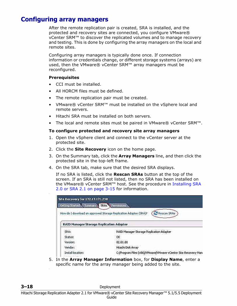
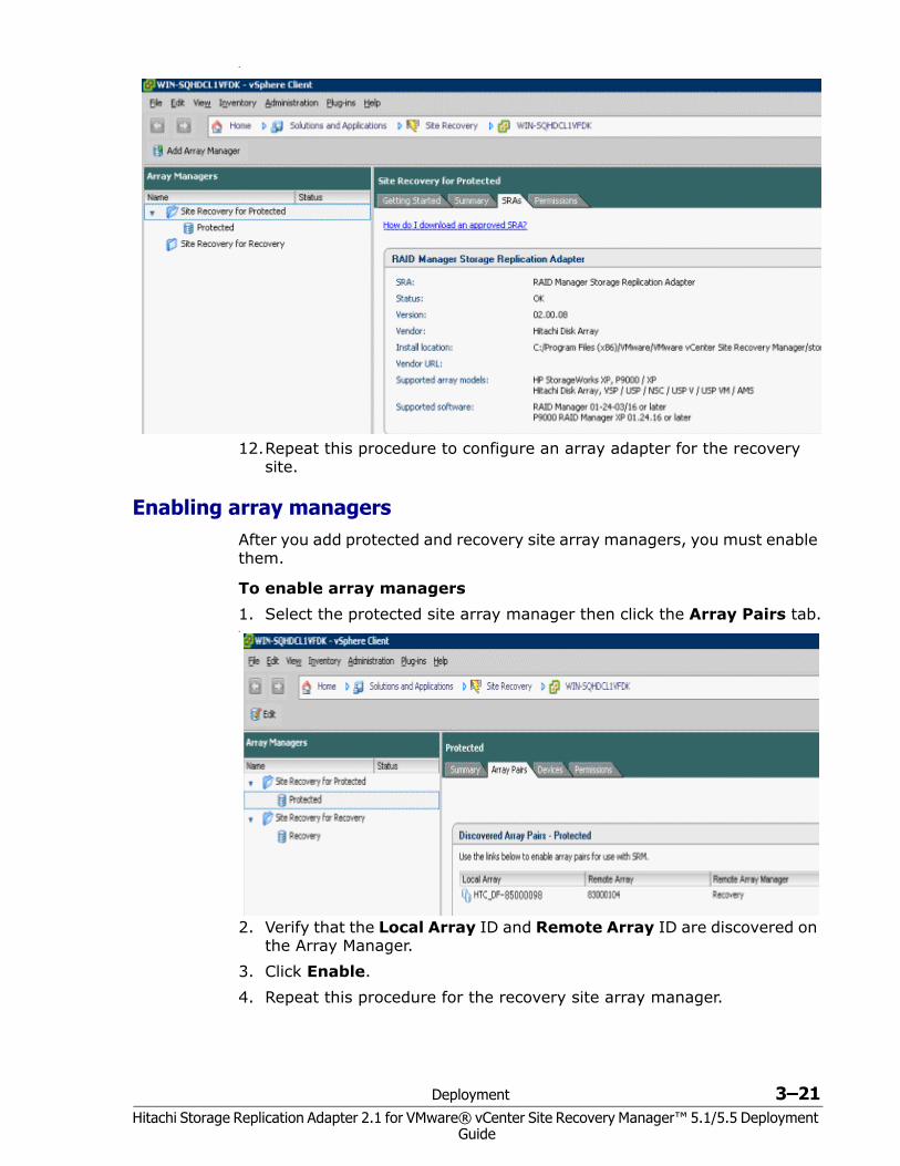
protected site in the top-left frame.4. On the SRA tab, make sure that the desired SRA displays.
If no SRA is listed, click the Rescan SRAs button at the top of the screen. If an SRA is still not listed, then no SRA has been installed on the VMware® vCenter SRM™ host. See the procedure in Installing SRA 2.0 or SRA 2.1 on page 3-15 for information.
•
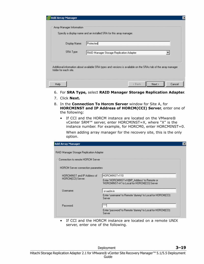
5. In the Array Manager Information box, for Display Name, enter a specific name for the array manager being added to the site.
•
Deployment 3–19Hitachi Storage Replication Adapter 2.1 for VMware® vCenter Site Recovery Manager™ 5.1/5.5 Deployment
Guide
•
6. For SRA Type, select RAID Manager Storage Replication Adapter.7. Click Next.8. In the Connection To Horcm Server window for Site A, for
HORCMINST and IP Address of HORCM(CCI) Server, enter one of the following: • If CCI and the HORCM instance are located on the VMware®
vCenter SRM™ server, enter HORCMINST=X, where “X” is the instance number. For example, for HORCM0, enter HORCMINST=0. When adding array manager for the recovery site, this is the only option.
•
• If CCI and the HORCM instance are located on a remote UNIX server, enter one of the following.
3–20 Deployment
Hitachi Storage Replication Adapter 2.1 for VMware® vCenter Site Recovery Manager™ 5.1/5.5 Deployment Guide
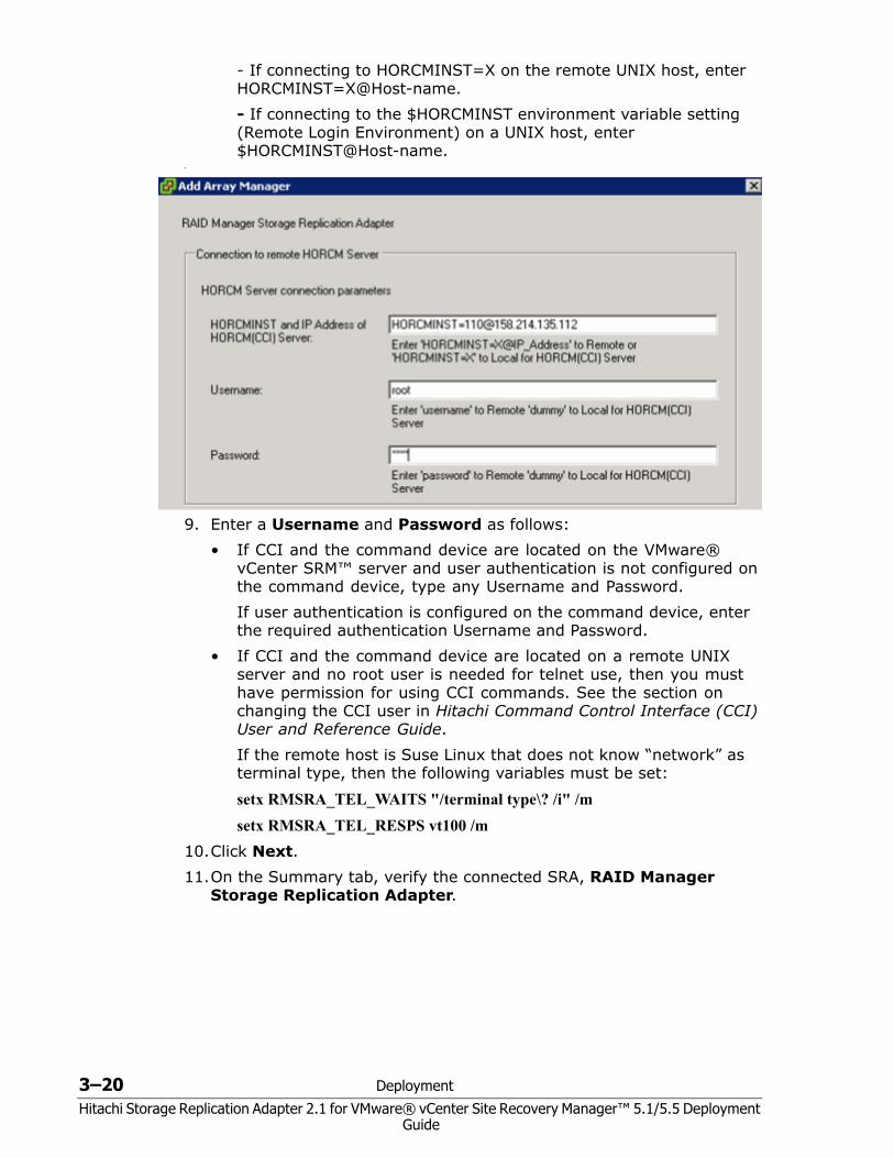
- If connecting to HORCMINST=X on the remote UNIX host, enter [email protected] If connecting to the $HORCMINST environment variable setting (Remote Login Environment) on a UNIX host, enter $HORCMINST@Host-name.
•
9. Enter a Username and Password as follows:• If CCI and the command device are located on the VMware®
vCenter SRM™ server and user authentication is not configured on the command device, type any Username and Password. If user authentication is configured on the command device, enter the required authentication Username and Password.
• If CCI and the command device are located on a remote UNIX server and no root user is needed for telnet use, then you must have permission for using CCI commands. See the section on changing the CCI user in Hitachi Command Control Interface (CCI) User and Reference Guide.If the remote host is Suse Linux that does not know “network” as terminal type, then the following variables must be set:
setx RMSRA_TEL_WAITS "/terminal type\? /i" /msetx RMSRA_TEL_RESPS vt100 /m
10.Click Next.11.On the Summary tab, verify the connected SRA, RAID Manager
Storage Replication Adapter.
Deployment 3–21Hitachi Storage Replication Adapter 2.1 for VMware® vCenter Site Recovery Manager™ 5.1/5.5 Deployment
Guide
•
12.Repeat this procedure to configure an array adapter for the recovery site.
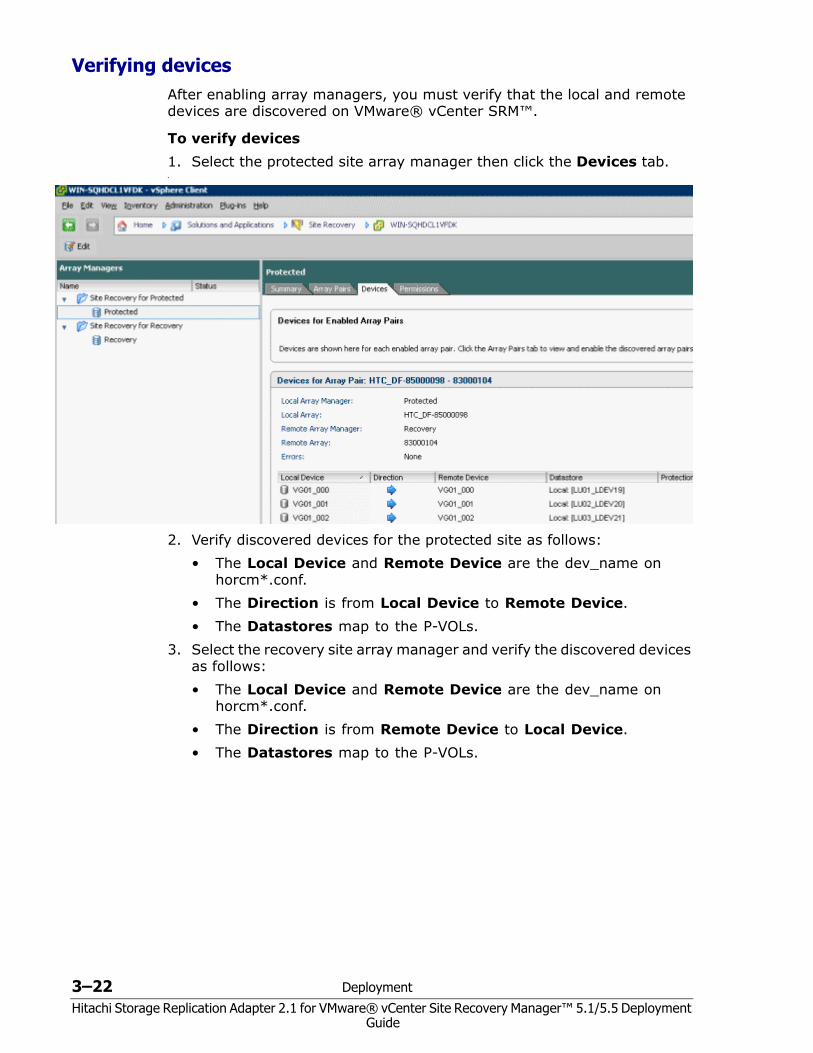
Enabling array managers After you add protected and recovery site array managers, you must enable them.
To enable array managers1. Select the protected site array manager then click the Array Pairs tab.•
2. Verify that the Local Array ID and Remote Array ID are discovered on the Array Manager.
3. Click Enable.4. Repeat this procedure for the recovery site array manager.
3–22 Deployment
Hitachi Storage Replication Adapter 2.1 for VMware® vCenter Site Recovery Manager™ 5.1/5.5 Deployment Guide
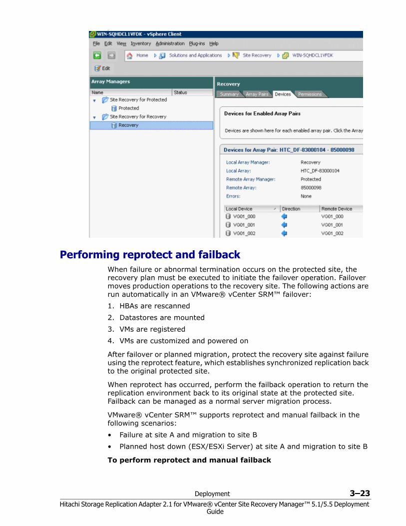
Verifying devices After enabling array managers, you must verify that the local and remote devices are discovered on VMware® vCenter SRM™.
To verify devices1. Select the protected site array manager then click the Devices tab.•
2. Verify discovered devices for the protected site as follows:• The Local Device and Remote Device are the dev_name on
horcm*.conf.• The Direction is from Local Device to Remote Device.• The Datastores map to the P-VOLs.
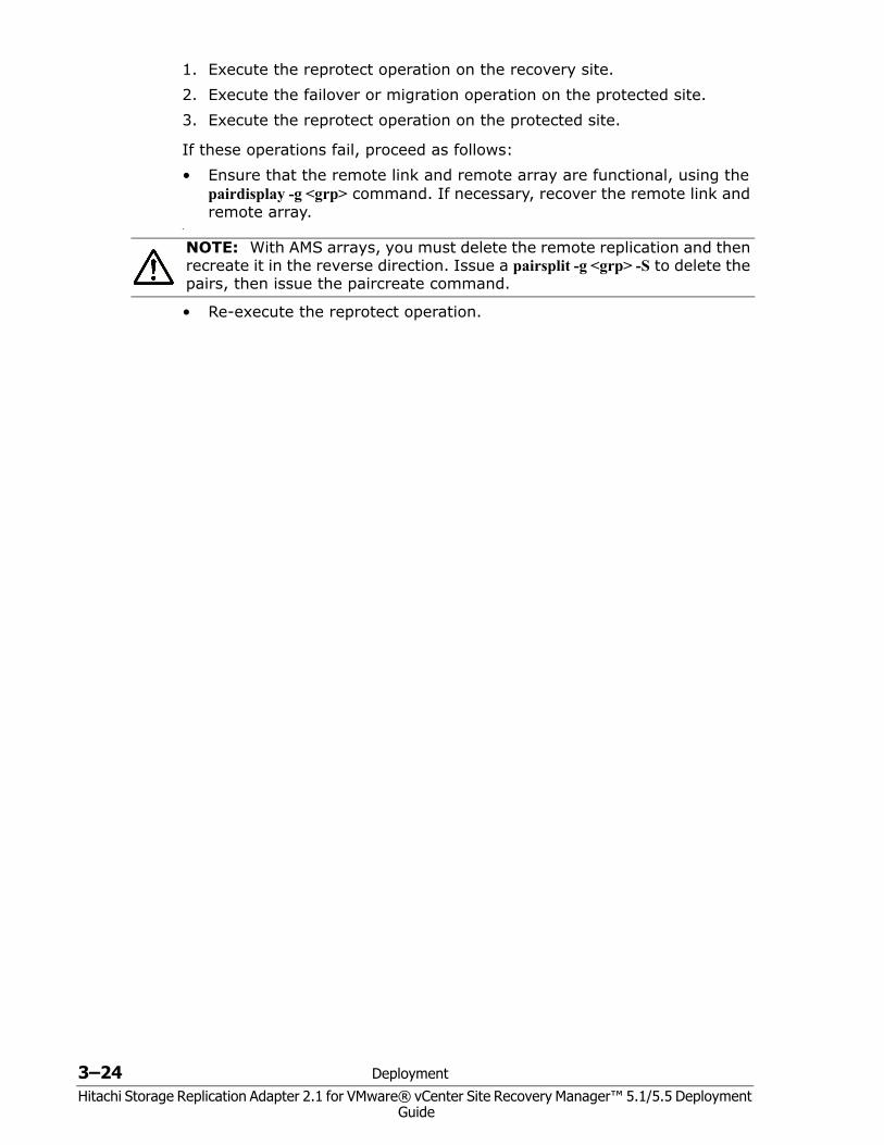
3. Select the recovery site array manager and verify the discovered devices as follows:• The Local Device and Remote Device are the dev_name on
horcm*.conf.• The Direction is from Remote Device to Local Device.• The Datastores map to the P-VOLs.
Deployment 3–23Hitachi Storage Replication Adapter 2.1 for VMware® vCenter Site Recovery Manager™ 5.1/5.5 Deployment
Guide
•
Performing reprotect and failback When failure or abnormal termination occurs on the protected site, the recovery plan must be executed to initiate the failover operation. Failover moves production operations to the recovery site. The following actions are run automatically in an VMware® vCenter SRM™ failover:1. HBAs are rescanned2. Datastores are mounted3. VMs are registered4. VMs are customized and powered on
After failover or planned migration, protect the recovery site against failure using the reprotect feature, which establishes synchronized replication back to the original protected site.
When reprotect has occurred, perform the failback operation to return the replication environment back to its original state at the protected site. Failback can be managed as a normal server migration process.
VMware® vCenter SRM™ supports reprotect and manual failback in the following scenarios: • Failure at site A and migration to site B• Planned host down (ESX/ESXi Server) at site A and migration to site B
To perform reprotect and manual failback
3–24 Deployment
Hitachi Storage Replication Adapter 2.1 for VMware® vCenter Site Recovery Manager™ 5.1/5.5 Deployment Guide
1. Execute the reprotect operation on the recovery site.2. Execute the failover or migration operation on the protected site.3. Execute the reprotect operation on the protected site.
If these operations fail, proceed as follows:• Ensure that the remote link and remote array are functional, using the
pairdisplay -g <grp> command. If necessary, recover the remote link and remote array.
•
• Re-execute the reprotect operation.
NOTE: With AMS arrays, you must delete the remote replication and then recreate it in the reverse direction. Issue a pairsplit -g <grp> -S to delete the pairs, then issue the paircreate command.
Troubleshooting 4–1
Hitachi Storage Replication Adapter 2.1 for VMware® vCenter Site Recovery Manager™ 5.1/5.5 Deployment Guide
4Troubleshooting
This chapter provides information and instructions for troubleshooting configuration problems. The following topics are discussed:
Error messages on VMware® vCenter SRM™ log files
Collecting information before contacting customer support
4–2 Troubleshooting
Hitachi Storage Replication Adapter 2.1 for VMware® vCenter Site Recovery Manager™ 5.1/5.5 Deployment Guide
Error messages on VMware® vCenter SRM™ log files RMSRA20 generates error messages in the following order in the VMware® vCenter SRM™ log files:• XML errors received from VMware® vCenter SRM™• Failure to launch scripts on page 4-8• Test failover errors on page 4-9
You can remove the cause of the error by referring to “[RMSRA20]” and “SRM ERROR messages” in the VMware® vCenter SRM™ log files.
The VMware® vCenter SRM™ log is located in the following directory:
Windows 2003: C:\Documents and Settings\All Users\VMware\VMware vCenter Site Recovery Manager\Logs\
Windows 2008: C:\ProgramData\VMware\VMware vCenter Site Recovery Manager\Logs\• Logs rollover after reaching 5 MB by default• vmware-dr-index contains the most recent Log File number
XML errors received from VMware® vCenter SRM™ 1002 • Cause: The HORCM instance could not start with the specified
connection address.• Action: Check whether the HORCM instance# specified in the
connection address is correct, or whether the horcm*.conf file exists.
1003• Cause: Authentication failed for User/Password for the specified
connection address.• Action: Check whether the User/Password for the connection address is
correct.
1301 [RMSRA20][Time]: [command_main] : XML length over -> [ XML parameter strings … ].• Cause: A parameter in XML was input from VMware® vCenter SRM™ to
the SRA, but it exceeds the defined length for the SRA specification.• Action: Confirm that VMware® vCenter SRM™ received the appropriate
parameters in XML from the VMware® vCenter SRM™ log message.
1302, 1303 [RMSRA20][Time]: [command_main] : Parameter in XML was NOT enough.• Cause: A parameter in XML was input from VMware® vCenter SRM™ to
the SRA but it could not be found in any parameters.• Action: Confirm that VMware® vCenter SRM™ received the appropriate
parameters in XML from the VMware® vCenter SRM™ log message.
Troubleshooting 4–3
Hitachi Storage Replication Adapter 2.1 for VMware® vCenter Site Recovery Manager™ 5.1/5.5 Deployment Guide
1304 [RMSRA20][Time]: [command_discoverDevics] : NO ArrayId or No PeerArrayId in XML.• Cause: A parameter in XML (discoverDevices) was input from VMware®
vCenter SRM™ to the SRA but the array ID could not be found.• Action: Confirm that VMware® vCenter SRM™ received the Array ID
parameter in XML from the VMware® vCenter SRM™ log message.
1305 [RMSRA20][Time]: [command_naming] : NO ArrayId or NO DeviceKey and GroupKey in XML.• Cause: A parameter in XML (naming) was input from VMware® vCenter
SRM™ to the SRA, but could not be found in TargetDevice Key(LDEV# of TC_S-VOL) or Target Group Key(dev_group in HORCM).
• Action: Confirm whether VMware® vCenter SRM™ was passed the TargetDevice Key parameter in XML from the VMware® vCenter SRM™ log message.
1XXX : Shows ERROR CODE for "queryErrorDefinitions"
Naming : checkTestFailoverStart/ checkFailover/ testFailoverStart / testFailoverStop/failover/
1305 [RMSRA20][Time]: [command_naming] : NO ArrayId or NO PeerArrayId or NO DeviceKey and GroupKey in XML.• Cause: A parameter in XML (naming) was input from VMware® vCenter
SRM™ to the SRA, but it could not be found in SourceDevice id(LDEV# of TC_S-VOL) or Consistency Group id(dev_group in HORCM).
• Action: Confirm whether VMware® vCenter SRM™ was passed the SourceDevice id parameter in XML from the VMware® vCenter SRM™ log message.
Naming : syncOnce/ querySyncStatus/ reverseReplication / restoreReplication/
1306 [RMSRA20][Time]: [command_naming] : Unsupported command 'command naming' in XML.• Cause: A command naming was input from VMware® vCenter SRM™ to
the SRA, but it could not be supported.• Action: Confirm whether VMware® vCenter SRM™ was passed an
appropriate command naming in XML from the VMware® vCenter SRM™ log message.
4–4 Troubleshooting
Hitachi Storage Replication Adapter 2.1 for VMware® vCenter Site Recovery Manager™ 5.1/5.5 Deployment Guide
1251 [RMSRA20][Time]: [command_main] : Can't be connected to HORCMINST=X@… with error(0x000000fc).• Cause: A connection address in XML was input from VMware® vCenter
SRM™ to the SRA, but HORCM instance #X could not be found.• Action: Check whether the HORCM instance# is running, or whether a
connection address (IPaddress) specified in Array Manager configuration is appropriate.
RAID Manager command errors in rmsra20.exe
1307 [RMSRA20][Time]: ["XML OUTPUT file name"] : fopen : “system error message”• Cause: A parameter in XML was input from VMware® vCenter SRM™ to
the SRA, but “XML OUTPUT file name” could not be created.• Action: Confirm that VMware® vCenter SRM™ received the appropriate
OutputFile in XML from the VMware® vCenter SRM™ log message, or refer to the system error message.
1270 [RMSRA20][Time]: [system()] : “Command line” : “system error message”• Cause: An execution of “Command line” failed via system() call.• Action: Confirm that RAID Manager is installed, that the path of
“Command line” is correct, that %HORCMROOT% ENV has been set, or refer to the system error message.
1269 [RMSRA20][Time]: ["Command line"] : popen : “system error message”• Cause: An execution of “Command line” failed via popen() call.• Action: Confirm that RAID Manager is installed, that the path of
Command line is correct, that %HORCMROOT% ENV has been set, or refer to the system error message.
1268[RMSRA20][Time]: [ ] : malloc : “system error message”• Cause: Memory was insufficient for executing an RM SRA.• Action: Increase system capacity of virtual memory, or terminate
unnecessary programs or daemon processes that are running simultaneously.
1xxx [RMSRA20][Time]: [ ] : “Command line” failed with RC=XXX.• Cause: An execution of “Command line” failed with RC=XXX.• Action: Check the RAID Manager error code and command error log
messages below, then remove the cause of the error.
Troubleshooting 4–5
Hitachi Storage Replication Adapter 2.1 for VMware® vCenter Site Recovery Manager™ 5.1/5.5 Deployment Guide
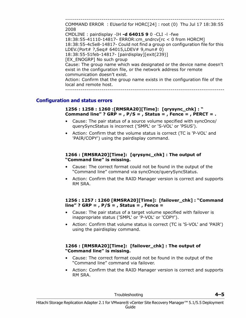
----------------------------------------------------------------------------------- COMMAND ERROR : EUserId for HORC[24] : root (0) Thu Jul 17 18:38:55 2008 CMDLINE : pairdisplay -IH -d 64015 9 0 -CLI -l -fwe 18:38:55-41110-14817- ERROR:cm_sndrcv[rc < 0 from HORCM] 18:38:55-4c5e8-14817- Could not find a group on configuration file for this LDEV.(Port# ?,Seq# 64015,LDEV# 9,mun# 0) 18:38:55-51feb-14817- [pairdisplay][exit(239)] [EX_ENOGRP] No such group Cause: The group name which was designated or the device name doesn't exist in the configuration file, or the network address for remote communication doesn’t exist. Action: Confirm that the group name exists in the configuration file of the local and remote host. -----------------------------------------------------------------------------------
Configuration and status errors
1256 : 1258 : 1260 :[RMSRA20][Time]: [qrysync_chk] : “ Command line” ? GRP = , P/S = , Status = , Fence = , PERCT = .• Cause: The pair status of a source volume specified with syncOnce/
querySyncStatus is incorrect ('SMPL' or 'S-VOL' or 'PSUS').• Action: Confirm that the volume status is correct (TC is 'P-VOL' and
'PAIR/COPY') using the pairdisplay command.
1266 : [RMSRA20][Time]: [qrysync_chk] : The output of “Command line” is missing.• Cause: The correct format could not be found in the output of the
“Command line” command via syncOnce/querySyncStatus.• Action: Confirm that the RAID Manager version is correct and supports
RM SRA.
1256 : 1257 : 1260 [RMSRA20][Time]: [failover_chk] : “Command line” ? GRP = , P/S = , Status = , Fence = • Cause: The pair status of a target volume specified with failover is
inappropriate status ('SMPL' or 'P-VOL' or 'COPY').• Action: Confirm that volume status is correct (TC is 'S-VOL' and 'PAIR')
using the pairdisplay command.
1266 : [RMSRA20][Time]: [failover_chk] : The output of “Command line” is missing.• Cause: The correct format could not be found in the output of the
“Command line” command via failover.• Action: Confirm that the RAID Manager version is correct and supports
RM SRA.
4–6 Troubleshooting
Hitachi Storage Replication Adapter 2.1 for VMware® vCenter Site Recovery Manager™ 5.1/5.5 Deployment Guide
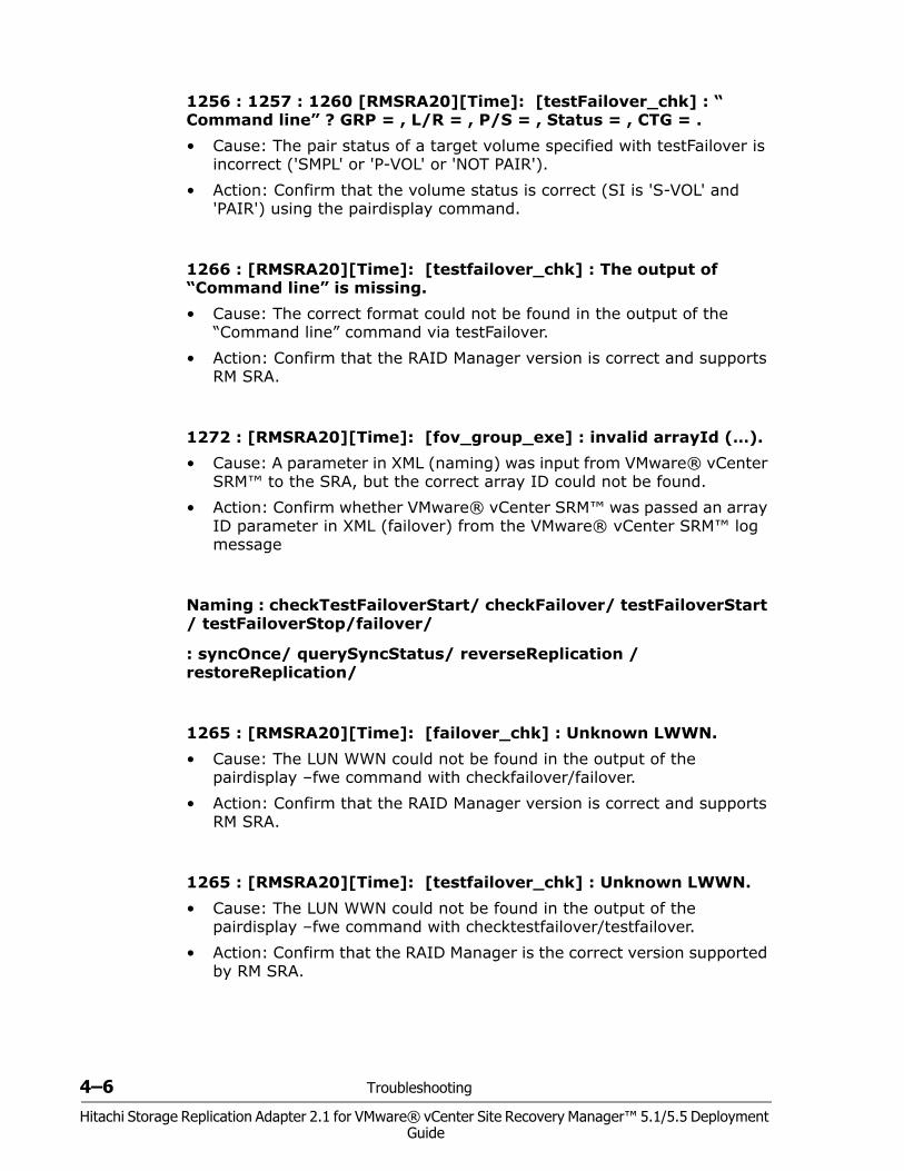
1256 : 1257 : 1260 [RMSRA20][Time]: [testFailover_chk] : “ Command line” ? GRP = , L/R = , P/S = , Status = , CTG = .• Cause: The pair status of a target volume specified with testFailover is
incorrect ('SMPL' or 'P-VOL' or 'NOT PAIR').• Action: Confirm that the volume status is correct (SI is 'S-VOL' and
'PAIR') using the pairdisplay command.
1266 : [RMSRA20][Time]: [testfailover_chk] : The output of “Command line” is missing.• Cause: The correct format could not be found in the output of the
“Command line” command via testFailover.• Action: Confirm that the RAID Manager version is correct and supports
RM SRA.
1272 : [RMSRA20][Time]: [fov_group_exe] : invalid arrayId (…).• Cause: A parameter in XML (naming) was input from VMware® vCenter
SRM™ to the SRA, but the correct array ID could not be found.• Action: Confirm whether VMware® vCenter SRM™ was passed an array
ID parameter in XML (failover) from the VMware® vCenter SRM™ log message
Naming : checkTestFailoverStart/ checkFailover/ testFailoverStart / testFailoverStop/failover/
: syncOnce/ querySyncStatus/ reverseReplication / restoreReplication/
1265 : [RMSRA20][Time]: [failover_chk] : Unknown LWWN.• Cause: The LUN WWN could not be found in the output of the
pairdisplay –fwe command with checkfailover/failover.• Action: Confirm that the RAID Manager version is correct and supports
RM SRA.
1265 : [RMSRA20][Time]: [testfailover_chk] : Unknown LWWN.• Cause: The LUN WWN could not be found in the output of the
pairdisplay –fwe command with checktestfailover/testfailover.• Action: Confirm that the RAID Manager is the correct version supported
by RM SRA.
Troubleshooting 4–7
Hitachi Storage Replication Adapter 2.1 for VMware® vCenter Site Recovery Manager™ 5.1/5.5 Deployment Guide
Error codes for multiple errors
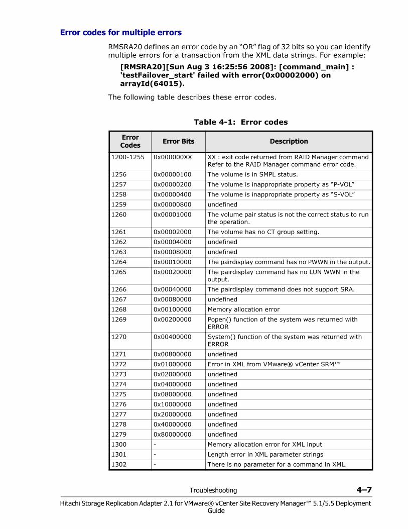
RMSRA20 defines an error code by an “OR” flag of 32 bits so you can identify multiple errors for a transaction from the XML data strings. For example:
[RMSRA20][Sun Aug 3 16:25:56 2008]: [command_main] : 'testFailover_start' failed with error(0x00002000) on arrayId(64015).
The following table describes these error codes.
Table 4-1: Error codes
Error Codes Error Bits Description
1200-1255 0x000000XX XX : exit code returned from RAID Manager command Refer to the RAID Manager command error code.
1256 0x00000100 The volume is in SMPL status. 1257 0x00000200 The volume is inappropriate property as “P-VOL”1258 0x00000400 The volume is inappropriate property as “S-VOL”1259 0x00000800 undefined1260 0x00001000 The volume pair status is not the correct status to run
the operation.1261 0x00002000 The volume has no CT group setting.1262 0x00004000 undefined1263 0x00008000 undefined1264 0x00010000 The pairdisplay command has no PWWN in the output.1265 0x00020000 The pairdisplay command has no LUN WWN in the
output.1266 0x00040000 The pairdisplay command does not support SRA.1267 0x00080000 undefined1268 0x00100000 Memory allocation error1269 0x00200000 Popen() function of the system was returned with
ERROR1270 0x00400000 System() function of the system was returned with
ERROR1271 0x00800000 undefined1272 0x01000000 Error in XML from VMware® vCenter SRM™1273 0x02000000 undefined1274 0x04000000 undefined1275 0x08000000 undefined1276 0x10000000 undefined1277 0x20000000 undefined1278 0x40000000 undefined1279 0x80000000 undefined1300 - Memory allocation error for XML input1301 - Length error in XML parameter strings1302 - There is no parameter for a command in XML.
4–8 Troubleshooting
Hitachi Storage Replication Adapter 2.1 for VMware® vCenter Site Recovery Manager™ 5.1/5.5 Deployment Guide
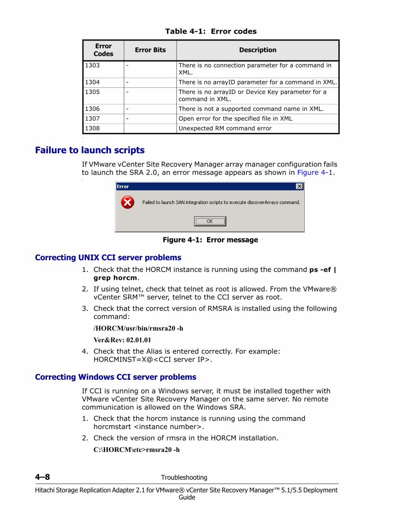
•
Failure to launch scriptsIf VMware vCenter Site Recovery Manager array manager configuration fails to launch the SRA 2.0, an error message appears as shown in Figure 4-1.•
Figure 4-1: Error message
Correcting UNIX CCI server problems1. Check that the HORCM instance is running using the command ps -ef |
grep horcm.2. If using telnet, check that telnet as root is allowed. From the VMware®
vCenter SRM™ server, telnet to the CCI server as root.3. Check that the correct version of RMSRA is installed using the following
command:
/HORCM/usr/bin/rmsra20 -hVer&Rev: 02.01.01
4. Check that the Alias is entered correctly. For example: HORCMINST=X@<CCI server IP>.
Correcting Windows CCI server problems
If CCI is running on a Windows server, it must be installed together with VMware vCenter Site Recovery Manager on the same server. No remote communication is allowed on the Windows SRA.1. Check that the horcm instance is running using the command
horcmstart <instance number>.2. Check the version of rmsra in the HORCM installation.
C:\HORCM\etc>rmsra20 -h
1303 - There is no connection parameter for a command in XML.
1304 - There is no arrayID parameter for a command in XML.1305 - There is no arrayID or Device Key parameter for a
command in XML.1306 - There is not a supported command name in XML.1307 - Open error for the specified file in XML1308 Unexpected RM command error
Table 4-1: Error codes
Error Codes Error Bits Description
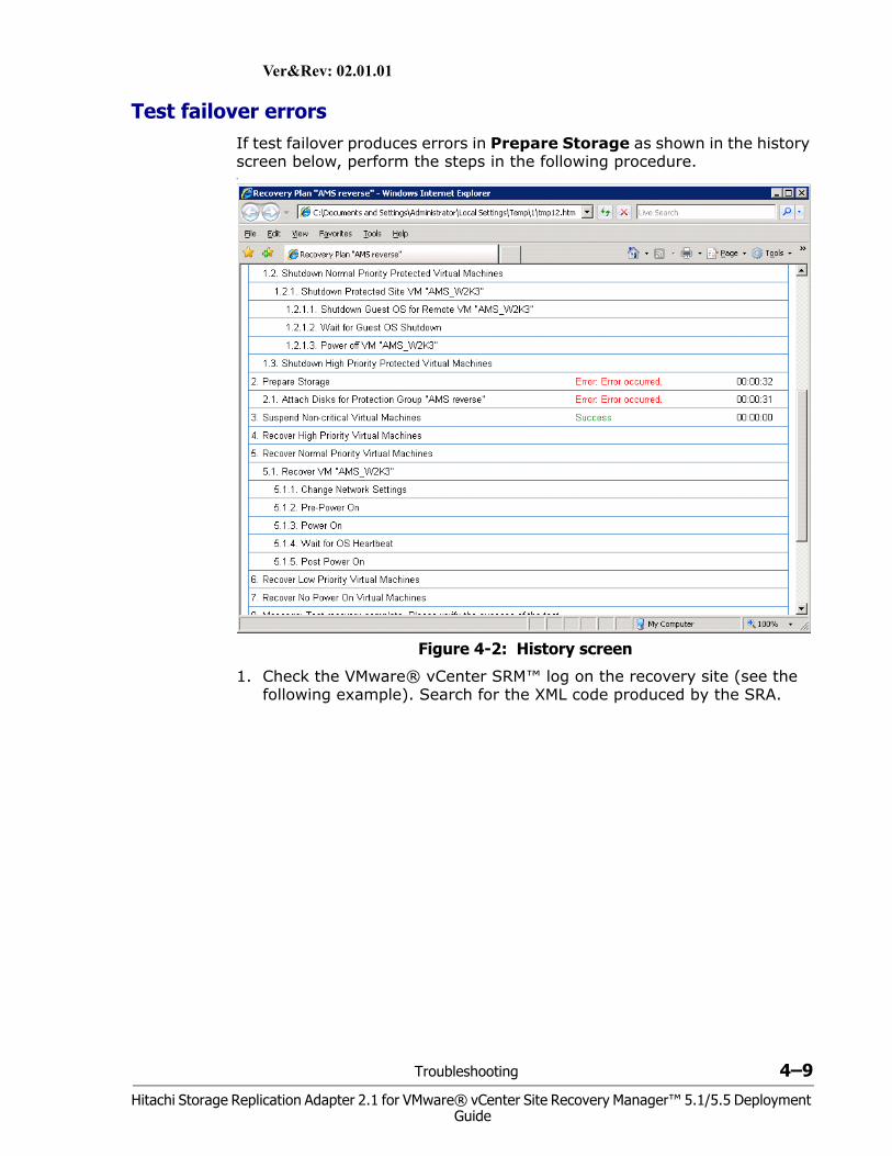
Troubleshooting 4–9
Hitachi Storage Replication Adapter 2.1 for VMware® vCenter Site Recovery Manager™ 5.1/5.5 Deployment Guide
Ver&Rev: 02.01.01
Test failover errorsIf test failover produces errors in Prepare Storage as shown in the history screen below, perform the steps in the following procedure.•
Figure 4-2: History screen
1. Check the VMware® vCenter SRM™ log on the recovery site (see the following example). Search for the XML code produced by the SRA.
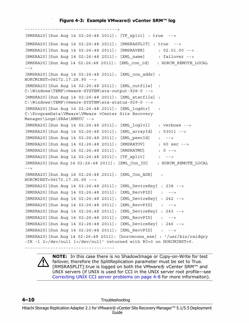
4–10 Troubleshooting
Hitachi Storage Replication Adapter 2.1 for VMware® vCenter Site Recovery Manager™ 5.1/5.5 Deployment Guide
•
•
Figure 4-3: Example VMware® vCenter SRM™ log
------------------------------------>
[RMSRA20][Sun Aug 14 02:26:48 2011]: [TF_split] : true -->
[RMSRA20][Sun Aug 14 02:26:48 2011]: [RMSRASPLIT] : true -->
[RMSRA20][Sun Aug 14 02:26:48 2011]: [RMSRAVER] : 02.01.00 -->
[RMSRA20][Sun Aug 14 02:26:48 2011]: [XML_name] : failover -->
[RMSRA20][Sun Aug 14 02:26:48 2011]: [XML_con_id] : HORCM_REMOTE_LOCAL -->
[RMSRA20][Sun Aug 14 02:26:48 2011]: [XML_con_addr] : [email protected] -->
[RMSRA20][Sun Aug 14 02:26:48 2011]: [XML_outfile] : C:\Windows\TEMP\vmware-SYSTEM\sra-output-928-0 -->
[RMSRA20][Sun Aug 14 02:26:48 2011]: [XML_statfile] : C:\Windows\TEMP\vmware-SYSTEM\sra-status-929-0 -->
[RMSRA20][Sun Aug 14 02:26:48 2011]: [XML_logdir] : C:\ProgramData\VMware\VMware vCenter Site Recovery Manager\Logs\SRAs\RMHTC -->
[RMSRA20][Sun Aug 14 02:26:48 2011]: [XML_loglvl] : verbose -->
[RMSRA20][Sun Aug 14 02:26:48 2011]: [XML_arrayId] : 53011 -->
[RMSRA20][Sun Aug 14 02:26:48 2011]: [XML_peerId] : -->
[RMSRA20][Sun Aug 14 02:26:48 2011]: [RMSRATOV] : 60 sec -->
[RMSRA20][Sun Aug 14 02:26:48 2011]: [RMSRATMU] : 0 -->
[RMSRA20][Sun Aug 14 02:26:48 2011]: [TF_split] : -->
[RMSRA20][Sun Aug 14 02:26:48 2011]: [XML_Con_ID] : HORCM_REMOTE_LOCAL -->
[RMSRA20][Sun Aug 14 02:26:48 2011]: [XML_Con_ADR] : [email protected] -->
[RMSRA20][Sun Aug 14 02:26:48 2011]: [XML_DeviceKey] : 238 -->
[RMSRA20][Sun Aug 14 02:26:48 2011]: [XML_RecvPID] : -->
[RMSRA20][Sun Aug 14 02:26:48 2011]: [XML_DeviceKey] : 242 -->
[RMSRA20][Sun Aug 14 02:26:48 2011]: [XML_RecvPID] : -->
[RMSRA20][Sun Aug 14 02:26:48 2011]: [XML_DeviceKey] : 243 -->
[RMSRA20][Sun Aug 14 02:26:48 2011]: [XML_RecvPID] : -->
[RMSRA20][Sun Aug 14 02:26:48 2011]: [XML_DeviceKey] : 246 -->
[RMSRA20][Sun Aug 14 02:26:48 2011]: [XML_RecvPID] : -->
[RMSRA20][Sun Aug 14 02:26:48 2011]: [horcmconn_exe] : '/usr/bin/raidqry -IH -l 2>/dev/null 1>/dev/null' returned with RC=0 on HORCMINST=0.
-----------------------------------
NOTE: In this case there is no ShadowImage or Copy-on-Write for test failover, therefore the SplitReplication parameter must be set to True. [RMSRASPLIT]:true is logged on both the VMware® vCenter SRM™ and UNIX servers (if UNIX is used for CCI in the UNIX server root profile—see Correcting UNIX CCI server problems on page 4-8 for more informaiton).
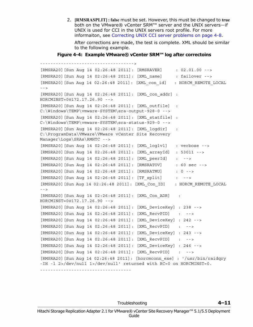
Troubleshooting 4–11
Hitachi Storage Replication Adapter 2.1 for VMware® vCenter Site Recovery Manager™ 5.1/5.5 Deployment Guide
2. [RMSRASPLIT] : false must be set. However, this must be changed to true both on the VMware® vCenter SRM™ server and the UNIX servers—if UNIX is used for CCI in the UNIX servers root profile. For more informaiton, see Correcting UNIX CCI server problems on page 4-8.After corrections are made, the test is complete. XML should be similar to the following example.
•
Figure 4-4: Example VMware® vCenter SRM™ log after correctoins
------------------------------------>
[RMSRA20][Sun Aug 14 02:26:48 2011]: [RMSRAVER] : 02.01.00 -->
[RMSRA20][Sun Aug 14 02:26:48 2011]: [XML_name] : failover -->
[RMSRA20][Sun Aug 14 02:26:48 2011]: [XML_con_id] : HORCM_REMOTE_LOCAL -->
[RMSRA20][Sun Aug 14 02:26:48 2011]: [XML_con_addr] : [email protected] -->
[RMSRA20][Sun Aug 14 02:26:48 2011]: [XML_outfile] : C:\Windows\TEMP\vmware-SYSTEM\sra-output-928-0 -->
[RMSRA20][Sun Aug 14 02:26:48 2011]: [XML_statfile] : C:\Windows\TEMP\vmware-SYSTEM\sra-status-929-0 -->
[RMSRA20][Sun Aug 14 02:26:48 2011]: [XML_logdir] : C:\ProgramData\VMware\VMware vCenter Site Recovery Manager\Logs\SRAs\RMHTC -->
[RMSRA20][Sun Aug 14 02:26:48 2011]: [XML_loglvl] : verbose -->
[RMSRA20][Sun Aug 14 02:26:48 2011]: [XML_arrayId] : 53011 -->
[RMSRA20][Sun Aug 14 02:26:48 2011]: [XML_peerId] : -->
[RMSRA20][Sun Aug 14 02:26:48 2011]: [RMSRATOV] : 60 sec -->
[RMSRA20][Sun Aug 14 02:26:48 2011]: [RMSRATMU] : 0 -->
[RMSRA20][Sun Aug 14 02:26:48 2011]: [TF_split] : -->
[RMSRA20][Sun Aug 14 02:26:48 2011]: [XML_Con_ID] : HORCM_REMOTE_LOCAL -->
[RMSRA20][Sun Aug 14 02:26:48 2011]: [XML_Con_ADR] : [email protected] -->
[RMSRA20][Sun Aug 14 02:26:48 2011]: [XML_DeviceKey] : 238 -->
[RMSRA20][Sun Aug 14 02:26:48 2011]: [XML_RecvPID] : -->
[RMSRA20][Sun Aug 14 02:26:48 2011]: [XML_DeviceKey] : 242 -->
[RMSRA20][Sun Aug 14 02:26:48 2011]: [XML_RecvPID] : -->
[RMSRA20][Sun Aug 14 02:26:48 2011]: [XML_DeviceKey] : 243 -->
[RMSRA20][Sun Aug 14 02:26:48 2011]: [XML_RecvPID] : -->
[RMSRA20][Sun Aug 14 02:26:48 2011]: [XML_DeviceKey] : 246 -->
[RMSRA20][Sun Aug 14 02:26:48 2011]: [XML_RecvPID] : -->
[RMSRA20][Sun Aug 14 02:26:48 2011]: [horcmconn_exe] : '/usr/bin/raidqry -IH -l 2>/dev/null 1>/dev/null' returned with RC=0 on HORCMINST=0.
-----------------------------------
4–12 Troubleshooting
Hitachi Storage Replication Adapter 2.1 for VMware® vCenter Site Recovery Manager™ 5.1/5.5 Deployment Guide
Collecting information before contacting customer supportPlease collect the following information before contacting customer support.
VMware® vCenter SRM™/SRA local configuration
On Windows where VMware® vCenter SRM™ is running, perform the following procedures.1. Collect the VMware® vCenter SRM™ log file on Windows on both
protection and recovery sites. Collect the following VMware® vCenter SRM™ log file including the error messages of “[RMSRA]” and “VMware® vCenter SRM™ ERROR messages” and the RAID Manager command error log.
%ALLUSERSPROFILE%\ Application Data\VMware\VMware Site Recovery Manager\Logs\vmware*.log2. Collect the outputs of the following command on
HORCMINST=XX(instance# for SRA)• set• %HORCMROOT%\HORCM\etc\raidqry -l • %HORCMROOT%\HORCM\etc\raidqry -g • %HORCMROOT%\HORCM\etc\pairdisplay -IH -g ??? -CLI -l -fwe
(where ??? is a group name shown by raidqry -g)• %HORCMROOT%\HORCM\etc\raidscan -IH -p port(i.e. cl1-a-0) -
CLI (port where connecting to ESX/ESXi server)
If ShadowImage is installed,• %HORCMROOT%\HORCM\etc\pairdisplay -g ??? -CLI -l -few -m
cas (where ??? is a group name shown by raidqry -g)
VMware® vCenter SRM™/SRA remote configuration
On Windows where VMware® vCenter SRM™ is running, and on UNIX where RAID Manager is running, perform the following procedures.1. Collect the VMware® vCenter SRM™ log file on Windows on both
protection and recovery site.2. Collect the following VMware® vCenter SRM™ log file including the error
messages of “[RMSRA]” and “SRM ERROR messages” and the RAID Manager command error log.%ALLUSERSPROFILE%\ Application Data\VMware\VMware Site Recovery Manager\Logs\vmware*.log
3. Collect the outputs of the following command on HORCMINST=XX(instance# for SRA) on remot UNIX• env• raidqry -l• raidqry -g• pairdisplay -IH -g ??? -CLI -l -fwe (where ??? is a group name
shown by raidqry -g)
Troubleshooting 4–13
Hitachi Storage Replication Adapter 2.1 for VMware® vCenter Site Recovery Manager™ 5.1/5.5 Deployment Guide
• raidscan -IH -p port(i.e. cl1-a-0) -CLI (port where connecting to ESX/ESXi sever)
If ShadowImage is installed, collect the following:• pairdisplay -g ??? -CLI -l -few -m cas (where ??? is a group name
shown by raidqry -g)

4–14 Troubleshooting
Hitachi Storage Replication Adapter 2.1 for VMware® vCenter Site Recovery Manager™ 5.1/5.5 Deployment Guide
Configurations with both sites active A–1Hitachi Storage Replication Adapter 2.1 for VMware® vCenter Site Recovery Manager™ 5.1/5.5 Deployment
Guide
AConfigurations with both
sites active
This chapter describes configurations in which both protected and recovery VMs are present on the local and remote sites. The following topics are discussed:
Protecting both sites
HORCM definition file setup
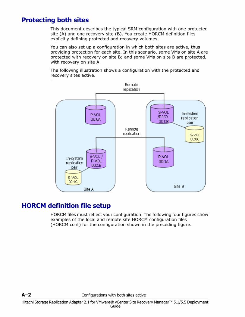
A–2 Configurations with both sites active
Hitachi Storage Replication Adapter 2.1 for VMware® vCenter Site Recovery Manager™ 5.1/5.5 Deployment Guide
Protecting both sitesThis document describes the typical SRM configuration with one protected site (A) and one recovery site (B). You create HORCM definition files explicitly defining protected and recovery volumes.
You can also set up a configuration in which both sites are active, thus providing protection for each site. In this scenario, some VMs on site A are protected with recovery on site B; and some VMs on site B are protected, with recovery on site A.
The following illustration shows a configuration with the protected and recovery sites active.•
HORCM definition file setupHORCM files must reflect your configuration. The following four figures show examples of the local and remote site HORCM configuration files (HORCM.conf) for the configuration shown in the preceding figure.
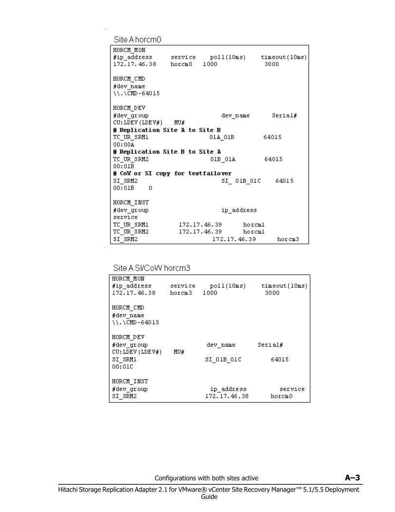
Configurations with both sites active A–3Hitachi Storage Replication Adapter 2.1 for VMware® vCenter Site Recovery Manager™ 5.1/5.5 Deployment
Guide
•
•
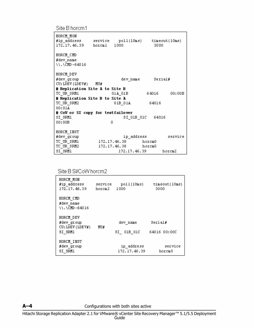
A–4 Configurations with both sites active
Hitachi Storage Replication Adapter 2.1 for VMware® vCenter Site Recovery Manager™ 5.1/5.5 Deployment Guide
Index-1
Hitachi Storage Replication Adapter 2.1 for VMware® vCenter Site Recovery Manager™ 5.1/5.5 Deployment Guide
Index
AAMS
host group requirement 2-7array managers
configuring 3-18enabling 3-21
At-Time Split operation, planning 2-6
CCCI
consistency groups 2-6installing 3-2locating 2-4overview 1-5
command devicecreating 3-3overview 1-5
components graphic 1-3configuring a command device 3-3configuring array managers 3-18configuring HORCM 3-6Connection To Horcm Server window 3-19consistency groups 2-6creating in-system pair 3-11creating pairs 3-11creating test copy 3-11
Ddeployment workflow 3-2devices, verifying 3-22
Eediting HORCM files 3-8enabling array managers 3-21environment variables
setting 3-14environment variables, setting 3-12
Ffailback 3-23fence level 2-7
HHitachi storage and SRM 1-2HORCM
configuration 3-6overview 1-5starting the instance 3-11
host group option for AMS 2-7
Iinstalling SRA 3-15instance, starting 3-11instances, HORCM 3-6in-system pair, creating 3-11in-system replication 2-5
Nnaming HORCM instances 3-6Never, fence level 2-7
Ooperating systems 2-2
Ppairs, creating 3-11port for ShadowImage 2-6
Rreplication software supported 2-3reprotect 3-23requirements 2-2rescan SRAs 3-18
Index-2
Hitachi Storage Replication Adapter 2.1 for VMware® vCenter Site Recovery Manager™ 5.1/5.5 Deployment Guide
Sserver locations for SRA/SRM/CCI 2-4ShadowImage
port requirement 2-6splitting pairs in a group 2-6SRA
checking the version 3-16installation 3-15
SRA/SRMhow it works 1-5locating 2-4overview 1-2setup workflow 3-2
SRMXML errors 4-2
SRM hostsetting variables for 3-14
supported Hitachi replication 1-3supported Hitachi storage 1-2
Ttesting
creating copy for 3-11options 2-4setting enviro. variables for 3-14
troubleshooting 4-2
UUNIX host
setting variables for 3-15with CCI 2-4
upgrading CCI 3-2
Vverifying devices 3-22VMware environment 2-2
Wworkflow, deployment 3-2
XXML errors 4-2

Hitachi Storage Replication Adapter 2.1 for VMware® vCenter Site Recovery Manager™ 5.1/5.5 Deployment Guide
MK-09RM6745-08
Hitachi Data Systems
Corporate Headquarters 750 Central Expressway Santa Clara, California 95050-2627 U.S.A. www.hds.com
Regional Contact Information
Americas +1 408 970 1000 [email protected]
Europe, Middle East, and Africa +44 (0)1753 618000 [email protected]
Asia Pacific +852 3189 7900 [email protected]


![Welcome! [] · 2019-08-05 · Zerto Virtual Replication 5.5. PRIVATE AND CONFIDENTIAL 18 Zerto is a software based replication tool for virtual infrastructure which is storage, hypervisor](https://img.pdfslide.net/doc/110x75/5f330c47c65afa37b30524b6/welcome-2019-08-05-zerto-virtual-replication-55-private-and-confidential.jpg)