Embed Size (px)
Citation preview
If copying/pasting, eye-drop this text toensure a uniform look for all installationparagraphs.
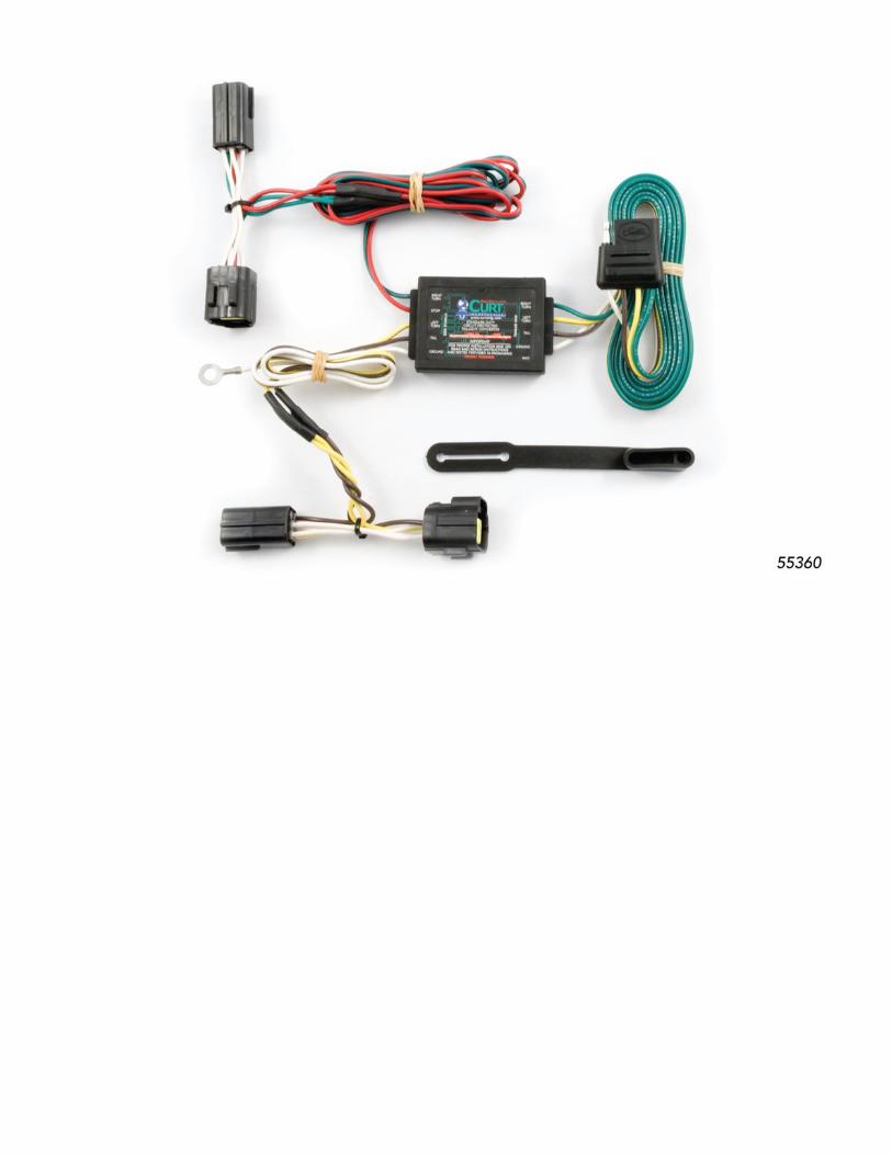
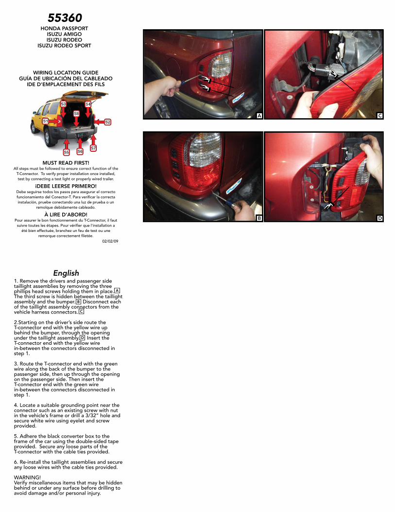
1. Remove the drivers and passenger side taillight assemblies by removing the three phillips head screws holding them in place. The third screw is hidden between the taillight assembly and the bumper. Disconnect each of the taillight assembly connectors from the vehicle harness connectors.
2.Starting on the driver’s side route the T-connector end with the yellow wire up behind the bumper, through the opening under the taillight assembly. Insert the T-connector end with the yellow wire in-between the connectors disconnected in step 1.
3. Route the T-connector end with the green wire along the back of the bumper to the passenger side, then up through the opening on the passenger side. Then insert the T-connector end with the green wire in-between the connectors disconnected in step 1.
4. Locate a suitable grounding point near the connector such as an existing screw with nut in the vehicle’s frame or drill a 3/32” hole and secure white wire using eyelet and screw provided.
5. Adhere the black converter box to the frame of the car using the double-sided tape provided. Secure any loose parts of the T-connector with the cable ties provided.
6. Re-install the taillight assemblies and secure any loose wires with the cable ties provided. WARNING!Verify miscellaneous items that may be hidden behind or under any surface before drilling to avoid damage and/or personal injury.
02/02/09
55360HONDA PASSPORT
ISUZU AMIGOISUZU RODEO
ISUZU RODEO SPORT