Embed Size (px)
Citation preview
HOSDB Body Armour Standards for
UK Police (2007)
Part 3: Knife and Spike Resistance
Publication No. 39/07/C
John Croft
Daniel Longhurst

Publication No. 39/07/C i
HOSDB Body Armour Standards for UK Police (2007)
Part 3: Knife and Spike Resistance
John Croft
Daniel Longhurst
Publication No. 39/07/C
1.0

ii Publication No. 39/07/C
HOSDB Body Armour Standards for UK Police (2007)
Part 3: Knife and Spike Resistance
John Croft Daniel Longhurst
Publication No. 39/07/C
1.0
ISBN: 978-1-84726-426-8
FIRST PUBLISHED JULY 2007
© CROWN COPYRIGHT 2007
For information on copyright see our website: http://science.homeoffice.gov.uk/hosdb/terms
Home Office Scientific Development Branch Sandridge St Albans AL4 9HQ United Kingdom Telephone: +44 (0)1727 865051 Fax: +44 (0)1727 816233 E-mail: [email protected] Website: http://science.homeoffice.gov.uk/hosdb/
Publication No. 39/07/C iii
Contents
Page
1 Introduction ............................................................................................................... 1
2 Scope ........................................................................................................................ 2
3 Associated Documents ............................................................................................. 3
4 Requirements............................................................................................................ 4
5 Test Methodology...................................................................................................... 5
5.1 The Test Equipment .......................................................................................... 5
5.2 The Knife/Spike Missile ..................................................................................... 5
5.3 The Engineered Test Knife and Spike .............................................................. 6
5.4 Velocity Measurement....................................................................................... 6
5.5 The Composite Backing Material ...................................................................... 7
6 Preparation of the Test Equipment ........................................................................... 8
6.1 Velocity Measuring Equipment Calibration ....................................................... 8
6.2 Selecting the Test Knife/Spike .......................................................................... 8
6.3 The Tip Sharpness Test.................................................................................... 8
6.4 Installing the Test Knife/Spike into the Missile .................................................. 9
6.5 Installing the Foam Damper into the Missile ..................................................... 9
6.6 Selecting the Backing Material ........................................................................ 10
6.7 Preparing the Composite Backing Material..................................................... 10
6.8 Calibrating the Composite Backing Material ................................................... 10
6.9 Preparing the Roma Plastilina® No 1 Backing Material ................................. 10
6.10 Conditioning the Roma Plastilina® No 1 Backing Material ............................. 11
6.11 Calibrating the Roma Plastilina® No 1 Backing Material ................................ 11
6.12 Mounting the Armour Sample ......................................................................... 11
7 Testing .................................................................................................................... 12
7.1 Threat Levels................................................................................................... 12
7.2 Knife Resistance Testing ................................................................................ 13
7.3 Spike Resistance Testing (optional)................................................................ 13
7.4 Test Procedure for Knife Protection Levels KR1, KR2 and KR3 .................... 14
7.5 Knife Test Strikes ............................................................................................ 14
7.5.1 E1 Test Strike No. 1.............................................................................. 14
7.5.2 E1 Test Strike No. 2 - 30....................................................................... 15
7.5.3 E2 Test Strike No. 31............................................................................ 15
7.5.4 E2 Test Strikes No. 32 - 40................................................................... 15
iv Publication No. 39/07/C
7.6 Drop Test Procedure for Spike Protection Level (Only as an addition to knife protection) ................................................................................................................16
7.7 Spike Test Strikes ............................................................................................16
7.7.1 Test Strike No. 1 ....................................................................................16
7.7.2 Test Strike No. 2 - 10.............................................................................16
7.8 Additional Test Strikes at Specific Points of Weakness ..................................16
7.9 Additional Test Strikes on Female Armour ......................................................17
7.10 Additional 45° Angle Test Strikes ....................................................................17
7.11 Measurement of Penetration (Knife Test Only) ...............................................18
7.12 Measurement of Penetration for Composite Backing Material (Knife Test Only)18
7.13 Measurement of Penetration for Roma Plastilina® No 1 Backing Material (Knife Test Only) ......................................................................................................18
7.14 Measurement of Penetration for Composite Backing Material (Spike Test Only) ........................................................................................................................18
7.15 Measurement of Penetration for Plastilina® Backing Material (Spike Test Only) ........................................................................................................................19
8 Manufacturers Quality Testing (MQT) .....................................................................20
8.1 MQT 1 and MQT 2 ...........................................................................................20
8.2 MQT 1 and MQT 2 Knife Test Protocol ...........................................................20
8.3 MQT 1 and MQT 2 Spike Test Protocol...........................................................20
Appendix A: ..................................................................................................................................21
A.1 HOSDB P1/B Test Knife ..................................................................................21
A.2 HOSDB SP/B Test Spike .................................................................................22
A.3 Conversion Chart for P1/B Knife Penetration Depths from Witness Paper Cut Length ......................................................................................................................23
A.4 Conversion Chart for Modified Rockwell values to CATRA Force Values.......23
A.5 Operation and Calibration of Mitutoyo ATk F1000 Hardness Tester When Used as a Sharpness Tester ...................................................................................24
Appendix B: ..................................................................................................................................25
B.1 Packs and Components of the Composite Backing Material...........................25
B.2 Component Parts of the Composite Backing Material .....................................25
B.3 Damping Disc Material .....................................................................................26
B.4 HOSDB Engineered Knife (P1B) and Spike (SP) ............................................26
B.5 99.997% Pure Aluminium for Knife Sharpness Test........................................26
B.6 140g/m2 Polyart
® Paper ...................................................................................26
B.7 1.043kg Spherical Steel Ball ............................................................................27
HOSDB Body Armour Standards for UK Police (2007)
Publication No. 39/07/C 1
1 Introduction
This part of the standard provides information on the stab resistant test
requirements and methods for manufacturers of body armour to achieve
successful compliance testing within the Home Office Scientific Development
Branch (HOSDB) voluntary testing programme. This Standard is part of a
series of documents currently being produced within the HOSDB Police
Protection programme and is supported by:
• The Association of Chief Police Officers (ACPO) Conflict Management
Portfolio;
• The ACPO Body Armour Sub-group;
• The Home Office Public Order Unit;
• The Police Federation of England and Wales.
The standard provides a choice to police purchasing units and wearers
through three levels of knife and spike protection. These levels are described
below:
KR1 & KR1+SP1 is the lowest protection level allowed and is tested at a
performance level of 24 joules of energy. It should offer maximum periods of
wear in a low risk-patrolling environment. Armour tested to this level would
be suitable for covert or overt use;
KR2 & KR2+SP2 is a medium protection level, tested at a performance level
of 33 joules. This should provide a general duty garment for extended wear
and may be covert or overt;
KR3 & KR3+SP3 is a high protection level tested at a performance level of
43 joules. This would be suitable for short periods of wear in high-risk
situations. Armour manufactured to this level would normally be overt.
All of the above protection levels can be combined with ballistic protection
levels - described in part 2 of this Standard - to offer dual stab and ballistic
protection.

Home Office Scientific Development Branch
2 Publication No. 39/07/C
2 Scope
This document is Part 3 of the standard and contains the performance
requirements and test protocol for the testing of body armour to knife and
spike threat levels.

HOSDB Body Armour Standards for UK Police (2007)
Publication No. 39/07/C 3
3 Associated Documents
HOSDB Body Armour Standards for UK Police Part 1: General
Requirements;
HOSDB Body Armour Standards for UK Police Part 2: Ballistic Resistance.
PSDB Portable Ballistic Standard for UK Police (2004)
HOSDB Slash Resistance Standard for UK Police (2006)

Home Office Scientific Development Branch
4 Publication No. 39/07/C
4 Requirements
Knife or knife + spike resistant body armour shall also meet the requirements
described in Part 1 of this standard. Compliance with Parts 1 and 3 of the
HOSDB Body Armour Standard does not imply that the body armour provides
ballistic protection. Compliance with Parts 1 and 2 of this standard is
necessary for ballistic protection. For dual-purpose body armour i.e. Ballistic
+ Stab, compliance with Parts 1, 2 and 3 is required.
HOSDB Body Armour Standards for UK Police (2007)
Publication No. 39/07/C 5
5 Test Methodology
5.1 The Test EquipmentThe test shall be performed using the HOSDB guided rail drop tube assembly,
which will enable the knife/spike missile to fall under the influence of gravity
and strike the armour sample at a pre-determined point of impact. The guide
rails, situated inside the tube, prevent the knife/spike missile from rotating
about its vertical axis during its descent. These rails also ensure that the test
implement strikes at the correct orientation so that any weakness in the
armour design can be fully determined. The drop tube assembly must be
rigidly secured to a supporting wall or frame, and care must be taken when
installing the system to ensure that the tube is mounted vertically. Drawings
of the drop tube and knife/spike missile are available from HOSDB.
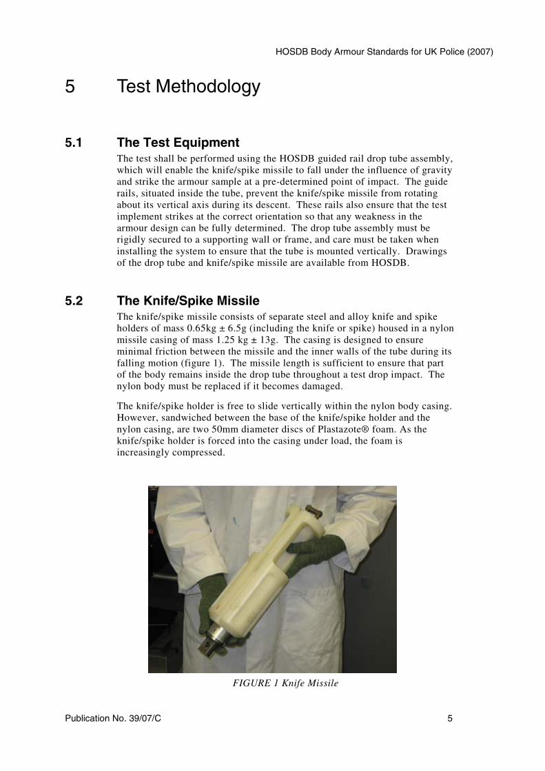
5.2 The Knife/Spike MissileThe knife/spike missile consists of separate steel and alloy knife and spike
holders of mass 0.65kg ± 6.5g (including the knife or spike) housed in a nylon
missile casing of mass 1.25 kg ± 13g. The casing is designed to ensure
minimal friction between the missile and the inner walls of the tube during its
falling motion (figure 1). The missile length is sufficient to ensure that part
of the body remains inside the drop tube throughout a test drop impact. The
nylon body must be replaced if it becomes damaged.
The knife/spike holder is free to slide vertically within the nylon body casing.
However, sandwiched between the base of the knife/spike holder and the
nylon casing, are two 50mm diameter discs of Plastazote® foam. As the
knife/spike holder is forced into the casing under load, the foam is
increasingly compressed.
FIGURE 1 Knife Missile
Home Office Scientific Development Branch
6 Publication No. 39/07/C
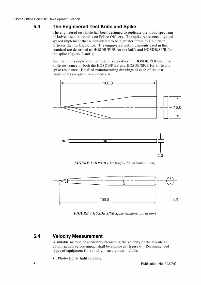
5.3 The Engineered Test Knife and SpikeThe engineered test knife has been designed to replicate the broad spectrum
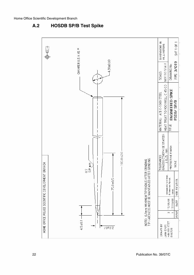
of knives used in assaults on Police Officers. The spike represents a typical
spiked implement that is considered to be a greater threat to UK Prison
Officers than to UK Police. The engineered test implements used in this
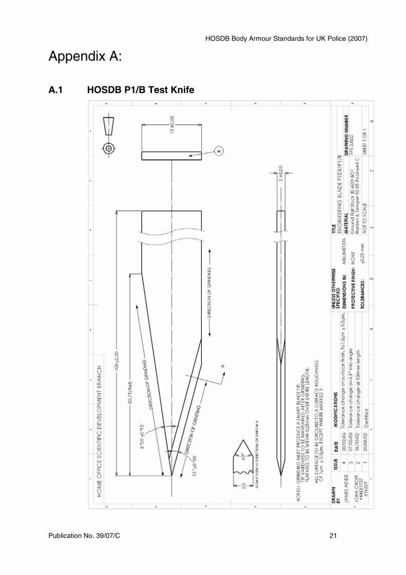
standard are described as HOSDB/P1/B for the knife and HOSDB/SP/B for
the spike (figures 2 and 3).
Each armour sample shall be tested using either the HOSDB/P1B knife for
knife resistance or both the HOSDB/P1/B and HOSDB/SP/B for knife and
spike resistance. Detailed manufacturing drawings of each of the test
implements are given in appendix A.
2.0
15.0
100.0
FIGURE 2 HOSDB P1B Knife (dimensions in mm)
FIGURE 3 HOSDB SP/B Spike (dimensions in mm)
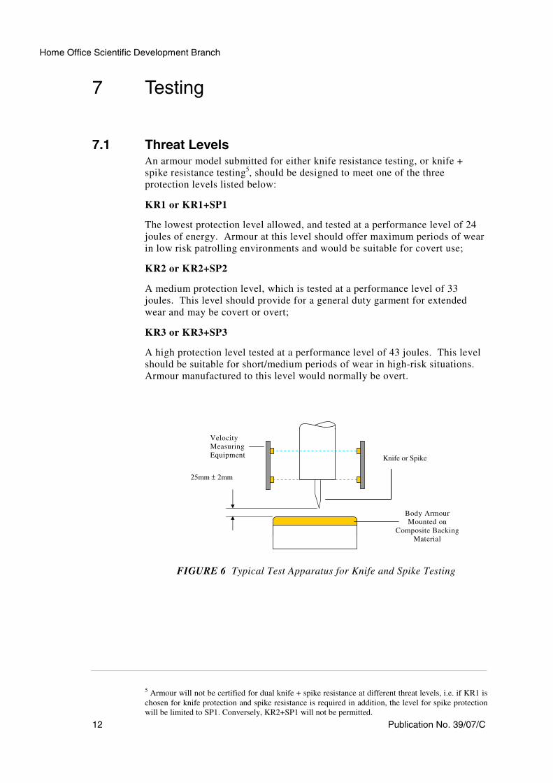
5.4 Velocity MeasurementA suitable method of accurately measuring the velocity of the missile at
25mm ±2mm before impact shall be employed (figure 6). Recommended
types of equipment for velocity measurement include:
• Photoelectric light screens;
100.0 4.5
HOSDB Body Armour Standards for UK Police (2007)
Publication No. 39/07/C 7
• Laser/light sensor diode light screens.
If light screens are used the base length of the timing sensors shall be a
maximum of 50mm (HOSDB test houses use a base length of 30mm). The
measuring equipment shall be calibrated so that it is capable of measuring the
velocity to an accuracy of ±0.2m/s.
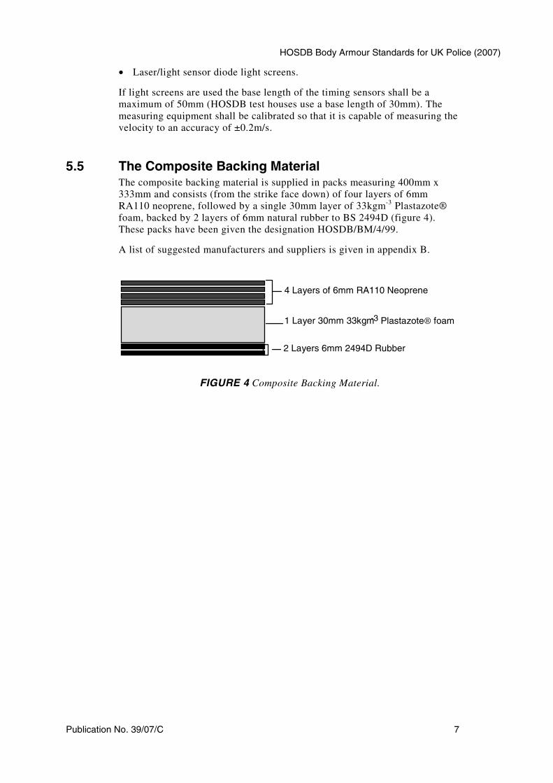
5.5 The Composite Backing MaterialThe composite backing material is supplied in packs measuring 400mm x
333mm and consists (from the strike face down) of four layers of 6mm
RA110 neoprene, followed by a single 30mm layer of 33kgm-3
Plastazote®
foam, backed by 2 layers of 6mm natural rubber to BS 2494D (figure 4).
These packs have been given the designation HOSDB/BM/4/99.
A list of suggested manufacturers and suppliers is given in appendix B.
4 Layers of 6mm RA110 Neoprene
1 Layer 30mm 33kgm-3 Plastazote® foam
2 Layers 6mm 2494D Rubber
FIGURE 4 Composite Backing Material.
Home Office Scientific Development Branch
8 Publication No. 39/07/C
6 Preparation of the Test Equipment
6.1 Velocity Measuring Equipment CalibrationThe instrumentation used for measuring the velocity of the falling knife/spike
missile must be calibrated according to the manufacturer's instructions. Test
calibration records must be maintained and be traceable to the requirements of
a recognised Quality Assurance Standard e.g. ISO 9001:2000, UKAS, ISO
17025 etc.
6.2 Selecting the Test Knife/SpikeFor compliance testing, a total of forty (40) P1/B test knives shall be selected
at random for knife resistant testing. If spike resistance is required, ten (10)
SP/B spikes shall be selected in addition to the knives. A new knife/spike
shall be used for each test. A visual check must be made to ensure the overall
finish of the knife/spike is clean and free from rough edges, and that it meets
the general requirements of the technical specification given in appendix A.
6.3 The Tip Sharpness TestPrior to testing, the knife/spike shall first be subjected to a tip-sharpness test
1.
This standard addresses two methods of assessing tip sharpness:
The first method consists of a standard Rockwell Hardness Testing Machine,
Mitutoyo model ATK-F1000, with a modified indenter holder to accept the
knife or spike. The machine must be pre-set to give minor and major loads of
3kg and 5kg respectively as detailed in appendix A5.
The knife/spike shall first be wiped with heavy duty degreaser solvent wipes2
to remove any traces of lubricant and allowed to dry. From this point
onwards, the knives should only be handled whilst wearing suitable
cotton/linen gloves. The tip sharpness shall then be tested by applying the
load at the knife/spike tip into a small sample block of 99.997% pure
aluminium that has been machined to a smooth surface finish.
A list of suggested suppliers of pure aluminium is given in appendix B.
Operation and calibration instructions for the sharpness test are given in
appendix A.
The test value from a new, unused blade shall lie between – 100HRC and
140HRC. These values can also be expressed in terms of indentation depth in
1 To accommodate manufacturers carrying out development testing, High Speed and Carbide (contact
details in Appendix B) have agreed to stock limited supplies of P1/B knives and SP/B spikes with
certified tip sharpness courtesy of the Cutlery and Allied Trades Research Association (CATRA) of
Sheffield.
2 The Degreasing wipes used by HOSDB test hoses can be purchased using the order code: 28635 or
70683 from: www.screwfix.com. Free phone: 0500 414141.
HOSDB Body Armour Standards for UK Police (2007)
Publication No. 39/07/C 9
the aluminium test block, produced by the major load application, and will
correspond to depths of 0.40 to 0.48mm as detailed in appendix A.
A second method of determining tip sharpness has also been established. Both
the PSDB P1/B knives and SP/B spikes may be tested for tip sharpness at the
Cutlery and Allied Trades Research Association (CATRA). The Rockwell
values of –100HRC to –140HRC compare (approximately) with CATRA
values of 4.5N force to 0.66N force.
These tip sharpness values can be converted into the values on the Rockwell
scale using the table shown in appendix A4.
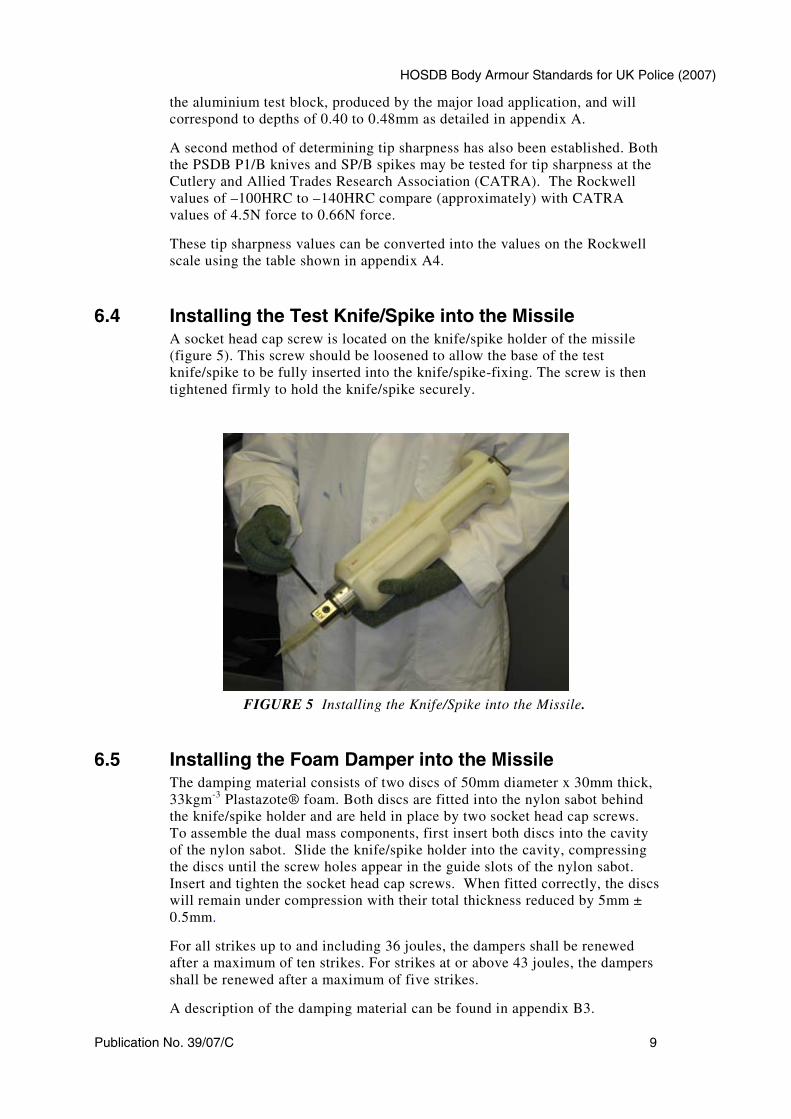
6.4 Installing the Test Knife/Spike into the MissileA socket head cap screw is located on the knife/spike holder of the missile
(figure 5). This screw should be loosened to allow the base of the test
knife/spike to be fully inserted into the knife/spike-fixing. The screw is then
tightened firmly to hold the knife/spike securely.
FIGURE 5 Installing the Knife/Spike into the Missile.
6.5 Installing the Foam Damper into the MissileThe damping material consists of two discs of 50mm diameter x 30mm thick,
33kgm-3
Plastazote® foam. Both discs are fitted into the nylon sabot behind
the knife/spike holder and are held in place by two socket head cap screws.
To assemble the dual mass components, first insert both discs into the cavity
of the nylon sabot. Slide the knife/spike holder into the cavity, compressing
the discs until the screw holes appear in the guide slots of the nylon sabot.
Insert and tighten the socket head cap screws. When fitted correctly, the discs
will remain under compression with their total thickness reduced by 5mm ±
0.5mm.
For all strikes up to and including 36 joules, the dampers shall be renewed
after a maximum of ten strikes. For strikes at or above 43 joules, the dampers
shall be renewed after a maximum of five strikes.
A description of the damping material can be found in appendix B3.
Home Office Scientific Development Branch
10 Publication No. 39/07/C
6.6 Selecting the Backing MaterialTwo types of backing material are available for the test. For all flat and/or
flexible armour samples the composite backing material shall be used.
However, when testing specific weak points of shaped female armours, or
where armours have a pre-formed curve to enable the armour to fit more
closely to the body, it may not be possible for the rear face of the armour
sample to lie in close contact with the surface of the composite backing
material. In these cases, Roma Plastilina® No 1 may be used for this portion
of the test.
Before testing, the appropriate backing material shall be prepared as
described in the relevant sections (6.7 to 6.11).
6.7 Preparing the Composite Backing Material The composite backing material pack shall be placed in a room held at a
temperature of 20° C ± 3° C and between 40% and 70% humidity for at least
12 hours prior to the trial.
6.8 Calibrating the Composite Backing Material After conditioning the composite backing material, calibration shall be carried
out using the methods and equipment specified below:
• Drop test sphere: Steel sphere grade ‘100’ PN3606 3;
• Sphere diameter: 63.5mm ± 0.05mm;
• Sphere mass: 1.043kg ± 5g;
• Drop height: 1.5m ± 0.02m;
• Drop spacing: 75mm minimum from any edge and 100mm between
indent centres.
The calibration drop shall consist of a free fall of the sphere onto the backing
material. To achieve this, the pack should be placed on a solid concrete floor.
Three drops shall be completed and the arithmetic mean height of rebound
achieved from three drops shall be 425mm ± 75mm.
A list of suggested manufacturers and suppliers of the composite backing
materials is given in appendix B.
6.9 Preparing the Roma Plastilina® No 1 Backing Material Steel trays measuring approximately 420mm x 350mm x 100mm, open on one
large face only, shall be filled with Roma Plastilina® No 1. The Roma
Plastilina® No 1 in each tray shall be manipulated to ensure no air gaps exist.
The trays shall be date marked with the date they were filled with new Roma
3 This sphere: ref P/N 3606 is available from: Salem Speciality Ball Co, Inc, PO Box 145
West Simsbury, CT 06092. USA.
HOSDB Body Armour Standards for UK Police (2007)
Publication No. 39/07/C 11
Plastilina® No 1and the contents must be disposed of no more than six
months after this date and the tray filled with fresh Roma Plastilina®.
6.10 Conditioning the Roma Plastilina® No 1 Backing Material The conditioning of the Roma Plastilina® No 1 shall be carried out in a
heated enclosure for at least 3 hours at a temperature above 30oC. Actual
conditioning temperature and recovery time between strikes shall be
determined by calibration results described in section 6.11. Conditioning
time, temperature and drop test performance may change as a function of the
age and usage of the Roma Plastilina® No 1.
6.11 Calibrating the Roma Plastilina® No 1 Backing Material After conditioning of the Roma Plastilina®, calibration must be carried out
using the methods and equipment specified below:
• Drop test sphere: Steel sphere grade ‘100’ PN3606 4;
• Sphere diameter: 63.5mm ± 0.05mm;
• Sphere mass: 1.043kg ± 5g;
• Drop height: 1.5m ± 0.02m;
• Drop spacing: 75mm minimum from any edge and 100mm between
indent centres.
The calibration drop shall consist of a free fall of the sphere onto the Roma
Plastilina®. A minimum of three drops shall be completed and the arithmetic
mean depth of depression from the drops shall be 15mm ± 1.5mm measured
from the top edges of the steel tray. This condition shall apply throughout the
duration of the stab test.
6.12 Mounting the Armour SampleThe appropriately conditioned backing material shall be placed beneath the
drop tube assembly, and the body armour securely fastened onto the backing
material. When testing body armours using the composite backing material, a
sheet of 140g/m2 Polyart
®paper may be placed between the backing material
and the armour to allow penetration measurements to be made. If it becomes
necessary to use Roma Plastilina® No 1 as the backing material, (i.e. when
testing armours with pre-curved surfaces), the Roma Plastilina® No 1 shall be
built up to ensure contact with the wear face of the armour. When using the
composite backing materials the armour shall be held in place using standard
webbing type strapping (supplied by HOSDB) ensuring that there is no visible
compression of the backing material.
4 This sphere: ref P/N 3606 is available from: Salem Speciality Ball Co, Inc, PO Box 145
West Simsbury, CT 06092. USA.
Home Office Scientific Development Branch
12 Publication No. 39/07/C
7 Testing
7.1 Threat LevelsAn armour model submitted for either knife resistance testing, or knife +
spike resistance testing5, should be designed to meet one of the three
protection levels listed below:
KR1 or KR1+SP1
The lowest protection level allowed, and tested at a performance level of 24
joules of energy. Armour at this level should offer maximum periods of wear
in low risk patrolling environments and would be suitable for covert use;
KR2 or KR2+SP2
A medium protection level, which is tested at a performance level of 33
joules. This level should provide for a general duty garment for extended
wear and may be covert or overt;
KR3 or KR3+SP3
A high protection level tested at a performance level of 43 joules. This level
should be suitable for short/medium periods of wear in high-risk situations.
Armour manufactured to this level would normally be overt.
FIGURE 6 Typical Test Apparatus for Knife and Spike Testing
5 Armour will not be certified for dual knife + spike resistance at different threat levels, i.e. if KR1 is
chosen for knife protection and spike resistance is required in addition, the level for spike protection
will be limited to SP1. Conversely, KR2+SP1 will not be permitted.
Velocity
Measuring
Equipment
Body Armour
Mounted on
Composite Backing
Material
25mm ± 2mm
Knife or Spike
HOSDB Body Armour Standards for UK Police (2007)
Publication No. 39/07/C 13
7.2 Knife Resistance TestingEach armour model shall be tested for its compliance to one of the knife
protection levels shown in figure 7 by performing a series of test strikes using
the knives described in section 5.3.
Three protective packs are required for this test; one complete armour and one
front or back panel. These shall be large size. See Part 1 appendix B for size
templates. The protective packs shall be removed from their carriers for the
purpose of knife resistance testing.
A total of 30 (thirty) 0o
strikes shall be conducted at energy level E1 using all
three panels (10 strikes per panel). The maximum allowed penetration is
7mm. Any strike where the energy is less than E1 shall be discounted unless
penetration exceeding the limit occurs. Particular areas of weakness (this will
include any angled shots considered necessary) will be counted as extra shots
at the discretion of the test house after consultation with HOSDB. No
penetrations above the maximum will be permitted. Bust and overlap shots
shall be extra shots and extra front panels shall be supplied.
The first set of tests consists of thirty (30) strikes, impacting at 0° angle of
incidence using blade type P1B at a specified energy E1. This is followed by
a further ten (10) strikes at energy E2. The values of E1 and E2 are described
for each protection level in figure 7. Following each test strike the penetration
of the impact shall be measured and shall not exceed the maximum permitted
penetration depth described in figure 7.
7.3 Spike Resistance Testing (optional)HOSDB certification will be given for spike resistance only in addition to
knife resistance. Spike resistance was introduced into this standard primarily
to address the additional threat faced by Prison Officers, therefore, is not
available as a stand-alone protection level. If it is considered that spike
resistance is required in addition to knife protection, each armour model shall
be tested for its compliance to one of the protection levels shown in figure 7.
Spike testing is described in detail in section 7.6. The protective packs shall
be removed from their carriers prior to testing.
Home Office Scientific Development Branch
14 Publication No. 39/07/C
Protection
Levels
Energy
Level E1
(joules)
Maximum
Penetration
at E1 (mm)
Energy
Level E2
(joules)
Maximum
Penetration
at E2 (mm)
KR1 24 7 36 20*
KR1+SP1 24 KR1=7, SP1 =0* KR1= 36, SP1 = N/A KR1=20*, SP1 = N/A
KR2 33 7 50 20*
KR2+SP2 33 KR2=7, SP2 =0* KR2= 50, SP2 = N/A KR2=20*, SP2 = N/A
KR3 43 7 65 20*
KR3+SP3 43 KR3=7, SP3 =0* KR3= 65, SP3 = N/A KR3=20*, SP3 = N/A
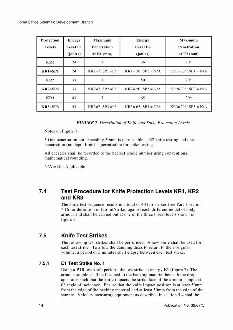
FIGURE 7 Description of Knife and Spike Protection Levels
Notes on Figure 7:
* One penetration not exceeding 30mm is permissible at E2 knife testing and one
penetration (no depth limit) is permissible for spike testing.
All energies shall be recorded to the nearest whole number using conventional
mathematical rounding.
N/A = Not Applicable
7.4 Test Procedure for Knife Protection Levels KR1, KR2 and KR3The knife test sequence results in a total of 40 fair strikes (see Part 1 section
7.16 for definition of fair hit/strike) against each different model of body
armour and shall be carried out at one of the three threat levels shown in
figure 7.
7.5 Knife Test StrikesThe following test strikes shall be performed. A new knife shall be used for
each test strike. To allow the damping discs to return to their original
volume, a period of 5 minutes shall elapse between each test strike.
7.5.1 E1 Test Strike No. 1
Using a P1B test knife perform the test strike at energy E1 (figure 7). The
armour sample shall be fastened to the backing material beneath the drop
apparatus such that the knife impacts the strike face of the armour sample at
0° angle of incidence. Ensure that the knife impact position is at least 50mm
from the edge of the backing material and at least 50mm from the edge of the
sample. Velocity measuring equipment as described in section 5.4 shall be
HOSDB Body Armour Standards for UK Police (2007)
Publication No. 39/07/C 15
used to determine the impact velocity of the test knife. See also section 6.1
and figure 8.
If the impact fulfils the criteria of a fair strike as defined in Part 1 section
7.16, measure any penetration of the knife and record it along with the impact
energy in a test report form. Reposition the armour sample onto the backing
material and fasten the holding straps to secure it in place.
7.5.2 E1 Test Strike No. 2 - 30
Select a new area of the armour sample so that the knife impact position is at
least 50mm from any other impact and at least 50mm from the edge of the
sample and the edge of the backing material and repeat test strike procedure
No.1 using a P1/B test knife at energy E1.
7.5.3 E2 Test Strike No. 31
Using a P1B test knife perform the first test strike at energy E2 (figure 7).
The body armour shall be fastened to the backing material beneath the drop
apparatus such that the knife impacts the strike face at 0° angle of incidence.
Ensure that the knife impact position is at least 50mm from any other impact
and at least 50mm from the edge of the armour sample. Velocity measuring
equipment as described in section 5.4 shall be used to determine the impact
velocity of the test knife. See also section 6.1 and figure 8.
If the impact fulfils the criteria of a fair strike, measure any penetration of the
knife and record it along with the impact energy, in the test report form.
Reposition the armour sample onto the backing material and fasten the
holding straps to secure it in place.
7.5.4 E2 Test Strikes No. 32 - 40
Select a new area of the armour sample so that the knife impact position is at
least 50mm from any other impact and at least 50mm from the edge of the
sample and repeat test strike procedure No.5 using a P1/B test knife at energy
E2. Continue testing at E2 until 10 fair strikes have been completed.
Note: One penetration not exceeding 30mm is permissible at E2.
Protection
Level
Energy
Level
Energy
(joules)
Total Missile Mass
(kg)
Velocity
(m/s)
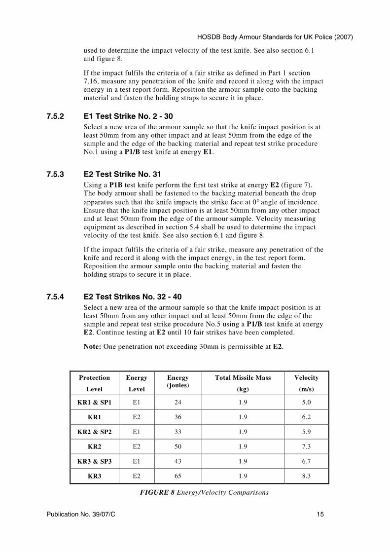
KR1 & SP1 E1 24 1.9 5.0
KR1 E2 36 1.9 6.2
KR2 & SP2 E1 33 1.9 5.9
KR2 E2 50 1.9 7.3
KR3 & SP3 E1 43 1.9 6.7
KR3 E2 65 1.9 8.3
FIGURE 8 Energy/Velocity Comparisons
Home Office Scientific Development Branch
16 Publication No. 39/07/C
7.6 Drop Test Procedure for Spike Protection Level (Only as an addition to knife protection)The test sequence results in a total of 10 fair strikes (see Part 1 section 7.16
for definition of fair hit/strike against each different model of body armour
and shall be carried out at one of the three threat levels shown in figure 7.
10 (ten) strikes at E1 allowing for one penetration shall be carried out on one
or more of the three panels used for the knife test. The protective packs will
be removed from their carriers for the purpose of spike resistance testing.
For all strikes up to and including 36 joules, the dampers shall be renewed
after a maximum of ten strikes. For strikes at or above 43 joules, the dampers
shall be renewed after a maximum of five strikes.
7.7 Spike Test StrikesThe following test strikes shall be performed. A new spike shall be used for
each successive test strike. To allow the damping discs to return to their
original volume, a period of not less than 5 minutes shall elapse between each
test strike.
7.7.1 Test Strike No. 1
Using a new SP/B test spike perform the test strike at energy E1 (figure 7).
The armour sample shall be fastened to the backing material beneath the drop
apparatus, such that the spike impacts the strike face of the sample at 0° angle
of incidence. Ensure that the spike impact position is at least 50mm from any
other impact and at least 50mm from the edge of the armour sample. Velocity
measuring equipment as described in section 5.4 shall be used to determine
the impact velocity of the test knife. See also section 6.1 and figure 8.
If the impact fulfils the criteria of a fair hit, examine the body-side of the
sample to determine whether the spike has “HELD” or “PENETRATED” and
record it along with the actual impact energy, in the test report form.
Reposition the armour onto the backing material and fasten the holding straps
to secure it in place.
7.7.2 Test Strike No. 2 - 10
Select a new area of the armour sample so that the spike impact position is at
least 50mm from any other impact, and at least 50mm from the edge of the
armour sample, and repeat test strike procedure No.1 using a SP/B test spike
at energy E1.
Note: One penetration of the spike (no depth limit) is permissible.
7.8 Additional Test Strikes at Specific Points of WeaknessPotential points of weakness, such as seams or other joins between materials
used in the protective pack of the body armour, shall be subjected to at least
one additional strike at energy level E1. These strikes shall be carried out at
each seam or join type, in an orientation most likely to show weaknesses in
the joint or seam. Ensure that the knife and/or spike impact position is at
least 50mm from any other impact and at least 50mm from the edge of the
HOSDB Body Armour Standards for UK Police (2007)
Publication No. 39/07/C 17
sample. Additional armour samples may be necessary to meet this
requirement.
The maximum knife penetration allowed for these strikes is 7mm. No
penetration of the spike is permitted.
7.9 Additional Test Strikes on Female ArmourThe strikes shall be performed with the knife or spike (or both) as specified in
the relevant protection level. A minimum of two strikes shall be carried out
on a separate front female panel as described below. All strikes shall be
spaced at a distance of at least 50mm from one another.
The test strikes shall be performed with the backing material built up to
remove any air gaps between the face of the backing material and the armour
sample.
Strike 1: A 0° angle of incidence strike at E1 striking within 5mm of the tip
of the breast cup, at least 50mm from any other strike.
Strike 2: A 0° angle of incidence strike at E1 shall be carried out at each
line or area of weakness, i.e. a join between two sections of fabric (where a
fabric is cut and stitched or folded) or a significant change in direction of the
fabric fibres.
The maximum penetration allowed for the knife strikes on breast cups is
7mm. No penetration of the spike is permitted.
7.10 Additional 45°°°° Angle Test StrikesThe following test strikes shall be performed at the discretion of the test
house if overlapping plates have been used in the armour construction or
where a construction may be compromised by an angled attack. A new
knife/spike should be used for each successive test strike. To allow the
damping discs to return to their original volume, a period of not less than 5
minutes shall elapse between each test strike.
Using the P1/B test knife or SP/B spike, perform a minimum of three test
strikes for the knife test and three test strikes for the spike test as required at
energy E1 (figure 7). The armour shall be fastened to the backing material
beneath the drop apparatus such that the knife impacts the strike face of
armour sample at a 45° angle of incidence. Ensure that the knife impact
position is at least 50mm from any other impact and at least 50mm from the
edge of the armour sample. Velocity measuring equipment as described in
section 5.4 shall be used to determine the impact velocity of the test
knife/spike. See also section 6.1 and figure 8.
If the impact fulfils the criteria of a fair strike, measure any penetration of the
knife and record it along with the impact energy in the test report form.
The maximum knife penetration allowed on angle strikes is 7mm. No
penetration of the spike is permitted.
Home Office Scientific Development Branch
18 Publication No. 39/07/C
7.11 Measurement of Penetration (Knife Test Only)Following a test strike, the armour should be carefully removed from the
backing material and examined to ensure that the P1/B knife has not
penetrated the rear face of the protective pack. If any penetration has
occurred, the depth shall be measured as follows:
The penetration depth shall (where possible) be determined by measuring the
length of the P1B knife protruding from the rear surface of the sample. In
cases where the rear face of the armour sample is soft, the armour material
may become compressed as the knife penetrates the backing material. When
the armour is then removed from the backing material, the soft back face of
the armour may return to its original thickness. This can lead to inaccuracies
when measuring the penetration depth. Under these circumstances, the depth
shall be measured using the appropriate method described in section 7.12 or
7.13.
7.12 Measurement of Penetration for Composite Backing Material (Knife Test Only)Carefully measure the penetration of the knife through the rear face of the
armour, if this is in excess of the maximum allowed no further measurements
are required. If the measurement is within the tolerances it should be
compared with the width of the cut in the wear face of the armour or if
necessary the body side layer of protective element within the armour cover.
By consulting the appropriate table in appendix A3, the depth of knife
penetration can be determined.
7.13 Measurement of Penetration for Roma Plastilina® No 1Backing Material (Knife Test Only)Carefully insert a P1/B knife into the witness mark in the backing material.
Once resistance is met, a mark should be made on the knife/spike to indicate
the point of maximum penetration. The test knife can then be withdrawn and
the penetration depth measured.
7.14 Measurement of Penetration for Composite Backing Material (Spike Test Only)If the spike remains in the armour sample, carefully release the missile from
the spike by undoing the holding screws in the spike holder and raising and
securing the missile in the drop tube. Remove the armour sample (spike still
embedded) from the backing material and examine the body-side of the
sample for perforation.
The armour has failed the spike test if (on more than one strike):
• Penetration of the spike causes a clearly visible hole through the wear
face of the armour sample;
• Penetration evidence can be seen on the wear face of the armour sample.
If the spike bounces out of the armour sample, examine the body-side of the
armour sample for signs of perforation. Holding the 140g/m2 Polyart®
HOSDB Body Armour Standards for UK Police (2007)
Publication No. 39/07/C 19
witness paper (if used) up to a good light, examine for any sign of perforation
(not tearing) that may have been caused by the spike.
The armour has failed the spike test if (on more than one strike):
• Light can clearly be seen through the perforation;
• Penetration evidence can be seen on the wear face of the armour sample.
7.15 Measurement of Penetration for Plastilina® Backing Material (Spike Test Only)If the spike remains in the armour sample, carefully release the missile from
the spike by undoing the holding screws in the spike holder and raising and
securing the missile in the drop tube. Remove the armour sample (spike still
embedded) from the backing material and examine the body-side of the
sample for perforation.
The armour has failed the spike test if (on more than one strike)::
Penetration of the spike causes a clearly visible hole through the wear face of
the armour sample;
Penetration evidence can be seen on the wear face of the armour sample or
on the surface of the Plastilina® No 1.
If the spike bounces out of the armour sample, examine the body-side of the
armour sample for signs of perforation.
The armour has failed the spike test if (on more than one strike):
Penetration evidence can be seen on the wear face of the armour sample.
Home Office Scientific Development Branch
20 Publication No. 39/07/C
8 Manufacturers Quality Testing (MQT)
8.1 MQT 1 and MQT 2For the purpose of MQT1 knife and spike testing the armour samples shall be
removed from carriers. For the purpose of MQT 2 in-service testing, the
armour may be tested in the carriers supplied. Two medium or large size
panels are required for these tests.
8.2 MQT 1 and MQT 2 Knife Test ProtocolA total of 10 (ten) 0
o strikes at E1 shall be carried out 5 (five strikes on each
panel). The allowed maximum penetration is 7mm. However, one strike not
exceeding 9mm shall be permitted. Any strike where the energy is less than
E1 shall be discounted unless penetration exceeding the allowed limit occurs.
Bust, overlap and angled shots two strikes each (if considered necessary) shall
be in addition to the 10 strikes. No penetrations exceeding 7mm is permitted
for the additional knife strikes
A further 10 (ten), 0o strikes at E2 shall be carried out (five strikes on each
panel). The allowed maximum penetration is 20mm. However, one strike not
exceeding 30mm shall be permitted.
Note:The penetration allowance is a stand-alone allowance per 10 shot sampling. It
is not cumulative e.g. a 10 shot sampling with no more than 7mm penetration
cannot be carried forward to the next 10 shot sampling to give an allowance
of two penetrations
8.3 MQT 1 and MQT 2 Spike Test Protocol10 (ten) strikes at E1 allowing for one penetration shall be carried out on the
two panels (five strikes on each panel) used for the knife test.
Bust, overlap and angled shots two strikes each (if considered necessary) shall
be in addition to the 10 strikes. No penetrations are permitted for the
additional spike strikes
The penetration allowance is not cumulative.
HOSDB Body Armour Standards for UK Police (2007)
Publication No. 39/07/C 21
Appendix A:
A.1 HOSDB P1/B Test Knife
Home Office Scientific Development Branch
22 Publication No. 39/07/C
A.2 HOSDB SP/B Test Spike
HOSDB Body Armour Standards for UK Police (2007)
Publication No. 39/07/C 23
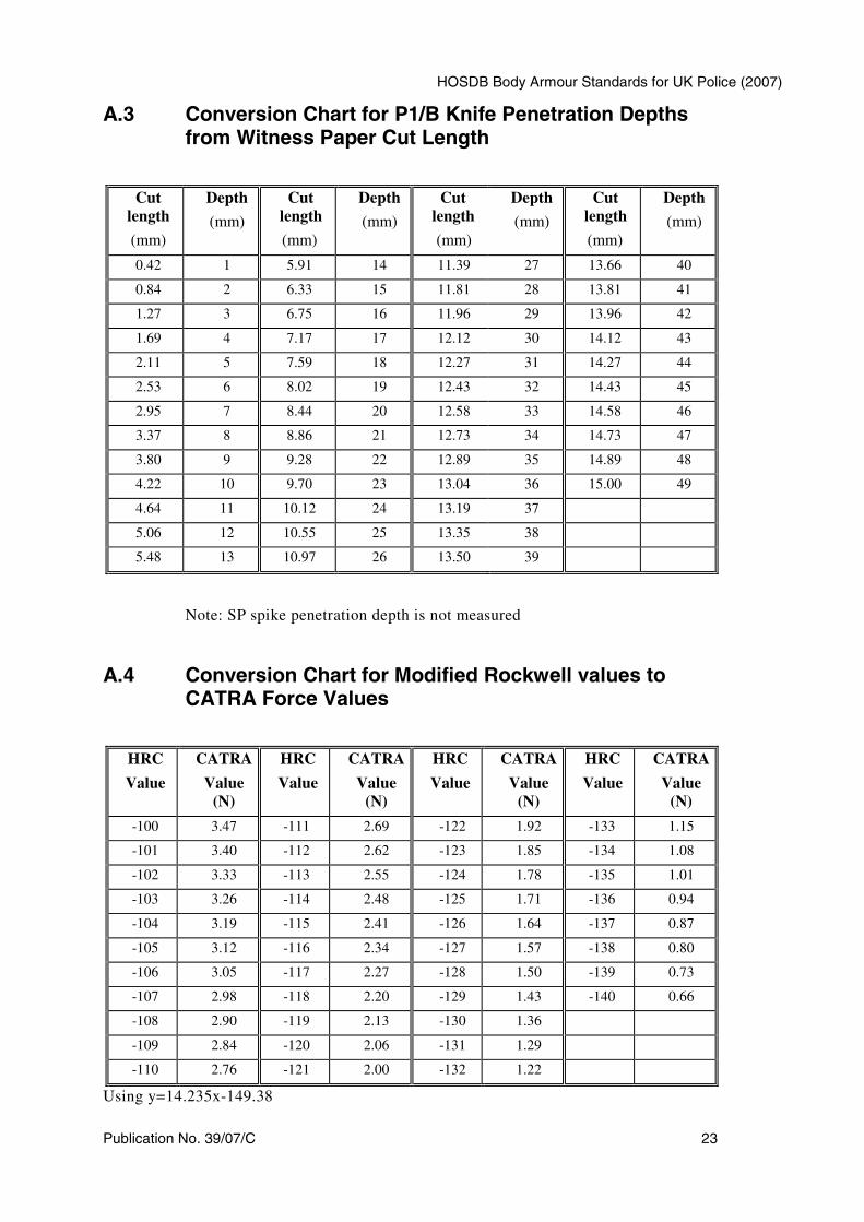
A.3 Conversion Chart for P1/B Knife Penetration Depths from Witness Paper Cut Length
Cut
length
(mm)
Depth
(mm)
Cut
length
(mm)
Depth
(mm)
Cut
length
(mm)
Depth
(mm)
Cut
length
(mm)
Depth
(mm)
0.42 1 5.91 14 11.39 27 13.66 40
0.84 2 6.33 15 11.81 28 13.81 41
1.27 3 6.75 16 11.96 29 13.96 42
1.69 4 7.17 17 12.12 30 14.12 43
2.11 5 7.59 18 12.27 31 14.27 44
2.53 6 8.02 19 12.43 32 14.43 45
2.95 7 8.44 20 12.58 33 14.58 46
3.37 8 8.86 21 12.73 34 14.73 47
3.80 9 9.28 22 12.89 35 14.89 48
4.22 10 9.70 23 13.04 36 15.00 49
4.64 11 10.12 24 13.19 37
5.06 12 10.55 25 13.35 38
5.48 13 10.97 26 13.50 39
Note: SP spike penetration depth is not measured
A.4 Conversion Chart for Modified Rockwell values to CATRA Force Values
HRC
Value
CATRA
Value
(N)
HRC
Value
CATRA
Value
(N)
HRC
Value
CATRA
Value
(N)
HRC
Value
CATRA
Value
(N)
-100 3.47 -111 2.69 -122 1.92 -133 1.15
-101 3.40 -112 2.62 -123 1.85 -134 1.08
-102 3.33 -113 2.55 -124 1.78 -135 1.01
-103 3.26 -114 2.48 -125 1.71 -136 0.94
-104 3.19 -115 2.41 -126 1.64 -137 0.87
-105 3.12 -116 2.34 -127 1.57 -138 0.80
-106 3.05 -117 2.27 -128 1.50 -139 0.73
-107 2.98 -118 2.20 -129 1.43 -140 0.66
-108 2.90 -119 2.13 -130 1.36
-109 2.84 -120 2.06 -131 1.29
-110 2.76 -121 2.00 -132 1.22
Using y=14.235x-149.38
Home Office Scientific Development Branch
24 Publication No. 39/07/C
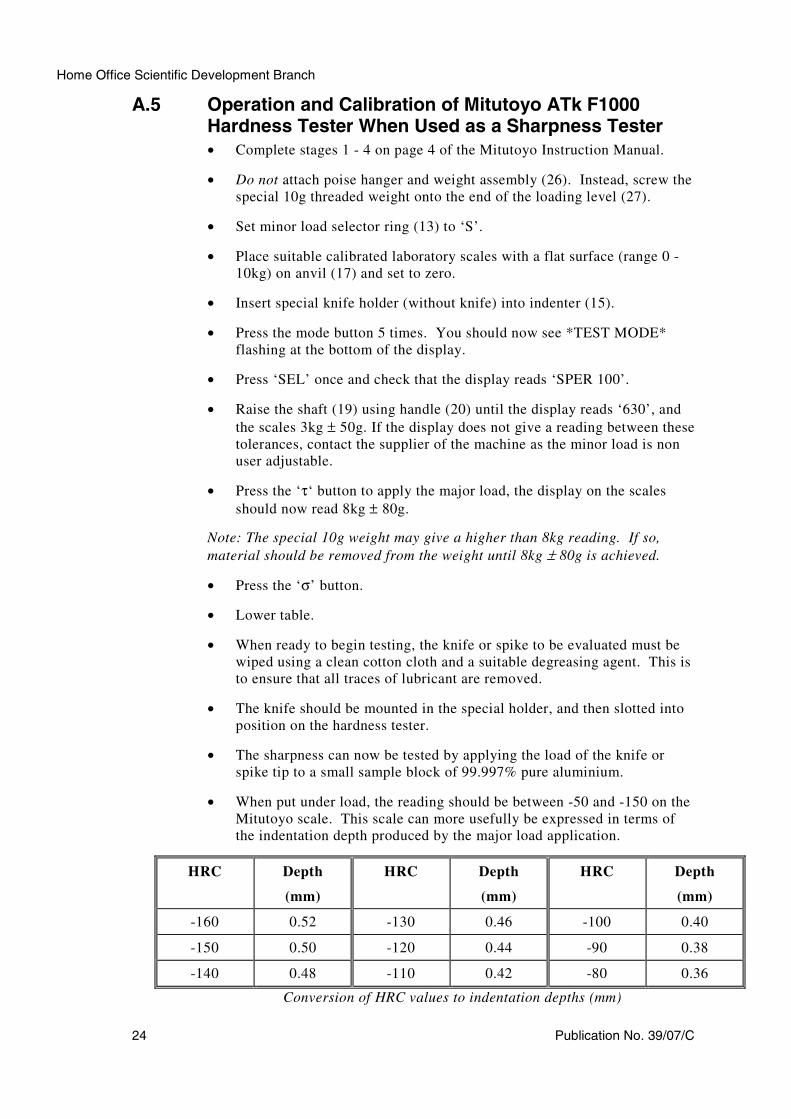
A.5 Operation and Calibration of Mitutoyo ATk F1000 Hardness Tester When Used as a Sharpness Tester
• Complete stages 1 - 4 on page 4 of the Mitutoyo Instruction Manual.
• Do not attach poise hanger and weight assembly (26). Instead, screw the
special 10g threaded weight onto the end of the loading level (27).
• Set minor load selector ring (13) to ‘S’.
• Place suitable calibrated laboratory scales with a flat surface (range 0 -
10kg) on anvil (17) and set to zero.
• Insert special knife holder (without knife) into indenter (15).
• Press the mode button 5 times. You should now see *TEST MODE*
flashing at the bottom of the display.
• Press ‘SEL’ once and check that the display reads ‘SPER 100’.
• Raise the shaft (19) using handle (20) until the display reads ‘630’, and
the scales 3kg ± 50g. If the display does not give a reading between these
tolerances, contact the supplier of the machine as the minor load is non
user adjustable.
• Press the ‘τ‘ button to apply the major load, the display on the scales
should now read 8kg ± 80g.
Note: The special 10g weight may give a higher than 8kg reading. If so,
material should be removed from the weight until 8kg ± 80g is achieved.
• Press the ‘σ’ button.
• Lower table.
• When ready to begin testing, the knife or spike to be evaluated must be
wiped using a clean cotton cloth and a suitable degreasing agent. This is
to ensure that all traces of lubricant are removed.
• The knife should be mounted in the special holder, and then slotted into
position on the hardness tester.
• The sharpness can now be tested by applying the load of the knife or
spike tip to a small sample block of 99.997% pure aluminium.
• When put under load, the reading should be between -50 and -150 on the
Mitutoyo scale. This scale can more usefully be expressed in terms of
the indentation depth produced by the major load application.
HRC Depth
(mm)
HRC Depth
(mm)
HRC Depth
(mm)
-160 0.52 -130 0.46 -100 0.40
-150 0.50 -120 0.44 -90 0.38
-140 0.48 -110 0.42 -80 0.36
Conversion of HRC values to indentation depths (mm)
HOSDB Body Armour Standards for UK Police (2007)
Publication No. 39/07/C 25
Appendix B:
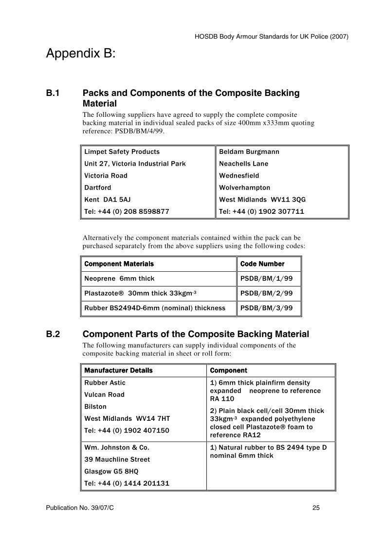
B.1 Packs and Components of the Composite Backing MaterialThe following suppliers have agreed to supply the complete composite
backing material in individual sealed packs of size 400mm x333mm quoting
reference: PSDB/BM/4/99.
Limpet Safety Products
Unit 27, Victoria Industrial Park
Victoria Road
Dartford
Kent DA1 5AJ
Tel: +44 (0) 208 8598877
Beldam Burgmann
Neachells Lane
Wednesfield
Wolverhampton
West Midlands WV11 3QG
Tel: +44 (0) 1902 307711
Alternatively the component materials contained within the pack can be
purchased separately from the above suppliers using the following codes:
Component MaterialsComponent MaterialsComponent MaterialsComponent Materials Code NumberCode NumberCode NumberCode Number
Neoprene 6mm thick PSDB/BM/1/99
Plastazote® 30mm thick 33kgm-3 PSDB/BM/2/99
Rubber BS2494D-6mm (nominal) thickness PSDB/BM/3/99
B.2 Component Parts of the Composite Backing MaterialThe following manufacturers can supply individual components of the
composite backing material in sheet or roll form:
Manufacturer DetailsManufacturer DetailsManufacturer DetailsManufacturer Details ComponentComponentComponentComponent
Rubber Astic
Vulcan Road
Bilston
West Midlands WV14 7HT
Tel: +44 (0) 1902 407150
1) 6mm thick plainfirm density
expanded neoprene to reference
RA 110
2) Plain black cell/cell 30mm thick
33kgm-3 expanded polyethylene
closed cell Plastazote® foam to
reference RA12
Wm. Johnston & Co.
39 Mauchline Street
Glasgow G5 8HQ
Tel: +44 (0) 1414 201131
1) Natural rubber to BS 2494 type D
nominal 6mm thick
Home Office Scientific Development Branch
26 Publication No. 39/07/C
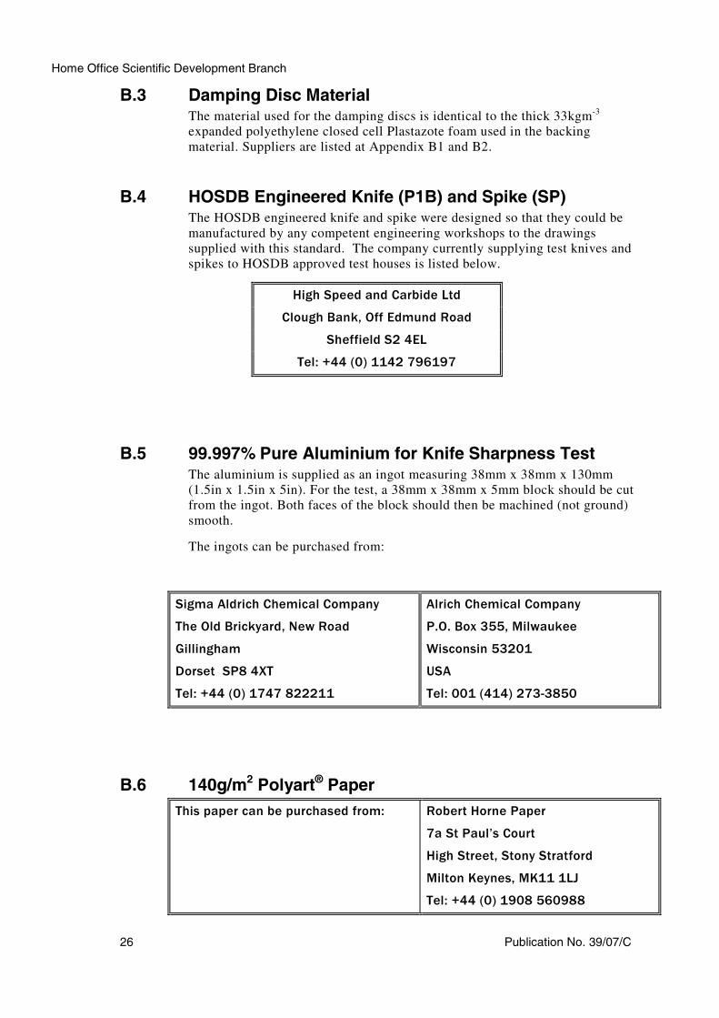
B.3 Damping Disc MaterialThe material used for the damping discs is identical to the thick 33kgm
-3
expanded polyethylene closed cell Plastazote foam used in the backing
material. Suppliers are listed at Appendix B1 and B2.
B.4 HOSDB Engineered Knife (P1B) and Spike (SP)The HOSDB engineered knife and spike were designed so that they could be
manufactured by any competent engineering workshops to the drawings
supplied with this standard. The company currently supplying test knives and
spikes to HOSDB approved test houses is listed below.
High Speed and Carbide Ltd
Clough Bank, Off Edmund Road
Sheffield S2 4EL
Tel: +44 (0) 1142 796197
B.5 99.997% Pure Aluminium for Knife Sharpness TestThe aluminium is supplied as an ingot measuring 38mm x 38mm x 130mm
(1.5in x 1.5in x 5in). For the test, a 38mm x 38mm x 5mm block should be cut
from the ingot. Both faces of the block should then be machined (not ground)
smooth.
The ingots can be purchased from:
Sigma Aldrich Chemical Company
The Old Brickyard, New Road
Gillingham
Dorset SP8 4XT
Tel: +44 (0) 1747 822211
Alrich Chemical Company
P.O. Box 355, Milwaukee
Wisconsin 53201
USA
Tel: 001 (414) 273-3850
B.6 140g/m2 Polyart® Paper
This paper can be purchased from: Robert Horne Paper
7a St Paul’s Court
High Street, Stony Stratford
Milton Keynes, MK11 1LJ
Tel: +44 (0) 1908 560988

HOSDB Body Armour Standards for UK Police (2007)
Publication No. 39/07/C 27
B.7 1.043kg Spherical Steel Ball
The 1.043kg, 63.5mm spherical steel
ball grade 100 can be purchased from:
Salem Speciality Ball Co, Inc,
PO Box 145 West Simsbury,
CT 06092. USA.


Home Office Scientific Development BranchSandridgeSt AlbansAL4 9HQUnited Kingdom
Telephone: +44 (0)1727 865051Fax: +44 (0)1727 816233E-mail: [email protected]: http://science.homeoffice.gov.uk/hosdb/
This is an official document.
If found please return to the nearest police station and informthem how and when it was found. Its unauthorised possession,use, retention, alteration, destruction or transfer to anotherperson may be an offence under the Official Secrets Act.
ISBN: 978-1-84726-426-8


![[Arms and Armour Press] Blitzkrieg. Armour Camouflage and Markings, 1939-40](https://img.pdfslide.net/doc/110x75/5453a1e3b1af9fac578b4afe/arms-and-armour-press-blitzkrieg-armour-camouflage-and-markings-1939-40.jpg)