Embed Size (px)
Citation preview
A S H R A E J O U R N A L a s h r a e . o r g M AY 2 0 181 4
TECHNICAL FEATURE
Kishor Khankari, Ph.D., is president at AnSight LLC in Ann Arbor, Mich.
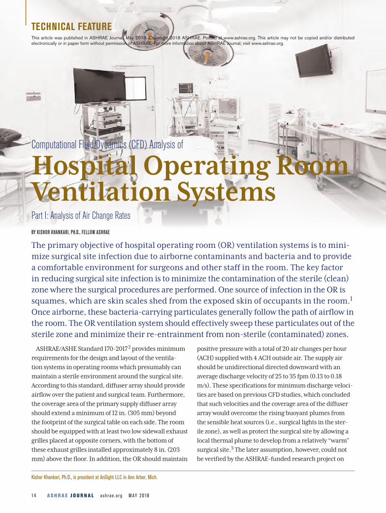
Computational Fluid Dynamics (CFD) Analysis of
Hospital Operating Room Ventilation Systems BY KISHOR KHANKARI, PH.D., FELLOW ASHRAE
The primary objective of hospital operating room (OR) ventilation systems is to mini-mize surgical site infection due to airborne contaminants and bacteria and to provide a comfortable environment for surgeons and other staff in the room. The key factor in reducing surgical site infection is to minimize the contamination of the sterile (clean) zone where the surgical procedures are performed. One source of infection in the OR is squames, which are skin scales shed from the exposed skin of occupants in the room.1 Once airborne, these bacteria-carrying particulates generally follow the path of airflow in the room. The OR ventilation system should effectively sweep these particulates out of the sterile zone and minimize their re-entrainment from non-sterile (contaminated) zones.
ASHRAE/ASHE Standard 170-2017 2 provides minimum
requirements for the design and layout of the ventila-
tion systems in operating rooms which presumably can
maintain a sterile environment around the surgical site.
According to this standard, diffuser array should provide
airflow over the patient and surgical team. Furthermore,
the coverage area of the primary supply diffuser array
should extend a minimum of 12 in. (305 mm) beyond
the footprint of the surgical table on each side. The room
should be equipped with at least two low sidewall exhaust
grilles placed at opposite corners, with the bottom of
these exhaust grilles installed approximately 8 in. (203
mm) above the floor. In addition, the OR should maintain
positive pressure with a total of 20 air changes per hour
(ACH) supplied with 4 ACH outside air. The supply air
should be unidirectional directed downward with an
average discharge velocity of 25 to 35 fpm (0.13 to 0.18
m/s). These specifications for minimum discharge veloci-
ties are based on previous CFD studies, which concluded
that such velocities and the coverage area of the diffuser
array would overcome the rising buoyant plumes from
the sensible heat sources (i.e., surgical lights in the ster-
ile zone), as well as protect the surgical site by allowing a
local thermal plume to develop from a relatively “warm”
surgical site.3 The later assumption, however, could not
be verified by the ASHRAE-funded research project on
Part I: Analysis of Air Change Rates
This article was published in ASHRAE Journal, May 2018. Copyright 2018 ASHRAE. Posted at www.ashrae.org. This article may not be copied and/or distributed electronically or in paper form without permission of ASHRAE. For more information about ASHRAE Journal, visit www.ashrae.org.
M AY 2 0 18 a s h r a e . o r g A S H R A E J O U R N A L 15
experimental evaluation of hospital OR ventilation sys-
tems.4 It should be noted that the role ASHRAE standards
is to provide only “minimum requirements,” which may
not be the optimal design guidelines.
Air is the primary carrier of heat, moisture, contami-
nants, and airborne particulates in operating rooms. The
distribution of supply air and the associated flow path of
the air determine the resulting air velocities, temperature,
and concentration of contaminants, and flow path of air-
borne particulates at various locations in the room. Such
distribution, in turn, determines thermal comfort, air
quality, and potential for transmission of airborne particu-
lates. Ideally, in an operating room the supply air should
pass through the sterile zone and exit through exhaust
grilles in a “single pass” manner without recirculation and
mixing with the supply airstream. It is generally believed
that high air change rates can yield a cleaner environment
in the operating rooms. However, recent studies indicate
increasing ACH does not necessarily provide a cleaner envi-
ronment but substantially increases the operating costs.5
The airflow patterns, temperature distribution, and
resulting flow path of airborne contaminants can depend
on several interrelated factors including the location,
type, and number of supply diffusers; supply air change
rates and supply air temperature; locations and strengths
of various heat sources in a room, including the ambi-
ent and surgical lights; size and location of equipment in
the room that can obstruct the flow path of the air and
contaminants; size and locations of room returns; and
perhaps also on the frequency of opening and closing OR
doors. Physical testing and real time measurements of all
the parameters that can affect the performance of the OR
ACH = 23
ACH = 15
ACH = 31
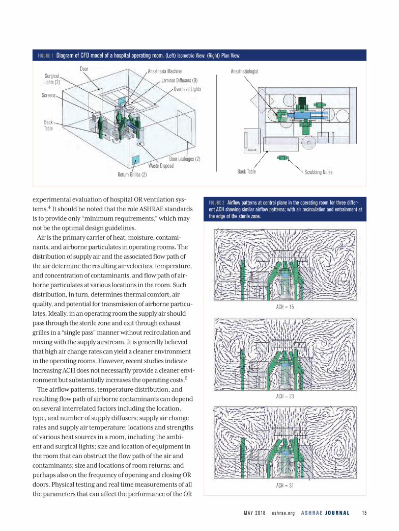
FIGURE 1 Diagram of CFD model of a hospital operating room. (Left) Isometric View. (Right) Plan View.
Door Anesthesia Machine
Laminar Diffusers (9)
Overhead Lights
Door Leakages (2)Waste Disposal
Return Grilles (2)
Back Table
Screens
Surgical Lights (2)
Anesthesiologist
Back Table Scrubbing Nurse
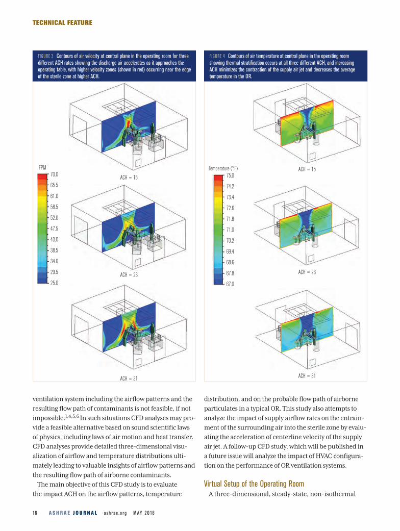
FIGURE 2 Airflow patterns at central plane in the operating room for three differ-ent ACH showing similar airflow patterns; with air recirculation and entrainment at the edge of the sterile zone.
A S H R A E J O U R N A L a s h r a e . o r g M AY 2 0 1816
TECHNICAL FEATURE
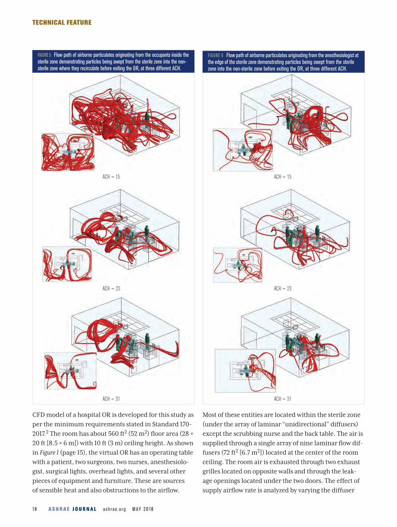
FIGURE 3 Contours of air velocity at central plane in the operating room for three different ACH rates showing the discharge air accelerates as it approaches the operating table, with higher velocity zones (shown in red) occurring near the edge of the sterile zone at higher ACH.
FIGURE 4 Contours of air temperature at central plane in the operating room showing thermal stratification occurs at all three different ACH, and increasing ACH minimizes the contraction of the supply air jet and decreases the average temperature in the OR.
ventilation system including the airflow patterns and the
resulting flow path of contaminants is not feasible, if not
impossible.1,4,5,6 In such situations CFD analyses may pro-
vide a feasible alternative based on sound scientific laws
of physics, including laws of air motion and heat transfer.
CFD analyses provide detailed three-dimensional visu-
alization of airflow and temperature distributions ulti-
mately leading to valuable insights of airflow patterns and
the resulting flow path of airborne contaminants.
The main objective of this CFD study is to evaluate
the impact ACH on the airflow patterns, temperature
distribution, and on the probable flow path of airborne
particulates in a typical OR. This study also attempts to
analyze the impact of supply airflow rates on the entrain-
ment of the surrounding air into the sterile zone by evalu-
ating the acceleration of centerline velocity of the supply
air jet. A follow-up CFD study, which will be published in
a future issue will analyze the impact of HVAC configura-
tion on the performance of OR ventilation systems.
Virtual Setup of the Operating RoomA three-dimensional, steady-state, non-isothermal
ACH = 15
ACH = 23
ACH = 15
ACH = 23
ACH = 31 ACH = 31
FPM70.0
65.5
61.0
58.5
52.0
47.5
43.0
38.5
34.0
29.5
25.0
Temperature (°F)75.0
74.2
73.4
72.6
71.8
71.0
70.2
69.4
68.6
67.8
67.0
A S H R A E J O U R N A L a s h r a e . o r g M AY 2 0 1818
TECHNICAL FEATURE
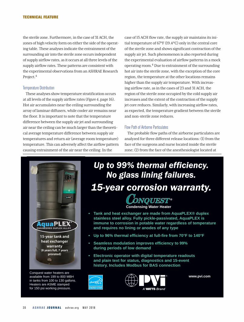
ACH = 15
ACH = 23
ACH = 31
FIGURE 6 Flow path of airborne particulates originating from the anesthesiologist at the edge of the sterile zone demonstrating particles being swept from the sterile zone into the non-sterile zone before exiting the OR, at three different ACH.
CFD model of a hospital OR is developed for this study as
per the minimum requirements stated in Standard 170-
2017.2 The room has about 560 ft2 (52 m2) floor area (28 ×
20 ft [8.5 × 6 m]) with 10 ft (3 m) ceiling height. As shown
in Figure 1 (page 15), the virtual OR has an operating table
with a patient, two surgeons, two nurses, anesthesiolo-
gist, surgical lights, overhead lights, and several other
pieces of equipment and furniture. These are sources
of sensible heat and also obstructions to the airflow.
Most of these entities are located within the sterile zone
(under the array of laminar “unidirectional” diffusers)
except the scrubbing nurse and the back table. The air is
supplied through a single array of nine laminar flow dif-
fusers (72 ft2 [6.7 m2]) located at the center of the room
ceiling. The room air is exhausted through two exhaust
grilles located on opposite walls and through the leak-
age openings located under the two doors. The effect of
supply airflow rate is analyzed by varying the diffuser
ACH = 15
ACH = 23
ACH = 31
FIGURE 5 Flow path of airborne particulates originating from the occupants inside the sterile zone demonstrating particles being swept from the sterile zone into the non-sterile zone where they recirculate before exiting the OR, at three different ACH.

M AY 2 0 18 a s h r a e . o r g A S H R A E J O U R N A L 19
TECHNICAL FEATURE
discharge air velocity from 20, 30, and 40 fpm (0.1, 0.15,
and 0.2 m/s), which correspond to 15, 23, and 31 ACH,
respectively. The exhaust flow rate through the exhaust
grilles was maintained lower than the supply flow rate
such that the exhaust flow rate (leakage) through the two
door openings remains at 350 cfm (165 L/s), and thus,
the room was maintained at positive pressure.
The sensible heat loads due to the occupants and the
overhead lights were assumed to be 1500 Btu/h (440 W)
and 2457 Btu/h (720 W), respectively. The total sensible
heat load due to the other equipment, including the anes-
thesia machine, screens, surgical lights, and monitors was
assumed to be 3583 Btu/h (1050 W). Thus, the total sensible
heat load in the room was assumed to be 7,540 Btu/h (2210
W). The supply air temperature was set at 67°F (19.4°C)
which maintained the average room temperature at 70°F
(21°C). The supply airflow rate at 30 fpm (0.15 m/s) is in
accordance with the minimum requirements in ASHRAE
Standard 170-2017.2 This study did not analyze the transport
of moisture and resulting relative humidity in the space.
The standard k-epsilon (k-e) turbulence model was
employed to compute the turbulent viscosity of the
air. The probable flow paths of airborne particulates
are analyzed by tracking the airflow path streamlines
released from the occupant’s faces which are probably
the most exposed skin surfaces of the surgeons. The
particulates are assumed to be skin squames which are
about 10 microns in diameter.3 This analysis assumes
most of the airborne particles released from the occu-
pant’s faces would follow the flow path of the air.
Particles less than 20 microns can readily follow the flow
path of the air.4 Since the main goal of the proposed
analysis is to analyze the flow path of airborne particles,
any settling and deposition of these particulates on the
surfaces is not explicitly considered in this study.
Results and DiscussionAirflow Patterns
The analyses for three different supply airflow rates
show similar airflow patterns (Figure 2, page 15). In all
three cases, the air from the non-sterile zone entrains at
the edges of the sterile zone. While the air near the floor
moves away from the sterile zone towards the exhaust
grilles, the air in the middle and upper sections of the
room moves from the non-sterile zone into the ster-
ile zone. Also, in all three cases the discharge air from
the laminar diffusers accelerates as it approaches the
operating table (Figure 3, page 16). However, the location
of this high velocity zone changes with the supply airflow
rates.
In the case of low airflow rate (15 ACH) the zone of high
velocity is formed almost at the center of the sterile zone.
In the case of higher airflow rates (23 and 31 ACH) the
zone of high velocity moves towards the outer region of
ACH = 15
ACH = 23
ACH = 31
FIGURE 7 Flow path of airborne particulates originating from the scrubbing nurse located outside the sterile zone showing entrainment of the particles back into the sterile zone for all three ACH.
A S H R A E J O U R N A L a s h r a e . o r g M AY 2 0 182 0
TECHNICAL FEATURE
the sterile zone. Furthermore, in the case of 31 ACH, the
zones of high velocity form on either the side of the operat-
ing table. These analyses indicate the entrainment of the
surrounding air into the sterile zone occurs independent
of supply airflow rates, as it occurs at all three levels of the
supply airflow rates. These patterns are consistent with
the experimental observations from an ASHRAE Research
Project.4
Temperature Distribution
These analyses show temperature stratification occurs
at all levels of the supply airflow rates (Figure 4, page 16).
Hot air accumulates near the ceiling surrounding the
array of laminar diffusers, while cooler air remains near
the floor. It is important to note that the temperature
difference between the supply air jet and surrounding
air near the ceiling can be much larger than the theoreti-
cal average temperature difference between supply air
temperatures and return air (average room temperature)
temperature. This can adversely affect the airflow pattern
causing entrainment of the air near the ceiling. In the
case of 15 ACH flow rate, the supply air maintains its ini-
tial temperature of 67°F (19.4°C) only in the central core
of the sterile zone and shows significant contraction of the
supply air jet. Such phenomenon is also reported during
the experimental evaluation of airflow patterns in a mock
operating room.4 Due to entrainment of the surrounding
hot air into the sterile zone, with the exception of the core
region, the temperature at the other locations remains
higher than the supply air temperature. With increas-
ing airflow rate, as in the cases of 23 and 31 ACH, the
region of the sterile zone occupied by the cold supply air
increases and the extent of the contraction of the supply
jet core reduces. Similarly, with increasing airflow rates,
as expected, the temperature gradient between the sterile
and non-sterile zone reduces.
Flow Path of Airborne Particulates
The probable flow paths of the airborne particulates are
analyzed for three different release locations: (1) from the
face of the surgeons and nurse located inside the sterile
zone; (2) from the face of the anesthesiologist located at
www.pvi.com
• Tank and heat exchanger are made from AquaPLEX® duplex
stainless steel alloy. Fully pickle-passivated, AquaPLEX is
immune to corrosion in potable water regardless of temperature
and requires no lining or anodes of any type
• Up to 96% thermal efficiency at full-fire from 70°F to 140°F
• Seamless modulation improves efficiency to 99%
during periods of low demand
• Electronic operator with digital temperature readouts
and plain text for status, diagnostics and 15-event
history. Includes Modbus for BAS connection
Condensing Water Heater
ONQUESTC ®
Up to 99% thermal efficiency.No glass lining failures.
15-year corrosion warranty.
ENGINEERED DUPLEX ALLOY
®
15-year tank and
heat exchanger
warranty (8 years full, 7 years
prorated)
Conquest water heaters are
available from 199 to 800 MBH
in tanks from 100 to 130 gallons.
Heaters are ASME stamped
for 150 psi working pressure.

A S H R A E J O U R N A L a s h r a e . o r g M AY 2 0 182 2
TECHNICAL FEATURE
the edge of the sterile zone; and (3) from the face of the
scrubbing nurse located outside of the sterile zone. When
the airborne particulates are released within the sterile
zone they are readily swept out of the sterile zone without
any significant entrainment (Figure 5, page 18). This pat-
tern is consistent for all three cases of the ACH. These
particulates can circulate and mix with the air in the non-
sterile zone before exiting the OR, however, at low ACH
these particles may accumulate in the non-sterile zone.
When the airborne particulates are released from the
anesthesiologist located at the outer edge of the sterile
zone, they are also swept away from the sterile zone
(Figure 6, page 18). These particulates also tend to circu-
late within the non-sterile zone before exiting the room.
In the case of the low airflow rate of 15 and 23 ACH, these
particulates may get entrained into the outer edges of
the sterile zone, whereas in the case of the high airflow
rate of 31 ACH they readily exit the OR without signifi-
cant recirculation in the non-sterile zone.
In the final scenario, where airborne particulates
are released from the face of a scrubbing nurse located
outside the sterile zone, the particulates initially move
upward toward the ceiling, and then get entrained back
into the sterile zone. This occurs at all three ACH rates.
After passing through the sterile zone, they follow the
similar path of those particulates that originate from
within the sterile zone (Figure 7, page 19). After exiting the
sterile zone, the particulates can circulate and mix with
the air in the non-sterile zone before exiting the OR.
It should be noted in all these cases the particles are
swept away from the critical zone surrounding the
patient. However, the particulates tend to remain and
circulate in the non-sterile zone before exiting the OR,
which increases the probability of their entrainment into
the sterile zone. Since the two exhaust grilles are located
in the two opposite corners of the room, the particulates
take a convoluted path to eventually exit the room. During
this time prior to exiting the room, these particles have
the opportunity to deposit on the back table located in
the non-sterile zone. This is consistent with the results of
previous studies.1,3,4,6 The size, location, and number of
the exhaust grilles play an important role in determining
M AY 2 0 18 a s h r a e . o r g A S H R A E J O U R N A L 2 3
TECHNICAL FEATURE
the fl ow path of airborne contaminants, especially in the
non-sterile zone. Previous studies of airfl ow paths in the
patient room indicated that modifi cations in the air sup-
ply and return locations can signifi cantly alter the fl ow
path of airborne contaminants.8
Analysis of Centerline Velocity
Hospital operating rooms are often characterized by
high sensible heat loads concentrated within a relatively
small sterile zone. Heat released from various equipment
and surgical lights can cause hot air to rise locally against
the incoming cold supply air. Additionally, as described
before, a zone of high temperature and thermal stratifi ca-
tion often forms surrounding the cold supply air jets. The
temperature gradients between the sterile and non-ster-
ile zone can cause acceleration of the supply air jet from
the laminar diffusers, which in turn, may promote unde-
sirable entrainment of the surrounding contaminated air
from the non-sterile zone into the clean sterile zone.
Due to the recirculation pattern of the entrained air
in and out of the sterile zone, it is diffi cult to quantify
the exact fl ow rate of the recirculated air between the
sterile and non-sterile zone. The extent of acceleration
in the centerline velocity of the supply air along the ver-
tical centerline from the ceiling to the fl oor can provide
an indirect estimate of this entrainment. Archimedes
Number (Ar), a non-dimensional parameter, is a ratio
of the buoyancy force and the inertial force of the down-
ward air jet. The supply airfl ow rates of 15, 23, and 31
ACH (discharge velocity of 20, 30, and 40 fpm [0.1, 0.15,
and 0.2 m/s]) correspond to the Ar number of 21, 6.3,
and 2.7, respectively. Details regarding the calculation of
Ar are given in an ASHRAE Research report.4 Increasing
the discharge velocity (increasing the mass fl ow rate
of the supply air) reduces theoretical temperature dif-
ference between supply and return temperature (∆T ),
which in turn, results in lowering the Ar. Therefore, at
higher airfl ow rates the lower values of Ar indicate fl ow
dominated by inertial force.
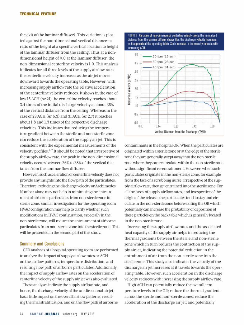
Figure 8 shows the variation of non-dimensional veloc-
ity (a ratio of centerline velocity at a specifi c distance
along the vertical centerline to the discharge velocity at
A S H R A E J O U R N A L a s h r a e . o r g M AY 2 0 182 4
TECHNICAL FEATURE
the exit of the laminar diffuser). This variation is plot-
ted against the non-dimensional vertical distance—a
ratio of the height at a specific vertical location to height
of the laminar diffuser from the ceiling. Thus at a non-
dimensional height of 0.0 at the laminar diffuser, the
non-dimensional centerline velocity is 1.0. This analysis
indicates for all three levels of the supply airflow rates
the centerline velocity increases as the air jet moves
downward towards the operating table. However, with
increasing supply airflow rate the relative acceleration
of the centerline velocity reduces. It shows in the case of
low 15 ACH (Ar 21) the centerline velocity reaches about
3.4 times of the initial discharge velocity at about 38%
of the vertical distance from the ceiling. Whereas in the
case of 23 ACH (Ar 6.3) and 31 ACH (Ar 2.7) it reaches
about 1.8 and 1.3 times of the respective discharge
velocities. This indicates that reducing the tempera-
ture gradient between the sterile and non-sterile zone
can reduce the acceleration of the supply air jet. This is
consistent with the experimental measurements of the
velocity profiles.4,7 It should be noted that irrespective of
the supply airflow rate, the peak in the non-dimensional
velocity occurs between 36% to 38% of the vertical dis-
tance from the laminar flow diffuser.
However, such acceleration of centerline velocity does not
provide any insights into the flow path of the particulates.
Therefore, reducing the discharge velocity or Archimedes
Number alone may not help in minimizing the entrain-
ment of airborne particulates from non-sterile zone to
sterile zone. Similar investigations for the operating room
HVAC configuration may help to clarify whether such
modifications in HVAC configuration, especially in the
non-sterile zone, will reduce the entrainment of airborne
particulates from non-sterile zone into the sterile zone. This
will be presented in the second part of this study.
Summary and ConclusionsCFD analyses of a hospital operating room are performed
to analyze the impact of supply airflow rates or ACH
on the airflow patterns, temperature distribution, and
resulting flow path of airborne particulates. Additionally,
the impact of supply airflow rates on the acceleration of
centerline velocity of the supply air jet was also evaluated.
These analyses indicate the supply airflow rate, and
hence, the discharge velocity of the unidirectional air jet,
has a little impact on the overall airflow patterns, result-
ing thermal stratification, and on the flow path of airborne
contaminants in the hospital OR. When the particulates are
originated within a sterile zone or at the edge of the sterile
zone they are generally swept away into the non-sterile
zone where they can recirculate within the non-sterile zone
without significant re-entrainment. However, when such
particulates originate in the non-sterile zone, for example
from the face of a scrubbing nurse, irrespective of the sup-
ply airflow rate, they get entrained into the sterile zone. For
all the cases of supply airflow rates, and irrespective of the
origin of the release, the particulates tend to stay and cir-
culate in the non-sterile zone before exiting the OR which
potentially can increase the probability of deposition of
these particles on the back table which is generally located
in the non-sterile zone.
Increasing the supply airflow rates and the associated
heat capacity of the supply air helps in reducing the
thermal gradients between the sterile and non-sterile
zone which in turn reduces the contraction of the sup-
ply air jet, indicating the potential reduction in the
entrainment of air from the non-sterile zone into the
sterile zone. This study also indicates the velocity of the
discharge air jet increases at it travels towards the oper-
ating table. However, such acceleration in the discharge
velocity reduces with increasing the supply airflow rate.
High ACH can potentially reduce the overall tem-
perature levels in the OR; reduce the thermal gradients
across the sterile and non-sterile zones; reduce the
acceleration of the discharge air jet; and potentially
FIGURE 8 Variation of non-dimensional centerline velocity along the normalized distance from the laminar diffuser shows that the discharge velocity increases as it approached the operating table. Such increase in the velocity reduces with increasing ACH.
0.00 0.14 0.28 0.42 0.56
Vertical Distance from the Discharge (Y/Yd)
4.0
3.5
3.0
2.5
2.0
1.5
1.0
0.5
0.0
Cent
erlin
e Ve
locity
(U/U
d)
20 fpm (15 ach)
30 fpm (23 ach)
40 fpm (31 ach)
A S H R A E J O U R N A L a s h r a e . o r g M AY 2 0 182 6
TECHNICAL FEATURE
minimize recirculation of airborne particulates in the
non-sterile zone. However, high ACH add to the initial
and operating costs of OR ventilation systems and it can-
not alter the overall airflow patterns and the resulting
flow path of the airborne contaminants (including pos-
sible entrainment of airborne particulates from the non-
sterile zone into the sterile zone).
HVAC configuration including the size, number, and
locations of supply and return of the air may play a role
in determining the flow path of airborne contaminants,
especially in the non-sterile zone. By altering the airflow
patterns in the non-sterile zone, the flow of path of these
particulates may be altered to avoid entrainment. The
legacy HVAC design for hospital operating rooms involv-
ing a ceiling array of laminar supply diffusers and low
wall exhaust grilles on the opposite walls needs further
evaluation to minimize the transfer of airborne particu-
lates from non-sterile to sterile zones.
AcknowledgmentsThe author acknowledges valuable suggestions provided
by several members of ASHRAE Technical Committee 9.6,
Healthcare Facilities. The author is thankful to Dr. Nikhil
Khankari, cancer epidemiologist, for reviewing the man-
uscript and making valuable suggestions.
References1. Wagner, J., K. Schreiber, R. Cohen. 2014. “Using cleanroom
technology – Improving operating room contamination control.”
ASHRAE Journal 56(2):18–27.
2. ANSI/ASHRAE/ASHE Standard 170-2017, Ventilation of Healthcare
Facilities.
3. Memarzadeh, F., A. Manning. 2002. “Comparison of operating
room ventilation systems in the protection of the surgical site.”
ASHRAE Transactions 108(2).
4. Zhai, Z., et al. 2013. “Experimental Investigation of Hospital
Operating Room (OR) Air Distribution.” ASHRAE Research Report RP-1397.
5. Gormley, T., et al. 2017. “Cost-benefit analysis of different air
change rates in an operating room environment.” American Journal of
Infection Control 45:1318–23.
6. Gormley, T., et al. 2017. “Methodology for analyzing
environmental quality indicators in a dynamic operating room
environment.” American Journal of Infection Control 45:354–9.
7. Cook, G., D. Int-Hout. 2009. “Air motion control in the
hospital operating room.” ASHRAE Journal 51(3):30–36.
8. Khankari, K. 2016. Airflow Path Matters: Patient Room HVAC.
ASHRAE Journal 58 (6), 16-26.
Supermarket HVACNew and direct replacement HVAC units built for the
Supermarket industry
• New and direct replacements with increased energy efficiency at full and part load capacity that meet current 2018 DOE requirements
• Double wall aluminum exterior that never rusts
• Best solution for time critical applications where stores cannot afford to be closed any longer than necessary.
• 8 hour change out that matches existing curb and utilities
• Fully configured solutions from 20 tons up
For over 30 years, Seasons 4 is a leading manufacturer of Supermarket HVAC equipment offering
new and replacement units with standard features required specifically for Supermarket duty.
Hot gas reheat coils, Heat reclaim coils, Custom DDC control packages, Single and Dual Path
arrangements all provided for Supermarket dehumidification applications.
www.seasons4.net/AMG