Embed Size (px)
Citation preview
1
TDC800 Manual
Hotr
unner
Contr
olle
r M
anual
Page KAS11-2011
PHRS-GUI Hot Runner Controller Manual
TDC800
Hot Runner Controller
KCTAuto
TDC800
Hot Runner Controller
KCTAuto
TDC800
Hot Runner Controller
KCTAuto
2011.11.08
Ver. Ds2.0
2
TDC800 Manual
Hotr
unner
Contr
olle
r M
anual
Page KAS11-2011
Contents
Thanks for choosing the PHRS- GUI
Function and characteristic
Serial model
Technology specification
Chapter 1 installation and connection
1. Security rules
2. Notes before usage
3. Function description
7. Connect controller with mould
4. Model and Naming rule
5. Structure of the controller
6. Supply power connection
8. Define the module’s position
9. Electrical connection diagram
10. Module sketch map
11. Set communication address
12. Layout plan
Chapter 2 function and principle
1. Running Mode description
2. SOFT START description
3. AUTO TURN description
4. PAC Output
5. SSR Output
Chapter 3 Touch panel operation
1. Menu tree
2. Startup interface
3. Communication setting
5. Main control interface
4. Global setting
6. branch control interface
7. Zone control interface
8. Help interface
Chapter 4 attachment
Running status
Alarm message
Factory setting
3
TDC800 Manual
Hotr
unner
Contr
olle
r M
anual
Page KAS11-2011
Thanks for choosing PHRS-GUI
Function and characteristic
This equipment is based on micro-computer system, and is equipped with centralized
monitoring, standard bus network, modularized construction and touch-panel operation, It
is designed special for hot runner system use.
Temperature control system: Each temperature module control 4 zones temperature,
24pcs of module can be installed in this equipment, so the maximum configuration is 96
zones temperature control loop.
Sequence control system: Each sequence module supply 8 timer controller, 3pcs of
sequence module can be installed in this equipment , so the maximum configuration is 24
zones timer.
PHRS-GUI belong to compact, intensive and multiloop hot runner controller. Temperature
control and sequence control are integrated to one system. Especially suit to control the hot
runner system which is used for producing the Preform of bottle and bottle cap.
PHRS-GUI adopt touch-panel interface, it can display complete running information and easy to
use for new buyer.
PHRS-GUI adopt modularized construction, modules are interchangeable each other, this
reduce spare parts store, save time and money for our customer.
Provide 2 types of thermocouple, K-type or J-type , it can be select in the menu.
Provide 2 types output mode: PAC (Phase-angle shift trigger) or SSR (over zero triggering) , it
can be select in the menu.
In the menu, you can select displaying temperature as Celsius or Fahrenheit
Alarm function:
object’s temperature over upper limit or lower than lower limit
thermocouple open circuit or reverse polar connection
heater open circuit or short circuit
TRIAC broken
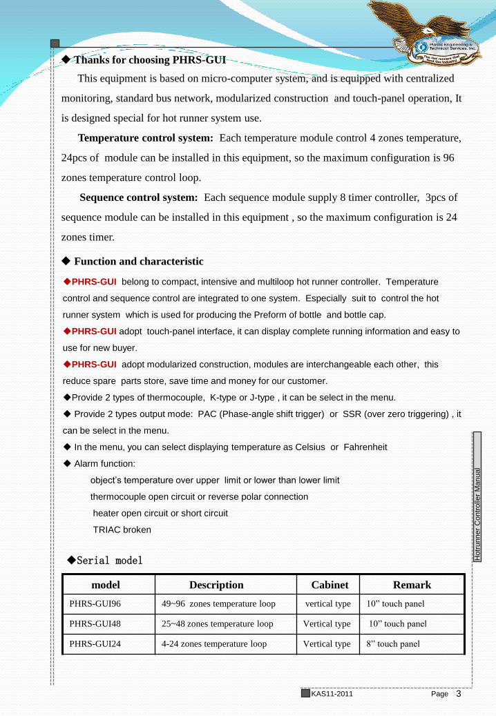
model Description Cabinet Remark
PHRS-GUI96 49~96 zones temperature loop vertical type 10” touch panel
PHRS-GUI48 25~48 zones temperature loop Vertical type 10” touch panel
PHRS-GUI24 4-24 zones temperature loop Vertical type 8” touch panel
Serial model
4
TDC800 Manual
Hotr
unner
Contr
olle
r M
anual
Page KAS11-2011
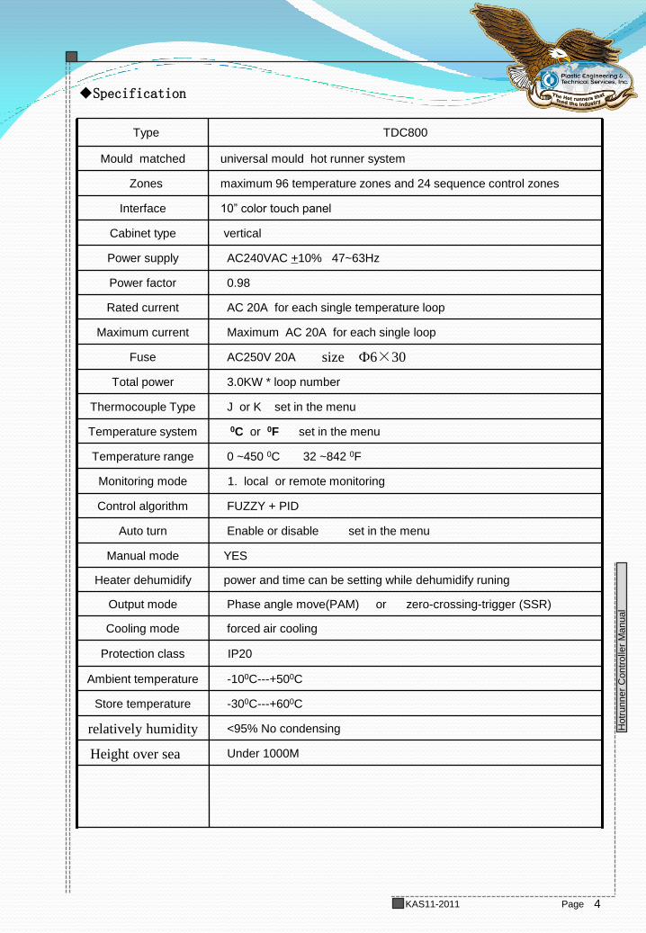
0 ~450 0C 32 ~842 0F Temperature range
AC250V 20A Fuse
power and time can be setting while dehumidify runing Heater dehumidify
YES Manual mode
Enable or disable set in the menu Auto turn
FUZZY + PID Control algorithm
1. local or remote monitoring Monitoring mode
0C or 0F set in the menu Temperature system
forced air cooling Cooling mode
3.0KW * loop number Total power
Phase angle move(PAM) or zero-crossing-trigger (SSR) Output mode
J or K set in the menu Thermocouple Type
Maximum AC 20A for each single loop Maximum current
AC 20A for each single temperature loop Rated current
0.98 Power factor
AC240VAC +10% 47~63Hz Power supply
vertical Cabinet type
10” color touch panel Interface
maximum 96 temperature zones and 24 sequence control zones Zones
universal mould hot runner system Mould matched
TDC800 Type
Under 1000M
<95% No condensing relatively humidity
-300C---+600C Store temperature
-100C---+500C Ambient temperature
IP20 Protection class
Specification
size Ф6×30
Height over sea
5
TDC800 Manual
Hotr
unner
Contr
olle
r M
anual
Page KAS11-2011
Chapter 1 installation and connection
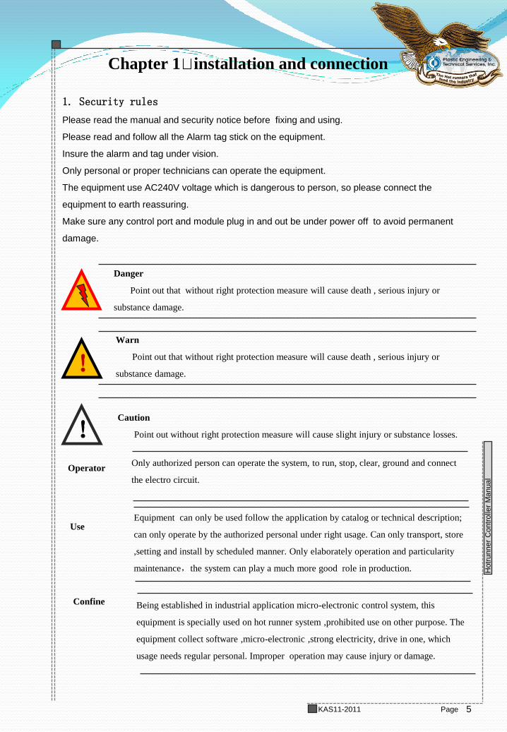
1. Security rules
Please read the manual and security notice before fixing and using.
Please read and follow all the Alarm tag stick on the equipment.
Insure the alarm and tag under vision.
Only personal or proper technicians can operate the equipment.
The equipment use AC240V voltage which is dangerous to person, so please connect the
equipment to earth reassuring.
Make sure any control port and module plug in and out be under power off to avoid permanent
damage.
!
!
Danger
Point out that without right protection measure will cause death , serious injury or
substance damage.
Warn
Point out that without right protection measure will cause death , serious injury or
substance damage.
Caution
Point out without right protection measure will cause slight injury or substance losses.
Only authorized person can operate the system, to run, stop, clear, ground and connect
the electro circuit.
Operator
Equipment can only be used follow the application by catalog or technical description;
can only operate by the authorized personal under right usage. Can only transport, store
,setting and install by scheduled manner. Only elaborately operation and particularity
maintenance,the system can play a much more good role in production.
Use
Confine Being established in industrial application micro-electronic control system, this
equipment is specially used on hot runner system ,prohibited use on other purpose. The
equipment collect software ,micro-electronic ,strong electricity, drive in one, which
usage needs regular personal. Improper operation may cause injury or damage.
6
TDC800 Manual
Hotr
unner
Contr
olle
r M
anual
Page KAS11-2011
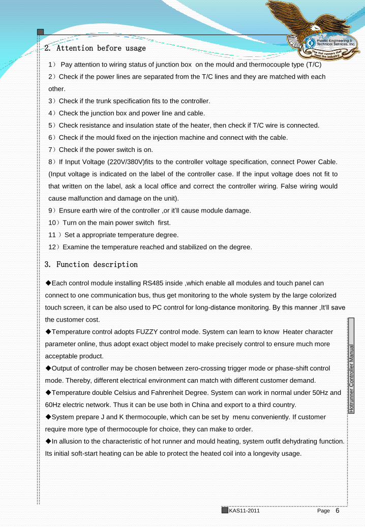
2. Attention before usage
3. Function description
1) Pay attention to wiring status of junction box on the mould and thermocouple type (T/C)
2)Check if the power lines are separated from the T/C lines and they are matched with each
other.
3)Check if the trunk specification fits to the controller.
4)Check the junction box and power line and cable.
5)Check resistance and insulation state of the heater, then check if T/C wire is connected.
6)Check if the mould fixed on the injection machine and connect with the cable.
7)Check if the power switch is on.
8)If Input Voltage (220V/380V)fits to the controller voltage specification, connect Power Cable.
(Input voltage is indicated on the label of the controller case. If the input voltage does not fit to
that written on the label, ask a local office and correct the controller wiring. False wiring would
cause malfunction and damage on the unit).
9)Ensure earth wire of the controller ,or it’ll cause module damage.
10)Turn on the main power switch first.
11 )Set a appropriate temperature degree.
12)Examine the temperature reached and stabilized on the degree.
Each control module installing RS485 inside ,which enable all modules and touch panel can
connect to one communication bus, thus get monitoring to the whole system by the large colorized
touch screen, it can be also used to PC control for long-distance monitoring. By this manner ,It‘ll save
the customer cost.
Temperature control adopts FUZZY control mode. System can learn to know Heater character
parameter online, thus adopt exact object model to make precisely control to ensure much more
acceptable product.
Output of controller may be chosen between zero-crossing trigger mode or phase-shift control
mode. Thereby, different electrical environment can match with different customer demand.
Temperature double Celsius and Fahrenheit Degree. System can work in normal under 50Hz and
60Hz electric network. Thus it can be use both in China and export to a third country.
System prepare J and K thermocouple, which can be set by menu conveniently. If customer
require more type of thermocouple for choice, they can make to order.
In allusion to the characteristic of hot runner and mould heating, system outfit dehydrating function.
Its initial soft-start heating can be able to protect the heated coil into a longevity usage.

7
TDC800 Manual
Hotr
unner
Contr
olle
r M
anual
Page KAS11-2011
In terms of equipment running management, system software design includes energy
consumption measurement and current measurement, equipment effective running timer,
alarm information storage, meanwhile equips abnormal detection and protection for
thermocouple, heater, triac, fuse and such element like this.
Module use plug-in structure as standard insert card type. As a result of module structure
,once the equipment broken, it needs replace the broken module only, which consumedly
save consumer’s maintenance time.
8
TDC800 Manual
Hotr
unner
Contr
olle
r M
anual
Page KAS11-2011
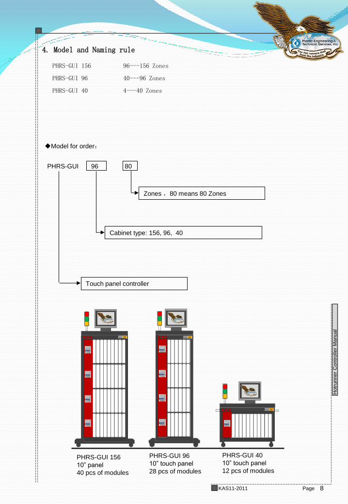
PHRS-GUI 156 96---156 Zones
PHRS-GUI 96 40---96 Zones
PHRS-GUI 40 4---40 Zones
Model for order:
4. Model and Naming rule
PHRS-GUI 96 80
Touch panel controller
Zones ,80 means 80 Zones
Cabinet type: 156, 96, 40
TDC800
Hot Runner Controller
KCTAuto
TDC800
Hot Runner Controller
KCTAuto
TDC800
Hot Runner Controller
KCTAuto
PHRS-GUI 156
10” panel
40 pcs of modules
PHRS-GUI 96
10” touch panel
28 pcs of modules
PHRS-GUI 40
10” touch panel
12 pcs of modules
9
TDC800 Manual
Hotr
unner
Contr
olle
r M
anual
Page KAS11-2011
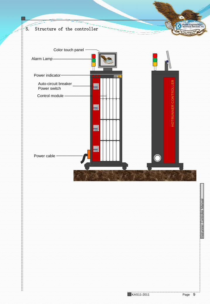
5. Structure of the controller
Power indicator
Auto-circuit breaker
Power switch
Control module
Power cable
Color touch panel
Alarm Lamp
TDC800
Hot Runner Controller
KCTAuto
TDC800
Hot Runner Controller
KCTAuto
TDC800
Hot Runner Controller
KCTAuto
HO
TR
UN
NE
R C
ON
TR
OL
LE
R
10
TDC800 Manual
Hotr
unner
Contr
olle
r M
anual
Page KAS11-2011
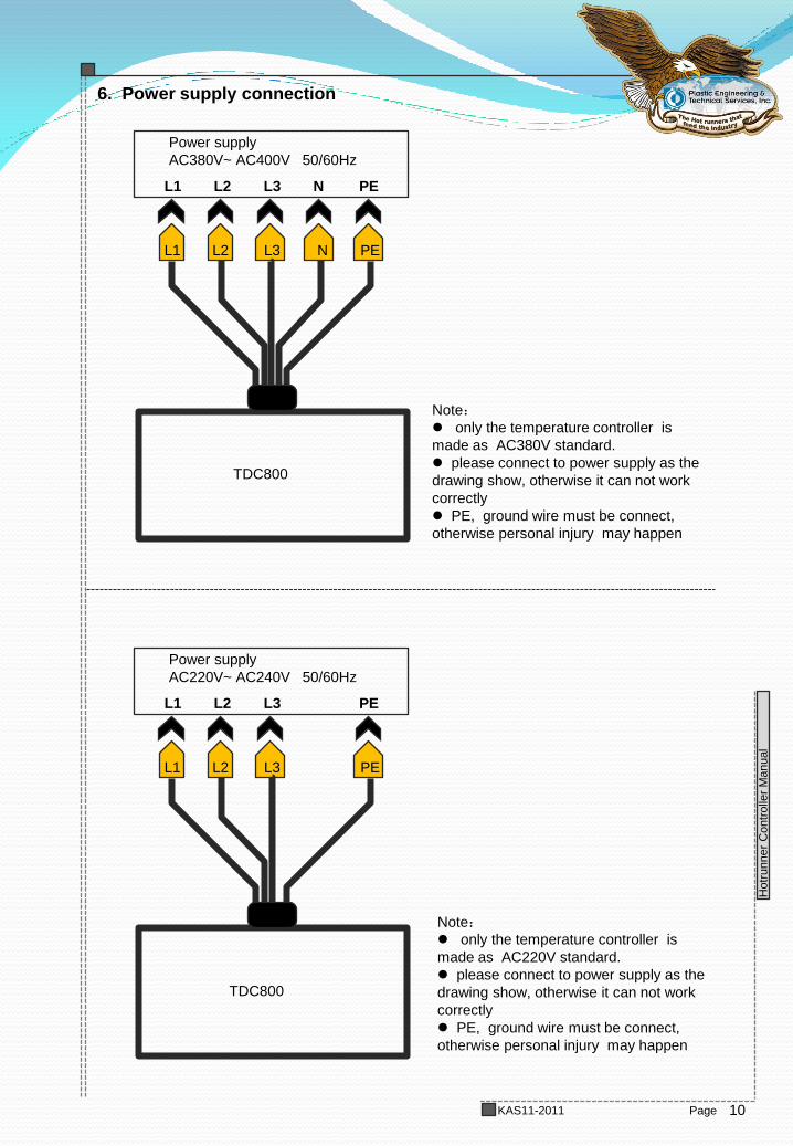
6. Power supply connection
Note:
only the temperature controller is
made as AC380V standard.
please connect to power supply as the
drawing show, otherwise it can not work
correctly
PE, ground wire must be connect,
otherwise personal injury may happen
Power supply
AC380V~ AC400V 50/60Hz
L1 L3 L2 PE N
L1 L2 L3 N PE
TDC800
Power supply
AC220V~ AC240V 50/60Hz
L1 L3 L2 PE
L1 L2 L3 PE
TDC800
Note:
only the temperature controller is
made as AC220V standard.
please connect to power supply as the
drawing show, otherwise it can not work
correctly
PE, ground wire must be connect,
otherwise personal injury may happen
11
TDC800 Manual
Hotr
unner
Contr
olle
r M
anual
Page KAS11-2011
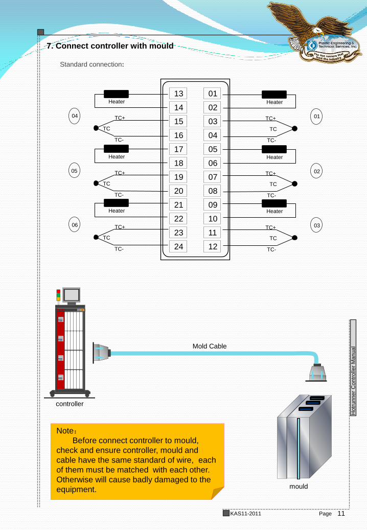
7. Connect controller with mould
Standard connection:
01
02
03
04
05
06
07
08
09
10
11
12
13
14
15
16
17
18
19
20
21
22
23
24
Heater
TC
TC+
TC-
01
Heater
TC
TC+
TC-
02
Heater
TC
TC+
TC-
03
Heater
TC
TC+
TC-
04
Heater
TC
TC+
TC-
05
Heater
TC
TC+
TC-
06
TDC800
Hot Runner Controller
KCTAuto
TDC800
Hot Runner Controller
KCTAuto
TDC800
Hot Runner Controller
KCTAuto
controller
Mold Cable
mould
Note:
Before connect controller to mould,
check and ensure controller, mould and
cable have the same standard of wire, each
of them must be matched with each other.
Otherwise will cause badly damaged to the
equipment.
12
TDC800 Manual
Hotr
unner
Contr
olle
r M
anual
Page KAS11-2011
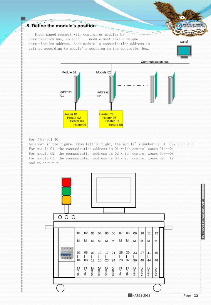
8. Define the module’s position
Touch paned connect with controller modules by communication bus, so each module must have a unique communication address. Each module’s communication address is defined according to module’s position in the controller box.
Module 01 Module 02
address
01 address
02
Heater 01 Heater 02
Heater 03
Heater04
Heater 05 Heater 06
Heater 07
Heater 08
Communication bus
For PHRS-GUI 40: As shown in the figure,from left to right, the module’s number is 01, 02,03……… For module 01, the communication address is 01 which control zones 01---04 For module 02, the communication address is 02 which control zones 05---08 For module 03, the communication address is 03 which control zones 09---12 And so on……….
panel
TDC800
Hot Runner Controller
KCTAuto
TDC800
Hot Runner Controller
KCTAuto
01
M
01
|
04
Zo
nes
02
M
05
|
08
Zo
nes
03
M
09
|
12
Zo
nes
04
M
13
|
16
Zo
nes
05
M
17
|
20
Zo
nes
06
M
21
|
24
Zo
nes
07
M
25
|
28
Zo
nes
08
M
29
|
32
Zo
nes
09
M
33
|
36
Zo
nes
10
M
37
|
40
Zo
nes
11
M
41
|
44
Zo
nes
12
M
45
|
48
Zones
13
TDC800 Manual
Hotr
unner
Contr
olle
r M
anual
Page KAS11-2011
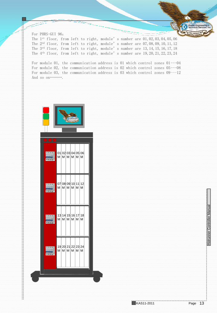
For PHRS-GUI 96: The 1st floor, from left to right, module’s number are 01,02,03,04,05,06 The 2nd floor, from left to right, module’s number are 07,08,09,10,11,12 The 3rd floor, from left to right, module’s number are 13,14,15,16,17,18 The 4th floor, from left to right, module’s number are 19,20,21,22,23,24 For module 01, the communication address is 01 which control zones 01---04 For module 02, the communication address is 02 which control zones 05---08 For module 03, the communication address is 03 which control zones 09---12 And so on……….
01
M
02
M
03
M
04
M
05
M
06
M
07
M
08
M
09
M
10
M
11
M
12
M
13
M
14
M
15
M
16
M
17
M
18
M
19
M
20
M
21
M
22
M
23
M
24
M
14
TDC800 Manual
Hotr
unner
Contr
olle
r M
anual
Page KAS11-2011
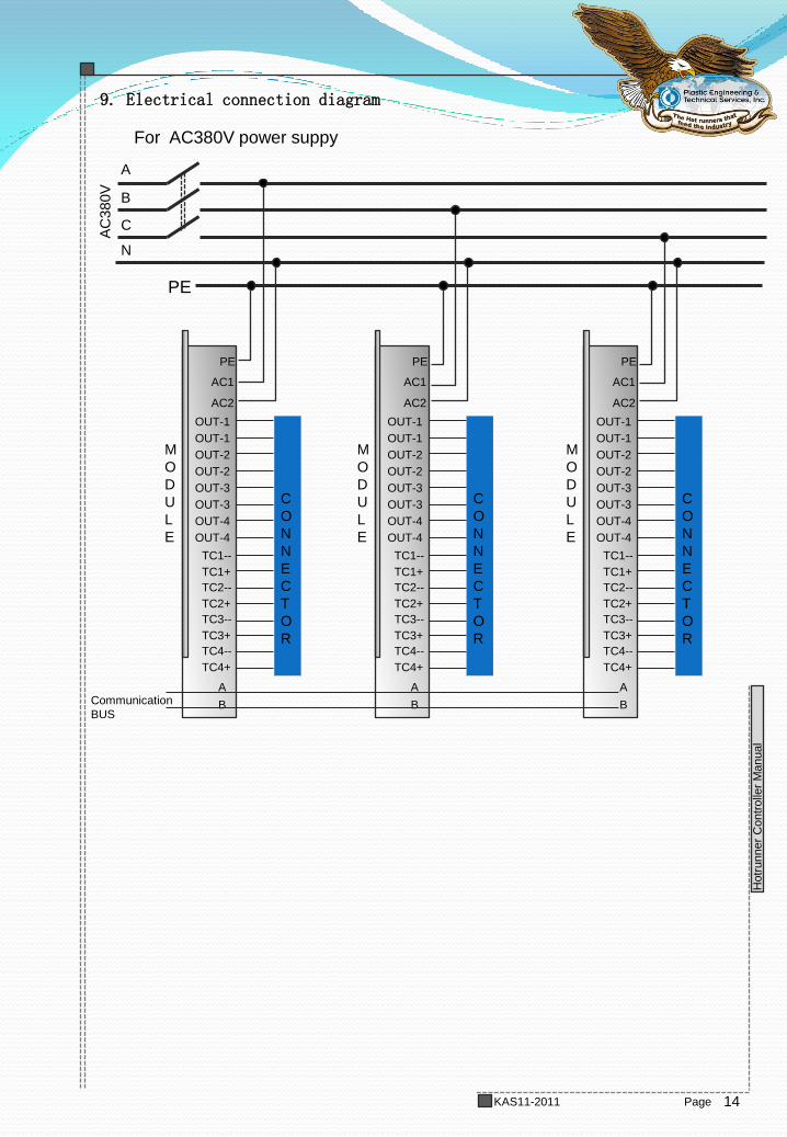
9. Electrical connection diagram A
C380V
PE
A
B
C
N
For AC380V power suppy
PE
AC1
AC2
OUT-1
TC1--
TC1+
C
O
N
N
E
C
T
O
R
M
O
D
U
L
E
OUT-1
OUT-2
OUT-2
OUT-3
OUT-3
OUT-4
OUT-4
TC2--
TC2+
TC3--
TC3+
TC4--
TC4+
A
B
PE
AC1
AC2
OUT-1
TC1--
TC1+
C
O
N
N
E
C
T
O
R
M
O
D
U
L
E
OUT-1
OUT-2
OUT-2
OUT-3
OUT-3
OUT-4
OUT-4
TC2--
TC2+
TC3--
TC3+
TC4--
TC4+
A
B
PE
AC1
AC2
OUT-1
TC1--
TC1+
C
O
N
N
E
C
T
O
R
M
O
D
U
L
E
OUT-1
OUT-2
OUT-2
OUT-3
OUT-3
OUT-4
OUT-4
TC2--
TC2+
TC3--
TC3+
TC4--
TC4+
A
B Communication
BUS
15
TDC800 Manual
Hotr
unner
Contr
olle
r M
anual
Page KAS11-2011
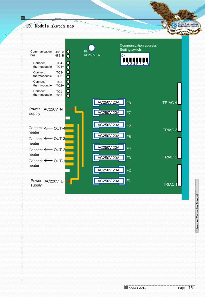
OUT-1
OUT-2
OUT-3
OUT-4
AC220V L
AC220V N
TC1-
TC1+
TC2-
TC2+
TC3-
TC3+
TC4-
TC4+
485 A
485 B
Communication
bus
Connect
thermocouple
Power
supply
Power
supply
Connect
heater
AC250V 20A
AC250V 20A
AC250V 20A
AC250V 20A
AC250V 20A
AC250V 20A
AC250V 20A
AC250V 20A
TRIAC 1
TRIAC 2
TRIAC 3
TRIAC 4
F1
F2
F3
F4
F5
F6
F7
F8
F9
AC250V 1A
1 2 3 4 5 6 7 8
ON
Communication address
Setting switch
10. Module sketch map
Connect
heater
Connect
heater
Connect
heater
Connect
thermocouple
Connect
thermocouple
Connect
thermocouple

16
TDC800 Manual
Hotr
unner
Contr
olle
r M
anual
Page KAS11-2011
1. 8-bit switch is used for setting communication address
2. in one system, each module must has a unique address,. Two
modules can not have same address in one system.
3. the communication address of every module must correspond
with it’s location.
Address and switch position ( blank space = off)
Card Address (Label)
DIP Switch
S1 S4 S3 S2 S5 S6 S7 S8
1
4
3
2
5
6
7
8
9
14
13
12
15
16
17
18
10
11
19
ON
ON ON ON ON ON ON ON
ON ON ON ON ON ON
ON ON ON ON ON ON
ON
ON ON ON ON ON ON ON
ON
ON ON ON ON ON ON
ON
ON ON ON ON ON
ON
ON
ON ON ON ON ON
ON
ON ON
ON ON ON ON
ON ON
ON ON ON ON ON
ON
ON
ON
ON ON ON ON
ON
ON
ON
ON ON ON ON ON
ON ON
ON ON ON ON
ON
ON ON
ON ON ON ON
ON
ON ON
ON ON ON
ON
ON ON
ON
ON
ON ON ON ON ON
11. Set communication address
OFF ON
S8
S4
S7
S6
S5
S3
S2
S1
ON
ON
ON ON ON
ON ON
ON ON ON
ON
ON ON ON
ON ON
ON
ON
ON ON ON ON
22
21
20
23
24
25
26
ON ON ON ON ON
ON ON ON ON ON ON
ON
ON
ON
ON
ON ON ON ON ON
17
TDC800 Manual
Hotr
unner
Contr
olle
r M
anual
Page KAS11-2011
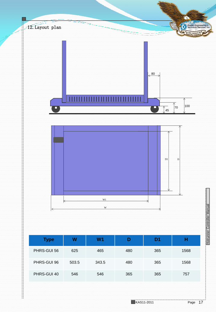
4570
100
80
DD1
W
W1
12.Layout plan
Type W W1 D D1 H
PHRS-GUI 56 625 465 480 365 1568
PHRS-GUI 96 503.5 343.5 480 365 1568
PHRS-GUI 40 546 546 365 365 757
18
TDC800 Manual
Hotr
unner
Contr
olle
r M
anual
Page KAS11-2011
Chapter 2 function and principle
1. Running mode description
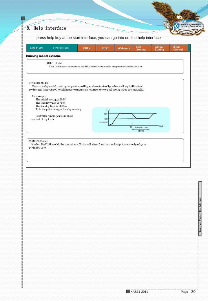
AUTO Mode:
this is the most common mode, controller trace setpoint and maintain temperature
automatically.
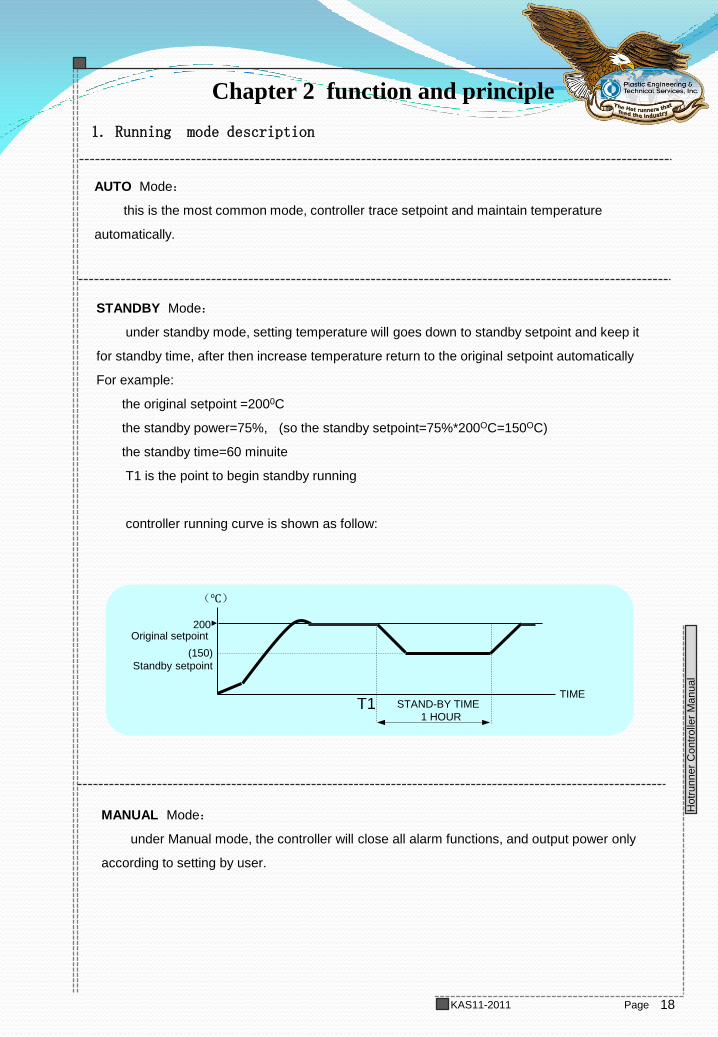
STANDBY Mode:
under standby mode, setting temperature will goes down to standby setpoint and keep it
for standby time, after then increase temperature return to the original setpoint automatically
For example:
the original setpoint =2000C
the standby power=75%, (so the standby setpoint=75%*200OC=150OC)
the standby time=60 minuite
T1 is the point to begin standby running
controller running curve is shown as follow:
MANUAL Mode:
under Manual mode, the controller will close all alarm functions, and output power only
according to setting by user.
(℃)
(150)
Standby setpoint
TIME STAND-BY TIME
1 HOUR
200
T1
Original setpoint
19
TDC800 Manual
Hotr
unner
Contr
olle
r M
anual
Page KAS11-2011
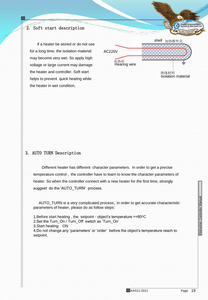
AC220V
电热丝
加热棒外壳
绝缘材料
if a heater be stored or do not use
for a long time, the isolation material
may become very wet. So apply high
voltage or large current may damage
the heater and controller. Soft start
helps to prevent quick heating while
the heater in wet condition,
2. Soft start description
Different heater has different character parameters. In order to get a precise
temperature control , the controller have to learn to know the character parameters of
heater. So when the controller connect with a new heater for the first time, strongly
suggest do the ‘AUTO_TURN’ process.
AUTO_TURN is a very complicated process, in order to get accurate characteristic
parameters of heater, please do as follow steps:
1.Before start heating , the setpoint - object’s temperature >=80oC
2.Set the Turn_On / Turn_Off switch as ‘Turn_On’
3.Start heating: ON
4.Do not change any ‘parameters’ or ‘order’ before the object’s temperature reach to
setpoint.
3. AUTO TURN Description
shell
Hearing wire
Isolation material
20
TDC800 Manual
Hotr
unner
Contr
olle
r M
anual
Page KAS11-2011
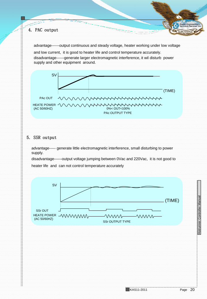
advantage------output continuous and steady voltage, heater working under low voltage
and low current, it is good to heater life and control temperature accurately.
disadvantage------generate larger electromagnetic interference, it wil disturb power
supply and other equipment around.
可用 键选择不同的输出方式 (PWM)或 (SSR) 。
设定结束后同时按 键+ 键。
(TIME)
SV
PAc OUT
PAc OUTPUT TYPE
HEATE POWER
(AC 50/60HZ)
advantage----- generate little electromagnetic interference, small disturbing to power
supply.
disadvantage------output voltage jumping between 0Vac and 220Vac, it is not good to
heater life and can not control temperature accurately
0%< OUT<100%
4. PAC output
5. SSR output
SSr OUT
HEATE POWER
(AC 50/60HZ) SSr OUTPUT TYPE
(TIME)
SV
21
TDC800 Manual
Hotr
unner
Contr
olle
r M
anual
Page KAS11-2011
Chapter 3 Touch panel operation
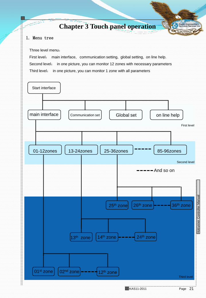
1. Menu tree
Start interface
main interface Communication set Global set on line help
01-12zones 13-24zones 25-36zones 85-96zones
01st zone 02nd zone 12th zone
13th zone 14th zone 24th zone
25th zone 26th zone 36th zone
And so on
Three level menu:
First level: main interface, communication setting, global setting, on line help.
Second level: in one picture, you can monitor 12 zones with necessary parameters
Third level: in one picture, you can monitor 1 zone with all parameters
First level
Second level
Third level
22
TDC800 Manual
Hotr
unner
Contr
olle
r M
anual
Page KAS11-2011
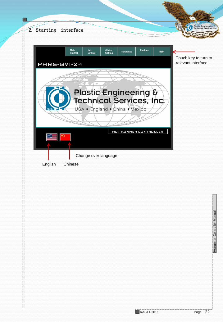
2. Starting interface
English
Touch key to turn to
relevant interface
Chinese
Change over language
23
TDC800 Manual
Hotr
unner
Contr
olle
r M
anual
Page KAS11-2011
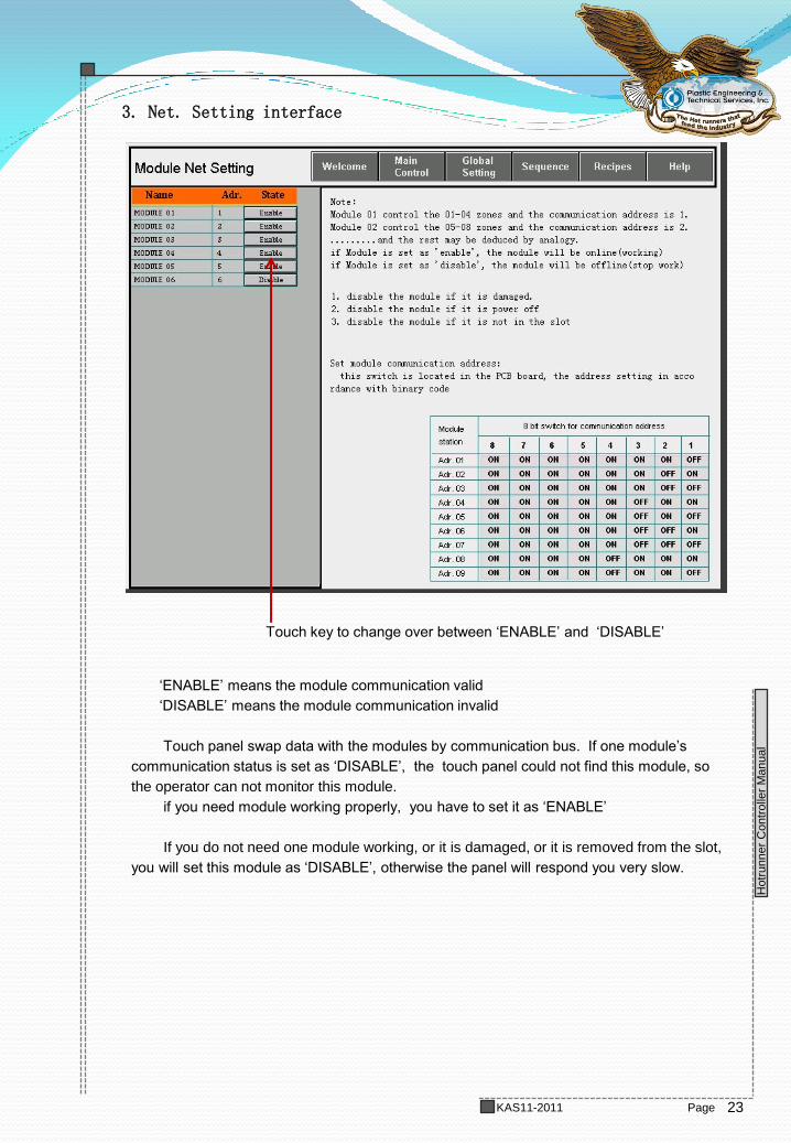
3. Net. Setting interface
‘ENABLE’ means the module communication valid
‘DISABLE’ means the module communication invalid
Touch panel swap data with the modules by communication bus. If one module’s
communication status is set as ‘DISABLE’, the touch panel could not find this module, so
the operator can not monitor this module.
if you need module working properly, you have to set it as ‘ENABLE’
If you do not need one module working, or it is damaged, or it is removed from the slot,
you will set this module as ‘DISABLE’, otherwise the panel will respond you very slow.
Touch key to change over between ‘ENABLE’ and ‘DISABLE’
24
TDC800 Manual
Hotr
unner
Contr
olle
r M
anual
Page KAS11-2011
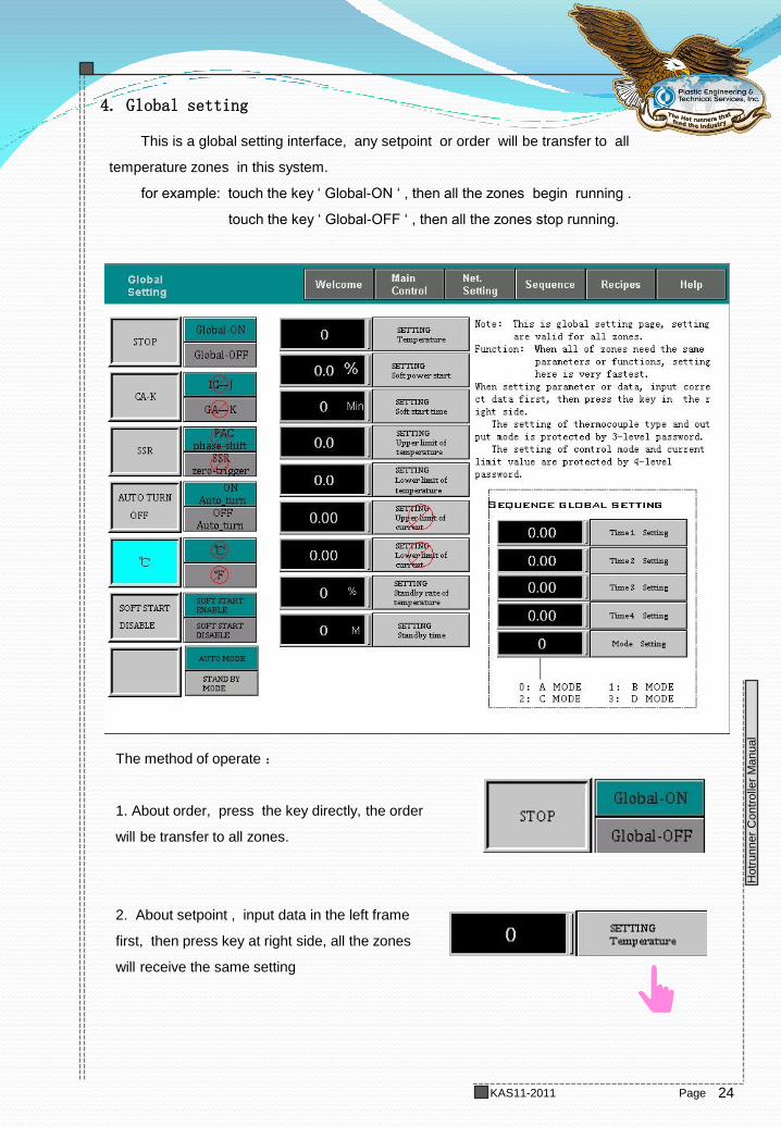
4. Global setting
This is a global setting interface, any setpoint or order will be transfer to all
temperature zones in this system.
for example: touch the key ‘ Global-ON ‘ , then all the zones begin running .
touch the key ‘ Global-OFF ‘ , then all the zones stop running.
The method of operate :
1. About order, press the key directly, the order
will be transfer to all zones.
2. About setpoint , input data in the left frame
first, then press key at right side, all the zones
will receive the same setting
25
TDC800 Manual
Hotr
unner
Contr
olle
r M
anual
Page KAS11-2011
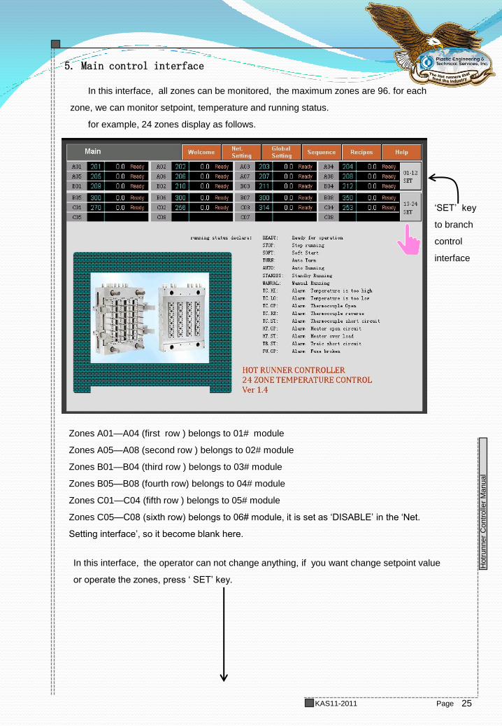
5. Main control interface
In this interface, all zones can be monitored, the maximum zones are 96. for each
zone, we can monitor setpoint, temperature and running status.
for example, 24 zones display as follows.
Zones A01—A04 (first row ) belongs to 01# module
Zones A05—A08 (second row ) belongs to 02# module
Zones B01—B04 (third row ) belongs to 03# module
Zones B05—B08 (fourth row) belongs to 04# module
Zones C01—C04 (fifth row ) belongs to 05# module
Zones C05—C08 (sixth row) belongs to 06# module, it is set as ‘DISABLE’ in the ‘Net.
Setting interface’, so it become blank here.
In this interface, the operator can not change anything, if you want change setpoint value
or operate the zones, press ‘ SET’ key.
‘SET’ key
to branch
control
interface
26
TDC800 Manual
Hotr
unner
Contr
olle
r M
anual
Page KAS11-2011
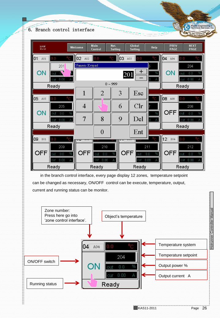
6. Branch control interface
in the branch control interface, every page display 12 zones, temperature setpoint
can be changed as necessary, ON/OFF control can be execute, temperature, output,
current and running status can be monitor.
Zone number:
Press here go into
‘zone control interface’. Object’s temperature
Temperature system
Temperature setpoint
Output power %
Output current A
Running status
ON/OFF switch
27
TDC800 Manual
Hotr
unner
Contr
olle
r M
anual
Page KAS11-2011
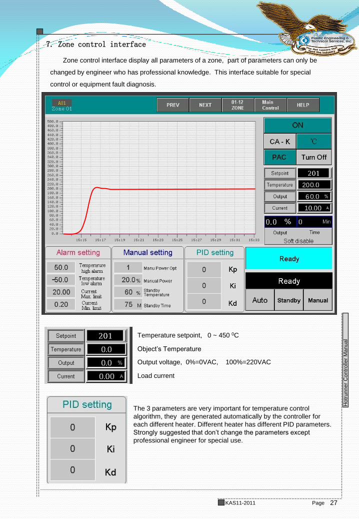
7. Zone control interface
Zone control interface display all parameters of a zone, part of parameters can only be
changed by engineer who has professional knowledge. This interface suitable for special
control or equipment fault diagnosis.
Temperature setpoint, 0 ~ 450 0C
The 3 parameters are very important for temperature control
algorithm, they are generated automatically by the controller for
each different heater. Different heater has different PID parameters.
Strongly suggested that don’t change the parameters except
professional engineer for special use.
20
1
6
Object’s Temperature
Output voltage, 0%=0VAC, 100%=220VAC
Load current
28
TDC800 Manual
Hotr
unner
Contr
olle
r M
anual
Page KAS11-2011
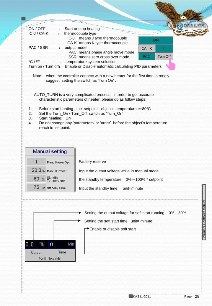
ON / OFF : Start or stop heating
IC-J / CA-K : thermocouple type
IC-J means J type thermocouple
CA-K means K type thermocouple
PAC / SSR : output mode
PAC means phase angle move mode
SSR means zero cross over mode 0C / 0F : temperature system selection
Turn on / Turn off: Enable or Disable automatic calculating PID parameters
Note: when the controller connect with a new heater for the first time, strongly
suggest setting the switch as ‘Turn On’ .
AUTO_TURN is a very complicated process, in order to get accurate
characteristic parameters of heater, please do as follow steps:
1. Before start heating , the setpoint - object’s temperature >=80oC
2. Set the Turn_On / Turn_Off switch as ‘Turn_On’
3. Start heating: ON
4. Do not change any ‘parameters’ or ‘order’ before the object’s temperature
reach to setpoint.
Input the output voltage while in manual mode
the standby temperature = 0%---100% * setpoint
Input the standby time: unit=minute
Setting the output voltage for soft start running 0%---30%
Setting the soft start time unit= minute
Enable or disable soft start
Factory reserve
29
TDC800 Manual
Hotr
unner
Contr
olle
r M
anual
Page KAS11-2011
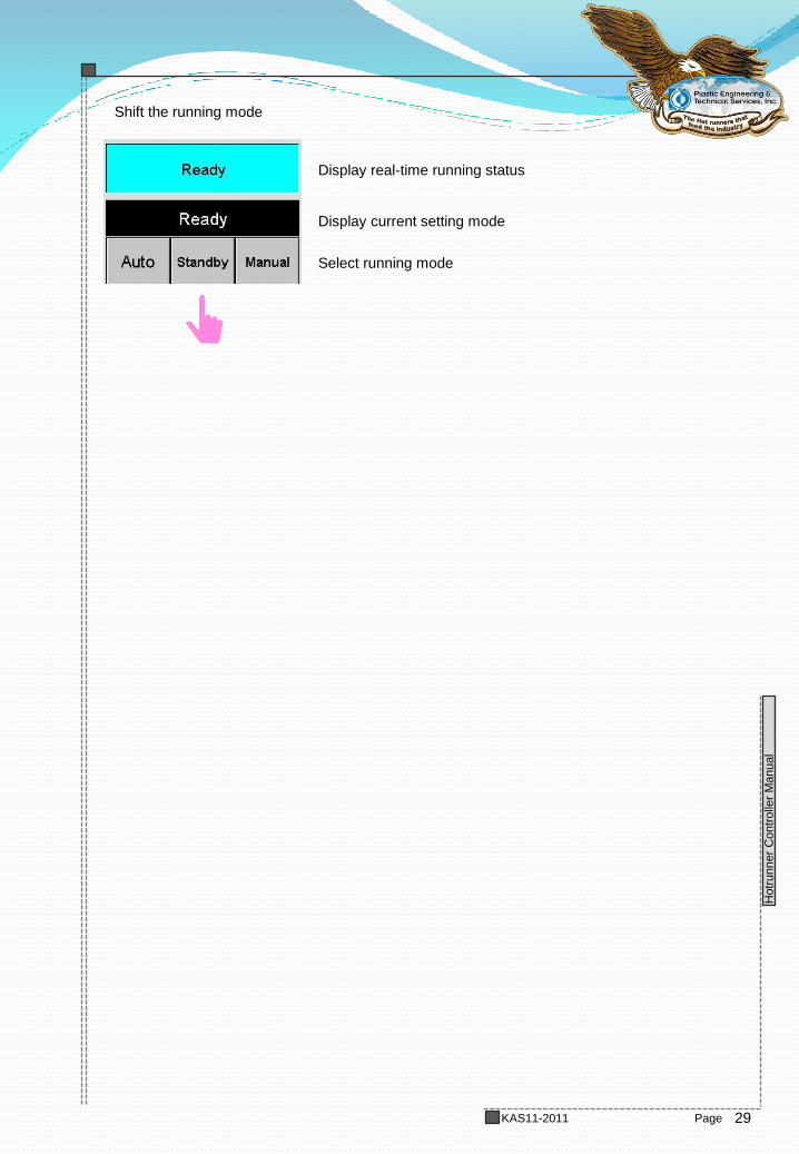
Display real-time running status
Shift the running mode
Display current setting mode
Select running mode
30
TDC800 Manual
Hotr
unner
Contr
olle
r M
anual
Page KAS11-2011
8. Help interface
press help key at the start interface, you can go into on-line help interface
31
TDC800 Manual
Hotr
unner
Contr
olle
r M
anual
Page KAS11-2011
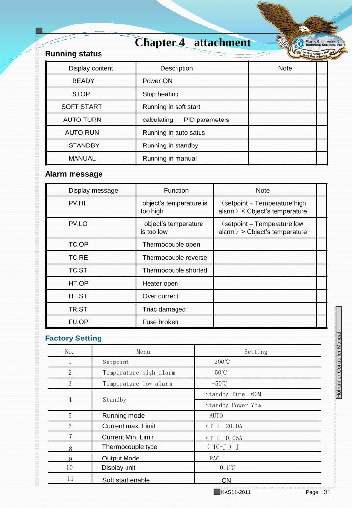
Display content Description Note
READY Power ON
STOP Stop heating
SOFT START Running in soft start
AUTO TURN calculating PID parameters
AUTO RUN Running in auto satus
STANDBY Running in standby
MANUAL Running in manual
Running status
Display message Function Note
PV.HI object’s temperature is
too high
(setpoint + Temperature high
alarm)< Object’s temperature
PV.LO object’s temperature
is too low
(setpoint – Temperature low
alarm)> Object’s temperature
TC.OP Thermocouple open
TC.RE Thermocouple reverse
TC.ST Thermocouple shorted
HT.OP Heater open
HT.ST Over current
TR.ST Triac damaged
FU.OP Fuse broken
Alarm message
Chapter 4 attachment
Factory Setting
CT-H 20.0A Current max. Limit 6
AUTO Running mode 5
Standby Power 75%
Standby Time 60M Standby 4
-50℃ Temperature low alarm 3
50℃ Temperature high alarm 2
200℃ Setpoint 1
Setting Menu No.
9
8
7
10
Current Min. Limir
Thermocouple type
Output Mode
Display unit
CT-L 0.05A
PAC
0.1OC
( IC-J ) J
11 Soft start enable ON
32
TDC800 Manual
Hotr
unner
Contr
olle
r M
anual
Page KAS11-2011
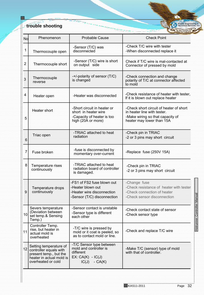
trouble shooting
Setting temperature of controller equals with present temp., but the heater in actual mold is overheated or cold
-Change fuse
-Check resistance of heater with tester
-Check connection of heater
-Check sensor disconnection
-Check resistance of heater with tester, If it is blown out replace heater
-Check contact state of sensor
-Check sensor type
-Sensor contact is unstable
-Sensor type is different each other
Severs temperature (Deviation between set temp.& Sensing Temp.)
11
-Make T/C (sensor) type of mold with that of controller.
-T/C Sensor type between mold and controller is different
EX: CA(K) -IC(J)
IC(J) -CA(K)
-Check and replace T/C wire -T/C wire is pressed by mold or it coat is peeled, so as to contact mold or line.
Controller Temp. rise, but heater in actual mold is overheated
12
-FS1 of FS2 fuse blown out
-Heater blown out
-Heater wire disconnection
-Sensor (T/C) disconnection
Temperature drops continuously
10
-Check pin in TRIAC
-2 or 3 pins may short circuit
-TRIAC attached to heat radiation board of controller is damaged.
Temperature rises continuously
9
8
-Replace fuse (250V 15A) -fuse is disconnected by momentary over-current Fuse broken 7
-Check pin in TRIAC
-2 or 3 pins may short circuit
-TRIAC attached to heat radiation Triac open
6
-Check short circuit of heater of short in heater line with tester.
-Make wiring so that capacity of heater may lower than 15A
-Short circuit in heater or short in heater wire
-Capacity of heater is too high (20A or more)
Heater short
5
-Heater was disconnected Heater open 4
-Check connection and change polarity of T/C at connector affected to mold
-+/-polarity of sensor (T/C) is changed
Thermocouple reverse
3
Check if T/C wire is mal-contacted at Connector of pressed by mold
-Sensor (T/C) wire is short on output side Thermocouple short 2
-Check T/C wire with tester
-When disconnected replace it -Sensor (T/C) was disconnected Thermocouple open 1
Check Point Probable Cause Phenomenon No