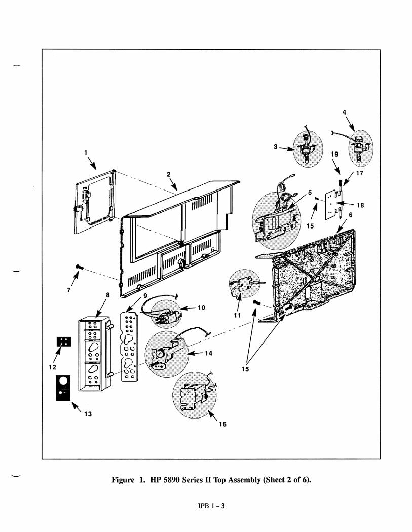
Embed Size (px)
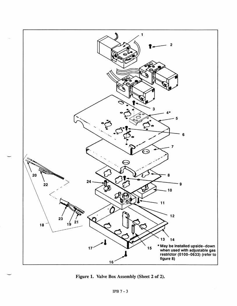
DESCRIPTION
HP 5890 GC Parts Breakdown
Citation preview
5
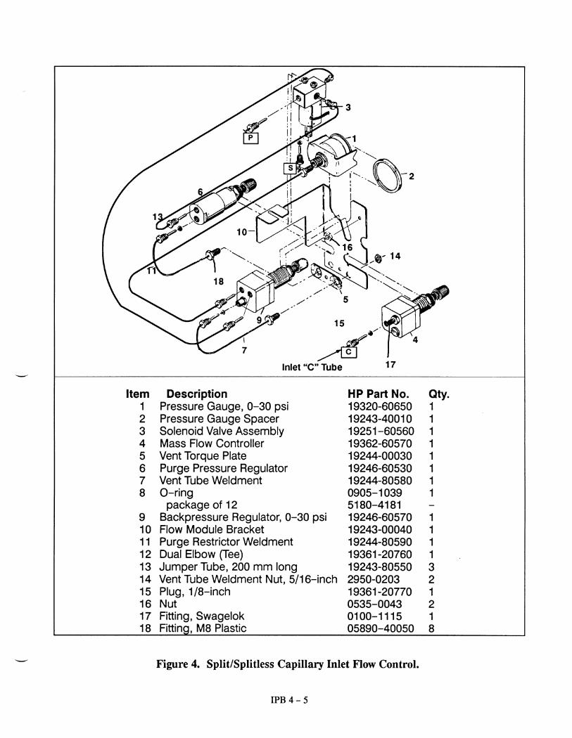
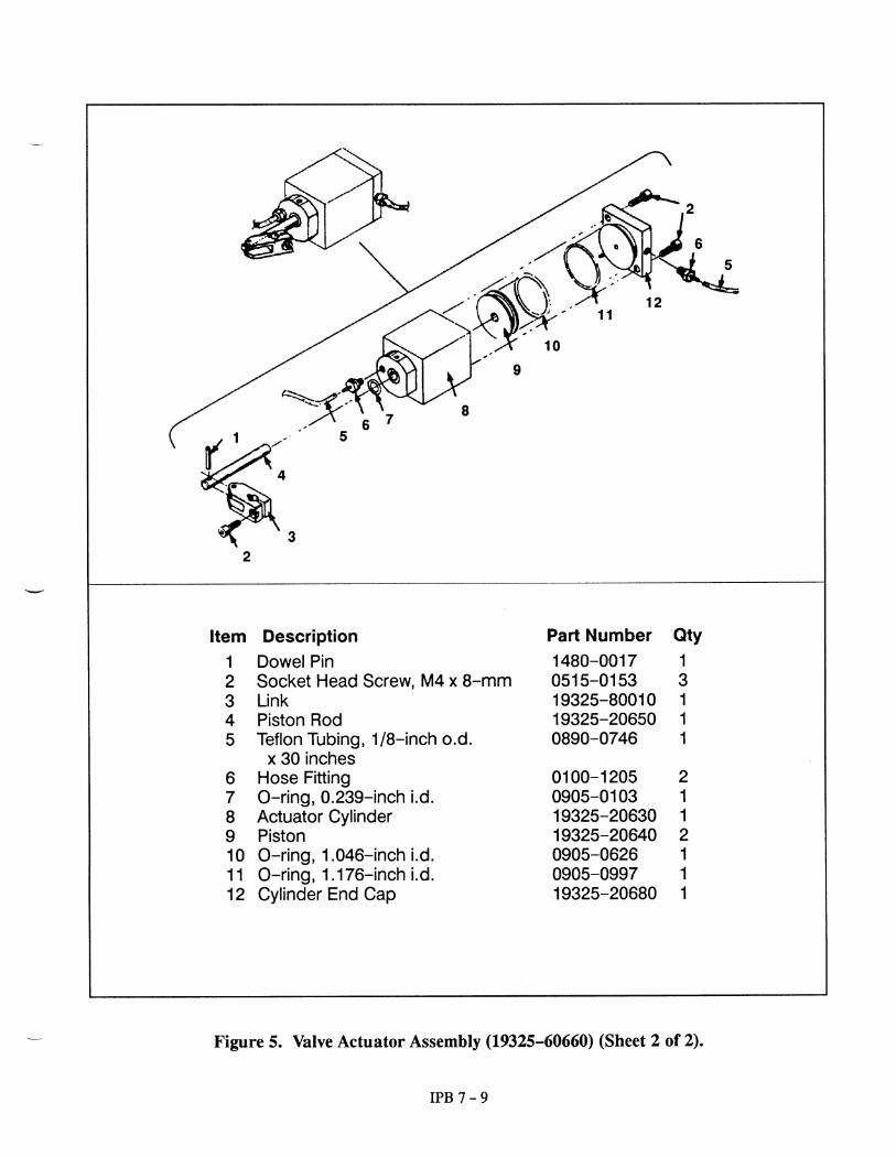
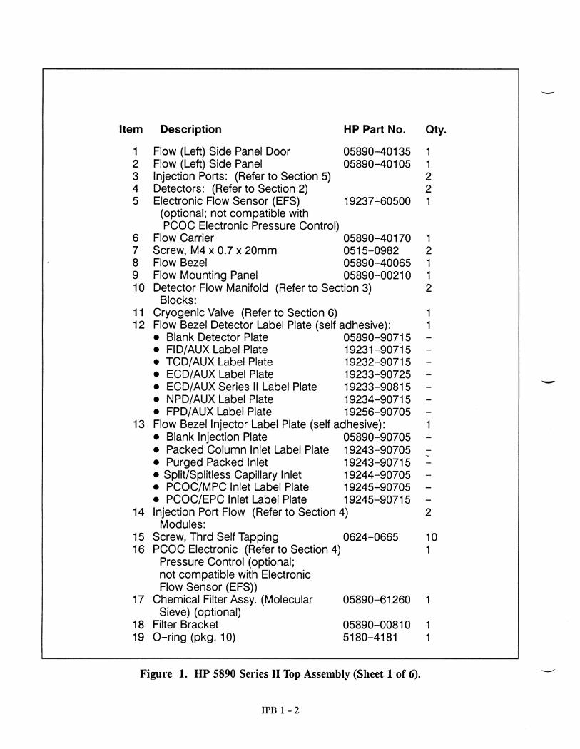
Item Description HP Part No.
1 M8 Plastic Fitting (Package of 10) 5181-33942 O-ring (Package of 12) 5180-41813 M8 x M8 Side Tube Weldment 19245-806404 M8 Brass Plug 19361-20770
Figure 3. Back Pressure-Controlled Split/Splitless Capillary Inlet (Sheet 1 of 2). .
6
3
2
2
1
1
2
2
4
1
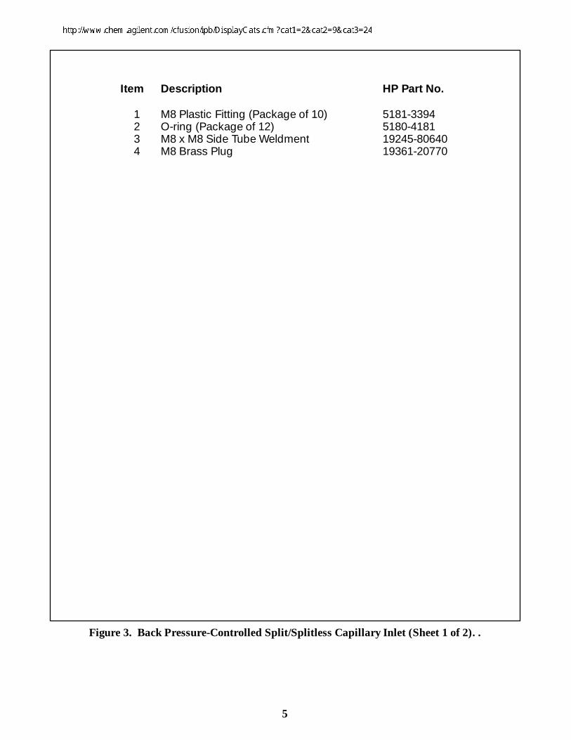
Figure 3. Back Pressure Controlled Split/Splitless Capillary Inlet (Sheet 2 of 2).
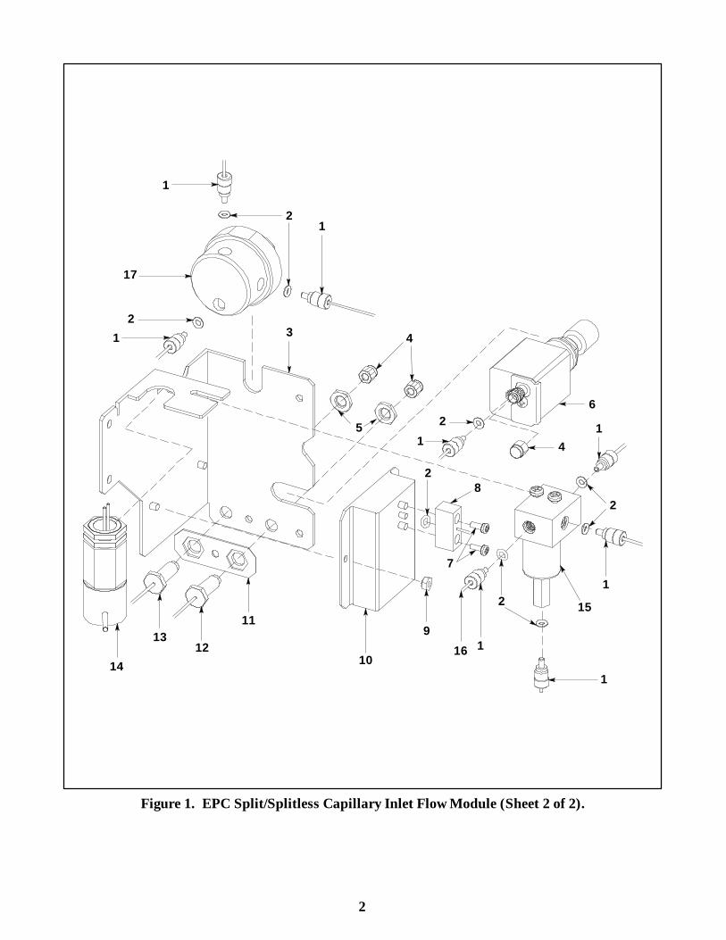
1
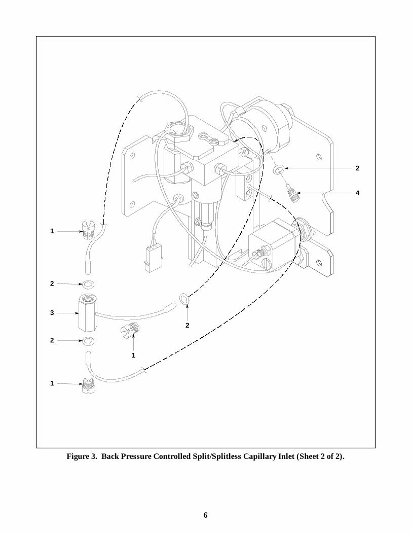
Item Description HP Part No.
1 Plastic M8 Fitting (Nut) 05890-400502 O-ring 0905-1039
12/pk 5180-41813 EPC1/BPR2 Bracket 19243-001254 1/8-in. Swagelok Plastic Cap 05890-402305 5/16-in. Hex Nut 2950-02036 0-400 Mass Flow Controller 19362-60575
For replacement parts see Section 47 Machine Screw M3 x 0, 5 x 8 0515-09128 Transducer Brazement 19243-806009 Hex Nut with Lockwasher 0535-0043
10 EPC Sensor PCB Assembly0-100 psi (2 Channel) 19245-600200-100 psi (6 Channel) 19245-600250-15 psi (6 Channel) 19245-60050
11 Vent Torque Plate 19244-0003012 Aux Vent Brazement 19251-8052713 Septa Vent Tube Weldment 19244-8058014 Proportional Control Valve 19251-60720 (includes 19251-60656)15 Solenoid Valve Assembly 19251-6056016 Connects to Insert Assembly317 Septa Purge Regulator (Approx. 3 ml) 19251-60710
NOT SHOWN:Cable, 6 Channel EPC 19245-60705External Sampler Interface Kit 19245-60990
1EPC— Electronic Pressure Control2BPR— Back Pressure Regulator3See Item 22 of next figure
Figure 1. EPC Split/Splitless Capillary Inlet Flow Module (Sheet 1 of 2).
2
1
21
32
1
2
2
2
21
1
1
4
56
41
7
8
9
10
11
1213
14
15
16
17
1
Figure 1. EPC Split/Splitless Capillary Inlet Flow Module (Sheet 2 of 2).
3
Item Description HP Part No.
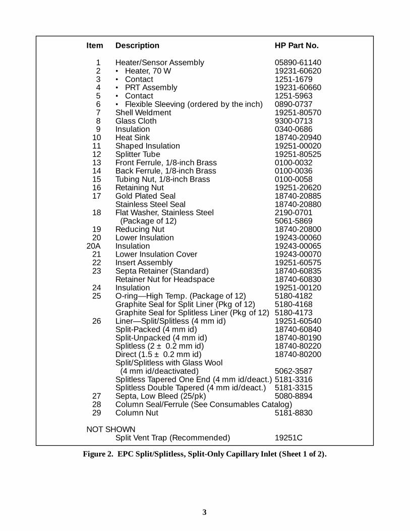
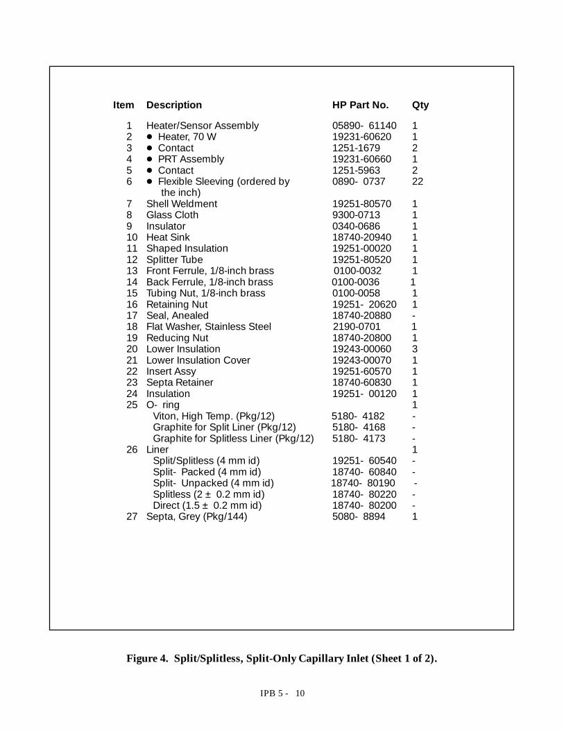
1 Heater/Sensor Assembly 05890-611402 · Heater, 70 W 19231-606203 · Contact 1251-16794 · PRT Assembly 19231-606605 · Contact 1251-59636 · Flexible Sleeving (ordered by the inch) 0890-07377 Shell Weldment 19251-805708 Glass Cloth 9300-07139 Insulation 0340-0686
10 Heat Sink 18740-2094011 Shaped Insulation 19251-0002012 Splitter Tube 19251-8052513 Front Ferrule, 1/8-inch Brass 0100-003214 Back Ferrule, 1/8-inch Brass 0100-003615 Tubing Nut, 1/8-inch Brass 0100-005816 Retaining Nut 19251-2062017 Gold Plated Seal 18740-20885
Stainless Steel Seal 18740-2088018 Flat Washer, Stainless Steel 2190-0701
(Package of 12) 5061-586919 Reducing Nut 18740-2080020 Lower Insulation 19243-00060
20A Insulation 19243-0006521 Lower Insulation Cover 19243-0007022 Insert Assembly 19251-6057523 Septa Retainer (Standard) 18740-60835
Retainer Nut for Headspace 18740-6083024 Insulation 19251-0012025 O-ring— High Temp. (Package of 12) 5180-4182
Graphite Seal for Split Liner (Pkg of 12) 5180-4168Graphite Seal for Splitless Liner (Pkg of 12) 5180-4173
26 Liner— Split/Splitless (4 mm id) 19251-60540Split-Packed (4 mm id) 18740-60840Split-Unpacked (4 mm id) 18740-80190Splitless (2 ± 0.2 mm id) 18740-80220Direct (1.5 ± 0.2 mm id) 18740-80200Split/Splitless with Glass Wool
(4 mm id/deactivated) 5062-3587Splitless Tapered One End (4 mm id/deact.) 5181-3316Splitless Double Tapered (4 mm id/deact.) 5181-3315
27 Septa, Low Bleed (25/pk) 5080-889428 Column Seal/Ferrule (See Consumables Catalog)29 Column Nut 5181-8830
NOT SHOWNSplit Vent Trap (Recommended) 19251C
Figure 2. EPC Split/Splitless, Split-Only Capillary Inlet (Sheet 1 of 2).
4
16
18
10
11
17
19
20
21
5
2
3
4
9
15 1413
12
8
7
24
1
6
20A
23
27
25
26
22
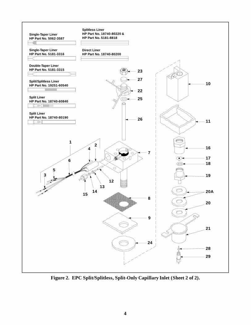
Single-Taper LinerHP Part No. 5062-3587
Split LinerHP Part No. 18740-80190
Double-Taper LinerHP Part No. 5181-3315
Single-Taper LinerHP Part No. 5181-3316
Direct LinerHP Part No. 18740-80200
Splitless LinerHP Part No. 18740-80220 &HP Part No. 5181-8818
Split LinerHP Part No. 18740-60840
Split/Splitless LinerHP Part No. 19251-60540
2829
Figure 2. EPC Split/Splitless, Split-Only Capillary Inlet (Sheet 2 of 2).
IPB 5 - 10
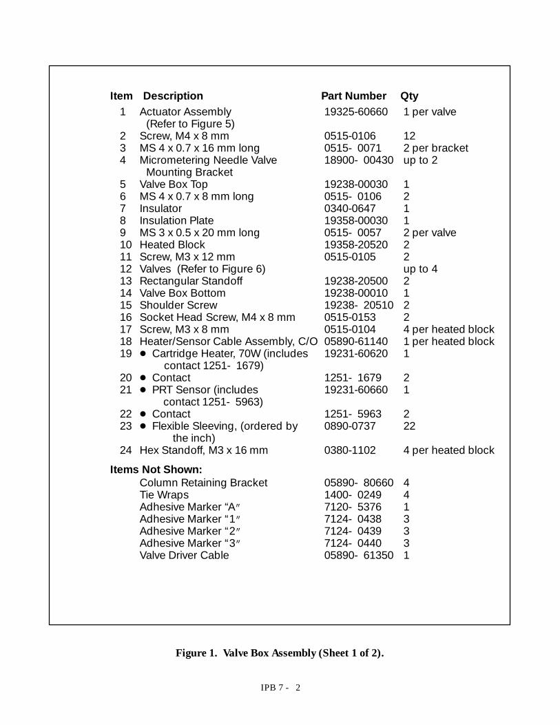
Item Description HP Part No. Qty
1 Heater/Sensor Assembly 05890- 61140 12 D Heater, 70 W 19231-60620 13 D Contact 1251-1679 24 D PRT Assembly 19231-60660 15 D Contact 1251-5963 26 D Flexible Sleeving (ordered by 0890- 0737 22
the inch)7 Shell Weldment 19251-80570 18 Glass Cloth 9300-0713 19 Insulator 0340-0686 110 Heat Sink 18740-20940 111 Shaped Insulation 19251-00020 112 Splitter Tube 19251-80520 113 Front Ferrule, 1/8-inch brass 0100-0032 114 Back Ferrule, 1/8-inch brass 0100-0036 115 Tubing Nut, 1/8-inch brass 0100-0058 116 Retaining Nut 19251- 20620 117 Seal, Anealed 18740-20880 -18 Flat Washer, Stainless Steel 2190-0701 119 Reducing Nut 18740-20800 120 Lower Insulation 19243-00060 321 Lower Insulation Cover 19243-00070 122 Insert Assy 19251-60570 123 Septa Retainer 18740-60830 124 Insulation 19251- 00120 125 O- ring 1
Viton, High Temp. (Pkg/12) 5180- 4182 -Graphite for Split Liner (Pkg/12) 5180- 4168 -Graphite for Splitless Liner (Pkg/12) 5180- 4173 -
26 Liner 1Split/Splitless (4 mm id) 19251- 60540 -Split- Packed (4 mm id) 18740- 60840 -Split- Unpacked (4 mm id) 18740- 80190 -Splitless (2 ± 0.2 mm id) 18740- 80220 -Direct (1.5 ± 0.2 mm id) 18740- 80200 -
27 Septa, Grey (Pkg/144) 5080- 8894 1
Figure 4. Split/Splitless, Split-Only Capillary Inlet (Sheet 1 of 2).

IPB 5 - 4
Item Description HP Part No. Qty
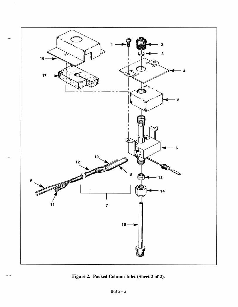
1 Screw, M4 x 8 mm 0515-0910 22 Septum Nut Assy 19243-60500 13 Septa (Pkg of 24) 5080-8728 14 Insulation Plate (Retainer) 19243-00050 1
(used on older models)5 Insulation 19231-00080 16 Injection Port Weldment 19243-80500 17 Heater/Sensor Cable Assy 05890-61140 18 D Heater, 70 W 19231-60620 19 D Contact 1251- 1679 210 D PRT Sensor 19231-60660 111 D Contact 1251- 5963 212 D Flexible Sleeving (ordered by 0890- 0737 22
the inch)1/4 inch x 22 inch
13 Vespel Ferrule, 1/4 inch 0100-1061 114 Brass Nut, 1/4 inch 0100-0056 115 Liner: (Refer to Figure 6) 116 Top Cover (used on newer models) 19243- 00080 117 Top Insulation (used with new 19243- 00100 1
top cover only)
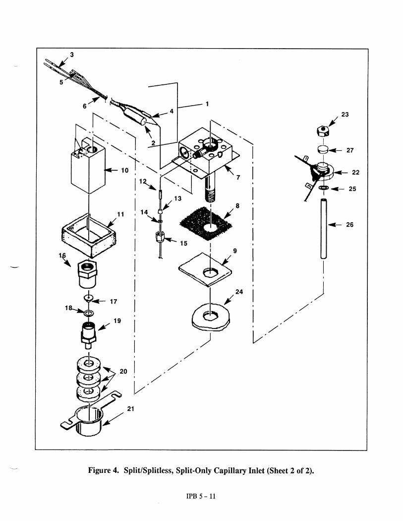
Figure 2. Packed Column Inlet (Sheet 1 of 2).

IPB 5 - 4
Item Description HP Part No. Qty
1 Screw, M4 x 8 mm 0515-0910 22 Septum Nut Assy 19243-60500 13 Septa (Pkg of 24) 5080-8728 14 Insulation Plate (Retainer) 19243-00050 1
(used on older models)5 Insulation 19231-00080 16 Injection Port Weldment 19243-80500 17 Heater/Sensor Cable Assy 05890-61140 18 D Heater, 70 W 19231-60620 19 D Contact 1251- 1679 210 D PRT Sensor 19231-60660 111 D Contact 1251- 5963 212 D Flexible Sleeving (ordered by 0890- 0737 22
the inch)1/4 inch x 22 inch
13 Vespel Ferrule, 1/4 inch 0100-1061 114 Brass Nut, 1/4 inch 0100-0056 115 Liner: (Refer to Figure 6) 116 Top Cover (used on newer models) 19243- 00080 117 Top Insulation (used with new 19243- 00100 1
top cover only)
Figure 2. Packed Column Inlet (Sheet 1 of 2).

13
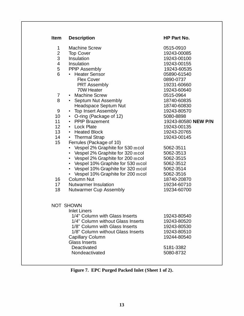
Item Description HP Part No.
1 Machine Screw 0515-09102 Top Cover 19243-000853 Insulation 19243-001004 Insulation 19243-001555 PPIP Assembly 19243-605356 · Heater Sensor 05890-61540
Flex Cover 0890-0737PRT Assembly 19231-6066070W Heater 19243-60640
7 · Machine Screw 0515-09648 · Septum Nut Assembly 18740-60835
Headspace Septum Nut 18740-608309 · Top Insert Assembly 19243-80570
10 · O-ring (Package of 12) 5080-889811 · PPIP Brazement 19243-80580 NEW P/N12 · Lock Plate 19243-0013513 · Heated Block 19243-2076514 · Thermal Strap 19243-0014515 Ferrules (Package of 10)
· Vespel 2% Graphite for 530 m col 5062-3511· Vespel 2% Graphite for 320 m col 5062-3513· Vespel 2% Graphite for 200 m col 5062-3515· Vespel 10% Graphite for 530 m col 5062-3512· Vespel 10% Graphite for 320 m col 5062-3514· Vespel 10% Graphite for 200 m col 5062-3516
16 Column Nut 18740-2087017 Nutwarmer Insulation 19234-6071018 Nutwarmer Cup Assembly 19234-60700
NOT SHOWNInlet Liners
1/4”Column with Glass Inserts 19243-805401/4”Column without Glass Inserts 19243-805201/8”Column with Glass Inserts 19243-805301/8”Column without Glass Inserts 19243-80510
Capillary Column 19244-80540Glass Inserts
Deactivated 5181-3382Nondeactivated 5080-8732
Figure 7. EPC Purged Packed Inlet (Sheet 1 of 2).
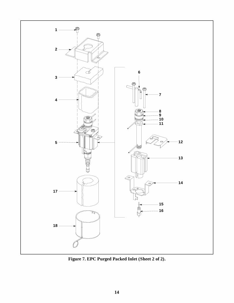
14
6
7
11
12
13
14
1
2
3
17
18
8910
4
5
1516
Figure 7. EPC Purged Packed Inlet (Sheet 2 of 2).
11
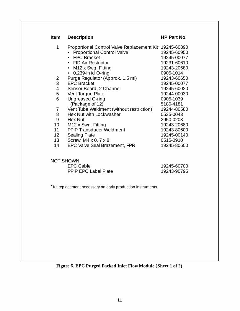
Item Description HP Part No.
1 Proportional Control Valve Replacement Kit*19245-60890· Proportional Control Valve 19245-60950· EPC Bracket 19245-00077· FID Air Restrictor 19231-60610· M12 x Swg. Fitting 19243-20680· 0.239-in id O-ring 0905-1014
2 Purge Regulator (Approx. 1.5 ml) 19243-606503 EPC Bracket 19245-000774 Sensor Board, 2 Channel 19245-600205 Vent Torque Plate 19244-000306 Ungreased O-ring 0905-1039
(Package of 12) 5180-41817 Vent Tube Weldment (without restriction) 19244-805808 Hex Nut with Lockwasher 0535-00439 Hex Nut 2950-0203
10 M12 x Swg. Fitting 19243-2068011 PPIP Transducer Weldment 19243-8060012 Sealing Plate 19245-0014013 Screw, M4 x 0, 7 x 8 0515-091014 EPC Valve Seal Brazement, FPR 19245-80600
NOT SHOWN:EPC Cable 19245-60700PPIP EPC Label Plate 19243-90795
*Kit replacement necessary on early production instruments
Figure 6. EPC Purged Packed Inlet Flow Module (Sheet 1 of 2).
12
1
2
3
4
5
6
6
6
6
6
7
8
910
11
12
1314
13
7
7
7
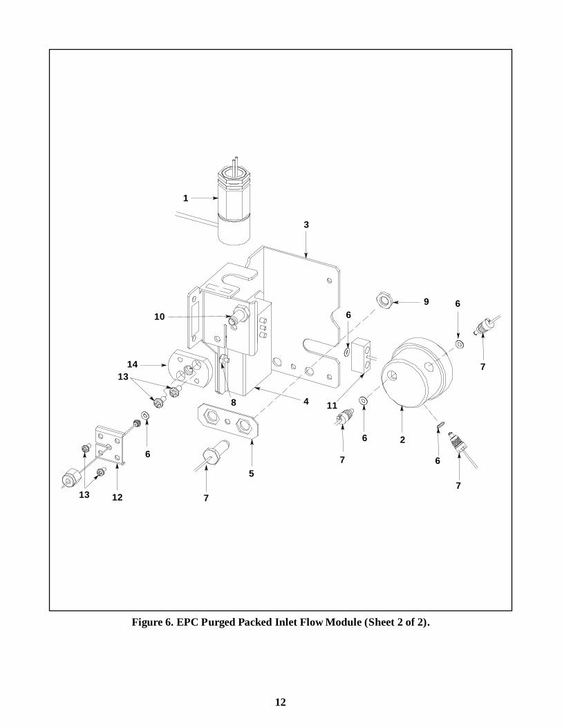
Figure 6. EPC Purged Packed Inlet Flow Module (Sheet 2 of 2).
IPB 5 - 6
Item Description HP Part No. Qty
1 Screw, M4 x 12 mm 0515-0910 62 Fin 19243-00110 13 Top Cover 19243-00080 14 Top Insulation 19243-00100 15 Heater/Sensor Assembly 05890-61140 16 D Cartridge Heater, 70 W 19231-60620 17 D Contact 1251- 1679 28 D PRT (Sensor) Assembly 19231-60660 19 D Contact 1251- 5963 210 D Insulation Sleeving (ordered by 0890- 0737 22
the inch)11 Purged-Packed Inlet Weldment
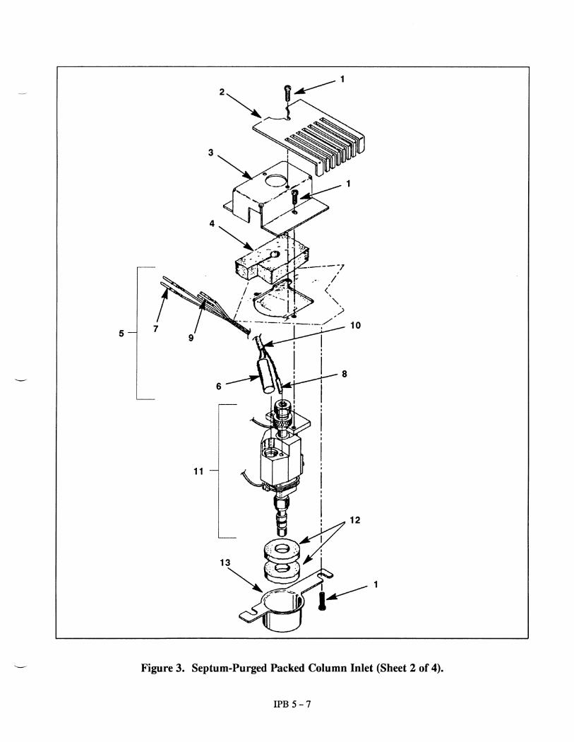
Assembly (See sheet 4 for breakdown) 12 Bottom Insulation 19243-00060 113 Bottom Insulation Cover 19243-00070 1
Figure 3. Septum-Purged Packed Column Inlet (Sheet 1 of 4).
IPB 5 - 8
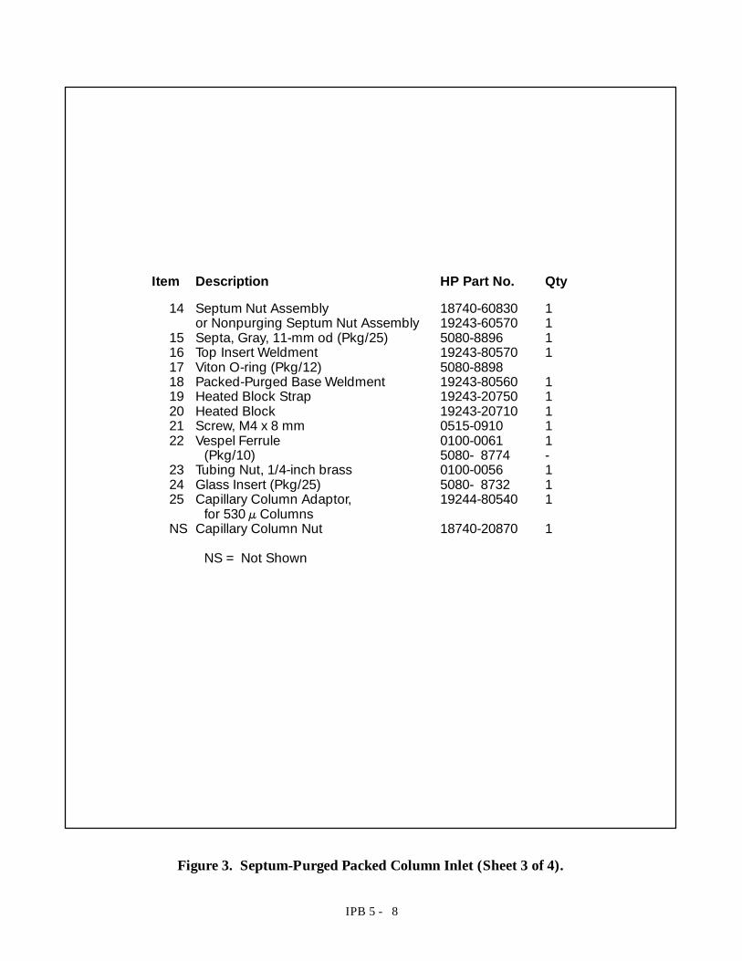
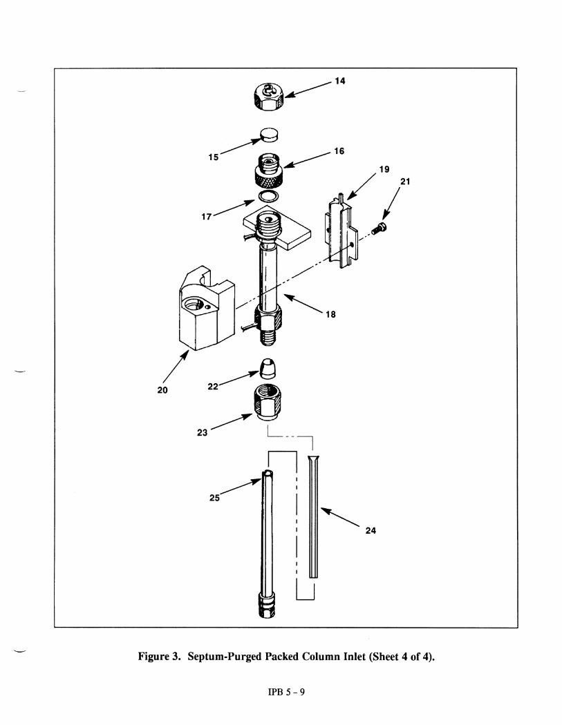
Item Description HP Part No. Qty
14 Septum Nut Assembly 18740-60830 1or Nonpurging Septum Nut Assembly 19243-60570 1
15 Septa, Gray, 11-mm od (Pkg/25) 5080-8896 116 Top Insert Weldment 19243-80570 117 Viton O-ring (Pkg/12) 5080-889818 Packed-Purged Base Weldment 19243-80560 119 Heated Block Strap 19243-20750 120 Heated Block 19243-20710 121 Screw, M4 x 8 mm 0515-0910 122 Vespel Ferrule 0100-0061 1
(Pkg/10) 5080- 8774 -23 Tubing Nut, 1/4-inch brass 0100-0056 124 Glass Insert (Pkg/25) 5080- 8732 125 Capillary Column Adaptor, 19244-80540 1
for 530 µColumnsNS Capillary Column Nut 18740-20870 1
NS = Not Shown
Figure 3. Septum-Purged Packed Column Inlet (Sheet 3 of 4).
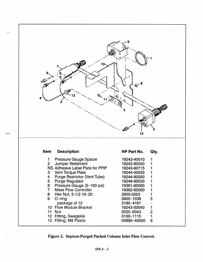
7
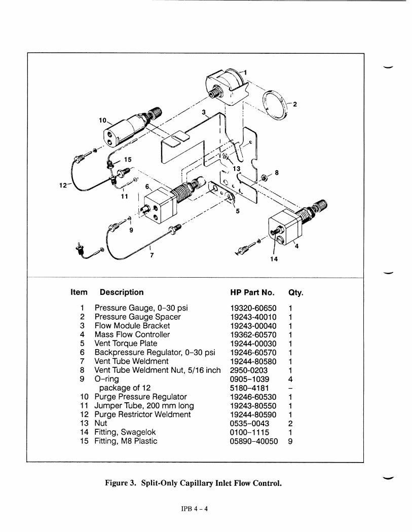
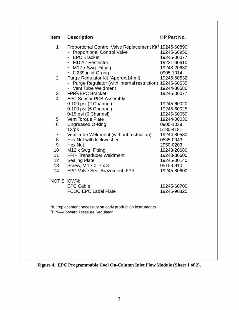
Item Description HP Part No.
1 Proportional Control Valve Replacement Kit1 19245-60890· Proportional Control Valve 19245-60950· EPC Bracket 19245-00077· FID Air Restrictor 19231-60610· M12 x Swg. Fitting 19243-20680· 0.239-in id O-ring 0905-1014
2 Purge Regulator Kit (Approx.14 ml) 19245-60532· Purge Regulator (with internal restriction) 19245-60535· Vent Tube Weldment 19244-80580
3 FPR2/EPC Bracket 19245-000774 EPC Sensor PCB Assembly
0-100 psi (2 Channel) 19245-600200-100 psi (6 Channel) 19245-600250-15 psi (6 Channel) 19245-60050
5 Vent Torque Plate 19244-000306 Ungreased O-Ring 0905-1039
12/pk 5180-41817 Vent Tube Weldment (without restriction) 19244-805808 Hex Nut with lockwasher 0535-00439 Hex Nut 2950-0203
10 M12 x Swg. Fitting 19243-2068011 PPIP Transducer Weldment 19243-8060012 Sealing Plate 19245-0014013 Screw, M4 x 0, 7 x 8 0515-091014 EPC Valve Seal Brazement, FPR 19245-80600
NOT SHOWN:EPC Cable 19245-60700PCOC EPC Label Plate 19245-90825
1Kit replacement necessary on early production instruments2FPR— Forward Pressure Regulator
Figure 4. EPC Programmable Cool On-Column Inlet Flow Module (Sheet 1 of 2).
8
1
2
3
4
5
6
6
6
6
6
7
8
910
11
12
13
14
13
7
Figure 4. EPC Programmable Cool On-Column Inlet Flow Module (Sheet 2 of 2).
9
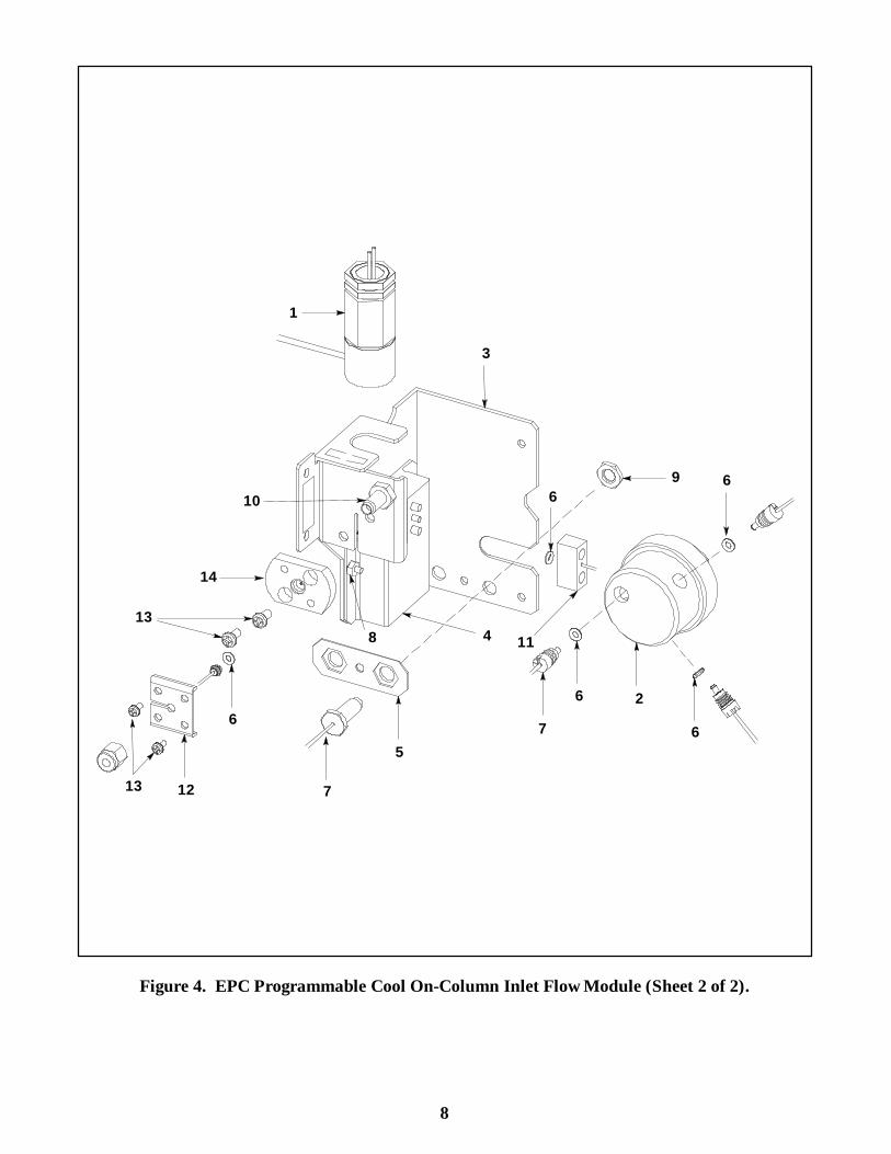
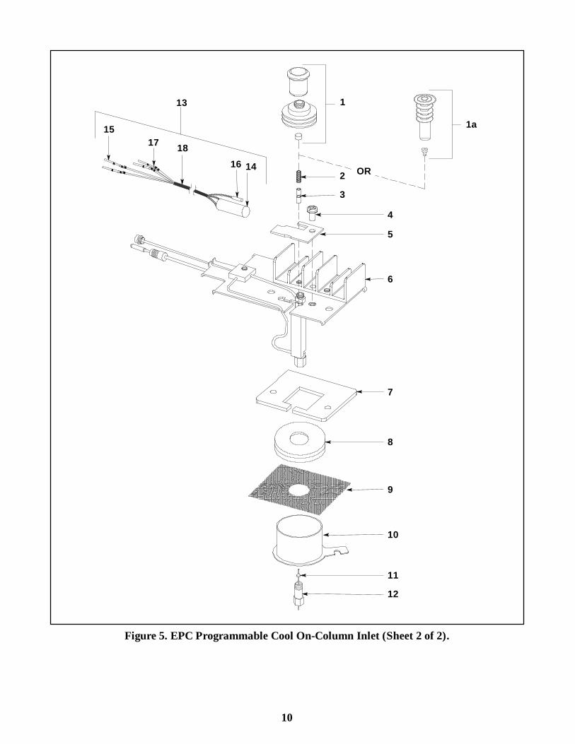
Item Description HP Part No.
1 Automatic Injection Assembly· Needle Guide Top 19245-20670· Septum Nut Base Assembly 19245-80520· Septum (Package of 25) 5181-1260
1a Manual Injection Assembly· Cooling Tower Assembly/Needle Guide 19320-80625· Duckbill (Package of 10) 19245-40050
2 PCOC Insert Spring 19245-607603 Inserts:
NOTEInserts are identified by the number of rings around them· Narrow Bore Insert; 200 m (1 ring) 19245-20510· Wide Bore Insert; 320 m (2 rings) 19245-20525· Megabore Insert; 530 m (0 rings) 19245-20580· Capillary Insert for Glass Columns 19245-20550
(3 rings)4 Screw, M4 x 8 mm 0515-09105 Heater Clamp 19245-000956 On-Column Weldment 19245-805077 PCOC Inlet Insulation 19245-206308 Lower Insulation 19243-000659 Glass Cloth 9300-0713
10 PCOC Cavity Sleeve 19245-0006011 Ferrules (Package of 10)
· Vespel 2% Graphite for 530 m col 5062-3511· Vespel 2% Graphite for 320 m col 5062-3513· Vespel 2% Graphite for 200 m col 5062-3515· Vespel 10% Graphite for 530 m col 5062-3512· Vespel 10% Graphite for 320 m col 5062-3514· Vespel 10% Graphite for 200 m col 5062-3516
12 Column Nut 18740-2087013 Heater/Sensor Assembly 19245-6052014 · Heater, Cartridge, 60 W 19245-6057015 · Contact 1251-167916 · PRT Assembly 19231-6066017 · Contact 1251-596318 · Insulation Sleeving (ordered by the inch) 0890-0737
NOT SHOWNCleaning Wire Kit 5180-4153Screw, M4 x 0.7 x 8 0515-0106
Figure 5. EPC Programmable Cool On-Column Inlet (Sheet 1 of 2).
10
13
1416
1
23
1517 18
7
10
6
OR
8
9
1a
5
4
1112
Figure 5. EPC Programmable Cool On-Column Inlet (Sheet 2 of 2).
IPB 4 - 8
Item Description HP Part No. Qty.1 Screw, Machine, M4 x 0.7 x 6 0515- 0915 22 EPC Flow Bracket 19245- 00070 13 Nut, Hex with Lock Washer 0535- 0043 44 Screw, Thread Cutting 0624- 0665 15 Plug 1/8- inch 19361- 20770 16 Nut, Hex, 5/16 2950- 0203 17 EPC Sensor Board 19245- 60020 18 Screw, Machine M3 x 0.5 x 8 0515- 0912 29 M8 Swagelok Plastic Cap, 1/8- inch 05890- 40230 210 O- ring 0905- 1174 611 PCOC Purge Restrictor Assembly 19245- 80530 112 Vent Torque Plate 19244- 00030 113 O- ring, 0.239 id 0905- 1014 214 PPIP High Pressure 19243- 60560 1
Restrictor (red/blue)15 Screw, Machine, M4 x 0.7 x 12 0515- 0909 416 Valve Transducer Brazement 19245- 80540 117 Fitting Housing 19245- 20750 118 Screw, Machine, M4 x 0.7 x 8 0515- 0910 519 Sealing Plate 19245- 00140 120 PCOC Proportional Control Valve 19245- 60540 121 FID Air Restrictor (brown) 19231- 60610 122 PCOC Inlet Brazement 19245- 80580 123 Inlet Bypass Clamp 19245- 20890 124 Interface Cable 19245- 60700 125 PCOC Purge Regulator 19245- 60530 1
Figure 6. PCOC Electronic Pressure Control (Sheet 1 of 2).
IPB 4 - 9
1 2
34
56
7
3
8
9
9
10
1112
1314
15 1617
18
1819
10
10
20
13
21
22
23
1524
25
TO PRESSURE CONTROL PCB
SEPTUM PURGE OUTLETFROM INJECTION PORT
CARRIER INPUT TOINJECTION PORT
Figure 6. PCOC Electronic Pressure Control (Sheet 2 of 2).
IPB 4 - 6
Item Description HP Part No. Qty.
1 0- 30 Pressure Gauge 19320- 60650 12 O- ring 0905- 1174 53 Spacer, Pressure Gauge 19243- 40010 14 Swagelok Plastic Cap, 1/8- inch 05890- 40050 25 0- 30 Forward Pressure Regulator 19245- 60690 16 Screw, Machine, M4 x 0.7 x 8 0515- 0910 37 FPR Clamp Plate 19245- 20700 18 Inlet Fitting 19231- 20560 19 FID Air Restrictor (brown dot) 19231- 60610 110 O- ring, 0.239 id 0905- 1014 111 Nut, Hex with Lock Washer 0535- 0043 212 Screw, Thread Cutting 0624- 0665 113 PCOC Purge Regulator 19245- 60530 114 PCOC Purge Restrictor Assy. 19245- 80530 115 Vent Torque Plate 19244- 00030 116 MPCOC Flow Bracket 19245- 00100 117 Hex Nut, 5/16- inch 2950- 0203 1
Figure 5. PCOC Manual Pressure Control (Sheet 1 of 2).
IPB 4 - 7
12
3
4
52
67
89 10
11
11
4
12
4
13
2
1415
16
17
SEPTUM PURGEOUTLETFROM INJECTIONPORT
CARRIER INPUT TOINJECTION PORT
Figure 5. PCOC Manual Pressure Control (Sheet 2 of 2).
IPB 5 - 12
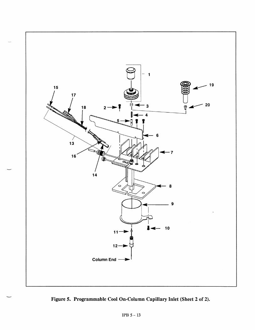
Item Description HP Part No. Qty
1 Automatic Injection Assembly: 1D Needle Guide Top 19245- 20670 -D Septum Nut Base Assembly 19245- 80520 -
2 Screw, M4 x 8 mm 0515- 0910 43 Septum (Pkg/24) 9301- 0682 -4 PCOC Insert Spring 19245- 60760 15 Inserts: 1
NOTEInserts may be identified by the number ofrings around them.D Narrow Bore Insert; 200 µ 19245- 20510
1 silver ringD Wide Bore Insert; 320 µ 19245- 20520
2 silver ringsD Megabore Insert; 530 µ 19245- 20580
0 ringsD Capillary Insert for Glass 19245- 20550
Columns; 3 silver rings6 Air Deflector 19245- 00090 17 On-Column Weldment 19245- 805058 PCOC Inlet Insulation 19245- 20630 19 PCOC Cavity Sleeve 19245- 00060 110 Screw, M4 x 0.7 x 8 0515- 0106 111 Ferrules (Pkg/10) 1- Vespel 2% Graphite for 530 µcol 5062- 3511 -- Vespel 2% Graphite for 320 µcol 5062- 3513 -- Vespel 2% Graphite for 200 µcol 5062- 3515 -- Vespel 10% Graphite for 530 µ col 5062- 3512 -- Vespel 10% Graphite for 320 µ col 5062- 3514 -- Vespel 10% Graphite for 200 µ col 5062- 3516 -12 Column Nut 18740- 20870 113 Heater/Sensor Assembly 19245- 60520 114 D Heater, Cartridge, 60 W 19245- 60570115 D Contact 1251- 1679 216 D PRT Assembly 19231- 60660 117 D Contact 1251- 5963 218 D Insulation Sleeving (ordered by 0890- 0737 22
the inch)19 Optional Manual Injection Assembly:D Cooling Tower Assembly/ 19320- 80625 -
Needle Guide20 Duckbill (Pkg/10) 19245- 40050 -NS Cleaning Wire 19245- 20570 -
Figure 5. Programmable Cool On-Column Capillary Inlet (Sheet 1 of 2).
IPB 5 - 3
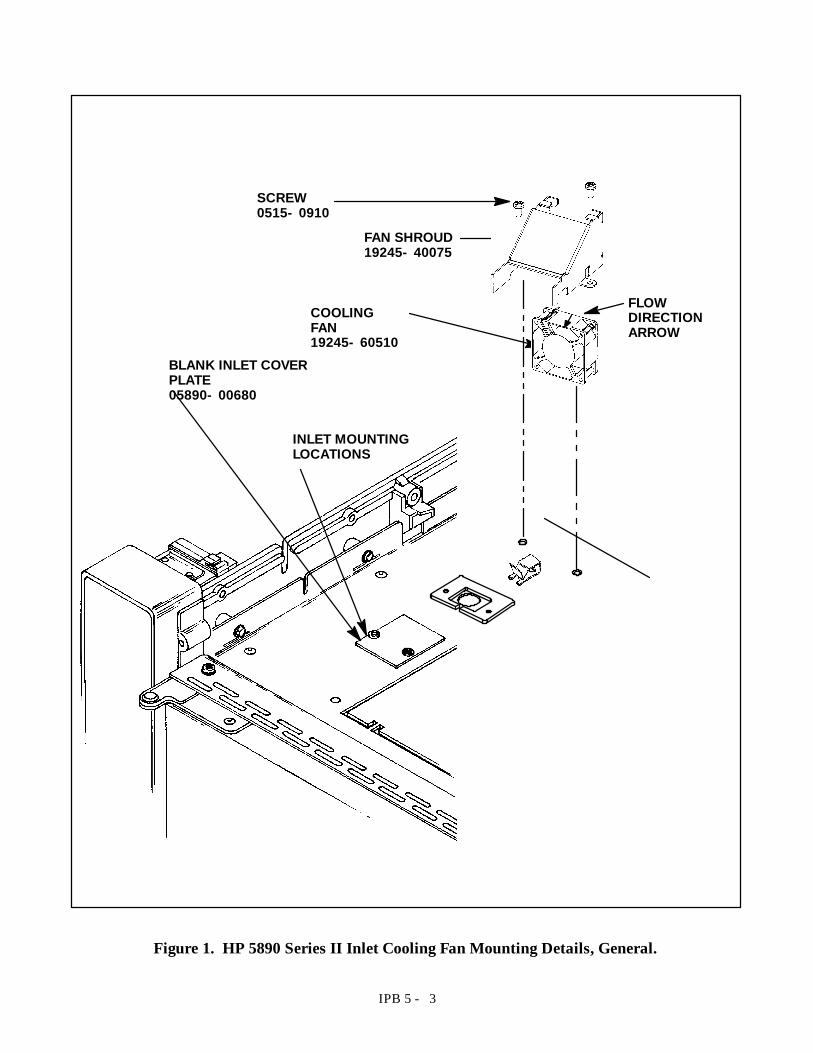
COOLINGFAN19245- 60510
FAN SHROUD19245- 40075
FLOWDIRECTIONARROW
SCREW0515- 0910
INLET MOUNTINGLOCATIONS
BLANK INLET COVERPLATE05890- 00680
Figure 1. HP 5890 Series II Inlet Cooling Fan Mounting Details, General.
IPB 5 - 14
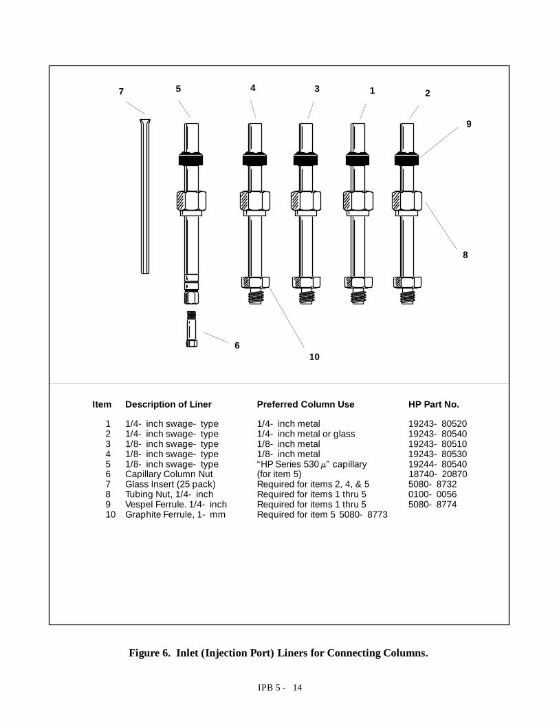
Item Description of Liner Preferred Column Use HP Part No.
1 1/4- inch swage- type 1/4- inch metal 19243- 805202 1/4- inch swage- type 1/4- inch metal or glass 19243- 805403 1/8- inch swage- type 1/8- inch metal 19243- 805104 1/8- inch swage- type 1/8- inch metal 19243- 805305 1/8- inch swage- type “HP Series 530 µ”capillary 19244- 805406 Capillary Column Nut (for item 5) 18740- 208707 Glass Insert (25 pack) Required for items 2, 4, & 5 5080- 87328 Tubing Nut, 1/4- inch Required for items 1 thru 5 0100- 00569 Vespel Ferrule. 1/4- inch Required for items 1 thru 5 5080- 877410 Graphite Ferrule, 1- mm Required for item 5 5080- 8773
7 5 4 3 1 2
9
8
106
Figure 6. Inlet (Injection Port) Liners for Connecting Columns.
19
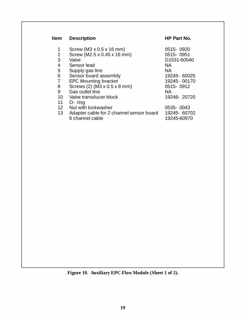
Item Description HP Part No.
1 Screw (M3 x 0.5 x 16 mm) 0515- 09202 Screw (M2.5 x 0.45 x 16 mm) 0515- 09513 Valve G1531-605404 Sensor lead NA5 Supply gas line NA6 Sensor board assembly 19245- 600257 EPC Mounting bracket 19245- 001708 Screws (2) (M3 x 0.5 x 8 mm) 0515- 09129 Gas outlet line NA10 Valve transducer block 19246- 2072011 O- ring12 Nut with lockwasher 0535- 004313 Adapter cable for 2 channel sensor board 19245- 60702
6 channel cable 19245-60970
Figure 10. Auxiliary EPC Flow Module (Sheet 1 of 2).
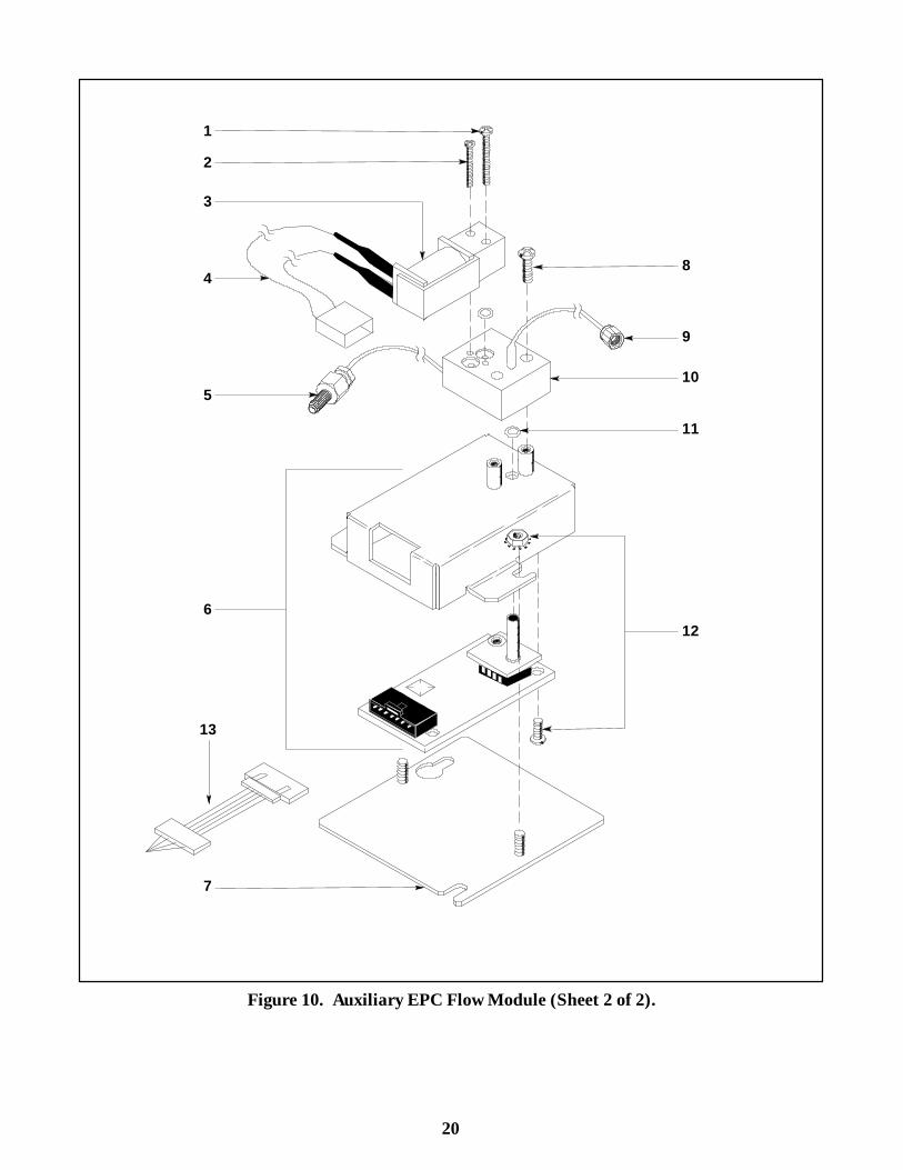
20
2
1
3
4
5
7
8
9
10
11
126
13
Figure 10. Auxiliary EPC Flow Module (Sheet 2 of 2).

21
Item Description HP Part No.
1 Auxiliary EPC Retrofit Flow Bracket 19245-00190(L43 Area)
2 Auxiliary EPC Retrofit Flow Bracket 19245-00160(Flow Sensor Area)
Figure 11. Auxiliary EPC Retrofit Flow Module Bracket (Sheet 1 of 2).
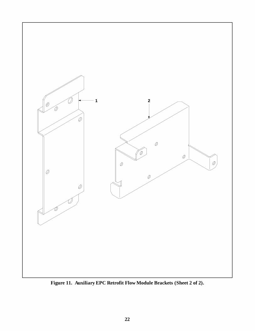
22
1 2
Figure 11. Auxiliary EPC Retrofit Flow Module Brackets (Sheet 2 of 2).
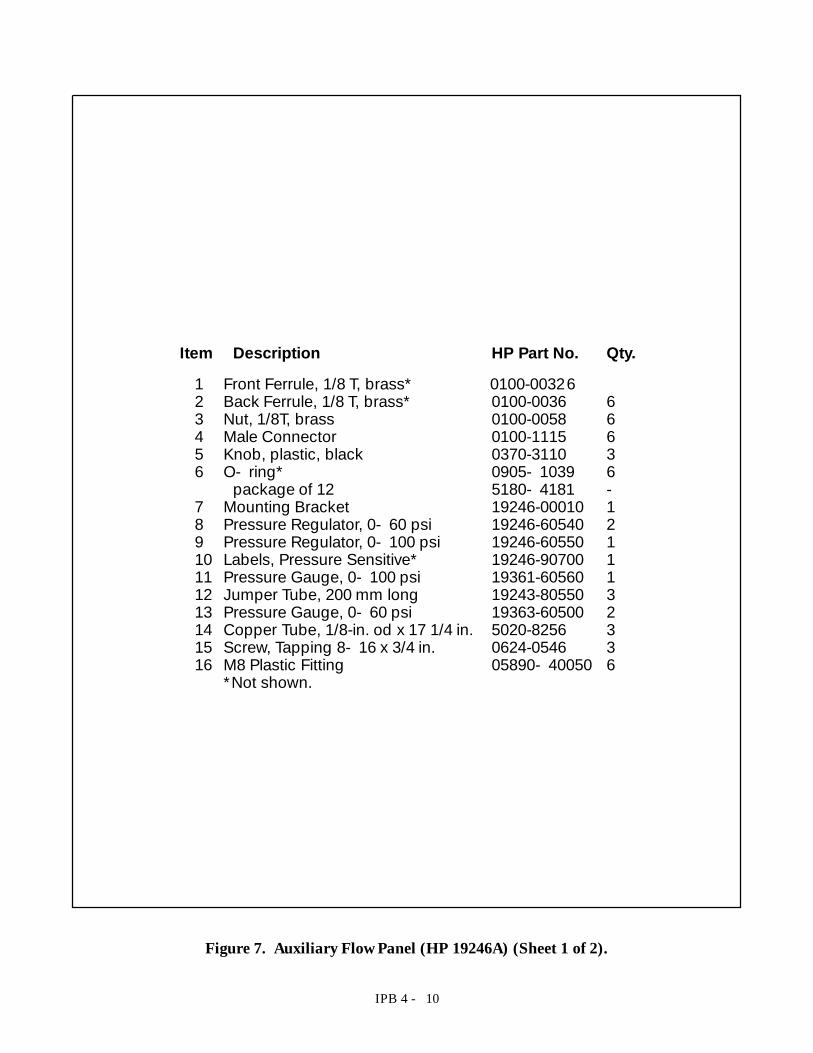
IPB 4 - 10
Item Description HP Part No. Qty.1 Front Ferrule, 1/8 T, brass* 0100-003262 Back Ferrule, 1/8 T, brass* 0100-0036 63 Nut, 1/8T, brass 0100-0058 64 Male Connector 0100-1115 65 Knob, plastic, black 0370-3110 36 O- ring* 0905- 1039 6
package of 12 5180- 4181 -7 Mounting Bracket 19246-00010 18 Pressure Regulator, 0- 60 psi 19246-60540 29 Pressure Regulator, 0- 100 psi 19246-60550 110 Labels, Pressure Sensitive* 19246-90700 111 Pressure Gauge, 0- 100 psi 19361-60560 112 Jumper Tube, 200 mm long 19243-80550 313 Pressure Gauge, 0- 60 psi 19363-60500 214 Copper Tube, 1/8-in. od x 17 1/4 in. 5020-8256 315 Screw, Tapping 8- 16 x 3/4 in. 0624-0546 316 M8 Plastic Fitting 05890- 40050 6
*Not shown.
Figure 7. Auxiliary Flow Panel (HP 19246A) (Sheet 1 of 2).
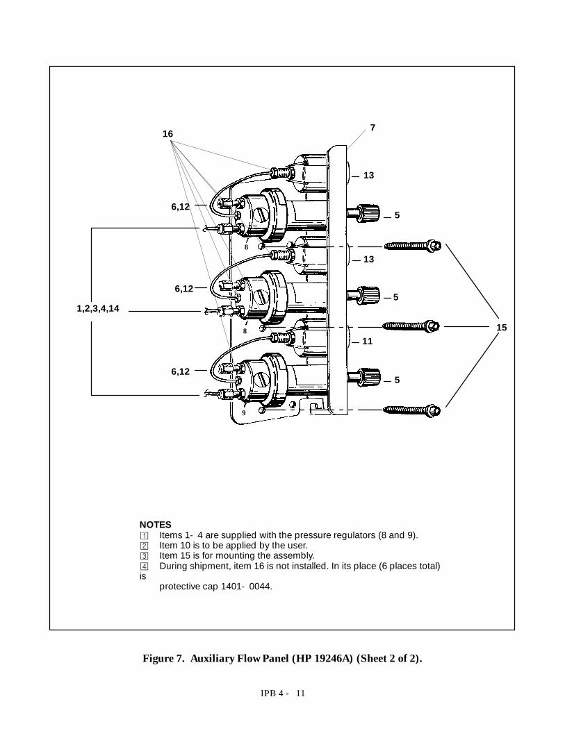
IPB 4 - 11
NOTES¡ Items 1- 4 are supplied with the pressure regulators (8 and 9).© Item 10 is to be applied by the user.¢ Item 15 is for mounting the assembly.£ During shipment, item 16 is not installed. In its place (6 places total)is
protective cap 1401- 0044.
6,12
13
5
13
5
11
5
6,12
6,12
1,2,3,4,14
8
8
9
15
16 7
Figure 7. Auxiliary Flow Panel (HP 19246A) (Sheet 2 of 2).
25
Item Description HP Part No.
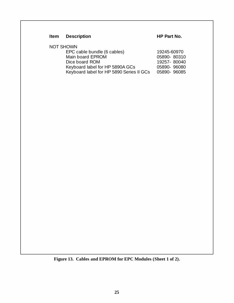
NOT SHOWNEPC cable bundle (6 cables) 19245-60970Main board EPROM 05890- 80310Dice board ROM 19257- 80040Keyboard label for HP 5890A GCs 05890- 96080Keyboard label for HP 5890 Series II GCs 05890- 96085
Figure 13. Cables and EPROM for EPC Modules (Sheet 1 of 2).
26
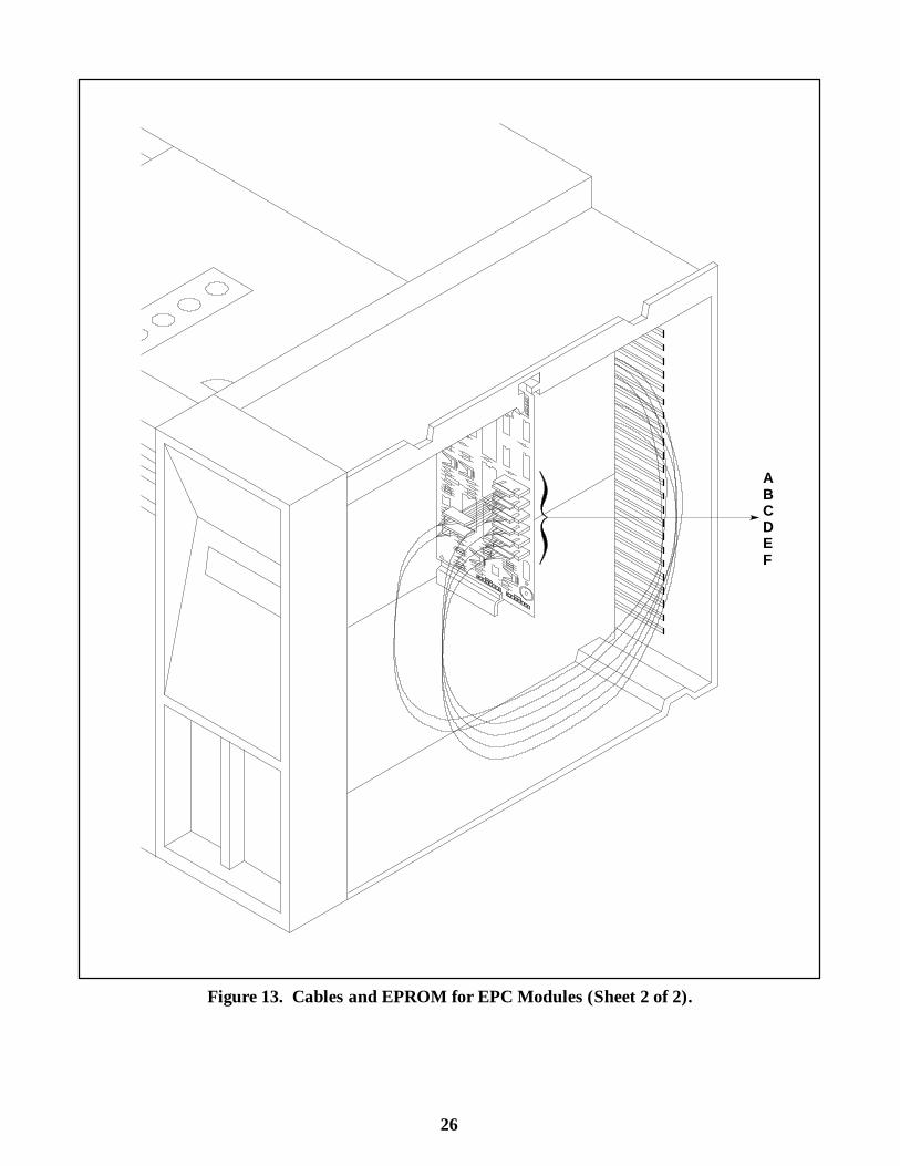
ABCDEF
Figure 13. Cables and EPROM for EPC Modules (Sheet 2 of 2).
23
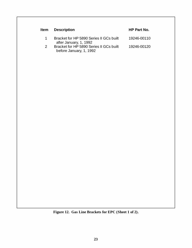
Item Description HP Part No.
1 Bracket for HP 5890 Series II GCs built 19246-00110after January, 1, 1992
2 Bracket for HP 5890 Series II GCs built 19246-00120before January, 1, 1992
Figure 12. Gas Line Brackets for EPC (Sheet 1 of 2).
24
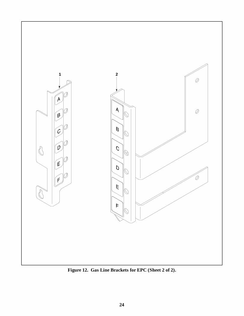
1 2
Figure 12. Gas Line Brackets for EPC (Sheet 2 of 2).

IPB 4 - 12
Item Description HP Part No. Qty.1 Screw, Self-tapping, 8- 16 x 3/4-inch 0624-0546 22 Label, Pressure Sensitive 19246-90700 13 Mounting Bracket 19246-00080 14 O- ring 0905- 1039 4
package of 12 5180- 4181 -5 Hex Nut, 1/2- 20 0590-0007 16 Internal Tooth Lock Washer 2190-0562 17 Retrofit Mounting Bracket 19246-00070 18 Pressure Gauge, 0- 10 psi 19246-60590 19 Jumper Weldment — 360 mm (tube) 19302-80560 110 HP-M8 Tee Fitting 19361-20760 111 Jumper Weldment— 200 mm (tube) 19243-80550 1- - Installation Instructions (not shown) 19247-90100 1
Figure 8. Gauge Assembly, 0- 10psi (HP 19247A) (Sheet 1 of 2).
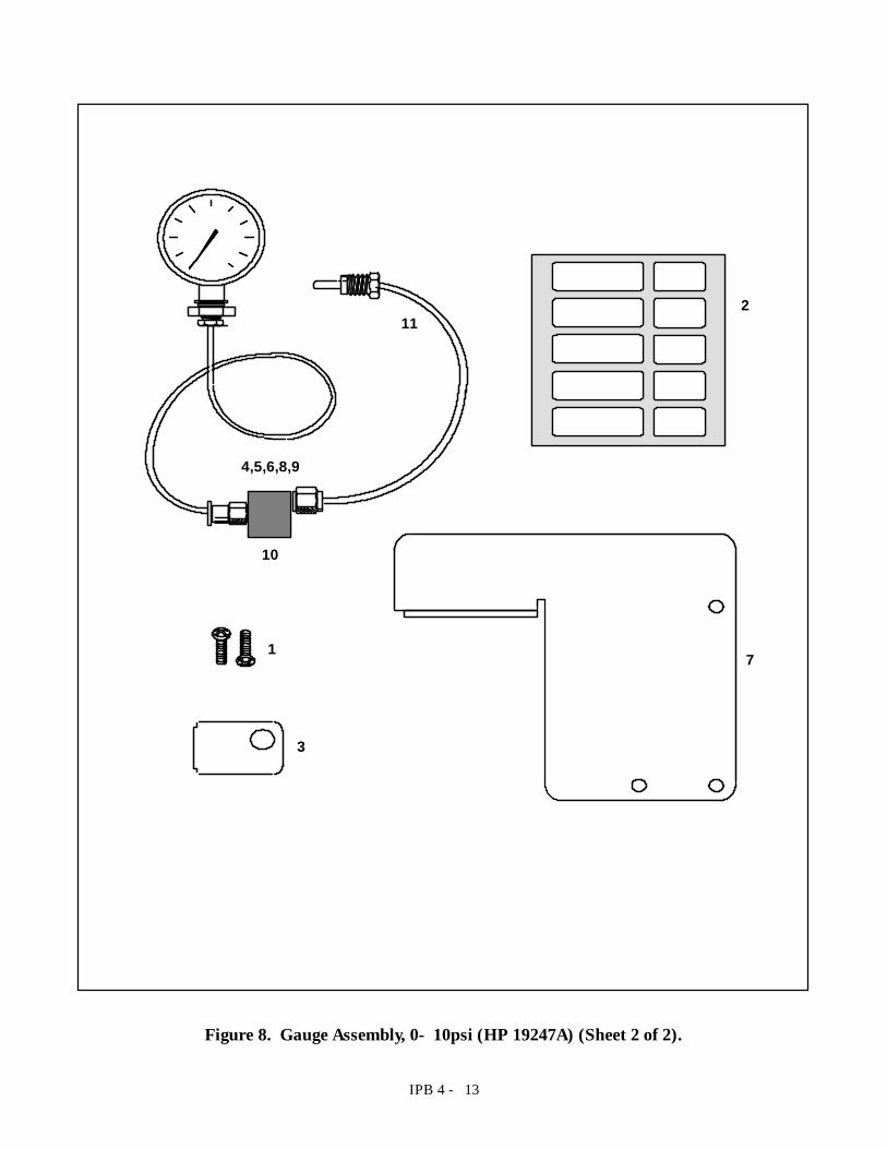
IPB 4 - 13
4,5,6,8,9
11
10
2
3
71
Figure 8. Gauge Assembly, 0- 10psi (HP 19247A) (Sheet 2 of 2).

17
Item Description HP Part No.
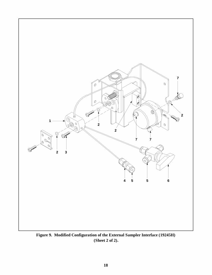
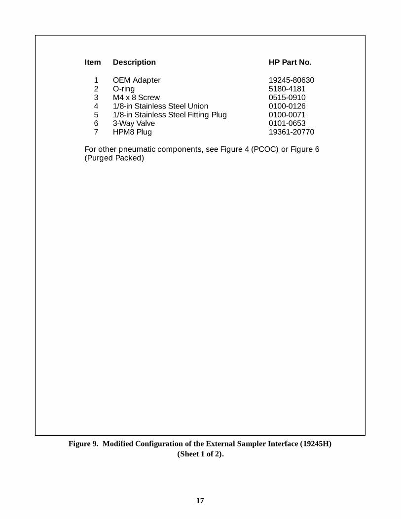
1 OEM Adapter 19245-806302 O-ring 5180-41813 M4 x 8 Screw 0515-09104 1/8-in Stainless Steel Union 0100-01265 1/8-in Stainless Steel Fitting Plug 0100-00716 3-Way Valve 0101-06537 HPM8 Plug 19361-20770
For other pneumatic components, see Figure 4 (PCOC) or Figure 6(Purged Packed)
Figure 9. Modified Configuration of the External Sampler Interface (19245H)(Sheet 1 of 2).
18
1
2 3
6
7
2
22
54 5
77
Figure 9. Modified Configuration of the External Sampler Interface (19245H)(Sheet 2 of 2).
15
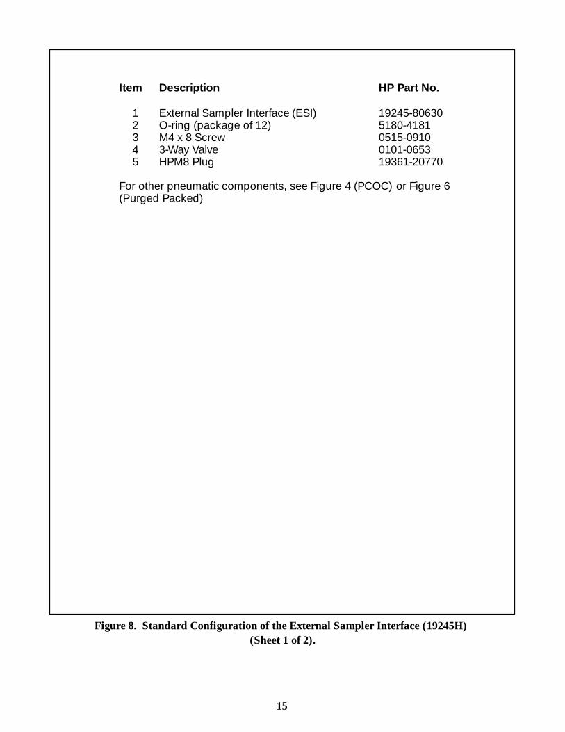
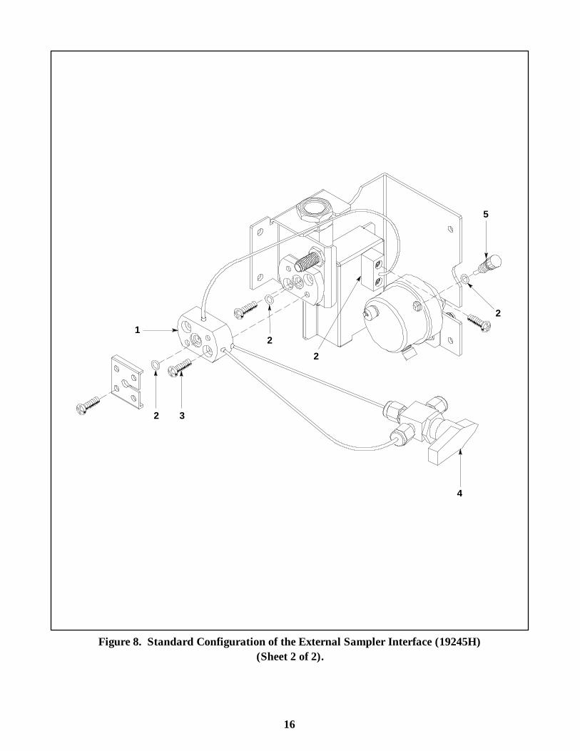
Item Description HP Part No.
1 External Sampler Interface (ESI) 19245-806302 O-ring (package of 12) 5180-41813 M4 x 8 Screw 0515-09104 3-Way Valve 0101-06535 HPM8 Plug 19361-20770
For other pneumatic components, see Figure 4 (PCOC) or Figure 6(Purged Packed)
Figure 8. Standard Configuration of the External Sampler Interface (19245H)(Sheet 1 of 2).
16
1
2 3
4
5
2
22
Figure 8. Standard Configuration of the External Sampler Interface (19245H)(Sheet 2 of 2).
17
Item Description HP Part No.
1 OEM Adapter 19245-806302 O-ring 5180-41813 M4 x 8 Screw 0515-09104 1/8-in Stainless Steel Union 0100-01265 1/8-in Stainless Steel Fitting Plug 0100-00716 3-Way Valve 0101-06537 HPM8 Plug 19361-20770
For other pneumatic components, see Figure 4 (PCOC) or Figure 6(Purged Packed)
Figure 9. Modified Configuration of the External Sampler Interface (19245H)(Sheet 1 of 2).
28
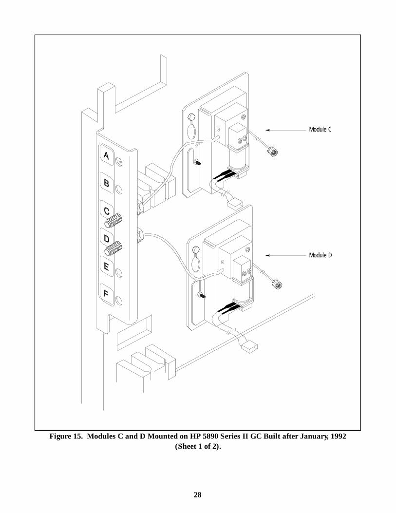
Module C
Module D
Figure 15. Modules C and D Mounted on HP 5890 Series II GC Built after January, 1992(Sheet 1 of 2).
29
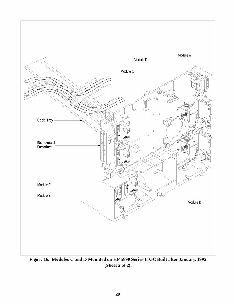
Cable Tray
BulkheadBracket
Module B
Module F
Module E
Module A
Module C
Module D
Figure 16. Modules C and D Mounted on HP 5890 Series II GC Built after January, 1992(Sheet 2 of 2).

27
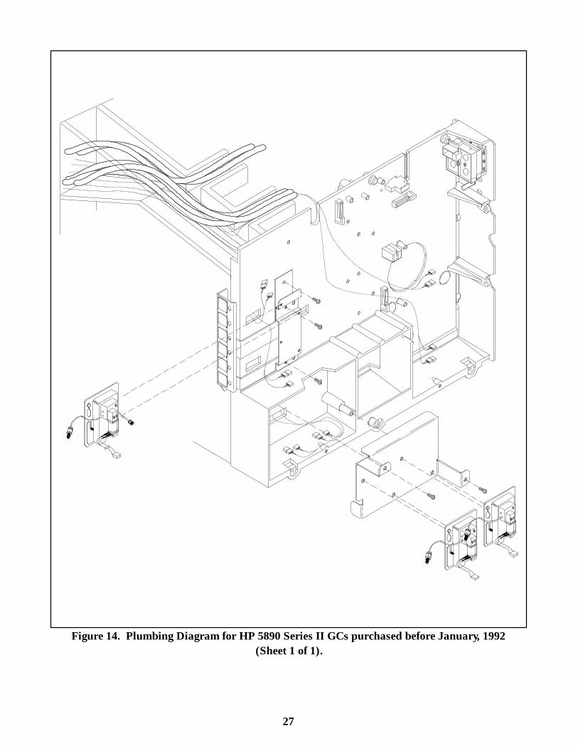
Figure 14. Plumbing Diagram for HP 5890 Series II GCs purchased before January, 1992(Sheet 1 of 1).
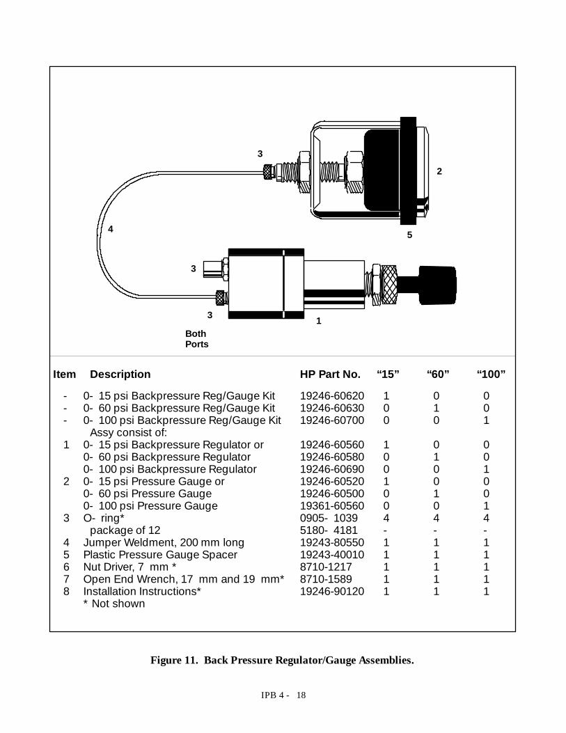
IPB 4 - 18
Item Description HP Part No. “15” “60” “100”- 0- 15 psi Backpressure Reg/Gauge Kit 19246-60620 1 0 0- 0- 60 psi Backpressure Reg/Gauge Kit 19246-60630 0 1 0- 0- 100 psi Backpressure Reg/Gauge Kit 19246-60700 0 0 1
Assy consist of:1 0- 15 psi Backpressure Regulator or 19246-60560 1 0 0
0- 60 psi Backpressure Regulator 19246-60580 0 1 00- 100 psi Backpressure Regulator 19246-60690 0 0 1
2 0- 15 psi Pressure Gauge or 19246-60520 1 0 00- 60 psi Pressure Gauge 19246-60500 0 1 00- 100 psi Pressure Gauge 19361-60560 0 0 1
3 O- ring* 0905- 1039 4 4 4package of 12 5180- 4181 - - -
4 Jumper Weldment, 200 mm long 19243-80550 1 1 15 Plastic Pressure Gauge Spacer 19243-40010 1 1 16 Nut Driver, 7 mm * 8710-1217 1 1 17 Open End Wrench, 17 mm and 19 mm* 8710-1589 1 1 18 Installation Instructions* 19246-90120 1 1 1
* Not shown
BothPorts
3
3
32
5
1
4
Figure 11. Back Pressure Regulator/Gauge Assemblies.
IPB 4 - 14
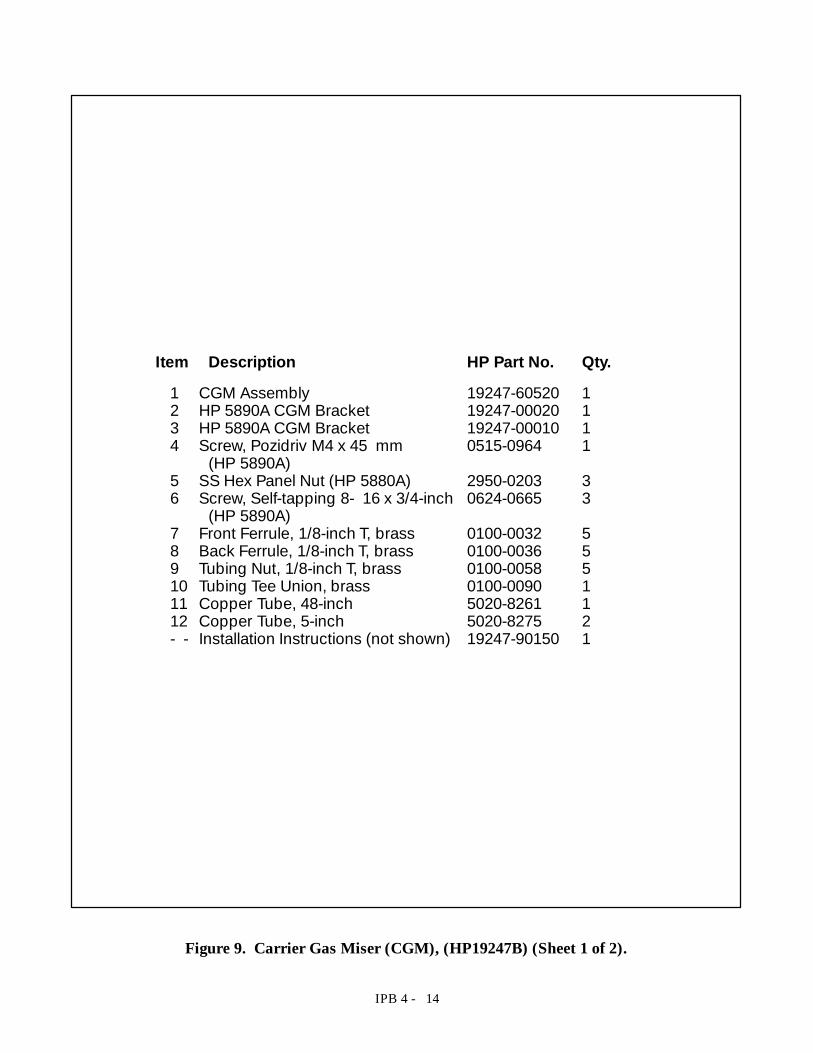
Item Description HP Part No. Qty.1 CGM Assembly 19247-60520 12 HP 5890A CGM Bracket 19247-00020 13 HP 5890A CGM Bracket 19247-00010 14 Screw, Pozidriv M4 x 45 mm 0515-0964 1
(HP 5890A)5 SS Hex Panel Nut (HP 5880A) 2950-0203 36 Screw, Self-tapping 8- 16 x 3/4-inch 0624-0665 3
(HP 5890A)7 Front Ferrule, 1/8-inch T, brass 0100-0032 58 Back Ferrule, 1/8-inch T, brass 0100-0036 59 Tubing Nut, 1/8-inch T, brass 0100-0058 510 Tubing Tee Union, brass 0100-0090 111 Copper Tube, 48-inch 5020-8261 112 Copper Tube, 5-inch 5020-8275 2- - Installation Instructions (not shown) 19247-90150 1
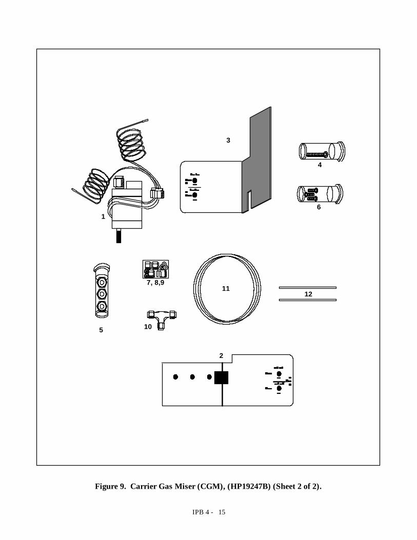
Figure 9. Carrier Gas Miser (CGM), (HP19247B) (Sheet 1 of 2).
IPB 4 - 15
1
4
6
105
11
3
2
7, 8,912
Figure 9. Carrier Gas Miser (CGM), (HP19247B) (Sheet 2 of 2).
IPB 4 - 16
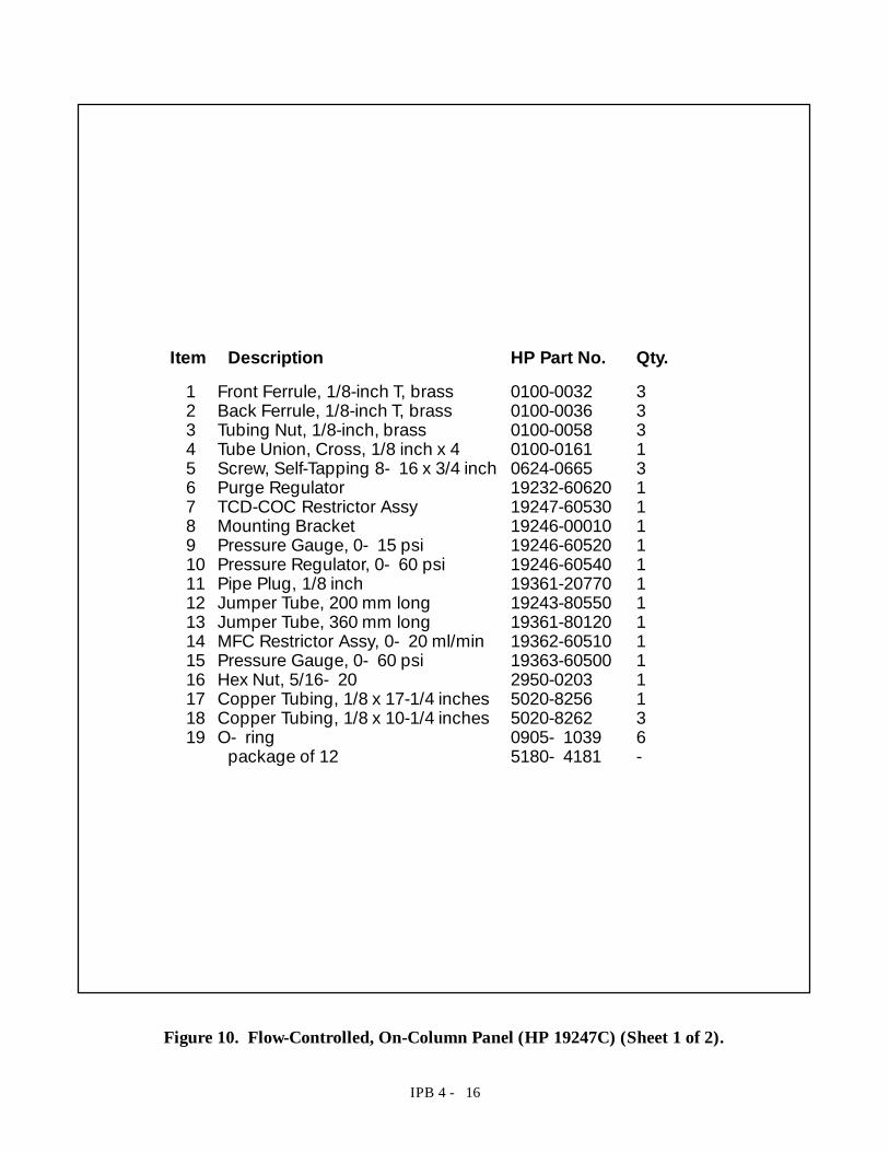
Item Description HP Part No. Qty.1 Front Ferrule, 1/8-inch T, brass 0100-0032 32 Back Ferrule, 1/8-inch T, brass 0100-0036 33 Tubing Nut, 1/8-inch, brass 0100-0058 34 Tube Union, Cross, 1/8 inch x 4 0100-0161 15 Screw, Self-Tapping 8- 16 x 3/4 inch 0624-0665 36 Purge Regulator 19232-60620 17 TCD-COC Restrictor Assy 19247-60530 18 Mounting Bracket 19246-00010 19 Pressure Gauge, 0- 15 psi 19246-60520 110 Pressure Regulator, 0- 60 psi 19246-60540 111 Pipe Plug, 1/8 inch 19361-20770 112 Jumper Tube, 200 mm long 19243-80550 113 Jumper Tube, 360 mm long 19361-80120 114 MFC Restrictor Assy, 0- 20 ml/min 19362-60510 115 Pressure Gauge, 0- 60 psi 19363-60500 116 Hex Nut, 5/16- 20 2950-0203 117 Copper Tubing, 1/8 x 17-1/4 inches 5020-8256 118 Copper Tubing, 1/8 x 10-1/4 inches 5020-8262 319 O- ring 0905- 1039 6
package of 12 5180- 4181 -
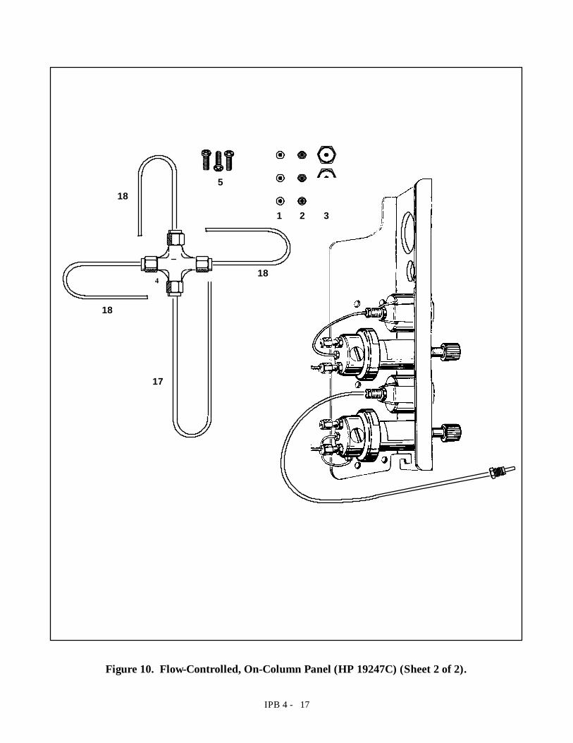
Figure 10. Flow-Controlled, On-Column Panel (HP 19247C) (Sheet 1 of 2).
IPB 4 - 17
18
18
18
17
4
1 2 3
5
Figure 10. Flow-Controlled, On-Column Panel (HP 19247C) (Sheet 2 of 2).
IPB 4 - 19
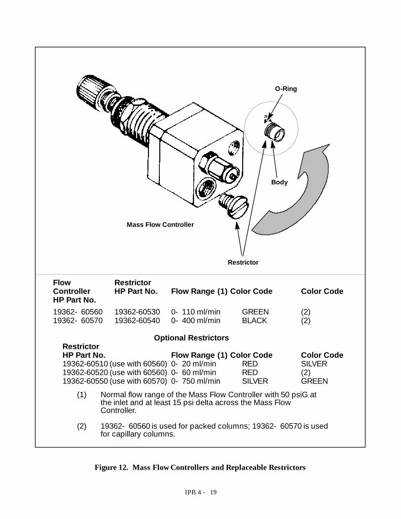
(1) Normal flow range of the Mass Flow Controller with 50 psiG atthe inlet and at least 15 psi delta across the Mass FlowController.
(2) 19362- 60560 is used for packed columns; 19362- 60570 is usedfor capillary columns.
Flow RestrictorController HP Part No. Flow Range (1) Color Code Color CodeHP Part No.19362- 60560 19362-60530 0- 110 ml/min GREEN (2)19362- 60570 19362-60540 0- 400 ml/min BLACK (2)
Optional RestrictorsRestrictorHP Part No. Flow Range (1) Color Code Color Code19362-60510 (use with 60560) 0- 20 ml/min RED SILVER19362-60520 (use with 60560) 0- 60 ml/min RED (2)19362-60550 (use with 60570) 0- 750 ml/min SILVER GREEN
Mass Flow Controller
O-Ring
Restrictor
Body
Figure 12. Mass Flow Controllers and Replaceable Restrictors
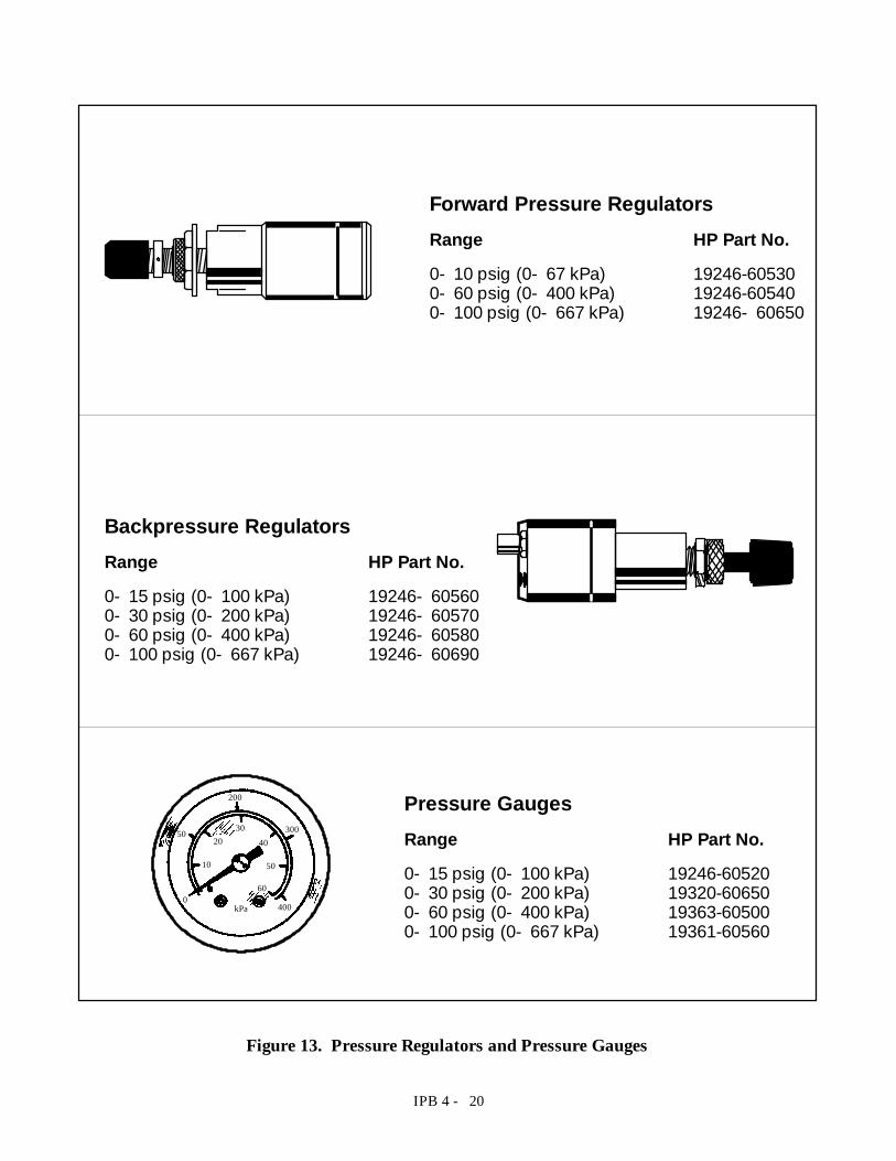
IPB 4 - 20
Pressure GaugesRange HP Part No.0- 15 psig (0- 100 kPa) 19246-605200- 30 psig (0- 200 kPa) 19320-606500- 60 psig (0- 400 kPa) 19363-605000- 100 psig (0- 667 kPa) 19361-60560
Backpressure RegulatorsRange HP Part No.0- 15 psig (0- 100 kPa) 19246- 605600- 30 psig (0- 200 kPa) 19246- 605700- 60 psig (0- 400 kPa) 19246- 605800- 100 psig (0- 667 kPa) 19246- 60690
10
2030
40
50
600
50
200
300
400kPa
Forward Pressure RegulatorsRange HP Part No.0- 10 psig (0- 67 kPa) 19246-605300- 60 psig (0- 400 kPa) 19246-605400- 100 psig (0- 667 kPa) 19246- 60650
Figure 13. Pressure Regulators and Pressure Gauges
27
Figure 14. Plumbing Diagram for HP 5890 Series II GCs purchased before January, 1992(Sheet 1 of 1).
IPB 3 - 4
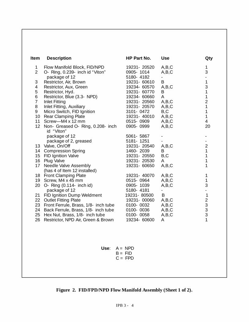
Item Description HP Part No. Use Qty
1 Flow Manifold Block, FID/NPD 19231- 20520 A,B,C 12 O- Ring, 0.239- inch id “Viton” 0905- 1014 A,B,C 3
package of 12 5180- 4182 - -3 Restrictor, Air, Brown 19231- 60610 B 14 Restrictor, Aux, Green 19234- 60570 A,B,C 35 Restrictor, Hyd. 19231- 60770 B 16 Restrictor, Blue (3.3- NPD) 19234- 60660 A 17 Inlet Fitting 19231- 20560 A,B,C 28 Inlet Fitting, Auxiliary 19231- 20570 A,B,C 19 Micro Switch, FID Ignition 3101- 0472 B,C 110 Rear Clamping Plate 19231- 40010 A,B,C 111 Screw— M4 x 12 mm 0515- 0909 A,B,C 412 Non- Greased O- Ring, 0.208- inch 0905- 0999 A,B,C 20
id “Viton”package of 12 5061- 5867 - -package of 2, greased 5181- 1251 - -
13 Valve, On/Off 19231- 20540 A,B,C 214 Compression Spring 1460- 2039 B 115 FID Ignition Valve 19231- 20550 B,C 116 Plug Valve 19231- 20530 A 117 Needle Valve Assembly 19231- 60650 A,B,C 1
(has 4 of Item 12 installed)18 Front Clamping Plate 19231- 40070 A,B,C 119 Screw, M4 x 45 mm 0515- 0964 A,B,C 120 O- Ring (0.114- inch id) 0905- 1039 A,B,C 3
package of 12 5180- 4181 - -21 FID Ignition Dump Weldment 19231- 80500 B 122 Outlet Fitting Plate 19231- 00060 A,B,C 223 Front Ferrule, Brass, 1/8- inch tube 0100- 0032 A,B,C 324 Back Ferrule, Brass, 1/8- inch tube 0100- 0036 A,B,C 325 Hex Nut, Brass, 1/8- inch tube 0100- 0058 A,B,C 326 Restrictor, NPD Air, Green & Brown 19234- 60600 A 1
Use: A = NPDB = FIDC = FPD
Figure 2. FID/FPD/NPD Flow Manifold Assembly (Sheet 1 of 2).
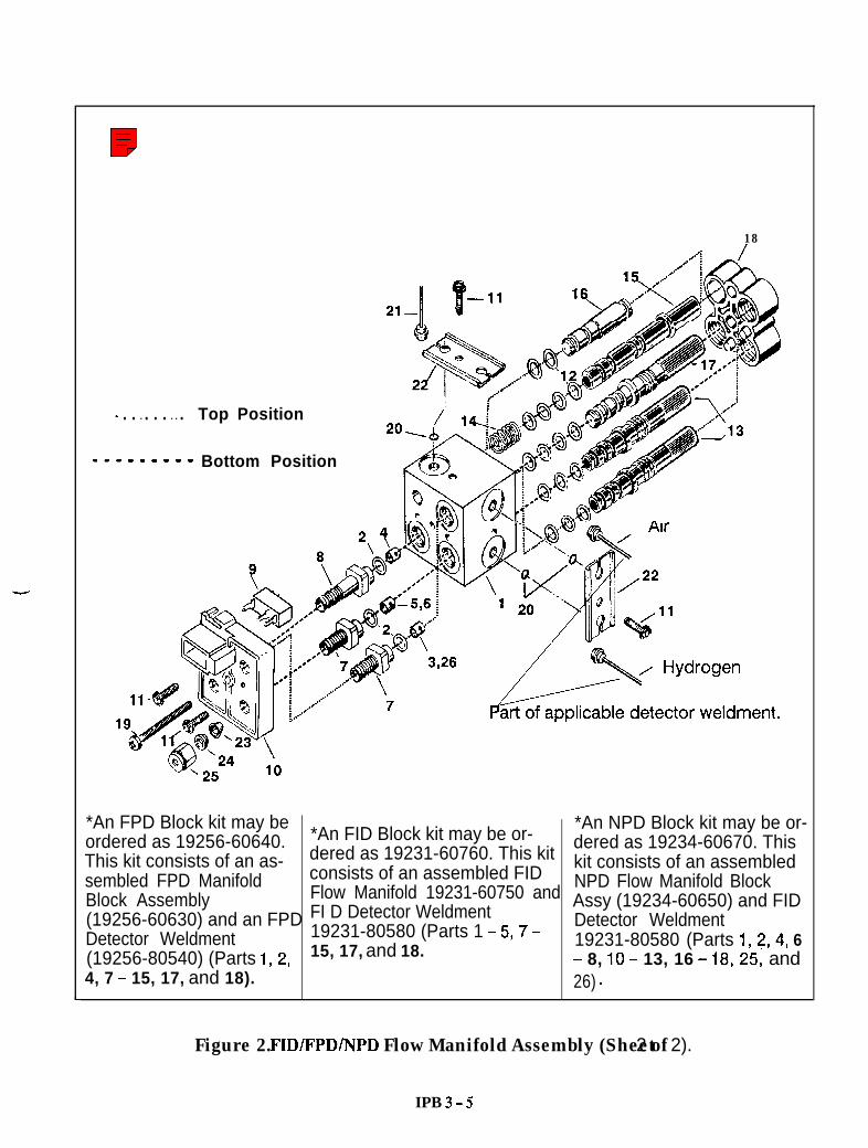
18
. . l . . . l l . Top Position
mmmNm_ Bottom Position
*An FPD Block kit may beordered as 19256-60640.This kit consists of an as-sembled FPD ManifoldBlock Assembly(19256-60630) and an FPDDetector Weldment(19256-80540) (Parts 1,2,4, 7 - 15, 17, and 18).
*An FID Block kit may be or-dered as 19231-60760. This kitconsists of an assembled FIDFlow Manifold 19231-60750 andFI D Detector Weldment19231-80580 (Parts 1 - 5,7 -15, 17, and 18.
*An NPD Block kit may be or-dered as 19234-60670. Thiskit consists of an assembledNPD Flow Manifold BlockAssy (19234-60650) and FIDDetector Weldment19231-80580 (Parts 1,2,4, 6- 8, IO - 13, 16 - 18,25, and26) .
Figure 2. FID/FPD/NPD Flow Manifold Assembly (Sheet 2 of 2).
IPB 3 - 5
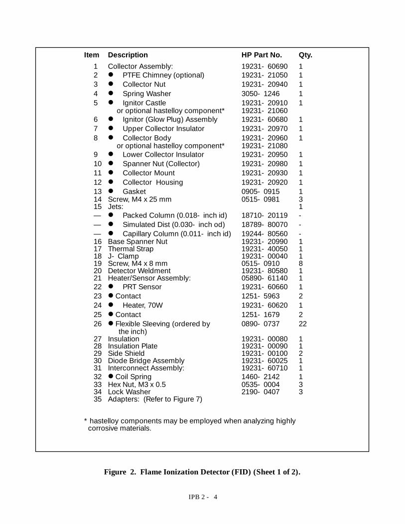
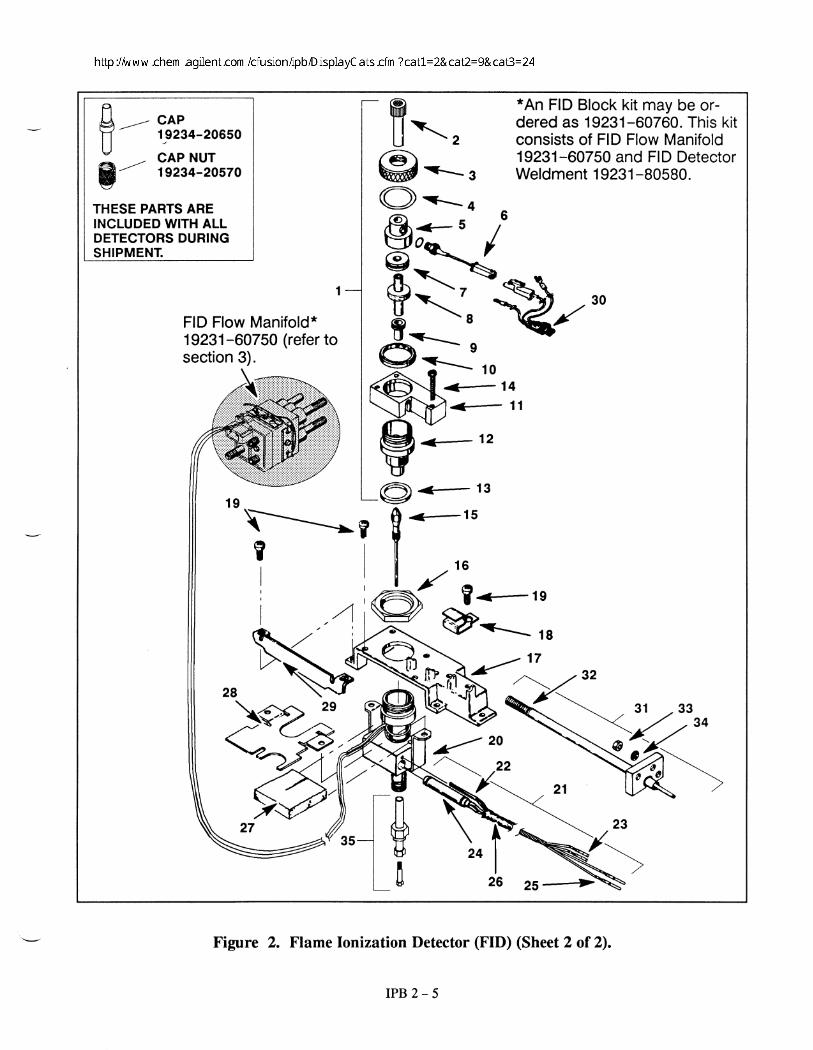
IPB 2 - 4
Item Description HP Part No. Qty.1 Collector Assembly: 19231- 60690 12 D PTFE Chimney (optional) 19231- 21050 13 D Collector Nut 19231- 20940 14 D Spring Washer 3050- 1246 15 D Ignitor Castle 19231- 20910 1
or optional hastelloy component* 19231- 210606 D Ignitor (Glow Plug) Assembly 19231- 60680 17 D Upper Collector Insulator 19231- 20970 18 D Collector Body 19231- 20960 1
or optional hastelloy component* 19231- 210809 D Lower Collector Insulator 19231- 20950 110 D Spanner Nut (Collector) 19231- 20980 111 D Collector Mount 19231- 20930 112 D Collector Housing 19231- 20920 113 D Gasket 0905- 0915 114 Screw, M4 x 25 mm 0515- 0981 315 Jets: 1— D Packed Column (0.018- inch id) 18710- 20119 -— D Simulated Dist (0.030- inch od) 18789- 80070 -— D Capillary Column (0.011- inch id) 19244- 80560 -16 Base Spanner Nut 19231- 20990 117 Thermal Strap 19231- 40050 118 J- Clamp 19231- 00040 119 Screw, M4 x 8 mm 0515- 0910 820 Detector Weldment 19231- 80580 121 Heater/Sensor Assembly: 05890- 61140 122 D PRT Sensor 19231- 60660 123 D Contact 1251- 5963 224 D Heater, 70W 19231- 60620 125 D Contact 1251- 1679 226 D Flexible Sleeving (ordered by 0890- 0737 22
the inch)27 Insulation 19231- 00080 128 Insulation Plate 19231- 00090 129 Side Shield 19231- 00100 230 Diode Bridge Assembly 19231- 60025 131 Interconnect Assembly: 19231- 60710 132 D Coil Spring 1460- 2142 133 Hex Nut, M3 x 0.5 0535- 0004 334 Lock Washer 2190- 0407 335 Adapters: (Refer to Figure 7)
* hastelloy components may be employed when analyzing highlycorrosive materials.
Figure 2. Flame Ionization Detector (FID) (Sheet 1 of 2).
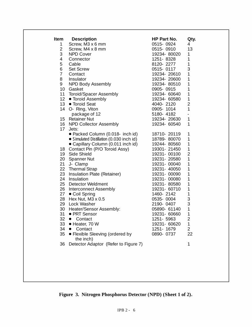
IPB 2 - 6
Item Description HP Part No. Qty.1 Screw, M3 x 6 mm 0515- 0924 42 Screw, M4 x 8 mm 0515- 0910 133 NPD Cover 19234- 80020 14 Connector 1251- 8328 15 Cable 8120- 2277 16 Set Screw 0515- 0117 37 Contact 19234- 20610 18 Insulator 19234- 20600 19 NPD Body Assembly 19234- 80510 110 Gasket 0905- 0915 111 Toroid/Spacer Assembly 19234- 60640 112 D Toroid Assembly 19234- 60580 113 D Toroid Seat 4040- 2120 214 O- Ring, Viton 0905- 1014 1
package of 12 5180- 4182 -15 Retainer Nut 19234- 20630 116 NPD Collector Assembly 19234- 60540 117 Jets:D Packed Column (0.018- inch id) 18710- 20119 1D Simulated Distillation (0.030 inch id) 18789- 80070 1D Capillary Column (0.011 inch id) 19244- 80560 1
18 Contact Pin (P/O Toroid Assy) 19301- 21450 119 Side Shield 19231- 00100 220 Spanner Nut 19231- 20580 121 J- Clamp 19231- 00040 122 Thermal Strap 19231- 40050 123 Insulation Plate (Retainer) 19231- 00090 124 Insulation 19231- 00080 125 Detector Weldment 19231- 80580 126 Interconnect Assembly 19231- 60710 127 D Coil Spring 1460- 2142 128 Hex Nut, M3 x 0.5 0535- 0004 329 Lock Washer 2190- 0407 330 Heater/Sensor Assembly: 05890- 61140 131 D PRT Sensor 19231- 60660 132 D Contact 1251- 5963 233 D Heater, 70 W 19231- 60620 134 D Contact 1251- 1679 235 D Flexible Sleeving (ordered by 0890- 0737 22
the inch)36 Detector Adaptor (Refer to Figure 7) 1
Figure 3. Nitrogen Phosphorus Detector (NPD) (Sheet 1 of 2).
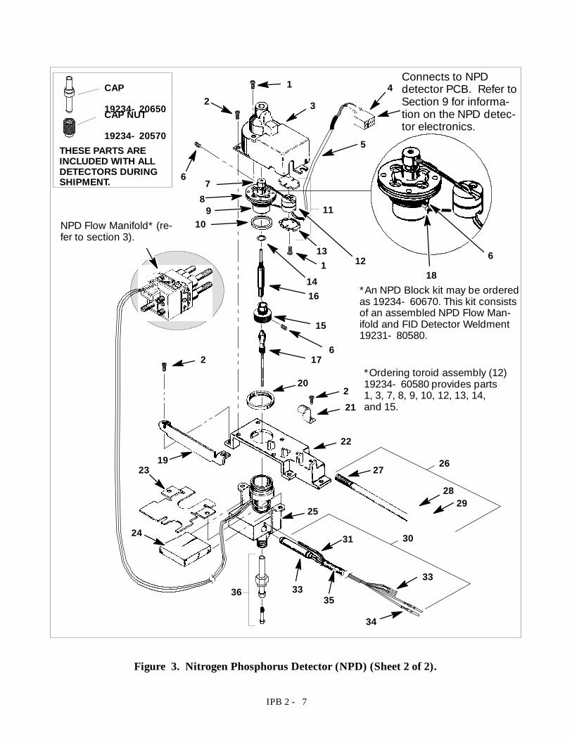
IPB 2 - 7
12
6
3
5
4
6
1812
131
14
109
8
16
15
617
20221
2
1923
24
25
27
22
2829
31
3335
34
33
30
26
36
11
*An NPD Block kit may be orderedas 19234- 60670. This kit consistsof an assembled NPD Flow Man-ifold and FID Detector Weldment19231- 80580.
NPD Flow Manifold* (re-fer to section 3).
Connects to NPDdetector PCB. Refer toSection 9 for informa-tion on the NPD detec-tor electronics.
7
CAP
19234- 20650CAP NUT
19234- 20570THESE PARTS AREINCLUDED WITH ALLDETECTORS DURINGSHIPMENT.
*Ordering toroid assembly (12)19234- 60580 provides parts1, 3, 7, 8, 9, 10, 12, 13, 14,and 15.
Figure 3. Nitrogen Phosphorus Detector (NPD) (Sheet 2 of 2).
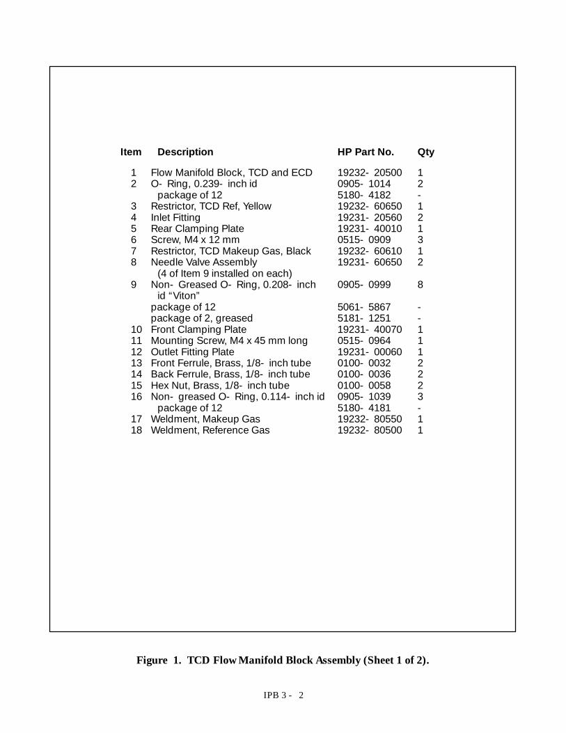
IPB 3 - 2
Item Description HP Part No. Qty
1 Flow Manifold Block, TCD and ECD 19232- 20500 12 O- Ring, 0.239- inch id 0905- 1014 2
package of 12 5180- 4182 -3 Restrictor, TCD Ref, Yellow 19232- 60650 14 Inlet Fitting 19231- 20560 25 Rear Clamping Plate 19231- 40010 16 Screw, M4 x 12 mm 0515- 0909 37 Restrictor, TCD Makeup Gas, Black 19232- 60610 18 Needle Valve Assembly 19231- 60650 2
(4 of Item 9 installed on each)9 Non- Greased O- Ring, 0.208- inch 0905- 0999 8
id “Viton”package of 12 5061- 5867 -package of 2, greased 5181- 1251 -
10 Front Clamping Plate 19231- 40070 111 Mounting Screw, M4 x 45 mm long 0515- 0964 112 Outlet Fitting Plate 19231- 00060 113 Front Ferrule, Brass, 1/8- inch tube 0100- 0032 214 Back Ferrule, Brass, 1/8- inch tube 0100- 0036 215 Hex Nut, Brass, 1/8- inch tube 0100- 0058 216 Non- greased O- Ring, 0.114- inch id 0905- 1039 3
package of 12 5180- 4181 -17 Weldment, Makeup Gas 19232- 80550 118 Weldment, Reference Gas 19232- 80500 1
Figure 1. TCD Flow Manifold Block Assembly (Sheet 1 of 2).
IPB 2 - 2
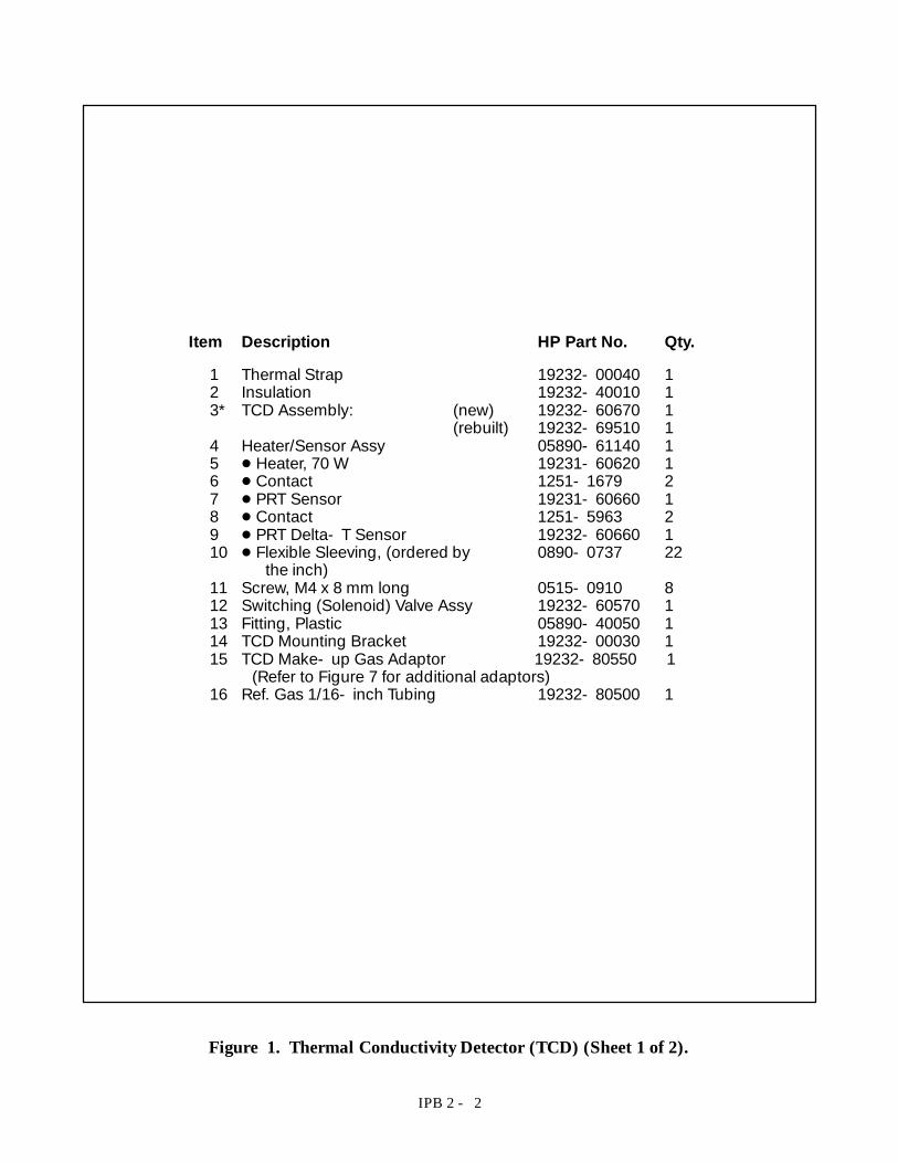
Item Description HP Part No. Qty.
1 Thermal Strap 19232- 00040 12 Insulation 19232- 40010 13* TCD Assembly: (new) 19232- 60670 1
(rebuilt) 19232- 69510 14 Heater/Sensor Assy 05890- 61140 15 D Heater, 70 W 19231- 60620 16 D Contact 1251- 1679 27 D PRT Sensor 19231- 60660 18 D Contact 1251- 5963 29 D PRT Delta- T Sensor 19232- 60660 110 D Flexible Sleeving, (ordered by 0890- 0737 22
the inch)11 Screw, M4 x 8 mm long 0515- 0910 812 Switching (Solenoid) Valve Assy 19232- 60570 113 Fitting, Plastic 05890- 40050 114 TCD Mounting Bracket 19232- 00030 115 TCD Make- up Gas Adaptor 19232- 80550 1
(Refer to Figure 7 for additional adaptors)16 Ref. Gas 1/16- inch Tubing 19232- 80500 1
Figure 1. Thermal Conductivity Detector (TCD) (Sheet 1 of 2).
IPB 2 - 3
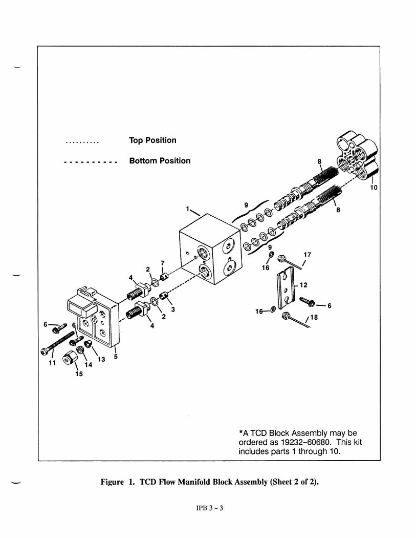
11
1
5 4
15
12
14
13
16
79
3
2
68
10
CAP
19234- 20650CAP NUT
19234- 20570THESE PARTS AREINCLUDED WITH ALLDETECTORS DURINGSHIPMENT.
Figure 1. Thermal Conductivity Detector (TCD) (Sheet 2 of 2).
IPB 2 - 12
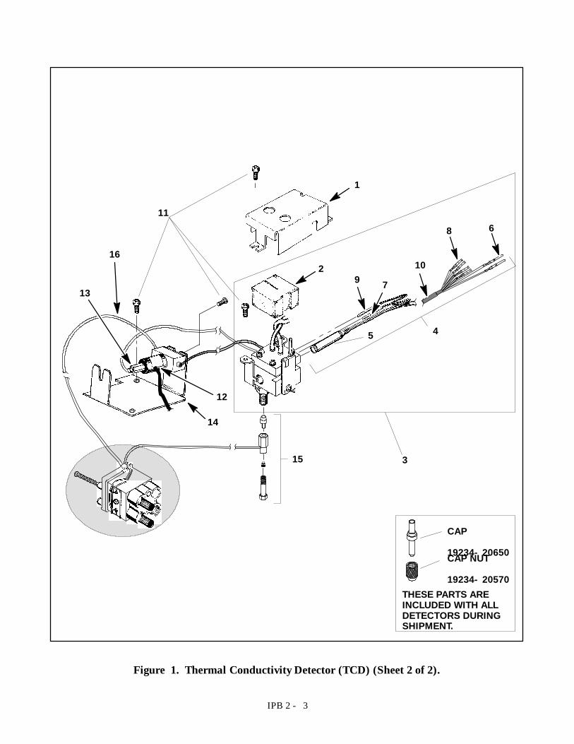
Item Description HP Part No. Qty.
1 Chimney 19256- 80510 12 Screw, M4 x 25 mm long 0515- 0065 143 PMT Assembly 19256- 60510 14 D Tube Body 19256- 20780 15 D Photo- Multiplier Tube 19256- 80050 16 D O- ring 0905- 1099 17 D End Cap 19256- 20790 18 D Cable Assembly 19256- 60580 19 Chimney Back 19256- 00100 110 Main Bracket 19256- 00060 111 Support Bracket 19256- 00080 112 Heater/Sensor Assembly 05890- 61140 113 D Heater 19231- 60620 114 D Contact 1251- 1679 215 D PRT Sensor 19231- 60660 116 D Contact 1251- 5963 217 D Flexible Sleeving 1/4 x 20 inches 0890- 0862 1
NOTE: A second heater element is used in the FPD detector;HP Part No. 19256- 60540 (refer to Sheet 6 for illustration).
Figure 6. Flame Photometric Detector (FPD) (Sheet 1 of 6).
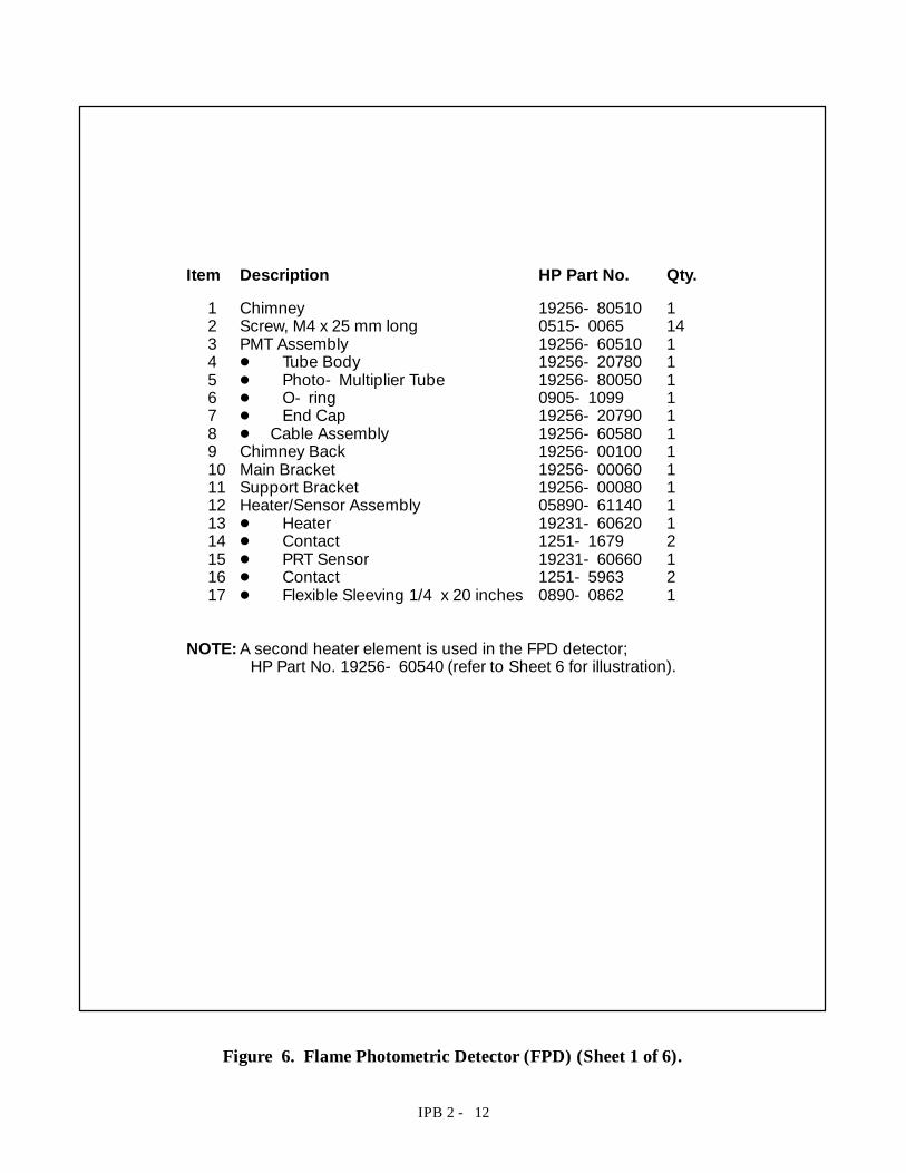
IPB 2 - 13
12
24
5
67
8
9
10
11
REFER TO SHEET 4FOR BREAKDOWN
REFER TO SHEET 6FOR BREAKDOWN
12
13
14
15
16
17
2
2
3
FPD Flow Manifold(Refer to Section 3)
CAP
19234- 20650CAP NUT
19234- 20570THESE PARTS AREINCLUDED WITH ALLDETECTORS DURINGSHIPMENT.
REFER TO FIGURE 7FOR INFORMATIONON ADAPTORS
Figure 6. Flame Photometric Detector (FPD) (Sheet 2 of 6).
IPB 2 - 14
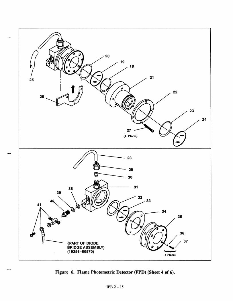
Item Description HP Part No. Qty.
18 O- ring, Silicone .926- inch id 0905- 0955 119 Second Heat Shield Window 19256- 80060 120 O- ring, Silicone 1.05- inch id 0905- 1104 121 Flange Adaptor 19256- 20510 122 Flange Ring 19256- 00200 123 O- ring, Viton 1.239- inch id 0905- 1100124 Filter, Sulphur 1
393 Nm 19256- 80000 -525 Nm 19256- 80010 -
25 Drip Tube 19256- 20730 126 Clamp 19256- 00090 127 Screw, M3 x 25 mm- long 0515- 0065 428 Exit Tube Assembly 19256- 20700 129 Brass Nut, 1/4- inch 0100- 0056 130 Vespel Ferrule, 1/4- inch id 0100- 1061 131 Block Weldment 19256- 80560 132 Heat Shield Gasket 19256- 80040 133 First Heat Shield Window 19256- 80030 134 Heat Shield Disk 19256- 20580 135 Stainless Steel Coupling 19256- 20550 136 Lock Washer 2190- 0108 437 Screw, M3 x 12 mm- long 0515- 0105 438 O- ring, Kalrez 2010 0905- 1102 139 Ignitor Spacer 19256- 20590 140 Glow- Plug 0854- 0141 141 Diode Bridge Assembly. 19256- 60570 1
Figure 6. Flame Photometric Detector (FPD) (Sheet 3 of 6).
IPB 2 - 16
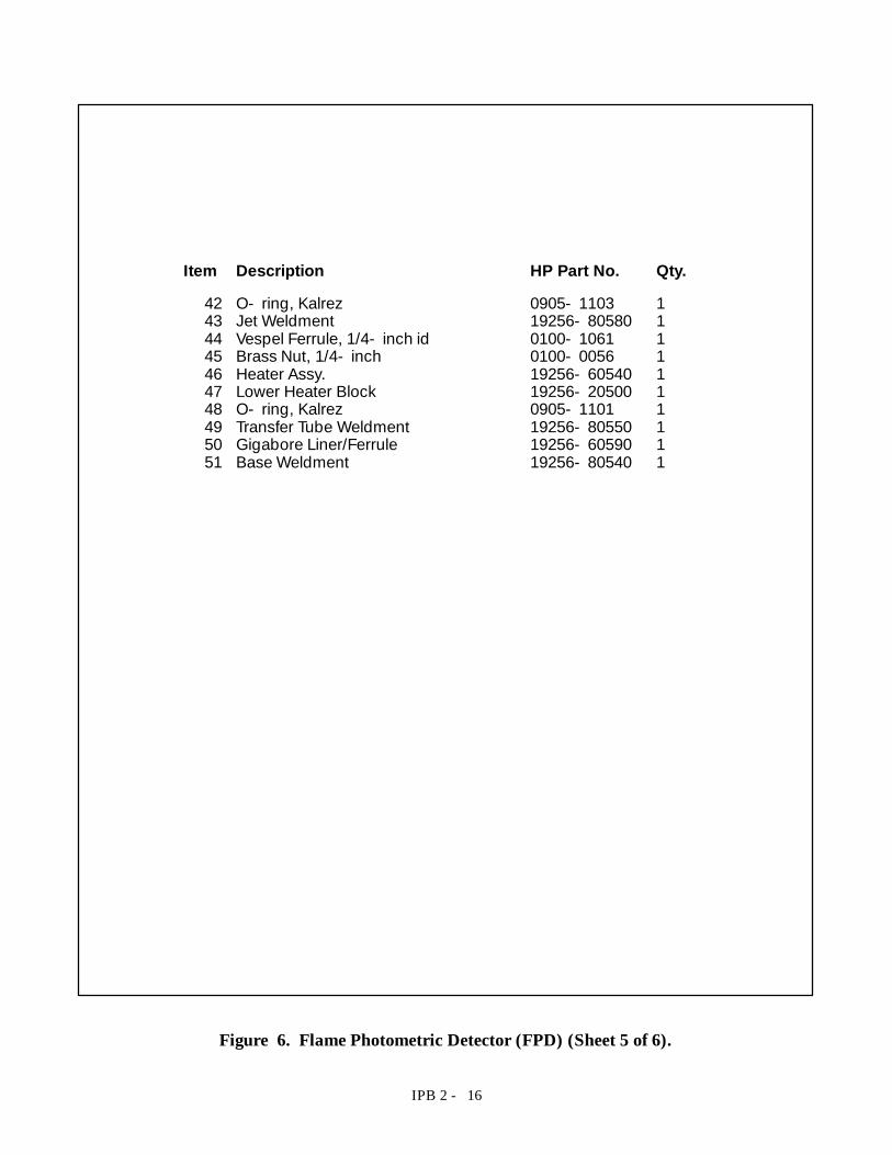
Item Description HP Part No. Qty.
42 O- ring, Kalrez 0905- 1103 143 Jet Weldment 19256- 80580 144 Vespel Ferrule, 1/4- inch id 0100- 1061 145 Brass Nut, 1/4- inch 0100- 0056 146 Heater Assy. 19256- 60540 147 Lower Heater Block 19256- 20500 148 O- ring, Kalrez 0905- 1101 149 Transfer Tube Weldment 19256- 80550 150 Gigabore Liner/Ferrule 19256- 60590 151 Base Weldment 19256- 80540 1
Figure 6. Flame Photometric Detector (FPD) (Sheet 5 of 6).
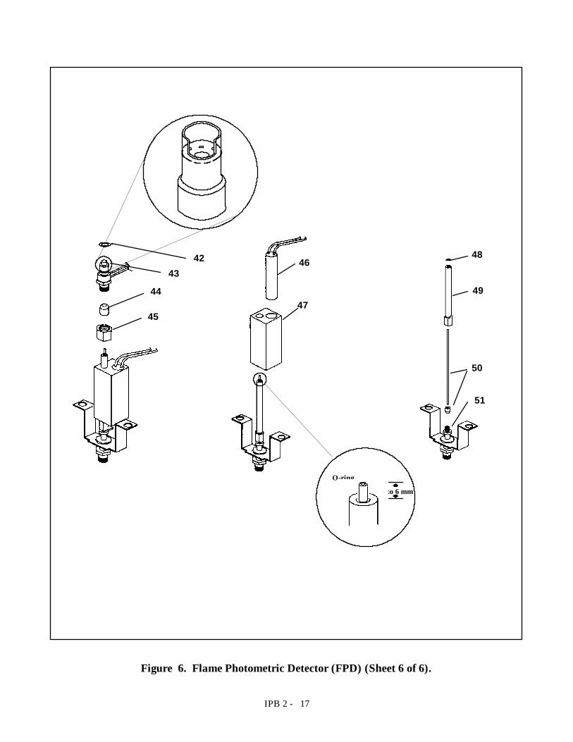
IPB 2 - 17
O-ring
3 to 6 mmby
4243
44
45
46
47
48
49
50
51
Figure 6. Flame Photometric Detector (FPD) (Sheet 6 of 6).
IPB 2 - 8
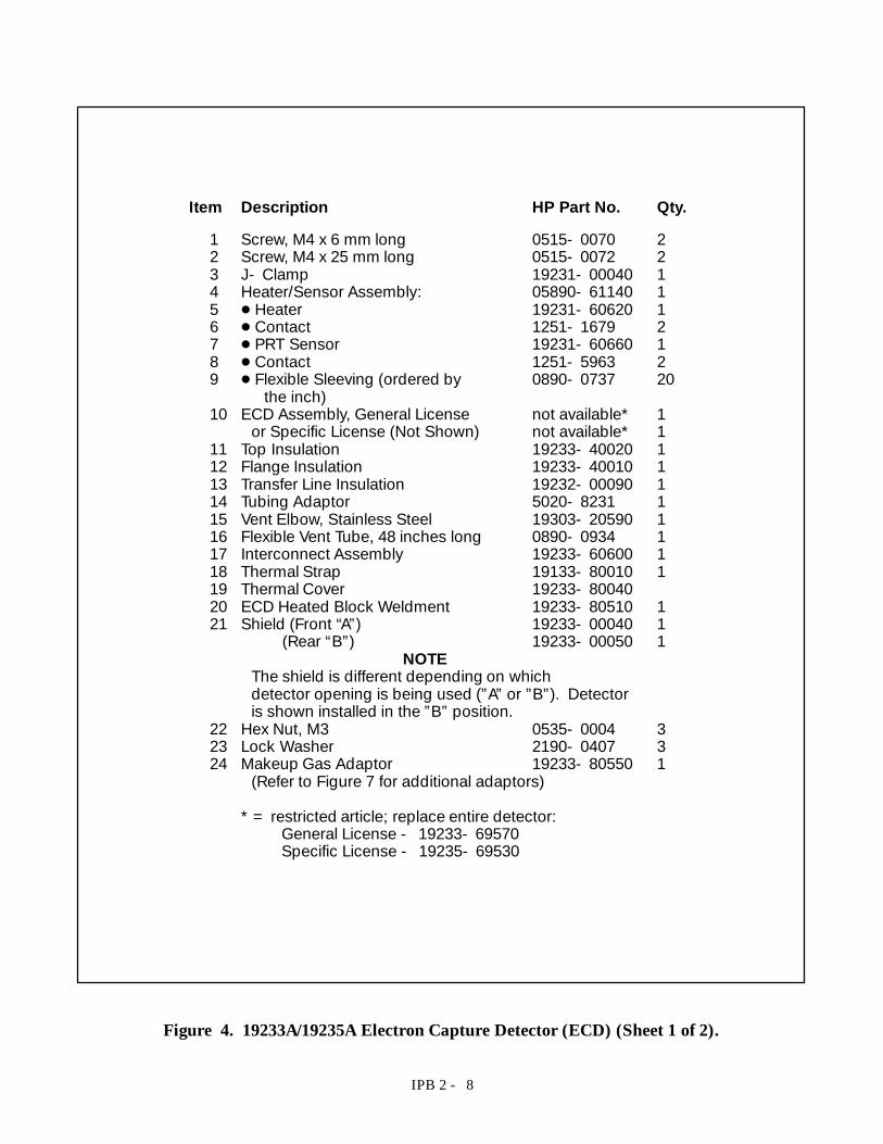
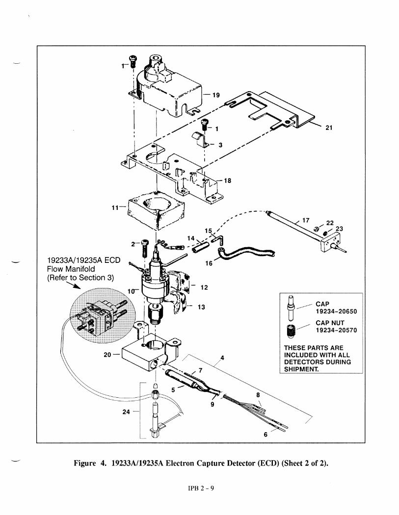
Item Description HP Part No. Qty.
1 Screw, M4 x 6 mm long 0515- 0070 22 Screw, M4 x 25 mm long 0515- 0072 23 J- Clamp 19231- 00040 14 Heater/Sensor Assembly: 05890- 61140 15 D Heater 19231- 60620 16 D Contact 1251- 1679 27 D PRT Sensor 19231- 60660 18 D Contact 1251- 5963 29 D Flexible Sleeving (ordered by 0890- 0737 20
the inch)10 ECD Assembly, General License not available* 1
or Specific License (Not Shown) not available* 111 Top Insulation 19233- 40020 112 Flange Insulation 19233- 40010 113 Transfer Line Insulation 19232- 00090 114 Tubing Adaptor 5020- 8231 115 Vent Elbow, Stainless Steel 19303- 20590 116 Flexible Vent Tube, 48 inches long 0890- 0934 117 Interconnect Assembly 19233- 60600 118 Thermal Strap 19133- 80010 119 Thermal Cover 19233- 8004020 ECD Heated Block Weldment 19233- 80510 121 Shield (Front “A”) 19233- 00040 1
(Rear “B”) 19233- 00050 1NOTE
The shield is different depending on whichdetector opening is being used (”A”or ”B”). Detectoris shown installed in the ”B”position.
22 Hex Nut, M3 0535- 0004 323 Lock Washer 2190- 0407 324 Makeup Gas Adaptor 19233- 80550 1
(Refer to Figure 7 for additional adaptors)
* = restricted article; replace entire detector:General License - 19233- 69570Specific License - 19235- 69530
Figure 4. 19233A/19235A Electron Capture Detector (ECD) (Sheet 1 of 2).
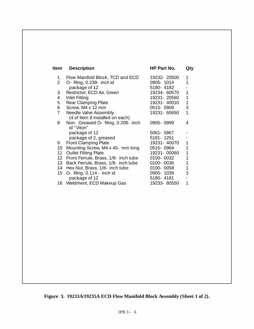
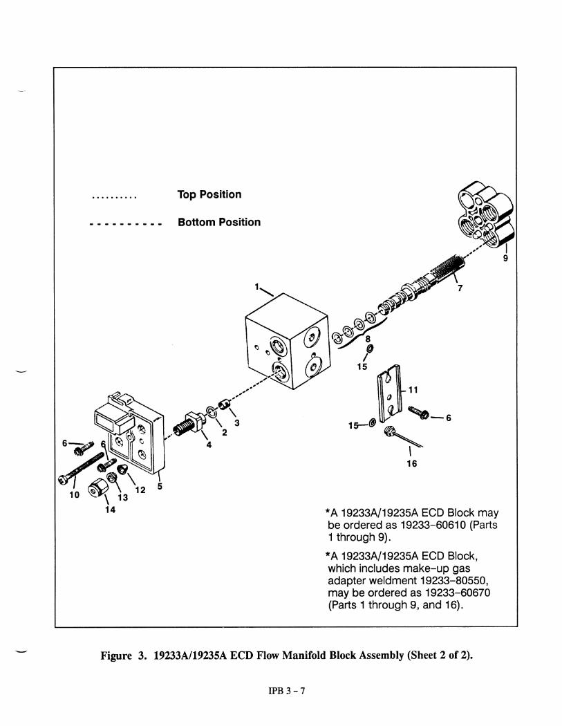
IPB 3 - 6
Item Description HP Part No. Qty
1 Flow Manifold Block, TCD and ECD 19232- 20500 12 O- Ring, 0.239- inch id 0905- 1014 1
package of 12 5180- 4182 -3 Restrictor, ECD Air, Green 19234- 60570 14 Inlet Fitting 19231- 20560 15 Rear Clamping Plate 19231- 40010 16 Screw, M4 x 12 mm 0515- 0909 37 Needle Valve Assembly 19231- 60650 1
(4 of Item 8 installed on each)8 Non- Greased O- Ring, 0.208- inch 0905- 0999 4
id “Viton”package of 12 5061- 5867 -package of 2, greased 5181- 1251 -
9 Front Clamping Plate 19231- 40070 110 Mounting Screw, M4 x 45- mm long 0515- 0964 111 Outlet Fitting Plate 19231- 00060 112 Front Ferrule, Brass, 1/8- inch tube 0100- 0032 113 Back Ferrule, Brass, 1/8- inch tube 0100- 0036 114 Hex Nut, Brass, 1/8- inch tube 0100- 0058 115 O- Ring, 0.114 - inch id 0905- 1039 3
package of 12 5180- 4181 -16 Weldment, ECD Makeup Gas 19233- 80550 1
Figure 3. 19233A/19235A ECD Flow Manifold Block Assembly (Sheet 1 of 2).
IPB 3 - 8
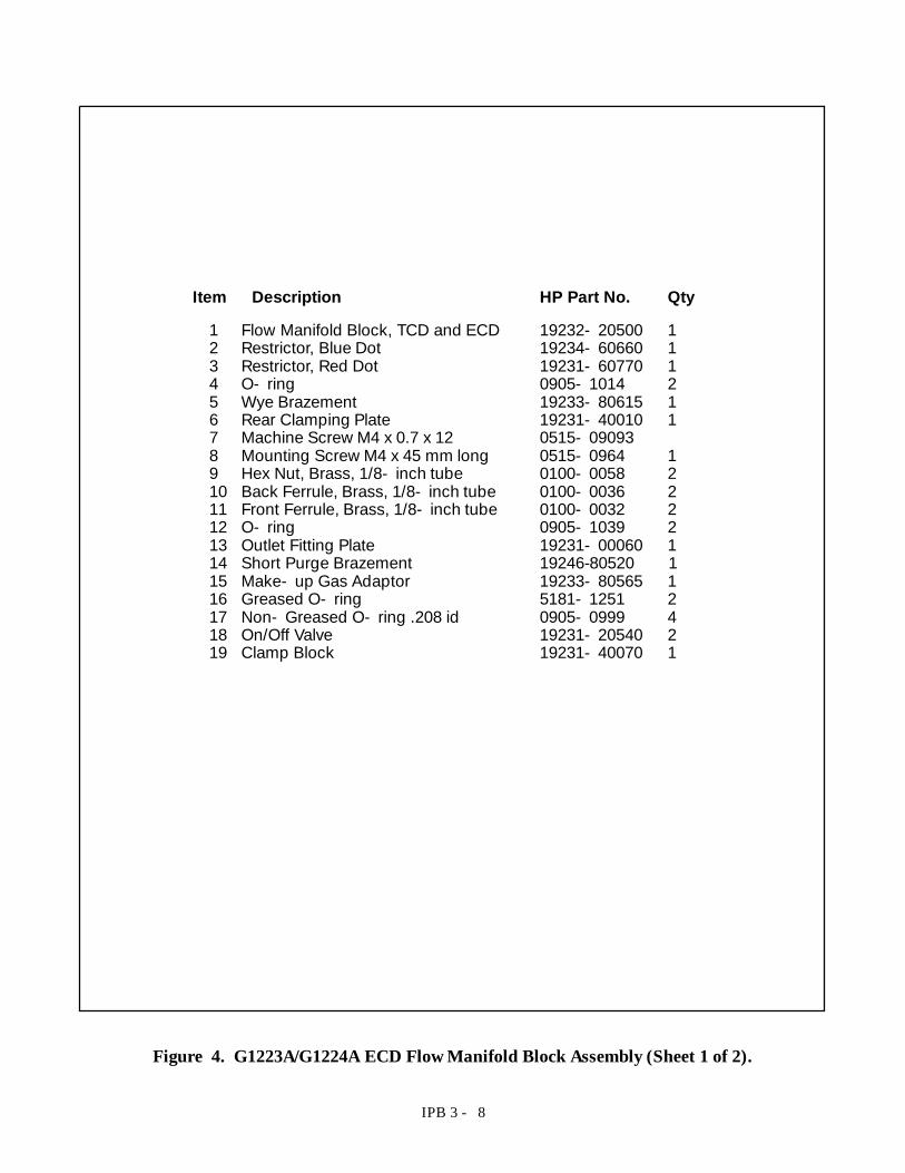
Item Description HP Part No. Qty
1 Flow Manifold Block, TCD and ECD 19232- 20500 12 Restrictor, Blue Dot 19234- 60660 13 Restrictor, Red Dot 19231- 60770 14 O- ring 0905- 1014 25 Wye Brazement 19233- 80615 16 Rear Clamping Plate 19231- 40010 17 Machine Screw M4 x 0.7 x 12 0515- 090938 Mounting Screw M4 x 45 mm long 0515- 0964 19 Hex Nut, Brass, 1/8- inch tube 0100- 0058 210 Back Ferrule, Brass, 1/8- inch tube 0100- 0036 211 Front Ferrule, Brass, 1/8- inch tube 0100- 0032 212 O- ring 0905- 1039 213 Outlet Fitting Plate 19231- 00060 114 Short Purge Brazement 19246-80520 115 Make- up Gas Adaptor 19233- 80565 116 Greased O- ring 5181- 1251 217 Non- Greased O- ring .208 id 0905- 0999 418 On/Off Valve 19231- 20540 219 Clamp Block 19231- 40070 1
Figure 4. G1223A/G1224A ECD Flow Manifold Block Assembly (Sheet 1 of 2).
IPB 2 - 10
Item Description HP Part No. Qty.
1 Cover 19233- 00085 12 Anode/Ferrule/Nut Assembly 19233- 67010 13 D Anode Weldment 19233-80585 14 D Anode Retaining Nut 19233-20725 15 D Anode Ferrule 19233- 20695 16 ECD Cover 19233- 00075 17 Screw 0515- 0964 28 Upper Heater Block 19233- 20525 19 Screw-Socket M4 x 0.7 0515-0321 410 Upper Cell Weldment 19233-80525 111 Plated Lower Body not available* 112 Mounting Strap 19231- 00145 113 ECD Flange Insulation 19233- 40015 114 Bottom Insulation 19233- 40016 115 Lower Heater Block 19233- 20515 116 Heater/Sensor Assy 19233- 60625 117 D PRT Sensor 19231- 60660 118 D Contact 1251- 5963 219 D Heater, 60 W 19233- 60627 120 D Contact 1251- 1679 221 D Flexible Sleeving (ordered by 0890- 0737 22
the inch)22 Adapter (Refer to Figure 7) 23 Interconnect Lead 19233- 60635 124 Interconnect Assembly 19233- 60600 125 Hex Nut, M3 0535- 0407 326 Lock Washer 2190- 0407 327 Thermal Cover Clip 19233- 00095 128 Screw 0515- 0910 1
* = restricted article; replace entire detector:General License - 19233- 69576Specific License - 19235- 69536
Figure 5. G1223A/G1224A Electron Capture Detector (ECD) (Sheet 1 of 2).
IPB 2 - 11
1
3
6
7
9
8
45
10
11
16
17
1915
21
13
14
12
18
2022
2
G1223A/G1224A ECDFlow Manifold(Refer to Section 3)
CAP
19234- 20650CAP NUT
19234- 20570THESE PARTS AREINCLUDED WITH ALLDETECTORS DURINGSHIPMENT.
2324 2526
27
28
Figure 5. G1223A/G1224A Electron Capture Detector (ECD) (Sheet 2 of 2).
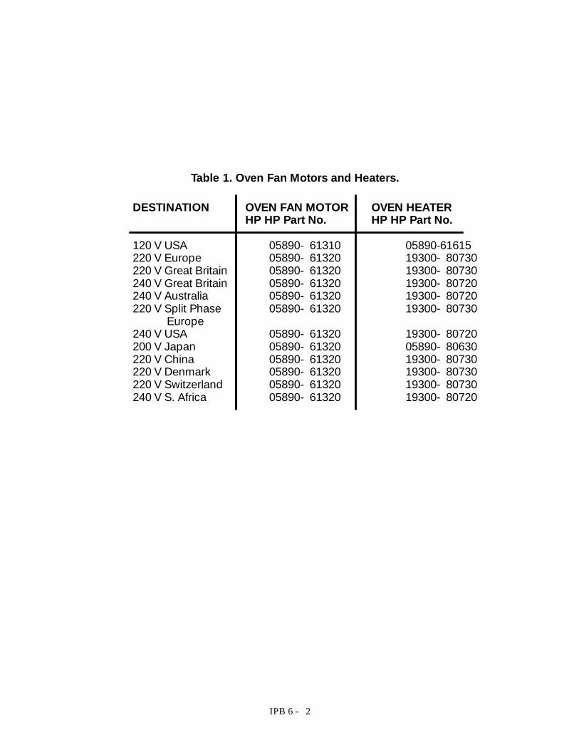
IPB 6 - 2
DESTINATION OVEN FAN MOTOR OVEN HEATERHP HP Part No. HP HP Part No.
120 V USA 05890- 61310 05890-61615220 V Europe 05890- 61320 19300- 80730220 V Great Britain 05890- 61320 19300- 80730240 V Great Britain 05890- 61320 19300- 80720240 V Australia 05890- 61320 19300- 80720220 V Split Phase 05890- 61320 19300- 80730
Europe240 V USA 05890- 61320 19300- 80720200 V Japan 05890- 61320 05890- 80630220 V China 05890- 61320 19300- 80730220 V Denmark 05890- 61320 19300- 80730220 V Switzerland 05890- 61320 19300- 80730240 V S. Africa 05890- 61320 19300- 80720
Table 1. Oven Fan Motors and Heaters.
IPB 6 - 3
3
6
8
11
7
10
9
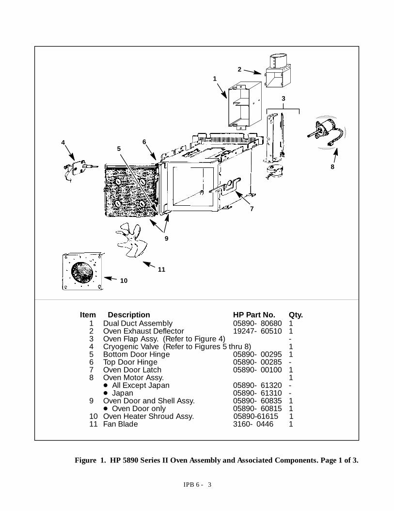
5
Item Description HP Part No. Qty.1 Dual Duct Assembly 05890- 80680 12 Oven Exhaust Deflector 19247- 60510 13 Oven Flap Assy. (Refer to Figure 4) -4 Cryogenic Valve (Refer to Figures 5 thru 8) 15 Bottom Door Hinge 05890- 00295 16 Top Door Hinge 05890- 00285 -7 Oven Door Latch 05890- 00100 18 Oven Motor Assy. 1D All Except Japan 05890- 61320 -D Japan 05890- 61310 -
9 Oven Door and Shell Assy. 05890- 60835 1D Oven Door only 05890- 60815 1
10 Oven Heater Shroud Assy. 05890-61615 111 Fan Blade 3160- 0446 1
4
12
Figure 1. HP 5890 Series II Oven Assembly and Associated Components. Page 1 of 3.
IPB 6 - 4
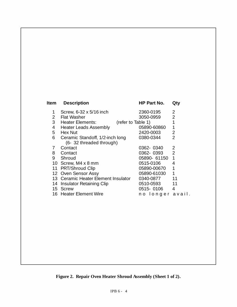
Item Description HP Part No. Qty1 Screw, 6-32 x 5/16 inch 2360-0195 22 Flat Washer 3050-0959 23 Heater Elements: (refer to Table 1) 14 Heater Leads Assembly 05890-60860 15 Hex Nut 2420-0003 26 Ceramic Standoff, 1/2-inch long 0380-0344 2
(6- 32 threaded through)7 Contact 0362- 0340 28 Contact 0362- 0393 29 Shroud 05890- 61150 110 Screw, M4 x 8 mm 0515-0106 411 PRT/Shroud Clip 05890-00670 112 Oven Sensor Assy 05890-61030 113 Ceramic Heater Element Insulator 0340-0877 1114 Insulator Retaining Clip 0510-0593 1115 Screw 0515- 0106 416 Heater Element Wire n o l o n g e r a v a i l .
Figure 2. Repair Oven Heater Shroud Assembly (Sheet 1 of 2).
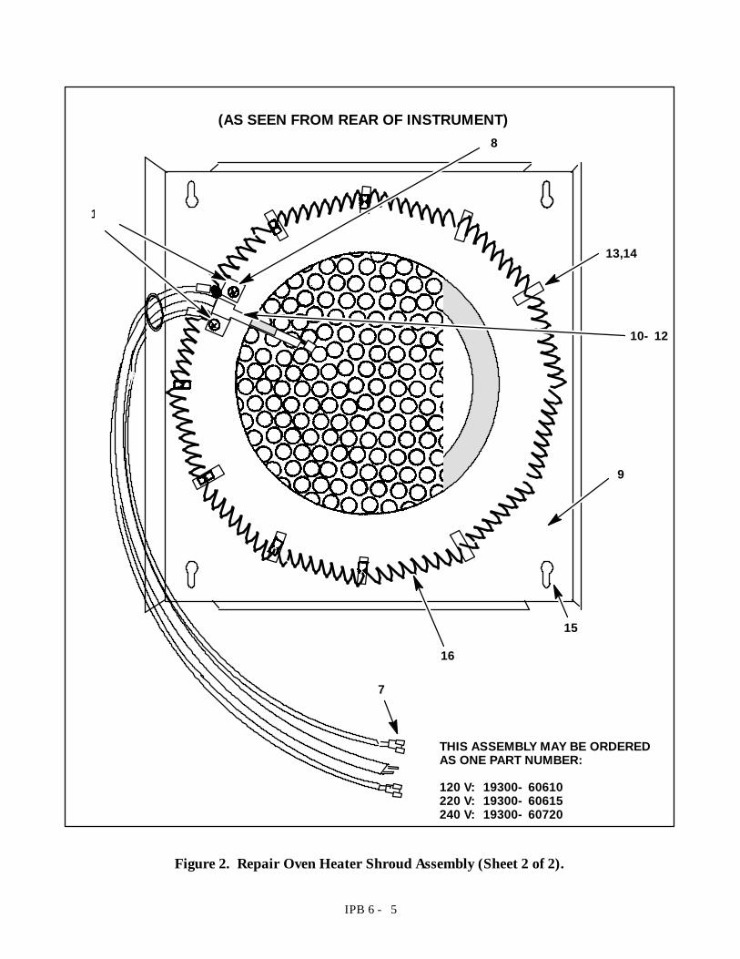
IPB 6 - 5
1- 6
10- 12
9
13,14
15
THIS ASSEMBLY MAY BE ORDEREDAS ONE PART NUMBER:
120 V: 19300- 60610220 V: 19300- 60615240 V: 19300- 60720
7
8
16
(AS SEEN FROM REAR OF INSTRUMENT)
Figure 2. Repair Oven Heater Shroud Assembly (Sheet 2 of 2).
IPB 6 - 7
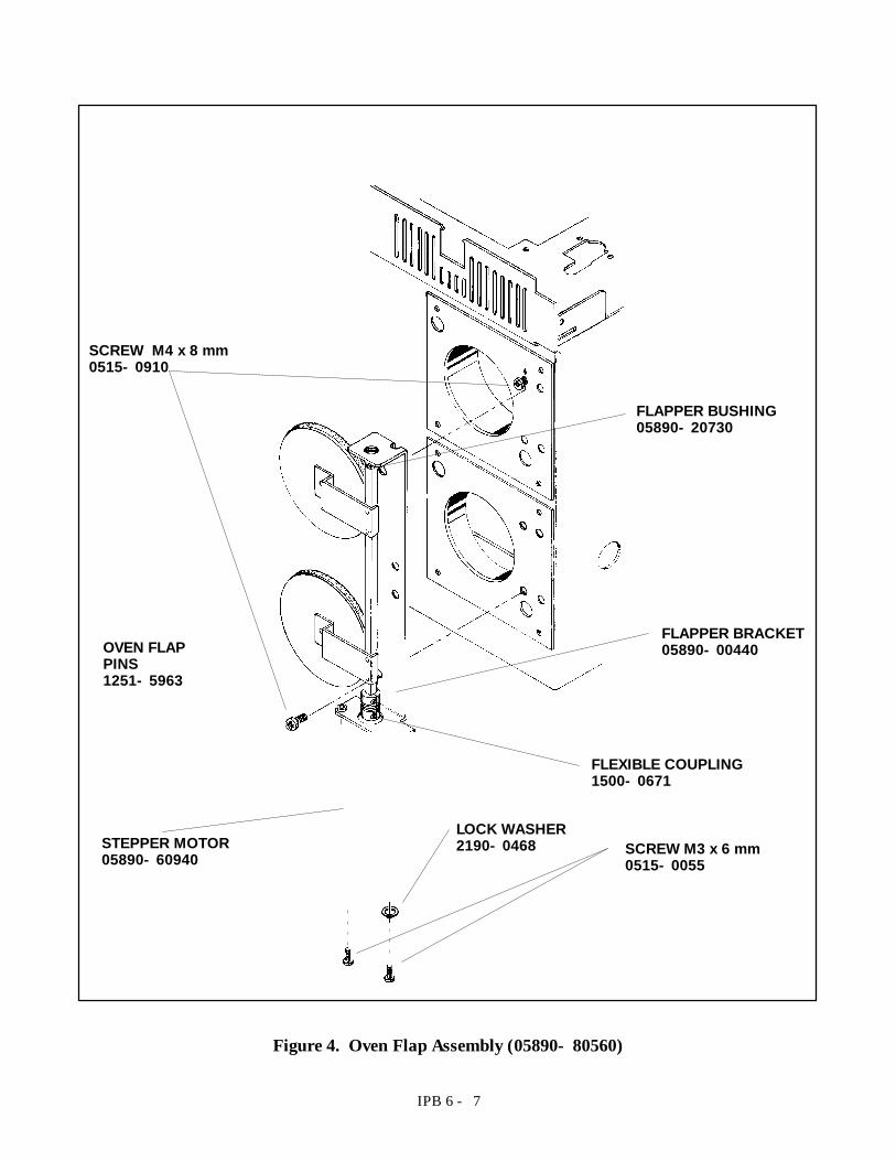
OVEN FLAPPINS1251- 5963
SCREW M4 x 8 mm0515- 0910
FLAPPER BUSHING05890- 20730
FLAPPER BRACKET05890- 00440
FLEXIBLE COUPLING1500- 0671
SCREW M3 x 6 mm0515- 0055
STEPPER MOTOR05890- 60940
LOCK WASHER2190- 0468
Figure 4. Oven Flap Assembly (05890- 80560)
IPB 7 - 6
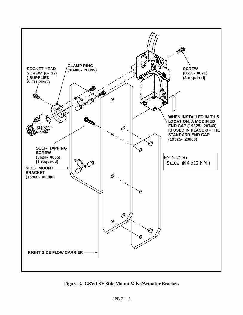
WHEN INSTALLED IN THISLOCATION, A MODIFIEDEND CAP (19325- 20740)IS USED IN PLACE OF THESTANDARD END CAP(19325- 20680)
CLAMP RING(18900- 20045)
SIDE- MOUNTBRACKET(18900- 00940)
SOCKET HEADSCREW (6- 32)( SUPPLIEDWITH RING)
RIGHT SIDE FLOW CARRIER
SELF- TAPPINGSCREW(0624- 0665)(3 required)
SCREW(0515- 0071)(2 required)
Figure 3. GSV/LSV Side Mount Valve/Actuator Bracket.
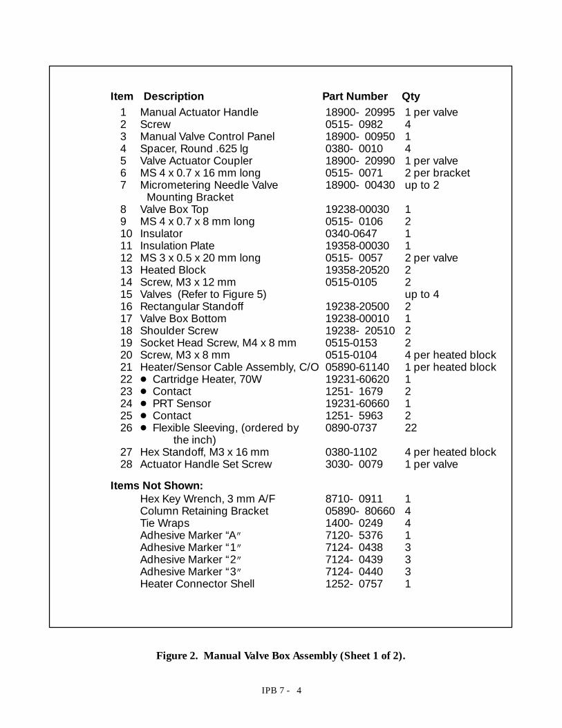
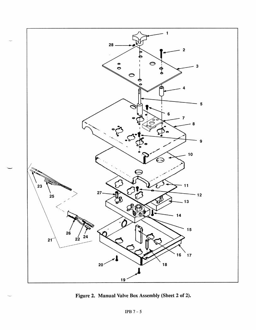
IPB 7 - 4
Item Description Part Number Qty
Hex Key Wrench, 3 mm A/F 8710- 0911 1Column Retaining Bracket 05890- 80660 4Tie Wraps 1400- 0249 4Adhesive Marker “A” 7120- 5376 1Adhesive Marker “1” 7124- 0438 3Adhesive Marker “2” 7124- 0439 3Adhesive Marker “3” 7124- 0440 3Heater Connector Shell 1252- 0757 1
Items Not Shown:
1 Manual Actuator Handle 18900- 20995 1 per valve2 Screw 0515- 0982 43 Manual Valve Control Panel 18900- 00950 14 Spacer, Round .625 lg 0380- 0010 45 Valve Actuator Coupler 18900- 20990 1 per valve6 MS 4 x 0.7 x 16 mm long 0515- 0071 2 per bracket7 Micrometering Needle Valve 18900- 00430 up to 2
Mounting Bracket8 Valve Box Top 19238-00030 19 MS 4 x 0.7 x 8 mm long 0515- 0106 210 Insulator 0340-0647 111 Insulation Plate 19358-00030 112 MS 3 x 0.5 x 20 mm long 0515- 0057 2 per valve13 Heated Block 19358-20520 214 Screw, M3 x 12 mm 0515-0105 215 Valves (Refer to Figure 5) up to 416 Rectangular Standoff 19238-20500 217 Valve Box Bottom 19238-00010 118 Shoulder Screw 19238- 20510 219 Socket Head Screw, M4 x 8 mm 0515-0153 220 Screw, M3 x 8 mm 0515-0104 4 per heated block21 Heater/Sensor Cable Assembly, C/O 05890-61140 1 per heated block22 D Cartridge Heater, 70W 19231-60620 123 D Contact 1251- 1679 224 D PRT Sensor 19231-60660 125 D Contact 1251- 5963 226 D Flexible Sleeving, (ordered by 0890-0737 22
the inch)27 Hex Standoff, M3 x 16 mm 0380-1102 4 per heated block28 Actuator Handle Set Screw 3030- 0079 1 per valve
Figure 2. Manual Valve Box Assembly (Sheet 1 of 2).
IPB 7 - 15
1/8- INCH SS NUT (0100- 0057), FRONTFERRULE (0100- 0034), AND BACK FERRULE(0100- 0038) (A PACKAGE OF 20 SETS OFNUTS AND BOTH FERRULES IS AVAILABLEAS 5080- 8751)
1/16- INCH SS UNION (0100- 0124)
1/16- INCH TUBE REDUCING UNION(0100- 0073)
1/16- INCH ZERO DEAD VOLUME UNION(0100- 0900)
7µM SAMPLE INLET FILTER (0101- 0532)
MICROMETERINGNEEDLE (ADJUSTABLERESTRICTOR) VALVEMOUNTING BRACKET(LOCATED ON LEFTSIDE CARRIER BE-HIND ACCESS DOOR(18900- 00980)
Tube, 1/16- inch SS 102- mm long 18900- 20230Tube, 1/16- inch SS 203- mm long 18900- 20240Tube, 1/16- inch SS 400- mm long 18900- 20280Tube, 1/16- inch SS 575- mm long 18900- 20281Tube, 1/16- inch SS 510- mm long 18900- 20290Tube, 1/16- inch SS 560- mm long 18900- 20300Tube, Nickel, 1/16- inch 460- mm long 18900- 20506Tube, Nickel, 1/16- inch 663- mm long 18900- 20507Tube, 1/16- inch w/1/8- inch flare SS 360 mm long 1530- 2163Tube, 1/16- inch w/1/8- inch flare SS 520 mm long 1530- 2167Tube, 1/16- inch w/1/8- inch flare SS 280 mm long 18900- 20250Tube, 1/16- inch w/1/8- inch bulkhead fitting 520 mm long 07675- 80050Tube, Nickel, 1/16- inch w/1/8- inch bulkhead fitting 460 mm long 18900- 80255
ABC
A:
B:
C:
1/16- INCH REDUCER/RESTRICTOR(18900- 80210)
BRASS RETAINER NUT(0590- 0385)(USED WITH07675- 80050)
Figure 11. Miscellaneous Hardware (Sheet 1 of 2).
IPB 7 - 16
1/16- INCH COUNTERBORENUT
(0100- 1511)
POLYIMIDE LINER (0.6- 0.8 mm O.D.)(FOR .530 CAPILLARY COLUMNS)
(0100- 1513)*
SS BULKHEAD ZERO DEAD VOLUME UNION(FOR .530 CAPILLARY COLUMNS)
(0100- 1515)
1/16- INCH I.D. POLYIMIDEFERRULE (0100- 1512)
SS BULKHEAD ZERO DEAD VOLUME UNION(FOR .320 CAPILLARY COLUMNS)
(0100- 1527)
POLYIMIDE LINER (0.5 mm O.D.)(FOR .320 CAPILLARY COLUMNS)
(0100- 1514)*
*Assembly tool for liners shown above is 18900- 20850.
Figure 11. Miscellaneous Hardware (Sheet 2 of 2).
IPB 7 - 12
18900-62XXX series numbers are for sets consisting of a loop, nuts, and ferrules. The 0101- 0XXXseries numbers, shown are for the loops only. All loops connect to valves using Valco 1/16- inch nutsand ferrules. (Nickel loops and smaller loops do not include nuts and ferrules.) Part numbers for at-
taching hardware are nut (0100- 0791) and ferrule (0100- 1022).
10 cc
5 cc
2 cc
1 cc
0.5 cc
0.25 cc
0101-030118900-62306
0101-029918900-62304
0101-030318900-62302
0101-030218900-62307
0101-030018900-62305
0101-028218900-62303
Nickel Sample Loops:.25 cc 18900- 20502.50 cc 18900- 205031.0 cc 18900- 205042.0 cc 18900- 20505
Smaller Sample Loops:25 µL 0101- 066550 µL 0101- 0667100 µL 0101- 0666
Figure 9. Sample Loops.
IPB 7 - 8
90°MaxAir In
Air Line(Normally
Actuated Port)
LinkarmLock Screw
Valve RotorCoupling Shaft
Air Line(Normally
Relaxed Port)
Piston
Cylinder Piston Rod
MODIFIEDSCREW19325- 80030
MODIFIEDSCREW19325- 80030
QUICK- RELEASE PIN1480- 0632
COUPLER/SHAFT ASSEMBLY19325- 60640
ELBOWFITTING0100- 1220
1/8- INCH HOSEFITTING0100- 1205
FLEXIBLE TUBING 1/8- INCH od0890- 0746
(ordered by the inch; 21inches for each connection)1/8- INCH HOSE
FITTING0100- 1205
FLEXIBLE TUBING1/8- INCH od0890- 0746
(ordered by the inch; 21inches for each connec-tion)
36° ACTUATORLIMITER (18900- 21000)
(INSTALLED IN 60_ POSITION ONLY)
REGULAR END CAP(19325- 20680) ORMODIFIED END CAP*(19325- 20740)
* USED IN SIDE MOUNTONLY (REFER TO FIGURE 3)
Figure 5. Valve Actuator Assembly (19325- 60660) (Sheet 1 of 2).
IPB 7 - 2
1 Actuator Assembly 19325-60660 1 per valve(Refer to Figure 5)
2 Screw, M4 x 8 mm 0515-0106 123 MS 4 x 0.7 x 16 mm long 0515- 0071 2 per bracket4 Micrometering Needle Valve 18900- 00430 up to 2
Mounting Bracket5 Valve Box Top 19238-00030 16 MS 4 x 0.7 x 8 mm long 0515- 0106 27 Insulator 0340-0647 18 Insulation Plate 19358-00030 19 MS 3 x 0.5 x 20 mm long 0515- 0057 2 per valve10 Heated Block 19358-20520 211 Screw, M3 x 12 mm 0515-0105 212 Valves (Refer to Figure 6) up to 413 Rectangular Standoff 19238-20500 214 Valve Box Bottom 19238-00010 115 Shoulder Screw 19238- 20510 216 Socket Head Screw, M4 x 8 mm 0515-0153 217 Screw, M3 x 8 mm 0515-0104 4 per heated block18 Heater/Sensor Cable Assembly, C/O 05890-61140 1 per heated block19 D Cartridge Heater, 70W (includes 19231-60620 1
contact 1251- 1679)20 D Contact 1251- 1679 221 D PRT Sensor (includes 19231-60660 1
contact 1251- 5963)22 D Contact 1251- 5963 223 D Flexible Sleeving, (ordered by 0890-0737 22
the inch)24 Hex Standoff, M3 x 16 mm 0380-1102 4 per heated block
Item Description Part Number Qty
Column Retaining Bracket 05890- 80660 4Tie Wraps 1400- 0249 4Adhesive Marker “A” 7120- 5376 1Adhesive Marker “1” 7124- 0438 3Adhesive Marker “2” 7124- 0439 3Adhesive Marker “3” 7124- 0440 3Valve Driver Cable 05890- 61350 1
Items Not Shown:
Figure 1. Valve Box Assembly (Sheet 1 of 2).
IPB 7 - 11
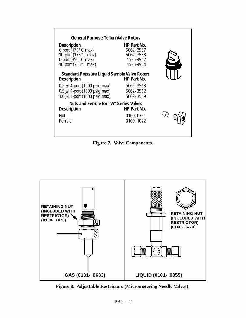
General Purpose Teflon Valve RotorsDescription HP Part No.6-port (175_C max) 5062- 355710-port (175_C max) 5062- 35586-port (350_C max) 1535-495210-port (350_C max) 1535-4954
Standard Pressure Liquid Sample Valve RotorsDescription HP Part No.0.2 µl 4-port (1000 psig max) 5062- 35630.5 µl 4-port (1000 psig max) 5062- 35621.0 µl 4-port (1000 psig max) 5062- 3559
Nuts and Ferrule for “W” Series ValvesDescription HP Part No.Nut 0100- 0791Ferrule 0100- 1022
Figure 7. Valve Components.
GAS (0101- 0633) LIQUID (0101- 0355)
RETAINING NUT(INCLUDED WITHRESTRICTOR)(0100- 1470)
RETAINING NUT(INCLUDED WITHRESTRICTOR)(0100- 1470)
Figure 8. Adjustable Restrictors (Micrometering Needle Valves).
IPB 7 - 13
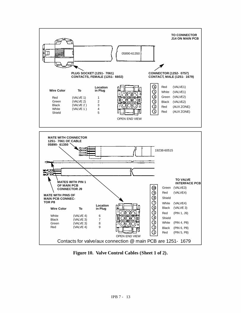
LocationWire Color To in Plug
Red (VALVE 1) 1Green (VALVE 2) 2Black (VALVE 2 ) 3White (VALVE 1 ) 4Shield 5
Red (VALVE1)654321
05890-61350
PLUG SOCKET (1251- 7061)CONTACTS, FEMALE (1251- 6602)
CONNECTOR (1252- 0757)CONTACT, MALE (1251- 1679)
White (VALVE1)Green (VALVE2)Black (VALVE2)Red (AUX ZONE)Red (AUX ZONE)
OPEN END VIEW
1 3
7 9
TO CONNECTORJ14 ON MAIN PCB
19238-60515
654321
10987
Contacts for valve/aux connection @ main PCB are 1251- 1679
MATES WITH PIN 1OF MAIN PCBCONNECTOR J9
MATE WITH PINS OFMAIN PCB CONNEC-TOR P8
MATE WITH CONNECTOR1251- 7061 OF CABLE05890- 61350
Green (VALVE3)Red (VALVE4)ShieldWhite (VALVE4)Black (VALVE 3)Red (PIN 1, J9)ShieldWhite (PIN 4, P8)Black (PIN 6, P8)Red (PIN 5, P8)
LocationWire Color To in Plug
White (VALVE 4) 6Black (VALVE 3) 7Green (VALVE 3) 8Red (VALVE 4) 9
OPEN END VIEW
1 3
7 9
TO VALVEINTERFACE PCB
Figure 10. Valve Control Cables (Sheet 1 of 2).
IPB 7 - 14
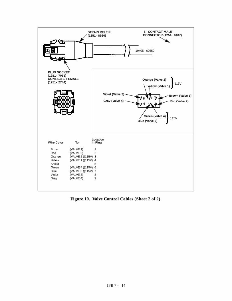
LocationWire Color To in Plug
Brown (VALVE 1) 1Red (VALVE 2) 2Orange (VALVE 2 )(115V) 3Yellow (VALVE 1 )(115V) 4Shield 5Green (VALVE 4 )(115V) 6Blue (VALVE 3 )(115V) 7Violet (VALVE 3) 8Gray (VALVE 4) 9
2
134
56
Orange (Valve 2)
Yellow (Valve 1)
Violet (Valve 3)
Gray (Valve 4)
Green (Valve 4)Blue (Valve 3)
Red (Valve 2)Brown (Valve 1)
115V
4 6531 2
7 8 9
115V
19405- 60550
6- CONTACT MALECONNECTOR (1251- 0407)
PLUG SOCKET(1251- 7061)CONTACTS, FEMALE(1251- 2744)
STRAIN RELEIF(1251- 8920)
Figure 10. Valve Control Cables (Sheet 2 of 2).
IPB 7 - 7
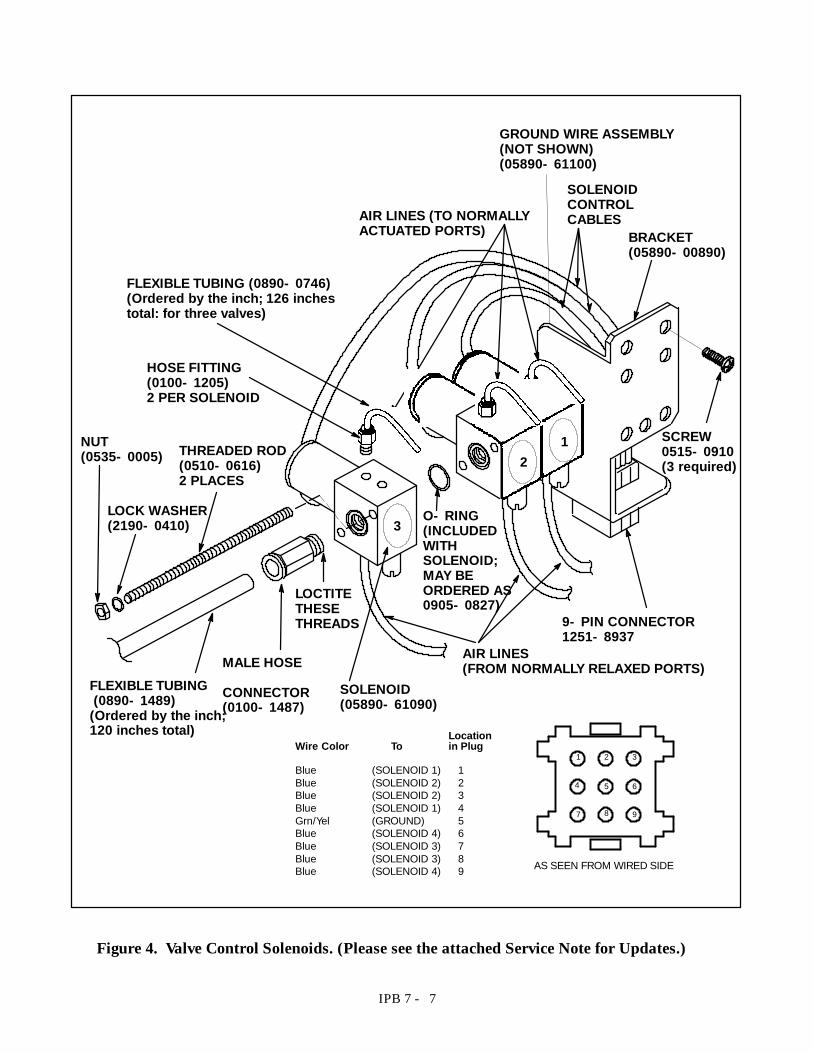
AIR LINES (TO NORMALLYACTUATED PORTS)
SOLENOIDCONTROLCABLES
AIR LINES(FROM NORMALLY RELAXED PORTS)
9- PIN CONNECTOR1251- 8937
FLEXIBLE TUBING(0890- 1489)
(Ordered by the inch;120 inches total)
FLEXIBLE TUBING (0890- 0746)(Ordered by the inch; 126 inchestotal: for three valves)
HOSE FITTING(0100- 1205)2 PER SOLENOID
MALE HOSE
CONNECTOR(0100- 1487)
BRACKET(05890- 00890)
THREADED ROD(0510- 0616)2 PLACES
LOCK WASHER(2190- 0410)
NUT(0535- 0005)
O- RING(INCLUDEDWITHSOLENOID;MAY BEORDERED AS0905- 0827)
SOLENOID(05890- 61090)
GROUND WIRE ASSEMBLY(NOT SHOWN)(05890- 61100)
LocationWire Color To in Plug
Blue (SOLENOID 1) 1Blue (SOLENOID 2) 2Blue (SOLENOID 2) 3Blue (SOLENOID 1) 4Grn/Yel (GROUND) 5Blue (SOLENOID 4) 6Blue (SOLENOID 3) 7Blue (SOLENOID 3) 8Blue (SOLENOID 4) 9
1 2 3
4 5 6
7 8 9
AS SEEN FROM WIRED SIDE
LOCTITETHESETHREADS
12
3
SCREW0515- 0910(3 required)
Figure 4. Valve Control Solenoids. (Please see the attached Service Note for Updates.)
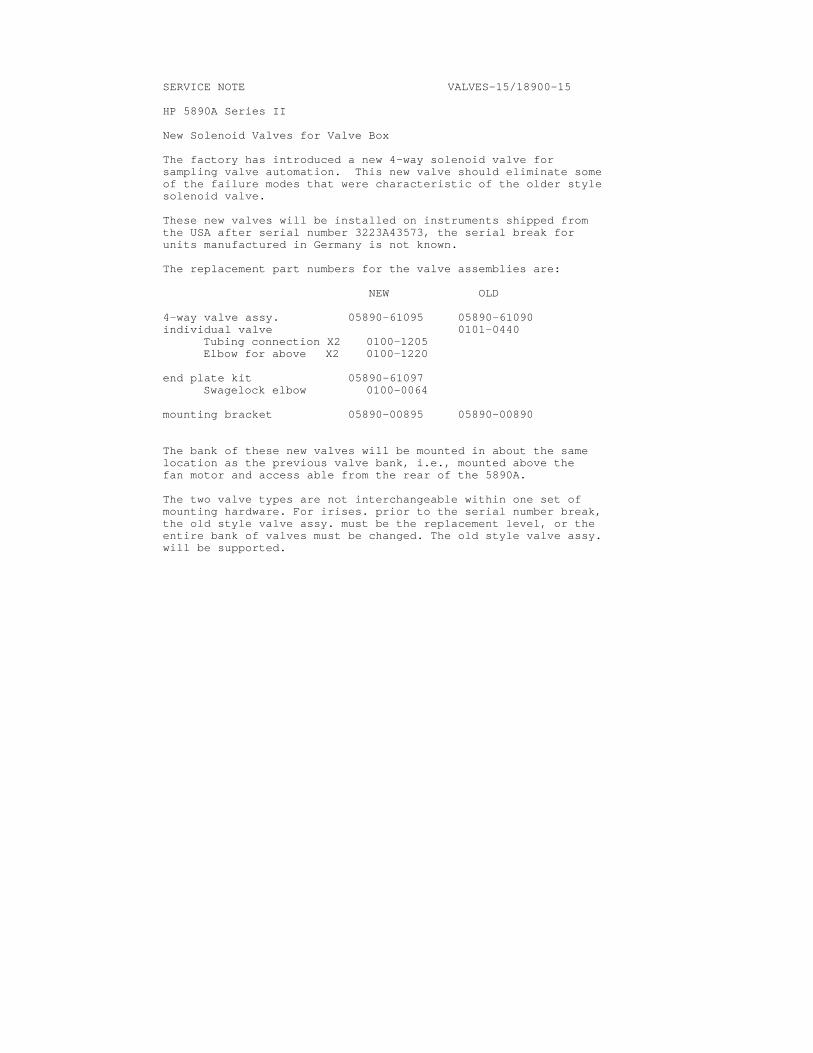
SERVICE NOTE VALVES-15/18900-15 HP 5890A Series II New Solenoid Valves for Valve Box The factory has introduced a new 4-way solenoid valve for sampling valve automation. This new valve should eliminate some of the failure modes that were characteristic of the older style solenoid valve. These new valves will be installed on instruments shipped from the USA after serial number 3223A43573, the serial break for units manufactured in Germany is not known. The replacement part numbers for the valve assemblies are: NEW OLD 4-way valve assy. 05890-61095 05890-61090 individual valve 0101-0440 Tubing connection X2 0100-1205 Elbow for above X2 0100-1220 end plate kit 05890-61097 Swagelock elbow 0100-0064 mounting bracket 05890-00895 05890-00890 The bank of these new valves will be mounted in about the same location as the previous valve bank, i.e., mounted above the fan motor and access able from the rear of the 5890A. The two valve types are not interchangeable within one set of mounting hardware. For irises. prior to the serial number break, the old style valve assy. must be the replacement level, or the entire bank of valves must be changed. The old style valve assy. will be supported.
IPB 7 - 10
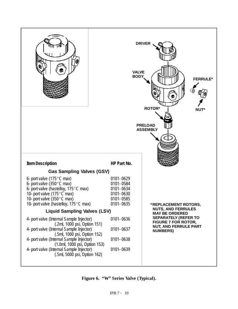
VALVEBODY
ROTOR*
PRELOADASSEMBLY
FERRULE*
NUT*
Item Description HP Part No.
6- port valve (175_C max) 0101- 06296- port valve (350_C max) 0101- 05846- port valve (hastelloy, 175_C max) 0101- 063410- port valve (175_C max) 0101- 063010- port valve (350_C max) 0101- 058510- port valve (hastelloy, 175_C max) 0101- 0635
4- port valve (Internal Sample Injector) 0101- 0636(.2ml, 1000 psi, Option 151)
4- port valve (Internal Sample Injector) 0101- 0637(.5ml, 1000 psi, Option 152)
4- port valve (Internal Sample Injector) 0101- 0638(1.0ml, 1000 psi, Option 153)
4- port valve (Internal Sample Injector) 0101- 0639(.5ml, 5000 psi, Option 162)
*REPLACEMENT ROTORS,NUTS, AND FERRULESMAY BE ORDEREDSEPARATELY (REFER TOFIGURE 7 FOR ROTOR,NUT, AND FERRULE PARTNUMBERS)
DRIVER
Gas Sampling Valves (GSV)
Liquid Sampling Valves (LSV)
Figure 6. “W”Series Valve (Typical).
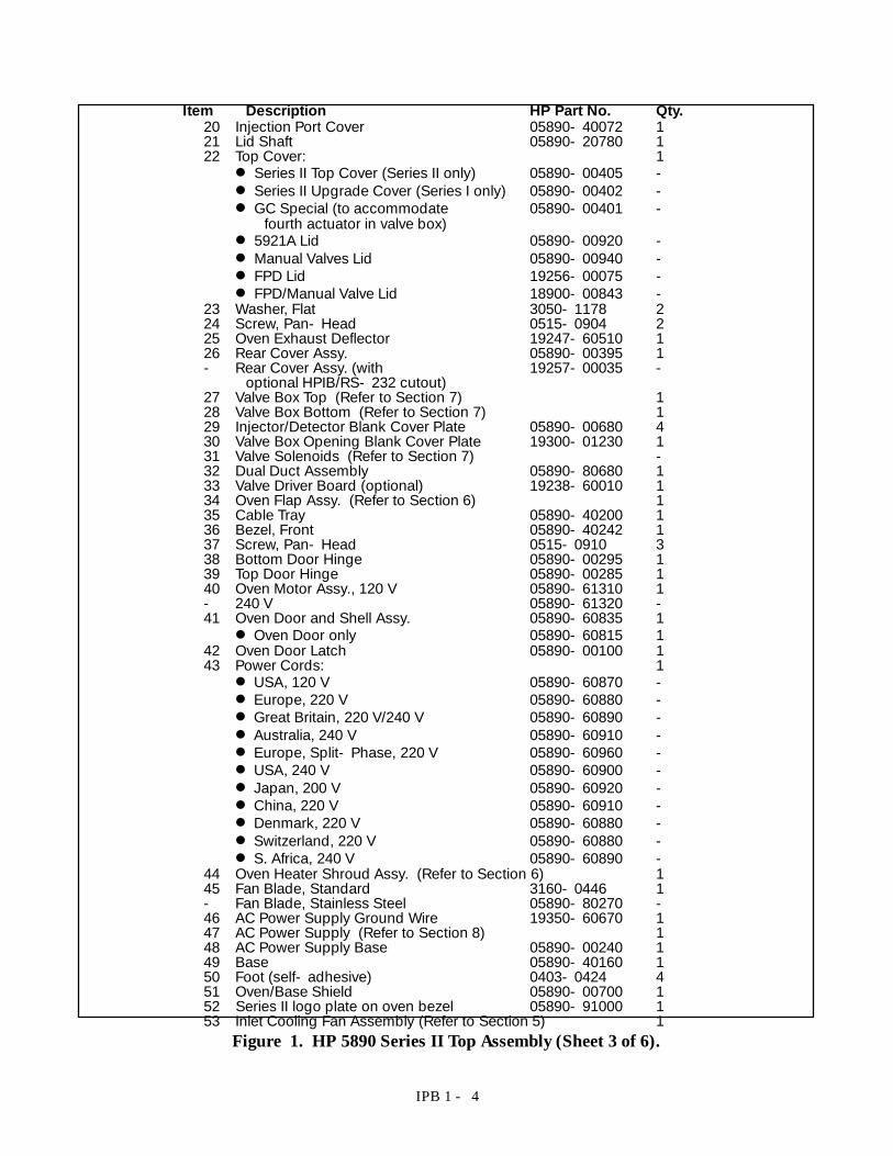
IPB 1 - 4
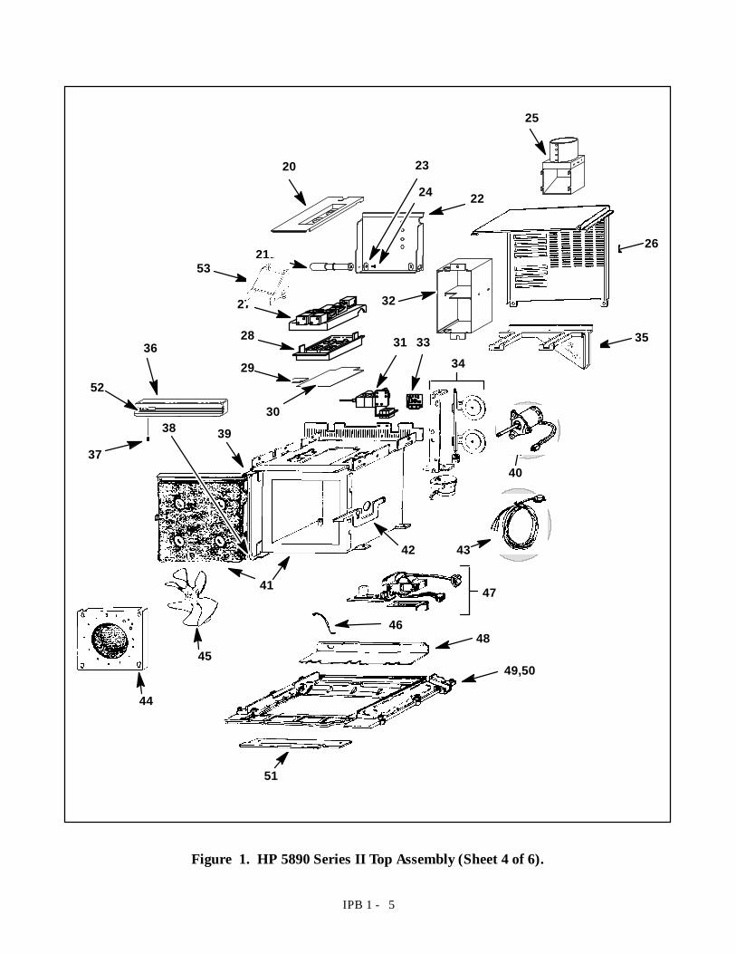
Item Description HP Part No. Qty.20 Injection Port Cover 05890- 40072 121 Lid Shaft 05890- 20780 122 Top Cover: 1D Series II Top Cover (Series II only) 05890- 00405 -D Series II Upgrade Cover (Series I only) 05890- 00402 -D GC Special (to accommodate 05890- 00401 -
fourth actuator in valve box)D 5921A Lid 05890- 00920 -D Manual Valves Lid 05890- 00940 -D FPD Lid 19256- 00075 -D FPD/Manual Valve Lid 18900- 00843 -
23 Washer, Flat 3050- 1178 224 Screw, Pan- Head 0515- 0904 225 Oven Exhaust Deflector 19247- 60510 126 Rear Cover Assy. 05890- 00395 1- Rear Cover Assy. (with 19257- 00035 -
optional HPIB/RS- 232 cutout)27 Valve Box Top (Refer to Section 7) 128 Valve Box Bottom (Refer to Section 7) 129 Injector/Detector Blank Cover Plate 05890- 00680 430 Valve Box Opening Blank Cover Plate 19300- 01230 131 Valve Solenoids (Refer to Section 7) -32 Dual Duct Assembly 05890- 80680 133 Valve Driver Board (optional) 19238- 60010 134 Oven Flap Assy. (Refer to Section 6) 135 Cable Tray 05890- 40200 136 Bezel, Front 05890- 40242 137 Screw, Pan- Head 0515- 0910 338 Bottom Door Hinge 05890- 00295 139 Top Door Hinge 05890- 00285 140 Oven Motor Assy., 120 V 05890- 61310 1- 240 V 05890- 61320 -41 Oven Door and Shell Assy. 05890- 60835 1D Oven Door only 05890- 60815 1
42 Oven Door Latch 05890- 00100 143 Power Cords: 1D USA, 120 V 05890- 60870 -D Europe, 220 V 05890- 60880 -D Great Britain, 220 V/240 V 05890- 60890 -D Australia, 240 V 05890- 60910 -D Europe, Split- Phase, 220 V 05890- 60960 -D USA, 240 V 05890- 60900 -D Japan, 200 V 05890- 60920 -D China, 220 V 05890- 60910 -D Denmark, 220 V 05890- 60880 -D Switzerland, 220 V 05890- 60880 -D S. Africa, 240 V 05890- 60890 -
44 Oven Heater Shroud Assy. (Refer to Section 6) 145 Fan Blade, Standard 3160- 0446 1- Fan Blade, Stainless Steel 05890- 80270 -46 AC Power Supply Ground Wire 19350- 60670 147 AC Power Supply (Refer to Section 8) 148 AC Power Supply Base 05890- 00240 149 Base 05890- 40160 150 Foot (self- adhesive) 0403- 0424 451 Oven/Base Shield 05890- 00700 152 Series II logo plate on oven bezel 05890- 91000 153 Inlet Cooling Fan Assembly (Refer to Section 5) 1
Figure 1. HP 5890 Series II Top Assembly (Sheet 3 of 6).
IPB 1 - 5
26
34
39
40
41
38
49,5045
48
42
47
35
46
43
51
44
25
20 23
2224
21
3227
28
29
30
3136
52
37
33
53
Figure 1. HP 5890 Series II Top Assembly (Sheet 4 of 6).
IPB 1 - 6
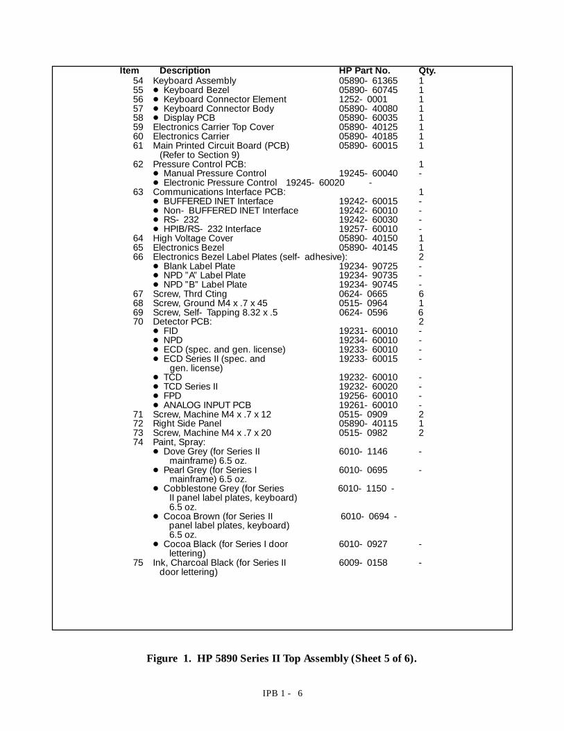
Item Description HP Part No. Qty.54 Keyboard Assembly 05890- 61365 155 D Keyboard Bezel 05890- 60745 156 D Keyboard Connector Element 1252- 0001 157 D Keyboard Connector Body 05890- 40080 158 D Display PCB 05890- 60035 159 Electronics Carrier Top Cover 05890- 40125 160 Electronics Carrier 05890- 40185 161 Main Printed Circuit Board (PCB) 05890- 60015 1
(Refer to Section 9)62 Pressure Control PCB: 1
D Manual Pressure Control 19245- 60040 -D Electronic Pressure Control 19245- 60020 -
63 Communications Interface PCB: 1D BUFFERED INET Interface 19242- 60015 -D Non- BUFFERED INET Interface 19242- 60010 -D RS- 232 19242- 60030 -D HPIB/RS- 232 Interface 19257- 60010 -
64 High Voltage Cover 05890- 40150 165 Electronics Bezel 05890- 40145 166 Electronics Bezel Label Plates (self- adhesive): 2
D Blank Label Plate 19234- 90725 -D NPD ”A”Label Plate 19234- 90735 -D NPD ”B”Label Plate 19234- 90745 -
67 Screw, Thrd Cting 0624- 0665 668 Screw, Ground M4 x .7 x 45 0515- 0964 169 Screw, Self- Tapping 8.32 x .5 0624- 0596 670 Detector PCB: 2
D FID 19231- 60010 -D NPD 19234- 60010 -D ECD (spec. and gen. license) 19233- 60010 -D ECD Series II (spec. and 19233- 60015 -
gen. license)D TCD 19232- 60010 -D TCD Series II 19232- 60020 -D FPD 19256- 60010 -D ANALOG INPUT PCB 19261- 60010 -
71 Screw, Machine M4 x .7 x 12 0515- 0909 272 Right Side Panel 05890- 40115 173 Screw, Machine M4 x .7 x 20 0515- 0982 274 Paint, Spray:
D Dove Grey (for Series II 6010- 1146 -mainframe) 6.5 oz.
D Pearl Grey (for Series I 6010- 0695 -mainframe) 6.5 oz.
D Cobblestone Grey (for Series 6010- 1150 -II panel label plates, keyboard)6.5 oz.
D Cocoa Brown (for Series II 6010- 0694 -panel label plates, keyboard)6.5 oz.
D Cocoa Black (for Series I door 6010- 0927 -lettering)
75 Ink, Charcoal Black (for Series II 6009- 0158 -door lettering)
Figure 1. HP 5890 Series II Top Assembly (Sheet 5 of 6).
IPB 1 - 7
55
59
60
61 64
72
57
70
65
63
66
62
PRESS. CONTROLPCB MOUNTINGLOCATION
COMM.PCBMOUNTINGLOCATION
DETECTOR “B”PCBMOUNTING LOCATION
DETECTOR “A”PCBMOUNTING LOCATION
74
75
56
54
58
6769
68
71 73
Figure 1. HP 5890 Series II Top Assembly (Sheet 6 of 6).
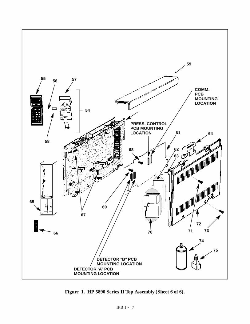
IPB 2 - 18
Item Detector Column Type HP Part No.1 FID/NPD 1/4- inch Packed Column 19231- 805302 FID/NPD 1/8- inch Packed Column 19231- 805203 FID/NPD Capillary Column 19242- 80610
and4 FID/NPD Capillary Column nut 18740- 208705 FID/NPD Vespel Ferrule, 1/4- inch 5080- 87746 FID/NPD Graphite Ferrule, 0.5 or 1- mm Table 4- 17 FID/NPD Tubing Nut, 1/4- inch 0100- 0056- TCD/ECD (Refer to Sheet 3) -8 FPD Capillary Column 19256- 805709 FPD 1/8- inch Packed Column 19256- 80590
4
63
5
1
2
1/8- inch PackedColumn Use(FPD)
CapillaryColumn Use(FPD)
CapillaryColumn Use(FID/NPD)
1/4- inch PackedColumn Use
1/8- inch PackedColumn Use(FID/NPD)
8
9
7
Figure 7. Detector Column and Makeup Gas Adaptors (Sheet 1 of 3).
IPB 2 - 19
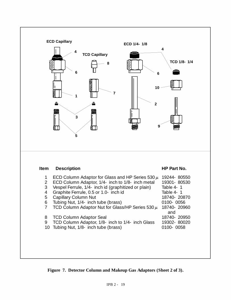
Item Description HP Part No.1 ECD Column Adaptor for Glass and HP Series 530 µ 19244- 805502 ECD Column Adaptor, 1/4- inch to 1/8- inch metal 19301- 805303 Vespel Ferrule, 1/4- inch id (graphitized or plain) Table 4- 14 Graphite Ferrule, 0.5 or 1.0- inch id Table 4- 15 Capillary Column Nut 18740- 208706 Tubing Nut, 1/4- inch tube (brass) 0100- 00567 TCD Column Adaptor Nut for Glass/HP Series 530 µ 18740- 20960
and8 TCD Column Adaptor Seal 18740- 209509 TCD Column Adaptor, 1/8- inch to 1/4- inch Glass 19302- 8002010 Tubing Nut, 1/8- inch tube (brass) 0100- 0058
9
2
10
6
4
8
7
3
5
1
6
4
ECD Capillary
TCD Capillary
ECD 1/4- 1/8
TCD 1/8- 1/4
Figure 7. Detector Column and Makeup Gas Adaptors (Sheet 2 of 3).
IPB 2 - 20
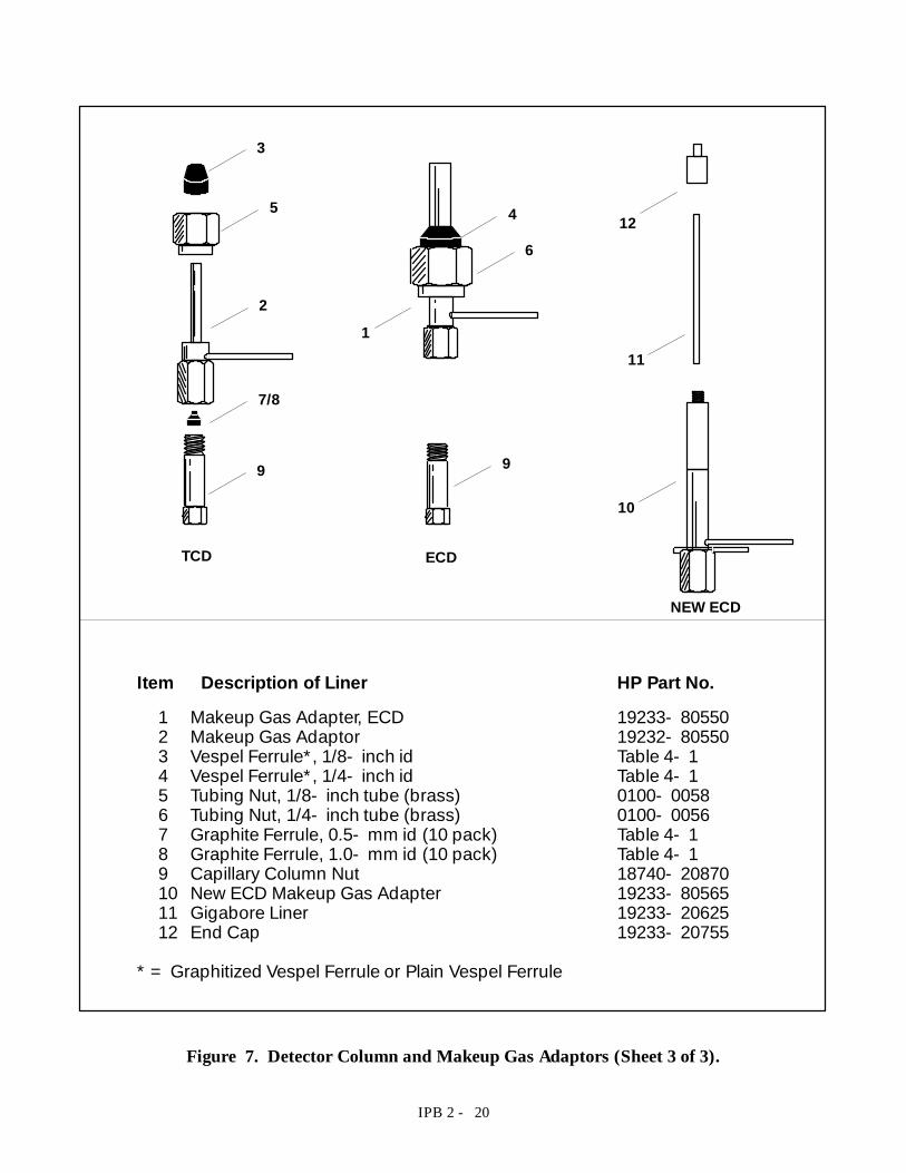
Item Description of Liner HP Part No.1 Makeup Gas Adapter, ECD 19233- 805502 Makeup Gas Adaptor 19232- 805503 Vespel Ferrule*, 1/8- inch id Table 4- 14 Vespel Ferrule*, 1/4- inch id Table 4- 15 Tubing Nut, 1/8- inch tube (brass) 0100- 00586 Tubing Nut, 1/4- inch tube (brass) 0100- 00567 Graphite Ferrule, 0.5- mm id (10 pack) Table 4- 18 Graphite Ferrule, 1.0- mm id (10 pack) Table 4- 19 Capillary Column Nut 18740- 2087010 New ECD Makeup Gas Adapter 19233- 8056511 Gigabore Liner 19233- 2062512 End Cap 19233- 20755
* = Graphitized Vespel Ferrule or Plain Vespel Ferrule
ECDTCD
4
3
5
2
7/8
9 9
6
1
NEW ECD
10
11
12
Figure 7. Detector Column and Makeup Gas Adaptors (Sheet 3 of 3).
IPB 2 - 21
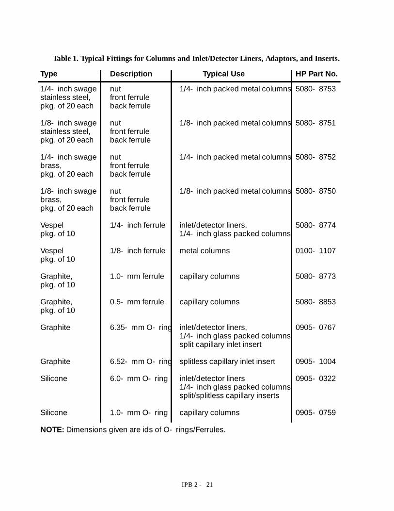
Type Description Typical Use HP Part No.1/4- inch swage nut 1/4- inch packed metal columns 5080- 8753stainless steel, front ferrulepkg. of 20 each back ferrule
1/8- inch swage nut 1/8- inch packed metal columns 5080- 8751stainless steel, front ferrulepkg. of 20 each back ferrule
1/4- inch swage nut 1/4- inch packed metal columns 5080- 8752brass, front ferrulepkg. of 20 each back ferrule
1/8- inch swage nut 1/8- inch packed metal columns 5080- 8750brass, front ferrulepkg. of 20 each back ferrule
Vespel 1/4- inch ferrule inlet/detector liners, 5080- 8774pkg. of 10 1/4- inch glass packed columns
Vespel 1/8- inch ferrule metal columns 0100- 1107pkg. of 10
Graphite, 1.0- mm ferrule capillary columns 5080- 8773pkg. of 10
Graphite, 0.5- mm ferrule capillary columns 5080- 8853pkg. of 10
Graphite 6.35- mm O- ring inlet/detector liners, 0905- 07671/4- inch glass packed columnssplit capillary inlet insert
Graphite 6.52- mm O- ring splitless capillary inlet insert 0905- 1004
Silicone 6.0- mm O- ring inlet/detector liners 0905- 03221/4- inch glass packed columnssplit/splitless capillary inserts
Silicone 1.0- mm O- ring capillary columns 0905- 0759
NOTE: Dimensions given are ids of O- rings/Ferrules.
Table 1. Typical Fittings for Columns and Inlet/Detector Liners, Adaptors, and Inserts.
IPB 8 - 2
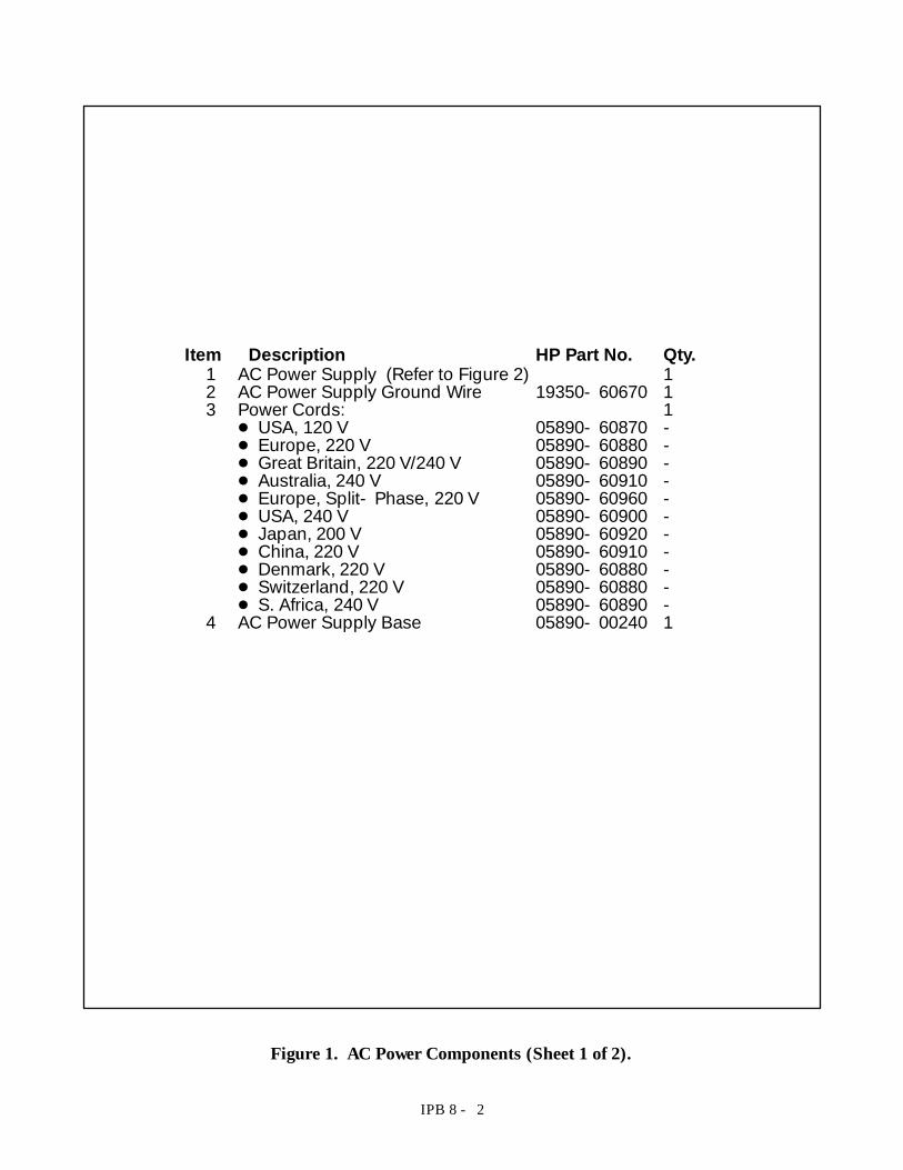
Item Description HP Part No. Qty.1 AC Power Supply (Refer to Figure 2) 12 AC Power Supply Ground Wire 19350- 60670 13 Power Cords: 1D USA, 120 V 05890- 60870 -D Europe, 220 V 05890- 60880 -D Great Britain, 220 V/240 V 05890- 60890 -D Australia, 240 V 05890- 60910 -D Europe, Split- Phase, 220 V 05890- 60960 -D USA, 240 V 05890- 60900 -D Japan, 200 V 05890- 60920 -D China, 220 V 05890- 60910 -D Denmark, 220 V 05890- 60880 -D Switzerland, 220 V 05890- 60880 -D S. Africa, 240 V 05890- 60890 -
4 AC Power Supply Base 05890- 00240 1
Figure 1. AC Power Components (Sheet 1 of 2).

IPB 8 - 3
4
1
2
3
Figure 1. AC Power Components (Sheet 2 of 2).

IPB 8 - 2
Item Description HP Part No. Qty.1 AC Power Supply (Refer to Figure 2) 12 AC Power Supply Ground Wire 19350- 60670 13 Power Cords: 1D USA, 120 V 05890- 60870 -D Europe, 220 V 05890- 60880 -D Great Britain, 220 V/240 V 05890- 60890 -D Australia, 240 V 05890- 60910 -D Europe, Split- Phase, 220 V 05890- 60960 -D USA, 240 V 05890- 60900 -D Japan, 200 V 05890- 60920 -D China, 220 V 05890- 60910 -D Denmark, 220 V 05890- 60880 -D Switzerland, 220 V 05890- 60880 -D S. Africa, 240 V 05890- 60890 -
4 AC Power Supply Base 05890- 00240 1
Figure 1. AC Power Components (Sheet 1 of 2).
IPB 8 - 3
4
1
2
3
Figure 1. AC Power Components (Sheet 2 of 2).

IPB 8 - 4
Item Description HP Part No. Qty.1 DPST Rocker Switch (Power Switch) 3101- 0402 12 Nut/Lock Washer 0535- 0043 73 Screw 0515- 1276 44 Insulator Bushing 0340- 0793 45 AC Printed Circuit Board (Refer to Table 1) 16 Screw 0515- 0910 17 Lock Washer 2190- 0409 18 AC Power Supply Ground Wire 19350- 60670 19 AC Power Supply Base 05890- 00240 110 Transformer Bracket 05890- 80690 111 Transformer (Refer to Table 1) 112 Extension Cable for upgraded 05890- 61340 1
Series I
Figure 2. AC Power, Common (Sheet 1 of 2).

IPB 8 - 5
1
2
3,4
5
6,78
9
101112
Figure 2. AC Power, Common (Sheet 2 of 2).
IPB 8 - 4
Item Description HP Part No. Qty.1 DPST Rocker Switch (Power Switch) 3101- 0402 12 Nut/Lock Washer 0535- 0043 73 Screw 0515- 1276 44 Insulator Bushing 0340- 0793 45 AC Printed Circuit Board (Refer to Table 1) 16 Screw 0515- 0910 17 Lock Washer 2190- 0409 18 AC Power Supply Ground Wire 19350- 60670 19 AC Power Supply Base 05890- 00240 110 Transformer Bracket 05890- 80690 111 Transformer (Refer to Table 1) 112 Extension Cable for upgraded 05890- 61340 1
Series I
Figure 2. AC Power, Common (Sheet 1 of 2).
IPB 8 - 5
1
2
3,4
5
6,78
9
101112
Figure 2. AC Power, Common (Sheet 2 of 2).